Download - Request for Information - GVEA
Request for Information
Solicitation for New Photovoltaic Solar, Onshore
Wind Power Supply Generation and Energy Storage
January 25, 2021
Golden Valley Electric Association, Inc.
2
PART I – Overview A. Introduction
Nearly fifty thousand homes and businesses are energized with electricity from Golden
Valley Electric Association (the “Company” or “GVEA”), headquartered in Fairbanks,
Alaska. The Company is committed to safely providing its member-owners with
reliable electric service, quality customer service, and innovative energy solutions at
fair and reasonable prices. A diverse mix of generating resources consisting of
GVEA-owned wind, solar, coal, hydro and distillate petroleum provides power to
GVEA members. Additionally, the Company purchases capacity and energy from
non-utility generators and other utilities on the interconnected Alaska Railbelt.
GVEA’s approximately $700 million of assets provide electric generation,
transmission, and distribution to Interior Alaska.
In 2019, GVEA’s Board adopted a goal to reduce carbon dioxide emissions 26 percent
over the 2012 emission levels by 2030 on a per Megawatt-hour basis with no adverse
long-term impact on rates. For more information, visit https://www.gvea.com. This goal
remains active and GVEA is evaluating numerous ways to achieve these emission
reductions, including reviewing renewable energy projects that may be added to
GVEA’s generation mix.
B. Purpose With this Request for Information (“Request”), GVEA is soliciting project proposals
f rom parties interested in providing new photovoltaic (“PV”) solar generation, new
onshore wind Unit Capacity (as defined below) or other renewable energy to GVEA.
Although this Request primarily targets solar and wind, any other proposals that
reduce GVEA emissions of carbon dioxide and are commercially proven are welcome.
Hydroelectric and biomass generation are possible candidates.
The Company is conducting this Request in conjunction with its own internal review
of generation assets and seeks third-party proposals in order to fully evaluate and
determine the most favorable new renewable energy option(s) available for its
members with the objective of reducing GVEA’s carbon dioxide emissions, while
ensuring that any projects being considered make economic sense.

3
Aggregate Project capacity for all Proposals should be approximately 15MW to 30MW,
however, any individual site projects that are part of the aggregate Project capacity
must be a minimum of 1 MW per site. GVEA anticipates that the cost of energy from
variable renewable generation resources will be under $0.09/kWh without shaping or
“regulation”. Low-carbon generation that is dispatchable (through the incorporation of
energy storage or by its nature, i.e., hydro or biomass), is potentially more valuable to
GVEA. Respondents will be required to detail size, location, price and preferred
structure for the Project as discussed further below.
Respondents are encouraged to create a proposal that maximizes the value to GVEA
members by minimizing costs and using creative and cost-effective means to mitigate
the impact of the variable output of renewable generation.
It is the intent of this Request that interested parties respond with proposals that would
meet the scope and parameters defined in this Request. GVEA will review all
submitted Proposals and those that are found to meet GVEA evaluation standards will
be held for two years. If during the two year period GVEA elects to proceed with a
Request For Proposal for third-party renewable generation, only those Respondents
that submitted proposals for review and consideration during this Request will be
invited to participate.
C. Scope All Proposals must conform to the requirements detailed below. Any Proposal that
does not conform to one or more of the Request requirements may be eliminated from
further consideration.
1. Product
For the purposes of this Request, “Unit Capacity” is defined as maximum net MW
(ac) output, and includes capacity, energy, ancillary services and environmental
attributes (including but not limited to renewable energy certificates) delivered from
a specific new PV solar facility, PV + energy storage facility, new onshore wind
facility, new onshore wind + energy storage facility, or a stand-alone energy
storage facility.

4
2. Structures
The Company is seeking Proposals based on any of the following structures.
Respondents has the option of submitting more than one Proposal for a single
facility, each based on a different purchase structure. A Company proposed
Power Purchase Agreement and Asset Purchase Agreement will be supplied to
bidders if and when an RFP is opened as follow-up to this Request. For the
purposes of this Request, Respondent shall indicate which purchase structure they
would be interested in supplying energy under, as well as the detailed information
regarding that structure as indicated in this Request and any Attachments.
a. Power Purchase Agreement (“PPA”): Agreement that provides Company the
exclusive right to 100% of the Unit Capacity of the facility from which such
output will be delivered. The suggested PPA term is twenty years. PPA’s that
provide the Company an option to acquire the facility’s assets on or after the
tenth full year of operation may be considered more favorably.
b. Asset Acquisition of Development Project at Notice to Proceed (“Development
Proposal”): Proposal that provides a price for the sale of a development project,
including property rights, permits, interconnection queue position, reports and
preliminary design documents and agreements that would allow the Company
to complete development and construction of the facility by the expected in-
service date.
c. Asset Acquisition of Project at Mechanical Completion (“MC Proposal”):
Proposal that provides a price for the sale of a project that is to be developed,
constructed and turned over to the Company at Mechanical Completion. Any
proposed Project would be required to be built to industry utility standards,
GVEA standards and USDA Rural Utilities Service standards.
3. Commercial Operations Date
To line up with other generation choices being made by Company, a proposed facility
would need to be in-service and capable of delivering its full rated output by January
1, 2025. Respondents shall clearly designate in Proposal when a proposed facility is
expected to be in commercial operation. Company may consider Proposals that are
5
completed prior to the deadline more favorably.
4. Quantity
The Company is seeking Proposals for up to 30 MW (ac) total capacity at the point of
interconnection from new solar PV and onshore wind facilities with Unit Capacity of at
least 15 MW.
The Company is also seeking PV + energy storage, and onshore wind + energy storage
Proposals for up to 30 MW (ac or dc) total capacity (as capable of being delivered to the
interconnection point).
For all PV + energy storage, and onshore wind + energy storage Proposals which the
Respondent is seeking PPA or Development Proposal build structure for, the Company
recommends a four-hour duration Lithium-ion battery energy storage system to be
included as a component of all those Proposals. The Company will also consider
Additional Alternative Storage Bids as part of the submittal of a four-hour duration
Lithium-ion battery energy storage system. These Additional Alternative Storage Bids
can include, but are not limited to, flow batteries, hydro energy storage, mechanical
energy storage, cryogenic energy storage, compressed air energy storage or other
commercially viable energy storage systems.
All four-hour Lithium-ion Proposals are to include the following inputs/assumptions:
• One full charge / discharge cycle in a twenty-four-hour period at submitted
Minimum and Maximum States of Charge
• Battery augmentation cycle that maintains facility output (Nameplate Capacity
MWac multiplied by four-hour or other vendor-specified duration) over a ten-
year period
• Annual degradation rate to be applied to initial facility output (Nameplate Capacity
MWac multiplied by four-hour or other vendor-specified duration) assuming no
battery augmentation is performed
• Submission of anticipated facility useful life, given the charge / discharge cycle
use case requirements noted above
Respondents should submit required Storage System Technical Aspects that align with
the use cases and duration / cycling / augmentation requirements as noted above. All
6
Additional Alternative Storage Bid non-conforming four-hour (or other duration) storage
Proposals may submit multiple charge / discharge cycles in a twenty-four-hour period.
It is encouraged that augmentation cycles and annual degradation rates be supplied
with these Additional Alternative Storage Bids Proposals, as applicable.
5. Delivery Point
The Company will consider Proposals for facilities connected at either transmission or
distribution levels. In the event facilities are connected at the distribution level, they
must be directly interconnected to the Company’s distribution system. The Company
prefers facilities that are physically located in its service territory, whether they are
distribution or transmission connected, but will consider facilities in other service
territories.
Projects with delivery points that the Company deems are likely to provide locational
grid benefits may be evaluated more favorably.
6. Technology & Fuel Reliability
All Proposals must utilize existing, proven technologies, with demonstrated reliable
generation performance.
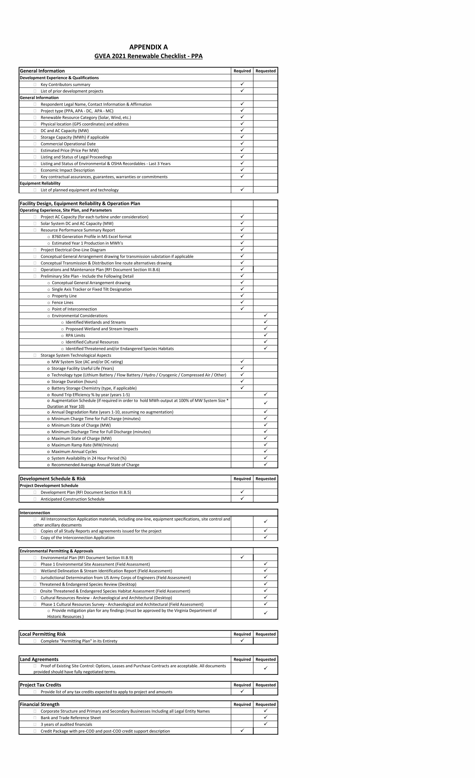
7. Checklist
A Checklist has been developed that outlines “Required” and “Requested” information
for each Proposal. This checklist is attached to this Request as Appendix A. If all
Required items are not delivered by the Proposal Submittal Date, Proposals may be
disqualified from the evaluation process. All Proposals must have a well-defined and
credible development timeline to complete the development, construction and
commissioning of the facility.
8. Alternative Proposals
The Company is not seeking or accepting demand side management resources or
fossil fueled generation. While these excluded resources are outside the scope of this

7
Request, the Company may consider these resources in other existing and future
Company-sponsored procurement programs.
D. Schedule & Process 1. Key Dates
RFI Announcement & Issuance January 25, 2021
Proposal Submittal Deadline April 30, 2021
RFI Concluded July 31, 2021
2. Respondent Financial Information
Respondents will be required to provide their last audited financial information and, if
applicable, for the identified sources of funding that would finance their Proposal.
Financial Information should include, at a minimum, a Balance Sheet, Statements of
Income, and Statements of Cash Flows, with accompanying footnotes.
3. Proposal Submittal
Respondents must submit Proposal(s) by April 30, 2021, no later than 3:00 PM ADT.
Proposals must be submitted electronically via email to [email protected]. The
Company will not accept Proposals that are mailed or hand delivered.
In order to be accepted as complete, Proposals must contain all the documents and data
requested in the form and format required, as described in Part III of this RFI document
and any other information requested in Appendix A.
4. Communications a. RFI Process Information
In addition to the information and instructions provided in this RFI document,
please refer periodically to the ShareFile site for updates from GVEA Purchasing
for additional information or announcements regarding this RFI.
b. Respondent Questions & Answers
8
Respondent may submit questions to the Company concerning this Request
process via email to [email protected]. Please note that such questions
will not be treated as confidential, and the question and answer may be shared
for the benefit of other interested parties via GVEA’s ShareFile Site.
c. Company Questions & Answers
Proposals with material omissions may be deemed non-responsive and may be
eliminated from consideration by the Company. Note that the Company does not
plan to contact Respondents in the event of such non-conforming Proposals prior
to elimination.
However, in addition to the information requested from Respondents in this
Request, the Company may have the need for clarifications or additional
information as part of its review of Proposals. In such case, the Company will call
or email the designated Respondent contact. Prompt responses to these
questions will be required in order to maintain a responsive Proposal.
E. Modifications to RFI The Company reserves the right to modify this Request for any reason and at any time.
Such changes will be communicated via the ShareFile website.
F. Confidentiality The Company will maintain the confidentiality of all Proposals submitted and will not
share such Proposal information outside of employees of GVEA, GVEA Board
members, or to any additional third-party affiliate of Company as may be necessary to
complete our evaluation.
G. Miscellaneous 1. The Company reserves the right, without qualification and at its sole discretion, to
select any Proposal(s) or reject any and all Proposal(s), and/or to waive any
formality or technicality in any Proposal(s) received. Respondents who submit
Proposal(s) do so without recourse against the Company for rejection by the
Company.

9
2. The Company shall not reimburse Respondent, and Respondent is responsible
for any cost incurred in the preparation or submission of a Proposal(s).
3. Any information provided in the Request, or on the Company’s RFI website, has
been prepared to assist Responders in evaluating the Request. It does not purport
to contain all the information that may be relevant to Respondent in satisfying its
due diligence efforts. The Company makes no representation or warranty,
expressed or implied, as to the accuracy, reliability or completeness of the
information in the Request or the Request website, and shall not be liable for any
representation expressed or implied in the Request or the Request website or any
omissions from the Request or the Request website, or any information provided
to a Respondent by any other source.
4. Respondent should check the Company’s Request ShareFile site frequently to
ensure it has the latest documentation and information. Neither the Company nor
its representatives shall be liable to any Respondent or any of its representatives
for any consequences relating to or arising from the Respondent's use of outdated
information.
5. Respondent shall indemnify and hold the Company harmless from any and all
damages and costs, including but not limited to legal costs, in connection with all
claims, expenses, losses, proceedings or investigations that arise as a result of
the Request and/or Respondent’s participation in this Request.
6. The submission of a Proposal to the Company shall constitute Respondent’s
acknowledgment and acceptance of all the terms, conditions and requirements of
this Request.
7. Respondent shall be responsible for all licensing and permits that may be required
by any governmental body or agency necessary to perform Respondent’s
Proposal. Respondent's subcontractors, employees, agents and representatives
in performance of the proposed Project shall comply with all applicable
governmental laws, ordinances, rules, regulations, orders and all other
governmental requirements.
8. Proposed project will need to meet all existing reliability standards of GVEA and
the Railbelt Utilities, as applicable. Also, projects will be required to comply with
requirements of State or Federal government authority (Authorities) and have the
ability to meet future requirements of any Authorities, including those of any
Electric Reliability Organization deriving its authority from the State or Federal
10
Government (e.g., NERC).
PART II – The Proposal Evaluation A. Evaluation Methodology Overview
1. Overview of Price & Non-Price Methodology
The Company will review and evaluate Proposals to determine the outcomes that
provide the lowest reasonable cost and lowest CO2e emissions while complying
with applicable rules and regulations, and maintaining reliability and flexibility for
GVEA members. This evaluation will be conducted in consecutive steps, as
outlined in Section II.B, in order to conduct a thorough and efficient review of
Proposals. Proposals selected to be retained for a future RFP will be those that
offer the most favorable combinations of the Price Evaluation and Non-Price
Evaluation, as described further below.
B. Evaluation Process 1. Review for Completeness
For Proposals received by the Submittal Deadline, the Company will open and
review all responses for completeness and responsiveness. Failure to provide the
requested information in accordance with the submittal requirements described in
Part III may result in disqualification of the Proposal.
2. Review for Scope Compliance
The Company will then review Proposals for compliance with the Request scope
as described in Section I.C. Any Proposal not conforming to one or more of the
Request scoping factors may be eliminated from further consideration.
3. Initial Economic Screening
Depending upon the number of Proposals that are determined to be complete and
that meet scope compliance requirements, the Company may perform an initial
economic screening in order to eliminate uneconomic Proposals. This will allow
the final evaluation process to focus on the most economic Proposals relative to
other Proposals received.
4. Detailed Proposal Evaluation

11
The Company will conduct the final review and evaluation of remaining Proposals
based on the Price Evaluation and Non-Price Evaluation as described below.
C. Price Evaluation The Price Evaluation will analyze each Proposal’s value to GVEA members based on
the Proposal’s pricing. The Company will use generation planning and production cost
models to determine the economic value and emissions, with the objective of
minimizing present value revenue requirements for members while maintaining low
CO2e emissions, grid reliability, and grid flexibility. Depending on the nature of the
Proposals, the Company may examine combinations of Proposals, along with one or
more of the Company’s Build Options, to determine the lowest reasonable cost future
PV solar, onshore wind, and energy storage resources.
In addition to the price evaluation process outlined above, Proposals which include
energy storage components will be evaluated based on additional benefits those types
of projects are able to provide. Proposals with energy storage components that
provide enhanced capacity value through effective regulation of renewable generation
will be evaluated more favorably. The energy storage project’s power and duration
(in MW & MWh) will be used to evaluate the project’s capacity value.
D. Non-Price Evaluation Criteria 1. Economic Benefit
The Company will consider each proposed facility’s use of labor, materials and
other resources within interior Alaska and from interior Alaska businesses.
2. Experience, Qualifications and Financial Strength
It is critical that the Company have a high degree of confidence in the Responder’s
ability to construct and operate a facility as applicable to their Proposal. Therefore,
Bidders must demonstrate they have the experience, qualifications and financial
strength to successfully execute their Proposal, and will be evaluated as such.
Proposals backed by a strong credit package may be evaluated more favorably.
3. Technical Review of Facility Design, Equipment and Operations
The long-term performance of the proposed facility is critical to providing the
intended value for the Company’s members. The reliability and capabilities of the
12
facility’s design, equipment and operations will be evaluated, including:
• Proven equipment and technology from qualified equipment providers
• Equipment warranties
• Performance guarantees, backed by contractual commitments
• Appropriate operating and maintenance plan
The Company has provided their GVEA Interconnection specifications, included
as Appendix B. To the degree a Proposal differs from those specifications,
Respondent shall detail which specifications are not met and how they differ in
their Proposals. Proposals that do not meet GVEA’s Interconnection
specifications may be excluded from further consideration. Proposals that provide
strong commitments to the operation and performance of the facility, may be
evaluated more favorably.
4. Key Risk Factors
As the Price Evaluation and Non-Price Evaluation reviews are conducted, certain key
risks will be compiled and included in the final evaluation (“Key Risk Factors”). These
Key Risk Factors may be unique to a Proposal and while reflected in the Price and
Non-Price Evaluation, may be significant enough to independently impact the overall
favorability of a Proposal. For example, if there is significant uncertainty whether a key
permit for a facility can be secured, jeopardizing the ability of the facility to be
constructed, then that risk may also be included as an independent consideration in
the evaluation.
PART III – Proposal Submittals A. Proposal Requirements & General Instructions
Respondents may submit more than one Proposal. For multiple Proposals related to
a single facility, Respondents may provide a single Proposal submittal package that
clearly identifies the Proposals’ differences. For Proposals that are based on different
facilities, Bidders should provide a complete and separate proposal submittal
package for each facility.
Respondents must submit Proposal(s) by April 30, 2021, no later than 3:00 PM ADT.

13
Proposals must be submitted electronically via email to [email protected]. The
Company will not accept Proposals that are mailed or hand delivered.
The purpose of these requirements and instructions is to acquire sufficient information
from all Respondents that will ensure a uniform and impartial evaluation and ranking
of each Proposal. For this reason, the Company requires that Respondents complete
all applicable items for each Proposal submitted: B - Proposal Summary Submittal, C
- Information Form Addendum, and D – Planned Development and Construction
Schedule as described in this Part III. Additionally, Respondents should provide
information as requested from the Checklists in Appendix A for details on required
and requested information to be included in each Proposal.
In order to be accepted as complete, Proposals must contain all the documents and
data requested in the form and format required. Any Proposals with material
omissions or incomplete responses to the requested items will be deemed non-
responsive and may be eliminated from further consideration.
B. Proposal Summary Submittal Respondent’s Proposal Summary must be provided in Microsoft Word or Adobe
Acrobat PDF file format and contain the following information. Please maintain the
order and content as listed below to facilitate the review of Proposals.
1. Respondent Name, Contact information and Affirmation
Proposal(s) must be submitted in the legal name of the actual party or the ultimate
“upstream” organizational entity that would be bound by any resulting agreement with
GVEA and authenticated by an officer or other employee who is authorized to bind
Respondent to an agreement based on the Proposal(s).
The first page of the Proposal shall list the Respondent and the Respondent Contact
Information (Name, Title, Phone, Email Address, and Mailing Address).
Additionally, it must include the following statement, signed by an authorized
representative of Respondent:
“I, (enter name) , am an authorized
representative of (“Respondent”) and
14
hereby certify and affirm that: (i) I am authorized to obligate the Respondent to the
terms of its Proposal; and (ii) the Bidder’s Proposal shall remain for GVEA
consideration as outlined in Part I (B); and neither Respondent nor any person or entity
acting or purporting to act on its behalf or with Respondent has entered into any
combination, conspiracy, agreement or other form of collusive arrangement with any
person, corporation, partnership or other entity, which directly or indirectly has to any
extent lessened competition between the Respondent and any other person or entity
for this RFI.”
2. Proposal Summary: Please provide a brief summary of the Proposal, including key
information on the facility, costs and identification of the proposed structure(s) (i.e.,
PPA Proposal, Development Proposal or MC Proposal). Please highlight any
significant, unique attributes of the facility relative to similarly situated facilities in the
industry.
If submitting multiple Proposals for a single facility, please clearly identify and summarize each Proposal in a single Summary.
3. Respondent Summary: Please provide a summary of the Respondent’s qualifications.
Summary must include ultimate corporate parent entity and relationship to Respondent,
in addition to the following information:
a. Prior experience and qualifications of Respondent as it relates to the
execution of the Proposal.
b. Summary of Respondent’s and guarantor’s financial strength and
capabilities to develop, own and operate the facility as applicable to the
Proposal structure (PPA or Development Proposal).
c. Key Contributors Summary: Please provide a summary of the experience
and qualifications of other key contributors. Summary must include:
i. Prior experience and qualifications of any key developers,
engineering, procurement and construction contractors,
operators, or other key contributors specifically as it relates to the
execution of the Proposal;
ii. Summary of the status of contractual relationship with each key

15
contributor;
iii. Key contractual assurances, guarantees, warranties or
commitments supporting the Proposal; and
iv. Past experience of Respondent working with each key contributor.
4. Site Summary: Please provide information on the Project site, including: Respondent’s
rights (owned, leased, under recorded option, executed letter of intent) to such site. If
applicable, provide details of lease agreement, option, or letter of intent terms. Please
indicate whether additional land rights (including easements) are necessary for the
development, construction, interconnection and operation of the facility. Note that for
Development Proposals, projects with land control that cover a 35-year operating life
will receive preference in the evaluation process.
5. Development Plan: Please provide a summary of Respondent’s development plan,
including:
a. Discussion of the development schedule, and associated risks and risk
mitigants for that schedule, including whether there are contract commitments
from contractors supporting the proposed schedule. Respondent should be
prepared to document proposed development schedule.
b. Discussion of the financing arrangements, including an overview of the
sources of funds, and level of commitment from debt, equity or other
investors. Strong evidence of Respondent’s ability to obtain Project financing
will be evaluated favorably.
c. Discussion on Permitting, including a list of all required permits, permitting
status of each, and key risks to securing necessary future permits approvals.
A Permitting Plan should be provided.
d. Discussion on Interconnection, including status of application, information
on any studies and agreements, estimated cost, and estimated schedule
for completion of upgrades.
e. Discussion on any rezoning that may be required, including the schedule and
process for rezoning.
f. For acquisition Proposals, discussion on tree clearing expectations if
applicable. The Company will require that all tree clearing be completed
prior to taking ownership of any facility.

16
g. For acquisition Proposals, all GVEA design and construction standards
must be met. Any subsurface conditions for the site should be provided.
6. Operations and Maintenance Plan: Please provide a summary of the O&M plan for
the facility. Such plan should include any third-party roles and responsibilities for
operating, maintaining and servicing the facility, including any contractual
arrangements currently in place.
7. Projected Production: Please provide expected hourly energy production and
monthly energy production for the project. This data will be used to evaluate the
impact of variable output on the cost of production from other GVEA generation
resources. Information about the data that documents the industry-standard
protocols used to ensure reliability of the information and to quantify the variability
over various timeframes is recommended.
8. Production Guarantee: Please provide a monthly production guarantee for the
Project (MWH/month).
9. Environmental Plan: Please provide a summary of all environmental diligence
completed to date, including any identified concerns and the associated mitigation.
For environmental diligence that remains, please provide a detailed scope and
schedule that supports a January 1, 2025 COD or sooner. All Proposals should include
a description of planned environmental mitigation measures to minimize impacts to air
quality during project construction and efforts to minimize the carbon footprint
associated with the production and transportation of permanently installed equipment
to the site.
10. Legal Proceedings: Provide a summary of all material actions, suits, claims or
proceedings (threatened or pending) against Respondent, its Guarantor (if applicable)
or involving the Proposal facility as of the Proposal due date, including those related
to employment and labor laws, environmental laws, or contractual disputes for the
development, construction or operation of the facility.
11. Environmental Violations / OSHA Recordables: Provide a list of all environmental

17
violations and OSHA recordable incidents incurred within the last three (3) years by
the Respondent or its contractors on projects built by Respondent. Also include a
description of mitigation efforts to address these incidents and the measures that will
be employed in the future to avoid recurrences.
12. Economic Impact: Provide a description of the expected use of labor, materials
and other resources from Alaska and/or Alaska businesses for the development,
construction and operation of the Proposal facility. Additionally, provide a
description of the expected benefits to be derived by the industries and
communities associated with the development, construction and operation of the
Proposal facility.
13. Project Tax Credits: Development Proposals that include actions that have been taken,
or a plan to secure tax credits, should detail how that credit is expected to be secured.
14. Project Price:
a. For Proposals under the PPA Build Structure, provide the estimated PPA Base
Price, in $/MWh, applicable for the first contract year subject. If any escalation
factors are being proposed in subsequent years, that should also be explained
in the summary along with the reasoning for the escalation.
b. For Proposals under the PPA Build Structure that include a storage component,
include an estimated fixed Storage Payment per month, in $/MW, for the storage
facility. If any escalation factors are being proposed in subsequent years, that
amount should also be explained in the summary along with the reasoning for
the escalation.
c. For Development Proposals and MC Proposals Build Structures, provide the
price applicable for acquisition of project at the relevant development state.
15. Credit Package (PPA proposals only): Provide a summary of the proposed credit
package (pre-COD and post-COD) to support Respondent’s contractual
commitments, such as parental guaranties and letters of credit, including
amounts/limits.

18
C. Planned Development and Construction Schedule Respondent shall provide a Planned Development and Construction Schedule in
Adobe Acrobat PDF file format, which should include:
a. Permitting activities for each major permit
b. Certificate of Public Convenience and Necessity (“CPCN”) (for PPA
Proposals) or activities to obtain
c. Interconnection Process and Schedule
d. Major Equipment Procurement (for PPA Proposals)
e. Engineering, Procurement and Construction Bid and Award Process (for
PPA Proposals)
f. Construction & Commissioning Schedule (for PPA Proposals)
g. Commercial Operations Date

General Information Required RequestedDevelopment Experience & Qualifications
� Key Contributors summary � List of prior development projects
General Information� Respondent Legal Name, Contact Information & Affirmation � Project type (PPA, APA - DC, APA - MC) � Renewable Resource Category (Solar, Wind, etc.) � Physical location (GPS coordinates) and address � DC and AC Capacity (MW) � Storage Capacity (MWh) if applicable � Commercial Operational Date � Estimated Project Price (Asset purchase) � Listing and Status of Legal Proceedings � Listing and Status of Environmental & OSHA Recordables - Last 3 Years � Economic Impact Description � Provide list of any tax credits expected to apply to project and amounts � Development Plan (RFI Document Section III.B.5) � Key contractual assurances, guarantees, warranties or commitments
Equipment Reliability� List of planned equipment and technology
Land/Constructability RiskEngineering
� Project AC Capacity (for each turbine under consideration) � Solar System DC and AC Capacity (MW) � Resource Performance Summary Report
o 8760 Generation Profile in MS Excel format o Estimated Year 1 Production in MWh's
� Geotechnical Study (1 bore per 10 turbines) � Preliminary Erosion Control Features Drawing (during-construction) � Preliminary Storm Water Management Features Drawing (post-construction) � Met data - 2 years with calibration records � Topographical Survey Report (LIDAR or other) With 1 Foot Contours in CAD Format � Project Electrical One-Line Diagram � Conceptual General Arrangement drawing for transmission substation if applicable � Conceptual Transmission & Distribution line route alternatives drawing � Storage System Technological Aspects
o MW System Size (AC rating) o Storage Facility Useful Life (Years) o Technology type (Lithium Battery / Flow Battery / Hydro / Cryogenic / Compressed Air / Other)
o Storage Duration (hours) o Battery Storage Chemistry (type, if applicable) o Round Trip Efficiency % by year (years 1-5) o Augmentation Schedule (if required in order to hold MWh output at 100% of MW System Size * Duration at Year 10)
GVEA 2021 Renewable RFI Checklist - APAAPPENDIX A

o Annual Degradation Rate (years 1-10, assuming no augmentation) o Minimum Charge Time for Full Charge (minutes) o Minimum State of Charge (MW) o Minimum Discharge Time for Full Discharge (minutes) o Maximum State of Charge (MW) o Maximum Ramp Rate (MW/minute to fully recharge system) o Maximum Annual Cycles o System Availability in 24 Hour Period (%) o Recommended Average Annual State of Charge
� Site Considerationso Total usable acres o Tree clearing needed for placement of the facility (acres)
o Acres allocated for Erosion Control Features (e.g sediment basins during-construction)
o Acres allocated for Storm Water Management Features (e.g storm water management ponds and conserved open spaces post-construction)
o Estimated Balanced Cut and Fill (cubic yards) o Estimated Wetland and Stream Impact (table listing square footage of Wetlands and Stream and linear footage of Stream)
o Table listing total drainage area to pond and drainage area from site o Turbine to turbine spacing assumptions o View Shed Study o Transportation plan and routes - on and offsite (road study) o Size and location of laydown/staging area(s) o Maximum planned road grade and associated grade profiles
Site Plans (Provide in CAD Format)� Preliminary Site Plans - Include the Following Detail
o Single Axis Tracker or Fixed Tilt Designation o Property Line o Property to be conveyed fee simple for substation (transmission only) o Access road required for substation (transmission only) o Fence Lines o Site entrance(s) from public right-of-way o Interior Roads o If a lease scenario, provide improvements required for Landowner to access unleased land or adjacent parcels
o Existing Road Crossings of Wetlands and Streams (Identify Crossing Type - At Grade, Culverted, Bridged, etc)
o Existing ponds/impoundments on the site and all adjacent properties o Buffers and Setbacks o Required Screening o Point of Interconnection o Met tower locations and heights o Existing Utility Easements o Proposed Utility Easements o Environmental Considerations
o Identified Wetlands and Streams o Proposed Wetland and Stream Impacts o RPA Limits o Identified Cultural Resources o Identified Threatened and/or Endangered Species Habitats

Interconnection Required RequestedProjects Interconnection
� All Interconnection Application materials, including one-line, equipment specifications, site control and other ancillary documents
� Copies of all Study Reports issued for the project � Copy of the Interconnection Agreement, where available
Telecommunications� Cost Estimate for Telecommunications
Local Permitting Risk Required Requested� Complete "Permitting Plan" in its Entirety
Environmental Required Requested� Phase 1 Environmental Site Assessment (Field Assessment) � Wetland Delineation & Stream Identification Report (Field Assessment) � Jurisdictional Determination from US Army Corps of Engineers (Field Assessment) � Threatened & Endangered Species Review (Desktop)
o U.S. Fish and Wildlife Service - Trust Resource List (no agency coordination)
o U.S. Fish and Wildlife Service - Official Species List (w/ agency coordination) o Alaska Department of Fish & Game requirements
� Onsite Threatened & Endangered Species Habitat Assessment (Field Assessment)
� Cultural Resources Review - Archaeological and Architectural (Desktop)
� Phase 1 Cultural Resources Survey - Archaeological and Architectural (Field Assessment)
o Provide mitigation plan for any findings � Noise Studies (for each turbine under consideration) � Shadow Flicker Study � Avian studies and schedule for completion � FAA Determinations of No Hazard � Decommissioning requirements and study � Environmental Plan (RFI Document Section III.B.9)
Land Agreements Required Requested� Proof of Existing Site Control: Purchase Contracts are preferred. Options and Leases are acceptable. All documents provided should have fully negotiated terms.
� All third-party utility easements, crossing agreements, and consents � All access easements from neighboring properties � If property is developer owned, provide a copy of all existing deeds � List of parcel numbers and tax record information � Title Commitment � Title exception documents with hyperlink in Commitment
� ALTA/ACSM Land Title Survey with attached Table A Requirements in CAD Format
Financial Strength Required Requested� Corporate Structure and Primary/Secondary Businesses Including all Legal Entity Names � Bank and Trade Reference Sheet � 3 years of audited financials � One contact (name, telephone number and e-mail address) for each project referenced in the Bidder’s Proposal (for reference purposes)
� Credit Package with pre-COD and post-COD credit support description
General Information Required RequestedDevelopment Experience & Qualifications
� Key Contributors summary � List of prior development projects
General Information� Respondent Legal Name, Contact Information & Affirmation � Project type (PPA, APA - DC, APA - MC) � Renewable Resource Category (Solar, Wind, etc.) � Physical location (GPS coordinates) and address � DC and AC Capacity (MW) � Storage Capacity (MWh) if applicable � Commercial Operational Date � Estimated Price (Price Per MW) � Listing and Status of Legal Proceedings � Listing and Status of Environmental & OSHA Recordables - Last 3 Years � Economic Impact Description � Key contractual assurances, guarantees, warranties or commitments
Equipment Reliability� List of planned equipment and technology
Facility Design, Equipment Reliability & Operation PlanOperating Experience, Site Plan, and Parameters
� Project AC Capacity (for each turbine under consideration) � Solar System DC and AC Capacity (MW) � Resource Performance Summary Report
o 8760 Generation Profile in MS Excel format o Estimated Year 1 Production in MWh's
� Project Electrical One-Line Diagram � Conceptual General Arrangement drawing for transmission substation if applicable � Conceptual Transmission & Distribution line route alternatives drawing � Operations and Maintenance Plan (RFI Document Section III.B.6) � Preliminary Site Plan - Include the Following Detail
o Conceptual General Arrangement drawing o Single Axis Tracker or Fixed Tilt Designation o Property Line o Fence Lines o Point of Interconnection o Environmental Considerations
o Identified Wetlands and Streams o Proposed Wetland and Stream Impacts o RPA Limits o Identified Cultural Resources o Identified Threatened and/or Endangered Species Habitats
� Storage System Technological Aspectso MW System Size (AC and/or DC rating) o Storage Facility Useful Life (Years) o Technology type (Lithium Battery / Flow Battery / Hydro / Cryogenic / Compressed Air / Other) o Storage Duration (hours) o Battery Storage Chemistry (type, if applicable) o Round Trip Efficiency % by year (years 1-5) o Augmentation Schedule (if required in order to hold MWh output at 100% of MW System Size * Duration at Year 10)
o Annual Degradation Rate (years 1-10, assuming no augmentation) o Minimum Charge Time for Full Charge (minutes) o Minimum State of Charge (MW) o Minimum Discharge Time for Full Discharge (minutes) o Maximum State of Charge (MW) o Maximum Ramp Rate (MW/minute) o Maximum Annual Cycles o System Availability in 24 Hour Period (%) o Recommended Average Annual State of Charge
Development Schedule & Risk Required RequestedProject Development Schedule
� Development Plan (RFI Document Section III.B.5) � Anticipated Construction Schedule
Interconnection � All Interconnection Application materials, including one-line, equipment specifications, site control and other ancillary documents
� Copies of all Study Reports and agreements issued for the project � Copy of the Interconnection Application
Environmental Permitting & Approvals� Environmental Plan (RFI Document Section III.B.9) � Phase 1 Environmental Site Assessment (Field Assessment) � Wetland Delineation & Stream Identification Report (Field Assessment) � Jurisdictional Determination from US Army Corps of Engineers (Field Assessment) � Threatened & Endangered Species Review (Desktop) � Onsite Threatened & Endangered Species Habitat Assessment (Field Assessment) � Cultural Resources Review - Archaeological and Architectural (Desktop) � Phase 1 Cultural Resources Survey - Archaeological and Architectural (Field Assessment)
o Provide mitigation plan for any findings (must be approved by the Virginia Department of Historic Resources )
Local Permitting Risk Required Requested� Complete "Permitting Plan" in its Entirety
Land Agreements Required Requested� Proof of Existing Site Control: Options, Leases and Purchase Contracts are acceptable. All documents provided should have fully negotiated terms.
Project Tax Credits Required Requested� Provide list of any tax credits expected to apply to project and amounts
Financial Strength Required Requested� Corporate Structure and Primary and Secondary Businesses Including all Legal Entity Names � Bank and Trade Reference Sheet � 3 years of audited financials � Credit Package with pre-COD and post-COD credit support description
GVEA 2021 Renewable Checklist - PPAAPPENDIX A
GVEA Interconnect Specifications
A Technical Guide for Operating, Metering,
Monitoring, and Protective Relaying of
Non-Utility Power Producers and
Co-Generators
Revised March, 2012
Fairbanks ● P O Box 71249, Fairbanks AK 99707 ● 452-1151 Delta Junction ● P O Box 909, Delta Junction AK 99737 ● 895-4500
Nenana ● P O Box 00130, Nenana AK 99760 ● 832-5481 1-800-770-GVEA (4832) ● www.gvea.com
APPENDIX B
GVEA -Technical Guidelines for Operating, Metering and Protective Relaying for Non-Utility Power Producers and Co-Generators
Page 1
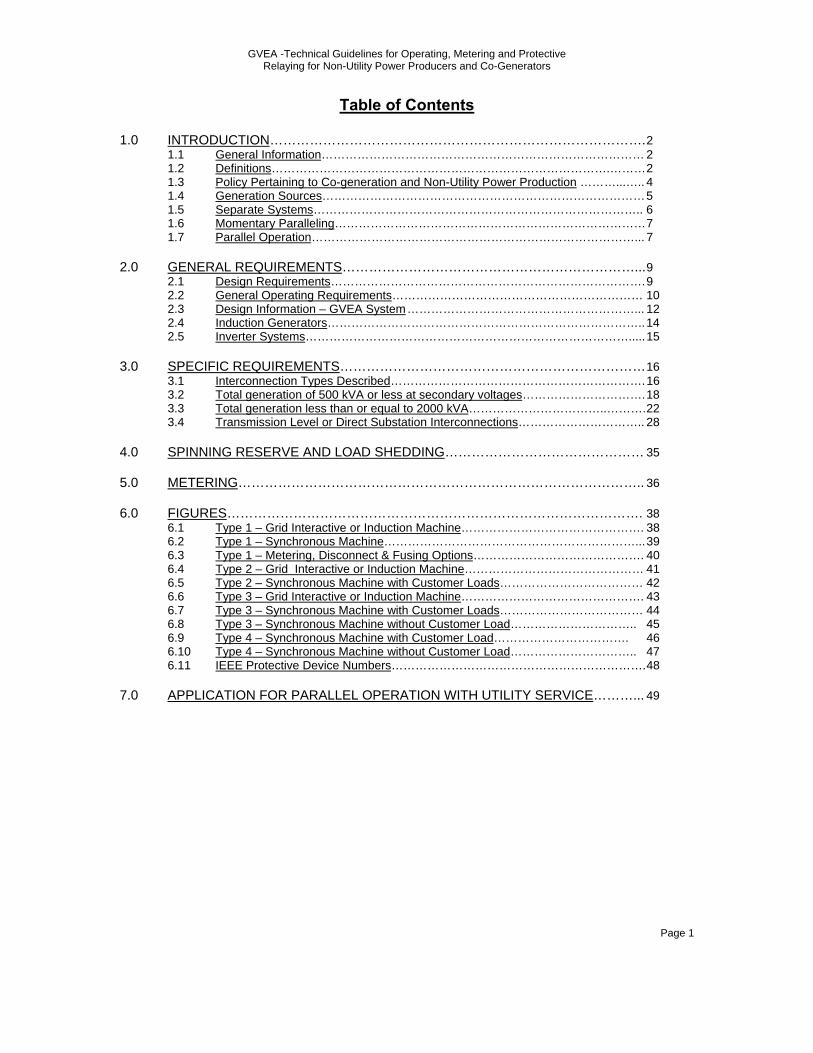
Table of Contents 1.0 INTRODUCTION…………………………………………………………………………. 2
1.1 General Information……………………………………………………………………… 2 1.2 Definitions………………………………………………………………………….……… 2 1.3 Policy Pertaining to Co-generation and Non-Utility Power Production ………...….. 4 1.4 Generation Sources……………………………………………………………………… 5 1.5 Separate Systems……………………………………………………………………….. 6 1.6 Momentary Paralleling…………………………………………………………………… 7 1.7 Parallel Operation………………………………………………………………………... 7
2.0 GENERAL REQUIREMENTS…………………………………………………………... 9 2.1 Design Requirements……………………………………………………………………. 9
2.2 General Operating Requirements……………………………………………………… 10 2.3 Design Information – GVEA System …………………………………………………... 12 2.4 Induction Generators…………………………………………………………………….. 14 2.5 Inverter Systems………………………………………………………………………..... 15 3.0 SPECIFIC REQUIREMENTS…………………………………………………………… 16 3.1 Interconnection Types Described………………………………………………………. 16 3.2 Total generation of 500 kVA or less at secondary voltages…………………………. 18 3.3 Total generation less than or equal to 2000 kVA……………………………..………. 22 3.4 Transmission Level or Direct Substation Interconnections………………………….. 28 4.0 SPINNING RESERVE AND LOAD SHEDDING……………………………………… 35 5.0 METERING……………………………………………………………………………….. 36 6.0 FIGURES…………………………………………………………………………………. 38 6.1 Type 1 – Grid Interactive or Induction Machine………………………………………. 38
6.2 Type 1 – Synchronous Machine………………………………………………………... 39 6.3 Type 1 – Metering, Disconnect & Fusing Options……………………………………. 40 6.4 Type 2 – Grid Interactive or Induction Machine……………………………………… 41 6.5 Type 2 – Synchronous Machine with Customer Loads……………………………… 42 6.6 Type 3 – Grid Interactive or Induction Machine………………………………………. 43 6.7 Type 3 – Synchronous Machine with Customer Loads……………………………… 44 6.8 Type 3 – Synchronous Machine without Customer Load………………………….. 45 6.9 Type 4 – Synchronous Machine with Customer Load……………………………. 46 6.10 Type 4 – Synchronous Machine without Customer Load………………………….. 47 6.11 IEEE Protective Device Numbers………………………………………………………. 48
7.0 APPLICATION FOR PARALLEL OPERATION WITH UTILITY SERVICE………... 49
GVEA -Technical Guidelines for Operating, Metering and Protective Relaying for Non-Utility Power Producers and Co-Generators
Page 2
1.0 INTRODUCTION
1.1. General Information
1.1.1. These guidelines serve to provide the minimum acceptable requirements for safe and effective operation of Customer-owned generation interconnected with the Golden Valley Electric Association (GVEA) power system. Customer and GVEA personnel will be guided by this document when planning for the installation of Customer-owned generation. It is emphasized that these requirements are general and may not cover all details in specific cases.
1.1.2. These guidelines apply to applicants/Customers regardless if they
self generate, generate for sale back to GVEA, or whether they buy and sell concurrently.
1.1.3. The potential Customer should discuss all project plans with GVEA
before purchasing or installing equipment.
1.2. Definitions – Hierarchal Order
1.2.1. “GVEA” will be used in this guideline to refer to Golden Valley Electric Association, Inc.
1.2.2. “NUPP” (Non-Utility Power Producer) will refer to any electrical
generation not owned by GVEA.
1.2.3. “COG” will refer to Co-generation and is defined as the production of two useful forms of energy such as high-temperature heat and electricity from the same process facility not owned by GVEA.
1.2.4. “Customer” will refer to either a NUPP or COG facility.
1.2.5. “Members” will be used in this guideline to refer to power
consuming Co-operative members who are connected to GVEA and do not have the capability to produce power.
1.2.6. “Interconnection” will mean the point of electrical connection
between the Customers facility and the GVEA power system.
1.2.7. “Separate Operation” will be used in this guideline to refer to the operation of a Customers facility that is capable of generation which does not have the capability of transferring electrical energy to GVEA.

GVEA -Technical Guidelines for Operating, Metering and Protective Relaying for Non-Utility Power Producers and Co-Generators
Page 3
1.2.8. “Momentary Paralleling” will be used in this guideline to refer to a Customer who will only operate in parallel with GVEA for durations of 100 milliseconds or less.
1.2.9. “Parallel Operation” will be used in this guideline to refer to a
Customers facility that is interconnected with GVEA while operating electrically connected to the GVEA power system. Electrical power may flow either into or out of this Interconnection.
1.2.10. “Open Transition” will be used in this guideline to refer to break-
before-make type transfer switches or the transfer of power to a load from different sources without the ability to momentarily or permanently electrically connect the different sources.
1.2.11. “Closed Transition” will be used in this guideline to refer to make-
before-break “momentary” type transfer switches with a maximum of 100 milliseconds parallel time. Any parallel time greater than 100 milliseconds will not be considered momentary or Closed Transition.
1.2.12. “Islanding” or “Islanded” refers to the situation where a portion of
GVEA’s load becomes isolated from GVEA sources but remains electrically connected to the Customers generation source.
1.2.13. “Back Feed” will be used in this guideline to refer to the transfer of
electric power from an emergency stored energy source to any portion of the normal power system.
1.2.14. “Short Circuit Ratio” = (Short Circuit kVA of GVEA + Short Circuit
kVA of the Customer) / (Short Circuit kVA of the Customer). When computing the Short Circuit Ratio the first cycle current magnitude shall be used at the point of study. Short Circuit Ratio is sometimes referred to as system stiffness, stiffness ratio, or short circuit current ratio.
1.2.15. “Reclosing” refers to the operation of a device that has the
functionality to sense and interrupt over-currents by de-energizing the circuit and to then automatically re-energize the circuit.
1.2.16. “Distributed Resource” refers to electrical power generation fed to
the electric utility grid through a distribution circuit not a transmission circuit.
1.2.17. “Grid Interactive” will be used in this guideline to refer to an
electric power production device, intended to be interconnected as a
GVEA -Technical Guidelines for Operating, Metering and Protective Relaying for Non-Utility Power Producers and Co-Generators
Page 4
distributed resource, which meets IEEE 1547-2003 and UL 1741 requirements and incorporates all GVEA minimum protective requirement for a given interconnection type.
1.2.18. “CT” is the acronym for Current Transformer
1.2.19. “PT” is the acronym for Potential Transformer
1.2.20. “SCADA” is the acronym for Supervisory Control And Data
Acquisition
1.3. Policy Pertaining to Co-generation and Non-Utility Power Production (COG/NUPP)
1.3.1. It is the policy of GVEA to permit any Customer to operate their
generating equipment in parallel with GVEA’s electric system provided this can be done without adverse effects to the general public, or to GVEA’s Members, Customers, equipment, personnel, or system operations. Customer’s generation interconnected to GVEA’s power system shall be through a transformer.
1.3.2. Protective devices (including relays, circuit breakers, and the like),
as specified by GVEA must be installed at any location where a Customer desires to operate generation in parallel with the GVEA power system. The purpose of these devices is to promptly disconnect the Customer’s generating equipment from the GVEA system whenever faults or abnormal operation occur which could affect the interconnected system. Other site specific modifications to the electrical system configuration or protective relays shall be required as necessary to safely accommodate parallel operation.
1.3.3. Power electronic equipment such as DC to AC inverters shall meet
the most recent IEEE and UL applicable standards as outlined in subsequent sections. Such equipment employing internally protective electronic methods will be subject to GVEA review for acceptance. Any recommendations from GVEA for specific protective settings will be made prior to energizing the Customer’s equipment.
1.3.4. Customer facilities with the ability to export greater than 2 MW of
electrical power into the GVEA power system shall be required to connect to the GVEA power system at the transmission level. The Customer shall bear any and all costs associated with equipment upgrades required to accommodate Customer Interconnections.
GVEA -Technical Guidelines for Operating, Metering and Protective Relaying for Non-Utility Power Producers and Co-Generators
Page 5
1.3.4.1. Differing transmission system conditions due to location,
physical parameters, or any number of factors dictate that Customer applications will be evaluated on a case by case basis to determine the specific Customer Interconnect requirements at the transmission level.
1.3.4.2. A Customer with an Interconnection of 2 MW or greater shall
contribute its pro rata share of GVEA's operating reserve capacity as per Section 4, “Spinning Reserve and Load Shedding”.
1.3.5. With the advent of Distributed Resources becoming more popular
and the differing conditions of distribution feeders, each Customer application will be evaluated on a case by case basis to determine the specific Customer Interconnect requirements. Differing distribution system conditions may dictate that generation may not be connected to a distribution feeder in a given location.
1.3.6. GVEA does not assume any responsibility for protection of the
Customer’s generator(s) or any other portion of the Customer’s electrical equipment. The Customer is fully responsible for protecting their equipment in such a manner that faults or other disturbances on the interconnected system do not cause damage to the Customer’s equipment.
1.4. Generation Sources
1.4.1. The Customer may elect to use any of a variety of energy sources including hydro, solar, wind, conventional fossil fuels, or other types of energy sources. The end conversion for connection to GVEA’s system must be 60 Hz alternating current at a voltage compatible with GVEA’s system at the interconnecting point. Customer generation sources shall be operated so that variations from the acceptable voltage levels and other service impairing disturbances do not occur. This includes: compliance with the harmonic limits stated in IEEE Standards as specified throughout Section 3 of this specification for current and voltage distortion; and any other disturbance from the Customer’s facility which could impair service to GVEA Customers or Members.
GVEA -Technical Guidelines for Operating, Metering and Protective Relaying for Non-Utility Power Producers and Co-Generators
Page 6
1.4.2. Protective devices must provide protection to GVEA’s system and to its Customers or Members from a Customers facility experiencing disturbances that produce abnormal voltage and frequencies.
1.4.3. Customers are required to generate their own reactive power
requirements to assure generation at a machine specified power factor and to enhance the Customers generator stability. Reactive power requirements for an induction machine shall be reviewed on a case by case basis.
1.4.4. The Customer may elect to run generation in parallel with GVEA or
as a separate system with either the capability of momentary parallel or nonparallel load transfer between the two independent systems. The requirements for these three methods of operation are outlined in the following sections.
1.5. Separate Systems
1.5.1. For a Customer’s facility operating in a Separate Operation mode to be practical, the Customer may want to maintain the capability of transferring load between the two systems with such transfer being accomplished in an Open Transition mode. This can be accomplished by either an electrically or mechanically interlocked switching arrangement which precludes operation of both switches in the closed position simultaneously.
1.5.2. If the Customer has a separate system, the Customer shall permit
GVEA to verify by any reasonable method that the transfer scheme meets the nonparallel requirements. This verification shall be accomplished but is not limited to review of drawings and equipment specifications and by field inspection of the transfer scheme. GVEA is not responsible for approving the Customer’s generation equipment system design or operation, not withstanding the fact that GVEA may from time to time comment thereon.
1.5.3. Most Uninterruptible Power Supply (UPS) systems do not
specifically meet the Separate Operation criteria. However, if they are not capable of Back Feed they shall be classified as a Separate Operation system. If they can Back Feed, they must meet the requirements of either Momentary Paralleling or Parallel Operation.

GVEA -Technical Guidelines for Operating, Metering and Protective Relaying for Non-Utility Power Producers and Co-Generators
Page 7
1.6. Momentary Paralleling 1.6.1. Momentary Paralleling shall require the use of a Closed Transition
(Make-Before-Break) integrated Automatic Transfer Switch with synchronizing capabilities. Other protective equipment as specified in Section 1.6.2 shall be required. The Automatic Transfer Switch shall be incapable of paralleling the Customer with GVEA’s system longer than 100 milliseconds and shall be tested, verified, and documented by the Customer for proper operation at least every 2 years. GVEA may require being present during this testing.
1.6.2. Other protective equipment needed for Momentary Paralleling shall
include equipment capable of sensing a failed Closed Transition transfer switch operation and tripping the inter-tie breaker. If the Closed Transition transfer switch operation fails (paralleling time greater than 100 milliseconds) then the equipment must open the inter-tie breaker.
1.6.3. Momentary Paralleling shall be limited to 500 kVA to reduce
possible voltage flicker for other Members receiving their power from the same distribution feeder as the Customer. Momentary Paralleling of greater than 500 kVA may be permitted following a system study to determine if such an installation will cause adverse effects to other Members or Customers. The cost of the system study shall be borne by the Customer.
1.7. Parallel Operation
1.7.1. A transfer of power between the two systems is a direct and often desired result of parallel operation. A consequence of such parallel operation is that parallel generation becomes an electrically connected part of the GVEA power system which must be considered in the electrical protection of GVEA facilities. GVEA’s ability to provide safety to GVEA personnel who may need to perform work on a power line is lost when a Customer facility is operating in an Islanded mode. The ability to maintain electrical power within specifications to Customers or Members is also lost during an Islanded operating condition. For these reasons protection from Islanding shall be incorporated into each Customer’s facility connected in parallel to GVEA.
1.7.2. Protection system design incorporated into Customer facilities shall
be performed by a power system engineer qualified to perform such

GVEA -Technical Guidelines for Operating, Metering and Protective Relaying for Non-Utility Power Producers and Co-Generators
Page 8
work and who is licensed as a professional engineer in the state of Alaska. The protection system design shall be reviewed by GVEA. Prior to energizing a Customer facility any changes to the protection system design requested by GVEA will be made by the Customer. Smaller inverter type equipment meeting the most recent UL and IEEE standards for interconnecting to utility power systems may have integral protection equipment built into one complete package. All adjustable or factory set protection parameters incorporated into Grid Interactive equipment shall be reviewed by GVEA. Prior to energizing Customer’s inverter type generation facilities, all settable protection parameters recommended by GVEA will be made to the Customers equipment by the Customer and confirmed by GVEA and a Customer representative during a facility inspection.
1.7.3. The general and specific requirements for parallel generation
installations of various sizes are discussed in the following sections.

GVEA -Technical Guidelines for Operating, Metering and Protective Relaying for Non-Utility Power Producers and Co-Generators
Page 9
2.0 GENERAL REQUIREMENTS
2.1. Design Requirements
2.1.1. When applying protective devices for the protection of GVEA’s system, the Customer shall submit a single-line drawing of this equipment to GVEA for approval of the protective functions. Any changes required by GVEA shall be made prior to final acceptance and GVEA shall be provided with dated copies of the final drawings. GVEA will approve only those portions of drawings which apply to protection of the GVEA system. GVEA may comment on other areas which appear to be incorrect or deficient, but will not assume responsibility for the correctness of protection pertaining to the Customer’s system.
2.1.2. A manual disconnecting device which can be opened and locked
open for line clearances shall be provided. The form of this device will vary with the service voltage and capacity. This device shall permit GVEA to disconnect the Customer’s generation from the GVEA system for safety purposes during system maintenance. This device must provide a “visible open” for GVEA personnel.
2.1.3. The protective methods and devices referred to in these guidelines
(including but not limited to relays and circuit breakers) which aid in the protection of GVEA’s system, metering equipment, Customer equipment and synchronizing equipment must be installed as required by GVEA and/or the protection system engineer. The protective devices may differ with the size and characteristics of the installation. See Section 3 for specific requirements.
2.1.4. Instrument Transformer Specifications:
2.1.4.1. GVEA requires that PTs used for either revenue metering or
protective relaying meet an ANSI accuracy rating of 0.3% at IEEE C57.13-1993 standard burden designations. GVEA requires a minimum IEEE PT burden designation rating of “Y”. See Section 7.2, Standard Burdens, in IEEE C57.13-1993.
2.1.4.2. GVEA requires that CTs used solely for revenue metering
meet an ANSI accuracy rating of 0.3% at a burden of 0.5 Ohms at 100% rated current.

GVEA -Technical Guidelines for Operating, Metering and Protective Relaying for Non-Utility Power Producers and Co-Generators
Page 10
2.1.4.3. GVEA requires that CTs used for protective relaying meet ANSI Standard C57.13 minimum CT accuracy of C200. However higher CT accuracy may be required due to system conditions.
2.1.4.4. One set of PTs may be used for both relaying and metering
provided that the total burden placed on the PT’s does not exceed the PT’s specified limit.
2.1.5. Customer Interconnections with GVEA shall be accomplished
through the use of a “dedicated transformer” which serves no other Customers or Members. Small Interconnections may be exempt from this requirement. Each Interconnection Type as described in Section 3 has different transformer connection requirements.
2.1.6. The Customer’s installation must meet all applicable national, state
and local construction and safety codes in addition to all applicable UL, ANSI and IEEE Standards and Guidelines.
2.2. General Operating Requirements
2.2.1. Any Parallel Operation, regardless of time duration, or any Momentary Paralleling of the Customer’s generating equipment with the GVEA system shall not under any circumstance be permitted to cause any reduction in the quality of service being provided to other GVEA Customers or Members. No abnormal voltages, harmonic distortions, frequency deviations, or interruptions shall be permitted. If credible high or low voltage complaints or flicker complaints result from operation of the Customer’s generation, such generating equipment shall be immediately isolated from GVEA’s system or disconnected until the problem is resolved.
2.2.2. The Customer may not commence parallel operation of
generator(s) until final written approval has been given by GVEA. At any reasonable time, GVEA reserves the right to inspect the Customer’s facility and test or witness testing of any equipment or devices associated with the Interconnection.
2.2.3. Once a GVEA distribution circuit is de-energized for any reason,
the Customer shall disconnect from the GVEA system and will not be permitted to reconnect to GVEA’s system until GVEA has first energized its system.
GVEA -Technical Guidelines for Operating, Metering and Protective Relaying for Non-Utility Power Producers and Co-Generators
Page 11
2.2.4. Reclosing of a GVEA distribution feeder will not be adversely effected by the Customer. The Customer shall coordinate with the GVEA reclosing strategies. GVEA will review all anti-islanding functions of the Customers equipment prior to acceptance.
2.2.5. Transmission circuit Interconnections will be reviewed on a case by
case basis to determine post disturbance reconnection strategies.
2.2.6. Operation of the Customer’s generator shall not adversely affect the voltage regulation of GVEA’s system to which it is connected. Adequate voltage control shall be provided by the Customer to minimize voltage fluctuation on GVEA’s system caused by changing generator loading conditions.
2.2.6.1. For synchronous generators, sufficient generator reactive
power capability shall be provided to withstand normal voltage changes on GVEA’s system. The generator reactive power requirements, voltage regulation, and transformer ratio settings will be jointly determined by GVEA and the Customer to ensure inter-system coordination and operating capability. Customers are required to generate their own reactive power requirements to assure generation at the specified power factor and to enhance generator stability.
2.2.6.2. In cases where starting or load changing on induction
generators will have an adverse impact on GVEA’s system voltage, step-switched capacitors or other techniques may be required to bring the voltage changes to acceptable levels. All equipment costs associated with such reactive power production shall be borne by the Customer.
2.2.7. The Customer shall maintain his equipment in good order. GVEA
reserves the right to inspect the Customer’s facilities whenever it appears that the Customer is operating in a manner hazardous to GVEA’s system integrity.
2.2.8. The Customer shall discontinue parallel operation when requested
by GVEA:
2.2.8.1. To facilitate maintenance, test or repair of GVEA or other Customer facilities.
2.2.8.2. During system emergencies.
GVEA -Technical Guidelines for Operating, Metering and Protective Relaying for Non-Utility Power Producers and Co-Generators
Page 12
2.2.8.3. When the Customer’s generating equipment is interfering with other Customers or Members on GVEA’s system.
2.2.8.4. When an inspection of the Customer’s generating equipment
reveals a condition hazardous to GVEA’s system or a lack of adequate maintenance of equipment necessary to protect GVEA’s system.
2.2.9. GVEA may require the Customer to notify GVEA, in writing, of the
monthly kWh production of each generator on the first regular working day of the following month. Larger power producers shall be required to report energy and peak demand information through a remote telecommunication medium.
2.2.10. For facilities of 225 kVA and larger the Customer shall maintain
an operating log at each generating facility indicating changes in operating status (available or unavailable), maintenance outages, trip indications, or other unusual conditions found upon inspection. For generators which are “block-loaded” to a specific kW level, changes in load settings shall also be logged. Logs may be electronic.
2.3. Design Information – GVEA System
2.3.1. GVEA’s primary distribution voltages are 7.2/12.47, 14.4/24.9, and 19.9/34.5 kV. Transmission voltages are 69 and 138 kV. GVEA’s distribution circuits are effectively grounded with a substantial number of grounding points on each four-wire distribution circuit. Specific requirements for Customer’s generation on these circuits are described in Section 3 of this specification. Contact GVEA for information on the specific circuit which shall serve a Customer’s facility.
2.3.2. Because most short circuits on overhead lines are temporary in
nature, it is GVEA’s practice to automatically reclose on such lines one or more times within a few cycles delay after they have automatically tripped. This practice improves continuity of service to all GVEA Customers and Members. The protective relays specified by GVEA or IEEE articles for parallel generation interfaces are intended to disconnect the generation from faulted or isolated lines before reclosing occurs. Should the Customer desire additional protection against the possibility that reclosing might occur with a generator still connected to the line (a potentially damaging occurrence for synchronous generators), GVEA will consider revising
GVEA -Technical Guidelines for Operating, Metering and Protective Relaying for Non-Utility Power Producers and Co-Generators
Page 13
radial line protection schemes on distribution feeders. GVEA’s preference is to avoid such measures due to the possibility of adverse effects on service continuity and the problems of moving or rearranging the equipment to accommodate system changes. Costs for installing, maintaining, and/or rearranging such equipment (if permitted) will be borne by the Customer(s) requesting the equipment.
2.3.3. System reconfiguration costs needed to accommodate Customer’s
connecting generation at either the transmission or distribution level (if permitted) will be borne by the Customer(s) requesting the equipment.
2.3.4. Customers with three-phase generators should be aware that
certain conditions in the utility system may cause negative sequence currents to flow in the generator. It is the sole responsibility of the Customer to protect his equipment for excessive negative sequence currents.
2.3.5. The effect that a Customer will have upon a distribution circuit will
depend on the total distributed generation on that circuit prior to the Customer’s connection. The greater the available short-circuit MVA, the stiffer the circuit. The addition of a Customer on a distribution feeder will have less impact to a stiff system.
2.3.5.1. A Short Circuit Ratio or stiffness of 50 or less at the
interconnection shall be used as a determining factor for any additional protection equipment needed above that outlined in the Interconnection Type specifications in Section 3.
2.3.5.2. If physical GVEA power system components differ from the
standard norm at a point where a Customer wishes to connect or a Customer wishes to construct a facility with non-standard operating equipment a protection study shall be performed accounting for non-standard variations. The protection system design shall be performed by a power system engineer qualified to perform such work. The protection system design shall be reviewed by GVEA. All protection system design costs will be borne by the Customer.
GVEA -Technical Guidelines for Operating, Metering and Protective Relaying for Non-Utility Power Producers and Co-Generators
Page 14
2.4. Induction Generators
2.4.1. Reactive power supply for induction generators may pose difficult design problems depending upon the generator size. Specific installations may require the installation of capacitors limiting the adverse effects of reactive power flow on GVEA’s system for proper voltage regulation. Such capacitor installations will be at the expense of the Customer.
2.4.2. The installation of capacitors for reactive power supply at, or near,
an induction generator greatly increases the risk that the induction machine may become self-excited if accidentally isolated from the GVEA system. A self-excited induction generator can produce abnormally high voltages which can cause damage to the equipment of other GVEA Customers or Members. Over-voltage relays can limit the duration of such over-voltages but cannot control their magnitude because of the rapid voltage rise which occurs with self-excitation. Because of these problems, reactive power supply for large induction generators must be studied on an individual basis.
2.4.3. In order to reduce the possibility of self-excited operation, reactive
power requirements for induction generators shall be supplied by GVEA except in unusual situations such as those stated in Section 2.4.2. Reactive power supply will be from general utility sources and specific charges may be made to the Customer for the reactive power.
2.4.4. Self-excitation problems are more likely in rural areas where the
system capacity and load density are low. Since these areas are more likely to be chosen for certain forms of small power production such as wind and hydro, it is particularly important to contact GVEA when considering connecting induction machines to existing distribution lines. Where self-excitation problems appear likely, special service arrangements will be required in order to avoid the induction generator from becoming isolated with small amounts of load. For example, a two-line loop service back to the existing transmission system or a transmission level service. In many cases, the additional expense for such special service methods may outweigh the cost savings associated with induction generators.
GVEA -Technical Guidelines for Operating, Metering and Protective Relaying for Non-Utility Power Producers and Co-Generators
Page 15
2.5. Inverter Systems
2.5.1. Reactive power supply requirements for inverter systems are similar to those for induction generators and the general guidelines discussed in Section 2.4 shall apply. Likewise, inverter systems are also capable of Islanded operation. Self-commutated inverters have this capability by design. Line commutated inverters could operate Islanded if connected to rotating machines which provide the necessary commutation. Because of the possibilities of self-excited operation, inverter systems are treated as induction machines in these guidelines.
2.5.1.1. Grid Interactive inverters meeting UL 1741 may incorporate
all needed protective requirements, and reactive power issues may be incorporated into their design. GVEA will review the Customers inverter specifications for reactive power needs and compliance.
2.5.2. Total harmonic current output of power inverters shall not be
greater than 5% total harmonic distortion. Higher order even and odd harmonic currents shall be limited to the most restrictive of that specified in IEEE std. 1547-2003 Table 3 or as specified in IEEE 519 Section 10.2.
2.5.3. Harmonic voltage distortion shall not be greater than 5% total
harmonic distortion. Higher order harmonic voltages shall be limited to the most restrictive of that specified in UL 1741 Section 45.4, IEEE 1547-2003 Table 6, or IEEE 519 Table 11-1.
2.5.4. If a Customer’s parallel generation is found to be interfering with
other Customers or Members, or exceeds UL or IEEE recommended specifications, the Customer may be required to install filtering to bring the harmonic output of the inverter to a level which will eliminate such interference and comply with UL and IEEE specifications.

GVEA -Technical Guidelines for Operating, Metering and Protective Relaying for Non-Utility Power Producers and Co-Generators
Page 16
3.0 SPECIFIC REQUIREMENTS
3.1. Interconnection Types Described
3.1.1. Customer-owned parallel generation facilities are classified by generation size, ratings, voltage, and current. See Tables 3.1 and 3.2.
3.1.2. A calculated Short Circuit Ratio of 50 or less at the Interconnection
will require a system protection study to determine any additional protection equipment needed above that outlined for each of the standard Interconnection types. Such protection may include but is not limited to loss of excitation, loss of synchronism, or over excitation protection. Any cost associated with the study and/or additional equipment due to a Short Circuit Ratio of 50 or less will be borne by the Customer
3.1.3. Each facility shall have distinctive protection, metering, and
operating requirements.
3.1.4. Where multiple generators are connected to GVEA’s system through a single service point, the Interconnection Type will be determined by the sum of the ratings of the generators. The final decision as to the requirements for each installation will depend on the Customers load magnitude, the magnitude of other loads connected to that circuit/system, ampacity of serving circuit, maximum power to be delivered to GVEA’s system, available short circuit contribution, short circuit current ratio, etc.
3.1.5. Interconnection Type definitions, Tables, and notes:
3.1.5.1. The following Tables identify the type of Customer
generation and minimum requirements that must be met to Interconnect with GVEA’s system.
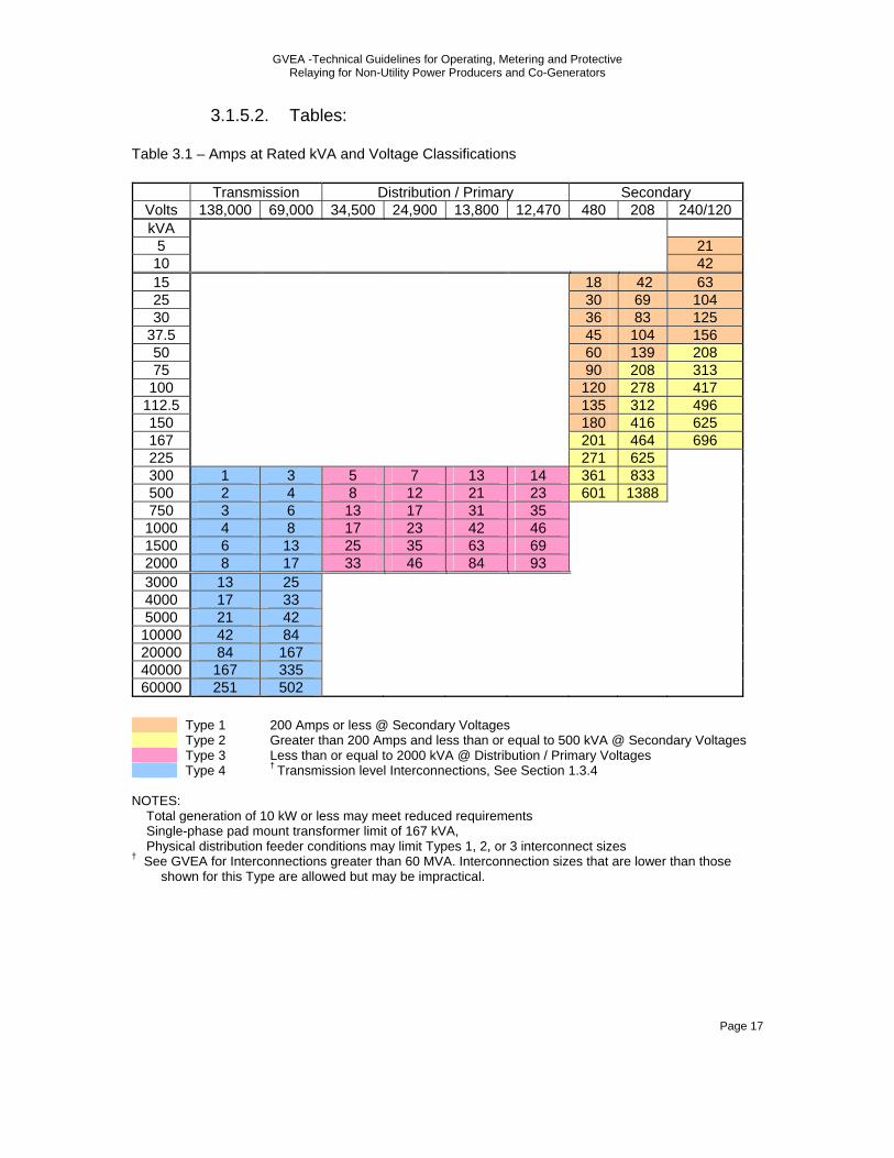
GVEA -Technical Guidelines for Operating, Metering and Protective Relaying for Non-Utility Power Producers and Co-Generators
Page 17
3.1.5.2. Tables: Table 3.1 – Amps at Rated kVA and Voltage Classifications
Transmission Distribution / Primary Secondary Volts 138,000 69,000 34,500 24,900 13,800 12,470 480 208 240/120 kVA
5 21 10 42 15 18 42 63 25 30 69 104 30 36 83 125
37.5 45 104 156 50 60 139 208 75 90 208 313
100 120 278 417 112.5 135 312 496 150 180 416 625 167 201 464 696 225 271 625 300 1 3 5 7 13 14 361 833 500 2 4 8 12 21 23 601 1388 750 3 6 13 17 31 35 1000 4 8 17 23 42 46 1500 6 13 25 35 63 69 2000 8 17 33 46 84 93 3000 13 25 4000 17 33 5000 21 42 10000 42 84 20000 84 167 40000 167 335 60000 251 502
Type 1 200 Amps or less @ Secondary Voltages Type 2 Greater than 200 Amps and less than or equal to 500 kVA @ Secondary Voltages Type 3 Less than or equal to 2000 kVA @ Distribution / Primary Voltages Type 4 † Transmission level Interconnections, See Section 1.3.4
NOTES: Total generation of 10 kW or less may meet reduced requirements Single-phase pad mount transformer limit of 167 kVA, Physical distribution feeder conditions may limit Types 1, 2, or 3 interconnect sizes † See GVEA for Interconnections greater than 60 MVA. Interconnection sizes that are lower than those shown for this Type are allowed but may be impractical.

GVEA -Technical Guidelines for Operating, Metering and Protective Relaying for Non-Utility Power Producers and Co-Generators
Page 18
Table 3.2 - Minimum requirements for Interconnection Types
Type 1†† Type 2†† Type 3 Type 4 Single Phase Connection (Limited kVA, See Notes) Y Y N N Lockable Disconnect with Visible Open Y Y Y Y Interconnect Breaker (B) or Fuse (F) B or F B or F B B In/Out Metering Y Y Y Y Energy Recorder N N N Y Dedicated Transformer N N Y Y Transformer - Customer Pays / Utility Owns Y Y N N Transformer - Customer Pays / Customer Owns N N Y Y Under-Voltage (27) † Y Y Y Y Over-Voltage (59) † Y Y Y Y Under-Frequency (81U) † Y Y Y Y Over-Frequency (81O) † Y Y Y Y Phase Over-Current (50/51)*, † Y Y Y Y Neutral Over-Current (51N) † N N Y Y Transfer Trip N N TBD TBD Close Permissive Required N N Y Y Automatic Synchronizer (synchronous machine) 25†, 25a† Y Y Y Y Automatic Synchronizer (induction machine) 25†, 25a† N N N N Automatic Synchronizer (UL 1741 inverter) 25†, 25a† N N N TBD Isolation Detection / Anti-Islanding† Y Y Y Y Comm – Voice Y Y Y Y Telemetry Y** Y** Y Y*** Power Quality Monitoring N N Y Y Export Power Control Equipment N N Y Y Operational Data Logging N N Y Y Sequence of Event Reporting N N Y Y Fault Recording N N Y Y PSS/E Modeling N N N Y Machine Testing N N N Y Metering CTs Supplied By GVEA (Customer Installs) N/A Y Y N Metering CTs Supplied By Customer (Customer Installs) N/A N N Y Momentary Paralleling Y Y N N
Notes: TBD means To Be Determined during design phase * Three Phase Only, may not be required for inverters or induction machines ** Minimal Telemetry may be required *** Dedicated Telemetry † These requirements are met if Grid Interactive equipment is used. †† Physical distribution feeder conditions may limit interconnect size Short Circuit Current Ratio of 50 or less will require a protection study to determine any additional needed protection 225 kVA Maximum Three-Phase Pole Mount Transformer Limit 75 kVA Maximum Single-Phase Pole Mount Transformer Limit 167 kVA Maximum Single-Phase Pad Mount Transformer Limit 2000 kVA and Greater Special Requirements Apply Regardless of Interconnection Type:
Dedicated Telemetry*** Arrange for Spinning Reserve, See Section 1.3.4.2
3.2. Total generation of 500 kVA or less at secondary voltages
3.2.1. Type 1 and Type 2 Interconnections are described in this section as outlined in Section 3.1. See Figures 6.1 through 6.5 for example one-line diagrams.

GVEA -Technical Guidelines for Operating, Metering and Protective Relaying for Non-Utility Power Producers and Co-Generators
Page 19
3.2.1.1. The difference between a Type 1 and Type 2 Interconnection is the ampacity. Interconnections of 200 Amps and less (Type 1) do not require a current transformer meter installation.
3.2.1.2. Type 1 and Type 2 Interconnection requirements are based
on an assumed low density of parallel generation Customers on the serving circuit. Other conditions may be imposed should the density exceed a tolerable limit.
3.2.1.3. Type 1 and Type 2 Interconnections with a GVEA
distribution level circuit may be done on a single-phase or three-phase basis.
3.2.1.4. Where GVEA has only single-phase distribution lines:
3.2.1.4.1. The Customer shall fund a single-phase to three-phase
line conversion, if required for a three-phase generator installation.
3.2.1.4.2. If the Customer is a Qualifying Facility (QF) as defined by
the Alaska Administrative Code, 3 AAC 52.500 (23), and the Customer has three-phase generation, the Customer shall either fund a single-phase to three-phase line conversion prior to interconnection with GVEA or arraigned for long-term financing for the single-phase to three-phase line conversion prior to interconnection with GVEA. The terms and conditions of any long-term financing shall be at GVEA's sole discretion.
3.2.2. A manual disconnecting device with provisions for locking in the
open position shall be required at or near the point of Type 1 and Type 2 Interconnections as per Section 2.1.2 of this specification.
3.2.3. The Customer’s Interconnection shall be equipped with fuses or a
breaker rated for the installation ampacity and must have an interrupt rating adequate for the available fault current at the Interconnection.
3.2.4. Metering of Type 1 and Type 2 Interconnections
3.2.4.1. Type 1 and Type 2 Interconnections shall be equipped with
metering equipment capable of recording the kWh (in) and kWh (out) separately. Additional metering for kW and kVARH will be

GVEA -Technical Guidelines for Operating, Metering and Protective Relaying for Non-Utility Power Producers and Co-Generators
Page 20
determined by the requirements of the individual installations. See Section 5 for more detailed metering information.
3.2.4.2. Current Transformers (CTs) for revenue metering shall be
provided by GVEA and installed by the Customer at locations shown in Figures 6.4 and 6.5.
3.2.5. Customer Interconnections of Type 1 and Type 2 shall be served
from a GVEA four-wire multi-grounded neutral distribution circuit to provide adequate grounding. This is necessary to avoid dangerous over-voltages to other customers served from phase-to-neutral connected distribution transformers. A three-phase Interconnection transformer shall have a grounded-wye, grounded-wye winding configuration connection to GVEA’s system.
3.2.5.1. Type 1 and Type 2 Interconnection transformers shall be
supplied, installed, and maintained by GVEA. 3.2.5.2. Single-phase pad mounted transformer Interconnections are
limited to a maximum of 167 kVA. Single-phase pole mounted transformer Interconnections are limited to a maximum of 75 kVA.
3.2.5.3. Pad mount transformers shall be installed by GVEA on a
Customers constructed pad mount transformer base as detailed in GVEA’s Commercial and Multi-Residential Services Requirements Booklet. Single-phase limitations may apply depending on the electrical Interconnection location, total generation size, and total Member load on a distribution feeder. Each Interconnection shall be reviewed on a case-by-case basis.
3.2.5.4. Pole mounted transformers shall be installed by GVEA. If the
Customer’s facility is to be Interconnected via an underground feeder the Customer shall be responsible for all costs and materials required as outlined in GVEA’s Commercial and Multi-Residential Services Requirements Booklet.
3.2.6. Customer protection systems and Compliance with IEEE 1547-
2003 and UL 1741 shall be as follows:
3.2.6.1. Generation equipment used for Type 1 and Type 2 Interconnections shall meet the requirements of IEEE 1547-2003 and UL 1741 along with any supporting documents created for testing, clarification, or information follow up of each article.
GVEA -Technical Guidelines for Operating, Metering and Protective Relaying for Non-Utility Power Producers and Co-Generators
Page 21
3.2.6.2. Customer Interconnections using generation equipment such
as standalone synchronous or induction machines that do not comply with IEEE 1547-2003 or UL 1741 must be equipped with protective devices that will make the Interconnection installation meet the requirements of these articles. A line voltage relay and a shunt trip breaker which will prevent the generator from being connected to a de-energized or single-phased (if normally three-phase) source may be required. This relay is to disconnect the generator from a de-energized utility line and prevent its reconnection (islanding) until the line is re-energized by GVEA. Re-energizing times and feeder reclosing will be coordinated with GVEA. A Customer’s facility shall not adversely affect GVEA feeder reclosing.
3.2.6.3. Depending upon specific system conditions or the type of
Customer generation other protective devices above those outlined throughout Section 3.2 may be required.
3.2.6.4. Instrument transformer accuracy for protective relaying shall
meet the accuracy requirements of Section 2.1.4 of this specification. Circuit design and specified equipment shall be reviewed by GVEA prior to installation. System design costs shall be borne by the Customer.
3.2.6.5. Phase fault relay protection shall be required for three-phase
installations. Inverter and Induction machine installations may not require phase fault relay protection. A fuse or main breaker may suffice for over-current protection of single-phase installation and inverter or induction machines.
3.2.6.6. The Customer shall provide information on the type of anti-
islanding protection used and coordinate those protection schemes such that any GVEA circuit reclosing will not be adversely affected.
3.2.7. The Customer shall provide and maintain an on-site, 24 hr. “Voice
Quality” communication method. This may be a phone to a manned control room at the Customers facility or a message phone where emergency information can be left for the Customer to contact GVEA control center.
GVEA -Technical Guidelines for Operating, Metering and Protective Relaying for Non-Utility Power Producers and Co-Generators
Page 22
3.2.8. Remote Control, Telemetry, and SCADA.
3.2.8.1. Remote control of Customer equipment or devices by GVEA system operators will not be required for Type 1 and Type 2 Interconnections.
3.2.8.2. GVEA may require telemetry capability to allow GVEA to
“dial-up” the installation and verify at a minimum, on-line/off-line (tie point breaker) status and measure amps, watts, vars and voltage output. The Customer will be required to install the necessary transducers, provide space for a telephone line interface, provide telephone isolation equipment, and arrange for the telephone line. All costs related to operational telemetry as required for GVEA to accommodate Customer’s generation shall be borne by the Customer as part of the interconnect costs.
3.2.9. Harmonic output of power inverters will comply with IEEE 1547,
IEEE 519, and/or UL 1741. If a Customer is found to be interfering with other Customers or Members, or exceeds IEEE recommended specifications, the Customer may be required to install filtering to bring the harmonic output of their inverter(s) to an acceptable level.
3.3. Total generation less than or equal to 2000 kVA
3.3.1. Type 3 Interconnections are described in this section as outlined in Section 3.1. See Figures 6.6 through 6.8 for example one-line diagrams.
3.3.1.1. A Type 3 employs a point of service at the primary or
distribution circuit voltage. 3.3.1.2. All Type 3 Interconnections require a GVEA review of the
Customers protective functions.
3.3.1.3. All Type 3 Interconnections with a GVEA distribution level circuit shall be done on a three-phase, four wire basis only.
3.3.1.4. Where GVEA has only single-phase distribution the
Customer shall NOT be allowed to connect a Type 3 Interconnection. GVEA may upgrade the distribution feeder to accommodate the Customers generation needs at the Customers expense.
GVEA -Technical Guidelines for Operating, Metering and Protective Relaying for Non-Utility Power Producers and Co-Generators
Page 23
3.3.2. A manual disconnecting device with provisions for locking in the open position shall be required at or near the point of Type 3 Interconnections as per Section 2.1.2 of this specification.
3.3.3. The Customers Interconnection shall be equipped with breakers,
reclosers, or switch gear rated for the installation ampacity and have an interrupt rating adequate for the available fault current at the Interconnection.
3.3.4. Metering of Type 3 Interconnections.
3.3.4.1. Type 3 Interconnections shall be equipped with metering
equipment capable of recording the kWh (in) and kWh (out) separately. Additional metering for kW and kVARH will be determined by the requirements of the individual installations. Required metering points are shown in Figures 6.6 through 6.8.
3.3.4.2. Current Transformers (CTs) and Potential Transformers (PTs),
for Type 3 Interconnections shall be provided by GVEA and installed by the Customer. Type 3 Interconnections are primary metered. See Figures 6.6 and 6.8.
3.3.4.3. Instrument transformer accuracy shall be as specified in
Section 2.1.4.
3.3.4.4. In installations where surplus power sales are anticipated, and for all simultaneous buy and sell arrangements, GVEA will install metering and be given access as required. This metering will be located at the GVEA interconnection facility or at the Customer’s switchgear, as appropriate.
3.3.4.5. The Customer shall provide adequate space in the generator
switchgear for GVEA to install, at its option, metering and/or telemetering of the generator output.
3.3.4.6. See Section 5 for more detailed metering information.
3.3.5. Customer Interconnections of Type 3 shall be served from a GVEA
four-wire multi-grounded neutral distribution circuit to provide adequate grounding. This is necessary to avoid dangerous over-voltages to other customers served from phase-to-neutral connected distribution transformers.

GVEA -Technical Guidelines for Operating, Metering and Protective Relaying for Non-Utility Power Producers and Co-Generators
Page 24
3.3.5.1. Type 3 Interconnection dedicated transformers shall be purchased, owned, installed, and maintained by the Customer.
3.3.5.2. Type 3 Interconnection Pad mount transformers shall be
installed by GVEA on a Customers constructed pad mount transformer base as detailed in GVEA’s Commercial and Multi-Residential Services Requirements Booklet.
3.3.5.3. Pole mounted transformers shall be installed by GVEA. If the
Customer’s facility is to be Interconnected via an underground feeder the Customer shall be responsible for all cost and materials required as outlined in GVEA’s Commercial and Multi-Residential Services Requirements Booklet.
3.3.5.4. The Customer’s main power transformer shall have a
grounded-wye, grounded-wye winding configuration connection to GVEA’s system if the Interconnection is to supply any Customer load.
3.3.5.5. If the Customer’s machine configuration is a delta connection
and the Customer plans to supply load, the Interconnection transformer will be grounded-wye, grounded-wye and it will be the Customer’s responsibility to supply the appropriate equipment to connect a delta machine configuration.
3.3.5.6. If the Customer Interconnection is solely used for generation,
a grounded-wye (high side), delta (low side) connection may be used depending upon the Customer’s machine configuration.
3.3.6. Customer protection systems and Compliance with IEEE 1547-
2003 and UL 1741.
3.3.6.1. Customer generation equipment used for Type 3 Interconnections shall meet the requirements of IEEE 1547-2003 and UL 1741 along with any supporting documents created for testing, clarification, or information follow up of each article.
3.3.6.2. Customer Interconnections using generation equipment such
as standalone synchronous or induction machines that do not comply with IEEE 1547-2003 or UL 1741 must be equipped with protective devices that will make the Interconnection installation meet the requirements of these articles. A line voltage relay or contactor which will prevent the generator from being connected to a de-energized or single-phased (if normally three-phase)

GVEA -Technical Guidelines for Operating, Metering and Protective Relaying for Non-Utility Power Producers and Co-Generators
Page 25
source may be required. This relay is to disconnect the generator from a de-energized utility line and prevent its reconnection (islanding) until the line is re-energized by GVEA. Re-energizing times and feeder reclosing will be coordinated with GVEA. A Customer’s facility shall not adversely affect GVEA feeder reclosing.
3.3.6.3. Customer provided protection and typical protection devices
which may be required to satisfy Type 3 Interconnection requirements:
3.3.6.3.1. The Customer shall provide adequate protective devices
to detect and clear the generator(s) from short circuits or grounds on the GVEA facilities serving the Customer.
3.3.6.3.2. The Customer shall provide adequate protective devices
to detect the voltage and frequency changes which can occur if the GVEA facilities serving the Customer are disconnected from the main system; and if abnormal voltages or frequencies exist, these relays would then clear the Customer generation from the isolated system. Isolation from the GVEA system should be such that it will not affect the GVEA reclosing cycle normally employed on the serving facilities.
3.3.6.3.3. Phase over-current trip devices (Device 51). In most
cases these will be voltage-restrained or voltage-controlled over-current relays in order to provide coordination with GVEA relays.
3.3.6.3.4. Residual over-voltage relay to trip for ground faults on the
GVEA system (Device 59N).
3.3.6.3.5. Phase under/over-voltage relays (Device 27/59). Under-voltage Relays should be adjustable from 75-90% of nominal voltage and have time delay to prevent unnecessary tripping of external faults. The time delay should coordinate with the utility reclosing cycle. Over-voltage relays should be adjustable from 110-120% of nominal voltage and should be instantaneous. Setting change with temperature variation should not exceed + 2 volts over the expected temperature range.

GVEA -Technical Guidelines for Operating, Metering and Protective Relaying for Non-Utility Power Producers and Co-Generators
Page 26
3.3.6.3.6. Under/over frequency relays (Device 81). The Under-frequency relay should be adjustable from 55-60 Hz and the over-frequency relay from 61-65 Hz. Setting change with temperature variation over the expected range, or voltage variation over + 10%, should not exceed + 0.008 Hz. Time delays should be settable from no intentional delay up to 60 cycles in one cycle increments.
3.3.6.3.7. Phase sequence/under-voltage relay (Device 47/27). To
permit paralleling when GVEA voltage and phase sequence are normal.
3.3.6.3.8. A synchronizing check relay shall be required for a
synchronous generator (Device 25).
3.3.6.3.9. In specific installations, particularly with large generators (over 1,000 kVA), GVEA may require specific additional protective functions such as loss of excitation, loss of synchronism, and over excitation protection, if these conditions would have an impact on GVEA’s system.
3.3.6.3.10. Depending on the size of the generation and the size of
the distribution system to which it is connected, GVEA may require the Customer to utilize “utility grade” protective relays. Such relays have more stringent tolerances, are more flexible, and the characteristics are more widely published than “industrial grade” relays. This requirement shall be invoked only if generation is of such size that close coordination with GVEA’s relays is required. In general, installations aggregating less than 200 kVA will not be subject to this requirement.
3.3.6.3.11. Where induction generators or static inverters are
employed rather than synchronous machines, the phase over-current protective devices required by GVEA may be waived since these sources will not deliver sustained over-currents. The other protective devices would still be required.
3.3.6.3.12. In some cases, protective devices supplied with the
Customer’s generating equipment will meet some or all of the GVEA protective device requirements. However, the minimum requirement must provide the ability to trip the generator whenever GVEA source is lost. If the Customer

GVEA -Technical Guidelines for Operating, Metering and Protective Relaying for Non-Utility Power Producers and Co-Generators
Page 27
desires to automatically separate from the GVEA source and commence isolated operation upon loss of the GVEA source, additional devices may be necessary to effect the separation.
3.3.6.3.13. All protective devices supplied to satisfy the
requirements in 3.3.6.3 shall be equipped with operation indicators (targets) or shall be connected to an annunciator or event recorder so that it will be possible to determine, after the event, which devices caused a particular trip.
3.3.6.3.14. All protective devices supplied to satisfy the
requirements in 3.3.6.3 shall be tested, certified and sealed by qualified personnel at intervals recommended by the manufacturer. Special tests may also be required by GVEA to investigate apparent misoperations or to compile a record of performance.
3.3.6.4. Instrument transformer accuracy for protective relaying shall
meet the accuracy requirements of Section 2.1.4 of this specification.
3.3.6.5. The Customer shall provide information on the type of anti-
islanding protection used and coordinate those protection schemes such that any GVEA circuit reclosing shall not be adversely affected. Additionally system design information showing the method of preventing reparalleling Customer generation shall be provided to GVEA. Reparalleling Customer generation shall not occur after a circuit is disconnected unless the GVEA service voltage is of normal magnitude, normal phase sequence, and approval is received from the GVEA control center.
3.3.7. The Customer shall provide and maintain on-site, 24 hr. “Voice”
dedicated telephone, VHF radio, or microwave facilities for communications between the Customers generating facility and GVEA’s control center. The Customer shall provide telephone isolation equipment where necessary to protect the communications circuit and site workers.
3.3.8. Remote Control, Telemetry, and SCADA
3.3.8.1. Remote control of Customer equipment or devices by GVEA
system operators shall be required for Type 3 Interconnections.
GVEA -Technical Guidelines for Operating, Metering and Protective Relaying for Non-Utility Power Producers and Co-Generators
Page 28
Remote control may be waived depending upon total generation, physical system parameters, or other governing factors. Types of control by the GVEA control center includes:
3.3.8.1.1. Close Permissive Control 3.3.8.1.2. Transfer Trip Capabilities
3.3.8.1.3. Interconnect breaker tripping
3.3.8.2. GVEA shall require telemetry capability to allow GVEA to “dial-
up” the installation and verify at a minimum, on-line/off-line (tie point breaker) status and measure amps, watts, vars and voltage output. The Customer shall be required to install the necessary transducers, provide space for a telephone line interface, provide telephone isolation equipment, and arrange for the telephone line. All costs related to operational telemetry and control as required for GVEA to accommodate Customer’s generation shall be borne by the Customer.
3.3.9. Harmonic output of power inverters will comply with IEEE 1547,
IEEE 519, and/or UL 1741. If a Customer is found to be interfering with other Customers or Members, or exceeds IEEE recommended specifications, the Customer may be required to install filtering to bring the harmonic output of their inverter(s) to an acceptable level.
3.4. Transmission Level or Direct Substation Interconnections
3.4.1. Type 4 Interconnections are described in this section as outlined in Section 3.1. Total generation greater than 2000 kVA shall be Interconnected at the transmission level. The Customer shall bear the costs of all upgrades to existing infrastructure required to accommodate the Interconnection. Total generation less than 2000 kVA may be Interconnected at transmission voltages or directly to the low voltage distribution substation bus.
3.4.1.1. See Section 1.3.4.2 for required reserve provisions with regard
to conditions of the Alaska Intertie Agreement.
3.4.1.2. Type 4 Interconnections will require an independent design review for each Customer facility. Type 4 Interconnections utilize a point of service at the transmission voltage level and will be done on a three-phase, three wire basis only.
GVEA -Technical Guidelines for Operating, Metering and Protective Relaying for Non-Utility Power Producers and Co-Generators
Page 29
3.4.1.3. All Type 4 Interconnections require a GVEA review of
protective functions. Design information shall be provided by the Customer. Refer to Figures 6.9 to 6.10 for installation requirements. GVEA shall be contacted during the design process for information and coordination of the Customer’s facility and protective requirements.
3.4.2. A manual disconnecting device with provisions for locking in the
open position shall be required at or near the point of Type 4 Interconnections as per Section 2.1.2 of this specification.
3.4.3. The Customer’s Interconnection shall be equipped with breakers
rated for the installation ampacity and have an interrupt rating adequate for the available fault current at the Interconnection.
3.4.4. Metering of Type 4 Interconnections:
3.4.4.1. Type 4 Interconnections shall be equipped with metering
equipment capable of recording the kWh (in), kWh (out), kVARh (in), and kVARh (out) separately. Additional demand metering will be determined by the requirements of the individual installations. A backup energy recording device shall be required.
3.4.4.2. Metering for Type 4 Interconnections shall be capable of load
profiling.
3.4.4.3. CTs and PTs for Type 4 Interconnections shall be provided and installed by the Customer after approval by GVEA.
3.4.4.4. Instrument transformer accuracy shall be as specified in
Section 2.1.4.
3.4.4.5. In installations where surplus power sales are anticipated, and for all simultaneous buy and sell arrangements, GVEA will install metering and be given access as required. This metering will be located at the Interconnection point.
3.4.4.6. The Customer shall provide adequate space in the facility
switchgear for GVEA to install, at its option, metering and/or telemetering of the generator output.
3.4.4.7. See Section 5 for more detailed metering information.
GVEA -Technical Guidelines for Operating, Metering and Protective Relaying for Non-Utility Power Producers and Co-Generators
Page 30
3.4.5. The Customer shall bear the costs of all upgrades to existing
infrastructure, including design and construction, required to accommodate Type 4 Interconnections. GVEA shall review and comment on the design and shall be an active participant reviewing each design phase submittal from a qualified Engineer performing the design.
3.4.5.1. Type 4 Interconnections at the GVEA transmission level shall
be accomplished through the use of a dedicated grounded wye (high side) delta (low side) winding configuration transformer and shall be provided, owned, and maintained by the Customer.
3.4.6. Customer protection systems for Type 4 Interconnections:
3.4.6.1. Customer protection and generation equipment shall comply
with the most recent standards and utility practices.
3.4.6.2. Generation equipment used for Type 4 Interconnections shall be reviewed on a case by case basis.
3.4.6.3. Customer provided protection and typical protection devices
which may be required to satisfy Type 4 Interconnection requirements.
3.4.6.3.1. The Customer shall provide adequate protective devices
to detect and clear the generator(s) from short circuits or grounds on the GVEA facilities serving the Customer.
3.4.6.3.2. The Customer shall provide adequate protective devices
to detect the voltage and frequency changes which can occur if the GVEA facilities serving the Customer are disconnected from the main system; and if abnormal voltages or frequencies exist, these relays shall disconnect the Customer generation from the system.
3.4.6.3.3. Phase over-current trip devices (Device 51). In most
cases these will be voltage-restrained or voltage-controlled over-current relays in order to provide coordination with GVEA relays.
3.4.6.3.4. Residual over-current relays to trip for ground faults on
the GVEA system (Devices 51N).
GVEA -Technical Guidelines for Operating, Metering and Protective Relaying for Non-Utility Power Producers and Co-Generators
Page 31
3.4.6.3.5. Under/over-voltage relays (Device 27/59). Under-voltage relays shall be adjusted to a percentage of nominal voltage as specified by GVEA during design coordination and have sufficient time delay to prevent unnecessary tripping of external faults. Over-voltage relays should be adjustable from 110-120% of nominal voltage and should be instantaneous. Setting change with temperature variation should not exceed + 2 volts over the expected temperature range.
3.4.6.3.6. Under/over-frequency relays (Device 81). The
under/over-frequency relay shall be set as specified by GVEA during design coordination.
3.4.6.3.7. Phase sequence/under-voltage relay (Device 47/27). To
permit paralleling when GVEA voltage and phase sequence are normal.
3.4.6.3.8. A synchronizing check relay and an auto-synchronizing
relay shall be required for a synchronous generator (Device 25).
3.4.6.4. Instrument transformer accuracy for protective relaying shall
meet the accuracy requirements of Section 2.1.4 of this specification.
3.4.6.5. The Customer shall provide information on the type of anti-
islanding protection used and coordinate those protection schemes such that any GVEA circuit reclosing shall not be adversely affected. Additionally system design information showing the method of preventing reparalleling Customer generation shall be provided to GVEA. Reparalleling Customer generation shall not occur after a circuit is disconnected unless the GVEA service voltage is of normal magnitude, normal phase sequence, and approval is received from the GVEA control center.
3.4.6.6. In specific installations, particularly with large generators
GVEA may require specific additional protective functions such as loss of excitation, loss of synchronism, and under/over excitation limiting protection, if these conditions would have an impact on the GVEA’s system.

GVEA -Technical Guidelines for Operating, Metering and Protective Relaying for Non-Utility Power Producers and Co-Generators
Page 32
3.4.6.7. All Type 4 Interconnections require the Customer to utilize “utility grade” protective relays. Such relays have more stringent tolerances, are more flexible, and the characteristics are more widely published than “industrial grade” relays.
3.4.6.8. All protective devices supplied to satisfy the requirements in
3.1.1 shall be equipped with operation indicators (targets) or shall be connected to an annunciator or event recorder so that it will be possible to determine, after the fact, which device(s) caused a particular trip.
3.4.6.9. All protective devices supplied to satisfy the requirements in
3.1.1 shall be tested, certified and sealed by a qualified person. Special tests may also be required by GVEA to investigate apparent misoperations or to compile a record of performance.
3.4.6.10. Phase over-current protection shall be required regardless of
generation source type.
3.4.7. The Customer shall provide and maintain on-site, 24 hr. “Voice” dedicated telephone, VHF radio, or microwave facilities for communications between the Customer’s generating facility and the GVEA control center. The Customer shall provide telephone isolation equipment where necessary to protect the communications circuit and site workers.
3.4.8. Remote Control, Telemetry, and SCADA: All costs related to
operational telemetry and control as required for GVEA to accommodate Customer’s generation shall be borne by the Customer.
3.4.8.1. Remote control of Customer equipment or devices by the
GVEA control center shall be required for Type 4 Interconnections. GVEA shall require dedicated communications for both telemetry and control. Additionally, GVEA may also have other communication or control requirements which will be determined during the project design coordination phase. Types of control by GVEA’s control center includes:
3.4.8.1.1. Close Permissive Control 3.4.8.1.2. Transfer Trip Capabilities
3.4.8.1.3. Interconnect breaker tripping

GVEA -Technical Guidelines for Operating, Metering and Protective Relaying for Non-Utility Power Producers and Co-Generators
Page 33
3.4.8.2. GVEA shall require telemetry capability to allow GVEA
continuous monitoring of the installation and verify at a minimum, on-line/off-line (tie point breaker) status and measure amps, watts, vars and voltage output.
3.4.8.2.1. The Customer shall provide and install a Remote
Terminal Unit (RTU) compatible with GVEA’s SCADA system along with any necessary transducers.
3.4.8.2.2. All transducers used for GVEA monitoring shall be utility
grade quality and subject to GVEA approval. 3.4.8.2.3. The Customer shall provide a telephone line interface, a
four wire data circuit, provide telephone isolation equipment, and arrange for the telephone lines. Fiber optic communication may be substituted for dedicated phone lines if such system infrastructure is feasible.
3.4.8.2.4. The Customer shall provide space for all required
communication and control equipment in their facility.
3.4.9. Harmonic output of Customer generation shall comply with IEEE 519. If Grid Interactive power sources are used IEEE 1547 and UL 1741 shall also apply and the most stringent specification shall govern. If a Customer is found to be interfering with other Customers or Members, or exceeds IEEE recommended specifications, the Customer may be required to install filtering to bring the harmonic output of their inverter(s) to an acceptable level.
3.4.10. Adequate facility and equipment grounding meeting NESC, IEEE
recommended standards, and current safe utility practices for grounding must be designed and installed by the Customer.
3.4.11. Reactive power requirements: In order to reduce the possibility of
self-excited operation, all reactive power requirements for induction generators shall be supplied by GVEA. Except in unusual situations, this reactive power supply shall be from general utility sources and specific charges may be made to the Customer for the reactive power.
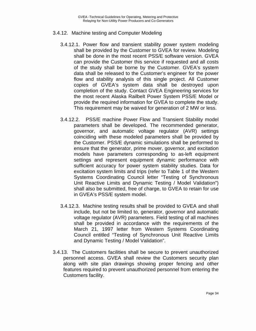
GVEA -Technical Guidelines for Operating, Metering and Protective Relaying for Non-Utility Power Producers and Co-Generators
Page 34
3.4.12. Machine testing and Computer Modeling
3.4.12.1. Power flow and transient stability power system modeling shall be provided by the Customer to GVEA for review. Modeling shall be done in the most recent PSS/E software version. GVEA can provide the Customer this service if requested and all costs of the study shall be borne by the Customer. GVEA’s system data shall be released to the Customer’s engineer for the power flow and stability analysis of this single project. All Customer copies of GVEA’s system data shall be destroyed upon completion of the study. Contact GVEA Engineering services for the most recent Alaska Railbelt Power System PSS/E Model or provide the required information for GVEA to complete the study. This requirement may be waived for generation of 2 MW or less.
3.4.12.2. PSS/E machine Power Flow and Transient Stability model
parameters shall be developed. The recommended generator, governor, and automatic voltage regulator (AVR) settings coinciding with these modeled parameters shall be provided by the Customer. PSS/E dynamic simulations shall be performed to ensure that the generator, prime mover, governor, and excitation models have parameters corresponding to as-left equipment settings and represent equipment dynamic performance with sufficient accuracy for power system stability studies. Data for excitation system limits and trips (refer to Table 1 of the Western Systems Coordinating Council letter “Testing of Synchronous Unit Reactive Limits and Dynamic Testing / Model Validation”) shall also be submitted, free of charge, to GVEA to retain for use in GVEA’s PSS/E system model.
3.4.12.3. Machine testing results shall be provided to GVEA and shall
include, but not be limited to, generator, governor and automatic voltage regulator (AVR) parameters. Field testing of all machines shall be provided in accordance with the requirements of the March 21, 1997 letter from Western Systems Coordinating Council entitled “Testing of Synchronous Unit Reactive Limits and Dynamic Testing / Model Validation”.
3.4.13. The Customers facilities shall be secure to prevent unauthorized
personnel access. GVEA shall review the Customers security plan along with site plan drawings showing proper fencing and other features required to prevent unauthorized personnel from entering the Customers facility.
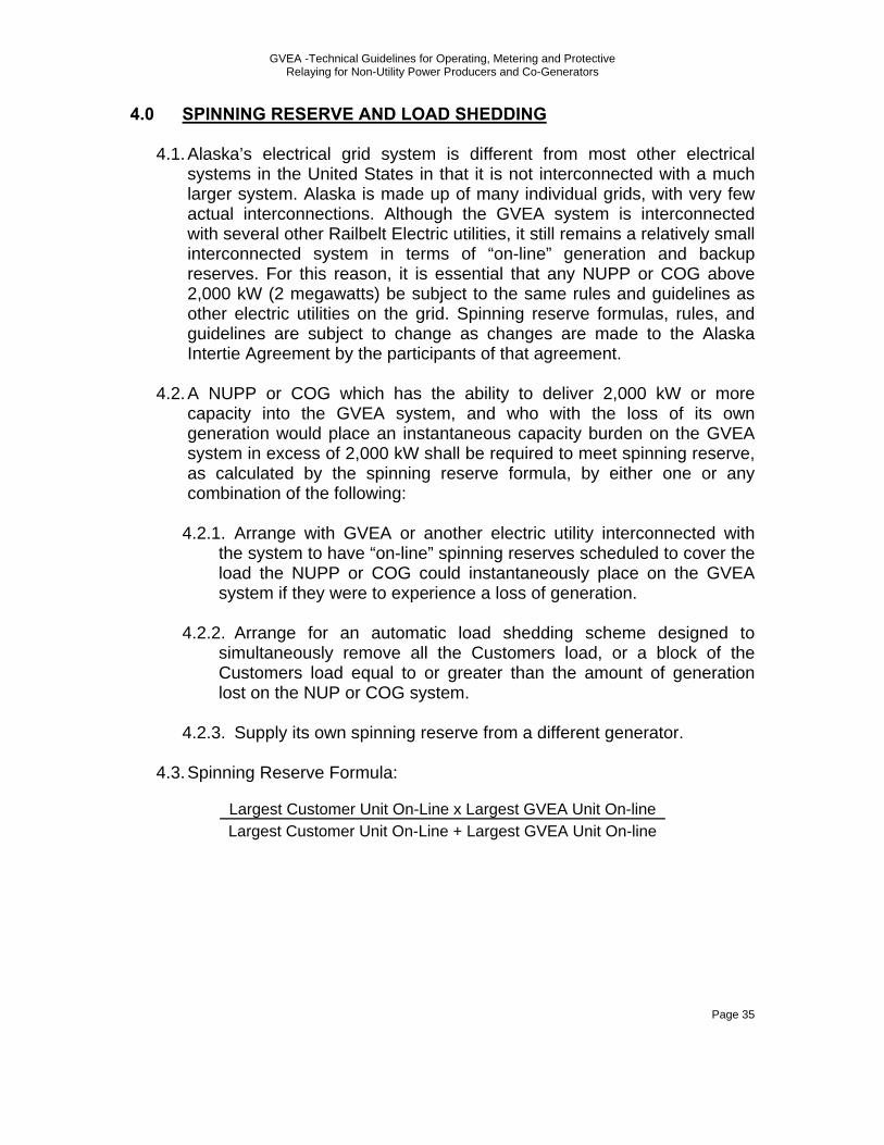
GVEA -Technical Guidelines for Operating, Metering and Protective Relaying for Non-Utility Power Producers and Co-Generators
Page 35
4.0 SPINNING RESERVE AND LOAD SHEDDING
4.1. Alaska’s electrical grid system is different from most other electrical systems in the United States in that it is not interconnected with a much larger system. Alaska is made up of many individual grids, with very few actual interconnections. Although the GVEA system is interconnected with several other Railbelt Electric utilities, it still remains a relatively small interconnected system in terms of “on-line” generation and backup reserves. For this reason, it is essential that any NUPP or COG above 2,000 kW (2 megawatts) be subject to the same rules and guidelines as other electric utilities on the grid. Spinning reserve formulas, rules, and guidelines are subject to change as changes are made to the Alaska Intertie Agreement by the participants of that agreement.
4.2. A NUPP or COG which has the ability to deliver 2,000 kW or more
capacity into the GVEA system, and who with the loss of its own generation would place an instantaneous capacity burden on the GVEA system in excess of 2,000 kW shall be required to meet spinning reserve, as calculated by the spinning reserve formula, by either one or any combination of the following:
4.2.1. Arrange with GVEA or another electric utility interconnected with
the system to have “on-line” spinning reserves scheduled to cover the load the NUPP or COG could instantaneously place on the GVEA system if they were to experience a loss of generation.
4.2.2. Arrange for an automatic load shedding scheme designed to
simultaneously remove all the Customers load, or a block of the Customers load equal to or greater than the amount of generation lost on the NUP or COG system.
4.2.3. Supply its own spinning reserve from a different generator.
4.3. Spinning Reserve Formula:
Largest Customer Unit On-Line x Largest GVEA Unit On-line Largest Customer Unit On-Line + Largest GVEA Unit On-line

GVEA -Technical Guidelines for Operating, Metering and Protective Relaying for Non-Utility Power Producers and Co-Generators
Page 36
5.0 METERING
5.1. Energy flow to GVEA shall be measured by bi-directional meters or meters equipped with detents so that the record of those flows will not be affected by any flows to the Customer. Flows to Customer shall be metered separately and billed monthly in accordance with the terms of the Purchase Agreement, if any, existing between the parties, and/or otherwise in accordance with tariffs filed and approved by the Regulatory Commission of Alaska.
5.2. At GVEA’s option, GVEA shall procure, install, own, inspect, test, and
maintain meters to record flows to and from GVEA’s system. All such metering equipment shall conform to the requirements specified in the Alaska Intertie Agreements, or its successor(s). Such meters shall be placed at GVEA’s designated location(s), shall measure kWh, and shall record and indicate the integrated demand.
5.3. GVEA shall determine the integrated demand for each fifteen (15) minute
period for such recordings. GVEA shall also procure, install, own, inspect, test, and maintain meters for measurement of reactive volt-amperes. GVEA may also, in its sole discretion, install additional metering devices at a location agreed upon by both parties within Customer’s facility to enable GVEA to telemeter information and data. All costs relating to metering devices and any metering related telemetering equipment installed and required for GVEA to accommodate Customer’s generation shall be borne by Customer as part of the interconnection costs.
5.4. Metering error adjustment
5.4.1. Meters shall be replaced and tested at the Customers request or at
GVEA discretion. 5.4.2. If the Customer is either producing or consuming power and the
meter does not over or under register by more than 2%, a charge as set forth in the applicable schedule of fees will be made to the Customer who requests such a test.
5.4.3. When the Customer is consuming power and the meter in service is
tested and found to have over-registered the amount of energy delivered to the Customer by more than 2%, GVEA will recalculate the bills for service from the known date of error and will make a refund if the amount of adjustment exceeds $5. If the beginning date of error is unknown, GVEA will refund or credit the most recent Customer of record for the billed error for the period since the meter

GVEA -Technical Guidelines for Operating, Metering and Protective Relaying for Non-Utility Power Producers and Co-Generators
Page 37
was last tested, not to exceed six months, or the period during which the most recent Customer of record received service through the meter, whichever period is shorter. Adjustments will be made in reference to 100% accuracy of the meter.
5.4.4. When the Customer is consuming power and a meter in service is
tested and found to have under-registered the amount of energy delivered to the Customer by more than 2%, GVEA shall for GS2 and wholesale Custormers recalculate the bills for service from the known date. GVEA will not charge the Customer for the underbillings for GS1 Customers unless there is evidence of meter or electric service tampering.
5.4.5. When the Customer is producing power and the meter in service is
tested and found to have over-registered the amount of energy received from the Customer by more than 2%, GVEA shall for GS2 and wholesale Custormers recalculate the bill for service from the known date. GVEA will not charge the Customer for the underbillings for GS1 Customers unless there is evidence of meter or electric service tampering.
5.4.6. When the Customer is producing power and a meter in service is
tested and found to have under-registered the amount of energy delivered to the Customer by more than 2%, GVEA will recalculate the bills for service from the known date of error and will make a refund if the amount of adjustment exceeds $5. If the beginning date of error is unknown, GVEA will refund or credit the most recent Customer of record for the billed error for the period since the meter was last tested, not to exceed six months, or the period during which the most recent Customer of record received service through the meter, whichever period is shorter. Adjustments will be made in reference to 100% accuracy of the meter.
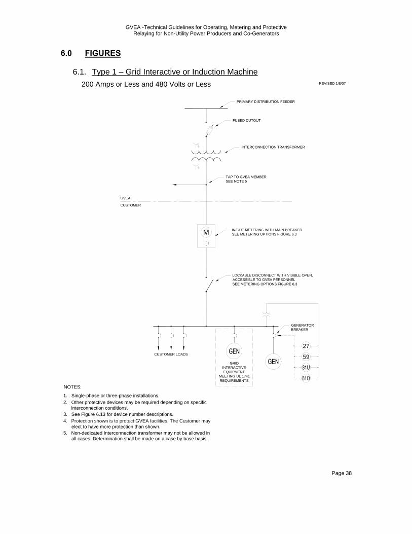
GVEA -Technical Guidelines for Operating, Metering and Protective Relaying for Non-Utility Power Producers and Co-Generators
Page 38
6.0 FIGURES
6.1. Type 1 – Grid Interactive or Induction Machine REVISED 1/8/07
PRIMARY DISTRIBUTION FEEDER
M
GVEA
CUSTOMER
200 Amps or Less and 480 Volts or Less
FUSED CUTOUT
INTERCONNECTION TRANSFORMER
IN/OUT METERING WITH MAIN BREAKERSEE METERING OPTIONS FIGURE 6.3
LOCKABLE DISCONNECT WITH VISIBLE OPEN, ACCESSIBLE TO GVEA PERSONNELSEE METERING OPTIONS FIGURE 6.3
CUSTOMER LOADS
GENERATOR BREAKER
1.
NOTES:
Single-phase or three-phase installations.
27
59
2.
GRID INTERACTIVE EQUIPMENT
MEETING UL 1741 REQUIREMENTS
Other protective devices may be required depending on specific interconnection conditions.
3. See Figure 6.13 for device number descriptions.4. Protection shown is to protect GVEA facilities. The Customer may
elect to have more protection than shown.
TAP TO GVEA MEMBERSEE NOTE 5
5. Non-dedicated Interconnection transformer may not be allowed in all cases. Determination shall be made on a case by base basis.

GVEA -Technical Guidelines for Operating, Metering and Protective Relaying for Non-Utility Power Producers and Co-Generators
Page 39
6.2. Type 1 – Synchronous Machine
GVEA
CUSTOMER
CUSTOMER LOADS
GENERATOR BREAKER
27
59
51
1.
NOTES:
Single-phase or three-phase installations.2. Other protective devices may be required depending on specific
interconnection conditions.3. See Figure 6.13 for device number descriptions.
200 Amps or Less and 480 Volts or Less
4. Protection shown is to protect GVEA facilities. The Customer may elect to have more protection than shown.
32
PRIMARY DISTRIBUTION FEEDER
M
FUSED CUTOUT
IN/OUT METERING WITH MAIN BREAKERSEE METERING OPTIONS FIGURE 6.3
LOCKABLE DISCONNECT WITH VISIBLE OPEN, ACCESSIBLE TO GVEA PERSONNEL
SEE METERING OPTIONS FIGURE 6.3
TAP TO GVEA MEMBERSEE NOTE 5
INTERCONNECTION TRANSFORMER
5. Non-dedicated Interconnection transformer may not be allowed in all cases. Determination shall be made on a case by base basis.
25SEE NOTE 6
6. Sync check relay (25) supervises manual synchronized closing.
REVISED 1/8/07
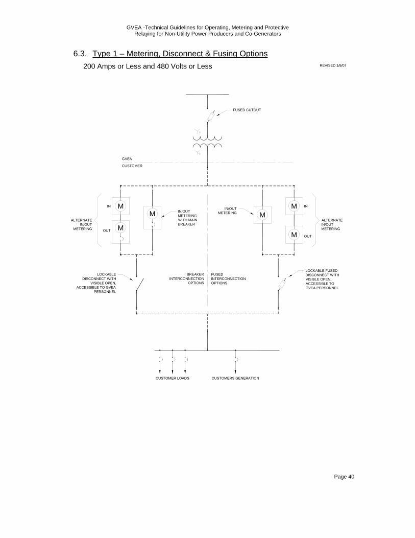
GVEA -Technical Guidelines for Operating, Metering and Protective Relaying for Non-Utility Power Producers and Co-Generators
Page 40
6.3. Type 1 – Metering, Disconnect & Fusing Options
M
GVEA
CUSTOMER
IN/OUT METERING WITH MAIN BREAKER
LOCKABLE DISCONNECT WITH
VISIBLE OPEN, ACCESSIBLE TO GVEA
PERSONNEL
CUSTOMER LOADS
M
M
ALTERNATE IN/OUT
METERING
IN
OUT
IN/OUT METERING
LOCKABLE FUSED DISCONNECT WITH VISIBLE OPEN, ACCESSIBLE TO GVEA PERSONNEL
M IN
OUT
M
M
ALTERNATE IN/OUT METERING
BREAKER INTERCONNECTION
OPTIONS
FUSED INTERCONNECTION OPTIONS
CUSTOMERS GENERATION
200 Amps or Less and 480 Volts or Less
FUSED CUTOUT
REVISED 1/8/07

GVEA -Technical Guidelines for Operating, Metering and Protective Relaying for Non-Utility Power Producers and Co-Generators
Page 41
6.4. Type 2 – Grid Interactive or Induction Machine
PRIMARY DISTRIBUTION FEEDER
GVEA
CUSTOMER
Greater than 200 Amps and 500 kVA or Less at Secondary Voltages
FUSED CUTOUT
INTERCONNECTION TRANSFORMERSEE NOTE 6
GRID INTERACTIVE EQUIPMENT
MEETING UL 1741 REQUIREMENTS
IN/OUT METERINGM
LOCKABLE FUSED DISCONNECT WITH VISIBLE OPEN, ACCESSIBLE TO GVEA PERSONNEL
GENERATOR BREAKER
27
59
1.
NOTES:
Single-phase or three-phase installations.2. Other protective devices may be required depending on specific
interconnection conditions.3. See Figure 6.13 for device number descriptions.4. Protection shown is to protect GVEA facilities. The Customer may
elect to have more protection than shown.5. Non-dedicated Interconnection transformer may not be allowed in
all cases. Determination shall be made on a case by base basis.
TAP TO GVEA MEMBERSEE NOTE 5
6. If no GVEA Members or Customer loads are served the transformer may be wye (high side) delta (low side) connected.
CUSTOMER LOADSSEE NOTE 5
REVISED 1/8/07
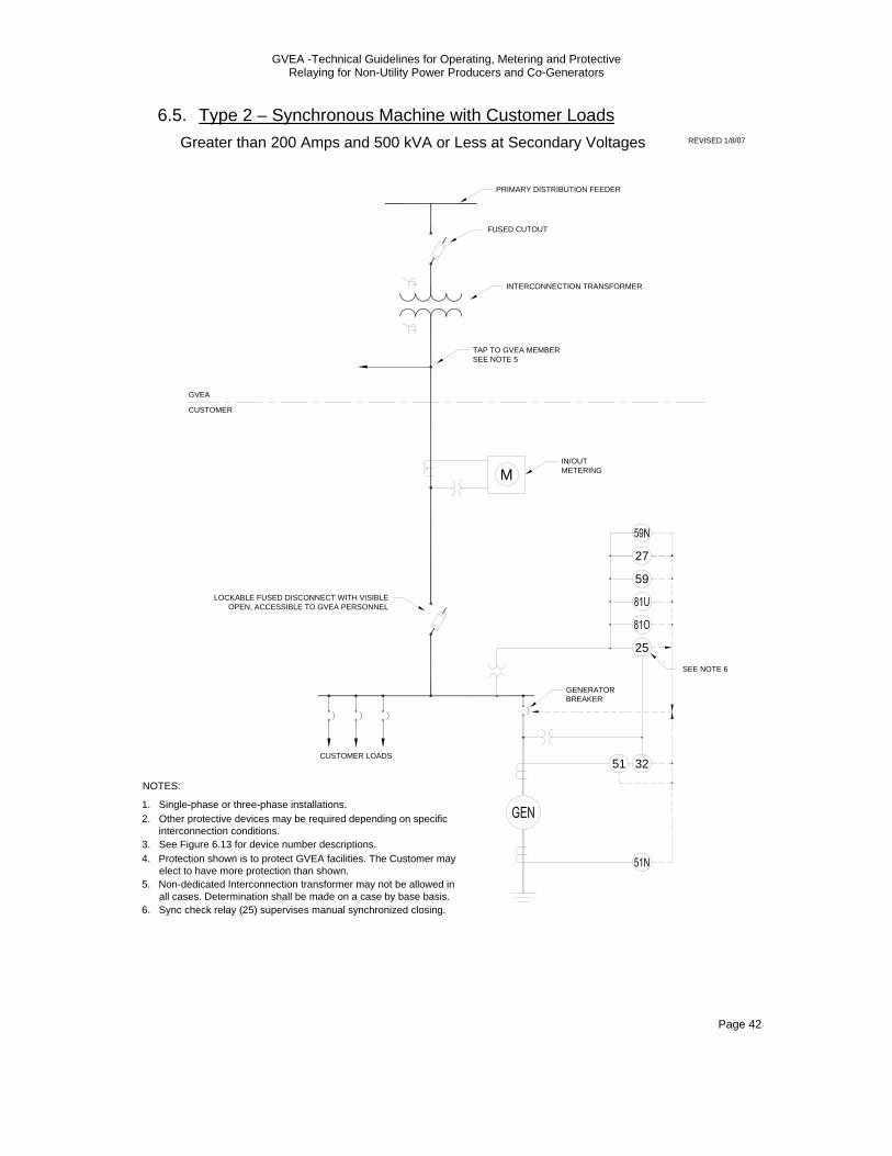
GVEA -Technical Guidelines for Operating, Metering and Protective Relaying for Non-Utility Power Producers and Co-Generators
Page 42
6.5. Type 2 – Synchronous Machine with Customer Loads
GVEA
CUSTOMER
CUSTOMER LOADS
1.
NOTES:
Single-phase or three-phase installations.2. Other protective devices may be required depending on specific
interconnection conditions.3. See Figure 6.13 for device number descriptions.4. Protection shown is to protect GVEA facilities. The Customer may
elect to have more protection than shown.
PRIMARY DISTRIBUTION FEEDER
FUSED CUTOUT
TAP TO GVEA MEMBERSEE NOTE 5
INTERCONNECTION TRANSFORMER
5. Non-dedicated Interconnection transformer may not be allowed in all cases. Determination shall be made on a case by base basis.
LOCKABLE FUSED DISCONNECT WITH VISIBLE OPEN, ACCESSIBLE TO GVEA PERSONNEL
IN/OUT METERINGM
6. Sync check relay (25) supervises manual synchronized closing.
GENERATOR BREAKER
27
59
32
25SEE NOTE 6
51
Greater than 200 Amps and 500 kVA or Less at Secondary Voltages REVISED 1/8/07
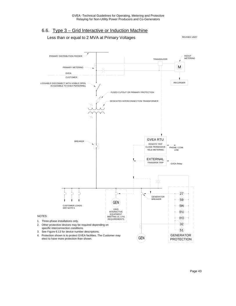
GVEA -Technical Guidelines for Operating, Metering and Protective Relaying for Non-Utility Power Producers and Co-Generators
Page 43
6.6. Type 3 – Grid Interactive or Induction Machine
GVEA
CUSTOMER
Less than or equal to 2 MVA at Primary Voltages
FUSED CUTOUT OR PRIMARY PROTECTION
DEDICATED INTERCONNECTION TRANSFORMER
LOCKABLE DISCONNECT WITH VISIBLE OPEN, ACCESSIBLE TO GVEA PERSONNEL
M
IN/OUT METERING
PRIMARY DISTRIBUTION FEEDER
RECORDER
TRANSDUCER
PRIMARY METERING
1.
NOTES:
Three-phase installations only.2. Other protective devices may be required depending on
specific interconnection conditions.3. See Figure 6.13 for device number descriptions.4. Protection shown is to protect GVEA facilities. The Customer may
elect to have more protection than shown.
CUSTOMER LOADSSEE NOTE 5
BREAKER
GRID INTERACTIVE EQUIPMENT
MEETING UL 1741 REQUIREMENTS
GVEA RTU
CLOSE PERMISSIVEREMOTE TRIP
TELE-METERINGPHONE / COM.
LINE
GENERATOR BREAKER
TRANSFER TRIPEXTERNAL
GVEA Relay
GENERATORPROTECTION
27
59
32
51
REVISED 1/8/07
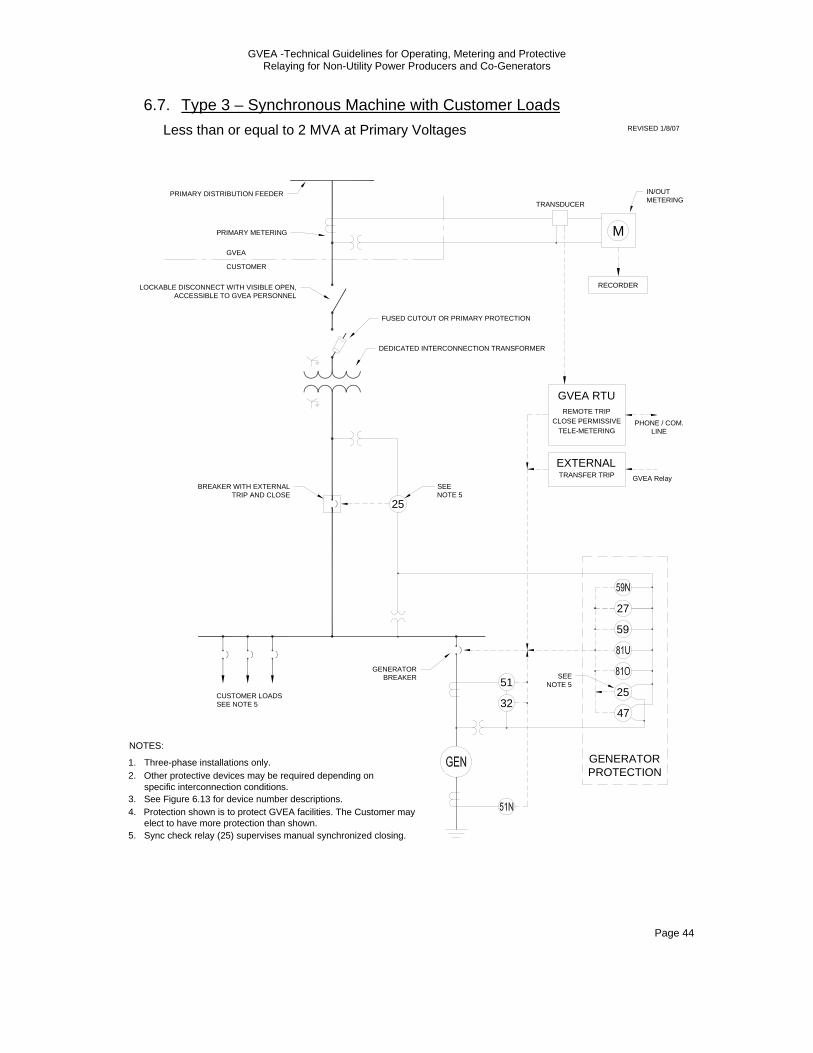
GVEA -Technical Guidelines for Operating, Metering and Protective Relaying for Non-Utility Power Producers and Co-Generators
Page 44
6.7. Type 3 – Synchronous Machine with Customer Loads
GVEA
CUSTOMER
FUSED CUTOUT OR PRIMARY PROTECTION
DEDICATED INTERCONNECTION TRANSFORMER
LOCKABLE DISCONNECT WITH VISIBLE OPEN, ACCESSIBLE TO GVEA PERSONNEL
M
IN/OUT METERING
PRIMARY DISTRIBUTION FEEDER
RECORDER
TRANSDUCER
PRIMARY METERING
1.
NOTES:
Three-phase installations only.2. Other protective devices may be required depending on
specific interconnection conditions.3. See Figure 6.13 for device number descriptions.4. Protection shown is to protect GVEA facilities. The Customer may
elect to have more protection than shown.
BREAKER WITH EXTERNAL TRIP AND CLOSE
25
GVEA RTU
CLOSE PERMISSIVEREMOTE TRIP
TELE-METERING
TRANSFER TRIPEXTERNAL
CUSTOMER LOADSSEE NOTE 5
PHONE / COM. LINE
GVEA Relay
GENERATOR BREAKER
27
59
51
47
25
GENERATORPROTECTION
SEENOTE 5
32
5. Sync check relay (25) supervises manual synchronized closing.
SEENOTE 5
Less than or equal to 2 MVA at Primary Voltages REVISED 1/8/07
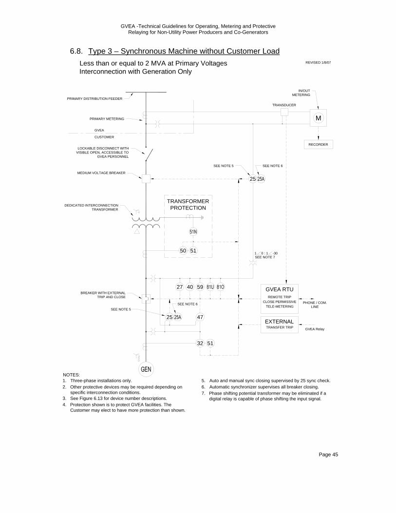
GVEA -Technical Guidelines for Operating, Metering and Protective Relaying for Non-Utility Power Producers and Co-Generators
Page 45
6.8. Type 3 – Synchronous Machine without Customer Load
1.NOTES:
Three-phase installations only.2. Other protective devices may be required depending on
specific interconnection conditions.3. See Figure 6.13 for device number descriptions.
50 51
GVEA
CUSTOMER
LOCKABLE DISCONNECT WITH VISIBLE OPEN, ACCESSIBLE TO
GVEA PERSONNEL
M
PRIMARY DISTRIBUTION FEEDER
TRANSDUCER
PRIMARY METERING
Less than or equal to 2 MVA at Primary VoltagesInterconnection with Generation Only
BREAKER WITH EXTERNAL TRIP AND CLOSE
47
59
25
GVEA RTU
CLOSE PERMISSIVEREMOTE TRIP
TELE-METERING
TRANSFER TRIPEXTERNAL
51
4. Protection shown is to protect GVEA facilities. The Customer may elect to have more protection than shown.
GVEA Relay
PHONE / COM. LINE
MEDIUM VOLTAGE BREAKER
TRANSFORMERPROTECTION
40
32
DEDICATED INTERCONNECTION TRANSFORMER
27
25
IN/OUT METERING
RECORDER
SEE NOTE 5
SEE NOTE 5
1 0 : 1 -30SEE NOTE 7
5.Automatic synchronizer supervises all breaker closing.6.Auto and manual sync closing supervised by 25 sync check.
Phase shifting potential transformer may be eliminated if a digital relay is capable of phase shifting the input signal.
7.
REVISED 1/8/07
SEE NOTE 6
SEE NOTE 6
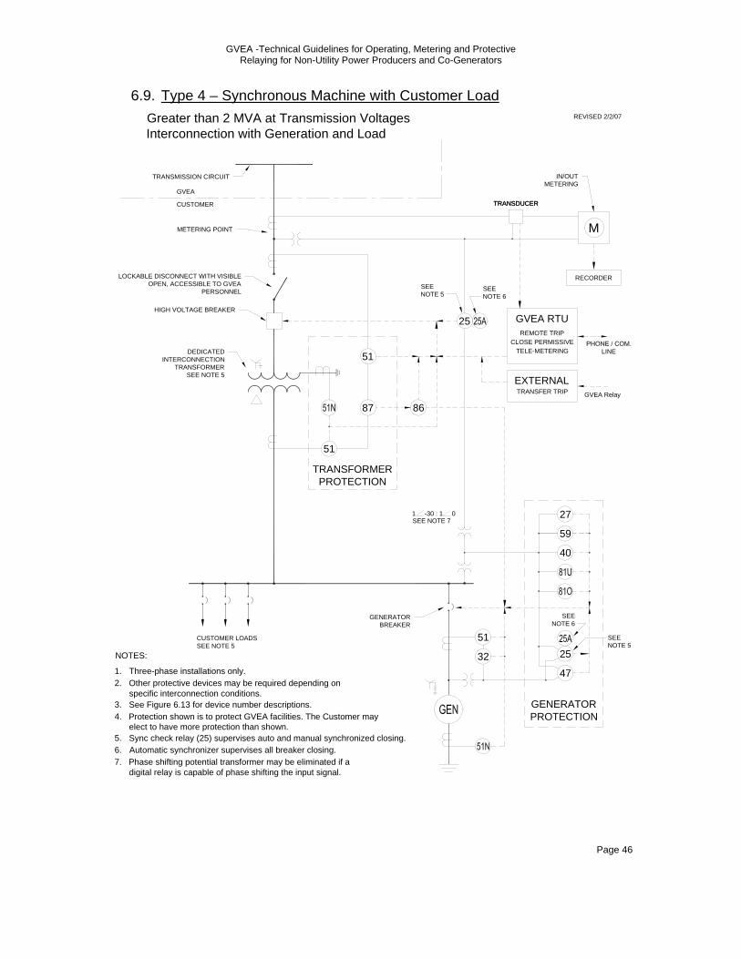
GVEA -Technical Guidelines for Operating, Metering and Protective Relaying for Non-Utility Power Producers and Co-Generators
Page 46
6.9. Type 4 – Synchronous Machine with Customer Load Greater than 2 MVA at Transmission VoltagesInterconnection with Generation and Load
GVEA
CUSTOMER
LOCKABLE DISCONNECT WITH VISIBLE OPEN, ACCESSIBLE TO GVEA
PERSONNEL
TRANSDUCER
METERING POINT
1.
NOTES:
Three-phase installations only.2. Other protective devices may be required depending on
specific interconnection conditions.3. See Figure 6.13 for device number descriptions.4. Protection shown is to protect GVEA facilities. The Customer may
elect to have more protection than shown.
GVEA RTU
CLOSE PERMISSIVEREMOTE TRIP
TELE-METERING
TRANSFER TRIPEXTERNAL
CUSTOMER LOADSSEE NOTE 5
59
40
51
47
25
GENERATORPROTECTION
TRANSMISSION CIRCUIT
HIGH VOLTAGE BREAKER
DEDICATED INTERCONNECTION
TRANSFORMERSEE NOTE 5
GVEA Relay
LINE
M
TRANSDUCER
IN/OUT METERING
RECORDER
51
TRANSFORMERPROTECTION
32
GENERATOR BREAKER
27
SEENOTE 6
5. Sync check relay (25) supervises auto and manual synchronized closing.6.
25
Phase shifting potential transformer may be eliminated if a digital relay is capable of phase shifting the input signal.
7.
1 -30 : 1 0SEE NOTE 7
REVISED 2/2/07
SEE NOTE 6
SEE NOTE 5
Automatic synchronizer supervises all breaker closing.
SEENOTE 5
51
87 86
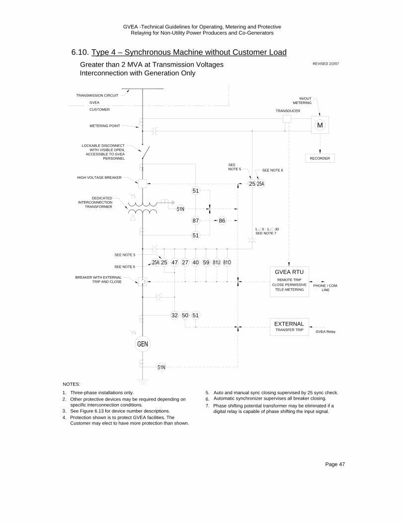
GVEA -Technical Guidelines for Operating, Metering and Protective Relaying for Non-Utility Power Producers and Co-Generators
Page 47
6.10. Type 4 – Synchronous Machine without Customer Load
1.
NOTES:
Three-phase installations only.2. Other protective devices may be required depending on
specific interconnection conditions.3. See Figure 6.13 for device number descriptions.
50 51
GVEA
CUSTOMER
LOCKABLE DISCONNECT WITH VISIBLE OPEN,
ACCESSIBLE TO GVEA PERSONNEL
M
TRANSMISSION CIRCUIT
RECORDER
TRANSDUCER
METERING POINT
Greater than 2 MVA at Transmission VoltagesInterconnection with Generation Only
BREAKER WITH EXTERNAL TRIP AND CLOSE
27 594725
4. Protection shown is to protect GVEA facilities. The Customer may elect to have more protection than shown.
5.
HIGH VOLTAGE BREAKER
GVEA RTU
CLOSE PERMISSIVEREMOTE TRIP
TELE-METERINGPHONE / COM.
LINE
TRANSFER TRIPEXTERNAL
GVEA Relay
IN/OUT METERING
DEDICATED INTERCONNECTION
TRANSFORMER
40
32
25
1 0 : 1 -30SEE NOTE 7
6.Auto and manual sync closing supervised by 25 sync check.
Phase shifting potential transformer may be eliminated if a digital relay is capable of phase shifting the input signal.
7.
SEE NOTE 5
REVISED 2/2/07
SEE NOTE 6
SEE NOTE 6
Automatic synchronizer supervises all breaker closing.
SEE NOTE 5
51
51
87 86
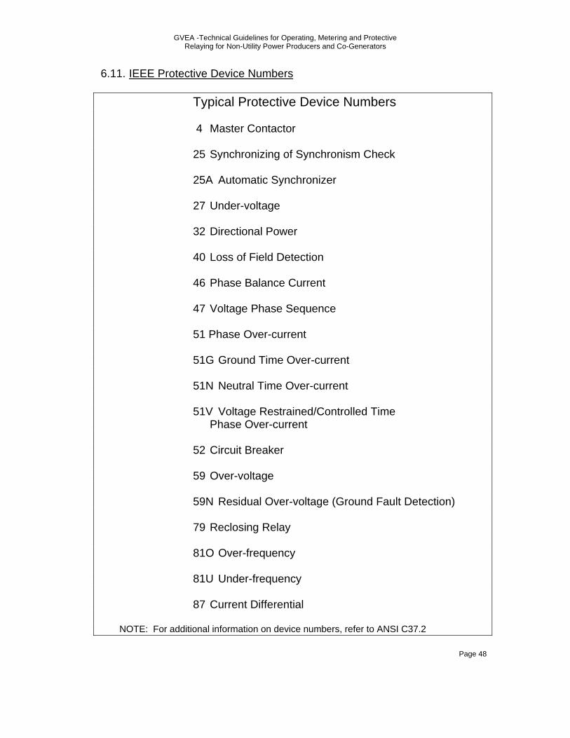
GVEA -Technical Guidelines for Operating, Metering and Protective Relaying for Non-Utility Power Producers and Co-Generators
Page 48
6.11. IEEE Protective Device Numbers Typical Protective Device Numbers 4 Master Contactor 25 Synchronizing of Synchronism Check 25A Automatic Synchronizer 27 Under-voltage 32 Directional Power 40 Loss of Field Detection 46 Phase Balance Current 47 Voltage Phase Sequence 51 Phase Over-current 51G Ground Time Over-current 51N Neutral Time Over-current 51V Voltage Restrained/Controlled Time Phase Over-current 52 Circuit Breaker 59 Over-voltage 59N Residual Over-voltage (Ground Fault Detection) 79 Reclosing Relay 81O Over-frequency 81U Under-frequency 87 Current Differential NOTE: For additional information on device numbers, refer to ANSI C37.2

GVEA -Technical Guidelines for Operating, Metering and Protective Relaying for Non-Utility Power Producers and Co-Generators
Page 49
7.0 APPLICATION FOR PARALLEL OPERATION WITH UTILITY SERVICE To ensure that GVEA has received adequate information to properly and thoroughly review an application from a Qualifying Facility, GVEA has prepared an application form to facilitate this process. A sample of this form is included in this section. It is the policy of GVEA to provide a preliminary written response to a Qualifying Facility applicant within 15 working days. The preliminary written response is intended to accomplish the following: 1. Acknowledge receipt of Qualifying Facility’s application. 2. Clearly identify any deficiencies in the contents of the application
and to state what additional information is required to complete the application, if any.
3. If the application is complete, GVEA will attempt to identify any
areas of concern which GVEA feels the application must address. 4. Identify a preliminary time schedule for the initial review process
and identify the person or persons within GVEA who will be a point of contact for continued coordination.
5. Advise the applicant if there are costs attributable to the applicant
for the initial review process. 6. Establish a date, time, and place to conduct a follow-up
coordination meeting to assist the applicant in the on-going process.
It is further the policy of GVEA to thoroughly document the review process as it progresses. As such, it will be necessary at each phase of the review process to reduce to writing, the understandings reached between the applicant and GVEA. It is the intent of GVEA to assure the applicant at all times that this application is receiving a prompt review.
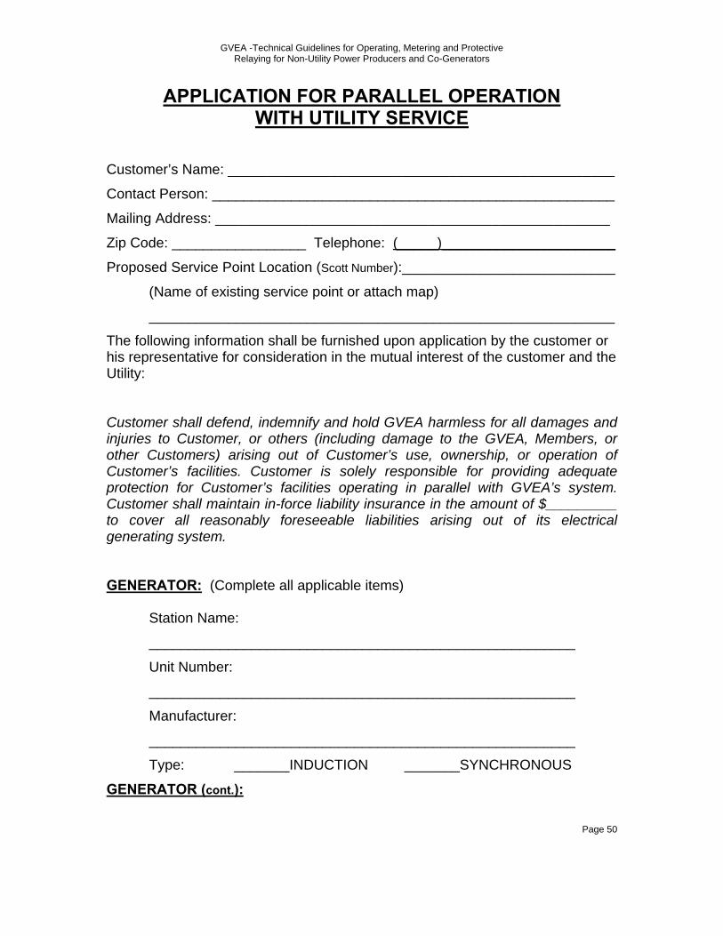
GVEA -Technical Guidelines for Operating, Metering and Protective Relaying for Non-Utility Power Producers and Co-Generators
Page 50
APPLICATION FOR PARALLEL OPERATION WITH UTILITY SERVICE
Customer’s Name: _________________________________________________
Contact Person: ___________________________________________________
Mailing Address: __________________________________________________
Zip Code: _________________ Telephone: (_____)______________________
Proposed Service Point Location (Scott Number):___________________________
(Name of existing service point or attach map)
___________________________________________________________
The following information shall be furnished upon application by the customer or his representative for consideration in the mutual interest of the customer and the Utility: Customer shall defend, indemnify and hold GVEA harmless for all damages and injuries to Customer, or others (including damage to the GVEA, Members, or other Customers) arising out of Customer’s use, ownership, or operation of Customer’s facilities. Customer is solely responsible for providing adequate protection for Customer’s facilities operating in parallel with GVEA’s system. Customer shall maintain in-force liability insurance in the amount of $_________ to cover all reasonably foreseeable liabilities arising out of its electrical generating system. GENERATOR: (Complete all applicable items)
Station Name:
______________________________________________________
Unit Number:
______________________________________________________
Manufacturer:
______________________________________________________
Type: _______INDUCTION _______SYNCHRONOUS
GENERATOR (cont.):
GVEA -Technical Guidelines for Operating, Metering and Protective Relaying for Non-Utility Power Producers and Co-Generators
Page 51
Kilowatt Rating: ______________________________________________
Kilovolt-ampere Rating: ________________________________________
Power Factor: _______________________________________________
Volts: ______________________________________________________
Amperes: ___________________________________________________
Phase and Frequency: ________________________________________
R.P.M.: ____________________________________________________
Field Amps: _________________________________________________
Field Volts: _________________________________________________
Synchronous Reactance: __________________% on __________ base.
Transient Reactance: _____________________% on ___________ base.
Subtransient Reactance: __________________% on ___________ base.
Negative Sequence Reactance: _____________% on ___________ base.
Zero Sequence Reactance: ________________% on ___________ base.
Motoring Power: __________________________kw _________________
Year Manufactured: ___________________________________________
Serial Number: ______________________________________________
PRIME MOVER:
Manufacturer: _______________________________________________
Year Manufactured: ___________________________________________
Type: ______________________________________________________
Energy Source: Briefly describe the cogeneration, wind, solar, stream, hydro, or other energy source:
___________________________________________________________
___________________________________________________________
___________________________________________________________
___________________________________________________________
INTERFACE CIRCUIT:

GVEA -Technical Guidelines for Operating, Metering and Protective Relaying for Non-Utility Power Producers and Co-Generators
Page 52
Describe the proposed interface circuit to be interposed between the generator and the Utility supply circuit.
Manufacturer:________________________________________________
Manufacturer’s Reference Number:_______________________________
Serial Number: ______________________________________________
Describe power conversion (if any) process, i.e. rectifiers, inverters, batteries, etc. ___________________________________________________________
___________________________________________________________
___________________________________________________________
___________________________________________________________
___________________________________________________________
___________________________________________________________
COMBINED CHARACTERISTICS OF GENERATOR AND INTERFACE CIRCUIT
(a) Maximum generated capacity (to be measured at interface output terminals). This is not the generator capacity but the capacity that can be fed into the network when operating at nominal voltage.
__________________kW __________________kVA (b) Output voltage to system:
______________________________________ (c) Unit WR2 (Lbs-Ft2):
__________________________________________ Items d, e, and f apply to inverter installations only. (d) Attach to this form an oscillographic print showing the wave shape
of current supplied to the network system at the interface output terminals. The wave shape of the utility system voltage should also be shown on the same print. If energy source is wind, state wind velocity at time of the test and output capacity (power supplied to
GVEA -Technical Guidelines for Operating, Metering and Protective Relaying for Non-Utility Power Producers and Co-Generators
Page 53
the system). If actual data is not available, oscillograms from a similar installation will be considered.
(e) Estimated (or measured) percent wave-shape distortion, at
interface output terminals, for equipment operating at maximum output. Submit calculations or certified test report.
(f) Estimated (or measured) power factor at interface output terminals
for same conditions as above. Submit calculations or certified test report.
PROTECTION EQUIPMENT: Do NOT complete Items a, b, and c below for three-phase generator installations since the Utility will specify protective device model numbers and settings at the interface. (a) Manufacturer: __________________________________________ (b) Manufacturer’s Reference Number, Type, or Style:
_____________________________________________________
(c) Submit diagram and describe the operation (including protective device settings) for the tripping of the interface or generator circuit breaker for both:
(1) Utility voltage outage (Loss of supply voltage) (2) Utility short circuit (Three-phase and single Phase-to-ground) (d) Name of individual, licensed electrician, or electrical contracting
firm responsible for circuit breaker maintenance (if the customer owns the circuit breaker tripped by the interface protective devices).
_______________________________________________________________________________________________________________________________________________________________
Upon any changes in Item (d), the customer hereby agrees to
provide prompt written notification to the Utility of the name of the individual or firm responsible for the maintenance f the circuit breaker.
(e) Submit maintenance schedule to be followed for the circuit breaker. (f) A maintenance log sheet shall be kept at the premises and made
available for verification by the Utility.

GVEA -Technical Guidelines for Operating, Metering and Protective Relaying for Non-Utility Power Producers and Co-Generators
Page 54
ADDITIONAL REQUIREMENTS: 1. The customer shall submit a detailed, one line, electrical diagram of
his generating equipment, protective features, and connection to the Utility’s supply line.
2. The customer agrees to allow the Utility to install on his premises
any equipment needed to measure loads or any part thereof, to measure the energy produced, to collect and obtain any other data necessary to determine operating characteristics of such installation served under this particular service classification.
Other Information Requested by: Prepared and submitted for Approval by: (Name and Address)
___________________________________________________________
___________________________________________________________
___________________________________________________________
___________________________________________________________
Applicant or Legal Representative: ___________________________________________ Date: __________________________________ Name and address of applicant and ___________________________________ premises to be served:______________________________________________ Received by: ___________________________ (For: Name of the Utility) ________________________________________________________________________________________________________________________________ Date: ______________________________
GOLDEN VALLEY ELECTRIC ASSOCIATION INC


