© Renault s.a.s. 2005
"The repair methods given by the manufacturer in this document are based on the technicalspecifications current when it was prepared.
The methods may be modified as a result of changes introduced by the manufacturer in theproduction of the various component units and accessories from which his vehicles areconstructed."
All copyrights reserved by Renault.
The reproduction or translation in part of whole of the present document, as well as the useof the spare parts reference numbering system, are prohibited without the prior writtenconsent of Renault.
77 11 318 102 MARCH 2003 Edition Anglaise
X84, and B84 or C84 or G84 or S84
8 Electrical equipment
80A BATTERY
80B HEADLIGHTS
80C XENON BULBS
81A REAR LIGHTING
81B INTERIOR LIGHTING
81C FUSES
82A ENGINE IMMOBILISER
82B HORN
82C ALARM
83A INSTRUMENT PANEL
83C ON-BOARD TELEMATICS SYSTEM
© Renault s.a.s. 2005
"The repair methods given by the manufacturer in this document are based on the technicalspecifications current when it was prepared.
The methods may be modified as a result of changes introduced by the manufacturer in theproduction of the various component units and accessories from which his vehicles areconstructed."
All copyrights reserved by Renault.
The reproduction or translation in part of whole of the present document, as well as the useof the spare parts reference numbering system, are prohibited without the prior writtenconsent of Renault.
77 11 318 102 MARCH 2003 Edition Anglaise
X84, and B84 or C84 or G84 or S84
83D CRUISE CONTROL
84A CONTROLS - SIGNALS
85A WIPING - WASHING
86A RADIO
87BPASSENGER COMPARTMENT CONNECTION UNIT
87C OPENING ELEMENTS MANAGEMENT
87D ELECTRIC WINDOWS - SUNROOF
87F PARKING AID
87G ENGINE INTERCONNECTION UNIT
88A WIRING HARNESS
88C AIRBAG AND PRETENSIONERS
Mégane II - Section 8
Contents
Page
Mégane II - Section 8ContentsPage
80A BATTERY
Battery : Removal - Refitting 80A-1
Battery: Precautions for repair 80A-9
80B HEADLIGHTS
Automatic headlights 80B-1
Halogen headlight: Removal - Refitting 80B-2
Halogen headlight: Adjustment 80B-3
Halogen bulbs: Replacement 80B-4
Front fog light: Removal - Refitting 80B-6
Remote headlight adjustment control: Removal - Refitting 80B-7
Remote headlight adjustment motor: Removal - Refitting 80B-8
80C XENON BULBS
Xenon headlights: Description 80C-1
Xenon headlight: Removal - Refitting 80C-4
Xenon headlights: Adjustment 80C-5
Xenon bulb: Replacement 80C-6
Xenon bulb computer: Removal - Refitting 80C-8
Headlight adjustment front sensor: Removal - Refitting 80C-9
Headlight adjustment rear sensor: Removal - Refitting 80C-10
81A REAR LIGHTING
Third brake light: Removal - Refitting 81A-1
Rear light on wing: Removal - Refitting 81A-2
Registration plate light 81A-3
81B INTERIOR LIGHTING
Operating principle 81B-1
Courtesy light: General information 81B-2
Courtesy light 81B-3
Courtesy light: General information 81B-4
Vanity light: Removal - Refitting 81B-5
Lower door light: Removal - Refitting 81B-6
Lower door light switch: Removal - Refitting 81B-7
80C XENON BULBS
Contents
81C FUSES
Passenger compartment fuse and relay box: Identification 81C-1
Engine Compartment Fuse and Relay Box 81C-3
Battery protection fuses 81C-7
82A ENGINE IMMOBILISER
Immobiliser system: List and location of components 82A-1
Starting aerial: Removal - Refitting 82A-2
Start button: Removal - Refitting 82A-4
Steering column electric lock: Removal - Refitting 82A-7
Immobiliser system: Programming: 82A-10
Card reader: Removal - Refitting 82A-11
82B HORN
Horn 82B-1
82C ALARM
Pre-equipment 82C-1
83A INSTRUMENT PANEL
Dashboard: Removal - Refitting 83A-1
Instrument panel: General information 83A-12
Instrument panel: Description 83A-17
Instrument panel: Removal - Refitting 83A-19
Instrument panel: Configuration 83A-21
Instrument panel: Warning and indicator lights 83A-22
Instrument panel: Warning lights and messages 83A-23
Instrument panel: Defect modes 83A-25
Fuel level sensor: Operating principle 83A-28
Oil level detection 83A-30
83C ON-BOARD TELEMATICS SYSTEM
Radio navigation system: Removal - Refitting 83C-1
Navigation computer: Removal - Refitting 83C-2
Navigation interface unit: Removal - Refitting 83C-3
Navigation screen: Removal - Refitting 83C-4
Navigation aerial: Removal - Refitting 83C-5
83D CRUISE CONTROL
Cruise control and speed limiter: General information 83D-1
Speed limiter: Operating principle 83D-4
Cruise control: Operating principle 83D-5
83A INSTRUMENT PANEL
Contents
Switch: Removal - Refitting 83D-6
Steering wheel switch: Removal - Refitting 83D-7
84A CONTROLS - SIGNALS
Steering wheel controls assembly: Removal - Refitting 84A-1
Under steering wheel control assembly: Operating principle 84A-3
Hazard warning lights switch and central locking: Removal - Refitting 84A-5
Remote headlight adjustment control: Removal - Refitting 84A-7
External temperature sensor: Removal - Refitting 84A-8
External temperature sensor: Checking 84A-9
85A WIPING - WASHING
Operating principle 85A-1
Rain and light sensor: Removal - Refitting 85A-2
Rear screen wiper blade: Removal - Refitting 85A-3
Windscreen wiper mechanism: Removal - Refitting 85A-4
Windscreen wiper motor: Removal - Refitting 85A-7
Rear screen wiper motor 85A-8
Windscreen washer 85A-11
Windscreen washer pump: Removal - Refitting 85A-12
83D CRUISE CONTROL
Headlight washers 85A-13
Headlight washer jet: Removal - Refitting 85A-14
Rear screen wiper arm: Removal - Refitting 85A-15
86A RADIO
Audio equipment: List and location of components 86A-1
Car radio: Removal - Refitting 86A-2
"entry level": General information 86A-3
Entry level audio equipment: Removal - Refitting 86A-4
"entry level": Protection code 86A-5
"entry level": Self-diagnostic 86A-6
"top of the range": General information 86A-7
"Top of the range" audio equipment: Removal - Refitting 86A-8
"top of the range": Operating principle 86A-9
"top of the range": Protection code 86A-11
"top of the range": Entering the security code 86A-12
Tuner-amplifier: Removal - Refitting 86A-14
"top of the range": Self-test procedure 86A-15
Display: Removal - Refitting 86A-16
Tweeter: Removal - Refitting 86A-17
Front speakers: Removal - Refitting 86A-18
Rear speakers: Removal - Refitting 86A-19
85A WIPING - WASHING
Contents
Aerial Operating principle 86A-20
Radio aerial: Removal - Refitting 86A-21
Radio control satellite: Removal - Refitting 86A-22
87B PASSENGER COMPARTMENT CONNECTION UNIT
UCH: General information 87B-1
UCH: Removal - Refitting 87B-4
UCH: Configuration 87B-8
87C OPENING ELEMENTS MANAGEMENT
Keyless vehicle: Description 87C-1
Keyless vehicle: 87C-2
Keyless vehicle: Operating principle 87C-10
Starting aerial: Removal - Refitting 87C-12
Opener aerials 87C-14
Tailgate opening switch: Removal - Refitting 87C-15
Tailgate locking switch: Removal - Refitting 87C-16
Tailgate lock: Removal - Refitting 87C-17
Lock motor for the fuel filling compartment: Removal - Refitting 87C-18
87D ELECTRIC WINDOWS - SUNROOF
Electric window: Operation 87D-1
Front driver's door electric window switch 87D-2
86A RADIO
Front electric window switch on the passenger door 87D-3
Rear electric window switch on rear door 87D-4
Child safety lock switch 87D-5
Front electric window motor 87D-6
Rear electric window motor 87D-7
Electric sunroof: Operating principle 87D-8
Sunroof opening motor Removal - Refitting 87D-10
87F PARKING AID
Parking proximity sensor switch: Removal - Refitting 87F-1
Parking proximity sensor buzzer: Removal - Refitting 87F-2
Parking proximity sensor computer: Removal - Refitting 87F-3
Proximity radar Removal - Refitting 87F-4
87G ENGINE INTERCONNECTION UNIT
Engine accessories unit: Removal - Refitting 87G-1
Protection and Switching Unit: General information 87G-4
Protection and Switching Unit: Removal - Refitting 87G-6
88A WIRING HARNESS
Diagnostic socket 88A-1
87D ELECTRIC WINDOWS - SUNROOF
Contents
Computer locations 88A-2
Headlining wiring: Removal - Refitting 88A-3
88C AIRBAG AND PRETENSIONERS
General information 88C-1
Operating principle 88C-4
Precautions during repair 88C-5
Airbag computer locking procedure 88C-7
Computer 88C-8
Computer: Configuration 88C-11
Side impact sensor: Removal - Refitting 88C-12
Seat position sensor 88C-13
Inhibitor switch: Operating principle 88C-14
Inhibitor switch: Removal - Refitting 88C-15
Front buckle pretensioner: Removal - Refitting 88C-16
Rear pyrotechnic inertia reel: Removal - Refitting 88C-18
Lap belt pretensioner and anti-submarining airbag: Description 88C-19
Front lap belt pretensioner: Removal - Refitting 88C-21
Anti-submarining airbag: Removal - Refitting 88C-23
Driver's front airbag: Removal - Refitting 88C-25
Passenger front airbag: Removal - Refitting 88C-27
Front (chest) side airbag: Removal - Refitting 88C-29
88A WIRING HARNESS
Rear (chest) side airbag: Removal - Refitting 88C-31
Side curtain airbag: Removal - Refitting 88C-33
Destruction procedure 88C-37
88C AIRBAG AND PRETENSIONERS
80A-1
BATTERYBattery : Removal - Refitting
B84 or C84
80A
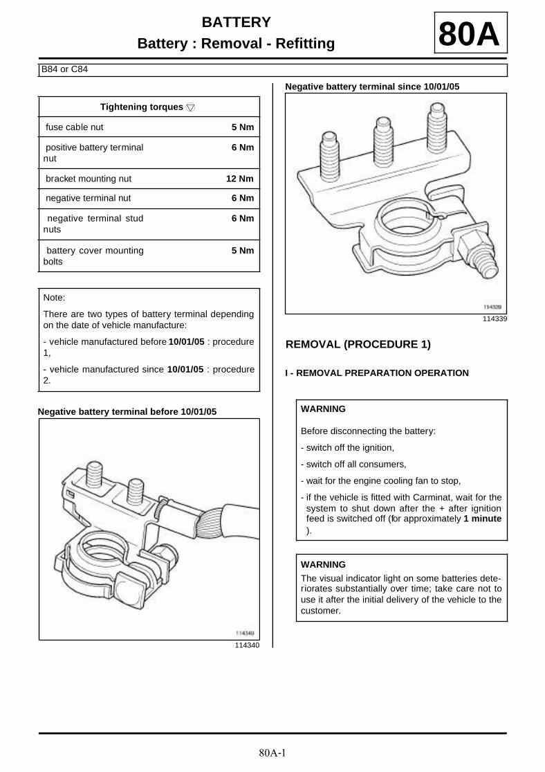
Negative battery terminal before 10/01/05
Negative battery terminal since 10/01/05
REMOVAL (PROCEDURE 1)
I - REMOVAL PREPARATION OPERATION
Tightening torquesm
fuse cable nut 5 Nm
positive battery terminalnut
6 Nm
bracket mounting nut 12 Nm
negative terminal nut 6 Nm
negative terminal studnuts
6 Nm
battery cover mountingbolts
5 Nm
Note:
There are two types of battery terminal dependingon the date of vehicle manufacture:
- vehicle manufactured before 10/01/05 : procedure1,
- vehicle manufactured since 10/01/05 : procedure2.
114340
114339
WARNING
Before disconnecting the battery:
- switch off the ignition,
- switch off all consumers,
- wait for the engine cooling fan to stop,
- if the vehicle is fitted with Carminat, wait for thesystem to shut down after the + after ignitionfeed is switched off (for approximately 1 minute).
WARNING
The visual indicator light on some batteries dete-riorates substantially over time; take care not touse it after the initial delivery of the vehicle to thecustomer.
80A-2
BATTERYBattery : Removal - Refitting
B84 or C84
80A
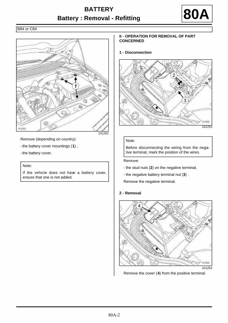
Remove (depending on country):
- the battery cover mountings (1) ,
- the battery cover.
II - OPERATION FOR REMOVAL OF PART CONCERNED
1 - Disconnection
Remove:
- the stud nuts (2) on the negative terminal,
- the negative battery terminal nut (3) .
Remove the negative terminal.
2 - Removal
Remove the cover (4) from the positive terminal.
101252
Note:
If the vehicle does not have a battery cover,ensure that one is not added.
101253
Note:
Before disconnecting the wiring from the nega-tive terminal, mark the position of the wires.
101253
80A-3
BATTERYBattery : Removal - Refitting
B84 or C84
80A
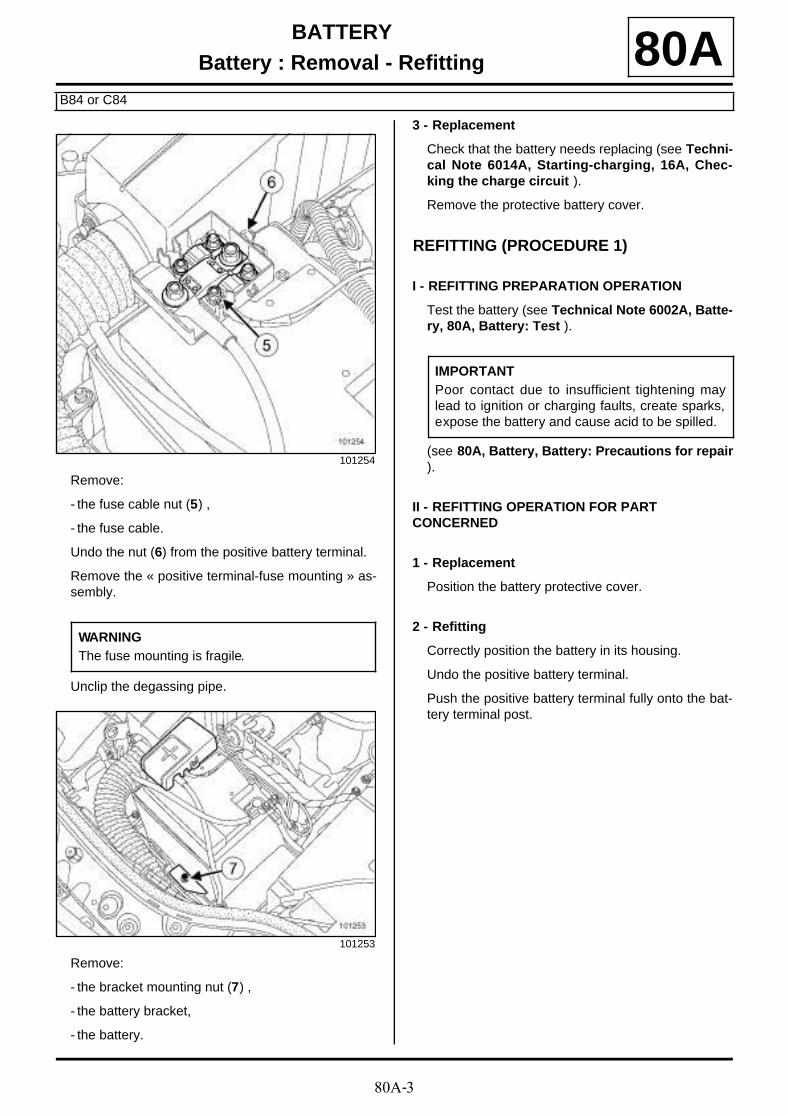
Remove:
- the fuse cable nut (5) ,
- the fuse cable.
Undo the nut (6) from the positive battery terminal.
Remove the « positive terminal-fuse mounting » as-sembly.
Unclip the degassing pipe.
Remove:
- the bracket mounting nut (7) ,
- the battery bracket,
- the battery.
3 - Replacement
Check that the battery needs replacing (see Techni-cal Note 6014A, Starting-charging, 16A, Chec-king the charge circuit ).
Remove the protective battery cover.
REFITTING (PROCEDURE 1)
I - REFITTING PREPARATION OPERATION
Test the battery (see Technical Note 6002A, Batte-ry, 80A, Battery: Test ).
(see 80A, Battery, Battery: Precautions for repair).
II - REFITTING OPERATION FOR PART CONCERNED
1 - Replacement
Position the battery protective cover.
2 - Refitting
Correctly position the battery in its housing.
Undo the positive battery terminal.
Push the positive battery terminal fully onto the bat-tery terminal post.
101254
WARNINGThe fuse mounting is fragile.
101253
IMPORTANTPoor contact due to insufficient tightening maylead to ignition or charging faults, create sparks,expose the battery and cause acid to be spilled.

80A-4
BATTERYBattery : Removal - Refitting
B84 or C84
80A
Tighten to torque the positive terminal nut (6 Nm)(8) .
Position the fuse cable.
Tighten to torque the fuse cable nut ( 5 Nm ) (9) .
Fit the positive terminal cover.
Connect the degassing pipe.
Position the battery bracket.
Tighten to torque the bracket mounting nut (12Nm) .
3 - Connection
Loosen the negative battery terminal.
Take care that the square washer does not becomeskewed.
Push the negative battery terminal fully onto the bat-tery terminal post.
Tighten to torque the negative terminal nut (6 Nm)(10) .
Tighten to torque the negative terminal stud nuts(6 Nm) (11) .
101254
101253
WARNING
In order to avoid premature loosening of the studnuts when removing the negative terminalcables, only allow a maximum of two terminalsper stud, distr ibuting them between the variousstuds when refitting.
80A-5
BATTERYBattery : Removal - Refitting
B84 or C84
80AIII - FINAL OPERATION
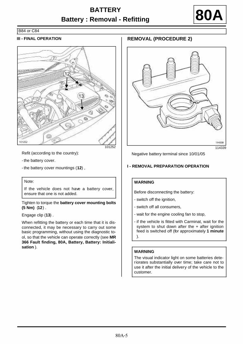
Refit (according to the country):
- the battery cover.
- the battery cover mountings (12) ,
Tighten to torque the battery cover mounting bolts(5 Nm) (12) .
Engage clip (13) .
When refitting the battery or each time that it is dis-connected, it may be necessary to carry out somebasic programming, without using the diagnostic to-ol, so that the vehicle can operate correctly (see MR366 Fault finding, 80A, Battery, Battery: Initiali-sation ).
REMOVAL (PROCEDURE 2)
Negative battery terminal since 10/01/05
I - REMOVAL PREPARATION OPERATION
101252
Note:
If the vehicle does not have a battery cover,ensure that one is not added.
114339
WARNING
Before disconnecting the battery:
- switch off the ignition,
- switch off all consumers,
- wait for the engine cooling fan to stop,
- if the vehicle is fitted with Carminat, wait for thesystem to shut down after the + after ignitionfeed is switched off (for approximately 1 minute).
WARNING
The visual indicator light on some batteries dete-riorates substantially over time; take care not touse it after the initial delivery of the vehicle to thecustomer.
80A-6
BATTERYBattery : Removal - Refitting
B84 or C84
80A
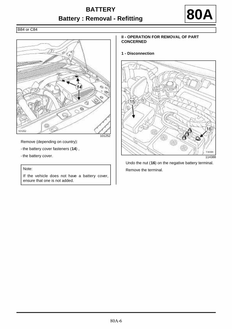
Remove (depending on country):
- the battery cover fasteners (14) ,
- the battery cover.
II - OPERATION FOR REMOVAL OF PART CONCERNED
1 - Disconnection
Undo the nut (16) on the negative battery terminal.
Remove the terminal.
101252
Note:
If the vehicle does not have a battery cover,ensure that one is not added.
114388

80A-7
BATTERYBattery : Removal - Refitting
B84 or C84
80A2 - Removal
Remove the cover (15) from the positive terminal.
Undo the nut (17) on the positive battery terminal.
Remove the terminal.
Unclip the degassing pipe.
Remove:
- the bracket mounting nut (18) ,
- the battery bracket,
- the battery.
3 - Replacement
Check that the battery needs replacing (see Techni-cal Note 6014A, Starting-charging, 16A, Chec-king the charge circuit ).
Remove the protective battery cover.
REFITTING (PROCEDURE 2)
I - REFITTING PREPARATION OPERATION
Test the battery (see Technical Note 6002A, Batte-ry, 80A, Battery: Test ).
(see 80A, Battery, Battery: Precautions for repair).
II - REFITTING OPERATION FOR PART CONCERNED
1 - Replacement
Position the battery protective cover.
2 - Refitting
Correctly position the battery in its housing.
Undo the positive battery terminal.
Push the positive battery terminal fully onto the bat-tery terminal post.
Tighten to torque the positive battery terminal nut( 6 Nm ) .
Fit the positive terminal cover.
Connect the degassing pipe.
Position the battery bracket.
Tighten to torque the bracket mounting nut ( 12Nm ) .
114241
WARNING
The fuse mounting is fragile.
IMPORTANT
Poor contact due to insufficient tightening maylead to ignition or charging faults, create sparks,expose the battery and cause acid to be spilled.
80A-8
BATTERYBattery : Removal - Refitting
B84 or C84
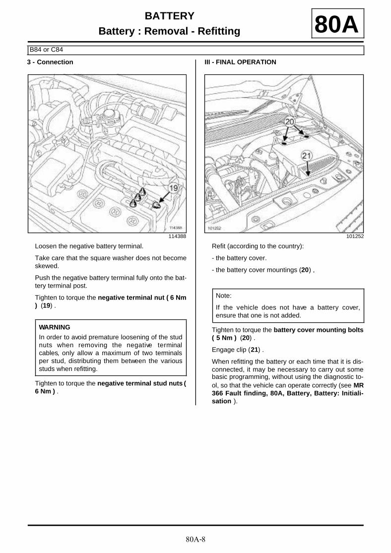
80A3 - Connection
Loosen the negative battery terminal.
Take care that the square washer does not becomeskewed.
Push the negative battery terminal fully onto the bat-tery terminal post.
Tighten to torque the negative terminal nut ( 6 Nm) (19) .
Tighten to torque the negative terminal stud nuts (6 Nm ) .
III - FINAL OPERATION
Refit (according to the country):
- the battery cover.
- the battery cover mountings (20) ,
Tighten to torque the battery cover mounting bolts( 5 Nm ) (20) .
Engage clip (21) .
When refitting the battery or each time that it is dis-connected, it may be necessary to carry out somebasic programming, without using the diagnostic to-ol, so that the vehicle can operate correctly (see MR366 Fault finding, 80A, Battery, Battery: Initiali-sation ).
114388
WARNING
In order to avoid premature loosening of the studnuts when removing the negative terminalcables, only allow a maximum of two terminalsper stud, distributing them between the variousstuds when refitting.
101252
Note:
If the vehicle does not have a battery cover,ensure that one is not added.
80A-9
BATTERYBattery: Precautions for repair 80A
I - SAFETY
1 - DANGER: RISK FROM ACID LINKED TO HANDLING AND TO INCORRECT TIGHTENING OF THE MOUNTING FLANGE.
Sulphuric acid is a highly aggressive and toxic subs-tance which corrodes most metals.
When handling batteries, it is very important to take the following precautions:
- protect your eyes by wearing goggles,
- wear acid-proof gloves and clothing.
2 - DANGER: RISK OF EXPLOSION LINKED TO CHARGING AND TO INCORRECT TIGHTENING OF THE TERMINALS.
When a battery is charging oxygen and hydrogen areproduced. Gas formation is at a maximum when thebattery is completely charged, and the quantity of gasproduced is proportional to the strength of the chargingcurrent.
The oxygen and hydrogen mix in the space on the sur-face of the plates, forming an explosive mixture. Thismixture is highly explosive.
The smallest of sparks or heat sources can cause anexplosion. The explosion is so strong that the batterycan shatter and spray the acid into the surrounding at-mosphere.
People nearby are at risk (exploded fragments, acidsplashes). Acid splashes are dangerous. They also da-mage clothing.
Safeguards against the danger of explosion, which canbe caused by handling a battery carelessly, must be ta-ken very seriously.
II - CLEANLINESS
Check that there is no creep leakage (sulphation) onthe battery terminals.
Clean the battery terminals if there is a build-up ofsalts.
III - SPECIAL RECOMMENDATIONS
When refitting the battery or each time it is disconnec-ted, it may be necessary to carry out some basic pro-gramming, without using the diagnostic tool, so that thevehicle can operate correctly (see MR 366 Fault fin-ding, 80A, Battery, Battery: Initialisation ).
IMPORTANT
- Batteries contain sulphuric acid, which is a dange-rous substance.
- When a battery is being charged, oxygen andhydrogen are created, the mixture of these gasescan present a risk of explosion.
IMPORTANT
- If acid splashes onto you, rinse all contaminatedareas thoroughly with water.
- If it comes into contact with skin, consult a doctor.
IMPORTANT
To avoid all risk of sparks, ensure that all electricalconsumers are fully switched off.
When a battery is being charged in a room, switchoff the charger before connecting or disconnectingthe battery.
Do not place any metallic items on the battery asthis may create a short circuit across the terminals.
never hold a naked flame, a welding gun, blowtorch,a cigarette or a lit match near to a battery.
WARNING
Poor contact may cause starting or charging faults,create sparks and cause the battery to explode.
WARNING
These vehicles are equipped with a battery with lowwater consumption. Topping up the electrolyte istherefore prohibited.
WARNING
Before disconnecting the battery:
- switch off the ignition,
- switch off all consumers,
- wait for the fan unit to stop,
- if the vehicle is fitted with Carminat, wait for theentire system to shut down after the + after igni-tion feed is switched off (approximately 1 minute).
80B-1
HEADLIGHTSAutomatic headlights 80B
I - AUTOMATIC HEADLIGHTS WHEN THE VEHICLE IS STATIONARY (SEE-ME-HOME FUNCTION).
Depending on the version, vehicles may be fitted withdipped headlights that come on automatically (whenthe engine is switched off) to light the area in front ofthe vehicle.
This function is only available with the ignition switchedoff, the lighting stalk in its neutral position and the lightsnot lit, and operates for timed periods of 30 seconds (2 minutes maximum).
Activation
It is switched on with the lighting stalk:
- switch off the ignition,
- flash the main beam headlights using the stalk,
- the dipped beam headlights are supplied for 30 se-conds .
Switching on the side lights or switching on the ignitionwill exit the function.
II - AUTOMATIC HEADLIGHTS ON WHILE DRIVING
The lighting stalk is used for activating or inhibiting the function, if the UCH is configured correctly ( (see 87B, Passenger compartment connection unit) ):
- with the engine stopped or stationary and the enginerunning,
- press and hold the « Auto » button on the end of thelighting stalk,
- when the status changes, the instrument panel beepsand a message is displayed.
From now on the system will operate in automatic mo-de.
Perform the same operation to return to manual mode.
Note:
Each request for main beam headlights using thelighting stalk will add a time of 30 seconds ( 2minutes maximum).
Note:
For special notes on replacing the light sensor (see85A, Wiping - Washing) .

80B-2
HEADLIGHTSHalogen headlight: Removal - Refitting
DOCUMENT PHASE 2
80B
The headlight and the direction indicator are one unit.
REMOVALRemove the front bumper (see MR 365 Bodywork,55A, Exterior protection, Front bumper: Removal- Refitting ).
Remove the headlight lower mounting bolts (1) .
Remove the headlight upper mounting bolt (2) .
Disconnect the headlight connectors.
Remove the headlight.
REFITTING
Refit:
- the headlight;
- the headlight mounting bolts.
Tighten to torque the headlight mounting bolts ( 4Nm ) .
Connect the connectors.
Refit the front bumper (see MR 365 Bodywork,55A, Exterior protection, Front bumper: Removal- Refitting ).
Adjust the headlights (see 80B, Headlights,Halogen headlight: Adjustment, page 80B-3) .
Tightening torquesm
headlight mountingbolts
4 Nm
Note:
When removing the xenon headlights, it is essentialto respect the safety regulations (see 80C, Xenonbulbs, Xenon headlight: Removal - Refitting,page 80C-4) .
115725
115726
80B-3
HEADLIGHTSHalogen headlight: Adjustment 80B
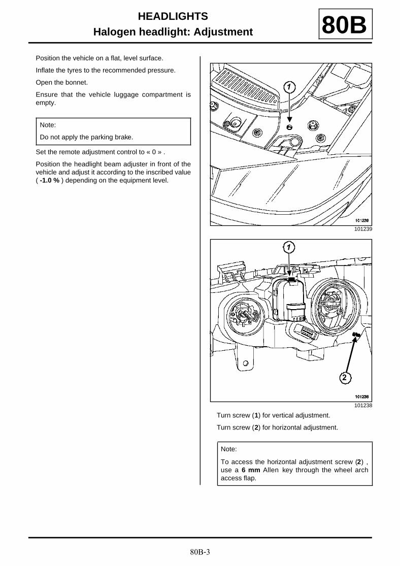
Position the vehicle on a flat, level surface.
Inflate the tyres to the recommended pressure.
Open the bonnet.
Ensure that the vehicle luggage compartment isempty.
Set the remote adjustment control to « 0 » .
Position the headlight beam adjuster in front of thevehicle and adjust it according to the inscribed value( -1.0 % ) depending on the equipment level.
Turn screw (1) for vertical adjustment.
Turn screw (2) for horizontal adjustment.
Note:
Do not apply the parking brake.
101239
101238
Note:
To access the horizontal adjustment screw (2) ,use a 6 mm Allen key through the wheel archaccess flap.
1
1
2
80B-4
HEADLIGHTSHalogen bulbs: Replacement 80B
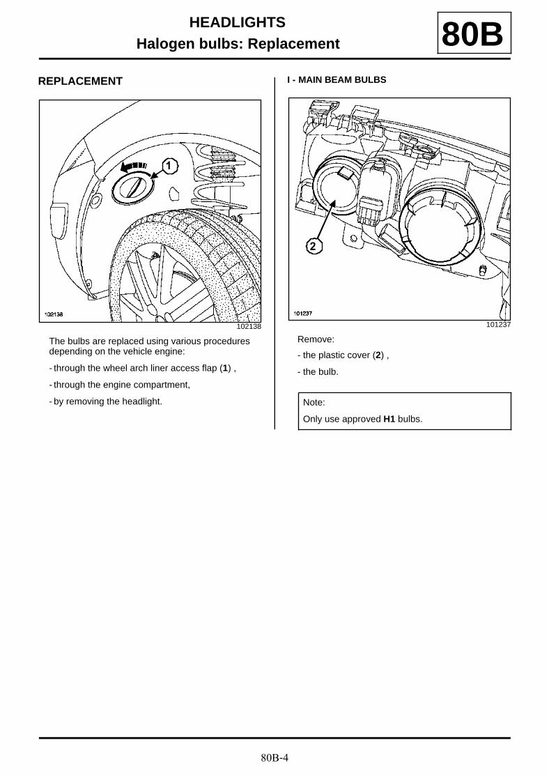
REPLACEMENT
The bulbs are replaced using various procedures depending on the vehicle engine:
- through the wheel arch liner access flap (1) ,
- through the engine compartment,
- by removing the headlight.
I - MAIN BEAM BULBS
Remove:
- the plastic cover (2) ,
- the bulb.
102138
1
101237
Note:
Only use approved H1 bulbs.
2

80B-5
HEADLIGHTSHalogen bulbs: Replacement 80B
II - SIDE LIGHT BULB
Remove:
- the plastic cover (3) ,
- the bulb.
III - DIPPED BEAM HEADLIGHT BULB
Remove:
- the plastic cover (3) ,
- the bulb.
IV - DIRECTION INDICATOR BULB
Remove:
- the plastic cover (4) ,
- the bulb.
101237
Note:
Only use approved W5W bulbs.
Note:
- Only use approved H7 bulbs.
- For replacing Xenon headlight bulbs ( (see 80C,Xenon bulbs) ).
3
101946
WARNING
Only use approved PY21W bulbs.
4
80B-6
HEADLIGHTSFront fog light: Removal - Refitting 80B
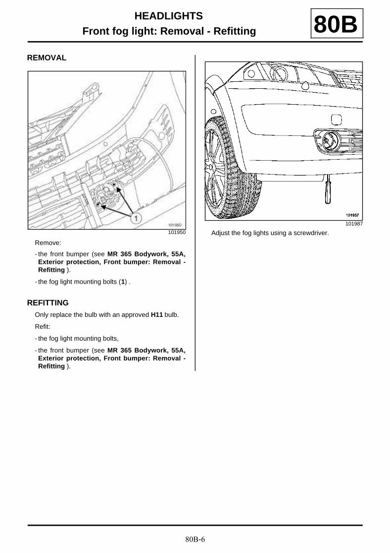
REMOVAL
Remove:
- the front bumper (see MR 365 Bodywork, 55A,Exterior protection, Front bumper: Removal -Refitting ).
- the fog light mounting bolts (1) .
REFITTINGOnly replace the bulb with an approved H11 bulb.
Refit:
- the fog light mounting bolts,
- the front bumper (see MR 365 Bodywork, 55A,Exterior protection, Front bumper: Removal -Refitting ).
Adjust the fog lights using a screwdriver.101950
101987
80B-7
HEADLIGHTSRemote headlight adjustment control: Removal - Refitting 80B
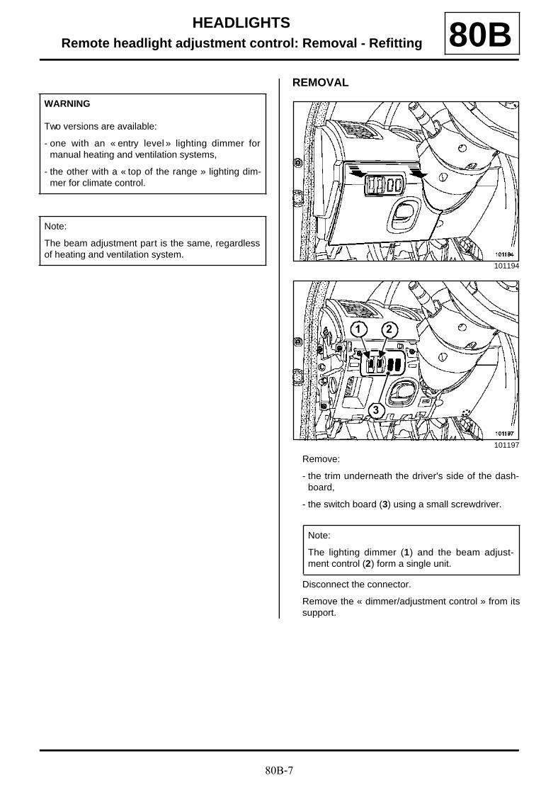
REMOVAL
Remove:
- the trim underneath the driver's side of the dash-board,
- the switch board (3) using a small screwdriver.
Disconnect the connector.
Remove the « dimmer/adjustment control » from itssupport.
WARNING
Two versions are available:
- one with an « entry level » lighting dimmer formanual heating and ventilation systems,
- the other with a « top of the range » lighting dim-mer for climate control.
Note:
The beam adjustment part is the same, regardlessof heating and ventilation system.
101194
101197
Note:
The lighting dimmer (1) and the beam adjust-ment control (2) form a single unit.
1 2
3
80B-8
HEADLIGHTSRemote headlight adjustment motor: Removal - Refitting 80B
It is necessary to remove the lens unit to remove thebeam adjustment actuator.
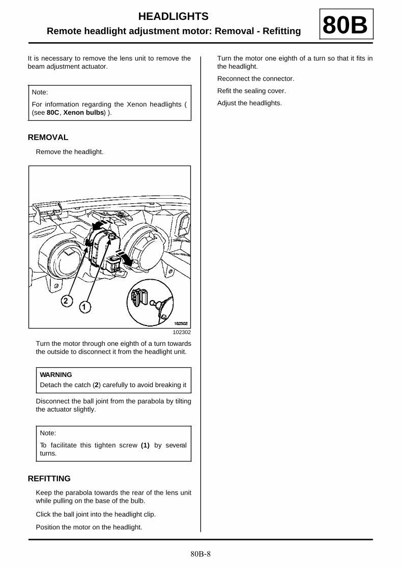
REMOVAL
Remove the headlight.
Turn the motor through one eighth of a turn towardsthe outside to disconnect it from the headlight unit.
Disconnect the ball joint from the parabola by tiltingthe actuator slightly.
REFITTING
Keep the parabola towards the rear of the lens unitwhile pulling on the base of the bulb.
Click the ball joint into the headlight clip.
Position the motor on the headlight.
Turn the motor one eighth of a turn so that it fits inthe headlight.
Reconnect the connector.
Refit the sealing cover.
Adjust the headlights.
Note:
For information regarding the Xenon headlights ((see 80C, Xenon bulbs) ).
102302
WARNING
Detach the catch (2) carefully to avoid breaking it
Note:
To facilitate this tighten screw (1) by severalturns.
12
80C-1
XENON BULBSXenon headlights: Description 80C
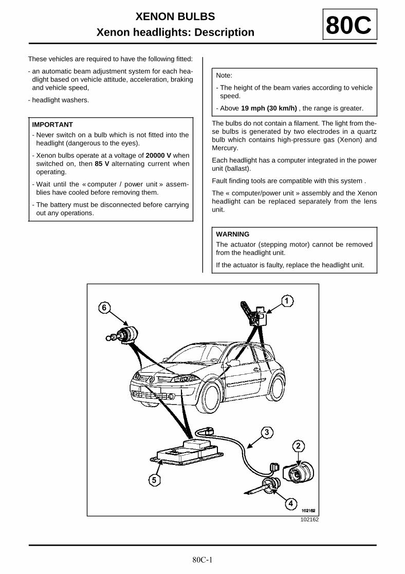
These vehicles are required to have the following fitted:
- an automatic beam adjustment system for each hea-dlight based on vehicle attitude, acceleration, brakingand vehicle speed,
- headlight washers.
The bulbs do not contain a filament. The light from the-se bulbs is generated by two electrodes in a quartzbulb which contains high-pressure gas (Xenon) andMercury.
Each headlight has a computer integrated in the powerunit (ballast).
Fault finding tools are compatible with this system .
The « computer/power unit » assembly and the Xenonheadlight can be replaced separately from the lensunit.
IMPORTANT
- Never switch on a bulb which is not fitted into theheadlight (dangerous to the eyes).
- Xenon bulbs operate at a voltage of 20000 V whenswitched on, then 85 V alternating current whenoperating.
- Wait until the « computer / power unit » assem-blies have cooled before removing them.
- The battery must be disconnected before carryingout any operations.
Note:
- The height of the beam varies according to vehiclespeed.
- Above 19 mph (30 km/h) , the range is greater.
WARNING
The actuator (stepping motor) cannot be removedfrom the headlight unit.
If the actuator is faulty, replace the headlight unit.
102162
6
5
4
3
2
1

80C-2
XENON BULBSXenon headlights: Description 80C
System diagram
(1) Front and rear height sensor
(2) Condenser
(3) High-voltage wiring
(4) Xenon bulb
(5) Computer - output unit
(6) Actuator (stepper motor)
103457
843
1413
2
1
12
1110
9
765
1 Rain and light sensor
2 Lighting stalk
3 UCH
4 Dipped / main beam headlights signal (Protection and Switching Unit)
5 Vehicle speed signal (ABS computer)
6 Front height (front sensor)
7 Rear height (rear sensor)
8 K diagnostic line
9 Computer + output unit (left-hand headlight)
10 Bulb

80C-3
XENON BULBSXenon headlights: Description 80C
11 Left-hand height adjustment actuator
12 Computer + output unit (right-hand headlight)
13 Right-hand height adjustment actuator
14 Bulb
80C-4
XENON BULBSXenon headlight: Removal - Refitting 80C
REMOVING - REFITTING
The procedure for removing and refitting headlightsfitted with xenon bulbs is identical to the procedurefor halogen headlights (see 8 0 B, Headlights,Halogen headlight: Removal - Refitting, page80B-2) .
Adjust the headlight beam (see 80C, Xenon bulbs,Xenon headlights: Adjustment, page 80C-5) .
IMPORTANT
- To prevent eye injuries, do not look at a xenonbulb when lit (lighting voltage of 20,000 V ).
- Wait until the « computer-power unit » assem-blies have cooled before removing them.
- It is forbidden to switch on a xenon bulb if thebulb is not fitted in the headlight (risk of seriouseye injury).
- Disconnect the battery, starting with the nega-tive terminal.
80C-5
XENON BULBSXenon headlights: Adjustment 80C
(see MR 366 Fault finding, 80C Xenon bulbs, Faultfinding - Configuration and programming ) and (see80C, Xenon bulbs, Xenon headlights: Adjustment,page 80C-5) .
Check that the computer is configured and calibra-ted correctly (see MR 366 Fault finding, 80C Xe-non bulbs, Fault finding - Configuration andprogramming ).
Place the vehicle on a level horizontal surface.
Set the tyres at the recommended pressure for thevehicle chassis model.
Open the bonnet.
Ensure that the luggage compartment is empty.
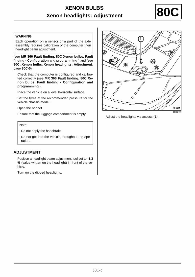
ADJUSTMENT
Position a headlight beam adjustment tool set to -1.3% (value written on the headlight) in front of the ve-hicle.
Turn on the dipped headlights.
Adjust the headlights via access (1) .
WARNING
Each operation on a sensor or a part of the axleassembly requires calibration of the computer thenheadlight beam adjustment.
Note:
- Do not apply the handbrake.
- Do not get into the vehicle throughout the ope-ration.
101239
1
80C-6
XENON BULBSXenon bulb: Replacement 80C
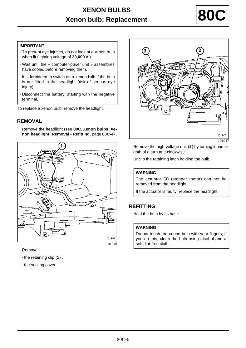
To replace a xenon bulb, remove the headlight.
REMOVAL
Remove the headlight (see 80C, Xenon bulbs, Xe-non headlight: Removal - Refitting, page 80C-4) .
Remove:
- the retaining clip (1) ,
- the sealing cover.
Remove the high-voltage unit (2) by turning it one ei-ghth of a turn anti-clockwise.
Unclip the retaining latch holding the bulb.
REFITTINGHold the bulb by its base.
IMPORTANT
- To prevent eye injuries, do not look at a xenon bulbwhen lit (lighting voltage of 20,000 V ).
- Wait until the « computer-power unit » assemblieshave cooled before removing them.
- It is forbidden to switch on a xenon bulb if the bulbis not fitted in the headlight (risk of serious eyeinjury).
- Disconnect the battery, starting with the negativeterminal.
101945
1101947
WARNING
The actuator (3) (stepper motor) can not beremoved from the headlight.
If the actuator is faulty, replace the headlight.
WARNING
Do not touch the xenon bulb with your fingers; ifyou do this, clean the bulb using alcohol and asoft, lint-free cloth.
23
80C-7
XENON BULBSXenon bulb: Replacement 80C
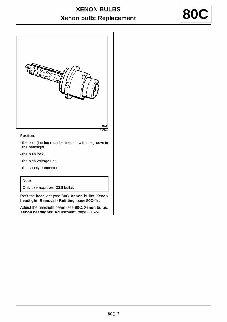
Position:
- the bulb (the lug must be lined up with the groove inthe headlight),
- the bulb lock,
- the high voltage unit,
- the supply connector.
Refit the headlight (see 80C, Xenon bulbs, Xenonheadlight: Removal - Refitting, page 80C-4) .
Adjust the headlight beam (see 80C, Xenon bulbs,Xenon headlights: Adjustment, page 80C-5) .
12398
Note:
Only use approved D2S bulbs.
80C-8
XENON BULBSXenon bulb computer: Removal - Refitting 80C
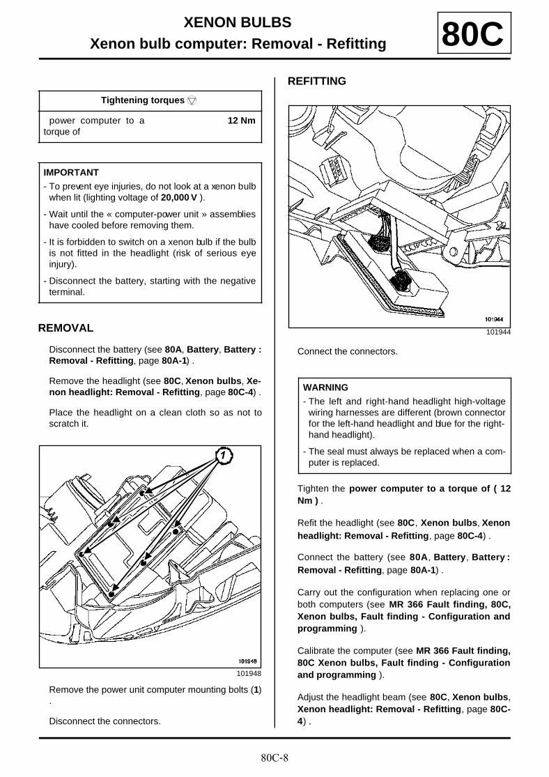
REMOVAL
Disconnect the battery (see 80A, Battery, Battery :Removal - Refitting, page 80A-1) .
Remove the headlight (see 80C, Xenon bulbs, Xe-non headlight: Removal - Refitting, page 80C-4) .
Place the headlight on a clean cloth so as not toscratch it.
Remove the power unit computer mounting bolts (1).
Disconnect the connectors.
REFITTING
Connect the connectors.
Tighten the power computer to a torque of ( 12Nm ) .
Refit the headlight (see 80C, Xenon bulbs, Xenonheadlight: Removal - Refitting, page 80C-4) .
Connect the battery (see 80A, Battery, Battery :Removal - Refitting, page 80A-1) .
Carry out the configuration when replacing one orboth computers (see MR 366 Fault finding, 80C,Xenon bulbs, Fault finding - Configuration andprogramming ).
Calibrate the computer (see MR 366 Fault finding,80C Xenon bulbs, Fault finding - Configurationand programming ).
Adjust the headlight beam (see 80C, Xenon bulbs,Xenon headlight: Removal - Refitting, page 80C-4) .
Tightening torquesm
power computer to atorque of
12 Nm
IMPORTANT
- To prevent eye injuries, do not look at a xenon bulbwhen lit (lighting voltage of 20,000 V ).
- Wait until the « computer-power unit » assemblieshave cooled before removing them.
- It is forbidden to switch on a xenon bulb if the bulbis not fitted in the headlight (risk of serious eyeinjury).
- Disconnect the battery, starting with the negativeterminal.
101948
111
101944
WARNING
- The left and right-hand headlight high-voltagewiring harnesses are different (brown connectorfor the left-hand headlight and blue for the right-hand headlight).
- The seal must always be replaced when a com-puter is replaced.
80C-9
XENON BULBSHeadlight adjustment front sensor: Removal - Refitting 80C
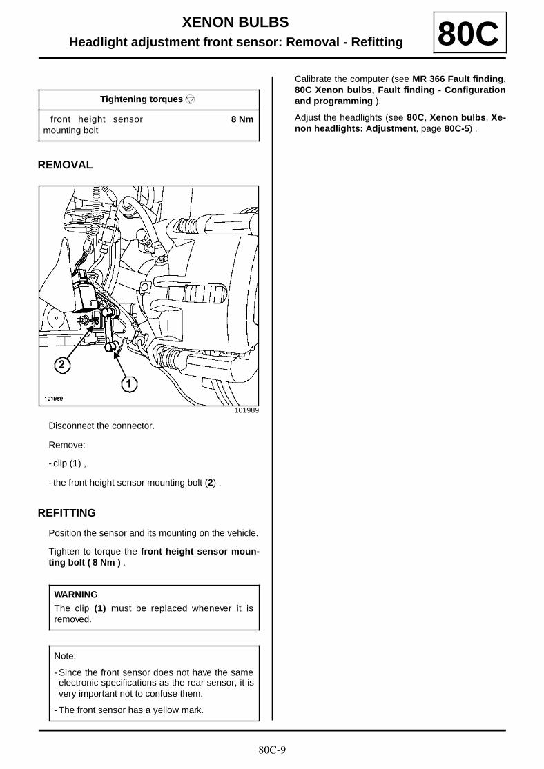
REMOVAL
Disconnect the connector.
Remove:
- clip (1) ,
- the front height sensor mounting bolt (2) .
REFITTING
Position the sensor and its mounting on the vehicle.
Tighten to torque the front height sensor moun-ting bolt ( 8 Nm ) .
Calibrate the computer (see MR 366 Fault finding,80C Xenon bulbs, Fault finding - Configurationand programming ).
Adjust the headlights (see 80C, Xenon bulbs, Xe-non headlights: Adjustment, page 80C-5) .
Tightening torquesm
front height sensormounting bolt
8 Nm
101989
WARNING
The clip (1) must be replaced whenever it isremoved.
Note:
- Since the front sensor does not have the sameelectronic specifications as the rear sensor, it isvery important not to confuse them.
- The front sensor has a yellow mark.
1
2
80C-10
XENON BULBSHeadlight adjustment rear sensor: Removal - Refitting 80C
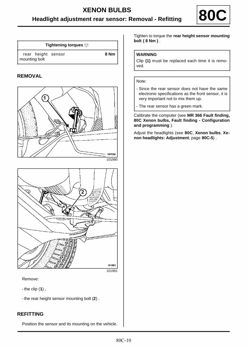
REMOVAL
Remove:
- the clip (1) ,
- the rear height sensor mounting bolt (2) .
REFITTING
Position the sensor and its mounting on the vehicle.
Tighten to torque the rear height sensor mountingbolt ( 8 Nm ) .
Calibrate the computer (see MR 366 Fault finding,80C Xenon bulbs, Fault finding - Configurationand programming ).
Adjust the headlights (see 80C, Xenon bulbs, Xe-non headlights: Adjustment, page 80C-5) .
Tightening torquesm
rear height sensormounting bolt
8 Nm
101990
101991
1
2
WARNING
Clip (1) must be replaced each time it is remo-ved.
Note:
- Since the rear sensor does not have the sameelectronic specifications as the front sensor, it isvery important not to mix them up.
- The rear sensor has a green mark.

81A-1
REAR LIGHTINGThird brake light: Removal - Refitting 81A
REMOVAL
Remove the interior tailgate trim( (see Tailgatelining: Removal - Refitting) following WorkshopRepair Manual 365 - Bodywork .
Unclip the light by pressing on the lugs (1) with a flatscrewdriver.
Unclip the washer jet (2) .
Disconnect the connector (3) .
Remove the third brake light.
REFITTINGTo refit, proceed in the reverse order of removal.
101363
101361
1
2
101362
Note:
The vehicles are fitted with a brake light contai-ning diodes.
3

81A-2
REAR LIGHTINGRear light on wing: Removal - Refitting 81A
REMOVAL
Remove the two nuts (1) .
Unclip the rear light.
Disconnect the rear light connectors.
Unclip the bulb mountings by pressing the tabs (2) toaccess the bulbs.
REFITTING
To refit, proceed in the reverse order to removal.
101240
101242
1
2
81A-3
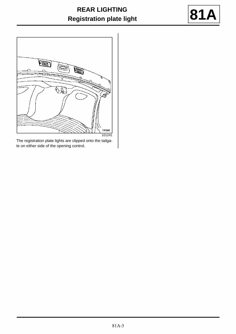
REAR LIGHTINGRegistration plate light 81A
The registration plate lights are clipped onto the tailga-te on either side of the opening control.
101241

81B-1
INTERIOR LIGHTINGOperating principle 81B
I - SPECIAL FEATURES
Vehicles can have:
- independent lights at the bottom of the doors (lit whenthe door or compartment under the floor concerned isopened,
- timed courtesy lights (front and rear);
- lights in the luggage compartment;
- interior lights below each sun visor.
II - TIMER OPERATION
The interior lights are switched on Immediately by the UCH:
- when a door or the tailgate/boot is opened,
- when the doors are unlocked with the remote control(or the hands-free function),
The UCH switches the interior lights off after a delay, as appropriate
- switch off without delay: when the doors or boot arelocked using the remote control (doors and bootclosed)
- switch off with delay:
• after the last door or the boot is closed,
• when the doors or boot are unlocked with the remotecontrol,
• when the ignition is switched on ( « progressive » ).
Note:
The UCH switches off the interior lights afterapproximately 20 minutes .

81B-2
INTERIOR LIGHTINGCourtesy light: General information 81B
Depending on the position of the courtesy light and thevehicle equipment, the lighting may have:
- a single centre light switch,
- a centre light switch and a reading light,
- a central light switch and two reading lights.
81B-3
INTERIOR LIGHTINGCourtesy light 81B
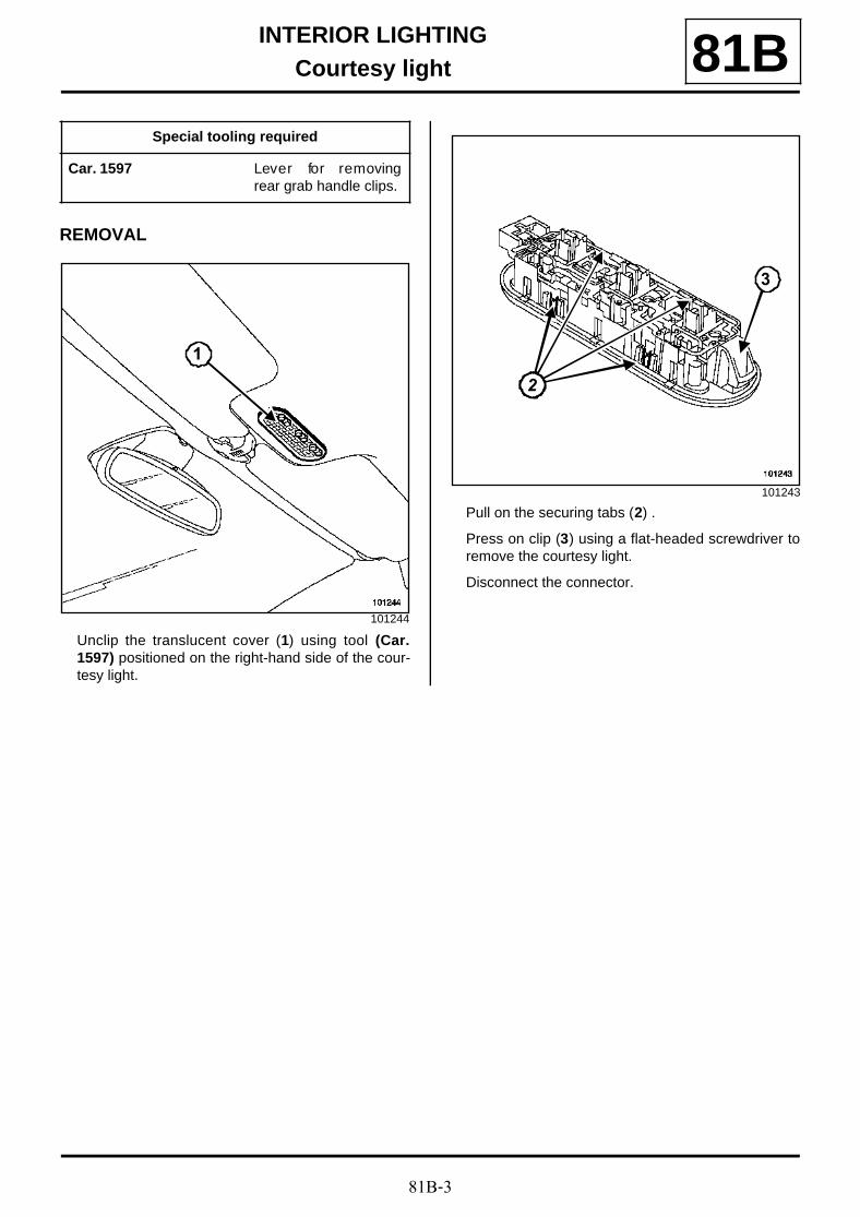
REMOVAL
Unclip the translucent cover (1) using tool (Car.1597) positioned on the right-hand side of the cour-tesy light.
Pull on the securing tabs (2) .
Press on clip (3) using a flat-headed screwdriver toremove the courtesy light.
Disconnect the connector.
Special tooling required
Car. 1597 Lever for removingrear grab handle clips.
101244
1
101243
22
3
81B-4
INTERIOR LIGHTINGCourtesy light: General information 81B
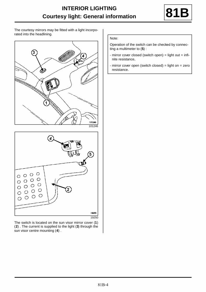
The courtesy mirrors may be fitted with a light incorpo-rated into the headlining.
The switch is located on the sun visor mirror cover (1)(2) . The current is supplied to the light (3) through thesun visor centre mounting (4) .
101246
19250
1
43
5
4
2
Note:
Operation of the switch can be checked by connec-ting a multimeter to (5) :
- mirror cover closed (switch open) = light out = infi-nite resistance,
- mirror cover open (switch closed) = light on = zeroresistance.
81B-5
INTERIOR LIGHTINGVanity light: Removal - Refitting 81B
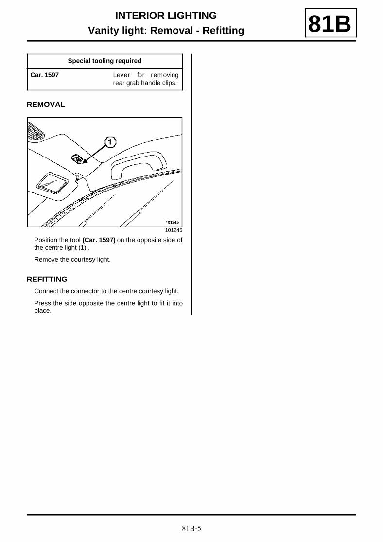
REMOVAL
Position the tool (Car. 1597) on the opposite side ofthe centre light (1) .
Remove the courtesy light.
REFITTINGConnect the connector to the centre courtesy light.
Press the side opposite the centre light to fit it intoplace.
Special tooling required
Car. 1597 Lever for removingrear grab handle clips.
101245
1
81B-6
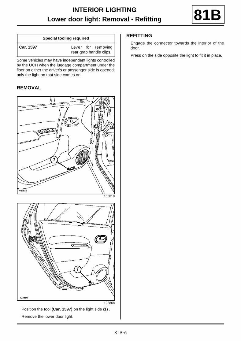
INTERIOR LIGHTINGLower door light: Removal - Refitting 81B
Some vehicles may have independent lights controlledby the UCH when the luggage compartment under thefloor on either the driver's or passenger side is opened;only the light on that side comes on.
REMOVAL
Position the tool (Car. 1597) on the light side (1) .
Remove the lower door light.
REFITTING
Engage the connector towards the interior of thedoor.
Press on the side opposite the light to fit it in place.
Special tooling required
Car. 1597 Lever for removingrear grab handle clips.
103818
103868
1
1
81B-7
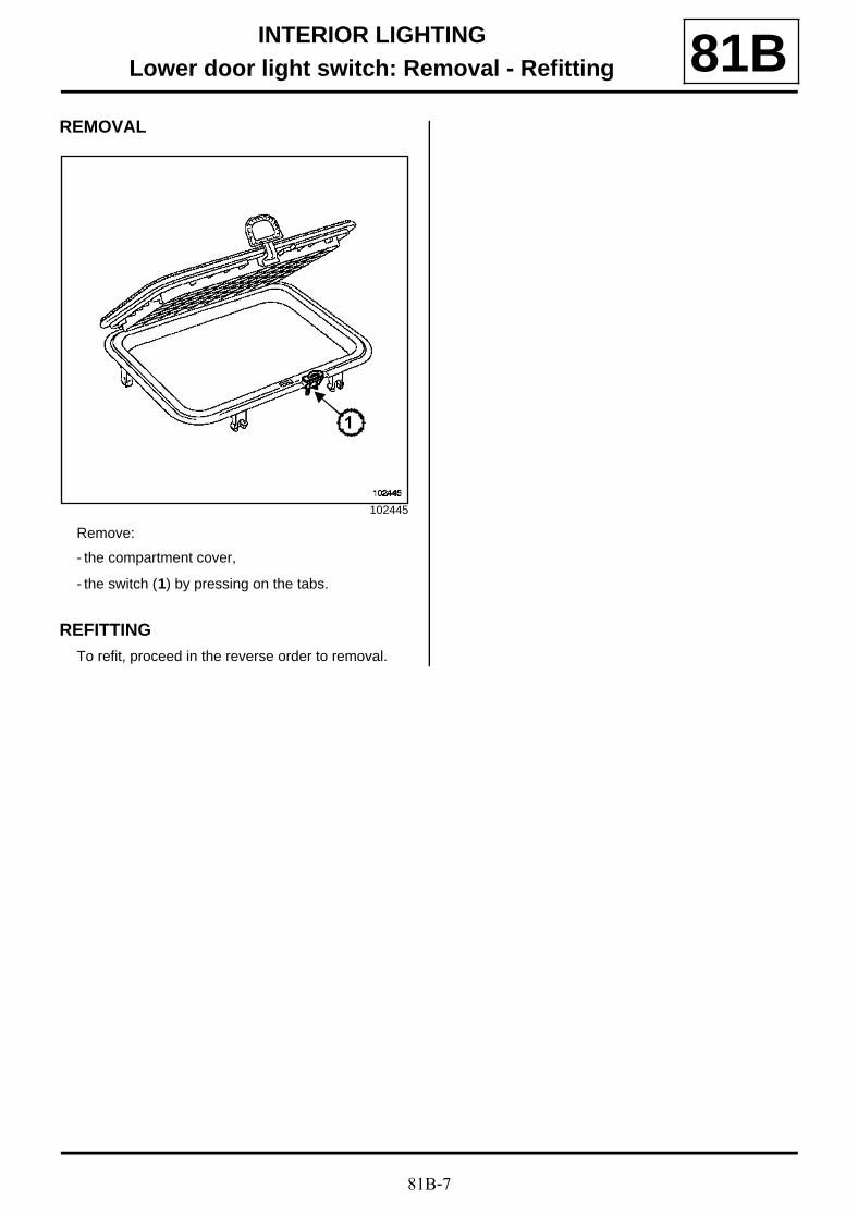
INTERIOR LIGHTINGLower door light switch: Removal - Refitting 81B
REMOVAL
Remove:
- the compartment cover,
- the switch (1) by pressing on the tabs.
REFITTINGTo refit, proceed in the reverse order to removal.
102445
1

81C-1
FUSESPassenger compartment fuse and relay box: Identification 81C
This fuse box is located in the passenger compartmenton the left-hand side.
The unit is located behind the flap (1) .
The unit is located behind the flap (2) .
Relay
DG
101194
DD
102319
1
2
102294
K
T
J
S
I
E
H
D
G
O
C
F
WN
V
B
M
A
L
U
Key Nominal current Description
(A) 30 A Electric window relay
(B) 40 A Accessories relay
81C-2
FUSESPassenger compartment fuse and relay box: Identification 81C
Fuses
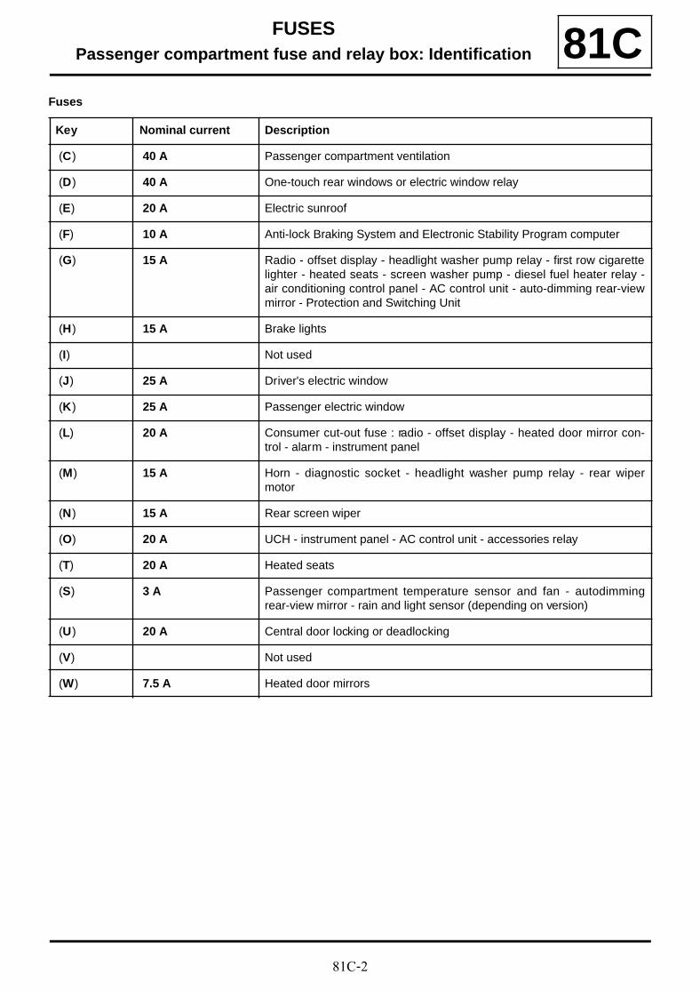
Key Nominal current Description
(C) 40 A Passenger compartment ventilation
(D) 40 A One-touch rear windows or electric window relay
(E) 20 A Electric sunroof
(F) 10 A Anti-lock Braking System and Electronic Stability Program computer
(G) 15 A Radio - offset display - headlight washer pump relay - first row cigarettelighter - heated seats - screen washer pump - diesel fuel heater relay -air conditioning control panel - AC control unit - auto-dimming rear-viewmirror - Protection and Switching Unit
(H) 15 A Brake lights
(I) Not used
(J) 25 A Driver's electric window
(K) 25 A Passenger electric window
(L) 20 A Consumer cut-out fuse : radio - offset display - heated door mirror con-trol - alarm - instrument panel
(M) 15 A Horn - diagnostic socket - headlight washer pump relay - rear wipermotor
(N) 15 A Rear screen wiper
(O) 20 A UCH - instrument panel - AC control unit - accessories relay
(T) 20 A Heated seats
(S) 3 A Passenger compartment temperature sensor and fan - autodimmingrear-view mirror - rain and light sensor (depending on version)
(U) 20 A Central door locking or deadlocking
(V) Not used
(W) 7.5 A Heated door mirrors
81C-3
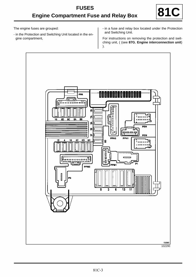
FUSESEngine Compartment Fuse and Relay Box 81C
The engine fuses are grouped:
- in the Protection and Switching Unit located in the en-gine compartment,
- in a fuse and relay box located under the Protectionand Switching Unit.
For instructions on removing the protection and swit-ching unit, ( (see 87G, Engine interconnection unit)).
102290
81C-4
FUSESEngine Compartment Fuse and Relay Box 81C
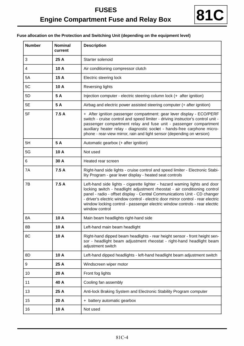
Fuse allocation on the Protection and Switching Unit (depending on the equipment level)
Number Nominalcurrent
Description
3 25 A Starter solenoid
4 10 A Air conditioning compressor clutch
5A 15 A Electric steering lock
5C 10 A Reversing lights
5D 5 A Injection computer - electric steering column lock (+ after ignition)
5E 5 A Airbag and electric power assisted steering computer (+ after ignition)
5F 7.5 A + After ignition passenger compartment: gear lever display - ECO/PERFswitch - cruise control and speed limiter - driving instructor's control unit -passenger compartment relay and fuse unit - passenger compartmentauxiliary heater relay - diagnostic socket - hands-free carphone micro-phone - rear-view mirror, rain and light sensor (depending on version)
5H 5 A Automatic gearbox (+ after ignition)
5G 10 A Not used
6 30 A Heated rear screen
7A 7.5 A Right-hand side lights - cruise control and speed limiter - Electronic Stabi-lity Program - gear lever display - heated seat controls
7B 7.5 A Left-hand side lights - cigarette lighter - hazard warning lights and doorlocking switch - headlight adjustment rheostat - air conditioning controlpanel - radio - offset display - Central Communications Unit - CD changer- driver's electric window control - electric door mirror control - rear electricwindow locking control - passenger electric window controls - rear electricwindow control
8A 10 A Main beam headlights right-hand side
8B 10 A Left-hand main beam headlight
8C 10 A Right-hand dipped beam headlights - rear height sensor - front height sen-sor - headlight beam adjustment rheostat - right-hand headlight beamadjustment switch
8D 10 A Left-hand dipped headlights - left-hand headlight beam adjustment switch
9 25 A Windscreen wiper motor
10 20 A Front fog lights
11 40 A Cooling fan assembly
13 25 A Anti-lock Braking System and Electronic Stability Program computer
15 20 A + battery automatic gearbox
16 10 A Not used
81C-5
FUSESEngine Compartment Fuse and Relay Box 81C
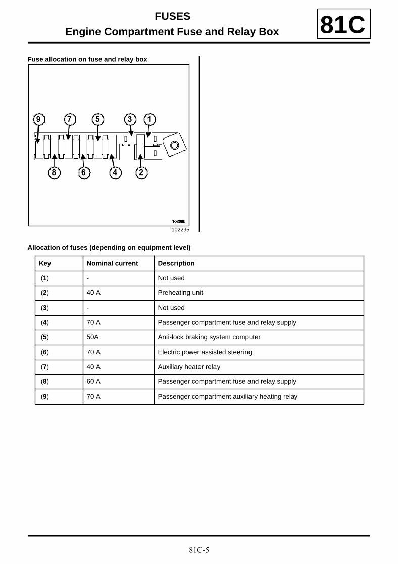
Fuse allocation on fuse and relay box
Allocation of fuses (depending on equipment level)
102295
1
2
3
4
5
6
7
8
9
Key Nominal current Description
(1) - Not used
(2) 40 A Preheating unit
(3) - Not used
(4) 70 A Passenger compartment fuse and relay supply
(5) 50A Anti-lock braking system computer
(6) 70 A Electric power assisted steering
(7) 40 A Auxiliary heater relay
(8) 60 A Passenger compartment fuse and relay supply
(9) 70 A Passenger compartment auxiliary heating relay
81C-6
FUSESEngine Compartment Fuse and Relay Box 81C
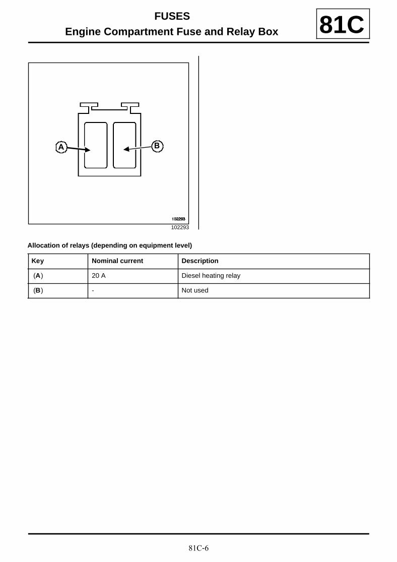
Allocation of relays (depending on equipment level)
102293
A B
Key Nominal current Description
(A) 20 A Diesel heating relay
(B) - Not used
81C-7
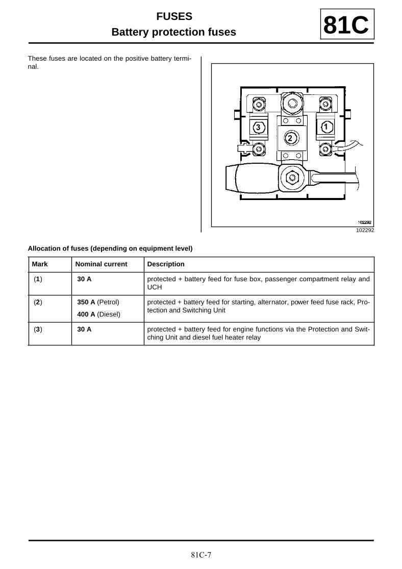
FUSESBattery protection fuses 81C
These fuses are located on the positive battery termi-nal.
Allocation of fuses (depending on equipment level)
102292
1
23
Mark Nominal current Description
(1) 30 A protected + battery feed for fuse box, passenger compartment relay andUCH
(2) 350 A (Petrol)
400 A (Diesel)
protected + battery feed for starting, alternator, power feed fuse rack, Pro-tection and Switching Unit
(3) 30 A protected + battery feed for engine functions via the Protection and Swit-ching Unit and diesel fuel heater relay
82A-1
ENGINE IMMOBILISERImmobiliser system: List and location of components 82A
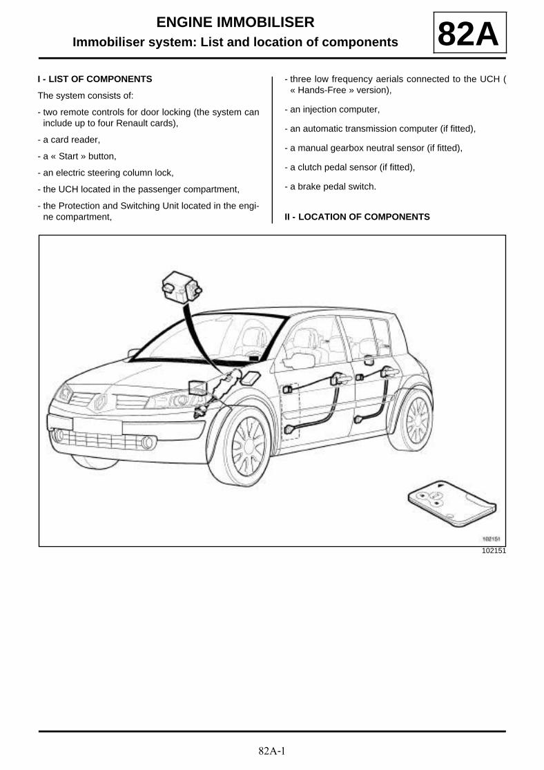
I - LIST OF COMPONENTS
The system consists of:
- two remote controls for door locking (the system caninclude up to four Renault cards),
- a card reader,
- a « Start » button,
- an electric steering column lock,
- the UCH located in the passenger compartment,
- the Protection and Switching Unit located in the engi-ne compartment,
- three low frequency aerials connected to the UCH (« Hands-Free » version),
- an injection computer,
- an automatic transmission computer (if fitted),
- a manual gearbox neutral sensor (if fitted),
- a clutch pedal sensor (if fitted),
- a brake pedal switch.
II - LOCATION OF COMPONENTS
102151
82A-2
ENGINE IMMOBILISERStarting aerial: Removal - Refitting 82A
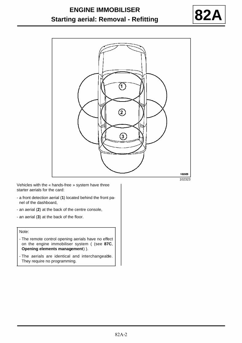
Vehicles with the « hands-free » system have three starter aerials for the card:
- a front detection aerial (1) located behind the front pa-nel of the dashboard,
- an aerial (2) at the back of the centre console,
- an aerial (3) at the back of the floor.
102323
3
2
1
Note:
- The remote control opening aerials have no effecton the engine immobiliser system ( (see 87C,Opening elements management) ).
- The aerials are identical and interchangeable.They require no programming.
82A-3
ENGINE IMMOBILISERStarting aerial: Removal - Refitting 82A
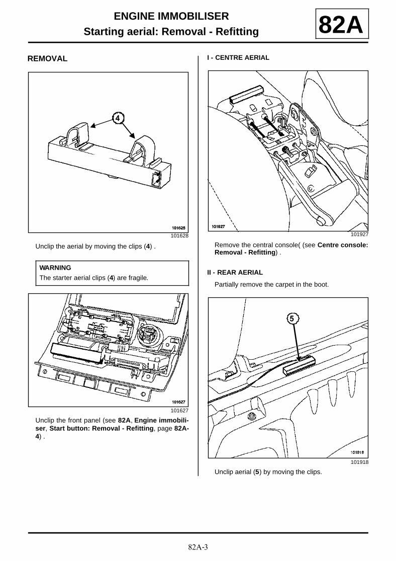
REMOVAL
Unclip the aerial by moving the clips (4) .
Unclip the front panel (see 82A, Engine immobili-ser, Start button: Removal - Refitting, page 82A-4) .
I - CENTRE AERIAL
Remove the central console( (see Centre console:Removal - Refitting) .
II - REAR AERIAL
Partially remove the carpet in the boot.
Unclip aerial (5) by moving the clips.
101628
WARNING
The starter aerial clips (4) are fragile.
101627
4
101927
101918
5
82A-4
ENGINE IMMOBILISERStart button: Removal - Refitting 82A
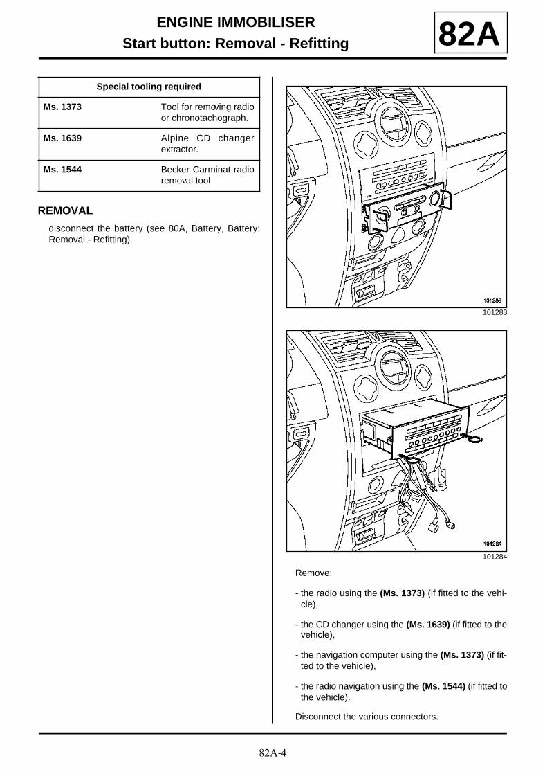
REMOVAL
disconnect the battery (see 80A, Battery, Battery:Removal - Refitting).
Remove:
- the radio using the (Ms. 1373) (if fitted to the vehi-cle),
- the CD changer using the (Ms. 1639) (if fitted to thevehicle),
- the navigation computer using the (Ms. 1373) (if fit-ted to the vehicle),
- the radio navigation using the (Ms. 1544) (if fitted tothe vehicle).
Disconnect the various connectors.
Special tooling required
Ms. 1373 Tool for removing radioor chronotachograph.
Ms. 1639 Alpine CD changerextractor.
Ms. 1544 Becker Carminat radioremoval tool
101283
101284
82A-5
ENGINE IMMOBILISERStart button: Removal - Refitting 82A
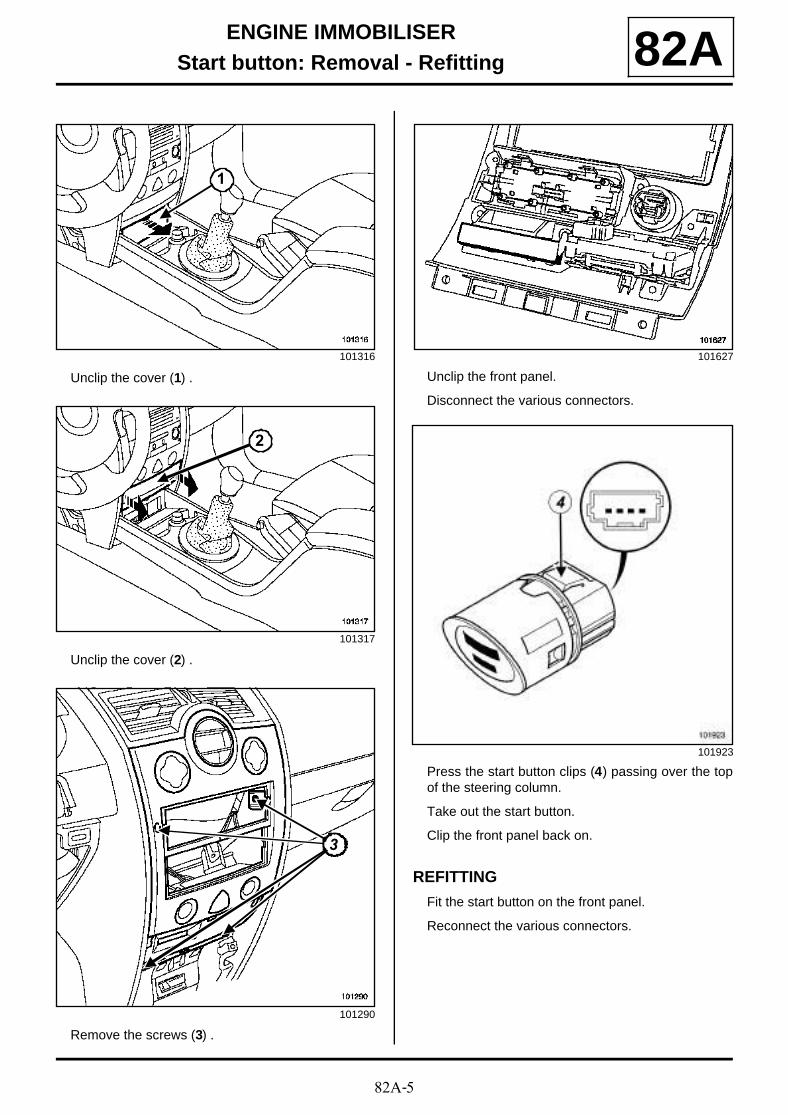
Unclip the cover (1) .
Unclip the cover (2) .
Remove the screws (3) .
Unclip the front panel.
Disconnect the various connectors.
Press the start button clips (4) passing over the topof the steering column.
Take out the start button.
Clip the front panel back on.
REFITTING
Fit the start button on the front panel.
Reconnect the various connectors.
101316
101317
101290
1
2
33
101627
101923
82A-6
ENGINE IMMOBILISERStart button: Removal - Refitting 82A
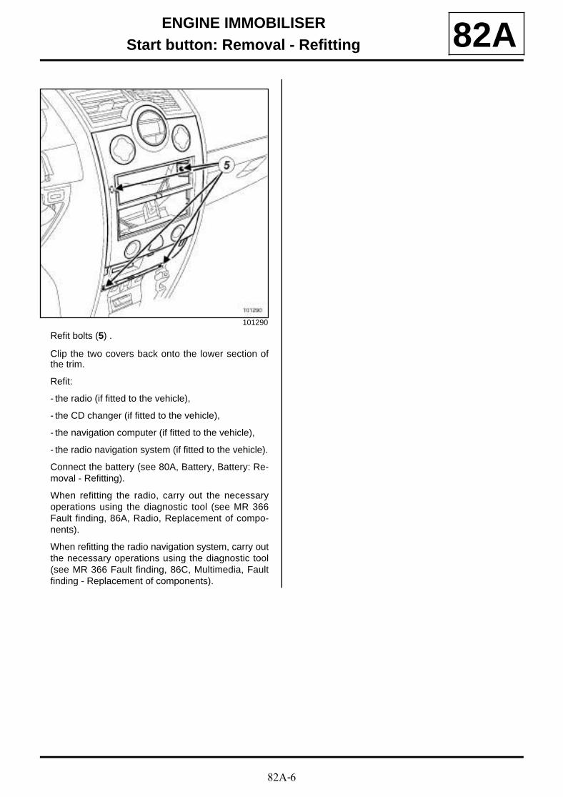
Refit bolts (5) .
Clip the two covers back onto the lower section ofthe trim.
Refit:
- the radio (if fitted to the vehicle),
- the CD changer (if fitted to the vehicle),
- the navigation computer (if fitted to the vehicle),
- the radio navigation system (if fitted to the vehicle).
Connect the battery (see 80A, Battery, Battery: Re-moval - Refitting).
When refitting the radio, carry out the necessaryoperations using the diagnostic tool (see MR 366Fault finding, 86A, Radio, Replacement of compo-nents).
When refitting the radio navigation system, carry outthe necessary operations using the diagnostic tool(see MR 366 Fault finding, 86C, Multimedia, Faultfinding - Replacement of components).
101290
82A-7
ENGINE IMMOBILISERSteering column electric lock: Removal - Refitting 82A
The electric steering column lock is mounted on thesteering column.
REMOVAL
Lock the airbag computer using the diagnostic toolto unlock the steering column lock (see MR 366Fault finding, 88C, Airbag and pretensioners,Fault finding - Replacement of components ).
Shift the steering column to its highest position.
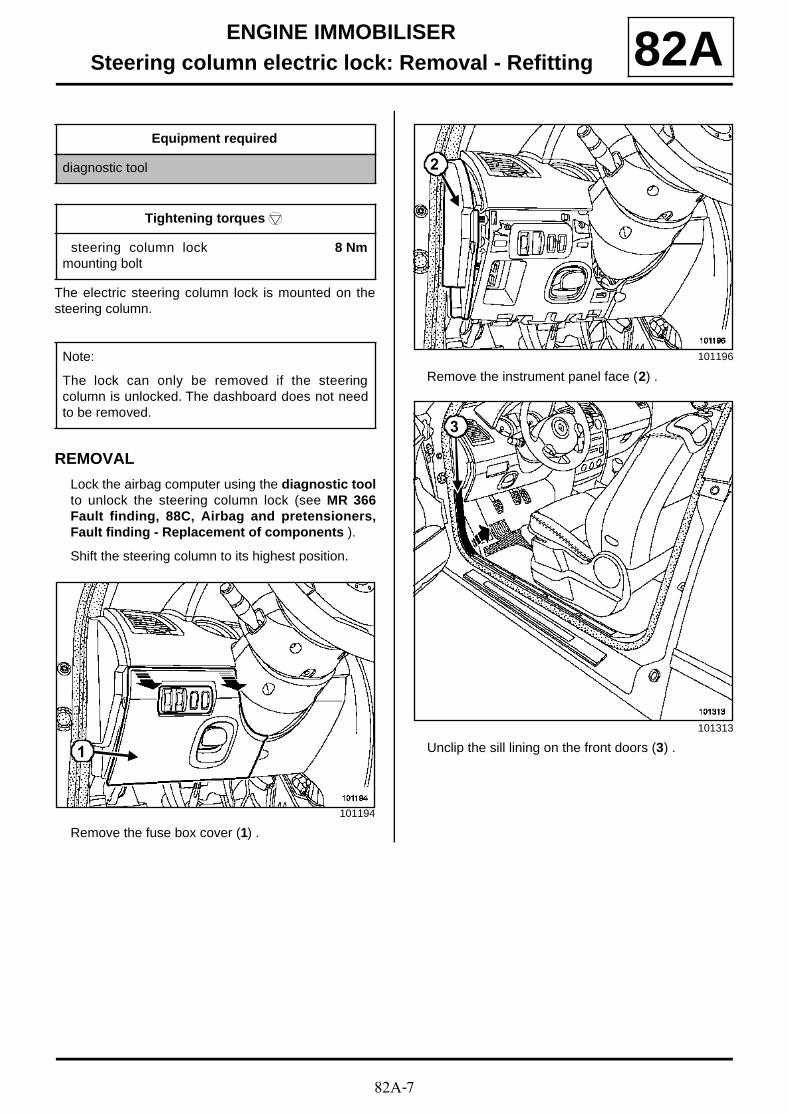
Remove the fuse box cover (1) .
Remove the instrument panel face (2) .
Unclip the sill lining on the front doors (3) .
Equipment required
diagnostic tool
Tightening torquesm
steering column lockmounting bolt
8 Nm
Note:
The lock can only be removed if the steeringcolumn is unlocked. The dashboard does not needto be removed.
101194
1
101196
101313
2
3
82A-8
ENGINE IMMOBILISERSteering column electric lock: Removal - Refitting 82A
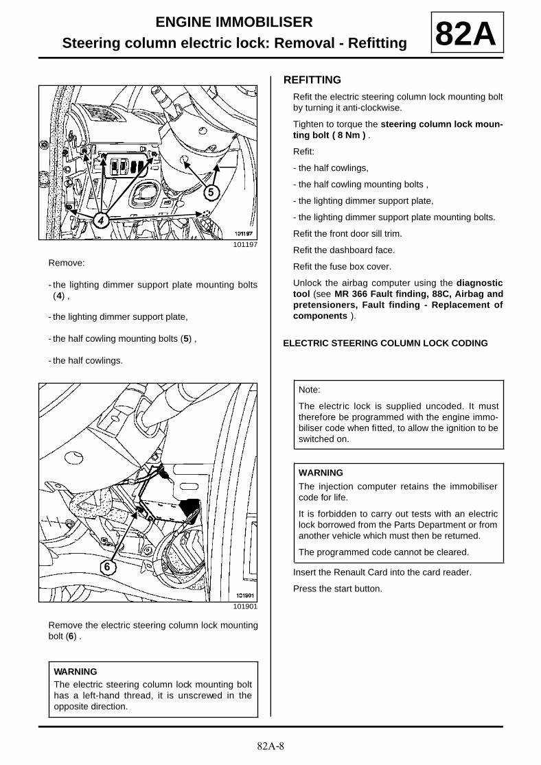
Remove:
- the lighting dimmer support plate mounting bolts(4) ,
- the lighting dimmer support plate,
- the half cowling mounting bolts (5) ,
- the half cowlings.
Remove the electric steering column lock mountingbolt (6) .
REFITTING
Refit the electric steering column lock mounting boltby turning it anti-clockwise.
Tighten to torque the steering column lock moun-ting bolt ( 8 Nm ) .
Refit:
- the half cowlings,
- the half cowling mounting bolts ,
- the lighting dimmer support plate,
- the lighting dimmer support plate mounting bolts.
Refit the front door sill trim.
Refit the dashboard face.
Refit the fuse box cover.
Unlock the airbag computer using the diagnostictool (see MR 366 Fault finding, 88C, Airbag andpretensioners, Fault finding - Replacement ofcomponents ).
ELECTRIC STEERING COLUMN LOCK CODING
Insert the Renault Card into the card reader.
Press the start button.
101197
101901
WARNINGThe electric steering column lock mounting bolthas a left-hand thread, it is unscrewed in theopposite direction.
444
5
6
Note:
The electric lock is supplied uncoded. It musttherefore be programmed with the engine immo-biliser code when fitted, to allow the ignition to beswitched on.
WARNING
The injection computer retains the immobilisercode for life.
It is forbidden to carry out tests with an electriclock borrowed from the Parts Department or fromanother vehicle which must then be returned.
The programmed code cannot be cleared.
82A-9
ENGINE IMMOBILISERSteering column electric lock: Removal - Refitting 82A
Remove the Renault card from the card reader toswitch off the ignition.
Note:
- The electric steering column lock locks thesteering column after a few seconds; coding isthen complete.
- The red immobiliser indicator light flashes toindicate that the immobiliser function is active.
82A-10
ENGINE IMMOBILISERImmobiliser system: Programming: 82A
Program the engine immobiliser system (see MR366 Fault finding, 87B, Passenger compartmentconnection unit, Replacement of components ).
82A-11
ENGINE IMMOBILISERCard reader: Removal - Refitting 82A
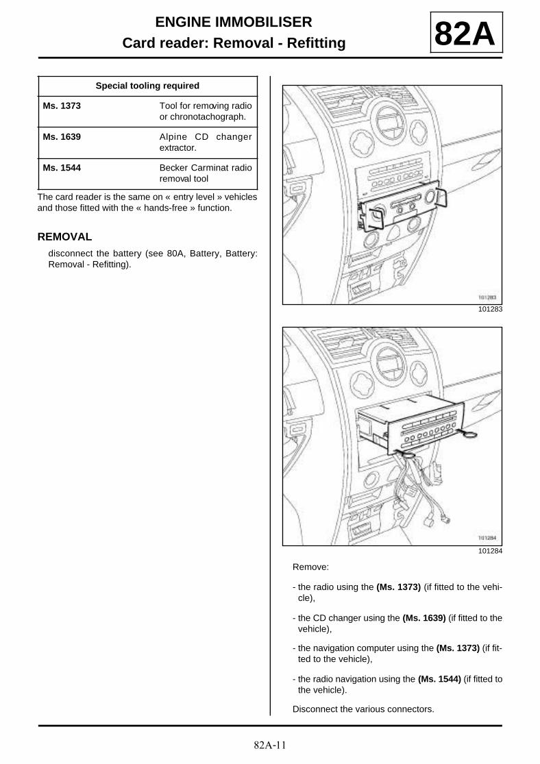
The card reader is the same on « entry level » vehiclesand those fitted with the « hands-free » function.
REMOVALdisconnect the battery (see 80A, Battery, Battery:Removal - Refitting).
Remove:
- the radio using the (Ms. 1373) (if fitted to the vehi-cle),
- the CD changer using the (Ms. 1639) (if fitted to thevehicle),
- the navigation computer using the (Ms. 1373) (if fit-ted to the vehicle),
- the radio navigation using the (Ms. 1544) (if fitted tothe vehicle).
Disconnect the various connectors.
Special tooling required
Ms. 1373 Tool for removing radioor chronotachograph.
Ms. 1639 Alpine CD changerextractor.
Ms. 1544 Becker Carminat radioremoval tool
101283
101284
82A-12
ENGINE IMMOBILISERCard reader: Removal - Refitting 82A
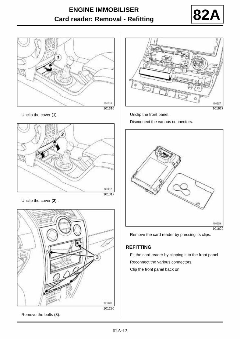
Unclip the cover (1) .
Unclip the cover (2) .
Remove the bolts (3).
Unclip the front panel.
Disconnect the various connectors.
Remove the card reader by pressing its clips.
REFITTING
Fit the card reader by clipping it to the front panel.
Reconnect the various connectors.
Clip the front panel back on.
101316
101317
101290
101627
101629

82A-13
ENGINE IMMOBILISERCard reader: Removal - Refitting 82A
Refit the bolts (5).
Clip the two covers back onto the lower section ofthe trim.
Refit:
- the radio (if fitted to the vehicle),
- the CD changer (if fitted to the vehicle),
- the navigation computer (if fitted to the vehicle),
- the radio navigation system (if fitted to the vehicle).
Connect the battery (see 80A, Battery, Battery: Re-moval - Refitting).
When refitting the radio, carry out the necessaryoperations using the diagnostic tool (see MR 366Fault finding, 86A, Radio, Replacement of compo-nents).
When refitting the radio navigation system, carry outthe necessary operations using the diagnostic tool(see MR 366 Fault finding, 86C, Multimedia, Faultfinding - Replacement of components).
101290
82B-1
HORNHorn 82B
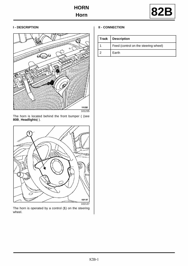
I - DESCRIPTION
The horn is located behind the front bumper ( (see80B, Headlights) ).
The horn is operated by a control (1) on the steeringwheel.
II - CONNECTION
101235
102137
1
Track Description
1 Feed (control on the steering wheel)
2 Earth
82C-1
ALARMPre-equipment 82C
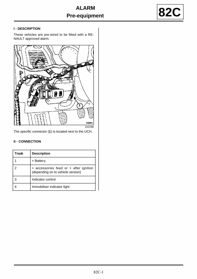
I - DESCRIPTION
These vehicles are pre-wired to be fitted with a RE-NAULT approved alarm.
The specific connector (1) is located next to the UCH.
II - CONNECTION
102296
Track Description
1 + Battery
2 + accessories feed or + after ignition(depending on to vehicle version)
3 Indicator control
4 Immobiliser indicator light
1

83A-1
INSTRUMENT PANELDashboard: Removal - Refitting 83A
REMOVAL
Disconnect the battery, starting with the negativeterminal.
Remove the centre console (see 57A, Interior ac-cessories, Centre console ).
Unclip the mounting clip (1) .
Remove:
- the clip (2) ,
- the sun visor (3) .
Special tooling required
Ms. 1373 Tool for removing radioor chronotachograph.
Ms. 1639 Alpine CD changerextractor.
Car. 1597 Lever for removingrear grab handle clips.
Equipment required
diagnostic tool
Tightening torquesm
airbag module bolts 2 Nm
steering wheel bolt 44 Nm
mounting bolt 2 Nm
battery cover bolts 4 Nm
IMPORTANT
Before carrying out any work on a safety systemcomponent, it is essential to lock the airbag com-puter using the diagnostic tool (see 88C, Air-bags and pretensioners, Airbag computerlocking procedure ). When this function is acti-vated, all the trigger lines are inhibited and theairbag warning light on the instrument panellights up continuously (ignition on).
Locking the airbag computer also unlocks theelectric steering column lock.
IMPORTANT
Handling pyrotechnic systems (airbags or preten-sioners) near to a source of heat or flame is for-bidden: there is a risk of triggering the airbags orpretensioners.
101323
101324
1
2
3
83A-2
INSTRUMENT PANELDashboard: Removal - Refitting 83A
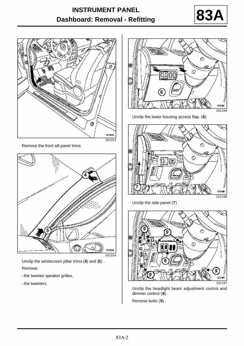
Remove the front sill panel trims.
Unclip the windscreen pillar trims (4) and (5) .
Remove:
- the tweeter speaker grilles,
- the tweeters.
Unclip the lower housing access flap. (6)
Unclip the side panel (7) .
Unclip the headlight beam adjustment control anddimmer control (8) .
Remove bolts (9) .
101313
101314
4
5
101194
101196
101197
6
7
99
99
8
83A-3
INSTRUMENT PANELDashboard: Removal - Refitting 83A
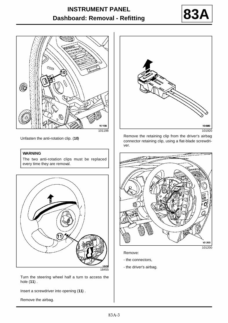
Unfasten the anti-rotation clip. (10)
Turn the steering wheel half a turn to access thehole (11) .
Insert a screwdriver into opening (11) .
Remove the airbag.
Remove the retaining clip from the driver's airbagconnector retaining clip, using a flat-blade screwdri-ver.
Remove:
- the connectors,
- the driver's airbag.
101198
WARNING
The two anti-rotation clips must be replacedevery time they are removal.
18455
10
11
101920
101200
83A-4
INSTRUMENT PANELDashboard: Removal - Refitting 83A
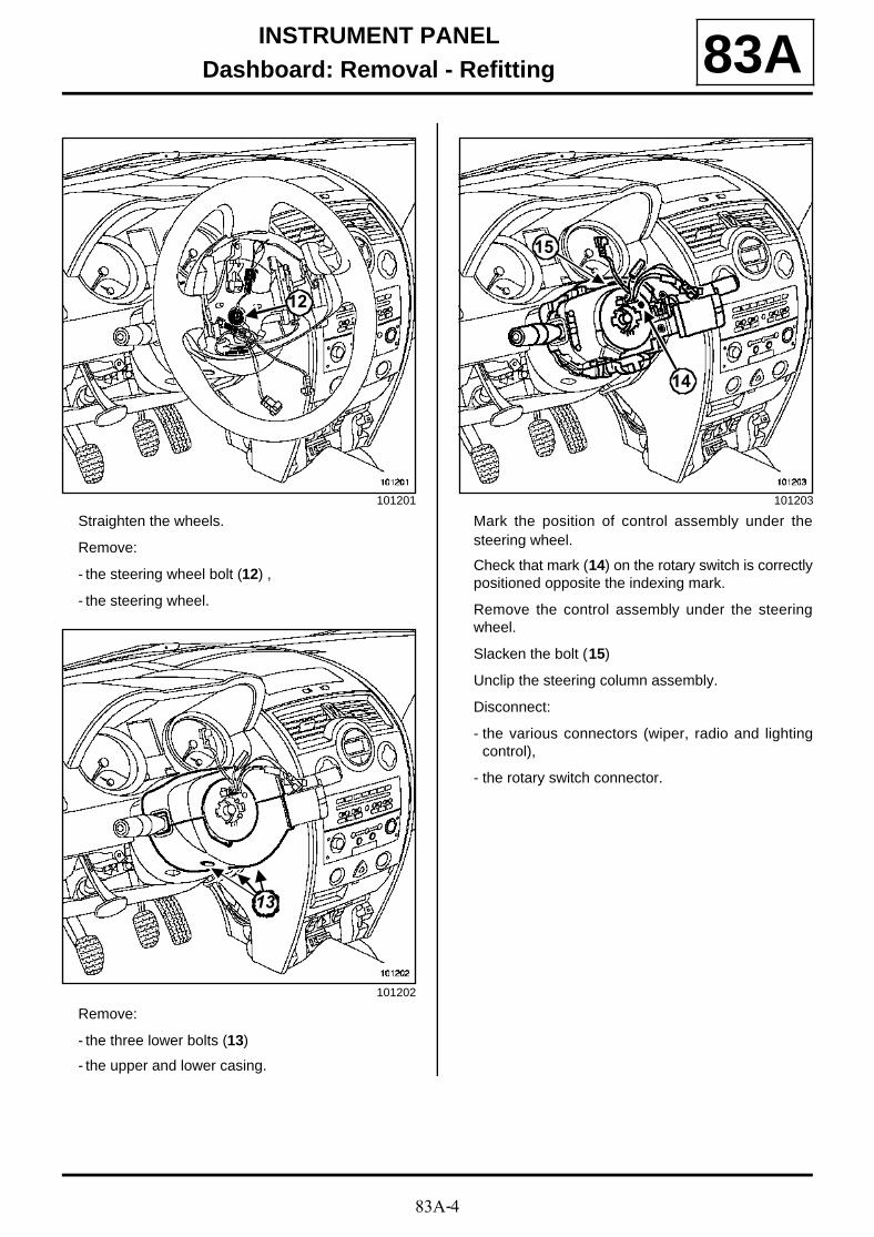
Straighten the wheels.
Remove:
- the steering wheel bolt (12) ,
- the steering wheel.
Remove:
- the three lower bolts (13)
- the upper and lower casing.
Mark the position of control assembly under thesteering wheel.
Check that mark (14) on the rotary switch is correctlypositioned opposite the indexing mark.
Remove the control assembly under the steeringwheel.
Slacken the bolt (15)
Unclip the steering column assembly.
Disconnect:
- the various connectors (wiper, radio and lightingcontrol),
- the rotary switch connector.
101201
101202
12
1313
101203
14
15
83A-5
INSTRUMENT PANELDashboard: Removal - Refitting 83A
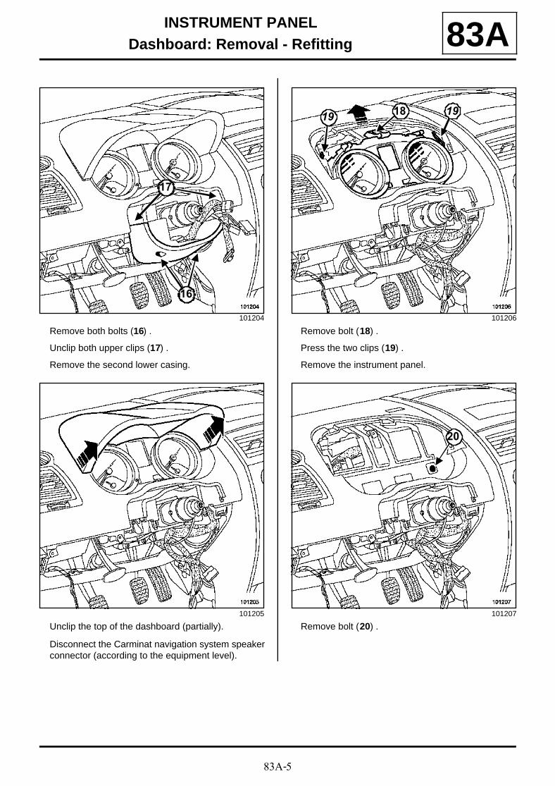
Remove both bolts (16) .
Unclip both upper clips (17) .
Remove the second lower casing.
Unclip the top of the dashboard (partially).
Disconnect the Carminat navigation system speakerconnector (according to the equipment level).
Remove bolt (18) .
Press the two clips (19) .
Remove the instrument panel.
Remove bolt (20) .
101204
101205
16
17
101206
101207
1819 19
20
83A-6
INSTRUMENT PANELDashboard: Removal - Refitting 83A
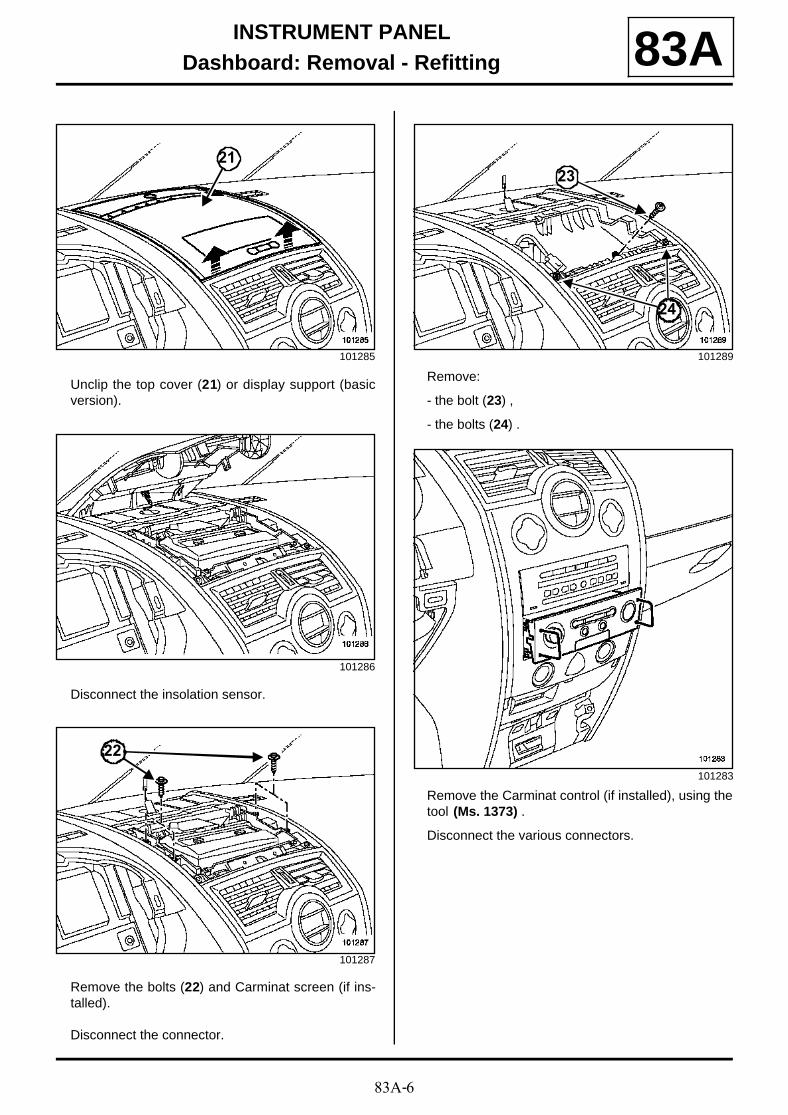
Unclip the top cover (21) or display support (basicversion).
Disconnect the insolation sensor.
Remove the bolts (22) and Carminat screen (if ins-talled).
Disconnect the connector.
Remove:
- the bolt (23) ,
- the bolts (24) .
Remove the Carminat control (if installed), using thetool (Ms. 1373) .
Disconnect the various connectors.
101285
101286
101287
21
22
101289
101283
23
24
83A-7
INSTRUMENT PANELDashboard: Removal - Refitting 83A
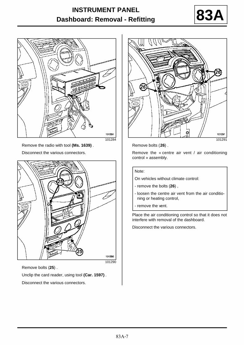
Remove the radio with tool (Ms. 1639) .
Disconnect the various connectors.
Remove bolts (25) .
Unclip the card reader, using tool (Car. 1597) .
Disconnect the various connectors.
Remove bolts (26) .
Remove the « centre air vent / air conditioningcontrol » assembly.
Place the air conditioning control so that it does notinterfere with removal of the dashboard.
Disconnect the various connectors.
101284
101290
25
25
101291
Note:
On vehicles without climate control:
- remove the bolts (26) ,
- loosen the centre air vent from the air conditio-ning or heating control,
- remove the vent.
26
26
83A-8
INSTRUMENT PANELDashboard: Removal - Refitting 83A
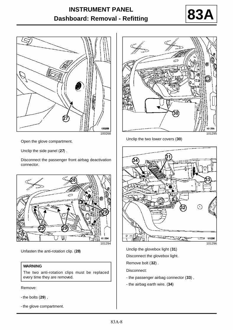
Open the glove compartment.
Unclip the side panel (27) .
Disconnect the passenger front airbag deactivationconnector.
Unfasten the anti-rotation clip. (28)
Remove:
- the bolts (29) ,
- the glove compartment.
Unclip the two lower covers (30)
Unclip the glovebox light (31)
Disconnect the glovebox light.
Remove bolt (32) .
Disconnect:
- the passenger airbag connector (33) ,
- the airbag earth wire. (34)
100268
101294
WARNING
The two anti-rotation clips must be replacedevery time they are removed.
27
28
2929
2929
101295
101296
30
32
31
33
34
83A-9
INSTRUMENT PANELDashboard: Removal - Refitting 83A
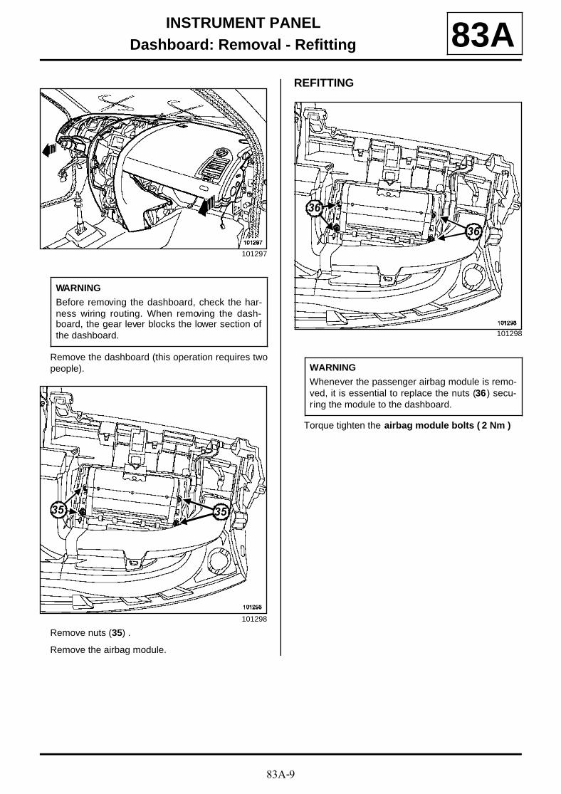
Remove the dashboard (this operation requires twopeople).
Remove nuts (35) .
Remove the airbag module.
REFITTING
Torque tighten the airbag module bolts ( 2 Nm )
101297
WARNING
Before removing the dashboard, check the har-ness wiring routing. When removing the dash-board, the gear lever blocks the lower section ofthe dashboard.
101298
35 35
101298
WARNING
Whenever the passenger airbag module is remo-ved, it is essential to replace the nuts (36) secu-ring the module to the dashboard.
36
36
83A-10
INSTRUMENT PANELDashboard: Removal - Refitting 83A
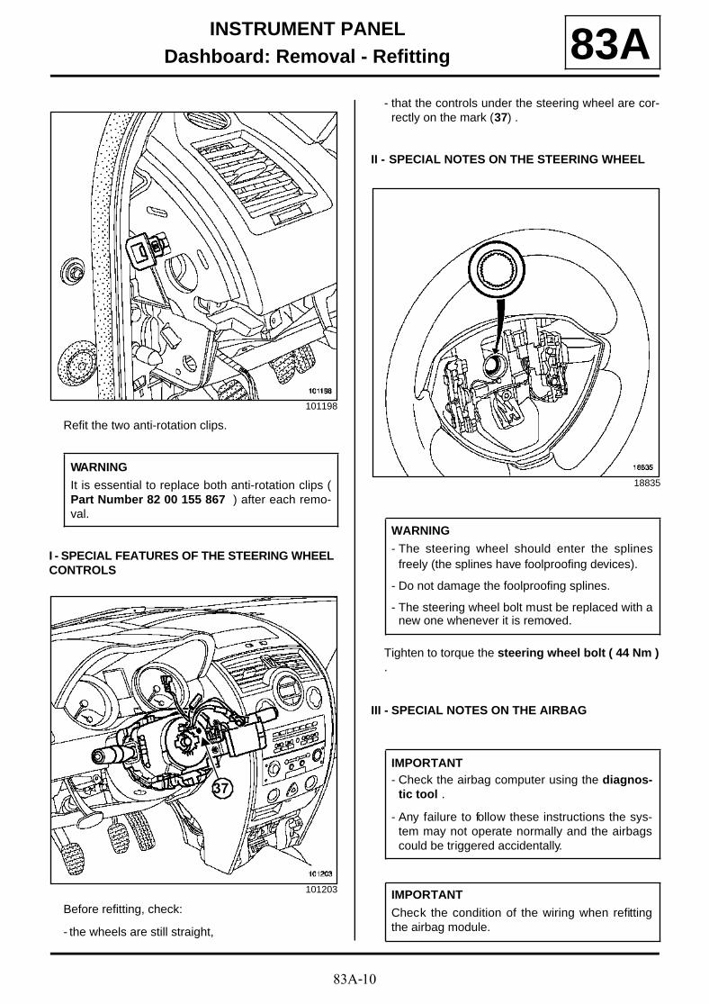
Refit the two anti-rotation clips.
I - SPECIAL FEATURES OF THE STEERING WHEEL CONTROLS
Before refitting, check:
- the wheels are still straight,
- that the controls under the steering wheel are cor-rectly on the mark (37) .
II - SPECIAL NOTES ON THE STEERING WHEEL
Tighten to torque the steering wheel bolt ( 44 Nm ).
III - SPECIAL NOTES ON THE AIRBAG
101198
WARNING
It is essential to replace both anti-rotation clips (Part Number 82 00 155 867 ) after each remo-val.
101203
37
18835
WARNING
- The steering wheel should enter the splinesfreely (the splines have foolproofing devices).
- Do not damage the foolproofing splines.
- The steering wheel bolt must be replaced with anew one whenever it is removed.
IMPORTANT- Check the airbag computer using the diagnos-
tic tool .
- Any failure to follow these instructions the sys-tem may not operate normally and the airbagscould be triggered accidentally.
IMPORTANT
Check the condition of the wiring when refittingthe airbag module.
83A-11
INSTRUMENT PANELDashboard: Removal - Refitting 83A
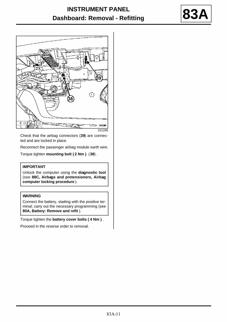
Check that the airbag connectors (39) are connec-ted and are locked in place.
Reconnect the passenger airbag module earth wire.
Torque tighten mounting bolt ( 2 Nm ) (38) .
Torque tighten the battery cover bolts ( 4 Nm ) .
Proceed in the reverse order to removal.
101296
IMPORTANT
Unlock the computer using the diagnostic tool(see 88C, Airbags and pretensioners, Airbagcomputer locking procedure ).
WARNING
Connect the battery, starting with the positive ter-minal; carry out the necessary programming (see80A, Battery: Remove and refit ).
38
39

83A-12
INSTRUMENT PANELInstrument panel: General information 83A
Three types of instrument panel can be found on vehi-cles:
- « entry level » instrument panel,
- « mid-range » instrument panel,
- « top of the range » instrument panel.
(1)Special instrument panel
Entry level Mid-range Top of therange
Multiplex connection(vehicle)
X X X
Multiplex connection(multimedia)
- - X
Fault finding procedure X X X
Self-test procedure X X X
Needle gauge
Vehicle speed X X X
Rev counter X X X
Coolant temperature X X X
Fuel X X X
Display
Total mileage X X X
Trip mileage X X X
Oil level X X X
Door and tailgate status X - -
ADAC Computer X X X
Mileage before oil change X X X
Cruise control or speed limiter setting - X X
Fault message X X X
Additional display
Door location - X X
Tyre pressure monitor - X X
automatic gearbox gear display - X X(1)
Large-screen display
Time - - X
External temperature - - X
Radio display - - X
text messages
Overspeed feature (Saudi Arabia) X X X
LPG data display (not used) X X X
Warning light display X X X
Horn X X X
83A-13
INSTRUMENT PANELInstrument panel: General information 83A
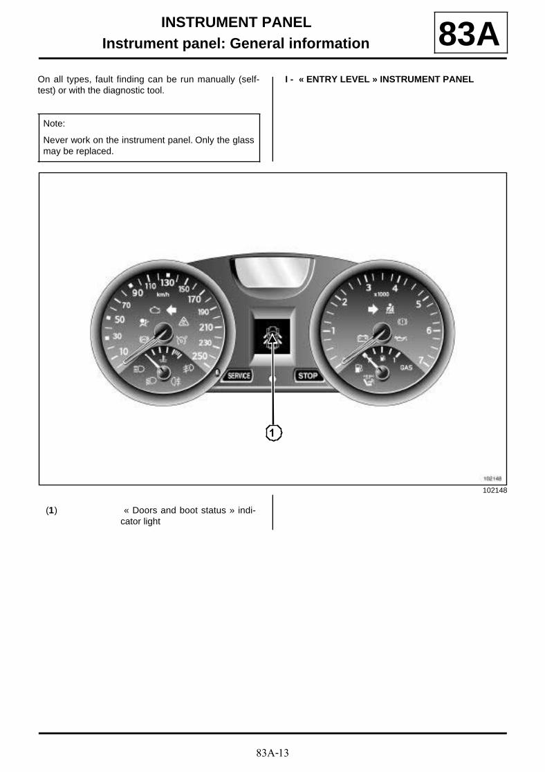
On all types, fault finding can be run manually (self-test) or with the diagnostic tool.
I - « ENTRY LEVEL » INSTRUMENT PANEL
Note:
Never work on the instrument panel. Only the glassmay be replaced.
102148
1
(1) « Doors and boot status » indi-cator light
83A-14
INSTRUMENT PANELInstrument panel: General information 83A
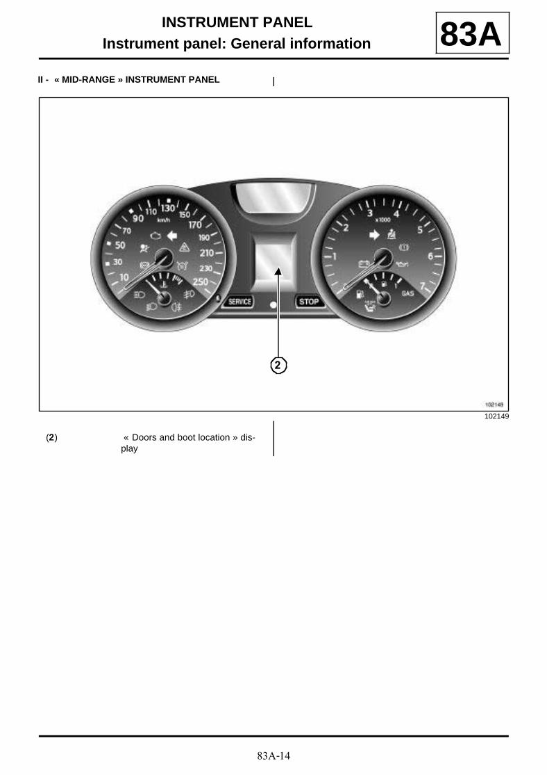
II - « MID-RANGE » INSTRUMENT PANEL
102149
2
(2) « Doors and boot location » dis-play
83A-15
INSTRUMENT PANELInstrument panel: General information 83A
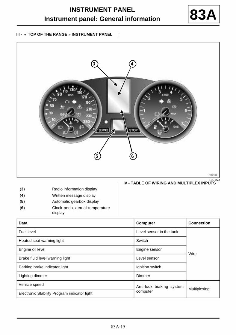
III - « TOP OF THE RANGE » INSTRUMENT PANEL
IV - TABLE OF WIRING AND MULTIPLEX INPUTS102150
3 4
5 6
(3) Radio information display
(4) Written message display
(5) Automatic gearbox display
(6) Clock and external temperaturedisplay
Data Computer Connection
Fuel level Level sensor in the tank
Wire
Heated seat warning light Switch
Engine oil level Engine sensor
Brake fluid level warning light Level sensor
Parking brake indicator light Ignition switch
Lighting dimmer Dimmer
Vehicle speed Anti-lock braking systemcomputer
MultiplexingElectronic Stability Program indicator light

83A-16
INSTRUMENT PANELInstrument panel: General information 83A
* The audible alarm confirms activation of the passen-ger compartment functions.
Engine speed
Injection computer Multiplexing
Coolant temperature
Fuel consumed
Preheating, injection, etc. indicator lights
Cruise control/speed limiter:
Gear engaged Automatic gearbox compu-ter
Multiplexing
Tyre pressure monitor
UCH Multiplexing
Direction indicators and lights
Horn
Engine immobiliser (messages)
Doors (status and location)
« Trip computer and warning system » scroll button
Wiper fault
Engine immobiliser (indicator light) UCH Wire
Engine oil pressure Protection and switchingunit
MultiplexingBattery charge
Seat belt warning lightAirbag computer Multiplexing
Fault and inhibitor warning lights
Radio display
Central CommunicationUnit
Multiplexing(multimedia)
Time
External temperature
Instrument panel alarm Central CommunicationUnit
Wire
Data Computer Connection
83A-17
INSTRUMENT PANELInstrument panel: Description 83A
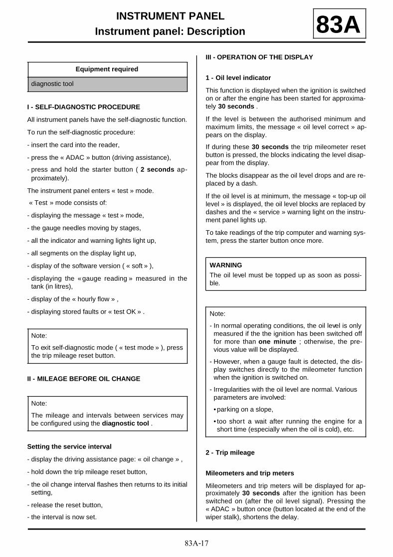
I - SELF-DIAGNOSTIC PROCEDURE
All instrument panels have the self-diagnostic function.
To run the self-diagnostic procedure:
- insert the card into the reader,
- press the « ADAC » button (driving assistance),
- press and hold the starter button ( 2 seconds ap-proximately).
The instrument panel enters « test » mode.
« Test » mode consists of:
- displaying the message « test » mode,
- the gauge needles moving by stages,
- all the indicator and warning lights light up,
- all segments on the display light up,
- display of the software version ( « soft » ),
- displaying the « gauge reading » measured in thetank (in litres),
- display of the « hourly flow » ,
- displaying stored faults or « test OK » .
II - MILEAGE BEFORE OIL CHANGE
Setting the service interval
- display the driving assistance page: « oil change » ,
- hold down the trip mileage reset button,
- the oil change interval flashes then returns to its initialsetting,
- release the reset button,
- the interval is now set.
III - OPERATION OF THE DISPLAY
1 - Oil level indicator
This function is displayed when the ignition is switchedon or after the engine has been started for approxima-tely 30 seconds .
If the level is between the authorised minimum andmaximum limits, the message « oil level correct » ap-pears on the display.
If during these 30 seconds the trip mileometer resetbutton is pressed, the blocks indicating the level disap-pear from the display.
The blocks disappear as the oil level drops and are re-placed by a dash.
If the oil level is at minimum, the message « top-up oillevel » is displayed, the oil level blocks are replaced bydashes and the « service » warning light on the instru-ment panel lights up.
To take readings of the trip computer and warning sys-tem, press the starter button once more.
2 - Trip mileage
Mileometers and trip meters
Mileometers and trip meters will be displayed for ap-proximately 30 seconds after the ignition has beenswitched on (after the oil level signal). Pressing the« ADAC » button once (button located at the end of thewiper stalk), shortens the delay.
Equipment required
diagnostic tool
Note:
To exit self-diagnostic mode ( « test mode » ), pressthe trip mileage reset button.
Note:
The mileage and intervals between services maybe configured using the diagnostic tool .
WARNING
The oil level must be topped up as soon as possi-ble.
Note:
- In normal operating conditions, the oil level is onlymeasured if the the ignition has been switched offfor more than one minute ; otherwise, the pre-vious value will be displayed.
- However, when a gauge fault is detected, the dis-play switches directly to the mileometer functionwhen the ignition is switched on.
- Irregularities with the oil level are normal. Various parameters are involved:
• parking on a slope,
• too short a wait after running the engine for ashort time (especially when the oil is cold), etc.
83A-18
INSTRUMENT PANELInstrument panel: Description 83A
The trip meter can be reset by pressing the « RESET »button once. Resetting the trip meter is different to re-setting the « ADAC » (distance travelled).
IV - TRIP COMPUTER AND WARNING SYSTEM
The various sequences of the trip computer and war-ning system can be displayed instead of the mileage bypressing the « ADAC » button (located at the end ofthe wiper stalk). It is reset by pressing the « RESET »button).
The information from the trip computer is displayed af-ter the trip meter as follows:
- fuel consumption since last reset (in litres or gallons*),
- average consumption (in l/100 km or mpg*) since thelast reset,
- current consumption (in l/100 km),
- estimated range with remaining fuel (in kilometres orin miles*),
- distance travelled since the last reset,
- average speed since the last reset,
- mileage to next oil change informs the driver of thedistance (in km or in miles*) which can be travelledbefore the next oil change,
- cruising speed
* UK version.
Note:
It is not possible to select the display in kilometresor miles. The instrument panel must also be repla-ced if it is replaced.
Note:
- This is only displayed once the vehicle has travel-led approximately 400 m .
- This takes into consideration the distance coveredand the fuel consumption since the last time thereset button was pressed.
Note:
- This is only displayed when the vehicle speed isabove approximately 18 mph (30 km/h) .
- With the accelerator pedal in the no load position,if the speed is above 18 mph (30 km/h) , the cur-rent consumption is equal to « 0 » .
- This function is not available on the UK version.
Note:
- This is only displayed once the vehicle has travel-led approximately 400 m .
- This is the potential distance remaining calculatedby taking into account the distance travelled, theamount of fuel remaining in the tank and the fuelconsumed.
- The remaining range is not displayed if the lowfuel warning light is lit.
Note:
- This is only displayed once the vehicle has travel-led approximately 400 m .
- This is obtained by dividing the distance travelledby the time elapsed since the last time the resetbutton was pressed.
- The time base is generated in the trip computer.
Note:
- If the vehicle is fitted with the « Cruise control /Speed limiter » function, the display shows thesetting in km/h or in mph*.
- Each time the setting is changed or if it cannot berespected, this information replaces the « ADAC »information selected ( (see 83D, Cruise control)).
WARNING
If the trip computer displays flashing dashes, thismeans that the computer has detected a fault (see83A, Instrument panel, Instrument panel: Gene-ral information, page 83A-12) .
83A-19
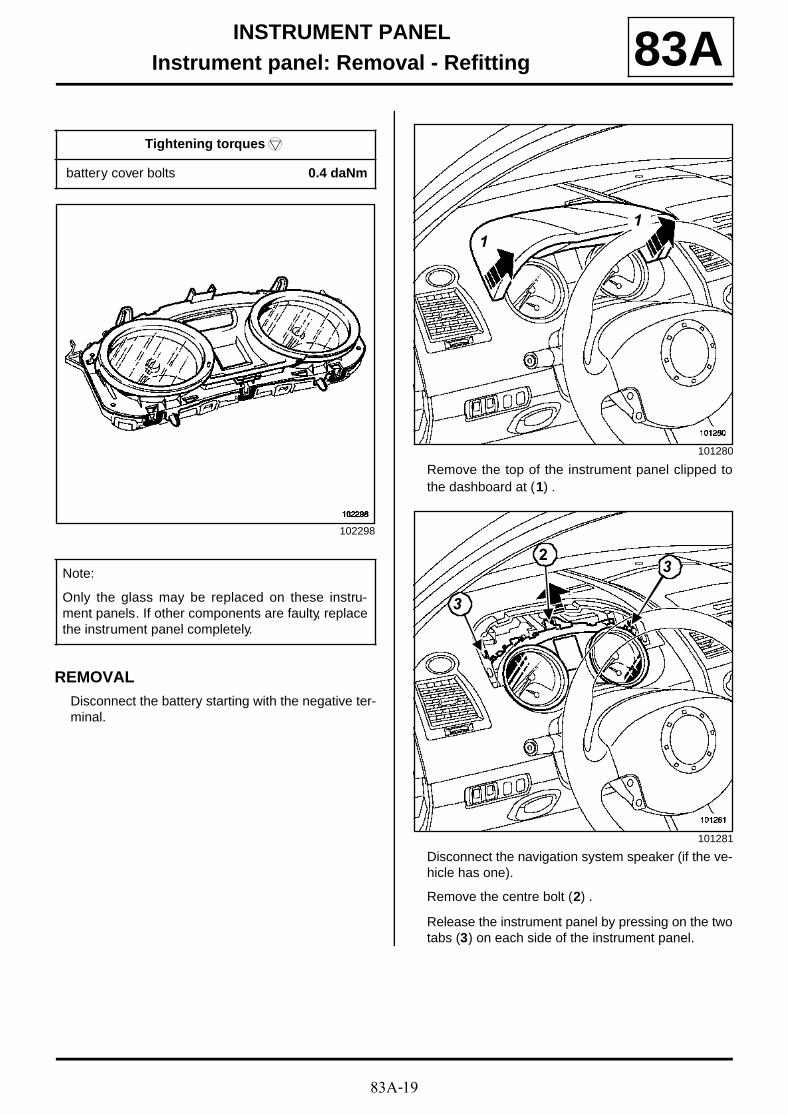
INSTRUMENT PANELInstrument panel: Removal - Refitting 83A
REMOVALDisconnect the battery starting with the negative ter-minal.
Remove the top of the instrument panel clipped tothe dashboard at (1) .
Disconnect the navigation system speaker (if the ve-hicle has one).
Remove the centre bolt (2) .
Release the instrument panel by pressing on the twotabs (3) on each side of the instrument panel.
Tightening torquesm
battery cover bolts 0.4 daNm
102298
Note:
Only the glass may be replaced on these instru-ment panels. If other components are faulty, replacethe instrument panel completely.
101280
101281
11
3
32
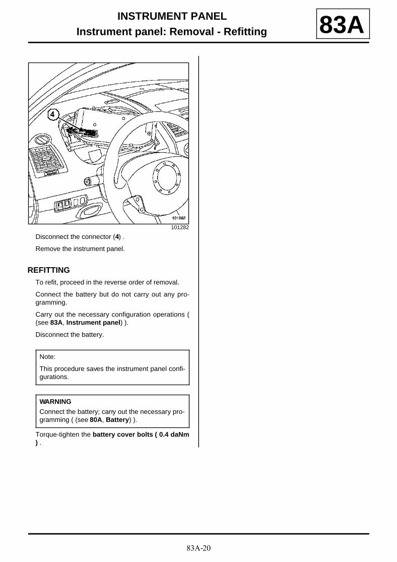
83A-20
INSTRUMENT PANELInstrument panel: Removal - Refitting 83A
Disconnect the connector (4) .
Remove the instrument panel.
REFITTINGTo refit, proceed in the reverse order of removal.
Connect the battery but do not carry out any pro-gramming.
Carry out the necessary configuration operations ((see 83A, Instrument panel) ).
Disconnect the battery.
Torque-tighten the battery cover bolts ( 0.4 daNm) .
101282
Note:
This procedure saves the instrument panel confi-gurations.
WARNING
Connect the battery; carry out the necessary pro-gramming ( (see 80A, Battery) ).
4
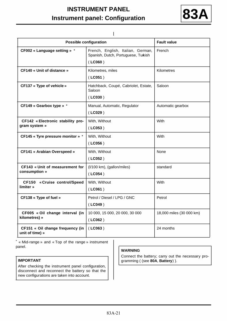
83A-21
INSTRUMENT PANELInstrument panel: Configuration 83A
* « Mid-range » and « Top of the range » instrumentpanel.
Possible configuration Fault value
CF002 « Language setting » * French, English, Italian, German,Spanish, Dutch, Portuguese, Turkish
( LC060 )
French
CF140 « Unit of distance » Kilometres, miles
( LC051 )
Kilometres
CF137 « Type of vehicle » Hatchback, Coupé, Cabriolet, Estate,Saloon
( LC030 )
Saloon
CF149 « Gearbox type » * Manual, Automatic, Regulator
( LC029 )
Automatic gearbox
CF142 « Electronic stability pro-gram system »
With, Without
( LC053 )
With
CF145 « Tyre pressure monitor » * With, Without
( LC056 )
With
CF141 « Arabian Overspeed » With, Without
( LC052 )
None
CF143 « Unit of measurement forconsumption »
(l/100 km), (gallon/miles)
( LC054 )
standard
CF150 « Cruise control/Speedlimiter »
With, Without
( LC061 )
With
CF138 « Type of fuel » Petrol / Diesel / LPG / GNC
( LC049 )
Petrol
CF005 « Oil change interval (inkilometres) »
10 000, 15 000, 20 000, 30 000
( LC062 )
18,000 miles (30 000 km)
CF151 « Oil change frequency (inunit of time) »
( LC063 ) 24 months
IMPORTANT
After checking the instrument panel configuration,disconnect and reconnect the battery so that thenew configurations are taken into account.
WARNING
Connect the battery; carry out the necessary pro-gramming ( (see 80A, Battery) ).
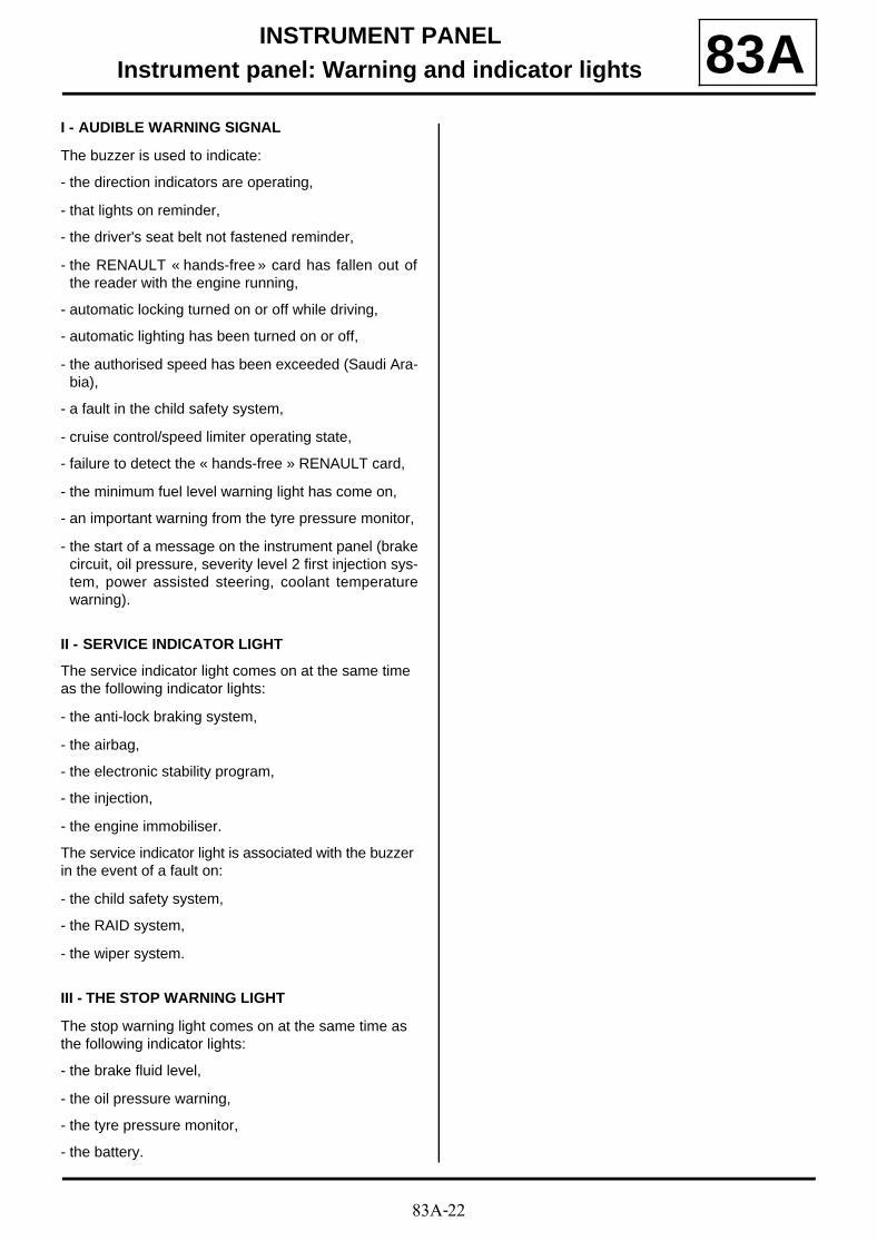
83A-22
INSTRUMENT PANELInstrument panel: Warning and indicator lights 83A
I - AUDIBLE WARNING SIGNAL
The buzzer is used to indicate:
- the direction indicators are operating,
- that lights on reminder,
- the driver's seat belt not fastened reminder,
- the RENAULT « hands-free » card has fallen out ofthe reader with the engine running,
- automatic locking turned on or off while driving,
- automatic lighting has been turned on or off,
- the authorised speed has been exceeded (Saudi Ara-bia),
- a fault in the child safety system,
- cruise control/speed limiter operating state,
- failure to detect the « hands-free » RENAULT card,
- the minimum fuel level warning light has come on,
- an important warning from the tyre pressure monitor,
- the start of a message on the instrument panel (brakecircuit, oil pressure, severity level 2 first injection sys-tem, power assisted steering, coolant temperaturewarning).
II - SERVICE INDICATOR LIGHT
The service indicator light comes on at the same time as the following indicator lights:
- the anti-lock braking system,
- the airbag,
- the electronic stability program,
- the injection,
- the engine immobiliser.
The service indicator light is associated with the buzzer in the event of a fault on:
- the child safety system,
- the RAID system,
- the wiper system.
III - THE STOP WARNING LIGHT
The stop warning light comes on at the same time as the following indicator lights:
- the brake fluid level,
- the oil pressure warning,
- the tyre pressure monitor,
- the battery.
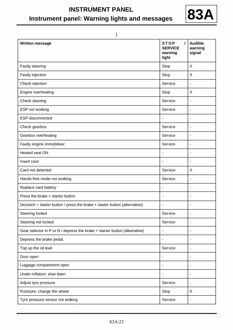
83A-23
INSTRUMENT PANELInstrument panel: Warning lights and messages 83A
Written message S T O P /SERVICEwarninglight
Audiblewarningsignal
Faulty steering Stop X
Faulty injection Stop X
Check injection Service -
Engine overheating Stop X
Check steering Service -
ESP not working Service -
ESP disconnected - -
Check gearbox Service -
Gearbox overheating Service -
Faulty engine immobiliser Service -
Heated seat ON - -
Insert card - -
Card not detected Service X
Hands-free mode not working Service -
Replace card battery - -
Press the brake + starter button - -
Declutch + starter button / press the brake + starter button (alternative) - -
Steering locked Service -
Steering not locked Service -
Gear selector in P or N / depress the brake + starter button (alternative) - -
Depress the brake pedal. - -
Top up the oil level Service -
Door open - -
Luggage compartment open - -
Under-inflation: slow down - -
Adjust tyre pressure Service -
Puncture: change the wheel Stop X
Tyre pressure sensor not working Service -

83A-24
INSTRUMENT PANELInstrument panel: Warning lights and messages 83A
Speed limiter - -
Cruise control - -
XXX km (or miles) in memory - -
Speed limiter out of order Service -
Cruise control not working Service -
Electronic fault Service -
Roof not working (convertible) Service -
Automatic lighting OFF - -
Automatic lighting not working Service -
No message stored - -
Boot open / insert card (depending on equipment) - -
Confirm engine stop / press « stop » twice (depending on equipment) - -
Remove card - -
Shift into neutral - -
Automatic wipers OFF - -
Automatic wipers not working - -
Card reader not working Service -
Card reader not working / electronic fault (depending on equipment) Service -
Electronic fault Stop X
Restricted card mode - -
Oil level - -
Check diesel filter Service -
Regenerate cabin filter - -
Written message S T O P /SERVICEwarninglight
Audiblewarningsignal
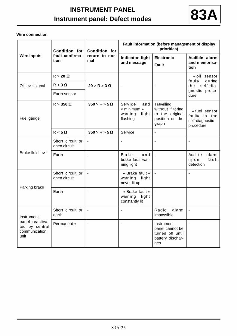
83A-25
INSTRUMENT PANELInstrument panel: Defect modes 83A
Wire connection
Wire inputsCondition forfault confirma-tion
Condition forreturn to nor-mal
Fault information (before management of display priorities)
Indicator lightand message
Electronic
Fault
Audible alarmand memorisa-tion
Oil level signal
R > 20 Ω
20 > R > 3 Ω - -
« oil sensorfaul t » duringthe self-dia-gnostic proce-dure
R < 3 Ω
Earth sensor
Fuel gauge
R > 350 Ω 350 > R > 5 Ω Serv ice and« minimum »warning l ightflashing
Travellingwithout filteringto the originalposition on thegraph
« fuel sensorfault » in theself-diagnosticprocedure
R < 5 Ω 350 > R > 5 Ω Service -
Brake fluid level
Short circuit oropen circuit
- - - -
Earth - Bra k e a n dbrake fault war-ning light
- Audible alarmu p o n f a u l tdetection
Parking brake
Short circuit oropen circuit
- « Brake fault »warning l ightnever lit up
- -
Earth - « Brake fault »warning l ightconstantly lit
- -
Instrumentpanel reactiva-ted by centralcommunicationunit
Short circuit orearth
- - Radio alarmimpossible
-
Permanent + - - Instrumentpanel cannot beturned off untilbattery dischar-ges
-
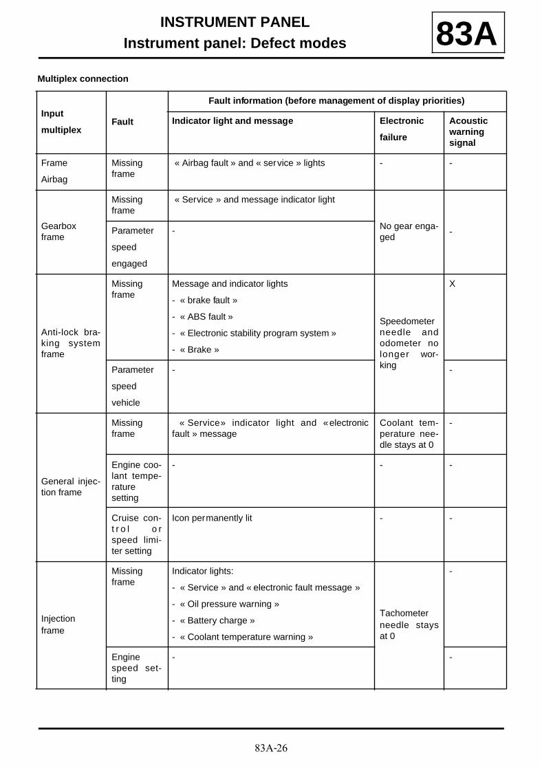
83A-26
INSTRUMENT PANELInstrument panel: Defect modes 83A
Multiplex connection
Input
multiplexFault
Fault information (before management of display priorities)
Indicator light and message Electronic
failure
Acousticwarningsignal
Frame
Airbag
Missingframe
« Airbag fault » and « service » lights - -
Gearboxframe
Missingframe
« Service » and message indicator light
No gear enga-ged
-Parameter
speed
engaged
-
Anti-lock bra-king systemframe
Missingframe
Message and indicator lights
- « brake fault »
- « ABS fault »
- « Electronic stability program system »
- « Brake »
Speedometerneedle andodometer nolonger wor-king
X
Parameter
speed
vehicle
- -
General injec-tion frame
Missingframe
« Service » indicator light and « electronicfault » message
Coolant tem-perature nee-dle stays at 0
-
Engine coo-lant tempe-raturesetting
- - -
Cruise con-t r o l o rspeed limi-ter setting
Icon permanently lit - -
Injectionframe
Missingframe
Indicator lights:
- « Service » and « electronic fault message »
- « Oil pressure warning »
- « Battery charge »
- « Coolant temperature warning »
Tachometerneedle staysat 0
-
Enginespeed set-ting
- -
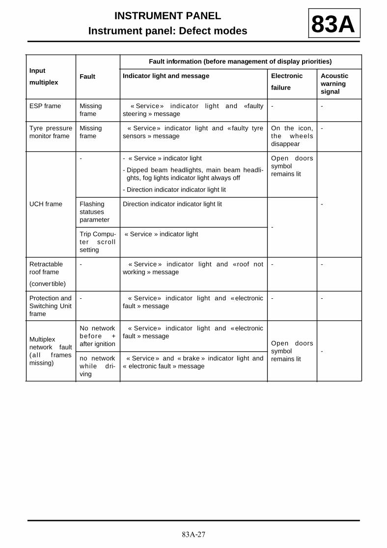
83A-27
INSTRUMENT PANELInstrument panel: Defect modes 83A
ESP frame Missingframe
« Service » indicator light and « faultysteering » message
- -
Tyre pressuremonitor frame
Missingframe
« Service » indicator light and « faulty tyresensors » message
On the icon,the wheelsdisappear
-
UCH frame
- - « Service » indicator light
- Dipped beam headlights, main beam headli-ghts, fog lights indicator light always off
- Direction indicator indicator light lit
Open doorssymbolremains lit
-Flashingstatusesparameter
Direction indicator indicator light lit
-Trip Compu-ter scrol lsetting
« Service » indicator light
Retractableroof frame
(conver tible)
- « Service » indicator light and « roof notworking » message
- -
Protection andSwitching Unitframe
- « Service » indicator light and « electronicfault » message
- -
Multiplexnetwork fault(a l l f ramesmissing)
No networkbefore +after ignition
« Service » indicator light and « electronicfault » message
Open doorssymbolremains lit
-no networkwhile dri-ving
« Service » and « brake » indicator light and« electronic fault » message
Input
multiplexFault
Fault information (before management of display priorities)
Indicator light and message Electronic
failure
Acousticwarningsignal
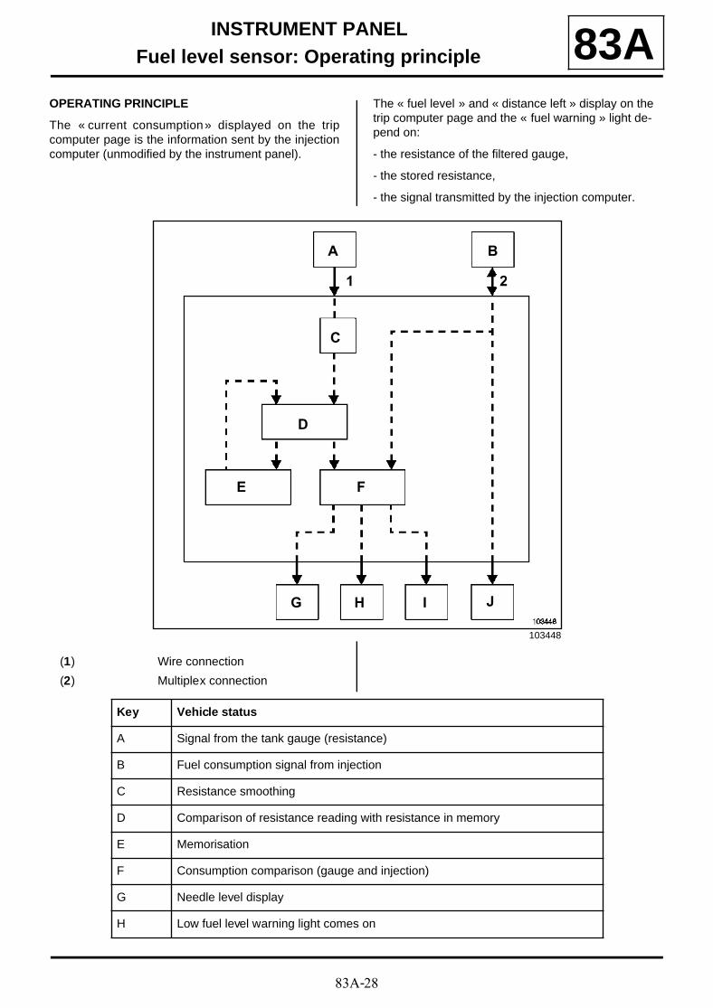
83A-28
INSTRUMENT PANELFuel level sensor: Operating principle 83A
OPERATING PRINCIPLE
The « current consumption » displayed on the tripcomputer page is the information sent by the injectioncomputer (unmodified by the instrument panel).
The « fuel level » and « distance left » display on the trip computer page and the « fuel warning » light de-pend on:
- the resistance of the filtered gauge,
- the stored resistance,
- the signal transmitted by the injection computer.
103448
JIHG
F
C
E
B
D
A
21
(1) Wire connection
(2) Multiplex connection
Key Vehicle status
A Signal from the tank gauge (resistance)
B Fuel consumption signal from injection
C Resistance smoothing
D Comparison of resistance reading with resistance in memory
E Memorisation
F Consumption comparison (gauge and injection)
G Needle level display
H Low fuel level warning light comes on
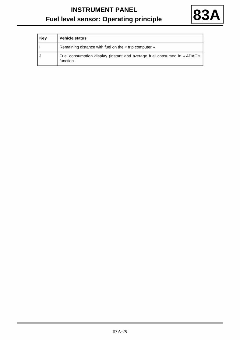
83A-29
INSTRUMENT PANELFuel level sensor: Operating principle 83A
I Remaining distance with fuel on the « trip computer »
J Fuel consumption display (instant and average fuel consumed in « ADAC »function
Key Vehicle status

83A-30
INSTRUMENT PANELOil level detection 83A
LOCATION
Example of the K4J engine
The oil level sensor (1) is located in the lower engine.
102306
1
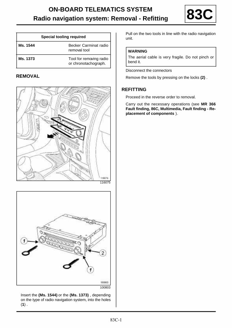
83C-1
ON-BOARD TELEMATICS SYSTEMRadio navigation system: Removal - Refitting 83C
REMOVAL
Insert the (Ms. 1544) or the (Ms. 1373) , dependingon the type of radio navigation system, into the holes(1) .
Pull on the two tools in line with the radio navigationunit.
Disconnect the connectors
Remove the tools by pressing on the locks (2) .
REFITTING
Proceed in the reverse order to removal.
Carry out the necessary operations (see MR 366Fault finding, 86C, Multimedia, Fault finding - Re-placement of components ).
Special tooling required
Ms. 1544 Becker Carminat radioremoval tool
Ms. 1373 Tool for removing radioor chronotachograph.
116075
100803
WARNING
The aerial cable is very fragile. Do not pinch orbend it.
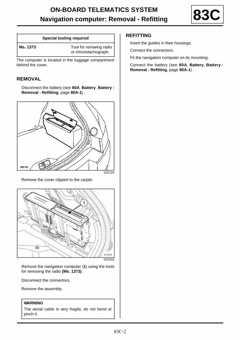
83C-2
ON-BOARD TELEMATICS SYSTEMNavigation computer: Removal - Refitting 83C
The computer is located in the luggage compartmentbehind the cover.
REMOVAL
Disconnect the battery (see 80A, Battery, Battery :Removal - Refitting, page 80A-1) .
Remove the cover clipped to the carpet.
Remove the navigation computer (1) using the toolsfor removing the radio (Ms. 1373) .
Disconnect the connectors.
Remove the assembly.
REFITTING
Insert the guides in their housings.
Connect the connectors.
Fit the navigation computer on its mounting.
Connect the battery (see 80A, Battery, Battery :Removal - Refitting, page 80A-1) .
Special tooling required
Ms. 1373 Tool for removing radioor chronotachograph.
102133
101916
WARNING
The aerial cable is very fragile, do not bend orpinch it.
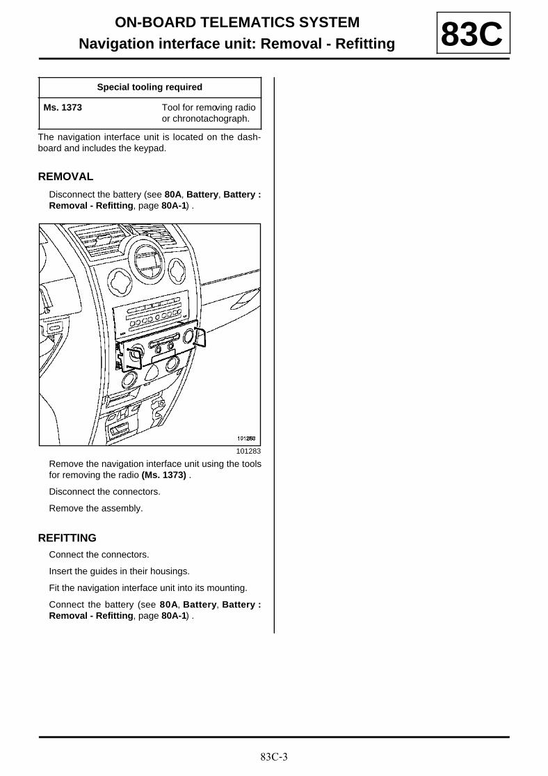
83C-3
ON-BOARD TELEMATICS SYSTEMNavigation interface unit: Removal - Refitting 83C
The navigation interface unit is located on the dash-board and includes the keypad.
REMOVAL
Disconnect the battery (see 80A, Battery, Battery :Removal - Refitting, page 80A-1) .
Remove the navigation interface unit using the toolsfor removing the radio (Ms. 1373) .
Disconnect the connectors.
Remove the assembly.
REFITTINGConnect the connectors.
Insert the guides in their housings.
Fit the navigation interface unit into its mounting.
Connect the battery (see 80A, Battery, Battery :Removal - Refitting, page 80A-1) .
Special tooling required
Ms. 1373 Tool for removing radioor chronotachograph.
101283
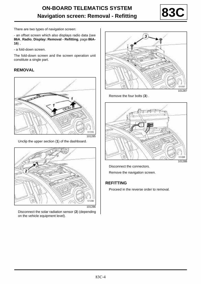
83C-4
ON-BOARD TELEMATICS SYSTEMNavigation screen: Removal - Refitting 83C
There are two types of navigation screen:
- an offset screen which also displays radio data (see86A, Radio, Display: Removal - Refitting, page 86A-16) ,
- a fold-down screen.
The fold-down screen and the screen operation unitconstitute a single part.
REMOVAL
Unclip the upper section (1) of the dashboard.
Disconnect the solar radiation sensor (2) (dependingon the vehicle equipment level).
Remove the four bolts (3) .
Disconnect the connectors.
Remove the navigation screen.
REFITTING
Proceed in the reverse order to removal.
101285
101286
101287
101288
83C-5
ON-BOARD TELEMATICS SYSTEMNavigation aerial: Removal - Refitting 83C
The aerial is fitted on the roof.
Remove the navigation aerial (see 86A, Radio, Ra-dio aerial: Removal - Refitting, page 86A-21) .
Note:
The GPS aerial incorporates the radio aerial, theamplifier and the telephone aerial (dual band).
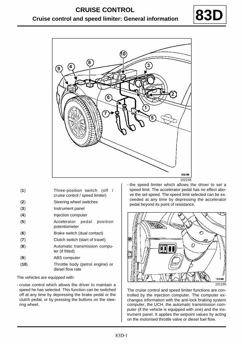
83D-1
CRUISE CONTROLCruise control and speed limiter: General information 83D
The vehicles are equipped with:
- cruise control which allows the driver to maintain aspeed he has selected. This function can be switchedoff at any time by depressing the brake pedal or theclutch pedal, or by pressing the buttons on the stee-ring wheel,
- the speed limiter which allows the driver to set aspeed limit. The accelerator pedal has no effect abo-ve the set speed. The speed limit selected can be ex-ceeded at any time by depressing the acceleratorpedal beyond its point of resistance.
The cruise control and speed limiter functions are con-trolled by the injection computer. The computer ex-changes information with the anti-lock braking systemcomputer, the UCH, the automatic transmission com-puter (if the vehicle is equipped with one) and the ins-trument panel. It applies the setpoint values by actingon the motorised throttle valve or diesel fuel flow.
102158
7
6
5
34
10
1
98
2
(1) Three-position switch (off /cruise control / speed limiter)
(2) Steering wheel switches
(3) Instrument panel
(4) Injection computer
(5) Accelerator pedal positionpotentiometer
(6) Brake switch (dual contact)
(7) Clutch switch (start of travel)
(8) Automatic transmission compu-ter (if fitted)
(9) ABS computer
(10) Throttle body (petrol engine) ordiesel flow rate
101195
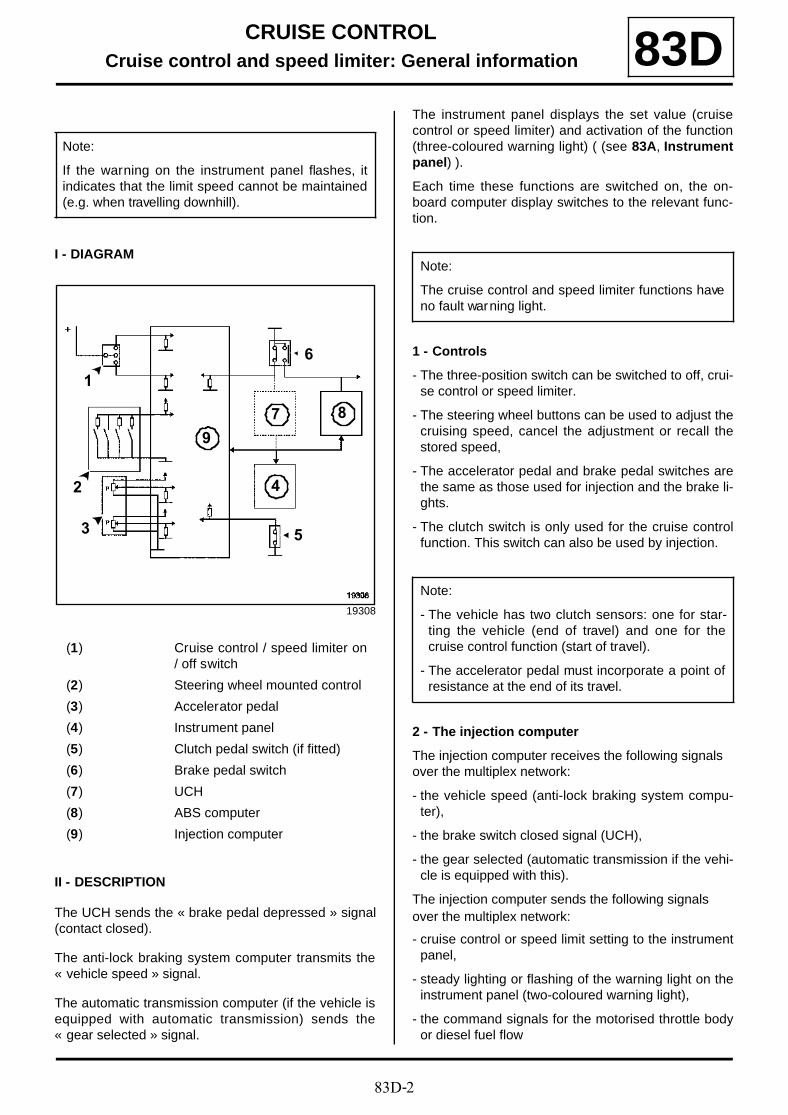
83D-2
CRUISE CONTROLCruise control and speed limiter: General information 83D
I - DIAGRAM
II - DESCRIPTION
The UCH sends the « brake pedal depressed » signal(contact closed).
The anti-lock braking system computer transmits the« vehicle speed » signal.
The automatic transmission computer (if the vehicle isequipped with automatic transmission) sends the« gear selected » signal.
The instrument panel displays the set value (cruisecontrol or speed limiter) and activation of the function(three-coloured warning light) ( (see 83A, Instrumentpanel) ).
Each time these functions are switched on, the on-board computer display switches to the relevant func-tion.
1 - Controls
- The three-position switch can be switched to off, crui-se control or speed limiter.
- The steering wheel buttons can be used to adjust thecruising speed, cancel the adjustment or recall thestored speed,
- The accelerator pedal and brake pedal switches arethe same as those used for injection and the brake li-ghts.
- The clutch switch is only used for the cruise controlfunction. This switch can also be used by injection.
2 - The injection computer
The injection computer receives the following signals over the multiplex network:
- the vehicle speed (anti-lock braking system compu-ter),
- the brake switch closed signal (UCH),
- the gear selected (automatic transmission if the vehi-cle is equipped with this).
The injection computer sends the following signals over the multiplex network:
- cruise control or speed limit setting to the instrumentpanel,
- steady lighting or flashing of the warning light on theinstrument panel (two-coloured warning light),
- the command signals for the motorised throttle bodyor diesel fuel flow
Note:
If the warning on the instrument panel flashes, itindicates that the limit speed cannot be maintained(e.g. when travelling downhill).
19308
(1) Cruise control / speed limiter on/ off switch
(2) Steering wheel mounted control
(3) Accelerator pedal
(4) Instrument panel
(5) Clutch pedal switch (if fitted)
(6) Brake pedal switch
(7) UCH
(8) ABS computer
(9) Injection computer
4
5
6
8
9
7
1
2
3
Note:
The cruise control and speed limiter functions haveno fault warning light.
Note:
- The vehicle has two clutch sensors: one for star-ting the vehicle (end of travel) and one for thecruise control function (start of travel).
- The accelerator pedal must incorporate a point ofresistance at the end of its travel.

83D-3
CRUISE CONTROLCruise control and speed limiter: General information 83D
- the gear change signals from the automatic transmis-sion (if the vehicle is equipped with it).
The injection computer receives signals by wire:
- from the accelerator pedal,
- from the brake switch (two switches: open andclosed),
- from the clutch switch (if the vehicle is equipped withit),
- from the on/off switch (three positions),
- from the controls at the steering wheel.

83D-4
CRUISE CONTROLSpeed limiter: Operating principle 83D
Entry conditions:
- switch in speed limiter position,
- 19 mph (30 km/h) minimum, 125 mph (200 km/h)maximum (guideline only),
- « + » , « - » or « R » buttons pressed.
Exit conditions:
- accelerator depressed firmly (beyond the safety resis-tance point),
- switch in the « off » position,
- « 0 » button depressed,
- injection computer intervention (fault or overspeed),
Note:
If the warning light on the instrument panel flashes,it informs to the driver that the cruising speed can-not be maintained.

83D-5
CRUISE CONTROLCruise control: Operating principle 83D
Entry conditions:
- cruise control switch,
- 20 mph (30 km/h) minimum, 120 mph (200 km/h)maximum (information purposes),
- press the « + » or « R » buttons.
Conditions for exiting speed limiter mode:
- depress accelerator,
- depression of the brake or clutch pedal,
- press on « 0 » ,
- switch in the « off » position,
- intervention of the directional stability control system,
- work on injection computer (fault or over-speed).
- gearbox in « Neutral » , « Park » or « Neutral » posi-tion.
Note:
If the indicator flashes green on the instrumentpanel, it indicates to the driver that the set speedcannot be maintained.
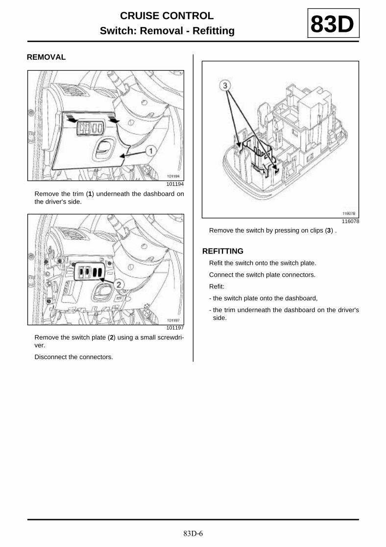
83D-6
CRUISE CONTROLSwitch: Removal - Refitting 83D
REMOVAL
Remove the trim (1) underneath the dashboard onthe driver's side.
Remove the switch plate (2) using a small screwdri-ver.
Disconnect the connectors.
Remove the switch by pressing on clips (3) .
REFITTINGRefit the switch onto the switch plate.
Connect the switch plate connectors.
Refit:
- the switch plate onto the dashboard,
- the trim underneath the dashboard on the driver'sside.
101194
101197
116078

83D-7
CRUISE CONTROLSteering wheel switch: Removal - Refitting 83D
REMOVAL
Disconnect the battery (see 80A, Battery, Battery :Removal - Refitting, page 80A-1) .
Remove the driver's frontal airbag (see 88C, Airbagand Pretensioners, Driver's front airbag: Remo-val - Refitting, page 88C-25) .
Disconnect the intermediate connector (1) .
Remove:
- the switch mounting bolts (2) on the steering wheel,
- the steering wheel switches.
REFITTINGRefit:
- the steering wheel switches,
- the switch mounting bolts onto the steering wheel.
Connect the intermediate connector.
Refit the driver's frontal airbag (see 88C, Airbagand Pretensioners, Driver's front airbag: Remo-val - Refitting, page 88C-25) .
Connect the battery (see 80A, Battery, Battery :Removal - Refitting, page 80A-1) .
116070
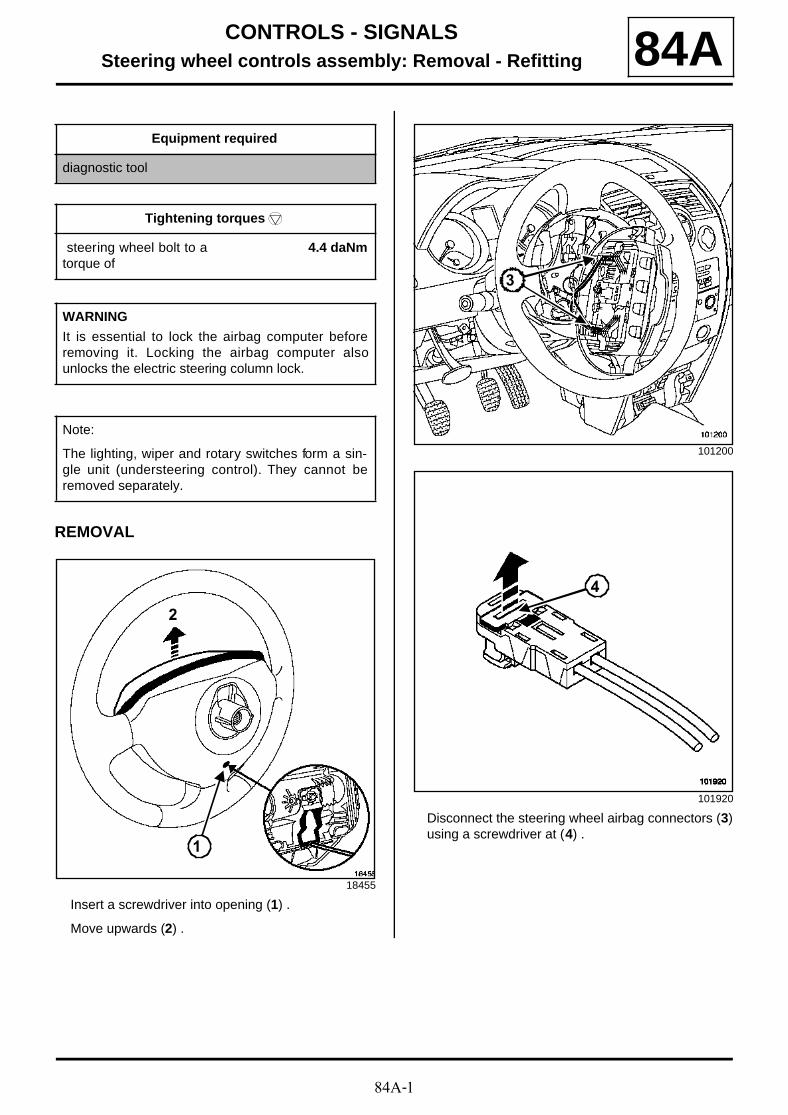
84A-1
CONTROLS - SIGNALSSteering wheel controls assembly: Removal - Refitting 84A
REMOVAL
Insert a screwdriver into opening (1) .
Move upwards (2) .
Disconnect the steering wheel airbag connectors (3)using a screwdriver at (4) .
Equipment required
diagnostic tool
Tightening torquesm
steering wheel bolt to atorque of
4.4 daNm
WARNING
It is essential to lock the airbag computer beforeremoving it. Locking the airbag computer alsounlocks the electric steering column lock.
Note:
The lighting, wiper and rotary switches form a sin-gle unit (understeering control). They cannot beremoved separately.
18455
2
1
101200
101920
3
4
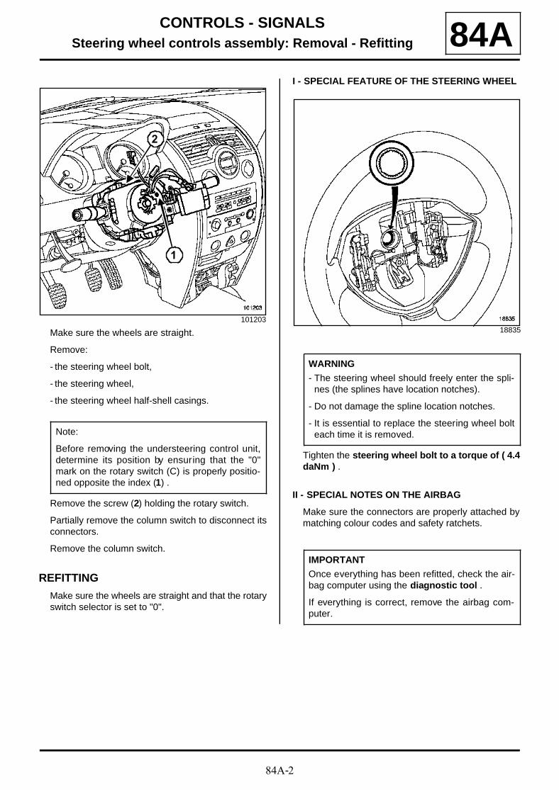
84A-2
CONTROLS - SIGNALSSteering wheel controls assembly: Removal - Refitting 84A
Make sure the wheels are straight.
Remove:
- the steering wheel bolt,
- the steering wheel,
- the steering wheel half-shell casings.
Remove the screw (2) holding the rotary switch.
Partially remove the column switch to disconnect itsconnectors.
Remove the column switch.
REFITTING
Make sure the wheels are straight and that the rotaryswitch selector is set to "0".
I - SPECIAL FEATURE OF THE STEERING WHEEL
Tighten the steering wheel bolt to a torque of ( 4.4daNm ) .
II - SPECIAL NOTES ON THE AIRBAG
Make sure the connectors are properly attached bymatching colour codes and safety ratchets.
101203
Note:
Before removing the understeering control unit,determine its position by ensuring that the "0"mark on the rotary switch (C) is properly positio-ned opposite the index (1) .
1
2
18835
WARNING
- The steering wheel should freely enter the spli-nes (the splines have location notches).
- Do not damage the spline location notches.
- It is essential to replace the steering wheel bolteach time it is removed.
IMPORTANT
Once everything has been refitted, check the air-bag computer using the diagnostic tool .
If everything is correct, remove the airbag com-puter.
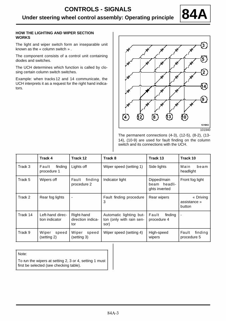
84A-3
CONTROLS - SIGNALSUnder steering wheel control assembly: Operating principle 84A
HOW THE LIGHTING AND WIPER SECTION WORKS
The light and wiper switch form an inseparable unitknown as the « column switch » .
The component consists of a control unit containingdiodes and switches.
The UCH determines which function is called by clo-sing certain column switch switches.
Example: when tracks 12 and 14 communicate, theUCH interprets it as a request for the right hand indica-tors.
The permanent connections (4-3), (12-5), (8-2), (13-14), (10-9) are used for fault finding on the columnswitch and its connections with the UCH.
101940
2
3
4
5
8
9
1012 13
14
Track 4 Track 12 Track 8 Track 13 Track 10
Track 3 Faul t findingprocedure 1
Lights off Wiper speed (setting 1) Side lights Ma in beamheadlight
Track 5 Wipers off Fault findingprocedure 2
Indicator light Dipped/mainbeam headli-ghts inverted
Front fog light
Track 2 Rear fog lights - Fault finding procedure3
Rear wipers « Drivingassistance »button
Track 14 Left-hand direc-tion indicator
Right-handdirection indica-tor
Automatic lighting but-ton (only with rain sen-sor)
Faul t findingprocedure 4
-
Track 9 Wiper speed(setting 2)
Wiper speed(setting 3)
Wiper speed (setting 4) High-speedwipers
Fault findingprocedure 5
Note:
To run the wipers at setting 2, 3 or 4, setting 1 mustfirst be selected (see checking table).

84A-4
CONTROLS - SIGNALSUnder steering wheel control assembly: Operating principle 84A
* If the UCH detects no column switch contact, thelow-speed wipers are automatically selected. The wi-pers stop when the switch (tracks 4 and 5) is closed.
101925
Note:
The following states can be checked with a multi-meter (set to diodemeter).
Settings Tracks
Wipers off 5 and 4
Wiper speed
(setting 1)
3 and 8
Wiper speed
(setting 2)
3 and 8 + 9 and4
Wiper speed
(setting 3)
3 and 8 + 9 and12
Wiper speed
(setting 4)
3 and 8 + 9 and8
Low-speed wipers * No ignition
High-speed wipers 9 and 13
Rear wipers 2 and 13
Trip computer « button » 2 and 10
Lights off 3 and 12
Side lights 3 and 13
1
Dipped headlights 3 and 10
Main beam headlight 3 and 10 + 5and 13
Fog lights 5 and 10
Fog lights 2 and 4
Operating button 14 and 8
Left-hand direction indicator 14 and 4
Right-hand direction indicator 14 and 12
Indicator light 8 and 5
Settings Tracks
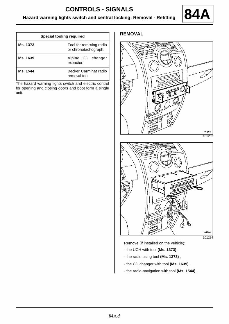
84A-5
CONTROLS - SIGNALSHazard warning lights switch and central locking: Removal - Refitting 84A
The hazard warning lights switch and electric controlfor opening and closing doors and boot form a singleunit.
REMOVAL
Remove (if installed on the vehicle):
- the UCH with tool (Ms. 1373) ,
- the radio using tool (Ms. 1373) ,
- the CD changer with tool (Ms. 1639) ,
- the radio-navigation with tool (Ms. 1544) .
Special tooling required
Ms. 1373 Tool for removing radioor chronotachograph.
Ms. 1639 Alpine CD changerextractor.
Ms. 1544 Becker Carminat radioremoval tool
101283
101284
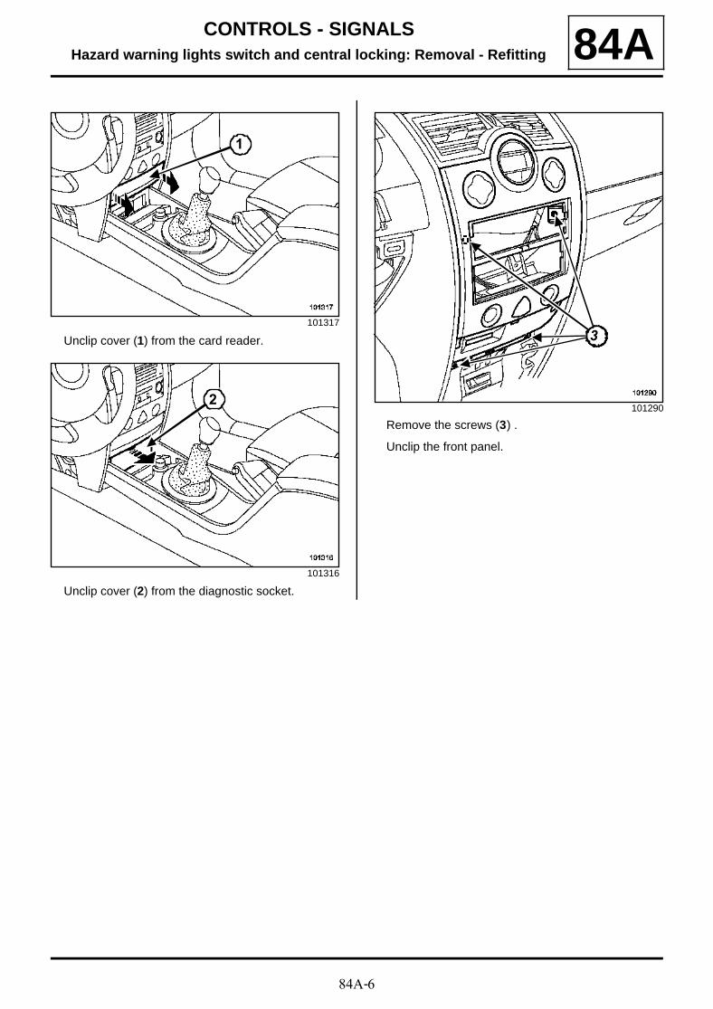
84A-6
CONTROLS - SIGNALSHazard warning lights switch and central locking: Removal - Refitting 84A
Unclip cover (1) from the card reader.
Unclip cover (2) from the diagnostic socket.
Remove the screws (3) .
Unclip the front panel.
101317
101316
1
2101290
33

84A-7
CONTROLS - SIGNALSRemote headlight adjustment control: Removal - Refitting 84A
REMOVAL
Remove:
- the trim underneath the driver's side of the dash-board,
- the switch board (3) using a small screwdriver.
Disconnect the connector.
Remove the « dimmer/adjustment control » from itssupport.
WARNING
Two versions are available:
- one with an « entry level » lighting dimmer formanual heating and ventilation systems,
- the other with a « top of the range » lighting dim-mer for climate control.
Note:
The beam adjustment part is the same, regardlessof heating and ventilation system.
101194
101197
Note:
The lighting dimmer (1) and the beam adjust-ment control (2) form a single unit.
1 2
3
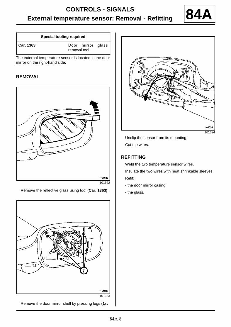
84A-8
CONTROLS - SIGNALSExternal temperature sensor: Removal - Refitting 84A
The external temperature sensor is located in the doormirror on the right-hand side.
REMOVAL
Remove the reflective glass using tool (Car. 1363) .
Remove the door mirror shell by pressing lugs (1) .
Unclip the sensor from its mounting.
Cut the wires.
REFITTINGWeld the two temperature sensor wires.
Insulate the two wires with heat shrinkable sleeves.
Refit:
- the door mirror casing,
- the glass.
Special tooling required
Car. 1363 Door mirror glassremoval tool.
101622
101623
11
101624
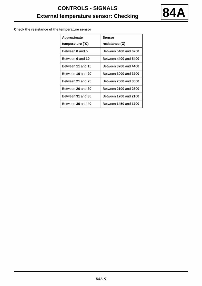
84A-9
CONTROLS - SIGNALSExternal temperature sensor: Checking 84A
Check the resistance of the temperature sensor
Approximate
temperature (˚C)
Sensor
resistance (Ω)
Between 0 and 5 Between 5400 and 6200
Between 6 and 10 Between 4400 and 5400
Between 11 and 15 Between 3700 and 4400
Between 16 and 20 Between 3000 and 3700
Between 21 and 25 Between 2500 and 3000
Between 26 and 30 Between 2100 and 2500
Between 31 and 35 Between 1700 and 2100
Between 36 and 40 Between 1450 and 1700
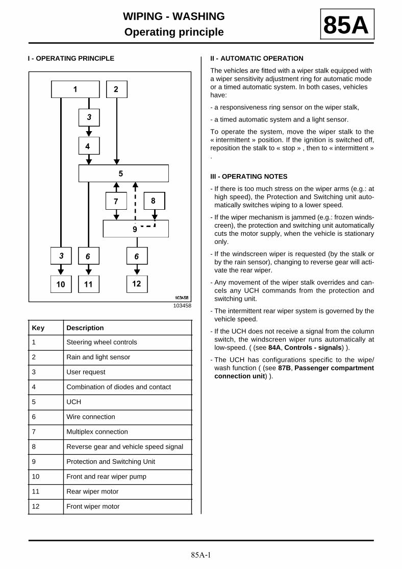
85A-1
WIPING - WASHINGOperating principle 85A
I - OPERATING PRINCIPLE II - AUTOMATIC OPERATION
The vehicles are fitted with a wiper stalk equipped with a wiper sensitivity adjustment ring for automatic mode or a timed automatic system. In both cases, vehicles have:
- a responsiveness ring sensor on the wiper stalk,
- a timed automatic system and a light sensor.
To operate the system, move the wiper stalk to the« intermittent » position. If the ignition is switched off,reposition the stalk to « stop » , then to « intermittent ».
III - OPERATING NOTES
- If there is too much stress on the wiper arms (e.g.: athigh speed), the Protection and Switching unit auto-matically switches wiping to a lower speed.
- If the wiper mechanism is jammed (e.g.: frozen winds-creen), the protection and switching unit automaticallycuts the motor supply, when the vehicle is stationaryonly.
- If the windscreen wiper is requested (by the stalk orby the rain sensor), changing to reverse gear will acti-vate the rear wiper.
- Any movement of the wiper stalk overrides and can-cels any UCH commands from the protection andswitching unit.
- The intermittent rear wiper system is governed by thevehicle speed.
- If the UCH does not receive a signal from the columnswitch, the windscreen wiper runs automatically atlow-speed. ( (see 84A, Controls - signals) ).
- The UCH has configurations specific to the wipe/wash function ( (see 87B, Passenger compartmentconnection unit) ).
103458
Key Description
1 Steering wheel controls
2 Rain and light sensor
3 User request
4 Combination of diodes and contact
5 UCH
6 Wire connection
7 Multiplex connection
8 Reverse gear and vehicle speed signal
9 Protection and Switching Unit
10 Front and rear wiper pump
11 Rear wiper motor
12 Front wiper motor
3
6
10
2
9
8
1
7
5
1211
4
3 6
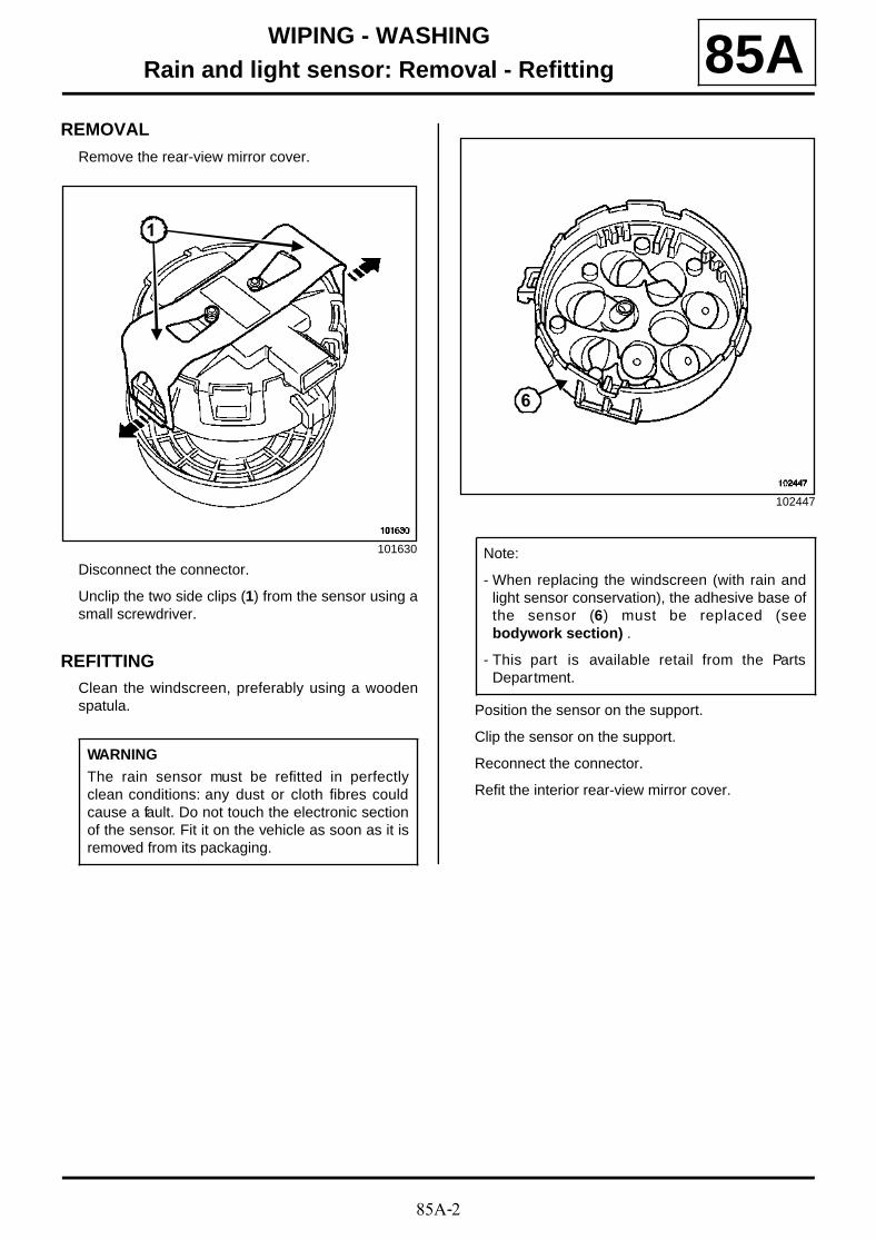
85A-2
WIPING - WASHINGRain and light sensor: Removal - Refitting 85A
REMOVAL
Remove the rear-view mirror cover.
Disconnect the connector.
Unclip the two side clips (1) from the sensor using asmall screwdriver.
REFITTINGClean the windscreen, preferably using a woodenspatula. Position the sensor on the support.
Clip the sensor on the support.
Reconnect the connector.
Refit the interior rear-view mirror cover.
101630
WARNING
The rain sensor must be refitted in perfectlyclean conditions: any dust or cloth fibres couldcause a fault. Do not touch the electronic sectionof the sensor. Fit it on the vehicle as soon as it isremoved from its packaging.
1
102447
Note:
- When replacing the windscreen (with rain andlight sensor conservation), the adhesive base ofthe sensor (6) must be replaced (seebodywork section) .
- This part is available retail from the PartsDepartment.
6

85A-3
WIPING - WASHINGRear screen wiper blade: Removal - Refitting 85A
REMOVAL
OPERATION FOR REMOVAL OF PART CONCERNED
Unclip the blade (1) .
REFITTING
REFITTING OPERATION FOR PART CONCERNED
Clip the blade onto the wiper arm.
116071
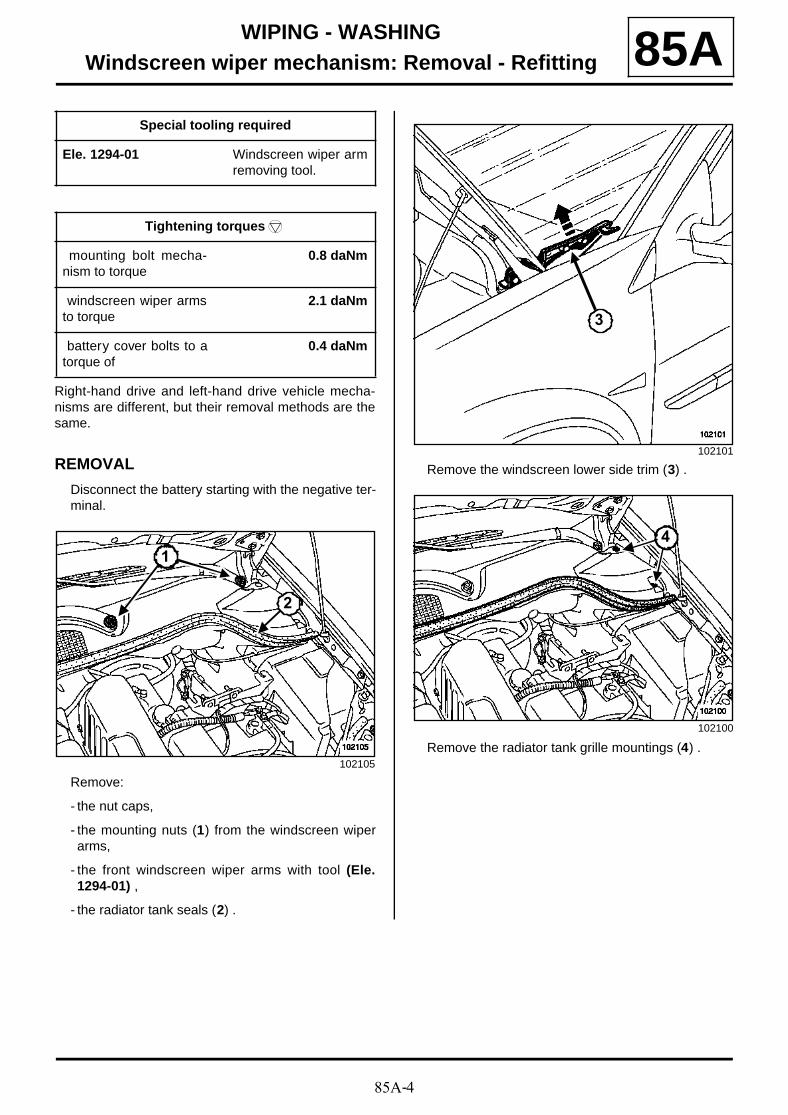
85A-4
WIPING - WASHINGWindscreen wiper mechanism: Removal - Refitting 85A
Right-hand drive and left-hand drive vehicle mecha-nisms are different, but their removal methods are thesame.
REMOVAL
Disconnect the battery starting with the negative ter-minal.
Remove:
- the nut caps,
- the mounting nuts (1) from the windscreen wiperarms,
- the front windscreen wiper arms with tool (Ele.1294-01) ,
- the radiator tank seals (2) .
Remove the windscreen lower side trim (3) .
Remove the radiator tank grille mountings (4) .
Special tooling required
Ele. 1294-01 Windscreen wiper armremoving tool.
Tightening torquesm
mounting bolt mecha-nism to torque
0.8 daNm
windscreen wiper armsto torque
2.1 daNm
battery cover bolts to atorque of
0.4 daNm
102105
1
2
102101
102100
3
4
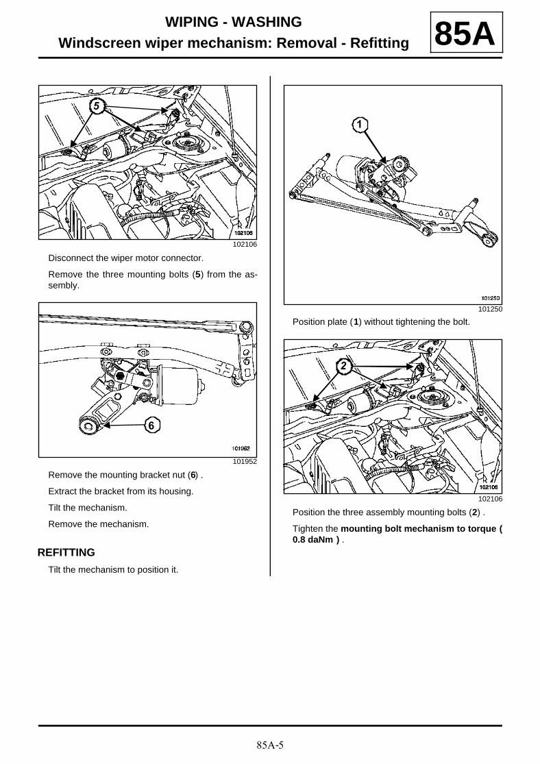
85A-5
WIPING - WASHINGWindscreen wiper mechanism: Removal - Refitting 85A
Disconnect the wiper motor connector.
Remove the three mounting bolts (5) from the as-sembly.
Remove the mounting bracket nut (6) .
Extract the bracket from its housing.
Tilt the mechanism.
Remove the mechanism.
REFITTING
Tilt the mechanism to position it.
Position plate (1) without tightening the bolt.
Position the three assembly mounting bolts (2) .
Tighten the mounting bolt mechanism to torque (0.8 daNm ) .
102106
101952
55
6
101250
102106
1
22
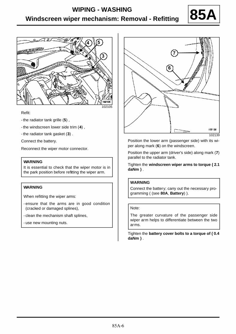
85A-6
WIPING - WASHINGWindscreen wiper mechanism: Removal - Refitting 85A
Refit:
- the radiator tank grille (5) ,
- the windscreen lower side trim (4) ,
- the radiator tank gasket (3) .
Connect the battery.
Reconnect the wiper motor connector.
Position the lower arm (passenger side) with its wi-per along mark (6) on the windscreen.
Position the upper arm (driver's side) along mark (7)parallel to the radiator tank.
Tighten the windscreen wiper arms to torque ( 2.1daNm ) .
Tighten the battery cover bolts to a torque of ( 0.4daNm ) .
102105
WARNINGIt is essential to check that the wiper motor is inthe park position before refitting the wiper arm.
WARNING
When refitting the wiper arms:
- ensure that the arms are in good condition(cracked or damaged splines),
- clean the mechanism shaft splines,
- use new mounting nuts.
54
3
102139
WARNING
Connect the battery; carry out the necessary pro-gramming ( (see 80A, Battery) ).
Note:
The greater curvature of the passenger sidewiper arm helps to differentiate between the twoarms.
7
6
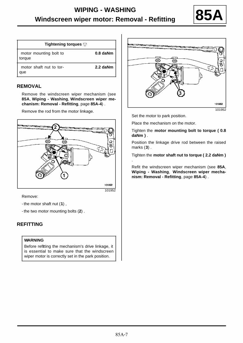
85A-7
WIPING - WASHINGWindscreen wiper motor: Removal - Refitting 85A
REMOVAL
Remove the windscreen wiper mechanism (see85A, Wiping - Washing, Windscreen wiper me-chanism: Removal - Refitting, page 85A-4) .
Remove the rod from the motor linkage.
Remove:
- the motor shaft nut (1) ,
- the two motor mounting bolts (2) .
REFITTING
Set the motor to park position.
Place the mechanism on the motor.
Tighten the motor mounting bolt to torque ( 0.8daNm ) .
Position the linkage drive rod between the raisedmarks (3) .
Tighten the motor shaft nut to torque ( 2.2 daNm ).
Refit the windscreen wiper mechanism (see 85A,Wiping - Washing, Windscreen wiper mecha-nism: Removal - Refitting, page 85A-4) .
Tightening torquesm
motor mounting bolt totorque
0.8 daNm
motor shaft nut to tor-que
2.2 daNm
101952
WARNING
Before refitting the mechanism's drive linkage, itis essential to make sure that the windscreenwiper motor is correctly set in the park position.
1
2
101952
3
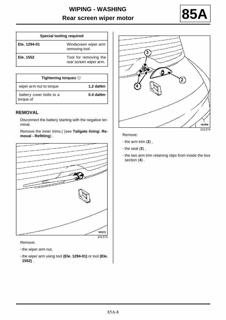
85A-8
WIPING - WASHINGRear screen wiper motor 85A
REMOVAL
Disconnect the battery starting with the negative ter-minal.
Remove the inner trims,( (see Tailgate lining: Re-moval - Refitting) .
Remove:
- the wiper arm nut,
- the wiper arm using tool (Ele. 1294-01) or tool (Ele.1552) .
Remove:
- the arm trim (2) ,
- the seal (3) ,
- the two arm trim retaining clips from inside the boxsection (4) .
Special tooling required
Ele. 1294-01 Windscreen wiper armremoving tool.
Ele. 1552 Tool for removing therear screen wiper arm.
Tightening torquesm
wiper arm nut to torque 1.2 daNm
battery cover bolts to atorque of
0.4 daNm
101373
101374
3
24
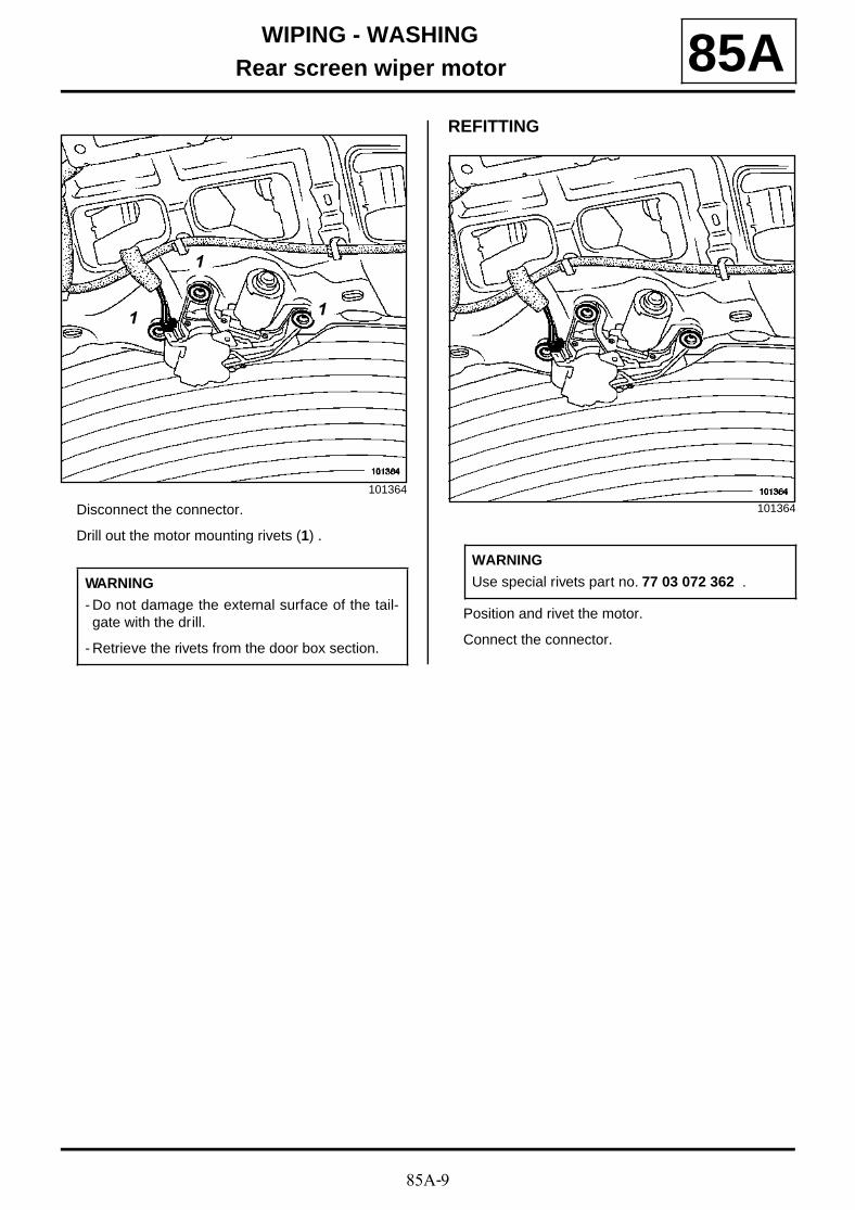
85A-9
WIPING - WASHINGRear screen wiper motor 85A
Disconnect the connector.
Drill out the motor mounting rivets (1) .
REFITTING
Position and rivet the motor.
Connect the connector.
101364
WARNING
- Do not damage the external surface of the tail-gate with the drill.
- Retrieve the rivets from the door box section.
1
1
1
101364
WARNING
Use special rivets part no. 77 03 072 362 .
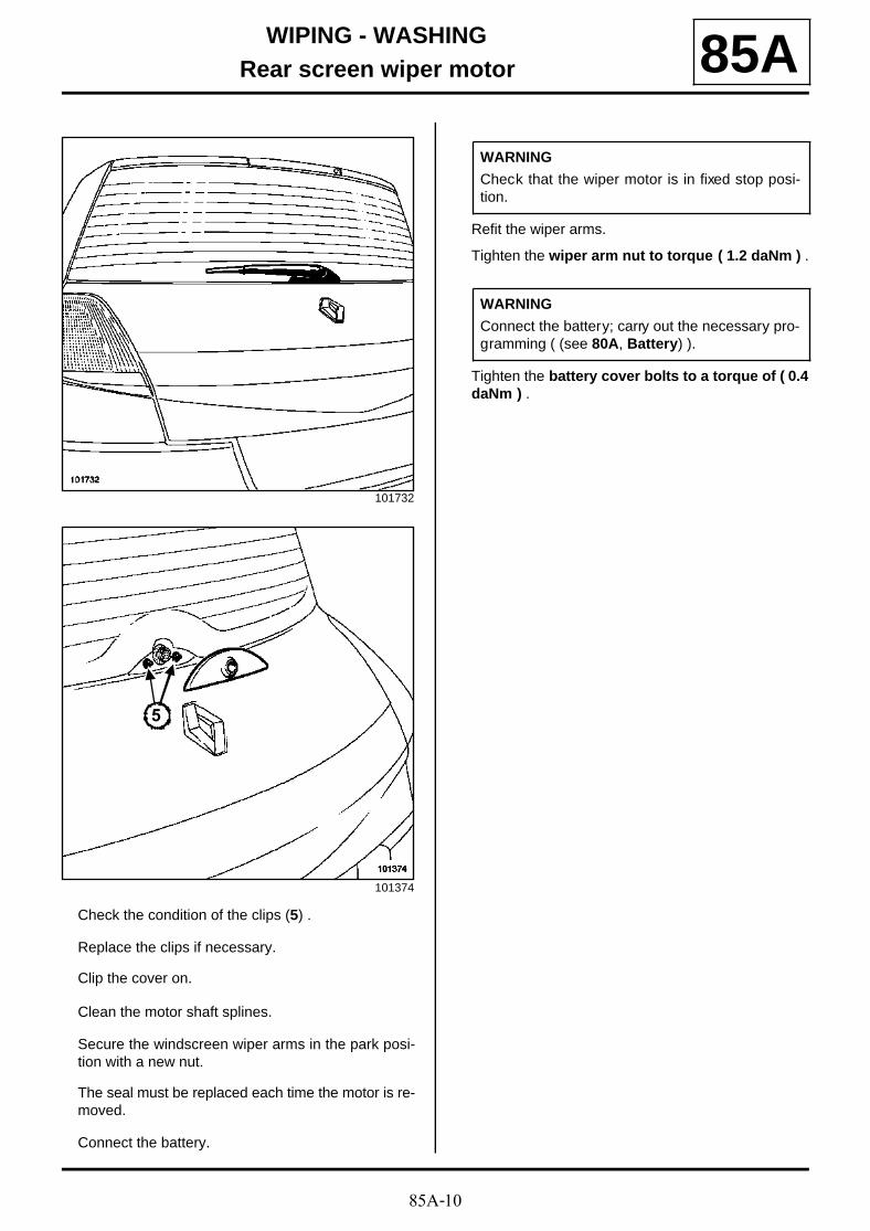
85A-10
WIPING - WASHINGRear screen wiper motor 85A
Check the condition of the clips (5) .
Replace the clips if necessary.
Clip the cover on.
Clean the motor shaft splines.
Secure the windscreen wiper arms in the park posi-tion with a new nut.
The seal must be replaced each time the motor is re-moved.
Connect the battery.
Refit the wiper arms.
Tighten the wiper arm nut to torque ( 1.2 daNm ) .
Tighten the battery cover bolts to a torque of ( 0.4daNm ) .
101732
101374
5
WARNING
Check that the wiper motor is in fixed stop posi-tion.
WARNING
Connect the battery; carry out the necessary pro-gramming ( (see 80A, Battery) ).
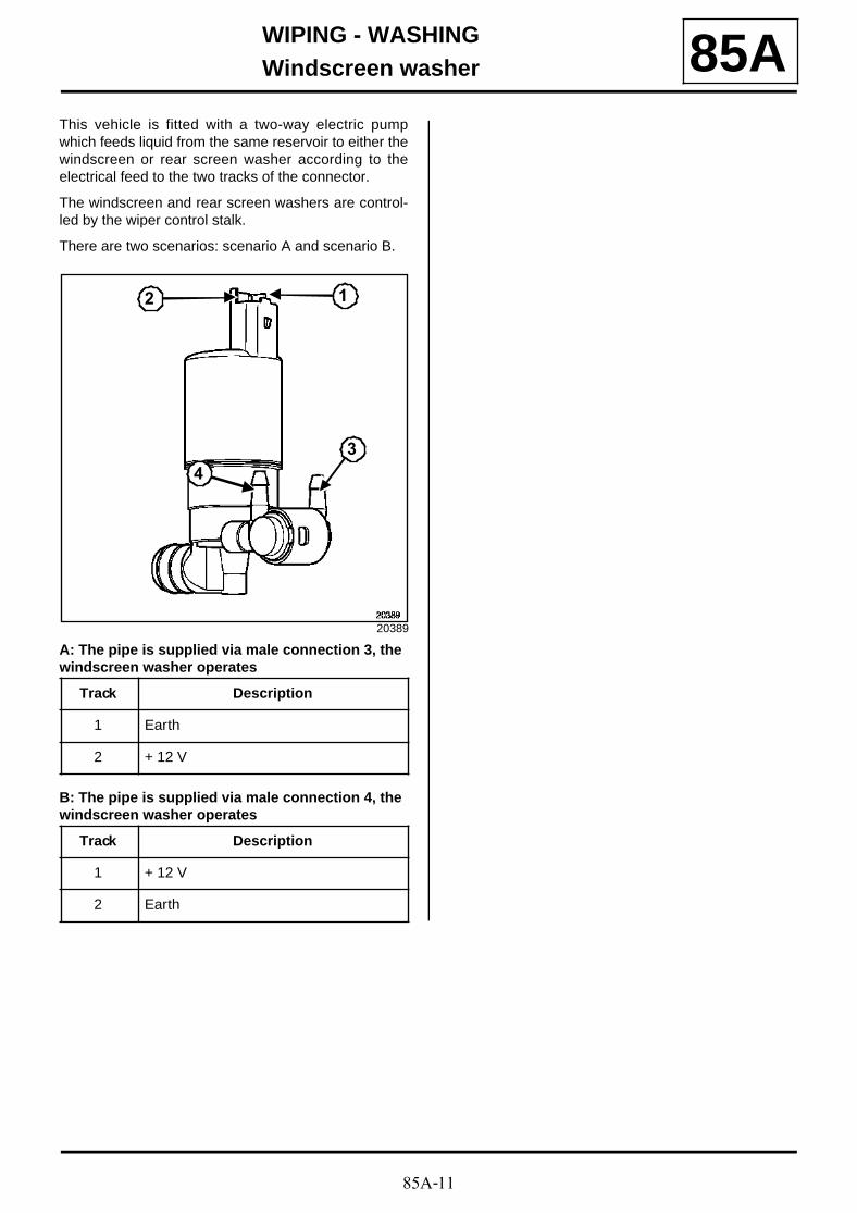
85A-11
WIPING - WASHINGWindscreen washer 85A
This vehicle is fitted with a two-way electric pumpwhich feeds liquid from the same reservoir to either thewindscreen or rear screen washer according to theelectrical feed to the two tracks of the connector.
The windscreen and rear screen washers are control-led by the wiper control stalk.
There are two scenarios: scenario A and scenario B.
A: The pipe is supplied via male connection 3, the windscreen washer operates
B: The pipe is supplied via male connection 4, the windscreen washer operates
20389
Track Description
1 Earth
2 + 12 V
Track Description
1 + 12 V
2 Earth
4
3
12
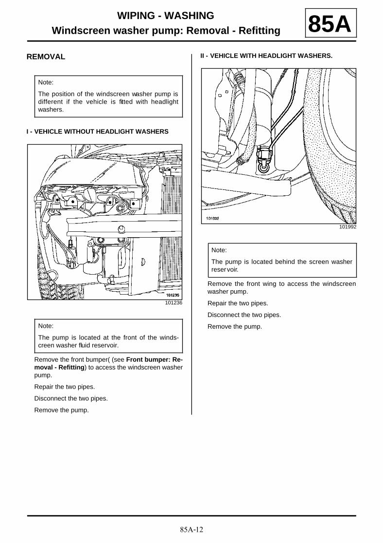
85A-12
WIPING - WASHINGWindscreen washer pump: Removal - Refitting 85A
REMOVAL
I - VEHICLE WITHOUT HEADLIGHT WASHERS
Remove the front bumper( (see Front bumper: Re-moval - Refitting) to access the windscreen washerpump.
Repair the two pipes.
Disconnect the two pipes.
Remove the pump.
II - VEHICLE WITH HEADLIGHT WASHERS.
Remove the front wing to access the windscreenwasher pump.
Repair the two pipes.
Disconnect the two pipes.
Remove the pump.
Note:
The position of the windscreen washer pump isdifferent if the vehicle is fitted with headlightwashers.
101236
Note:
The pump is located at the front of the winds-creen washer fluid reservoir.
101992
Note:
The pump is located behind the screen washerreservoir.
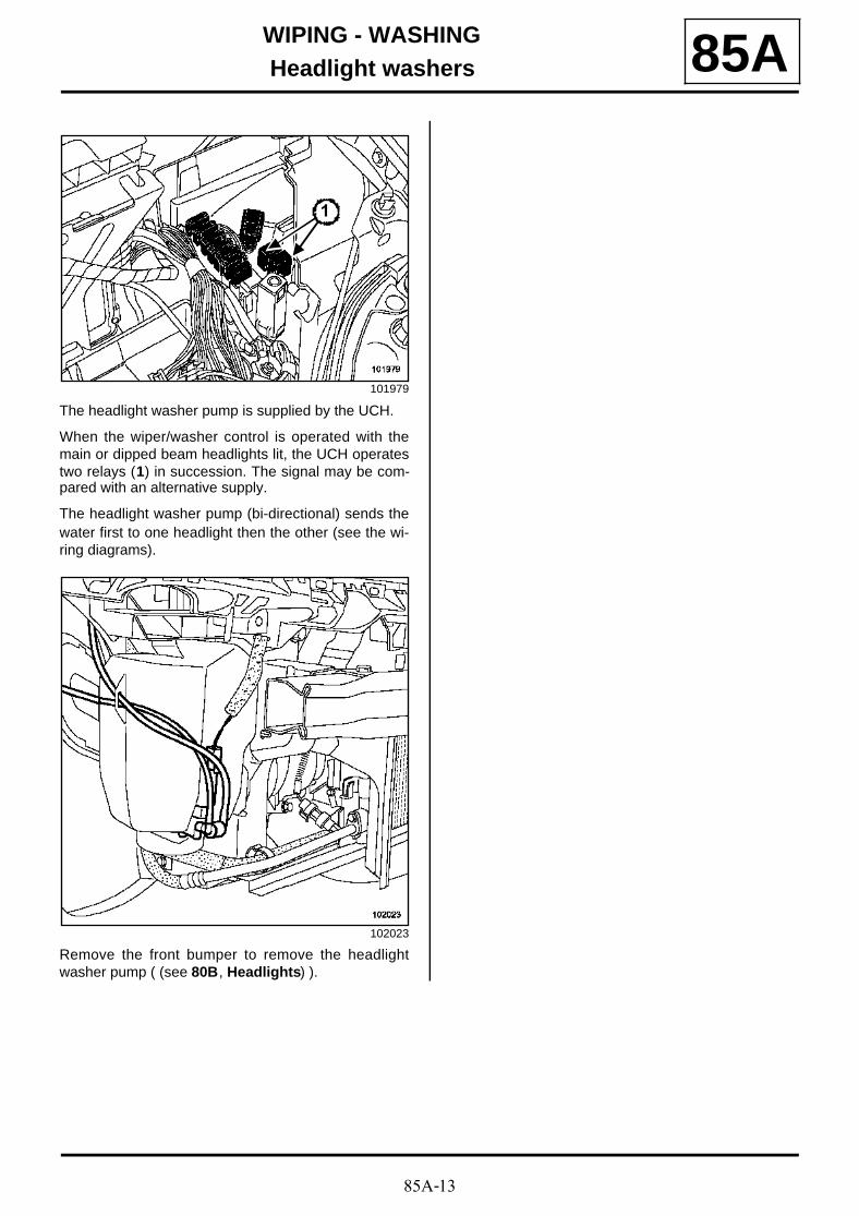
85A-13
WIPING - WASHINGHeadlight washers 85A
The headlight washer pump is supplied by the UCH.
When the wiper/washer control is operated with themain or dipped beam headlights lit, the UCH operatestwo relays (1) in succession. The signal may be com-pared with an alternative supply.
The headlight washer pump (bi-directional) sends thewater first to one headlight then the other (see the wi-ring diagrams).
Remove the front bumper to remove the headlightwasher pump ( (see 80B, Headlights) ).
101979
102023
1
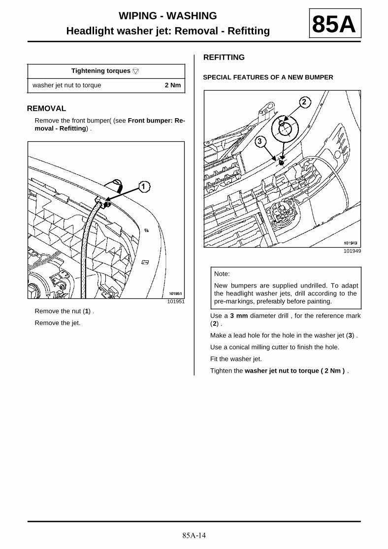
85A-14
WIPING - WASHINGHeadlight washer jet: Removal - Refitting 85A
REMOVALRemove the front bumper( (see Front bumper: Re-moval - Refitting) .
Remove the nut (1) .
Remove the jet.
REFITTING
SPECIAL FEATURES OF A NEW BUMPER
Use a 3 mm diameter drill , for the reference mark(2) .
Make a lead hole for the hole in the washer jet (3) .
Use a conical milling cutter to finish the hole.
Fit the washer jet.
Tighten the washer jet nut to torque ( 2 Nm ) .
Tightening torquesm
washer jet nut to torque 2 Nm
101951
1
101949
Note:
New bumpers are supplied undrilled. To adaptthe headlight washer jets, drill according to thepre-markings, preferably before painting.
2
3
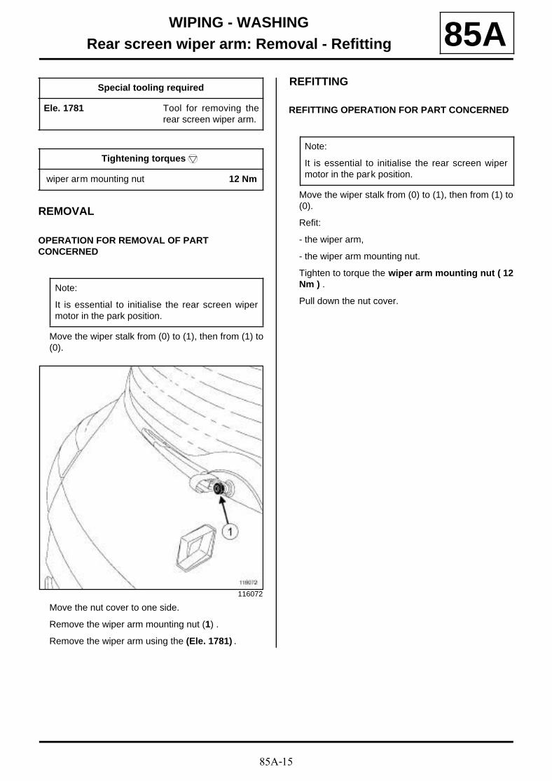
85A-15
WIPING - WASHINGRear screen wiper arm: Removal - Refitting 85A
REMOVAL
OPERATION FOR REMOVAL OF PART CONCERNED
Move the wiper stalk from (0) to (1), then from (1) to(0).
Move the nut cover to one side.
Remove the wiper arm mounting nut (1) .
Remove the wiper arm using the (Ele. 1781) .
REFITTING
REFITTING OPERATION FOR PART CONCERNED
Move the wiper stalk from (0) to (1), then from (1) to(0).
Refit:
- the wiper arm,
- the wiper arm mounting nut.
Tighten to torque the wiper arm mounting nut ( 12Nm ) .
Pull down the nut cover.
Special tooling required
Ele. 1781 Tool for removing therear screen wiper arm.
Tightening torquesm
wiper arm mounting nut 12 Nm
Note:
It is essential to initialise the rear screen wipermotor in the park position.
116072
Note:
It is essential to initialise the rear screen wipermotor in the park position.
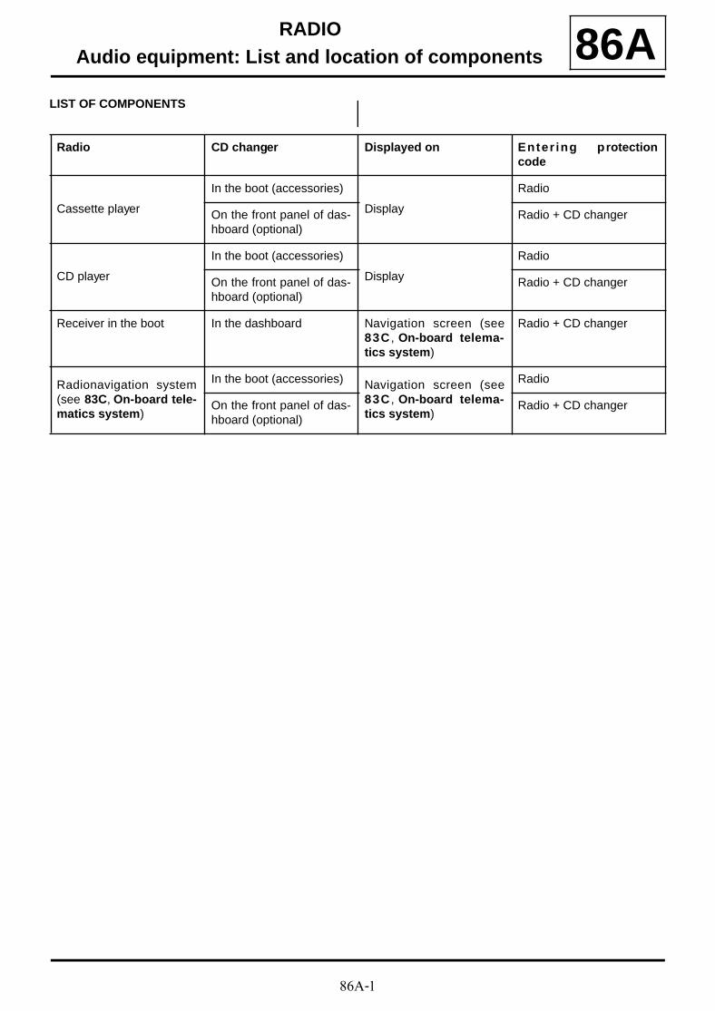
86A-1
RADIOAudio equipment: List and location of components 86A
LIST OF COMPONENTS
Radio CD changer Displayed on Enter ing protectioncode
Cassette player
In the boot (accessories)
Display
Radio
On the front panel of das-hboard (optional)
Radio + CD changer
CD player
In the boot (accessories)
Display
Radio
On the front panel of das-hboard (optional)
Radio + CD changer
Receiver in the boot In the dashboard Navigation screen (see83C , On-board telema-tics system)
Radio + CD changer
Radionavigation system(see 83C, On-board tele-matics system)
In the boot (accessories) Navigation screen (see83C , On-board telema-tics system)
Radio
On the front panel of das-hboard (optional)
Radio + CD changer
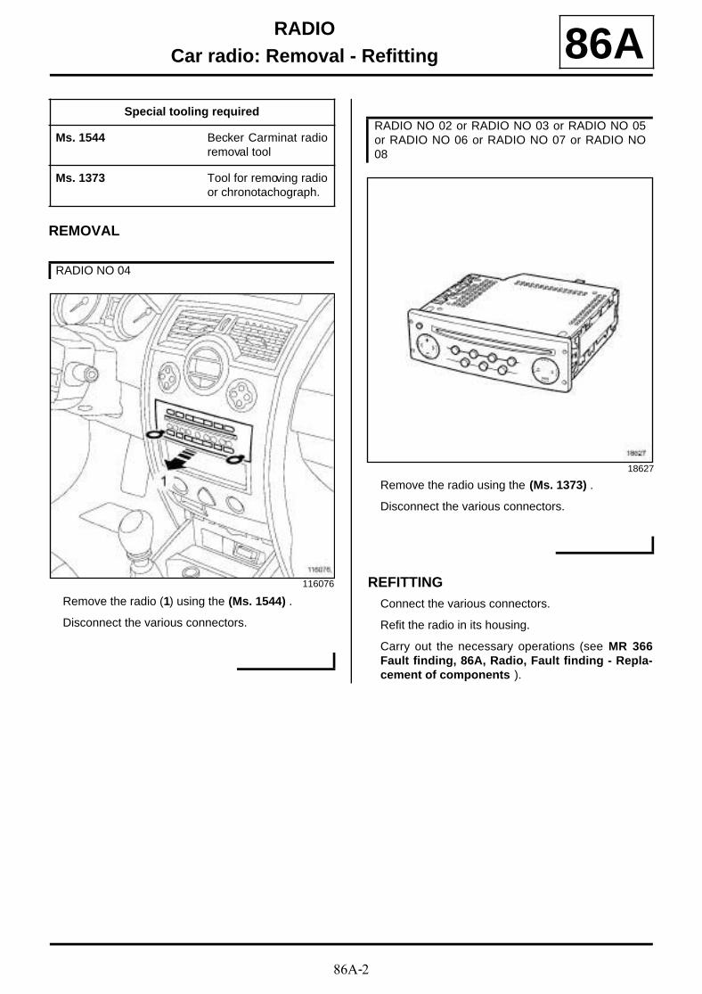
86A-2
RADIOCar radio: Removal - Refitting 86A
REMOVAL
Remove the radio (1) using the (Ms. 1544) .
Disconnect the various connectors.
Remove the radio using the (Ms. 1373) .
Disconnect the various connectors.
REFITTINGConnect the various connectors.
Refit the radio in its housing.
Carry out the necessary operations (see MR 366Fault finding, 86A, Radio, Fault finding - Repla-cement of components ).
Special tooling required
Ms. 1544 Becker Carminat radioremoval tool
Ms. 1373 Tool for removing radioor chronotachograph.
RADIO NO 04
116076
RADIO NO 02 or RADIO NO 03 or RADIO NO 05or RADIO NO 06 or RADIO NO 07 or RADIO NO08
18627
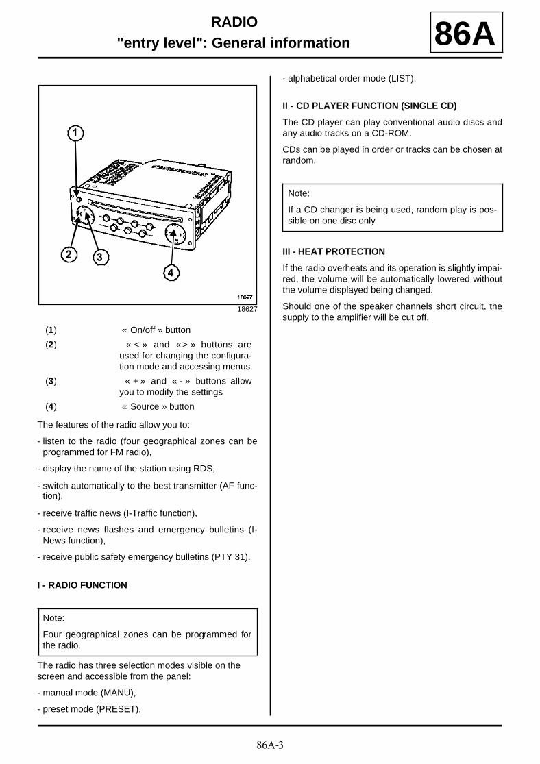
86A-3
RADIO"entry level": General information 86A
The features of the radio allow you to:
- listen to the radio (four geographical zones can beprogrammed for FM radio),
- display the name of the station using RDS,
- switch automatically to the best transmitter (AF func-tion),
- receive traffic news (I-Traffic function),
- receive news flashes and emergency bulletins (I-News function),
- receive public safety emergency bulletins (PTY 31).
I - RADIO FUNCTION
The radio has three selection modes visible on the screen and accessible from the panel:
- manual mode (MANU),
- preset mode (PRESET),
- alphabetical order mode (LIST).
II - CD PLAYER FUNCTION (SINGLE CD)
The CD player can play conventional audio discs andany audio tracks on a CD-ROM.
CDs can be played in order or tracks can be chosen atrandom.
III - HEAT PROTECTION
If the radio overheats and its operation is slightly impai-red, the volume will be automatically lowered withoutthe volume displayed being changed.
Should one of the speaker channels short circuit, thesupply to the amplifier will be cut off.
18627
(1) « On/off » button
(2) « < » and « > » buttons areused for changing the configura-tion mode and accessing menus
(3) « + » and « - » buttons allowyou to modify the settings
(4) « Source » button
Note:
Four geographical zones can be programmed forthe radio.
1
2 3
4
Note:
If a CD changer is being used, random play is pos-sible on one disc only
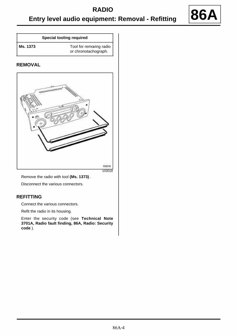
86A-4
RADIOEntry level audio equipment: Removal - Refitting 86A
REMOVAL
Remove the radio with tool (Ms. 1373) .
Disconnect the various connectors.
REFITTINGConnect the various connectors.
Refit the radio in its housing.
Enter the security code (see Technical Note3701A, Radio fault finding, 86A, Radio: Securitycode ).
Special tooling required
Ms. 1373 Tool for removing radioor chronotachograph.
103018
86A-5
RADIO"entry level": Protection code 86A
The radio is protected by a four-digit code. This codemust be entered using the satellite control or with theradio keypad after each disconnection of the battery(see Technical Note 3701A, Radio fault finding,86A, Radio: Security code ).
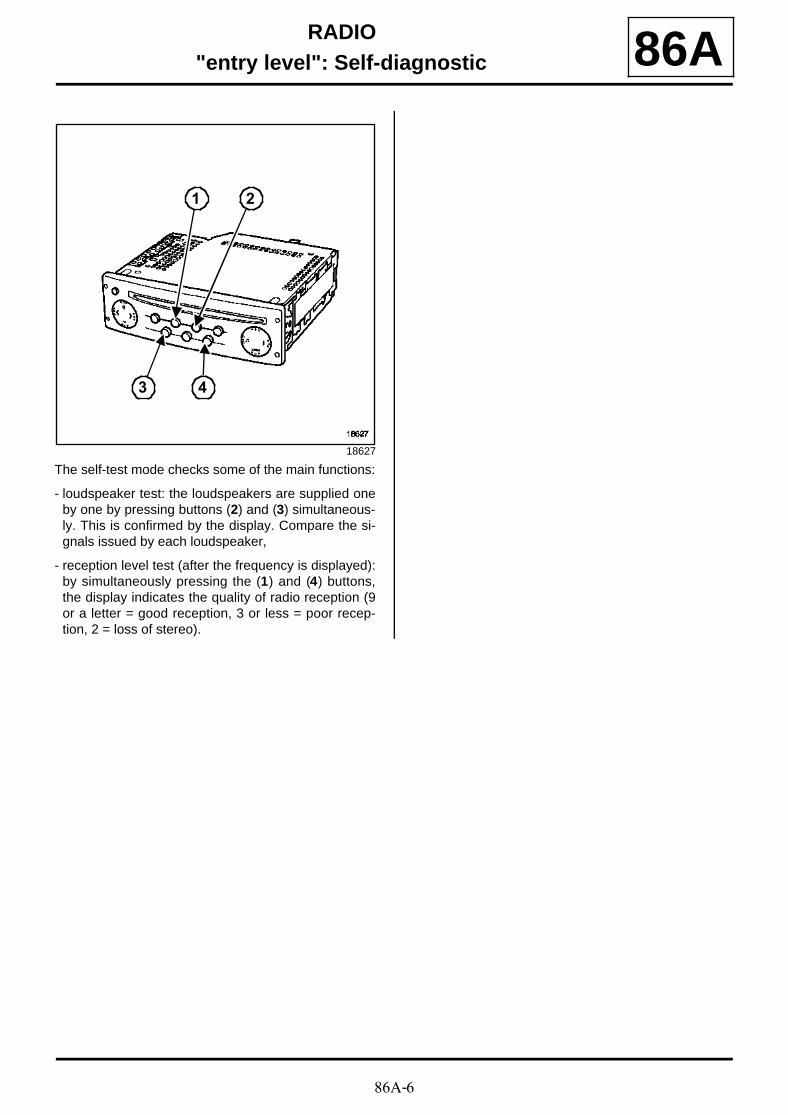
86A-6
RADIO"entry level": Self-diagnostic 86A
The self-test mode checks some of the main functions:
- loudspeaker test: the loudspeakers are supplied oneby one by pressing buttons (2) and (3) simultaneous-ly. This is confirmed by the display. Compare the si-gnals issued by each loudspeaker,
- reception level test (after the frequency is displayed):by simultaneously pressing the (1) and (4) buttons,the display indicates the quality of radio reception (9or a letter = good reception, 3 or less = poor recep-tion, 2 = loss of stereo).
18627
43
21
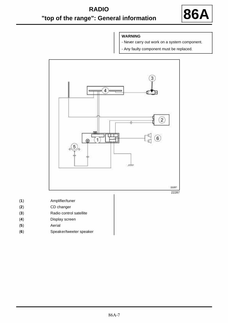
86A-7
RADIO"top of the range": General information 86A
WARNING
- Never carry out work on a system component.
- Any faulty component must be replaced.
22287
(1) Amplifier/tuner
(2) CD changer
(3) Radio control satellite
(4) Display screen
(5) Aerial
(6) Speaker/tweeter speaker

86A-8
RADIO"Top of the range" audio equipment: Removal - Refitting 86A
REMOVAL
Remove the radio using the (Ms. 1373) , inserting at(1) .
Disconnect the various connectors.
REFITTINGConnect the various connectors.
Refit the radio in its housing.
Enter the security code (see Technical Note3701A, Radio fault finding, 86A, Radio: Securitycode ).
Special tooling required
Ms. 1373 Tool for removing radioor chronotachograph.
18627

86A-9
RADIO"top of the range": Operating principle 86A
The radio allows operation without accessories posi-tion for approximately 20 minutes . The system beepsthen switches off.
I - RADIO FUNCTION
This system uses two different tuners:
- the radio tuner,
- the tuner for « traffic information » system messages.
The radio tuner has three selection modes displayed on the screen and accessible from the front panel:
- manual mode (MANU),
- preset mode (PRESET),
- manual or dynamic mode alphabetical (LIST) (see theSettings section).
II - CD READER FUNCTION
The CD changer can hold up to 6 discs (insert throughthe front panel).
The CD changer can play conventional compact discsand any audio tracks on a CD-ROM.
A disc can be played in order or randomly.
1 - Inserting compact discs
Press the (7) « LOAD » button
Use buttons (1) to (6) to select the required position ofthe CD.
Insert the disc into the slot (8) .
Repeat this process for other CDs.
2 - Ejecting compact discs
Press button (7) .
Use buttons (1) to (6) to select the CD to eject.
Note:
- Random play can only be applied to the tracks onone disc. When one CD is finished, random playcontinues on the next disc.
- The « mute » function stops the CD playing andthe display shows « pause » (depending on theversion).
100794
Note:
« SELECT » is displayed.
Note:
« WAIT » is displayed, then the message« INSERT » .
Note:
« LOAD » is displayed, then the CD plays.
1 2 3 4 5 6
7
8
9
86A-10
RADIO"top of the range": Operating principle 86A
III - SPECIAL NOTE CONCERNING TIME SETTING BY SATELLITE
Press and hold down the « source - » button (top right)to enter time setting mode.
Press buttons « + » and « - » to adjust the hour.
Press the source « - » button to confirm the data entry.
Press buttons « + » and « - » to adjust the minutes.
Press the « source - » button to confirm the data entryand quit the time setting.
IV - VOLUME CONTROL
When the audio equipment is switched on, the volumeis the same as when it was switched off, with a maxi-mum volume of 15.
1 - Volume adjustment
The volume can be varied according to vehicle speed.To activate the function, select the required volume ad-justment curve with « expert » mode (press and holdthe « source » button until you hear a beep): 5 formaximum adjustment, 0 to cancel the adjustment.
2 - Balance control
The audio equipment has a range of settings depen-ding on the type of music being played: CLASSIC /JAZZ / POP / VOICE / FLAT / PERSO.
3 - Balance/fader
For a simplified operation, the audio equipment allows all or some of the speakers to be activated or deactiva-ted:
- < FRONT >: only the front speakers work,
- < FRONT: only the front left-hand speaker works,
- FRONT >: only the front right-hand speaker works,
- < REAR >: only the rear speakers work,
- ALL CAR: all the speakers work (balance and fadercentred),
- PERSO: customised settings.
4 - Auxiliary output
In the « EXPERT » menu, the operating mode of the auxiliary source may be chosen:
- AUX ON: scrolls through source selection (radio,CDs, aux, radio, etc), even if there is no source signalto the radio,
- AUX AUTO: automatic connection to the radio when asource signal appears,
- AUX OFF: suppresses the source (radio, CD, radio,etc).
Note:
- The disc ejects. If the disc is still present afterapproximately 15 seconds the disc is automati-cally re-inserted.
- The sound is automatically switched off during allof these processes.
- All CDs can be ejected by pressing the (9)« ALL » button.
Note:
The hours flash on the display.
Note:
The minutes flash on the display.
Note:
- The « mute » function stops the CD from playing.
- The « Traffic Information » messages are playedat the audio equipment's current volume setting. Ifthe volume is altered during a message, the set-ting is stored until it is reset.
- If the radio overheats and its operation is slightlyimpaired, the volume will be automatically loweredwithout the volume displayed being changed.
- Should one of the speakers short circuit, the sup-ply to the amplifier will be cut off.
86A-11
RADIO"top of the range": Protection code 86A
Two components of the radio are protected by a code:
An initial four-digit security code is linked to the tuner-amplifier. This code is required each time the supply iscut off. This code can be entered via the control satelli-te.
If the vehicle is equipped with a code in the front panel,the code is exchanged between the CD changer andthe tuner-amplifier.
(see Technical Note 3701A, Radio fault finding,86A, Radio: Security code ).

86A-12
RADIO"top of the range": Entering the security code 86A
FAULT FINDING CHART 1
The display shows CODE or 0000
Enter the security code. The radio beeps every two seconds for two minutes then displays « CODE » .
Does the audio equipment display « CODE » then « 0000 » ?
Return to scrambled mode.
With the audio equipment switched off, press but-tons 2, 5 and ON.
Wait approximately two minutes until « CODE » then « 0000 » appear.
no
Enter the first digit using the tumble wheel control under the steering wheel.
yes
Confirm the digit by briefly pressing the lower button on the steering wheel control.
Use the same procedure to enter the remaining three digits.
Confirm the security code by pressing and holding down the same button.
Does the audio equipment display « ERROR » then « CODE » ?
Re-enter the code.yes
Does the audio equipment display « CD ERROR » then « CD CODE » ?
no
The audio equipment enters « CONFIGURATION » mode (if being used for the first time) and operates
normally.
no
(see 86A, Radio, "top of the range": Entering the security code, page 86A-13)
yes
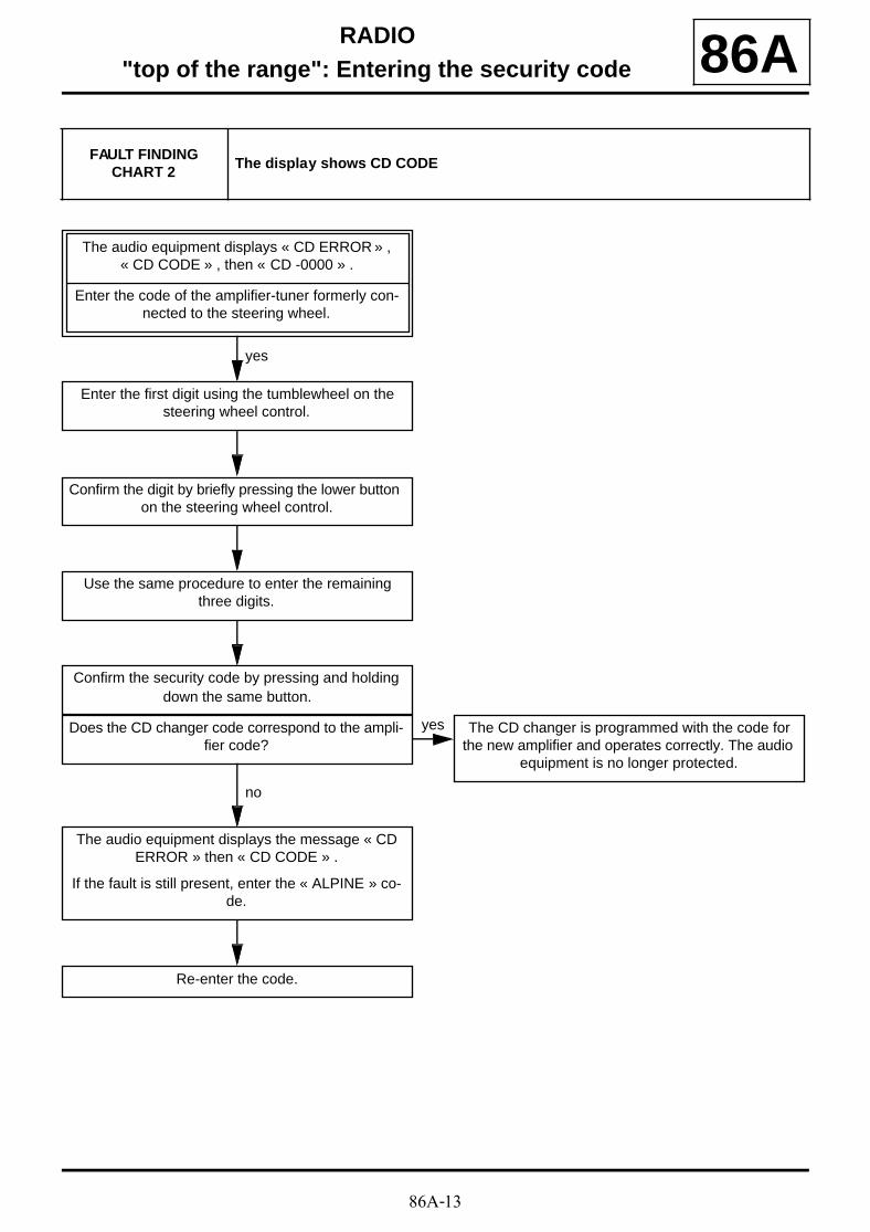
86A-13
RADIO"top of the range": Entering the security code 86A
FAULT FINDING CHART 2
The display shows CD CODE
The audio equipment displays « CD ERROR » , « CD CODE » , then « CD -0000 » .
Enter the code of the amplifier-tuner formerly con-nected to the steering wheel.
Enter the first digit using the tumblewheel on the steering wheel control.
yes
Confirm the digit by briefly pressing the lower button on the steering wheel control.
Use the same procedure to enter the remaining three digits.
Confirm the security code by pressing and holding down the same button.
Does the CD changer code correspond to the ampli-fier code?
The CD changer is programmed with the code for the new amplifier and operates correctly. The audio
equipment is no longer protected.
yes
The audio equipment displays the message « CD ERROR » then « CD CODE » .
If the fault is still present, enter the « ALPINE » co-de.
no
Re-enter the code.
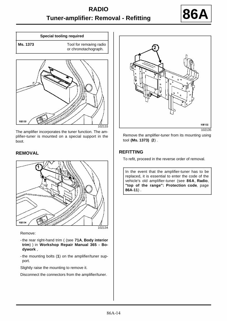
86A-14
RADIOTuner-amplifier: Removal - Refitting 86A
The amplifier incorporates the tuner function. The am-plifier-tuner is mounted on a special support in theboot.
REMOVAL
Remove:
- the rear right-hand trim ( (see 71A, Body interiortrim) ) in Workshop Repair Manual 365 - Bo-dywork ,
- the mounting bolts (1) on the amplifier/tuner sup-port.
Slightly raise the mounting to remove it.
Disconnect the connectors from the amplifier/tuner.
Remove the amplifier-tuner from its mounting usingtool (Ms. 1373) (2) .
REFITTINGTo refit, proceed in the reverse order of removal.
Special tooling required
Ms. 1373 Tool for removing radioor chronotachograph.
102133
102134
1
102135
In the event that the amplifier-tuner has to bereplaced, it is essential to enter the code of thevehicle's old amplifier-tuner (see 86A , Radio,"top of the range": Protection code, page86A-11) .
2
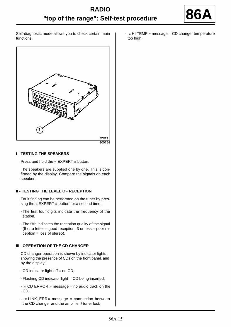
86A-15
RADIO"top of the range": Self-test procedure 86A
Self-diagnostic mode allows you to check certain mainfunctions.
I - TESTING THE SPEAKERS
Press and hold the « EXPERT » button.
The speakers are supplied one by one. This is con-firmed by the display. Compare the signals on eachspeaker.
II - TESTING THE LEVEL OF RECEPTION
Fault finding can be performed on the tuner by pres-sing the « EXPERT » button for a second time.
- The first four digits indicate the frequency of thestation,
- The fifth indicates the reception quality of the signal(9 or a letter = good reception, 3 or less = poor re-ception = loss of stereo).
III - OPERATION OF THE CD CHANGER
CD changer operation is shown by indicator lights showing the presence of CDs on the front panel, and by the display:
- CD indicator light off = no CD,
- Flashing CD indicator light = CD being inserted,
- « CD ERROR » message = no audio track on theCD,
- « LINK_ERR » message = connection betweenthe CD changer and the amplifier / tuner lost,
- « HI TEMP » message = CD changer temperaturetoo high.
100794
1
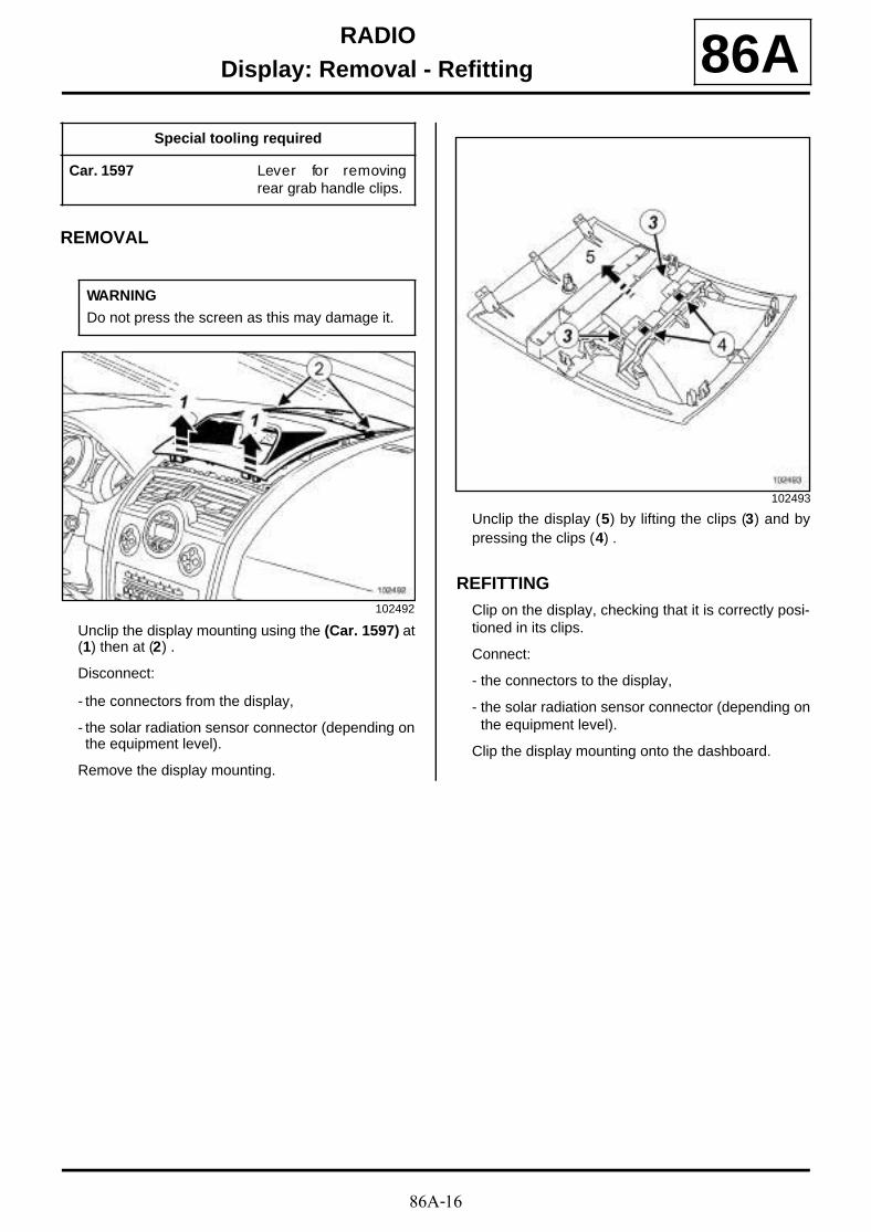
86A-16
RADIODisplay: Removal - Refitting 86A
REMOVAL
Unclip the display mounting using the (Car. 1597) at(1) then at (2) .
Disconnect:
- the connectors from the display,
- the solar radiation sensor connector (depending onthe equipment level).
Remove the display mounting.
Unclip the display (5) by lifting the clips (3) and bypressing the clips (4) .
REFITTINGClip on the display, checking that it is correctly posi-tioned in its clips.
Connect:
- the connectors to the display,
- the solar radiation sensor connector (depending onthe equipment level).
Clip the display mounting onto the dashboard.
Special tooling required
Car. 1597 Lever for removingrear grab handle clips.
WARNING
Do not press the screen as this may damage it.
102492
102493
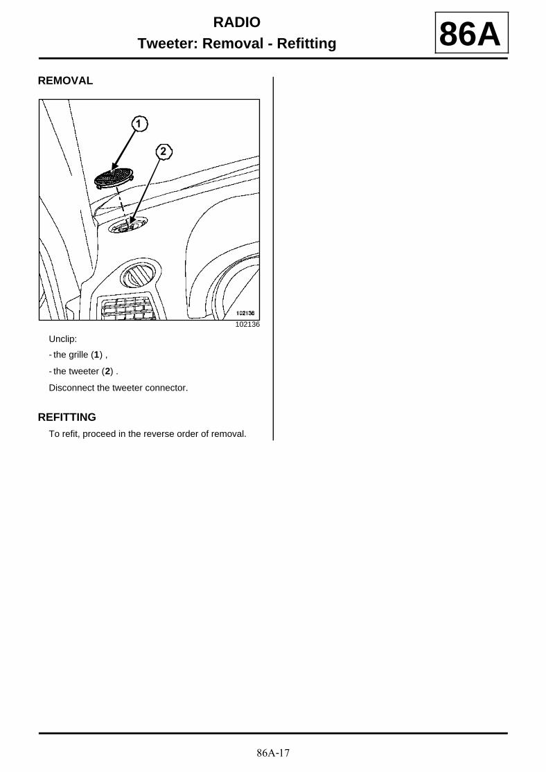
86A-17
RADIOTweeter: Removal - Refitting 86A
REMOVAL
Unclip:
- the grille (1) ,
- the tweeter (2) .
Disconnect the tweeter connector.
REFITTINGTo refit, proceed in the reverse order of removal.
102136
1
2
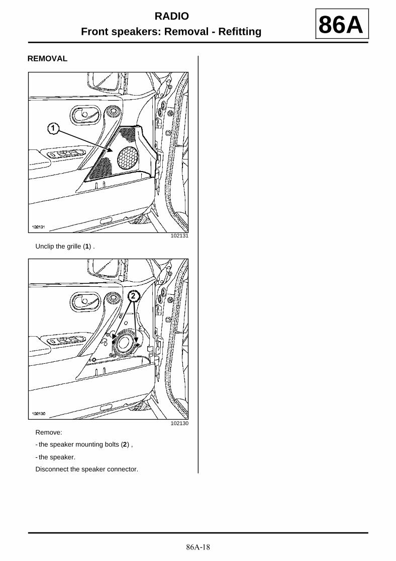
86A-18
RADIOFront speakers: Removal - Refitting 86A
REMOVAL
Unclip the grille (1) .
Remove:
- the speaker mounting bolts (2) ,
- the speaker.
Disconnect the speaker connector.
102131
102130
1
2
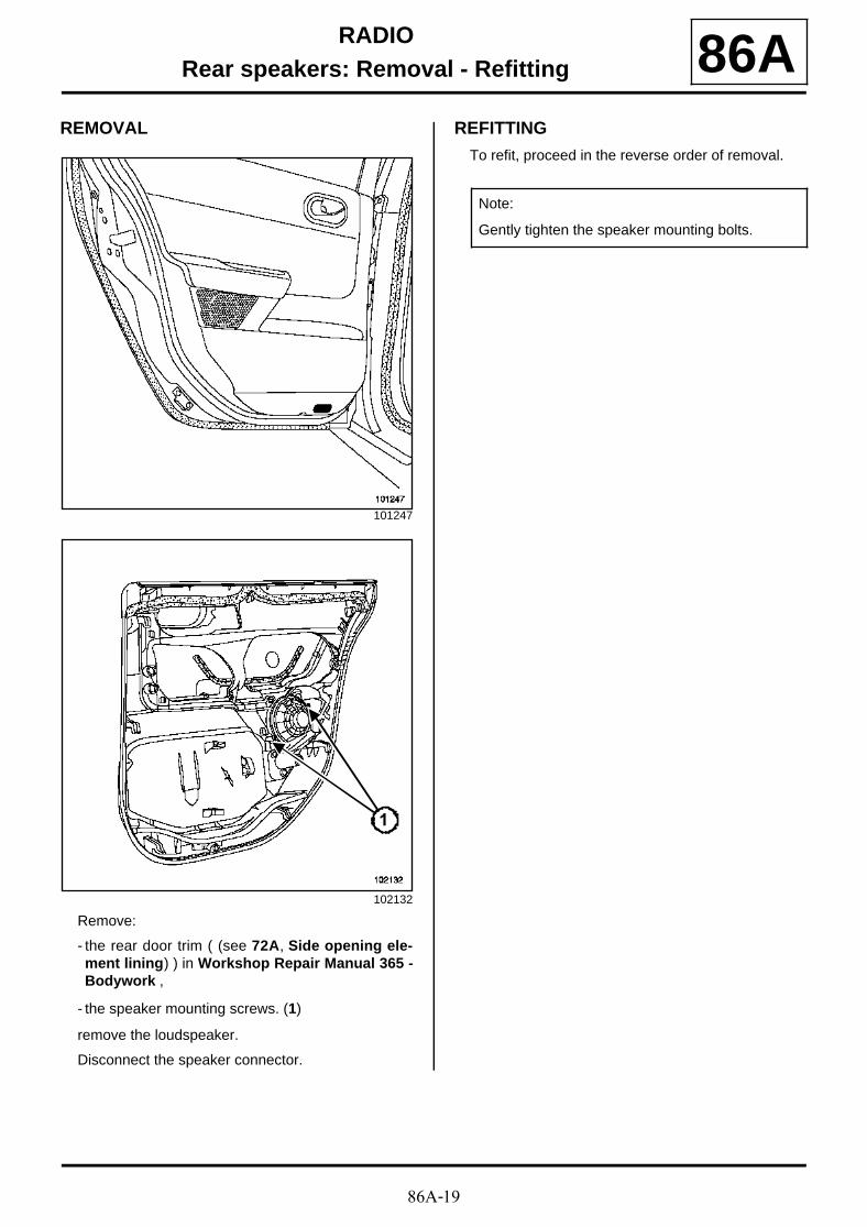
86A-19
RADIORear speakers: Removal - Refitting 86A
REMOVAL
Remove:
- the rear door trim ( (see 72A, Side opening ele-ment lining) ) in Workshop Repair Manual 365 -Bodywork ,
- the speaker mounting screws. (1)
remove the loudspeaker.
Disconnect the speaker connector.
REFITTING
To refit, proceed in the reverse order of removal.
101247
102132
1
Note:
Gently tighten the speaker mounting bolts.
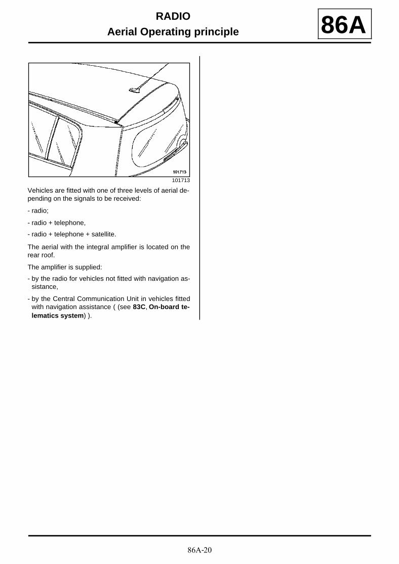
86A-20
RADIOAerial Operating principle 86A
Vehicles are fitted with one of three levels of aerial de-pending on the signals to be received:
- radio;
- radio + telephone,
- radio + telephone + satellite.
The aerial with the integral amplifier is located on therear roof.
The amplifier is supplied:
- by the radio for vehicles not fitted with navigation as-sistance,
- by the Central Communication Unit in vehicles fittedwith navigation assistance ( (see 83C, On-board te-lematics system) ).
101713
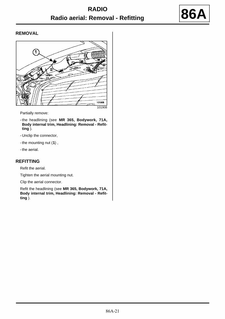
86A-21
RADIORadio aerial: Removal - Refitting 86A
REMOVAL
Partially remove:
- the headlining (see MR 365, Bodywork, 71A,Body internal trim, Headlining: Removal - Refit-ting ).
- Unclip the connector,
- the mounting nut (1) ,
- the aerial.
REFITTINGRefit the aerial.
Tighten the aerial mounting nut.
Clip the aerial connector.
Refit the headlining (see MR 365, Bodywork, 71A,Body internal trim, Headlining: Removal - Refit-ting ).
101908
1
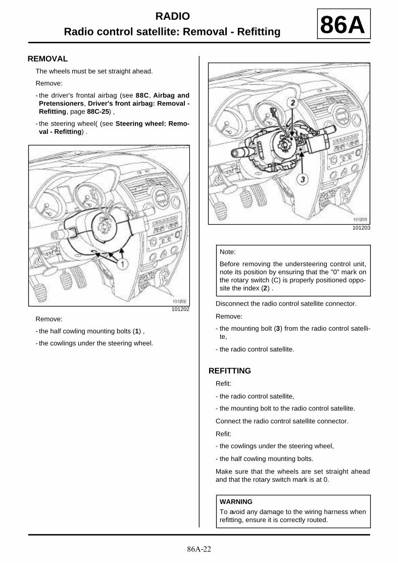
86A-22
RADIORadio control satellite: Removal - Refitting 86A
REMOVAL
The wheels must be set straight ahead.
Remove:
- the driver's frontal airbag (see 88C, Airbag andPretensioners, Driver's front airbag: Removal -Refitting, page 88C-25) ,
- the steering wheel( (see Steering wheel: Remo-val - Refitting) .
Remove:
- the half cowling mounting bolts (1) ,
- the cowlings under the steering wheel.
Disconnect the radio control satellite connector.
Remove:
- the mounting bolt (3) from the radio control satelli-te,
- the radio control satellite.
REFITTING
Refit:
- the radio control satellite,
- the mounting bolt to the radio control satellite.
Connect the radio control satellite connector.
Refit:
- the cowlings under the steering wheel,
- the half cowling mounting bolts.
Make sure that the wheels are set straight aheadand that the rotary switch mark is at 0.
101202
101203
Note:
Before removing the understeering control unit,note its position by ensuring that the "0" mark onthe rotary switch (C) is properly positioned oppo-site the index (2) .
WARNING
To avoid any damage to the wiring harness whenrefitting, ensure it is correctly routed.
86A-23
RADIORadio control satellite: Removal - Refitting 86A
Refit:
- the steering wheel( (see Steering wheel: Remo-val - Refitting) ,
- the driver's frontal airbag (see 88C, Airbag andPretensioners, Driver's front airbag: Removal -Refitting, page 88C-25) .
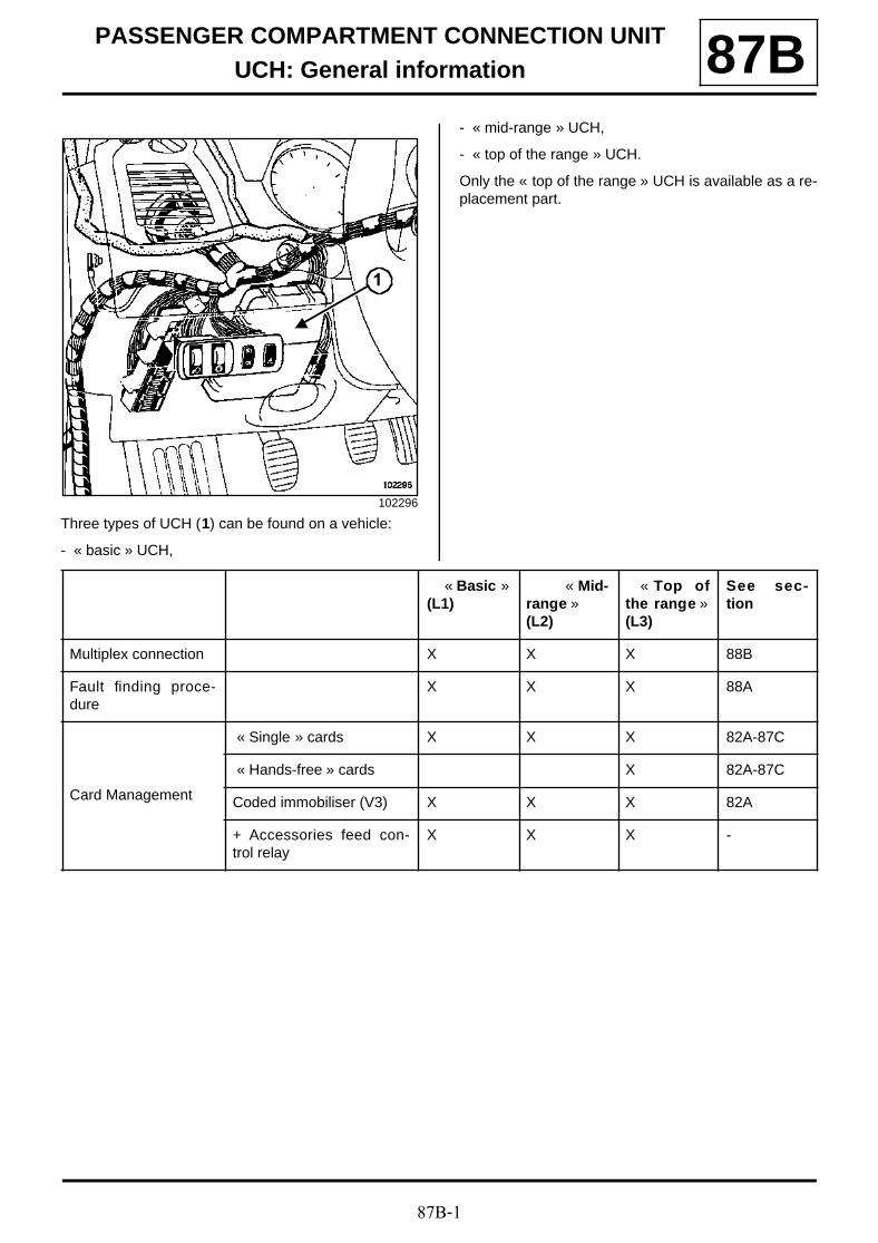
87B-1
PASSENGER COMPARTMENT CONNECTION UNITUCH: General information 87B
Three types of UCH (1) can be found on a vehicle:
- « basic » UCH,
- « mid-range » UCH,
- « top of the range » UCH.
Only the « top of the range » UCH is available as a re-placement part.
102296
1
« Basic »(L1)
« Mid-range »(L2)
« Top ofthe range »(L3)
See sec-tion
Multiplex connection X X X 88B
Fault finding proce-dure
X X X 88A
Card Management
« Single » cards X X X 82A-87C
« Hands-free » cards X 82A-87C
Coded immobiliser (V3) X X X 82A
+ Accessories feed con-trol relay
X X X -

87B-2
PASSENGER COMPARTMENT CONNECTION UNITUCH: General information 87B
Doors and boot
Central door locking (andunlocking in the event ofan impact) while driving
X X X 87C
Relocking the doors andboot/tailgate
X X X 87C
Electric and one-touchwindows (authorisation)
X X X 87D
Tailgate lock X X X 87D
Deadlocking the doors andboot/tailgate
X X 87D
Electric childproof lock X X 84A
« Driver's door only »opening program
X X 87D
Exterior locking buttonmanagement (Hands-free)
X 87D
Wipers
Rain and light sensor X X X 85A
Windscreen wipers (lowand high-speed manage-ment)
X X X 85A
Rear screen wiper (wiperspeed according to vehiclespeed)
X X X 85A
Windscreen and rearscreen washers
X X X 85A
Headlight washers X X 80B-85A
« Basic »(L1)
« Mid-range »(L2)
« Top ofthe range »(L3)
See sec-tion
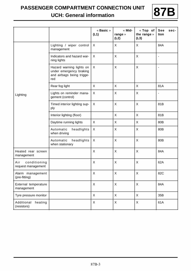
87B-3
PASSENGER COMPARTMENT CONNECTION UNITUCH: General information 87B
Lighting
Lighting / wiper controlmanagement
X X X 84A
Indicators and hazard war-ning lights
X X X -
Hazard warning lights onunder emergency brakingand airbags being trigge-red
X X X -
Rear fog light X X X 81A
Lights on reminder mana-gement (control)
X X X -
Timed interior lighting sup-ply
X X X 81B
Interior lighting (floor) X X 81B
Daytime running lights X X X 80B
Automatic headl ightswhen driving
X X X 80B
Automatic headl ightswhen stationary
X X X 80B
Heated rear screenmanagement
X X X 84A
Ai r cond i t ion ingrequest management
X X X 62A
Alarm management(pre-fitting)
X X X 82C
External temperaturemanagement
X X X 84A
Tyre pressure monitor X X X 35B
Additional heating(resistors)
X X X 61A
« Basic »(L1)
« Mid-range »(L2)
« Top ofthe range »(L3)
See sec-tion
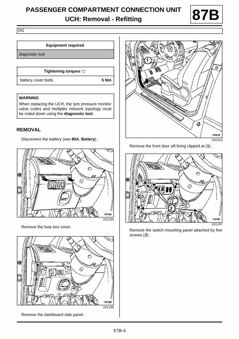
87B-4
PASSENGER COMPARTMENT CONNECTION UNITUCH: Removal - Refitting
DG
87B
REMOVAL
Disconnect the battery (see 80A, Battery) .
Remove the fuse box cover.
Remove the dashboard side panel.
Remove the front door sill lining clipped at (1) .
Remove the switch mounting panel attached by fivescrews (2) .
Equipment required
diagnostic tool
Tightening torquesm
battery cover bolts 5 Nm
WARNING
When replacing the UCH, the tyre pressure monitorvalve codes and multiplex network topology mustbe noted down using the diagnostic tool .
101194
101196
101313
101197
1
222
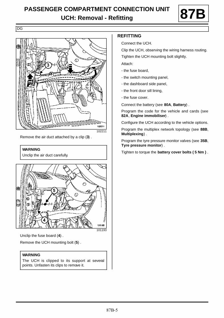
87B-5
PASSENGER COMPARTMENT CONNECTION UNITUCH: Removal - Refitting
DG
87B
Remove the air duct attached by a clip (3) .
Unclip the fuse board (4) .
Remove the UCH mounting bolt (5) .
REFITTING
Connect the UCH.
Clip the UCH, observing the wiring harness routing.
Tighten the UCH mounting bolt slightly.
Attach:
- the fuse board,
- the switch mounting panel,
- the dashboard side panel,
- the front door sill lining,
- the fuse cover.
Connect the battery (see 80A, Battery) .
Program the code for the vehicle and cards (see82A, Engine immobiliser) .
Configure the UCH according to the vehicle options.
Program the multiplex network topology (see 88B,Multiplexing) .
Program the tyre pressure monitor valves (see 35B,Tyre pressure monitor) .
Tighten to torque the battery cover bolts ( 5 Nm ) .
102211
WARNING
Unclip the air duct carefully.
101193
WARNING
The UCH is clipped to its support at severalpoints. Unfasten its clips to remove it.
3
5
4

87B-6
PASSENGER COMPARTMENT CONNECTION UNITUCH: Removal - Refitting
DD
87B
REMOVALDisconnect the battery (see 80A, Battery) .
Open the glove compartment.
Remove:
- the dashboard panel,
- the door sill lining.
Remove the glovebox mounting bolts (1) .
Remove:
- the glove compartment,
- the bolt (2) securing the UCH.
Equipment required
diagnostic tool
Tightening torquesm
battery cover bolts 5 Nm
WARNING
When replacing the UCH, the tyre pressure monitorvalve codes and multiplex network topology mustbe noted down using the diagnostic tool
101980
101981
101976
WARNING
The UCH is clipped to its support at severalpoints. Unfasten its clips to remove it.
111
2
87B-7
PASSENGER COMPARTMENT CONNECTION UNITUCH: Removal - Refitting
DD
87BREFITTING
Connect the UCH.
Clip the UCH, observing the wiring harness routing.
Tighten the UCH mounting bolt slightly.
Attach:
- the glove compartment, taking care not to pinch thepassenger airbag wiring harness,
- the dashboard side panel,
- the front door sill lining.
Connect the battery (see 80A, Battery) .
Program the code for the vehicle and cards (see82A, Engine immobiliser) .
Configure the UCH according to the vehicle options.
Program the multiplex network topology (see 88B,Multiplexing) .
Program the tyre pressure monitor valves (see 35B,Tyre pressure monitor) .
Tighten to torque the battery cover bolts ( 5 Nm ) .
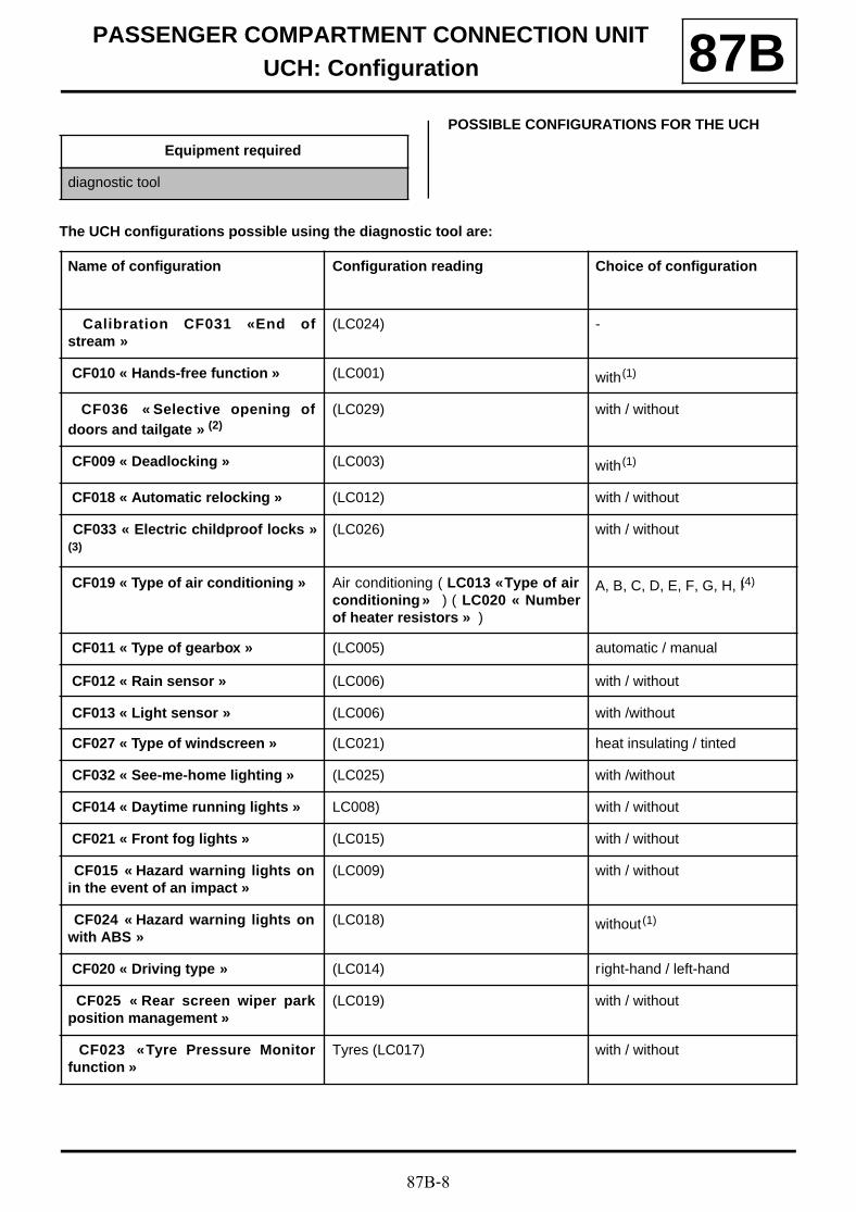
87B-8
PASSENGER COMPARTMENT CONNECTION UNITUCH: Configuration 87B
POSSIBLE CONFIGURATIONS FOR THE UCH
The UCH configurations possible using the diagnostic tool are:
Equipment required
diagnostic tool
Name of configuration Configuration reading Choice of configuration
Calibration CF031 « End ofstream »
(LC024) -
CF010 « Hands-free function » (LC001) with(1)
CF036 « Selective opening ofdoors and tailgate » (2)
(LC029) with / without
CF009 « Deadlocking » (LC003) with(1)
CF018 « Automatic relocking » (LC012) with / without
CF033 « Electric childproof locks »(3)
(LC026) with / without
CF019 « Type of air conditioning » Air conditioning ( LC013 « Type of airconditioning » ) ( LC020 « Numberof heater resistors » )
A, B, C, D, E, F, G, H, I(4)
CF011 « Type of gearbox » (LC005) automatic / manual
CF012 « Rain sensor » (LC006) with / without
CF013 « Light sensor » (LC006) with /without
CF027 « Type of windscreen » (LC021) heat insulating / tinted
CF032 « See-me-home lighting » (LC025) with /without
CF014 « Daytime running lights » LC008) with / without
CF021 « Front fog lights » (LC015) with / without
CF015 « Hazard warning lights onin the event of an impact »
(LC009) with / without
CF024 « Hazard warning lights onwith ABS »
(LC018) without(1)
CF020 « Driving type » (LC014) right-hand / left-hand
CF025 « Rear screen wiper parkposition management »
(LC019) with / without
CF023 « Tyre Pressure Monitorfunction »
Tyres (LC017) with / without
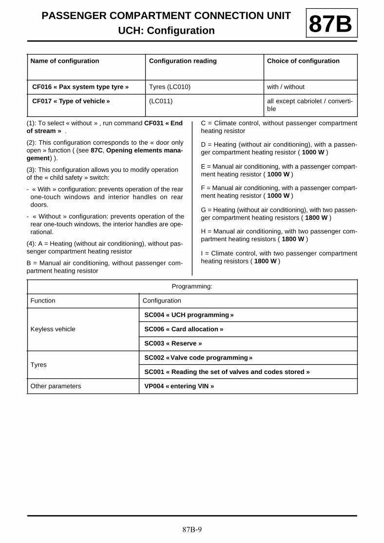
87B-9
PASSENGER COMPARTMENT CONNECTION UNITUCH: Configuration 87B
(1): To select « without » , run command CF031 « Endof stream » .
(2): This configuration corresponds to the « door onlyopen » function ( (see 87C, Opening elements mana-gement) ).
(3): This configuration allows you to modify operation of the « child safety » switch:
- « With » configuration: prevents operation of the rearone-touch windows and interior handles on reardoors.
- « Without » configuration: prevents operation of therear one-touch windows, the interior handles are ope-rational.
(4): A = Heating (without air conditioning), without pas-senger compartment heating resistor
B = Manual air conditioning, without passenger com-partment heating resistor
C = Climate control, without passenger compartmentheating resistor
D = Heating (without air conditioning), with a passen-ger compartment heating resistor ( 1000 W )
E = Manual air conditioning, with a passenger compart-ment heating resistor ( 1000 W )
F = Manual air conditioning, with a passenger compart-ment heating resistor ( 1000 W )
G = Heating (without air conditioning), with two passen-ger compartment heating resistors ( 1800 W )
H = Manual air conditioning, with two passenger com-partment heating resistors ( 1800 W )
I = Climate control, with two passenger compartmentheating resistors ( 1800 W )
CF016 « Pax system type tyre » Tyres (LC010) with / without
CF017 « Type of vehicle » (LC011) all except cabriolet / converti-ble
Name of configuration Configuration reading Choice of configuration
Programming:
Function Configuration
Keyless vehicle
SC004 « UCH programming »
SC006 « Card allocation »
SC003 « Reserve »
Tyres SC002 « Valve code programming »
SC001 « Reading the set of valves and codes stored »
Other parameters VP004 « entering VIN »
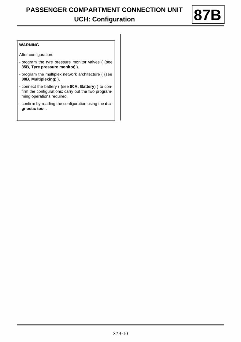
87B-10
PASSENGER COMPARTMENT CONNECTION UNITUCH: Configuration 87B
WARNING
After configuration:
- program the tyre pressure monitor valves ( (see35B, Tyre pressure monitor) ).
- program the multiplex network architecture ( (see88B, Multiplexing) ),
- connect the battery ( (see 80A, Battery) ) to con-firm the configurations; carry out the two program-ming operations required,
- confirm by reading the configuration using the dia-gnostic tool .
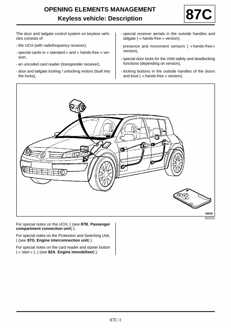
87C-1
OPENING ELEMENTS MANAGEMENTKeyless vehicle: Description 87C
The door and tailgate control system on keyless vehi-cles consists of:
- the UCH (with radiofrequency receiver),
- special cards in « standard » and « hands-free » ver-sion,
- an uncoded card reader (transponder receiver),
- door and tailgate locking / unlocking motors (built intothe locks),
- special receiver aerials in the outside handles andtailgate ( « hands-free » version),
- presence and movement sensors ( « hands-free »version),
- special door locks for the child safety and deadlockingfunctions (depending on version),
- locking buttons in the outside handles of the doorsand boot ( « hands-free » version).
For special notes on the UCH, ( (see 87B, Passengercompartment connection unit) ).
For special notes on the Protection and Switching Unit,( (see 87G, Engine interconnection unit) ).
For special notes on the card reader and starter button( « start » ), ( (see 82A, Engine immobiliser) ).
102151
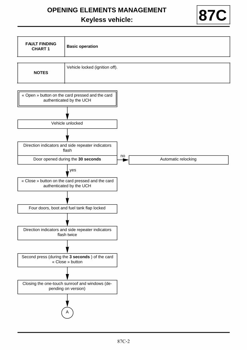
87C-2
OPENING ELEMENTS MANAGEMENTKeyless vehicle: 87C
FAULT FINDING CHART 1
Basic operation
NOTESVehicle locked (ignition off).
« Open » button on the card pressed and the card authenticated by the UCH
Vehicle unlocked
Direction indicators and side repeater indicators flash
Door opened during the 30 seconds Automatic relockingno
« Close » button on the card pressed and the card authenticated by the UCH
yes
Four doors, boot and fuel tank flap locked
Direction indicators and side repeater indicators flash twice
Second press (during the 3 seconds ) of the card « Close » button
Closing the one-touch sunroof and windows (de-pending on version)
A
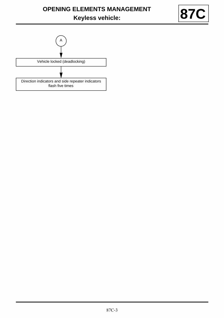
87C-3
OPENING ELEMENTS MANAGEMENTKeyless vehicle: 87C
A
Vehicle locked (deadlocking)
Direction indicators and side repeater indicators flash five times

87C-4
OPENING ELEMENTS MANAGEMENTKeyless vehicle: 87C
FAULT FINDING CHART 2
Hands-free operation
NOTESVehicle locked (ignition off)
Card authenticated by opening aerial
-Vehicle locked for less than 72 hours : hand de-tected by handle presence sensor
-Vehicle locked for more than 72 hours : opening request made by movement sensor (handle pul-
led) or by luggage compartment lid opening switch
Vehicle unlocked
Direction indicators and side repeater indicators flash
Door opened within 30 seconds Automatic relockingno
Card authenticated by opening aerials and press the following buttons:
-outside door handle
- « luggage compartment lid badge »
- « close » button on card
yes
Four doors, boot and fuel tank flap locked
Direction indicators and side repeater indicators flash twice
A

87C-5
OPENING ELEMENTS MANAGEMENTKeyless vehicle: 87C
A
Second press (within 3 seconds ) on the same but-ton:
-of outside door handle
-of « luggage compartment lid badge »
-of « close » button on card
Closing the windows and sunroof (depending on version)
Vehicle locked (deadlocked)
Direction indicators and side repeater indicators flash five times
The presence sensors are inhibited for approxima-tely 3 seconds

87C-6
OPENING ELEMENTS MANAGEMENTKeyless vehicle: 87C
FAULT FINDING CHART 3
Deadlocking function operation
NOTESVehicle deadlocked (ignition off)
« Open » button on the card pressed and the card authenticated by the UCH
Driver's door and fuel tank flap unlocked
Direction indicators and side repeater indicators flash
Door opened during the 30 seconds Automatic relockingno
Second press of the card « open » button
yes
Four doors, boot and fuel tank flap unlocked
Vehicle unlocked
Direction indicators and side repeater indicators flash
« Close » button on the card pressed and the card authenticated by the UCH
A

87C-7
OPENING ELEMENTS MANAGEMENTKeyless vehicle: 87C
A
Four doors, boot and fuel tank flap locked
Direction indicators and side repeater indicators flash twice
Second press (during the 3 seconds ) of the « Close » button on the same card
Closing the one-touch sunroof and windows (de-pending on version)
Vehicle locked (deadlocking)
Direction indicators and side repeater indicators flash five times
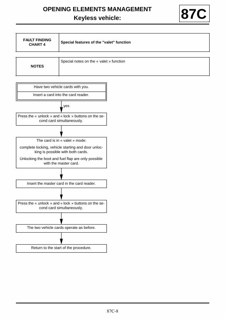
87C-8
OPENING ELEMENTS MANAGEMENTKeyless vehicle: 87C
FAULT FINDING CHART 4
Special features of the "valet" function
NOTESSpecial notes on the « valet » function
Have two vehicle cards with you.
Insert a card into the card reader.
Press the « unlock » and « lock » buttons on the se-cond card simultaneously.
yes
The card is in « valet » mode:
complete locking, vehicle starting and door unloc-king is possible with both cards.
Unlocking the boot and fuel flap are only possible with the master card.
Insert the master card in the card reader.
Press the « unlock » and « lock » buttons on the se-cond card simultaneously.
The two vehicle cards operate as before.
Return to the start of the procedure.

87C-9
OPENING ELEMENTS MANAGEMENTKeyless vehicle: 87C
FAULT FINDING CHART 5
Tailgate operation
NOTESVehicle locked (ignition off)
Luggage compartment lid opening switch pressed and card authenticated by the UCH
Boot unlocked
Direction indicators and side repeater indicators flash
Door opened within 30 seconds Automatic relockingno
Press:
-the « luggage compartment » button on the card
-the « luggage compartment badge » button
and card authenticated by the UCH
yes
Boot locked
Direction indicators and side repeater indicators flash twice
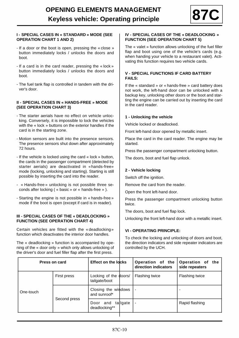
87C-10
OPENING ELEMENTS MANAGEMENTKeyless vehicle: Operating principle 87C
I - SPECIAL CASES IN « STANDARD » MODE (SEE OPERATION CHART 1 AND 2)
- If a door or the boot is open, pressing the « close »button immediately locks / unlocks the doors andboot.
- If a card is in the card reader, pressing the « lock »button immediately locks / unlocks the doors andboot.
- The fuel tank flap is controlled in tandem with the dri-ver's door.
II - SPECIAL CASES IN « HANDS-FREE » MODE (SEE OPERATION CHART 3)
- The starter aerials have no effect on vehicle unloc-king. Conversely, it is impossible to lock the vehicleswith the « lock » buttons on the exterior handles if thecard is in the starting zone.
- Motion sensors are built into the presence sensors.The presence sensors shut down after approximately72 hours.
- If the vehicle is locked using the card « lock » button,the cards in the passenger compartment (detected bystarter aerials) are deactivated in « hands-free »mode (locking, unlocking and starting). Starting is stillpossible by inserting the card into the reader.
- « Hands-free » unlocking is not possible three se-conds after locking ( « basic » or « hands-free » ).
- Starting the engine is not possible in « hands-free »mode if the boot is open (except if card is in reader).
III - SPECIAL CASES OF THE « DEADLOCKING » FUNCTION (SEE OPERATION CHART 4)
Certain vehicles are fitted with the « deadlocking »function which deactivates the interior door handles.
The « deadlocking » function is accompanied by ope-ning of the « door only » which only allows unlocking ofthe driver's door and fuel filler flap after the first press.
IV - SPECIAL CASES OF THE « DEADLOCKING » FUNCTION (SEE OPERATION CHART 5)
The « valet » function allows unlocking of the fuel fillerflap and boot using one of the vehicle's cards (e.g.when handing your vehicle to a restaurant valet). Acti-vating this function requires two vehicle cards.
V - SPECIAL FUNCTIONS IF CARD BATTERY FAILS:
If the « standard » or « hands-free » card battery doesnot work, the left-hand door can be unlocked with abackup key, unlocking other doors or the boot and star-ting the engine can be carried out by inserting the cardin the card reader.
1 - Unlocking the vehicle
Vehicle locked or deadlocked.
Front left-hand door opened by metallic insert.
Place the card in the card reader. The engine may bestarted.
Press the passenger compartment unlocking button.
The doors, boot and fuel flap unlock.
2 - Vehicle locking
Switch off the ignition.
Remove the card from the reader.
Open the front left-hand door.
Press the passenger compartment unlocking buttontwice.
The doors, boot and fuel flap lock.
Unlocking the front left-hand door with a metallic insert.
VI - OPERATING PRINCIPLE:
To check the locking and unlocking of doors and boot,the direction indicators and side repeater indicators arecontrolled by the UCH.
Press on card Effect on the locks Operation of thedirection indicators
Operation of theside repeaters
One-touch
First press Locking of the doors/tailgate/boot
Flashing twice Flashing twice
Second press
Closing the windowsand sunroof*
- -
Door and tailgatedeadlocking**
- Rapid flashing

87C-11
OPENING ELEMENTS MANAGEMENTKeyless vehicle: Operating principle 87C
* For this function, the vehicle must be fitted with one-touch electric windows and anti-pinch electric sunroof.
** certain vehicles may be equipped with the« deadlocking » function and the « door onlyunlocking » function. This function allows you to onlylock the driver's door and fuel flap with the first press onthe card.
This system may comprise up to four cards.
The « standard » and « hands-free » cards are diffe-rent and are not interchangeable.
The cards are equipped with a backup key which al-lows the door to be unlocked in the event of a fault.
Cards delivered as spare parts are blank. A cover is fit-ted in the place of the emergency key.
Card operation
For the procedure for programming or allocating acard, ( (see 82A, Engine immobiliser) ).
One-touch
First press Unlocking of thedoors and luggagecompartment or thedriver's door**
Flashing once Flashing once
Second press Unlocking of thedoors and boot**
- -
Press on card Effect on the locks Operation of thedirection indicators
Operation of theside repeaters
Note:
A backup key can be ordered from the replacementparts store by giving them the vehicle identificationand safety numbers.
101930
43
2
1
(1) « Unlocking » button
(2) « Locking » button
(3) « Boot unlocking / locking » but-ton
(4) Backup key
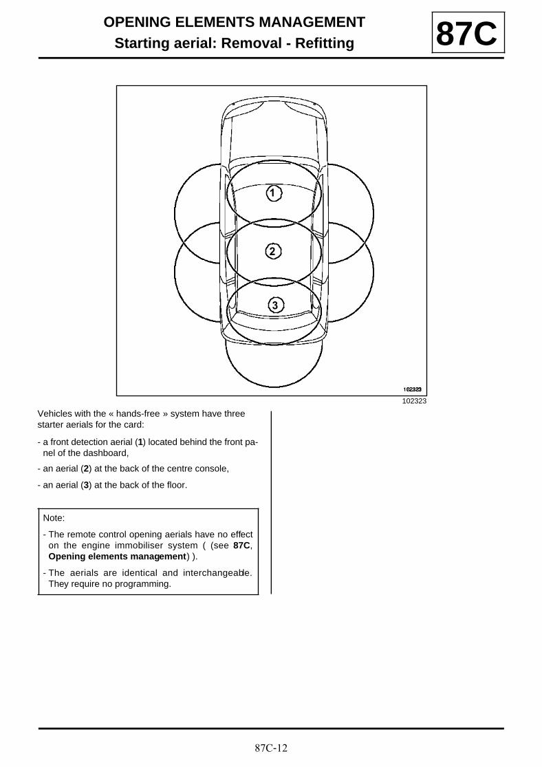
87C-12
OPENING ELEMENTS MANAGEMENTStarting aerial: Removal - Refitting 87C
Vehicles with the « hands-free » system have three starter aerials for the card:
- a front detection aerial (1) located behind the front pa-nel of the dashboard,
- an aerial (2) at the back of the centre console,
- an aerial (3) at the back of the floor.
102323
3
2
1
Note:
- The remote control opening aerials have no effecton the engine immobiliser system ( (see 87C,Opening elements management) ).
- The aerials are identical and interchangeable.They require no programming.
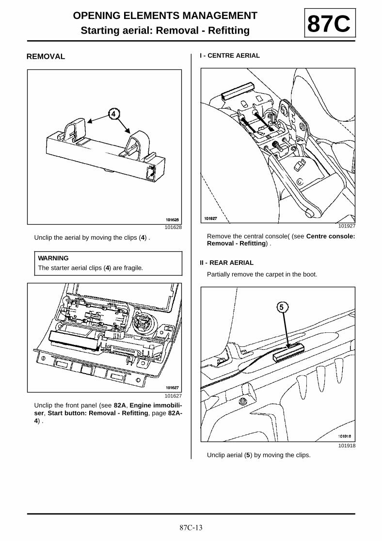
87C-13
OPENING ELEMENTS MANAGEMENTStarting aerial: Removal - Refitting 87C
REMOVAL
Unclip the aerial by moving the clips (4) .
Unclip the front panel (see 82A, Engine immobili-ser, Start button: Removal - Refitting, page 82A-4) .
I - CENTRE AERIAL
Remove the central console( (see Centre console:Removal - Refitting) .
II - REAR AERIAL
Partially remove the carpet in the boot.
Unclip aerial (5) by moving the clips.
101628
WARNING
The starter aerial clips (4) are fragile.
101627
4
101927
101918
5
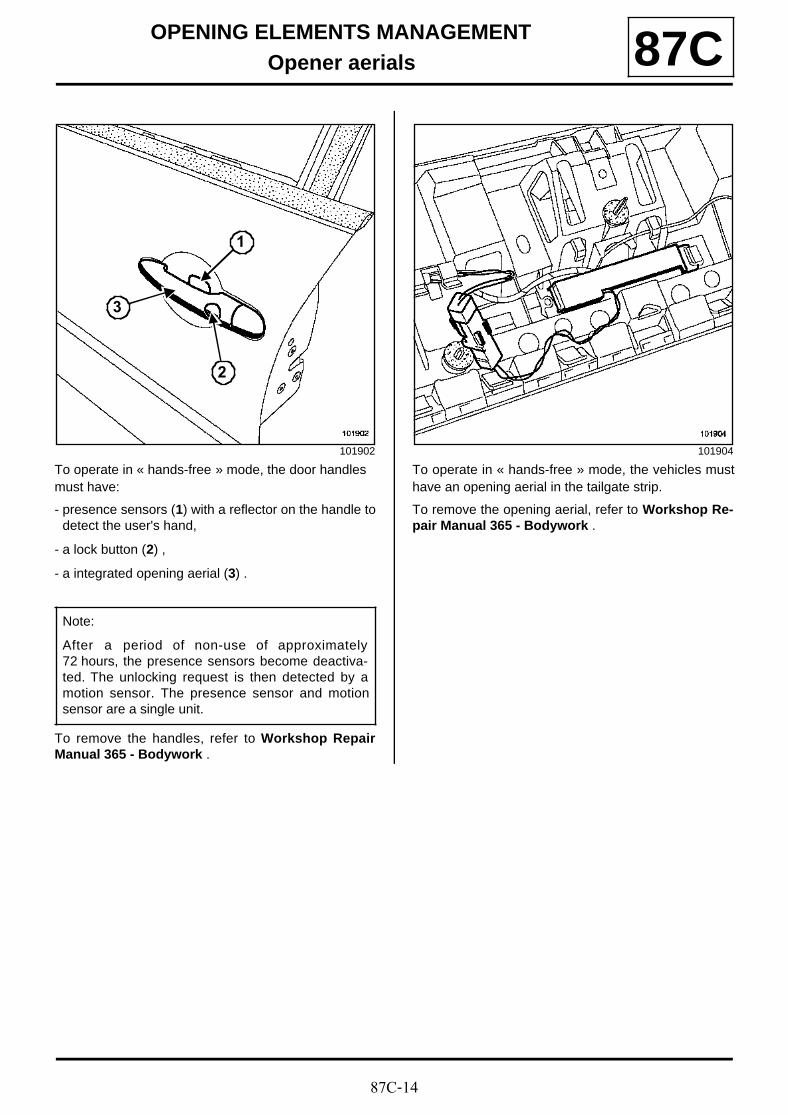
87C-14
OPENING ELEMENTS MANAGEMENTOpener aerials 87C
To operate in « hands-free » mode, the door handles must have:
- presence sensors (1) with a reflector on the handle todetect the user's hand,
- a lock button (2) ,
- a integrated opening aerial (3) .
To remove the handles, refer to Workshop RepairManual 365 - Bodywork .
To operate in « hands-free » mode, the vehicles musthave an opening aerial in the tailgate strip.
To remove the opening aerial, refer to Workshop Re-pair Manual 365 - Bodywork .
101902
Note:
After a period of non-use of approximately72 hours, the presence sensors become deactiva-ted. The unlocking request is then detected by amotion sensor. The presence sensor and motionsensor are a single unit.
1
2
3
101904

87C-15
OPENING ELEMENTS MANAGEMENTTailgate opening switch: Removal - Refitting 87C
REMOVAL
Protect the edge of the opening control with maskingtape.
Unclip the control at (1) and (2) using a flat screwdri-ver.
Disconnect the connector (3) .
REFITTING
To refit, proceed in the reverse order of removal.
Note:
It is not necessary to remove the door strip toperform this operation.
101380
101383
21
3
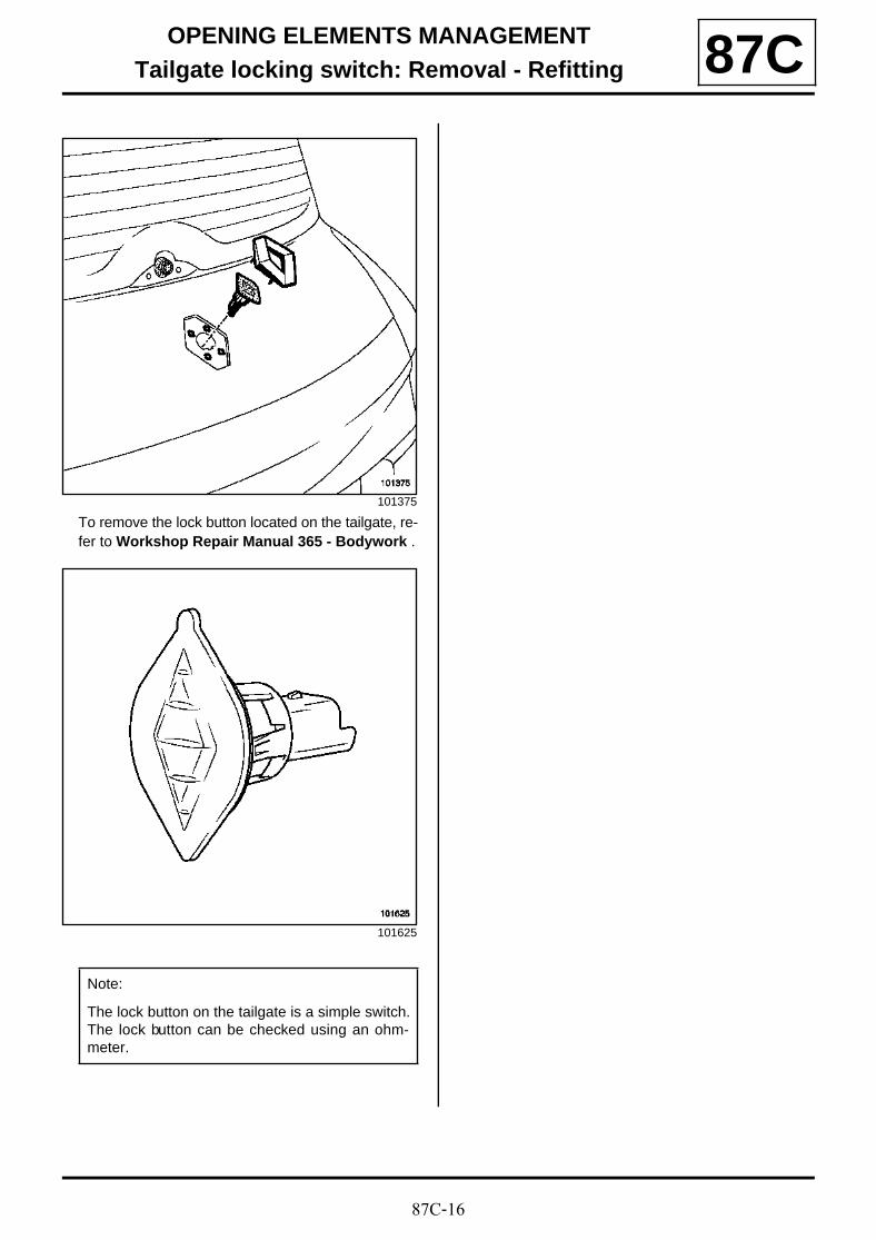
87C-16
OPENING ELEMENTS MANAGEMENTTailgate locking switch: Removal - Refitting 87C
To remove the lock button located on the tailgate, re-fer to Workshop Repair Manual 365 - Bodywork .
101375
101625
Note:
The lock button on the tailgate is a simple switch.The lock button can be checked using an ohm-meter.
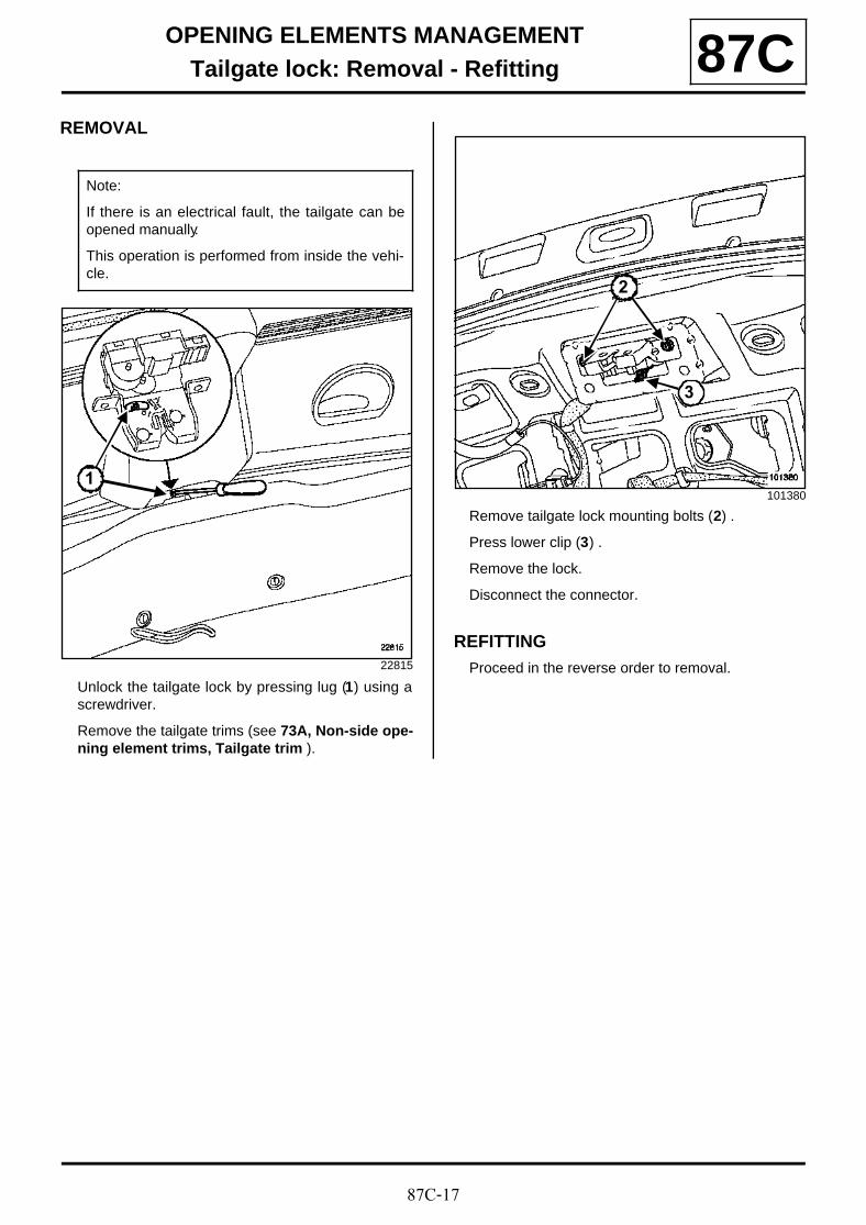
87C-17
OPENING ELEMENTS MANAGEMENTTailgate lock: Removal - Refitting 87C
REMOVAL
Unlock the tailgate lock by pressing lug (1) using ascrewdriver.
Remove the tailgate trims (see 73A, Non-side ope-ning element trims, Tailgate trim ).
Remove tailgate lock mounting bolts (2) .
Press lower clip (3) .
Remove the lock.
Disconnect the connector.
REFITTINGProceed in the reverse order to removal.
Note:
If there is an electrical fault, the tailgate can beopened manually.
This operation is performed from inside the vehi-cle.
22815
1101380
2
3
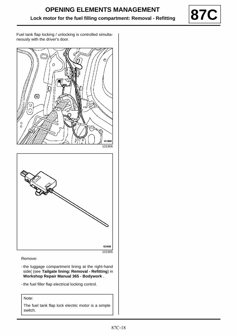
87C-18
OPENING ELEMENTS MANAGEMENTLock motor for the fuel filling compartment: Removal - Refitting 87C
Fuel tank flap locking / unlocking is controlled simulta-neously with the driver's door.
Remove:
- the luggage compartment lining at the right-handside( (see Tailgate lining: Removal - Refitting) inWorkshop Repair Manual 365 - Bodywork .
- the fuel filler flap electrical locking control.
101906
101905
Note:
The fuel tank flap lock electric motor is a simpleswitch.
87D-1
ELECTRIC WINDOWS - SUNROOFElectric window: Operation 87D
I - TYPES OF UNIT
Three types of electric window switches can be found on the driver's door:
- driver and passenger electric windows,
- driver's one-touch and passenger electric window
- driver's and passenger one-touch electric windows.
Two types of electric window switches can be found on the passenger door.
- electric window,
- one-touch electric window.
All rear electric window switches are the one-touch ty-pe.
II - ELECTRIC WINDOWS
Operating principle: The electric window motor ispowered through the switch, which can also flip the po-larity (for lowering or raising).
III - ONE-TOUCH ELECTRIC WINDOW
The one-touch switch has two positions for raising and two for lowering the windows.
- First raising contact: raising earth connection (basicraising).
- Second raising contact: raising and lowering connec-tion earthing (one-touch raising to the highest posi-tion).
- First lowering contact: raising connection earthing(basic lowering).
- Second lowering contact: raising and lowering con-nection earthing (one-touch lowering to the lowest po-sition).
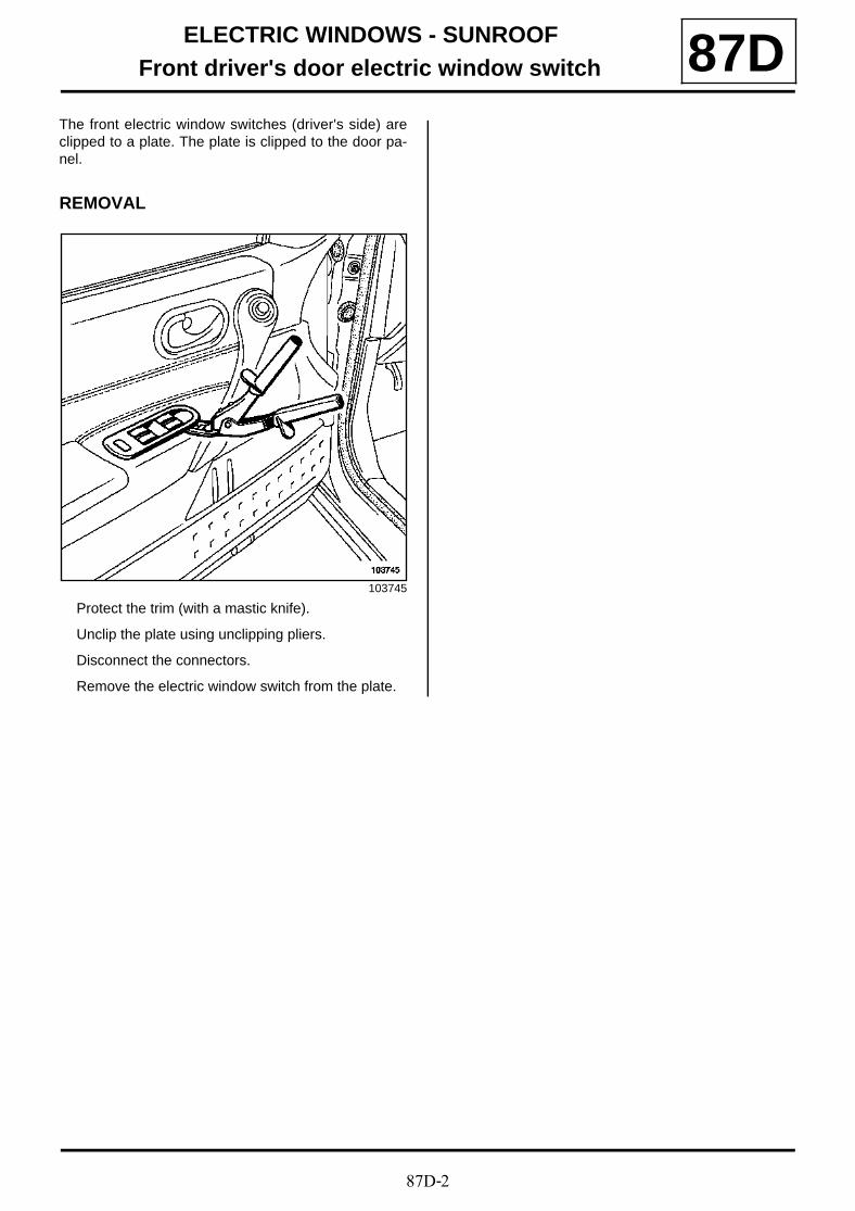
87D-2
ELECTRIC WINDOWS - SUNROOFFront driver's door electric window switch 87D
The front electric window switches (driver's side) areclipped to a plate. The plate is clipped to the door pa-nel.
REMOVAL
Protect the trim (with a mastic knife).
Unclip the plate using unclipping pliers.
Disconnect the connectors.
Remove the electric window switch from the plate.
103745
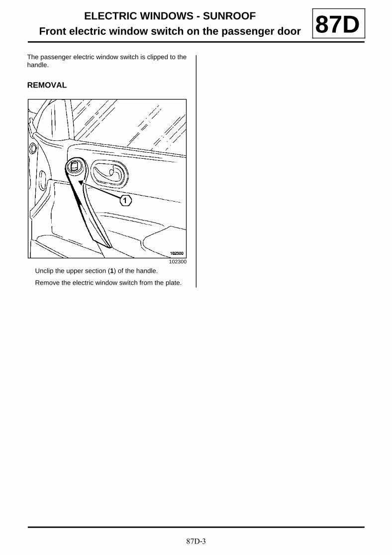
87D-3
ELECTRIC WINDOWS - SUNROOFFront electric window switch on the passenger door 87D
The passenger electric window switch is clipped to thehandle.
REMOVAL
Unclip the upper section (1) of the handle.
Remove the electric window switch from the plate.
102300
1
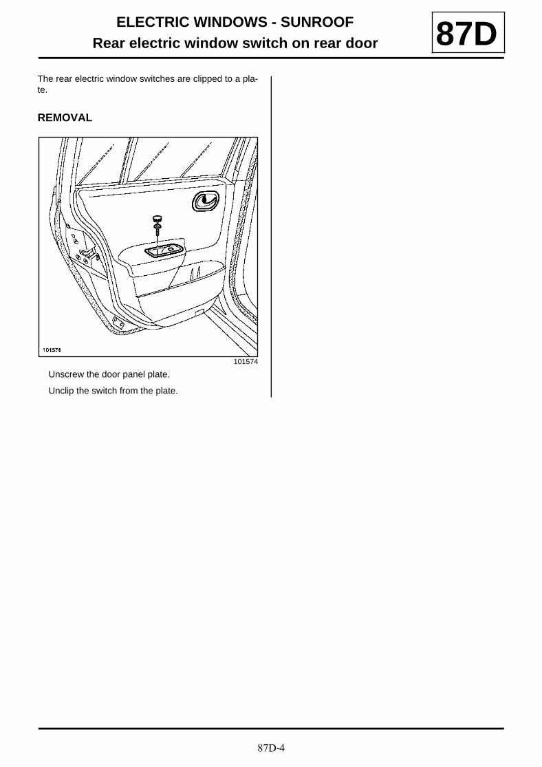
87D-4
ELECTRIC WINDOWS - SUNROOFRear electric window switch on rear door 87D
The rear electric window switches are clipped to a pla-te.
REMOVAL
Unscrew the door panel plate.
Unclip the switch from the plate.
101574
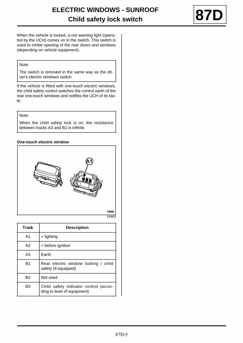
87D-5
ELECTRIC WINDOWS - SUNROOFChild safety lock switch 87D
When the vehicle is locked, a red warning light (opera-ted by the UCH) comes on in the switch. This switch isused to inhibit opening of the rear doors and windows(depending on vehicle equipment).
If the vehicle is fitted with one-touch electric windows,the child safety control switches the control earth of therear one-touch windows and notifies the UCH of its sta-te.
One-touch electric window
Note:
The switch is removed in the same way as the dri-ver's electric windows switch.
Note:
When the child safety lock is on, the resistancebetween tracks A3 and B1 is infinite.
18463
Track Description
A1 + lighting
A2 + before ignition
A3 Earth
B1 Rear electric window locking / childsafety (if equipped)
B2 Not used
B3 Child safety indicator control (accor-ding to level of equipment)
A1
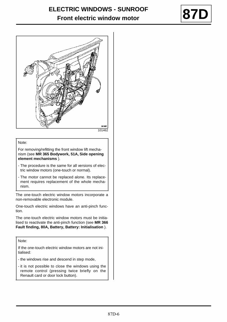
87D-6
ELECTRIC WINDOWS - SUNROOFFront electric window motor 87D
The one-touch electric window motors incorporate anon-removable electronic module.
One-touch electric windows have an anti-pinch func-tion.
The one-touch electric window motors must be initia-lised to reactivate the anti-pinch function (see MR 366Fault finding, 80A, Battery, Battery: Initialisation ).
101462
Note:
For removing/refitting the front window lift mecha-nism (see MR 365 Bodywork, 51A, Side opening element mechanisms ).
- The procedure is the same for all versions of elec-tric window motors (one-touch or normal).
- The motor cannot be replaced alone. Its replace-ment requires replacement of the whole mecha-nism.
Note:
If the one-touch electric window motors are not ini-tialised:
- the windows rise and descend in step mode,
- it is not possible to close the windows using theremote control (pressing twice briefly on theRenault card or door lock button).
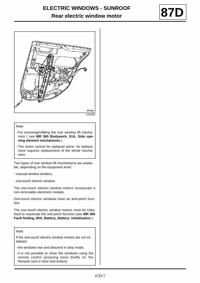
87D-7
ELECTRIC WINDOWS - SUNROOFRear electric window motor 87D
Two types of rear window lift mechanisms are availa-ble, depending on the equipment level:
- manual window winders,
- one-touch electric window.
The one-touch electric window motors incorporate anon-removable electronic module.
One-touch electric windows have an anti-pinch func-tion.
The one-touch electric window motors must be initia-lised to reactivate the anti-pinch function (see MR 366Fault finding, 80A, Battery, Battery: Initialisation ).
101555
Note:
- For removing/refitting the rear window lift mecha-nism ( see MR 365 Bodywork, 51A, Side ope-ning element mechanisms ).
- The motor cannot be replaced alone. Its replace-ment requires replacement of the whole mecha-nism.
Note:
If the one-touch electric window motors are not ini-tialised:
- the windows rise and descend in step mode,
- it is not possible to close the windows using theremote control (pressing twice briefly on theRenault card or door lock button).
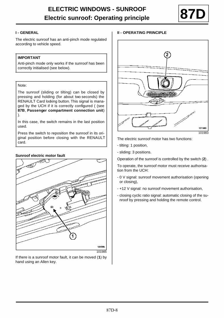
87D-8
ELECTRIC WINDOWS - SUNROOFElectric sunroof: Operating principle 87D
I - GENERAL
The electric sunroof has an anti-pinch mode regulatedaccording to vehicle speed.
Sunroof electric motor fault
If there is a sunroof motor fault, it can be moved (1) byhand using an Allen key.
II - OPERATING PRINCIPLE
The electric sunroof motor has two functions:
- tilting: 1 position,
- sliding: 3 positions.
Operation of the sunroof is controlled by the switch (2) .
To operate, the sunroof motor must receive authorisa-tion from the UCH:
- 0 V signal: sunroof movement authorisation (openingor closing),
- +12 V signal: no sunroof movement authorisation,
- closing cyclic ratio signal: automatic closing of the su-nroof by pressing and holding the remote control.
IMPORTANT
Anti-pinch mode only works if the sunroof has beencorrectly initialised (see below).
Note:
The sunroof (sliding or tilting) can be closed bypressing and holding (for about two seconds) theRENAULT Card locking button. This signal is mana-ged by the UCH if it is correctly configured ( (see87B, Passenger compartment connection unit)).
In this case, the switch remains in the last positionused.
Press the switch to reposition the sunroof in its ori-ginal position before closing with the RENAULTcard.
101985
1
101983
2
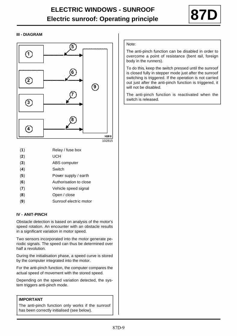
87D-9
ELECTRIC WINDOWS - SUNROOFElectric sunroof: Operating principle 87D
III - DIAGRAM
IV - ANIT-PINCH
Obstacle detection is based on analysis of the motor'sspeed rotation. An encounter with an obstacle resultsin a significant variation in motor speed.
Two sensors incorporated into the motor generate pe-riodic signals. The speed can thus be determined overhalf a revolution.
During the initialisation phase, a speed curve is storedby the computer integrated into the motor.
For the anti-pinch function, the computer compares theactual speed of movement with the stored speed.
Depending on the speed variation detected, the sys-tem triggers anti-pinch mode.
102815
(1) Relay / fuse box
(2) UCH
(3) ABS computer
(4) Switch
(5) Power supply / earth
(6) Authorisation to close
(7) Vehicle speed signal
(8) Open / close
(9) Sunroof electric motor
IMPORTANT
The anti-pinch function only works if the sunroofhas been correctly initialised (see below).
1
2
3
4
5
6
7
8
9
Note:
The anti-pinch function can be disabled in order toovercome a point of resistance (bent rail, foreignbody in the runners).
To do this, keep the switch pressed until the sunroofis closed fully in stepper mode just after the sunroofswitching is triggered. If the operation is not carriedout just after the anti-pinch function is triggered, itwill not be disabled.
The anti-pinch function is reactivated when theswitch is released.
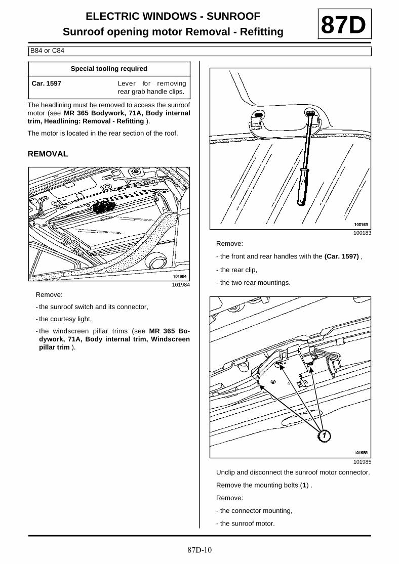
87D-10
ELECTRIC WINDOWS - SUNROOFSunroof opening motor Removal - Refitting
B84 or C84
87D
The headlining must be removed to access the sunroofmotor (see MR 365 Bodywork, 71A, Body internaltrim, Headlining: Removal - Refitting ).
The motor is located in the rear section of the roof.
REMOVAL
Remove:
- the sunroof switch and its connector,
- the courtesy light,
- the windscreen pillar trims (see MR 365 Bo-dywork, 71A, Body internal trim, Windscreenpillar trim ).
Remove:
- the front and rear handles with the (Car. 1597) ,
- the rear clip,
- the two rear mountings.
Unclip and disconnect the sunroof motor connector.
Remove the mounting bolts (1) .
Remove:
- the connector mounting,
- the sunroof motor.
Special tooling required
Car. 1597 Lever for removingrear grab handle clips.
101984
100183
101985
11
87D-11
ELECTRIC WINDOWS - SUNROOFSunroof opening motor Removal - Refitting
B84 or C84
87DREFITTING
Proceed in the reverse order to removal.
The system must be initialised after the motor hasbeen refitted (see MR 366 Fault finding, 80A, Bat-tery, Battery: Initialisation ).
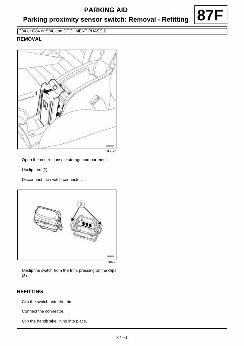
87F-1
PARKING AIDParking proximity sensor switch: Removal - Refitting
C84 or G84 or S84, and DOCUMENT PHASE 2
87FREMOVAL
Open the centre console storage compartment.
Unclip trim (1) .
Disconnect the switch connector.
Unclip the switch from the trim, pressing on the clips(2) .
REFITTING
Clip the switch onto the trim.
Connect the connector.
Clip the handbrake lining into place.
105572
18463
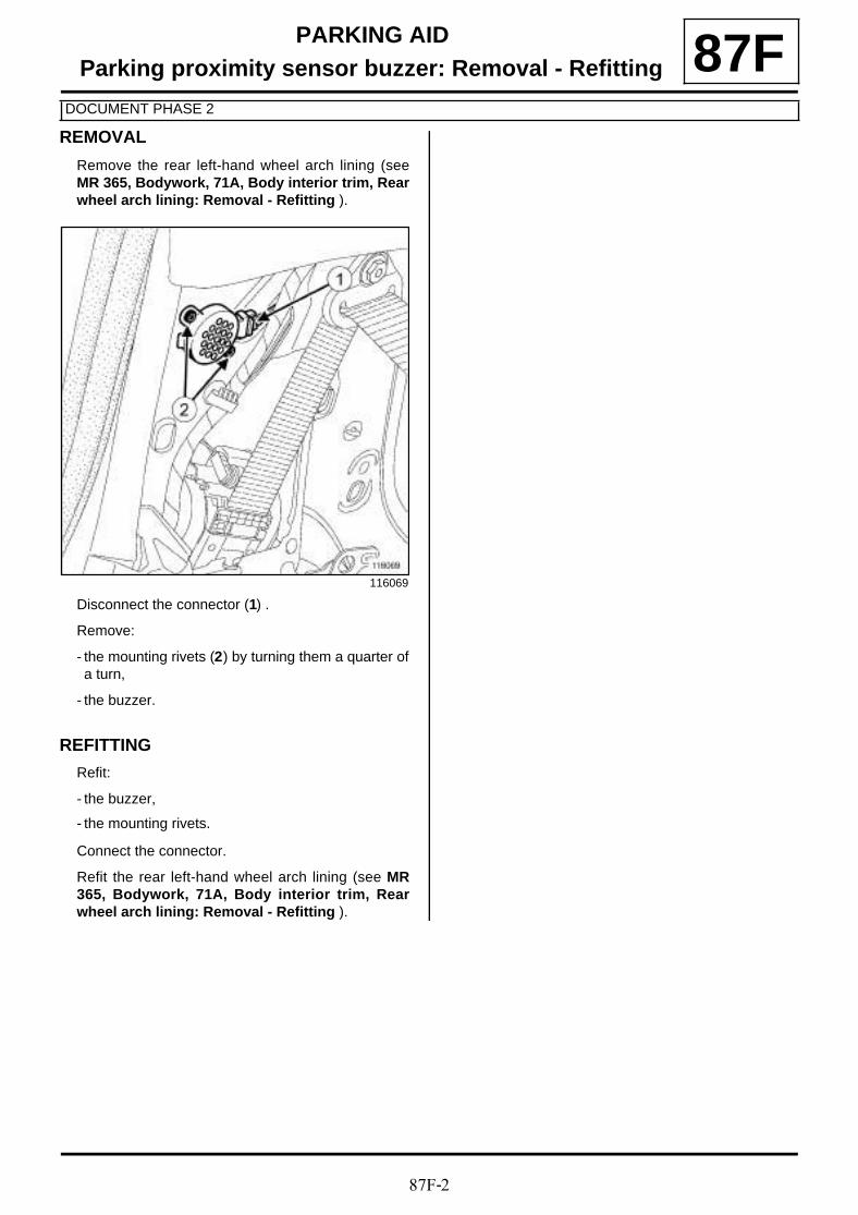
87F-2
PARKING AIDParking proximity sensor buzzer: Removal - Refitting
DOCUMENT PHASE 2
87FREMOVAL
Remove the rear left-hand wheel arch lining (seeMR 365, Bodywork, 71A, Body interior trim, Rearwheel arch lining: Removal - Refitting ).
Disconnect the connector (1) .
Remove:
- the mounting rivets (2) by turning them a quarter ofa turn,
- the buzzer.
REFITTING
Refit:
- the buzzer,
- the mounting rivets.
Connect the connector.
Refit the rear left-hand wheel arch lining (see MR365, Bodywork, 71A, Body interior trim, Rearwheel arch lining: Removal - Refitting ).
116069
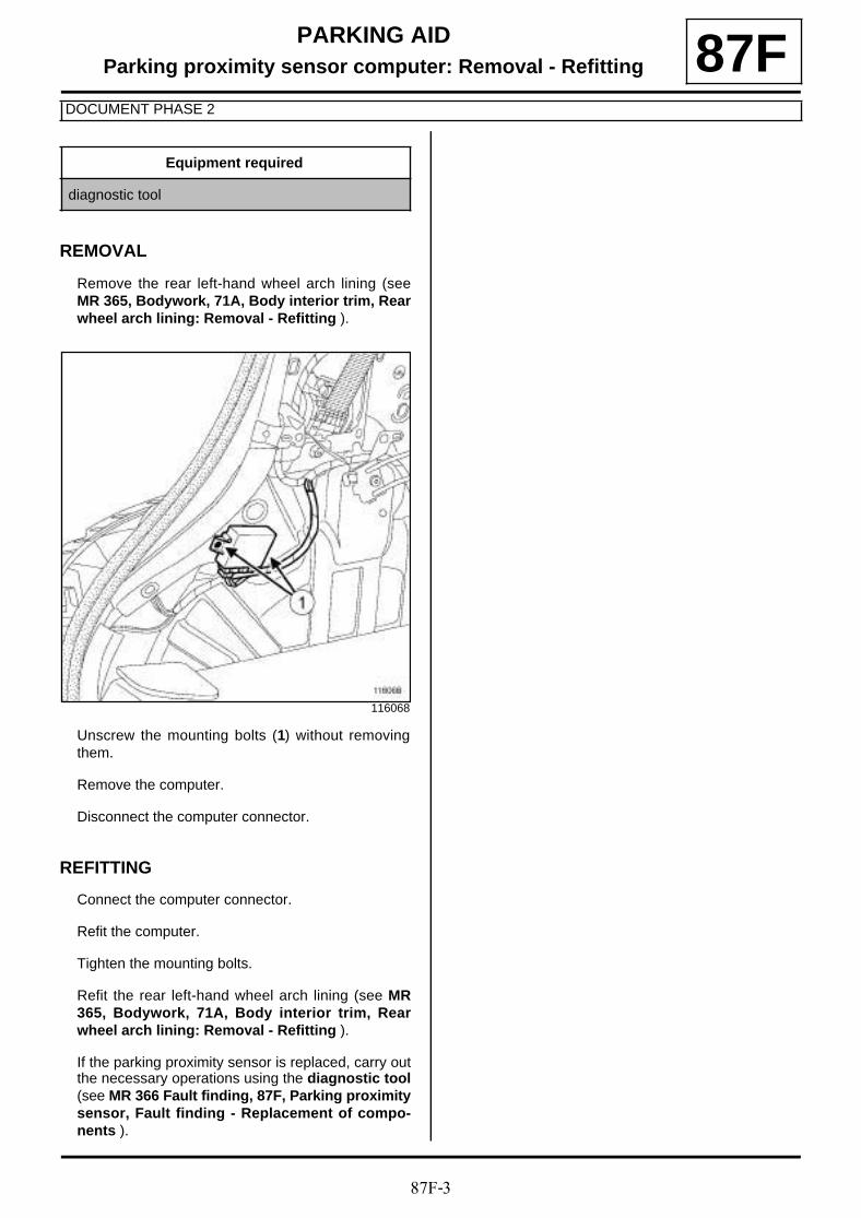
87F-3
PARKING AIDParking proximity sensor computer: Removal - Refitting
DOCUMENT PHASE 2
87F
REMOVAL
Remove the rear left-hand wheel arch lining (seeMR 365, Bodywork, 71A, Body interior trim, Rearwheel arch lining: Removal - Refitting ).
Unscrew the mounting bolts (1) without removingthem.
Remove the computer.
Disconnect the computer connector.
REFITTING
Connect the computer connector.
Refit the computer.
Tighten the mounting bolts.
Refit the rear left-hand wheel arch lining (see MR365, Bodywork, 71A, Body interior trim, Rearwheel arch lining: Removal - Refitting ).
If the parking proximity sensor is replaced, carry outthe necessary operations using the diagnostic tool(see MR 366 Fault finding, 87F, Parking proximitysensor, Fault finding - Replacement of compo-nents ).
Equipment required
diagnostic tool
116068
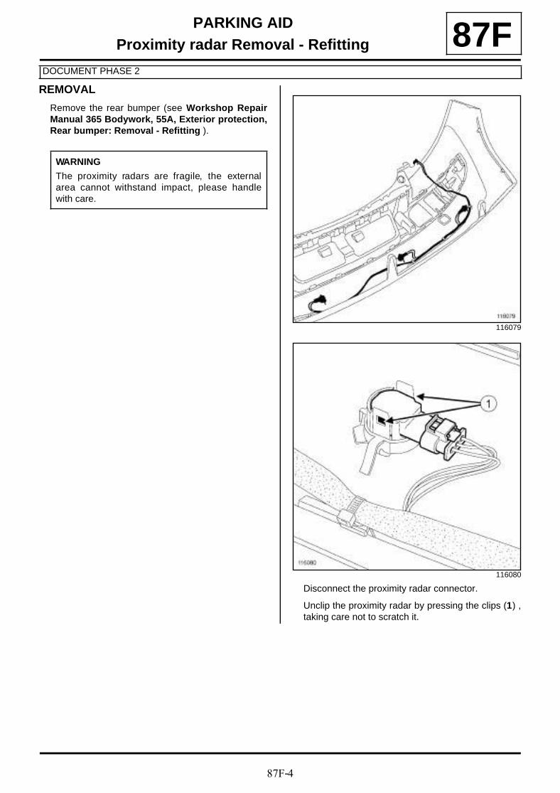
87F-4
PARKING AIDProximity radar Removal - Refitting
DOCUMENT PHASE 2
87FREMOVAL
Remove the rear bumper (see Workshop RepairManual 365 Bodywork, 55A, Exterior protection,Rear bumper: Removal - Refitting ).
Disconnect the proximity radar connector.
Unclip the proximity radar by pressing the clips (1) ,taking care not to scratch it.
WARNING
The proximity radars are fragile, the externalarea cannot withstand impact, please handlewith care.
116079
116080
87F-5
PARKING AIDProximity radar Removal - Refitting
DOCUMENT PHASE 2
87FREFITTING
Clip the proximity radar back in, taking care not toscratch it.
Connect the proximity radar connector.
Refit the rear bumper (see Workshop Repair Ma-nual 365 Bodywork, 55A, Exterior protection,Rear bumper: Removal - Refitting ).
WARNING
The proximity radars are fragile, the externalarea cannot withstand impact, please handlewith care.
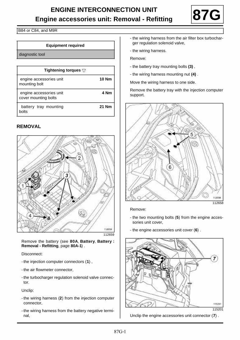
87G-1
ENGINE INTERCONNECTION UNITEngine accessories unit: Removal - Refitting
B84 or C84, and M9R
87G
REMOVAL
Remove the battery (see 80A, Battery, Battery :Removal - Refitting, page 80A-1) .
Disconnect:
- the injection computer connectors (1) ,
- the air flowmeter connector,
- the turbocharger regulation solenoid valve connec-tor.
Unclip:
- the wiring harness (2) from the injection computerconnector,
- the wiring harness from the battery negative termi-nal,
- the wiring harness from the air filter box turbochar-ger regulation solenoid valve,
- the wiring harness.
Remove:
- the battery tray mounting bolts (3) ,
- the wiring harness mounting nut (4) .
Move the wiring harness to one side.
Remove the battery tray with the injection computersupport.
Remove:
- the two mounting bolts (5) from the engine acces-sories unit cover,
- the engine accessories unit cover (6) .
Unclip the engine accessories unit connector (7) .
Equipment required
diagnostic tool
Tightening torquesm
engine accessories unitmounting bolt
10 Nm
engine accessories unitcover mounting bolts
4 Nm
battery tray mountingbolts
21 Nm
112659
112658
115201
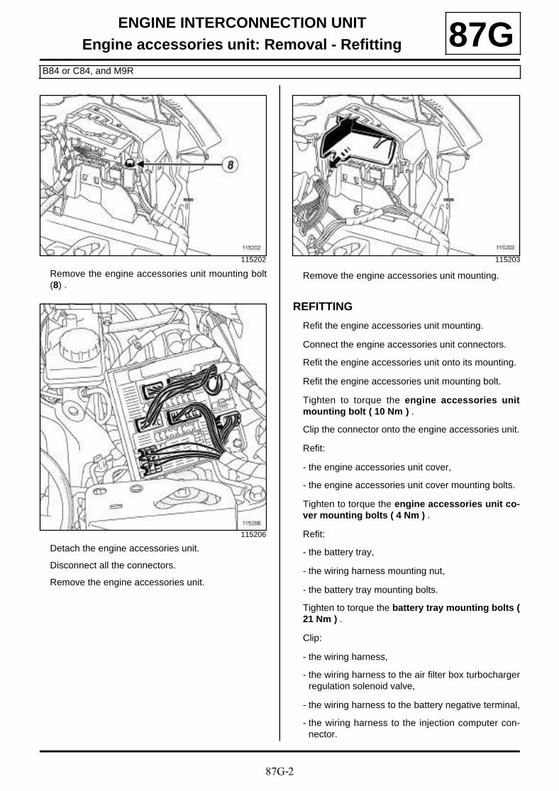
87G-2
ENGINE INTERCONNECTION UNITEngine accessories unit: Removal - Refitting
B84 or C84, and M9R
87G
Remove the engine accessories unit mounting bolt(8) .
Detach the engine accessories unit.
Disconnect all the connectors.
Remove the engine accessories unit.
Remove the engine accessories unit mounting.
REFITTING
Refit the engine accessories unit mounting.
Connect the engine accessories unit connectors.
Refit the engine accessories unit onto its mounting.
Refit the engine accessories unit mounting bolt.
Tighten to torque the engine accessories unitmounting bolt ( 10 Nm ) .
Clip the connector onto the engine accessories unit.
Refit:
- the engine accessories unit cover,
- the engine accessories unit cover mounting bolts.
Tighten to torque the engine accessories unit co-ver mounting bolts ( 4 Nm ) .
Refit:
- the battery tray,
- the wiring harness mounting nut,
- the battery tray mounting bolts.
Tighten to torque the battery tray mounting bolts (21 Nm ) .
Clip:
- the wiring harness,
- the wiring harness to the air filter box turbochargerregulation solenoid valve,
- the wiring harness to the battery negative terminal,
- the wiring harness to the injection computer con-nector.
115202
115206
115203
87G-3
ENGINE INTERCONNECTION UNITEngine accessories unit: Removal - Refitting
B84 or C84, and M9R
87GConnect:
- the turbocharger regulation solenoid valve connec-tor,
- the air flowmeter connector,
- the injection computer connectors.
Refit the battery (see 80A, Battery, Battery : Re-moval - Refitting, page 80A-1) .
When replacing the engine and accessories unit,carry out the necessary operations using the dia-gnostic tool (see MR 366 Fault finding, 87G, En-gine compartment connection unit, Fault finding- Replacement of components ).

87G-4
ENGINE INTERCONNECTION UNITProtection and Switching Unit: General information 87G
Three models of protection and switching unit may be fitted to vehicles:
- « entry level N1 » protection and switching unit,
- « top end N2 » protection and switching unit,
- « top end N3 » protection and switching unit.
Only the « top end N2 and N3 » protection and swit-ching units are available as spare parts.
The N2 and N3 versions are distinguished by the high speed fan assembly actuation:
- with N2, the UPC controls an external relay,
- with N3, the relay is built into the UPC.
Fuse assignment ( (see 81C, Fuses) ).
Protection and Switching Unit fault services Level 1 Level 2 Level 3
Multiplex connection X X X
Fault finding X X X
« + After ignition » feed management:
- to the starter X X X
- to the electric power steering X X X
- to the injection computer X X X
- to the fuel pump X X X
- to the diesel fuel heater X X X
- to the ABS computer X X X
- to the automatic transmission computer - X X
Keyless vehicle:
- « neutral » engaged on gearbox X X X
- electric steering column lock X X X
Lights management:
- side lights X X X
- dipped headlights X X X
- main beam headlights X X X
- fog lights (front) X X X
- fan assembly low speed X X X
- fan assembly high speed (external relay control) - X -
- fan assembly high speed (internal UPC relay) - - X
Air conditioning compressor clutch management - X X
Oil pressure display management (interconnection) X X X
Battery charge warning light display management X X X
87G-5
ENGINE INTERCONNECTION UNITProtection and Switching Unit: General information 87G
Windscreen wipers management X X X
Timed rear screen de-icing management X X X
Protection and Switching Unit fault services Level 1 Level 2 Level 3

87G-6
ENGINE INTERCONNECTION UNITProtection and Switching Unit: Removal - Refitting
B84 or C84 or S84
87G
REMOVAL
If replacing the Protection and Switching Unit, carryout the necessary operations using the diagnostictool (see MR 366 Fault finding, 87G, Engine com-partment connection unit, Fault finding - Repla-cement of components ).
Remove:
- the Protection and Switching Unit cover mountingbolts,
- the cover.
Remove the engine covers.
Disconnect the battery (see 80A, Battery, Battery :Removal - Refitting, page 80A-1) .
Remove:
- the battery,
- the upper section of the engine compartment con-nection unit,
- the bolt (1) .
Disconnect the connectors (2) .
Equipment required
diagnostic tool
Tightening torquesm
Protection and Swit-ching Unit mountingbolts
10 Nm
Protection and Swit-ching Unit cover moun-ting bolts
4 Nm
DOCUMENT PHASE 2
112658
101977

87G-7
ENGINE INTERCONNECTION UNITProtection and Switching Unit: Removal - Refitting
B84 or C84 or S84
87G
Disconnect the remaining connectors.
Remove the Protection and Switching Unit.
REFITTING
Connect the connectors.
Refit:
- the Protection and Switching Unit,
- the Protection and Switching Unit mounting bolt.
Tighten to torque the Protection and SwitchingUnit mounting bolts ( 10 Nm ) .
Refit:
- the upper section of the engine compartment con-nection unit,
- the battery (see 80A, Battery, Battery : Removal- Refitting, page 80A-1) .
Refit the engine covers.
Tighten to torque the Protection and SwitchingUnit cover mounting bolts ( 4 Nm ) .
When replacing the Protection and Switching Unit,carry out the necessary operations using the dia-gnostic tool (see MR 366 Fault finding, 87G, En-gine compartment connection unit, Fault finding- Replacement of components ).
101978
Note:
To unlock the connector (3) , use lock (4) .
DOCUMENT PHASE 2
3
4
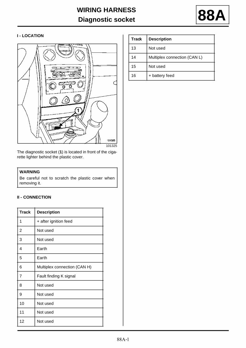
88A-1
WIRING HARNESSDiagnostic socket 88A
I - LOCATION
The diagnostic socket (1) is located in front of the ciga-rette lighter behind the plastic cover.
II - CONNECTION
101325
WARNING
Be careful not to scratch the plastic cover whenremoving it.
Track Description
1 + after ignition feed
2 Not used
3 Not used
4 Earth
5 Earth
6 Multiplex connection (CAN H)
7 Fault finding K signal
8 Not used
9 Not used
10 Not used
11 Not used
12 Not used
1
13 Not used
14 Multiplex connection (CAN L)
15 Not used
16 + battery feed
Track Description
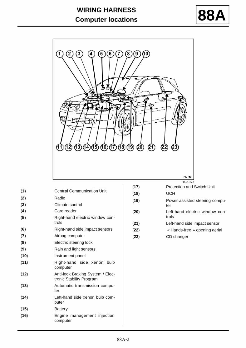
88A-2
WIRING HARNESSComputer locations 88A
102159
1 2 3 4 5 6 7 8 9 10
11 12 13 14 15 16 17 18 19 20 21 22 23
(1) Central Communication Unit
(2) Radio
(3) Climate control
(4) Card reader
(5) Right-hand electric window con-trols
(6) Right-hand side impact sensors
(7) Airbag computer
(8) Electric steering lock
(9) Rain and light sensors
(10) Instrument panel
(11) Right-hand side xenon bulbcomputer
(12) Anti-lock Braking System / Elec-tronic Stability Program
(13) Automatic transmission compu-ter
(14) Left-hand side xenon bulb com-puter
(15) Battery
(16) Engine management injectioncomputer
(17) Protection and Switch Unit
(18) UCH
(19) Power-assisted steering compu-ter
(20) Left-hand electric window con-trols
(21) Left-hand side impact sensor
(22) « Hands-free » opening aerial
(23) CD changer
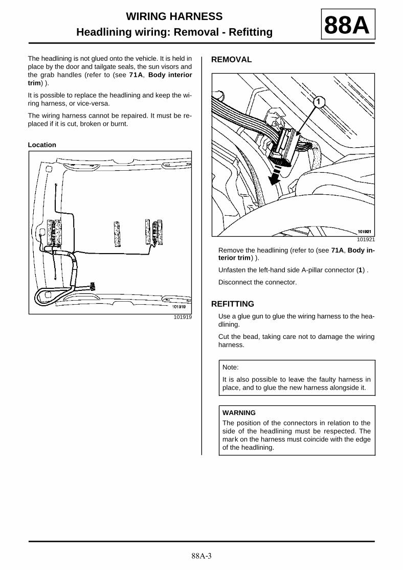
88A-3
WIRING HARNESSHeadlining wiring: Removal - Refitting 88A
The headlining is not glued onto the vehicle. It is held inplace by the door and tailgate seals, the sun visors andthe grab handles (refer to (see 71A, Body interiortrim) ).
It is possible to replace the headlining and keep the wi-ring harness, or vice-versa.
The wiring harness cannot be repaired. It must be re-placed if it is cut, broken or burnt.
Location
REMOVAL
Remove the headlining (refer to (see 71A, Body in-terior trim) ).
Unfasten the left-hand side A-pillar connector (1) .
Disconnect the connector.
REFITTINGUse a glue gun to glue the wiring harness to the hea-dlining.
Cut the bead, taking care not to damage the wiringharness.
101919
101921
Note:
It is also possible to leave the faulty harness inplace, and to glue the new harness alongside it.
WARNING
The position of the connectors in relation to theside of the headlining must be respected. Themark on the harness must coincide with the edgeof the headlining.
1
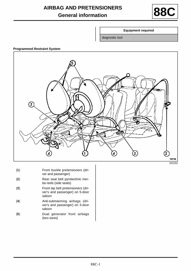
88C-1
AIRBAG AND PRETENSIONERSGeneral information 88C
Programmed Restraint System
Equipment required
diagnostic tool
102152
5
1 244
3
3
(1) Front buckle pretensioners (dri-ver and passenger)
(2) Rear seat belt pyrotechnic iner-tia reels (side seats)
(3) Front lap belt pretensioners (dri-ver's and passenger) on 5-doorsaloon
(4) Anti-submarining airbags (dri-ver's and passenger) on 3-doorsaloon
(5) Dual generator front airbags(two sizes)

88C-2
AIRBAG AND PRETENSIONERSGeneral information 88C
These vehicles are fitted with a passive safety system of the SRP (Programmed Restraint System) type, com-prising:
- front buckle pretensioners (driver's and passenger),
- pyrotechnic retractors on the rear seat belts (sideseats),
- front lap belt pretensioners (driver's and passenger)on 5-door saloon,
- anti-submarining airbags (driver's and passenger) on3-door saloon version,
- dual generator front airbags (two sizes),
- a 75-track computer with two impact sensors,
- side thorax airbags in the front seats in the seatbacks,
- curtain airbags,
- Rear seat side thorax airbags (if the vehicle is fittedwith them),
- driver's seat position sensor,
- a front passenger airbag deactivation switch,
- system fault warning light,
- a deactivation indicator light.
PRECAUTIONS DURING REPAIR
102153
1
8
2
7
44
6
6
3
3
(6) Side thorax airbags in the frontseat seatbacks
(7) Curtain airbags
(8) Rear seat side thorax airbag (iffitted to the vehicle)
IMPORTANT
- All operations on airbag and pretensioner systemsmust be carried out by qualified trained personnel.
- Never handle the pyrotechnic systems close to asource of heat or a naked flame; there is a risk oftriggering.
- The airbags have a pyrotechnic gas generator withan ignition module and airbag which must not beseparated.
- Before removing a safety system component,check the airbag computer using the diagnostictool . When this function is activated all the trigge-ring lines are disabled and the airbag warning lighton the instrument panel lights up (ignition on).
- Any operation, even minor, on the pyrotechniccomponents triggering lines is forbidden.
88C-3
AIRBAG AND PRETENSIONERSGeneral information 88C
When an airbag or a pretensioner is triggered, thecomputer is permanently locked and the « airbagfault » warning light lights up on the instrument panel.The airbag computer must be replaced (some compo-nents lose their settings after the trigger energy haspassed through them).
After refitting all the parts, carry out a check using thediagnostic tool .
If everything is correct, unlock the computer, otherwiserefer to the fault finding document .
After an impact:
- if the buckle pretensioner has been triggered, the seatframe and the seat belt must be replaced if it was fas-tened, (the buckle pretensioners are supplied in se-ries),
- if the rear pyrotechnic inertia reels have been trigge-red, the « seat belt / pyrotechnic inertia reel » assem-bly must be replaced, the pyrotechnic inertia reelssupply wiring is in series,
- if the driver's front airbag was triggered, the steeringwheel and its mounting bolt must be replaced,
- if the passenger front airbag has been triggered, thedashboard must be replaced,
- if a seat side airbag is triggered, the seat frame mustbe replaced,
- if the anti-submarining airbag has been triggered, theseat frame must be replaced,
- if the curtain airbag has been triggered, the plate mustbe repositioned and the deflector must be replaced;see Repair plate .
IMPORTANT
- It is essential to refer to the Destruction proce-dure when scrapping a pyrotechnic system thathas not been triggered.
- The impact computers and sensors have fragilecomponents, do not drop them.
- Do not fit a seat cover onto the front seats (exceptspecific products from the RENAULT shop).
- Do not place objects in the airbag deploymentzone.
- When working under the vehicle (on thebodywork, sill panel, etc.), it is essential to lock theairbag computer using the diagnostic tool andswitch off the ignition.
- For special notes on removing and refitting theseat trims, see the Bodywork repair manual .
- Pyrotechnic systems (pretensioners and airbags) must be checked using the diagnostic tool :
• following an accident which did not trigger thesystems,
• following theft or attempted theft of the vehicle,
• before selling a used vehicle.
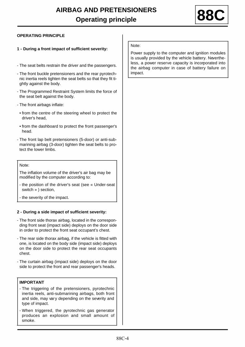
88C-4
AIRBAG AND PRETENSIONERSOperating principle 88C
OPERATING PRINCIPLE
1 - During a front impact of sufficient severity:
- The seat belts restrain the driver and the passengers.
- The front buckle pretensioners and the rear pyrotech-nic inertia reels tighten the seat belts so that they fit ti-ghtly against the body.
- The Programmed Restraint System limits the force ofthe seat belt against the body.
- The front airbags inflate:
• from the centre of the steering wheel to protect thedriver's head,
• from the dashboard to protect the front passenger'shead.
- The front lap belt pretensioners (5-door) or anti-sub-marining airbag (3-door) tighten the seat belts to pro-tect the lower limbs.
2 - During a side impact of sufficient severity:
- The front side thorax airbag, located in the correspon-ding front seat (impact side) deploys on the door sidein order to protect the front seat occupant’s chest.
- The rear side thorax airbag, if the vehicle is fitted withone, is located on the body side (impact side) deployson the door side to protect the rear seat occupantschest.
- The curtain airbag (impact side) deploys on the doorside to protect the front and rear passenger's heads.
Note:
The inflation volume of the driver's air bag may be modified by the computer according to:
- the position of the driver's seat (see « Under-seatswitch » ) section,
- the severity of the impact.
IMPORTANT
- The triggering of the pretensioners, pyrotechnicinertia reels, anti-submarining airbags, both frontand side, may vary depending on the severity andtype of impact.
- When triggered, the pyrotechnic gas generatorproduces an explosion and small amount ofsmoke.
Note:
Power supply to the computer and ignition modulesis usually provided by the vehicle battery. Neverthe-less, a power reserve capacity is incorporated intothe airbag computer in case of battery failure onimpact.
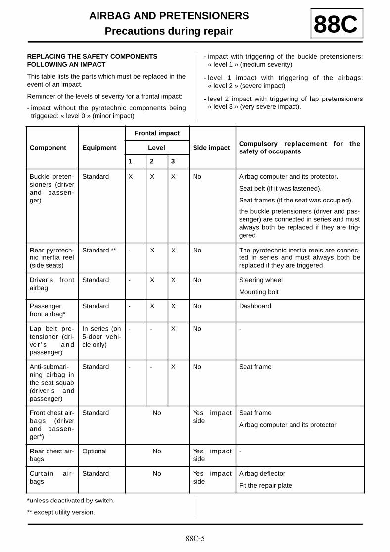
88C-5
AIRBAG AND PRETENSIONERSPrecautions during repair 88C
REPLACING THE SAFETY COMPONENTS FOLLOWING AN IMPACT
This table lists the parts which must be replaced in theevent of an impact.
Reminder of the levels of severity for a frontal impact:
- impact without the pyrotechnic components beingtriggered: « level 0 » (minor impact)
- impact with triggering of the buckle pretensioners:« level 1 » (medium severity)
- level 1 impact with triggering of the airbags:« level 2 » (severe impact)
- level 2 impact with triggering of lap pretensioners« level 3 » (very severe impact).
*unless deactivated by switch.
** except utility version.
Component Equipment
Frontal impact
Side impactCompulsory replacement for thesafety of occupants
Level
1 2 3
Buckle preten-sioners (driverand passen-ger)
Standard X X X No Airbag computer and its protector.
Seat belt (if it was fastened).
Seat frames (if the seat was occupied).
the buckle pretensioners (driver and pas-senger) are connected in series and mustalways both be replaced if they are trig-gered
Rear pyrotech-nic inertia reel(side seats)
Standard ** - X X No The pyrotechnic inertia reels are connec-ted in series and must always both bereplaced if they are triggered
Driver's frontairbag
Standard - X X No Steering wheel
Mounting bolt
Passengerfront airbag*
Standard - X X No Dashboard
Lap belt pre-tensioner (dri-ve r ' s a n dpassenger)
In series (on5-door vehi-cle only)
- - X No -
Anti-submari-ning airbag inthe seat squab(driver's andpassenger)
Standard - - X No Seat frame
Front chest air-bags (driverand passen-ger*)
Standard No Yes impactside
Seat frame
Airbag computer and its protector
Rear chest air-bags
Optional No Yes impactside
-
Curtain air-bags
Standard No Yes impactside
Airbag deflector
Fit the repair plate
88C-6
AIRBAG AND PRETENSIONERSPrecautions during repair 88C
IMPORTANT
The triggering of the pretensioners, pyrotechnicinertia reels, anti-submarining airbags, both frontand side, may vary depending on the severity andtype of impact.
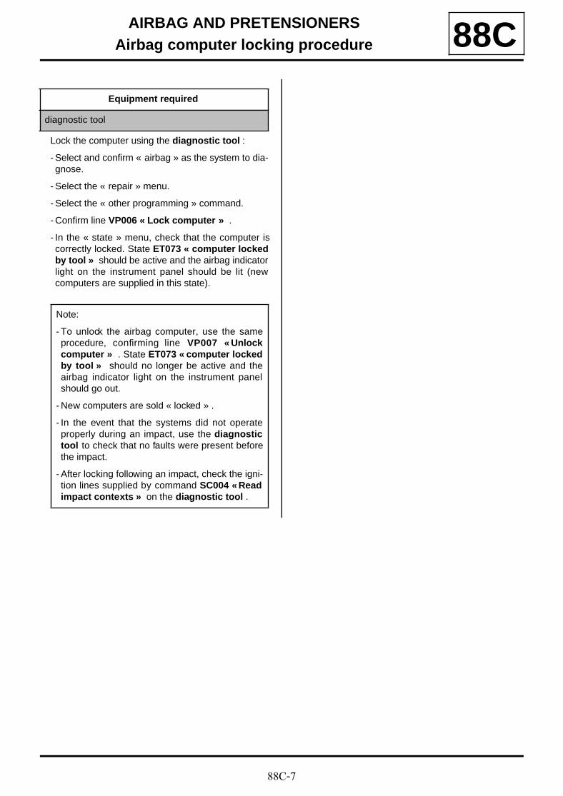
88C-7
AIRBAG AND PRETENSIONERSAirbag computer locking procedure 88C
Lock the computer using the diagnostic tool :
- Select and confirm « airbag » as the system to dia-gnose.
- Select the « repair » menu.
- Select the « other programming » command.
- Confirm line VP006 « Lock computer » .
- In the « state » menu, check that the computer iscorrectly locked. State ET073 « computer lockedby tool » should be active and the airbag indicatorlight on the instrument panel should be lit (newcomputers are supplied in this state).
Equipment required
diagnostic tool
Note:
- To unlock the airbag computer, use the sameprocedure, confirming line VP007 « Unlockcomputer » . State ET073 « computer lockedby tool » should no longer be active and theairbag indicator light on the instrument panelshould go out.
- New computers are sold « locked » .
- In the event that the systems did not operateproperly during an impact, use the diagnostictool to check that no faults were present beforethe impact.
- After locking following an impact, check the igni-tion lines supplied by command SC004 « Readimpact contexts » on the diagnostic tool .
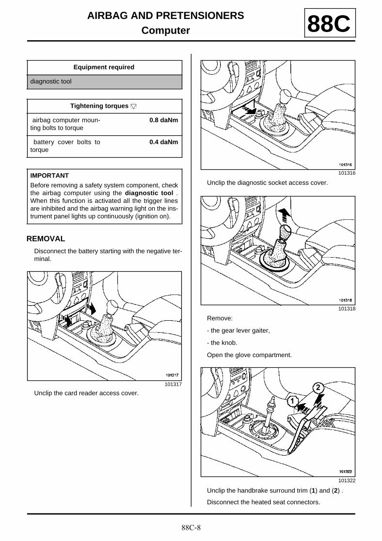
88C-8
AIRBAG AND PRETENSIONERSComputer 88C
REMOVAL
Disconnect the battery starting with the negative ter-minal.
Unclip the card reader access cover.
Unclip the diagnostic socket access cover.
Remove:
- the gear lever gaiter,
- the knob.
Open the glove compartment.
Unclip the handbrake surround trim (1) and (2) .
Disconnect the heated seat connectors.
Equipment required
diagnostic tool
Tightening torquesm
airbag computer moun-ting bolts to torque
0.8 daNm
battery cover bolts totorque
0.4 daNm
IMPORTANT
Before removing a safety system component, checkthe airbag computer using the diagnostic tool .When this function is activated all the trigger linesare inhibited and the airbag warning light on the ins-trument panel lights up continuously (ignition on).
101317
101316
101318
101322
2
1
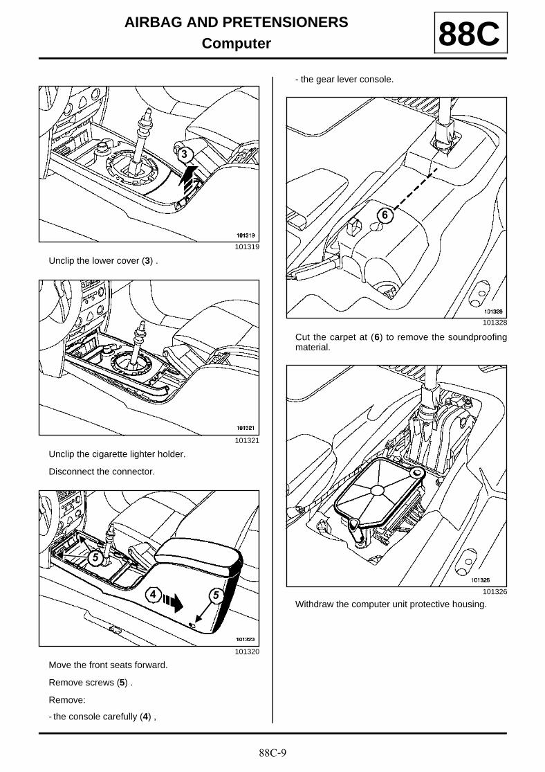
88C-9
AIRBAG AND PRETENSIONERSComputer 88C
Unclip the lower cover (3) .
Unclip the cigarette lighter holder.
Disconnect the connector.
Move the front seats forward.
Remove screws (5) .
Remove:
- the console carefully (4) ,
- the gear lever console.
Cut the carpet at (6) to remove the soundproofingmaterial.
Withdraw the computer unit protective housing.
101319
101321
101320
3
5
5
4
101328
101326
6
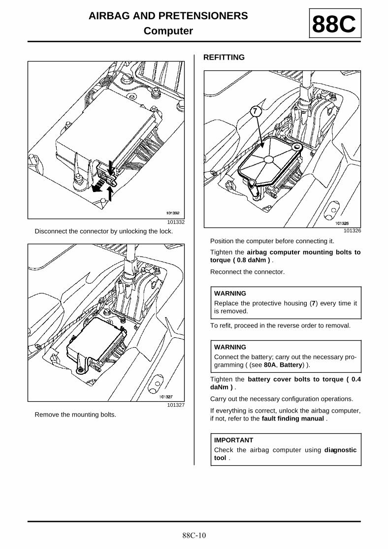
88C-10
AIRBAG AND PRETENSIONERSComputer 88C
Disconnect the connector by unlocking the lock.
Remove the mounting bolts.
REFITTING
Position the computer before connecting it.
Tighten the airbag computer mounting bolts totorque ( 0.8 daNm ) .
Reconnect the connector.
To refit, proceed in the reverse order to removal.
Tighten the battery cover bolts to torque ( 0.4daNm ) .
Carry out the necessary configuration operations.
If everything is correct, unlock the airbag computer,if not, refer to the fault finding manual .
101332
101327
101326
WARNING
Replace the protective housing (7) every time itis removed.
WARNING
Connect the battery; carry out the necessary pro-gramming ( (see 80A, Battery) ).
IMPORTANT
Check the airbag computer using diagnostictool .
7
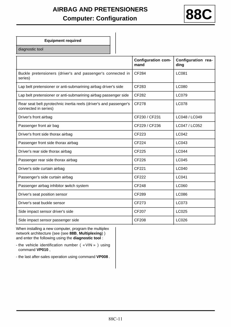
88C-11
AIRBAG AND PRETENSIONERSComputer: Configuration 88C
When installing a new computer, program the multiplex network architecture (see (see 88B, Multiplexing) ) and enter the following using the diagnostic tool :
- the vehicle identification number ( « VIN » ) usingcommand VP010 ,
- the last after-sales operation using command VP008 .
Equipment required
diagnostic tool
Configuration com-mand
Configuration rea-ding
Buckle pretensioners (driver's and passenger's connected inseries)
CF284 LC081
Lap belt pretensioner or anti-submarining airbag driver's side CF283 LC080
Lap belt pretensioner or anti-submarining airbag passenger side CF282 LC079
Rear seat belt pyrotechnic inertia reels (driver's and passenger'sconnected in series)
CF278 LC078
Driver's front airbag CF230 / CF231 LC048 / LC049
Passenger front air bag CF229 / CF236 LC047 / LC052
Driver's front side thorax airbag CF223 LC042
Passenger front side thorax airbag CF224 LC043
Driver's rear side thorax airbag CF225 LC044
Passenger rear side thorax airbag CF226 LC045
Driver's side curtain airbag CF221 LC040
Passenger's side curtain airbag CF222 LC041
Passenger airbag inhibitor switch system CF248 LC060
Driver's seat position sensor CF289 LC086
Driver's seat buckle sensor CF273 LC073
Side impact sensor driver's side CF207 LC025
Side impact sensor passenger side CF208 LC026

88C-12
AIRBAG AND PRETENSIONERSSide impact sensor: Removal - Refitting 88C
REMOVAL
Remove the B-pillar lower trim,( (see B-pillar lowertrim: Removal - Refitting) .
Remove the sensor mounting bolt.
Disconnect the connector.
Remove the side impact sensors located on each si-de, behind the B-pillar trim.
REFITTING
Position the sensor with its tab.
Tighten the side impact sensor mounting bolts totorque ( 0.8 daNm ) .
Reconnect the connector.
Unlock the computer.
To refit, proceed in the reverse order to removal.
Equipment required
diagnostic tool
Tightening torquesm
side impact sensormounting bolts to torque
0.8 daNm
IMPORTANT
Before removing a safety system component, lockthe airbag computer using the diagnostic tool .When this function is activated all the trigger linesare inhibited and the airbag warning light on the ins-trument panel lights up continuously (ignition on).
101915
IMPORTANT
Check using the diagnostic tool .
Note:
These sensors do not require programming withthe diagnostic tool .
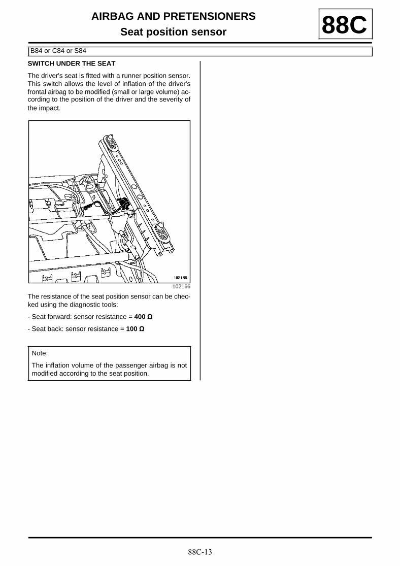
88C-13
AIRBAG AND PRETENSIONERSSeat position sensor
B84 or C84 or S84
88CSWITCH UNDER THE SEAT
The driver's seat is fitted with a runner position sensor.This switch allows the level of inflation of the driver'sfrontal airbag to be modified (small or large volume) ac-cording to the position of the driver and the severity ofthe impact.
The resistance of the seat position sensor can be chec-ked using the diagnostic tools:
- Seat forward: sensor resistance = 400 Ω
- Seat back: sensor resistance = 100 Ω
102166
Note:
The inflation volume of the passenger airbag is notmodified according to the seat position.
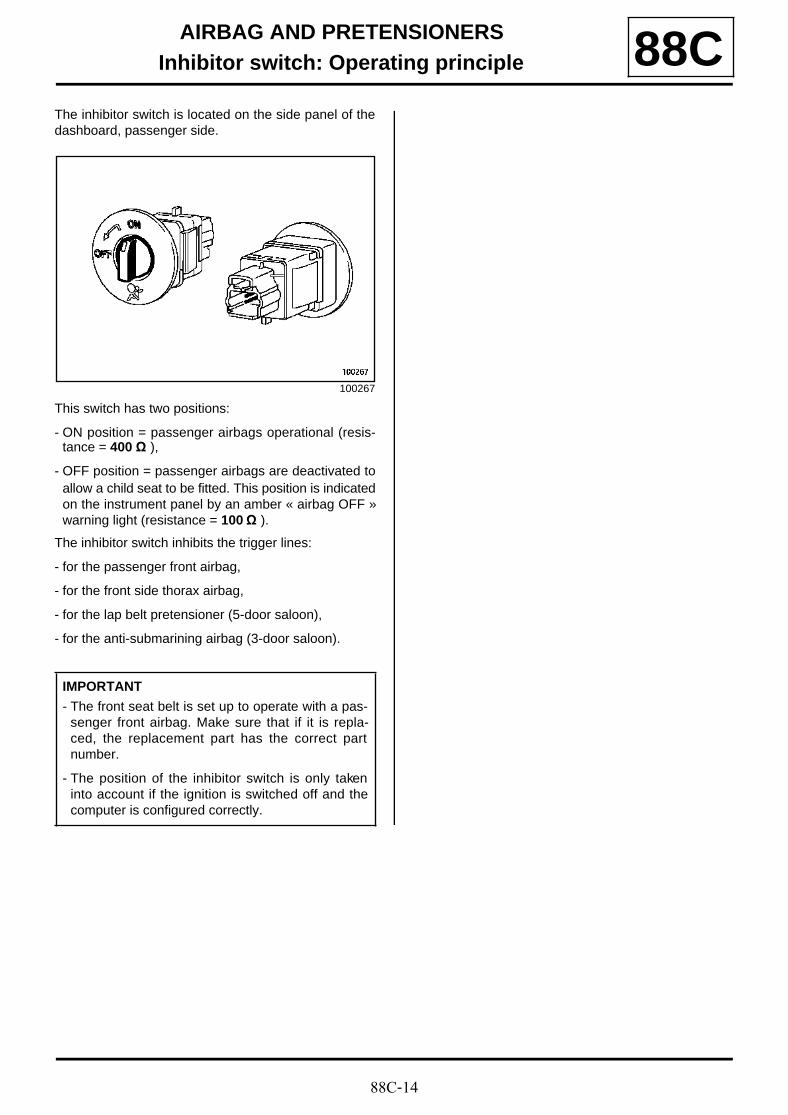
88C-14
AIRBAG AND PRETENSIONERSInhibitor switch: Operating principle 88C
The inhibitor switch is located on the side panel of thedashboard, passenger side.
This switch has two positions:
- ON position = passenger airbags operational (resis-tance = 400 Ω ),
- OFF position = passenger airbags are deactivated toallow a child seat to be fitted. This position is indicatedon the instrument panel by an amber « airbag OFF »warning light (resistance = 100 Ω ).
The inhibitor switch inhibits the trigger lines:
- for the passenger front airbag,
- for the front side thorax airbag,
- for the lap belt pretensioner (5-door saloon),
- for the anti-submarining airbag (3-door saloon).
100267
IMPORTANT
- The front seat belt is set up to operate with a pas-senger front airbag. Make sure that if it is repla-ced, the replacement part has the correct partnumber.
- The position of the inhibitor switch is only takeninto account if the ignition is switched off and thecomputer is configured correctly.
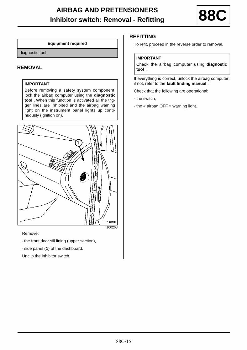
88C-15
AIRBAG AND PRETENSIONERSInhibitor switch: Removal - Refitting 88C
REMOVAL
Remove:
- the front door sill lining (upper section),
- side panel (1) of the dashboard.
Unclip the inhibitor switch.
REFITTING
To refit, proceed in the reverse order to removal.
If everything is correct, unlock the airbag computer,if not, refer to the fault finding manual .
Check that the following are operational:
- the switch,
- the « airbag OFF » warning light.
Equipment required
diagnostic tool
IMPORTANT
Before removing a safety system component,lock the airbag computer using the diagnostictool . When this function is activated all the trig-ger lines are inhibited and the airbag warninglight on the instrument panel lights up conti-nuously (ignition on).
100268
1
IMPORTANT
Check the airbag computer using diagnostictool .
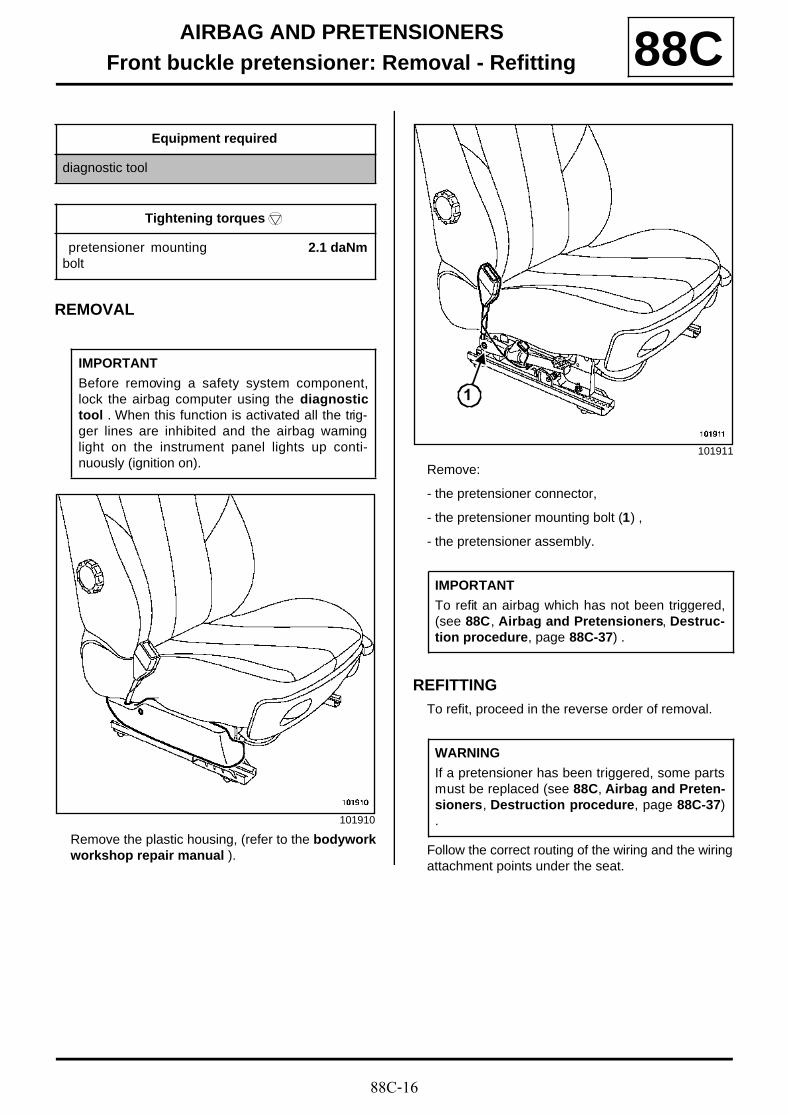
88C-16
AIRBAG AND PRETENSIONERSFront buckle pretensioner: Removal - Refitting 88C
REMOVAL
Remove the plastic housing, (refer to the bodyworkworkshop repair manual ).
Remove:
- the pretensioner connector,
- the pretensioner mounting bolt (1) ,
- the pretensioner assembly.
REFITTINGTo refit, proceed in the reverse order of removal.
Follow the correct routing of the wiring and the wiringattachment points under the seat.
Equipment required
diagnostic tool
Tightening torquesm
pretensioner mountingbolt
2.1 daNm
IMPORTANT
Before removing a safety system component,lock the airbag computer using the diagnostictool . When this function is activated all the trig-ger lines are inhibited and the airbag warninglight on the instrument panel lights up conti-nuously (ignition on).
101910
101911
IMPORTANT
To refit an airbag which has not been triggered,(see 88C, Airbag and Pretensioners, Destruc-tion procedure, page 88C-37) .
WARNING
If a pretensioner has been triggered, some partsmust be replaced (see 88C, Airbag and Preten-sioners, Destruction procedure, page 88C-37).
1
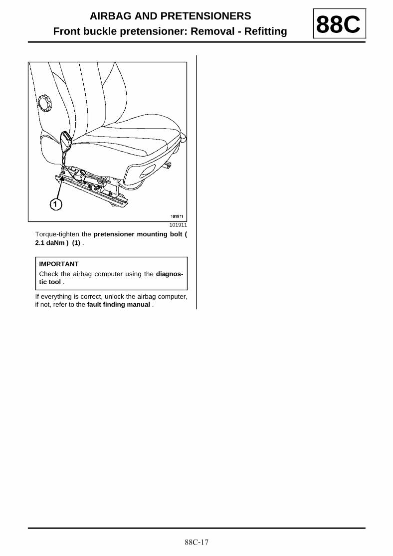
88C-17
AIRBAG AND PRETENSIONERSFront buckle pretensioner: Removal - Refitting 88C
Torque-tighten the pretensioner mounting bolt (2.1 daNm ) (1) .
If everything is correct, unlock the airbag computer,if not, refer to the fault finding manual .
101911
IMPORTANT
Check the airbag computer using the diagnos-tic tool .
1

88C-18
AIRBAG AND PRETENSIONERSRear pyrotechnic inertia reel: Removal - Refitting
B84 or C84
88C
The rear seat belts (side seats) are fitted with pyrotech-nic inertia reels.
REMOVAL
Remove the trim:
- from the luggage compartment,
- from the rear quarter panel.
Remove the seat belt mounting bolt (1) .
Disconnect the connector.
Remove the pretensioner mounting bolt (2) .
REFITTING
To refit, proceed in the reverse order of removal.
Follow the correct routing of the wiring and the wiringattachment points under the seat.
Tighten to torque:
- the pretensioner mounting bolt ( 2.1 daNm ) ,
- the seat belt fitting mounting bolt ( 2.1 daNm ) .
If everything is correct, unlock the airbag computer,if not, refer to the fault finding manual .
Equipment required
diagnostic tool
Tightening torquesm
pretensioner mountingbolt
2.1 daNm
seat belt fitting moun-ting bolt
2.1 daNm
IMPORTANT
Before removing a safety system component,lock the airbag computer using the diagnostictool . When this function is activated all the trig-ger lines are inhibited and the airbag warninglight on the instrument panel lights up conti-nuously (ignition on).
101338
1
101907
IMPORTANT
To refit an airbag which has not been triggered,(see 88C, Airbag and Pretensioners, Destruc-tion procedure, page 88C-37) .
WARNING
If a pretensioner has been triggered, some partsmust be replaced (see 88C, Airbag and Preten-sioners, Precautions during repair, page 88C-5) ..
IMPORTANT
Check the airbag computer using diagnostictool .
2
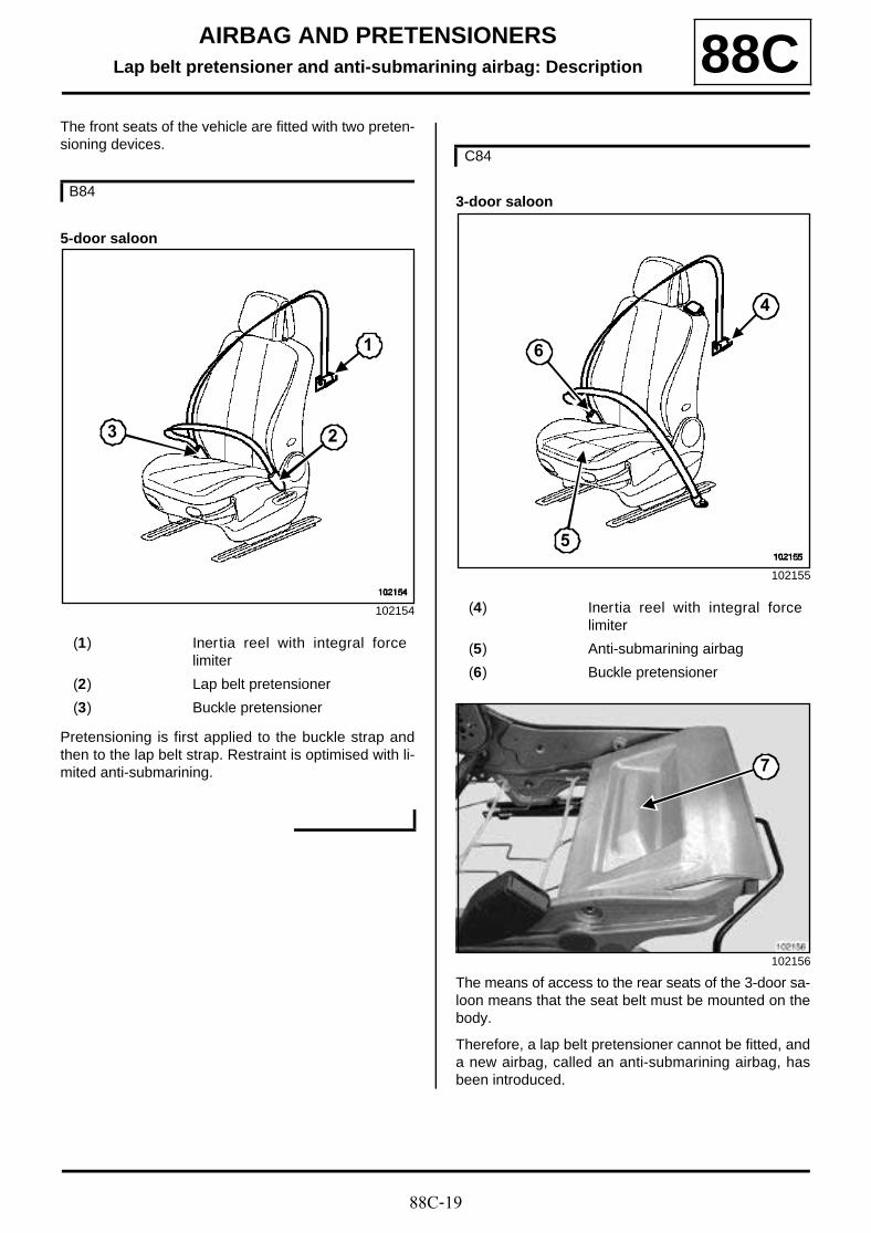
88C-19
AIRBAG AND PRETENSIONERSLap belt pretensioner and anti-submarining airbag: Description 88C
The front seats of the vehicle are fitted with two preten-sioning devices.
5-door saloon
Pretensioning is first applied to the buckle strap andthen to the lap belt strap. Restraint is optimised with li-mited anti-submarining.
3-door saloon
The means of access to the rear seats of the 3-door sa-loon means that the seat belt must be mounted on thebody.
Therefore, a lap belt pretensioner cannot be fitted, anda new airbag, called an anti-submarining airbag, hasbeen introduced.
B84
102154
(1) Inertia reel with integral forcelimiter
(2) Lap belt pretensioner
(3) Buckle pretensioner
3 2
1
C84
102155
(4) Inertia reel with integral forcelimiter
(5) Anti-submarining airbag
(6) Buckle pretensioner
102156
5
4
6
7
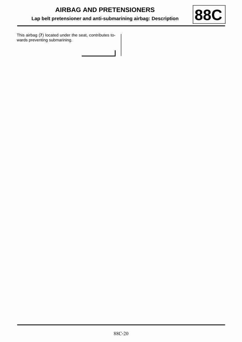
88C-20
AIRBAG AND PRETENSIONERSLap belt pretensioner and anti-submarining airbag: Description 88C
This airbag (7) located under the seat, contributes to-wards preventing submarining.
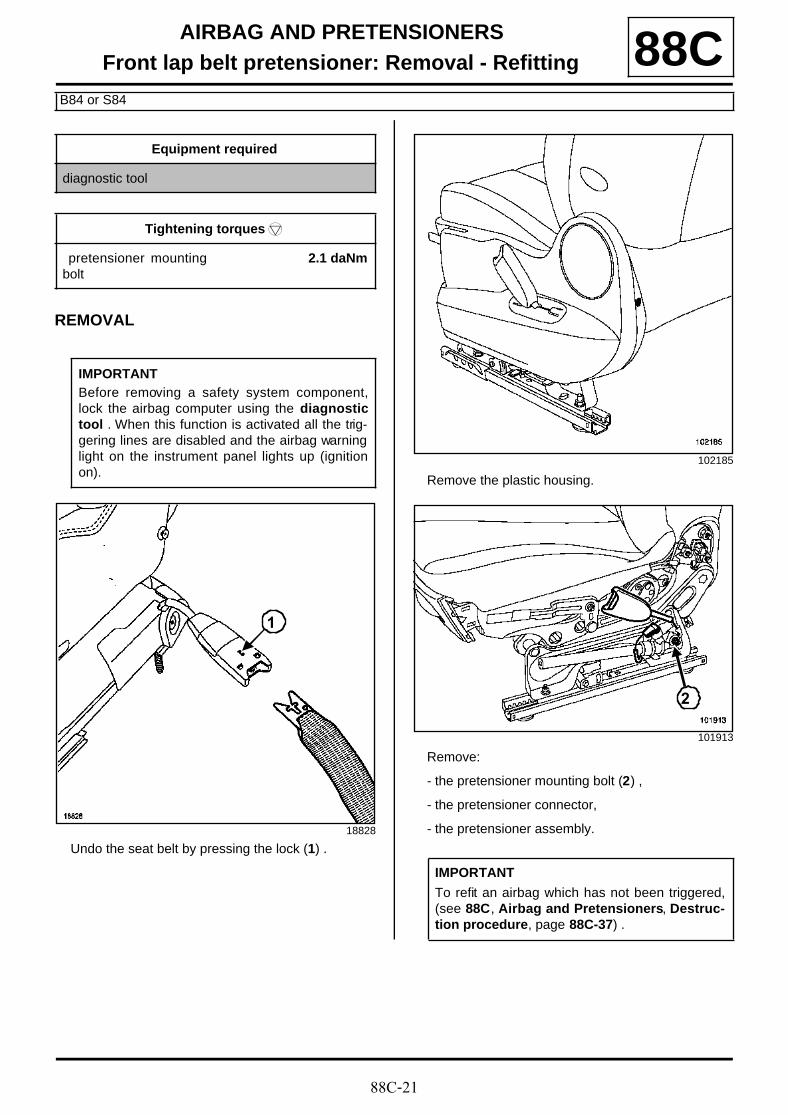
88C-21
AIRBAG AND PRETENSIONERSFront lap belt pretensioner: Removal - Refitting
B84 or S84
88C
REMOVAL
Undo the seat belt by pressing the lock (1) .
Remove the plastic housing.
Remove:
- the pretensioner mounting bolt (2) ,
- the pretensioner connector,
- the pretensioner assembly.
Equipment required
diagnostic tool
Tightening torquesm
pretensioner mountingbolt
2.1 daNm
IMPORTANTBefore removing a safety system component,lock the airbag computer using the diagnostictool . When this function is activated all the trig-gering lines are disabled and the airbag warninglight on the instrument panel lights up (ignitionon).
18828
1
102185
101913
IMPORTANT
To refit an airbag which has not been triggered,(see 88C, Airbag and Pretensioners, Destruc-tion procedure, page 88C-37) .
2
88C-22
AIRBAG AND PRETENSIONERSFront lap belt pretensioner: Removal - Refitting
B84 or S84
88CREFITTING
To refit, proceed in the reverse order of removal.
Follow the correct routing of the wiring and the wiringmounting points under the seat.
Torque-tighten the pretensioner mounting bolt (2.1 daNm ) .
Replace any faulty parts.
Reconnect the connector.
If everything is correct, unlock the airbag computer,if not, refer to the fault finding manual .
WARNING
When an airbag has been triggered, certainparts must be replaced ( « Precautions forrepair » ).
IMPORTANT
Check the airbag computer using the diagnos-tic tool .
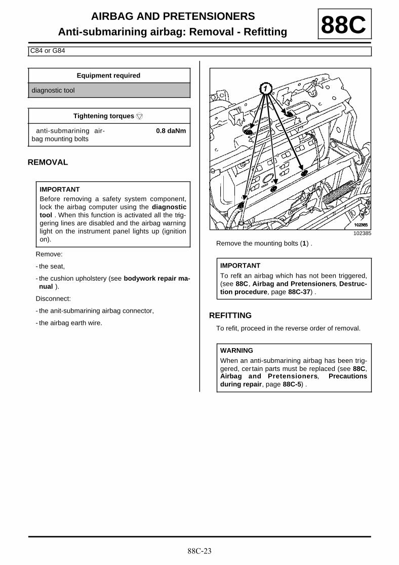
88C-23
AIRBAG AND PRETENSIONERSAnti-submarining airbag: Removal - Refitting
C84 or G84
88C
REMOVAL
Remove:
- the seat,
- the cushion upholstery (see bodywork repair ma-nual ).
Disconnect:
- the anit-submarining airbag connector,
- the airbag earth wire.
Remove the mounting bolts (1) .
REFITTING
To refit, proceed in the reverse order of removal.
Equipment required
diagnostic tool
Tightening torquesm
anti-submarining air-bag mounting bolts
0.8 daNm
IMPORTANTBefore removing a safety system component,lock the airbag computer using the diagnostictool . When this function is activated all the trig-gering lines are disabled and the airbag warninglight on the instrument panel lights up (ignitionon).
102385
IMPORTANT
To refit an airbag which has not been triggered,(see 88C, Airbag and Pretensioners, Destruc-tion procedure, page 88C-37) .
WARNING
When an anti-submarining airbag has been trig-gered, cer tain parts must be replaced (see 88C,Airbag and Pretensioners, Precautionsduring repair, page 88C-5) .
111
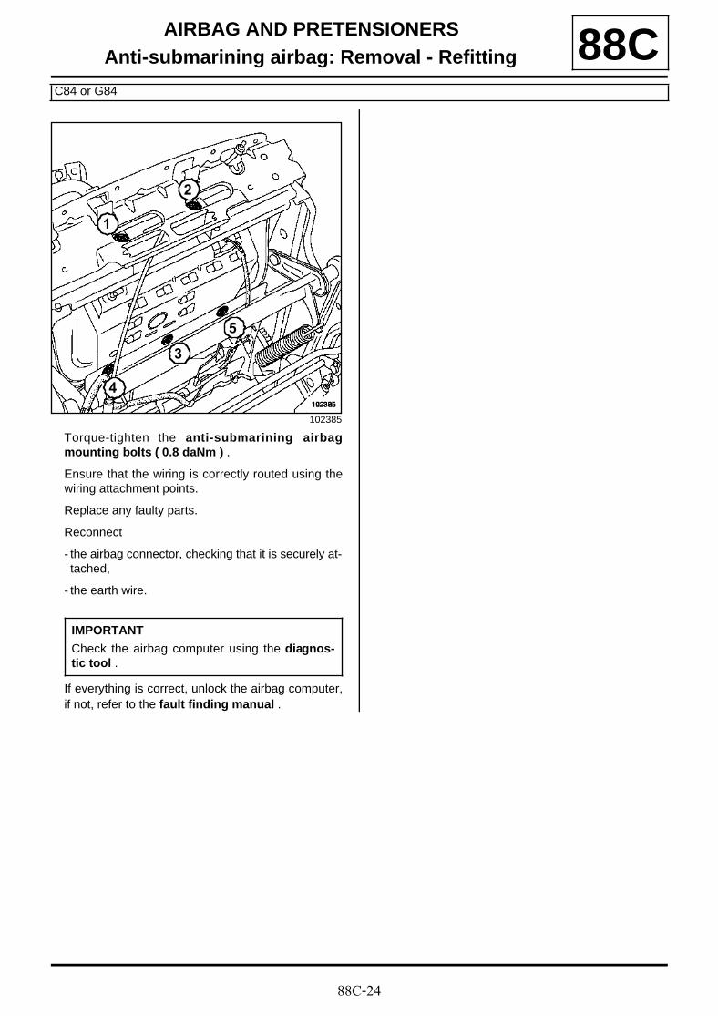
88C-24
AIRBAG AND PRETENSIONERSAnti-submarining airbag: Removal - Refitting
C84 or G84
88C
Torque-tighten the anti-submarining airbagmounting bolts ( 0.8 daNm ) .
Ensure that the wiring is correctly routed using thewiring attachment points.
Replace any faulty parts.
Reconnect
- the airbag connector, checking that it is securely at-tached,
- the earth wire.
If everything is correct, unlock the airbag computer,if not, refer to the fault finding manual .
102385
IMPORTANT
Check the airbag computer using the diagnos-tic tool .
2
3
4
5
1
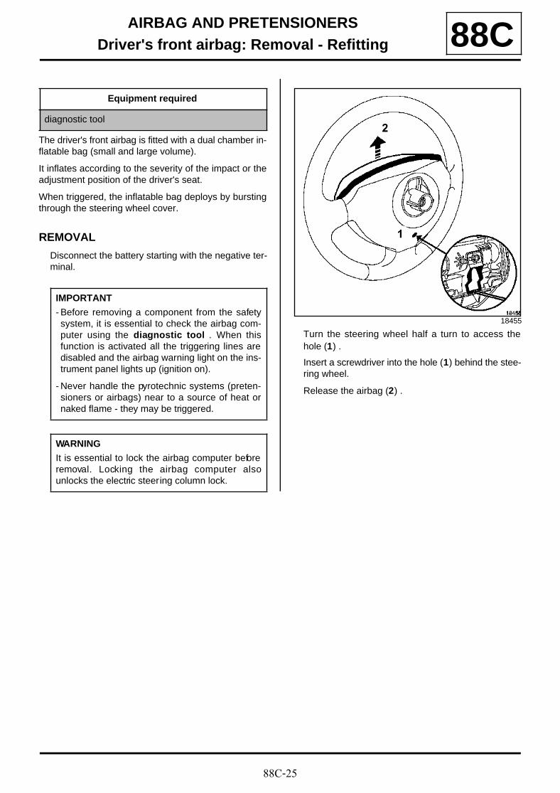
88C-25
AIRBAG AND PRETENSIONERSDriver's front airbag: Removal - Refitting 88C
The driver's front airbag is fitted with a dual chamber in-flatable bag (small and large volume).
It inflates according to the severity of the impact or theadjustment position of the driver's seat.
When triggered, the inflatable bag deploys by burstingthrough the steering wheel cover.
REMOVAL
Disconnect the battery starting with the negative ter-minal.
Turn the steering wheel half a turn to access thehole (1) .
Insert a screwdriver into the hole (1) behind the stee-ring wheel.
Release the airbag (2) .
Equipment required
diagnostic tool
IMPORTANT
- Before removing a component from the safetysystem, it is essential to check the airbag com-puter using the diagnostic tool . When thisfunction is activated all the triggering lines aredisabled and the airbag warning light on the ins-trument panel lights up (ignition on).
- Never handle the pyrotechnic systems (preten-sioners or airbags) near to a source of heat ornaked flame - they may be triggered.
WARNING
It is essential to lock the airbag computer beforeremoval. Locking the airbag computer alsounlocks the electric steering column lock.
18455
1
2

88C-26
AIRBAG AND PRETENSIONERSDriver's front airbag: Removal - Refitting 88C
Unclip the connector mountings at (3) using a smallscrewdriver.
Disconnect the connectors:
- for the driver's front airbag,
- for the cruise control buttons.
Remove:
- the airbag,
- the connector mounting clip with a small flatscrewdriver.
REFITTING
Fit both connectors.
Position the airbag on the steering wheel.
Slide the airbag downwards to clip it in place.
If everything is correct, unlock the airbag computer,if not, refer to the fault finding manual .
To refit, proceed in the reverse order of removal.
101200
101920
3
IMPORTANT
- The airbag has a connector which short circuitsif it is disconnected to prevent accidental trigge-ring.
- To refit a pyrotechnic reel which has not beentriggered, (see 88C , Airbag and Pretensio-ners, Computer, page 88C-8) .
WARNING
- When an airbag has been triggered, certainparts must be replaced (see 88C, Airbag andPretensioners, Precautions during repair,page 88C-5) .
- Whenever the steering wheel is removed,replace the steering wheel mounting bolt.
IMPORTANT
Check the airbag computer using diagnostictool .
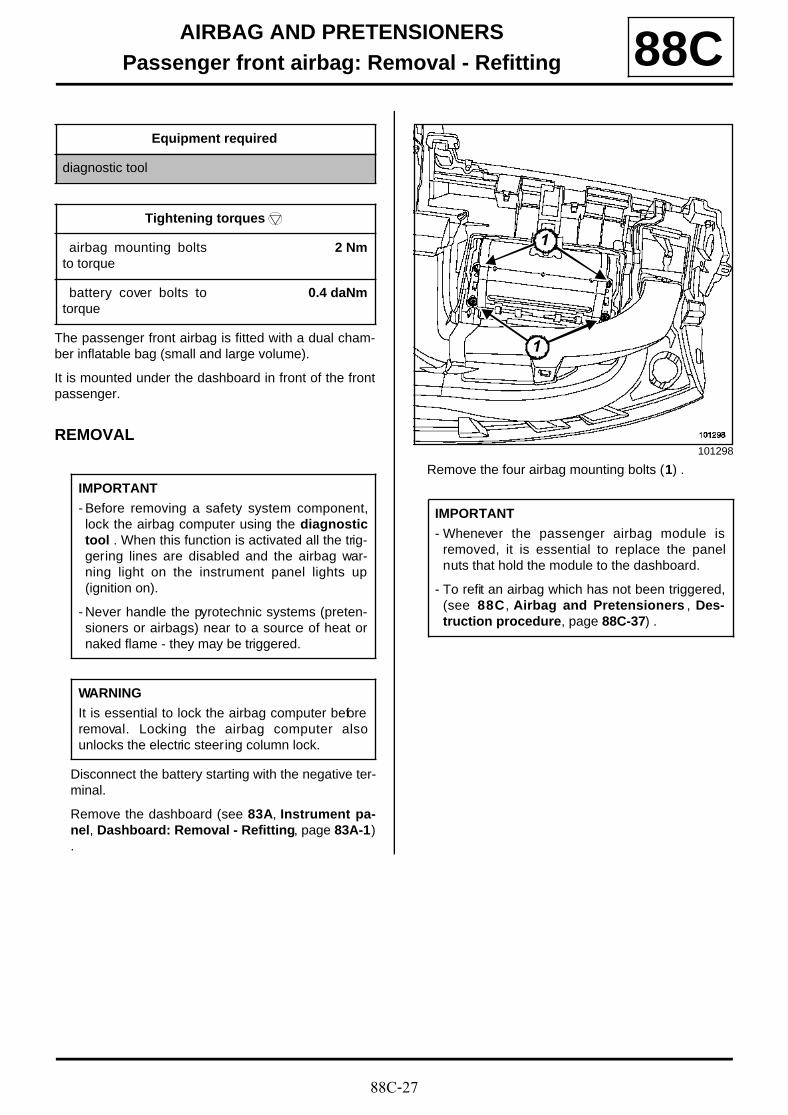
88C-27
AIRBAG AND PRETENSIONERSPassenger front airbag: Removal - Refitting 88C
The passenger front airbag is fitted with a dual cham-ber inflatable bag (small and large volume).
It is mounted under the dashboard in front of the frontpassenger.
REMOVAL
Disconnect the battery starting with the negative ter-minal.
Remove the dashboard (see 83A, Instrument pa-nel, Dashboard: Removal - Refitting, page 83A-1).
Remove the four airbag mounting bolts (1) .
Equipment required
diagnostic tool
Tightening torquesm
airbag mounting boltsto torque
2 Nm
battery cover bolts totorque
0.4 daNm
IMPORTANT
- Before removing a safety system component,lock the airbag computer using the diagnostictool . When this function is activated all the trig-gering lines are disabled and the airbag war-ning light on the instrument panel lights up(ignition on).
- Never handle the pyrotechnic systems (preten-sioners or airbags) near to a source of heat ornaked flame - they may be triggered.
WARNING
It is essential to lock the airbag computer beforeremoval. Locking the airbag computer alsounlocks the electric steering column lock.
101298
IMPORTANT
- Whenever the passenger airbag module isremoved, it is essential to replace the panelnuts that hold the module to the dashboard.
- To refit an airbag which has not been triggered,(see 88C , Airbag and Pretensioners , Des-truction procedure, page 88C-37) .
1
1
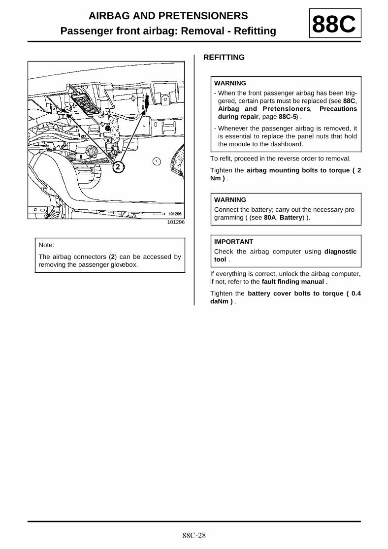
88C-28
AIRBAG AND PRETENSIONERSPassenger front airbag: Removal - Refitting 88C
REFITTING
To refit, proceed in the reverse order to removal.
Tighten the airbag mounting bolts to torque ( 2Nm ) .
If everything is correct, unlock the airbag computer,if not, refer to the fault finding manual .
Tighten the battery cover bolts to torque ( 0.4daNm ) .
101296
Note:
The airbag connectors (2) can be accessed byremoving the passenger glovebox.
2
WARNING
- When the front passenger airbag has been trig-gered, certain parts must be replaced (see 88C,Airbag and Pretensioners, Precautionsduring repair, page 88C-5) .
- Whenever the passenger airbag is removed, itis essential to replace the panel nuts that holdthe module to the dashboard.
WARNING
Connect the battery; carry out the necessary pro-gramming ( (see 80A, Battery) ).
IMPORTANT
Check the airbag computer using diagnostictool .
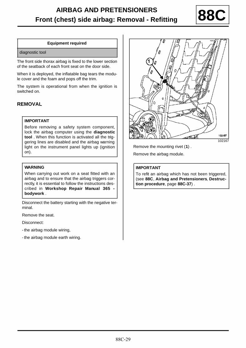
88C-29
AIRBAG AND PRETENSIONERSFront (chest) side airbag: Removal - Refitting 88C
The front side thorax airbag is fixed to the lower sectionof the seatback of each front seat on the door side.
When it is deployed, the inflatable bag tears the modu-le cover and the foam and pops off the trim.
The system is operational from when the ignition isswitched on.
REMOVAL
Disconnect the battery starting with the negative ter-minal.
Remove the seat.
Disconnect:
- the airbag module wiring,
- the airbag module earth wiring.
Remove the mounting rivet (1) .
Remove the airbag module.
Equipment required
diagnostic tool
IMPORTANT
Before removing a safety system component,lock the airbag computer using the diagnostictool . When this function is activated all the trig-gering lines are disabled and the airbag warninglight on the instrument panel lights up (ignitionon).
WARNING
When carrying out work on a seat fitted with anairbag and to ensure that the airbag triggers cor-rectly, it is essential to follow the instructions des-cribed in Workshop Repair Manual 365 -bodywork .
102167
IMPORTANT
To refit an airbag which has not been triggered,(see 88C, Airbag and Pretensioners, Destruc-tion procedure, page 88C-37) .
1
88C-30
AIRBAG AND PRETENSIONERSFront (chest) side airbag: Removal - Refitting 88C
REFITTING
Position the airbag on the frame.
Rivet the airbag to the frame (special rivet).
Refit the wiring under the seat as before and respectthe routing and the mounting points.
Connect the earth wire.
Verify that connector is locked correctly.
Refit the seat trim, following the advice (see Works-hop Repair Manual 365 - bodywork ).
Fit the seat to the vehicle (see Workshop RepairManual 365 - bodywork ).
If everything is correct, unlock the airbag computer,if not, refer to the fault finding manual .
WARNING
When an airbag has been triggered, certainparts must be replaced (see 88C, Airbag andPretensioners, Precautions during repair,page 88C-5) .
WARNING
Connect the battery; carry out the necessary pro-gramming ( (see 80A, Battery) ).
IMPORTANT
Check the airbag computer using the diagnos-tic tool .

88C-31
AIRBAG AND PRETENSIONERSRear (chest) side airbag: Removal - Refitting
B84
88C
The rear side chest airbag module is mounted on thequarter panel lining.
The airbag detaches the lining when it deploys.
REMOVAL
Remove the trim (see Workshop Repair Manual365 - bodywork ).
Disconnect:
- the airbag connector,
- the airbag earth wire.
Remove:
- the two mounting bolts (1) ,
- the rear side chest airbag.
REFITTING
Position the airbag.
Tighten the rear side chest airbag mounting boltto a torque of ( 0.4 daNm ) .
Connect:
- the airbag connector, checking that the connectoris correctly tightened,
- the earth wire.
Refit the trim.
If everything is correct, unlock the computer, if not,refer to fault finding manual .
Equipment required
diagnostic tool
Tightening torquesm
rear side chest airbagmounting bolt to a tor-que of
0.4 daNm
101914
IMPORTANT
Before removing a safety system component,lock the airbag computer using the diagnostictool . When this function is activated all the trig-gering lines are disabled and the airbag warninglight on the instrument panel lights up (ignitionon).
101982
IMPORTANT
To refit a pyrotechnic reel which has not beentr iggered, (see 88C , Airbag and Pretensio-ners, Destruction procedure, page 88C-37) .
IMPORTANT
Carry out an airbag computer test using the dia-gnostic tool .
1
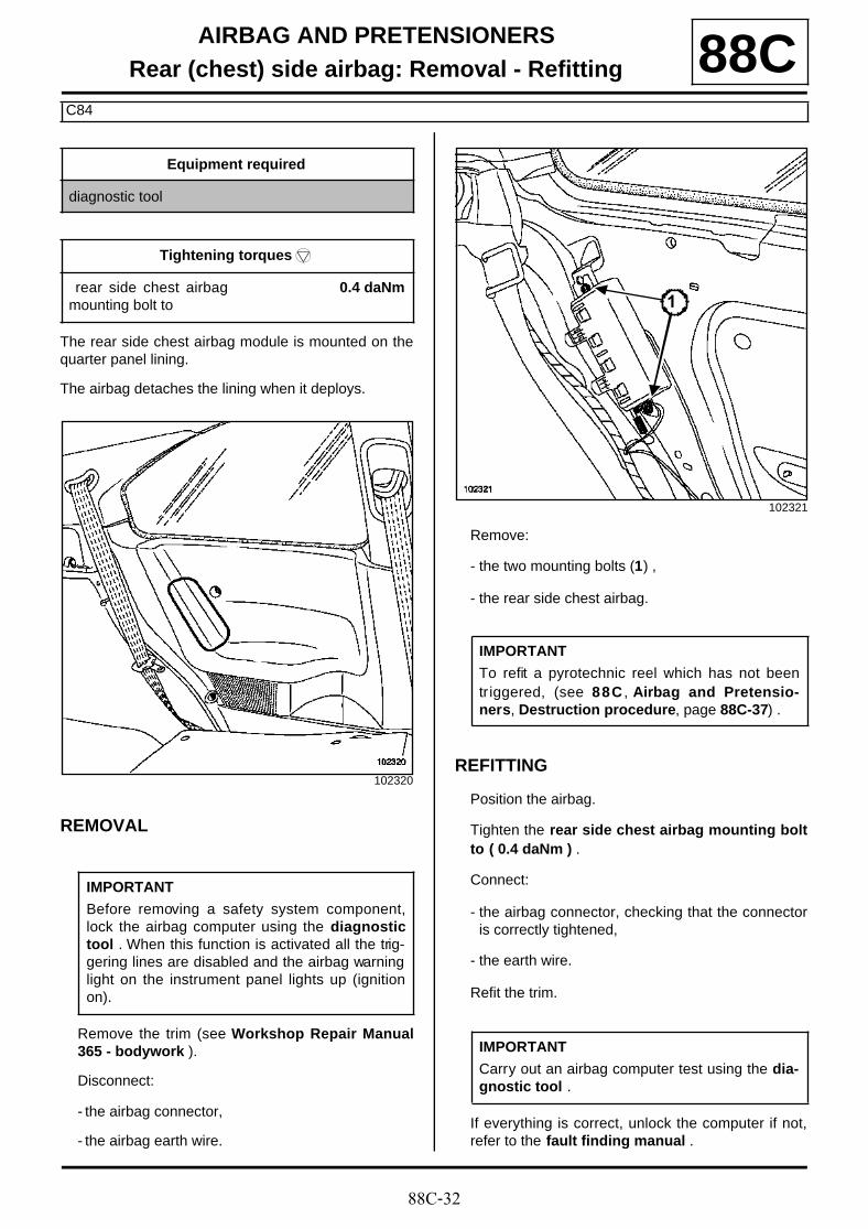
88C-32
AIRBAG AND PRETENSIONERSRear (chest) side airbag: Removal - Refitting
C84
88C
The rear side chest airbag module is mounted on thequarter panel lining.
The airbag detaches the lining when it deploys.
REMOVAL
Remove the trim (see Workshop Repair Manual365 - bodywork ).
Disconnect:
- the airbag connector,
- the airbag earth wire.
Remove:
- the two mounting bolts (1) ,
- the rear side chest airbag.
REFITTING
Position the airbag.
Tighten the rear side chest airbag mounting boltto ( 0.4 daNm ) .
Connect:
- the airbag connector, checking that the connectoris correctly tightened,
- the earth wire.
Refit the trim.
If everything is correct, unlock the computer if not,refer to the fault finding manual .
Equipment required
diagnostic tool
Tightening torquesm
rear side chest airbagmounting bolt to
0.4 daNm
102320
IMPORTANT
Before removing a safety system component,lock the airbag computer using the diagnostictool . When this function is activated all the trig-gering lines are disabled and the airbag warninglight on the instrument panel lights up (ignitionon).
102321
IMPORTANT
To refit a pyrotechnic reel which has not beentr iggered, (see 88C , Airbag and Pretensio-ners, Destruction procedure, page 88C-37) .
IMPORTANT
Carry out an airbag computer test using the dia-gnostic tool .
1
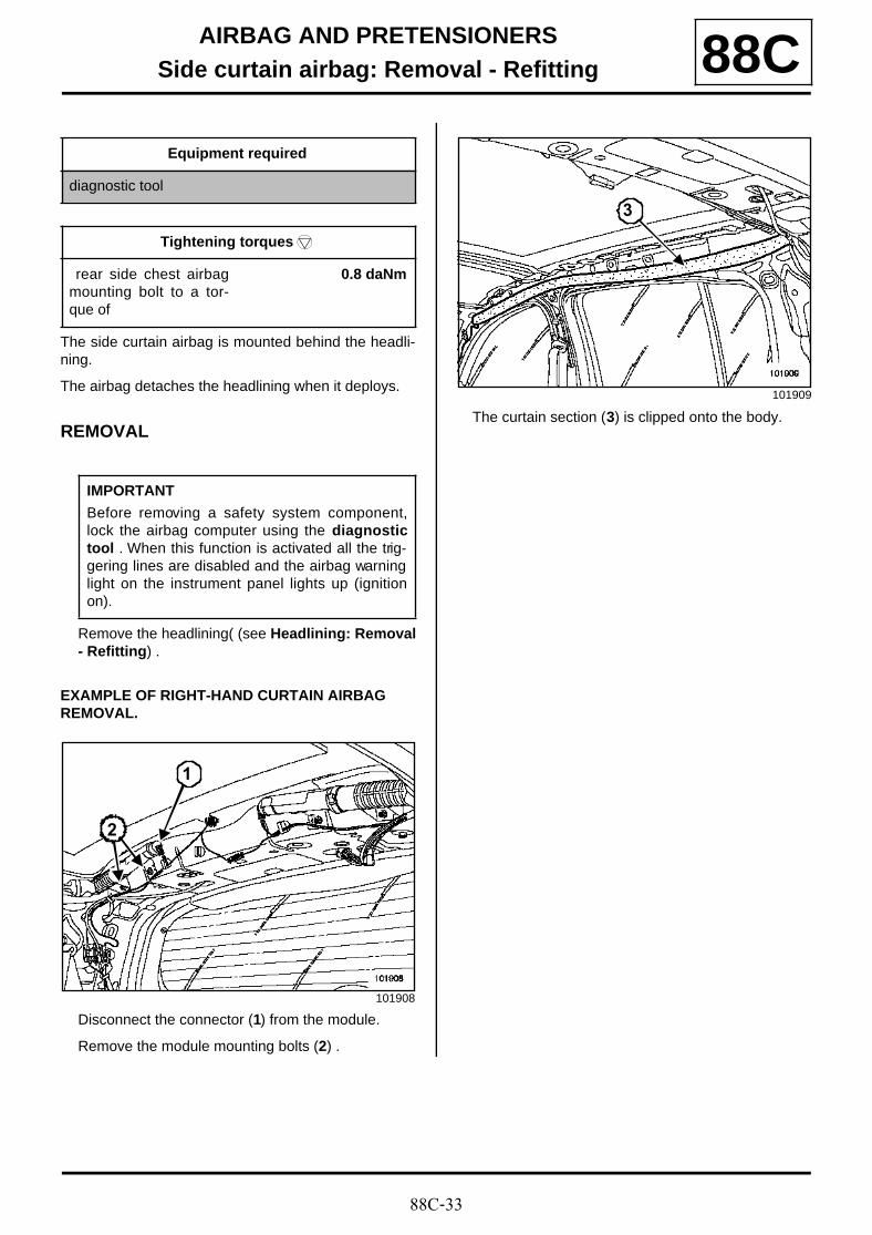
88C-33
AIRBAG AND PRETENSIONERSSide curtain airbag: Removal - Refitting 88C
The side curtain airbag is mounted behind the headli-ning.
The airbag detaches the headlining when it deploys.
REMOVAL
Remove the headlining( (see Headlining: Removal- Refitting) .
EXAMPLE OF RIGHT-HAND CURTAIN AIRBAG REMOVAL.
Disconnect the connector (1) from the module.
Remove the module mounting bolts (2) .
The curtain section (3) is clipped onto the body.
Equipment required
diagnostic tool
Tightening torquesm
rear side chest airbagmounting bolt to a tor-que of
0.8 daNm
IMPORTANT
Before removing a safety system component,lock the airbag computer using the diagnostictool . When this function is activated all the trig-gering lines are disabled and the airbag warninglight on the instrument panel lights up (ignitionon).
101908
1
2
101909
3

88C-34
AIRBAG AND PRETENSIONERSSide curtain airbag: Removal - Refitting 88C
Unclip the curtain at:
- lowering (4) the curtain, to lower the clip mountedon the body,
- pulling (5) the curtain to release the clip from its up-per section,
- lifting (6) the assembly.
REFITTING
Use the following replacement parts:
- a curtain airbag,
- a plate part number 82 00 277 635 ,
- two special rivets part number 77 03 072 050 ,
- a sachet of adhesive part number 77 11 171 805 .
100236
100237
IMPORTANTTo refit a pyrotechnic reel which has not beentriggered, (see 88C , Airbag and Pretensio-ners, Destruction procedure, page 88C-37) .
4
4
5
6
6
WARNING
- If a curtain airbag module is triggered, thedamage to the first mounting always requiresthat a plate supplied as a replacement part befitted.
- If a curtain airbag is triggered, it is essential toreplace certain parts (see 88C, Airbag andPretensioners, Precautions during repair,page 88C-5) .
20234
Note:
The plate is identical on the left and right-handsides.
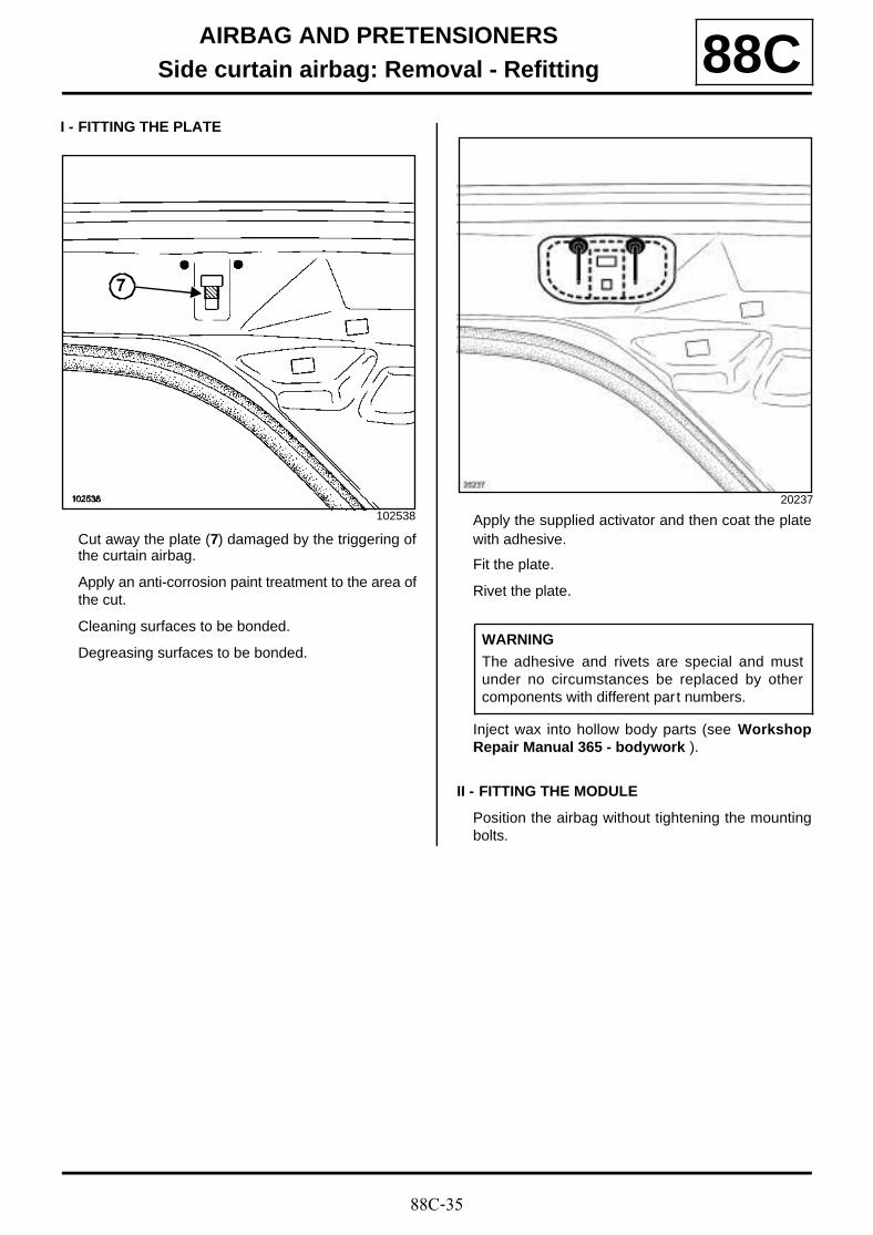
88C-35
AIRBAG AND PRETENSIONERSSide curtain airbag: Removal - Refitting 88C
I - FITTING THE PLATE
Cut away the plate (7) damaged by the triggering ofthe curtain airbag.
Apply an anti-corrosion paint treatment to the area ofthe cut.
Cleaning surfaces to be bonded.
Degreasing surfaces to be bonded.
Apply the supplied activator and then coat the platewith adhesive.
Fit the plate.
Rivet the plate.
Inject wax into hollow body parts (see WorkshopRepair Manual 365 - bodywork ).
II - FITTING THE MODULE
Position the airbag without tightening the mountingbolts.
102538
7
20237
WARNING
The adhesive and rivets are special and mustunder no circumstances be replaced by othercomponents with different part numbers.
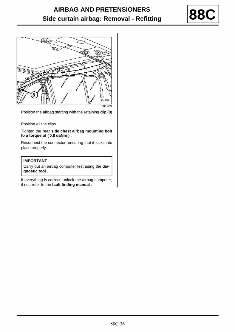
88C-36
AIRBAG AND PRETENSIONERSSide curtain airbag: Removal - Refitting 88C
Position the airbag starting with the retaining clip (8).
Position all the clips.
Tighten the rear side chest airbag mounting boltto a torque of ( 0.8 daNm ) .
Reconnect the connector, ensuring that it locks intoplace properly.
If everything is correct, unlock the airbag computer,if not, refer to the fault finding manual .
101909
IMPORTANTCarry out an airbag computer test using the dia-gnostic tool .
8
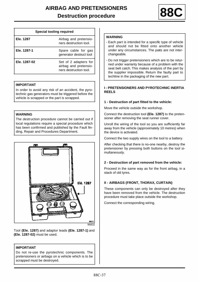
88C-37
AIRBAG AND PRETENSIONERSDestruction procedure 88C
Tool (Ele. 1287) and adaptor leads (Ele. 1287-1) and(Ele. 1287-02) must be used.
I - PRETENSIONERS AND PYROTECHNIC INERTIA REELS
1 - Destruction of part fitted to the vehicle:
Move the vehicle outside the workshop.
Connect the destruction tool (Ele. 1287) to the preten-sioner after removing the seat runner cover.
Unroll the wiring of the tool so you are sufficiently faraway from the vehicle (approximately 10 metres) whenthe device is activated.
Connect the two supply wires on the tool to a battery.
After checking that there is no-one nearby, destroy thepretensioner by pressing both buttons on the tool si-multaneously.
2 - Destruction of part removed from the vehicle:
Proceed in the same way as for the front airbag, in astack of old tyres.
II - AIRBAGS (FRONT, THORAX, CURTAIN)
These components can only be destroyed after theyhave been removed from the vehicle. The destructionprocedure must take place outside the workshop.
Connect the corresponding wiring.
Special tooling required
Ele. 1287 Airbag and pretensio-ners destruction tool.
Ele. 1287-1 Spare cable for gasgenerator destruct tool
Ele. 1287-02 Set of 2 adapters forairbag and pretensio-ners destruction tool.
IMPORTANT
In order to avoid any risk of an accident, the pyro-technic gas generators must be triggered before thevehicle is scrapped or the part is scrapped.
WARNINGThe destruction procedure cannot be carried out iflocal regulations require a special procedure whichhas been confirmed and published by the Fault fin-ding, Repair and Procedures Department.
96832
IMPORTANTDo not re-use the pyrotechnic components. Thepretensioners or airbags on a vehicle which is to bescrapped must be destroyed.
WARNING
- Each part is intended for a specific type of vehicleand should not be fitted onto another vehicleunder any circumstances. The parts are not inter-changeable.
- Do not trigger pretensioners which are to be retur-ned under warranty because of a problem with theseat belt catch. This makes analysis of the part bythe supplier impossible. Return the faulty part totechline in the packaging of the new part.
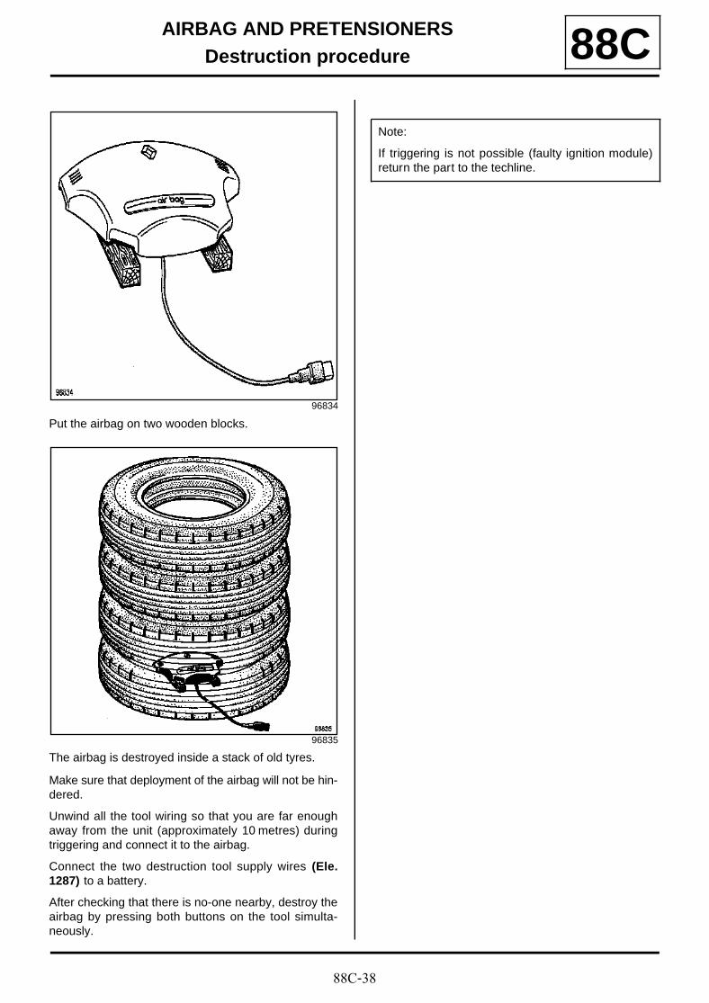
88C-38
AIRBAG AND PRETENSIONERSDestruction procedure 88C
Put the airbag on two wooden blocks.
The airbag is destroyed inside a stack of old tyres.
Make sure that deployment of the airbag will not be hin-dered.
Unwind all the tool wiring so that you are far enoughaway from the unit (approximately 10 metres) duringtriggering and connect it to the airbag.
Connect the two destruction tool supply wires (Ele.1287) to a battery.
After checking that there is no-one nearby, destroy theairbag by pressing both buttons on the tool simulta-neously.
96834
96835
Note:
If triggering is not possible (faulty ignition module)return the part to the techline.


