
Recommendation ITU-R BS.1873(03/2010)
Serial multichannel audio digital interface for broadcasting studios
BS SeriesBroadcasting service (sound)
ii Rec. ITU-R BS.1873
Foreword
The role of the Radiocommunication Sector is to ensure the rational, equitable, efficient and economical use of the radio-frequency spectrum by all radiocommunication services, including satellite services, and carry out studies without limit of frequency range on the basis of which Recommendations are adopted.
The regulatory and policy functions of the Radiocommunication Sector are performed by World and Regional Radiocommunication Conferences and Radiocommunication Assemblies supported by Study Groups.
Policy on Intellectual Property Right (IPR)
ITU-R policy on IPR is described in the Common Patent Policy for ITU-T/ITU-R/ISO/IEC referenced in Annex 1 of Resolution ITU-R 1. Forms to be used for the submission of patent statements and licensing declarations by patent holders are available from http://www.itu.int/ITU-R/go/patents/en where the Guidelines for Implementation of the Common Patent Policy for ITU-T/ITU-R/ISO/IEC and the ITU-R patent information database can also be found.
Series of ITU-R Recommendations (Also available online at http://www.itu.int/publ/R-REC/en)
Series Title
BO Satellite deliveryBR Recording for production, archival and play-out; film for televisionBS Broadcasting service (sound)BT Broadcasting service (television)F Fixed serviceM Mobile, radiodetermination, amateur and related satellite servicesP Radiowave propagationRA Radio astronomyRS Remote sensing systemsS Fixed-satellite serviceSA Space applications and meteorologySF Frequency sharing and coordination between fixed-satellite and fixed service systemsSM Spectrum managementSNG Satellite news gatheringTF Time signals and frequency standards emissionsV Vocabulary and related subjects
Note: This ITU-R Recommendation was approved in English under the procedure detailed in Resolution ITU-R 1.
Electronic PublicationGeneva, 2010
ITU 2010
All rights reserved. No part of this publication may be reproduced, by any means whatsoever, without written permission of ITU.

Rec. ITU-R BS.1873 1
RECOMMENDATION ITU-R BS.1873
Serial multichannel audio digital interface for broadcasting studios(Question ITU-R 130/6)
(2010)
Scope
This Recommendation specifies a serial multichannel sound digital interface to be used in broadcasting studios. The specification includes the data organization and electrical characteristics for the serial digital transmission of linearly represented digital data at a common sampling frequency over coaxial or fibre-optic lines.
The ITU Radiocommunication Assembly,
considering
a) that Recommendation ITU-R BS.775 specifies one universal multichannel stereophonic sound system with three front channels and two rear/side channels together with an optional low frequency effects (LFE) channel;
b) that a significant number of sound channels are generally used for sound programme production in broadcasting studios;
c) that there is a need to interconnect multichannel sound signals between various pieces of digital sound equipment in broadcasting studios;
d) that it is advantageous for all the equipment to use the same interface connections;
e) that Recommendation ITU-R BS.647 – A digital audio interface for broadcasting studios, specifies the digital interface for the serial digital transmission of two channels of linearly represented digital sound data used in production for sound and television broadcasting;
f) that Recommendation ITU-R BS.646 – Source encoding for digital sound signals in broadcasting studios, defines the digital sound format used in production for sound and television broadcasting,
recommends
1 that the interface described in Annex 1 should be used as a serial multichannel sound digital interface in broadcasting studios;
2 that compliance with this Recommendation is voluntary. However, the Recommendation may contain certain mandatory provisions (to ensure e.g. interoperability or applicability) and compliance with the Recommendation is achieved when all of these mandatory provisions are met. The words “shall” or some other obligatory language such as “must” and the negative equivalents are used to express requirements. The use of such words shall in no way be construed to imply partial or total compliance with this Recommendation.
2 Rec. ITU-R BS.1873
Annex 1
Serial multichannel audio digital interface (MADI)
1 Introduction
This annex specifies the data organization and electrical characteristics for a multichannel audio digital interface for broadcasting studios. It includes a bit-level description, features in common with the two-channel format of Recommendation ITU-R BS.647 and the data rates required for its utilization. The specification provides for the serial digital transmission over coaxial or fibre-optic lines of 56 or 64 channels of linearly represented digital data at a common sampling frequency within the range of 32 kHz to 48 kHz having a resolution of up to 24 bits per channel. Only single-point to single-point interconnections from one transmitter to one receiver are supported.
The interface specified here is primarily intended to be used at 48 kHz as this is the recommended sampling frequency for use in broadcasting studios according to Recommendation ITU-R BS.646.
2 Terminology
For the purpose of this specification the following definitions of terms apply.
2.1 Audio sample data
Audio signal that has been periodically sampled, quantized, and digitally represented in 2’s complement form.
2.2 Channel
Set of audio sample data related to one signal accompanied by other data bits transmitted in any one period of the source sampling frequency.
2.3 Two-channel format
Bit, block, and subframe structure (fewer preambles) of the Recommendation ITU-R BS.647 serial transmission format for linearly represented digital audio data.
2.4 Frame
Sequence of 64 or less (typically 56) subframes designated using numbers 0 to 63, each carrying audio sample and related data that are transmitted in one sample period, with the start of a frame beginning with the first bit of subframe 0.
2.5 Link
Connection between a single serial multichannel digital audio transmitter and a single multichannel digital audio receiver.
2.6 Sync symbol
Decoder synchronization symbol.
Rec. ITU-R BS.1873 3
2.7 MADI
Multichannel audio digital interface.
2.8 NRZI (Non-return to Zero, Invert on Ones)
A technique in which a polarity transition represents a logical “1” (one). The absence of a polarity transition denotes a logical “0” (zero).
3 Format
This specification provides for the serial digital transmission over coaxial or fibre-optic lines of 56 or 64 channels of linearly-represented digital data at a common sampling frequency within the range of 32 kHz to 48 kHz having a resolution of up to 24 bits per channel. See Fig. 1.
FIGURE 1Diagram of MADI
3.1 Frame format
Each frame consists of n channels, which are numbered from 0 to n – 1. The channels are consecutive within the frame, starting with channel 0 as shown in Fig. 2.
BS.1873-01
Receiver
Synchronizationregenerator
Transmitter
Buffer32
Receiver
Receiver
TransmitterClockReadTransmitter
Crystal
Data4B/5BEncoder
Mastersynchronization
m
Data
Clockgenerator
32
Crystal
f´s
5B/4BDecoderClock
Synchronizationregenerator
Clocksynchro-nization
32
Data
fsfs
fs
32
Data
Buffer
Serial NRZI125 Mbit/s Data
Note 1 – As sample rate changes NRZI data rate stays constant; transmitter and receiver are asynchronous. Sampling frequencies (fs) are 32 kHz to 48 kHz.

4 Rec. ITU-R BS.1873
FIGURE 248 kHz with 56 channels working
3.2 Channel format
Each channel consists of 32 bits, of which 24 are allocated to audio or to other data as defined by the audio/non-audio status flag. A further 4 bits represent the validity (V), user (U), status (C), and parity (P) bits of the Recommendation ITU-R BS.647 two-channel format interface, with a further 4 bits allocated for mode identification. In this manner, the Recommendation ITU-R BS.647 two-channel format is preserved. The channel format is shown in Fig. 3.
FIGURE 3Channel data format
3.2.1 Mode bits
The mode bits provide for frame synchronization, for block start per Recommendation ITU-R BS.647, for identification of the A and B subframes also present in Recommendation ITU-R BS.647, and for active/inactive status per channel.
3.2.2 Audio data representation
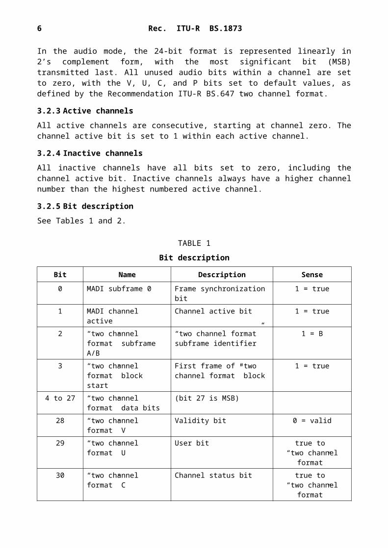
In the audio mode, the 24-bit format is represented linearly in 2’s complement form, with the most significant bit (MSB) transmitted last. All unused audio bits within a channel are set to zero, with the V, U, C, and P bits set to default values, as defined by the Recommendation ITU-R BS.647 two channel format.
3.2.3 Active channels
All active channels are consecutive, starting at channel zero. The channel active bit is set to 1 within each active channel.
BS.1873-02
0Ch 0
nA
MADI subframeAudio channelSample numberRec. ITU-R BS.647subframe
1Ch 1
nB
2Ch 2
nA
3Ch 3
nB
4 54Ch 54
nA
55Ch 55
nB
0Ch 0n + 1
A
20.8 µs
Note 1Note 2
– Synchronization symbols not shown. – The period of each pattern is shown for the 48 kHz sampling frequency. It can be longer for
lower frequencies and can vary with varispeed operation.
BS.1873-03
ON/OFF (MADI channel active)
Unencoded channel data bits
MADI subframe zero
Rec. ITU-R BS.647 subframe A/BRec. ITU-R BS.647 block start
Rec. ITU-R BS.647CRec. ITU-R BS.647P
Rec. ITU-R BS.647URec. ITU-R BS.647V
Audio data bit 27 = MSB
MSB
0 1 2 3 4 5 6 7 8 9 10 11 12 13 14 15 16 17 18 19 20 21 22 23 24 25 26 27 28 29 30 31

Rec. ITU-R BS.1873 5
3.2.4 Inactive channels
All inactive channels have all bits set to zero, including the channel active bit. Inactive channels always have a higher channel number than the highest numbered active channel.
3.2.5 Bit description
See Tables 1 and 2.
TABLE 1
Bit description
Bit Name Description Sense
0 MADI subframe 0 Frame synchronization bit 1 = true1 MADI channel active Channel active bit 1 = true2 “two channel format”
subframe A/B“two channel format” subframe identifier
1 = B
3 “two channel format” block start
First frame of “two channel format” block
1 = true
4 to 27 “two channel format” data bits
(bit 27 is MSB)
28 “two channel format” V Validity bit 0 = valid29 “two channel format” U User bit true to
“two channel format”30 “two channel format” C Channel status bit true to
“two channel format”31 “two channel format” P Parity bit (excludes bits 0 to 3) Even
TABLE 2
Bits 2 to 3 compatibility with “two channel format”
Bit 2 Bit 3 Two-channel form Description
0 0 Form 2 A subframe0 1 Form 1 A subframe status block start1 0 Form 3 B subframe1 1 Form 4(1) B subframe status block start
(1) Does not conform to the Recommendation ITU-R BS.647 two-channel format.
3.3 Transmission format
3.3.1 4B5B coding
The channels are transmitted serially. The binary sequence is recoded from 100 Mbit/s to 125 Mbit/s by replacing every 4 source bits with a unique 5-bit sequence specified in § 3.3.1.1. This scheme is known as 4B5B coding.NOTE 1 – The purpose of this new code is that it contains no continuous sequences of ones or zeros.

6 Rec. ITU-R BS.1873
3.3.1.1 Encoding scheme
For the purposes of encoding, the 32-bit channel data are broken down into 8 words of 4 bits each, as shown in Table 3.
TABLE 3
32-bit channel data
Word Channel data bit
0 01231 45672 89..3 ....4 ....5 ....6 ....7 ...31
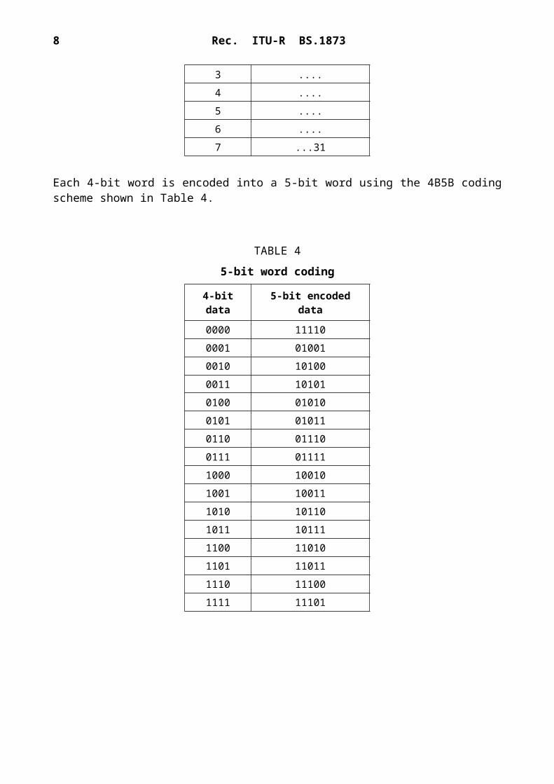
Each 4-bit word is encoded into a 5-bit word using the 4B5B coding scheme shown in Table 4.
TABLE 4
5-bit word coding
4-bit data 5-bit encoded data
0000 111100001 010010010 101000011 101010100 010100101 010110110 011100111 011111000 100101001 100111010 101101011 101111100 110101101 110111110 111001111 11101
Rec. ITU-R BS.1873 7
Each 5-bit encoded word is transmitted from the left, as defined in Table 5.
TABLE 5
5-bit word transmission
Word Channel data bit
0 012341 567892 .....3 .....4 .....5 .....6 .....7 ....39
3.3.2 4B5B synchronization symbol (sync symbol)
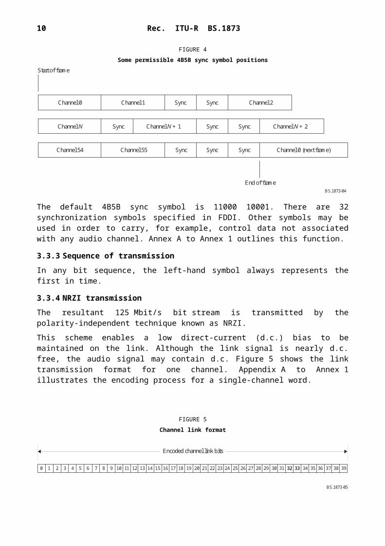
A 4B5B sync symbol is inserted into the data stream at least once per frame period to ensure transmitter and receiver synchronization of the 4B5B decoder in the receiver. Sufficient 4B5B sync symbols are inserted by interleaving with the encoded data words to fill the total link capacity. The 4B5B sync symbol is transmitted from the left. The 4B5B sync symbol may only be inserted at 40-bit channel boundaries, but may be repeated between channels or during the idle period after the last channel has been transmitted in each frame capacity, or both. The order placement of 4B5B sync symbols is not specified. Some examples of permissible positions of the 4B5B sync symbol are shown in Fig. 4.
FIGURE 4Some permissible 4B5B sync symbol positions
The default 4B5B sync symbol is 11000 10001. There are 32 synchronization symbols specified in FDDI. Other symbols may be used in order to carry, for example, control data not associated with any audio channel. Annex A to Annex 1 outlines this function.
BS.1873-04
Start of frame
Channel 0 Channel 1 Channel 2Sync Sync
Channel N Channel 1N + Channel 2N +Sync Sync Sync
Channel 54 Channel 55 Channel 0 (next frame)Sync Sync Sync
End of frame

8 Rec. ITU-R BS.1873
3.3.3 Sequence of transmission
In any bit sequence, the left-hand symbol always represents the first in time.
3.3.4 NRZI transmission
The resultant 125 Mbit/s bit stream is transmitted by the polarity-independent technique known as NRZI.
This scheme enables a low direct-current (d.c.) bias to be maintained on the link. Although the link signal is nearly d.c. free, the audio signal may contain d.c. Figure 5 shows the link transmission format for one channel. Appendix A to Annex 1 illustrates the encoding process for a single-channel word.
FIGURE 5Channel link format
3.3.5 Control data carriage
This section describes in outline a method of carrying control data in the transport carrier independent of any particular audio channel. The transport sync symbol words inserted between audio data words can carry this control data by virtue of the fact that there are a number of forms of sync symbol, of which the default is that used by MADI systems. Four-bit nibbles are associated with 16 of the sync symbol forms, thus allowing data to be inserted in the available space. The default sync symbol described in § 3.3.2 is associated with the binary value 0000.
A stream of 56 channels at 48 kHz ± 12.5% and highest permitted varispeed rate uses 96.768 Mbit/s, and a 64-channel 48 kHz stream uses 98.304 Mbit/s. Thus there will always be at least 1 Mbit/s for this data. This may need to be reduced to ensure that bit-stream synchronization is maintained.
3.3.5.1 Data insertion
3.3.5.1.1 Ordering
Default sync symbol words are transmitted at least as often as required, in order to guarantee correct data recovery of the whole transport stream. Coded sync symbols are inserted as and when required, subject to the needs of audio data and the provision above.
3.3.5.1.2 Data coding
A format relating to the high-level data link control protocol uses the look-up table. See Table 6 below as an example.
BS.1873-05
0 1 2 3 4 5 6 7 8 9 10 11 12 13 14 15 16 17 18 19 20 21 22 23 24 25 26 32 33 37 38 3927 28 29 30 31 32 33 34 35 36
Encoded channel link bits
Rec. ITU-R BS.1873 9
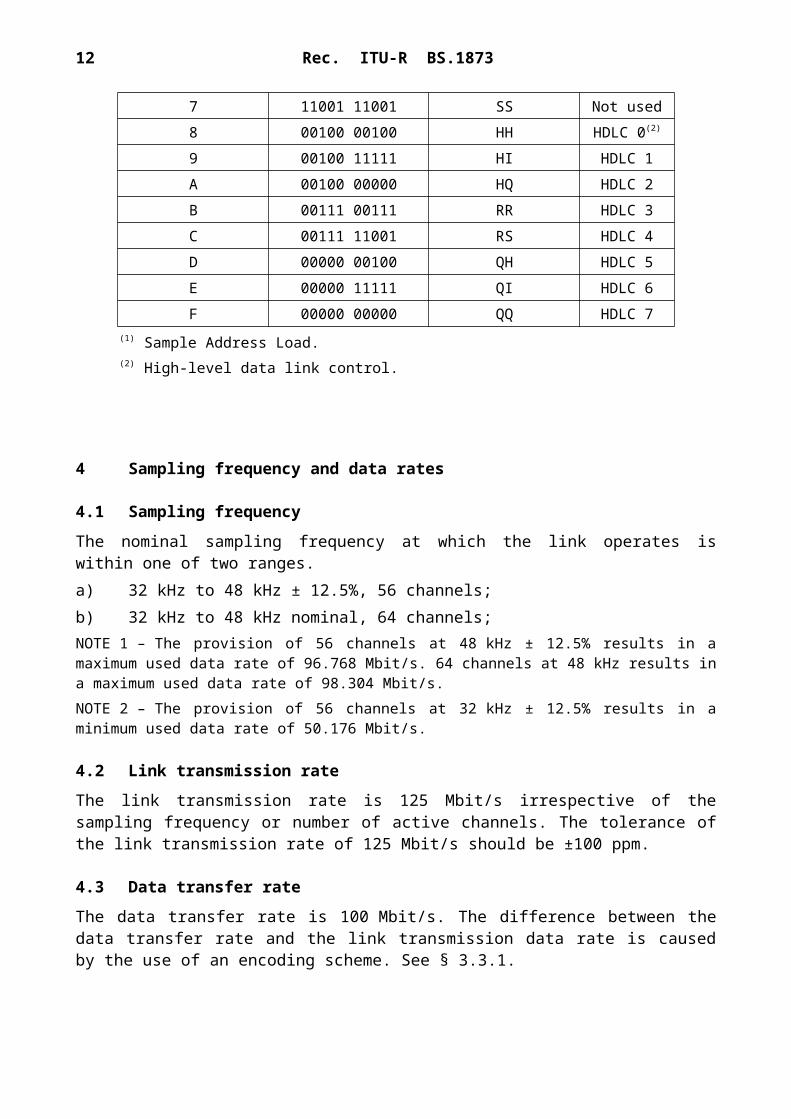
TABLE 6
Data coding look-up table
Command number Command symbol Name of symbol Function
0 11000 10001 JK Sync1 11111 11111 II Not used2 01101 01101 TT Not used3 01101 11001 TS Not used4 11111 00100 IH SAL(1)
5 01101 00111 TR Not used6 11001 00111 SR Not used7 11001 11001 SS Not used8 00100 00100 HH HDLC 0(2)
9 00100 11111 HI HDLC 1A 00100 00000 HQ HDLC 2B 00111 00111 RR HDLC 3C 00111 11001 RS HDLC 4D 00000 00100 QH HDLC 5E 00000 11111 QI HDLC 6F 00000 00000 QQ HDLC 7
(1) Sample Address Load.(2) High-level data link control.
4 Sampling frequency and data rates
4.1 Sampling frequency
The nominal sampling frequency at which the link operates is within one of two ranges.a) 32 kHz to 48 kHz ± 12.5%, 56 channels;b) 32 kHz to 48 kHz nominal, 64 channels;NOTE 1 – The provision of 56 channels at 48 kHz ± 12.5% results in a maximum used data rate of 96.768 Mbit/s. 64 channels at 48 kHz results in a maximum used data rate of 98.304 Mbit/s.NOTE 2 – The provision of 56 channels at 32 kHz ± 12.5% results in a minimum used data rate of 50.176 Mbit/s.
4.2 Link transmission rate
The link transmission rate is 125 Mbit/s irrespective of the sampling frequency or number of active channels. The tolerance of the link transmission rate of 125 Mbit/s should be ±100 ppm.
4.3 Data transfer rate
The data transfer rate is 100 Mbit/s. The difference between the data transfer rate and the link transmission data rate is caused by the use of an encoding scheme. See § 3.3.1.

10 Rec. ITU-R BS.1873
5 Synchronization
This section covers the sample synchronization of transmitters and receivers relative to a master synchronizing signal. It does not apply in the case of a master-slave connection only.
For further information, see also the Bibliography.
5.1 Sampling
Each transmitter and receiver is provided with an independently distributed master synchronizing signal.
5.2 Sample timing
The link is not intended to carry sample timing information. The exact timing of connected equipment is controlled by the independently distributed master synchronizing signal, not by the MADI.
5.3 Transmitted frame start time
In order to maintain constant latency, the frame start time output from a transmitter should be within ±5% of a sample period of the reference time defined by the transmitter’s externally supplied master synchronizing signal.
5.4 Received frame start time
A receiver should be able to correctly interpret a signal of any phase relative to the sample period of the externally supplied master synchronizing signal. Constant latency should be maintained with a signal whose frame start time is within ±25% of a sample period of the reference time defined by the receiver’s externally supplied master synchronizing signal.
6 Electrical characteristics
The transmission medium is either 75-Ω coaxial cable (see § 6.1) or fibre-optic cable (see § 6.2). For the purposes of transmission characterization, the data input to the encoder is replaced with a pseudorandom data generator having a sequence length of at least 216 − 1.NOTE 1 – The random data are applied prior to the 4-bit to 5-bit encoder in order to represent accurately those signals most likely to appear in normal transmission.
6.1 Coaxial cable
6.1.1 Transmitter
6.1.1.1 Line driver
The line driver has a single-ended output having an output impedance of 75 Ω ± 2 Ω. The connection between the emitter-coupled logic (ECL) signal transmitter, for example, and the coaxial cable may be achieved by the circuits shown in Fig. 6.
Rec. ITU-R BS.1873 11
FIGURE 6MADI transmitter circuit buffer* (informative)
6.1.1.3 Peak output
The peak-to-peak voltage of the output when terminated by a 75-Ω resistor should be between 0.3 V and 0.6 V.
6.1.1.4 Rise and fall times
When the output is terminated by a 75-Ω resistor, the rise and fall times measured between the 20% and 80% amplitude points should be no greater than 3 ns and no shorter than 1 ns, and the relative timing difference to the average of the amplitude points should be no more than ±0.5 ns.
6.1.2 Receiver
6.1.2.1 Eye pattern
The eye pattern represented by the characteristics of Fig. 7 shows the range of signals at the input terminals that should be decoded by a conformant receiver.
BS.1873-06
10K1N4148 1N4148
0V
68R150nOutput 1
10K1N4148 1N4148
68ROutput 2
100R
150n
0V
100R
120R
+ 5V
120RTransmitter
* To indicate resistance with numerical values in a code, commonly used multiples and submultiples in electrical and electronic usage are the milliohm, kilohm, and megohm. “R” indicates the position of the decimal point. For examples: “470R” = 470 , “4K7” = 4.7K , “47K” = 47K , “4M7” = 4.7M .
The 1N4148 is a standard small signal silicon diode used in signal processing.
W W W W

12 Rec. ITU-R BS.1873
FIGURE 7Eye pattern diagram for maximum and minimum input signals:
tnom = 8 ns; tmin = 6 ns; Vmax = 0.6 V; Vmin = 0.15 V
6.1.3 Cable
The coaxial cable should have a 75 Ω ± 2 Ω characteristic impedance.
6.1.4 Connectors
BNC connectors defined in IEC 61169-81 are used throughout.NOTE 1 – IEC 61169-8 Radio-frequency connectors – Part 8: RF coaxial connectors with inner diameter of outer conductor 6.5 mm (0.256 in) with bayonet lock – Characteristic impedance 50 Ω (type BNC).
6.1.5 Interface circuit example (informative)
The connection between the coaxial cable medium and a balanced ECL signal may be achieved by the circuit illustrated in Fig. 8.
1 Please note that the title of this normative reference may be misleading. This standard requires the use of the 75-Ω connector defined in this reference.
BS.1873-07
tmin
tnom
Vmax Vmin
Rec. ITU-R BS.1873 13
FIGURE 8MADI buffer circuits (informative)
6.1.6 Grounding
The coaxial cable shield is grounded at the transmitter. The coaxial cable is grounded to the receiver chassis at radio frequencies above 30 MHz.
For the purpose of minimizing radio-frequency emissions, it is recommended that the connection be achieved by direct bonding of the coaxial cable body to the equipment chassis. At the receiver this may be achieved by capacitive bonding of the coaxial cable connector body to the receiver chassis. A suitable value of capacitor is 1 000 pF. The capacitor should be a low-inductance type, having a sufficient low impedance at all frequencies from 30 MHz to 500 MHz. The lead bonding lengths should be kept as small as practical. This method prevents the possibility of audio-frequency ground currents.NOTE 1 – Designers should note that specialized techniques, described in appropriate literature, are required in order that the interface meets international regulations for electromagnetic compatibility (EMC). Bonding the receiver coaxial outer to the enclosure at DC with a total 360° connection is preferred if other considerations do not preclude it.
6.2 Fibre-optic interfacing
6.2.1 Fibre type
A fibre interface should be used as specified according to ISO/IEC 9314-3. It should be a graded-index fibre with a core diameter of 62.5 nm, nominal cladding diameter of 125 nm and a numerical aperture of 0.275, at a wavelength of 1 300 nm. This specification can provide a range of up to 2 km.
6.2.2 Connectors
The ST1 connector should be used. It is designed to be optically and mechanically compatible with the media interface connector (MIC) according to ISO/IEC 9314-3.NOTE 1 – ISO/IEC 9314-3; Information processing systems – Fibre distributed data interface (FDDI) – Part 3: Physical layer medium dependent (PMD).
BS.1873-08
75R1N4148 1N4148
10n
10n
1000pF
1N4148
1N4148
1N4148
1N4148
1N4148
1N414810K
0V
Input
4K7 4K7
2
3
4
15
6
330R 330R– 5V
SP9680(7 and 8 = OL)
1/16V
100R 100R
68R 68R
+ 5V
Receiver (s)
1/16V

14 Rec. ITU-R BS.1873
Appendix 1
Example of link encoding
Suppose the channel data is as follows:
0 1 2 3Bit: 0123 4567 8901 2345 6789 0123 4567 8901
Data: 1100 1010 0101 1111 0000 1100 0011 0000
These data words translate into the following:
Word 4-bit data 5-bit encoded data0 1100 110101 1010 101102 0101 010113 1111 111014 0000 111105 1100 110106 0011 101017 0000 11110
The transmitted bit stream is thus:
0 1 2 3Bit: 01234 56789 01234 56789 01234 56789 01234 56789
4B5B code : 11010 10110 01011 11101 11110 11010 10101 11110Transmission code: 01001 10010 00110 10100 10101 10110 01100 10101
Direction of transmission
Bibliography
AES 11 AES Recommended practice for digital audio engineering – Synchronization of digital audio equipment in studio operations.


