(English) DM-RARD001-02
Dealer's Manual
ROAD MTB Trekking
City Touring/Comfort Bike
URBAN SPORT E-BIKE
Rear Derailleur
DURA-ACERD-R9100
ULTEGRARD-R8000
2
CONTENTS
IMPORTANT NOTICE .............................................................................................. 3
TO ENSURE SAFETY ............................................................................................... 4
LIST OF TOOLS TO BE USED .................................................................................. 7
INSTALLATION ....................................................................................................... 9Installation of the rear derailleur ................................................................................................................9
Direct mount type ......................................................................................................................................10
ADJUSTMENT ...................................................................................................... 12Stroke adjustment ......................................................................................................................................12
Installing the chain .....................................................................................................................................14
Securing the cable ......................................................................................................................................15
Using the end adjust bolt ..........................................................................................................................18
SIS adjustment ............................................................................................................................................19
MAINTENANCE .................................................................................................... 23Replacement of the plate and the plate tension spring ..........................................................................23
Replacement of the pulley ........................................................................................................................25
Replacing the cable ....................................................................................................................................25

3
IMPORTANT NOTICE
IMPORTANT NOTICE
• This dealer’s manual is intended primarily for use by professional bicycle mechanics. Users who are not professionally trained for bicycle assembly should not attempt to install the components themselves using the dealer’s manuals. If any part of the information on the manual is unclear to you, do not proceed with the installation. Instead, contact your place of purchase or a local bicycle dealer for their assistance.
• Make sure to read all instruction manuals included with the product.
• Do not disassemble or modify the product other than as stated in the information contained in this dealer’s manual.
• All dealer’s manuals and instruction manuals can be viewed on-line on our website (http://si.shimano.com).
• Please observe the appropriate rules and regulations of the country, state or region in which you conduct your business as a dealer.
For safety, be sure to read this dealer’s manual thoroughly before use, and follow it for correct use.
The following instructions must be observed at all times in order to prevent personal injury and physical damage to equipment and surroundings. The instructions are classified according to the degree of danger or damage which may occur if the product is used incorrectly.
DANGER
Failure to follow the instructions will result in death or serious injury.
WARNING
Failure to follow the instructions could result in death or serious injury.
CAUTION
Failure to follow the instructions could cause personal injury or physical damage to equipment and surroundings.
4
TO ENSURE SAFETY
TO ENSURE SAFETY
WARNING
• Be sure to follow the instructions provided in the manuals when installing the product.It is recommended to use genuine Shimano parts only. If parts such as bolts and nuts become loose or damaged, the bicycle may suddenly fall over, which may cause serious injury. In addition, if adjustments are not carried out correctly, problems may occur, and the bicycle may suddenly fall over, which may cause serious injury.
• Be sure to wear safety glasses or goggles to protect your eyes while performing maintenance tasks such as replacing parts.
• After reading the dealer's manual thoroughly, keep it in a safe place for later reference.
Be sure to also inform users of the following: • Intervals between maintenance depend on the use and riding circumstances. Clean the chain with an appropriate chain cleaner regularly. Never use alkali based or acid based solvents, such as rust cleaners. If those solvents are used the chain might break and cause serious injury.
• Check the chain for any damage (deformation or crack), skipping, or other abnormalities such as unintended gear shifting. If any problems are found, consult a dealer or an agency. The chain may break, and you may fall.
5
TO ENSURE SAFETY
NOTE
Be sure to also inform users of the following: • If gear shifting operations cannot be carried out smoothly, clean the derailleur and lubricate all moving parts.
• If looseness in the links is so great that gear shifting adjustments cannot be made, replace the derailleur.
• The gears should be periodically washed with a neutral detergent. In addition, cleaning the chain with neutral detergent and lubricating it can be an effective way of extending the life of the gears and the chain.
• Products are not guaranteed against natural wear and deterioration from normal use and aging.
• For maximum performance we highly recommend Shimano lubricants and maintenance products.
For Installation to the Bicycle, and Maintenance: • Use the OT-RS900 cable and a cable guide for smooth operation.
• Grease the inner cable and the inside of the outer casing before use to ensure that they slide properly. Do not let dust adhere to the inner cable. If the grease on the inner cable is wiped off, the application of SIS SP41 grease (Y04180000) is recommended.
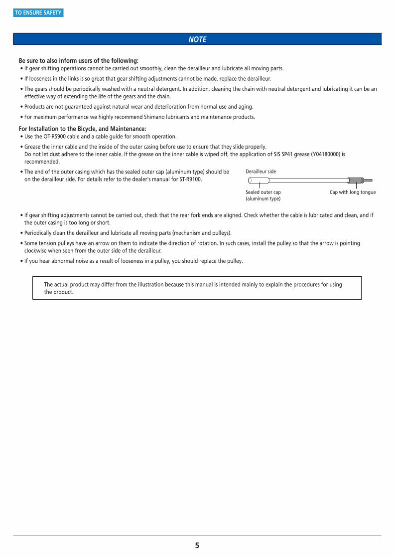
• The end of the outer casing which has the sealed outer cap (aluminum type) should be on the derailleur side. For details refer to the dealer's manual for ST-R9100.
Sealed outer cap (aluminum type)
Cap with long tongue
Derailleur side
• If gear shifting adjustments cannot be carried out, check that the rear fork ends are aligned. Check whether the cable is lubricated and clean, and if the outer casing is too long or short.
• Periodically clean the derailleur and lubricate all moving parts (mechanism and pulleys).
• Some tension pulleys have an arrow on them to indicate the direction of rotation. In such cases, install the pulley so that the arrow is pointing clockwise when seen from the outer side of the derailleur.
• If you hear abnormal noise as a result of looseness in a pulley, you should replace the pulley.
The actual product may differ from the illustration because this manual is intended mainly to explain the procedures for using the product.
LIST OF TOOLS TO BE USED
7
LIST OF TOOLS TO BE USED
LIST OF TOOLS TO BE USED
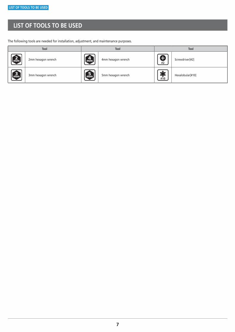
The following tools are needed for installation, adjustment, and maintenance purposes.
Tool Tool Tool
2mm hexagon wrench 4mm hexagon wrench Screwdriver[#2]
3mm hexagon wrench 5mm hexagon wrench Hexalobular[#10]
INSTALLATION

9
INSTALLATION
Installation of the rear derailleur
INSTALLATION
� Installation of the rear derailleur
(A)
(B)
Install the rear derailleur. (A) Fork end
(B) Bracket
Tightening torque
8 - 10 N·m
NOTE
Periodically check that there is no gap between the fork end and the bracket as shown in the illustration. If there is a gap between these two parts, problems with gear shifting performance may occur.

10
INSTALLATION
Direct mount type
� Direct mount type
Replacing with direct mount type
Remove the bracket axle.

ADJUSTMENT

12
ADJUSTMENT
Stroke adjustment
ADJUSTMENT
� Stroke adjustment
Top adjustment
B A
B A
(A)
(B)(C)
Turn the top adjustment screw to position the guide pulley over the outer line of the smallest sprocket when seen from the rear side.
(A) Top adjustment screw
(B) Smallest sprocket
(C) Guide pulley
13
ADJUSTMENT
Stroke adjustment
Low adjustment
BA
B A
(A)
(B)
(C)
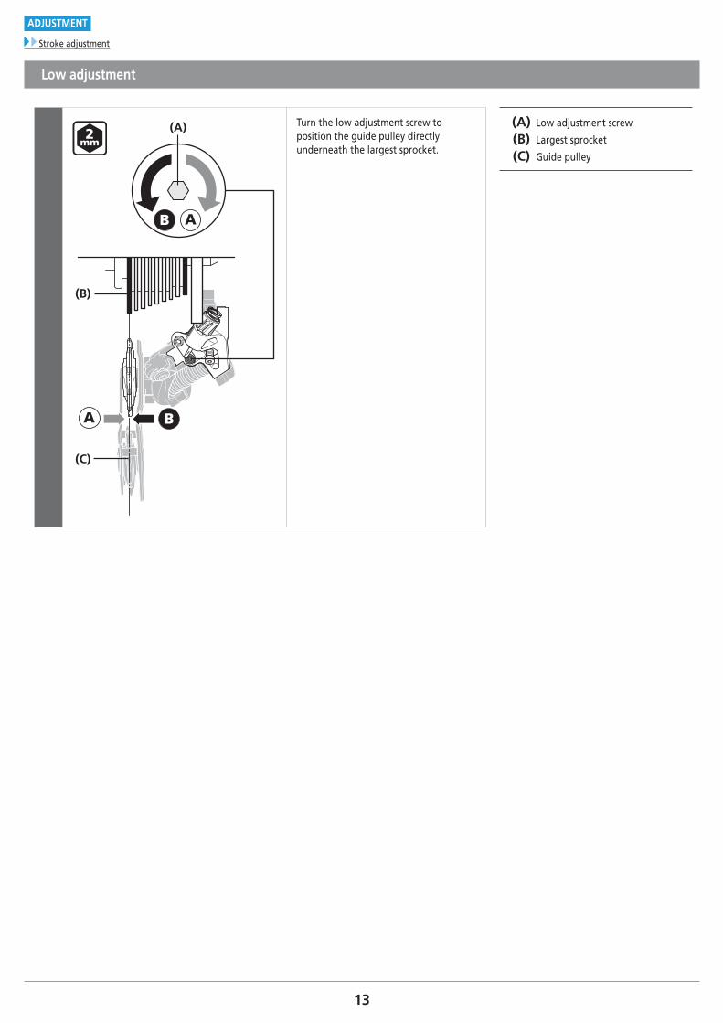
Turn the low adjustment screw to position the guide pulley directly underneath the largest sprocket.
(A) Low adjustment screw
(B) Largest sprocket
(C) Guide pulley
14
ADJUSTMENT
Installing the chain
� Installing the chain
Chain length
+
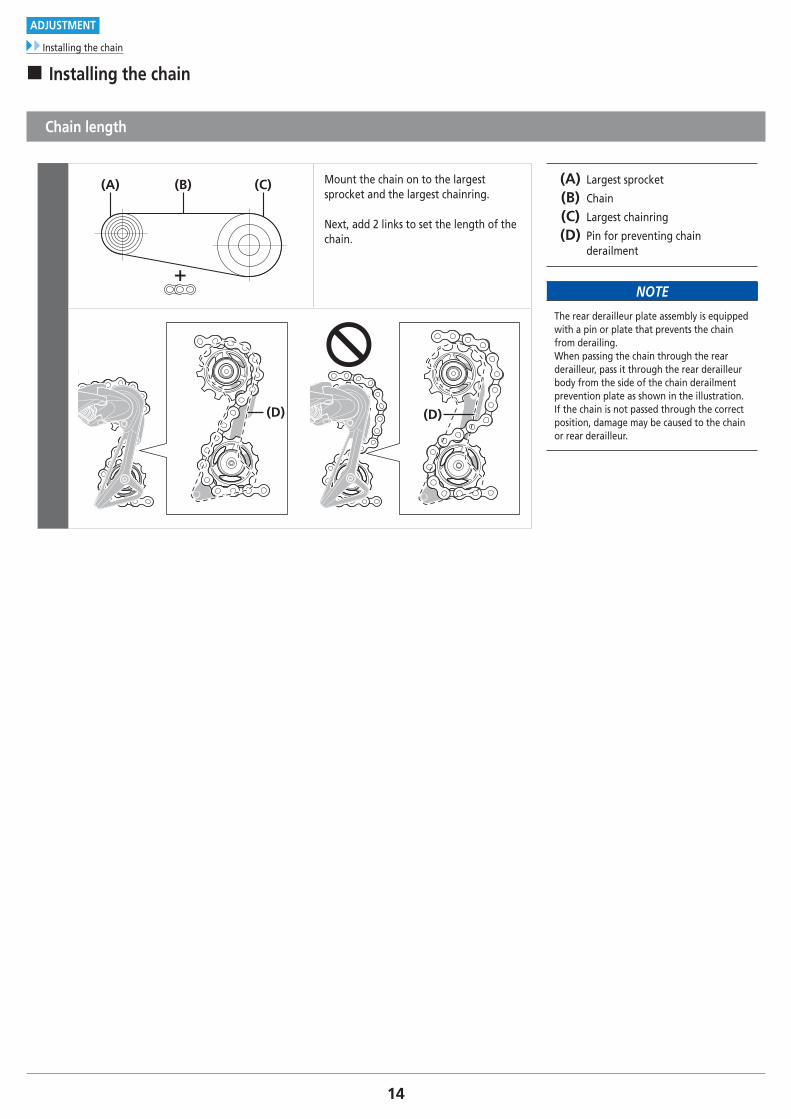
(A) (B) (C) Mount the chain on to the largest sprocket and the largest chainring.
Next, add 2 links to set the length of the chain.
(A) Largest sprocket
(B) Chain
(C) Largest chainring
(D) Pin for preventing chain derailment
NOTE
The rear derailleur plate assembly is equipped with a pin or plate that prevents the chain from derailing. When passing the chain through the rear derailleur, pass it through the rear derailleur body from the side of the chain derailment prevention plate as shown in the illustration. If the chain is not passed through the correct position, damage may be caused to the chain or rear derailleur.
(D)(D)

15
ADJUSTMENT
Securing the cable
� Securing the cable
Cutting the outer casing
1
When cutting the outer casing, cut the end opposite to the end with the marking.
After cutting the outer casing, make the end round so that the inside of the hole has a uniform diameter.
2
OT-RS900
OT-RS900
(A) (B) (C) After cutting, attach the same cap with long tongue to the end.
(A) Cap with long tongue
(B) OT-RS900
(C) Sealed outer cap (aluminum type)
NOTE
• Make sure to use OT-RS900 for the outer casing.
• When cutting the outer casing, make sure to cut nearer the end with the cap with long tongue.
16
ADJUSTMENT
Securing the cable
Outer casing length
1(A)
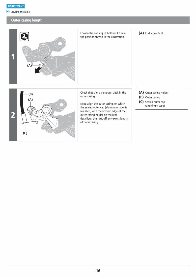
Loosen the end adjust bolt until it is in the position shown in the illustration.
(A) End adjust bolt
2
(A)
(C)
(B) Check that there is enough slack in the outer casing.
Next, align the outer casing, on which the sealed outer cap (aluminum type) is installed, with the bottom edge of the outer casing holder on the rear derailleur, then cut off any excess length of outer casing.
(A) Outer casing holder
(B) Outer casing
(C) Sealed outer cap (aluminum type)

17To be continued on next page
ADJUSTMENT
Securing the cable
Connecting and securing the cable
1
(A) (B) Connect the inner cable to the rear derailleur.
(A) Inner cable
(B) Cover with tongue
NOTE
• Replacing the cover with tongue is recommended when replacing the inner cable.
• Fuzz may be generated when the inner cable is installed or when the coating is damaged during use, but this will not affect its functions.
Cover with tongue
2
Remove the initial slack from the cable as shown in the illustration.
3
(A) Reconnect the inner cable to the rear derailleur.
Be sure that the cable is securely in the groove.
(A) Inner cable
Tightening torque
6 - 7 N·m
18
ADJUSTMENT
Using the end adjust bolt
4(z)
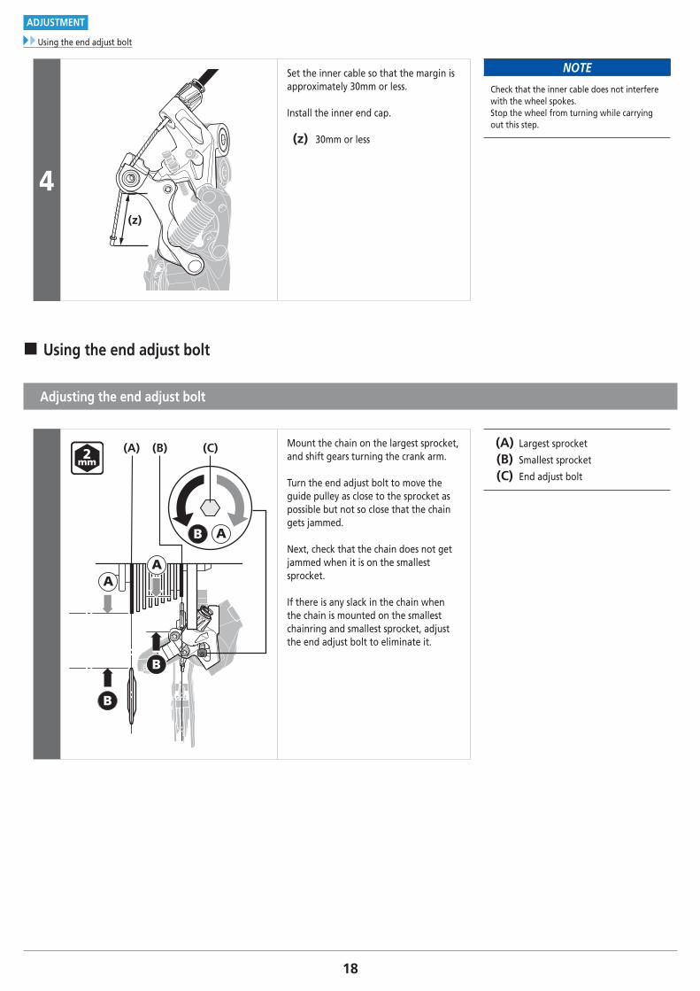
Set the inner cable so that the margin is approximately 30mm or less.
Install the inner end cap.
(z) 30mm or less
NOTE
Check that the inner cable does not interfere with the wheel spokes. Stop the wheel from turning while carrying out this step.
� Using the end adjust bolt
Adjusting the end adjust bolt
AA
B
B
B A
(A) (C)(B) Mount the chain on the largest sprocket, and shift gears turning the crank arm.
Turn the end adjust bolt to move the guide pulley as close to the sprocket as possible but not so close that the chain gets jammed.
Next, check that the chain does not get jammed when it is on the smallest sprocket.
If there is any slack in the chain when the chain is mounted on the smallest chainring and smallest sprocket, adjust the end adjust bolt to eliminate it.
(A) Largest sprocket
(B) Smallest sprocket
(C) End adjust bolt

19To be continued on next page
ADJUSTMENT
SIS adjustment
� SIS adjustment
SIS adjustment
1 Operate the shifting lever once to move the chain from the smallest sprocket to the 2nd sprocket.
Best setting
2
The best setting is when the shifting lever is operated just enough to close the lever gap and the chain touches the 3rd sprocket counting from the smallest sprocket and makes noise.
20To be continued on next page
ADJUSTMENT
SIS adjustment
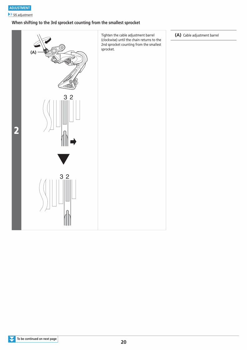
When shifting to the 3rd sprocket counting from the smallest sprocket
2
(A)
Tighten the cable adjustment barrel (clockwise) until the chain returns to the 2nd sprocket counting from the smallest sprocket.
(A) Cable adjustment barrel
21
ADJUSTMENT
SIS adjustment
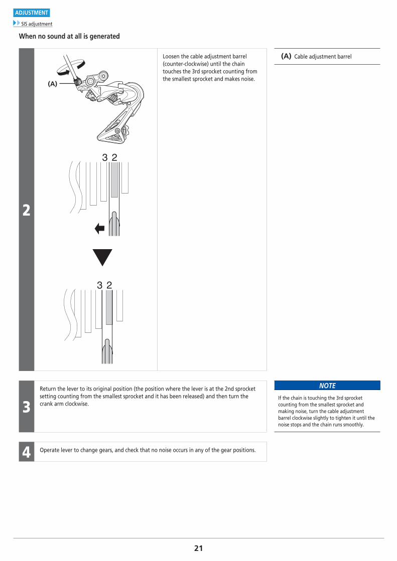
When no sound at all is generated
2
(A)
Loosen the cable adjustment barrel (counter-clockwise) until the chain touches the 3rd sprocket counting from the smallest sprocket and makes noise.
(A) Cable adjustment barrel
3Return the lever to its original position (the position where the lever is at the 2nd sprocket setting counting from the smallest sprocket and it has been released) and then turn the crank arm clockwise.
NOTE
If the chain is touching the 3rd sprocket counting from the smallest sprocket and making noise, turn the cable adjustment barrel clockwise slightly to tighten it until the noise stops and the chain runs smoothly.
4 Operate lever to change gears, and check that no noise occurs in any of the gear positions.

MAINTENANCE
23To be continued on next page
MAINTENANCE
Replacement of the plate and the plate tension spring
MAINTENANCE
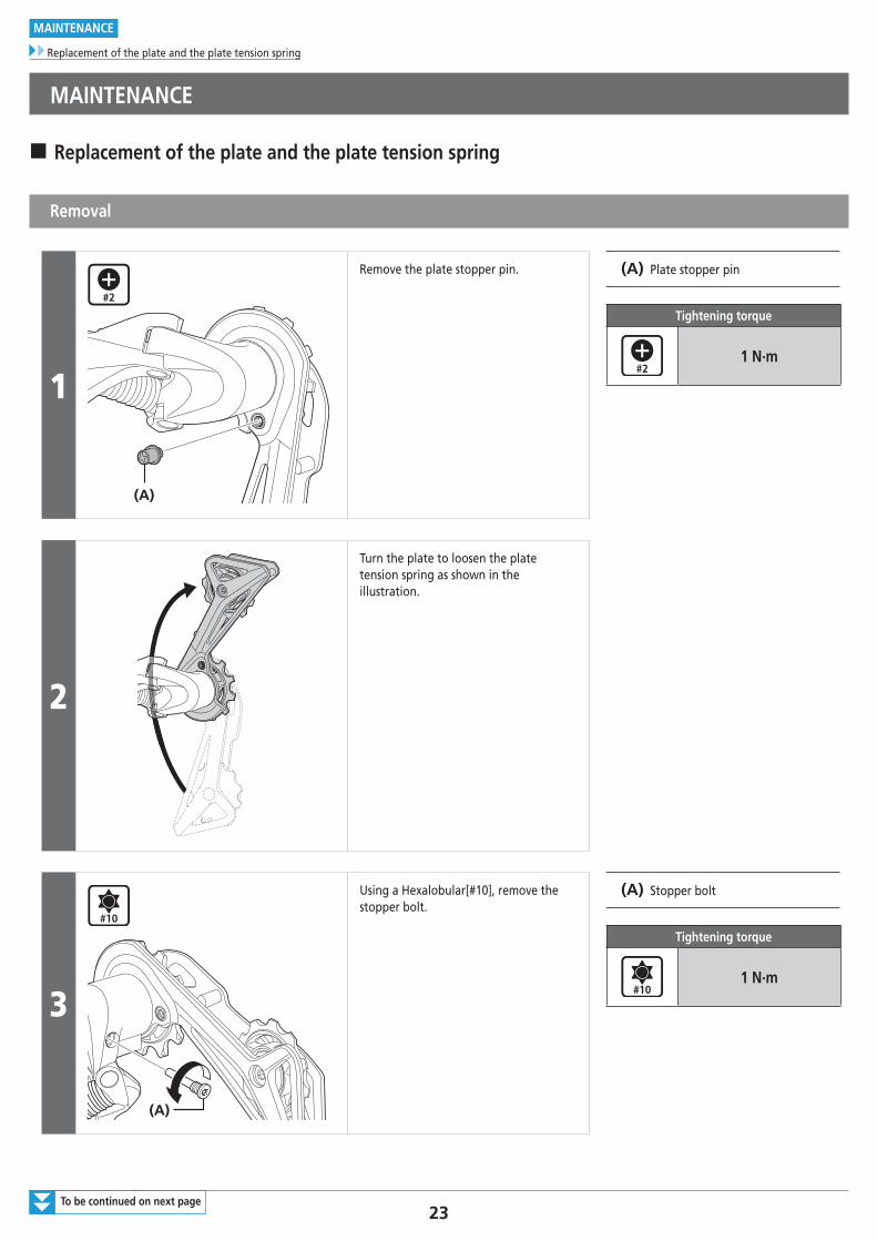
� Replacement of the plate and the plate tension spring
Removal
1
(A)
Remove the plate stopper pin. (A) Plate stopper pin
Tightening torque
1 N·m
2
Turn the plate to loosen the plate tension spring as shown in the illustration.
3
(A)
Using a Hexalobular[#10], remove the stopper bolt.
(A) Stopper bolt
Tightening torque
1 N·m
24
MAINTENANCE
Replacement of the plate and the plate tension spring
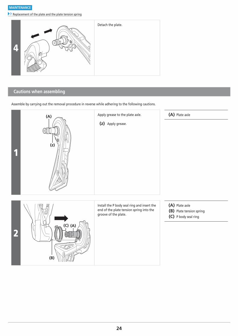
4
Detach the plate.
Cautions when assembling
Assemble by carrying out the removal procedure in reverse while adhering to the following cautions.
1(z)
(A) Apply grease to the plate axle.
(z) Apply grease.
(A) Plate axle
2
(B)
(A)(C)
Install the P body seal ring and insert the end of the plate tension spring into the groove of the plate.
(A) Plate axle
(B) Plate tension spring
(C) P body seal ring
25
MAINTENANCE
Replacement of the pulley
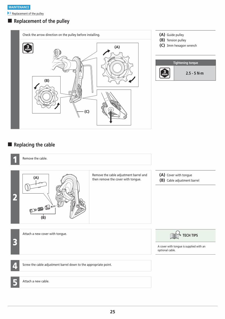
� Replacement of the pulley
Check the arrow direction on the pulley before installing. (A) Guide pulley
(B) Tension pulley
(C) 3mm hexagon wrench
Tightening torque
2.5 - 5 N·m
(A)
(C)
(B)
� Replacing the cable
1 Remove the cable.
2
(A)
(B)
Remove the cable adjustment barrel and then remove the cover with tongue.
(A) Cover with tongue
(B) Cable adjustment barrel
3Attach a new cover with tongue. TECH TIPS
A cover with tongue is supplied with an optional cable.
4 Screw the cable adjustment barrel down to the appropriate point.
5 Attach a new cable.

Please note: specifications are subject to change for improvement without notice. (English) © Dec. 2016 by Shimano Inc. ITP


