
Radisoity
Ed Angel
Professor of Computer Science, Electrical and Computer
Engineering, and Media Arts
Director, Arts Technology Center
University of New Mexico
2Angel: Interactive Computer Graphics 4E © Addison-Wesley 2005
Introduction
• Ray tracing is best with many highly specular sufaces
Not characteristic of real scenes
• Rendering equation describes general shading problem
• Radiosity solves rendering equation for perfectly diffuse surfaces
3Angel: Interactive Computer Graphics 4E © Addison-Wesley 2005
Terminology
• Energy ~ light (incident, transmitted) Must be conserved
• Energy flux = luminous flux = power = energy/unit time
Measured in lumens
Depends on wavelength so we can integrate over spectrum using luminous efficiency curve of sensor
• Energy density (Φ) = energy flux/unit area

4Angel: Interactive Computer Graphics 4E © Addison-Wesley 2005
Terminology
Intensity ~ brightness Brightness is perceptual
= flux/area-solid angle = power/unit projected area per solid angle
Measured in candela
Φ = ∫ ∫ I dA dω
5Angel: Interactive Computer Graphics 4E © Addison-Wesley 2005
Rendering Eqn (Kajiya)
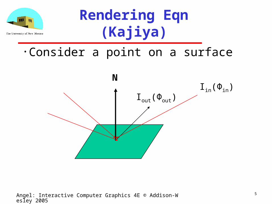
• Consider a point on a surface
N
Iout(Φout)Iin(Φin)
6Angel: Interactive Computer Graphics 4E © Addison-Wesley 2005
Rendering Equation
• Outgoing light is from two sources Emission
Reflection of incoming light
• Must integrate over all incoming light Integrate over hemisphere
• Must account for foreshortening of incoming light

7Angel: Interactive Computer Graphics 4E © Addison-Wesley 2005
Rendering Equation
Iout(Φout) = E(Φout) + ∫ 2πRbd(Φout, Φin )Iin(Φin) cos θ dω
bidirectional reflection coefficient
angle between normal and Φinemission
Note that angle is really two angles in 3D and wavelength is fixed

8Angel: Interactive Computer Graphics 4E © Addison-Wesley 2005
Rendering Equation
• Rendering equation is an energy balance Energy in = energy out
• Integrate over hemisphere• Fredholm integral equation
Cannot be solved analytically in general
• Various approximations of Rbd give standard rendering models
• Should also add an occlusion term in front of right side to account for other objects blocking light from reaching surface

9Angel: Interactive Computer Graphics 4E © Addison-Wesley 2005
Another version
Consider light at a point p arriving from p’
i(p, p’) = υ(p, p’)(ε(p,p’)+ ∫ ρ(p, p’, p’’)i(p’, p’’)dp’’
occlusion = 0 or 1/d2emission from p’ to p
light reflected at p’ from all points p’’ towards p
10Angel: Interactive Computer Graphics 4E © Addison-Wesley 2005
Radiosity
• Consider objects to be broken up into flat patches (which may correspond to the polygons in the model)
• Assume that patches are perfectly diffuse reflectors
• Radiosity = flux = energy/unit area/ unit time leaving patch
11Angel: Interactive Computer Graphics 4E © Addison-Wesley 2005
Notation
n patches numbered 1 to n
bi = radiosity of patch I
ai = area patch I
total intensity leaving patch i = bi ai
ei ai = emitted intensity from patch I
ρi = reflectivity of patch I
fij = form factor = fraction of energy leaving patch j that reaches patch i

12Angel: Interactive Computer Graphics 4E © Addison-Wesley 2005
Radiosity Equation
energy balance
biai = eiai + ρi ∑ fjibjaj
reciprocity
fijai = fjiaj
radiosity equation
bi = ei + ρi ∑ fijbj
13Angel: Interactive Computer Graphics 4E © Addison-Wesley 2005
Matrix Form
b = [bi]
e = [ei]
R = [rij] rij = ρi if i ≠ j rii = 0
F = [fij]

14Angel: Interactive Computer Graphics 4E © Addison-Wesley 2005
Matrix Form
b = e - RFb
formal solution
b = [I-RF]-1e
Not useful since n is usually very largeAlternative: use observation that F is sparse
We will consider determination of form factors later

15Angel: Interactive Computer Graphics 4E © Addison-Wesley 2005
Solving the Radiosity Equation
For sparse matrices, iterative methods usuallyrequire only O(n) operations per iteration
Jacobi’s method
bk+1 = e - RFbk
Gauss-Seidel: use immediate updates

16Angel: Interactive Computer Graphics 4E © Addison-Wesley 2005
Series Approximation
1/(1-x) = 1 + x + x2+ ……
b = [I-RF]-1e = e + RFe + (RF)2e +…
[I-RF]-1 = I + RF +(RF)2+…
17Angel: Interactive Computer Graphics 4E © Addison-Wesley 2005
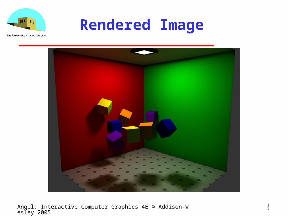
Rendered Image

18Angel: Interactive Computer Graphics 4E © Addison-Wesley 2005
Patches

19Angel: Interactive Computer Graphics 4E © Addison-Wesley 2005
Computing Form Factors
• Consider two flat patches
20Angel: Interactive Computer Graphics 4E © Addison-Wesley 2005
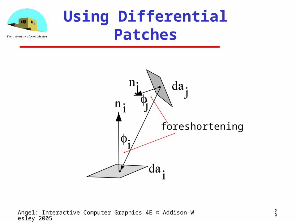
Using Differential Patches
foreshortening
21Angel: Interactive Computer Graphics 4E © Addison-Wesley 2005
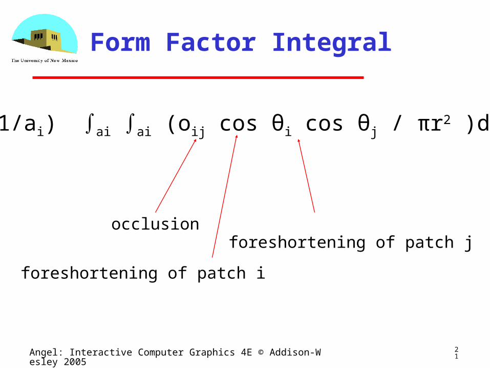
Form Factor Integral
fij = (1/ai) ∫ai ∫ai (oij cos θi cos θj / πr2 )dai daj
occlusion
foreshortening of patch i
foreshortening of patch j

22Angel: Interactive Computer Graphics 4E © Addison-Wesley 2005
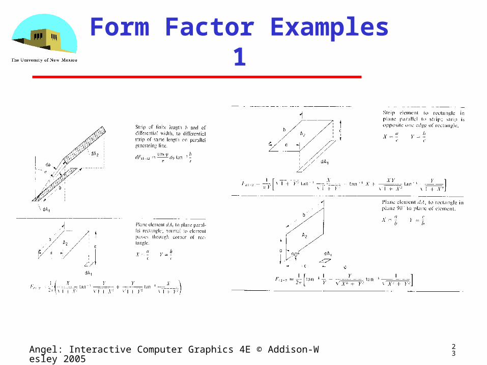
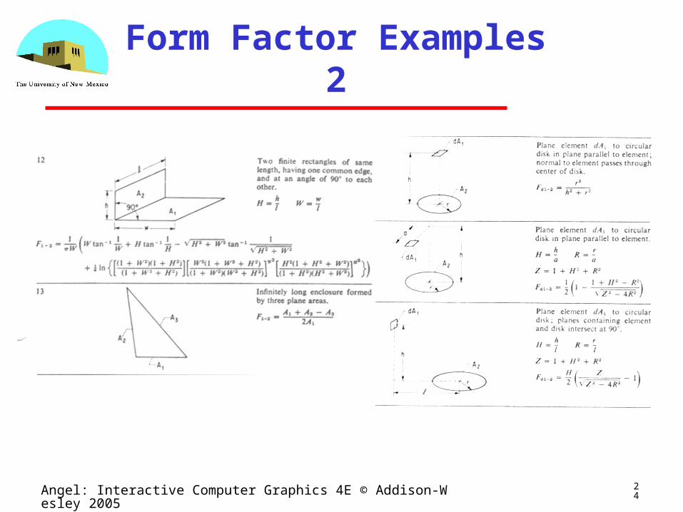
Solving the Intergral
• There are very few cases where the integral has a (simple) closed form solution
Occlusion further complicates solution
• Alternative is to use numerical methods• Two step process similar to texture mapping
Hemisphere
Hemicube
23Angel: Interactive Computer Graphics 4E © Addison-Wesley 2005
Form Factor Examples 1
24Angel: Interactive Computer Graphics 4E © Addison-Wesley 2005
Form Factor Examples 2

25Angel: Interactive Computer Graphics 4E © Addison-Wesley 2005
Form Factor Examples 3
26Angel: Interactive Computer Graphics 4E © Addison-Wesley 2005
Hemisphere
• Use illuminating hemisphere• Center hemisphere on patch with normal pointing up
• Must shift hemisphere for each point on patch

27Angel: Interactive Computer Graphics 4E © Addison-Wesley 2005
Hemisphere

28Angel: Interactive Computer Graphics 4E © Addison-Wesley 2005
Hemicube
• Easier to use a hemicube instead of a hemisphere
• Rule each side into “pixels”• Easier to project on pixels which give delta form factors that can be added up to give desired from factor
• To get a delta form factor we need only cast a ray through each pixel

29Angel: Interactive Computer Graphics 4E © Addison-Wesley 2005
Hemicube
30Angel: Interactive Computer Graphics 4E © Addison-Wesley 2005
Instant Radiosity
• Want to use graphics system if possible• Suppose we make one patch emissive• The light from this patch is distributed among the other patches
• Shade of other patches ~ form factors• Must use multiple OpenGL point sources to approximate a uniformly emissive patch


