Download - Radio System Design Telecommunications

Radio System Designfor
TelecommunicationsSecond Edition
Roger L. Freeman
A Wiley-lnterscience PublicationJOHN WILEY & SONS, INC.
New York • Chichester • Weinheim • Brisbane • Singapore • Toronto
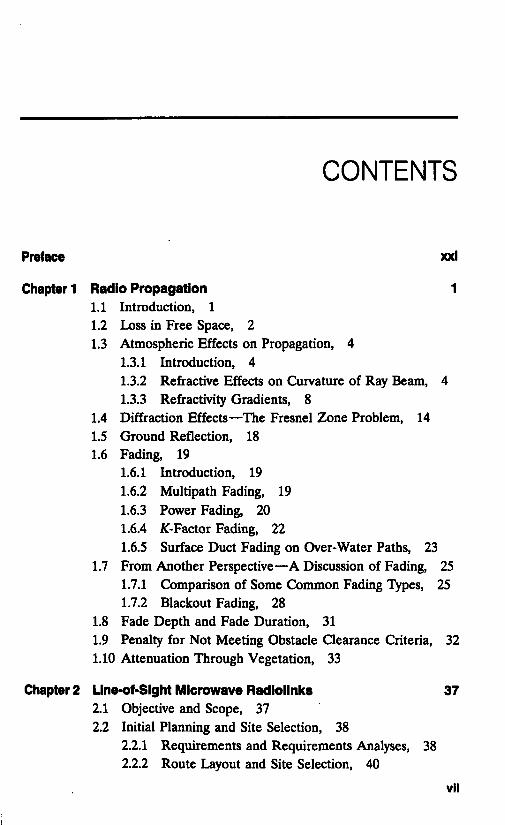
CONTENTS
Preface
Chapter 1
xxl
Radio Propagation1.1 Introduction, 11.2 Loss in Free Space, 21.3 Atmospheric Effects on Propagation, 4
1.3.1 Introduction, 41.3.2 Refractive Effects on Curvature of Ray Beam,1.3.3 Refractivity Gradients, 8
1.4 Diffraction Effects—The Fresnel Zone Problem, 141.5 Ground Reflection, 181.6 Fading, 19
1.6.1 Introduction, 19Multipath Fading, 191.6.2
1.6.31.6.41.6.5
Power Fading, 20^-Factor Fading, 22Surface Duct Fading on Over-Water Paths, 23
1.7 From Another Perspective—A Discussion of Fading, 251.7.1 Comparison of Some Common Fading Types, 251.7.2 Blackout Fading, 28
1.8 Fade Depth and Fade Duration, 311.9 Penalty for Not Meeting Obstacle Clearance Criteria, 321.10 Attenuation Through Vegetation, 33
Chapter 2 Llne-of-Sight Microwave Radlollnks 372.1 Objective and Scope, 372.2 Initial Planning and Site Selection, 38
2.2.1 Requirements and Requirements Analyses, 382.2.2 Route Layout and Site Selection, 40
vil
Vlli CONTENTS
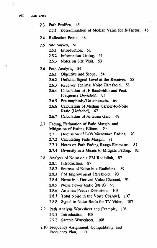
2.3 Path Profiles, 43
2.3.1 Determiniation of Median Value for K-Factor, 46
2.4 Reflection Point, 48
2.5 Site Survey, 512.5.1 Introduction, 512.5.2 Information Listing, 512.5.3 Notes on Site Visit, 53
2.6 Path Analysis, 542.6.1 Objective and Scope, 542.6.2 Unfaded Signal Level at the Receiver, 552.6.3 Receiver Thermal Noise Threshold, 582.6.4 Calculation of IF Bandwidth and Peak
Frequency Deviation, 612.6.5 Pre-emphasis/De-emphasis, 642.6.6 Calculation of Median Carrier-to-Noise
Ratio (Unfaded), 672.6.7 Calculation of Antenna Gain, 69
2.7 Fading, Estimation of Fade Margin, andMitigation of Fading Effects, 702.7.1 Discussion of LOS Microwave Fading, 702.7.2 Calculating Fade Margin, 712.7.3 Notes on Path Fading Range Estimates, 812.7.4 Diversity as a Means to Mitigate Fading, 82
2.8 Analysis of Noise on a FM Radiolink, 872.8.1 Introduction, 872.8.2 Sources of Noise in a Radiolink, 892.8.3 FM Improvement Threshold, 902.8.4 Noise in a Derived Voice Channel, 912.8.5 Noise Power Ratio (NPR), 952.8.6 Antenna Feeder Distortion, 1032.8.7 Total Noise in the Voice Channel, 1072.8.8 Signal-to-Noise Ratio for TV Video, 107
2.9 Path Analysis Worksheet and Example, 1082.9.1 Introduction, 1082.9.2 Sample Worksheet, 108
2.10 Frequency Assignment, Compatibility, andFrequency Plan, 113

CONTENTS IX
2.10.1 Introduction, 1132.10.2 Frequency Planning—Channel Arrangement, 1132.10.3 Some Typical ITU-R Channel Arrangements, 1182.10.4 Several FCC Frequency Plans, 126
Chapter 3 Digital Line-of-Sight Microwave Radiolinks 1373.1 Introduction, 137
3.1.1 Energy per Bit per Noise Density Ratio,Eb/N0, 138
3.2 Regulatory Issues, 1393.3 Modulation Techniques, Spectral Efficiency,
and Bandwidth, 1423.3.1 Introduction, 1423.3.2 Bit Packing, 1423.3.3 Spectral Efficiency, 1453.3.4 Power Amplifier Distortion, 147
3.4 Comparison of Several Types of Modulation, 1483.4.1 Objective, 1483.4.2 Definitions and Notation, 1483.4.3 Modulation Format Comparison, 1493.4.4 Notes on Implementation and BER
Performance, 1503.5 Some System Impairments Peculiar to Digital
Operation, 1543.5.1 Mitigation Techniques for Multipath Fading, 1553.5.2 ITU-R Guidelines on Combating
Propagation Effects, 1573.6 Performance Requirements and Objectives for
Digital Radiolinks, 1593.6.1 Introduction, 1593.6.2 Five Definitions, 1593.6.3 Hypothetical Reference Digital Path
(HRDP) for Radio-Relay Systemswith a Capacity Above the SecondHierarchical Level, 159
3.6.4 Error Performance Objectives for RealDigital Radiolinks Forming Part of aHigh-Grade Circuit in an ISDN Network, 160
3.6.5 Error Performance Objectives of a 27,500-kmHypothetical Reference Path, 163
3.6.6 Jitter and Wander, 164

X CONTENTS
3.6.7 Error Performance from a BellcorePerspective, 165
3.7 Application of High-Level M-QAM toHigh-Capacity SDH/SONET Formats, 165
3.8 Considerations of Fading on LOS DigitalMicrowave Systems, 1663.8.1 Introduction, 1663.8.2 Other Views of Calculations of Fade
Margins on Digital LOS Microwave, 1673.83 Multipath Fading Calculations Based on
TIATSB10-F, 1683.8.4 Simple Calculations of Path Dispersiveness, 173
3.9 Path Analyses or Link Budgets on Digital LOSMicrowave Paths, 174
Chapter 4 Forward Error Correction and Advanced DigitalWaveforms 1794.1 Objective, 1794.2 Forward Error Correction, 179
4.2.1 Background and Objective, 1794.2.2 Basic Forward Error Correction, 1814.2.3 FEC Codes, 1844.2.4 Binary Convolutional Codes, 1914.2.5 Channel Performance of Uncoded and
Coded Systems, 2004.2.6 Coding with Bursty Errors, 205
4.3 Advanced Signal Waveforms, 2114.3.1 Block-Coded Modulation (BCM), 2114.3.2 Trellis-Coded Modulation (TCM), 2144.3.3 Multilevel-Coded Modulation (MCLM), 2154.3.4 Partial Response with a Soft Decoder, 217
Chapter 5 Over-the-Horizon Radiolinks 2235.1 Objectives and Scope, 2235.2 Application, 2235.3 Introduction to Tropospheric Scatter Propagation, 2245.4 Tropospheric Scatter Link Design, 227
5.4.1 Site Selection, Route Selection, PathProfile, and Field Survey, 227
5.4.2 Link Performance Calculations, 228

CONTENTS Xi
5.5 Path Calculation/Link Analysis, 288
5.5.1 Introduction, 2885.5.2 Path Intermodulation Noise—AnalogSystems, 2885.5.3 Sample Link Analysis, 293
5.6 Threshold Extension, 2955.7 Digital Transhorizon Radiolinks, 296
5.7.1 Introduction, 2965.7.2 Digital Link Analysis, 2965.7.3 Dispersion, 2985.7.4 Some Methods of Overcoming the Effects
of Dispersion, 2995.7.5 Some ITU-R Perspectives on Transhorizon
Radio Systems, 3015.8 Troposcatter Frequency Bands and the Sharing
with Space Radio-Communication Systems, 3045.8.1 Frequency Bands Shared with Space
Services (Space-to-Earth), 304
Chapter 6 Basic Principles of Satellite Communications 3096.1 Introduction, Scope, and Applications, 3096.2 Satellite Systems—An Introduction, 310
6.2.1 Satellite Orbits, 3106.2.2 Elevation Angle, 3126.2.3 Determination of Range and Elevation
Angle of a Geostationary Satellite, 3136.3 Introduction to Link Analysis or Link Budget, 315
6.3.1 Rationale, 3156.3.2 Frequency Bands Available for Satellite
Communications, 3156.3.3 Free-Space Loss or Spreading Loss, 3196.3.4 Isotropic Receive Level—Simplified Model, 3196.3.5 Limitation of Flux Density on Earth's Surface, 3206.3.6 Thermal Noise Aspects of Low-Noise Systems, 3226.3.7 Calculation of C/No , 3256.3.8 Gain-to-Noise Temperature Ratio, G/T, 3276.3.9 Calculation of C/No Using the Link Budget, 3366.3.10 Calculation S/N, 341
6.4 Access Techniques, 3476.4.1 Introduction, 347

Xll CONTENTS
6.4.2 Frequency Division Multiple Access (FMDA), 3496.4.3 Brief Overview of Time Division Multiple
Access (TDMA), 3566.5 INTELSAT Systems, 358
6.5.1 Introduction, 3586.5.2 INTELSAT Type A Standard Earth Stations, 3586.5.3 INTELSAT Standard B Earth Stations, 3646.5.4 INTELSAT Standard C Earth Stations, 3656.5.5 INTELSAT Standard D Earth Stations, 3656.5.6 INTELSAT Standard E Earth Stations, 3676.5.7 INTELSAT Standard F Earth Stations, 3686.5.8 Basic INTELSAT Space Segment Data
Common to All Families of StandardEarth Stations, 368
6.5.9 Television Operation Over INTELSAT, 3686.6 Domestic and Regional Satellite Systems, 376
6.6.1 Introduction, 3766.6.2 Rationale, 3776.6.3 Approaches to Cost Reduction, 3776.6.4 A Typical Satellite Series that Can
Provide Transponder Space forEnterprise Networks, 378
Chapter 7 Digital Communications by Satellite 3857.1 Introduction, 3857.2 Digital Operations of a Bent-Pipe Satellite System, 386
7.2.1 General, 3867.2.2 Digital FMDA Operation, 3867.2.3 TDMA Operation on a Bent-Pipe Satellite, 398
7.3 Digital Speech Interpolation, 4077.3.1 Freeze-Out and Clipping, 4087.3.2 TASI-Based DSI, 4097.3.3 Speech Predictive Encoding DSI, 410
7.4 INTELSAT TDMA/DSI System, 4117.4.1 Overview, 4117.4.2 Frame, Multiframe, and Burst Format, 4137.4.3 Acquisition and Synchronization, 4197.4.4 Transponder Hopping, 4197.4.5 Digital Speech Interpolation Interface, 419
CONTENTS Xlll
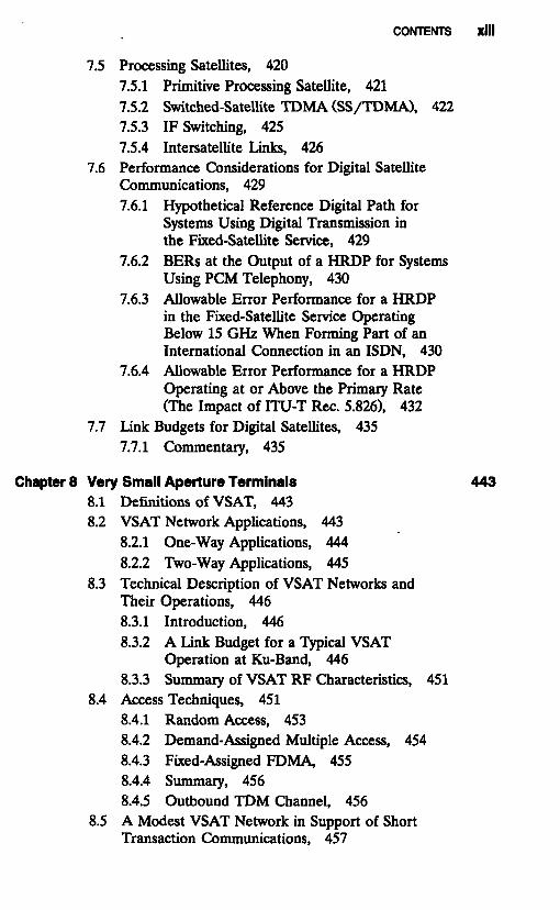
7.5 Processing Satellites, 4207.5.1 Primitive Processing Satellite, 4217.5.2 Switched-Satellite TDMA (SS/TDMA), 4227.5.3 IF Switching, 4257.5.4 Intersatellite Links, 426
7.6 Performance Considerations for Digital SatelliteCommunications, 4297.6.1 Hypothetical Reference Digital Path for
Systems Using Digital Transmission inthe Fixed-Satellite Service, 429
7.6.2 BERs at the Output of a HRDP for SystemsUsing PCM Telephony, 430
7.6.3 Allowable Error Performance for a HRDPin the Fixed-Satellite Service OperatingBelow 15 GHz When Forming Part of anInternational Connection in an ISDN, 430
7.6.4 Allowable Error Performance for a HRDPOperating at or Above the Primary Rate(The Impact of ITU-T Rec. 5.826), 432
7.7 Link Budgets for Digital Satellites, 4357.7.1 Commentary, 435
Chapter 8 Very Small Aperture Terminals 4438.1 Definitions of VSAT, 4438.2 VSAT Network Applications, 443
8.2.1 One-Way Applications, 4448.2.2 Two-Way Applications, 445
8.3 Technical Description of VSAT Networks andTheir Operations, 4468.3.1 Introduction, 4468.3.2 A Link Budget for a Typical VSAT
Operation at Ku-Band, 4468.3.3 Summary of VSAT RF Characteristics, 451
8.4 Access Techniques, 4518.4.1 Random Access, 4538.4.2 Demand-Assigned Multiple Access, 4548.4.3 Fixed-Assigned FDMA, 4558.4.4 Summary, 4568.4.5 Outbound TDM Channel, 456
8.5 A Modest VSAT Network in Support of ShortTransaction Communications, 457
XlV CONTENTS
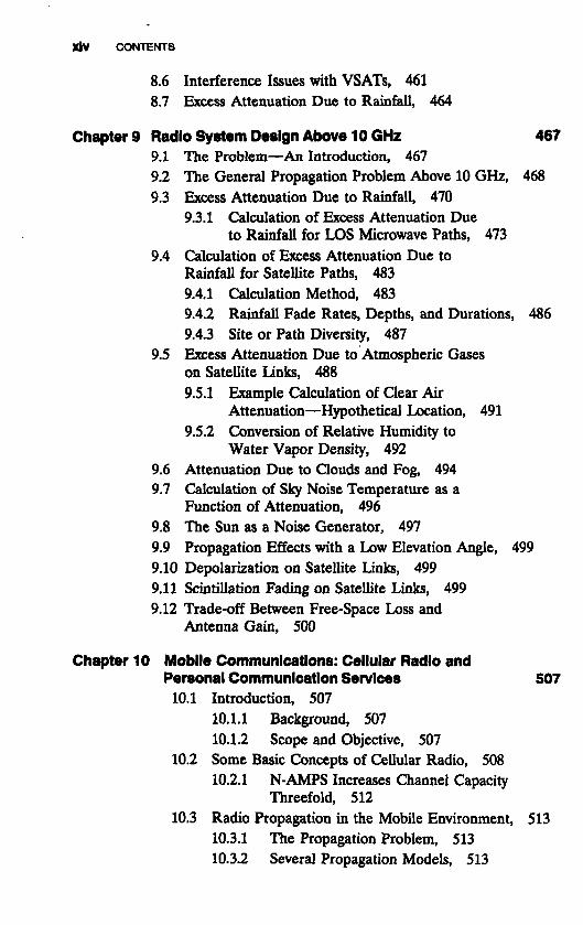
8.6 Interference Issues with VSATs, 4618.7 Excess Attenuation Due to Rainfall, 464
Chapter 9 Radio System Design Above 10 GHz 4679.1 The Problem—An Introduction, 4679.2 The General Propagation Problem Above 10 GHz, 4689.3 Excess Attenuation Due to Rainfall, 470
9.3.1 Calculation of Excess Attenuation Dueto Rainfall for LOS Microwave Paths, 473
9.4 Calculation of Excess Attenuation Due toRainfall for Satellite Paths, 4839.4.1 Calculation Method, 4839.4.2 Rainfall Fade Rates, Depths, and Durations, 4869.4.3 Site or Path Diversity, 487
9.5 Excess Attenuation Due to Atmospheric Gaseson Satellite Links, 4889.5.1 Example Calculation of Clear Air
Attenuation—Hypothetical Location, 4919.5.2 Conversion of Relative Humidity to
Water Vapor Density, 4929.6 Attenuation Due to Clouds and Fog, 4949.7 Calculation of Sky Noise Temperature as a
Function of Attenuation, 4969.8 The Sun as a Noise Generator, 4979.9 Propagation Effects with a Low Elevation Angle, 4999.10 Depolarization on Satellite Links, 4999.11 Scintillation Fading on Satellite Links, 4999.12 Trade-off Between Free-Space Loss and
Antenna Gain, 500
Chapter 10 Mobile Communications: Cellular Radio andPersonal Communication Services 507
10.1 Introduction, 50710.1.1 Background, 50710.1.2 Scope and Objective, 507
10.2 Some Basic Concepts of Cellular Radio, 50810.2.1 N-AMPS Increases Channel Capacity
Threefold, 51210.3 Radio Propagation in the Mobile Environment, 513
10.3.1 The Propagation Problem, 51310.3.2 Several Propagation Models, 513
CONTENTS XV
10.3.3 Microcell Prediction Model Accordingto Lee, 516
10.4 Impairments—Fading in the Mobile Environment, 51910.4.1 Introduction, 51910.4.2 Classification of Fading, 52010.4.3 Diversity—A Technique to Mitigate
the Effects of Fading and Dispersion, 52210.4.4 Cellular Radio Path Calculations, 525
10.5 The Cellular Radio Bandwidth Dilemma, 52510.5.1 Background and Objectives, 52510.5.2 Bit Rate Reduction of the Digital
Voice Channel, 52610.6 Network Access Techniques, 526
10.6.1 Introduction, 52610.6.2 Frequency Division Multiple Access
(FDMA), 52710.6.3 Time Division Multiple Access
(TDMA), 52810.6.4 Code Division Multiple Access
(CDMA), 53110.7 Frequency Reuse, 53910.8 Paging Systems, 542
10.8.1 What Are Paging Systems?, 54210.8.2 Radio-Frequency Bands for Pagers, 54210.8.3 Radio Propagation into Buildings, 54210.8.4 Techniques Available for Multiple
Transmitter Zones, 54210.8.5 Paging Receivers, 54310.8.6 System Capacity, 54410.8.7 Codes and Formats for Paging Systems, 54410.8.8 Considerations for Selecting Codes
and Formats, 54410.9 Personal Communication Systems, 545
10.9.1 Defining Personal Communications, 54510.9.2 Narrowband Microcell Propagation
at PCS Distances, 54610.10 Cordless Telephone Technology, 550
10.10.1 Background, 55010.10.2 North American Cordless Telephones, 55010.10.3 European Cordless Telephones, 550
10.11 Wireless LANs, 553

XVl CONTENTS
10.12 Future Public Land Mobile TelecommunicationSystem (FPLMTS), 55310.12.1 Introduction, 55310.12.2 Traffic Estimates, 55310.12.3 Estimates of Spectrum Requirements, 55610.12.4 Sharing Considerations, 55810.12.5 Sharing Between FPLMTS and
Other Services, 55810.13 Mobile Satellite Communications, 559
10.13.1 Background and Scope, 55910.13.2 Overview of Satellite Mobile Services, 55910.13.3 System Trends, 56010.13.4 IRIDIUM, 561
Chapter 11 High-Frequency (HF) Transmission Links, 57711.1 General, 57711.2 Applications of HF Radio Communication, 57711.3 Typical HF Link Operation, Conceptual
Introduction, 57911.4 Basic HF Propagation, 579
11.4.1 Introduction, 57911.4.2 Skywave Transmission, 581
11.5 Choice of Optimum Operating Frequency, 58411.5.1 Frequency Management, 591
11.6 Propagation Modes, 60211.6.1 Basic Groundwave Propagation, 60211.6.2 Skywave Propagation, 60311.6.3 Near-Vertical Incidence (NVI)
Propagation, 60411.6.4 Reciprocal Reception, 608
11.7 HF Communication Impairments, 60911.7.1 Introduction, 60911.7.2 Fading, 60911.7.3 Effects of Impairments at the HF
Receiver, 61211.8 Mitigation of Propagation-Related Impairments, 61511.9 HF Impairments—Noise in the Receiving System, 617
11.9.1 Introduction, 61711.9.2 Interference, 617

CONTENTS XVii
11.9.3 Atmospheric Noise, 62011.9.4 Man-Made Noise, 62611.9.5 Receiver Thermal Noise, 629
11.10 Notes on HF Link Transmission LossCalculations, 62911.10.1 Introduction, 62911.10.2 Transmission Loss Components, 62911.10.3 A Simplified Example of Transmission
Loss Calculation, 63811.10.4 Groundwave Transmission Loss, 639
11.11 Link Analysis for Equipment Dimensioning, 64411.11.1 Introduction, 64411.11.2 Methodology, 645
11.12 Some Advanced Modulation and CodingSchemes, 64711.12.1 Two Approaches, 64711.12.2 Parallel Tone Operation, 64711.12.3 Serial Tone Operation, 649
11.13 Improved Lincompex for HF Radio TelephoneCircuits, 654
Chapter 12 Meteor Burst Communication 66112.1 Introduction, 66112.2 Meteor Trails, 662
12.2.1 General, 66212.2.2 Distribution of Meteors, 66412.2.3 Underdense Trails, 66412.2.4 Overdense Trails, 665
12.3 Typical Meteor Burst Terminals and TheirOperation, 667
12.4 System Design Parameters, 66912.4.1 Introduction, 66912.4.2 Operating Frequency, 67012.4.3 Data Rate, 67012.4.4 Transmit Power, 67012.4.5 Antenna Gain, 67012.4.6 Receiver Threshold, 670
12.5 Prediction of MBC Link Performance, 67112.5.1 Introduction, 67112.5.2 Receiver Threshold, 671

XVlll CONTENTS
12.5.3 Positions of Regions of OptimumScatter, 672
12.5.4 Effective Length, Average Height,and Radius of Meteor Trails, 674
12.5.5 Ambipolar Diffusion Constant, 67512.5.6 Received Power, 67512.5.7 Meteor Rate, 67812.5.8 Burst Time Duration, 67912.5.9 Burst Rate Correction Factor, 682
12.5.10 Waiting Time Probability, 68312.6 Design/Performance Prediction Procedure, 68712.7 Notes on MBC Transmission Loss, 68712.8 MBC Circuit Optimization, 68912.9 Meteor Burst Networks, 690
12.10 Privacy and the Meteor Burst Footprint, 690
Chapter 13 Interference Issues in Radio Communications 69513.1 Rationale, 69513.2 Spurious Response Interference Windows
at a Receiver, 69613.3 Typical Interference Control for Line-of-Sight
Microwave and Satellite CommunicationFacilities, 69713.3.1 Introduction, 69713.3.2 Conceptual Approach to Interference
Determination, 69813.3.3 Applicable FCC Rule for Minimum
Antenna Radiation Suppression, 70313.3.4 Coordination Contours, 70513.3.5 The FCC Rule—Calculation of
Maximum Permissible InterferencePower, 707
13.4 Victim Digital Systems, 71013.5 Definition of C/I Ratio, 712
13.5.1 Example C/I Calculations BasedonRef. 6, 713
13.5.2 Example of Digital Interferer intoVictim Digital System, 716
13.6 Obstructed Interfering Paths, 71913.7 CCIR Approach to Digital Link Performance
Under Interference Conditions, 720

CONTENTS XiX
13.7.1 Gaussian Interference Environment—M-QAM Systems, 720
Chapter 14 Radio Terminal Design Considerations 72714.1 Objective, 727
14.1.1 The Generic Terminal, 72714.2 Analog Iine-of-Sight Radiolink Terminals
and Repeaters, 72814.2.1 Basic Analog LOS Microwave Terminal, 728
14.3 Digital LOS Microwave Terminals, 73114.3.1 Gray or Reflected Binary Codes, 73414.3.2 The Antenna Subsystem for LOS
Microwave Installations, 73514.3.3 Analog Radiolink Repeaters, 74614.3.4 Diversity Combiners, 74714.3.5 Hot-Standby Operation, 75514.3.6 Pilot Tones, 75914.3.7 Service Channels, 76114.3.8 Alarm and Supervisory Subsystems, 76214.3.9 Antenna Towers—General, 76614.3.10 Waveguide Pressurization, 771
14.4 Tropospheric Scatter and DiffractionInstallations: Analog and Digital, 77214.4.1 Antennas, Transmission Lines,
Duplexer, and Related TransmissionLine Devices, 774
14.4.2 Modulator-Exciter and Power Amplifier, 77514.4.3 FM Receiver Group, 77614.4.4 Diversity Operation, 77614.4.5 Isolation, 777
14.5 Satellite Communications, Terminal Segment, 77814.5.1 Functional Operation of a "Standard"
Earth Station, 77814.5.2 The Antenna Subsystem, 78314.5.3 Very Small Aperture Terminals
(VSATs), 79314.6 Cellular and PCS Installations: Analog and
Digital, 79414.6.1 Introduction, 79414.6.2 Base Station or Cell Design Concepts, 79514.6.3 The MTSO or MSC, 79714.6.4 Personal Communication Services, 799
XX CONTENTS
14.7 HF Terminals and Antennas, 80014.7.1 Introduction, 80014.7.2 Composition of Basic HF Equipment, 80114.7.3 Basic Single-Sideband (SSB) Operation, 80214.7.4 SSB System Considerations, 80314.7.5 Linear Power Amplifiers, 80414.7.6 HF Configuration Notes , 80614.7.7 HF Antennas, 806
14.8 Meteor Burst Installations, 81414.8.1 Yagi Antennas, 815
Appendix 1 Availability of a Line-of-Slght Microwave UnkAl . l Introduction, 821A1.2 Contributors to Unavailability, 822A1.3 Availability Requirements, 823A1.4 Calculation of Availability of LOS Radiolinks
in Tandem, 823Al.4.1 Discussion of Partition of Unavailability,Al.4.2 Propagation Availability, 825
A1.5 Improving Availability, 825A1.6 Application to Other Radio Media, 826
821
823
Appendix 2 Reference Fields and Theoretical References;Converting RF Field Strength to PowerA2.1 Reference Fields—Theoretical References,A2.2 Conversion of Radio-Frequency (RF) Field
Strength to Power, 829
Appendix 3 Glossary of Acronyms and Abbreviations
Index
827827
831
843


