
Electrical
Systems and
Safety
Oversight
Qualification Standard
Reference Guide
DECEMBER 2009

This page is intentionally blank.
Table of Contents
i.
i
LIST OF FIGURES ..................................................................................................................... vi
LIST OF TABLES ..................................................................................................................... viii
ACRONYMS ................................................................................................................................ ix
PURPOSE ...................................................................................................................................... 1
SCOPE ........................................................................................................................................... 1
PREFACE ...................................................................................................................................... 1
GENERAL TECHNICAL COMPETENCIES .......................................................................... 3
I. KNOWLEDGE OF ELECTRICAL THEORY & EQUIPMENT ............................... 3
1. Electrical personnel shall demonstrate a working level knowledge of electrical and
circuit theory, theorems, terminology, laws, and analysis. ........................................................3
2. Electrical personnel shall demonstrate a working level knowledge of basic AC theory. ........24
3. Electrical personnel shall demonstrate a working level knowledge of the construction
and operation of AC generators (such as operating characteristics, method of torque
production, and the advantages of specific motor types). ........................................................26
4. Electrical personnel shall demonstrate a working level knowledge of the construction
and operation of AC motors (such as operating characteristics, method of torque
production, and the advantages of specific motor types). ........................................................36
5. Electrical personnel shall demonstrate a working level knowledge of AC reactive
components, including inductive and capacitive reactance and phase relationships in
reactive circuits. .......................................................................................................................41
6. Electrical personnel shall demonstrate a working level knowledge of electrical
transmission and distribution systems (IEEE Brown Book; reference IEEE Std-399). ..........46
7. Electrical personnel shall demonstrate a working level knowledge of transformers. ..............60
8. Electrical personnel shall demonstrate a working level knowledge of Uninterruptible
Power Supplies (UPS)..............................................................................................................67
9. Electrical personnel shall demonstrate a working level knowledge of Variable
Frequency (speed) Drives (VFDs). ..........................................................................................68
10. Electrical personnel shall demonstrate a working level knowledge of electrical test
instruments and measuring devices. ........................................................................................72
11. Electrical personnel shall demonstrate a familiarity level knowledge of the principles
and concepts of natural phenomena hazards such as static electricity (NFPA 77) and
their effects on personnel and electrical systems. ....................................................................78
12. Electrical personnel shall demonstrate a working level knowledge of DC generators. ...........84
13. Electrical personnel shall demonstrate a working level knowledge of DC motors. ................91
Table of Contents
i.
ii
14. Electrical personnel shall demonstrate a working level knowledge of battery
construction, voltage production, and hazards (IEEE Std-450, etc.). ......................................97
II. ELECTRICAL ISSUE IDENTIFICATION & REPORTING ................................. 104
15. Electrical personnel shall demonstrate a working level knowledge of surveillance and
assessment techniques, reporting, and follow up actions for electrical systems and
programmatic elements of an electrical safety program, such as management systems,
problem remediation and trends processes, inspection programs, training and
qualification programs, and oversight of contractor assurance systems. ...............................104
16. Electrical personnel shall demonstrate the ability to communicate technical issues (both
orally and written) when working or interacting with the contractor, stakeholders, and
other internal and external organizations. ..............................................................................114
17. Electrical personnel shall demonstrate a familiarity level knowledge of the
Environmental Safety and Health (ES&H) reporting requirements as noted in DOE M
231.1-1A, Environment, Safety and Health Reporting Manual.............................................114
18. Electrical personnel shall demonstrate a working level knowledge of problem analysis
principles and the ability to apply the techniques necessary to identify problems,
determine potential causes of problems, and identify corrective action(s). ...........................117
19. Electrical personnel shall demonstrate the ability to perform electrical safety and
system walkdowns, and observe and report nonconformance to OSHA 29 CFR 1910,
29 CFR 1926, NFPA-70 (National Electrical Code), NFPA-70E, and IEEE C2- NESC......120
SPECIFIC TECHNICAL COMPETENCIES ....................................................................... 121
III. SAFETY & HEALTH RELATED TO ELECTRICAL SYSTEMS AND
COMPONENTS ............................................................................................................ 121
20. Electrical personnel shall demonstrate a working level knowledge of how electrical
hazards are addressed via the Integrated Safety Management System (ISMS) process,
including applicable site contractor(s) job planning (job hazard analysis and
identification and integration of hazard controls within work package) and application
of hazard controls during the work control process. ..............................................................121
21. Electrical personnel shall demonstrate a working level knowledge of 29 CFR 1910.
331–335; 29 CFR 1910.269; and NFPA 70E, Article 110, Electrical Safety-Related
Work Practices. ......................................................................................................................125
22. Electrical personnel shall demonstrate a working level knowledge of the site
contractor‘s procedure/work control program, how electrical work performed by the
site contractor is within planned controls, and the specific work control requirements
for each job observed. The level of rigor of these jobs should allow the candidate to
review the functional areas, requirements, and workscope for compliance with 29 CFR
1910, 29 CFR 1926, and NFPA 70E......................................................................................128
Table of Contents
i.
iii
23. From the jobs observed in Competency 22 above, electrical personnel shall demonstrate
the ability to assess how well contractor management systems (lessons learned and
other feedback processes) are integrated with the work planning and ISMS process and
how lessons learned are addressed by each contractor‘s ISMS feedback process (DOE P
450.4, Safety Management System Policy). ..........................................................................140
24. Electrical personnel shall demonstrate a working level knowledge of 29 CFR 1910; 29
CFR 1926; and NFPA 70E, Article 420 requirements. .........................................................140
25. Electrical personnel shall demonstrate a working level knowledge of the safety
requirements in DOE-HDBK-1092-2004, Electrical Safety Handbook. ...............................149
26. Electrical personnel shall demonstrate a working level knowledge of the requirements
related to safe work practices for laser operations (NFPA 70E, Chapter 3, etc.). .................152
IV. ELECTRICAL MAINTENANCE MANAGEMENT FOR NUCLEAR AND NON-
NUCLEAR FACILITIES ............................................................................................. 154
27. Electrical personnel shall demonstrate a familiarity level knowledge of the DOE
maintenance management requirements as defined in DOE O 433.1A, Maintenance
Management Program for DOE Nuclear Facilities, and DOE Guide 433.1-1, Nuclear
Facility Maintenance Management Program Guide for Use with DOE O 433.1 (IEEE
Yellow Book; reference IEEE Std-902). ...............................................................................154
28. Electrical personnel shall demonstrate a familiarity level knowledge of the safety
requirements for electrical equipment maintenance as defined by NFPA 70B,
manufacturers‘ requirements, American Society for Testing and Materials (ASTM),
ANSI, etc................................................................................................................................162
29. Electrical personnel shall demonstrate a familiarity level knowledge of safety-related
maintenance requirements as defined in 29 CFR 1910.269 and NFPA 70E, Chapter 2. ......170
V. ELECTRICAL DESIGN & INSTALLATION (SAFETY AND SYSTEMS) ......... 179
30. Electrical personnel shall demonstrate a working level knowledge of the current
National Electrical Code and the requirements for wiring design and protection
(NFPA 70 and NFPA 70E, Chapter 4)...................................................................................179
31. Electrical personnel shall demonstrate a familiarity level knowledge of the
requirements for the installation of lightning protection systems (NFPA 780; UL 96,
Lightning Protection Components; and UL 96A, Installation Requirements for
Lightning Protection Systems). ..............................................................................................182
32. Electrical personnel shall demonstrate a working level knowledge of electrical
diagrams, such as one-line diagrams, schematics, construction drawings, as-built
drawings, and wiring diagrams. .............................................................................................183
33. Electrical personnel shall demonstrate a familiarity level knowledge of the
configuration management process as applied to electrical documentation (e.g.,
documenting, controlling, revising, and issuance of electrical drawings) and drawings
Table of Contents
i.
iv
that are updated and issued ―as built‖ (DOE-STD-1073-2003, Configuration
Management Program and DOE O 414.1C, Quality Assurance). .........................................184
34. Electrical personnel shall demonstrate a familiarity level knowledge with battery
installations, maintenance, testing, and replacement as described in NFPA 70E, Chapter
3; IEEE Std-450; IEEE C2 - NESC; manufacturers‘ recommendations; etc.........................195
35. Electrical personnel shall demonstrate a familiarity level knowledge of ventilation and
battery room requirements as cited in 29 CFR 1910; 29 CFR 1926; NFPA 70E,
Chapter 3; IEEE Std-450; IEEE C2 – NESC; etc. .................................................................197
VI. ELECTRICAL VITAL SAFETY SYSTEMS (VSS)* ............................................... 200
36. Mandatory Performance Activity: Electrical personnel shall demonstrate a familiarity
level of knowledge of 10 CFR 830, Nuclear Safety Management, and DOE O 414.1C
as related to electrical safety programs, processes, and systems, to include: ........................200
37. Electrical personnel shall demonstrate a familiarity level knowledge of all assigned
electrical power VSS and how they are addressed during the design, construction, and
operation of nuclear facilities.................................................................................................206
38. Electrical personnel shall demonstrate a familiarity level knowledge of the possible
functional interfaces/relationships between all electrical VSS and instrument and
control safety software, analysis safety software, and design safety software. .....................244
39. Mandatory Performance Activity: Electrical personnel shall demonstrate the ability to
perform a quarterly walkthrough, bi-annual status walkthrough, or an assessment and
generate a report identifying observations and/or findings....................................................247
40. During a walkthrough of assigned electrical VSS, electrical personnel shall demonstrate
a familiarity level knowledge of functional classifications for safety systems and the
design expectations associated with all assigned electrical systems that carry these
functional classifications, as described in DOE O 420.1B, Facility Safety, and its
associated guide DOE G 420.1-1. ..........................................................................................248
41. Electrical personnel shall demonstrate a familiarity level knowledge of electrical safety
systems criteria for VSS (IEEE Stds-308-2001, 323-2003, 379-2000, 384-1992, and
603-1998; DOE O 420.1B; DOE G 420.1-1; etc.). ................................................................255
42. Electrical personnel shall demonstrate a familiarity level knowledge of electrical safety
design requirements for emergency, standby, and UPS systems for VSS (IEEE Stds-
387-1984, 650-1990, and 944-1986; DOE O 420.1B; DOE G 420.1-1; etc.). ......................274
43. Electrical personnel shall demonstrate a familiarity level knowledge of electrical safety
design requirements for VSS accident monitoring instrumentation (IEEE Std-497-2002,
DOE O 420.1B, DOE G 420.1-1, etc.). .................................................................................283
44. Electrical personnel shall demonstrate a familiarity level knowledge of electrical safety
design requirements for VSS Motor Control Centers (MCC) (IEEE Std 649-1991, DOE
O 420.1B, DOE G 420.1-1, etc.)............................................................................................287
Table of Contents
i.
v
45. Electrical personnel shall demonstrate a familiarity level knowledge of electrical safety
design requirements for digital computers supporting VSS (IEEE Std 7-4.3.2-2003,
Annex E; DOE O 420.1B; DOE G 420.1-1; etc.). .................................................................295
46. Electrical personnel shall demonstrate a familiarity level knowledge of electrical safety
design requirements for VSS protection systems (IEEE Stds 741-1997 and 833-1988,
DOE O 420.1B, DOE G 420.1-1, etc.). .................................................................................298
47. Electrical personnel shall demonstrate a familiarity level knowledge of electrical safety
design requirements for Instrumentation and Control (I&C) equipment grounding of
VSS (IEEE Std 1050-1996, DOE O 420.1B, DOE G 420.1-1, etc.). ....................................300
48. Electrical personnel shall demonstrate a familiarity level knowledge of electrical safety
design requirements for VSS Motor Operated Valves (MOV) (IEEE Std 1290-1996,
DOE O 420.1B, DOE G 420.1-1, etc.). .................................................................................305
VII. ELECTRICAL SAFETY REQUIREMENTS AND PRACTICES .......................... 306
49. Electrical personnel shall demonstrate a familiarity level knowledge of electrical safety
requirements and practices in the following list of regulatory and consensus standards
documents, including the relationship between these documents and which are
―enforceable‖ in your site‘s contractors contract, such as OSHA (29 CFR 1910 and
Subpart S, and 29 CFR 1926 Subparts K and V); NFPA 70E, Standard for Electrical
Safety in the Workplace/Maintenance; NFPA-70B, Recommended Practice of
Electrical Equipment Maintenance; DOE-HDBK-1092-2004, Electrical Safety
Handbook; and 10 CFR 851, Worker Safety and Health Program. .......................................306
50. Electrical personnel shall demonstrate a familiarity level knowledge of DOE O 414.1C,
Quality Assurance, as it pertains to electrical systems. .........................................................309
51. Electrical personnel shall demonstrate a familiarity level of knowledge of DOE
O 430.1B Chg 1, Real Property Asset Management, with regard to life-cycle asset
management. ..........................................................................................................................312
Selected Bibliography and Suggested Reading ...................................................................... 318
Table of Contents
i.
vi
Figures
Figure 1. Electrostatic field between two charges of opposite polarity ..........................................3
Figure 2. Electrostatic field between two charges of like polarity ..................................................4
Figure 3. Potential difference between two charged objects ..........................................................5
Figure 4. Using Kirchhoff's voltage law to find current with one source .....................................10
Figure 5. Using Kirchhoff's voltage law to find current with multiple battery sources ................11
Figure 6. Illustration of Kirchhoff's current law ...........................................................................12
Figure 7. Power triangle ................................................................................................................16
Figure 8. Voltaic chemical cell .....................................................................................................18
Figure 9. Static electricity model ..................................................................................................18
Figure 10. Magnetic induction model ...........................................................................................19
Figure 11. Piezoelectric model......................................................................................................19
Figure 12. Thermoelectricity model..............................................................................................20
Figure 13. Photoelectric effect ......................................................................................................20
Figure 14. Thermionic emission ...................................................................................................21
Figure 15. Resistance in a series circuit ........................................................................................22
Figure 16. Resistance in a parallel circuit .....................................................................................22
Figure 17. Graphical representation of a sine wave ......................................................................25
Figure 18. Phase relationship between two sine waves ................................................................26
Figure 19. Simple AC Generator ..................................................................................................26
Figure 20. Development of sine-wave output in an AC generator ...............................................27
Figure 21. Stationary field, rotating armature AC generator ........................................................29
Figure 22. Rotating field, stationary armature AC generator .......................................................29
Figure 23. Sine-wave output with slip rings .................................................................................31
Figure 24. AC generator nameplate ratings ..................................................................................33
Figure 25. Split-phase motor .........................................................................................................37
Figure 26. Current, self-induced EMF, and applied voltage in an inductive circuit .....................43
Figure 27. Coil circuit and phasor diagram ...................................................................................44
Figure 28. Voltage, charge, and current in a capacitor .................................................................44
Figure 29. Circuit and phasor diagram ..........................................................................................45
Figure 30. Positive-, negative-, and zero-sequence voltages for respective phases of a 3-
phase system ................................................................................................................56
Figure 31. Symmetrical component sums (dashed vectors) of positive, negative, and zero
sequences showing the unbalanced magnitudes and phase relationships ...................57
Figure 32. Positive-sequence network ..........................................................................................57
Table of Contents
i.
vii
Figure 33. Negative-sequence network .........................................................................................58
Figure 34. Zero-sequence network ................................................................................................58
Figure 35. Basic guidelines for preliminary NPH performance categorization of structures,
systems, and components ............................................................................................82
Figure 36. Basic DC machine .......................................................................................................87
Figure 37. Voltage vs. current for a compounded DC generator ..................................................91
Figure 38. Counter-electromotive force (CEMF) .........................................................................93
Figure 39. Current-carrying conductors in a magnetic field .........................................................94
Figure 40. Torque vs. speed for a shunt-wound DC motor...........................................................96
Figure 41. Torque vs. speed for a series-wound DC motor ..........................................................96
Figure 42. Basic chemical production of electrical power ............................................................97
Figure 43. Cells connected in parallel .........................................................................................101
Figure 44. The NRTL listing/certification process .....................................................................180
Figure 45. Typical utility generation, transmission, and distribution system .............................209
Figure 46. Two traveling bodies of charge result when a quantity of charge is deposited on
conducting line by lightning ......................................................................................210
Figure 47. Versatility of busways, showing use of feeders, plug-in, lighting, and trolley
lights ..........................................................................................................................215
Figure 48. Wound CT .................................................................................................................218
Figure 49. Bar CT .......................................................................................................................218
Figure 50. Window CT ...............................................................................................................219
Figure 51. Typical time-current plot for electromechanical trip devices ....................................222
Figure 52. Typical time-current plot for electronic trip devices .................................................223
Figure 53. Direct or solid grounding (uses ground relays to trip)...............................................224
Figure 54. Grounding systems ....................................................................................................227
Figure 55. Variation of R and X with conductor size and spacing .............................................230
Figure 56. Charged and uncharged bodies insulated from ground .............................................232
Figure 57. Both insulated bodies share the same charge ............................................................232
Figure 58. Both bodies are grounded and have no charge ..........................................................232
Figure 59. Methods of ground metal rollers or shafting: (a) spring bronze brush, (b) brass
or carbon brush, (c) carbon brush and holder ...........................................................233
Figure 60. Average number of thunderstorm days per year .......................................................234
Figure 61. Approximate density of tornadoes— cross-hatched areas: 100 to 200 in 40
years; black area: over 200 in 40 years .....................................................................234
Figure 62. Stationary battery installation ....................................................................................239
Figure 63. Three-phase decrement curves for engine generators ...............................................242
Table of Contents
i.
viii
Figure 64. Three-phase short-circuit current versus molded-case circuit breakers in series ......243
Figure 65. Three-phase decrements for 900 kW turbine generator ............................................244
Figure 66. Association by connection and application of isolation devices ...............................268
Figure 67. Association by proximity ...........................................................................................268
Figure 68. Association by shared signal source ..........................................................................269
Figure 69. Isolation device application in control and instrumentation circuits .........................269
Figure 70. Single UPS unit with rectifier/charger, inverter, and battery ....................................281
Figure 71. Single UPS unit with separate battery charger ..........................................................281
Figure 72. Single UPS unit with alternate source and static transfer switch ..............................281
Figure 73. Standby redundant UPS units ....................................................................................282
Figure 74. Communication between safety channels (one-way communication) ......................296
Figure 75. Communication between safety channels (two-way communication) ......................296
Figure 76. Communication between safety and nonsafety computers (one-way
communication) .........................................................................................................297
Figure 77. Communication between safety and nonsafety computers (two-way
communication) .........................................................................................................298
Figure 78. Single-point ground system for low-frequency signals with cabinets widely
separated ....................................................................................................................302
Figure 79. Multiple-point ground system for low-frequency signals with cabinets widely
separated ....................................................................................................................303
Figure 80. Floating ground system .............................................................................................304
Tables
Table 1. Standard nominal system voltages and voltage ranges ...................................................54
Table 2. Voltage and current ratings of transformers ....................................................................63
Table 3. Category rating table .......................................................................................................78
Table 4. Approach boundaries to live parts for shock protection ...............................................130
Table 5. Minimum depth of clear working space at electrical equipment ..................................172
Table 6. Safe harbor methodologies ............................................................................................204
Table 7. Critical decision authority thresholds............................................................................253
Table 8. Items included in systems covered by scope.................................................................261
Table 9. Illustrative surveillance methods...................................................................................262
Table 10. Design and application considerations ........................................................................277
Table 11. Summary of accident monitoring variable types/source documents...........................285
Table 12. Typical operational aging parameters .........................................................................289
Table 13. Typical functional tests ...............................................................................................290
i.
ix
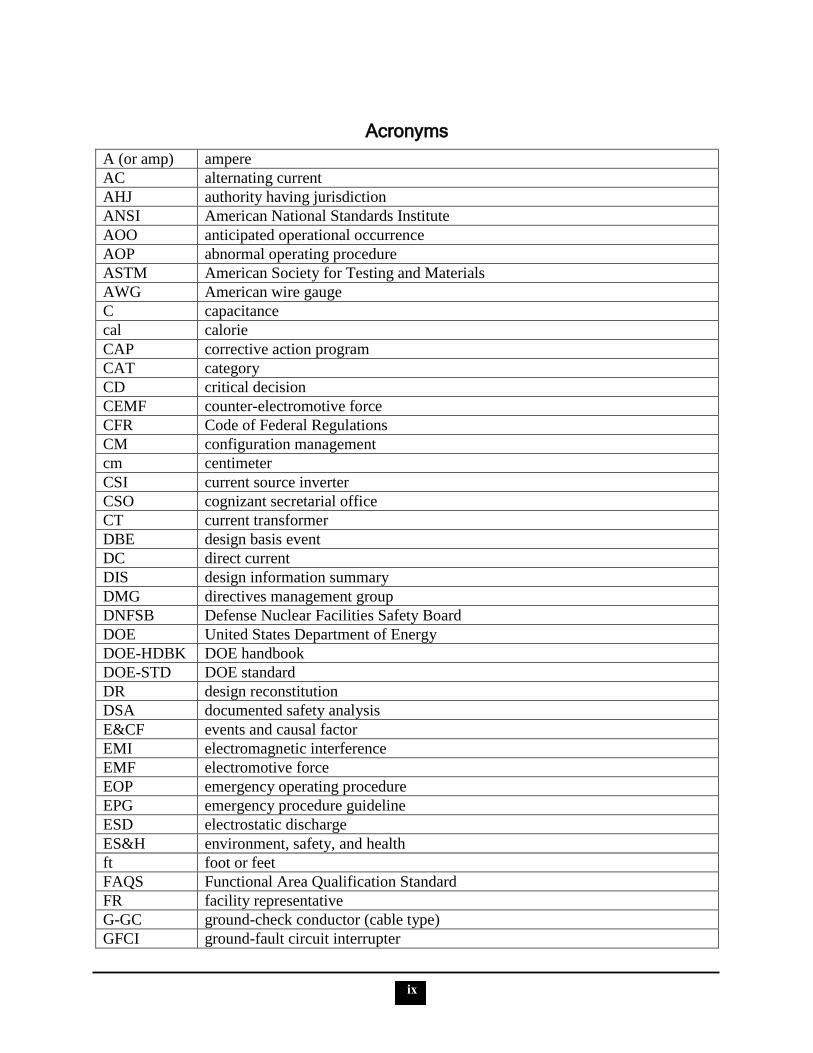
Acronyms
A (or amp) ampere
AC alternating current
AHJ authority having jurisdiction
ANSI American National Standards Institute
AOO anticipated operational occurrence
AOP abnormal operating procedure
ASTM American Society for Testing and Materials
AWG American wire gauge
C capacitance
cal calorie
CAP corrective action program
CAT category
CD critical decision
CEMF counter-electromotive force
CFR Code of Federal Regulations
CM configuration management
cm centimeter
CSI current source inverter
CSO cognizant secretarial office
CT current transformer
DBE design basis event
DC direct current
DIS design information summary
DMG directives management group
DNFSB Defense Nuclear Facilities Safety Board
DOE United States Department of Energy
DOE-HDBK DOE handbook
DOE-STD DOE standard
DR design reconstitution
DSA documented safety analysis
E&CF events and causal factor
EMI electromagnetic interference
EMF electromotive force
EOP emergency operating procedure
EPG emergency procedure guideline
ESD electrostatic discharge
ES&H environment, safety, and health
ft foot or feet
FAQS Functional Area Qualification Standard
FR facility representative
G-GC ground-check conductor (cable type)
GFCI ground-fault circuit interrupter

i.
x
Acronyms
GFPE ground-fault protection for equipment
GOCO government-owned, contractor-operated
H Henry
HELB high energy line break
hp horsepower
HVAC heating, ventilating, and air conditioning
Hz hertz
I&C instrumentation and control
IEC International Electrotechnical Commission
IEEE Institute of Electrical and Electronics Engineers
in. inch or inches
ISA Instrumentation, Systems, and Automation Society
ISMS integrated safety management system
J joule
kA kiloampere
kHz kilohertz
kN kilonewton
kV kilovolt
kVA kilovolt-ampere
kW kilowatt
KSA knowledge, skill or ability
L inductance
LBD licensing basis documentation
LOCA loss of coolant accident
LOTO lockout/tagout
LPS lightning protection system
LPSO lead Program Secretarial Office
LVPCB low-voltage power circuit breaker
m meter
MCA material condition and aging
MCCs motor control centers
MCL maximum contaminant level
MHz megahertz
mm millimeter
MORT management oversight risk tree
MOV motor-operated valve
MV medium voltage
MVA megavolt-ampere
MW megawatt electrical
MWt megawatt thermal
N newton
NEC National Electrical Code
i.
xi
Acronyms
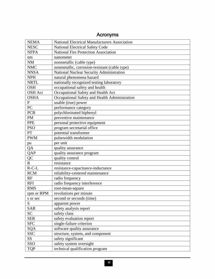
NEMA National Electrical Manufacturers Association
NESC National Electrical Safety Code
NFPA National Fire Protection Association
nm nanometer
NM nonmetallic (cable type)
NMC nonmetallic, corrosion-resistant (cable type)
NNSA National Nuclear Security Administration
NPH natural phenomena hazard
NRTL nationally recognized testing laboratory
OSH occupational safety and health
OSH Act Occupational Safety and Health Act
OSHA Occupational Safety and Health Administration
P usable (true) power
PC performance category
PCB polychlorinated biphenyl
PM preventive maintenance
PPE personal protective equipment
PSO program secretarial office
PT potential transformer
PWM pulsewidth modulation
pu per unit
QA quality assurance
QAP quality assurance program
QC quality control
R resistance
R-C-L resistance-capacitance-inductance
RCM reliability-centered maintenance
RF radio frequency
RFI radio frequency interference
RMS root-mean-square
rpm or RPM revolutions per minute
s or sec second or seconds (time)
S apparent power
SAR safety analysis report
SC safety class
SER safety evaluation report
SFC single-failure criterion
SQA software quality assurance
SSC structure, system, and component
SS safety significant
SSO safety system oversight
TQP technical qualification program
i.
xii
Acronyms
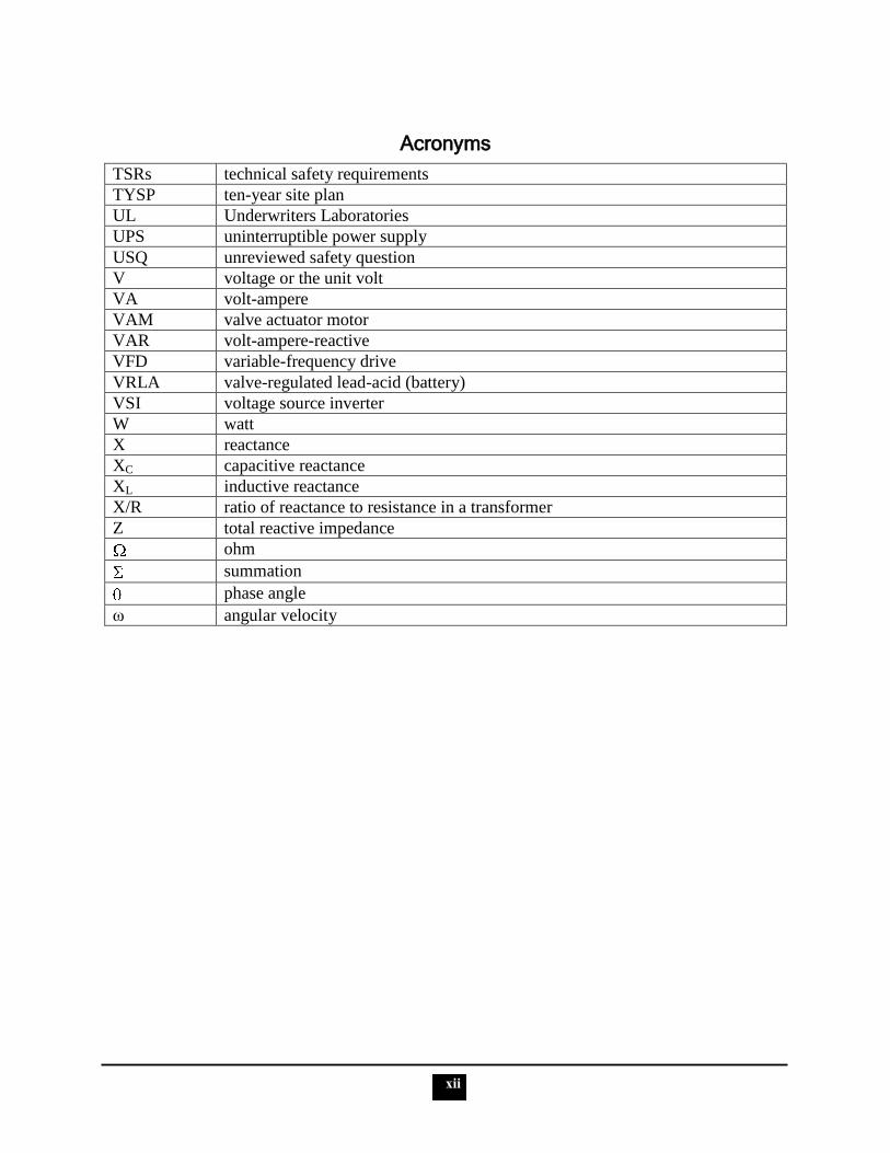
TSRs technical safety requirements
TYSP ten-year site plan
UL Underwriters Laboratories
UPS uninterruptible power supply
USQ unreviewed safety question
V voltage or the unit volt
VA volt-ampere
VAM valve actuator motor
VAR volt-ampere-reactive
VFD variable-frequency drive
VRLA valve-regulated lead-acid (battery)
VSI voltage source inverter
W watt
X reactance
XC capacitive reactance
XL inductive reactance
X/R ratio of reactance to resistance in a transformer
Z total reactive impedance
ohm
summation
phase angle
ω angular velocity
1
PURPOSE
The purpose of this reference guide is to provide a document that contains the information
required for a Department of Energy (DOE)/National Nuclear Security Administration (NNSA)
technical employee to successfully complete the Electrical Systems and Safety Oversight
Functional Area Qualification Standard (FAQS). Information essential to meeting the
qualification requirements is provided; however, some competency statements require extensive
knowledge or skill development. Reproducing all the required information for those statements
in this document is not practical. In those instances, the candidate is directed to additional
resources.
SCOPE
This reference guide addresses the competency statements in the August 2007 edition of
DOE-STD-1170-2007, Electrical Systems and Safety Oversight Functional Area Qualification
Standard. The qualification standard contains 51 competency statements within 7 sections.
Please direct your questions or comments related to this document to the NNSA Learning and
Career Development Department.
PREFACE
Competency statements and supporting knowledge, skill or ability (KSA) statements from the
qualification standard are shown in contrasting bold type, while the corresponding information
associated with each statement is provided below it.
A comprehensive list of acronyms and abbreviations is found at the beginning of this document.
It is recommended that the candidate review the list prior to proceeding with the competencies,
as the acronyms and abbreviations may not be further defined within the text unless special
emphasis is required.
The competencies and supporting KSA statements are taken directly from the FAQS. Most
corrections to spelling, punctuation, and grammar have been made without remark, and all
document-related titles, which variously appear in roman or italic type or set within quotation
marks, have been changed to plain text, also mostly without remark. Capitalized terms are found
as such in the qualification standard and remain so in this reference guide. When they are needed
for clarification, explanations are enclosed in brackets.
Every effort has been made to provide the most current information and references available as
of December 2009. However, the candidate is advised to verify the applicability of the
information provided. It is recognized that some personnel may oversee facilities that utilize
predecessor documents to those identified. In those cases, such documents should be included in
local qualification standards via the Technical Qualification Program (TQP).
In the cases where information about an FAQS topic in a competency or KSA statement is not
available in the newest edition of a standard (consensus or industry), an older version is
referenced. These references are noted in the text and in the bibliography.
2
Unless noted otherwise, a specific reference in a competency statement to a regulation, directive,
or other industry or consensus standard is the source of the discussion text. Some of the
directives referred to have been archived.
In DOE-STD-1170-2007, the letters E and V represent volts and voltage. This reference guide
uses only the letter V.
Much of the text in this reference guide is taken directly from the four volumes of the electrical
science guides in the DOE Fundamentals Handbooks series. While efforts were made to ensure
the accuracy of the content of the manuals, the QC process has continued, and inaccuracies are
occasionally identified.
3
GENERAL TECHNICAL COMPETENCIES
I. KNOWLEDGE OF ELECTRICAL THEORY & EQUIPMENT
1. Electrical personnel shall demonstrate a working level knowledge of electrical and circuit theory, theorems, terminology, laws, and analysis.
a. Explain the basic law of electrostatics.
The following is taken from DOE-HDBK-1011/1-92
The First Law of Electrostatics
The first law of electrostatics (sometimes referred to as the law of electrical charges) states
that a negative charge of the electron is equal to, but opposite, the positive charge of the
proton. These charges are referred to as electrostatic charges.
In nature unlike charges (such as electrons and protons) attract each other, and like charges
repel each other. Some atoms can lose electrons and others can gain electrons; thus, it is
possible to transfer electrons from one object to another. When this occurs, the equal
distribution of negative and positive charges no longer exists. One object will contain an
excess of electrons and become negatively charged, and the other will become deficient in
electrons and become positively charged. These objects, which can contain billions of atoms,
will then follow the same law of electrostatics as the electron and the proton. The electrons
that can move around within an object are said to be free electrons. The greater the number
of these free electrons an object contains, the greater its negative electric charge. Thus, the
electric charge can be used as a measure of electrons.
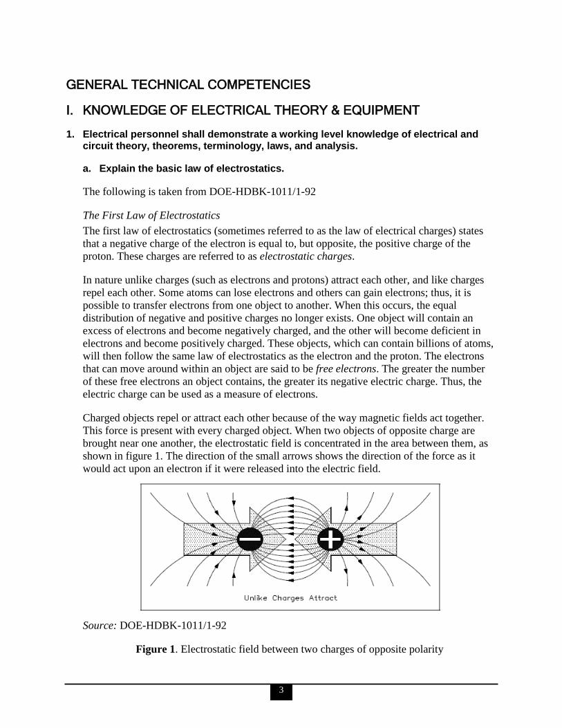
Charged objects repel or attract each other because of the way magnetic fields act together.
This force is present with every charged object. When two objects of opposite charge are
brought near one another, the electrostatic field is concentrated in the area between them, as
shown in figure 1. The direction of the small arrows shows the direction of the force as it
would act upon an electron if it were released into the electric field.
Source: DOE-HDBK-1011/1-92
Figure 1. Electrostatic field between two charges of opposite polarity

4
Source: DOE-HDBK-1011/1-92
Figure 2. Electrostatic field between two charges of like polarity
When two objects of like charge are brought near one another, the lines of force repel each
other, as shown in figure 2.
The strength of the attraction or of the repulsion force depends upon two factors: (1) the
amount of charge on each object, and (2) the distance between the objects. The greater the
charge on the objects, the greater is the electrostatic field. The greater the distance between
the objects, the weaker is the electrostatic field between them, and vice versa. This leads us
to the law of electrostatic attraction, commonly referred to as Coulomb’s law of electrostatic
charges, which states that the force of electrostatic attraction, or repulsion, is directly
proportional to the product of the two charges and inversely proportional to the square of the
distance between them, as shown in this equation:
where
d = distance between two particles (meters [m])
F = force of electrostatic attraction or repulsion (newtons [N])
K = constant of proportionality (coulomb 2/N-m
2)
q1 = charge of first particle (coulombs)
q2 = charge of second particle (coulombs)
If q1 and q2 are both either positively or negatively charged, the force is repulsive. If q1 and q2
are opposite polarity, or charge, the force is attractive.
―Potential difference‖ is the term used to describe how large the electrostatic force is between
two charged objects. If a charged body is placed between two objects with a potential
difference, the charged body will try to move in one direction, depending upon the polarity of
the object. If an electron is placed between a negatively charged body and a positively
charged body, the action due to the potential difference is to push the electron toward the
positively charged object. The electron, being negatively charged, will be repelled from the
(+q1) (-q2)
d2
5
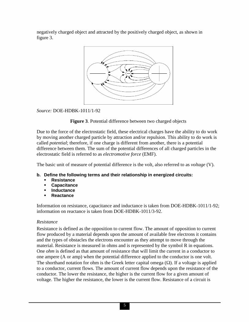
negatively charged object and attracted by the positively charged object, as shown in
figure 3.
Source: DOE-HDBK-1011/1-92
Figure 3. Potential difference between two charged objects
Due to the force of the electrostatic field, these electrical charges have the ability to do work
by moving another charged particle by attraction and/or repulsion. This ability to do work is
called potential; therefore, if one charge is different from another, there is a potential
difference between them. The sum of the potential differences of all charged particles in the
electrostatic field is referred to as electromotive force (EMF).
The basic unit of measure of potential difference is the volt, also referred to as voltage (V).
b. Define the following terms and their relationship in energized circuits: Resistance Capacitance Inductance Reactance
Information on resistance, capacitance and inductance is taken from DOE-HDBK-1011/1-92;
information on reactance is taken from DOE-HDBK-1011/3-92.
Resistance
Resistance is defined as the opposition to current flow. The amount of opposition to current
flow produced by a material depends upon the amount of available free electrons it contains
and the types of obstacles the electrons encounter as they attempt to move through the
material. Resistance is measured in ohms and is represented by the symbol R in equations.
One ohm is defined as that amount of resistance that will limit the current in a conductor to
one ampere (A or amp) when the potential difference applied to the conductor is one volt.
The shorthand notation for ohm is the Greek letter capital omega ( ). If a voltage is applied
to a conductor, current flows. The amount of current flow depends upon the resistance of the
conductor. The lower the resistance, the higher is the current flow for a given amount of
voltage. The higher the resistance, the lower is the current flow. Resistance of a circuit is

6
equal to the applied voltage divided by the circuit current. The following equation is a
mathematical representation of this concept:
R (or ) = I
V
where
I = current (A)
V = voltage
R = resistance ( )
Capacitance
In electromagnetism and electronics, capacitance is the ability of a body to hold an electrical
charge. Capacitance is also a measure of the amount of electrical energy stored (or separated)
for a given electric potential. A common form of energy storage device is a parallel-plate
capacitor. In a parallel plate capacitor, capacitance is directly proportional to the surface area
of the conductor plates and inversely proportional to the separation distance between the
plates. If the charges on the plates are +Q and −Q, and V gives the voltage between the
plates, then the capacitance is given by
C =
Capacitance is defined as the ability to store an electric charge and is symbolized by the
capital letter C. Capacitance, measured in farads, is equal to the amount of charge (Q) that
can be stored in a device or capacitor divided by the voltage (V) applied across the device or
capacitor plates when the charge was stored. The following equation is the mathematical
representation for capacitance:
t
VCIc
where
Ic = capacitive or capacitor current
C = capacitance
ΔV= change in voltage
Δt = change in time
Inductance
Inductance is defined as the ability of a coil to store energy, induce a voltage in itself, and
oppose changes in current flowing through it. The symbol used to indicate inductance in
electrical formulas and equations is a capital L. The units of measurement are called henries.
The unit henry is abbreviated by the capital letter H. One henry is the amount of inductance
(L) that permits one volt to be induced when the current through the coil changes at a rate of
one ampere per second.

7
The quantitative definition of the (self-) inductance of a wire loop in SI units (webers per
ampere, known as henries) is
L =
where L is the inductance, Φ denotes the magnetic flux through the area spanned by the loop,
N is the number of wire turns, and i is the current in amperes.
The following equation is the mathematical representation for the voltage VL induced in a
coil with inductance L. The negative sign indicates that voltage induced opposes the change
in current through the coil per unit time ( I/ t):
= -L
Reactance
In an inductive alternating current (AC) circuit, the current is continually changing and is
continuously inducing an EMF. Because this EMF opposes the continuous change in the
flowing current, its effect is measured in ohms. This opposition of the inductance to the flow
of an AC is called inductive reactance (XL).
The following equation is the mathematical representation of the current flowing in a circuit
that contains only inductive reactance:
I = L
X
V
where
I = effective current (A)
XL = inductive reactance ( )
V = effective voltage across the reactance
The value of XL in any circuit is dependent on the inductance of the circuit and on the rate at
which the current is changing through the circuit. This rate of change depends on the
frequency of the applied voltage. The following equation is the mathematical representation
for XL:
XL = 2 f L
where
= ~3.14
f = frequency (hertz [Hz])
L = inductance (H)
The magnitude of an induced EMF in a circuit depends on how fast the flux that links the
circuit is changing.

8
In considering the relationship between resistance impedance and reactive impedance, the
associated equation is used:
Z = R + j (XL + XC)
where
Z = total reactive impedance
R = resistance
j = square root of -1
XL = inductive reactance
XC = capacitive reactance
The voltage across a circuit that has resistance and reactive impedance would then be as
follows:
V = I × Z
Capacitive reactance (XC) is the opposition by a capacitor or a capacitive circuit to the flow
of current. The current flowing in a capacitive circuit is directly proportional to the
capacitance and to the rate at which the applied voltage is changing. The rate at which the
applied voltage is changing is determined by the frequency of the supply; therefore, if the
frequency of the capacitance of a given circuit is increased, the current flow will increase. It
can also be said that if the frequency or capacitance is increased, the opposition to current
flow decreases; therefore, capacitive reactance, which is the opposition to current flow, is
inversely proportional to frequency and capacitance. Capacitive reactance is measured in
ohms, as is inductive reactance. The following equation is a mathematical representation for
capacitive reactance:
XC = πfC2
1
where
f = frequency (Hz)
= ~3.14
C = capacitance (farads)
c. Explain the following fundamental laws of circuit analysis: Ohm‘s Law Kirchhoff‘s Law
The following is taken from DOE-HDBK-1011/1-92.
Ohm’s Law
In 1827, Georg Simon Ohm discovered that there was a definite relationship between
voltage, current, and resistance in an electrical circuit. Ohm‘s law defines this relationship
and can be stated in three ways.
9
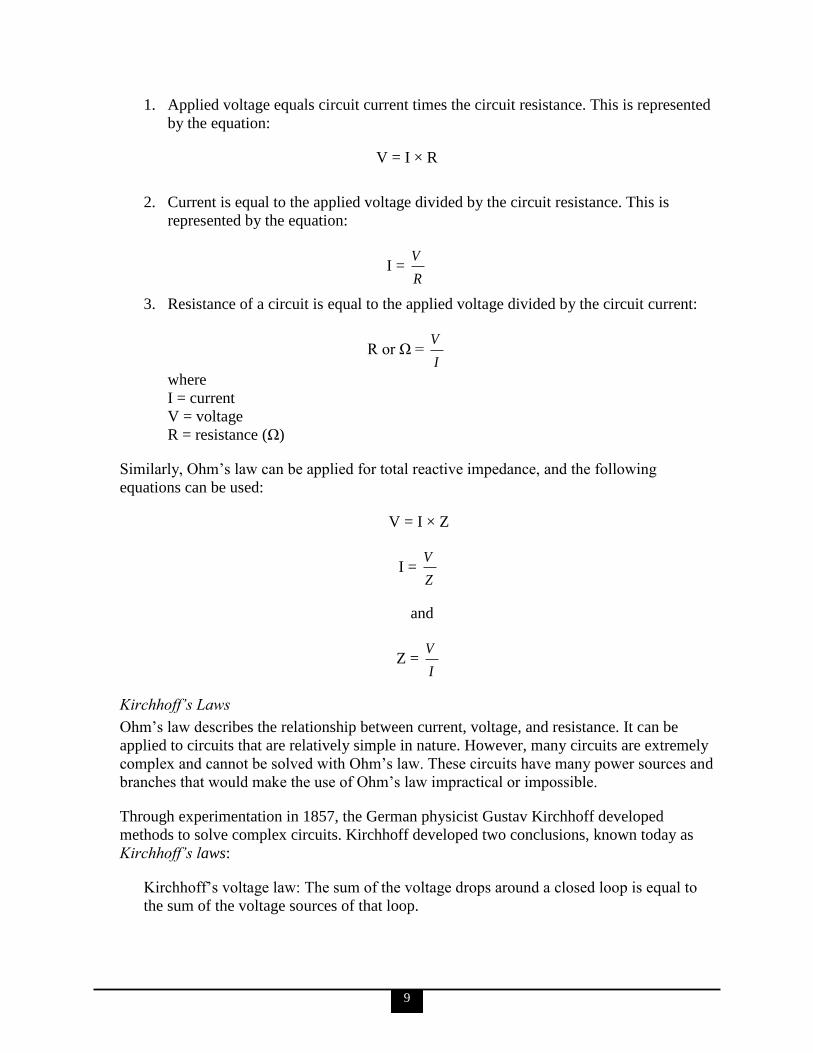
1. Applied voltage equals circuit current times the circuit resistance. This is represented
by the equation:
V = I × R
2. Current is equal to the applied voltage divided by the circuit resistance. This is
represented by the equation:
I = R
V
3. Resistance of a circuit is equal to the applied voltage divided by the circuit current:
R or Ω = I
V
where
I = current
V = voltage
R = resistance (Ω)
Similarly, Ohm‘s law can be applied for total reactive impedance, and the following
equations can be used:
V = I × Z
I = Z
V
and
Z = I
V
Kirchhoff’s Laws
Ohm‘s law describes the relationship between current, voltage, and resistance. It can be
applied to circuits that are relatively simple in nature. However, many circuits are extremely
complex and cannot be solved with Ohm‘s law. These circuits have many power sources and
branches that would make the use of Ohm‘s law impractical or impossible.
Through experimentation in 1857, the German physicist Gustav Kirchhoff developed
methods to solve complex circuits. Kirchhoff developed two conclusions, known today as
Kirchhoff’s laws:
Kirchhoff‘s voltage law: The sum of the voltage drops around a closed loop is equal to
the sum of the voltage sources of that loop.
10
Kirchhoff‘s current law: The current arriving at any junction point in a circuit is equal to
the current leaving that junction.
The voltage law gives the relationship between the voltage drops around any closed loop in a
circuit, and the voltage sources in that loop. The total of these two quantities is always equal.
In equation form,
Vsource = V1 + V2 + V3 + etc. = I1 R1 + I2 R2 + I3 R3 + etc.
Vsource = IR
where the symbol (the Greek letter sigma) means ―the sum of.‖
For a simple series circuit, Kirchhoff‘s voltage law corresponds to Ohm‘s law.
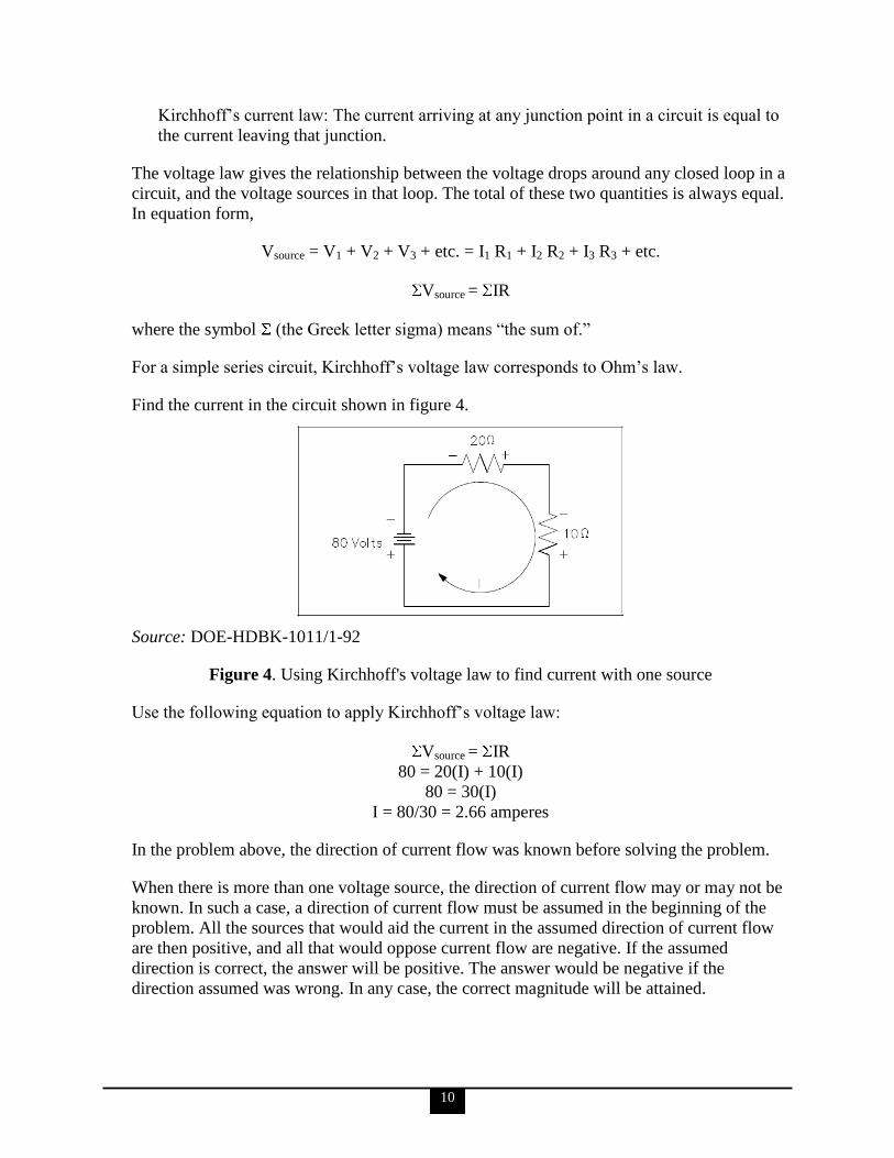
Find the current in the circuit shown in figure 4.
Source: DOE-HDBK-1011/1-92
Figure 4. Using Kirchhoff's voltage law to find current with one source
Use the following equation to apply Kirchhoff‘s voltage law:
Vsource = IR
80 = 20(I) + 10(I)
80 = 30(I)
I = 80/30 = 2.66 amperes
In the problem above, the direction of current flow was known before solving the problem.
When there is more than one voltage source, the direction of current flow may or may not be
known. In such a case, a direction of current flow must be assumed in the beginning of the
problem. All the sources that would aid the current in the assumed direction of current flow
are then positive, and all that would oppose current flow are negative. If the assumed
direction is correct, the answer will be positive. The answer would be negative if the
direction assumed was wrong. In any case, the correct magnitude will be attained.
11
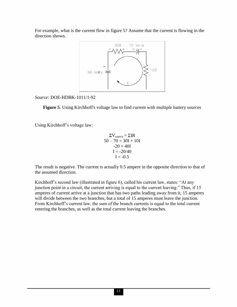
For example, what is the current flow in figure 5? Assume that the current is flowing in the
direction shown.
Source: DOE-HDBK-1011/1-92
Figure 5. Using Kirchhoff's voltage law to find current with multiple battery sources
Using Kirchhoff‘s voltage law:
Vsource = IR
50 – 70 = 30I + 10I
-20 = 40I
I = -20/40
I = -0.5
The result is negative. The current is actually 0.5 ampere in the opposite direction to that of
the assumed direction.
Kirchhoff‘s second law (illustrated in figure 6), called his current law, states: ―At any
junction point in a circuit, the current arriving is equal to the current leaving.‖ Thus, if 15
amperes of current arrive at a junction that has two paths leading away from it, 15 amperes
will divide between the two branches, but a total of 15 amperes must leave the junction.
From Kirchhoff‘s current law, the sum of the branch currents is equal to the total current
entering the branches, as well as the total current leaving the branches.
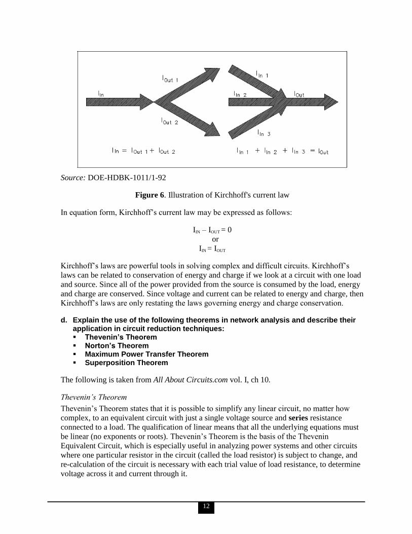
12
Source: DOE-HDBK-1011/1-92
Figure 6. Illustration of Kirchhoff's current law
In equation form, Kirchhoff‘s current law may be expressed as follows:
IIN – IOUT = 0
or
IIN = IOUT
Kirchhoff‘s laws are powerful tools in solving complex and difficult circuits. Kirchhoff‘s
laws can be related to conservation of energy and charge if we look at a circuit with one load
and source. Since all of the power provided from the source is consumed by the load, energy
and charge are conserved. Since voltage and current can be related to energy and charge, then
Kirchhoff‘s laws are only restating the laws governing energy and charge conservation.
d. Explain the use of the following theorems in network analysis and describe their application in circuit reduction techniques: Thevenin‘s Theorem Norton‘s Theorem Maximum Power Transfer Theorem Superposition Theorem
The following is taken from All About Circuits.com vol. I, ch 10.
Thevenin’s Theorem
Thevenin‘s Theorem states that it is possible to simplify any linear circuit, no matter how
complex, to an equivalent circuit with just a single voltage source and series resistance
connected to a load. The qualification of linear means that all the underlying equations must
be linear (no exponents or roots). Thevenin‘s Theorem is the basis of the Thevenin
Equivalent Circuit, which is especially useful in analyzing power systems and other circuits
where one particular resistor in the circuit (called the load resistor) is subject to change, and
re-calculation of the circuit is necessary with each trial value of load resistance, to determine
voltage across it and current through it.

13
Norton’s Theorem
Norton‘s Theorem (the basis of the Norton equivalent circuit) states that it is possible to
simplify any linear circuit, no matter how complex, to an equivalent circuit with just a single
current source and parallel resistance connected to a load. Just as with Thevenin‘s Theorem,
the qualification of linear means that all underlying equations must be linear (no exponents or
roots). As with the Thevenin equivalent circuit, the only useful information from this analysis
is the voltage and current values for the load resistor; the rest of the information is irrelevant
to the original circuit. However, the same advantages seen with Thevenin‘s Theorem apply to
Norton‘s as well: if we wish to analyze load resistor voltage and current over several
different values of load resistance, we can use the Norton equivalent circuit again and again,
applying nothing more complex than simple parallel circuit analysis to determine what‘s
happening with each trial load.
Maximum Power Transfer Theorem
The Maximum Power Transfer Theorem is not so much a means of analysis as it is an aid to
system design. Simply stated, the maximum amount of power will be dissipated by a load
resistance when that load resistance is equal to the Thevenin/Norton resistance of the
network supplying the power. If the load resistance is lower or higher than the
Thevenin/Norton resistance of the source network, its dissipated power will be less than
maximum.
This is essentially what is aimed for in radio transmitter design, where the antenna or
transmission line impedance is matched to final power amplifier impedance for maximum
radio frequency (RF) power output. Impedance, the overall opposition to AC and DC current,
is very similar to resistance, and must be equal between source and load for the greatest
amount of power to be transferred to the load. A load impedance that is too high will result in
low power output. A load impedance that is too low will not only result in low power output,
but possibly overheating of the amplifier due to the power dissipated in its internal (Thevenin
or Norton) impedance.
Superposition Theorem
The strategy used in the Superposition Theorem is to eliminate all but one source of power
within a network at a time, using series/parallel analysis to determine voltage drops (and/or
currents) within the modified network for each power source separately. Then, once voltage
drops and/or currents have been determined for each power source working separately, the
values are all ―superimposed‖ on top of each other (added algebraically) to find the actual
voltage drops/currents with all sources active.
It must be noted, though, that the Superposition Theorem works only for circuits that are
reducible to series/parallel combinations for each of the power sources at a time (thus, this
theorem is useless for analyzing an unbalanced bridge circuit), and it only works where the
underlying equations are linear (no mathematical powers or roots). The requisite of linearity
means that Superposition Theorem is only applicable for determining voltage and current,
not power. Power dissipations, being nonlinear functions, do not algebraically add to an
accurate total when only one source is considered at a time. The need for linearity also means
this Theorem cannot be applied in circuits where the resistance of a component changes with
14
voltage or current. Hence, networks containing components like lamps (incandescent or gas-
discharge) or varistors could not be analyzed.
Another prerequisite for the Superposition Theorem is that all components must be bilateral,
meaning that they behave the same with electrons flowing either direction through them.
Resistors have no polarity-specific behavior, and so the circuits we've been studying so far all
meet this criterion.
The Superposition Theorem finds use in the study of AC circuits, and semiconductor
(amplifier) circuits, where sometimes AC is often mixed (superimposed) with DC. Because
AC voltage and current equations (Ohm‘s Law) are linear just like DC, we can use
Superposition to analyze the circuit with just the DC power source, then just the AC power
source, combining the results to tell what will happen with both AC and DC sources in effect.
For now, though, Superposition will suffice as a break from having to do simultaneous
equations to analyze a circuit.
e. Discuss the fundamental relationships in Direct Current (DC) circuits among voltage, current, resistance, and power.
The information for KSAs ‗e‘ and ‗f‘ is taken from DOE-HDBK-1011/1-92 (in this source Q
= charge).
Voltage
Voltage, EMF, or potential difference, is described as the pressure or force that causes
electrons to move in a conductor. In electrical formulas and equations, voltage is symbolized
with a capital E, while on laboratory equipment or schematic diagrams, voltage is often
represented with a capital V. In this guide, voltage will always be represented with a capital
V.
Current
Electron current, or amperage, is described as the movement of free electrons through a
conductor. In electrical formulas, current is symbolized with a capital I, while in the
laboratory or on schematic diagrams, it is common to use a capital A to indicate amps or
amperage (amps). In this guide, current will always be represented with a capital I.
Resistance
Now that we have discussed the concepts of voltage and current, we are ready to discuss a
third key concept called resistance. Resistance is defined as the opposition to current flow.
The amount of opposition to current flow produced by a material depends upon the amount
of available free electrons it contains and the types of obstacles the electrons encounter as
they attempt to move through the material. Resistance is measured in ohms and is
represented by the symbol (R) in equations. One ohm is defined as that amount of resistance
that will limit the current in a conductor to one ampere when the potential difference
(voltage) applied to the conductor is one volt. The shorthand notation for ohm is the Greek
letter capital omega ( ). If a voltage is applied to a conductor, current flows. The amount of
current flow depends upon the resistance of the conductor. The lower the resistance, the
15
higher the current flow for a given amount of voltage. The higher the resistance, the lower
the current flow.
Ohm’s Law
Ohm‘s Law is discussed in detail in KSA ‗c‘ of this competency. In summary, it defines the
relationship between voltage, current, and resistance in an electrical circuit, and can be
represented by the equation:
E = I x R or E = IR
where
E = voltage (V)
I = current (A)
R = resistance ( )
Power
Electricity is generally used to do some sort of work, such as turning a motor or generating
heat. Specifically, power is the rate at which work is done, or the rate at which heat is
generated. The unit commonly used to specify electric power is the watt. In equations, power
is abbreviated with the capital letter P, and watts, the units of measure for power, are
abbreviated with the capital letter W. Power is also described as the current (I) in a circuit
times the voltage (E) across the circuit. The following equation is a mathematical
representation of this concept.
P = I x E or P = IE
f. Explain the treatment of inductance and capacitance values in steady-state direct current circuits.
Inductance is defined as the ability of a coil to store energy, induce a voltage in itself, and
oppose changes in current flowing through it. The symbol used to indicate inductance in
electrical formulas and equations is a capital L. The units of measurement are called henries.
The unit henry is abbreviated by using the capital letter H. One henry is the amount of
inductance (L) that permits one volt to be induced (VL) when the current through the coil
changes at a rate of one ampere per second. The equation below is the mathematical
representation of the rate of change in current through a coil per unit time.
The next equation is the mathematical representation for the voltage VL induced in a coil
with inductance L. The negative sign indicates that voltage induced opposes the change in
current through the coil per unit time (Δ I/Δ t).
VL = -L

16
Capacitance is defined as the ability to store an electric charge and is symbolized by the
capital letter C. Capacitance (C), measured in farads, is equal to the amount of charge (Q)
that can be stored in a device or capacitor divided by the voltage (E) applied across the
device or capacitor plates when the charge was stored. The following equation is the
mathematical representation for capacitance.
C =E
Q
g. Discuss the fundamental relationships in Alternating Current (AC) circuits among voltage, current, resistance, reactance, impedance, power, and power factor.
The following is taken from DOE-HDBK-1011/3-92 (in this source Q = reactive power).
These relationships are very complex and thus are discussed only briefly here. See modules
7, 8 & 9 of the above reference for a much more detailed discussion.
In AC circuits, voltage and current are normally out of phase and as a result, not all the
power produced by the generator can be used to accomplish work. By the same token, power
cannot be calculated in AC circuits in the same manner as in DC circuits. The power triangle
(figure 7) equates AC power to DC power by showing the relationship between generator
output (apparent power—S) in volt-amperes (VA), usable power (true power—P) in watts,
and wasted or stored power (reactive power—Q) in volt-amperes-reactive (VAR). The phase
angle ( ) represents the efficiency of the AC circuit and corresponds to the total reactive
impedance (Z) to the current flow in the circuit.
Source: DOE-HDBK-1011/3-92
Figure 7. Power triangle

17
Apparent power, reactive power, and true power can be calculated by using the DC
equivalent (root-mean-square [RMS] value) of the AC voltage and current components along
with the power factor.
h. Describe how the following methods produce a voltage: Electrochemistry Static electricity Magnetic induction Piezoelectric effect Thermoelectricity Photoelectric effect Thermionic emission
The information for KSAs ‗h‘ through ‗j‘ is taken from DOE-HDBK-1011/1-92.
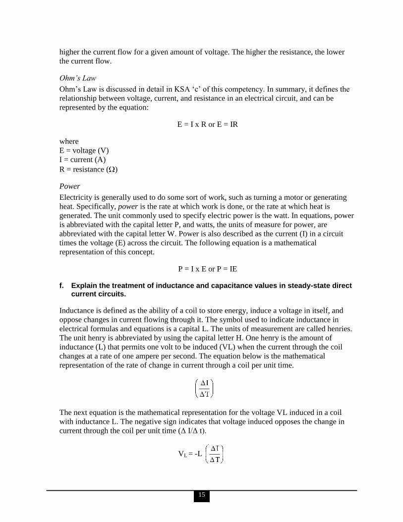
Electrochemistry
As illustrated in figure 8, chemicals can be combined with certain metals to cause a chemical
reaction that will transfer electrons to produce electrical energy. A chemical reaction
produces and maintains opposite charges on two dissimilar metals that serve as the positive
and negative terminals. The metals are in contact with an electrolyte solution. Connecting
together more than one of these cells will produce a battery.
18
Source: DOE-HDBK-1011/1-92
Figure 8. Voltaic chemical cell
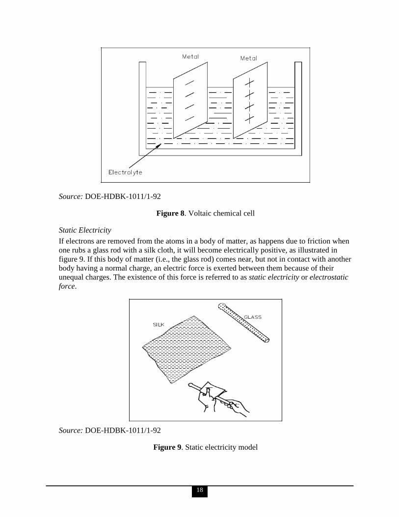
Static Electricity
If electrons are removed from the atoms in a body of matter, as happens due to friction when
one rubs a glass rod with a silk cloth, it will become electrically positive, as illustrated in
figure 9. If this body of matter (i.e., the glass rod) comes near, but not in contact with another
body having a normal charge, an electric force is exerted between them because of their
unequal charges. The existence of this force is referred to as static electricity or electrostatic
force.
Source: DOE-HDBK-1011/1-92
Figure 9. Static electricity model
19
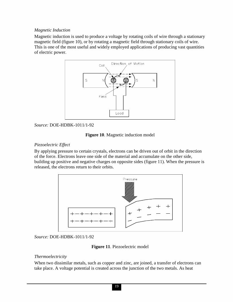
Magnetic Induction
Magnetic induction is used to produce a voltage by rotating coils of wire through a stationary
magnetic field (figure 10), or by rotating a magnetic field through stationary coils of wire.
This is one of the most useful and widely employed applications of producing vast quantities
of electric power.
Source: DOE-HDBK-1011/1-92
Figure 10. Magnetic induction model
Piezoelectric Effect
By applying pressure to certain crystals, electrons can be driven out of orbit in the direction
of the force. Electrons leave one side of the material and accumulate on the other side,
building up positive and negative charges on opposite sides (figure 11). When the pressure is
released, the electrons return to their orbits.
Source: DOE-HDBK-1011/1-92
Figure 11. Piezoelectric model
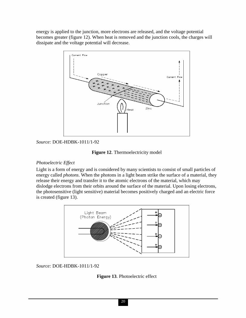
Thermoelectricity
When two dissimilar metals, such as copper and zinc, are joined, a transfer of electrons can
take place. A voltage potential is created across the junction of the two metals. As heat
20
energy is applied to the junction, more electrons are released, and the voltage potential
becomes greater (figure 12). When heat is removed and the junction cools, the charges will
dissipate and the voltage potential will decrease.
Source: DOE-HDBK-1011/1-92
Figure 12. Thermoelectricity model
Photoelectric Effect
Light is a form of energy and is considered by many scientists to consist of small particles of
energy called photons. When the photons in a light beam strike the surface of a material, they
release their energy and transfer it to the atomic electrons of the material, which may
dislodge electrons from their orbits around the surface of the material. Upon losing electrons,
the photosensitive (light sensitive) material becomes positively charged and an electric force
is created (figure 13).
Source: DOE-HDBK-1011/1-92
Figure 13. Photoelectric effect
21
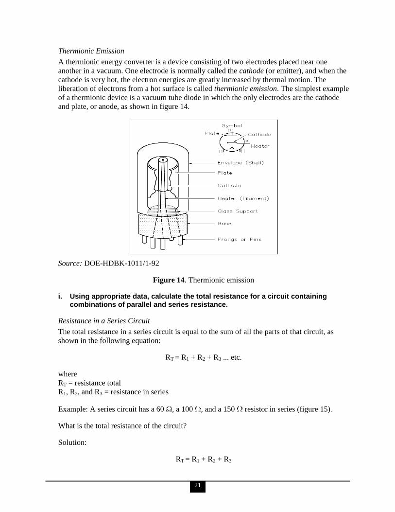
Thermionic Emission
A thermionic energy converter is a device consisting of two electrodes placed near one
another in a vacuum. One electrode is normally called the cathode (or emitter), and when the
cathode is very hot, the electron energies are greatly increased by thermal motion. The
liberation of electrons from a hot surface is called thermionic emission. The simplest example
of a thermionic device is a vacuum tube diode in which the only electrodes are the cathode
and plate, or anode, as shown in figure 14.
Source: DOE-HDBK-1011/1-92
Figure 14. Thermionic emission
i. Using appropriate data, calculate the total resistance for a circuit containing combinations of parallel and series resistance.
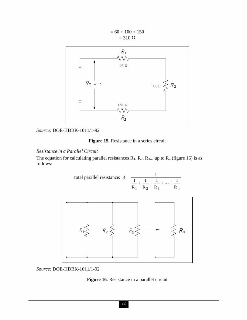
Resistance in a Series Circuit
The total resistance in a series circuit is equal to the sum of all the parts of that circuit, as
shown in the following equation:
RT = R1 + R2 + R3 ... etc.
where
RT = resistance total
R1, R2, and R3 = resistance in series
Example: A series circuit has a 60 , a 100 , and a 150 resistor in series (figure 15).
What is the total resistance of the circuit?
Solution:
RT = R1 + R2 + R3
22
= 60 + 100 + 150
= 310
Source: DOE-HDBK-1011/1-92
Figure 15. Resistance in a series circuit
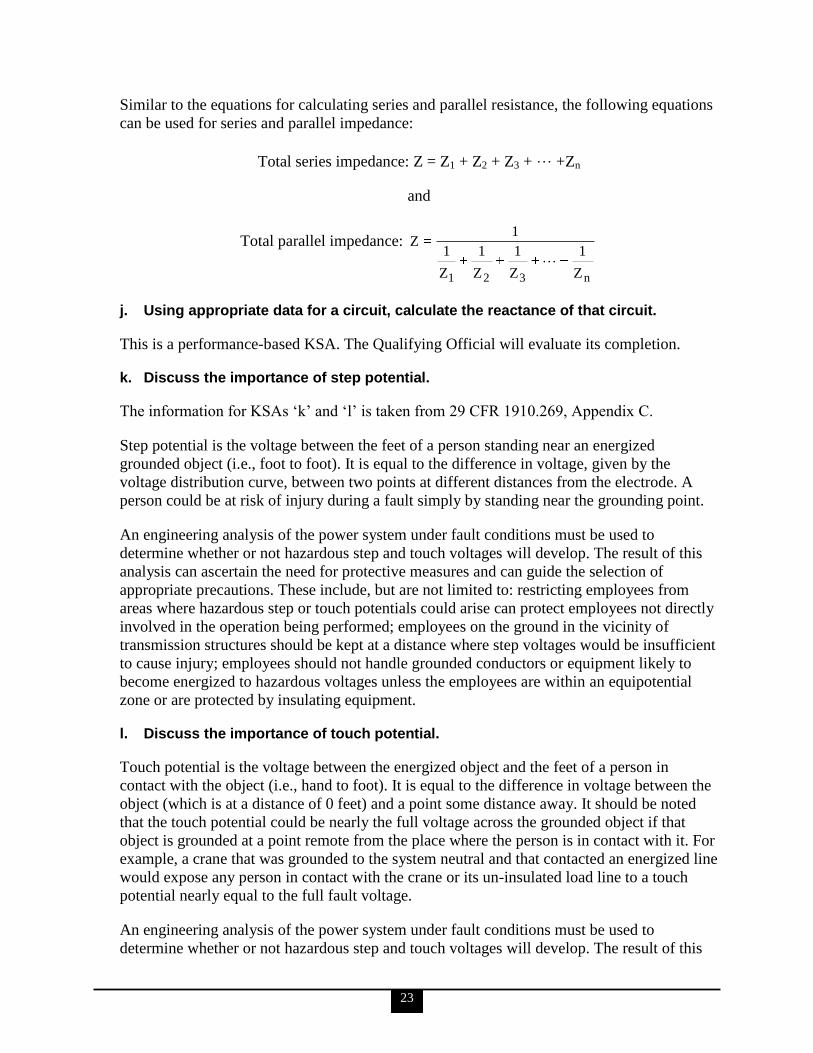
Resistance in a Parallel Circuit
The equation for calculating parallel resistances R1, R2, R3....up to Rn (figure 16) is as
follows:
Total parallel resistance:
n321 R
1
R
1
R
1
R
1
1R
Source: DOE-HDBK-1011/1-92
Figure 16. Resistance in a parallel circuit
Rn
23
Similar to the equations for calculating series and parallel resistance, the following equations
can be used for series and parallel impedance:
Total series impedance: Z = Z1 + Z2 + Z3 + … +Zn
and
Total parallel impedance:
n321 Z
1
Z
1
Z
1
Z
1
1Z
j. Using appropriate data for a circuit, calculate the reactance of that circuit.
This is a performance-based KSA. The Qualifying Official will evaluate its completion.
k. Discuss the importance of step potential.
The information for KSAs ‗k‘ and ‗l‘ is taken from 29 CFR 1910.269, Appendix C.
Step potential is the voltage between the feet of a person standing near an energized
grounded object (i.e., foot to foot). It is equal to the difference in voltage, given by the
voltage distribution curve, between two points at different distances from the electrode. A
person could be at risk of injury during a fault simply by standing near the grounding point.
An engineering analysis of the power system under fault conditions must be used to
determine whether or not hazardous step and touch voltages will develop. The result of this
analysis can ascertain the need for protective measures and can guide the selection of
appropriate precautions. These include, but are not limited to: restricting employees from
areas where hazardous step or touch potentials could arise can protect employees not directly
involved in the operation being performed; employees on the ground in the vicinity of
transmission structures should be kept at a distance where step voltages would be insufficient
to cause injury; employees should not handle grounded conductors or equipment likely to
become energized to hazardous voltages unless the employees are within an equipotential
zone or are protected by insulating equipment.
l. Discuss the importance of touch potential.
Touch potential is the voltage between the energized object and the feet of a person in
contact with the object (i.e., hand to foot). It is equal to the difference in voltage between the
object (which is at a distance of 0 feet) and a point some distance away. It should be noted
that the touch potential could be nearly the full voltage across the grounded object if that
object is grounded at a point remote from the place where the person is in contact with it. For
example, a crane that was grounded to the system neutral and that contacted an energized line
would expose any person in contact with the crane or its un-insulated load line to a touch
potential nearly equal to the full fault voltage.
An engineering analysis of the power system under fault conditions must be used to
determine whether or not hazardous step and touch voltages will develop. The result of this

24
analysis can ascertain the need for protective measures and can guide the selection of
appropriate precautions. These include, but are not limited to: restricting employees from
areas where hazardous step or touch potentials could arise can protect employees not directly
involved in the operation being performed; employees on the ground in the vicinity of
transmission structures should be kept at a distance where step voltages would be insufficient
to cause injury; employees should not handle grounded conductors or equipment likely to
become energized to hazardous voltages unless the employees are within an equipotential
zone or are protected by insulating equipment.
2. Electrical personnel shall demonstrate a working level knowledge of basic AC theory.
The information for competency statements ‗2‘ and ‗3‘ and their associated KSAs is taken
from DOE-HDBK-1011/3-92.
a. Define the effective value of an AC relative to DC.
Effective value of AC is the amount of AC that produces the same heating effect as an equal
amount of DC. In simpler terms, one ampere effective value of AC will produce the same
amount of heat in a conductor, in a given time, as one ampere of DC.
Effective value of AC can be calculated by squaring all the amplitudes of the voltage sine
wave over one period, taking the average of these values, and then taking the square root.
The effective voltage value, being the root of the mean (average) square of the voltages, is
known as the root-mean-square, or RMS, voltage value.
The RMS voltage (Vrms) value is
Vrms =2
2Vmax = 0.707 Vmax
The associated RMS current (Irms) can then be calculated using the equation below. Note: The
current of any electrical circuit is derived by the applied voltage source and the total
impedance of that circuit.
Irms=Vrms × Z
b. Describe the relationship between maximum, average, and Root-Mean-Square (RMS) values of voltage and current in an AC waveform.
One way to refer to AC voltage or current is by peak voltage (Vmax) or peak current (Imax),
these values representing the maximum voltage or current for an AC sine wave.
The values of current (I) and voltage (V) that are normally encountered are assumed to be
RMS values; therefore, no subscript is normally used.
Another useful value is the average value of the amplitude during the positive half of the
cycle. The following equations show the mathematical relationship between maximum (Vmax,
Imax), RMS (V, I), and average (Vav, Iav) voltage and current:
25
Voltage = 0.637 Vmax – 0.90 V
Current = 0.637 Imax – 0.90 I
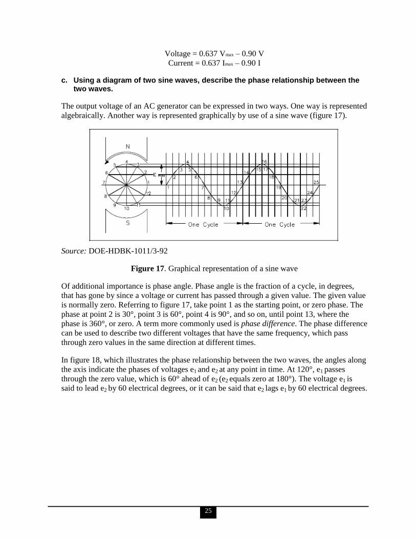
c. Using a diagram of two sine waves, describe the phase relationship between the two waves.
The output voltage of an AC generator can be expressed in two ways. One way is represented
algebraically. Another way is represented graphically by use of a sine wave (figure 17).
Source: DOE-HDBK-1011/3-92
Figure 17. Graphical representation of a sine wave
Of additional importance is phase angle. Phase angle is the fraction of a cycle, in degrees,
that has gone by since a voltage or current has passed through a given value. The given value
is normally zero. Referring to figure 17, take point 1 as the starting point, or zero phase. The
phase at point 2 is 30°, point 3 is 60°, point 4 is 90°, and so on, until point 13, where the
phase is 360°, or zero. A term more commonly used is phase difference. The phase difference
can be used to describe two different voltages that have the same frequency, which pass
through zero values in the same direction at different times.
In figure 18, which illustrates the phase relationship between the two waves, the angles along
the axis indicate the phases of voltages e1 and e2 at any point in time. At 120°, e1 passes
through the zero value, which is 60° ahead of e2 (e2 equals zero at 180°). The voltage e1 is
said to lead e2 by 60 electrical degrees, or it can be said that e2 lags e1 by 60 electrical degrees.
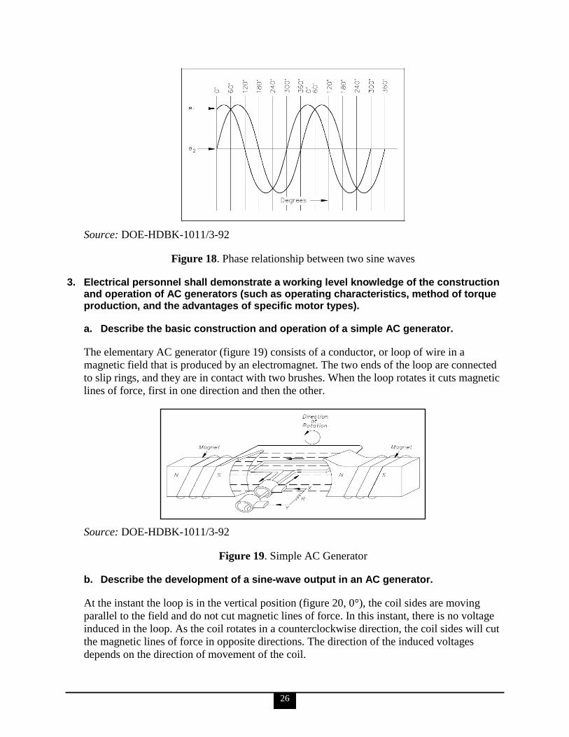
26
Source: DOE-HDBK-1011/3-92
Figure 18. Phase relationship between two sine waves
3. Electrical personnel shall demonstrate a working level knowledge of the construction and operation of AC generators (such as operating characteristics, method of torque production, and the advantages of specific motor types).
a. Describe the basic construction and operation of a simple AC generator.
The elementary AC generator (figure 19) consists of a conductor, or loop of wire in a
magnetic field that is produced by an electromagnet. The two ends of the loop are connected
to slip rings, and they are in contact with two brushes. When the loop rotates it cuts magnetic
lines of force, first in one direction and then the other.
Source: DOE-HDBK-1011/3-92
Figure 19. Simple AC Generator
b. Describe the development of a sine-wave output in an AC generator.
At the instant the loop is in the vertical position (figure 20, 0°), the coil sides are moving
parallel to the field and do not cut magnetic lines of force. In this instant, there is no voltage
induced in the loop. As the coil rotates in a counterclockwise direction, the coil sides will cut
the magnetic lines of force in opposite directions. The direction of the induced voltages
depends on the direction of movement of the coil.
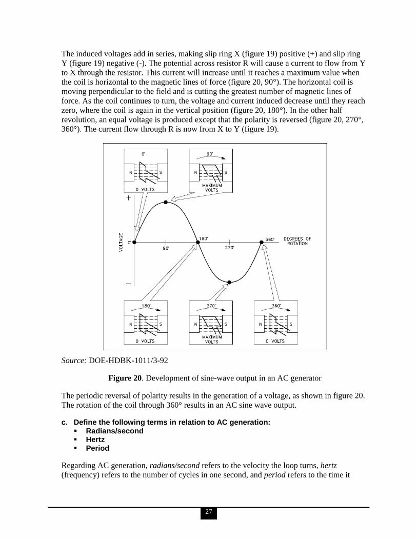
27
The induced voltages add in series, making slip ring X (figure 19) positive (+) and slip ring
Y (figure 19) negative (-). The potential across resistor R will cause a current to flow from Y
to X through the resistor. This current will increase until it reaches a maximum value when
the coil is horizontal to the magnetic lines of force (figure 20, 90°). The horizontal coil is
moving perpendicular to the field and is cutting the greatest number of magnetic lines of
force. As the coil continues to turn, the voltage and current induced decrease until they reach
zero, where the coil is again in the vertical position (figure 20, 180°). In the other half
revolution, an equal voltage is produced except that the polarity is reversed (figure 20, 270°,
360°). The current flow through R is now from X to Y (figure 19).
Source: DOE-HDBK-1011/3-92
Figure 20. Development of sine-wave output in an AC generator
The periodic reversal of polarity results in the generation of a voltage, as shown in figure 20.
The rotation of the coil through 360° results in an AC sine wave output.
c. Define the following terms in relation to AC generation: Radians/second Hertz Period
Regarding AC generation, radians/second refers to the velocity the loop turns, hertz
(frequency) refers to the number of cycles in one second, and period refers to the time it
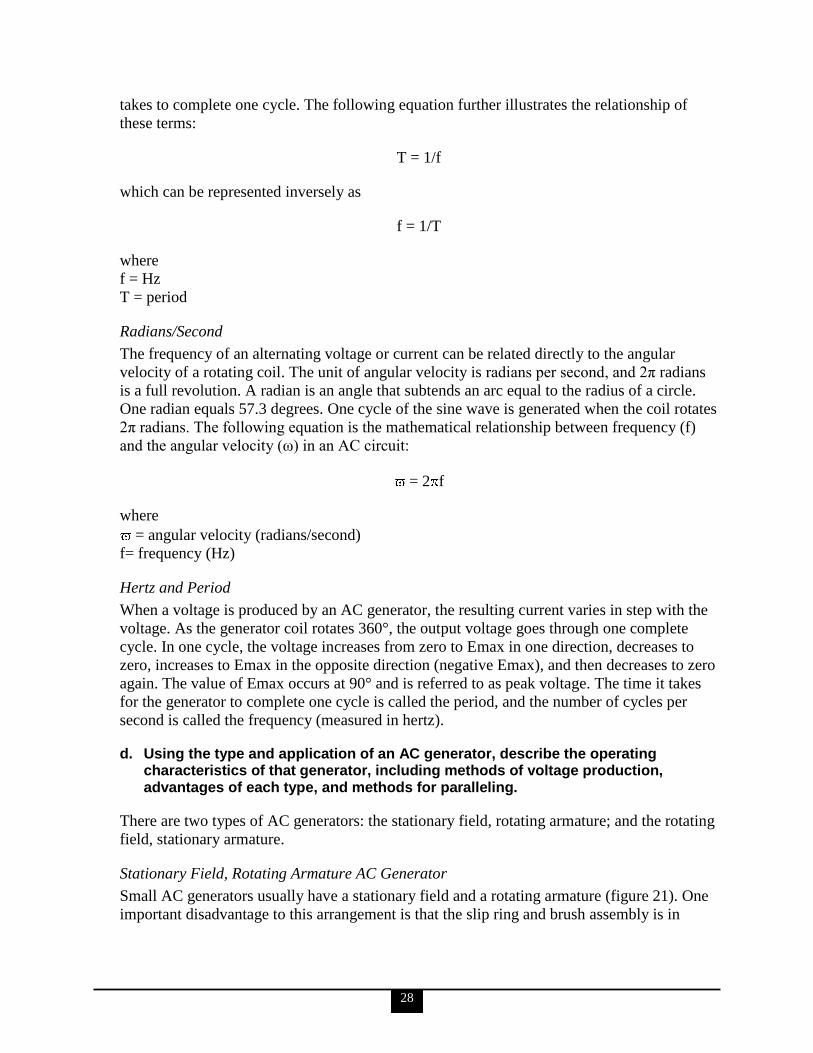
28
takes to complete one cycle. The following equation further illustrates the relationship of
these terms:
T = 1/f
which can be represented inversely as
f = 1/T
where
f = Hz
T = period
Radians/Second
The frequency of an alternating voltage or current can be related directly to the angular
velocity of a rotating coil. The unit of angular velocity is radians per second, and 2π radians
is a full revolution. A radian is an angle that subtends an arc equal to the radius of a circle.
One radian equals 57.3 degrees. One cycle of the sine wave is generated when the coil rotates
2π radians. The following equation is the mathematical relationship between frequency (f)
and the angular velocity (ω) in an AC circuit:
= 2 f
where
= angular velocity (radians/second)
f= frequency (Hz)
Hertz and Period
When a voltage is produced by an AC generator, the resulting current varies in step with the
voltage. As the generator coil rotates 360°, the output voltage goes through one complete
cycle. In one cycle, the voltage increases from zero to Emax in one direction, decreases to
zero, increases to Emax in the opposite direction (negative Emax), and then decreases to zero
again. The value of Emax occurs at 90° and is referred to as peak voltage. The time it takes
for the generator to complete one cycle is called the period, and the number of cycles per
second is called the frequency (measured in hertz).
d. Using the type and application of an AC generator, describe the operating characteristics of that generator, including methods of voltage production, advantages of each type, and methods for paralleling.
There are two types of AC generators: the stationary field, rotating armature; and the rotating
field, stationary armature.
Stationary Field, Rotating Armature AC Generator
Small AC generators usually have a stationary field and a rotating armature (figure 21). One
important disadvantage to this arrangement is that the slip ring and brush assembly is in
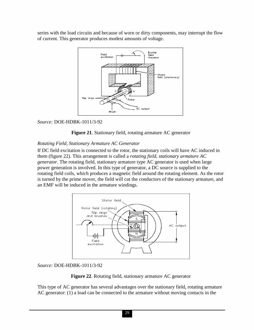
29
series with the load circuits and because of worn or dirty components, may interrupt the flow
of current. This generator produces modest amounts of voltage.
Source: DOE-HDBK-1011/3-92
Figure 21. Stationary field, rotating armature AC generator
Rotating Field, Stationary Armature AC Generator
If DC field excitation is connected to the rotor, the stationary coils will have AC induced in
them (figure 22). This arrangement is called a rotating field, stationary armature AC
generator. The rotating field, stationary armature type AC generator is used when large
power generation is involved. In this type of generator, a DC source is supplied to the
rotating field coils, which produces a magnetic field around the rotating element. As the rotor
is turned by the prime mover, the field will cut the conductors of the stationary armature, and
an EMF will be induced in the armature windings.
Source: DOE-HDBK-1011/3-92
Figure 22. Rotating field, stationary armature AC generator
This type of AC generator has several advantages over the stationary field, rotating armature
AC generator: (1) a load can be connected to the armature without moving contacts in the

30
circuit; (2) it is much easier to insulate stator fields than rotating fields; and (3) much higher
voltages and currents can be generated.
Paralleling AC Generators
Three conditions must be met prior to paralleling (or synchronizing) AC generators:
1. Their terminal voltages must be equal. If the voltages of the two AC generators are
not equal, one of the AC generators could be picked up as a reactive load to the other
AC generator. This causes high currents to be exchanged between the two machines,
possibly causing generator or distribution system damage.
2. Their frequencies must be equal. A mismatch in frequencies of the two AC generators
will cause the generator with the lower frequency to be picked up as a load on the
other generator (a condition referred to as motoring). This can cause an overload in
the generators and the distribution system.
3. Their output voltages must be in phase. A mismatch in the phases will cause large
opposing voltages to be developed. The worst-case mismatch would be 180° out of
phase, resulting in an opposing voltage between the two generators of twice the
output voltage. This high voltage can cause damage to the generators and distribution
system due to high currents.
During paralleling operations, voltages of the two generators that are to be paralleled are
indicated through the use of voltmeters. Frequency matching is accomplished through the use
of output frequency meters. Phase matching is accomplished through the use of a
synchroscope, a device that senses the two frequencies and gives an indication of phase
differences and a relative comparison of frequency differences.
e. State the purpose of the following components of an AC generator: Field Armature Prime mover Rotor Stator Slip rings
Field
The field in an AC generator consists of coils of conductors within the generator that receive
a voltage from a source (called excitation) and produce a magnetic flux. The magnetic flux in
the field cuts the armature to produce a voltage. This voltage is ultimately the output voltage
of the AC generator.
Armature
The armature is the part of an AC generator in which voltage is produced. This component
consists of many coils of wire that are large enough to carry the full-load current of the
generator.
Prime Mover
The prime mover is the component that is used to drive the AC generator. The prime mover
may be any type of rotating machine, such as a diesel engine, a steam turbine, or a motor.
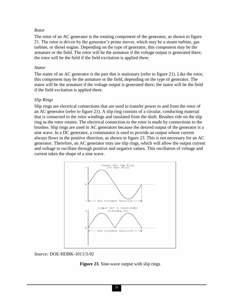
31
Rotor
The rotor of an AC generator is the rotating component of the generator, as shown in figure
21. The rotor is driven by the generator‘s prime mover, which may be a steam turbine, gas
turbine, or diesel engine. Depending on the type of generator, this component may be the
armature or the field. The rotor will be the armature if the voltage output is generated there;
the rotor will be the field if the field excitation is applied there.
Stator
The stator of an AC generator is the part that is stationary (refer to figure 21). Like the rotor,
this component may be the armature or the field, depending on the type of generator. The
stator will be the armature if the voltage output is generated there; the stator will be the field
if the field excitation is applied there.
Slip Rings
Slip rings are electrical connections that are used to transfer power to and from the rotor of
an AC generator (refer to figure 21). A slip ring consists of a circular, conducting material
that is connected to the rotor windings and insulated from the shaft. Brushes ride on the slip
ring as the rotor rotates. The electrical connection to the rotor is made by connections to the
brushes. Slip rings are used in AC generators because the desired output of the generator is a
sine wave. In a DC generator, a commutator is used to provide an output whose current
always flows in the positive direction, as shown in figure 23. This is not necessary for an AC
generator. Therefore, an AC generator may use slip rings, which will allow the output current
and voltage to oscillate through positive and negative values. This oscillation of voltage and
current takes the shape of a sine wave.
Source: DOE-HDBK-1011/3-92
Figure 23. Sine-wave output with slip rings
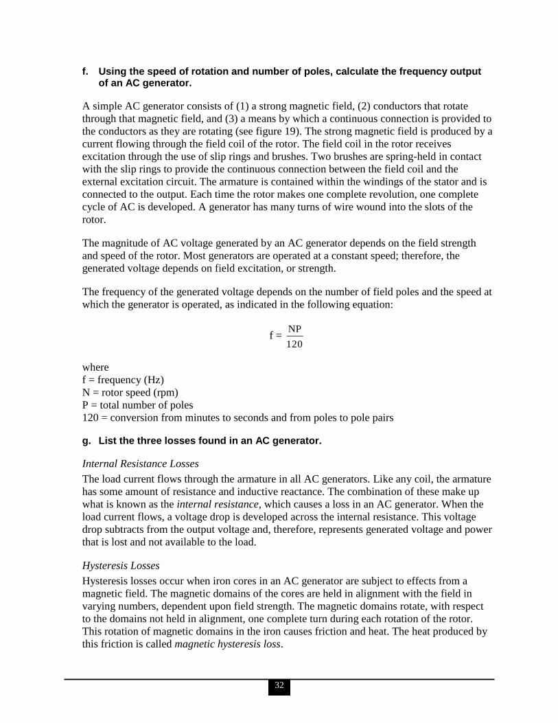
32
f. Using the speed of rotation and number of poles, calculate the frequency output of an AC generator.
A simple AC generator consists of (1) a strong magnetic field, (2) conductors that rotate
through that magnetic field, and (3) a means by which a continuous connection is provided to
the conductors as they are rotating (see figure 19). The strong magnetic field is produced by a
current flowing through the field coil of the rotor. The field coil in the rotor receives
excitation through the use of slip rings and brushes. Two brushes are spring-held in contact
with the slip rings to provide the continuous connection between the field coil and the
external excitation circuit. The armature is contained within the windings of the stator and is
connected to the output. Each time the rotor makes one complete revolution, one complete
cycle of AC is developed. A generator has many turns of wire wound into the slots of the
rotor.
The magnitude of AC voltage generated by an AC generator depends on the field strength
and speed of the rotor. Most generators are operated at a constant speed; therefore, the
generated voltage depends on field excitation, or strength.
The frequency of the generated voltage depends on the number of field poles and the speed at
which the generator is operated, as indicated in the following equation:
f = 120
NP
where
f = frequency (Hz)
N = rotor speed (rpm)
P = total number of poles
120 = conversion from minutes to seconds and from poles to pole pairs
g. List the three losses found in an AC generator.
Internal Resistance Losses
The load current flows through the armature in all AC generators. Like any coil, the armature
has some amount of resistance and inductive reactance. The combination of these make up
what is known as the internal resistance, which causes a loss in an AC generator. When the
load current flows, a voltage drop is developed across the internal resistance. This voltage
drop subtracts from the output voltage and, therefore, represents generated voltage and power
that is lost and not available to the load.
Hysteresis Losses
Hysteresis losses occur when iron cores in an AC generator are subject to effects from a
magnetic field. The magnetic domains of the cores are held in alignment with the field in
varying numbers, dependent upon field strength. The magnetic domains rotate, with respect
to the domains not held in alignment, one complete turn during each rotation of the rotor.
This rotation of magnetic domains in the iron causes friction and heat. The heat produced by
this friction is called magnetic hysteresis loss.
33
Mechanical Losses
Rotational or mechanical losses can be caused by bearing friction, brush friction on the
commutator, and air friction (called windage), which is caused by the air turbulence due to
armature rotation.
h. Given the prime mover input and generator output, determine the efficiency of an AC generator.
Efficiency of an AC generator is the ratio of the useful power output to the total power input.
Because any mechanical process experiences some losses, no AC generators can be
100 percent efficient. Efficiency of an AC generator can be calculated using the following
equation:
Efficiency = 100Input
Output
i. Describe the basis for the kilowatt and kilovolt-amperes ratings of an AC generator.
Typical nameplate data for an AC generator (see figure 24) includes (1) manufacturer;
(2) serial number and type number; (3) speed (RPM), number of poles, frequency of output,
number of phases, and maximum supply voltage; (4) capacity rating in kilovolt-amperes
(kVA) and kilowatts (kW) at a specified power factor and maximum output voltage;
(5) armature and field current per phase; and (6) maximum temperature rise. Power (kW)
ratings of an AC generator are based on the ability of the prime mover to overcome generator
losses and the ability of the machine to dissipate the internally generated heat. The voltage
rating of an AC generator is based on the insulation rating of the machine.
Westinghouse
AC generator air cooled NO. 6750616 Type ATB 3600 RPM
2 poles 60 hertz 3-phase wye-connected for 13800 volts
Rating 15625 kVA 12500 kW 0.80 PF exciter 250 volts
Armature 654 amp field 183 amp
Guaranteed temp. rise not to exceed 60° C on armature by detector
80° C on field by resistance
Source: DOE-HDBK-1011/3-92
Figure 24. AC generator nameplate ratings
34
j. Describe the conditions that must be met prior to paralleling two AC generators, including the consequences of not meeting these conditions.
Paralleling AC Generators
Three conditions must be met prior to paralleling (or synchronizing) AC generators:
1. Their terminal voltages must be equal. If the voltages of the two AC generators are
not equal, one of the AC generators could be picked up as a reactive load to the other
AC generator. This causes high currents to be exchanged between the two machines,
possibly causing generator or distribution system damage.
2. Their frequencies must be equal. A mismatch in frequencies of the two AC generators
will cause the generator with the lower frequency to be picked up as a load on the
other generator (a condition referred to as motoring). This can cause an overload in
the generators and the distribution system.
3. Their output voltages must be in phase. A mismatch in the phases will cause large
opposing voltages to be developed. The worst-case mismatch would be 180° out of
phase, resulting in an opposing voltage between the two generators of twice the
output voltage. This high voltage can cause damage to the generators and distribution
system due to high currents.
During paralleling operations, voltages of the two generators that are to be paralleled are
indicated through the use of voltmeters. Frequency matching is accomplished through the use
of output frequency meters. Phase matching is accomplished through the use of a
synchroscope, a device that senses the two frequencies and gives an indication of phase
differences and a relative comparison of frequency differences.
k. Describe the difference between a stationary field, rotating armature AC generator, and a rotating field, stationary armature AC generator.
Stationary Field, Rotating Armature AC Generator
Small AC generators usually have a stationary field and a rotating armature (see figure 21).
One important disadvantage to this arrangement is that the slip ring and brush assembly is in
series with the load circuits and because of worn or dirty components, may interrupt the flow
of current. This generator produces modest amounts of voltage.
Rotating Field, Stationary Armature AC Generator
If DC field excitation is connected to the rotor, the stationary coils will have AC induced in
them (see figure 19). This arrangement is called a rotating field, stationary armature AC
generator. The rotating field, stationary armature type AC generator is used when large
power generation is involved. In this type of generator, a DC source is supplied to the
rotating field coils, which produces a magnetic field around the rotating element. As the rotor
is turned by the prime mover, the field will cut the conductors of the stationary armature, and
an EMF will be induced in the armature windings.
This type of AC generator has several advantages over the stationary field, rotating armature
AC generator: (1) a load can be connected to the armature without moving contacts in the
circuit; (2) it is much easier to insulate stator fields than rotating fields; and (3) much higher
voltages and currents can be generated.
35
l. Explain the differences between a wye-connected and delta-connected AC generator, including advantages and disadvantages of each type.
In the delta connection, all three phases are connected in series to form a closed loop. In the
wye connection, three common ends of each phase are connected together at a common
terminal (marked ―N‖ for neutral), and the other three ends are connected to a three-phase
line.
The advantage of a wye-connected AC generator is that each phase only has to carry
57.7 percent of line voltage and, therefore, can be used for high voltage generation. However,
the wye-connected AC generator provides an increase in voltage, but no increase in current.
The following equations are the mathematical representation of line voltage and line current
in a balanced wye load:
VL = φ
V 3
IL= I
where
VL = line voltage
V = phase voltage
IL = line current
I = phase current
The advantage of the delta-connected AC generator is that if one phase becomes damaged or
open, the remaining two phases can still deliver three-phase power at a reduced capacity of
57.7 percent. However, a delta-connected generator provides an increase in current, but no
increase in voltage. The following equations are the mathematical representation of line
voltage and line current in a balanced delta load:
VL = V
IL = φ
I 3
where
VL = line voltage
V = phase voltage
IL = line current
I = phase current
36
4. Electrical personnel shall demonstrate a working level knowledge of the construction and operation of AC motors (such as operating characteristics, method of torque production, and the advantages of specific motor types).
The information for KSAs ‗a‘ through ‗i‘ and ‗k‘ is taken from DOE-HDBK-1011/4-92.
a. Describe how an AC motor produces a rotating magnetic field.
A magnetic field is produced in an AC motor through the action of the three-phase voltage
that is applied. Each of the three phases is 120° from the other phases. From one instant to
the next, the magnetic fields combine to produce a magnetic field whose position shifts
through a certain angle. At the end of one cycle of AC, the magnetic field will have shifted
through 360°, or one revolution.
b. Describe how an AC motor produces torque.
Torque in an AC motor is developed through interactions with the rotor and the rotating
magnetic field, and is dependent upon the strength of the interacting rotor and stator fields
and the phase relationship between them. The rotating magnetic field cuts the bars of the
rotor and induces a current in them due to generator action. This induced current will produce
a magnetic field around the conductors of the rotor, which will try to line up with the
magnetic field of the stator. Torque can be calculated by using the following equation:
T = K IR cos R
where
T = torque (pounds-feet)
K = constant
= stator magnetic flux
IR = rotor current (A)
cos R = power factor of rotor
c. Using field speed and rotor speed, calculate percent slip in an AC motor.
The percentage difference between the speed of the rotor and the speed of the rotating
magnetic field is called slip. The smaller the percentage, the closer the rotor speed is to the
rotating magnetic field speed. Percent slip can be found by using the following equation:
SLIP = %100N
NN
S
RS
where
NS = synchronous speed (rpm)
NR = rotor speed (rpm)
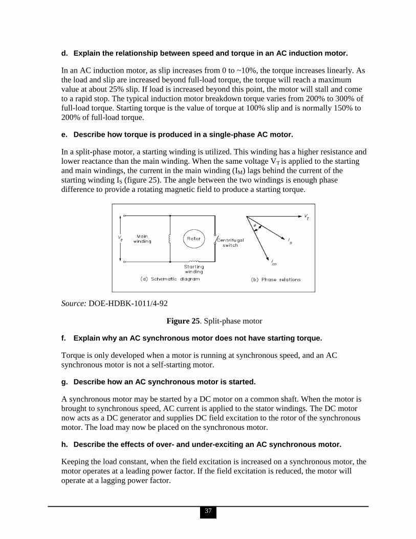
37
d. Explain the relationship between speed and torque in an AC induction motor.
In an AC induction motor, as slip increases from 0 to ~10%, the torque increases linearly. As
the load and slip are increased beyond full-load torque, the torque will reach a maximum
value at about 25% slip. If load is increased beyond this point, the motor will stall and come
to a rapid stop. The typical induction motor breakdown torque varies from 200% to 300% of
full-load torque. Starting torque is the value of torque at 100% slip and is normally 150% to
200% of full-load torque.
e. Describe how torque is produced in a single-phase AC motor.
In a split-phase motor, a starting winding is utilized. This winding has a higher resistance and
lower reactance than the main winding. When the same voltage VT is applied to the starting
and main windings, the current in the main winding (IM) lags behind the current of the
starting winding IS (figure 25). The angle between the two windings is enough phase
difference to provide a rotating magnetic field to produce a starting torque.
Source: DOE-HDBK-1011/4-92
Figure 25. Split-phase motor
f. Explain why an AC synchronous motor does not have starting torque.
Torque is only developed when a motor is running at synchronous speed, and an AC
synchronous motor is not a self-starting motor.
g. Describe how an AC synchronous motor is started.
A synchronous motor may be started by a DC motor on a common shaft. When the motor is
brought to synchronous speed, AC current is applied to the stator windings. The DC motor
now acts as a DC generator and supplies DC field excitation to the rotor of the synchronous
motor. The load may now be placed on the synchronous motor.
h. Describe the effects of over- and under-exciting an AC synchronous motor.
Keeping the load constant, when the field excitation is increased on a synchronous motor, the
motor operates at a leading power factor. If the field excitation is reduced, the motor will
operate at a lagging power factor.
38
i. State some applications of the following types of AC motors: Induction Single-phase Synchronous
Induction
Previous explanations of the operation of an AC motor dealt with induction motors. The
induction motor is the most commonly used AC motor in industrial applications because of
its simplicity, rugged construction, and relatively low manufacturing costs.
Single-Phase
Single-phase motors are used for very small commercial applications such as household
appliances and buffers.
Synchronous
Synchronous motors are used to accommodate large loads and to improve the power factor of
transformers in large industrial complexes.
j. Describe the differences in starting and operating characteristics of premium efficiency motors.
The following is taken from The Consortium for Energy Efficiency, Efficient Motors:
Selection and Application Considerations.
Premium efficiency motors offer increased reliability when starting, 20% to 60% more
copper in the windings, more and thinner laminations of higher-quality steel, optimized air
gap between stator and rotor, more efficient rotor-bar designs, reduced fan losses, higher
quality control (QC) during manufacturing, and longer cores to reduce I2R (resistance) losses.
Many efficient motors run cooler and are more likely to withstand voltage variations and
harmonics better than less-efficient motors. Many efficient motors have a slightly higher
power factor on average than their standard counterparts. Most efficient motors operate more
quietly than standard motors.
k. Describe the characteristics and operation of motor controllers.
Motor controllers range from simple toggle switches to complex systems using solenoids,
relays, and timers. The basic functions of a motor controller are to control and protect the
operation of a motor. This includes starting and stopping the motor, and protecting the motor
from overcurrent, undervoltage, and overheating conditions that would cause damage to the
motor. There are two basic categories of motor controllers: the manual controller and the
magnetic controller.
The manual controller is operated by hand and is provided with thermal and direct-acting
overload units to protect the motor from overload conditions. It is basically an ―ON-OFF‖
switch with overload protection. Manual controllers are normally used on small loads such as
machine tools, fans, blowers, pumps, and compressors. They do not provide low voltage
protection or low voltage release.
39
Magnetic controllers are operated from remote locations or operate automatically in response
to control signals. Because manual controllers cannot provide this type of control magnetic
controllers must be used for this type of application. Overload devices are incorporated into
magnetic controllers. These overload devices protect the motor from overcurrent conditions
that would be extremely harmful.
l. Explain the following motor terms: Nameplate revolutions per minute (RPM) National Electrical Manufacturers Association (NEMA) frame size Service factor Insulation class National Electrical Manufacturers Association (NEMA) design designation
(letter) Non-symmetrical load
The information for all the terms in this KSA, except for non-symmetrical load, is taken from
PDHonline, Understanding Motor Nameplate Information. The information for non-
symmetrical load is taken from DOE-HDBK-1011/3-92.
Nameplate Revolutions per Minute (RPM)
RPM of the motor is approximate speed under full-load conditions when voltage and
frequency are at the rated values. It is generally given as RPM on the nameplate. Multi-speed
shaded pole motors show maximum speed first, followed by the total number of speeds (e.g.,
3000/3-Spd). Multi-speed split-phase and capacitor-start motors have maximum speed shown
first, followed by the second speed (e.g., 1725/1140). The RPM rating for a gear motor
represents output shaft speed.
National Electrical Manufacturers Association (NEMA) Frame Size
Under the NEMA system, most motor dimensions are standardized and categorized by a
frame size number and letter designation. The number describes the mounting dimensions,
including foot hole mounting pattern, shaft diameter, shaft height, etc. It does not define
overall length and height, conduit box extension length, etc. NEMA frame size refers to
mounting only and has no direct bearing on the motor body diameter. As a frame number
becomes higher so in general does the physical size of the motor and the horsepower (HP).
There are many motors of the same HP built on different frames. Two digit frame numbers
represent the shaft height of the motor from the bottom of the base in sixteenths of an inch.
For example, a motor with a frame size of 56 will always have a shaft height above the base
of 3½ inches.
Service Factor
The service factor is a multiplier that indicates the amount of overload a motor can be
expected to handle. For example, a motor with a 1.0 service factor cannot be expected to
handle more than its nameplate HP on a continuous basis. Similarly, a motor with a 1.15
service factor can be expected to safely handle intermittent loads amounting to 15% beyond
its nameplate HP.

40
Insulation Class
Insulation class is an industry standard classification of the thermal tolerance of the motor
winding. Insulation is crucial in a motor. This is determined by the ambient temperature, the
heat generated at fully loaded conditions (temperature rise) and the thermal capacity of the
motor insulation. These materials are classified as A, B, F and H. The letter designation
indicates the thermal tolerance, or winding‘s ability to survive a specified operating
temperature for a specified period of time.
The classes are based on adding the ambient temperature and the operational heat created by
the motor. Insulation classes of a letter deeper into the alphabet perform better. For example,
class F insulation has a longer nominal life at a given operation temperature than class A, or
for a given life it can survive higher temperatures.
National Electrical Manufacturers Association (NEMA) Design Designation (letter)
There are standard definitions for designs A, B, C, and D.
Design A motors have normal starting torques, but high starting currents. This is useful for
applications with brief heavy overloads. Injection molding machines are good applications
for this type of motor
Design B motors are the most common. They feature normal starting torque combined with a
low starting current. These motors have sufficient locked rotor torques to start a wide variety
of industrial applications.
Design C motors have high starting torques with low starting currents. They are designed for
starting heavy loads due to their high locked rotor torques and high full load slip.
Design D motors have high starting torques with low starting currents, however they feature
high slip. This reduces power peaks. In the event that peak power is encountered, motor slip
will increase.
Non-symmetrical Load
A three-phase (3 ) system is a combination of three single-phase systems. In a 3 balanced
system, power comes from a 3 AC generator that produces three separate and equal
voltages, each of which is 120° out of phase with the other voltages.
An important property of a three-phase balanced system is that the phasor sum of the three
line or phase voltages is zero, and the phasor sum of the three line or phase currents is zero.
When the three load impedances are not equal to one another, the phasor sums and the
neutral current (In) are not zero, and the load is, therefore, unbalanced (i.e., non-
symmetrical). The imbalance occurs when an open or short circuit appears at the load.
m. Describe the importance of rotational checks prior to placing a three-phase motor in service.
The following is taken from DOE-HDBK-1011/4-92.
41
A magnetic field is produced in an AC motor through the action of the three-phase voltage
that is applied. Each of the three phases is 120° from the other phases. From one instant to
the next, the magnetic fields combine to produce a magnetic field whose position shifts
through a certain angle. At the end of one cycle of AC, the magnetic field will have shifted
through 360°, or one revolution. A rotational check prior to applying voltage ensures proper
clockwise rotation, thus eliminating the potential for current spikes, damage to the motor or
decreased efficiency.
5. Electrical personnel shall demonstrate a working level knowledge of AC reactive components, including inductive and capacitive reactance and phase relationships in reactive circuits.
The information for all of the KSAs of this competency statement is taken from DOE-
HDBK-1011/3-92.
a. Define the following: Inductive reactance Capacitive reactance Impedance Resonance Power factor Non-symmetrical load
Inductive Reactance
In an inductive AC circuit, the current is continually changing and is continuously inducing
an EMF. Because this EMF opposes the continuous change in the flowing current, its effect
is measured in ohms. This opposition of the inductance to the flow of an AC is called
inductive reactance (XL) and is measured in ohms.
Capacitive Reactance
Capacitive reactance is the opposition by a capacitor or a capacitive circuit to the flow of
current. The current flowing in a capacitive circuit is directly proportional to the capacitance
and to the rate at which the applied voltage is changing. The rate at which the applied voltage
is changing is determined by the frequency of the supply; therefore, if the frequency of the
capacitance of a given circuit is increased, the current flow will increase. It can also be said
that if the frequency or capacitance is increased, the opposition to current flow decreases;
therefore, capacitive reactance, which is the opposition to current flow, is inversely
proportional to frequency and capacitance. Capacitive reactance XC is measured in ohms, as
is inductive reactance
Impedance
No circuit is without some resistance, whether desired or not. Resistive and reactive
components in an AC circuit oppose current flow. The total opposition to current flow in a
circuit depends on its resistance, its reactance, and the phase relationships between them.
Impedance (Z) is defined as the total opposition to current flow in a circuit and is measured
in ohms.
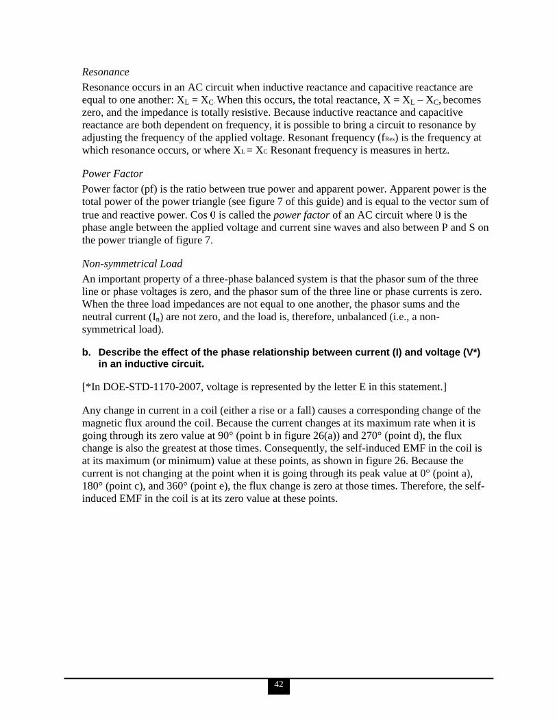
42
Resonance
Resonance occurs in an AC circuit when inductive reactance and capacitive reactance are
equal to one another: XL = XC. When this occurs, the total reactance, X = XL – XC, becomes
zero, and the impedance is totally resistive. Because inductive reactance and capacitive
reactance are both dependent on frequency, it is possible to bring a circuit to resonance by
adjusting the frequency of the applied voltage. Resonant frequency (fRes) is the frequency at
which resonance occurs, or where XL = XC Resonant frequency is measures in hertz.
Power Factor
Power factor (pf) is the ratio between true power and apparent power. Apparent power is the
total power of the power triangle (see figure 7 of this guide) and is equal to the vector sum of
true and reactive power. Cos is called the power factor of an AC circuit where is the
phase angle between the applied voltage and current sine waves and also between P and S on
the power triangle of figure 7.
Non-symmetrical Load
An important property of a three-phase balanced system is that the phasor sum of the three
line or phase voltages is zero, and the phasor sum of the three line or phase currents is zero.
When the three load impedances are not equal to one another, the phasor sums and the
neutral current (In) are not zero, and the load is, therefore, unbalanced (i.e., a non-
symmetrical load).
b. Describe the effect of the phase relationship between current (I) and voltage (V*) in an inductive circuit.
[*In DOE-STD-1170-2007, voltage is represented by the letter E in this statement.]
Any change in current in a coil (either a rise or a fall) causes a corresponding change of the
magnetic flux around the coil. Because the current changes at its maximum rate when it is
going through its zero value at 90° (point b in figure 26(a)) and 270° (point d), the flux
change is also the greatest at those times. Consequently, the self-induced EMF in the coil is
at its maximum (or minimum) value at these points, as shown in figure 26. Because the
current is not changing at the point when it is going through its peak value at 0° (point a),
180° (point c), and 360° (point e), the flux change is zero at those times. Therefore, the self-
induced EMF in the coil is at its zero value at these points.

43
Source: DOE-HDBK-1011/3-92
Figure 26. Current, self-induced EMF, and applied voltage in an inductive circuit
According to Lenz‘s law, the induced voltage always opposes the change in current.
Referring to figure 26, with the current at its maximum negative value (point a), the induced
EMF is at a zero value and falling. Thus, when the current rises in a positive direction (point
a to point c), the induced EMF is of opposite polarity to the applied voltage and opposes the
rise in current. Notice that as the current passes through its zero value (point b) the induced
voltage reaches its maximum negative value. With the current now at its maximum positive
value (point c), the induced EMF is at a zero value and rising. As the current is falling toward
its zero value at 180° (point c to point d), the induced EMF is of the same polarity as the
current and tends to keep the current from falling. When the current reaches a zero value, the
induced EMF is at its maximum positive value. Later, when the current is increasing from
zero to its maximum negative value at 360° (point d to point e), the induced voltage is of the
opposite polarity as the current and tends to keep the current from increasing in the negative
direction. Thus, the induced EMF can be seen to lag the current by 90°.
The value of the self-induced EMF varies as a sine wave and lags the current by 90°, as
shown in figure 26. The applied voltage must be equal and opposite to the self-induced EMF
at all times; therefore, the current lags the applied voltage by 90° in a purely inductive circuit.
If the applied voltage is represented by a vector rotating in a counterclockwise direction, then
the current can be expressed as a vector that is lagging the applied voltage by 90°. Diagrams
of this type are referred to as phasor diagrams.
Figure 27(b), a phasor diagram, shows the applied voltage (V) vector leading (above) the
current (I) vector by the amount of the phase angle differential due to the relationship
between voltage and current in an inductive circuit.
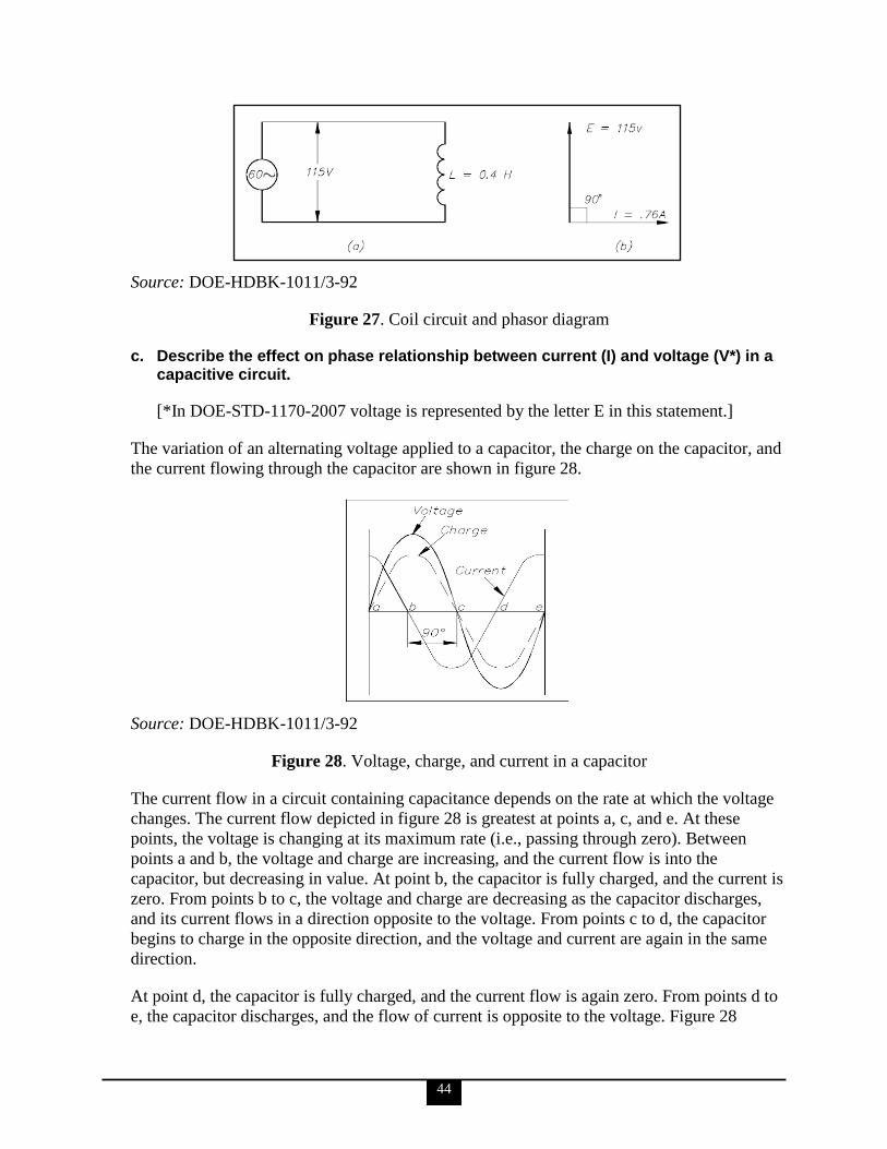
44
Source: DOE-HDBK-1011/3-92
Figure 27. Coil circuit and phasor diagram
c. Describe the effect on phase relationship between current (I) and voltage (V*) in a capacitive circuit.
[*In DOE-STD-1170-2007 voltage is represented by the letter E in this statement.]
The variation of an alternating voltage applied to a capacitor, the charge on the capacitor, and
the current flowing through the capacitor are shown in figure 28.
Source: DOE-HDBK-1011/3-92
Figure 28. Voltage, charge, and current in a capacitor
The current flow in a circuit containing capacitance depends on the rate at which the voltage
changes. The current flow depicted in figure 28 is greatest at points a, c, and e. At these
points, the voltage is changing at its maximum rate (i.e., passing through zero). Between
points a and b, the voltage and charge are increasing, and the current flow is into the
capacitor, but decreasing in value. At point b, the capacitor is fully charged, and the current is
zero. From points b to c, the voltage and charge are decreasing as the capacitor discharges,
and its current flows in a direction opposite to the voltage. From points c to d, the capacitor
begins to charge in the opposite direction, and the voltage and current are again in the same
direction.
At point d, the capacitor is fully charged, and the current flow is again zero. From points d to
e, the capacitor discharges, and the flow of current is opposite to the voltage. Figure 28
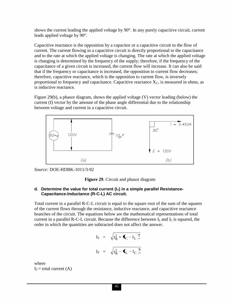
45
shows the current leading the applied voltage by 90°. In any purely capacitive circuit, current
leads applied voltage by 90°.
Capacitive reactance is the opposition by a capacitor or a capacitive circuit to the flow of
current. The current flowing in a capacitive circuit is directly proportional to the capacitance
and to the rate at which the applied voltage is changing. The rate at which the applied voltage
is changing is determined by the frequency of the supply; therefore, if the frequency of the
capacitance of a given circuit is increased, the current flow will increase. It can also be said
that if the frequency or capacitance is increased, the opposition to current flow decreases;
therefore, capacitive reactance, which is the opposition to current flow, is inversely
proportional to frequency and capacitance. Capacitive reactance XC, is measured in ohms, as
is inductive reactance.
Figure 29(b), a phasor diagram, shows the applied voltage (V) vector leading (below) the
current (I) vector by the amount of the phase angle differential due to the relationship
between voltage and current in a capacitive circuit.
Source: DOE-HDBK-1011/3-92
Figure 29. Circuit and phasor diagram
d. Determine the value for total current (IT) in a simple parallel Resistance-Capacitance-Inductance (R-C-L) AC circuit.
Total current in a parallel R-C-L circuit is equal to the square root of the sum of the squares
of the current flows through the resistance, inductive reactance, and capacitive reactance
branches of the circuit. The equations below are the mathematical representations of total
current in a parallel R-C-L circuit. Because the difference between IL and IC is squared, the
order in which the quantities are subtracted does not affect the answer.
IT = 2
LC2R III
IT = 2
CL2R
III
where
IT = total current (A)
46
IR = current through resistance leg of circuit (A)
IC = current through capacitive reactance leg of circuit (A)
IL = current through inductive reactance leg of circuit (A)
e. Describe the relationship between apparent, true, and reactive power.
Apparent power (S) is the total power delivered to the electrical circuit, and is the vector sum
of the true and reactive powers. True power (P) is the power consumed by the resistive loads
in an electrical circuit. Reactive power (Q) is the power consumed in an AC circuit because
of the expansion and collapse of magnetic (inductive) and electrostatic (capacitive) fields.
The power triangle in figure 7 represents comparable values that can be used directly to find
the efficiency level of generated power to usable power, which is expressed as the power
factor. Apparent power, reactive power, and true power can be calculated by using the DC
equivalent (RMS value) of the AC voltage and current components along with the power
factor.
f. Describe the indications of an unbalanced load in a three-phase power system.
In a fault condition or during asymmetrical loading of circuits, the neutral connection in a
wye-connected load will carry more current than the phase under a balanced load.
Unbalanced three-phase circuits are indicated by abnormally high currents in one or more of
the phases. This may cause damage to equipment if the imbalance is allowed to continue.
g. Discuss circuit considerations required for non-symmetrical loads.
An important property of a three-phase balanced system is that the phasor sum of the three
line or phase voltages is zero, and the phasor sum of the three line or phase currents is zero.
When the three load impedances are not equal to one another, the phasor sums and the
neutral current (In) are not zero, and the load is, therefore, unbalanced. The imbalance occurs
when an open or short circuit appears at the load.
If a three-phase system has an unbalanced load and an unbalanced power source, the methods
of fixing the system are complex.
6. Electrical personnel shall demonstrate a working level knowledge of electrical transmission and distribution systems (IEEE Brown Book; reference IEEE Std-399).
a. Explain the differences between transmission and distribution systems.
The following is taken from the OSHA Electric Power Generation, Transmission, and
Distribution Industry eTool - Illustrated Glossary.
A transmission system consists of substations that receive power from the generating stations
and transmission lines that deliver this power to the distribution system.
A distribution system consists of all the facilities and equipment connecting a transmission
system to the customer‘s equipment. A typical distribution system can consist of substations,
47
distribution feeder circuits, switches, protective equipment, primary circuits, distribution
transformers, secondaries and circuits.
b. Identify and discuss the advantages and disadvantages associated with underground and above-ground distribution systems.
The following is taken from Florida Power & Light Company website FAQs.
While underground facilities are not as susceptible to wind and debris-blown
damage, they are more susceptible to water intrusion and local flood damage,
which can make repairs more time consuming and costly.
Overhead facility damage is easier to locate than underground and can
generally be repaired quicker.
Underground interruptions may be less frequent, but typically last longer due
to more complex repair requirements.
Following recent hurricanes, the areas that took the longest to repair were
generally those served by underground facilities still flooded days after the
storm passed.
Damage and corrosion of underground electrical systems often shows up days
or even months later, causing additional outages and inconvenience to
customers.
Storm winds can damage both types of systems causing outages. Overhead
systems face outages resulting from trees and debris blowing into lines.
Underground systems face outages from trees collapsing on above-ground
transformers and switch boxes or from tree root systems uprooting buried
cable when trees topple.
Also, we often forget that while a neighborhood may be locally served by
underground cable, all electric service eventually comes back above-ground
and connects to overhead service, either in the neighborhood next door, or
further down the street where overhead main lines and transmission lines
move power from power plants and substations into our neighborhoods. Thus,
exposure to above-ground electric service from weather, animals, and trees is
never fully eliminated.
c. Describe the function and importance of the following control and protective devices: Circuit breakers Protective relays Fuses Transient protection
48
The information for all the terms in this KSA, except for transient protection, is taken from
DOE-HDBK-1011/4-92. The information for transient protection is taken from D & B Power
Associates, Inc., Surge and Transient Protection.
Circuit Breakers
The purpose of a circuit breaker is to break the circuit and stop the current flow when the
current exceeds a predetermined value without causing damage to the circuit or the circuit
breaker. Circuit breakers are commonly used in place of fuses and sometimes eliminate the
need for a switch. A circuit breaker differs from a fuse in that it ―trips‖ to break the circuit
and may be reset, while a fuse melts and must be replaced.
Protective Relays
Protective relays are designed to cause the prompt removal of any part of a power system that
might cause damage or interfere with the effective and continuous operation of the rest of the
system. Protective relays are aided in this task by circuit breakers that are capable of
disconnecting faulty components or subsystems.
Protective relays can be used for types of protection other than short circuit or overcurrent.
The relays can be designed to protect generating equipment and electrical circuits from any
undesirable condition, such as undervoltage, underfrequency, or interlocking system lineups.
There are only two operating principles for protective relays: (1) electromagnetic attraction
and (2) electromagnetic induction. Electromagnetic attraction relays operate by a plunger
being drawn up into a solenoid or an armature that is attracted to the poles of an
electromagnet. This type of relay can be actuated by either DC or AC systems.
Electromagnetic induction relays operate on the induction motor principle whereby torque is
developed by induction in a rotor. This type of relay can be used only in AC circuits.
Fuses
A fuse is a device that protects a circuit only from an overcurrent condition. It has a fusible
link directly heated and destroyed by the current passing through it. A fuse contains a
current-carrying element sized so that the heat generated by the flow of normal current
through it does not cause it to melt the element; however, when an overcurrent or short-
circuit current flows through the fuse, the fusible link will melt and open the circuit.
Transient Protection
Power surges and transients are electrical fluctuations caused by lightning or other power
utility issues. The surge or transient is conducted through both power and data lines and can
damage or destroy downstream equipment. Vulnerable circuitry exists in an extremely hostile
environment. A properly applied surge protector can prevent equipment damage, downtime,
and data corruption.
d. Compare and contrast the characteristics of three-phase and single-phase distribution systems.
The following is taken from DOE-HDBK-1011/4-92.
49
Unlike the single-phase wiring scheme that must make a provision for a neutral leg and
separate ground, the three-phase system needs neither a separate neutral nor a ground to
operate safely. However, to prevent any unsafe condition, all 3- and 4-wire, three-phase
systems can include an effective ground path. As with a single-phase, only the secondary side
of the transformer and its connected load need to be studied.
A three-phase system is a combination of three single-phase systems. In a three-phase
balanced system, power comes from a three-phase AC generator that produces three separate
and equal voltages each of which is 120° out of phase with the other voltages. Three-phase
equipment (motors, transformers, etc.) weighs less than single-phase equipment of the same
power rating. They have a wide range of voltages and can be used for single-phase loads.
Three-phase equipment is smaller, weighs less, and is more efficient than single-phase
equipment.
One of the major advantages of three-phase systems is lower current requirements for load
capacity. For example, a single-phase, 2 hp motor operating at 240 volts might require
6 amps for operation, whereas a three-phase, 2 hp motor operating at 240 volts may require
less than 4 amps, resulting in a line capacity reduction of almost 35% to 50%.
e. Discuss the principles associated with ensuring continual power availability during electrical outages.
The following is taken from IEEE Std 446-1995.
The nature of electric power failures, interruptions, and their duration covers a range in time
from microseconds to days. Voltage excursions occur within a range from 20 times normal
(or more) to a complete absence of voltage. Frequency excursions can vary as widely in
many forms, from harmonics to DC. These variables occur due to a multitude of conditions
both in the power system ahead of the user‘s service entrance and following the service
entrance within the user‘s area of distribution.
Such elements as lightning, automobiles striking power poles, ice storms, tornadoes,
switching to alternate lines, and equipment failure are but a few of the causes of interruptions
in the electric power supply ahead of the service entrance.
Within the user‘s area of distribution are such elements as short and open circuits, undersized
feeders, equipment failures, operator errors, temporary overloads, single-phasing unbalanced
feeders, fire, switching, and many other causes of power interruption or failure.
The following 4 systems are available to ensure continual power. The needs of the individual
facility affected must be considered in making a decision as to which method or combination
of methods is appropriate for that facility. Once installed, protection, grounding and
maintenance of these systems is critical to ensure they will be available when needed.
Emergency power systems are of the following two basic types:
An electric power source separate from the prime source of power, operating in
parallel, which maintains power to the critical loads should the prime source fail.
50
An available reliable power source to which critical loads are rapidly switched
automatically when the prime source of power fails.
Standby power systems are made up of the following main components:
An alternative reliable source of electric energy separate from the prime power
source.
Starting and regulating control if onsite standby generation is selected as the source.
Controls that transfer loads from the prime or emergency power source to the standby
source.
Battery systems store energy in electrochemical cells that convert chemical energy into
electrical energy.
Mechanical systems store energy in the form of kinetic energy in a rotating mass. This energy
is converted to useful power by using the kinetic energy to turn an AC generator.
f. Explain the following terms as they relate to power systems: Fault current Available fault current Fault duty
The following is taken from IEEE Std 666-2007.
Fault Current
Fault current, also called short-circuit current, describes current flow during a short. Fault
current passes through all components in the affected circuit. Fault current is generally very
large and, therefore, hazardous. Only the combined impedance of the object responsible for
the short, the wire, and the transformer limits its magnitude.
Available Fault Current
Fault current calculations are a critical piece of the electrical design/engineering puzzle for
electrical distribution systems in commercial and industrial installations. A fault current
calculation determines the maximum available current that will be available (the available
fault current) at a given node or location. Once the fault currents have been calculated, then
overcurrent protection equipment, breakers, and fuses with a fault current rating equal to or
greater than those values can be selected.
Fault Duty
Fault duties are classified as type 1, type 2, or type 3, and pertain to analysis levels that are
explained in greater detail in IEEE Std 666-2007, IEEE Design Guide for Electric Power
Service Systems for Generating Stations.
g. Discuss the safety considerations associated with high voltage transmission systems.
High voltage is defined by DOE-HDBK-1011/4-92 as ―the voltage that is above
15,000 volts.‖
51
The following is taken from DOE-HDBK-1092-2004 and delineates the responsibilities of
workers and supervisors.
Workers
The greatest responsibility for a worker‘s safety lies directly with the worker. This means
that all workers are responsible for performing their work in a manner that does not endanger
themselves, their co-workers, or others in the area and for complying with safety rules and
requirements. Workers should not rely solely on the care exercised by another for their
protection. Workers are encouraged to contribute to the safety program and bring to the
attention of their supervisors or safety representative any condition they believe is unsafe.
Other safety responsibilities of workers include the following:
The worker should examine the work area for existing hazards and proceed in a safe
manner.
When seen in a dangerous situation, fellow workers should be warned in such a
manner as to avoid confusing, startling, or suddenly alarming them.
Before climbing poles, ladders, or other such structures or before working on
scaffolds, workers shall make a careful inspection to determine whether the structures
are safe and are properly supported. Workers should not carry anything in their hands
while ascending or descending ladders. Small objects or tools may be carried in
pockets or pouches. Larger objects, however, should be raised or lowered by use of
hand lines or ropes and blocks. Others working nearby or below should remain out of
line of the work area in case anything should accidentally be dropped.
It is the responsibility of each worker to attend safety meetings. Workers should also
make a practice of learning safety information made available to them that will help
them perform their work more safely.
The worker shall report to the supervisor any personal injury as defined by the facility
as soon as possible.
The worker should exercise care and good judgment when lifting heavy material,
obtaining help if the object is too heavy or awkward for one person to handle.
Supervisors
Supervisors are responsible for knowing and implementing applicable safety policies and
directives and taking action as required to provide for the safety of the personnel and
operations they supervise. This includes taking positive action to determine and reduce, as
necessary, the hazards associated with their operations; instructing employees in safe work
methods and associated safety requirements; allowing only those employees that are
qualified for the work to perform the work; and ensuring that employees perform their work
safely. Supervisors shall be responsible for the safety of all employees under their
supervision. They shall enforce the rules that apply to the hazards involved.
Supervisors shall make certain that each new or transferred employee is instructed in the safe
practices pertaining to his or her work. Supervisors shall ensure that the appropriate
employees receive instruction in appropriate emergency techniques, such as cardio-
pulmonary resuscitation, first aid, pole top, and confined space rescue, warranted by the
employee‘s duties.
52
Other duties of supervisors include the following:
Provide instructions on safe practices for the crew and see that they are followed.
Periodically examine supervised employees on their knowledge of the safety rules
and approved emergency techniques.
Not allow a worker to perform any task that cannot be performed safely or for which
the worker is not qualified.
Report every injury in the established manner prescribed for the facility.
Be responsible for the care and proper use of all protective devices.
Be responsible for proper posting of hazardous work areas as a safeguard to those
supervised. Under no circumstances shall the supervisor allow work to continue if
safety precautions are ignored.
Designate a qualified worker to be in charge of work during the supervisor‘s absence.
The supervisor should not leave the job while dangerous work is in progress.
Coach and direct employees who are working near exposed, energized wires,
equipment, or apparatus.
Prescribe, along with employees, the appropriate personal protective equipment
(PPE) when establishing safety related work practices.
h. Explain the requirements for and uses of alternate power supplies.
The following is taken from IEEE Std 446-1995. Much greater detail is available from this
source.
Alternate power supplies include emergency power systems, standby power systems, battery
systems and mechanical systems. These supplies provide response, recovery, and continuity
of operations during emergencies and/or outages.
Requirements for alternate power supplies include
protection for their individual components from short circuits;
grounding requirements, including the coordinated design, proper installation, and
maintenance of components such as circuit-protective equipment, systems grounding,
equipment grounding and transfer switching equipment;
preventive maintenance (PM) for electrical equipment, which consists of planned
inspections, testing, cleaning, drying, monitoring, adjusting, corrective modification,
and minor repair in order to maintain equipment in optimum operating condition and
maximum reliability.
i. Discuss the uses of different voltages in a facility.
The following is taken from IEEE Std 141-1993.
Standard nominal system voltages for the United States
These voltages and their associated tolerance limits are listed in ANSI C84.1-1989 for
voltages from 120 V to 230 000 V and in ANSI C92.2-1987 for voltages above 230 kV
nominal.
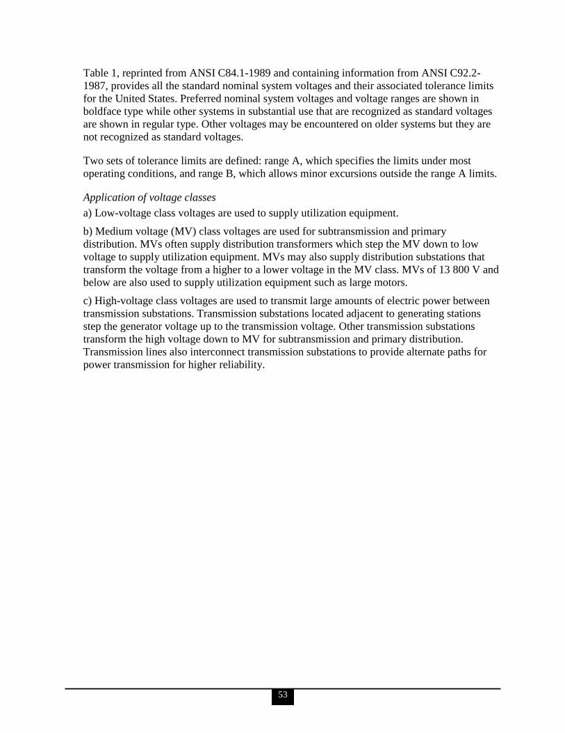
53
Table 1, reprinted from ANSI C84.1-1989 and containing information from ANSI C92.2-
1987, provides all the standard nominal system voltages and their associated tolerance limits
for the United States. Preferred nominal system voltages and voltage ranges are shown in
boldface type while other systems in substantial use that are recognized as standard voltages
are shown in regular type. Other voltages may be encountered on older systems but they are
not recognized as standard voltages.
Two sets of tolerance limits are defined: range A, which specifies the limits under most
operating conditions, and range B, which allows minor excursions outside the range A limits.
Application of voltage classes
a) Low-voltage class voltages are used to supply utilization equipment.
b) Medium voltage (MV) class voltages are used for subtransmission and primary
distribution. MVs often supply distribution transformers which step the MV down to low
voltage to supply utilization equipment. MVs may also supply distribution substations that
transform the voltage from a higher to a lower voltage in the MV class. MVs of 13 800 V and
below are also used to supply utilization equipment such as large motors.
c) High-voltage class voltages are used to transmit large amounts of electric power between
transmission substations. Transmission substations located adjacent to generating stations
step the generator voltage up to the transmission voltage. Other transmission substations
transform the high voltage down to MV for subtransmission and primary distribution.
Transmission lines also interconnect transmission substations to provide alternate paths for
power transmission for higher reliability.

54
Table 1. Standard nominal system voltages and voltage ranges
Source: ANSI C84.1-1989
55
j. Discuss the reasons for using single-phase versus three-phase power systems in a facility.
The following is taken from DOE-HDBK-1011/3-92.
Three-phase power systems are used in the industry because three-phase circuits weigh less
than single-phase circuits of the same power rating; they have a wide range of voltages and
yet can also be used for single-phase loads; they are smaller; and they are overall more
efficient than single-phase equipment (three-phase systems have more load capacity for less
current demand).
However, despite the advantages of three-phase systems, most residential and much
commercial power and lighting loads are single-phase. Single-phase systems are generally
less expensive and are, therefore, more commonly used in residential and commercial
systems. Examples include air-conditioning loads, lighting, receptacles, and utilization
equipment (e.g., toasters, microwave ovens, washing machines, refrigerators, etc.).
k. Discuss which systems would benefit from line filtering.
The information for KSAs ‗k‘ through ‗o‘ is taken from IEEE Std. 399-1997.
Many types of filters are applied in power systems for different purposes. A single-tuned
filter is used to suppress a specific harmonic at or near the tuned frequency. High-pass filters
can be of first, second, or third order. The second-order filter is often used to suppress higher
frequencies. A more recent type of high-pass filter, a C-type filter, is becoming popular due
to its smaller losses at the fundamental frequency. Application of filters is one of the
commonly employed solutions to limit the effects of harmonics. Other remedial measures
such as moving the disturbing loads to higher voltage levels, reinforcing the system,
changing capacitor sizes, and adding tuning reactors to capacitor banks are also used. In any
case, economics will dictate the most appropriate solution. Recent studies advocate the
utilization of active filtering in an effort to counter the injected harmonics close to the source,
but primarily in low-voltage systems.
l. Discuss the types of noise for which systems benefiting from line filtering would be susceptible to without implementation of line filtering.
Noise is undesirable electrical signals in an electrical or electronic circuit. It can be introduced
into a circuit from a multitude of sources. In a three-phase system, neutral-to-ground voltage
or ground circuit can be a result of common mode noise. Transverse mode noise occurs in
phase on all 3-phase conductors and neutral. Electromagnetic interference (EMI) and RF
interference (RFI) can also appear as transverse or common mode noise.
m. Define the terms harmonics, positive, negative and zero sequence currents.
Harmonics
Harmonics are those voltages or currents whose frequencies are integer multiples of the
fundamental frequency. The fundamental frequency (usually 60 Hz) is the predominant,
intended frequency of a power system. Harmonics distort and change the magnitude of the
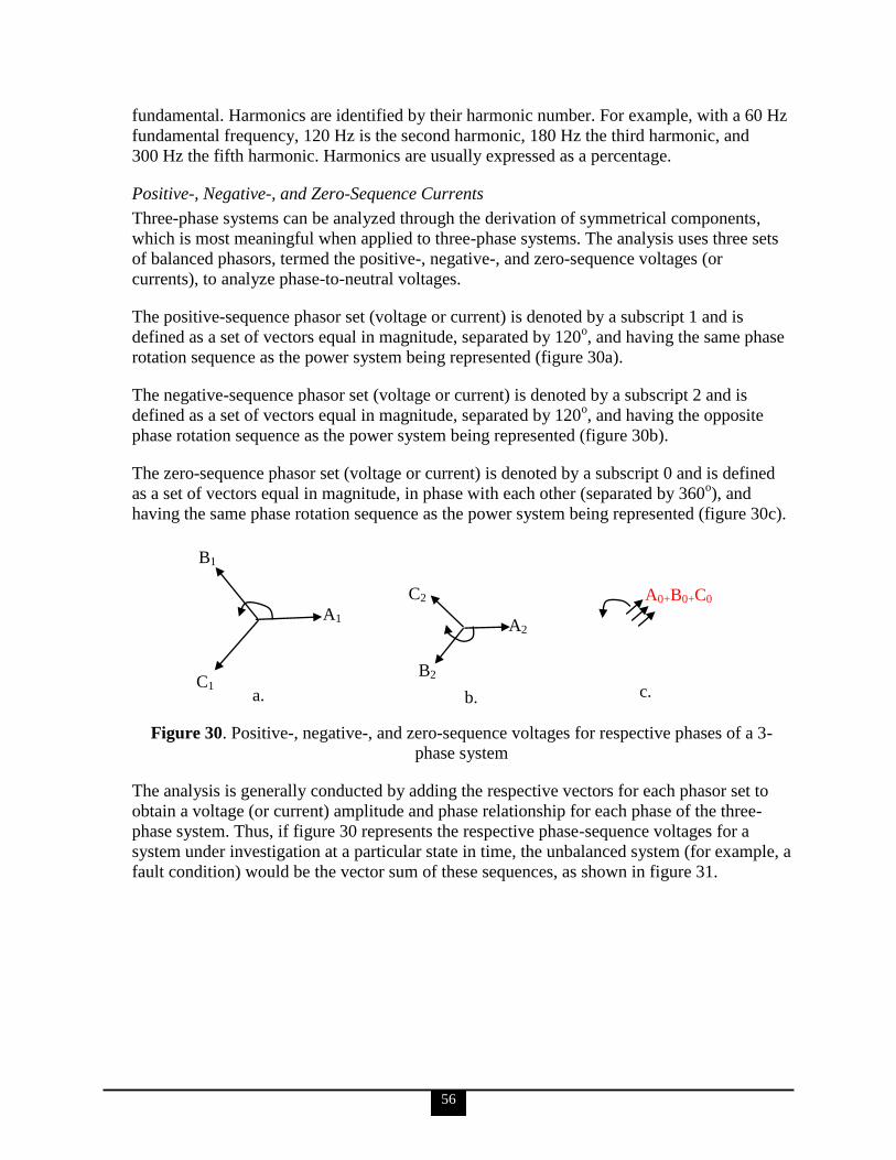
56
fundamental. Harmonics are identified by their harmonic number. For example, with a 60 Hz
fundamental frequency, 120 Hz is the second harmonic, 180 Hz the third harmonic, and
300 Hz the fifth harmonic. Harmonics are usually expressed as a percentage.
Positive-, Negative-, and Zero-Sequence Currents
Three-phase systems can be analyzed through the derivation of symmetrical components,
which is most meaningful when applied to three-phase systems. The analysis uses three sets
of balanced phasors, termed the positive-, negative-, and zero-sequence voltages (or
currents), to analyze phase-to-neutral voltages.
The positive-sequence phasor set (voltage or current) is denoted by a subscript 1 and is
defined as a set of vectors equal in magnitude, separated by 120o, and having the same phase
rotation sequence as the power system being represented (figure 30a).
The negative-sequence phasor set (voltage or current) is denoted by a subscript 2 and is
defined as a set of vectors equal in magnitude, separated by 120o, and having the opposite
phase rotation sequence as the power system being represented (figure 30b).
The zero-sequence phasor set (voltage or current) is denoted by a subscript 0 and is defined
as a set of vectors equal in magnitude, in phase with each other (separated by 360o), and
having the same phase rotation sequence as the power system being represented (figure 30c).
Figure 30. Positive-, negative-, and zero-sequence voltages for respective phases of a 3-
phase system
The analysis is generally conducted by adding the respective vectors for each phasor set to
obtain a voltage (or current) amplitude and phase relationship for each phase of the three-
phase system. Thus, if figure 30 represents the respective phase-sequence voltages for a
system under investigation at a particular state in time, the unbalanced system (for example, a
fault condition) would be the vector sum of these sequences, as shown in figure 31.
B1
C1
A1
C2
A2
B2
A0+B0+C0
a. b.
c.
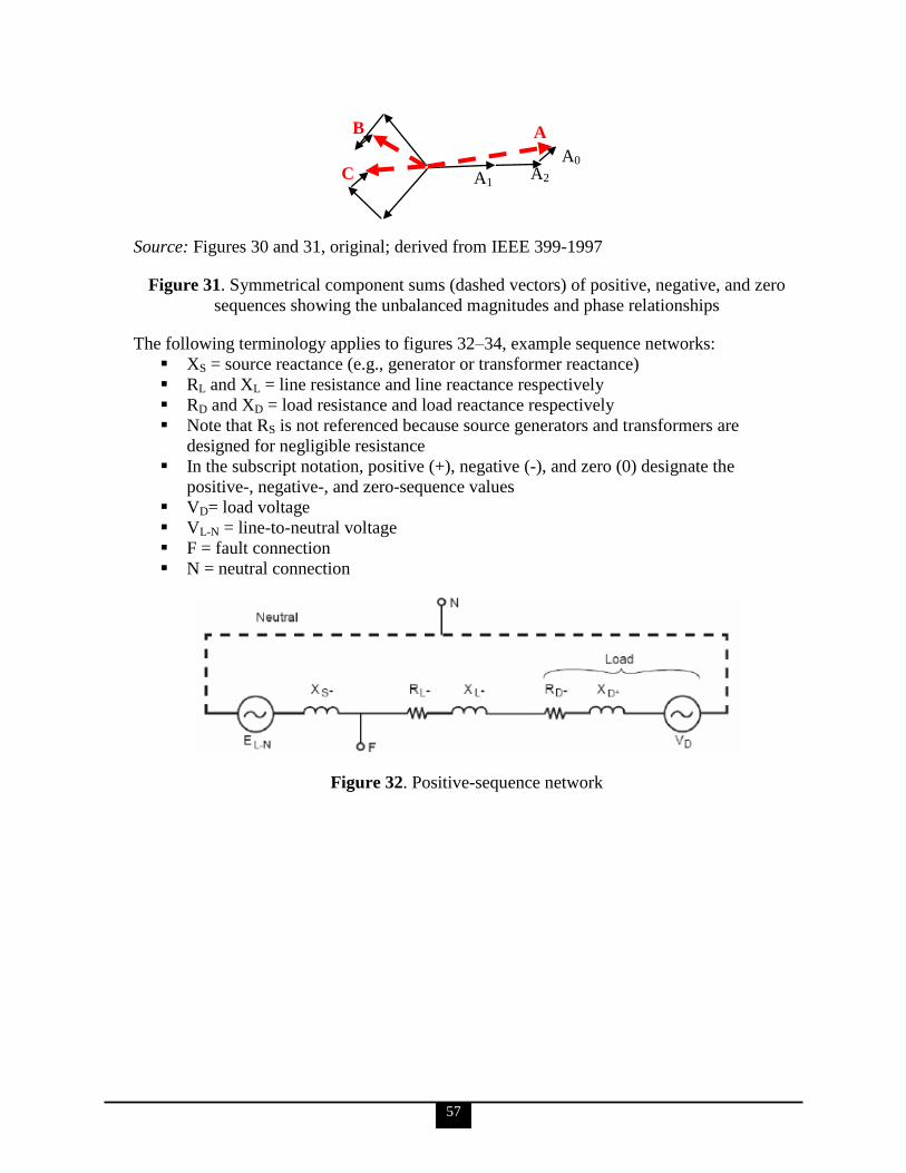
57
Source: Figures 30 and 31, original; derived from IEEE 399-1997
Figure 31. Symmetrical component sums (dashed vectors) of positive, negative, and zero
sequences showing the unbalanced magnitudes and phase relationships
The following terminology applies to figures 32–34, example sequence networks:
XS = source reactance (e.g., generator or transformer reactance)
RL and XL = line resistance and line reactance respectively
RD and XD = load resistance and load reactance respectively
Note that RS is not referenced because source generators and transformers are
designed for negligible resistance
In the subscript notation, positive (+), negative (-), and zero (0) designate the
positive-, negative-, and zero-sequence values
VD= load voltage
VL-N = line-to-neutral voltage
F = fault connection
N = neutral connection
Figure 32. Positive-sequence network
A0 C
B A
A2 A1
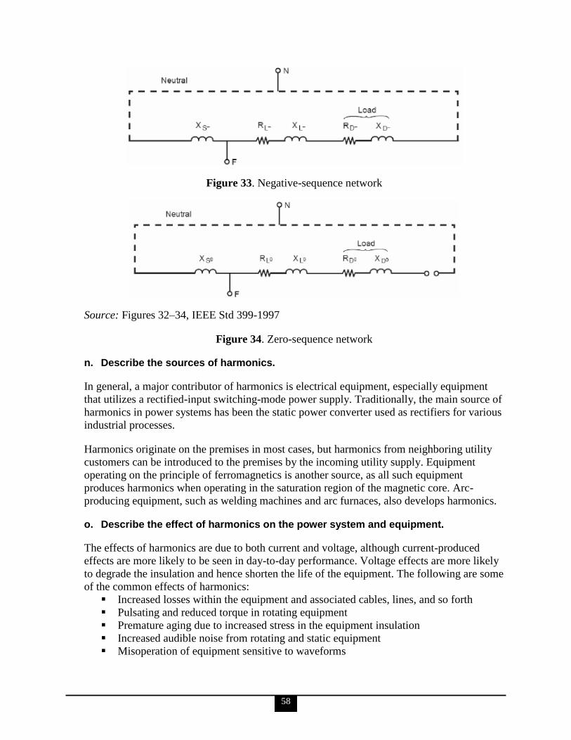
58
Figure 33. Negative-sequence network
Source: Figures 32–34, IEEE Std 399-1997
Figure 34. Zero-sequence network
n. Describe the sources of harmonics.
In general, a major contributor of harmonics is electrical equipment, especially equipment
that utilizes a rectified-input switching-mode power supply. Traditionally, the main source of
harmonics in power systems has been the static power converter used as rectifiers for various
industrial processes.
Harmonics originate on the premises in most cases, but harmonics from neighboring utility
customers can be introduced to the premises by the incoming utility supply. Equipment
operating on the principle of ferromagnetics is another source, as all such equipment
produces harmonics when operating in the saturation region of the magnetic core. Arc-
producing equipment, such as welding machines and arc furnaces, also develops harmonics.
o. Describe the effect of harmonics on the power system and equipment.
The effects of harmonics are due to both current and voltage, although current-produced
effects are more likely to be seen in day-to-day performance. Voltage effects are more likely
to degrade the insulation and hence shorten the life of the equipment. The following are some
of the common effects of harmonics:
Increased losses within the equipment and associated cables, lines, and so forth
Pulsating and reduced torque in rotating equipment
Premature aging due to increased stress in the equipment insulation
Increased audible noise from rotating and static equipment
Misoperation of equipment sensitive to waveforms
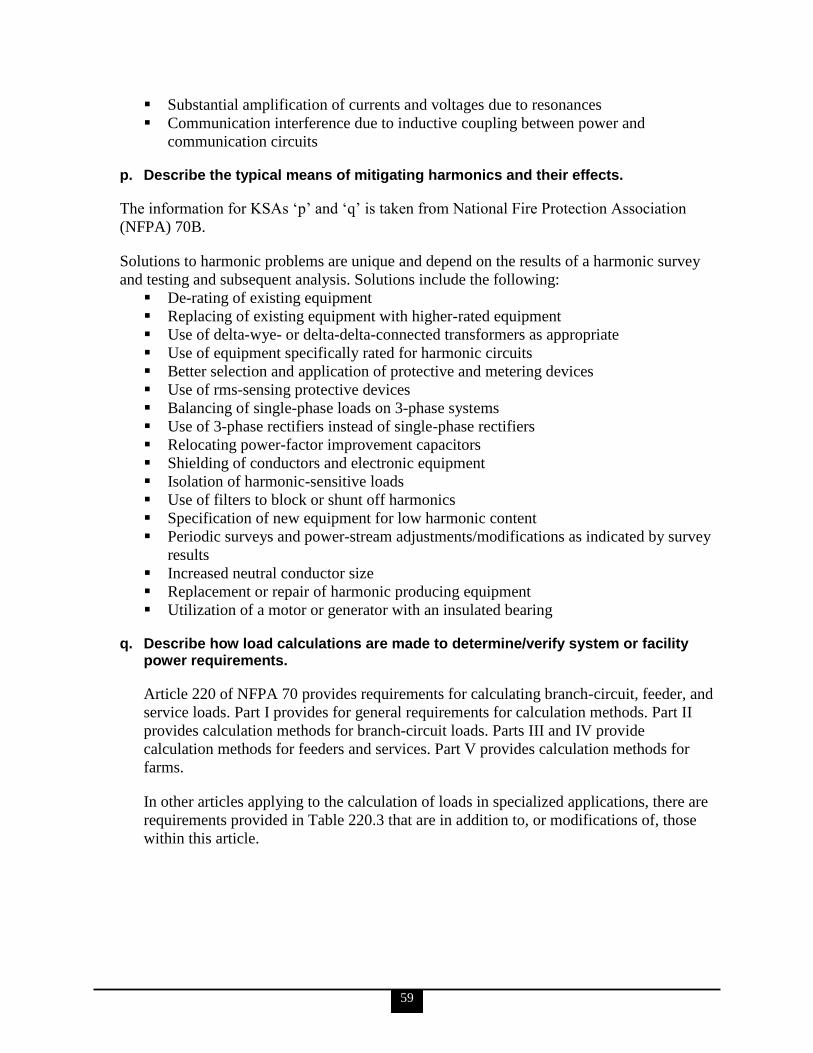
59
Substantial amplification of currents and voltages due to resonances
Communication interference due to inductive coupling between power and
communication circuits
p. Describe the typical means of mitigating harmonics and their effects.
The information for KSAs ‗p‘ and ‗q‘ is taken from National Fire Protection Association
(NFPA) 70B.
Solutions to harmonic problems are unique and depend on the results of a harmonic survey
and testing and subsequent analysis. Solutions include the following:
De-rating of existing equipment
Replacing of existing equipment with higher-rated equipment
Use of delta-wye- or delta-delta-connected transformers as appropriate
Use of equipment specifically rated for harmonic circuits
Better selection and application of protective and metering devices
Use of rms-sensing protective devices
Balancing of single-phase loads on 3-phase systems
Use of 3-phase rectifiers instead of single-phase rectifiers
Relocating power-factor improvement capacitors
Shielding of conductors and electronic equipment
Isolation of harmonic-sensitive loads
Use of filters to block or shunt off harmonics
Specification of new equipment for low harmonic content
Periodic surveys and power-stream adjustments/modifications as indicated by survey
results
Increased neutral conductor size
Replacement or repair of harmonic producing equipment
Utilization of a motor or generator with an insulated bearing
q. Describe how load calculations are made to determine/verify system or facility power requirements.
Article 220 of NFPA 70 provides requirements for calculating branch-circuit, feeder, and
service loads. Part I provides for general requirements for calculation methods. Part II
provides calculation methods for branch-circuit loads. Parts III and IV provide
calculation methods for feeders and services. Part V provides calculation methods for
farms.
In other articles applying to the calculation of loads in specialized applications, there are
requirements provided in Table 220.3 that are in addition to, or modifications of, those
within this article.
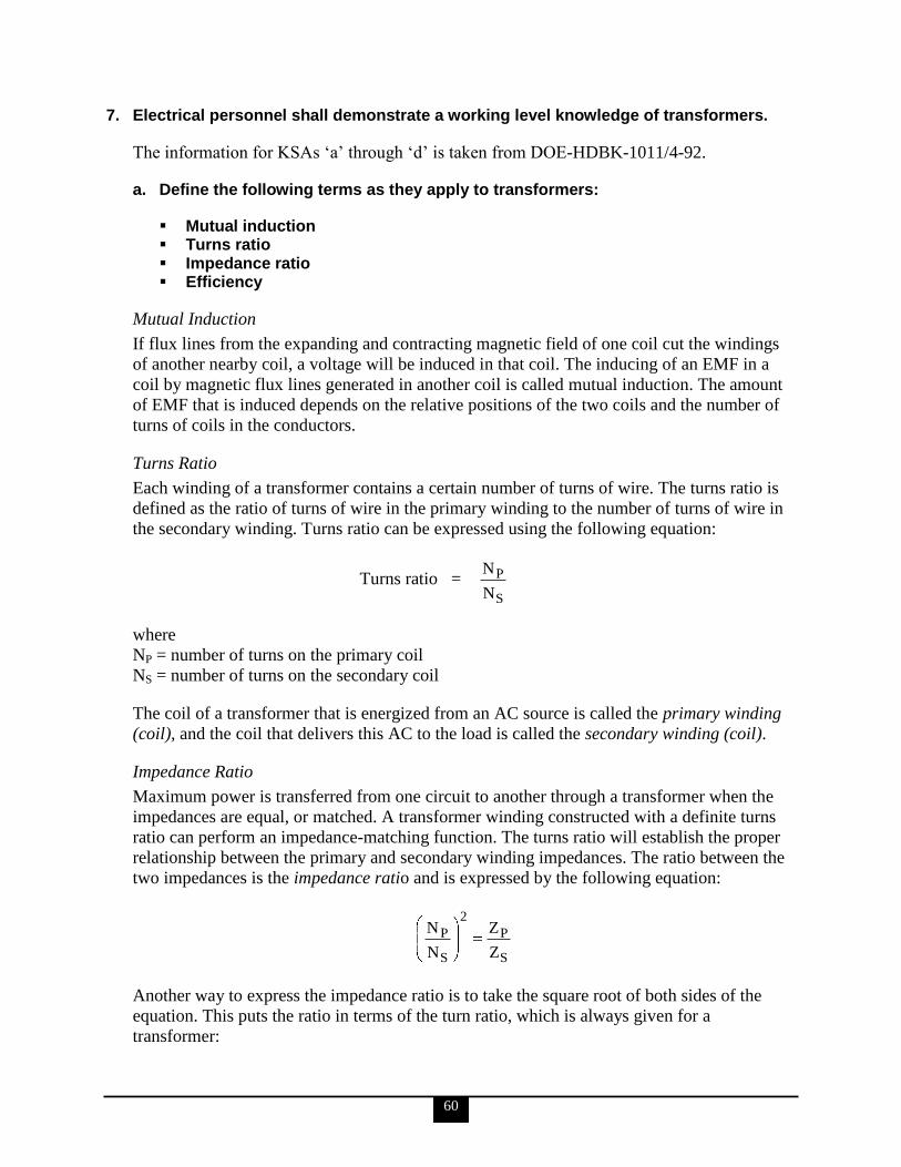
60
7. Electrical personnel shall demonstrate a working level knowledge of transformers.
The information for KSAs ‗a‘ through ‗d‘ is taken from DOE-HDBK-1011/4-92.
a. Define the following terms as they apply to transformers:
Mutual induction Turns ratio Impedance ratio Efficiency
Mutual Induction
If flux lines from the expanding and contracting magnetic field of one coil cut the windings
of another nearby coil, a voltage will be induced in that coil. The inducing of an EMF in a
coil by magnetic flux lines generated in another coil is called mutual induction. The amount
of EMF that is induced depends on the relative positions of the two coils and the number of
turns of coils in the conductors.
Turns Ratio
Each winding of a transformer contains a certain number of turns of wire. The turns ratio is
defined as the ratio of turns of wire in the primary winding to the number of turns of wire in
the secondary winding. Turns ratio can be expressed using the following equation:
Turns ratio = S
P
N
N
where
NP = number of turns on the primary coil
NS = number of turns on the secondary coil
The coil of a transformer that is energized from an AC source is called the primary winding
(coil), and the coil that delivers this AC to the load is called the secondary winding (coil).
Impedance Ratio
Maximum power is transferred from one circuit to another through a transformer when the
impedances are equal, or matched. A transformer winding constructed with a definite turns
ratio can perform an impedance-matching function. The turns ratio will establish the proper
relationship between the primary and secondary winding impedances. The ratio between the
two impedances is the impedance ratio and is expressed by the following equation:
S
P
2
S
P
Z
Z
N
N
Another way to express the impedance ratio is to take the square root of both sides of the
equation. This puts the ratio in terms of the turn ratio, which is always given for a
transformer:
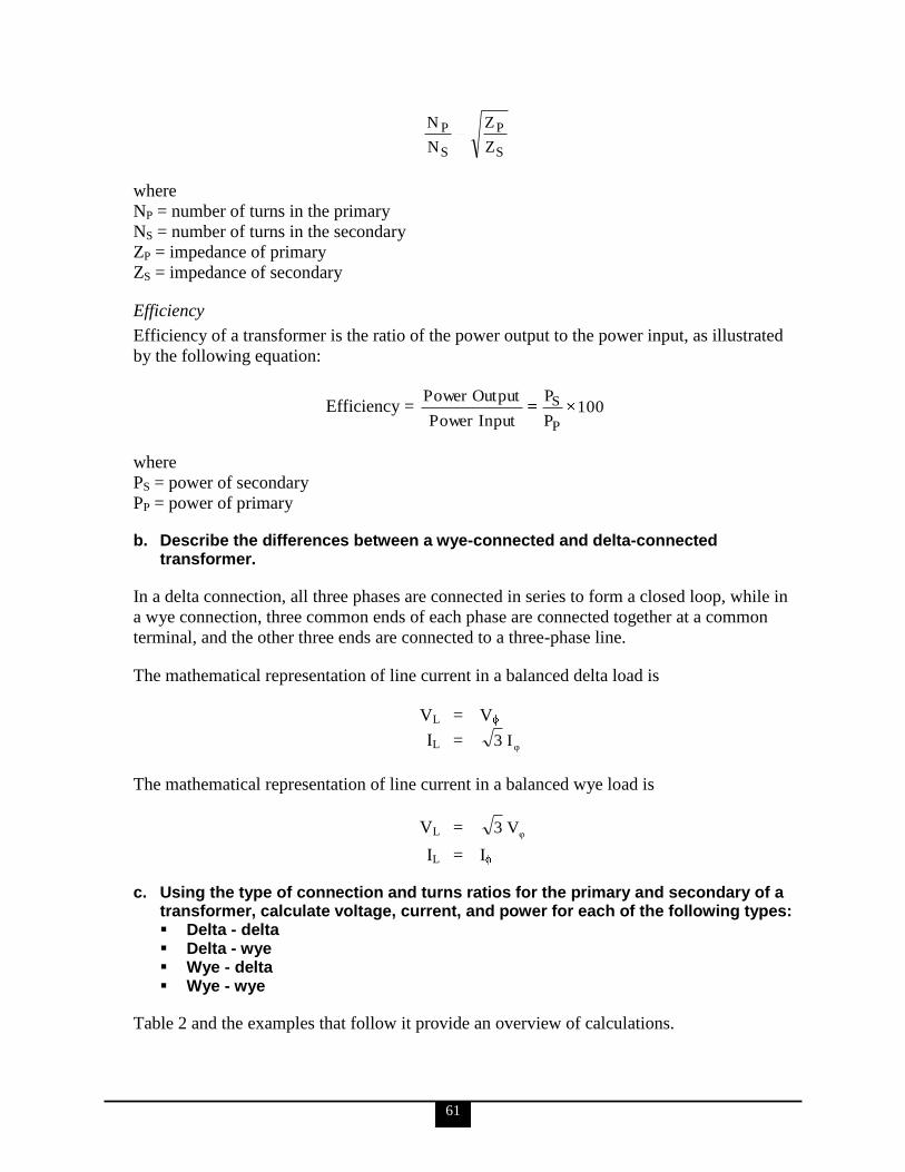
61
S
P
S
P
Z
Z
N
N
where
NP = number of turns in the primary
NS = number of turns in the secondary
ZP = impedance of primary
ZS = impedance of secondary
Efficiency
Efficiency of a transformer is the ratio of the power output to the power input, as illustrated
by the following equation:
Efficiency = 100P
P
InputPower
OutputPower
P
S
where
PS = power of secondary
PP = power of primary
b. Describe the differences between a wye-connected and delta-connected transformer.
In a delta connection, all three phases are connected in series to form a closed loop, while in
a wye connection, three common ends of each phase are connected together at a common
terminal, and the other three ends are connected to a three-phase line.
The mathematical representation of line current in a balanced delta load is
VL = V
IL = φ
I 3
The mathematical representation of line current in a balanced wye load is
VL = φ
V 3
IL = I
c. Using the type of connection and turns ratios for the primary and secondary of a transformer, calculate voltage, current, and power for each of the following types: Delta - delta Delta - wye Wye - delta Wye - wye
Table 2 and the examples that follow it provide an overview of calculations.

62
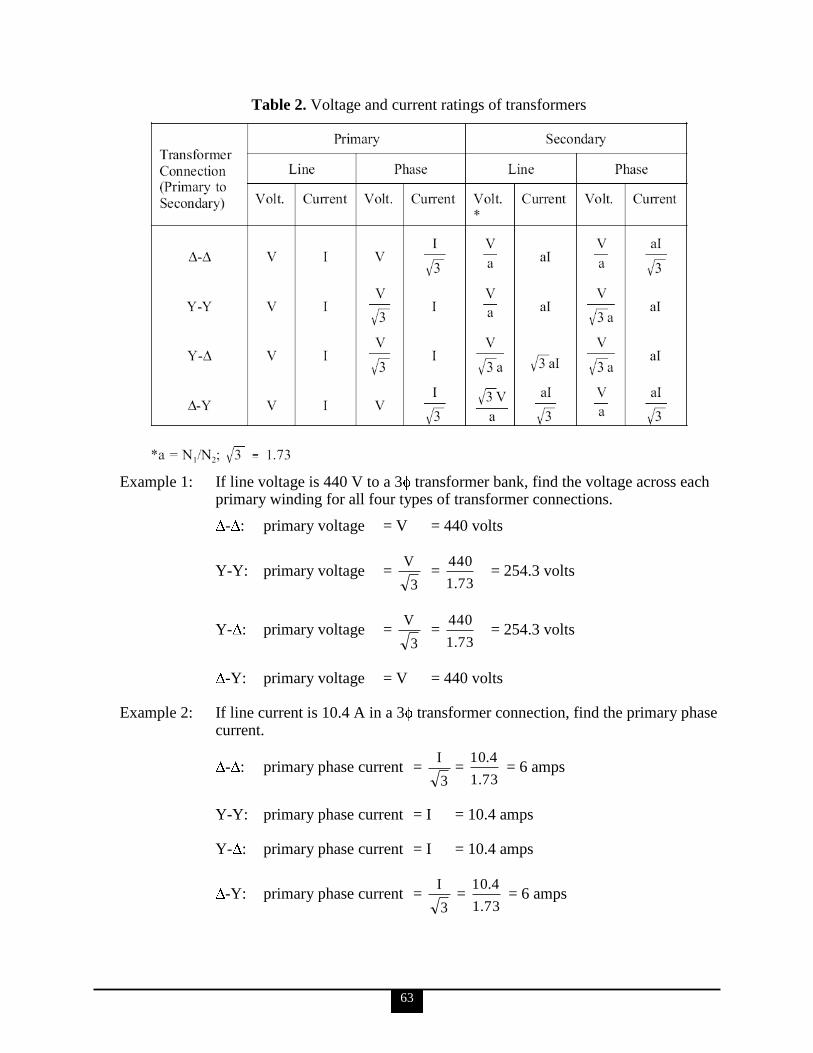
63
Table 2. Voltage and current ratings of transformers
Example 1: If line voltage is 440 V to a 3 transformer bank, find the voltage across each primary winding for all four types of transformer connections.
- : primary voltage = V = 440 volts
Y-Y: primary voltage = 3
V =
73.1
440 = 254.3 volts
Y- : primary voltage = 3
V =
73.1
440 = 254.3 volts
-Y: primary voltage = V = 440 volts
Example 2: If line current is 10.4 A in a 3 transformer connection, find the primary phase current.
- : primary phase current = 3
I =
73.1
4.10 = 6 amps
Y-Y: primary phase current = I = 10.4 amps
Y- : primary phase current = I = 10.4 amps
-Y: primary phase current = 3
I =
73.1
4.10 = 6 amps
64
Example 3: Find the secondary line current and phase current for each type of transformer connection, if primary line current is 20 amps, and the turns ratio is 4:1.
- : secondary line current = 4(20) = 80 amps
secondary phase current = 3
aI =
1.73
(20) 4 = 46.2 amps
Y-Y: second line current = aI = 4(20) = 80 amps
second phase current = aI = 4(20) = 80 amps
Y- : secondary line current = 3 aI = (1.73)(4)(20) = 138.4 amps
secondary phase current = aI = 4(20) = 80 amps
-Y: secondary line current = 3
aI =
1.73
(20) 4 = 46.2 amps
secondary phase current = 3
aI =
1.73
(20) 4 = 46.2 amps
d. State the applications of each of the following types of transformers: Distribution Power Control Auto Isolation Instrument potential Instrument current
Distribution
Distribution transformers are generally used in electrical power distribution and transmission
systems. This class of transformer has the highest power, or volt-ampere ratings, and the
highest continuous voltage rating. The power rating is normally determined by the type of
cooling methods the transformer may use. Some commonly-used methods of cooling are by
using oil or some other heat-conducting material. Ampere rating is increased in a distribution
transformer by increasing the size of the primary and secondary windings; voltage ratings are
increased by increasing the voltage rating of the insulation used in making the transformer.
Power
Power transformers are used in electronic circuits and come in many different types and
applications. Electronics or power transformers are sometimes considered to be those with
ratings of 300 volt-amperes and below. These transformers normally provide power to the
power supply of an electronic device, such as in power amplifiers in audio receivers.
65
Control
Control transformers are generally used in electronic circuits that require constant voltage or
constant current with a low power or volt-amp rating. Various filtering devices, such as
capacitors, are used to minimize the variations in the output. This results in a more constant
voltage or current.
Auto
The auto transformer is generally used in low power applications where a variable voltage is
required. The auto transformer is a special type of power transformer. It consists of only one
winding. By tapping or connecting at certain points along the winding, different voltages can
be obtained.
Isolation
Isolation transformers are normally low power transformers used to isolate noise from or to
ground electronic circuits. Since a transformer cannot pass DC voltage from primary to
secondary, any DC voltage (such as noise) cannot be passed, and the transformer acts to
isolate this noise.
Instrument Potential
The instrument potential transformer (PT) steps down voltage of a circuit to a low value that
can be effectively and safely used for operation of instruments such as ammeters, voltmeters,
watt meters, and relays used for various protective purposes.
Instrument Current
The instrument current transformer (CT) steps down the current of a circuit to a lower value
and is used in the same types of equipment as a PT. This is done by constructing the
secondary coil consisting of many turns of wire, around the primary coil, which contains only
a few turns of wire. In this manner, measurements of high values of current can be obtained.
A CT should always be short-circuited when not connected to an external load. Because the
magnetic circuit of a CT is designed for low magnetizing current when under load, this large
increase in magnetizing current will build up a large flux in the magnetic circuit and cause
the transformer to act as a step-up transformer, inducing an excessively high voltage in the
secondary when under no load.
e. Describe the hazardous materials that are associated with transformers.
The following is taken from U.S. EPA, Technical Factsheet on: Polychlorinated Biphenyls
(PCBs).
Transformers manufactured before 1979 may contain PCBs as a cooling medium. The health
effects are of two levels: acute and chronic.
Acute, short-term exposure to PCBs above the maximum contaminant level (MCL)
may potentially cause acne-like eruptions and pigmentation of the skin, vision and
hearing problems, and spasms.
66
Chronic exposure to PCBs above the MCL has the potential to cause effects similar to
acute poisoning, irritation of nose, throat and gastrointestinal tracts, and changes in
liver function. There is some evidence that PCBs have the potential to cause cancer
from a lifetime exposure at levels above the MCL.
Polychlorinated biphenyls were banned from new use and sale in 1979. Modern transformers
are now cooled with oil-based media, which are not inherently hazardous, though may pose
an environmental hazard should the transformer become damaged and leakage occur onto the
ground or into water.
f. Describe the conditions that must be met prior to paralleling two transformers, including consequences of not meeting these conditions.
The following is taken from Schneider Electric U.S.A., Loading Considerations When
Paralleling Transformers,
Transformers connected in parallel have the same voltage on each primary and the same
voltage on each secondary. The difference in the voltage between the primary and secondary
windings is the turn ratios. For these terminal voltages to be the same for the paralleled
transformers, their impedance drops must be identical. Therefore, under any condition of
load, the current will be divided such that the product of impedance and current in one
transformer is equal to the product of impedance and current in the other. Also, if the turn
ratios of the transformers are different, but the primary and secondary terminal voltages are
the same in both transformers, then circulating currents must flow between the transformers,
even at no load. Transformers are suitable for parallel operation when their turn ratios,
percent impedances, and X/R ratios are the same. Connecting transformers when one of these
parameters is different results in either circulating currents or unwanted current division.
Both of these situations lower the efficiency and reduce the maximum amount of load the
combined transformers can carry.
The standard method of connecting transformers in parallel is to have the same turn ratios,
percent impedances, and kVA ratings. Paralleling is typically accomplished by maintaining a
tie breaker in the normally closed position. Connecting transformers in parallel with the same
parameters results in equal load sharing and no circulating currents in the transformer
windings.
Although it is not common practice for new installations, sometimes two transformers with
different kVAs and the same percent impedances are connected to one common bus. In this
situation, the current division causes each transformer to carry its rated load. There will be no
circulating currents because the voltages (turn ratios) are the same.
Frequently in practice, engineers try to enhance their plant power system by connecting
existing transformers in parallel that have the same kVA rating, but with different percent
impedances. This is common when budget constraints limit the purchase of a new
transformer with the same parameters. What the engineer needs to understand is that the
current divides in inverse proportions to the impedances, and larger current flows through the
smaller impedance. Thus, the lower percent impedance transformer can be overloaded when
67
subjected to heavy loading while the other higher percent impedance transformer will be
lightly loaded.
Loading considerations for paralleling transformers are simple unless kVA, percent
impedances, or ratios are different. When paralleled transformer turn ratios and percent
impedances are the same, equal load division will exist on each transformer. When paralleled
transformer kVA ratings are the same, but the percent impedances are different, then unequal
load division will occur. The same is true for unequal percent impedances and unequal kVA.
Circulating currents only exist if the turn ratios do not match on each transformer. The
magnitude of the circulating currents will also depend on the X/R ratios of the transformers.
Paralleling delta-delta to delta-wye transformers should never be attempted because there is a
30o phase shift in delta-wye and wye-delta configurations. This causes extremely high
circulating currents in the transformers. These circulating currents would overheat the
transformers.
8. Electrical personnel shall demonstrate a working level knowledge of Uninterruptible Power Supplies (UPS).
a. Describe how a UPS works.
The following is taken from NFPA 70B.
The basic function of UPS systems is to preserve power to electrical or electronic equipment.
Most UPS systems are intended to provide regulated power to prevent power supply
fluctuations or aberrations that can damage or cause malfunction of systems
electrical/electronic equipment, such as computers and process controllers. There are two
basic types of UPS systems: static and rotary.
b. Identify the various UPS components.
The following is summarized from IEEE Std 446-1995. Much greater detail is available from
this source.
The basic components of a static UPS system are the battery, rectifier or battery charger,
inverter, and often a static transfer switch. A basic rotary UPS system is essentially a motor-
generator set that provides isolation between the incoming power supply and the load and
that buffers power supply aberrations by flywheel mechanical inertia effect. Another
significant component of a UPS system is the isolation transformer that diminishes or
removes system harmonics and surges to the UPS.
c. Describe the use of UPS in safety systems (such as a radiation criticality accident alarm system).
The following is taken from NFPA 70B.
When periodic checks are conducted in the maintenance of system alarms, on a quarterly
basis, a visual inspection should be made for signs of overheating and corrosion. Wherever
68
additional loads are connected to the UPS, the protective-device coordination, calibration,
and proper operation of the modified system should be checked.
9. Electrical personnel shall demonstrate a working level knowledge of Variable Frequency (speed) Drives (VFDs).
a. Describe the major components and operation of a VFD.
The following is taken from DOE/GO-102001-1165.
Variable-frequency drives (VFDs), a type of variable-speed drive, are controllers that vary
the speed of induction motors. VFDs save substantial energy when applied to variable-torque
loads, thus reducing electricity bills for most facilities. These energy savings are possible
with variable-torque loads, such as fans and pumps, because torque varies as the square of
speed, and HP varies as the cube of speed. For example, if fan speed is reduced by
20 percent, motor HP (and energy consumption) is reduced by 50 percent.
VFDs generate variable voltage and frequency output in the proper volts/hertz ratio for an
induction motor from the fixed utility-supplied power. VFDs can be retrofitted into existing
motor systems and can operate both standard and high-efficiency motors ranging in size from
1/3 hp to several thousand hp. Unlike mechanical or hydraulic motor controllers, they can be
located remotely and do not require mechanical coupling between the motor and the load.
This simplifies the installation and alignment of motor systems.
Three major VFD designs are commonly used: pulsewidth modulation (PWM), current
source inverter (CSI), and variable source inverter (VSI). A fourth type, the flux vector PWM
drive, is gaining popularity but is considered too expensive and sophisticated for most
applications. Knowing the characteristics of the load is critical in evaluating the advantages
and disadvantages of each technology.
Pulse-width modulation is the dominant VFD design in the ½ hp to 500 hp range
because of its reliability, affordability, and availability. PWM outputs emulate
sinusoidal power waves by varying the width of voltage pulses in each half cycle.
Advantages of PWMs are low harmonic motor heating, excellent input displacement
power factor, high efficiencies at 92–96%, and ability to control multiple motor
systems with a single drive.
Current source inverter designs are quite reliable because of their inherent current-
limiting characteristics and simple circuitry. CSIs have regenerative power
capabilities, meaning that CSI drives can reverse the power flow back from the motor
through the drive. However, CSIs ―reflect‖ large amounts of power harmonics back to
the source, have poor input power factors, and produce jerky motor operations
(cogging) at very low speeds. CSIs are typically used for large (over 300 hp)
induction and synchronous motors.
Voltage source inverter designs are similar to CSI designs, but VSIs generate
variable-frequency outputs to motors by regulating voltage rather than current.
Harmonics, power factor, and cogging at low frequencies can be problems.
69
b. Give examples where VFDs are used in safety systems and in other applications.
The following is taken from Alliant Energy, Variable Frequency Drives.
VFDs accomplish part load control by varying electric motor speed. Energy savings of 50
percent or more over other part load control strategies are common.
The majority of variable frequency drive applications are for centrifugal pumps and fans. The
savings potential for these devices is the largest since the theoretical input power varies with
the cube of fan/pump speed and volume.
For example, a fan operating at half speed will require only about 13 percent of full-speed
power. Losses in the variable frequency drive will reduce savings somewhat, but the savings
are still very impressive.
There are several methods for air and water flow control, including recirculating a portion of
the flow, throttling, variable inlet vanes, and variable frequency drives.
Recirculating part of the flow results in the fan or pump operating at full volume all the time.
Only a portion of the flow is used for the system or process and the rest is recirculated back
to the inlet of the fan or pump. This is the least-efficient means of controlling flow.
Throttling essentially chokes the outlet of the pump or fan to decrease flow much like
holding your thumb over the end of a garden hose. The pressure increases and the flow
decreases. This results in some energy savings over a constant volume recirculating system
but is still wasteful.
Variable inlet vanes apply only to fans and compressors, not pumps. Inlet vanes control flow
by pre-spinning the air entering a fan wheel or compressor impeller in the direction of
rotation, which effectively varies its capacity.
VFDs can also be applied to what are called constant torque loads. Unlike the fan and pump
power that varies with the cube of speed, constant torque applications vary power in direct
proportion to speed. This results in lower savings for a given reduction in speed but there are
still significant savings available in some applications.
VFDs can be installed with manual or automatic bypasses. In the early days of the variable
frequency drives, bypasses were more common since variable frequency drives were not as
reliable as they are at the present time. The bypasses were installed in the event of a drive
failure to ensure the system or process would remain on line. Bypasses are still available but
not always installed. The criticality of the application must be considered in each case to
determine whether the added cost and security of a bypass is warranted.
Nearly all variable frequency drives manufactured today are referred to as pulse width
modulation drives. These drives contain electronic circuitry that converts the 60 Hz line
power to DC, then pulses the output voltage for varying lengths of time to mimic an AC at
the frequency desired.
70
c. Describe the importance of line filtering for VFD equipment.
The following is taken from Alliant Energy, Variable Frequency Drives.
Harmonic filtering may be necessary in some applications. VFDs can produce harmonics that
can make their way back to the rest of the building and interfere with sensitive electronic
equipment and machines. Line reactors can be used on smaller drives of 20 hp and less to
dampen and mitigate harmonics.
The following is taken from Pacific Gas and Electric Company, Solution of EMI Problems
from Operation of Variable Frequency Drives.
Electromagnetic interference filters for VFD applications are typically structured as low-pass
filters with series inductance and bypass capacitors connected in line-to-ground mode. These
filters are usually installed on the input leads of the VFD. The line-to-ground by-pass
capacitors in the filter provide a low impedance path for the common-mode noise currents to
flow back to the VFD input out of the ground. The common-mode and phase inductors or the
EMI filter provide high impedance to the high-frequency noise current. Drive-based
equipment that must meet the European Conformity requirements must use an EMI/RFI filter
connected to the drive input.
d. Describe the importance of proper selection of the cable and lead wires for use with VFDs to minimize the effect of electromagnetic interference on nearby equipment and adjacent systems.
The following is taken from Pacific Gas and Electric Company, Solution of EMI Problems
from Operation of Variable Frequency Drives.
Abrupt voltage transitions on the output terminals of a VFD are an inherent source of
radiated and conducted EMI. These voltage transition times are essentially determined by the
rise and fall time of the semiconductor devices used in the inverter section of VFDs.
Electromagnetic interference problems can be minimized to a great degree by adopting
preventive measures during the installation phase of VFDs. The most successful preventive
measure is to use a shielded power cable to connect the VFD to the motor. This forces the
noise current to flow through the shield back to the inverter, before it gets out into the system
grid and takes multiple high-frequency paths that are difficult to track down in an
installation.
The use of shielded power cables also reduces the area of the loop antenna that is responsible
for radiated interference. The shield should be connected to ground at both ends. It is
important to ensure good electrical contact from the installation plate through the installation
screws to the metal cabinet of the VFD. Cable clamps should be used instead of twisted
shield ends, since this ruins the shielding effect at high frequencies.
If a shielded cable is not used, avoid random lay of unshielded cables in cable troughs. Using
3-wire plus ground conductor (green wire) in a conduit ensures some degree of noise
abatement as the conduit and the green wire carry most of the return current. However,
71
accidental contact with grid ground structure due to strap supports, or other equipment, is still
a possibility. In contrast, with a shielded cable, this situation can be avoided by using a
polyvinyl chloride outer coating.
In addition to the use of shielded power cable, the following noise reduction practices are
usually employed for control signal wiring practice:
Twist the leads to provide a balanced capacitive coupling.
Use shielded cable to return the noise current flowing in the shield back to the source,
instead of through the signal leads.
Maintain at least 8-inch separation between control and power wires in open air,
conduit, or cable trays.
Use a common-mode choke wound with multiple turns of both signal and shield.
Use optical isolation modules for control signal communications.
e. Describe other issues related to the transients and harmonics generated by use of VFDs, and how they need to be addressed to obtain reliable and safe system operation and long cable life (IEEE Emerald Book; reference IEEE Std-1100 and IEEE Std-1050).
The following is taken from Electrical Construction & Maintenance Magazine, Line Reactors
and VFDs.
Address harmonics by using line reactors on the line side of a VFD. Harmonic-compensated
line reactors are specially designed to handle the waveform‘s harmonic content. By inserting
inductive reactance into the circuit, which is a high impedance to harmonic frequencies, line
reactors reduce the amount of harmonics produced by a VFD system. For harmonic reduction
purposes, 5% impedance line reactors are typically applied to the input of motor drives 20 hp
and higher. This reduces input harmonics to 35% total harmonic current distortion or less and
minimizes the effects of harmonics on motors and other devices powered off the same
electrical system.
In situations where drives are located very close to the incoming facility power source, such
as a substation, they may be susceptible to any incoming spikes and other transients. This is
because there may not be enough impedance (in the form of transformers, power feeders, and
the like) to help counteract these transient voltage spikes. This situation can damage the front
end (diode section) of the drives or cause nuisance overvoltage tripping on the system.
Installing a 5% impedance line reactor at the input to each drive helps counteract line spikes,
keeping them from tripping or damaging the drives.
On the other hand, if drives are located far from the facility power source (as often seen in
hospitals), they may be affected by line harmonics caused by other harmonic-generating
equipment (nonlinear loads). In most applications, harmonic problems are best solved at their
source. Large nonlinear loads, such as VFDs, should have a 5% impedance line reactor
applied on the input to those pieces of equipment to minimize the system harmonics.
72
10. Electrical personnel shall demonstrate a working level knowledge of electrical test instruments and measuring devices.
a. Describe the purpose and method of operation of the following in-place measuring devices, and explain how to use the correct electrical instrument/measuring device in accordance with the manufacturer‘s specifications and instructions (i.e., within the device‘s rated voltage of 600 volts or less): Voltmeter Ammeter Ohmmeter Wattmeter Ampere-hour meter Power factor meter Ground detector Synchroscope Megger Power quality monitors
The information for all the terms in this KSA, except for power quality monitors, is taken
from DOE-HDBK-1011/4-92. The information on power quality monitors is taken from
NFPA 70B.
Voltmeter
A simple DC voltmeter can be constructed by placing a resistor, called a multiplier, in series
with the ammeter meter movement, and marking the meter face to read voltage. Voltmeters
are connected in parallel with the load being measured. When constructing a voltmeter, the
resistance of the multiplier must be determined to measure the desired voltage.
When a voltmeter is connected in a circuit, the voltmeter will draw current from that circuit.
This current causes a voltage drop across the resistance of the meter, which is subtracted
from the voltage being measured by the meter. This reduction in voltage is known as the
loading effect and can have a serious effect on measurement accuracy, especially for low-
current circuits. The accuracy of a voltmeter is defined as the ratio of measured voltage when
the meter is in the circuit to the voltage measured with the meter out of the circuit.
Ammeter
The ammeter measures electric current. It may be calibrated in amperes, milliamperes, or
microamperes. In order to measure current, the ammeter must be placed in series with the
circuit to be tested. When an ammeter is placed in series with a circuit, it will increase the
resistance of that circuit by an amount equal to the internal resistance of the meter.
The percent loading error is that percent of error due to loading effects that result from the
added resistance of the meter. A second error that occurs in an ammeter is calibration error.
Calibration error is an error that occurs due to inaccurately marked meter faces. Typical
values of calibration error in terms of full-scale current are about 3%.
73
Ohmmeter
The ohmmeter is an instrument used to determine resistance. A simple ohmmeter consists of
a battery, a meter movement calibrated in ohms, and a variable resistor. Ohmmeters are
connected to a component that is removed from the circuit. The reason for removing the
component is that measurement of current through the component determines the resistance.
If the component remains in the circuit and a parallel path exists in the circuit, the current
will flow in the path of least resistance and give an erroneous reading.
When the unknown resistance is connected across the ohmmeter terminals, the current is
measured by calculating the total series resistance. An easy way to determine ohmmeter
deflection is by use of a deflection factor, which is the ratio of circuit current to meter
current.
Wattmeter
The wattmeter is an instrument that measures DC power or true AC power. The wattmeter
uses fixed coils to indicate current, while the movable coil indicates voltage. Wattmeters are
rated in terms of their maximum current, voltage, and power. All of these ratings must be
observed to prevent damage to the meter.
Total power in a 3 circuit is the sum of the powers of the separate phases. The total power
could be measured by placing a wattmeter in each phase; however, this method is not feasible
since it is often impossible to break into the phases of a delta load. It also may not be feasible
for the Y load, since the neutral point to which the wattmeters must be connected is not
always accessible. Normally, only two wattmeters are used in making 3 power
measurements. In balanced 3 systems, with any power factor, total power is calculated by
adding the A and B phase powers.
Ampere-Hour Meter
The ampere-hour meter registers ampere-hours and is an integrating meter similar to the
watt-hour meter used to measure electricity usage in a home. Typical ampere-hour meters are
digital indicators similar to the odometer used in automobiles. The ampere-hour meter is a
DC meter that will register in either direction depending on the direction of current flow. For
example, starting from a given reading, it will register the amount of discharge of a battery;
when the battery is placed on charge, it will operate in the opposite direction, returning once
again to its starting point. When this point is reached, the battery has received a charge equal
to the discharge, and the charge is stopped. It is normally desired to give a battery a 10%
overcharge. This is accomplished by designing the ampere-hour meter to run 10% slow in the
charge direction.
These meters are subject to inaccuracies and cannot record the internal losses of a battery.
They attempt to follow the charge and discharge, but inherently do not indicate the correct
state of charge. Similar to an ammeter, the ampere-hour meter is connected in series.
Although the ampere-hour meters were used quite extensively in the past, they have been
largely superseded by the voltage-time method of control.

74
Power Factor Meter
A power factor meter is a type of electrodynamometer movement when it is made with two
movable coils set at right angles to each other. At a power factor of unity, one potential coil
current leads and one lags the current in phase B by 30°; thus, the coils are balanced. A
change in power factor will cause the current of one potential coil to become more in phase
and the other potential coil to be more out of phase with the current in phase B, so that the
moving element and pointer take a new position of balance to show the new power factor.
Ground Detector
The ground detector is an instrument that is used to detect conductor insulation resistance to
ground. An ohmmeter, or a series of lights, can be used to detect the insulation strength of an
ungrounded distribution system. Most power distribution systems in use today are of the
grounded variety; however, some ungrounded systems still exist. In the ohmmeter method, a
DC voltage is applied to the conductor. If a leakage path exists between the conductor
insulator and ground, a current will flow through the ground to the ohmmeter proportional to
the insulation resistance of the conductor. In the ground detector lamp method, a set of three
lamps connected through transformers to the system is used. To check for grounds, the
switch is closed and the brilliance of the lamps is observed. If the lamps are equally bright,
no ground exists and all the lamps receive the same voltage. If any one lamp is dark, and the
other two lamps are brighter, the phase in which the darkened lamp is in is grounded. In this
case, the primary winding of the transformer is shorted to ground and receives no voltage.
Synchroscope
A synchroscope indicates when two AC generators are in the correct phase relation for
connecting in parallel and shows whether the incoming generator is running faster or slower
than the on-line generator. The synchroscope consists of a two-phase stator. The two stator
windings are at right angles to one another, and by means of a phase-splitting network, the
current in one phase leads the current of the other phase by 90°, thereby generating a rotating
magnetic field. The stator windings are connected to the incoming generator, and a polarizing
coil is connected to the running generator.
The rotating element is unrestrained and is free to rotate through 360°. It consists of two iron
vanes mounted in opposite directions on a shaft, one at the top and one at the bottom, and
magnetized by the polarizing coil.
If the frequencies of the incoming and running generators are different, the synchroscope will
rotate at a speed corresponding to the difference. It is designed so that if incoming frequency
is higher than running frequency, it will rotate in the clockwise direction; if incoming
frequency is less than running frequency, it will rotate in the counterclockwise direction.
When the synchroscope indicates 0o
o phase difference, the pointer is at the ―12 o‘clock‖
position and the two AC generators are in phase.
Megger
The megger is a portable instrument used to measure insulation resistance. The megger
consists of a hand-driven DC generator and a direct reading ohmmeter. The moving element
of the ohmmeter consists of two coils, A and B, which are rigidly mounted to a pivoted
75
central shaft and are free to rotate over a C-shaped core. These coils are connected by means
of flexible leads. The moving element may point in any meter position when the generator is
not in operation.
As current provided by the hand-driven generator flows through coil B, the coil will tend to
set itself at right angles to the field of the permanent magnet. With the test terminals open,
giving an infinite resistance, no current flows in coil A. Coil B will govern the motion of the
rotating element, causing it to move to the extreme counterclockwise position, which is
marked as infinite resistance.
Power Quality Monitors
Power quality monitors assist the troubleshooter in identifying and solving many power
quality problems. Disturbance waveshapes from these monitors provide important clues for
locating the source of problems.
Monitoring can be used to determine the presence of transients. Storage-type, high-
bandwidth oscilloscopes with high-voltage capability can be used, but more information can
be obtained from the use of power disturbance analyzers specifically designed for transient
and other types of power-quality problems. Monitoring might be required over an extended
period of time, due to the characteristics of transients, which vary as loads and system
configurations change. Monitoring is often performed at specific locations where a sensitive
load is connected or is to be connected. Other devices on the monitored circuit, such as the
power quality monitor itself, can contain surge-protection devices that limit transients and
distort the results. An alternative power source for powering monitoring equipment should be
used if possible.
Power monitoring instruments are quite sensitive, and outside factors can influence their
accuracy.
b. Describe safe methods for using the following portable test equipment: Ammeter Voltmeter Ohmmeter
The following is taken from IEEE Std 242-2001.
Portable equipment should be handled in a manner that will not cause damage. Flexible
electric cords connected to equipment should not be used for raising or lowering the
equipment. Flexible cords should not be fastened with staples or hung in such a fashion as
could damage the outer jacket or insulation.
Employees‘ hands should not be wet when plugging and unplugging flexible cords and cord-
and-plug-connected equipment if energized equipment is involved. Energized plug and
receptacle connections should be handled only with insulating protective equipment if the
condition of the connection could provide a conductive path to the employee‘s hand (if, for
example, a cord connector is wet from being immersed in water). Locking-type connectors
should be secured after connection.
76
Before use on any shift, portable cord-and-plug-connected equipment should be visually
inspected for external defects (such as loose parts, deformed and missing pins) and for
evidence of possible internal damage (such as pinched or crushed outer jacket).
Overcurrent protection of circuits and conductors should not be modified, even on a
temporary basis, beyond that permitted by NFPA 70E, Article 410.9, ―Overcurrent
Protection.‖
Trailing cables should be of minimal length, of adequate construction, and properly protected
(e.g., by ground-fault circuit-interrupting circuit breakers); and cable connectors should be of
suitable design for the environment in which they are operating. All portable equipment
should be regularly inspected and tested; should have a label attached showing the due date
for the next test; and, where feasible, should be inspected before each use.
c. Describe the importance of tolerances and calibration requirements for test instruments.
The following is taken from NFPA 70B.
All test equipment should be calibrated at regular intervals to ensure the validity of the data
obtained. In order to get valid test results, it might be necessary to regulate the power input to
the test equipment for proper waveform and frequency and to eliminate voltage surges.
Equipment calibrations should be scheduled on a routine basis, with the frequency depending
on the operating conditions particular to the process or equipment. In general, any test
equipment used for the calibration of other equipment should have an accuracy at least twice
the accuracy of the equipment under test. The test equipment should be maintained in good
condition and should be used only by qualified test operators.
Each facility differs in its tolerance to harmonic distortion. There are guidelines that can be
followed to determine if harmonics are within acceptable limits. IEEE Std 519,
Recommended Practices and Requirements for Harmonic Control in Electrical Power
Systems, is one such standard. Other information sources include the following: American
National Standards Institute (ANSI)/IEEE C57.110, Recommended Practice for Establishing
Transformer Capability When Supplying Nonsinusoidal Load Currents, and IEEE Std 1100,
Recommended Practice for Powering and Grounding Sensitive Electronic Equipment.
d. Describe the importance of different category meters (such as CAT I, CAT II, CAT III, and CAT IV; reference UL 3111-1).
[Note: UL 3111-1 has been superseded by UL 61010B-1. Other UL 3111-series standards referenced in the discussion have also been superseded. Their successors are shown parenthetically. The candidate is encouraged to review the new standards for applicability.]
The information for KSAs ‗d‘ and ‗e‘ is taken from Electrical Construction & Maintenance
Magazine, ―What You Need to Know About Category Ratings.‖ Both of these KSAs are
discussed under KSA ‗e‘ below.
77
e. Describe the types of meters used for over 600 volts.
Test instruments are rated on their ability to withstand a voltage spike, which is applied
through a specified level of resistance (table 3). The ratings are broken down by categories—
Cat I, II, III, and IV.
Cat I-rated test instruments are signal-level tools for telecommunications and electronic
equipment. Transient voltage risk is limited, but still exists, due to the distances between
equipment locations and other equipment located between it and the primary electrical
supply. The International Electrotechnical Commission (IEC) no longer specifies protection
levels for Cat I instruments. Underwriters Laboratories (UL) 3111-1, Standard for Electrical
Measuring and Test Equipment; Part 1: General Requirements, specifies that a Cat I 150 V-
rated instrument must be protected to 800 V. Under IEC 61010-1, 2nd edition, Safety
Requirements for Electrical Equipment for Measurement, Control, and Laboratory Use, a
Cat I 150 V meter could be protected only to 500 V, as long as that information is in the
user‘s manual.
Cat II-rated test instruments cover the local level of circuits for fixed or non-fixed power
devices. This includes most lighting equipment, appliances, and 120 V or 240 V equipment
inside a building.
Cat III-rated test instruments can withstand the transient voltage range found on most
distribution circuits. These instruments are used primarily on fixed primary feeders or branch
circuits. They‘re separated from Cat IV utility service or other high-voltage source
equipment by at least one level or through transformer isolation.
Cat IV-rated test instruments are designed for testing on the primary supply source, which
also includes 120 V or 240 V overhead or underground lines that power detached buildings
or underground lines that power well pumps. The Cat IV rating covers the highest and most
dangerous level of transient overvoltage electricians encounter when working on utility
service equipment like exterior transformers.
The latest UL standard for electrical test instruments is UL 61010B-1, UL Standard for
Safety Electrical Measuring and Test Equipment; Part 1: General Requirements, which is a
revision of UL 3111-1. It specifies the general safety requirements, such as material, design,
and testing requirements, and the environmental conditions in which the standard applies.
UL 3111-2-031 (UL 61010B-2-031, Electrical Equipment for Measurement, Control, and
Laboratory Use; Part 2: Particular Requirements for Hand-Held Probe Assemblies for
Electrical Measurement and Test) lists additional requirements for test probes. The
requirements for hand-held current clamps, such as the current measuring portion of clamp
meters, are included in UL 3111-2-032 (UL 61010B-2-032, Standard for Electrical
Equipment for Measurement, Control, and Laboratory Use; Part 2: Particular Requirements
for Hand-Held Current Clamps for Electrical Measurement and Test).
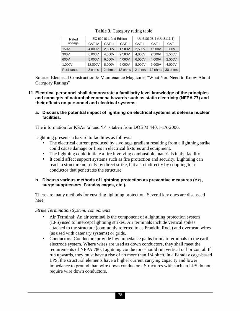
78
Table 3. Category rating table
Rated voltage
IEC 61010-1 2nd Edition UL 61010B-1 (UL 3111-1)
CAT IV CAT III CAT II CAT III CAT II CAT I
150V 4,000V 2,500V 1,500V 2,500V 1,500V 800V
300V 6,000V 4,000V 2,500V 4,000V 2,500V 1,500V
600V 8,000V 6,000V 4,000V 6,000V 4,000V 2,500V
1,000V 12,000V 8,000V 6,000V 8,000V 6,000V 4,000V
Resistance 2 ohms 2 ohms 12 ohms 2 ohms 12 ohms 30 ohms
Source: Electrical Construction & Maintenance Magazine, ―What You Need to Know About
Category Ratings‖
11. Electrical personnel shall demonstrate a familiarity level knowledge of the principles and concepts of natural phenomena hazards such as static electricity (NFPA 77) and their effects on personnel and electrical systems.
a. Discuss the potential impact of lightning on electrical systems at defense nuclear facilities.
The information for KSAs ‗a‘ and ‗b‘ is taken from DOE M 440.1-1A-2006.
Lightning presents a hazard to facilities as follows:
The electrical current produced by a voltage gradient resulting from a lightning strike
could cause damage or fires in electrical fixtures and equipment.
The lightning could initiate a fire involving combustible materials in the facility.
It could affect support systems such as fire protection and security. Lightning can
reach a structure not only by direct strike, but also indirectly by coupling to a
conductor that penetrates the structure.
b. Discuss various methods of lightning protection as preventive measures (e.g., surge suppressors, Faraday cages, etc.).
There are many methods for ensuring lightning protection. Several key ones are discussed
here.
Strike Termination System: components
Air Terminal: An air terminal is the component of a lightning protection system
(LPS) used to intercept lightning strikes. Air terminals include vertical spikes
attached to the structure (commonly referred to as Franklin Rods) and overhead wires
(as used with catenary systems) or grids.
Conductors: Conductors provide low impedance paths from air terminals to the earth
electrode system. Where wires are used as down conductors, they shall meet the
requirements of NFPA 780. Lightning conductors should run vertical or horizontal. If
run upwards, they must have a rise of no more than 1/4 pitch. In a Faraday cage-based
LPS, the structural elements have a higher current carrying capacity and lower
impedance to ground than wire down conductors. Structures with such an LPS do not
require wire down conductors.

79
Grounding
LPSs, to include integral and catenary systems, but with the exception of Faraday
cage or Faraday-like Shield systems, require an earth electrode (ground) system to
dissipate the electrical energy of a lightning strike to the earth. The use of earth
electrode systems with a Faraday-like shield LPS is not required as the floor of such a
structure acts as the earth (ground) electrode; however, electrical safety grounding
requirements do apply. Examples of earth electrode systems include ground rods, a
ring electrode (counterpoise) system, buried metal plates, or Ufer grounds.
Bonding
Bonding provides a physical and electrical connection from all parts of the LPS to the
ground connection. Bonding produces electrical continuity between the LPS and
metallic objects to minimize potential differences. Methods of bonding include
mechanical, compression and thermal connections.
Surge Suppression for Incoming Conductors
Surge suppression devices shall be provided in accordance with NFPA and the
provisions of this Manual on each power line, signal line, or communication line
conductor entering the LPS protected structure. They shall be located between the
respective conductor and the structure ground and/or Faraday cage, as close as
reasonably achievable to the point where the conductor penetrates the LPS zone of
protection or the structure. All cabling, power cabling, communication lines, data
lines, and electrical conduit shall be buried underground in metallic conduit for a
minimum of 50 ft (15.2 m) before entering an explosives structure. These and other
metallic utility lines and pipes shall be electrically bonded to the LPS or structural
steel of the building as close as reasonably achievable to their entry point.
Sideflash (Arcing) Protection
Sideflash is an electrical spark caused by differences of potential that occurs between
conductive metal bodies or between conductive metal bodies and a component of the
LPS or earth electrode system. Sideflash presents direct and indirect hazards to
facility personnel and components.
For further information, see also NFPA 780, Standard for the Installation of Lightning
Protection Systems.
c. Briefly describe the safety measures and design features commonly used as safeguards against natural hazards and identify the relevant industry consensus standards that codify accepted design and installation practices for these safeguards. Reference the following: DOE-STD-1020-2002, Natural Phenomena Hazards Design and Evaluation
Criteria for Department of Energy Facilities DOE-STD-1021-93, Natural Phenomena Hazards Performance Categorization
Guidelines for Structures, Systems, and Components DOE-STD-1022-94, Natural Phenomena Hazards Site Characterization Criteria
80
DOE-STD-1020-2002, Natural Phenomena Hazards Design and Evaluation Criteria for
Department of Energy Facilities
This standard, developed from UCRL-15910, Design and Evaluation Guidelines for
Department of Energy Facilities Subjected to Natural Phenomena Hazards, provides criteria
for design of new structures, systems, and components (SSCs) and for evaluation,
modification, or upgrade of existing SSCs so that DOE facilities safely withstand the effects
of natural phenomena hazards (NPHs) such as earthquakes, extreme winds, and flooding.
DOE-STD-1020-2002 provides consistent criteria for all DOE sites across the United States.
These criteria are provided as the means of implementing DOE O 420.1B and the associated
Guides, and Executive Orders 12699, ―Seismic Safety of Federal and Federally Assisted or
Regulated New Building Construction,‖ and 12941, ―Seismic Safety of Existing Federally
Owned or Leased Buildings,‖ for earthquakes.
The design and evaluation criteria in DOE-STD-1020-2002 provide relatively
straightforward procedures to evaluate, modify, or upgrade existing facilities or to design
new facilities for the effects of NPHs. The intent is to control the level of conservatism in the
design/evaluation process such that (1) the hazards are treated consistently; and (2) the level
of conservatism is appropriate for SSC characteristics related to safety, environmental
protection, importance, and cost. The requirements for each hazard are presented in separate
chapters. Terminology, guidelines, and commentary material are included in appendices that
follow the requirement chapters.
Prior to applying these criteria, SSCs have been placed in one of five performance categories
(PCs), PC-0 to PC-4. No special considerations for NPH are needed for PC-0; therefore, no
guidance is provided. Different criteria are provided for the remaining four PCs, each with a
specified performance goal. Design and evaluation criteria aimed at target probabilistic
performance goals require probabilistic NPH assessments. NPH loads are developed from
such assessments by specifying NPH mean annual probabilities of exceedance. Performance
goals may then be achieved by using the resulting loads combined with deterministic design
and evaluation procedures that provide a consistent and appropriate level of conservatism.
Design/evaluation procedures conform closely to industry practices using national consensus
codes and standards so that the procedures will be easily understood by most engineers. SSCs
comprising a DOE facility are to be assigned to a PC utilizing the approach described in the
DOE G 420.1-2 and performance categorization standard, DOE-STD-1021-93, Natural
Phenomena Hazards Performance Categorization Guidelines for Structures, Systems, and
Components. These design and evaluation criteria (DOE-STD-1020) are the specific
provisions to be followed such that the performance goal associated with the PC of the SSC
under consideration is achieved. For each category, the criteria include the following steps:
1. NPH loads are determined at specified NPH probabilities as per DOE-STD-1023,
Natural Phenomena Hazards Assessment Criteria.
2. Design and evaluation procedures are used to evaluate SSC response to NPH loads.
3. Criteria are used to assess whether or not computed response in combination with
other design loads is permissible.
4. Design detailing provisions are implemented so that the expected performance during
a potential NPH occurrence will be achieved.
5. Quality assurance (QA) and peer review are applied using a graded approach.
81
NPH safety requirements are briefly described in 10 CFR 830, ―Nuclear Safety
Management,‖ and DOE O 420.1B, Facility Safety. The associated Guides are
DOE G 420.1-1, Nonreactor Nuclear Safety Design Criteria and Explosive Safety
Criteria Guide for use with DOE O 420.1 Facility Safety
DOE G 420.1-2, Guide for the Mitigation of Natural Phenomena Hazards for DOE
Nuclear Facilities and Non-nuclear Facilities
DOE G 420.1-3, Implementation Guide for DOE Fire Protection and Emergency
Services Programs for Use with DOE O 420.1B, Facility Safety
These guides describe acceptable methods to meet these requirements in a consistent manner
throughout DOE, which include (1) providing a safe work place; (2) protecting against
property loss and damage; (3) maintaining operation of essential facilities; and (4) protecting
against exposure to hazardous materials during and after occurrences of NPHs. There is an
established hierarchy in the set of documents that specify NPH requirements. In this
hierarchy, 10 CFR part 830 is the highest authority (for nuclear facilities only), followed by
DOE O 420.1B. The next set of controlling documents is the associated Guides followed by
the set of NPH standards (DOE-STD-1020 through DOE-STD-1023). The NPH requirements
have been developed to provide the necessary information that assesses the NPH safety basis
for DOE facilities, which is documented in safety analysis reports (SARs), if available. 10
CFR part 830, DOE Order 5480.23, Nuclear Safety Analysis Report, and the guidance
provided in the associated standard, DOE-STD-3009-94, Preparation Guide For U. S.
Department of Energy Nonreactor Nuclear Facility Documented Safety Analyses, prescribe
the use of a graded approach for the effort to be expended in safety analysis and the level of
detail required to be presented in the associated documentation. DOE NPH mitigation
requirements are also consistent with the National Earthquake Hazards Reduction Program
and Executive Orders 12699 and 12941.
DOE-STD-1021-93, Natural Phenomena Hazards Performance Categorization Guidelines
for Structures, Systems, and Components
DOE-STD-1021-93 provides guidelines to be used for NPH performance categorization of
SSCs, and recommends systematic procedures to implement these guidelines.
The application of the basic categorization guidelines establishes the preliminary PC of
SSCs, as summarized in figure 35. The preliminary PC may not account for system
interactions but shall account for common-cause failure effects. Note that the hazard
categorization is based on a method for assessing risk from potential hazards and follows the
graded approach discussed in the NPH implementation Guide for DOE O 420.1B (DOE G
420.1-2).
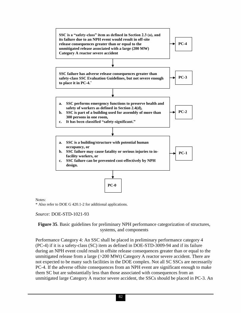
82
Notes:
* Also refer to DOE G 420.1-2 for additional applications.
Source: DOE-STD-1021-93
Figure 35. Basic guidelines for preliminary NPH performance categorization of structures,
systems, and components
Performance Category 4: An SSC shall be placed in preliminary performance category 4
(PC-4) if it is a safety-class (SC) item as defined in DOE-STD-3009-94 and if its failure
during an NPH event could result in offsite release consequences greater than or equal to the
unmitigated release from a large (>200 MWt) Category A reactor severe accident. There are
not expected to be many such facilities in the DOE complex. Not all SC SSCs are necessarily
PC-4. If the adverse offsite consequences from an NPH event are significant enough to make
them SC but are substantially less than those associated with consequences from an
unmitigated large Category A reactor severe accident, the SSCs should be placed in PC-3. An
SSC is a “safety-class” item as defined in Section 2.3 (a), and
its failure due to an NPH event would result in off-site
release consequences greater than or equal to the
unmitigated release associated with a large (200 MW)
Category A reactor severe accident
PC-4
SSC failure has adverse release consequences greater than
safety-class SSC Evaluation Guidelines, but not severe enough
to place it in PC-4.*
PC-3
a. SSC performs emergency functions to preserve health and
safety of workers as defined in Section 2.4(d),
b. SSC is part of a building used for assembly of more than
300 persons in one room,
c. It has been classified “safety-significant.”
PC-2
a. SSC is a building/structure with potential human
occupancy, or
b. SSC failure may cause fatality or serious injuries to in-
facility workers, or
c. SSC failure can be prevented cost-effectively by NPH
design.
PC-1
PC-0

83
SSC that does not satisfy the above criteria may also be placed in PC-4 for improved
performance if justified from cost-benefit considerations.
Performance Category 3: An SSC shall be placed in preliminary performance category 3
(PC-3) if it is not covered in paragraph 2.4(b) of DOE-STD-1021-93, and if its failure results
in adverse release consequences greater than SC SSC evaluation guidelines limits but much
less than those associated with PC-4 SSCs. For additional applications refer to DOE G 420.1-
2. An SSC that does not satisfy the criteria may also be placed in PC-3 for improved
performance if justified from cost-benefit considerations. For new facilities, since it may not
cost too much more to design the facility as PC-4 instead of PC-3, it may be desirable to
design such PC-3 facilities in the conceptual design stage to PC-4 criteria, subject to funding
constraints.
Performance Category 2: An SSC shall be placed in preliminary performance category 2
(PC-2) if it is not covered in paragraphs 2.4(b) and 2.4(c) of DOE-STD-1021-93, and if any
of the following conditions apply:
The SSC‘s failure by itself or in combination with one or more SSCs may result in
loss of function of any emergency handling, hazard recovery, fire suppression,
emergency preparedness, communication, or power system that may be needed to
preserve the health and safety of workers and visitors. This includes NPH-caused
release of radioactive and toxic materials that would result in these consequences.
The SSC is part of a building that is primarily used for assembly of more than 300
persons (in one room), and the SSC failure may adversely affect the life safety of the
occupants.
The SSC has been classified safety-significant (SS). For details refer to DOE
G 420.1-2. An SSC that does not satisfy the above criteria may also be placed in PC-2
from cost and mission considerations, (e.g., when SSC failure causes excessive
downtime, the SSC is very difficult to replace, or SSC replacement/repair is very
costly).
Performance Category 1: An SSC that is not covered in paragraphs 2.4(b), 2.4(c), and 2.4(d)
in DOE-STD-1021-93 shall be placed in preliminary performance category 1 (PC-1) if any of
the following conditions apply:
It is a building/structure with potential human occupancy.
The SSC‘s failure may cause a fatality or serious injuries to in-facility workers.
The SSC‘s failure may cause damage that can be prevented or reduced cost-
effectively by designing it to withstand NPH effects.
Performance Category 0: An SSC that is not covered in paragraphs 2.4(b) through 2.4(e) in
DOE-STD-1021-93 may be placed in preliminary performance category 0 (PC-0), if it is not
important because of safety, mission, or cost considerations, and if it is more cost-effective to
replace or repair it than to design it to withstand NPH effects; however, an SSC whose failure
may have any adverse effect on the performance of a PC-1, PC-2, PC-3, or PC-4 SSC shall
not be placed in PC-0.
84
DOE-STD-1022-94, Natural Phenomena Hazards Site Characterization Criteria
The purpose of DOE-STD-1022-94 is to provide criteria for site characterization to provide
site-specific information needed for implementing DOE O 420.1B requirements and to develop
a site-wide database related to NPH that should be obtained to support individual SARs.
Criteria are presented for meteorological, hydrological, geological, seismological, and
geotechnical studies to characterize the site and to provide the necessary site-specific
information. The required information is necessary to complete the hazard assessments
described in DOE-STD-1023-95, Natural Phenomena Hazards Assessment Criteria, and in
turn to provide input for design and evaluation requirements described in DOE-STD-1020-
2002, Natural Phenomena Hazards Design and Evaluation Criteria for Department of
Energy Facilities. The scope and degree of detail of investigations to address these NPHs
depend on several factors, including the PCs of the SSCs making up the facilities; the hazard
classification of the facilities; the subsurface conditions at the site; the meteorologic,
hydrologic, and seismotectonic environment of the site region; and the extent of prior
knowledge, investigations, and data regarding the site and site region. Although more
detailed investigations are generally appropriate for facilities having higher PCs,
investigations of lesser scope and detail may be appropriate when the existing knowledge of
the site and region is extensive and up-to-date.
For a full list of design and installation practices for the many natural hazards described here,
see DOE-STD-1022-94, Natural Phenomena Hazards Site Characterization Criteria.
12. Electrical personnel shall demonstrate a working level knowledge of DC generators.
a. Describe the relationship between shaft speed, field flux, and generated voltage.
The following is taken from DOE-HDBK-1011/2-92.
A basic DC generator has four primary parts: a magnetic field; a single conductor, or loop; a
commutator (shaft); and brushes. The magnetic field may be supplied by either a permanent
magnet or an electromagnet. A coil of wire is mounted in the shaft and electrical connections
are made to this spinning coil via stationary carbon ―brushes‖ contacting copper strips on the
rotating shaft. The purpose of the brushes is to connect the generated voltage to an external
circuit. In order to do this, each brush must make contact with one of the ends of the loop. An
increase in field current will cause field flux to increase. Conversely, if the resistance of the
field is increased, field flux will decrease. If the field flux of a DC motor is decreased, the
motor speed will increase.
The relationship between shaft speed, field flux, and generated voltage is represented in the
following equation:
VG = KΦN
where
VG = generated voltage
K = constant
Φ = generator field flux
N = shaft speed
85
b. Define the following: Electromotive force Excitation Compounding Armature Terminal voltage Load current Shunt windings Series windings
The definitions of all the terms in this KSA, except for EMF, are taken from DOE-HDBK-
1011/2-92. The definition for EMF is taken from DOE-HDBK-1011/1-92.
Electromotive Force
EMF is the sum of the potential differences of all charged particles in an electrostatic field.
Excitation
The magnetic fields in DC generators are most commonly provided by electromagnets. A
current must flow through the electromagnet conductors to produce a magnetic field. In order
for a DC generator to operate properly, the magnetic field must always be in the same
direction. Therefore, the current through the field winding must be DC. This current is
known as the field excitation current and can be supplied to the field winding in one of two
ways. It can come from a separate DC source external to the generator (e.g., a separately
excited generator) or it can come directly from the output of the generator.
Compounding
One means of supplying a stable output voltage is by using a compound generator. The
compound generator has a field winding in parallel with the generator armature (the same as
a shunt-wound generator) and a field winding in series with the generator armature (the same
as a series-wound generator). The two windings of the compounded generator are made such
that their magnetic fields will either aid or oppose one another.
If the two fields are wound so that their flux fields oppose one another, the generator is said
to be differentially compounded. Due to the nature of this type of generator, it is used only in
special cases and will not be discussed further in this reference guide. If the two fields of a
compound generator are wound so that their magnetic fields aid one another, the generator is
said to be cumulatively compounded. As the load current increases, the current through the
series field winding increases, increasing the overall magnetic field strength and causing an
increase in the output voltage of the generator. With proper design, the increase in the
magnetic field strength of the series winding will compensate for the decrease in shunt field
strength. Therefore, the overall strength of the combined magnetic fields remains almost
unchanged, so the output voltage will remain constant. In reality, the two fields cannot be
made so that their magnetic field strengths compensate for each other completely. There will
be some change in output voltage from the no-load to full-load conditions.
86
Armature
The purpose of the armature is to provide the energy conversion in a DC machine. In a DC
generator, the armature is rotated by an external mechanical force, such as a steam turbine.
This rotation induces a voltage and current flow in the armature. Thus, the armature converts
mechanical energy to electrical energy. In a DC motor, the armature receives voltage from an
outside electrical source and converts electrical energy into mechanical energy in the form of
torque.
Terminal Voltage
Terminal voltage, as applied to DC generators, is defined as the voltage that can be measured
at the output of the generator.
Load Current
Each electrical circuit has at least four basic parts: a source of EMF, conductors, load or
loads, and some means of control. For example, the source of EMF might be the battery; the
conductors could be the wires which connect the various component parts; the resistor would
be the load; and a switch could be used as the circuit control device. A closed circuit is an
uninterrupted, or unbroken, path for current from the source (EMF), through the load, and
back to the source. An open circuit, or incomplete circuit, exists if a break in the circuit
occurs; this prevents a complete path for current flow.
Shunt Windings
When the field winding of a generator is connected in parallel with the generator armature,
the generator is called a shunt-wound generator. The excitation current in a shunt-wound
generator is dependent upon the output voltage and the field resistance. Normally, field
excitation is maintained between 0.5 and 5% of the total current output of the generator.
Series Windings
When the field winding of a DC generator is connected in series with the armature, the
generator is called a series-wound generator. The excitation current in a series-wound
generator is the same as the current the generator delivers to the load. If the load has a high
resistance and only draws a small amount of current, the excitation current is also small.
Therefore, the magnetic field of the series field winding is weak, making the generated
voltage low. Conversely, if the load draws a large current, the excitation current is also high.
Therefore, the magnetic field of the series field winding is very strong, and the generated
voltage is high.
c. State the purpose of the following components of a DC machine: Armature Rotor Stator Field
The information for KSAs ‗c‘ through ‗k‘ is taken from DOE-HDBK-1011/2-92.
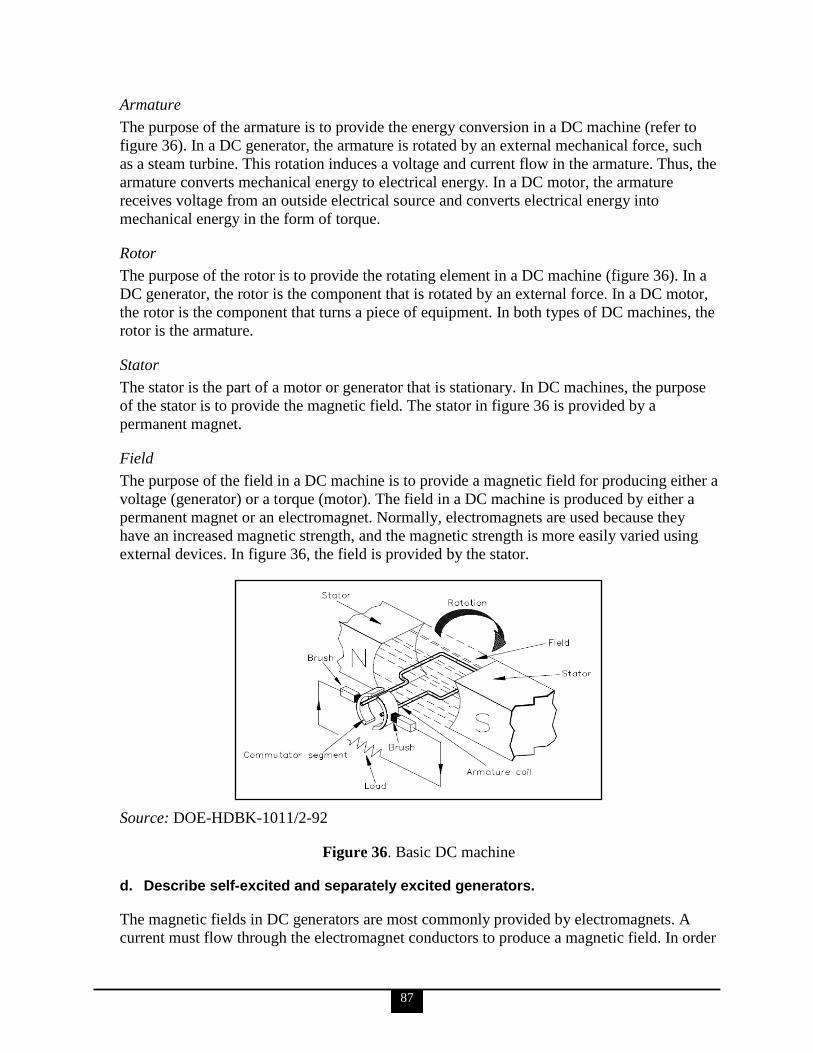
87
Armature
The purpose of the armature is to provide the energy conversion in a DC machine (refer to
figure 36). In a DC generator, the armature is rotated by an external mechanical force, such
as a steam turbine. This rotation induces a voltage and current flow in the armature. Thus, the
armature converts mechanical energy to electrical energy. In a DC motor, the armature
receives voltage from an outside electrical source and converts electrical energy into
mechanical energy in the form of torque.
Rotor
The purpose of the rotor is to provide the rotating element in a DC machine (figure 36). In a
DC generator, the rotor is the component that is rotated by an external force. In a DC motor,
the rotor is the component that turns a piece of equipment. In both types of DC machines, the
rotor is the armature.
Stator
The stator is the part of a motor or generator that is stationary. In DC machines, the purpose
of the stator is to provide the magnetic field. The stator in figure 36 is provided by a
permanent magnet.
Field
The purpose of the field in a DC machine is to provide a magnetic field for producing either a
voltage (generator) or a torque (motor). The field in a DC machine is produced by either a
permanent magnet or an electromagnet. Normally, electromagnets are used because they
have an increased magnetic strength, and the magnetic strength is more easily varied using
external devices. In figure 36, the field is provided by the stator.
Source: DOE-HDBK-1011/2-92
Figure 36. Basic DC machine
d. Describe self-excited and separately excited generators.
The magnetic fields in DC generators are most commonly provided by electromagnets. A
current must flow through the electromagnet conductors to produce a magnetic field. In order
88
for a DC generator to operate properly, the magnetic field must always be in the same
direction. Therefore, the current through the field winding must be DC. This current is
known as the field excitation current and can be supplied to the field winding in one of two
ways. It can come from a separate DC source external to the generator (e.g., a separately
excited generator) or it can come directly from the output of the generator, in which case it is
called a self-excited generator.
In a self-excited generator, the field winding is connected directly to the generator output.
The field may be connected in series with the output, in parallel with the output, or a
combination of the two. Separate excitation requires an external source, such as a battery or
another DC source. It is generally more expensive than a self-excited generator. Separately
excited generators are, therefore, used only where self-excitation is not satisfactory. They
would be used in cases where the generator must respond quickly to an external control
source or where the generated voltage must be varied over a wide range during normal
operations.
e. Describe the operation of compound-wound generators.
Series-wound and shunt-wound generators have a disadvantage in that changes in load
current cause changes in generator output voltage. Many applications in which generators are
used require a more stable output voltage than can be supplied by a series-wound or shunt-
wound generator. One means of supplying a stable output voltage is by using a compound
generator. The compound generator has a field winding in parallel with the generator
armature (the same as a shunt-wound generator) and a field winding in series with the
generator armature (the same as a series-wound generator). The two windings of the
compounded generator are made such that their magnetic fields will either aid or oppose one
another. When the magnetic field flux is decreased, motor speed increases, for a constant
generated voltage.
f. Describe how the terminal voltage of a DC generator is adjusted.
DC generator output voltage is dependent on three factors: the number of conductor loops in
series in the armature, armature speed, and magnetic field strength. In order to change the
generator output, one of these three factors must be varied. The number of conductors in the
armature cannot be changed in a normally operating generator, and it is usually impractical to
change the speed at which the armature rotates. The strength of the magnetic field, however,
can be changed quite easily by varying the current through the field winding. This is the most
widely used method for regulating the output voltage of a DC generator.
g. State the basis behind each DC generator rating.
A DC generator contains four ratings: voltage, current, power, and speed.
Voltage
The voltage rating of a machine is based on the insulation type and design of the machine.
89
Current
The current rating is based on the size of the conductor and the amount of heat that can be
dissipated in the generator.
Power
The power rating is based on the mechanical limitations of the device that is used to turn the
generator and on the thermal limits of conductors, bearings, and other components of the
generator.
Speed
The speed rating, at the upper limit, is determined by the speed at which mechanical damage
is done to the machine. The lower speed rating is based on the limit for field current (as
speed increases, a higher field current is necessary to produce the same voltage).
h. Describe the internal losses found in a DC generator.
There are four internal losses that contribute to lower efficiency of a DC generator: copper
losses, eddy-current losses, hysteresis losses, and mechanical losses.
Copper Losses
Copper loss is the power lost as heat in the windings; it is caused by the flow of current
through the coils of the DC armature or DC field. This loss varies directly with the square of
the current in the armature or field and the resistance of the armature or field coils.
Eddy-Current Losses
As the armature rotates within the field, it cuts the lines of flux at the same time that the
copper coils of wire that are wound on the armature cut the lines of flux. Since the armature
is made of iron, an EMF is induced in the iron, which causes a current to flow. These
circulating currents within the iron core are called eddy currents. To reduce eddy currents,
the armature and field cores are constructed from laminated (layered) steel sheets. The
laminated sheets are insulated from one another so that current cannot flow from one sheet to
the other.
Hysteresis Losses
Hysteresis losses occur when the armature rotates in a magnetic field. The magnetic domains
of the armature are held in alignment with the field in varying numbers, dependent upon field
strength. The magnetic domains rotate, with respect to the particles not held in alignment, by
one complete turn during each rotation of the armature. This rotation of magnetic domains in
the iron causes friction and heat. The heat produced by this friction is called magnetic
hysteresis loss. To reduce hysteresis losses, most DC armatures are constructed of heat-
treated silicon steel, which has an inherently low hysteresis loss. After the heat-treated silicon
steel is formed to the desired shape, the laminations are heated to a dull red and then allowed
to cool. This process, known as annealing, reduces hysteresis losses to a very low value.
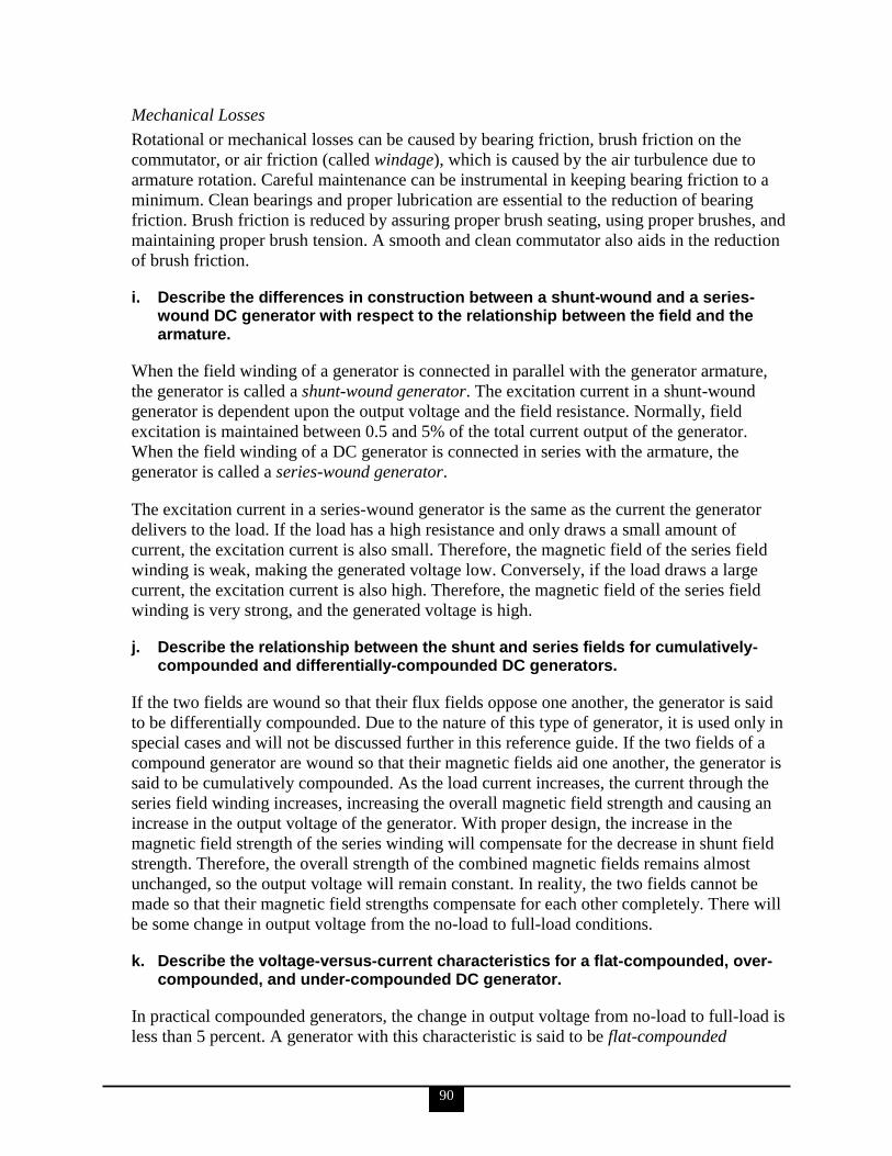
90
Mechanical Losses
Rotational or mechanical losses can be caused by bearing friction, brush friction on the
commutator, or air friction (called windage), which is caused by the air turbulence due to
armature rotation. Careful maintenance can be instrumental in keeping bearing friction to a
minimum. Clean bearings and proper lubrication are essential to the reduction of bearing
friction. Brush friction is reduced by assuring proper brush seating, using proper brushes, and
maintaining proper brush tension. A smooth and clean commutator also aids in the reduction
of brush friction.
i. Describe the differences in construction between a shunt-wound and a series-wound DC generator with respect to the relationship between the field and the armature.
When the field winding of a generator is connected in parallel with the generator armature,
the generator is called a shunt-wound generator. The excitation current in a shunt-wound
generator is dependent upon the output voltage and the field resistance. Normally, field
excitation is maintained between 0.5 and 5% of the total current output of the generator.
When the field winding of a DC generator is connected in series with the armature, the
generator is called a series-wound generator.
The excitation current in a series-wound generator is the same as the current the generator
delivers to the load. If the load has a high resistance and only draws a small amount of
current, the excitation current is also small. Therefore, the magnetic field of the series field
winding is weak, making the generated voltage low. Conversely, if the load draws a large
current, the excitation current is also high. Therefore, the magnetic field of the series field
winding is very strong, and the generated voltage is high.
j. Describe the relationship between the shunt and series fields for cumulatively-compounded and differentially-compounded DC generators.
If the two fields are wound so that their flux fields oppose one another, the generator is said
to be differentially compounded. Due to the nature of this type of generator, it is used only in
special cases and will not be discussed further in this reference guide. If the two fields of a
compound generator are wound so that their magnetic fields aid one another, the generator is
said to be cumulatively compounded. As the load current increases, the current through the
series field winding increases, increasing the overall magnetic field strength and causing an
increase in the output voltage of the generator. With proper design, the increase in the
magnetic field strength of the series winding will compensate for the decrease in shunt field
strength. Therefore, the overall strength of the combined magnetic fields remains almost
unchanged, so the output voltage will remain constant. In reality, the two fields cannot be
made so that their magnetic field strengths compensate for each other completely. There will
be some change in output voltage from the no-load to full-load conditions.
k. Describe the voltage-versus-current characteristics for a flat-compounded, over-compounded, and under-compounded DC generator.
In practical compounded generators, the change in output voltage from no-load to full-load is
less than 5 percent. A generator with this characteristic is said to be flat-compounded
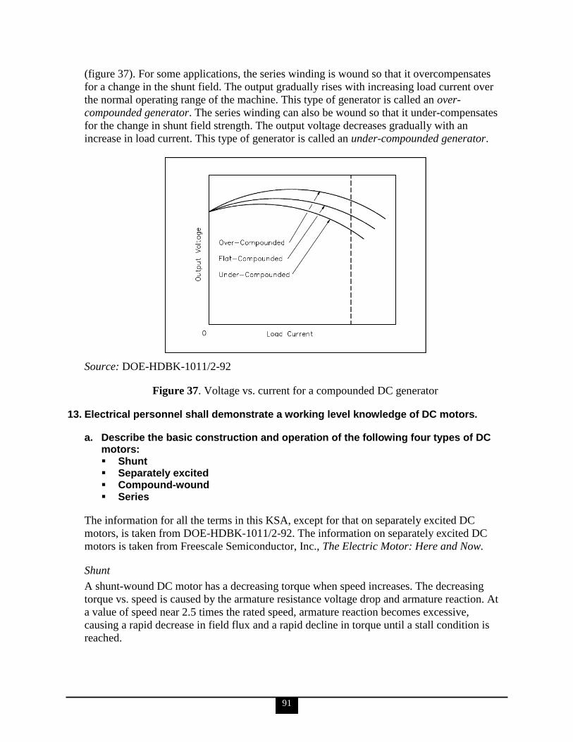
91
(figure 37). For some applications, the series winding is wound so that it overcompensates
for a change in the shunt field. The output gradually rises with increasing load current over
the normal operating range of the machine. This type of generator is called an over-
compounded generator. The series winding can also be wound so that it under-compensates
for the change in shunt field strength. The output voltage decreases gradually with an
increase in load current. This type of generator is called an under-compounded generator.
Source: DOE-HDBK-1011/2-92
Figure 37. Voltage vs. current for a compounded DC generator
13. Electrical personnel shall demonstrate a working level knowledge of DC motors.
a. Describe the basic construction and operation of the following four types of DC motors: Shunt Separately excited Compound-wound Series
The information for all the terms in this KSA, except for that on separately excited DC
motors, is taken from DOE-HDBK-1011/2-92. The information on separately excited DC
motors is taken from Freescale Semiconductor, Inc., The Electric Motor: Here and Now.
Shunt
A shunt-wound DC motor has a decreasing torque when speed increases. The decreasing
torque vs. speed is caused by the armature resistance voltage drop and armature reaction. At
a value of speed near 2.5 times the rated speed, armature reaction becomes excessive,
causing a rapid decrease in field flux and a rapid decline in torque until a stall condition is
reached.

92
The characteristics of a shunt-wound motor give it very good speed regulation, and it is
classified as a constant speed motor, even though the speed does slightly decrease as load is
increased.
Shunt-wound motors are used in industrial and automotive applications where precise control
of speed and torque are required.
Separately Excited
In many traction applications where both armature voltage and stator current are needed to
control the speed and torque of the motor from no load to full load, the separately excited DC
motor is used for its high-torque capability at low speed, achieved by separately generating a
high stator field current and enough armature voltage to produce the required rotor torque
current. As torque decreases and speed increases, the stator field current requirement
decreases and the armature voltage increases. Without a load (known as zero torque speed),
the speed of the separately excited motor is strictly limited by the armature voltage and stator
field current.
Separately excited DC motors are the first type of motor to use closed-loop control and can
also be used in servo systems for control of speed and/or position.
Compound-Wound
The compounded motor is desirable for a variety of applications because it combines the
characteristics of a series-wound motor and a shunt-wound motor. The compounded motor
has a greater torque than a shunt motor due to the series field; however, it has a fairly
constant speed due to the shunt field winding. Loads such as presses, shears, and
reciprocating machines are often driven by compounded motors.
Series
Since the armature and field in a series-wound motor are connected in series, the armature
and field currents become identical. As the speed decreases, the torque for a series-wound
motor increases sharply. As load is removed from a series motor, the speed will increase
sharply. For these reasons, series-wound motors must have a load connected to prevent
damage from high speed conditions.
The advantage of a series-wound motor is that it develops a large torque and can be operated
at low speed. It is a motor that is well-suited for starting heavy loads; it is often used for
industrial cranes and winches where very heavy loads must be moved slowly and lighter
loads moved more rapidly.
b. State the function of torque in a DC motor and explain how it is developed.
The information for KSAs ‗b‘ through ‗h‘ is taken from DOE-HDBK-1011/2-92.
Torque is defined as that force that tends to produce and maintain rotation. The function of
torque in a DC motor is to provide the mechanical output or drive the piece of equipment that
the DC motor is attached to.
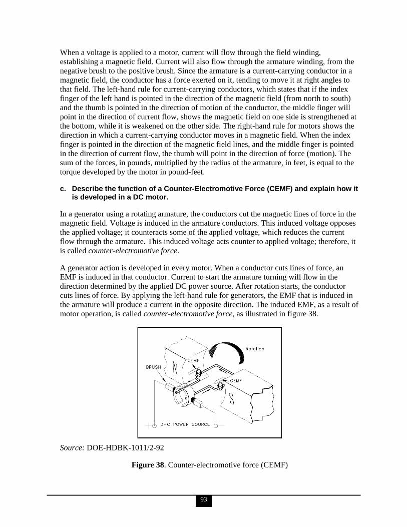
93
When a voltage is applied to a motor, current will flow through the field winding,
establishing a magnetic field. Current will also flow through the armature winding, from the
negative brush to the positive brush. Since the armature is a current-carrying conductor in a
magnetic field, the conductor has a force exerted on it, tending to move it at right angles to
that field. The left-hand rule for current-carrying conductors, which states that if the index
finger of the left hand is pointed in the direction of the magnetic field (from north to south)
and the thumb is pointed in the direction of motion of the conductor, the middle finger will
point in the direction of current flow, shows the magnetic field on one side is strengthened at
the bottom, while it is weakened on the other side. The right-hand rule for motors shows the
direction in which a current-carrying conductor moves in a magnetic field. When the index
finger is pointed in the direction of the magnetic field lines, and the middle finger is pointed
in the direction of current flow, the thumb will point in the direction of force (motion). The
sum of the forces, in pounds, multiplied by the radius of the armature, in feet, is equal to the
torque developed by the motor in pound-feet.
c. Describe the function of a Counter-Electromotive Force (CEMF) and explain how it is developed in a DC motor.
In a generator using a rotating armature, the conductors cut the magnetic lines of force in the
magnetic field. Voltage is induced in the armature conductors. This induced voltage opposes
the applied voltage; it counteracts some of the applied voltage, which reduces the current
flow through the armature. This induced voltage acts counter to applied voltage; therefore, it
is called counter-electromotive force.
A generator action is developed in every motor. When a conductor cuts lines of force, an
EMF is induced in that conductor. Current to start the armature turning will flow in the
direction determined by the applied DC power source. After rotation starts, the conductor
cuts lines of force. By applying the left-hand rule for generators, the EMF that is induced in
the armature will produce a current in the opposite direction. The induced EMF, as a result of
motor operation, is called counter-electromotive force, as illustrated in figure 38.
Source: DOE-HDBK-1011/2-92
Figure 38. Counter-electromotive force (CEMF)
94
Since the CEMF is generated by the action of the armature cutting lines of force, the value of
CEMF will depend on field strength and armature speed, as shown in the following equation:
ECEMF = K N
where
ECEMF = counter-electromotive force
K = constant
= field flux strength
N = speed of the armature
d. Describe the relationship between field current and magnetic field size in a DC motor.
There are two conditions that are necessary to produce a force on a conductor: the conductor
must be carrying current, and the conductor must be within a magnetic field. When these two
conditions exist, a force will be applied to the conductor, which will attempt to move the
conductor in a direction perpendicular to the magnetic field. This is the basic theory by which
all DC motors operate.
In figure 39, above the conductor on the left, the field caused by the conductor is in the
opposite direction of the main field, and therefore opposes the main field. Below the
conductor on the left, the field caused by the conductor is in the same direction as the main
field, and therefore aids the main field. The net result is that above the conductor the main
field is weakened, or flux density is decreased; below the conductor the field is strengthened,
or flux density is increased. A force is developed on the conductor that moves the conductor
in the direction of the weakened field (upward).
Source: DOE-HDBK-1011/2-92
Figure 39. Current-carrying conductors in a magnetic field
Above the conductor on the right, the field caused by the conductor is in the same direction
as the main field, and therefore aids the main field. Below the conductor on the right, the
field caused by the conductor is in the opposite direction of the main field, and therefore
opposes the main field. The net result is that above the conductor the field is strengthened, or
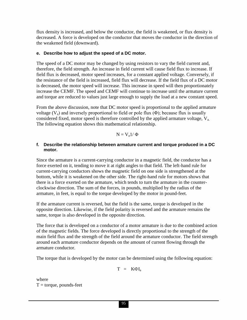
95
flux density is increased, and below the conductor, the field is weakened, or flux density is
decreased. A force is developed on the conductor that moves the conductor in the direction of
the weakened field (downward).
e. Describe how to adjust the speed of a DC motor.
The speed of a DC motor may be changed by using resistors to vary the field current and,
therefore, the field strength. An increase in field current will cause field flux to increase. If
field flux is decreased, motor speed increases, for a constant applied voltage. Conversely, if
the resistance of the field is increased, field flux will decrease. If the field flux of a DC motor
is decreased, the motor speed will increase. This increase in speed will then proportionately
increase the CEMF. The speed and CEMF will continue to increase until the armature current
and torque are reduced to values just large enough to supply the load at a new constant speed.
From the above discussion, note that DC motor speed is proportional to the applied armature
voltage (Va) and inversely proportional to field or pole flux (Φ); because flux is usually
considered fixed, motor speed is therefore controlled by the applied armature voltage, Va.
The following equation shows this mathematical relationship.
N = Va1/ Φ
f. Describe the relationship between armature current and torque produced in a DC motor.
Since the armature is a current-carrying conductor in a magnetic field, the conductor has a
force exerted on it, tending to move it at right angles to that field. The left-hand rule for
current-carrying conductors shows the magnetic field on one side is strengthened at the
bottom, while it is weakened on the other side. The right-hand rule for motors shows that
there is a force exerted on the armature, which tends to turn the armature in the counter-
clockwise direction. The sum of the forces, in pounds, multiplied by the radius of the
armature, in feet, is equal to the torque developed by the motor in pound-feet.
If the armature current is reversed, but the field is the same, torque is developed in the
opposite direction. Likewise, if the field polarity is reversed and the armature remains the
same, torque is also developed in the opposite direction.
The force that is developed on a conductor of a motor armature is due to the combined action
of the magnetic fields. The force developed is directly proportional to the strength of the
main field flux and the strength of the field around the armature conductor. The field strength
around each armature conductor depends on the amount of current flowing through the
armature conductor.
The torque that is developed by the motor can be determined using the following equation:
T = K Ia
where
T = torque, pounds-feet
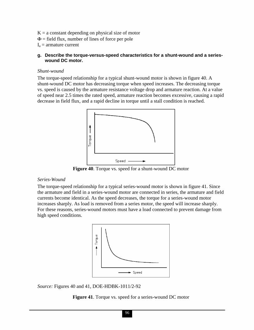
96
K = a constant depending on physical size of motor
= field flux, number of lines of force per pole
Ia = armature current
g. Describe the torque-versus-speed characteristics for a shunt-wound and a series-wound DC motor.
Shunt-wound
The torque-speed relationship for a typical shunt-wound motor is shown in figure 40. A
shunt-wound DC motor has decreasing torque when speed increases. The decreasing torque
vs. speed is caused by the armature resistance voltage drop and armature reaction. At a value
of speed near 2.5 times the rated speed, armature reaction becomes excessive, causing a rapid
decrease in field flux, and a rapid decline in torque until a stall condition is reached.
Figure 40. Torque vs. speed for a shunt-wound DC motor
Series-Wound
The torque-speed relationship for a typical series-wound motor is shown in figure 41. Since
the armature and field in a series-wound motor are connected in series, the armature and field
currents become identical. As the speed decreases, the torque for a series-wound motor
increases sharply. As load is removed from a series motor, the speed will increase sharply.
For these reasons, series-wound motors must have a load connected to prevent damage from
high speed conditions.
Source: Figures 40 and 41, DOE-HDBK-1011/2-92
Figure 41. Torque vs. speed for a series-wound DC motor

97
h. Explain why starting resistors may be necessary for large DC motors.
The starting resistors are used in a DC motor by placing them in the starting circuit of the
motor controller that is used to start the DC motor. Starting resistors are normally of variable
resistances, with the value of resistance in the circuit at any time being either manually or
automatically controlled. The maximum amount of resistance will always be inserted when
the motor is first started. As the speed of the motor increases, CEMF will begin to increase,
decreasing armature current. The starting resistors may then be cut out, in successive steps,
until the motor reaches full running speed.
14. Electrical personnel shall demonstrate a working level knowledge of battery construction, voltage production, and hazards (IEEE Std-450, etc.).
a. Using a cutaway drawing of a simple multi-cell storage battery, identify the following components and discuss their function: Positive terminal Negative terminal Electrode Cell
The information for KSAs ‗a‘ and ‗b‘ is taken from DOE-HDBK-1011/2-92.
The purpose of a battery is to store chemical energy and to convert this chemical energy into
electrical energy when the need arises. A chemical cell (or voltaic cell) consists of two
electrodes of different types of metals or metallic compounds and an electrolyte solution that
is capable of conducting an electric current, as illustrated in figure 42.
A good example of a voltaic cell is one that contains zinc and copper electrodes. The zinc
electrode contains an abundance of negatively charged atoms, and the copper electrode
contains an abundance of positively charged atoms. When these electrodes are immersed in
an electrolyte, chemical action begins. The zinc electrode will accumulate a much larger
negative charge because it dissolves into the electrolyte. The atoms, which leave the zinc
electrode, are positively charged and are attracted by the negatively charged ions of the
electrolyte; the atoms repel the positively charged ions of the electrolyte toward the copper
electrode. Positive and negative terminals correspond with the positive and negative ionic
charges.
Source: DOE-HDBK-1011/2-92
Figure 42. Basic chemical production of electrical power
98
b. Describe the hazards associated with storage batteries.
Short circuits cause a great reduction in battery capacity. To prevent short circuits in a
battery, overcharging and over-discharging should be avoided at all costs.
If gassing occurs and the gases are allowed to collect, an explosive mixture of hydrogen and
oxygen can be readily produced. To reduce the amount of gassing, charging voltages above
2.30 volts per cell should be minimized.
Higher temperatures will give some additional capacity, but they will eventually reduce the
life of the battery. Very high temperatures, 125°F and higher, can actually do damage to the
battery and cause early failure.
Low temperatures will lower battery capacity but also prolong battery life under floating (i.e.,
slightly charging) operation or storage. Extremely low temperatures can freeze the
electrolyte, but only if the battery is low in specific gravity.
c. Define the following terms: Voltaic cell Battery Electrode Electrolyte Specific gravity Ampere-hour Electrolysis Equalizing charge Float charge Pilot cell
All of these definitions are taken from DOE-HDBK-1011/2-92 except as follows.
Electrolysis, equalizing charge and float charge are taken from DOE-HDBK-1084-95, and
pilot cell is taken from DOE-SPEC-3019-96.
Voltaic Cell
The term ―voltaic cell‖ is defined as a combination of materials used to convert chemical
energy into electrical energy. A voltaic or chemical cell consists of two electrodes made of
different types of metals or metallic compounds placed in an electrolyte solution.
Battery
A battery is a group of two or more connected voltaic cells.
Electrode
An electrode is a metallic compound, or metal, that has an abundance of electrons (negative
electrode) or an abundance of positive charges (positive electrode).
99
Electrolyte
An electrolyte is a solution that is capable of conducting an electric current. The electrolyte
of a cell may be a liquid or a paste. If the electrolyte is a paste, the cell is referred to as a dry
cell; if the electrolyte is a liquid, it is called a wet cell.
Specific Gravity
Specific gravity is defined as the ratio comparing the weight of any liquid to the weight of an
equal volume of water. The specific gravity of pure water is 1.000. Lead-acid batteries use an
electrolyte that contains sulfuric acid. Pure sulfuric acid has a specific gravity of 1.835; it
weighs 1.835 times as much as pure water per unit volume.
Since the electrolyte of a lead-acid battery consists of a mixture of water and sulfuric acid,
the specific gravity of the electrolyte will fall between 1.000 and 1.835. Normally, the
electrolyte for a battery is mixed such that the specific gravity is less than 1.350.
Specific gravity is measured with a hydrometer. A simple hydrometer consists of a glass float
inside a glass tube. The hydrometer float is weighted at one end and sealed at both ends. A
scale calibrated in specific gravity is positioned lengthwise along the body of the float. The
float is placed inside the glass tube, and the fluid to be tested is drawn into the tube. As the
fluid is drawn into the tube, the hydrometer float will sink to a certain level in the fluid. The
extent to which the hydrometer float protrudes above the level of the fluid depends on the
specific gravity of the fluid. The reading on the float scale at the surface of the fluid is the
specific gravity of the fluid.
Ampere-Hour
An ampere-hour is defined as a current of one ampere flowing for 1 hour. If the current in
amperes is multiplied by the time of flow in hours, the result is the total number of ampere-
hours. Ampere-hours are normally used to indicate the amount of energy a storage battery
can deliver.
Electrolysis
Electrolysis is the chemical dissociation of water into hydrogen and oxygen gas caused by
passage of an electrical current.
Equalizing charge
Equalizing charge is the charge applied to a battery which is greater than the normal float
charge and is used to completely restore the active materials in the cell, bringing the cell float
voltage and the specific gravity of the individual cells back to ―equal‖ values.
Float Charge
Float charge is the method of charging in which a secondary cell is continuously connected
to a constant-voltage supply that maintains the cell in a fully charged condition.
Pilot Cell
A pilot cell is a selected cell whose condition is assumed to indicate the condition of the
entire battery string. The pilot cell is usually selected for representative measurements for a

100
select period of time. Once this time period has elapsed, another cell from the battery string is
selected in turn to be the pilot cell.
d. Describe the operation of a simple voltaic cell.
The information for KSAs ‗d‘ through ‗i‘ is taken from DOE-HDBK-1011/2-92.
A voltaic cell consists of two electrodes of different types of metals or metallic compounds
and an electrolyte solution that is capable of conducting an electric current. A good example
of a voltaic cell is one that contains zinc and copper electrodes. The zinc electrode contains
an abundance of negatively charged atoms, and the copper electrode contains an abundance
of positively charged atoms. When these electrodes are immersed in an electrolyte, chemical
action begins. The zinc electrode will accumulate a much larger negative charge because it
dissolves into the electrolyte. The atoms, which leave the zinc electrode, are positively
charged and are attracted by the negatively charged ions of the electrolyte; the atoms repel
the positively charged ions of the electrolyte toward the copper electrode.
e. Explain the relationship between specific gravity and state of charge of a lead-acid battery.
The decrease in specific gravity on discharge is proportional to the ampere-hours discharged.
While charging a lead-acid battery, the rise in specific gravity is not uniform, or proportional,
to the amount of ampere-hours charged. The electrolyte in a lead-acid battery plays a direct
role in the chemical reaction. The specific gravity decreases as the battery discharges and
increases to its normal, original value as it is charged. Since specific gravity of a lead-acid
battery decreases proportionally during discharge, the value of specific gravity at any given
time is an approximate indication of the battery‘s state of charge. To determine the state of
charge, compare the specific gravity, as read using a hydrometer, with the full charge value
and the manufacturer‘s published specific gravity drop, which is the decrease from full to
nominal charge value.
f. Describe the relationship between total battery voltage and individual cell voltage for a series-connected battery.
When several cells are connected in series, the total voltage output of the battery is equal to
the sum of the individual cell voltages. When cells are connected in series, the positive
terminal of one cell is connected to the negative terminal of the next cell. The current flow
through a battery connected in series is the same as for one cell.
g. Explain the advantage of connecting a battery in parallel with respect to current-carrying capability.
Cells connected in parallel, as in figure 43, give the battery a greater current capacity. When
cells are connected in parallel, all the positive terminals are connected together, and all the
negative terminals are connected together. The total voltage output of a battery connected in
parallel is the same as that of a single cell. Cells connected in parallel have the same effect as
increasing the size of the electrodes and electrolyte in a single cell. The advantage of
connecting cells in parallel is the increase in current-carrying capability of the battery.
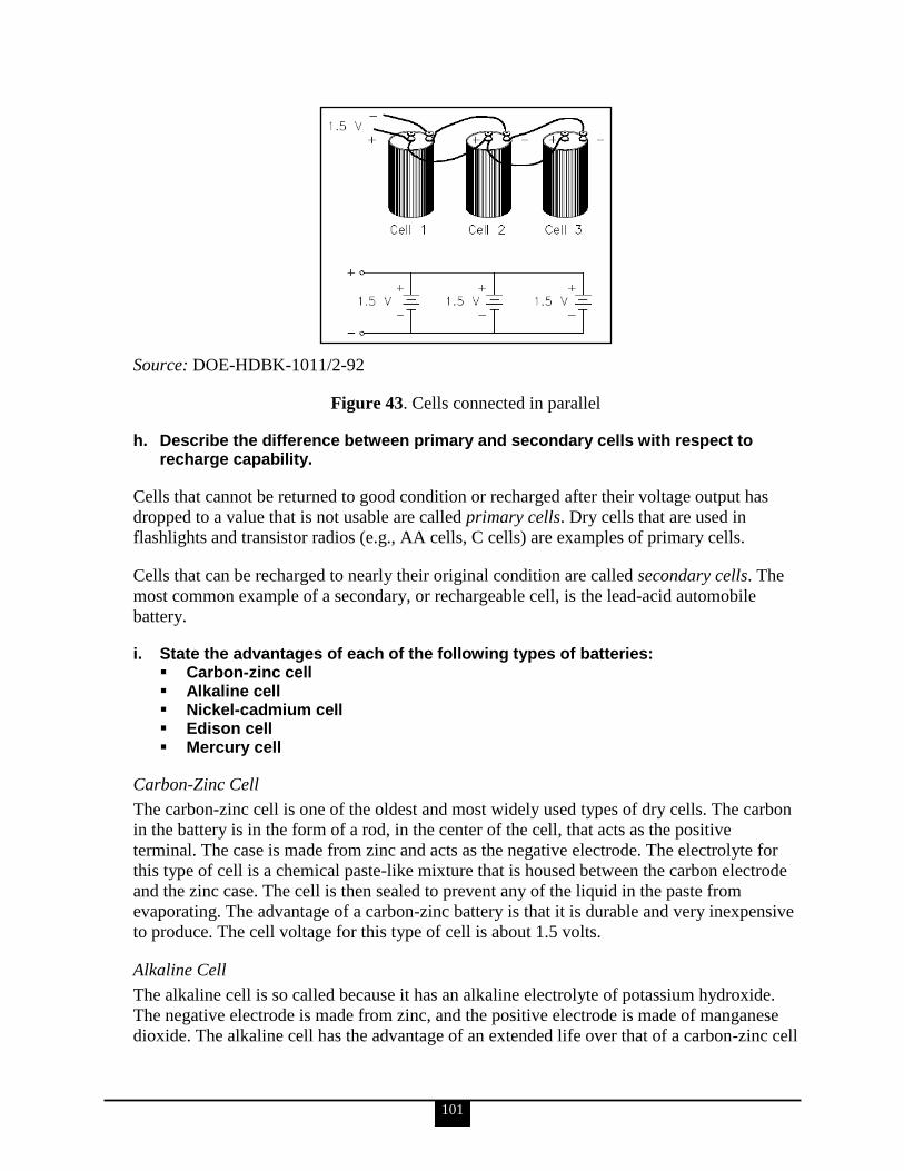
101
Source: DOE-HDBK-1011/2-92
Figure 43. Cells connected in parallel
h. Describe the difference between primary and secondary cells with respect to recharge capability.
Cells that cannot be returned to good condition or recharged after their voltage output has
dropped to a value that is not usable are called primary cells. Dry cells that are used in
flashlights and transistor radios (e.g., AA cells, C cells) are examples of primary cells.
Cells that can be recharged to nearly their original condition are called secondary cells. The
most common example of a secondary, or rechargeable cell, is the lead-acid automobile
battery.
i. State the advantages of each of the following types of batteries: Carbon-zinc cell Alkaline cell Nickel-cadmium cell Edison cell Mercury cell
Carbon-Zinc Cell
The carbon-zinc cell is one of the oldest and most widely used types of dry cells. The carbon
in the battery is in the form of a rod, in the center of the cell, that acts as the positive
terminal. The case is made from zinc and acts as the negative electrode. The electrolyte for
this type of cell is a chemical paste-like mixture that is housed between the carbon electrode
and the zinc case. The cell is then sealed to prevent any of the liquid in the paste from
evaporating. The advantage of a carbon-zinc battery is that it is durable and very inexpensive
to produce. The cell voltage for this type of cell is about 1.5 volts.
Alkaline Cell
The alkaline cell is so called because it has an alkaline electrolyte of potassium hydroxide.
The negative electrode is made from zinc, and the positive electrode is made of manganese
dioxide. The alkaline cell has the advantage of an extended life over that of a carbon-zinc cell
102
of the same size; however, it is usually more expensive. The typical alkaline cell generates
1.5 volts.
Nickel-Cadmium Cell
The nickel-cadmium cell is a secondary cell, and the electrolyte is potassium hydroxide. The
negative electrode is made of nickel hydroxide, and the positive electrode is made of
cadmium hydroxide. The nickel-cadmium battery has the advantage of being a dry cell that is
a true storage battery with a reversible chemical reaction (i.e., it can be recharged). It is a
rugged, dependable battery that gives dependable service under extreme conditions of
temperature, shock, and vibration. Due to its dependability, it is ideally suited for use in
portable communications equipment. The nominal voltage of a nickel-cadmium cell is
1.25 volts.
Edison Cell
In an Edison cell the positive plate consists of nickel and nickel hydrate, and the negative
plate is made of iron. The electrolyte is alkaline. The Edison cell has the advantage of being a
lighter and more rugged secondary cell than a lead-acid storage battery. Typical voltage
output is 1.4 volts, and it should be recharged when it reaches 1.0 volts.
Mercury Cell
Mercury cells come in two types: (1) flat cell that is shaped like a button and (2) cylindrical
cell that looks like a regular flashlight battery. These cells are very rugged and have a
relatively long shelf life. The mercury cell has the advantage of maintaining a fairly constant
output under varying load conditions. For this reason, they are used in products such as
electric watches, hearing aids, cameras, and test instruments. Each cell produces about
1.35 volts.
j. Explain how gas generation is minimized for a lead-acid battery and list the steps to prevent hydrogen buildup.
The following 3 paragraphs are taken from DOE-HDBK-1011/2-92.
A lead-acid battery cannot absorb all the energy from the charging source when the battery is
nearing the completion of the charge. This excess energy dissociates water by way of
electrolysis into hydrogen and oxygen. Oxygen is produced by the positive plate, and
hydrogen is produced by the negative plate. This process is known as gassing.
Gassing is first noticed when cell voltage reaches 2.30–2.35 volts per cell and increases as
the charge progresses. At full charge, the amount of hydrogen produced is about one cubic
foot per cell for each 63 ampere-hours input. If gassing occurs and the gases are allowed to
collect, an explosive mixture of hydrogen and oxygen can be readily produced. It is
necessary, therefore, to ensure that the area is well ventilated and that it remains free of any
open flames or spark-producing equipment.
As long as battery voltage is greater than 2.30 volts per cell, gassing will occur and cannot be
prevented entirely. To reduce the amount of gassing, charging voltages above 2.30 volts per
cell should be minimized (e.g., 13.8 volts for a 12 volt battery).
103
The following paragraph is taken from DOE-HDBK-1084-95.
With good air circulation around a battery, hydrogen accumulation is normally not a
problem. However, if relatively large batteries are confined in small rooms, exhaust fans
should be installed to vent the room constantly or to be turned on automatically when
hydrogen accumulation exceeds 20% of the lower explosive limit. Battery boxes should also
be vented to the atmosphere. Sparks or flame can ignite these hydrogen mixtures above the
LEL. To prevent ignition, electrical sources of arcs, sparks, or flame should be mounted in
explosion-proof metal boxes. Flooded batteries can similarly be equipped with flame
arrestors in the vents to prevent outside sparks from igniting explosive gases inside the cell
cases. It is mandatory to refrain from smoking, using open flames, or creating sparks in the
vicinity of the battery.
k. Explain how heat is generated in a lead-acid battery.
The following is taken from DOE-HDBK-1011/2-92.
Whenever a lead-acid battery is charged, the current flowing through the battery will cause
heat to be generated by the electrolysis of water. The current flowing through the battery (I)
will also cause heat to be generated (P) during charge and discharge as it passes through the
internal resistance (Ri), as illustrated in the following formula:
P = I2Ri
l. Describe the various uses of battery banks in DOE facilities.
The following is taken from Renewable Energy Resource Center, Solar Electric Basics.
A battery bank, comprising several batteries linked together, collects and stores energy for
periods when power is not available, when a surplus of power is desired, or when there is an
outage.
Several factors can be used to help determine the size of the battery bank. These include the
electric load, the duration of required reserve power, and the availability of a source of
backup power (grid or generator). A good quality, lead-acid battery bank will last from
500 to 1,000 charge-discharge cycles depending on depth of discharge and attention to
maintenance considerations. A battery box is needed to enclose the battery bank. The box
contains potential acid spills, keeps out unfamiliar persons, and keeps objects from falling on
the batteries, possibly damaging or shorting battery terminals.
m. Describe how batteries are tested.
The following is taken from DOE-HDBK-1084-95.
Batteries should be tested at regular intervals to (a) determine whether the battery meets its
specification or the manufacturer‘s rating, or both; (b) periodically determine whether the
performance of the battery, as found, is within acceptable limits, and (c) if required,
determine whether the battery as found meets the design requirements of the system to which
104
it is connected. The schedule and procedure for battery capacity tests should be performed
according to the requirements of ANSI/IEEE 450, IEEE Recommended Practice for
Maintenance, Testing, and Replacement of Large Lead Storage Batteries for Generating
Stations and Substations.
For an acceptance or performance test, use the following equation to determine battery
capacity:
% capacity at 25ºC (77ºF) = Ta/Ts • 100
where:
Ta = actual time of test to specified terminal voltage
Ts = rated time to specified terminal voltage.
ANSI/IEEE 450 recommends replacement of a battery if its capacity as determined from the
equation above is less than 80% manufacturer‘s rating. A capacity of 80% shows that the
battery rate of deterioration is increasing even if there is ample capacity to meet load
requirements. If individual cells are required to be replaced, they should be compatible with
existing cells and tested prior to installation. It is recommended that when one or more
cells/jars are replaced the entire battery string be replaced in order to prevent large
differences in cell impedance. If uncorrected, this may result in unequal charging of the
battery string.
II. ELECTRICAL ISSUE IDENTIFICATION & REPORTING
15. Electrical personnel shall demonstrate a working level knowledge of surveillance and assessment techniques, reporting, and follow up actions for electrical systems and programmatic elements of an electrical safety program, such as management systems, problem remediation and trends processes, inspection programs, training and qualification programs, and oversight of contractor assurance systems.
a. Describe the role of electrical personnel in performance oversight of Government-owned, Contractor-operated (GOCO) facilities.
The information for KSAs ‗a‘ and ‗b‘ is taken from DOE-O-226.1.A.
Periodically, a company should perform a self-assessment to determine how well their
written electrical safety program is actually being implemented. To be of value, the
assessment should be very objective, without trying to blame people. The goal is to improve
the safety performance, not to punish employees. Besides, if the program is not being carried
out effectively, a significant part of the blame belongs to management. Occasionally, it is
also prudent to have the company‘s safety organization, or even an outside-contracted safety
auditor, perform an electrical safety audit. This way, a set of eyes that is not so familiar with
the facility, and does not have a fear of retaliation from local management, can discover
things that self-assessors might overlook.
The electrical safety program should contain a requirement that the written program itself be
occasionally audited. The auditing should be designed to identify new or revised
105
requirements, as well as weaknesses in the system. Attention should be paid not only to the
written work practices and procedural requirements, but also to how well personnel appear to
understand and implement these requirements.
Whenever electrical safety-related incidents or accidents occur, there should be a thorough
investigation to determine the root cause and contributing factors. As a result of the
investigation, actions should be taken to prevent a recurrence of the incident. Lessons-learned
information should be distributed to all personnel who could get involved in, or influence
decisions about, similar future situations.
Additionally, an effective oversight process enables contractors to incorporate the following
as appropriate:
Federal Responsibility and Accountability for Activities
DOE line management will require that contracts adequately delineate contractor
responsibilities for programs, management systems, and assurance programs. Contractors
will be responsible under their contracts to provide these assurances. DOE line management
and contractors may perform some assessments jointly to increase efficiency and promote
common understanding of processes and results. However, DOE line management is
responsible and accountable for understanding and accepting the hazards and risks associated
with activities. To accomplish this, DOE has the right and responsibility to perform oversight
at the level necessary to understand the hazards and risks, to ensure compliance with
applicable requirements, to pursue excellence through continuous improvement, to ensure
timely identification and correction of deficient conditions, and to verify the effectiveness of
completed corrective actions.
Program Plan
Documented program plans need to identify the program areas to be reviewed, the periodicity
of reviews, the reviews necessary to maintain the baseline oversight program, the
qualifications of review personnel, and the source of review criteria. Documented program
plans need to describe the various oversight methods used, how they are used, and how the
results of the various methods are integrated and considered as a whole to give an accurate
oversight picture.
Continuous Improvement
Assurance systems and oversight processes will identify ways to make programs more
effective and efficient through improved performance and report such opportunities to line
managers for their consideration. Line managers at all levels are responsible for using the
results of DOE line and independent oversight processes and assurance systems. These
results are to be used to make informed decisions about corrective actions that will improve
the effectiveness and efficiency of their programs and operations and about the acceptability
of residual risks. The use of external, nationally recognized experts should be considered to
carry out independent risk and vulnerability studies and to validate that contractor
management systems meet applicable standards. DOE sites and DOE line management must
have effective processes for communicating issues up the management chain to senior
management using a graded approach that considers hazards and risks. The processes must

106
provide sufficient technical basis to allow managers to make informed decisions. Processes
for resolving disputes about oversight findings and other significant issues shall also be
implemented and include provisions for independent technical reviews of significant issues.
Requirements and Performance Objectives
DOE oversight programs and assurance systems will evaluate performance against
requirements and performance objectives, which may include laws, regulations, national
standards, DOE directives, DOE-approved plans and program documents (e.g., security
plans, authorization basis documents, and QA plans), site-specific procedures/manuals,
criteria review and DOE P 226.1A, Department of Energy Oversight Policy, approach
documents, other contractually mandated requirements, and contractual performance
objectives. Requirements and performance objectives are established and interpreted through
approved processes so that they are relevant to the site and mission.
Personnel Competence
Personnel responsible for managing and performing assurance and oversight functions will
possess experience, knowledge, skills, and abilities commensurate with their responsibilities.
Line managers are responsible for ensuring that their personnel with oversight
responsibilities meet applicable qualifications standards. Continuing training and
professional development activities are encouraged to supplement individual experience and
provide a means to maintain awareness of changes and advances in the various fields of
expertise.
Baseline Oversight Program and Priorities
Line management is responsible and accountable for establishing and implementing a
baseline oversight program that provides for an adequate assessment of programs,
management systems, and assurance systems. Clear and unambiguous lines of authority and
responsibility for performing line management oversight functions will be established and
maintained. Line management will provide its oversight processes with sufficient resources
and access to conduct an effective oversight program. Site assurance systems and DOE
oversight processes will be tailored to be effective and efficient and will take into account
hazards and risks (including risks associated with potentially hazardous activities and risks to
DOE missions, including schedule, cost, and scope uncertainties). Oversight priorities are to
be based on a systematic analysis of hazards, risks, and past performance of organizations,
programs, and facilities, including previous assessment results. Higher hazard or risk
activities (e.g., facilities with a higher nuclear material attractiveness level) and less mature
programs will be assessed more frequently and/or in more depth. The scope and results of
reviews by external regulators (e.g., the Environmental Protection Agency) and organizations
(e.g., the Defense Nuclear Facilities Safety Board [DNFSB]) are important factors in
determining oversight priorities but are not a substitute for effective line management
oversight.
DOE Headquarters and field element line management regularly assess site assurance
systems to determine the appropriate level of overlap and redundancy of DOE Headquarters
and field element line management oversight. Accordingly, DOE line management
organizations may increase their frequency and/or depth based on performance deficiencies
107
or events or may decrease the frequency and/or depth of line management oversight
assessments to reflect sustained, effective site performance. Although external organization
reviews and the effectiveness of assurance systems are considered in determining DOE line
management oversight priorities and the scope and frequency of oversight activities, DOE
line management must always maintain an adequate minimum baseline oversight program
that enables DOE line management to understand the hazards and risks of activities.
Performance Indicators and Measures
Performance indicators and measures will be used as one mechanism to help line
management identify adverse trends and promote improvements. This data is considered in a
variety of DOE P 226.1A management decisions, such as allocating resources, establishing
goals, identifying performance trends, identifying potential problems, and applying lessons
learned and good practices. Site performance criteria will focus on results and system-based
metrics to drive improvements in site programs and management systems at DOE sites.
Self-Assessments of Line Management Functions
Line management must perform self-assessments of its activities, including its oversight
activities and activities necessary to support site assurance and mission activities.
Headquarters, field element, and contractor management organizations are responsible for
establishing effective management assessments and line management oversight processes
and to address shortcomings, identified through self-assessments, in their oversight
programs.
b. Describe the assessment requirements and limitations associated with the interface of electrical personnel and contractor employees.
A rigorous and credible assessment program is the cornerstone of effective, efficient
management of programs such as environment, safety, and health (EH&S); safeguards and
security; cyber security; and emergency management. Contractors will be responsible for
developing, implementing, and performing comprehensive assessments of all facilities,
systems, and organizational elements, including subcontractors, on a recurring basis. The
scope and frequency of assessments must be specified in site plans and program documents
(e.g., the QA program [QAP]) and must ensure that assessments required by applicable DOE
directives are being performed; the effectiveness of safety management programs, including
programs that are credited in the safety basis for nuclear facilities, are being assessed
adequately; deficiencies are being self-identified; and corrective actions are being taken in a
timely and effective manner. External peers or subject matter experts may be utilized to
support assessment activities.
Self-assessment is used to periodically evaluate performance at all levels and to determine
the effectiveness of policies, requirements, and standards and the implementation status (see
also DOE O 414.1C, Quality Assurance, criterion 9, ―Management Assessment‖).
Management self-assessments (also called management assessments) are performed by
contractor management, and are developed (scope and review criteria) based on the nature of
the facility/activity being assessed and the hazards and risks to be controlled. Self-
assessments, which focus on hands-on work and the implementation of administrative
processes, involve workers, supervisors, and managers to encourage identification and
108
resolution of deficiencies at the lowest level practicable (e.g., workplace inspections and
post-job reviews). Support organizations will perform self-assessments of their performance
and the adequacy of their processes. Contractors, at all levels, will assess the implementation
and adequacy of their processes, including analysis of the collective results of lower-level
self-assessments. Self-assessment results will be documented commensurate with the
significance of and risks associated with activities being evaluated. Deficiencies will be
accurately described and documented for evaluation and correction using formal issues
management processes.
Internal independent assessments will be performed by contractor organizations or personnel
that have authority and independence from line management, to support unbiased evaluations
(see also DOE O 414.1C, criterion 10, ―Independent Assessment‖). The assessments will be
formally planned and scheduled based on the risk, hazards, and complexity of the processes
and activities to be evaluated. Independent evaluators will be appropriately trained and
qualified and have knowledge of the areas assessed. Reviewers will be dedicated contractor
staff, members of external organizations, or both. Although independent assessments are
applied to individual activities and processes, they will typically focus on entire facilities or
projects, and programs and management processes that are used by multiple organizations.
Internal independent assessments will concentrate on performance and observation of work
activities and the results of process implementation.
c. Describe how planning, observations, interviews, and document research are used during an assessment.
The following is taken from DOE G 414.1-1B.
Planning
Planning management assessments is an organization-specific effort that should be integrated
with other assessment processes. No single method is appropriate for every situation. Either
quantitative or qualitative assessment methods may be used as appropriate for the assessment
scope. Managers are challenged to make the assessment a value-added process that will lead
to improvement in organizational performance, safety, meeting customer expectations, and
achieving mission goals in full compliance with regulatory and DOE requirements. It is
important to remember that while management assessments have some commonalities with
audits, they should focus on evaluating organizational performance and identifying barriers
that hinder improved performance.
Observation
Observation, the viewing of actual work activities, is often considered the most effective
technique for determining whether performance is in accordance with requirements.
Assessors should understand the effect their presence has on the person being observed and
convey an attitude that is helpful, constructive, positive, and unbiased. The primary goal
during observation is to obtain the most complete picture possible of the performance, which
should then be put into perspective relative to the overall program, system, or process.

109
Interviews
Interviews provide the means of verifying the results of observation, document review,
inspection, and performance testing; allow the responsible person to explain and clarify those
results; help to eliminate misunderstandings about program implementation; and provide a
venue where apparent conflicts or recent changes can be discussed and organization and
program expectations can be described.
Document Research
Document reviews provide the objective evidence to substantiate compliance with applicable
requirements. A drawback is that the accuracy of the records cannot be ascertained by review
alone. This technique should be combined with interviews, observation, inspection, and/or
performance testing to complete the performance picture. Records and documents should be
selected carefully to ensure that they adequately characterize the program, system, or process
being assessed.
d. Explain the essential elements of a performance-based assessment, including investigation, fact-finding, and reporting. Include a discussion of the essential elements and processes of the following assessment activities: Exit interviews Closure process Tracking to closure Follow-up Contractor corrective action implementation
The following information through ‗Exit Interviews‘ is taken from DOE G 414.1-1B.
Performance-based assessments take the approach of focusing first on the adequacy of the
process that produced a product or service, and then on the product itself. If problems are
found in the product or work processes, the assessor evaluates the methods and procedures
used to implement the applicable requirements in an effort to find the failure that led to the
problems. The assessor is expected to determine whether a non-compliance or series of non-
compliances with procedures could result in a failure to satisfy top-level requirements.
Results of prior compliance assessments may help the assessor in determining the focus areas
for planning performance-based assessments.
Investigation and Fact-Finding
In performance-based assessments, great emphasis is placed on getting the full story on a
problem before coming to a conclusion. If an assessor sees a problem with the execution of a
welding process, the next step should determine the extent of the problem. Is it limited to one
welder? Is it limited to one process? Can the problem be traced to the qualification program
for the welder or to the qualification program for the welding process? Or is there a problem
with the weld material itself, indicating a problem such as engineering or procurement?
While the assessor should be familiar with requirements and procedures, in performance-
based assessments the assessor‘s experience and knowledge play an integral part in
determining whether requirements are satisfied. Therefore, participants in performance-based
assessments should be technically competent in the areas they are assessing. For example, if

110
an assessor is evaluating a welding process, the assessor relies heavily on his or her
knowledge of welding codes, welding processes, and metallurgy, rather than just verifying
simple procedure compliance.
Performance-based assessments usually provide the most useful information to management;
however, it requires a much higher level of competence on the part of the assessment team.
Results of performance-based assessments may provide useful insight for management‘s
pursuit of excellence.
Reporting
Assessment reports are required for documentation of assessment results. Assessment team
leaders have the overall responsibility for preparing the report and obtaining appropriate
approval for its release as applicable. The report may be formal (e.g., distributed by
memorandum) or informal (e.g., letter to file or email), depending on the level of assessment
performed, but should provide a clear picture of the results in terms of the programs, systems,
and processes assessed. The assessment report should be clear, concise, accurate, and easy to
understand, and should include only facts that directly relate to assessment observations and
results. It should include sufficient information to enable the assessed organization to
develop and implement appropriate improvement plans.
Specific report formats may vary considerably from one organization to the next. An
independent assessment report usually includes the following sections:
Executive summary
Assessment scope
Identification of team members
Identification of personnel contacted
Documents reviewed
Work performance observed
Assessment process and criteria (e.g., criteria review and assessment documents)
Results of the assessment, including identification of areas for improvement, and/or
strengths
A management assessment report may not require all of the listed sections and may only
require an executive summary.
Exit Interviews
An exit interview meeting is used primarily by the assessment team to present the assessment
summary.
Reasonable time should be allowed to discuss any concerns, but this meeting should not be
used to argue the assessment findings or methodology. There should be no surprises during
the exit meeting since the assessment team should have taken every effort possible during the
conduct of the assessment to ensure that the assessed organization was aware of the team‘s
findings and concerns. Prior to the exit meeting the assessment team should consider
combining related findings into a small number of well-supported findings to help focus
management‘s opportunities for improvement.

111
Objective evidence needs to be available to substantiate assessment findings. Additionally,
performance metrics should reflect the assessment process itself, not individuals. There
should be a clear linkage between identified findings and how they impact the mission/goals
of the organization.
Closure Process
The information for ‗Closure Process‘ and ‗Tracking to Closure‘ is taken from DOE O
226.1A.
In the closure process, contractors send a letter to the directives management group (DMG)
requesting closure and stating that the corrective actions in the implementation plan have
been completed. The DMG coordinates approval of the closure with the appropriate division
of primary interest and the contracting officer‘s representative.
Tracking to Closure
DOE line management requires that findings be tracked and resolved through structured and
formal processes, including provisions for review of corrective action plans.
The following are integral tracking elements:
Determining the risk, significance, and priority of deficiencies
Evaluating the scope and extent of the condition or deficiency (e.g., applicability to
other equipment, activities, facilities, or organizations)
Determining event reportability under applicable requirements (e.g., Price-Anderson
Amendments Act, Occurrence Reporting and Processing System, security incident
reporting)
Identifying root causes (applied to all items using a graded approach based on risk)
Identifying and documenting suitable corrective actions and recurrence controls,
based on analyses, to correct the conditions and prevent recurrence
Identifying individuals/organizations responsible for implementing corrective actions
Establishing appropriate milestones for completion of corrective actions, including
consideration of significance and risk
Tracking progress toward milestones such that responsible individuals and managers
can ensure timely completion of actions and resolution of issues
The following information through the end of this KSA is taken from DOE G 414.1-1B.
Information systems comprise a wide range of different forms and formats, and can be useful
tracking tools. In their simplest form they may include the weekly and monthly laboratory or
organizational performance reports that may be used to alert the organization to potential
assessment areas. In more complex form, these systems may include computerized databases
that link performance to specific performance objectives or track actions to resolve
programmatic weaknesses. In any case, information systems are important tools for
assessors, providing much of the necessary data to focus assessment activities.
Follow-Up
A follow-up assessment with special focus may be performed and should be completed in
accordance with applicable corrective action documents. Particularly, this follow-up

112
assessment should evaluate the effectiveness of corrective actions. A reasonable subset of
corrective actions should be reviewed for effectiveness.
Contractor Corrective Action Implementation
Managers responsible for the activities assessed are also responsible for the development of
effective corrective actions for the problem areas/deficiencies discovered during the
assessment. At a minimum, these corrective actions should include the following:
Measures to correct each deficiency
Identification of all root causes for significant deficiencies
Determination of the existence of similar deficiencies or underlying causes (i.e.,
extent of condition, extent of cause)
Actions to preclude recurrence of like or similar deficiencies
Assignment of corrective action responsibility; and completion dates for each
corrective action
Managers should verify that corrective actions are likely to fully address the identified
deficiency and when actions are completed, validate that the actions have corrected the
deficiency.
e. Describe the actions to be taken if the contractor challenges the assessment findings and explain how such challenges can be avoided.
The following is taken from DOE G 414.1-5.
Disputes between assessed and assessing employees or organizations concerning corrective
action program (CAP) development, implementation, or completion should be resolved at the
lowest possible organizational level. If informal discussions successfully resolve the dispute,
the resolution should be documented in a mutually agreeable way. If the dispute cannot be
resolved in informal discussions, it should be elevated to the minimum extent necessary to
reach resolution through the organizational level of management hierarchy.
If problem findings identified in the assessment/event report and/or corrective actions to be
addressed involve multiple sites/organizations, it may be feasible to designate a lead manager
to coordinate and approve a single comprehensive CAP by mutual agreement of all
applicable senior managers. Other sites/organizations would forward their portions of the
CAP and status of corrective action activities to the designated lead manager for
consolidation.
f. Describe the methods by which noncompliance is determined and communicated to the contractor and Departmental management.
The following is taken from DOE G 414.1-1B.
Site/facility protocols should be followed for what to do if an imminent danger situation or a
reportable noncompliance or violation is encountered during the course of an assessment.
Any assessment schedules or specific protocols established during the pre-assessment
meeting are used to ensure that the assessment is conducted effectively and safely. Assessors
should keep their points of contact informed of their activities to preclude surprises during
113
the post-assessment conference. This may include requests for additional assistance or the
communication of concerns that require immediate action on the part of the assessed
organization. Timely communication, oral and written, will allow the assessed organization
to verify the accuracy of observations and provide relevant facts and background on the
issues. One way to accomplish this is to meet periodically (daily or every other day) with the
organization being assessed to convey questions/concerns and provide a status update.
Daily team meetings may be helpful in ensuring continuity and overall focus by providing
assessment team leaders with information about the completion status of the assessment
checklists, and offering the opportunity for inquiry into issues requiring additional action
(e.g., clearances, access, requests for personnel or material, and impasse resolution). These
meetings also provide the setting for advising other team members of issues that may be of
interest in their assigned scope, or for integrating data gathered by the various assessors. The
meetings should be brief so that they do not significantly reduce the team members‘ field
time with the processes they are to assess and the people they are to interview.
It is important that sufficient information be gathered during the assessment to determine
whether an activity meets the performance criteria established. The assessor should be able to
state clearly the criterion impacted by the activity and whether identified findings impact the
mission/goals of the organization. To accomplish this, the assessor may deviate from the
assessment schedule to determine the extent and significance of an issue. Deviations that
affect the assessor‘s ability to complete the assessment team‘s interview schedule should
immediately be made known to the organization being assessed and the team leader.
g. Describe the role of electrical personnel in the contractor performance evaluation process.
The following is from DOE electrical subject matter experts SMEs.
Electrical personnel may be asked to provide written records of work completed and work
inprocess. They may be interviewed or observed so as to provide an assessor with important
job-task data. Additionally, they may be asked to engage in a performance test so as to
provide response data that may normally only be available during a crisis and not when the
assessor is visiting.
h. Participate in the evaluation of a contractor‘s performance.
Elements ‗h‘ through ‗k‘ are performance-based KSAs. The Qualifying Official will evaluate
their completion.
i. Conduct an interview as part of an evaluation of an occurrence.

114
j. Develop an assessment report.
k. Participate in formal meetings between Departmental management and senior contractor management to discuss the results of electrical assessments.
16. Electrical personnel shall demonstrate the ability to communicate technical issues (both orally and written) when working or interacting with the contractor, stakeholders, and other internal and external organizations.
Elements ‗a‘ through ‗c‘ are performance-based KSAs. The Qualifying Official will evaluate
their completion.
a. Identify the various internal and external groups with whom electrical personnel must interface in the performance of their duties.
b. Apply written communication skills in the development of: Assessment reports Technical reports Technical papers
c. Apply effective and appropriate communications skills when interfacing with the contractor.
17. Electrical personnel shall demonstrate a familiarity level knowledge of the Environmental Safety and Health (ES&H) reporting requirements as noted in DOE M 231.1-1A, Environment, Safety and Health Reporting Manual.
a. Using an occurrence report related to an electrical system or component and using DOE M 231.1-2 as a reference, identify the following: Causes Corrective actions Lessons learned Whether corrective actions have been completed
This is a performance-based KSA. The Qualifying Official will evaluate its completion.
b. State the purpose of DOE Order (O) 231.1A and DOE M 231.1-2.
DOE O 231.1A, Environment, Safety, and Health Reporting
The purpose of DOE O 231.1A is to ensure timely collection, reporting, analysis, and
dissemination of information on EH&S issues as required by law or regulations or as needed
to ensure that DOE and NNSA are kept fully informed on a timely basis about events that
could adversely affect the health and safety of the public or the workers, the environment, the
intended purpose of DOE facilities, or the credibility of the Department.
DOE M 231.1-2, Occurrence Reporting and Processing of Operations Information
The purpose of DOE M 231.1-2 is to provide detailed requirements to supplement DOE O
231.1A, Environment, Safety, and Health Reporting. It is approved for use by all DOE
Elements and their contractors.
115
c. Define the following terms: Event Condition Facility Notification report Occurrence report Reportable occurrence Near miss Hazardous energy control
The following is taken from DOE M 231.1-2.
Event
An event is something significant and real-time that happens (e.g., pipe break, valve failure,
loss of power, environmental spill, earthquake, tornado, flood).
Condition
A condition is any as-found state, whether or not resulting from an event, that may have
adverse safety, health, QA, operational or environmental implications. A condition is usually
programmatic in nature, for example, errors in analysis or calculation, anomalies associated
with design or performance, or items indicating a weakness in the management process are
all conditions.
Facility
A facility is any equipment, structure, system, process, or activity that fulfills a specific
purpose. Examples include accelerators, storage areas, fusion research devices, nuclear
reactors, production or processing plants, coal conversion plants, magnetohydrodynamic
experiments, windmills, radioactive waste disposal systems and burial grounds,
environmental restoration activities, testing laboratories, research laboratories, transportation
activities, and accommodations for analytical examinations of irradiated and unirradiated
components.
Notification Report
A notification report is the initial documented report, to the Department, of an event or
condition that meets the reporting criteria defined in DOE M 231.1-2, Occurrence Reporting
and Processing of Operations Information.
Occurrence Report
An occurrence report is a documented evaluation of an event or condition that is prepared in
sufficient detail to enable the reader to assess its significance, consequences, or implications
and to evaluate the actions being proposed or employed to correct the condition or to avoid
recurrence.
Reportable Occurrence
A reportable occurrence is an occurrence to be reported in accordance with the criteria
defined in DOE M 231.1-2.
116
Near Miss
A near miss is a situation where no barrier or only one barrier prevented an event from
having a reportable consequence.
Hazardous Energy Control
Hazardous energy control may include a control process (e.g., lockout/tagout [LOTO]) or
focus on mitigating a disturbance of a previously unknown or mislocated hazardous energy
source (e.g., live electrical power circuit, steam line, pressurized gas) resulting in a person
contacting (burn, shock, etc.) hazardous energy.
d. Discuss the Department‘s policy regarding the reporting of occurrences as outlined in the Order and Manual.
Refer to sections 4 through 11 in DOE M 231.1-2 for in-depth coverage of the Department‘s
occurrence reporting policy. DOE O 231.1A covers the same in less detail.
e. State the different categories of reportable occurrences and discuss each.
The following is taken from DOE M 231.1-2.
Operational Emergency Occurrences
Operational Emergency Occurrences are the most serious occurrences and require an
increased alert status for onsite personnel and in specified cases, for offsite authorities.
(Operational emergencies are defined in DOE O 151.1A, Comprehensive Emergency
Management System. The prompt notification requirements, definitions, criteria, and
classifications of operational emergencies and appropriate responses are provided in DOE
O 151.1A, as well.) Written occurrence reports, however, must be completed in accordance
with the DOE M 231.1-2 contractor requirements document.
Significance Category 1
Occurrences in this category are those that are not Operational Emergencies and that have a
significant impact on safe facility operations, worker or public safety and health, regulatory
compliance, or public/business interests.
Significance Category R
Occurrences in this category are those identified as recurring, as determined from the
periodic performance analysis of occurrences across a site.
Significance Category 2
Occurrences in this category are those that are not Operational Emergencies and that have a
moderate impact on safe facility operations, worker or public safety and health, regulatory
compliance, or public/business interests.
117
Significance Category 3
Occurrences in this category are those that are not Operational Emergencies and that have a
minor impact on safe facility operations, worker or public safety and health, regulatory
compliance, or public/business interests.
Significance Category 4
Occurrences in this category are those that are not Operational Emergencies and that have
some impact on safe facility operations, worker or public safety and health, public/business
interests.
f. Review a sample of Occurrence Reports and Operating Experience Weekly Reports for issues on electrical safety and discuss the lessons learned.
This is a performance-based KSA. The Qualifying Official will evaluate its completion.
18. Electrical personnel shall demonstrate a working level knowledge of problem analysis principles and the ability to apply the techniques necessary to identify problems, determine potential causes of problems, and identify corrective action(s).
a. Describe and explain the application of problem analysis techniques, including the following: Root cause analysis Causal factor analysis Change analysis Barrier analysis Management oversight risk tree (MORT) analysis
The information for KSAs ‗a‘ and ‗b‘ is taken from DOE G 225.1A-1.
Root Cause Analysis
Root cause analysis is used in accident investigations to identify those deficiencies, including
management system factors that, if corrected, would prevent recurrence of the accident (i.e.,
the root cause[s] of an accident). Root causes of an accident can be determined using
numerous automated and manual techniques. A manual version of root cause analysis—such
as compliance/noncompliance or tier diagramming—is acceptable. Commercially available
automated techniques are widely used in the DOE complex. Whatever technique is used,
investigators should assure that actual root causes are determined, not just contributing
causes. The contributing causes are important; however, the need to find concise and justified
root causes should be the main intent of using these analytical techniques.
Causal Factor Analysis
Identifying systemic causal factors requires understanding the sequence of events over time
and the interaction of those events and their causal factors. This sequence proceeds from an
initiating event through the final loss-producing occurrence. A meticulous tracing of, for
example, unwanted energy transfers and their relationships to each other and to the people,
plant, procedures, and controls involved in an accident will usually reveal a definable
sequence for an accident.

118
Two basic principles are helpful in defining and understanding these sequences of events,
causal factors, and energy transfers: (1) accidents result from a set of successive events that
produce unintentional harm (i.e., personal injury, property damage), and (2) the accident
sequence occurs during the conduct of some work activity (i.e., a series of events directed
toward some anticipated or intended outcome other than injury or damage).
Event and causal factor charting is an integral and important part of the DOE accident
investigation process. It is used in conjunction with other key tools (such as root cause
analysis, change analysis, and barrier analysis) to achieve optimal analytical results in
accident investigation.
An event and causal factor chart is a graphic representation that produces a picture of the
accident: both the sequence of events that led to the accident and the conditions that were
causal factors. Event and causal factor analysis is an effective means of integrating other
analytical techniques into a concise and complete investigative summary. Event and causal
factor analysis depicts, in logical sequence, the necessary and sufficient events and
conditions for accident occurrence. It provides a systematic accident analysis tool to aid in
collecting, organizing, and depicting accident information; validating information from other
analytical techniques; writing and illustrating the accident investigation report; and briefing
management on the results of the investigation.
Change Analysis
Change analysis is a systematic approach to problem-solving that can help identify accident
causes. Change analysis is a simple, straightforward process that is relatively quick and easy
to learn and apply.
Change is a necessary ingredient for progress; however, changes to systems and their impact
also contribute to errors, loss of control, and accidents. The purpose of change analysis is to
identify and examine all changes systematically and to determine the significance or impact
of the changes. The use of this technique in accident investigation is particularly well-suited
for finding quick answers and identifying causal factors that are not otherwise obvious.
It has been demonstrated that when problems arise for any functional system that has been
operating satisfactorily (i.e., up to some standard), changes and differences associated with
personnel, plant and hardware, or procedures and managerial controls are actual causal
factors in creating these problems. Change can be thought of as stress on a system that was
previously in a state of dynamic equilibrium. Change can also be viewed as anything that
disturbs the planned or normal functioning of a system.
Accident investigators need to carefully evaluate all the changes identified during the
investigation. Did the change really cause the result, or did the change merely bring an
existing system deficiency to light? The investigation must focus on the systemic deficiencies
that allowed the accident to happen and not just accept the changes identified as being the
sole cause of the accident. Often, change analysis will lead to further insight into areas that
must be explored by other analytical techniques.
119
Barrier Analysis
The basic premise of barrier analysis is that there is energy flow associated with all accidents.
This energy may be kinetic, potential, electromagnetic, thermal, steam, other pressurized
gases or liquids, or a myriad of other types of energy. It is the isolation, shielding, and
control (barriers) of this energy (hazard) from people, property, or the environment (targets)
that prevent accidents. Generally, barriers can be grouped in the following categories:
equipment, design, administrative (procedures and work processes), supervisory/
management, warning devices, knowledge and skills, and physical. Therefore, identifying the
energy sources and the failed or deficient barriers and controls in an accident investigation
provides the means for identifying the causal factors of the accident.
If barriers were installed and one failed partially or totally, an investigator would examine the
secondary safety systems, if any, that were in place to mitigate the failure. The investigator
would also determine what events led up to and through the failure sequence, paying
particular attention to changes made in the system. To accomplish this, the entire sequence of
events can be broken down into a logical flow from the beginning to the end of an accident.
Questions are asked about the practicality of the barriers and controls selected, why they
failed, or why none were selected for use.
The principal benefits of barrier analysis are that it identifies safety system elements that
failed, and the results can be succinctly presented. Another benefit of barrier analysis is that
the results can easily be presented graphically. A graphical flowchart (diagram) can clearly
and concisely portray the energy flows and failed or unused barriers that led to the accident.
Thus, barrier analysis is valuable in understanding the accident and the sequence of events
that led to it.
Management Oversight Risk Tree (MORT) Analysis
For complex accidents, more rigorous techniques such as MORT analysis may be employed.
MORT analysis involves complicated analytical trees that may be necessary to ensure that
accident causation is identified.
There are many acceptable equivalent methods of using analytical trees, such as fault trees
(computerized and manual versions). Additional information on the application of analytical
trees to accident investigations can be found in section 7.4 of the DOE workbook Conducting
Accident Investigations.
b. Describe and explain the application of the following root cause analysis processes in the performance of occurrence investigations: Event and causal factors charting Root cause coding Recommendation generation
Events and Causal Factors Charting
The events and causal factors (E&CF) chart (or diagram) depicts in logical sequence the
necessary and sufficient E&CF for accident occurrence. It can be used not only to analyze the
accident and evaluate the evidence during investigation, but also can help validate the
accuracy of pre-accident systems analyses. The E&CF sequence charting technique is an
120
integral and important part of the MORT-based DOE accident investigation process. It is
used in conjunction with other key MORT tools, such as MORT analysis, change analysis,
and energy trace and barrier analysis, to achieve optimum results in accident investigation.
E&CF charting has been used successfully as a focal point of analysis on several DOE
accident and incident investigations with excellent results.
Root Cause Coding
Root cause coding is a useful tool that enables an investigator to visualize the various root
causes, as well as contributing causes. The coding system is broken down into seven main
categories: (1) equipment/material problem, (2) procedure problem, (3) personnel error, (4)
design problem, (5) training deficiency, (6) management problem, and (7) external
phenomenon.
Recommendation Generation
Recommendation generation provides for valuable input to program management that should
lead to improved safety practices, with the ultimate goal of avoiding future similar
occurrences and accidents. Based on the review of an occurrence‘s facts and environment,
sound analysis, using a graded approach, should provide an avenue to achieve that goal.
Recommendations are generated through coordination with the accident investigation
program manager, as outlined in DOE G 225.1-1A, and DOE O 225.1A.
c. Using event and/or occurrence data, apply problem analysis techniques and identify the problems and how they could have been avoided.
Elements ‗c‘ through ‗e‘ are performance-based KSAs. The Qualifying Official will evaluate
their completion.
d. Participate in at least one contractor or Department problem analysis and critique the results.
e. Using data, interpret two fault tree analyses.
19. Electrical personnel shall demonstrate the ability to perform electrical safety and system walkdowns, and observe and report nonconformance to OSHA 29 CFR 1910, 29 CFR 1926, NFPA-70 (National Electrical Code), NFPA-70E, and IEEE C2- NESC.
Elements ‗a‘ and ‗b‘ are performance-based KSAs. The Qualifying Official will evaluate
their completion.

121
a. Coordinate and conduct two or more electrical safety and system walkdowns of applicable contractor facilities and document issues in a report.
b. For each report finding (if any), cite noncompliance to one or more of the above mentioned requirements documents, describe the ―as found‖ condition, and explain how it is not in compliance with the cited requirement(s).
SPECIFIC TECHNICAL COMPETENCIES
III. SAFETY & HEALTH RELATED TO ELECTRICAL SYSTEMS AND COMPONENTS This section is optional and should be used by the program and/or field offices to assist them with specific technical qualifications for that office.
20. Electrical personnel shall demonstrate a working level knowledge of how electrical hazards are addressed via the Integrated Safety Management System (ISMS) process, including applicable site contractor(s) job planning (job hazard analysis and identification and integration of hazard controls within work package) and application of hazard controls during the work control process.
a. Describe and explain how the ISMS process addresses and controls electrical hazards.
The following is taken from DOE P 450.4.
The objective of an ISMS is to incorporate safety into management and work practices at all
levels, addressing all types of work and all types of hazards to ensure safety for the workers,
the public, and the environment. To achieve this objective, DOE has established guiding
principles and core safety management functions.
The following three guiding principles relate to responsibilities intrinsic in all ISMS core
functions:
Line management responsibility for safety
Clear roles and responsibilities
Competence commensurate with responsibilities
These interrelated guiding principles help ensure that the management structure has
personnel who focus on the safe accomplishment of mission, understand their assignments,
and can carry out the core safety management functions correctly and efficiently.
See DOE G 450.4-1B, Integrated Safety Management System Guide for Use with Safety
Management System Policies (DOE P 450.4, DOE P 450.5, and DOE P 450.6); the
Functions, Responsibilities, and Authorities Manual; and the Department of Energy
Acquisition Regulation for in-depth treatment of all core principles and functions related to
ISMS.
b. Describe and explain the contractors‘ electrical work control process in the following areas: Work planning

122
Hazard identification via hazard analysis Hazard controls Work performance Work feedback
The information on work planning and hazard identification via hazard analysis is taken from
DOE G 151.1-2. The information on the remaining terms of this KSA is taken from DOE G
414.1-2A.
Work Planning
Facility guidance that describes safety preplanning requirements for all operational activities
should exist. The guidance should explain the role of safety analysis reviews, job safety
analyses, and the handling of safety matters. All operations personnel should understand the
safety planning requirements.
See DEAR 970.5223-1, ―Integration of Environment, Safety, and Health into Work Planning
and Execution,‖ for detailed information.
Hazard Identification via Hazard Analysis
The hazards survey is an effective method of identifying and analyzing hazards in a facility
or site. The hazards survey document should be a distinct document and should contain, or
incorporate by reference, the information specified in DOE G 151.1-2, Technical Planning
Basis: Emergency Management Guide. A tabular/matrix presentation can be used to
efficiently summarize and document the survey information.
The recommended steps in the hazards survey process are as follows:
1. Briefly describe each facility and identify its hazards.
2. Screen hazardous materials to determine the need for further analyses in a facility-
specific quantitative emergency planning hazard assessment.
3. Identify the generic types of emergency events and conditions that apply to each
facility.
4. Qualitatively describe the potential health, safety, environmental, or national security
impacts of the applicable emergencies.
5. Identify and document the applicable Base Program planning and preparedness
requirements.
A hazards survey may address one or more facilities. A single hazards survey document may
even cover an entire site.
Each facility or activity covered by the hazards survey should be identified and a brief
description of its operations provided. Any detailed descriptive information should be
included by reference. Sufficient information to provide a general understanding of the
facility and its associated hazards can be adequately presented in a table or matrix. This
information should include
a general characterization of the facility and its operations (e.g., office building,
laboratory, warehouse);
the number of workers normally assigned;
123
any special designations, such as nuclear facility, radiological facility, hazardous
waste site, treatment, storage, or disposal facility, etc.;
whether hazardous materials, other than standard office products and cleaning
supplies, are used or stored in the facility.
Hazard Controls
A graded approach is used to identify proper hazard controls. The first step in the grading
process is to identify the hazards, and for the facility level, their consequences and
probability of a failure, before work begins. The second step is to identify the specific
requirements and controls to be applied. The third step is to determine the depth, extent, and
degree of rigor necessary in the application of the requirements and controls. The final step is
to communicate and implement the selected requirements and controls and their degree of
rigor by means of documented work processes (procedures, instructions, specifications, and
controls).
The logic, method of implementation, and basis for grading should be documented in the
quality management system, periodically reviewed in light of changes that may have
occurred, and if appropriate, revised to reflect those changes.
The graded approach must not be used to ―grade QA criterion to zero,‖ which has the effect
of eliminating all verifications of the requirement (―to get out of work‖). Even in the least
stringent application, compliance with applicable portions of stated requirements is
mandatory unless an exemption is approved through an appropriate process.
When considering the use of grading of an item or activity, it is important to consider the
impact of safety on personnel, the public, and the environment. The safety class or safety
significance of the item or activity is critical to the number of controls imposed to assure the
requisite or desired quality.
Risk is a fundamental consideration in determining the extent to which controls should be
applied at the facility level. The varying degrees of the controls applied should be dependent
upon function, complexity, consequence of failure, reliability, repeatability of results, and
economic considerations.
These controls are documented and communicated to facility/activity personnel to ensure
appropriate application. The documentation should take the form of written procedures,
practices, requirements manuals, policy statements, standing orders, or other written and
controlled means as deemed appropriate by facility/activity management. The level of
approval of this documentation is also based on the hazards, complexity, and/or relative risk.
Work Performance
Managers are responsible for ensuring that personnel under their supervision have the
training, skills (including knowledge and understanding of the capabilities of the processes
being used), equipment, work process documents, and resources needed to accomplish their
work. Line management and workers should cooperate to identify processes that can be
improved based on feedback prior to and following implementation of the work process.

124
Management should ensure that the following are clearly identified and conveyed to workers
before they begin work:
Customer and data requirements for the work and final product
Hazards associated with the work
Safety, administrative, technical, environmental, and QCs to be used during the work
Technical standards applicable to the work and final product
Acceptance criteria applicable to the work and final product
Procedures for verification of the completed work using established criteria
Procedures, work instructions, or other appropriate means used to define work processes
should be documented and controlled. The scope and detail of documentation should be
commensurate with the complexity and importance of the work, the skills required to
perform the work, the hazards and risks or consequences of quality problems in the product,
process, or service, and the need to meet regulatory and contract requirements. Control of
processes, skills, hazards, and equipment should be clearly specified, understood, and fully
documented. This serves as the point of integration for Integrated Safety Management and
QA into an integrated management approach. See DOE P 450.4 and DOE Order 5480.19 for
details and additional requirements.
Workers are responsible for the quality of their work. Workers should do their work correctly
the first time, in accordance with established procedures and work instructions. Because
workers are the best resource for contributing ideas for improving work processes, products,
and services, they should be involved in work process design, process evaluation (pre-job
briefing), and providing the feedback necessary for improvement.
Operating problems should be documented and evaluated. Based on assessments of these
problems, corrective actions should be taken to improve the performance of the operations
department. Additionally, frequent, direct observation of operations activities by supervisors
and managers is essential to the monitoring of operations. Safety, environment, and operating
goals should be used as a management tool for involving cognizant groups or individuals in
improving operating performance and for measuring operating effectiveness.
Work Feedback
Work activities and management systems can be continuously improved through assessment
and feedback processes. Effective feedback from multiple sources is the foundation for
processes designed to prevent, identify, and correct problems. The least desirable form of
feedback results from accidents or unplanned events that self-disclose a quality problem. The
process should include the use of lessons learned from the local organization and other
organizations. Identified improvement actions should also be shared with other organizations.
Management should track the actions to closure and ensure the actions are effective in
providing the anticipated improvements. Quality improvement processes will support safety
management system policy feedback and improvement core function, and the Department‘s
commitment to develop corrective action plans for safety issues (findings) reported by the
Office of Independent Oversight and Performance Assurance, or for judgments of need
resulting from Type A accident investigations. These findings will be tracked using the DOE
Corrective Action Tracking System.

125
21. Electrical personnel shall demonstrate a working level knowledge of 29 CFR 1910. 331–335; 29 CFR 1910.269; and NFPA 70E, Article 110, Electrical Safety-Related Work Practices.
[Note: The 2004 version of NFPA 70E has been superseded by the 2009 revision and is archived but still available. Because the 2009 revision was drastically reduced in scope it is not used as a reference in this guide.]
The information for this competency statement is taken from DOE HDBK 1092-2004.
a. Describe and explain electrical training and qualification programs.
Only qualified workers shall perform work on electrical systems. It is dangerous for
unqualified personnel to attempt to do electrical work. There should be an employee training
program implemented to qualify workers in the safety-related work practices that pertain to
their respective job assignments.
Management should establish formal training and qualifications for qualified workers before
they are permitted to perform electrical work. Refresher training is recommended at intervals
not to exceed three years to provide an update on new regulations and electrical safety
criteria. The training shall be on-the-job and/or classroom type. The degree of training
provided shall be determined by the risk to the employee. This training shall be documented.
Qualified employees shall be trained and familiar with, but not be limited to, the following:
Safety-related work practices, including proper selection and use of PPE, that pertain
to their respective job assignments
Skills and techniques necessary to distinguish exposed live parts from other parts of
electrical equipment
Skills and techniques necessary to determine the nominal voltage of exposed live
parts, clearance distances, and the corresponding voltages to which the qualified
person will be exposed
Procedures on how to perform their jobs safely and properly
How to LOTO energized electrical circuits and equipment safely. Other types of
training recommended for electrical workers include the following:
o National Electrical Code (NFPA 70) (2002)
o National Electrical Safety Code (ANSI C2) (2002)
o Use of personal protective grounds
o Use of testing and measuring equipment
o Work permit and work authorization procedures
o Use and care of PPE
o Proper clothing required for arc flash or arc blast protection
o First-aid and CPR refresher training is recommended at intervals not to exceed 3
years
o Standard for Electrical Safety in the Workplace (NFPA 70E) (2004)
29 CFR 1910.269(a) and 1910.332 also require training for persons other than qualified
workers if their job assignments bring them close enough to exposed parts of electrical
circuits operating at 50 V or more to ground for a hazard to exist.
126
b. Describe and explain electrical safety program elements.
The six basic elements of an effective Electrical Safety Program are listed below:
1. Management must have complete commitment to the program;
2. Effective training for all degrees of hazard and a baseline for training must be
established;
3. Effective and complete safe electrical work practices must be established;
4. Documentation must be kept for all activities;
5. Electrical safety engineering support must be made; and
6. Oversight for the electrical safety program must be established also.
Management commitment
Management ensures that the Electrical Safety Program is integrated into an overall ES&H
program, selects the Electrical Safety Committee Chair, and approves the committee‘s
charter.
Effective training
Establish qualification requirements, training programs and certifications where
appropriate for all personnel.
Prior to performing electrical work, personnel must be qualified to perform job-
related electrical tasks as required by 29 CFR 1910.332.
Personnel exposed to the presence of voltages of 50 V or more will have formal
electrical safety awareness training. This training can be in a classroom or on the job.
All training must be documented.
o Instructors must provide course outlines.
o Proof of successful completion must be maintained in appropriate files.
Minimum training requirements should include
o electrical safety awareness;
o electrical safety theory;
o applicable codes, DOE orders, regulations, and standards;
o demonstrations and hands-on practice;
o use and care of PPE;
o job-specific safe electrical work practices; and
o electrical requirements of safe operating procedures and operating procedures.
o Personnel working with high voltage (greater than 600 V) must have specialized
electrical awareness training.
o Periodic training refresher courses are required to maintain and update skills and
code requirements.
Management and supervision who oversee electrical work must have completed
Electrical Safety Awareness Training at a level commensurate with the level of work
being performed.
Safe electrical work practices
Provide general and job-specific training in safe electrical work practices as required
in 29 CFR 1910, Subpart S.
127
All safety-related electrical work practices covered by the provisions in 29 CFR
1910.331 through .335 shall be followed.
Develop and implement safe operating procedures to ensure safe electrical work
practices that mitigate the risks of electrical hazards.
Documentation
Document all results of any inspection.
Documentation should be developed to substantiate the acceptance of any equipment.
Such documentation should include but not be limited to:
o Tests performed
o Conditions of acceptability
o Applicable standards to which the equipment was evaluated
o Limitations of approved use, if any
Establish measurement criteria and documentation for self-assessment of the
Electrical Safety Program.
Document work experience, on-the-job, and offsite formal training to verify
understanding and retention of minimum knowledge, skills, and abilities.
Electrical safety engineering support
Management must ensure that any necessary engineering support is provided.
Program oversight
ES&H managers provide oversight for implementing the Electrical Safety Program.
Safety managers provide oversight and customer liaison for electrical safety for the
departments. They also provide cognizant electrical safety professionals trained in the
application of the National Electrical Code (NEC), OSHA, etc.
Qualified QA personnel will participate in the QA process and provide design input
and oversight as follows:
o Review electrical plans for all new, or modifications to, facilities and research and
development projects.
o Review safe operating procedures for Electrical Safety Program compliance.
o Periodically inspect wiring materials, connections, and components of existing
facilities and R&D projects.
o Review drawings, specifications, and manufacturer‘s installation operation
instructions for all electrical equipment prior to connection and operations.
128
22. Electrical personnel shall demonstrate a working level knowledge of the site contractor‘s procedure/work control program, how electrical work performed by the site contractor is within planned controls, and the specific work control requirements for each job observed. The level of rigor of these jobs should allow the candidate to review the functional areas, requirements, and workscope for compliance with 29 CFR 1910, 29 CFR 1926, and NFPA 70E.
[Note: The 2004 version of NFPA 70E has been superseded by the 2009 revision and is archived but still available. Because the 2009 revision was drastically reduced in scope it is not used as a reference in this guide.]
Note: To safely observe electrical work on or near energized electrical conductors, the candidate must be previously trained to the appropriate requirements. Candidates are not to cross any shock or arc flash boundary without the appropriate training and understanding of the potential hazards.
The information for KSAs ‗a‘ through ‗f‘ is taken from NFPA 70E.
a. Describe and explain electrical safety-related work practices and the establishment of electrically safe work conditions (29 CFR 1910.147, 29 CFR 1910.331–335, and NFPA 70E, Article 120) including, but not limited to, Lockout/Tagout (LOTO), de-energization requirements, zero-energy checks, and the electrically-safe-work-condition verification process.
Lockout/Tagout
Each person who could be exposed directly or indirectly to a source of electrical
energy shall be involved in the LOTO process.
All persons who could be exposed shall be trained to understand the established
procedure to control the energy and their responsibility in executing the procedure.
New (or reassigned) employees shall be trained (or retrained) to understand the
LOTO procedure as related to their new assignment.
A plan shall be developed on the basis of the existing electrical equipment and system
and shall utilize up-to-date diagrammatic drawing representation(s).
All sources of electrical energy shall be controlled in such a way as to minimize
employee exposure to electrical hazards.
The LOTO device shall be unique and readily identifiable as a LOTO device.
Voltage shall be removed and absence of voltage verified.
The established electrical LOTO procedure shall be coordinated with all of the
employer‘s procedures associated with LOTO of other energy sources. The LOTO
procedure shall be audited for execution and completeness on an annual basis.
The employer shall establish LOTO procedures for the organization, provide training
to employees, provide equipment necessary to execute the details of the procedure,
audit execution of the procedures to ensure employee understanding/compliance, and
audit the procedure for improvement opportunity and completeness.
De-energization Requirements
De-energization should always be accompanied by approved positive lockout or LOTO
procedures to ensure against an unexpected re-energization and resulting hazard to personnel

129
or equipment. De-energization should be immediately followed by a test to ensure that the
equipment is de-energized. The equipment should be grounded prior to the start of any work.
Each employer shall identify, document, and implement LOTO procedures conforming to
Article 120 to safeguard employees from exposure to electrical hazards while they are
working on or near de-energized electrical conductors or circuit parts that are likely to result
in injury from inadvertent or accidental contact or equipment failure. The LOTO procedure
shall be appropriate for the experience and training of the employees and conditions as they
exist in the workplace.
A complex LOTO plan shall be permitted where one or more of the following exist:
Multiple energy sources
Multiple crews
Multiple crafts
Multiple locations
Multiple employers
Different disconnecting means
Particular sequences
A job or task that continues for more than one work period
Zero-Energy Checks
In addition to the processes and procedures associated with the practices described above, all
sources of electrical energy shall be controlled in such a way as to minimize employee
exposure to electrical hazards. Voltage shall be removed and the absence of voltage verified.
Electrically Safe Work Condition Verification Process
An electrically safe work condition shall be achieved when work is performed in accordance
with the procedures of NFPA 70E, Article 120.2, and verified by the following process:
Determine all possible sources of electrical supply to the specific equipment. Check
applicable up-to-date drawings, diagrams, and identification tags.
After properly interrupting the load current, open the disconnecting device(s) for each
source.
Wherever possible, visually verify that all blades of the disconnecting devices are
fully open or that drawout-type circuit breakers are withdrawn to the fully
disconnected position.
Apply LOTO devices in accordance with a documented and established policy.
Use an adequately rated voltage detector to test each phase conductor or circuit part to
verify they are de-energized. Test each phase conductor or circuit part both phase-to-
phase and phase-to-ground. Before and after each test, determine that the voltage
detector is operating satisfactorily.
Where the possibility of induced voltages or stored electrical energy exists, ground
the phase conductors or circuit parts before touching them. Where it could be
reasonably anticipated that the conductors or circuit parts being de-energized could
contact other exposed energized conductors or circuit parts, apply ground connecting
devices rated for the available fault duty.
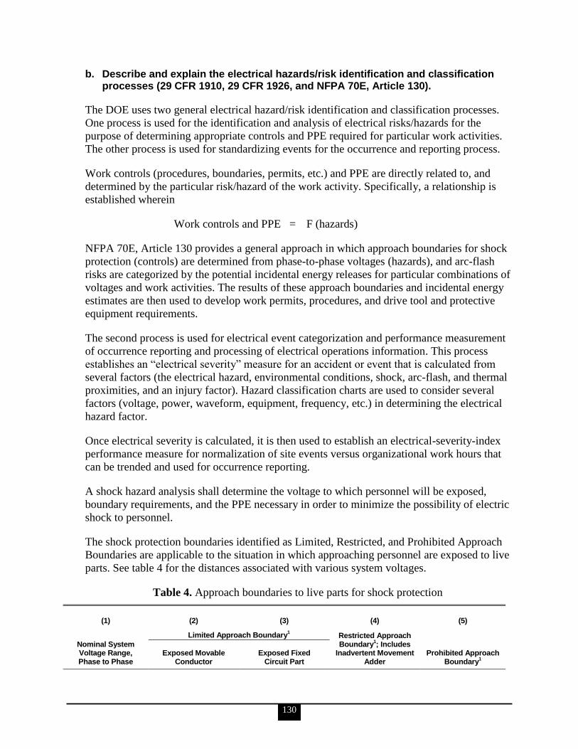
130
b. Describe and explain the electrical hazards/risk identification and classification processes (29 CFR 1910, 29 CFR 1926, and NFPA 70E, Article 130).
The DOE uses two general electrical hazard/risk identification and classification processes.
One process is used for the identification and analysis of electrical risks/hazards for the
purpose of determining appropriate controls and PPE required for particular work activities.
The other process is used for standardizing events for the occurrence and reporting process.
Work controls (procedures, boundaries, permits, etc.) and PPE are directly related to, and
determined by the particular risk/hazard of the work activity. Specifically, a relationship is
established wherein
Work controls and PPE = F (hazards)
NFPA 70E, Article 130 provides a general approach in which approach boundaries for shock
protection (controls) are determined from phase-to-phase voltages (hazards), and arc-flash
risks are categorized by the potential incidental energy releases for particular combinations of
voltages and work activities. The results of these approach boundaries and incidental energy
estimates are then used to develop work permits, procedures, and drive tool and protective
equipment requirements.
The second process is used for electrical event categorization and performance measurement
of occurrence reporting and processing of electrical operations information. This process
establishes an ―electrical severity‖ measure for an accident or event that is calculated from
several factors (the electrical hazard, environmental conditions, shock, arc-flash, and thermal
proximities, and an injury factor). Hazard classification charts are used to consider several
factors (voltage, power, waveform, equipment, frequency, etc.) in determining the electrical
hazard factor.
Once electrical severity is calculated, it is then used to establish an electrical-severity-index
performance measure for normalization of site events versus organizational work hours that
can be trended and used for occurrence reporting.
A shock hazard analysis shall determine the voltage to which personnel will be exposed,
boundary requirements, and the PPE necessary in order to minimize the possibility of electric
shock to personnel.
The shock protection boundaries identified as Limited, Restricted, and Prohibited Approach
Boundaries are applicable to the situation in which approaching personnel are exposed to live
parts. See table 4 for the distances associated with various system voltages.
Table 4. Approach boundaries to live parts for shock protection
(1) (2) (3) (4) (5)
Limited Approach Boundary1 Restricted Approach
Boundary1; Includes
Inadvertent Movement Adder
Nominal System Voltage Range, Phase to Phase
Exposed Movable Conductor
Exposed Fixed Circuit Part
Prohibited Approach Boundary
1

131
(1) (2) (3) (4) (5)
Limited Approach Boundary1 Restricted Approach
Boundary1; Includes
Inadvertent Movement Adder
Nominal System Voltage Range, Phase to Phase
Exposed Movable Conductor
Exposed Fixed Circuit Part
Prohibited Approach Boundary
1
Less than 50 Not specified Not specified Not specified Not specified
50 to 300 3.05 m (10 ft 0 in.) 1.07 m (3 ft 6 in.) Avoid contact Avoid contact
301 to 750 3.05 m (10 ft 0 in.) 1.07 m (3 ft 6 in.) 304.8 mm (1 ft 0 in.) 25.4 (0 ft 1 in.)
751 to 15 kV 3.05 m (10 ft 0 in.) 1.53 m (5 ft 0 in.) 660.4 mm (2 ft 2 in.) 177.8 mm (0 ft 7 in.)
15.1 kV to 36 kV 3.05 m (10 ft 0 in.) 1.83 m (6 ft 0 in.) 787.4 mm (2 ft 7 in.) 254 mm (0 ft 10 in.)
36.1 kV to 46 kV 3.05 m (10 ft 0 in.) 2.44 m (8 ft 0 in.) 838.2 mm (2 ft 9 in.) 431.8 mm (1 ft 5 in.)
46.1 kV to 72.5 kV 3.05 m (10 ft 0 in.) 2.44 m (8 ft 0 in.) 965.2 mm (3 ft 2 in.) 635 mm (2 ft 1 in.)
72.6 kV to 121 kV 3.25 m (10 ft 8 in.) 2.44 m (8 ft 0 in.) 991 mm (3 ft 3 in.) 812.8 mm (2 ft 8 in.)
138 kV to 145 kV 3.36 m (11 ft 0 in.) 3.05 m (10 ft 0 in.) 1.093 m (3 ft 7 in.) 939.8 mm (3 ft 1 in.)
161 kV to 169 kV 3.56 m (11 ft 8 in.) 3.56 m (11 ft 8 in.) 1.22 m (4 ft 0 in.) 1.07 m (3 ft 6 in.)
230 kV to 242 kV 3.97 m (13 ft 0 in.) 3.97 m (13 ft 0 in.) 1.6 m (5 ft 3 in.) 1.45 m (4 ft 9 in.)
345 kV to 362 kV 4.68 m (15 ft 4 in.) 4.68 m (15 ft 4 in.) 2.59 m (8 ft 6 in.) 2.44 m (8 ft 0 in.)
500 kV to 550 kV 5.8 m (19 ft 0 in.) 5.8 m (19 ft 0 in.) 3.43 m (11 ft 3 in.) 3.28 m (10 ft 9 in.)
765 kV to 800 kV 7.24 m (23 ft 9 in.) 7.24 m (23 ft 9 in.) 4.55 m (14 ft 11 in.) 4.4 m (14 ft 5 in.)
Note: For Flash Protection Boundary, see 130.3(A). 1See definition in Article 100 and text in 130.2(D)(2) and Annex C for elaboration.
Source: NFPA 70E
c. Describe and explain how to conduct electrical work on or near live parts, including, but not limited to, energized electrical work permits (elements and exemptions), shock and arc-flash hazard analyses, arc flash calculation methodology, arc flash reduction techniques, approach boundaries, and associated Personal Protective Equipment (PPE) (NFPA 70E, Article 130; IEEE Std 1584; etc.).
Energized Electrical Work Permits
If live parts are not placed in an electrically safe work condition (i.e., for the reasons of
increased or additional hazards or infeasibility per NFPA 70E, 130.1), work to be performed
shall be considered energized electrical work and shall be performed by written permit only.
The energized electrical work permit shall include, but not be limited to, the following items:
A description of the circuit and equipment to be worked on and their location
Justification for why the work must be performed in an energized condition
A description of the safe work practices to be employed
Results of the shock hazard analysis
Determination of shock protection boundaries
Results of the flash hazard analysis
The flash protection boundary
The necessary PPE to safely perform the assigned task
Means employed to restrict the access of unqualified persons from the work area
132
Evidence of completion of a job briefing, including a discussion of any job-specific
hazards
Energized work approval (authorizing or responsible management, safety officer, or
owner, etc.) signature(s)
Work performed on or near live parts by qualified persons related to tasks such as testing,
troubleshooting, voltage measuring, etc., shall be permitted to be performed without an
energized electrical work permit, provided appropriate safe work practices and PPE are
provided and used.
Shock and Arc-Flash Hazard Analyses
A shock hazard analysis shall determine the voltage to which personnel will be exposed,
boundary requirements, and the PPE necessary in order to minimize the possibility of electric
shock to personnel. The shock protection boundaries identified as Limited, Restricted, and
Prohibited Approach Boundaries are applicable to the situation in which approaching
personnel are exposed to live parts. See table 4 for the distances associated with various
system voltages.
A flash hazard analysis shall be done in order to protect personnel from the possibility of
being injured by an arc flash. The analysis shall determine the flash protection boundary and
the PPE that people within the flash protection boundary shall use. For systems that are 600
volts or less, the flash protection boundary shall be 4.0 feet, based on the product of clearing
times of 6 cycles (0.1 second) and the available bolted fault current of 50 kiloamperes (kA)
or any combination not exceeding 300 kA cycles (5,000 ampere-seconds). For clearing times
and bolted fault currents other than 300 kA cycles, or under engineering supervision, the
flash protection boundary shall alternatively be permitted to be calculated in accordance with
the following general formula:
21
65.2 tMVAD bfc
or
21
53 tMVADc
where:
Dc = distance in feet from an arc source for a second-degree burn
bfMVA = bolted fault capacity available at point involved (in megavolt-amperes)
MVA = capacity rating of transformer (megavolt-amperes). For transformers with MVA
ratings below 0.75 MVA, multiply the transformer MVA rating by 1.25
t = time of arc exposure (in seconds)
At voltage levels above 600 volts, the flash protection boundary is the distance at which the
incident energy equals 5 J/cm2(1.2 calorie [cal] /cm
2). For situations where fault-clearing
time is 0.1 second (or faster), the flash protection boundary is the distance at which the
incident energy level equals 6.24 J/cm2(1.5 cal/cm
2).
Arc-Flash Calculation Methodology
See above formula.
133
Arc-Flash Reduction Techniques
Shock and arc-flash hazard analyses, proper PPE, and noting limited approach to boundaries
are methods by which arc flashes may be reduced and altogether avoided.
Approach Boundaries
See table 4 and associated boundary explanations.
Personal Protective Equipment
Personal Protective Equipment requirements are directly derived from the identified hazards
and risks for the particular work activity. Where it has been determined that work will be
performed within the flash protection boundary, the flash hazard analysis shall determine,
and the employer shall document, the incident energy exposure of the worker (in calories per
square centimeter). The incident energy exposure level shall be based on the working
distance of the employee‘s face and chest areas from a prospective arc source for the specific
task to be performed. Flame-resistant clothing and PPE shall be used by the employee based
on the incident energy exposure associated with the specific task. Recognizing that incident
energy increases as the distance from the arc flash decreases, additional PPE shall be used for
any parts of the body that are closer than the distance at which the incident energy was
determined. As an alternative, the PPE requirements of NFPA 70E 130.7(C)(9) shall be
permitted to be used in lieu of the detailed flash hazard analysis approach described in NFPA
70E 130.3(A).
When flame-resistant clothing is worn to protect an employee, it shall cover all ignitable
clothing and shall allow for movement and visibility. Employees shall wear nonconductive
head protection wherever there is a danger of head injury from electric shock or burns due to
contact with live parts or from flying objects resulting from electrical explosion. Employees
shall wear nonconductive protective equipment for the face, neck, and chin whenever there is
a danger of injury from exposure to electric arcs or flashes or from flying objects resulting
from electrical explosion. Employees shall wear protective equipment for the eyes whenever
there is danger of injury from electric arcs, flashes, or from flying objects resulting from
electrical explosion. Employees shall wear flame-resistant clothing wherever there is possible
exposure to an electric arc flash above the threshold incident-energy level for a second-
degree burn.
Employees shall wear rubber insulating gloves where there is danger of hand and arm injury
from electric shock due to contact with live parts. Hand and arm protection shall be worn
where there is possible exposure to arc flash burn. Where insulated footwear is used as
protection against step and touch potential, dielectric overshoes shall be required. Insulated
soles shall not be used as primary electrical protection.

134
d. Describe and explain safety-related maintenance requirements, including grounding and bonding, safety equipment, clear space requirements, substations, switchgear, panels, motor control centers, premises wiring, controller equipment, fuses and circuit breakers, rotating equipment, hazardous locations, batteries and battery rooms, portable electric tools and equipment, and personal safety and protective equipment (NFPA 70E, Chapter 2; IEEE Std-450; etc.).
Grounding and Bonding
Equipment, raceways, cable trays, and enclosure bonding and grounding shall be maintained
to ensure electrical continuity.
Safety Equipment
Locks, interlocks, and other safety equipment shall be maintained in proper working
condition to accomplish the control purpose.
Clear Space Requirements
Access to working space and escape passages shall be kept clear and unobstructed.
Substations, Switchgear, Panels, Motor Control Centers (MCCS).
Enclosures shall be kept free of material that would create a hazard.
Fences, physical protection, enclosures, or other protective means, where required to guard
against unauthorized access or accidental contact with exposed live parts, shall be
maintained.
Current-carrying conductors (buses, switches, disconnects, joints, and terminations) and
bracing shall be maintained to
conduct rated current without overheating, and
withstand available fault current.
Insulation integrity shall be maintained to support the voltage impressed.
Protective devices shall be maintained to adequately withstand or interrupt available fault
current.
Premises Wiring
Covers for wiring system components shall be in place with all associated hardware, and
there shall be no unprotected openings.
Open wiring protection, such as location or barriers, shall be maintained to prevent accidental
contact.
Raceways and cable trays shall be maintained to provide physical protection and support for
conductors.
135
Controller Equipment
The following shall apply to controllers, including electrical equipment that governs the
starting, stopping, direction of motion, acceleration, speed, and protection of rotating
equipment and other power utilization apparatus in the workplace: protection and control
circuitry used to guard against accidental contact with live parts and to prevent other
electrical or mechanical hazards shall be maintained.
Fuses and Circuit Breakers
Fuses shall be maintained free of breaks or cracks in fuse cases, ferrules, and insulators. Fuse
clips shall be maintained to provide adequate contact with fuses.
Molded-case circuit breakers shall be maintained free of cracks in cases and cracked or
broken operating handles.
Circuit breakers that interrupt faults approaching their ratings shall be inspected and tested in
accordance with the manufacturer‘s instructions.
Rotating Equipment
Terminal chambers, enclosures, and terminal boxes shall be maintained to guard against
accidental contact with live parts and other electrical hazards.
Guards, barriers, and access plates shall be maintained to prevent employees from contacting
moving or energized parts.
Hazardous Locations
Equipment and installations in hazardous locations shall be maintained such that the
following apply:
No energized parts are exposed. Exception: intrinsically safe and non-incendive
circuits.
There are no breaks in conduit systems, fittings, or enclosures from damage,
corrosion, or other causes.
All bonding jumpers are securely fastened and intact.
All fittings, boxes, and enclosures with bolted covers have all bolts installed and
bolted tight.
All threaded conduit shall be wrench-tight, and enclosure covers shall be tightened in
accordance with the manufacturer‘s instructions.
There are no open entries into fittings, boxes, or enclosures that would compromise
the protection characteristics.
All close-up plugs, breathers, seals, and drains are securely in place.
Marking of luminaires (lighting fixtures) for maximum lamp wattage and temperature
rating is legible and not exceeded.
Required markings are secure and legible.

136
Batteries and Battery Rooms
Ventilation systems, forced or natural, shall be maintained to prevent buildup of explosive
mixtures. This maintenance shall include a functional test of any associated detection and
alarm systems.
Eye and body wash apparatus shall be maintained in operable condition.
Battery cell ventilation openings shall be unobstructed, and cell flame arresters shall be
maintained.
Portable Electric Tools and Equipment
Attachment plugs, receptacles, cover plates, and cord connectors shall be maintained such
that the following apply:
There are no breaks, damage, or cracks exposing live parts.
There are no missing cover plates.
Terminations have no stray strands or loose terminals.
There are no missing, loose, altered, or damaged blades, pins, or contacts.
Polarity is correct.
Personal Safety and Protective Equipment
Personal safety and protective equipment such as the following shall be maintained in a safe
working condition:
Grounding equipment
Hot sticks
Rubber gloves, sleeves, and leather protectors
Voltage test indicators
Blanket and similar insulating equipment
Insulating mats and similar insulating equipment
Protective barriers
External circuit breaker rack-out devices
Portable lighting units
Safety grounding equipment
Dielectric footwear
Protective clothing
e. Describe and explain the safety requirements for special equipment such as Research and Development (R&D) electrical safety requirements and work practices for such R&D equipment, i.e., laser operations and power electronic equipment, etc. (NFPA 70E, Article 400; American National Standards Institute (ANSI); etc.).
Laser Operations
Employees shall be provided with eye protection as required by Federal regulation. Warning
signs shall be posted at the entrances to areas or protective enclosures containing laser
products. High-power laser equipment shall include a key-operated master control. High-
power laser equipment shall include a fail-safe laser radiation emission audible and visible
warning when it is switched on or the capacitor banks are charged. Beam shutters or caps

137
shall be utilized, or the laser switched off, when laser transmission is not required. The laser
shall be switched off when unattended for 30 minutes or more. Laser beams shall not be
aimed at employees. Laser equipment shall bear a label indicating its maximum output.
Personnel protective equipment shall be provided for users and operators of high-power laser
equipment.
Employees shall be responsible for the following:
Obtaining authorization for laser use
Obtaining authorization for being in a laser operating area
Observing safety rules
Reporting laser equipment failures and accidents to the employer
Power Electronic Equipment
The employee and employer responsibilities listed below shall apply to safety-related work
practices around power electronic equipment, including the following:
Electric arc welding equipment
High-power radio, radar, and television transmitting towers and antennae
Industrial dielectric and RF induction heaters
Shortwave or RF diathermy devices
Process equipment that includes rectifiers and inverters such as the following:
o Motor drives
o Uninterruptible power supply (UPS) systems
o Lighting controllers
The employer shall be responsible for the following:
Proper training and supervision by properly qualified personnel, including the
following:
o The nature of the associated hazard
o Strategies to minimize the hazard
o Methods of avoiding or protecting against the hazard
o The necessity of reporting any hazardous incident
Properly installed equipment
Proper access to the equipment
Availability of the correct tools for operation and maintenance
Proper identification and guarding of dangerous equipment
Provision of complete and accurate circuit diagrams and other published information
to the employee prior to the employee starting work. The circuit diagrams should be
marked to indicate the hazardous components
Maintenance of clear and clean work areas around the equipment to be worked
Provision of adequate and proper illumination of the work area
The employee is responsible for the following:
Being continuously alert and aware of the possible hazards
Using the proper tools and procedures for the work
Informing the employer of malfunctioning protective measures, such as faulty or
inoperable enclosures and locking schemes
138
Examining all documents provided by the employer relevant to the work, especially
those documents indicating the hazardous component‘s location
Maintaining good housekeeping around the equipment and work space
Reporting any hazardous incident
f. Describe and explain the installation safety requirements for power systems protection; flash protection; guarding of live parts; wiring design and protection; wiring methods, components, and equipment; specific purpose equipment and installations [cranes and hoists, elevators, Heating, Ventilating and Air-conditioning (HVAC), X-ray equipment, motor controllers, etc.]; and hazardous locations (NFPA 70 and NFPA 70E, Chapter 4).
Power Systems Protection
The requirements contained in Chapter 4 of NFPA 70E shall be based on the provisions of
NFPA 70, National Electrical Code. Where installations of electric conductors and
equipment have been found to conform with the safety requirements of the NEC in use at the
time of installation by governmental bodies or agencies having legal jurisdiction for
enforcement of the NEC, this conformance shall be prima facie evidence that such
installations were adequately designed and installed.
The chapter is divided into six articles. Article 400, 410, and 420 apply generally. Article 430
applies to specific-purpose equipment installations. Articles 440 and 450 apply to hazardous
(classified) locations and special systems. Articles 430, 440, and 450 supplement or modify
the general rules, and 450.5 covers communications systems and is independent of the other
paragraphs and chapters except where specifically referenced. Articles 400, 410, and 420
apply except as amended by Articles 430, 440, and 450 for the particular condition.
Flash Protection
Switchboards, panelboards, industrial control panels, and MCCs that are in other than
dwelling occupancies and are likely to require examination, adjustment, servicing, or
maintenance while energized shall be field marked to warn qualified persons of potential
electric arc-flash hazards. The marking shall be located so as to be clearly visible to qualified
persons before examination, adjustment, servicing, or maintenance of the equipment.
Guarding of Live Parts
Except as elsewhere required or permitted, live parts of electric equipment operating at
50 volts or more shall be guarded against accidental contact by approved enclosures or by
any of the following means:
Location in a room, vault, or similar enclosure that is accessible only to qualified
persons
Suitable permanent, substantial partitions or screens arranged so that only qualified
persons have access to the space within reach of the live parts. Any openings in such
partitions or screens shall be sized and located so that persons are not likely to come
into accidental contact with the live parts or to bring conducting objects into contact
with them
Location on a suitable balcony, gallery, or platform elevated and arranged so as to
exclude unqualified persons

139
Elevation of 2.5 m (8 ft) or more above the floor or other working surface
In locations where electric equipment is likely to be exposed to physical damage, enclosures
or guards shall be so arranged and of such strength as to prevent such damage. Entrances to
rooms and other guarded locations that contain exposed live parts operating at 50 volts or
more shall be marked with conspicuous warning signs forbidding unqualified persons to
enter.
Wiring Design and Protection
A conductor used as a grounded conductor shall be identifiable and distinguishable from all
other conductors. No grounded conductor shall be attached to any terminal or lead so as to
reverse designated polarity.
A lengthy description of wiring and design protection is available in NFPA 70E, Article 410.
Wiring Methods, Components, and Equipment
The provisions of the following paragraph are not intended to apply to the conductors that
form an integral part of equipment, such as motors, controllers, MCCs, factory assembled
control equipment, or listed utilization equipment.
Metal raceways, cable trays, cable armor, cable sheath, enclosures, frames, fittings, and other
metal non-current-carrying parts that are to serve as grounding conductors, with or without
the use of supplementary equipment grounding conductors, shall be effectively bonded where
necessary to ensure electrical continuity and the capacity to conduct safely any fault current
likely to be imposed on them. Any nonconductive paint, enamel, or similar coating shall be
removed at threads, contact points, and contact surfaces or be connected by means of fittings
designed so as to make such removal unnecessary.
A lengthy description of wiring methods, components, and equipment is available in
NFPA 70E, Article 420.
Specific Purpose Equipment and Installations—Cranes and Hoists, Elevators, Heating,
Ventilating and Air-Conditioning, X-ray Equipment, Motor Controllers, etc.
A lengthy description of specific purpose equipment and installations is available in
NFPA 70E, Article 430.
Hazardous Locations
NFPA 70E, Article 440 applies to the requirements for electric equipment and wiring in
locations that are classified, depending on the properties of the flammable vapors, liquids, or
gases or combustible dusts or fibers that might be present therein and the likelihood that a
flammable or combustible concentration or quantity is present. Hazardous (classified)
locations can be found in occupancies such as, but not limited to, aircraft hangars, gasoline
dispensing and service stations, bulk storage plants for gasoline or other volatile flammable
liquids, paint-finishing process plants, health care facilities, agricultural or other facilities
where excessive combustible dusts might be present, marinas, boat yards, and petroleum and
chemical processing plants. Each room, section, or area shall be considered individually in
determining its classification.

140
A lengthy description of specific purpose equipment and installations is available in
NFPA 70E, Article 440.
23. From the jobs observed in Competency 22 above, electrical personnel shall demonstrate the ability to assess how well contractor management systems (lessons learned and other feedback processes) are integrated with the work planning and ISMS process and how lessons learned are addressed by each contractor‘s ISMS feedback process (DOE P 450.4, Safety Management System Policy).
The information for all of the KSAs in this competency statement is taken from DOE O
226.1A.
a. Describe and explain the contractors‘ lessons learned program.
Formal programs must be established to communicate lessons learned during work activities,
process reviews, and event analyses to potential users and applied to future work activities.
Contractors must identify, apply, and exchange lessons learned with the rest of the DOE
complex.
b. Describe and explain how electrical lessons learned are integrated into the contractors‘ work planning process.
Contractors must review and apply lessons learned identified by other DOE organizations
and external sources to prevent similar occurrences (see also DOE O 414.1C, criterion 3,
―Quality Improvement‖).
c. Describe and explain how feedback from the workers who have completed an electrical job is integrated into the contractors‘ work planning process.
In addition to structured assessments, DOE contractors will establish and implement
processes to solicit feedback from workers and work activities. Common feedback
mechanisms are described in site plans/program documents and include the following:
employee concerns programs, telephone or intranet ―hotline‖ processes for reporting
concerns or questions, pre-job briefs, job hazard walk-downs by workers prior to work, post-
job reviews, employee suggestion forms, safety meetings, employee participation in
committees and working groups, and labor organization input.
24. Electrical personnel shall demonstrate a working level knowledge of 29 CFR 1910; 29 CFR 1926; and NFPA 70E, Article 420 requirements.
[Note: The 2004 version of NFPA 70E has been superseded by the 2009 revision and is archived but still available. Because the 2009 revision was drastically reduced in scope it is not used as a reference in this guide.]
a. Describe and explain wiring methods, bonding of enclosures, temporary wiring, and permitted use of cable trays.
The information for KSAs ‗a‘ through ‗f‘ and ‗h‘ is taken from NFPA 70E.

141
Wiring Methods
These provisions are not intended to apply to the conductors that form an integral part of
equipment, such as motors, controllers, MCCs, factory assembled control equipment, or
listed utilization equipment.
Bonding of Enclosures
Metal raceways, cable trays, cable armor, cable sheath, enclosures, frames, fittings, and other
metal non-current-carrying parts that are to serve as grounding conductors, with or without
the use of supplementary equipment grounding conductors, shall be effectively bonded where
necessary to ensure electrical continuity and the capacity to conduct safely any fault current
likely to be imposed on them. Any nonconductive paint, enamel, or similar coating shall be
removed at threads, contact points, and contact surfaces or be connected by means of fittings
designed so as to make such removal unnecessary.
Where required for the reduction of electrical noise (EMI) of the grounding circuit, an
equipment enclosure supplied by a branch circuit shall be permitted to be isolated from a
raceway containing circuits that supply only that equipment by one or more listed
nonmetallic raceway fittings located at the point of attachment of the raceway to the
equipment enclosure. The metal raceway shall comply with provisions of this standard and
shall be supplemented by an internal insulated equipment grounding conductor installed to
ground the equipment enclosure.
No wiring systems of any type shall be installed in ducts used to transport dust, loose stock,
or flammable vapors. No wiring system of any type shall be installed in any duct, or any
shaft containing only such ducts, used for vapor removal or for ventilation of commercial-
type cooking equipment.
Temporary Wiring
Temporary electrical power and lighting wiring methods may be of a class less than would be
required for a permanent installation. Except as specifically modified in sections
420.1(B)(1)(a) through 420.1(B)(1)(d), all other requirements of NFPA 70E for permanent
wiring shall apply to temporary wiring installations.
Feeders shall be protected as provided in Article 410.9. They shall originate in an approved
distribution center. Conductors shall be permitted within cable assemblies or within
multiconductor cords or cables of a type identified for hard usage or extra-hard usage. For the
purpose of this section, type NM (nonmetallic) and type NMC (nonmetallic, corrosion-
resistant) cables shall be permitted to be used in any dwelling, building, or structure without
any height limitation.
Single insulated conductors shall be permitted where installed for the purpose(s) specified in
Article 420.1(B)(3)(c) where accessible only to qualified persons.
All branch circuits shall originate in an approved power outlet or panelboard. Conductors
shall be permitted within cable assemblies or within multiconductor cord or cable of a type
identified for hard usage or extra-hard usage. All conductors shall be protected as provided in

142
Article 410.9. For the purpose of this section, type NM and NMC cables shall be permitted to
be used in any dwelling, building, or structure without any height limitation.
Branch circuits installed for the purposes specified in sections 420.1(B)(3)(b) or
420.1(B)(3)(c) shall be permitted to be run as single insulated conductors. Where the wiring
is installed in accordance with Article 420.1(B)(1)(c), the voltage to ground shall not exceed
150 volts, the wiring shall not be subject to physical damage, and the conductors shall be
supported on insulators at intervals so that excessive strain is not transmitted to the
lampholders.
All receptacles shall be of the grounding type. Unless installed in a continuous grounded
metal raceway or metal-covered cable, all branch circuits shall contain a separate equipment
grounding conductor, and all receptacles shall be electrically connected to the equipment
grounding conductors. Receptacles on construction sites shall not be installed on branch
circuits that supply temporary lighting. Receptacles shall not be connected to the same
ungrounded conductor of multiwire circuits that supply temporary lighting. Suitable
disconnecting switches or plug connectors shall be installed to permit the disconnection of all
ungrounded conductors of each temporary circuit. Multiwire branch circuits shall be
provided with a means to disconnect simultaneously all ungrounded conductors at the power
outlet or panelboard where the branch circuit originated. Approved handle ties shall be
permitted. All lamps for general illumination shall be protected from accidental contact or
breakage by a suitable fixture or lampholder with a guard. Brass shell, paper-lined sockets, or
other metal-cased sockets shall not be used unless the shell is grounded. On construction
sites, a box shall not be required for splices or junction connections where the circuit
conductors are multiconductor cord or cable assemblies, provided that the equipment
grounding continuity is maintained with or without the box. A box, conduit body, or terminal
fitting having a separately bushed hole for each conductor shall be used wherever a change is
made to a conduit or tubing system or a metal-sheathed cable system.
Flexible cords and cables shall be protected from accidental damage. Sharp corners and
projections shall be avoided. Where passing through doorways or other pinch points,
protection shall be provided to avoid damage. Flexible cords and cables entering enclosures
containing devices requiring termination shall be secured to the box with fittings designed for
the purpose. Cable assemblies and flexible cords and cables shall be supported in place at
intervals that ensure that they will be protected from physical damage. Support shall be in the
form of staples, cable ties, straps, or similar type fittings installed so as not to cause damage.
Vegetation shall not be used for support of overhead spans of branch circuits or feeders.
Permitted Use of Cable Trays
Cable tray shall be permitted to be used as a support system for services, feeders, branch
circuits, communications circuits, control circuits, and signaling circuits. Cable tray
installations shall not be limited to industrial establishments. Where exposed to direct rays of
the sun, insulated conductors and jacketed cables shall be identified as being sunlight
resistant. Cable trays and their associated fittings shall be identified for the intended use.
The following wiring methods shall be permitted to be installed in cable tray systems:
armored cable; communication raceways; electrical metallic tubing; electrical nonmetallic
143
tubing; fire alarm cables; flexible metal conduit; flexible metallic tubing; instrumentation
tray cable; intermediate metal conduit; liquidtight flexible metal conduit and liquidtight
flexible nonmetallic conduit; metal-clad cable; mineral-insulated, metal-sheathed cable;
multiconductor service-entrance cable; multiconductor underground feeder and branch-
circuit cable; multipurpose and communications cables; nonmetallic-sheathed cable; power
and control tray cable; power-limited tray cable; optical fiber cables; optical fiber raceways;
other factory-assembled, multiconductor control, signal, or power cables that are specifically
approved for installation in cable trays; rigid metal conduit; and rigid nonmetallic conduit.
The wiring methods in Article 420.1(C)(2) shall be permitted to be used in any industrial
establishment under the conditions described in their respective articles. In industrial
establishments only, where conditions of maintenance and supervision ensure that only
qualified persons service the installed cable tray system, any of the cables in sections
420.1(C)(2)(a) and 420.1(C)(2)(b) shall be permitted to be installed in ladder, ventilated
trough, solid bottom, or ventilated channel cable trays. Single conductor cables shall be
permitted to be installed in accordance with the following: single conductor cable shall be
1/0 American wire gauge (AWG) or larger and shall be of a type listed and marked on the
surface for use in cable trays. Where 1/0 AWG through 4/0 AWG single conductor cables are
installed in ladder cable tray, the maximum allowable run spacing for the ladder cable tray
shall be 230 mm (9 in.). Welding cables shall be installed in dedicated cable trays, as
permitted. Single conductors used as equipment grounding conductors shall be insulated,
covered, or bare, and they shall be 4 AWG or larger. Single- and multi-conductor medium
voltage cables shall be type MV cable. Single conductors shall be installed in accordance
with Article 420.1(C)(1).
Metallic cable trays shall be permitted to be used as equipment grounding conductors where
continuous maintenance and supervision ensure that qualified persons service the installed
cable tray system. Hazardous (classified) locations as permitted. Nonmetallic cable tray shall
be permitted in corrosive areas and in areas requiring voltage isolation.
Cable tray systems shall not be used in hoistways or where subject to severe physical
damage. Cable tray systems shall not be used in environmental airspaces, except as permitted
in Article 420.1(A)(2) to support wiring methods recognized for use in such spaces.
b. Describe and explain safety positioning and connection of switches.
Safety Positioning
Single-throw knife switches shall be placed so that gravity will not tend to close them.
Single-throw knife switches approved for use in the inverted position shall be provided with
a locking device that ensures that the blades remain in the open position when so set.
Double-throw knife switches shall be permitted to be mounted so that the throw is either
vertical or horizontal. Where the throw is vertical, a locking device shall be provided to hold
the blades in the open position when so set.

144
Connection of Switches
Single-throw knife switches and switches with butt contacts shall be connected so that their
blades are de-energized when the switch is in the open position. Bolted pressure contact
switches shall have barriers that prevent inadvertent contact with energized blades. Single-
throw knife switches, bolted pressure contact switches, molded-case switches, switches with
butt contacts, and circuit breakers used as switches shall be connected so that the terminals
supplying the load are de-energized when the switch is in the open position.
The blades and terminals supplying the load of a switch shall be permitted to be energized
when the switch is in the open position where the switch is connected to circuits or
equipment inherently capable of providing a backfeed source of power. For such
installations, a permanent sign shall be installed on the switch enclosure or immediately
adjacent to open switches with the following words or equivalent:
WARNING
LOAD SIDE TERMINALS MAY BE ENERGIZED
BY BACKFEED
c. Describe and explain switch/panelboard location and access requirements.
Switchboards that have any exposed live parts operating at 50 volts or more shall be located
in permanently dry locations and then only where under competent supervision and
accessible only to qualified persons. Switchboards shall be located so that the probability of
damage from equipment or processes is reduced to a minimum. Panelboards shall be
mounted in cabinets, cutout boxes, or enclosures designed for the purpose and shall be dead
front. Panelboards other than of the dead-front, externally operable type shall be permitted
where accessible only to qualified persons.
d. Describe and explain enclosures for damp and wet locations.
In damp or wet locations, surface-type enclosures within the scope of this standard shall be
placed or equipped so as to prevent moisture or water from entering and accumulating within
the cabinet or cutout box, and shall be mounted so there is at least a 6-mm (¼-in.) airspace
between the enclosure and the wall or other supporting surface. Enclosures installed in wet
locations shall be weatherproof. Nonmetallic enclosures shall be permitted to be installed
without the airspace on a concrete, masonry, tile, or similar surface.
Switchboards or panelboards in a wet location or outside of a building shall be enclosed in a
weatherproof enclosure or cabinet that shall comply with Article 420.5(A).
e. Describe and explain conductor identification requirements.
Insulated or covered grounded conductors shall be identified in accordance with NFPA 70E,
Article 420. Equipment grounding conductors shall be identified in accordance with this
standard. Conductors that are intended for use as ungrounded conductors, whether used as a
single conductor or in multiconductor cables, shall be finished to be clearly distinguishable
from grounded and grounding conductors. Distinguishing markings shall not conflict in any
manner with the surface markings.
145
f. Describe and explain permitted and non-permitted use of flexible cords and cables.
Permitted Use
Flexible cords and cables shall be used only for the following:
Pendants
Wiring on luminaires (fixtures)
Connection of portable lamps, portable and mobile signs, or appliances
Elevator cables
Wiring on cranes and hoists
Connection of utilization equipment to facilitate frequent interchange
Prevention of the transmission of noise or vibration
Appliances where the fastening means and mechanical connections are specifically
designed to permit ready removal for maintenance and repair, and the appliance is
intended or identified for flexible cord connection
Data processing cables
Connection of moving parts
Temporary wiring
Where used as permitted in NFPA 70E, Article 420.7(B)(1)(3), (9), and (11), each flexible
cord shall be equipped with an attachment plug and shall be energized from a receptacle
outlet.
Non-permitted Use
Unless specifically permitted in Article 420.7(B), flexible cords and cables shall not be used
for the following:
As a substitute for the fixed wiring of a structure
Where run through holes in walls, structural ceilings, suspended ceilings, dropped
ceilings, or floors
Where run through doorways, windows, or similar openings
Where attached to building surfaces (exception would be that flexible cord and cable
shall be permitted to be attached to building surfaces in accordance with the
provisions of NEC Article 368.8)
Where concealed by walls, floors, or ceilings or where located above suspended or
dropped ceilings
Where installed in raceways, except as otherwise permitted in this standard
g. Describe and explain portable cables over 600 volts.
The following is taken from 29 CFR 1910.305.
The conductors shall be 8 AWG copper or larger and shall employ flexible stranding.
The size of the insulated ground-check conductor of type G-GC cables shall be not
smaller than 10 AWG.
Cables operated at over 2,000 volts shall be shielded. Shielding shall be for the
purpose of confining the voltage stresses to the insulation.
146
An equipment grounding conductor(s) shall be provided. The total area shall not be
less than that of the size of the equipment grounding conductor required in NFPA
70E, Article 420.
All shields shall be grounded.
Grounding conductors shall be connected in accordance with NFPA 70E, Article 420.
The minimum bending radii for portable cables during installation and handling in
service shall be adequate to prevent damage to the cable.
Connectors used to connect lengths of cable in a run shall be of a type that locks
firmly together. Provisions shall be made to prevent opening or closing these
connectors while energized. Suitable means shall be used to eliminate tension at
connectors and terminations.
Portable cables shall not contain splices unless the splices are of the permanent
molded, vulcanized types in accordance with this standard. Terminations on portable
cables rated over 600 volts, nominal, shall be accessible only to authorized and
qualified personnel.
h. Describe and explain motor, transformer, and capacitor general use equipment.
Motor
Where one piece of equipment shall be ―in sight from,‖ ―within sight from,‖ or ―within
sight,‖ and so forth, of another piece of equipment, the specified equipment is to be visible
and not more than 15 m (50 ft) distant from the other.
An individual disconnecting means shall be provided for each controller and shall disconnect
the controller. The disconnecting means shall be located in sight from the controller location.
For motor circuits over 600 volts, nominal, a controller disconnecting means capable of
being locked in the open position shall be permitted to be out of sight of the controller,
provided the controller is marked with a warning label giving the location of the
disconnecting means. A single disconnecting means shall be permitted for a group of
coordinated controllers that drive several parts of a single machine or piece of apparatus. The
disconnecting means shall be located in sight from the controllers, and both the disconnecting
means and the controllers shall be located in sight from the machine or apparatus.
A separate disconnecting means shall be located in sight from the motor location and the
driven machinery location. The disconnecting means required in accordance with NFPA 70E,
Article 420.10(E)(1), shall be permitted to serve as the disconnecting means for the motor if
it is located in sight from the motor location and the driven machinery location.
The disconnecting means shall not be required to be in sight from the motor and the driven
machinery location under either condition (a) or (b), provided the disconnecting means
required in accordance with Article 420.10(E)(2) is individually capable of being locked in
the open position. The provision for locking or adding a lock to the disconnecting means
shall be permanently installed on or at the switch or circuit breaker used as the disconnecting
means.
(a) Where such a location of the disconnecting means is impracticable or introduces
additional or increased hazard to persons or property.
147
(b) In industrial installations, with written safety procedures, where conditions of
maintenance and supervision ensure that only qualified persons service the
equipment.
Some examples of increased or additional hazards include, but are not limited to, motors
rated in excess of 100 hp, multimotor equipment, submersible motors, motors associated with
variable frequency drives, and motors located in hazardous (classified) locations. The
disconnecting means shall plainly indicate whether it is in the open (off) or closed (on)
position. At least one of the disconnecting means shall be readily accessible.
Each motor shall be provided with an individual disconnecting means. A single
disconnecting means shall be permitted to serve a group of motors under any one of the
following conditions:
Where a number of motors drive several parts of a single machine or piece of
apparatus, such as metal and woodworking machines, cranes, and hoists
Where a group of motors is under the protection of one set of branch-circuit
protective devices
Where a group of motors is in a single room within sight from the location of the
disconnecting means
Overload devices are intended to protect motors, motor-control apparatus, and motor
branch-circuit conductors against excessive heating due to motor overloads and
failure to start. Overload in electrical apparatus is an operating overcurrent that, when
it persists for a sufficient length of time, would cause damage or dangerous
overheating of the apparatus. It does include short circuits or ground faults. These
provisions shall not be interpreted as requiring overload protection where it might
introduce additional or increased hazards, as in the case of fire pumps.
Exposed live parts of motors and controllers operating at 50 volts or more shall be
guarded against accidental contact by enclosures or by location as follows: by
installation in a room or enclosure that is accessible only to qualified persons; by
installation on a suitable balcony, gallery, or platform elevated and arranged so as to
exclude unqualified persons; by elevation 2.5 m (8 ft) or more above the floor. The
only exception is that live parts of motors operating at more than 50 volts between
terminals shall not require additional guarding for stationary motors that have
commutators, collectors, and brush rigging located inside of motor-end brackets and
not conductively connected to supply circuits operating at more than 150 volts to
ground.
Where live parts of motors or controllers operating at over 150 volts to ground are
guarded against accidental contact only by location, and where adjustment or other
attendance might be necessary during the operation of the apparatus, suitable
insulating mats or platforms shall be provided so that the attendant cannot readily
touch live parts unless standing on the mats or platforms
Transformer
Sections 420.10(F)(2) through 420.10(F)(8) of NFPA 70E, Article 420 cover the installation
of all transformers. The following transformers are not covered by 420.10(F):
Current transformers
148
Dry-type transformers that constitute a component part of other apparatus and comply
with requirements for such apparatus
Transformers that are an integral part of an X-ray, high-frequency, or electrostatic-
coating apparatus
Transformers used with Class 2 and Class 3 circuits
Transformers for sign and outline lighting
Transformers for electric-discharge lighting
Transformers used for power-limited fire alarm circuits
Transformers used for research, development, or testing, where effective
arrangements are provided to safeguard persons from contacting energized parts
The operating voltage of exposed live parts operating at 50 volts or more of transformer
installations shall be indicated by signs or visible markings on the equipment or structures.
Dry-type transformers installed indoors and rated over 35 kV shall be installed in a vault.
Oil-insulated transformers installed indoors shall be installed in a vault. Combustible
material, combustible buildings, and parts of buildings, fire escapes, and door and window
openings shall be safeguarded from fires originating in oil-insulated transformers installed on
roofs, attached to or adjacent to a building or combustible material. Vault doorways shall be
protected in accordance with sections 420.10(F)(6)(a), 420.10(F)(6)(b), and 420.10(F)(6)(c):
Each doorway leading into a vault from the building interior shall be provided with a
tight-fitting door that has a minimum fire rating of 3 hours. The authority having
jurisdiction (AHJ) shall be permitted to require such a door for an exterior wall
opening where conditions warrant. The exception is that where transformers are
protected with automatic sprinklers, water spray, carbon dioxide, or halon,
construction of 1-hour rating shall be permitted.
A door sill or curb that is of sufficient height to confine the oil from the largest
transformer within the vault shall be provided, and in no case shall the height be less
than 100 mm (4 in.).
Doors shall be equipped with locks, and doors shall be kept locked, access being
allowed only to qualified persons. Personnel doors shall swing out and be equipped
with panic bars, pressure plates, or other devices that are normally latched but open
under simple pressure.
Any pipe or duct system foreign to the electrical installation shall not enter or pass through a
transformer vault. Piping or other facilities provided for vault fire protection, or for
transformer cooling, shall not be considered foreign to the electrical installation.
Materials shall not be stored in transformer vaults.
Capacitor
Group-operated switches shall be used for capacitor switching and shall be capable of the
following:
Carrying continuously not less than 135 percent of the rated current of the capacitor
installation
149
Interrupting the maximum continuous load current of each capacitor, capacitor bank,
or capacitor installation that will be switched as a unit
Withstanding the maximum inrush current, including contributions from adjacent
capacitor installations
Carrying currents due to faults on capacitor side of switch
A means shall be installed to isolate from all sources of voltage each capacitor, capacitor
bank, or capacitor installation that will be removed from service as a unit. The isolating
means shall provide a visible gap in the electrical circuit adequate for the operating voltage.
Isolating or disconnecting switches (with no interrupting rating) shall be interlocked with the
load-interrupting device or shall be provided with prominently displayed caution signs to
prevent switching load current.
The proper switching sequence shall be ensured by use of one of the following:
Mechanically sequenced isolating and bypass switches
Interlocks
Switching procedure prominently displayed at the switching location
25. Electrical personnel shall demonstrate a working level knowledge of the safety requirements in DOE-HDBK-1092-2004, Electrical Safety Handbook.
a. Describe and explain hazards identification, classification, PPE, and associated work practices.
Hazards Identification and Classification
The DOE uses two general electrical hazard/risk identification and classification processes.
The first process, which is used for the identification and analysis of electrical risks/hazards
for the purpose of determining appropriate controls and PPE required for particular work
activities, is covered in NFPA 70E, Article 130.
Work controls (procedures, boundaries, permits, etc.) and PPE are directly related to and
determined by the particular risk/hazard of the work activity. Specifically, a relationship is
established wherein:
Work controls and PPE = F (hazards)
NFPA 70E, Article 130 provides a general approach in which approach boundaries for shock
protection (controls) are determined from phase-to-phase voltages (hazards), and arc-flash
risks are categorized by the potential incidental energy releases for particular combinations of
voltages and work activities. The results of these approach boundaries and incidental energy
estimates are then used to develop work permits, procedures, and drive tool and protective
equipment requirements.
The second process, outlined in DOE G 231.1-x (under development) is used for electrical
event categorization and performance measurement of occurrence reporting and processing
of electrical operations information. This process establishes an ―electrical severity‖ measure
for an accident or event that is calculated from several factors (the electrical hazard,

150
environmental conditions, shock, arc-flash, and thermal proximities, and an injury factor).
Hazard classification charts are used to consider several factors (voltage, power, waveform,
equipment, frequency, etc.) in determining the electrical hazard factor. Once electrical
severity is calculated, it is then used to establish an electrical-severity-index performance
measure for normalization of site events versus organizational work hours that can be trended
and used for occurrence reporting.
Employees who are exposed or potentially exposed must be able to recognize when and how
they are exposed. Management has the responsibility to provide training to deal with each
known hazard, as required.
Hazardous areas and locations are classified by group, class, and division. These
classifications are determined by the atmospheric mixtures of various gases, vapors, dust, and
other materials present. The intensity of the explosion that can occur depends on
concentrations, temperatures, and many other factors that are listed in NFPA codes.
Hazardous locations must be well understood by anyone designing, installing, working on, or
inspecting electrical equipment and wiring in such areas. Such locations carry a threat of
flammable or combustible gases, vapors, or dusts being present some or all of the time.
Information in this section will assist in classifying areas or locations with respect to
hazardous conditions, whether from atmospheric concentrations of hazardous gases, vapors,
and deposits, or from accumulations of readily ignitable materials.
Section 5.0 of DOE-HDBK-1092-2004 covers the requirements for electrical equipment and
wiring in locations that are classified according to the properties of the flammable vapors,
liquids, or gases or combustible dusts that may be present and the likelihood that a flammable
or combustible concentration is present. The hazardous (classified) locations are assigned the
following designations:
Class I Division 1
Class I Division 2
Class II Division 1
Class II Division 2
Class I, Zone 0, Zone 1, Zone 2
A detailed description of hazards identification and classification can be reviewed in
section 5.0 of DOE-HDBK-1092-2004.
PPE
Qualified workers are responsible for avoiding and preventing accidents while performing
electrical work, repairs, or troubleshooting electrical equipment. Personnel shall wear or use
PPE and protective clothing that is appropriate for safe performance of work. Qualified
workers need to use appropriate arc-fault PPE whenever they work near electrical equipment
that could create an arc flash hazard.
151
Managers shall ensure that appropriate PPE is provided and ensure that employees using PPE
are trained in their proper use. Furthermore, managers shall ensure that employees use the
appropriate PPE for their assigned task.
A detailed description of hazards identification and classification can be reviewed in sections
2.0 and 7.0 of DOE-HDBK-1092-2004.
Associated Work Practices
The following is taken from DOE-HDBK-1092-2002,
NFPA 70E covers electrical safety-related work practices and procedures for
qualified and unqualified employees who work on or near exposed energized
electrical conductors or circuit parts in workplaces. This information provides a
foundation for establishing an electrically safe working environment. NFPA 70E
has embedded four basic strategies in the document. These strategies are:
1. establish an electrically safe work condition,
2. training,
3. planning the work, and
4. PPE.
NFPA 70E is updated on a 3-year cycle in compliance with ANSI requirements.
This schedule allows for the latest acceptable technology and experience to be
integrated into the document.
There are several topics under these strategies that provide specific guidance.
b. Describe and explain equipment configuration and operational practices.
Chapter 4 of DOE-STD-1039-93, Guide to Good Practices for Control of Equipment and
System Status, contains ten specific areas of good practices. The topics are as follows:
4.1, Status Change Authorization and Reporting
4.2, Equipment and System Alignment
4.3, Equipment Locking and Tagging
4.4, Operational Limits Compliance
4.5, Alarm Status
4.6, Equipment Deficiency Identification and Documentation
4.7, Work Authorization and Documentation
4.8, Equipment Post-Maintenance Testing and Return to Service
4.9, Temporary Modification and Control
4.10, Distribution and Control of Equipment and System Documents
Additional information on the specific topics can be found in the referenced Standard.
c. Describe and explain training and qualifications requirements.
According to DOE-HDBK-1092-2004, ―effective training for all degrees of hazard‖ is one of
the six basic elements of an effective electrical safety program. Training programs must be
established in accordance with 29 CFR 1910.331-335.
152
Facility engineering managers are responsible for ensuring that their personnel receive
training in accordance with general and job-specific safe electrical work practices as required
in 29 CFR 1910, subpart S, as well as training in NFPA, IEEE, and ANSI codes and
standards.
Construction managers are responsible for implementing and enforcing the requirements of
NFPA 70, IEEE C2, and Occupational Safety and Health Administration (OSHA)
29 CFR 1926 during construction of all facilities by providing AHJ-approved certification for
electrical inspectors. They also ensure that the inspectors receive training in NFPA 70,
29 CFR 1926, IEEE C2, and electrical safety awareness.
Safety managers provide oversight and customer liaison for electrical safety for the
departments. They also provide cognizant electrical safety professionals trained in the
application of NEC, Occupational Safety and Health Act (OSH Act), etc.
Department managers are responsible for ensuring that personnel receive electrical systems
and safety awareness training and other task-specific electrical safety training as required by
29 CFR 1910.332.
All employees and onsite contractors are responsible for attending appropriate electrical
systems and safety awareness training and other equivalent job-specific training as required
by 29 CFR 1910.332.
ES&H training managers are responsible for developing and overseeing electrical safety
training courses, including any site-specific electrical safety training courses, as required by
the Electrical Safety Committee and the Electrical Safety Program.
26. Electrical personnel shall demonstrate a working level knowledge of the requirements related to safe work practices for laser operations (NFPA 70E, Chapter 3, etc.).
[Note: The 2004 version of NFPA 70E has been superseded by the 2009 revision and is archived but still available. Because the 2009 revision was drastically reduced in scope it is not used as a reference in this guide.]
The information for KSAs ‗a‘ and ‗c‘ through ‗e‘ is taken from NFPA 70E.
a. Describe and explain fail-safe interlocks.
A fail-safe interlock is an interlock that in the failure mode does not defeat the purpose of the
interlock, for example, an interlock that is positively driven into the off position as soon as a
hinged cover begins to open, or before a detachable cover is removed, and that is positively
held in the off position until the hinged cover is closed or the detachable cover is locked in
the closed position.
Though fail-safe interlocks do not apply to Class 1 lasers due to their application, ANSI
Z136.1 defines the item as:
―…protective housings which enclose embedded Class 3a, Class 3b, or Class
4 lasers or laser systems [which] shall be provided with an interlock system

153
which is activated when the protective housing is intended to be opened
during operation and maintenance. The interlock or interlock system shall be
designed to prevent access to laser radiation above the applicable MPE
(maximum permissible exposure). The interlock may, for example, be
electrically or mechanically interfaced to a shutter which interrupts the beam
when the protective housing is removed.‖
b. Describe and explain controlled areas.
The following is taken from 10 CFR 835.602.
A controlled area is an area where the occupancy and activity of those within are subject to
control and supervision for the purpose of protection from radiation hazards.
Each access point to a controlled area (as defined at § 835.2) shall be posted whenever
radiological areas or radioactive material areas exist in the area. Individuals who enter only
controlled areas without entering radiological areas or radioactive material areas are not
expected to receive a total effective dose of more than 0.1 rem (0.001 sievert) in a year. Signs
used for this purpose may be selected by the contractor to avoid conflict with local security
requirements
c. Describe and explain laser characteristics.
A laser is any device that can be made to produce or amplify electromagnetic radiation in the
wavelength range from 100 nm to 1 mm primarily by the process of controlled stimulated
emission. Important key concepts related to lasers are as follows:
Laser energy source—any device intended for use in conjunction with a laser to
supply energy for the excitation of electrons, ions, or molecules. General energy
sources, such as electrical supply services or batteries, shall not be considered to
constitute laser energy sources.
Laser fiber optic transmission system—a system consisting of one or more laser
transmitters and associated fiber optic cable.
Laser hazard area—the area within which the beam irradiance or radiant exposure
exceeds the appropriate corneal maximum permissible exposure, including the
possibility of accidental misdirection of the beam.
Laser product—any product or assembly of components that constitutes, incorporates,
or is intended to incorporate a laser or laser system.
Laser radiation—all electromagnetic radiation emitted by a laser product between
100 nm and 1 mm that is produced as a result of a controlled stimulated emission.
Laser system—a laser in combination with an appropriate laser energy source with or
without additional incorporated components.
d. Describe and explain safety training and qualifications.
Training includes, but is not limited to, the following:
Familiarization with laser principles of operation, laser types, and laser emissions
Laser safety, including the following:
o System operating procedures
154
o Hazard control procedures
o The need for personnel protection
o Accident reporting procedures
o Biological effects of the laser upon the eye and the skin
o Electrical and other hazards associated with the laser equipment, including the
following:
High voltages (>1 kV) and stored energy in the capacitor banks
Circuit components, such as electron tubes, with anode voltages greater than
5 kV emitting X-rays
Capacitor bank explosions
Production of ionizing radiation
Poisoning from the solvent or dye switching liquids or laser media
High sound intensity levels from pulsed lasers
Proof of qualification of the laser equipment operator shall be available and in possession of
the operator at all times.
e. Describe and explain safeguarding of personnel.
Employees shall be provided with eye protection as required by Federal regulation. Warning
signs shall be posted at the entrances to areas or protective enclosures containing laser
products. High-power laser equipment shall include a key-operated master control. High-
power laser equipment shall include a fail-safe laser radiation emission audible and visible
warning when it is switched on or if the capacitor banks are charged. Beam shutters or caps
shall be utilized, or the laser switched off, when laser transmission is not required. The laser
shall be switched off when unattended for 30 minutes or more. Laser beams shall not be
aimed at employees. Laser equipment shall bear a label indicating its maximum output. PPE
shall be provided for users and operators of high-power laser equipment.
IV. ELECTRICAL MAINTENANCE MANAGEMENT FOR NUCLEAR AND NON-NUCLEAR FACILITIES
This section is optional and should be used by the program and/or field offices to assist them
with specific technical qualifications for that office.
27. Electrical personnel shall demonstrate a familiarity level knowledge of the DOE maintenance management requirements as defined in DOE O 433.1A, Maintenance Management Program for DOE Nuclear Facilities, and DOE Guide 433.1-1, Nuclear Facility Maintenance Management Program Guide for Use with DOE O 433.1 (IEEE Yellow Book; reference IEEE Std-902).
a. Define each of the following maintenance-related terms and explain their relationship to each other: Corrective Planned Preventive Reliability centered Predictive
155
The information for KSAs ‗a‗ through ‗c‘ is taken from DOE G 433.1-1.
Corrective Maintenance
Corrective maintenance is the repair of failed or malfunctioning equipment, system, or
facilities to restore the intended function or design condition. This maintenance does not
result in a significant extension of the expected useful life.
Planned Maintenance
Planned maintenance is preventive or seasonal maintenance activities performed before SSC
failure that may be initiated by predictive or periodic maintenance results, through vendor
recommendations, or by experience/lessons learned. These include actions such as scheduled
cold weather protection, valve repacking, replacement of bearings as indicated from vibration
analysis, major or minor overhauls based on experience factors or vendor recommendations,
and replacement of known life-span components. For example, repacking a valve because of
packing leakage would be corrective maintenance, but scheduled repacking before leakage
would be planned maintenance.
Preventive Maintenance
This type of maintenance includes all those planned, systematic, periodic, and seasonal
maintenance actions taken to prevent SSC or facility failures, to maintain designed-in
operating conditions, and to extend operating life. The PM process takes into account the
inevitability of failures in any simple or complex piece of equipment, although the
consequences of failures can be controlled by careful design and effective maintenance. The
reason for the failure incident can be apparent if basic differences between expected
behaviors and the actual behaviors of SSCs are considered. These differences can be
translated into possible failure modes. PM identifies any differences between actual and
expected behavior of SSCs. Generally, regulatory and code requirements, DOE technical
safety requirements (TSRs) for surveillances, in-service inspection and testing, vendor
recommendations, and other forms of maintenance action and frequency selection based on
engineering judgment or analytical methods are the pursuit of proactive planned
maintenance.
Reliability-Centered Maintenance (RCM)
Reliability-centered maintenance is a proactive systematic decision logic tree approach to
identify or revise PM tasks or plans to preserve or promptly restore operability, reliability
and availability of facility SSCs; or to prevent failures and reduce risk through types of
maintenance action and frequency selection to ensure high performance. Reliability centered
maintenance is the performance of scheduled maintenance for complex equipment,
quantified by the relationship of PM to reliability and the benefits of reliability to safety and
cost reduction through the optimization of maintenance task/frequency intervals. The concept
relies on empirical maintenance task/frequency intervals to make determinations about real
applicable data suggesting an effective interval for task accomplishment. The approach taken
to establish a logical path for each functional failure is that each functional failure, failure
effect, and failure cause be processed through the logic so that a judgment can be made as to
the necessity of the task, and includes (1) reporting PM activities, plans, and schedules; (2)
optimizing/calculating the PM interval by balancing availability, reliability, and cost; (3)

156
ranking PM tasks; (4) accessing PM information from piping and instrumentation drawings;
(5) accessing PM and other maintenance data; (6) listing recurring failure modes/parts,
including failure to start and failure to run; (7) calculating and monitoring SSC availability;
(8) accessing PM procedures, and (9) keeping track of PM cost.
Implementing an RCM program involves taking an existing electrical preventive
maintenance program and modifying it to align with the critical path or mission of the
facility. In a data center, that would include everything that is necessary to keep the
computers running, which includes the UPS as well as the air conditioning system. All the
systems in the critical path would receive priority, while the remaining nonessential support
systems would receive much less attention.
Predictive Maintenance
Predictive maintenance is the actions necessary to monitor; find trends; and analyze
parameters, properties, and performance characteristics or signatures associated with SSCs,
facilities, or pieces of equipment to discern whether a state or condition may be approaching
that is indicative of deteriorating performance or impending failure, where the intended
function of the SSCs, facilities, or pieces of equipment may be compromised. Predictive
maintenance activities involve continuous or periodic monitoring and diagnosis to forecast
component degradation so that ―as-needed‖ planned maintenance can be initiated before
failure. Not all SSC, facility, or equipment conditions and failure modes can be monitored
and diagnosed in advance; therefore, predictive maintenance should be selectively applied.
To the extent that predictive maintenance can be relied on without large uncertainties, it is
normally preferable to activities such as periodic internal inspection or equipment overhauls.
b. Discuss the importance of maintaining a proper balance of preventive and corrective maintenance.
A proper balance of corrective maintenance and PM should be used to provide a high degree
of confidence that degradation of facility equipment is identified and corrected, that life of
equipment is optimized, and that the maintenance program is cost-effective. The maintenance
program includes preventive, predictive, and corrective maintenance.
c. Identify typical maintenance performance indicators, and discuss their importance.
A program should be in place to regularly provide management with accurate information
regarding key maintenance performance indicators. Such information should be measurable
and used to assess maintenance performance and identify areas requiring management
attention. Overall indicators relevant to maintenance performance, indicators to measure
progress in achieving goals and objectives, and specific indicators for monitoring current
performance problems and performance in specific functional areas should be selected.
Information should be presented in a systematic way that provides ready recognition of
trends and comparison of actual versus expected results and, where appropriate, clearly
indicates corrective action and the results of these actions.
157
The results of maintenance performance indicators, goals and objectives, and other related
information should be developed, trended, and reported to provide feedback. This feedback
should be used by senior management in progress and feedback reviews. Section 4.14.2 of
DOE G 433.1-1 discusses the development of performance indicators, goals, and objectives
for maintenance. Reports should include trends of the performance indicators, goals, and
objectives; a brief explanation for trends that appear unusual (positively or negatively); and
intended corrective measures where warranted.
d. Discuss the relationship between maintenance and conduct of operations, quality assurance, and configuration management.
Conduct of Operations
The following is taken from DOE O 5480.19.
Conduct of operations in electrical-related maintenance efforts should reflect high operating
standards by management; by communicating operating standards to the working level; by
providing sufficient resources to the operations department; by ensuring personnel are well
trained; by closely monitoring performance in operations; and by holding workers and their
supervisors accountable for their performance in conducting activities.
Quality Assurance
The following is taken from DOE O 414.1C.
Quality assurance as related to electrical maintenance involves all those actions that provide
confidence that quality is achieved. This includes development of a management program, a
personnel training and qualification program, quality improvement processes, a document
and records management program, clearly identified work processes, designed items and
interfaces validated/verified according to engineering/scientific principles and appropriate
standards, established procurement processes, established inspection and acceptance testing
processes, management assessments, and independent assessments.
Configuration Management
The following is taken from DOE-STD-1073-2003.
Configuration management (CM) includes processes that involve identifying and defining the
configuration items in an electrical system, controlling the release and change of these items
throughout the system‘s life cycle, and recording and reporting the status of configuration
items and change requests.
e. Discuss the requirements for receiving and inspecting parts, materials, and equipment.
The information for KSAs ‗e‘ through ‗g‘ is taken from DOE G 433.1.1.
Many personnel at a facility are involved in some portion of the stores operation. They
should be aware of the correct process to receive, inspect, handle, and store facility material
and equipment so that it is easily retrievable and usable when issued. Therefore, policies
should be established that address these functions. These policies must be understood by
158
stores personnel and other organizations that interface with them, such as purchasing, QA,
quality control (QC), engineering, radiological protection, operations, safety, and
maintenance. Procedures should be prepared that specifically describe the responsibilities
and the techniques for receiving, inspecting, handling, storing, retrieving, and issuing
material from stores. QA/QC aspects of the stores function should be incorporated into these
procedures.
When parts, materials, and equipment are received, stores personnel should inspect them
before they are accepted for storage or are used. This inspection is conducted to verify that
the items delivered agree with the approved purchase documentation, are packaged in
accordance with purchase order specifications, have necessary product control requirements
furnished by the vendor (such as special storage or shelf-life information), and appear to be
in good condition. In the case of safety items and designated critical items important to
reliable facility operations, stores personnel should inspect them to ensure that the vendor has
supplied what was ordered, that the necessary formal documentation has accompanied the
shipment or is otherwise on hand, and that items have been received in an acceptable
condition. Technical staff and maintenance personnel may be needed to assist in the
inspection of more complicated parts, materials, and equipment.
Technical staff and QC personnel should approve any deviation from design specifications of
material or equipment received before the item is accepted into the stores system. They
should also approve any upgrade of material or equipment from a nonsafety to a safety
category. An acceptance tag or label placed on the received material may be used to signify
that the receiving inspection was performed and that the applicable requirements have been
met.
A separate receiving and inspection area, as well as a separate holding area, should be
provided. The latter area is used to hold material and equipment that has not been officially
received into the stores system because of nonconformance. Nonconforming material must
also be clearly tagged or labeled to prevent its inadvertently being issued. A tracking or
follow-up method should be established to ensure that problems with nonconforming items
are promptly resolved.
During receipt inspection, the designated organization should ensure that special storage
instructions have been addressed. Before final acceptance of an item, the designated
organization should ensure that the necessary purchase order instructions and requirements
are completed, such as the following:
The tickler file has been updated.
Appropriate items have been added to the PM program.
Appropriate inspection instructions are clearly defined.
Inspection and test activities should be selectively and judiciously applied to new, repaired,
and replacement items, on the basis of risk to safety and/or importance to reliable capacity, to
ensure items will perform as expected.
159
Plant Engineering should develop a process for providing data sheets that form the basis for
procurement of SC items and other major purchases (e.g., equipment and construction
projects). These data sheets should provide
procurement information,
critical parameters and their acceptance criteria,
unique or special testing requirements/methods,
reorder instructions, and
suspect/counterfeit parts information.
Items or parameter values that do not satisfy established acceptance criteria should be
rejected; Plant Engineering approval should be required for other disposition.
Nonconforming items should be
clearly identified,
segregated from normal items to prevent inadvertent use,
documented on a nonconformance report and/or a defective or substandard material
report, and
tracked and dispositioned as soon as practical by the applicable authority.
Routine inspections performed by appropriate personnel should ensure that:
packaging is appropriate (as designated on the purchase order when specified), is
undamaged, and/or has not deteriorated;
color, count, shape, size, part number, model number, manufacturer/vendor name,
etc., are as specified on the purchase order;
shelf-life and other time-environment requirements have not been violated;
date and time of receipt are logged for regular follow-up review during the storage
period; and
specified vendor documentation, in the quantities required by the purchase order,
exists.
Special inspections should be performed on SC items, safety-significant SSCs, and other
items when designated by the requisitioner.
Special inspections should be performed by the organization specified on the
requisition.
Special inspection requirements for items not involving Engineering data sheets
should be defined by the requisitioner.
Special inspections normally require formal quality records of all measured data,
formal date the inspection was performed, identification of the individual and the
organization performing the inspection, accept/reject status identification, and
signature of the applicable authority to approve the status.
Items receiving special inspection (especially SC items and safety-significant SSCs) should
be appropriately identified and segregated from normal stock to indicate status and ensure
proper application.
Before becoming available for use or restock, materials and equipment that have been
repaired and/or stored in the plant should require the same inspection defined for the original
purchase and/or appropriate for its intended application as specified by engineering.
160
Stored items that are affected by time-environment should be regularly checked by
designated personnel; expired or otherwise jeopardized items should be removed from
normal storage until dispositioned by the proper authority.
An ―acceptance tag‖ should be placed on the item after satisfactory receipt inspection. The
tag should be legibly marked to indicate whether an item has any type of special storage
requirements. This provides the user, requestor, or storeroom personnel with an easy method
to ensure special storage control requirements are satisfied. The tag may cross-reference a
particular entry in a file system (tickler file) for further instructions.
A method should be developed to accept material that has been repaired or reworked by the
facility maintenance organization. Whenever materials or parts are repaired or reworked,
suitable testing and inspection requirements should be specified by design engineering to
ensure that the materials or parts perform acceptably when placed in service. This method
should also address material that has been issued and is sent back to stores for reissuance.
Warehouse documents should be updated to reflect receipt of the material and any shelf-life
or PM requirements.
f. Describe the difference between temporary and permanent repairs/work and the requirements and controls in place to prevent inadvertent modifications.
DOE G 433.1-1, Nuclear Facility Maintenance Management Program Guide for Use with
DOE O 433.1, guidelines suggests that temporary modifications be installed or removed
using an approved work request and/or work order.
Temporary repairs should be tracked after their completion for consideration of permanent
repairs, and permanent corrective action should be taken as soon as practicable. Temporary
repairs are recorded and controlled by the facility temporary modification program, and
permanent repairs are scheduled when facility conditions permit. Because temporary repairs
often precede permanent repairs, it is important to note several requirements and controls
necessary for the prevention of inadvertent modifications.
Temporary modifications should be controlled to ensure necessary personnel are aware of all
changes and the expected duration of temporary modifications and that temporary alterations
made to facility SSCs do not unacceptably alter or degrade the original design, facility safety,
or reliability. The number and duration of temporary modifications should be minimized. Use
of this guideline should control temporary modifications by requiring them to be adequately
identified, reviewed, approved, documented, and periodically reassessed for continued
applicability.
A temporary modification is any short-term alteration made to facility SSCs that does not
conform with approved drawings or other design documents. The following are examples of
temporary modifications: lifted leads, electrical jumpers, pulled circuit boards, disabled
annunciators/alarms, mechanical jumpers/bypasses, temporary setpoint changes, installed or
removed blank flanges, disabled relief or safety valves, installed or removed filters or
strainers, plugged floor drains, and temporary pipe supports.
161
A facility program to control temporary modifications should include the following elements:
Owner/operator approval of temporary modifications before installation or removal
Positive identification of electrical temporary modifications with independent
verification before installation
Independent verification or functional test of all temporary modifications after they
are installed or removed
Record of all installed temporary modifications
Assurance that operators and supervisors are trained on installed temporary
modifications and their impact on system/component operation before returning the
system to service
Safety reviews of temporary modifications installed on in-service (operable)
equipment to ensure that the modified equipment should continue to perform as
intended and not adversely affect plant or personnel safety
Assurance of the quality of work and suitability of materials used for temporary
modifications
Method to review the temporary modifications periodically for errors and continued
need
Method of clearly identifying installed temporary modifications
Method to provide operators with instructions for operating temporarily modified
equipment and/or guidance regarding the periodic monitoring of its operation (e.g.,
drawings and procedures should be marked up or annotated to reflect the new
configuration before returning the system to operation)
g. Discuss the importance and methods of establishing acceptance criteria for inspection and testing.
Equipment that is important to safe and reliable facility operation should be tested in
accordance with approved procedures. Post maintenance test procedures should contain
acceptance criteria that aid in measuring the performance of repaired equipment. Baseline
data should be provided, if applicable.
If a surveillance test, calibration, or special procedure does not exist to test particular
equipment following maintenance, a special test procedure may be written, or the test may be
performed in accordance with instructions written for the work request or work order. With
any of these procedure methods, the required and actual testing performed should be
described, data recorded, acceptance criteria specified, and appropriate reviews and
approvals performed and documented. If special test procedures are written to perform post
maintenance tests, the appropriate safety and technical reviews should be performed in
accordance with facility procedures.
Test instructions should include details such as initial conditions and prerequisites, hold
points, cautions, personnel qualification requirements, personnel safety requirements, clear
acceptance criteria, and post-test restoration.
Test instructions should be as specific as possible and should avoid using vague criteria such
as ―verify proper operation‖ or ―check for excessive temperature.‖

162
28. Electrical personnel shall demonstrate a familiarity level knowledge of the safety requirements for electrical equipment maintenance as defined by NFPA 70B, manufacturers‘ requirements, American Society for Testing and Materials (ASTM), ANSI, etc.
a. Describe and explain electrical preventive maintenance program elements.
The following is taken from DOE-HDBK-1092-2004. Additional detail is available from that
document.
The EPM program should include the essential elements described in NFPA 70B, Chapter 5,
What is an Effective EPM Program? This includes planning, identifying the main parts, and
utilizing available support services for a program. For example:
assigning qualified personnel
surveying and analyzing equipment maintenance requirements
performing routine inspections and tests
analyzing inspection and test reports
prescribing corrective measures
performing necessary work
preparing appropriate records
b. Describe and explain training requirements; special precautions relating to electronic equipment, e.g., equipment de-energization; zero-energy checks; prevention of shock; and grounding requirements for maintenance actions.
The information for all of the items in this KSA is taken from NFPA 70B, except for
‗Prevention of Shock‘, which is taken from NFPA 70E.
Training Requirements
Maintenance should be performed only by qualified personnel who are trained in safe
maintenance practices. These individuals should be familiar with the requirements for safe
electrical installations. A person does not have to be fully trained in all categories so long as
the specific task information provided and the safety-related information provided are
adequate and the employee has demonstrated he/she understands the procedure. Specific
training should be determined by the needs of the employee.
Equipment De-energization
Live parts to which an employee may be exposed shall be de-energized before the employee
works on or near them, unless the employer can demonstrate that de-energizing introduces
additional or increased hazards or is infeasible due to equipment design or operational
limitations. Live parts that operate less than 50 volts to ground need not be de-energized if
there will be no increased exposure to electrical burns or to explosions due to electric arcs.
Each employer shall identify, document, and implement LOTO procedures to safeguard
employees from exposure to electrical hazards while they are working on or near de-
energized electrical conductors.
163
Zero-Energy Checks
Use an adequately rated voltage detector to test each phase conductor or circuit part to verify
they are de-energized. Test each phase conductor or circuit part both phase-to-phase and
phase-to-ground. Before and after each test, determine whether the voltage detector is
operating satisfactorily.
Prevention of Shock
Shock prevention is best ensured within an electrically safe work condition. NFPA 70E
delineates six steps for achieving an electrically safe work condition, summarized as follows:
1. Determine all possible sources of electrical supply to the specific equipment.
2. After properly interrupting the load current, open the disconnecting device(s) for each
source.
3. Wherever possible, visually verify that all blades of the disconnecting devices are
fully open or that the drawout-type circuit breakers are withdrawn to the fully
disconnected position.
4. Apply LOTO devices in accordance with a documented and established policy.
5. Use an adequately rated voltage detector to test each phase conductor or circuit part to
verify they are de-energized.
6. Where the possibility of induced voltages or stored electrical energy exists, ground
the phase conductors or circuit parts before touching them.
Grounding Requirements for Maintenance Operations
If any vehicle or mechanical equipment capable of having parts of its structure elevated near
energized overhead lines is intentionally grounded, employees working on the ground near
the point of grounding shall not stand at the grounding location whenever there is a
possibility of overhead line contact. Additional precautions, such as the use of barricades or
insulation, shall be taken to protect employees from hazardous ground potentials (step and
touch potential), which can develop within a few feet or more outward from the grounded
point.
c. Describe and explain Ground Fault Circuit Interrupter (GFCI) and Ground-Fault Protection for Equipment (GFPE) maintenance requirements, e.g., trip tests, records keeping, and approved listing of test equipment.
The following is taken from NFPA 70B, chapter 15. Key points are noted below.
A GFCI is designed to protect a person from electrocution when contact between a live part
of the protected circuit and ground causes current to flow through a person‘s body. GFPE is
intended for two uses: where there might be excessive ground-fault leakage current from
equipment, and where equipment and conductors are to be protected from damage in the
event of a higher-level ground fault (either solid or arcing). These types of protective
equipment are only for use on AC, grounded circuits and cause the circuit to be disconnected
when a current equal to or higher than its pickup setting or rating flows to ground.
Trip Tests
Standard molded-case circuit breakers generally are not equipped with ground-fault sensing
and protection devices and, therefore, will not normally trip and clear low-level ground
164
faults, which can do immense damage. Special ground-fault sensing and protection devices
should be specified to achieve this type of equipment protection where necessary. GFCIs are
equipped with an integral test means for checking the tripping operation, and should be used
according to the frequency recommended by the manufacturer. When a separate GFCI test
instrument is used, if the tester indicates ―no trip‖ and the GFCI integral test button indicates
―trip‖ the following mis-wiring scenarios should be investigated: line and load wires
transposed, reverse polarity, open ground.
Records Keeping
Results and dates of tests should be recorded on the test record label or card supplied with
each permanently installed GFCI unit. A copy of test reports (e.g., acceptance testing) should
be forwarded to the plant engineer for the maintenance records.
Approved Listing of Test Equipment
Circuit-breaker-type GFCIs, receptacle-type GFCIs, portable-type GFCIs, and permanently
mounted-type GFCIs require particular maintenance, which is explained in detail in NFPA
70B, chapter 15.
d. Describe and explain testing and test methods, precautions and safety, qualifications of test operators, test equipment, and protective device testing.
The following is taken from NFPA 70B, chapter 21.
Testing
Data obtained from electrical power tests assist in determining whether any corrective
maintenance or replacement is necessary or desirable, ascertaining the ability of the element
to continue to perform its desired function adequately, as well as charting the gradual
deterioration of the equipment over its service life.
Test Methods
The most common tests are acceptance tests, routine maintenance tests, special maintenance
tests, as-found tests, as-left tests, and insulation testing (e.g., direct-current testing,
alternating-current testing, step-current testing, transformer testing, circuit breaker testing,
etc.).
Precautions and Safety
Adequate safety rules should be implemented and practiced to prevent injury to personnel.
Also, test procedures should be designed to ensure that no intentional damage to equipment
results from the testing process.
Regarding equipment, over-potential or high-potential testing is intended to stress the
insulation structure above that of normal system voltage. However, some insulation might
break down with no warning; therefore, plans for coping with this possibility should be
included in the test schedule. Low-voltage insulation testing can generally be done at the
beginning of a planned maintenance shutdown. In the event of an insulation failure under
test, maximum time would be available for repair prior to the scheduled plant start-up.
165
Equipment found in wet or dirty condition should be cleaned and dried before high-potential
testing is done, since a breakdown could damage the equipment.
Qualifications of Test Operators
The test operator should be thoroughly acquainted with the equipment being used in the type
of test to be performed and also should be sufficiently experienced to be able to detect any
equipment abnormalities or questionable data during the performance of the tests.
Test Equipment
Only proper equipment may be used to perform the required tests. In general, any test
equipment used for the calibration of other equipment should have an accuracy that is at least
twice the accuracy of the equipment under test. All test equipment should be calibrated at
regular intervals to ensure the validity of the data obtained. In order to get valid test results, it
might be necessary to regulate the power input to the test equipment for proper waveform
and frequency and to eliminate voltage surges.
Protective Device Testing
Chapter 21 of NFPA 70B covers the tests ordinarily used in the field to determine the
condition of various elements of an electrical power distribution system. The data obtained in
these tests provide information that is used as follows:
To determine whether any corrective maintenance or replacement
is necessary or desirable
To ascertain the ability of the element to continue to perform its design function
adequately
To chart the gradual deterioration of the equipment over its service life
e. Describe and explain de-energizing and grounding of equipment to provide protection for electrical maintenance personnel, such as grounding requirements and symptoms and causes of inadequate grounding.
The following is taken from NFPA 70E, Article 130.
Grounding equipment consists mainly of several heavy-duty clamps that are connected to
cables of adequate capacity for the system fault current. This current, which might well be in
excess of 100,000 amperes, will flow until the circuit overcurrent protective devices operate
to de-energize the conductors. The grounding equipment should not be larger than necessary
because bulkiness and weight hinder personnel connecting them to the conductors, especially
when they are working with hot-line sticks. Selection of grounding clamps and grounding
procedures are explained in detail in NFPA 70B, chapter 7.
Common reasons for grounding electrical systems and equipment are to limit the voltage
imposed by lightning, line surges (transients), or unintentional contact with higher voltages;
to stabilize the voltage to earth under normal operation; and to establish an effective path for
fault current.
There are several symptoms and causes of inadequate grounding. Common mode noise
voltages can develop when the equipment-grounding conductor and the grounded conductor

166
are not effectively bonded. Common mode noise can be produced in wiring without an
equipment grounding conductor and without electrically continuous raceway. Ground loops
can be undesirable because they create a path for noise currents to flow. Undesirable touch
potentials can result from contacting metallic surfaces that are improperly grounded.
Equipment misoperation due to unequal ground potentials results in improper data
communication or improper readings of transducers. Shutdown or damage of electronic
equipment can be due to electrostatic discharge (ESD). Non-operation or malfunction of
protective circuit devices or voltage sag can be due to high-impedance ground fault paths.
Damage, non-operation, or misoperation of electronic components can be caused by poor
connections in the grounding path. Damage or destruction of the neutral conductor or cable
shields can result from improper sizing of a high-impedance neutral grounding device.
Voltage can be present on de-energized circuits during testing of these conductors.
Destruction of equipment and surge protection devices can follow a voltage transient, such as
a lightning strike.
In spite of all precautions, de-energized circuits can be inadvertently reenergized. When this
occurs, adequate grounding is the only protection for personnel working on those circuits.
For this reason, it is especially important that adequate grounding procedures be established
and rigidly enforced.
f. Describe and explain grounding system inspection, testing and monitoring, and solutions for inadequate grounding.
The information for KSAs ‗f‖ and ‗g‘ is taken from NFPA 70B.
Grounding System Inspection, Testing, and Monitoring
A visual and physical inspection should be made to verify the integrity of the grounding and
bonding conductors and associated connections. The integrity of the grounding electrode
system and substation grids should be checked on a periodic basis.
The electrical connection to earth can be measured using one of several available methods
and technologies. A ground loop impedance test should be performed on the equipment-
grounding path with a four-lead, low-resistance ohmmeter such as a Wheatstone bridge, a
Kelvin bridge, or a digital low-resistance ohmmeter. Impedances should be appropriate for
the type, length, and size of the path.
Measure the voltage between the equipment-grounding conductor and the grounded
conductor at multiple locations throughout the system, as applicable. At the bonding jumper,
the voltage normally should be less than 0.1 volt AC. It is normal to find voltage downstream
from the main bonding jumper in energized circuits, due to current flow in the grounded
conductor. Readings in excess of 3 volts AC or less than 0.5 volt AC at locations remote
from the bonding jumper should be investigated to determine if this represents a problem for
the system.
167
The current on the equipment-grounding conductor should be measured for objectionable
levels, which will depend on the location and type of the facility. The source of currents on
equipment-grounding conductors should be determined and corrected. Use of a true RMS
ammeter is recommended. The voltage from the chassis of equipment and an external ground
point should be measured. Differences should be less than 2 volts.
Continuous monitoring of ground and neutral currents in information technology areas is
recommended. In the absence of any specifications, when ESD systems are being examined,
the leakage resistance should not exceed 1 megohm from any conductor to ground.
Testing of the ground integrity of data communication cable shields might require special
instrumentation and expertise. If a result of testing indicates that changes to a substation
grounding system are necessary or required, reference should be made to IEEE 80-2000,
Guide for Safety in AC Substation Grounding, for appropriate design requirements.
Solutions for Inadequate Grounding
To minimize the resistance between the grounding electrode system and the earth, the
following should be done:
Clean and tighten and test connections as needed, using appropriate safety
precautions.
Replace or repair damaged or corroded components.
Size the grounding electrode conductor in accordance with Article 250 of NFPA 70,
National Electrical Code.
Use soil enhancement material as necessary.
The grounded conductor should be connected to the equipment-grounding conductor only as
permitted by Article 250 of NFPA 70, National Electrical Code. The grounded conductor
and the equipment-grounding conductor should be sized in accordance with NFPA 70.
Many of the grounding electrode corrosion problems are caused by galvanic action. This
problem can be minimized by using a system of cathodic protection (active or passive). The
use of dissimilar metals should be avoided.
An isolation transformer has separate primary and secondary windings. The bonding jumper
between the equipment-grounding conductor and the secondary grounded conductor provides
protection from common mode electrical noise. It is recommended that a shielded isolation
transformer be used. It contains an electrostatic shield between the primary and secondary
windings that is connected to the equipment-grounding terminal.
One solution is to install an isolated ground receptacle (identified by orange color and/or
orange triangle) in which the equipment-grounding terminal is insulated from the mounting
strap. An insulated equipment-grounding conductor is then connected in accordance with
NFPA 70. The insulated equipment-grounding conductor is connected to the applicable
derived system or service grounding terminal.
168
g. Describe and explain maintenance and servicing of transformers, cables, breakers, and motors.
Transformers
Power and distribution transformers require regular maintenance if they are to have a normal
service life. The extent and frequency of maintenance should be based not only on size or
voltage but also on the relative importance of the transformer in the system. The failure of a
small distribution transformer serving a critical load can have more impact on an operation
than the failure of a larger or higher-voltage unit. Also, on some smaller systems, the failure
of a distribution transformer can result in an outage of the complete system. When the level
of maintenance on a transformer is being planned, consideration should also be given to other
factors, such as replacement lead time.
Transformers can be divided into two general categories, according to their insulating
medium and construction: liquid filled and dry type. Each has several variations listed under
the specific maintenance recommendations, and each requires different maintenance
techniques. In general, insulation tests, such as power-factor testing and insulation-resistance
testing, and diagnostic tests, such as turns-ratio testing and exciting-current testing, are the
major maintenance tests for all transformers. In addition, liquid-filled transformers should be
tested to determine the quality of the insulating liquid.
Cables
Cables in manholes should be inspected for sharp bends, physical damage, excessive tension,
oil leaks, pits, cable movement, insulation swelling, soft spots, cracked jackets in nonlead
cables, damaged fireproofing, poor ground connections, deterioration of metallic sheath
bonding, as well as corroded and weakened cable supports and the continuity of any main
grounding system. Terminations and splices of nonlead cables should be squeezed in search
of soft spots and inspected for tracking or signs of corona. The ground braid should be
inspected for corrosion and tight connections. The bottom surface of the cable should be
inspected for wear or scraping, due to movement, at the point of entrance into the manhole
and also where it rests on the cable supports.
The manhole should be inspected for spalling concrete or deterioration of the aboveground
portion. In some instances, the manhole can be equipped with drains, which might require
cleaning. In some instances, it might be necessary to pump water from the manhole prior to
entrance. A manhole should not be entered unless a test for dangerous gas has been made and
adequate ventilation is provided. The inspection crew should always consist of two or more
persons with at least one remaining outside the manhole.
Potheads should be inspected for oil or compound leaks and cracked or chipped porcelain.
The porcelain surfaces should be cleaned and, if the connections are exposed, their tightness
should be checked.
Cable identification tags or marking should be checked.
169
Because inspection intervals normally are 1 year or more, comprehensive records are an
important part of any maintenance program. Comprehensive records should be arranged to
facilitate comparison from year to year.
Aerial cable installations should be inspected for mechanical damage due to vibration,
deteriorating supports, or suspension systems. Special attention should be given to the dead-
end supports to ensure that the cable insulation is not abraded, pinched, or bent too sharply.
Terminations should be inspected as covered in NFPA 70B, chapter 11.
Because the raceway is the primary mechanical support for the cable, it should be inspected
for signs of deterioration, mechanical damage, cable jacket abrasion, or mechanically caused
damage. In many installations, the raceway serves as a part of the ground-fault current
circuit. Joints should be inspected for signs of looseness or corrosion that could result in a
high resistance. The recommendations for splices and terminations covered in NFPA 70B,
chapter 11 also apply in this section.
The two most commonly used tests for cable insulation are insulation-resistance testing and
DC over-potential testing.
Breakers
Breakers are an integral feature of substations, the maintenance of which is summarized
below. Substations in an electrical system perform the functions of voltage transformation,
system protection, power factor correction metering, and circuit switching. They are
comprised of electrical power products, such as transformers, regulators, air switches, circuit
breakers, capacitors, and lightning arresters.
Circuit interrupters in switchgear assemblies are either circuit breakers or interrupter
switches.
The general rules for maintaining contacts on all types of breakers are as follows:
They should be kept clean, smooth, and in good alignment.
The pressure should be kept normal, as prescribed in the manufacturers‘ literature.
Concerning air circuit breakers, prior to any maintenance work, the manufacturers‘
instruction manuals should be obtained and read carefully. If the breaker is a drawout type, it
should be removed from its cubicle and placed in a secure, convenient location for
maintenance. A stored-energy-type circuit breaker or its mechanism never should be worked
on while its closing spring is charged.
The principal difference between vacuum circuit breakers and air circuit breakers is in the
main contact and interrupter equipment. In the vacuum circuit breaker, these components are
in the vacuum bottle and are not available for cleaning, repair, or adjustment. Contact-wear
indicators are available for measuring contact wear. Vacuum integrity is checked by
application of test voltage across the open contacts of the bottle. This test should be
performed strictly in accordance with the manufacturer‘s instructions.

170
In replacing the oil, only the oil recommended by the manufacturer should be used, and it
should have been stored in sealed containers. In addition, the oil should be given a dielectric
breakdown test immediately prior to use and to avoid air entrapment when it is added. An oil
pump or other means should be used, to avoid aeration. In the event entrapment of air cannot
be avoided, the entrapped air should be removed by application of vacuum, or the equipment
should be allowed to stand for 8 to 12 hours prior to being energized. The main contacts of
an oil circuit breaker are not readily accessible for routine inspection. Contact resistance
should be measured. Contact engagement can be measured by measuring the travel of the lift
rod from the start of contact opening to the point where contacts separate, as indicated by an
ohmmeter. More extensive maintenance on main contacts might require removal of the oil
and lowering the tank and should therefore be performed less frequently than routine
maintenance.
The frequency should be determined by the severity of the breaker duty, for example, the
number of operations and operating current levels. Any time the breaker has interrupted a
fault current at or near its maximum rating, this type of maintenance should be performed.
The contacts should be inspected for erosion or pitting. Contact pressures and alignment
should be checked. All bolted connections and contact springs should be inspected for
looseness.
Motors
Motor control equipment should be inspected and serviced at the same time as the motors. As
a general rule, overhaul procedures for control equipment are less involved than motor
overhauling. Most repairs can be made onsite. Motor starters represent one area in which
manufacturers have emphasized simplicity of construction and wiring. Improvements have
resulted in starters that are simple to install, maintain, and operate. Connections are readily
accessible. Some parts are the plug-in type and can be replaced easily. Coils are often
encapsulated in epoxy compounds and are less likely to burn out. Practically all newer
starters have provisions for adding several auxiliary contacts with very little effort. Spare
parts for starters are usually available from local suppliers. Spare starters, as well as spare
parts, for the most used types and sizes should be stocked in the regular shop supply
channels.
29. Electrical personnel shall demonstrate a familiarity level knowledge of safety-related maintenance requirements as defined in 29 CFR 1910.269 and NFPA 70E, Chapter 2.
[Note: The 2004 version of NFPA 70E has been superseded by the 2009 revision and is archived but still available. Because the 2009 revision was drastically reduced in scope it is not used as a reference in this guide.]
a. Describe and explain grounding and bonding.
The following is taken from 29CFR1910.269.
Grounding and Bonding
For the employee to work lines or equipment as de-energized, the lines or equipment shall be
de-energized under the provisions of paragraph (m) of 29 CFR 1910.269 and shall be
171
grounded as specified in paragraphs (n)(3) through (n)(9). However, if the employer can
demonstrate that installation of a ground is impracticable or that the conditions resulting from
the installation of a ground would present greater hazards than working without grounds, the
lines and equipment may be treated as de-energized provided all of the following conditions
are met:
The lines and equipment have been de-energized under the provisions of paragraph
(m) of 29 CFR 1910.269.
There is no possibility of contact with another energized source.
The hazard of induced voltage is not present.
Temporary protective grounds shall be placed at such locations and arranged in such a
manner as to prevent each employee from being exposed to hazardous differences in
electrical potential. Protective grounding equipment shall be capable of conducting the
maximum fault current that could flow at the point of grounding for the time necessary to
clear the fault. This equipment shall have an ampacity greater than or equal to that of no. 2
AWG copper. Protective grounds shall have an impedance low enough to cause immediate
operation of protective devices in case of accidental energizing of the lines or equipment.
Before any ground is installed, lines and equipment shall be tested and found absent of
nominal voltage, unless a previously installed ground is present.
When a ground is to be attached to a line or to equipment, the ground-end connection shall be
attached first, and then the other end shall be attached by means of a live-line tool.
When a ground is to be removed, the grounding device shall be removed from the line or
equipment using a live-line tool before the ground-end connection is removed.
When work is performed on a cable at a location remote from the cable terminal, the cable
may not be grounded at the cable terminal if there is a possibility of hazardous transfer of
potential should a fault occur.
Grounds may be removed temporarily during tests. During the test procedure, the employer
shall ensure that each employee uses insulating equipment and is isolated from any hazards
involved, and the employer shall institute any additional measures as may be necessary to
protect each exposed employee in case the previously grounded lines and equipment become
energized.
A bond is the electrical interconnection of conductive parts designed to maintain a common
electrical potential. While an employee is approaching, leaving, or bonding to an energized
circuit, the minimum approach distances shall be maintained between the employee and any
grounded parts.
b. Describe and explain safety equipment and clear space requirements.
The following is taken from NFPA 70E.
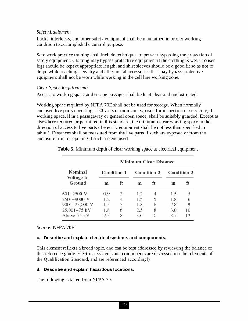
172
Safety Equipment
Locks, interlocks, and other safety equipment shall be maintained in proper working
condition to accomplish the control purpose.
Safe work practice training shall include techniques to prevent bypassing the protection of
safety equipment. Clothing may bypass protective equipment if the clothing is wet. Trouser
legs should be kept at appropriate length, and shirt sleeves should be a good fit so as not to
drape while reaching. Jewelry and other metal accessories that may bypass protective
equipment shall not be worn while working in the cell line working zone.
Clear Space Requirements
Access to working space and escape passages shall be kept clear and unobstructed.
Working space required by NFPA 70E shall not be used for storage. When normally
enclosed live parts operating at 50 volts or more are exposed for inspection or servicing, the
working space, if in a passageway or general open space, shall be suitably guarded. Except as
elsewhere required or permitted in this standard, the minimum clear working space in the
direction of access to live parts of electric equipment shall be not less than specified in
table 5. Distances shall be measured from the live parts if such are exposed or from the
enclosure front or opening if such are enclosed.
Table 5. Minimum depth of clear working space at electrical equipment
Source: NFPA 70E
c. Describe and explain electrical systems and components.
This element reflects a broad topic, and can be best addressed by reviewing the balance of
this reference guide. Electrical systems and components are discussed in other elements of
the Qualification Standard, and are referenced accordingly.
d. Describe and explain hazardous locations.
The following is taken from NFPA 70.
173
Hazardous locations must be well understood by anyone designing, installing, working on, or
inspecting electrical equipment and wiring in such areas. Such locations carry a threat of
flammable or combustible gases, vapors, or dusts being present some or all of the time.
Hazardous areas and locations are classified by group, class, and division. These
classifications are determined by the atmospheric mixtures of various gases, vapors, dust, and
other materials present. The intensity of the explosion that can occur depends on
concentrations, temperatures, and many other factors that are listed in NFPA codes.
Information in section 5.3 of DOE-HDBK-1092-2004, DOE Handbook: Electrical Safety,
assists in classifying areas or locations with respect to hazardous conditions, whether from
atmospheric concentrations of hazardous gases, vapors, and deposits, or from accumulations
of readily ignitable materials. This section covers the requirements for electrical equipment
and wiring in locations that are classified according to the properties of the flammable
vapors, liquids, or gases or combustible dusts that may be present and the likelihood that a
flammable or combustible concentration is present. The hazardous (classified) locations are
assigned the following designations:
1. Class I Division 1
2. Class I Division 2
3. Class I, Zone 0, Zone 1, Zone 2
4. Class II Division 1
5. Class II Division 2
Class III fibers and flyings are not covered in this section.
Class I
Class I locations are identified in the NEC as those in which flammable gases or vapors are
or may be present in the air in amounts sufficient to create explosive or ignitable mixtures.
Gases or vapors may be continuously or intermittently present. However, if a gas or vapor is
present, there is a potential that a flammable mixture will be present.
From an engineering standpoint, greater precautions are needed if a particular set of
conditions is likely to occur (e.g., the presence of a flammable mixture within the explosive
range) than if it is unlikely. This is the reason for dividing hazardous locations into two
divisions.
Division 1
NEC 500.5 defines Class I, Division 1 hazardous locations as those in which
1. ignitable concentrations of flammable gases, liquids, or vapors can exist under normal
operating conditions;
2. ignitable concentrations of such gases or vapors may exist frequently because of
repair or maintenance operations or because of leakage; or
3. breakdown or faulty operation of equipment or processes might release ignitable
concentrations of flammable gases, liquids, or vapors and might also cause
simultaneous failure of electrical equipment.
174
Note: In each case, ignitable concentrations are mentioned. This means concentrations
between the lower and upper flammable or explosion limits.
Division 2
NEC 500.5(B)(2) defines Class I, Division 2 locations as those
1. in which flammable liquids or gases are handled, processed, or used, but where such
materials are normally confined in closed containers or closed systems from which
they can escape only in case of accidental rupture or breakdown of such containers or
systems or in case of abnormal equipment operation.
2. in which gases or vapors are normally prevented, by positive mechanical ventilation,
from forming ignitable concentrations and which might become hazardous through
failure or abnormal operation of the ventilating equipment.
3. that are adjacent to a Class I Division 1 location and to which ignitable concentrations
of gases or vapors might occasionally be transmitted unless such transmittal is
prevented by adequate positive-pressure ventilation from a source of clean air, and
effective safeguards against ventilation failure are provided.
NEC 500.5 describes a number of areas and occupancies normally classified as Class I,
Division 1 and Class I, Division 2 locations.
Zone 0
Class I, Zone 0. A Class I, Zone 0 location is a location in which
1. ignitable concentrations of flammable gases or vapors are present continuously, or
2. ignitable concentrations of flammable gases or vapors are present for long periods of
time.
Zone 1
A Class I, Zone 1 location is a location
1. in which ignitable concentrations of flammable gases or vapors are likely to exist
under normal operating conditions; or
2. in which ignitable concentrations of flammable gases or vapors may exist frequently
because of repair or maintenance operations or because of leakage; or
3. in which equipment is operated or processes are carried on, of such a nature that
equipment breakdown or faulty operations could result in the release of ignitable
concentrations of flammable gases or vapors and also cause simultaneous failure of
electrical equipment in a mode to cause the electrical equipment to become a source
of ignition; or
4. that is adjacent to a Class I, Zone 0 location from which ignitable concentrations of
vapors could be communicated, unless communication is prevented by adequate
positive pressure ventilation from a source of clean air and effective safeguards
against ventilation failure are provided.
Zone 2
A Class I, Zone 2 location is a location
1. in which ignitable concentrations of flammable gases or vapors are not likely to occur
in normal operation and, if they do occur, will exist only for a short period; or

175
2. in which volatile flammable liquids, flammable gases, or flammable vapors are
handled, processed, or used but in which the liquids, gases, or vapors normally are
confined within closed containers or closed systems from which they can escape only
as a result of accidental rupture or breakdown of the containers or system, or as a
result of the abnormal operation of the equipment with which the liquids or gases are
handled, processed, or used; or
3. in which ignitable concentrations of flammable gases or vapors normally are
prevented by positive mechanical ventilation but which may become hazardous as a
result of failure or abnormal operation of the ventilating equipment; or
4. that is adjacent to a Class I, Zone 1 location from which ignitable concentrations of
flammable gases or vapors could be communicated, unless such communication is
prevented by adequate positive-pressure ventilation from a source of clean air and
effective safeguards against ventilation failure are provided.
Class II
A Class II location is defined in NEC 500 as an area where combustible dust presents a fire
or explosion hazard. Class II locations are divided into two divisions based on the normal
presence or absence of dust.
Division 1
A Class II, Division 1 location is one
1. in which combustible dust is in the air under normal operating conditions in quantities
sufficient to produce explosive or ignitable mixtures;
2. where mechanical failure or abnormal operation of machinery or equipment might
cause such explosive or ignitable mixtures to be produced and might also provide a
source of ignition through simultaneous failure of electrical equipment, operation of
protective devices, or other causes; or
3. in which combustible dusts of an electrically conductive nature may be present in
hazardous quantities.
Division 2
A Class II, Division 2 location is one where
1. combustible dust is not normally in the air in quantities sufficient to produce
explosive or ignitable mixtures;
2. dust accumulations are normally insufficient to interfere with the normal operation of
electrical equipment or other apparatus, but where combustible dust may be
suspended in the air as a result of infrequent malfunctioning of handling or processing
equipment; and
3. combustible dust accumulations on, in, or in the vicinity of the electrical equipment
may be sufficient to interfere with the safe dissipation of heat from electrical
equipment or may be ignitable by abnormal operation or failure of electrical
equipment.
e. Describe and explain PPE.
The following is taken from 29 CFR 1910.137 & 268.

176
Personal protective equipment is functionally derived from the hazards and risks that have
been previously identified and analyzed for the particular work. PPE comprises clothing,
tools, equipment, etc., necessary to work safely.
Qualified employees shall be trained and competent in the use of special precautionary
techniques, PPE, insulating and shielding materials, and insulated tools for working on or
near exposed energized parts of electric equipment. Employers shall ensure that an employee
in charge conducts a job briefing with the employees involved before they start each job. The
briefing shall cover at least the following subjects: hazards associated with the job, work
procedures involved, special precautions, energy source controls, and PPE requirements.
Body belts, safety straps, lanyards, lifelines, and body harnesses shall be inspected before use
each day to determine whether the equipment is in safe working condition. Defective
equipment may not be used.
Work related to tasks such as testing, troubleshooting, voltage measuring, etc., on or near live
parts, and performed by qualified persons shall be permitted to be performed without an
energized electrical work permit, provided appropriate safe work practices are followed and
appropriate PPE is used.
A shock hazard analysis shall determine the voltage to which personnel will be exposed,
boundary requirements, and the PPE necessary in order to minimize the possibility of
electrical shock to personnel.
A flash hazard analysis shall be done in order to protect personnel from the possibility of
being injured by an arc flash. The analysis shall determine the flash protection boundary and
the PPE that people within the flash protection boundary shall use.
Fall arrest equipment, work positioning equipment, or travel restricting equipment shall be
used by employees working at elevated locations more than 4 feet (1.2 m) above the ground
on poles, towers, or similar structures if other fall protection has not been provided. Fall
protection equipment is not required to be used by a qualified employee climbing or
changing location on poles, towers, or similar structures, unless conditions, such as, but not
limited to, ice, high winds, the design of the structure (for example, no provision for holding
on with hands), or the presence of contaminants on the structure, could cause the employee to
lose his or her grip or footing. This paragraph applies to structures that support overhead
electric power generation, transmission, and distribution lines and equipment. It does not
apply to portions of buildings, such as loading docks, to electric equipment, such as
transformers and capacitors, nor to aerial lifts. Requirements for fall protection associated
with walking and working surfaces are contained in subpart D of 29 CFR 1910; requirements
for fall protection associated with aerial lifts are contained in 29 CFR 1910.67. Employees
undergoing training are not considered qualified employees for the purposes of this
provision. Unqualified employees (including trainees) are required to use fall protection any
time they are more than 4 feet (1.2 m) above the ground.
The following requirements apply to personal fall arrest systems:
177
When stopping or arresting a fall, personal fall arrest systems shall limit the
maximum arresting force on an employee to 900 pounds (4 kilonewtons [kN]) if used
with a body belt.
When stopping or arresting a fall, personal fall arrest systems shall limit the
maximum arresting force on an employee to 1,800 pounds (8 kN) if used with a body
harness.
Personal fall arrest systems shall be rigged such that an employee can neither free fall
more than 6 feet (1.8 m) nor contact any lower level.
If vertical lifelines or droplines are used, not more than one employee may be
attached to any one lifeline.
Snaphooks may not be connected to loops made in webbing-type lanyards.
Snaphooks may not be connected to each other.
Additional information regarding PPE can be reviewed in NFPA 70E, Article 130.
f. Identify and discuss elements of an electrical safety program, such as the two-man rule, stored energy, and component labeling.
Two-Man Rule
The following is taken from 29 CFR 1910.269.
At least two employees shall be present while the following types of work are being
performed:
Installation, removal, or repair of lines that are energized at more than 600 volts
Installation, removal, or repair of de-energized lines if an employee is exposed to
contact with other parts energized at more than 600 volts
Installation, removal, or repair of equipment such as transformers, capacitors, and
regulators if an employee is exposed to contact with parts energized at more than
600 volts
Work involving the use of mechanical equipment, other than insulated aerial lifts,
near parts energized at more than 600 volts
Other work that exposes an employee to electrical hazards greater than or equal to
those posed by operations that are specifically listed in 29 CFR 1910.269, paragraphs
(l)(1)(i)(A) through (l)(1)(i)(D)
However, this rule does not apply to the following operations:
Routine switching of circuits, if the employer can demonstrate that conditions at the
site allow this work to be performed safely
Work performed with live-line tools if the employee is positioned so that he or she is
neither within reach of nor otherwise exposed to contact with energized parts
Emergency repairs to the extent necessary to safeguard the general public
Stored Energy
The following is taken from DOE-HDBK-1092-2004.
The employer shall establish a program consisting of energy control procedures, employee
training, and periodic inspections to ensure that, before any employee performs any servicing
178
or maintenance on a machine or equipment where the unexpected energizing, start-up, or
release of stored energy could occur and cause injury, the machine or equipment is isolated
from the energy source and rendered inoperative.
If there is a possibility of re-accumulation of stored energy to a hazardous level, verification
of isolation shall be continued until the servicing or maintenance is completed or until the
possibility of such accumulation no longer exists.
Procedures shall be used during shift or personnel changes to ensure the continuity of LOTO
protection, including provision for the orderly transfer of LOTO device protection between
off-going and on-coming employees, to minimize their exposure to hazards from the
unexpected energizing or start-up of the machine or equipment or from the release of stored
energy.
A direct ground shall be applied to the exposed terminals when the stored energy drops to a
level at which it is safe to do so.
Where required, install grounding equipment/conductor device on the phase conductors or
circuit parts, to eliminate induced voltage or stored energy, before touching them. Where it
has been determined that contact with other exposed energized conductors or circuit parts is
possible, apply ground connecting devices rated for the available fault duty. In regard to
identifying elements of control, the procedure shall include requirements for releasing stored
electric or mechanical energy that might endanger personnel. All capacitors shall be
discharged, and high-capacitance elements shall also be short-circuited and grounded before
the associated equipment is touched or worked on. Springs shall be released or physical
restraint shall be applied when necessary to immobilize mechanical equipment and
pneumatic and hydraulic pressure reservoirs. Other sources of stored energy shall be blocked
or otherwise relieved.
Sources of stored energy, such as capacitors or springs, shall be relieved of their energy, and
a mechanism shall be engaged to prevent the re-accumulation of energy. The employees shall
be notified that a LOTO system is going to be implemented and the reason therefore. The
qualified employee implementing the LOTO shall know the disconnecting means location for
all sources of electrical energy and the location of all sources of stored energy.
Component Labeling
The following is taken from DOE-HDBK-1092-2004.
Labeled or listed equipment shall be installed and used in accordance with any instructions
included in the listing or labeling. Labeling is a key feature for determining suitability of
identified equipment.
Labeled equipment is equipment or materials to which has been attached a label, symbol, or
other identifying mark of an organization that is acceptable to the AHJ and concerned with
product evaluation, that maintains periodic inspection of production of labeled equipment or
materials, and by whose labeling the manufacturer indicates compliance with appropriate
standards or performance in a specified manner.

179
Listed equipment is equipment, materials, or services included in a list published by an
organization that is acceptable to the AHJ and concerned with evaluation of products or
services, that maintains periodic inspection of production of listed equipment or materials or
periodic evaluation of services, and whose listing states that the equipment, material, or
service either meets appropriate designated standards or has been tested and found suitable
for a specified purpose. The means for identifying listed equipment may vary for each
organization concerned with product evaluation; some organizations do not recognize
equipment as listed unless it is also labeled. Use of the system employed by the listing
organization allows the AHJ to identify a listed product.
Warning labels or signs that read ―DANGER — HIGH VOLTAGE — KEEP OUT‖ shall be
attached to the equipment and shall be plainly visible where persons might come in contact
with energized parts when doors are open or closed or when panels are removed from
compartments containing over 150 volts AC or DC.
The AHJ may also refer to the listings or labeling practices of an organization that is
concerned with product evaluations and is thus in a position to determine compliance with
appropriate standards for the current production of listed items.
V. ELECTRICAL DESIGN & INSTALLATION (SAFETY AND SYSTEMS) This section is optional and should be used by the program and/or field offices to assist them with specific technical qualifications for that office.
30. Electrical personnel shall demonstrate a working level knowledge of the current National Electrical Code and the requirements for wiring design and protection (NFPA 70 and NFPA 70E, Chapter 4).
[Note: The 2004 version of NFPA 70E has been superseded by the 2009 revision and is archived but still available. Because the 2009 revision was drastically reduced in scope it is not used as a reference in this guide.]
a. Describe and explain the use of listed and labeled Nationally Recognized Test Laboratory (NRTL) electrical equipment.
The following is taken from Curtis, Jon. Conformity, ―Electrical Product Safety for
Retailers‖.
There are 18 organizations running electrical product safety certification schemes (illustrated
in figure 44) in the United States and 9 in Canada. Commonly referred to as NRTLs, these
organizations find that approximately 20 percent of designs submitted for initial testing have
deviations that need to be corrected for compliance with accepted safety standards prior to
certification of the designs. Not all of these defects would have gone on to become recalls or
to harm users, but simple math indicates that the NRTLs help contain significant risk.
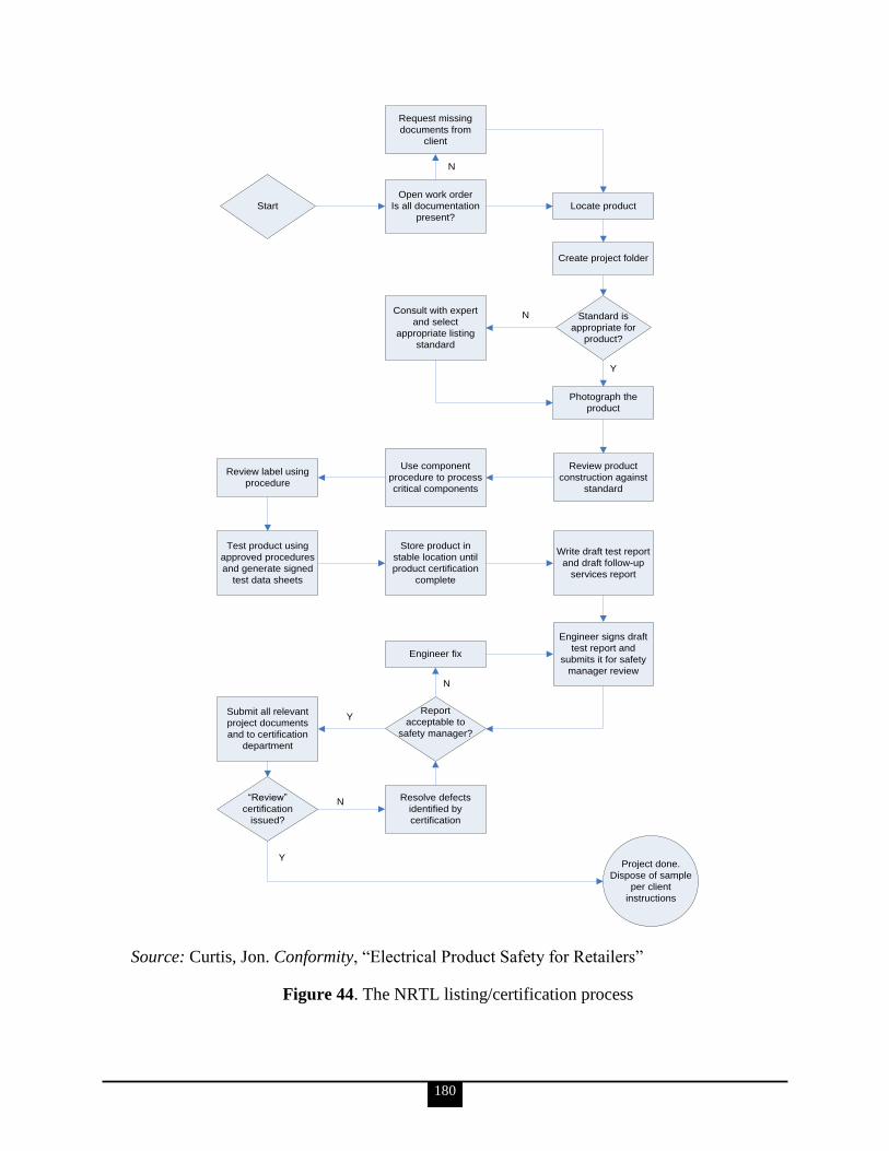
180
Start
Request missing
documents from
client
Open work order
Is all documentation
present?
Consult with expert
and select
appropriate listing
standard
Use component
procedure to process
critical components
Store product in
stable location until
product certification
complete
Engineer fix
Resolve defects
identified by
certification
Report
acceptable to
safety manager?
“Review”
certification
issued?
Submit all relevant
project documents
and to certification
department
Review label using
procedure
Test product using
approved procedures
and generate signed
test data sheets
Locate product
Create project folder
Standard is
appropriate for
product?
Photograph the
product
Review product
construction against
standard
Write draft test report
and draft follow-up
services report
Engineer signs draft
test report and
submits it for safety
manager review
Project done.
Dispose of sample
per client
instructions
N
N
Y
N
Y
N
Y
Source: Curtis, Jon. Conformity, ―Electrical Product Safety for Retailers‖
Figure 44. The NRTL listing/certification process
181
Underwriters Laboratories is the largest, most recognized, North American provider of
services, but over the last decade several other NRTLs with global laboratory networks have
developed significant market share and are widely accepted by major retailers. Many of these
alternative NRTLs are attractive for their turnaround and pricing policies. Most retailers now
offer their vendors a choice of any of the globally distributed NRTL providers in order to
reduce supply chain expenses and delays through the application of competitive market
forces.
The means for identifying listed equipment may vary for each organization concerned with
product evaluation, some of which do not recognize equipment as listed unless it is also
labeled. Use of the system employed by the listing organization allows the AHJ to identify a
listed product.
b. Describe and explain branch circuit identification.
The following is taken from NFPA 70B.
Where more than one nominal voltage system exists in a building, each ungrounded
conductor of a multiwire branch circuit, where accessible, shall be identified by phase and
system. The means of identification shall be permitted to be by separate color coding,
marking tape, tagging, or other approved means and shall be permanently posted at each
branch circuit panelboard.
Where the premise‘s wiring system has branch circuits supplied from more than one nominal
voltage system, each ungrounded conductor of a branch circuit shall be identified by phase or
line and system at all termination, connection, and splice points. The means of identification
shall be permitted to be by separate color coding, marking tape, tagging, or other approved
means. The method utilized for conductors originating within each branch-circuit panelboard
or similar branch-circuit distribution equipment shall be documented in a manner that is
readily available or shall be permanently posted at each branch-circuit panelboard or similar
branch-circuit distribution equipment.
c. Describe and explain GFCI protection for personnel.
A GFCI is a device intended for the protection of personnel that functions to de-energize a
circuit or portion thereof within an established period of time when a current to ground
exceeds the values established for a Class A device.
GFCI protection is prescribed variously based on the specific location and/or facility at hand.
Detailed descriptions are listed in NFPA 70E, Article 430, and in most location descriptions
discussed in NFPA 70, beginning in Article 525.
d. Describe and explain outside circuits and conductors for 600 volt (or less) systems.
Article 225 of NFPA 70 covers requirements for outside branch circuits and feeders run on or
between buildings, structures, or poles on the premises; and electrical equipment and wiring

182
for the supply of utilization equipment that is located on or attached to the outside of
buildings, structures, or poles.
Where within 3.0 m (10 ft) of any building or structure other than supporting poles or towers,
open individual (aerial) overhead conductors shall be insulated or covered. Conductors in
cables or raceways, except Type MI cable, shall be of the rubber-covered type or
thermoplastic type and, in wet locations, shall comply with NFPA 70, Article 310.8.
Conductors for festoon lighting shall be of the rubber-covered or thermoplastic type.
e. Describe and explain overcurrent protection for 600 volt (or less) and greater-than 600 volt circuits.
Parts I through VII of NFPA 70, Article 240 provide the general requirements for overcurrent
protection and overcurrent protective devices not more than 600 volts, nominal. Part VIII
covers overcurrent protection for those portions of supervised industrial installations
operating at voltages of not more than 600 volts, nominal. Part IX covers overcurrent
protection over 600 volts, nominal.
Overcurrent protection for conductors and equipment is provided to open the circuit if the
current reaches a value that will cause an excessive or dangerous temperature in conductors
or conductor insulation.
See also Article 110.9 for requirements on interrupting ratings and Article 110.10 for
requirements for protection against fault currents.
f. Describe and explain grounding and bonding requirements as noted in NFPA 70E, Article 410.10.
NFPA 70E, Article 410.10 paragraphs (A) through (G) cover grounding requirements for
systems, circuits, and equipment. These requirements include the following topics:
Grounding path
General bonding
Systems that supply premises wiring to be grounded
Grounding connections
Enclosure, raceway, and service cable grounding
Equipment considered effectively grounded
Grounding of systems and circuits of 1 kV and over (high voltage)
31. Electrical personnel shall demonstrate a familiarity level knowledge of the requirements for the installation of lightning protection systems (NFPA 780; UL 96, Lightning Protection Components; and UL 96A, Installation Requirements for Lightning Protection Systems).
a. Describe and explain the principles of lightning.
The following is taken from NFPA 780. Additional detail is available in that document.
The fundamental principle in the protection of life and property against
lightning is to provide a means by which a lightning discharge can enter or
183
leave the earth without resulting damage or loss. A low-impedance path which
the discharge current will follow in preference to all alternative high-
impedance paths offered by building materials such as wood, brick, tile, stone,
or concrete should be offered. When lightning follows the higher impedance
paths, damage can be caused by the heat and mechanical forces generated
during the passage of the discharge.
b. Describe and explain how lightning protection systems work and their associated requirements.
The following is taken from DOE-HDBK-1092-2004.
An LPS operates to dissipate the energy from a lightning strike through a strike termination
device. Lightning-protection systems should be visually inspected every 7 months and a
report on their conditions filed at least annually. Any evidence of corrosion, broken wires or
connections, or any other problem that negates the system‘s usefulness shall be noted and the
problem repaired.
Lightning protection systems should be tested electrically every 14 months to ensure testing
during all seasons, or immediately following any repair or modification. The testing shall be
conducted only with instruments designed specifically for earth-ground system testing. The
instruments shall be able to measure 10 ohms ±10% for ground resistance testing and 1 ohm
±10% for bonding testing. Electrical resistance readings shall be recorded.
Inspection records shall contain the most recent electrical test report and any subsequent
visual inspection reports for each building with a LPS.
32. Electrical personnel shall demonstrate a working level knowledge of electrical diagrams, such as one-line diagrams, schematics, construction drawings, as-built drawings, and wiring diagrams.
Elements ‗a‘ through ‗e‘ are performance-based KSAs. The Qualifying Official will evaluate
their completion.
a. Using a schematic, identify an electrical component by its symbology.
b. Using a logic diagram for a control circuit, identify and describe the effects of an action taken.
c. Using a one-line diagram, identify power sources and loads.
d. Using a one-line diagram or schematic diagram, analyze the effects of a component failure in a system.
e. Using a construction drawing, identify the emergency power supplies.
f. Discuss the origin and purpose of ―as-built‖ drawings.
184
The following is taken from U.S. Army Corps of Engineers, Huntsville Engineering and
Support Center (CEHNC) 1180-3-1, Chapter 10, As-built Drawing.
―As-built‖ drawings are drawings that depict the actual conditions of a completed
construction, providing a record of each project feature. These working as-built drawings will
typically be red-lined markups of two sets of the construction plans: one for use by the
contractor and one for use by the Government. The working as-built drawings must be
reviewed at least monthly by the Resident Engineer in conjunction with the approval of
progress payments. The contract requires the Systems Contractor to prepare, maintain and
deliver to the Government a set of redlined, record drawings, which show the actual as-built
conditions of the construction phases. After Government review and approval, these marked-
up drawings will be sent to the contractor who will produce three copies of a final set of as-
built drawings. One set for the Corps of Engineers, one for the User or Owner, and one for
the Systems Contractor who must also keep a permanent set of as built drawings.
The as-built drawing procedure has three steps:
All changes, no matter how minor, as well as all clarifications are entered into a
change database and recorded by the Systems Contractor on two sets of redlined or
record drawings. Changes and clarifications refer to shop drawings, field electrical
controller products, change orders, modifications, and RFIs which have been
reviewed and approved by the Government.
Redlined drawings must be transferred to the Architect-Engineer for CM verification,
baseline comparison, entry into the computer-aided design and drafting system, and
creation of a reproducible set of drawings labeled As-Built Drawings.
When as-built drawings are completed and approved by the Government, the entire
set is then sent to the Systems Contractor to use during the systemization and
operations phases of the contract. Office of Safety and Compliance policy and
procedures establish storage, updating, and maintaining of as-builts in the data control
center during these phases.
33. Electrical personnel shall demonstrate a familiarity level knowledge of the configuration management process as applied to electrical documentation (e.g., documenting, controlling, revising, and issuance of electrical drawings) and drawings that are updated and issued ―as built‖ (DOE-STD-1073-2003, Configuration Management Program and DOE O 414.1C, Quality Assurance).
a. Discuss the change control process described in DOE-STD-1073-2003.
The information for KSAs ‗a‘ and ‗b‘ is taken from DOE-STD-1073-2003.
Contractors must establish and use a formal change control process as part of the CM
process. The objective of change control is to maintain consistency among design
requirements, the physical configuration, and the related facility documentation, even as
changes are made. The change control process is used to ensure changes are properly
reviewed and coordinated across the various organizations and personnel responsible for
activities and programs at the nuclear facility.
Through the change control process, contractors must ensure that

185
changes are identified and assessed through the change control process,
changes receive appropriate technical and management review to evaluate the
consequences of the change,
changes are approved or disapproved,
waivers and deviations are properly evaluated and approved or denied and the
technical basis for the approval or the denial is documented,
approved changes are adequately and fully implemented or the effects of the partial
implementation are evaluated and accepted,
implemented changes are properly assessed to ensure the results of the changes agree
with the expectations, and
documents are revised consistent with the changes and the revised documents are
provided to the users.
b. Describe the purpose and objectives of the operational configuration management program, and explain how it relates to electrical systems.
Configuration management is a disciplined process that involves both management and
technical direction to establish and document the design requirements and the physical
configuration of a nuclear facility and to ensure that they remain consistent with each other
and the documentation.
The size, complexity, and missions of DOE nuclear facilities vary widely and CM processes
may need to be structured to individual facilities, activities, and operations. It would
generally be inappropriate to apply the same CM standards to widely different activities, for
example, a reactor facility and a small, simple laboratory. The detailed examples and
methodologies in DOE-STD-1073-2003 are provided to aid those developing their CM
processes; however, they are provided for guidance only and may not be appropriate for
application to all DOE nuclear activities. The individuals defining the CM process for a
particular nuclear activity will need to apply judgment to determine whether the examples
and the methods presented in DOE-STD-1073-2003 are appropriate for the activity.
Nevertheless, the basic objectives and general principles of CM are the same for all activities.
The objectives of CM are to
establish consistency among design requirements, physical configuration, and
documentation (including analysis, drawings, and procedures) for the activity, and
maintain this consistency throughout the life of the facility or activity, particularly as
changes are being made.
Performance data tools, drawings, technical discipline reviews, and detailed project design
are all considerations that apply to CM of electrical systems.
The following are examples of critical characteristics for electrical components:
Component number
Drawing number (e.g., schematic, one-line diagram, etc.)
Manufacturer
Model number
Serial number

186
Component type
Power (watts)
Voltage (e.g., 125 DC, 4 kV AC, etc.)
Amperage
Contact rating
Other (e.g., environmental qualification, fuse type, location, etc.)
c. Discuss the following elements of the configuration management program as they relate to electrical systems: Design requirements Document control Change control Assessments Design reconstitution adjunct Material condition and aging adjunct
The information for Design requirements, Document control, Change control and
Assessments is taken from DOE-STD-1073-2003. The information for Design reconstitution
adjunct and Material condition and aging adjunct is taken from DOE-STD-1073-1993
(archived).
Design Requirements
Design requirements are those engineering requirements reflected in design output
documents (such as drawings and specifications) that define the functions, capabilities,
capacities, physical sizes and dimensions, limits and setpoints, etc. specified by design
engineering for an SSC. The design requirements provide the results of the design process.
A CM program‘s elements encompass the following functions: establishing and maintaining
the facility design requirements, establishing system and process boundaries, assigning SSC
grades based on the associated design requirements, identifying the specific list of SSCs for
inclusion in the CM program, and establishing and maintaining the design basis for the
design requirements.
The objective of the design requirements element is to establish and maintain the design
requirements and the associated design basis. The design requirements should be formally
established, documented, and maintained. For each SSC, the design requirements should be
categorized into the types established by the equipment scope criteria. A technical
management review should be performed to determine the adequacy of the design
requirements. If the design requirements are not fully documented, not accurate, or not
complete, the design requirements should be reconstituted to the extent identified by the
design reconstitution (DR) adjunct program. The design requirements should be incorporated
into an equipment database that correlates each SSC with the SSC grade, the design
requirements, the technical topics involved, and the associated documentation. The design
requirements for new facilities and modifications to existing facilities should be established,
categorized, and documented as they are developed, in a form amenable to review and
addition to the equipment database.
187
The boundaries for each system and process should be established in such a manner as to
contain the components necessary to satisfy the design requirements for that system or
process. Each SSC should be assigned a grade based on the most important type of design
requirements applicable to it. The SSC grade should be used as the basis for the degree of
control on all activities associated with the SSC. On the basis of the equipment scope criteria
and the assignment of SSC grades, the specific SSCs included in the CM program should be
identified. The basis for design requirements should be formally established, correlated with
the design requirements, documented, and maintained.
A technical management review should be performed to determine the adequacy of the
design basis. If the design basis is not fully documented, not accurate, or not complete, it
should be reconstituted to the extent identified by the DR adjunct program. The design basis
for new or modified design requirements should be established and documented as these
requirements are developed.
With the exception of components whose design requirements have been established and
found to be adequate and outside the equipment scope criteria, all components within a CM
system should be included in the CM program, even those without a safety, environmental,
or mission function. Once the design requirements are fully established and adequate, the
CM equipment scope criteria may be used to consider component exclusions. However, the
inclusion of components other than safety, environment, and mission components is
generally advisable for CM systems to enhance overall configuration control.
Document Control
The objective of the document control element is to identify and maintain documents within
the CM program consistent with the physical configuration and design requirements. The
types of documents that need to be included in the CM program should be determined, and
document owners should be established for each of these document types. The document
owners should be responsible for the technical content of assigned documents. Within each
document type, the specific documents to be included in CM document control should be
identified for each SSC. The document owners should establish priorities for document
revision and retrieval.
Originals or master copies of documents within the CM program should be stored and
protected. Retention times should be established to meet the needs of the document owners
and users and the minimums specified by DOE O 243.1, Records Management Program.
Only the currently-approved revisions of documents within the CM program should be used.
Revisions to documents within the CM program to incorporate pending changes should be
completed in a timely manner. The number of unincorporated document changes allowed to
accumulate before revisions are implemented should be determined according to the priority
of the document, the complexity of the changes and the overlap of the changes. For each
document within the CM program, the following information should be readily available:
revision level, current status, document owner, information regarding pending changes, and
other data necessary for control and tracking, such as storage location and outstanding
document change notices.

188
Documents should be retrieved in a timely manner upon request. Maximum retrieval times
for each document should be established, and they should be based on the priorities
established by the document owners. Documents should be identifiable from a document
database, which should be able to identify documents within the CM program related to
particular SSCs, types of SSCs, technical topics, and other information to support
identification, such as SSC vendors. When a copy of a document within the CM program is
issued, pending changes and associated information should be identified.
Early in CM program development, a determination should be made as to which documents
will be included. The steps necessary to accomplish this are as follows:
Identify document types used at the facility.
Determine which document types should be in the CM program.
Determine which specific documents should be in the CM program.
First, a complete survey of document types in use should be conducted with support of the
various organizations at the facility. Each organization should identify the document types it
prepares and the important document types it uses. Document types identified during the
initial assessments should also be addressed.
After document types are identified, a document owner should be assigned to each document
type. The natural document owner is the person or organization responsible for developing
and revising the technical content of documents within the assigned document type. The
owners should review the document types for which they are responsible to identify those
important for supporting the CM program objective and criteria. They should then perform
an importance evaluation in light of their experience with, and knowledge of, the document
types. Document scope criteria may vary according to the importance of the SSCs involved.
These criteria should be defined to include only those document types that support the design
or operation of facility SSCs included in the CM program. Document types that reflect the
facility‘s design requirements and those that are necessary for day-to-day operation should
receive the highest priority for inclusion in the CM program.
Finally, the document owners, with the assistance of those persons responsible for the
document retrieval function, should identify the individual documents within each document
type and determine which of these documents should be included in the CM program.
Change Control
The objective of the change control element is to maintain consistency among the design
requirements, the physical configuration, and the facility documentation as changes are
made. All mechanisms that can lead to temporary or permanent changes in the design
requirements, facility configuration, or facility documentation within the CM program should
be identified. Such mechanisms might include hardware modifications not controlled as
projects, hardware modifications controlled as projects, maintenance changes, operational
changes, procurement changes, document changes, and computer software changes. Change
mechanisms should be evaluated to determine which are adequate as is, and which need to be
improved, consolidated, or terminated.
189
The resulting change mechanisms should be integrated with the CM program. Within
approved CM change mechanisms, each proposed change, including temporary changes and
partially implemented changes, should be described sufficiently to support technical reviews,
management reviews, and approvals.
Each specific proposed change should be reviewed to determine if it is within the bounds of
the design requirements. Changes to the design requirements should be evaluated and
approved by the design authority prior to implementation. The technical reviews should
evaluate safety, environmental, and mission impacts; determine appropriate post-
implementation acceptance criteria; and identify the affected SSCs and facility
documentation.
Before implementation, management should review proposed changes (including those that
do not involve a change to design requirements) to verify that the technical reviews have
been performed adequately, that the change package is complete and ready for
implementation, and that any external approvals necessary prior to implementation have been
obtained. On the basis of these reviews, management should take approval action.
Each change should be implemented in accordance with its approved change package. The
change process should include mechanisms for field change requests, and technical reviews
and approvals of field changes should be commensurate with those of the original change
package. The change process should generate accurate as-built information. After the
physical implementation of changes, post-modification testing should be conducted.
Each change should be documented and that documentation should include a description of
the change, as well as an account of the technical reviews, management approvals, as-built
information, and post-modification test results. Documents that are included in the CM
program and are affected by a change, either directly or indirectly, should be revised.
Specific changes should be identified only within established change processes. The need for
a potential change may be identified by anyone within the facility and should be documented
by the requester to support the processing of the change request. As defined by the CM
program criteria, each proposed change should be described adequately to support technical
and management reviews prior to approval. Change initiation should include the name of the
requester, a description of the proposed change, the affected SSCs and the associated SSC
grade, the reason for the change, alternative solutions, the due date, and constraints. It should
also include any other information needed for review, tracking, approval, and further
processing.
Effective change control involves formal, multi-disciplined, technical reviews for each
change. Some of these are necessary to maintain configuration and others are defined as good
management practices. The technical reviews defined by the CM program criteria to maintain
configuration can be grouped into these areas: design envelope review; identification of
affected hardware and documents; identification of post-implementation acceptance criteria;
and, safety, environment, and mission reviews.
190
As defined by the CM program criteria, management should review the proposed change to
verify that the technical reviews have been performed adequately, the change package is
complete and ready for implementation, any necessary external approvals have been
obtained, and that the change is authorized for implementation.
Assessments
The objective of the assessments element is to help define facility CM needs and to measure
how effective the CM program is in establishing and maintaining the program‘s basic
relationships. CM assessments are conducted in an initial phase, in a post-implementation
phase, and throughout the life of the facility.
The adequacy of CM programs and procedures should be assessed using vertical and
horizontal slice assessments.
Initial Assessments
During the planning for the CM program, initial assessments should be conducted to
determine the strengths and weaknesses of existing programs and procedures with regard to
determining where upgrade actions and resource investments are necessary. Two vertical
slice assessments relevant to the facility should be conducted. One of these should be on a
safety system related to the principal facility hazard, either nuclear or non-nuclear. Two
horizontal slice assessments relevant to the facility should also be performed. One of these
should be on change control and the other on a technical topical area, such as seismic
qualification or fire protection.
Post-implementation Assessments
After the CM program upgrades are implemented, a horizontal slice assessment should be
performed for each CM program element to determine if that element addresses identified
weaknesses and is effective in accomplishing the CM functions.
For each system design information summary (DIS) developed by the DR adjunct program, a
field validation should be performed to ensure that the design requirements are accurately
reflected in the physical configuration and the associated facility documentation. After the
material condition and aging (MCA) adjunct program is developed, a technical quality
review should be performed of its assumptions, methods, and products.
After the CM program and its adjunct programs have been implemented, a combination of
vertical and horizontal slice assessments should be performed periodically to measure the
overall CM program effectiveness and to determine if CM controls are adequate and
appropriate. The results of these assessments should establish the basis for revisions to the
CM program plan, either increasing or decreasing controls.
Physical configuration assessments, or walkdowns, should be performed for representative
sample SSCs to determine the degree of agreement between the physical configuration and
the configuration depicted in the facility documentation. Physical walkdowns should be
included as part of the programmatic assessments conducted during the initial assessments,
post-implementation assessments, and periodic effectiveness assessments. If substantive
discrepancies (either in number or type) are discovered, appropriate immediate corrective
191
actions should be developed to establish agreement between the physical configuration and
the documentation. The corrective actions should include additional walkdowns to
characterize the problem and to determine the extent of the problem. They should also
include technical evaluations to determine whether the physical configuration or the
documentation should be changed.
Structures, systems, and components within the CM program should be tested periodically to
determine if they are still capable of meeting their design requirements. This monitoring
should also address surveillance actions, periodic in-service inspections and tests, and other
monitoring of SSCs to ensure safe and reliable operation of the facility. Monitoring should
also include measurements and trending of data related to the actual aging degradation of
equipment, to the extent identified by the MCA adjunct program and approved by the design
authority.
An SSC within the CM program should be tested after modification (and before being turned
over for service) to determine if it is capable of meeting its design requirements (i.e., the
post-implementation acceptance criteria). If a changed SSC fails to meet its post-
implementation acceptance criteria, turnover for operation should be postponed until either a
technical review has been completed and any follow-up actions are completed or the SSC is
returned to its original condition and tested satisfactorily.
The assessments element may be considered fully developed on completion of the following:
Initial CM programmatic and physical configuration assessments
Detailed action plans and procedures for conducting post-implementation assessments
Ongoing assessment programs established by procedure and effectively implemented
Senior management should retain overall responsibility for management assessments (i.e., all
initial and post-implementation assessments and the periodic program effectiveness
assessments). Direct participation of senior management during these assessments is
essential. This process should also involve other levels of management, as appropriate.
Management assessment results should be documented. Senior management should take
prompt action and document decisions in response to recommendations resulting from the
management assessment process. Follow-up should include an evaluation of the effectiveness
of management‘s actions.
Design Reconstitution Adjunct
If the design requirements are not fully documented, not accurate, or not complete, the design
requirements should be reconstituted to the extent identified by the DR adjunct program.
The objective of the DR adjunct program is to establish, organize, and document design
information (i.e., both design requirements and design basis), where existing design
information is not adequate. A program plan, an action plan, and implementing procedures
should be developed for the DR adjunct program. The DR program plan should be based on
the initial assessments and the graded approach. The DR adjunct program should be
implemented in stages to provide a timely initial set of design information and more
information as it becomes available. It should include prioritization of the development and

192
issuance of DISs. Design information summaries for systems or technical topics necessary to
support the facility accident analysis and TSRs should receive the highest priority.
The identification and retrieval of design information should be accomplished in stages, with
emphasis on the most important and most accessible information first. The objective and
scope of source documents to be reviewed should be defined for each document
identification and retrieval stage. The recommended stages are the formal review, the smart
search, and the comprehensive search. The formal review should address those on-hand
documents, such as the facility safety analysis and TSRs, that contain summary-type design
information; the smart search should identify and retrieve those types of documents that can
be identified as most likely to contain design requirements; and the comprehensive search
should identify and retrieve any remaining documents that might contain design information,
including DOE correspondence and vendor correspondence.
Technical review and identification of design information from each source document should
include both design requirements and design basis information. Extracted design information
should be identified as to the applicable facility SSC, type of SSC, technical topic area, and
whether it is a design requirement or design basis. The technical review and identification of
design information from each source document should be complete, such that the document
does not have to be reconsidered during subsequent searches and reviews.
Extracted design information should be verified by a second party to ensure that the design
information was extracted completely and accurately from the source documents. Extracted
design information should be technically validated to ensure that it is reasonable, that it is
applicable to the current facility mission and configuration, and that the analytical methods
and technical assumptions used in the design process are valid and appropriate. Design basis
information should be correlated with the design requirements. Extracted design information
should also be evaluated to identify any missing design requirements or design basis
information. Design information summaries should be field validated to ensure that design
requirements are properly reflected in the physical configuration and in the associated facility
documentation.
Validated situations involving the following should be documented as open items: apparent
contradictions in the information from different source documents; concerns; unanswered
technical questions; and cases of missing, undocumented, or inaccurate information. The
open items should be dispositioned by a formal resolution process and should be tracked to
completion and closeout, including documentation of their resolution. SS open items (i.e.,
discrepancies) should be promptly addressed by existing programs for determining
operability and reportability and resolved by those programs.
Missing design information should be evaluated to determine which part needs to be
regenerated. Missing design information that is critical, including that necessary to support
the facility accident analysis and TSRs, should be regenerated in order of priority.
Extracted design requirements should be entered into the CM equipment database promptly
after verification and technical validation. Design information summaries should include a
system description (including systems interface information), system operability
193
requirements, system-level design requirements, component-level design requirements, the
design basis, and related design topical information. They also should identify design
requirements by type; attributes of the design that were not mandatory for the designer
should be distinguished from other types of design requirements. The authorization basis
should be clearly distinguished from other aspects of the design basis. The DISs should be
written for easy use by individuals at all levels of experience. A DIS should be initially
issued when the design requirements are complete and technically validated, including the
regeneration of missing critical design requirements. This initial version should also contain
available technically validated design basis information and should identify open items to be
resolved. The DIS should be revised and reissued when the design basis has been
reconstituted (including regeneration of missing critical design basis) and the field validation
has been completed.
Material Condition and Aging Adjunct
The objective of the MCA adjunct program is to prevent the failure of facility life-limiting
components from aging degradation and the associated impact on facility operations. Aging
degradation can so impair the performance capability of equipment that it no longer meets its
design requirements, and this can compromise the CM program basic relationships.
A program plan, an action plan, and implementing procedures should be developed for the
MCA adjunct program. The program plan should be based on the initial assessments and the
graded approach.
Components in the facility, including passive components (e.g., structures), should be
screened to identify those that are potentially life limiting for the facility. The remaining
lifetime for each potentially life-limiting component should be evaluated. Major aging
degradation mechanisms that could affect potentially life-limiting components should be
identified. The present material condition of each such component should be determined.
The remaining lifetime of each potentially life-limiting component, with no life extension
techniques applied, should be estimated using engineering judgment. The facility remaining
lifetime is the shortest estimated remaining lifetime for a potentially life-limiting component.
If DOE has not specified a facility desired lifetime, the contractor should request that it do so.
If not specified, the desired lifetime should be taken to be the same as the remaining lifetime
without the application of life extension techniques. As appropriate, the feasibility of
continued operations and the feasibility of extended operations should be assessed. Objects
of such an assessment would include the following: management alternatives for continued
operation or extended operations of the facility; the estimated costs for each alterative as a
function of time; and recommendations regarding facility continued operations and extended
operations.
Detailed component screening, aging degradation evaluations, more rigorous determinations
of facility remaining lifetime, the feasibility of continued operations, and the feasibility of
extended operations should be performed. The physical characteristics related to aging
degradation of specific life-limiting components should be determined, and measurements
that could be made to determine the material condition of life-limiting components should be
194
defined. Baseline measurements should be performed to establish the material condition of
facility life-limiting components. The results of these measurements should be included in
the aging degradation evaluations.
Aging degradation measurements and associated frequencies should be provided to the
design authority as proposed new design requirements. Detailed aging degradation
evaluations should also be provided to the design authority as the design basis for the new
design requirements. The results of the periodic aging degradation measurements should be
trended and extrapolated to update the remaining lifetime determinations after each set of
measurements. As needed, life extension techniques for life-limiting components should be
developed and implemented.
d. Discuss the purpose, concepts, and general process for applying the graded approach to operational configuration management. Using the guidance in DOE-STD-1073-2003, discuss the system engineer
concept as it applies to oversight of safety systems. Specifically address the areas of configuration management, assessment of system status and performance, and technical support for operation and maintenance activities, or for Documented Safety Analysis (DSA) reviews.
Using DOE O 414.1C, discuss how the pedigree of electrical equipment should be maintained when supporting a nuclear related activity, and/or performing a safety function.
DOE-STD-1073-2003, Configuration Management Program
One of the challenges of change control is to be cognizant of many ongoing changes—from
proposal, through development, to implementation—and to understand the integrated effect
of the various changes. The system engineering concept has been used in the commercial
nuclear industry to provide a technical focal point for each system. The system engineer
develops resident technical expertise and facility knowledge, centralizes resolution of SSC
performance problems for more timely and effective response, and interfaces between the
facility operations and maintenance organizations and the design engineering organization.
The systems engineering concept benefits CM as well as many other facility activities
including facility status and troubleshooting, operations support, coordination of testing and
other system-related activities, and communication among departments.
For the purpose of change control, it is recommended that DOE contractors, in a manner
similar to the commercial industry, institute the systems engineering concept. The duties,
responsibilities, and interfaces of each system engineer need to be clearly defined,
documented, and communicated to and understood by supporting facility organizations.
System engineer responsibilities should include the following major items:
Monitoring and tracking the status of the system, especially during changes (e.g.,
physical changes in progress and temporary physical changes)
Conducting and/or observing equipment performance monitoring, evaluating the
results of performance monitoring and surveillance, trending important data, and
initiating corrective actions
Reviewing and approving post-modification, post-maintenance, surveillance, and
special test procedures and test results
Providing assistance to operations and maintenance, as needed
195
Identifying any situation where the design engineering organization should be
consulted for advice or services
To implement systems engineering, selected facility engineers would be assigned the
responsibility of important systems. These individuals should have an engineering degree or
a strong technical background combined with a knowledge of the assigned system and how it
relates to overall facility operation. An understanding of the policies, procedures, and
organizational interfaces is also important. The number of systems assigned to each engineer
should be limited (e.g., two to five) based on system complexity, the experience of the
individual, and time considerations.
DOE O 414.1C, Quality Assurance
DOE O 414.1C, Criterion 5, states that work performed must be consistent with technical
standards, administrative controls, and hazard controls adopted to meet regulatory or contract
requirements using approved instructions, procedures, etc. Items must be identified and
controlled to ensure proper use. Items must be maintained to prevent damage, loss, or
deterioration. And finally, equipment used for process monitoring or data collection must be
calibrated and maintained as well.
34. Electrical personnel shall demonstrate a familiarity level knowledge with battery installations, maintenance, testing, and replacement as described in NFPA 70E, Chapter 3; IEEE Std-450; IEEE C2 - NESC; manufacturers‘ recommendations; etc.
[Note: The 2004 version of NFPA 70E has been superseded by the 2009 revision and is archived but still available. Because the 2009 revision was drastically reduced in scope it is not used as a reference in this guide.]
Unless otherwise noted, all of the information for this competency statement is taken from
NFPA 70E, Chapter 3.
a. Describe and explain connections and capacities.
Connections
Batteries usually consist of a number of identical cells connected in series. The voltage of a
series connection of cells is the voltage of a single cell multiplied by the number of cells. If
cells of sufficiently large capacity are available, then two or more series-connected strings of
equal numbers of cells could be connected in parallel to achieve the desired rated capacity.
The rated capacity of such a battery is the sum of the capacities of a group of cells
comprising a single cell from each of the parallel branches. Cells of unequal capacity should
not be connected in series. Parallel connections of batteries should be limited to four strings.
Parallel connections of batteries are not recommended for constant current-charging
applications. Cells connected in series have high voltages that could produce a shock hazard.
Manufacturers can usually provide suitable racks for batteries that provide protection and
easy maintenance. It is important to have properly sized racks that space cells to minimize
overheating and corrosion problems, allow easy maintenance, and still utilize available space
in an optimum manner. Connections between cells should minimize strain on battery posts.
196
Capacities
Battery capacity is the quantity of electricity (electric charge), usually expressed in ampere-
hour, that a fully charged battery can deliver under specified conditions. Additionally, it is
the manufacturer‘s statement of the number of ampere-hours or watt-hours that can be
delivered by a fully charged battery at a specific discharge rate and electrolyte temperature,
to a given end-of-discharge voltage.
The requirements of NFPA 70E, Article 320, apply to the safety requirements related to
installations of batteries and battery rooms with a stored capacity exceeding 1 kilowatt-hour
or a floating voltage that exceeds 115 volts but does not exceed 650 volts.
If information regarding the short-circuit protection of a battery is not available from the
manufacturer, the prospective fault level at the battery terminals shall be considered to be
twenty times the nominal battery capacity at the 3-hour rate.
When the battery capacity exceeds 100 ampere-hours or where the nominal battery voltage is
in excess of 50 volts, suitable warning notices indicating the battery voltage and the
prospective short-circuit current of the installation shall be displayed.
A dry cell battery shall be considered an inherently limited Class 2 power source, provided
the voltage is 30 volts or less and the capacity is equal to or less than that available from
series connected no. 6 carbon-zinc cells.
b. Describe and explain DC systems grounding and ground-fault detection.
One of the following four types of available DC grounding systems, Type 1 through Type 4,
shall be used. Stationary battery systems should not be grounded.
Type 1: The ungrounded DC system in which neither pole of the battery is connected
to ground. Work on such a system should be carried out with the battery isolated from
the battery charger. If an intentional ground is placed at one end of the battery, an
increased shock hazard would exist between the opposite end of the battery and
ground. Also, if another ground develops within the system (e.g., dirt and acid
touching the battery rack), it creates a short-circuit that could cause a fire. An
ungrounded DC system should be equipped with an alarm to indicate the presence of
a ground fault.
Type 2: The solidly grounded DC system where either the positive or negative pole of
the battery is connected directly to ground.
Type 3: The resistance grounded DC system, where the battery is connected to
ground through a resistance. The resistance is used to permit operation of a current
relay, which in turn initiates an alarm.
Type 4: A tapped solid ground, either at the center point or at another point to suit the
load system.
c. Describe and explain DC circuit protection and alarms.
The information on DC Circuit Protection is taken from IEEE Std 446-1995. The information
on Alarms is taken from NFPA 70E.
197
DC Circuit Protection
The battery manufacturer shall be consulted regarding the sizing of the battery short-circuit
protection. If information regarding the short-circuit protection of a battery is not available
from the manufacturer, the prospective fault level at the battery terminals shall be considered
to be twenty times the nominal battery capacity at the 3-hour rate.
Circuit protection shall not be required for control and instrumentation that are totally within
the cell line working zone.
Various types of circuit protection are satisfactory for ground-fault protection. Some
commonly used types are circuit breakers with series trips, circuit-interrupting equipment
tripped by ground-fault current-sensing devices, and, to a lesser extent, fuses. Selection and
application of circuit-protective equipment requires a detailed analysis of each system and
circuit to be protected, including the system and equipment grounding arrangements.
Alarms
Alarms shall be provided for early warning of the following abnormal conditions of battery
operation:
For vented batteries:
o Over-voltage
o Under-voltage
o Over-current
o Ground-fault
For valve-regulated lead-acid (VRLA) batteries, the abnormal conditions listed above
for vented batteries, plus over-temperature as measured at the pilot cell
The alarm system shall provide an audible alarm and visual indication at the battery
location, and where applicable, at a remote manned control point
35. Electrical personnel shall demonstrate a familiarity level knowledge of ventilation and battery room requirements as cited in 29 CFR 1910; 29 CFR 1926; NFPA 70E, Chapter 3; IEEE Std-450; IEEE C2 – NESC; etc.
[Note: The 2004 version of NFPA 70E has been superseded by the 2009 revision and is archived but still available. Because the 2009 revision was drastically reduced in scope it is not used as a reference in this guide.]
Unless otherwise noted, all of the information for this competency statement is taken from
NFPA 70E, Chapter 3.
a. Describe and explain DC systems grounding and ground-fault detection.
See KSA 34b for discussion of grounding and ground-fault detection.
198
b. Describe and explain ventilation requirements for different battery types.
Ventilation systems, forced or natural, shall be maintained to prevent the buildup of
explosive mixtures. This maintenance shall include a functional test of any associated
detection and alarm systems.
Vented-Type Batteries
Batteries shall be located in rooms or enclosures with outside vents or in well-ventilated
rooms, so arranged to prevent the escape of fumes, gases, or electrolyte spray into other
areas. Ventilation shall be provided so as to prevent liberated hydrogen gas from exceeding
1 percent concentration. Room ventilation shall be adequate to assure that pockets of trapped
hydrogen gas do not occur, particularly at the ceiling, to prevent the accumulation of an
explosive mixture. Exhaust air shall not pass over electrical equipment unless the equipment
is listed for the use. Inlets shall be no higher than the tops of the battery cells and outlets at
the highest level in the room. Where mechanical ventilation is installed, the following shall
be required:
Airflow sensors shall be installed to initiate an alarm if the ventilation fan becomes
inoperative.
Control equipment for the exhaust fan shall be located more than 1,800 mm (6 ft)
from the battery and a minimum of 100 mm (4 in.) below the lowest point of the
highest ventilation opening.
Where mechanical ventilation is used in a dedicated battery room, all exhaust air shall
be discharged outside the building.
Fans used to remove air from a battery room shall not be located in the duct unless
the fan is listed for the use.
VRLA-Type Batteries
Ventilation shall be provided so as to prevent liberated hydrogen gas from exceeding a
1 percent concentration. Room ventilation shall be adequate to ensure that pockets of trapped
hydrogen gas do not occur, particularly at the ceiling, to prevent the accumulation of an
explosive mixture. Exhaust air shall not pass over electrical equipment unless the equipment
is listed for the use. Inlets shall be no higher than the tops of the battery cells and outlets at
the highest level in the room. Where mechanical ventilation is installed, the following shall
be required:
Airflow sensors shall be installed to initiate an alarm if the ventilation fan becomes
inoperative.
Control equipment for the exhaust fan shall be located more than 1,800 mm (6 ft)
from the battery and a minimum of 100 mm (4 in.) below the lowest point of the
highest ventilation opening.
Where mechanical ventilation is used in a dedicated battery room, all exhaust air shall
be discharged outside the building.
Fans used to remove air from a battery room shall not be located in the duct unless
the fan is listed for the use.
Ventilation shall be provided to maintain design temperature to prevent thermal runaway that
can cause cell meltdown leading to a fire or explosion.
199
Sealed Gelled Electrolyte-Type Batteries
Ventilation shall be provided to maintain design temperature to prevent thermal runaway that
can cause cell meltdown leading to a fire or explosion. Where mechanical ventilation is
installed, airflow sensors shall be installed to initiate an alarm if the ventilation fan becomes
inoperative.
c. Describe and explain battery room restrictions, barriers, illumination, and enclosure requirements.
A battery room is a room specifically intended for the installation of batteries that have no
other protective enclosure.
Batteries shall be installed in one of the following:
Dedicated battery rooms
An area accessible only to authorized personnel
An enclosure with lockable doors or a suitable housing that shall be lockable and
provide protection against electrical contact and damage to the battery
Battery room lighting shall be installed to provide a minimum level of illumination of 30 lux
(30 ft-candles). Emergency illumination shall be provided for safe egress from the battery
room. Lighting fixtures shall not be installed directly over cells or exposed live parts.
The battery room shall be accessible only to authorized personnel and shall be locked when
unoccupied. The battery room and enclosure doors shall open outward. The doors shall be
equipped with quick-release, quick-opening hardware. The battery room shall be located so
that access to the batteries is unobstructed. Direct-current switching equipment, rotating
machinery other than exhaust fans, and other equipment not directly part of the battery and
charging facilities shall be external to the battery room. Alternatively, DC switching
equipment shall be separated from the battery by a partition of a height no less than 2 m
(6 ft 6 in.) and of sufficient length to prevent accidental contact with live surfaces. Foreign
piping shall not pass through the battery room. Passageways shall be of sufficient width to
allow the replacement of all battery room equipment. Emergency exits shall be provided as
required. Access and entrance to working space about the battery shall be provided as
required by NFPA 70E, Article 400.15.
d. Describe and explain battery protection requirements.
Batteries of the unsealed type shall be located in enclosures with outside vents or in well-
ventilated rooms and shall be arranged so as to prevent the escape of fumes, gases, or
electrolyte spray into other areas. Ventilation shall be provided to ensure diffusion of the
gases from the battery and to prevent the accumulation of an explosive mixture. Racks and
trays shall be substantial and shall be treated to make them resistant to the electrolyte. Floors
shall be of acid-resistant construction unless protected from acid accumulations. Face shields,
aprons, and rubber gloves shall be provided for workers handling acids or batteries. Facilities
for quick drenching of the eyes and body shall be provided within 25 feet (7.62 m) of battery-
handling areas. Facilities shall be provided for flushing and neutralizing spilled electrolyte
and for fire protection.
200
VI. ELECTRICAL VITAL SAFETY SYSTEMS (VSS)* This section is optional and should be used by the program and/or field offices to assist them with specific technical qualifications for that office.
* This section also applies to safety significant, SC, and defense-in-depth structures,
systems, and components.
36. Mandatory Performance Activity: Electrical personnel shall demonstrate a familiarity level of knowledge of 10 CFR 830, Nuclear Safety Management, and DOE O 414.1C as related to electrical safety programs, processes, and systems, to include: Knowledge of site VSS interfaces for electrical, software, and instrument and
control systems (complete competency 38); The basic purpose of the Unreviewed Safety Question (USQ) process; General purpose and constitution of the DSA; Purpose and content of Technical Safety Requirements (TSR) documentation. Review and evaluate a USQ determination, including walking down the proposed
change/potential inadequacy with the cognizant contractor electrical VSS system engineer or DOE Facility Representative (FR).
Review and evaluate an authorization agreement, and then discuss TSRs (and/or other controls) with the cognizant contractor electrical VSS system engineer.
Review and evaluate a Safety Evaluation Report (SER) and discuss with the cognizant contractor electrical VSS system engineer.
Walkdown a facility with Safety System Oversight (SSO) person, safety analyst, or cognizant contractor electrical VSS engineer and identify the safety controls contained in a TSR.
Complete a review of a hazard analysis or accident analysis, including walking down the scope of work area or accident scenario with the cognizant contractor electrical VSS system engineer or DOE FR.
a. Discuss the reasons for performing a USQ determination.
The information for KSAs ‗a‘ through ‗e‘ is taken from 10 CFR 830.
The USQ process is the mechanism for keeping a safety basis current by reviewing potential
USQs, reporting USQs to DOE, and obtaining approval from DOE prior to taking any action
that involves a USQ.
Reasons for performing a USQ would be due to the following:
Changes to a facility
Changes to procedures
New tests or experiments
Discovery of an inadequate safety analysis
b. Describe the situations for which a safety evaluation is required to be performed.
DOE will prepare a SER to document the results of its review of a DSA. A DSA must
contain any conditions or changes required by DOE.
A SER is the report prepared by DOE to document
201
the sufficiency of the DSA for a hazard category 1, 2, or 3 DOE nuclear facility;
the extent to which a contractor has satisfied the requirements of subpart B of 10 CFR
830; and
the basis for approval by DOE of the safety basis for the facility, including any
conditions for approval.
c. Define the conditions for a USQ.
Need for a USQ means that
a situation exists where the probability of an occurrence or the consequences of an
accident or the malfunction of equipment important to safety previously evaluated in
the DSA could be increased;
the possibility of an accident or malfunction of a different type than any evaluated
previously in the DSA could be created;
a margin of safety could be reduced; or
the DSA may not be bounding or may be otherwise inadequate.
d. Describe the responsibilities of contractors authorized to operate defense nuclear facilities regarding the performance of safety evaluations.
The contractor responsible for a hazard category 1, 2, or 3 DOE new nuclear facility must
submit for DOE approval a procedure for its USQ process on a schedule that allows DOE
approval in a SER issued pursuant to section 207(d) of 10 CFR 830.
If a contractor responsible for a hazard category 1, 2, or 3 DOE nuclear facility discovers or
is made aware of a potential inadequacy of the DSA, the contractor must
take action, as appropriate, to place or maintain the facility in a safe condition until an
evaluation of the safety of the situation is completed;
notify DOE of the situation;
perform a USQ determination and notify DOE promptly of the results; and
submit the evaluation of the safety of the situation to DOE prior to removing any
operational restrictions initiated to meet paragraph (g)(1) of 10 CFR 830.203.
e. Describe the actions to be taken by a contractor upon identifying information that indicates a potential inadequacy of a previous safety analyses or a possible reduction in the margin of safety, as defined in the TSRs.
A contractor may take emergency actions that depart from an approved TSR when no actions
consistent with the TSR are immediately apparent, and when these actions are needed to
protect workers, the public, or the environment from imminent and significant harm. Such
actions must be approved by a certified operator for a reactor or by a person in authority as
designated in the TSRs for nonreactor nuclear facilities. The contractor must report the
emergency actions to DOE as soon as practicable.
A contractor for an environmental restoration activity may follow the provisions of 29 CFR
1910.120 or 1926.65 to develop the appropriate hazard controls (rather than the provisions
for TSRs in paragraph (a) of 10 CFR 830), provided the activity involves either
work not done within a permanent structure, or
202
the decommissioning of a facility with only low-level, residual, fixed radioactivity.
f. Discuss the purpose of the TSRs.
The following is taken from DOE O 414.1C .
TSRs contain the limits, controls, and related actions that establish the specific parameters
and requisite actions for the safe operation of a nuclear facility and include, as appropriate for
the work and the hazards identified in the DSA for the facility, safety limits, operating limits,
surveillance requirements, administrative and management controls, use and application
provisions, and design features, as well as a bases appendix.
g. Describe the responsibilities of contractors authorized to operate defense nuclear facilities regarding the TSRs.
The information for KSAs ‗g‘ through ‗n‘ is taken from 10 CFR 830.
A contractor responsible for a hazard category 1, 2, or 3 DOE nuclear facility must
develop TSRs that are derived from the DSA;
prior to use, obtain DOE approval of TSRs and any change to TSRs;
notify DOE of any violation of a TSR;
operate facilities and equipment in accordance with the TSR controls and safety basis.
h. Define the following terms and discuss the purpose of each: Safety limit Limiting control settings Limiting conditions for operation Surveillance requirements
Safety Limit
Safety limits are the limits on process variables associated with those SC physical barriers,
generally passive, that are necessary for the intended facility function and that are required to
guard against the uncontrolled release of radioactive materials.
Limiting Control Settings
Limiting control settings are the settings on safety systems that control process variables to
prevent exceeding a safety limit.
Limiting Conditions for Operation
Limiting conditions for operation are the limits that represent the lowest functional capability
or performance level of safety SSCs required for safe operations.
Surveillance Requirements
Surveillance requirements are requirements relating to test, calibration, or inspection to
ensure that the necessary operability and quality of safety SSCs and their support systems
required for safe operations are maintained, that facility operation is within safety limits, and
that limiting control settings and limiting conditions for operation are met.
203
i. Describe the general content of each of the following sections of the TSRs: Use and Application Safety Limits Operating Limits Surveillance Requirements Administrative Controls Basis Design Features
Use and Application
Use and application provisions are the basic instructions for applying TSRs.
Safety Limits
Safety limits are the limits on process variables associated with those SC physical barriers,
generally passive, that are necessary for the intended facility function and that are required to
guard against the uncontrolled release of radioactive materials.
Operating Limits
Operating limits are those limits required to ensure the safe operation of a nuclear facility,
including limiting control settings and limiting conditions for operation.
Surveillance Requirements
Surveillance requirements are requirements relating to test, calibration, or inspection to
ensure that the necessary operability and quality of safety SSCs and their support systems
required for safe operations are maintained, that facility operation is within safety limits, and
that limiting control settings and limiting conditions for operation are met.
Administrative Controls
Administrative controls are the provisions relating to organization and management,
procedures, recordkeeping, assessment, and reporting necessary to ensure safe operation of a
facility.
Basis
The basis of the limits and other requirements in TSRs are described in a bases appendix.
Design Features
The design features of a nuclear facility specified in the TSRs that, if altered or modified,
would have a significant effect on safe operation.
j. Discuss the basic purposes and objectives of a DSA.
A DSA is a documented analysis of the extent to which a nuclear facility can be operated
safely with respect to workers, the public, and the environment, including a description of the
conditions, safe boundaries, and hazard controls that provide the basis for ensuring safety.
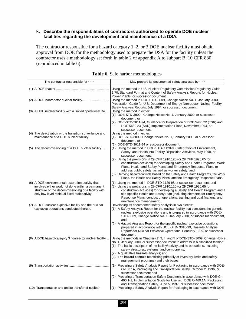
204
k. Describe the responsibilities of contractors authorized to operate DOE nuclear facilities regarding the development and maintenance of a DSA.
The contractor responsible for a hazard category 1, 2, or 3 DOE nuclear facility must obtain
approval from DOE for the methodology used to prepare the DSA for the facility unless the
contractor uses a methodology set forth in table 2 of appendix A to subpart B, 10 CFR 830
(reproduced in table 6).
Table 6. Safe harbor methodologies
The contractor responsible for * * * May prepare its documented safety analyses by * * *
(1) A DOE reactor............................................................ Using the method in U.S. Nuclear Regulatory Commission Regulatory Guide 1.70, Standard Format and Content of Safety Analysis Reports for Nuclear Power Plants, or successor document.
(2) A DOE nonreactor nuclear facility……………………. Using the method in DOE-STD- 3009, Change Notice No. 1, January 2000, Preparation Guide for U.S. Department of Energy Nonreactor Nuclear Facility Safety Analysis Reports, July 1994, or successor document.
(3) A DOE nuclear facility with a limited operational life…. Using the method in either: (1) DOE-STD-3009-, Change Notice No. 1, January 2000, or successor
document, or (2) DOE-STD-3011-94, Guidance for Preparation of DOE 5480.22 (TSR) and
DOE 5480.23 (SAR) Implementation Plans, November 1994, or successor document.
(4) The deactivation or the transition surveillance and maintenance of a DOE nuclear facility.
Using the method in either: (1) DOE-STD-3009, Change Notice No. 1, January 2000, or successor
document, or (2) DOE-STD-3011-94 or successor document.
(5) The decommissioning of a DOE nuclear facility……. (1) Using the method in DOE-STD- 1120-98, Integration of Environment, Safety, and Health into Facility Disposition Activities, May 1998, or successor document;
(2) Using the provisions in 29 CFR 1910.120 (or 29 CFR 1926.65 for construction activities) for developing Safety and Health Programs, Work Plans, Health and Safety Plans, and Emergency Response Plans to address public safety, as well as worker safety; and
(3) Deriving hazard controls based on the Safety and Health Programs, the Work Plans, the Health and Safety Plans, and the Emergency Response Plans.
(6) A DOE environmental restoration activity that involves either work not done within a permanent structure or the decommissioning of a facility with only low-level residual fixed radioactivity.
(1) Using the method in DOE-STD-1120-98 or successor document, and (2) Using the provisions in 29 CFR 1910.120 (or 29 CFR 1926.65 for
construction activities) for developing a Safety and Health Program and a site-specific Health and Safety Plan (including elements for Emergency Response Plans, conduct of operations, training and qualifications, and maintenance management).
(7) A DOE nuclear explosive facility and the nuclear explosive operations conducted therein.
Developing its documented safety analysis in two pieces: (1) A Safety Analysis Report for the nuclear facility that considers the generic
nuclear explosive operations and is prepared in accordance with DOE-STD-3009, Change Notice No. 1, January 2000, or successor document, and
(2) A Hazard Analysis Report for the specific nuclear explosive operations prepared in accordance with DOE-STD- 3016-99, Hazards Analysis Reports for Nuclear Explosive Operations, February 1999, or successor document.
(8) A DOE hazard category 3 nonreactor nuclear facility.... Using the methods in Chapters 2, 3, 4, and 5 of DOE-STD- 3009, Change Notice No. 1, January 2000, or successor document to address in a simplified fashion: (1) The basic description of the facility/activity and its operations, including
safety structures, systems, and components; (2) A qualitative hazards analysis; and (3) The hazard controls (consisting primarily of inventory limits and safety
management programs) and their bases.
(9) Transportation activities............................................. (1) Preparing a Safety Analysis Report for Packaging in accordance with DOE-O-460.1A, Packaging and Transportation Safety, October 2, 1996, or successor document and
(2) Preparing a Transportation Safety Document in accordance with DOE-G-460.1-1, Implementation Guide for Use with DOE O 460.1A, Packaging and Transportation Safety, June 5, 1997, or successor document.
(10) Transportation and onsite transfer of nuclear (1) Preparing a Safety Analysis Report for Packaging in accordance with DOE-

205
The contractor responsible for * * * May prepare its documented safety analyses by * * *
explosives, nuclear components, Naval nuclear fuel elements, Category I and Category II special nuclear materials, special assemblies, and other materials of national security.
O-461.1, Packaging and Transportation of Materials of National Security Interest, September 29, 2000, or successor document and
(2) Preparing a Transportation Safety Document in accordance with DOE-M-461.1-1, Packaging and Transfer of Materials of National Security Interest Manual, September 29, 2000, or successor document.
Source: 10 CFR 830, subpart B, appendix A
l. Define the following terms and discuss the purpose of each: Safety basis Design features Safety evaluation report
Safety Basis
Safety basis means the DSA and hazard controls that provide reasonable assurance that a
DOE nuclear facility can be operated safely in a manner that adequately protects workers, the
public, and the environment.
Design Features
Design features means the design features of a nuclear facility specified in the TSRs that, if
altered or modified, would have a significant effect on safe operation.
Safety Evaluation Report
Safety evaluation report is the report prepared by DOE to document
the sufficiency of the DSA for a hazard category 1, 2, or 3 DOE nuclear facility;
the extent to which a contractor has satisfied the requirements of subpart B of 10 CFR
830; and
the basis for approval by DOE of the safety basis for the facility, including any
conditions for approval.
m. Describe the requirements for the scope and content of a DSA and discuss the general content of each of the required sections of a DSA.
The DSA for a hazard category 1, 2, or 3 DOE nuclear facility must, as appropriate for the
complexities and hazards associated with the facility,
describe the facility (including the design of safety SSCs) and the work to be
performed;
provide a systematic identification of both natural and man-made hazards associated
with the facility;
evaluate normal, abnormal, and accident conditions, including consideration of
natural and man-made external events, identification of energy sources or processes
that might contribute to the generation or uncontrolled release of radioactive and
other hazardous materials, and consideration of the need for analysis of accidents
which may be beyond the design basis of the facility;
derive the hazard controls necessary to ensure adequate protection of workers, the
public, and the environment; demonstrate the adequacy of these controls to eliminate,

206
limit, or mitigate identified hazards; and define the process for maintaining the hazard
controls current at all times and controlling their use;
define the characteristics of the safety management programs necessary to ensure the
safe operation of the facility, including (where applicable) QA, procedures,
maintenance, personnel training, conduct of operations, emergency preparedness, fire
protection, waste management, and radiation protection; and
with respect to a nonreactor nuclear facility with fissionable material in a form and
amount sufficient to pose a potential for criticality, define a criticality safety program
that:
o ensures that operations with fissionable material remain sub-critical under all
normal and credible abnormal conditions,
o identifies applicable nuclear criticality safety standards, and
o describes how the program meets applicable nuclear criticality safety standards.
n. Discuss the uses that contractor management makes of a DSA.
The results of a DSA lead to a solid safety basis, meaning that the DSA and hazard controls
provide reasonable assurance that a DOE nuclear facility can be operated safely in a manner
that adequately protects workers, the public, and the environment.
37. Electrical personnel shall demonstrate a familiarity level knowledge of all assigned electrical power VSS and how they are addressed during the design, construction, and operation of nuclear facilities
Elements ‗a‘ and ‗b‘ are performance-based KSAs. The Qualifying Official will evaluate
their completion.
a. Mandatory Performance Activity: Walkdown electrical power VSSs with the cognizant contractor electrical VSS system engineer or DOE FR. Locate and identify major components, subsystems, and interfaces.
b. Identify all assigned electrical power VSS (site-specific), and discuss the functional classifications, safety functions, and functional requirements of these systems.
c. Discuss electrical power distribution with the regard to the following elements (IEEE Red Book; reference IEEE Std-141 or another source can be used as a guide in developing the discussion): Basic design considerations and electrical distribution design Voltage considerations Surge voltage protection techniques System protective devices Power factor and its effects in electrical distribution systems Power switching, transformation, and motor-control apparatus Cable system basics Busway design
The following is taken from IEEE Std 141-1993.
207
Basic Design Considerations
Safety of life and preservation of property are two of the most important factors to be
considered in the design of the electric system. Codes must be followed and recommended
practices or standards should be followed in the selection and application of material and
equipment. Equally important is providing equipment that is properly and adequately sized
and rated to handle available fault levels in the system in accordance with established fault
duty calculation procedures. Adequate safety features should be incorporated into all parts of
the system. Listed below are the electric system operating and design limits that should be
considered in order to provide safe working conditions for personnel:
Interrupting devices must be able to function safely and properly under the most
severe duty to which they may be exposed.
Protection must be provided against accidental contact with energized conductors,
such as enclosing the conductors, installing protective barriers, or installing the
conductors at sufficient height to avoid accidental contact.
Isolating switches must not be operated while they are carrying current, unless they
are designed to interrupt such current. They should be equipped with safety interlocks
and warning signs if load or transformer magnetizing current-load-interrupting and
fault-closing capability are not provided.
In many instances it is desirable to isolate a power circuit breaker using disconnect
switches. In such cases, the circuit breaker must be opened before the disconnect
switches. Safety interlocks to ensure this sequence should be used, together with
detailed and specific personnel operating instructions.
The system should be designed so that maintenance work on circuits and equipment
can be accomplished with the particular circuits and equipment de-energized and
grounded. System design should provide for locking out circuits or equipment for
maintenance, including grounding instructions. A written procedure should be
established to provide instructions on tagging or locking out circuits during
maintenance, and re-energizing after completion of the maintenance work following
disconnection of the grounding equipment.
Electric equipment rooms, especially those containing apparatus over 600 V, such as
transformers, motor controls, or motors, should be equipped and located to eliminate
or minimize the need for access by non-electrical maintenance or operating personnel.
Conveniently located exits should be provided to allow quick exit during an
emergency.
Electric apparatus located outside special rooms should be provided with protection
against mechanical damage due to equipment location, personnel access, and
vehicular traffic. The area should be accessible to maintenance and operating
personnel for emergency operation of protective devices.
Equipment location should be carefully considered. A non-hazardous area should be
set aside for electrical equipment, or it may be necessary to locate explosion-proof
equipment in the hazardous area. The advantages and disadvantages of not only initial
cost but the maintenance cost and the ability to maintain the integrity of the
equipment should all be carefully considered.
Warning signs should be installed on electric equipment accessible to unqualified
personnel, on fences surrounding electric equipment, on doors giving access to
electrical rooms, and on conduits or cables above 600 V in areas that include other
208
equipment or pipelines. An electrical single-line diagram should be installed in each
electrical switching room.
An adequate grounding system must be installed.
Emergency lights should be provided where necessary to protect personnel against
sudden lighting failure. In facilities, the Life Safety Codes requires that escape routes
and exits have emergency lighting. In addition, process control locations and electric
switching centers should be equipped with standby lighting.
Operating and maintenance personnel should be provided with complete operating
and maintenance instructions, including wiring diagrams, equipment ratings, and
protective device settings. Spare fuses of the correct ratings should be stocked.
Electrical Distribution Design
The distribution system should include provisions for predictive and PM requirements in the
initial design. Accessibility and availability for inspection and repair with safety are
important considerations in selecting equipment. Space should be provided for inspection,
adjustment, and repair in clean, well-lighted, and temperature-controlled areas.
Investigate the various types of plant distribution systems and select the system or systems
best suited to the requirements of the plant. A variety of basic circuit arrangements is
available for industrial plant power distribution. Selection of the best system or combination
of systems will depend upon the needs of the manufacturing process. In general, system costs
increase with system reliability if component quality is equal. Maximum reliability per unit
investment can be achieved by using properly applied and well-designed components.
The first step is the analysis of the manufacturing process to determine its reliability need and
potential losses and costs in the event of power interruption. Some plant processes are
minimally affected by interruption. Here a simple radial system may be satisfactory. Other
plant processes may sustain long-term damage or experience excessive cost by even a brief
interruption; therefore, a more complex system with an alternate power source for critical
loads may be justified.
Primary Distribution Systems
Include primary switching, fusing, other protective devices, transformer connections,
ratings, system grounding, nominal loading (kilovolt-amperes and amperes), and low-
voltage protective-device arrangement for unit substation and load centers. Indicate
each protective device‘s continuous-current rating, symmetrical interrupting current
and asymmetrical momentary or closing-and-latching current rating, manufacturer,
type, and model identification. Indicate tap settings on all primary transformers.
Indicate bus ratings in amperes.
Identify major load centers and indicate general electrical configuration.
Identify nominal loads in kilovolt-amperes and amperes on unit substations,
transformers, and load centers.
Identify and show all major MV loads and motors, including associated transformers
and all other major, significant, and identifiable loads, such as motor loads on MCCs,
large press and other motor or drive loads, dedicated lighting loads, arc furnaces,
induction furnaces, special purpose loads, such as data processing and computer

209
applications, welding loads, powerhouse loads, including waste treatment, air
compressor loads, etc.
Voltage Considerations
An understanding of system voltage nomenclature and the preferred voltage ratings of
distribution apparatus and utilization equipment is essential to ensure proper voltage
identification throughout a power distribution system. The dynamic characteristics of the
system need to be recognized and the proper principles of voltage control applied so that
satisfactory voltages will be supplied to all utilization equipment under all normal conditions
of operation. Consideration should be given for transient and momentary voltage variations
to ensure appropriate performance of utilization equipment.
A general understanding of the principles of power transmission and distribution in utility
systems is necessary since most industrial plants obtain most of their electric power from the
local electric utility. Figure 45 shows a simplified, one-line diagram of a typical utility power
generation, transmission, and distribution system.
Source: IEEE Std 141-1993
Figure 45. Typical utility generation, transmission, and distribution system
Voltage Classes
High-voltage-class voltages are used to transmit large amounts of electric power
between transmission substations. Transmission substations located adjacent to
generating stations step the generator voltage up to the transmission voltage. Other
transmission substations transform the high voltage down to MV for subtransmission
and primary distribution. Transmission lines also interconnect transmission
substations to provide alternate paths for power transmission for higher reliability.
Medium-voltage-class voltages are used for subtransmission and primary distribution.
Medium voltages often supply distribution transformers that step the MV down to
low voltage to supply utilization equipment. Medium voltages may also supply
distribution substations that transform the voltage from a higher to a lower voltage in
the MV class. Medium voltages of 13,800 V and below are also used to supply
utilization equipment such as large motors.
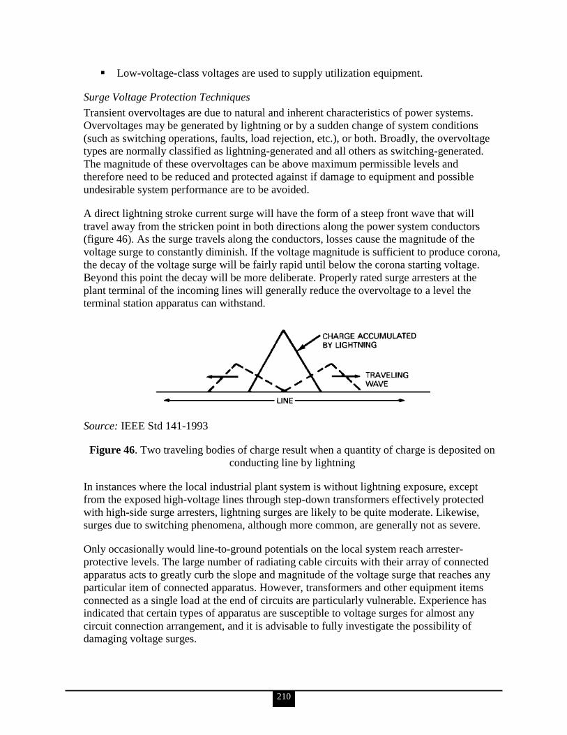
210
Low-voltage-class voltages are used to supply utilization equipment.
Surge Voltage Protection Techniques
Transient overvoltages are due to natural and inherent characteristics of power systems.
Overvoltages may be generated by lightning or by a sudden change of system conditions
(such as switching operations, faults, load rejection, etc.), or both. Broadly, the overvoltage
types are normally classified as lightning-generated and all others as switching-generated.
The magnitude of these overvoltages can be above maximum permissible levels and
therefore need to be reduced and protected against if damage to equipment and possible
undesirable system performance are to be avoided.
A direct lightning stroke current surge will have the form of a steep front wave that will
travel away from the stricken point in both directions along the power system conductors
(figure 46). As the surge travels along the conductors, losses cause the magnitude of the
voltage surge to constantly diminish. If the voltage magnitude is sufficient to produce corona,
the decay of the voltage surge will be fairly rapid until below the corona starting voltage.
Beyond this point the decay will be more deliberate. Properly rated surge arresters at the
plant terminal of the incoming lines will generally reduce the overvoltage to a level the
terminal station apparatus can withstand.
Source: IEEE Std 141-1993
Figure 46. Two traveling bodies of charge result when a quantity of charge is deposited on
conducting line by lightning
In instances where the local industrial plant system is without lightning exposure, except
from the exposed high-voltage lines through step-down transformers effectively protected
with high-side surge arresters, lightning surges are likely to be quite moderate. Likewise,
surges due to switching phenomena, although more common, are generally not as severe.
Only occasionally would line-to-ground potentials on the local system reach arrester-
protective levels. The large number of radiating cable circuits with their array of connected
apparatus acts to greatly curb the slope and magnitude of the voltage surge that reaches any
particular item of connected apparatus. However, transformers and other equipment items
connected as a single load at the end of circuits are particularly vulnerable. Experience has
indicated that certain types of apparatus are susceptible to voltage surges for almost any
circuit connection arrangement, and it is advisable to fully investigate the possibility of
damaging voltage surges.

211
The occurrence of abnormal applied voltage stresses, transient, short-time, or sustained
steady-state, contributes to premature insulation failure. Electrical organic insulation
deterioration to the point of failure results from an aggregate accumulation of insulation
damage that finally reaches the critical stage, in which a conducting path is rapidly driven
through the insulation sheath and failure (short circuit) takes place. Large amounts of current
may then be driven through the faulted channel, producing large amounts of heat. An
excessive increase in temperature results, which rapidly expands the zone of insulation
damage, and complete destruction occurs rather quickly unless the supply of electric current
is interrupted. Some insulation punctures that might be discovered after special
nondestructive testing of apparatus will require repair or replacement.
The optimum method of avoiding insulation failure is having balanced, or coordinated,
protection. An acceptable system of insulation protection will be influenced by a number of
factors. Of prime importance is a knowledge of the insulation system withstand capability
and endurance qualities. These properties are indicated by insulation-type designations and
specified high-potential and surge-voltage test withstand capabilities. Another facet of the
problem relates to the identification of likely sources of overvoltage exposure and the
character, magnitude, duration, and repetition rate that are likely to be impressed on the
apparatus and circuits.
The appropriate application of surge-protective devices will lessen the magnitude and
duration of surges as seen by the protected equipment, and is the most effective tool for
achieving the desired insulation security. A working understanding of the behavior pattern of
electric surge voltage propagation along electrical conductors is necessary to achieve the
optimum solution. The problem is complicated by the fact that insulation failure results not
only because of impressed overvoltages, but also because of the aggregate sum total duration
of such overvoltages. No simple devices are available that can correctly integrate the
cumulative effects of sequentially applied excessive overvoltage. The time factor must be
estimated and then factored into the design and application of the protection system.
As stated, lightning is a major source of transient overvoltage. Some industrial operations use
open-wire overhead lines that are subject to direct exposure to lightning, allowing lightning
surges to be propagated into the industrial distribution system. However, many industrial
complexes have cable entrances with surge-arrester protection installed at the overhead-to-
underground junction. Although the surge arresters protect the cable entrance, they will not
necessarily protect the substation equipment from incoming surges; additional arresters may
have to be installed at the cable open-end point or last transformer.
System Protective Devices
Power system protective devices provide the intelligence and initiate the action that enables
circuit switching equipment to respond to abnormal or dangerous system conditions.
Normally, relays control power circuit breakers rated above 600 V and current-responsive,
self-contained elements operate multiple-pole, low-voltage circuit breakers to isolate circuits
experiencing overcurrents on any phase. Similarly, fuses function alone or in combination
with other suitable means to properly provide isolation of faulted or overloaded circuits. In
other cases, special types of relays that respond to abnormal electric system conditions may

212
cause circuit breakers or other switching devices to disconnect defective equipment from the
remainder of the system.
Power Factor and its Effects in Electrical Distribution Systems
Maintaining a high power factor in a plant can yield direct savings. Some, such as reduced
power bills and release of system capacity, are quite obvious; others, such as improved
voltage and decreased I2R losses, are less obvious but nonetheless real, as are many indirect
savings as a result of more efficient performance.
The cost of improving the power factor in existing plants and of maintaining proper levels as
load is added depends on the power-factor value selected and the equipment chosen to supply
the compensating reactive power.
Adding capacitors generally is the most economical way to improve the plant power factor,
especially in existing plants. There are cases in which synchronous motors may prove most
economical or beneficial.
Capacitors have several beneficial features, including relatively low cost, ease of installation,
minimal maintenance requirements, very low losses, plus the fact that they are manufactured
in a variety of sizes. Individual units also can be combined into suitable banks to obtain a
large range of ratings. Thus, capacitors can be added in small or large units to meet existing
operating requirements with additional units added only when necessary to meet increased
future requirements. Caution must be exercised in applying capacitors, however, as they are
sensitive to overvoltage and may severely impact systems that have nonlinear loads requiring
harmonic currents and/or equipment sensitive to switching transients.
Power Switching, Transformation, and Motor-Control Apparatus
Switching apparatus can be defined as a device for opening and closing, or for changing the
connections of a circuit. The general classification of switching apparatus as defined in IEEE
Std 141-1993, chapter 10, includes switches, fuses, circuit breakers, and service protectors.
The types of switches normally used for power circuits include the following: isolating; load
interrupter; safety switches for 600 V and lower power applications, including bolted-
pressure switches and high-pressure contact switches and power protectors; transfer switches
for load transfer, including emergency and standby switching.
Transformers have many classifications that are useful in industry to distinguish or define
certain characteristics of design and application. There are two classifications based on the
rating of transformers measured in kilovolt-amperes: the distribution type covers the range of
3 to 500 kVA; the power type covers all ratings above 500 kVA.
The majority of motors utilized by industrial firms are integral HP induction motors of
squirrel-cage design supplied from distribution systems of three-phase 600 V AC and below.
The choice of an integral HP controller depends on a number of factors:
Power System. Does it use DC or AC; is it single-phase or three-phase? What is the
voltage and frequency? Will the system permit large inrush currents during full-
voltage starting without excessive voltage drop?

213
Motor. Is the controller to be used with DC, squirrel-cage induction, wound-rotor
induction, synchronous motor, or adjustable frequency drives? What is the HP? Will
the motor be jogged or reversed frequently? What is the acceleration time from start
to full speed? Will the motor design specify reduced current inrush?
Load. Is the load geared, belt-driven, or direct-coupled? Loaded or unloaded start?
Operation. Is operation to be manual or automatic?
Protection. Are fuses or circuit protectors to be used for short-circuit protection? To
size the elements of motor overload relays, the full-load current of the motor, the
ambient temperature at the motor, controller, and the service factor of the motor
should be known.
Environment. Will the motor and controller be subjected to excessive vibration, dirt,
dust, oil, or water? Will either be located in a hazardous or corrosive area?
Cable Connections and Space. Will there be the required space for cable entrance,
bending radius, terminations, and for reliable connections to line and load buses? Will
capacitors be installed at the motor terminal box for power factor correction? Will
surge-protective equipment, surge arresters, and capacitors, be installed at the motor
terminal box? Will CTs for motor differential protection be installed at the motor
terminal box?
Cable System Basics
The primary function of cable is to carry energy reliably between source and utilization
equipment. In carrying this energy, there are heat losses generated in the cable that must be
dissipated. The ability to dissipate these losses depends on how the cables are installed, and
this affects their ratings.
Cables may be installed in raceway, in cable trays, underground in duct or direct buried, in
cable bus, as open runs of cable, or may be messenger supported.
The selection of conductor size requires consideration of the load current to be carried and
the loading cycle, emergency overloading requirements and duration, fault clearing time and
interrupting capacity of the cable overcurrent protection or source capacity, voltage drop, and
ambient temperatures for the particular installation conditions. Caution must be exercised
when locating conductors in high ambient heat areas so that the operating temperature will
not exceed that designated for the type of insulated conductor involved.
Insulations can be classified in broad categories as solid insulations, taped insulations, and
special purpose insulations. Cables incorporating these insulations cover a range of
maximum and normal operating temperatures and exhibit varying degrees of flexibility, fire
resistance, and mechanical and environmental protection. The installation of cables requires
care in order to avoid excessive pulling tensions that could stretch the conductor or insulation
shield, or rupture the cable jacket when pulled around bends. The minimum bending radius
of the cable or conductors should not be exceeded during pulling around bends, at splices,
and particularly at terminations to avoid damage to the conductors. The engineer should also
check each run to ensure that the conductor jamming ratio is correct and the maximum
allowable sidewall pressure is not exceeded.
Provisions should be made for the proper terminating, splicing, and grounding of cables.
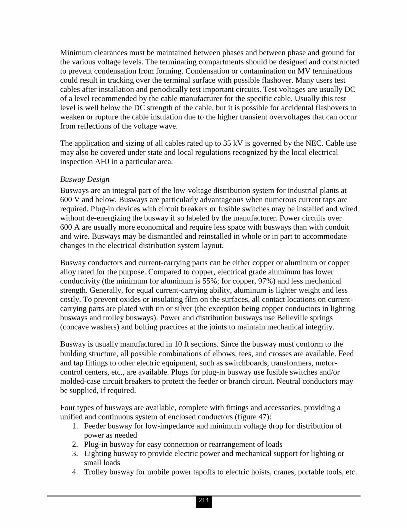
214
Minimum clearances must be maintained between phases and between phase and ground for
the various voltage levels. The terminating compartments should be designed and constructed
to prevent condensation from forming. Condensation or contamination on MV terminations
could result in tracking over the terminal surface with possible flashover. Many users test
cables after installation and periodically test important circuits. Test voltages are usually DC
of a level recommended by the cable manufacturer for the specific cable. Usually this test
level is well below the DC strength of the cable, but it is possible for accidental flashovers to
weaken or rupture the cable insulation due to the higher transient overvoltages that can occur
from reflections of the voltage wave.
The application and sizing of all cables rated up to 35 kV is governed by the NEC. Cable use
may also be covered under state and local regulations recognized by the local electrical
inspection AHJ in a particular area.
Busway Design
Busways are an integral part of the low-voltage distribution system for industrial plants at
600 V and below. Busways are particularly advantageous when numerous current taps are
required. Plug-in devices with circuit breakers or fusible switches may be installed and wired
without de-energizing the busway if so labeled by the manufacturer. Power circuits over
600 A are usually more economical and require less space with busways than with conduit
and wire. Busways may be dismantled and reinstalled in whole or in part to accommodate
changes in the electrical distribution system layout.
Busway conductors and current-carrying parts can be either copper or aluminum or copper
alloy rated for the purpose. Compared to copper, electrical grade aluminum has lower
conductivity (the minimum for aluminum is 55%; for copper, 97%) and less mechanical
strength. Generally, for equal current-carrying ability, aluminum is lighter weight and less
costly. To prevent oxides or insulating film on the surfaces, all contact locations on current-
carrying parts are plated with tin or silver (the exception being copper conductors in lighting
busways and trolley busways). Power and distribution busways use Belleville springs
(concave washers) and bolting practices at the joints to maintain mechanical integrity.
Busway is usually manufactured in 10 ft sections. Since the busway must conform to the
building structure, all possible combinations of elbows, tees, and crosses are available. Feed
and tap fittings to other electric equipment, such as switchboards, transformers, motor-
control centers, etc., are available. Plugs for plug-in busway use fusible switches and/or
molded-case circuit breakers to protect the feeder or branch circuit. Neutral conductors may
be supplied, if required.
Four types of busways are available, complete with fittings and accessories, providing a
unified and continuous system of enclosed conductors (figure 47):
1. Feeder busway for low-impedance and minimum voltage drop for distribution of
power as needed
2. Plug-in busway for easy connection or rearrangement of loads
3. Lighting busway to provide electric power and mechanical support for lighting or
small loads
4. Trolley busway for mobile power tapoffs to electric hoists, cranes, portable tools, etc.

215
Source: IEEE Std 141-1993
Figure 47. Versatility of busways, showing use of feeders, plug-in, lighting, and trolley
lights
d. Discuss protection and coordination with regard to the following elements (IEEE Buff Book; reference IEEE Std-242 or another source can be used as a guide in developing the discussion): Fault calculations Short-circuit current calculations for single and three-phase circuits Instrument transformer basics Protective relay selection and application Fuse selection and application Low-voltage circuit breaker fundamentals (IEEE Blue Book; reference IEEE
Std-1015) Ground-fault protection fundamentals Conductor, motor, transformer, generator, and bus and switchgear protection Maintenance, testing, and calibration of electrical systems
All of the following is taken from IEEE Std-242, except for Low-voltage circuit breaker
fundamentals, which is taken from IEEE Std-1015.
Fault Calculations
The process of calculating protective device fault levels requires a series of steps. Today,
most analysts choose to perform these calculations using computers, and the procedure
outlined in the bulleted list below assumes that computers are used. However, the basic
principles apply to manual calculations, although the analyst in that instance should be more
216
careful to decide up front precisely what information is needed in order to minimize the
amount of tedious work to be done.
State the problem to be solved. The nature of the problem determines the type of
calculation to be done and, in turn, dictates what specific data are required. In the
present context, the calculation is of fault currents for protective devices. However,
unlike fault calculations for breaker applications, protective device calculations
generally are not done for every bus.
Collect data. This step entails understanding the interconnection of the various
components that make up the system, as well as collecting data on each of the
components. A one-line diagram is usually an essential tool in correlating system
data, and some analysts choose to use the one-line diagram as the principal tool for
recording all the data.
Put aside information that does not apply to the immediate problem. Generally, power
factor capacitors, surge arresters, and surge capacitors do not contribute to the
distribution of fault current as recognized by protection engineers, so these
components may be ignored. More generally, however, some information may affect
the magnitude of protective device currents, but not necessarily the currents of
interest in the immediate problem; and in the interest of saving time, ignoring these
data may be possible. A good example of this type of data is zero-sequence data.
Delta-connected transformers establish boundaries for zero-sequence calculations,
and, if the problem statement calls for ground-fault data in only one area of the
system, entanglement with zero- sequence data in other areas may be avoided.
Decide on a common base for the per-unit calculations.
Convert component impedances to per-unit values on the appropriate base quantities.
These per-unit values should be arranged in the fashion required by the computer
software. For a manual calculation, they should be recorded on a one-line diagram.
Computer software usually accepts nominal nameplate parameters and performs this
tedious and exacting task.
Perform the network reduction calculations necessary to arrive at driving-point
positive- and zero-sequence impedance values at each point of interest defined by the
original statement of the problem. Using these driving-point impedances, the
sequence impedance network interconnections should be set up to calculate per-unit
magnitudes of sequence currents. Finally, these per-unit values should be converted
into ampere values. Again, this tedious, time-consuming calculation is most often
done with the computer today.
Set up the sequence impedance connections needed for the desired currents. Again,
many computer programs can do this step automatically, but it is instructive to take
raw driving-point impedances and perform this step by hand.
Record the calculated currents. This step is often overlooked although it is extremely
important.
Short-Circuit Current Calculations for Single- and Three-Phase Circuits
Short-circuit currents can create massive destruction to the power system. Short circuits
typically have magnitudes many times greater than load currents. The consequences of these
high-magnitude currents can be catastrophic to normal operation of the power system. First,
the presence of short-circuit currents in system conductors results in additional heating,
217
which the system is usually not designed to sustain continuously. These currents also
introduce severe mechanical forces on conductors, which can break insulators, distort
transformer windings, or cause other physical damage. The flow of high-magnitude short-
circuit currents through system impedances may also result in abnormally low voltages,
which in turn lead to otherwise healthy equipment being forced to shut down. Finally, at the
point of the short circuit itself, generally the release of energy in the form of an arc, if left
uncorrected, can start a fire, which may spread well beyond the point of initiation.
Of all the demands placed upon the power system protection engineer, the most analytical is
to determine the magnitude of voltages and currents that the system can produce under
various short-circuit conditions. Only when these quantities are understood can the
application of protective devices proceed with confidence that they will perform their
intended function when short circuits occur.
The most fundamental principle involved in determining the magnitude of short-circuit
current is Ohm‘s Law: the current that flows in a network of impedances is related to the
driving voltage by the relationship
Z
V I
Where:
I = short circuit current
V = voltage
Z = impedance
The general procedure for applying this principle entails the three steps involved in
Thevenin‘s Theorem of circuits.
Develop a graphical representation of the system, called a one-line (or single-line)
diagram, with symbolic voltage sources and circuit impedances.
Calculate the total impedance from the source of current (i.e., the driving voltage) to
the point at which a hypothetical short-circuit current is to be calculated. This value is
the Thevenin equivalent impedance, sometimes called the driving point impedance.
Knowing the open circuit pre-fault voltage, use Ohm‘s Law to calculate the short
circuit current magnitude.
Of course, the actual application of these basic principles is more involved, and the
remainder of IEEE Std-242, chapter 2.6 is devoted to a treatment of the specific details of
short-circuit current calculations.
Instrument Transformer Basics
A CT transforms line current into values suitable for standard protective relays and isolates
the relays from line voltages. A CT has two windings, designated as primary and secondary,
which are insulated from each other. The various types of primary windings are covered in
IEEE Std 242-2001, section 3.2.1. The secondary is wound on an iron core. The primary
winding is connected in series with the circuit carrying the line current to be measured; and
the secondary winding is connected to protective devices, instruments, meters, or control

218
devices. The secondary winding supplies a current in direct proportion and at a fixed
relationship to the primary current.
The four common types of CTs are as follows:
A wound CT has a primary winding consisting of one or more turns mechanically
encircling the core or cores. The primary and secondary windings are insulated from
each other and from the core(s) and are assembled as an integral structure (figure 48).
Figure 48. Wound CT
A bar CT has a fixed, insulated, straight conductor in the form of a bar, rod, or tube
that is a single primary turn passing through the magnetic circuit and is assembled to
the secondary, core and winding (figure 49).
Figure 49. Bar CT
A window CT has a secondary winding insulated from and permanently assembled on
the core, but has no primary winding as an integral part of the structure. Primary
insulation is provided in the window through which one or more turns of the line
conductor can be passed to provide the primary winding (figure 50).

219
Source: Figures 48–50, IEEE Std 242-2001
Figure 50. Window CT
A bushing CT has an annular core and a secondary winding insulated from, and
permanently assembled on the core, but has no primary winding or insulation for a
primary winding. This type of CT is used with a fully insulated conductor as the
primary winding and used typically in equipment where the primary conductor is a
component part of other apparatus, for example, on bushings of a transformer or
circuit breaker.
The secondary windings of bushing CTs are usually fully distributed around the core.
Typically they are multiratio with each winding tap also being fully distributed.
Protective Relay Selection and Application
Power systems should be designed so that protective relays operate to sense and isolate faults
quickly to limit the extent and duration of service interruptions. Protective relays are
important in industrial power systems because they can prevent large losses of production
due to unnecessary equipment outages or unnecessary equipment damage occurring as a
result of a fault or overload. Other considerations are safety, property losses, and
replacements.
Protective relays have been called the watchdogs, or silent sentinels, of a power system.
Protective relays are classified by the variable they monitor or by the function they perform.
For instance, an overcurrent relay senses current and operates when the current exceeds a
predetermined value. Another example is a thermal overload relay that senses the
temperature of a system component, either directly or indirectly (as a function of current), or
both, and operates when the temperature is above a rated value.
The application of relays is often called an art rather than a science because judgment is
involved in making selections. The selection of protective relays requires compromises
between conflicting objectives, while maintaining the capability of operating properly for
several system operating conditions. These compromises include providing

220
maximum protection
minimum equipment cost
reliable protection
high-speed operation
simple designs
high sensitivity to faults
insensitivity to normal load currents
selectivity in isolating a minimum portion of the system
Planning for the protection system should be considered in the power system design stage to
ensure that a good system can be implemented. The cost of applying protective relays should
be balanced against the potential costs of not providing protection.
Fuse Selection and Application
Fuse selection, application, and classification are dealt with in detail in IEEE Std 242-2001,
chapters 5 and 6. A general overview is presented here.
A low-voltage fuse is a device that protects a circuit by opening its current-responsive
element when an overcurrent passes through it. A fuse, as defined in the Authoritative
Dictionary of IEEE Standards, seventh edition, is an overcurrent protective device with a
circuit-opening fusible part that is heated and severed by the passage of the overcurrent
through it. Note: A fuse comprises all the parts that form a unit capable of performing the
prescribed functions. It may or may not be the complete device necessary to connect it into
an electric circuit.
A fuse has the following functional characteristics:
It combines both the sensing and interrupting elements in one self-contained device.
It is direct acting in that it responds to a combination of magnitude and duration of
circuit current flowing through it.
It normally does not include any provision for manually making and breaking the
connection to an energized circuit, but requires separate devices (e.g., a disconnect
switch) to perform this function.
It is a single-phase device. Only the fuse in the phase or phases subjected to
overcurrent responds to de-energize the affected phase or phases of the circuit or
equipment that is faulty.
After having interrupted an overcurrent, it is renewed by the replacement of its
current-responsive element before restoration of service.
ANSI standards and IEEE standards define high-voltage fuses as fuses rated above 1,000 V.
High-voltage fuses are available in voltages through 169 kV maximum rating. ANSI C84.1-
2006, American National Standard for Electric Power Systems and Equipment—Voltage
Ratings (60 Hertz), defines MV systems as having a nominal voltage greater than 1,000 V
and less than 100,000 V. High-voltage systems are defined as having a nominal voltage equal
to or greater than 100,000 V and equal to or less than 230,000 V. High-voltage fuses are,
therefore, used on both medium- and high-voltage systems up to their maximum voltage
ratings.
221
Low-Voltage Circuit Breaker Fundamentals (IEEE Blue Book; reference IEEE Std-1015)
A selectively coordinated power system has protective devices that isolate the smallest
portion of the system when interrupting a short circuit or overload and thus limit damage to
components. This is accomplished with low-voltage circuit breakers by the selection of
appropriate operating ratings, trip characteristics, and trip settings so that only the closest
circuit breaker on the source side of an overcurrent condition clears the abnormality.
The low-voltage circuit breaker has a protective element that operates in response to the
magnitude and duration of current passing through it. It is direct acting in that the current
through it provides energy to release the opening mechanism. The characteristic time-current
curve has a band of operating area. The upper limit of the band represents the maximum total
clearing time for the circuit breaker. The lower limit of the band shows the maximum
resettable delay, i.e., the maximum time that a given amount of through current (e.g., a fault
or overload) may persist and then subside without tripping the circuit breaker. Bands
indicating the pickup current (vertical asymptote) of the characteristic show the tolerance of
the pickup point. Currents less than the long-time pickup band can be sustained without
tripping the circuit breaker. Currents at or above the upper limit of the band will result in
tripping of the circuit breaker.
The low-voltage power circuit breaker (LVPCB) may be found in two general varieties:
those with electromechanical trip devices, and those with electronic trip devices. Each has
some combination of long-time delay, short-time delay, instantaneous, and ground-fault trip
elements. IEEE C37.17-1997, American National Standard for Trip Devices for AC and
General Purpose DC Low Voltage Power Circuit Breakers, defines those characteristics and
their limits. Dual trip devices have long-time and instantaneous elements. Selective trip
devices have long-time and short-time elements. Triple selective devices have long-time,
short-time, and instantaneous elements.
Electromechanical trip devices use a magnetic circuit directly applied to the circuit-breaker
current-carrying conductor. A variety of springs, dashpots, and escapements provide the
time-current characteristic (figure 51). The time delay band is relatively broad due to the
tolerance of the mechanical devices, temperature, wear, age, etc. Sensitive ground-fault
protection must be provided by external sensing and remote tripping devices. Those remote
devices must trip the LVPCB by a shunt trip.
Electronic trip devices have become the industry standard. Sensors detect the current and
provide tripping energy. The time-current characteristic is electronically developed and is
more accurate with narrower tolerances than for the electromechanical device (figure 52).
The long-time element provides overload protection and the short-time and instantaneous
elements provide fault protection.
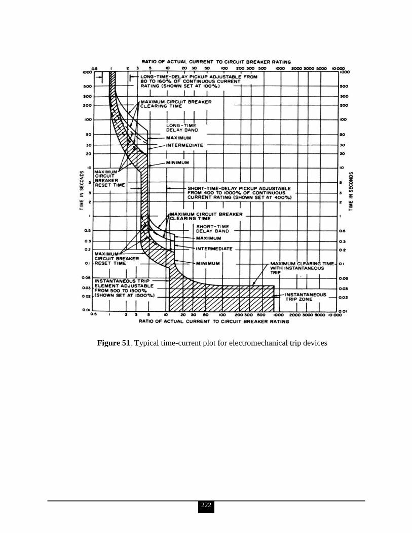
222
Figure 51. Typical time-current plot for electromechanical trip devices
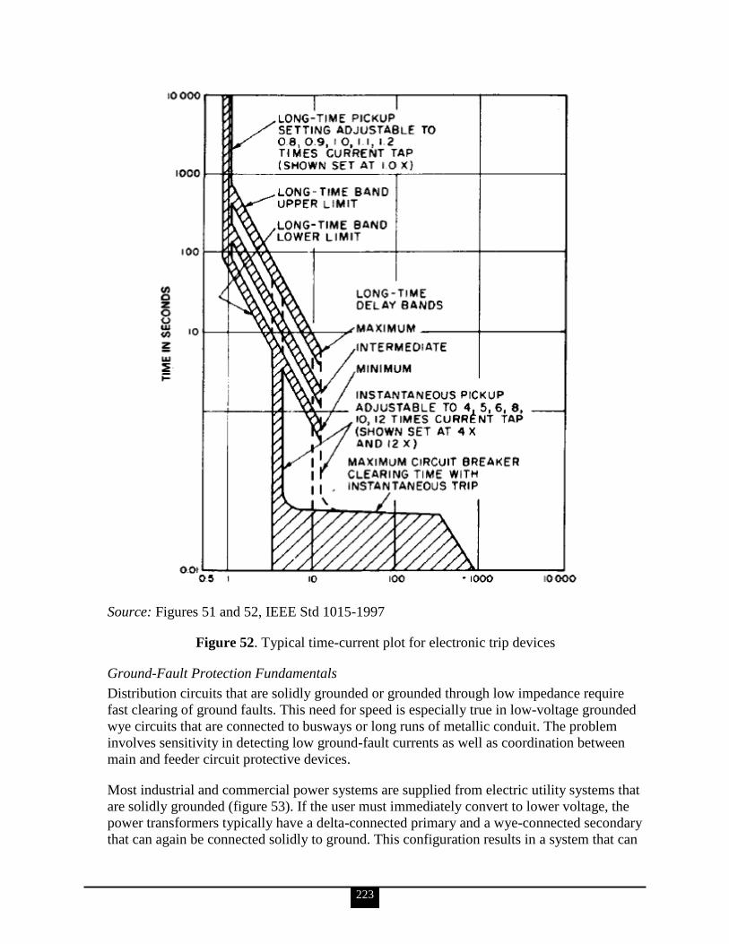
223
Source: Figures 51 and 52, IEEE Std 1015-1997
Figure 52. Typical time-current plot for electronic trip devices
Ground-Fault Protection Fundamentals
Distribution circuits that are solidly grounded or grounded through low impedance require
fast clearing of ground faults. This need for speed is especially true in low-voltage grounded
wye circuits that are connected to busways or long runs of metallic conduit. The problem
involves sensitivity in detecting low ground-fault currents as well as coordination between
main and feeder circuit protective devices.
Most industrial and commercial power systems are supplied from electric utility systems that
are solidly grounded (figure 53). If the user must immediately convert to lower voltage, the
power transformers typically have a delta-connected primary and a wye-connected secondary
that can again be connected solidly to ground. This configuration results in a system that can

224
be conveniently protected against over-voltages and ground faults. The system has flexibility
because the neutral can be carried with the phase conductors, and this feature permits
connecting loads from phase to phase and from phase to neutral.
Systems Above 600 V
Ground relaying of MV and high-voltage systems that are solidly grounded has been
successfully accomplished for many years using residually connected ground relays or zero-
sequence sensing. The circuit breakers normally have CTs to provide the signal for the
phase-overcurrent relays, and the ground-overcurrent relay is connected in the wye point
(i.e., residual) to provide increased sensitivity for ground faults. Ground-fault magnitudes
usually are comparable to phase-fault magnitudes and are, therefore, easily detected by relays
or fuses unless they occur in equipment windings near the neutral point.
Systems 600 V and Below
All 208 V systems are solidly grounded so that loads can be connected from line to neutral to
provide 120 V service. Similarly, all 480 V systems that are to serve 277 V lighting should
also be solidly grounded. As a result of this requirement, 480 V systems in most commercial
buildings and many industrial plants are solidly grounded. Even where 277 V lighting is not
used, 480 V systems in many industrial plants are solidly grounded to limit overvoltages and
to facilitate clearing ground faults.
Source: IEEE Std 242-2001
Figure 53. Direct or solid grounding (uses ground relays to trip)
Conductor Protection
The proper selection and rating or derating of power cables is as much a part of cable
protection as the application of the short-circuit and overcurrent protection devices. The
whole scheme of protection is based on a cable rating that is matched to the environment and
operating conditions. Methods of assigning these ratings are discussed in chapter 9 of IEEE
242-2001.
225
Motor Protection
Many factors should be considered in choosing motor protection: motor importance, motor
rating (from one to several thousand HP), thermal limit of rotor or stator, environment, power
system source and its neutral grounding method, type of motor controller, etc. Protection for
each specific motor installation should meet the requirements of the application. Power
quality of the plant distribution system should be given appropriate attention, especially with
regard to voltage sags and surges, harmonics, service interruptions, and operation of
distribution line re-closers.
Transformer Protection
Transformer failure may result in loss of service. However, prompt fault clearing, in addition
to minimizing the damage and cost of repairs, usually minimizes system disturbance, the
magnitude of the service outage, and the duration of the outage. Prompt fault clearing usually
prevents catastrophic damage. Proper protection is, therefore, important for transformers of
all sizes, even though they are among the simplest and most reliable components in the
plant‘s electrical system.
Generator Protection
Generator protection requires the consideration of many abnormal conditions that are not
present with other system elements. The following abnormal conditions may occur with
generators:
Overheating
o Stator (due to overload or loss of cooling)
o Rotor (due to overexcitation, loss of cooling)
Winding faults
o Stator (phase and ground faults)
o Rotor (ground faults and shorted turns)
Overspeed and underspeed
Overvoltage
Loss of excitation
Motoring
Unbalanced current operation
Out of step
Subsynchronous oscillations
Inadvertent energization
Nonsynchronized connection
Where the equipment is unattended, it should be provided with automatic stator and rotor
protection against all harmful conditions. In installations where an attendant is present, use of
alarms on some abnormal conditions may be preferable to removing the generator from
service. Generator protective schemes vary depending on the objectives to be achieved.
Bus and Switchgear Protection
The substation bus and switchgear are the parts of the power system used to direct the flow
of power to various feeders and to isolate apparatus and circuits from the power system.
These parts include the bus bars, circuit breakers, fuses, disconnection devices, CTs, voltage
226
transformers, and the structure on or in which they are mounted. The term bus refers to the
bus within an assembly of equipment (e.g., MV, metal-enclosed switchgear, MV control,
low-voltage switchgear, power switchboards, panelboards, MCCs, bus duct).
Maintenance, Testing, and Calibration of Electrical Systems
Chapter 16 of IEEE 242-2001 sets out recommendations and procedures for the maintenance
of electrical switchgear having rated voltages not greater than 34.5 kV. At voltages above
this level, the design of equipment, system operations, and consequently maintenance
requirements and practices may differ significantly. However, the principles formulated in
this recommended practice, especially the principles regarding the safety of personnel, are for
the most part applicable at the higher voltages.
e. Discuss electrical system grounding with regard to the following elements (IEEE Green Book; reference IEEE Std-142 or another source can be used as a guide in developing the discussion): Electrical system grounding fundamentals Electrical equipment grounding fundamentals Static and lightning grounding fundamentals
The following is taken from IEEE Std 142-1991.
Grounding of an electrical system is a decision that must be faced sometime by most
engineers charged with planning or modifying electrical distribution. Grounding in some
form is generally recommended, although there are certain exceptions. Several methods and
criteria exist for system grounding; each has its own purpose. It is the intention of this section
to assist the engineer in making decisions on the subject by presenting basic reasons for
grounding or not grounding and by reviewing general practices and methods of system
grounding.
The practices set forth in IEEE Std 142-1991, chapter 1, are primarily applicable to industrial
power systems that distribute and utilize power at medium or low voltage, usually within a
smaller geographical area than is covered by a utility. Where distances or power levels may
dictate circuitry and equipment similar to a utility, consideration of utility practices is
warranted. However, restrictions of the NEC, particular needs of service, and the experience
and training of the workforce should also be considered.
Where an industrial power system includes power-generating equipment, the reasons for
grounding these components may be the same as those for grounding similar components of
public utility systems. The methods of grounding would generally be similar under like
conditions of service. However, in the industrial setting, conditions of service may be altered
by
location within the power system
individual generator characteristics
manufacturing process requirements
All of these may affect grounding decisions.
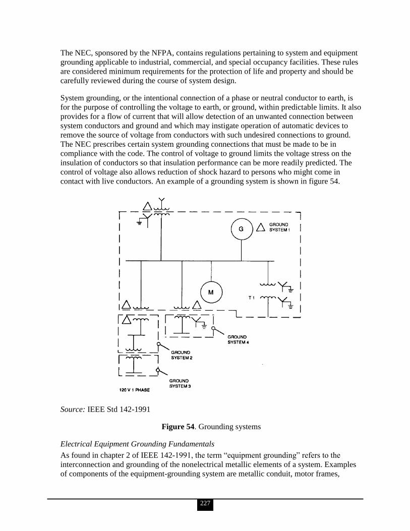
227
The NEC, sponsored by the NFPA, contains regulations pertaining to system and equipment
grounding applicable to industrial, commercial, and special occupancy facilities. These rules
are considered minimum requirements for the protection of life and property and should be
carefully reviewed during the course of system design.
System grounding, or the intentional connection of a phase or neutral conductor to earth, is
for the purpose of controlling the voltage to earth, or ground, within predictable limits. It also
provides for a flow of current that will allow detection of an unwanted connection between
system conductors and ground and which may instigate operation of automatic devices to
remove the source of voltage from conductors with such undesired connections to ground.
The NEC prescribes certain system grounding connections that must be made to be in
compliance with the code. The control of voltage to ground limits the voltage stress on the
insulation of conductors so that insulation performance can be more readily predicted. The
control of voltage also allows reduction of shock hazard to persons who might come in
contact with live conductors. An example of a grounding system is shown in figure 54.
Source: IEEE Std 142-1991
Figure 54. Grounding systems
Electrical Equipment Grounding Fundamentals
As found in chapter 2 of IEEE 142-1991, the term ―equipment grounding‖ refers to the
interconnection and grounding of the nonelectrical metallic elements of a system. Examples
of components of the equipment-grounding system are metallic conduit, motor frames,
228
equipment enclosures, and a grounding conductor. Note that a grounding conductor is a part
of the equipment grounding system, as distinguished from a grounded conductor, which is a
part of the power distribution system.
The basic objectives of an equipment-grounding system are the following:
To reduce electric shock hazard to personnel
To provide adequate current carrying capability, both in magnitude and duration, to
accept the ground-fault current permitted by the overcurrent protection system
without creating a fire or explosive hazard to building or contents
To provide a low impedance return path for ground-fault current necessary for the
timely operation of the overcurrent protection system
Effective equipment grounding practices can minimize personal injuries. A breakdown of
insulation can cause accidental contact between an energized electrical conductor and the
metal frame that encloses it. Such contact tends to energize the frame to the voltage level of
the conductor. Avoiding shock-hazard voltage requires nullifying this tendency. The
equipment-grounding system should do this by forming a low impedance path to ground.
The impedance of the grounding conductor must be low enough to accept the available line-
to-ground-fault current without creating a hazardous impedance voltage drop. The available
ground-fault current of the supply system will have a direct bearing on the equipment-
grounding conductor requirements.
The grounding conductor must also function to conduct the available ground-fault current
(magnitude and duration) without excessive temperature rise or arcing. The use of a large
cross-section grounding conductor is not enough. All parts of the fault circuit, including the
terminations and other parts, must be capable of carrying the fault current without distress.
The installation must also provide a lower impedance fault return path than other possible
parallel paths that may have inadequate current-carrying capacity. Summaries of large-loss
fires indicate that approximately one out of four fires in manufacturing establishments
originate in electrical systems. These reports undoubtedly place some unjustified blame on
electrical systems. Effective design, installation, and maintenance of equipment-grounding
systems are vital elements in reducing these fire hazards.
Joints and connectors are critical components of the fault return path. Good workmanship is
essential to a safe system and must be demanded. Supervision of installation, inspection, and
proper maintenance should assure that the grounding system is not compromised. One of the
more critical connections is the locknut connection between metallic raceway or cable and
the sheet metal enclosure. Particular assurance that this connection be made and maintained
clean and tight is imperative. A grounding bushing, as required by NFPA 70 for services and
systems of over 250 V to ground, with its terminal bonded to an adequate terminal within the
enclosure, is recommended for all applications.
The equipment-ground system is an essential part of the overcurrent protection system. The
overcurrent protection system requires a low-impedance ground return path to operate
promptly and properly. The earth ground system is rarely of low enough impedance and is
not intended to provide an adequate return path. The impedance of the grounding conductor
229
must be low enough that sufficient ground-fault current will flow to operate the overcurrent
protective device and clear the fault rapidly. In AC applications, it is the total impedance (R
+ jX) that controls the current division among paralleled paths. In 60 Hz circuits rated 40 A
or less, the circuit reactance (jX) is an insignificant part of the circuit impedance. Because
reactance increases significantly with conductor separation, reactance is the predominant
element of impedance for open wire and tray systems for circuits rated above 200 A. For
cable systems or conductors in conduit with close proximity, reactance is a significant
component of impedance for circuits rated over 200 A. The reactance of an AC circuit is
determined mainly by the spacing between outgoing and return conductors and is only
slightly affected by conductor size (figure 55). The circuit resistance is directly affected by
conductor size. This means that the ratio of X/R and the relative effect of reactance on circuit
impedance increases as the conductor size increases.
Note: Increased separation spacing between grounding and phase conductors increases not
only the reactance Xg of the grounding conductor but also the zero-sequence reactance Xo of
the phase conductors. In 60 Hz AC circuits rated above 40 A, it becomes mandatory that the
installed grounding conductor be physically placed to present a much lower reactance than
other less capable parallel paths.
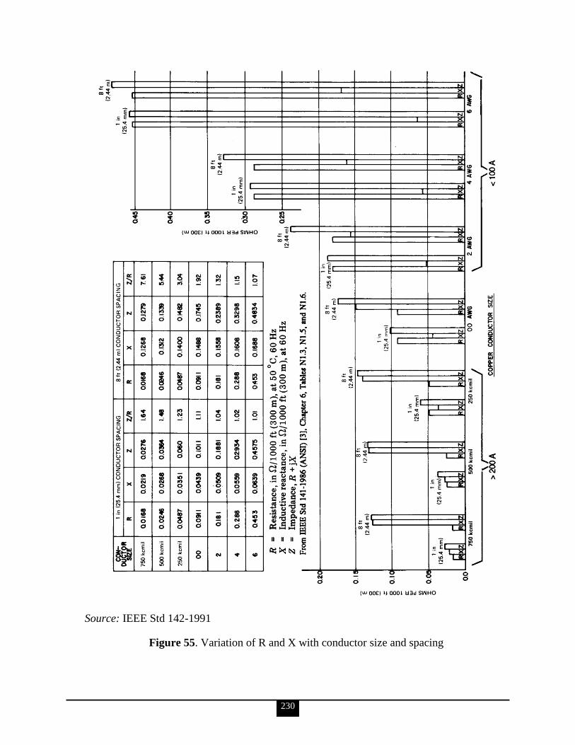
230
Source: IEEE Std 142-1991
Figure 55. Variation of R and X with conductor size and spacing
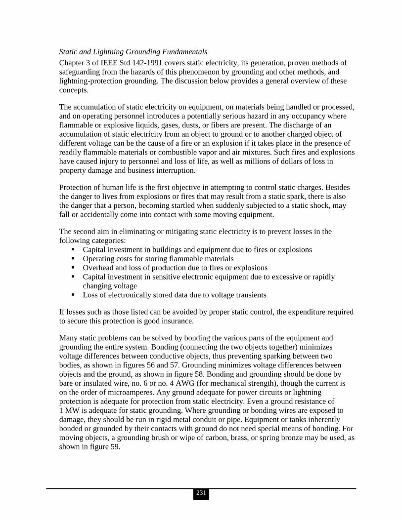
231
Static and Lightning Grounding Fundamentals
Chapter 3 of IEEE Std 142-1991 covers static electricity, its generation, proven methods of
safeguarding from the hazards of this phenomenon by grounding and other methods, and
lightning-protection grounding. The discussion below provides a general overview of these
concepts.
The accumulation of static electricity on equipment, on materials being handled or processed,
and on operating personnel introduces a potentially serious hazard in any occupancy where
flammable or explosive liquids, gases, dusts, or fibers are present. The discharge of an
accumulation of static electricity from an object to ground or to another charged object of
different voltage can be the cause of a fire or an explosion if it takes place in the presence of
readily flammable materials or combustible vapor and air mixtures. Such fires and explosions
have caused injury to personnel and loss of life, as well as millions of dollars of loss in
property damage and business interruption.
Protection of human life is the first objective in attempting to control static charges. Besides
the danger to lives from explosions or fires that may result from a static spark, there is also
the danger that a person, becoming startled when suddenly subjected to a static shock, may
fall or accidentally come into contact with some moving equipment.
The second aim in eliminating or mitigating static electricity is to prevent losses in the
following categories:
Capital investment in buildings and equipment due to fires or explosions
Operating costs for storing flammable materials
Overhead and loss of production due to fires or explosions
Capital investment in sensitive electronic equipment due to excessive or rapidly
changing voltage
Loss of electronically stored data due to voltage transients
If losses such as those listed can be avoided by proper static control, the expenditure required
to secure this protection is good insurance.
Many static problems can be solved by bonding the various parts of the equipment and
grounding the entire system. Bonding (connecting the two objects together) minimizes
voltage differences between conductive objects, thus preventing sparking between two
bodies, as shown in figures 56 and 57. Grounding minimizes voltage differences between
objects and the ground, as shown in figure 58. Bonding and grounding should be done by
bare or insulated wire, no. 6 or no. 4 AWG (for mechanical strength), though the current is
on the order of microamperes. Any ground adequate for power circuits or lightning
protection is adequate for protection from static electricity. Even a ground resistance of
1 MW is adequate for static grounding. Where grounding or bonding wires are exposed to
damage, they should be run in rigid metal conduit or pipe. Equipment or tanks inherently
bonded or grounded by their contacts with ground do not need special means of bonding. For
moving objects, a grounding brush or wipe of carbon, brass, or spring bronze may be used, as
shown in figure 59.
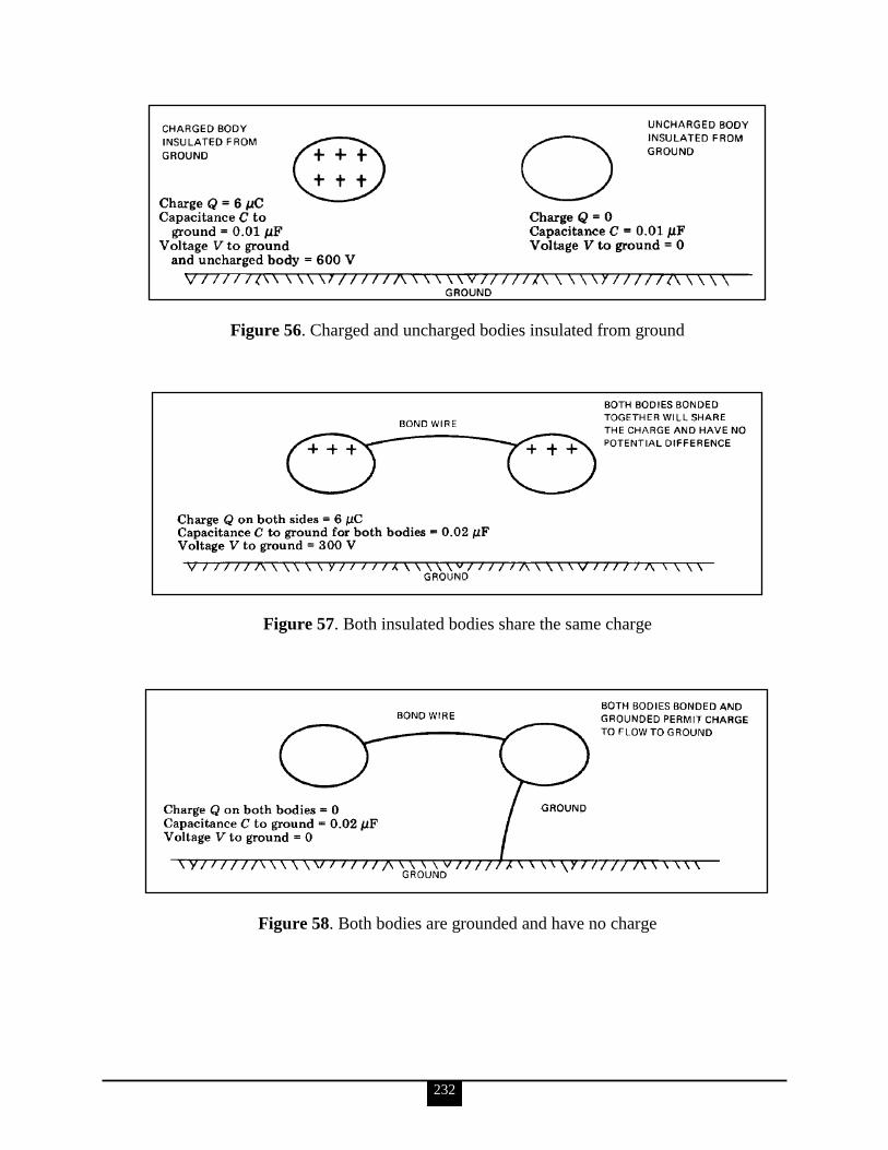
232
Figure 56. Charged and uncharged bodies insulated from ground
Figure 57. Both insulated bodies share the same charge
Figure 58. Both bodies are grounded and have no charge

233
Source: Figures 56–59, IEEE Std 142-1991
Figure 59. Methods of ground metal rollers or shafting: (a) spring bronze brush, (b) brass or
carbon brush, (c) carbon brush and holder
Lightning-protection grounding is essential for the protection of buildings, transmission lines,
and electrical equipment from lightning discharges and surges.
f. Discuss emergency and standby power with regard to the following elements (IEEE Orange Book; reference IEEE Std-446 or another source can be used as a guide in developing the discussion): Emergency and standby power guidelines Generator and electric utility system fundamentals (IEEE Brown Book;
reference IEEE Std-399) Stored energy system fundamentals Protection device fundamentals
The following is taken from IEEE Std-446-1995.
Emergency and Standby Power Guidelines
While all who use electric power desire perfect frequency, voltage stability, and reliability at
all times, this cannot be realized in practice because of the many causes of power supply
disturbances that are beyond the control of the utility. For example, power failures can be
caused by automobiles hitting poles; animals climbing across insulators; lightning striking
overhead lines; and high winds blowing tree branches and other debris into lines.
The lightning, wind, and rain produced by thunderstorms and tornadoes can also cause power
interruptions and transients. Figures 60 and 61 are useful in determining the probability of
such power failures (from thunderstorms and from tornadoes, respectively) depending upon
the user‘s geographic location. More widely located storms, such as hurricanes, snowstorms,
ice storms, and floods, also take their toll on power supply systems.
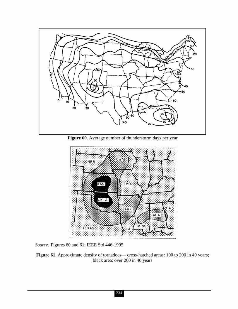
234
Figure 60. Average number of thunderstorm days per year
Source: Figures 60 and 61, IEEE Std 446-1995
Figure 61. Approximate density of tornadoes— cross-hatched areas: 100 to 200 in 40 years;
black area: over 200 in 40 years
235
Tools for Determination of Power Failures
Although there is less chance for a power interruption caused by severe weather or other
natural phenomena occurring on an underground system, and although an underground
system has fewer dips, the duration of any interruption that occurs may be much longer
because of the greater length of time required to discover the source of the cable failure and
to make repairs.
Even the operation of protective devices can cause power supply disturbances. As an
example, overcurrent and short-circuit protective devices require excessive current to operate
and are accompanied by a voltage dip on any line supplying the excessive current until the
device opens to clear the fault. Devices opening to clear a lightning flashover with
subsequent reclosing cause a momentary interruption.
Since utility companies have little practical control over disturbances on their systems, they
are unwilling to accept responsibility for them or to make power quality or continuity
guarantees. The following disclaimer is taken from a typical utility sales contract:
The power delivered hereunder shall be three-phase AC at a frequency of
approximately 60 Hz and at a nominal voltage of 208/120 V wye. Except for
temporary periods of abnormal operating conditions, variations from normal
voltage shall not exceed 5% up or down. The utility will use reasonable
diligence to provide a regular and uninterrupted supply of power, but in case
such supply should be interrupted for any cause, the utility shall not be liable
for damages resulting therefrom.
In several instances, utility companies have recognized the limitations of their power quality
and have offered auxiliary equipment with special purchase agreements to satisfy the needs
of those who use sensitive utilization equipment.
Utility companies are by no means the only source of power system disturbances.
Disturbances and outages also occur in the plant system through the loss of power due to
short circuits in wiring and failures of local generation including emergency and standby
equipment.
Noise is generated in otherwise acceptable electric power by motors, welders, switches,
semiconductor-controlled rectifier gating, dielectric heating, arcing short circuits, and myriad
other sources.
Ordinary power meters and instrumentation cannot be used to measure power transients or
disturbances. Recording devices with extremely fast response must be used to detect,
measure, and record disturbance magnitudes and durations. Most disturbances will not only
vary within a given 24-hour period, but depending on the geographical area, could be subject
to seasonal variations.
Any meaningful data with regard to power quality, or lack of it, will become obvious only
after conducting a thorough and detailed measurement recording and analysis program. Such
a program would include the monitoring of an incoming power line over a representative

236
period of time. Since much of the instrumentation is costly (typically, $3,000–$16,000) in
relation to its limited duration usage, rental arrangements are often a popular choice. Without
a good power disturbance monitor to measure and record disturbances continuously, there is
a tendency to make judgments regarding disturbances in the power source in terms of their
effects upon various electrical loads. When the lights go out and the electrical equipment all
stops working, this is usually a fairly reliable indication of a power interruption. However, if
the lights merely flicker or the electronic equipment malfunctions, it is difficult to judge
whether or not there has been a severe change in voltage for a very short time or a very small
voltage change for a much longer time. One cannot determine, without a disturbance
monitor, whether or not the disturbance was unusually severe or the electronic equipment
was unusually susceptible to the disturbance. Without the necessary features in a disturbance
monitor, one cannot tell if the source of the disturbance was external to the load equipment or
was the load equipment itself.
The following list describes methods that can be used to reduce to acceptable limits, or even
eliminate, the effects of power supply disturbances:
Modification of the design of utilization equipment so as to be impervious to power
disturbances and discontinuities
Modification of the prime power distribution system to be compatible with utilization
equipment
Modification of both equipment and systems to meet a criterion that is realistic for
both
Interposing a continuous electric supply system between the prime source and the
utilization equipment; this will function as a buffer to external sources of transients,
but depending on the design, could increase the magnitude of load-induced
disturbances
Generator and Electric Utility System Fundamentals (IEEE Brown Book; reference IEEE
Std 399)
When an equipment problem is experienced, due to failure of the electric power supply, the
options are to (1) tolerate the problem and do nothing, (2) modify the equipment or system to
perform satisfactorily during a power failure, or (3) alter or supplement the power supply to
prevent potential occurrences of failure. In many cases, the best decision is to modify the
equipment or system.
If the electric power user‘s study has shown that the most beneficial approach is to alter or
supplement the power supply source, another study should be undertaken to determine the
proper systems, configuration, and hardware that will meet the determined power
requirements for the lowest cost.
Combinations of systems and hardware have been proven reliable in preventing the following
types of electric power failure:
Long-time interruption (hours)
Medium-time interruption (minutes)
Short-time interruption (seconds)
Over- or under-voltage
Over- or under-frequency

237
Emergency power systems are of the following two basic types:
An electric power source separate from the prime source of power, operating in
parallel, that maintains power to the critical loads should the prime source fail
An available reliable power source to which critical loads are rapidly switched
automatically when the prime source of power fails
Standby power systems are made up of the following main components:
An alternative reliable source of electric energy separate from the prime power
source, starting and regulating control if onsite standby generation is selected as the
source
Controls that transfer loads from the prime or emergency power source to the standby
source
For reasons of economy, it would be prudent to establish specific needs for emergency and
standby power before specifying and purchasing equipment, since equipment costs are
proportional to the following requirements and specifications:
Longer equipment life
Increased capacity
Closer frequency regulation
Closer voltage regulation
Freedom from voltage or frequency transients
Increased availability
Increased reliability
Increased temporary overload capability
Quiet operation
Safety from fuel hazards
Pollution-free operation
Freedom from harmonics
Close voltage and frequency regulation with wider-range rapid load changes
The following 2 paragraphs are taken from IEEE Std-399.
IEEE Std 399-1997 notes that the need for DC power system analysis of emergency standby
power supplies has steadily increased in data processing facilities, long-distance telephone
companies, and generating stations during the past several years.
DC emergency power is used for circuit breaker control, protective relaying, inverters,
instrumentation, emergency lighting, communications, annunciators, fault recorders, and
auxiliary motors. The introduction of computer techniques to DC power systems analysis has
allowed a more rapid and rigorous analysis of these systems compared to earlier manual
techniques.
Stored Energy System Fundamentals
Energy usable for electrical power generation may be stored in many ways. For example,
liquid and gaseous fuels are a form of energy stored for use in engines and turbines to turn
generators.
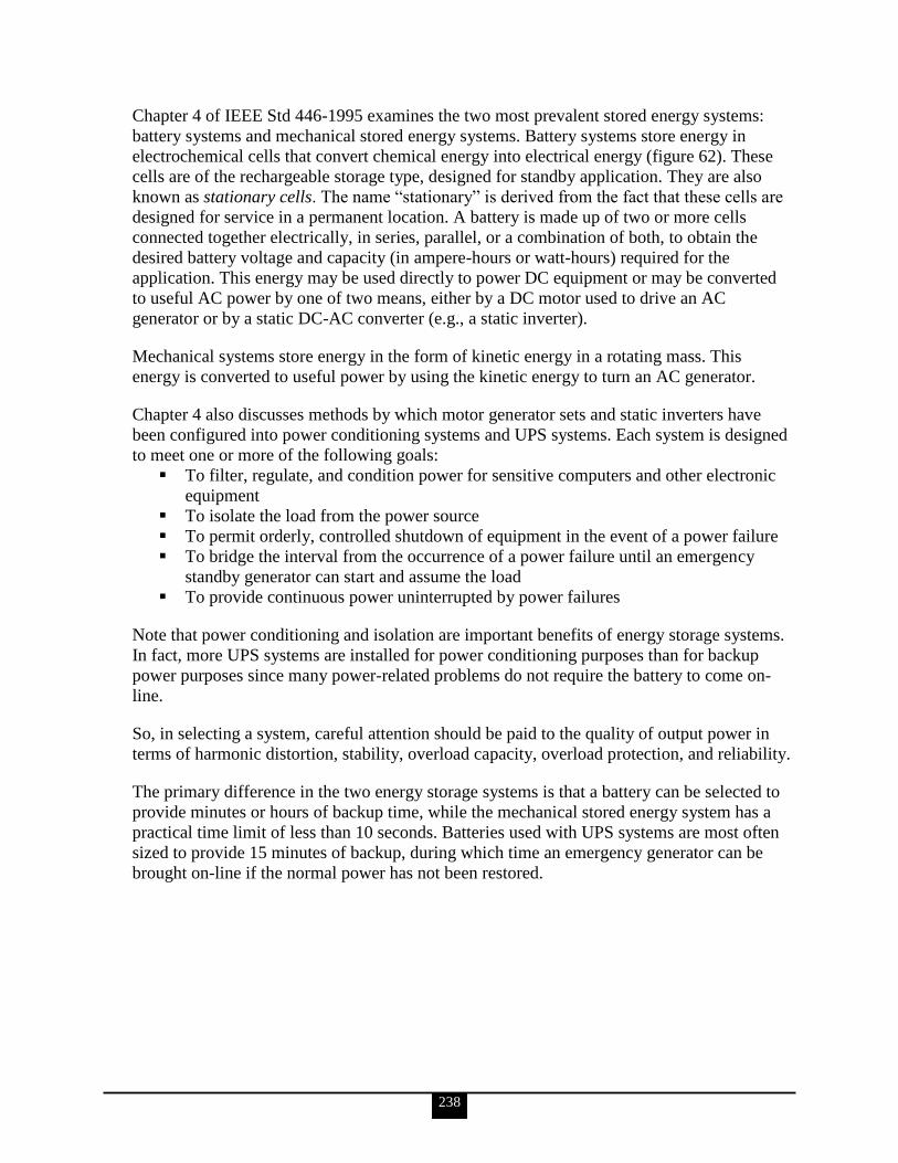
238
Chapter 4 of IEEE Std 446-1995 examines the two most prevalent stored energy systems:
battery systems and mechanical stored energy systems. Battery systems store energy in
electrochemical cells that convert chemical energy into electrical energy (figure 62). These
cells are of the rechargeable storage type, designed for standby application. They are also
known as stationary cells. The name ―stationary‖ is derived from the fact that these cells are
designed for service in a permanent location. A battery is made up of two or more cells
connected together electrically, in series, parallel, or a combination of both, to obtain the
desired battery voltage and capacity (in ampere-hours or watt-hours) required for the
application. This energy may be used directly to power DC equipment or may be converted
to useful AC power by one of two means, either by a DC motor used to drive an AC
generator or by a static DC-AC converter (e.g., a static inverter).
Mechanical systems store energy in the form of kinetic energy in a rotating mass. This
energy is converted to useful power by using the kinetic energy to turn an AC generator.
Chapter 4 also discusses methods by which motor generator sets and static inverters have
been configured into power conditioning systems and UPS systems. Each system is designed
to meet one or more of the following goals:
To filter, regulate, and condition power for sensitive computers and other electronic
equipment
To isolate the load from the power source
To permit orderly, controlled shutdown of equipment in the event of a power failure
To bridge the interval from the occurrence of a power failure until an emergency
standby generator can start and assume the load
To provide continuous power uninterrupted by power failures
Note that power conditioning and isolation are important benefits of energy storage systems.
In fact, more UPS systems are installed for power conditioning purposes than for backup
power purposes since many power-related problems do not require the battery to come on-
line.
So, in selecting a system, careful attention should be paid to the quality of output power in
terms of harmonic distortion, stability, overload capacity, overload protection, and reliability.
The primary difference in the two energy storage systems is that a battery can be selected to
provide minutes or hours of backup time, while the mechanical stored energy system has a
practical time limit of less than 10 seconds. Batteries used with UPS systems are most often
sized to provide 15 minutes of backup, during which time an emergency generator can be
brought on-line if the normal power has not been restored.

239
Source: IEEE Std 446-1995
Figure 62. Stationary battery installation

240
Protection Device Fundamentals
This section discusses recommended practices and guidelines for protection of emergency
and standby power systems. Even though standard practice for protection of equipment
should always be given full consideration when applying the equipment in emergency and
standby use, reliability often warrants special consideration when a power supply for critical
loads is designed. Although compliance with all national, state, and local codes and standards
applicable to protection of the components that make up the emergency or standby power
system is necessary, it may be desirable to exceed these codes and standards in the design
process.
Individual components that make up the most common emergency and standby power
systems, with emphasis on maintaining the required integrity and reliability of the system are
to be protected. Proper application and maintenance of systems should be considered an
important aspect of protection.
Of the many areas of concern for protection of components that make up an emergency or
standby power system, one needing special consideration is that of magnitude and duration of
short-circuit current available from the emergency or standby power source. Fault conditions
obviously have a direct effect on the availability of the power supply to serve its intended
purpose.
Studies should be made to determine available short-circuit current throughout the system
supplied by an emergency or standby power supply, especially at switching and current-
interrupting devices.
When the performance of an emergency or standby generator under fault conditions is
evaluated, a critical concern is whether sufficient fault current is available for sufficient
duration to selectively trip overcurrent devices in a properly coordinated system. In most
cases, emergency or standby power sources do not produce as much fault current as the
normal source. When both sources are designed to supply a distribution system, through
automatic or manual switching devices, the magnitude of the fault current available from the
normal supply usually determines the required interrupting or withstand rating of the system
components. Careful planning is necessary to design a system that assures optimum
selectivity and coordination with both power sources. An emergency or standby generator‘s
available short-circuit current should be compared to the ratings of system overcurrent
devices to determine how this coordination is to be achieved. Normally the emergency or
standby power source should be connected into the power system so as to be physically and
electrically as close to the loads as practical. This will minimize the number and size of
distribution system circuit breakers involved and the number of coordination levels required.
Selective coordination of overcurrent devices is the process of applying these devices so that
one will operate before another under given levels of fault currents, thereby allowing
effective isolation of the faulted circuit from unfaulted circuits. For a detailed analysis of the
principles of selective coordination, see IEEE Std 242-1986.
Evaluating the available fault current from an emergency or standby generator includes
determining the magnitude of the fault current and how long the fault current will exist and

241
how it may change. Test information on generator short-circuit characteristics may be
necessary from the manufacturer. One should not assume that the speed of the generator will
remain unchanged for a fault fed only by the generator; the effects of frequency changes and
prime mover load should also be accounted for. The coordination of the mechanical and
electrical stored energy in a generator set and the type of excitation system will determine
how long the engine and generator will sustain fault current and how rapidly this fault current
will decay. In some cases, the initial power to a fault is higher (sometimes several times
higher) than the prime mover power rating. The result can be a rapid reduction in speed. This
overloading of the prime mover is more likely in small generator set applications than in
larger power systems since the X/R ratios of both the generator windings and distribution
circuits in small systems are lower.
An excitation system usually will not respond fast enough to significantly affect the first one
or two cycles of fault current, so at this point the type of excitation system does not matter. If
the fault is not cleared in the first 2–4 cycles, a serious concern is whether or not the
generator set can recover, after the fault is finally cleared, to maintain acceptable service to
unfaulted branch circuits. For systems where the fault current decays rapidly to levels below
instantaneous and delayed overcurrent trip settings, tripping will only be possible in the first
few cycles. This diminishes the ability to selectively trip the overcurrent devices, leaving
only the instantaneous settings to work with.
Figure 63 illustrates the rate of decay of three-phase fault current from tests on three typical
generators; the first two are separately excited (with fixed excitation) and tested at no load.
The curves are approximations of actual test results. In figure 63a, about 40 cycles elapse
before the fault current decays to the full-load rating of the generator. In figure 63b, the fault
current decayed to the full-load rating in about 25 cycles. The quicker decline of fault current
from the smaller generator is a common occurrence.
The current (I) shown is in per unit (pu) based on generator full-load current rating. Figure
63c illustrates an approximation of short-circuit current of a shunt-excited generator without
short-circuit sustaining capability. In this case, the current has decayed to full-load rating in
10 cycles and to nearly zero in 20 cycles.
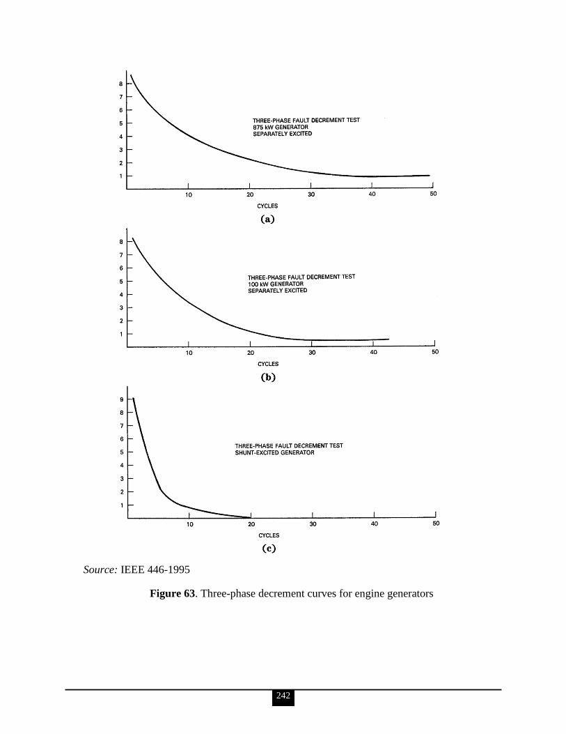
242
Source: IEEE 446-1995
Figure 63. Three-phase decrement curves for engine generators
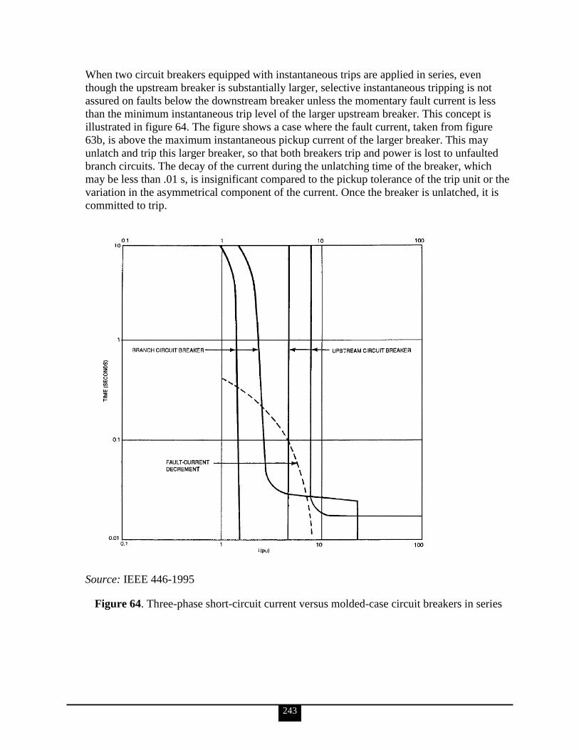
243
When two circuit breakers equipped with instantaneous trips are applied in series, even
though the upstream breaker is substantially larger, selective instantaneous tripping is not
assured on faults below the downstream breaker unless the momentary fault current is less
than the minimum instantaneous trip level of the larger upstream breaker. This concept is
illustrated in figure 64. The figure shows a case where the fault current, taken from figure
63b, is above the maximum instantaneous pickup current of the larger breaker. This may
unlatch and trip this larger breaker, so that both breakers trip and power is lost to unfaulted
branch circuits. The decay of the current during the unlatching time of the breaker, which
may be less than .01 s, is insignificant compared to the pickup tolerance of the trip unit or the
variation in the asymmetrical component of the current. Once the breaker is unlatched, it is
committed to trip.
Source: IEEE 446-1995
Figure 64. Three-phase short-circuit current versus molded-case circuit breakers in series
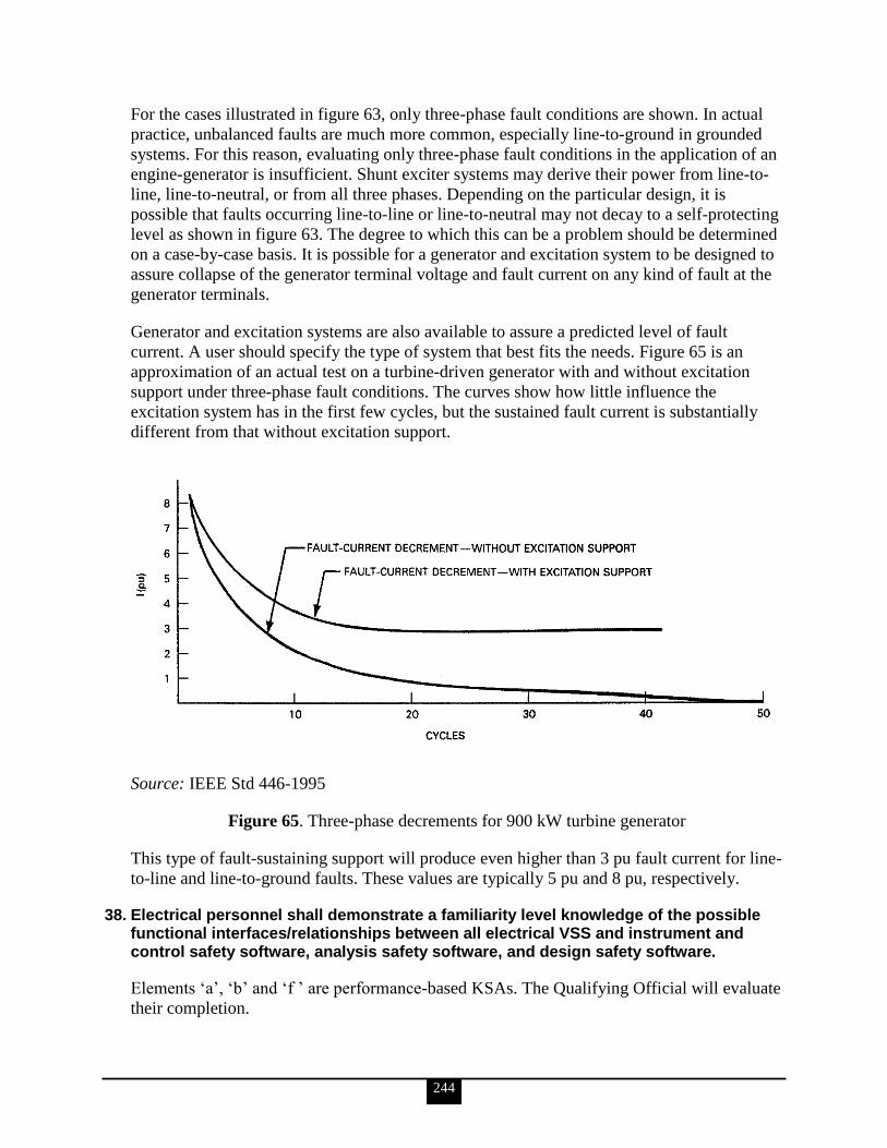
244
For the cases illustrated in figure 63, only three-phase fault conditions are shown. In actual
practice, unbalanced faults are much more common, especially line-to-ground in grounded
systems. For this reason, evaluating only three-phase fault conditions in the application of an
engine-generator is insufficient. Shunt exciter systems may derive their power from line-to-
line, line-to-neutral, or from all three phases. Depending on the particular design, it is
possible that faults occurring line-to-line or line-to-neutral may not decay to a self-protecting
level as shown in figure 63. The degree to which this can be a problem should be determined
on a case-by-case basis. It is possible for a generator and excitation system to be designed to
assure collapse of the generator terminal voltage and fault current on any kind of fault at the
generator terminals.
Generator and excitation systems are also available to assure a predicted level of fault
current. A user should specify the type of system that best fits the needs. Figure 65 is an
approximation of an actual test on a turbine-driven generator with and without excitation
support under three-phase fault conditions. The curves show how little influence the
excitation system has in the first few cycles, but the sustained fault current is substantially
different from that without excitation support.
Source: IEEE Std 446-1995
Figure 65. Three-phase decrements for 900 kW turbine generator
This type of fault-sustaining support will produce even higher than 3 pu fault current for line-
to-line and line-to-ground faults. These values are typically 5 pu and 8 pu, respectively.
38. Electrical personnel shall demonstrate a familiarity level knowledge of the possible functional interfaces/relationships between all electrical VSS and instrument and control safety software, analysis safety software, and design safety software.
Elements ‗a‘, ‗b‘ and ‗f ‘ are performance-based KSAs. The Qualifying Official will evaluate
their completion.

245
a. Mandatory Performance Activity: With the assistance of the cognizant software quality assurance (SQA) subject matter expert, identify how functional requirements and applicability of safety analysis and design computer codes are defined, documented, and controlled relative to modeling and data assumptions, design constraints, sizing and timing conditions, and input/output parameters as described in DOE O 414.1C, Quality Assurance, and DOE G 414.1-4, Safety Software Guide for Use with 10 CFR 830, Subpart A, Quality Assurance Requirements, and DOE O 414.1C, Quality Assurance.
b. Review a development project for safety analysis or design software. Explain how the problem being addressed by the software was translated into functional requirements, how the requirements were established and controlled, and how the code was reconciled with the original problem.
c. Identify how system level requirements are established and then assigned to hardware, software, and human components of a digital instrumentation and control system.
The information for KSAs ‗c‘, ‗d‘ and ‗e‘ is taken from DOE G 414.1-4.
The Department has recognized the need to establish rigorous and effective requirements for
the application of QA programs to safety software. In evaluating DNFSB recommendation
2002-1 and through assessing the current state of safety software, the Department concluded
that an integrated and effective SQA infrastructure must be in place throughout the
Department‘s nuclear facilities.
System-level issues impacting safety software are the availability of trained and
knowledgeable personnel to develop, maintain, and use the software; human factor issues
such as understandability of the displays or ambient lighting conditions; and potential
EMI/RFI, which should be analyzed. Fault tolerance and common cause failure issues,
performance requirements, and proper identification and analysis of functional requirements
that have safety, security or integrity implications need to be propagated to the safety
software.
Safety system requirements provide the foundation for the requirements to be implemented in
the software. These system requirements should be translated into requirements specific for
the software. The identified software requirements may be documented in system-level
requirements documents, software requirements specifications, procurement contracts, and/or
acquired software agreements. These requirements should identify functional; performance;
security, including user access control; interface and safety requirements; and installation
considerations and design constraints, where appropriate. The requirements should be
complete, correct, consistent, clear, verifiable, and feasible.
SQA cannot address the risks created by the failure of other system components (hardware,
data, human process, power system failures) but can address the software ―reaction‖ to
effects caused by these types of failures. SQA should not be isolated from system-level QA
and other system-level activities. In many instances, hardware fail-safe methods are
implemented to mitigate risk of safety software failure. Additionally other interfaces such as
hardware and human interfaces with safety software should implement QA activities.

246
Safety systems requirements impact instrumentation and control system software, including
embedded microprocessors, distributed control systems, supervisory control and data
acquisition systems, programmable logic controllers, and other related software.
A broader, more general description of system-level requirements is available in DOE
O 414.1C.
d. Identify the typical requirements that define functional interfaces between safety software components and the system-level design, as described in DOE O 414.1C, Quality Assurance, and DOE G 414.1-4, Safety Software Guide for Use with 10 CFR 830, Subpart A, Quality Assurance Requirements, and DOE O 414.1C, Quality Assurance.
During design and implementation the software is developed, documented, reviewed, and
controlled. The software design elements should identify the operating system, function,
interfaces, performance requirements, installation considerations, design inputs, and design
constraints. The software design should be complete and sufficient to meet the software
requirements. The design activities and documentation should be adequate to fully describe
how the software will fully interface with other system components and how the software
will function internally. Data structure requirements and layouts may be necessary to fully
understand the internal operations of the software.
Custom developed software will require more formality in the documentation and review of
the design than configurable or utility calculations. Simple process flows, relationships
between data elements, interfaces with external components, and basic database table
structures may be all that are needed for configurable or utility calculations, whereas for
custom-developed software, complete functional and logical designs of the software
components, the input and output data, and pseudo code may be required to fully understand
the safety software design. The software design description may be combined with the
documentation of the software requirements or software source code.
During implementation, static analysis, clean room inspections, and reviews are common
techniques to ensure the implementation remains consistent with the design and does not add
complexity or functions that could decrease the safe operation of the software. Many tools
exist to evaluate the complexity and other attributes of the source code design structure.
Walkthroughs and more formal inspections, such as Fagan inspections, can be used to
identify defects in source code, as well as design descriptions and other software
development process outputs.
For software design and implementation work activity for Levels A, B, and C custom
developed software applications, the design, including interfaces and data structures, should
be completely documented; reviews of the design and code should be performed.
Additionally, formal developer testing that includes functional, structural, timing, stress,
security, and human-factors testing should be planned, performed, and the results
documented. It is recommended that the complexity of the custom developed safety software
be evaluated and analysis performed to reduce the complexity of the source code modules.

247
Configurable and utility calculation for Levels A, B, and C software applications may be
graded for this work activity. This grading should include fully performing the design work
activities as with custom developed software. However, less formal design and code reviews,
such as simple desk checks by another individual other than the developer, may be
performed. Developer testing that includes safety functions, security, and performance
testing should be performed and documented. This work activity does not apply to acquired
or commercial design and analysis safety software types since the design and implementation
activities associated with commercial design and analysis software are performed by the
service supplier. DOE controls the SQA activities of that software through procurement
agreements and specifications.
The design of the software is critical to ensuring safe operation of the system. The software
design should consider principles of simplicity, decoupling, and isolation to eliminate
hazards. Complexity of the software design, including the logic and number of data inputs,
has proven to increase the defect density in software components. The safety features should
be separate from non-safety modules, minimizing the impact of failure of one module on
another. The interfaces between the modules need to be defined and tested thoroughly.
e. Identify the specific records that must be maintained and the requirements for maintaining these records to document the development of safety system software.
The following documents and records must be maintained: Software Project Management
Plan and/or Software Quality Assurance Plan ; Software Safety Plan, Software Configuration
Management Plan or related documents; contractual documents or other software
procurement and use agreement documentation; Software Requirements Specifications or
related document; Software Design Description; Model description; Programmers Reference
Model or other related documents; Software Safety Analysis documentation; Verification and
Validation Report; Test Case Description, Outcome Report and other testing documents;
Software Error Notification and Corrective Action Report; User Instructions or User
Manuals; Training Packages and User Qualification.
These documents and records should be evaluated for adequacy and to determine whether
they are appropriate and are being used to verify that software requirements and performance
criteria described in the software requirements documentation are satisfied.
f. Review a development project for safety system software. Explain how the functional interfaces between components and the system level design were established and controlled.
This is a performance-based KSA. The Qualifying Official will evaluate its completion.
39. Mandatory Performance Activity: Electrical personnel shall demonstrate the ability to perform a quarterly walkthrough, bi-annual status walkthrough, or an assessment and generate a report identifying observations and/or findings.
Elements ‗a‘ through ‗c‘ are performance-based KSAs. The Qualifying Official will evaluate
their completion.
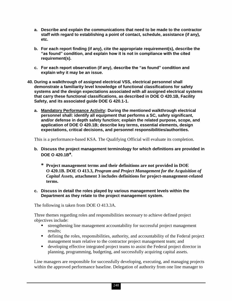
248
a. Describe and explain the communications that need to be made to the contractor staff with regard to establishing a point of contact, schedule, assistance (if any), etc.
b. For each report finding (if any), cite the appropriate requirement(s), describe the ―as found‖ condition, and explain how it is not in compliance with the cited requirement(s).
c. For each report observation (if any), describe the ―as found‖ condition and explain why it may be an issue.
40. During a walkthrough of assigned electrical VSS, electrical personnel shall demonstrate a familiarity level knowledge of functional classifications for safety systems and the design expectations associated with all assigned electrical systems that carry these functional classifications, as described in DOE O 420.1B, Facility Safety, and its associated guide DOE G 420.1-1.
a. Mandatory Performance Activity: During the mentioned walkthrough electrical personnel shall: identify all equipment that performs a SC, safety significant, and/or defense in depth safety function; explain the related purpose, scope, and application of DOE O 420.1B; describe key terms, essential elements, design expectations, critical decisions, and personnel responsibilities/authorities.
This is a performance-based KSA. The Qualifying Official will evaluate its completion.
b. Discuss the project management terminology for which definitions are provided in
DOE O 420.1B*.
* Project management terms and their definitions are not provided in DOE
O 420.1B. DOE O 413.3, Program and Project Management for the Acquisition of
Capital Assets, attachment 3 includes definitions for project-management-related
terms.
c. Discuss in detail the roles played by various management levels within the Department as they relate to the project management system.
The following is taken from DOE O 413.3A.
Three themes regarding roles and responsibilities necessary to achieve defined project
objectives include:
strengthening line management accountability for successful project management
results;
defining the roles, responsibilities, authority, and accountability of the Federal project
management team relative to the contractor project management team; and
developing effective integrated project teams to assist the Federal project director in
planning, programming, budgeting, and successfully acquiring capital assets.
Line managers are responsible for successfully developing, executing, and managing projects
within the approved performance baseline. Delegation of authority from one line manager to

249
a lower-level line manager must be documented and consistent with DOE delegation
authorities and the qualifications of the lower-level line manager. Although the authority and
responsibility for decision-making may be delegated to a lower-level manager, the senior
manager remains accountable for the decisions made by subordinate managers.
Key roles and responsibilities of line managers are described in the following sections:
Heads of Field Organizations
Direct initial project planning and execution roles for projects assigned by the
acquisition executive.
Initiate definition of mission need based on input from sites, laboratories, and
program offices.
Establish the integrated project team.
Oversee development of project definition, technical scope, and budget to support
mission need.
Initiate development of the acquisition strategy before CD-1 (during the period
preceding designation of the Federal project director).
Perform functions as acquisition executive when so delegated.
Develop project performance measures, and monitor and evaluate project
performance throughout the project‘s life cycle.
Allocate resources throughout the program.
Oversee the project line-management organization and ensure the line project teams
have the necessary experience, expertise, and training in design engineering, safety
and security analysis, construction, and testing.
Serve as the Federal project director until the Federal project director is appointed.
Ensure that safety is fully integrated into design and construction for high-risk, high-
hazard, and hazard category 1, 2, and 3 nuclear facilities.
Acquisition Executives
The following roles and responsibilities are for illustrative purposes, and each designated
Acquisition Executive is guided by the specific limits of his/her delegated authority:
Approve critical decisions (CDs) (CD-0 cannot be delegated below the Program
Secretarial Officer level).
Appoint and chair acquisition advisory boards to provide advice and
recommendations on key project decisions.
Approve the appointment of the Federal project director.
Designate the design authority at CD-1.
Monitor the effectiveness of Federal project directors and their support staff.
Approve project changes in compliance with change control levels identified in
Project Execution Plans.
Conduct monthly and quarterly project performance reviews.
Ensure that safety is fully integrated into design and construction for high-risk, high-
hazard, and hazard category 1, 2, and 3 nuclear facilities.

250
Federal Project Director
Successful performance of DOE projects depends on professional and effective project
management by the Federal project director. The Federal project director is responsible and
accountable to the acquisition executive/Program Secretarial Officer or delegated authority,
as appropriate, for executing the project.
The Federal project director‘s assigned project must meet cost, schedule, and performance
targets unless circumstances beyond the control of the project director result in cost overruns
and/or delays. Federal project directors must demonstrate initiative in incorporating and
managing an appropriate level of risk to ensure best value for the government. In cases where
significant cost overruns and/or delays occur, the Federal project director alerts senior
management in a timely manner and takes appropriate steps to mitigate these cost overruns or
delays.
Roles and responsibilities of the Federal project director‘s team must be clearly defined
relative to the contractor management team. Further guidance is provided in DOE M 413.3-1.
Attains and maintains certification in concert with the requirements outlined in DOE
O 361.1A before they are delegated authority to serve as a Federal project director.
Plans, implements, and completes a project using a systems engineering approach.
Initiates development and implementation of key project documentation (e.g., project
execution plan).
Defines project cost, schedule, performance, and scope baselines.
Is responsible for design, construction, environmental, safety, security, health, and
quality efforts performed comply with the contract, public law, regulations, and
Executive Orders.
Is responsible for timely, reliable, and accurate integration of contractor performance
data into the project‘s scheduling, accounting, and performance measurement
systems.
Evaluates and verifies reported progress; makes projections of progress and identifies
trends.
Serves as the single point of contact between Federal and contractor staff for all
matters relating to a project and its performance.
Serves as the contracting officer‘s representative, as determined by the contracting
officer.
Leads the integrated project team and provides broad program guidance. Delegates
appropriate decision-making authority to the integrated project team members.
Prepares and maintains the integrated project team charter and operating guidance
with integrated project team support.
Approves changes in compliance with the approved change control process
documented in the project execution plan.
Ensures that safety is fully integrated into design and construction for high-risk, high-
hazard, and hazard category 1, 2, and 3 nuclear facilities.
251
d. Discuss the purpose of ―critical decisions.‖ Include in this discussion the responsible authorities for critical decisions.
All of the following is taken from DOE O 413.3A except for the the definition of CD
immediately below, which is taken from DOE G 433.1.1.
A CD is a formal determination at a specific point in a project that allows the project to
proceed. Critical decisions occur in the course of a project, for example, before conceptual
design, execution, and turnover.
The five CDs are major milestones, approved by the Secretarial Acquisition Executive or
acquisition executive, that establish the mission need, the recommended alternative, the
acquisition strategy, the performance baseline, and other essential elements required to
ensure that the project meets applicable mission, design, security, and safety requirements.
Each CD marks an increase in commitment of resources by the Department and requires
successful completion of the preceding phase or CD. Collectively, the CDs affirm the
following:
There is a need that cannot be met through other than material means.
The selected alternative and approach are the optimum solution.
Definitive scope, schedule, and cost baselines have been developed.
The project is ready for implementation.
The project is ready for turnover or transition to operations.
The amount of time between decisions will vary. Projects may quickly proceed through the
early CDs due to a lack of complexity, the presence of constraints that reduce available
alternatives, or the absence of significant technology and developmental requirements. In
these cases, more than one CD may be approved simultaneously. Conversely, there may be a
need to split a CD.
The following paragraphs delineate the criteria, processes, and authorities for each of the five
CDs.
CD-0, Approve Mission Need
The initiation phase begins with the identification of a mission-related need. A program
identifies a credible performance gap between its current capabilities and capacities and those
required to achieve the goals articulated in its strategic plan and/or in the DOE target
enterprise architecture for information technology capital asset projects. A mission need
statement is the translation of this gap into functional requirements that cannot be met
through other than material means. It should describe the general parameters of the project,
how it fits within the mission of the program, and why it is critical to the overall
accomplishment of the Department‘s mission, including the benefits to be realized. The
mission need is independent of a particular solution, and should not be defined by equipment,
facility, technological solution, or physical end-item. This approach allows the program the
flexibility to explore a variety of solutions and not limit potential solutions. Approval of
CD-0 formally establishes a project and begins the process of conceptual planning and design
used to develop alternative concepts and functional requirements. Additionally, CD-0

252
approval allows the program to request project engineering and design funds for use in
preliminary design, final design, and baseline development.
CD-1, Approve Alternative Selection and Cost Range
CD-1 approval marks the completion of the project definition phase, during which time the
conceptual design is developed. This is an iterative process to define, analyze, and refine
project concepts and alternatives. This process uses a systems methodology that integrates
requirement analysis, risk identification and analysis, acquisition strategies, and concept
exploration to evolve a cost-effective, preferred solution to meet a mission need. Approval of
CD-1 provides the authorization to begin the project execution phase and allows project
engineering and design funds to be used. For design-build projects, project engineering and
design funds may be used to develop a statement of work/request for proposal. Additionally,
long-lead procurements may be approved during this phase provided National Environmental
Policy Act documentation is prepared, where applicable.
CD-2, Approve Performance Baseline
Completion of preliminary design is the first major milestone in the project execution phase.
Preliminary design is complete when it provides sufficient information for development of
the performance baseline in support of CD-2. The performance baseline is developed based
on a mature design, a well-defined and documented scope, a resource-loaded detailed
schedule, a definitive cost estimate, and defined key performance parameters. Approval of
CD-2 authorizes submission of a budget request for the total project cost. For projects with
design periods less than 18 months, a budget request may be submitted prior to CD-2
approval as part of tailoring.
CD-3, Approve Start of Construction
With design and engineering essentially complete, a final design review performed, all
environmental and safety criteria met, and all security concerns addressed, the project is
ready to begin construction, implementation, procurement, or fabrication. CD-3 provides
authorization to complete all procurement and construction and/or implementation activities
and initiate all acceptance and turnover activities. Approval of CD-3 authorizes the project to
commit all the resources necessary, within the funds provided, to execute the project.
CD-4, Approve Start of Operations or Project Completion
CD-4 marks the achievement of the completion criteria defined in the project execution plan
and approval of transition to operations. This decision is predicated on the readiness to
operate and/or maintain the system, facility, or capability. Transition and turnover does not
necessarily terminate all project activity. Rather, it marks a point at which the operations
organizations assume responsibility for operation and maintenance. All projects must have a
project transition/closeout plan that clearly defines the basis for attaining initial or full
operating capability or meeting performance criteria as required for project closeout, as
applicable. The key attributes in turnover are the Government‘s readiness to operate, the
ability to assume operational responsibility, and the acceptance of the asset.
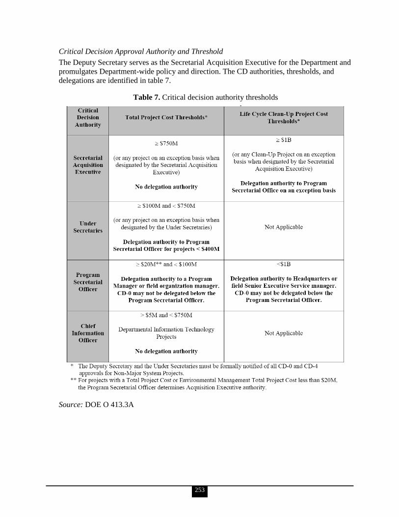
253
Critical Decision Approval Authority and Threshold
The Deputy Secretary serves as the Secretarial Acquisition Executive for the Department and
promulgates Department-wide policy and direction. The CD authorities, thresholds, and
delegations are identified in table 7.
Table 7. Critical decision authority thresholds
Source: DOE O 413.3A

254
e. Describe the process by which projects are designated.
The following is taken from DOE O 413.3A,
Projects are designated as either major projects or non-major projects.
Major System Projects
Projects with a Total Project Cost greater than or equal to $750M or
Environmental Management Clean-Up Projects with an Environmental
Management Total Project Cost of $1B are Major System Projects. All Major
System Project Critical Decisions must be proposed by the appropriate
Program Secretarial Officer and approved by the Deputy Secretary as DOE‘s
designated Secretarial Acquisition Executive before proceeding to the next
project phase or Critical Decision.
Non-Major System Projects
Projects with a Total Project Cost less than $750M or Environmental
Management Clean-Up Projects with an Environmental Management Total
Project Cost less than $1B are Non-Major System Projects. The designated
Acquisition Executive must approve all Non-Major System Project Critical
Decisions, except for CD-0, which cannot be delegated below the Program
Secretarial Officer.
f. Define the term ―safety-class‖ and discuss the implications of an electrical system carrying this functional classification.
The information for KSAs ‗f‘ and ‗g‘ is taken from DOE-STD-3009-94. Additional detail is
available from this source and from DOE O 420.1B
Safety-class SSCs are structures, systems, or components, including portions of process
systems, whose preventive and mitigative functions are necessary to limit radioactive
hazardous material exposure to the public, as determined from the accident analysis.
The results of the accident analysis form the basis for determining additional safety controls
imposed on the facility (e.g., SC SSCs and TSRs) as a function of the Evaluation Guideline.
These specific controls are then factored into overall safety management programs that
ensure the operational discipline required by the hazards identified is maintained.
SC electrical systems must be designed to preclude single point failures.
g. Define the term ―safety-significant‖ and discuss the implications of an electrical system carrying this functional classification.
Safety-significant SSCs are structures, systems, and components that are not designated as
SC SSCs but whose preventive or mitigative function is a major contributor to defense in
depth and/or worker safety as determined from safety analyses.
255
The results of the hazard analysis must be used to identify the design basis accidents that in
turn must be used to define the functional and performance requirements of the facility safety
SSCs. Safety SSCs required to prevent or mitigate accidents whose consequences approach
or exceed offsite evaluation guidelines must be defined as SC SSCs, while SS SSCs must be
selected for worker protection and to provide defense in depth.
As a rule of thumb, SS SSC designations based on worker safety are limited to those SSCs
whose failure is estimated to result in a prompt worker fatality or serious injuries (e.g., loss
of eye, loss of limb) or significant radiological or chemical exposures to workers. This is
neither an evaluation guideline nor a quantitative criterion. It represents a threshold of
concern for which SS SSC designation may be warranted. Estimates of worker consequences
for the purpose of an SS SSC designation are not intended to require detailed analytical
modeling, due to the uncertainties in analyses, especially for facility workers. Considerations
should be based on engineering judgment of possible effects and the potential added value of
SS SSC designation. Experience has shown that SS SSCs identified through defense-in-depth
considerations also provide safety for workers.
41. Electrical personnel shall demonstrate a familiarity level knowledge of electrical safety systems criteria for VSS (IEEE Stds-308-2001, 323-2003, 379-2000, 384-1992, and 603-1998; DOE O 420.1B; DOE G 420.1-1; etc.).
a. Identify and describe the following requirements for principal design criteria of electrical power systems supporting VSS (Class 1E power systems): design basis and design basis events, independence, the equipment qualification process for Class 1E power systems, single-failure criterion, requirements for connecting of non-Class 1E systems to Class 1E systems, and Class 1E protection requirements.
Design Basis
The information for design basis and design basis events (DBEs) is taken from IEEE Std
308-2001.
A specific design basis shall be provided for the Class 1E power systems of each nuclear
power generating station. The design basis shall include, as a minimum, the following:
Events requiring operation of the Class 1E power systems
Actuation signals for operation of the Class 1E power systems
A list of the loads connected to the Class 1E buses and standby power supplies
The sequence for start-up and the loading profile of the Class 1E power sources
Time, voltage, speed, and other limits applicable to the standby generators and their
prime movers when subjected to the start-up sequence of events
The malfunctions, accidents, environmental events, and operating modes that could
physically damage Class 1E power systems or lead to degradation of system
performance and for which provisions shall be incorporated
The acceptable ranges for transient and steady-state conditions of both the energy
supply and environment (e.g., voltage, frequency, humidity, temperature, pressure,
vibration, etc.) during normal, abnormal, and accident circumstances throughout
which the equipment must perform

256
Minimum equipment or system performance criteria (e.g., standby power supply unit
start-up time, undervoltage relay accuracy, voltage regulation limits, load limits,
battery charging time, voltage, etc.)
Conditions that should be permitted to shut down or disconnect Class 1E power
sources (e.g., differential relay actuation, engine overspeed)
Design Basis Events
Design basis events established for a unit shall indicate the postulated events that might
adversely affect the Class 1E power system. The severity and expected results of those events
shall be defined. The required portions of the Class 1E power systems shall be capable of
performing their function when subjected to the effects of any DBE.
Independence
The following is taken from IEEE Std 384-1992. It summarizes what is available from that
source.
Independence of redundant equipment and circuits shall be in accordance with IEEE Std 384-
1992. Physical separation and electrical isolation shall be provided to maintain the
independence of Class 1E circuits and equipment so that the safety functions required during
and following any DBE can be accomplished.
The physical separation of circuits and equipment shall be achieved by the use of SC
structures, separation distance, or barriers or any combination thereof. Electrical isolation
shall be achieved by the use of separation distance, isolation devices, shielding and wiring
techniques, or combinations thereof.
Equipment and circuits requiring independence shall be determined and delineated during the
plant design and shall be identified on documents and drawings in a distinctive manner.
The independence of Class 1E circuits and equipment shall not be compromised by the
functional failure of auxiliary supporting features. For example, an auxiliary supporting
feature (such as Class 1E switchgear room ventilation) shall be assigned to the same division
as the Class 1E system it is supporting in order to prevent the loss of mechanical function in
one division from causing loss of electrical function in another division.
Equipment Qualification Process for Class 1E Power Systems
The following is taken from IEEE Std 323-2003.
A type test subjects a representative sample of equipment, including interfaces, to a series of
tests, simulating the effects of significant aging mechanisms during normal operation. The
sample is subsequently subjected to DBE testing that simulates and thereby establishes the
tested configuration for installed equipment service, including mounting, orientation,
interfaces, conduit sealing, and expected environments. A successful type test demonstrates
that the equipment can perform the intended safety function(s) for the required operating
time before, during, and/or following the DBE, as appropriate.
257
The primary objective of qualification is to demonstrate with reasonable assurance that
Class 1E equipment for which a qualified life or condition has been established can perform
its safety function(s) without experiencing common-cause failures before, during, and after
applicable DBEs. Class 1E equipment, with its interfaces, must meet or exceed the
equipment specification requirements. This continued capability is ensured through a
program that includes, but is not limited to, design control, QC, qualification, installation,
maintenance, periodic testing, and surveillance.
For equipment located in a mild environment for meeting its functional requirements during
normal environmental conditions and anticipated operational occurrences (AOOs), the
requirements shall be specified in the design/purchase specifications. A qualified life is not
required for equipment located in a mild environment and which has no significant aging
mechanisms. When seismic testing is used to qualify equipment located in a mild
environment, pre-aging prior to the seismic tests is required only where significant aging
mechanisms exist. A maintenance/surveillance program based on a vendor‘s
recommendations, which may be supplemented with operating experience, should ensure that
equipment meets the specified requirements.
Degradation with time followed by exposure to environmental extremes of temperature,
pressure, humidity, radiation, vibration and, if applicable, chemical spray and submergence
resulting from a DBE condition can precipitate common-cause failures of Class 1E
equipment. For this reason, it is necessary to establish a qualified life for equipment with
significant aging mechanisms. The qualified life determination must consider degradation of
equipment capability prior to and during service. Inherent in establishing a qualified life is
that a qualified condition is also established. This qualified condition is the state of
degradation for which successful performance during a subsequent DBE was demonstrated.
Single-Failure Criterion
The following is taken from IEEE Std 379-2000.
Class 1E power systems shall perform all safety functions required for a DBE in the presence
of
any single detectable failure within the Class 1E power systems concurrent with all
identifiable but nondetectable failures
all failures caused by the single failure
all failures and spurious system actions that cause or are caused by the DBE requiring
the safety functions
The single failure could occur prior to, or at any time during, the DBE for which the safety
system is required to function. The single-failure criterion (SFC) applies to the Class 1E
power systems whether control is by automatic or manual means.
A probabilistic assessment shall not be used in lieu of the single-failure analysis. However,
reliability analysis, probability assessment, operating experience, engineering judgment, or a
combination thereof, may be used to establish a basis for excluding a particular failure from
the single-failure analysis. For further guidance in performing reliability analyses and
probabilistic assessments, see IEEE Std 352-1987 and IEEE Std 577-1976.
258
Where reasonable indication exists that a design that meets the SFC may not satisfy all the
reliability requirements specified in the design basis, a probabilistic assessment of the Class
1E power system shall be performed. The assessment shall not be limited to single failures. If
the assessment shows that the design basis reliability requirements are not met, design
features shall be provided or corrective modifications shall be made to ensure that the system
meets the specified reliability requirements.
Requirements for Connecting of Non-Class 1E Systems to Class 1E Systems
The following is taken from IEEE Std 308-2001.
Connection of non-Class 1E circuits to Class 1E power systems is not recommended.
However, if connections are made, they should be limited to loads that need connection to a
reliable standby power source. If non-Class 1E circuits are supplied from Class 1E power
systems, the Class 1E systems shall not be degraded below an acceptable level as specified
by IEEE Std 308-2001. The non-Class 1E circuits shall meet the independence and isolation
requirements as established in IEEE Std 384-1992.
Class 1E Protection Requirements
The following is taken from IEEE Std 741-1997. It is a summary of what is available from
that source.
Protective devices shall be provided to limit the degradation of the Class 1E power systems
below an acceptable level in accordance with IEEE Std 741-1997.
As used in IEEE Std 741-1997, protection refers to the sense, command, and execute features
with their associated interconnections (see IEEE Std 603-1991) that are provided to minimize
equipment damage and any interruption of electrical service resulting from mechanical or
electrical failures or other unacceptable conditions.
Protection includes equipment required to support the Class 1E power system in the
performance of its safety function, and components whose function is to increase the
availability and reliability of the safety-related equipment. The protection shall be capable of
the following:
Preventing failures in safety systems and equipment from disabling safety functions
to below an acceptable level. The protective actions of each load group shall be
independent of the protective actions provided by redundant load groups (see IEEE
Std 308-2001).
Operating the required devices upon detection of unacceptable conditions to reduce
the severity and extent of electrical system disturbances, equipment damage, and
potential personnel and property hazards.
Monitoring the connected preferred power supply and, where an alternate preferred
power supply is provided by the design, of automatically initiating a transfer or
alerting the operator to manually transfer to the preferred alternate power supply.
Providing indication and identification of the protective operations.
Periodic testing to verify logic schemes and protective functions.
Being designed in such a way that the availability of protection control power is
monitored.
259
Periodic testing to verify setpoints. This requirement is not applicable to fuses.
b. Identify and describe the requirements for supplementary design criteria of electrical power systems supporting VSS (Class 1E power systems): Class 1E power systems, AC power systems, DC power systems; instrumentation and control power systems, and execute and sense-and-command features.
The information for KSAs ‗b‘ and ‗c‘ is taken from IEEE Std 308-2001.
Class 1E Power Systems, AC Power Systems, DC Power Systems
Class 1E power systems consist of an AC power system, a DC power system, and an
instrument and control power system. The Class 1E power systems shall support the safety
systems by providing acceptable power under the conditions stated in the design basis. The
duration of the connection between the preferred power supply and the standby power supply
shall be minimized (e.g., limited to the time required to perform standby power supply
testing). Refer to IEEE Std 741-1997 for information on automatic bus transfers that may be
included in the design of these systems.
The AC power system shall include power supplies and distribution systems arranged to
provide power to the Class 1E AC loads and controls. Features such as physical separation,
electrical isolation, redundancy, and qualified equipment shall be included in the design to
aid in preventing a mechanism by which a single DBE could cause redundant equipment
within the station‘s Class 1E power system to be inoperable. Design requirements shall
include the following:
The Class 1E electric loads shall be separated into two or more redundant load
groups.
The protective actions of each load group shall be independent of the protective
actions provided by redundant load groups.
Each of the redundant load groups shall have access to both a preferred and a standby
power supply.
Two or more load groups may have a common power supply if the consequences of
the loss of the common power supply to the load groups under DBEs are acceptable.
Features shall be incorporated in the design of the standby power supply so that any
DBE will not cause failures in redundant power sources. In addition, the design shall
minimize common-cause failures of a preferred power source and standby power
source associated with a single load group.
The DC power systems include power supplies and distribution systems arranged to provide
power to the Class 1E DC loads and for control and switching of the Class 1E power
systems. Features such as physical separation, electrical isolation, redundancy, and qualified
equipment shall be included in the design to aid in preventing a mechanism by which a single
DBE can cause redundant equipment within the station‘s Class 1E power system to be
inoperable. (For guidance, refer to IEEE Std 946-1992.)
Design requirements shall include the following:
The Class 1E electric loads shall be separated into two or more redundant load
groups.
260
The protective actions of each load group shall be independent of the protective
actions provided by redundant load groups.
Each of the redundant load groups shall have access to a power supply that consists of
one or more batteries and one or more battery chargers.
Each load group shall have its own battery charger (or chargers) with no automatic
interconnecting provision. Two or more chargers may have a common AC power
supply if the consequences of the loss of the power supply to the load group under
design basis conditions are acceptable.
The batteries shall have features so that common-cause failures are minimized
between redundant batteries. For further guidance, refer to IEEE Std 484-1996.
Instrumentation and Control Power Systems
The instrumentation and control power systems include power supplies and distribution
systems arranged to provide AC and DC electric power to the Class 1E instrumentation and
control loads.
These systems shall be designed to provide a highly reliable source of power to the reactor
trip system, engineered safety features, auxiliary supporting features, and other auxiliary
features.
Design requirements shall include the following:
The Class 1E instrumentation and control loads shall be separated into two or more
redundant load groups.
The protective actions of each load group shall be independent of the protective
actions provided by redundant load groups.
Two or more independent DC power supplies shall be provided for instrumentation
and control. Within each redundant division, the DC source may be a common battery
for both Class 1E DC power and instrumentation and control loads.
Two or more independent AC power supplies shall be provided for instrumentation
and control.
The sources and effects of harmonics shall be considered.
To meet the requirements, special power supplies may be required that are isolated from the
AC and DC power supplies used for the normal instrumentation and control of the unit(s).
Execute Features
The execute features are listed in table 8. They include actuation devices, interconnecting
wire and cabling, and actuated equipment that utilize electric power to provide actions when
signals are received from the sense and command features. The execute features are subject
to the execute features functional and design requirements in clause 7 of IEEE Std 603-1998
and the supplementary requirements in section IEEE Std 308-2001, section 5.5.2.
If manual control of any actuated equipment in the execute features is required, the features
necessary to accomplish such manual control shall
be Class 1E;
meet the requirements of IEEE Std 308-2001, section 5.5.1;
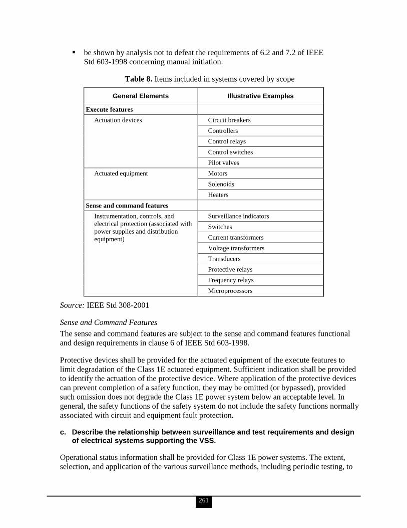
261
be shown by analysis not to defeat the requirements of 6.2 and 7.2 of IEEE
Std 603-1998 concerning manual initiation.
Table 8. Items included in systems covered by scope
General Elements Illustrative Examples
Execute features
Actuation devices Circuit breakers
Controllers
Control relays
Control switches
Pilot valves
Actuated equipment Motors
Solenoids
Heaters
Sense and command features
Instrumentation, controls, and
electrical protection (associated with
power supplies and distribution
equipment)
Surveillance indicators
Switches
Current transformers
Voltage transformers
Transducers
Protective relays
Frequency relays
Microprocessors
Source: IEEE Std 308-2001
Sense and Command Features
The sense and command features are subject to the sense and command features functional
and design requirements in clause 6 of IEEE Std 603-1998.
Protective devices shall be provided for the actuated equipment of the execute features to
limit degradation of the Class 1E actuated equipment. Sufficient indication shall be provided
to identify the actuation of the protective device. Where application of the protective devices
can prevent completion of a safety function, they may be omitted (or bypassed), provided
such omission does not degrade the Class 1E power system below an acceptable level. In
general, the safety functions of the safety system do not include the safety functions normally
associated with circuit and equipment fault protection.
c. Describe the relationship between surveillance and test requirements and design of electrical systems supporting the VSS.
Operational status information shall be provided for Class 1E power systems. The extent,
selection, and application of the various surveillance methods, including periodic testing, to
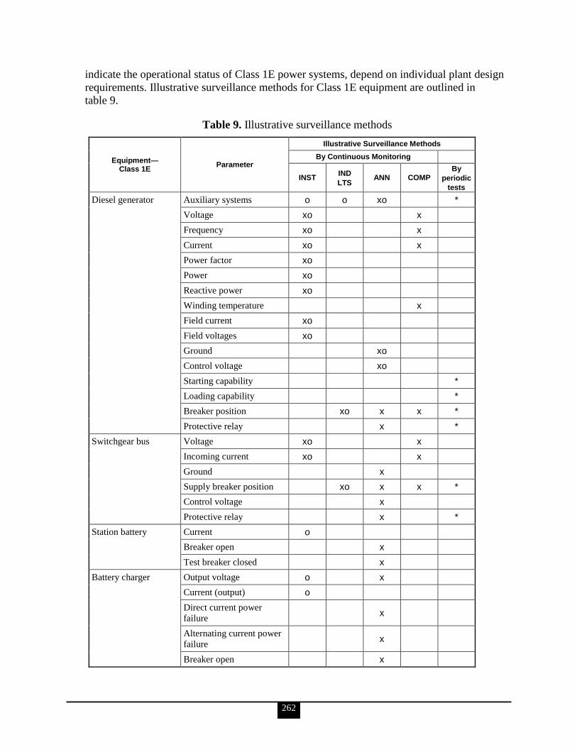
262
indicate the operational status of Class 1E power systems, depend on individual plant design
requirements. Illustrative surveillance methods for Class 1E equipment are outlined in
table 9.
Table 9. Illustrative surveillance methods
Equipment— Class 1E
Parameter
Illustrative Surveillance Methods
By Continuous Monitoring
INST IND
LTS ANN COMP
By
periodic
tests
Diesel generator Auxiliary systems o o xo *
Voltage xo x
Frequency xo x
Current xo x
Power factor xo
Power xo
Reactive power xo
Winding temperature x
Field current xo
Field voltages xo
Ground xo
Control voltage xo
Starting capability *
Loading capability *
Breaker position xo x x *
Protective relay x *
Switchgear bus Voltage xo x
Incoming current xo x
Ground x
Supply breaker position xo x x *
Control voltage x
Protective relay x *
Station battery Current o
Breaker open x
Test breaker closed x
Battery charger Output voltage o x
Current (output) o
Direct current power
failure x
Alternating current power
failure x
Breaker open x

263
Equipment— Class 1E
Parameter
Illustrative Surveillance Methods
By Continuous Monitoring
INST IND
LTS ANN COMP
By
periodic
tests
High direct current voltage
relay
(Opens main alternating
current supply breaker)
Direct current bus Voltage xo x
Ground o x
Cross tie breaker closed x
Instrument and control
power system
Voltage o
Current o
Breaker/fuse status x
Power quality (e.g., Total
Harmonic Distortion) x
Key: INST Instrumentation
IND LTS Indicating lights
ANN Annunciator
COMP Computer
x Denotes methods in the main control room.
o Denotes methods outside the main control room.
* Periodic rest is supplementary or an alternative to continuous surveillance as
indicated.
Source: IEEE Std 308-2001
d. Discuss the Equipment Qualification process for Class 1E power systems in support of VSS: principles of equipment qualification, qualification methods, the qualification program, and documentation requirements.
The following is taken from IEEE Std 323-2003.
The primary objective of qualification is to demonstrate with reasonable assurance that
Class 1E equipment for which a qualified life or condition has been established can perform
its safety function(s) without experiencing common-cause failures before, during, and after
applicable DBEs. Class 1E equipment, with its interfaces, must meet or exceed the
equipment specification requirements. This continued capability is ensured through a
program that includes, but is not limited to, design control, QC, qualification, installation,
maintenance, periodic testing, and surveillance.
For equipment located in a mild environment for meeting its functional requirements during
normal environmental conditions and AOOs, the requirements shall be specified in the
design/purchase specifications. A qualified life is not required for equipment located in a
mild environment and which has no significant aging mechanisms. When seismic testing is
used to qualify equipment located in a mild environment, pre-aging prior to the seismic tests

264
is required only where significant aging mechanisms exist (see IEEE Std 323-2003, section
6.2.1.1). A maintenance/surveillance program based on a vendor‘s recommendations, which
may be supplemented with operating experience, should ensure that equipment meets the
specified requirements.
Degradation with time followed by exposure to environmental extremes of temperature,
pressure, humidity, radiation, vibration and, if applicable, chemical spray and submergence
resulting from a DBE condition can precipitate common-cause failures of Class 1E
equipment. For this reason, it is necessary to establish a qualified life for equipment with
significant aging mechanisms. The qualified life determination must consider degradation of
equipment capability prior to and during service. Inherent in establishing a qualified life is
that a qualified condition is also established. This qualified condition is the state of
degradation for which successful performance during a subsequent DBE was demonstrated.
Qualification Methods
Operations Test. A type test subjects a representative sample of equipment, including
interfaces, to a series of tests, simulating the effects of significant aging mechanisms during
normal operation. The sample is subsequently subjected to DBE testing that simulates and
thereby establishes the tested configuration for installed equipment service, including
mounting, orientation, interfaces, conduit sealing, and expected environments. A successful
type test demonstrates that the equipment can perform the intended safety function(s) for the
required operating time before, during, and/or following the DBE, as appropriate.
Operations Experience. Performance data from equipment of similar design that has
successfully operated under known service conditions may be used in qualifying other
equipment to equal or less severe conditions. Applicability of this data depends on the
adequacy of documentation establishing past service conditions, equipment performance, and
similarity against the equipment to be qualified and upon which operating experience exists.
A demonstration of required operability during applicable DBE(s) shall be included in
equipment qualification programs based on operating experience, when DBE qualification is
required.
Analytical Model. Qualification by analysis requires a logical assessment or a valid
mathematical model of the equipment to be qualified. The bases for analysis typically include
physical laws of nature, results of test data, operating experience, and condition indicators.
Analysis of data and tests for material properties, equipment rating, and environmental
tolerance can be used to demonstrate qualification. However, analysis alone cannot be used
to demonstrate qualification.
Equipment may be qualified by combinations of type test, operating experience, and analysis.
For example, where type test of a complete assembly is not possible, component testing
supplemented by analysis may be used.
The Qualification Program
The essential elements of equipment qualification include the following:
Equipment specification, including definition of the safety function(s)
Acceptance criteria
265
Description of the service conditions, including applicable DBEs and their duration
Qualification program plan
Implementation of the plan
Documentation demonstrating successful qualification, including maintenance
activities required to maintain qualification. The equipment user is responsible for
specifying performance requirements
Verifying that the documentation demonstrates that the requirements have been
satisfied
A technical description of the equipment to be qualified, including applicable performance
and qualification standards, shall be provided.
Loadings at interfaces (i.e., physical attachments, mounting, auxiliary components,
connectors [electrical and mechanical] to the equipment at the equipment boundary) shall be
specified. Motive power or control signal inputs and outputs, and the physical manner by
which they are supplied (e.g., connectors, terminal blocks), shall be specified. Control,
indicating, and other auxiliary components mounted internal or external to the equipment and
required for proper operation shall be included. Material incompatibilities at interfaces shall
be considered and evaluated.
Where applicable, the equipment qualified life objective of the program shall be stated.
The equipment specification shall identify the equipment‘s safety function(s), including the
required operating times.
Note: Components not involved in the equipment‘s safety function(s) may be excluded from
the qualification process if it can be demonstrated and documented that assumed failures,
including spurious operation, have no adverse effect on any and all safety functions, have no
adverse effect on the safety function of interfaced equipment, would not mislead an operator,
and shall not fail in a manner as to cause the failure of other safety-related electric
equipment.
The service conditions for the equipment shall be specified. These conditions shall include
the nominal values and their expected durations, as well as extreme values and their expected
durations. Examples include, but are not limited to, the following:
Ambient pressure and temperature
Relative humidity
Radiation environment
Seismic operating basis earthquake and non-seismic vibration
Operating cycles
Electrical loading and signals
Condensation, chemical spray, and submergence
EMI/RFI and power surges
The postulated DBE conditions, including specified high-energy line break, loss-of-coolant
accident, main steam line break, and/or safe shutdown seismic events, during or after which
the equipment is required to perform its safety function(s), shall be specified. Equipment
266
shall be qualified for the duration of its operational performance requirement for each
applicable DBE condition, including any required post-DBE operability period.
Documentation Requirements
Documentation shall be retained throughout the qualified life of the equipment or its installed
life. The documents required to demonstrate the qualification of Class 1E equipment located
in a mild environment are the design/purchase specifications, seismic test reports (if
applicable), and an evaluation and/or certificate of conformance. The design/purchase
specifications shall contain a description of the functional requirements for a specific
environmental zone during normal environmental conditions and AOOs.
The qualification documentation shall provide evidence that the Class 1E equipment is
qualified for its application, meets its specification requirements, and has its qualified life
and periodic surveillance, maintenance, and/or condition monitoring interval established.
Data used to demonstrate the qualification of the equipment shall be pertinent to the
application and shall be organized in a readily understandable and traceable manner that
permits independent auditing of the conclusions presented.
The harsh environment documentation requirements are as follows:
Identification of the equipment being qualified, including manufacturer, model, and
model family, if applicable
Identification of the safety-related function(s)
Identification and description of the qualification method utilized
Identification of test sample equipment, if applicable
Identification of normal environmental conditions, including those resulting from
AOOs, as applicable, for temperature, pressure, radiation, relative humidity,
EMI/RFI, power surge environment and operational cycling, and DBEs to which the
equipment is qualified
Identification of the acceptance criteria and performance results
Identification of the test sequence, if applicable
Identification of installation considerations and requirements for mounting,
orientation, interfaces, and conduit sealing
Identification of tested configuration (whether any connections within the test
chamber are exposed to simulated accident effects)
Justification of how test sample equipment is representative of the qualified
equipment
Evaluation of significant aging mechanisms and the method for addressing these in
the qualification program
Identification of the qualified life of the equipment and its basis
Identification of age conditioning test results, as applicable
Identification of the DBE test results, as applicable, including temperature versus
time curve, pressure versus time curve, humidity, chemical spray, water spray,
electrical loading, mechanical loading, applied voltage, applied frequency, and
submergence
Identification of radiation test results, as applicable, including radiation type, dose
rate, and total dose
Identification of seismic test results, as applicable
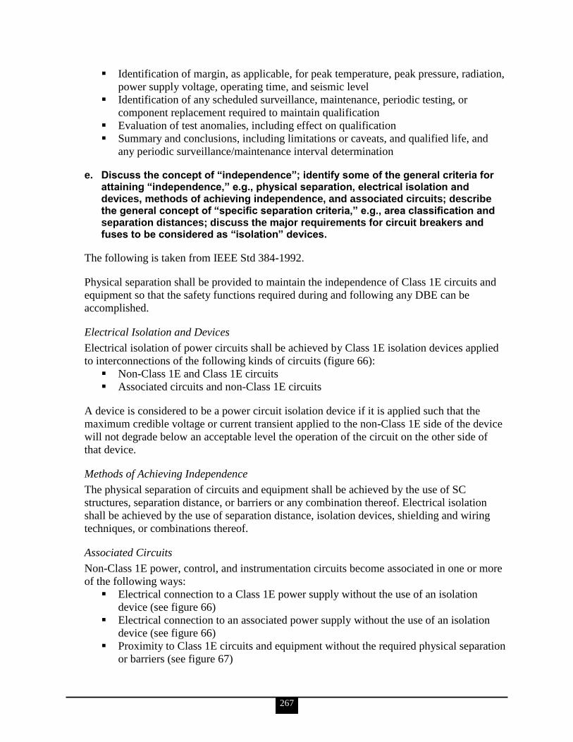
267
Identification of margin, as applicable, for peak temperature, peak pressure, radiation,
power supply voltage, operating time, and seismic level
Identification of any scheduled surveillance, maintenance, periodic testing, or
component replacement required to maintain qualification
Evaluation of test anomalies, including effect on qualification
Summary and conclusions, including limitations or caveats, and qualified life, and
any periodic surveillance/maintenance interval determination
e. Discuss the concept of ―independence‖; identify some of the general criteria for attaining ―independence,‖ e.g., physical separation, electrical isolation and devices, methods of achieving independence, and associated circuits; describe the general concept of ―specific separation criteria,‖ e.g., area classification and separation distances; discuss the major requirements for circuit breakers and fuses to be considered as ―isolation‖ devices.
The following is taken from IEEE Std 384-1992.
Physical separation shall be provided to maintain the independence of Class 1E circuits and
equipment so that the safety functions required during and following any DBE can be
accomplished.
Electrical Isolation and Devices
Electrical isolation of power circuits shall be achieved by Class 1E isolation devices applied
to interconnections of the following kinds of circuits (figure 66):
Non-Class 1E and Class 1E circuits
Associated circuits and non-Class 1E circuits
A device is considered to be a power circuit isolation device if it is applied such that the
maximum credible voltage or current transient applied to the non-Class 1E side of the device
will not degrade below an acceptable level the operation of the circuit on the other side of
that device.
Methods of Achieving Independence
The physical separation of circuits and equipment shall be achieved by the use of SC
structures, separation distance, or barriers or any combination thereof. Electrical isolation
shall be achieved by the use of separation distance, isolation devices, shielding and wiring
techniques, or combinations thereof.
Associated Circuits
Non-Class 1E power, control, and instrumentation circuits become associated in one or more
of the following ways:
Electrical connection to a Class 1E power supply without the use of an isolation
device (see figure 66)
Electrical connection to an associated power supply without the use of an isolation
device (see figure 66)
Proximity to Class 1E circuits and equipment without the required physical separation
or barriers (see figure 67)

268
Proximity to associated circuits and equipment without the required physical
separation or barriers (see figure 67)
Sharing a Class 1E or associated signal source without the use of an isolation device
(see figures 68 and 69)
Figure 66. Association by connection and application of isolation devices
Figure 67. Association by proximity
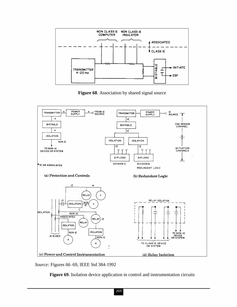
269
Figure 68. Association by shared signal source
Source: Figures 66–69, IEEE Std 384-1992
Figure 69. Isolation device application in control and instrumentation circuits

270
Associated Circuits—Independence
Associated circuits shall comply with one of the following requirements:
They shall be uniquely identified as such or as Class 1E and shall remain with
(traceable to the associated Class 1E division), or be physically separated the same as,
those Class 1E circuits with which they are associated. They shall be subject to the
requirements placed on Class 1E circuits, unless it can be demonstrated by analysis or
testing that the absence of such requirements cannot degrade the Class 1E circuits
below an acceptable level.
They shall be in accordance with the preceding list item, from the Class 1E
equipment to and including an isolation device. Beyond the isolation device, such a
circuit is non-Class 1E provided that it does not again become associated with a
Class 1E system.
They shall be analyzed or tested to demonstrate that Class 1E circuits are not
degraded below an acceptable level.
Associated circuits, including their isolation devices or the connected loads without the
isolation devices, shall be subject to the qualification requirements placed on Class 1E
circuits to ensure that the Class 1E circuits are not degraded below an acceptable level.
Associated circuits need not be qualified for performance of function, since the function is
non-Class 1E.
Specific Separation Criteria—Area Classification and Separation Distances
The areas through which Class 1E and associated circuit cables are routed and in which
equipment is located shall be reviewed for the existence of potential hazards such as
high-energy piping, missiles, combustible material, ignition sources, and flooding. These
areas, explained in greater detail in IEEE Std 384-1992, shall be classified as follows:
Non-hazard areas (see section 6.1.3)
Limited-hazard areas (see section 6.1.4)
Hazard areas (see section 6.1.5)
Separation commensurate with the damage potential of the hazard shall be provided for early
in the design through the use of features such as separate rooms. Opposite sides of rooms or
areas may be used provided there is an adequate heat removal capability.
The minimum separation distances specified in IEEE Std 384-1992, sections 6.1.3, 6.1.4, and
6.1.5, may be used to provide adequate physical separation if the following criteria are met:
All cables involved shall meet the fire propagation requirements of IEEE Std 383-
1974.
Exposed raceways other than conduit shall be noncombustible per ASTM E136-92.
Exposed conduit shall meet the requirements of metallic conduit per
IEEE Std 628-1987.
Raceway fire stops through fire barriers shall have a fire-resistance rating
commensurate with the fire hazards being protected against.
Open trays shall be as defined in NEMA VE 1-1991 for ladder or trough-type.
Enclosed trays shall be solid-bottom-type as defined in NEMA VE 1-1991, with a
solid cover or open trays with solid top and bottom covers.

271
These distances reflect the minimum acceptable for physical separation to maintain
independence. Other considerations such as maintenance, cable pulling, and termination may
require greater distances.
In IEEE Std 384-1992, sections 6.1.3, 6.1.4, and 6.1.5, separation distances are grouped into
the following three categories:
Open to open: Includes open tray to open tray, open tray to free-air cable, and free-air
cable to free-air cable configurations
Enclosed to enclosed: Includes enclosed tray to enclosed tray, enclosed tray to
conduit, and conduit to conduit configurations
Enclosed to open: Includes enclosed tray to open tray, enclosed tray to free-air cable,
conduit to open tray, and conduit to free-air cable configurations
Requirements for Circuit Breakers and Fuses to Be Considered as “Isolation” Devices
When the following requirements are met, the circuit breakers may be used as acceptable
isolation devices for instrumentation and control circuits:
A device is considered an electrical isolation device for instrumentation and control
circuits if it is applied so that (a) the maximum credible voltage or current transient
applied to the device‘s non-Class 1E side will not degrade the operation of the circuit
connected to the device Class 1E or associated side below an acceptable level; and
(b) shorts, grounds, or open circuits occurring in the non-Class 1E side will not
degrade the circuit connected to the device Class 1E or associated side below an
acceptable level.
The highest voltage to which the isolation device non-Class 1E side is exposed shall
determine the minimum voltage level that the device shall withstand across the non-
Class 1E side terminals, and between the non-Class 1E side terminals and ground.
Transient voltages that may appear in the non-Class 1E side must also be considered.
The separation of the wiring at the input and output terminals of the isolation device
may be less than 1 in. (2.5 cm) as required in 6.6.2 of IEEE Std 384-1992, provided
that it is not less than the distance between input and output terminals.
Minimum separation requirements do not apply for wiring and components within the
isolation device; however, separation shall be provided wherever practicable.
The capability of the device to perform its isolation function shall be demonstrated by
qualification test. The qualification shall consider the levels and duration of the fault
current on the non-Class 1E side.
When the circuit breaker requirements listed above are met, a fuse may be used as an
isolation device (except between redundant divisions) if the following additional criteria are
met:
Fuses shall provide the design overcurrent protection capability for the life of the
fuse.
The fuse time-overcurrent trip characteristic for all circuit faults shall cause the fuse
to open prior to the initiation of an opening of any upstream interrupting device.
The power source shall supply the necessary fault current to ensure the proper
coordination without loss of function of Class 1E loads.
272
f. State the general requirement for the single-failure criterion (SFC) and identify the major conditions used to apply the SFC to safety systems design: independence and redundancy; non-detectable, cascaded, common-cause failures; design basis events; and shared systems.
All of the information for this KSA is taken from IEEE Std 379-2000 unless specified
otherwise.
General Requirement for the SFC
The following is taken from IEEE Std 603-1998.
The safety systems shall perform all safety functions required for a DBE in the presence of
any single detectable failure within the safety systems concurrent with all identifiable
but nondetectable failures
all failures caused by the single failure
all failures and spurious system actions that cause or are caused by the DBE requiring
the safety functions
The single failure could occur prior to, or at any time during, the DBE for which the safety
system is required to function. The SFC applies to the safety systems whether control is by
automatic or manual means. IEEE Std 379-2000 provides guidance on the application of the
SFC. (Additionally, IEEE Std 7- 4.3.2-1993 addresses common-cause failures for digital
computers.)
This criterion does not invoke coincidence (or multiple-channel) logic within a safety group;
however, the application of coincidence logic may evolve from other criteria or
considerations to maximize plant availability or reliability. An evaluation has been performed
and documented in other standards to show that certain fluid system failures need not be
considered in the application of this criterion. The performance of a probabilistic assessment
of the safety systems may be used to demonstrate that certain postulated failures need not be
considered in the application of the criterion. A probabilistic assessment is intended to
eliminate consideration of events and failures that are not credible; it shall not be used in lieu
of the SFC. IEEE Std 352-1987 and IEEE Std 577-1976 provide guidance for reliability
analysis.
Where reasonable indication exists that a design that meets the SFC may not satisfy all the
reliability requirements specified in clause 4, item i, of IEEE Std 603-1998, of the design
basis, a probabilistic assessment of the safety system shall be performed. The assessment
shall not be limited to single failures. If the assessment shows that the design basis
requirements are not met, design features shall be provided or corrective modifications shall
be made to ensure that the system meets the specified reliability requirements.
Independence and Redundancy
The principle of independence is basic to the effective utilization of the SFC. The design of a
safety system shall be such that no single failure of a component will interfere with the
proper operation of an independent redundant component or system.

273
Nondetectable, Cascaded, Common-Cause Failures
The detectability of failures is implicit in the application of the SFC. Detectability is a
function of the system design and the specified tests. A failure that cannot be detected
through periodic testing, or revealed by alarm or anomalous indication, is nondetectable. An
objective in an analysis of safety systems is to identify nondetectable failures. When
nondetectable failures are identified, one of the following courses of action shall be taken:
Preferred course: The system or the test scheme shall be redesigned to make the
failure detectable.
Alternative course: When analyzing the effect of each single failure, all identified
nondetectable failures shall be assumed to have occurred.
Whenever the design is such that additional failures could be expected from the occurrence
of a single failure from any source (e.g., mechanical, electrical, and environmental), these
cascaded failures, collectively, shall be considered to be a single failure.
Certain common-cause failures shall be treated as single failures when conducting the single-
failure analysis. Such failures can be in dissimilar components and can have dissimilar failure
modes. Failures resulting from cascaded failure and DBEs have already been discussed, and
are those that shall be included in the analysis.
Common-cause failures not subject to single-failure analysis include those that can result
from external environmental effects (e.g., voltage, frequency, radiation, temperature,
humidity, pressure, vibration, and EMI), design deficiencies, manufacturing errors,
maintenance errors, and operator errors. Design qualification and QAPs are intended to
afford protection from external environmental effects, design deficiencies, and
manufacturing errors. Personnel training, proper control room design, and operating,
maintenance, and surveillance procedures are intended to afford protection from maintenance
and operator errors.
Additionally, provisions should be made to address common-cause failures. Examples of
techniques are detailed defense-in-depth studies, failure mode and effects analysis, and
analyses of abnormal conditions or events. Design techniques, such as diversity and defense
in depth, can be used to address common-cause failures.
Comprehensive guidance on using diversity to address common-cause failures in digital
computers is provided in IEEE Std 7-4.3.2-1993.
Design Basis Events
Design basis events are postulated events used in the design to establish the acceptable
performance requirements of the structures, systems, and components. A DBE that results in
the need for safety functions may cause failure of system components, modules, or channels.
In order to provide protection from these failures, the equipment should be designed,
qualified, and installed so as to be immune to such anticipated challenges. When analysis
indicates that failures in a safety system result from DBEs, these failures shall be considered
a consequence of the event.
274
Shared Systems
The SFC is applied to units with shared systems as follows:
The safety systems of all units shall be capable of performing their required safety
functions with a single failure assumed within the shared systems or within the
auxiliary supporting features or other systems with which the shared systems
interface.
The safety systems of each unit shall be capable of performing their required safety
functions, with a single failure initiated concurrently in each unit within the systems
that are not shared. Provisions shall be included in the design to ensure that single
failures within one unit will not adversely affect (propagate to) the other unit, thereby
preventing the shared systems from performing the required safety functions.
The failures in the criteria listed above need not be considered simultaneously in the
performance of the single-failure analysis, (i.e., the single-failure analysis is conducted for
the plant to demonstrate that the criterion listed first is met). The single-failure analysis is
repeated to demonstrate that the criterion listed second is met.
IEEE Std 379-2000 includes a note that the above description is meant to ―neither endorse
nor forbid‖ the use of shared systems.
42. Electrical personnel shall demonstrate a familiarity level knowledge of electrical safety design requirements for emergency, standby, and UPS systems for VSS (IEEE Stds-387-1984, 650-1990, and 944-1986; DOE O 420.1B; DOE G 420.1-1; etc.).
a. Identify and discuss the principal design criteria for standby power supplies supporting VSS: capability, ratings, interactions, design and application considerations, and design features.
The following is taken from IEEE Std 387-1984.
Capability
When in service, each diesel-generator unit shall have the capability of performing as a
redundant unit of a standby power supply, in accordance with the requirements stated in
IEEE Std 308-1980.
The diesel-generator unit shall also have each of the following specific capabilities to meet
design, application, and qualification requirements:
Design Conditions. The unit shall be capable of operating during and after any DBE
without support from the preferred power supply. The following design conditions,
including appropriate margins as required by IEEE Std 323-1983, 6.3.1.5, shall be
specified by those individuals responsible for the system application and, as a
minimum, shall include
o operational cycles (4,000 starts over a period of 40 years, unless otherwise
specified)
o operating hours (4,000 hours over a period of 40 years, unless otherwise
specified)
275
o temperature at equipment locations (minimum and maximum with durations and
average annual ambient)
o seismic response spectra
o radiation (1–10 rads of gamma integrated dose over a period of 40 years, unless
otherwise specified)
o humidity (minimum and maximum with durations)
o load profile (including allowable voltage and frequency variations)
o absolute barometric pressure (altitude and tornado depressurization, duration, and
magnitude)
o combustion air contaminants (salt, sand, etc.)
o fuel type and quality
o auxiliary electrical power supply requirements and quality
o effect of fire protection actuation
o service water quality
Starting and Loading. The unit shall be capable of starting, accelerating, and being
loaded with the design load within the time required by the equipment specification
requirements and quality
o from the normal standby condition
o with cooling not available, for a time equivalent to that required to bring the
cooling equipment into service with energy from the diesel-generator unit
o on a restart with an initial engine temperature equal to the continuous rating full-
load engine temperature
Light Load or No Load Operation. The unit shall be capable of accepting design load
following operation at light load or no load for the time required by the equipment
specification.
Design Load. The unit shall be capable of carrying the design load for the time
required by the equipment specification.
Quality of Power. The unit shall be capable of maintaining voltage and frequency at
the generator terminals within limits that will not degrade the performance of any of
the loads comprising the design load below their minimum requirements, including
the duration of transients caused by load application or load removal.
The loads will usually dictate the size of the UPS system (usually rated in kVA at a given
power factor). An important factor to consider in sizing the UPS system is the inrush current
imposed on it. Since the UPS has very little overload capability, it is usually not practical or
economical to size the UPS so that the unit is capable of furnishing inrush or short-circuit
current requirements. The use of a transfer switch can compensate for the lack of this
capability by providing a transfer of the transient load to the bypass source of power. Where
no transfer capability exists, consideration should be given to selective loading of high inrush
loads onto the UPS system. Consideration should also be given to the selection of fault-
clearing devices to compensate for the lack of capability of supplying high short-circuit
current.
Environmental capability of SC electrical equipment must be demonstrated by testing,
analysis, and operating experience, or a combination of these methods.
276
Ratings
A diesel-generator unit shall have continuous and short-time ratings which shall reflect the
output capabilities of the diesel-generator unit in accordance with all capability requirements
mentioned in IEEE Std 387-1984, section 5.1, and the following rules:
Inspections and scheduled maintenance shall be performed periodically using the
manufacturer‘s recommendations and procedures.
Unscheduled maintenance shall be performed in accordance with the need as
indicated by the periodic inspections and operating experience.
The diesel-generator units may be utilized to the limit of their power capabilities, as defined
by the continuous and short-time rating. Unless time and load parameters for light and no-
load operation are established by tests and documentation, the following precautions shall be
taken:
When 4 hours of operation at 30% or less of the continuous rating have been
accumulated without at least 0.5 hour of operation above 50% of the continuous
rating, the unit shall be operated at a load of at least 50% of the continuous rating for
a minimum of 0.5 hour.
Operating at 30% or greater continuous rating shall be restricted to the manufacturers‘
recommendations.
Interactions
Mechanical and electric system interactions between a particular diesel-generator unit and
other units of the standby power supply, the nuclear plant, the conventional plant, and the
Class 1E electric system shall be coordinated in such a way that the diesel-generator unit‘s
design function, and capability requirements, may be realized for any DBE, except failure of
that diesel-generator unit.
Design and Application Considerations
Design and application considerations shall include, but not necessarily be limited to, the
considerations listed in table 10.
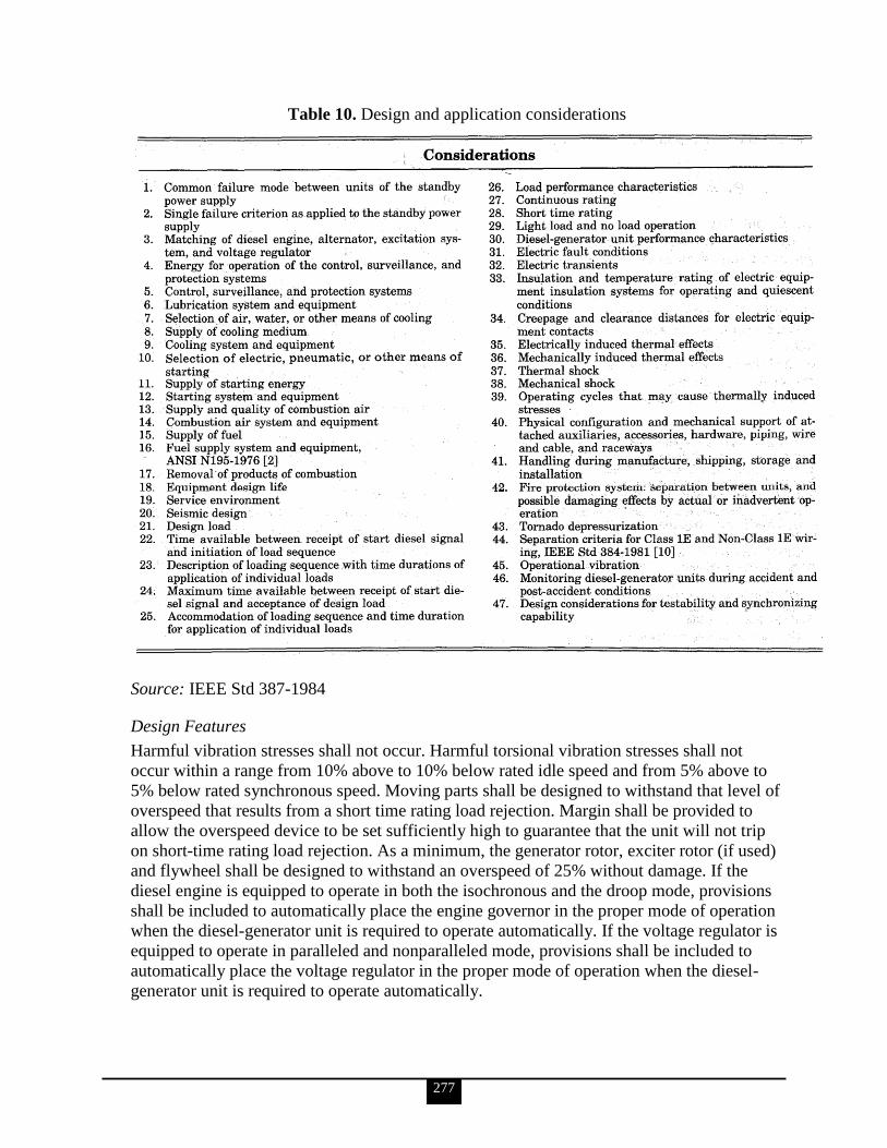
277
Table 10. Design and application considerations
Source: IEEE Std 387-1984
Design Features
Harmful vibration stresses shall not occur. Harmful torsional vibration stresses shall not
occur within a range from 10% above to 10% below rated idle speed and from 5% above to
5% below rated synchronous speed. Moving parts shall be designed to withstand that level of
overspeed that results from a short time rating load rejection. Margin shall be provided to
allow the overspeed device to be set sufficiently high to guarantee that the unit will not trip
on short-time rating load rejection. As a minimum, the generator rotor, exciter rotor (if used)
and flywheel shall be designed to withstand an overspeed of 25% without damage. If the
diesel engine is equipped to operate in both the isochronous and the droop mode, provisions
shall be included to automatically place the engine governor in the proper mode of operation
when the diesel-generator unit is required to operate automatically. If the voltage regulator is
equipped to operate in paralleled and nonparalleled mode, provisions shall be included to
automatically place the voltage regulator in the proper mode of operation when the diesel-
generator unit is required to operate automatically.
278
The diesel-generator unit shall be provided with control systems, permitting automatic and
manual control. Upon receipt of a start-diesel signal, the automatic control system shall
provide automatic startup and automatic adjustment of speed and voltage to a ready-to-load
condition. A start-diesel signal shall override all other operating modes and return control of
the diesel-generator unit to the automatic control system. A start-diesel signal shall not
override any manual non-operating modes such as those for repair and maintenance.
Provisions shall be made for control from the control room and external to the control room.
The diesel-generator unit shall be provided with surveillance systems permitting remote and
local surveillance and indicating the occurrence of abnormal, pretrip, or trip conditions. As a
minimum, the following conditions shall be surveyed:
Unit not running
Unit running, not loaded
Unit running, loaded
Unit out of service
The following systems shall have sufficient mechanical and electrical instrumentation to
survey the variables required for successful operation and to generate the abnormal, pretrip,
and trip signals required for alarm of such conditions:
Starting system
Lubricating system
Fuel system
Primary cooling system
Secondary cooling system
Combustion air system
Exhaust system
Generator
Excitation system
Voltage regulation system
Governor system
The diesel-generator unit shall be automatically tripped on an engine overspeed or generator
differential overcurrent or both. Protective features, other than engine overspeed and
generator differential overcurrent, shall be
blocked from automatically tripping the diesel-generator unit during an accident
condition and shall annunciate the condition they monitor in the plant control room;
or
if protective features other than engine overspeed and generator differential
overcurrent are retained during accident conditions, two or more independent
measurements of each of these parameters with coincident trip logic shall be
provided.
All protective devices shall remain effective during diesel-generator unit testing or operation
during non-accident conditions.

279
b. Identify and discuss some of the design application requirements for UPS supporting VSS: performance requirements, UPS sizing and capacities, and UPS configurations.
The following is taken from IEEE Std 944-1986.
Performance Requirements
The UPS system must be capable of providing a reliable, regulated, and filtered source of
uninterruptible power to the vital loads of a power-generating station. To support this goal
UPS systems are designed to supply power during power supply outages and to provide
power conditioning when supply voltages and frequency variations exceed those allowable
for the load. A properly selected UPS system will provide continuous power to the load
throughout most disturbances encountered in the power supply system. Under certain
conditions up to a 4.17 millisecond interruption in the power supply to the load may occur as
the load is transferred from the inverter output to the bypass source or vice versa.
UPS Sizing and Capacities
The loads will usually dictate the size of the UPS system (usually rated in kilovolt-amperes at
a given power factor). An important factor to consider in sizing the UPS system is the inrush
current imposed on it. Since the UPS has very little overload capability, it is usually not
practical or economical to size the UPS so that the unit is capable of furnishing inrush or
short-circuit current requirements. The use of a transfer switch can compensate for the lack
of this capability by providing a transfer of the transient load to the bypass source of power.
Where no transfer capability exists, consideration should be given to selective loading of
high inrush loads onto the UPS system. Consideration should also be given to the selection of
fault-clearing devices to compensate for the lack of capability of supplying high short-circuit
current.
The following load data shall be used in the sizing of a UPS system:
Total steady-state load
Load power factor
Continuous or short-duration load
Inrush current requirements of load
The UPS real-power and reactive-power rating should respectively equal or exceed 125% of
the total real-power and 125% of the total reactive-power requirements for all normal steady-
state load configurations. The 25% margin should be included in the UPS capacity to account
for the margin in calculating the maximum load. It should be recognized that the largest real-
power requirements might occur for a load configuration that is different from that which
results in the largest reactive-power requirements. Where the load power factor is unknown,
a power factor of 0.8 lagging should be used. The UPS shall be designed to supply 100% of
rated kilovolt-amperes over the entire AC and DC input-voltage ranges described in 5.7 of
IEEE Std 944-1986, and for any load-current waveforms with a crest factor not greater than
2.0.
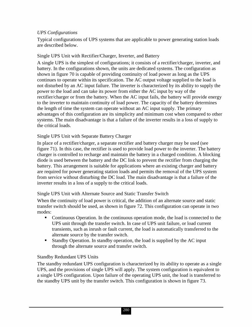
280
UPS Configurations
Typical configurations of UPS systems that are applicable to power generating station loads
are described below.
Single UPS Unit with Rectifier/Charger, Inverter, and Battery
A single UPS is the simplest of configurations; it consists of a rectifier/charger, inverter, and
battery. In the configurations shown, the units are dedicated systems. The configuration as
shown in figure 70 is capable of providing continuity of load power as long as the UPS
continues to operate within its specification. The AC output voltage supplied to the load is
not disturbed by an AC input failure. The inverter is characterized by its ability to supply the
power to the load and can take its power from either the AC input by way of the
rectifier/charger or from the battery. When the AC input fails, the battery will provide energy
to the inverter to maintain continuity of load power. The capacity of the battery determines
the length of time the system can operate without an AC input supply. The primary
advantages of this configuration are its simplicity and minimum cost when compared to other
systems. The main disadvantage is that a failure of the inverter results in a loss of supply to
the critical loads.
Single UPS Unit with Separate Battery Charger
In place of a rectifier/charger, a separate rectifier and battery charger may be used (see
figure 71). In this case, the rectifier is used to provide load power to the inverter. The battery
charger is controlled to recharge and maintain the battery in a charged condition. A blocking
diode is used between the battery and the DC link to prevent the rectifier from charging the
battery. This arrangement is suitable for applications where an existing charger and battery
are required for power generating station loads and permits the removal of the UPS system
from service without disturbing the DC load. The main disadvantage is that a failure of the
inverter results in a loss of a supply to the critical loads.
Single UPS Unit with Alternate Source and Static Transfer Switch
When the continuity of load power is critical, the addition of an alternate source and static
transfer switch should be used, as shown in figure 72. This configuration can operate in two
modes:
Continuous Operation. In the continuous operation mode, the load is connected to the
UPS unit through the transfer switch. In case of UPS unit failure, or load current
transients, such as inrush or fault current, the load is automatically transferred to the
alternate source by the transfer switch.
Standby Operation. In standby operation, the load is supplied by the AC input
through the alternate source and transfer switch.
Standby Redundant UPS Units
The standby redundant UPS configuration is characterized by its ability to operate as a single
UPS, and the provisions of single UPS will apply. The system configuration is equivalent to
a single UPS configuration. Upon failure of the operating UPS unit, the load is transferred to
the standby UPS unit by the transfer switch. This configuration is shown in figure 73.
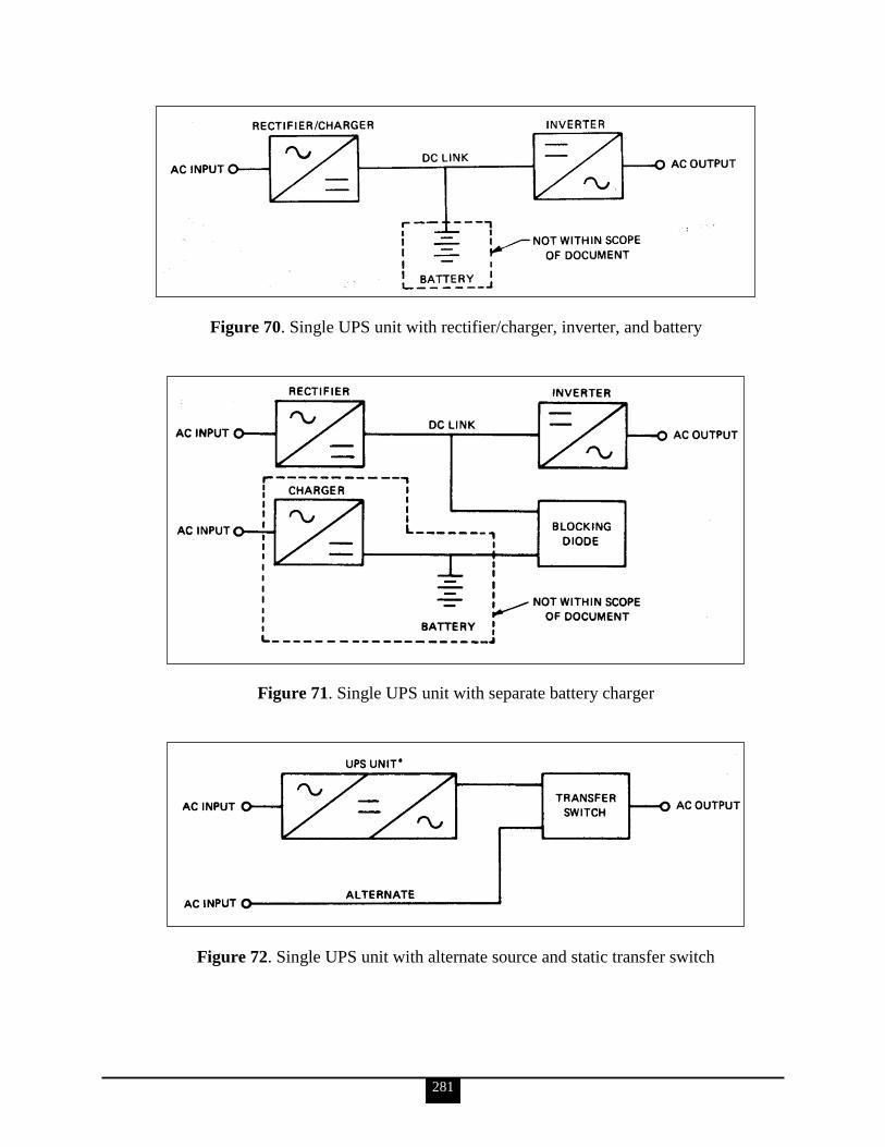
281
Figure 70. Single UPS unit with rectifier/charger, inverter, and battery
Figure 71. Single UPS unit with separate battery charger
Figure 72. Single UPS unit with alternate source and static transfer switch
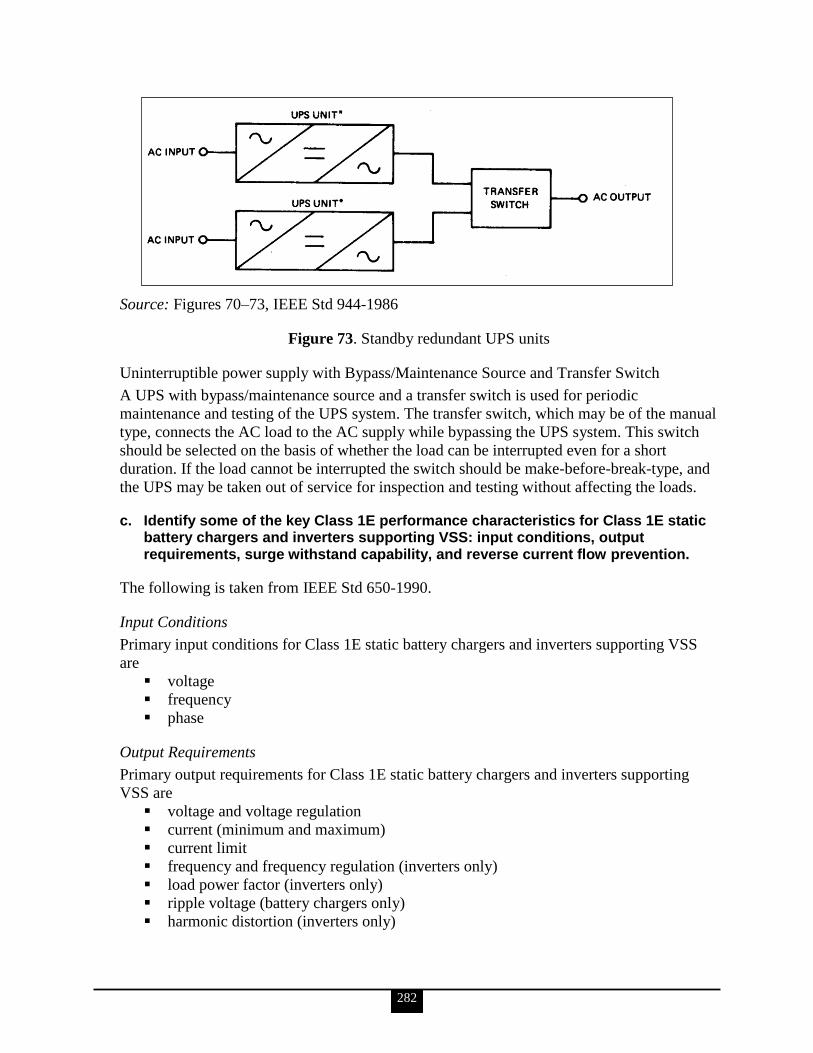
282
Source: Figures 70–73, IEEE Std 944-1986
Figure 73. Standby redundant UPS units
Uninterruptible power supply with Bypass/Maintenance Source and Transfer Switch
A UPS with bypass/maintenance source and a transfer switch is used for periodic
maintenance and testing of the UPS system. The transfer switch, which may be of the manual
type, connects the AC load to the AC supply while bypassing the UPS system. This switch
should be selected on the basis of whether the load can be interrupted even for a short
duration. If the load cannot be interrupted the switch should be make-before-break-type, and
the UPS may be taken out of service for inspection and testing without affecting the loads.
c. Identify some of the key Class 1E performance characteristics for Class 1E static battery chargers and inverters supporting VSS: input conditions, output requirements, surge withstand capability, and reverse current flow prevention.
The following is taken from IEEE Std 650-1990.
Input Conditions
Primary input conditions for Class 1E static battery chargers and inverters supporting VSS
are
voltage
frequency
phase
Output Requirements
Primary output requirements for Class 1E static battery chargers and inverters supporting
VSS are
voltage and voltage regulation
current (minimum and maximum)
current limit
frequency and frequency regulation (inverters only)
load power factor (inverters only)
ripple voltage (battery chargers only)
harmonic distortion (inverters only)

283
Surge Withstand Capability
Surge withstand capability is mentioned but not elaborated on in primary references,
including IEEE, NFPA, and DOE documents. See note below.
Reverse Current Flow Prevention
Reverse current flow prevention is mentioned but not elaborated on in primary references,
including IEEE, NFPA, and DOE documents. See note below.
Note: Regarding surge withstand capability and reverse current flow prevention, IEEE
Std 650-1990 notes the following: ―The required Class 1E performance characteristics and
the safety function shall be specified by those responsible for the design application of the
equipment, and shall include, as a minimum, numerical values and durations for normal,
abnormal, design-basis event, and post-design-basis event conditions.‖
43. Electrical personnel shall demonstrate a familiarity level knowledge of electrical safety design requirements for VSS accident monitoring instrumentation (IEEE Std-497-2002, DOE O 420.1B, DOE G 420.1-1, etc.).
The information for KSA‘s ‗a‘ and ‗b‘ is taken from IEEE Std 497-2002.
a. Identify and discuss the selection criteria used for identifying the ―‗type variables‖ for accident monitoring instrumentation.
The variable types will be referred to as A, B, C, D, and E. Criteria for the selection of each
type of variable are given below and summarized in table 11.
Type A variables are those variables that provide the primary information required to permit
the control room operating staff to
take specific, planned, manually-controlled actions for which no automatic control is
provided and that are required for safety systems to perform their safety-related
functions as assumed in the plant accident analysis licensing basis;
take specific, planned, manually-controlled actions for which no automatic control is
provided and that are required to mitigate the consequences of an AOO.
Type A variables provide information essential for the direct accomplishment of specific
safety-related functions that require manual action. These variables are a subset of those
necessary to implement the plant-specific emergency procedure guidelines (EPGs) or the
plant specific emergency operating procedures (EOPs) or the plant abnormal operating
procedures (AOPs). Type A variables do not include those variables that are associated with
contingency actions that may also be identified in written procedures.
Type B variables are those variables that provide primary information to the control room
operators to assess the plant critical safety functions. Any plant critical safety functions
addressed in the EPGs or the plant-specific EOPs that are in addition to those identified
above shall also be included. The Type B variables shall be those necessary to implement the
plant functional restoration EPGs, plant-specific EOPs, and the plant critical safety function
status trees, if applicable.
284
Type C variables are those variables that provide primary information to the control room
operators to indicate the potential for breach or the actual breach of the three fission product
barriers (extended range): fuel cladding, reactor coolant system pressure boundary, and
containment pressure boundary. The selection of these variables represents a minimum set of
plant variables that provide the most direct indication of the integrity of the three fission
product barriers and provide the capability for monitoring beyond the normal operating
range.
Type D variables are those variables that are required in procedures and licensing basis
documentation (LBD) to
indicate the performance of those safety systems and auxiliary supporting features
necessary for the mitigation of DBEs
indicate the performance of other systems necessary to achieve and maintain a safe
shutdown condition
verify safety system status
Type D variables shall be based upon the plant accident analysis licensing basis and those
necessary to implement the following procedures (as applicable to the plant design):
Event-specific EPGs or plant-specific EOPs
Functional restoration EPGs or plant-specific EOPs
Plant AOPs
Type E variables are those variables required for use in determining the magnitude of the
release of radioactive materials and continually assessing such releases. These variables shall
include, but not be limited to, monitoring the following:
The magnitude of releases of radioactive materials through identified pathways (e.g.,
secondary safety valves and condenser air ejector)
The environmental conditions used to determine the impact of releases of radioactive
materials through identified pathways (e.g., wind speed, wind direction, and air
temperature)
Radiation levels and radioactivity in the plant environs
Radiation levels and radioactivity in the control room and selected plant areas where
access may be required for plant recovery
Documentation shall be developed and maintained for the selection bases of the accident
monitoring variables consistent with the plant LBD.
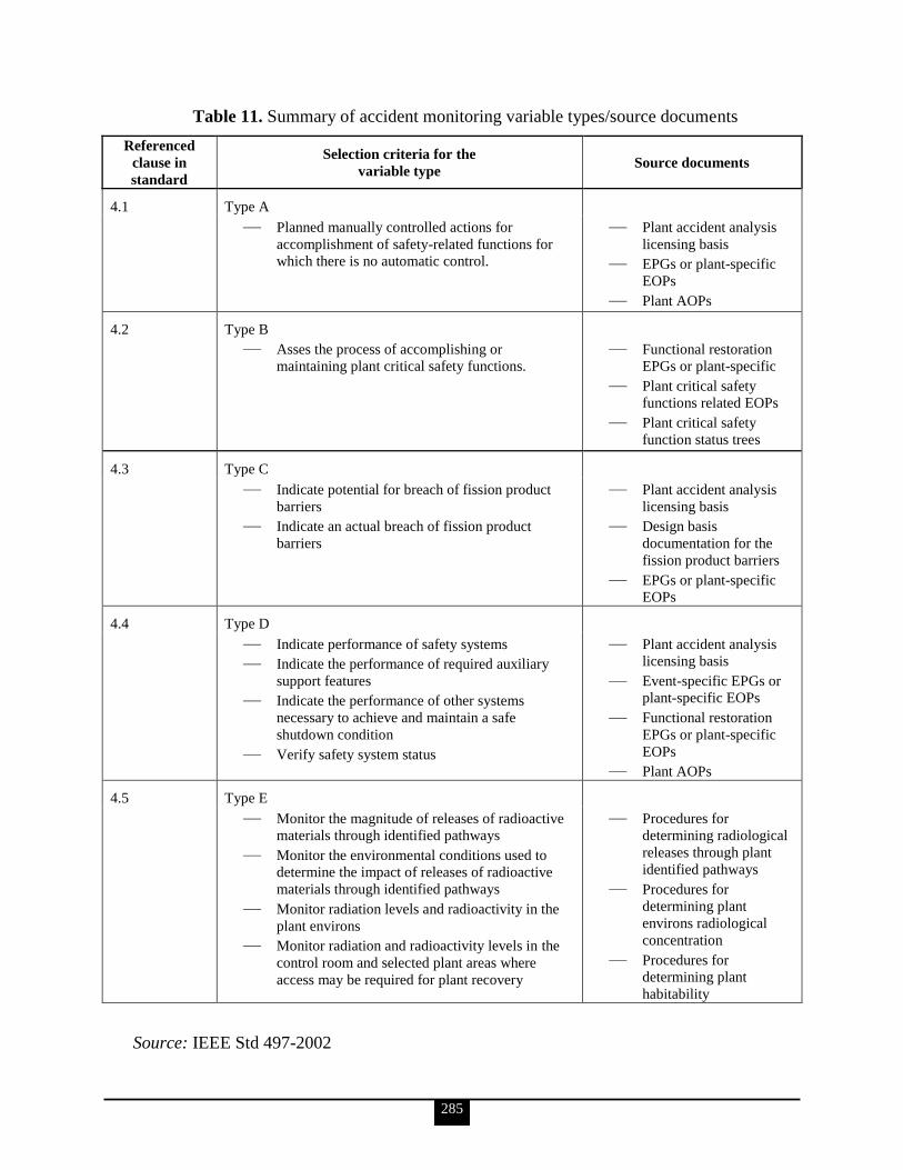
285
Table 11. Summary of accident monitoring variable types/source documents
Referenced
clause in
standard
Selection criteria for the
variable type Source documents
4.1 Type A
— Planned manually controlled actions for
accomplishment of safety-related functions for
which there is no automatic control.
— Plant accident analysis
licensing basis
— EPGs or plant-specific
EOPs
— Plant AOPs
4.2 Type B
— Asses the process of accomplishing or
maintaining plant critical safety functions.
— Functional restoration
EPGs or plant-specific
— Plant critical safety
functions related EOPs
— Plant critical safety
function status trees
4.3 Type C
— Indicate potential for breach of fission product
barriers
— Indicate an actual breach of fission product
barriers
— Plant accident analysis
licensing basis
— Design basis
documentation for the
fission product barriers
— EPGs or plant-specific
EOPs
4.4 Type D
— Indicate performance of safety systems
— Indicate the performance of required auxiliary
support features
— Indicate the performance of other systems
necessary to achieve and maintain a safe
shutdown condition
— Verify safety system status
— Plant accident analysis
licensing basis
— Event-specific EPGs or
plant-specific EOPs
— Functional restoration
EPGs or plant-specific
EOPs
— Plant AOPs
4.5 Type E
— Monitor the magnitude of releases of radioactive
materials through identified pathways
— Monitor the environmental conditions used to
determine the impact of releases of radioactive
materials through identified pathways
— Monitor radiation levels and radioactivity in the
plant environs
— Monitor radiation and radioactivity levels in the
control room and selected plant areas where
access may be required for plant recovery
— Procedures for
determining radiological
releases through plant
identified pathways
— Procedures for
determining plant
environs radiological
concentration
— Procedures for
determining plant
habitability
Source: IEEE Std 497-2002

286
b. Identify some key performance criteria of accident monitoring instrumentation.
Range
The range of a monitoring channel shall be established to ensure that it covers the transients
identified in the plant LBD. The range for Type C variables shall encompass, with margin,
those limits that would indicate a breach in a fission product barrier. For example,
measurement of reactor pressure shall include the capability of measuring, with margin, up to
Level D service limits of the reactor vessel (see American Society of Mechanical Engineers
2007 Boiler and Pressure Vessel Code).
Accuracy
The required accuracy of accident monitoring instrument channels shall be established based
on the assigned function.
Response Time
Accident monitoring instruments shall be designed to provide real-time and timely
information. Typically, the displayed information will lag behind actual conditions because
of sensor location, thermal heat transfer time lag, information processing cycle times, degree
of severity of environmental conditions, and other potential effects on instrument response
times. In general, these response times are not as critical as in the case when the instrument
provides a signal for automatic reactor protection system or engineered safeguard system
action. For computer driven displays, the indicated variable will additionally lag real-time
conditions depending on the update frequency of the display. The update frequency shall be
fast enough to avoid the potential of misleading the operator with respect to plant conditions.
It is considered prudent that this update period be approximately 1 to 2 seconds.
Required Instrumentation Duration
The post-event operating time for each variable shall be defined and addressed in the
development of the qualification program.
The post-event operating time for Type A variable instrument channels shall be the
duration for which the measured variable is required by the plant‘s LBD.
The post-event operating time for Type B variable instrument channels shall be at
least the duration associated with the longest-duration DBE for that variable.
The post-event operating time for Type C variable instrument channels shall be at
least 100 days for instrument channels monitoring the fission product barriers:
o Fuel cladding
o Reactor coolant system pressure boundary
o Containment pressure boundary
The qualification duration for other Type C variable instrument channels shall be the
duration for which the measured variable is required by the plant‘s LBD.
The post-event operating time for Type D and Type E variable instrument channels
shall be based on the plant‘s LBD.
A shorter post-event operating time may be acceptable if equipment replacement or repair
can be accomplished within an acceptable out-of-service time, taking into consideration the
location and accessibility of the equipment.
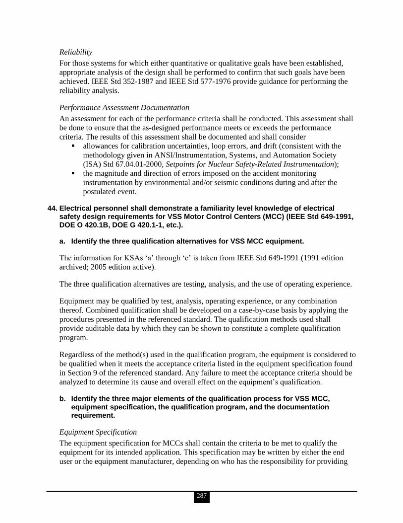
287
Reliability
For those systems for which either quantitative or qualitative goals have been established,
appropriate analysis of the design shall be performed to confirm that such goals have been
achieved. IEEE Std 352-1987 and IEEE Std 577-1976 provide guidance for performing the
reliability analysis.
Performance Assessment Documentation
An assessment for each of the performance criteria shall be conducted. This assessment shall
be done to ensure that the as-designed performance meets or exceeds the performance
criteria. The results of this assessment shall be documented and shall consider
allowances for calibration uncertainties, loop errors, and drift (consistent with the
methodology given in ANSI/Instrumentation, Systems, and Automation Society
(ISA) Std 67.04.01-2000, Setpoints for Nuclear Safety-Related Instrumentation);
the magnitude and direction of errors imposed on the accident monitoring
instrumentation by environmental and/or seismic conditions during and after the
postulated event.
44. Electrical personnel shall demonstrate a familiarity level knowledge of electrical safety design requirements for VSS Motor Control Centers (MCC) (IEEE Std 649-1991, DOE O 420.1B, DOE G 420.1-1, etc.).
a. Identify the three qualification alternatives for VSS MCC equipment.
The information for KSAs ‗a‘ through ‗c‘ is taken from IEEE Std 649-1991 (1991 edition
archived; 2005 edition active).
The three qualification alternatives are testing, analysis, and the use of operating experience.
Equipment may be qualified by test, analysis, operating experience, or any combination
thereof. Combined qualification shall be developed on a case-by-case basis by applying the
procedures presented in the referenced standard. The qualification methods used shall
provide auditable data by which they can be shown to constitute a complete qualification
program.
Regardless of the method(s) used in the qualification program, the equipment is considered to
be qualified when it meets the acceptance criteria listed in the equipment specification found
in Section 9 of the referenced standard. Any failure to meet the acceptance criteria should be
analyzed to determine its cause and overall effect on the equipment‘s qualification.
b. Identify the three major elements of the qualification process for VSS MCC, equipment specification, the qualification program, and the documentation requirement.
Equipment Specification
The equipment specification for MCCs shall contain the criteria to be met to qualify the
equipment for its intended application. This specification may be written by either the end
user or the equipment manufacturer, depending on who has the responsibility for providing

288
the qualification requirements to the organization performing the qualification program. As a
minimum, the following shall be included:
Equipment Description. The equipment specification shall describe the MCC in terms
of physical and electrical configuration.
Equipment Safety Functions. The specification shall describe the performance
requirements and specific safety functions of the MCC equipment, including the
required operating times; when in the DBE sequence these functions are required to
occur; and the maximum allowable time that a contact subject to chatter can remain in
its unintended state.
Interfaces. Interfaces and loadings via physical attachments to the equipment at the
equipment boundary shall be specified. These interfaces include mounting
requirements, cable, and cable raceway connections, as well as bus duct connections.
Design Standards. Specifications shall indicate, by number and date, applicable UL,
NEMA, ANSI, IEEE, and other industry standards or sections of standards.
Service Conditions. The range of values for operational and environmental
parameters shall be specified for the application. They may include the following as
applicable:
o Supply and control voltages and frequency
o Design ambient temperature
o Ambient time/temperature profile
o Ambient time/pressure profile
o Duty cycle
o Seismic requirements
o Radiation
o Percent relative humidity
o Abnormal vibration or altitude
o Spray or jet impingement
o Electrical loading at rated voltage (inductive and/or resistive)
Normal and abnormal service conditions and conditions resulting from DBEs shall be
specified. The service conditions for these events should be expressed as a time
history for each parameter that may affect equipment functions during the event.
Margin. It should be indicated whether or not margin has been included in the
specified values.
Operational Aging Parameters. Operational aging parameters given in table 12 reflect
typical requirements for a generic qualification program. Where specific applications
require different values, the values shall be specified.
Qualified Life Objective. The desired qualified life objective shall be stated for the
MCC or its component(s) that are subject to significant aging mechanisms.
Acceptance Criteria. Acceptance criteria shall be defined so that all failures to
perform the specified safety function(s) in the service conditions for which the
equipment is being qualified can be identified. The operational tests given in table 12
reflect typical requirements for a generic qualification program. Where specific
applications require different values, the values shall be specified; however, care
should be taken to ensure that the acceptance criteria selected are not overly
restrictive or based on measurements not related to the specified safety functions.
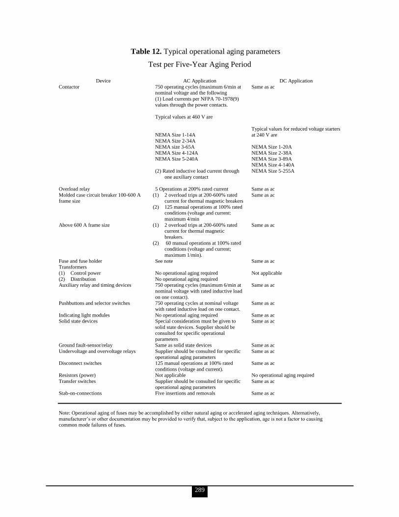
289
Table 12. Typical operational aging parameters
Test per Five-Year Aging Period
Device AC Application DC Application
Contactor 750 operating cycles (maximum 6/min at nominal voltage and the following
(1) Load currents per NFPA 70-1978(9)
values through the power contacts.
Typical values at 460 V are
NEMA Size 1-14A
NEMA Size 2-34A NEMA size 3-65A
NEMA Size 4-124A
NEMA Size 5-240A
(2) Rated inductive load current through
one auxiliary contact
Same as ac
Typical values for reduced voltage starters
at 240 V are
NEMA Size 1-20A
NEMA Size 2-38A
NEMA Size 3-89A NEMA Size 4-140A
NEMA Size 5-255A
Overload relay 5 Operations at 200% rated current Same as ac
Molded case circuit breaker 100-600 A frame size
(1) 2 overload trips at 200-600% rated current for thermal magnetic breakers
(2) 125 manual operations at 100% rated conditions (voltage and current:
maximum 4/min
Same as ac
Above 600 A frame size (1) 2 overload trips at 200-600% rated current for thermal magnetic
breakers.
(2) 60 manual operations at 100% rated conditions (voltage and current;
maximum 1/min).
Same as ac
Fuse and fuse holder See note Same as ac Transformers
(1) Control power
(2) Distribution
No operational aging required
No operational aging required
Not applicable
Auxiliary relay and timing devices 750 operating cycles (maximum 6/min at
nominal voltage with rated inductive load
on one contact).
Same as ac
Pushbuttons and selector switches 750 operating cycles at nominal voltage
with rated inductive load on one contact.
Same as ac
Indicating light modules No operational aging required Same as ac Solid state devices Special consideration must be given to
solid state devices. Supplier should be
consulted for specific operational parameters
Same as ac
Ground fault-sensor/relay Same as solid state devices Same as ac
Undervoltage and overvoltage relays Supplier should be consulted for specific operational aging parameters
Same as ac
Disconnect switches 125 manual operations at 100% rated
conditions (voltage and current).
Same as ac
Resistors (power) Not applicable No operational aging required
Transfer switches Supplier should be consulted for specific
operational aging parameters
Same as ac
Stab-on-connections Five insertions and removals Same as ac
Note: Operational aging of fuses may be accomplished by either natural aging or accelerated aging techniques. Alternatively,
manufacturer‘s or other documentation may be provided to verify that, subject to the application, age is not a factor to causing common mode failures of fuses.
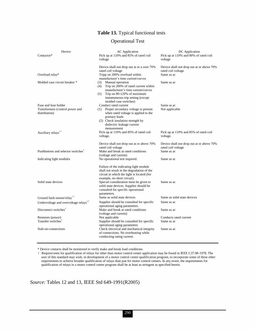
290
Table 13. Typical functional tests
Operational Test
Device AC Application DC Application
Contactor* Pick up at 110% and 85% of rated coil voltage
Device shall not drop out at or a over 70% rated coil voltage
Pick up at 110% and 80% of rated coil voltage
Device shall not drop out at or above 70% rated coil voltage
Overload relay* Tripp on 200% overload within
manufacturer‘s time current/curves
Same as ac
Molded case circuit breaker * (3) Manual operation
(4) Trip on 200% of rated current within
manufacturer‘s time current/curves (5) Trip on 80-120% of maximum
instantaneous trip setting (except
molded case switches)
Same as ac
Fuse and fuse holder Conduct rated current Same as ac
Transformers (control power and
distribution)
(1) Proper secondary voltage is present
when rated voltage is applied to the primary leads
(2) Check insulation strength by
dielectric leakage current measurement
Not applicable
Auxiliary relays*† Pick up at 110% and 85% of rated coil voltage.
Device shall not drop out at or above 70% rated coil voltage
Pick up at 110% and 85% of rated coil voltage.
Device shall not drop out at or above 70% rated coil voltage
Pushbuttons and selector switches* Make and break at rated conditions
(voltage and current)
Same as ac
Indicating light modules No operational test required.
Failure of the indicating light module shall not result in the degradation of the
circuit in which the light is located (for
example, no short circuit).
Same as ac
Solid state devices Special consideration must be given to
solid state devices. Supplier should be
consulted for specific operational parameters.
Same as ac
Ground fault-sensor/relay*† Same as solid state devices Same as solid state devices
Undervoltage and overvoltage relays*† Supplier should be consulted for specific
operational aging parameters.
Same as ac
Disconnect switches* Make and break at rated conditions (voltage and current)
Same as ac
Resistors (power) Not applicable Conducts rated current
Transfer switches* Supplier should be consulted for specific operational aging parameters
Same as ac
Stab-on-connections Check electrical and mechanical integrity
of connections. No overheating while conducting rating current.
Same as ac
* Device contacts shall be monitored to verify make and break load conditions.
† Requirements for qualification of relays for other than motor control center application may be found in IEEE C37.98-1978. The
user of this standard may wish, in development of a motor control center qualification program, to incorporate some of these other
requirements to achieve broader qualification of relays than just for motor control centers. In any event, the requirements for qualification of relays in a motor control center program shall be at least as stringent as specified herein.
Source: Tables 12 and 13, IEEE Std 649-1991(R2005)

291
Not all of the acceptance criteria in table 13 can be demonstrated with the equipment inside a
test chamber. Therefore, the specifier must determine which criteria are to be demonstrated
during and after a harsh environment test. Alternative criteria such as the following may also
be used:
No unwanted tripping of thermal sensitive devices such as circuit breakers, fuses, and
overload relays
No dielectric breakdown that results in the permanent loss of control or main power
voltage
No spurious circuit operations
Qualification Program
The qualification program required by IEEE Std 649-1991 is conducted in the following
sequence:
Development of a Qualification Plan. The purpose of a documented qualification plan
is to provide an auditable link between the equipment specifications and the results of
the qualification program presented in the qualification report. A qualification plan is
required. It shall describe the method(s) for identifying any significant aging
mechanisms, the qualification program as determined from the identification of the
significant aging mechanisms, the specified DBEs, and other requirements. It shall
contain other information as specified in section 12 of IEEE Std 649-1991.
Identification of Significant Aging Mechanisms. Motor control center equipment is
composed of devices and components having a variety of materials, designs, and
functions. Each device or component must be reviewed in terms of its materials,
design, function, and specified environments to identify significant aging mechanisms
that could prevent the performance of its required safety functions. The most likely
aging mechanisms for MCC equipment are the effects produced by
o operational cycling
o temperature
o radiation
When other service conditions such as humidity, altitude, or normal vibration exist
that could potentially produce aging mechanisms, the conditions shall be specified by
the user and addressed in the qualification program. For MCC applications, the
temperature and radiation effects apply primarily to nonmetallic materials. When it
can be demonstrated and documented that these or other aging mechanisms are not
significant, no further evaluation of aging is required.
Implementation of the Qualification Plan. Qualification procedures described in
section 10 of IEEE Std 649-1991 shall then be used to qualify the MCC and/or its
components based on the results of the significant aging mechanism identification.
Variations from the conditions specified in the qualification plan require alteration of
the procedure and appropriate justification. The qualification sequence, when the test
alternative is utilized, shall be as follows:
o Device- (and component-) level qualification
Inspection
Baseline data measurement

292
Aging (if significant aging mechanisms are identified)
Functional tests (if aging is performed)
Seismic qualification
Other tests required by the qualification plan (see 10.6.2 of IEEE Std 649-
1991)
Final functional test
o Assembled MCC-level qualification (if required)
Device and component testing as required
Seismic qualification
Other tests required by the qualification plan (see 10.6.2 of IEEE Std 649-
1991)
Final functional test
Determination of Qualification. In the evaluation of the qualification program results,
the MCC and its components are considered to have passed when they meet the
acceptance criteria specified in the equipment specification. Any failure to meet the
acceptance criteria shall be analyzed to determine appropriate modification(s) of the
equipment or the limitation that shall be imposed on its use. Failures shall be
documented as described in 12.2.4 of IEEE Std 649-1991.
Failure during the qualification process does not mean that the equipment is
disqualified for its intended safety application if it can be demonstrated that the
failure was not common cause in nature or if the failure does not affect the MCC‘s
safety functions. When such demonstration is possible, the failed device or
component may be replaced by a similar, equivalently-aged device or component, and
the qualification process may be continued or repeated, provided that the effect on
interface connections can be shown to be insignificant.
Section 11 of IEEE Std 649-1991 addresses modifications during the qualification
program. Common cause failures may be addressed either by design changes to
eliminate the cause of failure, by reducing the qualified life, or by specifying an
appropriate component replacement interval, all in conjunction with repeating part or
all of the qualification process. A common cause failure must be thoroughly analyzed
and its resolution documented. Continued qualification is based on adherence to
specified service conditions, maintenance schedules, and replacement schedules
provided by the qualifier to maintain qualified life.
Documentation Requirement
The documentation shall be sufficient to provide justification that the MCC and its
subcomponents can meet their specified safety functions for normal service conditions,
abnormal service conditions, DBEs, and post-DBEs. The documentation shall be presented in
an organized and auditable form.
293
The documentation shall include a tabulation of all normal, abnormal, DBE, and post-DBE
specified service conditions, and the service conditions for which the equipment was
qualified.
Specific features that were demonstrated by the equipment qualification program shall be
identified.
The qualification plan shall contain sufficient details to identify the acceptance criteria,
describe the required procedures, and correlate the qualification methods and results to the
equipment specifications. The qualification plan shall contain the following:
Equipment specification (as noted above)
Number (quantity) of units to be tested
Mounting, connection, and other interface requirements
Aging simulation procedures, including the qualified life objectives
Service conditions to be simulated
Performance and environmental variables to be measured
Test equipment requirements, including accuracies
Environmental, operating, and measurement sequence in step-by-step detail
Acceptance criteria
Type test data
Statement of nonapplicable portions of the specification
Description of any conditions peculiar to the MCC and its subassemblies that are not
covered above but that could affect the equipment during testing
Method(s) for identification of significant aging mechanisms
The qualification report shall contain the following:
Qualification plan
Objectives (acceptance criteria)
Detailed description of equipment tested
Test facility description and identification of instrumentation
Test procedures
Test data
Required periodic maintenance, surveillance, and/or testing
Evaluation of any component failure or abnormality encountered during the test
Summary and conclusions, including qualified life statement
Supporting documentation
Approval, signature of the qualifier, and date
Partial type tests of MCCs that are augmented by operating experience, analysis,
extrapolation, or combinations thereof shall include the following items:
Operating Experience Data
o Equipment specification (as noted above)
o Interface and boundary conditions of the equipment
o Specification of equipment for which operating experience is available
o Identification of the specific features to be demonstrated using operating
experiences
294
o Comparison of past application and specifications with the new equipment
specification for each feature to be demonstrated using operating experiences
o Summary and source of operating experience applicable to equipment
qualification, including maintenance/repair history, environmental conditions,
electrical loadings, and seismic/vibrational loadings
o Basis on which the data have been determined to be suitable and the equipment
qualified
o Approval, signature of the qualifier, and date
Analysis
o Equipment specification (as noted above)
o Interface boundary conditions of the equipment
o Specific features, postulated failure modes, or failure effects to be analyzed
o Assumptions, empirically derived values, and the mathematical models used,
together with justification for their use
o Test data that support the assumptions and mathematical models
o Description of analytical methods or computer programs used
o Summary of analytically established performance characteristics and their
acceptability
o Approval, signature of the qualifier, and date
When the test data or operating experience data have been extrapolated, the basis and
justification of the validity for the extrapolation shall be provided.
c. Discuss the qualification procedural requirements for VSS MCCs relating to aging, seismic qualification, and harsh environment events.
Equipment may be qualified by test, analysis, operating experience, or any
combination thereof. Combined qualification shall be developed on a case-by-
case basis by applying the procedures presented in this section. The
qualification methods used shall provide auditable data by which they can be
shown to constitute a complete qualification program.
Regardless of the method(s) used in the qualification program, the equipment
is considered to be qualified when it meets the acceptance criteria listed in the
equipment specification (see section 9 of IEEE Std 649). Any failure to meet
the acceptance criteria shall be analyzed to determine its cause and overall
effect on the equipment‘s qualification as discussed in section 10.8.
Aging
Aging may be addressed by several methods. These methods include age
conditioning (testing), analysis, operating experience, in-service surveillance
and maintenance for extension of qualified life, or any combination thereof.
An aging method shall be selected based on an evaluation of the materials and
application of the specific device or component. Age conditioning or analysis
need not be performed even if significant aging mechanisms exist if naturally
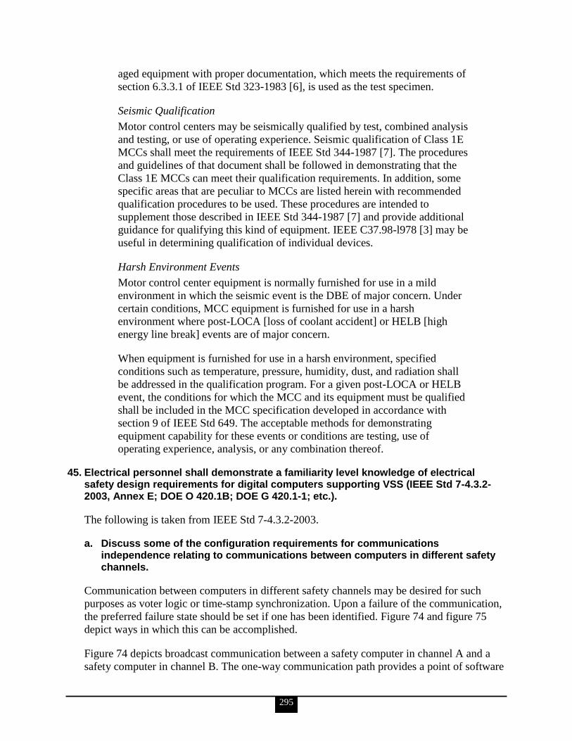
295
aged equipment with proper documentation, which meets the requirements of
section 6.3.3.1 of IEEE Std 323-1983 [6], is used as the test specimen.
Seismic Qualification
Motor control centers may be seismically qualified by test, combined analysis
and testing, or use of operating experience. Seismic qualification of Class 1E
MCCs shall meet the requirements of IEEE Std 344-1987 [7]. The procedures
and guidelines of that document shall be followed in demonstrating that the
Class 1E MCCs can meet their qualification requirements. In addition, some
specific areas that are peculiar to MCCs are listed herein with recommended
qualification procedures to be used. These procedures are intended to
supplement those described in IEEE Std 344-1987 [7] and provide additional
guidance for qualifying this kind of equipment. IEEE C37.98-l978 [3] may be
useful in determining qualification of individual devices.
Harsh Environment Events
Motor control center equipment is normally furnished for use in a mild
environment in which the seismic event is the DBE of major concern. Under
certain conditions, MCC equipment is furnished for use in a harsh
environment where post-LOCA [loss of coolant accident] or HELB [high
energy line break] events are of major concern.
When equipment is furnished for use in a harsh environment, specified
conditions such as temperature, pressure, humidity, dust, and radiation shall
be addressed in the qualification program. For a given post-LOCA or HELB
event, the conditions for which the MCC and its equipment must be qualified
shall be included in the MCC specification developed in accordance with
section 9 of IEEE Std 649. The acceptable methods for demonstrating
equipment capability for these events or conditions are testing, use of
operating experience, analysis, or any combination thereof.
45. Electrical personnel shall demonstrate a familiarity level knowledge of electrical safety design requirements for digital computers supporting VSS (IEEE Std 7-4.3.2-2003, Annex E; DOE O 420.1B; DOE G 420.1-1; etc.).
The following is taken from IEEE Std 7-4.3.2-2003.
a. Discuss some of the configuration requirements for communications independence relating to communications between computers in different safety channels.
Communication between computers in different safety channels may be desired for such
purposes as voter logic or time-stamp synchronization. Upon a failure of the communication,
the preferred failure state should be set if one has been identified. Figure 74 and figure 75
depict ways in which this can be accomplished.
Figure 74 depicts broadcast communication between a safety computer in channel A and a
safety computer in channel B. The one-way communication path provides a point of software
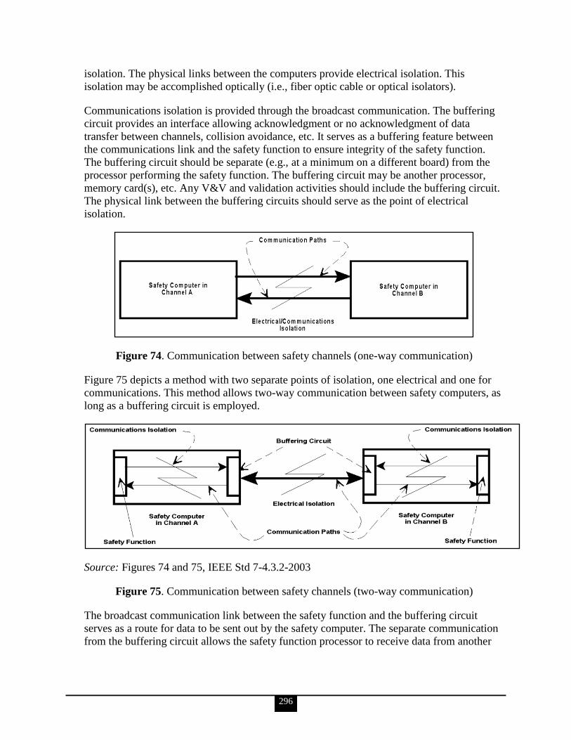
296
isolation. The physical links between the computers provide electrical isolation. This
isolation may be accomplished optically (i.e., fiber optic cable or optical isolators).
Communications isolation is provided through the broadcast communication. The buffering
circuit provides an interface allowing acknowledgment or no acknowledgment of data
transfer between channels, collision avoidance, etc. It serves as a buffering feature between
the communications link and the safety function to ensure integrity of the safety function.
The buffering circuit should be separate (e.g., at a minimum on a different board) from the
processor performing the safety function. The buffering circuit may be another processor,
memory card(s), etc. Any V&V and validation activities should include the buffering circuit.
The physical link between the buffering circuits should serve as the point of electrical
isolation.
Figure 74. Communication between safety channels (one-way communication)
Figure 75 depicts a method with two separate points of isolation, one electrical and one for
communications. This method allows two-way communication between safety computers, as
long as a buffering circuit is employed.
Source: Figures 74 and 75, IEEE Std 7-4.3.2-2003
Figure 75. Communication between safety channels (two-way communication)
The broadcast communication link between the safety function and the buffering circuit
serves as a route for data to be sent out by the safety computer. The separate communication
from the buffering circuit allows the safety function processor to receive data from another
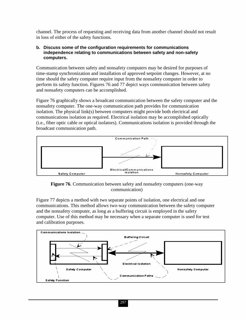
297
channel. The process of requesting and receiving data from another channel should not result
in loss of either of the safety functions.
b. Discuss some of the configuration requirements for communications independence relating to communications between safety and non-safety computers.
Communication between safety and nonsafety computers may be desired for purposes of
time-stamp synchronization and installation of approved setpoint changes. However, at no
time should the safety computer require input from the nonsafety computer in order to
perform its safety function. Figures 76 and 77 depict ways communication between safety
and nonsafety computers can be accomplished.
Figure 76 graphically shows a broadcast communication between the safety computer and the
nonsafety computer. The one-way communication path provides for communication
isolation. The physical link(s) between computers might provide both electrical and
communications isolation as required. Electrical isolation may be accomplished optically
(i.e., fiber optic cable or optical isolators). Communications isolation is provided through the
broadcast communication path.
Figure 76. Communication between safety and nonsafety computers (one-way
communication)
Figure 77 depicts a method with two separate points of isolation, one electrical and one
communications. This method allows two-way communication between the safety computer
and the nonsafety computer, as long as a buffering circuit is employed in the safety
computer. Use of this method may be necessary when a separate computer is used for test
and calibration purposes.
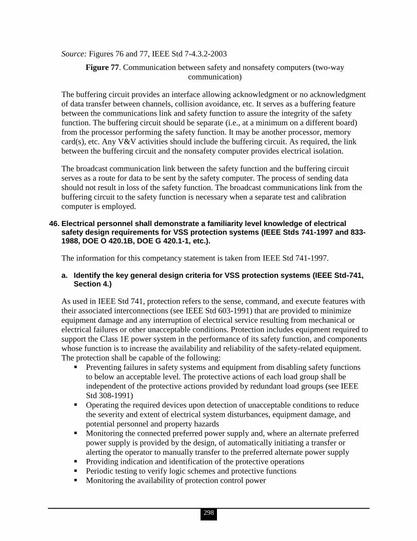
298
Source: Figures 76 and 77, IEEE Std 7-4.3.2-2003
Figure 77. Communication between safety and nonsafety computers (two-way
communication)
The buffering circuit provides an interface allowing acknowledgment or no acknowledgment
of data transfer between channels, collision avoidance, etc. It serves as a buffering feature
between the communications link and safety function to assure the integrity of the safety
function. The buffering circuit should be separate (i.e., at a minimum on a different board)
from the processor performing the safety function. It may be another processor, memory
card(s), etc. Any V&V activities should include the buffering circuit. As required, the link
between the buffering circuit and the nonsafety computer provides electrical isolation.
The broadcast communication link between the safety function and the buffering circuit
serves as a route for data to be sent by the safety computer. The process of sending data
should not result in loss of the safety function. The broadcast communications link from the
buffering circuit to the safety function is necessary when a separate test and calibration
computer is employed.
46. Electrical personnel shall demonstrate a familiarity level knowledge of electrical safety design requirements for VSS protection systems (IEEE Stds 741-1997 and 833-1988, DOE O 420.1B, DOE G 420.1-1, etc.).
The information for this competancy statement is taken from IEEE Std 741-1997.
a. Identify the key general design criteria for VSS protection systems (IEEE Std-741, Section 4.)
As used in IEEE Std 741, protection refers to the sense, command, and execute features with
their associated interconnections (see IEEE Std 603-1991) that are provided to minimize
equipment damage and any interruption of electrical service resulting from mechanical or
electrical failures or other unacceptable conditions. Protection includes equipment required to
support the Class 1E power system in the performance of its safety function, and components
whose function is to increase the availability and reliability of the safety-related equipment.
The protection shall be capable of the following:
Preventing failures in safety systems and equipment from disabling safety functions
to below an acceptable level. The protective actions of each load group shall be
independent of the protective actions provided by redundant load groups (see IEEE
Std 308-1991)
Operating the required devices upon detection of unacceptable conditions to reduce
the severity and extent of electrical system disturbances, equipment damage, and
potential personnel and property hazards
Monitoring the connected preferred power supply and, where an alternate preferred
power supply is provided by the design, of automatically initiating a transfer or
alerting the operator to manually transfer to the preferred alternate power supply
Providing indication and identification of the protective operations
Periodic testing to verify logic schemes and protective functions
Monitoring the availability of protection control power
299
Periodic testing to verify setpoints. This requirement is not applicable to fuses
Those parts of the protection that have a safety function shall meet the requirements of IEEE
Std 603-1991 and IEEE Std 308-1991. Documentation requirements for the protection of
Class 1E power systems and equipment are found in IEEE Std 308-1991. Those parts of the
protection whose function is nonsafety related shall be designed such that their failure does
not degrade the Class 1E power system below an acceptable level.
b. Identify the major criteria for establishing bus voltage monitoring schemes (IEEE Std-741, Section 5.1.2 a) – h)).
Bus voltage monitoring schemes that are used for disconnecting the preferred power source,
load shedding, and starting the standby power sources are part of the protection and shall
meet the criteria that follow. Voltage monitoring schemes that are used only for alarms do
not have to meet these criteria.
a) Bus voltage shall be detected directly from the Class 1E bus to which the standby
power source is connected.
b) Upon sensing preferred power supply degradation, the condition shall be alarmed in
the main control room. On sensing preferred power supply degradation to an
unacceptable low-voltage condition, the affected preferred power supply shall be
automatically disconnected from the Class 1E buses.
c) Each division shall have an independent scheme of detection of degraded voltage and
loss-of-voltage conditions. Within each division, common equipment may be used for
the detection of both conditions.
d) Each scheme shall monitor all three phases. The protection system design shall be
such that a blown fuse in the voltage transformer circuit or other single phasing
condition will not cause incorrect operation, nor prevent correct operation, of the
scheme. Means shall be provided to detect and identify these failures.
e) The design shall minimize unwanted operation of the standby power sources and
disconnection of the preferred power supply. The use of coincident logic and time
delay to override transient conditions is a way to accomplish this.
f) Capability for test and calibration during power operation shall be provided.
g) The selection of undervoltage and time delay setpoints shall be determined from an
analysis of the voltage requirements of the Class 1E loads at all onsite distribution
levels.
h) Indication shall be provided in the control room for any bypass incorporated in the
design.
c. Identify the major requirement for selecting protective devices for direct-geared valve actuator motors (IEEE Std-741, Section 5.5, first paragraph, first sentence).
The selection of a protective device for the direct geared valve actuator motor (VAM) shall
ensure that the time current characteristic of the protective device is coordinated with the
time current characteristic of the motor, as derived from motor time temperature data.

300
47. Electrical personnel shall demonstrate a familiarity level knowledge of electrical safety design requirements for Instrumentation and Control (I&C) equipment grounding of VSS (IEEE Std 1050-1996, DOE O 420.1B, DOE G 420.1-1, etc.).
The information for this competancy statement is taken from IEEE Std 1050-1996.
a. Discuss some design considerations for electrical noise minimization, noise sources, noise-coupling methods, and techniques for electrical noise minimization.
Design considerations for electrical noise minimization include the identification of the
different types of noise sources, noise-coupling or transmission methods, and techniques that
may be utilized that minimize the impact that electrical noise can have on vital safety
systems. IEEE Std 1050-1996, IEEE Guide for Instrumentation and Control Equipment
Grounding in Generating Stations, devotes an entire chapter to this topic. A summary is
provided below.
Noise Sources
Noise sources can be divided into the following categories:
Natural sources—these happen independently of human activity, but their effects can
be controlled.
Incidental sources—these are caused by human activity, but they are not intentional.
Intentional sources—these are emissions of potentially interfering energy produced
for specific purposes unrelated to the equipment or systems under consideration.
Noise-Coupling Methods
Noise can be coupled into (or transmitted from) control circuits by any one of the following
four different methods:
1. Conductive (direct contact)
2. Capacitive (electric)
3. Inductive (magnetic)
4. Radiative (electromagnetic)
Both capacitive and inductive coupling refer primarily to near field coupling. A control
circuit or cable is considered to be in the near field of an electromagnetic source when the
source to circuit distance is less than 0.167 of the wavelength (λ/2π) of the highest source
frequency. Radiative coupling refers to circuits located in the far field of a source where the
source‘s emissions are seen as a true propagating wave.
Techniques for Electrical Noise Minimization
There are five primary techniques for electrical noise minimization:
1. Suppression at the source
2. Positioning and isolating control cables
3. Shielding
4. Grounding
5. Filters
301
Other electrical noise minimization techniques include
use of isolation and/or neutralizing transformers
use of differential amplifiers
increasing the signal-to-noise ration
use of fiber optic cable
b. Describe the purpose or use, and advantages and disadvantages, of single-point ground systems, multi-point ground systems, and floating ground systems.
Single-Point Ground System
The single-point ground system is used to eliminate circulation of ground currents that cause
common mode noise. This is the most commonly used system in an industrial environment. It
is implemented by connecting the signal circuit to the station ground at only one point. This
grounding method is very effective and is adequate when dealing with equipment operating
at frequencies below 300 kHz. (Various sources place this frequency at anywhere between
100 kHz and 10 MHz. The equipment manufacturer should be consulted for each specific
installation.)
A disadvantage of the system is that it is ineffective at high frequencies where signal
wavelengths approach the equipment enclosure dimensions or the ground cable length. As
equipment dimensions or ground cable lengths approach 0.15 of the signal wavelength, the
cable can no longer be considered a low-impedance ground. Single-point reference grounds
should be differentiated from signal return conductors, which do carry current under normal
conditions.
In a distributed control system the equipment may be widely scattered throughout the station,
and it is impractical to implement a single-point grounding arrangement. An I&C system is
considered a distributed system when the individual control station cabinets are widely
separated from each other. Such a system has special problems since the impedance in the
signal reference conductors will result in a ground potential difference between the cabinets.
Figure 78 illustrates an approach to providing a single-point ground system for this condition.
The communications circuits between the cabinets should have appropriate protection for the
common mode noise that is likely to result from the impedance of the long, insulated signal
grounds.
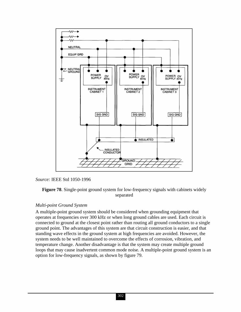
302
Source: IEEE Std 1050-1996
Figure 78. Single-point ground system for low-frequency signals with cabinets widely
separated
Multi-point Ground System
A multiple-point ground system should be considered when grounding equipment that
operates at frequencies over 300 kHz or when long ground cables are used. Each circuit is
connected to ground at the closest point rather than routing all ground conductors to a single
ground point. The advantages of this system are that circuit construction is easier, and that
standing wave effects in the ground system at high frequencies are avoided. However, the
system needs to be well maintained to overcome the effects of corrosion, vibration, and
temperature change. Another disadvantage is that the system may create multiple ground
loops that may cause inadvertent common mode noise. A multiple-point ground system is an
option for low-frequency signals, as shown by figure 79.

303
This configuration accepts that a ground voltage difference will exist between the signal
references and that the appropriate degree of protection should be provided for the resulting
common mode noise.
Source: IEEE Std 1050-1996
Figure 79. Multiple-point ground system for low-frequency signals with cabinets widely
separated
Floating Ground System
The floating ground system is used to isolate circuits or equipment electrically from a
common ground plane or from common wiring that might introduce circulating currents and
produce common mode noise. It is implemented by electrically interconnecting the signal
grounds, yet isolating them from a common ground plane (see figure 80). A hazard of this
system is that static charges may accumulate and eventually cause a destructive or noise-
producing discharge current to flow. It is usually advisable to implement this system with a
bleeding resistor connected to ground to avoid the buildup of static charges.

304
Source: IEEE Std 1050-1996
Figure 80. Floating ground system
c. Identify the IEEE Standard citing requirements for VSS I&C equipment signal cable shield grounding requirements (IEEE Std 1050-1996).
IEEE Std 1050-1996 contains information about grounding methods for generating station
I&C equipment. The identification of I&C equipment grounding methods to achieve both a
suitable level of protection for personnel and equipment is included, as well as suitable noise
immunity for signal ground references in generating stations. Ideal theoretical methods and
accepted practices in the electric utility industry are presented.
305
48. Electrical personnel shall demonstrate a familiarity level knowledge of electrical safety design requirements for VSS Motor Operated Valves (MOV) (IEEE Std 1290-1996, DOE O 420.1B, DOE G 420.1-1, etc.).
a. Identify the IEEE Standard, citing requirements for motor applications, protection, and control for MOV motor applications (IEEE Std-1290).
The following is taken from IEEE Std 1290-1996.
Applications
Valve actuator motors (VAMs) have a unique design that can result in significantly different
operating characteristics than NEMA Design B motors. Continuous duty motors, such as
NEMA Design B Motors, are rated in HP, which implies a constant torque. VAMs are
neither continuous duty nor constant torque at rated speed. They can be characterized as short
duty time, high starting torque motors.
Protection
In general, protection schemes shall consider the design function of the VAM and its ability
to perform this function. The protection scheme shall also consider the protection of the
VAM. However, protection cannot always be designed to enable the valve to perform this
design function and to protect the valve actuator. When this occurs, VAM protection should
be established to encompass one of the following options:
Protect the VAM at the expense of its design function to ensure that later VAM
operation is possible. However, protection should not be provided that infringes on
the design basis safety function of the VAM.
Provide as much VAM protection as possible without limiting its chances of
accomplishing its design function. Providing limited VAM protection may allow
undetected VAM degradation.
Protection can be provided by various types and combinations of devices. This guide
discusses thermal overload relays; fuses; thermal contacts; resistance temperature detector—
resistors; molded case circuit breakers; and DC VAM surge protection. This guide is
concerned only with VAM coordination with upstream power sources. As VAMs frequently
have not been fuse protected, this guide provides some detail on fuse application.
Control
This clause includes considerations to be addressed in designing an MOV control circuit.
Each block represents an individual portion of the control scheme that will be discussed in
detail in the following subclauses. This clause provides suggestions for integrating the
individual blocks into a complete control circuit such that the MOV can perform the required
function for its application. The Electric Power Research Institute application guide NP-
6660-D also provides guidance for selecting control, protection, and alarm functions that are
consistent with typical MOV applications.

306
The first step in designing a control circuit is to obtain the specific system design
requirements. The MOV system requirement data sheet can be used to document the valve
functional requirements needed to develop the control circuit. The design of a control scheme
is based on the valve application, system design requirements, valve design and type
(including design limits), vendor requirements, and limitations of control devices.
Subclauses 6.1 through 6.6 provide brief descriptions of each block of the control logic,
including advantages, disadvantages, and design considerations for each. These descriptions,
in combination with the MOV system requirements, give the parameters necessary to select a
control configuration appropriate for the MOV control circuit.
Protection can be provided by various types of devices. For examples of these devices, see
clause 5.
VII. ELECTRICAL SAFETY REQUIREMENTS AND PRACTICES This section is optional and should be used by the program and/or field offices to assist them with specific technical qualifications for that office.
49. Electrical personnel shall demonstrate a familiarity level knowledge of electrical safety requirements and practices in the following list of regulatory and consensus standards documents, including the relationship between these documents and which are ―enforceable‖ in your site‘s contractors contract, such as OSHA (29 CFR 1910 and Subpart S, and 29 CFR 1926 Subparts K and V); NFPA 70E, Standard for Electrical Safety in the Workplace/Maintenance; NFPA-70B, Recommended Practice of Electrical Equipment Maintenance; DOE-HDBK-1092-2004, Electrical Safety Handbook; and 10 CFR 851, Worker Safety and Health Program.
[Note: The title of NFPA 70E does not contain the term ―Maintenance.‖]
[Note: The 2004 version of NFPA 70E has been superseded by the 2009 revision and is archived but still available. Because the 2009 revision was drastically reduced in scope it is not used as a reference in this guide.]
a. Describe the purpose, scope, and application of the requirements detailed in the listed standards and Orders.
29 CFR 1910
The Williams-Steiger Occupational Safety and Health Act of 1970 (84 Stat. 1593) states that
Without regard to chapter 5 of title 5, United States Code, or to the other
subsections of this section, the Secretary shall, as soon as practicable during
the period beginning with the effective date of this Act and ending 2 years
after such date, by rule promulgate as an occupational safety or health
standard any national consensus standard, and any established Federal
standard, unless he determines that the promulgation of such a standard would
not result in improved safety or health for specifically designated employees.
The legislative purpose of this provision is to establish, as rapidly as possible and without
regard to the rule-making provisions of the Administrative Procedure Act, standards with
307
which industries are generally familiar, and on whose adoption interested and affected
persons have already had an opportunity to express their views. Such standards are either
national consensus standards on whose adoption affected persons have reached substantial
agreement, or Federal standards already established by Federal statutes or regulations.
29 CFR 1910 carries out the directive to the Secretary of Labor under section 6(a) of the Act.
It contains occupational safety and health standards that have been found to be national
consensus standards or established Federal standards.
29 CFR 1926
29 CFR 1926, beginning with subpart A, sets forth the safety and health standards
promulgated by the Secretary of Labor under section 107 of the Contract Work Hours and
Safety Standards Act. The standards are published in subpart C of this part and following
subparts. Subpart B of this part contains statements of general policy and interpretations of
section 107 of the Contract Work Hours and Safety Standards Act having general
applicability.
NFPA 70E, Standard for Electrical Safety in the Workplace
NFPA 70E addresses those workplace electrical safety requirements that are necessary for
the practical safeguarding of employees in their pursuit of gainful employment. This standard
covers the installation of electric conductors, electric equipment, signaling and
communications conductors and equipment, and raceways for the following:
Public and private premises, including buildings, structures, mobile homes,
recreational vehicles, and floating buildings
Yards, lots, parking lots, carnivals, and industrial substations
Installations of conductors and equipment that connect to the supply of electricity
Installations used by the electric utility, such as office buildings, warehouses, garages,
machine shops, and recreational buildings, that are not an integral part of a generating
plant, substation, or control center
NFPA-70B, Recommended Practice of Electrical Equipment Maintenance
NFPA-70B applies to PM for electrical, electronic, and communication systems and
equipment and is not intended to duplicate or supersede instructions that manufacturers
normally provide. Systems and equipment covered are typical of those installed in industrial
plants, institutional and commercial buildings, and large multifamily residential complexes.
Consumer appliances and equipment intended primarily for use in the home are not included.
The purpose of this recommended practice is to reduce hazards to life and property that can
result from failure or malfunction of industrial-type electrical systems and equipment.
DOE-HDBK-1092-2004, Electrical Safety Handbook
The Electrical Safety Handbook presents the DOE safety standards for DOE field offices or
facilities involved in the use of electrical energy. It has been prepared to provide a uniform
set of electrical safety guidance and information for DOE installations to effect a reduction or
elimination of risks associated with the use of electrical energy. The objectives of this
308
handbook are to enhance electrical safety awareness and mitigate electrical hazards to
employees, the public, and the environment.
This handbook provides general information to enhance understanding of DOE Orders,
national codes, national standards, and local, state, and Federal regulations. This handbook
shall not supersede more stringent requirements in those applicable codes, standards, and
regulations.
10 CFR 851
Title 10 CFR 851, ―Worker Safety and Health Program,‖ codifies the Department‘s worker
protection program requirements established in DOE O 440.1B, Worker Protection Program
for DOE (Including the National Nuclear Security Administration) Federal Employees.
Consistent with the intent of Congress, DOE O 440.1B forms the basis for the rule‘s
substantive requirements. The Conference Committee for the National Defense Authorization
Act recognized that contractors currently operate under this Order, ―which provides an
adequate level of safety.‖ (Conference Report 107–772, November 12, 2002, at 797.)
b. Discuss the graded approach process that Department line management uses to determine an appropriate level of coverage by electrical personnel. Include in this discussion the factors that may influence the level of coverage.
The following is taken from DOE O 5480.20A.
A graded approach means a process by which the level of analysis, documentation, and
action necessary to comply with a requirement are commensurate with the relative
importance to safety, safeguards, and security; the magnitude of any hazard involved; the
life-cycle stage of a facility; the programmatic mission of a facility; the particular
characteristics of a facility; and any other relevant factor.
The following is taken from DOE O 420.1B.
A graded approach considers the following factors:
Remaining Facility Lifetime and the Safety Significance of Remaining Operations.
Facilities undergoing deactivation, and decontamination and decommissioning, may
be undergoing frequent changes, modifications, and in some cases, removal of
systems no longer needed to support the safety basis of those operations. After
deactivation or when a facility is in long-term surveillance and maintenance, there
may be less need for attention.
Safety Importance of the System. Not all systems are equal as measured by the
likelihood and consequences of the hazard and the accidents that they prevent or
mitigate. The level of system documentation detail in CM should be tailored to the
importance of the system.
c. Determine contractor compliance with the listed documents as they apply to contract design requirements and electrical system activities at a defense nuclear facility.
This is a performance-based KSA. The Qualifying Official will evaluate its completion.
309
50. Electrical personnel shall demonstrate a familiarity level knowledge of DOE O 414.1C, Quality Assurance, as it pertains to electrical systems.
a. Mandatory Performance Activity: Describe how electrical equipment is procured based upon its safety function and/or nuclear-related activity using quality assurance criteria and appropriate national or international consensus standards.
This is a performance-based KSA. The Qualifying Official will evaluate its completion.
b. Describe what is meant by implementing quality assurance criteria using a graded approach.
The following is taken from DOE O 414.1C.
Each DOE organization must develop and implement a QAP that implements QA criteria
using a graded approach. The QAP must address the following management, performance,
and assessment criteria:
Management/Criterion 1—Program: Establish an organizational structure, functional
responsibilities, levels of authority, and interfaces for those managing, performing,
and assessing work. Establish management processes, including planning, scheduling,
and providing resources for work.
Management/Criterion 2—Personnel Training and Qualification: Train and qualify
personnel to be capable of performing assigned work. Provide continuing training to
personnel to maintain job proficiency.
Management/Criterion 3—Quality Improvement: Establish and implement processes
to detect and prevent quality problems. Identify, control, and correct items, services,
and processes that do not meet established requirements. Identify the causes of
problems, and include prevention of recurrence as a part of corrective action
planning. Review item characteristics, process implementation, and other quality-
related information to identify items, services, and processes needing improvement.
Management/Criterion 4—Documents and Records: Prepare, review, approve, issue,
use, and revise documents to prescribe processes, specify requirements, or establish
design. Specify, prepare, review, approve, and maintain records.
Performance/Criterion 5—Work Processes: Perform work consistent with technical
standards, administrative controls, and hazard controls adopted to meet regulatory or
contract requirements using approved instructions, procedures, etc. Identify and
control items to ensure their proper use. Maintain items to prevent their damage, loss,
or deterioration. Calibrate and maintain equipment used for process monitoring or
data collection.
Performance/Criterion 6—Design: Design items and processes using sound
engineering/scientific principles and appropriate standards. Incorporate applicable
requirements and design bases in design work and design changes. Identify and
control design interfaces. Verify/validate the adequacy of design products using
individuals or groups other than those who performed the work. Verify/validate work
before approval and implementation of the design.
Performance/Criterion 7—Procurement: Procure items and services that meet
established requirements and perform as specified. Evaluate and select prospective
310
suppliers on the basis of specified criteria. Establish and implement processes to
ensure that approved suppliers continue to provide acceptable items and services.
Performance/Criterion 8—Inspection and Acceptance Testing: Inspect and test
specified items, services, and processes using established acceptance and
performance criteria. Calibrate and maintain equipment used for inspections and tests.
Assessment/Criterion 9—Management Assessment: Ensure that managers assess their
management processes and identify and correct problems that hinder the organization
in achieving its objectives.
Assessment/Criterion 10—Independent Assessment: Plan and conduct independent
assessments to measure item and service quality and the adequacy of work
performance and to promote improvement. Establish sufficient authority and freedom
from line management for independent assessment teams. Ensure that persons
conducting independent assessments are technically qualified and knowledgeable in
the areas to be assessed.
The criteria listed above are implemented using a graded approach that accounts for the
following factors:
The relative importance to safety, safeguards, and security
The magnitude of any hazard involved
The life-cycle stage of a facility or item
The programmatic mission of a facility
The particular characteristics of a facility or item
The relative importance to radiological and nonradiological hazards
Any other relevant factors
c. Describe the types of documents related to electrical systems that should be controlled by a document control system.
The information for KSAs ‗c‘ and ‗d‘ is taken from DOE G 414.1-2A.
Records should be compiled in a records management system. Typical records include
procedures, plans, and manuals; training and qualification results; acceptance test results;
technical/regulatory correspondence; operational records; design basis descriptions, design
review results, design revisions, and CM data; and quality problem resolutions. Records may
be in a variety of forms (e.g., electronic, written, or printed; microfilm; photographs;
radiographs; or optical disks).
A document control system should be in place to control the preparation, review, approval,
issuance, management, and revision of documents. Documents are required by organizations,
projects, or programs to control policy and administrative and/or technical information. A
document may describe work to be done, data to be used at different locations or by different
people, or, in changing situations, data to be controlled from time to time for reference
purposes. The document control system should be established to supply the documents
necessary for personnel to safely and correctly perform their assigned responsibilities.
DOE-HDBK-1092-2004, Electrical Safety, notes that the following must be documented and
maintained in records:
311
Performance of work
Personnel training
Work instructions
Equipment testing data
LOTO procedures
Maintenance inspections and servicing
Manufacturer‘s recommendations
Hazardous location evaluations
Dielectric test results
Safety determinations
Accepted risk determinations
Decisions to forgo grounding or bonding
Equipment design data
Self-assessments
Electrical deficiencies noted
Maintenance and care of PPE
d. Discuss the requirements for revision and distribution of controlled documents.
A document control system should be in place to control the preparation, review, approval,
issue, control, and revision of documents. Documents are required by organizations, projects,
or programs to control policy and administrative and/or technical information. A document
may describe work to be done, data to be used at different locations or by different people,
or, in changing situations, data to be controlled from time to time for reference purposes. The
document control system should be established to supply the documents necessary for
personnel to safely and correctly perform their assigned responsibilities. Document control
systems ensure that the mechanisms developed to implement the safety management
functions of DOE P 450.4 are properly prepared, controlled, and available for use.
e. Discuss the determination of calibration frequency for electrical test equipment.
The following is taken from DOE-HDBK-1092-2004.
Instrumentation shall be calibrated per manufacturers‘ instructions. A record of calibration
should be maintained for each instrument, by serial number or an equivalent method,
showing dates of inspection, calibration data as received, the date when it should be recalled
from the field and a recalibration check made, and any interim repairs. After a period of time,
it should become obvious what frequency needs to be established for calibrating each
instrument.
Calibration schedules and procedures for calibrating testing apparatus are recommended to
be in accordance with ANSI C39.1.
The following is taken from NFPA 70B, ch 21.7.
In general, any test equipment used for the calibration of other equipment should have an
accuracy at least twice the accuracy of the equipment under test. The test equipment should
be maintained in good condition and should be used only by qualified test operators.
312
f. Describe the effect of using inappropriate calibration standards on electrical test equipment.
The following taken from NFPA 70B.
Data loss and unsafe work conditions can result from the use of inappropriate calibration
standards. All test equipment should be calibrated at regular intervals to ensure the validity of
the data obtained. In order to get valid test results, it might be necessary to regulate the power
input to the test equipment for proper waveform and frequency and to eliminate voltage
surges.
g. Discuss the key elements of the procurement process for electrical systems as described in DOE O 414.1C, Quality Assurance.
Key elements of the procurement process, as delineated in DOE O 414.1C, are as follows:
Procure items and services that meet established requirements and perform as
specified.
Evaluate and select prospective suppliers on the basis of specified criteria.
Establish and implement processes to ensure that approved suppliers continue to
provide acceptable items and services.
51. Electrical personnel shall demonstrate a familiarity level of knowledge of DOE O 430.1B Chg 1, Real Property Asset Management, with regard to life-cycle asset management.
a. Explain the Department‘s role in the oversight of contractor maintenance operations.
The information for KSAs ‗a‘ and ‗b‘ is taken from DOE O 430.1B Chg 1.
Delineated below is a summary list of the responsibilities and authorities for effective
management of DOE real property assets and the accountabilities for real property asset
management, from planning and acquisition through operations and disposal:
Lead Program Secretarial Offices (LPSOs) issue program missions, budgets, and
planning estimates covering a 10-year planning horizon for site infrastructure and
LPSO-related real property assets and approve 10-year site plans and land-use
management plans for their sites.
Cognizant Secretarial Offices (CSOs) and Program Secretarial Offices (PSOs) issue
program missions, budgets, and planning estimates covering a 10-year planning
horizon for their program-related work and/or real property assets and approve
elements of TYSPs related to their programmatic responsibilities at related sites.
Site/field managers ensure mission resource requirements for real property assets,
including their plans and budgets, are prepared to meet the program missions,
budgets, and planning estimates, and the results are documented in the TYSP.
Site/field managers perform a key role coordinating program and tenant activities and
real property asset needs at the site.
313
TYSPs are submitted by site/field managers to the LPSOs/CSOs/PSOs as the plans
for real property assets at the sites. TYSPs support LPSO/CSO/PSO programming
decisions regarding real property assets and subsequent site budget requests.
The Office of Engineering and Construction Management develops policies and
procedures for real property asset management and provides corporate oversight for
implementation.
b. Identify the key elements of a contractor maintenance plan as required by the DOE Order referenced above.
The contractor must maintain real property assets in a manner that promotes operational
safety, worker health, environmental compliance, property preservation, and cost-
effectiveness while meeting the program missions. This requires a balanced approach that not
only sustains the assets but also provides for their recapitalization and includes the following
as a minimum:
A maintenance management program that includes a condition assessment of the real
property assets, a work control system, management of deferred maintenance, a
method to prioritize, and systems to budget and track maintenance expenditures.
Identification of 5-year maintenance and repair requirements (sustainment) and
funding for deferred maintenance reduction.
Identification of 5-year recapitalization requirements to replace or modernize existing
facilities.
Condition assessments that must be performed on real property assets at least once
within a 5-year period, and may be required more frequently for mission-essential
facilities and infrastructure. The condition assessment program shall utilize a tailored
approach based on facility status, mission, and importance and the magnitude of the
hazards associated with facilities and infrastructure. Inspection methodology shall be
consistent with industry practice and shall include identification of safety and health
hazards. Deferred maintenance estimates will be based on nationally recognized
cost-estimating systems or the DOE Condition Assessment Information System. The
condition assessment program will support the reporting requirements of the Facilities
Information Management System.
c. Describe configuration control and its relationship to the maintenance work control process and the maintenance history file.
The following is taken from DOE G 433.1-1
Configuration management is a discipline that applies technical and administrative direction
and surveillance to identify and document the physical characteristics of a facility. It is a
method of doing business that maintains consistency among design requirements, physical
configuration, and facility documentation. It audits to verify conformance to specifications
and related documentation. Basically, it boils down to doing all those things that should be
done all along to properly manage and control physical and functional items at a facility.
Such a program can be broken down into five basic programmatic elements:
1. Program management
2. Design requirements
314
3. Document control
4. Change control
5. Assessments
An important aspect of a CM program is the assurance that the design basis of a DOE nuclear
facility is established, documented, and maintained. The facility SSCs and computer software
should conform to approved design requirements and any changes to them must be
minimized through an integrated management review process with established approval
criteria. This will help to establish that the operations of the facility are reliable if personnel
operating the facility are knowledgeable about changes through timely review and training.
Proposed changes should be thoroughly evaluated to determine their impact on other
hardware and documents. Such changes should be reviewed and approved by appropriate,
responsible managers before implementation. This way, the program maintains a consistency
between the documents of all departments and organizations (i.e., design, inspection,
operations, maintenance, testing, or training). Safety, mission, economic impact, and benefit
can be fully analyzed through the full range of review and approval contained in the program
(see DOE-STD-1039-93 and DOE-STD-1073-2003).
The work control process should be integrated with the planning process and should include
provisions for equipment repair history.
d. Describe the mechanisms for feedback of relevant information, such as trend analysis and instrumentation performance/reliability data, to identify necessary program modifications.
The following is taken from DOE O 226.1A. Additional detail is available from that source.
Mechanisms anchored in a contractor assurance system will provide a variety of feedback
types, as follows:
Assessments (including self-assessments or management assessments, operational
awareness or management walk-throughs, QA assessments, and internal independent
assessments)
Event reporting (including reporting, analyzing, and trending operational events,
accidents, and injuries)
Worker feedback mechanisms
Issues management (including analysis of causes, identification of corrective actions,
corrective action tracking, monitoring and closure, verification of effectiveness, trend
analysis, and identification of continuous improvement opportunities)
Lessons learned
Performance measures
e. Review a contractor preventive maintenance activity and describe the preventive maintenance factors to be considered as the activity is planned.
This is a performance-based KSA. The Qualifying Official will evaluate its completion.
315
f. Discuss the importance of post-maintenance testing and the elements of an effective post-maintenance testing program.
The following is taken from DOE G 433.1-1.
Post-maintenance testing should be performed to verify that components will fulfill their
current, authorized design function when returned to service after maintenance.
Post-maintenance testing includes all testing performed after maintenance activities. An
effective post-maintenance testing program should apply to all maintenance activities and
should address each organization‘s responsibilities, equipment to be included, degree and
type of testing, procedure needs, acceptance requirements, testing control, and documentation
of results. Post-maintenance testing could be as simple as checking a manual valve for leaks
at normal operating pressure after packing adjustment or as detailed as an in-depth diesel
generator performance test.
The objective of post-maintenance testing is to verify that SSCs are capable of performing
their intended function when returned to service following maintenance and to ensure that the
original deficiency is corrected. Post-maintenance testing requires close coordination among
various facility groups and contract personnel. Post-maintenance testing integrates with the
work-control system and the health and safety permit system.
Post-maintenance testing involves the following key elements:
Responsibilities of each group are clearly defined.
Scope of equipment tested includes all facility equipment.
Input from maintenance, owner/operator, and technical support groups is included in
the specification of appropriate tests.
Guidance is available to planners for identifying appropriate tests.
Testing is conducted with owner/operator‘s authorization, uses approved procedures
or instructions, and is performed and reviewed by qualified personnel.
Tests are conducted under the appropriate system operating parameters.
A form is used to authorize, document, and review the results of post-maintenance
testing.
Post-test system restoration is formally controlled (restoring system to normal and/or
standby modes following completion of post-maintenance testing).
g. Review the results of post-maintenance testing activities and discuss the acceptance of post-maintenance testing.
This is a performance-based KSA. The Qualifying Official will evaluate its completion.
h. Discuss the importance of maintaining a maintenance history.
The following summary is taken from DOE G 433.1-1, section 4.15. Additional detail is
available from that source.
A maintenance history and trending program should be maintained to document data, provide
historical information for maintenance planning, and support maintenance and performance

316
trending of facility systems and components. The documentation of complete, detailed, and
usable history will be increasingly important as plant-life extension becomes an issue.
One objective of a good equipment maintenance history program is the ability to readily
retrieve equipment maintenance, performance, and reference information to improve facility
reliability.
The work-control system may be useful as a maintenance history data collection tool. The
maintenance history program should provide a system to document component identification
and description, vendor reference information and correspondence, diagnostic monitoring
data, corrective and PM or modification information, and spare parts information. This
system may be maintained centrally or locally by the group responsible for collecting the
data. In either case, easy access should be provided to all groups needing the information.
The historical data, combined with operating experience at similar facilities, operating logs
and records, and facility performance monitoring data, can be effective in analyzing trends
and failures in equipment performance and making adjustments to the maintenance program.
The maintenance history program should clearly define systems and equipment to be
included, data to be collected, methods for recording data, and uses for the data.
i. Review a maintenance history file and discuss the potential implications of repeat maintenance items.
This is a performance-based KSA. The Qualifying Official will evaluate its completion.
j. Explain how various problem analysis processes can be used to enhance maintenance programs (DOE G 433.1-1, Nuclear Facility Maintenance Management Program Guide for Use with DOE O 433.1).
The following is taken from DOE G 433.1-1.
Root-cause analyses of unplanned, recurring, and persistent maintenance problems,
incidents, and outages that impact safe and reliable operations, although historically
performed, have only recently adopted formal methodologies to systematically and clearly
lead to their effective resolution. The root cause is seldom a single factor.
Individuals at all levels should be trained in the use of one or more of a variety of formal
problem analysis and solving methodologies, including
Kepner-Tregoe;
job hazard analysis;
function analysis;
total quality management—performance improvement process;
reliability, availability, and maintainability analysis;
single-failure analysis;
root-cause analysis;
facility safety analysis and review;
risk assessment (including failure modes and effects analysis);
value engineering.

317
The interaction and effects of one or more of the following factors should be considered:
Design
Drawings
Procedures
Training
Qualification verification
Tools
Attitude
Supervision
Human error
Management control
Communication
When the nature of specific concerns warrants (based upon uniqueness, warranty,
complexity, time-constraints, state-of-the-art technology, special skills/equipment/tools, etc.)
outside expertise may need to be contracted to ensure the appropriate focus.
Root-cause categories should be established to facilitate future analyses, correlate proven
corrective actions, and focus management action on the critical few.
These methods result in value-added and knowledge-based correction plans that should be
followed to validated resolution and documented in the maintenance history files. Applicable
information should be shared as lessons learned for broad-based benefit from local actions.
318
Selected Bibliography and Suggested Reading
Code of Federal Regulations
10 CFR 830, ―Nuclear Safety Management‖. January 1, 2009.
10 CFR 830, Subpart A, ―Quality Assurance Requirements.‖
10 CFR 830, Subpart B, ―Safety Basis Requirements.‖
10 CFR 835.602, ―Controlled Areas.‖
10 CFR 851, ―Worker Safety and Health Program.‖
29 CFR 1910, ―Occupational Safety and Health Standards.‖
29 CFR 1910.67, ―Vehicle-Mounted Elevating and Rotating Work Platforms.‖
29 CFR 1910.120, ―Hazardous Waste Operations and Emergency Response.‖
29 CFR 1910.137, ―Electrical Protective Devices.‖
29 CFR 1910.147, ―The Control of Hazardous Energy (Lockout/Tagout).‖
29 CFR 1910.268, ―Telecommunications.‖
29 CFR 1910.269, ―Electric Power Generation, Transmission, and Distribution.‖
29 CFR 1910.305, ―Wiring Methods, Components, and Equipment for General Use.‖
29 CFR 1910.331–335, ―Electrical safety-related work practices.‖
29 CFR1910.1200, ―Hazard Communication.‖
29 CFR 1926, ―Safety and Health Regulations for Construction.‖
All About Circuits.com, Vol I: DC, Ch 10: DC Network Analysis
Alliant Energy, Variable Frequency Drives.
American National Standards Institute (ANSI)
ANSI C37.17-1997, American National Standard for Trip Devices for AC and General
Purpose DC Low Voltage Power Circuit Breakers.
ANSI C39.1, Requirements for Electrical Analog Indicating Instruments. (1981 ed.
withdrawn).
ANSI/IEEE C57.110, Recommended Practice for Establishing Transformer Capability
When Supplying Nonsinusoidal Load Currents. (1986 ed. archived; 1988 ed. active;
Nov. 2007 ed. active approved draft).
ANSI C84.1-2006, American National Standard for Electric Power Systems and
Equipment—Voltage Ratings (60 Hertz). (2006 is the current edition).
ANSI C92.2-1987, Alternating-Current Electrical Systems and Equipment Operating at
Voltages Above 230 kV Nominal - Preferred Voltage Ratings.
ANSI/ISA-67.04.01-2000, Setpoints for Nuclear Safety-Related Instrumentation. 2000.
ANSI Z136.1, Laser Safety Standards.
American Society of Mechanical Engineers (ASME). 2007 Boiler and Pressure Vessel Code.
American Society for Testing and Materials (ASTM) E136-92, Standard Test Method for
Behavior of Materials in a Vertical Tube Furnace at 750 Degrees C.
Consortium for Energy Efficiency. Efficient Motors: Selection and Application
Considerations. Boston, MA. 1999.
Curtis, Jon. Electrical Product Safety for Retailers. Conformity. July 1, 2006.
D & B Power Associates. Inc. Surge and Transient Protection.

319
Electric Power Research Institute (EPRI). EPRI NP-6660-D.
Ellis, Chera M. What You Need to Know about Category Ratings. Electrical Construction &
Maintenance Magazine. January 1, 2004.
Houdek, John A. Line Reactors and VFDs. Electrical Construction & Maintenance
Magazine. May 1, 2002.
Executive Order 12699. ―Seismic Safety of Federal and Federally Assisted or Regulated New
Building Construction.‖ January, 1990.
Executive Order 12941. ―Seismic Safety of Existing Federally Owned or Leased Buildings.‖
December 1, 1994.
Florida Power & Light Company. Overhead and Underground Electrical Service FAQs.
Freescale Semiconductor, Inc. The Electric Motor: Here and Now.
Institute of Electrical and Electronics Engineers (IEEE)
IEEE Std 7-4.3.2, Criteria for Digital Computers in Safety Systems of Nuclear Power
Generating Stations. (1993 ed. archived, 2003 ed. active).
IEEE Std 80-2000, Guide for Safety in AC Substation Grounding.
IEEE Std 100-2000, The Authoritative Dictionary of IEEE Standards Terms, 7th ed.
IEEE Std 308, Standard Criteria for Class 1E Power Systems for Nuclear Power
Generating Stations. (1980 and 1991 eds. archived, 2001 ed. active).
IEEE Std 323, Standard for Qualifying Class 1E Equipment for Nuclear Power
Generating Stations. (1983 ed. archived. 2003 ed. active).
IEEE Std 344-1987, Recommended Practice for Seismic Qualification of Class 1E
Equipment for Nuclear Power Generating Stations.
IEEE Std 352-1987, Guide for General Principles of Reliability Analysis of Nuclear
Power Generating Station Safety Systems.
IEEE Std 379, Standard Application of the Single-Failure Criterion to Nuclear Power
Generating Station Safety Systems. (1988 and 1994 eds. archived, 2000 ed. active).
IEEE Std 383, Standard for Qualifying Class 1E Electric Cables and Field Splices for
Nuclear Power Generating Stations. (1974 ed. archived, 2003 ed. active).
IEEE Std 384, Standard Criteria for Independence of Class 1E Equipment and Circuits.
(1992 ed. active, Nov. 2007 ed. active unapproved draft).
IEEE Std 387, Standard Criteria for Diesel-Generator Units Applied as Standby Power
Supplies for Nuclear Power Generating Stations. (1984 ed. archived, 1995 ed.
active).
IEEE Std 446, Recommended Practice for Emergency and Standby Power Systems for
Industrial and Commercial Applications. (1987 ed. Archived, 1995 ed. Active.)
IEEE Std 450, Recommended Practice for Maintenance, Testing, and Replacement of
Vented Lead-Acid Batteries for Stationary Applications. (1987 and 1995 eds.
archived, 2002 ed. active).
IEEE Std 484, Recommended Practice for Installation Design and Installation of Vented
Lead-Acid Batteries for Stationary Applications. (1987 and 1996 eds. archived, 2002
ed. active).
320
IEEE Std 497, Standard Criteria for Accident Monitoring Instrumentation for Nuclear
Power Generating Stations. (1981 ed. withdrawn; 2002 ed. and Corrigendum 1, 2007,
active).
IEEE Std 519, Recommended Practices and Requirements for Harmonic Control in
Electrical Power Systems. (1981 ed. archived, 1992 ed. active).
IEEE Std 577, Standard Requirements for Reliability Analysis in the Design and
Operation of Safety Systems for Nuclear Power Generating Stations. (1976 ed.
archived, 2004 ed. active).
IEEE Std 603, Standard Criteria for Safety Systems for Nuclear Power Generating
Stations. (1988 and 1991 eds. archived, 1998 ed. active).
IEEE Std 628, Standard Criteria for the Design, Installation, and Qualification of
Raceway Systems for Class 1E Circuits for Nuclear Power Generating Stations.
(1987 ed. archived, 2001 ed. active).
IEEE Std 649, Standard for Qualifying Class 1E Motor Control Centers for Nuclear
Power Generating Stations. (1980 and1991eds. archived, 2005 ed. active).
IEEE Std 650, Standard for Qualification of Class 1E Static Battery Chargers and
Inverters for Nuclear Power Generating Stations. (1979 and 1990 eds. archived, 2006
ed. active).
IEEE Std 666, IEEE Design Guide for Electric Power Service Systems for Generating
Stations. (1991 ed. archived, 2007 ed. active).
IEEE Std 741, Standard Criteria for the Protection of Class 1E Power Systems and
Equipment in Nuclear Power Generating Stations. (1986, 1990, and 1997 eds.
archived, 2007 ed. active).
IEEE Std 833, Recommended Practice for the Protection of Electric Equipment in
Nuclear Power Generating Stations from Water Hazards. (1988 ed. archived, 2005
ed. active).
IEEE Std 944, Recommended Practice for the Application and Testing of Uninterruptible
Power Supplies for Power Generating Stations. (1986 ed. withdrawn).
IEEE Std 946, Recommended Practice for the Design of DC Auxiliary Power Systems for
Generating Stations. (1985, and 1992 eds. archived, 2004 ed. active).
IEEE Std 1050, Guide for Instrumentation and Control Equipment Grounding in
Generating Stations. (1996 ed. archived, 2004 ed. active).
IEEE Std 1290, Guide for Motor Operated Valve (MOV) Motor Application, Protection,
Control, and Testing in Nuclear Power Generating Stations. (1996 ed. active).
IEEE Std 1584, Guide for Performing Arc-Flash Hazard Calculations. (2002 ed. active;
1584a, Amendment 1, ed. 2004 active).
IEEE C2, National Electrical Safety Code. (1997 and 2002 eds. archived, 2007 ed.
active).
IEEE C37.98, Seismic Testing of Relays. (1978 ed. Active).
IEEE Color Books Set:
IEEE Std 141, Red Book—Recommended Practice for Electric Power Distribution for
Industrial Power Plants. (1986 ed. archived, 1993 ed. active).
IEEE Std 142, Green Book—Recommended Practice for Grounding of Industrial and
Commercial Power Systems. (1991 ed. archived, 2007 ed. active).
IEEE Std 242, Buff Book—Recommended Practice for Protection and Coordination of
Industrial and Commercial Power Systems. (1986 ed. archived, 2001 ed. active).
321
IEEE Std 399, Brown Book—Recommended Practice for Industrial and Commercial
Power Systems Analysis. (1980 and 1990 eds. archived, 1997 ed. active).
IEEE Std 446, Orange Book—Recommended Practice for Emergency and Standby Power
Systems for Industrial and Commercial Applications. (1987 ed. archived, 1995 ed.
active).
IEEE Std 666, IEEE Design Guide for Electric Power Service Systems for Generating
Stations. (2007 ed. active).
IEEE Std 902, Yellow Book—Guide for Maintenance, Operation and Safety of Industrial
and Commercial Power Systems. (1998 ed. active).
IEEE Std 1015, Blue Book—Recommended Practice for Applying Low-Voltage Circuit
Breakers Used in Industrial and Commercial Power Systems. (1997 ed. archived;
2007 Corrigendum 1 ed. archived approved draft; 2006 and 2006 Corrigendum 1 eds.
active).
IEEE Std 1100, Emerald Book—Recommended Practice for Powering and Grounding
Sensitive Electronic Equipment. (1992 and 1999 eds. archived; 2005 archived
approved draft; 2005 ed. active).
IEC 61010-1, Safety Requirements for Electrical Equipment for Measurement, Control, and
Laboratory Use. 2nd edition. 2001.
NEMA VE 1-1991.
National Fire Protection Association
NFPA 70, National Electrical Code. 2008.
NFPA 70B, Recommended Practice of Electrical Equipment Maintenance. (2006 ed.
current).
NFPA 70E, Standard for Electrical Safety in the Workplace. 2004. The 2004 version of
this reference has been superseded by the 2009 revision and is archived but still
available. Because the 2009 revision was drastically reduced in scope it is not used as
a reference in this guide.
NFPA 77, Recommended Practice on Static Electricity. (2007 ed. current).
NFPA 780, Standard for the Installation of Lightning Protection Systems. (2008 ed.
current).
National High Field Magnet Laboratory.
Occupational Safety and Health Administration (OSHA) Electric Power Generation,
Transmission, and Distribution Industry eTool - Illustrated Glossary
PDHonline. Understanding Motor Nameplate Information.
Pacific Gas and Electric Company. Solution of EMI Problems from Operation of Variable
Frequency Drives.
Renewable Energy Resource Center, Solar Electric Basics.
Schneider Electric U.S.A. Product Data Bulletin: Doc. Number 7400DB0701, Application
Guide: Loading Considerations when Paralleling Transformers. February 2007.

322
Underwriters Laboratories (UL)
UL 3111-1, Electrical Measuring and Test Equipment; Part 1: General Requirements.
Superseded by UL 61010B-1, Electrical Measuring and Test Equipment; Part 1:
General Requirements. January 24, 2003.
UL 3111-2-031, Hand-Held Probe Assemblies for Electrical Measurement and Test
Superseded by UL 61010B-2-031, Electrical Equipment for Measurement, Control,
and Laboratory Use; Part 2: Particular Requirements for Hand-Held Probe
Assemblies for Electrical Measurement and Test. June 25, 2003.
UL 3111-2-032, Hand-held Current Clamps for Electrical Measurement and Test.
Superseded by UL 61010B-2-032, Standard for Electrical Equipment for
Measurement, Control, and Laboratory Use; Part 2: Particular Requirements for
Hand-Held Probe Assemblies for Electrical Measurement and Test. June 26, 2003.
U.S. Army Corps of Engineers, Huntsville Engineering and Support Center (CEHNC) 1180-
3-1, Chapter 10, As-built Drawings, January, 1996.
U.S. Congress
―Administrative Procedure Act.‖ January 16, 2004.
―Contract Work Hours and Safety Standards Act.‖ 1986.
―National Defense Authorization Act.‖
―National Environmental Policy Act.‖ 1969.
―Occupational Safety and Health Act.‖ 1970.
―Price-Anderson Amendments Act.‖ 1984.
U.S. Department of Energy (Guides, Manuals, Orders, and Policies)
DOE Guide 151.1-2, Technical Planning Basis: Emergency Management Guide. July
2007.
DOE Guide 414.1-1B, Management and Independent Assessments Guide for Use with 10
CFR, Part 830, Subpart A, and DOE O 414.1C, Quality Assurance; DOE M 450.4-1,
Integrated Safety Management System Manual; and DOE O 226.1A, Implementation
of Department of Energy Oversight Policy. September 2007.
DOE Guide 414.1-2A, Quality Assurance Management System Guide for Use with 10
CFR 830 Subpart A, Quality Assurance Requirements, and DOE O 414, Quality
Assurance. May 31, 2001.
DOE G 414.1-4, Safety Software Guide for Use with 10 CFR 830, Subpart A, Quality
Assurance Requirements. June 17,2005.
DOE Guide 414.1-5, Corrective Action Program Guide, March 2, 2006.
DOE Guide 420.1-1, Nonreactor Nuclear Safety Design Criteria and Explosives Safety
Criteria Guide for use with DOE O 420.1, Facility Safety. March 2000.
DOE Guide 420.1-2, Guide for the Mitigation of Natural Phenomena Hazards for DOE
Nuclear Facilities and Non-nuclear Facilities. March 2000.
DOE Guide 420.1-3, Implementation Guide for DOE Fire Protection and Emergency
Services Programs for Use with DOE O 420.1B, Facility Safety. September 2007.
DOE Guide 433.1-1, Nuclear Facility Maintenance Management Program Guide for Use
with DOE O 433.1. September 2001.

323
DOE Guide 450.4-1B, Integrated Safety Management System Guide for Use with Safety
Management System Policies (DOE P 450.4, DOE P 450.5, and DOE P 450.6); the
Functions, Responsibilities, and Authorities Manual; and the Department of Energy
Acquisition Regulation. March 2001.
DOE Manual 231.1-1A, Environment, Safety and Health Reporting Manual. June 2007.
DOE Manual 231.1-2, Occurrence Reporting and Processing of Operations Information.
August 2003.
DOE Manual 413.3-1, Project Management for the Acquisition of Capital Assets.
October 8, 2009. (Archived but still active).
DOE Manual 440.1-1A, DOE Explosives Safety Manual. January 2006.
DOE Order 151.1A, Comprehensive Emergency Management System. November 2000.
(Archived).
DOE Order 151.1C, Comprehensive Emergency Management System. November 2005.
DOE Order 226.1A, Implementation of Department of Energy Oversight Policy. July 31,
2007.
DOE Order 231.1A, Environment, Safety, and Health Reporting. June 3, 2004.
DOE Order 243.1, Records Management Program. February 3, 2006.
DOE Order 361.1A, Acquisition Career Development Program. April 19, 2004.
(Archived). 361.1B, Acquisition Career Management Program. January 24, 2008.
(Active).
DOE Order 413.3A, Program and Project Management for the Acquisition of Capital
Assets. July 28, 2006.
DOE Order 414.1C, Quality Assurance. June 17, 2005.
DOE Order 420.1, Facility Safety. October 13, 1995; October 24, 1994; October 24,
1996; November 22, 2000. (All archived editions).
DOE Order 420.1B, Facility Safety. December 22, 2005.
DOE Order 430.1B Chg 1, Real Property Asset Management. February 27, 2008.
DOE Order 433.1A, Maintenance Management Program for DOE Nuclear Facilities.
February 13, 2007.
DOE Order 440.1B, Worker Protection Program for DOE (Including the National
Nuclear Security Administration) Federal Employees. May 17, 2007.
DOE Order 5480.19 Chg 1, Conduct of Operations Requirements for DOE Facilities.
May 18, 1992. (Archived). (Chg 2. October 23, 2001 Active).
DOE Order 5480.20A, Personnel Selection, Qualification, and Training
Requirements for DOE Nuclear Facilities. November 15, 1994.
DOE Order 5480.23, Nuclear Safety Analysis Reports. April 30, 1992. (Archived). (Chg
1. March 10, 1994. Archived but still active).
DOE Policy 226.1A, Department of Energy Oversight Policy. May 25, 2007.
DOE Policy 450.4, Safety Management System Policy. October 15, 1996.
U.S. Department of Energy (Handbooks and Standards)
DOE-HDBK-1011/1-92, DOE Fundamentals Handbook: Electrical Science, vol.1. June
1992.
DOE-HDBK-1011/2-92, DOE Fundamentals Handbook: Electrical Science, vol.2. June
1992.
DOE-HDBK-1011/3-92, DOE Fundamentals Handbook: Electrical Science, vol.3. June
1992.
324
DOE-HDBK-1011/4-92, DOE Fundamentals Handbook: Electrical Science, vol.4. June
1992.
DOE-HDBK-1084, Primer on Lead-Acid Storage Batteries. September 1995.
DOE-HDBK-1092-2004, Electrical Safety Handbook. December 2004.
DOE-STD-1020-2002, Natural Phenomena Hazards Design and Evaluation Criteria for
Department of Energy Facilities. January 2002.
DOE-STD-1021-93, Natural Phenomena Hazards Performance Categorization
Guidelines for Structures, Systems, and Components. April 2002.
DOE-STD-1022-94, Natural Phenomena Hazards Site Characterization Criteria. April
2002.
DOE-STD-1023-95, Natural Phenomena Hazards Assessment Criteria. March 1995.
DOE-STD-1039-93, Guide to Good Practices for Control of Equipment and System
Status. March 1993.
DOE-STD-1073-93, Guide for Operational Configuration Management Program.
November 1993. (Archived).
DOE-STD-1073-2003, Configuration Management. October 2003.
DOE-STD-1170-2007, Electrical Systems and Safety Oversight Functional Area
Qualification Standard.
DOE-STD-3009-94, Preparation Guide For U. S. Department of Energy Nonreactor
Nuclear Facility Documented Safety Analyses. March 2006.
U.S. Department of Energy Other References
DEAR (48 CFR chap. 9) 970.5223-1, Integration of Environment, Safety, and Health into
Work Planning and Execution. October, 2005.
DOE/GO 102001-1165, Greening Federal Facilities: An Energy, Environmental, and
Economic Reference Guide for Federal Facility Managers and Designers, 2nd
edition.
2001.
DOE-SPEC-3019-1996, Valve-Regulated Type Lead-Acid Storage Batteries. Cancelled
but still available.
DOE Workbook, Conducting Accident Investigations. May 1, 1999.
URCL-15910, Design and Evaluation Guidelines for Department of Energy Facilities
Subjected to Natural Phenomena Hazards.
U.S. Environmental Protection Agency. ―Technical Factsheet on: Polychlorinated
Biphenyls.‖
University of California Radiation Laboratory (UCRL) UCRL-15910, Design and Evaluation
Guidelines for Department of Energy Facilities Subjected to Natural Phenomena
Hazards. By R. P. Kennedy et al. Prepared for DOE, Lawrence Livermore National
Laboratory. (Superseded and revised by DOE-STD-1020).
Electrical Systems and Safety Oversight Quali f icat ion Standard
Reference Guide December 2009


![CHdN Gestion Qualification Personnel[1]](https://cdn.vdocuments.us/doc/165x107/577c86b61a28abe054c254be/chdn-gestion-qualification-personnel1.jpg)


