Download - Q Mitsubichi File 314 1232

(Basic)
Q C
orresponding Ethernet Interface M
odule User's M
anual (Basic)
UQ Corresponding EthernetInterface Module
Q Corresponding EthernetInterface ModuleUser's Manual (Basic) User's Manual
Mitsubishi Programmable Logic Controller
Specifications subject to change without notice.
MODEL
MODELCODE
QJ71E71-U-KI-E
13JL88
SH(NA)-080009-F(0210)MEE
QJ71E71-100QJ71E71-B5QJ71E71-B2
When exported from Japan, this manual does not require application to theMinistry of Economy, Trade and Industry for service transaction permission.
HEAD OFFICE : 1-8-12, OFFICE TOWER Z 14F HARUMI CHUO-KU 104-6212,JAPANNAGOYA WORKS : 1-14 , YADA-MINAMI 5 , HIGASHI-KU, NAGOYA , JAPAN
BL


A - 1 A - 1
• SAFETY PRECAUTIONS •(Always read these instructions before using this equipment.)
Before using this product, please read this manual and the relevant manuals introduced in this manualcarefully and pay full attention to safety to handle the product correctly.The instructions given in this manual are concerned with this product. For the safety instructions of theprogrammable controller system, please read the user's manual of the CPU module to use.In this manual, the safety instructions are ranked as "DANGER" and "CAUTION".
! DANGER
CAUTION!
Indicates that incorrect handling may cause hazardous conditions,resulting in death or severe injury.
Indicates that incorrect handling may cause hazardous conditions, resulting in medium or slight personal injury or physical damage.
Note that the ! CAUTION level may lead to a serious consequence according to the circumstances.Always follow the instructions of both levels because they are important to personal safety.
Please save this manual to make it accessible when required and always forward it to the end user.
[Design Precautions]! DANGER
• For details on the operating status of each station when a communication abnormality occurs inthe data link, see the manual for each data link. Erroneous outputs and malfunctions may leadto accidents.Not doing so can cause an accident due to false output or malfunction.
• To prevent malfunctions of the PLC system that may be caused by illegal e-mails from theoutside, take a proper countermeasure (such as virus detection) so that illegal e-mails are notreceived by the mail server of this module.
• If it is necessary to ensure the security of the PLC system against unauthorized access fromexternal devices via the Internet, appropriate measures must be incorporated by the user.
• Then controlling a running PLC (modifying data) by connecting peripheral devices to the CPUmodule or connecting a personal computer to the intelligent function module, configure aninterlocking circuit in a sequence program so that the safety of the overall system is alwaysmaintained. Also, before performing other control operations (program modifications andoperation status modifications (status control)) on the running PLC, be sure to read the manualcarefully and thoroughly confirm the safety.Especially in the above mentioned control operations that are performed from an external deviceto a remote PLC, any problems on the PLC side may not be dealt with promptly due to abnormaldata communication. In addition to configuring an interlocking circuit in a sequence program,determine how the system handles data communication abnormalities, etc. between theopposite devices and the PLC CPU.
A - 2 A - 2
[Design Precautions]! DANGER
• Do not write any data in the "system area" of the buffer memory of the intelligent functionmodule. Also, do not output (turn on) the "use prohibited" signal, which is one of the outputsignals from the PLC CPU to the intelligent function module. If data is written to the "systemarea" or the "use prohibited" signal is output, there is a risk that the PLC system maymalfunction.
! CAUTION• Do not bundle the control wires and the communication cables with the main circuit and the
power wires, and do not install them close to each other. They should be installed at least 100mm (3.94 in.) away from each other. Failure to do so may generate noise that may causemalfunctions.
• When the status control (remote RUN/STOP, etc) of the PLC CPU is performed from theexternal device, select the "Always wait for OPEN" parameter set by an user in advance. (Selectwith the initial timing setting in the operational setting.) If "Do not wait for OPEN" is selected thecommunication line at remote STOP is closed. The communication line cannot be reopened onthe PLC CPU side after that, and the remote RUN from the external device cannot start either.
[Installation Precautions]! DANGER
• Use the PLC in the operating environment that meets the general specifications described in theuser's manual of the CPU Module to use. Using the PLC in any other operating environmentsmay cause electric shocks, fires or malfunctions, or may damage or degrade the module.
• While pressing the installation lever located at the bottom of module, insert the module fixing tabinto the fixing hole in the base unit until it stops. Then, securely mount the module with the fixinghole as a supporting point.If the module is not installed properly, it may cause the module to malfunction, fail or fall off.Secure the module with screws especially when it is used in an environment where constantvibrations may occur.
• Be sure to tighten the screws using the specified torque. If the screws are loose, it may causethe module to short-circuit, malfunction or fall off. If the screws are tightened excessively, it maydamage the screws and cause the module to short-circuit, malfunction or fall off.
• Before mounting or dismounting the module, make sure to shut off all phases of the externalpower supply. Failure to do so may damage the module.
• Do not directly touch the conducting parts and electronic parts of the module.This may cause the module to malfunction or fail.
A - 3 A - 3
[Wiring Instructions]! CAUTION
• Use crimp-contact, pressure-displacement or soldering to wire the connectors for externalconnections properly using the manufacturer-specified tools.If the connection is incomplete, it may cause the module to short circuit, catch fire, ormalfunction.
• Do no connect the AUI cable when the power to the station in which the module is loaded is on.
• Make sure to place the communication and power cables to be connected to the module in aduct or fasten them using a clamp. If the cables are not placed in a duct or fastened with aclamp, their positions may be unstable or moved, and they may be pulled inadvertently.This may damage the module and the cables or cause the module to malfunction because offaulty cable connections.
• Tighten the terminal screws using the specified torque. If the terminal screws are loose, it maycause the module to short-circuit, malfunction or fall off. If the terminal screws are tightenedexcessively, it may damage the screws and cause the module to short-circuit, malfunction or falloff.
• When disconnecting the communication and power cables from the module, do not pull thecables by hand. When disconnecting a cable with a connector, hold the connector to the moduleby hand and pull it out to remove the cable. When disconnecting a cable connected to a terminalblock, loosen the screws on the terminal block first before removing the cable. If a cable ispulled while being connected to the module, it may cause the module to malfunction or damagethe module and the cable.
• Be careful not to let any foreign matter such as wire chips get inside the module. They maycause fire, as well as breakdowns and malfunctions of the module.
• A protective sheet is pasted on the upper part of the module in order to prevent foreign mattersuch as wire chips to get inside the module while wiring.Do not remove this protective sheet during wiring work. However, be sure to remove theprotective sheet before operating the module to allow heat radiation during operation.
• Make sure to install the attached terminal covers on the product before turning the power backon and starting the operation after wiring work. Failing to install the terminal covers may result inmalfunctions.
• Solder the coaxial cable connectors properly. Incomplete soldering may result in malfunctions.
A - 4 A - 4
[Setup and Maintenance Precautions]! CAUTION
• Never disassemble or modify the module. This may cause breakdowns, malfunctions, injuries orfire.
• Before mounting or dismounting the module, make sure to shut off all phases of the externalpower supply. Failure to do so may cause the module to breakdown or malfunction.
• Do not mount/remove the module onto/from base unit more than 50 times (IEC61131-2-compliant), after the first use of the product.Failure to do so may cause the module to malfunction due to poor contact of connector.
• Do not touch the terminals while the power is on. Doing so may cause electric shocks ormalfunctions.
• Before cleaning the module or retightening the terminal screws and the module mountingscrews, make sure to shut off all phases of the external power supply. Failure to do so maycause the module to breakdown or malfunction. If the screws are loose, it may cause themodule to short-circuit, malfunction or fall off. If the screws are tightened excessively, it maydamage the screws and cause the module to short circuit, malfunction or fall off.
• Always make sure to touch the grounded metal to discharge the electricity charged in the body,etc., before touching the module.Failure to do so may cause a failure or malfunctions of the module.
[Operating Precautions]! CAUTION
• Please read the user's manual carefully and confirm the safety thoroughly before proceeding toperform control operations of the PLC (especially, modifications of data, programs and operationstatus (status control)) that is running by connecting personal computers, etc. to the intelligentfunction module.Incorrect modifications of data, programs and operating status may cause system malfunctions,damages to the machines, or accidents.
[Precautions When Disposing of This Product]! CAUTION
• Dispose of this product as an industrial waste.
A - 5 A - 5
REVISIONS The manual number is given on the bottom left of the back cover.
Print Date Manual Number RevisionDec., 1999 SH (NA) -080009-A First EditionOct., 2000 SH (NA) -080009-B Reflect the contents of the function version B.
Put Windows base software products together from MitsubishiProgrammable Logic Controller MELSEC series to Mitsubishi integratedFA software MELSOFT series. Standardize the name from softwarepackage (GPP function) to product name (GX Developer).
CorrectionEntire manual (change MELSECNET/10H to MELSECNET/H), SAFETYPRECAUTIONS, Contents, About Manuals, The Manual's Usage andStructure (Structure of this manual (2)), About the Generic Terms andAbbreviations, Section 1.1, 1.2, 1.3, Section 2.1, 2.2, 2.3, 2.5, 2.6,Section 3.1, 3.2, 3.5, 3.6, 3.7, 3.8 (2), Section 4.1.1, 4.2, 4.3, 4.4.1, 4.5(entire), 4.5.1 (Table), 4.6, 4.7, 4.8, 4.9 (entire), Section 5.2.1, 5.2.2, 5.3,5.5, 5.6 (entire), 5.7.2, 5.8, Chapter 6 (entire), Section 7.1, 7.2, 7.3.1,7.3.2, 7.4.2, 7.5.2, Chapter 8, Section 8.1, 8.2, 8.3.1, 8.3.2, 8.5.1, 8.6.2,Section 9.2.3, Section 10.2 to 10.8, Chapter 11, Section 11.1.1, 11.1.2(2), 11.2, 11.2.2, 11.2.4, 11.3 (5) (6), 11.3.1 to 11.3.3, 11.4, 11.4.4,Appendix 1 (entire), Appendix 2 (entire), Appendix 3, Appendix 8 (entire),Appendix 11
AdditionEntire manual (add the explanation on MELSECNET/H remote I/Ostation), The Manual’s Usage and Structure (2) (e), Section 5.4, Section11.2, 11.2.1, 11.2.3, 11.3.1 (error code 63H), 11.3.3 (error code 0063H,C086H, C087H, C0DAH, C0DBH, C119H, C200H to C205H)
Jun., 2001 SH (NA)-080009-C Added the description of the model QJ71E71-100 Ethernet interfacemodule.
Additional modelQJ71E71-100
CorrectionConformation to the EMC Directive and the Low Voltage Instruction, TheManual’s Usage and Structure, About the Generic Terms andAbbreviations, Product Configuration, Section 1.2, 1.3, 1.4 (Figure),Section 2.1, 2.2, 2.3 (POINT), 2.4, 2.5, 2.7, Chapter 3 (entire), Section4.2, 4.3, 4.4, 4.7, 4.8.1, Section 5.1 (Figure), 5.3 (1) (Figure), 5.4, 5.5, 5.6(POINT), 5.6.1, 5.6.2, 5.8 (2) (3), 5.9.1 (1) (2), 5.9.3 (Figure), 5.9.5, 5.9.6(3), 5.9.7, Section 6.2, Section 7.1, 7.2 (Figure), 7.3.1 (Figure), 7.3.2 (2)(Figure), 7.5.2, Section 8.2 (Figure), 8.3.1 (Figure), 8.3.2 (2) (Figure),8.5.1, 8.6.2, Section 9.2.3 (2) (Figure), Section 10.1 (POINT), 10.6, 10.8,Section 11.1.1, 11.1.2, 11.2.3, 11.3 (7) (Figure), 11.3.3 (error codesC113H, C114H, and C14EH), 11.4 (POINT), 11.4.6 (Figure), Appendix 1.1,Appendix 2.1, 2.2 (2), Appendix 8.3, Appendix 11

A - 6 A - 6
The manual number is given on the bottom left of the back cover.
Print Date Manual Number RevisionJun., 2001 SH (NA)-080009-C Addition
Section 1.2 (5) (6), Section 2.2 (1), 2.6, Section 5.4.2, Section 11.3 (6),11.3.2 (error code 1FH), 11.3.3 (error codes C0F7H and C300H),Appendix 4, Appendix 7, Appendix 9, Appendix 11
Oct., 2001 SH (NA)-080009-D CorrectionSection 1.2 (4) (7), 1.3, 1.4 (1), Section 2.2 (POINT), 2.5 (1), 2.7 (1),Section 3.1, 3.5, 3.8, Section 4.1.1 (2), 4.3, 4.4.1 (POINT), 4.7 (5),Section 5.2.2 (REMARK), 5.2.3, 5.4.2, 5.5 (Table), 5.6.1, 5.6.2, 5.6.3,Section 10.1, Section 11.2.2 (2), 11.2.4, 11.3.3, Appendix 1.1, Appendix8.2, Appendix 9
AdditionSection 10.9
Mar., 2002 SH (NA) -080009-E CorrectionAbout the Generic Terms and Abbreviations, Section 1.2 (7), Section 2.1(1), 2.7 (1), Section 3.7 (Table), Section 5.1 (Figure), 5.2.2 (REMARK),5.2.3, Section 7.5.1, Section 10.9, Section 11.3.1 (Table), 11.3.3(REMARK), 11.4.2 (Figure), Appendix 1.1 (2) (Table), Appendix 2.2 (2)(a), Appendix 8
AdditionSection 11.3.3 (error code C1BAH), 11.4 2, Appendix 4 (4)
Apr., 2003 SH (NA)-080009-F Additional modelQJ71E71-B5
Deleted modelQJ71E71
CorrectionSAFETY PRECAUTIONS, About the Generic Terms and Abbreviations,Section 1.2 (1) (5) (6), 1.3, 1.4 (1), Section 2.1, 2.2, 2.5, 2.6, 2.7, Section3.1, 3.4, 3.8, Section 4.1, 4.3, 4.4, 4.5, 4.6, Section 5.2.2 (REMARK) (5),5.2.3 (REMARK), 5.3, 5.4.2 (1)(c), 5.4.3, 5.5 (6), 5.6 (2) (POINT), 5.9.1,5.9.6 (3) (6), Section 6.2, Section 10.8, 10.9, Section 11.1.1, 11.2.2 (2),11.3, 11.4.5 (Figure), Appendix 1.1, Appendix 2, Appendix 4, Appendix 7,Appendix 10, Appendix 11
AdditionSection 11.2.1 (POINT), 11.3.3 (error code C0B2H, C0E0H to C0EFH,C171H to C17FH), Appendix 9
Jul., 2003 SH (NA)-080009-G CorrectionThe Manual's Usage and Structure, Section 1.4 (1), Section 2.2 (1), 2.7,Section 3.8, Section 4.7, Section 5.2.2 (REMARK), 5.5 (POINT), 5.6.1,5.6.2, Section 7.5.2, Section 8.6.2, Section 11.4, Appendix 2, Appendix8.1, Appendix 11, Appendix 12
A - 7 A - 7
The manual number is given on the bottom left of the back cover.
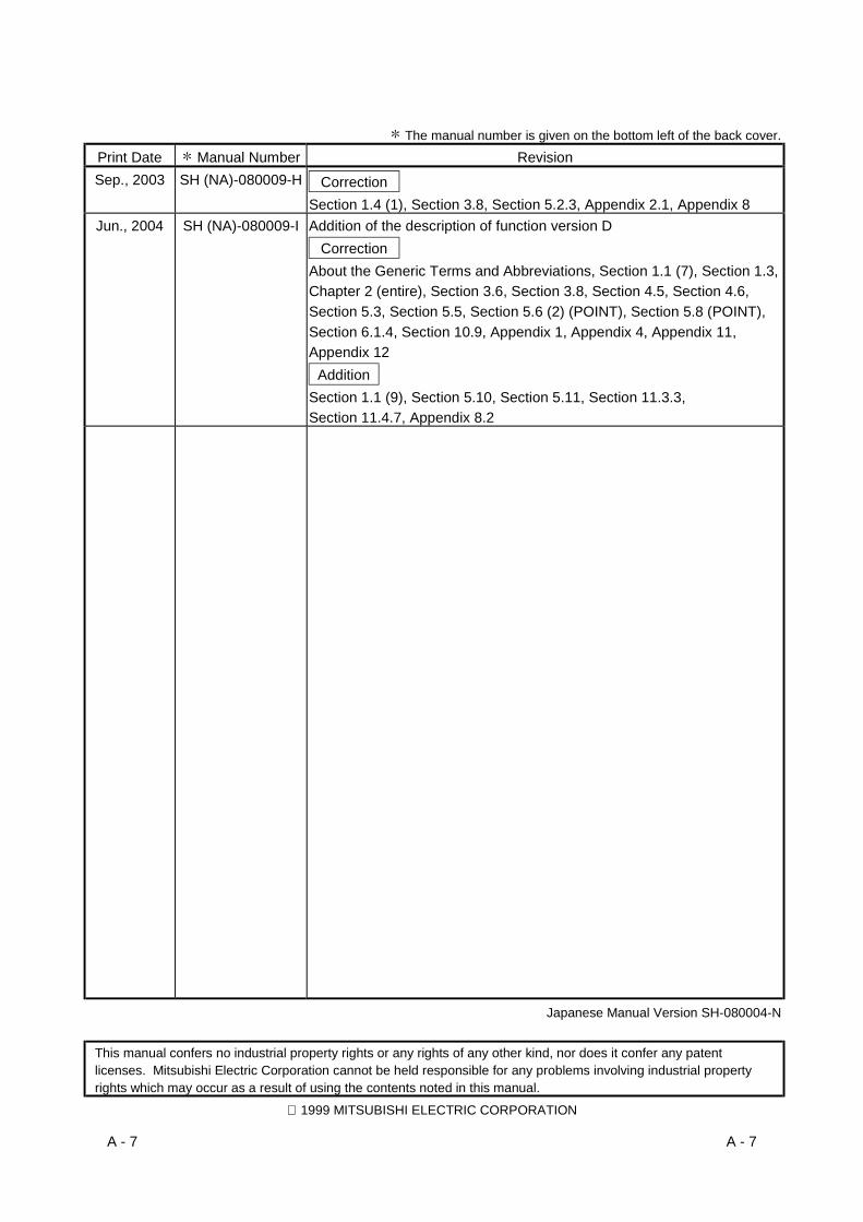
Print Date Manual Number RevisionSep., 2003 SH (NA)-080009-H Correction
Section 1.4 (1), Section 3.8, Section 5.2.3, Appendix 2.1, Appendix 8Jun., 2004 SH (NA)-080009-I Addition of the description of function version D
CorrectionAbout the Generic Terms and Abbreviations, Section 1.1 (7), Section 1.3,Chapter 2 (entire), Section 3.6, Section 3.8, Section 4.5, Section 4.6,Section 5.3, Section 5.5, Section 5.6 (2) (POINT), Section 5.8 (POINT),Section 6.1.4, Section 10.9, Appendix 1, Appendix 4, Appendix 11,Appendix 12
AdditionSection 1.1 (9), Section 5.10, Section 5.11, Section 11.3.3,Section 11.4.7, Appendix 8.2
Japanese Manual Version SH-080004-N
This manual confers no industrial property rights or any rights of any other kind, nor does it confer any patentlicenses. Mitsubishi Electric Corporation cannot be held responsible for any problems involving industrial propertyrights which may occur as a result of using the contents noted in this manual.
1999 MITSUBISHI ELECTRIC CORPORATION

A - 8 A - 8
INTRODUCTION
Thank you for purchasing the MELSEC-Q series PLC.Before using the equipment, please read this manual carefully to develop full familiarity with the functionsand performance of the Q series PLC you have purchased, so as to ensure correct use.Please forward a copy of this manual to the end user.
CONTENTS (This manual)
SAFETY PRECAUTIONS..............................................................................................................................A- 1REVISIONS....................................................................................................................................................A- 5CONTENTS....................................................................................................................................................A- 8About Manuals ...............................................................................................................................................A-16Conformation to the EMC Directive and Low Voltage Instruction ................................................................A-16The Manual's Usage and Structure ...............................................................................................................A-17About the Generic Terms and Abbreviations ................................................................................................A-21Product Configuration ....................................................................................................................................A-22
1 OVERVIEW 1- 1 to 1-15
1.1 Overview of the Ethernet Module ........................................................................................................... 1- 11.2 Features of the Ethernet Module............................................................................................................ 1- 21.3 Additional Functions in Function Version B or Later.............................................................................. 1-121.4 Software Configuration ........................................................................................................................... 1-14
2 SYSTEM CONFIGURATIONS 2- 1 to 2-19
2.1 Applicable Systems................................................................................................................................. 2- 12.2 Devices Required for Network Configuration......................................................................................... 2- 32.3 For Use in Multiple CPU System............................................................................................................ 2- 82.4 For Use with Q00J/Q00/Q01CPU .......................................................................................................... 2-102.5 For Use with Q12PRH/Q25PRHCPU..................................................................................................... 2-112.6 For Use at MELSECNET/H Remote I/O Station.................................................................................... 2-142.7 Checking the Function Version and Serial No. ...................................................................................... 2-18
3 SPECIFICATIONS 3- 1 to 3-27
3.1 Performance Specifications.................................................................................................................... 3- 13.2 Data Codes for Communication ............................................................................................................. 3- 33.3 Relationship between the External Devices and Additional Functions for Each Communication
Function................................................................................................................................................... 3- 53.4 Ethernet Module Function List................................................................................................................ 3- 63.5 Dedicated Instruction List........................................................................................................................ 3- 83.6 List of GX Developer Setting Items for Ethernet Modules..................................................................... 3- 93.7 List of Input/Output Signals to/from the PLC CPU................................................................................. 3-103.8 List of Applications and Assignments of the Buffer Memory ................................................................. 3-12

A - 9 A - 9
4 SETTINGS AND PROCEDURES PRIOR TO OPERATION 4- 1 to 4-25
4.1 Loading and Installation.......................................................................................................................... 4- 14.1.1 Handling precautions ....................................................................................................................... 4- 14.1.2 Installation environment ................................................................................................................... 4- 2
4.2 Settings and Procedures Prior to Starting the Operation ...................................................................... 4- 34.3 Components of the Ethernet Module...................................................................................................... 4- 54.4 Connecting to the Network ..................................................................................................................... 4- 7
4.4.1 Connecting to the 10BASE-T/100BASE-TX network ..................................................................... 4- 84.4.2 Connecting to the 10BASE5 network .............................................................................................. 4- 94.4.3 Connecting to the 10BASE2 network .............................................................................................. 4-10
4.5 Settings from GX Developer................................................................................................................... 4-124.5.1 I/O assignment setting ..................................................................................................................... 4-124.5.2 Other settings ................................................................................................................................... 4-13
4.6 Network Parameters Setting the Number of MNET/10H Ethernet Cards............................................. 4-164.7 Operational Settings ............................................................................................................................... 4-194.8 Self-Diagnostic Tests .............................................................................................................................. 4-22
4.8.1 Self refrain test ................................................................................................................................. 4-224.8.2 Hardware test (H/W Test) ................................................................................................................ 4-23
4.9 Maintenance and Inspection................................................................................................................... 4-244.9.1 Maintenance and inspection ............................................................................................................ 4-244.9.2 Mounting and dismounting the module ........................................................................................... 4-25
5 COMMUNICATION PROCEDURE 5- 1 to 5-111
5.1 Overview of the Communication Procedure .......................................................................................... 5- 15.2 Initial Processing ..................................................................................................................................... 5- 3
5.2.1 Initial processing............................................................................................................................... 5- 35.2.2 Initial settings.................................................................................................................................... 5- 45.2.3 Re-initial Processing......................................................................................................................... 5-10
5.3 Router Relay Parameter ......................................................................................................................... 5-165.4 Confirming the Completion of the Initial Processing.............................................................................. 5-21
5.4.1 PING test using GX Developer (Via Ethernet board)...................................................................... 5-215.4.2 PING test using GX Developer (Via CPU) ...................................................................................... 5-265.4.3 Loop back test using GX Developer................................................................................................ 5-295.4.4 PING command (Personal computer Ethernet module) ............................................................ 5-345.4.5 Loop back test (Communication using the MC protocol)................................................................ 5-35
5.5 Open Settings.......................................................................................................................................... 5-365.6 Open Processing/Close Processing of the Connection......................................................................... 5-43
5.6.1 Active open processing/close processing ....................................................................................... 5-455.6.2 Passive open processing/close processing .................................................................................... 5-525.6.3 UDP/IP open processing/close processing..................................................................................... 5-60
5.7 Pairing Open ........................................................................................................................................... 5-635.7.1 Pairing open ..................................................................................................................................... 5-635.7.2 Example of pairing open settings from GX Developer.................................................................... 5-64
5.8 Automatic Open UDP Port...................................................................................................................... 5-66
A - 10 A - 10
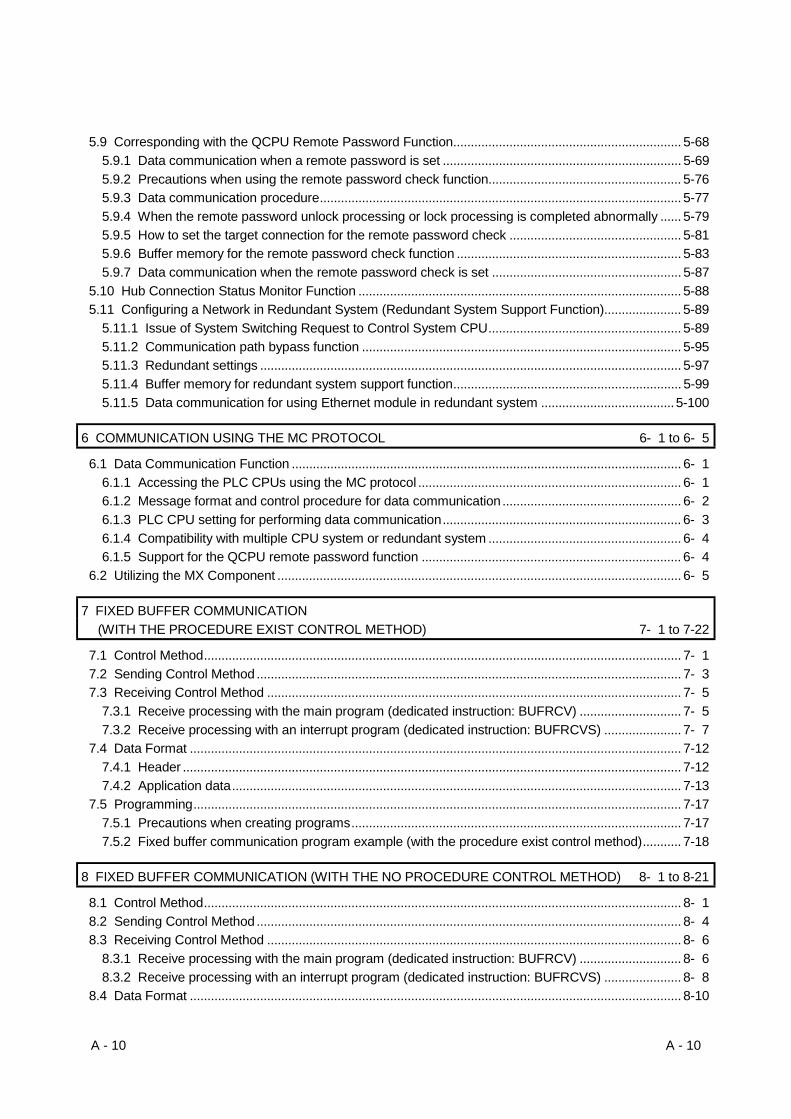
5.9 Corresponding with the QCPU Remote Password Function................................................................. 5-685.9.1 Data communication when a remote password is set .................................................................... 5-695.9.2 Precautions when using the remote password check function....................................................... 5-765.9.3 Data communication procedure....................................................................................................... 5-775.9.4 When the remote password unlock processing or lock processing is completed abnormally ...... 5-795.9.5 How to set the target connection for the remote password check ................................................. 5-815.9.6 Buffer memory for the remote password check function ................................................................ 5-835.9.7 Data communication when the remote password check is set ...................................................... 5-87
5.10 Hub Connection Status Monitor Function ............................................................................................ 5-885.11 Configuring a Network in Redundant System (Redundant System Support Function)...................... 5-89
5.11.1 Issue of System Switching Request to Control System CPU....................................................... 5-895.11.2 Communication path bypass function ........................................................................................... 5-955.11.3 Redundant settings ........................................................................................................................ 5-975.11.4 Buffer memory for redundant system support function................................................................. 5-995.11.5 Data communication for using Ethernet module in redundant system ......................................5-100
6 COMMUNICATION USING THE MC PROTOCOL 6- 1 to 6- 5
6.1 Data Communication Function ............................................................................................................... 6- 16.1.1 Accessing the PLC CPUs using the MC protocol ........................................................................... 6- 16.1.2 Message format and control procedure for data communication ................................................... 6- 26.1.3 PLC CPU setting for performing data communication.................................................................... 6- 36.1.4 Compatibility with multiple CPU system or redundant system ....................................................... 6- 46.1.5 Support for the QCPU remote password function .......................................................................... 6- 4
6.2 Utilizing the MX Component ................................................................................................................... 6- 5
7 FIXED BUFFER COMMUNICATION(WITH THE PROCEDURE EXIST CONTROL METHOD) 7- 1 to 7-22
7.1 Control Method........................................................................................................................................ 7- 17.2 Sending Control Method ......................................................................................................................... 7- 37.3 Receiving Control Method ...................................................................................................................... 7- 5
7.3.1 Receive processing with the main program (dedicated instruction: BUFRCV) ............................. 7- 57.3.2 Receive processing with an interrupt program (dedicated instruction: BUFRCVS) ...................... 7- 7
7.4 Data Format ............................................................................................................................................ 7-127.4.1 Header .............................................................................................................................................. 7-127.4.2 Application data................................................................................................................................ 7-13
7.5 Programming........................................................................................................................................... 7-177.5.1 Precautions when creating programs.............................................................................................. 7-177.5.2 Fixed buffer communication program example (with the procedure exist control method)........... 7-18
8 FIXED BUFFER COMMUNICATION (WITH THE NO PROCEDURE CONTROL METHOD) 8- 1 to 8-21
8.1 Control Method........................................................................................................................................ 8- 18.2 Sending Control Method ......................................................................................................................... 8- 48.3 Receiving Control Method ...................................................................................................................... 8- 6
8.3.1 Receive processing with the main program (dedicated instruction: BUFRCV) ............................. 8- 68.3.2 Receive processing with an interrupt program (dedicated instruction: BUFRCVS) ...................... 8- 8
8.4 Data Format ............................................................................................................................................ 8-10

A - 11 A - 11
8.5 Simultaneous Broadcast Using UDP/IP................................................................................................. 8-118.5.1 Sending by simultaneous broadcasting........................................................................................... 8-118.5.2 Receiving by simultaneous broadcasting........................................................................................ 8-138.5.3 Precautions when using the simultaneous broadcast function....................................................... 8-16
8.6 Programming........................................................................................................................................... 8-178.6.1 Precautions when creating programs.............................................................................................. 8-178.6.2 Fixed buffer communication program example (with the no procedure control method) .............. 8-18
9 COMMUNICATION USING THE RANDOM ACCESS BUFFER 9- 1 to 9-16
9.1 Control Method........................................................................................................................................ 9- 19.1.1 Control method by read requests from an external device............................................................. 9- 39.1.2 Control method by write requests from an external device ............................................................ 9- 4
9.2 Data Format ............................................................................................................................................ 9- 59.2.1 Header .............................................................................................................................................. 9- 59.2.2 Application data................................................................................................................................ 9- 69.2.3 Examples of the command/response formats................................................................................. 9-11
9.3 Physical and Logical Addresses of the Random Access Buffer ........................................................... 9-159.4 Precautions when Creating Programs ................................................................................................... 9-16
10 DEDICATED INSTRUCTIONS 10- 1 to 10-26
10.1 Dedicated Instruction List ................................................................................................................... 10- 110.2 BUFRCV Instruction............................................................................................................................ 10- 210.3 BUFRCVS Instruction ......................................................................................................................... 10- 510.4 BUFSND Instruction............................................................................................................................ 10- 810.5 CLOSE Instruction ..............................................................................................................................10-1110.6 ERRCLR Instruction............................................................................................................................10-1410.7 ERRRD Instruction..............................................................................................................................10-1710.8 OPEN Instruction ................................................................................................................................10-1910.9 UINI Instruction....................................................................................................................................10-23
11 TROUBLESHOOTING 11- 1 to 11-63
11.1 How to Check Errors Using LED Displays ......................................................................................... 11- 211.1.1 Checking error display ................................................................................................................. 11- 211.1.2 How to turn off COM.ERR LED and to read/clear error information .......................................... 11- 4
11.2 How to Check an Error Through GX Developer ................................................................................ 11- 511.2.1 Ethernet diagnostics..................................................................................................................... 11- 611.2.2 System monitor ............................................................................................................................ 11- 811.2.3 Buffer memory that can be monitored with the GX Developer diagnostic function ...................11-1011.2.4 Checking the error information by the buffer memory batch monitoring function......................11-12
11.3 Error Code List ....................................................................................................................................11-1311.3.1 End codes (Complete codes) returned to an external device during data communication.......11-2211.3.2 Abnormal codes returned during communication using A compatible 1E frames.....................11-2411.3.3 Error codes stored in the buffer memory.....................................................................................11-25
A - 12 A - 12
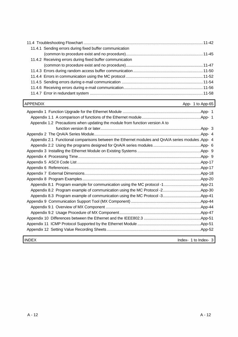
11.4 Troubleshooting Flowchart .................................................................................................................11-4211.4.1 Sending errors during fixed buffer communication
(common to procedure exist and no procedure).........................................................................11-4511.4.2 Receiving errors during fixed buffer communication
(common to procedure exist and no procedure).........................................................................11-4711.4.3 Errors during random access buffer communication ..................................................................11-5011.4.4 Errors in communication using the MC protocol .........................................................................11-5211.4.5 Sending errors during e-mail communication .............................................................................11-5411.4.6 Receiving errors during e-mail communication........................................................................... 11-5611.4.7 Error in redundant system ...........................................................................................................11-58
APPENDIX App- 1 to App-65
Appendix 1 Function Upgrade for the Ethernet Module ..........................................................................App- 1Appendix 1.1 A comparison of functions of the Ethernet module........................................................App- 1Appendix 1.2 Precautions when updating the module from function version A to
function version B or later...............................................................................................App- 3Appendix 2 The QnA/A Series Module.....................................................................................................App- 4
Appendix 2.1 Functional comparisons between the Ethernet modules and QnA/A series modules .App- 4Appendix 2.2 Using the programs designed for QnA/A series modules .............................................App- 6
Appendix 3 Installing the Ethernet Module on Existing Systems ............................................................App- 9Appendix 4 Processing Time....................................................................................................................App- 9Appendix 5 ASCII Code List .....................................................................................................................App-17Appendix 6 References.............................................................................................................................App-17Appendix 7 External Dimensions..............................................................................................................App-18Appendix 8 Program Examples ................................................................................................................App-20
Appendix 8.1 Program example for communication using the MC protocol -1...................................App-21Appendix 8.2 Program example of communication using the MC Protocol -2....................................App-30Appendix 8.3 Program example of communication using the MC Protocol -3....................................App-41
Appendix 9 Communication Support Tool (MX Component) ..................................................................App-44Appendix 9.1 Overview of MX Component ..........................................................................................App-44Appendix 9.2 Usage Procedure of MX Component.............................................................................App-47
Appendix 10 Differences between the Ethernet and the IEEE802.3 ......................................................App-51Appendix 11 ICMP Protocol Supported by the Ethernet Module ............................................................App-51Appendix 12 Setting Value Recording Sheets .........................................................................................App-52
INDEX Index- 1 to Index- 3

A - 13 A - 13
(Related Manual-1) ··· Q Corresponding Ethernet Interface Module User's Manual (Application)SH-080010-G
1 OVERVIEW1.1 Overview1.2 Additional Functions in Function Version B or
Later
2 USING THE E-MAIL FUNCTION2.1 E-mail Function2.2 Configuration and Environment of the
Applicable System2.3 Precautions for Using the E-mail Function2.4 E-mail Specifications2.5 Processing Procedure of the E-mail Function2.6 E-mail Setting from GX Developer2.7 Sending/Receiving E-mail (Attached Files) by
the PLC CPU2.8 Sending E-mail (Main Text) by the PLC CPU2.9 Sending E-mails Using the PLC CPU
Monitoring Function
3 WHEN COMMUNICATING WITHMELSECNET/H, MELSECNET/10 RELAY
3.1 MELSECNET/H, MELSECNET/10 RelayCommunication
3.2 Remote Station PLC Accessible Range andStations
3.3 Settings for Accessing Other Stations3.4 Procedure for Accessing Other Stations3.5 Precautions for Accessing Other Stations
4 WHEN THE QCPU ACCESSES THE OTHERSTATION PLC USING THE DATA LINKINSTRUCTION
4.1 Other Station Access with the Data LinkInstruction
4.2 Precautions for Accessing Other Stations4.3 Using the Data Link Instructions4.4 Data Link Instructions4.5 Data Sending/Receiving4.6 Reading/Writing Word Devices of Other
Stations (READ/WRITE)4.7 Reading/Writing Word Devices of Other
Stations (ZNRD/ZNWR)4.8 Reading/Writing Clock Data, Remote
RUN/Remote STOP (REQ)4.9 Error Codes for Data Link Instructions
5 WHEN USING FILE TRANSFER FUNCTIONS(FTP SERVER)
5.1 File Transfer Functions5.2 File Transferable Range5.3 FTP Parameter Settings for File Transfer from
GX Developer5.4 Procedure and Required Processing on the
External Device Side (FTP Client)
5.5 Precautions when Using the File TransferFunctions
5.6 FTP Commands
6 DEDICATED INSTRUCTIONS6.1 Dedicated Instruction List6.2 MRECV Instruction6.3 MSEND Instruction6.4 READ Instruction6.5 RECV Instruction (for the Main Program)6.6 RECVS Instruction (for Interrupt Programs)6.7 REQ Instruction (Remote RUN/STOP)6.8 REQ Instruction (Clock Data Read/Write)6.9 SEND Instruction6.10 SREAD Instruction6.11 SWRITE Instruction6.12 WRITE Instruction6.13 ZNRD Instruction6.14 ZNWR Instruction
A - 14 A - 14
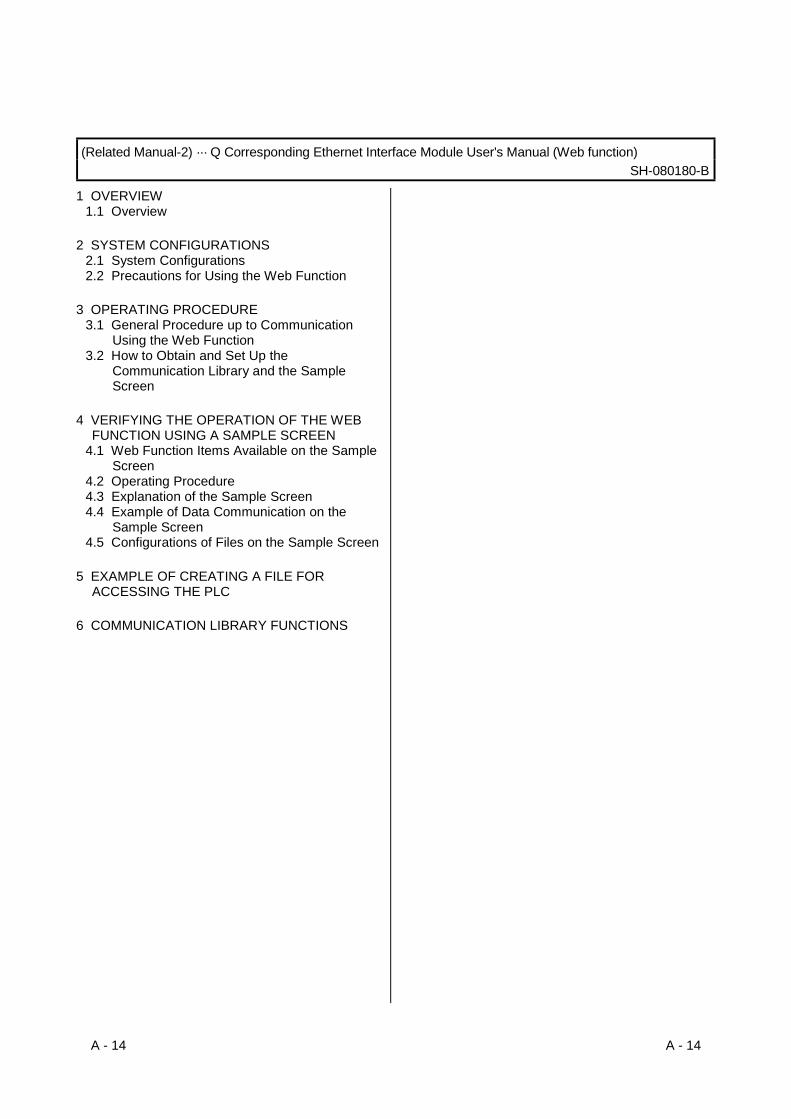
(Related Manual-2) ··· Q Corresponding Ethernet Interface Module User's Manual (Web function)SH-080180-B
1 OVERVIEW1.1 Overview
2 SYSTEM CONFIGURATIONS2.1 System Configurations2.2 Precautions for Using the Web Function
3 OPERATING PROCEDURE3.1 General Procedure up to Communication
Using the Web Function3.2 How to Obtain and Set Up the
Communication Library and the SampleScreen
4 VERIFYING THE OPERATION OF THE WEBFUNCTION USING A SAMPLE SCREEN
4.1 Web Function Items Available on the SampleScreen
4.2 Operating Procedure4.3 Explanation of the Sample Screen4.4 Example of Data Communication on the
Sample Screen4.5 Configurations of Files on the Sample Screen
5 EXAMPLE OF CREATING A FILE FORACCESSING THE PLC
6 COMMUNICATION LIBRARY FUNCTIONS

A - 15 A - 15
(Related Manual-3) … Q Corresponding MELSEC Communication Protocol Reference ManualSH-080008-F
1 OVERVIEW1.1 Overview of the MELSEC Communication
Protocol1.2 Features of the MELSEC Communication
Protocol
2 DATA COMMUNICATION USING THE MELSECCOMMUNICATION PROTOCOL
2.1 Types and Applications of DataCommunication Frames
2.2 Accessible Range of Each DataCommunication Frames
2.3 How to Read the Control Procedures of theMC Protocol
2.4 Access Timing of the PLC CPU Side2.5 Setting Method for Writing to the PLC CPU
during RUN2.6 Accessing Other Stations2.7 Precautions on Data Communication2.8 Time Chart and Communication Time of the
Transmission Sequence of the SerialCommunication Module
2.9 Transmission Time When Accessing OtherStations Via MELSECNET/H, MELSECNET/10
2.10 Compatibility with Multiple CPU Systems2.11 Compatibility with the Q00CPU, Q01CPU
Serial Communication Function
3 WHEN COMMUNICATING USING THE QnACOMPATIBLE 3E/3C/4C FRAMES
3.1 Message Formats3.2 List of Commands and Functions for the QnA
Compatible 3E/3C/4C Frames3.3 Device Memory Read/Write3.4 Buffer Memory Read/Write3.5 Reading from and Writing to the Buffer
Memory of an Intelligent Function Module3.6 PLC CPU Status Control3.7 Drive Memory Defragmentation (for Other
Station QnACPU)3.8 File Control3.9 Registering, Deleting and Reading User
Frames: for Serial Communication Modules3.10 Global Function: for Serial Communication
Modules3.11 Data Transmission to an External device
(On-Demand Function): for SerialCommunication Modules
3.12 Initializing the Transmission Sequence: forSerial Communication Modules
3.13 Mode Switching: for Serial CommunicationModule
3.14 Turning Off Displayed LEDs and InitializingCommunication Error Information and ErrorCode: for Serial Communication Module
3.15 Turning Off the COM.ERR LED: for EthernetModules
3.16 Loopback Test3.17 Registering or Canceling PLC CPU
Monitoring: for Serial CommunicationModules
3.18 Remote Password Unlock/Lock
4 WHEN COMMUNICATING USING THE QnACOMPATIBLE 2C FRAMES
4.1 Control Procedures and Message Formats4.2 Contents of the Data Designation Items4.3 List of Commands and Functions for QnA
Compatible 2C Frames4.4 Precautions on the Data Communication4.5 Example of Data Communication Using QnA
Compatible 2C Frames
5 WHEN COMMUNICATING USING THE ACOMPATIBLE 1C FRAMES
5.1 Control Procedures and Message Formats5.2 Device Memory Read/Write5.3 Extension File Register Read and Write5.4 Reading and Writing in the Buffer Memory of
an Intelligent Function Module5.5 Loopback Test
6 WHEN COMMUNICATING USING THE ACOMPATIBLE 1E FRAMES
6.1 Message Formats and Control Procedures6.2 List of Commands and Functions for A
Compatible 1E Frames6.3 Device Memory Read/Write6.4 Extension File Register Read and Write6.5 Reading and Writing in the Buffer Memory of
an Intelligent Function Module
APPENDIXAppendix-1 Reading and Writing by Designation
of the Device Memory ExtensionAppendix 2 Reading from and Writing to the
Buffer MemoryAppendix-3 Processing Time of the PLC CPU
Side While Communicating Usingthe MC Protocol
A - 16 A - 16
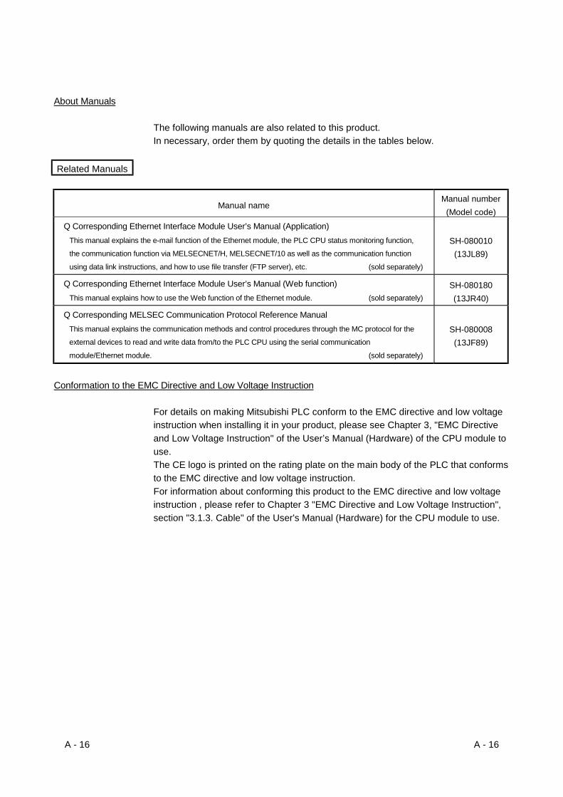
About Manuals
The following manuals are also related to this product.In necessary, order them by quoting the details in the tables below.
Related Manuals
Manual nameManual number
(Model code)Q Corresponding Ethernet Interface Module User’s Manual (Application)
This manual explains the e-mail function of the Ethernet module, the PLC CPU status monitoring function,
the communication function via MELSECNET/H, MELSECNET/10 as well as the communication function
using data link instructions, and how to use file transfer (FTP server), etc. (sold separately)
SH-080010(13JL89)
Q Corresponding Ethernet Interface Module User’s Manual (Web function)This manual explains how to use the Web function of the Ethernet module. (sold separately)
SH-080180(13JR40)
Q Corresponding MELSEC Communication Protocol Reference ManualThis manual explains the communication methods and control procedures through the MC protocol for the
external devices to read and write data from/to the PLC CPU using the serial communication
module/Ethernet module. (sold separately)
SH-080008(13JF89)
Conformation to the EMC Directive and Low Voltage Instruction
For details on making Mitsubishi PLC conform to the EMC directive and low voltageinstruction when installing it in your product, please see Chapter 3, "EMC Directiveand Low Voltage Instruction" of the User’s Manual (Hardware) of the CPU module touse.The CE logo is printed on the rating plate on the main body of the PLC that conformsto the EMC directive and low voltage instruction.For information about conforming this product to the EMC directive and low voltageinstruction , please refer to Chapter 3 "EMC Directive and Low Voltage Instruction",section "3.1.3. Cable" of the User's Manual (Hardware) for the CPU module to use.
A - 17 A - 17
The Manual's Usage and Structure
How to use this manualIn this manual, explanations are given for each application of the Ethernet modules(QJ71E71-100, QJ71E71-B5 and QJ71E71-B2).Please use this manual using the following key items below as a reference.
(1) To find out about the features and utility lists(a) To find out about the features and functions
• Chapter 1 describes the features of the Ethernet modules.• Chapter 3 describes the common functions and specifications of the
Ethernet modules.
(b) To find out about the packaged items and network configured items• The section prior to Chapter 1, "Product Configuration" describes the items
that are supplied together with the Ethernet module.• Section 2.2 describes the system configuration of the Ethernet module.
Parts and components other than those packaged with the module must bepurchased separately by the user.
(2) To find out about the processing required prior to starting theoperation of the Ethernet module(a) To find out about the startup procedure
• Section 4.2 describes an outline of the procedures prior to starting theoperation of the Ethernet module.
(b) To find out about the connection to the Ethernet network system.• Section 2.2 describes the devices required to connect to the Ethernet
network system.• Section 4.4 describes the connection methods for each type of interface.
(c) To find out about the parameter settings required prior to starting theoperation of the Ethernet module• Section 4.5 describes the types of the parameter setting screens for GX
Developer in order to use the Ethernet module.• Section 3.6 describes the parameter settings required for each function to
be used.Confirm the required parameters, set them according to the relevantsection providing detailed explanation, and save the setting values in thePLC CPU to which the Ethernet module is installed.
(d) To find out how to check for Ethernet module failures• Section 4.8 describes the self-diagnostic test for the Ethernet module.

A - 18 A - 18
(e) To find out how to check for connection errors with the external devices• Sections 5.4.1 to 5.4.3 describe how to check for connection errors by
performing the PING test and loop back test through GX Developer.• Section 5.4.4 describes how to check for connection errors using the
"PING" command.• Section 5.4.5 describes how to check for connection errors by performing
the loopback test through MC protocol-based communication. For details of the loopback test commands through MC protocol, refer to theQ Corresponding MELSEC Communication Protocol Reference Manual.
(3) To find out about the connection between the Ethernet module andthe external devices(a) To find out about the communication procedures
• Section 5.1 describes an outline of the communication procedures
(b) To find out about the connections with the external devices• Section 5.6 describes the connections (open and close processing) for
each of the communication method (TCP/IP, UDP/IP) and the open method(Active, Passive), including programming procedures.
(4) To find out about the details of the data communication functions(a) To find out about the communication functions
• Section 1.2 describes an overview of the Ethernet module communicationfunctions and related section numbers and manual names that can bereferenced for more detailed explanations.
• Special functions of the Ethernet module are described in the User'sManual (Application).
• Web functions of the Ethernet module are described in the User's Manual(Web function).
(5) To find out about the data communication functions andprogramming(a) To find out how data is read from and written to the PLC CPU
• Data is read from and written to the PLC CPU with communicationfunctions using the MC protocol.
• Chapter 6 describes an overview of the communication functions using theMC protocol.
For details, refer to the Q Corresponding MELSEC CommunicationProtocol Reference Manual.
(b) To find out how to send and receive data between the PLC CPU and theexternal devices• Data communication between the PLC CPU and the external devices is
performed with the communication functions using either the fixed buffersor the random access buffers.
• Chapters 7 and 8 explains details of the communication functions andprogramming using the fixed buffers.
• Chapter 9 explains details of the communication functions andprogramming using the random access buffers.
A - 19 A - 19
(6) To find out how to check for error occurrences and take correctiveactions(a) To find out about the contents of the error codes
• Chapter 11 describes troubleshooting, how to check for errors, andcontents and reference manual of error codes.
(b) To find out about the storage area of the error codes in the buffer memory ofthe Ethernet module• Section 11.3 describes the error code storage areas in the buffer memory.
(7) To learn about functions that have been added to function versionB and later• Section 1.3 provides the added function list and detailed explanation manual.• Appendix 1.1 provides the comparison of the Ethernet module functions.
Structure of this manual(1) Setting parameters with GX Developer
(a) Using GX Developer to set parameters, the sequence programs forcommunicating with external devices can be simplified in the Ethernetmodule.
(b) In this manual, parameter settings using GX Developer are explained asfollows.1) Section 4.5 describes the types of setting screens, objectives of settings,
items and an outline of settings.2) Details are explained in the detailed explanatory sections on the screens
or in the text in Section 4.5.
(c) Confirm the required parameters and set them according to the relevantexplanatory section or manual, and save the values in the PLC CPU to whichthe Ethernet module is installed.
A - 20 A - 20
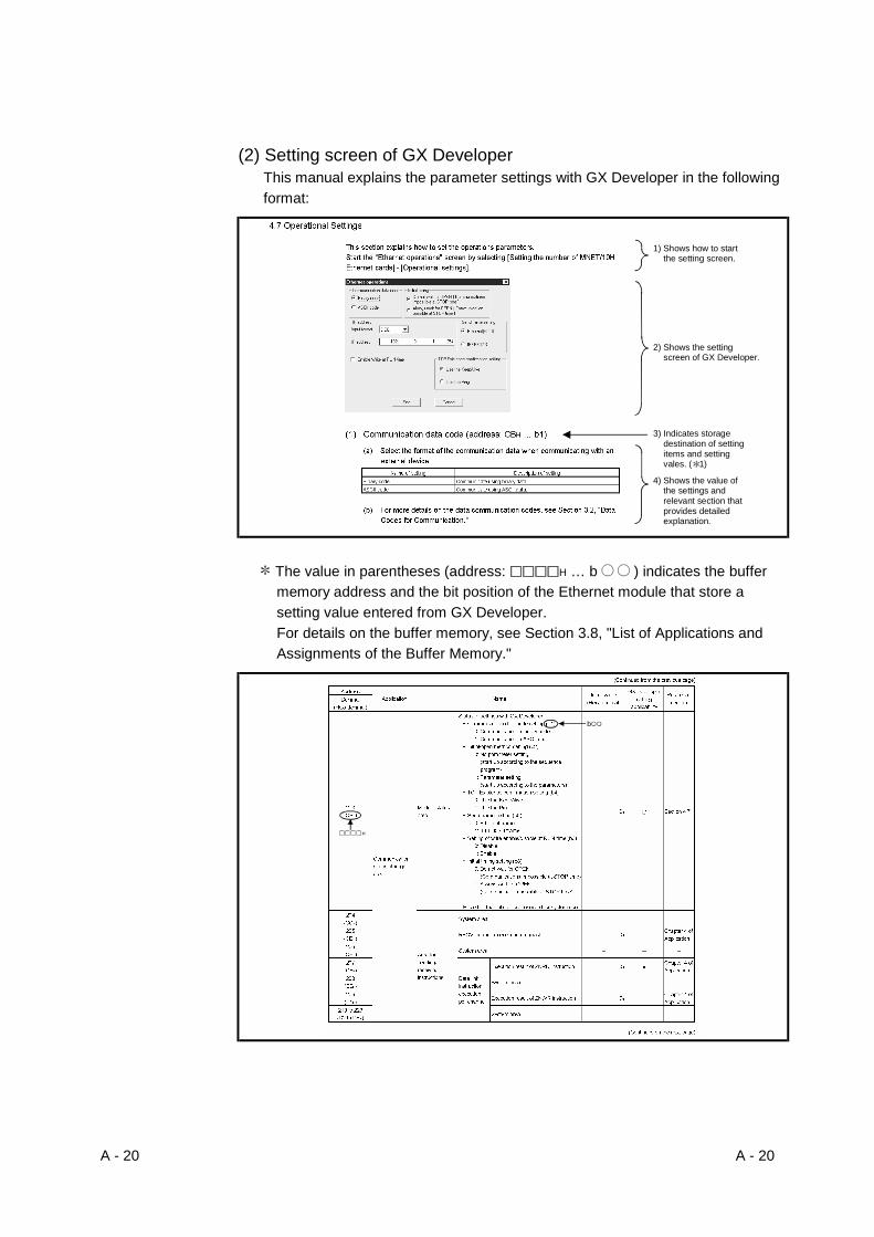
(2) Setting screen of GX DeveloperThis manual explains the parameter settings with GX Developer in the followingformat:
1) Shows how to start the setting screen.
3) Indicates storage destination of setting items and setting vales. ( 1)
2) Shows the setting screen of GX Developer.
4) Shows the value of the settings and relevant section that provides detailed explanation.
The value in parentheses (address: H … b ) indicates the buffermemory address and the bit position of the Ethernet module that store asetting value entered from GX Developer.For details on the buffer memory, see Section 3.8, "List of Applications andAssignments of the Buffer Memory."
H
b

A - 21 A - 21
About the Generic Terms and Abbreviations
This manual uses the following generic terms and abbreviations to describe theModel QJ71E71-100, QJ71E71-B5 and QJ71E71-B2 Ethernet interface modules,unless otherwise specified.
Generic Term/Abbreviation DescriptionACPU Generic term for AnNCPU, AnACPU, and AnUCPU
AnACPU Generic term A2ACPU, A2ACPU-S1, A2ACPUP21/R21, A2ACPUP21/R21-S1,A3ACPU, A3ACPUP21/R21
AnNCPU Generic term A1NCPU, A1NCPUP21/R21, A2NCPU, A2NCPU-S1,A2NCPUP21/R21, A2NCPUP21/R21-S1, A3NCPU, A3NCPUP21/R21
AnUCPU Generic term for A2UCPU, A2UCPU-S1, A2ASCPU, A2ASCPU-S1, A3UCPU, andA4UCPU
Ethernet Address
A machine-specific address that is also referred to as the MAC (Media Access Control)address. This is used to identify the addresses of external devices over a network.The Ethernet address of the Ethernet module can be verified on the MAC ADDcolumn of the rating plate.
Ethernet moduleAbbreviation for Model QJ71E71-100, QJ71E71-B5 and QJ71E71-B2 EthernetInterface Modules(Described as the Ethernet module or E71 in the figures)
Ethernet network system Abbreviation for 10BASE2,10BASE5, 10BASE-T and 100BASE-TX network systems
External device Generic term for personal computers, computers, workstations (WS) and Ethernetmodule etc. that are connected by the Ethernet for data communication
GX Developer Abbreviation for GX Developer (SWnD5C-GPPW-E). (n in the model name is 4 or greater)MELSECNET/10 Abbreviation for MELSECNET/10 Network systemMELSECNET/H Abbreviation for MELSECNET/H Network systemMX Component Abbreviation for MX Component (SW0D5C-ACT-E or later)Network module(N/W module)
Abbreviation for interface modules compatible with the MELSECNET/10 (H) networksystem
OPS
Generic term for the partner product installed with redundant system-compatibleEZSocket (operator station).The OPS can make communication using the Ethernet module's user connection forOPS connection. (Refer to Section 5.5.)
Personal computer Generic term for IBM PC/AT (or 100% compatible) personal computer
QCPU Q modeGeneric term for Q00JCPU, Q00CPU, Q01CPU, Q02CPU, Q02HCPU,Q06HCPU, Q12HCPU, Q25HCPU, Q12PHCPU, Q25PHCPU,Q12PRHCPU, and Q25PRHCPU
QCPU-A A mode Generic term for for Q02CPU-A, Q02HCPU-A, and Q06HCPU-AQCPU station Abbreviation for the PLC with QCPU installed.
QnACPU Generic term for Q2ACPU, Q2ACPU-S1, Q2ASCPU, Q2ASCPU-S1, Q2ASHCPU,Q2ASHCPU-S1, Q3ACPU, Q4ACPU, and Q4ARCPU
Q/QnA Generic term for QCPU and QnACPU
Reference Manual Abbreviation for the Q Corresponding MELSEC Communication Protocol ReferenceManual
User's Manual (Application) Abbreviation for the Q Corresponding Ethernet Interface Module User's Manual(Application)
User's Manual (Basic) Abbreviation for the Q Corresponding Ethernet Interface Module User's Manual(Basic)
User's Manual (Web function) Abbreviation for the Q Corresponding Ethernet Interface Module User's Manual(Web function)

A - 22 A - 22
Product Configuration
The following lists the product configuration of the Ethernet interface modules.
Model Item name QuantityQJ71E71-100 QJ71E71-100 Ethernet interface module 1QJ71E71-B5 QJ71E71-B5 Ethernet interface module 1QJ71E71-B2 QJ71E71-B2 Ethernet interface module 1
1 - 1 1 - 1
MELSEC-Q1 OVERVIEW
11 OVERVIEW
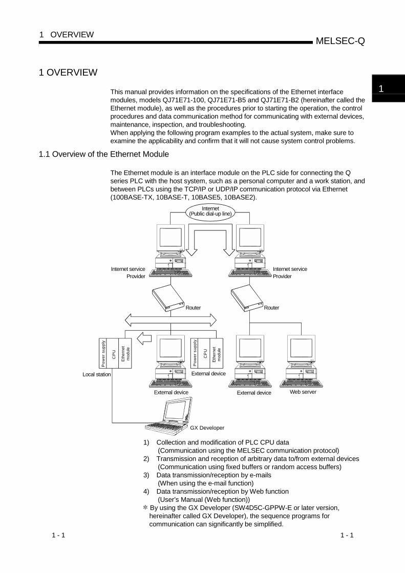
This manual provides information on the specifications of the Ethernet interfacemodules, models QJ71E71-100, QJ71E71-B5 and QJ71E71-B2 (hereinafter called theEthernet module), as well as the procedures prior to starting the operation, the controlprocedures and data communication method for communicating with external devices,maintenance, inspection, and troubleshooting.When applying the following program examples to the actual system, make sure toexamine the applicability and confirm that it will not cause system control problems.
1.1 Overview of the Ethernet Module
The Ethernet module is an interface module on the PLC side for connecting the Qseries PLC with the host system, such as a personal computer and a work station, andbetween PLCs using the TCP/IP or UDP/IP communication protocol via Ethernet(100BASE-TX, 10BASE-T, 10BASE5, 10BASE2).
Internet serviceProvider
Internet(Public dial-up line)
Router Router
Internet serviceProvider
External device Web server
Pow
er s
uppl
y
CP
U
Pow
er s
uppl
y
CP
U
Local station
External device
External device
Ethe
rnet
m
odul
e
Ethe
rnet
m
odul
e
GX Developer
1) Collection and modification of PLC CPU data(Communication using the MELSEC communication protocol)
2) Transmission and reception of arbitrary data to/from external devices(Communication using fixed buffers or random access buffers)
3) Data transmission/reception by e-mails(When using the e-mail function)
4) Data transmission/reception by Web function(User’s Manual (Web function))
By using the GX Developer (SW4D5C-GPPW-E or later version,hereinafter called GX Developer), the sequence programs forcommunication can significantly be simplified.

1 - 2 1 - 2
MELSEC-Q1 OVERVIEW
1
1.2 Features of the Ethernet Module
(1) Data communication using the MELSEC communication protocol(Details are explained in Chapter 6 of the MELSEC CommunicationProtocol Reference Manual)In the "data communication using the MELSEC communication protocol(hereinafter called the MC protocol)", the device data and program files of thePLC can be read from/written to the host system.This protocol is a passive protocol that communicates data solely according tothe requests from the host system. It does not require a sequence program fordata communication after a connection is established.If the host system is a personal computer running one of the basic operationsystems below, it is possible to create a communication program for the hostsystem without considering the detailed MC protocol (transmission/receptionprocedures) using one of the following separately sold communication supporttools.(Supported basic operation systems)• Microsoft® Windows® 95 Operating System• Microsoft® Windows® 98 Operating System• Microsoft® Windows NT® Workstation Operating System Version 4.0• Microsoft® Windows® Millennium Edition Operating System• Microsoft® Windows® 2000 Professional Operating System• Microsoft® Windows® XP Professional Operating System• Microsoft® Windows® XP Home Edition Operating System
Depending on the version of MX Component used, different operatingsystems are supported.See the manual of MX Component for the details.
(Separately sold communication support tools)• MX Component (SW0D5C-ACT-E or later, hereinafter abbreviated as MX
Component) See Appendix 9 for the overview of MX Component.
CPU
External device
Local station
Com
man
d
Res
pons
e
Pow
er s
uppl
y
Ethe
rnet
m
odul
e
REMARK
The communication functions using the MC protocol correspond to thecommunication functions for reading/writing data from/to the PLC CPU that aresupported by the A/QnA series Ethernet modules (A1SJ71E71/A1SJ71QE71, etc.).
1 - 3 1 - 3
MELSEC-Q1 OVERVIEW
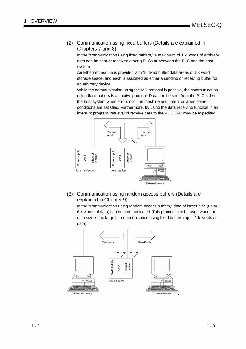
(2) Communication using fixed buffers (Details are explained inChapters 7 and 8)In the "communication using fixed buffers," a maximum of 1 k words of arbitrarydata can be sent or received among PLCs or between the PLC and the hostsystem.An Ethernet module is provided with 16 fixed buffer data areas of 1 k wordstorage space, and each is assigned as either a sending or receiving buffer foran arbitrary device.While the communication using the MC protocol is passive, the communicationusing fixed buffers is an active protocol. Data can be sent from the PLC side tothe host system when errors occur in machine equipment or when someconditions are satisfied. Furthermore, by using the data receiving function in aninterrupt program, retrieval of receive data to the PLC CPU may be expedited.
CPU
External device
External device
Pow
er s
uppl
y
CPU
Pow
er s
uppl
y
Local station
Receive/send
Receive/send
Ethe
rnet
m
odul
e
Ethe
rnet
m
odul
e
(3) Communication using random access buffers (Details areexplained in Chapter 9)In the "communication using random access buffers," data of larger size (up to6 k words of data) can be communicated. This protocol can be used when thedata size is too large for communication using fixed buffers (up to 1 k words ofdata).
CPU
Ethe
rnet
mod
ule
Local station
Pow
er s
uppl
y
Read/writeRead/write
External deviceExternal device \

1 - 4 1 - 4
MELSEC-Q1 OVERVIEW
(4) Communication by e-mails (Details are explained in the User’sManual (Application))With “sending/receiving e-mail,” data can be sent to and received from anexternal device at a remote location using e-mail via an Internet line.
(a) Sending/receiving e-mail by the PLC CPUThe following data can be sent/received by using dedicated instructions(MSEND, MRECV).1) Sending/receiving data as attached files
Up to 6K words of data can be sent to or received from a personalcomputer or other Ethernet module as a file attached to e-mail.
2) Sending data as main textUp to 960 words of data can be sent to a personal computer orportable terminal as main text of e-mail.
(b) Sending e-mail by the PLC CPU Monitoring functionBy setting up the Ethernet parameters, the notification conditions (PLCCPU status or device value) set by the user can be monitored at constantintervals, and up to 960 words of data can be sent by either of the followingmethods when the notification conditions are satisfied:1) Sending data as an attached file2) Sending data as main text
Internet service provider
Internet (Public dial-up line)
Pow
er s
uppl
y
Ethe
rnet
m
odul
e
Local station
External device
CPU
Internet service provider
Router Router
E-mail sending/receiving

1 - 5 1 - 5
MELSEC-Q1 OVERVIEW
(5) Communication by the Web function (Details are explained in theUser’s Manual (Web function))With “communication using the Web function,” the system administrator canmonitor a Q Series CPU at a remote location via the Internet using acommercially available Web browser.
(a) By setting up a communication library in the Web server, datacommunication with the PLC can be performed.A sample screen to be displayed by a Web browser is also available foryour use.Contact your local agency or marketing company.
(b) A Web server and a Web browser are required to use the Web function. (Basic operating systems)
• Microsoft® Windows® 2000 Server Operating System• Microsoft® Windows® 2000 Professional Operating System• Microsoft® Windows NT® Server Network Operating System Version 4.0• Microsoft® Windows NT® Workstation Operating System Version 4.0• Microsoft® Windows® 98 Operating System
(Web servers)• Microsoft® Internet Information Server 5.0• Microsoft® Internet Information Server 4.0• Microsoft® Peer Web Services 4.0• Microsoft® Personal Web Server 4.0
(Web browsers)• Internet Explorer 4.0 or later (Microsoft® Corporation)• Netscape® Communicator 4.05 or later (Netscape® Communications
Corporation)
Pow
er s
uppl
y
Ethe
rnet
m
odul
e
CPU
Web server External device
HTTP(MCprotocol)
Display of requests/results
Web browserHTML
ASPExecution of the ASP file
Communicationlibrary
Access to the PLC
HTTP
Local station
1 - 6 1 - 6
MELSEC-Q1 OVERVIEW
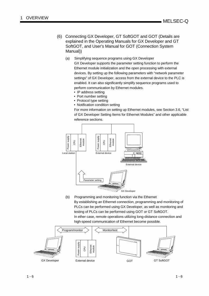
(6) Connecting GX Developer, GT SoftGOT and GOT (Details areexplained in the Operating Manuals for GX Developer and GTSoftGOT, and User’s Manual for GOT (Connection SystemManual))(a) Simplifying sequence programs using GX Developer
GX Developer supports the parameter setting function to perform theEthernet module initialization and the open processing with externaldevices. By setting up the following parameters with “network parametersettings” of GX Developer, access from the external device to the PLC isenabled. It can also significantly simplify sequence programs used toperform communication by Ethernet modules.• IP address setting• Port number setting• Protocol type setting• Notification condition settingFor more information on setting up Ethernet modules, see Section 3.6, “Listof GX Developer Setting Items for Ethernet Modules” and other applicablereference sections.
CPU
Ethe
rnet
mod
ule
Pow
er s
uppl
y
CPU
External device
Pow
er s
uppl
y
Local station
Parameter setting
GX Developer
Ethe
rnet
mod
ule
External device
(b) Programming and monitoring function via the EthernetBy establishing an Ethernet connection, programming and monitoring ofPLCs can be performed using GX Developer, as well as monitoring andtesting of PLCs can be performed using GOT or GT SoftGOT.In ether case, remote operations utilizing long-distance connection andhigh-speed communication of Ethernet become possible.
External device GOT GT SoftGOT
Monitor/test
GX Developer
Program/monitor
Pow
er s
uppl
y
CPU
Ethe
rnet
m
odul
e

1 - 7 1 - 7
MELSEC-Q1 OVERVIEW
(c) Connecting multiple MELSOFT products (GX Developer, GT SoftGOT, andMX Component) or GOTsThis product can be connected with one or more MELSOFT product (GXDeveloper, GT SoftGOT, and MX Component) or GOT simultaneously viaTCP/IP communication or UDP/IP communication. 1 2
1) Connection via TCP/IP communication• The Ethernet module side can connect up to 17 units of MELSOFT
product via TCP/IP communication simultaneously by using onededicated system connection and up to 16 user connections. 3
• If only one MELSOFT product is to be connected, the followingsettings using GX Developer are not required.If two or more MELSOFT product are to be connected, the followingsettings using GX Developer are required since user connectionswill be used.On the "Ethernet open settings" screen for network parameters, set"TCP" in the protocol field of the connection number to be used, and"MELSOFT connection" in the open method field. (See Section 5.5.)
2) Connection via UDP/IP communication. 4
By using one dedicated system connection, the Ethernet module sidecan connect MELSOFT product or GOT via UDP/IP communication.
Connection via TCP/IP
One unit
Multiple units
• • • • Uses a dedicated system connection. The Ethernet open settings parameter is not required.
or
(Protocol used)(External device) (Connection used on the Ethernet module side)
Connection via UDP/IP
Connection via TCP/IP
Ethe
rnet
m
odul
e
Pow
er s
uppl
y
CPU
One unit Multiple units
[Connections used by the Ethernet module side when connecting a MELSOFT product or GOT]
• • • • Uses a dedicated system connection. The Ethernet open settings parameter is not required.
• • • • Uses a dedicated system connection and user connections set up by the user for MELSOFT connection. The Ethernet open settings parameter is required.
1 It is possible to use the same station number if two or more MELSOFTproducts are started up from one personal computer in order to performTCP/IP communication and UDP/IP communication with one Ethernet module.(It is not necessary to use different station numbers for TCP/IP and UDP/IP.)
2 GT SoftGOT and GOT support UDP/IP communication only.3 Dedicated connections will be used to connect MELSOFT products for data
communication. These dedicated connections cannot be used to perform datacommunication with external devices other than MELSOFT product.
4 It is possible to access other stations without performing Conversion setting(Network No., Station No., and IP address) if they are accessed from aMELSOFT product via the Ethernet module using the Communication withMELSECNET/H or MELSECNET/10 relay.See Chapter 3 of User's Manual (Application) for the relay function ofMELSECNET/H and MELSECNET/10.

1 - 8 1 - 8
MELSEC-Q1 OVERVIEW
(7) Functions supporting Multiple CPU systems (Details are explainedin the Reference Manual.)(a) When performing the following data communication with QCPUs in a
multiple CPU system, it is possible to perform data communication such asreading/writing device data or reading/writing files by specifying the QCPUto be accessed.1) Communication by MC protocol2) Communication by GX Developer3) When using the file transfer function (FTP server)
When using the Ethernet module in a multiple CPU system, a QCPUcontrolling the Ethernet module (hereinafter referred to as the controlPLC) should be specified through GX Developer.It is also possible to mount an Ethernet module of function version A ona multiple CPU system and access to the only control PLC (the PLCNo.1).
1) : PLC No.12) : PLC No.23) : PLC No.34) : PLC No.41 : Module controlled by
PLC No.1: Module controlled by PLC No.2
2
External device
Communication through GX DeveloperCommunication using the MC protocolFile transfer(FTP server) function
Setting from GX Developer
1 21) 2) 3) 4)
Ethernet modulecontrol PLC
Ethernet modulenon-control PLCs
Ethernet module
1
(b) When the Ethernet module of function version B or later is used in a multipleCPU system, the following data can be transferred to/from the Ethernetmodule.1) Communication using the fixed buffer, communication using data link
instructions and sending/receiving of e-mail are possible from thecontrol PLC.
2) It is possible to read the buffer memory from non-control PLCs.Input/output signals can be used as contacts.
Buffer memoryFROM/TO instructionDedicated instructionFROM
instruction
Use the input/output signal as a contact
Use the input/output signal as a contactIt should be output to an output signal
Data communication
Non-control PLC Control PLC Ethernet module External device
X
Y
1 - 9 1 - 9
MELSEC-Q1 OVERVIEW
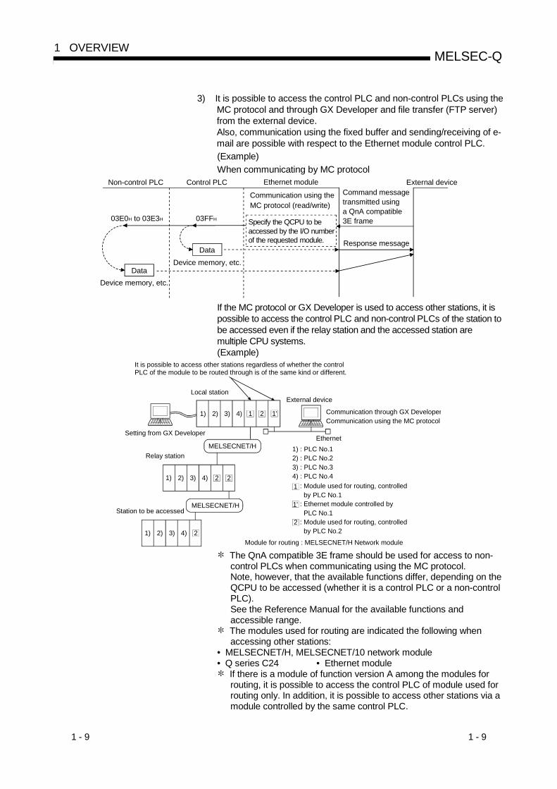
3) It is possible to access the control PLC and non-control PLCs using theMC protocol and through GX Developer and file transfer (FTP server)from the external device.Also, communication using the fixed buffer and sending/receiving of e-mail are possible with respect to the Ethernet module control PLC.(Example)When communicating by MC protocol
Non-control PLC Control PLC Ethernet module
Specify the QCPU to be accessed by the I/O numberof the requested module.
External deviceCommand message transmitted using a QnA compatible 3E frame03FFH03E0H to 03E3H
Device memory, etc.Data
Response message
Communication using the MC protocol (read/write)
Device memory, etc.Data
If the MC protocol or GX Developer is used to access other stations, it ispossible to access the control PLC and non-control PLCs of the station tobe accessed even if the relay station and the accessed station aremultiple CPU systems.(Example)
MELSECNET/H 1) : PLC No.12) : PLC No.23) : PLC No.34) : PLC No.41 : Module used for routing, controlled
by PLC No.1: Ethernet module controlled by PLC No.1: Module used for routing, controlled by PLC No.2
1'
2
Local station
Relay station
External device
Communication through GX DeveloperCommunication using the MC protocol
Setting from GX Developer
MELSECNET/HStation to be accessed
1 2 1'1) 2) 3) 4)
2
Ethernet
It is possible to access other stations regardless of whether the control PLC of the module to be routed through is of the same kind or different.
Module for routing : MELSECNET/H Network module
1) 2) 3) 4)
21) 2) 3) 4)
2
The QnA compatible 3E frame should be used for access to non-control PLCs when communicating using the MC protocol.Note, however, that the available functions differ, depending on theQCPU to be accessed (whether it is a control PLC or a non-controlPLC).See the Reference Manual for the available functions andaccessible range.
The modules used for routing are indicated the following whenaccessing other stations:
• MELSECNET/H, MELSECNET/10 network module• Q series C24 • Ethernet module
If there is a module of function version A among the modules forrouting, it is possible to access the control PLC of module used forrouting only. In addition, it is possible to access other stations via amodule controlled by the same control PLC.
1 - 10 1 - 10
MELSEC-Q1 OVERVIEW
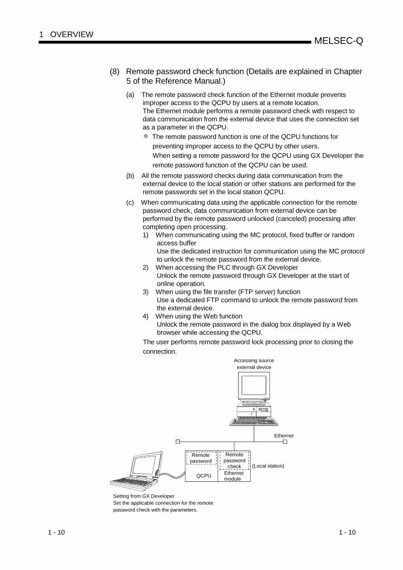
(8) Remote password check function (Details are explained in Chapter5 of the Reference Manual.)(a) The remote password check function of the Ethernet module prevents
improper access to the QCPU by users at a remote location.The Ethernet module performs a remote password check with respect todata communication from the external device that uses the connection setas a parameter in the QCPU.
The remote password function is one of the QCPU functions forpreventing improper access to the QCPU by other users.When setting a remote password for the QCPU using GX Developer theremote password function of the QCPU can be used.
(b) All the remote password checks during data communication from theexternal device to the local station or other stations are performed for theremote passwords set in the local station QCPU.
(c) When communicating data using the applicable connection for the remotepassword check, data communication from external device can beperformed by the remote password unlocked (canceled) processing aftercompleting open processing.1) When communicating using the MC protocol, fixed buffer or random
access bufferUse the dedicated instruction for communication using the MC protocolto unlock the remote password from the external device.
2) When accessing the PLC through GX DeveloperUnlock the remote password through GX Developer at the start ofonline operation.
3) When using the file transfer (FTP server) functionUse a dedicated FTP command to unlock the remote password fromthe external device.
4) When using the Web functionUnlock the remote password in the dialog box displayed by a Webbrowser while accessing the QCPU.
The user performs remote password lock processing prior to closing theconnection.
Setting from GX DeveloperSet the applicable connection for the remote password check with the parameters.
Ethernet
Accessing source external device
(Local station)Ethernet module
Remotepassword
Remotepassword
check
QCPU

1 - 11 1 - 11
MELSEC-Q1 OVERVIEW
(9) Redundant system support function (Detailed explanation: Chapter5)(a) Backup of Ethernet modules
By mounting the Ethernet modules of function version D or later on themain base units of a redundant system, the Ethernet modules can bebacked up. If a failure or communication error occurs in the Ethernetmodule, the system can be switched between the control system andstandby system to continue the communication of the Ethernet module. 1
(b) Issue of system switching request to control system CPUWhen the Ethernet module mounted on the main base unit of the controlsystem CPU in the redundant system detects a communication error ordisconnection, it can issue a system switching request to the control systemCPU.
(c) Access to redundant systemCommunication using MC protocol or data link instruction enables datacommunication, such as read/write of device data and files, from/to thecontrol system/standby system or system A/system B of the redundantsystem.
(d) Connection with OPSThe Ethernet module can communicate with the OPS using the userconnection for OPS connection.Set the user connection for OPS connection in the open setting of GXDeveloper. (Refer to Section 5.5.)
1 The module can also be mounted on the MELSECNET/H remote I/Ostation of the redundant system. Since there are restrictions on theavailable functions, however, refer to Section 2.6 when mounting themodule on the MELSECNET/H remote I/O station.
MELSECNET/H (MELSECNET/10 mode) PLC to PLC network (Communication with other stations)
Remote I/O station
Remote device station
Intelligent device station
Tracking cable
OPS
Ethernet(Communication with host)
CC-Link(I/O control, communication with outside)
MELSECNET/H remote I/O network(I/O control, communication with outside)
Remote I/O station
Remote I/O station
Remote I/O station
Personal computer
AnACPU(Normal station)
AnUCPU(Normal station)
AnNCPU(Normal station)
QCPU(Normal station)
QnACPU(Normal station)
Q4ARCPU(Normal station/control station)
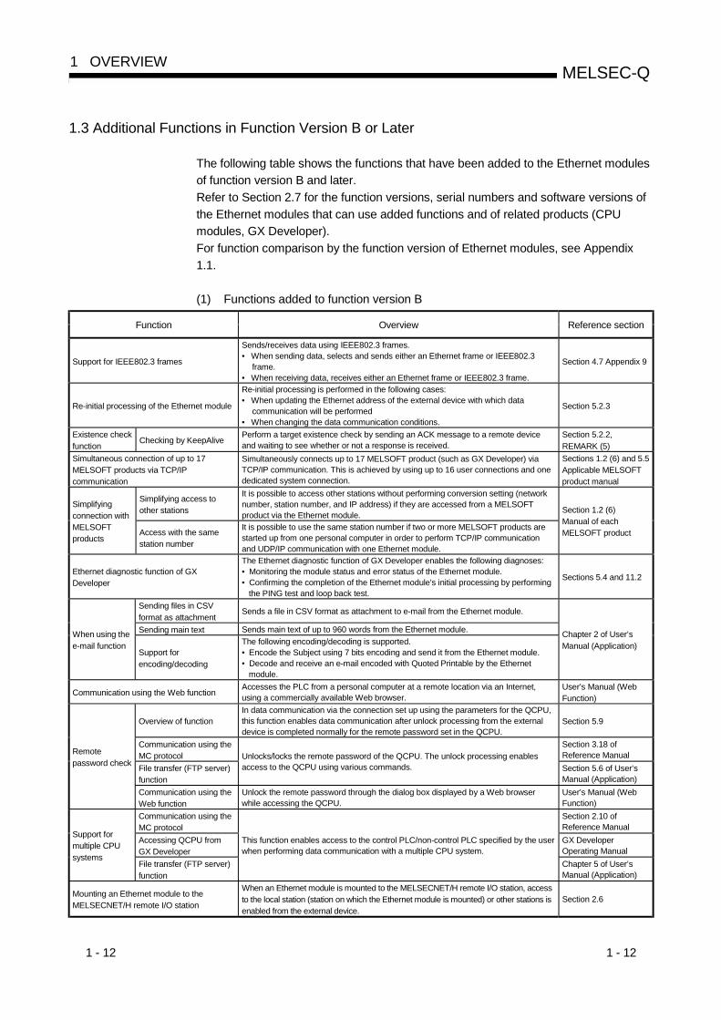
1 - 12 1 - 12
MELSEC-Q1 OVERVIEW
1.3 Additional Functions in Function Version B or Later
The following table shows the functions that have been added to the Ethernet modulesof function version B and later.Refer to Section 2.7 for the function versions, serial numbers and software versions ofthe Ethernet modules that can use added functions and of related products (CPUmodules, GX Developer).For function comparison by the function version of Ethernet modules, see Appendix1.1.
(1) Functions added to function version B
Function Overview Reference section
Support for IEEE802.3 frames
Sends/receives data using IEEE802.3 frames.• When sending data, selects and sends either an Ethernet frame or IEEE802.3
frame.• When receiving data, receives either an Ethernet frame or IEEE802.3 frame.
Section 4.7 Appendix 9
Re-initial processing of the Ethernet module
Re-initial processing is performed in the following cases:• When updating the Ethernet address of the external device with which data
communication will be performed• When changing the data communication conditions.
Section 5.2.3
Existence checkfunction
Checking by KeepAlivePerform a target existence check by sending an ACK message to a remote deviceand waiting to see whether or not a response is received.
Section 5.2.2,REMARK (5)
Simultaneous connection of up to 17MELSOFT products via TCP/IPcommunication
Simultaneously connects up to 17 MELSOFT product (such as GX Developer) viaTCP/IP communication. This is achieved by using up to 16 user connections and onededicated system connection.
Sections 1.2 (6) and 5.5Applicable MELSOFTproduct manual
Simplifying access toother stations
It is possible to access other stations without performing conversion setting (networknumber, station number, and IP address) if they are accessed from a MELSOFTproduct via the Ethernet module.
Simplifyingconnection withMELSOFTproducts
Access with the samestation number
It is possible to use the same station number if two or more MELSOFT products arestarted up from one personal computer in order to perform TCP/IP communicationand UDP/IP communication with one Ethernet module.
Section 1.2 (6)Manual of eachMELSOFT product
Ethernet diagnostic function of GXDeveloper
The Ethernet diagnostic function of GX Developer enables the following diagnoses:• Monitoring the module status and error status of the Ethernet module.• Confirming the completion of the Ethernet module’s initial processing by performing
the PING test and loop back test.
Sections 5.4 and 11.2
Sending files in CSVformat as attachment
Sends a file in CSV format as attachment to e-mail from the Ethernet module.
Sending main text Sends main text of up to 960 words from the Ethernet module.When using thee-mail function
Support forencoding/decoding
The following encoding/decoding is supported.• Encode the Subject using 7 bits encoding and send it from the Ethernet module.• Decode and receive an e-mail encoded with Quoted Printable by the Ethernet
module.
Chapter 2 of User’sManual (Application)
Communication using the Web functionAccesses the PLC from a personal computer at a remote location via an Internet,using a commercially available Web browser.
User’s Manual (WebFunction)
Overview of functionIn data communication via the connection set up using the parameters for the QCPU,this function enables data communication after unlock processing from the externaldevice is completed normally for the remote password set in the QCPU.
Section 5.9
Communication using theMC protocol
Section 3.18 ofReference Manual
File transfer (FTP server)function
Unlocks/locks the remote password of the QCPU. The unlock processing enablesaccess to the QCPU using various commands. Section 5.6 of User’s
Manual (Application)
Remotepassword check
Communication using theWeb function
Unlock the remote password through the dialog box displayed by a Web browserwhile accessing the QCPU.
User’s Manual (WebFunction)
Communication using theMC protocol
Section 2.10 ofReference Manual
Accessing QCPU fromGX Developer
GX DeveloperOperating Manual
Support formultiple CPUsystems
File transfer (FTP server)function
This function enables access to the control PLC/non-control PLC specified by the userwhen performing data communication with a multiple CPU system.
Chapter 5 of User’sManual (Application)
Mounting an Ethernet module to theMELSECNET/H remote I/O station
When an Ethernet module is mounted to the MELSECNET/H remote I/O station, accessto the local station (station on which the Ethernet module is mounted) or other stations isenabled from the external device.
Section 2.6
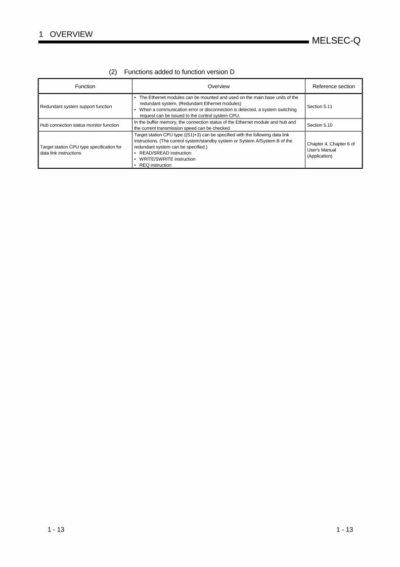
1 - 13 1 - 13
MELSEC-Q1 OVERVIEW
(2) Functions added to function version D
Function Overview Reference section
Redundant system support function
• The Ethernet modules can be mounted and used on the main base units of theredundant system. (Redundant Ethernet modules)
• When a communication error or disconnection is detected, a system switchingrequest can be issued to the control system CPU.
Section 5.11
Hub connection status monitor function In the buffer memory, the connection status of the Ethernet module and hub andthe current transmission speed can be checked. Section 5.10
Target station CPU type specification fordata link instructions
Target station CPU type ((S1)+3) can be specified with the following data linkinstructions. (The control system/standby system or System A/System B of theredundant system can be specified.)• READ/SREAD instruction• WRITE/SWRITE instruction• REQ instruction
Chapter 4, Chapter 6 ofUser's Manual(Application)

1 - 14 1 - 14
MELSEC-Q1 OVERVIEW
1.4 Software Configuration
The Ethernet modules support the TCP/IP and UDP/IP protocols.
User program Q Series PLC CPU
Buffer memory
Dedicated instruction
Commun-icationusingfixed
buffers
Commu-nication using
randomaccessbuffers
Commun-icationusing
the MCprotocol
Commun-icationusingdatalink
instructi-ons
Commun-ication
viaMELSEC
NET/HMELSECNET/10
FTP Commun-ication
bye-mails
TCP/UDP
IP ICMPARP
Ethernet(100BASE-TX,10BASE-T,10BASE5,10BASE2)
TCP
IP
UDP
Ethernet(100BASE-TX, 10BASE-T, 10BASE5,10BASE2)
ICMPARP
System call
CPU
Ethernetmodule
Personal computer/work-station PLC
Commun-ication
byWeb
SMTPPOP3DNS
HTTP
OSI reference model corres-ponding to the PLC configuration(Layers)
Application layerPresentation layerSession layer
765
Transport layer4
Network layer3
Data link layer2Physical layer1
Socket
(1) TCP (Transmission Control Protocol)This protocol guarantees data credibility or reliability in a communication betweena personal computer/work station and the PLC that are connected via network,and provides the following functions:• Creates a logical connection by establishing a connection (logical line) as if a
dedicated line was created between external devices.• A maximum of 16 connections can be established and communication to
multiple buffers can be performed at the same time in the Ethernet module.• Data reliability is maintained by the sequence control using the sequence
numbers, the data retransmission function and the check sum.• The communication data flow can be controlled by operations using Windows.• Supports the Maximum Segment option.
The Maximum Segment option can be made valid for TCP transmission orTCP re-transmission.The data reception side must check the length of received data beforeprocessing the message.
1 - 15 1 - 15
MELSEC-Q1 OVERVIEW
(2) UDP (User Datagram Protocol)This protocol may not guarantee data credibility and reliability in a communicationbetween a personal computer/work station and the PLC that are connected vianetwork. Thus, even if the data does not reach the target node, it will not beretransmitted.• Because it is connectionless, high-speed transmission is possible.• A check sum is used to increase the reliability of the communication data.
However, when greater reliability must be maintained, a user application or theTCP should be utilized.
(3) IP (Internet Protocol)• Communication data is sent and received in datagram format.• Communication data can be divided and reassembled.• Routing option is not supported.
(4) ARP (Address Resolution Protocol)• This protocol is used to get the Ethernet physical addresses from the IP
addresses.
(5) ICMP (Internet Control Message Protocol)• This protocol is used to exchange errors occurred on an IP network and
various information related to the network.• Provides a function to transmit IP error messages.• See Appendix for information regarding the option support type (ICMP
protocol).
(6) FTP (File Transfer Protocol)• This protocol is used to transfer files.• Can upload and download PLC CPU files.
(7) DNS (Domain Name System)• This system translates IP addresses to names that are easy to remember by
the user.
(8) SMTP (Simple Mail Transfer Protocol)• This protocol transfers mails.
(9) POP3 (Post Office Protocol Ver. 3)• This protocol transfers mails received by a mail server to a local computer.
(10) HTTP (Hyper Text Transfer Protcol)• This protocol is used to perform data communication for world wide web of the
internet.
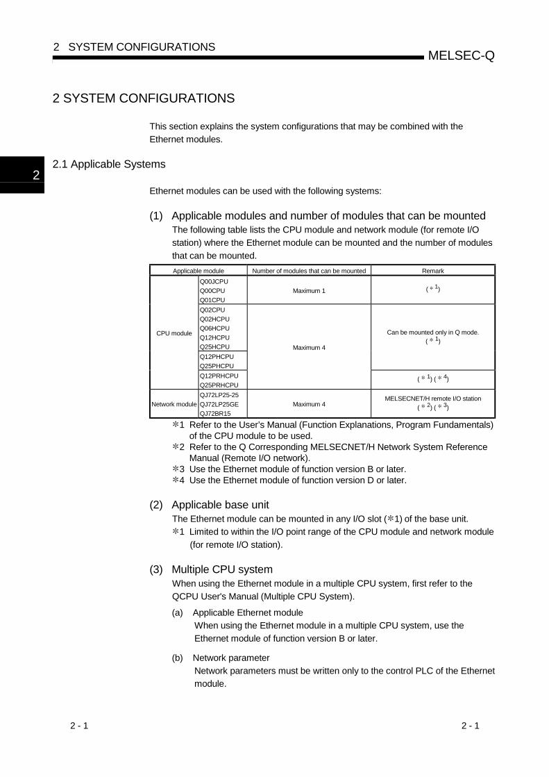
2 - 1 2 - 1
MELSEC-Q2 SYSTEM CONFIGURATIONS
2
2 SYSTEM CONFIGURATIONS
This section explains the system configurations that may be combined with theEthernet modules.
2.1 Applicable Systems
Ethernet modules can be used with the following systems:
(1) Applicable modules and number of modules that can be mountedThe following table lists the CPU module and network module (for remote I/Ostation) where the Ethernet module can be mounted and the number of modulesthat can be mounted.Applicable module Number of modules that can be mounted Remark
Q00JCPUQ00CPUQ01CPU
Maximum 1 ( 1)
Q02CPUQ02HCPUQ06HCPUQ12HCPUQ25HCPUQ12PHCPUQ25PHCPU
Can be mounted only in Q mode.( 1)
CPU module
Q12PRHCPUQ25PRHCPU
Maximum 4
( 1) ( 4)
Network moduleQJ72LP25-25QJ72LP25GEQJ72BR15
Maximum 4MELSECNET/H remote I/O station
( 2) ( 3)
1 Refer to the User’s Manual (Function Explanations, Program Fundamentals)of the CPU module to be used.
2 Refer to the Q Corresponding MELSECNET/H Network System ReferenceManual (Remote I/O network).
3 Use the Ethernet module of function version B or later.4 Use the Ethernet module of function version D or later.
(2) Applicable base unitThe Ethernet module can be mounted in any I/O slot ( 1) of the base unit.
1 Limited to within the I/O point range of the CPU module and network module(for remote I/O station).
(3) Multiple CPU systemWhen using the Ethernet module in a multiple CPU system, first refer to theQCPU User's Manual (Multiple CPU System).
(a) Applicable Ethernet moduleWhen using the Ethernet module in a multiple CPU system, use theEthernet module of function version B or later.
(b) Network parameterNetwork parameters must be written only to the control PLC of the Ethernetmodule.
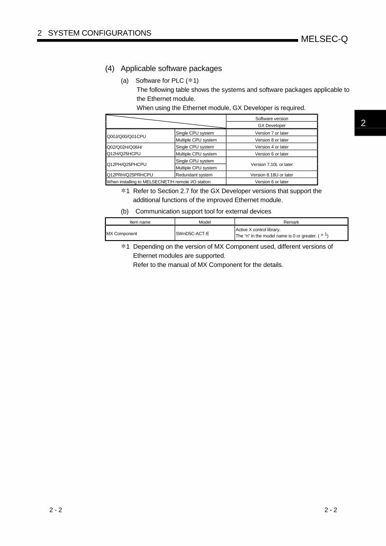
2 - 2 2 - 2
MELSEC-Q2 SYSTEM CONFIGURATIONS
2
(4) Applicable software packages(a) Software for PLC ( 1)
The following table shows the systems and software packages applicable tothe Ethernet module.When using the Ethernet module, GX Developer is required.
Software versionGX Developer
Single CPU system Version 7 or laterQ00J/Q00/Q01CPU
Multiple CPU system Version 8 or laterSingle CPU system Version 4 or laterQ02/Q02H/Q06H/
Q12H/Q25HCPU Multiple CPU system Version 6 or laterSingle CPU system
Q12PH/Q25PHCPUMultiple CPU system
Version 7.10L or later
Q12PRH/Q25PRHCPU Redundant system Version 8.18U or laterWhen installing to MELSECNET/H remote I/O station Version 6 or later
1 Refer to Section 2.7 for the GX Developer versions that support theadditional functions of the improved Ethernet module.
(b) Communication support tool for external devicesItem name Model Remark
MX Component SWnD5C-ACT-EActive X control library.The “n” in the model name is 0 or greater. ( 1)
1 Depending on the version of MX Component used, different versions ofEthernet modules are supported.Refer to the manual of MX Component for the details.

2 - 3 2 - 3
MELSEC-Q2 SYSTEM CONFIGURATIONS
2.2 Devices Required for Network Configuration
This section explains the devices that are required to configure a network.Network installation work requires sufficient safeguard; ask a network specialist forinstallation.
(1) When configuring an Ethernet system with a QJ71E71-100When connecting a QJ71E71-100 to a network, either a 10BASE-T or 100BASE-TX can be used.The Ethernet module detects whether it is 10BASE-T or 100BASE-TX, and thefull-duplex or half-duplex transmission mode according to the hub.For connection to the hub without the auto detection function, set the half-duplexmode on the hub side.
(a) Connection using the 100BASE-TX
E71
External device
Twisted pair cableHub
Up to 2 levels are allowed for cascade connection
Use devices that satisfy the standards of IEEE802.3 and 100BASE-TX.(About the devices under the hub in the illustration above)• Shielded twisted pair cable (STP cable), category 5
Straight cables can be used.(Correct operation is not guaranteed if a crossed cable is used to connect toan external device via the 100BASE-TX of the Ethernet module. However, itis possible to use crossed cables to connect two Ethernet modules (i.e., twoQJ71E71-100 modules) for data communication or to connect an Ethernetmodule to a GOT.)
• RJ45 jacks• 100Mbps hub
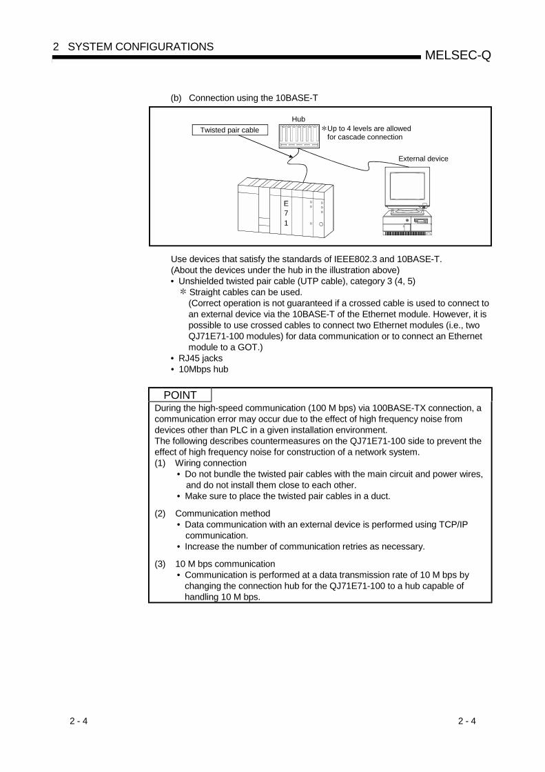
2 - 4 2 - 4
MELSEC-Q2 SYSTEM CONFIGURATIONS
(b) Connection using the 10BASE-T
E71
External device
Twisted pair cableHub
Up to 4 levels are allowed for cascade connection
Use devices that satisfy the standards of IEEE802.3 and 10BASE-T.(About the devices under the hub in the illustration above)• Unshielded twisted pair cable (UTP cable), category 3 (4, 5)
Straight cables can be used.(Correct operation is not guaranteed if a crossed cable is used to connect toan external device via the 10BASE-T of the Ethernet module. However, it ispossible to use crossed cables to connect two Ethernet modules (i.e., twoQJ71E71-100 modules) for data communication or to connect an Ethernetmodule to a GOT.)
• RJ45 jacks• 10Mbps hub
POINTDuring the high-speed communication (100 M bps) via 100BASE-TX connection, acommunication error may occur due to the effect of high frequency noise fromdevices other than PLC in a given installation environment.The following describes countermeasures on the QJ71E71-100 side to prevent theeffect of high frequency noise for construction of a network system.(1) Wiring connection
• Do not bundle the twisted pair cables with the main circuit and power wires,and do not install them close to each other.
• Make sure to place the twisted pair cables in a duct.
(2) Communication method• Data communication with an external device is performed using TCP/IP
communication.• Increase the number of communication retries as necessary.
(3) 10 M bps communication• Communication is performed at a data transmission rate of 10 M bps by
changing the connection hub for the QJ71E71-100 to a hub capable ofhandling 10 M bps.

2 - 5 2 - 5
MELSEC-Q2 SYSTEM CONFIGURATIONS
(2) When configuring the Ethernet system with a QJ71E71-B5
(a) Connecting using the 10BASE5
E71DC
Power supply
N-type terminator Coaxial cable for 10BASE5 Transceiver
External device
AUI cable
1) Use a 10BASE5 coaxial cable, an N-type terminator, a transceiver, andan AUI cable (transceiver cable) that meet the Ethernet standards.
2) Use a transceiver with SQETEST (Signal Quality Error TEST) or aheart beat function.
3) Use a DC power supply (power supply for transceiver) that meets thespecifications of the transceiver and the AUI cable. (Refer toREMARK.)
REMARK
The transceiver power characteristics are as follows:• Input terminal voltage: 12 V-6% to 15 V+5%
• AUI cable direct resistance: 40 Ω/km or less, maximum length 50 m (164 ft.)• Maximum current consumption: 500 mA or lessThus, the applicable transceiver supply power will be from 13.28 V to 15.75 V.
Calculation of the transceiver supply power's voltage drop (V)Voltage drop (V) = AUI cable direct current resistance (Ω/m)
AUI cable length (m) 2 (both directions) transceiverconsumption current (A)
(Example)2.0 (V) = 0.04 (Ω/m) 50 (m) 2 0.5 (A)In this case, the recommended transceiver supply power is more than 13.28 V.13.28 (V) = 12 V-6% (11.28 V) + 2.0 (V)
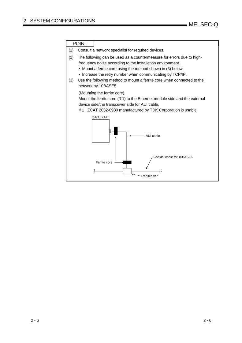
2 - 6 2 - 6
MELSEC-Q2 SYSTEM CONFIGURATIONS
POINT(1) Consult a network specialist for required devices.
(2) The following can be used as a countermeasure for errors due to high-frequency noise according to the installation environment.• Mount a ferrite core using the method shown in (3) below.• Increase the retry number when communicating by TCP/IP.
(3) Use the following method to mount a ferrite core when connected to thenetwork by 10BASE5.
(Mounting the ferrite core)Mount the ferrite core ( 1) to the Ethernet module side and the externaldevice side/the transceiver side for AUI cable.
1 ZCAT 2032-0930 manufactured by TDK Corporation is usable.
Ferrite core
AUI cable
Coaxial cable for 10BASE5
Transceiver
QJ71E71-B5
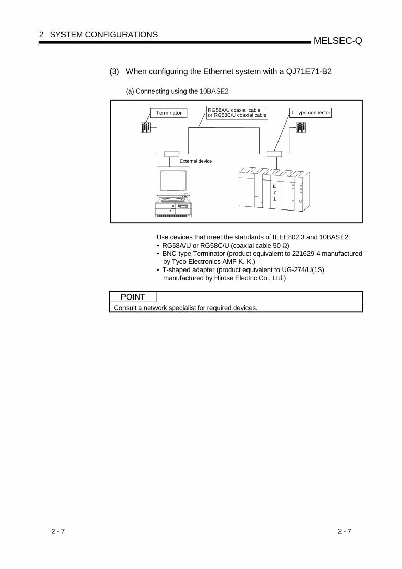
2 - 7 2 - 7
MELSEC-Q2 SYSTEM CONFIGURATIONS
(3) When configuring the Ethernet system with a QJ71E71-B2
(a) Connecting using the 10BASE2
E71
T-Type connector
External device
Terminator RG58A/U coaxial cable or RG58C/U coaxial cable
Use devices that meet the standards of IEEE802.3 and 10BASE2.• RG58A/U or RG58C/U (coaxial cable 50 )• BNC-type Terminator (product equivalent to 221629-4 manufactured
by Tyco Electronics AMP K. K.)• T-shaped adapter (product equivalent to UG-274/U(1S)
manufactured by Hirose Electric Co., Ltd.)
POINTConsult a network specialist for required devices.
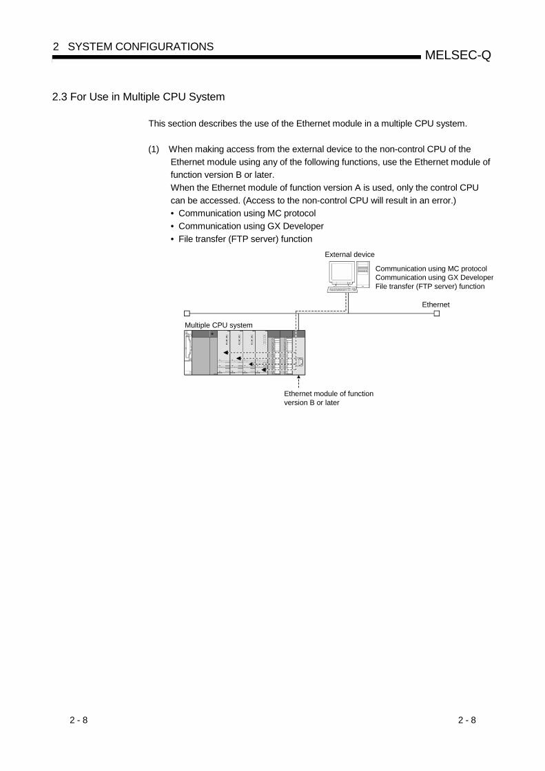
2 - 8 2 - 8
MELSEC-Q2 SYSTEM CONFIGURATIONS
2.3 For Use in Multiple CPU System
This section describes the use of the Ethernet module in a multiple CPU system.
(1) When making access from the external device to the non-control CPU of theEthernet module using any of the following functions, use the Ethernet module offunction version B or later.When the Ethernet module of function version A is used, only the control CPUcan be accessed. (Access to the non-control CPU will result in an error.)• Communication using MC protocol• Communication using GX Developer• File transfer (FTP server) function
External device
Multiple CPU system
Communication using MC protocolCommunication using GX DeveloperFile transfer (FTP server) function
Ethernet
Ethernet module of function version B or later
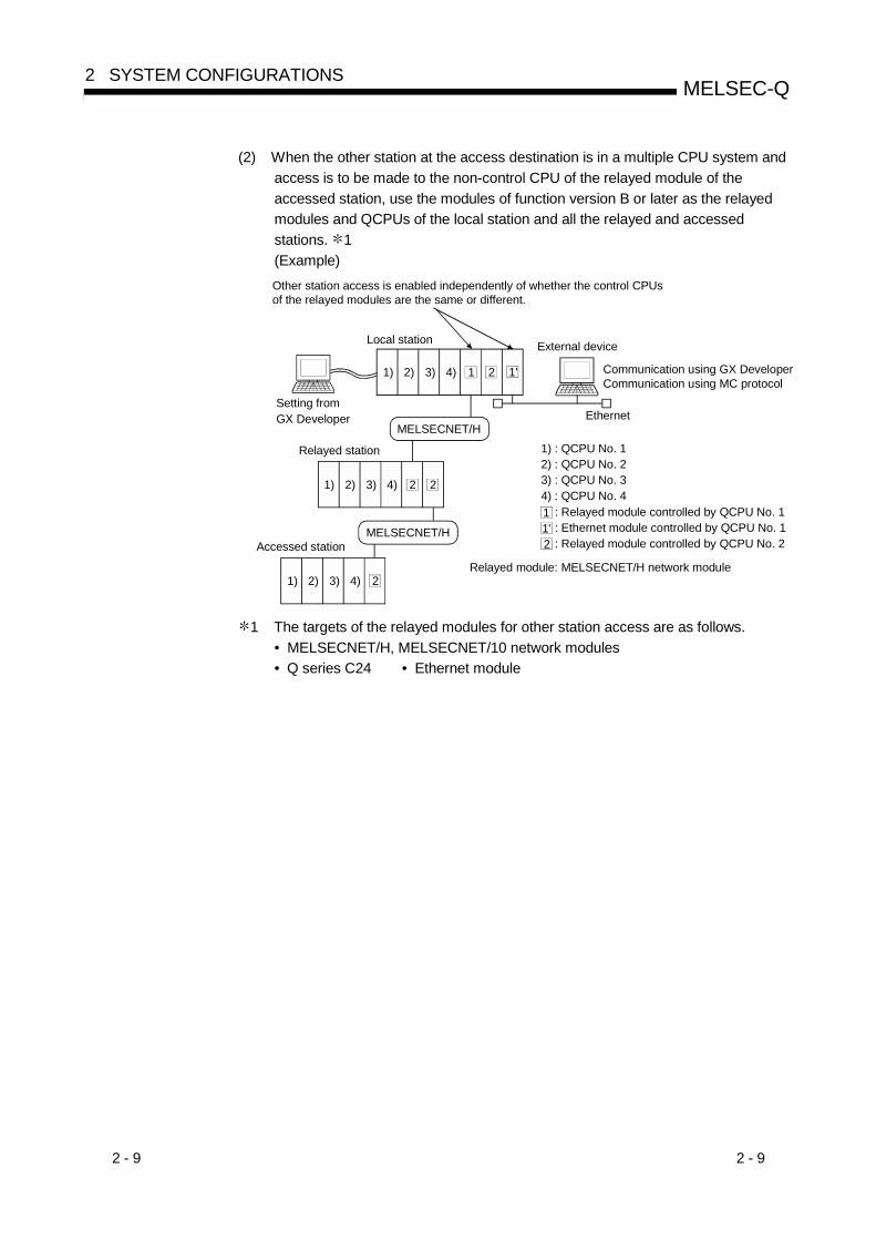
2 - 9 2 - 9
MELSEC-Q2 SYSTEM CONFIGURATIONS
(2) When the other station at the access destination is in a multiple CPU system andaccess is to be made to the non-control CPU of the relayed module of theaccessed station, use the modules of function version B or later as the relayedmodules and QCPUs of the local station and all the relayed and accessedstations. 1(Example)
MELSECNET/H1) : QCPU No. 12) : QCPU No. 23) : QCPU No. 34) : QCPU No. 41 : Relayed module controlled by QCPU No. 1
: Ethernet module controlled by QCPU No. 1: Relayed module controlled by QCPU No. 2
1'2
Local station
Relayed station
External device
Communication using GX DeveloperCommunication using MC protocol
Setting from GX Developer
MELSECNET/HAccessed station
1 2 1'1) 2) 3) 4)
2 21) 2) 3) 4)
21) 2) 3) 4)
Ethernet
Other station access is enabled independently of whether the control CPUs of the relayed modules are the same or different.
Relayed module: MELSECNET/H network module
1 The targets of the relayed modules for other station access are as follows.• MELSECNET/H, MELSECNET/10 network modules• Q series C24 • Ethernet module

2 - 10 2 - 10
MELSEC-Q2 SYSTEM CONFIGURATIONS
2.4 For Use with Q00J/Q00/Q01CPU
This section describes the use of the Ethernet module with the Q00J/Q00/Q01CPU.
(1) Available functionsThe following functions are available when the Ethernet module is mounted onthe main base unit of the Q00J/Q00/Q01CPU.
Function AvailabilityCommunication using the MC protocol ( 1)Communication using the fixed buffer
Reception processing by an interrupt program ( 3)
Communication using the random access bufferSending/receiving of e-mail ( 3)
Communication using the data link instruction ( 2)
Reception processing by an interrupt program ( 3)
File transfer (FTP server function)Communication using the Web functionMELSECNET/H, MELSECNET/10 relay communicationRouter relay communication (Router relay function)External device existence confirmationPairing open communicationCommunication via automatic open UDP portSimultaneous broadcastSupport for the QCPU remote password function ( 3)
Setting the Ethernet parameters through GX DeveloperAccess to QCPU with GX Developer (TCP/IP or UDP/IP)
: Available : Available with restriction : Unavailable
1 For the number of its processing time, refer to the Reference Manual.The devices that can be accessed and its range are different according tothe frame used for data communication.
2 When the target station of the SREAD/SWRITE instruction is theQ00J/Q00/Q01CPU, the read reporting device to the target station set to theargument (D3) is ignored.The operation of the SREAD/SWRITE instruction is the same as that of theREAD/WRITE instruction.For the SREAD/SWRITE instruction, refer to Chapter 4 or Chapter 6 of theUser's Manual (Application).
3 Available for the Q00J/Q00/Q01CPU (function version B) or later.To use the function, GX Developer Version 8 or later is required.
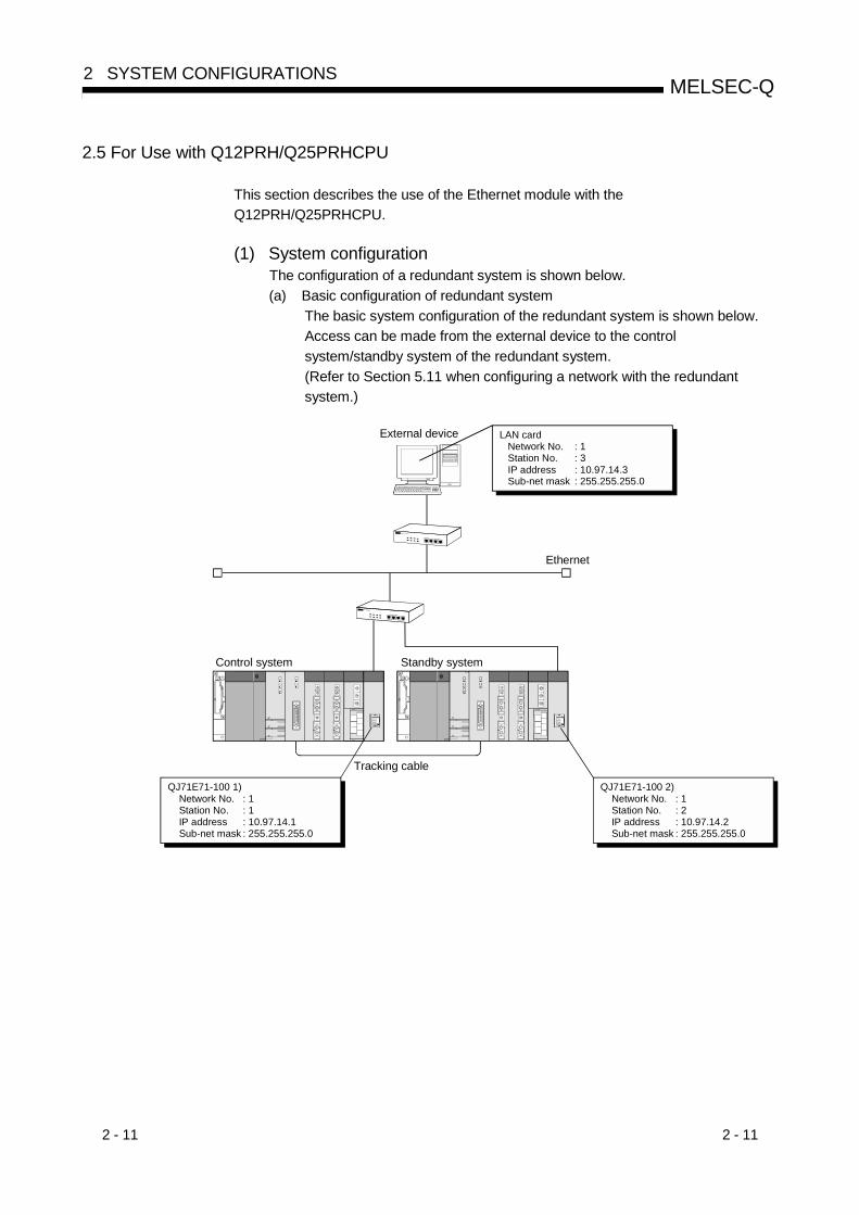
2 - 11 2 - 11
MELSEC-Q2 SYSTEM CONFIGURATIONS
2.5 For Use with Q12PRH/Q25PRHCPU
This section describes the use of the Ethernet module with theQ12PRH/Q25PRHCPU.
(1) System configurationThe configuration of a redundant system is shown below.(a) Basic configuration of redundant system
The basic system configuration of the redundant system is shown below.Access can be made from the external device to the controlsystem/standby system of the redundant system.(Refer to Section 5.11 when configuring a network with the redundantsystem.)
External device
Tracking cable
Ethernet
Control system Standby system
LAN card Network No. : 1 Station No. : 3 IP address : 10.97.14.3 Sub-net mask : 255.255.255.0
QJ71E71-100 1) Network No. : 1 Station No. : 1 IP address : 10.97.14.1 Sub-net mask : 255.255.255.0
QJ71E71-100 2) Network No. : 1 Station No. : 2 IP address : 10.97.14.2 Sub-net mask : 255.255.255.0
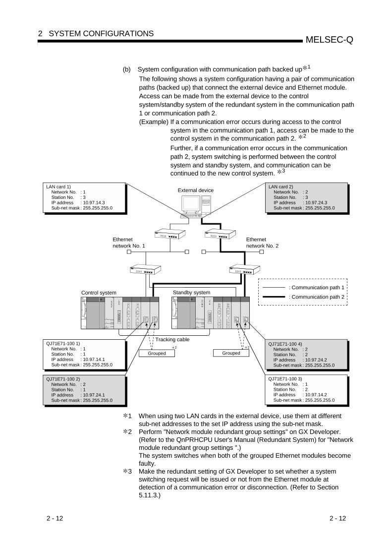
2 - 12 2 - 12
MELSEC-Q2 SYSTEM CONFIGURATIONS
(b) System configuration with communication path backed up 1
The following shows a system configuration having a pair of communicationpaths (backed up) that connect the external device and Ethernet module.Access can be made from the external device to the controlsystem/standby system of the redundant system in the communication path1 or communication path 2.(Example) If a communication error occurs during access to the control
system in the communication path 1, access can be made to thecontrol system in the communication path 2. 2
Further, if a communication error occurs in the communicationpath 2, system switching is performed between the controlsystem and standby system, and communication can becontinued to the new control system. 3
External device
Control system Standby system
LAN card 1) Network No. : 1 Station No. : 3 IP address : 10.97.14.3 Sub-net mask : 255.255.255.0
QJ71E71-100 1) Network No. : 1 Station No. : 1 IP address : 10.97.14.1 Sub-net mask : 255.255.255.0
QJ71E71-100 2) Network No. : 2 Station No. : 1 IP address : 10.97.24.1 Sub-net mask : 255.255.255.0
QJ71E71-100 4) Network No. : 2 Station No. : 2 IP address : 10.97.24.2 Sub-net mask : 255.255.255.0
QJ71E71-100 3) Network No. : 1 Station No. : 2 IP address : 10.97.14.2 Sub-net mask : 255.255.255.0
LAN card 2) Network No. : 2 Station No. : 3 IP address : 10.97.24.3 Sub-net mask : 255.255.255.0
Ethernet network No. 2
Ethernet network No. 1
Grouped2
Grouped2
Tracking cable
: Communication path 1
: Communication path 2
1 When using two LAN cards in the external device, use them at differentsub-net addresses to the set IP address using the sub-net mask.
2 Perform "Network module redundant group settings" on GX Developer.(Refer to the QnPRHCPU User's Manual (Redundant System) for "Networkmodule redundant group settings ".)The system switches when both of the grouped Ethernet modules becomefaulty.
3 Make the redundant setting of GX Developer to set whether a systemswitching request will be issued or not from the Ethernet module atdetection of a communication error or disconnection. (Refer to Section5.11.3.)

2 - 13 2 - 13
MELSEC-Q2 SYSTEM CONFIGURATIONS
(2) Available functionsThe following functions are available when the Ethernet module is mounted onthe main base unit of the Q12PRH/Q25PRHCPU.
Function AvailabilityCommunication using the MC protocolCommunication using the fixed bufferCommunication using the random access bufferSending/receiving of e-mailCommunication using the data link instructionFile transfer (FTP server function)Communication using the Web functionMELSECNET/H, MELSECNET/10 relay communicationRouter relay communication (Router relay function)External device existence confirmationPairing open communicationCommunication via automatic open UDP portSimultaneous broadcastSupport for the QCPU remote password functionSetting the Ethernet parameters through GX DeveloperAccess to QCPU with GX Developer (TCP/IP or UDP/IP)
: Available : Available with restriction ( 1) : Unavailable
1 Refer to Section 5.11.5 for the precautions for using the functions on theQ12PRH/Q25PRHCPU.
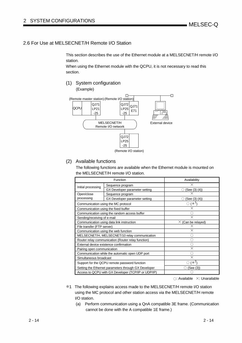
2 - 14 2 - 14
MELSEC-Q2 SYSTEM CONFIGURATIONS
2.6 For Use at MELSECNET/H Remote I/O Station
This section describes the use of the Ethernet module at a MELSECNET/H remote I/Ostation.When using the Ethernet module with the QCPU, it is not necessary to read thissection.
(1) System configuration(Example)
MELSECNET/H Remote I/O network
QCPUQJ71LP21-25
(Remote master station) (Remote I/O station)
(Remote I/O station)
External device
QJ71E71
QJ72LP25-25
QJ72LP25-25
(2) Available functionsThe following functions are available when the Ethernet module is mounted onthe MELSECNET/H remote I/O station.
Function AvailabilitySequence programInitial processingGX Developer parameter setting (See (3) (4))Sequence programOpen/close
processing GX Developer parameter setting (See (3) (4))Communication using the MC protocol ( 1)Communication using the fixed bufferCommunication using the random access bufferSending/receiving of e-mailCommunication using data link instruction (Can be relayed)File transfer (FTP server)Communication using the web functionMELSECNET/H, MELSECNET/10 relay communicationRouter relay communication (Router relay function)External device existence confirmationPairing open communicationCommunication while the automatic open UDP portSimultaneous broadcastSupport for the QCPU remote password function ( 2)Setting the Ethernet parameters through GX Developer (See (3))Access to QCPU with GX Developer (TCP/IP or UDP/IP)
: Available : Unarailable
1 The following explains access made to the MELSECNET/H remote I/O stationusing the MC protocol and other station access via the MELSECNET/H remoteI/O station.(a) Perform communication using a QnA compatible 3E frame. (Communication
cannot be done with the A compatible 1E frame.)

2 - 15 2 - 15
MELSEC-Q2 SYSTEM CONFIGURATIONS
(b) The following functions are available for the MELSECNET/H remote I/Ostation. For the QnA/A series compatible MELSECNET/10 remote I/Ostation, only read/write of the intelligent function module buffer memory canbe performed.
Available function FunctionBatch read, batch writeRandom read, test (random write)Monitor data registration, monitor
Read/write of device memory
Multiple-block batch read, multiple-block batch writeRead/write of buffer memory Read/write of Ethernet module buffer memoryRead/write of intelligentfunction module buffer memory
Read/write of specified intelligent function module buffer memory
(c) The following devices of the MELSECNET/H remote I/O station areaccessible by read/write of the device memory.See the Reference Manual for a detailed explanation.
Device name Device symbol Device name Device symbolSpecial relay SM Link relay BSpecial register SD Data register DInput relay X Link register WOutput relay Y Link special relay SBInternal relay M Link special register SW
(d) Other station access via the MELSECNET/H remote I/O station enablesaccess to the MELSECNET/H remote master station and access to theMELSECNET/H remote I/O station.1) In the following figure, access can be made from the external device to
the remote master station and to the MELSECNET/H remote I/Ostation.
MELSECNET/HRemote I/O net
QCPUQJ71LP21-25
(Remote master station)
QJ71E71
QJ72LP25-25
(Remote I/O station)QJ71E71
QJ72LP25-25
QJ71E71
QJ71E71
QJ72LP25-25
Access allowedAccess prohibited
External device
station-1
station-2
station-3
2) Other station access via the following MELSECNET/H remote I/Ostations cannot be made.• Other station access from the MELSECNET/H remote master station
via the Ethernet module mounted on the MELSECNET/H remote I/Ostation. (Station 1 in the above figure)
• Other station access via between the Ethernet modules. (Station 2 inthe above figure)
2 This function is available for the MELSECNET/H remote I/O station of functionversion D and later.GX Developer Version 8.18U or later is required to use the function.

2 - 16 2 - 16
MELSEC-Q2 SYSTEM CONFIGURATIONS
(3) Setting parameters for the Ethernet module through GX DeveloperThe following parameters should be set through GX Developer in order to usethe Ethernet module mounted on MELSECNET/H remote I/O station.The setting can be made in the same way as when setting the parameters for theEthernet module mounted on a QCPU station. See Section 4.5 and later.See the operating manual for GX Developer for how to display each settingscreen.(Parameter setting items for the Ethernet module mounted on MELSECNET/Hremote I/O station)
Parameter setting item Setting Remarks
I/O assignment Set the module mounting information.Setting notrequired
Network Parameters Setting theNumber of MNET/10H Ethernet Cards
Perform settings to allow the Ethernet module to be used as a networkmodule.
Operational settings Perform settings for items common to Ethernet modules.Initial settings Set timer values for data communication.Open settings Perform settings relating to open/close processing for connections.Router relay parameter Perform settings when communicating using routing relays.
Station No. <-> IP informationPerform settings when communicating via the MELSECNET/H,MELSECNET/10.
Remote password settings Perform settings for the remote password.
—
POINT(1) Connect GX Developer to MELSECNET/H remote I/O station and use it to set
the parameters.
(2) Always set the "Network parameters setting the number of MNET/10HEthernet cards" and "Operational settings."
(3) Reset MELSECNET/H remote I/O station after changing the setting.
REMARK
It is not necessary to set the “Intelligent function module switch settings” with GXDeveloper’s I/O assignment.Each type of setting corresponding to the switch settings is performed in the abovementioned “Operational settings,” “Initial settings, “ and “Open settings.”

2 - 17 2 - 17
MELSEC-Q2 SYSTEM CONFIGURATIONS
(4) Data communication procedure
(a) Connect GX Developer to MELSECNET/H remote I/O station and performthe following settings:
1) Communicating with TCP/IP• Select "Always wait for OPEN" for the "Initial Timing" under the
"Operational Settings."• Select "Unpassive or Full passive" for the "Open system" setting
under "Open settings."
2) Communicating with UDP/IP (when using the user port)Select "Always wait for OPEN" for the "Initial Timing" under the"Operational Settings."Data communication can also be done using the automatic open UDPport for the Ethernet module.
(b) Start up MELSECNET/H remote I/O station.
(c) Perform the open processing.
1) When communicating using TCP/IP, always perform "Active open"from the external device. (The status of the Ethernet module side is"Wait for open" because of "Passive open.")
2) When communicating using UDP/IP, perform the open processing onthe external device side. (The status of the Ethernet module side is"Data communication enabled" through internal processing.)
(d) Perform data communication.
(e) After completing data communication, perform the close processing.
1) When communicating using TCP/IP, always perform the closeprocessing from the external device. (The Ethernet module sideperforms the close processing at a request from the external deviceand its status becomes able to receive another open request.)
2) When communicating using UDP/IP, perform the close processing forthe external device. (The close processing on the Ethernet moduleside is not required.)

2 - 18 2 - 18
MELSEC-Q2 SYSTEM CONFIGURATIONS
2.7 Checking the Function Version and Serial No.
This section explains the function version, serial No. and how to check them for relatedproducts that can use functions added through improvements in the Ethernet module.(1) Compatibility with related products designed for using functions
added to the Ethernet moduleVersion of Ethernet module Version of related productAdded function
QJ71E71-100 QJ71E71-B5 QJ71E71-B2 CPU module GX Developer
Support for IEEE802.3 framesFunction version B orlater, whose first 5 digits ofthe serial No. are 03102
Version 7 or later
Re-initial processingusing sequenceprograms
Function version B orlater, whose first 5 digits ofthe serial No. are 03061
Re-initial processing viadedicated instruction(UINI instruction)
Function version B orlater, whose first 5digits of the serial No.are 03102
Function version B orlater, whose first 5 digits ofthe serial No. are 03102
Re-initialprocessing ofthe Ethernetmodule
TCP Maximum Segmentsplit transmission
Function version B orlater, whose first 5digits of the serial No.are 05051
Function version B orlater, whose first 5 digits ofthe serial No. are 05051
Re-open processing of the Ethernetmodule ( 1)
Function version B orlater, whose first 5digits of the serial No.are 05051
Function version B orlater, whose first 5 digits ofthe serial No. are 05051
Existencecheck function Checking by KeepAlive
Function version B orlater, whose first 5digits of the serial No.are 05051
Function version B orlater, whose first 5 digits ofthe serial No. are 05051
Version 8.05F orlater
Connection of up to 17 MELSOFTproducts via TCP/IP communication
Function version B orlater, whose first 5 digits ofthe serial No. are 02122
Version 6.05F orlater
Simplifying access toother stations
SimplifyingconnectionwithMELSOFTproducts
Access with the samestation number
Function version B orlater, whose first 5digits of the serial No.are 05051
Function version B orlater, whose first 5 digits ofthe serial No. are 05051
Monitoring of variousEthernet module statusesPING test/loopback testvia Ethernet board
Version 6 or laterEthernetdiagnosticfunction of GXDeveloper
PING test via CPU
Function version B or later
Function versionA or later, whosefirst 5 digits of theserial No. are02092 Version 7 or later
Hub connection status monitor function Function version D orlater
Sending files in CSVformat as attachment Function version B or later Version 6 or later
Sending main textFunction version B orlater, whose first 5 digits ofthe serial No. are 03102
Version 7 or laterWhen usingthe e-mailfunction
Support forencoding/decoding
Function version B orlater, whose first 5digits of the serial No.are 03102
Function version B orlater, whose first 5 digits ofthe serial No. are 03102
Target station CPU type specification fordata link instructions
Function version D orlater
Function version Dor later
Function version D or later
Multiple CPU system compatibility of filetransfer (FTP server) function
Function version B orlater, whose first 5 digits ofthe serial No. are 03102
Function versionB or later
Communication using the Web functionFunction version B orlater, whose first 5 digits ofthe serial No. are 05051
Remote password check Function version B or later
Function versionA or later, whosefirst 5 digits of theserial No. are02092
Version 6 or later
: Available (no restrictions on version) : Unavailable
1 Change was made to the operation of the Ethernet module to be performed when the Active open request isreceived again from the external device in the open completion status of TCP. (Refer to POINT in Section 5.6 (2).)

2 - 19 2 - 19
MELSEC-Q2 SYSTEM CONFIGURATIONS
(2) Checking the function version and serial No. of the Q series PLC
(a) Checking using the "Rating plate" on the side of the moduleThe serial No. and function version of the subject module are displayed inthe SERIAL line of the rating plate.
Serial No. (first 5 digits)Function version
Conformed standard
(b) Checking through GX DeveloperThe following explains how to check the serial No. and function version ofthe target module through GX Developer.The serial No. and function version are displayed on the "ProductInformation List" or the "Module's Detailed Information" screen of GXDeveloper.The following diagram shows how to check the serial No. and functionversion on the "Product Information List" screen. (See Section 11.2 for the"Module's Detailed Information" screen.)
[Startup procedure]"Diagnostics" "System monitor" "Product Inf. List"
[Serial No., Ver.]• The serial No. of the target module is displayed in the serial No. area.• The function version of the target module is displayed in the Ver. area.

3 - 1 3 - 1
MELSEC-Q3 SPECIFICATIONS
3
3 SPECIFICATIONS
This section explains the Ethernet module performance specifications andtransmission specifications.For more details on the general specifications, refer to the User's Manual for the QCPU(Q mode).
3.1 Performance Specifications
The following explains the performance specifications of the Ethernet module.Specification
Item QJ71E71-100 QJ71E71-B5 QJ71E71-B2100BASE-TX 10BASE-T 10BASE5 10BASE2
Data transmission speed 100 M bps 10 M bpsCommunication mode Full-duplex/Half-duplex Half-duplexTransmission method Base bandMaximum node-to-node distance — 2500 m (8202.10 ft.) 925 m (3034.77 ft.)Maximum segment length 100 m (328.08 ft.) ( 1) 500 m (1640.42 ft.) 185 m (606.96 ft.)
Maximum number of nodes/connection
CascadeconnectionMaximum 2
stages
CascadeconnectionMaximum 4
stages
100 units/segment 30 units/segment
Transmissionspecifications
Interval between the minimum nodes — 2.5 m (8.20 ft.) 0.5 m (1.64 ft.)Number of simultaneously openconnections allowed
16 connections (Connections usable by the sequence program)
Fixed buffer 1 k words × 16Random access buffer 6 k words × 1
Attached file 6 k words × 1 ( 4)
Transmission datastorage memory
E-mailMain text 960 words × 1 ( 4)
Number of I/O points occupied 32 points/1 slot (I/O assignment: intelligent)
5 V DC internal current consumption 0.50 A 0.50 A 0.60 A ( 3)
12 V DC external power supply capacity (Transceiver) — ( 2) —External dimensions 98 (3.86 in.) (H) × 27.4 (1.08 in.) (W) × 90 (3.54 in.) (D) [mm]
Weight 0.11 kg (0.24 Ib) 0.12 kg (0.26 Ib) 0.13 kg (0.29 Ib) ( 3)
1 Length between the Hub and nobe.2 It is necessary to apply a transceiver, or a device that meets AUI cable
specifications. (Refer to Section 2.2)3 The product with first 5 digits of serial number "05049" or earlier is different as
follows:! 5V DC internal current consumption: 0.70A! Weight: 0.14kg (0.31lb.)
4 The following table outlines the specifications of the e-mail transmission andreception function.The e-mail transmission and reception function of the PLC CPU and the randomaccess buffer communication function cannot be used together; only one of thefunctions can be used at a time. (The e-mail transmitting function of the Ethernetmodule's PLC CPU monitoring function and the random access buffercommunication function can be used together.)
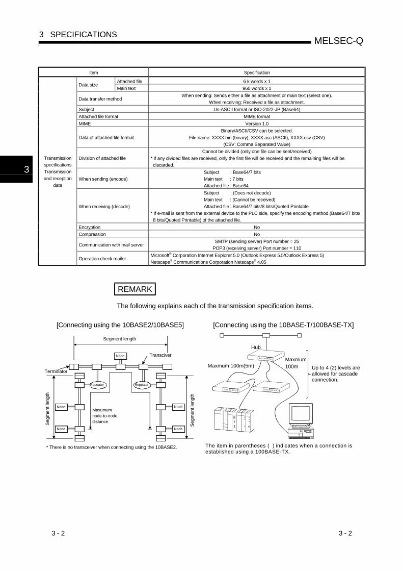
3 - 2 3 - 2
MELSEC-Q3 SPECIFICATIONS
3
Item Specification
Attached file 6 k words x 1Data size
Main text 960 words x 1
Data transfer methodWhen sending: Sends either a file as attachment or main text (select one).
When receiving: Received a file as attachment.Subject Us-ASCII format or ISO-2022-JP (Base64)Attached file format MIME formatMIME Version 1.0
Data of attached file formatBinary/ASCII/CSV can be selected.
File name: XXXX.bin (binary), XXXX.asc (ASCII), XXXX.csv (CSV)(CSV: Comma Separated Value)
Division of attached fileCannot be divided (only one file can be sent/received)
* If any divided files are received, only the first file will be received and the remaining files will be discarded.
When sending (encode)Subject : Base64/7 bitsMain text : 7 bitsAttached file : Base64
When receiving (decode)
Subject : (Does not decode)Main text : (Cannot be received)Attached file : Base64/7 bits/8 bits/Quoted Printable
* If e-mail is sent from the external device to the PLC side, specify the encoding method (Base64/7 bits/ 8 bits/Quoted Printable) of the attached file.
Encryption NoCompression No
Communication with mail serverSMTP (sending server) Port number = 25
POP3 (receiving server) Port number = 110
TransmissionspecificationsTransmissionand reception
data
Operation check mailerMicrosoft® Corporation Internet Explorer 5.0 (Outlook Express 5.5/Outlook Express 5)Netscape® Communications Corporation Netscape® 4.05
REMARK
The following explains each of the transmission specification items.
[Connecting using the 10BASE2/10BASE5] [Connecting using the 10BASE-T/100BASE-TX]
Segment length
Transciver
Terminator
Maxumum node-to-nodedistance
Repeater
Node
Node
Node
Node
Node
Repeater
Segm
ent l
engt
h
Segm
ent l
engt
h
* There is no transceiver when connecting using the 10BASE2.
Up to 4 (2) levels are allowed for cascade connection.
Hub
Maxmum 100m(5m)Maxmum100m
E71
The item in parentheses ( ) indicates when a connection is established using a 100BASE-TX.
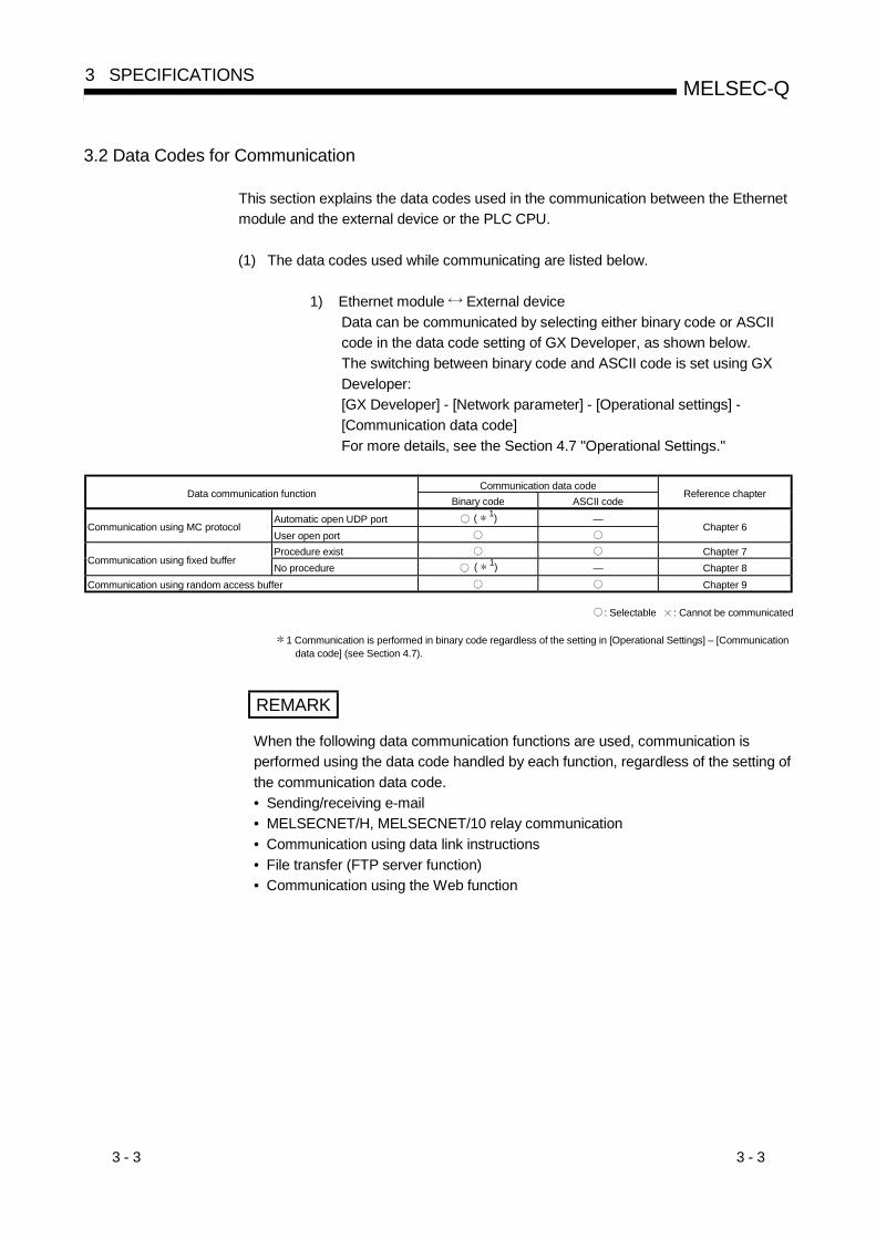
3 - 3 3 - 3
MELSEC-Q3 SPECIFICATIONS
3.2 Data Codes for Communication
This section explains the data codes used in the communication between the Ethernetmodule and the external device or the PLC CPU.
(1) The data codes used while communicating are listed below.
1) Ethernet module External deviceData can be communicated by selecting either binary code or ASCIIcode in the data code setting of GX Developer, as shown below.The switching between binary code and ASCII code is set using GXDeveloper:[GX Developer] - [Network parameter] - [Operational settings] -[Communication data code]For more details, see the Section 4.7 "Operational Settings."
Communication data codeData communication function
Binary code ASCII codeReference chapter
Automatic open UDP port ( 1) —Communication using MC protocol
User open portChapter 6
Procedure exist Chapter 7Communication using fixed buffer
No procedure ( 1) — Chapter 8Communication using random access buffer Chapter 9
: Selectable : Cannot be communicated
1 Communication is performed in binary code regardless of the setting in [Operational Settings] – [Communicationdata code] (see Section 4.7).
REMARK
When the following data communication functions are used, communication isperformed using the data code handled by each function, regardless of the setting ofthe communication data code.• Sending/receiving e-mail• MELSECNET/H, MELSECNET/10 relay communication• Communication using data link instructions• File transfer (FTP server function)• Communication using the Web function
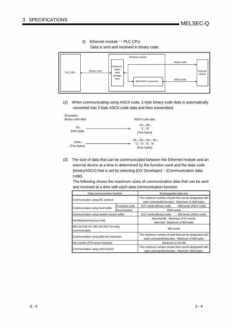
3 - 4 3 - 4
MELSEC-Q3 SPECIFICATIONS
2) Ethernet module PLC CPUData is sent and received in binary code.
Ethernet module
PLC CPUBinary code
Communi-cation data
storage area
Binary code
External device
BIN/ASCII conversionASCII code
(2) When communicating using ASCII code, 1-byte binary code data is automaticallyconverted into 2-byte ASCII code data and then transmitted.
31H, 35 H
"1", "5"(Two bytes)
31H, 32 H, 33 H, 34 H
"1", "2", "3", "4"(Four bytes)
(Example)Binary code data ASCII code data
15H
(One byte)
1234 H
(Two bytes)
(3) The size of data that can be communicated between the Ethernet module and anexternal device at a time is determined by the function used and the data code(binary/ASCII) that is set by selecting [GX Developer] – [Communication datacode].The following shows the maximum sizes of communication data that can be sentand received at a time with each data communication function.
Data communication function Exchangeable data size
Communication using MC protocolThe maximum number of point that can be designated with
each command/instruction : Maximum of 1920 bytesProcedure exist 1017 words (Binary code) 508 words (ASCII code)
Communication using fixed bufferNo procedure 2046 words
Communication using random access buffer 1017 words (Binary code) 508 words (ASCII code)
Sending/receiving by e-mailAttached file : Maximum of 6 k words,
Main text : Maximum of 960 bytesMELSECNET/H, MELSECNET/10 relaycommunication
480 words
Communication using data link instructionThe maximum number of point that can be designated with
each command/instruction : Maximum of 960 bytesFile transfer (FTP server function) Maximum of one file
Communication using web functionThe maximum number of point that can be designated with
each command/instruction : Maximum 1920 bytes.
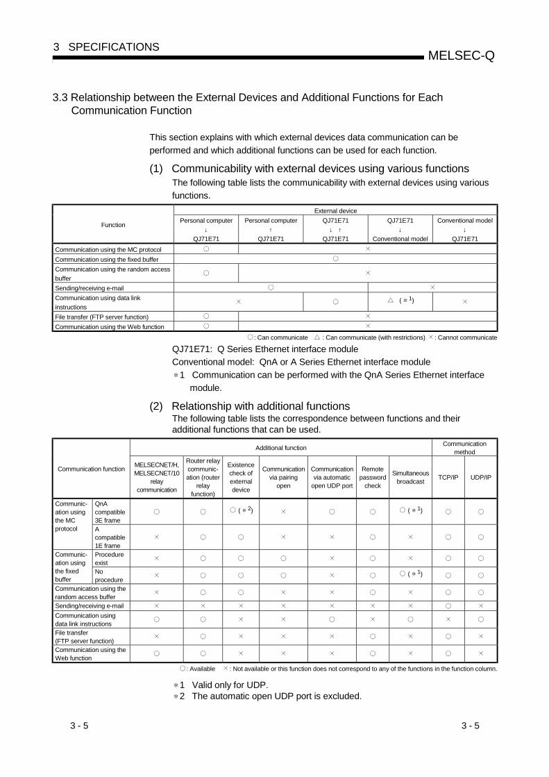
3 - 5 3 - 5
MELSEC-Q3 SPECIFICATIONS
3.3 Relationship between the External Devices and Additional Functions for EachCommunication Function
This section explains with which external devices data communication can beperformed and which additional functions can be used for each function.
(1) Communicability with external devices using various functionsThe following table lists the communicability with external devices using variousfunctions.
External device
FunctionPersonal computer
↓QJ71E71
Personal computer↑
QJ71E71
QJ71E71↓ ↑
QJ71E71
QJ71E71↓
Conventional model
Conventional model↓
QJ71E71Communication using the MC protocolCommunication using the fixed bufferCommunication using the random accessbufferSending/receiving e-mailCommunication using data linkinstructions
( 1)
File transfer (FTP server function)Communication using the Web function
: Can communicate : Can communicate (with restrictions) : Cannot communicate
QJ71E71: Q Series Ethernet interface moduleConventional model: QnA or A Series Ethernet interface module
1 Communication can be performed with the QnA Series Ethernet interfacemodule.
(2) Relationship with additional functionsThe following table lists the correspondence between functions and theiradditional functions that can be used.
Additional function Communicationmethod
Communication function MELSECNET/H,MELSECNET/10
relaycommunication
Router relaycommunic-ation (router
relayfunction)
Existencecheck ofexternaldevice
Communicationvia pairing
open
Communicationvia automatic
open UDP port
Remotepassword
check
Simultaneousbroadcast TCP/IP UDP/IP
QnAcompatible3E frame
( 2) ( 1)Communic-ation usingthe MCprotocol A
compatible1E frameProcedureexist
Communic-ation usingthe fixedbuffer
Noprocedure
( 1)
Communication using therandom access bufferSending/receiving e-mailCommunication usingdata link instructionsFile transfer(FTP server function)Communication using theWeb function
: Available : Not available or this function does not correspond to any of the functions in the function column.
1 Valid only for UDP.2 The automatic open UDP port is excluded.

3 - 6 3 - 6
MELSEC-Q3 SPECIFICATIONS
3.4 Ethernet Module Function List
This section shows a list of Ethernet module functions.
(1) Basic functions of the Ethernet moduleThe Ethernet module can perform the communications shown in the table belowvia the TCP/IP or UDP/IP communication.
Function Description Reference sectionQnAcompatible 3Eframe
Communication usingthe MC protocol
A compatible1E frame
Reads/writes PLC CPU data from/to an external device.Chapter 5Reference Manual
Procedure exist Chapter 7Communication usingthe fixed buffer No procedure
Sends/receives arbitrary data between the PLC CPU and theexternal device using the fixed buffer of the Ethernet module. Chapter 8
Communication using the randomaccess buffer
Reads/writes data from multiple external devices to therandom access buffer of the Ethernet module.
Chapter 9
Sending/receiving e-mail
Sends/receives data via e-mail.• Sending/receiving by the PLC CPU• Sending by the PLC CPU monitoring function (automatic
notification function)
Chapter 2 of User’sManual(Application)
Communication using data linkinstructions
Reads/writes the PLC CPU data of other station via Ethernetusing data link instructions.
Chapter 4 of User’sManual(Application)
File transfer (FTP server function)Reads/writes in file units using the FTP command from theexternal device.
Chapter 5 of User’sManual(Application)
Communication using the Web functionReads/writes the PLC CPU data via the Internet using acommercially available Web browser.
User’s Manual(Web Function)
(2) Additional functions of the Ethernet moduleThe following table lists the additional functions of the Ethernet module that canbe used.
Function Description Reference section
MELSECNET/H, MELSECNET/10 relaycommunication
In a network system on which an Ethernet and a MELSECNET/H orMELSECNET/10 coexist or in a network system that relays multipleEthernets, data communication is performed via multiple number ofsuch networks.
Chapter 3 of User’sManual(Application)
Router relay communication (router relayfunction)
Performs data communication via a router or gateway. (The routerrelay function is not a function by which the Ethernet module works asa router.)
Section 5.3
Existence check of external device (Existencecheck function)
Checks whether or not the external device is working normally after aconnection is established (open processing).
Sections 5.2.2 and 5.5
Communication via pairing openPairs and then opens a reception connection and a transmissionconnection (for fixed buffer).
Section 5.7
Communication via automatic open UDP portEnables communication after the station in which an Ethernet moduleis mounted has been started. (Open/close processing by sequenceprograms is not required.)
Section 5.8
Remote password check Prevents unauthorized access by a remote user to a QCPU. Section 5.9
Simultaneous broadcastSends/receives data for all external devices on the same Ethernet asfor the Ethernet module in data communication via UDP/IP.
Section 8.5
Connecting MELSOFT products (GXDeveloper, MX Component etc.) and GOTs
MELSOFT products (GX Developer, MX Component etc.) and GOTsare connected via TCP/IP communication or UDP/IP communication. Itis also possible to connect multiple MELSOFT products and GOTssimultaneously.
Section 1.2 (6)Manual of eachMELSOFT product

3 - 7 3 - 7
MELSEC-Q3 SPECIFICATIONS
(3) Status check of the Ethernet moduleWhether the Ethernet module is working normally and whether it cancommunicate normally are checked.
Function Description Reference section
Self refrain testChecks the Ethernet module’s sending/receiving function and lineconnection status.
Section 4.8.1
Hardware test Tests the RAM and ROM of the Ethernet module. Section 4.8.2
Communication error storage
When a data communication error occurs, this function stores the errorinformation (error log), including the message subheader and IPaddress of the external device for a maximum of 16 pairs in the buffermemory.
Chapter 11
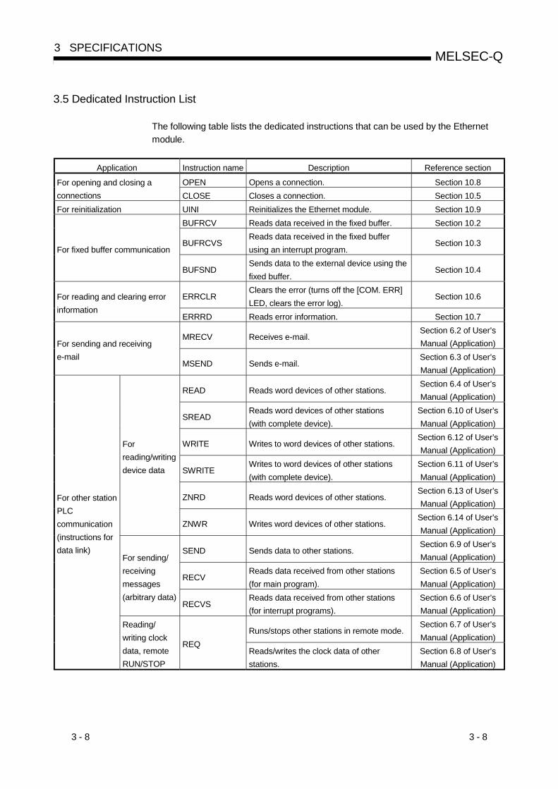
3 - 8 3 - 8
MELSEC-Q3 SPECIFICATIONS
3.5 Dedicated Instruction List
The following table lists the dedicated instructions that can be used by the Ethernetmodule.
Application Instruction name Description Reference section
OPEN Opens a connection. Section 10.8For opening and closing aconnections CLOSE Closes a connection. Section 10.5For reinitialization UINI Reinitializes the Ethernet module. Section 10.9
BUFRCV Reads data received in the fixed buffer. Section 10.2
BUFRCVSReads data received in the fixed bufferusing an interrupt program.
Section 10.3For fixed buffer communication
BUFSNDSends data to the external device using thefixed buffer.
Section 10.4
ERRCLRClears the error (turns off the [COM. ERR]LED, clears the error log).
Section 10.6For reading and clearing errorinformation
ERRRD Reads error information. Section 10.7
MRECV Receives e-mail.Section 6.2 of User’sManual (Application)For sending and receiving
e-mailMSEND Sends e-mail.
Section 6.3 of User’sManual (Application)
READ Reads word devices of other stations.Section 6.4 of User’sManual (Application)
SREADReads word devices of other stations(with complete device).
Section 6.10 of User’sManual (Application)
WRITE Writes to word devices of other stations.Section 6.12 of User’sManual (Application)
SWRITEWrites to word devices of other stations(with complete device).
Section 6.11 of User’sManual (Application)
ZNRD Reads word devices of other stations.Section 6.13 of User’sManual (Application)
Forreading/writingdevice data
ZNWR Writes word devices of other stations.Section 6.14 of User’sManual (Application)
SEND Sends data to other stations.Section 6.9 of User’sManual (Application)
RECVReads data received from other stations(for main program).
Section 6.5 of User’sManual (Application)
For sending/receivingmessages(arbitrary data)
RECVSReads data received from other stations(for interrupt programs).
Section 6.6 of User’sManual (Application)
Runs/stops other stations in remote mode.Section 6.7 of User’sManual (Application)
For other stationPLCcommunication(instructions fordata link)
Reading/writing clockdata, remoteRUN/STOP
REQReads/writes the clock data of otherstations.
Section 6.8 of User’sManual (Application)

3 - 9 3 - 9
MELSEC-Q3 SPECIFICATIONS
3.6 List of GX Developer Setting Items for Ethernet Modules
The following table lists the parameter setting items that are set using GX Developer.Function and parameter setting requirement ( 1)
Parameter setting item Description of settingMC Fixed Random Data
link FTP Automaticnotification Mail Web
Refer-ence
section( 2)
PLC parameter — — —
I/O assignmentsettings
Set the module mount information.This is set when an Ethernet module isused in a multiple CPU system.
Section4.5
Interrupt pointersettings
Set the relationship between thecontrol number (SI) on the Ethernetmodule side and the interrupt pointerused on the PLC CPU side.
— — — — — —- Section7.3
Network parametersSetting the number ofMNET/10H Ethernetcards
Perform settings for using the Ethernetmodule as a network module.
Section4.6
Operationalsettings
Set the common items of the modules.These settings are required for initialprocessing.
Section4.7
Set the data communication timervalues.
Section5.2
Initial settingsSet the DNS server’s IP address. — — — — — —
Chapter2 of
Applicati-on
Open settings
Set up the open processing forconnection in order to perform datacommunication with the externaldevice.
— — — — — Section5.5
Router relayparameter
Set the router relay of Ethernet. Section5.3
Station No. <-> IPinformation
Perform settings so that Ethernet canbe treated equivalent to aMELSECNET/H or MELSECNET/10network system in order tocommunicate with PLCs of otherstations.
— — — — —
Chapter 3of
Applicati-on
FTP parameters Perform settings for file transfer (FTP). — — — — — — —
Chapter5 of
Applicati-on
E-mail settingsPerform settings for sending/receivinge-mail and for using the automaticnotification function.
— — — — — —
Send mailaddress setting
Set the destination mail address. — — — — — —
News setting Set the notification conditions. — — — — — — —
Chapter 2of
Applicati-on
Interrupt settingsSet the control number (SI) on theEthernet module side when requestingan interrupt to the PLC CPU.
— — — — — — Section7.3
Redundant setting Section5.11.3
Group settings
Perform settings for using the Ethernetmodule in a redundant system. — — — — — — — — Section
4.6
Routingparameters
Perform settings of the relay station sothat Ethernet can be treated equivalentto a MELSECNET/H orMELSECNET/10 network system inorder to communicate with PLCs ofother stations.
— — — — —
Chapter 3of
Applicati-on
Remote passwordsettings
Set the target connection of the remotepassword check. — — Section
5.9.5
: Must be set when the applicable function is used. : Set as needed : Setting is not required.
1 The meanings of the abbreviations used in the table above are as follows:MC: Communication using the MC protocolRandom: Communication using the random access bufferFTP: File transfer protocolMail:E-mailFixed: Communication using the fixed bufferData link: Communication using data link instructionsAutomatic notification: Data transmission via automatic notificationWeb: Communication using the Web function
2 “Application” in the Reference Section column refers to the User’s Manual (Application).

3 - 10 3 - 10
MELSEC-Q3 SPECIFICATIONS
3.7 List of Input/Output Signals to/from the PLC CPU
This section explains the input/output signals of the Ethernet module.For assignments of the input/output signals shown in the table below, it is assumedthat the Ethernet module is mounted in slot 0 of the basic base unit.Device numbers starting with X indicate input signals from the Ethernet module to thePLC CPU, and device numbers starting with Y indicate output signals from the PLCCPU to the Ethernet module.The following shows the input/output signals to/from the PLC CPU.
Signal direction: Ethernet module PLC CPU Signal direction: PLC CPU Ethernet moduleDevicenumber
Signal nameReference
sectionDevicenumber
Signal nameReference
section
X0For fixed buffer communication of connection No. 1ON : Sending normal completion or reception completionOFF:
Y0
Connection No. 1ON : At sending request or reception complete
confirmation signalOFF:
X1For fixed buffer communication of connection No. 1ON: Detection of sending error or reception errorOFF:
Y1
Connection No. 2ON : At sending request or reception complete
confirmation signalOFF:
X2For fixed buffer communication of connection No. 2ON : Sending normal completion or reception completionOFF:
Y2
Connection No. 3ON : At sending request or reception complete
confirmation signalOFF:
X3For fixed buffer communication of connection No. 2ON: Detection of sending error or reception errorOFF:
Y3
Connection No. 4ON : At sending request or reception complete
confirmation signalOFF:
X4For fixed buffer communication of connection No. 3ON : Sending normal completion or reception completionOFF:
Y4
Connection No. 5ON : At sending request or reception complete
confirmation signalOFF:
X5For fixed buffer communication of connection No. 3ON: Detection of sending error or reception errorOFF:
Y5
Connection No. 6ON : At sending request or reception complete
confirmation signalOFF:
X6For fixed buffer communication of connection No. 4ON : Sending normal completion or reception completionOFF:
Y6
Connection No. 7ON : At sending request or reception complete
confirmation signalOFF:
X7For fixed buffer communication of connection No. 4ON: Detection of sending error or reception errorOFF:
Y7
Connection No. 8ON : At sending request or reception complete
confirmation signalOFF:
X8For fixed buffer communication of connection No. 5ON : Sending normal completion or reception completionOFF:
Y8Connection No. 1ON : Open requestOFF:
X9For fixed buffer communication of connection No. 5ON: Detection of sending error or reception errorOFF:
Y9Connection No. 2ON : Open requestOFF:
XAFor fixed buffer communication of connection No. 6ON : Sending normal completion or reception completionOFF:
YAConnection No. 3ON : Open requestOFF:
XBFor fixed buffer communication of connection No. 6ON: Detection of sending error or reception errorOFF:
YBConnection No. 4ON : Open requestOFF:
XCFor fixed buffer communication of connection No. 7ON : Sending normal completion or reception completionOFF:
YCConnection No. 5ON : Open requestOFF:
XDFor fixed buffer communication of connection No. 7ON: Detection of sending error or reception errorOFF:
YDConnection No. 6ON : Open requestOFF:
XEFor fixed buffer communication of connection No. 8ON : Sending normal completion or reception completionOFF:
YEConnection No. 7ON : Open requestOFF:
XFFor fixed buffer communication of connection No. 8ON: Detection of sending error or reception errorOFF:
YFConnection No. 8ON : Open requestOFF:
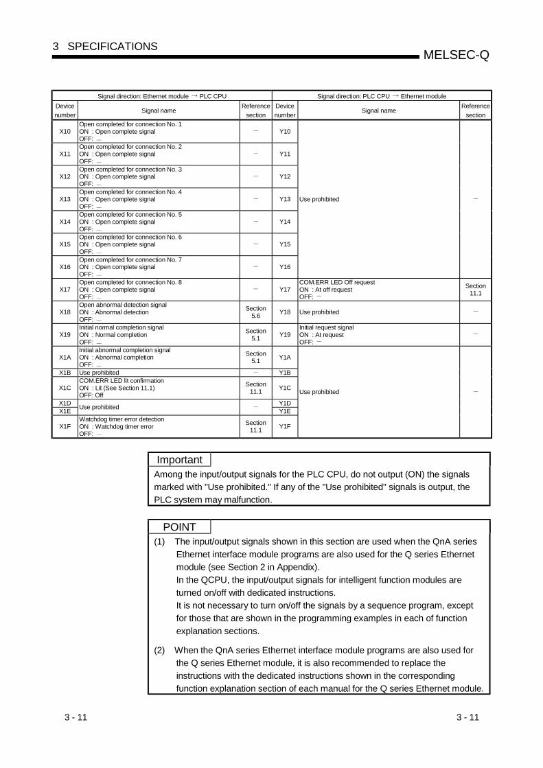
3 - 11 3 - 11
MELSEC-Q3 SPECIFICATIONS
Signal direction: Ethernet module PLC CPU Signal direction: PLC CPU Ethernet moduleDevicenumber
Signal nameReference
sectionDevicenumber
Signal nameReference
section
X10Open completed for connection No. 1ON : Open complete signalOFF:
Y10
X11Open completed for connection No. 2ON : Open complete signalOFF:
Y11
X12Open completed for connection No. 3ON : Open complete signalOFF:
Y12
X13Open completed for connection No. 4ON : Open complete signalOFF:
Y13
X14Open completed for connection No. 5ON : Open complete signalOFF:
Y14
X15Open completed for connection No. 6ON : Open complete signalOFF:
Y15
X16Open completed for connection No. 7ON : Open complete signalOFF:
Y16
Use prohibited
X17Open completed for connection No. 8ON : Open complete signalOFF:
Y17COM.ERR LED Off requestON : At off requestOFF:
Section11.1
X18Open abnormal detection signalON : Abnormal detectionOFF:
Section5.6 Y18 Use prohibited
X19Initial normal completion signalON : Normal completionOFF:
Section5.1 Y19
Initial request signalON : At requestOFF:
X1AInitial abnormal completion signalON : Abnormal completionOFF:
Section5.1 Y1A
X1B Use prohibited Y1B
X1CCOM.ERR LED lit confirmationON : Lit (See Section 11.1)OFF: Off
Section11.1 Y1C
X1D Y1DX1E Use prohibited Y1E
X1FWatchdog timer error detectionON : Watchdog timer errorOFF:
Section11.1 Y1F
Use prohibited
ImportantAmong the input/output signals for the PLC CPU, do not output (ON) the signalsmarked with "Use prohibited." If any of the "Use prohibited" signals is output, thePLC system may malfunction.
POINT(1) The input/output signals shown in this section are used when the QnA series
Ethernet interface module programs are also used for the Q series Ethernetmodule (see Section 2 in Appendix).In the QCPU, the input/output signals for intelligent function modules areturned on/off with dedicated instructions.It is not necessary to turn on/off the signals by a sequence program, exceptfor those that are shown in the programming examples in each of functionexplanation sections.
(2) When the QnA series Ethernet interface module programs are also used forthe Q series Ethernet module, it is also recommended to replace theinstructions with the dedicated instructions shown in the correspondingfunction explanation section of each manual for the Q series Ethernet module.
3 - 12 3 - 12
MELSEC-Q3 SPECIFICATIONS
3.8 List of Applications and Assignments of the Buffer Memory
This section explains details of the buffer memory.
(1) Configuration of the buffer memoryBuffer memory consists of a user area and a system area, as listed below.
(a) User areas
1) The areas where the user writes/reads data.
2) A user area consists of a parameter area for initial processing anddata communication, an area for data communication, and an area forstoring communication status and communication error data.
3) Reading/writing data to the user area should be performed accordingto the instructions in the corresponding detailed explanation section.Data communication may take long if continually executed; therefore,execute only when needed.
(b) System areasThe areas used by the Ethernet module
ImportantDo not write data in the "system areas" of the buffer memory.If data is written to any of the system areas, the PLC system may not be operatedproperly.Some of the user areas contain partially system areas. Care must be taken whenreading/writing to the buffer memory.
POINT(1) Use the FROM/TO instructions or other applicable commands to access the
buffer memory addresses shown in this section when the QnA seriesEthernet module programs are used for the Q series Ethernet module (seeSection 2 in Appendix).In the QCPU, the buffer memory of an intelligent function module is accessedby dedicated instructions.It is not necessary to access directly using the FROM/TO or other instructionsfrom the sequence program, except when accessing the buffer memory asshown in the programming examples in each of function explanation sections.
(2) When the QnA series Ethernet module programs are used for the Q seriesEthernet module, it is also recommended to replace the instructions with thededicated instructions shown in the corresponding function explanationsection of each manual for the Q series Ethernet module.

3 - 13 3 - 13
MELSEC-Q3 SPECIFICATIONS
(2) Assignments of the buffer memoryA buffer memory consists of 16 bits per address.
<Bit configuration diagram>
The following shows the buffer memory addresses.
Address
Decimal(Hexadecimal)
Application NameInitial value
(Hexadecimal)
GX Developersetting
applicability( 1)
Referencesection( 2)
0 to 1(0 to 1H)
Local station Ethernet module IP address C00001FEH Section 4.7
2 to 3(2 to 3H)
System area
4(4H)
Special function settings• Router relay function (b5, b4)
00: Do not use (default)01: Use
• Conversion system setting for MELSECNET/H, MELSECNET/10relay function (b7, b6)
00: Automatic response system (default)01: IP address computation system10: Table exchange system11: Use-together system
• FTP function setting (b9, b8)00: Do not use01: Use (default)
Bits other than above are reserved for system use.
0100H
Section 5.3
Chapter 3 ofApplication
Chapter 5 ofApplication
5 to 10(5 to A H)
System area
11(BH)
TCP ULP timer valueSetting time = setting value × 500 ms
3CH (60)
12(CH)
TCP zero window timer valueSetting time = setting value × 500 ms
14H (20)
13(DH)
TCP resend timer valueSetting time = setting value × 500 ms
14H (20)
14(EH)
TCP end timer valueSetting time = setting value × 500 ms
28H (40)
15(FH)
IP assembly timer valueSetting time = setting value × 500 ms
AH (10)
16(10H)
Response monitoring timer valueSetting time = setting value × 500 ms
3CH (60)
17(11H)
Destination existence confirmation starting intervalSetting time = setting value × 500 ms
4B0H (1200)
18(12H)
Destination existence confirmation interval timerSetting time = setting value × 500 ms
14H (20)
19(13H)
Monitoring timer
Destination existence confirmation resend timer 3H (3)
Section 5.2
20(14H)
Automatic open UDP port number 1388H Section 5.8
21 to 30(15 to 1EH)
Initial processingparameter settingarea
System area
(Continues on the next page)
1 Setting from GX Developer allowed/prohibited
: Setting allowed : Setting prohibited
2 "Application" in the reference section column refers to the User’s Manual (Application).
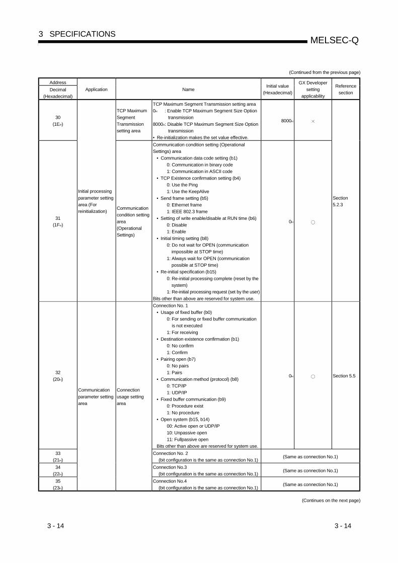
3 - 14 3 - 14
MELSEC-Q3 SPECIFICATIONS
(Continued from the previous page)
AddressDecimal
(Hexadecimal)Application Name
Initial value(Hexadecimal)
GX Developersetting
applicability
Referencesection
30(1EH)
TCP MaximumSegmentTransmissionsetting area
TCP Maximum Segment Transmission setting area0H : Enable TCP Maximum Segment Size Option
transmission8000H: Disable TCP Maximum Segment Size Option
transmission• Re-initialization makes the set value effective.
8000H
31(1FH)
Initial processingparameter settingarea (Forreinitialization) Communication
condition settingarea(OperationalSettings)
Communication condition setting (OperationalSettings) area
• Communication data code setting (b1)0: Communication in binary code1: Communication in ASCII code
• TCP Existence confirmation setting (b4)0: Use the Ping1: Use the KeepAlive
• Send frame setting (b5)0: Ethernet frame1: IEEE 802.3 frame
• Setting of write enable/disable at RUN time (b6)0: Disable1: Enable
• Initial timing setting (b8)0: Do not wait for OPEN (communication
impossible at STOP time)1: Always wait for OPEN (communication
possible at STOP time)• Re-initial specification (b15)
0: Re-initial processing complete (reset by thesystem)
1: Re-initial processing request (set by the user)Bits other than above are reserved for system use.
0H
Section5.2.3
32(20H)
Connection No. 1• Usage of fixed buffer (b0)
0: For sending or fixed buffer communicationis not executed
1: For receiving• Destination existence confirmation (b1)
0: No confirm1: Confirm
• Pairing open (b7)0: No pairs1: Pairs
• Communication method (protocol) (b8)0: TCP/IP1: UDP/IP
• Fixed buffer communication (b9)0: Procedure exist1: No procedure
• Open system (b15, b14)00: Active open or UDP/IP10: Unpassive open11: Fullpassive open
Bits other than above are reserved for system use.
0H Section 5.5
33(21H)
Connection No. 2(bit configuration is the same as connection No.1)
(Same as connection No.1)
34(22H)
Connection No.3(bit configuration is the same as connection No.1)
(Same as connection No.1)
35(23H)
Communicationparameter settingarea
Connectionusage settingarea
Connection No.4(bit configuration is the same as connection No.1)
(Same as connection No.1)
(Continues on the next page)
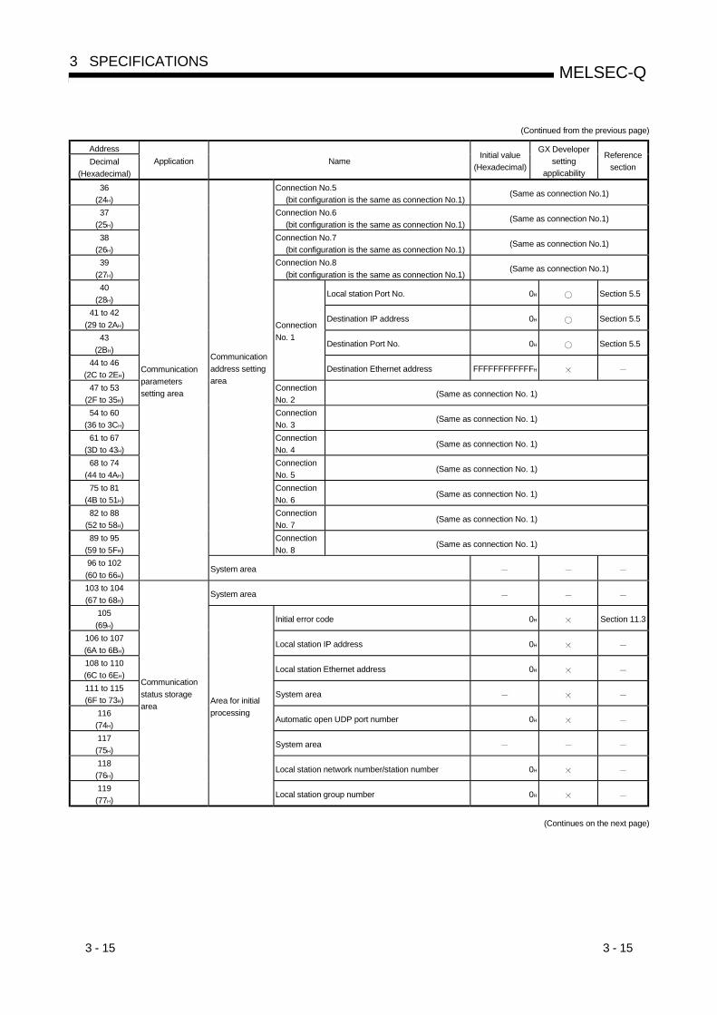
3 - 15 3 - 15
MELSEC-Q3 SPECIFICATIONS
(Continued from the previous page)
AddressDecimal
(Hexadecimal)Application Name
Initial value(Hexadecimal)
GX Developersetting
applicability
Referencesection
36(24H)
Connection No.5(bit configuration is the same as connection No.1)
(Same as connection No.1)
37(25H)
Connection No.6(bit configuration is the same as connection No.1)
(Same as connection No.1)
38(26H)
Connection No.7(bit configuration is the same as connection No.1)
(Same as connection No.1)
39(27H)
Connection No.8(bit configuration is the same as connection No.1)
(Same as connection No.1)
40(28H)
Local station Port No. 0H Section 5.5
41 to 42(29 to 2AH)
Destination IP address 0H Section 5.5
43(2BH)
Destination Port No. 0H Section 5.5
44 to 46(2C to 2EH)
ConnectionNo. 1
Destination Ethernet address FFFFFFFFFFFFH
47 to 53(2F to 35H)
ConnectionNo. 2
(Same as connection No. 1)
54 to 60(36 to 3CH)
ConnectionNo. 3
(Same as connection No. 1)
61 to 67(3D to 43H)
ConnectionNo. 4
(Same as connection No. 1)
68 to 74(44 to 4AH)
ConnectionNo. 5
(Same as connection No. 1)
75 to 81(4B to 51H)
ConnectionNo. 6
(Same as connection No. 1)
82 to 88(52 to 58H)
ConnectionNo. 7
(Same as connection No. 1)
89 to 95(59 to 5FH)
Communicationaddress settingarea
ConnectionNo. 8
(Same as connection No. 1)
96 to 102(60 to 66H)
Communicationparameterssetting area
System area
103 to 104(67 to 68H)
System area
105(69H)
Initial error code 0H Section 11.3
106 to 107(6A to 6BH)
Local station IP address 0H
108 to 110(6C to 6EH)
Local station Ethernet address 0H
111 to 115(6F to 73H)
System area
116(74H)
Automatic open UDP port number 0H
117(75H)
System area
118(76H)
Local station network number/station number 0H
119(77H)
Communicationstatus storagearea Area for initial
processing
Local station group number 0H
(Continues on the next page)

3 - 16 3 - 16
MELSEC-Q3 SPECIFICATIONS
(Continued from the previous page)
AddressDecimal
(Hexadecimal)Application Name Initial value
(Hexadecimal)
GX Developersetting
applicability
Referencesection
120(78H) Local station Port No. 0H
121 to 122(79 to 7AH) Destination IP address 0H
123(7BH) Destination Port No. 0H
124(7CH) Open error code 0H Section 11.3
125(7DH) Fixed buffer sending error code 0H Section 11.3
126(7EH) Connection end code 0H Section 11.3
127(7FH) Maximum value 0H
128(80H) Minimum value 0H
129(81H)
ConnectionNo. 1
Fixed buffercommunicationtime
Current value 0H
130 to 139(82 to 8BH)
ConnectionNo. 2 (Same as connection No. 1)
140 to 149(8C to 95H)
ConnectionNo. 3 (Same as connection No. 1)
150 to 159(96 to 9FH)
ConnectionNo. 4 (Same as connection No. 1)
160 to 169(A0 to A9H)
ConnectionNo. 5 (Same as connection No. 1)
170 to 179(AA to B3H)
ConnectionNo. 6 (Same as connection No. 1)
180 to 189(B4 to BDH)
ConnectionNo. 7 (Same as connection No. 1)
190 to 199(BE to C7H)
Connectioninformation area
ConnectionNo. 8 (Same as connection No. 1)
200(C8H)
LED on/off status(Stores the on/off status of the LEDs on the front ofthe Ethernet module)
• [INIT.] LED (b0)0: off1: on (initial processing completed)
• [OPEN] LED (b1)0: off1: on (connection open processing completed)
• [ERR.] LED (b3)0: off1: on (setting error)
• [COM.ERR.] LED (b4)0: off1: on (communication error)
Bits other than above are reserved for system use.
0H
201(C9H)
Hub connection status area• Communication mode (b9)
0: Half duplex1: Full duplex
• Hub connection status (b10)0: Hub not connected/disconnected1: Hub connected
• Data transmission speed (b14)0: Operating at 10BASE-T1: Operating at 100BASE-TX
Bits other than above are reserved for system use.
0H Section 5.10
202(CAH)
Communicationstatus storagearea
Area for modulestatus
• Switch status (operational mode setting)0: Online1: Offline2: Self refrain test3: Hardware test (H/W test)
0H Section 4.6
(Continues on the next page)
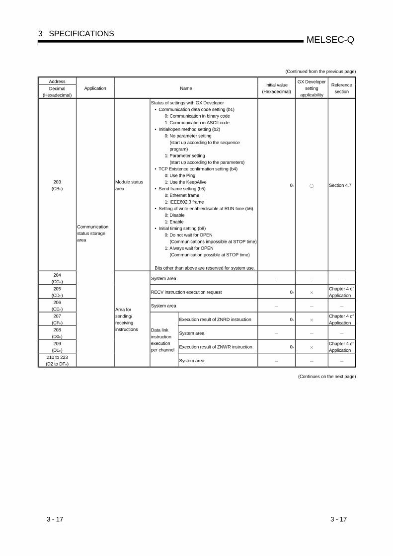
3 - 17 3 - 17
MELSEC-Q3 SPECIFICATIONS
(Continued from the previous page)
AddressDecimal
(Hexadecimal)Application Name
Initial value(Hexadecimal)
GX Developersetting
applicability
Referencesection
203(CBH)
Module statusarea
Status of settings with GX Developer• Communication data code setting (b1)
0: Communication in binary code1: Communication in ASCII code
• Initial/open method setting (b2)0: No parameter setting
(start up according to the sequenceprogram)
1: Parameter setting(start up according to the parameters)
• TCP Existence confirmation setting (b4)0: Use the Ping1: Use the KeepAlive
• Send frame setting (b5)0: Ethernet frame1: IEEE802.3 frame
• Setting of write enable/disable at RUN time (b6)0: Disable1: Enable
• Initial timing setting (b8)0: Do not wait for OPEN
(Communications impossible at STOP time)1: Always wait for OPEN
(Communication possible at STOP time)
Bits other than above are reserved for system use.
0H Section 4.7
204(CCH)
System area
205(CDH)
RECV instruction execution request 0HChapter 4 ofApplication
206(CEH)
System area
207(CFH)
Execution result of ZNRD instruction 0HChapter 4 ofApplication
208(D0H)
System area
209(D1H)
Execution result of ZNWR instruction 0HChapter 4 ofApplication
210 to 223(D2 to DFH)
Communicationstatus storagearea
Area forsending/receivinginstructions Data link
instructionexecutionper channel
System area
(Continues on the next page)

3 - 18 3 - 18
MELSEC-Q3 SPECIFICATIONS
(Continued from the previous page)
AddressDecimal
(Hexadecimal)Application Name
Initial value(Hexadecimal)
GX Developersetting
applicability
Referencesection
224 to 226(E0 to E2H)
System area
227(E3H)
Number of error occurrence
228(E4H)
Error log write pointer0H Section 11.3
229(E5H)
Error code/end code
230(E6H)
Subheader
231(E7H)
Command code
232(E8H)
Connection No.
233(E9H)
Local station Port No.
234 to 235(EA to EBH)
Destination IP address
236(ECH)
Destination Port No.
0H Section 11.3
237(EDH)
Error logblock 1
System area
238 to 246(EE to F6H)
Error logblock 2
(Same as error log block 1)
247 to 255(F7 to FFH)
Error logblock 3
(Same as error log block 1)
256 to 264(100 to 108H)
Error logblock 4
(Same as error log block 1)
265 to 273(109 to 111H)
Error logblock 5
(Same as error log block 1)
274 to 282(112 to 11AH)
Error logblock 6
(Same as error log block 1)
283 to 291(11B to 123H)
Error logblock 7
(Same as error log block 1)
292 to 300(124 to 12CH)
Error logblock 8
(Same as error log block 1)
301 to 309(12D to 135H)
Error logblock 9
(Same as error log block 1)
310 to 318(136 to 13EH)
Error logblock 10
(Same as error log block 1)
319 to 327(13F to 147H)
Error logblock 11
(Same as error log block 1)
328 to 336(148 to 150H)
Error logblock 12
(Same as error log block 1)
337 to 345(151 to 159H)
Error logblock 13
(Same as error log block 1)
346 to 354(15A to 162H)
Error logblock 14
(Same as error log block 1)
355 to 363(163 to 16BH)
Error logblock 15
(Same as error log block 1)
364 to 372(16C to 174H)
Error log blockarea
Error logblock 16
(Same as error log block 1)
373 to 375(175 to 177H)
Error log area
System area
(Continues on the next page)

3 - 19 3 - 19
MELSEC-Q3 SPECIFICATIONS
(Continued from the previous page)
AddressDecimal
(Hexadecimal)Application Name
Initial value(Hexadecimal)
GX Developersetting
applicability
Referencesection
376 to 377(178 to 179H)
Received IP packet count
378 to 379(17A to 17BH)
Received IP packet count discardeddue to sum check error
380 to 381(17C to 17DH)
Sent IP packet total count
0H Section 11.3
382 to 397(17E to 18DH)
System area
398 to 399(18E to 18FH)
Simultaneous transmission errordetection count
0HSection 11.4POINT (3)
400 to 407(190 to 197H)
IP
System area
408 to 409(198 to 199H)
Received ICMP packet count
410 to 411(19A to 19BH)
Received ICMP packet countdiscarded due to sum check error
412 to 413(19C to 19DH)
Sent ICMP packet total count
414 to 415(19E to 19FH)
Echo request total count of receivedICMP packets
416 to 417(1A0 to 1A1H)
Echo reply total count of sent ICMPpackets
418 to 419(1A2 to 1A3H)
Echo request total count of sent ICMPpackets
420 to 421(1A4 to 1A5H)
Echo reply total count of receivedICMP packets
0H
422 to 439(1A6 to 1B7H)
ICMP
System area
440 to 441(1B8 to 1B9H)
Received TCP packet count
442 to 443(1BA to 1BBH)
Received TCP packet count discardeddue to sum check error
444 to 445(1BC to 1BDH)
Sent TCP packet total count
0H
446 to 471(1BE to 1D7H)
TCP
System area
472 to 473(1D8 to 1D9H)
Received UDP packet count
474 to 475(1DA to 1DBH)
Received UDP packet count discardeddue to sum check error
476 to 477(1DC to 1DDH)
Sent UDP packet total count
0H
478 to 481(1DE to 1E1H)
UDP
System area
482 to 491(1E2 to 1EBH)
System area
492 to 493(1EC to 1EDH)
Framing error count 0H
494 to 495(1EE to 1EFH)
Overflow count 0H
496 to 497(1F0 to 1F1H)
Receivingerror
crc error count 0H
498 to 511(1F2 to 1FFH)
Error log areaStatus for eachprotocol
System area
—
(Continues on the next page)
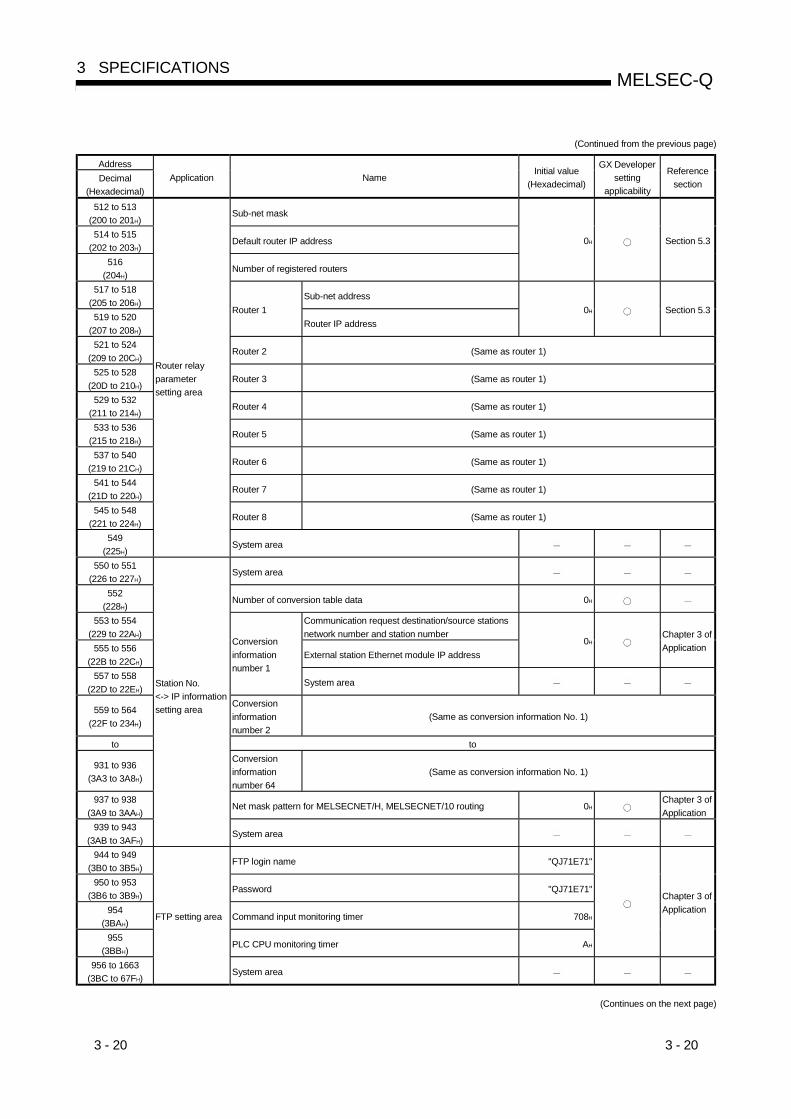
3 - 20 3 - 20
MELSEC-Q3 SPECIFICATIONS
(Continued from the previous page)
AddressDecimal
(Hexadecimal)Application Name
Initial value(Hexadecimal)
GX Developersetting
applicability
Referencesection
512 to 513(200 to 201H)
Sub-net mask
514 to 515(202 to 203H)
Default router IP address
516(204H)
Number of registered routers
0H Section 5.3
517 to 518(205 to 206H)
Sub-net address
519 to 520(207 to 208H)
Router 1Router IP address
0H Section 5.3
521 to 524(209 to 20CH)
Router 2 (Same as router 1)
525 to 528(20D to 210H)
Router 3 (Same as router 1)
529 to 532(211 to 214H)
Router 4 (Same as router 1)
533 to 536(215 to 218H)
Router 5 (Same as router 1)
537 to 540(219 to 21CH)
Router 6 (Same as router 1)
541 to 544(21D to 220H)
Router 7 (Same as router 1)
545 to 548(221 to 224H)
Router 8 (Same as router 1)
549(225H)
Router relayparametersetting area
System area
550 to 551(226 to 227H)
System area
552(228H)
Number of conversion table data 0H
553 to 554(229 to 22AH)
Communication request destination/source stationsnetwork number and station number
555 to 556(22B to 22CH)
External station Ethernet module IP address0H
Chapter 3 ofApplication
557 to 558(22D to 22EH)
Conversioninformationnumber 1
System area
559 to 564(22F to 234H)
Conversioninformationnumber 2
(Same as conversion information No. 1)
to to
931 to 936(3A3 to 3A8H)
Conversioninformationnumber 64
(Same as conversion information No. 1)
937 to 938(3A9 to 3AAH)
Net mask pattern for MELSECNET/H, MELSECNET/10 routing 0HChapter 3 ofApplication
939 to 943(3AB to 3AFH)
Station No.<-> IP informationsetting area
System area
944 to 949(3B0 to 3B5H)
FTP login name "QJ71E71"
950 to 953(3B6 to 3B9H)
Password "QJ71E71"
954(3BAH)
Command input monitoring timer 708H
955(3BBH)
PLC CPU monitoring timer AH
Chapter 3 ofApplication
956 to 1663(3BC to 67FH)
FTP setting area
System area
(Continues on the next page)
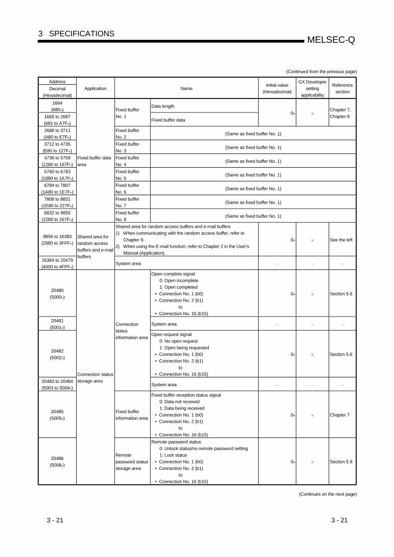
3 - 21 3 - 21
MELSEC-Q3 SPECIFICATIONS
(Continued from the previous page)
AddressDecimal
(Hexadecimal)Application Name
Initial value(Hexadecimal)
GX Developersetting
applicability
Referencesection
1664(680H)
Data length
1665 to 2687(681 to A7FH)
Fixed bufferNo. 1
Fixed buffer data0H
Chapter 7,Chapter 8
2688 to 3711(A80 to E7FH)
Fixed bufferNo. 2
(Same as fixed buffer No. 1)
3712 to 4735(E80 to 127FH)
Fixed bufferNo. 3
(Same as fixed buffer No. 1)
4736 to 5759(1280 to 167FH)
Fixed bufferNo. 4
(Same as fixed buffer No. 1)
5760 to 6783(1680 to 1A7FH)
Fixed bufferNo. 5
(Same as fixed buffer No. 1)
6784 to 7807(1A80 to 1E7FH)
Fixed bufferNo. 6
(Same as fixed buffer No. 1)
7808 to 8831(1E80 to 227FH)
Fixed bufferNo. 7
(Same as fixed buffer No. 1)
8832 to 9855(2280 to 267FH)
Fixed buffer dataarea
Fixed bufferNo. 8
(Same as fixed buffer No. 1)
9856 to 16383(2680 to 3FFFH)
Shared area for random access buffers and e-mail buffers1) When communicating with the random access buffer, refer to
Chapter 9.2) When using the E-mail function, refer to Chapter 2 in the User’s
Manual (Application).
0H See the left
16384 to 20479(4000 to 4FFFH)
Shared area forrandom accessbuffers and e-mailbuffers
System area
20480(5000H)
Open complete signal0: Open incomplete1: Open completed
• Connection No. 1 (b0)• Connection No. 2 (b1)
to• Connection No. 16 (b15)
0H Section 5.6
20481(5001H)
System area
20482(5002H)
Open request signal0: No open request1: Open being requested
• Connection No. 1 (b0)• Connection No. 2 (b1)
to• Connection No. 16 (b15)
0H Section 5.6
20483 to 20484(5003 to 5004H)
Connectionstatusinformation area
System area
20485(5005H)
Fixed bufferinformation area
Fixed buffer reception status signal0: Data not received1: Data being received
• Connection No. 1 (b0)• Connection No. 2 (b1)
to• Connection No. 16 (b15)
0H Chapter 7
20486(5006H)
Connection statusstorage area
Remotepassword statusstorage area
Remote password status0: Unlock status/no remote password setting1: Lock status
• Connection No. 1 (b0)• Connection No. 2 (b1)
to• Connection No. 16 (b15)
0H Section 5.9
(Continues on the next page)

3 - 22 3 - 22
MELSEC-Q3 SPECIFICATIONS
(Continued from the previous page)
AddressDecimal
(Hexadecimal)Application Name
Initial value(Hexadecimal)
GX Developersetting
applicability
Referencesection
20487(5007H)
Remotepassword statusstorage area
Remote password status0: Unlock status/no remote password setting1: Lock status
• Automatic open UDP port (b0)• GX Developer (UDP port) (b1)• GX Developer (TCP port) (b2)• FTP port (b3)
0H
20488(5008H)
System portinformation area
System port useprohibiteddesignation area
System port use prohibited designation0: Use allowed1: Use prohibited
• Automatic open UDP port (b0)• GX Developer (UDP port) (b1)• GX Developer (TCP port) (b2)
0H
Section 5.9
20489 to 20591(5009 to 506FH)
System area
20592(5070H)
Remote password mismatch notificationaccumulated count designation(For user open port)0: No designation1 or higher: Notification accumulated count
1H
20593(5071H)
Remote password mismatch notificationaccumulated count designation(For automatic open UDP port, GX Developercommunication port (TCP, UDP) and FTPcommunication port)0: No designation1 or higher: Notification accumulated count
2H
20594(5072H)
Accumulated count of unlock processnormal completion
20595(5073H)
Accumulated count of unlock processabnormal completion
20596(5074H)
Accumulated count of lock processnormal completion
20597(5075H)
Accumulated count of lock processabnormal completion
20598(5076H)
ConnectionNo.1
Accumulated count of lock processbased on close
0H
Section5.9.6
20599 to 20603(5077H to 507B H)
ConnectionNo.2
(Same as connection No.1)
20604 to 20608(507CH to 5080 H)
ConnectionNo.3
(Same as connection No.1)
20609 to 20613(5081H to 5085 H)
ConnectionNo.4
(Same as connection No.1)
20614 to 20618(5086H to 508A H)
ConnectionNo.5
(Same as connection No.1)
20619 to 20623(508BH to 508F H)
ConnectionNo.6
(Same as connection No.1)
20624 to 20628(5090H to 5094 H)
ConnectionNo.7
(Same as connection No.1)
20629 to 20633(5095H to 5099 H)
ConnectionNo.8
(Same as connection No.1)
20634 to 20638(509AH to 509E H)
ConnectionNo.9
(Same as connection No.1)
20639 to 20643(509FH to 50A3 H)
ConnectionNo.10
(Same as connection No.1)
20644 to 20648(50A4H to 50A8 H)
Monitoring areaRemotepasswordfunctionmonitoring area
ConnectionNo.11
(Same as connection No.1)
(Continues on the next page)
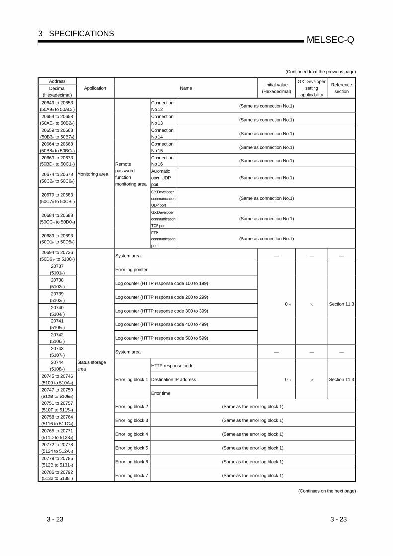
3 - 23 3 - 23
MELSEC-Q3 SPECIFICATIONS
(Continued from the previous page)
AddressDecimal
(Hexadecimal)Application Name
Initial value(Hexadecimal)
GX Developersetting
applicability
Referencesection
20649 to 20653(50A9H to 50ADH)
ConnectionNo.12
(Same as connection No.1)
20654 to 20658(50AEH to 50B2H)
ConnectionNo.13
(Same as connection No.1)
20659 to 20663(50B3H to 50B7H)
ConnectionNo.14
(Same as connection No.1)
20664 to 20668(50B8H to 50BCH)
ConnectionNo.15
(Same as connection No.1)
20669 to 20673(50BDH to 50C1H)
ConnectionNo.16
(Same as connection No.1)
20674 to 20678(50C2H to 50C6H)
Automaticopen UDPport
(Same as connection No.1)
20679 to 20683(50C7H to 50CBH)
GX DevelopercommunicationUDP port
(Same as connection No.1)
20684 to 20688(50CCH to 50D0H)
GX DevelopercommunicationTCP port
(Same as connection No.1)
20689 to 20693(50D1H to 50D5H)
Monitoring area
Remotepasswordfunctionmonitoring area
FTPcommunicationport
(Same as connection No.1)
20694 to 20736(50D6 H to 5100H)
System area — — —
20737(5101H)
Error log pointer
20738(5102H)
Log counter (HTTP response code 100 to 199)
20739(5103H)
Log counter (HTTP response code 200 to 299)
20740(5104H)
Log counter (HTTP response code 300 to 399)
20741(5105H)
Log counter (HTTP response code 400 to 499)
20742(5106H)
Log counter (HTTP response code 500 to 599)
0 H Section 11.3
20743(5107H)
System area — — —
20744(5108H)
HTTP response code
20745 to 20746(5109 to 510AH)
Destination IP address
20747 to 20750(510B to 510EH)
Error log block 1
Error time
0 H Section 11.3
20751 to 20757(510F to 5115H)
Error log block 2 (Same as the error log block 1)
20758 to 20764(5116 to 511CH)
Error log block 3 (Same as the error log block 1)
20765 to 20771(511D to 5123H)
Error log block 4 (Same as the error log block 1)
20772 to 20778(5124 to 512AH)
Error log block 5 (Same as the error log block 1)
20779 to 20785(512B to 5131H)
Error log block 6 (Same as the error log block 1)
20786 to 20792(5132 to 5138H)
Status storagearea
Error log block 7 (Same as the error log block 1)
(Continues on the next page)
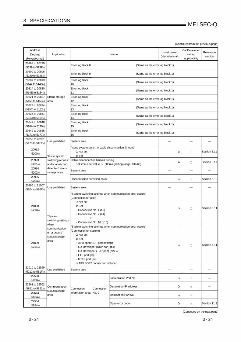
3 - 24 3 - 24
MELSEC-Q3 SPECIFICATIONS
(Continued from the previous page)
AddressDecimal
(Hexadecimal)Application Name
Initial value(Hexadecimal)
GX Developersetting
applicability
Referencesection
20793 to 20799(5139 to 513FH)
Error log block 8 (Same as the error log block 1)
20800 to 20806(5140 to 5146H)
Error log block 9 (Same as the error log block 1)
20807 to 20813(5147 to 514DH)
Error log block10
(Same as the error log block 1)
20814 to 20820(514E to 5154H)
Error log block11
(Same as the error log block 1)
20821 to 20827(5155 to 515BH)
Error log block12
(Same as the error log block 1)
20828 to 20834(515C to 5162H)
Error log block13
(Same as the error log block 1)
20835 to 20841(5163 to 5169H)
Error log block14
(Same as the error log block 1)
20842 to 20848(516A to 5170H)
Error log block15
(Same as the error log block 1)
20849 to 20855(5171 to 5177H)
Status storagearea
Error log block16
(Same as the error log block 1)
20856 to 20991(5178 to 51FFH)
Use prohibited System area — — —
20992(5200H)
"Issue system switch in cable disconnection timeout"0: Not set1: Set
1H Section 5.11
20993(5201H)
Cable disconnection timeout settingSet time = set value 500ms (setting range: 0 to 60)
4H Section 5.11
20994(5202H)
System area — — —
20995(5203H)
"Issue systemswitching requestat disconnectiondetection" statusstorage area
Disconnection detection count 0H Section 5.10
20996 to 21007(5204 to 520FH)
Use prohibited System area — — —
21008(5210H)
"System switching settings when communication error occurs"(Connection for user)
0: Not set1: Set• Connection No. 1 (b0)• Connection No. 2 (b1) to• Connection No. 16 (b15)
0H Section 5.11
21009(5211H)
"Systemswitching settingswhencommunicationerror occurs"status storagearea
"System switching settings when communication error occurs"(Connection for system)
0: Not set1: Set• Auto open UDP port settings• GX Developer (UDP port) (b1)• GX Developer (TCP port) (b2) • FTP port (b3)• HTTP port (b4)
MELSOFT connection included
0H Section 5.11
21010 to 22559(5212 to 581FH)
Use prohibited System area — — —
22560(5820H)
Local station Port No. 0H —
22561 to 22562(5821 to 5822H)
Destination IP address 0H —
22563(5823H)
Destination Port No. 0H —
22564(5824H)
Communicationstatus storagearea
Connectioninformation area
ConnectionNo. 9
Open error code 0H Section 11.3
(Continues on the next page)

3 - 25 3 - 25
MELSEC-Q3 SPECIFICATIONS
(Continued from the previous page)
AddressDecimal
(Hexadecimal)Application Name
Initial value(Hexadecimal)
GX Developersetting
applicability
Referencesection
22565(5825H)
Fixed buffer sending error code 0H Section 11.3
22566(5826H)
Connection end code 0H Section 11.3
22567(5827H)
Maximum value 0H —
22568(5828H)
Minimum value 0H —
22569(5829H)
ConnectionNo. 9
Fixed buffercommunicationtime
Current value 0H —
22570 to 22579(582A to 5833H)
ConnectionNo. 10
(Same as connection No.9)
22580 to 22589(5834 to 583DH)
ConnectionNo. 11
(Same as connection No.9)
22590 to 22599(583E to 5847H)
ConnectionNo. 12
(Same as connection No.9)
22600 to 22609(5848 to 5851H)
ConnectionNo. 13
(Same as connection No.9)
22610 to 22619(5852 to 585BH)
ConnectionNo. 14
(Same as connection No.9)
22620 to 22629(585C to 5865H)
ConnectionNo. 15
(Same as connection No.9)
22630 to 22639(5866 to 586FH)
Communicationstatus storagearea
Connectioninformation area
ConnectionNo. 16
(Same as connection No.9)
22640(5870H)
Number of mails remaining on the server
22641(5871H)
Dedicated instruction normal completion count
22642(5872H)
Dedicated instruction abnormal completion count
22643(5873H)
Normal receiving count
22644(5874H)
Attached file receiving count
22645(5875H)
Server inquiry count
22646(5876H)
Server communication error count
22647(2877H)
Error log write count
22648(5878H)
Receiving error log write pointer
0H Section 11.3
22649(5879H)
Error code
22650(587AH)
Command code
22651 to 22658(587B to 5882H)
From
22659 to 22662(5883 to 5886H)
Date
22663 to 22692(5887 to 58A4H)
Error logblock 1
Subject
0H Section 11.3
22693 to 22736(58A5 to 58D0H)
Error logblock 2
(Same as error log block 1)
22737 to 22780(58D1 to 58FCH)
Error logblock 3
(Same as error log block 1)
22781 to 22824(58FD to 5928H)
E-mail statusstorage area
Receive
Error logblock 4
(Same as error log block 1)
(Continues on the next page)
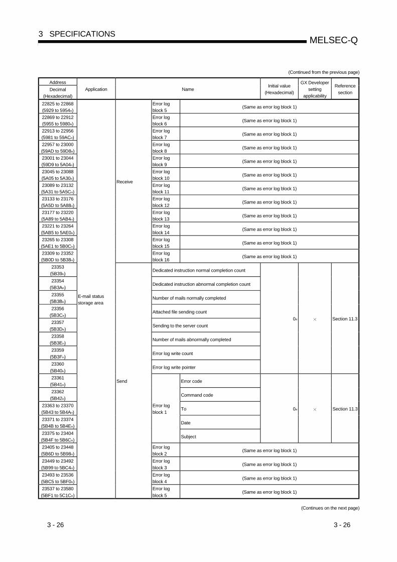
3 - 26 3 - 26
MELSEC-Q3 SPECIFICATIONS
(Continued from the previous page)
AddressDecimal
(Hexadecimal)Application Name
Initial value(Hexadecimal)
GX Developersetting
applicability
Referencesection
22825 to 22868(5929 to 5954H)
Error logblock 5
(Same as error log block 1)
22869 to 22912(5955 to 5980H)
Error logblock 6
(Same as error log block 1)
22913 to 22956(5981 to 59ACH)
Error logblock 7
(Same as error log block 1)
22957 to 23000(59AD to 59D8H)
Error logblock 8
(Same as error log block 1)
23001 to 23044(59D9 to 5A04H)
Error logblock 9
(Same as error log block 1)
23045 to 23088(5A05 to 5A30H)
Error logblock 10
(Same as error log block 1)
23089 to 23132(5A31 to 5A5CH)
Error logblock 11
(Same as error log block 1)
23133 to 23176(5A5D to 5A88H)
Error logblock 12
(Same as error log block 1)
23177 to 23220(5A89 to 5AB4H)
Error logblock 13
(Same as error log block 1)
23221 to 23264(5AB5 to 5AE0H)
Error logblock 14
(Same as error log block 1)
23265 to 23308(5AE1 to 5B0CH)
Error logblock 15
(Same as error log block 1)
23309 to 23352(5B0D to 5B38H)
Receive
Error logblock 16
(Same as error log block 1)
23353(5B39H)
Dedicated instruction normal completion count
23354(5B3AH)
Dedicated instruction abnormal completion count
23355(5B3BH)
Number of mails normally completed
23356(5B3CH)
Attached file sending count
23357(5B3DH)
Sending to the server count
23358(5B3EH)
Number of mails abnormally completed
23359(5B3FH)
Error log write count
23360(5B40H)
Error log write pointer
0H Section 11.3
23361(5B41H)
Error code
23362(5B42H)
Command code
23363 to 23370(5B43 to 5B4AH)
To
23371 to 23374(5B4B to 5B4EH)
Date
23375 to 23404(5B4F to 5B6CH)
Error logblock 1
Subject
0H Section 11.3
23405 to 23448(5B6D to 5B98H)
Error logblock 2
(Same as error log block 1)
23449 to 23492(5B99 to 5BC4H)
Error logblock 3
(Same as error log block 1)
23493 to 23536(5BC5 to 5BF0H)
Error logblock 4
(Same as error log block 1)
23537 to 23580(5BF1 to 5C1CH)
E-mail statusstorage area
Send
Error logblock 5
(Same as error log block 1)
(Continues on the next page)

3 - 27 3 - 27
MELSEC-Q3 SPECIFICATIONS
(Continued from the previous page)
AddressDecimal
(Hexadecimal)Application Name
Initial value(Hexadecimal)
GX Developersetting
applicability
Referencesection
23581 to 23624(5C1D to 5C48H)
Error logblock 6
(Same as error log block 1)
23625 to 23668(5C49 to 5C74H)
Error logblock 7
(Same as error log block 1)
23669 to 23712(5C75 to 5CA0H)
Send
Error logblock 8
(Same as error log block 1)
23713 to 24575(5CA1 to 5FFFH)
E-mail statusstorage area
System area
24576(6000H)
Data length
24577 to 25599(6001 to 63FFH)
Fixed bufferNo. 9
Fixed buffer data0H
25600 to 26623(6400 to 67FFH)
Fixed bufferNo. 10
(Same as fixed buffer No. 9)
26624 to 27647(6800 to 6BFFH)
Fixed bufferNo. 11
(Same as fixed buffer No. 9)
27648 to 28671(6C00 to 6FFFH)
Fixed bufferNo. 12
(Same as fixed buffer No. 9)
28672 to 29695(7000 to 73FFH)
Fixed bufferNo. 13
(Same as fixed buffer No. 9)
29696 to 30719(7400 to 77FFH)
Fixed bufferNo. 14
(Same as fixed buffer No. 9)
30720 to 31743(7800 to 7BFFH)
Fixed bufferNo. 15
(Same as fixed buffer No. 9)
31744 to 32767(7C00 to 7FFFH)
Fixed buffer dataarea
Fixed bufferNo. 16
(Same as fixed buffer No. 9)

4 - 1 4 - 1
MELSEC-Q4 SETTINGS AND PROCEDURES PRIOR TO OPERATION
4
4 SETTINGS AND PROCEDURES PRIOR TO OPERATION
This chapter explains the settings and procedures required prior to starting theoperation of the Ethernet module in a system.
4.1 Loading and Installation
This section explains precautions for Ethernet module handling from unpacking toinstallation, as well as the installation environment common to all modules.For more details on the module mounting and installation, refer to the User's Manualfor the PLC CPU module used.
4.1.1 Handling precautions
The following explains precautions for Ethernet module handling:
(1) Since it is made of resin, the Ethernet module case should not be dropped orsubjected to any shock.
(2) Tighten the module terminal and fixing screws within the following specifiedclamping torque range:
Screw location Tightening torque rangeExternal power supply terminal screw (M2.5 screw) ( 1) 40 N•cmModule fixing screw (usually not required) (M3 screw) ( 2) 36 to 48 N•cm
1 This terminal is used as an external power input terminal for supplying power to the transceiver when being
connected to a 10BASE5.
2 The module can be easily fixed onto the base unit using the hook provided at the top of the module. However, it
is recommended that the module will be secured with the dedicated installation screws if it is subject to
significant vibration or shock.
DANGER • Do not touch the terminals and connectors while the power is on.Doing so may result in electric shocks and malfunctions.
• Make sure to turn off all phases of the external power supply before cleaning or re-tightening the screws. Failure to do so may cause damages or malfunctions of themodule.If the screws are loose, it may cause the module to short circuit, malfunction or falloff.Tightening the screws excessively may damage the screws and/or the module andcause the module to short circuit, malfunction or fall off.
• Check the safety before performing control operations to the running PLC(especially, modifications of data, programs and operation status (status control)).
4 - 2 4 - 2
MELSEC-Q4 SETTINGS AND PROCEDURES PRIOR TO OPERATION
4
CAUTION • To install the module, securely insert the module fastening latch in the installationhole on the base unit while holding down the module installation lever on the lowerpart of the module.If the module is not installed properly, it may cause the module to malfunction, fail orfall off.Secure the module with screws especially when it is used in an environment whereconstant vibrations may occurs.
• Be careful not to let any foreign matter such as wire chips get inside the module.They may cause fire, as well as breakdowns and malfunctions of the module.
• Never disassemble or modify the module.This may cause breakdowns, malfunctions, injuries or fire.
• Before mounting or dismounting the module, make sure to switch all phases of theexternal power supply off.Failure to do so may cause the module to breakdown or malfunction.
• Tighten the terminal screws using the specified torque.If the terminal screws are loose, it may cause the module to short-circuit,malfunction or fall off.Tightening the terminal screws excessively may damage the screws and/or themodule and cause the module to short-circuit, malfunction or fall off.
• Do not directly touch the conducting parts and electronic parts of the module.This may cause the module to malfunction or fail.
• When disposing of this product, treat it as industrial waste.• A protective sheet is pasted on the upper part of the module in order to prevent
foreign matter such as wire chips to get inside the module while wiring.Do not remove this protective sheet during wiring work.However, be sure to remove the protective sheet before operating the module toallow heat radiation during operation.
4.1.2 Installation environment
This section explains the installation environment for the PLC. When installing thePLC, the following environments must be avoided:• Locations where the ambient temperature exceeds the range of 0 to 55 °C.• Locations where the ambient humidity exceeds the range of 5 to 95 % RH.• Locations where condensation occurs due to a sudden temperature change.• Locations where there are corrosive or inflammable gases.• Locations exposed to considerable amounts of conductive powdery substances such
as dust and iron filing, oil mist, salt, or organic solvents.• Locations exposed to direct sunlight.• Location exposed to strong electric or magnetic fields.• Location where vibrations or impacts are directly applied to the main unit.
CAUTION • Use the PLC in the operating environment that meets the general specificationsdescribed in the user’s manual of the CPU module to use.Using the PLC in any other operating environments may cause electric shocks, firesor malfunctions, or may damage or degrade the module.

4 - 3 4 - 3
MELSEC-Q4 SETTINGS AND PROCEDURES PRIOR TO OPERATION
4.2 Settings and Procedures Prior to Starting the Operation
The following shows a flow of the procedure that is required prior to starting theoperation:
………
………
………
………
………
………
………
Procedures priorto operation
Install the Ethernet module to the base unit
Connect the Ethernet module to the Ethernet network See Section 4.4, "Connecting to the Network."
Connect GX Developer and QCPU with a cable
Set the network parameters for the Ethernet module with GX Developer See Section 4.5, "Settings from GX Developer."
Perform self-diagnostics tests with GX Developer See Section 4.8, "Self-Diagnostic Tests."
Set the operation mode to "Online" with GX Developer See Section 4.5, "Settings from GX Developer."
Send the "Ping" command from an external device andconfirm the completion of the Ethernet module initial processing
See Section 5.4, "Confirming the Completionof the Initial Processing."
Perform loopback test See Section 5.4.3, "Loopback Test."
Create a program for each communication See applicable communication function
Operation
POINTTo operate the Ethernet module after the parameter settings are added or modifiedwith GX Developer, the PLC CPU must be reset after saving the parameter valuesin the PLC CPU.
4 - 4 4 - 4
MELSEC-Q4 SETTINGS AND PROCEDURES PRIOR TO OPERATION
Important(1) Do not write any data in the "System area" of the buffer memory of the
intelligent function module.
(2) Do not output (turn on) the "Use prohibited" signal, which is one of the outputsignals.
(3) When status control (such as remote RUN/STOP) from a external device isused for the PLC CPU, the user should make the selection beforehand usingthe selecting parameters "Always wait for OPEN". (Select using initial timingin the operation settings.)If "Do not wait for OPEN" is selected, the communication line will be closedduring remote STOP After that it cannot be reopened from the PLC CPU sideand remote run from the external device also cannot be started.
(4) When using sequence programs created for Ethernet modules of conventionalmodels, do not use the open request signals (Y8 to YF), fixed buffercommunication signals (Y0 to Y7) and the dedicated OPEN/CLOSE andBUFSND/BUFRCV instructions for the same connection simultaneously in theprogram. It may result in malfunctioning.
(5) When the Ethernet module is replaced, reset the external device as well. (Ifthe external device retains the Ethernet address, it may be impossible tocontinue the communication because a module is replaced and the Ethernetaddress changes.)In the same may, when the external device (personal computer, etc.)isreplaced, restart the Ethernet module.

4 - 5 4 - 5
MELSEC-Q4 SETTINGS AND PROCEDURES PRIOR TO OPERATION
4.3 Components of the Ethernet Module
This section shows the components of the Ethernet module.
1)
2)
3)
1)
5)
QJ71E71-100
10BASE-T/100BASE-TX
RUNINIT.OPEN
SD RD
COM.ERR.ERR.
QJ71E71-100
100M
QJ71E71-B2
ERR.COM.ERR.
RDSDOPENINIT.
RUNQJ71E71-B2
1)
4)
QJ71E71-B5 EXT. POWER
10BASE 5
ERR.COM.ERR.
RDSDOPENINIT.RUN
12V
QJ71E71-B5
+12
12G
Name Description1) LED display Refer to the contents of the LED displays (1).
2)10BASE-T/100BASE-TXconnector (RJ45) ( 1)
Connector for connecting the Ethernet module to the 10BASE-T/100BASE-TX.(Ethernet module discriminate between 10BASE-T and 100BASE-TX according tothe hub.)
3) 10BASE5 connectorConnector for connecting the Ethernet module to the 10BASE5(for connecting AUI cable (transceiver cable) of 10BASE5)
4) 10BASE2 connectorConnector for connecting the Ethernet module to the 10BASE2(for connecting 10BASE2 coaxial cable)
5) External power supply terminalPower supply terminal for supplying power to the transceiver when connecting by10BASE5 (13.28 V to 15.75 V)
1 The LED on the connector does not light up.For connectors with first 5 digits of serial No. "05059" or earlier, theorientation of the connectors has been rotated by 180 degrees.
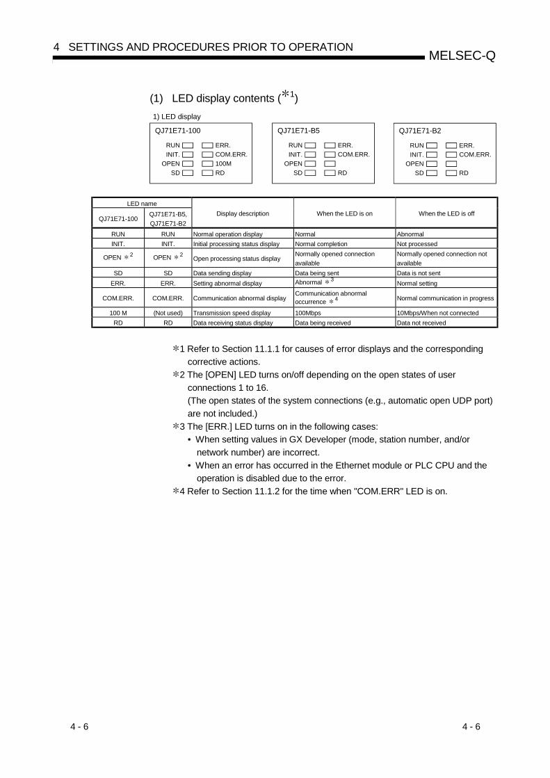
4 - 6 4 - 6
MELSEC-Q4 SETTINGS AND PROCEDURES PRIOR TO OPERATION
(1) LED display contents ( 1)1) LED display
QJ71E71-100
RUNINIT.
OPENSD
ERR.COM.ERR.
RD
QJ71E71-B5
RUNINIT.
OPENSD
ERR.COM.ERR.
RD100M
QJ71E71-B2
RUNINIT.
OPENSD
ERR.COM.ERR.
RD
LED name
QJ71E71-100QJ71E71-B5,QJ71E71-B2
Display description When the LED is on When the LED is off
RUN RUN Normal operation display Normal AbnormalINIT. INIT. Initial processing status display Normal completion Not processed
OPEN 2 OPEN 2 Open processing status displayNormally opened connectionavailable
Normally opened connection notavailable
SD SD Data sending display Data being sent Data is not sentERR. ERR. Setting abnormal display Abnormal 3 Normal setting
COM.ERR. COM.ERR. Communication abnormal displayCommunication abnormaloccurrence 4 Normal communication in progress
100 M (Not used) Transmission speed display 100Mbps 10Mbps/When not connectedRD RD Data receiving status display Data being received Data not received
1 Refer to Section 11.1.1 for causes of error displays and the correspondingcorrective actions.
2 The [OPEN] LED turns on/off depending on the open states of userconnections 1 to 16.(The open states of the system connections (e.g., automatic open UDP port)are not included.)
3 The [ERR.] LED turns on in the following cases:• When setting values in GX Developer (mode, station number, and/or
network number) are incorrect.• When an error has occurred in the Ethernet module or PLC CPU and the
operation is disabled due to the error.4 Refer to Section 11.1.2 for the time when "COM.ERR" LED is on.

4 - 7 4 - 7
MELSEC-Q4 SETTINGS AND PROCEDURES PRIOR TO OPERATION
4.4 Connecting to the Network
The following explains how to connect the Ethernet module to the 100BASE-TX,10BASE-T, 10BASE5 and 10BASE2 networks.Some precautions that should be observed while connecting the Ethernet module arealso shown below. Pay strict attention to the safety and use the Ethernet moduleproperly.
(1) Sufficient safety precautions are required when installing the 100BASE-TX,10BASE-T, 10BASE5 and 10BASE2 networks. Consult a specialist whenconnecting cable terminals or installing trunk line cables, etc.
(2) Use a connection cable conforming to the standards shown in Section 2.2.
(3) The allowable bending radius for coaxial cable is preset. When bending coaxialcables to connect them, a space that is larger than the coaxial cables’ allowableradius is required.For information regarding the coaxial cables’ allowable bending radius, pleaseconsult the cable manufacturer.
CAUTION • Do not bundle the control wires and the communication cables with the main circuitand the power wires, and do not install them close to each other. They should beinstalled at least 100 mm (3.94 in.) away from each other. Failure to do so maygenerate noise that may cause malfunctions.
• Do not connect the AUI cables while the power to the module installed station is on.• Make sure to place the communication and power cables to be connected to the
module in a duct or fasten them using a clamp.If the cables are not placed in a duct or fastened with a clamp, their positions maybe unstable or moved, and they may be pulled inadvertently. This may damage themodule and the cables or cause the module to malfunction because of faulty cableconnections.
• When disconnecting the communication and power cables from the module, do notpull the cables by hand.When disconnecting a cable with a connector, hold the connector to the module byhand and pull it out to remove the cable.When disconnecting a cable without a connector, loosen the screws on the terminalblock first before removing the cable.If a cable is pulled while being connected to the module, it may cause the module tomalfunction or damage the module and the cable.
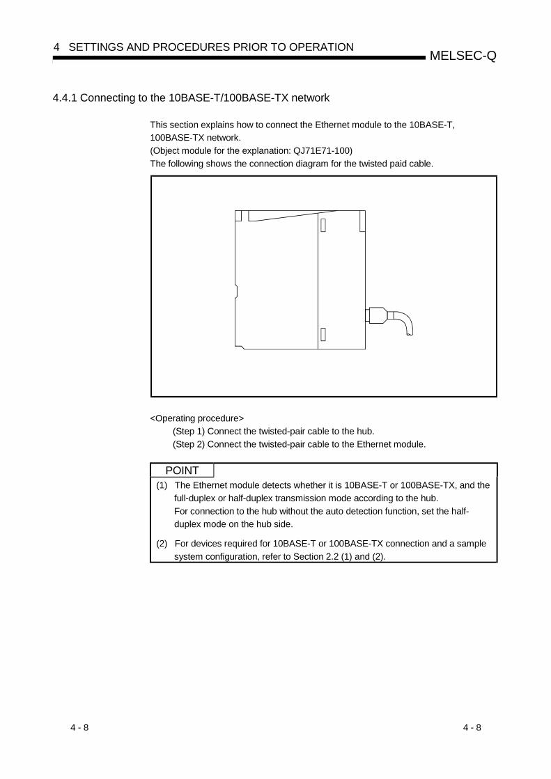
4 - 8 4 - 8
MELSEC-Q4 SETTINGS AND PROCEDURES PRIOR TO OPERATION
4.4.1 Connecting to the 10BASE-T/100BASE-TX network
This section explains how to connect the Ethernet module to the 10BASE-T,100BASE-TX network.(Object module for the explanation: QJ71E71-100)The following shows the connection diagram for the twisted paid cable.
<Operating procedure>(Step 1) Connect the twisted-pair cable to the hub.(Step 2) Connect the twisted-pair cable to the Ethernet module.
POINT(1) The Ethernet module detects whether it is 10BASE-T or 100BASE-TX, and the
full-duplex or half-duplex transmission mode according to the hub.For connection to the hub without the auto detection function, set the half-duplex mode on the hub side.
(2) For devices required for 10BASE-T or 100BASE-TX connection and a samplesystem configuration, refer to Section 2.2 (1) and (2).
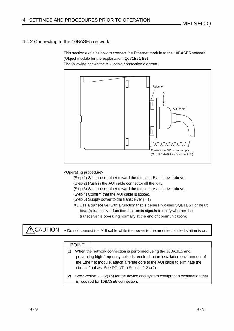
4 - 9 4 - 9
MELSEC-Q4 SETTINGS AND PROCEDURES PRIOR TO OPERATION
4.4.2 Connecting to the 10BASE5 network
This section explains how to connect the Ethernet module to the 10BASE5 network.(Object module for the explanation: QJ71E71-B5)The following shows the AUI cable connection diagram.
A
B
Transceiver DC power supply(See REMARK in Section 2.2.)
Retainer
AUI cable
<Operating procedure>(Step 1) Slide the retainer toward the direction B as shown above.(Step 2) Push in the AUI cable connector all the way.(Step 3) Slide the retainer toward the direction A as shown above.(Step 4) Confirm that the AUI cable is locked.(Step 5) Supply power to the transceiver ( 1).
1 Use a transceiver with a function that is generally called SQETEST or heartbeat (a transceiver function that emits signals to notify whether thetransceiver is operating normally at the end of communication).
CAUTION • Do not connect the AUI cable while the power to the module installed station is on.
POINT(1) When the network connection is performed using the 10BASE5 and
preventing high-frequency noise is required in the installation environment ofthe Ethernet module, attach a ferrite core to the AUI cable to eliminate theeffect of noises. See POINT in Section 2.2 a(2).
(2) See Section 2.2 (2) (b) for the device and system configration explanation thatis required for 10BASE5 connection.

4 - 10 4 - 10
MELSEC-Q4 SETTINGS AND PROCEDURES PRIOR TO OPERATION
4.4.3 Connecting to the 10BASE2 network
This section explains how to connect the Ethernet module to the 10BASE2 network.(Object module for the explanation: QJ71E71-B2)The following shows the 10BASE-2 coaxial cable connection diagram.
[2]
[1]
<Operating procedure>(Step 1) Push in the connector by aligning the groove [1] and tab [2] as shown
above.(Step 2) While pushing in the connector, rotate it clockwise a 1/4 turn.(Step 3) Turn until the connector locks.(Step 4) Check that the connector is locked.
POINTSee (3) in Section 2.2 for the device and system configuration example that isrequired for 10BASE2 connection.

4 - 11 4 - 11
MELSEC-Q4 SETTINGS AND PROCEDURES PRIOR TO OPERATION
REMARK
Attaching the connector for the coaxial cableThe following section explains how to attach the BNC connector (connector plug forthe coaxial cable) to the cable.
(1) Structure of the BNC connector and coaxial cableThe following shows the composition of the BNC connector and coaxial cable.
Parts comprising the BNC connector
Nut Washer Gasket
Plug shell
Clamp Contact
Structure of the coaxial cable
Internal conductor
External conductor
Outer sheathInsulation material
(2) How to attach the BNC connector and the coaxial cableThe following shows how to attach the BNC connector and the coaxial cable.
(a) Cut the length shown in the diagram to theright off the outer sheath of the coaxial cable.Be careful not to damage the externalconductor.
15 mm
Cut this portion of the outer sheath
(0.6 in.)
(b) Fix the nut, washer, gasket and clamp untothe coaxial cable as shown in the diagramto the right and unfasten the externalconductor. Gasket
Clamp
NutWasher
(c) Cut the external conductor, insulationmaterial, and internal conductor to thedimensions shown in the diagram to the right.However, cut the external conductor to thesame dimensions as those of the taperedSection of the clamp, and smooth it down tothe clamp.
6 mm3 mm
(0.11 in.)Clamp and external conductor
Insulation materialInternal conductor
(0.23 in.)
(d) Solder the contact to the internal conductor. Solder here
(e) Insert the connector assembly (d) into theplug shell and screw the nut into the plugshell.
POINTPay attention to the following when soldering the internal conductors and contacts:
(1) Make sure that the solder does not bead up on the soldered section.
(2) Make sure that there are no gaps between the connector and the cableinsulator and that they do not cut into each other
(3) Solder as quickly as possible to prevent the insulation material from deforming.

4 - 12 4 - 12
MELSEC-Q4 SETTINGS AND PROCEDURES PRIOR TO OPERATION
4.5 Settings from GX Developer
This section explains the names of the setting screens for GX Developer that areavailable for the Ethernet module.Perform the settings according to the function used by referring to Section 3.6,"Ethernet Module GX Developer Setting Item List."For details on how to display each screen, refer to the GX Developer OperatingManual.
4.5.1 I/O assignment setting
[Setting purpose]The I/O assignment settings perform the settings for the types of modules to bemounted on a base unit and the range of input/output signals.
[Startup procedure][GX Developer] [PLC Parameter] I/O assignment
For screen display, see the operating manual for GX Developer.[Setting screen]
[Display contents]Item name Setting for item Remarks
Type Select "Intelli."Model name Enter the module model name to be mounted (Example: QJ71E71-100).Points Select 32 points.Start-XY Enter the start I/O signal (hexadecimal) for the target module.
—I/O assignment
Detailed settingSelect the control PLC of the Ethernet module when a multiple CPU system isemployed.
Multiple CPU setting Select when using a multiple CPU system.
See QCPU User's Manual(Multiple CPU System).
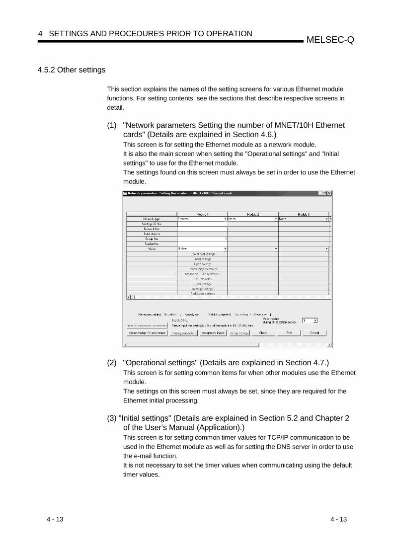
4 - 13 4 - 13
MELSEC-Q4 SETTINGS AND PROCEDURES PRIOR TO OPERATION
4.5.2 Other settings
This section explains the names of the setting screens for various Ethernet modulefunctions. For setting contents, see the sections that describe respective screens indetail.
(1) "Network parameters Setting the number of MNET/10H Ethernetcards" (Details are explained in Section 4.6.)This screen is for setting the Ethernet module as a network module.It is also the main screen when setting the "Operational settings" and "Initialsettings" to use for the Ethernet module.The settings found on this screen must always be set in order to use the Ethernetmodule.
(2) "Operational settings" (Details are explained in Section 4.7.)This screen is for setting common items for when other modules use the Ethernetmodule.The settings on this screen must always be set, since they are required for theEthernet initial processing.
(3) "Initial settings" (Details are explained in Section 5.2 and Chapter 2of the User’s Manual (Application).)This screen is for setting common timer values for TCP/IP communication to beused in the Ethernet module as well as for setting the DNS server in order to usethe e-mail function.It is not necessary to set the timer values when communicating using the defaulttimer values.

4 - 14 4 - 14
MELSEC-Q4 SETTINGS AND PROCEDURES PRIOR TO OPERATION
(4) "Open settings" (Details are explained in Section 5.5.)This screen is for connection open processing settings and settings related tobuffer memory usage when using fixed buffer communication to communicatedata with an external device.
(5) "Router relay parameter (Routing information)" (Details areexplained in Section 5.3.)The following settings for data communication with external devices areperformed on this screen:• Communicating data with external devices connected to other Ethernet via a router• Classifying each device connected to the Ethernet into groups and
communicating data with an external device in an arbitrary group using thedata link instructions
(6) "Station No. <-> IP information (MNET/10 routing information)"(Details are explained in Chapter 3 of the User’s Manual(Application).)This setting is for communicating with PLC CPUs on other stations via theEthernet or MELSECNET/H, MELSECNET/10.
(7) "FTP Parameters" (Details are explained in Chapter 5 of the User’sManual (Application).)This setting is for using the file transfer (FTP server) function.By using the file transfer function, an external device can read/write data from/tothe files in the QCPU to which the Ethernet module is installed.
(8) "E-mail settings" (Details are explained in Chapter 2 of the User’sManual (Application).)These settings are for using the e-mail transmission/reception and automaticnews (notification) functions.
(9) "Send mail address setting" (Details are explained in Chapter 2 ofthe User's Manual)This screen is for setting sending destination mail addresses when using the e-mail sending/receiving function.
(10) "News settings" (Details are explained in Chapter 2 of the User’sManual (Application).)On this screen, the settings for news (notifying) the PLC CPU monitoring resultsusing the e-mail function are performed.
4 - 15 4 - 15
MELSEC-Q4 SETTINGS AND PROCEDURES PRIOR TO OPERATION
(11) "Interrupt settings" and "Interrupt pointer setting" (Details areexplained in Section 7.3.)On this screen, the settings for reading the receive data using the followingfunctions by means of the PLC CPU interrupt program are performed.• Reading the reception data in fixed buffer communication using a dedicated
instruction (BUFRCVS).• Reading data transmitted from another station’s PLC CPU using a data link
instruction (RECVS).
(12) "Redundant setting", "group setting" (Detailed explanation: Section5.11, QCPU User's Manual)Make settings for using the Ethernet module in a redundant system.
(13) "Routing parameters" (Details are explained in Chapter 3 of theUser’s Manual (Application).)This screen is for setting which stations are passed through when communicatingwith PLC CPUs of other stations via the Ethernet or MELSECNET/H,MELSECNET/10.
(14) "Multiple CPU settings" (Details are explained in QCPU User'sManual.)This screen is for setting the control PLC for the Ethernet module when it is usedin a multiple CPU system.
(15) "Remote Password" (Details are explained in Section 5.9.5.)This screen is for setting connections subject to the remote password checkperformed by the Ethernet module when the QCPU remote password function isused.
REMARK
It is not necessary to set the "Intelligent function module switch settings" with GXDeveloper’s I/O assignment.Each type of setting corresponding to the switch settings is performed in the abovementioned "Operational settings," "Initial settings," and "Open settings."

4 - 16 4 - 16
MELSEC-Q4 SETTINGS AND PROCEDURES PRIOR TO OPERATION
4.6 Network Parameters Setting the Number of MNET/10H Ethernet Cards
This section explains one of the network parameters, setting the number of MNET/10HEthernet cards.Start the "Network parameters Setting the number of MNET/10H Ethernet cards"screen by selecting [GX Developer] - [Network parameter]. For details on how todisplay the screen, refer to the GX Developer Operating Manual.
Item name Description of setting Setting range/selection
Valid unit during other station accessSelect the module by which the access is made when the access request does notspecify the network number.
1 to 8
Network type Select the mounting module. EthernetStarting I/O No. Set the head address of the module. 0000 to 0FE0H
Network No. Set the network number of the module. 1 to 239Group No. Set the group number of the module. 1 to 32Station No. Select the station number of the module. 1 to 64
Mode Select the operation mode of the module.
• Online• Offline• Self refrain test• H/W test
Operational settings Set the common items for modules.Initial settings Set the common timer values for modules.Open settings Settings for connection open processing.Router relay parameter Settings for using the router relay function.
Station No. <-> IP informationSettings for using the MELSECNET/H, MELSECNET/10 relay communicationfunction.
FTP Parameters Settings for using the file transfer (FTP) function.E-mail settings Settings for transmitting/receiving e-mails.Interrupt settings Settings for executing an interrupt program.Redundant setting Settings for using the Ethernet module in a redundant system.
Group settings
Settings for disabling system switching if an error occurs in one communication pathwhen the redundant communication paths are used for the external device andEthernet module in a redundant system.(Refer to the QnPRHCPU User's Manual (Redundant System).)
Routing parametersSettings for using the MELSECNET/H, MELSECNET/10 relay communicationfunction.
—

4 - 17 4 - 17
MELSEC-Q4 SETTINGS AND PROCEDURES PRIOR TO OPERATION
(1) Valid module during other station access(a) This item designates the network module to which the request is directed,
when the local station issues a data communication request and it cannotspecify the network number of the access destination PLC station. Thisshould be one of the following:• A network module for the MELSECNET/H, MELSECNET/10• An Ethernet module
(2) Network type(a) Select "Ethernet," then each setting item is displayed as shown in the above
screen.The following items must be set.• Starting I/O No.• Network No.• Group No.• Station No.• Mode• Operational settings• Initial settings (Settings not required when using the default values)
(3) Starting I/O No.(a) Set the head I/O number of the Ethernet module in units of 16 points
(hexadecimal).
(b) An example of the setting is shown below.(Example)1) CPU type : Q25 (H) CPU2) Existing mounted module : Serial communication module QJ71C243) I/O usage status : X/Y000 to X/Y01F (used by QJ71C24)
X/Y020 to X/Y03F (used by the Ethernetmodule)
The head I/O number is "0020" in the above environment.
(4) Network No.(a) Set the network number of the target Ethernet module (setting range from 1
to 239) for the MELSECNET/H, MELSECNET/10.
(b) Do not set the network number to a value already assigned to existingsystems and other Ethernet and MELSECNET/H, MELSECNET/10 networksystems.
(5) Group No.(a) Set the group number of the target Ethernet module (setting range from 1 to
32) for the MELSECNET/H, MELSECNET/10.
(b) By designating a group number, data can be communicated with multipleQCPU stations using the same group number.

4 - 18 4 - 18
MELSEC-Q4 SETTINGS AND PROCEDURES PRIOR TO OPERATION
(6) Station No.(a) Set the station number of the target Ethernet module (setting range from 1
to 64) for the MELSECNET/H, MELSECNET/10.
(b) Do not set the number to a value already assigned to existing systems andother Ethernet modules.
(7) Mode (address: CAH)
(a) Select the operating mode of the Ethernet module.Name of setting Description of setting
Online Communicate with the external device in normal operation mode.Offline Disconnecting the local station from the network.Self refrain test Execute a self refrain test for self-diagnostics. ( 1)
H/W test Execute tests of RAM and ROM. ( 1)
1 See Section 4.8, "Self-Diagnostic Tests."
(b) When the operation mode is changed, reset the PLC CPU.
(8) Operational settings through Routing parametersSet the parameters from operational settings through routing settings accordingto the explanations in Section 4.5.
POINT(1) Both the "Setting the number of MNET/10H Ethernet cards" and "Operational
setting" parameters must always be specified. If the settings are changed, theQCPU (PLC No.1 when used in a multiple CPU system) must be reset.
(2) Write the network parameters in the control PLC of the Ethernet module whenthe module is used in a multiple CPU system.

4 - 19 4 - 19
MELSEC-Q4 SETTINGS AND PROCEDURES PRIOR TO OPERATION
4.7 Operational Settings
This section explains how to set the operations parameters.Start the "Ethernet operations" screen by selecting [Setting the number of MNET/10HEthernet cards] - [Operational settings].
Item name Setting description of item Setting range/selection
Communication data code Select the communication data code.• Binary code• ASCII code
Initial Timing Perform the setting for opening.• Do not wait for OPEN• Always wait for OPEN
Input format Select the IP address input format.• Decimal• HexadecimalIP Address
IP address Set the IP address of the local station.
Send frame setting Select the frame format to send• Ethernet (V2.0)• IEEE 802.3
Enable Write at RUN time(for the MC protocol)
Set to allow writing to the PLC CPU during RUN.• Check mark (enable)• No check mark (disable)
TCP Existence confirmation setting Select the existence check method for TCP communication• Use the KeepAlive• Use the Ping
(1) Communication data code (address: CBH … b1)
(a) Select the format of the communication data when communicating with anexternal device.
Name of setting Description of settingBinary code Communicate using binary data.ASCII code Communicate using ASCII data.
(b) For more details on the data communication codes, see Section 3.2, "DataCodes for Communication."
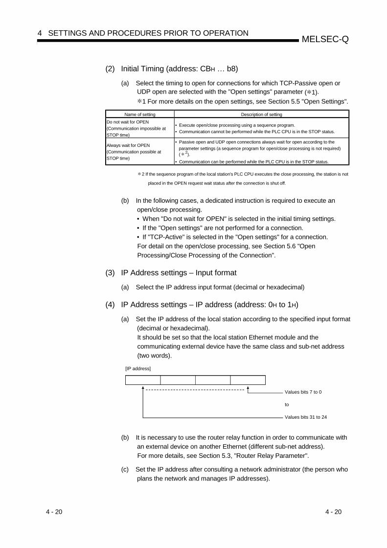
4 - 20 4 - 20
MELSEC-Q4 SETTINGS AND PROCEDURES PRIOR TO OPERATION
(2) Initial Timing (address: CBH … b8)
(a) Select the timing to open for connections for which TCP-Passive open orUDP open are selected with the "Open settings" parameter ( 1).
1 For more details on the open settings, see Section 5.5 "Open Settings".
Name of setting Description of settingDo not wait for OPEN(Communication impossible atSTOP time)
• Execute open/close processing using a sequence program.• Communication cannot be performed while the PLC CPU is in the STOP status.
Always wait for OPEN(Communication possible atSTOP time)
• Passive open and UDP open connections always wait for open according to theparameter settings (a sequence program for open/close processing is not required)( 2).
• Communication can be performed while the PLC CPU is in the STOP status.
2 If the sequence program of the local station's PLC CPU executes the close processing, the station is not
placed in the OPEN request wait status after the connection is shut off.
(b) In the following cases, a dedicated instruction is required to execute anopen/close processing.• When "Do not wait for OPEN" is selected in the initial timing settings.• If the "Open settings" are not performed for a connection.• If "TCP-Active" is selected in the "Open settings" for a connection.For detail on the open/close processing, see Section 5.6 "OpenProcessing/Close Processing of the Connection".
(3) IP Address settings – Input format
(a) Select the IP address input format (decimal or hexadecimal)
(4) IP Address settings – IP address (address: 0H to 1H)
(a) Set the IP address of the local station according to the specified input format(decimal or hexadecimal).It should be set so that the local station Ethernet module and thecommunicating external device have the same class and sub-net address(two words).
Values bits 7 to 0
to
Values bits 31 to 24
[IP address]
(b) It is necessary to use the router relay function in order to communicate withan external device on another Ethernet (different sub-net address).For more details, see Section 5.3, "Router Relay Parameter".
(c) Set the IP address after consulting a network administrator (the person whoplans the network and manages IP addresses).
4 - 21 4 - 21
MELSEC-Q4 SETTINGS AND PROCEDURES PRIOR TO OPERATION
(5) Send frame setting(a) Select the frame of the Ethernet header for the data link layer to be sent by
the Ethernet module.Setting item Description of setting
Ethernet (V2.0) Transmits using an Ethernet frame.IEEE802.3 Transmits using an IEEE802.3 frame.
(b) When receiving data from the external device, reception should occurregardless of whether the Ethernet frame or IEEE802.3 frame is used
REMARK
(1) Transmission using Ethernet frames is generally recommended.(2) When communication with the external device fails, check whether or not
communication is possible using a PING command.
(6) Enable Write at RUN time (address: CBH … b6)
(a) Select enable/disable external devices to write data while communicatingthrough the MC protocol while the PLC CPU is running.
Name of setting Description of settingCheck mark(Enable write at RUN time)
Allows an external device to write while the PLC CPU is running.
No check mark(Disable write at RUN time)
Prohibits an external device to write while the PLC CPU is running.
(7) TCP Existence confirmation settingSelect the existence check method for TCP communication. *1For the existence check function, refer to Section 5.2.2.
Name of setting Description of settingUse the KeepAlive Checks connection status with KeepAlive.Use the Ping Checks connection status with Ping.
*1 Do not use GX Developer incompatible with this setting together with compatible GX Developer. (Doingso may change the setting to "Use the Ping".)This setting is ignored when the Ethernet module does not support the KeepAlive check function. (Ping isused for the existence check.)Refer to Section 2.7 for applicable versions of the Ethernet module and GX Developer.
POINT(1) The "Setting the number of MNET/10H Ethernet cards" and "Operational
settings" parameters must always be set.If the settings are changed, the PLC CPU must be reset.
(2) If the re-initial processing of the Ethernet module is required due to theoccurrence of an error, perform re-initial processing using sequence programs(see Section 5.2.3).
(3) When using the programs for conventional models, be sure to delete or disablethe program for initial processing that uses I/O signals.
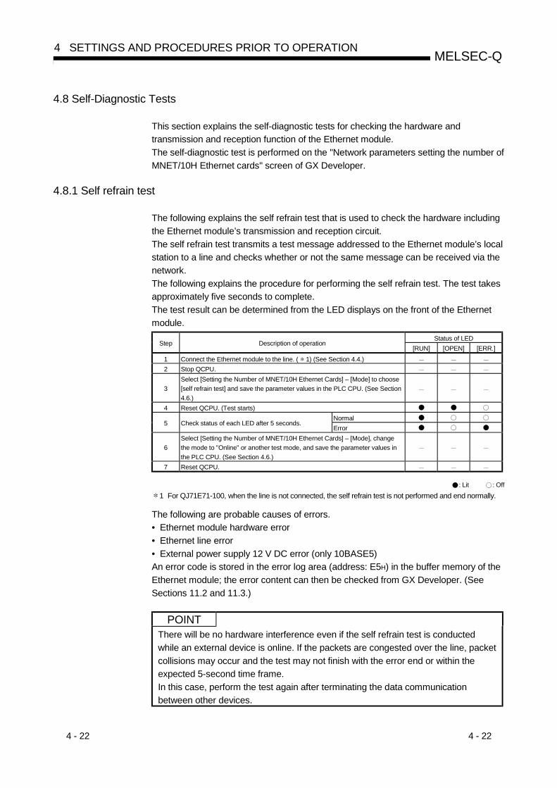
4 - 22 4 - 22
MELSEC-Q4 SETTINGS AND PROCEDURES PRIOR TO OPERATION
4.8 Self-Diagnostic Tests
This section explains the self-diagnostic tests for checking the hardware andtransmission and reception function of the Ethernet module.The self-diagnostic test is performed on the "Network parameters setting the number ofMNET/10H Ethernet cards" screen of GX Developer.
4.8.1 Self refrain test
The following explains the self refrain test that is used to check the hardware includingthe Ethernet module’s transmission and reception circuit.The self refrain test transmits a test message addressed to the Ethernet module’s localstation to a line and checks whether or not the same message can be received via thenetwork.The following explains the procedure for performing the self refrain test. The test takesapproximately five seconds to complete.The test result can be determined from the LED displays on the front of the Ethernetmodule.
Status of LEDStep Description of operation
[RUN] [OPEN] [ERR.]1 Connect the Ethernet module to the line. ( 1) (See Section 4.4.)2 Stop QCPU.
3Select [Setting the Number of MNET/10H Ethernet Cards] – [Mode] to choose[self refrain test] and save the parameter values in the PLC CPU. (See Section4.6.)
4 Reset QCPU. (Test starts)Normal
5 Check status of each LED after 5 seconds.Error
6Select [Setting the Number of MNET/10H Ethernet Cards] – [Mode], changethe mode to "Online" or another test mode, and save the parameter values inthe PLC CPU. (See Section 4.6.)
7 Reset QCPU.
: Lit : Off
1 For QJ71E71-100, when the line is not connected, the self refrain test is not performed and end normally.
The following are probable causes of errors.• Ethernet module hardware error• Ethernet line error• External power supply 12 V DC error (only 10BASE5)An error code is stored in the error log area (address: E5H) in the buffer memory of theEthernet module; the error content can then be checked from GX Developer. (SeeSections 11.2 and 11.3.)
POINTThere will be no hardware interference even if the self refrain test is conductedwhile an external device is online. If the packets are congested over the line, packetcollisions may occur and the test may not finish with the error end or within theexpected 5-second time frame.In this case, perform the test again after terminating the data communicationbetween other devices.

4 - 23 4 - 23
MELSEC-Q4 SETTINGS AND PROCEDURES PRIOR TO OPERATION
4.8.2 Hardware test (H/W Test)
This section explains the RAM and ROM tests for the Ethernet module. The procedurefor the hardware test is as shown in the table below.The test results are judged from the LED displays on the front of the Ethernet module.
Status of LEDStep Description of operation
[RUN] [OPEN] [ERR.]1 Stop QCPU.
2Select [Setting the Number of MNET/10H Ethernet Cards] – [Mode] to choose[H/W test] and save the parameter values in the PLC CPU. (See Section 4.6.)
3 Reset QCPU. (Test starts.)Normal
4 Check status of each LED after 5 seconds.Error
5Select [Setting the Number of MNET/10H Ethernet Cards] – [Mode], changethe mode to "Online" or another test mode, and save the parameter values inthe PLC CPU. (See Section 4.6.)
6 Reset QCPU.
: Lit : Off
The following are probable causes of errors.• Ethernet module RAM/ROM errorAn error code is stored in the error log area (address: E5H) in the buffer memory of theEthernet module; the error content can then be checked from GX Developer. (SeeSections 11.2 and 11.3.)
POINTIf the result of the hardware test shows an error, conduct the test again.If this test result also shows an error, the hardware of the Ethernet module may befaulty.Please consult the nearest branch office or dealer with details of the errors.

4 - 24 4 - 24
MELSEC-Q4 SETTINGS AND PROCEDURES PRIOR TO OPERATION
4.9 Maintenance and Inspection
This section explains the maintenance and inspection as well as the mounting anddismounting of the Ethernet module.
4.9.1 Maintenance and inspection
The Ethernet module does not need to be inspected for anything particular other thanchecking whether or not the connections of terminators and cables are loose. Maintainand inspect the system according to the same inspection items as described in theuser’s manual for the PLC CPU in order to use it in optimal operating conditions.
DANGER • Do not touch the terminals and connectors while the power is on.Doing so may cause in electric shocks and malfunctions.
• Do not touch the connector inside the cover at the upper section of the module.Doing so may cause damages and malfunctions of the module.
• Make sure to turn off all phases of the external power supply before cleaning or re-tightening the screws. Failure to do so may cause damages or malfunctions of themodule.If the screws are loose, it may cause the module to short-circuit, malfunction or falloff.Tightening the screws excessively may damage the screws and/or the module andcause the module to short circuit, malfunction or fall off.
CAUTION • Be careful not to let any foreign matter such as wire chips get inside the module.They may cause fire, as well as breakdowns and malfunctions of the module.
• Never disassemble or modify the module.This may cause breakdowns, malfunctions, injuries or fire.
4 - 25 4 - 25
MELSEC-Q4 SETTINGS AND PROCEDURES PRIOR TO OPERATION
4.9.2 Mounting and dismounting the module
Before mounting or dismounting the Ethernet module, make sure to read Section 4.1,"Handling Precautions" thoroughly, secure the safety, and handle the module properlyaccording to the instructions.The following explains the procedures when mounting/dismounting the Ethernetmodule.
<Operation procedure when replacing the Ethernet module>(Step 1) Turn off the power supply to the Ethernet module installed station.(Step 2) Remove the network cable and Ethernet module.(Step 3) Install and start up the new Ethernet module according to Section 4.2,
"Settings and Procedures Prior to Starting the Operation."(Step 4) Reset the external device. ( 1)
<Operation procedure when replacing the QCPU>(Step 1) Read the parameters for the Ethernet module from the PLC CPU and
save them using GX Developer. ( 2)(Step 2) Replace the QCPU. (See the applicable QCPU User’s Manual.)(Step 3) Load the parameters for the Ethernet module that have been saved in
GX Developer to the new QCPU.(Step 4) Reset the external device.
1 When the Ethernet module is replaced, reset the external device as well. (If theexternal device retains the Ethernet address, it may be impossible to continue thecommunication because a module is replaced and the Ethernet addresschanges.)In the same may, when the external device (personal computer, etc.)is replaced,restart the Ethernet module.
2 It is recommended to record and save parameters not only when the CPU isreplaced but also when parameters for the Ethernet module are created ormodified.
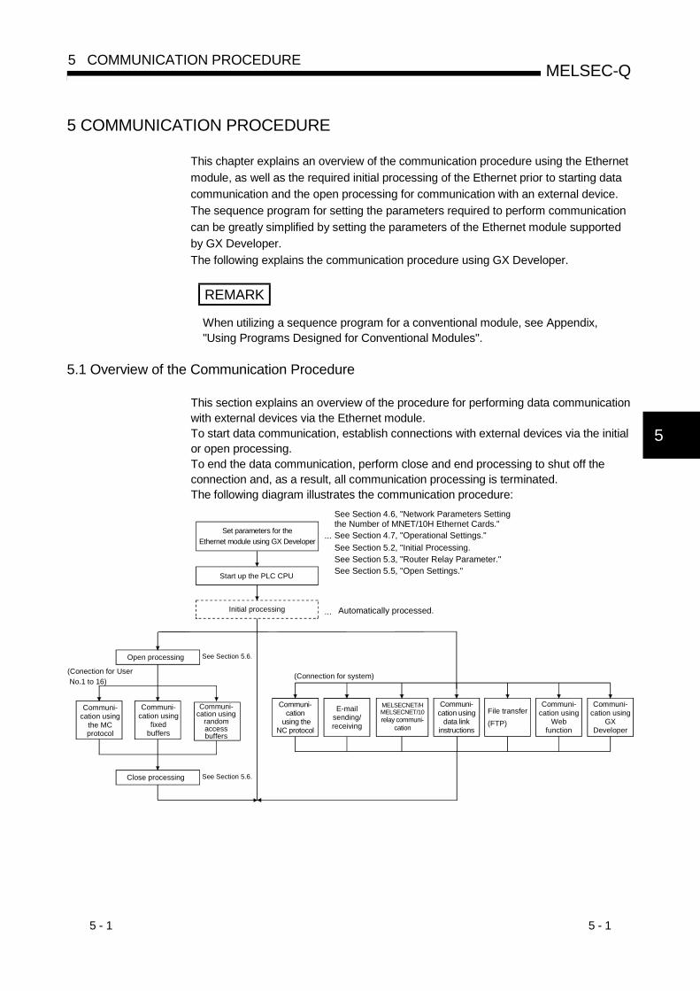
5 - 1 5 - 1
MELSEC-Q5 COMMUNICATION PROCEDURE
5
5 COMMUNICATION PROCEDURE
This chapter explains an overview of the communication procedure using the Ethernetmodule, as well as the required initial processing of the Ethernet prior to starting datacommunication and the open processing for communication with an external device.The sequence program for setting the parameters required to perform communicationcan be greatly simplified by setting the parameters of the Ethernet module supportedby GX Developer.The following explains the communication procedure using GX Developer.
REMARK
When utilizing a sequence program for a conventional module, see Appendix,"Using Programs Designed for Conventional Modules".
5.1 Overview of the Communication Procedure
This section explains an overview of the procedure for performing data communicationwith external devices via the Ethernet module.To start data communication, establish connections with external devices via the initialor open processing.To end the data communication, perform close and end processing to shut off theconnection and, as a result, all communication processing is terminated.The following diagram illustrates the communication procedure:
Open processing
See Section 5.2, "Initial Processing.See Section 5.3, "Router Relay Parameter."See Section 5.5, "Open Settings."
See Section 4.6, "Network Parameters Settingthe Number of MNET/10H Ethernet Cards."
Set parameters for the Ethernet module using GX Developer
See Section 4.7, "Operational Settings."...
Start up the PLC CPU
Automatically processed....Initial processing
See Section 5.6.
E-mailsending/receiving
MELSECNET/HMELSECNET/10relay communi-
cation
Communi-cation using
data linkinstructions
Communi-cation using
Webfunction
File transfer(FTP)
(Connection for system)
Communi-cation using
the MCprotocol
Communi-cation using
fixedbuffers
Close processing See Section 5.6.
(Conection for User No.1 to 16)
Communi-cation using
random access buffers
Communi-cation using
GXDeveloper
Communi-cation
using the NC protocol
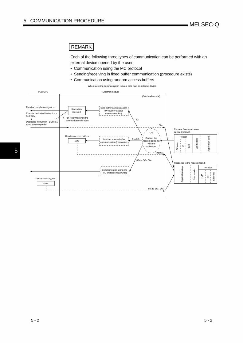
5 - 2 5 - 2
MELSEC-Q5 COMMUNICATION PROCEDURE
5
REMARK
Each of the following three types of communication can be performed with anexternal device opened by the user.• Communication using the MC protocol• Sending/receiving in fixed buffer communication (procedure exists)• Communication using random access buffers
OS
61H/62H
E1/E2H
00H to 3CH, 50H
80H to BCH, D0H
60H
E0H
When receiving communication request data from an external device
PLC CPU Ethernet module
(Subheader code)
Receive completion signal onStore data received
Fixed buffer communication (Procedure exists) (communication)Execute dedicated instruction -
BUFRCV
Dedicated instruction - BUFRCV execution completion
Sub
head
er
Appl
icat
ion
data
Ethe
rnet
Random access buffer communication (read/write)
Confirm the request contents
with the subheader.
Device memory, etc.
Communication using the MC protocol (read/write)
Header
IP TCP
Response to the request (send)
Request from an external device (receive)
Header
IPTCP
Sub
head
er
Appl
icat
ion
data
Data
Data
For receiving when thecommunication is open
Random access buffers
Ethe
rnet
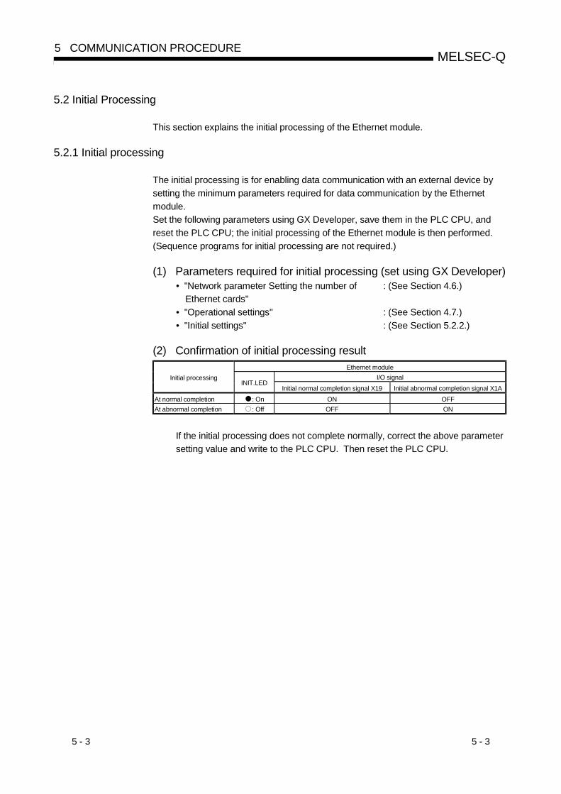
5 - 3 5 - 3
MELSEC-Q5 COMMUNICATION PROCEDURE
5.2 Initial Processing
This section explains the initial processing of the Ethernet module.
5.2.1 Initial processing
The initial processing is for enabling data communication with an external device bysetting the minimum parameters required for data communication by the Ethernetmodule.Set the following parameters using GX Developer, save them in the PLC CPU, andreset the PLC CPU; the initial processing of the Ethernet module is then performed.(Sequence programs for initial processing are not required.)
(1) Parameters required for initial processing (set using GX Developer)• "Network parameter Setting the number of
Ethernet cards": (See Section 4.6.)
• "Operational settings" : (See Section 4.7.)• "Initial settings" : (See Section 5.2.2.)
(2) Confirmation of initial processing resultEthernet module
I/O signalInitial processingINIT.LED
Initial normal completion signal X19 Initial abnormal completion signal X1AAt normal completion : On ON OFFAt abnormal completion : Off OFF ON
If the initial processing does not complete normally, correct the above parametersetting value and write to the PLC CPU. Then reset the PLC CPU.
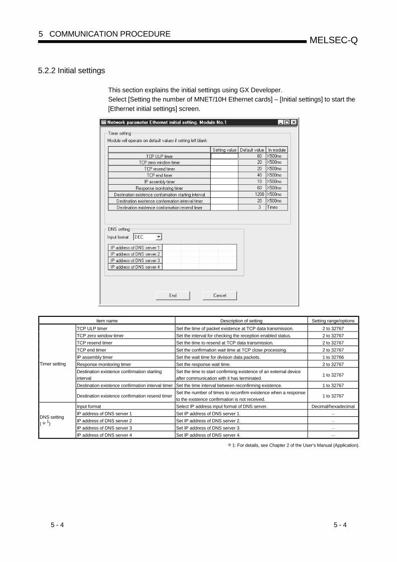
5 - 4 5 - 4
MELSEC-Q5 COMMUNICATION PROCEDURE
5.2.2 Initial settings
This section explains the initial settings using GX Developer.Select [Setting the number of MNET/10H Ethernet cards] – [Initial settings] to start the[Ethernet initial settings] screen.
Item name Description of setting Setting range/optionsTCP ULP timer Set the time of packet existence at TCP data transmission. 2 to 32767TCP zero window timer Set the interval for checking the reception enabled status. 2 to 32767TCP resend timer Set the time to resend at TCP data transmission. 2 to 32767TCP end timer Set the confirmation wait time at TCP close processing. 2 to 32767IP assembly timer Set the wait time for division data packets. 1 to 32766Response monitoring timer Set the response wait time. 2 to 32767Destination existence confirmation startinginterval
Set the time to start confirming existence of an external deviceafter communication with it has terminated.
1 to 32767
Destination existence confirmation interval timer Set the time interval between reconfirming existence. 1 to 32767
Timer setting
Destination existence confirmation resend timerSet the number of times to reconfirm existence when a responseto the existence confirmation is not received.
1 to 32767
Input format Select IP address input format of DNS server. Decimal/hexadecimalIP address of DNS server 1 Set IP address of DNS server 1.IP address of DNS server 2 Set IP address of DNS server 2.IP address of DNS server 3 Set IP address of DNS server 3.
DNS setting( 1)
IP address of DNS server 4 Set IP address of DNS server 4.
1: For details, see Chapter 2 of the User’s Manual (Application).

5 - 5 5 - 5
MELSEC-Q5 COMMUNICATION PROCEDURE
(1) Timer setting – TCP ULP timer (address: BH)(a) This item sets the time of packet existence during TCP data sending.
This timer is passed through the parameter when TCP opens or data issent.
(b) Designate the setting value in a range from 2 to 32767.(When the default value is used, setting is not required.)
(c) Timer setting = setting value × 500 ms
(2) Timer setting - TCP zero window timer (address: CH)(a) The window indicates the reception buffer on the receiving side.
(b) When there is no more space in the receiving buffer (window size = 0) onthe receiving side, data communication has to wait until enough space ismade.When this occurs, the sending side sends a sending window confirmationpacket to the receiving side after the TCP zero window timer value hasbeen reached, and confirms the reception enabled status.
(c) Designate the setting value in a range from 2 to 32767.(When the default value is used, setting is not required.)
(d) Timer setting = setting value × 500 ms
(3) Timer setting – TCP resend timer (address: DH)(a) Set the resend time if ACK is not returned at TCP opening or data
transmission. This timer is also used for the existence time of the ARPfunction.(ARP is resent in TCP resend timer value/2 if a response is not returned inreply to the sent ARP request.)It also serves as the minimum setting time for the data link instructionarrival monitoring time.
(b) Designate the setting value in a range from 2 to 32767.(When the default value is used, setting is not required.)
(c) Timer setting = setting value × 500 ms
(4) Timer setting – TCP end timer (address: EH)(a) When the TCP connection is closed from the local station, this timer sets the
monitoring time for how long the local station waits for a FIN request froman external device after it sends an FIN request and the external devicereturns an ACK.
(b) If the FIN request cannot be received from the external device before thetime designated by the TCP end timer setting, a RST should be sent to theexternal device to forcefully close the connection.
(c) Designate the setting value in a range from 2 to 32767.(When the default value is used, setting is not required.)
(d) Timer setting = setting value × 500 ms

5 - 6 5 - 6
MELSEC-Q5 COMMUNICATION PROCEDURE
(5) Timer setting - IP assembly timer (address: FH)(a) Communication data may be divided on the IP level due to the restriction on
the buffer on the sending or receiving station.
(b) Designate the setting value in a range from 1 to 32766.(When the default value is used, setting is not required.)
(c) Timer setting = setting value × 500 ms
(6) Timer setting - Response monitoring timer (address: 10H)(a) This timer setting sets the following times.
1) The time to wait for a response after sending a command.
2) The time to wait for the last message after receiving the first messagewhen the message is divided.
(b) Designate the setting value in a range from 2 to 32767.(When the default value is used, setting is not required.)
(c) Timer setting = setting value × 500 ms
(7) Timer setting - Destination existence confirmation starting interval(address: 11H)(a) This timer sets the time interval before starting to confirm the existence of
an external side when an open connection for which existence confirmationis set to confirm stops dead.
(b) Designate the setting value in a range from 1 to 32767.(When the default value is used, setting is not required.)
(c) Timer setting = setting value × 500 ms
(8) Timer setting - Destination existence confirmation interval timer(address: 12H)(a) This timer sets the time interval before reconfirming the existence of an
external device on an open connection for which existence confirmation isset to confirm that does not respond.
(b) Designate the setting value in a range from 1 to 32767.(When the default value is used, setting is not required.)
(c) Timer setting = setting value × 500 ms
(9) Timer setting - Destination existence confirmation resend timer(address: 13H)(a) This timer sets the number of times to reconfirm existence when there is no
response from an external device on an open connection for whichexistence confirmation is set to confirm.
(b) Designate the setting value in a range from 1 to 32767.(When the default value is used, setting is not required.)
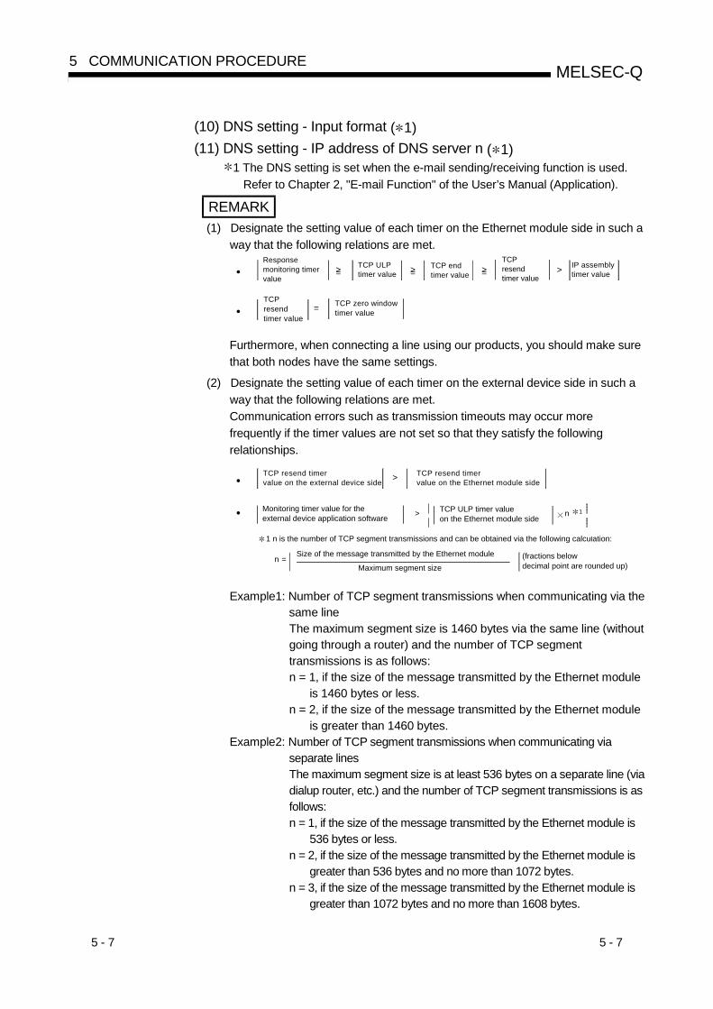
5 - 7 5 - 7
MELSEC-Q5 COMMUNICATION PROCEDURE
(10) DNS setting - Input format ( 1)(11) DNS setting - IP address of DNS server n ( 1)
1 The DNS setting is set when the e-mail sending/receiving function is used.Refer to Chapter 2, "E-mail Function" of the User’s Manual (Application).
REMARK(1) Designate the setting value of each timer on the Ethernet module side in such a
way that the following relations are met.
•Response monitoring timervalue
>TCP ULP timer value
TCP end timer value
TCP resendtimer value
IP assembly timer value=> =>=>
•TCP resendtimer value
TCP zero windowtimer value=
Furthermore, when connecting a line using our products, you should make surethat both nodes have the same settings.
(2) Designate the setting value of each timer on the external device side in such away that the following relations are met.Communication errors such as transmission timeouts may occur morefrequently if the timer values are not set so that they satisfy the followingrelationships.
• >TCP resend timer value on the external device side
TCP resend timer value on the Ethernet module side
• > n 1
11 n is the number of TCP segment transmissions and can be obtained via the following calculation:
n = Maximum segment size
Monitoring timer value for the external device application software
TCP ULP timer value on the Ethernet module side
Size of the message transmitted by the Ethernet module (fractions below decimal point are rounded up)
Example1: Number of TCP segment transmissions when communicating via thesame lineThe maximum segment size is 1460 bytes via the same line (withoutgoing through a router) and the number of TCP segmenttransmissions is as follows:n = 1, if the size of the message transmitted by the Ethernet module
is 1460 bytes or less.n = 2, if the size of the message transmitted by the Ethernet module
is greater than 1460 bytes.Example2: Number of TCP segment transmissions when communicating via
separate linesThe maximum segment size is at least 536 bytes on a separate line (viadialup router, etc.) and the number of TCP segment transmissions is asfollows:n = 1, if the size of the message transmitted by the Ethernet module is
536 bytes or less.n = 2, if the size of the message transmitted by the Ethernet module is
greater than 536 bytes and no more than 1072 bytes.n = 3, if the size of the message transmitted by the Ethernet module is
greater than 1072 bytes and no more than 1608 bytes.
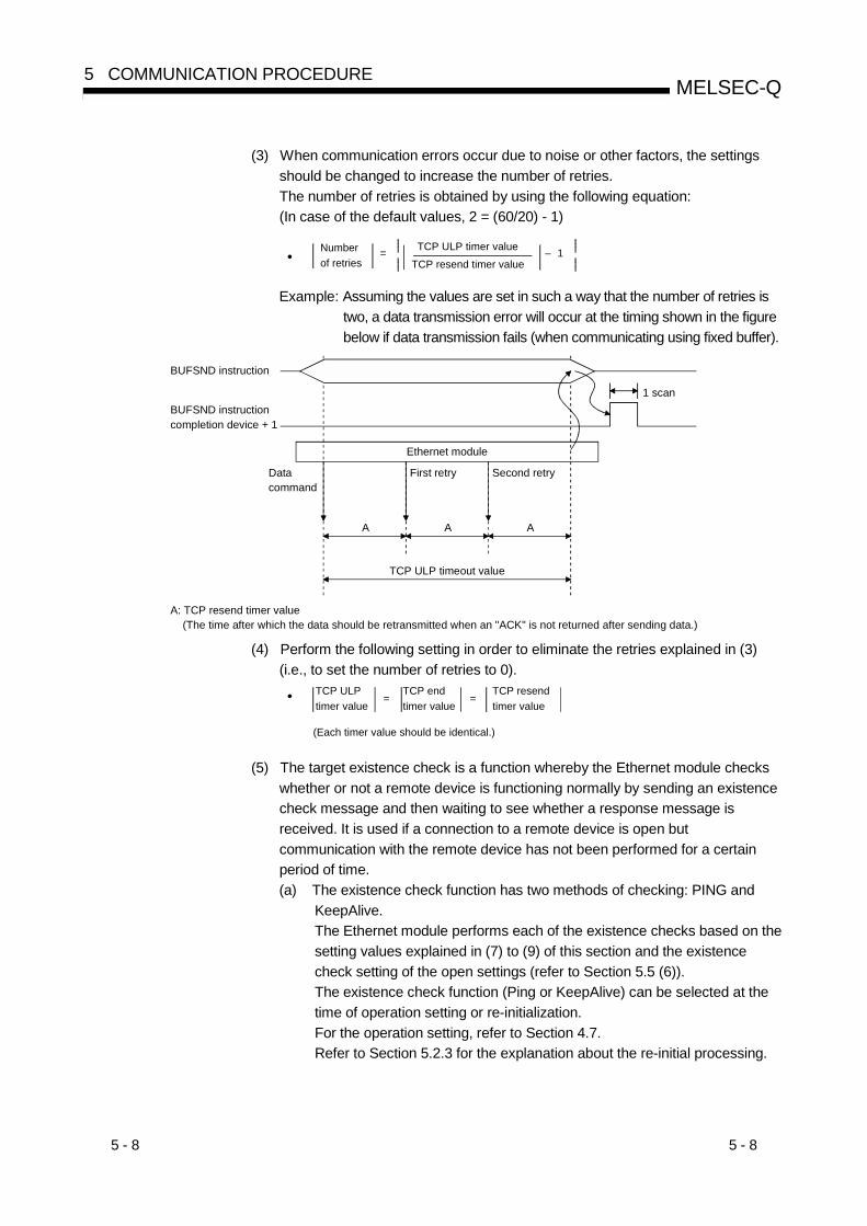
5 - 8 5 - 8
MELSEC-Q5 COMMUNICATION PROCEDURE
(3) When communication errors occur due to noise or other factors, the settingsshould be changed to increase the number of retries.The number of retries is obtained by using the following equation:(In case of the default values, 2 = (60/20) - 1)
•Number of retries
= TCP ULP timer valueTCP resend timer value
– 1
Example: Assuming the values are set in such a way that the number of retries istwo, a data transmission error will occur at the timing shown in the figurebelow if data transmission fails (when communicating using fixed buffer).
Data command
Ethernet module
First retry Second retry
A A A
TCP ULP timeout value
A: TCP resend timer value (The time after which the data should be retransmitted when an "ACK" is not returned after sending data.)
BUFSND instruction completion device + 1
BUFSND instruction
1 scan
(4) Perform the following setting in order to eliminate the retries explained in (3)(i.e., to set the number of retries to 0).
• TCP ULP timer value
TCP end timer value
TCP resendtimer value
(Each timer value should be identical.)
= =
(5) The target existence check is a function whereby the Ethernet module checkswhether or not a remote device is functioning normally by sending an existencecheck message and then waiting to see whether a response message isreceived. It is used if a connection to a remote device is open butcommunication with the remote device has not been performed for a certainperiod of time.(a) The existence check function has two methods of checking: PING and
KeepAlive.The Ethernet module performs each of the existence checks based on thesetting values explained in (7) to (9) of this section and the existencecheck setting of the open settings (refer to Section 5.5 (6)).The existence check function (Ping or KeepAlive) can be selected at thetime of operation setting or re-initialization.For the operation setting, refer to Section 4.7.Refer to Section 5.2.3 for the explanation about the re-initial processing.

5 - 9 5 - 9
MELSEC-Q5 COMMUNICATION PROCEDURE
1) Checking by KeepAliveThis method is used for a connection opened via the TCP/IP protocol.The Ethernet module performs an existence check by sending anexistence check ACK message to a remote device with whichcommunication has not been performed for a certain period of timeand waiting to see whether or not a response is received. ( 1)
1 The connection may be cut off if the remote device does notsupport the TCP KeepAlive function (response to KeepAlive ACKmessages).
2) Checking by PINGThis method is used for a connection opened via the TCP/IP orUDP/IP protocol.The Ethernet module performs an existence check by sending a PINGcommand (using the ICMP echo request/response function) to aremote device with which communication has not been performed fora certain period of time and waiting to see whether or not a responseis received. ( 2)
2 Note that the Ethernet module automatically returns an echoresponse packet when it receives a PING echo requestcommand. (It sends a response to the received PING commandeven if the connection used in the data communication with theremote device is closed.)
(b) The following actions are taken if a response message cannot be received(an error is detected) from the remote device.• The corresponding connection will be forcibly closed (the line is
disconnected). ( 3)3 It is possible to reopen it with a user program.
• The Ethernet module turns off the open completion signal (thecorresponding bit in address: 5000H) and stores the error code (C035H)in places such as the open error code storage area.
Example: Assuming the values are set under the condition that thenumber of retries is three, the Ethernet module performstarget existence check at the timing shown in the figurebelow. (An example of existence check by PING)
Last communication
Ethernet module
PING command
Open completion signal (address: 5000H)
PING command
PING command
Target existence check starting interval timer value
Target existence check interval timer value
Target existence check interval timer value
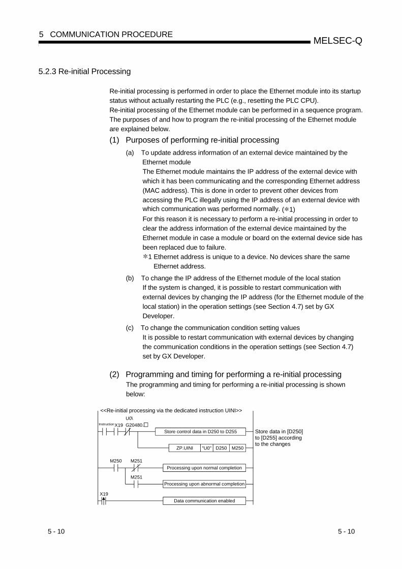
5 - 10 5 - 10
MELSEC-Q5 COMMUNICATION PROCEDURE
5.2.3 Re-initial Processing
Re-initial processing is performed in order to place the Ethernet module into its startupstatus without actually restarting the PLC (e.g., resetting the PLC CPU).Re-initial processing of the Ethernet module can be performed in a sequence program.The purposes of and how to program the re-initial processing of the Ethernet moduleare explained below.(1) Purposes of performing re-initial processing
(a) To update address information of an external device maintained by theEthernet moduleThe Ethernet module maintains the IP address of the external device withwhich it has been communicating and the corresponding Ethernet address(MAC address). This is done in order to prevent other devices fromaccessing the PLC illegally using the IP address of an external device withwhich communication was performed normally. ( 1)For this reason it is necessary to perform a re-initial processing in order toclear the address information of the external device maintained by theEthernet module in case a module or board on the external device side hasbeen replaced due to failure.
1 Ethernet address is unique to a device. No devices share the sameEthernet address.
(b) To change the IP address of the Ethernet module of the local stationIf the system is changed, it is possible to restart communication withexternal devices by changing the IP address (for the Ethernet module of thelocal station) in the operation settings (see Section 4.7) set by GXDeveloper.
(c) To change the communication condition setting valuesIt is possible to restart communication with external devices by changingthe communication conditions in the operation settings (see Section 4.7)set by GX Developer.
(2) Programming and timing for performing a re-initial processingThe programming and timing for performing a re-initial processing is shownbelow:
ZP.UINI "U0" D250 M250
M250 M251
M251
X19U0\G20480.
X19
Store control data in D250 to D255
<<Re-initial processing via the dedicated instruction UINI>>
Instruction
Store data in [D250] to [D255] according to the changes
Processing upon normal completion
Processing upon abnormal completion
Data communication enabled

5 - 11 5 - 11
MELSEC-Q5 COMMUNICATION PROCEDURE
Close processing Re-initial processing
1 scan
Initial normal completion signal X19
Open completion signal (address: 5000H)
UINI instruction
UINI instruction completion device
UINI instruction completion device + 1
1)
2)
3)
Module initialization
Communication condition setting area (address: 1FH, b15)
4)
1) It is confirmed whether the initial processing has been completed normally.2) All data communication currently being performed with external devices
is terminated, and close processing will be performed on all connections.3) Dedicated instruction UINI is executed.
(Initial normal completion signal (X19): ON)(Open completion signal (address: 5000H (20480)): All OFF (0H))The Ethernet module is initialized after the parameters (local station IPaddress, operation settings) have been specified via the control data ofthe dedicated instruction.
4) When the re-initial processing is completed, the re-initial specification(address: 1FH, bit 15) becomes "0" and the initial processingcompletion signal X19 turns on.
If the re-initial processing is completed abnormally, the error code isstored in the following area.Initial error code storage area (address: 69H (105))
(3) Precautions for combination with the MELSOFT products when thesetting is changed to "Enable TCP Maximum Segment Size Optiontransmission" in re-initial processing
(a) MELSOFT series products supporting the TCP Maximum Segmenttransmission functionFor setting the "Enable TCP Maximum Segment Size Option transmission",use the following MELSOFT products.
GX Developer : Version8.07H or laterMX Component : Version3.03D or laterMX Links : Version3.08J or later
(b) MELSOFT series products not listed above (a)When using a MELSOFT product that is not listed above (a) to makecommunication via Ethernet, set it to "Disable TCP Maximum SegmentSize Option transmission" or use UDP/IP type communication.Otherwise, the sequence program may not function correctly (read/write isincorrect).
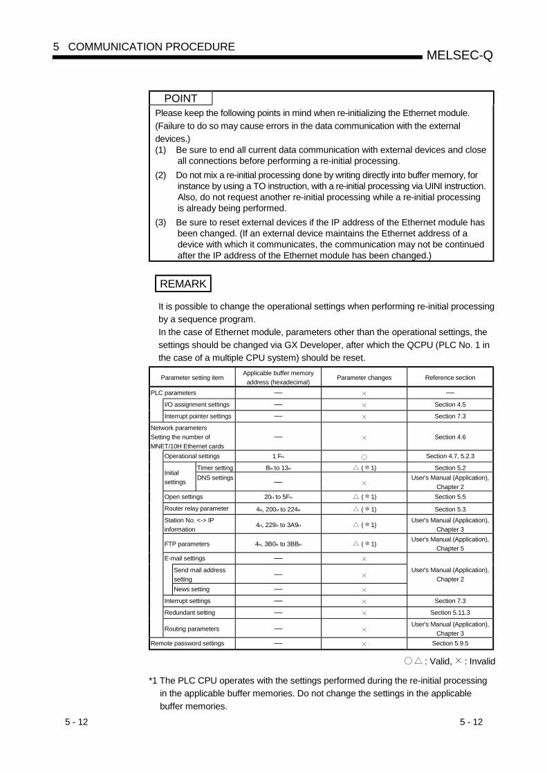
5 - 12 5 - 12
MELSEC-Q5 COMMUNICATION PROCEDURE
POINTPlease keep the following points in mind when re-initializing the Ethernet module.(Failure to do so may cause errors in the data communication with the externaldevices.)(1) Be sure to end all current data communication with external devices and close
all connections before performing a re-initial processing.(2) Do not mix a re-initial processing done by writing directly into buffer memory, for
instance by using a TO instruction, with a re-initial processing via UINI instruction.Also, do not request another re-initial processing while a re-initial processingis already being performed.
(3) Be sure to reset external devices if the IP address of the Ethernet module hasbeen changed. (If an external device maintains the Ethernet address of adevice with which it communicates, the communication may not be continuedafter the IP address of the Ethernet module has been changed.)
REMARK
It is possible to change the operational settings when performing re-initial processingby a sequence program.In the case of Ethernet module, parameters other than the operational settings, thesettings should be changed via GX Developer, after which the QCPU (PLC No. 1 inthe case of a multiple CPU system) should be reset.
Parameter setting itemApplicable buffer memory
address (hexadecimal)Parameter changes Reference section
PLC parameters — —I/O assignment settings — Section 4.5
Interrupt pointer settings — Section 7.3
Network parametersSetting the number ofMNET/10H Ethernet cards
— Section 4.6
Operational settings 1 FH Section 4.7, 5.2.3
Timer setting BH to 13H ( 1) Section 5.2Initialsettings DNS settings — User's Manual (Application),
Chapter 2Open settings 20H to 5FH ( 1) Section 5.5
Router relay parameter 4H, 200H to 224H ( 1) Section 5.3
Station No. <-> IPinformation
4H, 229H to 3A9H ( 1)User's Manual (Application),
Chapter 3
FTP parameters 4H, 3B0H to 3BBH ( 1)User's Manual (Application),
Chapter 5E-mail settings —
Send mail addresssetting
—
News setting —
User's Manual (Application),Chapter 2
Interrupt settings — Section 7.3
Redundant setting — Section 5.11.3
Routing parameters — User's Manual (Application),Chapter 3
Remote password settings — Section 5.9.5
: Valid, : Invalid
*1 The PLC CPU operates with the settings performed during the re-initial processingin the applicable buffer memories. Do not change the settings in the applicablebuffer memories.
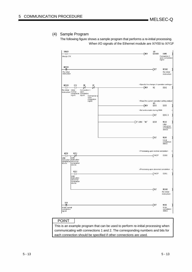
5 - 13 5 - 13
MELSEC-Q5 COMMUNICATION PROCEDURE
(4) Sample ProgramThe following figure shows a sample program that performs a re-initial processing.
When I/O signals of the Ethernet module are X/Y00 to X/Y1F
Re-initialinstruction
Re-initialinstruction
Re-initialinstruction
D261INCP
D260INCP
POINTThis is an example program that can be used to perform re-initial processing whencommunicating with connections 1 and 2. The corresponding numbers and bits foreach connection should be specified if other connections are used.

5 - 14 5 - 14
MELSEC-Q5 COMMUNICATION PROCEDURE
REMARK
Direct write to the following buffer memory addresses enables the re-initialprocessing of the Ethernet module.The procedure for performing the re-initial processing by directly writing to the buffermemory is explained below:(a) Change the value stored in the TCP Maximum Segment transmission area
(address: 1EH).0000H: Enable TCP Maximum Segment Size Option transmission8000H: Disable TCP Maximum Segment Size Option transmission
(b) Change the values stored in the communication condition setting area (address:1FH).Bits 0 to 14 : Specify the values set in the operation settings.Bit 15 : "1"
1) 0
b1
4)5)6)
b6b8b15
00Buffer memoryaddress 1FH
3)
b5
2)
b4
1) Communication data code setting (b1)0: Communication in binary code1: Communication in ASCII code
2) TCP Existence confirmation setting (b4)0: Use the Ping1: Use the KeepAlive
3) Send frame setting (b5)0: Ethernet frame1: IEEE802.3 frame
4) Setting of write enable/disable at RUN time (b6)0: Disable1: Enable
5) Initial timing setting (b8)0: Do not wait for OPEN (communication impossible at STOP time)1: Always wait for OPEN (communication possible at STOP time)
6) Re-initial specification (b15)0: Re-initial processing complete (reset by the system)1: Re-initial processing request (set by the user)
(c) Once the re-initial processing is complete, the re-initial specification(address: 1FH, bit 15) is set to "0." The initial processing completion signalX19 also turns ON.
If the re-initial processing completed abnormally, an error code will bestored in the following area:Initial error code storage area (address: 69H(105))
(Sample Program)The following figure shows a sample program that performs a re-initialprocessing by writing directly to buffer memory.Create a program that contains contacts (user flags, etc.) indicating theconditions shown below within a sequence program.• A contact where the initial processing completion signal (X19) is ON• Open completion signal storage area (address: 5000H (20480))
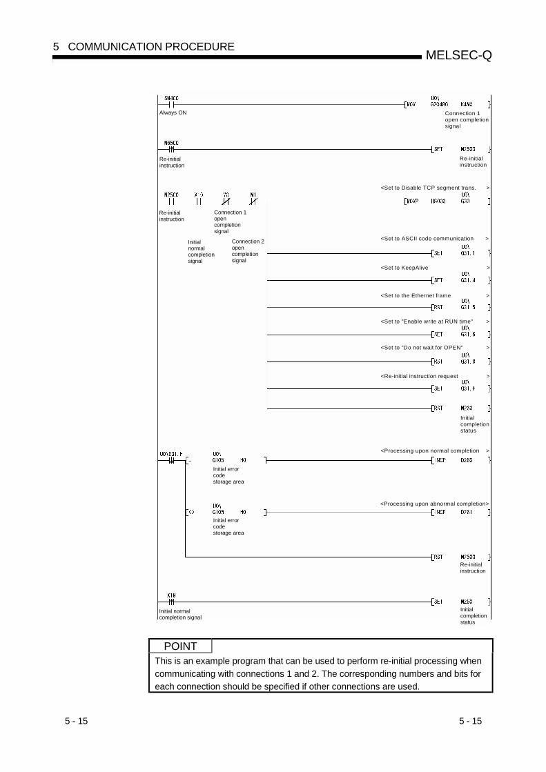
5 - 15 5 - 15
MELSEC-Q5 COMMUNICATION PROCEDURE
Always ON
Re-initial instruction
Initial normal completion signal
Connection 1open completionsignal
Re-initialinstruction
Connection 2 opencompletionsignal
Initial errorcodestorage area
Initial errorcodestorage area
Initial normal completion signal
Initial completionstatus
Re-initial instruction
<Processing upon abnormal completion>
<Processing upon normal completion >
Initial completionstatus
<Set to "Do not wait for OPEN" >
<Set to "Enable write at RUN time" >
<Set to the Ethernet frame >
<Set to KeepAlive >
<Set to ASCII code communication >
Re-initial instruction
Connection 1open completionsignal
<Set to Disable TCP segment trans. >
<Re-initial instruction request >
POINTThis is an example program that can be used to perform re-initial processing whencommunicating with connections 1 and 2. The corresponding numbers and bits foreach connection should be specified if other connections are used.
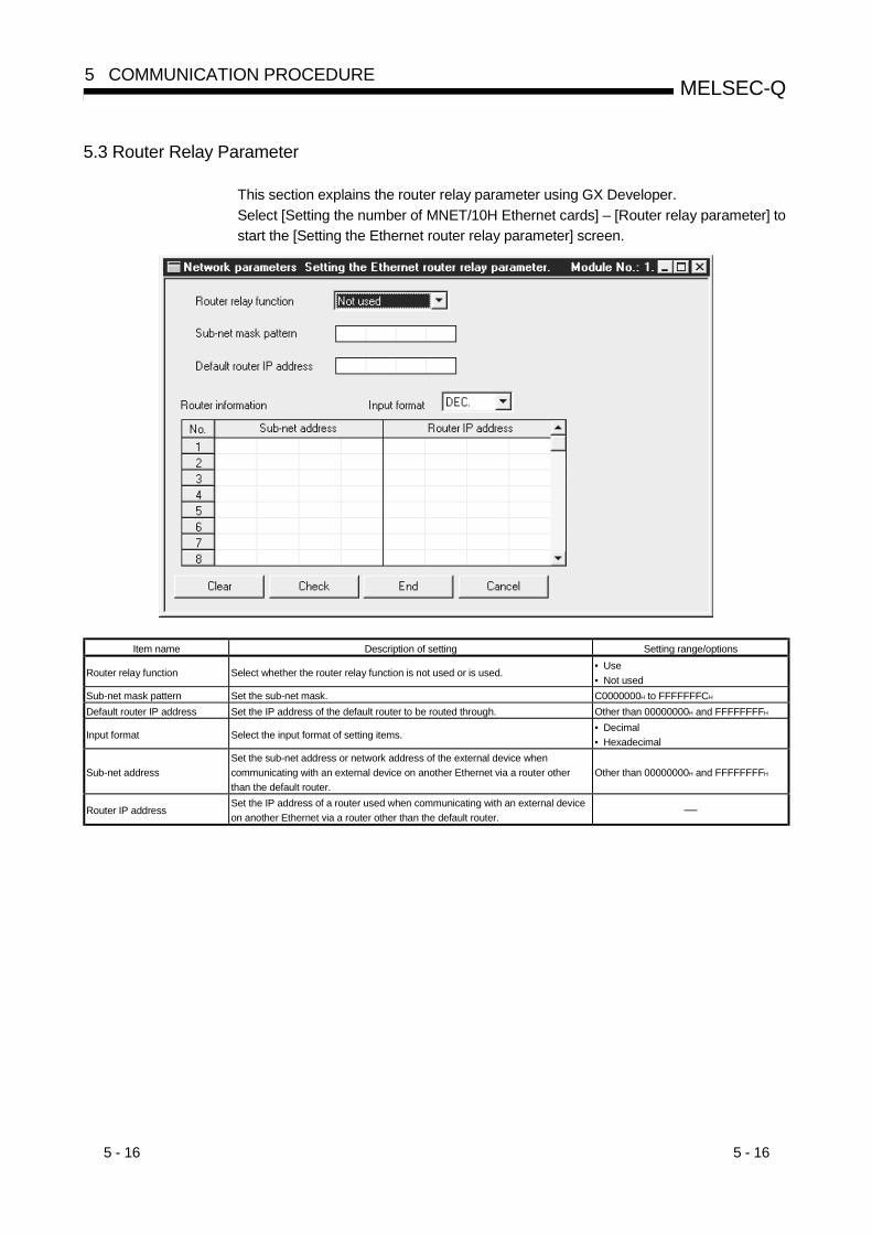
5 - 16 5 - 16
MELSEC-Q5 COMMUNICATION PROCEDURE
5.3 Router Relay Parameter
This section explains the router relay parameter using GX Developer.Select [Setting the number of MNET/10H Ethernet cards] – [Router relay parameter] tostart the [Setting the Ethernet router relay parameter] screen.
Item name Description of setting Setting range/options
Router relay function Select whether the router relay function is not used or is used.• Use• Not used
Sub-net mask pattern Set the sub-net mask. C0000000H to FFFFFFFCH
Default router IP address Set the IP address of the default router to be routed through. Other than 00000000H and FFFFFFFFH
Input format Select the input format of setting items.• Decimal• Hexadecimal
Sub-net addressSet the sub-net address or network address of the external device whencommunicating with an external device on another Ethernet via a router otherthan the default router.
Other than 00000000H and FFFFFFFFH
Router IP addressSet the IP address of a router used when communicating with an external deviceon another Ethernet via a router other than the default router.
—

5 - 17 5 - 17
MELSEC-Q5 COMMUNICATION PROCEDURE
(1) Router relay function (Address: 4H ... b5, b4)(a) Set whether the router relay function will be used or not.
The router relay function is not needed when the QJ71MT91 communicateswith the target device on the same Ethernet (the subnet address of the IPaddress is the same).
(b) The router relay function allows communication with devices on otherEthernets via routers and gateways.(The router relay function does not mean a function with which theQJ71MT91 acts as a router.)
(c) One default router and a maximum of any eight routers can be set for therouter relay function.
(2) Subnet mask pattern (Address: 200H, 201H)(a) Set the subnet mask. 1 (Setting range: C0000000H to FFFFFFFCH)
Consult the network administrator for the setting.
(b) When not using the subnet mask, set any of the following table valuesaccording to the class.
Class Mask value
Class A FF000000H
Class B FFFF0000H
Class C FFFFFF00H
1 Networks constructed by Ethernet include small-scaled network systemswhere multiple devices are connected to one Ethernet, and medium- andlarge-scaled network systems where multiple small-scaled networks areconnected by routers, etc.The subnet mask logically divides one network, where many devices areconnected, into multiple sub-networks to facilitate administration.
IP address
Subnet mask
1 0 0 0 0 0 0 181H
0 0 0 0 0 1 0 105H
0 0 1 0 1 1 1 12FH
0 0 0 0 0 0 0 101H
Network address
1 1 1 1 1 1 1 1FFH
0 0 0 0 0 0 0 000H
1 1 1 1 1 1 1 1FFH
1 1 1 1 1 1FCH
00
0 0 0 0 0 0 0 11 0 0 0 0 0 0 1 0 0 0 0 0 1 0 1
Subnet address Host address
IP address 0 0 1 0 1 1 1 1
(Example) Class B
81H 05H 2FH 01H
POINT(1) All devices on the same sub-network must have common subnet masks.(2) When not administrated by the sub-network, the connected devices need not
have subnet masks. (Set the network address of the corresponding class.)

5 - 18 5 - 18
MELSEC-Q5 COMMUNICATION PROCEDURE
(3) Default router IP address (Address: 202H, 203H)Set the IP address of the router (default router) to be used when the QJ71MT91communicates with the target device on another Ethernet via other than therouter specified in the router information (refer to (4) below).Set the value that satisfies the following conditions.• Condition 1: The IP address class is any of A, B and C.• Condition 2: The sub-net address of the default router is the same as that of
the local station Ethernet module.• Condition 3: The host address bits are not all "0" or all "1".
POINTIf the corresponding sub-net address does not exist in the router information (referto (4) in this section) when the connection is opened or data communication ismade, communication is made via the default router.
(4) Router information: Subnet address (Address: 205H, 206H andlater)(a) Set the network address ( 1) or subnet address ( 2) of the target device
when the QJ71MT91 communicates with the target device on anotherEthernet via other than the default router.Set the value that satisfies the following conditions.• Condition 1: The IP address class is any of A, B and C.• Condition 2: The host address bits are all "0".
1 If the class (network address) of the local station differs from that ofthe external device, set the network address of the external device.
2 If the class (network address) of the local station is the same as that ofthe external device, set the sub-net address of the external device.
(b) Subnet address setting examples
Local station Ethernet module Class B IP address : 81052F01H (129.5.47.1) Subnet mask: FFFFFC00H (255.255.252.0)
Target device 1) Class B IP address: 81044001H
(129.4.64.1)
Ethernet4
Target device 3) Class B IP address: 81052902H
(129.5.41.2)
Target device 2) Class A IP address: 71044001H
(113.4.64.1)
Ethernet1 Ethernet2 Ethernet3
Router 1 Router 3Router 2
Setting example 1 Setting example 2 Setting example 3
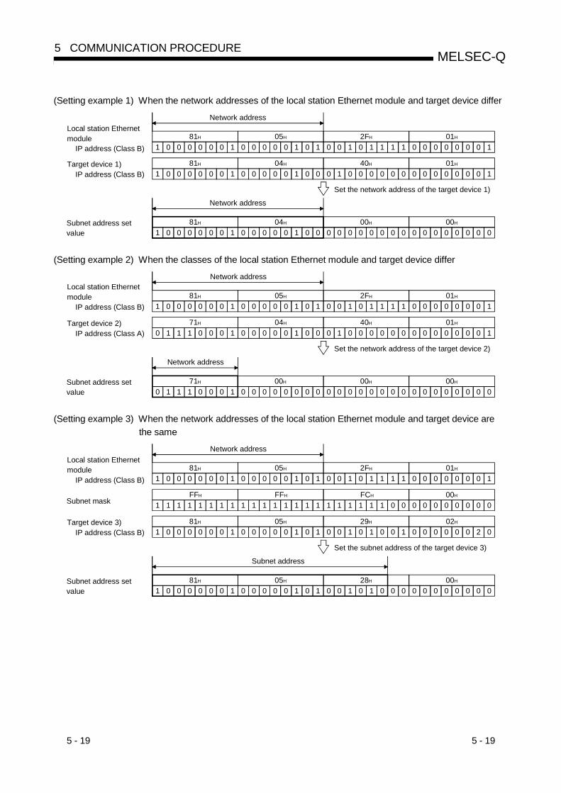
5 - 19 5 - 19
MELSEC-Q5 COMMUNICATION PROCEDURE
(Setting example 1) When the network addresses of the local station Ethernet module and target device differ
Local station Ethernet module IP address (Class B) 1 0 0 0 0 0 0 1
81H
0 0 0 0 0 1 0 105H
0 0 1 0 1 1 1 12FH
0 0 0 0 0 0 0 101H
Network address
Target device 1) IP address (Class B) 1 0 0 0 0 0 0 1
81H
0 0 0 0 0 1 0 004H
0 1 0 040H
0 0 0 0 0 0 0 101H
0 0 0 0
Subnet address setvalue 1 0 0 0 0 0 0 1
81H
0 0 0 0 0 1 0 004H
0 0 0 000H
0 0 0 0
Network address
Set the network address of the target device 1)
0 0 0 000H
0 0 0 0
(Setting example 2) When the classes of the local station Ethernet module and target device differ
Local station Ethernet module IP address (Class B) 1 0 0 0 0 0 0 1
81H
0 0 0 0 0 1 0 105H
0 0 1 0 1 1 1 12FH
0 0 0 0 0 0 0 101H
Network address
Target device 2) IP address (Class A) 0 1 1 1 0 0 0 1
71H
0 0 0 0 0 1 0 004H
0 1 0 040H
0 0 0 0 0 0 0 101H
0 0 0 0
Subnet address setvalue 0 0 0 0
00H
0 0 0 0
Network address
Set the network address of the target device 2)
0 0 0 000H
0 0 0 00 1 1 1 0 0 0 171H
0 0 0 000H
0 0 0 0
(Setting example 3) When the network addresses of the local station Ethernet module and target device arethe same
Local station Ethernet module IP address (Class B) 1 0 0 0 0 0 0 1
81H
0 0 0 0 0 1 0 105H
0 0 1 0 1 1 1 12FH
0 0 0 0 0 0 0 101H
Network address
Target device 3) IP address (Class B) 1 0 0 0 0 0 0 1
81H
0 0 0 0 0 1 0 105H
0 0 1 029H
0 0 0 0 0 0 2 002H
1 0 0 1
Subnet address setvalue 1 0 0 0 0 0 0 1
81H
Subnet address
Set the subnet address of the target device 3)
0 0 0 000H
0 0 0 0
1 1FFH
Subnet mask 1 1 1 1 1 1 1 1FFH
1 1 1 1 1 1 1 0FCH
1 1 1 1 1 0 0 0 0 000H
0 0 0 0
0 0 0 0 0 1 0 105H
0 0 1 028H
1 0 0 0
5 - 20 5 - 20
MELSEC-Q5 COMMUNICATION PROCEDURE
(5) Router information: Router IP address (Address: 207H, 208H andlater)Set the IP addresses of the routers to be used when the QJ71MT91communicates with the target devices on other Ethernets via other than thedefault router.Set the value that satisfies the following conditions.• Condition 1: The IP address class is any of A, B and C.• Condition 2: The sub-net address of the router is the same as that of the local
station Ethernet module.• Condition 3: The host address bits are not all "0" or all "1".
POINT(1) When the Ethernet module communicates with the external device via the
router in Passive open (TCP/IP) status, communication can be made withoutuse of the router relay function.
(2) The router relay function is not needed in a system that uses the Proxy router.

5 - 21 5 - 21
MELSEC-Q5 COMMUNICATION PROCEDURE
5.4 Confirming the Completion of the Initial Processing
The initial processing of the Ethernet module completes by saving the followingparameters in the PLC CPU of the station to which the Ethernet module is installedand by restarting the PLC CPU.(When the processing is completed normally, the [INIT.] LED on the front of theEthernet module turns on.)• "Network parameters Setting the number of MNET/10H Ethernet cards" parameter• "Operational settings" parameter• "Initial settings" parameterThis section explains how to check the completion of the initial processing.
POINTThe status of the Ethernet module becomes communication enabled when theinitial processing is completed normally. See reference sections for eachcommunication function to perform communication.When the initial processing has not been completed normally, do the following tocheck the contents of the error, take corrective actions, then execute the initialprocessing again.• Check the error code using the "Parameter status" of the Ethernet diagnostics.
(See Section 11.2.)• Check the contents of the error corresponding to the error code, then take
corrective actions. (See Section 11.3.3.)
5.4.1 PING test using GX Developer (Via Ethernet board)
This section explains how to check the completion status of the initial processing forthe Ethernet module using the PING test function of the GX Developer Ethernetdiagnostics.
(1) PING test(a) The PING test is used to check, through GX Developer, the existence of an
Ethernet module on the same Ethernet line that has completed the initialprocessing ( 1) or an external device (such as a personal computer) withthe designated IP address.
1 The PING test can also be performed for the QnA/A Series Ethernetmodules. However, the PING test can be performed for the followingA Series Ethernet modules starting with software version S:AJ71E71, AJ71E71-B2, AJ71E71-B5
(b) The following can be checked by performing the PING test for the Ethernetmodule:• Whether a line has been properly connected to the test target Ethernet
module• Whether the parameters for the Ethernet module have been correctly set• Whether the initial processing for the Ethernet module has been
completed normally

5 - 22 5 - 22
MELSEC-Q5 COMMUNICATION PROCEDURE
(c) The PING test can be performed for an Ethernet module in the sameEthernet as the local station (same sub-net address.)
(d) If the external device subject to the PING test is an Ethernet module, do notdesignate the UDP port for GX Developer of the Ethernet module as a validport for the remote password check. If it is designated as a valid port for theremote password check, the PING test cannot be performed.
(2) Executing the PING testThe example below explains the PING test methodology and GX Developersettings when performing a PING test for the Ethernet module in the sameEthernet from a peripheral device.
GX Developer
Ethernetmodule
QCPU2)
Ethernet
(PING test target station)
Station No.: 3[10.97.85.223]
Station No.: 1[10.97.85.221]
Station No.: 2[10.97.85.222]
Network No. 1
Ethernetmodule
QCPU1)
(a) Setting the PING test target station
1) Set the following Ethernet module parameters for the PING test targetstation through GX Developer.Use default values for setting items other than those listed below.
Setting descriptionSetting screen Setting item
QCPU 1) QCPU 2)Network type Ethernet EthernetStarting I/O No. 0000 0000Network No. 1 1Group No. 1 1
Network parameters settingthe number of MNET/10HEthernet cards
Station No. 1 2Operational setting IP address [10.97.85.221] [10.97.85.222]
2) Write the parameters to the applicable station.
3) The initial processing is completed when the PLC CPU restarts.(When the initial processing is completed normally, the [INIT.] LED ofthe Ethernet module lights up.)

5 - 23 5 - 23
MELSEC-Q5 COMMUNICATION PROCEDURE
(b) Designating GX Developer connection destination (connecting to QCPU [2])
(c) Executing the PING test through GX Developer
1) Select the PING test on the Ethernet diagnostics screen.GX Developer [Diagnostics] [Ethernet diagnostics] PING test
2) Perform the settings indicated below, then click the Execute button.The execution results of the PING test are displayed.(Example) The following shows the flow of the PING test when "4" is
designated as the transmission count.
GX Developer
Ethernet line
Ethernet module
Number of transmissions: 4 timesSuccess/transmissions = 3/4
Time of the communication time check: 1 s
Normalresponse
Abnormalresponse
Normal response occurs when the PING test response is received within the time of the communication time check.
Normalresponse
Normalresponse

5 - 24 5 - 24
MELSEC-Q5 COMMUNICATION PROCEDURE
[PING test screen]
(Example of normal completion) (Example of abnormal completion)
[Display contents]Item name Description of item setting Setting range/options
IP address Specify the IP address for the PING test target station. (Target station IP address)IP address input form Select the input format for the IP address. Decimal/hexadecimal
Addressspecification
Host name Specify the host name for the PING test target station. —Display the hostname
Results are displayed using the host name corresponding to the IP address inthe result display field.
—
Specify the data size Specify the size of the system data transmitted during the PING test.1 to 8192 bytes (Specify 1460 bytes orless for the Ethernet module.)
Specify the time ofthe communicationtime check
Specify the completion wait time for the PING test. 1 to 30 s
Optionspecification
Specify the numberof transmission
Specify the transmission count.• Specify the number of times.• Execute till interrupting.
Result Display results of the PING test. —
Success/transmissionsDisplay the total packet transmission count and the number of successesduring the PING test.
—
5 - 25 5 - 25
MELSEC-Q5 COMMUNICATION PROCEDURE
(Address specification)The PING test target station (external device subject to the PING test) isspecified by the IP address or the host name.1) Specification using the IP address
• Select the input format for the IP address (select: Decimal orhexadecimal)
• Specify the IP address of the external device according to the inputformat (decimal or hexadecimal).
2) Specification using the host nameSpecify the host name of the external device set in the DNS server orthe HOSTS file for the personal computer on which GX Developer ismounted.
The IP address can also be entered in the host name specificationfield.
(Option specification)Set the details for the PING test. (No setting required if the default is used.)1) Display the host name.
Select this to display the host name instead of the IP address for thePING test destination device in the result display field.
2) Specify the data size.Specify the size of the system data to be transmitted for the test duringthe PING test.Input range: 1 to 8192 bytes (default: 32 bytes)
The Ethernet module will return a response of 1460 bytes if thePING test is performed when a data size of 1460 bytes or greaterfor transmitting to the Ethernet module is specified.
3) Specify the time of the communication time check.Specify the response wait time for the PING test.Input range: 1 to 30 s (default: 1 s)
4) Specify the number of transmissions.Specify the number of times the PING test is to be performed.
Selection item Description of item Remarks
Specify the number of times The PING test is performed for the number of specified times.Transmission count: 1 to 50 times(default: 4 times)
Execute till interrupting The PING test is performed until the interrupt button is pressed. —
(Result)Results of the PING test are displayed.<When the test is completed abnormally>Check the following, then perform the PING test again.• How the Ethernet module is mounted on the base unit.• Status of the connection to the Ethernet.• Contents of the parameters written to the PLC CPU.• Operating status of the PLC CPU (whether any errors have occurred).• IP addresses set in GX Developer and the PING test target station.• Whether the external device has reset when the Ethernet module was
changed.(Success/transmissions)The number of successes and the total packet transmission count when thePING test is performed are displayed.

5 - 26 5 - 26
MELSEC-Q5 COMMUNICATION PROCEDURE
5.4.2 PING test using GX Developer (Via CPU)
This section explains how to check the completion status of the initial processing forthe Ethernet module using the PING test function of GX Developer’s Ethernetdiagnostics.
(1) PING test(a) The PING test is used to check the existence of an Ethernet module on the
same Ethernet line as the connection station of GX Developer that hascompleted the initial processing ( 1) or an external device (such as apersonal computer) with the designated IP address.
1 The PING test can also be performed for the QnA/A Series Ethernetmodules. However, the PING test can be performed for the following ASeries Ethernet modules starting with software version S:AJ71E71, AJ71E71-B2, AJ71E71-B5
(b) The following items can be checked by performing the PING test for theEthernet module:• Whether a line has been properly connected to the test target Ethernet
module.• Whether the parameters for the Ethernet module have been correctly set.• Whether the initial processing for the Ethernet module has been
completed normally.
(c) The PING test can be performed for an Ethernet module on the sameEthernet as that of the local station (same sub-net address).Note that the PING test is not available for the Ethernet module mounted onthe station to which GX Developer is directly connected (local station). (ThePING test addressed to the local station is not available.)
(d) If the external device subject to the PING test is an Ethernet module, do notdesignate the UDP port for GX Developer of the Ethernet module as a validport for the remote password check. If the port is designated as such, thePING test cannot be performed.
(2) Executing the PING testThe example below explains the PING test methodology and GX Developersettings when a PING test is performed for an Ethernet module of other stationfrom GX Developer connected to the QCPU.
Ethernetmodule
Ethernet
Ethernetmodule
QCPU2)
Network No. 1
QCPU1)
Station number: 2[10.97.85.222]
GX Developer
(PING test target station)
Station number: 1[10.97.85.221]
(GX Developer connecting station)

5 - 27 5 - 27
MELSEC-Q5 COMMUNICATION PROCEDURE
(a) Settings on the QCPU station side1) Set the following Ethernet module parameters for each QCPU using
GX Developer.Use default values for setting items other than those listed below.
Setting descriptionSetting screen Setting item QCPU 1) QCPU 2)Network type Ethernet EthernetStarting I/O No. 0000 0000Network No. 1 1Group No. 1 1
Network parameters settingthe number of MNET/10HEthernet cards
Station No. 1 2Operational setting IP address [10. 97. 85. 221] [10. 97. 85. 222]
2) Write the parameters to the applicable station.3) The initial processing is completed when the PLC CPU restarts.
(When the initial processing is completed normally, the [INIT. ] LED ofthe Ethernet module lights up.)
(b) Designating the GX Developer connection destination (connecting to QCPU2)
(c) Executing the PING test through GX Developer1) Select the PING test on the Ethernet diagnostics screen.
GX Developer → [Diagnostics] → [Ethernet diagnostics] → PING test2) Perform the settings indicated below, then click the Execute button.
The execution results of the PING test are displayed.(Example) The following shows the flow of the PING test when "4" is
designated as the transmission count.
GX Developer
Ethernet line
Ethernet module
Number of transmissions: 4 timesSuccess/transmissions = 3/4
Time of the communication time check: 1 s
Normalresponse
Abnormalresponse
Normal response occurs when the PING test response is received within the time of the communication time check.
Normalresponse
Normalresponse
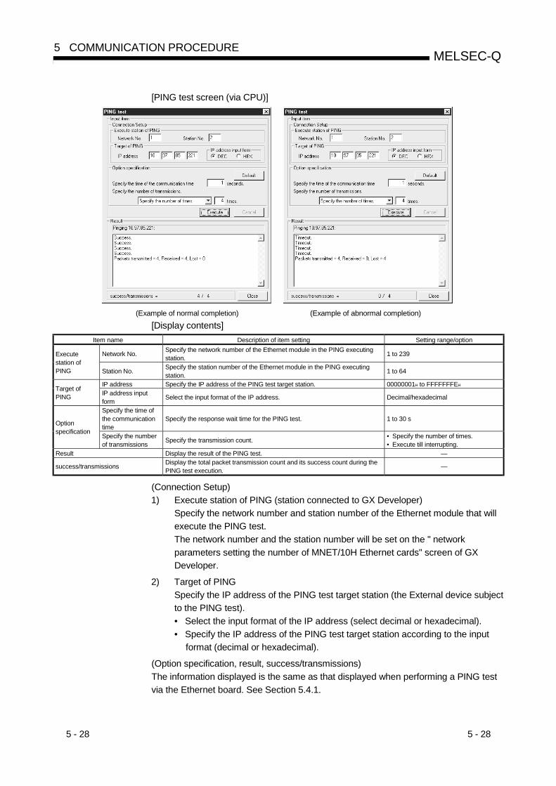
5 - 28 5 - 28
MELSEC-Q5 COMMUNICATION PROCEDURE
[PING test screen (via CPU)]
(Example of normal completion) (Example of abnormal completion)
[Display contents]Item name Description of item setting Setting range/option
Network No. Specify the network number of the Ethernet module in the PING executingstation. 1 to 239Execute
station ofPING Station No. Specify the station number of the Ethernet module in the PING executing
station. 1 to 64
IP address Specify the IP address of the PING test target station. 00000001H to FFFFFFFEHTarget ofPING IP address input
form Select the input format of the IP address. Decimal/hexadecimal
Specify the time ofthe communicationtime
Specify the response wait time for the PING test. 1 to 30 sOptionspecification
Specify the numberof transmissions Specify the transmission count. • Specify the number of times.
• Execute till interrupting.Result Display the result of the PING test. —
success/transmissions Display the total packet transmission count and its success count during thePING test execution. —
(Connection Setup)1) Execute station of PING (station connected to GX Developer)
Specify the network number and station number of the Ethernet module that willexecute the PING test.The network number and the station number will be set on the " networkparameters setting the number of MNET/10H Ethernet cards" screen of GXDeveloper.
2) Target of PINGSpecify the IP address of the PING test target station (the External device subjectto the PING test).• Select the input format of the IP address (select decimal or hexadecimal).• Specify the IP address of the PING test target station according to the input
format (decimal or hexadecimal).
(Option specification, result, success/transmissions)The information displayed is the same as that displayed when performing a PING testvia the Ethernet board. See Section 5.4.1.
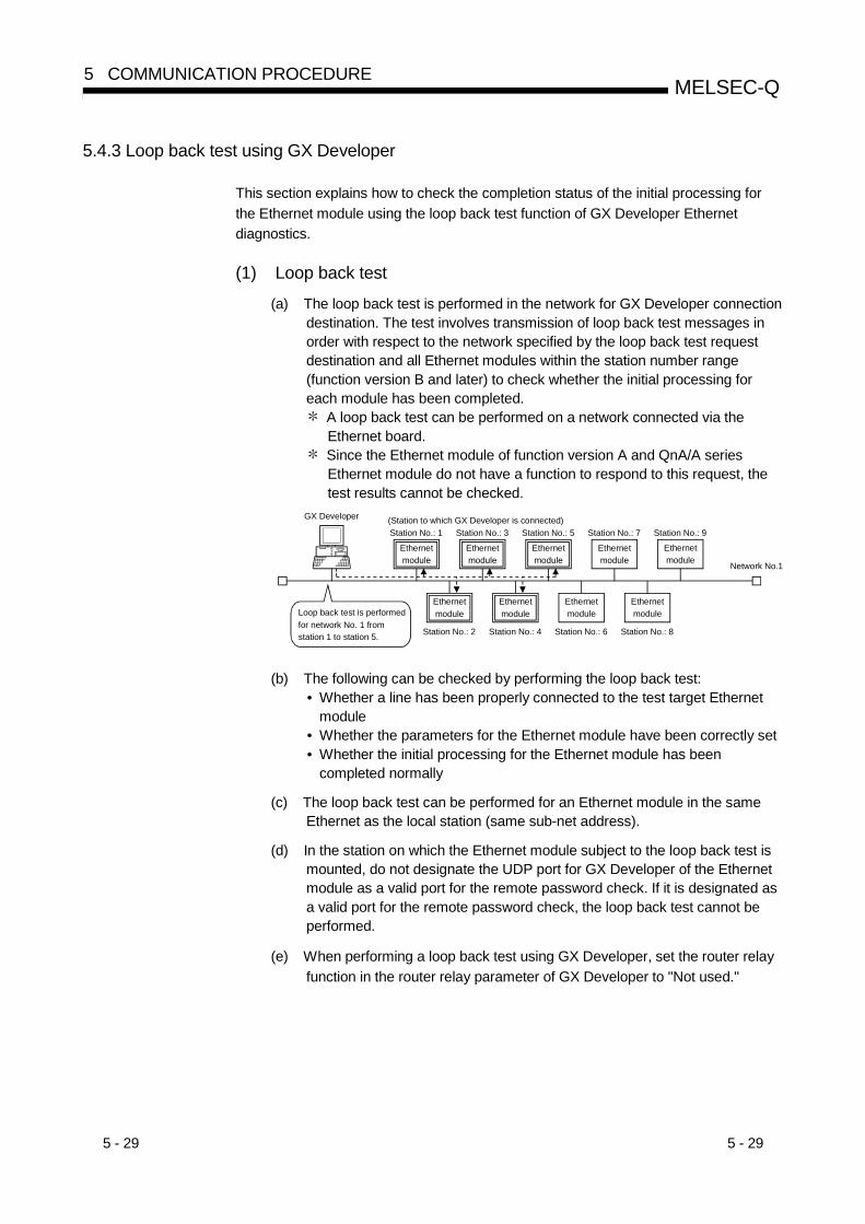
5 - 29 5 - 29
MELSEC-Q5 COMMUNICATION PROCEDURE
5.4.3 Loop back test using GX Developer
This section explains how to check the completion status of the initial processing forthe Ethernet module using the loop back test function of GX Developer Ethernetdiagnostics.
(1) Loop back test
(a) The loop back test is performed in the network for GX Developer connectiondestination. The test involves transmission of loop back test messages inorder with respect to the network specified by the loop back test requestdestination and all Ethernet modules within the station number range(function version B and later) to check whether the initial processing foreach module has been completed.
A loop back test can be performed on a network connected via theEthernet board.
Since the Ethernet module of function version A and QnA/A seriesEthernet module do not have a function to respond to this request, thetest results cannot be checked.
GX Developer
Ethernetmodule
(Station to which GX Developer is connected)
Network No.1
Station No.: 1
Station No.: 2
Station No.: 3
Station No.: 4
Station No.: 5
Station No.: 6
Station No.: 7
Station No.: 8
Station No.: 9
Loop back test is performed for network No. 1 from station 1 to station 5.
Ethernetmodule
Ethernetmodule
Ethernetmodule
Ethernetmodule
Ethernetmodule
Ethernetmodule
Ethernetmodule
Ethernetmodule
(b) The following can be checked by performing the loop back test:• Whether a line has been properly connected to the test target Ethernet
module• Whether the parameters for the Ethernet module have been correctly set• Whether the initial processing for the Ethernet module has been
completed normally
(c) The loop back test can be performed for an Ethernet module in the sameEthernet as the local station (same sub-net address).
(d) In the station on which the Ethernet module subject to the loop back test ismounted, do not designate the UDP port for GX Developer of the Ethernetmodule as a valid port for the remote password check. If it is designated asa valid port for the remote password check, the loop back test cannot beperformed.
(e) When performing a loop back test using GX Developer, set the router relayfunction in the router relay parameter of GX Developer to "Not used."

5 - 30 5 - 30
MELSEC-Q5 COMMUNICATION PROCEDURE
(2) Executing the loop back testThe example explains the loop back test methodology and GX Developersettings when performing a loop back test for the Ethernet module in the sameEthernet from the GX Developer.
GX Developer
Ethernetmodule
QCPU1)
EthernetNetwork No.1
Station No.: 3[10.97.85.223]
Station No.: 1[10.97.85.221]
Station No.: 2[10.97.85.222]
Ethernetmodule
QCPU2)
(a) QCPU station side settings
1) Set the following Ethernet module parameters for each PLC CPUthrough GX Developer.Use default values for setting items other than those listed below.
Setting descriptionSetting screen Setting item
QCPU 1) QCPU 2)Remarks
Network type Ethernet EthernetStarting I/O No. 0000 0000Network No. 1 1Group No. 1 1
Network parameterssetting the number ofMNET/10H Ethernetcards
Station No. 1 2
See Section 4.6Set the local stationnetwork No., etc.
Operational setting IP address [10.97.85.221] [10.97.85.222]See Section 4.7Enter the local station IPaddress.
MNET/10 routingsystem
Table exchange system Table exchange system
Network No. 1 1Station No. 3 3
MNET/10 routinginformation
IP address [10.97.85.223] [10.97.85.223]
See Section 3.3.1 ofUser's Manual(Application).
It is not necessary to set the network No., station No. and IP address forGX Developer (station performing the loop back test) when "Automaticresponse system" is specified as the MNET/10 routing system under theMNET/10 routing information.
2) Write the parameters to the applicable station.
3) The initial processing is completed when the PLC CPU reboots.(When the initial processing is completed normally, the [INIT.] LED ofthe Ethernet module lights up.)
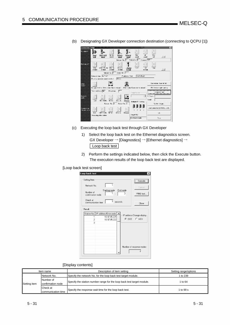
5 - 31 5 - 31
MELSEC-Q5 COMMUNICATION PROCEDURE
(b) Designating GX Developer connection destination (connecting to QCPU [1])
(c) Executing the loop back test through GX Developer
1) Select the loop back test on the Ethernet diagnostics screen.GX Developer [Diagnostics] [Ethernet diagnostics] Loop back test
2) Perform the settings indicated below, then click the Execute button.The execution results of the loop back test are displayed.
[Loop back test screen]
[Display contents]Item name Description of item setting Setting range/options
Network No. Specify the network No. for the loop back test target module. 1 to 239Number ofconfirmation node
Specify the station number range for the loop back test target module. 1 to 64Setting item
Check atcommunication time
Specify the response wait time for the loop back test. 1 to 99 s

5 - 32 5 - 32
MELSEC-Q5 COMMUNICATION PROCEDURE
(Network No. (1 to 239))Specify the loop back test request destination network No.Input range: 1 to 239
(Number of confirmation node (1 to 64))1) Specify the range (starting node and end node) of the Ethernet module
subject to the loop back test using the station No.Input range: 1 to 64
2) The loop back test is performed in order from the starting node. Upon the reception of a response from the station performing the
loop back test or after the time of the communication time checkelapses, the loop back test is performed for the next target stationand so on in order until the end station.
(Check at communication time)Specify the response wait time for the loop back test for each station.Input range: 1 to 99 s (default: 10 s)
(Result)Results of the loop back test are displayed.
1) The IP address for the Ethernet module that has completed the loopback test normally is displayed.
If the same IP address or station number has been set to multiplestations due to a parameter setting error on the loop back testtarget module side, only the results for the station that issued aresponse first will be displayed.
2) "No response" or an error code will be displayed for an Ethernetmodule in which the loop back test is completed abnormally.
"No response" is not shown with GX Developer Version 6.03D or former products.
3) If the local station is specified as a loop back test target station (stationperforming a loop back test), "No response" will be displayed as theloop back test results for the local station.
"No response" is not shown with GX Developer Version 6.03D or former products.
(d) Corrective action when the test is completed abnormallyThe table below shows the display contents, status of the target Ethernetmodule, causes and corrective actions when the loop back test has beencompleted abnormally.
Display contents ofloop back test results
Status of the targetEthernet module
Cause Corrective action
"IP address"Initial processing normalcompletion status([INIT.] LED ON status)
— —
The initial processing for the target Ethernet modulehas not been completed normally.
Check the setting values for the followingparameters:• Network parameters setting the number of
MNET/10H Ethernet cards• Operational setting• Initial setting
"No response" No error
There is an error in the line connection to the targetEthernet module. (Cable disconnection, breakage,etc.)
• Check the cable.• Check the transceiver.

5 - 33 5 - 33
MELSEC-Q5 COMMUNICATION PROCEDURE
Display contents ofloop back test results
Status of the targetEthernet module
Cause Corrective action
IP address for the target Ethernet module isincorrect. (Class or sub-net address differs from theEthernet module setting.)The same IP address has been set to multiple targetEthernet modules.
Check the parameter setting values for theoperation setting.
The same network number or station number hasbeen set to multiple target Ethernet modules.
Perform a PING test for the "No response"module.If the test has been completed normally,check the parameter setting value for thenetwork parameters setting the number ofMNET/10H Ethernet cards.
No error
The Ethernet line is in the high load status (includinga case in which an error equivalent to the error codeC030H, C031H is occurring).
Perform another test when the load on theEthernet line is low.
"No response"
Error exists Routing parameter is not set. (An error equivalent tothe error code C080H is occurring.)
Check the setting value for the routingparameter. (See Chapter 3 of User's Manual(Application )
The remote password status of GX Developer UDPfor the target Ethernet module is in the lock status.
Cancel the remote password setting and writethe parameter to the PLC CPU.
The target Ethernet module is a function version Amodule.
Check the model and function version for thesubject module.
No error"Error code"
Error exists
The Ethernet line is in the high load status (includinga case in which an error equivalent to the error codeC030H, C031H is occurring)
Perform another test when the load on theEthernet line is low.
POINT(1) The loop back test can only be performed for the Ethernet module of function
version B and later.Test results cannot be checked for the following modules. ("No response" willbe displayed. However, nothing is shown under the use of GX Developerversion 6.03D or former products.)Also, they will not be counted in the total number of stations.• Ethernet module of function version A, QnA/A series Ethernet module
(This is because there is no function to respond to this request.)• Ethernet module that has not completed the initial processing
(This is because the initial processing has not been completed.) If the Ethernet module of function version A or QnA/A series Ethernet
module that does not have a function to respond to the loop back testreceives a loop back test request, the following error codes will be storedin the error log area of the buffer memory.• Error code 4080H in the case of an Ethernet module of function version
A or QnA series Ethernet module of function version B• Error code 50H in the case of a QnA series Ethernet module of function
version A or A series Ethernet module.
(2) After checking the contents of the error and taking corrective actions for anEthernet module in which the loop back test has been completed abnormally,reboot the station on which the Ethernet module is mounted.With rebooting, the initial processing for the Ethernet module will beperformed.Check the completion of the initial processing for the Ethernet module usingthe PING test.The PING test can also be performed on the "Loop back test" screen.
(3) If an error code is displayed due to abnormal completion of the loop back test,check the contents of the error corresponding to the error code, then takecorrective actions by referring to Section 11.3.3.

5 - 34 5 - 34
MELSEC-Q5 COMMUNICATION PROCEDURE
5.4.4 PING command (Personal computer Ethernet module)
The following example illustrates how to confirm the completion of the initial processingby issuing the PING command to the local station’s Ethernet module from an externaldevice connected on the same Ethernet. (In the example, the confirmation is madebetween devices whose IP address class and sub-net address are identical.)
<Designation method>ping IP address
<Example>IP address of the Ethernet module: 192.0.1.254
C:\>ping 192.0.1.254…Execute the ping command
Pinging 192.0.1.254 with 32 bytes of data:
Reply from 192.0.1.254: bytes=32 time=1ms TTL=128Reply from 192.0.1.254: bytes=32 time<10ms TTL=128Reply from 192.0.1.254: bytes=32 time<10ms TTL=128Reply from 192.0.1.254: bytes=32 time<10ms TTL=128
Ping statistics for 192.0.1.254: Packets: Sent = 4, Received = 4, Lost = 0 (0% loss)
Approximate round trip times in milli-seconds: Minimum = 0ms, Maximum = 1ms, Average = 0ms
C:\>_
Example of screen at normal completion
C:\>ping 192.0.1.254…Execute the ping command
Pinging 192.0.1.254 with 32 bytes of data:
Request timed out:Request timed out:Request timed out:Request timed out:
Ping statistics for 192.0.1.254: Packets: Sent = 4, Received = 0, Lost = 4 (100% loss)Approximate round trip times in milli-seconds: Minimum = 0ms, Maximum = 0ms, Average = 0ms
C:\>_
Example of screen at abnormal completion
<When the PING command does not respond successfully>Check the following items and send the PING command again.• Check the Ethernet module's attachment to the base unit.• Check the connection to the Ethernet network.• Check the contents of each parameter written to the PLC CPU.• Check the operation condition of the PLC CPU (are there any irregularities?).• Check the IP address of the Ethernet module dictated by the PING command.
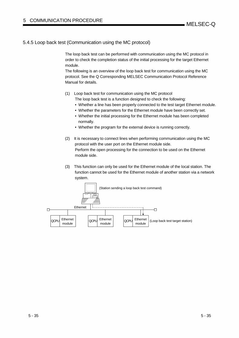
5 - 35 5 - 35
MELSEC-Q5 COMMUNICATION PROCEDURE
5.4.5 Loop back test (Communication using the MC protocol)
The loop back test can be performed with communication using the MC protocol inorder to check the completion status of the initial processing for the target Ethernetmodule.The following is an overview of the loop back test for communication using the MCprotocol. See the Q Corresponding MELSEC Communication Protocol ReferenceManual for details.
(1) Loop back test for communication using the MC protocolThe loop back test is a function designed to check the following:• Whether a line has been properly connected to the test target Ethernet module.• Whether the parameters for the Ethernet module have been correctly set.• Whether the initial processing for the Ethernet module has been completed
normally.• Whether the program for the external device is running correctly.
(2) It is necessary to connect lines when performing communication using the MCprotocol with the user port on the Ethernet module side.Perform the open processing for the connection to be used on the Ethernetmodule side.
(3) This function can only be used for the Ethernet module of the local station. Thefunction cannot be used for the Ethernet module of another station via a networksystem.
(Station sending a loop back test command)
Ethernetmodule
QCPU
Ethernet
(Loop back test target station)Ethernetmodule
QCPU Ethernetmodule
QCPU
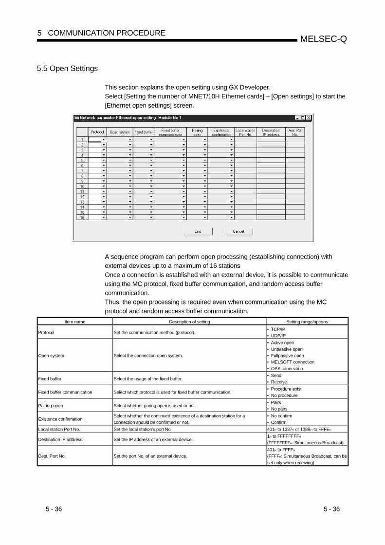
5 - 36 5 - 36
MELSEC-Q5 COMMUNICATION PROCEDURE
5.5 Open Settings
This section explains the open setting using GX Developer.Select [Setting the number of MNET/10H Ethernet cards] – [Open settings] to start the[Ethernet open settings] screen.
A sequence program can perform open processing (establishing connection) withexternal devices up to a maximum of 16 stationsOnce a connection is established with an external device, it is possible to communicateusing the MC protocol, fixed buffer communication, and random access buffercommunication.Thus, the open processing is required even when communication using the MCprotocol and random access buffer communication.
Item name Description of setting Setting range/options
Protocol Set the communication method (protocol).• TCP/IP• UDP/IP
Open system Select the connection open system.
• Active open• Unpassive open• Fullpassive open• MELSOFT connection• OPS connection
Fixed buffer Select the usage of the fixed buffer.• Send• Receive
Fixed buffer communication Select which protocol is used for fixed buffer communication.• Procedure exist• No procedure
Pairing open Select whether paring open is used or not.• Pairs• No pairs
Existence confirmationSelect whether the continued existence of a destination station for aconnection should be confirmed or not.
• No confirm• Confirm
Local station Port No. Set the local station’s port No. 401H to 1387H or 138BH to FFFEH
Destination IP address Set the IP address of an external device.1H to FFFFFFFFH
(FFFFFFFFH: Simultaneous Broadcast)
Dest. Port No. Set the port No. of an external device.401H to FFFFH
(FFFFH: Simultaneous Broadcast, can beset only when receiving)

5 - 37 5 - 37
MELSEC-Q5 COMMUNICATION PROCEDURE
(1) Protocol(connection numbers 1 to 8; addresses: 20H to 27H … b8)(connection numbers 9 to 16; addresses: System area is used)(a) Select the protocol for each connection.
Name of setting Description of settingTCP Communicate using TCP/IP.UDP Communicate using UDP/IP.
(b) For protocols (TCP/UDP), see 1.4, "Software Configuration".
(2) Open system(connection numbers 1 to 8; addresses: 20H to 27H … b15, b14)(connection numbers 9 to 16; addresses: System area is used)(a) Select the connection open system for each connection for which "TCP" is
selected in "(1) Protocol". If "UDP" is selected, the specification of this itemis not required.
Name of setting Description of setting
Active Perform active open processing to an external device that waits for a passive open(Fullpassive/Unpassive) on the TCP connection.
UnpassivePerform passive open processing on the TCP connection addressing all the devices connectedto a network.(The local station is placed in the wait status to wait for an Active open request to be sent.
Fullpassive
Perform passive open processing on the TCP connection, only addressing specific devices.(The local station is placed in the wait status to wait for an Active open request to be sent.)The local station waits for an Active open request from the opposite station set in "(8)Destination IP address".
MELSOFT connection1 2 3
Used to connect MELSOFT products via TCP/IP communication.Perform passive open processing on the TCP connection, addressing all the MELSOFTproducts connected to a network.(The local station is placed in the wait status for an Active open request to be sent.)
OPS connection 1 4Used to connect the OPS via TCP/IP communication.Perform passive open processing on the TCP connection, addressing only specific OPSs. (Thelocal station waits for an Active open request from the OPS set in "(8) Destination IP address".)
1 Regardless of the initial timing setting in the operation setting (refer to Section 4.7),this connection will always wait for the open status.
2 The set connection is dedicated to data communication with the MELSOFT products.3 When simultaneously connecting to multiple MELSOFT products, set the connections
as many as the number of MELSOFT products. (Setting is unnecessary when onlyone product is connected. The connection dedicated to the system is used.)
4 When using the MELSOFT product, such as GX Developer, on the OPS to makeTCP/IP communication with the Ethernet module, use the dedicated connection forsystem (GX Developer communication TCP port) or set "MELSOFT connection" inthis setting.
PLC CPU PLC CPU
Initial completion
OpenActive open
Open completion
Initial request
Initial completion
Open completionOpen completion
Ethernet module Ethernet module
Wait for open request
Initial request
Initial completion
Open completion
Open request
Initial processing Initial processing
Initial processing completion
Fullpassive/Unpassive
open
5 - 38 5 - 38
MELSEC-Q5 COMMUNICATION PROCEDURE
(3) Fixed buffer(connection numbers 1 to 8; addresses: 20H to 27H … b0)(connection numbers 9 to 16; addresses: System area is used)
(a) Here it is selected whether the fixed buffer corresponding to each applicableconnection number will be used for sending or receiving whencommunicating using the fixed buffers.
Name of setting Description of settingSend For sending or fixed buffer communication is not executed.Receive For receiving.
(b) When both sending and receiving are performed with an external deviceusing fixed buffer communication, one buffer for sending and one forreceiving are required. Thus, two connections should be set.
(c) Whether the fixed buffers are set for sending or receiving, external devicescan communicate using the MC protocol or the random access buffers.
(4) Fixed buffer communication(connection numbers 1 to 8; addresses: 20H to 27H … b9)(connection numbers 9 to 16; addresses: System area is used)
(a) For this item, select the communication method when communicating usingthe fixed buffers.
Name of setting Description of setting
Procedure exist
• In fixed buffer communication, data is communicated in 1:1 by handshaking with theexternal device.
• Communication using the MC protocol and the random access buffers can beperformed as well.
No procedure
• The no procedure fixed buffer communication uses dedicated connections.• The PLC CPU and external devices communicate data in 1:1 or 1:n mode through
simultaneous broadcasting. ( 1)• The handshaking with an external device must be performed using a sequence
program.
1 For details on the simultaneous broadcasting, see Section 8.3, "Simultaneous Broadcasting When
UDP/IP is Used".
(5) Pairing open(connection numbers 1 to 8; addresses: 20H to 27H … b7)(connection numbers 9 to 16; addresses: System area is used)
(a) Select whether or not the Ethernet module’s receiving and sendingconnections should be made into one pair and connected to one port of anexternal device when using fixed buffer communication (both of theprocedure exists and no procedure can be designated).For more details on this, see Section 5.7, "Pairing Open".
Name of setting Description of settingNo pairs Does not use the pairing open method.Pairs Uses the pairing open method.
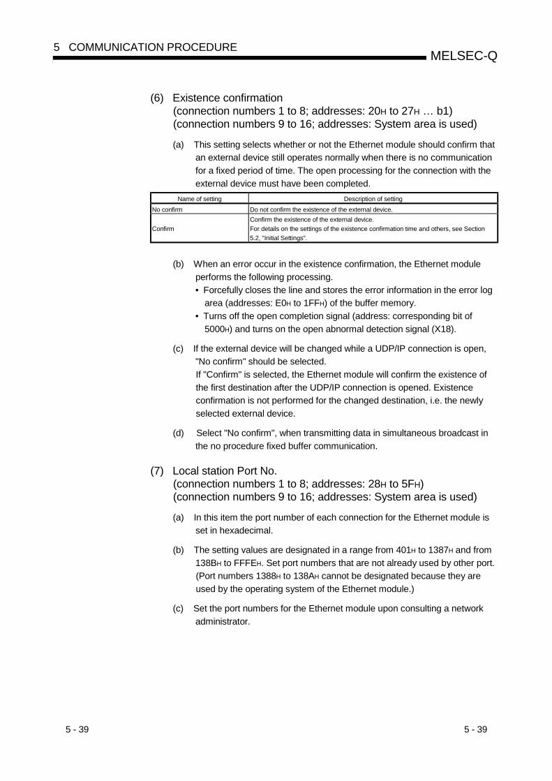
5 - 39 5 - 39
MELSEC-Q5 COMMUNICATION PROCEDURE
(6) Existence confirmation(connection numbers 1 to 8; addresses: 20H to 27H … b1)(connection numbers 9 to 16; addresses: System area is used)
(a) This setting selects whether or not the Ethernet module should confirm thatan external device still operates normally when there is no communicationfor a fixed period of time. The open processing for the connection with theexternal device must have been completed.
Name of setting Description of settingNo confirm Do not confirm the existence of the external device.
ConfirmConfirm the existence of the external device.For details on the settings of the existence confirmation time and others, see Section5.2, "Initial Settings".
(b) When an error occur in the existence confirmation, the Ethernet moduleperforms the following processing.• Forcefully closes the line and stores the error information in the error log
area (addresses: E0H to 1FFH) of the buffer memory.• Turns off the open completion signal (address: corresponding bit of
5000H) and turns on the open abnormal detection signal (X18).
(c) If the external device will be changed while a UDP/IP connection is open,"No confirm" should be selected.If "Confirm" is selected, the Ethernet module will confirm the existence ofthe first destination after the UDP/IP connection is opened. Existenceconfirmation is not performed for the changed destination, i.e. the newlyselected external device.
(d) Select "No confirm", when transmitting data in simultaneous broadcast inthe no procedure fixed buffer communication.
(7) Local station Port No.(connection numbers 1 to 8; addresses: 28H to 5FH)(connection numbers 9 to 16; addresses: System area is used)
(a) In this item the port number of each connection for the Ethernet module isset in hexadecimal.
(b) The setting values are designated in a range from 401H to 1387H and from138BH to FFFEH. Set port numbers that are not already used by other port.(Port numbers 1388H to 138AH cannot be designated because they areused by the operating system of the Ethernet module.)
(c) Set the port numbers for the Ethernet module upon consulting a networkadministrator.
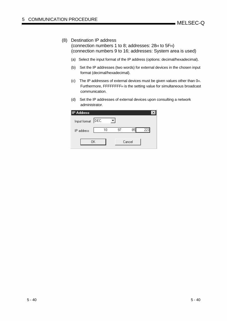
5 - 40 5 - 40
MELSEC-Q5 COMMUNICATION PROCEDURE
(8) Destination IP address(connection numbers 1 to 8; addresses: 28H to 5FH)(connection numbers 9 to 16; addresses: System area is used)
(a) Select the input format of the IP address (options: decimal/hexadecimal).
(b) Set the IP addresses (two words) for external devices in the chosen inputformat (decimal/hexadecimal).
(c) The IP addresses of external devices must be given values other than 0H.Furthermore, FFFFFFFFH is the setting value for simultaneous broadcastcommunication.
(d) Set the IP addresses of external devices upon consulting a networkadministrator.

5 - 41 5 - 41
MELSEC-Q5 COMMUNICATION PROCEDURE
(9) Destination Port No.(connection numbers 1 to 8; addresses: 28H to 5FH)(connection numbers 9 to 16; addresses: System area is used)
(a) Set the port numbers of the external devices for each connection inhexadecimal.
(b) The port numbers of the external devices are set in a range from 401H toFFFFH. Furthermore, FFFFH is the setting value for simultaneous broadcastcommunication.
(c) Set the port numbers for the external device upon consulting a networkadministrator.
(d) The following table provides some precautions that should be observedwhen setting port numbers.( in the diagram indicates a device and indicates a port number.)
CommunicationprotocolStatus of connection establishment
( : Port (indicates port number))Description of connection
TCP UDP
Ethernet module
External device
External deviceWhen connecting to multiple external devices,set multiple port numbers for the local station.
Ethernet module
External device
External device
When connecting to multiple external devices,set single port number for the local station.(However, it is necessary to open a connectionfor each external device)This cannot be chosen when the local station isUnpassive.
Ethernet module External device When connecting to multiple ports of an externaldevice, set multiple port numbers for theEthernet module.
Ethernet module External device
When connecting to multiple ports of an externaldevice, set single port number for the Ethernetmodule. (However, it is necessary to open aconnection for each external device port)This cannot be chosen when the local station isUnpassive.
Ethernet module External deviceWhen connecting to the same ports of anexternal device, set multiple port number for theEthernet module. (However, it is necessary toopen a connection for each Ethernet moduleport)
Ethernet module External device Setting multiple ports numbers for the same portof an external device and the Ethernet module ispossible only when paring open is set.
ImportantParameters for connections that communicate by Passive open and UDP openmust always be set from this screen when "Always wait for OPEN (communicationpossible at STOP time)" is selected in the Operational settings (see Section 4.7).

5 - 42 5 - 42
MELSEC-Q5 COMMUNICATION PROCEDURE
POINTSet parameters according to the open method to be used for open connection.
TCPCommunication systemopen system
Active PassiveUDP
ARP function ofexternal device
ARP function ofexternal device
Parameter Yes NoUn-passive Full-passive
Yes No
Local station PortNo.Destination IPaddressDestination PortNo.
Communicationaddress
DestinationEthernet address( 2)
( 1) ( 1)
1 Use the default value (FFFFFFFFFFFFH) or "0".
2 When using the "Open settings" of GX Developer, the default value is used.
When communicating with an external device without the ARP function, use the dedicated OPEN instruction and
set the external device’s Ethernet address in the control data.
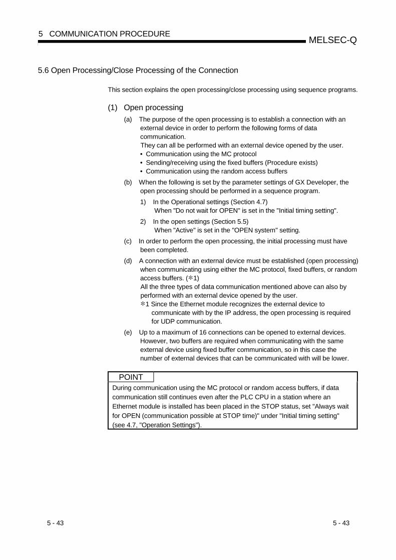
5 - 43 5 - 43
MELSEC-Q5 COMMUNICATION PROCEDURE
5.6 Open Processing/Close Processing of the Connection
This section explains the open processing/close processing using sequence programs.
(1) Open processing(a) The purpose of the open processing is to establish a connection with an
external device in order to perform the following forms of datacommunication.They can all be performed with an external device opened by the user.• Communication using the MC protocol• Sending/receiving using the fixed buffers (Procedure exists)• Communication using the random access buffers
(b) When the following is set by the parameter settings of GX Developer, theopen processing should be performed in a sequence program.1) In the Operational settings (Section 4.7)
When "Do not wait for OPEN" is set in the "Initial timing setting".2) In the open settings (Section 5.5)
When "Active" is set in the "OPEN system" setting.(c) In order to perform the open processing, the initial processing must have
been completed.(d) A connection with an external device must be established (open processing)
when communicating using either the MC protocol, fixed buffers, or randomaccess buffers. ( 1)All the three types of data communication mentioned above can also byperformed with an external device opened by the user.
1 Since the Ethernet module recognizes the external device tocommunicate with by the IP address, the open processing is requiredfor UDP communication.
(e) Up to a maximum of 16 connections can be opened to external devices.However, two buffers are required when communicating with the sameexternal device using fixed buffer communication, so in this case thenumber of external devices that can be communicated with will be lower.
POINTDuring communication using the MC protocol or random access buffers, if datacommunication still continues even after the PLC CPU in a station where anEthernet module is installed has been placed in the STOP status, set "Always waitfor OPEN (communication possible at STOP time)" under "Initial timing setting"(see 4.7, "Operation Settings").

5 - 44 5 - 44
MELSEC-Q5 COMMUNICATION PROCEDURE
(2) Close processing
(a) The purpose of the close processing is to disconnect (cancel) theconnection with the external device that has been established by the openprocessing mentioned previously.
(b) The close processing is used when terminating a connection with anexternal device, changing an external device of a connection, changingcommunication conditions, etc.
(c) Perform the close processing for connections that have been established bythe open processing using sequence programs.
(d) Determine the timing of close processing with the external device.
The examples in the following sections describe the procedures for establishing aconnection from the Ethernet module to an external device and subsequently closing itagain by open and close processing for connection number 1.• TCP/IP Active open : See 5.6.1, "Active open processing/close processing".• TCP/IP Passive open : See 5.6.2, "Passive open processing/close processing".• UDP/IP Open : See 5.6.3, "UDP/IP open processing/close processing".
ImportantNever execute the open/close processing to the same connection using theinput/input signals and use together with dedicated OPEN/CLOSE instructions forOPEN/CLOSE processing. It may result in malfunctions.
POINTExcept when the close processing is requested, the open completion signal(address: applicable bit of 5000H) automatically turns off and the communicationline is closed in the following cases:(1) When the existence confirmation function times out occur (see Section 5.5).
( 1)
(2) When a close or the ABORT (RST) instruction is received from an externaldevice.
(3) When the Active open request is received again from the external device inthe open completion status of TCP.Depending on its version, the Ethernet module operates as described below.(a) Ethernet module whose first 5 digits of the serial No. are 05051 or later
After returning ACK to the external device, the Ethernet module closesthe connection when the RST command is received from the externaldevice.
(b) Ethernet module whose first 5 digits of the serial No. are 05049 or earlierAfter sending the RST command, the Ethernet module closes theconnection.
However, when receiving the Active open request again from the externaldevice with a different IP address or port No., the Ethernet module only sendsthe RST command. (It does not close the connection.)

5 - 45 5 - 45
MELSEC-Q5 COMMUNICATION PROCEDURE
5.6.1 Active open processing/close processing
This section explains the procedure for opening and closing a connection with anexternal device from the Ethernet module.
M0 M1
M1
M100 M101
M101
ZP.OPEN "U0" K1 D0 M0
ZP.CLOSE "U0" K1 D100 M100
<<Open processing for connection No. 1 using the dedicated OPEN instruction>>
directionSet the control data to D0 to D8 When setting the application of GX Developer in the "Open settings"
• Control data [D0]:H0
Processing for normal completion
Processing for abnormal completion
Processing for abnormal completion
When setting the application of OPEN instruction in the "Control data"• [D0]: H8000• Set [D1] to [D9] according to the application.
<<Close processing for connection No. 1 using the dedicated instruction CLOSE>>
direction
Processing for normal completion
1)
2)
3) 4)
5)
FIN6) 7)
SYN
SYN + ACK FIN + ACK
CLOSE instruction
CLOSE instruction complete device
CLOSE instruction complete device + 1
Power-on
Parameter communication
completedOpen status
Open allowed status(closed)
Initial normal completion X19
Closed status
OPEN instructionOne scan
OPEN instruction complete device
OPEN instruction complete device + 1
Open abnormal detection signal X18
One scan
Open completion signal(Address: 5000H)
Open request signal(Address: 5002H)
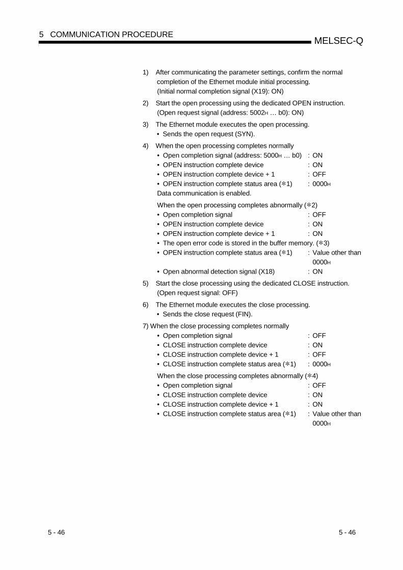
5 - 46 5 - 46
MELSEC-Q5 COMMUNICATION PROCEDURE
1) After communicating the parameter settings, confirm the normalcompletion of the Ethernet module initial processing.(Initial normal completion signal (X19): ON)
2) Start the open processing using the dedicated OPEN instruction.(Open request signal (address: 5002H … b0): ON)
3) The Ethernet module executes the open processing.• Sends the open request (SYN).
4) When the open processing completes normally• Open completion signal (address: 5000H … b0) : ON• OPEN instruction complete device : ON• OPEN instruction complete device + 1 : OFF• OPEN instruction complete status area ( 1) : 0000H
Data communication is enabled.
When the open processing completes abnormally ( 2)• Open completion signal : OFF• OPEN instruction complete device : ON• OPEN instruction complete device + 1 : ON• The open error code is stored in the buffer memory. ( 3)• OPEN instruction complete status area ( 1) : Value other than
0000H
• Open abnormal detection signal (X18) : ON
5) Start the close processing using the dedicated CLOSE instruction.(Open request signal: OFF)
6) The Ethernet module executes the close processing.• Sends the close request (FIN).
7) When the close processing completes normally• Open completion signal : OFF• CLOSE instruction complete device : ON• CLOSE instruction complete device + 1 : OFF• CLOSE instruction complete status area ( 1) : 0000H
When the close processing completes abnormally ( 4)• Open completion signal : OFF• CLOSE instruction complete device : ON• CLOSE instruction complete device + 1 : ON• CLOSE instruction complete status area ( 1) : Value other than
0000H
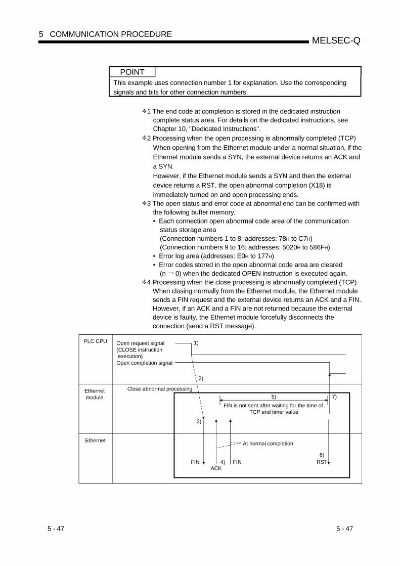
5 - 47 5 - 47
MELSEC-Q5 COMMUNICATION PROCEDURE
POINTThis example uses connection number 1 for explanation. Use the correspondingsignals and bits for other connection numbers.
1 The end code at completion is stored in the dedicated instructioncomplete status area. For details on the dedicated instructions, seeChapter 10, "Dedicated Instructions".
2 Processing when the open processing is abnormally completed (TCP)When opening from the Ethernet module under a normal situation, if theEthernet module sends a SYN, the external device returns an ACK anda SYN.However, if the Ethernet module sends a SYN and then the externaldevice returns a RST, the open abnormal completion (X18) isimmediately turned on and open processing ends.
3 The open status and error code at abnormal end can be confirmed withthe following buffer memory.• Each connection open abnormal code area of the communication
status storage area(Connection numbers 1 to 8; addresses: 78H to C7H)(Connection numbers 9 to 16; addresses: 5020H to 586FH)
• Error log area (addresses: E0H to 177H)• Error codes stored in the open abnormal code area are cleared
(n 0) when the dedicated OPEN instruction is executed again.4 Processing when the close processing is abnormally completed (TCP)
When closing normally from the Ethernet module, the Ethernet modulesends a FIN request and the external device returns an ACK and a FIN.However, if an ACK and a FIN are not returned because the externaldevice is faulty, the Ethernet module forcefully disconnects theconnection (send a RST message).
FINACK
1)
2)
3)
4)
5)
6)
7)
FIN RST
Ethernet
PLC CPU
Ethernet module
Close abnormal processing
FIN is not sent after waiting for the time of TCP end timer value
At normal completion
Open request signal(CLOSE instruction execution)Open completion signal

5 - 48 5 - 48
MELSEC-Q5 COMMUNICATION PROCEDURE
1) The open request signal is turned off by the dedicated CLOSEinstruction.
2) The Ethernet module executes the close processing.
3) The Ethernet module sends a FIN request to the external device.
4) The external device sends back FIN and ACK messages in reply to theFIN request sent by the Ethernet module.(When the reply is not returned, the Ethernet module sends the FINrequest again.)
5) The Ethernet module waits for the external device to send an ACK anda FIN.(The module waits for the amount of time set in the TCP end timervalue. For details on how to set it, see Section 5.2, "Initial Settings".)If the ACK and FIN messages are received at this point, it returns anACK as in the normal processing.
6) If an ACK and a FIN are not received within the time designated in theTCP end timer value, an RST message is sent to the external device.
7) The Ethernet module determines that the close procedure is completedand turns off the open completion signal regardless of the status of theexternal device.
REMARK
(1) When the procedure above is performed, the Ethernet module determines thatthe closing of the external device is executed normally, thus the closeprocessing result is not stored in the error log area.
(2) The procedure described above is a special function of the Ethernet module; itis not available for general TCP/IP protocols.
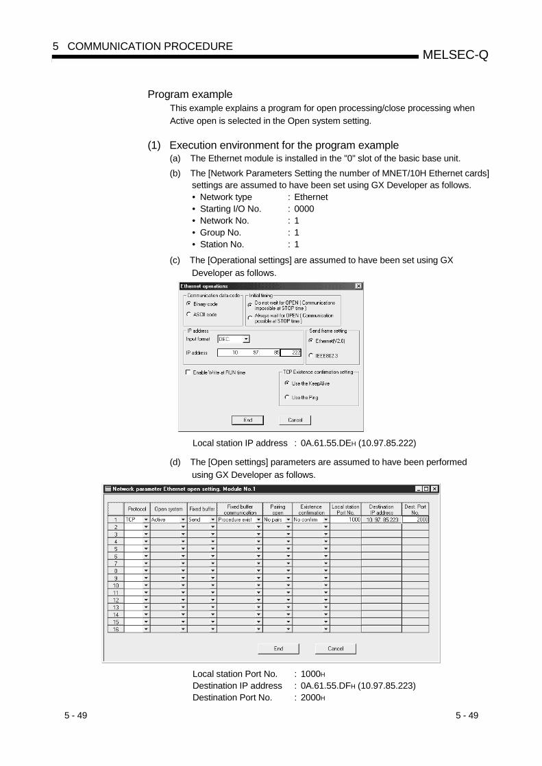
5 - 49 5 - 49
MELSEC-Q5 COMMUNICATION PROCEDURE
Program exampleThis example explains a program for open processing/close processing whenActive open is selected in the Open system setting.
(1) Execution environment for the program example(a) The Ethernet module is installed in the "0" slot of the basic base unit.(b) The [Network Parameters Setting the number of MNET/10H Ethernet cards]
settings are assumed to have been set using GX Developer as follows.• Network type : Ethernet• Starting I/O No. : 0000• Network No. : 1• Group No. : 1• Station No. : 1
(c) The [Operational settings] are assumed to have been set using GXDeveloper as follows.
Local station IP address : 0A.61.55.DEH (10.97.85.222)
(d) The [Open settings] parameters are assumed to have been performedusing GX Developer as follows.
Local station Port No. : 1000H
Destination IP address : 0A.61.55.DFH (10.97.85.223)Destination Port No. : 2000H
5 - 50 5 - 50
MELSEC-Q5 COMMUNICATION PROCEDURE
(e) The following contact signals are used in the program.Connection No. 1 open completion signal : M0Connection No. 1 open request signal : M20Connection No. 1 OPEN instruction control data : Stored in D100 to
D109Connection No. 1 CLOSE instruction control data : Stored in D200
and D201
(f) The area enclosed with in the program example should be used whenthe [Open settings] Ethernet module parameters are not set for GXDeveloper.This part of the program is not required when the [Open settings]parameters are used for GX Developer.
(g) For details on the dedicated OPEN instruction, see Chapter 10, "DedicatedInstructions".
(2) Outline of the program example
(a) After each parameter is set from GX Developer and write to PLC CPU,restart the PLC CPU and confirm the completion of the initial processing.
(b) The Ethernet module performs the open processing for connection No. 1 tothe external device set in the [Open settings] or control data.
(c) The close processing for connection No. 1 is performed according to theclose instruction to the Ethernet module or the close request from theexternal device.
REMARK
The "U0\G20480" and "U0\G20482" codes shown in the program designate thefollowing areas in the buffer memory.U0\G20480: Open completion signal storage area (address: 5000H (20480))U0\G20482: Open request signal storage area (address: 5002H (20482))
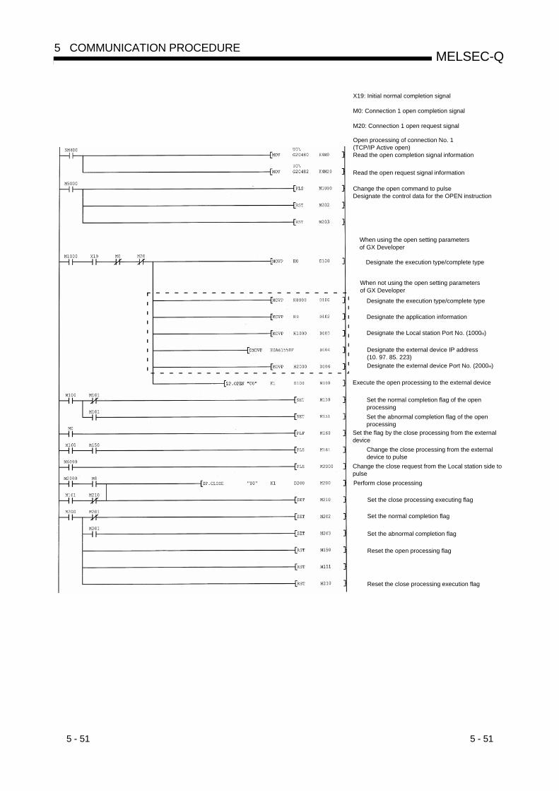
5 - 51 5 - 51
MELSEC-Q5 COMMUNICATION PROCEDURE
X19: Initial normal completion signal
M0: Connection 1 open completion signal
M20: Connection 1 open request signal
Open processing of connection No. 1(TCP/IP Active open)Read the open completion signal information
Read the open request signal information
Change the open command to pulseDesignate the control data for the OPEN instruction
Reset the close processing execution flag
When using the open setting parameters of GX Developer
Designate the execution type/complete type
When not using the open setting parameters of GX Developer
Designate the execution type/complete type
Designate the application information
Designate the Local station Port No. (1000H)
Designate the external device IP address (10. 97. 85. 223)Designate the external device Port No. (2000H)
Execute the open processing to the external device
Set the normal completion flag of the open processingSet the abnormal completion flag of the open processing
Set the flag by the close processing from the external device
Change the close processing from the external device to pulse
Change the close request from the Local station side to pulsePerform close processing
Set the close processing executing flag
Reset the open processing flag
Set the normal completion flag
Set the abnormal completion flag

5 - 52 5 - 52
MELSEC-Q5 COMMUNICATION PROCEDURE
5.6.2 Passive open processing/close processing
This section explains the procedure for opening and closing a connection with theEthernet module from an external device.The operations of Passive open processing/close processing differ depending onwhether "Always wait for OPEN" or "Do not wait for OPEN" is selected, as shown inthis section.
(1) When "Always wait for OPEN" is selected in the operational settingWhen [Operational setting] - [Initial timing setting] - [Always wait for OPEN(Communication possible at STOP time)] is selected from GX Developer, theopen processing/close processing is performed as explained below.In this case, sequence programs for open processing and close processing arenot required because the Ethernet module keeps the connection in the alwayswait for the OPEN status according to the [Open settings] parameter setting.For detail on the [Open settings] parameter, see Section 5.5, "Open Settings".
( 1)
2)FIN
3)SYN + ACK FIN + ACK
SYN
4)
Open request signal(Address: 5002H)
Power-on 1)Open status
Open allowed status (closed)(Active open acknowledge enabled)Close status
Initial normal completionx19
Open completion signal(Address: 5000H)
Parameter communication
completed
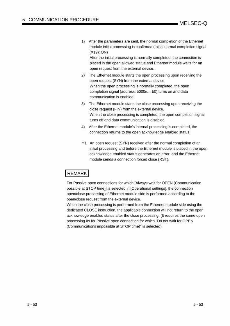
5 - 53 5 - 53
MELSEC-Q5 COMMUNICATION PROCEDURE
1) After the parameters are sent, the normal completion of the Ethernetmodule initial processing is confirmed (Initial normal completion signal(X19): ON)After the initial processing is normally completed, the connection isplaced in the open allowed status and Ethernet module waits for anopen request from the external device.
2) The Ethernet module starts the open processing upon receiving theopen request (SYN) from the external device.When the open processing is normally completed, the opencompletion signal (address: 5000H… b0) turns on and datacommunication is enabled.
3) The Ethernet module starts the close processing upon receiving theclose request (FIN) from the external device.When the close processing is completed, the open completion signalturns off and data communication is disabled.
4) After the Ethernet module’s internal processing is completed, theconnection returns to the open acknowledge enabled status.
1 An open request (SYN) received after the normal completion of aninitial processing and before the Ethernet module is placed in the openacknowledge enabled status generates an error, and the Ethernetmodule sends a connection forced close (RST).
REMARK
For Passive open connections for which [Always wait for OPEN (Communicationpossible at STOP time)] is selected in [Operational settings], the connectionopen/close processing of Ethernet module side is performed according to theopen/close request from the external device.When the close processing is performed from the Ethernet module side using thededicated CLOSE instruction, the applicable connection will not return to the openacknowledge enabled status after the close processing. (It requires the same openprocessing as for Passive open connection for which "Do not wait for OPEN(Communications impossible at STOP time)" is selected).
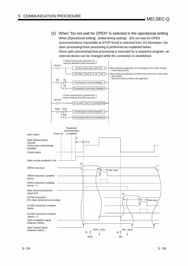
5 - 54 5 - 54
MELSEC-Q5 COMMUNICATION PROCEDURE
(2) When "Do not wait for OPEN" is selected in the operational settingWhen [Operational setting] - [Initial timing setting] – [Do not wait for OPEN(communications impossible at STOP time)] is selected from GX Developer, theopen processing/close processing is performed as explained below.Since open processing/close processing is executed by a sequence program, anexternal device can be changed while the connection is established.
M0 M1
M1
M100 M101
M101
ZP.OPEN "U0" K1 D0 M0
ZP.CLOSE "U0" K1 D100 M100
<<Open processing for connection No. 1 using the dedicated OPEN instruction>>
directionSet the control data to D0 to D9 When setting the application of GX Developer in the "Open settings"
• Control data [D0] H0
Processing for normal completion
Processing for abnormal completion
Processing for abnormal completion
When setting the application of OPEN instruction in the "Control data"• [D0]: H8000• Set [D1] to [D9] according to the application.
<<Close processing for connection No. 1 using the dedicated CLOSE instruction>>
direction
Processing for normal completion
1)
2)
5)
3)
FIN
4)
SYN
SYN + ACK FIN + ACK
CLOSE instruction(For Open abnormal processing)
CLOSE instruction complete device
CLOSE instruction complete device + 1
Parameter communication
completedOpen status
Open allowed status(closed)(Active open acknowledge enabled)
Initial normal completion X19
Closed status
OPEN instruction
OPEN instruction complete device
OPEN instruction complete device + 1
Open abnormal detection signal X18
Open completion signal(Address: 5000H)
Open request signal(Address: 5002H)
Power-on
One scan
One scan
( 1)
5 - 55 5 - 55
MELSEC-Q5 COMMUNICATION PROCEDURE
1) After communicating the parameter settings, confirm the normalcompletion of the Ethernet module initial processing.(Initial normal completion signal (X19): ON)
2) Start the open processing using the dedicated OPEN instruction.(Open request signal (address: 5002H … b0): ON)
3) The Ethernet module starts the open processing upon receiving theopen request (SYN) from the external device.
At normal completion• Open completion signal (address: 5000H … b0) : ON• OPEN instruction complete device : ON• OPEN instruction complete device + 1 : OFF• OPEN instruction complete status area ( 2) : 0000H
Data communication is enabled.
At abnormal completion• Open completion signal : OFF• OPEN instruction complete device : ON• OPEN instruction complete device + 1 : ON• The open error code is stored in the buffer memory• OPEN instruction complete status area ( 2) : Value other
than 0000H
• Open abnormal detection signal (X18) : ON
4) The Ethernet module starts the close processing upon receiving theclose request (FIN) from the external device.When the close processing is completed, the open completion signalturns off and data communication is disabled.
5) Start the close processing using the dedicated CLOSE instruction.(Open request signal: OFF)
At normal completion of internal processing• Open completion signal : OFF• CLOSE instruction complete device : ON• CLOSE instruction complete device + 1 : OFF• CLOSE instruction complete status area ( 2) : 0000H
At abnormal completion of internal processing• Open completion signal : OFF• CLOSE instruction complete device : ON• CLOSE instruction complete device + 1 : ON• CLOSE instruction complete status area ( 2) : Value other
than 0000H
POINTThis example uses connection number 1 for explanation. Use the correspondingsignals and bits for other connection numbers.
5 - 56 5 - 56
MELSEC-Q5 COMMUNICATION PROCEDURE
1 An open request (SYN) received after the normal completion of aninitial processing and before the Ethernet module is placed in theopen acknowledge enabled status generates an error, and theEthernet module sends a connection forced close (RST).
2 The end code at completion is stored in the dedicated instructioncomplete status area. For details on the dedicated instructions,see Chapter 10, "Dedicated Instructions".
REMARK
(1) If the settings of the connection need modifying, the modifications should bedone before executing the dedicated OPEN instruction.
(2) Once open processing is executed, an open request cannot be canceledbefore the open processing completes.Perform close processing (CLOSE instruction) after the open processing hascompleted.

5 - 57 5 - 57
MELSEC-Q5 COMMUNICATION PROCEDURE
Program exampleThis example explains a program for open processing/close processing whenUnpassive open is selected in the open system setting.
(1) Execution environment for the program example
(a) The Ethernet module is installed in the "0" slot of the basic base unit.
(b) The [Network Parameters Setting the number of MNET/10H Ethernet cards]settings are assumed to have been set using GX Developer as follows.• Network type : Ethernet• Starting I/O No. : 0000• Network No. : 1• Group No. : 1• Station No. : 2
(c) The [Operational settings] parameters are assumed to have been set usingGX Developer as follows.
Local station IP address : 0A.61.55.DFH (10.97.85.223)
(d) The [Open settings] are assumed to have been set using GX Developer asfollows.
Local station Port No. : 2000H

5 - 58 5 - 58
MELSEC-Q5 COMMUNICATION PROCEDURE
(e) The following contact signals are used in the program.Connection No. 1 open completion signal : M0Connection No. 1 open request signal : M20Connection No. 1 OPEN instruction control data : Stored in D100 to
D109Connection No. 1 CLOSE instruction control data : Stored in D200
and D201
(f) The area enclosed with in the program example should be used whenthe [Open settings] Ethernet module parameter are not set for GXDeveloper.This part of the program is not required when the [Open settings]parameters are used for GX Developer.
(g) For details on the dedicated OPEN instruction, see Chapter 10, "DedicatedInstructions".
(2) Outline of the program example
(a) After each parameter is set from GX Developer and write to PLC CPU,restart the PLC CPU and confirm the completion of the initial processing.
(b) The open processing for connection No. 1 of the Ethernet module isperformed.After the completion of the open processing, connection No. 1 waits for theopen request from the external device.
(c) The close processing for connection No. 1 is performed according to theclose instruction to the Ethernet module or the close request from theexternal device.
REMARK
The "U0\G20480" and "U0\G20482" codes shown in the program designate thefollowing areas in the buffer memory.U0\G20480: Open completion signal storage area (address: 5000H (20480))U0\G20482: Open request signal storage area (address: 5002H (20482))

5 - 59 5 - 59
MELSEC-Q5 COMMUNICATION PROCEDURE
X19: Initial normal completion signal
M0: Connection 1 open completion signal
M20: Connection 1 open request signal
Open processing of connection No. 1(TCP/IP Unpassive open)
Read the open completion signal information
Read the open request signal information
Change the open command to pulseDesignate the control data for the OPEN instruction
Reset the close processing execution flag
When using the open setting parameters of GX Developer
Designate the execution type/complete type
When not using the open setting parameters of GX Developer
Designate the execution type/complete type
Designate the information of the application
Designate the Local station Port No. (2000H)
Execute the open processing to the external device
Set the normal completion flag of the open processingSet the abnormal completion flag of the open processing
Set the flag when the close processing is performed from the external device
Change the close processing from the external device to pulse
Change the close request from the Local station side to pulsePerform close processing
Set the close processing executing flag
Reset the open processing flag
Set the normal completion flag
Set the abnormal completion flag

5 - 60 5 - 60
MELSEC-Q5 COMMUNICATION PROCEDURE
5.6.3 UDP/IP open processing/close processing
The following explains the UDP/IP open processing.
The operations of the open processing/close processing in UDP/IP differ depending onwhether "Always wait for OPEN" or "Do not wait for OPEN" is selected in the settingsusing GX Developer, [Operational settings] – [Initial settings], as shown below.
(1) When "Always wait for OPEN" is selected in the operationalsettings (Communications possible at STOP time)According to the [Open settings] with GX Developer, a connection for which theUDP/IP communication is selected is established automatically after the Ethernetmodule installed station has been restarted, and the data transmission/receptionis enabled.Sequence programs for open processing and close processing are not required.For details on the [Open settings] parameter, see Section 5.5, "Open Settings".
REMARK
Even when "Always wait for OPEN (Communication possible at STOP time)" isselected at "Operational settings", if there is a dedicated OPEN instruction from theEthernet mudule, open processing using the CLOSE instruction and closeprocessing, there is a need to perform all open processing and close processingafter the relevant connection using the sequence program.If "Do not wait for OPEN (Communication impossible at STOP time) is selected,there is a need to perform open processing and close processing in the samemanner as a connection.
(2) When "Do not wait for OPEN" is selected in the operational settings(Communications impossible at STOP time)In this case, the open processing and close processing in the sequence programshown in the next page are required. Data transmission and reception areenabled after the open processing is normally completed.Perform the open processing and close processing using the applicablededicated instructions.For more details, see Chapter 10, "Dedicated Instructions".
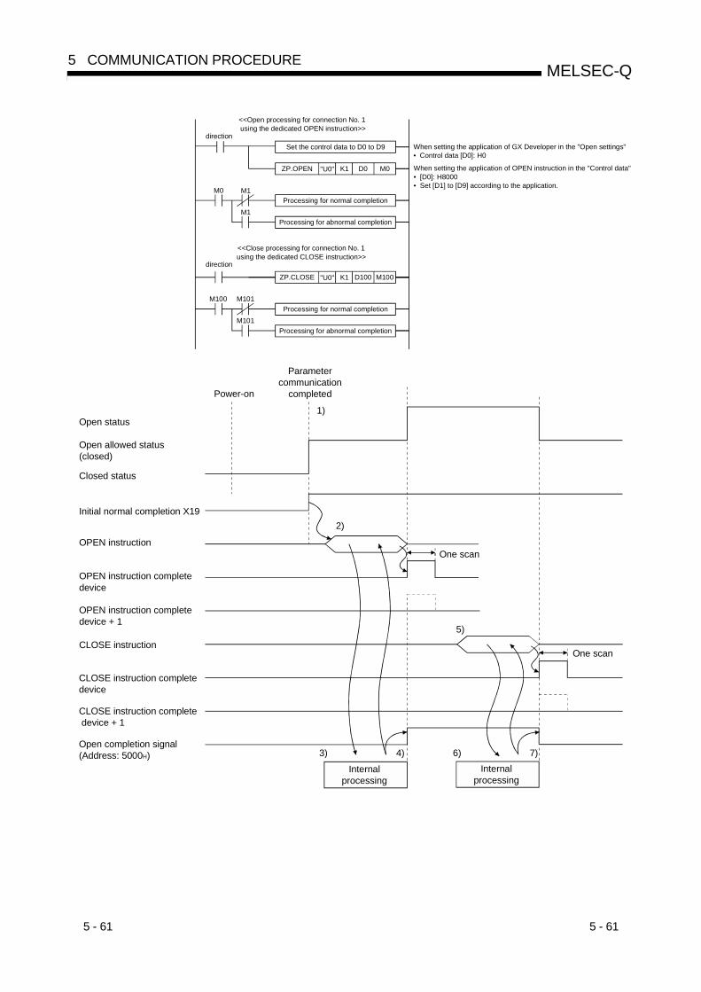
5 - 61 5 - 61
MELSEC-Q5 COMMUNICATION PROCEDURE
M0 M1
M1
M100 M101
M101
ZP.OPEN "U0" K1 D0 M0
ZP.CLOSE "U0" K1 D100 M100
<<Open processing for connection No. 1 using the dedicated OPEN instruction>>
directionSet the control data to D0 to D9 When setting the application of GX Developer in the "Open settings"
• Control data [D0]: H0
Processing for normal completion
Processing for abnormal completion
Processing for abnormal completion
When setting the application of OPEN instruction in the "Control data"• [D0]: H8000• Set [D1] to [D9] according to the application.
<<Close processing for connection No. 1 using the dedicated CLOSE instruction>>
direction
Processing for normal completion
CLOSE instruction
Open status
Open allowed status(closed)
Initial normal completion X19
Closed status
OPEN instruction
OPEN instruction complete device
OPEN instruction complete device + 1
Open completion signal(Address: 5000H)
Power-on
Parameter communication
completed
CLOSE instruction complete device + 1
CLOSE instruction complete device
One scan
One scan
Internal processing
Internal processing
1)
2)
5)
3) 4) 6) 7)
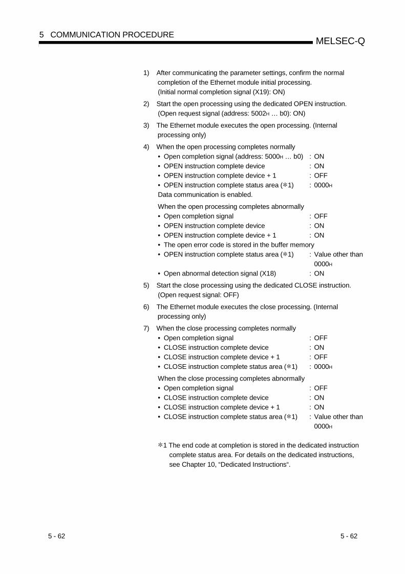
5 - 62 5 - 62
MELSEC-Q5 COMMUNICATION PROCEDURE
1) After communicating the parameter settings, confirm the normalcompletion of the Ethernet module initial processing.(Initial normal completion signal (X19): ON)
2) Start the open processing using the dedicated OPEN instruction.(Open request signal (address: 5002H … b0): ON)
3) The Ethernet module executes the open processing. (Internalprocessing only)
4) When the open processing completes normally• Open completion signal (address: 5000H … b0) : ON• OPEN instruction complete device : ON• OPEN instruction complete device + 1 : OFF• OPEN instruction complete status area ( 1) : 0000H
Data communication is enabled.
When the open processing completes abnormally• Open completion signal : OFF• OPEN instruction complete device : ON• OPEN instruction complete device + 1 : ON• The open error code is stored in the buffer memory• OPEN instruction complete status area ( 1) : Value other than
0000H
• Open abnormal detection signal (X18) : ON
5) Start the close processing using the dedicated CLOSE instruction.(Open request signal: OFF)
6) The Ethernet module executes the close processing. (Internalprocessing only)
7) When the close processing completes normally• Open completion signal : OFF• CLOSE instruction complete device : ON• CLOSE instruction complete device + 1 : OFF• CLOSE instruction complete status area ( 1) : 0000H
When the close processing completes abnormally• Open completion signal : OFF• CLOSE instruction complete device : ON• CLOSE instruction complete device + 1 : ON• CLOSE instruction complete status area ( 1) : Value other than
0000H
1 The end code at completion is stored in the dedicated instructioncomplete status area. For details on the dedicated instructions,see Chapter 10, “Dedicated Instructions“.
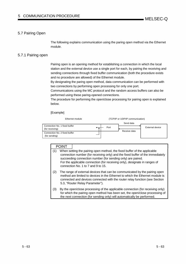
5 - 63 5 - 63
MELSEC-Q5 COMMUNICATION PROCEDURE
5.7 Pairing Open
The following explains communication using the paring open method via the Ethernetmodule.
5.7.1 Pairing open
Pairing open is an opening method for establishing a connection in which the localstation and the external device use a single port for each, by pairing the receiving andsending connections through fixed buffer communication (both the procedure existsand no procedure are allowed) of the Ethernet module.By designating the paring open method, data communication can be performed withtwo connections by performing open processing for only one port.Communications using the MC protocol and the random access buffers can also beperformed using these paring-opened connections.The procedure for performing the open/close processing for pairing open is explainedbelow.
[Example]
Connection No. 2 fixed buffer (for sending)
Ethernet module (TCP/IP or UDP/IP communication)
Connection No. 1 fixed buffer (for receiving) Port
Send data
External deviceReceive data
POINT(1) When setting the pairing open method, the fixed buffer of the applicable
connection number (for receiving only) and the fixed buffer of the immediatelysucceeding connection number (for sending only) are paired.For the applicable connection (for receiving only), designate in ranges ofconnection No. 1 to 7 and 9 to 15.
(2) The range of external devices that can be communicated by the pairing openmethod are limited to devices in the Ethernet to which the Ethernet module isconnected and devices connected with the router relay function (see Section5.3, "Router Relay Parameter").
(3) By the open/close processing of the applicable connection (for receiving only)for which the pairing open method has been set, the open/close processing ofthe next connection (for sending only) will automatically be performed.

5 - 64 5 - 64
MELSEC-Q5 COMMUNICATION PROCEDURE
5.7.2 Example of pairing open settings from GX Developer
This section explains the settings using GX Developer in order to communicate in thepairing open method by giving an example.The screen below shows an example of the settings under the following conditions.• Connection No. 1 and 2 are used.• The Ethernet module port number is 0500H.• The Unpassive open system is used.
(1) ProtocolBoth "TCP/IP" and "UDP/IP" are allowed.
(2) Open systemAll the open systems - "Active", "Unpassive", and "Fullpassive" - can be set.
(3) Fixed bufferIn the open pairing, the applicable connection No. and the subsequentconnection No. are paired. Set the applicable connection No. to "Receive" andthe next connection number to "Send".
(4) Fixed buffer communicationBoth "Procedure exist" and "No procedure" can be selected.
(5) Pairing openSet the receiving connection to "Pairs" and the sending connection to "No pairs".
(6) Existence confirmationIf existence confirmation is going to be executed, set the receiving connection to"Confirm" and the sending connection to "No confirm".If existence confirmation is not going to be executed, select "No confirm" for both.
5 - 65 5 - 65
MELSEC-Q5 COMMUNICATION PROCEDURE
(7) Local station Port No.Set this for the receiving connection for receiving only. (Setting is not required forthe sending connection.)Set the port number upon consulting a network administrator.
(8) Destination IP address
(a) If the Unpassive system is chosenSetting is not required.
(b) If either Active or Fullpassive system is chosenSetting is required.Set for the receiving connection only upon consulting a networkadministrator.
(9) Destination Port No.
(a) If the Unpassive system is chosenSetting is not required.
(b) If either Active or Fullpassive system is chosenSetting is required.Set for the receiving connection only upon consulting a networkadministrator.
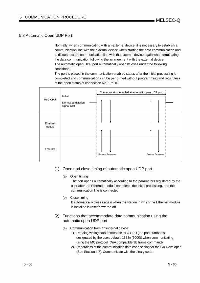
5 - 66 5 - 66
MELSEC-Q5 COMMUNICATION PROCEDURE
5.8 Automatic Open UDP Port
Normally, when communicating with an external device, it is necessary to establish acommunication line with the external device when starting the data communication andto disconnect the communication line with the external device again when terminatingthe data communication following the arrangement with the external device.The automatic open UDP port automatically opens/closes under the followingconditions.The port is placed in the communication enabled status after the initial processing iscompleted and communication can be performed without programming and regardlessof the open status of connection No. 1 to 16.
Initial
Normal completion signal X19
Communication enabled at automatic open UDP port
PLC CPU
Ethernetmodule
Ethernet
Request Response Request Response
(1) Open and close timing of automatic open UDP port
(a) Open timingThe port opens automatically according to the parameters registered by theuser after the Ethernet module completes the initial processing, and thecommunication line is connected.
(b) Close timingIt automatically closes again when the station in which the Ethernet moduleis installed is reset/powered off.
(2) Functions that accommodate data communication using theautomatic open UDP port
(a) Communication from an external device1) Reading/writing data from/to the PLC CPU (the port number is
designated by the user; default: 1388H (5000)) when communicatingusing the MC protocol (QnA compatible 3E frame command).
2) Regardless of the communication data code setting for the GX Developer(See Section 4.7). Communicate with the binary code.

5 - 67 5 - 67
MELSEC-Q5 COMMUNICATION PROCEDURE
(b) Communication from the station in which the Ethernet module is installedIn this case, it is possible to communicate using data link instructions (usingport numbers of the operating system of the Ethernet module).
POINT(1) The Ethernet module enables communication through the automatic open
UDP port numbers after the initial processing is normally completed, andwaits for communication requests to the local station Ethernet module.(Automatic open)
(2) It acknowledges and processes requests from anywhere as long as they arerequests addressed to the Ethernet module itself.
(3) When a communication request is acknowledged, the applicable port numberis occupied until the processing is completed. Even if the next communicationrequest is acknowledged during this time, the communication processing hasto wait.
(4) The automatic open UDP port can be used in communication betweenEthernet modules using the MELSECNET/H, MELSECNET/10 relaycommunication function.
(5) Re-initial processing is required to change the port number of the automaticopen UDP port. (Refer to Section 5.2.3 for re-initial processing.)
(3) Accessible rangeThe accessible range differs depending on the data communication function.
Data communication function Accessible rangeReference
sectionCommunication using the MCprotocol (QnA comparatible 3Eframe)
• The QCPU of the Ethernet module installed station• PLC CPU in the network system containing the Ethernet module
installed station
Data link instruction
• PLC CPU in the Ethernet to which the Ethernet module is connected• PLC CPU in the Ethernet connected via a router• PLC CPU in the network system containing the Ethernet module
installed station
Chapter 4 ofApplication
(4) Maximum size of data per communicationThe maximum size of data per communication differs depending on the datacommunication function.
Data communication function Maximum size of data per communicationReference
sectionCommunication using the MCprotocol (QnA comparatible 3Eframe)
The number of data that can be designated with the commands for theQnA compatible 3E frame
Chapter 6
Data link instructionThe number of data that can be designated with the commands for datalink
Chapter 4 ofApplication

5 - 68 5 - 68
MELSEC-Q5 COMMUNICATION PROCEDURE
5.9 Corresponding with the QCPU Remote Password Function
The remote password function is one of the QCPU functions for the purpose ofpreventing improper access to the QCPU from users at the remote location.The remote password function can be used by setting a remote password in theQCPU.This section explains Ethernet module data communication in relation to the QCPUremote password function.
The remote password function is a function that has been added to the QCPU as a means of preventingimproper access (such as destroying a program or data) from an external device. However, this functioncannot completely prevent improper access.The user should incorporate his/her own safeguards when it is need to keep the security of the PLC systemagainst improper access from an external device.The company cannot assume any responsibility for any problems that may arise from system troublescaused by improper access.
Examples of measures to prevent improper access• Establish a firewall.• Set up a personal computer as a relay station and control the relay of sending/receiving data using an
application program.• Set up an access controllable external device as a relay station.
Please consult with a network connection vendor or equipment sales vendor regarding accesscontrollable external devices.

5 - 69 5 - 69
MELSEC-Q5 COMMUNICATION PROCEDURE
5.9.1 Data communication when a remote password is set
This section explains the use and setting of the QCPU remote password function anddata communication between the external device and the QCPU when a remotepassword has been set.
(1) Overview of the remote password function(a) Remote password function
1) The remote password function enables/disables access from theexternal device to the QCPU via the following modules:• Ethernet module• Q series C24
2) When the remote password function is enabled for the Ethernetmodule, the remote password check is performed for access from theexternal device to the following connections:Users can select desired connections to which the remote passwordcheck is to be applied.• User connection No.1 to 16• Auto open UDP port• FTP transmission port (TCP/IP)• GX Developer transmission port (TCP/IP)• GX Developer transmission port (UDP/IP)• HTTP port
(b) Station that the remote password and remote password check are set1) In the case of single network system
GX Developerparameter setting• Remote password• Applicable connection for the remote password check (See (3).)
Ethernet
Accessing sourceexternal device
(Local station)Ethernetmodule
Remotepassword
Remotepassword
check
QCPU
2) In the case of multiple network systemSet in the QCPU station that serves as the entrance to the PLCsystem as viewed from the external device (the local station QCPU inthe diagram below).
Ethernetmodule
Ethernet
Accessing sourceexternal device
QCPU(Relaystation)
(Station to be accessed)
(Local station)
Network system 1
Ethernet Ethernet
QCPU
Remotepassword check
Remote password
Set in the local station to allow/prohibit access from the external device to the network system 1.
Do not set in the relay station or station to be accessed. ( )
Ethernetmodule
Ethernetmodule
Ethernetmodule
EthernetmoduleQCPU
Setting in a station other than the QCPU station that serves as the entrance to thePLC system (relay station and station to be accessed in the above diagram), accessto other stations beyond the set station is prohibited. (See (3).)
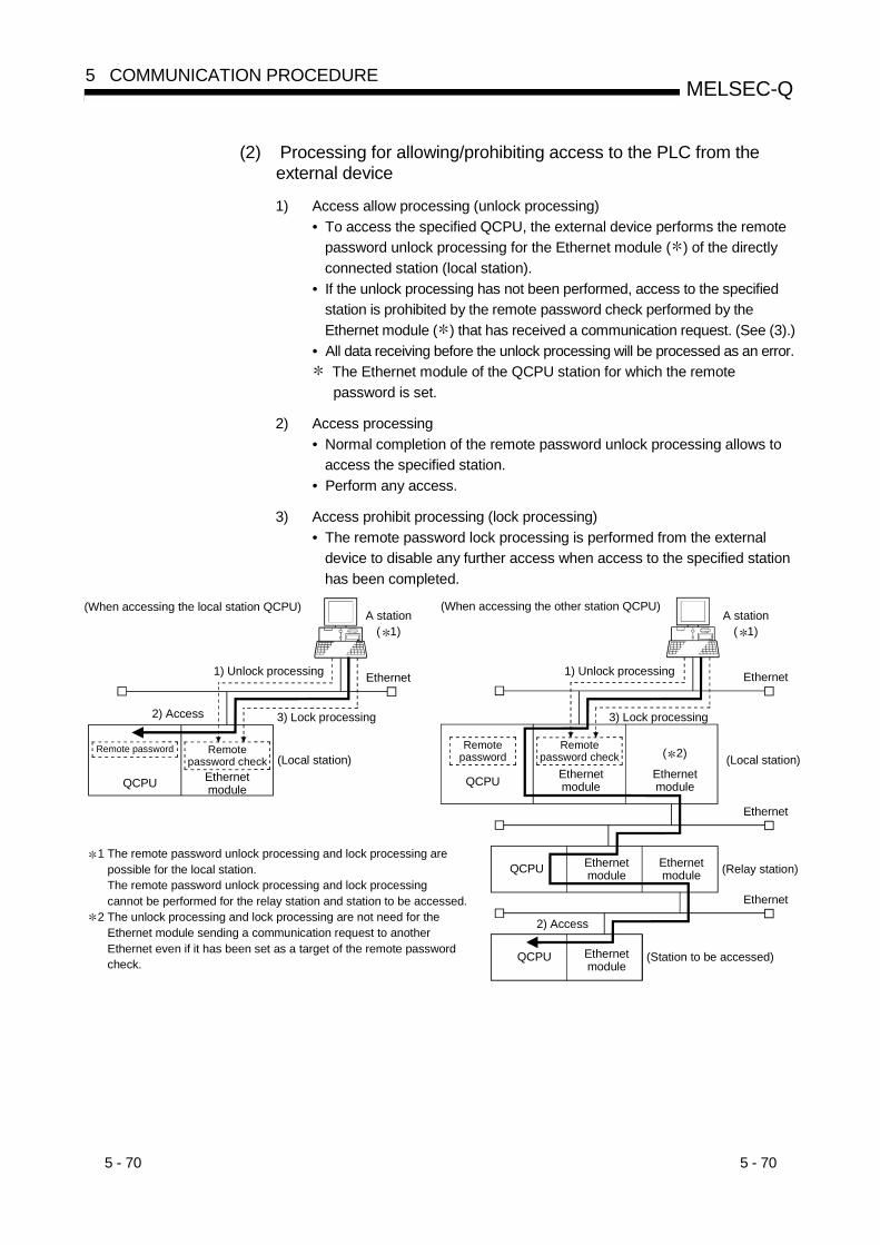
5 - 70 5 - 70
MELSEC-Q5 COMMUNICATION PROCEDURE
(2) Processing for allowing/prohibiting access to the PLC from theexternal device
1) Access allow processing (unlock processing)• To access the specified QCPU, the external device performs the remote
password unlock processing for the Ethernet module ( ) of the directlyconnected station (local station).
• If the unlock processing has not been performed, access to the specifiedstation is prohibited by the remote password check performed by theEthernet module ( ) that has received a communication request. (See (3).)
• All data receiving before the unlock processing will be processed as an error. The Ethernet module of the QCPU station for which the remote
password is set.
2) Access processing• Normal completion of the remote password unlock processing allows to
access the specified station.• Perform any access.
3) Access prohibit processing (lock processing)• The remote password lock processing is performed from the external
device to disable any further access when access to the specified stationhas been completed.
1 The remote password unlock processing and lock processing are possible for the local station. The remote password unlock processing and lock processing cannot be performed for the relay station and station to be accessed.2 The unlock processing and lock processing are not need for the Ethernet module sending a communication request to another Ethernet even if it has been set as a target of the remote password check.
Ethernet
QCPU
(When accessing the other station QCPU)
Ethernet
Remotepassword check
1) Unlock processing
3) Lock processing2) Access
QCPU Ethernetmodule
(When accessing the local station QCPU)A station
( 1)
QCPU
QCPU
Ethernet
Ethernet
(Local station)
(Relay station)
(Station to be accessed)
Remote password
1) Unlock processing
A station ( 1)
3) Lock processing
Remotepassword check
Ethernetmodule
Ethernetmodule
( 2) (Local station)
Ethernetmodule
Ethernetmodule
Ethernetmodule
2) Access
Remotepassword

5 - 71 5 - 71
MELSEC-Q5 COMMUNICATION PROCEDURE
POINT(1) The remote password unlock processing and lock processing are performed
for the only Ethernet module in the local station directly connected to theexternal device.The remote password unlock processing and lock processing cannot beperformed for an Ethernet module in any other station (relay station andstation to be accessed).
(2) The remote password unlock processing and lock processing are performed fromthe external device using dedicated instructions for MC protocol communication.(They are performed with dedicated FTP commands when using the filetransfer (FTP server) function. The remote password is input with the dialogbox when using the Web function or GX Developer.)
(3) Remote password check performed by the Ethernet module
(a) Communication in which a remote password check is performed
1) When the following parameters have been set for the Ethernet modulemounted on the QCPU station, the Ethernet module performs a remotepassword check for communication requests as indicated below:• When a remote password is set in the QCPU.• When the connection that is communicating data with the external
device is set as a target for the remote password check.
2) The Ethernet module performs a remote password check with respectto a communication request to the local station/other station receivedfrom the external device.
3) The Ethernet module performs transmission with respect to the followingtransmission requests without performing a remote password check:• Transmission request from the local station QCPU (such as
transmission using the fixed buffer).• Communication request from the external device (including GX
Developer connected to the local station QCPU) to send to anotherstation upon request from the QCPU.

5 - 72 5 - 72
MELSEC-Q5 COMMUNICATION PROCEDURE
QCPURemote password checkapplicable path
Ethernet module
Out of remote passwordcheck applicable path
Remotepasswordcheck 1)
QCPU
2)
3)
(Local station)
(Other station) 3)
Ethernet module
Remote password
GX Developer
( 1)
Remotepassword check
Remotepassword
GX Developer
1 In the above diagram, a communication request from the externaldevice cannot be received since a remote password check hasbeen set.If the remote password check has not been set, a communicationrequest can be received and data communication from theexternal device is possible.
(b) Selecting a connection for which the remote password check is performedThe user can select any connection for which the Ethernet moduleperforms a remote password check and set this using QCPU parameters.(This is set on the "Setting the remote password" screen of GX Developer.)
1) User connections (connections 1 to 16)
2) System connections (such as GX Developer communication port)
(c) Stations that can be accessed when the remote password check isperformedThe stations that can be accessed from the external device when a remotepassword is set in the QCPU and the QCPU stations for which the remotepassword unlock processing and lock processing can be performed areindicated.
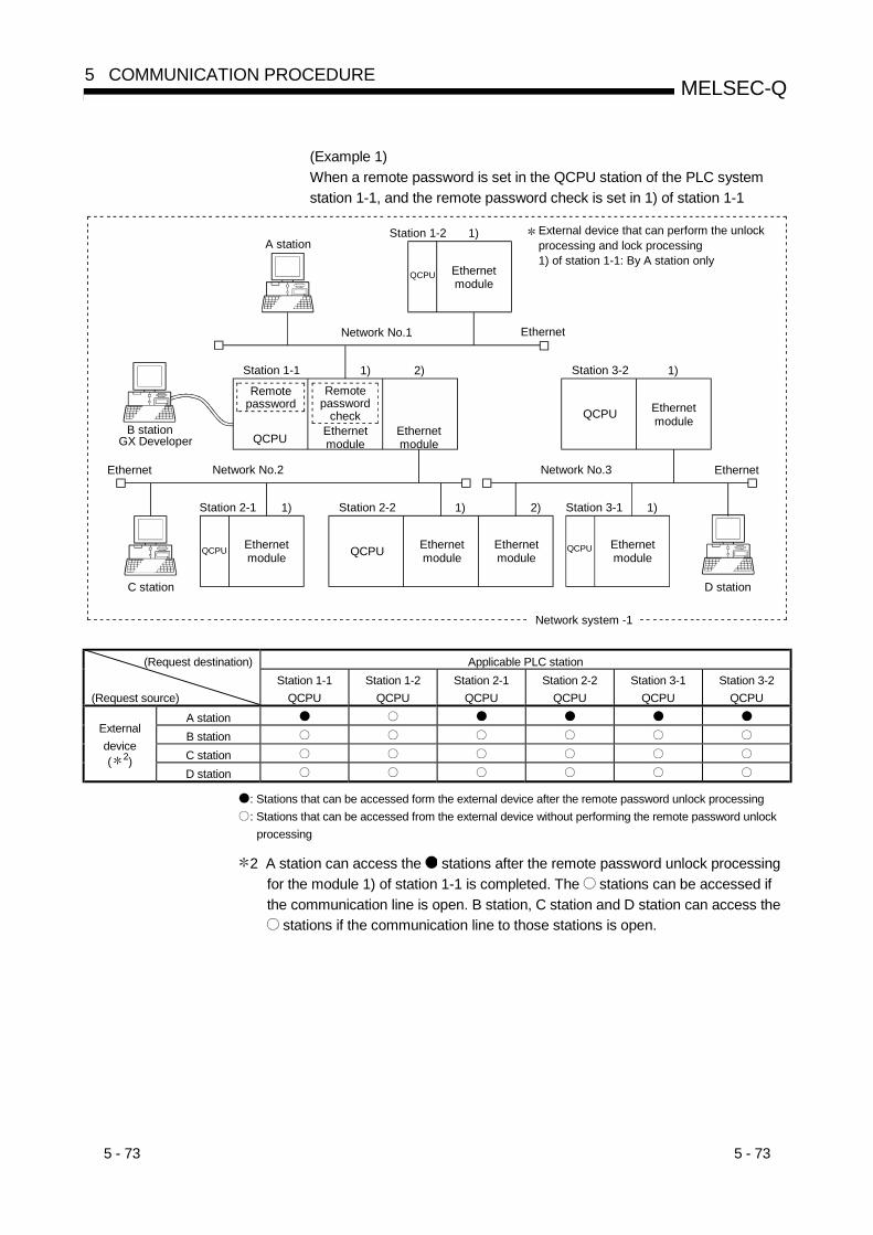
5 - 73 5 - 73
MELSEC-Q5 COMMUNICATION PROCEDURE
(Example 1)When a remote password is set in the QCPU station of the PLC systemstation 1-1, and the remote password check is set in 1) of station 1-1
Ethernet
Ethernet
GX Developer QCPU Ethernetmodule
B station
C station D station
A station
Remotepassword
QCPUQCPU
Ethernet
QCPU Ethernetmodule
QCPU
QCPU
1)
Network No.1
Network No.2 Network No.3
Network system -1
1)Station 1-1 2)
Station 2-1 Station 2-2 2) 1)Station 3-1
1)Station 3-2
External device that can perform the unlockprocessing and lock processing1) of station 1-1: By A station only
Station 1-2
1)1)
Ethernetmodule
Ethernetmodule
Ethernetmodule
Ethernetmodule
Ethernetmodule
Ethernetmodule
Remotepassword
check
(Request destination) Applicable PLC station
(Request source)Station 1-1
QCPUStation 1-2
QCPUStation 2-1
QCPUStation 2-2
QCPUStation 3-1
QCPUStation 3-2
QCPUA stationB stationC station
Externaldevice( 2)
D station
: Stations that can be accessed form the external device after the remote password unlock processing: Stations that can be accessed from the external device without performing the remote password unlock
processing
2 A station can access the stations after the remote password unlock processingfor the module 1) of station 1-1 is completed. The stations can be accessed ifthe communication line is open. B station, C station and D station can access the
stations if the communication line to those stations is open.
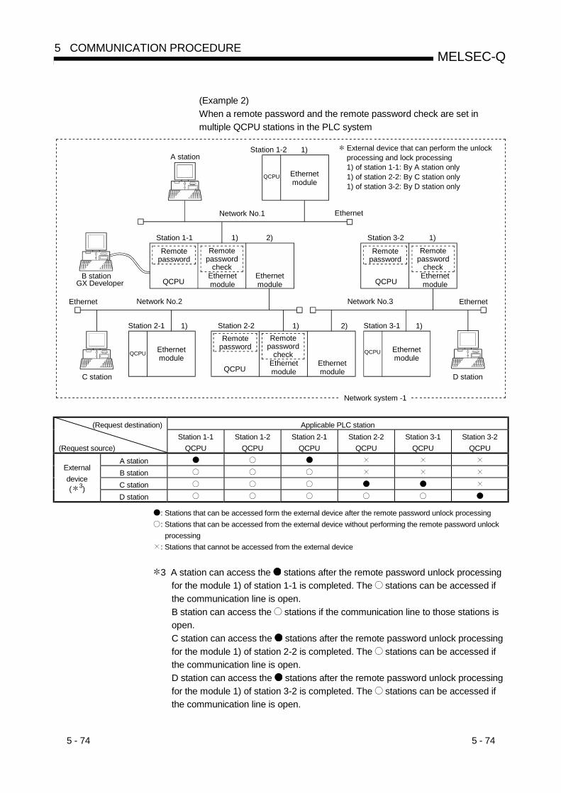
5 - 74 5 - 74
MELSEC-Q5 COMMUNICATION PROCEDURE
(Example 2)When a remote password and the remote password check are set inmultiple QCPU stations in the PLC system
Ethernet
Ethernet
GX Developer QCPUEthernetmodule
B station
C station D station
A station
Remotepassword
QCPU
Ethernet
QCPU
QCPU
1)
Network No.1
Network No.2 Network No.3
Network system -1
1)Station 1-1 2)
Station 2-1 Station 2-2 2) 1)Station 3-1
1)Station 3-2
External device that can perform the unlockprocessing and lock processing1) of station 1-1: By A station only1) of station 2-2: By C station only1) of station 3-2: By D station only
Station 1-2
1)1)
Ethernetmodule
Ethernetmodule
Ethernetmodule
Ethernetmodule
Remotepassword
check
Remotepassword
Remotepassword
check
QCPUEthernetmodule
QCPUEthernetmodule
Remotepassword
Ethernetmodule
Remotepassword
check
(Request destination) Applicable PLC station
(Request source)Station 1-1
QCPUStation 1-2
QCPUStation 2-1
QCPUStation 2-2
QCPUStation 3-1
QCPUStation 3-2
QCPUA stationB stationC station
Externaldevice( 3)
D station
: Stations that can be accessed form the external device after the remote password unlock processing: Stations that can be accessed from the external device without performing the remote password unlock
processing: Stations that cannot be accessed from the external device
3 A station can access the stations after the remote password unlock processingfor the module 1) of station 1-1 is completed. The stations can be accessed ifthe communication line is open.B station can access the stations if the communication line to those stations isopen.C station can access the stations after the remote password unlock processingfor the module 1) of station 2-2 is completed. The stations can be accessed ifthe communication line is open.D station can access the stations after the remote password unlock processingfor the module 1) of station 3-2 is completed. The stations can be accessed ifthe communication line is open.

5 - 75 5 - 75
MELSEC-Q5 COMMUNICATION PROCEDURE
POINTTo prohibit access to another station from the external device using the Ethernetmodule MELSECNET/H, MELSECNET/10 relay communication function, place acheck mark at the following setting items in the remote password setting for therelay station and station to be accessed.
"GX Developer communication port (UDP/IP) ( ), dedicated instructions,MELSECNET/H, MELSECNET/10 relay communication port"
Set this on the remote password setting screen of GX Developer. Other stations can be accessed if a check mark is not placed in the above
setting items.

5 - 76 5 - 76
MELSEC-Q5 COMMUNICATION PROCEDURE
5.9.2 Precautions when using the remote password check function
The following are precautions when using the remote password check function for theEthernet module.
(1) After a remote password is set in the QCPU, reboot the QCPU (PLC No.1 for amultiple CPU system) (reset using the RESET/L.CLR switch or power reset).By rebooting the QCPU, the remote password becomes valid.
(2) Set the remote password check to only the connection to be used in datacommunication with the external device that can perform the unlock processingand lock processing.(Example) The remote password check should not be set in the reception
connection for receiving data transmitted from the MELSEC PLC CPUwhen communicating by fixed buffer.
A check mark should not be placed at the applicable connection onthe "Remote password detail settings" screen shown in Section5.9.5.
(3) The remote password check should not be set, since the remote password checkis not performed for the connection performing communication using a non-procedure fixed buffer.
(4) When the external device accesses the PLC other station via the Ethernetmodule, it may not be able to access the PLC if a remote password has been setin the QCPU of the relay station or station to be accessed. (See Section 5.9.1 (1)and (3).)
(5) Precautions when performing UDP/IP communication1) Decide the external device that will be communicating.
Never perform data communication with a non-specified external device.2) Use the Ethernet module existence confirmation function.
Also, always perform the remote password lock processing whencompleting data communication.
If the lock processing is not performed, data communication from otherdevices is allowed until a time out is generated by the Ethernet moduleexistence confirmation function.For this reason, always specify the following as to the settings from GXDeveloper for the applicable connection:• When performing initial settings, set the start interval timer value and
the interval timer value for the existence confirmation function as smallas possible.
• Regarding the open settings, select "Confirm" for the "Existenceconfirmation" item.
The existence confirmation is automatically performed when theconnection for data communication using the automatic open UDP portis set as a target for the remote password check.
(6) As much as possible, use TCP/IP communication to perform communication fromGX Developer using an Ethernet connection.

5 - 77 5 - 77
MELSEC-Q5 COMMUNICATION PROCEDURE
5.9.3 Data communication procedure
This section explains the procedure when the external device performs datacommunication using the connection for which a remote password check is performed.
(1) Set the target connection for the remote password check in the "Remotepassword detail settings" through GX Developer and write the parameters in theQCPU. (See Section 5.9.5.)
(2) After booting the QCPU, write the setting values to the following buffer memory inthe Ethernet module as necessary: (See Section 5.9.6 (3).)Accumulated count designation area for remote password mismatch notification
· · · Address 20592 to 20593 (5070H to 5071H)
(3) The remote password unlock (release) processing is performed after the openprocessing for the connection is completed.All data received before the unlock processing will be processed as an error.(See the troubleshooting section for error codes.)
(4) When the unlock processing for the remote password is performed from theexternal device, the specified station can be accessed from the external device ifthe remote password specified by the user matches the remote password set inthe local station QCPU.
(5) After data communication is completed, close the applicable connection afterperforming the remote password lock processing from the external device.
(6) The remote password unlock processing and lock processing are performed fromthe external device connected to the Ethernet module using the dedicatedinstructions for MC protocol communication. (They are performed with dedicatedFTP commands when using the file transfer (FTP server) function. The remotepassword is input with the dialog box when using the Web function or GXDeveloper.)
REMARK
When the "GX Developer communication port" is set as the remote password checkconnection, access the PLC after performing the unlock processing on the GXDeveloper screen shown when access begins.
(7) The remote password unlock and lock processing can only be performed for thelocal station QCPU on which the Ethernet module is mounted. The remotepassword unlock and lock processing cannot be performed for other stationQCPU. (See Section 5.9.1 (2).)

5 - 78 5 - 78
MELSEC-Q5 COMMUNICATION PROCEDURE
(Data communication procedure)
See Section 5.2, "Initial Processing."See Section 5.3, "Router Relay Parameter."See Section 5.5, "Open Settings."
See Section 4.6, "Network Parameters Setting the Number of MNET/10H Ethernet Cards."
Set parameters for the Ethernetmodule through GX Developer
See Section 4.7, "Operational Settings."...
Start up the PLC CPU
Automatically processed...Initial processing
Designate the "Accumulated countfor remote password mism atch
notification "from the QCPU
See Section 5.9.5, "How to set the target connection for the remote passowrd check."
See Section 5.9.6, "Buffer memory forthe remote password check function."
...
Close processing
Remote password unlock processing
Remote password lock processing
Open processing See Section 5.6
( 1)(: 1)
See Section 5.6
(Communication No.1 to 16for user)
(Communication for system)
Remote passwordunlock processing
Remote passwordunlock processing
Remote passwordunlock processing
Communicationusing tne MCprotocol
Communicationusing fixedbuffer
Communicationusing randomaccess buffer
E-mailsending/receiving
MELSECNET/H,MELSECNET/10relaycommunication
Communicationusing datalinkinstructions
Remote passwordlock processing
Remote passwordlock processing
Remote passwordlock processing
File transferCommunicationusing Webfunction
CommunicationusingGX Developer(FTP)
1 When accessing the PLC of other station, access to the other station may not beallowed if a remote password is set in the QCPU of the relay station on which theEthernet module is mounted and the station to be accessed. (See Section 5.9.1(1) and (3).)
POINT(1) In TCP/IP communication, if the connection is closed without performing the
remote password lock processing, the Ethernet module automaticallyperforms the lock processing when the connection is closed.
(2) In UDP/IP communication, be sure to close the connection after performingthe remote password lock processing.When the connection is closed, the Ethernet module does not perform theremote password lock processing.
5 - 79 5 - 79
MELSEC-Q5 COMMUNICATION PROCEDURE
5.9.4 When the remote password unlock processing or lock processing is completedabnormally
This section explains the procedures to be performed by the user when the remotepassword unlock processing or lock processing is completed abnormally.
(1) Perform the unlock/lock processing again after checking the remote password setin the QCPU.
(2) The Ethernet module performs the following when the number of occurrencetimes for an unlock processing/lock processing abnormal completion is greaterthan the accumulated notification count ( 1) set in the buffer memory.
(a) The COM.ERR LED lights up.
(b) The code C200H is stored in the error code and end code storage area ofthe buffer memory error log area (address 227 to 372 (E3H to 174H)).
1 This is the count set from the QCPU in the remote password mismatchnotification accumulated count designation area (address 20592(5070H), 20593 (5071H)) when the Ethernet module starts up. (Count isset with T0 instruction, etc.)
(3) Monitor the above buffer memory when the COM.ERR LED of the Ethernetmodule lights up.If the error code C200H is stored, monitor the storage area for abnormalcompletion accumulated count in the buffer memory (address 20595 (5073H),20597 (5075H), · · · ) and check for which connection the unlock processing orlock processing has been completed abnormally.
(4) The user performs the following as required:
(a) Close the applicable connection.
(b) Write "0" in the storage area for abnormal completion accumulated count inthe buffer memory.
If the accumulated count is not cleared by writing "0", the process in (2)above is performed each time an abnormal completion in excess of theaccumulated notification count occurs.
(c) If the number of times an unlock processing/lock processing abnormalcompletion occurred for the applicable connection is greater than the aboveaccumulated notification count, this could indicate improper access from theexternal device.Disable the use of the applicable connection using the system port useprohibited designation area of the buffer memory (address 20488 (5008H)).(After this, the unlock processing cannot be performed with respect toapplicable connection until the "use allowed" is set.)
(d) Inform the system manager that the number of occurrence times for anunlock processing/lock processing abnormal completion is greater than theaccumulated notification count and take appropriate actions.
5 - 80 5 - 80
MELSEC-Q5 COMMUNICATION PROCEDURE
REMARK
(1) The following accumulated counts stored in the buffer memory can be clearedunder the user's option. (Write "0" to the applicable area from the QCPU.)
• Storage area for unlock processing normal completion accumulated count:Address 20594 (5072H) · · ·
• Storage area for lock processing normal completion accumulated count:Address 20596 (5074H) · · ·
(2) See Section 11.1.2 of User's Manual (Basic) for how to turn off the COM.ERRLED for the Ethernet module after it has lit up.

5 - 81 5 - 81
MELSEC-Q5 COMMUNICATION PROCEDURE
5.9.5 How to set the target connection for the remote password check
Set the connection for the remote password check with the parameter settings throughGX Developer.
[Startup procedure]"GX Developer" Remote password "Remote password settings" screen
Detail "Remote password detail settings" screen
[Setting screen]
[Setting items]Item name Description of item setting Setting range/options
Password settings Enter the password to be set in the QCPU ( 1). —
Model nameSelect the model name for the module performing the check for the remotepassword set in the QCPU.
QJ71E71
Start XY Set the head address of the module performing the remote password check. 0000H to 0FE0H
Passwordactive modulesettings
Module condition (Display the "Remote password detail settings" screen.) Detail settingsUser connection No.
Auto open UDP portFTP transmissionport (TCP/IP)GX Developertransmission port(TCP/IP)GX Developertransmission port(UCP/IP)
Systemconnection
HTTP port
Set the connection subject to the remote password check.Place a check mark at the target
connection.
1 Refer to the following when setting a remote password:• Avoid using a character string of simple numbers or letters only.• Combine numbers, letters and special characters (?,!&%,etc.).• Avoid using a character string that represents the user's name or date of birth.
5 - 82 5 - 82
MELSEC-Q5 COMMUNICATION PROCEDURE
POINT(1) When using the Ethernet module in a multiple CPU system, set the remote
password by writing it to the control PLC of the Ethernet module.
(2) After the remote password is set in the QCPU, reboot the QCPU (the firstQCPU module for a multiple CPU system) (reset using the RESET/L.CLRswitch or power reset).By rebooting the QCPU, the remote password becomes valid.
(3) The password supported by the QCPU of function version A is used to prohibitreading/writing of file data in the QCPU through GX Developer.Dual access control can be provided by using the remote password describedin this section and password for file access.

5 - 83 5 - 83
MELSEC-Q5 COMMUNICATION PROCEDURE
5.9.6 Buffer memory for the remote password check function
This section explains the buffer memory used for the remote password check function.
ApplicationAddress Buffer memory for the remote password check function
Setting Monitor
20486 (5006H) Remote password status (user port)20487 (5007H) Remote password status (system port)20488 (5008H) System port use prohibited designation20592 (5070H) Remote password mismatch notification accumulated count designation20593 (5071H) Remote password mismatch notification accumulated count designation20594 (5072H) Accumulated count unlock process normal completion20595 (5073H) Accumulated count unlock process abnormal completion20596 (5074H) Accumulated count lock process normal completion20597 (5075H) Accumulated count lock process abnormal completion20598 (5076H)
ConnectionNo. 1
Accumulated count of lock process based on close: : :
20669 (50BDH) Accumulated count unlock process normal completion20670 (50BEH) Accumulated count unlock process abnormal completion20671 (50BFH) Accumulated count lock process normal completion20672 (50C0H) Accumulated count lock process abnormal completion20673 (50C1H)
ConnectionNo. 16
Accumulated count of lock process based on close20674 (50C2H) Accumulated count unlock process normal completion20675 (50C3H) Accumulated count unlock process abnormal completion20676 (50C4H) Accumulated count lock process normal completion20677 (50C5H) Accumulated count lock process abnormal completion20678 (50C6H)
Connection forautomatic openUDP port
Accumulated count of lock process based on close20679 (50C7H) Accumulated count unlock process normal completion20680 (50C8H) Accumulated count unlock process abnormal completion20681 (50C9H) Accumulated count lock process normal completion20682 (50CAH) Accumulated count lock process abnormal completion20683 (50CBH)
Connection forGX Developercommunication(for UDP/IPcommunication) Accumulated count of lock process based on close
20684 (50CCH) Accumulated count unlock process normal completion20685 (50CDH) Accumulated count unlock process abnormal completion20686 (50CEH) Accumulated count lock process normal completion20687 (50CFH) Accumulated count lock process abnormal completion20688 (50D0H)
Connection forGX Developercommunication(for TCP/IPcommunication) Accumulated count of lock process based on close
20689 (50D1H) Accumulated count unlock process normal completion20690 (50D2H) Accumulated count unlock process abnormal completion20691 (50D3H) Accumulated count lock process normal completion20692 (50D4H) Accumulated count lock process abnormal completion20693 (50D5H)
Connection forFTPcommunication
Accumulated count of lock process based on close

5 - 84 5 - 84
MELSEC-Q5 COMMUNICATION PROCEDURE
(1) Remote password status storage area (address 20486 to 20487(5006H to 5007H))
(a) The current unlock/lock status of the remote password for each connectionis stored.The unlock/lock status for connection No. 1 to No. 16 that use the user portis stored in the address 20486.The unlock/lock status for connections that use the system port is stored inthe address 20487.
(b) The remote password status for each connection is indicated in bits asfollows:1 (ON): Lock status0 (OFF): Unlock status/no remote password check setting
1/0
b15 b14 b13 b12 b11 b10 b9 b8 b7 b6 b5 b4 b3 b2 b1 b0
Status of connection No. 2
Status of connection No. 1
Buffer memory address 20486 1/01/01/01/01/01/01/01/01/01/01/01/01/0 1/0 1/0
Status of connection No. 16
• • • • • • • • • • • • • • • • • • • • • • • • • • • • • • • • • • • • • • • • • • •
b15 b14 b13 b12 b11 b10 b9 b8 b7 b6 b5 b4 b3 b2 b1 b0
Status of the GX Developercommunication port (For UDP/IP communication)
Status of the automaticopen UDP port
Buffer memory address 20487 1/01/01/01/0(For the system)
Status of the FTP communication port
Status of the GX Developer communication port (For TCP/IP communication)
(2) System port use prohibited designation area (address 20488(5008H))
(a) The opposite device is allowed/prohibited from performing the following datacommunication using the port provided by the Ethernet module system:• Communication using the automatic open UDP port (communication
using the MC protocol)• Communication from GX Developer using the Ethernet connection
(b) This designation is determined by the user.1 (ON): Use prohibited0 (OFF): Use allowed (default)
b15 b14 b13 b12 b11 b10 b9 b8 b7 b6 b5 b4 b3 b2 b1 b0
GX Developer communication port (For UDP/IP communication)
Automatic open UDP port
1/01/01/0(For the system)
GX Developer communication port (For TCP/IP communication)
Buffer memory address 20488
(c) If the remote password check is performed and the remote password statusof the connection using the applicable port is in the lock status, the use ofthe applicable port can be prohibited.
5 - 85 5 - 85
MELSEC-Q5 COMMUNICATION PROCEDURE
(d) If improper access from the opposite device has been performed during theabove data communication, set the applicable port to "use prohibited." (SeeSection 5.9.4 for details.)
REMARK
To prohibit data communication from the opposite device using the Ethernet moduleFTP function, set "Not used" in the FTP function setting item under the "Setting theEthernet FTP parameters" through GX Developer. (See Section 5.3 of User'sManual (Application).)
(3) Remote password mismatch notification accumulated countdesignation area (Address 20592 to 20593 (5070H to 5071H))
(a) Use 0 to FFFFH to designate the count that will be the notification timing tothe user when the number of occurrence of remote password mismatchesbecome the permit or more during the unlock/lock processing from theuser/external device after the Ethernet module starts up. (This designationis common to all connections.)0H: No designation
(The process (c) when a remote password mismatch occurs is notperformed.)
1 to FFFFH: Notification accumulated count
(b) Designate the notification accumulated count for each of the followingconnections in this area:Address 20592 area: Connection No. 1 to No. 16Address 20593 area: Connection using the automatic open UDP port
Communication from GX Developer using theEthernet connectionCommunication from the external device that usesthe FTP function
(c) When the number of times a remote password mismatch occurred duringthe unlock/lock processing exceeds the notification accumulated count, theEthernet module performs the following a mismatch occurs. (See Section5.9.4 for details.)• The COM.ERR LED lights up.• The code C200H is stored in the error code and end code storage area of
the buffer memory error log area (address 227 to 372 (E3H to 174H)). The Ethernet module system does not close the connection.
(d) The accumulated number of times a remote password mismatch occurredup to the present (accumulated count value according to the Ethernetmodule) can be checked using the storage area for abnormal completionaccumulated count indicated in (4) below.
5 - 86 5 - 86
MELSEC-Q5 COMMUNICATION PROCEDURE
(4) Storage area for accumulated count unlock process normalcompletion of (address 20594 (5072H) · · · )Storage area for accumulated count unlock process abnormalcompletion of (address 20595 (5073H) · · ·)Storage area for accumulated count lock process normalcompletion of (address 20596 (5074H) · · ·)Storage area for accumulated count lock process abnormalcompletion of (address 20597 (5075H) · · ·)
(a) The accumulated number of times the remote password unlock/lockprocessing for the applicable connection has been completednormally/abnormally up to present is stored.
(b) The user should clear the value stored in each of the accumulated countstorage areas. (Write "0" to the applicable area from the QCPU.)
(5) Storage area for accumulated count of lock process based on close(Address 20598 (5076H) · · · )
(a) When the user closes the applicable connection without performing theremote password lock processing, the Ethernet module will automaticallyperform the lock processing.The accumulated number of times the Ethernet module performed the lockprocessing automatically is stored in this area.
(b) The user should clear the value stored in this accumulated count storagearea. (Write "0" to the applicable area from the QCPU.)
POINTThe maximum value that can be stored in the areas indicated in (4) and (5) aboveis FFFFH. An accumulated count that exceeds FFFFH (65535) is not stored.
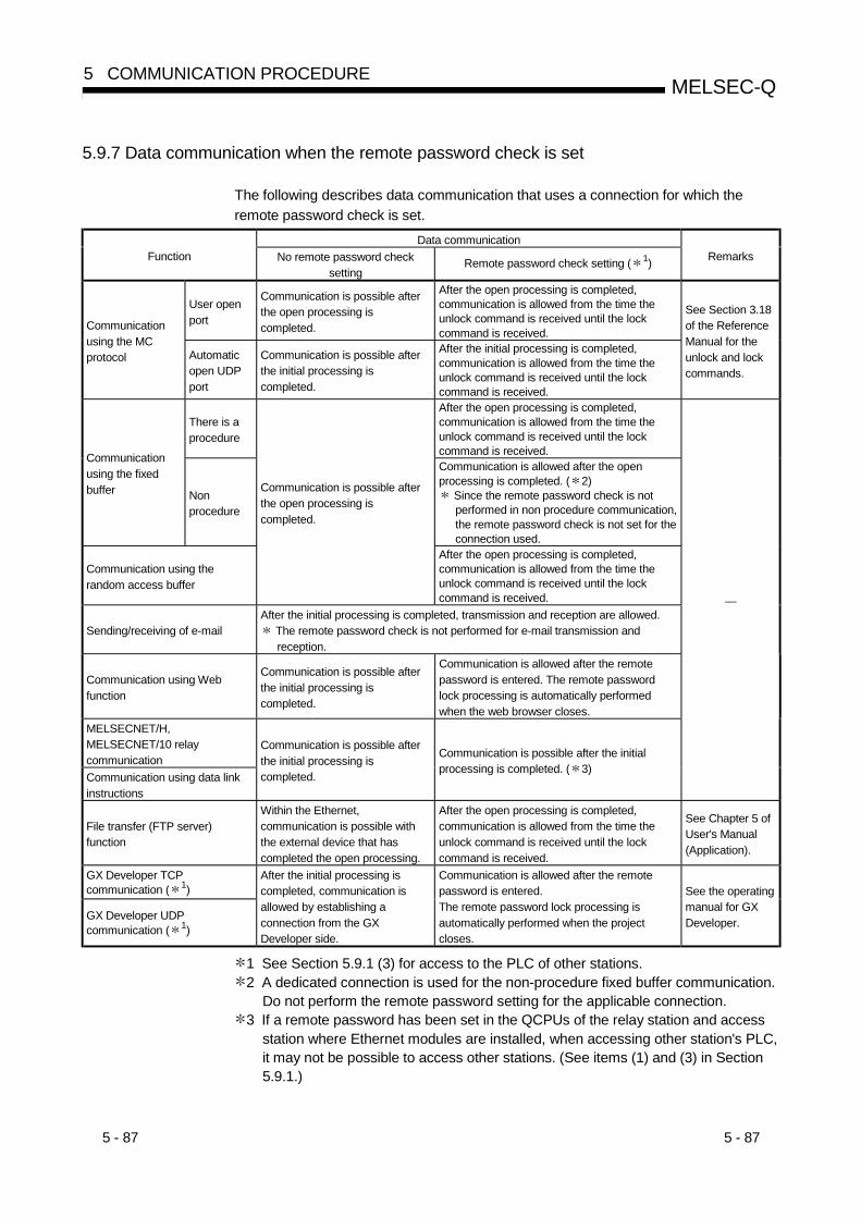
5 - 87 5 - 87
MELSEC-Q5 COMMUNICATION PROCEDURE
5.9.7 Data communication when the remote password check is set
The following describes data communication that uses a connection for which theremote password check is set.
Data communicationFunction No remote password check
settingRemote password check setting ( 1) Remarks
User openport
Communication is possible afterthe open processing iscompleted.
After the open processing is completed,communication is allowed from the time theunlock command is received until the lockcommand is received.Communication
using the MCprotocol Automatic
open UDPport
Communication is possible afterthe initial processing iscompleted.
After the initial processing is completed,communication is allowed from the time theunlock command is received until the lockcommand is received.
See Section 3.18of the ReferenceManual for theunlock and lockcommands.
There is aprocedure
After the open processing is completed,communication is allowed from the time theunlock command is received until the lockcommand is received.Communication
using the fixedbuffer Non
procedure
Communication is allowed after the openprocessing is completed. ( 2)
Since the remote password check is notperformed in non procedure communication,the remote password check is not set for theconnection used.
Communication using therandom access buffer
Communication is possible afterthe open processing iscompleted.
After the open processing is completed,communication is allowed from the time theunlock command is received until the lockcommand is received.
Sending/receiving of e-mailAfter the initial processing is completed, transmission and reception are allowed.
The remote password check is not performed for e-mail transmission andreception.
Communication using Webfunction
Communication is possible afterthe initial processing iscompleted.
Communication is allowed after the remotepassword is entered. The remote passwordlock processing is automatically performedwhen the web browser closes.
MELSECNET/H,MELSECNET/10 relaycommunicationCommunication using data linkinstructions
Communication is possible afterthe initial processing iscompleted.
Communication is possible after the initialprocessing is completed. ( 3)
—
File transfer (FTP server)function
Within the Ethernet,communication is possible withthe external device that hascompleted the open processing.
After the open processing is completed,communication is allowed from the time theunlock command is received until the lockcommand is received.
See Chapter 5 ofUser's Manual(Application).
GX Developer TCPcommunication ( 1)
GX Developer UDPcommunication ( 1)
After the initial processing iscompleted, communication isallowed by establishing aconnection from the GXDeveloper side.
Communication is allowed after the remotepassword is entered.The remote password lock processing isautomatically performed when the projectcloses.
See the operatingmanual for GXDeveloper.
1 See Section 5.9.1 (3) for access to the PLC of other stations.2 A dedicated connection is used for the non-procedure fixed buffer communication.
Do not perform the remote password setting for the applicable connection.3 If a remote password has been set in the QCPUs of the relay station and access
station where Ethernet modules are installed, when accessing other station's PLC,it may not be possible to access other stations. (See items (1) and (3) in Section5.9.1.)

5 - 88 5 - 88
MELSEC-Q5 COMMUNICATION PROCEDURE
5.10 Hub Connection Status Monitor Function
The current connection status of the Ethernet module and hub, the transmissionspeed, and the number of times the Ethernet module detected disconnection can bechecked at the following buffer memory addresses. (QJ71E71-100 only)
Ethernet module Hub External device
10BASE-T/100BASE-TX,Full duplex/half duplex
(1) Hub connection status area (Address: 201 (C9H))Stores the current connection status of the QJ71E71-100 and hub and thetransmission speed.
b15 b14Address: 201(C9H)
b13 b11 b10 b9 b8 b0
1) Communication mode 0: Half duplex 1: Full duplex2) Hub connection status 0: Hub not connected/disconnected 1: Hub connected3) Data transmission speed 0: Operating at 10BASE-T 1: Operating at 100BASE-TX
1)2)3)
(Bits other than above are reserved for system use.)
to to
(2) Disconnection detection count storage area (Address: 20995(5203H))(a) Stores the number of disconnection detection times after initial processing is
completed (X19 turns ON).Disconnection is detected in any of the following cases.• Disconnection between Ethernet module and hub• Cable removal from hub side connector• Hub power-off• Cable removal from Ethernet module side connector
(b) If an error has occurred 65536 times or more, a count stops at FFFFH
(65535).Write "0" to this area using a sequence program to clear the stored value.

5 - 89 5 - 89
MELSEC-Q5 COMMUNICATION PROCEDURE
5.11 Configuring a Network in Redundant System (Redundant System Support Function)
This section explains the functions and settings for use of the Ethernet module in theredundant system. Refer to Section 2.5 for the system configuration.
5.11.1 Issue of System Switching Request to Control System CPU
(1) "Issue of System Switching Request to Control System CPU"This function issues a system switching request to the control system CPU whenthe Ethernet module mounted on the main base unit of the control system CPU inthe redundant system detects a communication error or disconnection.
External device
Control system (System A) Standby system (System B)
Communication error occurrence
Tracking cableSystem switching request
(2) "System switching request issuing condition"When any of the following conditions set in the redundant setting of GXDeveloper is satisfied, the Ethernet module issues a system switching request tothe control system CPU. (Refer to Section 5.11.3 for the redundant setting.)
System switching request issuing condition Description
Existence checkAfter the connection is opened (after open processing),the existence of the external device cannot be checked.Communication error
detectionULP timeout
There is no ACK response from the external devicewithin the TCP ULP timer value.
Disconnection detectionThe cable connected to the Ethernet module wasdisconnected. (QJ71E71-100 only)
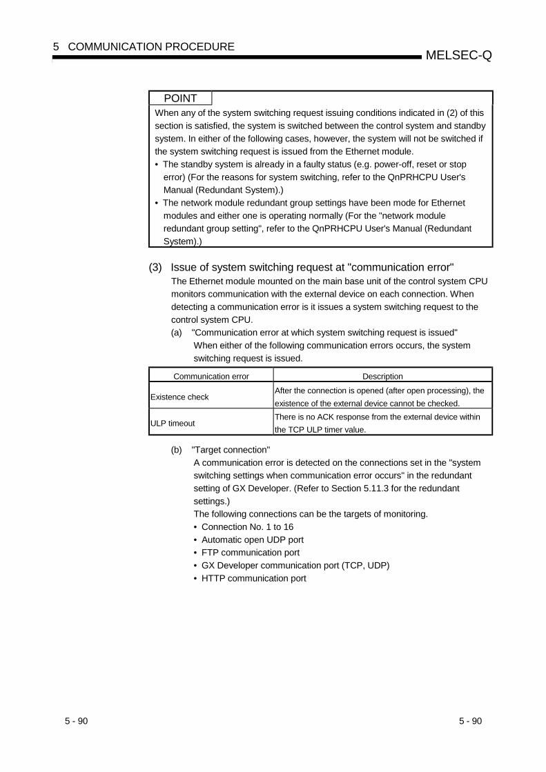
5 - 90 5 - 90
MELSEC-Q5 COMMUNICATION PROCEDURE
POINTWhen any of the system switching request issuing conditions indicated in (2) of thissection is satisfied, the system is switched between the control system and standbysystem. In either of the following cases, however, the system will not be switched ifthe system switching request is issued from the Ethernet module.• The standby system is already in a faulty status (e.g. power-off, reset or stop
error) (For the reasons for system switching, refer to the QnPRHCPU User'sManual (Redundant System).)
• The network module redundant group settings have been mode for Ethernetmodules and either one is operating normally (For the "network moduleredundant group setting", refer to the QnPRHCPU User's Manual (RedundantSystem).)
(3) Issue of system switching request at "communication error"The Ethernet module mounted on the main base unit of the control system CPUmonitors communication with the external device on each connection. Whendetecting a communication error is it issues a system switching request to thecontrol system CPU.(a) "Communication error at which system switching request is issued"
When either of the following communication errors occurs, the systemswitching request is issued.
Communication error Description
Existence checkAfter the connection is opened (after open processing), theexistence of the external device cannot be checked.
ULP timeoutThere is no ACK response from the external device withinthe TCP ULP timer value.
(b) "Target connection"A communication error is detected on the connections set in the "systemswitching settings when communication error occurs" in the redundantsetting of GX Developer. (Refer to Section 5.11.3 for the redundantsettings.)The following connections can be the targets of monitoring.• Connection No. 1 to 16• Automatic open UDP port• FTP communication port• GX Developer communication port (TCP, UDP)• HTTP communication port

5 - 91 5 - 91
MELSEC-Q5 COMMUNICATION PROCEDURE
(c) System switching request operation at "communication error"The Ethernet module checks communication with the external device for anerror using the existence check function or TCP ULP timer.The system switching request operation performed at a communicationerror is described below.
Normal communication
Control system (System A) Standby system (System B)
Tracking cable
External device 1) During normal communicationSystem A is operating as a control system,and system B as a standby system.The external device is communicating withthe Ethernet module mounted on the mainbase unit of the control system CPU. ( 1)
Control system (System A) Standby system (System B)
Tracking cable
Communication error occurrence
System switching request
External device 2) At error detection ( 2)When the Ethernet module mounted onthe main base unit of the control systemCPU detects the communication error thatoccurred between the external device andEthernet module, it issues a systemswitching request to the control systemCPU. ( 3)
Normal communication
Standby system (System A) Control system (System B)
Tracking cable
External device 3) After system switchingSystem A operates as a standby system,and the system B as a control system.The external device changes theconnection destination, andcommunicates with the Ethernet modulemounted on the main base unit of thecontrol system CPU (System B).

5 - 92 5 - 92
MELSEC-Q5 COMMUNICATION PROCEDURE
1 By connecting the external device and the Ethernet module mounted on the mainbase unit of the standby system CPU via TCP, a standby system CPU side errorcan be detected.
2 System switching timing at communication errorThe timing of issuing the system switching request to the control system CPU at acommunication error is shown below.
(a) System switching timing by "existence check"
Ethernet module
Issue of system switching request to control system CPU
Last communication
Target existence check starting interval timer value
Open completion signal(Address: 5000H)
Existence check message
Target existence check interval timer value
Existence check message
Target existence check interval timer value
Existence check message
Response message cannot be received from external device
1) The Ethernet module makes an existence check on the external devicewhose connection is open if communication is not made for apredetermined period of time. (Refer to Section 5.2.2 for the existencecheck function.)
2) If the Ethernet module cannot receive a response message from theexternal device, it closes the corresponding connection and issues asystem switching request to the control system CPU.(The above chart shows an existence check example of two resendtimes.)
(b) System switching timing by "ULP timeout"
Ethernet module
Issue of system switching request to control system CPU
Data command
TCP resend timer value
BUFSND instruction
First retry
ACK is not returned from external device
TCP resend timer value
TCP resend timer value
Second retry
TCP ULP timer value
BUFSND instruction completion device+1
1) If ACK is not returned from the external device within the TCP ULPtimer period at TCP opening or data transmission, a transmission erroroccurs and the Ethernet issues a system switching request to thecontrol system CPU. (Refer to Section 5.2.2 for the TCP ULP timer.)(The above chart shows a setting example of two retries.)
3 Set whether the system switching request will be issued or not to the controlsystem CPU in the redundant settings of GX Developer. (Refer to Section 5.11.3.)

5 - 93 5 - 93
MELSEC-Q5 COMMUNICATION PROCEDURE
(4) Issue of system switching request at "disconnection detection"The Ethernet module mounted on the main base unit of the control system CPUmonitors the connection status of the cable connected to the Ethernet module,and on detection of disconnection, it issues a system switching request to thecontrol system CPU.This function is available for the QJ71E71-100 only.(a) "Disconnection detection at which system switching request is issued"
Disconnection is detected in any of the following cases.• Disconnection between Ethernet module and hub• Cable removal from hub side connector• Hub power-off• Cable removal from Ethernet module side connector
(b) System switching request operation at "disconnection detection"The Ethernet module always checks the connected cable for disconnection.The system switching request operation performed at disconnectiondetection is described below.
Control system (System A) Standby system (System B)
Disconnection occurrence
Tracking cable
External device 1) Disconnection monitoringThe Ethernet module always checks theconnected cable for disconnection. ( 1)The monitoring result is stored into thehub connection status area (address: 201(C9H)) of the buffer memory. (Refer toSection 5.10.)
Control system (System A) Standby system (System B)
Tracking cableSystem switching request
External device 2) At disconnection detection ( 2)When the Ethernet module mounted onthe main base unit of the control systemCPU detects disconnection, it executes adisconnection status time check, andwhen a disconnection status continues forthe period of cable disconnection timeoutsetting, the Ethernet module issues asystem switching request to the controlsystem CPU. ( 3)
(To next page)
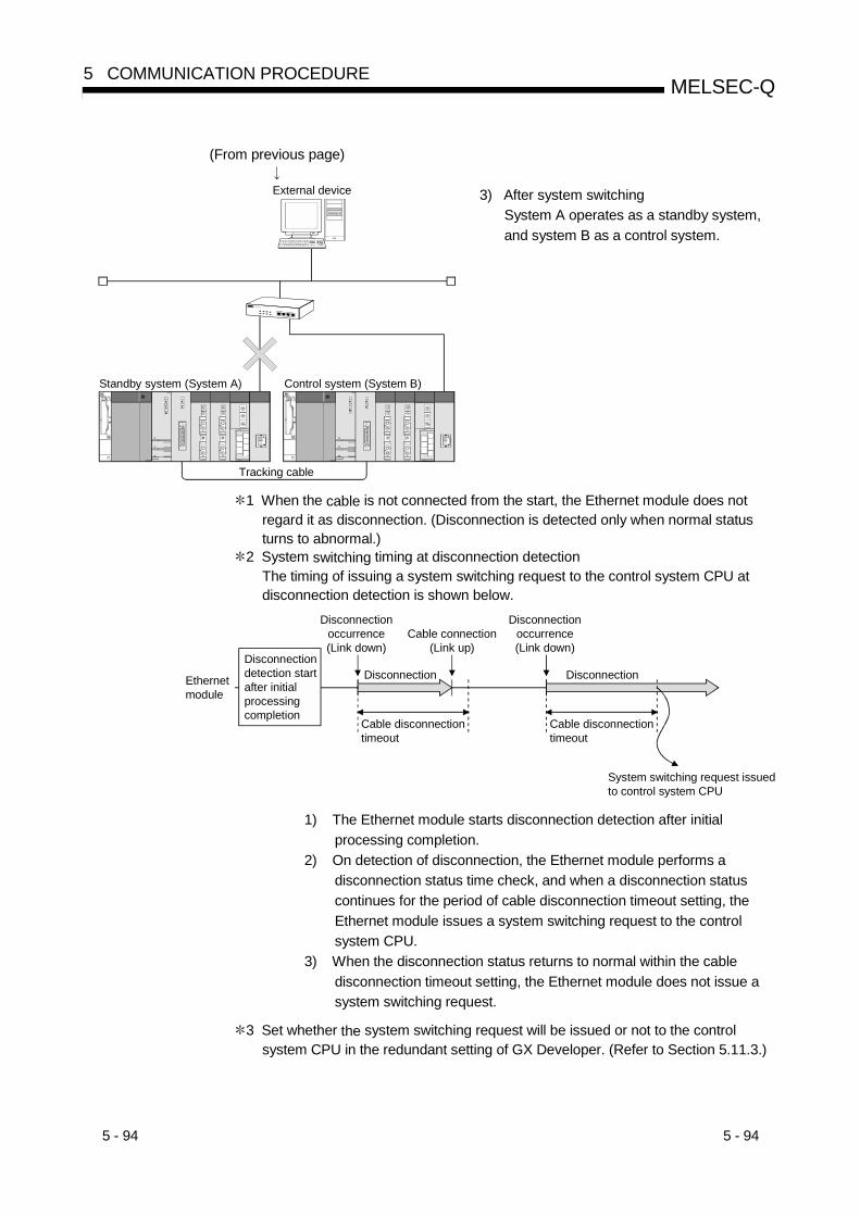
5 - 94 5 - 94
MELSEC-Q5 COMMUNICATION PROCEDURE
(From previous page)
Standby system (System A) Control system (System B)
Tracking cable
External device 3) After system switchingSystem A operates as a standby system,and system B as a control system.
1 When the cable is not connected from the start, the Ethernet module does notregard it as disconnection. (Disconnection is detected only when normal statusturns to abnormal.)
2 System switching timing at disconnection detectionThe timing of issuing a system switching request to the control system CPU atdisconnection detection is shown below.
Ethernet module
System switching request issued to control system CPU
Disconnection occurrence(Link down)
Disconnection detection start after initial processing completion
Cable connection(Link up)
Disconnection occurrence(Link down)
Cable disconnection timeout
Disconnection Disconnection
Cable disconnection timeout
1) The Ethernet module starts disconnection detection after initialprocessing completion.
2) On detection of disconnection, the Ethernet module performs adisconnection status time check, and when a disconnection statuscontinues for the period of cable disconnection timeout setting, theEthernet module issues a system switching request to the controlsystem CPU.
3) When the disconnection status returns to normal within the cabledisconnection timeout setting, the Ethernet module does not issue asystem switching request.
3 Set whether the system switching request will be issued or not to the controlsystem CPU in the redundant setting of GX Developer. (Refer to Section 5.11.3.)

5 - 95 5 - 95
MELSEC-Q5 COMMUNICATION PROCEDURE
5.11.2 Communication path bypass function
(1) Communication path bypass functionWhen any of the following redundant system-support applications is used, thepath where a communication error occurred can be automatically bypassed tocontinue communication if an error occurs in communication with the Ethernetmodule.The user need not change from one communication path to the other.• Application that operates on the OPS (except the MELSOFT products such as
GX Developer) 1• GX Developer• PX Developer monitor toolFor the compatible versions and available functions, refer to the manual of thecorresponding application.
1 The Ethernet module can communicate with the OPS using the userconnection for OPS connection.Set the user connection for OPS connection in the open settings of GXDeveloper. (Refer to Section 5.5.)

5 - 96 5 - 96
MELSEC-Q5 COMMUNICATION PROCEDURE
(2) Example of redundant system-support application operation atoccurrence of communication errorThe following provides an example of redundant system-support applicationoperation performed when an error occurs during communication with the controlsystem CPU.
Normal communication
Control system (Station No. 1) Standby system (Station No. 2)
Tracking cable
Redundant system-support application
External device 1) During normal communicationStation No. 1 is operating as a controlsystem, and station No. 2 as a standbysystem.The redundant system-support applicationis communicating with the control systemCPU.
Control system (Station No. 1) Standby system (Station No. 2)
(1) Path is bypassed to make access to control system CPU.(2) Communication with control system CPU is continued using tracking cable.
(1)
(2) Tracking cable
Redundant system-support application
Communication error occurrence
External device 2) At communication error occurrenceStation No. 1 is operating as a controlsystem, and station No. 2 as a standbysystem.(Without system switching) ( 1)
[Operation of redundant system-supportapplication]
Since a communication error occurredbetween the redundant system-supportapplication and the Ethernet modulemounted on the main base unit of thecontrol system CPU, the redundantsystem-support application changes thecommunication path automatically andcommunicates with the control systemCPU via the standby system CPU.
[Operation of standby system CPU]Since the received data is addressed tothe control system CPU, data is relayed tothe control system CPU via the trackingcable.
1 Set whether the system switching requestwill be issued or not to the control systemCPU in the redundant settings of GXDeveloper. (Refer to Section 5.11.3.)
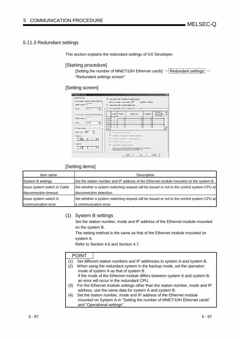
5 - 97 5 - 97
MELSEC-Q5 COMMUNICATION PROCEDURE
5.11.3 Redundant settings
This section explains the redundant settings of GX Developer.
[Starting procedure][Setting the number of MNET/10H Ethernet cards] Redundant settings "Redundant settings screen"
[Setting screen]
[Setting items]Item name Description
System B settings Set the station number and IP address of the Ethernet module mounted on the system B.Issue system switch in Cabledisconnection timeout
Set whether a system switching request will be issued or not to the control system CPU atdisconnection detection.
Issue system switch incommunication error
Set whether a system switching request will be issued or not to the control system CPU ata communication error.
(1) System B settingsSet the station number, mode and IP address of the Ethernet module mountedon the system B.The setting method is the same as that of the Ethernet module mounted onsystem A.Refer to Section 4.6 and Section 4.7.
POINT(1) Set different station numbers and IP addresses to system A and system B.(2) When using the redundant system in the backup mode, set the operation
mode of system A as that of system B.If the mode of the Ethernet module differs between system A and system B,an error will occur in the redundant CPU.
(3) For the Ethernet module settings other than the station number, mode and IPaddress, use the same data for system A and system B.
(4) Set the station number, mode and IP address of the Ethernet modulemounted on System A in "Setting the number of MNET/10H Ethernet cards"and "Operational settings".
5 - 98 5 - 98
MELSEC-Q5 COMMUNICATION PROCEDURE
(2) "Issue system switch in Cable disconnection timeout"When this setting is made valid, the Ethernet module issues a system switchingrequest to the control system CPU when a disconnection status continues for aperiod of disconnection monitoring time after detection of the disconnection.Refer to Section 5.11.1 for system switching at disconnection detection.
Item Description Setting range/choicesIssue system switch inCable disconnectiontimeout
Set whether a system switching request willbe issued or not at disconnection detection.
• Checked (System switching request is issued)• Not checked (System switching request is not
issued)(Default: Checked)
Cable disconnectiontimeout setting
Set the time from when disconnection isdetected until the system switching request isissued to the control system CPU.
0.0s to 30.0s(Default: 2.0s)
POINTSet the cable disconnection timeout setting to several seconds to several tenseconds.If it is shorter than the above, a system switching request may be generated due tonoise, etc.
(3) "Issue system switch in communication error"When this setting is made valid, the Ethernet module issues a system switchingrequest to the control system CPU when a communication error is detected onthe connection set in the "system switching settings when communication erroroccurs".Refer to Section 5.11.1 for system switching at communication error.
Item Description Setting range/choicesIssue system switch incommunication error
Set whether a system switching request willbe issued or not at communication error.
• Checked (System switching request is issued)• Not checked (System switching request is not
issued)(Default: Not checked)
System switchingsettings whencommunication erroroccurs 1 2 3
Set the target connection whosecommunication error will cause a systemswitching request to be issued.
Check the target connection.(Default: Not checked)
1 The settings of the automatic open UDP port and GX Developer communication UDPport are made valid when the following conditions are satisfied.1) The remote password setting is valid.2) The remote password is canceled.When the above conditions are not satisfied, a system switching request is not issuedif a communication error occurs on the target connection.
2 Do not set the following connection as the target connection. (Do not check its checkbox.)• Initial timing setting of operation setting : "Always waiting for OPEN (communication
enabled during STOP)"Protocol of open setting : "UDP"Existence check of open setting : "Check"
If the above connection is set as the target connection, system switching may occurconsecutively in the redundant system when a communication error occurs due tocable disconnection or external device power-off.
3 It is recommended not to set the connection, which has been set to "MELSOFTconnection" in the open system of the open setting, as the target connection. (Do notcheck the check box.)If the above connection is set as the target connection, all the MELSOFT productsconnected to the network will be targets, and therefore, the target external device(MELSOFT product) cannot be identified.
5 - 99 5 - 99
MELSEC-Q5 COMMUNICATION PROCEDURE
5.11.4 Buffer memory for redundant system support function
The redundant setting status of GX Developer can be checked in the following buffermemory areas.
(1) "Issue system switch in Cable disconnection timeout" (Address:20992 (5200H))Stores the setting status of "Issue system switch in Cable disconnection timeout".0: Not set1: Set
(2) Disconnection timeout setting (Address: 20993 (5201H))Stores the setting status of the "disconnection timeout setting".Set time = set value 500ms(Example) When the set time is 2s, the storage value is 4H.
(3) "System switching settings when communication error occurs"(Connection for user) (Address: 21008 (5210H))Stores the setting status of "System switching settings when communication erroroccurs" to the connection for user.0: Not set1: Set
b15 b14 b13 b11 b10 b9 b8 b0
Connection No. 1
Address: 21008(5210H)b7 b6 b5 b4 b3 b2 b1b12
Connection No. 2
Connection No. 16
(4) "System switching settings when communication error occurs"(Connection for system) (Address: 21009 (5211H))Stores the setting status of "System switching settings when communication erroroccurs" to the connection for system.0: Not set1: Set
b15 b0
Automatic open UDP port
Address: 21009(5211H)b5 b4 b3 b2 b1
GX Developer communication UDP port
FTP communication port
GX Developer communication TCP port
HTTP communication portMELSOFT connection included
(For system)
to
5 - 100 5 - 100
MELSEC-Q5 COMMUNICATION PROCEDURE
5.11.5 Data communication for using Ethernet module in redundant system
This section describes data communication made when the Ethernet module ismounted on the main base unit of a redundant system.For other than the following, data communication can be made in the same manner aswhen the Ethernet module is mounted on the main base unit of a single CPU system.Refer to the explanation item of the corresponding function.
(1) "Initial processing"(a) Execution of initial processing
Make settings for data communication using GX Developer, write the sameparameters to the control system CPU and standby system CPU, and thensimultaneously reset the both redundant CPUs.Note that different station numbers and IP addresses must be set to systemA and system B. (Refer to Section 5.11.3.)
(b) When performing re-initial processing (Refer to Section 5.2.3)Do not change the local station IP address and operation settings.If they are changed, normal communication cannot be made.1) When using the UINI instruction
Execute the instruction after specifying "0H" for the change target((S1+2) of the control data.
2) When directly writing to buffer memoryWrite "1" to bit 15 of the communication condition setting area(address: 1FH) without changing the set value of the buffer memoryarea.
(c) Initial processing by I/O signalSince the output signal (Y) turns off in the standby system CPU, initialprocessing by I/O signal is unavailable.Set the network parameters of GX Developer and perform initialprocessing. (Refer to Section 5.2.)
(2) "Open/close processing"(a) When making communication via TCP/IP
Place the Ethernet module in an open waiting status (Passive open), andperform open/close processing from the external device.When Active open processing is performed from the Ethernet module,close processing is performed from the Ethernet module, but if systemswitching occurs before execution of close processing, close processingcannot be executed.
5 - 101 5 - 101
MELSEC-Q5 COMMUNICATION PROCEDURE
(b) When using user connection to communicate with standby system (Forcommunication using MC protocol or random access buffer)1) Operation setting (Refer to Section 4.7)
Set the initial timing setting to "Always waiting for OPEN(communication enabled during STOP)".
2) Open setting (Refer to Section 5.5)When making TCP/IP communication, set the open system to"Unpassive or Fullpassive".
(c) Open/close processing by I/O signalSince the output signal (Y) turns off in the standby system CPU, open/closeprocessing by I/O signal is unavailable.Set the initial timing setting of the operation setting to "Always waiting forOPEN (communication enabled during STOP)", or use the dedicatedinstruction (OPEN/CLOSE instruction). (Refer to Section 5.6.)
POINTWhen using the user connection for communication, it is recommended to preparethe connections for communication with system A and for communication withsystem B.If a communication error occurs in the host system or the system switching occurs,the above enables immediate communication with the other system.On the Ethernet module, up to 16 user connections can be set.

5 - 102 5 - 102
MELSEC-Q5 COMMUNICATION PROCEDURE
(3) "Communication using MC protocol"The QnA-compatible 3E frame can be used to access the control system/standbysystem or system A/system B.For the message format and data specification method, refer to the ReferenceManual.(a) Operation performed for access to control system/standby system or
system A/system B1) When system switching occurred (Example of access to control system
CPU)
Access to control system
Control system (System A) Standby system (System B)
QnA-compatible 3E frame Request destination module I/O No. : 03D0H Network No. : 00H PLC No. : FFH
Tracking cable
External device 1) The external device connects to theEthernet module mounted on the mainbase unit of the control system CPU andmakes access to the control system CPU.
(System switching occurrence)
Access to control system is continued via tracking cable.
Standby system (System A) Control system (System B)
QnA-compatible 3E frame Request destination module I/O No. : 03D0H Network No. : 00H PLC No. : FFH
Tracking cable
External device 2) If system switching occurs, the externaldevice automatically continues access tothe control system via the tracking cable.However, when the communication linewith the connection destination is faulty orthe standby system is powered off, forexample, the connection destination mustbe changed on the external device side.
2) For access to the system that is not the connection destination(Example of connection to control system and access to standbysystem CPU)QnA-compatible 3E frame Request destination module I/O No. : 03D1H Network No. : 00H PLC No. : FFH
Access to standby system
Accessible if communication line is faulty
Control system (System A) Standby system (System B)
Tracking cable
External device 1) The external device connects to theEthernet module mounted on the mainbase unit of the control system CPU andmakes access to the standby system CPUvia the tracking cable.This enables access if the communicationline between the external device andstandby system is faulty.

5 - 103 5 - 103
MELSEC-Q5 COMMUNICATION PROCEDURE
(b) Communication procedure example for access to control system CPU inredundant systemThe following shows a communication procedure example for access to thecontrol system CPU in the redundant system.Place the Ethernet module in an open waiting status and performopen/close processing from the external device.
Communication procedure example
Perform open processing with System A.
Is SM1515 ON?(Operation system type)
Is response message normally terminated?
Perform open processing with System B.
Is SM1516 ON?(Operation system type)
ON:System A is control system
OFF: System A is standby system
OFF TRK. CABLE ERR. occurred. Refer to QnPRHCPU User's Manual (Redundant System) for details.
Is it repeated?
Close system A.
End
Close system A.
Is response message normally terminated?
Close system B.
Is SM1515 ON?(Operation system type)
Is SM1516 ON?(Operation system type)
OFF: System B is standby system
ON: System B is standby system
ON: System A is standby system
ON:System B is control system
OFF
YES
YES
NO NO
YES
YES
Close system B.NO NO
Is it repeated?
Send command message.Request destination module I/O number: 03D0H
Send command message.Request destination module I/O number: 03D0H

5 - 104 5 - 104
MELSEC-Q5 COMMUNICATION PROCEDURE
(c) Precautions for writing parameter file or program file1) Be sure to write the same file to system A and system B.
An error will occur if different files are written or a file is written to onlyone system.
2) Write a parameter file or program file when the operating status of theCPU is "STOP".
3) Perform file write in the following procedure.
Set the standby system CPU to STOP by remote operation.
Start
A continue error occurs in the standby system CPU.
Execute file write to the control system CPU.Execute file write to the standby system CPU.
Complete
( 1)
Clear the error of the standby system CPU. ( 2)
Set the control system CPU to STOP by remote operation.
Set the standby system CPU to RUN by remote operation.
Set the control system CPU to RUN by remote operation.
1 After writing a parameter file, simultaneously reset the both redundantCPUs.
2 When the operation status of the control system CPU is switched fromSTOP to RUN, check the error status of the standby system CPU, andif an error has occurred, set the error code (6010H) to SD50, and thenturn on SM50 to clear the error.
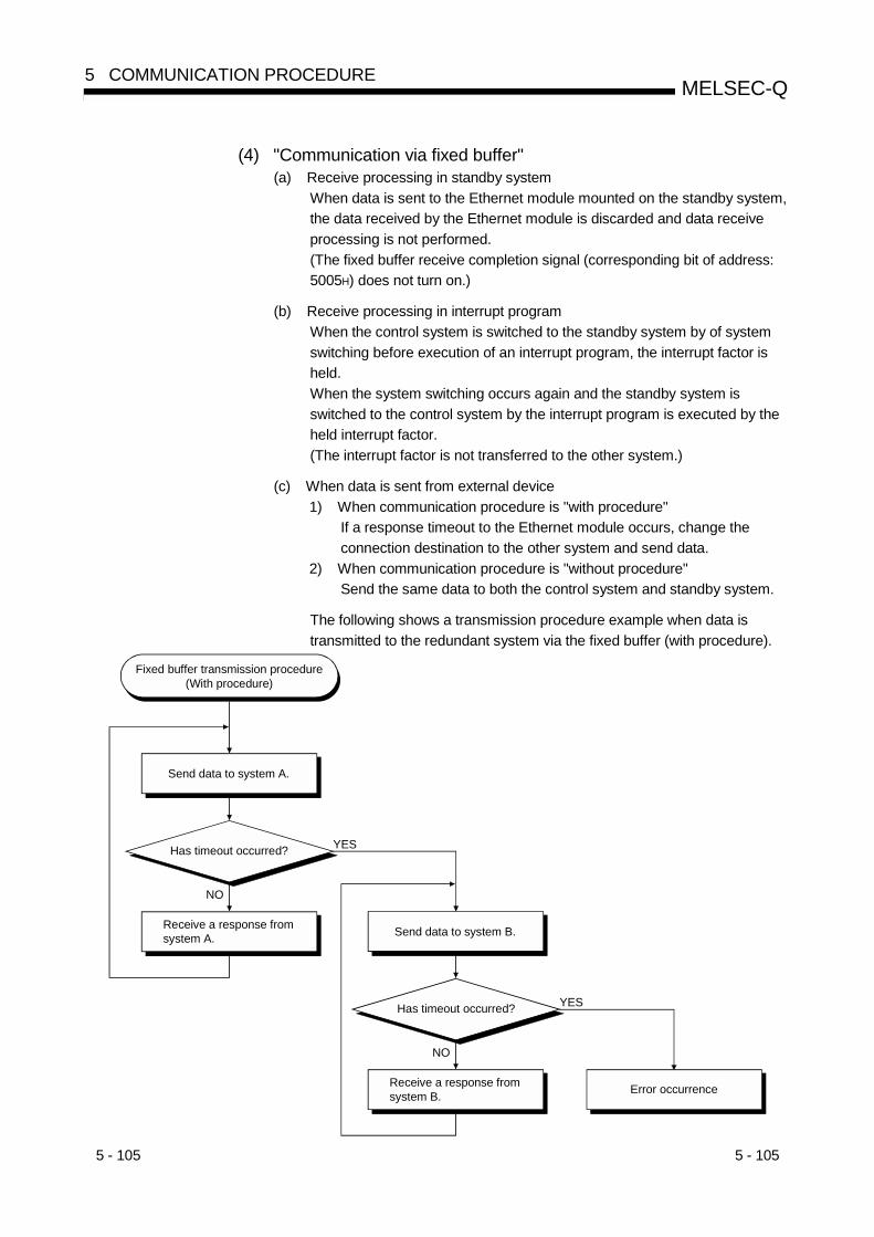
5 - 105 5 - 105
MELSEC-Q5 COMMUNICATION PROCEDURE
(4) "Communication via fixed buffer"(a) Receive processing in standby system
When data is sent to the Ethernet module mounted on the standby system,the data received by the Ethernet module is discarded and data receiveprocessing is not performed.(The fixed buffer receive completion signal (corresponding bit of address:5005H) does not turn on.)
(b) Receive processing in interrupt programWhen the control system is switched to the standby system by of systemswitching before execution of an interrupt program, the interrupt factor isheld.When the system switching occurs again and the standby system isswitched to the control system by the interrupt program is executed by theheld interrupt factor.(The interrupt factor is not transferred to the other system.)
(c) When data is sent from external device1) When communication procedure is "with procedure"
If a response timeout to the Ethernet module occurs, change theconnection destination to the other system and send data.
2) When communication procedure is "without procedure"Send the same data to both the control system and standby system.
The following shows a transmission procedure example when data istransmitted to the redundant system via the fixed buffer (with procedure).
NO
YESHas timeout occurred?
Fixed buffer transmission procedure(With procedure)
Send data to system A.
Receive a response from system A.
NO
YESHas timeout occurred?
Send data to system B.
Receive a response from system B. Error occurrence

5 - 106 5 - 106
MELSEC-Q5 COMMUNICATION PROCEDURE
POINTNote the following when executing re-transmission processing at system switching.(1) When making communication while synchronizing transmission and reception
During communication, system switching may occur with transmission andreception not synchronized.When system switching has occurred, resume communication after initializingsynchronization to ensure safety.
(2) When using the dedicated instructionSince whether the execution of the write instruction is completed or not isdifficult to judge, the same instruction must be executed again.In this case, note that the same instruction may be executed twice.
(5) "Communication via random access buffer"The buffer memory of the Ethernet module is not tracked. Therefore, whenwriting data to the random access buffer, write the same data to the controlsystem and standby system.
(6) "When using e-mail function"(a) Receive of e-mail
1) After receiving an e-mail by the Ethernet module, send a reply mail tothe mail transmission source so that the mail transmission sourceconfirms that it received the e-mail.If receipt cannot be confirmed, send the e-mail again.
2) After the MRECV instruction is executed, the read e-mail is deletedfrom the mail server. Therefore, when system switching occurs duringexecution of the MRECV instruction, the mail may not be received bythe new control system CPU after system switching if the MRECVinstruction is re-executed. (The e-mail has been deleted from the mailserver.)
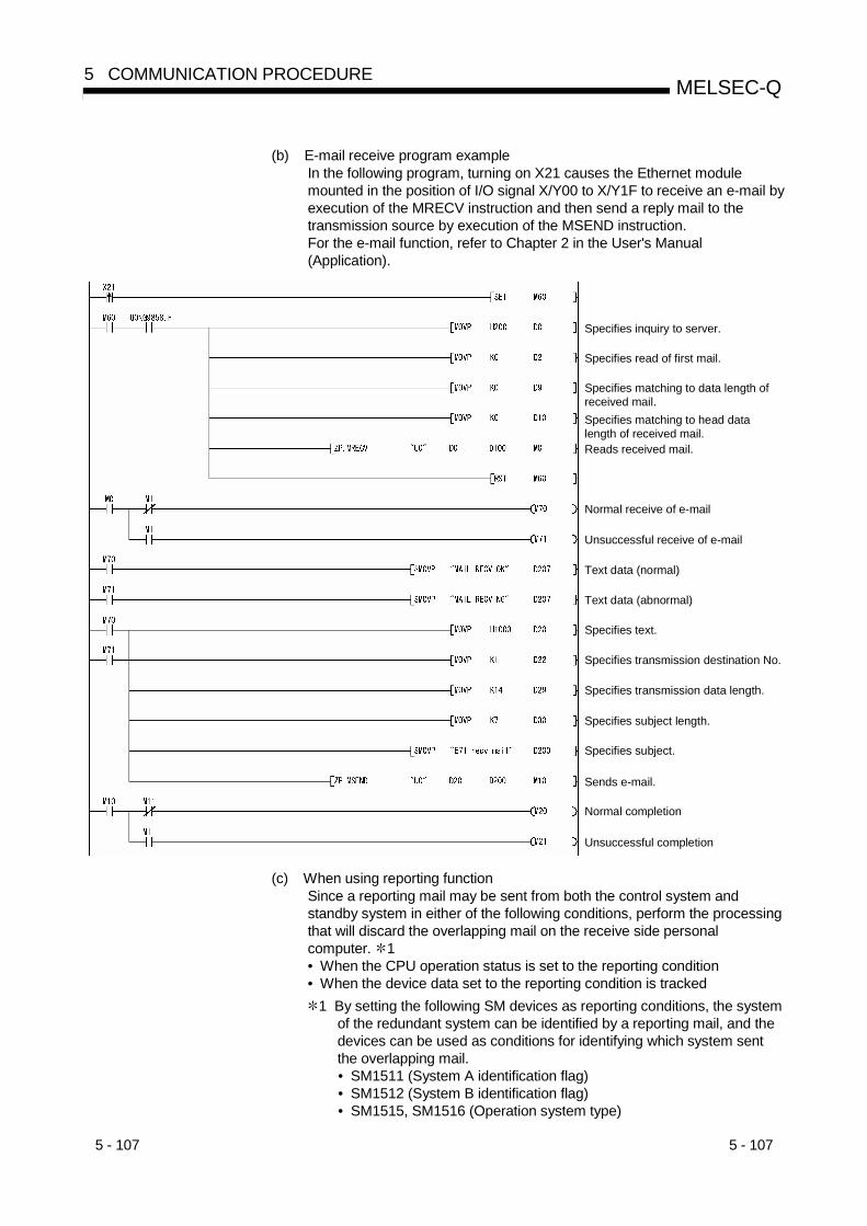
5 - 107 5 - 107
MELSEC-Q5 COMMUNICATION PROCEDURE
(b) E-mail receive program exampleIn the following program, turning on X21 causes the Ethernet modulemounted in the position of I/O signal X/Y00 to X/Y1F to receive an e-mail byexecution of the MRECV instruction and then send a reply mail to thetransmission source by execution of the MSEND instruction.For the e-mail function, refer to Chapter 2 in the User's Manual(Application).
Specifies inquiry to server.
Specifies read of first mail.
Specifies matching to data length of received mail.
Reads received mail.
Specifies matching to head data length of received mail.
Normal receive of e-mail
Unsuccessful receive of e-mail
Text data (normal)
Text data (abnormal)
Specifies text.
Specifies transmission destination No.
Specifies transmission data length.
Specifies subject length.
Specifies subject.
Normal completion
Unsuccessful completion
Sends e-mail.
(c) When using reporting functionSince a reporting mail may be sent from both the control system andstandby system in either of the following conditions, perform the processingthat will discard the overlapping mail on the receive side personalcomputer. 1• When the CPU operation status is set to the reporting condition• When the device data set to the reporting condition is tracked
1 By setting the following SM devices as reporting conditions, the systemof the redundant system can be identified by a reporting mail, and thedevices can be used as conditions for identifying which system sentthe overlapping mail.• SM1511 (System A identification flag)• SM1512 (System B identification flag)• SM1515, SM1516 (Operation system type)

5 - 108 5 - 108
MELSEC-Q5 COMMUNICATION PROCEDURE
(7) "When communication is made via MELSECNET/H orMELSECNET/10"(a) When redundant system is on network
When making access via redundant system, note that the routingparameter setting must be changed by the RTWRITE instruction at therequest source station or relay station at the time of system switching.(Refer to (b) below.)
(b) When access is made via redundant systemThe routing parameter setting must be set to the request source station orrelay station to access other station via Ethernet using the MELSECNET/H,MELSECNET/10 relay communication function. (Refer to Chapter 3 in theUser's Manual (Application).)When making access via the redundant system, set the station, whichbecomes a control system, as a routing station.
Ethernet moduleStation No. 1
QnPRHCPU
Ethernet moduleStation No. 1
Ethernet moduleStation No. 2
QnPRHCPU
Ethernet moduleStation No. 2
Ethernet moduleStation No. 3
QCPU
Ethernet moduleStation No. 3
QCPU
Network No. 2
Network No. 1
Network parameter settingTransfer destination network No.
Relay destination network No.
Relay destination station No.
1 2 1
Request source station
Request destination station
Control system Standby system
Change the routing parameter setting with the RTWRITE instruction at therelay source station or relay station so that access is made via the station ofthe new control system after system switching when system switchingoccurs. (For the RTWRITE instruction, refer to the QCPU (QMode)/QnACPU Programming Manual (Common Instructions).)
Ethernet moduleStation No. 1
QnPRHCPU
Ethernet moduleStation No. 1
Ethernet moduleStation No. 2
QnPRHCPU
Ethernet moduleStation No. 2
Ethernet moduleStation No. 3
QCPU
Ethernet moduleStation No. 3
QCPU
Network No. 2
Network No. 1
Network parameter settingTransfer destination network No.
Relay destination network No.
Relay destination station No.
1 2
Request source station
Request destination station
Standby system Control system
1 2
Change using RTWRITE instruction.

5 - 109 5 - 109
MELSEC-Q5 COMMUNICATION PROCEDURE
(8) "When QCPU accesses other station PLC using data linkinstruction"(a) Redundant system-compatible data link instructions
1) By specifying the target station CPU type of the control data in any ofthe following data link instructions, access can be made to the controlsystem/standby system or system A/system B. (Refer to Chapter 4 orChapter 6 of the User's Manual (Application) for the data linkinstructions.)• READ/SREAD instruction• WRITE/SWRITE instruction• REQ instruction
2) Operation performed for access to control system/standby system orsystem A/system B (Example of executing the READ instruction)Since the received command is addressed to the control system CPU(target station CPU type: 3D0H) when the target station is in thestandby system, data is relayed to the control system CPU via thetracking cable to read the data of the control system CPU.
Tracking cable
Control system Standby system (Target station)
QCPU
Device
E71
Channel 3READ
(Local station)
Device
(b) Processing at error completionIn case that the data link instruction is executed for the specified station(control system CPU/standby system CPU) in the redundant system andthat target station causes system switching the data link instruction mayresult in error completion. (Error code: 4244H, 4248H)If the data link instruction results in error completion due to the above error,execute the data link instruction again.
5 - 110 5 - 110
MELSEC-Q5 COMMUNICATION PROCEDURE
(c) SEND instruction1) Execution of SEND instruction
When the target station is in a redundant system, the communicationrequest source station must identify that the target station is the controlsystem to execute the SEND instruction.When the target station is the standby system, the target stationstorage channel cannot be used since the RECV instruction is notexecuted at the target station after data is sent by the SENDinstruction. (Channel being used)
2) When performing broadcastWhen a redundant system exists on the network where a broadcast isperformed, the storage channel cannot be used since the RECVinstruction is not executed for the standby system. (Channel beingused)
(d) RECV instruction, interrupt program (RECVS instruction)When the SEND instruction is executed for the redundant system, theprocessing of the RECV instruction or interrupt program (RECVSinstruction) changes depending on the following condition.1) When system switching occurs between execution of the SEND
instruction for the control system and execution of the RECVinstruction or interrupt programWhen the control system is switched to the standby system by systemswitching before execution of the RECV instruction or interruptprogram, it holds the RECV instruction execution request area(address: 205 (CDH)) of the buffer memory or the interrupt factor(interrupt pointer) of the interrupt program.When system switching occurs again and the standby system isswitched to the control system, the RECV instruction or interruptprogram is executed using the held RECV instruction executionrequest area of the buffer memory or the interrupt factor of the interruptprogram.
2) When the SEND instruction is executed for the standby systemWhen the standby system receives data from the transmission station,it holds the RECV instruction execution request area (address: 205(CDH)) of the buffer memory and the interrupt factor (interrupt pointer)of the interrupt program.Therefore, when the standby system is switched to the control systemby system switching, the RECV instruction or interrupt program isexecuted using the held RECV instruction execution request area ofthe buffer memory and the interrupt factor of the interrupt program.
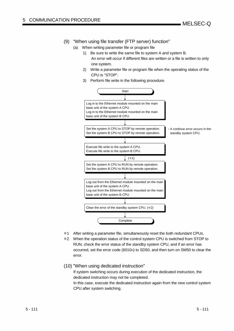
5 - 111 5 - 111
MELSEC-Q5 COMMUNICATION PROCEDURE
(9) "When using file transfer (FTP server) function"(a) When writing parameter file or program file
1) Be sure to write the same file to system A and system B.An error will occur if different files are written or a file is written to onlyone system.
2) Write a parameter file or program file when the operating status of theCPU is "STOP".
3) Perform file write in the following procedure.
A continue error occurs in the standby system CPU.
Execute file write to the system A CPU.Execute file write to the system B CPU.
Clear the error of the standby system CPU. ( 2)
Complete
Start
Log in to the Ethernet module mounted on the main base unit of the system A CPU.Log in to the Ethernet module mounted on the main base unit of the system B CPU.
Log out from the Ethernet module mounted on the main base unit of the system A CPU.Log out from the Ethernet module mounted on the main base unit of the system B CPU.
Set the system A CPU to STOP by remote operation.Set the system B CPU to STOP by remote operation.
Set the system A CPU to RUN by remote operation.Set the system B CPU to RUN by remote operation.
( 1)
1 After writing a parameter file, simultaneously reset the both redundant CPUs.2 When the operation status of the control system CPU is switched from STOP to
RUN, check the error status of the standby system CPU, and if an error hasoccurred, set the error code (6010H) to SD50, and then turn on SM50 to clear theerror.
(10) "When using dedicated instruction"If system switching occurs during execution of the dedicated instruction, thededicated instruction may not be completed.In this case, execute the dedicated instruction again from the new control systemCPU after system switching.

6 - 1 6 - 1
MELSEC-Q6 COMMUNICATION USING THE MC PROTOCOL
6
6 COMMUNICATION USING THE MC PROTOCOL
This chapter explains an overview of the MELSEC communication protocol (hereinafterreferred to as the MC protocol).See the following manual for details on the data communication function using the MCprotocol:MELSEC Communication Protocol Reference Manual (SH-080008)
6.1 Data Communication Function
The MC protocol is the abbreviated name of the MELSEC protocol that is acommunication system for the Q series PLCs. Using this protocol, the external devicescan read or write device data and programs from/to the PLC CPUs via the Q seriesEthernet module or Q series serial communication module.Any external devices on which application programs can be installed and which cansend and receive data in accordance with the MELSEC PLC protocol cancommunicate with the PLC CPUs using the MC protocol.
6.1.1 Accessing the PLC CPUs using the MC protocol
This section explains the main functions for accessing the PLC CPUs using theMC protocol.On the PLC side, the Ethernet module sends and receives data based oncommands from the external devices.Thus, the PLC CPU side does not require sequence programs for datacommunication.
(1) Data read/writeThis function reads/writes data from/to the PLC CPU device memory of the localstation or another station on the MELSECNET/H, MELSECNET/10 as well as theintelligent function module buffer memory.By reading and writing data, the PLC CPU operation monitoring, data analysisand production management can be performed on the external device side.Also, production instructions can be executed from the external device side.
(2) File read/ writeThis function reads and writes files such as sequence programs and parameterfiles that are stored in the PLC CPU.By reading and writing these files, the file management for the QCPU and theQnACPUs of other stations can be performed on the external station side.Also, execution programs can be changed (replaced) from the external deviceside.

6 - 2 6 - 2
MELSEC-Q6 COMMUNICATION USING THE MC PROTOCOL
6
(3) Remote control of the PLC CPUThis function executes remote RUN/STOP/PAUSE/latch clear/reset operations.Remote operations of the PLC CPU can be performed from the external deviceside using the PLC CPU remote control function.
FunctionCommunication using QnA compatible 3E framesCommunication using A compatible 1E frames
Communication using ASCII codeCommunication using binary code
Batch read/write in bit/word unitsDevice memory monitoringMultiple block batch read/writeRead/write by extension designation
Device memory read/write
Other station access via a network systemRead/write of the Ethernet module buffer memoryRead/write of the intelligent function module buffer memoryRead/write of the sequence program files
Communication using the MCprotocol
Status control of the PLC CPU (remote RUN/STOP, etc.)
6.1.2 Message format and control procedure for data communication
The data communication functions using the MC protocol correspond to the functionsfor reading/writing data in the PLC CPU supported by the A/QnA series Ethernetinterface modules.Therefore, the message format and control procedure are the same as whenaccessing the PLC using A/QnA series Ethernet interface modules.• Communication using QnA compatible 3E frames
This message format is used for the QnA series Ethernet interface modules• Communication using A compatible 1E frame
This message format is used for the A series Ethernet interface modulesThe external device side can access the Q series PLC with a program used foraccessing the PLC via A/QnA series Ethernet interface module.
L H H
Head device
Text (Command)
ACPUmonitoring
timer
PCNo.Su
bhea
derHeader
Ethe
rnet
(14 bytes)
IP
(20 bytes)
TCP /
UDP
L
Text (response)
Read data
(Command message for the A compatible 1E frame) (Response message for the A compatible 1E frame)
Num
ber o
fde
vice
poi
nts
(14 bytes) (20 bytes)
Subh
eade
rHeader
Ethe
rnet IP TCP
/UDP
Com
plet
e co
de
00H 0AH 00H 00H00H00H 20H40H 0CH 00HFFH 64H 80H 00H 10H10H 10H10H 10H10H 10H
(Example)
POINTThe following manual is available for performing data communication using the MCprotocol.Q Corresponding MELSEC Communication Protocol Reference Manual (soldseparately)

6 - 3 6 - 3
MELSEC-Q6 COMMUNICATION USING THE MC PROTOCOL
6.1.3 PLC CPU setting for performing data communication
Data communication via MC protocol is enabled by making the following settings usingGX Developer and writing the parameters to the PLC CPU.
1) Setting the number of Ethernet cards (see Section 4.6)
2) Initial settings (see Section 5.2)
3) Open settings (see Section 5.5)
POINT(1) By using the automatic open UDP ports of the Ethernet module,
communication using the MC protocol can be performed regardless of theRUN/STOP status of the PLC CPU.When the automatic open UDP ports are not used, connect the user open portfirst and perform data communication referring to Chapter 4, "Settings andProcedures Prior to Starting the Operation" and Chapter 5, "CommunicationProcedure" of this manual.
(2) When writing from an external device to the PLC CPU, the enable/disable writeat CPU RUN time setting can be set using the GX Developer "Ethernetoperational settings" parameters.
When writing data to the remote I/O station of the MELSECNET/H, set theenable/disable write at CPU RUN time parameter to "Enable".

6 - 4 6 - 4
MELSEC-Q6 COMMUNICATION USING THE MC PROTOCOL
6.1.4 Support of multiple CPU system or redundant system
When the external device accesses the QPU in a multiple CPU system or redundantsystem, specifying the target QCPU with the "request destination module I/O number"in the QnA-compatible 3E frame for MC protocol enables access to the control CPU ornon-control CPU of the multiple CPU system or to the control system CPU/standbysystem CPU or system A CPU/system B CPU of the redundant system.Refer to the Reference Manual for details.Refer to Chapter 2 of this manual for the system configuration.(Example) When multiple system CPU No. 1 is specified
Hea
der Q header
30H 30H
H0
L0
30H 33H 45H 30H 30H 30H 30H 34H 30H 31H30H30H 30H 31H4DH2AH
M30H30H 30H 31H30H 30H 30H 30H30H 38H35H 30H 30H 30H
5 046H 46H 30H 30H 31H 38H 30H 30H 31H 30H
Request data area
0 0
Subh
eade
r
Net
wor
k N
o.
PC N
o.
Req
uest
dest
inat
ion
mod
ule
I/O N
o.
Req
uest
des
tinat
ion
mod
ule
stat
ion
No.
Req
uest
data
leng
th
CPU
mon
itorin
gtim
er
Com
man
d
Subc
omm
and
Dev
ice
code
Hea
d de
vice
Num
ber o
fde
vice
poi
nts
HF
LF
H0
–3
–E
L0
H0
L0
H0
–0
–1
L8
H0
–0
–1
L0
H0
–4
L1
–0
H0
–0
L1
–0
H0
–0
–0
–1
–0
L0
H0
–0
–0
L8
(Command message for QnA compatible 3E frame)
REMARK
• When using the Ethernet module in a multiple CPU system, set the QCPUcontrolling the Ethernet module (hereinafter referred to as the control CPU)through GX Developer.
• It is possible to mount an Ethernet module of function version A on a multiple CPUsystem, in which case the access is limited to the control PLC (PLC No.1).
6.1.5 Support for the QCPU remote password function
When the following parameters have been set for the Ethernet module mounted on theQCPU, the Ethernet module performs the remote password check when the externaldevice accesses the PLC:(QCPU parameter settings)• When a remote password is set in the QCPU• When the connection that is communicating data with the external device is set as a
target for the remote password check
Section 5.9 of this manual explains the remote password subject to the passwordcheck, data communication procedure and the unlock/lock processing for the remotepassword.Refer to Section 5.9 first if the connection that is communicating data with the externaldevice is set as a target for the remote password check.

6 - 5 6 - 5
MELSEC-Q6 COMMUNICATION USING THE MC PROTOCOL
6.2 Utilizing the MX Component
If the external device is a PC running one of the basic operation systems below, it ispossible to create a communication program for the external device withoutconsidering the detailed MC protocol (transmission/reception procedures) using one ofthe following separately sold communication support tools.Refer to Appendix 9 for the overview of MX Component.
(Supported basic operation systems)• Microsoft® Windows® 95 Operating System• Microsoft® Windows® 98 Operating System• Microsoft® Windows NT® Workstation Operating System Version 4.0• Microsoft® Windows® Millennium Edition Operating System• Microsoft® Windows® 2000 Professional Operating System• Microsoft® Windows® XP Professional Operating System• Microsoft® Windows® XP Home Edition Operating System
Depending on the version of MX Component used, different operating systems aresupported.See the manual of MX Component for details.
(Communication support tools)• MX Component (SW0D5C-ACT-E or later.)
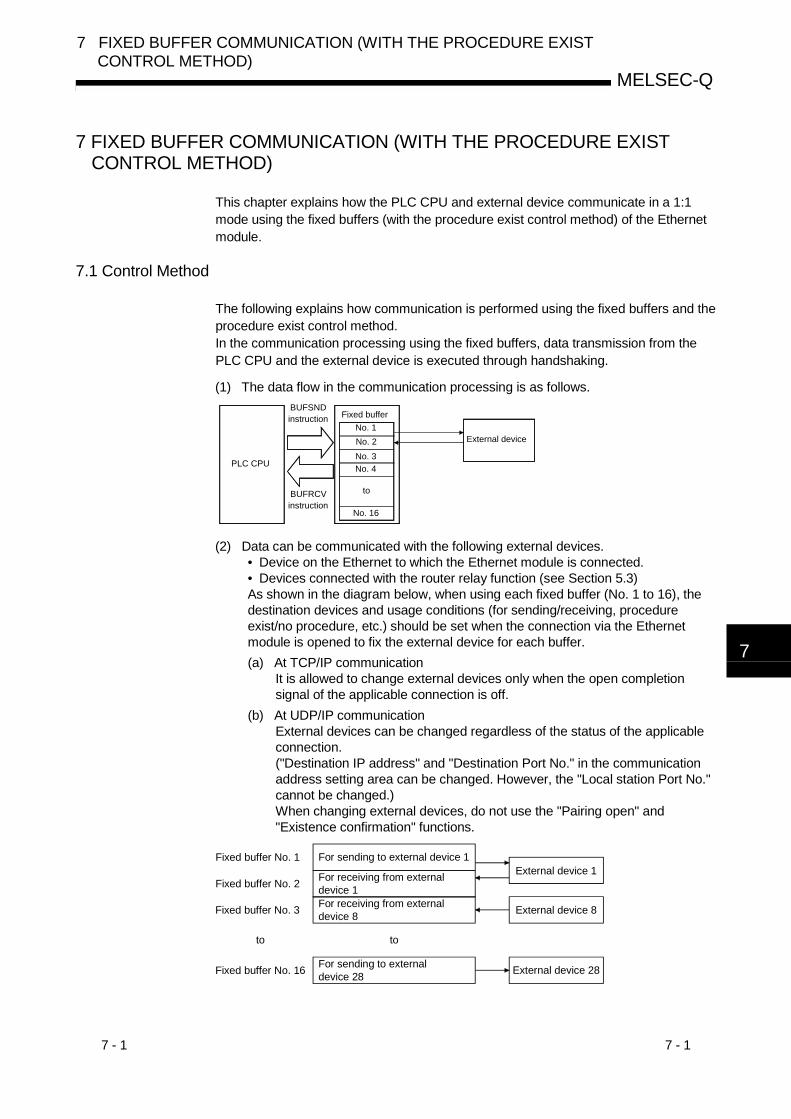
7 - 1 7 - 1
MELSEC-Q
7 FIXED BUFFER COMMUNICATION (WITH THE PROCEDURE EXISTCONTROL METHOD)
7
7 FIXED BUFFER COMMUNICATION (WITH THE PROCEDURE EXISTCONTROL METHOD)
This chapter explains how the PLC CPU and external device communicate in a 1:1mode using the fixed buffers (with the procedure exist control method) of the Ethernetmodule.
7.1 Control Method
The following explains how communication is performed using the fixed buffers and theprocedure exist control method.In the communication processing using the fixed buffers, data transmission from thePLC CPU and the external device is executed through handshaking.
(1) The data flow in the communication processing is as follows.
PLC CPU
BUFSND instruction
External device
BUFRCV instruction
No. 4
Fixed bufferNo. 1No. 2
No. 16
No. 3
to
(2) Data can be communicated with the following external devices.• Device on the Ethernet to which the Ethernet module is connected.• Devices connected with the router relay function (see Section 5.3)As shown in the diagram below, when using each fixed buffer (No. 1 to 16), thedestination devices and usage conditions (for sending/receiving, procedureexist/no procedure, etc.) should be set when the connection via the Ethernetmodule is opened to fix the external device for each buffer.(a) At TCP/IP communication
It is allowed to change external devices only when the open completionsignal of the applicable connection is off.
(b) At UDP/IP communicationExternal devices can be changed regardless of the status of the applicableconnection.("Destination IP address" and "Destination Port No." in the communicationaddress setting area can be changed. However, the "Local station Port No."cannot be changed.)When changing external devices, do not use the "Pairing open" and"Existence confirmation" functions.
For sending to external device 28
For sending to external device 1External device 1
Fixed buffer No. 1
Fixed buffer No. 2 For receiving from external device 1
External device 8Fixed buffer No. 3 For receiving from external device 8
Fixed buffer No. 16 External device 28
toto

7 - 2 7 - 2
MELSEC-Q
7 FIXED BUFFER COMMUNICATION (WITH THE PROCEDURE EXISTCONTROL METHOD)
7
POINTIn communication where the procedure exist control method is selected, the datacan be communicated by the following methods after the open processing iscompleted.• Fixed buffer communication with the procedure exist control method (sending or
receiving)• Communication using the random access buffers• Communication using the MC protocol
(3) At data sending/receiving, the Ethernet module performs the following processing.
(a) At data sendingWhen the PLC CPU executes the dedicated BUFSND instruction ( 1) in asequence program, the Ethernet module sends data of the applicable fixedbuffer (No. n) to the external device that is specified in the communicationaddress setting area (addresses: 28H to 5FH and 5038H to 507FH)corresponding to fixed buffer No. n ( 2).
(b) At data receivingThe Ethernet module processes the received data if the data is receivedfrom an external device set in the communication setting area thatcorresponds to fixed buffer No. n. ( 2)If data is received from an external device not set in the connectioninformation area of the buffer memory, the Ethernet module does notrequest to read the receive data to the PLC CPU side.
1 For details on the dedicated instructions, see Chapter 10, "DedicatedInstructions".
2 In case of TCP/IP Unpassive open, data is communicated with anexternal device stored in the connection information areacorresponding to fixed buffer No. n.
POINTWhen the Ethernet module stores the receive data in the corresponding fixed bufferin the receive processing for the simultaneous broadcasting, it updates thedestination IP address and destination port No. in the connection information area(addresses: 78H to C7H and 5820H to 586FH) that corresponds to fixed buffer No. n.
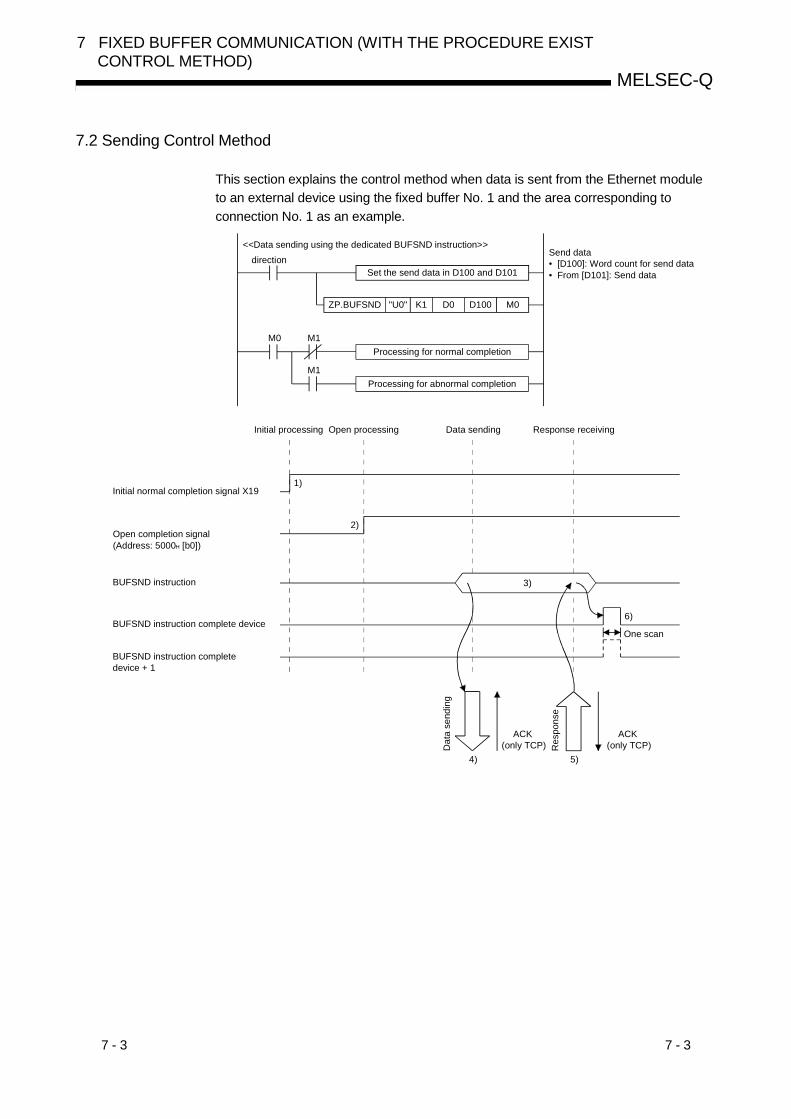
7 - 3 7 - 3
MELSEC-Q
7 FIXED BUFFER COMMUNICATION (WITH THE PROCEDURE EXISTCONTROL METHOD)
7.2 Sending Control Method
This section explains the control method when data is sent from the Ethernet moduleto an external device using the fixed buffer No. 1 and the area corresponding toconnection No. 1 as an example.
ZP.BUFSND "U0" K1 D0 D100 M0
M0 M1
M1
<<Data sending using the dedicated BUFSND instruction>>direction
Set the send data in D100 and D101
Processing for normal completion
Send data• [D100]: Word count for send data• From [D101]: Send data
Processing for abnormal completion
1)
2)
3)
6)
5)4)
Initial processing Open processing Data sending Response receiving
Initial normal completion signal X19
Open completion signal(Address: 5000H [b0])
BUFSND instruction
BUFSND instruction complete device
BUFSND instruction completedevice + 1
One scan
Dat
a se
ndin
g
ACK (only TCP)
ACK (only TCP)R
espo
nse
7 - 4 7 - 4
MELSEC-Q
7 FIXED BUFFER COMMUNICATION (WITH THE PROCEDURE EXISTCONTROL METHOD)
1) Confirm the normal completion of the initial processing.2) Confirm the normal completion of the open processing of connection
No. 13) Execute the dedicated BUFSND instruction.
The Ethernet module processes the following and sends the data.• Writes the send data length and send data to the fixed buffer (No. 1)
area.Send data length : The head address area of the target
fixed address ( 1)Send data : Area beginning from the head address
of the target fixed buffer + 11 The send data length denotes a word count.
4) The size of send data in the fixed buffer (No. 1) area designated by thesend data length is sent to the designated external device (set in theopen processing).
5) Upon receiving the data from the Ethernet module, the external devicereturns a "Response" to the Ethernet module.
6) Upon receiving the "Response" from the external device, the Ethernetmodule ends the data transmission.If the "Response" is not returned within the response monitoring timervalues (see Section 5.2), a data send error occurs.At normal completion• BUFSND instruction complete device : ON• BUFSND instruction complete device + 1 : OFF• BUFSND instruction complete status area ( 2) : 0000H
• Response end code ( 3) : 00H
At abnormal completion• BUFSND instruction complete device : ON• BUFSND instruction complete device + 1 : ON• BUFSND instruction complete status area ( 2) : Value other than
0000H
• Response end code ( 3) : Value other than00H
After the data transmission is abnormally completed, execute thededicated BUFSND instruction again to repeat the transmissionprocessing.
2 The status at completion is stored in the complete status area of theBUFSND instruction. For details on the dedicated instructions, seeChapter 10, "Dedicated Instructions".
3 The response end code is stored in the communication storage statusarea of the buffer memory.For details on the response end code, see Section 7.4.2, "ApplicationData, (5) End codes".
POINTThe destination setting (see Section 5.5) for a connection whose parameters areset with GX Developer becomes valid when the open completion signal (address:5000H … corresponding bit) of the Ethernet module switches from off to on.
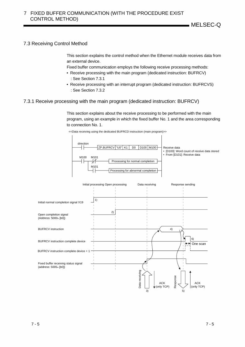
7 - 5 7 - 5
MELSEC-Q
7 FIXED BUFFER COMMUNICATION (WITH THE PROCEDURE EXISTCONTROL METHOD)
7.3 Receiving Control Method
This section explains the control method when the Ethernet module receives data froman external device.Fixed buffer communication employs the following receive processing methods:• Receive processing with the main program (dedicated instruction: BUFRCV)
: See Section 7.3.1• Receive processing with an interrupt program (dedicated instruction: BUFRCVS)
: See Section 7.3.2
7.3.1 Receive processing with the main program (dedicated instruction: BUFRCV)
This section explains about the receive processing to be performed with the mainprogram, using an example in which the fixed buffer No. 1 and the area correspondingto connection No. 1.
ZP.BUFRCV "U0" K1 D0 D100 M100
M100 M101
M101
Receive data• [D100]: Word count of receive data stored • From [D101]: Receive data
<<Data receiving using the dedicated BUFRCD instruction (main program)>>
direction
Processing for normal completion
Processing for abnormal completion
1)
2)
4)
6)
5)3)
Initial processing Open processing Data receiving Response sending
Initial normal completion signal X19
Open completion signal(Address: 5000H [b0])
BUFRCV instruction
BUFRCV instruction complete device
BUFRCV instruction complete device + 1
Dat
a re
ceiv
ing
ACK (only TCP)
ACK (only TCP)R
espo
nse
Fixed buffer receiving status signal (address: 5005H [b0])
One scan
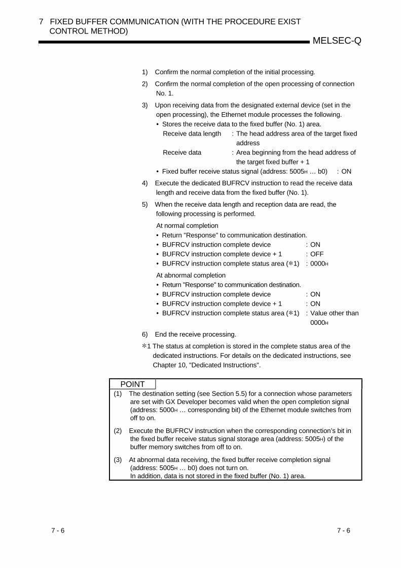
7 - 6 7 - 6
MELSEC-Q
7 FIXED BUFFER COMMUNICATION (WITH THE PROCEDURE EXISTCONTROL METHOD)
1) Confirm the normal completion of the initial processing.
2) Confirm the normal completion of the open processing of connectionNo. 1.
3) Upon receiving data from the designated external device (set in theopen processing), the Ethernet module processes the following.• Stores the receive data to the fixed buffer (No. 1) area.
Receive data length : The head address area of the target fixedaddress
Receive data : Area beginning from the head address ofthe target fixed buffer + 1
• Fixed buffer receive status signal (address: 5005H … b0) : ON
4) Execute the dedicated BUFRCV instruction to read the receive datalength and receive data from the fixed buffer (No. 1).
5) When the receive data length and reception data are read, thefollowing processing is performed.
At normal completion• Return "Response" to communication destination.• BUFRCV instruction complete device : ON• BUFRCV instruction complete device + 1 : OFF• BUFRCV instruction complete status area ( 1) : 0000H
At abnormal completion• Return "Response" to communication destination.• BUFRCV instruction complete device : ON• BUFRCV instruction complete device + 1 : ON• BUFRCV instruction complete status area ( 1) : Value other than
0000H
6) End the receive processing.
1 The status at completion is stored in the complete status area of thededicated instructions. For details on the dedicated instructions, seeChapter 10, "Dedicated Instructions".
POINT(1) The destination setting (see Section 5.5) for a connection whose parameters
are set with GX Developer becomes valid when the open completion signal(address: 5000H … corresponding bit) of the Ethernet module switches fromoff to on.
(2) Execute the BUFRCV instruction when the corresponding connection’s bit inthe fixed buffer receive status signal storage area (address: 5005H) of thebuffer memory switches from off to on.
(3) At abnormal data receiving, the fixed buffer receive completion signal(address: 5005H … b0) does not turn on.In addition, data is not stored in the fixed buffer (No. 1) area.
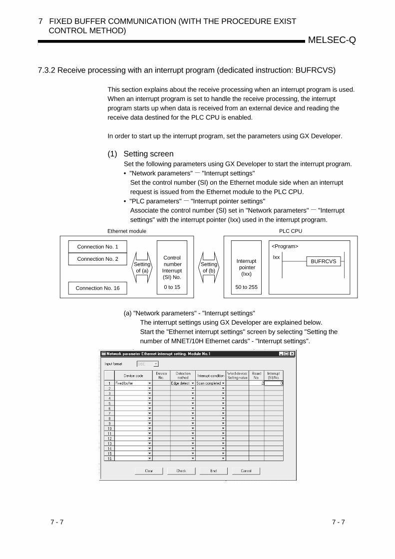
7 - 7 7 - 7
MELSEC-Q
7 FIXED BUFFER COMMUNICATION (WITH THE PROCEDURE EXISTCONTROL METHOD)
7.3.2 Receive processing with an interrupt program (dedicated instruction: BUFRCVS)
This section explains about the receive processing when an interrupt program is used.When an interrupt program is set to handle the receive processing, the interruptprogram starts up when data is received from an external device and reading thereceive data destined for the PLC CPU is enabled.
In order to start up the interrupt program, set the parameters using GX Developer.
(1) Setting screenSet the following parameters using GX Developer to start the interrupt program.• "Network parameters" "Interrupt settings"
Set the control number (SI) on the Ethernet module side when an interruptrequest is issued from the Ethernet module to the PLC CPU.
• "PLC parameters" "Interrupt pointer settings"Associate the control number (SI) set in "Network parameters" "Interruptsettings" with the interrupt pointer (Ixx) used in the interrupt program.
IxxBUFRCVS
Connection No. 16
Ethernet module PLC CPU
Connection No. 1
Control numberInterrupt (SI) No.
Interrupt pointer
(Ixx)
<Program>
Connection No. 2Setting of (a)
Setting of (b)
0 to 15 50 to 255
(a) "Network parameters" - "Interrupt settings"The interrupt settings using GX Developer are explained below.Start the "Ethernet interrupt settings" screen by selecting "Setting thenumber of MNET/10H Ethernet cards" - "Interrupt settings".
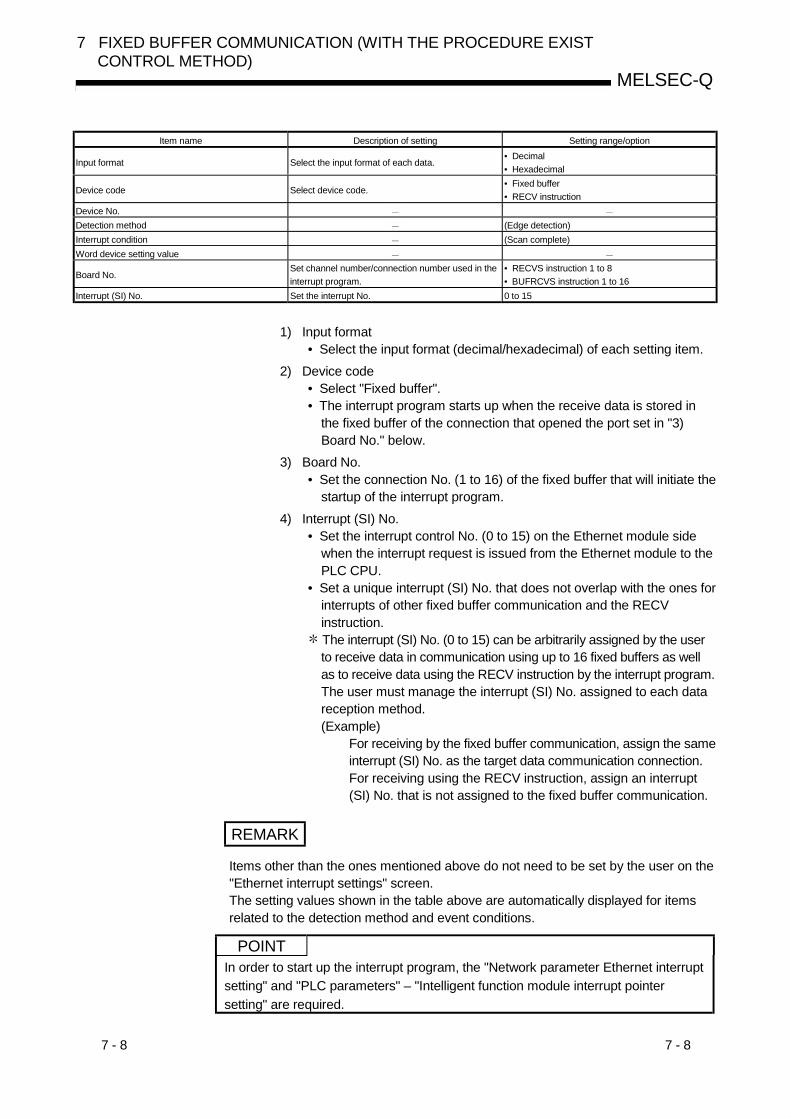
7 - 8 7 - 8
MELSEC-Q
7 FIXED BUFFER COMMUNICATION (WITH THE PROCEDURE EXISTCONTROL METHOD)
Item name Description of setting Setting range/option
Input format Select the input format of each data.• Decimal• Hexadecimal
Device code Select device code.• Fixed buffer• RECV instruction
Device No.Detection method (Edge detection)Interrupt condition (Scan complete)Word device setting value
Board No.Set channel number/connection number used in theinterrupt program.
• RECVS instruction 1 to 8• BUFRCVS instruction 1 to 16
Interrupt (SI) No. Set the interrupt No. 0 to 15
1) Input format• Select the input format (decimal/hexadecimal) of each setting item.
2) Device code• Select "Fixed buffer".• The interrupt program starts up when the receive data is stored in
the fixed buffer of the connection that opened the port set in "3)Board No." below.
3) Board No.• Set the connection No. (1 to 16) of the fixed buffer that will initiate the
startup of the interrupt program.4) Interrupt (SI) No.
• Set the interrupt control No. (0 to 15) on the Ethernet module sidewhen the interrupt request is issued from the Ethernet module to thePLC CPU.
• Set a unique interrupt (SI) No. that does not overlap with the ones forinterrupts of other fixed buffer communication and the RECVinstruction. The interrupt (SI) No. (0 to 15) can be arbitrarily assigned by the userto receive data in communication using up to 16 fixed buffers as wellas to receive data using the RECV instruction by the interrupt program.The user must manage the interrupt (SI) No. assigned to each datareception method.(Example)
For receiving by the fixed buffer communication, assign the sameinterrupt (SI) No. as the target data communication connection.For receiving using the RECV instruction, assign an interrupt(SI) No. that is not assigned to the fixed buffer communication.
REMARK
Items other than the ones mentioned above do not need to be set by the user on the"Ethernet interrupt settings" screen.The setting values shown in the table above are automatically displayed for itemsrelated to the detection method and event conditions.
POINTIn order to start up the interrupt program, the "Network parameter Ethernet interruptsetting" and "PLC parameters" – "Intelligent function module interrupt pointersetting" are required.
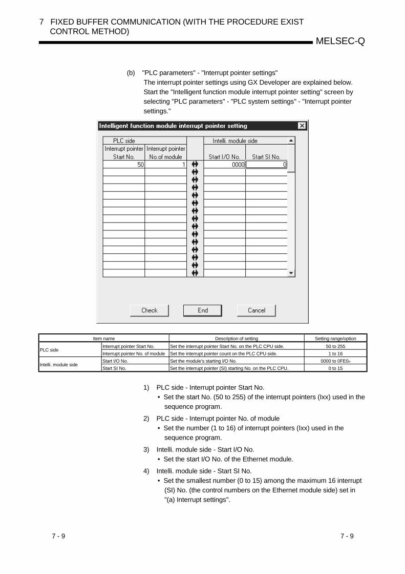
7 - 9 7 - 9
MELSEC-Q
7 FIXED BUFFER COMMUNICATION (WITH THE PROCEDURE EXISTCONTROL METHOD)
(b) "PLC parameters" - "Interrupt pointer settings"The interrupt pointer settings using GX Developer are explained below.Start the "Intelligent function module interrupt pointer setting" screen byselecting "PLC parameters" - "PLC system settings" - "Interrupt pointersettings."
Item name Description of setting Setting range/optionInterrupt pointer Start No. Set the interrupt pointer Start No. on the PLC CPU side. 50 to 255
PLC sideInterrupt pointer No. of module Set the interrupt pointer count on the PLC CPU side. 1 to 16Start I/O No. Set the module’s starting I/O No. 0000 to 0FE0H
Intelli. module sideStart SI No. Set the interrupt pointer (SI) starting No. on the PLC CPU. 0 to 15
1) PLC side - Interrupt pointer Start No.• Set the start No. (50 to 255) of the interrupt pointers (Ixx) used in the
sequence program.
2) PLC side - Interrupt pointer No. of module• Set the number (1 to 16) of interrupt pointers (Ixx) used in the
sequence program.
3) Intelli. module side - Start I/O No.• Set the start I/O No. of the Ethernet module.
4) Intelli. module side - Start SI No.• Set the smallest number (0 to 15) among the maximum 16 interrupt
(SI) No. (the control numbers on the Ethernet module side) set in"(a) Interrupt settings".
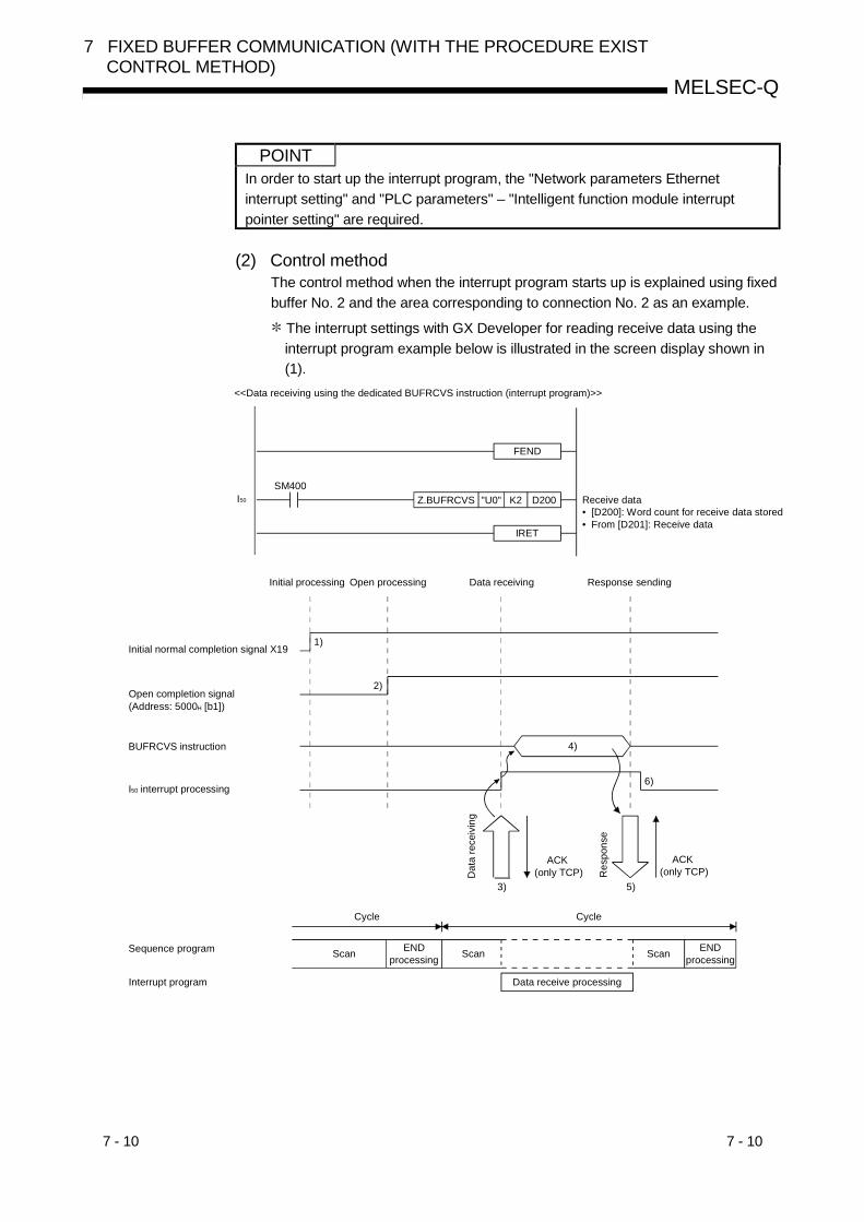
7 - 10 7 - 10
MELSEC-Q
7 FIXED BUFFER COMMUNICATION (WITH THE PROCEDURE EXISTCONTROL METHOD)
POINTIn order to start up the interrupt program, the "Network parameters Ethernetinterrupt setting" and "PLC parameters" – "Intelligent function module interruptpointer setting" are required.
(2) Control methodThe control method when the interrupt program starts up is explained using fixedbuffer No. 2 and the area corresponding to connection No. 2 as an example.
The interrupt settings with GX Developer for reading receive data using theinterrupt program example below is illustrated in the screen display shown in(1).
FEND
Z.BUFRCVS "U0" K2 D200
IRET
I50
SM400
<<Data receiving using the dedicated BUFRCVS instruction (interrupt program)>>
Receive data• [D200]: Word count for receive data stored• From [D201]: Receive data
1)
2)
4)
5)3)
6)
Initial processing Open processing Data receiving Response sending
Initial normal completion signal X19
Open completion signal(Address: 5000H [b1])
BUFRCVS instruction
I50 interrupt processing
Dat
a re
ceiv
ing
ACK (only TCP)
ACK (only TCP)R
espo
nse
Cycle Cycle
Sequence program END processing Scan
Interrupt program Data receive processing
Scan END processingScan

7 - 11 7 - 11
MELSEC-Q
7 FIXED BUFFER COMMUNICATION (WITH THE PROCEDURE EXISTCONTROL METHOD)
1) Confirm the normal completion of the initial processing.
2) Confirm the normal completion of the open processing of connectionNo. 2.
3) Upon receiving data from the designated external device (set in theopen processing), the Ethernet module processes the following.• Stores the receive data to the fixed buffer (No. 2) area.
Receive data length : The head address area of the target fixedaddress
Receive data : Area beginning from the head address ofthe target fixed buffer + 1
• Fixed buffer receive status signal (address: 5005H … b1) : ON• Request the PLC CPU to start up the interrupt program.
4) The interrupt program starts up.Execute the dedicated BUFRCVS instruction to read the receive datalength and receive data from the fixed buffer (No. 2).
5) When the receive data length and reception data are read, thefollowing processing is performed.
At normal completion• Return a "Response" to the destination.• PLC CPU error flag (SM0) ( 1) : OFF
At abnormal completion• PLC CPU error flag (SM0) ( 1) : ON• PLC CPU error code (SD0) ( 1) : error code
6) The execution of the interrupt program is finished and the execution ofthe main program starts again.
1 For information of the PLC CPU error flag (SM0) and error code(SD0), see the manual for the PLC CPU.
REMARK
To start up an interrupt program, create an interrupt enable/disable program in themain program.The instructions to be used for this are EI and DI.
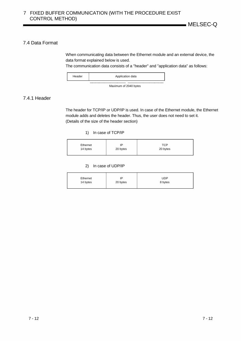
7 - 12 7 - 12
MELSEC-Q
7 FIXED BUFFER COMMUNICATION (WITH THE PROCEDURE EXISTCONTROL METHOD)
7.4 Data Format
When communicating data between the Ethernet module and an external device, thedata format explained below is used.The communication data consists of a "header" and "application data" as follows:
Maximum of 2040 bytes
Header Application data
7.4.1 Header
The header for TCP/IP or UDP/IP is used. In case of the Ethernet module, the Ethernetmodule adds and deletes the header. Thus, the user does not need to set it.(Details of the size of the header section)
1) In case of TCP/IP
TCP20 bytes
Ethernet14 bytes
IP20 bytes
2) In case of UDP/IP
UDP8 bytes
Ethernet14 bytes
IP20 bytes

7 - 13 7 - 13
MELSEC-Q
7 FIXED BUFFER COMMUNICATION (WITH THE PROCEDURE EXISTCONTROL METHOD)
7.4.2 Application data
As shown below, the data code in the application data can be expressed in eitherbinary or ASCII code. Switching between binary code and ASCII code is performedwith GX Developer as follows.[GX Developer] – [Network parameters] [Operational settings] [Communicationdata code]For more details, see Section 4.7, "Operational Settings".
(1) Format
(a) Communication using binary code
L H L H
Application data section(command message)
2 bytes 2 bytesMaximum of 1017 words
Communication request source side
Subheader Data length setting
Text (command)
Communication request destination side Subheader End code
1 byte 1 byte
Application data section(response)
(b) Communication using ASCII code
LH - - LH - -
LHLH
Application data section(command message)
4 bytes 4 bytesMaximum of 1016 words
Communication request source side
Subheader Data length setting
Text (command)
Communication request destination side Subheader End code
2 byte 2 byte
Application data section(response)

7 - 14 7 - 14
MELSEC-Q
7 FIXED BUFFER COMMUNICATION (WITH THE PROCEDURE EXISTCONTROL METHOD)
(2) SubheaderThe format of the subheader is as shown below.The user does not need to set the subheader when using the Ethernet modulesince the Ethernet module adds and deletes it.
b7 b6 b5 b4 b3 b2 b1 b0
1 1 0 0 0 0 0
Command/response type(The bit status indicated in the figure shows that communication using fixed buffers is being performed.)
Command/response flagAt command…0At response…1
1 1 0 0 0 0 0b7 b00
00H60H
1 1 0 0 0 0 0b7 b00
30H36H 30H 30H
"6" 6H "0" 0H
1 1 0 0 0 0 0b7 b0
E0H
1 1 0 0 0 0 0b7 b0
45H 30H
"E" EH "0" 0H
1
1
Commandto
Responseto
Communication using binary code
Subheader Subheader
to to
Subheader Subheader
Communication using ASCII code

7 - 15 7 - 15
MELSEC-Q
7 FIXED BUFFER COMMUNICATION (WITH THE PROCEDURE EXISTCONTROL METHOD)
(3) Data length settingThis value indicates the data size of the text (command) section.
POINTThe data length can be designated in the following range:• Communication using binary code: Maximum of 1017 words• Communication using ASCII code: Maximum of 508 words (*1)
1 Since data is sent/received as ASCII data, the communication data size isapproximately half of the data size when using binary code.
(4) Text (command)The format of the command/response when communicating using fixed buffers isconfigured as follows.
(a) Communication using binary code
(L)00H (H)60H (L) (H) (L) (H) (L) (H) (L) (H)
(L)(H)
(L)(H)
(L)(H)
(L)(H)
n + 1
n + 2
n + 3
n
to
Command formatMaximum of 1017 words
SubheaderData designation/storage device for sending/receiving instructions
Data lengthsetting
Send/receive data
n + setting data Length
1 word (2 bytes)

7 - 16 7 - 16
MELSEC-Q
7 FIXED BUFFER COMMUNICATION (WITH THE PROCEDURE EXISTCONTROL METHOD)
(b) Communication using ASCII code
36H
(H) (L)n + 1
n + 2
30H30H30H (H) (L)to (H) (L)to (H) (L)to (H) (L)to
n
(H) (L)
(H) (L)
to
Command formatMaximum of 1016 words
Subheader
Data designation/storage device for sending/receiving instructions
Data lengthsetting
Send/receive data
n + setting datalength
1 word (2 bytes)
ASCII-BIN conversion
(Maximum of 508 words)
(Example)
n + 1
n + 2
34H12H
78H56H
(H) (L) (H) (L)
36H 30H 30H 30H 30H 30H 32H 31H 32H 33H 34H 35H 37H 38H36H30H
Data lengthSubheader to to
(5) End codesFor more details on the end codes added to a response when communicatingusing the fixed buffers, see Section 11.3.1.End codes are stored in the complete status area (in the control data) of theBUFSND and BUFRCV instructions, as well as the communication statusstorage area of the buffer memory.
7 - 17 7 - 17
MELSEC-Q
7 FIXED BUFFER COMMUNICATION (WITH THE PROCEDURE EXISTCONTROL METHOD)
7.5 Programming
This section explains the programming method when the Ethernet module and anexternal device communicate using the fixed buffers and the procedure exist controlmethod.
7.5.1 Precautions when creating programs
(1) In order to communicate using the fixed buffer, the initial processing and theconnection open processing must be completed.
(2) The contents of the parameter settings have been loaded into the Ethernetmodule when the Ethernet module open completion signal (address: 5000H …corresponding bit) switches from off to on.
(3) The data length in word count is designated (stored) using the dedicatedinstruction for the communication with the procedure exist control method.If the send data length exceeds this range at data sending, a communicationerror occurs and the data is not sent.
(4) Perform the fixed buffer communication using the following dedicated instructions.• Data sending : BUFSND instruction• Data receiving : BUFRCV instruction (for main program)
: BUFRCVS instruction (for interrupt program)For details on the dedicated instructions, see Chapter 10, "DedicatedInstructions".
(5) The following should be observed when using a connection opened by UDP.• External devices can be switched by modifying the setting values in the
communication address setting area of the communication parameter settingarea before sending/receiving data. Thus, data can be sent to multiple externaldevices sequentially. When performing sending/receiving, make sure toperform switching between external devices properly so that no communicationproblems occur.
(6) When reading of the data received from the same connection, reading of datareceived by the main program and the reading of data received by the interruptprogram cannot be done together.Use only one of the above-mentioned programs for reading the data received.
Reading of data received by the main program cannot be performed whensetting is being performed by GX Developer for reading of received data usingthe interrupt program.
(7) For data (commnd) transmission, the next data (commnd) should be after thecompletion of data commnication (such as after the reception of a response) forthe transmission of the previous data (commnd).
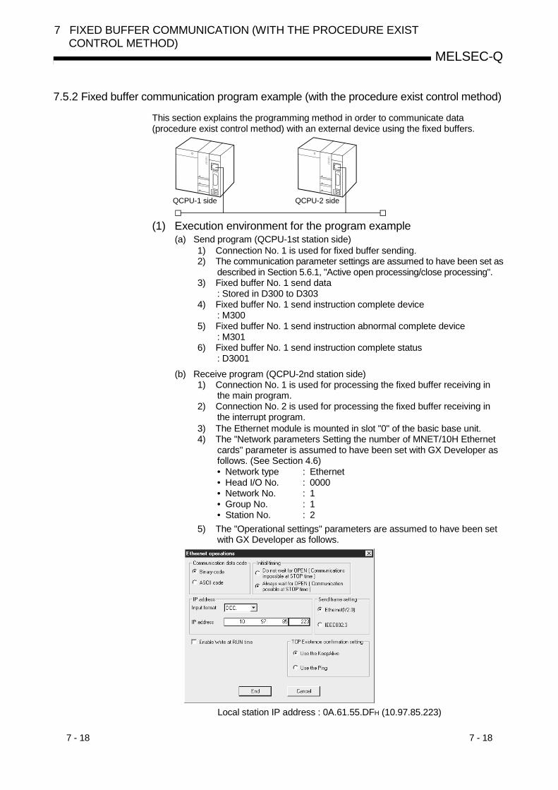
7 - 18 7 - 18
MELSEC-Q
7 FIXED BUFFER COMMUNICATION (WITH THE PROCEDURE EXISTCONTROL METHOD)
7.5.2 Fixed buffer communication program example (with the procedure exist control method)
This section explains the programming method in order to communicate data(procedure exist control method) with an external device using the fixed buffers.
QCPU-1 side QCPU-2 side
(1) Execution environment for the program example(a) Send program (QCPU-1st station side)
1) Connection No. 1 is used for fixed buffer sending.2) The communication parameter settings are assumed to have been set as
described in Section 5.6.1, "Active open processing/close processing".3) Fixed buffer No. 1 send data
: Stored in D300 to D3034) Fixed buffer No. 1 send instruction complete device
: M3005) Fixed buffer No. 1 send instruction abnormal complete device
: M3016) Fixed buffer No. 1 send instruction complete status
: D3001(b) Receive program (QCPU-2nd station side)
1) Connection No. 1 is used for processing the fixed buffer receiving inthe main program.
2) Connection No. 2 is used for processing the fixed buffer receiving inthe interrupt program.
3) The Ethernet module is mounted in slot "0" of the basic base unit.4) The "Network parameters Setting the number of MNET/10H Ethernet
cards" parameter is assumed to have been set with GX Developer asfollows. (See Section 4.6)• Network type : Ethernet• Head I/O No. : 0000• Network No. : 1• Group No. : 1• Station No. : 2
5) The "Operational settings" parameters are assumed to have been setwith GX Developer as follows.
Local station IP address : 0A.61.55.DFH (10.97.85.223)

7 - 19 7 - 19
MELSEC-Q
7 FIXED BUFFER COMMUNICATION (WITH THE PROCEDURE EXISTCONTROL METHOD)
6) The "Open settings" parameters are assumed to have been set withGX Developer as follows.
Connection No. 1 Local station Port No. : 2000H
(for main program)Connection No. 2 Local station Port No. : 3000H
(for interrupt program)
7) Fixed buffer No. 1 receive data: Stored in D500 to D503
8) Fixed buffer No. 2 receive data: Stored in D700 to D703
9) Fixed buffer No. 1 receive instruction complete device: M500
10) Fixed buffer No. 1 receive instruction abnormal complete device: M501
11) Fixed buffer No. 1 send instruction complete status: D5001
12) Fixed buffer No. 1 receive status signal: M40
13) The parameter settings to start up the interrupt program are assumedto have been set with GX Developer as described in the screensettings in Section 7.3.2 "Receive processing with an interruptprogram".Fixed buffer No. 2 interrupt pointer: I50 (SI No. 0)
POINTSecure sufficient device memory according to the maximum length of data sentfrom the source in order to prevent device areas used for other purposes frombeing overwritten by the reception data.
7 - 20 7 - 20
MELSEC-Q
7 FIXED BUFFER COMMUNICATION (WITH THE PROCEDURE EXISTCONTROL METHOD)
(2) Outline of the program example
(a) Send program (QCPU-1st station side)
1) After setting each parameter with GX Developer and write to PLCCPU, reset the PLC CPU and confirm that the initial processing iscompleted.
2) Perform open processing (Active open) of connection No. 1. ( 1)
3) Communicate data from the PLC CPU using fixed buffercommunication (procedure exist sending).
4) After the data sending is completed, perform close processing ofconnection No. 1. ( 1)
1 Use the program example described in Section 5.6.1, "Active openprocessing/close processing" for the sequence program thatexecutes the open processing/close processing.
(b) Receive program (QCPU-2nd station side)
1) After setting each parameter with GX Developer and write to PLCCPU, reset the PLC CPU and confirm that the initial processing iscompleted.When the initial processing is normally completed, connection No. 1and 2 wait for an Active open request from the external device.
2) Communicate data from the external device using fixed buffercommunication (procedure exist sending).
3) Data received in the corresponding fixed buffer data area in theEthernet module is read to the PLC CPU.

7 - 21 7 - 21
MELSEC-Q
7 FIXED BUFFER COMMUNICATION (WITH THE PROCEDURE EXISTCONTROL METHOD)
(Send program)
Open processing program
X19: Initial normal completion signal
M0: Connection 1 open completion signal
Fixed buffer No. 1 sending program
Change the sending command to pulse
Designate the BUFSND instruction dataDesignate the send data lengthDesignate the send data
Execute the data sending to the external device
Perform the sending normal completion processing
Perform the sending abnormal completionprocessing
Normal completion processing
Abnormal completion processing
Close processing program
(See Section 5.6.1)
(See Section 5.6.1)
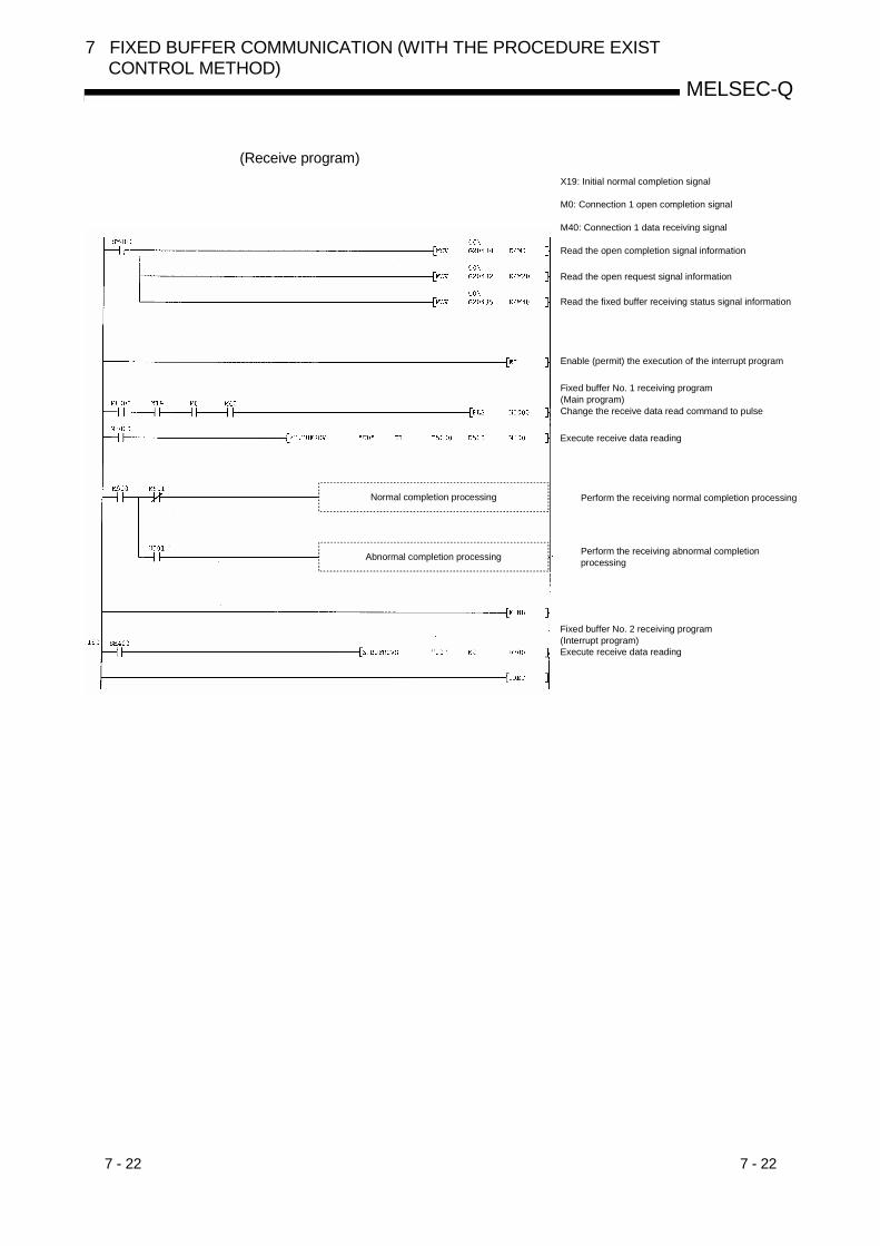
7 - 22 7 - 22
MELSEC-Q
7 FIXED BUFFER COMMUNICATION (WITH THE PROCEDURE EXISTCONTROL METHOD)
(Receive program)X19: Initial normal completion signal
M0: Connection 1 open completion signal
M40: Connection 1 data receiving signal
Read the open completion signal information
Read the open request signal information
Read the fixed buffer receiving status signal information
Enable (permit) the execution of the interrupt program
Fixed buffer No. 1 receiving program(Main program)Change the receive data read command to pulse
Execute receive data reading
Perform the receiving normal completion processing
Perform the receiving abnormal completion processing
Fixed buffer No. 2 receiving program(Interrupt program)Execute receive data reading
Normal completion processing
Abnormal completion processing
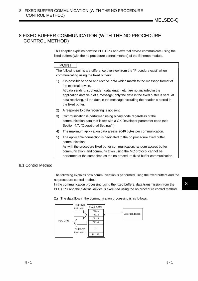
8 - 1 8 - 1
MELSEC-Q
8 FIXED BUFFER COMMUNICATION (WITH THE NO PROCEDURECONTROL METHOD)
8
8 FIXED BUFFER COMMUNICATION (WITH THE NO PROCEDURECONTROL METHOD)
This chapter explains how the PLC CPU and external device communicate using thefixed buffers (with the no procedure control method) of the Ethernet module.
POINTThe following points are difference overview from the "Procedure exist" whencommunicating using the fixed buffers:
1) It is possible to send and receive data which match to the message format ofthe external device.At data sending, subheader, data length, etc. are not included in theapplication data field of a message; only the data in the fixed buffer is sent. Atdata receiving, all the data in the message excluding the header is stored inthe fixed buffer.
2) A response to data receiving is not sent.
3) Communication is performed using binary code regardless of thecommunication data that is set with a GX Developer parameter code (seeSection 4.7, "Operational Settings".)
4) The maximum application data area is 2046 bytes per communication.
5) The applicable connection is dedicated to the no procedure fixed buffercommunication.As with the procedure fixed buffer communication, random access buffercommunication, and communication using the MC protocol cannot beperformed at the same time as the no procedure fixed buffer communication.
8.1 Control Method
The following explains how communication is performed using the fixed buffers and theno procedure control method.In the communication processing using the fixed buffers, data transmission from thePLC CPU and the external device is executed using the no procedure control method.
(1) The data flow in the communication processing is as follows.
PLC CPU
BUFSND instruction
External device
BUFRCV instruction
No. 4
Fixed bufferNo. 1No. 2
No. 16
No. 3
to

8 - 2 8 - 2
MELSEC-Q
8 FIXED BUFFER COMMUNICATION (WITH THE NO PROCEDURECONTROL METHOD)
8
(2) Data can be communicated with the following external devices.• Device on the Ethernet to which the Ethernet module is connected.• Devices connected with the router relay function (see Section 5.3)As shown in the diagram below, when using each fixed buffer (No. 1 to 16), thedestination devices and usage conditions (for sending/receiving, procedureexist/no procedure, etc.) should be set when the connection via the Ethernetmodule is opened to fix the external device for each buffer.
(a) At TCP/IP communicationIt is allowed to change external devices only when the open completionsignal of the applicable connection is off.
(b) At UDP/IP communicationExternal devices can be changed regardless of the status of the applicableconnection.("Destination IP address" and "Destination Port No." in the communicationaddress setting area can be changed. However, "Local station Port No."cannot be changed.)When changing external devices, do not use the "Pairing open" and"Existence confirmation" functions.
For sending to external device 28
For sending to external device 1 External device 1
Fixed buffer No. 1
Fixed buffer No. 2 For receiving from external device 1
External device 8Fixed buffer No. 3 For receiving from external device 8
Fixed buffer No. 16 External device 28
toto to
POINTThe connections for which no procedure is selected are dedicated to the fixedbuffer sending or receiving after the completion of open processing.
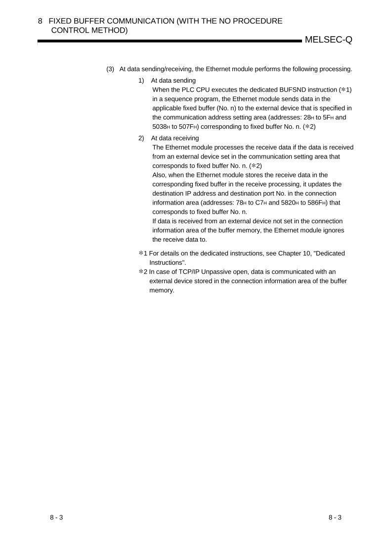
8 - 3 8 - 3
MELSEC-Q
8 FIXED BUFFER COMMUNICATION (WITH THE NO PROCEDURECONTROL METHOD)
(3) At data sending/receiving, the Ethernet module performs the following processing.
1) At data sendingWhen the PLC CPU executes the dedicated BUFSND instruction ( 1)in a sequence program, the Ethernet module sends data in theapplicable fixed buffer (No. n) to the external device that is specified inthe communication address setting area (addresses: 28H to 5FH and5038H to 507FH) corresponding to fixed buffer No. n. ( 2)
2) At data receivingThe Ethernet module processes the receive data if the data is receivedfrom an external device set in the communication setting area thatcorresponds to fixed buffer No. n. ( 2)Also, when the Ethernet module stores the receive data in thecorresponding fixed buffer in the receive processing, it updates thedestination IP address and destination port No. in the connectioninformation area (addresses: 78H to C7H and 5820H to 586FH) thatcorresponds to fixed buffer No. n.If data is received from an external device not set in the connectioninformation area of the buffer memory, the Ethernet module ignoresthe receive data to.
1 For details on the dedicated instructions, see Chapter 10, "DedicatedInstructions".
2 In case of TCP/IP Unpassive open, data is communicated with anexternal device stored in the connection information area of the buffermemory.
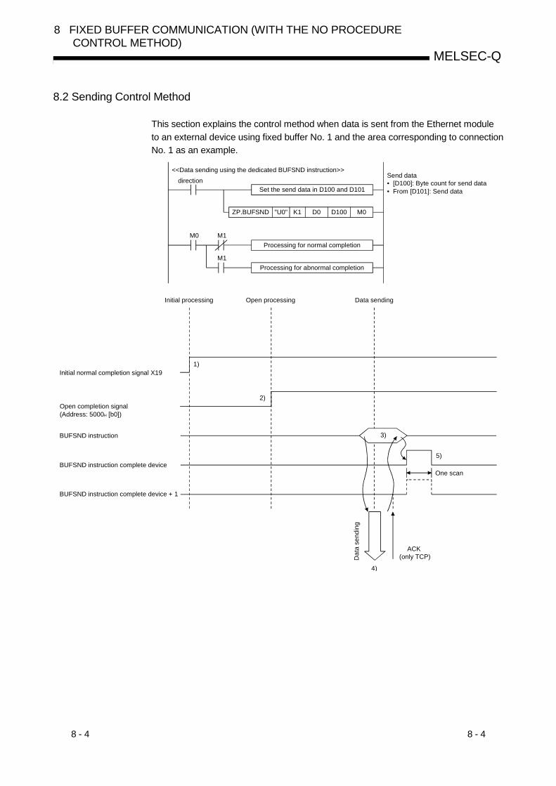
8 - 4 8 - 4
MELSEC-Q
8 FIXED BUFFER COMMUNICATION (WITH THE NO PROCEDURECONTROL METHOD)
8.2 Sending Control Method
This section explains the control method when data is sent from the Ethernet moduleto an external device using fixed buffer No. 1 and the area corresponding to connectionNo. 1 as an example.
ZP.BUFSND "U0" K1 D0 D100 M0
M0 M1
M1
<<Data sending using the dedicated BUFSND instruction>>direction
Set the send data in D100 and D101
Processing for normal completion
Send data• [D100]: Byte count for send data• From [D101]: Send data
Processing for abnormal completion
3)
5)
2)
1)
4)
Initial processing Open processing Data sending
Initial normal completion signal X19
Open completion signal(Address: 5000H [b0])
BUFSND instruction
BUFSND instruction complete device
BUFSND instruction complete device + 1
One scan
Dat
a se
ndin
g
ACK (only TCP)
8 - 5 8 - 5
MELSEC-Q
8 FIXED BUFFER COMMUNICATION (WITH THE NO PROCEDURECONTROL METHOD)
1) Confirm normal completion of the initial processing.
2) Confirm the normal completion of the open processing for connectionNo. 1.
3) Execute the dedicated BUFSND instruction.The Ethernet module processes the following and sends the data.• Writes send data length and send data to the fixed buffer (No. 1)
area.Send data length : The head address area of the target
fixed address ( 1)Send data : Area beginning from the head address
of the target fixed buffer + 11 The send data length is expressed by a byte count.
4) Only the size of the send data in the fixed buffer (No. 1) designated bythe send data length is sent to the designated external device (set inthe open processing).
5) The Ethernet module terminates the data transmission.
At normal completion• BUFSND instruction complete device : ON• BUFSND instruction complete device + 1 : OFF• BUFSND instruction complete status area ( 2) : 0000H
At abnormal completion :• BUFSND instruction complete device : ON• BUFSND instruction complete device + 1 : ON• BUFSND instruction complete status area ( 2) : Value other than
0000H
After the data transmission is abnormally completed, execute thededicated BUFSND instruction again to repeat the transmissionprocessing.
2 The status at completion is stored in the complete status area ofthe dedicated instructions. For details on the dedicated instructions,see Chapter 10, "Dedicated Instructions".
POINTThe following precaution should be observed when communicating using UDP/IP:• When the Ethernet module’s internal processing is normally completed, data
send processing ends even if the communication line between the PLC CPU andan external device is disconnected because of cable disconnection, etc. It isrecommended to send/receive data using a communication procedure defined bythe user.

8 - 6 8 - 6
MELSEC-Q
8 FIXED BUFFER COMMUNICATION (WITH THE NO PROCEDURECONTROL METHOD)
8.3 Receiving Control Method
This section explains the control method when the Ethernet module receives data froman external device.Fixed buffer communication employs the following receive processing methods:• Receive processing with the main program (dedicated instruction: BUFRCV)
: See Section 8.3.1• Receive processing with an interrupt program (dedicated instruction: BUFRCVS)
: See Section 8.3.2
8.3.1 Receive processing with the main program (dedicated instruction: BUFRCV)
This section explains about the receive processing to be performed with the mainprogram, using an example in which the fixed buffer No. 1 and the area correspondingto connection No. 1.
ZP.BUFRCV "U0" K1 D0 D100 M100
M100 M101
M101
Receive data• [D100]: Byte count of receive data stored• From [D101]: Receive data
<<Data receiving using the dedicated BUFRCV instruction (main program)>>
direction
Processing for normal completion
Processing for abnormal completion
4)
5)
2)
1)
3)
Initial processing Open processing Data sending
Initial normal completion signal X19
Open completion signal(Address: 5000H [b0])
BUFRCV instruction
BUFRCV instruction complete device
BUFRCV instruction complete device + 1
Dat
a re
ceiv
ing
ACK (only TCP)
Fixed buffer receiving status signal (address: 5005H [b0])
One scan

8 - 7 8 - 7
MELSEC-Q
8 FIXED BUFFER COMMUNICATION (WITH THE NO PROCEDURECONTROL METHOD)
1) Confirm the normal completion of the initial processing.
2) Confirm the normal completion of the open processing for connectionNo. 1.
3) Upon receiving data from the designated external device (set in theopen processing), the Ethernet module processes the following.• Stores the receive data to the fixed buffer (No. 1) area.
(Area beginning from the head address of the target fixed buffer + 1)• Stores the data length to the head address area of the target fixed
address ( 1)• Fixed buffer receive status signal (address: 5005H … b0) : ON
1 The receive data length is expressed by a byte count.When an odd number of data bytes is received, the last receiveddata is stored at the lower byte of the last data storage area. (Thehigher byte becomes a non-constant value.)
4) Execute the dedicated BUFRCV instruction and read the receive datalength and receive data from the fixed buffer (No. 1).
5) End the receive processing.
At normal completion• BUFRCV instruction complete device : ON• BUFRCV instruction complete device + 1 : OFF• BUFRCV instruction complete status area ( 2) : 0000H
At abnormal completion• BUFRCV instruction complete device : ON• BUFRCV instruction complete device + 1 : ON• BUFRCV instruction complete status area ( 2) : Value other than
0000H
2 The status at completion is stored in the complete status area ofthe dedicated instructions. For details on the dedicatedinstructions, see Chapter 10, "Dedicated Instructions".
POINT(1) The destination setting (see Section 5.5) for a connection whose parameters
are set with GX Developer becomes valid when the open completion signal(address: 5000H … corresponding bit) of the Ethernet module switches fromoff to on.
(2) Execute the BUFRCV instruction when the corresponding connection’s bit inthe fixed buffer receive status signal storage area (address: 5005H) of thebuffer memory switches from off to on.
(3) At abnormal data receiving, the fixed buffer receive completion signal(address: 5005H … b0) does not turn on.In addition, data is not stored in the fixed buffer (No. 1) area.

8 - 8 8 - 8
MELSEC-Q
8 FIXED BUFFER COMMUNICATION (WITH THE NO PROCEDURECONTROL METHOD)
8.3.2 Receive processing with an interrupt program (dedicated instruction: BUFRCVS)
This section explains about the receive processing when an interrupt program is used.When an interrupt program is set up to handle the receive processing, the interruptprogram starts up when data is received from an external device and reading thereceive data destined for the PLC CPU is enabled.
In order to start up the interrupt program, set the parameters using GX Developer.
(1) Setting screenSet the following parameters using GX Developer to start the interrupt program.The setting screen and setting method are the same as for the fixed buffercommunication (procedure exist). See Section 7.3.2 (1).
(2) Control methodThe control method when the interrupt sequence program starts up is explainedusing fixed buffer No. 2 and the area corresponding to connection No. 2 as anexample.
The interrupt settings with GX Developer for reading the receive data using theinterrupt program example below is illustrated in the screen display shown inSection 7.3.2 (1).
FEND
Z.BUFRCVS "U0" K2 D200
IRET
I50
SM400
<<Data receiving using the dedicated BUFRCVS instruction (interrupt program)>>
Receive data• [D100]: Byte count for receive data stored• From [D101]: Receive data
4)
2)
1)
3)
5)
Initial processing
Initial normal completion signal X19
Open completion signal(Address: 5000H [b1])
BUFRCVS instruction
I50 interruput processing
Dat
a re
ceiv
ing
ACK (only TCP)
Open processing Data receiving
Cycle Cycle
END processing Scan
Data receiving processing
Scan ScanSequence program
Interrupt program
END processing

8 - 9 8 - 9
MELSEC-Q
8 FIXED BUFFER COMMUNICATION (WITH THE NO PROCEDURECONTROL METHOD)
1) Confirm the normal completion of the initial processing.
2) Confirm the normal completion of the open processing for connectionNo. 2.
3) Upon receiving data from the designated external device (set in theopen processing), the Ethernet module processes the following.• Stores the receive data in the fixed buffer (No. 2) area.
(Area beginning from the head address of the target fixed buffer + 1)• Stores the data length in the head address area of the target fixed
address ( 1)• Request the PLC CPU to start up the interrupt program.
1 The receive data length is expressed by a byte count.When an odd number of data bytes is received, the last receiveddata is stored at the lower byte of the last data storage area. (Thehigher byte becomes a non-constant value.)
4) The interrupt program starts up.Execute the dedicated BUFRCVS instruction and read the receivedata length and receive data from the fixed buffer (No. 2).
At normal completion• PLC CPU error flag (SMO) ( 2) : OFFAt abnormal completion• PLC CPU error flag (SMO) ( 2) : ON• PLC CPU error code (SDO) ( 2) : error code
2 For more details on the PLC CPU error flag (SMO) and error code(SDO), see the manual for the PLC CPU used.
5) The execution of the interrupt program is finished and the execution ofthe main program starts again.
REMARK
(1) To start up an interrupt program, create an interrupt enable/disable program inthe main program using the EI and DI instructions.
(2) The programming for reading of receive data with an interrupt program is thesame as that for communicating (procedure exist) by fixed buffer. Refer toprogram example indicated in Section 7.5.2 when programming.

8 - 10 8 - 10
MELSEC-Q
8 FIXED BUFFER COMMUNICATION (WITH THE NO PROCEDURECONTROL METHOD)
8.4 Data Format
When communicating data between the Ethernet module and an external device, thedata format explained below is used.The communication data consists of a "header" and "application data" as shownbelow.
Header Application data
(1) HeaderThe header for TCP/IP or UDP/IP is used. In case of the Ethernet module, theEthernet module adds and deletes the header. Thus, the user does not need toset it.(Details of the size of the header section)
1) In case of TCP/IP
TCP20 bytes
Ethernet14 bytes
IP20 bytes
2) In case of UDP/IP
UDP8 bytes
Ethernet14 bytes
IP20 bytes
(2) Application DataThe data code in the application data is expressed in binary code.Communication is performed using binary code, regardless of the setcommunication data (see Section 4.7).
Maximum of 2064 bytes
Text (command)
REMARK
The subheader and data length that are added for communications using the fixedbuffers in the procedure exist control method are not present for communications inthe no procedure control method. All data is treated as valid text.

8 - 11 8 - 11
MELSEC-Q
8 FIXED BUFFER COMMUNICATION (WITH THE NO PROCEDURECONTROL METHOD)
8.5 Simultaneous Broadcast Using UDP/IP
When UDP/IP is used for no procedure fixed buffer communication, data can bebroadcast simultaneously to all Ethernet module installed stations on the sameEthernet where the Ethernet module is located. This allows writing the same data to allstations, etc.
POINT(1) In simultaneous broadcasting, if the messages received by the simultaneous
broadcasting are not needed, external devices connected to the sameEthernet should discard them at first given opportunity.
(2) The user needs to determine the port numbers dedicated to the transmissionand reception by simultaneous broadcasting, after which simultaneousbroadcasting can be performed by designating these port numbers.
8.5.1 Sending by simultaneous broadcasting
Sending can be performed through simultaneous broadcasting by setting the externaldevice IP address to FFFFFFFFH and performing the open processing.For data sending by simultaneous broadcasting, the Ethernet sets the requestdestination IP address to FFFFFFFFH and send data over the Ethernet.
(1) Setting screenThis section explains the "Open settings" for sending by simultaneousbroadcasting.• Connection No. 15 is used.• The Ethernet module Port No. is 0800H.
(a) ProtocolSelect "UDP/IP".
(b) Open systemSetting is not required.
(c) Fixed bufferSelect "Send".
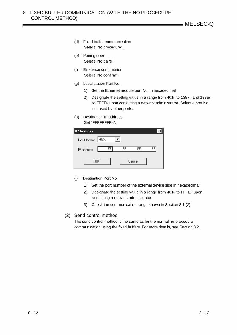
8 - 12 8 - 12
MELSEC-Q
8 FIXED BUFFER COMMUNICATION (WITH THE NO PROCEDURECONTROL METHOD)
(d) Fixed buffer communicationSelect "No procedure".
(e) Pairing openSelect "No pairs".
(f) Existence confirmationSelect "No confirm".
(g) Local station Port No.
1) Set the Ethernet module port No. in hexadecimal.
2) Designate the setting value in a range from 401H to 1387H and 138BH
to FFFEH upon consulting a network administrator. Select a port No.not used by other ports.
(h) Destination IP addressSet "FFFFFFFFH".
(i) Destination Port No.
1) Set the port number of the external device side in hexadecimal.
2) Designate the setting value in a range from 401H to FFFEH uponconsulting a network administrator.
3) Check the communication range shown in Section 8.1 (2).
(2) Send control methodThe send control method is the same as for the normal no-procedurecommunication using the fixed buffers. For more details, see Section 8.2.

8 - 13 8 - 13
MELSEC-Q
8 FIXED BUFFER COMMUNICATION (WITH THE NO PROCEDURECONTROL METHOD)
8.5.2 Receiving by simultaneous broadcasting
Data is received through simultaneous broadcasting, by setting FFFFFFFFH for the IPaddress of an external device that is to send data to the Ethernet module, and FFFFH
for the port No., then performing the open processing.
(1) Setting screenThis section explains the "Open settings" for receiving by simultaneousbroadcasting.• Connection No. 16 is used.• The Ethernet module Port No. is 0801H.
(a) ProtocolSelect "UDP/IP".
(b) Open systemSetting is not required.
(c) Fixed bufferSelect "Receive".
(d) Fixed buffer communicationSelect "No procedure".
(e) Pairing openSelect "No pairs".
(f) Existence confirmationSelect "No confirm".

8 - 14 8 - 14
MELSEC-Q
8 FIXED BUFFER COMMUNICATION (WITH THE NO PROCEDURECONTROL METHOD)
(g) Local station Port No.
1) Set the Ethernet module port No. in hexadecimal.
2) Designate the setting value in a range from 401H to 1387H and 138BH
to FFFEH.
3) If the receive data from specific external device is to be processed,designate the user-defined port No. upon consulting a networkadministrator.
(h) Destination IP addressSet "FFFFFFFFH".
(i) Destination Port No.Set "FFFFH".
(2) Receive control methodThe receive control method is the same as for the normal no procedurecommunication using the fixed buffers. For more details, see Section 8.3.
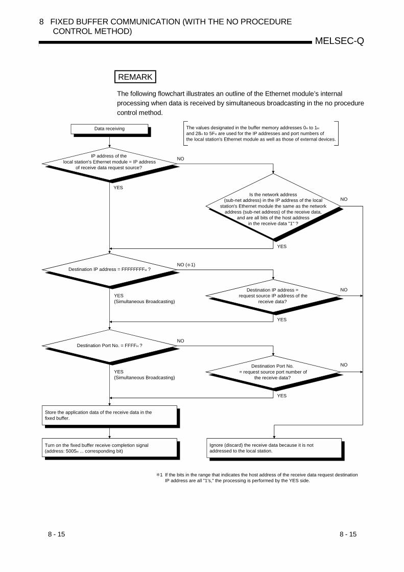
8 - 15 8 - 15
MELSEC-Q
8 FIXED BUFFER COMMUNICATION (WITH THE NO PROCEDURECONTROL METHOD)
REMARK
The following flowchart illustrates an outline of the Ethernet module’s internalprocessing when data is received by simultaneous broadcasting in the no procedurecontrol method.
NO
YES
NO
YES
YES
NO
YES
NO
NO
Data receiving The values designated in the buffer memory addresses 0H to 1H and 28H to 5FH are used for the IP addresses and port numbers of the local station's Ethernet module as well as those of external devices.
IP address of the local station's Ethernet module = IP address
of receive data request source?
Is the network address (sub-net address) in the IP address of the local
station's Ethernet module the same as the network address (sub-net address) of the receive data,
and are all bits of the host address in the receive data "1" ?
Destination IP address = FFFFFFFFH ?
YES(Simultaneous Broadcasting)
Destination IP address = request source IP address of the
receive data?
Destination Port No. = FFFFH ?
YES(Simultaneous Broadcasting)
Destination Port No. = request source port number of
the receive data?
Store the application data of the receive data in the fixed buffer.
Turn on the fixed buffer receive completion signal (address: 5005H ... corresponding bit)
Ignore (discard) the receive data because it is not addressed to the local station.
If the bits in the range that indicates the host address of the receive data request destinationIP address are all "1's," the processing is performed by the YES side.
1
NO ( 1)
8 - 16 8 - 16
MELSEC-Q
8 FIXED BUFFER COMMUNICATION (WITH THE NO PROCEDURECONTROL METHOD)
8.5.3 Precautions when using the simultaneous broadcast function
The following precautions should be observed when broadcasting simultaneously inthe no procedure communication using the fixed buffers.
(1) The user needs to determine the port No. dedicated to the sending and receivingby simultaneous broadcasting, after which simultaneous broadcasting can beperformed by designating these port No..
(2) The send message by simultaneous broadcasting is sent to all external deviceson the same Ethernet to which the Ethernet module is connected.If the messages received by simultaneous broadcasting are not needed, theexternal devices that are connected to the same Ethernet should discard them.
The external devices should discard the message received if it is not needed.Also, do not return a response even if the external device is the station towhich the message received is addressed. The Ethernet module performsthese processes automatically.
(3) A maximum of 2046 bytes of data in the application data field can be processedper sending/receiving.When it is necessary to send/receive data that exceeds 2047 bytes, divide it intosmaller portions at the send source.
(4) When performing simultaneous broadcasting, set the "Existence confirmation"setting to "No confirm" in the "Open settings" of the corresponding connection.
REMARK
The size of the internal buffer for the operating system is approximately 40 k bytesand any received data that exceeds this size will be discarded.
8 - 17 8 - 17
MELSEC-Q
8 FIXED BUFFER COMMUNICATION (WITH THE NO PROCEDURECONTROL METHOD)
8.6 Programming
This section explains the programming method when the Ethernet module and anexternal device communicate using the fixed buffers and the no-procedure controlmethod.
8.6.1 Precautions when creating programs
(1) In order to communicate using the fixed buffers, the initial processing and theconnection open processing must be completed.
(2) The contents of the parameter settings have been loaded into the Ethernetmodule when the Ethernet module open completion signal (address: 5000H…
corresponding bit) switches from off to on.(3) The data length in byte count is designated (stored) using the dedicated
instruction for the no procedure communication.If the send data length exceeds this range at data sending, a communicationerror occurs and the data is not be sent.
(4) Perform the fixed buffer communication using the following dedicated instructions.• Data sending : BUFSND instruction• Data receiving : BUFRCV instruction (for main program)
: BUFRCVS instruction (for interrupt program)For details on the dedicated instructions, see Chapter 10, "Dedicated Instructions".
(5) The following should be observed when using a connection opened by UDP.• External devices can be switched by modifying the setting values in the
communication address setting area of the communication parameter settingarea before sending/receiving data. Thus, data can be sent to multiple externaldevices sequentially. When performing sending/receiving, make sure toperform switching between external devices properly so that no communicationproblems occur.
(6) The connections for which no procedure is selected are dedicated to the noprocedure fixed buffer sending/receiving. Thus, communications using fixedbuffers with the procedure exist control method, random access buffers and theMC protocol cannot be performed at the same time with a communication usingfixed buffers with the no procedure control method.
(7) Message data length is not used for the no procedure communication.The Ethernet module stores the size of the received message (packet) in thereceive data length storage area and turns on the fixed buffer receiving statussignal (address: 5005H … corresponding bit).It is recommended to employ a check system, such as including the data lengthand data type code in the application data of a message, so that the byte countand data type in the application data can be identified by the receiving side.
(8) When reading of the data received from the same connection, reading of datareceived by the main program and the reading of data received by the interruptprogram cannot be done together.Use only one of the above-mentioned programs for reading the data received.
Reading of data received by the main program cannot be performed whensetting is being performed by GX Developer for reading of received data usingthe interrupt program.

8 - 18 8 - 18
MELSEC-Q
8 FIXED BUFFER COMMUNICATION (WITH THE NO PROCEDURECONTROL METHOD)
8.6.2 Fixed buffer communication program example (with the no procedure control method)
This section explains the programming method in order to communication data (throughthe no procedure control method) with an external device using the fixed buffers.
QCPU-1 side QCPU-2 side
(1) Execution environment for the program example(a) Send program (QCPU-1st station side)
1) Connection No. 1 is used for fixed buffer sending.2) The communication parameters settings are assumed to have been set
as described in Section 5.6.1, "Active open processing/closeprocessing" except the "Fixed buffer communication" parameter.The "Fixed buffer communication" setting should be changed from"Procedure exist" to "No procedure".
3) Fixed buffer No. 1 send data: Stored in D300 to D303
4) Fixed buffer No. 1 send instruction complete device: M300
5) Fixed buffer No. 1 send instruction abnormal complete device: M301
6) Fixed buffer No. 1 send instruction complete status: D3001
(b) Receive program (QCPU-2nd station side)1) Connection No. 1 is used for processing the fixed buffer receiving.2) The Ethernet module is loaded in slot "0" of the basic base unit.3) The "Network parameters Setting the number of MNET/10H Ethernet
cards" parameters are assumed to have been set with GX Developeras follows. (See Section 4.6.)• Network type : Ethernet• Head I/O No. : 0000• Network No. : 1• Group No. : 1• Station No. : 2
4) The "Operational settings" parameters are assumed to have been setwith GX Developer as follows.
Local station IP address: 0A.61.55.DFH (10.97.85.223)

8 - 19 8 - 19
MELSEC-Q
8 FIXED BUFFER COMMUNICATION (WITH THE NO PROCEDURECONTROL METHOD)
5) The "Open settings" parameters are assumed to have been set withGX Developer as follows.
Connection No. 1 Local station Port No.: 2000H (for main program)
6) Fixed buffer No. 1 receive data: Stored in D500 to D503
7) Fixed buffer No. 1 receive instruction complete device: M500
8) Fixed buffer No. 1 receive instruction abnormal complete device: M501
9) Fixed buffer No. 1 send instruction complete status: D5001
10) Fixed buffer No. 1 receive status signal: M40
POINTSecure sufficient device memory according to the maximum length of data sentfrom the source in order to prevent device areas used for other purposes frombeing overwritten by the reception data.
(2) Outline of the program example
(a) Send program (QCPU-1st station side)
1) After setting each parameter with GX Developer and write to PLC CPU,reset the PLC CPU and confirm that the initial processing is completed.
2) Perform open processing (Active open) for connection No. 1. ( 1)
3) Communicate data from the PLC CPU using fixed buffercommunication (no procedure sending).
4) After the data sending is completed, perform close processing forconnection No. 1. ( 1)
1 Use the program example described in Section 5.6.1, "Active openprocessing/close processing" for the sequence program thatexecutes the open processing/close processing.Make sure to change the "Fixed buffer communication" settingfrom "Procedure exist" to "No procedure".
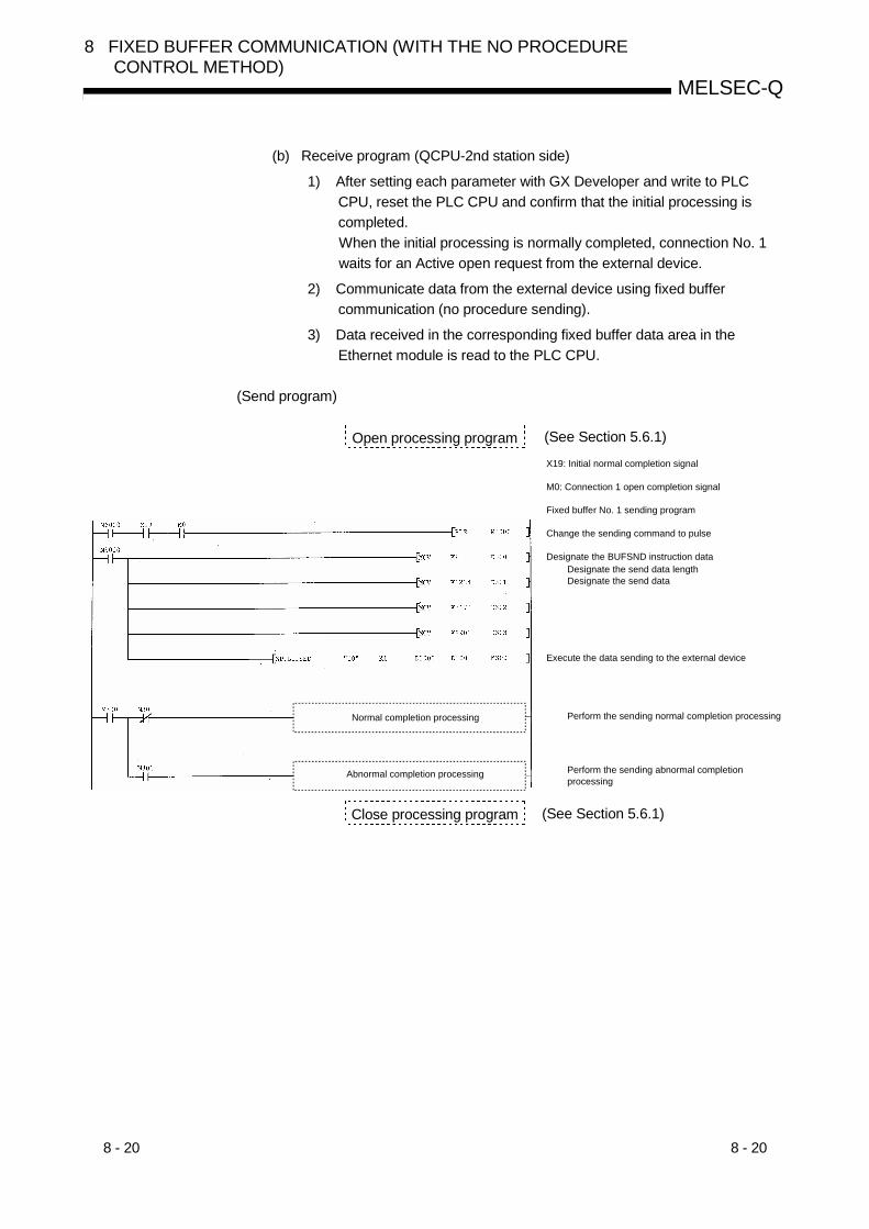
8 - 20 8 - 20
MELSEC-Q
8 FIXED BUFFER COMMUNICATION (WITH THE NO PROCEDURECONTROL METHOD)
(b) Receive program (QCPU-2nd station side)
1) After setting each parameter with GX Developer and write to PLCCPU, reset the PLC CPU and confirm that the initial processing iscompleted.When the initial processing is normally completed, connection No. 1waits for an Active open request from the external device.
2) Communicate data from the external device using fixed buffercommunication (no procedure sending).
3) Data received in the corresponding fixed buffer data area in theEthernet module is read to the PLC CPU.
(Send program)
Open processing programX19: Initial normal completion signal
M0: Connection 1 open completion signal
Fixed buffer No. 1 sending program
Change the sending command to pulse
Designate the BUFSND instruction dataDesignate the send data lengthDesignate the send data
Execute the data sending to the external device
Perform the sending normal completion processing
Perform the sending abnormal completion processing
Normal completion processing
Abnormal completion processing
Close processing program
(See Section 5.6.1)
(See Section 5.6.1)
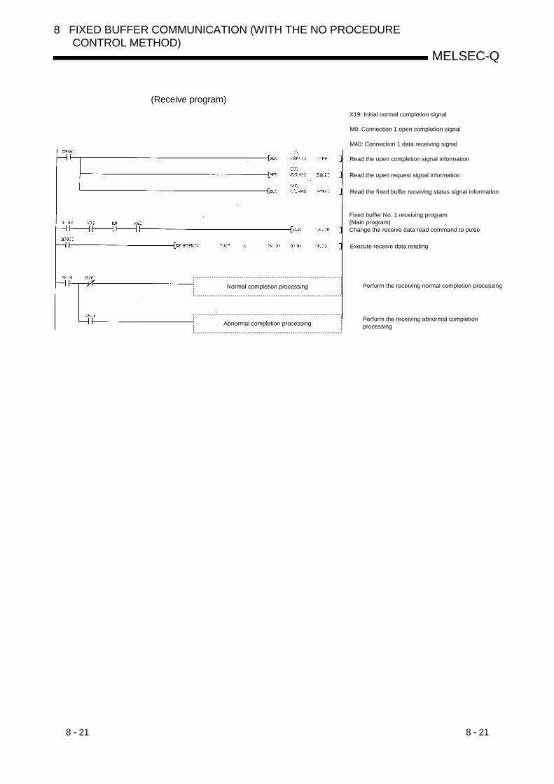
8 - 21 8 - 21
MELSEC-Q
8 FIXED BUFFER COMMUNICATION (WITH THE NO PROCEDURECONTROL METHOD)
(Receive program)X19: Initial normal completion signal
M0: Connection 1 open completion signal
M40: Connection 1 data receiving signal
Read the open completion signal information
Read the open request signal information
Read the fixed buffer receiving status signal information
Fixed buffer No. 1 receiving program(Main program)Change the receive data read command to pulse
Execute receive data reading
Perform the receiving normal completion processing
Perform the receiving abnormal completion processing
Normal completion processing
Abnormal completion processing
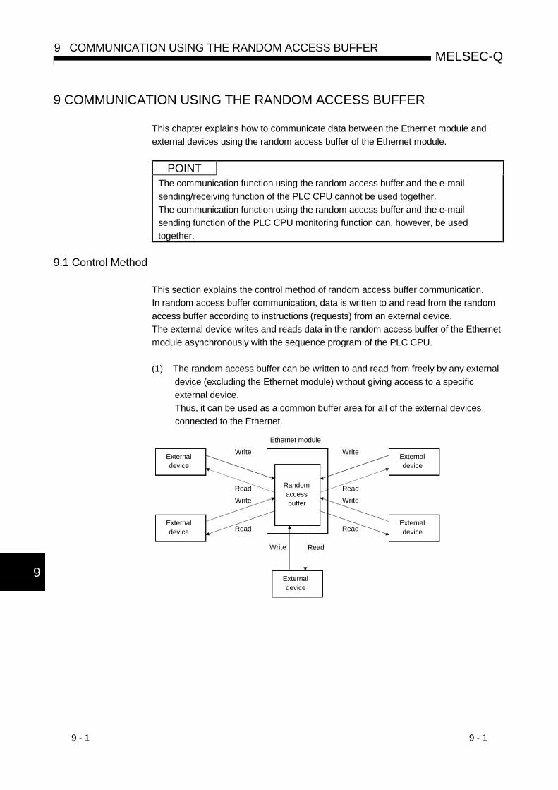
9 - 1 9 - 1
MELSEC-Q9 COMMUNICATION USING THE RANDOM ACCESS BUFFER
9
9 COMMUNICATION USING THE RANDOM ACCESS BUFFER
This chapter explains how to communicate data between the Ethernet module andexternal devices using the random access buffer of the Ethernet module.
POINTThe communication function using the random access buffer and the e-mailsending/receiving function of the PLC CPU cannot be used together.The communication function using the random access buffer and the e-mailsending function of the PLC CPU monitoring function can, however, be usedtogether.
9.1 Control Method
This section explains the control method of random access buffer communication.In random access buffer communication, data is written to and read from the randomaccess buffer according to instructions (requests) from an external device.The external device writes and reads data in the random access buffer of the Ethernetmodule asynchronously with the sequence program of the PLC CPU.
(1) The random access buffer can be written to and read from freely by any externaldevice (excluding the Ethernet module) without giving access to a specificexternal device.Thus, it can be used as a common buffer area for all of the external devicesconnected to the Ethernet.
Ethernet module
External device
External device
External device
External device
Randomaccess buffer
External device
Write
ReadWrite
Read
Write
Read
Write
Read
Write Read

9 - 2 9 - 2
MELSEC-Q9 COMMUNICATION USING THE RANDOM ACCESS BUFFER
9
(2) The following shows the data flow in the communication processing using therandom access buffer.
Data read
Ethernet module
TO instructionPLC CPU
Data written
Random access buffer
Read request External device
FROM instruction
(3) The random access buffer communication can be performed from all externaldevices except from the Ethernet module itself (including conventional modules).The random access buffer communication cannot be used for communicationbetween PLC CPUs.
(External devices that can perform communication using the random accessbuffer)• External devices on the Ethernet to which the Ethernet module is connected.• External devices on the Ethernet that are connected with the router relay
function (see Section 5.3)

9 - 3 9 - 3
MELSEC-Q9 COMMUNICATION USING THE RANDOM ACCESS BUFFER
9.1.1 Control method by read requests from an external device
The following diagram illustrates the control method when data is sent from theEthernet module in response to a read request from the external device.
2) 3)
1)
PLC CPU
External device
Rea
d re
ques
t (co
mm
and)
ACK (only TCP)
Res
pons
e, re
ad d
ata
ACK (only TCP)
Ethernet module Random access buffer
Writ
es w
ith th
e TO
inst
ruct
ion
1) The PLC CPU writes data to the random access buffer of the Ethernetmodule according to the TO instruction of the sequence program.Or, the external device writes data to the random access buffer of theEthernet module.
2) Asynchronously with the processing of 1) above, the external devicesends a read request to the Ethernet module.(The Ethernet module side: command receiving)
3) Upon receiving the read request from the external device, the Ethernetmodule sends the data written in the random access buffer to theexternal device which sent the read request.(The Ethernet module side: response sending)
POINT(1) In random access buffer communication, data can be communicated with an
external device for which the procedure exist control method is selected in thefixed buffer communication procedure setting (see Section 5.5) using aconnection where the Ethernet open completion signal (address: 5000H …corresponding bit) is on.
(2) Communication using the random access buffer is performed asynchronouslywith the sequence program. When it is necessary to synchronize, use thefixed buffer communication function.

9 - 4 9 - 4
MELSEC-Q9 COMMUNICATION USING THE RANDOM ACCESS BUFFER
9.1.2 Control method by write requests from an external device
The following diagram illustrates the control method when an external device writesdata to the random access buffer of the Ethernet module.
1) 2)
3)
External device
Writ
e da
ta (c
omm
and)
ACK (only TCP)
Res
pons
e
ACK (only TCP)
Ethernet module Random access buffer
Rea
ds w
ith th
e FR
OM
inst
ruct
ion
PLC CPU
1) The external device writes data to the random access buffer of theEthernet module.(The Ethernet module side: command receiving)
2) The Ethernet processes the write request from the external device andreturns the writing result to the external device that sent the writerequest.(The Ethernet module side: response sending)
3) Asynchronously with the processing of 1) and 2) above, the datawritten to the random access buffer is read with the FROM instructionof the sequence program.
POINT(1) In random access buffer communication, data can be communicated with an
external device for which the procedure exist control method is selected in thefixed buffer communication procedure setting (see Section 5.5) using aconnection where the Ethernet open completion signal (address: 5000H …corresponding bit) is on.
(2) Communication using the random access buffer is performed asynchronouslywith the sequence program. When it is necessary to synchronize, use thefixed buffer communication function.

9 - 5 9 - 5
MELSEC-Q9 COMMUNICATION USING THE RANDOM ACCESS BUFFER
9.2 Data Format
When communicating data between the Ethernet module and an external device, thedata format explained below is used.The communication data consists of a "header" and "application data" as shownbelow.
Maximum of 2044 bytes
Header Application data
9.2.1 Header
The header for TCP/IP or UDP/IP is used. In case of the Ethernet module, the Ethernetmodule adds the header.(Details of the size of the header section)
1) In case of TCP/IP
TCP20 bytes
Ethernet14 bytes
IP20 bytes
2) In case of UDP/IP
UDP8 bytes
Ethernet14 bytes
IP20 bytes
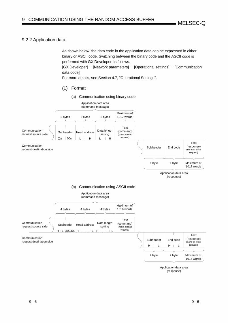
9 - 6 9 - 6
MELSEC-Q9 COMMUNICATION USING THE RANDOM ACCESS BUFFER
9.2.2 Application data
As shown below, the data code in the application data can be expressed in eitherbinary or ASCII code. Switching between the binary code and the ASCII code isperformed with GX Developer as follows.[GX Developer] [Network parameters] [Operational settings] [Communicationdata code]For more details, see Section 4.7, "Operational Settings".
(1) Format
(a) Communication using binary code
H 00H L H L H
Application data area(command message)
2 bytes 2 bytes 2 bytesMaximum of 1017 words
Communication request source side Subheader Head address Data length
setting
Text (command)(none at read
request)
Communication request destination side Subheader End code
Text (response)(none at write
request)
1 byte1 byte Maximum of 1017 words
Application data area(response)
(b) Communication using ASCII code
LH - -H L 30H 30H LH - -
H LH L
Application data area(command message)
4 bytes 4 bytes 4 bytesMaximum of 1016 words
Communication request source side Subheader Head address Data length
setting
Text (command)(none at read
request)
Communication request destination side Subheader End code
Text (response)(none at write
request)
2 byte2 byte Maximum of 1016 words
Application data area(response)
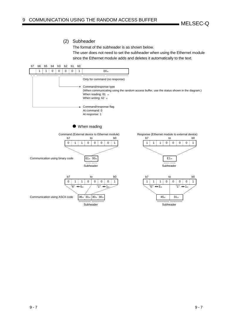
9 - 7 9 - 7
MELSEC-Q9 COMMUNICATION USING THE RANDOM ACCESS BUFFER
(2) SubheaderThe format of the subheader is as shown below.The user does not need to set the subheader when using the Ethernet modulesince the Ethernet module adds and deletes it automatically to the text.
b7 b6 b5 b4 b3 b2 b1 b01 1 0 0 0 0 1 00 H
Command/response flagAt command: 0At response: 1
Only for command (no response)
Command/response type(When communicating using the random access buffer, use the status shown in the diagram.)When reading: 61 H
When writing: 62 H
When reading
1 1 0 0 0 0 1b7 b00
00H61H
1 1 0 0 0 0 1b7 b00
31H36H 30H 30H
"6" 6H "1" 1H
1 1 0 0 0 0 1b7 b0
E1H
1 1 0 0 0 0 1b7 b0
45H 31H
"E" EH "1" 1H
1
1
Command (External device to Ethernet module)to
Response (Ethernet module to external device)to
Communication using binary code
Subheader Subheader
to to
Subheader Subheader
Communication using ASCII code

9 - 8 9 - 8
MELSEC-Q9 COMMUNICATION USING THE RANDOM ACCESS BUFFER
(3) Head addressIndicates the head address (ranging from 2680H to 3F7FH) of the random accessbuffer whose data is read/written from/to using its logical address (ranging from0H to 17FFH … See Section 9.3).
(a) Communication using binary code : Designate the head address by itsbinary value.
L H
2 bytes
(b) Communication using ASCII code : Designate an ASCII code value thatexpresses the head address inhexadecimal.
H – – L
4 bytes
(4) Data length settingIndicate the number of words of the read/written data in the random accessbuffer range.
(a) Communication using binary code : Designate the number of words by itsbinary value.
L H
2 bytes
(b) Communication using ASCII code : Designate an ASCII code value thatexpresses the number of words inhexadecimal.
H – – L
4 bytes
POINTThe data length can be designated in the following range:• Communication using binary code: Maximum of 1017 words• Communication using ASCII code: Maximum of 508 words ( 1)
1 Since data is sent/received as ASCII data, the communication data size isapproximately a half of the data size when using binary code.
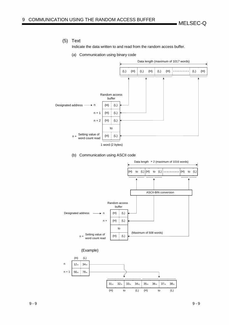
9 - 9 9 - 9
MELSEC-Q9 COMMUNICATION USING THE RANDOM ACCESS BUFFER
(5) TextIndicate the data written to and read from the random access buffer.
(a) Communication using binary code
(L) (H) (L) (H) (L) (H) (L) (H)
(L)(H)
(L)(H)
(L)(H)
(L)(H)
n
n + 1
n + 2
1 word (2 bytes)
Data length (maximum of 1017 words)
Random access buffer
Designated address
n + Setting value of word count read
to
(b) Communication using ASCII code
(H) (L)to (H) (L)to (H) (L)to
(L)(H)
(L)(H)
(L)(H)
n
n +
to
Data length × 2 (maximum of 1016 words)
ASCII-BIN conversion
Random access buffer
Designated address
n + Setting value of word count read
(Maximum of 508 words)
(Example)
n
31H 32H 33H 34H 35H 37H 38H36H
34H12H
78H56H
(H) to (L) (H) (L)to
n + 1
(L)(H)

9 - 10 9 - 10
MELSEC-Q9 COMMUNICATION USING THE RANDOM ACCESS BUFFER
(6) End codesThe following end codes are added to a response in random access buffercommunication.• Normal completion : 00H
• Abnormal completion : Value other than 00H (see Section 11.3.1)End codes are stored in the communication status storage area of the buffermemory.

9 - 11 9 - 11
MELSEC-Q9 COMMUNICATION USING THE RANDOM ACCESS BUFFER
9.2.3 Examples of the command/response formats
This section explains examples of the command/response formats duringcommunication using the random access buffer.
(1) Writing to the random access buffer by a write request from anexternal device
(a) Communication using binary code
1) Command format (external device to the Ethernet module)
00H00H62H 00H 0AH 00H 34H 12H 78H 56H BCH 9AH BCH 9AH
(L) (H) (L) (H) (L) (H) (L) (H) (L) (H)(L) (H)
(H) (L)
12H 34H
56H 78H
9AH BCH
9AH BCH
0H ( 0)
1H ( 1)
2H ( 2)
9H ( 9)
17FF H (6143)
2680 H ( 9856)
2681 H ( 9857)
2682 H ( 9858)
2689 H ( 9865)
3E7F H (15999)
SubheaderHead
addressData
length Text (10 words)
Ethernet module random access bufferPhysical address Logical address
(10 words)
to to to to
to to to
2) Response format (Ethernet module to the external device)
00HE2H
End codeSubheader
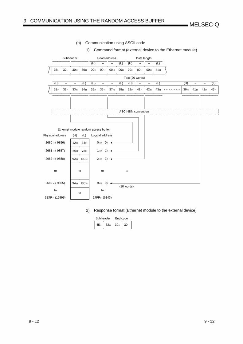
9 - 12 9 - 12
MELSEC-Q9 COMMUNICATION USING THE RANDOM ACCESS BUFFER
(b) Communication using ASCII code
1) Command format (external device to the Ethernet module)
(L) (H) (L)– – – (H) (L)– –(H) –(H) (L)– –
34H32H31H 33H 35H 36H 37H 38H 39H 41H 42H 43H 39H 41H 42H 43H
(L) (H) (L)– .– –(H) –
30H32H36H 30H 00H 00H 00H 00H 00H 00H 00H 41H
(H) (L)
2680 H ( 9856)
2681 H ( 9857)
2682 H ( 9858)
2689 H ( 9865)
3E7F H (15999)
0H ( 0)
1H ( 1)
2H ( 2)
9H ( 9)
17FF H (6143)
(10 words)
Subheader Head address Data length
Text (20 words)
Ethernet module random access buffer
ASCII-BIN conversion
Physical address Logical address
12H 34H
56H 78H
9AH BCH
9AH BCH
toto to to
toto to
2) Response format (Ethernet module to the external device)
45H 32H 30H 30H
Subheader End code

9 - 13 9 - 13
MELSEC-Q9 COMMUNICATION USING THE RANDOM ACCESS BUFFER
(2) Reading from the random access buffer by a read request from anexternal device
(a) Communication using binary code
1) Command format (external device to the Ethernet module)
00H00H61H 14H 0AH 00H
(L) (H)(L) (H)
Data lengthSubheaderHead
address
2) Response format (Ethernet module to the external device)Text (10 words)
(10 words)
(H)(L)
34H
Subheader End code
Ethernet module random access buffer
(H) (L)
12H 34H
56H 78H
9AH BCH
9AH BCH
Physical address Logical address
14H
15H
16H
1DH
17FFH
0H
(15999)3E7FH
( 9856)2680H
( 20)
( 21)
( 22)
( 29)
(6143)
( 0)
( 9885)269DH
( 9876)2694H
( 9877)2695H
( 9878)2696H
12H
(H)(L)
78H 56H
(H)(L)
BCH 9AH
(H)(L)
BCH 9AH00HE1H
to to to
to to to
to to to

9 - 14 9 - 14
MELSEC-Q9 COMMUNICATION USING THE RANDOM ACCESS BUFFER
(a) Communication using ASCII code
1) Command format (external device to the Ethernet module)
(H) (L)– –(L)–(H) –
30H31H36H 30H 00H 00H 31H 34H 00H 00H 00H 41H
Data lengthSubheader Head address
2) Response format (Ethernet module to the external device)
(L) (H) (L)– – – (H) (L)– –(H) –(H) (L)– –
34H32H31H 33H 35H 36H 37H 38H 39H 41H 42H 43H 39H 41H 42H 43H
30H31H45H 30H
(H) (L)
12H 34H
56H 78H
9AH BCH
9AH BCH
14H ( 20)
15H ( 21)
16H ( 22)
1DH ( 29)
17FFH (6143)
0H ( 0)
3E7FH (15999)
2680H ( 9856)
269DH ( 9885)
2694H ( 9876)
2695H ( 9877)
2696H ( 9878)
(10 words)
Subheader End code
Text (20 words)
ASCII-BIN conversion
Ethernet module random access bufferPhysical address Logical address
toto to
toto to
toto to

9 - 15 9 - 15
MELSEC-Q9 COMMUNICATION USING THE RANDOM ACCESS BUFFER
9.3 Physical and Logical Addresses of the Random Access Buffer
This section explains the head address of the Ethernet random access buffer (nobattery backup), which is designated with the commands used for the random accessbuffer communication.
The designated addresses of the random access buffer are shown below.Note that when designating the head address of the random access buffer, theaddress designated by an external device is different from that designated with theFROM/TO instructions in the sequence program.
Physical address : Address designated with the FROM/TO instructions of thesequence program
Logical address : Address designated by the external device as the head addressitem in the command
0H ( 0)
267FH ( 9855)
2680H ( 9856)
3E7FH (15999)
680H ( 1664)
17FFH (6143)
Random access buffer
Physical address Buffer memory
Fixed buffer
Logical address
toto
9 - 16 9 - 16
MELSEC-Q9 COMMUNICATION USING THE RANDOM ACCESS BUFFER
9.4 Precautions when Creating Programs
This section explains an outline of the precautions that should be observed whencreating programs for data communications between the Ethernet module and externaldevices using the random access buffer.
(1) In order to communicate using the random access buffer, the initial processingand the connection open processing must be completed.
(2) The PLC CPU cannot issue a send request when communicating using therandom access buffer.Also, receive completion is not confirmed to the PLC CPU.When it is necessary to synchronize data sending/receiving between the PLCCPU and an external device, use the fixed buffer communication function.
(3) The address designated for the random access buffer by an external device andthe address designated with the FROM/TO instructions of the sequence programare different.For more detail, see Section 9.3.

10 - 1 10 - 1
MELSEC-Q10 DEDICATED INSTRUCTIONS
10
10 DEDICATED INSTRUCTIONS
Dedicated instructions are used to simplify programming for using the functions of theintelligent function module.This chapter explains the dedicated instructions for the functions that are explained inthis manual, among those dedicated commands available for the Ethernet module thatcan be used by the QCPU.
10.1 Dedicated Instruction List
The following table lists the dedicated instructions explained in this chapter:Application Dedicated instruction Description of function Reference section
OPEN Establishes a connection. Section 10.8For opening and closing connections
CLOSE Disconnects a connection. Section 10.5
BUFRCVReads received data.(For main program)
Section 10.2
BUERCVSReads received data.(For interrupt program)
Section 10.3For fixed buffer communication
BURSND Sends data. Section 10.4ERRCLR Clears error information. Section 10.6
For reading and clearing error informationERRRD Reads error information. Section 10.7
For reinitialization UINIReinitializes the Ethernetmodule.
Section 10.9
POINT(1) The user should not change any data (control data, request data, etc.) that is
specified with a dedicated instruction until the execution of that dedicatedinstruction is completed.
(2) All dedicated instructions must be executed online.If any of the dedicated instructions is executed offline, no error will occur, butthe execution of the dedicated instruction will not be completed.

10 - 2 10 - 2
MELSEC-Q10 DEDICATED INSTRUCTIONS
10
10.2 BUFRCV Instruction
This instruction reads data received from an external device through fixed buffercommunication.This instruction is used in the main program.
Applicable device
Internal device(System, user)
MELSECNET/H,MELSECNET/10
Direct J \Constant
Settingdata
Bit Word
Fileregister
Bit Word
Special moduleU \G
Indexregister
ZnK, H $
Others
(S1)(S2)(D1)(D2)
(D2)"Un"ZP.BUFRCVBUFRCV (D1)(S2)(S1)
[Instruction code] [Executing condition]
Command
Setting dataSetting data Description Set by ( 1) Data type
"Un" Start input/output signal of the Ethernet module(00 to FE: The two most significant digits of the 3-digit input/output signal) Binary 16 bits
(S1) Connection number (1 to 16)User
Binary 16 bits(S2) Head number of the devices that designate control data Binary 16 bits(D1) Head number of the device that stores receive data Binary 16 bits
(D2)Head number of the local station bit device that turns on for one scanupon completion of instruction.(D2) + 1 also turns on if the instruction execution ends abnormally.
SystemBit
The file registers for each of the local device and the program cannot be used asdevices to be used in the setting data.
Control dataDevice Item Setting data Setting range Set by ( 1)(S2) + 0 System area
(S2) + 1 Complete status
• Stores the status at completion.0000H: Normal completionOther than 0000H
: Abnormal completion (error code) ( 2)
System
Receive dataDevice Item Setting data Setting range Set by ( 1)
• Stores the data length of the data read from thefixed buffer data area in word units.
There is a procedure (for communicationusing binary code): Number of words 1 to 1017
There is a procedure (for communicationusing ASCII code): Number of words 1 to 508
(D1) + 0 Receive datalength
Non procedure (for communication usingbinary code): Number of bytes 1 to 2046
System
(D1) + 1to
(D2) + nReceive data • Stores the data read from the fixed buffer data area
sequentially in ascending order. System
1 The "Set by" column indicates the following:• User : Data set by the user before executing a dedicated instruction.• System : The PLC CPU stores the execution results of a dedicated instruction.
2 For details on the error codes at abnormal completion, see Section 11.3, "Error Code List".
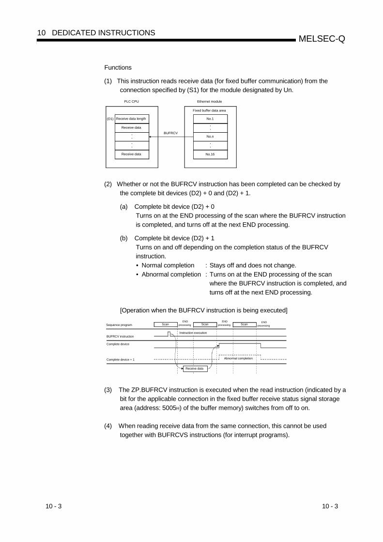
10 - 3 10 - 3
MELSEC-Q10 DEDICATED INSTRUCTIONS
Functions
(1) This instruction reads receive data (for fixed buffer communication) from theconnection specified by (S1) for the module designated by Un.
••
••
(D1) No.1
No.n
••
••
No.16
BUFRCV
Fixed buffer data area
PLC CPU Ethernet module
Receive data length
Receive data
Receive data
(2) Whether or not the BUFRCV instruction has been completed can be checked bythe complete bit devices (D2) + 0 and (D2) + 1.
(a) Complete bit device (D2) + 0Turns on at the END processing of the scan where the BUFRCV instructionis completed, and turns off at the next END processing.
(b) Complete bit device (D2) + 1Turns on and off depending on the completion status of the BUFRCVinstruction.• Normal completion : Stays off and does not change.• Abnormal completion : Turns on at the END processing of the scan
where the BUFRCV instruction is completed, andturns off at the next END processing.
[Operation when the BUFRCV instruction is being executed]
Instruction execution
Receive data
Sequence program ScanEND
processing Scan ScanEND
processingEND
processing
BUFRCV instruction
Complete device
Complete device + 1 Abnormal completion
(3) The ZP.BUFRCV instruction is executed when the read instruction (indicated by abit for the applicable connection in the fixed buffer receive status signal storagearea (address: 5005H) of the buffer memory) switches from off to on.
(4) When reading receive data from the same connection, this cannot be usedtogether with BUFRCVS instructions (for interrupt programs).
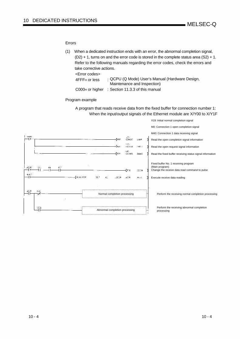
10 - 4 10 - 4
MELSEC-Q10 DEDICATED INSTRUCTIONS
Errors
(1) When a dedicated instruction ends with an error, the abnormal completion signal,(D2) + 1, turns on and the error code is stored in the complete status area (S2) + 1.Refer to the following manuals regarding the error codes, check the errors andtake corrective actions.<Error codes>4FFFH or less : QCPU (Q Mode) User’s Manual (Hardware Design,
Maintenance and Inspection)C000H or higher : Section 11.3.3 of this manual
Program example
A program that reads receive data from the fixed buffer for connection number 1:When the input/output signals of the Ethernet module are X/Y00 to X/Y1F
X19: Initial normal completion signal
M0: Connection 1 open completion signal
M40: Connection 1 data receiving signal
Read the open completion signal information
Read the open request signal information
Read the fixed buffer receiving status signal information
Fixed buffer No. 1 receiving program(Main program)Change the receive data read command to pulse
Execute receive data reading
Perform the receiving normal completion processing
Perform the receiving abnormal completion processing
Normal completion processing
Abnormal completion processing

10 - 5 10 - 5
MELSEC-Q10 DEDICATED INSTRUCTIONS
10.3 BUFRCVS Instruction
This instruction reads data received from an external device through fixed buffercommunication.This instruction is used in the interrupt program.
Applicable device
Internal device(System, user)
MELSECNET/H,MELSECNET/10
Direct J \Constant
Settingdata
Bit Word
Fileregister
Bit Word
Special moduleU \G
Indexregister
ZnK, H $
Others
(S1)(D1)
"Un"Z.BUFRCVSBUFRCVS (D1)(S1)
[Instruction code] [Executing condition]
Command
Setting dataSetting data Description Set by ( 1) Data type
"Un"Start input/output signal of the Ethernet module(00 to FE: The two most significant digits of the 3-digit input/output signal)
Binary 16 bits
(S1) Connection number (1 to 16)User
Binary 16 bits(D1) Head number of the device that stores receive data System Binary 16 bits
The file registers of each of the local device and the program cannot be used as deviceto be used in the setting data.
Receive dataDevice Item Setting data Setting range Set by ( 1)
• Stores the data length of the data read from thefixed buffer data area in word units.
There is a procedure (for communicationusing binary code): Number of words 1 to 1017
There is a procedure (for communicationusing ASCII code): Number of words 1 to 508
(D1) + 0Receive datalength
Non procedure (for communication usingbinary code): Number of bytes 1 to 2046
System
(D1) + 1to
(D1) + nReceive data
• Stores the data read from the fixed buffer data areasequentially in ascending order.
System
1 The "Set by" column indicates the following:• User : Data set by the user before executing a dedicated instruction.• System : The PLC CPU stores the execution results of a dedicated instruction.

10 - 6 10 - 6
MELSEC-Q10 DEDICATED INSTRUCTIONS
Functions
(1) This instruction reads receive data (for fixed buffer communication) from theconnection specified by (S1) for the module designated by Un.
••
••
(D1) No.1
No.n
••
••
No.16
BUFRCVS
Fixed buffer data area
PLC CPU Ethernet module
Receive data length
Receive data
Receive data
[Operation when the BUFRCVS instruction is being executed]Scan
Receive data storage
Sequence programEND processing
Interrupt program
BUFRCVS instruction Instruction execution
Data receiving
(2) The Z.BUFRCVS instruction is used by the interrupt programs and its processingcompletes within one scan.
(3) In order to read receive data with an interrupt program, it is necessary to performboth the interrupt settings and interrupt pointer settings with parameter settings ofGX Developer.
(4) When reading receive data from the same connection, this cannot be usedtogether with BUFRCV instructions (for main programs).
Errors
(1) When the dedicated instruction is completed abnormally, the error flag (SM0)turns on and the error code is stored in SD0.Refer to the following manuals regarding the error code, check the errors andtake corrective actions.<Error codes>4FFFH or less : QCPU (Q Mode) User’s Manual (Hardware Design,
Maintenance and Inspection)C000H or higher : Section 11.3.3 of this manual

10 - 7 10 - 7
MELSEC-Q10 DEDICATED INSTRUCTIONS
Program example
A program that reads receive data from the fixed buffer for connection number 2:When the input/output signals of the Ethernet module are X/Y00 to X/Y1F
Execute receive data reading
Enable (permit) the execution of the interrupt program
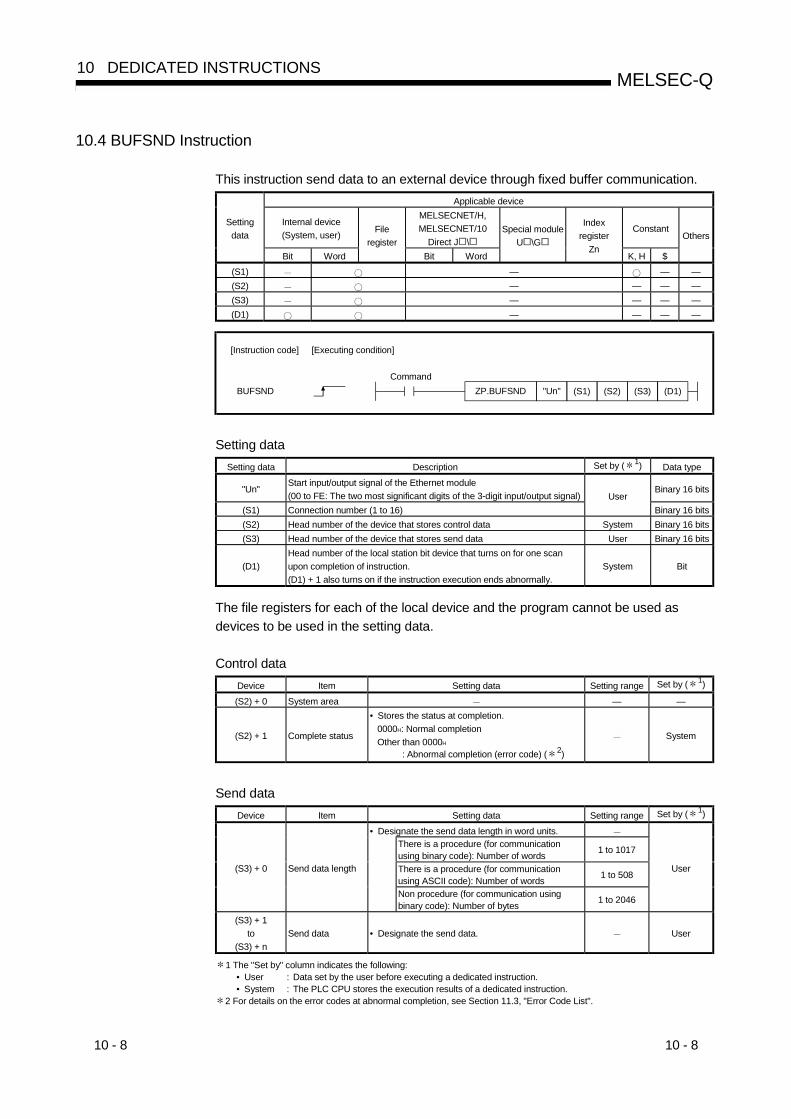
10 - 8 10 - 8
MELSEC-Q10 DEDICATED INSTRUCTIONS
10.4 BUFSND Instruction
This instruction send data to an external device through fixed buffer communication.Applicable device
Internal device(System, user)
MELSECNET/H,MELSECNET/10
Direct J \Constant
Settingdata
Bit Word
Fileregister
Bit Word
Special moduleU \G
Indexregister
ZnK, H $
Others
(S1) — — —(S2) — — — —(S3) — — — —(D1) — — — —
"Un"ZP.BUFSNDBUFSND (D1)(S2)(S1) (S3)
[Instruction code] [Executing condition]
Command
Setting dataSetting data Description Set by ( 1) Data type
"Un"Start input/output signal of the Ethernet module(00 to FE: The two most significant digits of the 3-digit input/output signal)
Binary 16 bits
(S1) Connection number (1 to 16)User
Binary 16 bits(S2) Head number of the device that stores control data System Binary 16 bits(S3) Head number of the device that stores send data User Binary 16 bits
(D1)Head number of the local station bit device that turns on for one scanupon completion of instruction.(D1) + 1 also turns on if the instruction execution ends abnormally.
System Bit
The file registers for each of the local device and the program cannot be used asdevices to be used in the setting data.
Control dataDevice Item Setting data Setting range Set by ( 1)
(S2) + 0 System area — —
(S2) + 1 Complete status
• Stores the status at completion.0000H: Normal completionOther than 0000H
: Abnormal completion (error code) ( 2)
System
Send dataDevice Item Setting data Setting range Set by ( 1)
• Designate the send data length in word units.There is a procedure (for communicationusing binary code): Number of words 1 to 1017
There is a procedure (for communicationusing ASCII code): Number of words 1 to 508
(S3) + 0 Send data length
Non procedure (for communication usingbinary code): Number of bytes 1 to 2046
User
(S3) + 1to
(S3) + nSend data • Designate the send data. User
1 The "Set by" column indicates the following:• User : Data set by the user before executing a dedicated instruction.• System : The PLC CPU stores the execution results of a dedicated instruction.
2 For details on the error codes at abnormal completion, see Section 11.3, "Error Code List".
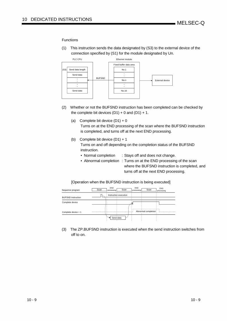
10 - 9 10 - 9
MELSEC-Q10 DEDICATED INSTRUCTIONS
Functions
(1) This instruction sends the data designated by (S3) to the external device of theconnection specified by (S1) for the module designated by Un.
••
••
(S3) No.1
No.n
••
••
No.16
BUFSND
Fixed buffer data area
PLC CPU Ethernet module
Send data length
Send data
Send data
External device
(2) Whether or not the BUFSND instruction has been completed can be checked bythe complete bit devices (D1) + 0 and (D1) + 1.
(a) Complete bit device (D1) + 0Turns on at the END processing of the scan where the BUFSND instructionis completed, and turns off at the next END processing.
(b) Complete bit device (D1) + 1Turns on and off depending on the completion status of the BUFSNDinstruction.• Normal completion : Stays off and does not change.• Abnormal completion : Turns on at the END processing of the scan
where the BUFSND instruction is completed, andturns off at the next END processing.
[Operation when the BUFSND instruction is being executed]
Instruction execution
Send data
Sequence program ScanEND
processing Scan ScanEND
processingEND
processing
BUFSND instruction
Complete device
Complete device + 1 Abnormal completion
(3) The ZP.BUFSND instruction is executed when the send instruction switches fromoff to on.
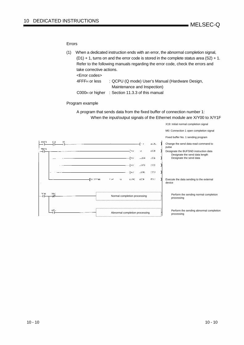
10 - 10 10 - 10
MELSEC-Q10 DEDICATED INSTRUCTIONS
Errors
(1) When a dedicated instruction ends with an error, the abnormal completion signal,(D1) + 1, turns on and the error code is stored in the complete status area (S2) + 1.Refer to the following manuals regarding the error code, check the errors andtake corrective actions.<Error codes>4FFFH or less : QCPU (Q mode) User’s Manual (Hardware Design,
Maintenance and Inspection)C000H or higher : Section 11.3.3 of this manual
Program example
A program that sends data from the fixed buffer of connection number 1:When the input/output signals of the Ethernet module are X/Y00 to X/Y1F
X19: Initial normal completion signal
M0: Connection 1 open completion signal
Fixed buffer No. 1 sending program
Change the send data read command to pulseDesignate the BUFSND instruction data
Designate the send data lengthDesignate the send data
Execute the data sending to the external device
Perform the sending normal completion processing
Perform the sending abnormal completion processingAbnormal completion processing
Normal completion processing

10 - 11 10 - 11
MELSEC-Q10 DEDICATED INSTRUCTIONS
10.5 CLOSE Instruction
This instruction disconnects (closes) a connection by which data was communicatedwith an external device.
Applicable device
Internal device(System, user)
MELSECNET/H,MELSECNET/10
Direct J \Constant
Settingdata
Bit Word
Fileregister
Bit Word
Special moduleU \G
Indexregister
ZnK, H $
Others
(S1)(S2)(D1)
"Un"ZP. CLOSECLOSE (D1)(S2)(S1)
[Instruction code] [Executing condition]
Command
Setting dataSetting data Description Set by ( 1) Data type
"Un"Start input/output signal of the Ethernet module(00 to FE: The two most significant digits of the 3-digit input/output signal)
Binary 16 bits
(S1) Connection number (1 to 16)User
Binary 16 bits(S2) Head number of the device that stores control data Binary 16 bits
(D1)Head number of the local station bit device that turns on for one scanupon completion of instruction.(D1) + 1 also turns on if the instruction execution ends abnormally.
SystemBit
The file registers for each of the local device and the program cannot be used asdevices to be used in the setting data.
Control dataDevice Item Setting data Setting range Set by ( 1)
(S2) + 0 System area
(S2) + 1 Complete status
• Stores the status at completion.0000H: Normal completionOther than 0000H
: Abnormal completion (error code) ( 2)
System
1 The "Set by" column indicates the following:• User : Data set by the user before executing a dedicated instruction.• System : The PLC CPU stores the execution results of a dedicated instruction.
2 For details on the error codes at abnormal completion, see Section 11.3, "Error Code List".

10 - 12 10 - 12
MELSEC-Q10 DEDICATED INSTRUCTIONS
Functions
(1) This instruction closes the connection specified by (S1) for the module designatedby Un (disconnecting connections).
(2) Whether or not the CLOSE instruction has been completed can be checked bythe complete bit devices (D1) + 0 and (D1) + 1.
(a) Complete bit device (D1) + 0Turns on at the END processing of the scan where the CLOSE instructionis completed, and turns off at the next END processing.
(b) Complete bit device (D1) + 1Turns on and off depending on the completion status of the CLOSEinstruction.• Normal completion : Stays off and does not change.• Abnormal completion : Turns on at the END processing of the scan
where the CLOSE instruction is completed, andturns off at the next END processing.
[Operation when the CLOSE instruction is being executed]
Instruction execution
Connection closed
Sequence program ScanEND
processing Scan ScanEND
processingEND
processing
CLOSE instruction
Complete device
Complete device + 1 Abnormal completion
(3) The ZP.CLOSE is executed when the close instruction switches from off to on.
ImportantNever execute the open/close processing using input/output signals and theopen/close processing using the OPEN or CLOSE dedicated instructionssimultaneously for the same connection. It will result in malfunctions.
Errors
(1) When a dedicated instruction ends with an error, the abnormal completion signal,(D1) + 1, turns on and the error code is stored in the complete status area (S2) + 1.Refer to the following manuals regarding the error codes, check the errors andtake corrective actions.<Error codes>4FFFH or less : QCPU (Q Mode) User’s Manual (Hardware Design,
Maintenance and Inspection)C000H or higher : Section 11.3.3 of this manual
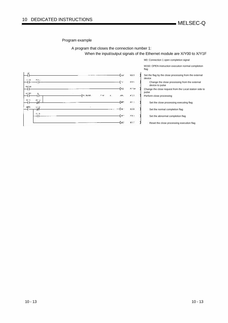
10 - 13 10 - 13
MELSEC-Q10 DEDICATED INSTRUCTIONS
Program example
A program that closes the connection number 1:When the input/output signals of the Ethernet module are X/Y00 to X/Y1F
Reset the close processing execution flag
M0: Connection 1 open completion signal
M150: OPEN instruction execution normal completion flag
Set the flag by the close processing from the external device
Change the close processing from the external device to pulse
Change the close request from the Local station side to pulsePerform close processing
Set the close processing executing flag
Set the normal completion flag
Set the abnormal completion flag

10 - 14 10 - 14
MELSEC-Q10 DEDICATED INSTRUCTIONS
10.6 ERRCLR Instruction
This instruction turns off the LEDs of the Ethernet module and clears data informationstored in the buffer memory.
Applicable device
Internal device(System, user)
MELSECNET/H,MELSECNET/10
Direct J \Constant
Settingdata
Bit Word
Fileregister
Bit Word
Special moduleU \G
Indexregister
ZnK, H $
Others
(S1) — — — — —(D1) — — — —
"Un"ZP.ERRCLRERRCLR (D1)(S1)
[Instruction code] [Executing condition]
Command
Setting dataSetting data Description Set by ( 1) Data type
"Un"Start input/output signal of the Ethernet module(00 to FE: The two most significant digits of the 3-digit input/output signal)
User Binary 16 bits
(S1) Head number of the device that stores control data User, system Binary 16 bits
(D1)Head number of the local station bit device that turns on for one scanupon completion of instruction.(D1) + 1 also turns on if the instruction execution ends abnormally.
System Bit
The file registers for each of the local device and the program cannot be used asdevices to be used in the setting data.
Control dataDevice Item Setting data Setting range Set by ( 1)
(S1) + 0 System area — — —
(S1) + 1 Complete status
• Stores the status at completion.0000H: Normal completionOther than 0000H
: Abnormal completion (error code) ( 2)
— System
(S1) + 2Clearing targetdesignation
• Designate the error information to be cleared.0000H: Initial abnormal code0001H to 0016H
: Open abnormal code for the applicableconnection
0100H: Error log block area0101H: Communication status – status by each
protocol0102H: Communication status – E-mail receive
status0103H: Communication status – E-mail send statusFFFFH: Clears all of the above
(as describedin the left)
User
(S1) + 3Clearing functiondesignation
• Designate the function to be cleared.0000H: [COM.ERR] LED off, error code clearFFFFH: Error log clear
0000H
FFFFHUser
(S1) + 4to
(S1) + 7System area — — —
1 The "Set by" column indicates the following:• User : Data set by the user before executing a dedicated instruction.• System : The PLC CPU stores the execution results of a dedicated instruction.
2 For details on the error codes at abnormal completion, see Section 11.3, "Error Code List".

10 - 15 10 - 15
MELSEC-Q10 DEDICATED INSTRUCTIONS
Functions
(1) This instruction turns [COM.ERR] LEDs off and clears error information listedbelow for the module designated by Un.
Target itemTarget
designation(S1) + 2
Functiondesignation
(S1) + 3
Error information to be cleared(buffer memory)
Initial error 0000H 0000H• Initial abnormal code (address: 69H)• [COM.ERR] LED off
Open error 0001H to 0016H 0000H
• Open abnormal code for applicableconnection (address: 7CH, 86H…)
• [COM.ERR] LED offError log 0100H FFFFH • Error log (address:E3H to 174H)
Status by eachprotocol
0101H FFFFH• Clears communication status
(address: 178H to 1FFH)E-mail receivestatus
0102H FFFFH • E-mail receiving (address: 5871H to 5B38H)Communicationstatus
E-mail send status 0103H FFFFH• E-mail sending
(address: 5B39H to 5CA0H)All FFFFH FFFFH • Clears all of the above.
(2) Whether or not the ERRCLR instruction has been completed can be checked bythe complete bit devices (D1) + 0 and (D1) + 1.
(a) Complete bit device (D1) + 0Turns on at the END processing of the scan where the ERRCLR instructionis completed, and turns off at the next END processing.
(b) Complete bit device (D1) + 1Turns on and off depending on the completion status of the ERRCLRinstruction.• Normal completion : Stays off and does not change.• Abnormal completion: Turns on at the END processing of the scan where
the ERRCLR instruction is completed, and turns offat the next END processing.
[Operation when the ERRCLR instruction is being executed]
Instruction execution
Error cleared
Sequence program ScanEND
processing Scan ScanEND
processingEND
processing
ERRCLR instruction
Complete device
Complete device + 1 Abnormal completion
(3) The ZP.ERRCLR function is executed when the clear instruction switches from offto on.

10 - 16 10 - 16
MELSEC-Q10 DEDICATED INSTRUCTIONS
Errors
(1) When a dedicated instruction ends with an error, the abnormal completion signal,(D1) + 1, turns on and the error code is stored in the complete status area (S1) + 1.Refer to the following manuals regarding the error code, check the errors andtake corrective actions.<Error codes>4FFFH or less : QCPU (Q Mode) User’s Manual (Hardware Design,
Maintenance and Inspection)C000H or higher : Section 11.3.3 of this manual
Program example
A program that clears the open abnormal code for connection 1:When the input/output signals of the Ethernet module are X/Y00 to X/Y1F
Reset the ERRCLR instruction execution flag
Designate to clear the connection 1 open abnormal codeDesignate to turn off ERR LED and clear the error codeSet the ERRCLR instruction execution flag
Execute error information clearing
Clear the retained error code at normal completion of the error information clear processingRetain the error code at abnormal completion of the error information clear processing
M0: Connection 1 open completion signal
Designate the ERRCLR instruction data

10 - 17 10 - 17
MELSEC-Q10 DEDICATED INSTRUCTIONS
10.7 ERRRD Instruction
This instruction reads the error information stored in the buffer memory of the Ethernetmodule.
Applicable device
Internal device(System, user)
MELSECNET/H,MELSECNET/10
Direct J \ConstantSetting
data
Bit Word
Fileregister
Bit Word
Special moduleU \G
Indexregister
ZnK, H $
Others
(S1) — — — —(D1) — — — —
"Un"ZP.ERRRDERRRD (D1)(S1)
[Instruction code] [Executing condition]
Command
Setting dataSetting data Description Set by ( 1) Data type
"Un" Start input/output signal of the Ethernet module(00 to FE: The two most significant digits of the 3-digit input/output signal) User Binary 16 bits
(S1) Head number of the device that stores control data User, system Binary 16 bits
(D1)Head number of the local station bit device that turns on for one scanupon completion of instruction.(D1) + 1 also turns on if the instruction execution ends abnormally.
System Bit
The file registers for each of the local device and the program cannot be used asdevices to be used in the setting data.
Control dataDevice Item Setting data Setting range Set by ( 1)
(S1) + 0 System area — —
(S1) + 1 Complete status
• Stores the status at completion.0000H: Normal completionOther than 0000H
: Abnormal completion (error code) ( 2)
— System
(S1) + 2 Read informationdesignation
• Designates the error information to read.0 : Initial abnormal code1 to 16: Open abnormal code for the applicable
connection
01 to 16 User
(S1) + 3Read targetinformationdesignation
• Designates a target of the error information to read.0000H: Information of the last error that has
occurred0000H User
(S1) + 4 Error information• Stores the error information that has been read.
000H : No errorOther than 0000H: Error code ( 2)
0000H System
(S1) + 5to
(S1) + 7System area — — —
1 The "Set by" column indicates the following:• User : Data set by the user before executing a dedicated instruction.• System : The PLC CPU stores the execution results of a dedicated instruction.
2 For details on the error codes at abnormal completion, see Section 11.3, "Error Code List".
Functions
(1) This instruction reads the error code and information in the error log of the moduledesignated by Un.
Target item Target designation (S1) + 2 Function designation (S1) + 3 Error information to be cleared(buffer memory)
Initial error 0000H 0H • Initial abnormal code (address: 69H)
Open error 0001H to 0016H 0H• Open abnormal code for applicable
connection (address: 7CH, 86H…)
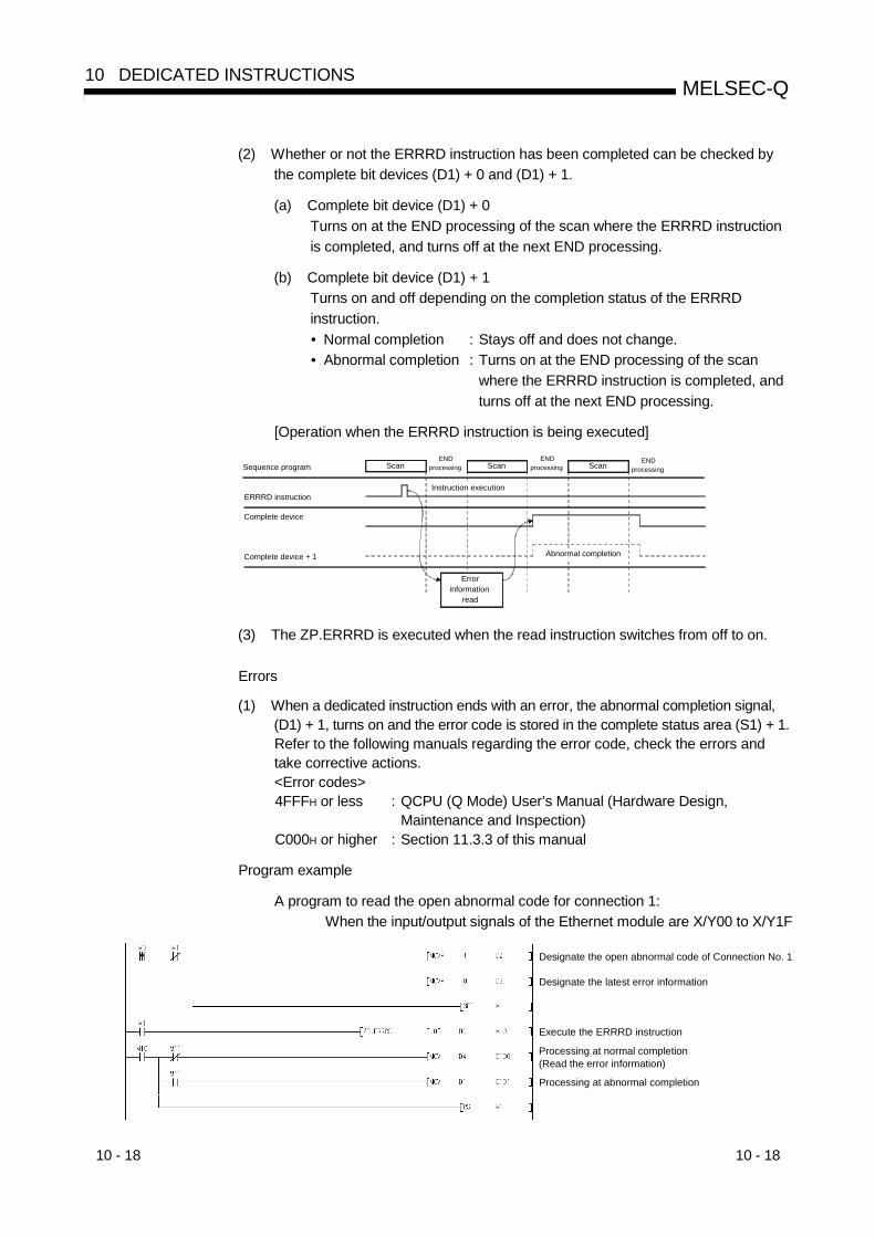
10 - 18 10 - 18
MELSEC-Q10 DEDICATED INSTRUCTIONS
(2) Whether or not the ERRRD instruction has been completed can be checked bythe complete bit devices (D1) + 0 and (D1) + 1.
(a) Complete bit device (D1) + 0Turns on at the END processing of the scan where the ERRRD instructionis completed, and turns off at the next END processing.
(b) Complete bit device (D1) + 1Turns on and off depending on the completion status of the ERRRDinstruction.• Normal completion : Stays off and does not change.• Abnormal completion : Turns on at the END processing of the scan
where the ERRRD instruction is completed, andturns off at the next END processing.
[Operation when the ERRRD instruction is being executed]
Instruction execution
Error information
read
Sequence program ScanEND
processing Scan ScanEND
processingEND
processing
ERRRD instruction
Complete device
Complete device + 1 Abnormal completion
(3) The ZP.ERRRD is executed when the read instruction switches from off to on.
Errors
(1) When a dedicated instruction ends with an error, the abnormal completion signal,(D1) + 1, turns on and the error code is stored in the complete status area (S1) + 1.Refer to the following manuals regarding the error code, check the errors andtake corrective actions.<Error codes>4FFFH or less : QCPU (Q Mode) User’s Manual (Hardware Design,
Maintenance and Inspection)C000H or higher : Section 11.3.3 of this manual
Program example
A program to read the open abnormal code for connection 1:When the input/output signals of the Ethernet module are X/Y00 to X/Y1F
Designate the open abnormal code of Connection No. 1
Designate the latest error information
Execute the ERRRD instruction
Processing at normal completion(Read the error information)
Processing at abnormal completion

10 - 19 10 - 19
MELSEC-Q10 DEDICATED INSTRUCTIONS
10.8 OPEN Instruction
This instruction establishes a connection (open processing) with an external device toperform data communication.
Applicable device
Internal device(System, user)
MELSECNET/H,MELSECNET/10
Direct J \Constant
Settingdata
Bit Word
Fileregister
Bit Word
Special moduleU \G
Indexregister
Zn K, H $
Others
(S1)(S2)(D1)
"Un"ZP.OPENZP.OPEN (D1)(S1) (S2)
[Instruction code] [Executing condition]
Command
Setting dataSetting data Description Set by ( 1) Data type
"Un"Start input/output signal of the Ethernet module(00 to FE: The two most significant digits of the 3-digit input/output signal)
Binary 16 bits
(S1) Connection number (1 to 16)User
Binary 16 bits(S2) Head number of the device that stores control data User, system Binary 16 bits
(D1)Head number of the local station bit device that turns on for one scanupon completion of instruction.(D1) + 1 also turns on if the instruction execution ends abnormally.
System Bit
The file registers for each of the local device and the program cannot be used asdevices to be used in the setting data.
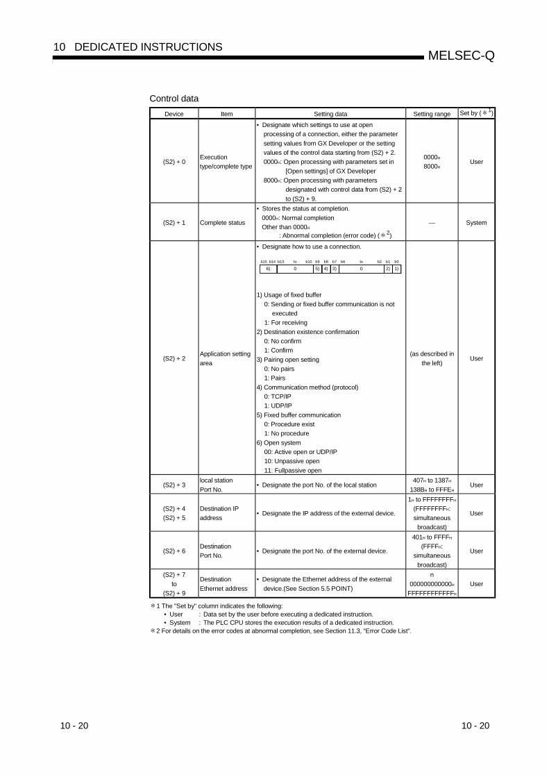
10 - 20 10 - 20
MELSEC-Q10 DEDICATED INSTRUCTIONS
Control dataDevice Item Setting data Setting range Set by ( 1)
(S2) + 0Executiontype/complete type
• Designate which settings to use at openprocessing of a connection, either the parametersetting values from GX Developer or the settingvalues of the control data starting from (S2) + 2.0000H: Open processing with parameters set in
[Open settings] of GX Developer8000H: Open processing with parameters
designated with control data from (S2) + 2to (S2) + 9.
0000H
8000HUser
(S2) + 1 Complete status
• Stores the status at completion.0000H: Normal completionOther than 0000H
: Abnormal completion (error code) ( 2)
— System
(S2) + 2Application settingarea
• Designate how to use a connection.
4)b8
3)b7
2)b1
1)b0
0b6 to b2
5)b9
0to b10
6)b14 b13b15
1) Usage of fixed buffer0: Sending or fixed buffer communication is not
executed1: For receiving
2) Destination existence confirmation0: No confirm1: Confirm
3) Pairing open setting0: No pairs1: Pairs
4) Communication method (protocol)0: TCP/IP1: UDP/IP
5) Fixed buffer communication0: Procedure exist1: No procedure
6) Open system00: Active open or UDP/IP10: Unpassive open11: Fullpassive open
(as described inthe left)
User
(S2) + 3local stationPort No.
• Designate the port No. of the local station407H to 1387H
138BH to FFFEHUser
(S2) + 4(S2) + 5
Destination IPaddress
• Designate the IP address of the external device.
1H to FFFFFFFFH
(FFFFFFFFH:simultaneous
broadcast)
User
(S2) + 6DestinationPort No.
• Designate the port No. of the external device.
401H to FFFFH
(FFFFH:simultaneous
broadcast)
User
(S2) + 7to
(S2) + 9
DestinationEthernet address
• Designate the Ethernet address of the externaldevice.(See Section 5.5 POINT)
n000000000000H
FFFFFFFFFFFFH
User
1 The "Set by" column indicates the following:• User : Data set by the user before executing a dedicated instruction.• System : The PLC CPU stores the execution results of a dedicated instruction.
2 For details on the error codes at abnormal completion, see Section 11.3, "Error Code List".
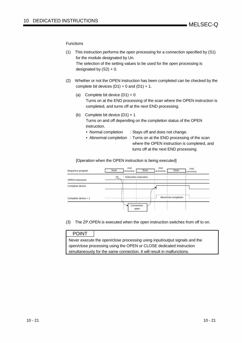
10 - 21 10 - 21
MELSEC-Q10 DEDICATED INSTRUCTIONS
Functions
(1) This instruction performs the open processing for a connection specified by (S1)for the module designated by Un.The selection of the setting values to be used for the open processing isdesignated by (S2) + 0.
(2) Whether or not the OPEN instruction has been completed can be checked by thecomplete bit devices (D1) + 0 and (D1) + 1.
(a) Complete bit device (D1) + 0Turns on at the END processing of the scan where the OPEN instruction iscompleted, and turns off at the next END processing.
(b) Complete bit device (D1) + 1Turns on and off depending on the completion status of the OPENinstruction.• Normal completion : Stays off and does not change.• Abnormal completion : Turns on at the END processing of the scan
where the OPEN instruction is completed, andturns off at the next END processing.
[Operation when the OPEN instruction is being executed]
Instruction execution
Connection open
Sequence program ScanEND
processing Scan ScanEND
processingEND
processing
OPEN instruction
Complete device
Complete device + 1 Abnormal completion
(3) The ZP.OPEN is executed when the open instruction switches from off to on.
POINTNever execute the open/close processing using input/output signals and theopen/close processing using the OPEN or CLOSE dedicated instructionsimultaneously for the same connection. It will result in malfunctions.

10 - 22 10 - 22
MELSEC-Q10 DEDICATED INSTRUCTIONS
Errors
(1) When a dedicated instruction ends with an error, the abnormal completion signal,(D1) + 1, turns on and the error code is stored in the complete status area (S2) + 1.Refer to the following manuals regarding the error code, check the errors andtake corrective actions.<Error codes>4FFFH or less : QCPU (Q Mode) User’s Manual (Hardware Design,
Maintenance and Inspection)C000H or higher : Section 11.3.3 of this manual
Program example
A program that Active open the connection 1 for TCP/IP communication:When the input/output signals of the Ethernet module are X/Y00 to X/Y1F
Set the abnormal completion flag of the open processing
X19: Initial normal completion signal
M0: Connection 1 open completion signal
M20: Connection 1 open request signal
Open processing of connection No. 1(TCP/IP Active open)
Read the open completion signal information
Read the open request signal information
Change the open command to pulseDesignate the control data for the OPEN instruction
When using the open setting parameters of GX Developer
When not using the open setting parameters of GX Developer
Designate the execution type/complete type
Designate the execution type/complete typeDesignate the information of the application
Designate the local station Port No. (1000H)
Designate the external device IP address (10.97.85.223)Designate the external device Port No. (2000H)
Execute the open processing to the external device
Set the normal completion flag of the open processing
(It is necessary to designate either one of the processing enclosed by a broken line.)1)
2)
Regarding sections 1) and 2) in the program, 1) is necessary when using theGX Developer "Open Setting" parameter. 2) is necessary when not using theGX Developer "Open Setting" parameter.
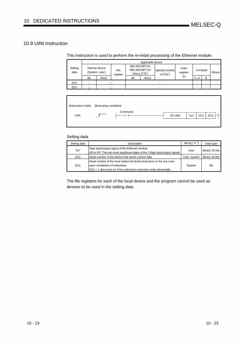
10 - 23 10 - 23
MELSEC-Q10 DEDICATED INSTRUCTIONS
10.9 UINI Instruction
This instruction is used to perform the re-initial processing of the Ethernet module.Applicable device
Internal device(System, user)
MELSECNET/H,MELSECNET/10
Direct J \Constant
Settingdata
Bit Word
Fileregister
Bit Word
Special moduleU \G
Indexregister
Zn K, H $
Others
(S1)(D1)
"Un"ZP.UINICommand
UINI (S1) (D1)
[Instruction code] [Executing condition]
Setting dataSetting data Description Set by ( 1) Data type
"Un"Start input/output signal of the Ethernet module(00 to FE: The two most significant digits of the 3-digit input/output signal)
User Binary 16 bits
(S1) Head number of the device that stores control data User, system Binary 16 bits
(D1)Head number of the local station bit device that turns on for one scanupon completion of instruction.(D1) + 1 also turns on if the instruction execution ends abnormally.
System Bit
The file registers for each of the local device and the program cannot be used asdevices to be used in the setting data.

10 - 24 10 - 24
MELSEC-Q10 DEDICATED INSTRUCTIONS
Control dataDevice Item Setting data Setting range Set by ( 1)
(S1) + 0 System area — — —
(S1) + 1 Completion status
• Stores the status at completion.0000H: Normal completionOther than 0000H
: Abnormal completion (error code) ( 2)
— System
(S1) + 2Specification oftarget of change
• Specifies the parameters to be changed.
1)b2 b1 b0b15
2)to0
1) Specification of whether or not to change the IPaddress of the local stationSpecifies whether or not to change the IP addressof the local station.(Specifies the address using (S1) + 3 and (S1) + 4if it is to be changed.)0: Do not change1: Change
2) Specification of whether or not to change theoperation settingsSpecifies whether or not to change the operationsettings.(Specifies the settings using (S1) + 5 if it is to bechanged.)0: Do not change1: Change
0H to 3H User
(S1) + 3(S1) + 4
Local stationIP address
• Specifies the IP address of the local station.00000001H toFFFFFFFEH
User
(S1) + 5Operation settings(See Section 4.7.)
• Specifies the operation settings.
1)b9 b8 b7 b6 b5 b4 b2 b1 b0b15
3)4)5)0 0 00to b3
2)
1) Communication data code setting0: Communication in binary code1: Communication in ASCII code
2) TCP Existence confirmation setting0: Use the Ping1: Use the KeepAlive
3) Send frame setting0: Ethernet frame1: IEEE802.3 frame
4) Setting of write enable/disable at RUN time0: Disable1: Enable
5) Initial timing setting0: Do not wait for OPEN
(communication impossible at STOP time)1: Always wait for OPEN
(communication possible at STOP time)
(See thedescription to
the left.)User
1 The "Set by" column indicates the following:• User : Data set by the user before executing a dedicated instruction.• System : The PLC CPU stores the execution results of a dedicated instruction.
2 For details on the error codes at abnormal completion, see Section 11.3, "Error Code List".
POINTWhen performing re-initial processing of the Ethernet module only, i.e., withoutchanging the local station IP address and operation settings, the control datashould be specified so that the value (0H) is stored in ((S1) + 2)), the specification oftarget of change, before executing the UINI instruction.The Ethernet module clears external device address information that it has beenmaintaining and performs re-initial processing in order to allow data communicationto restart. (The initial normal completion signal (X19) is on.)

10 - 25 10 - 25
MELSEC-Q10 DEDICATED INSTRUCTIONS
Functions
(1) Perform the re-initial processing of the Ethernet module specified in Un.
(2) Whether or not the UINI instruction has been completed can be checked by thecomplete bit devices (D1) + 0 and (D1) + 1.
(a) Complete bit device (D1) + 0Turns on at the END processing of the scan where the UINI instruction iscompleted, and turns off at the next END processing.
(b) Complete bit device (D1) + 1Turns on and off depending on the completion status of the UINI instruction.• Normal completion : Stays off and does not change.• Abnormal completion : Turns on at the END processing of the scan
where the UINI instruction is completed, andturns off at the next END processing.
[Operation when the UINI instruction is being executed]Scan ScanEND
processingEND
processing Scan ENDprocessing
Reinitialization request
instruction execution
Sequence program
UINI instruction
Complete device
Complete device + 1 Abnormal completion
Initialization of module
(3) The ZP.UINI is executed when the open instruction switches from off to on.
POINTPlease keep the following points in mind when reinitializing Ethernet module. (Failureto do so may cause errors in the data communication with the external devices.)(1) Be sure to end all current data communication with external devices and close
all connections before performing a re-initial processing.(2) Do not mix a re-initial processing done by writing directly into buffer memory, for
instance by using a TO instruction, with a re-initial processing via UINI instruction.Also, do not request another re-initial processing while a re-initial processingis already being performed.
(3) Be sure to reset external devices if the IP address of the Ethernet module hasbeen changed. (If an external device maintains the Ethernet address of adevice with which it communicates, the communication may not be continuedafter the IP address of the Ethernet module has been changed.)
(4) In a redundant system, do not change the IP address and operation settingwith the UINI instruction. If they are changed, normal communication cannotbe made.Use GX Developer to change the IP address and operation setting.
Errors(1) When a dedicated instruction ends with an error, the abnormal completion signal,
(D1) + 1, turns on and the error code is stored in the complete status area (S1) + 1.Refer to the following manuals regarding the error code, check the errors andtake corrective actions.<Error codes>4FFFH or less : QCPU (Q Mode) User’s Manual (Hardware Design,
Maintenance and Inspection)C000H or higher : Section 11.3.3 of this manual

10 - 26 10 - 26
MELSEC-Q10 DEDICATED INSTRUCTIONS
Program example
The following figure shows a sample program that performs a re-initial processing.When I/O signals of the Ethernet module are X/Y00 to X/Y1F
Re-initialinstruction
Re-initialinstruction
Re-initialinstruction
D261INCP
D260INCP
POINTThis is an example program that can be used to perform re-initial processing whencommunicating with connections 1 and 2. The corresponding numbers and bits foreach connection should be specified if other connections are used.
11 - 1 11 - 1
MELSEC-Q11 TROUBLESHOOTING
1111 TROUBLESHOOTING
This section explains the contents of the errors that may occur during communicationsbetween the Ethernet module and an external device as well as the troubleshootingprocedures.The following are methods for checking whether there is an error on the Ethernetmodule side and the contents of the error.Use one of the following methods to check whether there is an error and its content,then take corrective actions.
(1) Check using the display LED on the front of the Ethernet module(See Section 11.1.)The display LED on/off status can be used to check whether an error is occurringin the Ethernet module.
(2) Check through GX DeveloperGX Developer can be used to check various conditions of the Ethernet moduleas well as the error code corresponding to the contents of the error occurring andto perform tests.
(a) Ethernet diagnostics (using the dedicated screen)
1) Monitor for the status of various settings (See Section 11.2.)
2) PING test (See Section 5.4.1.)
3) Loop back test (See Section 5.4.2.)
4) COM. ERR off (See Sections 11.1.2 and 11.2.1.)
(b) System monitor (using the dedicated screen: see Section 11.2.2.)
1) Module's detailed information · · · · Module status, error code, etc.
2) H/W information · · · · LED on/off status, switch status, etc.
(c) Buffer memory batch monitorThe error code can be checked by monitoring the buffer memory of theEthernet module.
(3) Check the contents of the error using the error code (See Section11.3.)The contents of the error can be checked using the error code confirmed on theabove dedicated screen or by monitoring the buffer memory by referring toSection 11.3.
REMARK
If line errors and other errors occur when connecting devices of multiplemanufacturers, the users needs to isolate the malfunctioning parts using lineanalyzers, etc.

11 - 2 11 - 2
MELSEC-Q11 TROUBLESHOOTING
11
11.1 How to Check Errors Using LED Displays
This section describes the errors that can be checked with the LED displays on thefront of the Ethernet module.
11.1.1 Checking error display
The following can be checked with the LED displays on the front of the Ethernetmodule.
<Ethernet module LED>
QJ71E71-100
RUNINIT.
OPENSD
ERR.COM.ERR.
RD
QJ71E71-B5
RUNINIT.
OPENSD
ERR.COM.ERR.
RD100M
QJ71E71-B2
RUNINIT.
OPENSD
ERR.COM.ERR.
RD
LED name Status to check Cause/corrective action
1 [RUN]Turns off after powering onthe Ethernet module. ( 1)
1) Watchdog timer error• When a watchdog timer (approximately 600 ms) error occurs, the watchdog timer error detection
signal (X1F) is turned on by the self diagnosis function of the Ethernet module.2) Ethernet module installation fault
• Check if the power supply capacity (5 V DC) of the power supply module is insufficient.• Turn off the power supply and reinstall the module.
2 [ERR.]Turns on after powering onthe Ethernet module. ( 1)
1) Module parameter setting error• Check/correct the parameter setting values for the Ethernet module using GX Developer.
2) PLC CPU error• When the PLC CPU’s [RUN] LED is off/flashing, or the [ERR.] LED is on, check the content of the
error occurring in the PLC CPU and correct the problem.• Check that the Ethernet module is installed on the Q mode PLC CPU.
3) Ethernet module error (H/W error)
3 [COM.ERR]Turns on after powering onthe Ethernet module.
1) Check the contents of the error using the error codes stored by the error detection of the followingprocessing and remove the causes.• Initial processing• Fixed buffer send processing• E-mail send/receive processing• Open processing• Data communication processing• Other processing (processing for which error codes are stored in the error log area)
2) For a list of error codes, see Section 11.3.
(Continues on the following page)

11 - 3 11 - 3
MELSEC-Q11 TROUBLESHOOTING
(Continued from the previous page)
LED name Status to check Cause/corrective action
4 [SD]The [SD] LED does not flashat data sending.
1) [ERR.] or [COM.ERR] LED turns on.• Remove the factors that turn on the [ERR.] or [COM.ERR] LED.
2) Poor cable connection• Check the connection of the cable. ( 2)
3) Program reviewing is required• Review the sequence program for sending.
5 [RD][RD] LED stays off and datacannot be received.
1) [ERR.] or [COM.ERR] LED turns on.• Remove the factors that turn on the [ERR.] or [COM.ERR] LED.
2) Poor cable connection• Check the connection of the cable. ( 2)
3) Local station IP address setting error• If the cable connection is all right, review each setting value of the local station IP address, router
setting, and sub-net mask settings using GX Developer.4) Program reviewing is required
• Review the sequence program for sending.
1 Conduct a hardware test (H/W test) and check whether or not the Ethernet module operates normally.
For details on the hardware test, see Section 4.8.2, "Hardware test".
2 Conduct a confirmation of the completion for the initial processing and check whether or not there is any problem
in the cable connection and the Ethernet lines.
See Section 5.4, "Confirming the completion of the Initial Processing" for details on confirming the completion for
the initial processing. (Perform either one of the "Confirming the completion of the initial processing completion"
actions described in Section 5.4.)
POINTThe on/off status of the [INIT], [OPEN], [ERR.] and [COM.ERR] LEDs is stored inthe module status area (address: C8H) of the buffer memory.For more details, see Section 3.8, "List of Applications and Assignments of theBuffer Memory".
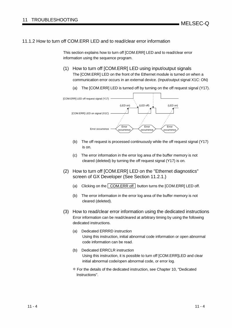
11 - 4 11 - 4
MELSEC-Q11 TROUBLESHOOTING
11.1.2 How to turn off COM.ERR LED and to read/clear error information
This section explains how to turn off [COM.ERR] LED and to read/clear errorinformation using the sequence program.
(1) How to turn off [COM.ERR] LED using input/output signalsThe [COM.ERR] LED on the front of the Ethernet module is turned on when acommunication error occurs in an external device. (Input/output signal X1C: ON)
(a) The [COM.ERR] LED is turned off by turning on the off request signal (Y17).
(LED on) (LED off) (LED on)
Error occurrenceError
occurrenceError
occurrenceError
occurrence
[COM.ERR] LED on signal (X1C)
[COM.ERR] LED off request signal (Y17)
(b) The off request is processed continuously while the off request signal (Y17)is on.
(c) The error information in the error log area of the buffer memory is notcleared (deleted) by turning the off request signal (Y17) is on.
(2) How to turn off [COM.ERR] LED on the "Ethernet diagnostics"screen of GX Developer (See Section 11.2.1.)
(a) Clicking on the COM.ERR off button turns the [COM.ERR] LED off.
(b) The error information in the error log area of the buffer memory is notcleared (deleted).
(3) How to read/clear error information using the dedicated instructionsError information can be read/cleared at arbitrary timing by using the followingdedicated instructions.
(a) Dedicated ERRRD instructionUsing this instruction, initial abnormal code information or open abnormalcode information can be read.
(b) Dedicated ERRCLR instructionUsing this instruction, it is possible to turn off [COM.ERR]LED and clearinitial abnormal code/open abnormal code, or error log.
For the details of the dedicated instruction, see Chapter 10, "DedicatedInstructions".

11 - 5 11 - 5
MELSEC-Q11 TROUBLESHOOTING
11.2 How to Check an Error Through GX Developer
The status of the various settings for the Ethernet module can be checked using theGX Developer functions.
(1) Ethernet diagnostics (See Section 11.2.1.)The module status of an Ethernet module, parameter settings, communicationstatus, error log and others can be checked using the Ethernet diagnosticfunction.The following are the functions of the Ethernet diagnostics.
Ethernetdiagnostics
Parameter status
Error log
Status of each connection
Status of each protocol
LED status
Received e-mail information
Send e-mail information
PING test
Loop back test
COM.ERR off
• Checks the stored parameters after the initial processing for the Ethernet module. (See Section 5.2.)
See Section 5.4
See Section 5.4
• Checks the error stored in the error log area. (See Section 11.3.)
• Checks the status of each connection after the connection to the external device is established with the open processing. (See Section 5.6.)
• Checks the communication status of each protocol supported by the Ethernet module.
• Checks the on/off status of the LED on the front of the Ethernet module. (See Section 11.1.)
• Checks the information for received e-mail. (See Section 11.3.)
• Checks the information for sent e-mail. (See Section 11.3.)
• Turns off the [COM.ERR] LED on the front of the Ethernet module.
See Section 11.1.2
• Checks the completion of the initial processing with the issuance of the PING command.
• Checks the completion of the initial processing for the Ethernet module in a network to which the loop back command is issued.
(2) System monitor (See Section 11.2.2.)The module status of an Ethernet module can be checked from the systemmonitor.
(a) Module's detailed informationThe function version and error code can be checked.
(b) H/W informationLED on/off status, connection status and parameter status of an Ethernetmodule can be checked.
(3) Buffer memory batch monitor (See Section 11.2.4.)The buffer memory of an Ethernet module is monitored.
POINTSee Section 11.2.3 for the buffer memory that can be checked on the "Ethernetdiagnostics" screen and "System monitor" screen.

11 - 6 11 - 6
MELSEC-Q11 TROUBLESHOOTING
11.2.1 Ethernet diagnostics
[Purpose]The module status of an Ethernet module, parameter settings, communication status,error log and others can be checked using the Ethernet diagnostic function of GXDeveloper.
[Operating procedure]GX Developer [Diagnostics] Ethernet diagnostics
[Ethernet diagnostics screen]
7)
1)
3)
2)
4)
5)
6)
8)
10)
9)
[Explanation of items]No. Item Description Setting range
1 Target module settingSpecifies the target Ethernet module for monitoring.
Number of cards for MELSECNET/H module is not included.Card 1 to Card 4
2 Change IP address display Switches the IP address display between decimal and hexadecimal. Decimal/hexadecimal
3Selection from the variousinformation monitors
Various types of information for the Ethernet module can be monitored.(See Section 11.2.3 for the buffer memory corresponding to the display contents.)
4 PING test Performs the PING test on the external device. (See Section 5.4.1, Section 5.4.2.)
5 Loop test Performs the loop back test for the network. (See Section 5.4.3.)
6 COM. ERR off Clicking this button turns the [COM.ERR] LED off. (See Section 11.1.2.)
7 Start monitor Clicking this button executes the Ethernet diagnostics.The display is updated during monitoring.
8 Stop monitor Clicking this button stops the Ethernet diagnostics.The display is retained while monitoring is stopped.
9 Clear history Clears the log.
10 Clear information Clears various values.
—

11 - 7 11 - 7
MELSEC-Q11 TROUBLESHOOTING
POINTWhen accessing a PLC on other station with a data link instruction during Ethernetdiagnostics, it may take some time to execute the data instruction.Take the following actions and then execute the Ethernet diagnostics whenexecuting data link instructions.• Execute the COM instruction.• Using the special register SD315, ensure the time for communication processing
of 2 to 3 ms.
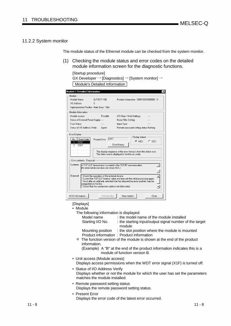
11 - 8 11 - 8
MELSEC-Q11 TROUBLESHOOTING
11.2.2 System monitor
The module status of the Ethernet module can be checked from the system monitor.
(1) Checking the module status and error codes on the detailedmodule information screen for the diagnostic functions.[Startup procedure]GX Developer [Diagnostics] [System monitor] Module's Detailed Information
[Displays]• Module
The following information is displayed:Model name : the model name of the module installedStarting I/O No. : the starting input/output signal number of the target
moduleMounting position : the slot position where the module is mountedProduct information : Product information
The function version of the module is shown at the end of the productinformation.(Example) A "B" at the end of the product information indicates this is a
module of function version B.• Unit access (Module access)
Displays access permissions when the WDT error signal (X1F) is turned off.• Status of I/O Address Verify
Displays whether or not the module for which the user has set the parametersmatches the module installed.
• Remote password setting statusDisplays the remote password setting status.
• Present ErrorDisplays the error code of the latest error occurred.

11 - 9 11 - 9
MELSEC-Q11 TROUBLESHOOTING
• Error DisplayDisplays the error codes stored in the error log area (address: E5H, EEH …,16CH) of the buffer memory.
• Error details, corrective actionDisplays the error details and corrective action for the error code selected inError Display.
(2) Checking the LED on/off status and operation mode number on theH/W information screen of the diagnostic functions
[Startup procedure]GX Developer [Diagnostics] [System monitor] Module's Detailed Information H/W Information
[Displays]This screen displays the Ethernet module information stored in the followingareas of the buffer memory.
No. Display content Corresponding buffer memory Address1 H/W LED information left side ( 1) Storage area for LEDs on station C8H (200)2 H/W LED information right side Storage area for connection status 5000H (20480)1 Network No. Local station network number/station number storage area 76H (118)2 Group No. Local station group number storage area 77H (119)3 Station No. Local station network number/station number storage area 76H (118)4 Mode No. Switch status (operation mode setting) storage area CAH (202)5
H/W switchinformation
Communication status ( 2) Communication status storage area CBH (203)
INIT.LEDOPEN LED
ERR.LEDCOM.ERR LED
b15 b5to b4 b3 b2 b1 b01/0 1/0 1/0 1/0– –
1 2
1: On0: Off
– 1/0 1/0 1/0 1/0– –tob15 b9 b8 b7 b6 b5 b2 b1 b0
1/0b3b4
1/0 –
1) Communication data code 0: Binary 1: ASCII2) Initial/Open method 0: No parameter setting 1: With parameter setting3)TCP existence confirmation 0: Ping 1: KeepAlive
6) 5) 4) 3) 2) 1)
4) Send frame 0: Ethernet 1: IEEE802.35) Write enable/disable at RUN time 0: Disable 1: Enable6) Initial timing 0: Do not wait for OPEN 1: Always wait for OPEN

11 - 10 11 - 10
MELSEC-Q11 TROUBLESHOOTING
11.2.3 Buffer memory that can be monitored with the GX Developer diagnostic function
The following is a list of the buffer memory addresses that can be displayed on the"Ethernet diagnostics" screen and "System monitor" screen of GX Developer.The display screen and display contents are mentioned for the Ethernet diagnosticsscreen. See Section 11.2.2 for how to display the System monitor screen.
AddressDec (Hex) Applicable buffer memory Ethernet diagnostics
display screen Display contents
Destination existence confirmation(b1) Existence confirmation
Pairing open (b7) Pairing openCommunication method (protocol)(b8) Protocol
32 (20H) Connection No. 1
Open system (b15, b14)
Connection No. 1
Open system33 to 39
(21 H to 27H)Connection No. 2 to 8(same as connection No. 1)
Status for eachconnection
Connection No. 2 to 8
105 (69H) Initial error code Initial error code106 to 107
(6A H to 6B H) Local station IP address IP address
108 to 110(6C H to 6E H) Local station Ethernet address Ethernet address
116 (74 H) Automatic open UDP port number Automatic open UDP port numberNetwork No.118 (76 H) 1 Local station network number/station number Station No.
119 (77 H) 1 Local station group number
Parameter status Module information
Group No.120 (78 H) Local station Port No. Local station Port No.121 to 122
(79 H to 7A H) Destination IP address Destination IP address
123 (7B H) Destination Port No. Destination Port No.124 (7C H) Open error code Open error code125 (7D H) Fixed buffer sending error code Fixed buffer transfer error code126 (7E H)
Connection No. 1
Connection end code
Connection No. 1
Connection end code130 to 199
(82 H to C7 H)Connection No. 2 to 8(same as connection No. 1)
Status of eachconnection
Connection No. 2 to 8
[INIT.]LED (b0) INIT.[OPEN]LED (b1) OPEN[ERR.]LED (b3) ERR.200 (C8 H) 1 LED on/off status
[COM.ERR] LED (b4)
LED display status
COM.ERR202 (CA H) 1 Switch status (operational mode setting)
LED status
Drive mode
203 (CB H) 1 Status of setting with GX Developer — (Check on the System monitor screen.)227 (E3 H) Number of error occurrence Number of error occurrence229 (E5 H) Error code/end code Error code/end code230 (E6 H) Subheader Subheader231 (E7 H) Command code Command code232 (E8 H) Connection No. Connection No.233 (E9 H) Local station Port No. Local station Port No.234 to 235
(EA H to EB H) Destination IP address Destination IP address
236 (EC H)
Error log block 1
Destination Port No.
Latest
Destination Port No.238 to 372
(EE H to 174 H) Error log block 2 to 16 (same as error log block 1)
Error log
No. 2 to No. 16
376 to 377(178 H to 179 H) Received IP packet count Total number of receives
378 to 379(17A H to 17B H)
Received IP packet countdiscarded due to sum check error
Total number of Sum check errorannulments
380 to 381(17C H to 17D H)
IP
Sent IP packet total count
IP packet
Total number of sends
408 to 409(198 H to 199 H) Received ICMP packet count Total number of receives
410 to 411(19A H to 19B H)
Received ICMP packet countdiscarded due to sum check error
Total number of Sum check errorannulments
412 to 413(19C H to 19D H) Sent ICMP packet total count Total number of sends
414 to 415(19E H to 19F H)
Echo request total count ofreceived ICMP packets
Total number of echo requestreceives
416 to 417(1A0 H to 1A1 H)
Echo reply total count of sentICMP packets Total number of echo reply sends
418 to 419(1A2 H to 1A3 H)
ICMP
Echo request total count of sentICMP packets
Status for eachprotocol
ICMP packet
Total number of echo requestsends

11 - 11 11 - 11
MELSEC-Q11 TROUBLESHOOTING
Address Decimal(hexadecimal) Applicable buffer memory Ethernet diagnostics
display screen Display contents
420 to 421(1A4 H to 1A5 H) ICMP Echo reply total count of received
ICMP packets ICMP packet Total number of echo replyreceives
440 to 441(1B8 H to 1B9 H) Received TCP packet count Total number of receives
442 to 443(1BA H to 1BB H)
Received TCP packet countdiscarded due to sum check error
Total number of Sum check errorannulments
444 to 445(1BC H to 1BD H)
TCP
Sent TCP packet total count
TCP packet
Total number of sends
472 to 473(1D8 H to 1D9 H) Received UDP packet total count Total number of receives
474 to 475(1DA H to 1DB H)
Received UDP packet countdiscarded due to sum check error
Total number of Sum check errorannulments
476 to 477(1DC H to 1DD H)
UDP
Sent UDP packet total count
Status of eachprotocol
UDP packet
Total number of sends
20480 (5000 H)1 Open completed signal for connections No. 1 to No. 16 — (Check on the System monitor screen.)
22560 to 22639(5820 H to 586F H)
Connection No. 9 to 16 (same as connection No. 1(address: 120 to 126 (78 H to 7E H)))
status of eachconnection Connection No. 9 to 16
22640 (5870 H) Number of mail remaining on theserver Number of mail remained on the server
22641 (5871 H) Dedicated instruction normalcompletion count Number of normal end of dedicated instructions
22642 (5872 H) Dedicated instruction abnormalcompletion count Number of error end of dedicated instructions
22643 (5873 H) Normal receiving count Number of normal receives22644 (5874 H) Attached file receiving count Number of attached file receives22645 (5875 H) Server inquiry count Number of sever inquires22646 (5876 H) Server communication error count Number of server transfer errors22647 (5877 H) Error log write count Number of Error log writes22649 (5879 H) Error code Error code22650 (587A H) Command code Command code22651 to 22658
(587B H to 5882 H) From From
22659 to 22662(5883 H to 5886 H) Date Receive date
22663 to 22692(5887 H to 58A4 H)
Error log block 1
Subject
Latest error log
Subject
22693 to 23352(58A5 H to 5B38 H)
Receive
Error log block 2 to 16(same as error log block 1)
Received e-mailinformation
Error log 2 to 16
23353 (5B39 H) Dedicated instruction normalcompletion count Number of normal end dedicated instructions
23354 (5B3A H) Dedicated instruction abnormalcompletion count Number of error end of dedicated instructions
23355 (5B3B H) Number of mails normally completed Number of normal end mails23356 (5B3C H) Attached file sending count Number of attached file sends23357 (5B3D H) Sending to the server count Number of server sends
23358 (5B3E H) Number of mails abnormallycompleted Number of error end mails
23359 (5B3F H) Error log write count Number of Error log writes23361 (5B41 H) Error code Error code23362 (5B42 H) Command code Command code23363 to 23370
(5B43 H to 5B4A H) To Send To
23371 to 23374(5B4B H to 5B4E H) Date Send date
23375 to 23404(5B4F H to 5B6C H)
Error log block 1
Subject
Latest error log
Subject
23405 to 23712(5B6D H to 5CA0 H)
Send
Error log block 2 to 16(same as error log block 1)
Sent e-mailinformation
Error log 2 to 16
1 Can be monitored on the System monitor screen of GX Developer. See Section 11.2.2.
11 - 12 11 - 12
MELSEC-Q11 TROUBLESHOOTING
11.2.4 Checking the error information by the buffer memory batch monitoring function
It is explained here how the Ethernet module errors can be checked from GXDeveloper.Error codes stored in the buffer memory of the Ethernet module can be monitoredusing the "Buffer memory batch monitoring" function of GX Developer.
[Operating procedure]
(Step 1) Select [Online] – [Monitor] – [Buffer memory batch] from the GX Developermenu bar, and start the "Buffer memory batch monitoring" screen.
(Step 2) Enter [Module start address:].For the module start address, enter the start I/O signal of the Ethernet moduleto be monitored using four digits.(Example)
Start I/O signal: Enter "0020" when monitoring modules of X/Y0020 to003F
(Step 3) Enter [Buffer memory start address:].Enter the buffer memory address to be monitored, using the selected inputformat (decimal/hexadecimal).For a list of the buffer memory addresses where error codes are stored, seeSection 11.3, "Error Code List".(Example)
When monitoring the initial abnormal code (buffer memory storageaddress: 69H):Enter "69" + "hexadecimal"
(Step 4) Click the Start Monitor button.
The contents of the buffer memory after the specified address are displayed.(In case of the above example, the contents of 69H and succeedingaddresses are displayed.)
REMARK
The display format can by modified as follows:Monitor format : Bits & words/ Multiple bit points/ Multiple word pointsDisplay : 16-bit integer/32-bit integer/real number/ASCII characterNumerical value : Decimal/hexadecimal
For details, refer to the "Operating Manual" for GX Developer.
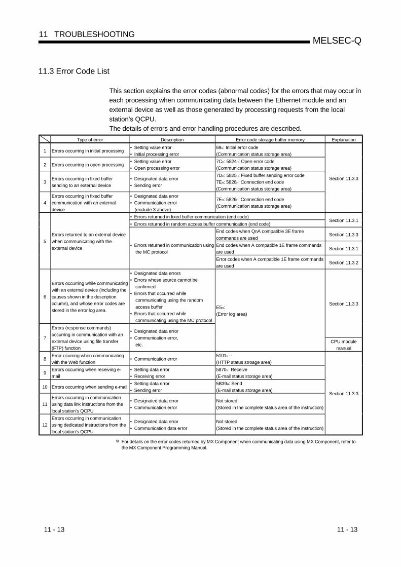
11 - 13 11 - 13
MELSEC-Q11 TROUBLESHOOTING
11.3 Error Code List
This section explains the error codes (abnormal codes) for the errors that may occur ineach processing when communicating data between the Ethernet module and anexternal device as well as those generated by processing requests from the localstation’s QCPU.The details of errors and error handling procedures are described.
Type of error Description Error code storage buffer memory Explanation
1 Errors occurring in initial processing• Setting value error• Initial processing error
69H: Initial error code(Communication status storage area)
2 Errors occurring in open processing• Setting value error• Open processing error
7CH: 5824H: Open error code(Communication status storage area)
3Errors occurring in fixed buffersending to an external device
• Designated data error• Sending error
7DH: 5825H: Fixed buffer sending error code7EH: 5826H: Connection end code(Communication status storage area)
4Errors occurring in fixed buffercommunication with an externaldevice
• Designated data error• Communication error
(exclude 3 above)
7EH: 5826H: Connection end code(Communication status storage area)
Section 11.3.3
• Errors returned in fixed buffer communication (end code)• Errors returned in random access buffer communication (end code)
Section 11.3.1
End codes when QnA compatible 3E framecommands are used
Section 11.3.3
End codes when A compatible 1E frame commandsare used
Section 11.3.15
Errors returned to an external devicewhen communicating with theexternal device • Errors returned in communication using
the MC protocolError codes when A compatible 1E frame commandsare used
Section 11.3.2
6
Errors occurring while communicatingwith an external device (including thecauses shown in the descriptioncolumn), and whose error codes arestored in the error log area.
• Designated data errors• Errors whose source cannot be
confirmed• Errors that occurred while
communicating using the randomaccess buffer
• Errors that occurred whilecommunicating using the MC protocol
Section 11.3.3
7
Errors (response commands)occurring in communication with anexternal device using file transfer(FTP) function
• Designated data error• Communication error,
etc.
E5H:(Error log area)
CPU modulemanual
8Error ocurring when communicatingwith the Web function
• Communication error5101H···(HTTP status stroage area)
9Errors occurring when receiving e-mail
• Setting data error• Receiving error
5870H: Receive(E-mail status storage area)
10 Errors occurring when sending e-mail• Setting data error• Sending error
5B39H: Send(E-mail status storage area)
11Errors occurring in communicationusing data link instructions from thelocal station’s QCPU
• Designated data error• Communication error
Not stored(Stored in the complete status area of the instruction)
12Errors occurring in communicationusing dedicated instructions from thelocal station’s QCPU
• Designated data error• Communication data error
Not stored(Stored in the complete status area of the instruction)
Section 11.3.3
For details on the error codes returned by MX Component when communicating data using MX Component, refer tothe MX Component Programming Manual.
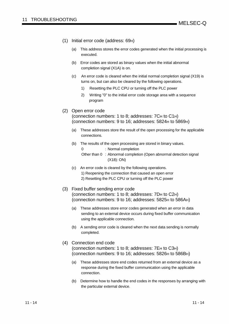
11 - 14 11 - 14
MELSEC-Q11 TROUBLESHOOTING
(1) Initial error code (address: 69H)
(a) This address stores the error codes generated when the initial processing isexecuted.
(b) Error codes are stored as binary values when the initial abnormalcompletion signal (X1A) is on.
(c) An error code is cleared when the initial normal completion signal (X19) isturns on, but can also be cleared by the following operations.
1) Resetting the PLC CPU or turning off the PLC power
2) Writing "0" to the initial error code storage area with a sequenceprogram
(2) Open error code(connection numbers: 1 to 8; addresses: 7CH to C1H)(connection numbers: 9 to 16; addresses: 5824H to 5869H)
(a) These addresses store the result of the open processing for the applicableconnections.
(b) The results of the open processing are stored in binary values.0 : Normal completionOther than 0 : Abnormal completion (Open abnormal detection signal
(X18): ON)
(c) An error code is cleared by the following operations.1) Reopening the connection that caused an open error2) Resetting the PLC CPU or turning off the PLC power
(3) Fixed buffer sending error code(connection numbers: 1 to 8; addresses: 7DH to C2H)(connection numbers: 9 to 16; addresses: 5825H to 586AH)
(a) These addresses store error codes generated when an error in datasending to an external device occurs during fixed buffer communicationusing the applicable connection.
(b) A sending error code is cleared when the next data sending is normallycompleted.
(4) Connection end code(connection numbers: 1 to 8; addresses: 7EH to C3H)(connection numbers: 9 to 16; addresses: 5826H to 586BH)
(a) These addresses store end codes returned from an external device as aresponse during the fixed buffer communication using the applicableconnection.
(b) Determine how to handle the end codes in the responses by arranging withthe particular external device.

11 - 15 11 - 15
MELSEC-Q11 TROUBLESHOOTING
(5) Error log area (address: E0H to 1FFH)This area stores the following errors.• Errors whose source cannot be confirmed• Errors that occurred during communications using the random access buffer• Errors that occurred during communications using the MC protocol
(a) Number of error occurrences (address: E3H)1) This address stores the number of errors registered in the error log
block area.2) When errors occur more than 65536 times, the count is stopped at
FFFFH (65535).
(b) Error log write pointer (address: E4H)1) This address stores the error log block number where the latest error
logging is registered.0 : No error. (No registration of error log)1 or more : Error log block number where the latest error logging is
registered If the pointer value is "16", it means that the latest error logging isregistered in the error log block 16 area.
2) When 17 or more errors occur, the registration of error logging startsfrom error log block 1 area again.
POINT(1) An error log block area consists of sixteen error log blocks that have the same
data order.(2) The error information is continued to be stored into the following areas even if the
count of the error occurrences is stopped and no longer stored:• Error log write pointer storage area• Error log block
(c) Error log block – Error code/end code (address: Starting from E5H)1) In the error code/end code area, the error codes that indicate error
content are stored. (See Section 11.3.)
(d) Error block – Subheader (address: starting from E6H)1) The subheader code of a faulty message is stored in bits 0 to 7 of the
corresponding area. ("0" is stored in bits 8 to 15).2) For errors below the TCP and UDP levels, "0" is stored.
(e) Error log block – Command code (address: starting from E7H)1) This block stores the command code of a faulty message, or each
lower byte value of request type and sub-request type of a data linkinstruction.
b15 b8to b7 b0tob15 b0toor
Request typeCommand code Sub-request type
2) "0" is stored in the following case.• For messages not containing a command code• For errors below the TCP and UDP levels (because their commands
are unknown)

11 - 16 11 - 16
MELSEC-Q11 TROUBLESHOOTING
(f) Error log block – Connection No. (address: starting from E8H)
1) The faulty connection No. is stored in bits 0 to 7 of the correspondingarea. ("0" is stored in bits 8 to 15).
2) For errors below the TCP and UDP levels, "0" is stored.
(g) Error log block – Local station Port No. (address: starting from E9H)
1) This block stores the local station’s port No. when an error occurred.
2) "0" is stored for errors below the TCP and UDP levels.
(h) Error log block – Destination IP address (address: EAH and starting fromEBH)
1) This block stores the IP address of an external device when an erroroccurred.
2) "0" is stored in the following cases.• For errors below the IP level• When an error response was performed by relaying through the PLC
CPU.
(i) Error log block – Destination Port No. (address: starting from ECH)
1) This block stores the external device’s port No. when an erroroccurred.
2) "0" is stored for errors below the TCP and UDP levels.
(j) Status for each protocol (addresses: 178H to 1FFH)
1) This address stores the count of the occurrence for the applicablecontents of each protocol’s condition.(The value counted by the Ethernet module.)
2) When the count value exceeds two words, the count stops atFFFFFFFFH (4294967295).
POINTValues stored in the buffer memory are cleared when the station in which theEthernet module is installed is powered on or reset. (They are not cleared duringthe initial processing.)Normally, it is not necessary to read this area; so, read it as needed duringmaintenance.

11 - 17 11 - 17
MELSEC-Q11 TROUBLESHOOTING
(6) HTTP status storage area (address: 5101H to 5177H)(a) Error log pointer (address: 5101H)
• This address stores the error log block number where the latest errorlogging is registered.0 : No error. (No registration of error log)1 or more : Error log block number where the latest error logging is
registered If the pointer value is "16", it means that the latest error logging is
registered in the error log block 16 area.• When 17 or more receiving errors occur, the registration of error logging
starts from error log block 1 area again.
POINTThe error log block area consists of 16 error log blocks that have the same dataorder.
(b) Log counter (HTTP response codes 100 to 199) (address: 5102H)Log counter (HTTP response codes 200 to 299) (address: 5103H)Log counter (HTTP response codes 300 to 399) (address: 5104H)Log counter (HTTP response codes 400 to 499) (address: 5105H)Log counter (HTTP response codes 500 to 599) (address: 5106H)The log counters store how many times the Ethernet module has sent theHTTP response codes to the Web browser.
(c) Error log block : HTTP response code (address: starting from 5108H)This error log block stores the HTTP response code when an error occurs.(See Section 11.3.)
(d) Error log block : Communication counterpart IP address (address: 5109H,510AH and up)This error log block stores the IP address of the server when an erroroccurs.
(e) Error log block : Error occurrence time (address: starting from 510BH)This block stores the time when the error occurs in BCD code.
Month (01H to 12H)b15 b8to
Lower 2-digitals of year (00H to 99H)b7 b0to
Hour (00H to 23H) Date (01H to 31H)
Second (00H to 59H) Minutes (00H to 59H)
Higher 2-digitals of year (00H to 99H) Day of the week (0 to 6)
b15 b8 to b7 b0 to
b15 b8 to b7 b0 to
b15 b8 to b7 b0 to
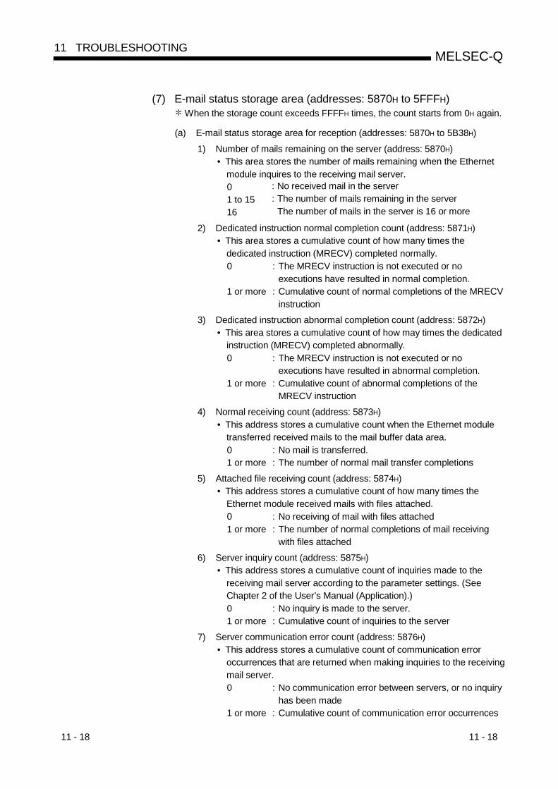
11 - 18 11 - 18
MELSEC-Q11 TROUBLESHOOTING
(7) E-mail status storage area (addresses: 5870H to 5FFFH) When the storage count exceeds FFFFH times, the count starts from 0H again.
(a) E-mail status storage area for reception (addresses: 5870H to 5B38H)
1) Number of mails remaining on the server (address: 5870H)• This area stores the number of mails remaining when the Ethernet
module inquires to the receiving mail server.0 : No received mail in the server1 to 15 : The number of mails remaining in the server16 The number of mails in the server is 16 or more
2) Dedicated instruction normal completion count (address: 5871H)• This area stores a cumulative count of how many times the
dedicated instruction (MRECV) completed normally.0 : The MRECV instruction is not executed or no
executions have resulted in normal completion.1 or more : Cumulative count of normal completions of the MRECV
instruction3) Dedicated instruction abnormal completion count (address: 5872H)
• This area stores a cumulative count of how may times the dedicatedinstruction (MRECV) completed abnormally.0 : The MRECV instruction is not executed or no
executions have resulted in abnormal completion.1 or more : Cumulative count of abnormal completions of the
MRECV instruction4) Normal receiving count (address: 5873H)
• This address stores a cumulative count when the Ethernet moduletransferred received mails to the mail buffer data area.0 : No mail is transferred.1 or more : The number of normal mail transfer completions
5) Attached file receiving count (address: 5874H)• This address stores a cumulative count of how many times the
Ethernet module received mails with files attached.0 : No receiving of mail with files attached1 or more : The number of normal completions of mail receiving
with files attached6) Server inquiry count (address: 5875H)
• This address stores a cumulative count of inquiries made to thereceiving mail server according to the parameter settings. (SeeChapter 2 of the User’s Manual (Application).)0 : No inquiry is made to the server.1 or more : Cumulative count of inquiries to the server
7) Server communication error count (address: 5876H)• This address stores a cumulative count of communication error
occurrences that are returned when making inquiries to the receivingmail server.0 : No communication error between servers, or no inquiry
has been made1 or more : Cumulative count of communication error occurrences
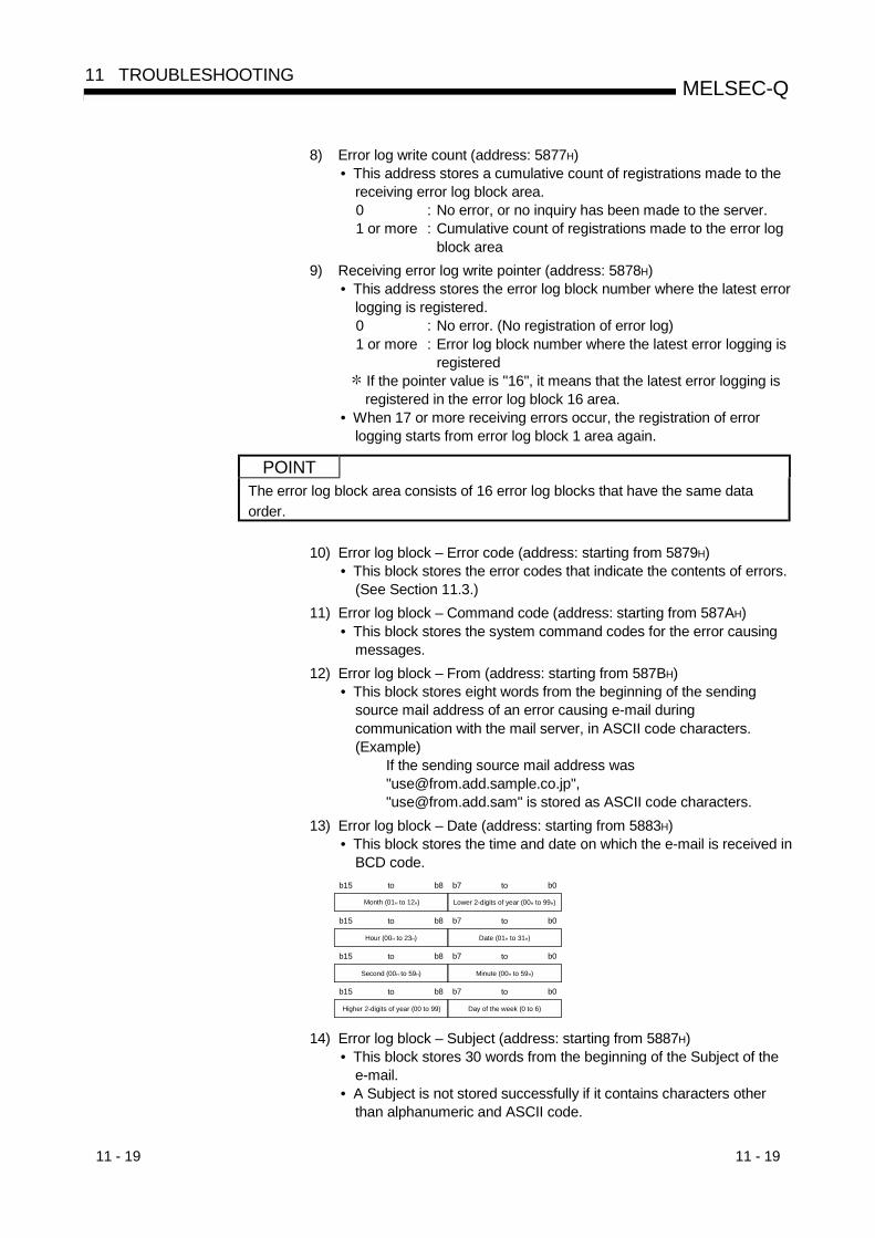
11 - 19 11 - 19
MELSEC-Q11 TROUBLESHOOTING
8) Error log write count (address: 5877H)• This address stores a cumulative count of registrations made to the
receiving error log block area.0 : No error, or no inquiry has been made to the server.1 or more : Cumulative count of registrations made to the error log
block area9) Receiving error log write pointer (address: 5878H)
• This address stores the error log block number where the latest errorlogging is registered.0 : No error. (No registration of error log)1 or more : Error log block number where the latest error logging is
registered If the pointer value is "16", it means that the latest error logging isregistered in the error log block 16 area.
• When 17 or more receiving errors occur, the registration of errorlogging starts from error log block 1 area again.
POINTThe error log block area consists of 16 error log blocks that have the same dataorder.
10) Error log block – Error code (address: starting from 5879H)• This block stores the error codes that indicate the contents of errors.
(See Section 11.3.)11) Error log block – Command code (address: starting from 587AH)
• This block stores the system command codes for the error causingmessages.
12) Error log block – From (address: starting from 587BH)• This block stores eight words from the beginning of the sending
source mail address of an error causing e-mail duringcommunication with the mail server, in ASCII code characters.(Example)
If the sending source mail address was"[email protected]","[email protected]" is stored as ASCII code characters.
13) Error log block – Date (address: starting from 5883H)• This block stores the time and date on which the e-mail is received in
BCD code.
Month (01H to 12H)
b15 b8to
Lower 2-digits of year (00H to 99H)
b7 b0to
Hour (00H to 23H)
b15 b8to
Date (01H to 31H)
b7 b0to
Second (00H to 59H)
b15 b8to
Minute (00H to 59H)
b7 b0to
Higher 2-digits of year (00 to 99)
b15 b8to
Day of the week (0 to 6)
b7 b0to
14) Error log block – Subject (address: starting from 5887H)• This block stores 30 words from the beginning of the Subject of the
e-mail.• A Subject is not stored successfully if it contains characters other
than alphanumeric and ASCII code.
11 - 20 11 - 20
MELSEC-Q11 TROUBLESHOOTING
(b) E-mail status storage area for sending (addresses: 5B39H to 5CA0H)
1) Dedicated instruction normal completion count (address: 5B39H)• This area stores a cumulative count of how many times the
dedicated instruction (MSEND) completed normally.0 : The MSEND instruction is not executed or no
executions have resulted in normal completion.1 or more : Cumulative count of normal completions of the MSEND
instruction
2) Dedicated instruction abnormal completion count (address: 5B3AH)• This area stores a cumulative count of how many times the
dedicated instruction (MSEND) completed abnormally.0 : The MSEND instruction is not executed or no
executions have resulted in abnormal completion.1 or more : Cumulative count of abnormal completions of the
MSEND instruction
3) Number of mails normally completed (address: 5B3BH)• This address stores a cumulative count of how many times the
Ethernet module transferred send mails to the Send mail server.0 : No mail is sent.1 or more : The number of normal completions of mail sending
4) Attached file sending count (address: 5B3CH)• This address stores a cumulative count of how many times the
Ethernet module sent mails with files attached.0 : No sending of mail with files attached.1 or more : The number of normal completions of mail sending with
files attached
5) Sending to the server count (address: 5B3DH)• This address stores a cumulative count of sending to the send mail
server.0 : No mail is sent to the server.1 or more : Cumulative count of sending to the server
6) Number of mails abnormally completed (address: 5B3EH)• This address stores a cumulative count of communication error
occurrences that are returned when requesting sending to thetransmitting mail server.0 : No communication error between servers, or no
transmission has been made1 or more : Cumulative count of communication error occurrences
7) Error log write count (address: 5B3FH)• This address stores a cumulative count of registrations made to the
sending error log block area.0 : No error, or no inquiry has been made to the server.1 or more : Cumulative count of registrations made to the error log
block area
11 - 21 11 - 21
MELSEC-Q11 TROUBLESHOOTING
8) Sending error log write pointer (address: 5B40H)• This address stores the error log block area number where the latest
sending error logging is registered.0 : No error. (No registration of sending error log)1 or more : Error log block number where the latest sending error
logging is registered If the pointer value is "8", it means that the latest error logging isregistered in the sending error log block 8 area.
• When 9 or more sending errors occur, the registration of sendingerror logging starts from sending error log block 1 area again.
POINTThe sending error log block area consists of eight error log blocks that have thesame order of data items.
9) Error log block – Error code (address: starting from 5B41H)• This block stores the error codes that indicate the contents of errors.
(See Section 11.3.)
10) Error log block – Command code (address: starting from 5B42H)• This block stores the system command codes for the error causing
messages.
11) Error log block – To (address: starting from 5B43H)• This block stores eight words from the beginning of the sending
source mail address of an error causing e-mail duringcommunication with the mail server, in ASCII code characters.
(Example)If the sending source mail address was"[email protected]","[email protected]" is stored as ASCII code characters.
12) Error log block – Date (address: starting from 5B4BH)• This block stores the time and date on which the e-mail is sent in
BCD code.• The order of date and time to be stored is the same as for the date
and time of e-mail reception shown in (a) 13).
13) Error log block – Subject (address: starting from 5B4FH)• This block stores 15 words from the beginning of the Subject of the
e-mail.

11 - 22 11 - 22
MELSEC-Q11 TROUBLESHOOTING
11.3.1 End codes (Complete codes) returned to an external device during datacommunication
This section explains the end codes (complete codes) that are added to responseswhen communicating using the fixed buffer, the random access buffer or the MCprotocol.For more details on the error codes that are added to responses during communicationusing A compatible 1E frames through the MC protocol, see Section 11.3.2.For more details on the end codes (error codes) that are stored in the buffer memory ofthe Ethernet module, see Section 11.3.3.
Communication functionEnd code Description Processing
Fixed Random MC
00H • Normal completion
02H• Designation of device range of devices to be read/written from/to is
incorrect.• Check and correct the designated head
device and number of points.• Codes for command/response type of subheader are not within the
specifications.
Communication processingCommand/
response typeCommunication using fixed buffer 60H
Communication using random access buffer 61H, 62H
Communication using the MC protocol 00H to 3CH
50H
• In communication using the fixed buffer, if the data length setting isless than the actual data count, the remaining data is determinedas the second data and processed. In this case, a subheaderundefined command type error may occur.
• Check and correct command/responsetype set by an external device.(The Ethernet module automaticallyadds command/response type; theuser does not need to set these.)See REMARK in Section 11.3.3.
• Check and correct the data length.
51H
• In communication using the random access buffer, the headaddress designated by an external device is set outside the rangefrom 0 to 6143.
• Check and correct the designated headaddress.
52H
• In communication using the random access buffer, head address +data word count (depending on the setting when reading)designated by an external device exceeds the range from 0 to6143.
• Data for the designated word count (text) cannot be sent in oneframe.(The value of the data length and amount of text communicated arenot in the allowable range.)
• Check and correct the head addressand data word count
• Correct the number of pointsread/written.
54H
• When “ASCII code communication” is selected in [Operationalsettings] – [Communication data code] with GX Developer, ASCIIcode data that cannot be converted to binary code was receivedfrom an external device.
• Check and correct the send data of theexternal device.
55H
• When [Operational setting] – [Enable Write at RUN time] is set todisable (no check mark) with GX Developer, an external devicerequests to write data while the PLC CPU is in the RUN status.
• An external device requests writing a parameter, sequenceprogram or microcomputer program while the PLC CPU is in theRUN status.(Not related to the settings in [Operational settings] – [Enable Writeat RUN time with GX Developer])
• Write data by setting [Enable Write atRUN time] to enable (with checkmark). However, writing a parameter,sequence program, or microcomputerprogram is not allowed while the CPUis in the RUN status.
• Write such data by placing the PLCCPU in the STOP status.
Fixed : Fixed buffer communication Random : Random access buffer communication MC : Communication using the MC protocol
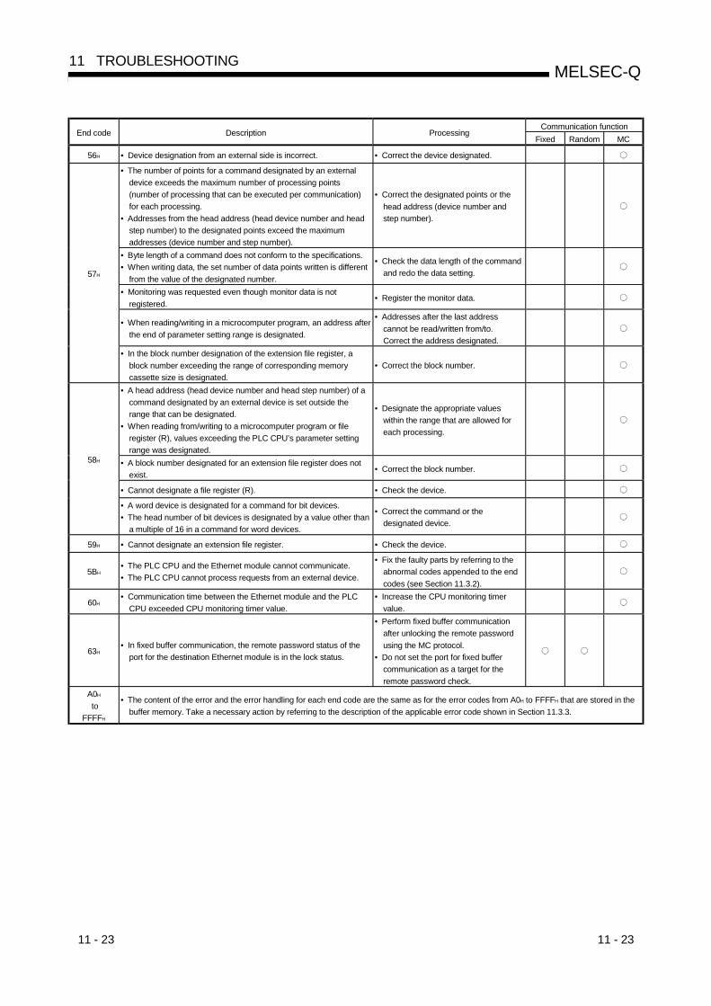
11 - 23 11 - 23
MELSEC-Q11 TROUBLESHOOTING
Communication functionEnd code Description Processing
Fixed Random MC
56H • Device designation from an external side is incorrect. • Correct the device designated.
• The number of points for a command designated by an externaldevice exceeds the maximum number of processing points(number of processing that can be executed per communication)for each processing.
• Addresses from the head address (head device number and headstep number) to the designated points exceed the maximumaddresses (device number and step number).
• Correct the designated points or thehead address (device number andstep number).
• Byte length of a command does not conform to the specifications.• When writing data, the set number of data points written is different
from the value of the designated number.
• Check the data length of the commandand redo the data setting.
• Monitoring was requested even though monitor data is notregistered.
• Register the monitor data.
• When reading/writing in a microcomputer program, an address afterthe end of parameter setting range is designated.
• Addresses after the last addresscannot be read/written from/to.Correct the address designated.
57H
• In the block number designation of the extension file register, ablock number exceeding the range of corresponding memorycassette size is designated.
• Correct the block number.
• A head address (head device number and head step number) of acommand designated by an external device is set outside therange that can be designated.
• When reading from/writing to a microcomputer program or fileregister (R), values exceeding the PLC CPU’s parameter settingrange was designated.
• Designate the appropriate valueswithin the range that are allowed foreach processing.
• A block number designated for an extension file register does notexist.
• Correct the block number.
• Cannot designate a file register (R). • Check the device.
58H
• A word device is designated for a command for bit devices.• The head number of bit devices is designated by a value other than
a multiple of 16 in a command for word devices.
• Correct the command or thedesignated device.
59H • Cannot designate an extension file register. • Check the device.
5BH• The PLC CPU and the Ethernet module cannot communicate.• The PLC CPU cannot process requests from an external device.
• Fix the faulty parts by referring to theabnormal codes appended to the endcodes (see Section 11.3.2).
60H• Communication time between the Ethernet module and the PLC
CPU exceeded CPU monitoring timer value.• Increase the CPU monitoring timer
value.
63H• In fixed buffer communication, the remote password status of the
port for the destination Ethernet module is in the lock status.
• Perform fixed buffer communicationafter unlocking the remote passwordusing the MC protocol.
• Do not set the port for fixed buffercommunication as a target for theremote password check.
A0H
toFFFFH
• The content of the error and the error handling for each end code are the same as for the error codes from A0H to FFFFH that are stored in thebuffer memory. Take a necessary action by referring to the description of the applicable error code shown in Section 11.3.3.

11 - 24 11 - 24
MELSEC-Q11 TROUBLESHOOTING
11.3.2 Abnormal codes returned during communication using A compatible 1E frames
This section explains the abnormal codes (error codes) that are added to responseswhen communicating using the MC protocol and A compatible 1E frames. (Anabnormal code is added only when an end code is "5B".)For more details on the end codes (error codes) that re added to responses, seeSection 11.3.1.For more details on the end codes (error codes) that are stored in the buffer memory ofthe Ethernet module, see Section 11.3.3.
00HAbnormal codeResponse format Subheader End code
When an abnormal code is stored, the end code is "58H."
Error code(hexadecimal)
Error Description of error Corrective action
10HPC number error(PLC number error)
A station with the specified PC number does not exist.(1) The PC number designated with a command is neither "FF" of the
local station nor any of the station numbers designated with theMELSECNET link parameters.
(1) Change the PC number to "FF" of the localstation or a station number set in the linkparameter, and communicate again.
11H Mode error
Poor communication between the Ethernet module and the PLC CPU(1) After the Ethernet module receives a request successfully from an
external device, the Ethernet module and the PLC CPU could notcommunicate for some reason (noise, etc.).
(1) Communicate again. If an error occurs again,check noise, etc. and replace the Ethernetmodule, then communicate again.
12H
Intelligent functionmodule designationerror
Intelligent function module error(1) The intelligent function module with the buffer memory that can be
communicated with, does not exist at the location designated bythe intelligent function module number. (For example, thecorresponding place is for an input/output module or an emptyslot.)
(1) Change the data content designated in thecontrol procedure or change the installationlocation of the intelligent function module, andcommunicate again.
18H Remote errorRemote RUN/STOP not accessible.
Another module (other Ethernet module, etc.) has already executedremote STOP/PAUSE.
(1) Check whether or not other module hasexecuted remote STOP/PAUSE. If one ofthese commands has been executed, cancel itand communicate again.
1FH Device error Invalid device specification(1) Review the specified device.(2) Does not access any non-existent device.
20H Link errorThe CPU module of the request destination is disconnected from thedata link.
Check whether or not the PLC CPU with thestation number set as PC number is disconnected.Remove the cause of disconnection and connectagain.
21HIntelligent functionmodule bus error
Cannot access the memory of the intelligent function module.(1) The control bus to the intelligent function module is faulty.(2) The intelligent function module is faulty.
One of the following hardware is faulty: the PLCCPU, base unit, intelligent function module, orEthernet module. Please consult your nearestdealer.

11 - 25 11 - 25
MELSEC-Q11 TROUBLESHOOTING
11.3.3 Error codes stored in the buffer memory
When an error occurs at each data communication processing between the Ethernetmodule and an external device, the error code (abnormal code) is stored in the buffermemory of the Ethernet module. This section explains the contents of this type oferrors and error handling procedures.The "Storage destination" column in the error code list indicates the buffer memorywhere the applicable error code is stored.The names used for the explanation indicated in the "Storage destination" columncorrespond to the buffer memory error code storage areas shown in the table below.(Error codes whose storage destination is not written are returned to the externaldevice.)Note that the buffer memory may store error codes of the messages returned from theexternal device. For error codes not shown in this manual, refer to the manual of theexternal device and check the returned messages.
Name used for explanation Buffer memory Buffer memory addressInitial Initial abnormal code area 69H (105)Open Open abnormal code area 7CH (124)…Fixed sending Fixed buffer sending abnormal code area 7DH (125)…Connection Connection end code/error log area 7EH (126)…Error code Error code/end code area E5H (229)…Data link ((S1) + 1 for data link instructions) —HTTP log HTTP response code area 5108 H (20744)E-mail log E-mail error log area 5879H (22649)…Dedicated instruction (Complete status area for dedicated instructions) —
Storage destination
Initi
al
Ope
n
Fixe
dse
ndin
g
Con
nect
ion
Erro
r cod
e
Dat
a lin
k
HTT
P lo
g
E-m
ail l
og
Ded
icat
edin
stru
ctio
n
Error code(abnormal
code)Description of error Error handling
69H 7CH 7DH 7EH E5H — 5108H 5879H —02H
0050H
0051H
0052H
0054H
0055H
0056H
0057H
0058H
0059H
The content of these errors and the error handling for each error code is thesame as the end codes (02H to 0063H) returned to the external device.Check the explanation of the applicable code shown in Section 11.3.1, andtake actions accordingly.
005BHRead and handle the error codeand end code area.
0060H
0063H
00A0H
Requests that cannot bedesignated for applicableconnection.
• Review the content of request.• Correct the open settings.
(See Section 5.5)
00A1H
Contents of request cannot beanalyzed because the length oftext area or request data length istoo short.
• Review and correct the length of the textarea or the request data length of the Qnheader, and send to the Ethernet moduleagain.
00A2HRequests that cannot beprocessed.
• Correct the content of request andcommand.
3E8H
to4FFFH
(Errors detected by the PLC CPU)
• Handle by referring to the troubleshootingsection of the CPU User’s Manual(Hardware Design, Maintenance andInspection).
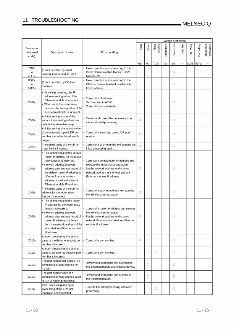
11 - 26 11 - 26
MELSEC-Q11 TROUBLESHOOTING
Storage destination
Initi
al
Ope
n
Fixe
dse
ndin
g
Con
nect
ion
Erro
r cod
e
Dat
a lin
k
HTT
P lo
g
E--m
ail l
og
Ded
icat
edin
stru
ctio
n
Error code(abnormal
code)Description of error Error handling
69H 7CH 7DH 7EH E5H — 5108H 5879H —7000H
to7FFFH
(Errors detected by serialcommunication module, etc.)
• Take corrective action, referring to theSerial Communication Module User'sManual, etc.
B000H
toBFFFH
(Errors detected by CC-Linkmodule)
• Take corrective action, referring to theCC-Link System Master/Local ModuleUser's Manual.
C001H
• At initial processing, the IPaddress setting value of theEthernet module is incorrect.
• When using the router relayfunction, the setting value of thesub-net mask field is incorrect.
• Correct the IP address.Set the class to A/B/C.
• Correct the sub-net mask.
C002H
At initial setting, some of thevarious timer setting values areoutside the allowable range.
• Review and correct the necessary timervalues at initial processing.
C003H
At initial setting, the setting valueof the automatic open UDP portnumber is outside the allowablerange.
• Correct the automatic open UDP portnumber.
C004HThe setting value of the sub-netmask field is incorrect.
• Correct the sub-net mask and execute theinitial processing again.
C005H
• The setting value of the defaultrouter IP address for the routerrelay function is incorrect.
• Network address (networkaddress after sub-net mask) ofthe default router IP address isdifferent from the networkaddress of the local station’sEthernet module IP address.
• Correct the default router IP address andexecute the initial processing again.
• Set the network address to the samenetwork address as the local station’sEthernet module IP address.
C006H
The setting value of the sub-netaddress for the router relayfunction is incorrect.
• Correct the sub-net address and executethe initial processing again.
C007H
• The setting value of the routerIP address for the router relayfunction is incorrect.
• Network address (networkaddress after sub-net mask) ofrouter IP address is differentfrom the network address of thelocal station’s Ethernet moduleIP address.
• Correct the router IP address and executethe initial processing again.
• Set the network address to the samenetwork ID as the local station’s Ethernetmodule IP address.
C010H
At open processing, the settingvalue of the Ethernet module portnumber is incorrect.
• Correct the port number.
C011H
At open processing, the settingvalue of an external device’s portnumber is incorrect.
• Correct the port number.
C012H
The port number set is used in aconnection already opened byTCP/IP.
• Review and correct the port numbers ofthe Ethernet module and external device.
C013H
The port number used in aconnection already opened is setin UDP/IP open processing.
• Review and correct the port number ofthe Ethernet module.
C014H
Initial processing and openprocessing of the Ethernetmodule is not completed.
• Execute the initial processing and openprocessing.
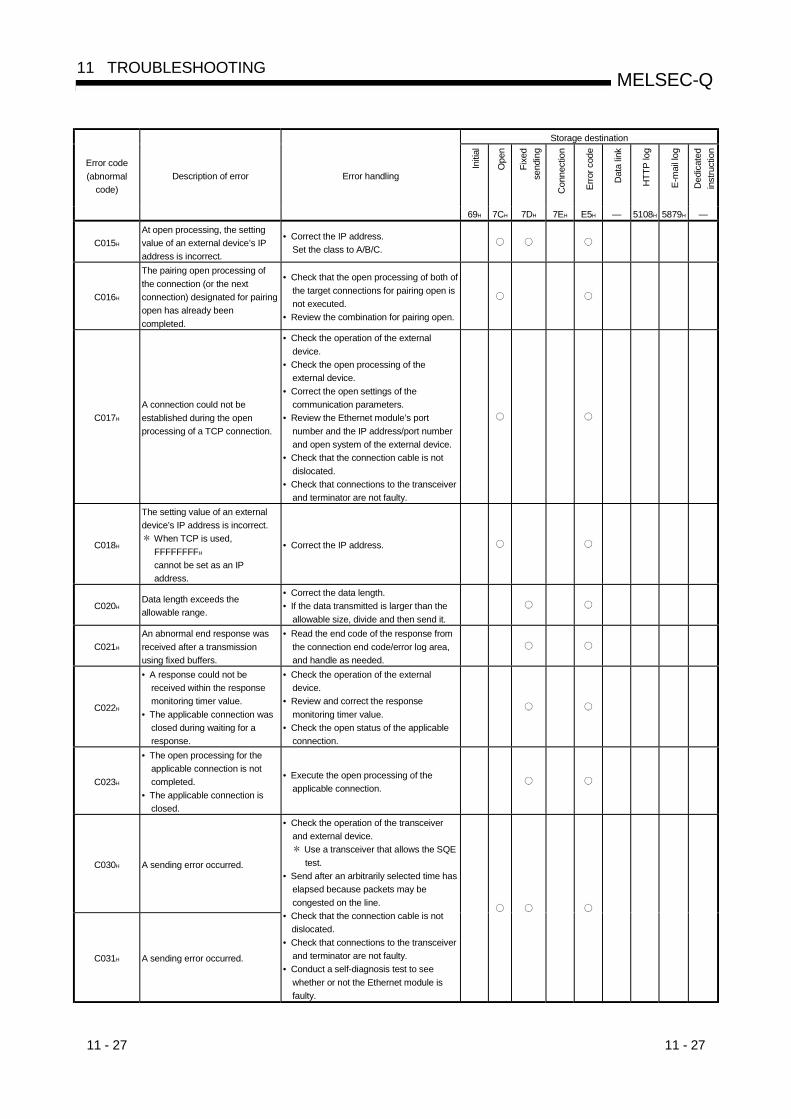
11 - 27 11 - 27
MELSEC-Q11 TROUBLESHOOTING
Storage destination
Initi
al
Ope
n
Fixe
dse
ndin
g
Con
nect
ion
Erro
r cod
e
Dat
a lin
k
HTT
P lo
g
E-m
ail l
og
Ded
icat
edin
stru
ctio
n
Error code(abnormal
code)Description of error Error handling
69H 7CH 7DH 7EH E5H — 5108H 5879H —
C015H
At open processing, the settingvalue of an external device’s IPaddress is incorrect.
• Correct the IP address.Set the class to A/B/C.
C016H
The pairing open processing ofthe connection (or the nextconnection) designated for pairingopen has already beencompleted.
• Check that the open processing of both ofthe target connections for pairing open isnot executed.
• Review the combination for pairing open.
C017H
A connection could not beestablished during the openprocessing of a TCP connection.
• Check the operation of the externaldevice.
• Check the open processing of theexternal device.
• Correct the open settings of thecommunication parameters.
• Review the Ethernet module’s portnumber and the IP address/port numberand open system of the external device.
• Check that the connection cable is notdislocated.
• Check that connections to the transceiverand terminator are not faulty.
C018H
The setting value of an externaldevice’s IP address is incorrect.
When TCP is used,FFFFFFFFH
cannot be set as an IPaddress.
• Correct the IP address.
C020HData length exceeds theallowable range.
• Correct the data length.• If the data transmitted is larger than the
allowable size, divide and then send it.
C021H
An abnormal end response wasreceived after a transmissionusing fixed buffers.
• Read the end code of the response fromthe connection end code/error log area,and handle as needed.
C022H
• A response could not bereceived within the responsemonitoring timer value.
• The applicable connection wasclosed during waiting for aresponse.
• Check the operation of the externaldevice.
• Review and correct the responsemonitoring timer value.
• Check the open status of the applicableconnection.
C023H
• The open processing for theapplicable connection is notcompleted.
• The applicable connection isclosed.
• Execute the open processing of theapplicable connection.
C030H A sending error occurred.
C031H A sending error occurred.
• Check the operation of the transceiverand external device.
Use a transceiver that allows the SQEtest.
• Send after an arbitrarily selected time haselapsed because packets may becongested on the line.
• Check that the connection cable is notdislocated.
• Check that connections to the transceiverand terminator are not faulty.
• Conduct a self-diagnosis test to seewhether or not the Ethernet module isfaulty.

11 - 28 11 - 28
MELSEC-Q11 TROUBLESHOOTING
Storage destination
Initi
al
Ope
n
Fixe
dse
ndin
g
Con
nect
ion
Erro
r cod
e
Dat
a lin
k
HTT
P lo
g
E-m
ail l
og
Ded
icat
edin
stru
ctio
n
Error code(abnormal
code)Description of error Error handling
69H 7CH 7DH 7EH E5H — 5108H 5879H —
C032H
A TCP ULP timeout error occurredin the TCP/IP communication.(An external device does not returnACK.)
• Check the operation of the externaldevice.
• Correct the TCP ULP timeout value andexecute the initial processing again.
• Send after an arbitrarily selected time haselapsed because packets may becongested on the line.
• Check that the connection cable is notdislocated.
• Check that connections to the transceiverand terminator are not faulty.
C033HAn external device side with the setIP address does not exist.
• Review and correct the external device’sIP address and the Ethernet address.
• If the external device has the ARPfunction, set the default value. If not, setthe Ethernet address of the externaldevice.
• Check the operation of the externaldevice.
• Send after an arbitrarily selected time haselapsed because packets may becongested on the line.
• Check that the connection cable is notdislocated.
• Check that connections to the transceiverand terminator are not faulty.
C035H
The existence of an externaldevice could not be confirmedwithin the response monitoringtimer value.
• Check the operation of the externaldevice.
• Review and correct each setting value forthe existence confirmation.
• Check that the connection cable is notdislocated.
• Check that connections to the transceiverand terminator are not faulty.
C036H
Send processing cannot beexecuted because a cable is notyet connected or disconnected.
• Check that the connection cable is notdislocated.
• Check that connections to the transceiverand terminator are not faulty.
• Conduct a loopback test to see that theline is not faulty.
• Conduct a self-diagnosis test to see thatthe Ethernet module is not faulty.
C040H
• Not all the data could bereceived within the responsemonitoring timer value.
• Sufficient data for the data lengthcould not be received.
• The remaining part of a messagedivided at the TCP/IP level couldnot be received within theresponse monitoring timer value.
• Review and correct the data length of thecommunication data.
• Review and correct each setting value atthe initial processing because thepackets may be congested on the line.
• Send the same data from the externaldevice again.
C041HWhen TCP is used, the checksumof the receive data is incorrect.
C042HWhen UDP is used, the checksumof the receive data is incorrect.
C043HThe checksum in header of IPpacket received is incorrect.
• Review the checksum on the externaldevice side and send the correct value.
• Investigate the conditions of the line(noise, distance between the line andpower line, contact of each device, etc.)
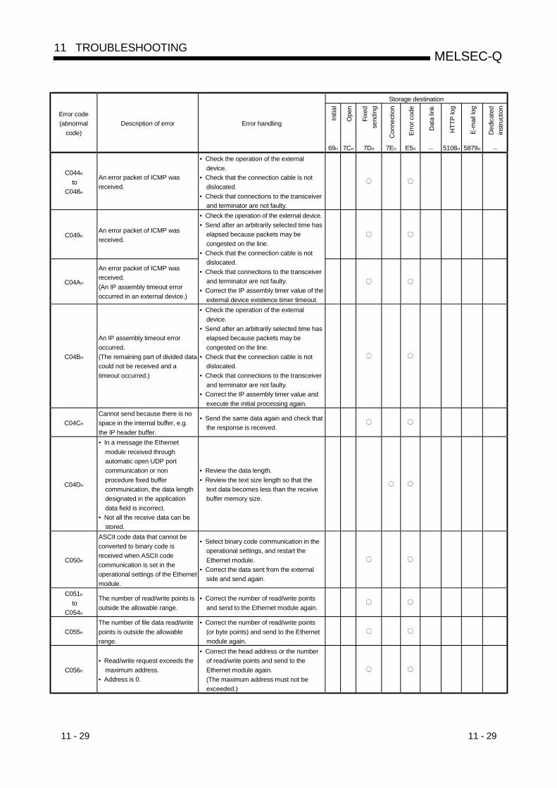
11 - 29 11 - 29
MELSEC-Q11 TROUBLESHOOTING
Storage destination
Initi
al
Ope
n
Fixe
dse
ndin
g
Con
nect
ion
Erro
r cod
e
Dat
a lin
k
HTT
P lo
g
E-m
ail l
og
Ded
icat
edin
stru
ctio
n
Error code(abnormal
code)Description of error Error handling
69H 7CH 7DH 7EH E5H 5108H 5879H
C044H
toC048H
An error packet of ICMP wasreceived.
• Check the operation of the externaldevice.
• Check that the connection cable is notdislocated.
• Check that connections to the transceiverand terminator are not faulty.
C049HAn error packet of ICMP wasreceived.
C04AH
An error packet of ICMP wasreceived.(An IP assembly timeout erroroccurred in an external device.)
• Check the operation of the external device.• Send after an arbitrarily selected time has
elapsed because packets may becongested on the line.
• Check that the connection cable is notdislocated.
• Check that connections to the transceiverand terminator are not faulty.
• Correct the IP assembly timer value of theexternal device existence timer timeout.
C04BH
An IP assembly timeout erroroccurred.(The remaining part of divided datacould not be received and atimeout occurred.)
• Check the operation of the externaldevice.
• Send after an arbitrarily selected time haselapsed because packets may becongested on the line.
• Check that the connection cable is notdislocated.
• Check that connections to the transceiverand terminator are not faulty.
• Correct the IP assembly timer value andexecute the initial processing again.
C04CH
Cannot send because there is nospace in the internal buffer, e.g.the IP header buffer.
• Send the same data again and check thatthe response is received.
C04DH
• In a message the Ethernetmodule received throughautomatic open UDP portcommunication or nonprocedure fixed buffercommunication, the data lengthdesignated in the applicationdata field is incorrect.
• Not all the receive data can bestored.
• Review the data length.• Review the text size length so that the
text data becomes less than the receivebuffer memory size.
C050H
ASCII code data that cannot beconverted to binary code isreceived when ASCII codecommunication is set in theoperational settings of the Ethernetmodule.
• Select binary code communication in theoperational settings, and restart theEthernet module.
• Correct the data sent from the externalside and send again.
C051H
toC054H
The number of read/write points isoutside the allowable range.
• Correct the number of read/write pointsand send to the Ethernet module again.
C055H
The number of file data read/writepoints is outside the allowablerange.
• Correct the number of read/write points(or byte points) and send to the Ethernetmodule again.
C056H
• Read/write request exceeds themaximum address.
• Address is 0.
• Correct the head address or the numberof read/write points and send to theEthernet module again.(The maximum address must not beexceeded.)

11 - 30 11 - 30
MELSEC-Q11 TROUBLESHOOTING
Storage destination
Initi
al
Ope
n
Fixe
dse
ndin
g
Con
nect
ion
Erro
r cod
e
Dat
a lin
k
HTT
P lo
g
E-m
ail l
og
Ded
icat
edin
stru
ctio
n
Error code(abnormal
code)Description of error Error handling
69H 7CH 7DH 7EH E5H — 5108H 5879H —
C057H
Request data length does notmatch with data count in characterarea (part of text).
• Review and correct the content of the textarea or the request data length of Qnheader, and send to the Ethernet moduleagain.
C058H
Request data length after ASCII-binary conversion does not matchwith data count in character area(part of text).
• Review and correct the content of the textarea or the request data length of Qnheader, and send to the Ethernet moduleagain.
C059HIncorrect designation of commandand subcommand.
• Review the content of the request.
C05AH
C05BH
The Ethernet module cannot readfrom/write to the designateddevice.
• Examine the device to be read/written.
C05CH
The content of a request isincorrect.(Requesting read/write in bit unitsto word devices.)
• Correct the content of the request andsend to the Ethernet module again.(Correction of subcommand, etc.)
C05DHMonitor registration is notperformed.
• Monitor after performing monitorregistration.
C05EH
Communication time between theEthernet module and PLC CPUexceeded the CPU monitoringtimer.
• Increase the CPU monitoring timer value.• Check whether or not the PLC CPU
operates normally.
C05FHThe request could not be executedon the target PLC.
• Correct the network number and PCnumber.
• Correct the content of the read/writerequest.
C060H
The content of a request isincorrect.(Incorrect data was designated forbit devices, etc.)
• Correct the content of the request andsend to the Ethernet module again.(Correction of data, etc.)
C061H
Request data length does notmatch with the number of data incharacter area (part of text).
• Review and correct the content of the textarea or the request data length of the Qnheader, and send it to the Ethernetmodule again.
C062H
When online correction wasinhibited, write operation via MCprotocol (QnA-compatible 3Eframe) was performed for theremote I/O station.
• When performing write operation to theremote I/O station via the MC protocol(QnA-compatible 3E frame), "enable" theonline correction setting of the operationsetting.
C070H
Extension of device memorycannot be designated for the targetstation.
• Read/write without designating extension. Device memory extension can bedesignated only for stations withEthernet modules installed andQ/QnACPUs that connect via theMELSECNET/H, MELSECNET/10.
C071H
Too many devices points toread/write for other than theQ/QnACPU.
• Correct the number of device points toread/write and send it to the Ethernetmodule again.
C072H
The content of a request isincorrect.(Requested read/write in bit units toword devices.)
• Check whether the content can berequested to the target PLC CPU.
• Correct the content of the request andsend it to the Ethernet module again.(Correction of subcommand, etc.)
C073H
Request was not supported by theEthernet module of the target PLCCPU.(Double word address points wasdesignated for other thanQ/QnACPU, etc.)
• Review the content of the request.

11 - 31 11 - 31
MELSEC-Q11 TROUBLESHOOTING
Storage destination
Initi
al
Ope
n
Fixe
dse
ndin
g
Con
nect
ion
Erro
r cod
e
Dat
a lin
k
HTT
P lo
g
E-m
ail l
og
Ded
icat
edin
stru
ctio
n
Error code(abnormal
code)Description of error Error handling
69H 7CH 7DH 7EH E5H — 5108H 5879H —
C074HRequest could not be executed onthe target PLC.
• Correct the network number and PCnumber.
• Correct the content of the read/writerequest.
C080H
The IP address of an external devicecould not be obtained duringMELSECNET/H, MELSECNET/10relay communication or data linkinstruction communication.
• Set the Station No. <-> IP information forthe Ethernet module.
• Change the parameter conversionmethod for the MELSECNET/H,MELSECNET/10.
C081H
The end processing for the Ethernetmodule has been completed anddata link instruction communicationcannot be checked.
• Execute the end processing of theEthernet module after all communicationis over.
C082H
Communication processing wasabnormally completed in followingcommunication.• Communication with GX
Developer (UDP/IP)• MELSECNET/H, MELSECNET/10
relay.
C083H
Communication processing wasabnormally completed in data linkinstruction communication.
• Check that the relay station/externalstation operates normally.(If communication is continuing, it is notnecessary to take actions for the error.)
• Check whether or not the cableconnection between the local station andexternal station is faulty.
• If some load is applied to the line, reducethe load.
C084H
Communication processing wasabnormally completed in data linkinstruction communication
• Check that the local station/relay stationand external station operate normally.
• Check whether or not the cableconnection between the local station andexternal station is faulty.
• Increase TCP resend timer value.
C085H
The local station’s channeldesignated by another station indata link instruction communicationis currently in use.
• Execute the request from the otherstation again.
C086HA message exceeding the receivemessage size was received.
• Correct the send message size from therequesting source.
C087H
There is an error in the IP addressfor the Station No. <-> IP informationsetting for MELSECNET/H,MELSECNET/10 relaycommunication.
• In the Station No. <-> IP informationsetting, set the IP address of the targetdevice for MELSECNET/H,MELSECNET/10 relay communication.
C0B2H
Insufficient free space in receivebuffer of the relay station forMELSOFT connection or data linkinstruction, or the communicationrequested station. (Receive bufferfull error)
• Provide sufficient time between requestintervals
• Reduce the number of request nodes.• Wait for a response to the request and
issue the next request after receiving theresponse.
• Review the time-out value.
C0B3H
A request that could not beprocessed from the PLC CPU wasmade.
• Review the content of the request.• Correct the network number and PC
number.
C0B5H
Data that could not be processed bythe PLC CPU/Ethernet module wasdesignated.
• Review the content of the request.• Cancel the current request.
C0B6HA channel number is outside theallowable range.
• Designate the channel number in therange from 1 to 8.
C0B7HA channel number currently in usewas designated.
• Change the channel number.• Execute after the current communication
is completed.

11 - 32 11 - 32
MELSEC-Q11 TROUBLESHOOTING
Storage destination
Initi
al
Ope
n
Fixe
dse
ndin
g
Con
nect
ion
Erro
r cod
e
Dat
a lin
k
HTT
P lo
g
E-m
ail l
og
Ded
icat
edin
stru
ctio
n
Error code(abnormal
code)Description of error Error handling
69H 7CH 7DH 7EH E5H — 5108H 5879H —
C0B8H
Network number and PC numberare outside the allowable range.A response from the PLC CPU isfaulty.
• Correct the network number and PCnumber.
• Check the operation of the PLC CPU.
C0B9H
The open processing of theapplicable connection is has notbeen completed.
• Execute the open processing.• Check the operation of the external
device.
C0BAH
Cannot acknowledge sendingrequest since the close processingis being executed via the CLOSEinstruction.
• Execute the open processing and make asending request.
C0BBHSystem error• The OS detected any error.
( 1)
C0BCHDesignated communication line isclosed.
• Open the communication line.• Review the target connection number.
C0BDHCannot send by acknowledgingcontinuous requests.
• Check whether or not requests are madecontinuously without waiting forresponses.
C0BEH
C0BFH
System error• The OS detected any error.
( 1)
C0C0H
The receiving completionconfirmation signal was turned onwhen the receiving completionsignal was not on.
• Review and correct the program.
C0C1HThe transmission interval of UDP istoo short.
• Check whether or not sending requestsare repeated.
• Make the sending interval longer.C0C2H
toC0C4H
System error• The OS detected any error.
( 1)
C0C5 H
• A sending request was made toan external device whoseclass/network address aredifferent from those of the localstation when the router relayfunction is not used.
• The setting of the router relayparameter is incorrect.
• Execute the initial processing by settingthat the router relay function should beused.
• Set the correct data for the router relayparameter.
• Correct the IP address of the externaldevice and execute the open processing.
• Check that the network address iscorrect.When it is changed, execute the initialprocessing again.
C0C6HSystem error• The OS detected any error.
( 1)
C0C7HAn Ethernet module system erroroccurred.
• Execute the initial processing again.• Execute the processing by referring
Section 11.4 POINT (3).C0C8H
toC0CAH
System error• The OS detected any error.
( 1)
C0CBH
Another sending request was madewhen the sending processing hasnot been completed.
• Make the next sending request after theprevious sending is completed.
C0CCH
C0CFH
System error• The OS detected any error.
( 1)
C0D0HIncorrect data length wasdesignated.
• Review the designated value of the datalength.
C0D1HIncorrect resent count wasdesignated.
• Review the designation of the resentcount.

11 - 33 11 - 33
MELSEC-Q11 TROUBLESHOOTING
Storage destination
Initi
al
Ope
n
Fixe
dse
ndin
g
Con
nect
ion
Erro
r cod
e
Dat
a lin
k
HTT
P lo
g
E-m
ail l
og
Ded
icat
edin
stru
ctio
n
Error code(abnormal
code)Description of error Error handling
69H 7CH 7DH 7EH E5H — 5108H 5879H —
C0D2HIncorrect watchdog time wasdesignated.
• Review the designated value of thewatchdog timer.
C0D3H
C0D4H
The number of relay stations inMELSECNET/H, MELSECNET/10exceeded the allowable count.
• Check the designated value of thedestination.
• Review the Station No. <-> IP informationbetween the local station and destination.
• Review the system specifications.
C0D5HIncorrect retry count wasdesignated.
• Review the retry count.
C0D6HThe designations of network numberor station number were incorrect.
• Review the content of the destinationdesignation.
• Review the designated values of thedestination.
C0D7HParameter values set by GXDeveloper have not been loaded.
• Set parameters using GX Developer andload them to the CPU module.
C0D8HThe number of blocks exceeded therange.
• Correct the designation value for thenumber of blocks.
C0D9HIncorrect subcommand value wasdesignated.
• Correct the designated value for thesubcommand.
C0DAH
A response to the PING test couldnot be received within the time of thecommunication time check.
• Review the IP address/host name of theEthernet module for the PING test.
• Change the status of the Ethernet modulefor the PING to allow communication (tothe status after the initial processing iscompleted).
C0DBH
There is an error in the IPaddress/host name of the Ethernetmodule for the PING test.
• Review the IP address/host name of theEthernet module for the PING test.
C0DCH
C0DDH
System error• The OS detected any error.
( 1)
C0DEHData could not be received withinthe designated watchdog time.
• Review the designated value of thewatchdog timer.
• Review the designated value of thechannel number.
• Check the status of the sending sourcestation and relay station.
C0DFHSystem error• The OS detected any error.
( 1)
C0E0H
toC0EFH
An error was detected in the PLCCPU.
• Check if the PLC CPU and intelligentfunction modules are correctly mountedto the base or not.
• Check that the PLC CPU does notremain in the reset status.
• Check that no error has occurred in thePLC CPU. If an error is found, takecorrective actions according to errordescription of the PLC CPU.
• Replace the power supply module, PLCCPU and/or intelligent function module.
C0F0H
An Ethernet module RAMabnormality was detected in thehardware test.
• Conduct a hardware test again. If anabnormality is detected again, theEthernet module hardware may be faulty.Consult your nearest branch office ordealer with the details of the errors.
C0F1H
An Ethernet module ROMabnormality was detected in thehardware test.
• Conduct a hardware test again. If anabnormality is detected again, theEthernet module hardware may be faulty.Consult your nearest branch office ordealer with the details of the errors.
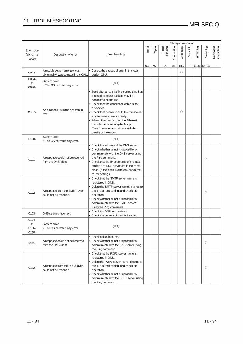
11 - 34 11 - 34
MELSEC-Q11 TROUBLESHOOTING
Storage destination
Initi
al
Ope
n
Fixe
dse
ndin
g
Con
nect
ion
Erro
r cod
e
Dat
a lin
k
HTT
P lo
g
E-m
ail l
og
Ded
icat
edin
stru
ctio
n
Error code(abnormal
code)Description of error Error handling
69H 7CH 7DH 7EH E5H — 5108H 5879H —
C0F3HA module system error (seriousabnormality) was detected in the CPU.
• Correct the causes of error in the localstation CPU.
C0F4H
toC0F6H
System error• The OS detected any error.
( 1)
C0F7 HAn error occurs in the self refraintest
• Send after an arbitrarily selected time haselapsed because packets may becongested on the line.
• Check that the connection cable is notdislocated.
• Check that connections to the transceiverand terminator are not faulty.
• When other than above, the Ethernetmodule hardware may be faulty.Consult your nearest dealer with thedetails of the errors.
C100HSystem error• The OS detected any error.
( 1)
C101HA response could not be receivedfrom the DNS client.
• Check the address of the DNS server.• Check whether or not it is possible to
communicate with the DNS server usingthe Ping command.
• Check that the IP addresses of the localstation and DNS server are in the sameclass. (If the class is different, check therouter setting.)
C102HA response from the SMTP layercould not be received.
• Check that the SMTP server name isregistered in DNS.
• Delete the SMTP server name, change tothe IP address setting, and check theoperation.
• Check whether or not it is possible tocommunicate with the SMTP serverusing the Ping command.
C103H DNS settings incorrect.• Check the DNS mail address.• Check the content of the DNS setting.
C104H
toC106H
C110H
System error• The OS detected any error.
( 1)
C111HA response could not be receivedfrom the DNS client.
• Check cable, hub, etc.• Check whether or not it is possible to
communicate with the DNS server usingthe Ping command.
C112HA response from the POP3 layercould not be received.
• Check that the POP3 server name isregistered in DNS.
• Delete the POP3 server name, change tothe IP address setting, and check theoperation.
• Check whether or not it is possible tocommunicate with the POP3 server usingthe Ping command.
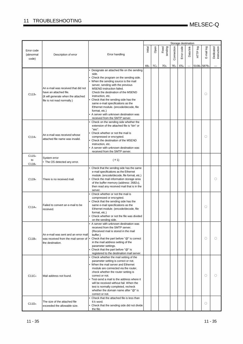
11 - 35 11 - 35
MELSEC-Q11 TROUBLESHOOTING
Storage destination
Initi
al
Ope
n
Fixe
dse
ndin
g
Con
nect
ion
Erro
r cod
e
Dat
a lin
k
HTT
P lo
g
E-m
ail l
og
Ded
icat
edin
stru
ctio
n
Error code(abnormal
code)Description of error Error handling
69H 7CH 7DH 7EH E5H — 5108H 5879H —
C113H
An e-mail was received that did nothave an attached file.(It will generate when the attachedfile is not read normally.)
• Designate an attached file on the sendingside.
• Check the program on the sending side.• When the sending source is the mail
server, sending with the previousMSEND instruction failed.Check the destination of the MSENDinstruction, etc.
• Check that the sending side has thesame e-mail specifications as theEthernet module. (encode/decode, fileformat, etc.)
• A server with unknown destination wasreceived from the SMTP server.
C114HAn e-mail was received whoseattached file name was invalid.
• Check on the sending side whether theextension of the attached file is “bin” or"asc".
• Check whether or not the mail iscompressed or encrypted.
• Check the destination of the MSENDinstruction, etc.
• A server with unknown destination wasreceived from the SMTP server.
C115H
toC118H
System error• The OS detected any error.
( 1)
C119H There is no received mail.
• Check that the sending side has the samee-mail specifications as the Ethernetmodule. (encode/decode, file format, etc.)
• Check the mail information storage areaof the buffer memory (address: 2682H),then read any received mail that is in theserver.
C11AHFailed to convert an e-mail to bereceived.
• Check whether or not the mail iscompressed or encrypted.
• Check that the sending side has thesame e-mail specifications as theEthernet module. (encode/decode, fileformat, etc.)
• Check whether or not the file was dividedon the sending side.
C11BH
An e-mail was sent and an error mailwas received from the mail server ofthe destination.
• A server with unknown destination wasreceived from the SMTP server.(Received mail is stored in the mailbuffer.)
• Check that the part before "@" is correctin the mail address setting of theparameter settings.
• Check that the part before "@" isregistered to the destination mail server.
C11CH Mail address not found.
• Check whether the mail setting of theparameter setting is correct or not.
• When the mail server and Ethernetmodule are connected via the router,check whether the router setting iscorrect or not.
• Test-send a mail to the address where itwill be received without fail. When thetest is normally completed, recheckwhether the domain name after "@" iscorrect or not.
C11DHThe size of the attached fileexceeded the allowable size.
• Check that the attached file is less than6 k word.
• Check that the sending side did not dividethe file.

11 - 36 11 - 36
MELSEC-Q11 TROUBLESHOOTING
Storage destination
Initi
al
Ope
n
Fixe
dse
ndin
g
Con
nect
ion
Erro
r cod
e
Dat
a lin
k
HTT
P lo
g
E-m
ail l
og
Ded
icat
edin
stru
ctio
n
Error code(abnormal
code)Description of error Error handling
69H 7CH 7DH 7EH E5H — 5108H 5879H —
C120H Could not open the SMTP server.
• Check that the port number of the SMTPserver = 25.
• Check whether or not it is possible tocommunicate with the SMTP serverusing the Ping command.
C121H
Cannot communicate with the SMTPserver.(Error response)
• Check if the SMTP server is busy.
C122H
Cannot communicate with the SMTPserver.(Abort)
• Check if the SMTP server is busy.
C123H
Cannot communicate with the SMTPserver.(Reset response)
• Check if the SMTP server is busy.
C124HA response from the SMTP servertimed out.
• Check whether or not the SMTP server isfaulty.
• Check whether or not there is too muchload on the network.
C125HForcefully disconnected from theSMTP server.
• Check whether or not the SMTP server isfaulty.
C126H Could not close the SMTP server.
• Check whether or not the SMTP server isfaulty.
• Check whether or not there is too muchload on the network.
C127HClosing the SMTP server gave anerror response.
• Check whether or not the SMTP server isfaulty.
C130HCommunication channel is closedbecause the service is not available.
• Check the status of the SMTP server.
C131H
The SMTP server was performingprocessing and an error responsewas received.
• Check if a user name not registered inthe server was designated.
• Send again after arbitrary set time haspassed.
C132H
The SMTP server was performingprocessing and an error responsewas received.(Local error)
• Check the status of the SMTP server.
C133H
The SMTP server was performingprocessing and an error responsewas received.(Insufficient memory area)
• Check the status of the SMTP server.
C134H
toC137H
System error• The OS detected any error.
( 1)
C138H
The SMTP server was performingprocessing and an error responsewas received.(Mailbox not found)
• Check that the Ethernet module’s mailaddress is set correctly.
C139HSystem error• The OS detected any error.
( 1)
C13AH
The SMTP server was performingprocessing and an error responsewas received. (Exceeded theallocation of memory area)
• Check the status of the SMTP server.
C13BH
The SMTP server was performingprocessing and an error responsewas received.(Illegal mail box name)
• Check that the Ethernet module’s mailaddress is set correctly.
C13CHSystem error• The OS detected any error.
( 1)

11 - 37 11 - 37
MELSEC-Q11 TROUBLESHOOTING
Storage destination
Initi
al
Ope
n
Fixe
dse
ndin
g
Con
nect
ion
Erro
r cod
e
Dat
a lin
k
HTT
P lo
g
E-m
ail l
og
Ded
icat
edin
stru
ctio
n
Error code(abnormal
code)Description of error Error handling
69H 7CH 7DH 7EH E5H — 5108H 5879H —
C140H Could not open the POP3 server.
• Check that the port number of the POP3server = 110. (For the Ethernet module,this is fixed to 110.)
• Check whether or not it is possible tocommunicate with the POP3 serverusing the Ping command.
C141H
Cannot communicate with the POP3server.(Error response)
• Check if the POP3 server is busy.
C142H
Cannot communicate with the POP3server.(Abort)
• Check if the POP3 server is busy.
C143H
Cannot communicate with the POP3server.(Reset response)
• Check if the POP3 server is busy.
C144HCould not receive a response fromthe POP3 server.
• Check whether or not the POP3 server isfaulty.
• Check whether or not there is too muchload on the network.
C145HForcefully disconnected from thePOP3 server.
• Check whether or not the POP3 server isfaulty.
C146H Could not close the POP3 server.
• Check whether or not the POP3 server isfaulty.
• Check whether or not there is too muchload on the network.
C147HClosing the POP3 server gave anerror response.
• Check whether or not the POP3 server isfaulty.
C150H POP3 server verification error. • Check the status of the POP3 server.
C151H
The Ethernet module’s mail address(e-mail address setting parameter) isdifferent from the account name inthe mailbox on the server side.
• Check the account name in the mailboxon the server side and correct themailbox account set for the Ethernetmodule.
C152H
The Ethernet module’s password (e-mail setting parameter) is differentfrom the password on the serverside.
• Check the password on the server sideand correct the password set for theEthernet module.
C153H
An error occurred when getting thereceived mail list.(Failed to obtain the list of mailarrived at the POP3 server.)
• Reset the server inquiry time to thedefault value and reset the local station’sPLC CPU.
C154H
An error occurred when receiving amail.(Cannot read e-mail from the POP3server.)
• Check whether or not the mail iscompressed or encrypted.
• Check that the sending side has thesame e-mail specifications as theEthernet module. (encode/decode, fileformat, etc.)
C160HReceived a response from the DNSserver after timeout.
C161HCould not receive a response fromthe DNS server.
• Check whether or not there is too muchload on the network.
• Check the status of the DNS server.

11 - 38 11 - 38
MELSEC-Q11 TROUBLESHOOTING
Storage destination
Initi
al
Ope
n
Fixe
dse
ndin
g
Con
nect
ion
Erro
r cod
e
Dat
a lin
k
HTT
P lo
g
E-m
ail l
og
Ded
icat
edin
stru
ctio
n
Error code(abnormal
code)Description of error Error handling
69H 7CH 7DH 7EH E5H — 5108H 5879H —C162H
C163H
C171H
toC17FH
An error is returned from DNS server.
• Check if the DNS server’s IP addresssetting is correct or not.
• Check if the mail server name setting(SMTP server name, POP server name)is correct or not.
• Check with the network administrator orsimilar person that the DNS function ofthe server set in the DNS setting" isbeing performed.
C1A0H An illegal request was made.
• Execute again.If the same error occurs, the Ethernetmodule’s hardware may be faulty.Consult your nearest dealer with thedetails of the error.
C1A2HA response to a request could not bereceived.
• Review and correct the response waittime.
C1A4HA request or subrequest wasincorrect.
• Correct the request or subrequest.
C1A5HThe designation of the target stationor clear target were incorrect.
• Correct the designated value of the targetstation or clear target.
C1A6HIncorrect connection number wasdesignated.
• Designate the connection number withinthe range of 1 to 16.
C1A7HIncorrect network number wasdesignated.
• Correct the designated value of thenetwork number.
C1A8HIncorrect station number wasdesignated.
• Correct the designated value of thestation number.
C1A9HIncorrect device number wasdesignated.
• Correct the designated device value ofthe device number.
C1AAHIncorrect device name wasdesignated.
• Correct the designated value of thedevice number.
C1ACHIncorrect resent count wasdesignated.
• Correct the designated value of theresent count.
C1ADH Incorrect data length was designated. • Correct the designated value of the datalength.
C1AEH
Incorrect mail sending/receiving datalength and header length weredesignated.
• Correct the designated values ofsending/receiving data length andheader length.
• Sending/receiving data length should beequal or longer than the header length.
C1AFHIncorrect port number wasdesignated.
• Correct the designated value of the portnumber.
C1B0H
The open processing of thedesignated connection is alreadycompleted.
• Execute the open processing afterexecuting the close processing.
C1B1H
The open processing of thedesignated connection has not beencompleted.
• Execute the open processing.
C1B2H
The OPEN/CLOSE instruction isbeing executed in the designatedconnection.
• Execute after the OPEN/CLOSEinstruction is completed.
C1B3H
Another sending/receiving instructionis being executed on the designatedchannel.
• Change the channel number.• Execute after the sending/receiving
instruction is completed.
C1B4H Incorrect arrival time was designated. • Set the watchdog timer within the properrange.
C1B5HData could not be received within thedesignated watchdog time.
• Review the designated value of thewatchdog timer.
C1B6HIncorrect mail destination numberwas designated.
• Review the designated value of the maildesignation number.
• Review the sending mail address settingparameter.

11 - 39 11 - 39
MELSEC-Q11 TROUBLESHOOTING
Storage destination
Initi
al
Ope
n
Fixe
dse
ndin
g
Con
nect
ion
Erro
r cod
e
Dat
a lin
k
HTT
P lo
g
E-m
ail l
og
Ded
icat
edin
stru
ctio
n
Error code(abnormal
code)Description of error Error handling
69H 7CH 7DH 7EH E5H — 5108H 5879H —
C1B7H
A reading operation was executedwhile no receiving e-mail was storedin the mail buffer data area.
• Execute the MRECV instruction when themail receiving flag of the mail informationis "yes".
C1B8H
The RECV instruction was executedfor the channel that had not receiveddata.
• Review the execution condition of theRECV instruction.
• Review the channel number.
C1B9H
The OPEN instruction cannot beexecuted for the specifiedconnection.
• Review the connection number.
C1BA H
A dedicated instruction wasexecuted while in the initializationuncompleted status
• Do not execute any dedicatedinstructions until after the initialprocessing is completed.
C1BBHThe target station CPU type iswrong.
• Review the value specified for the targetstation CPU type.
C200HThere is an error in the remotepassword.
• Review the remote password, thenperform the remote password unlock/lockprocessing again.
C201H
The remote password status of theport used for communication is inthe lock status.
• Unlock the remote password, thenperform communication.
C202H
When another station wasaccessed, the remote passwordcould not be unlocked.
• When accessing another station, do notset a remote password in the relaystation or station to be accessed, or setso they are not subject to the remotepassword check.
C203HSystem error• The OS detected any error.
( 1)
C204H
The device is different from the onerequesting the remote passwordunlock.
• Request the remote password lockprocessing from the opposite device thathas requested the remote passwordunlock processing.
C205H
When another station wasaccessed, the remote passwordcould not be unlocked.
• When accessing another station, do notset a remote password in the relaystation or station to be accessed, or setso they are not subject to the remotepassword check.
C206HSystem error• The OS detected any error.
( 1)
C207H Too many file name characters. • Reduce the file name characters to within255 characters.
C300 H
A response could not be receivedwithin the response monitoring timervalue.
• Check the operation of the externaldevice.
• Review and correct the responsemonitoring timer value.
F000H
toFFFFH
(Errors detected by theMELSECNET/H, MELSECNET/10network system)
• Refer to the MELSECNET/H,MELSECNET/10 Network System ReferenceManual for details on error handling.
1 Take corrective action in the following procedure.1) Check whether the Ethernet module, power supply module and CPU module are
mounted correctly on the base unit.2) Check whether the operating environment of the Ethernet module is within the general
specifications range of the CPU module.3) Check whether the power supply capacity is sufficient or not.4) Check whether the hardware of the Ethernet module, power supply module and CPU
module are normal according to the manuals of the corresponding modules.If any module is faulty, please request your local Mitsubishi service center orrepresentative to repair.
5) If the problem cannot be solved through the above steps, please consult your localMitsubishi service center or representative, explaining the operation/communicationconditions at error occurrence and the information stored in the error log area withinthe buffer memory of the Ethernet module.

11 - 40 11 - 40
MELSEC-Q11 TROUBLESHOOTING
REMARKDepending on the restrictions of the buffers of the local station and external device,data may be divided for communication.Data received separately is restored (reassembled) by the Ethernet module to becommunicated using the fixed buffer, random access buffer, etc. The received datais restored (reassembled) based on the data length in the communication data.The Ethernet module performs the following processing if data among thecommunication data is incorrect.
(1) When communication is performed using fixed buffer (with procedure) andrandom buffer(a) If the data length specified immediately after the subheader is smaller than
the amount of text data received1) The data immediately following the part of the text data equivalent to
the data length specified immediately after the subheader will beregarded as the next message.
2) Since the header of each message will be a subheader, the Ethernetmodule performs processing according to the code in the subheader.
3) If the subheader contains a code that is not recognized by theEthernet module, the Ethernet module will send a response notifyingabout abnormal completion to the external device.
This section is processed as a subheader.
Data sent by an external device Data determined by the Ethernet module
(First data) (Second data)
Subheader
Subheader
At this point, the Ethernet module returns a response containing a codeobtained by changing the most significant bit of the code processed assubheader to 1.For example, if the subheader field of a command is 65h, the subheader ofthe response will become E5h.

11 - 41 11 - 41
MELSEC-Q11 TROUBLESHOOTING
(b) If the data length specified immediately after the subheader is larger thanthe amount of text data received1) The Ethernet module waits for the reception of the remaining missing
data.2) If the remaining data could be received within the time allotted by the
response monitoring timer, the Ethernet module performs processingaccording to the code in the subheader.
3) If the remaining data could not be received within the time allotted bythe response monitoring timer, the Ethernet module performs thefollowing processing.• Sends the ABORT (RST) instruction to the external device and
closes the line.• Notifies about occurrence of an open error to the PLC CPU side via
the open error detection signal (X18 = ON).• Stores the error code in the open error code storage area. (The
error code is not stored in the error log storage area.)
POINTDesignate the actual data size of the text field for "data length" specified in theapplication data field of a message sent from the external device to the Ethernetmodule.The Ethernet module never sends a text whose size is different from the specifieddata length to the external device.
(2) When communication is performed using fixed buffer (non-procedure)Since no message data length is specified in non-procedure communication,the data received is stored in the receive buffer area as is.It is recommended to set up some method of checking that the data is receivedcorrectly. This can for instance be achieved by including the data length anddata type code in the application data of the message, so that the number ofbytes and data type of application data can be identified on the receiving side.
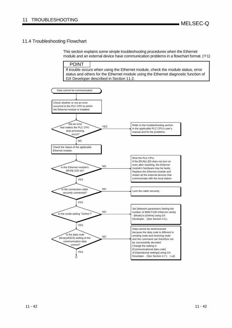
11 - 42 11 - 42
MELSEC-Q11 TROUBLESHOOTING
11.4 Troubleshooting Flowchart
This section explains some simple troubleshooting procedures when the Ethernetmodule and an external device have communication problems in a flowchart format. ( 1)
POINTIf trouble occurs when using the Ethernet module, check the module status, errorstatus and others for the Ethernet module using the Ethernet diagnostic function ofGX Developer described in Section 11.2.
YES
NO
NO
YES
NO
YES
NO
YES
NO
YES
1)
Data cannot be sent/received because the data code is different in sending node and receiving node and the command can therefore not be successfully decoded. Change the setting in [Communicational data code] of [Operational settings] using GX Developer. (See Section 4.7.) ( 2)
Data cannot be communicated.
Check whether or not an error occurred in the PLC CPU to which the Ethernet module is installed.
Did an error that makes the PLC CPU
stop processing occur?
Refer to the troubleshooting section in the applicable PLC CPU's user's manual and fix the problems.
Check the status of the applicable Ethernet module.
Is the Ethernet module's [RUN] LED on?
Rest the PLC CPU.If the [RUN] LED does not turn on even after resetting, the Ethernet module's hardware may be faulty. Replace the Ethernet module and restart all the external devices that communicate with the local station.
Is the connection cable securely connected? Lock the cable securely.
Is the mode setting "Online"?
Set [Network parameters Setting the number of MNET/10H Ethernet cards]- [Mode] to [Online] using GX Developer. (See Section 4.6.)
Is the data code (binary/ASCII) setting of the
communication data correct?

11 - 43 11 - 43
MELSEC-Q11 TROUBLESHOOTING
NO(X19 = OFF)
YES
NO
YES
1)
NO
YES
Is initial processing normally completed
(X19 = ON)?
Perform initial processing. (See Section 5.1.1.)If the initial processing parameters set with GX Developer and the sequence program for initial processing overlap, delete the sequence program for initial processing.
Connected using 10BASE2?
Check the contact status of the power supply module of the station in which the Ethernet module is installed.(LG and FG terminal grounding)
Are the LG and FG terminal grounded?
Sending error in fixed buffer communication: See Section 11.4.1.Receiving error in fixed buffer communication: See Section 11.4.2.Error in random access buffer communication: See Section 11.4.3.Error in the MC protocol communication: See Section 11.4.4.Send error during communication by e-mail: See Section 11.4.5.Receive error during communication by e-mail: See Section 11.4.6.Error in redundant system: See Section 11.4.7.
Check and fix the faulty part for each communication processing.
Ground the LG and FG terminals, start up the Ethernet module, and try communicating with an external device. ( 3)
Did it occur after replacing the Ethernet module?
Refer to POINT in this section and correct the error-causing part.
YES
NO
1 See Section 11.1 when the I/O signal X1C (COM.ERR LED ON confirmation signal) is turned on or when the display LED COM.ERR(communication error detection display) lights up.(Check the dedicated instruction control table for a processing during which an error occurred or the error code stored in the buffermemory, then check the contents of the error and take corrective actions by referring to Section 11.3.)
2 Error codes not found in the error code list may be returned to the external device side if the communication data settings on theEthernet module side (see Section 4.7) and the data code settings on the external device side are different.The Ethernet module cannot decode commands correctly if data with different data codes is received. The Ethernet module returnserror responses according to the communication data code settings.
60H00H
Text
End codeSubheader
Data length
Subheader
External device side
The external device side receives this portion as an end code.
45H30H 35H34H
Subheader
Ethernet module side
(Set to ASCII code)
(Set to binary code)
[Example] When communication is performed using a fixed buffer

11 - 44 11 - 44
MELSEC-Q11 TROUBLESHOOTING
3 If the LG and FG terminals of the power supply module of the station in which the Ethernet module is installed are not grounded, the
communication line is closed (disconnected) due to the effects of noise, and as a result communication with an external device may not
be performed.
Turn off the power to the station in which the Ethernet module is installed and ground the LG and FG terminals of the power supply
module after referring to the section in the PLC CPU User's Manual that explains the wiring procedure.
POINT(1) When the Ethernet module is replaced due to an error, reboot the following
external devices and restart data communication:• All external devices that communicated with the station whose Ethernet
module was replaced.• All external devices that communicated with other station’s PLC CPU via a
station whose Ethernet module was replaced.
(2) When connecting a device to the Ethernet module, see the following sectionsfor the required devices and connection method:Section 2.2: Devices Required for Network ConfigurationSection 4.4: Connection Method Check
(3) If the Ethernet module could not receive messages sent from external devicesfrequently, check the values stored in the following buffer memory.(a) Simultaneous transmission error detection count storage area (address:
18EH to 18FH) and Error/End code storage area for each error log block(address: E5H…)When the error detection count number is high or when the error codeC0C7H has been stored, high load may be applied to the Ethernetconnection line to transfer data among connected devices.To reduce the load to the Ethernet line, it is necessary to take correctivemeasures such as dividing the network or reducing the data transmissionfrequency.Consult your network administrator and take appropriate measures.
(b) TCP packet reception count storage area (address: 1B8H, 1B9H)When data cannot be received even though TCP packet reception counthas been renewed, set 8000H (Disable TCP Maximum Segment SizeOption transmission) to the TCP Maximum Segment Transmission settingarea (address: 1EH) and execute re-initialization.(For re-initialization, refer to Section 5.2.3.)
(4) All dedicated instructions must be executed online.If any of the dedicated instructions is executed offline, no error will occur, butthe execution of the dedicated instruction will not be completed.

11 - 45 11 - 45
MELSEC-Q11 TROUBLESHOOTING
11.4.1 Sending errors during fixed buffer communication(common to procedure exist and no procedure)
POINTCheck the abnormal code marked with " " by referring to the complete statusstored as the control data of the dedicated instruction.
NO
YES
NO
YES
NO
YES
NO
YES
1)
NO
YES
Sending error
Check the open status of the connectionwith an external device.
Execute the open processing of the applicable connection. (For details, see Section 5.6.)Make sure that the open/close processing using input/output signals and the OPEN or CLOSE dedicated instruction are not executed simultaneously in the same connection.If so, modify the program.
Read the open abnormal code (buffer memory address 124, 134...) of the communication status storage area and check that no errors have occurred.
Have parameter errors occurred?
Fix the error according to the error code (see Section 11.3).
Read the content of the communication abnormal code storage area (buffer memory address 125, 135...) corresponding to the fixed buffer of the buffer memory and check whether or not a communication error has occurred.
Has a communication error occurred?
Fix the error according to the error code (see Section 11.3).
Is the parameter, IP address of the external device,
correct?
Correct the IP address of the external device.
Does the communication protocol
(TCP/UDP) match that of the external device?
Match the protocol with the communication protocol (TCP/UDP) of the external device. (For details, see Section 5.5.)
Is the applicable connection open?
(Buffer memory address: applicable bit of 5000H)

11 - 46 11 - 46
MELSEC-Q11 TROUBLESHOOTING
NO
YES
NO
YES
1)
NO
YES
NO
YES
NO
YES
Was the dedicated BUFSND instruction
executed?
Correct the execution condition of the BUFSND instruction.Check that the send/receive processing using input/output signals and the dedicated BUFSND or BUFRCV instruction are not executed simultaneously in the same connection.If so, modify the program.
Did the BUFSND instruction complete
normally?
Is the send data length set in the
control data?Write the data length.
Check the communication status of the external device.
Does the external device operate
normally?
Fix the faulty part of the external device. (If the receiving side is also an Ethernet module, see Section 11.3.)
Are there any open errors or initial errors
in the error log area?Check and fix the faulty part.
The Ethernet module hardware on the sending side may be faulty. Consult your nearest dealer with the details of the errors.
Fix the error according to the abnormal code (see Section 11.3) in the BUFSND instruction complete status area.
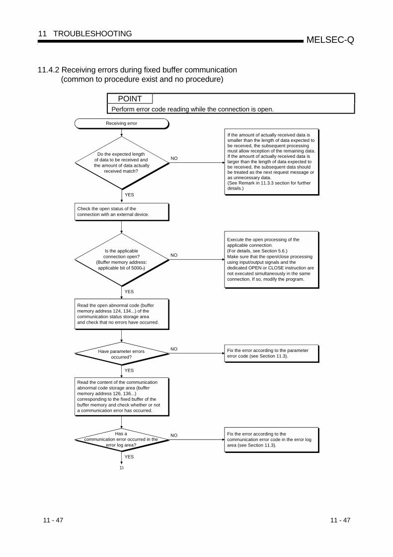
11 - 47 11 - 47
MELSEC-Q11 TROUBLESHOOTING
11.4.2 Receiving errors during fixed buffer communication(common to procedure exist and no procedure)
POINTPerform error code reading while the connection is open.
NO
YES
1)
NO
YES
Receiving error
Check the open status of the connection with an external device.
NO
YES
Execute the open processing of the applicable connection. (For details, see Section 5.6.)Make sure that the open/close processing using input/output signals and the dedicated OPEN or CLOSE instruction are not executed simultaneously in the same connection. If so, modify the program.
Read the open abnormal code (buffer memory address 124, 134...) of the communication status storage area and check that no errors have occurred.
Have parameter errors occurred?
Fix the error according to the parameter error code (see Section 11.3).
Read the content of the communication abnormal code storage area (buffer memory address 126, 136...) corresponding to the fixed buffer of the buffer memory and check whether or not a communication error has occurred.
Has a communication error occurred in the
error log area?
Fix the error according to the communication error code in the error log area (see Section 11.3).
NO
YES
Do the expected length of data to be received and
the amount of data actually received match?
Is the applicableconnection open?
(Buffer memory address:applicable bit of 5000H)
If the amount of actually received data is smaller than the length of data expected tobe received, the subsequent processing must allow reception of the remaining data.If the amount of actually received data is larger than the length of data expected to be received, the subsequent data should be treated as the next request message or as unnecessary data. (See Remark in 11.3.3 section for further details.)

11 - 48 11 - 48
MELSEC-Q11 TROUBLESHOOTING
NO
NO
YES
NO
YES
YES
NO
YES
NO
YES
NO
YES
NO
YES
Is the receive completion signal (buffer
memory address: corresponding bit of 5005H) of the applicable
fixed buffer on?
Data may not have been set from the external device.Check the sending side. (If the sending side is also an Ethernet module, see Section 11.3.)
Did the error occur in the device on the
sending side?Fix the faulty part of the device on sending side.
The Ethernet module on receiving side may be faulty. Consult your nearest dealer with the details of errors.
Perform receive processing using the interrupt
program?
Was the dedicated BUFRCVSinstruction executed?
Was the dedicated BUFRCV instruction executed?
Correct the execution condition of the BUFRCV instruction.Make sure that the send/receive processing using input/output signals and the dedicated BUFSND or BUFRCV instruction are not executed simultaneously executed in the same connection.If so, modify the program.
Correct the interrupt setting from GX Developer. (See Section 7.3.2.)Make sure that the send/receive processing using input/output signals and the dedicated BUFSND or BUFRCV instruction are not executed in the same connection. If so, modify the program.
Is the control data of the BUFRCVS instruction correct?
Did the BUFSND instruction complete normally?
Fix the error according to the abnormal code (see Section 11.3) in the BUFSND instruction complete status area.Correct the control data.
(For details, see Chapter 10.)
NO
YES
NO
YES
Correct the IP address of the external device.
Does the communication protocol (TCP/UDP) match that
of the external device?
Match the protocol with the communication protocol (TCP/UDP) of the external device. (For details, see Section 5.5.)
Is the parameter, IP address of the external
device, correct?
2)
1)
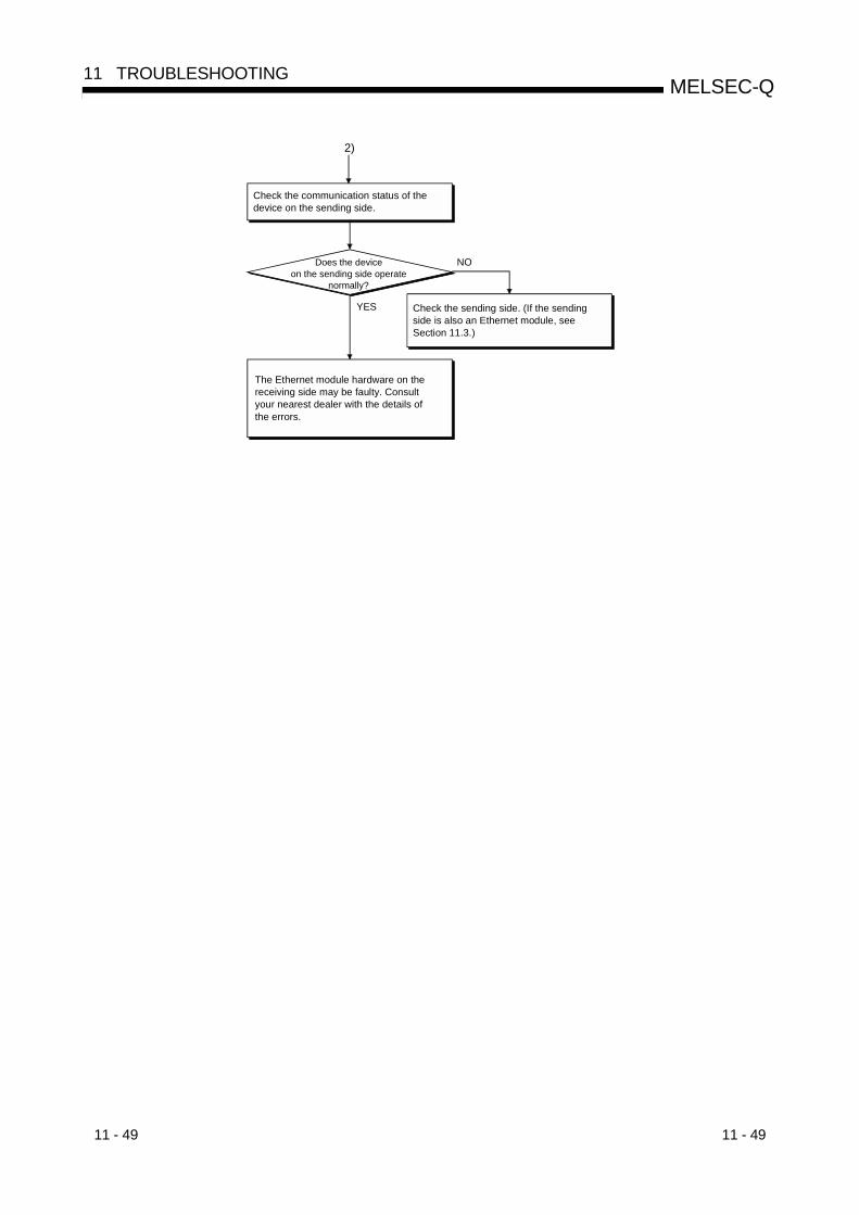
11 - 49 11 - 49
MELSEC-Q11 TROUBLESHOOTING
YES
NO
The Ethernet module hardware on the receiving side may be faulty. Consult your nearest dealer with the details of the errors.
Check the communication status of the device on the sending side.
Does the device on the sending side operate
normally?
Check the sending side. (If the sending side is also an Ethernet module, see Section 11.3.)
2)

11 - 50 11 - 50
MELSEC-Q11 TROUBLESHOOTING
11.4.3 Errors during random access buffer communication
NO
YES
NO
YES
NO
YES
YES
1)
NO
YES
NO
YES
NO Fix the faulty part according to the description of the end code (see Section 11.3).
Communication error
Check the open status of the connection with the external device.
Is the applicable connection open? (buffer memory
address: corresponding bit of 5000H)
Execute the open processing of the applicable connection. (For details, see Section 5.6.)Make sure that the open/close processing using input/output signals and the dedicated OPEN or CLOSE instruction are not executed simultaneously in the same connection.If so, modify the program.
Was a command sent form the external
device?Send the command to the Ethernet module.
Was a response returned to the device that
sent the command?
Is the IP address designation of the command
correct?
Correct the IP address and send the command again.
Does the communication protocol
(TCP/UDP) match with that of the external device?
Match the communication protocol (TCP/UDP) with the external device. (For details, see Section 5.5.)
The command may not be sent to the Ethernet module from the external device on the command sending side. Check the sending side.
Is the end code of the response "0"?
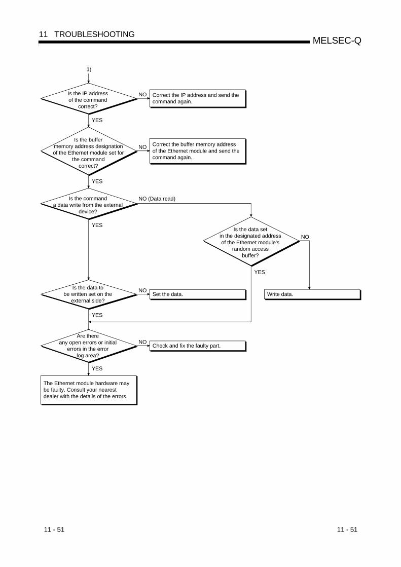
11 - 51 11 - 51
MELSEC-Q11 TROUBLESHOOTING
NO
NO (Data read)
YES
1)
NO
YES
YES
NO
YES
NO
YES
NO
YES
Is the IP address of the command
correct?
Correct the IP address and send the command again.
Is the buffer memory address designation of the Ethernet module set for
the command correct?
Correct the buffer memory address of the Ethernet module and send the command again.
Is the command a data write from the external
device?
Is the data set in the designated address of the Ethernet module's
random access buffer?
Is the data to be written set on the
external side?Set the data. Write data.
Are there any open errors or initial
errors in the error log area?
Check and fix the faulty part.
The Ethernet module hardware may be faulty. Consult your nearest dealer with the details of the errors.

11 - 52 11 - 52
MELSEC-Q11 TROUBLESHOOTING
11.4.4 Errors in communication using the MC protocol
NO
YES
NO
YES
NO
YES
YES
1)
NO
YES
NO
YES
NO
Communication error
Check the open status of the connection with the external device.
Is the applicable connection open? (buffer
memory address: corresponding bit of 5000 H)
Execute the open processing of the applicable connection. (For details, see Section 5.6.)Make sure that the open/close processing using input/output signals and the dedicated OPEN or CLOSE instruction are not executed simultaneously in the same connection. If so, modify the program.
Was a command sent form the external device? Send the command to the Ethernet module.
Was a response returned to the device that sent
the command?
Is the IP address designation of the command
correct?
Correct the IP address and send the command again.
Does the communication protocol
(TCP/UDP) match with that of the external device?
Match the communication protocol (TCP/UDP) with the external device. (For details, see Section 5.5.)
The command may not be sent to the Ethernet module from the external device on the command sending side. Check the sending side.
Is the end code of the response "0"?
Fix the faulty part according to the description of the end and abnormal codes (see Section 11.3).
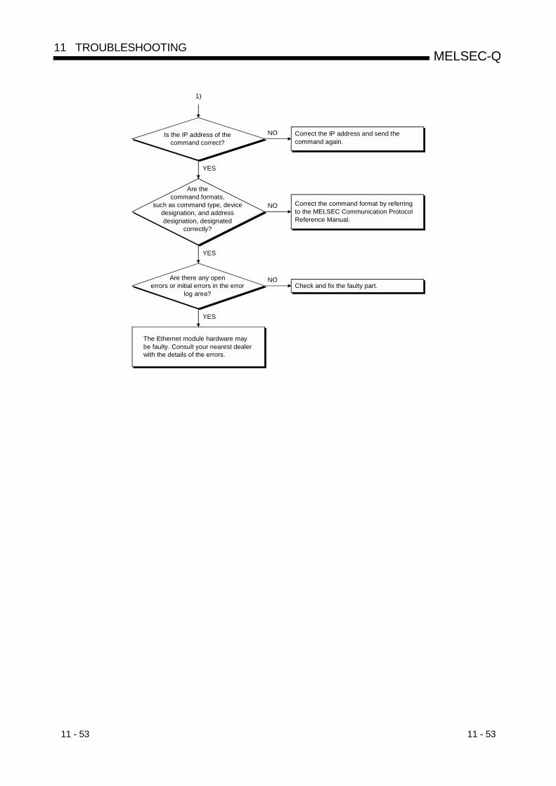
11 - 53 11 - 53
MELSEC-Q11 TROUBLESHOOTING
NO
1)
YES
NO
YES
NO
YES
Is the IP address of the command correct?
Correct the IP address and send the command again.
Are the command formats,
such as command type, device designation, and address designation, designated
correctly?
Correct the command format by referring to the MELSEC Communication Protocol Reference Manual.
Are there any open errors or initial errors in the error
log area?Check and fix the faulty part.
The Ethernet module hardware may be faulty. Consult your nearest dealer with the details of the errors.
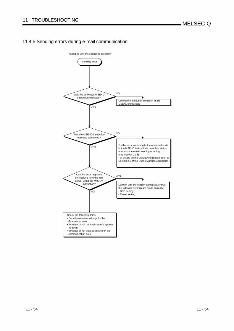
11 - 54 11 - 54
MELSEC-Q11 TROUBLESHOOTING
11.4.5 Sending errors during e-mail communication
NO
YES
NO
YES
YES
NO
Sending error
Was the dedicated MSEND instruction executed?
Correct the execution condition of the MSEND instruction.
Was the MSEND instruction normally completed?
Fix the error according to the abnormal code in the MSEND instruction's complete status area and the e-mail sending error log (see Section 11.3).For details on the MSEND instruction, refer to Section 2.6 of the User's Manual (Application).
Can the error response be received from the mail server using the MRECV
instruction? Confirm with the system administrator that the following settings are made correctly:• DNS setting• E-mail setting
Check the following items.• E-mail parameter settings for the Ethernet module.• Whether or not the mail server's system is down.• Whether or not there is an error in the communication path.
<Sending with the sequence program>
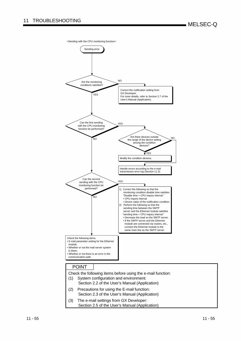
11 - 55 11 - 55
MELSEC-Q11 TROUBLESHOOTING
NO
YES
YES
NO
Check the following items.• E-mail parameter setting for the Ethernet module.• Whether or not the mail server system is down.• Whether or not there is an error in the communication path.
<Sending with the CPU monitoring function>
Sending error
Are the monitoring conditions satisfied?
Correct the notification setting from GX Developer.For more details, refer to Section 2.7 of the User's Manual (Application).
1) Correct the following so that the monitoring condition disable time satisfies "Disable time > CPU inquiry interval."
• CPU inquiry interval• Device value of the notification condition.
2) Perform the following so that the sending time between the SMTP server and the Ethernet module satisfies "sending time < CPU inquiry interval."
• Decrease the load on the SMTP server.• If the SMTP server and the Ethernet module are connected via routers, etc., connect the Ethernet module to the same main line as the SMTP server.
NO
YES
Are there devices outside the range of the device setting
among the condition devices?
Modify the condition devices.
Can the first sending with the CPU monitoring function be performed?
Handle errors according to the e-mail transmission error log (Section 11.3).
YES
NO
Can the secondsending with the CPU monitoring function be
performed?
POINTCheck the following items before using the e-mail function:(1) System configuration and environment:
Section 2.2 of the User’s Manual (Application)(2) Precautions for using the E-mail function:
Section 2.3 of the User’s Manual (Application)(3) The e-mail settings from GX Developer:
Section 2.5 of the User’s Manual (Application)
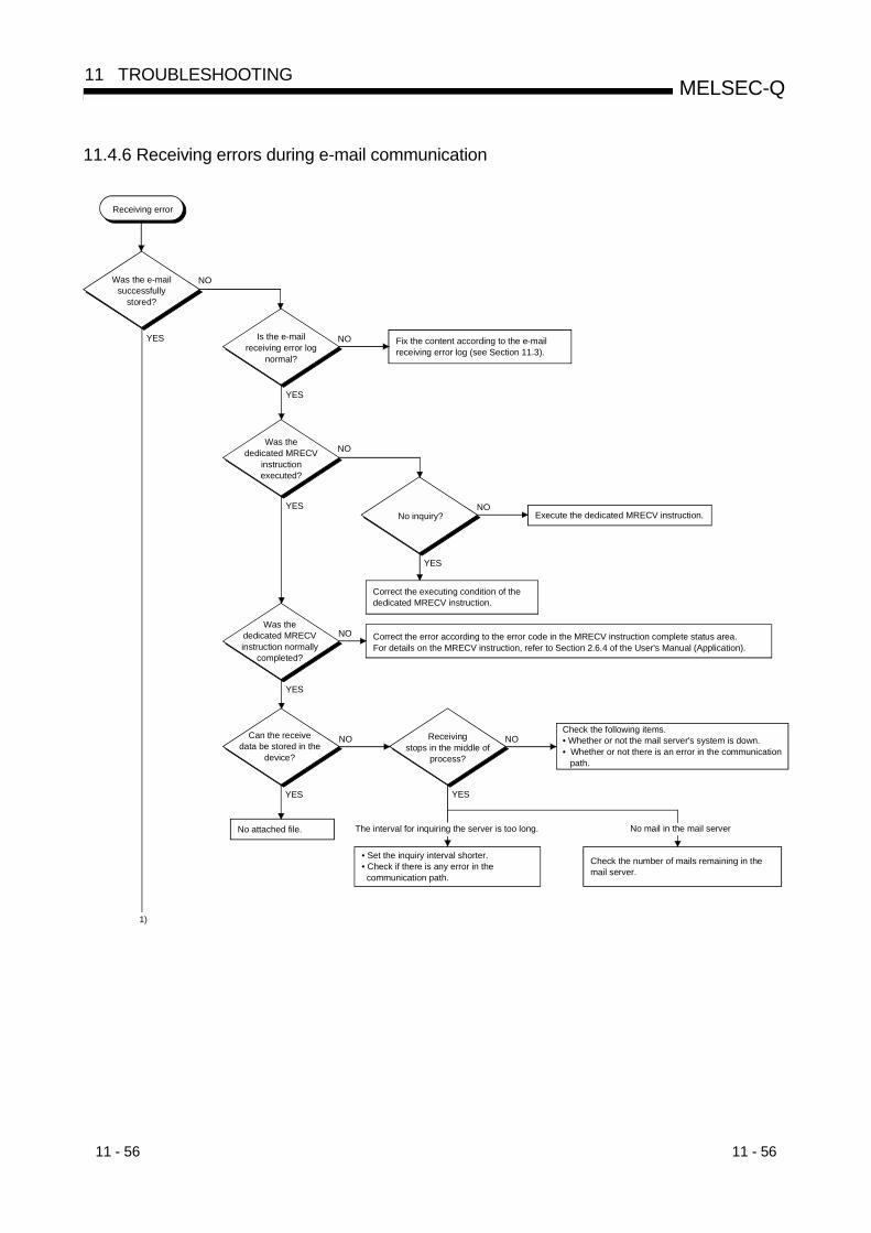
11 - 56 11 - 56
MELSEC-Q11 TROUBLESHOOTING
11.4.6 Receiving errors during e-mail communication
YES
YES
YES
YES
YES
NO
NO
NO
NO NO
NO
YES NO
YES
Receiving error
Was the e-mail successfully
stored?
Is the e-mail receiving error log
normal?
Fix the content according to the e-mail receiving error log (see Section 11.3).
Was the dedicated MRECV
instruction executed?
No inquiry? Execute the dedicated MRECV instruction.
Correct the executing condition of the dedicated MRECV instruction.
Was the dedicated MRECV instruction normally
completed?
Correct the error according to the error code in the MRECV instruction complete status area. For details on the MRECV instruction, refer to Section 2.6.4 of the User's Manual (Application).
Can the receive data be stored in the
device?
Receiving stops in the middle of
process?
Check the following items.• Whether or not the mail server's system is down.• Whether or not there is an error in the communication path.
No attached file. The interval for inquiring the server is too long. No mail in the mail server
• Set the inquiry interval shorter.• Check if there is any error in the communication path.
Check the number of mails remaining in the mail server.
1)

11 - 57 11 - 57
MELSEC-Q11 TROUBLESHOOTING
YES
YES
YES
NO
NO
NOIs the receive
data value incorrect? (Characters got
garbled)
Did the characters of the subject get
garbled?
Check the following items:• Whether or not the e-mail parameter settings for the Ethernet module are correct.• Whether or not the mail server's system is down.• Whether or not there is an error in the communication path.
Sending side sent in ASCII code.Sending side converted the ASCII code to ASCII code once more.
Codes other than "0 to 9" and "A to F" are used.
Correct the codes to "0" to "9" and "A" to "F."
Test the following items.• The sending side sends an attached file in binary code.• Whether or not the send data (attached file) is in ASCII code.• If the sending side is a PC, try sending using another mail program. If there is any difference due to the mail program, check the mail settings again.• Check that the mail server's encode and decode are the same as the Ethernet.
Is the sending side the Ethernet
module?
• Because decode processing is not performed, it cannot be received normally.
EUC or SHIFT-JIS is used. Check the PC setting.• Send from the PC to the local-station.• Check the header information of the receive data sent from the Local station.In case of Outlook Express, check "Property" "Details" "Content of header information -Type: text-plain:charset=iso-2022.jp."Correct the setting if it is charset="EUC.jp" or "SHIFT-JIS."
1)
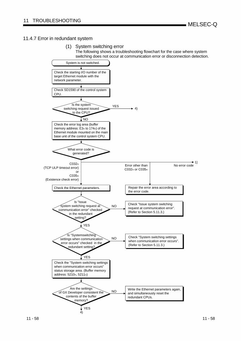
11 - 58 11 - 58
MELSEC-Q11 TROUBLESHOOTING
11.4.7 Error in redundant system(1) System switching error
The following shows a troubleshooting flowchart for the case where systemswitching does not occur at communication error or disconnection detection.
System is not switched.
Check SD1590 of the control system CPU.
YES
NO
4)
Check the error log area (buffer memory address: E3H to 174H) of the Ethernet module mounted on the main base unit of the control system CPU.
C032H
(TCP ULP timeout error)or
C035H
(Existence check error)
Check the Ethernet parameters. Repair the error area according to the error code.
1)Error other than C032H or C035H
No error code
YES
Check "Issue system switching request at communication error". (Refer to Section 5.11.3.)
YES
Check "System switching settings when communication error occurs". (Refer to Section 5.11.3.)
NO
Check the "System switching settings when communication error occurs" status storage area. (Buffer memory address: 5210H, 5211H)
YES
NO
4)
Check the starting I/O number of thetarget Ethernet module with the network parameter.
NO
Is the system switching request issued
to the CPU?
What error code is generated?
Is "Issue system switching request at
communication error" checked in the redundant
setting?
Is "Systemswitching settings when communication error occurs" checked in the
redundant setting?
Are the settings of GX Developer consistent the
contents of the buffer memory?
Write the Ethernet parameters again, and simultaneously reset the redundant CPUs.

11 - 59 11 - 59
MELSEC-Q11 TROUBLESHOOTING
Check the hub connection status area (buffer memory address: C9H).
Is disconnection detected?NO
YES
Check the Ethernet parameters.
Is "Issue system switching request
at disconnection detection" checked in the redundant
setting?
YES
Check the "cable disconnection timeout setting". (Refer to Section5.11.3.)
NO
Check the "Issue system switching request at disconnection detection"status storage area. (Buffer memory address: 5200H)
YES
NO
Check the "cable disconnection timeout setting". (Buffer memory address: 5201H)
Is the settingof the cable disconnection
timeout setting correct?
YES
NOReview the "cable disconnection timeout setting". (Refer to Section5.11.3.)
Are the settings of
GX Developer consistent with the contents of the buffer
memory?
2)
4)
1)
Write the Ethernet parameters again, and simultaneously reset the redundant CPUs.
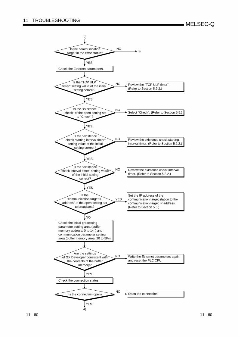
11 - 60 11 - 60
MELSEC-Q11 TROUBLESHOOTING
Is the communication target in the error status?
NO
YES
Check the Ethernet parameters.
Review the "TCP ULP timer". (Refer to Section 5.2.2.)
NOIs the "TCP ULP timer" setting value of the initial
setting correct?
YES
NOIs the "existence check" of the open setting set
to "Check"?
YES
Select "Check". (Refer to Section 5.5.)
NOIs the "existence
check interval timer" setting valueof the initial setting
correct?
YES
Review the existence check intervaltimer. (Refer to Section 5.2.2.)
YESIs the
"communication target IP address" of the open setting set
to broadcast?
NO
Set the IP address of the communication target station to the communication target IP address. (Refer to Section 5.5.)
NOAre the settings
of GX Developer consistent with the contents of the buffer
memory?
YES
Write the Ethernet parameters again and reset the PLC CPU.
Check the connection status.
NOIs the connection open?
YES
Open the connection.
NOIs the "existence
check starting interval timer"setting value of the initial
setting correct?
YES
Review the existence check starting interval timer. (Refer to Section 5.2.2.)
3)
2)
4)
Check the initial processing parameter setting area (buffer memory address: 0 to 14H) and communication parameter setting area (buffer memory area: 20 to 5FH).
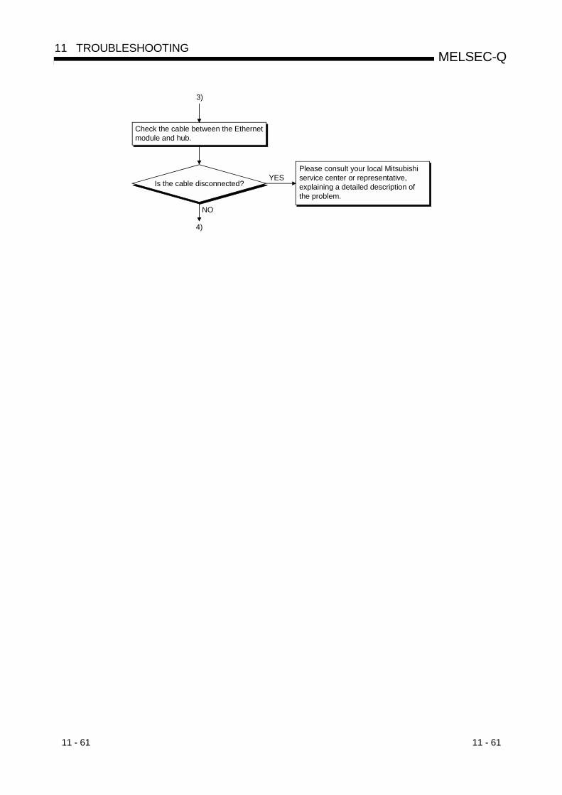
11 - 61 11 - 61
MELSEC-Q11 TROUBLESHOOTING
Check the cable between the Ethernet module and hub.
Please consult your local Mitsubishi service center or representative, explaining a detailed description of the problem.
YES
3)
Is the cable disconnected?
NO
4)
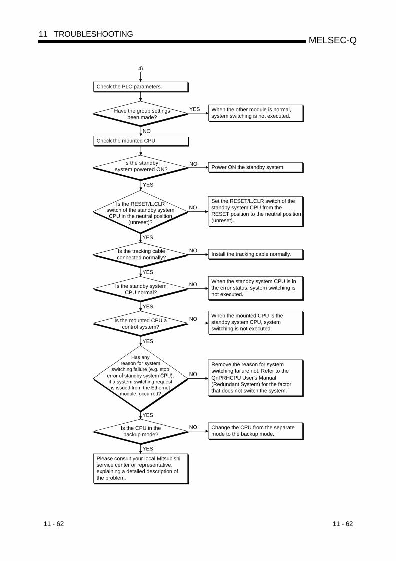
11 - 62 11 - 62
MELSEC-Q11 TROUBLESHOOTING
Check the PLC parameters.
YES
Check the mounted CPU.
NO
NO
YES
NO
YES
NO
YES
NO
YES
YES
NO
YES
NO
YES
NO
4)
Have the group settings been made?
Is the RESET/L.CLR switch of the standby system CPU in the neutral position
(unreset)?
Has any reason for system
switching failure (e.g. stop error of standby system CPU), if a system switching request is issued from the Ethernet
module, occurred?
Please consult your local Mitsubishi service center or representative, explaining a detailed description of the problem.
Is the standby system powered ON?
Is the tracking cable connected normally?
Is the standby system CPU normal?
Is the mounted CPU a control system?
Is the CPU in the backup mode?
When the other module is normal, system switching is not executed.
Power ON the standby system.
Set the RESET/L.CLR switch of the standby system CPU from the RESET position to the neutral position (unreset).
Install the tracking cable normally.
When the standby system CPU is in the error status, system switching is not executed.
When the mounted CPU is the standby system CPU, system switching is not executed.
Remove the reason for system switching failure not. Refer to the QnPRHCPU User's Manual (Redundant System) for the factor that does not switch the system.
Change the CPU from the separate mode to the backup mode.
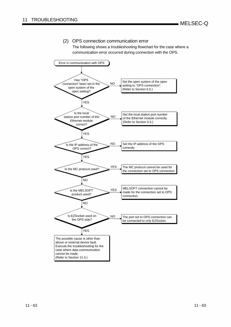
11 - 63 11 - 63
MELSEC-Q11 TROUBLESHOOTING
(2) OPS connection communication errorThe following shows a troubleshooting flowchart for the case where acommunication error occurred during connection with the OPS.
Error in communication with OPS
Has "OPS connection" been set in the
open system of the open setting?
YES
Is EZSocket used on the OPS side?
YES
The port set to OPS connection can be connected to only EZSocket.
NO
The possible cause is other than above or external device fault.Execute the troubleshooting for the case where data communication cannot be made. (Refer to Section 11.4.)
NO Set the open system of the open setting to "OPS connection". (Refer to Section 5.5.)
Is the local station port number of the
Ethernet module correct?
YES
NO Set the local station port number of the Ethernet module correctly. (Refer to Section 5.5.)
Is the IP address of the OPS correct?
YES
NO Set the IP address of the OPS correctly.
Is the MC protocol used?
NO
YES The MC protocol cannot be used for the connection set to OPS connection.
NO
YES MELSOFT connection cannot be made for the connection set to OPS connection.
Is the MELSOFT product used?
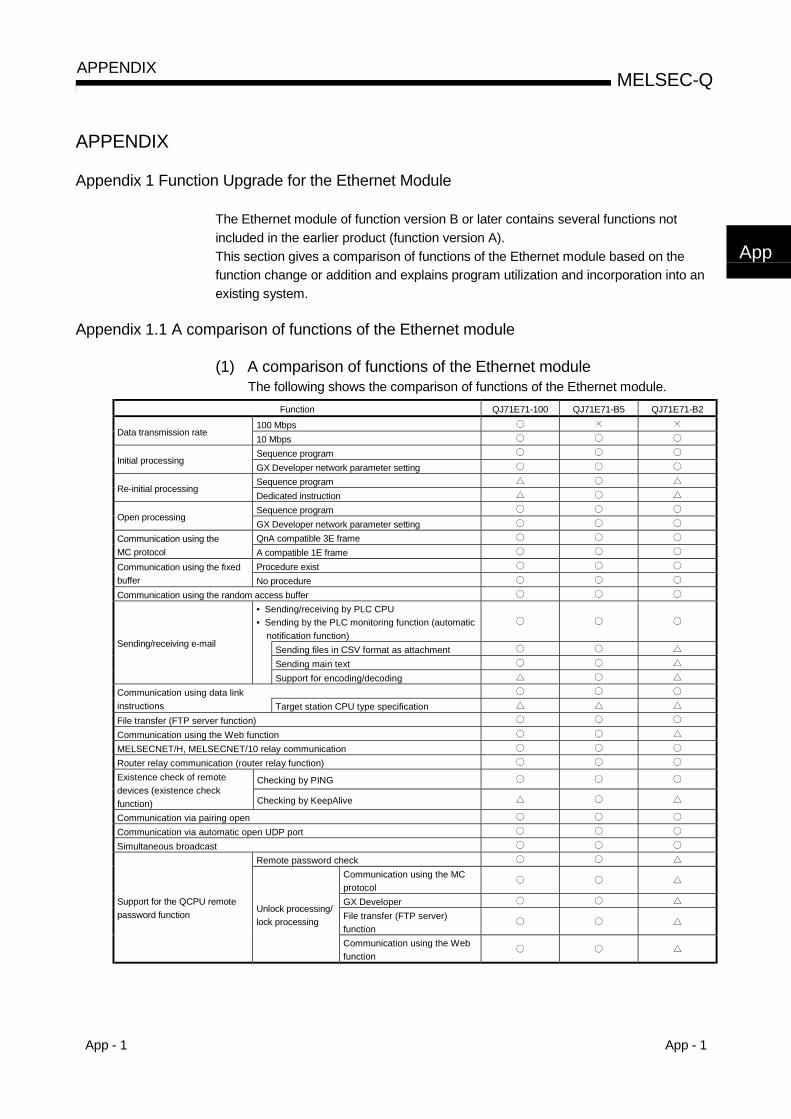
App - 1 App - 1
MELSEC-QAPPENDIX
App
APPENDIX
Appendix 1 Function Upgrade for the Ethernet Module
The Ethernet module of function version B or later contains several functions notincluded in the earlier product (function version A).This section gives a comparison of functions of the Ethernet module based on thefunction change or addition and explains program utilization and incorporation into anexisting system.
Appendix 1.1 A comparison of functions of the Ethernet module
(1) A comparison of functions of the Ethernet moduleThe following shows the comparison of functions of the Ethernet module.
Function QJ71E71-100 QJ71E71-B5 QJ71E71-B2
100 MbpsData transmission rate
10 MbpsSequence program
Initial processingGX Developer network parameter settingSequence program
Re-initial processingDedicated instructionSequence program
Open processingGX Developer network parameter settingQnA compatible 3E frameCommunication using the
MC protocol A compatible 1E frameProcedure existCommunication using the fixed
buffer No procedureCommunication using the random access buffer
• Sending/receiving by PLC CPU• Sending by the PLC monitoring function (automatic
notification function)Sending files in CSV format as attachmentSending main text
Sending/receiving e-mail
Support for encoding/decodingCommunication using data linkinstructions Target station CPU type specificationFile transfer (FTP server function)Communication using the Web functionMELSECNET/H, MELSECNET/10 relay communicationRouter relay communication (router relay function)
Checking by PINGExistence check of remotedevices (existence checkfunction) Checking by KeepAlive
Communication via pairing openCommunication via automatic open UDP portSimultaneous broadcast
Remote password checkCommunication using the MCprotocolGX DeveloperFile transfer (FTP server)function
Support for the QCPU remotepassword function Unlock processing/
lock processing
Communication using the Webfunction

App - 2 App - 2
MELSEC-QAPPENDIX
App
Function QJ71E71-100 QJ71E71-B5 QJ71E71-B2
Mounting to multiple CPU system stationsCommunication using theMC protocolGX Developer
Support for multiple CPUsystems
Access to non-controlPLC
File transfer (FTP server)function
Mounting an Ethernet module to redundant systemMounting an Ethernet module to the MELSECNET/H remote I/O stationSetting parameters to use Ethernet module functionsAccessing the QCPU via the Ethernet module (TCP/IP or UDP/IP)
Monitoring various Ethernet module statusesPING test
Via the Ethernet boardSelf-loop back test
Ethernet diagnostic function
Via the CPU PING testSupport for the IEEE802.3 frameConnection of MELSOFT products (such as GX Developer)
Simultaneous connection with multiple units viaTCP/IP communicationSimplifying access to other stationsAccess with the same station number
Hub connection status monitor function
: Can be used. : Can be used. (However, there are restrictions on the product serial No.
(manufactured date)) ( 1) : Cannot be used.1 : There is a time limit on the manufacturing date of Ethernet modules that
can support this function. For how to check the function version, seeSection 2.7.
POINTFor the description of the following items, see Section 2.7.• How to check the function version of the Ethernet module• Correspondence with related products (CPU modules, GX Developer) that can
use added functions.

App - 3 App - 3
MELSEC-QAPPENDIX
Appendix 1.2 Precautions when updating the module from function version A to functionversion B or later
This section explains the utilization of programs created for the Ethernet module offunction version A and incorporation into an existing system.
(1) Program utilizationA program created for use with the Ethernet module of function version A can beused as is with the Ethernet module of function version B or later.
(2) Incorporation into an existing systemWiring used for function version A can be used as is in the Ethernet module offunction version B or later.

App - 4 App - 4
MELSEC-QAPPENDIX
Appendix 2 The QnA/A Series ModuleThis section gives a comparison of functions of the Ethernet module and QnA/A seriesmodule and explains program utilization and incorporation into an existing system.The QnA/A series module refers to the following product:
Model name Product nameAJ71E71 AJ71E71, AISJ71E71-B2, AISJ71E71-B5AJ71E71-S3 AJ71E71-S3, AISJ71E71-B2-S3, AISJ71E71-B5-S3
AJ71E71NAJ71E71N-T, AJ71E71N-B5, AJ71E71N-B2, AJ71E71N-B5T, A1SJ71E71N-T,AISJ71E71N-B5, AISJ71E71N-B2, A1SJ71E71N-B5T
QE71 AJ71QE71, AJ71QE71-B5, A1SJ71QE71-B2, A1SJ71QE71-B5
QE71NAJ71QE71N-T, AJ71QE71N-B5, AJ71QE71N-B2, AJ71QE71N-B5T, A1SJ71QE71N-T,A1SJ71QE71N-B5, A1SJ71QE71N-B2, A1SJ71QE71N-B5T
Appendix 2.1 Functional comparisons between the Ethernet modules and QnA/A seriesmodules
The following tables list the functional comparisons of the Ethernet modules andQnA/A series modules.The symbol in the model name columns indicates that the corresponding functionsare compatible between the applicable models. (See each module’s manual for details.)
indicates functions that have been added to or modified from the QnA/Aseries modules.
QE71, QE71NFunction AJ71E71
AJ71E71-S3,
AJ71E71NProducts earlierthan 9706
Productsafter 9706B
QJ71E71-100,QJ71E71-B5,QJ71E71-B2
Remark
Sequence program ( 3)1 Initial processing
GX Developer parameter setting ( 3)( 8)
Sequence program ( 3)2 Open processing
GX Developer parameter setting ( 3)( 9)
Procedure exist ( 4) —3
Communication usingthe fixed buffer No procedure ( 4) —
4 Communication using the random access buffer ( 5) —
5 Read/write of data in the PLC CPC(Communication using the MC protocol) ( 10)
6 Communication using data link instructions ( 2) For communicationbetween the PLC CPUs
Fixed buffer communication BUFRCVS instruction7
Interrupt processing(at data receiving) Data link instruction RECVS instruction
Sending/receiving with thesequence program ( 11)
8Sending/receiving ofe-mail Sending with the automatic
notification function —
9 File transfer FTP server function10 Sending by the Web function —
11 Simultaneous broadcast Simultaneous broadcastfunction
12 Communication while the PLC CPU is in the STOP status ( 6) —13 Selection of communication data code (ASCII/binary) —14 MELSECNET/H, MELSECNET/10 relay communication ( 2) —15 Router relay function Router relay function
Ping —16 Existence check of remote devices
KeepAlive —
17 Paring open communication For communicationusing the fixed buffer
500 ms ( 1) (Fixed) (Fixed) (Fixed) —18
Unit of each timer setting value fordata communication 2 s (Fixed) —
TCP/IP For 1:1 communication19 Connection with GX Developer
UDP/IP Depends on the GXDeveloper function
20 Installation of EEPROM ( 7) Communicationparameter registration
21 TCP Maximum Segment Size Option transmission ( 13) ( 13) ( 12) —
: The function is available : The function is unavailable
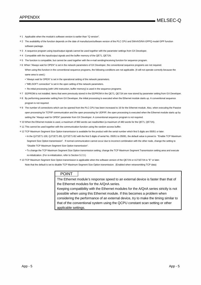
App - 5 App - 5
MELSEC-QAPPENDIX
1 Applicable when the module’s software version is earlier than "Q version".
2 The availability of the function depends on the date of manufacture/software version of the PLC CPU and SWnIVD/NX-GPPQ model GPP function
software package.
3 A sequence program using input/output signals cannot be used together with the parameter settings from GX Developer.
4 Compatible with the input/output signals and the buffer memory of the QE71, QE71N.
5 The function is compatible, but cannot be used together with the e-mail sending/receiving function for sequence program.
6 When "Always wait for OPEN" is set in the network parameters of GX Developer, the conventional sequence programs are not required.
When using this function in the conventional sequence programs, the following conditions are not applicable. (It will not operate correctly because the
same area is used.)
• "Always wait for OPEN" is set in the operational setting of the network parameters.
• "MELSOFT connection" is set in the open setting of the network parameters.
• Re-initial processing (with UINI instruction, buffer memory) is used in the sequence programs.
7 EEPROM is not installed. Items that were previously stored in the EEPROM in the QE71, QE71N are now stored by parameter setting from GX Developer.
8 By performing parameter setting from GX Developer, the initial processing is executed when the Ethernet module starts up. A conventional sequence
program is not required.
9 The number of connections which can be opened from the PLC CPU has been increased to 16 for the Ethernet module. Also, when executing the Passive
open processing for TCP/IP communication and the open processing for UDP/IP, the open processing is executed when the Ethernet module starts up by
setting the "Always wait for OPEN" parameter from GX Developer. A conventional sequence program is not required.
10 When the Ethernet module is used, a maximum of 960 words can read/written (a maximum of 480 words for the QE71, QE71N).
11 This cannot be used together with the communication function using the random access buffer.
12 TCP Maximum Segment Size Option transmission is available for the product with the serial number which first 5 digits are 05051 or later.
• In the QJ71E71-100, QJ71E71-B5, QJ71E71-B2 with the first 5 digits of serial No. 05051 to 05081, the default value is preset to "Enable TCP Maximum
Segment Size Option transmission". If normal communication cannot occur due to incorrect combination with the other node, change the setting to
"Disable TCP Maximum Segment Size Option transmission".
• To change the TCP Maximum Segment Size Option transmission setting, change the TCP Maximum Segment Transmission setting area and execute
re-initialization. (For re-initialization, refer to Section 5.2.3.)
13 TCP Maximum Segment Size Option transmission is applicable when the software version of the QE71N or AJ71E71N is "E" or later.
Note that the default is set to disable TCP Maximum Segment Size Option transmission. (Enabled when retransmitting TCP data)
POINTThe Ethernet module’s response speed to an external device is faster than that ofthe Ethernet modules for the A/QnA series.Keeping compatibility with the Ethernet modules for the A/QnA series strictly is notpossible when using this Ethernet module. If this becomes a problem whenconsidering the performance of an external device, try to make the timing similar tothat of the conventional system using the QCPU constant scan setting or otherapplicable settings.

App - 6 App - 6
MELSEC-QAPPENDIX
Appendix 2.2 Using the programs designed for QnA/A series modules
The data communication that was previously performed between the PLC CPU and anexternal device on the Ethernet using a QnA/A series Ethernet interface module (suchas the AJ71E71) can also be performed using an Ethernet module.The following explains how to use the programs designed for conventional modules toperform data communication using the Ethernet module.
(1) Using the programs designed for the AJ71E71(-S3) and AJ71E71N
(a) Using the programs designed of the external device sideThe following parts of the communication function programs of the externaldevice that are used for the AJ71E71(-S3) and AJ71E71N (hereinaftercalled the E71) can be utilized for communication with the Ethernet module.However, since the Ethernet module and the E71 have different responsespeeds, these programs may not be used as is. Make sure to test theoperation first.
DestinationProgram designed for E71
External device Ethernet module
Ethernet module External device
E71 Ethernetmodule
Ethernetmodule
E71Communication using the fixedbuffer (procedure exist)Communication using therandom access buffer
Communicationfunction
Read/write data from/to thePLC CPU (*1)
: Communication can be performed by utilizing the programs for the E71 of the external device.
1 Only A compatible 1E frame commands can be used for data communication.For details on the E71 commands, see the MELSEC Communication Protocol Reference Manual.To perform data communication using other commands than A compatible 1E frame commands, createa new program.
(b) Using the sequence programs designed for the local station’s E71.The Ethernet module and the E71 have different buffer memoryassignments, thus the sequence programs designed for the E71 cannot beutilized for the Ethernet module.Create a new program referring to the chapters that explain each of theapplicable functions.
(2) Using the programs designed for the AJ71QE71(N)
(a) Using the programs designed for the external deviceThe sequence programs of the external device that are designed for theAJ71QE71(N) (hereafter abbreviated as QE71) can be utilized forcommunication with the Ethernet module, except for the programs listedbelow:• Programs for commands relating to file manipulation
(Refer to the MELSEC Communication Protocol Reference Manual)• Programs for accessing a data link system
(QCPU (Q mode) modules cannot be connected to MELSECNET (II) andMELSECNET/B.)
However, since the Ethernet module and the QE71 have different responsespeeds, the programs may not be used as is. Make sure to test theoperation first
App - 7 App - 7
MELSEC-QAPPENDIX
(b) Using the programs designed for the local station’s QCPU
1) Do not write the parameters of the Ethernet module set by GXDeveloper (network parameters) to the QCPU if sequence programsare used for initial processing or end processing.If the parameter settings for the Ethernet module of GX Developer arenot used, the following precautions should be observed whenperforming the communication:• All the setting values of the communication condition setting
switches for the QE71 will operate in OFF status. Set thecommunication conditions by the re-initial processing described inSection 5.2.3.
• MELSOFT products (e.g., GX Developer) cannot access the QCPUvia the direct connection between MELSOFT products (e.g., GXDeveloper) and the Ethernet module.
2) If the parameter setting for the Ethernet module is performed using GXDeveloper, delete the sequence programs for initial processing andend processing.
3) The sequence programs designed for the local station’s QE71 can beutilized for communication with the Ethernet module, except for theprograms listed below:• Sequence programs for accessing data link system.
(Refer to the QCPU User's Manual.)• Sequence programs relating to EEPROM.• Paring open settings for connection No. 8.
(See Section 5.7.1 "Paring Open".)• Parameter setting program using the EPRSET instruction.
However, since the Ethernet module and the QE71 have different responsespeeds, the programs may not be used as is. Make sure to test theoperation first.
REMARK
Keep the following points in mind when utilizing the programs.• Do not use the sequence program for initial processing together with initial
processing by parameter setting from GX Developer.• Do not execute the following operations to the same connection simultaneously:
open/close processing using input/output signals and open/close processing usingthe OPEN/CLOSE dedicated instructions, as well as the fixed buffersending/receiving and sending/receiving processing using theBUFSND/BUFRCV/BUFRCVS instruction.
Furthermore, when setting parameters for the Ethernet module and communicatingwith the QCPU, make sure to use GX Developer (SW4D5C-GPPW-E or later).
App - 8 App - 8
MELSEC-QAPPENDIX
POINT(1) The operating mode and communication conditions can be set via the following
parameter setting screen of GX Developer when using Q Series Ethernetmodules:• "Network Parameters Setting the number of MNET/10H Ethernet cards"
screen• "Ethernet operational setting" screen
(2) On Q Series Ethernet modules, there are no setting switches for making theoperating mode settings and communication condition settings like there wereon QnA/A Series Ethernet interface modules.
(3) The Q Series Ethernet module cannot cancel an open request beforecompleting the open processing once the passive open processing is executed.Perform the close processing after the open processing is complete.

App - 9 App - 9
MELSEC-QAPPENDIX
Appendix 3 Installing the Ethernet Module on Existing Systems
The Ethernet module and the QnA/A series Ethernet interface module can coexist onthe same Ethernet. The Ethernet module can be installed on the existing system’sEthernet using the existing wiring for the QnA/A series Ethernet interface module.
Appendix 4 Processing Time
Calculate the minimum processing time for each function using the expressions below.Note that the processing time may become longer depending on the load factor on thenetwork (how congested the line is), the window size of each connected device, thenumber of connections used concurrently, and how the system is configured. Use thevalues obtained from the expressions below as a guideline for the processing timewhen communication is performed using only one connection.
(1) Minimum processing time of communication using the fixed buffer(communication between the Ethernet modules)(a) Communication using the fixed buffer (Procedure exist)
Tfs = St + Ke + (Kdf × Df) + SrTfs : Time from the start of sending to the completion of sending
(unit: ms)St : Sending station scan timeKe, Kdf : Constant (see the table below)Df : Word count of send dataSr : Receiving station scan time
QJ71E71-100 QJ71E71-B5, QJ71E71-B2Communication using
TCP/IPCommunication using
UDP/IPCommunication using
TCP/IPCommunication using
UDP/IPKe Kdf Ke Kdf Ke Kdf Ke Kdf
Data communication using binary code 12 0.0065 10 0.0069 25 0.020 20 0.019Data communication using ASCII code 12 0.030 10 0.029 26 0.068 21 0.068
(b) Communication using the fixed buffer (No procedure)Tfs = St + Ke + (Kdf × Df)
Tfs : Time from the start of sending to the completion of sending(unit: ms)
St : Sending station scan timeKe, Kdf : Constant (see the table below)Df : Byte count of send data
QJ71E71-100 QJ71E71-B5, QJ71E71-B2Communication using
TCP/IPCommunication using
UDP/IPCommunication using
TCP/IPCommunication using
UDP/IPKe Kdf Ke Kdf Ke Kdf Ke Kdf
Data communication using binary code 7 0.0018 4 0.0014 16 0.0057 9 0.0025
[Calculation example]Calculate the time from the start of sending to the completion ofsending (unit: ms) when the QJ71E71-B5 communicate using TCP/IPand send 1017 words of binary code data using fixed buffercommunication (procedure exist).• Assume that the scan time on the receiving side is 10 ms and the
scan time on the transmission side is 8 ms:63.34 (ms) 10 + 25 + (0.020 × 10¹⁷) + 8
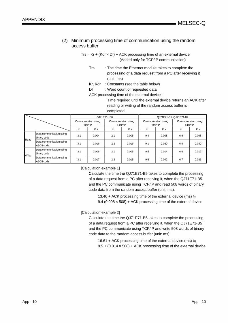
App - 10 App - 10
MELSEC-QAPPENDIX
(2) Minimum processing time of communication using the randomaccess buffer
Trs = Kr + (Kdr × Df) + ACK processing time of an external device(Added only for TCP/IP communication)
Trs : The time the Ethernet module takes to complete theprocessing of a data request from a PC after receiving it(unit: ms)
Kr, Kdr : Constants (see the table below)Df : Word count of requested dataACK processing time of the external device :
Time required until the external device returns an ACK afterreading or writing of the random access buffer iscompleted.
QJ71E71-100 QJ71E71-B5, QJ71E71-B2Communication using
TCP/IPCommunication using
UDP/IPCommunication using
TCP/IPCommunication using
UDP/IPKr Kdr Kr Kdr Kr Kdr Kr Kdr
Data communication usingbinary code
3.1 0.004 2.1 0.005 9.4 0.008 6.6 0.008Read
Data communication usingASCII code
3.1 0.016 2.2 0.016 9.1 0.030 6.5 0.030
Data communication usingbinary code
3.1 0.006 2.1 0.005 9.5 0.014 6.6 0.012Write
Data communication usingASCII code
3.1 0.017 2.2 0.015 9.6 0.042 6.7 0.036
[Calculation example 1]Calculate the time the QJ71E71-B5 takes to complete the processingof a data request from a PC after receiving it, when the QJ71E71-B5and the PC communicate using TCP/IP and read 508 words of binarycode data from the random access buffer (unit: ms).
13.46 + ACK processing time of the external device (ms) 9.4 (0.008 × 508) + ACK processing time of the external device
[Calculation example 2]Calculate the time the QJ71E71-B5 takes to complete the processingof a data request from a PC after receiving it, when the QJ71E71-B5and the PC communicate using TCP/IP and write 508 words of binarycode data to the random access buffer (unit: ms).
16.61 + ACK processing time of the external device (ms) 9.5 + (0.014 × 508) + ACK processing time of the external device
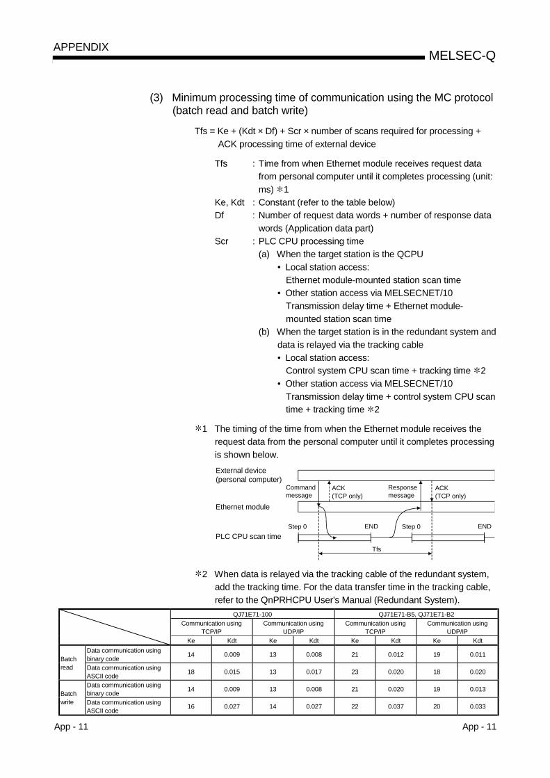
App - 11 App - 11
MELSEC-QAPPENDIX
(3) Minimum processing time of communication using the MC protocol(batch read and batch write)
Tfs = Ke + (Kdt × Df) + Scr × number of scans required for processing +ACK processing time of external device
Tfs : Time from when Ethernet module receives request datafrom personal computer until it completes processing (unit:ms) 1
Ke, Kdt : Constant (refer to the table below)Df : Number of request data words + number of response data
words (Application data part)Scr : PLC CPU processing time
(a) When the target station is the QCPU• Local station access:
Ethernet module-mounted station scan time• Other station access via MELSECNET/10
Transmission delay time + Ethernet module-mounted station scan time
(b) When the target station is in the redundant system anddata is relayed via the tracking cable• Local station access:
Control system CPU scan time + tracking time 2• Other station access via MELSECNET/10
Transmission delay time + control system CPU scantime + tracking time 2
1 The timing of the time from when the Ethernet module receives therequest data from the personal computer until it completes processingis shown below.External device (personal computer)
Ethernet module
PLC CPU scan time
Command message
Tfs
ACK(TCP only)
Step 0 END Step 0 END
Response message
ACK(TCP only)
2 When data is relayed via the tracking cable of the redundant system,add the tracking time. For the data transfer time in the tracking cable,refer to the QnPRHCPU User's Manual (Redundant System).
QJ71E71-100 QJ71E71-B5, QJ71E71-B2Communication using
TCP/IPCommunication using
UDP/IPCommunication using
TCP/IPCommunication using
UDP/IPKe Kdt Ke Kdt Ke Kdt Ke Kdt
Data communication usingbinary code 14 0.009 13 0.008 21 0.012 19 0.011
Batchread Data communication using
ASCII code 18 0.015 13 0.017 23 0.020 18 0.020
Data communication usingbinary code 14 0.009 13 0.008 21 0.020 19 0.013
Batchwrite Data communication using
ASCII code 16 0.027 14 0.027 22 0.037 20 0.033
App - 12 App - 12
MELSEC-QAPPENDIX
[Calculation example 1]Calculate the time the QJ71E71-B5 takes to complete the processingof a data request from a PC after receiving it, when the QJ71E71-B5and the PC perform TCP/IP communication and read 100 points ofASCII code data from the data register (D) of the local station (unit:ms) using the MC protocol communication.• Assume that the scan time of the station in which QJ71E71-B5 is
installed is 10 ms:
37.64 + ACK processing time of the external device (ms) 23 + (0.020 × (21 + 211)) + 10 × 1 + ACK processing time of theexternal device
Command data length = 21 wordsResponse data length = 211 words
[Calculation example 2]Calculate the time the QJ71E71-B5 takes to complete the processingof a data request from a PC after receiving it, when the QJ71E71-B5and the PC performs TCP/IP communication and write 100 points ofASCII code data to the data register (D) of the local station (unit: ms)using the MC protocol communication.• When "Enable Write at RUN time" is set• Assume that the scan time of the station in which QJ71E71-B5 is
installed is 10 ms:
40.58 (ms) 22 + (0.037 × (221 + 11)) + 10 × 1Command data length = 221 wordsResponse data length = 21 words
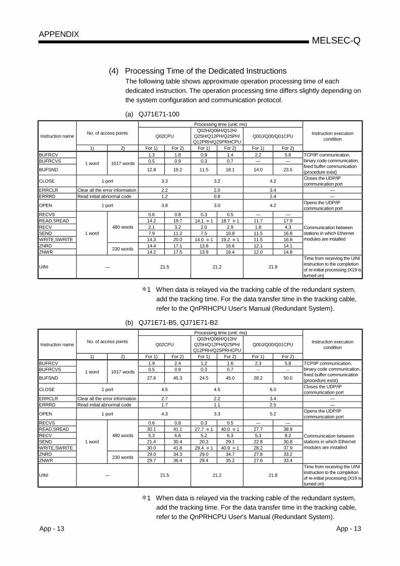
App - 13 App - 13
MELSEC-QAPPENDIX
(4) Processing Time of the Dedicated InstructionsThe following table shows approximate operation processing time of eachdedicated instruction. The operation processing time differs slightly depending onthe system configuration and communication protocol.
(a) QJ71E71-100Processing time (unit: ms)
No. of access points Q02CPUQ02H/Q06H/Q12H/
Q25H/Q12PH/Q25PH/Q12PRH/Q25PRHCPU
Q00J/Q00/Q01CPUInstruction name
1) 2) For 1) For 2) For 1) For 2) For 1) For 2)
Instruction executioncondition
BUFRCV 1.3 1.8 0.9 1.4 2.2 5.8BUFRCVS 0.5 0.9 0.3 0.7 — —
BUFSND1 word 1017 words
12.8 19.2 11.5 18.1 14.0 23.5
TCP/IP communication,binary code communication,fixed buffer communication(procedure exist)
CLOSE 1 port 3.3 3.2 4.2 Closes the UDP/IPcommunication port
ERRCLR Clear all the error information 2.2 2.0 3.4 —ERRRD Read initial abnormal code 1.2 0.8 2.4 —
OPEN 1 port 3.8 3.0 4.2 Opens the UDP/IPcommunication port
RECVS 0.6 0.8 0.3 0.5 — —READ,SREAD 14.2 19.7 14.1 1 18.7 1 11.7 17.9RECV 2.1 3.2 2.0 2.9 1.8 4.3SEND 7.9 11.2 7.5 10.8 11.5 16.8WRITE,SWRITE
480 words
14.3 20.0 14.0 1 19.2 1 11.5 16.8ZNRD 14.4 17.1 13.8 16.6 12.1 14.1ZNWR
1 word
230 words 14.2 17.5 13.9 16.4 12.0 14.8
Communication betweenstations in which Ethernetmodules are installed
UINI — 21.5 21.2 21.8
Time from receiving the UINIinstruction to the completionof re-initial processing (X19 isturned on)
1 When data is relayed via the tracking cable of the redundant system,add the tracking time. For the data transfer time in the tracking cable,refer to the QnPRHCPU User's Manual (Redundant System).
(b) QJ71E71-B5, QJ71E71-B2Processing time (unit: ms)
No. of access points Q02CPUQ02H/Q06H/Q12H/
Q25H/Q12PH/Q25PH/Q12PRH/Q25PRHCPU
Q00J/Q00/Q01CPUInstruction name
1) 2) For 1) For 2) For 1) For 2) For 1) For 2)
Instruction executioncondition
BUFRCV 1.9 2.4 1.2 1.6 2.3 5.8BUFRCVS 0.5 0.9 0.3 0.7
BUFSND1 word 1017 words
27.6 45.3 24.5 45.0 28.2 50.0
TCP/IP communication,binary code communication,fixed buffer communication(procedure exist)
CLOSE 1 port 4.5 4.5 6.0 Closes the UDP/IPcommunication port
ERRCLR Clear all the error information 2.7 2.2 3.4 —ERRRD Read initial abnormal code 1.7 1.1 2.5 —
OPEN 1 port 4.3 3.3 5.2 Opens the UDP/IPcommunication port
RECVS 0.6 0.8 0.3 0.5 — —READ,SREAD 30.1 41.1 27.7 1 40.0 1 27.7 38.9RECV 5.3 6.6 5.2 6.3 5.3 8.2SEND 21.4 30.4 20.3 29.1 22.8 30.8WRITE,SWRITE
480 words
30.0 41.8 29.4 1 40.9 1 28.2 37.9ZNRD 29.0 34.3 29.0 34.7 27.8 33.2ZNWR
1 word
230 words 29.7 36.4 29.4 35.2 27.6 33.4
Communication betweenstations in which Ethernetmodules are installed
UINI — 21.5 21.2 21.8
Time from receiving the UINIinstruction to the completionof re-initial processing (X19 isturned on)
1 When data is relayed via the tracking cable of the redundant system,add the tracking time. For the data transfer time in the tracking cable,refer to the QnPRHCPU User's Manual (Redundant System).

App - 14 App - 14
MELSEC-QAPPENDIX
(5) System switching time of redundant systemThe following indicates the system switching time required when the Ethernetmodule mounted on the main base unit of the control system CPU in theredundant system issues a system switching request to the control system CPUat communication error or disconnection detection.The system switching time is the time from when a communication error ordisconnection is detected until the control system CPU is switched to the standbysystem CPU.
(a) When communication error is detected1) When ULP timeout occurs
Tnc = Ttu + St + Tcc
Tnc : System switching timeTtu : TCP ULP timer valueSt : 1 scan timeTsw : CPU system switching time (Refer to the QnPRHCPU User's
Manual (Redundant System).)
The following shows the system switching operation timing when aULP timeout occurs.
External device
Control system (System A) Standby system (System B)
Communication error occurrence
Tracking cableSystem switching request
QJ71E71-100 (Station No. 1)
System A CPU scan time
System A
System B
System B CPU scan time
QJ71E71-100 (Station No. 2)
Control system operation
No response from external device
Standby system operation
System switching request is issued
Control system Standby system
Standby system Control system
Standby system operationTnc
Ttu
Tsw
QJ71E71-100Station No. 1
QJ71E71-100Station No. 2
Control system operation
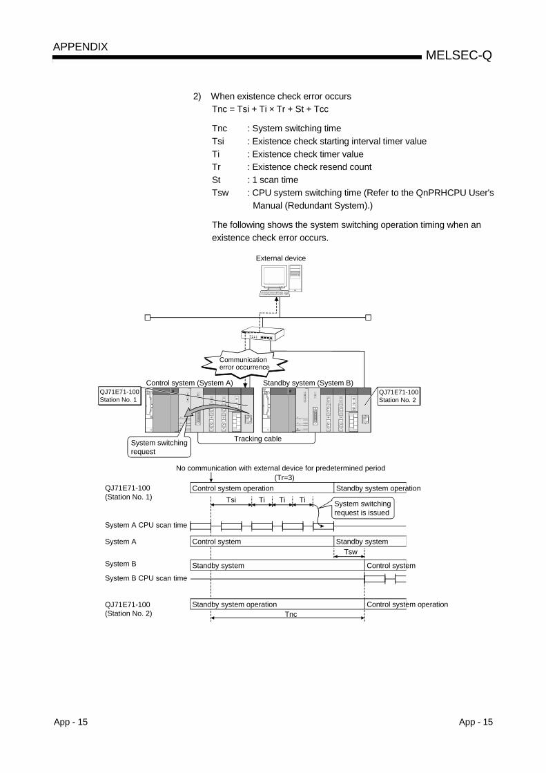
App - 15 App - 15
MELSEC-QAPPENDIX
2) When existence check error occursTnc = Tsi + Ti × Tr + St + Tcc
Tnc : System switching timeTsi : Existence check starting interval timer valueTi : Existence check timer valueTr : Existence check resend countSt : 1 scan timeTsw : CPU system switching time (Refer to the QnPRHCPU User's
Manual (Redundant System).)
The following shows the system switching operation timing when anexistence check error occurs.
External device
Control system (System A) Standby system (System B)
Communication error occurrence
Tracking cableSystem switching request
QJ71E71-100(Station No. 1)
System A CPU scan time
System A
System B
System B CPU scan time
QJ71E71-100(Station No. 2)
Control system operation
No communication with external device for predetermined period
Control system Standby system
Standby system
Standby system operationTnc
Tsi
Tsw
System switching request is issued
(Tr=3)
Ti Ti Ti
QJ71E71-100Station No. 1
QJ71E71-100Station No. 2
Control system
Control system operation
Standby system operation
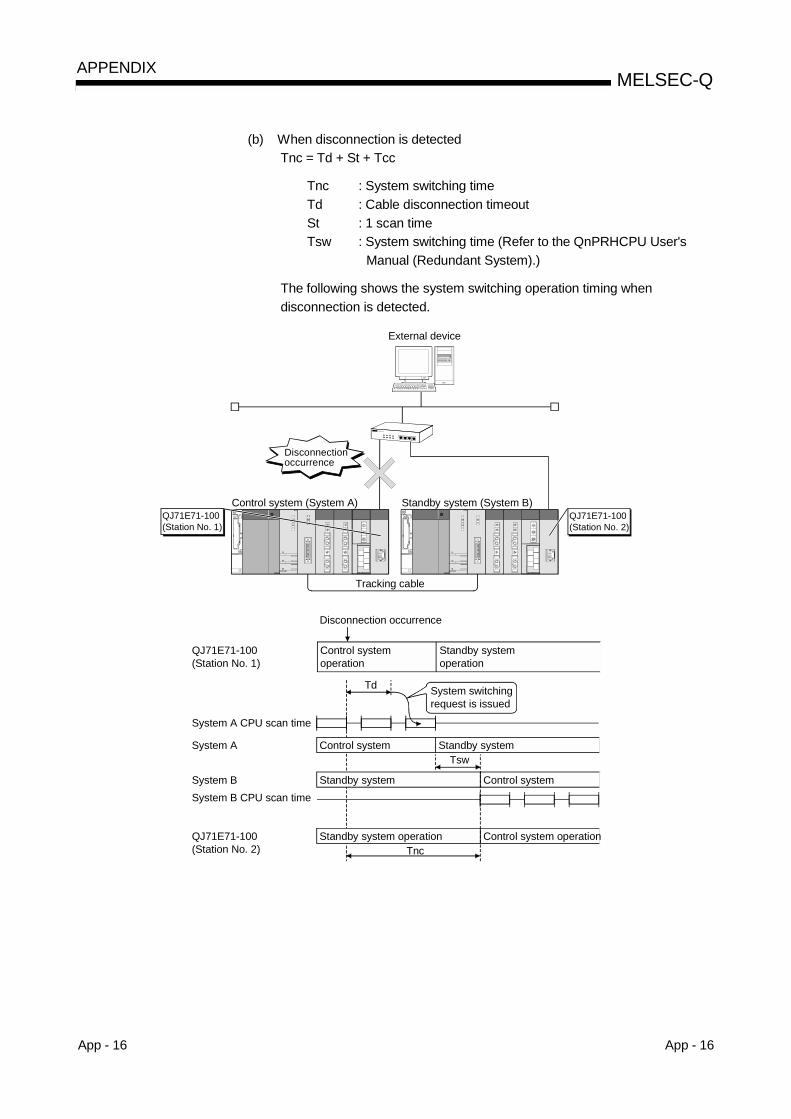
App - 16 App - 16
MELSEC-QAPPENDIX
(b) When disconnection is detectedTnc = Td + St + Tcc
Tnc : System switching timeTd : Cable disconnection timeoutSt : 1 scan timeTsw : System switching time (Refer to the QnPRHCPU User's
Manual (Redundant System).)
The following shows the system switching operation timing whendisconnection is detected.
External device
Control system (System A) Standby system (System B)
Disconnection occurrence
Tracking cable
QJ71E71-100 (Station No. 1)
System A CPU scan time
System A
System BSystem B CPU scan time
QJ71E71-100 (Station No. 2)
Control system operation
Disconnection occurrence
System switching request is issued
Control system Standby system
Standby system Control system
Standby system operationTnc
Td
Tsw
QJ71E71-100(Station No. 1)
QJ71E71-100(Station No. 2)
Standby system operation
Control system operation

App - 17 App - 17
MELSEC-QAPPENDIX
Appendix 5 ASCII Code List
MSD 0 1 2 3 4 5 6 7LSD 000 001 010 011 100 101 110 111
0 0000 NUL DLE (SP) 0 @ P ` p1 0001 SOH DC1 ! 1 A Q a q2 0010 STX DC2 “ 2 B R b r3 0011 ETX DC3 # 3 C S c s4 0100 EOT DC4 $ 4 D T d t5 0101 ENQ NAK % 5 E U e u6 0110 ACK SYN & 6 F V f v7 0111 BEL ETB ‘ 7 G W g w8 1000 BS CAN ( 8 H X h x9 1001 HT EM ) 9 I Y i yA 1010 LF SUB : J Z j zB 1011 VT ESC + ; K [ k C 1100 FF FS , < L \ l |D 1101 CR GS = M ] m E 1110 SO RS . > N ^ n ~F 1111 SI US / ? O – o DEL
Appendix 6 References
For details on TCP/IP, refer to the DDN Protocol Handbook (3 volumes).
PublisherDDN Network Information CenterSRI International333 Ravenswood Avenue, EJ291Menlo Park, California 94025
RFC NumberTCP RFC793UDP RFC768IP RFC791ICMP RFC792ARP RFC826
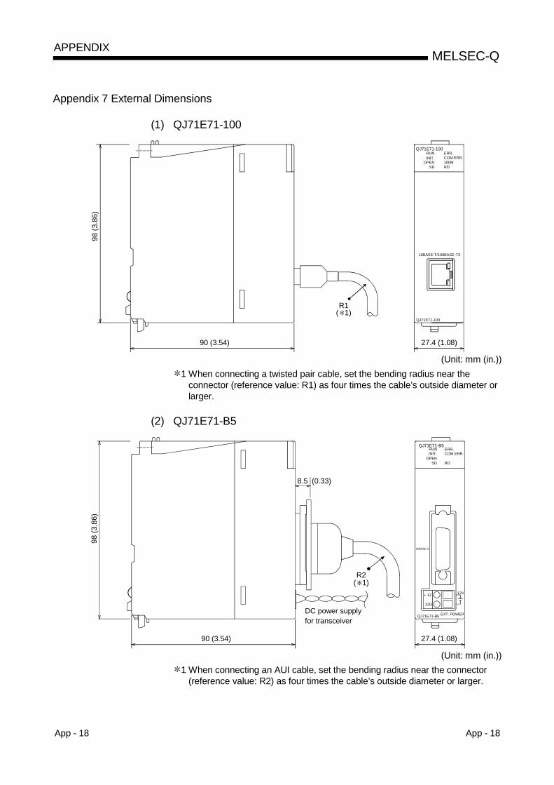
App - 18 App - 18
MELSEC-QAPPENDIX
Appendix 7 External Dimensions
(1) QJ71E71-100
27.4 (1.08)90 (3.54)
98 (3
.86)
QJ71E71-100
10BASE-T/100BASE-TX
RUNINIT.
OPENSD RD
COM.ERR.ERR.
QJ71E71-100
100M
( 1)R1
(Unit: mm (in.))1 When connecting a twisted pair cable, set the bending radius near the
connector (reference value: R1) as four times the cable’s outside diameter orlarger.
(2) QJ71E71-B5
QJ71E71-B5 EXT. POWER
10BASE 5
ERR.COM.ERR.
RDSDOPEN
INIT.RUN
12V
QJ71E71-B5
98 (3
.86)
90 (3.54)
8.5 (0.33)
27.4 (1.08)
DC power supplyfor transceiver
R2
+ 12
12G
( 1)
(Unit: mm (in.))1 When connecting an AUI cable, set the bending radius near the connector
(reference value: R2) as four times the cable’s outside diameter or larger.
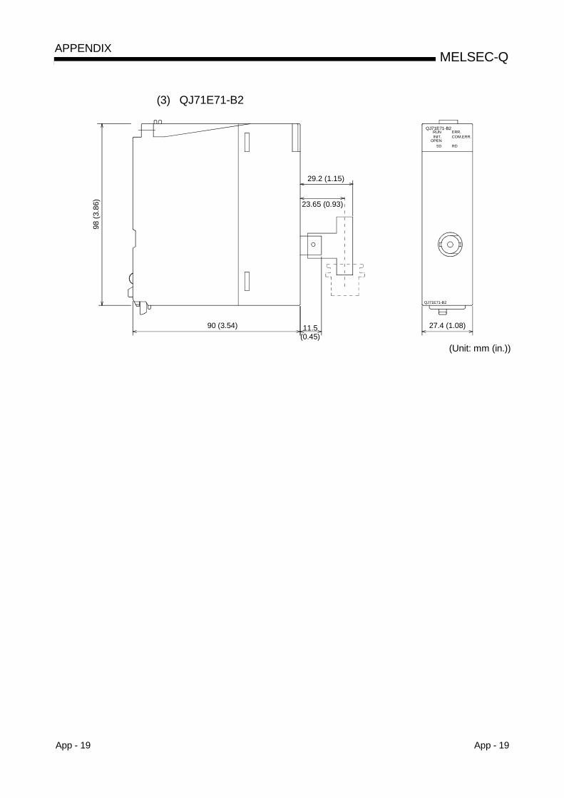
App - 19 App - 19
MELSEC-QAPPENDIX
(3) QJ71E71-B2
QJ71E71-B2
ERR.COM.ERR.
RDSDOPEN
INIT.RUN
QJ71E71-B2
98 (3
.86)
90 (3.54) 11.5(0.45)
27.4 (1.08)
29.2 (1.15)
23.65 (0.93)
(Unit: mm (in.))
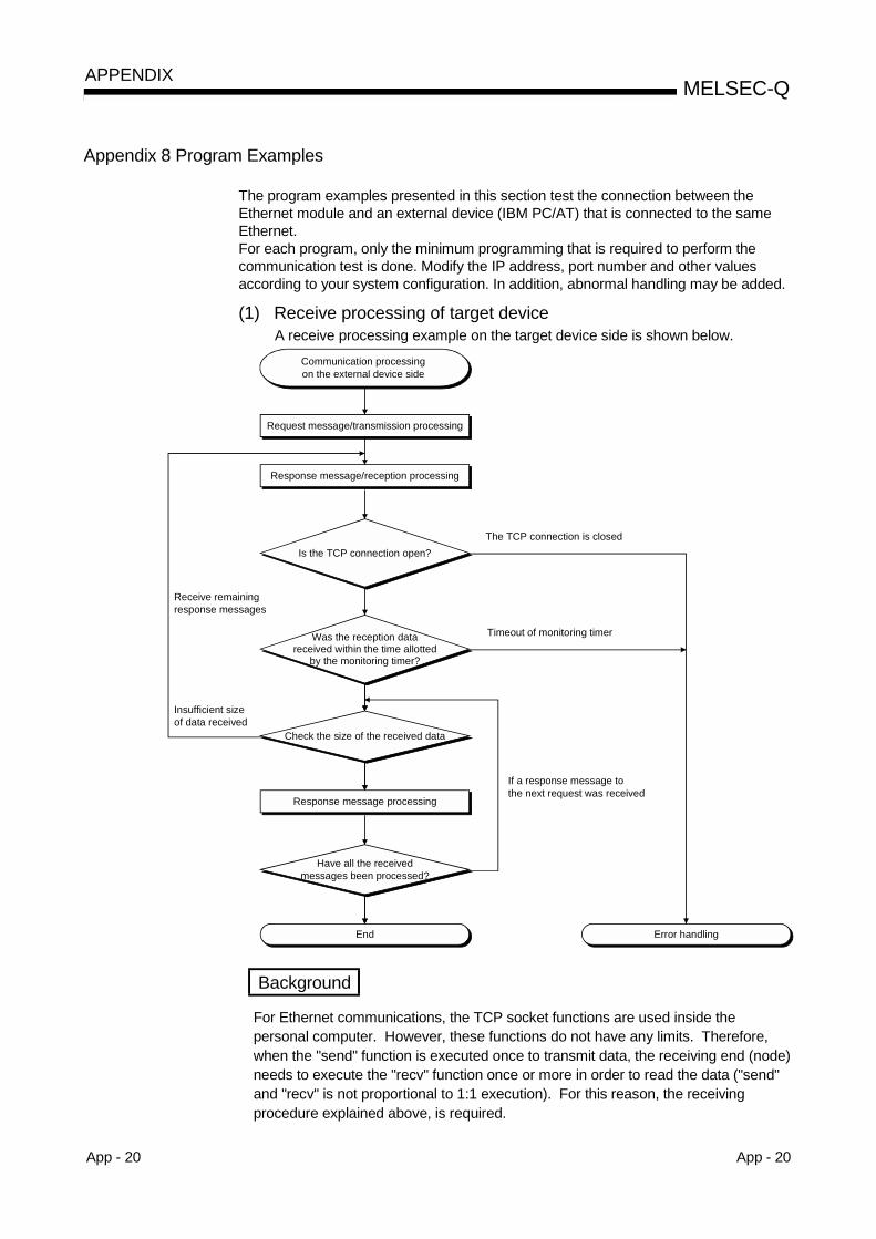
App - 20 App - 20
MELSEC-QAPPENDIX
Appendix 8 Program Examples
The program examples presented in this section test the connection between theEthernet module and an external device (IBM PC/AT) that is connected to the sameEthernet.For each program, only the minimum programming that is required to perform thecommunication test is done. Modify the IP address, port number and other valuesaccording to your system configuration. In addition, abnormal handling may be added.
(1) Receive processing of target deviceA receive processing example on the target device side is shown below.
Communication processing on the external device side
Is the TCP connection open?
Check the size of the received data
Response message processing
Have all the received messages been processed?
End Error handling
If a response message to the next request was received
Timeout of monitoring timer
The TCP connection is closed
Receive remaining response messages
Insufficient size of data received
Request message/transmission processing
Response message/reception processing
Was the reception datareceived within the time allotted
by the monitoring timer?
Background
For Ethernet communications, the TCP socket functions are used inside thepersonal computer. However, these functions do not have any limits. Therefore,when the "send" function is executed once to transmit data, the receiving end (node)needs to execute the "recv" function once or more in order to read the data ("send"and "recv" is not proportional to 1:1 execution). For this reason, the receivingprocedure explained above, is required.

App - 21 App - 21
MELSEC-QAPPENDIX
(2) When the transmission target does not support the receiveprocessing flow chart shown in section (1)If the transmission target does not support the receive processing shown inSection (1), the following results will occur when communicating with the "TCPMaximum Segment Size Option transmission" is set to enable.! Incorrect data read, when batch read is executed from the transmission
target using MC protocol.! Incorrect data read, after replacing the Ethernet module (which does not
support the TCP Maximum Segment Size Option transmission function) withthe alternative module supporting the function.
! Data is not received, even though the value of "Number of packet reception"area (Address: 1B8H, 1B9H) in the buffer memory was changed.
If this occurs, change the "TCP Maximum Segment Size Option transmission"setting to disable.
Appendix 8.1 Program example for communication using the MC protocol –1The following explains a program, its execution environment and the contents of datacommunication .
(1) Execution environment of the program example(a) PLC CPU side
1) QCPU model name of the Ethernet installed station : Q25HCPU2) Ethernet module I/O signal : X/Y000 to X/Y01F3) Ethernet module IP address : C0.00.01.FDH (192.00.01.253)4) Ethernet module port number : 2000H
5) GX Developer setting• Operational settings : See "(3) GX Developer setting (a)" on
the next page• Open settings : See "(3) GX Developer setting (b)" on
the next page(b) External device side
1) Operation environment : Microsoft® Windows® 95operating system
2) Ethernet interface board model name : WINSOCK compatible board3) Library : WSOCK32.LIB4) Software development environment : Microsoft® Corporation Visual
C++ (Version 4.0)5) Ethernet address : Setting not required because
the ARP function is available6) IP address : Receive at Active open7) Port number : Receive at Active open
(c) Communication protocol : TCP/IP
(2) Outline of the program example(a) Sequence program on the PLC CPU side
Parameters are set from GX Developer.(Sequence program is not required)
(b) Program on the external device sideExecutes the following read/write data communication with the PLC CPUusing the library mentioned above.• Write in word units (for 5 points from D0 to D4)• Read in word units (for 5 points from D0 to D4)
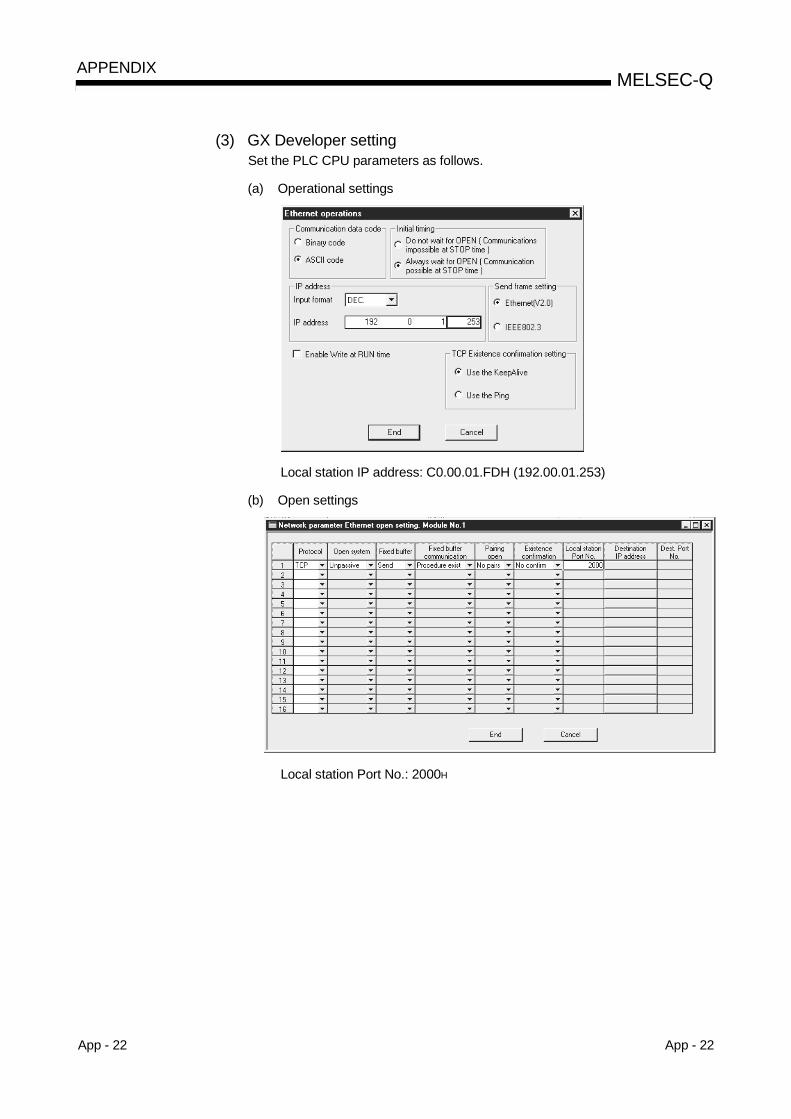
App - 22 App - 22
MELSEC-QAPPENDIX
(3) GX Developer settingSet the PLC CPU parameters as follows.
(a) Operational settings
Local station IP address: C0.00.01.FDH (192.00.01.253)
(b) Open settings
Local station Port No.: 2000H
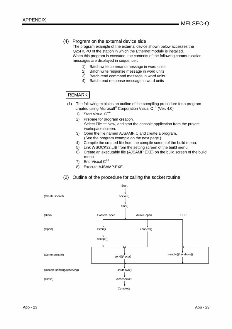
App - 23 App - 23
MELSEC-QAPPENDIX
(4) Program on the external device sideThe program example of the external device shown below accesses theQ25HCPU of the station in which the Ethernet module is installed.When this program is executed, the contents of the following communicationmessages are displayed in sequencer:
1) Batch write command message in word units2) Batch write response message in word units3) Batch read command message in word units4) Batch read response message in word units
REMARK
(1) The following explains an outline of the compiling procedure for a programcreated using Microsoft® Corporation Visual C++ (Ver. 4.0)1) Start Visual C++.2) Prepare for program creation.
Select File New, and start the console application from the projectworkspace screen.
3) Open the file named AJSAMP.C and create a program.(See the program example on the next page.)
4) Compile the created file from the compile screen of the build menu.5) Link WSOCK32.LIB from the setting screen of the build menu.6) Create an executable file (AJSAMP.EXE) on the build screen of the build
menu.7) End Visual C++.8) Execute AJSAMP.EXE.
(2) Outline of the procedure for calling the socket routine
socket()
bind()
(Bind) Active open UDP
listen() connect()
accept()
send()/recv()sendto()/recvfrom()
shutdown()
closesocket(Close)
Start
Complete
(Create socket)
(Open)
(Communicate)
(Disable sending/receiving)
Passive open
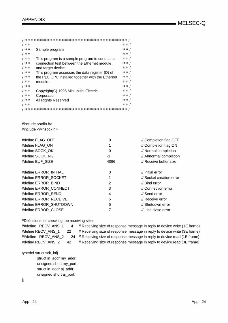
App - 24 App - 24
MELSEC-QAPPENDIX
/ // // // // // // // // // // // / / /
Sample program
This program is a sample program to conduct aconnection test between the Ethernet moduleand target device.This program accesses the data register (D) ofthe PLC CPU installed together with the Ethernetmodule.
Copyright(C) 1996 Mitsubishi ElectricCorporationAll Rights Reserved
/ / / /
/ /
#include <stdio.h>#include <winsock.h>
#define FLAG_OFF 0 // Completion flag OFF#define FLAG_ON 1 // Completion flag ON#define SOCK_OK 0 // Normal completion#define SOCK_NG -1 // Abnormal completion#define BUF_SIZE 4096 // Receive buffer size
#define ERROR_INITIAL 0 // Initial error#define ERROR_SOCKET 1 // Socket creation error#define ERROR_BIND 2 // Bind error#define ERROR_CONNECT 3 // Connection error#define ERROR_SEND 4 // Send error#define ERROR_RECEIVE 5 // Receive error#define ERROR_SHUTDOWN 6 // Shutdown error#define ERROR_CLOSE 7 // Line close error
//Definitions for checking the receiving sizes//#define RECV_ANS_1 4 // Receiving size of response message in reply to device write (1E frame)#define RECV_ANS_1 22 // Receiving size of response message in reply to device write (3E frame)//#define RECV_ANS_2 24 // Receiving size of response message in reply to device read (1E frame)#define RECV_ANS_2 42 // Receiving size of response message in reply to device read (3E frame)
typedef struct sck_infstruct in_addr my_addr;unsigned short my_port;struct in_addr aj_addr;unsigned short aj_port;
;
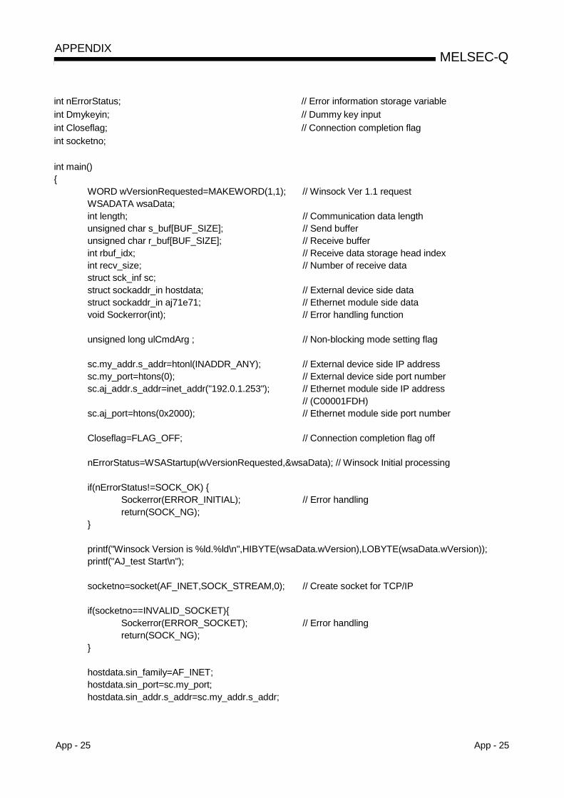
App - 25 App - 25
MELSEC-QAPPENDIX
int nErrorStatus; // Error information storage variableint Dmykeyin; // Dummy key inputint Closeflag; // Connection completion flagint socketno;
int main()
WORD wVersionRequested=MAKEWORD(1,1); // Winsock Ver 1.1 requestWSADATA wsaData;int length; // Communication data lengthunsigned char s_buf[BUF_SIZE]; // Send bufferunsigned char r_buf[BUF_SIZE]; // Receive bufferint rbuf_idx; // Receive data storage head indexint recv_size; // Number of receive datastruct sck_inf sc;struct sockaddr_in hostdata; // External device side datastruct sockaddr_in aj71e71; // Ethernet module side datavoid Sockerror(int); // Error handling function
unsigned long ulCmdArg ; // Non-blocking mode setting flag
sc.my_addr.s_addr=htonl(INADDR_ANY); // External device side IP addresssc.my_port=htons(0); // External device side port numbersc.aj_addr.s_addr=inet_addr("192.0.1.253"); // Ethernet module side IP address
// (C00001FDH)sc.aj_port=htons(0x2000); // Ethernet module side port number
Closeflag=FLAG_OFF; // Connection completion flag off
nErrorStatus=WSAStartup(wVersionRequested,&wsaData); // Winsock Initial processing
if(nErrorStatus!=SOCK_OK) Sockerror(ERROR_INITIAL); // Error handlingreturn(SOCK_NG);
printf("Winsock Version is %ld.%ld\n",HIBYTE(wsaData.wVersion),LOBYTE(wsaData.wVersion));printf("AJ_test Start\n");
socketno=socket(AF_INET,SOCK_STREAM,0); // Create socket for TCP/IP
if(socketno==INVALID_SOCKET)Sockerror(ERROR_SOCKET); // Error handlingreturn(SOCK_NG);
hostdata.sin_family=AF_INET;hostdata.sin_port=sc.my_port;hostdata.sin_addr.s_addr=sc.my_addr.s_addr;
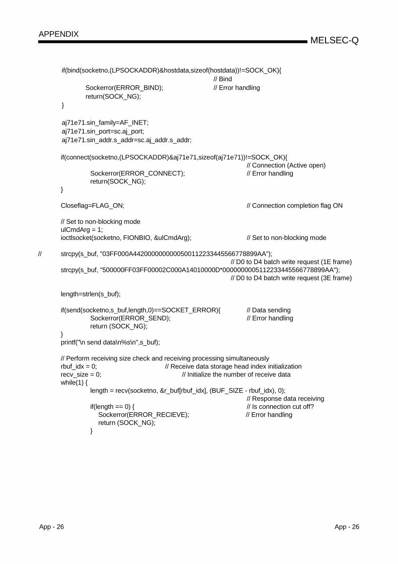
App - 26 App - 26
MELSEC-QAPPENDIX
if(bind(socketno,(LPSOCKADDR)&hostdata,sizeof(hostdata))!=SOCK_OK)// Bind
Sockerror(ERROR_BIND); // Error handlingreturn(SOCK_NG);
aj71e71.sin_family=AF_INET;aj71e71.sin_port=sc.aj_port;aj71e71.sin_addr.s_addr=sc.aj_addr.s_addr;
if(connect(socketno,(LPSOCKADDR)&aj71e71,sizeof(aj71e71))!=SOCK_OK)// Connection (Active open)
Sockerror(ERROR_CONNECT); // Error handlingreturn(SOCK_NG);
Closeflag=FLAG_ON; // Connection completion flag ON
// Set to non-blocking modeulCmdArg = 1;ioctlsocket(socketno, FIONBIO, &ulCmdArg); // Set to non-blocking mode
// strcpy(s_buf, "03FF000A4420000000000500112233445566778899AA");// D0 to D4 batch write request (1E frame)
strcpy(s_buf, "500000FF03FF00002C000A14010000D*0000000005112233445566778899AA");// D0 to D4 batch write request (3E frame)
length=strlen(s_buf);
if(send(socketno,s_buf,length,0)==SOCKET_ERROR) // Data sendingSockerror(ERROR_SEND); // Error handlingreturn (SOCK_NG);
printf("\n send data\n%s\n",s_buf);
// Perform receiving size check and receiving processing simultaneouslyrbuf_idx = 0; // Receive data storage head index initializationrecv_size = 0; // Initialize the number of receive datawhile(1)
length = recv(socketno, &r_buf[rbuf_idx], (BUF_SIZE - rbuf_idx), 0);// Response data receiving
if(length == 0) // Is connection cut off?Sockerror(ERROR_RECIEVE); // Error handlingreturn (SOCK_NG);

App - 27 App - 27
MELSEC-QAPPENDIX
if(length == SOCKET_ERROR) nErrorStatus = WSAGetLastError();if(nErrorStatus != WSAEWOULDBLOCK)
Sockerror(ERROR_RECIEVE); // Error handlingreturn (SOCK_NG);
else continue; // Repeat until messages are received
else
rbuf_idx += length; // Update the receive data storage// position
recv_size += length; // Update the number of receive dataif(recv_size >= RECV_ANS_1) // Have all response messages been
// received?break; // Stop repeating as messages have
// been received
r_buf[rbuf_idx] = '\0' ; // Set NULL at the end of receive data
printf("\n receive data\n%s\n",r_buf);
// strcpy(s_buf, "01FF000A4420000000000500"); // D0 to D4 batch read request// (1E frame)
strcpy(s_buf, "500000FF03FF000018000A04010000D*0000000005");// D0 to D4 batch read request// (3E frame)
length=strlen(s_buf);
if(send(socketno,s_buf,length,0)==SOCKET_ERROR) // Data sendingSockerror(ERROR_SEND); // Error handlingreturn (SOCK_NG);
printf("\n send data\n%s\n",s_buf);
// Perform receiving size check and receiving processing simultaneouslyrbuf_idx = 0; // Receive data storage head index
// initializationrecv_size = 0; // Initialize the number of receive datawhile(1)
length = recv(socketno, &r_buf[rbuf_idx], (BUF_SIZE - rbuf_idx), 0);// Response data receiving
if(length == 0) // Is connection cut off?Sockerror(ERROR_RECIEVE); // Error handlingreturn (SOCK_NG);
App - 28 App - 28
MELSEC-QAPPENDIX
if(length == SOCKET_ERROR) nErrorStatus = WSAGetLastError();if(nErrorStatus != WSAEWOULDBLOCK)
Sockerror(ERROR_RECIEVE); // Error handlingreturn (SOCK_NG);
else continue; // Repeat until messages are received
else
rbuf_idx += length; // Update the receive data storage// position
recv_size += length; // Update the number of receive dataif(recv_size >= RECV_ANS_2) // Have all response messages been
// received?break; // Stop repeating as messages have
// been received
r_buf[rbuf_idx] = '\0' ; // Set NULL at the end of receive data
printf("\receive data\n%s\n", r_buf);
if(shutdown(socketno,2)!=SOCK_OK) // Processing to disable// sending/receiving
Sockerror(ERROR_SHUTDOWN); // Error handlingreturn(SOCK_NG);
if(closesocket(socketno)!=SOCK_OK) // Close processingSockerror(ERROR_CLOSE); // Error handlingreturn(SOCK_NG);
Closeflag=FLAG_OFF; // Connection completion flag offWSACleanup(); // Release Winsock.DLL
printf("\nAJ_test End.\n\n Normally completed. \n");printf("Press any key to exit the program.\n");Dmykeyin=getchar(); // Wait for key input
return(SOCK_OK);
void Sockerror(int error_kind) // Error handling function
if(error_kind==ERROR_INITIAL)printf("Initial processing is abnormal.");
App - 29 App - 29
MELSEC-QAPPENDIX
elsenErrorStatus=WSAGetLastError();switch(error_kind)case ERROR_SOCKET:
printf("Failed to create socket.");break;
case ERROR_BIND:printf("Failed to bind.");break;
case ERROR_CONNECT:printf("Failed to establish connection.");break;
case ERROR_SEND:printf("Sending failed.");break;
case ERROR_RECIEVE:printf("Receiving failed.");break;
case ERROR_SHUTDOWN:printf("Failed to shutdown.");break;
case ERROR_CLOSE:printf("Failed to close normally.");break;
printf("Error code is %d.\n", nErrorStatus);
if(Closeflag==FLAG_ON)nErrorStatus=shutdown(socketno,2); // Shutdown processingnErrorStatus=closesocket(socketno); // Close processingCloseflag=FLAG_OFF; // Connection completion flag off
printf("Press any key to exit the program.\n");Dmykeyin=getchar(); // Wait for a key inputWSACleanup(); // Release Winsock.DLLreturn;

App - 30 App - 30
MELSEC-QAPPENDIX
Appendix 8.2 Program example of communication using the MC Protocol -2
This section provides the program example, execution environment and datacommunication contents.
(1) Execution environment of program example(a) PLC CPU side
1) Ethernet module-mounted station QCPU model name : Q25PRHCPU2) I/O signals of Ethernet module : X/Y000 to X/Y01F3) Ethernet module IP address (System A) : C0.00.01.FCH
(192.00.01.252)Ethernet module IP address (System B) : C0.00.01.FDH
(192.00.01.253)4) Ethernet module port number : 2000H
5) GX Developer settings• Operation setting : Refer to "(3) GX Developer settings (a)" on the
next page.• Open setting : Refer to "(3) GX Developer settings (b)" on the
next page.• Redundant settings : Refer to "(3) GX Developer settings (c)" on the
next page.
(b) External device side1) Operating environment :
Microsoft® Windows® XP Professional Operating SystemMicrosoft® Windows® XP Home Edition Operating System
2) Ethernet interface board model name : WINSOCK compatible board3) Library : WSOCK32.LIB4) Software development environment :
Microsoft® Corporation make Visual C++ (Ver. 6.0) is used.5) Ethernet address : Need not be set as the ARP function is available.6) IP address : Received at Active open7) Port number : Received at Active open
(c) Communication system : TCP/IP
(2) Overview of program example(a) PLC CPU side sequence program
Parameter settings must be made using GX Developer.(No sequence program required)
(b) External device side programWrites data to the data registers D0 to D4 (5 points) of the redundant CPU(control system) in word unit using the above library.If write of data from the system A side is unsuccessful due to acommunication error or similar reason at this time, data are written from thesystem B side to the data registers of the redundant CPU (control system).

App - 31 App - 31
MELSEC-QAPPENDIX
(3) GX Developer settingsSet the parameters of the PLC CPU as described below.(a) Operation setting
Ethernet module IP address (System A) : C0.00.01.FCH (192.00.01.252)
(b) Open setting
Local port number : 2000H
(c) Redundant setting
Ethernet module IP address (System B) : C0.00.01.FDH (192.00.01.253)

App - 32 App - 32
MELSEC-QAPPENDIX
(4) External device side programThe following shows a program example of the external device that accesses theEthernet module-mounted station Q25PRHCPU.When this program is executed, the following contents are displayed in dueorder.1) Version of used Winsock2) Test starting message3) Write of batch command messages in word unit4) Write of batch response messages in word unit5) Test end message
REMARK
The following describes the general compile procedure for the program createdusing Microsoft® Visual C++ (Ver. 6.0).1) Create a "QJSAMP.C" file using a text editor.
(Refer to the next page for the program example.)2) Start Visual C++.3) Open the "QJSAMP.C" file.
Choose File Open, specify "QJSAMP.C" created in Step 1), and open it.4) Execute the compile of the created program on the Compile sceen of the Build
menu.Choose Build Compile.Following the displayed messages, create a default project workspace.
5) Link WSOCK32.LIB from the Project setting screen.Choose Project Setting to display the "Project setting" dialog box.Select the Link tab and add WSOCK32.LIB to the "Object/library module".
6) Create an execution file (QJSAMP.EXE) on the Build screen of the Build menu.Choose Build Build.
7) Exit from Visual C++.8) Execute QJSAMP.EXE.
App - 33 App - 33
MELSEC-QAPPENDIX
/ // // // // // // // // // // // / /
Sample program
This program is a sample program for testing theconnection of the Ethernet module and externaldevice.This program accesses the data registers (D) ofthe redundant CPU (control system) mountedwith the Ethernet module.
Copyright(C) 2004 Mitsubishi Electric CorporationAll Rights Reserved
/ / /
/ /
#include <stdio.h>#include <winsock.h>
#define FLAG_OFF 0 // End flag OFF#define FLAG_ON 1 // End flag ON#define SOCK_OK 0 // Normal termination#define SOCK_NG -1 // Unsuccessful termination#define BUF_SIZE 4096 // Receive buffer size
#define ERROR_NO_ERROR 0 // No error#define ERROR_INITIAL 1 // Initial error#define ERROR_SOCKET 2 // Socket creation error#define ERROR_BIND 3 // Bind error#define ERROR_CONNECT 4 // Connect error#define ERROR_SEND 5 // Send error#define ERROR_SHUTDOWN 6 // Shutdown error#define ERROR_CLOSE 7 // Line close error
// Definition for checking receive size#define RECV_ANS_1 22 // Response message receive size in reply to device write (3E frame)
typedef struct sck_infstruct in_addr my_addr;unsigned short my_port;struct in_addr qj_addr;unsigned short qj_port;
;
int nErrorStatus; // Error information storage variableint Dmykeyin; // Dummy key inputint ShutdownflagA; // Shutdown flag (for System A connection)int ShutdownflagB; // Shutdown flag (for System B connection)
App - 34 App - 34
MELSEC-QAPPENDIX
int CloseflagA; // Connection end flag (for System A connection)int CloseflagB; // Connection end flag (for System B connection)int socketnoA;int socketnoB;int ConnectLastErrorA; // Connect processing error information (for System A connection)int ConnectLastErrorB; // Connect processing error information (for System B connection)int SendFlag; // Send completion flag
int main()
WORD wVersionRequested = MAKEWORD(1, 1); // Winsock Ver 1.1 requestWSADATA wsaData;int length; // Communication data lengthunsigned char s_buf[BUF_SIZE]; // Send bufferunsigned char r_bufA[BUF_SIZE],r_bufB[BUF_SIZE]; // Receive bufferstruct sck_inf scA,scB;struct sockaddr_in hostdataA,hostdataB; // External device side datastruct sockaddr_in qj71e71A,qj71e71B; // Ethernet module side dataBOOL DataRecv(int, unsigned char *, int); // Receive processing functionvoid Sockerror(int, int); // Error handling function
unsigned long ulCmdArgA,ulCmdArgB; // Non-blocking mode setting flag
scA.my_addr.s_addr = scB.my_addr.s_addr = htonl(INADDR_ANY); // External device side IP addressscA.my_port = scB.my_port = htons(0); // External device side port numberscA.qj_addr.s_addr = inet_addr("192.0.1.252");
// Ethernet module side IP address (System A: C00001FCh)scB.qj_addr.s_addr = inet_addr("192.0.1.253");
// Ethernet module side IP address (System B: C00001FDh)scA.qj_port = scB.qj_port = htons(0x2000); // Ethernet module side port number
ShutdownflagA = ShutdownflagB = FLAG_OFF; // Shutdown flag OFFCloseflagA = CloseflagB = FLAG_OFF; // Connection end flag OFF
nErrorStatus = WSAStartup(wVersionRequested, &wsaData); // Winsock initial processing
ConnectLastErrorA = ERROR_NO_ERROR;// Connect processing error information initialization (for System A)
ConnectLastErrorB = ERROR_NO_ERROR;// Connect processing error information initialization (for System B)
if(nErrorStatus != SOCK_OK) Sockerror(ERROR_INITIAL, ERROR_INITIAL); // Error handlingreturn (SOCK_NG);
printf("Winsock Version is %1d.%1d\n", HIBYTE(wsaData.wVersion), LOBYTE(wsaData.wVersion));printf("QJ_test Start\n");
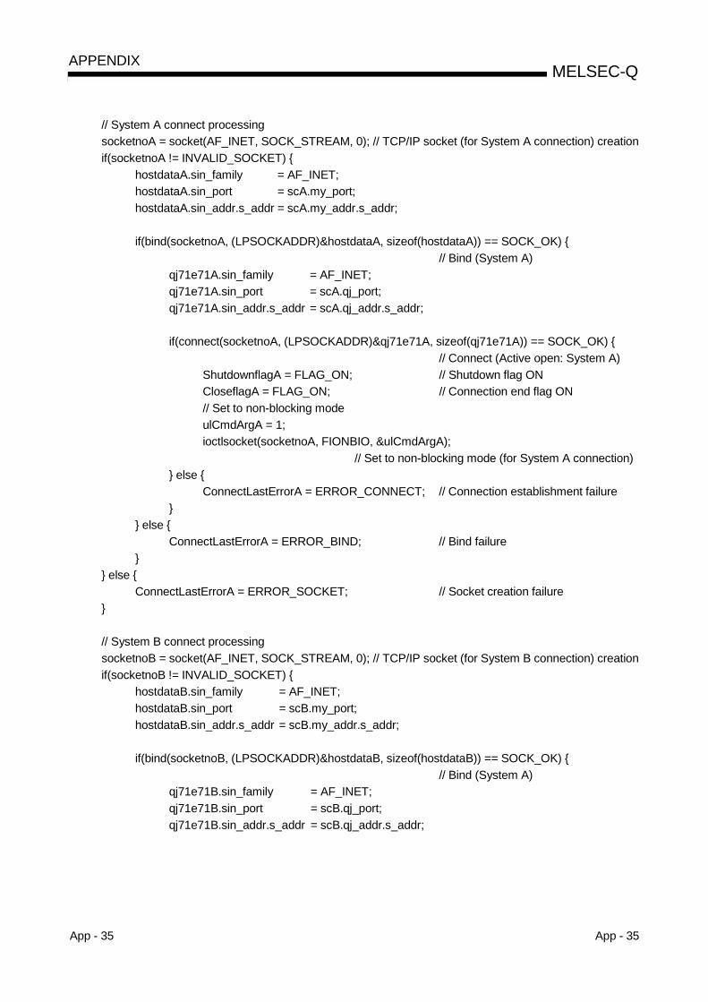
App - 35 App - 35
MELSEC-QAPPENDIX
// System A connect processingsocketnoA = socket(AF_INET, SOCK_STREAM, 0); // TCP/IP socket (for System A connection) creationif(socketnoA != INVALID_SOCKET)
hostdataA.sin_family = AF_INET;hostdataA.sin_port = scA.my_port;hostdataA.sin_addr.s_addr = scA.my_addr.s_addr;
if(bind(socketnoA, (LPSOCKADDR)&hostdataA, sizeof(hostdataA)) == SOCK_OK) // Bind (System A)
qj71e71A.sin_family = AF_INET;qj71e71A.sin_port = scA.qj_port;qj71e71A.sin_addr.s_addr = scA.qj_addr.s_addr;
if(connect(socketnoA, (LPSOCKADDR)&qj71e71A, sizeof(qj71e71A)) == SOCK_OK) // Connect (Active open: System A)
ShutdownflagA = FLAG_ON; // Shutdown flag ONCloseflagA = FLAG_ON; // Connection end flag ON// Set to non-blocking modeulCmdArgA = 1;ioctlsocket(socketnoA, FIONBIO, &ulCmdArgA);
// Set to non-blocking mode (for System A connection) else
ConnectLastErrorA = ERROR_CONNECT; // Connection establishment failure
else ConnectLastErrorA = ERROR_BIND; // Bind failure
else
ConnectLastErrorA = ERROR_SOCKET; // Socket creation failure
// System B connect processingsocketnoB = socket(AF_INET, SOCK_STREAM, 0); // TCP/IP socket (for System B connection) creationif(socketnoB != INVALID_SOCKET)
hostdataB.sin_family = AF_INET;hostdataB.sin_port = scB.my_port;hostdataB.sin_addr.s_addr = scB.my_addr.s_addr;
if(bind(socketnoB, (LPSOCKADDR)&hostdataB, sizeof(hostdataB)) == SOCK_OK) // Bind (System A)
qj71e71B.sin_family = AF_INET;qj71e71B.sin_port = scB.qj_port;qj71e71B.sin_addr.s_addr = scB.qj_addr.s_addr;

App - 36 App - 36
MELSEC-QAPPENDIX
if(connect(socketnoB, (LPSOCKADDR)&qj71e71B, sizeof(qj71e71B)) == SOCK_OK) // Connect (Active open: System B)
ShutdownflagB = FLAG_ON; // Shutdown flag ONCloseflagB = FLAG_ON; // Connection end flag ON// Set to non-blocking modeulCmdArgB = 1;ioctlsocket(socketnoB, FIONBIO, &ulCmdArgB);
// Set to non-blocking mode (for System B connection) else
ConnectLastErrorB = ERROR_CONNECT; // Connection establishment failure
else ConnectLastErrorB = ERROR_BIND; // Bind failure
else
ConnectLastErrorB = ERROR_SOCKET; // Socket creation failure
// Connect completion processingif( (CloseflagA == FLAG_OFF) && (CloseflagB == FLAG_OFF) ) // When both systems are abnormal
Sockerror(ConnectLastErrorA, ConnectLastErrorB); // Error handlingreturn (SOCK_NG);
strcpy(s_buf, "500000FF03D000002C000A14010000D*0000000005112233445566778899AA");// D0-D4 batch write request (3E frame, addressed to control system)
length = strlen(s_buf);
printf("Send starts. Press any key. \n");Dmykeyin = getchar(); // Waiting for key input
SendFlag = FLAG_OFF; // Send completion flag OFF// System A send processingif( CloseflagA == FLAG_ON && (SendFlag == FLAG_OFF) )
if(send(socketnoA, s_buf, length, 0) != SOCKET_ERROR) // Data send (System A)printf("\n Send data (System A) \n%s\n", s_buf); // Send data display (System A)SendFlag = FLAG_ON; // Send completion flag ON// Receive processingif(DataRecv(socketnoA, r_bufA, RECV_ANS_1) == TRUE) // Data receive
printf("\n Receive data (System A) \n%s\n", r_bufA); // Receive data display else
printf("Receive failure (System A) \n");
else printf("Send failure (System A) \n");
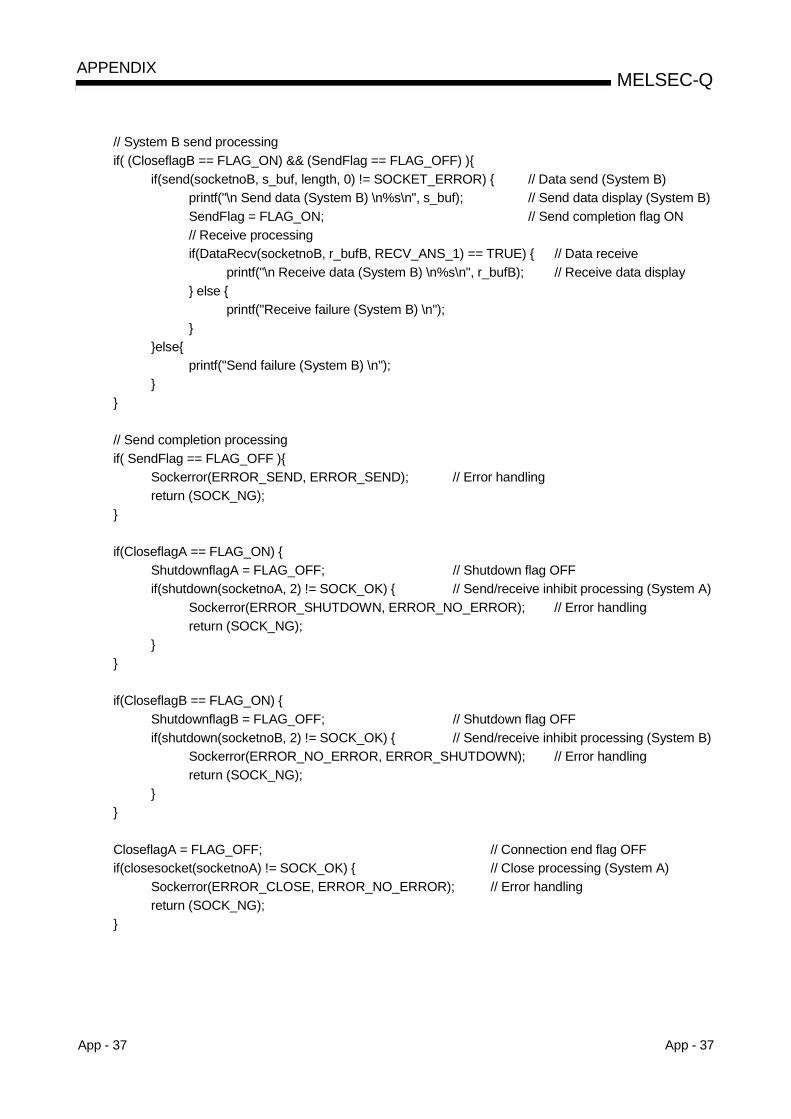
App - 37 App - 37
MELSEC-QAPPENDIX
// System B send processingif( (CloseflagB == FLAG_ON) && (SendFlag == FLAG_OFF) )
if(send(socketnoB, s_buf, length, 0) != SOCKET_ERROR) // Data send (System B)printf("\n Send data (System B) \n%s\n", s_buf); // Send data display (System B)SendFlag = FLAG_ON; // Send completion flag ON// Receive processingif(DataRecv(socketnoB, r_bufB, RECV_ANS_1) == TRUE) // Data receive
printf("\n Receive data (System B) \n%s\n", r_bufB); // Receive data display else
printf("Receive failure (System B) \n");
elseprintf("Send failure (System B) \n");
// Send completion processingif( SendFlag == FLAG_OFF )
Sockerror(ERROR_SEND, ERROR_SEND); // Error handlingreturn (SOCK_NG);
if(CloseflagA == FLAG_ON) ShutdownflagA = FLAG_OFF; // Shutdown flag OFFif(shutdown(socketnoA, 2) != SOCK_OK) // Send/receive inhibit processing (System A)
Sockerror(ERROR_SHUTDOWN, ERROR_NO_ERROR); // Error handlingreturn (SOCK_NG);
if(CloseflagB == FLAG_ON) ShutdownflagB = FLAG_OFF; // Shutdown flag OFFif(shutdown(socketnoB, 2) != SOCK_OK) // Send/receive inhibit processing (System B)
Sockerror(ERROR_NO_ERROR, ERROR_SHUTDOWN); // Error handlingreturn (SOCK_NG);
CloseflagA = FLAG_OFF; // Connection end flag OFFif(closesocket(socketnoA) != SOCK_OK) // Close processing (System A)
Sockerror(ERROR_CLOSE, ERROR_NO_ERROR); // Error handlingreturn (SOCK_NG);

App - 38 App - 38
MELSEC-QAPPENDIX
CloseflagB = FLAG_OFF; // Connection end flag OFFif(closesocket(socketnoB) != SOCK_OK) // Close processing (System B)
Sockerror(ERROR_NO_ERROR, ERROR_CLOSE); // Error handlingreturn (SOCK_NG);
WSACleanup(); // Winsock.DLL release
printf("\nQJ_test End. \n\nNormally completed. \n");printf("Program is closed. Press any key. \n");Dmykeyin = getchar(); // Waiting for key input
return (SOCK_OK);
BOOL DataRecv(int socketno, unsigned char *pR_buf, int size_max) // Receive processing function
int length; // Communication data lengthint rbuf_idx; // Receive data storage starting indexint recv_size; // Number of received data
// Performs receive processing while simultaneously making size checkrbuf_idx = 0; // Receive data storage starting index initializationrecv_size = 0; // Initializes the number of received datawhile(1)
length = recv(socketno, (pR_buf + rbuf_idx), (BUF_SIZE - rbuf_idx), 0);// Response data receive
if(length == 0) // Has connection been cut?return (FALSE); // Error handling
if(length == SOCKET_ERROR)
nErrorStatus = WSAGetLastError();if(nErrorStatus != WSAEWOULDBLOCK)
return (FALSE); // Error handling else
continue; // Repeated until data are received
else rbuf_idx += length; // Updates receive data storage positionrecv_size += length; // Updates the number of received dataif(recv_size >= size_max) // Have all response messages received?
break; // Stops repeating as data are received
*(pR_buf + rbuf_idx) = '\0' ; // At the end of received data
// set NULL

App - 39 App - 39
MELSEC-QAPPENDIX
return (TRUE); // Normal termination
void Sockerror(int error_kind_A, int error_kind_B) // Error handling function
if (error_kind_A == ERROR_INITIAL)printf("Initial processing is abnormal. \n");
else
nErrorStatus = WSAGetLastError();switch(error_kind_A)case ERROR_SOCKET:
printf("Socket could not be created. (System A)\n");break;
case ERROR_BIND:printf("Bind could not be executed. (System A)\n");break;
case ERROR_CONNECT:printf("Connection could not be established. (System A)\n");break;
case ERROR_SEND:printf("Send could not be executed. \n");break;
case ERROR_SHUTDOWN:printf("Shutdown could not be executed. (System A)\n");break;
case ERROR_CLOSE:printf("Normal close could not be executed. (System A)\n");break;
switch(error_kind_B)case ERROR_SOCKET:
printf("Socket could not be created. (System B)\n");break;
case ERROR_BIND:printf("Bind could not be executed. (System B)\n");break;
case ERROR_CONNECT:printf("Connection could not be established. (System B)\n");break;
case ERROR_SHUTDOWN:printf("Shutdown could not be executed. (System B)\n");break;
case ERROR_CLOSE:printf("Normal close could not be executed. (System B)\n");break;
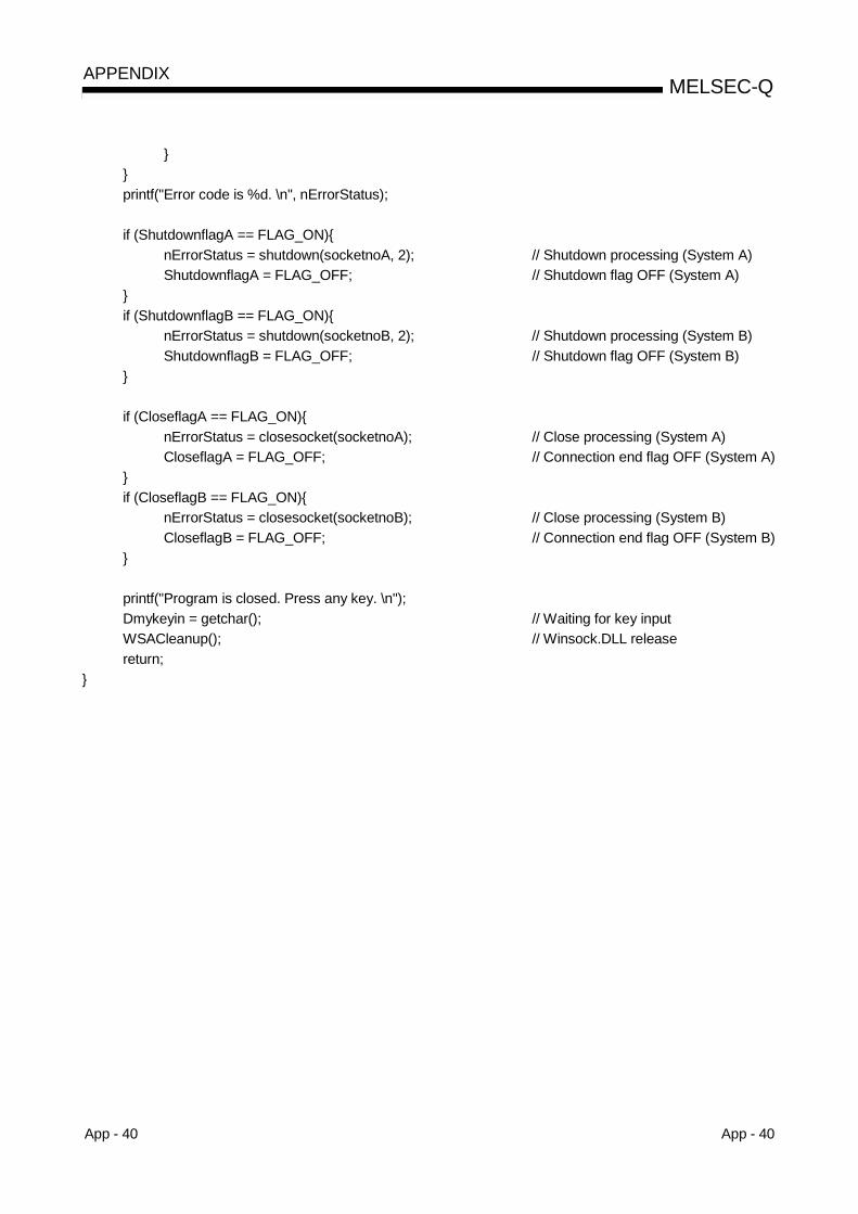
App - 40 App - 40
MELSEC-QAPPENDIX
printf("Error code is %d. \n", nErrorStatus);
if (ShutdownflagA == FLAG_ON)nErrorStatus = shutdown(socketnoA, 2); // Shutdown processing (System A)ShutdownflagA = FLAG_OFF; // Shutdown flag OFF (System A)
if (ShutdownflagB == FLAG_ON)
nErrorStatus = shutdown(socketnoB, 2); // Shutdown processing (System B)ShutdownflagB = FLAG_OFF; // Shutdown flag OFF (System B)
if (CloseflagA == FLAG_ON)nErrorStatus = closesocket(socketnoA); // Close processing (System A)CloseflagA = FLAG_OFF; // Connection end flag OFF (System A)
if (CloseflagB == FLAG_ON)
nErrorStatus = closesocket(socketnoB); // Close processing (System B)CloseflagB = FLAG_OFF; // Connection end flag OFF (System B)
printf("Program is closed. Press any key. \n");Dmykeyin = getchar(); // Waiting for key inputWSACleanup(); // Winsock.DLL releasereturn;
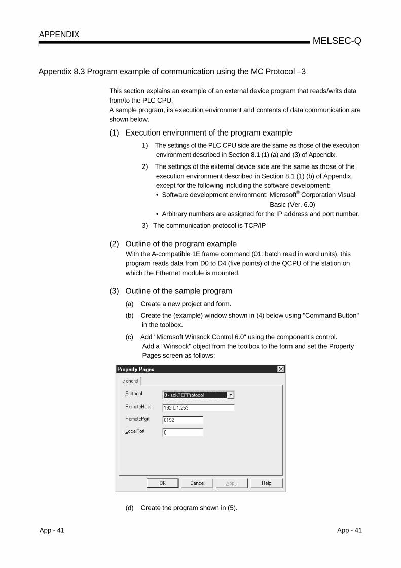
App - 41 App - 41
MELSEC-QAPPENDIX
Appendix 8.3 Program example of communication using the MC Protocol –3
This section explains an example of an external device program that reads/writs datafrom/to the PLC CPU.A sample program, its execution environment and contents of data communication areshown below.
(1) Execution environment of the program example1) The settings of the PLC CPU side are the same as those of the execution
environment described in Section 8.1 (1) (a) and (3) of Appendix.
2) The settings of the external device side are the same as those of theexecution environment described in Section 8.1 (1) (b) of Appendix,except for the following including the software development:• Software development environment: Microsoft® Corporation Visual
Basic (Ver. 6.0)• Arbitrary numbers are assigned for the IP address and port number.
3) The communication protocol is TCP/IP
(2) Outline of the program exampleWith the A-compatible 1E frame command (01: batch read in word units), thisprogram reads data from D0 to D4 (five points) of the QCPU of the station onwhich the Ethernet module is mounted.
(3) Outline of the sample program(a) Create a new project and form.
(b) Create the (example) window shown in (4) below using "Command Button"in the toolbox.
(c) Add "Microsoft Winsock Control 6.0" using the component's control.Add a "Winsock" object from the toolbox to the form and set the PropertyPages screen as follows:
(d) Create the program shown in (5).
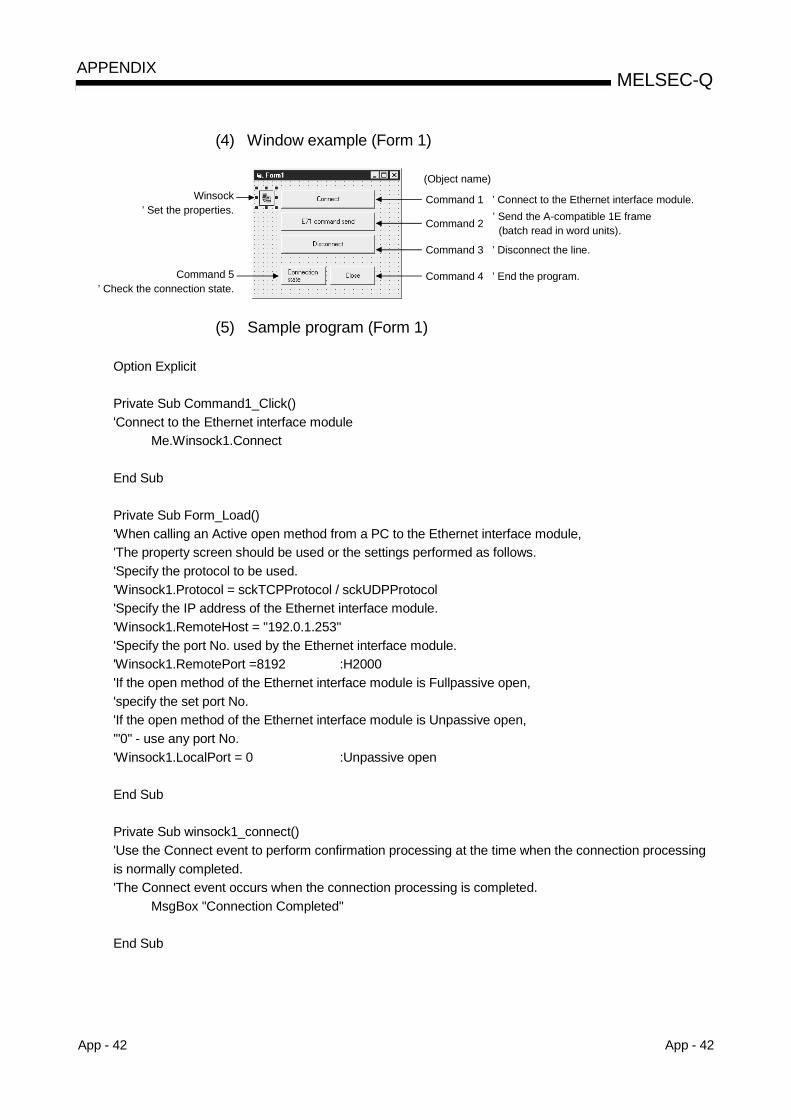
App - 42 App - 42
MELSEC-QAPPENDIX
(4) Window example (Form 1)
Command 1 ’ Connect to the Ethernet interface module. ’ Send the A-compatible 1E frame (batch read in word units).
Command 3 ’ Disconnect the line.
(Object name)
Command 4 ’ End the program.Command 5’ Check the connection state.
Winsock’ Set the properties.
Command 2
(5) Sample program (Form 1)
Option Explicit
Private Sub Command1_Click()'Connect to the Ethernet interface module
Me.Winsock1.Connect
End Sub
Private Sub Form_Load()'When calling an Active open method from a PC to the Ethernet interface module,'The property screen should be used or the settings performed as follows.'Specify the protocol to be used.'Winsock1.Protocol = sckTCPProtocol / sckUDPProtocol'Specify the IP address of the Ethernet interface module.'Winsock1.RemoteHost = "192.0.1.253"'Specify the port No. used by the Ethernet interface module.'Winsock1.RemotePort =8192 :H2000'If the open method of the Ethernet interface module is Fullpassive open,'specify the set port No.'If the open method of the Ethernet interface module is Unpassive open,'"0" - use any port No.'Winsock1.LocalPort = 0 :Unpassive open
End Sub
Private Sub winsock1_connect()'Use the Connect event to perform confirmation processing at the time when the connection processingis normally completed.'The Connect event occurs when the connection processing is completed.
MsgBox "Connection Completed"
End Sub
App - 43 App - 43
MELSEC-QAPPENDIX
Private Sub Command2_Click()Dim SData As String'Read D0 to D4 (5 points) with the A-compatible 1E frame command.
SData = "01ff000a4420000000000500"'Send the data.
Me.Winsock1.SendData SData
End Sub
Private Sub Command3_Click()'Close the TCP connection socket (disconnect the line).
Me.Winsock1.Close
End Sub
Private Sub Command4_Click()'End the program.
End
End Sub
Private Sub Command5_Click()'Check the state of Winsock.'See the Help of Visual Basic for details.
MsgBox Winsock1.State
End Sub
Private Sub Winsock1_DataArrival(ByVal bytesTotal As Long)'The DataArrival event occurs when new data arrives.
Dim RData As String'Obtain the current data block and save it as a variant type variable.'Read the response from the PLC CPU.
Me.Winsock1.GetData RDataMsgBox RData
End Sub
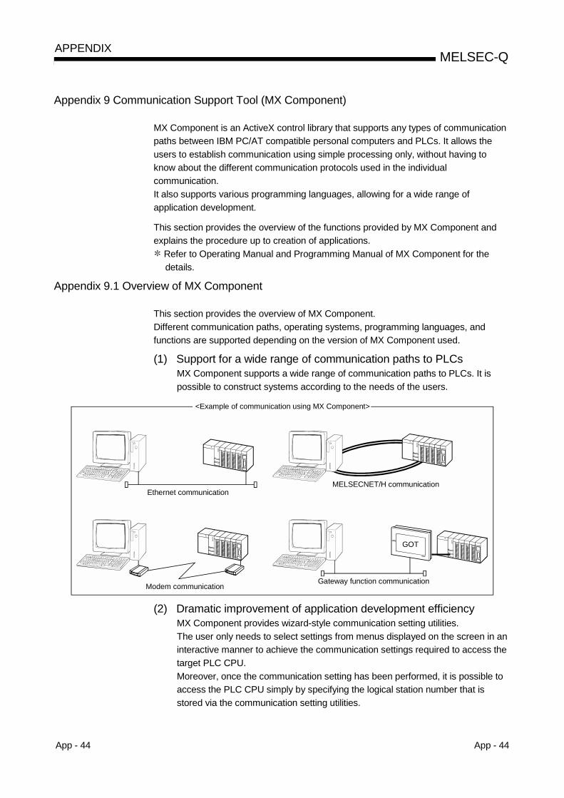
App - 44 App - 44
MELSEC-QAPPENDIX
Appendix 9 Communication Support Tool (MX Component)
MX Component is an ActiveX control library that supports any types of communicationpaths between IBM PC/AT compatible personal computers and PLCs. It allows theusers to establish communication using simple processing only, without having toknow about the different communication protocols used in the individualcommunication.It also supports various programming languages, allowing for a wide range ofapplication development.
This section provides the overview of the functions provided by MX Component andexplains the procedure up to creation of applications.
Refer to Operating Manual and Programming Manual of MX Component for thedetails.
Appendix 9.1 Overview of MX Component
This section provides the overview of MX Component.Different communication paths, operating systems, programming languages, andfunctions are supported depending on the version of MX Component used.
(1) Support for a wide range of communication paths to PLCsMX Component supports a wide range of communication paths to PLCs. It ispossible to construct systems according to the needs of the users.
Ethernet communication
Modem communication
MELSECNET/H communication
GOT
Gateway function communication
<Example of communication using MX Component>
(2) Dramatic improvement of application development efficiencyMX Component provides wizard-style communication setting utilities.The user only needs to select settings from menus displayed on the screen in aninteractive manner to achieve the communication settings required to access thetarget PLC CPU.Moreover, once the communication setting has been performed, it is possible toaccess the PLC CPU simply by specifying the logical station number that isstored via the communication setting utilities.

App - 45 App - 45
MELSEC-QAPPENDIX
(3) Support for wide choice of basic operating systemsMX Component can run on IBM PC/AT compatible personal computers runningthe following basic operating systems:
• Microsoft® Windows® 95 Operating System• Microsoft® Windows® 98 Operating System• Microsoft® Windows NT® Workstation Operating System Version 4.0• Microsoft® Windows® Millennium Edition Operating System• Microsoft® Windows® 2000 Professional Operating System• Microsoft® Windows® XP Professional Operating System• Microsoft® Windows® XP Home Edition Operating System
(4) Support for a wide variety of programming languagesMX Component supports the following programming languages.It allows the user to develop a wide range of customized applications.
Programming language Development software
Visual Basic® Microsoft® Visual Basic® 6.0Visual C++® Microsoft® Visual C++® 6.0VBScript Text editors and commercially available HTML tools
VBAMicrosoft® Excel 2000, Microsoft® Excel 2002,Microsoft® Access 2000 or Microsoft® Access 2002
(5) Support for functions dedicated for data communication with PLCsMX Component provides the functions necessary for data communication withPLCs, including functions for opening/closing communication lines andreading/writing devices.Multi-function communication programs can thus easily be developed with MXComponent.
Function name Function
Connect Connects a telephone line.Open Opens a communication line.Close Closes a communication line.Disconnect Disconnects a telephone line.GetErrorMessage Displays error definition and corrective action.ReadDeviceBlock Batch-reads data from devices. (LONG type)WriteDeviceBlock Batch-writes data to devices. (LONG type)ReadDeviceBlock2 Batch-reads data from devices. (SHORT type/INT type)WriteDeviceBlock2 Batch-writes data to devices. (SHORT type/INT type)ReadDeviceRandom Randomly reads data from devices. (LONG type)WriteDeviceRandom Randomly writes data to devices. (LONG type)ReadDeviceRandom2 Randomly reads data from devices. (SHORT type/INT type)WriteDeviceRandom2 Randomly writes data to devices. (SHORT type/INT type)SetDevice Sets one device. (LONG type)GetDevice Acquires the data of one device. (LONG type)SetDevice2 Sets one device. (SHORT type/INT type)GetDevice2 Acquires data of one device. (SHORT type/INT type)
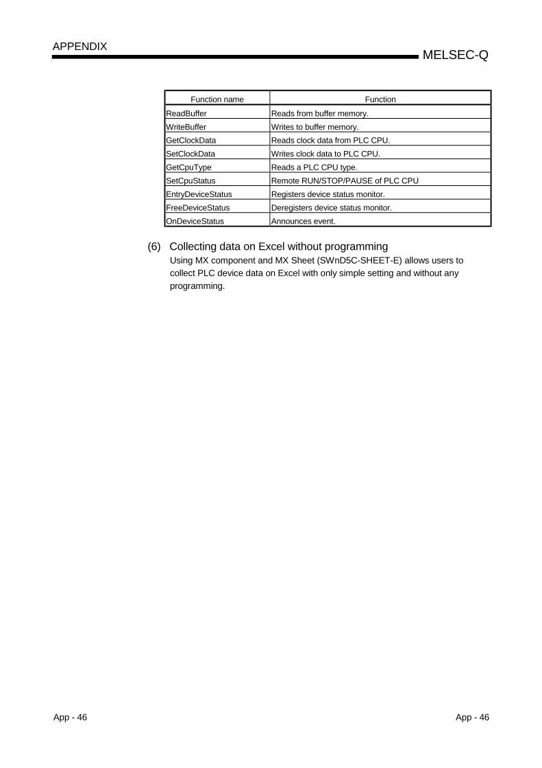
App - 46 App - 46
MELSEC-QAPPENDIX
Function name Function
ReadBuffer Reads from buffer memory.WriteBuffer Writes to buffer memory.GetClockData Reads clock data from PLC CPU.SetClockData Writes clock data to PLC CPU.GetCpuType Reads a PLC CPU type.SetCpuStatus Remote RUN/STOP/PAUSE of PLC CPUEntryDeviceStatus Registers device status monitor.FreeDeviceStatus Deregisters device status monitor.OnDeviceStatus Announces event.
(6) Collecting data on Excel without programmingUsing MX component and MX Sheet (SWnD5C-SHEET-E) allows users tocollect PLC device data on Excel with only simple setting and without anyprogramming.
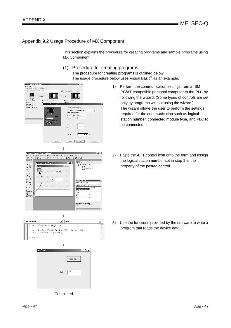
App - 47 App - 47
MELSEC-QAPPENDIX
Appendix 9.2 Usage Procedure of MX Component
This section explains the procedure for creating programs and sample programs usingMX Component.
(1) Procedure for creating programsThe procedure for creating programs is outlined below.The usage procedure below uses Visual Basic® as an example.
1) Perform the communication settings from a IBMPC/AT compatible personal computer to the PLC byfollowing the wizard. (Some types of controls are setonly by programs without using the wizard.)The wizard allows the user to perform the settingsrequired for the communication such as logicalstation number, connected module type, and PLC tobe connected.
↓
2) Paste the ACT control icon onto the form and assignthe logical station number set in step 1 to theproperty of the pasted control.
↓
3) Use the functions provided by the software to write aprogram that reads the device data.
↓
Completed

App - 48 App - 48
MELSEC-QAPPENDIX
(2) Sample programThe following sample program reads D0 to D4 (five points) of the target PLCusing the logical station number.(a) When Visual Basic® is used
1) Screen example (Form1)
Command1' Connect to the communication line.Command2' Read the device data.Command3' Cut the communication line.
Text1' Enter the logical station number.
ACT control (ActEasy IF)' ACT control for utility setting type
2) Program example
Private Sub Command1_Click()' ' Connection' Dim rtn As Long ' Get LogicalstationNumber ActEasyIF1. ActLogicalStationNumber = Val(Text1.Text) ' Connection rtn = ActEasyIF1. Open() If rtn = 0 Then MsgBox "The connection was successful" Else MsgBox "Connection Error:" & Hex(rtn) End IfEnd Sub
Private Sub Command2_Click()' ' Read' Dim rtn As LongDim idata(5) As Integer ' D0-D4 are read rtn = ActEasyIF1. ReadDeviceBlock2 ("D0", 5, idata(0)) If rtn = 0 Then MsgBox "D0-D5 = " & idata(0) & ", " & idata(1) & ", " & idata(2) & ", " & idata(3) & "," & idata(4) Else MsgBox "Read Error:" & Hex(rtn) End IfEnd Sub
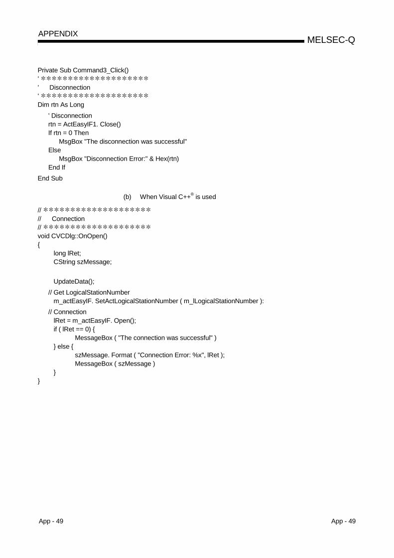
App - 49 App - 49
MELSEC-QAPPENDIX
Private Sub Command3_Click()' ' Disconnection' Dim rtn As Long ' Disconnection rtn = ActEasyIF1. Close() If rtn = 0 Then MsgBox "The disconnection was successful" Else MsgBox "Disconnection Error:" & Hex(rtn) End IfEnd Sub
(b) When Visual C++® is used
// // Connection// void CVCDlg::OnOpen() long lRet; CString szMessage;
UpdateData(); // Get LogicalStationNumber m_actEasyIF. SetActLogicalStationNumber ( m_lLogicalStationNumber ): // Connection lRet = m_actEasyIF. Open(); if ( lRet == 0) MessageBox ( "The connection was successful" ) else szMessage. Format ( "Connection Error: %x", lRet ); MessageBox ( szMessage )
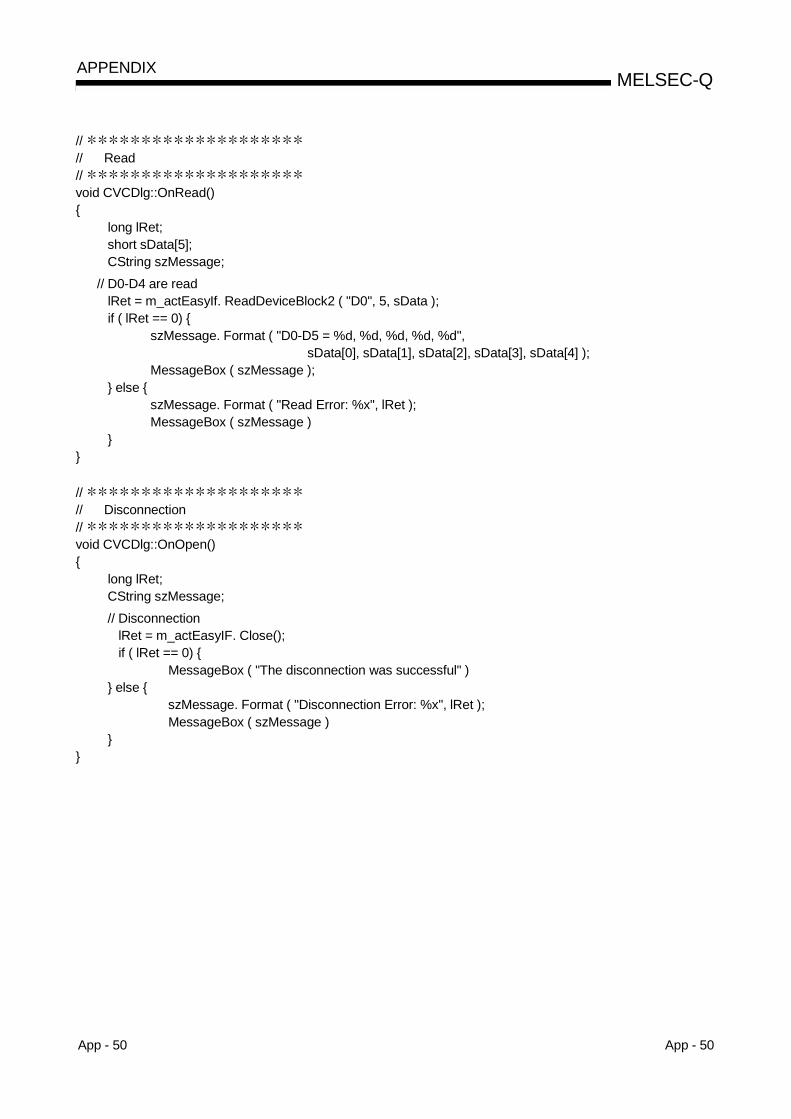
App - 50 App - 50
MELSEC-QAPPENDIX
// // Read// void CVCDlg::OnRead() long lRet; short sData[5]; CString szMessage; // D0-D4 are read lRet = m_actEasyIf. ReadDeviceBlock2 ( "D0", 5, sData ); if ( lRet == 0) szMessage. Format ( "D0-D5 = %d, %d, %d, %d, %d", sData[0], sData[1], sData[2], sData[3], sData[4] ); MessageBox ( szMessage ); else szMessage. Format ( "Read Error: %x", lRet ); MessageBox ( szMessage )
// // Disconnection// void CVCDlg::OnOpen() long lRet; CString szMessage; // Disconnection lRet = m_actEasyIF. Close(); if ( lRet == 0) MessageBox ( "The disconnection was successful" ) else szMessage. Format ( "Disconnection Error: %x", lRet ); MessageBox ( szMessage )
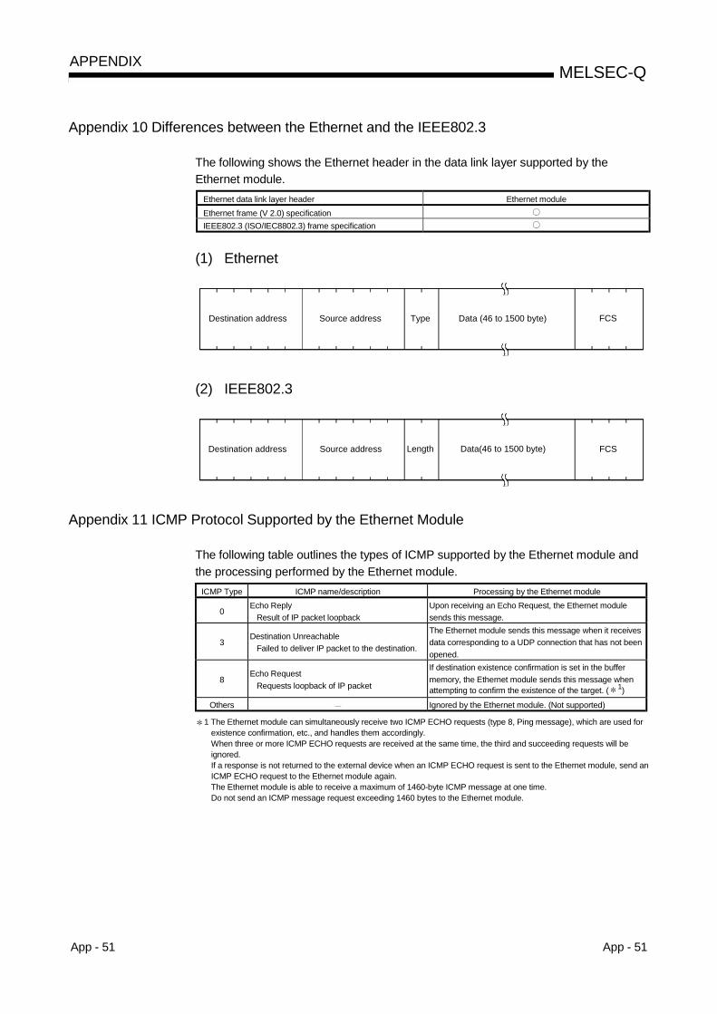
App - 51 App - 51
MELSEC-QAPPENDIX
Appendix 10 Differences between the Ethernet and the IEEE802.3
The following shows the Ethernet header in the data link layer supported by theEthernet module.
Ethernet data link layer header Ethernet moduleEthernet frame (V 2.0) specificationIEEE802.3 (ISO/IEC8802.3) frame specification
(1) Ethernet
FCSDestination address Source address Type Data (46 to 1500 byte)
(2) IEEE802.3
FCSDestination address Source address Length Data(46 to 1500 byte)
Appendix 11 ICMP Protocol Supported by the Ethernet Module
The following table outlines the types of ICMP supported by the Ethernet module andthe processing performed by the Ethernet module.
ICMP Type ICMP name/description Processing by the Ethernet module
0Echo Reply
Result of IP packet loopbackUpon receiving an Echo Request, the Ethernet modulesends this message.
3Destination Unreachable
Failed to deliver IP packet to the destination.
The Ethernet module sends this message when it receivesdata corresponding to a UDP connection that has not beenopened.
8Echo Request
Requests loopback of IP packet
If destination existence confirmation is set in the buffermemory, the Ethernet module sends this message whenattempting to confirm the existence of the target. ( 1)
Others Ignored by the Ethernet module. (Not supported)
1 The Ethernet module can simultaneously receive two ICMP ECHO requests (type 8, Ping message), which are used forexistence confirmation, etc., and handles them accordingly.When three or more ICMP ECHO requests are received at the same time, the third and succeeding requests will beignored.If a response is not returned to the external device when an ICMP ECHO request is sent to the Ethernet module, send anICMP ECHO request to the Ethernet module again.The Ethernet module is able to receive a maximum of 1460-byte ICMP message at one time.Do not send an ICMP message request exceeding 1460 bytes to the Ethernet module.
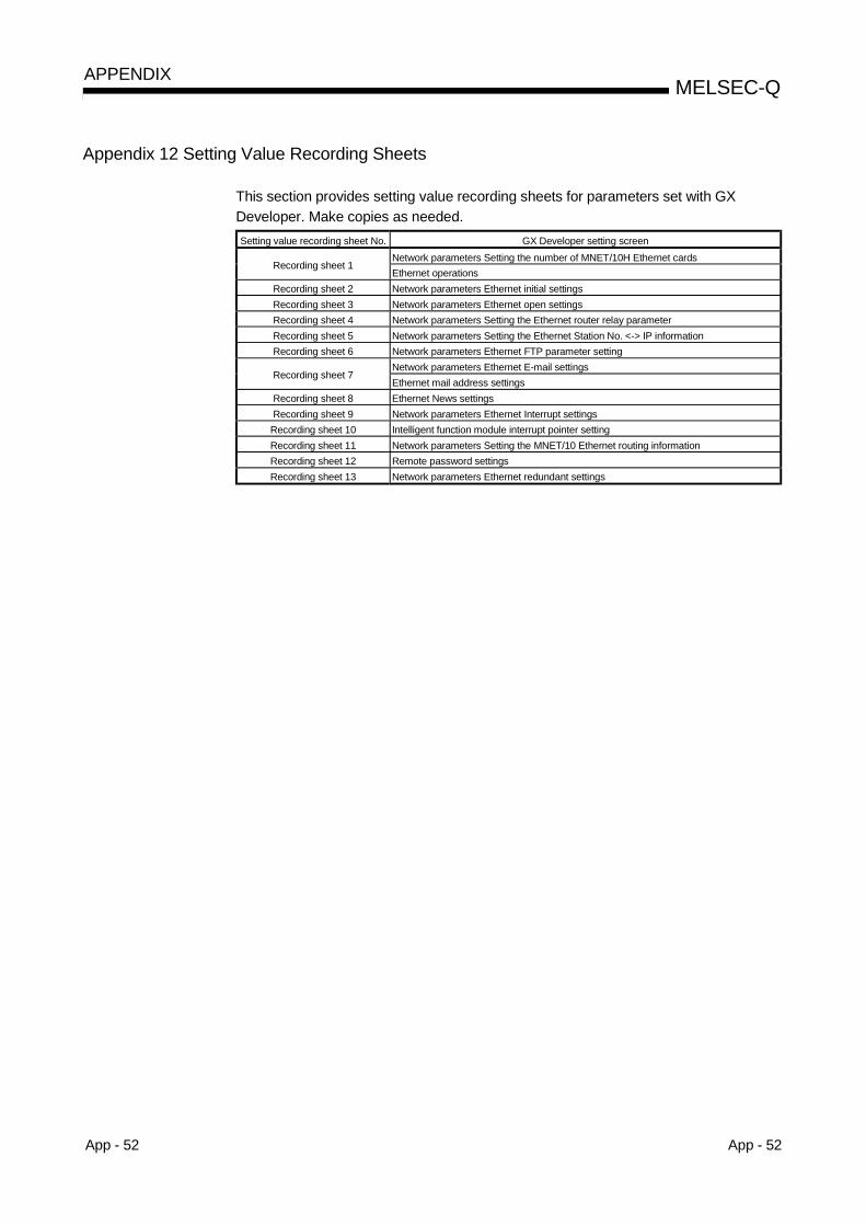
App - 52 App - 52
MELSEC-QAPPENDIX
Appendix 12 Setting Value Recording Sheets
This section provides setting value recording sheets for parameters set with GXDeveloper. Make copies as needed.Setting value recording sheet No. GX Developer setting screen
Network parameters Setting the number of MNET/10H Ethernet cardsRecording sheet 1
Ethernet operationsRecording sheet 2 Network parameters Ethernet initial settingsRecording sheet 3 Network parameters Ethernet open settingsRecording sheet 4 Network parameters Setting the Ethernet router relay parameterRecording sheet 5 Network parameters Setting the Ethernet Station No. <-> IP informationRecording sheet 6 Network parameters Ethernet FTP parameter setting
Network parameters Ethernet E-mail settingsRecording sheet 7
Ethernet mail address settingsRecording sheet 8 Ethernet News settingsRecording sheet 9 Network parameters Ethernet Interrupt settingsRecording sheet 10 Intelligent function module interrupt pointer settingRecording sheet 11 Network parameters Setting the MNET/10 Ethernet routing informationRecording sheet 12 Remote password settingsRecording sheet 13 Network parameters Ethernet redundant settings

App - 53 App - 53
MELSEC-QAPPENDIX
Recording sheet 1
[Module number ]Setting dataGX Developer setting
screenData item
Setting value Remark
Starting I/O No.
Network No.
Group No.
Station No.
OnlineOff line
Self refrain test
Network parametersSetting the number ofMNET/10H Ethernet
cards
Mode
Hardware (H/W) testBinary code communication
Communication data code settingASCII code communication
Do not wait for OPEN (Communications impossible atSTOP time)
Initial TimingAlways wait for OPEN (Communication possible at STOP
time)Decimal
Input formatHexadecimal
IP addressInput formatIP address
settingIP address
. . .Adjust to input format
Ethernet (V2.0)Send frame setting
IEEE802.3
Enable Write at RUN time Enable Write at RUN time Enable: Check mark
Use the KeepAlive
Ethernet Operations
TCP ExistenceConfirmation setting Use the Ping
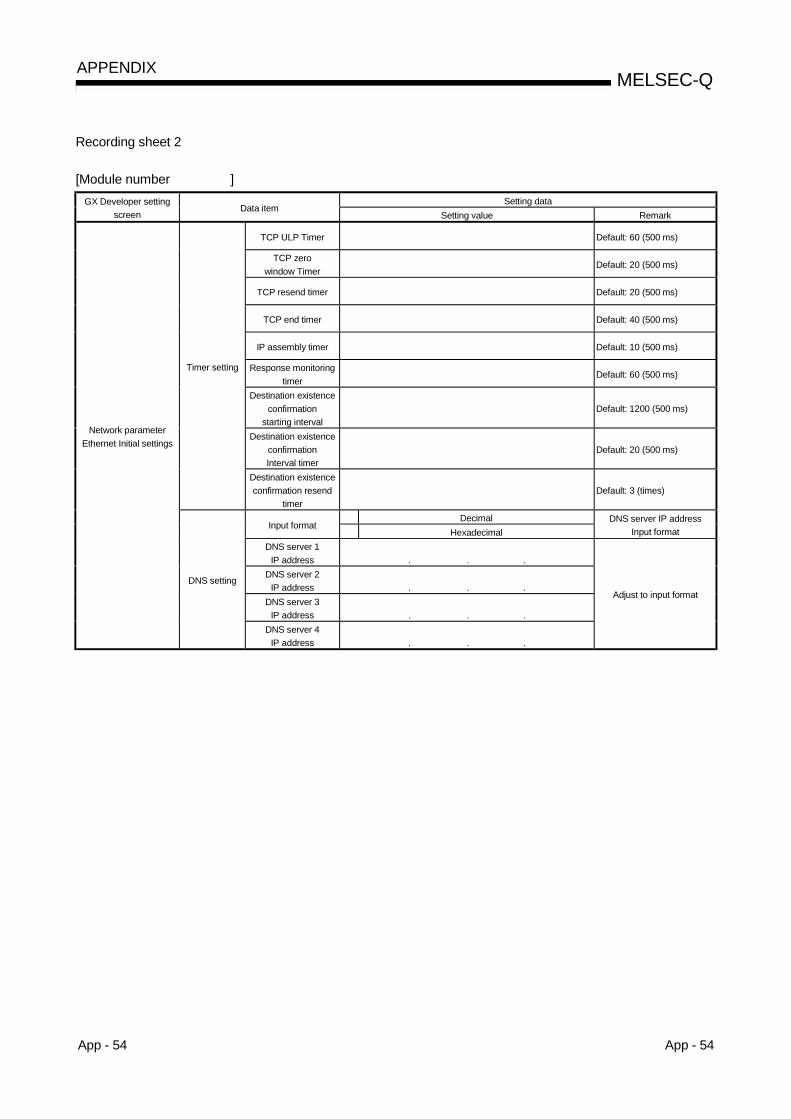
App - 54 App - 54
MELSEC-QAPPENDIX
Recording sheet 2
[Module number ]Setting dataGX Developer setting
screenData item
Setting value Remark
TCP ULP Timer Default: 60 (500 ms)
TCP zerowindow Timer
Default: 20 (500 ms)
TCP resend timer Default: 20 (500 ms)
TCP end timer Default: 40 (500 ms)
IP assembly timer Default: 10 (500 ms)
Response monitoringtimer
Default: 60 (500 ms)
Destination existenceconfirmation
starting intervalDefault: 1200 (500 ms)
Destination existenceconfirmationInterval timer
Default: 20 (500 ms)
Timer setting
Destination existenceconfirmation resend
timerDefault: 3 (times)
DecimalInput format
HexadecimalDNS server IP address
Input formatDNS server 1
IP address . . .DNS server 2
IP address . . .DNS server 3
IP address . . .
Network parameterEthernet Initial settings
DNS setting
DNS server 4IP address . . .
Adjust to input format

App - 55 App - 55
MELSEC-QAPPENDIX
Recording Sheet 3
[Module number ]Setting dataGX Developer setting
screenData item
Setting value RemarkTCP
ProtocolUDPActive
UnpassiveOpen systemFullpassive
Setting not required if UDP isselected.
SendFixed buffer
ReceiveProcedure existFixed buffer
communication No procedureNo pairs
Paring openPairs
No confirmExistence confirmation
Confirm
Local station Port No. Input format: Hexadecimal
DecimalHexadecimal
Destination IP address inputformatDestination
IP address. . .
Adjust to input format
ConnectionNo.
Destination Port No. Input format: Hexadecimal
TCPProtocol
UDPActive
UnpassiveOpen systemFullpassive
SendFixed buffer
ReceiveProcedure existFixed buffer
communication No procedureNo pairs
Paring openPairs
No confirmExistence confirmation
Confirm
Local station Port No. Input format: Hexadecimal
DecimalHexadecimal
Destination IP address inputformatDestination
IP address. . .
Adjust to input format
Network parameterEthernet open settings
ConnectionNo.
Destination Port No. Input format: Hexadecimal

App - 56 App - 56
MELSEC-QAPPENDIX
Recording sheet 4
[Module number ]Setting dataGX Developer setting
screenData item
Setting value RemarkDo not use
Router relay functionUse
Sub-net mask pattern. . .
Adjust to input format
Default router IP address. . .
Adjust to input format
DecimalInput format
HexadecimalRouter information Input
format
Sub-net address. . .
No.1Router IP address
. . .
Sub-net address. . .
No.2Router IP address
. . .
Sub-net address. . .
No.3Router IP address
. . .
Sub-net address. . .
No.4Router IP address
. . .
Sub-net address. . .
No.5Router IP address
. . .
Sub-net address. . .
No.6Router IP address
. . .
Sub-net address. . .
No7Router IP address
. . .
Sub-net address. . .
Network parametersSetting the Ethernet
router relay parameter
No.8Router IP address
. . .
Adjust to input format
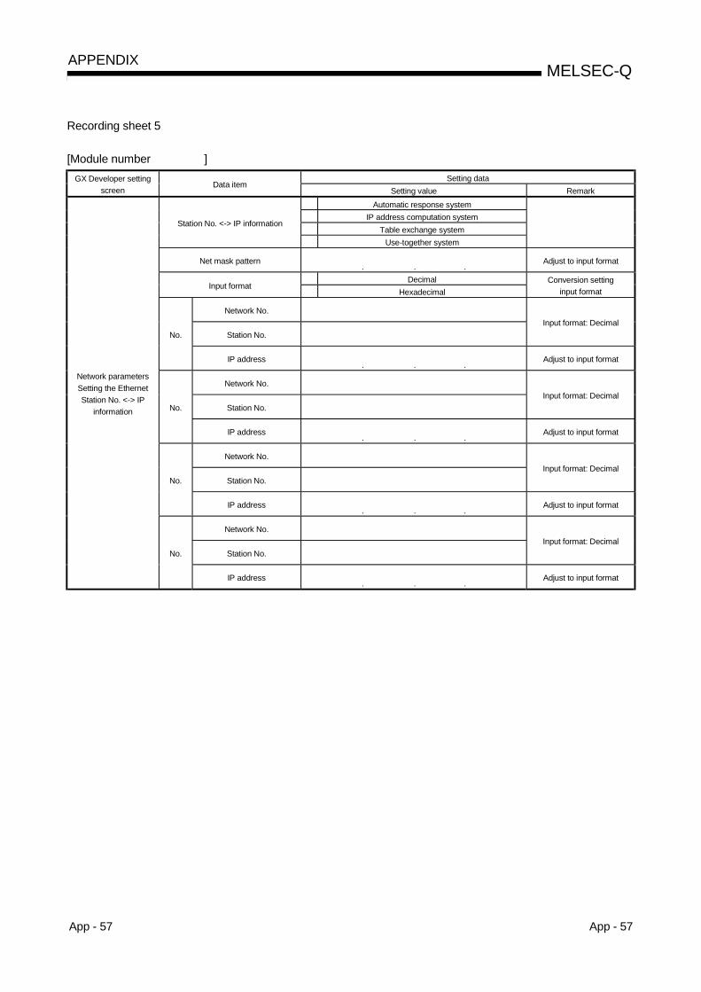
App - 57 App - 57
MELSEC-QAPPENDIX
Recording sheet 5
[Module number ]Setting dataGX Developer setting
screenData item
Setting value RemarkAutomatic response system
IP address computation systemTable exchange system
Station No. <-> IP information
Use-together system
Net mask pattern. . .
Adjust to input format
DecimalInput format
HexadecimalConversion setting
input format
Network No.
Station No.Input format: Decimal
No.
IP address. . .
Adjust to input format
Network No.
Station No.Input format: Decimal
No.
IP address. . .
Adjust to input format
Network No.
Station No.Input format: Decimal
No.
IP address. . .
Adjust to input format
Network No.
Station No.Input format: Decimal
Network parametersSetting the EthernetStation No. <-> IP
information
No.
IP address. . .
Adjust to input format

App - 58 App - 58
MELSEC-QAPPENDIX
Recording sheet 6
[Module number ]Setting dataGX Developer setting
screenData item
Setting value RemarkDo not use
FTP function settingsUse
Login name Default: "QJ71E71"
CurrentPassword
New
Command input monitoring timer
Network parametersEthernet FTP parameter
settings
PLC CPU monitoring timerUnit: Setting value × 500ms

App - 59 App - 59
MELSEC-QAPPENDIX
Recording sheet 7
[Module number ]Setting dataGX Developer setting
screenData item
Setting value Remark
Password
Mail address
Check of received mail Check received mails Check: Check mark
Set interval value to checkreceived mail.
smin
Generalsettings
Interval of inquiry
h
Select unit for interval tocheck received mail.
SMTPServer name
DecimalHexadecimal
IP address input formatSend settingIP address
. . .Adjust to input format
POPServer name
DecimalHexadecimal
IP address input format
Network parametersEthernet e-mail settings
MailServername
IP address
. . .Adjust to input format
Send mail address
No executeNo.
News settingExecute news
Send mail address
No executeNo.
News settingExecute news
Send mail address
No executeNo.
News settingExecute news
Send mail address
No executeNo.
News settingExecute news
Send mail address
No executeNo.
News settingExecute news
Send mail address
No execute
Ethernet send mailaddress settings
No.News setting
Execute news

App - 60 App - 60
MELSEC-QAPPENDIX
Recording sheet 8
[Module number ]Setting dataGX Developer setting
screenData item
Setting value RemarkNo settings
Normal STOPModule error/ module system error
(Medium/Major level disorder)Warning STOP (Minor disorder STOP)
Normal RUNWarning RUN (Minor disorder RUN)
Condition for PLC inspection
PAUSESend attached file
Send methodSend text mail
BinaryASCIIAttached file formatCSV
Adjust to input format
Attached file name
Interval of CPU inquirynumeric value setting
smin
PLC inquiry Interval
h
Interval of CPU inquiry unitselection
DecimalMonitoring value input format
HexadecimalMonitoring value input format
Condition device
Condition for inspection
Monitoring value Adjust to input format
News data storage device
No.
News data
Condition device
Condition for inspection
Monitoring value Adjust to input format
News data storage device
No.
News data
Condition device
Condition for inspection
Monitoring value Adjust to input format
News data storage device
Ethernet news settings
No.
News data
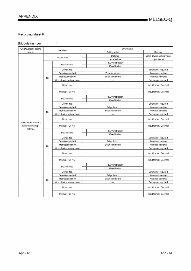
App - 61 App - 61
MELSEC-QAPPENDIX
Recording sheet 9
[Module number ]Setting dataGX Developer setting
screenData item
Setting value RemarkDecimal
Input formatHexadecimal
Word device setting valueinput format
RECV instructionDevice code
Fixed bufferDevice No. — Setting not required
Detection method Edge detection Automatic settingInterrupt condition Scan completed Automatic setting
Word device setting value — Setting not required
Board No. Input format: Decimal
No.
Interrupt (SI) No. Input format: Decimal
RECV instructionDevice code
Fixed bufferDevice No. — Setting not required
Detection method Edge detect Automatic settingInterrupt condition Scan completed Automatic setting
Word device setting value — Setting not required
Board No. Input format: Decimal
No.
Interrupt (SI) No. Input format: Decimal
RECV instructionDevice code
Fixed bufferDevice No. Setting not required
Detection method Edge detect Automatic settingInterrupt condition Scan completed Automatic setting
Word device setting value — Setting not required
Board No. Input format: Decimal
No.
Interrupt (SI) No. Input format: Decimal
RECV instructionDevice code
Fixed bufferDevice No. — Setting not required
Detection method Edge detect Automatic settingInterrupt condition Scan completed Automatic setting
Word device setting value — Setting not required
Board No. Input format: Decimal
Network parametersEthernet interrupt
settings
No.
Interrupt (SI) No. Input format: Decimal

App - 62 App - 62
MELSEC-QAPPENDIX
Recording sheet 10
Setting dataGX Developer settingscreen
Data itemSetting value Remark
Interrupt pointerstart No.PLC CPU
side Interrupt pointerNo. of module
Input format: Decimal
Start I/O No. Input format: HexadecimalNo.
Intelligentmodule
side Start SI No.
Interrupt pointerstart No.PLC CPU
side Interrupt pointerNo. of module
Input format: Decimal
Start I/O No. Input format: HexadecimalNo.
Intelligentmodule
side Start SI No.
Interrupt pointerstart No.PLC CPU
side Interrupt pointerNo. of module
Input format: Decimal
Start I/O No. Input format: HexadecimalNo.
Intelligentmodule
side Start SI No.
Interrupt pointerstart No.PLC CPU
side Interrupt pointerNo. of module
Input format: Decimal
Start I/O No. Input format: Hexadecimal
Intelligent functionmodule interrupt pointer
setting
No.Intelligentmodule
side Start SI No. Input format: Decimal
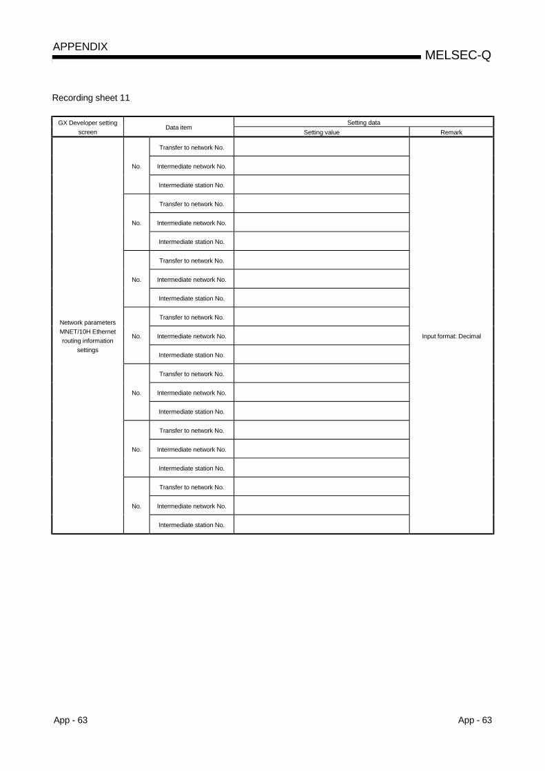
App - 63 App - 63
MELSEC-QAPPENDIX
Recording sheet 11
Setting dataGX Developer settingscreen
Data itemSetting value Remark
Transfer to network No.
Intermediate network No.No.
Intermediate station No.
Transfer to network No.
Intermediate network No.No.
Intermediate station No.
Transfer to network No.
Intermediate network No.No.
Intermediate station No.
Transfer to network No.
Intermediate network No.No.
Intermediate station No.
Transfer to network No.
Intermediate network No.No.
Intermediate station No.
Transfer to network No.
Intermediate network No.No.
Intermediate station No.
Transfer to network No.
Intermediate network No.
Network parametersMNET/10H Ethernetrouting information
settings
No.
Intermediate station No.
Input format: Decimal
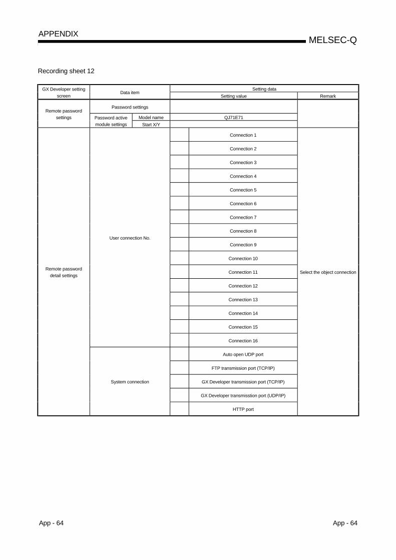
App - 64 App - 64
MELSEC-QAPPENDIX
Recording sheet 12
Setting dataGX Developer settingscreen
Data itemSetting value Remark
Password settings
Model name QJ71E71Remote password
settings Password activemodule settings Start X/Y
Connection 1
Connection 2
Connection 3
Connection 4
Connection 5
Connection 6
Connection 7
Connection 8
Connection 9
Connection 10
Connection 11
Connection 12
Connection 13
Connection 14
Connection 15
User connection No.
Connection 16
Auto open UDP port
FTP transmission port (TCP/IP)
GX Developer transmission port (TCP/IP)
GX Developer transmisstion port (UDP/IP)
Remote passworddetail settings
System connection
HTTP port
Select the object connection

App - 65 App - 65
MELSEC-QAPPENDIX
Recording sheet 13
[Module number ]Setting dataGX Developer setting
screenData item
Setting value RemarkStation number
OnlineOffline
Self-loopback test
Station number andmode setting(System B) Mode
H/W testDecimal
Input formatHexadecimal
IP address input formatIP address settings
System B . . . Adjust to input formatIssue system switch in cable
disconnection timeoutIssue system switch in cable disconnection timeout Issue: Check mark
Cable disconnection timeout setting Default: 2.0sIssue system switch in communication
errorIssue system switch in communication error Issue: Check mark
Connection 1
Connection 2
Connection 3
Connection 4
Connection 5
Connection 6
Connection 7
Connection 8
Connection 9
Connection 10
Connection 11
Connection 12
Connection 13
Connection 14
Connection 15
Connection 16
Enable auto open UDP port
Enable GX Developer UDP communication port
Enable GX Developer TCP communication port
Enable FTP communication port
Redundant settings
System switching settings whencommunication error occurs
Enable HTTP communication port
Select the object connection
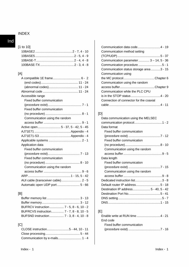
Index - 1 Index - 1
INDEX
[1 to 10]10BASE2............................................2 - 7, 4 - 1010BASE5..............................................2 - 5, 4 - 910BASE-T.............................................2 - 4, 4 - 8100BASE-TX........................................2 - 3, 4 - 8
[A]A compatible 1E frame................................. 6 - 2
(end codes)............................................ 11 - 24(abnormal codes)................................... 11 - 24
Abnormal code .......................................... 11 - 24Accessible range
Fixed buffer communication(procedure exist)........................................ 7 - 1Fixed buffer communication(no procedure) ........................................... 8 - 1Communication using the randomaccess buffer ............................................. 9 - 1
Active open........................... 5 - 37, 5 - 42, 5 - 45AJ71E71 ...........................................Appendix - 4AJ71E71-S3 .....................................Appendix - 4Applicable systems ....................................... 2 - 1Application data
Fixed buffer communication(procedure exist)...................................... 7 - 13Fixed buffer communication(no procedure) ......................................... 8 - 10Communication using the randomaccess buffer ............................................. 9 - 6
ARP...................................................1 - 15, 5 - 42AUI cable (transceiver cable)........................ 2 - 5Automatic open UDP port ........................... 5 - 66
[B]Buffer memory list ....................................... 3 - 13Buffer memory............................................. 3 - 12BUFRCV instruction ................. 7 - 5, 8 - 6, 10 - 2BUFRCVS instruction............... 7 - 7, 8 - 8, 10 - 5BUFSND instruction ................. 7 - 3, 8 - 4, 10 - 8
[C]CLOSE instruction..........................5 - 44, 10 - 11Close processing......................................... 5 - 44Communication by e-mails............................ 1 - 4
Communication data code...........................4 - 19Communication method setting(TCP/UDP) ...................................................5 - 37Communication parameter ............. 3 – 14, 5 - 36Communication procedure ............................5 - 1Communication status storage area ...........3 - 15Communication usingthe MC protocol.....................................Chapter 6Communication using the randomaccess buffer.........................................Chapter 9Communication while the PLC CPUis in the STOP status ...................................4 - 20Connection of connector for the coaxialcable.............................................................4 - 11
[D]Data communication using the MELSECcommunication protocol.................................1 - 2Data format
Fixed buffer communication(procedure exist) ......................................7 - 12Fixed buffer communication(no procedure)..........................................8 - 10Communication using the randomaccess buffer ..............................................9 - 5
Data lengthFixed buffer communication(procedure exist) ......................................7 - 15Communication using the randomaccess buffer ..............................................9 - 8
Dedicated instruction list................................3 - 8Default router IP address.............................5 - 18Destination IP address..................... 5 - 40, 5 - 42Destination Port No......................................5 - 41DNS setting ....................................................5 - 7DNS..............................................................1 - 15
[E]Enable write at RUN time ............................4 - 21End code
Fixed buffer communication(procedure exist) ......................................7 - 16
Ind
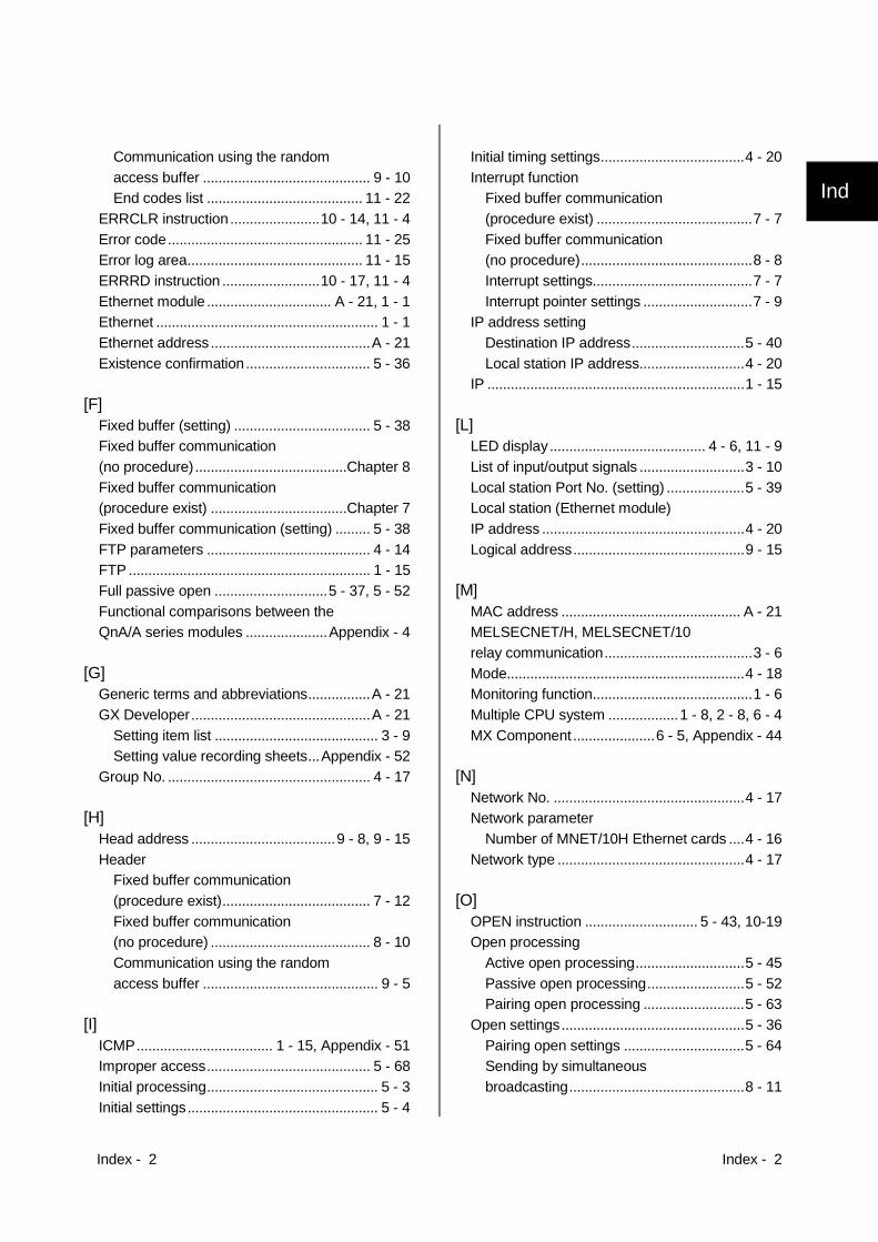
Index - 2 Index - 2
Communication using the randomaccess buffer ........................................... 9 - 10End codes list ........................................ 11 - 22
ERRCLR instruction .......................10 - 14, 11 - 4Error code.................................................. 11 - 25Error log area............................................. 11 - 15ERRRD instruction .........................10 - 17, 11 - 4Ethernet module ................................ A - 21, 1 - 1Ethernet ......................................................... 1 - 1Ethernet address.........................................A - 21Existence confirmation................................ 5 - 36
[F]Fixed buffer (setting) ................................... 5 - 38Fixed buffer communication(no procedure).......................................Chapter 8Fixed buffer communication(procedure exist) ...................................Chapter 7Fixed buffer communication (setting) ......... 5 - 38FTP parameters .......................................... 4 - 14FTP .............................................................. 1 - 15Full passive open .............................5 - 37, 5 - 52Functional comparisons between theQnA/A series modules .....................Appendix - 4
[G]Generic terms and abbreviations................A - 21GX Developer..............................................A - 21
Setting item list .......................................... 3 - 9Setting value recording sheets...Appendix - 52
Group No. .................................................... 4 - 17
[H]Head address .....................................9 - 8, 9 - 15Header
Fixed buffer communication(procedure exist)...................................... 7 - 12Fixed buffer communication(no procedure) ......................................... 8 - 10Communication using the randomaccess buffer ............................................. 9 - 5
[I]ICMP................................... 1 - 15, Appendix - 51Improper access.......................................... 5 - 68Initial processing............................................ 5 - 3Initial settings................................................. 5 - 4
Initial timing settings.....................................4 - 20Interrupt function
Fixed buffer communication(procedure exist) ........................................7 - 7Fixed buffer communication(no procedure)............................................8 - 8Interrupt settings.........................................7 - 7Interrupt pointer settings ............................7 - 9
IP address settingDestination IP address.............................5 - 40Local station IP address...........................4 - 20
IP ..................................................................1 - 15
[L]LED display........................................ 4 - 6, 11 - 9List of input/output signals ...........................3 - 10Local station Port No. (setting) ....................5 - 39Local station (Ethernet module)IP address ....................................................4 - 20Logical address............................................9 - 15
[M]MAC address .............................................. A - 21MELSECNET/H, MELSECNET/10relay communication......................................3 - 6Mode.............................................................4 - 18Monitoring function.........................................1 - 6Multiple CPU system ..................1 - 8, 2 - 8, 6 - 4MX Component .....................6 - 5, Appendix - 44
[N]Network No. .................................................4 - 17Network parameter
Number of MNET/10H Ethernet cards ....4 - 16Network type ................................................4 - 17
[O]OPEN instruction ............................. 5 - 43, 10-19Open processing
Active open processing............................5 - 45Passive open processing.........................5 - 52Pairing open processing ..........................5 - 63
Open settings...............................................5 - 36Pairing open settings ...............................5 - 64Sending by simultaneousbroadcasting.............................................8 - 11
Ind

Index - 3 Index - 3
Receiving by simultaneousbroadcasting ............................................ 8 - 13
Open system ............................................... 5 - 37Operational settings .................................... 4 - 19
[P]Pairing open ................................................ 5 - 63Parameter setting
Setting item list .......................................... 3 - 9Setting screen list .................................... 4 - 13Setting value recording sheets...Appendix - 52
Passive open........................ 5 - 37, 5 - 42, 5 - 52Physical address ......................................... 9 - 15POP3 ........................................................... 1 - 15Port No..............................................5 - 40, 5 - 41Program example
Open/close processing (Active) .............. 5 - 49Open/close processing (Passive) ........... 5 - 57Fixed buffer communication(procedure exist)...................................... 7 - 18Fixed buffer communication(no procedure) ......................................... 8 - 18
Protocol........................................................ 5 - 37
[Q]QE71.................................................Appendix - 4QnA compatible 3E frames........................... 6 - 2
[R]Re-initial processing...................................... 5 - 9Redundant System...........................1 - 11, 5 - 89Related manuals .........................................A - 13Remote password check............................. 5 - 68Remote password mismatch notificationaccumulated count ...................................... 5 - 85Response format
Fixed buffer communication(procedure exist)...................................... 7 - 13Communication using the randomaccess buffer ............................................. 9 - 6
Router IP address ....................................... 5 - 20Router relay function ................................... 5 - 17Router relay parameter ............................... 5 - 16
[S]Setting the number of cards.............4 - 13, 4 - 16Settings and procedures prior tostarting the operation .................................... 4 - 3
Simultaneous broadcasting .........................8 - 11SMTP ...........................................................1 - 15Specification..........................................Chapter 3Starting I/O No. ............................................4 - 17Station No.....................................................4 - 18Subheader
Fixed buffer communication(procedure exist) ......................................7 - 14Communication using the randomaccess buffer ..............................................9 - 7
Sub-net address...........................................5 - 18Sub-net mask pattern ..................................5 - 17System configuration ............................Chapter 2
[T]TCP .................................................. 1 - 14, 5 - 37Test
Self refrain test .........................................4 - 22Hardware test (H/W test) .........................4 - 23Loop back test ..........................................5 - 29PING command test.................................5 - 34
Text (command)Fixed buffer communication(procedure exist) ......................................7 - 15Communication using the randomaccess buffer ..............................................9 - 9
Timer setting ..................................................5 - 4
[U]UDP................................................. 1 - 15, 5 – 36UINI instruction............................... 5 - 13, 10 - 23Unpassive ........................................ 5 - 37, 5 - 52Usage setting ................................... 3 - 14, 5 - 36
[V]Valid module during other station access ...4 - 17

WARRANTY
Please confirm the following product warranty details before using this product.
1. Gratis Warranty Term and Gratis Warranty RangeIf any faults or defects (hereinafter "Failure") found to be the responsibility of Mitsubishi occurs during use of the productwithin the gratis warranty term, the product shall be repaired at no cost via the sales representative or Mitsubishi ServiceCompany.However, if repairs are required onsite at domestic or overseas location, expenses to send an engineer will be solely atthe customer’s discretion. Mitsubishi shall not be held responsible for any re-commissioning, maintenance, or testing on-site that involves replacement of the failed module.[Gratis Warranty Term]
The gratis warranty term of the product shall be for one year after the date of purchase or delivery to a designatedplace.Note that after manufacture and shipment from Mitsubishi, the maximum distribution period shall be six (6) months, andthe longest gratis warranty term after manufacturing shall be eighteen (18) months. The gratis warranty term of repairparts shall not exceed the gratis warranty term before repairs.
[Gratis Warranty Range](1) The range shall be limited to normal use within the usage state, usage methods and usage environment, etc.,
which follow the conditions and precautions, etc., given in the instruction manual, user's manual and caution labelson the product.
(2) Even within the gratis warranty term, repairs shall be charged for in the following cases.1. Failure occurring from inappropriate storage or handling, carelessness or negligence by the user. Failure caused
by the user's hardware or software design.2. Failure caused by unapproved modifications, etc., to the product by the user.3. When the Mitsubishi product is assembled into a user's device, Failure that could have been avoided if functions
or structures, judged as necessary in the legal safety measures the user's device is subject to or as necessaryby industry standards, had been provided.
4. Failure that could have been avoided if consumable parts (battery, backlight, fuse, etc.) designated in theinstruction manual had been correctly serviced or replaced.
5. Failure caused by external irresistible forces such as fires or abnormal voltages, and Failure caused by forcemajeure such as earthquakes, lightning, wind and water damage.
6. Failure caused by reasons unpredictable by scientific technology standards at time of shipment from Mitsubishi.7. Any other failure found not to be the responsibility of Mitsubishi or that admitted not to be so by the user.
2. Onerous repair term after discontinuation of production(1) Mitsubishi shall accept onerous product repairs for seven (7) years after production of the product is discontinued.
Discontinuation of production shall be notified with Mitsubishi Technical Bulletins, etc.(2) Product supply (including repair parts) is not available after production is discontinued.
3. Overseas serviceOverseas, repairs shall be accepted by Mitsubishi's local overseas FA Center. Note that the repair conditions at each FACenter may differ.
4. Exclusion of loss in opportunity and secondary loss from warranty liabilityRegardless of the gratis warranty term, Mitsubishi shall not be liable for compensation of damages caused by any causefound not to be the responsibility of Mitsubishi, loss in opportunity, lost profits incurred to the user by Failures of Mitsubishiproducts, special damages and secondary damages whether foreseeable or not , compensation for accidents, andcompensation for damages to products other than Mitsubishi products, replacement by the user, maintenance of on-siteequipment, start-up test run and other tasks.
5. Changes in product specificationsThe specifications given in the catalogs, manuals or technical documents are subject to change without prior notice.
6. Product application(1) In using the Mitsubishi MELSEC programmable logic controller, the usage conditions shall be that the application will
not lead to a major accident even if any problem or fault should occur in the programmable logic controller device, andthat backup and fail-safe functions are systematically provided outside of the device for any problem or fault.
(2) The Mitsubishi programmable logic controller has been designed and manufactured for applications in generalindustries, etc. Thus, applications in which the public could be affected such as in nuclear power plants and otherpower plants operated by respective power companies, and applications in which a special quality assurance systemis required, such as for Railway companies or Public service purposes shall be excluded from the programmable logiccontroller applications.In addition, applications in which human life or property that could be greatly affected, such as in aircraft, medicalapplications, incineration and fuel devices, manned transportation, equipment for recreation and amusement, andsafety devices, shall also be excluded from the programmable logic controller range of applications.However, in certain cases, some applications may be possible, providing the user consults their local Mitsubishirepresentative outlining the special requirements of the project, and providing that all parties concerned agree to thespecial circumstances, solely at the users discretion.

Microsoft, Windows, Windows NT are registered trademarks of Microsoft Corporation in the United Statesand other countries.Netscape is a registered trademark of Netscape Communication Corporation in the United States and othercountries.Adobe and Acrobat are registered trademarks of Adobe Systems Incorporation.Pentium and Celeron are trademarks of Intel Corporation in the United States and other countries.Ethernet is a trademark of Xerox Co., Ltd. in the United States.Other company names and product names used in this document are trademarks or registered trademarks ofrespective owners.

(Basic)
Q C
orresponding Ethernet Interface M
odule User's M
anual (Basic)
UQ Corresponding EthernetInterface Module
Q Corresponding EthernetInterface ModuleUser's Manual (Basic) User's Manual
Mitsubishi Programmable Logic Controller
MODEL
MODELCODE
QJ71E71-U-KI-E
13JL88
SH(NA)-080009-I(0406)MEE
QJ71E71-100QJ71E71-B5QJ71E71-B2
BL
Specifications subject to change without notice.
When exported from Japan, this manual does not require application to theMinistry of Economy, Trade and Industry for service transaction permission.
HEAD OFFICE : 1-8-12, OFFICE TOWER Z 14F HARUMI CHUO-KU 104-6212,JAPANNAGOYA WORKS : 1-14 , YADA-MINAMI 5-CHOME , HIGASHI-KU, NAGOYA , JAPAN


