
ptfe and stainless steel hoses

table of contents
3
description P.004 - Description of FX01 hoses P.004 - Description of FX02 hoses P.004 - Description of FX03 hoses P.005 - Description of FX06 hoses P.005
specifications of fX01 and fX02 hoses P.006 - Operating pressure P.006 - Temperature P.006 - Motion and vibrations P.006 - Bending radius P.007 - Optional safety cable P.007
ordering information P.008 - Selecting a reference P.008 - Standard connections P.009
description adapters P.011
effective length P.012
description of hoses for racks and switch over boards P.013
ordering information P.014
installation P.015
technical data P.016
description
SAGANA® hoses guarantee the highest degree of safety. They are designed and certified in accordance with the latest standards in effect. SAGANA® hoses allow connection of piping systems and equipment under some of the most severe pressure and/or temperature conditions. They can be easily installed through the use of adapters. There are 4 types of hoses based upon their composition and use.
FX01 hoses consist of a PTFE inner tube and a stainless steel single or double braid.
FX02 hoses consist of a 316L stainless steel inner tube and a stainless steel single or double braid.
FX03 hoses consist of an antistatic PTFE inner tube with high pressure stainless steel reinforcement. A special abrasion resistant cover protects the hose from wear.
FX06 hoses consist of a 316L stainless steel inner tube and a stainless steel double braid.
SAGANA® hoses have a wide range of uses through the addition of various types of adapters of the SAGANA® instrumentation line of products.
We recommend a safety cable above 1 meter of length. The safety cable is optional.
All hoses are individually tested hydraulically at 1.5 times the maximum working pressure.
applications
SAGANA® FX01, FX02 and FX06 hoses were designed for efficiency, security and convenience. SAGANA® hoses are used for liquid and gas service or under ultra-vacuum in industries such as:
- chemical- petrochemical- gas - energy- paper mill- research centers
- vacuum applications- hydraulic systems- pneumatic systems- laboratories,- etc...
SAGANA® FX03 hoses were designed and approved for CNG use in automotive applications
4
ALL RIGHTS OF CHANGE RESERVED
standard specifications
- important notice : By conception, FX01 flexibles have a restriction at every end since a nipple is inserted to perform the crimping. The table below summarizes the restrictions of the different flexible diameters.
- NICKEL standard for adapter seal washer. - Others available upon request. - see page 8 for service temperature
*Double braid **Single braid
standard specifications
- NICKEL gasket standard for adapter seal washer. - Others available upon request.
*Double braid **Single braid
fX01 - FX01 hoses consist of a PTFE inner tube and a single or double-braided stainless steel on the outside.
fX02 - FX02 hoses are high pressure hoses and consist of a 316L stainless steel corrugated inner tube and 304 stainless steel single or double-braided on the outside.
fX01 | ptfe / stainless steel hoses
fX01 ptfe / stainless steel
maximum service pressure see table p G-10interior dia. 6*, 10*, 16**, 20**, 25**mm (see page G-10)
standard overall length (mm) minimum 350mm. Please indicate for order. Standard sizes are: 500, 750, 1000,1250, 1500, 2000, 2500mm (adapter not included)
fluid compatibility All liquids and gases compatible with PTFE and AlSi 316L, except acetylene and combustive gases
max.leak rate 10-3 mbar l s-1temperature range -50°C (-58°F) +230°C (446°F) for welded connections
materialsinterior PTFE
braid Stainless steel AiSi 304fittings Stainless steel AiSi 316L
dn (mm) 6 10 16 20 25
restriction dia. (mm) 3 6 12 14.7 21
fX02 stainless steel
maximum service pressure see table p G-10interior dia. 6*, 10*, 16**, 20**, 25**mm(see page G-10)
standard overall length (mm) minimum 350mm. Please indicate for order. Standard sizes are: 500, 750, 1000,1250, 1500, 2000, 2500mm (adapter not included)
fluid compatibility All liquids and gases compatible with AiSi 316L except acetylene
max.leak rate 10-8 mbar l s-1temperature range -270°C(-454°F) ,+550°C(1022°F)
materialsinterior Stainless steel AiSi 316L
braid Stainless steel AiSi 304fittings Stainless steel AiSi 316L
description
fX02 | stainless steel hoses
standard specifications
- NICKEL gasket standard for adapter seal washer. - Others available upon request.
fX06 - FX06 hoses are medium pressure hoses and consist of a 316L stainless steel corrugated inner tube and 304 stainless steel double braid on the outside.
fX06 stainless steel
maximum service pressure see table belowinterior dia. 1/4” , 3/8”
standard overall length (mm) minimum 350mm. Please indicate for order. Standard sizes are: 500, 750, 1000,1250, 1500, 2000, 2500mm (adapter not included)
fluid compatibility All liquids and gases compatible with AiSi 316L except acetylenemax. leak rate 10-8 mbar l/s-1
temperature range -270° C (-454° F) , +550° C (1022° F)
materialsinterior Stainless steel AiSi 316L
braid Stainless steel AiSi 304fittings Stainless steel AiSi 316L
dn (mm) 1/4” 3/8”maximum service pressure (bar) 200 150inner dia.(mm) 6,3 10,2outer dia.(mm) 9,6 14,3minimum bend radius (mm) 30 42
ALL RIGHTS OF CHANGE RESERVED
5
fX03 - FX03 hoses consist of a PTFE inner tube and an elastomere covered stainless steel structure on the outside. For automotive CNG applications.
fX03 ptfe / stainless steel
maximum service pressure 260 barinterior dia. 6, 10, 13 mm
standard overall length (mm) minimum 500mm. Please indicate for order.Standard sizes are: 500, 1000
fluid compatibility CNGtemperature range -40°C to +120°C
materialsinterior Antistatic PTFE
reinforcement Stainless steel AiSi 304end fittings Stainless steel
cover Elastomerconnections Acc. SAE J516
dn (mm) 6 10 16
inner dia.(mm) 5,64 7,82 10,20outer dia.(mm) 9,90 12,44 15,62minimum bend radius (mm) 38,00 63,00 73,00
fX03 | ptfe / elastomere hoses
standard specifications
- important notice : By conception, FX01 flexibles have a restriction at every end since a nipple is inserted to perform the crimping. The table below summarizes the restrictions of the different flexible diameters.
- NICKEL standard for adapter seal washer. - Others available upon request. - see page 8 for service temperature
*Double braid **Single braid
fX06 | stainless steel hoses
description

6
ALL RIGHTS OF CHANGE RESERVED
operating pressure
Relationship between inner tube diameter (DN) and maximum operating pressure at 20ºC / 68°F in static mode.
fX01
ptfe / stainless steel
tube int. diam pressure max.dn 6 300 bar 4351 psi
dn 10 200 bar 2900 psidn 16 125 bar 1812 psidn 20 100 bar 1450 psidn 25 80 bar 1160 psi
fX02
stainless steel
tube int. diam pressure max.dn 6 360 bar 5221 psi
dn 10 240 bar 3480 psidn 16 85 bar 1232 psidn 20 80 bar 1160 psidn 25 70 bar 1015 psi
temperature
fX01: For applications at temperatures between 204ºC (400ºF) and 230ºC (445ºF), the maximum operating pressure should be reduced by 30% of the maximum operating pressure at ambient temperature.
fX02 and fX06: To determine the maximum pressure based upon temperature, use the coefficients in the table below.
example: the maximum operating pressure of a fluid at a temperature of 150ºC in a FX02 hose with a DN10 is 240bar x coef. 0.67 = 160.80 bar.
For hoses with screwed connections ( see page 04). Contact us for applications above 300°C on type FX02.
for fX02 and fX06 (stainless steel)
temp.°c 20 50 100 150 200 250 300 350 400 450 500 550temp.°f 68 122 212 302 392 482 572 662 752 842 932 1022
coefficient 1.00 0.90 0.73 0.67 0.61 0.58 0.53 0.51 0.50 0.49 0.47 0.47
motion and vibrations
fX02 and fX06: To determine the maximum pressure based upon dynamic structural loading, use the coefficients in the table below.
no vibrationsslow and small
movement
little vibrationsuniform and
repetitivemovement
strong vibrationscontinuous movement
uniform flow, slow and continuous 1 0,80 0,40
high and pulsed flow 0,80 0,64 0,32
turbulent anddiscontinuous flow 0,40 0,32 0,16
specifications
specifications
7
ALL RIGHTS OF CHANGE RESERVED
minimum bending radius (mm - inch)
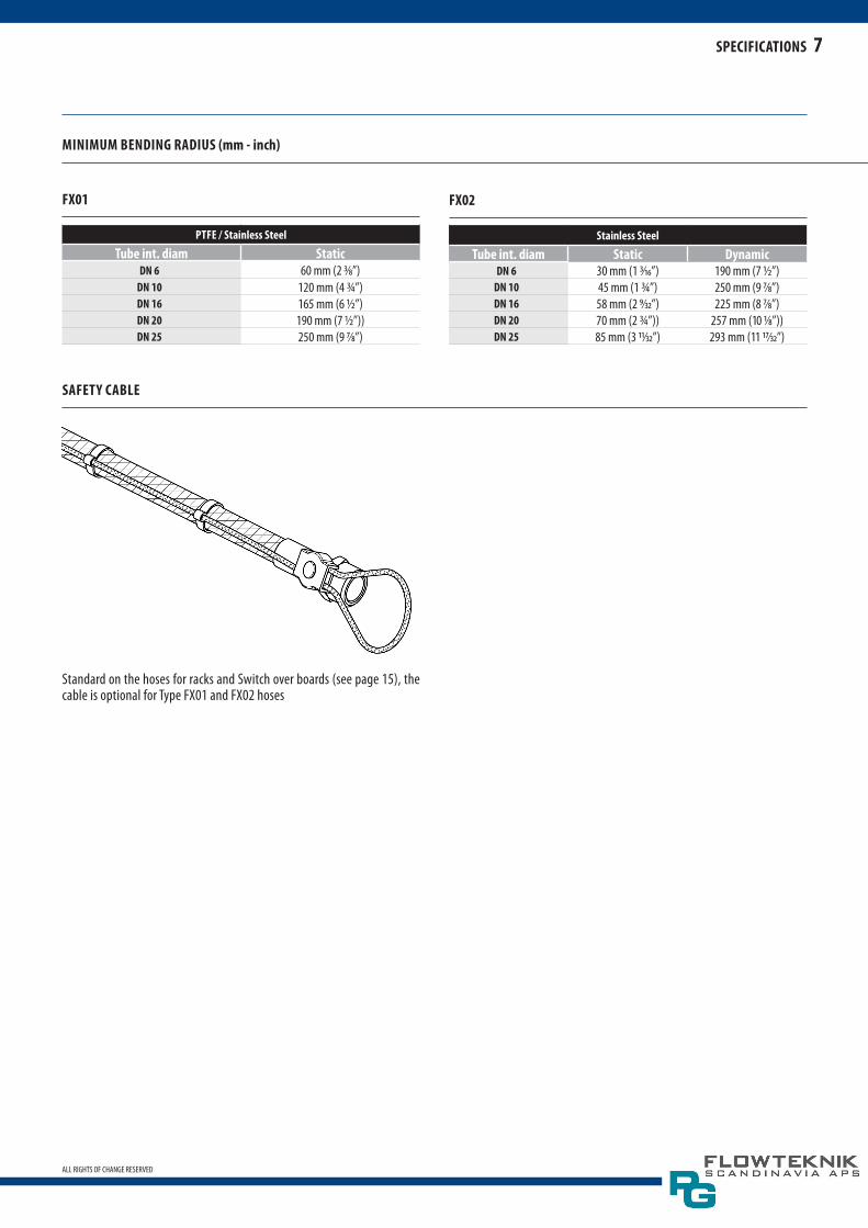
safety cable
Standard on the hoses for racks and Switch over boards (see page 15), the cable is optional for Type FX01 and FX02 hoses
fX01
ptfe / stainless steel
tube int. diam staticdn 6 60 mm (2 3/8”)
dn 10 120 mm (4 3/4”)dn 16 165 mm (6 1/2”)dn 20 190 mm (7 1/2”))dn 25 250 mm (9 7/8”)
fX02
stainless steel
tube int. diam static dynamicdn 6 30 mm (1 3/16”) 190 mm (7 1/2”)
dn 10 45 mm (1 3/4”) 250 mm (9 7/8”)dn 16 58 mm (2 9/32”) 225 mm (8 7/8”)dn 20 70 mm (2 3/4”)) 257 mm (10 1/8”))dn 25 85 mm (3 11/32”) 293 mm (11 17/32”)
specifications
8
ALL RIGHTS OF CHANGE RESERVED
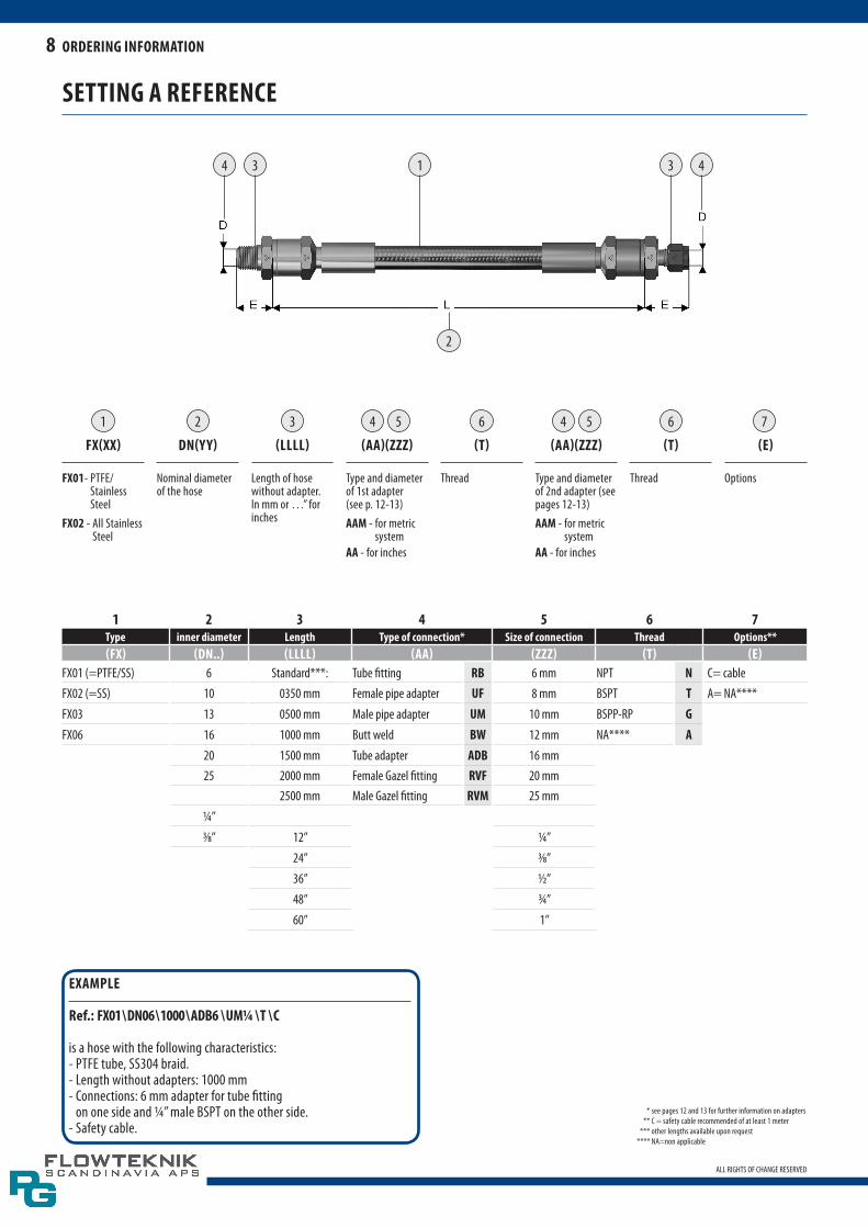
setting a reference
1 2 3 74 465 5 6
fX(XX)
fX01- PTFE/Stainless Steel
fX02 - All Stainless Steel
dn(yy)
Nominal diameter of the hose
(llll)
Length of hose without adapter. In mm or …” for inches
(aa)(ZZZ)
Type and diameter of 1st adapter (see p. 12-13)aam - for metric
systemaa - for inches
(t)
Thread
(aa)(ZZZ)
Type and diameter of 2nd adapter (see pages 12-13)aam - for metric
systemaa - for inches
(t)
Thread
(e)
Options
1 2 3 4 5 6 7type inner diameter length type of connection* size of connection thread options**(fX) (dn..) (llll) (aa) (ZZZ) (t) (e)
FX01 (=PTFE/SS) 6 Standard***: Tube fitting rb 6 mm NPT n C= cableFX02 (=SS) 10 0350 mm Female pipe adapter uf 8 mm BSPT t A= NA****
FX03 13 0500 mm Male pipe adapter um 10 mm BSPP-RP gFX06 16 1000 mm Butt weld bw 12 mm NA**** a
20 1500 mm Tube adapter adb 16 mm25 2000 mm Female Gazel fitting rvf 20 mm
2500 mm Male Gazel fitting rvm 25 mm
1/4”
3/8” 12” 1/4”
24” 3/8”
36” 1/2”
48” 3/4”
60” 1”
* see pages 12 and 13 for further information on adapters ** C = safety cable recommended of at least 1 meter *** other lengths available upon request **** NA=non applicable
eXample
ref.: fX01 \ dn06 \ 1000 \ adb6 \ um1/4 \ t \ c
is a hose with the following characteristics:- PTFE tube, SS304 braid.- Length without adapters: 1000 mm- Connections: 6 mm adapter for tube fitting
on one side and 1/4” male BSPT on the other side.- Safety cable.
ordering information
4 3 1 3 4
2

9
ALL RIGHTS OF CHANGE RESERVED
connections (based upon siZe)
For other specifications, contact us
fX02metric fractional
nominal diameter (dn) 6 mm 10 mm 16 mm 20 mm 25 mm 6 mm 10 mm 16 mm 20 mm 25 mm
connection diameter 6 8 8 10 12 16 18 20 25 1/4” 3/8” 1/2” 1/2” 3/4” 3/4” 1”DOuBLE BRAID SINGLE BRAID DOuBLE BRAID SINGLE BRAID
Stainless Steel
rb X X X X X X X X X X X X X X Xuf X X X X X X
um X X X X X Xrvf X X X X
rvm X X X Xbw X X X X
adb X X X X X X X X X X X X X XX = Standard. Others on request
fX06metric fractional
nominal diameter (dn) 1/4” 3/8” 1/4” 3/8” 3/8”
connection diameter 6 8 8 10 1/4” 3/8” 1/2”
Stainless Steel
rb X X X X X X Xuf X X X
um X X Xrvf X X
rvm X Xbw X X
adb X X X X X X XX = Standard. Others on request
fX01metric fractional
nominal diameter (dn) 6 mm 10 mm 16 mm 20 mm 25 mm 6 mm 10 mm 16 mm 20 mm 25 mm
connection diameter 6 8 8 10 12 16 18 20 25 1/4” 3/8” 1/2” 1/2” 3/4” 1”
DOuBLE BRAID SINGLE BRAID DOuBLE BRAID SINGLE BRAID
PTFE / Stainless Steel
rb X X X X X X X X X X X X X X Xuf X X X X X X
um X X X X X Xadb X X X X X X X X X X X X X
X = Standard. Others on request
ordering information

10
ALL RIGHTS OF CHANGE RESERVED
type washer materialfX01 & fX02 Nickel standard, other request
*used with screwed connections
rb - Type: FX01 & FX02 - Dimensions: 6, 8, 10, 12, 16, 18, 20, 25 mm
- 1/4”, 3/8”, 1/2”, 3/4”, 1”
tube fitting
uf - Type: FX01 & FX02 - Dimensions: - 1/4”, 3/8”, 1/2”, 3/4”, 1”
female pipe adapter npt-bspt-bspp (see table of standard threads on p.11)
note: For threads BSPP 1/8”, 1/4”, 3/8”, 1/2”, 3/4”, 1”, there is no screwed-on adapter or washer.
types of standard threads (based upon siZe)
male union
1/4” 3/8” 1/2” 3/4” 1”npt X X X X X
bspt X NS X X Xg or rp X X X X X
female union
1/4” 3/8” 1/2” 3/4” 1”npt X X X X NS
bspt X NS X NS NSg or rp X X X X X
tapered threads
n : npt National Pipe Tapered seal is made on the thread. Thread sealant is required
t : bspt (Whitworth conical) RT to ISO 7/1. BS 21, JIS B0203, DIN 2999 Seal is made on the thread. Thread sealant is required
straight or parallel threads
g : bspp Whitworth cylindrical RP to ISO228/1, BS 2779, JIS B0202 Metal-to-metal sealing to DIN 3852, Form B. O-ring sold separately
k : bspp Whitworth cylindrical RS to ISO 228/1, BS 2779, JIS B0202 utilizes a sealing washer to provide sealing. Reference DIN 3852 Form A. O-ring sold separately
ordering information / description of adapters
Joint screw-type fittings
gasket types*

11
ALL RIGHTS OF CHANGE RESERVED
um - Type: FX01 & FX02 - Dimensions:
1/4”, 3/8”, 1/2”, 3/4”, 1”
male pipe adapter npt-bspt-bspp (see table of standard threads on p. 04)
connection description
bw - Type: FX02 - Dimensions:
1/4”, 1/2”, 3/4”, 1”
welded connectionsbuttweld
adb - Type: FX01 & FX02 - Dimensions: 6,8,10,12,18,25 mm
1/4”, 3/8”, 1/2”, 3/4”, 1”
tube adapter
Each connector from our “Tube Fitting”catalog can be mounted on the type AD Tube adapter to obtain any desired connection “male or female, with any thread type and configuration (elbow, tee,...)”
gaZel fitting (face seal) female
rvf - Type: FX02 - Dimensions:
1/4”,1/2”, 3/4”, 1”
gaZel fitting (face seal) male
rvm - Type: FX02 - Dimensions:
1/4”,1/2”, 3/4”, 1”
description of adapters

Type A
Type B
12
ALL RIGHTS OF CHANGE RESERVED
determining the effective length based upon type of motion
angular motion
In the event that an end is fixed and the other end bends following a simple curve while ends are not parallel.
· L = effective length · R = axis bend radius · = bending angle (degrees) · π = 3.14
offset motion
In the event that one end of the hose bends perpendicularly to the longitu-dinal axis while ends are parallel without resulting in torsion stress.
· L = effective length of hose for zero offset · R = axis bend radius · Y = axis offset, more or less.
note: - In the event that the offset occurs on both sides of the axis, the effective
length of the hose should be calculated based upon the total motion or twice Y.
- The two conditions L and L2 must be met. In case of intermittent or con-tinuous motion, Y should never exceed 25% of the minimum intermittent bend radius.
radial motion:
Type A - Formula of motion loopType B - Formula of motion loop
· T = total motion · L = effective length of hose · R = axis bend radius
Should not be lower than the one indicated in the table on page 6.
· K = loop length
note: In the units with a loop, the hose and motion should be on the same plane as the bending.
effective length

13
ALL RIGHTS OF CHANGE RESERVED
line of products for racks and switch over boards
A special line of hoses has been designed for high-pressure applications and for connection with cylinders, switch over boards and modules.
description
This line of products features nonsymmetrical hoses equipped with a man-ual cylinder adapter in accordance with the existing standards at one end and a standard female G3/8-type adapter at the other end.upon request, both ends may come with a 90º elbow.
This line of products is available in the two versions previously described as FX01 and FX02 and has the same specifications (material, pressure, tem-perature). It is available in standard DN06 and DN10.
Each hose is equipped with a standard safety cable.
description
14
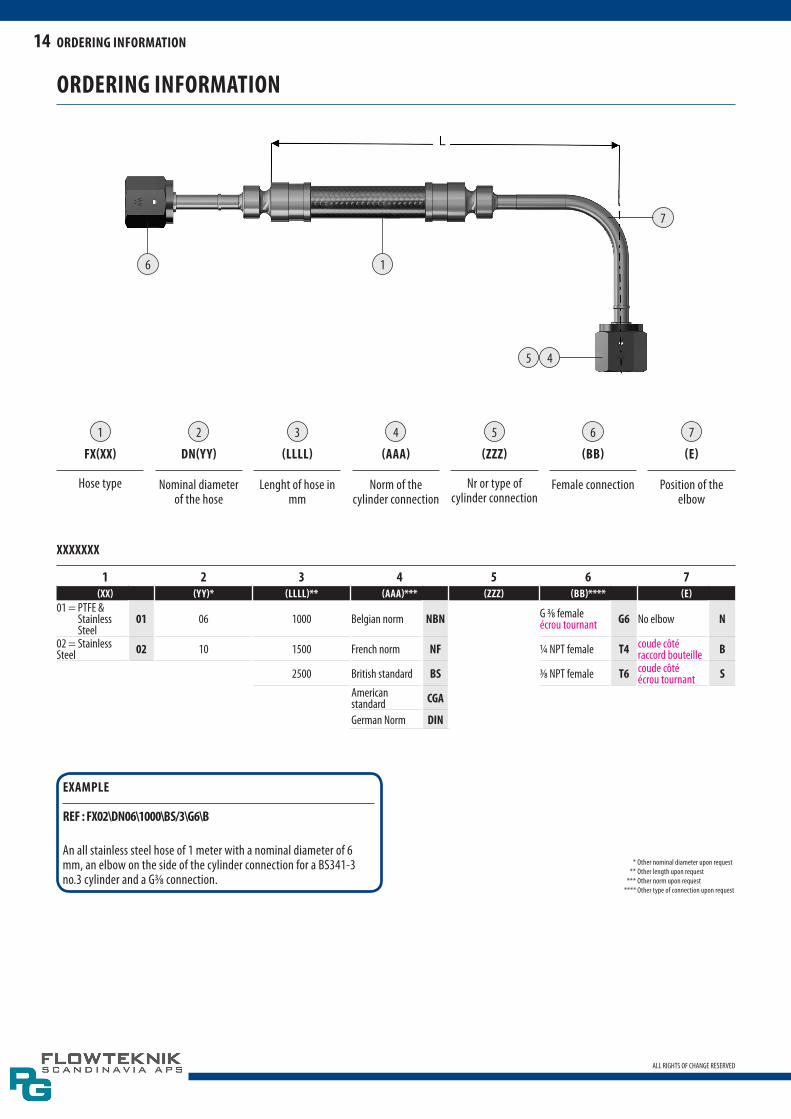
ALL RIGHTS OF CHANGE RESERVED
1 2 3 74 65
fX(XX)
Hose type
dn(yy)
Nominal diameter of the hose
(llll)
Lenght of hose in mm
(aaa)
Norm of the cylinder connection
(ZZZ)
Nr or type of cylinder connection
(bb)
Female connection
(e)
Position of the elbow
ordering information
* Other nominal diameter upon request ** Other length upon request *** Other norm upon request **** Other type of connection upon request
XXXXXXX
1 2 3 4 5 6 7(XX) (yy)* (llll)** (aaa)*** (ZZZ) (bb)**** (e)
01 = PTFE & Stainless Steel
01 06 1000 Belgian norm nbn G 3/8 femaleécrou tournant g6 No elbow n
02 = Stainless Steel 02 10 1500 French norm nf 1/4 NPT female t4 coude côté
raccord bouteille b
2500 British standard bs 3/8 NPT female t6 coude côté écrou tournant s
American standard cga
German Norm din
eXample
ref : fX02\dn06\1000\bs/3\g6\b
An all stainless steel hose of 1 meter with a nominal diameter of 6 mm, an elbow on the side of the cylinder connection for a BS341-3 no.3 cylinder and a G3/8 connection.
ordering information
6 1
5 4
7

15
ALL RIGHTS OF CHANGE RESERVED
instructions for proper installation
right wrong
installation

16
ALL RIGHTS OF CHANGE RESERVED
technical data
units
1 bar = 14,50 psi = 100 kPa.1 psi = 0.069 bar = 6,89 kPa
1 kpa (ISO) = 0.01 bar = 0,1451 psi1 kg/cm2 = 0.980 bar = 14,22 psi = 98 kPa
t° c (C : Celsius) = (T°F – 32) / 1.8 = T°K - 273,15t° f (F : Farenheit) = (1.8 x T°C) + 32 = (1.8 x T°K) + 523,69t° k (K : Kelvin) = T°C + 273.16 = (T°F/ 1.8) + 255,38t° r (R : Rankine) = (1.8 x T°C) + 491.69 = T°F + 459,69
1 inch = 25.4 mm1 mm = 0.045 inch
norms tapered
tapered (iso 7/1)
NPT(National Pipe Tapered) NFE 03-601
BSPT (Whitworth) : NFE 03-004
parallel (iso228/1)
BSPP (Whitworth) : NFE 03-005
thread pressure ratings - brass
male thread
f 1/16” 1/8” 1/4” 3/8” 1/2” 3/4” 1” 1 1/4” 1 1/2” 2”bar 379 345 276 269 262 248 179 - - -psi 5500 5000 4000 3900 3800 3600 2600 - - -
female thread
f 1/16” 1/8” 1/4” 3/8” 1/2” 3/4” 1” 1 1/4” 1 1/2” 2”bar 227 221 227 179 165 159 152 - - -psi 3300 3200 3300 2600 2400 2300 2200 - - -
thread pressure ratings - stainless steel 316l
male thread
f 1/16” 1/8” 1/4” 3/8” 1/2” 3/4” 1” 1 1/4” 1 1/2” 2”bar 717 648 517 503 496 469 345 393 324 248psi 10400 9400 7500 7300 7200 6800 5000 5700 4700 3600
female thread
f 1/16” 1/8” 1/4” 3/8” 1/2” 3/4” 1” 1 1/4” 1 1/2” 2”bar 434 420 427 345 317 296 283 324 296 255psi 6300 6100 6200 5000 4600 4300 4100 4700 4300 3700
technical data


