
PROPOSED GUIDELINES FOR PREFABRICATED BRIDGE ELEMENTS AND SYSTEMS TOLERANCES
NCHRP Project 12-98
FINAL: December 19, 2017


ABBREVIATED TABLE OF CONTENTS
Guidelines for Prefabricated Bridge Elements and Systems Tolerance, First Edition contains the following sections:
1. Introduction
2. Fabrication Tolerances
3. Erection Tolerances
4. Joints and Connections

FOREWORD
Accelerated Bridge Construction Technologies have evolved from the laboratory, to trial installations, and into
mainstream use. To date, the design and construction of ABC projects has been completed using engineering
judgement and existing design and construction provisions that are contained in the AASHTO LRFD Bridge Design
Specifications and the AASHTO LRFD Bridge Construction Specifications. These guidelines fulfill the majority of
the design and construction specification needs for an ABC project. These guidelines are intended to fill the gaps for
fabrication and erection of prefabricated elements with respect to tolerances.
These guidelines can be used to develop project special provisions or owner standard specifications. This
document was developed under NCHRP Project 12-98. The final report for this project contains information on the
sources and development of the recommended tolerances. There is a companion NCHRP Project 12-102 that is being
completed concurrently with this project that includes a document entitled “Guide Specification for Accelerated
Bridge Construction”, which is referenced in several provisions in this document.

PREFACE
Units
These Guidelines use U.S. Customary Units only. Per a decision by the AASHTO Subcommittee on Bridges and
Structures in 2009, SI units will no longer be included in specification documents.
References
If a standard is available as a stand-alone publication – for example, the ACI standards-the title is italicized in the
text and listed in the references. If a standard is available as part of a larger publication – for example, the AASHTO
materials specifications – the standard’s title is not italicized and the larger publication - in this case, Standard
Specifications for Transportation Materials and Methods of Sampling and Testing, 29th Edition - is listed in the
references.
Unit Abbreviations
Unit abbreviations in this document are consistent with the units in the AASHTO LRFD Bridge Design and
Bridge Construction Specifications. Users of these guidelines should refer to these documents for frequently used
abbreviations.
Please note the following:
Abbreviations for singular and plural are the same
Most units of time have one letter abbreviation. Unit abbreviations are always set in roman font, while
variable and factors are set in italic font.


1-1 GUIDELINES FOR PREFABRICATED BRIDGE ELEMENTS AND SYSTEMS TOLERANCES
1.1 SCOPE ................................................................................................................................................................... 2
1.2 USE OF THESE GUIDELINES ..................................................................................................................................... 2
1.3 DEFINITIONS ...................................................................................................................................................... 2
1.3.1 General Accelerated Bridge Construction Definitions .................................................................................. 2
1.3.2 Deck Elements ............................................................................................................................................... 3
1.3.3 Beam Elements .............................................................................................................................................. 3
1.3.4 Pier Elements ................................................................................................................................................. 4
1.3.5 Abutment and Wall Elements ........................................................................................................................ 4
1.3.6 Miscellaneous Elements And Definitions ...................................................................................................... 5
1.3.7 Systems .......................................................................................................................................................... 6
1.4 TOLERANCE NEEDS .......................................................................................................................................... 7
1.5 MANAGEMENT OF TOLERANCES .................................................................................................................. 7
1.5.1 Designer ......................................................................................................................................................... 7
1.5.2 Contractor ...................................................................................................................................................... 8
1.6 ITEMS NOT COVERED IN THESE GUIDELINES ........................................................................................... 8
1.6.1 Beam Elements .............................................................................................................................................. 8
1.6.2 Cast-In-Place Concrete Elements .................................................................................................................. 8
1.6.3 Steel Elements ............................................................................................................................................... 8
1.7 SIGN CONVENTION FOR TOLERANCES ........................................................................................................ 8
1.8 REFERENCES ...................................................................................................................................................... 9
SECTION 1: INTRODUCTION
TABLE OF CONTENTS
SECTION 1: INTRODUCTION 1-2
1.1 SCOPE
The provisions of these guidelines are intended for
use in the design, detailing, layout, and construction of
Prefabricated Bridge Elements and Systems. Tolerances
play an important role in all of these processes.
These guidelines are not intended to supplant proper
training or the exercise of judgement by the Designer.
The owner or the Designer may require the sophistication
of design or the quality of materials and construction to
be higher than the minimum requirements.
This document is a guideline document with
recommended criteria, not a specification. All provisions
contained herein are subject to review and adjustment by
the Designer with approval by the owner. In many
provisions, the term “shall” is included in the text. These
provisions are intended to be used in contract
specifications, where the term “shall” would be
appropriate. Other provisions contained herein make use
of the term “should” or “may”. The term “should”
indicates a strong preference for a given criterion. The
term “may” indicates a criterion that is usable, but other
local and suitably documented, verified, and approved
criterion may also be applied.
C1.1
The commentary within this document is not
intended to provide a complete historical background
concerning the development of these guidelines, nor is
it intended to provide a detailed summary of the studies
and research data reviewed in formulating the
provisions. The final report for NCHRP Project 12-98
(Culmo, et al, 2017) contains significant background
information that can be used to detail the development
of these guidelines.
1.2 Use of these Guidelines
This document contains guidelines for tolerances
applied to commonly used prefabricated bridge elements.
It shall be used in conjunction with other AASHTO
publications.
C1.2
These guidelines are based on current commonly
used ABC methods. In some cases, these guidelines
can be used as a basis for tolerance specifications and
management of other similar details. Certain details
may require determination of acceptable tolerances by
the Designer.
1.3 DEFINITIONS
The definitions contained herein refer to common
terms in use in Accelerated Bridge Construction (ABC).
C1.3
Many of the terms contained herein are for
information only. Not all of the terms included are
referenced in these guidelines.
General Accelerated Bridge Construction Definitions
SECTION 1
INTRODUCTION

1-3 GUIDELINES FOR PREFABRICATED BRIDGE ELEMENTS AND SYSTEMS TOLERANCES
Accelerated Bridge Construction (ABC) Bridge construction that uses innovative planning, design, materials,
and construction methods in a safe and cost-effective manner to reduce
the onsite construction time that occurs when building new bridges or
replacing and rehabilitating existing bridges.
Conventional Bridge Construction Bridge construction that does not significantly reduce the onsite
construction time that is needed to build, replace or rehabilitate a
bridge. Prefabrication is typically limited to beams and girders in this
form of construction.
Lateral Slide A method of moving a bridge system built adjacent to the final bridge
location using hydraulic jacks or cable winches while supported on
sliding materials or rollers. The bridge is typically built parallel to its
final alignment, facilitating the installation.
Prefabricated Bridge Elements and Structural components of a bridge that are built offsite or near the site
Systems (PBES) that include features that reduce the on-site construction time that
occurs with conventional bridge construction.
Prefabricated Element A category of PBES which comprise a single structural component of
a bridge. Prefabricated element can be made of any approved structural
material.
SPMT Self-Propelled Modular Transporter. A high capacity transport device
that can lift and move prefabricated elements and systems with a high
degree of precision and maneuverability in all three directional axes
without the aid of a tractor for propulsion.
Deck Elements
Aluminum Deck A full thickness deck made with extruded aluminum elements that are
connected to form an orthotropic deck system.
Exodermic Deck A steel grid deck system made with a partially filled concrete composite
topping that is placed above the top of the grid.
Full-Depth Precast Deck Panel w/PT A full thickness deck panel that makes up the entire structural deck.
Connected in the distribution direction with post-tensioning.
Full-Depth Precast Deck Panel w/o PT A full thickness deck panels that makes up the entire structural deck.
Connected in the distribution direction without post-tensioning
(typically with a reinforced concrete closure joint).
Orthotropic Deck A steel deck system made with a steel plate deck combined with welded
transverse and longitudinal ribs.
Partial-Depth Precast Deck Panel A reinforced or prestressed concrete deck panel that makes up the lower
portion of the bridge deck that is combined with a reinforced cast-in-
place concrete topping to form the completed structural deck.
Steel Grid (open) A steel grid deck system made without concrete fill.
Steel Grid (concrete filled) A steel grid deck system made with a partially filled concrete placed
within the grid.
Beam Elements
Adjacent Deck Beam Element Beams fabricated with an integral deck that is separated by a small
grouted joint, or a small closure joint. Also referred to as butted beams.
Adjacent beams come in several shapes including Deck Bulb T,
Inverted T, Double T, Box, Slabs, Voided Slabs, etc.
Full Width Beam Element An element that eliminates conventional on-site beam placement
activities. It is typically rolled, slid, or lifted into place to allow deck
placement operations to begin immediately after placement. Given the
size and weight of the element, the entire deck is not included.

SECTION 1: INTRODUCTION 1-4
Modular Decked Beam (MDB) An element that is fabricated with beams combined with an integral
composite reinforced concrete deck to form a modular unit. MDBs can
be made with steel or prestressed concrete beams. A MDB is typically
made with two or three beam elements.
Pier Elements
Precast Caisson Cap A reinforced concrete element that is placed on top of piles or drilled
shafts that are designed to support reinforcing and cast-in-place
concrete that is placed after the cap is erected.
Precast Cap Shell A reinforced concrete element that is fabricated without the core
concrete. The core concrete is placed after the shell has been erected.
Precast Cap and Column A reinforced concrete pier element comprised of a precast column cap
combined with precast column(s).
Precast Column A vertical reinforced concrete element that supports a beam or cap.
Precast Column Cap A reinforced concrete element placed on top of column elements.
Precast Integral Cap A reinforced concrete element that is integrally connected to the
superstructure and the lower pier elements to form a rigid connection.
Precast Footing A reinforced concrete element that makes up the structural footing of a
substructure or wall.
Precast Footing Shell A reinforced concrete shell that is used as a stay-in-place form for a
cast-in-place reinforced concrete footing.
Precast Pile Cap A reinforced concrete element that is placed directly on top of piles.
Precast Semi-Integral Cap A reinforced concrete element that is integrally connected to the
superstructure and pinned to the lower pier elements to form a pinned
connection.
Steel Cap and Column A structural steel element comprised of a steel column cap combined
with integral steel column(s).
Steel Column A vertical structural steel element that supports a beam or cap.
Steel Column Cap A structural steel element placed on top of column elements.
Steel Pile Cap A structural steel element that is placed directly on top of piles.
Abutment and Wall Elements
Precast Abutment Cap A beam type element that is placed directly on top of and connected to
the abutment wall elements to form the bridge seat.
Precast Abutment Stem A wall element that is located above the abutment footing that retains
embankment fill.
Precast Backwall A wall panel element that is behind the end of the superstructure that
retains the upper portion of the embankment fill.
Precast Cheek Wall A wall element that is placed at the corner of the abutment seat to hide
or retain the beam ends.
Precast Footing A footing element that is placed on soil that supports a substructure
element.
Precast Integral Abutment Stem A reinforced concrete wall element that is integrally connected to the
superstructure and the abutment piles to form a rigid connection.
Precast Lagging Panel Panel element placed between vertical structural elements to form the
face of an earth retaining wall system.
Precast Sheet Pile A vertical precast element that is driven or jetted into the soil to create
a cantilever wall (abutment or retaining wall).
Precast Wingwall A wall element that retains embankment fill behind or alongside the
abutment.

1-5 GUIDELINES FOR PREFABRICATED BRIDGE ELEMENTS AND SYSTEMS TOLERANCES
Precast 3-Sided Culvert A precast culvert element that has a top and sides, but no bottom, placed
on footings or pile caps to form a bottomless culvert structure.
Modular Block Wall A precast wall system made up of stacked precast block elements that
form a gravity retaining wall. The elements can be solid or voided. Soil
or crushed stone are typically placed within the voids to enhance the
resistance of the system.
MSE Wall A mechanically stabilized earth retaining wall system made up of
precast wall face elements connected to horizontal soil reinforcing
elements.
Steel Sheet Piling Interlocking vertical steel elements that are vibrated or driven into soil
to create a cantilever wall (abutment or retaining wall).
Miscellaneous Elements And Definitions
Assembly Plan A package of plans, specifications and calculations developed by the
contractor that describes the process for the assembly of prefabricated
elements. The assembly plan may include handling and erection plans,
materials specifications, details and calculations for bridge temporary
works, and construction scheduling.
Bars in Splice Coupler A connection that provides tension, shear and/or moment force transfer
between two precast concrete elements via a mechanical connection
that uses a projecting bar from one element grouted into a reinforcing
bar splice device cast into the adjacent element.
Closure Joint A gap between two elements or systems that is filled with materials to
form a connection. The joint may or may not include reinforcing. The
width of the closure joint can vary based on the type of material used to
fill the joint and the reinforcing within the joint. This feature is also
referred to as a “closure pour” by some agencies.
Closure Joint: CIP Reinforced A connection that provides tension, shear and/or moment force transfer
between two precast concrete elements via lapped reinforcing bars
combined with cast-in-place concrete, UHPC, or grout.
Closure Joint: Grouted Key A connection that provides compression or shear force transfer between
two precast concrete elements via a keyed joint filled with a cast-in-
place concrete or grout. Grouted key closure joints can be combined
with post-tensioning to form a moment connection.
Closure Joint: Match Cast A connection between two adjacent elements with a very small width
epoxy grouted joint that is fabricated by casting one element against the
adjacent element in the fabrication shop to form identical matching
surfaces. Match cast joints may be used to provide a shear connection
or combined with post-tensioning to form a moment connection.
Connection A means of transferring force between two or more elements.
Connection: Grouted Duct A connection that provides tension, shear, and/or or moment force
transfer between two precast concrete elements via a mechanical
connection that uses a projecting reinforcing bar from one element
grouted into a metal duct cast into the adjacent element.
Connection: Pocket A connection between two prefabricated elements thru the projection
of multiple bars or connectors of one element into a single void that is
cast internal to the receiving element. The void is then filled with either
concrete, grout, or other suitable material.
Connection: Socket A connection between two prefabricated elements thru the projection
of a single portion of one element into a single void of the receiving
element. The gap between the two elements is then filled with either
concrete, grout, or other suitable material.
Contractor The company responsible for the construction of the bridge or structure.

SECTION 1: INTRODUCTION 1-6
Designer The engineer responsible for the design of the bridge. Also known as
the engineer of record.
Fabricator The company responsible for the fabrication of the prefabricated
element.
Falsework Temporary construction used to support portions of the entire
permanent structure until it becomes self-supporting. Falsework could
include steel or timber beams, girder column piles and foundations, and
any proprietary equipment including modular shoring frames, posts
shores, self-propelled modular transporters, and horizontal shoring.
Grouted Blockout w/Shear Connectors A means of creating a composite connection between a full-depth
precast deck and a supporting beam or girder via shear connectors in a
grouted pocket.
Link Slab Links slabs are a transverse deck level connection at piers between the
decks of two adjacent spans, providing a jointless bridge without
continuity. The deck is made continuous across the pier, but the
supporting beams or girders are not connected.
Load Path A continuous path along which a load travels through structural
elements and connections.
Precast Approach Slab A reinforced concrete slab element that spans between the end of a
bridge deck or abutment and the approach pavement.
Prefabricated Railing An element used at the edge of a bridge deck to contain vehicles,
bicycles and pedestrians.
PT Ducts, Bonded A prestressing system used in concrete comprised of a duct and a
prestressing tendon that is grouted after stressing to form a bonded
reinforcing system.
PT Ducts, Un-bonded A prestressing system used in concrete comprised of a duct and a
prestressing tendon that is stressed to form an un-bonded reinforcing
system.
Seismic System A series of connected elements that transfer seismic loads through the
structure to the foundations.
Seismic Subsystem A localized group of elements and connections within a seismic system
that serves a specific design function, such as a knee-joint, plastic hinge
region, etc.
Shop Drawing A drawing that depicts the fabrication of elements based on the
requirements of the project plans and specifications.
Special Material A material used in construction that is proprietary or non-conventional.
A special material often requires the use of a performance specification.
Temporary Works Structures and other construction that are used to facilitate the
construction in progress, but removed in the final structure. In some
cases, temporary works can be left in place; however they are not part
of the completed structure.
Working Drawings Details and calculations developed for bridge temporary works that
involve the design of elements and processes. Specifications for
working drawings often require a seal by a professional engineer.
Systems
Prefabricated System A category of PBES that consists of an entire superstructure, an entire
superstructure and substructure, or a total bridge that is procured in a
modular manner such that traffic operations can be allowed to resume
after placement. A Prefabricated system is rolled, launched, slid, lifted,
or otherwise transported into place, having the deck and preferably the
railing in place such that no separate construction phase is required after
placement.
1-7 GUIDELINES FOR PREFABRICATED BRIDGE ELEMENTS AND SYSTEMS TOLERANCES
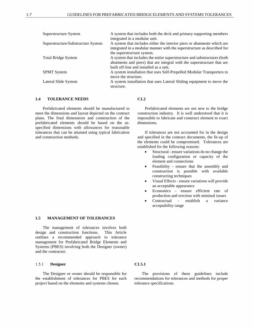
Superstructure System A system that includes both the deck and primary supporting members
integrated in a modular unit.
Superstructure/Substructure System A system that includes either the interior piers or abutments which are
integrated in a modular manner with the superstructure as described for
the superstructure system.
Total Bridge System A system that includes the entire superstructure and substructures (both
abutments and piers) that are integral with the superstructure that are
built off-line and installed as a unit.
SPMT System A system installation that uses Self-Propelled Modular Transporters to
move the structure.
Lateral Slide System A system installation that uses Lateral Sliding equipment to move the
structure.
1.4 TOLERANCE NEEDS
Prefabricated elements should be manufactured to
meet the dimensions and layout depicted on the contract
plans. The final dimensions and construction of the
prefabricated elements should be based on the as-
specified dimensions with allowances for reasonable
tolerances that can be attained using typical fabrication
and construction methods.
C1.2
Prefabricated elements are not new to the bridge
construction industry. It is well understood that it is
impossible to fabricate and construct element to exact
dimensions.
If tolerances are not accounted for in the design
and specified in the contract documents, the fit-up of
the elements could be compromised. Tolerances are
established for the following reasons:
Structural - ensure variations do no change the
loading configuration or capacity of the
element and connections
Feasibility - ensure that the assembly and
construction is possible with available
constructing techniques
Visual Effects - ensure variations will provide
an acceptable appearance
Economics - ensure efficient rate of
production and erection with minimal issues
Contractual - establish a variance
acceptability range
1.5 MANAGEMENT OF TOLERANCES
The management of tolerances involves both
design and construction functions. This Article
outlines a recommended approach to tolerance
management for Prefabricated Bridge Elements and
Systems (PBES) involving both the Designer (owner)
and the contractor.
Designer
The Designer or owner should be responsible for
the establishment of tolerances for PBES for each
project based on the elements and systems chosen.
C1.5.1
The provisions of these guidelines include
recommendations for tolerances and methods for proper
tolerance specifications.

SECTION 1: INTRODUCTION 1-8
The Designer should specify the required
fabrication tolerances, joint width tolerances, erection
tolerances.
The Designer should also identify the layout
method including working lines and working points
required to build the structure.
Contractor
The contractor and/or fabricator should be
responsible for the fabrication of elements within the
specified tolerances and installation of the elements
within the specified erection tolerances.
C1.5.2
If the contact documents do not include tolerance
specifications, the contractor may use these guidelines
for the management of tolerances.
1.6 ITEMS NOT COVERED IN THESE
GUIDELINES
Tolerances that currently exist in conventional
construction are still applicable to portions of projects
built with prefabricated elements.
Several tolerance items are commonly managed
through other specifications such as reinforcing bar
locations and cover.
C1.6
The intent of these guidelines is not to circumvent
or be in conflict with other specifications.
Beam Elements
The tolerances used for fabrication of beam elements
used in conventional construction are applicable to
bridges built using ABC. Standard specifications for
beam elements should be used.
Cast-In-Place Concrete Elements
Tolerances for cast-in-place concrete construction
should be according to the AASHTO LRFD Bridge
Construction Specifications.
Steel Elements
Tolerances for steel elements should be according to
the AASHTO/AWS D1.5 Bridge Welding Code as
amended by owner agency specifications.
C1.6.3
Article 3.11.1 of this guideline contains
recommendations for holes in bolted field splices.
1.7 SIGN CONVENTION FOR TOLERANCES
Specified tolerances may either be negative or
positive. Positive (+) refers to greater or larger and
negative (-) refers to lesser or smaller.
C1.7
Sign convention is specifically important when
sizing joints. The additive effect of multiple
concurrent positive tolerances can result in a joint that
is too narrow or un-buildable. The additive effect of

1-9 GUIDELINES FOR PREFABRICATED BRIDGE ELEMENTS AND SYSTEMS TOLERANCES
multiple concurrent negative tolerances is not as
critical for overall assembly of the prefabricated
elements.
1.8 REFERENCES
AASHTO LRFD Bridge Construction Specifications, Third Edition, American Association of State Highway
and Transportation Official, Washington, DC. (2010)
Culmo, M.P., et al, Guidelines for Prefabricated Bridge Elements and Systems Tolerances and Dynamic Effects
of Bridge Moves, NCHRP Project 12-98, Final Report, National Cooperative Highway Research Program,
Transportation Research Board, Washington, D.C. (2018)

SECTION 1: INTRODUCTION 1-10

2-1 GUIDELINES FOR PREFABRICATED BRIDGE ELEMENTS AND SYSTEMS TOLERANCES
2.1 SCOPE ................................................................................................................................................................... 2
2.2 RELATED DOCUMENTS ................................................................................................................................... 2
2.3 DEFINITIONS ...................................................................................................................................................... 2
2.4 NOTATION ........................................................................................................................................................... 3
2.5 BASIS OF PRODUCT FABRICATION TOLERANCE RECOMMENDATIONS ............................................. 3
2.6 FABRICATION .................................................................................................................................................... 4
Quality Assurance And Quality Control Measures ........................................................................................ 4
Quality Assurance (QA) ............................................................................................................................ 4
Quality Control (QC) ................................................................................................................................. 4
Acceptance Criteria........................................................................................................................................ 4
Management of Out of Tolerance Elements .................................................................................................. 5
Out of Tolerance during Pre-pour and Post-pour Processes ...................................................................... 5
2.7 RECOMMENDED FABRICATION TOLERANCES.......................................................................................... 6
Footing Element Fabrication Tolerances ....................................................................................................... 6
Column Element Fabrication Tolerances ....................................................................................................... 8
Cap Element Fabrication Tolerances ............................................................................................................. 9
Wall Panel Element Fabrication Tolerances ................................................................................................ 10
Full Depth Deck Panel Element Fabrication Tolerances ............................................................................. 11
Approach Slab Element Fabrication Tolerances .......................................................................................... 12
Sleeper Slab Element Fabrication Tolerances.............................................................................................. 14
Grouted Splice Coupler Fabrication Tolerances .......................................................................................... 15
Modular Deck Beam Element Tolerances ................................................................................................... 15
2.8 BRIDGE SYSTEM CONSTRUCTION TOLERANCES ................................................................................... 16
Temporary Bent Tolerances ......................................................................................................................... 17
Final Substructure Tolerances...................................................................................................................... 17
2.9 REFERENCES .................................................................................................................................................... 17
SECTION 2: FABRICATION TOLERANCES
TABLE OF CONTENTS
SECTION 2: FABRICATION TOLERANCES 2-2
2.1 SCOPE
The provisions in this section apply to tolerances
for the fabrication of various types elements used in
Accelerated Bridge Construction (ABC). This section
covers Prefabricated Bridge Elements (PBEs), Self-
Propelled Modular Transporter (SPMT) Bridge
Systems, and Lateral Slide Bridge Systems.
C2.1
Tolerances are used to ensure that properly detailed
elements can be successfully installed with proper fit and
alignment.
There are other types of tolerances covered in the
guideline. Section 3 covers erection tolerances and
Section 4 covers tolerances for joints and connections.
2.2 RELATED DOCUMENTS
This guideline is intended to supplement the
AASHTO LRFD Bridge Construction Specifications
(2010).
The document entitled AASHTO Guide
Specifications for Accelerated Bridge Construction
(2017) shall also be used in conjunction with this
guideline.
C2.2
This guideline does not contain tolerances for
placement of reinforcing steel and concrete cover as they
are covered in the cited AASHTO Specifications.
The cited guide specification contains information
on design and construction of prefabricated elements, as
well as assembly planning.
2.3 DEFINITIONS
Blockout A recess in a precast element, often used to facilitate connections (also
referred to as a pocket)
Bowing An overall out-of-plane curvature of a flat surfaced element along its
entire length
Camber The deflection that occurs in prestressed concrete element due to the net
bending resulting from the eccentricity of the prestress force
Contract Documents Project specifications and design drawings issued on behalf of the owner
by the Engineer and from which the project shop drawings and
production drawings are developed
Cover The least distance between the surface of the reinforcement and the
surface of the concrete element
Deviation The difference between the actual and the as-detailed dimension
Deviations may be either negative or positive (also referred to as
variance)
Deviation from Plane A local smoothness variation or surface out of planeness
Deviation from Horizontal Variation from specified plan end squareness or skew
Deviation from Vertical Variation from specified elevation due to end squareness or skew
Fabrication Tolerances Acceptable variations in dimensions relating to individual precast
concrete elements
Fabricator The company responsible for the fabrication of the prefabricated
element.
SECTION 2
FABRICATION TOLERANCES

2-3 GUIDELINES FOR PREFABRICATED BRIDGE ELEMENTS AND SYSTEMS TOLERANCES
Pocket A recess in a precast element, often used to facilitate connections (also
referred to as a blockout)
Primary Control Surface A surface or feature on an element, the dimensional location of which is
specifically set and controlled in the erection process (also known as a
working line)
Smoothness The degree to which a surface is locally flat
Sweep A variation in horizontal alignment from a straight line parallel to
centerline of element
Warping The twisting of an element, resulting in an overall out-of-plane curvature
of surfaces, characterized by non-parallel edges
2.4 NOTATION
This article is intentionally left blank at this time.
There are no specific global notations that are used in
this Section. Local notations are used for individual
tolerance details.
2.5 BASIS OF PRODUCT FABRICATION
TOLERANCE RECOMMENDATIONS
The fabrication tolerances specified in this section
are based on field experience of Fabricators and existing
published documents regarding tolerances.
C2.5
The fabrication tolerance of an element is controlled
by the Fabricator as opposed to erection tolerances,
which are controlled by the erection contractor.
Large tolerances are not recommended since they
can lead to improper fit and finish of the structure. They
can also lead to a need for large joints (to accommodate
the larger tolerances) and conflicts between elements
during erection (see Section 4 for information on joints).
Using very small tolerances can lead to higher risk for
the Fabricator, since there will be an increased
likelihood that elements will be rejected for not meeting
a small tolerance.
The goal of proper fabrication tolerances is to strike
a balance between tolerances that can be met in the
fabrication facility, and will fit properly during erection.
The tolerances contained herein are based on
discussions with contractors, consultation with owners,
and tolerance criteria that is used by the fabrication
industry. The main documents currently used for
fabrication tolerances for precast elements are the “PCI
Tolerance Manual for Precast and Prestressed Concrete
Construction” (2000) and the “ACI Specification for
Tolerances for Precast Concrete” (2009). These
manuals contain valuable information, however they are
primarily written for the vertical construction industry
(buildings). This guideline focuses on Prefabricated
Bridge Elements and Systems, using the cited
documents as a basis.

SECTION 2: FABRICATION TOLERANCES 2-4
The tolerances included in this guideline were
vetted by the bridge design and construction industries
to ensure that the values are reasonable and repeatable.
2.6 FABRICATION
All precast elements should be fabricated to a
specified tolerance. Fabrication tolerances should be
shown on the shop drawings for use by fabrication staff.
Quality Assurance And Quality Control
Measures
Quality assurance (QA) and quality control (QC)
measures are necessary in any fabrication facility.
Quality assurance is the process used to measure
and guarantee the quality of a product while quality
control is the process of ensuring products meet
specifications, including tolerances.
C2.6.1
Plant certifications ensure that a level of quality
control and assurance is followed for every element that
is produced. Products are manufactured in accordance
with the PCI Manual for Quality Control for Plant and
Production of Structural Precast Concrete Products,
Fourth Edition, MNL-116-99.
Quality Assurance (QA)
Quality assurance are planned actions necessary to
ensure that the final product will satisfy given
requirements for quality and perform the intended
function. Fabrication facilities should implement and
maintain a documented quality assurance program.
The most important aspects of a quality assurance
program are:
Adequate inspection personnel to ensure
review of all materials and processes.
Clearly defined responsibilities and required
functions for each inspector.
Management commitment to supporting the
quality assurance program and establishing a
uniform standard of quality in the plant.
Clear and complete records of inspection and
testing.
Updating and calibration of testing equipment
in a timely manner.
C2.6.1.1
The PCI Manual for Quality Control for Plant and
Production of Structural Precast Concrete Products,
Fourth Edition, MNL-116-99 is recommended for use in
precast concrete facilities.
Quality Control (QC)
Quality control are actions related to the physical
characteristics of the materials and processes, which
provide a means to measure and control the fabrication
tolerances. Quality control should be an accepted and
functioning part of the fabrication plant operation.
Acceptance Criteria C2.6.2

2-5 GUIDELINES FOR PREFABRICATED BRIDGE ELEMENTS AND SYSTEMS TOLERANCES
Elements should be accepted if they meet the
specified tolerances and other quality specifications
(materials strength, finish, etc.).
In Prefabricated Bridge Elements and Systems,
construction, fabrication tolerances are as important as
other quality features. Out of tolerance elements can
lead to delays during construction should the element not
fit together properly.
Management of Out of Tolerance Elements
Out of tolerance elements shall be subject to
structural review by the Fabricator and Contractor.
Elements should not be rejected solely on the grounds
of tolerances. The Fabricator and Contractor should
determine if it is possible to use an out-of-tolerance
element by making adjustment to the layout of the
bridge. If this is not feasible, the element should be
rejected and a new element made.
If there is concern regarding the constructability of
a connection or assembly, the Fabricator may choose to
dry fit the elements in the fabrication yard to
demonstrate that the elements will fit together in the
field.
When unacceptable fabrication tolerances occur,
immediate action should be taken by the Fabricator to
determine the cause of the problem and establish an
appropriate modification measure for preventing future
occurrences.
C2.6.3
Modification of erection activities to accommodate
out of tolerance elements requires close coordination
between the Fabricator and the Contractor.
Not all tolerances are critical in every case,
particularly when the structural performance is not
impaired. In some circumstances, the Engineer may
accept an out of tolerance element if it conforms with
one of the following:
The structural integrity is not affected by
exceeding the tolerance.
The erection of the overall structure can be
performed by satisfactory means, such as minor
adjustments to layout of connecting elements.
Out of Tolerance during Pre-pour
and Post-pour Processes
If an out of tolerance discrepancy found in the
forms in advance of placement of concrete cannot be
accommodated by coordination of other elements or
details, it should be rejected and should be corrected to
nominal tolerances prior to placement of concrete.
An out of tolerance discrepancy found after the
placement of concrete and pre-shipment can also occur.
In this case, the tolerance discrepancy should be
documented and evaluated to determine what corrective
action is needed.
Post-pour tolerance discrepancies found should
have documented procedures similar to pre-pour
tolerance discrepancies but are communicated for
evaluation instead of correction.
The procedure shall:
Outline which individual within the plant is
authorized to evaluate the consequences of
such discrepancies.
C2.6.3.1
The fabrication facility should have documented
procedures regarding the manner in which pre-pour
discrepancies noted by the quality control personnel are
communicated to the production personnel for
correction. These procedures should include a follow-
up step to assure that noted discrepancies have in fact
been corrected prior to concrete placement.

SECTION 2: FABRICATION TOLERANCES 2-6
Include a follow-up step to assure that noted
discrepancies have in fact been corrected or
that other appropriate steps have occurred,
such as notifying erection crew to see if the
problem can be solved during erection.
2.7 RECOMMENDED FABRICATION
TOLERANCES
Fabrication tolerances are applied to physical
dimensions of precast elements such as thickness,
length, width, squareness, and skew. The two most
important considerations in achieving specified
fabrication tolerances are the effects of formwork and
the measuring techniques used to set the forms and
assess the various fabrication dimensions.
The basis of the fabrication layout dimensions
should be determined by the Designer or Engineer and
shown on the plans. Fabrication tolerances may be
specified to the center of the element or to a specified
surface of the element. The plan details shall clearly
show the intent of the element layout including
dimensions of the elements from working lines or
working points.
If the element erection layout dimensions are
measured to the face of the element, the fabrication
tolerance measurements should be measured to the
same face of the element. Likewise, if the element
layout dimensions are measured to the centerline of the
element, the fabrication measurements should be
measured to the centerline of the element.
The following sections contain recommended
typical details for fabrication tolerance specifications.
For elements not specifically listed, select the
appropriate tolerances from the type that most closely
matches the function of the element. The Designer can
alter these details to suit the particular details and needs
of the structure. The Designer may also use tolerances
from one element type in another element type.
C2.7
The basis for these recommended tolerance values
is the PCI Tolerance Manual for Precast and Prestressed
Concrete Construction, MNL-135-00 (2000).
All layout dimensions should be based on a
common working line. There are two methods for laying
out elements during construction. The elements can be
laid out based on dimensions from the working line to
the centerlines of elements. The elements can also be
laid out based on dimensions from the working line to a
face on the element. Either method is acceptable and
appropriate for certain situations (see Section 3 for more
information on different layout methods).
The detailing of individual fabrication tolerances
should be consistent with the layout method used for the
overall structure therefore; the reference line used for
fabrication layout should be the same line used for
erection tolerances.
This guideline covers commonly used details for
various element types, however there could be numerous
permutations of details for all elements. It is inevitable
that details from one element would be used on another
element. For example, if a designer desired to include
details for projecting reinforcing bars in a tolerance
diagram for a column (Article 2.7.2), the tolerance
shown for a wall panel (Article 2.7.2) could be used on
the column details.
Footing Element Fabrication Tolerances
Figure 2.7.1-1 is an example of the recommended
fabrication tolerances for a precast concrete footing. A
column footing is shown. Other footing types would be
similar.
If footing is supported by piles see Figure 2.7.4-1
for pile blockout location tolerance.
C2.7.1
Voids in footing required to connect to piles should
be sized and located to accommodate the pile installation
tolerance.
See Section 4 for more information on pile
connection tolerances.
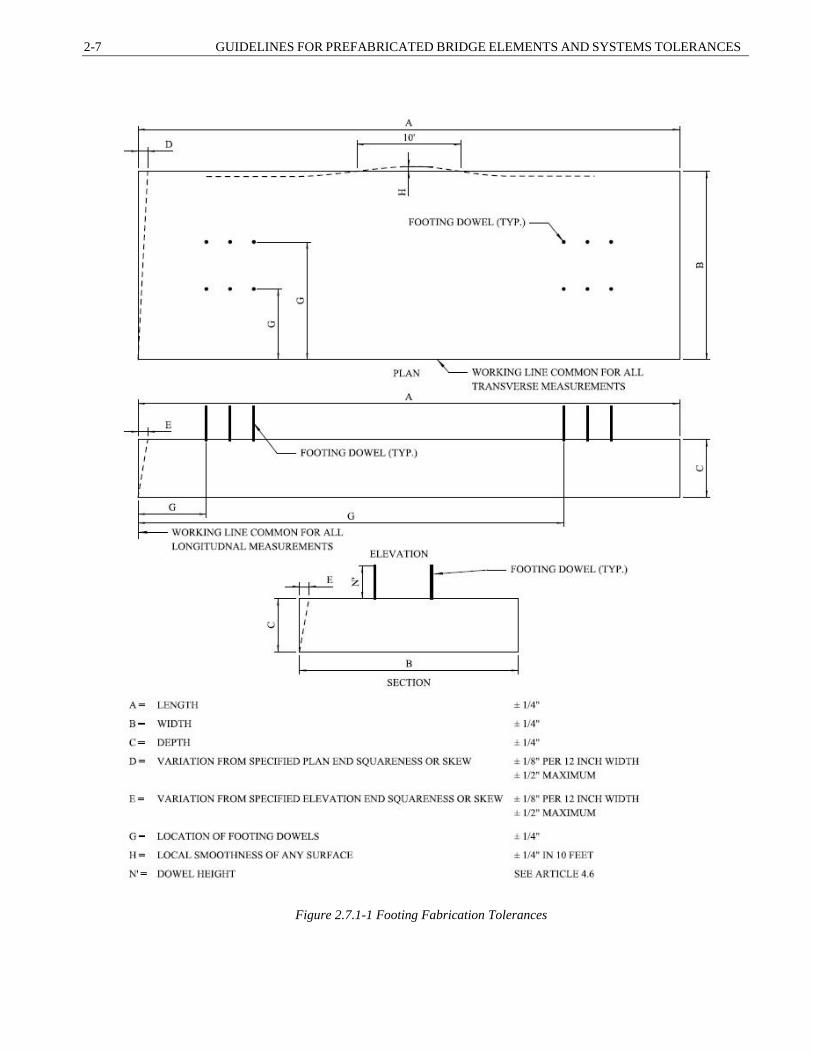
2-7 GUIDELINES FOR PREFABRICATED BRIDGE ELEMENTS AND SYSTEMS TOLERANCES
Figure 2.7.1-1 Footing Fabrication Tolerances
SECTION 2: FABRICATION TOLERANCES 2-8
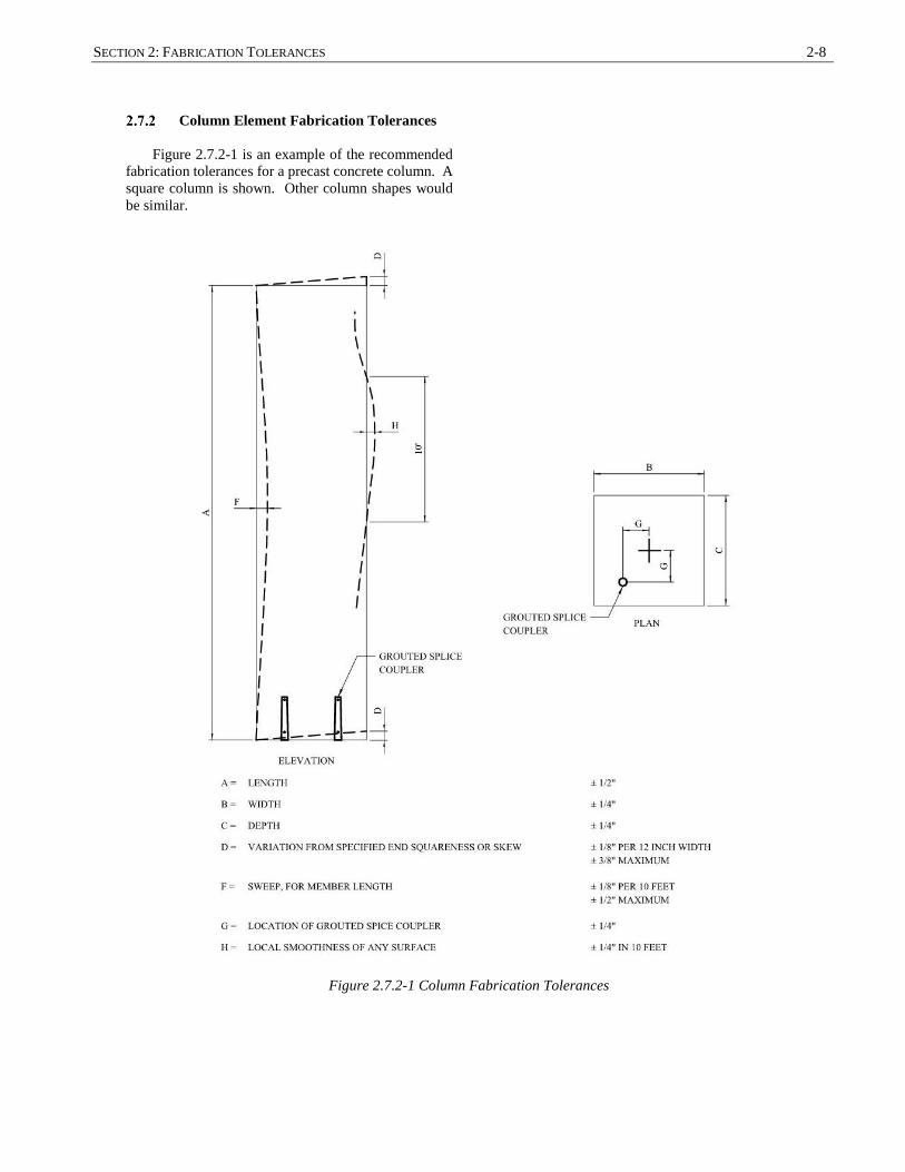
Column Element Fabrication Tolerances
Figure 2.7.2-1 is an example of the recommended
fabrication tolerances for a precast concrete column. A
square column is shown. Other column shapes would
be similar.
Figure 2.7.2-1 Column Fabrication Tolerances

2-9 GUIDELINES FOR PREFABRICATED BRIDGE ELEMENTS AND SYSTEMS TOLERANCES
Cap Element Fabrication Tolerances
Figure 2.7.3-1 is an example of the recommended
fabrication tolerances for a precast concrete cap, the
figure shows both grouted splice coupler and blockout
connection location tolerances.
Wall caps can be connected to wall elements with
a reinforced concrete blockout connection. This can be
accomplished through the use of a corrugated metal
pipe (CMP) cast into one or both elements. Dowel bars
can be extended into the CMP, which is subsequently
filled with concrete after erection. See Figure C2.7.3-1
for a schematic view of this connection.
Pier caps can be connected to the column element
with grouted couplers or other mechanical devices.
Dowel bars extend into the cap element within the
couplers. See Figure C2.7.3-1 for a schematic view of
this connection.
Pier caps can be supported by single columns, or
multiple columns.
C2.7.3
Wall cap refers to horizontal cap elements
supported on wall panels (abutments or wall piers).
Figure C2.7.3-1 Schematic Wall Cap Connection
Figure C2.7.3-2 Schematic Column to Cap Connection
It is recommended that the number of columns per
cap element be limited to three due to difficulties of
connecting many elements together in the field. If a
bridge has more than three columns, it is recommended
to use multiple cap elements detailed with an open joint
between them (see Section 4 for joint tolerances required
for this situation). Another option is to connect the
multiple caps after installation using a reinforced
concrete closure joint. The structure can be designed
such that the unconnected precast portions can support
the dead load of the structure and the connected cap can
be designed to support other loads. Using this approach,
the casting and curing of the closure joint will typically
not delay construction.
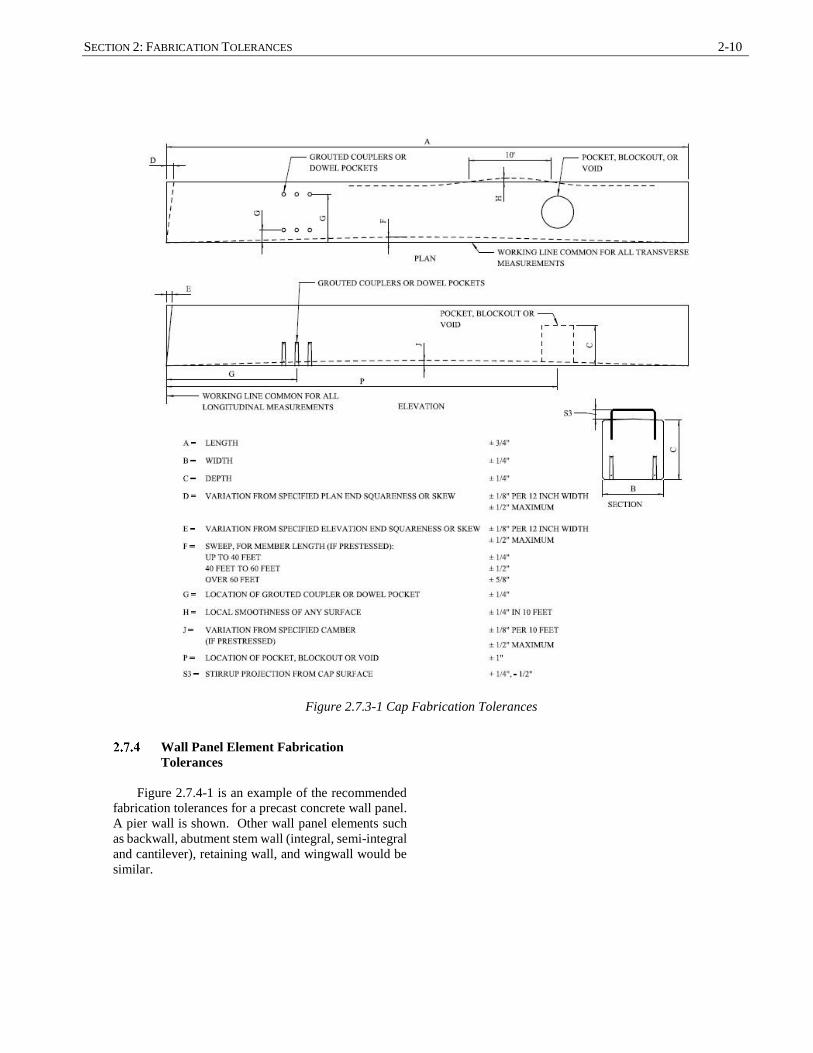
SECTION 2: FABRICATION TOLERANCES 2-10
Figure 2.7.3-1 Cap Fabrication Tolerances
Wall Panel Element Fabrication
Tolerances
Figure 2.7.4-1 is an example of the recommended
fabrication tolerances for a precast concrete wall panel.
A pier wall is shown. Other wall panel elements such
as backwall, abutment stem wall (integral, semi-integral
and cantilever), retaining wall, and wingwall would be
similar.

2-11 GUIDELINES FOR PREFABRICATED BRIDGE ELEMENTS AND SYSTEMS TOLERANCES
Figure 2.7.4-1 Wall Panel Fabrication Tolerances
Full Depth Deck Panel Element
Fabrication Tolerances
Figure 2.7.5-1 is an example of the recommended
fabrication tolerances for a precast concrete full depth
deck panel.

SECTION 2: FABRICATION TOLERANCES 2-12
Figure 2.7.5-1 Full Depth Deck Panel Fabrication Tolerances
Approach Slab Element Fabrication
Tolerances
Figure 2.7.6-1 is an example of the recommended
fabrication tolerances for a precast concrete approach
slab.
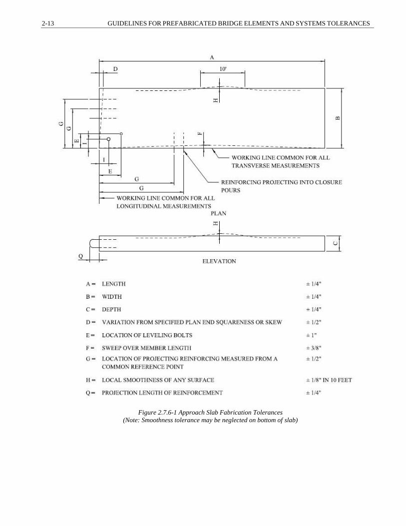
2-13 GUIDELINES FOR PREFABRICATED BRIDGE ELEMENTS AND SYSTEMS TOLERANCES
Figure 2.7.6-1 Approach Slab Fabrication Tolerances
(Note: Smoothness tolerance may be neglected on bottom of slab)

SECTION 2: FABRICATION TOLERANCES 2-14
Sleeper Slab Element Fabrication
Tolerances
Figure 2.7.7-1 is an example of the recommended
fabrication tolerances for a precast concrete sleeper
slab.
C2.7.7
A sleeper slab is used to support the end of an
approach slab that is away from the bridge abutment.
Sleeper slabs are not used by all owner agencies.
Figure 2.7.7-1 Sleeper Slab Fabrication Tolerances
(Note: Smoothness tolerance may be neglected on bottom of slab)

2-15 GUIDELINES FOR PREFABRICATED BRIDGE ELEMENTS AND SYSTEMS TOLERANCES
Grouted Splice Coupler Fabrication
Tolerances
See Figures 2.7.2-1, 2.7.3-1, and 2.7.4-1 for typical
details of grouted splice coupler. See Article 4.6.1 for
connection tolerances of the grouted splice coupler
connections.
Modular Deck Beam Element Tolerances
Figure 2.7.9-1 is an example of the recommended
fabrication tolerances for a modular deck beam element.
C2.7.9
Modular Deck Beams (MDBs) come in several
forms. The primary feature of MDBs is that the element
has both a beam and a deck within the element. The
beam elements can be made with precast concrete or
steel. The resulting elements is a module that typically
has two beam stems combined with an integral deck that
is cast in the fabrication facility.
Figure 2.7.9-1 Modular Deck Beam Fabrication Tolerances
Note: A steel beam MDB is shown, a precast MDB would be similar

SECTION 2: FABRICATION TOLERANCES 2-16
2.8 BRIDGE SYSTEM CONSTRUCTION
TOLERANCES
The construction of portions of the structure that
are to be moved with the SPMTs or Lateral Slide
techniques may be built using conventional
construction methods and construction tolerances,
except as modified herein.
The Designer should specify certain construction
tolerances that will be critical to the fit of the moved
portion of the bridge.
The following are recommended tolerances that
may be used for the overall length of the bridge,
measured from a working line defined as the mid-length
of the portion of the bridge system being moved
(tolerance measured to each end of the bridge):
Spans under 100 feet in length
Overall Length where the superstructure fits
between substructure elements: +0”, -½”
Overall length where the superstructure
overlaps the substructure elements: +½”, -0”
Spans over 100 feet in length
Overall Length where the superstructure fits
between substructure elements: +0”, -3/4”
Overall length where the superstructure
overlaps the substructure elements: +3/4”, -0”
If the working line is located at one end, the
tolerances should be doubled.
The following are recommended tolerances that
may be used for the location of the inside face of curb
with respect to a working line:
Bridges with fixed approach barriers: + ½”
Bridges with adjustable approach barriers: + 1”
C2.8
These recommendations are based on specifications
used by the Utah DOT (2015). The overlap description
is based on details commonly used for SPMT bridge
installations. Figure C2.8-1 is a schematic
representation of this detail. In this case the overall
bridge length tolerance would favor over-length versus
under-length.
Figure C2.8-1 Semi-integral abutment detail with
overlap connection
The relatively small tolerances for this type of
construction are commensurate with the ramifications of
a mis-fit during the system installation. Special care
should be exercised with regard to tolerances on bridge
systems. If the bridge detailing includes a reinforced
concrete closure joint at the ends of the bridge, the
tolerances for length can be increased.
This width tolerance is based on a need to have a
smooth transition between the bridge railing/barrier and
the approach railing/barrier. If the project details call for
installation of approach barriers after setting the bridge,
then larger tolerances may be acceptable.

2-17 GUIDELINES FOR PREFABRICATED BRIDGE ELEMENTS AND SYSTEMS TOLERANCES
The recommended tolerance for the fixed barrier
situation is to achieve an alignment that will produce a
maximum barrier face offset of + 1” when combined
with the transverse setting tolerance (see Article 3.12.3).
Temporary Bent Tolerances
The following are recommended tolerances for
support points on temporary falsework bents used in
bridge system installations:
Elevation of temporary bridge bearings seats:
+ 1/8” from final bridge seat elevations
Horizontal location of temporary bridge bearings:
+ 1/4” from final bridge layout dimensions
C2.8.1
Temporary falsework bents are used to construct the
bridge system off site. These are also referred to as
temporary abutments. It is critical that the configuration
of the temporary falsework bents match the final bridge
configuration.
Final Substructure Tolerances
The following are recommended tolerances for the
bearing locations on the permanent substructures used
in bridge system installations:
Elevation of final bridge bearings seats:
+ 1/8” from final bridge seat elevations
Horizontal location of final bridge bearings:
+ 1/4” from final bridge layout dimensions
Designers should consider detailing permanent
bridge bearings that can accommodate vertical
adjustment (shims) and horizontal adjustment.
C2.8.2
It is also possible to detail elastomeric bearings
without anchor rods (expansion bearings at each end)
where lateral and longitudinal restraint is achieved
through the use of reinforced concrete keys. The
elimination of anchor rods can remove one potential fit-
up problem during final bridge setting.
If anchor rods are necessary, the details can include
oversized sleeves cast into the substructure that will
allow for grouting of the anchor rods after placement of
the bridge system.
2.9 REFERENCES
AASHTO LRFD Bridge Construction Specifications, Third Edition, American Association of State Highway
and Transportation Official, Washington, DC. (2010)
AASHTO Guide Specifications for Accelerated Bridge Construction, First Edition, American Association of
State Highway and Transportation Official, Washington, DC. (2017)
ACI Specification for Tolerances for Precast Concrete, ACI ITG-7-09, American Concrete Institute,
Farmington Hills, MI, (2009)
PCI Northeast Guideline for Accelerated Bridge Construction Using Precast/Prestressed Concrete Elements
Including Guideline Details, PCINE-12-ABC, PCI Northeast Bridge Technical Committee (2014)
PCI Quality Control Manual for Plants and Production of Structural Precast Concrete Products – MNL-116-
99, Precast Prestressed Concrete Institute, Chicago, IL, (1999)
PCI Tolerance Manual for precast and Prestressed Concrete Construction - MNL-135-00, Precast Prestressed
Concrete Institute, Chicago, IL, (2000)
Utah DOT Structures Design and Detailing Manual, The Utah Department of Transportation, Salt Lake City,
Utah, (2015)

SECTION 2: FABRICATION TOLERANCES 2-18
3-1 GUIDELINES FOR PREFABRICATED BRIDGE ELEMENTS AND SYSTEMS TOLERANCES
3.1 SCOPE .................................................................................................................................................................... 2
3.2 DEFINITIONS ...................................................................................................................................................... 2
3.3 NOTATION ........................................................................................................................................................... 2
3.4 BASIS OF ERECTION TOLERANCE RECOMMENDATIONS .......................................................................................... 2
3.5 SPECIFYING WORKING POINTS AND WORKING LINES ............................................................................ 3
3.6 HORIZONTAL ERECTION TOLERANCES....................................................................................................... 4
3.6.1 Center of Element Layout Method ................................................................................................................ 5
3.6.2 Surface of Element Layout Method ............................................................................................................... 5
3.7 VERTICAL ERECTION TOLERANCES ............................................................................................................ 5
3.8 LEVEL AND PLUMBNESS TOLERANCE ......................................................................................................... 5
3.9 RECOMMENDED ERECTION TOLERANCES ................................................................................................. 6
3.9.1 Footing Erection Tolerances .......................................................................................................................... 7
3.9.2 Column Erection Tolerances.......................................................................................................................... 8
3.9.3 Pier Cap Erection Tolerances......................................................................................................................... 8
3.9.4 Wall Panel Erection Tolerances ..................................................................................................................... 9
3.9.5 Full-Depth Deck Panel and Modular Deck Beam Erection Tolerances ....................................................... 10
3.10 ERECTION DETAILS ........................................................................................................................................ 12
3.11 BUTTED ELEMENTS AND BUILD-UP OF TOLERANCES ........................................................................... 13
3.11.1 Accumulation of Tolerances ........................................................................................................................ 13
3.11.1.1 Precast Elements without Grouted Joints ............................................................................................. 13
3.11.1.2 Steel Elements ..................................................................................................................................... 14
3.12 SPMT SYSTEM TOLERANCES ........................................................................................................................ 15
3.12.1 Twist Tolerance ........................................................................................................................................... 15
3.12.2 Horizontal Setting Tolerances...................................................................................................................... 15
3.12.3 Vertical Setting Tolerances .......................................................................................................................... 16
3.12.4 Bearing Tolerance ........................................................................................................................................ 17
3.13 LATERAL SLIDE SYSTEM TOLERANCES .................................................................................................... 17
3.13.1 Slide Track Alignment ................................................................................................................................. 17
3.14 REFERENCES .................................................................................................................................................... 18
SECTION 3: ERECTION TOLERANCES
TABLE OF CONTENTS

SECTION 3: ERECTION TOLERANCES 3-2
3.1 SCOPE
The provisions in this section apply to tolerances
for the erection of various types of elements used in
Accelerated Bridge Construction (ABC). This section
covers Prefabricated Bridge Elements (PBEs), Self-
Propelled Modular Transporter (SPMT) Bridge
Systems, and Lateral Slide Bridge Systems.
Erection tolerances may be used to facilitate
connections to other elements or portions of the
structure, or to provide a smooth surface to planar
elements. Wall type structures may require certain
tolerances on exposed faces to provide acceptable
appearance of the finished wall surface. The Designer
should consider a combination of erection tolerances
and element tolerances in the detailing of the structure.
This Section focuses on erection tolerances for
precast concrete elements. Erection of steel elements is
covered in the AASHTO LRFD Bridge Construction
Specifications.
C3.1
This section does not cover the fabrication
tolerances for ABC. These tolerances can be found in
Section 2 of this document.
The articles in this section and other sections in this
document cover the influence of tolerances on detailing.
In most cases, the specified tolerances on bridge
elements are used to ensure proper connection fit-up.
3.2 DEFINITIONS
Erection tolerances are defined as acceptable
variations from the as-detailed vertical and horizontal
placement of a precast element to achieve acceptable
matching of adjacent elements after they are erected,
and to provide acceptable alignment and finish of the
completed structure.
See Section 1 of this document for definitions of
common Prefabricated Bridge Elements and Systems.
3.3 NOTATION
This article is intentionally left blank at this time.
There are no specific global notations that are used in
this Section. Local notations are used for individual
tolerance details.
3.4 BASIS OF ERECTION TOLERANCE
RECOMMENDATIONS
C3.4
SECTION 3
ERECTION TOLERANCES

3-3 GUIDELINES FOR PREFABRICATED BRIDGE ELEMENTS AND SYSTEMS TOLERANCES
The erection tolerances specified in this Section
are based on field experience of Contractors, Owners,
and several published documents used in the vertical
construction industry.
The actual erection of an element or a bridge system
is controlled by the Erection Contractor as opposed to
fabrication tolerances, which are controlled by the
Fabricator. Erection Contractors have the ability to set
and reset the elements multiple times if required to meet
the specified tolerances.
Based on this, erection tolerances can potentially be
very small, however this is not recommended. Small
erection tolerances may require elements to be set and
reset many times, which would lead to construction
delays. Large tolerances are also not recommended,
since they can lead to large joints in the structures (See
Section 4 of these guidelines). The goal of these
guidelines is to strike a balance between acceptable
tolerances and joint widths that will allow for fast
construction with reasonable joint widths.
The specified tolerances contained herein are based
on discussions with contractors, consultation with
owners, and tolerance criteria that is used by the vertical
construction industry (buildings). The main documents
used for erection tolerances for precast elements are the
PCI Tolerance Manual for Precast and Prestressed
Concrete Construction (2000) and the ACI Specification
for Tolerances for Precast Concrete (2009). The main
documents used for erection tolerances of bridge systems
are several FHWA manuals (1-2007 and 2-2013) and the
Utah DOT specification for bridge moves.
3.5 SPECIFYING WORKING POINTS AND
WORKING LINES
Erection tolerances should be based on a common
vertical datum and horizontal datum. Designers should
specify that all elements be erected based on a common
datum. All dimensions shown on the plans should be
based on the selected datum. The layout of elements
should not be based on center-to-center spacing of
elements.
The use of elevations should be based on a
specified vertical datum. The vertical datum should be
consistent with the datum used to define the vertical
geometry of the bridge.
Horizontal erection locations of elements should
be based on working lines or working points. Working
lines should be mathematically tied to the horizontal
geometry of the structure. Working points should be
tied to the bridge coordinate system (if used).
C3.5
Layout of precast elements should be based on a
common datum in order to avoid the potential build-up
of errors based on element and erection tolerances. If
elements are laid out based on center-to-center spacing,
there is potential for minor errors in each layout
dimension to accumulate to a larger overall error. For
example, if ten elements are erected with all center-to-
center spacing set to a plus tolerance of 0.25 inches, the
resulting overall length of the series of elements could be
2.25 inches longer than anticipated. If the same ten
elements are laid out using a common datum, the
maximum resulting variance would be 0.25 inches.
Some agencies specify working points and working
lines on the plans. The roadway baseline or survey
coordinate system may be used, or separate working
lines may be established for ease of detailing and
construction.

SECTION 3: ERECTION TOLERANCES 3-4
Working lines may be shown on the plans or
specified to be determined by the Contractor. If these
are not shown on the plans, the project specifications
should require the establishment of working lines or
working points on the erection plans.
If designers choose to not use horizontal and
vertical data for element layout, the structure detailing
should account for potential build-up of erection and
element tolerances.
Accurate measuring devices and methods with a
level of precision should be specified for both setting and
checking element dimensions.
This approach should only be used for elements that
are butted and are independent of adjacent elements. See
Article 3.11.1 for more information on this approach.
3.6 HORIZONTAL ERECTION
TOLERANCES
Horizontal erection tolerances are used to control
the horizontal location of individual elements as they
are placed in the assembled structure. Element erection
tolerances may be specified to the center of the element,
or to a specified surface of the element.
The detailing of individual element tolerances
should be consistent with the layout method used for
the overall structure.
Reference lines shall be used to specify layout
method. If center of element, the reference line is
located at center of element. If surface of element, the
reference line is the critical surface.
Horizontal erection tolerances for stacked
assemblies should be monitored closely during
construction. As levels are assembled, the Contractor
should determine the precise variation from specified
locations of all elements, with special attention given to
connection hardware. It may be possible to correct
variations from working lines during erection of
subsequent levels of assembly by adjusting the setting
of the elements.
C3.6
There are several ways to specify the layout of
elements depending on the intended outcome of the
assembled structure. It is possible to lay out an element
using both methods. For example, a precast deck
element may be specified as center of element layout for
the longitudinal direction and surface of element for the
transverse and vertical direction.
The goal of these guidelines is to improve element
fit-up. The following are examples of the application of
this guideline:
Element laid out using center of element layout
method: All tolerance specifications for the
individual elements are measured to a working line
that corresponds with the same reference line noted
in the erection tolerance details.
Element laid out using surface of element layout
method: All tolerance specifications for the
individual elements are measured to a working line
that corresponds with the same surface noted in the
erection tolerance details.
See Section 2 for information on tolerances for
fabrication of individual elements.
An example of adjusting stacked elements is the
construction of a pier bent. If the Contractor identifies
that the footing connections are slightly wider than
detailed, the erection location of the columns can be
shifted slightly to correct the variance. If this is not
possible within the connection, the Contractor may be
able to tilt the column slightly (within tolerance) to bring
the tops of the columns back into alignment with the
layout plan, thereby facilitating the erection and fit-up of
the pier cap.

3-5 GUIDELINES FOR PREFABRICATED BRIDGE ELEMENTS AND SYSTEMS TOLERANCES
3.6.1 Center of Element Layout Method
Center of element layout method should be used
for the spacing of elements along the length of the
structure or along a working line.
C3.6.1
The following are examples of center of element
layout approaches:
The layout dimension of columns in a pier bent may
be specified to the center of each column, since the
face to face alignment of each column is not as
critical as the location of the overall column. The
horizontal variation of the column surfaces due to
fabrication tolerances would be split between the
side face surface locations.
The longitudinal spacing of wall panels along the
face of the wall may be specified to the center of
each wall panel. The horizontal variation of the wall
panel length due to fabrication tolerances would be
split between the end surfaces of the panels, which
would be accommodated within the specified joint
width tolerance (see Section 4 of this document for
more information on joints and connections).
3.6.2 Surface of Element Layout Method
Surface of element layout method should be used
for the alignment of elements perpendicular to a surface
or working line where the finished surface of one
portion of the structure is critical.
C3.6.2
The following are examples of surface of element
layout approaches:
The alignment layout of a series of wall panels may
be specified to the front face of the wall to ensure a
smooth surface in the finished structure. The
variation of fabrication width tolerances would be
accounted for along the rear face of the wall panels
where they would not be seen.
The transverse layout of precast deck panels with
integral precast barriers may be specified to the
inside face of the barrier to ensure a smooth inside
surface of the barrier.
3.7 VERTICAL ERECTION TOLERANCES
Vertical erection tolerances are used to control the
elevation of individual elements as they are placed in
the assembled structure. Vertical element erection
tolerances may be specified to the center of the element,
or a specified surface of the element (typically the top
of the element).
C3.7
The approach for vertical layout of elements is
similar to horizontal layout. See Article C3.6 for
commentary on center of element layout and surface of
element layout.
3.8 LEVEL AND PLUMBNESS TOLERANCE
Level and plumbness erection tolerances are used
to control the variation from horizontal and vertical of
individual elements as they are placed in the assembled
structure. Level erection tolerances are typically
specified along the top surface of the element.
C3.8
For elements with multiple exposed faces such as
columns, the designer may elect to specify an average
plumbness for all faces of the column since surface
tolerances can lead to inaccurate overall plumbness.

SECTION 3: ERECTION TOLERANCES 3-6
Plumbness erection tolerances are typically specified to
the face of the element.
3.9 RECOMMENDED ERECTION
TOLERANCES
This article contains recommended erection
tolerances for common elements used in bridge
construction. These values may be used as a basis for
other similar elements.
The following sub-articles contain recommended
typical details for erection tolerances. Designers may
choose to use alternate tolerance reference lines
depending on the desired outcome of the structure. The
tolerance values noted should be followed regardless of
the reference line approach used.
C3.9
The basis for these recommended tolerance values
is the PCI Tolerance Manual for Precast and
Prestressed Concrete Construction, MNL-135-00
(2000).
Example of a potential change: A Designer may
choose to reference the front face of a wall footing to
ensure that the connection of the footing to the wall stem
is controlled. In this case, the footing would be
fabricated using the front face of the footing as the
reference line.
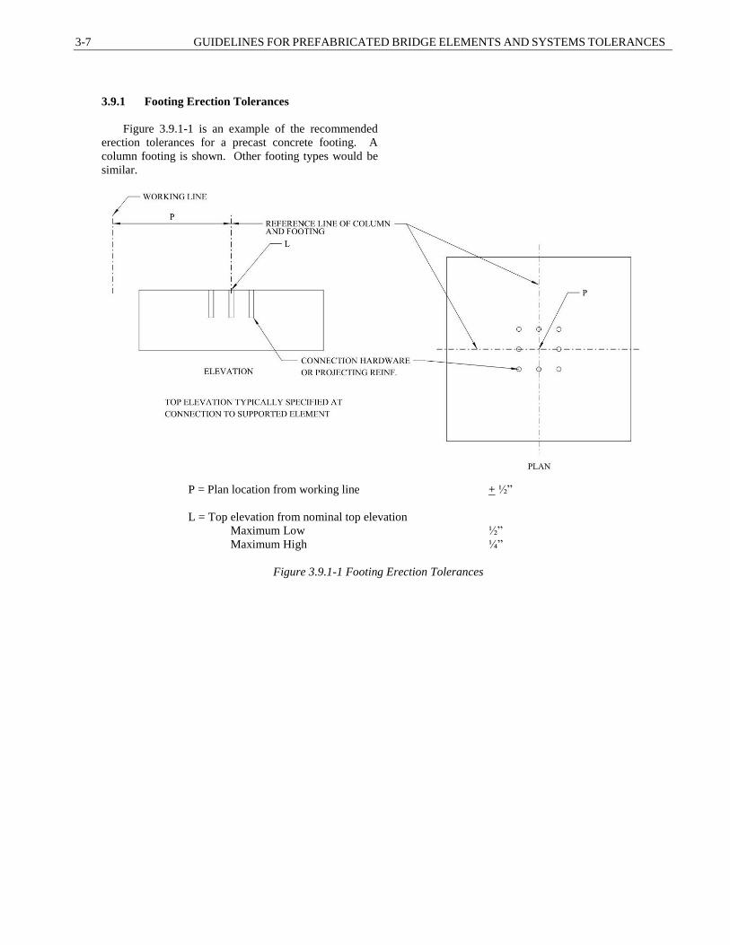
3-7 GUIDELINES FOR PREFABRICATED BRIDGE ELEMENTS AND SYSTEMS TOLERANCES
3.9.1 Footing Erection Tolerances
Figure 3.9.1-1 is an example of the recommended
erection tolerances for a precast concrete footing. A
column footing is shown. Other footing types would be
similar.
P = Plan location from working line + ½”
L = Top elevation from nominal top elevation
Maximum Low ½”
Maximum High ¼”
Figure 3.9.1-1 Footing Erection Tolerances

SECTION 3: ERECTION TOLERANCES 3-8
3.9.2 Column Erection Tolerances
Figure 3.9.2-1 is an example of the recommended
erection tolerances for a precast concrete column.
Column plumbness tolerances should be carefully
managed during erection to ensure the proper fit of the
column to cap connection based on the cap connection
details.
C3.9.2
The intent is to make use of this tolerance to make
adjustments to the erection of the columns during
erection. For example, if a footing is constructed
within tolerance, but farther apart than specified, the
Contractor could cant the column inward to bring the
top of the column within the tolerances for the cap
connections.
P = Plan location from working line + ½”
L = Top elevation from nominal top elevation
Maximum Low ½”
Maximum High ¼”
R = Maximum plumb variation over height of column 1”
U = Maximum plumb variation in any 10 feet ¼”
V = Jog in alignment of matching edges ¼”
Figure 3.9.2-1 Column Erection Tolerances
3.9.3 Pier Cap Erection Tolerances
Figure 3.9.3-1 is an example of the recommended
erection tolerances for a precast concrete pier cap. Other
cap type elements such as abutment caps would be similar.

3-9 GUIDELINES FOR PREFABRICATED BRIDGE ELEMENTS AND SYSTEMS TOLERANCES
P = Plan location from working line + ½”
L = Top elevation from nominal top elevation
Maximum Low ½”
Maximum High ¼”
U = Maximum plumb variation in any 10 feet ¼”
V = Jog in alignment of matching elements ¼”
Figure 3.9.3-1 Pier Cap Erection Tolerances
3.9.4 Wall Panel Erection Tolerances
Figure 3.9.4-1 is an example of the recommended
erection tolerances for a precast wall element. This
tolerance would be applicable abutment stems, integral
abutment stems and retaining wall panels.

SECTION 3: ERECTION TOLERANCES 3-10
P = Plan location from working line + ½”
L = Top elevation from nominal top elevation
Maximum Low ½”
Maximum High ¼”
U = Maximum plumb variation in any 10 feet ¼”
V = Jog in alignment of matching edges ¼”
Figure 3.9.4-1 Wall Panel Erection Tolerances
3.9.5 Full-Depth Deck Panel and Modular Deck
Beam Erection Tolerances
Figure 3.9.5-1 is an example of the recommended
erection tolerances for a precast concrete full-depth deck
panel or a modular deck beam element. This tolerance
would be applicable full-depth precast concrete deck

3-11 GUIDELINES FOR PREFABRICATED BRIDGE ELEMENTS AND SYSTEMS TOLERANCES
panels, steel grid deck panels modular deck beams made
with steel beams and modular deck beams made with
precast and prestressed concrete.
P = Plan location from working line + ¼”
L = Top elevation from nominal top elevation
Thick overlay
Maximum Low 1/4 ”
Maximum High 1/4”
Thin overlay or bare deck combined with grinding
Maximum Low 1/8”
Maximum High 1/8”
R = Differential top elevation
Thick overlay 1/4”
Thin overlay or bare deck combined with grinding 1/8”
Figure 3.9.5-1 Full-Depth Deck Panel and Modular Deck Beam Erection Tolerances

SECTION 3: ERECTION TOLERANCES 3-12
3.10 ERECTION DETAILS
The basis of the erection layout dimensions should
be determined by the Designer and shown on the plans.
One or both methods described in Articles 3.6 and 3.7
may be used. The plan details should clearly show the
intent of the element layout including dimensions of the
elements from working lines or working points.
The reference line used for erection layout should
be the same line used for element fabrication tolerances.
As stated in Articles 3.6 and 3.7, there are multiple
ways to specify element erection layouts. Figure 3.10-1
shows an example of an element erection layout detail
for a precast concrete pier. This detail is based on the
center of element layout method. Figure 3.10-2 shows
a sample precast element erection layout detail for a
precast concrete cantilever abutment structure. This
detail is based on the center of element layout method
for the longitudinal direction and surface of element
layout method for the transverse direction.
This aspect of tolerance detailing is critical for the
alignment of connections.
Figure 3.10-1 Example of Center of Element Erection Layout for a Precast Pier

3-13 GUIDELINES FOR PREFABRICATED BRIDGE ELEMENTS AND SYSTEMS TOLERANCES
Figure 3.10-2 Example of Abutment Erection Layout
(Center of Element Method used for Longitudinal Layout
Surface of Element Method used for Transverse Layout)
3.11 BUTTED ELEMENTS AND BUILD-UP OF
TOLERANCES
Precast elements may be detailed as butted (dry
stacked or dry fit with tight joints). Extra care should be
exercised with the design and detailing of these types of
structures.
C3.11
Proper management of the build-up of tolerances
in butted systems will facilitate the proper fit-up of the
structure as a whole.
3.11.1 Accumulation of Tolerances
Designers should account for the variance of erection
tolerances caused by the accumulation of tolerances of the
individual elements. If the exact location of the top end
of a series or elements is critical, then it should be noted
on the plans. The following articles contain examples of
common butted elements and recommendations on how
to manage these tolerances.
Plans and/or specifications should contain provisions
for closure pours, cast-in-place caps, or variable
dimensions to account for the potential accumulation of
tolerances.
C3.11.1
The variance in overall structure length or height
is due to the additive nature of stacked elements
fabricated to certain tolerances. For example; the
stacking of ten elements that are specified to be 1 foot
tall may end up totaling 10.1’ or 9.9’. In this case the
Designer may note the top of the stacked elements as
an approximate dimension that is subject to variation
due to tolerances.
It is not possible to accurately estimate this type
of variation, therefore a simple closure pour at the top
or end of a series of elements would be in order.
3.11.1.1 Precast Elements without Grouted
Joints
Precast elements that are detailed without variable
width grouted joints are prone to accumulation of
tolerances. In most cases, the variations will have little or
C3.11.1.1
Variable width grouted joints may be an effective
means of managing the accumulation of tolerances. In
some structures, it is not feasible or desirable to

SECTION 3: ERECTION TOLERANCES 3-14
no impact on the completed structure. Structures that
require more exact overall length and/or height
restrictions will require special detailing to manage the
variations.
Retaining walls constructed with precast facing
elements may be detailed as dry stacked. Vertical and
horizontal tolerance management may be accounted for
through the use of shims between the precast elements. If
variable shims are not used, the Designer should detail the
wall height and length with variable dimensions and
include provisions for accommodating the variation in the
precast wall height and/or length.
If adjustment of element layout is not included in the
design, details for accommodating the variable length or
height should be incorporated into the design. In many
cases, minor variation in the top of the stack of element
and the overall length of the aligned elements can be
accommodated.
include grouted joints in the construction. In these
cases, provisions for management of the accumulation
of tolerances are required. The most common use of
dry stacked elements is retaining walls constructed
with precast concrete facing elements. The provisions
and commentary in this article describe the
management of these structures. The same approach
can be used for other elements with similar detailing.
Examples of retaining structures where this
situation might occur include:
GRS/IBS Facing Blocks
Precast modular block retaining walls
MSE Wall Facing
Shims are commonly used in larger precast
modular block walls to maintain the desired elevation
of each course of construction and the length of the
wall. Preference should be for the use of soft material
shims. Steel shims can lead to high point loads and
potential spalling. Smaller block walls are typically
dry stacked, which will lead to variation in the overall
height and width of the block facing.
If element by element adjustments are not
specified and variable height and length are not
desirable, the Designer should consider the inclusion
of a variable height cast-in-place concrete cap to bring
the finished structure top to the prescribed elevation,
or a cast-in-place segment at the end of the elements
to provide an exact end location. Saw-cutting of
unreinforced concrete blocks may also be allowed in
project specifications to accommodate the top of wall
and end of wall variations.
3.11.1.2 Steel Elements
The use of standard sized holes for field connections
using bolts is recommended for most applications.
Welded connections should be detailed to allow for minor
variations due to fabrication tolerances. The use of
erection bolts combined with field welding is
recommended where feasible.
Special care should be exercised with steel structures
fabricated with connections that incorporate slotted or
oversized holes. Geometry should be checked as each
element is erected to ensure proper geometry of the entire
structure is maintained. The project specifications should
include requirements to check erection tolerances for
every element erected in order to ensure that the overall
geometry of the structure is maintained.
C3.11.1.2
Fabrication of steel can be controlled to tight
tolerances, which minimizes the potential of
significant accumulation of tolerances. Complex steel
assemblies fabricated with standard holes have proven
to be reliably constructed without accumulation of
tolerances.
The use of oversize and/or slotted holes should be
used with caution as they can lead to overall geometry
problems if the Contractor does not exercise care in
element fit-up. This issue is primarily applicable to
side-by-side steel elements such as Modular Steel
decked Beams.

3-15 GUIDELINES FOR PREFABRICATED BRIDGE ELEMENTS AND SYSTEMS TOLERANCES
3.12 SPMT SYSTEM TOLERANCES
The Designer should specify erection tolerances for
the SPMT Systems. The erection tolerance approach
based on working lines and elevations should be used.
The layout of the bridge in the staging area should
match the layout of the final bridge site. To reduce fit-up
problems, the temporary supports should be built to the
same relative line and grade as the permanent abutments
(or piers).
C3.12
SPMT Systems are typically built near site on
temporary supports in a staging area.
3.12.1 Twist Tolerance
The Designer should calculate and specify the
allowable twist tolerance for both the permanent
condition and the temporary condition (during the bridge
move). The basis for the twist tolerance should be to
control cracking of the bridge concrete during the move.
Twist tolerance may be specified at the anticipated lift
points, or at the ends of the bridge. The project plans and
specifications should include detail sheets that indicate
where the twist tolerance is to be applied.
The basis of the allowable twist should account for
the stiffness of the entire structure including the influence
of girders, cross frames, diaphragms, barriers, etc.
The calculation of twist tolerance should involve
inducing a twist displacement into the structural system
that results in stresses that are within acceptable limits.
The working stress method of analysis is recommended
for this process.
The project specifications should include
requirements for the Contractor to measure the twist of the
structure in real time, to ensure that the twist tolerance is
not exceeded. The plans should include details showing
the measurement location of the twist tolernace.
C3.12.1
The designers should determine the allowable
twist in the structure, since they have more intimate
knowledge of the structural framing system and the
stress limits in the system during the move. See
Article 3.10 for more information on erection
tolerance detail sheets.
The allowable twist in a bridge superstructure is
dependent on the stiffness of the structure and its
ability to accommodate twist without damage. A 3D
grid or finite element analysis may be required.
The working stress method of analysis is
recommended since cracking of the concrete deck and
concrete beams is a common stress limit that needs to
be checked.
The specific means of measuring twist is typically
left open to the Contractor. There are both
sophisticated methods and simple methods that have
been successfully used. Sophisticated methods
involve the use of lasers and video monitoring
systems. Simple methods include the use of string
lines running from the bridge corners that cross at the
center of the bridge. The gap between the lines can be
equated to the maximum allowable twist. The need to
measure twist in real time is important, since the
movement of the bridge and the SPMTs is a fluid
process.
3.12.2 Horizontal Setting Tolerances
There are several tolerances that may affect the
setting of a bridge structure on substructures:
C3.12.2
SECTION 3: ERECTION TOLERANCES 3-16
Longitudinal setting tolerance: This tolerance
influences the beam and deck level connections at the
end of the bridge. If wide closure joints are to be
used, the longitudinal setting tolerance may be based
on typical beam erection tolerances for conventional
construction. If narrow closure joints or details are
used, a more conservative longitudinal setting
tolerance should be used based on the detailing of the
joint.
Transverse setting tolerance for bridges with
concrete barriers at ends that transition to fixed
concrete barriers off the bridge: The recommended
transverse setting tolerance should be + ½” provided
that the edge of the barrier joint is detailed with a
1”x1” chamfer.
Transverse setting tolerance for bridges with barriers
that transition to railings off the bridge: The
recommended transverse setting tolerance should be
+ 1”.
The project plans and specifications should include
detail sheets depicting the allowable horizontal erection
setting tolerance.
See Section 4 for information on tolerances for
joints.
The primary driver for establishing this transverse
setting tolerance is the detailing of the bridge barriers.
Significant variations on the inside surface of the
barrier can affect the crashworthiness of the system.
Crash testing of concrete barriers with relief
indentations has shown that a face offset of up to 1” is
acceptable provided that the edge of the indentation is
chamfered at 45 degrees (White, et al., 2002). The
limitation of +½” is set to accommodate casting
tolerances for the bridge barrier. The additive nature
of multiple tolerances could result in an overall offset
of greater than 1” if this tolerance was to be increased.
This recommendation is based on the assumption
that the approach roadway barrier can be adjusted to
accommodate the transverse bridge barrier tolerance.
This provision would also be applicable for concrete
approach barriers that can be adjusted or installed after
the bridge is set.
See Article 3.10 for more information on
tolerance detail sheets.
3.12.3 Vertical Setting Tolerances
The final surface treatment of the bridge deck will
affect the vertical setting tolerances. Vertical setting
tolerances should be measured to the top surface of the
bridge deck.
The following are the recommended vertical setting
tolerances based on various surface treatments:
Thick overlay
Maximum Low 1/4”
Maximum High 1/4”
Thin overlay or bare deck combined with grinding
Maximum Low 1/8”
Maximum High 1/8”
The project plans and specifications should include
detail sheets depicting the allowable vertical erection
setting tolerance.
C3.12.3
The vertical setting tolerance is similar to the
vertical tolerances for full depth precast deck panels.
Some agencies use thick overlays, others use thin
overlays, and others use bare concrete decks combined
with profile grinding. Thick overlays provide
opportunities to accommodate larger tolerances, since
the overlay thickness can vary. Thin overlays and bare
decks require smaller tolerances in order to provide a
smooth riding surface.
See Article 3.10 for more information on
tolerance detail sheets.
3-17 GUIDELINES FOR PREFABRICATED BRIDGE ELEMENTS AND SYSTEMS TOLERANCES
3.12.4 Bearing Tolerance
The project details and specifications should include
provisions for adjustment of bearings to accommodate the
specified setting tolerances.
The use of anchor rods should be discouraged.
Designers should investigate other ways of providing
lateral resistance in the supports.
The Designer should detail bearing devices to
accommodate the specified vertical setting tolerances and
minor variations between the elevation of bearings on the
temporary supports and the elevation on the permanent
substructure.
C3.12.4
The tolerance for anchor rods is typically much
smaller than the tolerances for setting the bridge,
therefore other means of adjusting the bearing devices
should be investigated if anchor rods are proposed.
Some agencies rely on bearing friction (elastomeric
bearings) and shear keys (also known as keeper
blocks) to provide lateral resistance, which produces a
bridge without anchor rods.
The detailing of bearings vary greatly from
agency to agency. Most bearing designs may be
detailed to include shims that can be added or removed
to adjust the height of the bearing. Another option is
to cast bridge seats high and allow for grinding of the
bridge seat prior to setting the bridge. This option may
not be conducive to very fast construction projects
where grinding adjustments may not be feasible.
3.13 LATERAL SLIDE SYSTEM TOLERANCES
The designer should specify erection tolerances for
the bridge structure that is to be installed with the Lateral
Slide method. The same erection tolerance approach shall
be used based on working lines and elevations.
The layout of the bridge at the near-site fabrication
area should match the layout of the final bridge site. In
order to reduce fit-up problems, the temporary supports
should be built to the same relative line and grade as the
permanent abutments (or piers).
The tolerances for SPMTs noted in Article 3.12 are
also applicable to Lateral Slide installations.
C3.13
Lateral slide bridges are typically built adjacent to
the permanent bridge site on temporary supports. The
construction of a bridge for a Lateral Slide installation
is very similar to the construction for an SPMT
installation. The major difference is the method of
moving the bridge, which does not affect the required
tolerances.
3.13.1 Slide Track Alignment
There are multiple methods for sliding a bridge. The
design of the sliding mechanism should be developed by
the Contractor. Designers should include this
requirement in the slide plan submission. The project
specifications should include requirements to realign the
bridge during the slide.
The details for the actual slide mechanism are
typically designed by the Contractor. Project
specifications should require that the Contractor
develop and submit the slide mechanism for review.
Horizontal adjustment of the bridge during the move
is critical to prevent binding of the slide mechanism
on guide rails (if used) and setting of the bridge in the
final location.

SECTION 3: ERECTION TOLERANCES 3-18
The alignment of the slide tracks should be parallel
to each other and the bridge substructure. The Contractor
should specify the tolerance for the slide track alignment
based on the type of slide mechanism.
The Contractor should specify the maximum
deviation of lateral movement at each track location to
prevent binding of the slide mechanism or misalignment
of the bridge.
The project specifications should include
requirements for monitoring of the bridge during the slide.
The complexity of the system should be commensurate
with the complexity of the slide mechanism.
The alignment tolerance can vary depending on
the mechanism chosen. Slide systems with guide rails
can bind if the structure alignment is not maintained.
Other systems are less prone to binding. The
alignment of the slide track needs to be carefully
coordinated with the substructure so that the bridge
does not come in contact with the substructure during
the slide.
Monitoring systems can be a sophisticated control
system, or simple measurements combined with radio
communication.
3.14 REFERENCES
AASHTO LRFD Bridge Construction Specifications, Third Edition, The American Association of State Highway
and Transportation Officials, Washington, D.C. (2010)
ACI Specification for Tolerances for Precast Concrete, ACI ITG-7-09, American Concrete Institute, Farmington
Hills, MI, (2009)
FHWA (1) Manual on use of Self-Propelled Modular Transporters to Remove and Replace Bridges, Publication
FHWA-HIF-07-022, Federal Highway Administration, American Association of State Highway and
Transportation Officials, National Cooperative Highway Research Program, and Florida Department of
Transportation (2007)
FHWA (2) Slide-In Bridge Construction Implementation Guide, Project: F-ST99 (232), U.S. Department of
Transportation, Federal Highway Administration, Washington, D.C., pp 168, (2013)
Steel Bridge Erection Guide Specification, S10.1, AASHTO/NSBA Steel Bridge Collaboration, National Steel
Bridge Alliance, (2014)
PCI Tolerance Manual for precast and Prestressed Concrete Construction - MNL-135-00, Precast Prestressed
Concrete Institute, Chicago, IL, (2000)
White, et al., Crash Testing of Various Textured Barriers, Report No. FHWA/CA/TL-2002/03, California
Department of Transportation, Sacramento, CA, (2002)

4-1 GUIDELINES FOR PREFABRICATED BRIDGE ELEMENTS AND SYSTEMS TOLERANCES
4.1 SCOPE ................................................................................................................................................................... 2
4.2 DEFINITIONS ...................................................................................................................................................... 2
4.3 NOTATION ........................................................................................................................................................... 2
4.4 ROLE OF TOLERANCES IN JOINT SPECIFICATIONS .................................................................................. 3
4.5 JOINT WIDTH OR THICKNESS SPECIFICATIONS ......................................................................................... 4
Specified Joint Width Or Thickness .............................................................................................................. 4
Specified Joint Opening Tolerance ................................................................................................................ 5
Specified Vertical Joint Width Tolerances ................................................................................................ 5
Specified Horizontal Joint Thickness Tolerances (Stacked Vertical to Horizontal Element) .................. 10
Specified Horizontal Joint Thickness Tolerances (Stacked Vertical to Vertical Element) ...................... 15
4.6 CONNECTION TOLERANCES ......................................................................................................................... 17
Grouted Splice Couplers .............................................................................................................................. 17
Pocket Connections...................................................................................................................................... 18
Specified Dowel Pocket Width ................................................................................................................ 19
Projection Length ..................................................................................................................................... 20
Plumbness ................................................................................................................................................ 20
Reinforced Pocket Connections ................................................................................................................... 20
Specified Reinforced Pocket Width ......................................................................................................... 21
Specified Reinforcing Bar Projection Length .......................................................................................... 22
Pocket Depth ............................................................................................................................................ 23
Integral Abutment Pile Pocket Connections ................................................................................................ 24
Specified Pile Pocket Width .................................................................................................................... 24
Closure Joint with Lapped Reinforcing Bars ............................................................................................... 25
Specified Closure Joint Width ................................................................................................................. 26
4.7 REFERENCES .................................................................................................................................................... 27
SECTION 4: JOINTS AND CONNECTIONS
TABLE OF CONTENTS

SECTION 4: JOINTS AND CONNECTIONS 4-2
4.1 SCOPE
The provisions of this section applies to tolerances
for joints and connections of prefabricated elements.
Tolerances for joints and connections primarily apply
to precast concrete elements.
There are two types of joints; structural and non-
structural joints. Structural joints connect elements
with a joint that can transmit moment, shear and/or
axial forces. Non-structural joints include joints which
do not transfer load across the joint, such as expansion
joints. Tolerances play a key role in the specified width
of both structural and non-structural joints. Joint widths
need to be able to accommodate the fabrication
tolerances and erection tolerances of the connected
elements.
C4.1
This section does not cover the fabrication and
erection tolerances for ABC. These tolerances are
included in Section 2 and 3 of this document.
Non-structural joints may be used for thermal
movements such as a joint between panel walls. Another
purpose of non-structural joints is to separate discrete
portions of the structure such as a joint between
abutment and wingwall stems.
This guideline was developed under NCHRP
Project 12-98. The basis for this Section and the
theoretical background for the provisions contained
herein can be found in the final report for the project
(Culmo, et al (2017).
4.2 DEFINITIONS
Dimensional Growth The potential buildup of overall structure length or height due to the
accumulation of tolerances of stacked and adjacent elements without
tolerance joints to allow for length adjustment
Horizontal joints Joints located between stacked elements used to connect elements and
control vertical geometry by accounting for fabrication and erection
tolerances
Non-Structural Joints Joints which do not transfer load across the joint
Shim pack Materials placed between two precast elements used to provide a
specified separation or to make vertical grade adjustments
Structural Joints Joints which transfer load across the joint
Vertical joints Joints located between adjacent elements used to control horizontal
geometry by accounting for fabrication and erection tolerances
4.3 NOTATION
AL = maximum fabrication length tolerance of left element (in.) (C4.5.2.1)
AR = maximum fabrication length tolerance of right element (in.) (C4.5.2.1)
AU = maximum fabrication height tolerance of upper elements (in.) (C4.5.2.2)
BL = maximum fabrication width tolerance of left element (in.) (C4.5.2.1)
BR = maximum fabrication width tolerance of right element (in.) (C4.5.2.1)
CU = maximum fabrication depth tolerance of upper element (in.) (C4.5.2.2)
SECTION 4
JOINTS AND CONNECTIONS

4-3 GUIDELINES FOR PREFABRICATED BRIDGE ELEMENTS AND SYSTEMS TOLERANCES
DL = maximum fabrication end skew/squareness tolerance of left element (in.) (C4.5.2.1)
DR = maximum fabrication end skew/squareness tolerance of right element (in.) (C4.5.2.1)
DH = maximum fabrication end skew/squareness tolerance of horizontal element (in.) (C4.5.2.3)
DV = maximum fabrication end skew/squareness tolerance of vertical element (in.) (C4.5.2.2) (C4.5.2.3)
G = maximum fabrication location of grouted splice coupler; maximum fabrication reinforcing location
tolerance (in.) (4.6.1)
FL = maximum fabrication sweep tolerance of left element (in.) (C4.5.2.1)
FR = maximum fabrication sweep tolerance of right element (in.) (C4.5.2.1)
HL = maximum fabrication smoothness tolerance of left element (in.) (C4.5.2.1)
HR = maximum fabrication smoothness tolerance of right element (in.) (C4.5.2.1)
HH = maximum fabrication smoothness tolerance of horizontal element (in.) (C4.5.2.2)
HV = maximum fabrication smoothness tolerance of vertical element (in.) (C4.5.2.2)
I = maximum fabrication location of blockouts tolerance (in.) (C4.6.2.2) (C4.6.3.2) (C4.6.4.2)
J = maximum variance from specified camber tolerance for prestressed elements only (in.) (C4.5.2.2)
LHL = maximum horizontal erection tolerance of left element (in.) (C4.5.2.1)
LHR = maximum horizontal erection tolerance of right element (in.) (C4.5.2.1)
Llap = required minimum lap length (in.) (4.6.5.1)
LVL = maximum vertical erection tolerance of lower element (in.) (C4.5.2.2)
N = reinforcing bar design embedment length (in.) (4.6.3.3)
N’ = specified reinforcing bar projection length (in.) (4.6.3.3) (4.6.3.4)
P = specified pocket depth (in.) (4.6.3.4)
Sjt = specified joint thickness for stacked elements(in.) (4.5.1)
Scjw = specified width of closure joint (in.) (4.6.5.1)
Sjw = specified joint width for side-by-side elements (in.) (4.5.1)
Slap = specified length of lap for closure joints (in.) (4.5.1)
Sw = specified minimum width of pocket (in.) (4.6.2.1) (4.6.3.1)
Tjt = joint thickness tolerance for stacked elements (in.) (4.5.1) (4.5.2.2)
Tcjw = closure joint width tolerance for side-by-side elements (in.) (4.6.5.1)
Tjw = joint width tolerance for side-by-side elements (in.) (4.5.1) (4.5.2.1)
Tlap = reinforcing bar lap length tolerance for closure joints (in.) (4.6.5.1)
Tw = pocket reinforcing bar location tolerance for pocket connections (in.) (4.6.2.1) (4.6.2.2) (4.6.3.1)
(4.6.3.2)
tmin_jt = minimum tolerable joint thickness for stacked elements (in.) (4.5.1) (4.6.3.3) (4.6.3.4)
tmin_jw = minimum tolerable joint width for side-by-side elements (in.) (4.5.1)
tmin_cl = minimum tolerable clearance for pocket connection and closure joint reinforcing bars (in.) (4.6.2.1)
(4.6.3.1) (4.6.3.4) (4.6.4.1) (4.6.5.1)
φb = nominal reinforcing bar diameter (in.) (4.6.2.1)
O.D. = outer diameter of drilled shaft or opposite corner dimension of H-pile (in.)
4.4 ROLE OF TOLERANCES IN JOINT
SPECIFICATIONS
The joint opening between elements should be
specified to allow for the accommodation of fabrication
(element) tolerances and erection tolerances. Proper
joint width specifications are used to maintain
geometry of the structure during erection.
C4.4
There is a direct correlation between element
tolerances and joint width. Larger tolerances require
larger joint widths to accommodate them. The
tolerances included in this Section are based on the
element tolerances specified in Section 2 and the erection
tolerances specified in Section 3. The basis for
derivation of joint and connection tolerances is given in
the commentary for each Article. Probability theory was
used to account for the superposition of multiple
tolerances that can occur in a joint or connection.
Designers and owners may elect to specify
tolerances that differ from those recommended in

SECTION 4: JOINTS AND CONNECTIONS 4-4
Sections 2 and 3. In this case, the commentary in this
Section can be used to calculate joint or connection
tolerances using the developed probability equations for
each joint or connection.
4.5 JOINT WIDTH OR THICKNESS
SPECIFICATIONS
The specified width of joints should be based on
the following factors:
The minimum joint width required to insert
the filler material (if required)
The additional width required to
accommodate fabrication tolerances that are
larger than the specified width and erection
tolerances that could lead to a smaller joint
width
The Designer should specify all joint widths
between members, structural and non-structural joints
in the layout plans and details. The layout plan will be
used to determine the size of elements and a general
construction sequence.
C4.5
The goal of specifying joint widths is to have a joint
that will have sufficient width to install filler materials
and not have conflicts between connected elements, but
not too large so that the appearance of the structure is
compromised. Once the element fabrication tolerances
and erection tolerances are set, the designer can specify
a joint width and a joint thickness tolerance using this
guideline.
See Section 2 for recommended element fabrication
tolerances and Section 3 for recommended element
erection tolerances.
The Designer may set boundary conditions for the
Contractor such as; vertical joint to be placed away from
bearing locations, minimum width of elements, and stage
construction joint locations.
The Designer may choose to include contract
provisions that allow different joint configurations
within contract defined boundary conditions.
Specified Joint Width or Thickness
The designer should specify the joint opening
defined on the plans that accounts for the minimum
tolerable joint opening plus the tolerances of the two
adjoining elements.
Specified vertical joint width (side-by-side elements):
Sjw = tmin_jw + Tjw (4.5.1-1)
Specified horizontal joint thickness (stacked elements):
Sjt = tmin_jt + Tjt (4.5.1-2)
where:
Sjt = specified joint thickness (in.)
Sjw = specified joint width (in.)
tmin_jt = minimum tolerable joint thickness (in.)
tmin_jw = minimum tolerable joint width (in.)
Tjw = joint width tolerance (in.)
Tjt = joint thickness tolerance (in.)
C4.5.1
The following articles contain recommended joint
thicknesses and widths for typical element layouts. The
recommended values are based on the recommended
element fabrication tolerances included in Section 2 and
the recommended erection tolerances included in
Section 3. The following articles also contain the
equations used to generate the recommended tolerances
in the commentary. The designer can use these equation
to calculate joint width/thickness tolerances for elements
with tolerances that differ from the recommended
tolerances in Section 2 and section 3.
The determination of the minimum tolerable joint
width/thickness is based on the materials that are to be
used within the joint. For example, a joint with non-
shrink grout may have a minimum tolerable width of ½”,
while a joint with concrete may have a minimum
tolerable width of 1” (depending on the size of the
aggregate).
Example for joint width detail call out:
Given:
4-5 GUIDELINES FOR PREFABRICATED BRIDGE ELEMENTS AND SYSTEMS TOLERANCES
Element fabrication dimensions should be based
on the specified joint thickness or width. The detail call
out for a joint on the plans should be the specified joint
width/thickness plus or minus the joint width/thickness
tolerance denoted as follows:
Horizontal joint detail call out = Sjt + Tjt
Vertical joint detail call out = Sjw + Tjw
See Article 4.5.2 to obtain specified joint width and
joint thickness tolerances, Tjw and Tjt respectively.
Minimum tolerable width = ½”
Joint width tolerance = + 5/8 ”
Specified joint width = 11/8”
Therefore:
Detail call out = 11/8” + 5/8 ”
Specified Joint Opening Tolerance
The specified joint opening tolerance is set based
on the following factors:
The fabrication tolerances of the two joined
elements
The erection tolerance of the two joined
elements
The probability of occurrence of additive
tolerances
C4.5.2
The specified joint width should take into account
the probability that all of the maximum tolerances will
occur at the same time. If maximum tolerances are used
in the joint width equations, overly wide joints will
result.
The specified joint opening tolerances in this article
were determined through the use of probability
simulations (Monte Carlo method). These simulations
were used to obtain more realistic tolerance values based
on the probability of occurrence of each tolerance. The
simulations included both the fabrication and erection
tolerances.
The basic theory of Monte Carlo simulation is the
creation of many “what if” cases to determine the
expected results of a study. It allows users to account for
risk in quantitative analysis and decision making. The
joint width/thickness values included in this Section are
based on a 95% probability of achieving a success
connection. The 5% probability of exceeding the joint
width tolerance does not necessarily result in a
significant problem. This scenario would require
adjustment to be made to the elements (grinding of
edges, re-setting of elements).
Specified Vertical Joint Width
Tolerances
Vertical joints are typically found between wall
elements that are assembled side by side. The joint
width call out shown on the plans should be the
specified joint width, Sjw ± the vertical joint width
tolerance, Tjw.
C4.5.2.1
Vertical joints are used to control lateral alignment
by accounting for the fabrication tolerances and erection
tolerances, specified in Articles 2.6 and 3.9, so that the
final layout is as specified on the contract plans. Values
in Figures 4.5.2.1-1 and 4.5.2.1-6 are based on
fabrication and erection tolerances from Articles 2.6 and
3.9. The Designer may wish to modify the values in
Articles 2.6 and 3.9. When this occurs the Designer shall
use Table C4.5.2.1 to calculate vertical joint width
tolerances. The factor associated with Tjw in this table is

SECTION 4: JOINTS AND CONNECTIONS 4-6
Table 4.5.2.1 – Vertical Joint Tolerance Values for
Side-by-Side Elements, Tjw
Element Description Tjw
(in.) Left Right
All
(except noted)
All
(except noted)
5/8
Pier Cap Pier Cap 7/8
Full-Depth
Deck Panel
Full-Depth
Deck Panel
3/8
Modular Deck
Beam
Modular Deck
Beam
5/8
based on using the probability occurrence of the
maximum additive tolerances.
For vertical joint width tolerance, half the length
fabrication tolerance of the two adjacent elements are
used. It is assumed that half the additional length is
applied to each end of the element.
Skew/squareness and smoothness fabrication
tolerances are assumed to occur at different locations
along the joint; therefore these tolerances are not
additive.
During erection elements can be reset; therefore
erection tolerances are reduced by two assuming one of
the two side-by-elements can be reset and the other is
erected within tolerance.
In Tables 4.5.2.1 and C4.5.2.1, left and right
elements can be interchangeable.
The maximum end skew/squareness fabrication
tolerance, D, and the maximum smoothness fabrication
tolerance, H, can occur in either element (left or right).
H and D are shown in Figures 4.5.2.1-1 through
4.5.2.1-6 to represent the tolerances. The details show
one possible scenario. The other possible scenarios
include:
H at left and right elements
D at left and right elements
H at left and D at right element (and vice versa),
note this case is not included in determining Tjw,
the maximum of the first two cases will be
greater than this case.

4-7 GUIDELINES FOR PREFABRICATED BRIDGE ELEMENTS AND SYSTEMS TOLERANCES
Figure 4.5.2.1-1 Approach Slab to Approach Slab
Figure 4.5.2.1-2 Approach Slab to Sleeper Slab
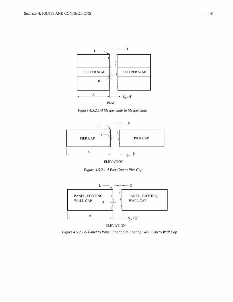
SECTION 4: JOINTS AND CONNECTIONS 4-8
Figure 4.5.2.1-3 Sleeper Slab to Sleeper Slab
Figure 4.5.2.1-4 Pier Cap to Pier Cap
Figure 4.5.2.1-5 Panel to Panel, Footing to Footing, Wall Cap to Wall Cap

4-9 GUIDELINES FOR PREFABRICATED BRIDGE ELEMENTS AND SYSTEMS TOLERANCES
Table C4.5.2.1 – Vertical Joint Tolerance for Side-by-Side Elements, Tjw
The equations in this table were used to develop the vertical joint width tolerances noted in this article. The 0.21
to 0.34 factors are the adjustment to the maximum tolerances to account for the probability of all maximum tolerances
occurring simultaneously.
Element Description Vertical Joint Width Tolerance
Tjw Left Right
Approach Slab Approach Slab ± 0.33 [0.5(BL + BR + LHL + LHR) + maximum of (DL + DR ),( HL + HR)]
Approach Slab Sleeper Slab ± 0.34 [0.5(AL + BR + LHL + LHR) + maximum of (DL + DR ),( HL + HR)]
Sleeper Slab Sleeper Slab
± 0.34 [0.5( AL + AR + LHL + LHR) + maximum of (DL + DR ),( HR + HL)] Pier Cap Pier Cap
Panel, Footing,
Wall Cap
Panel, Footing,
Wall Cap
Full-Depth
Deck Panel
Full-Depth
Deck Panel
± 0.21 [0.5(AL + AR + LHL + LHR) +
maximum of (DL + DR),(HR + HL + FL + FR)]
Modular Deck
Beam
Modular Deck
Beam
± 0.28 [0.5(AL + AR + LHL + LHR) +
maximum of (DL + DR),(HR + HL + FL + FR)]
where:
AL = maximum fabrication length tolerance of left element (in.)
AR = maximum fabrication length right element (in.)
BL = maximum fabrication width tolerance of left element (in.)
BR = maximum fabrication width tolerance of right element (in.)
DL = maximum fabrication end skew/squareness tolerance of left element (in.)
DR = maximum fabrication end skew/squareness tolerance of right element (in.)
FL = maximum fabrication sweep tolerance of left element (in.)
FR = maximum fabrication sweep tolerance of right element (in.)
HL = maximum fabrication smoothness tolerance of left element (in.)
HR = maximum fabrication smoothness tolerance of right element (in.)
Figure 4.5.2.1-6 Full-Depth Deck Panel or Modular Deck Beam
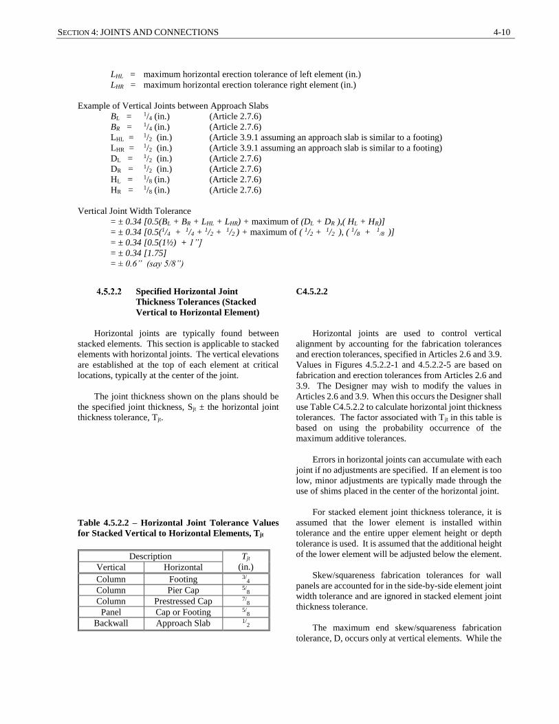
SECTION 4: JOINTS AND CONNECTIONS 4-10
LHL = maximum horizontal erection tolerance of left element (in.)
LHR = maximum horizontal erection tolerance right element (in.)
Example of Vertical Joints between Approach Slabs
BL = 1/4 (in.) (Article 2.7.6)
BR = 1/4 (in.) (Article 2.7.6)
LHL = 1/2 (in.) (Article 3.9.1 assuming an approach slab is similar to a footing)
LHR = 1/2 (in.) (Article 3.9.1 assuming an approach slab is similar to a footing)
DL = 1/2 (in.) (Article 2.7.6)
DR = 1/2 (in.) (Article 2.7.6)
HL = 1/8 (in.) (Article 2.7.6)
HR = 1/8 (in.) (Article 2.7.6)
Vertical Joint Width Tolerance
= ± 0.34 [0.5(BL + BR + LHL + LHR) + maximum of (DL + DR ),( HL + HR)]
= ± 0.34 [0.5(1/4 + 1/4 + 1/2 + 1/2 ) + maximum of ( 1/2 + 1/2 ), ( 1/8 + 1/8 )]
= ± 0.34 [0.5(1½) + 1”]
= ± 0.34 [1.75]
= ± 0.6” (say 5/8”)
Specified Horizontal Joint
Thickness Tolerances (Stacked
Vertical to Horizontal Element)
Horizontal joints are typically found between
stacked elements. This section is applicable to stacked
elements with horizontal joints. The vertical elevations
are established at the top of each element at critical
locations, typically at the center of the joint.
The joint thickness shown on the plans should be
the specified joint thickness, Sjt ± the horizontal joint
thickness tolerance, Tjt.
Table 4.5.2.2 – Horizontal Joint Tolerance Values
for Stacked Vertical to Horizontal Elements, Tjt
Description Tjt
(in.) Vertical Horizontal
Column Footing 3/4
Column Pier Cap 5/8
Column Prestressed Cap 7/8
Panel Cap or Footing 5/8
Backwall Approach Slab 1/2
C4.5.2.2
Horizontal joints are used to control vertical
alignment by accounting for the fabrication tolerances
and erection tolerances, specified in Articles 2.6 and 3.9.
Values in Figures 4.5.2.2-1 and 4.5.2.2-5 are based on
fabrication and erection tolerances from Articles 2.6 and
3.9. The Designer may wish to modify the values in
Articles 2.6 and 3.9. When this occurs the Designer shall
use Table C4.5.2.2 to calculate horizontal joint thickness
tolerances. The factor associated with Tjt in this table is
based on using the probability occurrence of the
maximum additive tolerances.
Errors in horizontal joints can accumulate with each
joint if no adjustments are specified. If an element is too
low, minor adjustments are typically made through the
use of shims placed in the center of the horizontal joint.
For stacked element joint thickness tolerance, it is
assumed that the lower element is installed within
tolerance and the entire upper element height or depth
tolerance is used. It is assumed that the additional height
of the lower element will be adjusted below the element.
Skew/squareness fabrication tolerances for wall
panels are accounted for in the side-by-side element joint
width tolerance and are ignored in stacked element joint
thickness tolerance.
The maximum end skew/squareness fabrication
tolerance, D, occurs only at vertical elements. While the
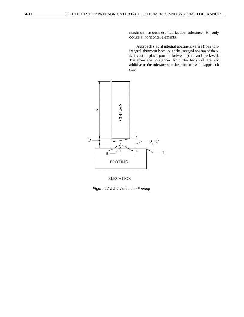
4-11 GUIDELINES FOR PREFABRICATED BRIDGE ELEMENTS AND SYSTEMS TOLERANCES
maximum smoothness fabrication tolerance, H, only
occurs at horizontal elements.
Approach slab at integral abutment varies from non-
integral abutment because at the integral abutment there
is a cast-in-place portion between joint and backwall.
Therefore the tolerances from the backwall are not
additive to the tolerances at the joint below the approach
slab.
Figure 4.5.2.2-1 Column to Footing

SECTION 4: JOINTS AND CONNECTIONS 4-12
Figure 4.5.2.2-2 Column to Pier Cap
Figure 4.5.2.2-3 Column to Prestressed Pier Cap

4-13 GUIDELINES FOR PREFABRICATED BRIDGE ELEMENTS AND SYSTEMS TOLERANCES
Figure 4.5.2.2-4 Panel to Cap
Figure 4.5.2.2-5 Panel to Footing
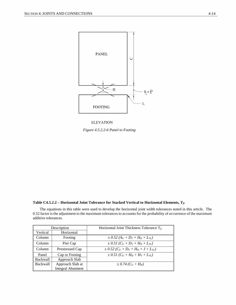
SECTION 4: JOINTS AND CONNECTIONS 4-14
Table C4.5.2.2 – Horizontal Joint Tolerance for Stacked Vertical to Horizontal Elements, Tjt
The equations in this table were used to develop the horizontal joint width tolerances noted in this article. The
0.52 factor is the adjustment to the maximum tolerances to accounts for the probability of occurrence of the maximum
additive tolerances.
Description Horizontal Joint Thickness Tolerance Tjt
Vertical Horizontal
Column Footing ± 0.52 (AU + DV + HH + LVL)
Column Pier Cap ± 0.51 (CU + DV + HH + LVL)
Column Prestressed Cap ± 0.52 (CU + DV + HH + J + LVL)
Panel Cap or Footing ± 0.51 (CU + HH + HV + LVL)
Backwall Approach Slab
Backwall Approach Slab at
Integral Abutment
± 0.74 (CU + HH)
Figure 4.5.2.2-6 Panel to Footing

4-15 GUIDELINES FOR PREFABRICATED BRIDGE ELEMENTS AND SYSTEMS TOLERANCES
where:
AU = maximum fabrication height tolerance of upper element (in.)
CU = maximum fabrication depth tolerance of upper element (in.)
DV = maximum fabrication end skew/squareness tolerance of vertical element (in.)
HH = maximum fabrication smoothness tolerance of horizontal element (in.)
HV = maximum fabrication smoothness tolerance of vertical element (in.)
LVL = maximum vertical elevation tolerance of lower element (in.)
J = maximum variance from specified camber tolerance (prestressed only) (in.)
Specified Horizontal Joint
Thickness Tolerances (Stacked
Vertical to Vertical Element)
Horizontal joints are typically found between
stacked elements. This section refers to stacked vertical
to vertical elements.
The joint thickness shown on the plans should be
the specified joint thickness, Sjt ± the horizontal joint
thickness tolerance, Tjt.
Table 4.5.2.3 – Horizontal Joint Tolerance Values
for Stacked Vertical to Vertical Elements, Tjt
Description Tjt
(in.) Vertical Vertical
Column Column 7/8
Panel Panel 5/8
C4.5.2.3
Vertical to vertical stacked elements are typically
incorporated in a design if the weight or size of the pieces
is excessive. Values in Figures 4.5.2.3-1 and 4.5.2.3-2
are based on fabrication and erection tolerances from
Articles 2.6 and 3.9. The Designer may wish to modify
the values in Articles 2.6 and 3.9. When this occurs the
Designer shall use Table C4.5.2.3 to calculate horizontal
joint thickness tolerances. The factor associated with Tjt
in this table is based on using the probability of
occurrence of the maximum additive tolerances.
Full height elements with vertical joints are typically
preferred over vertical to vertical stacked elements with
horizontal joints.
Horizontal joints in wall panels are not
recommended due to the complexity of the reinforced
connections. If wall panel weight gets excessive,
designers should consider reducing the width of the
panel or adding corrugated pipe voids to reduce the
element weight.

SECTION 4: JOINTS AND CONNECTIONS 4-16
Table C4.5.2.3 – Horizontal Joint Tolerance for Stacked Vertical to Vertical Elements, Tjt
The equations in this table were used to develop the horizontal joint width tolerances noted in this article. The
0.52 factor is the adjustment to the maximum tolerances to account for the probability of occurrence of the maximum
additive tolerances.
Description Horizontal Joint Thickness Tolerance
Tjt Vertical Vertical
Column Column + 0.52 (AU + DH + DV + LVL)
Panel Panel + 0.52 (CU + HL + HU + LVL)
where:
AU = maximum fabrication Height Tolerance Upper Element (in.)
CU = maximum fabrication Depth Tolerance Upper Element (in.)
DH = maximum fabrication end skew/squareness tolerance horizontal element (in.)
DV = maximum fabrication end skew/squareness tolerance vertical element (in.)
HU = maximum fabrication smoothness tolerance upper element (in.)
HL = maximum fabrication smoothness tolerance lower element (in.)
LVL = maximum vertical elevation tolerance of lower element (in.)
Tjt = joint thickness tolerance (in.)
Figure 4.5.2.3-1 Column to Column Figure 4.5.2.3-2 Panel to Panel

4-17 GUIDELINES FOR PREFABRICATED BRIDGE ELEMENTS AND SYSTEMS TOLERANCES
4.6 CONNECTION TOLERANCES
Connection devices between precast elements
include grouted sleeves, pile voids, reinforcing bars in
pockets, etc. The erection tolerance and the connection
device tolerances are interconnected. The combination
of these two potential installation tolerances should be
kept within the tolerance of the insertion of the bar in
the device.
C4.6
If a connection involves the insertion of a
reinforcing bar into a device (coupler or duct), the
specification for tolerances would be based on the
assumption that the bar is installed to one side and the
coupler installed to the opposite side.
Location of multiple connection devices shall
always be measured from the same control. Rather than
measuring some from a member’s edge and others from
intermediate connection devices.
Grouted Splice Couplers
The grouted splice couplers provides a structural
joint which can transmit moment and shear.
The following are typical connections of the
grouted splice coupler:
Columns to caps
Columns or wall panels to footings
Backwall to abutment stem or cap
Abutment stem to integral wingwall unit
Integral moment connections between
superstructures and substructures
It is recommended that the bar extension from one
element be fabricated over length and cut in the field
after erection of the element. The bar extension should
be based on the difference between the bottom of the
upper element (top of shim stack) and the required
embedment of the bar into the coupler.
See Articles 2.6 for horizontal location tolerances
of grouted splice couplers. Figure 4.6.1-1 shows
connection of column to footing other connections
similar.
C4.6.1
Other moment connections includes cast-in-place
closure joints and post-tensioning with match-cast
elements.
The length of a bar extension into a pocket or
coupler is affected by a number of different tolerances.
The relatively tight tolerance on the embedment of the
bar into the coupler makes specifying a tolerance on a
bar extension difficult and prone to dimensional
problems in the field.
In stacked element construction, the exact height of
shim pack is determined in field after survey and
measurement of upper element. The final goal is to meet
the elevation tolerance at the top of the upper element.
In horizontal construction (side-by-side elements),
shim packs are not used.

SECTION 4: JOINTS AND CONNECTIONS 4-18
Figure 4.6.1-1 Grouted Splice Coupler Connection Tolerances
Pocket Connections
Pocket or dowel connections provide a structural
joint which can transmit moment and/or shear through
the embedment of grouted reinforcing bars between the
two elements.
There are two types of pocket connections. The
first is a dowel pocket connection that is made by
placing a single reinforcing bar within a pocket at the
interface area between the two elements. The purpose
of dowel pocket connections is to pin two elements
together.
C4.6.2
An example of a dowel pocket connection would be
an approach slab to abutment connection. The abutment
reinforcing dowels might extend into a sleeve in the
approach slab. Multiple dowel pocket connections can
be detailed together in a pattern to form a moment
connection. An example of this type of connection can
be found in NCHRP Report Number 681 (Restrepo et al.
2011).
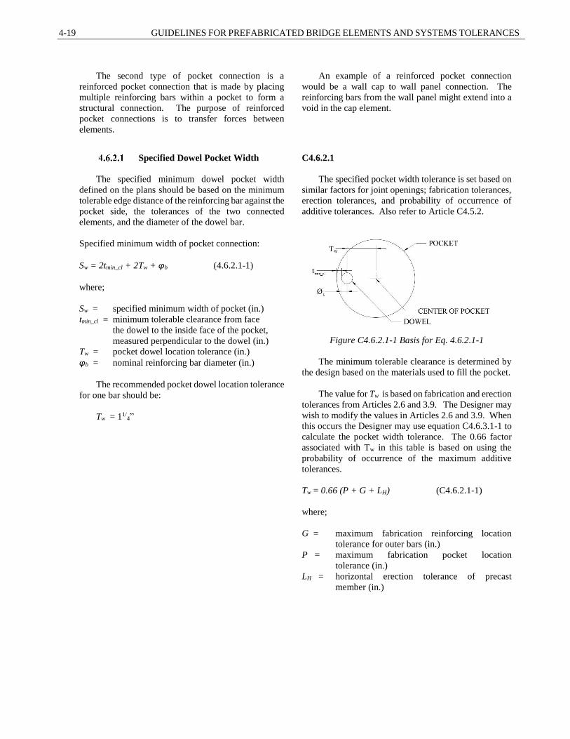
4-19 GUIDELINES FOR PREFABRICATED BRIDGE ELEMENTS AND SYSTEMS TOLERANCES
The second type of pocket connection is a
reinforced pocket connection that is made by placing
multiple reinforcing bars within a pocket to form a
structural connection. The purpose of reinforced
pocket connections is to transfer forces between
elements.
An example of a reinforced pocket connection
would be a wall cap to wall panel connection. The
reinforcing bars from the wall panel might extend into a
void in the cap element.
Specified Dowel Pocket Width
The specified minimum dowel pocket width
defined on the plans should be based on the minimum
tolerable edge distance of the reinforcing bar against the
pocket side, the tolerances of the two connected
elements, and the diameter of the dowel bar.
Specified minimum width of pocket connection:
Sw = 2tmin_cl + 2Tw + φb (4.6.2.1-1)
where;
Sw = specified minimum width of pocket (in.)
tmin_cl = minimum tolerable clearance from face
the dowel to the inside face of the pocket,
measured perpendicular to the dowel (in.)
Tw = pocket dowel location tolerance (in.)
φb = nominal reinforcing bar diameter (in.)
The recommended pocket dowel location tolerance
for one bar should be:
Tw = 11/4”
C4.6.2.1
The specified pocket width tolerance is set based on
similar factors for joint openings; fabrication tolerances,
erection tolerances, and probability of occurrence of
additive tolerances. Also refer to Article C4.5.2.
Figure C4.6.2.1-1 Basis for Eq. 4.6.2.1-1
The minimum tolerable clearance is determined by
the design based on the materials used to fill the pocket.
The value for Tw is based on fabrication and erection
tolerances from Articles 2.6 and 3.9. The Designer may
wish to modify the values in Articles 2.6 and 3.9. When
this occurs the Designer may use equation C4.6.3.1-1 to
calculate the pocket width tolerance. The 0.66 factor
associated with Tw in this table is based on using the
probability of occurrence of the maximum additive
tolerances.
Tw = 0.66 (P + G + LH) (C4.6.2.1-1)
where;
G = maximum fabrication reinforcing location
tolerance for outer bars (in.)
P = maximum fabrication pocket location
tolerance (in.)
LH = horizontal erection tolerance of precast
member (in.)
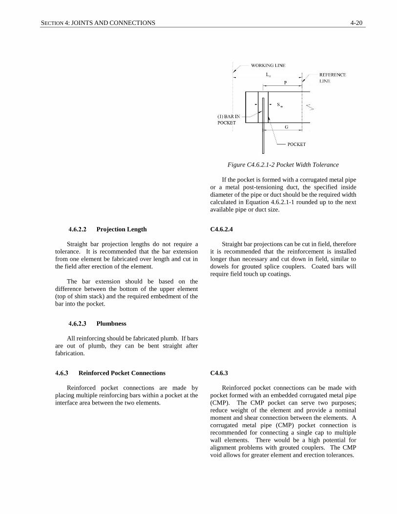
SECTION 4: JOINTS AND CONNECTIONS 4-20
Figure C4.6.2.1-2 Pocket Width Tolerance
If the pocket is formed with a corrugated metal pipe
or a metal post-tensioning duct, the specified inside
diameter of the pipe or duct should be the required width
calculated in Equation 4.6.2.1-1 rounded up to the next
available pipe or duct size.
Projection Length
Straight bar projection lengths do not require a
tolerance. It is recommended that the bar extension
from one element be fabricated over length and cut in
the field after erection of the element.
The bar extension should be based on the
difference between the bottom of the upper element
(top of shim stack) and the required embedment of the
bar into the pocket.
C4.6.2.4
Straight bar projections can be cut in field, therefore
it is recommended that the reinforcement is installed
longer than necessary and cut down in field, similar to
dowels for grouted splice couplers. Coated bars will
require field touch up coatings.
Plumbness
All reinforcing should be fabricated plumb. If bars
are out of plumb, they can be bent straight after
fabrication.
Reinforced Pocket Connections
Reinforced pocket connections are made by
placing multiple reinforcing bars within a pocket at the
interface area between the two elements.
C4.6.3
Reinforced pocket connections can be made with
pocket formed with an embedded corrugated metal pipe
(CMP). The CMP pocket can serve two purposes;
reduce weight of the element and provide a nominal
moment and shear connection between the elements. A
corrugated metal pipe (CMP) pocket connection is
recommended for connecting a single cap to multiple
wall elements. There would be a high potential for
alignment problems with grouted couplers. The CMP
void allows for greater element and erection tolerances.

4-21 GUIDELINES FOR PREFABRICATED BRIDGE ELEMENTS AND SYSTEMS TOLERANCES
Specified Reinforced Pocket Width
The specified minimum reinforced pocket width
defined on the plans should be based on the minimum
tolerable edge distance of the reinforcing bar against the
pocket side, the tolerances of the two connected
elements, the diameter of the bar, and the overall width
of the reinforcing pattern.
Specified minimum width of reinforced pocket
connection:
Sw = 2tmin_cl + 2Tw + φb + s (4.6.3.1-1)
where:
s = maximum distance between bar extremes,
center-to-center of bars (in.)
Sw = specified minimum width of pocket (in.)
tmin_cl = minimum tolerable clearance from face
of reinforcing bars to inside face of the pocket,
measured perpendicular to the reinforcing
bars (in.)
Tw = pocket reinforcing location tolerance (in.)
φb = bar diameter (in.)
The recommended pocket reinforcing location
tolerance for two or more bars should be:
Tw = 11/4”
C4.6.3.1
The specified reinforced pocket width tolerance is
set based on fabrication tolerances, erection tolerances,
and probability of occurrence of additive tolerances.
Figure C4.6.3.1-1 Basis for Eq. 4.6.3.1-1
The minimum tolerable clearance is determined by
the design based on the materials used to fill the pocket.
The value for Tw is based on fabrication and erection
tolerances from Articles 2.6 and 3.9. The Designer may
wish to modify the values in Articles 2.6 and 3.9. When
this occurs the Designer should use equation C4.6.3.1-1
to calculate the pocket width tolerance. The 0.62 factor
associated with Tw is based on using the probability
occurrence of the maximum additive tolerances.
Tw = 0.62 (P + 2G + LH) (C4.6.3.1-1)
where;
G = maximum fabrication reinforcing location
tolerance for outer bars (in.)
P = maximum fabrication pocket location
tolerance (in.)
LH = horizontal erection tolerance of precast
member (in.)
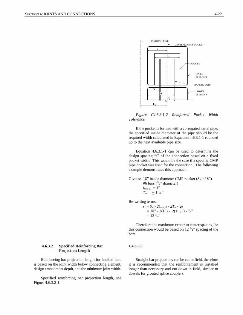
SECTION 4: JOINTS AND CONNECTIONS 4-22
Figure C4.6.3.1-2 Reinforced Pocket Width
Tolerance
If the pocket is formed with a corrugated metal pipe,
the specified inside diameter of the pipe should be the
required width calculated in Equation 4.6.3.1-1 rounded
up to the next available pipe size.
Equation 4.6.3.1-1 can be used to determine the
design spacing “s” of the connection based on a fixed
pocket width. This would be the case if a specific CMP
pipe pocket was used for the connection. The following
example demonstrates this approach:
Givens: 18” inside diameter CMP pocket (Sw =18”)
#6 bars (3/4” diameter)
tmin_cl = 1”
Tw = + 11/4 ”
Re-writing terms:
s = Sw - 2tmin_cl - 2Tw - φb
= 18” - 2(1”) - 2(11/4 ”) - 3/
4”
= 12 3/4”
Therefore the maximum center to center spacing for
this connection would be based on 12 3/4” spacing of the
bars.
Specified Reinforcing Bar
Projection Length
Reinforcing bar projection length for hooked bars
is based on the joint width below connecting element,
design embedment depth, and the minimum joint width.
Specified reinforcing bar projection length, see
Figure 4.6.3.2-1:
C4.6.3.3
Straight bar projections can be cut in field, therefore
it is recommended that the reinforcement is installed
longer than necessary and cut down in field, similar to
dowels for grouted splice couplers.

4-23 GUIDELINES FOR PREFABRICATED BRIDGE ELEMENTS AND SYSTEMS TOLERANCES
N’ = tmin_jt + Tjt + N (4.6.3.2-1)
where:
N = reinforcing bar design embedment length
required by design(in.)
tmin_jt = minimum tolerable joint thickness (in.)
Tjt = joint thickness tolerance (in.)
See Table 4.5.2.2 to obtain values for tolerable joint
thickness, Tjt.
The designer should specify the minimum joint
width based on the material chosen to fill the joint.
Figure C4.6.3.2-1 Reinforcing Bar Projection Length
in Pocket Section
Pocket Depth
The specified pocket depth is based on
reinforcement projection length, minimum joint
thickness, and the minimum reinforcing clearance.
Specified pocket depth, see Figure C4.6.3.3-1:
P = tmin_cl + tmin_jt + N’ (4.6.3.3-1)
where:
N’ = specified reinforcing bar projection length
(in.)
tmin_cl = minimum tolerable clearance between face of
reinforcing and end face of pocket (in.)
tmin_jt = minimum tolerable joint thickness (in.)
See Equation 4.6.3.2-1 to obtain values for
specified reinforcing bar projection length, N’.
Figure C4.6.3.3-1 Pocket Depth Section

SECTION 4: JOINTS AND CONNECTIONS 4-24
Integral Abutment Pile Pocket
Connections
Integral abutments are pile supported structures
that provide a full moment connection between the
superstructure and the abutment. The abutment stem is
integral with the piles requiring a fixed connection.
Corrugated metal pipe (CMP) pockets are typically
used to make this connection with piles and drilled
shafts. The element is placed over the piles and the
pocket is filled with concrete to complete the
connection.
The CMP pocket should be sized to account for the
horizontal location tolerances of the CMP void in the
precast abutment stem and the pile or drilled shaft.
C4.6.4
Additional CMP pockets can also be detailed to
reduce the shipping and handling weight of the abutment
stem. They can be filled with concrete at the same time
as the filling operation for the pile connections.
Specified Pile Pocket Width
The specified pile pocket width defined on the
plans is the absolute minimum tolerable width that
accounts for the pocket width tolerance, the required
edge clearances for the pile, and the largest width of the
pile.
Specified width of pile pocket connection:
Sw = 2tmin_cl + O.D. + 2Tw (4.6.4.1-1)
where:
tmin_cl = minimum tolerable clearance (in.)
Sw = specified width of pile or drilled shaft void
(in.)
Tw = pile pocket width tolerance (in.)
O.D. = outer diameter of drilled shaft and pipe pile or
measured diagonally from corners of H-pile
(in.)
Table 4.6.4.1-1 – Pile Pocket Width Tolerance, Tw
G
(in.)
Tw
(in.)
3 3 1/4
6 6 1/8
9 9 1/8
C4.6.4.1
The value for Tw is based on fabrication and erection
tolerances from Articles 2.6 and 3.9. The Designer may
wish to modify the values in Articles 2.6 and 3.9. When
this occurs the Designer should use Table C4.6.4.1 to
calculate the pocket width tolerances. The factor
associated with Tw in this table is based on using the
probability occurrence of the maximum additive
tolerances.
Table C4.6.4.1 – Pocket Width Tolerance, Tw
G
(in.)
Tw
(in.)
3 ± 0.72 (P+G+LH)
6 ± 0.81 (P+G+LH)
9 ± 0.86 (P+G+LH)
where:
G = maximum pile or drilled shaft lateral
installation tolerance (in.)
P = maximum fabrication pocket location
tolerance (in.)
LH = horizontal erection tolerance of precast
member (in.)
Tw = width of pile void connection tolerance (in.)
Note the maximum pile or drilled shaft lateral
installation tolerance, G, typically varies between States.
Table C4.6.4.1 gives a typical range of values of G to
determine the void width tolerance.
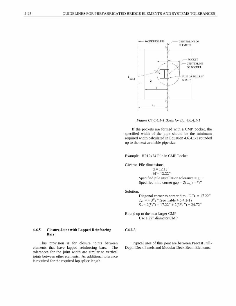
4-25 GUIDELINES FOR PREFABRICATED BRIDGE ELEMENTS AND SYSTEMS TOLERANCES
Figure C4.6.4.1-1 Basis for Eq. 4.6.4.1-1
If the pockets are formed with a CMP pocket, the
specified width of the pipe should be the minimum
required width calculated in Equation 4.6.4.1-1 rounded
up to the next available pipe size.
Example: HP12x74 Pile in CMP Pocket
Givens: Pile dimensions
d = 12.13”
bf = 12.22”
Specified pile installation tolerance = + 3”
Specified min. corner gap = 2tmin_cl = 1/2”
Solution:
Diagonal corner to corner dim., O.D. = 17.22”
Tw = + 31/4 ” (see Table 4.6.4.1-1)
Sw = 2(1/2”) + 17.22” + 2(31/
4 ”) = 24.72”
Round up to the next larger CMP
Use a 27” diameter CMP
Closure Joint with Lapped Reinforcing
Bars
This provision is for closure joints between
elements that have lapped reinforcing bars. The
tolerances for the joint width are similar to vertical
joints between other elements. An additional tolerance
is required for the required lap splice length.
C4.6.5
Typical uses of this joint are between Precast Full-
Depth Deck Panels and Modular Deck Beam Elements.

SECTION 4: JOINTS AND CONNECTIONS 4-26
Specified Closure Joint Width
The specified closure joint width defined on the
plans is the minimum tolerable width that accounts for
the minimum reinforcing bar splice length, bar
clearances, and the bar splice tolerance.
Specified closure joint width:
Scjw = Llap + Tlap + 2tmin_cl + Tcjw (4.6.5.1-1)
where:
Llap = required minimum lap length (in.)
Scjw = specified width of closure joint (in.)
tmin_cl = minimum tolerable clear distance from the
end of the bar to the adjacent element (in.)
Tcjw = closure joint width tolerance as specified in
Article 4.5.2.1 (in.)
Tlap = reinforcing bar lap length tolerance as
specified below (in.)
The specified reinforcing bar lap length defined on
the plans is the minimum required lap length that
accounts for the minimum reinforcing bar splice length
and the bar splice tolerance.
Specified lap length:
Slap = Llap + Tlap (4.6.5.1-2)
where:
Llap = required minimum lap length (in.)
Slap = specified length of lap (in.)
Tlap = lap length tolerance (in.)
Table 4.6.5.1-1 Lap Length Tolerance, Tlap
Element Type Tlap
(in.)
Full-Depth Deck Panels 1/2
Modular Deck Beams 3/4
C4.6.5.1
The value for Tjw is based on fabrication and erection
tolerances from Articles 2.7 and 3.9. The Designer may
wish to modify the values in Articles 2.7 and 3.9. When
this occurs the Designer should use the equations noted
in Article 4.5.2.1 to calculate the closure joint width
tolerance.
Figure C4.6.5.1-1 Basis for Eq. 4.6.5.1-1
and Eq. 4.6.5.1-2
The value for Tlap is based on fabrication and
erection tolerances from Articles 2.7 and 3.9. The
Designer may wish to modify the values in Articles 2.7
and 3.9. When this occurs the Designer should use
equation C4.6.3.1-1 to calculate the lap length tolerance.
The factor associated with Tlap in this equation is based
on using the probability occurrence of the maximum
additive tolerances.
For Full-Depth Deck Panel Connections:
Tlap = 0.24 [0.5(AL + AR + LHL + LHR)
+ maximum of (DL + DR),(HR + HL + FL + FR)
+ QL +QR]
(Eq. C4.6.5.1-1)
For Modular Deck Beam Flange Connections:
Tlap = 0.26 [0.5(AL + AR + LHL + LHR)
+ maximum of (DL + DR),(HR + HL + FL + FR)
+ QL +QR]
(Eq. C4.6.5.1-2)
where:
AL = maximum fabrication length tolerance of left
element (in.)
AR = maximum fabrication length tolerance of right
element (in.)
DL = maximum fabrication end skew/squareness

4-27 GUIDELINES FOR PREFABRICATED BRIDGE ELEMENTS AND SYSTEMS TOLERANCES
tolerance of left element (in.)
DR = maximum fabrication end skew/squareness
tolerance of right element (in.)
FL = maximum fabrication sweep tolerance of left
element (in.)
FR = maximum fabrication sweep tolerance of right
element (in.)
HL = maximum fabrication smoothness tolerance of
left element (in.)
HR = maximum fabrication smoothness tolerance of
right element (in.)
LHL = maximum horizontal erection tolerance of left
element (in.)
LHR = maximum horizontal erection tolerance right
element (in.)
QL = maximum bar projection tolerance for left
element (in.)
QR = maximum bar projection tolerance for right
element (in.)
4.7 REFERENCES
ACI Specification for Tolerances for Precast Concrete, ACI ITG-7-09, American Concrete Institute,
Farmington Hills, MI, (2009)
Culmo, M.P., et al, Guidelines for Prefabricated Bridge Elements and Systems Tolerances and Dynamic
Effects of Bridge Moves, Final Report, NCHRP Project 12-102, National Cooperative Highway Research
Program, Transportation Research Board, Washington, D.C. (2017)
PCI Northeast Guideline for Accelerated Bridge Construction Using Precast/Prestressed Concrete Elements
Including Guideline Details, PCINE-12-ABC, PCI Northeast Bridge Technical Committee (2014)
PCI Tolerance Manual for precast and Prestressed Concrete Construction - MNL-135-00, Precast
Prestressed Concrete Institute, Chicago, IL, (2000)
Restrepo, J.I., Et al, Development of a Precast Pier cap System for Seismic Regions, NCHRP Report 681,
National Cooperative Highway Research Program, Washington, D.C (2011)

SECTION 4: JOINTS AND CONNECTIONS 4-28


