Download - Project source 2 with 1.5

A Mini Project report
On
PROTECTION OF TRANSFORMER (132/33 KV SUBSTATION, CHINTAL)
Submitted in partial fulfillment of the
requirement for the award of degree of
BACHELOR OF TECHNOLOGY
in
ELECTRICAL & ELECTRONICS ENGINEERING
by
M.SHIVA KUMAR 11611A0217
N.KARTHIK 11611A0220
T.PRASHANTH KUMAR 11611A0228
V.BHARATH 11611A0232
DEPARTMENT OF ELECTRICAL & ELECTRONICS
ENGINEERING
P.R.R.M ENGINEERING COLLEGE (Affiliated to Jawaharlal Nehru Technological University, Hyderabad)
Shabad,R.R.Dist – 509217,T.S.
Page | 1
1.INTRODUCTION
1.1 TS Transco
The erstwhile Andhra Pradesh State Electricity Board which came
into existence in 1959 was responsible for Generation, Transmission and Distribution
of Electricity. Under Electricity Sector Reforms Agenda, Government of Andhra
Pradesh promulgated Andhra Pradesh Electricity Reforms Act,1998.The erstwhile
APSEB was unbundled into one Generation Company (APGENCO),One
Transmission Company(APTRANSCO) and Four Distribution Companies
(APDISCOMs) as part of the reform process.
APTRANSCO came into existence on 1.02.1999.From Feb 1999 to
June 2005 APTRANSCO remained as single buyer in the State-Purchasing power
from various Generators and selling it to DISCOMs in accordance with the terms and
conditions of the individual PPAs at Bulk Supply Tariff (BST) rates. Subsequently, in
accordance with the Third Transfer Scheme notified by GOAP, APTRANSCO ceased
to do power trading and has retained powers of controlling system operations of
Power Transmission.
As per AP Reorganization Act 2014, APTRANSCO was divided
into TSTRANSCO and APTRANSO. Accordingly TSTRANSCO was established as
a Company w.e.f 02.06.2014 for the State of Telangana.
1.2 Substation and Layout
In modern power system to have a normal operation of the system
without electrical failure and damage to the equipment two alternators are available
with the designer, one is to design the system so that faults cannot occur and other is
to accept the possibility of faults and take steps to guard against the ill effects of such
faults. The main objective of our mini project work is to study the protection of
transformer in 132/33kv substation. Protective scheme required for the protection of
power system components against abnormal conditions such as faults etc., consists of
circuit breakers. In 132/33kv substation they used SF6 circuit breaker at HV side and
VCB at LV side. The auxiliaries like isolators, lightening arrestors, CT’s, PT’s,
control panel and indicating instruments are used.

Page | 2
The assembly of apparatus used to stabilize the voltage from all
the components like harmonics, transients etc .,is called sub-station. Substation is
important part of power system. The continuity of supply depends to a considerable
extent upon the successful operation of substations. It is, therefore, essential to
exercise utmost care while designing and building a substation.
Fig. 1.1 Overview of Substation
We did the project at 132/33 KV substation which is located at Chintal near HMT
Tractor manufacturing company. The main feature of this substation is that it is very
near to the main load center. It is well designed, such that it consists of requisite area
for feature expansion.
Page | 3
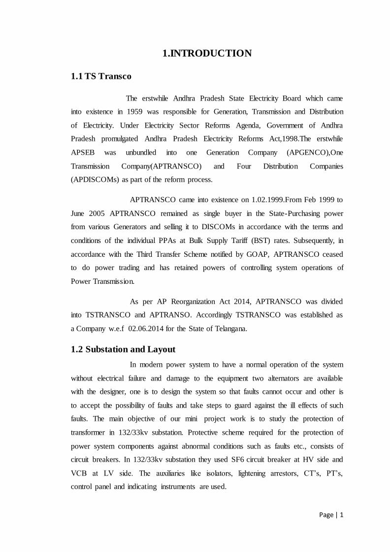
Fig. 1.2 Single Line Diagram
Page | 4
2. POWER TRANSFORMER
2.1Construction
A transformer is an electrical device that transfers energy between
two or more circuits through electromagnetic induction without change in frequency.
A varying current in the transformer's primary winding creates a
varying magnetic flux in the core and a varying magnetic field impinging on the
secondary winding. This varying magnetic field at the secondary induces a varying
electromotive force(emf) or voltage in the secondary winding. Making use of
Faraday's Law in conjunction with high magnetic permeability core properties,
transformers can thus be designed to efficiently change AC voltages from one voltage
level to another within power networks.
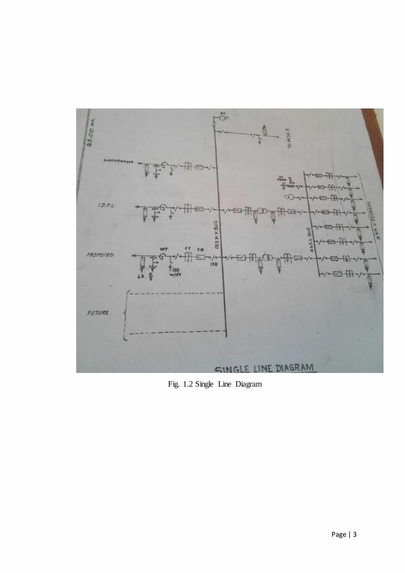
Fig. 2.1 31.5 MVA Fig. 2.2 50 MVA
In 132/33kv substation we use the power transformer of rating 31.5
MVA and 50 MVA.
For the construction of transformer different types of cores are used.
They are :-
1) Laminated steel cores
2) Solid cores
3) Toroidal cores
4) Air cores
Page | 5
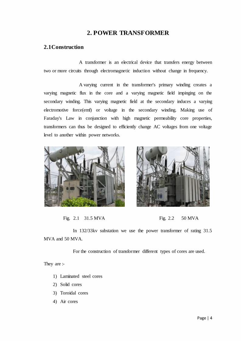
In this we use laminated steel type of core. The core, which
provides the magnetic path to channel the flux, consists of thin strips of high-grade
steel, called laminations, which are electrically separated by a thin coating of
insulating material. The strips can be stacked or wound, with the windings either built
integrally around the core or built separately and assembled around the core sections.
Fig. 2.3 Schematic of three-phase core form construction
Thickness ranges from 0.23 mm to upwards of 0.36 mm. The core
cross section can be circular or rectangular, with circular cores commonly referred to
as cruciform construction. Rectangular cores are used for smaller ratings and as
auxiliary transformers used within a power transformer. Rectangular cores use a
single width of strip steel, while circular cores use a combination of different strip
widths to approximate a circular cross-section. Just like other components in the
transformer, the heat generated by the core must be adequately dissipated.
While the steel and coating may be capable of withstanding higher
temperatures, it will come in contact with insulating materials with limited
temperature capabilities. In larger units, cooling ducts are used inside the core for
Page | 6
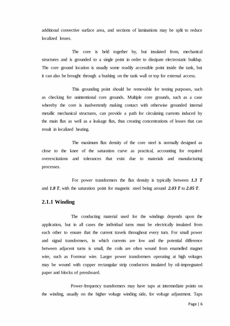
additional convective surface area, and sections of laminations may be split to reduce
localized losses.
The core is held together by, but insulated from, mechanical
structures and is grounded to a single point in order to dissipate electrostatic buildup.
The core ground location is usually some readily accessible point inside the tank, but
it can also be brought through a bushing on the tank wall or top for external access.
This grounding point should be removable for testing purposes, such
as checking for unintentional core grounds. Multiple core grounds, such as a case
whereby the core is inadvertently making contact with otherwise grounded internal
metallic mechanical structures, can provide a path for circulating currents induced by
the main flux as well as a leakage flux, thus creating concentrations of losses that can
result in localized heating.
The maximum flux density of the core steel is normally designed as
close to the knee of the saturation curve as practical, accounting for required
overexcitations and tolerances that exist due to materials and manufacturing
processes.
For power transformers the flux density is typically between 1.3 T
and 1.8 T, with the saturation point for magnetic steel being around 2.03 T to 2.05 T.
2.1.1 Winding
The conducting material used for the windings depends upon the
application, but in all cases the individual turns must be electrically insulated from
each other to ensure that the current travels throughout every turn. For small power
and signal transformers, in which currents are low and the potential difference
between adjacent turns is small, the coils are often wound from enamelled magnet
wire, such as Formvar wire. Larger power transformers operating at high voltages
may be wound with copper rectangular strip conductors insulated by oil-impregnated
paper and blocks of pressboard.
Power-frequency transformers may have taps at intermediate points on
the winding, usually on the higher voltage winding side, for voltage adjustment. Taps
Page | 7
may be manually reconnected, or a manual or automatic switch may be provided for
changing taps. Automatic on-load tap changers are used in electric power
transmission or distribution, on equipment such as arc furnace transformers, or for
automatic voltage regulators for sensitive loads.
2.1.2 Insulation Drying
Construction of oil-filled transformers requires that the insulation
covering the windings be thoroughly dried of residual moisture before the oil is
introduced. Drying is carried out at the factory, and may also be required as a field
service. Drying may be done by circulating hot air around the core, or by vapor-phase
drying (VPD) where an evaporated solvent transfers heat by condensation on the coil
and core.
For small transformers, resistance heating by injection of current into
the windings is used. The heating can be controlled very well, and it is energy
efficient. The method is called low-frequency heating (LFH) since the current used is
at a much lower frequency than that of the power grid, which is normally 50 or 60 Hz.
A lower frequency reduces the effect of inductance, so the voltage required can be
reduced. The LFH drying method is also used for service of older transformers.
2.1.3 Bushings
Larger transformers are provided with high-voltage insulated bushings
made of polymers or porcelain. A large bushing can be a complex structure since it
must provide careful control of the electric field gradient without letting the
transformer leak oil.
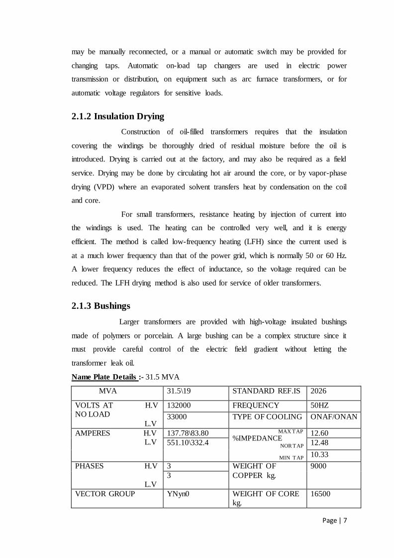
Name Plate Details :- 31.5 MVA
MVA 31.5\19 STANDARD REF.IS 2026
VOLTS AT H.V NO LOAD
L.V
132000 FREQUENCY 50HZ
33000 TYPE OF COOLING ONAF/ONAN
AMPERES H.V L.V
137.78\83.80 MAX TAP
%IMPEDANCE NOR TAP
MIN TAP
12.60
551.10\332.4 12.48
10.33
PHASES H.V
L.V
3 WEIGHT OF
COPPER kg.
9000
3
VECTOR GROUP YNyn0 WEIGHT OF CORE kg.
16500
Page | 8
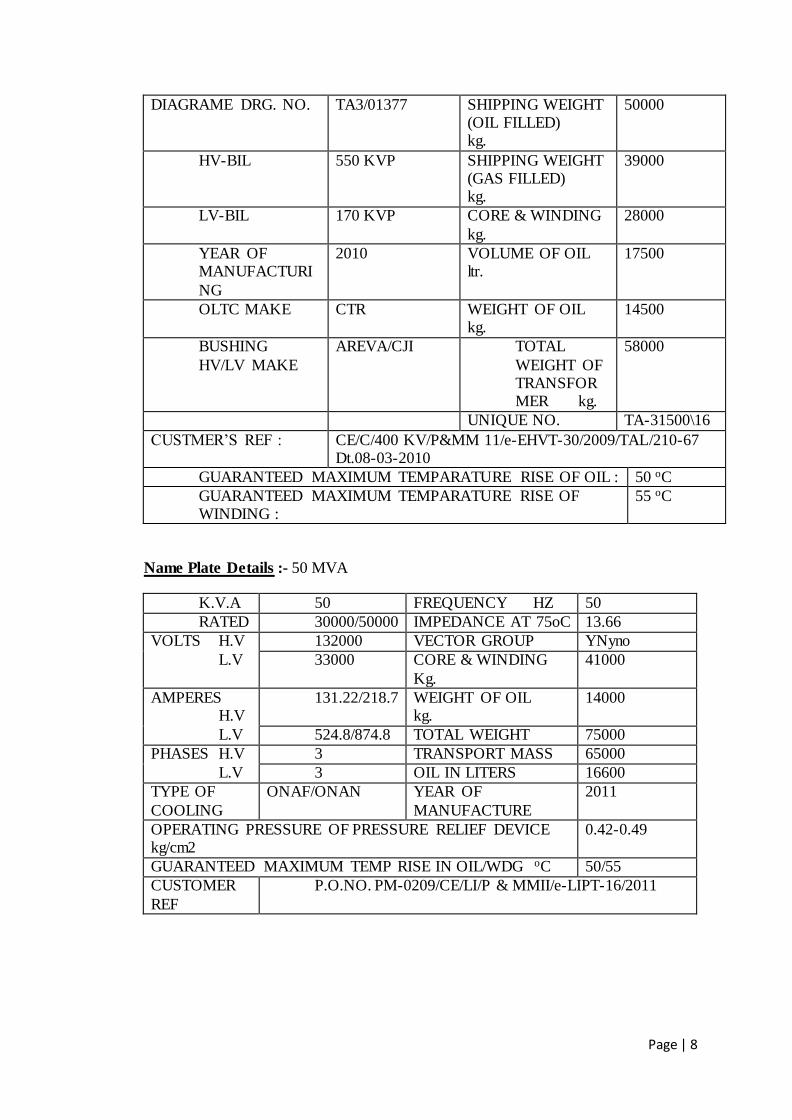
DIAGRAME DRG. NO. TA3/01377 SHIPPING WEIGHT (OIL FILLED) kg.
50000
HV-BIL 550 KVP SHIPPING WEIGHT (GAS FILLED) kg.
39000
LV-BIL 170 KVP CORE & WINDING
kg.
28000
YEAR OF MANUFACTURI
NG
2010 VOLUME OF OIL ltr.
17500
OLTC MAKE CTR WEIGHT OF OIL kg.
14500
BUSHING
HV/LV MAKE
AREVA/CJI TOTAL
WEIGHT OF TRANSFORMER kg.
58000
UNIQUE NO. TA-31500\16
CUSTMER’S REF : CE/C/400 KV/P&MM 11/e-EHVT-30/2009/TAL/210-67 Dt.08-03-2010
GUARANTEED MAXIMUM TEMPARATURE RISE OF OIL : 50 oC
GUARANTEED MAXIMUM TEMPARATURE RISE OF WINDING :
55 oC
Name Plate Details :- 50 MVA
K.V.A 50 FREQUENCY HZ 50
RATED 30000/50000 IMPEDANCE AT 75oC 13.66
VOLTS H.V
L.V
132000 VECTOR GROUP YNyno
33000 CORE & WINDING
Kg.
41000
AMPERES H.V
L.V
131.22/218.7 WEIGHT OF OIL kg.
14000
524.8/874.8 TOTAL WEIGHT 75000
PHASES H.V
L.V
3 TRANSPORT MASS 65000
3 OIL IN LITERS 16600
TYPE OF
COOLING
ONAF/ONAN YEAR OF
MANUFACTURE
2011
OPERATING PRESSURE OF PRESSURE RELIEF DEVICE kg/cm2
0.42-0.49
GUARANTEED MAXIMUM TEMP RISE IN OIL/WDG oC 50/55
CUSTOMER
REF
P.O.NO. PM-0209/CE/LI/P & MMII/e-LIPT-16/2011
Page | 9
2.1.4 Breather
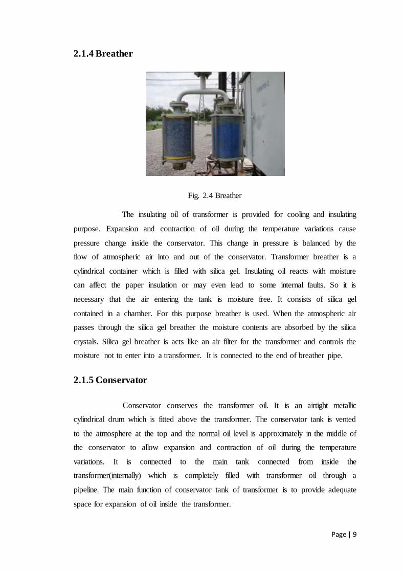
Fig. 2.4 Breather
The insulating oil of transformer is provided for cooling and insulating
purpose. Expansion and contraction of oil during the temperature variations cause
pressure change inside the conservator. This change in pressure is balanced by the
flow of atmospheric air into and out of the conservator. Transformer breather is a
cylindrical container which is filled with silica gel. Insulating oil reacts with moisture
can affect the paper insulation or may even lead to some internal faults. So it is
necessary that the air entering the tank is moisture free. It consists of silica gel
contained in a chamber. For this purpose breather is used. When the atmospheric air
passes through the silica gel breather the moisture contents are absorbed by the silica
crystals. Silica gel breather is acts like an air filter for the transformer and controls the
moisture not to enter into a transformer. It is connected to the end of breather pipe.
2.1.5 Conservator
Conservator conserves the transformer oil. It is an airtight metallic
cylindrical drum which is fitted above the transformer. The conservator tank is vented
to the atmosphere at the top and the normal oil level is approximately in the middle of
the conservator to allow expansion and contraction of oil during the temperature
variations. It is connected to the main tank connected from inside the
transformer(internally) which is completely filled with transformer oil through a
pipeline. The main function of conservator tank of transformer is to provide adequate
space for expansion of oil inside the transformer.
Page | 10
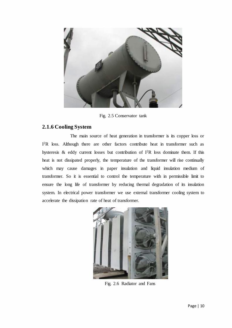
Fig. 2.5 Conservator tank
2.1.6 Cooling System
The main source of heat generation in transformer is its copper loss or
I2R loss. Although there are other factors contribute heat in transformer such as
hysteresis & eddy current losses but contribution of I2R loss dominate them. If this
heat is not dissipated properly, the temperature of the transformer will rise continually
which may cause damages in paper insulation and liquid insulation medium of
transformer. So it is essential to control the temperature with in permissible limit to
ensure the long life of transformer by reducing thermal degradation of its insulation
system. In electrical power transformer we use external transformer cooling system to
accelerate the dissipation rate of heat of transformer.
Fig. 2.6 Radiator and Fans

Page | 11
Radiators are used to cool the transformer oil. The transformer oil is
circulated through the them. The circulation of the oil may either be natural or forced
circulation. In natural circulation, when the temperature of the oil raises the hot oil
naturally moves to the top and the cold oil moves downwards. Thus the oil keeps on
circulating through the tubes. In Heat dissipation can obviously be increased, if
dissipating surface is increased but it can be make further faster by applying forced air
flow on that dissipating surface. Fans blowing air on cooling surface is employed.
Forced air takes away the heat from the surface of radiator and provides better cooling
than natural air. The full form of ONAF is "Oil Natural Air Forced". As the heat
dissipation rate is faster and more in ONAF transformer cooling method than ONAN
cooling system, electrical power transformer can be put into more load without
crossing the permissible temperature limits.
A) Oil Temperature Indicator or OTI
This device is used to measure the top oil temperature. An oil temperature indicator or
OTI is also used for protection of transformer.
Operating principle of Oil Temperature Indicator :
This device measures top oil temperature with the help of sensing bulb immersed in
the pocket by using liquid expansion in the bulb through a capillary line to operating
mechanism. A link and lever mechanism amplifies this movement to the disc carrying
pointer and mercury switches. When volume of the liquid in operating mechanism
changes, the bellow attached to end of capillary tube expands and contracts. This
movement of bellow is transmitted to the pointer in temperature indicator of
transformer through a lever linkage mechanism.
B) Winding Temperature Indicator or WTI
This device measures the LV and HV winding temperature. A winding temperature
indicator or WTI is also used as protection of transformer.
Page | 12
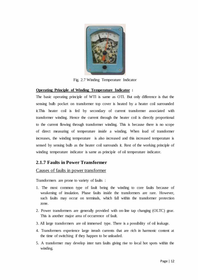
Fig. 2.7 Winding Temperature Indicator
Operating Principle of Winding Temperature Indicator :
The basic operating principle of WTI is same as OTI. But only difference is that the
sensing bulb pocket on transformer top cover is heated by a heater coil surrounded
it.This heater coil is fed by secondary of current transformer associated with
transformer winding. Hence the current through the heater coil is directly proportional
to the current flowing through transformer winding. This is because there is no scope
of direct measuring of temperature inside a winding. When load of transformer
increases, the winding temperature is also increased and this increased temperature is
sensed by sensing bulb as the heater coil surrounds it. Rest of the working principle of
winding temperature indicator is same as principle of oil temperature indicator.
2.1.7 Faults in Power Transformer
Causes of faults in power transformer
Transformers are prone to variety of faults :
1. The most common type of fault being the winding to core faults because of
weakening of insulation. Phase faults inside the transformers are rare. However,
such faults may occur on terminals, which fall within the transformer protection
zone.
2. Power transformers are generally provided with on-line tap changing (OLTC) gear.
This is another major area of occurrence of fault.
3. All large transformers are oil immersed type. There is a possibility of oil leakage.
4. Transformers experience large inrush currents that are rich in harmonic content at
the time of switching if they happen to be unloaded.
5. A transformer may develop inter turn faults giving rise to local hot spots within the
winding.
Page | 13
6. Transformers may suffer from over fluxing due to under frequency operation at
rated voltage. Over fluxing may also be caused when the transformer is subjected
to over voltage at the rated frequency.
7. In case of sustained overload conditions, the transformer should not be allowed to
operate for long duration.
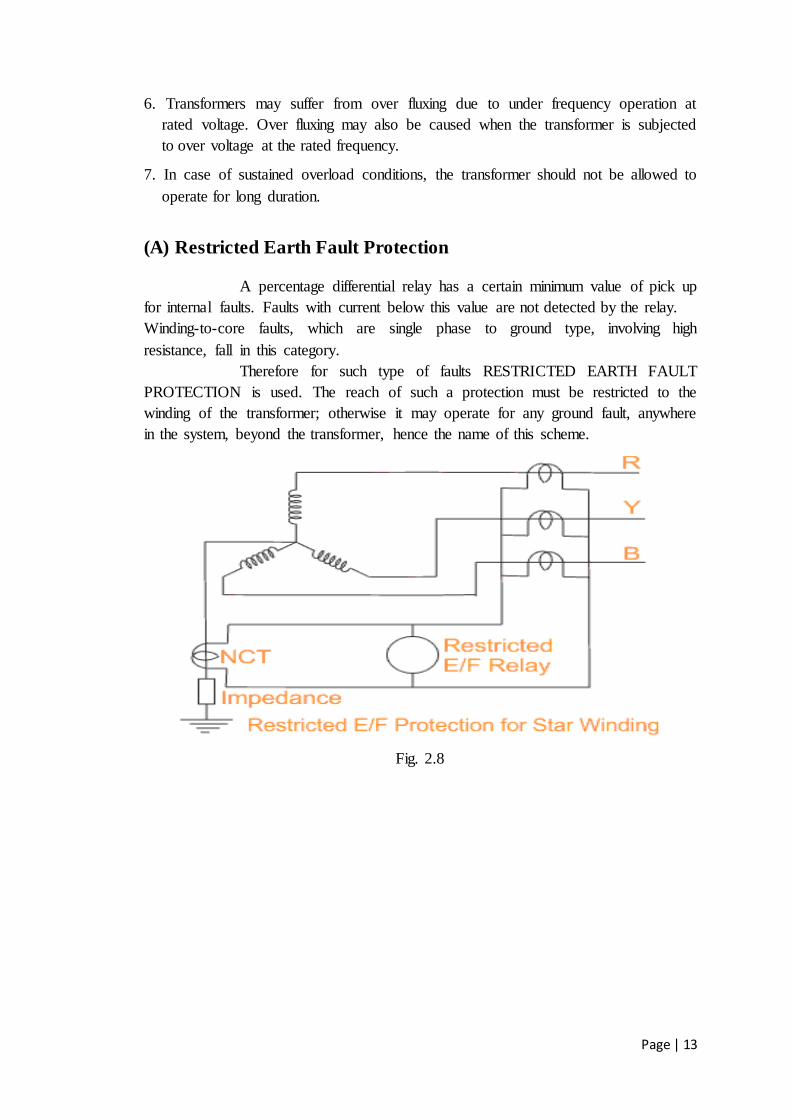
(A) Restricted Earth Fault Protection A percentage differential relay has a certain minimum value of pick up
for internal faults. Faults with current below this value are not detected by the relay.
Winding-to-core faults, which are single phase to ground type, involving high
resistance, fall in this category.
Therefore for such type of faults RESTRICTED EARTH FAULT
PROTECTION is used. The reach of such a protection must be restricted to the
winding of the transformer; otherwise it may operate for any ground fault, anywhere
in the system, beyond the transformer, hence the name of this scheme.
Fig. 2.8
Page | 14
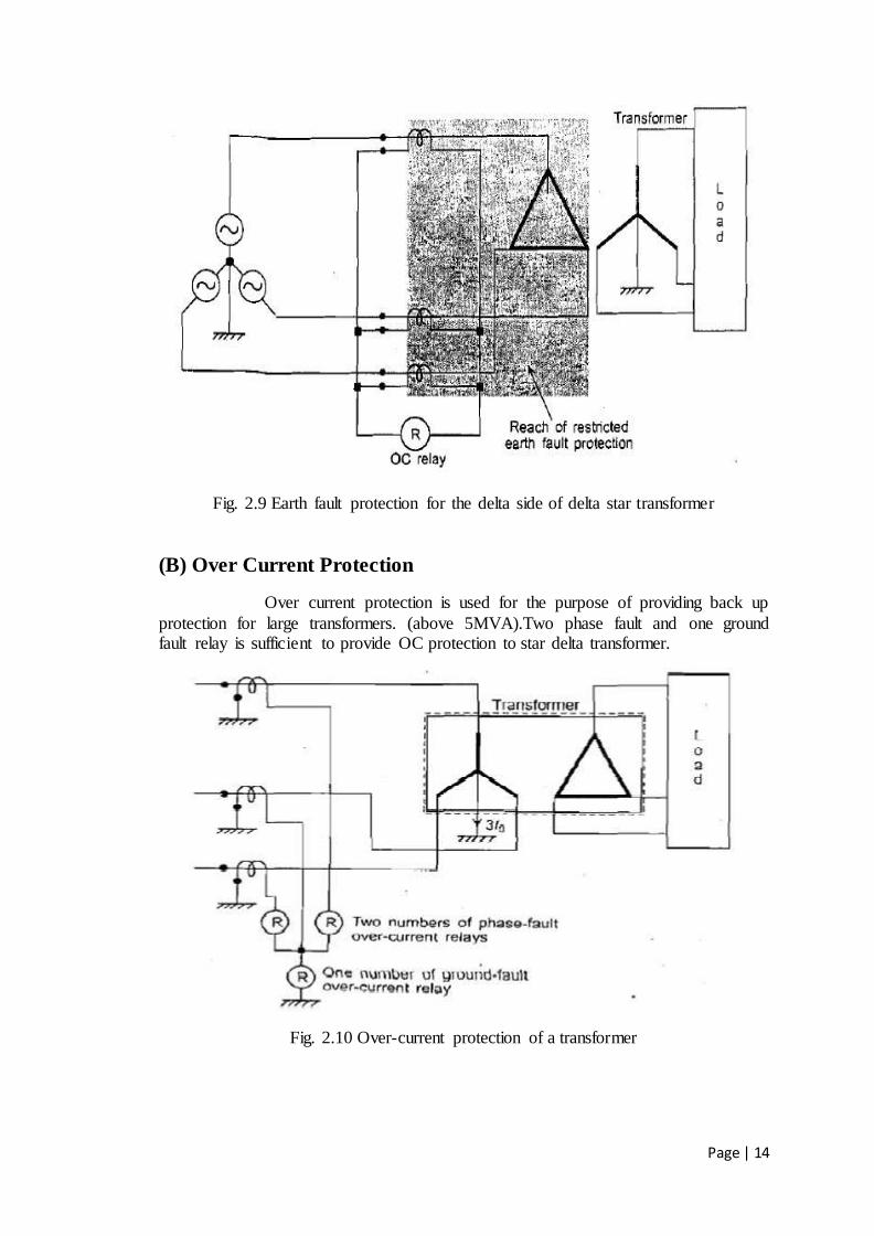
Fig. 2.9 Earth fault protection for the delta side of delta star transformer
(B) Over Current Protection
Over current protection is used for the purpose of providing back up
protection for large transformers. (above 5MVA).Two phase fault and one ground fault relay is sufficient to provide OC protection to star delta transformer.
Fig. 2.10 Over-current protection of a transformer

Page | 15
(C) Protection Against Overfluxing
The magnetic flux increases when voltage increases. This results in
increased iron loss and magnetizing current. The core and core bolts gets heated and
the lamination insulation is affected. Protection against overfluxing is required where overfluxing due to sustained overvoltage can occur. The reduction in frequency also increases the flux density and thus has the same effect of overfluxing.
The expression for flux in a transformer is given by
Φ = K E/f
Where Φ = flux, f = frequency, E = applied voltage and K is a constant.
To control flux, the ratio E/ f is controlled. When the ratio exceeds a threshold value,
it has to be detected. Electronic circuits with suitable relays are available to measure this ratio. Overfluxing does not require high speed tripping and hence instantaneous
operation is undesirable when momentary disturbances occur. But the transformer should be isolated in one or two minutes at the most if overfluxing persists.
(D) Protection Against Overheating
The rating of a transformer depends on the temperature rise above an assumed maximum ambient temperature. Sustained overload is not allowed if the
ambient temperature is equal to the assumed ambient temperature. The maximum safe overloading is that which does not overheat the winding. The maximum allowed
temperature is about 95°C. Thus the protection against overload depends on the winding temperature which is usually measured by thermal image technique.
In thermal image technique, a temperature sensing device like silicon resistor is placed in the transformer oil near the top of the transformer tank. A CT is employed on the L.V. side to supply current to a small heater. Both the temperature sensing
device and the heater are placed in a small pocket. The silicon resistor is used as an arm of a resistance bridge supplied from the stabilized dc source. An indicating
instrument is energized from the out of balance voltage of the bridge. Also the voltage across the silicon resistor is applied to a static control circuit which controls cooling pumps and fans, also gives warning of overheating ,in case of failure of cooling
system and ultimately trips the transformer circuit breakers.
(E) Protection Against Incipient Faults
Incipient Faults: Faults which are not serious at the beginning but which slowly develops into serious faults are known as incipient faults.

Page | 16
2.2 Protection
2.2.1 Buchholz Relay
It is a protective device container housed over the connecting pipe
from main tank to conservator tank. It is used to sense the faults occurring inside the
transformer. It is a simple relay which is operated by the gases emitted due to the
decomposition of transformer oil during internal faults. It helps in sensing and
protecting the transformer from internal faults
Fig. 2.11 Buchholz Relay
Buchholz relay in transformer is an oil container housed in the
connecting pipe from main tank to conservator tank. It has mainly two elements. The
upper element consists of a float. The float is attached to a hinge in such a way that it
can move up and down depending upon the oil level in the Buchholz relay Container.
One mercury switch is fixed on the float. The alignment of mercury switch hence
depends upon the position of the float.
The lower element consists of a baffle plate and mercury switch. This
plate is fitted on a hinge just in front of the inlet (main tank side) of Buchholz relay in
transformer in such a way that when oil enters in the relay from that inlet in high
pressure the alignment of the baffle plate along with the mercury switch attached to it,
will change.
In addition to these main elements a Buchholz relay has Gas Relief Cock
(GRC) on top. The electrical leads from both mercury switches are taken out through
a molded terminal block.

Page | 17
Fig. 2.12 Circuit Diagram
Operation:
In case of incipient faults within the transformer, the heat due to fault causes the
decomposition of some transformer oil in the main tank. The products of
decomposition contain more than 70% of hydrogen gas. The hydrogen gas being light
tries to go into the conservator and in the process gets entrapped in the upper part of
relay chamber. When a predetermined amount of gas gets accumulated, it exerts
sufficient pressure on the float to cause it to tilt and close the contacts of mercury
switch attached to it. This completes the alarm circuit to sound an alarm.
If a serious fault occurs in the transformer ,an enormous amount of gas is generated in
the main tank. The oil in the main tank rushes towards the conservator via the
Buchholz relay and in doing so tilts the flap to close the contacts of mercury switch.
This completes the trip circuit to open the circuit breaker controlling the transformer.
Advantages:
It is the simplest form of transformer protection.
It detects the incipient faults at a stage much earlier than is possible with other forms
of protection
Disadvantages:
It can only be used with oil immersed transformers equipped with conservator tanks.

Page | 18
The device can detect only faults below oil level in the transformer. Therefore,
separate protection is needed for connecting cables.
2.2.2 Differential protection
This scheme is employed for the protection of transformers against
internal short circuits. It provides the best overall protection for internal faults.
However in case of ungrounded or high impedance grounding it cannot provide
ground fault protection.
The following factors affect the differential current in transformers and
should be considered while applying differential protection.
These factors can result in a differential current even underbalanced power in & out
conditions:
1.Magnetizing inrush current– The normal magnetizing current drawn is 2–5% of
the rated current. However during Magnetizing inrush the current can be as high as
8–30times the rated current for typically 10 cycles, depending upon the transformer
and system resistance.
2.Overexcitation–This is normally of concern in generator–transformer units.
Transformers are typically designed to operate just below the flux saturation level.
Any further increase from the max permissible voltage level (or Voltage/Frequency
ratio), could lead to saturation of the core, in turn leading to substantial increase in
the excitation current drawn by the transformer.
3.CT Saturation – External fault currents can lead to CT saturation. This can cause
relay operating current to flow due to distortion of the saturated CT current.
4. Different primary and secondary voltage levels, that is the primary & secondary
CT’s are of different types and ratios
5. Phase displacement in Delta-Wye transformers.
Transformer Differential Relay
To account for the above variables less sensitive Percentage Differential Relays with
percentage characteristics in the range of 15 to 60% are applied to transformers.
Additionally, in modern microprocessor and numeric relays harmonic restraints can
be applied.
Page | 19
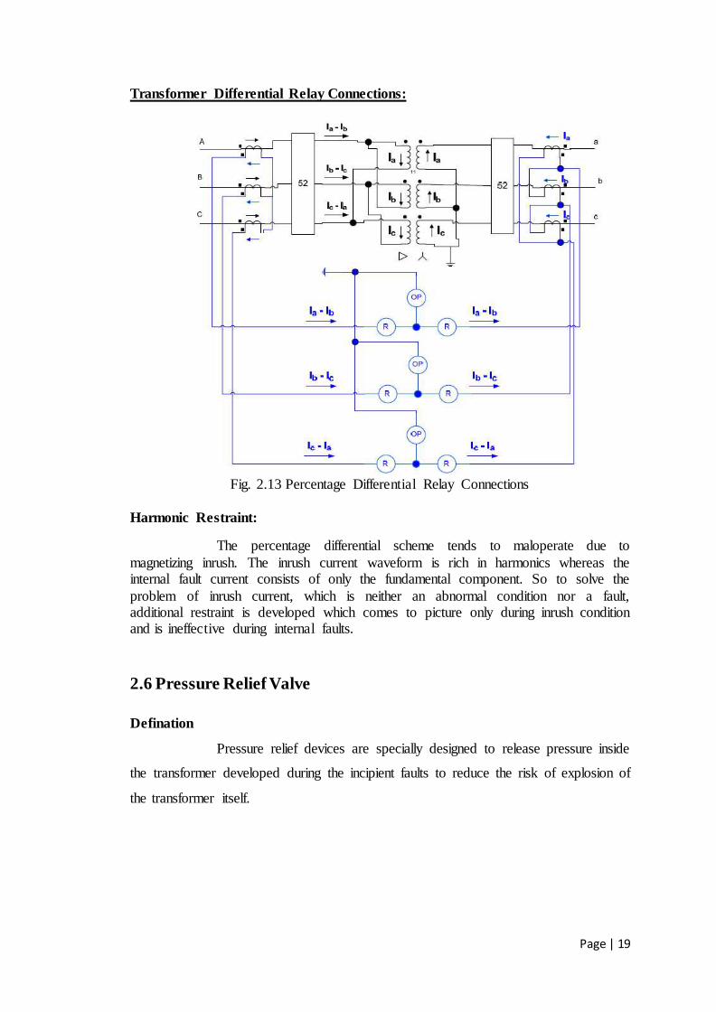
Transformer Differential Relay Connections:
Fig. 2.13 Percentage Differential Relay Connections
Harmonic Restraint:
The percentage differential scheme tends to maloperate due to
magnetizing inrush. The inrush current waveform is rich in harmonics whereas the internal fault current consists of only the fundamental component. So to solve the
problem of inrush current, which is neither an abnormal condition nor a fault, additional restraint is developed which comes to picture only during inrush condition and is ineffective during internal faults.
2.6 Pressure Relief Valve
Defination
Pressure relief devices are specially designed to release pressure inside
the transformer developed during the incipient faults to reduce the risk of explosion of
the transformer itself.

Page | 20
Fig. 2.14 Pressure relief valve
In case of sudden and uncontrolled increase in pressure inside the
transformer, the pressure relief device allows the discharge of insulating fluid in
milliseconds time facilitating the decrease of the pressure. It is highly recommended
to convey the outlet insulating fluid in order to preserve the environment and to
reduce the risk of fire.
This device can be used in:
Power oil insulated transformers with oil volume from 3000 to 25000 dm3. We
recommend using multiple pressure relied devices when insulating fluid exceed this
level.
There are smaller sizes available of pressure relief devices for distribution
transformers.
Description and general specifications:
Aim of the safety valves on electric transformers
The transformer tank filled with cooling liquid is a container subject to
internal pressure and then has to be provided with one or more safety valves suitably
calibrated for the maximum allowed pressure, so that over pressure caused by internal
faults can be instantaneously relieved through the valves, thus avoiding greater
damages such as the deformation or even the burst of the tank and the spraying of hot
oil with subsequent fire risks. It is necessary to protect the transformer tank with a
suitable equipment capable of almost instantaneously discharging overpressure can be
overcome by using special equipment called pressure relief valve.

Page | 21
General features
The safety valves consist schematicaly of :
a valve base comprising the valve opening venting area with its special y profiled
gasket and a seat for an O-ring gasket on the flanged end towards the transformer’s
tank.
a valve cap pressed against the profiled gasket by calibrated helical spring, thus
making the valve completely tight up to the rated pressure.
a splash diverter to avoid damages caused by hot oil sprinkles (on request).
a single or a double electrical contact.
Mechanical protection degree : IP 65
Insulation : 2000V 50Hz between terminals and
earth for a 60 seconds time
Cable gland : PG 13,5
Microswitch breaking capacity : 10 A 250V AC
1 A 125V DC
Safety valves - types
The safety valves are built with different Major Diameters and rated
pressure to satisfy the requirements of the various applications.
TYPE MAJOR
DIAMETER
RATED
PRESSURE
PREVAILING
USE
T125 - VS 150
125mm. 0,3 /1 bar big power transformers
VS 100 100 mm 0,3 /1 bar Medium power
transformers
T80 - VS 80 80mm 0,3 /1 bar small power transformers
T 50 - VS 50 50mm 0,3 /1 bar cable boxes - small
tanks
Safety valves series VS : The advantage of safety valves series VS consists in the total
absence of projecting parts in the transformers tank making the mounting point
choose easier. These valves can be mounted, with regards to their base plane, both
horizontal y on the cover and vertical y on the transformer walls at the points where
their safety action is presumed to be more necessary.

Page | 22
Safety valves series T : The advantage of safety valves series T is that, showing a
good effectiveness and reliability of valves series VS, their simplicity consent o
obtain very competitive prices.
Operating instruction and maintenance:
Instruction for mounting safety valves :-
The data about the transformer point where a short circuit is most
likely to occur, the preferential direction the resulting shock wave may have, the
intensity this one can reach, all depend on the transformer power, its transformation
ratio, its construction characteristic and the behaviour of the other installed protection
equipment.
Therefore, is not possible to give strict rules about safety valves application. It is the
manufacturer who must decide each time and on his own experience the valve type
and its position.
Mounting and maintenance :-
The safety valves mounting is carried out by means of the suitable
fastening holes of the flange, after the splash diverter removal and after the insertion
of the O-ring gasket supplied with the valve. After the transformer filling, the air
developed under the valve must be breathed by unscrewing the suitable breathing
screw. This breathing screw shall be tightened again as soon as the oil starts to come
out. During operation the safety valves do not ne d a particular maintenance.
Nevertheless , it is convenient to regularly check the electric contact go d operation
and to verify if there is no gas accumulation.
Instruction for ordering safety valves :-
The exhaust rated diameter shall be connected with the transformer oil
quantity and with the number of mounted valves. When a single valve is mounted the
barycentric posit on, with regards to the points where a failure is most likely to occur,
must be chosen.
Page | 23
3. LIGHTNING ARRESTER
Lightning arrester is a device used on electrical power systems and
telecommunications systems to protect the insulation and conductors of the system
from the damaging effects of lightning. The typical lightning arrester has a high-
voltage terminal and a ground terminal. When a lightning surge (or switching surge,
which is very similar) travels along the power line to the arrester, the current from the
surge is diverted through the arrestor, in most cases to earth. Here we used the latest
revolutionary type of Lightning Arrester i.e., metal oxide arrestor (MOA).
Smaller versions of lightning arresters, also called surge protectors, are
devices that are connected between each electrical conductor in power and
communications systems and the Earth. These prevent the flow of the normal power
or signal currents to ground, but
provide a path over which high-
voltage lightning current flows,
bypassing the connected
equipment. Lightning that strikes
the electrical system introduces
thousands of kilovolts that may
damage the transmission lines,
and can also cause severe damage
to transformers and other
electrical or electronic devices.
Lightning-produced extreme
voltage spikes in incoming power
lines can damage electrical home
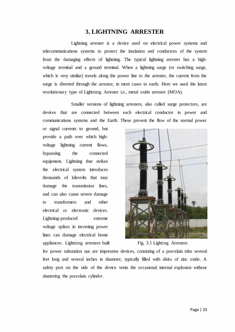
appliances. Lightning arresters built Fig. 3.1 Lighting Arresters
for power substation use are impressive devices, consisting of a porcelain tube several
feet long and several inches in diameter, typically filled with disks of zinc oxide. A
safety port on the side of the device vents the occasional internal explosion without
shattering the porcelain cylinder.

Page | 24
4. ISOLATORS
In electrical engineering, a disconnector, disconnect switch or isolator
switch is used to ensure that an
electrical circuit is completely
de-energised for service or
maintenance. Such switches are
often found in electrical
distribution and industrial
applications, where machinery
must have its source of driving
power removed for adjustment or
repair. High-voltage isolation
switches are used in electrical
substations to allow isolation of
apparatus such as circuit breakers,
transformers, and transmission
lines, for maintenance. The
disconnector is usually not intended Fig. 4.1 Isolators
for normal control of the circuit, but only for safety isolation. Disconnector can be
operated either manually or automatically (motorized disconnector). Unlike load
break switches and circuit breakers, disconnectors lack a mechanism for suppression
of electric arc, which occurs when conductors carrying high currents are electrically
interrupted. Thus, they are off-load devices, intended to be opened only after current
has been interrupted by some otherontrol device. Safety regulations of the utility must
prevent any attempt to open the disconnector while it supplies a circuit. Standards in
some countries for safety may require either local motor isolators or lockable
overloads (which can be padlocked).
In high-voltage or complex systems, these padlocks may be part of a
trapped-key interlock system to ensure proper sequence of operation.

Page | 25
5. CIRCUIT BREAKERS
A circuit breaker is an automatically operated electrical switch in
combination with relay designed to protect an electrical circuit from damage caused by
overload or short circuit. Its basic function is to detect a fault condition and interrupt
current flow. Unlike a fuse, which operates once and then must be replaced, a circuit
breaker can be reset (either manually or automatically) to resume normal operation.
Circuit breakers are made in varying sizes, from small devices that protect an
individual household appliance up to large switchgear designed to protect high
voltage circuits feeding an entire city.
In this substation we use two types of circuit breakers for high voltage
side and low voltage side. They are:-
1. Gas Circuit Breaker
2. Vacuum Circuit Breaker
Operation:-
All circuit breaker systems have common features in their operation,
although details vary substantially depending on the voltage class, current rating and
type of the circuit breaker.
The circuit breaker must detect a fault condition; in low voltage circuit
breakers this is usually done within the breaker enclosure. Circuit breakers for large
currents or high voltages are usually arranged with protective relay pilot devices to
sense a fault condition and to operate the trip opening mechanism. The trip solenoid
that releases the latch is usually energized by a separate battery, although some high-
voltage circuit breakers are self-contained with current transformers, protective relays
and an internal control power source.
Once a fault is detected, contacts within the circuit breaker must open
to interrupt the circuit; some mechanically-stored energy contained within the breaker
is used to separate the contacts, although some of the energy required may be
obtained from the fault current itself. Small circuit breakers may be manually
operated, larger units have solenoids to trip the mechanism, and electric motors to
restore energy to the springs.
Page | 26
The circuit breaker contacts must carry the load current without
excessive heating, and must also withstand the heat of the arc produced when
interrupting (opening) the circuit. Contacts are made of copper or copper alloys, silver
alloys and other highly conductive materials. Service life of the contacts is limited by
the erosion of contact material due to arcing while interrupting the current. Miniature
and molded-case circuit breakers are usually discarded when the contacts have worn,
but power circuit breakers and high-voltage circuit breakers have replaceable
contacts.
When a current is interrupted, an arc is generated. This arc must be
contained, cooled and extinguished in a controlled way, so that the gap between the
contacts can again withstand the voltage in the circuit. Different circuit breakers use
vacuum, air, insulating gas or oil as the medium the arc forms in.
Arc interruption:-
Gas (usually sulfur hexafluoride) circuit breakers sometimes stretch the
arc using a magnetic field, and then rely upon the dielectric strength of the sulfur
hexafluoride (SF6) to quench the stretched arc.
Vacuum circuit breakers have minimal arcing (as there is nothing to
ionize other than the contact material), so the arc quenches when it is stretched a very
small amount (less than 2–3 mm (0.079–0.118 in)). Vacuum circuit breakers are
frequently used in modern medium-voltage switchgear to 38,000 volts.
5.1 Gas Circuit Breaker
A sulphur hexafluoride circuit breaker uses contacts surrounded by
sulfur hexafluoride gas to quench the arc. They are most often used for transmission-
level voltages and may be incorporated into compact gas-insulated switchgear. In cold
climates, supplemental heating or de-rating of the circuit breakers may be required
due to liquefaction of the SF6 gas.
Page | 27
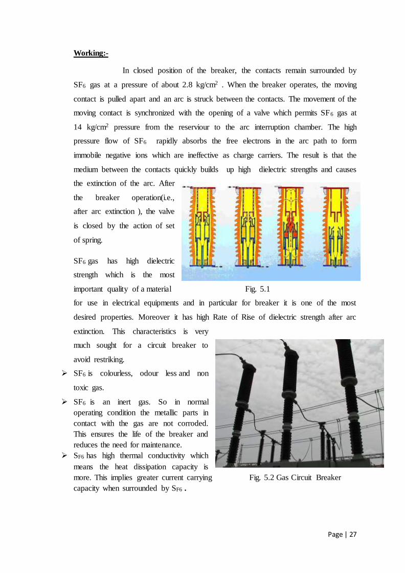
Working:-
In closed position of the breaker, the contacts remain surrounded by
SF6 gas at a pressure of about 2.8 kg/cm2 . When the breaker operates, the moving
contact is pulled apart and an arc is struck between the contacts. The movement of the
moving contact is synchronized with the opening of a valve which permits SF6 gas at
14 kg/cm2 pressure from the reserviour to the arc interruption chamber. The high
pressure flow of SF6 rapidly absorbs the free electrons in the arc path to form
immobile negative ions which are ineffective as charge carriers. The result is that the
medium between the contacts quickly builds up high dielectric strengths and causes
the extinction of the arc. After
the breaker operation(i.e.,
after arc extinction ), the valve
is closed by the action of set
of spring.
SF6 gas has high dielectric
strength which is the most
important quality of a material Fig. 5.1
for use in electrical equipments and in particular for breaker it is one of the most
desired properties. Moreover it has high Rate of Rise of dielectric strength after arc
extinction. This characteristics is very
much sought for a circuit breaker to
avoid restriking.
SF6 is colourless, odour less and non
toxic gas.
SF6 is an inert gas. So in normal
operating condition the metallic parts in
contact with the gas are not corroded.
This ensures the life of the breaker and
reduces the need for maintenance.
SF6 has high thermal conductivity which
means the heat dissipation capacity is
more. This implies greater current carrying Fig. 5.2 Gas Circuit Breaker
capacity when surrounded by SF6 .

Page | 28
SF6 has high thermal conductivity which means the heat dissipation
capacity is more. This implies greater current carrying capacity when surrounded
by SF6 .
SF6 being non-flammable so there is no risk of fire hazard and explosion.
5.2 Vacuum Circuit Breaker
A vacuum circuit breaker is such kind of circuit breaker where the
arc quenching takes place in vacuum. The technology is suitable for mainly medium
voltage application. For higher voltage vacuum technology has been developed but
not commercially viable. The operation of opening and closing of electric current
carrying contacts and associated arc interruption take place in a vacuum chamber in
the breaker which is called vacuum interrupter. The vacuum interrupter consists of a
steel arc chamber in the centre symmetrically arranged ceramic insulators. The
vacuum pressure inside a vacuum interrupter is normally maintained at 10 - 6 bar.
Working :-
The main aim of any circuit breaker is to quench arc during electric
current zero crossing, by establishing high dielectric strength in between the contacts
so that reestablishment of arc after electric current zero becomes impossible. The
dielectric strength of vacuum is eight times greater than that of air and four times
greater than that of SF6 gas. When the breaker operates, the moving contact separates
from the fixed contact and an arc is struck between the contacts. The production of
arc is due to the ionization of metal ions and depends very much upon the material of
contacts. The arc is quickly extinguished because the metallic vapours, electrons and
ions produced during arc are diffused in a short time and seized by the surface of
moving and fixed members and shields. Since vacuum has very fast rate of recovery
of dielectric strength, the arc extinction in a vacuum breaker occurs with a short
contact separation(say 0.625 cm).
They are compact, reliable and have longer life.
There are no fire hazards.
There is no generation of gas during and after operation.

Page | 29
They can interrupt any fault current. The outstanding feature of a VCB is that it can
break any heavy fault current perfectly just before the contacts reach the definite open
position.
They require little maintenance and are quite in operation.
They can successfully withstand lightning surges.
They have low arc energy and low inertia and hence require smaller power for control
mechanism.
Fig. 5.3 Vacuum Circuit Breaker
Page | 30
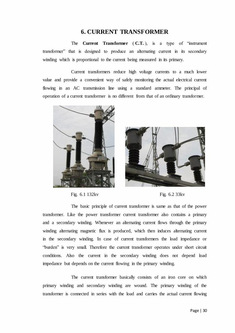
6. CURRENT TRANSFORMER
The Current Transformer ( C.T. ), is a type of “instrument
transformer” that is designed to produce an alternating current in its secondary
winding which is proportional to the current being measured in its primary.
Current transformers reduce high voltage currents to a much lower
value and provide a convenient way of safely monitoring the actual electrical current
flowing in an AC transmission line using a standard ammeter. The principal of
operation of a current transformer is no different from that of an ordinary transformer.
Fig. 6.1 132kv Fig. 6.2 33kv
The basic principle of current transformer is same as that of the power
transformer. Like the power transformer current transformer also contains a primary
and a secondary winding. Whenever an alternating current flows through the primary
winding alternating magnetic flux is produced, which then induces alternating current
in the secondary winding. In case of current transformers the load impedance or
“burden” is very small. Therefore the current transformer operates under short circuit
conditions. Also the current in the secondary winding does not depend load
impedance but depends on the current flowing in the primary winding.
The current transformer basically consists of an iron core on which
primary winding and secondary winding are wound. The primary winding of the
transformer is connected in series with the load and carries the actual current flowing
Page | 31
to the load while the secondary winding is connected to a measuring device or a relay.
The number of secondary turns is proportional to the current flowing through the
primary. (i.e.) larger the magnitude of current flowing through the primary, more the
number of secondary turns.
The ratio of primary current to the secondary current is known as the
current transformation ratio of the CT. Usually the current transformation ratio of the
CT is high. Normally the secondary ratings are of the order 5 A, 1 A, 0.1 A whereas
the primary rating vary from 10 A to 3000 A or more.
The CT handles very less power. Rated burden can be defines as the
product of current and voltage at the secondary side of the CT. It is measured in volt
ampere (VA).
The secondary of a current transformer should not be disconnected
from its Rated burden while current is flowing in the primary. As the primary current
is independent of the secondary current, the entire primary current acts as a
magnetizing current when secondary is opened. This results in deep saturation of the
core which cannot return to normal state and so the CT is no longer usable.
Current transformers can reduce or “step-down” current levels from
thousands of amperes down to a standard output of a known ratio to either 5 Amps or
1 Amp for normal operation. Thus, small and accurate instruments and control
devices can be used with CT’s because they are insulated away from any high-voltage
power lines. There are a variety of metering applications and uses for current
transformers such as with wattmeter’s, power factor meters, watt-hour meters,
protective relays, or as trip coils in magnetic circuit breakers, or MCB’s.
Page | 32
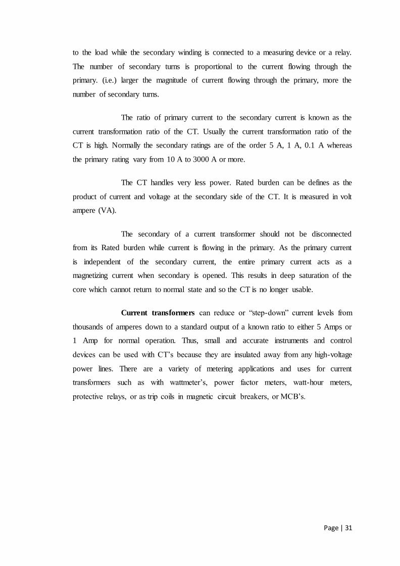
7. POTENTIAL TRANSFORMER
Potential transformers are instrument transformers used to feed the
potential coils of indicating and metering relays. These transformers make the
ordinary low voltage instruments suitable for the measurement of high voltages and
isolate them for high voltage.
The primary winding of the transformer is directly connected to the
high voltage power circuits between two phases or between a phase and ground
depending on the transformer rating and its application. The secondary of the
potential transformer is connected various measuring devices and relays. The primary
winding has a large number of turns and the secondary winding has lesser number of
turns than the primary winding. These two windings are magnetically coupled. The
number of secondary turns depends upon the purpose for which the potential
transformer is used.
Fig. 7.1 Potential Transformer
Operation:-
The theory of operation of a potential transformer is essentially same
as that of the power transformer. The main difference between a potential transformer
and a power transformer is that the load current of the potential transformer depends
purely on the exciting current and its secondary impedance. The secondary impedance

Page | 33
of the potential transformer will be resistive in nature. The potential transformers are
rated in terms of their maximum burden it delivers without exceeding specified limits
of error, whereas the power transformer is rated secondary output it delivers without
exceeding a specified temperature rise. The output of PTs is limited is usually limited
to few hundred volt amperes while the output of a power transformer varies from
several KVA to several MVA.

Page | 34
8. WAVETRAP
Line trap also is known as Wave trap. What it does is trapping the high
frequency communication signals sent on the line from the remote substation
anddivertingthemto thetelecom/teleportationpanelinthesubstationcontrol room(throug
hcouplingcapacitoraTisrelevant in Power Line Carrier Communication
(PLCC) systems for communication among various substations without dependence
on the telecom company network. The signals are primarily teleportation signals and
in addition, voice and data communication signals. Line trap also is known as
Wave trap. What it does is trapping the high frequency communication signals sent on
the line from the remote substation and diverting them to the
telecom/teleportation panel in the substation control room (through
coupling capacitor and LMU). This is relevant in Power Line Carrier Communication
(PLCC) systems for communication among various substations without dependence
on the telecom company network. The signals are primarily teleportation signals and
in addition, voice and data communication signals. The Line trap offers high
impedance to the high frequency communication signals thus obstructs the flow of
these signals in to the substation bus bars. If there were not to be there, then signal
loss is more and communication will be ineffective/probably impossible.
Fig. 8.1 Wave Trap
Page | 35
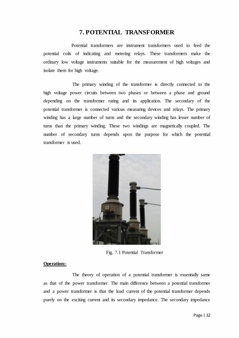
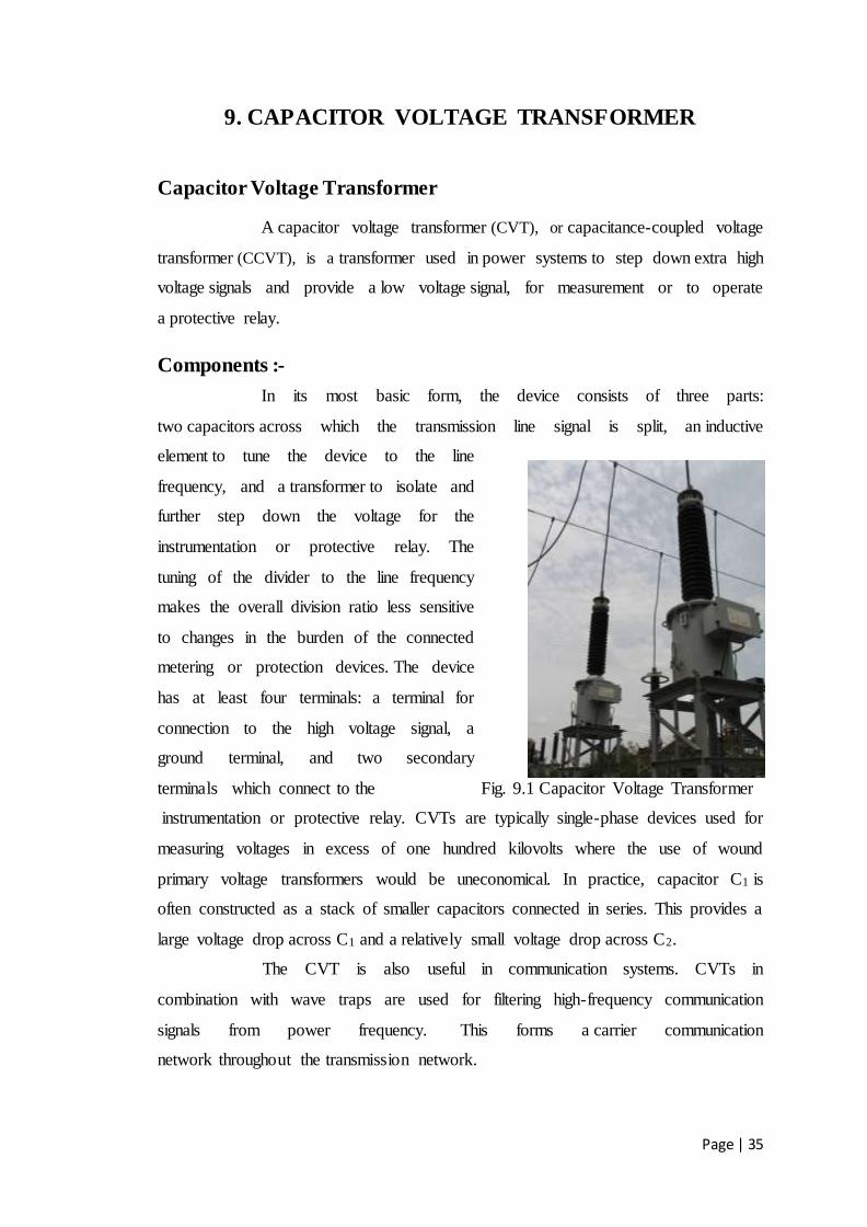
9. CAPACITOR VOLTAGE TRANSFORMER
Capacitor Voltage Transformer
A capacitor voltage transformer (CVT), or capacitance-coupled voltage
transformer (CCVT), is a transformer used in power systems to step down extra high
voltage signals and provide a low voltage signal, for measurement or to operate
a protective relay.
Components :-
In its most basic form, the device consists of three parts:
two capacitors across which the transmission line signal is split, an inductive
element to tune the device to the line
frequency, and a transformer to isolate and
further step down the voltage for the
instrumentation or protective relay. The
tuning of the divider to the line frequency
makes the overall division ratio less sensitive
to changes in the burden of the connected
metering or protection devices. The device
has at least four terminals: a terminal for
connection to the high voltage signal, a
ground terminal, and two secondary
terminals which connect to the Fig. 9.1 Capacitor Voltage Transformer
instrumentation or protective relay. CVTs are typically single-phase devices used for
measuring voltages in excess of one hundred kilovolts where the use of wound
primary voltage transformers would be uneconomical. In practice, capacitor C1 is
often constructed as a stack of smaller capacitors connected in series. This provides a
large voltage drop across C1 and a relatively small voltage drop across C2.
The CVT is also useful in communication systems. CVTs in
combination with wave traps are used for filtering high-frequency communication
signals from power frequency. This forms a carrier communication
network throughout the transmission network.
Page | 36
10. EARTH PITS
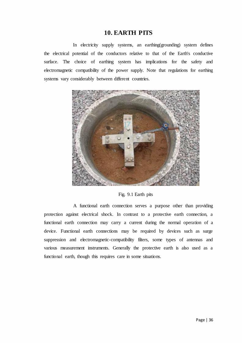
In electricity supply systems, an earthing(grounding) system defines
the electrical potential of the conductors relative to that of the Earth's conductive
surface. The choice of earthing system has implications for the safety and
electromagnetic compatibility of the power supply. Note that regulations for earthing
systems vary considerably between different countries.
Fig. 9.1 Earth pits
A functional earth connection serves a purpose other than providing
protection against electrical shock. In contrast to a protective earth connection, a
functional earth connection may carry a current during the normal operation of a
device. Functional earth connections may be required by devices such as surge
suppression and electromagnetic-compatibility filters, some types of antennas and
various measurement instruments. Generally the protective earth is also used as a
functional earth, though this requires care in some situations.

Page | 37
11. CONCLUSION
The project work is on protection of two transformers(i.e.,50MVA and
35.5MVA) in substation many devices have been employed for protection. The
external protection is given by using modern well developed metal oxide type
lightning arresters for protection over voltage surges, line isolators for the on load
operations,SF6 and vacuum circuit breakers, potential transformers for voltage
measurement, current transformers for current, capacitor voltage transformer and
wavetrap combinely for the auditing of incomming voltages and frequencies and the
internal protection is involved in cooling of oil by using radiators, pressure relive vent
and buchholz relay.
By this arrangement the protection of transformer from many faults
that occurred due to transients or extra high voltages with circuit breakers and relays,
current is measured using current transformer and the tripping action takes place.
The internal problems like oil heating due to transformer working
which increase core losses and shrinks the age of transformer is cooled by using
Radiators, Pressure balancing in the transformer is done by using pressure relive vent
and the Buchholz relay is for clearing dielectric failure. This protection is gone
through economic way not to exceed the cost of operation doesn’t effect the charges
to transmit power to customers.


