
Progress of High-Performance Steady-State Plasma and Critical PWI Issues in the LHD H. Kasahara, M. Tokitani, Y. Yoshimura, K. Nagasaki1, N. Ashikawa, Y. Ueda2, G.
Motojima, M. Shoji, T. Seki, K. Saito, R. Seki, S. Kamio, G. Nomura,
G. Nomura, F. Shimpo, S. Kubo, T. Shimozuma, H. Igami, H. Takahashi, S. Itoh, T. Ii, S. Masuzaki, H. Tanaka, J. Miyazawa, H. Tsuchiya, N. Tamura,
T. Tokuzawa, N. Yoshida3, T. Shinya4, Y. P. Zhao5, J. G. Kwak6, T. Mutoh,
and LHD Experiment Group
National Institute for Fusion Science 1Kyoto University, 2Osaka University, 3Kyushu University,
4University of Tokyo, 5ASIPP, 6NFRI
FEC2014, Park Inn by Radisson Pribaltyskaya 2014, 10/13-18 Saint Petersburg, RF
EX7/3
Contents of my presentation
• The extension of steady-state plasma duration with MW-class heating, and the operation regions
• Result of ultra-long pulse plasma duration with td ~ 48 min, PRF ~ 1.2MW, ne ~ 1.2x10¹⁹ m-3, Te ~ Ti ~ 2keV, and Winj ~ 3.4 GJ
– Thermal behavior and typical temperatures
Inhomogeneity of divertor heat flux
– The steady-state was terminated by sudden unintended entrance of the exfoliated mixed-material layers (MMLs) with continuous divertor erosion
– Characteristics of the MMLs
Thick region, the growth rate, the main elements, the physical property, and the trappable ability of He particles
– Preliminary estimation of He particle balance with the MMLs
• Summary and future plans
2

Contents of my presentation
• The extension of steady-state plasma duration with MW-class heating, and the operation regions
• Result of ultra-long pulse plasma duration with td ~ 48 min, PRF ~ 1.2MW, ne ~ 1.2x10¹⁹ m-3, Te ~ Ti ~ 2keV, and Winj ~ 3.4 GJ
– Thermal behavior and typical temperatures
Inhomogeneity of divertor heat flux
– The steady-state was terminated by sudden unintended entrance of the exfoliated mixed-material layers (MMLs) with continuous divertor erosion
– Characteristics of the MMLs
Thick region, the growth rate, the main elements, the physical property, and the trappable ability of He particles
– Preliminary estimation of He particle balance with the MMLs
• Summary and future plans
3
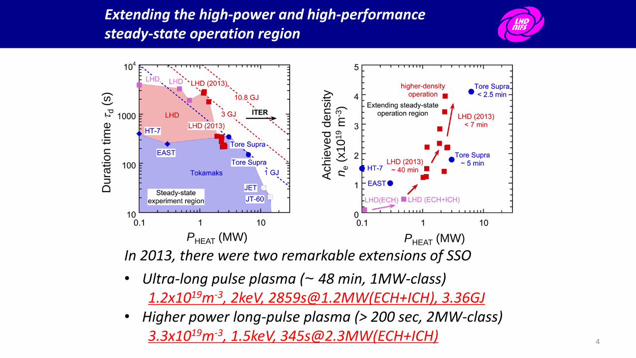
Extending the high-power and high-performance steady-state operation region
In 2013, there were two remarkable extensions of SSO
• Ultra-long pulse plasma (~ 48 min, 1MW-class) 1.2x10¹⁹m-3, 2keV, [email protected](ECH+ICH), 3.36GJ
• Higher power long-pulse plasma (> 200 sec, 2MW-class) 3.3x10¹⁹m-3, 1.5keV, [email protected](ECH+ICH) 4
PHEAT (MW) PHEAT (MW)
Dura
tion t
ime t
d (
s)
Achie
ved d
ensity
ne (
x10
19 m
-3)

Development of high-power heating systems, and the integration and optimizing of plasma operations
PA antenna
(#7.5) Large antenna coupling
w/o FS (hheat ~60%)
(upper strap)
w FS (hheat 70% )
(lower strap)
Sexcite ~ 0.26 m2
FAIT antenna (#4.5) Field-aligned, transforming
hheat ~ 80%, Sexcite ~ 0.12 m2
HAS antenna (#3.5 port) Field-aligned, large wavenumber
hheat ~ 90%, Sexcite ~ 0.27 m2
Thu. FIP/P5-3 T. Seki
• Steady-state RF heating sources ~ 3.54 MW (ICH: 3MW, ECH: 0.54MW) Hydrogen minority heating (38.5MHz), Core electron heating (77GHz, 154GHz)
• The integration of heating controls to decrease plasma degradations Scattering heating power, Maintaining heating power and plasma temperature
• Adequate gas-fueling with the time evolution for PWI effect PID control method and supplies using several gas-fueling devices 5

Contents of my presentation
• The extension of steady-state plasma duration with MW-class heating, and the operation regions
• Result of ultra-long pulse plasma duration with td ~ 48 min, PRF ~ 1.2MW, ne ~ 1.2x10¹⁹ m-3, Te ~ Ti ~ 2keV, and Winj ~ 3.4 GJ
– Thermal behavior and typical temperatures
Inhomogeneity of divertor heat flux
– The steady-state was terminated by sudden unintended entrance of the exfoliated mixed-material layers (MMLs) with continuous divertor erosion
– Characteristics of the MMLs
Thick region, the growth rate, the main elements, the physical property, and the trappable ability of He particles
– Preliminary estimation of He particle balance with the MMLs
• Summary and future plans
6

Demonstration of ultra-long ( ~ 48 min) plasma discharge with MW-class plasma heating
Development of steady-state heating and PWI devices were effectively carried out • Controlling electron density with PWI effect • Steady-state temperature Te ~ Ti
• Spark mitigation and no impurity accumulation
• Stable RF heating with event triggering heating power boost
• The integration of heating power systems These improvements produced a robust plasma discharge.
Achievement parameters: ne ~ 1.2x10¹⁹ m-3, Ti ~ Te ~ 2 keV, td ~ 2859 sec, PRF ~ 1.2 MW (PICH ~ 0.94 MW, PECH ~ 0.26 MW), Wheat ~ 3.4GJ, ni0tE
*Ti0 ~ 3.5x10¹⁸ keV m-3 s
7

Thermal behavior, toroidal uniformity of divertor heat load, and total heat balance
Toroidal ununiformity of divertor heat load:
PRF ~ 1.2MW, ne ~ 1.2x10¹⁹ m-3, Te~ Ti ~ 2 keV, 48 min.
Name Protector surface (IR)
Divertor surface (IR)
Divertor (thermocouple)
First wall (thermocouple)
Temp. (oC) 300-900 460 180-270 40 -110
Saturation
time-scale
~ 800 s ~ 600 s ~ 700 s > 3000 s
Material Graphite Graphite Graphite SUS316L 8
First wall SUS316L
Divertor plates Graphite
Dome plates Graphite
ICH antenna protector Graphite
Ave
rage
div
erto
r h
eati
ng
po
wer
(kW
)
Average d
ivertor h
eat flux (M
W/m
2)
Toroidal section
Total power balance: Radiation Prad: 17 % Divertor Pdiv: 56 % Other Pother: 27 % Average heat flux Gheat: 0.33 MW/m2
(0.25 ~ 0.4 MW/m2)

Evaluation of the local heat flux on the particular divertor plates (Poloidal uniformity of divertor heat flux)
• Large discrepancy between experiment result (460 ºC) and the calculation (Tsat ~ 72 ºC) with average heat flux (G ~ 0.33 MW/m2)
• The peak factor of poloidal inhomogeneity of divertor heat flux was ~ 18 (open helical divertor) and ~ 14 (closed helical divertor)
• The heat flux of particular carbon divertor plates (~ 6 MW/m2) in PRF ~ 1.2 MW and td ~ 48 min come close ITER relevant heat flux (~ 5-10 MW/m2)
Open Helical Divertor
Tsat ~ 460 ºC
Tcool ~ 50 ºC
Gheat (width ~ 1 cm)
Three-dimensional divertor model
9
A photo of Infra-red camera Model calculations Two block
Contents of my presentation
• The extension of steady-state plasma duration with MW-class heating, and the operation regions
• Result of ultra-long pulse plasma duration with td ~ 48 min, PRF ~ 1.2MW, ne ~ 1.2x10¹⁹ m-3, Te ~ Ti ~ 2keV, and Winj ~ 3.4 GJ
– Thermal behavior and typical temperatures
Inhomogeneity of divertor heat flux
– The steady-state was terminated by sudden unintended entrance of the exfoliated mixed-material layers (MMLs) with continuous divertor erosion
– Characteristics of the MMLs
Thick region, the growth rate, the main elements, the physical property, and the trappable ability of He particles
– Preliminary estimation of He particle balance with the MMLs
• Summary and future plans
10
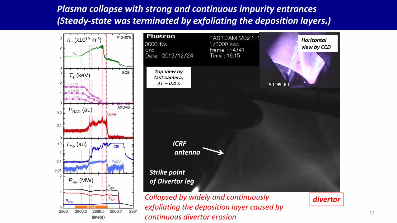
Plasma collapse with strong and continuous impurity entrances (Steady-state was terminated by exfoliating the deposition layers.)
ICRF antenna
Strike point of Divertor leg
Top view by
fast camera,
DT ~ 0.4 s
divertor
Horizontal view by CCD
Collapsed by widely and continuously exfoliating the deposition layer caused by continuous divertor erosion
11
ne (x1019 m-3)
Te (keV)
PRAD (au)
Iimp (au)
PRF (MW)

Contents of my presentation
• The extension of steady-state plasma duration with MW-class heating, and the operation regions
• Result of ultra-long pulse plasma duration with td ~ 48 min, PRF ~ 1.2MW, ne ~ 1.2x10¹⁹ m-3, Te ~ Ti ~ 2keV, and Winj ~ 3.4 GJ
– Thermal behavior and typical temperatures
Inhomogeneity of divertor heat flux
– The steady-state was terminated by sudden unintended entrance of the exfoliated mixed-material layers (MMLs) with continuous divertor erosion
– Characteristics of the MMLs
Thick region, the growth rate, the main elements, the physical property, and the trappable ability of He particles
– Preliminary estimation of He particle balance with the MMLs
• Summary and future plans
12

Characteristics of carbon-rich mixed-material layers (MMLs) and the exfoliation size at the plasma collapse
• MMLs: carbon (>90%) and iron (~ a few %), dense, hard, and brittle
• Plasma collapse occurred due to continuous exfoliation (~ 10 cm x 12 cm), and this will be a critical issue to maintain steady-state plasma.
• The thick MML was observed around the particular carbon divertor
plates with the large heat flux and the geometrical dense region.
M. Tokitani J. Nucl. Mater. 438 (2013) S818.
C > 90%, Fe ~ a few %, Ti, O Dense, hard, and brittle
The accumulation of a mixed-material layer and its elements
Exfoliated the carbon-rich mixed-material layer
mixed-material layers (dark)
Exfoliating small flakes from the first wall
First wall (SUS316L)
Exfoliating deposition layers
Deposition layer covered on first wall
13
12 cm
10 c
m
1 cm

Growth rate of carbon-rich mixed-material layers and the trappable particles by the fresh layer at the first wall position
Specimen (SUS316L)
TEM image with long exposure-time for only He SSO. M. Tokitani 2014 (PSI)
Exposure time (s) 1000 3389 9980
Thickness (nm) 5 15 40
C (x1019 atoms/m2) 260 370 (98%)
Fe (x1019 atoms/m2) 3.0 3.8 (1-2%)
Mo (x1019 atoms/m2) 0.07 0.23
Desorption (x1019 He/m2) 0.63 1.88 10.6 (300-600 K)
Predicted He particle retention rate: ~ 1.6 x10¹⁶ He/(m2 s) (= 2.34x10¹⁸ He/s (20%/730 m2)) 14

Fresh mixed-material layers (MMLs) affecting wall-pumping rate for He particles in several ten minutes
He particle balances w/wo the effect of the MMLs Wall-pumping: absorption (>0), desorption (<0) (Assumption: MMLs covered 26% of the PFCs.)
• Neutral pressure for He ~ constant • Particle fueling-rate recovered after
several ten minutes ( ~ 48 m3/s) The recovered wall-pumping rate was large. 1.11x10¹⁹ He/s ~ 95 % > 0.37x10¹⁹ He/s with 26% (realistic covered area)
• The study of the actual thickness map of MMLs will be more important for assessing accurate global particle balance.
Unit: x1019 He/s 0-200 s 500-1500 s 1800-2800 s
He fueling rate 6.22 0.28 1.48
Wall-pumping fuel – pump(0.4)
5.85 -0.09 (Desorption)
1.11 (Absorption)
w/ MMLs (26%) 5.48 -0.46 0.74
Three fueling phases 6.2 (0-200s), 0.3 (500-1500s), 1.5 (1800-2800s) (x1019 He/s).
15
ne (x1019 m-3)
Pressure (Pa)
Fueled and exhausted particles (x1019 He)
Time (s)

Summary
Extending steady-state plasma performance with MW-class plasma heating for He plasma
– Well controlled ICH, core electron heating (77 GHz, 154 GHz), event triggering boost of RF power power, and adequate gas fueling made robust plasmas with e-ITB profile.
– Ultra long-pulse (td ~ 48 min, PRF ~ 1.2 MW, Winj ~ 3.4 GJ):
ne ~ 1.2x10¹⁹ m-3, Te0 ~ Ti0 ~ 2 keV, ni0Ti0tE ~ 3.5x10¹⁸ m-3 keV s
– Long-pulse (td ~ 6 min, PRF ~ 2.3 MW, first trial)
ne, max ~ 3.3x10¹⁹ m-3, Te0 ~ Ti0 ~ 1.5 keV
The surface condition of PFCs was affected by continuous divertor erosion and ion impacts to the surfaces over several ten minutes.
– Carbon-rich mixed-material layers (MMLs) were grown around particular carbon divertor plates (geometrical dense and continuous large heat flux)
– Growth rate ~ 15 nm/hour
– The physical property ~ hard, dense, brittle, C (> 98%), Fe (~ a few %)
– Retention rate of He particles ~ 1.6x10¹⁶ He/m2 s (first wall position)
16

Future plans
17
For high-performance SSO,
• Performing the improvement of heating quality and the optimization
• Maintaining plasma performance in weak wall-pumping with ion impacts
For mixed-material layers (MMLs)
• Accurate assessments of the MMLs in various plasma parameters
• Revealing the growth and exfoliating mechanism of the MMLs
• Investigating the other MMLs (ex. W) caused by unavoidable divertor erosion
Courtesy to
M. Kikuchi

References
18
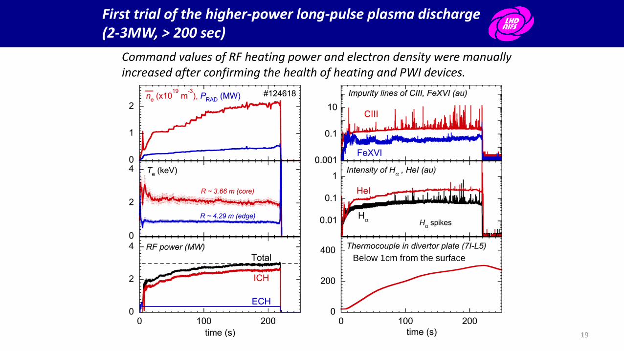
First trial of the higher-power long-pulse plasma discharge (2-3MW, > 200 sec)
Command values of RF heating power and electron density were manually increased after confirming the health of heating and PWI devices.
19
Below 1cm from the surface

Core electron heating and event triggering boost of heating power make a robust steady-state plasma
• Increasing the power (>0.3MW) of core electron heating (77, 154GHz) easily made e-ITB plasma during SSO, and it kept core electron temperature stable and high.
• Event triggering boost of heating power effectively carried out to maintain the plasma.
ECH only
Core electron heating power was increased (77GHz and 154GHz), PECH ~ 0.34MW.
e-ITB plasma was sustained during SSO PICH+ECH = 0.93MW (PECH=0.33MW)
ne ~ 1x10¹⁹ m-3, 11 min.
ICH+ECH
e-ITB plasma also was sustained using ECH+ICH.
Unintended impurity mixing
Event triggering boost of heating power
20

The particle fueling using the proportional-integral-derivative (PID) method was effectively carried out with the time evolution of wall-pumping rate.
Electron density followed the command value using the PID method.
Adequate gas-fueling was achieved with time delay for gas-fueling during long-pulse discharges.
This gas-fueling rate depends on the unintended impurity mixing events, too.
First trial of density control using the PI/PID method and plasma density followed the preprogramed command value.
: Differential part
: slow
: fast
In order to adopt various wall-pumping conditions, the integral method is required.
PRF ~ const (1.3 MW)
21
Th
e d
iffe
rence
be
twe
en
the
co
mm
and v
alu
e a
nd
the
actu
al d
en
sity

Confirming the stable sustainable density with the RF heating power of 2-3 MW.
Relatively high density operation ne
max ~ 3.3x10¹⁹m-3, Te ~ 1.5keV,
PRF ~ 2.3 MW, td ~ 345 sec
In order to confirm the stable sustainable density with PRF ~ 2-3 MW, the target value for density was gradually increased.
When the density reached 3 x10¹⁹ m-3, the ratio of the total radiation power for ejection power reached 28 %. (Usual operation is ~ 17%)
Heating quality was degraded, and it is necessary to confirm the minority ratio on the cyclotron resonance.
ne
Te
Prad
PRF
22

LHD and the divertor configurations
Typical device parameters:
Volume:
Inside vessel ~ 210 m3
Plasma ~ 30 m3 (Rax ~ 3.9m, a ~ 0.6m)
Closed Helical Divertor
Surface:
PFCs ~ 780 m2
First wall ~ 730 m2 (SUS316L)
Divertor plate ~ 50 m2 (Graphite) 23
Open helical divertor (OHD) Closed helical divertor (CHD)
Open divertor plates
Standing divertor plates
Standing divertor plates
Dome plates Geometrically dense
Divertor configuration OHD: 3 CHD:1-2, 4-10 Footprint S ~ 2 m2
(100m x 2 lines) x 1 cm

Progressing continuous erosion with no degradation of divertor heat removal
24
Isotropic carbon plate (IG-43) CFC plate (CX-2002) Carbon-fiber-composite
Deposition
Hollowed surface and edge
Hollowed surface and edge
Deposition
5
4
3
2
1
Schematic view of large heat flux divertor
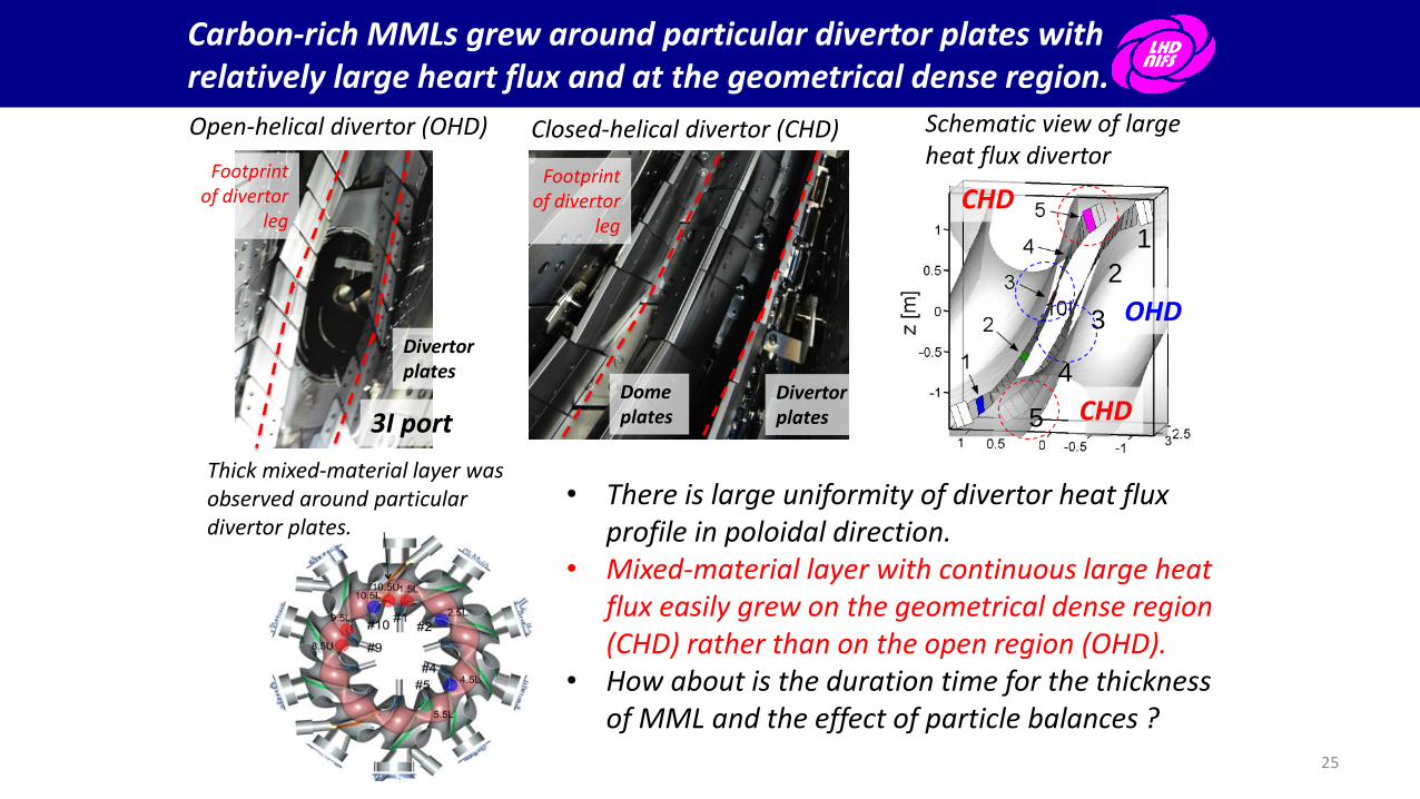
Carbon-rich MMLs grew around particular divertor plates with relatively large heart flux and at the geometrical dense region.
• There is large uniformity of divertor heat flux profile in poloidal direction.
• Mixed-material layer with continuous large heat flux easily grew on the geometrical dense region (CHD) rather than on the open region (OHD).
• How about is the duration time for the thickness of MML and the effect of particle balances ?
Thick mixed-material layer was observed around particular divertor plates.
OHD
CHD
CHD
Open-helical divertor (OHD)
3I port
Footprint of divertor
leg
Divertor plates
Closed-helical divertor (CHD)
Footprint of divertor
leg
Divertor plates
Dome plates
25
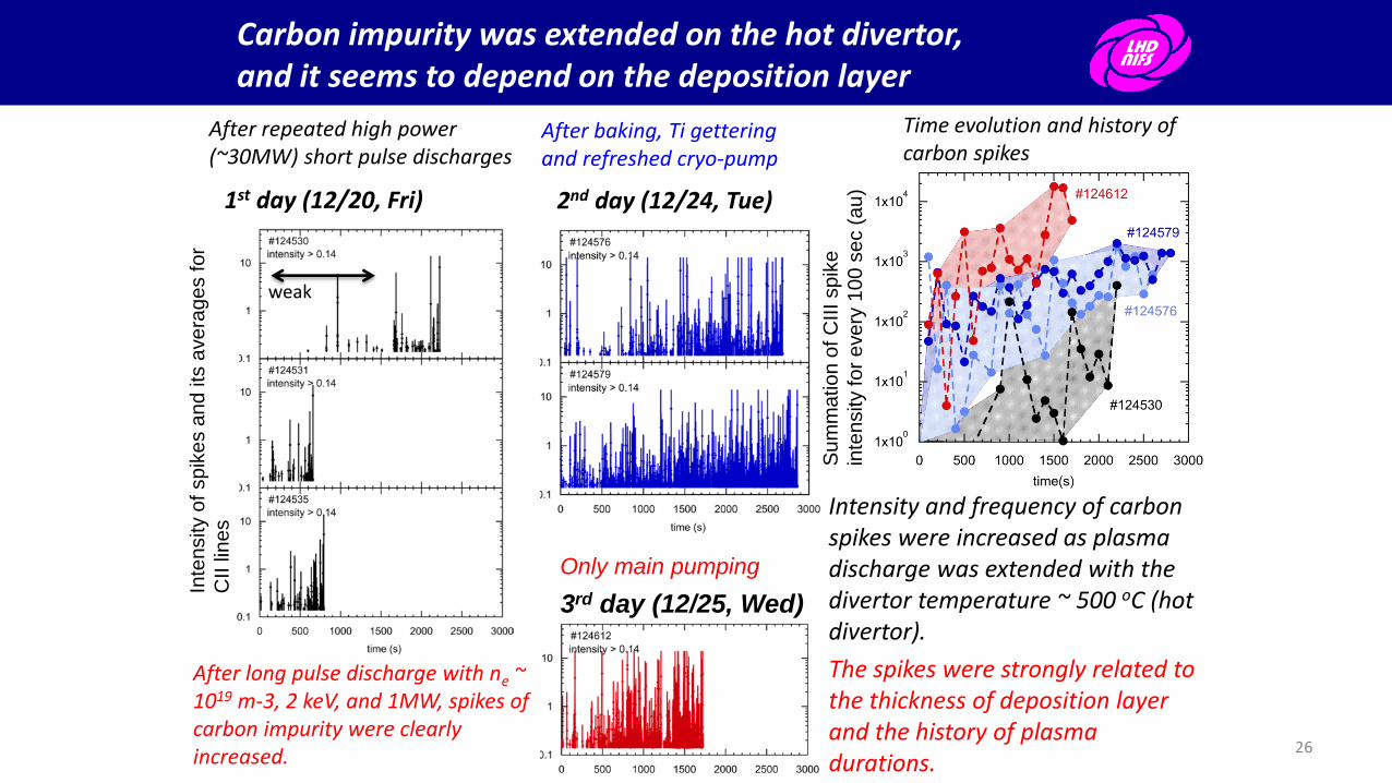
Carbon impurity was extended on the hot divertor, and it seems to depend on the deposition layer
Intensity and frequency of carbon spikes were increased as plasma discharge was extended with the divertor temperature ~ 500 oC (hot divertor).
The spikes were strongly related to the thickness of deposition layer and the history of plasma durations.
1st day (12/20, Fri) 2nd day (12/24, Tue)
3rd day (12/25, Wed)
After repeated high power (~30MW) short pulse discharges
After baking, Ti gettering and refreshed cryo-pump
Only main pumping
weak
After long pulse discharge with ne ~ 1019 m-3, 2 keV, and 1MW, spikes of carbon impurity were clearly increased.
Time evolution and history of carbon spikes
26
Inte
nsity o
f sp
ike
s a
nd
its
ave
rag
es fo
r
CII
lin
es
Su
mm
atio
n o
f C
III sp
ike
inte
nsity fo
r e
ve
ry 1
00 s
ec (
au
)

Exfoliation model of the mixed-material layers (MMLs)
27
Stainless steel specimen was only exposed by He long-pulse plasma duration with exposure time ~ 1000 sec.
Particle cohesion of He bubbles
Two exfoliation models of the mixed-material layers • Thermal stress with the temperature
profile • Explosive release by the cohesion of
He bubbles
Thermal stress caused by temperature profile
He
Plasma radiation (Plasma facing side)
higher
lower
Physical prosperity of MMLs Dense, hard, and brittle
Picture of the exfoliating MMLs from the first wall

First trial of the high-power steady-state heating (2-3MW) with the design value of the LHD
Command values of RF heating power and electron density were manually increased after confirming the health of heating devices and LHD devices.
Impurity line spectrum for Iron is stable, relatively.
Strong spike intensity is observed at relatively early time.
As increasing heating power and fueling particles, clear spike for intensity of Ha was occurred. 28
The clear correlation between Ha and CIII was first observed, and it played the key role for understanding the sudden impurity entrance.
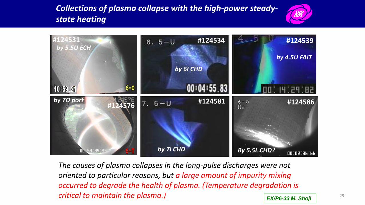
Collections of plasma collapse with the high-power steady-state heating
#124539
by 4.5U FAIT
#124534
by 6I CHD
#124531 by 5.5U ECH
#124576 by 7O port #124581
by 7I CHD
#124586
By 5.5L CHD?
The causes of plasma collapses in the long-pulse discharges were not oriented to particular reasons, but a large amount of impurity mixing occurred to degrade the health of plasma. (Temperature degradation is critical to maintain the plasma.) EX/P6-33 M. Shoji
29

An integration of RF heating systems and density-control relieves critical perturbations of plasma duration.
Critical time-scales of plasma collapse are less than 0.2 sec ( ~ tE). Automatic recovery scheme is required for the stable long-pulse plasma duration.
These three systems independently communicate with each others.
30

The integrating RF heating systems and the gas-fueling control relieved plasma perturbations for density and temperature in a few seconds.
The boost of RF heating power worked to effectively maintain the plasma parameters.
A unintended event occurred at t ~ 522 sec, and boosting RF heating power was carried out at the short-time delay (< ms). By boosting RF power, plasma density and temperature was recovered to the similar levels just before the event, and robust plasma with the ultra-long pulse and higher performance was demonstrated by these developments in the LHD.
However, the next critical issue of breaking steady-state plasma appeared…
Unintended impurity mixing
31
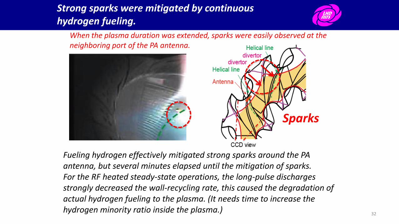
Strong sparks were mitigated by continuous hydrogen fueling.
Fueling hydrogen effectively mitigated strong sparks around the PA antenna, but several minutes elapsed until the mitigation of sparks. For the RF heated steady-state operations, the long-pulse discharges strongly decreased the wall-recycling rate, this caused the degradation of actual hydrogen fueling to the plasma. (It needs time to increase the hydrogen minority ratio inside the plasma.)
Sparks
When the plasma duration was extended, sparks were easily observed at the neighboring port of the PA antenna.
32

Confirming the exhausting ability of He particles using the cryo-absorption pump
The exhausting ability of He particles using the turbo-molecular pump is approximately 16 ~ 19 m3/s in the surrounding pressure of 10-2 ~ 10-3 Pa. The exhausting ability using the cryo-absorption pump was not negligible after the particle desorption. After continuous He fueling (~ one hour), the active exhausting rate of the cryo pump will be small (~4 m3/s), and it is necessary to consider the time evolution of the fueled he particles.
Ten cryo-absorption pump and five turbo pumps
Closed gates of cryo pumps
The fitted line of exhausting rate S(m3/s) = 2*(15+62*exp(-0.0014303*t))
Only turbo molecular pump
G. Motojima et al. (PSI 2014)
Using one turbo pump
Using five turbo pumps
33
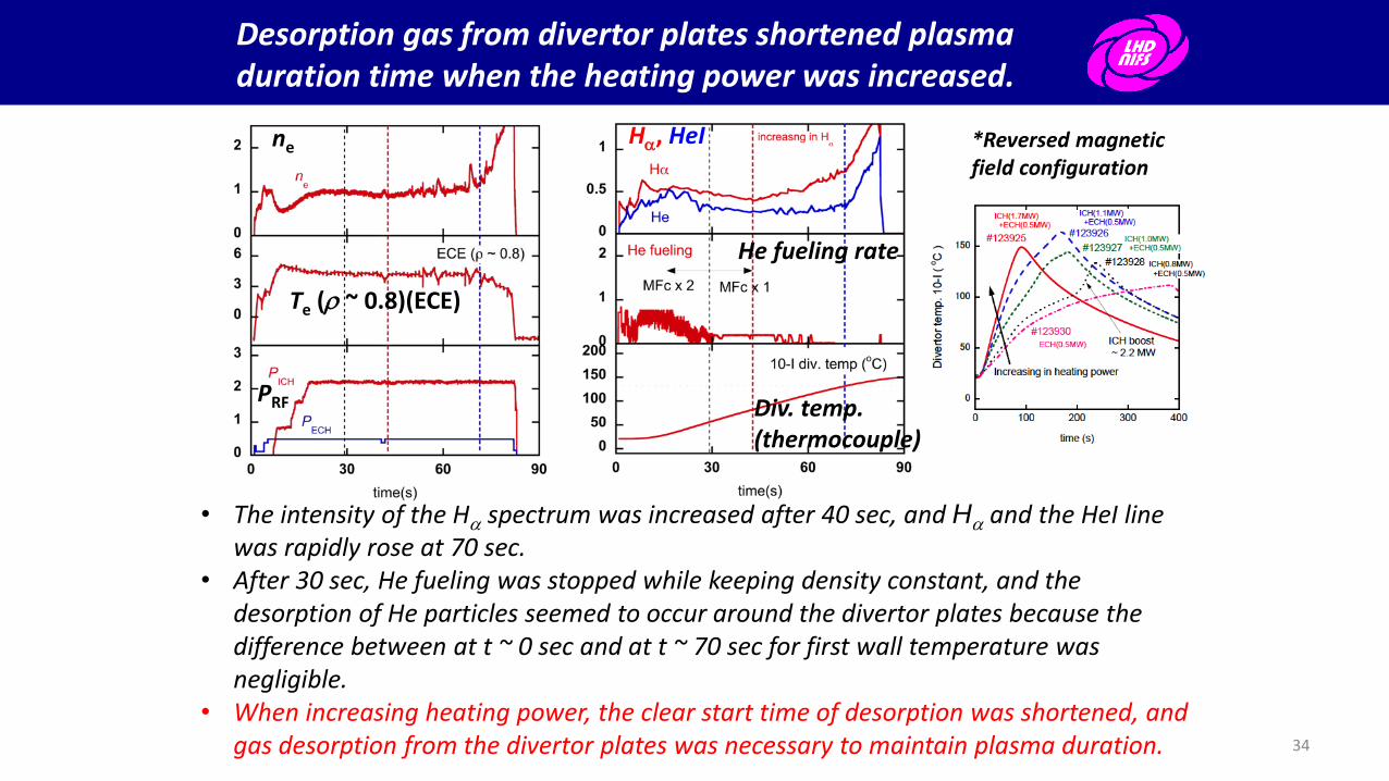
Desorption gas from divertor plates shortened plasma duration time when the heating power was increased.
*Reversed magnetic field configuration
• The intensity of the Ha spectrum was increased after 40 sec, and Ha and the HeI line was rapidly rose at 70 sec.
• After 30 sec, He fueling was stopped while keeping density constant, and the desorption of He particles seemed to occur around the divertor plates because the difference between at t ~ 0 sec and at t ~ 70 sec for first wall temperature was negligible.
• When increasing heating power, the clear start time of desorption was shortened, and gas desorption from the divertor plates was necessary to maintain plasma duration.
ne
Te (r ~ 0.8)(ECE)
PRF
Ha, HeI
He fueling rate
Div. temp. (thermocouple)
34

• Heat balance is easily estimated by the heating source and by removing
off power of cooling water on SSO:
Heating (PRF) = Radiation (Prad) + Divertor (Pdiv) + Wall (Pother) (fast + protector +
heating loss), Prad ~ 17%, Pdiv ~ 56%, Pother ~ 27% (#124579, Prad ~ 1.2MW)
• Retention rates(desorption and absorption) for wall and divertor are
functions of the surface temperatures and surrounding pressure. On the
SSO with thermal equilibrium, the various temperature profiles for
toroidal, poloidal, and heating geometrical conditions make more
complicated estimation of the retention rates. 35
Heat and particle balances on the steady-state operation

One of the carbon sources is a carbon-rich mixed-material layer around divertor tiles, and the thickness of the layer was extended during continuous SSO.
• Mixed-material layer strongly grew around the particular divertor plates with the large heat flux and the geometrically dense region.
• The main elements of the mixed-material layer were C (>90%) and Fe (~ a few %), and the layer effectively grew in continuous divertor erosion.
• The layer is dense, hard, and brittle, and the thick layer is easily exfoliated by the heat stress and the bubble of trapped particles (He and/or H).
5
4
3
2
1
Closed helical divertor w/o dome plates
M. Tokitani J. Nucl. Mater. 438 (2013) S818.
C > 90%, Fe ~ a few %, Ti, O
The history of a mixed-material layer and the elements
Exfoliated carbon-rich mixed-material layer
mixed-material layers (dark)
Thick mixed-material layer was observed around particular divertor plates.
36

One of the carbon sources is a carbon-rich mixed-material layer around the divertor tiles, and the thickness of the layer was extended during continuous SSO.
• As high-power plasma duration time with the increase of heating power was extended, small flakes and carbon-rich mixed-material layer (MML) were observed everywhere.
• The main elements of the flakes were carbon (>90%) and iron (~ a few %), and the thicknesses of MML grew around the particular divertor plates with the large heat flux and the geometrical dense region.
• The ultra-long pulse plasma was collapsed by the continuously exfoliated MMLs with the large region (~ 10 cm x 12 cm). This will be a critical new issue.
M. Tokitani J. Nucl. Mater. 438 (2013) S818.
C > 90%, Fe ~ a few %, Ti, O Dense, Hard, and brittle
The history of a mixed-material layer and the elements
Exfoliated carbon-rich mixed-material layer
mixed-material layers (dark)
Small flakes are on the port far from the plasma (center ~ 3m).
37

Typically early long-pulse plasma discharges in the LHD
• Particle fueling continuously occurs, and the wall-pumping has been active for the He plasma. (Not steady-state conditions for PWI)
• In order to mitigate sparks, heating power must be decreased because the sparks are one of the impurity mixing sources. This is a critical issue for high performance plasma discharge.
2nd harmonics ECH (84GHz) (3900s)
B=1.48T, Rax ~ 3.53m, Pin ~ 0.1MW
#56068 (8th cycle, 2005)
Manual control of gas-fueling rate
ICH+ECH (38.5MHz, 84GHz) (3268s)
B=2.71T, Rax ~ 3.64-3.67m, Pin ~ 0.5MW
#66053 (9th cycle, 2006)
Increasing
the heating
power and
plasma density
No wall-saturation Monotonic gas-fueling was continuously carried out, and no-wall saturation.
38

ne~0.4x10¹⁹ m-3,
PRF~0.5 MW, 54 min
ne~1.3x10¹⁹ m-3,
PRF~1.6 MW, 5 min
Density control lapsed into difficulty in the several ten minutes plasma discharge with P ~ 1MW and ne ~ 1019 m-3.
Increasing heating power and density
ne~1x10¹⁹ m-3, PRF~1 MW, 20 min
After 700 sec with the density of 1x10¹⁹ m-3 and heating power of 1 MW, the wall-pumping seemed to be first negligible and uncontrollable using early gas-feedback system. (Needs improvement of the gas-fueling system)
Saturated wall-
pumping !
For keeping steady-state ICH, minority-ratio control is an important issue, and the
controls of density and neutral gas-pressure are necessary to extend plasma
duration.
No wall saturation ! Particle decrease rate ~ active pumping rate
39

One of the critical issues for collapsing the long-pulse plasma with Te ~ 2keV and PRF ~ 1 MW was caused by the degrading heating power.
A chart of the collapse for steady-state plasma durations Decreasing heating power
Increasing the amount of the intensities for impurity lines (FeXVI, CIII)
Increasing the density and the radiation
Plasma collapse
Te, Ti ↓
ne ↑
Unstable
There is no additional heating support, and then …
Failing the control of density keeping, and then …
Mixing Fe
Decreasing Te
Decreasing Power
Mixing C
The health of the plasma is extremely weakens, and then …
Prad/PRF > 40 %. Impurity mixing easily occurs with the low temperature.
Time evolution of the plasma collapse for early long-pulse discharge with PRF ~ 1MW and ne ~ 1019 m-3
40
He
atin
g P
ow
er
(MW
) In
ten
sity C
III (a
u)
De
nsity
(x10
19 m
-3)
Ra
dia
tion
(au
)
Inte
nsity
Fe
XV
I (au
)

Contents of my presentation
• The extension of steady-state plasma duration with MW-class heating, and the operation regions
• Result of ultra-long pulse plasma duration with td ~ 48 min, PRF ~ 1.2MW, ne ~ 1.2x10¹⁹ m-3, Te ~ Ti ~ 2keV, and Winj ~ 3.4 GJ
– Thermal behavior and typical temperatures
Inhomogeneity of divertor heat flux
– The steady-state was terminated by sudden unintended entrance of the exfoliated mixed-material layers (MMLs) with continuous divertor erosion
– Characteristics of the MMLs
Thick region, the growth rate, the main elements, the physical property, and the trappable ability of He particles
– Preliminary estimation of He particle balance with the MMLs
• Summary and future plans
41


