
AXLE – AXLE SYSTEM AH–1
AH
AXLE SYSTEMPROBLEM SYMPTOMS TABLEHINT:Use the table below to help determine the cause of the problem symptom. The potential causes of the symptoms are listed in order of probability in the "Suspected area" column of the table. Check each symptom by checking the suspected areas in the order they are listed. Replace parts as necessary.
SymptomSymptom Suspected area See page
Wanders
1. Tire (improper air pressure, uneven wear) -
2. Wheel alignment (Front) SP-2
3. Wheel alignment (Rear) SP-10
4. Hub bearing AH-4
5. Front shock absorber with coil spring SP-14
6. Rear shock absorber with coil spring SP-33
Front wheel shimmy
1. Wheel (unbalance) -
2. Hub bearing AH-4
3. Front lower ball joint SP-24
4. Front shock absorber with coil spring SP-14
Noise (Front)
1. Front shock absorber with coil spring SP-14
2. Front drive shaft DS-7
3. Hub bearing AH-4
4. Front lower ball joint SP-24
Noise (Rear)1. Hub bearing AH-4
2. Rear shock absorber with coil spring SP-33

AH–2 AXLE – FRONT AXLE HUB BOLT
AH
FRONT AXLE HUB BOLTREMOVALHINT:• Use the same procedures for the RH side and LH side.• The procedures listed below are for the LH side.
1. REMOVE FRONT WHEEL2. DISCONNECT FRONT DISC BRAKE CALIPER
ASSEMBLY LH (See page AH-4)3. REMOVE FRONT DISC
HINT:Put matchmarks on the front disc and front axle hub.
4. REMOVE FRONT AXLE HUB BOLT LH(a) Temporarily install 2 nuts to any 2 hub bolts, except
the hub bolt that you will replace.(b) Using SST and a screwdriver or equivalent to hold
the front axle, remove the hub bolt that needs to be replaced.SST 09628-10011
Hold
Turn
SST
F047453E01

AXLE – FRONT AXLE HUB BOLT AH–3
AH
INSTALLATIONHINT:• Use the same procedures for the RH side and LH side.• The procedures listed below are for the LH side.
1. INSTALL FRONT AXLE HUB BOLT LH(a) Insert a new hub bolt into the bolt hole. Set a plate
washer and nut on the hub bolt end.(b) Using a screwdriver or equivalent to hold the front
axle, install the hub bolt by tightening the nut. Then remove the nut and plate washer.
(c) Remove the 2 temporary nuts.HINT:A plate washer of 5 mm (0.21 in.) or more in thickness is preferable.
2. INSTALL FRONT DISCHINT:Align the matchmarks of the front disc and front axle hub before installing them.
3. INSTALL FRONT DISC BRAKE CALIPER ASSEMBLY LH (See page AH-7)
4. INSTALL FRONT WHEELTorque: 103 N*m (1,050 kgf*cm, 76 ft.*lbf)
Hold
Turn
Plate Washer
F047454E01

AXLE – FRONT AXLE HUB AH–3
AH
SUSPENSION & AXLEAXLEFRONT AXLE HUBCOMPONENTS
FRONT AXLE HUB LH NUT
FRONT AXLE HUB SUB-ASSEMBLY LH
FRONT DISC
LOWER BALL JOINT ASSEMBLY
TIE ROD END SUB-ASSEMBLY LH
FRONT SHOCK ABSORBER LH
Non-reusable part
: Specified torqueN*m (kgf*cm, ft.*lbf)
153 (1,560, 113)
FRONT DRIVE SHAFT LH
STEERING KNUCKLE WITH AXLE HUB
8.0 (82, 71 in.*lbf)
CLIP
49 (500, 36)
216 (2,200, 159)
× 5
FRONT AXLE HUB BOLT
109 (1114, 81)
89 (908, 66)
56 (571, 41)
71 (724, 52)
CLIP
STEERING KNUCKLE LH
DISC BRAKE DUST COVER FRONT LH
FRONT DISC BRAKE CALIPER ASSEMBLY LH
FRONT NO. 1 WHEEL BEARING DUST DEFLECTOR LH
FRONT SPEED SENSOR LH
B133191E01

AH–4 AXLE – FRONT AXLE HUB
AH
ON-VEHICLE INSPECTION1. INSPECT FRONT AXLE HUB BEARING LOOSENESS
(a) Remove the front wheel.(b) Remove the front disc brake caliper.(c) Remove the front disc.
HINT:Put matchmarks on the front disc and front axle hub.
(d) Using a dial indicator, check for looseness at the center of the axle hub.Maximum looseness:
0.05 mm (0.0020 in.)If the looseness exceeds the maximum, replace the axle hub.
2. INSPECT FRONT AXLE HUB RUNOUT(a) Using a dial indicator, check for runout of the axle
hub.Maximum runout:
0.05 mm (0.0020 in.)If the runout exceeds the maximum, replace the axle hub.
(b) Install the front disc.HINT:Align the matchmarks of the front disc and front axle hub before installing them.
(c) Install the front disc brake caliper.Torque: 109 N*m (1,114 kgf*cm, 81 ft.*lbf)
(d) Install the front wheel.Torque: 103 N*m (1,050 kgf*cm, 76 ft.*lbf)
F046834E01
F046835E01

AXLE – FRONT AXLE HUB AH–5
AH
REMOVALHINT:• Use the same procedures for the RH side and LH side.• The procedures listed below are for the LH side.
1. REMOVE FRONT WHEEL2. REMOVE FRONT AXLE HUB NUT LH (See page DS-
5)3. DISCONNECT FRONT SPEED SENSOR LH (See page
BC-218)4. DISCONNECT FRONT DISC BRAKE CALIPER
ASSEMBLY LH(a) Remove the 2 bolts and disconnect the disc brake
caliper from the steering knuckle.NOTICE:Hang down the disc brake caliper with a wire or equivalent.
5. REMOVE FRONT DISCNOTICE:Ensure no oil attaches to the disc surface.
6. DISCONNECT TIE ROD END SUB-ASSEMBLY LH (See page DS-6)
7. DISCONNECT NO. 1 FRONT SUSPENSION ARM SUB-ASSEMBLY LOWER LH (See page DS-6)
8. REMOVE FRONT AXLE ASSEMBLY LH(a) Using a plastic-faced hammer, tap the end of the
front drive shaft and disengage the fitting between the front drive shaft and front axle.HINT:If it is difficult to disengage, tap the end of the front drive shaft with a brass bar and hammer.
(b) Push the front axle outward from the vehicle to remove the front drive shaft from the front axle.NOTICE:• Be careful not to push the front axle outward
from the vehicle more than is necessary to remove it.
• Be careful not to damage the drive shaft outboard joint boot.
• Be careful not to damage the speed sensor rotor.
• Hang the front drive shaft down with a string or equivalent.
C067088E05

AH–6 AXLE – FRONT AXLE HUB
AH
(c) Remove the 2 bolts and 2 nuts, and remove the front axle from the front shock absorber.
9. REMOVE FRONT NO. 1 WHEEL BEARING DUST DEFLECTOR LH(a) Mount the steering knuckle in a soft vise.(b) Using a screwdriver, remove the deflector from the
steering knuckle.NOTICE:Be careful not to damage the steering knuckle.
10. REMOVE LOWER BALL JOINT ASSEMBLY(a) Remove the clip and castle nut.(b) Using SST, remove the lower ball joint.
SST 09611-36020NOTICE:• Do not damage the steering knuckle.• Securely hang SST to the spacer of the
steering knuckle.• Replace the steering knuckle with a new one
if the spacer comes off the steering knuckle.
11. REMOVE FRONT AXLE HUB SUB-ASSEMBLY LH(a) Remove the 4 bolts, dust cover and front axle hub.
C094903E01
G028520E01
TurnSST
F046084E03
G028521E01

AXLE – FRONT AXLE HUB AH–7
AH
INSTALLATIONHINT:• Use the same procedures for the RH side and LH side.• The procedures listed below are for the LH side.
1. INSTALL FRONT AXLE HUB SUB-ASSEMBLY LH(a) Install the axle hub and dust cover with the 4 bolts.
Torque: 56 N*m (571 kgf*cm, 41 ft.*lbf)2. INSTALL LOWER BALL JOINT ASSEMBLY
(a) Install the lower ball joint to the steering knuckle, and install the castle nut.Torque: 71 N*m (724 kgf*cm, 52 ft.*lbf)NOTICE:• Be careful that grease does not adhere to the
threads or tapered part.• The clip hole alignment should be done after
tightening the castle nut up to 60° beyond the torque specification.
(b) Install a new clip.3. INSTALL FRONT NO. 1 WHEEL BEARING DUST
DEFLECTOR LH(a) Using SST and a press, press in a new dust
deflector.SST 09950-70010 (09951-07150), 09608-32010,
09950-60020 (09951-00720)NOTICE:Align the dust deflector hole and the steering knuckle hole.
4. INSTALL FRONT AXLE ASSEMBLY LH(a) Install the front axle to the shock absorber, insert the
2 bolts from the front of the vehicle and tighten the 2 nuts.Torque: 153 N*m (1,560 kgf*cm, 113 ft.*lbf)NOTICE:Apply engine oil to the nut threads or the seating surface only when reusing the bolt and nuts.
(b) Push the front axle outward from the vehicle to engage the spline of the drive shaft and insert it to the front axle.NOTICE:• Be careful not to push the front axle outward
from the vehicle more than is necessary to remove it.
• Be careful not to damage the drive shaft outboard joint boot.
• Be careful not to damage the speed sensor rotor.
• Check for any foreign matter on the speed sensor rotor and insertion part.
SST
SST
F047905E01
C094903E01

AH–8 AXLE – FRONT AXLE HUB
AH
5. CONNECT FRONT NO. 1 SUSPENSION ARM SUB-ASSEMBLY LOWER LH (See page DS-16)
6. CONNECT TIE ROD END SUB-ASSEMBLY LH (See page DS-16)
7. INSTALL FRONT DISC8. INSTALL FRONT DISC BRAKE CALIPER ASSEMBLY
LH(a) Install the disc brake caliper to the steering knuckle
with the 2 bolts.Torque: 109 N*m (1,114 kgf*cm, 81 ft.*lbf)
9. INSTALL FRONT AXLE HUB LH NUT(a) Using a 30 mm socket wrench, install a new hub
nut.Torque: 216 N*m (2,200 kgf*cm, 159 ft.*lbf)
10. DISCONNECT FRONT DISC BRAKE CALIPER ASSEMBLY LH
11. REMOVE FRONT DISC12. INSPECT FRONT AXLE HUB BEARING LOOSENESS
(See page AH-4)13. INSPECT FRONT AXLE HUB BEARING RUNOUT
(See page AH-4)14. INSTALL FRONT DISC (See page BR-43)15. INSTALL FRONT DISC BRAKE CALIPER ASSEMBLY
LHTorque: 109 N*m (1,114 kgf*cm, 81 ft.*lbf)
16. INSTALL FRONT SPEED SENSOR LH (See page BC-218)
17. INSTALL FRONT AXLE HUB NUT LH(a) Using a chisel and hammer, stake the hub nut.
18. INSTALL FRONT WHEELTorque: 103 N*m (1,050 kgf*cm, 76 ft.*lbf)
19. INSPECT AND ADJUST FRONT WHEEL ALIGNMENT (See page SP-3)
20. CHECK ABS SPEED SENSOR SIGNAL (See page BC-219)
C067088E05
AH–8 AXLE – REAR AXLE HUB BOLT
AH
REAR AXLE HUB BOLTREMOVALHINT:• Use the same procedures for the RH side and LH side.• The procedures listed below are for the LH side.
1. REMOVE REAR WHEEL2. REMOVE REAR BRAKE DRUM SUB-ASSEMBLY
HINT:Put matchmarks on the brake drum and hub.
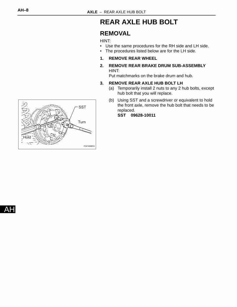
3. REMOVE REAR AXLE HUB BOLT LH(a) Temporarily install 2 nuts to any 2 hub bolts, except
hub bolt that you will replace.(b) Using SST and a screwdriver or equivalent to hold
the front axle, remove the hub bolt that needs to be replaced.SST 09628-10011
Hold
Turn
SST
F047468E01

AXLE – REAR AXLE HUB BOLT AH–9
AH
INSTALLATIONHINT:• Use the same procedures for the RH side and LH side.• The procedures listed below are for the LH side.
1. INSTALL REAR AXLE HUB BOLT LH(a) Insert a new hub bolt into the bolt hole. Set a plate
washer and nut on the hub bolt end.(b) Using a screwdriver or equivalent to hold the front
axle, install the hub bolt by tightening the nut. Then remove the nut and plate washer.
(c) Remove the 2 temporary nuts.HINT:A plate washer of 5 mm (0.20 in.) or more in thickness is preferable.
2. INSTALL REAR BRAKE DRUM SUB-ASSEMBLYHINT:Align the matchmarks of the brake drum and axle hub before installing them.
3. INSTALL REAR WHEELTorque: 103 N*m (1,050 kgf*cm, 76 ft.*lbf)
HoldTurn
Plate Washer
A125167E02

AXLE – REAR AXLE HUB AND BEARING AH–9
AH
SUSPENSION & AXLEAXLEREAR AXLE HUB AND BEARINGCOMPONENTS
REAR AXLE HUB AND BEARING ASSEMBLY LH
REAR BRAKE DRUM SUB-ASSEMBLY
SKID CONTROL SENSOR WIRE
: Specified torqueN*m (kgf*cm, ft.*lbf)
61 (622, 45)
REAR AXLE LH HUB BOLT
× 5
61 (622, 45)
B133192E01

AH–10 AXLE – REAR AXLE HUB AND BEARING
AH
ON-VEHICLE INSPECTION1. INSPECT REAR AXLE HUB BEARING LOOSENESS
(a) Remove the rear wheel.(b) Remove the rear brake drum.
HINT:Put matchmarks on the rear brake drum and hub bolt.
(c) Using a dial indicator, check for looseness at the center of the axle hub.Maximum looseness:
0.05 mm (0.0020 in.)If the looseness exceeds the maximum, replace the axle hub.
2. INSPECT REAR AXLE HUB BEARING RUNOUT(a) Using a dial indicator, check for runout of the axle
hub.Maximum runout:
0.07 mm (0.0028 in.)If the runout exceeds the maximum, replace the axle hub.
(b) Install the rear brake drum.HINT:Align the matchmarks of the rear brake drum and hub bolt before installing them.
(c) Install the rear wheel.Torque: 103 N*m (1,050 kgf*cm, 76 ft.*lbf)
F046836E01
F046837E01

AXLE – REAR AXLE HUB AND BEARING AH–11
AH
REMOVALHINT:• Use the same procedures for the RH side and LH side.• The procedures listed below are for the LH side.
1. REMOVE REAR WHEEL2. REMOVE REAR BRAKE DRUM SUB-ASSEMBLY3. DISCONNECT SKID CONTROL SENSOR
CONNECTORNOTICE:Be careful that foreign matter does not attach to the inside of the skid control sensor connector and on the installation portion.
4. REMOVE REAR AXLE HUB AND BEARING ASSEMBLY LH(a) Remove the 4 bolts and then remove the axle hub
and bearing.
C066800E01

AH–12 AXLE – REAR AXLE HUB AND BEARING
AH
INSTALLATIONHINT:• Use the same procedures for the RH side and LH side.• The procedures listed below are for the LH side.
1. INSTALL REAR AXLE HUB AND BEARING ASSEMBLY LH(a) Install the axle hub and bearing LH on the axle
beam with the 4 bolts.Torque: 61 N*m (622 kgf*cm, 45 ft.*lbf)
2. CONNECT SKID CONTROL SENSOR CONNECTOR3. INSPECT REAR AXLE HUB BEARING LOOSENESS
(See page AH-10)4. INSPECT REAR AXLE HUB BEARING RUNOUT (See
page AH-10)5. INSTALL REAR BRAKE DRUM SUB-ASSEMBLY6. INSTALL REAR WHEEL
Torque: 103 N*m (1,050 kgf*cm, 76 ft.*lbf)7. INSPECT REAR WHEEL ALIGNMENT (See page SP-
10)8. CHECK ABS SPEED SENSOR SIGNAL


