

Pressure Vessel Codes & Registrations:The items listed in this catalog have been designed and constructed in accordance with the ASME Section VIII Division I Code latest edition and are registered with the National Board of Boiler and Pressure Vessel Inspectors. Most of the items listed in this catalog are also approved for use in Canada (CRN).
Manchester Tank has the capability to also design and construct pressure vessels to many other codes, such as:
American Bureau of Shipping (ABS) United States Coast Guard (USCG) Department of Transportation (DOT) Transport Canada (TC) European Pressure Equipment Directive (PED) Transportable European Pressure Equipment Directive (TPED) Malaysia – Department of Occupational & Health (DOSH) Singapore – Ministry of Manpower (MOM) Australia Design Approval Brazilian NR-13 UN-Portable Intermediate Bulk Container (IBC) And many other international codes
Manufacturing Capabilities:Manchester Tank is capable of producing pressure vessels made from carbon steel, stainless steel and aluminum material with sizes ranging from 3” diameter at 3,000 PSI to 120” diameter at 200 PSI.
Engineering Capabilities: Manchester Tank’s engineering professionals are highly trained in AutoCAD & SolidWorks 3D CAD to support your organization’s technical design requirements. With 15 design stations and a Professional Engineer on staff, Manchester Tank is committed to fulfill your organization’s custom equipment needs in a timely manner.
Paint Specifications:The exterior surface of the items listed in this catalog has been painted with one coat of standard shop primer to serve as a temporary rust preventative. A wide variety of custom interior and exterior coatings are available.
For your convenience, Manchester Tank’s standard Pressure Vessels & Air Receiver drawings are available for download. Visit Manchester Tank’s website at mantank.com
Table of Contents:Vertical Air Receivers / 10-120 Gallons ___________________________1
Vertical Air Receivers / 120-500 Gallons __________________________2
Vertical Air Receivers / 660-10,000 Gallons _______________________3
Vacuum Receivers / 60-400 Gallons _____________________________4
Horizontal Air Receivers / 10-240 Gallons ________________________5
Horizontal Air Receivers / 400-2,560 Gallons ______________________6
Universal Horizontal Air Receivers / 1-30 Gallons __________________7
Horizontal Grasshopper Tanks / 30-240 Gallons ___________________8
Horizontal Gas Driven Tanks ___________________________________9
Extended Top Plate Tanks / 30-240 Gallons ______________________10
Technical Aids______________________________________________11
Vessel Installation & Maintenance Recommendations ____________12-13

Vertical Air Receivers / 10-120 Gallons
Gal 1010151520203030303060606060808080808080
120120120
Cu Ft 1.34 1.34 2.01 2.01 2.67 2.67 4.01 4.01 4.01 4.01 8.02 8.02 8.02 8.02
10.7010.7010.7010.7010.7010.7016.04 16.04 16.04
302400302401302402302403302404302405302406302407302408302409302410302411302412302413302414302415302417302418302419302420302423302424302425
200 300 200 300 200 300 200 300 200 300 200 300200 300 200 300 200300200300200200300
NONE NONENONENONENONENONENONENONE
.18 x 10 x 24
.18 x 10 x 24NONENONE
.18 x 13.5 x 30
.18 x 13.5 x 30NONENONENONENONE
.18 x 13.5 x 30
.18 x 13.5 x 30NONE
.25 x 15 x 40
.25 x 15 x 40
37414660609785
117107139159219192253 198268220282257319355415535
OD 10 10121214141616161620202020202024242424303030
TL 30 3033 333333 3838 383848 48 48 48 63 63 46 46 46 46 46 4646
TH 32.38 32.3835.38 35.38 35.2535.25 40.81 40.81 41.8141.81 50.75 50.75 52.06 52.06 65.75 65.75 49.19 49.19 51.25 51.25 54.00 55.50 55.50
A 11.25 11.2512.75 12.75 15.0015.0015.00 15.00 15.00 15.0017.00 17.00 17.00 17.00 17.00 17.00 21.00 21.00 21.00 21.00 27.00 27.00 27.00
B 2.38 2.382.38 2.38 2.252.252.81 2.81 2.81 2.812.75 2.75 2.75 2.75 2.75 2.75 3.19 3.19 3.19 3.19 8.00 8.00 8.00
C 1/2 1/21/2 1/2 1/21/21/2 1/2 1/21/21/2 1/2 1/21/21/2 1/2 1/21/21/2 1/2 1/21/2 1/2
D N/A N/AN/A N/A
1 1/2 1 1/2 1 1/2 1 1/21 1/2 1 1/2
2 2 2 2 2 2 2 2 2 2 2 2 2
E N/A N/AN/A N/A N/AN/A3/43/4 3/4 3/43/43/4 3/4 3/4
1 1/4 1 1/4 1 1/4 1 1/41 1/4 1 1/4
2 2 2
F 3/4 3/43/4 3/4
1 1/2 1 1/2 1 1/2 1 1/21 1/2 1 1/2
2 2 2 2 2 2 2 2 2 2 2 2 2
G 1/4 1/41/4 1/4 1/41/41/4 1/4 1/4 1/41/4 1/4 1/4 1/4 1/4 1/4 1/4 1/4 1/4 1/4 1/4 1/4 1/4
NOM CAP DIMENSIONS IN INCHES NPT OPENINGSPart # MAWP Top Plate TW
H 3/4 3/43/4 3/4 3/43/43/4 3/4 3/4 3/43/4 3/4 3/4 3/4
1 1/4 1 1/4 1 1/4 1 1/41 1/4 1 1/4
2 2 2
1
For your convenience, Manchester Tank’s standard Pressure Vessel & Air Receiver drawings are available for download. Visit Manchester Tank’s website at mantank.com

Gal 120120200200240240400400500500
Cu Ft 16.04 16.04 26.74 26.74 32.09 32.09 53.48 53.48 66.84 66.84
302421 302422 302426 302427 302428 302429 302432 302433 302436 302437
200 300 200 300 200 300 165 200 165 200
329379421720497930660783950910
OD 24 243030303036363636
TL 67 6772 72 8484 93 93
116116
TH 75 7580 80 9292
101 101 124 124
A 21 2127 27 272733 33 33 33
B 8 88 8 888 8 8 8
C 1 11 1 111 1 1 1
D 2 22 2 222 2 2 2
E 1/2 1/21/2 1/2 1/21/21/2 1/2 1/2 1/2
F 2 22 2 223 3 3 3
G 1 1/2 1 1/21 1/2 1 1/2 1 1/21 1/21 1/2 1 1/2 1 1/2 1 1/2
NOM CAP DIMENSIONS IN INCHES NPT OPENINGSPart # MAWP TW
H 1/4 1/41/4 1/4 1/41/41/4 1/4 1/4 1/4
2
Vertical Air Receivers / 120-500 Gallons
For your convenience, Manchester Tank’s standard Pressure Vessel & Air Receiver drawings are available for download. Visit Manchester Tank’s website at mantank.com

Gal 660660
10601060155015502200220025602560300030003800500050005000500080008000
10000
Cu Ft 88.24 88.24
141.71 141.71 207.22 207.22 294.12 294.12 242.25 242.25 401.07 401.07508.02668.45668.45668.45668.45
1069.521069.521336.90
302439 302440 302443 302444 302446 302447 302449 302450 302452 302453302454 302455 302457 305653 305995302459 304718 305138 304807303970
165 200 165 200 165 200 165 200 165 200137165165165200165200150137137
13651570178020362580308939324100436243755700570068008500
112001050010800123001400015700
OD 42 424848545460606060666672727284848496
108
TL 117 117144144166166190190220220214214228305305232232355276275
TH 125 125152152174174198198228228222222236313313240240363284283
A 36.50 36.5042.5042.5042.5042.5048.5048.5048.5048.5053.0053.0059.0059.0059.0070.0070.0070.0078.0087.00
B 8 88 8 888 8 8 88 888 8 8 8888
C 1 11 1
1 1/41 1/41 1/4 1 1/4 1 1/4 1 1/4 1 1/41 1/4 1 1/41 1/4 1 1/4 1 1/4 1 1/4 1 1/41 1/41 1/4
D 1 11 111 111 111 111 111 11
E 3 33 3 33 3 3 33 3 33 3 3 33333
F 1/4 1/41/4 1/4 1/41/41/4 1/4 1/4 1/41/4 1/41/41/4 1/4 1/4 1/41/4 1/4 1/4
G 3 3
6”RFSO 6”RFSO 6”RFSO6”RFSO6”RFSO 6”RFSO 6”RFSO 6”RFSO6”RFSO 6”RFSO 6”RFSO6”RFSO6”RFSO 6”RFSO 6”RFSO 6”RFSO6”RFSO 6”RFSO
NOM CAP DIMENSIONS IN INCHES NPT OPENINGSPart # MAWP TW
3
Vertical Air Receivers / 660-10,000 Gallons

Gal 6080
120240400
Cu Ft 8.02
10.70 16.04 32.09 53.48
300956 300957300958 300959 300960
150 150 150 150 150
29.9” Hg. 29.9” Hg. 29.9” Hg.29.9” Hg.29.9” Hg.
205220385750900
OD 20 20243036
TL 48 6367 84 93
TH 56 7175 92
101
A 17 1721 27 31
B 8 88 8 8
C 2 22 2 2
D 1/2 1/2 1/2 1/21/2
E 3 33
6” RFSO 6” RFSO
NOM CAP DIMENSIONS IN INCHES NPT OPENINGSPart # MAWP
Vacuum Rating TW
4
Vacuum Receivers / 60-400 Gallons
For your convenience, Manchester Tank’s standard Pressure Vessel & Air Receiver drawings are available for download. Visit Manchester Tank’s website at mantank.com
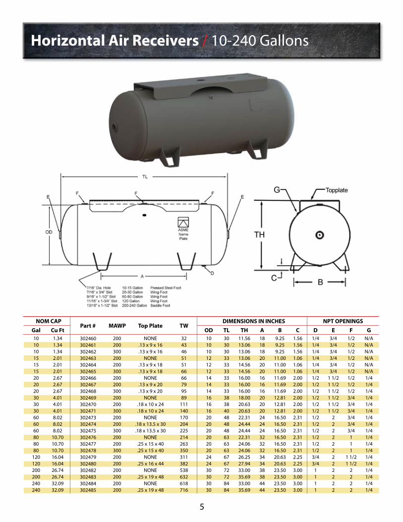
Horizontal Air Receivers / 10-240 Gallons
Gal 101010151515202020303030606060808080
120120200200240240
Cu Ft 1.34 1.34 1.34 2.01 2.01 2.01 2.67 2.67 2.67 4.01 4.01 4.01 8.02 8.02 8.02
10.70 10.7010.7016.0416.0426.7426.7432.0932.09
302460302461302462302463302464302465302466302467302468302469302470302471302473302474302475302476302477302478302479302480302482302483302484302485
200 200 300 200 200 300 200 200 300 200 200 300 200 200300 200 200 300 200200200200200200
NONE .13 x 9 x 16.13 x 9 x 16
NONE.13 x 9 x 18.13 x 9 x 18
NONE.13 x 9 x 20.13 x 9 x 20
NONE.18 x 10 x 24.18 x 10 x 24
NONE.18 x 13.5 x 30.18 x 13.5 x 30
NONE.25 x 15 x 40.25 x 15 x 40
NONE.25 x 16 x 44
NONE.25 x 19 x 48
NONE.25 x 19 x 48
32434651516666799589
111140170204 225214263350311382538632618716
OD 10 1010121212141414161616202020202020242430303030
TL 30 3030 33 333333 33 33 3838 40 48 48 48 63 63 63 67 67 72 72 84 84
TH 11.56 13.0613.06 13.06 14.5614.56 16.00 16.00 16.0018.00 20.63 20.63 22.31 24.44 24.44 22.31 24.06 24.06 26.25 27.94 33.00 35.69 33.00 35.69
A 18 1818 20 202016 16 16 2020 20 24 24 24 32 32 32 34 34 38 38 44 44
B 9.25 9.259.25
11.00 11.0011.0011.69 11.69 11.69 12.8112.81 12.81 16.50 16.50 16.50 16.50 16.50 16.50 20.63 20.63 23.50 23.50 23.50 23.50
C 1.56 1.561.56 1.06 1.061.062.00 2.00 2.00 2.002.00 2.00 2.31 2.31 2.31 2.31 2.31 2.31 2.25 2.25 3.00 3.00 3.00 3.00
D 1/4 1/41/4 1/4 1/41/41/2 1/2 1/2 1/21/2 1/2 1/2 1/2 1/2 1/2 1/2 1/2 3/4 3/4
1 1 1 1
E 3/4 3/43/4 3/4 3/43/4
1 1/2 1 1/2 1 1/2 1 1/21 1/2 1 1/2
2 2 2 2 2 2 2 2 2 2 2 2
F 1/2 1/21/2 1/2 1/21/21/2 1/2 1/2 3/43/4 3/4 3/4 3/4 3/4
1 1 1
1 1/2 1 1/2
2 2 2 2
G N/A N/AN/A N/A N/AN/A1/4 1/4 1/4 1/41/4 1/4 1/4 1/4 1/4 1/4 1/4 1/4 1/4 1/4 1/4 1/4 1/4 1/4
NOM CAP DIMENSIONS IN INCHES NPT OPENINGSPart # MAWP Top Plate TW
5

Horizontal Air Receivers / 400-2,560 Gallons
Gal 400400660660
10601060155022002560
Cu Ft 53.48 53.48 88.24 88.24
141.71 141.71 207.22 294.12 342.25
302487 302488 302490 302491 302493 302494 302496 302498 302500
165 200 165 200 165 200 165 165 165
750925
1375137522002500270042004500
OD 36 3642424848546060
TL 93 93
117 117 144144166 190 220
TH 42 4248 48 6060 66 72 72
A 52 5270 70 848498
116 131
B 33 3339 39 454551 57 57
C 6 66 6 666 6 6
D 3/4 3/43/4 3/4 3/43/43/4 3/4 3/4
E 1 1/2 1 1/2
3 3 333 3 3
F 1/4 1/41/4 1/4 1/41/41/4 1/4 1/4
G 1/2 1/2
1 1 111 1 1
NOM CAP DIMENSIONS IN INCHES NPT OPENINGSPart # MAWP TW
H 2 22 2 222 2 2
J 3 33 3
6” RFSO6” RFSO6” RFSO 6” RFSO 6” RFSO
6
For your convenience, Manchester Tank’s standard Pressure Vessel & Air Receiver drawings are available for download. Visit Manchester Tank’s website at mantank.com

Universal Horizontal Air Receivers / 1-30 Gallons
Gal 12357
10131519 2430
Cu Ft 0.13 0.27 0.40 0.67 0.94 1.34 1.74 2.01 2.54 3.21 4.01
304978 304980 304982 304932 304934 304936 304938 304940 304942 304944 304946
200 200 200 200 200 200 200 200 200 200 200
1517222529354551597285
OD 6 88
101212141416 1618
TL 11 1116 16 172323 26 25 3131
TH 8
1010 12 1414 16 16 18 18 20
A 7 7
10 10 101015 15 16 16 16
B 3.5 4.54.5 6.5 6.56.58.5 8.5
10.5 10.5 10.5
C 2 22 2 222 2 2 22
D 1/2 1/21/2 1/2 1/21/21/2 1/2 1/2 1/2 1/2
E 3/4 3/43/4 3/4 3/43/43/4 3/4 3/4 3/4 3/4
F 3/4 3/43/4 3/4 3/43/4
1 1/2 1 1/2 1 1/2 1 1/2 1 1/2
G 1 11 1 111 1 222
NOM CAP DIMENSIONS IN INCHES NPT OPENINGSPart # MAWP TW
7

Horizontal Grasshopper Tanks / 30-240 Gallons
Gal 306080
120200240
Cu Ft 4.01 8.02
10.70 16.04 26.74 32.09
305438 305439 305440 302481 302643 302652
200 200 200 200 200 200
125260300435780820
OD 16 2020243030
TL 38 4863 67 7284
TH 21 2525 29 3535
A 22 2742 43 4254
B 22.0 26.526.5 32.0 40.040.0
C 4 44 4 44
D 1/4 3/43/4 3/4
11
E 1 1/2
22 2 22
F 1/2 1/21/2 1/2 1/21/2
G 3/4 3/43/4 3/4 3/43/4
NOM CAP DIMENSIONS IN INCHES NPT OPENINGSPart # MAWP TW
H 1 1/2 1 1/21 1/2 1 1/2 1 1/21 1/2
J 1/8 1/81/8 1/8 1/81/8
8
For your convenience, Manchester Tank’s standard Pressure Vessel & Air Receiver drawings are available for download. Visit Manchester Tank’s website at mantank.com

Horizontal Gas Driven Tanks
Part #34917 approved for use in California
9
Gal 30
Cu Ft 4.01 302472 200 .25 x 15 x 39 160
NOM CAP
OD 16
TL 38
TH 17.25
A 22.00
B 13.13
C 0.38
D 1/4
E 1 1/2
F 1 1/4
DIMENSIONS IN INCHES NPT OPENINGS
Part # MAWP Top Plate TWGal 30
Cu Ft 4.01 34917 200 .25 x 11.5 x 42.5 161
NOM CAP
OD 16
TL 38
TH 20.56
A 38.94
B 13.00
C 2.75
D 1/4
E 1 1/2
F 3/4
DIMENSIONS IN INCHES NPT OPENINGS
Part # MAWP Top Plate TW

Extended Top Plate Horizontal Air Receivers / 30-240 Gallons
Gal 306080
120200240
Cu Ft 4.01 8.02
10.70 16.04 26.74 32.09
302686 302693 303977 302700 302701 303181
200 200 200 200 200 200
.18 x 12 x 40
.25 x 16 x 54
.25 x 16 x 69
.25 x 16 x 74
.25 x 18 x 86
.25 x 18 x 86
117216375475706728
OD 16 2020243030
TL 38 4863 69 7284
TH 20.63 25.5625.63 29.63 35.7535.75
A 22 2636 42 4254
B 14 1818 22 2828
C 3 44 4 44
D 1/4 1/23/4 3/4
11
E 1/2 1/23/4
1 11
F 3/8 3/83/8 3/8 3/83/8
G 3/4
11 1/2 1 1/2
22
NOM CAP DIMENSIONS IN INCHES NPT OPENINGSPart # MAWP Top Plate TW
H 1/4 1/41/4 1/4 1/41/4
J 1/4 1/41/4 1/2 1/21/2
K 3/4
11 1/4 1 1/2
22
10
L 1 1/2
22 2 22
For your convenience, Manchester Tank’s standard Pressure Vessel & Air Receiver drawings are available for download. Visit Manchester Tank’s website at mantank.com

11
GALLONS
306080
120
56
X
56H
X
143T
X
145T
XX
182T
X
184T
XXX
213T
XXX
215T
XX
254T
XX
Horizontal NEMA Frame Sizes
Air Receiver Capacity in Cubic Feet of Free Air at Various Pressures
GALLONS
306080
120200240400660
106016002560
75
4.08.0
10.716.126.832.253.688.4
142.0214.4343.0
100
27.3 54.7 73.0
109.3 182.2 218.7 364.5 601.4 965.9
1457.9 2333.0
125
34.268.210.792.2
136.2 227.8 455.6 751.7
1207.3 1822.4 2916.0
150
41.082.0
109.4164.0273.4328.0546.7902.1
1448.82186.93499.0
200
54.7109.4146.0218.7364.5437.4729.0
1202.81931.72915.84655.0
250
68.3136.7182.4273.3455.6546.7911.2
1503.42414.53644.85832.0
CU. FT.
4.08.0
10.716.126.832.253.688.4
142.0214.4343.0
CAPACITY PRESSURE (in pounds)
Capacites at other pressures are exactly in proportion.Example: At 200 lbs. pressure the capacity of a given size tank is exactly double the capacity at 100 lbs. pressure.
Cu. Ft. 0.134
Gallons = • • • Cu. Ft. = Gallons X 0.134
Useful Formulas - Sizing a Tank
A Tank Size (ft3) = Compressor Flow (CFM)7
Constant Speed Operation:
B
F
VR = 14.7 t (Qr-Qc)Pmax - Pmin
Typical Sizing Formula:
Pump Up Time:
where t = time (min) that receiver can supply required amount of air, Qr = consumption rate of pneumatic system (cfm), Qc = output flow rate of compressor (cfm), Pmax = maximum pressure level in receiver (psi), Pmin = minimum pressure level in receiver (psi), Vr = receiver size (ft3)
C 7.48 Gallons = 1 ft3 Volume
80 Gallon Tank7.5 gl./ft3
1066.6714.7 (the ATM Pressure) X 18 (the CFM of Unit)
E 35 CFM = 1 Meter3Min
D 14.5 psi = Bar
Example - 5 hp compressor on an 80 gallon tank, pumping from 0-100 psig
X (100 psig - 0 psig) = = 4 min
Technical Aids
GALLONS
306080
120
56
X
56H
X
143T
X
145T
XXX
182T
XX
184T
XXX
213T
XXX
215T
X
254T
X
Vertical NEMA Frame Sizes

12
I. INSTALLATION RECOMMENDATIONSVertical Vessels1. Vessels with a capacity of 660 gallons and above should be placed on a suitable concrete foundation.
a) Refer to Table 1 for recommended minimum concrete footing depths for vertical receivers.
b) For larger vessels or vessels with higher MAWP’s, greater weights, or vessels subjected to external seismic or wind loadings – consult a certified contractor or civil engineer for foundation requirements.
c) Vessels should be lifted into position using both lifting lugs. A 2-branch chain or wire rope sling should be used having a lift angle not less than 60 degrees from grade. Once the vessel is in position, torque anchor bolting until a tight, snug fit is achieved.
Table 1: Minimum Recommended concrete footing depths for Vertical Air Receivers
Horizontal Vessels1. Vessels with a capacity of 660 gallons and above should be placed on a suitable concrete foundation.
a) Refer to Table 2 for recommended minimum concrete footing depths for horizontal receivers.
b) For larger vessels or vessels with higher MAWP’s, greater weights, or vessels subjected to external seismic or wind loadings – consult a certified contractor or civil engineer for foundation requirements.
Table 1: Minimum Recommended concrete footing depths for Horizontal Air Receivers
TANK SIZE
42” X 117”48” X 144”54” X 166” 60” X 190” 60” X 220” 66” X 214” 72” X 228”
MAWP (PSI)
165165165 165 165165137
W.C. (GAL)
66010601550 220025603000 3800
APPROX. WT. (LBS.)
136521002600 3650 45005700 6800
SERVICE
AIRAIRAIRAIRAIR AIRAIR
SUPPORT
SKIRTSKIRTSKIRTSKIRTSKIRTSKIRTSKIRT
DEPTH (IN)
444 4 466
Vessel Installation and Maintenance Recommendations
TANK SIZE
42” X 117”48” X 144”54” X 166” 60” X 190” 60” X 220” 66” X 214” 72” X 228”
MAWP (PSI)
165165165 165 165165137
W.C. (GAL)
66010601550 220025603000 3800
APPROX. WT. (LBS.)
136521002600 3650 45005700 6800
SERVICE
AIRAIRAIRAIRAIR AIRAIR
SUPPORT
SADDLESADDLESADDLESADDLESADDLESADDLESADDLE
DEPTH (IN)
333 4 446

13
There should be at least one high quality pressure indicating device attached directly to an opening in the vessel.
A relief valve must be selected and installed. The valve must be sized according to the maximum flow rate into the vessel such that over-pressurization cannot occur. See ASME Section VIII, Division 1, Paragraph UG-125 for details on relief valves.
An automatic drain device is recommended to regularly drain any condensate from the vessel. In lieu of an automatic device, the user should be cautioned to regularly drain the receiver manually.
Notes: Reinforced concrete 28 day ultimate strength – 2500 psi minimum
Uniform gravel and soil base beneath footing. Footing surface shall be flat and level in all directions.
Anchoring the vessel to the concrete footing is necessary to stabilize the receiver only and is not intended to provide resistance against wind, seismic, or other external loadings that may create a vessel tipping condition. The above table represents footing depths for compressive loading only.
Check local construction codes, fire codes, or building standards.
Use an appropriately sized anchor bolt of SA-325 material or better, a wrought steel washer, and a heavy hex nut.
Footings exposed to freezing temperatures should be sufficiently sized in depth to prevent cracking.
Larger vessels not covered in the table, saddles may be provided which have holes on one end of the vessel and slots on the other end of the vessel. When bolting saddles to the foundation, anchor bolting should be fixed by first hand-tightening the nut and then locking the threads by staking, double nutting, or tack welding.
VESSEL MAINTENANCEAll Pressure VesselsMaintaining a pressure vessel includes proper inspection. Many states have adopted the National Board Inspection Code (NB-23) for rules concerning post-construction activities. Check with your local authorities having jurisdiction over pressure vessel installations and operations for any additional requirements concerning in-service inspection.
Vessel Installation and Maintenance Recommendations
Setting the Standard for Quality and Reliability

MANCHESTER TANK & EQUIPMENT CO., a division of McWane Inc., is the premier manufacturer of pressure vessels for the containment of propane, compressed air and chemical applications. Manchester Tank’s mission is to set the industry standard for quality and reliability while providing customers with the resources, service and technical support necessary to be profitable in an increasingly competitive global market.
• Capable of manufacturing a diverse product line, which includes Department of Transportation (DOT) approved steel and aluminum cylinders ranging in size from 5 to 420 pounds and American Society of Mechanical Engineers (ASME) approved steel tanks ranging in size from 1 to 30,000 gallons.
• State-of-the-art manufacturing facilities and distribution points strategically positioned in the United States, Canada, Australia and the Republic of Chile to guarantee timely delivery and convenience worldwide.
• Strong business development group with extensive knowledge and experience in providing solutions and ensuring customer needs are met efficiently and cost effectively.
• Highly trained, professional engineering and design team prepared to support any organizations innovative tank and equipment requirements.
• Long-time, loyal partners also committed to customer satisfaction and overall success.
• Years of active involvement with American Society of Mechanical Engineers (ASME), Pressure Vessel Manufacturers Association (PVMA) and National Board of Boiler & Pressure Vessels Inspectors professional associations to ensure product, operations and manufacturing requirements and issues meet the codes and standards that impact the industry.
Bedford, Indiana Customer ServicePhone: 800-399-5628Fax: 800-877-9988
Quincy, Illinois Customer Service Phone: 800-926-2791Fax: 800-596-2284
Catalog No. 49031-10/2014


