Preface
PrefaceCopyright
This publication, including all photographs, illustrations and software, is protectedunder international copyright laws, with all rights reserved. Neither this manual, norany of the material contained herein, may be reproduced without written consent ofthe author.
Version 2.0
DisclaimerThe information in this document is subject to change without notice. The manufac-turer makes no representations or warranties with respect to the contents hereof andspecifically disclaims any implied warranties of merchantability or fitness for anyparticular purpose. The manufacturer reserves the right to revise this publication andto make changes from time to time in the content hereof without obligation of themanufacturer to notify any person of such revision or changes.
Federal Communications Commission (FCC)This equipment has been tested and found to comply with the limits for a Class Bdigital device, pursuant to Part 15 of the FCC Rules. These limits are designed toprovide reasonable protection against harmful interference in a residential installa-tion. This equipment generates, uses, and can radiate radio frequency energy and, ifnot installed and used in accordance with the instructions, may cause harmful inter-ference to radio communications. However, there is no guarantee that interferencewill not occur in a particular installation. If this equipment does cause harmfulinterference to radio or television reception, which can be determined by turning theequipment off and on, the user is encouraged to try to correct the interference by oneor more of the following measures:
• Reorient or relocate the receiving antenna• Increase the separation between the equipment and the receiver• Connect the equipment onto an outlet on a circuit different from that to
which the receiver is connected• Consult the dealer or an experienced radio/TV technician for help
Shielded interconnect cables and a shielded AC power cable must be employed withthis equipment to ensure compliance with the pertinent RF emission limits govern-ing this device. Changes or modifications not expressly approved by the system’smanufacturer could void the user’s authority to operate the equipment.
Trademark RecognitionMicrosoft, MS-DOS and Windows are registered trademarks of Microsoft Corp.
MMX, Pentium, Pentium-II, Pentium-III, Celeron are registered trademarks of IntelCorporation.
Other product names used in this manual are the properties of their respectiveowners and are acknowledged.

ii
Preface
Declaration of ConformityThis device complies with part 15 of the FCC rules. Operation is subject to thefollowing conditions:
• This device may not cause harmful interference, and• This device must accept any interference received, including interfer-
ence that may cause undesired operation
Canadian Department of CommunicationsThis class B digital apparatus meets all requirements of the Canadian Interference-causing Equipment Regulations.
Cet appareil numérique de la classe B respecte toutes les exigences du Réglement surle matériel brouilieur du Canada.
About the ManualThe manual consists of the following:
Describes features of themotherboard.Go to page 1
Describes installation ofmotherboard components.Go to page 7Provides information on us-ing the BIOS Setup Utility.Go to page 25Describes the motherboardsoftwareGo to page 43
Chapter 1
Introducing the Motherboard
Chapter 2
Installing the Motherboard
Chapter 3
Using BIOS
Chapter 4
Using the Motherboard Software
Describes the ATICrossfireXTM TechnologyGo to page 47
Chapter 5
ATI CrossfireXTM Technology Support
Describes the Intel® MatrixStorage Manager RAID Con-figurationsGo to page 51
Chapter 6Intel® Matrix Storage ManagerRAID Configurations
Chapter 8Trouble Shooting
Go to page 67
Provides basic trouble shoot- ing tips
Chapter 7Setting Up eJIFFY
Describes the eJIFFYsetting upGo to page 57
iii
TTTTTABLE OF CONTENTSABLE OF CONTENTSABLE OF CONTENTSABLE OF CONTENTSABLE OF CONTENTS
Preface iChapter 1 1 1 1 1 1
Introducing the Motherboard 1Introduction......................................................................................1Feature ..............................................................................................2Specifications...................................................................................4Motherboard Components.............................................................5
Chapter 2 7 7 7 7 7
Installing the Motherboard 7Safety Precautions...........................................................................7Choosing a Computer Case............................................................7Installing the Motherboard in a Case...........................................7Checking Jumper Settings..............................................................8
Setting Jumpers....................................................................8Checking Jumper Settings....................................................9Jumper Settings....................................................................9
Installing Hardware.......................................................................10Installing the Processor......................................................10Installing Memory Modules...............................................12Expansion Slots..................................................................14Connecting Optional Devices.............................................16Installing a Hard Disk Drive/CD-ROM/SATA Hard Drive...18Installing a Floppy Diskette Drive.....................................19
Connecting I/O Devices...............................................................20Connecting Case Components....................................................21
Front Panel Header...........................................................24
Chapter 3 25 25 25 25 25
Using BIOS 25About the Setup Utility................................................................ 25
The Standard Configuration...............................................25
iv
Integrated Peripherals.......................................................33Power Management Setup.................................................34PCI/PNP Configuration.....................................................35PC Health Status................................................................36M.I.B. (MB Intelligent BIOS).............................................38Load Default Settings........................................................40Supervisor Password.........................................................40User Password...................................................................41Save & Exit Setup...............................................................41Exit Without Saving............................................................41Updating the BIOS.............................................................42
Chapter 4 43 43 43 43 43
Using the Motherboard Software 43About the Software DVD-ROM/CD-ROM..................................43Auto-installing under Windows XP/Vista/7...............................43
Running Setup....................................................................44Manual Installation........................................................................46Utility Software Reference............................................................46
Using BIOS.....................................................................................27Standard CMOS Setup.......................................................28Advanced Setup..................................................................30Advanced Chipset Setup.....................................................32
Entering the Setup Utility....................................................25Resetting the Default CMOS Values...................................26
Chapter 5 47 47 47 47 47
ATI CrossFireX™ Technology Support 47Requirements..................................................................................47Installing a single graphics card..................................................47
Installing CrossFireX™ graphics cards......................................48 The Catalyst™ Control Center Dialog Box.................................50
View.....................................................................................50To Enable CrossFireX™.....................................................50

v
Chapter 8 67 67 67 67 67
Trouble Shooting 67 Start up problems during assembly.............................................67 Start up problems after prolong use............................................68 Maintenance and care tips...........................................................68 Basic Troubleshooting Flowchart..............................................69
Chapter 6 51 51 51 51 51
Intel® Matrix Storage Manager RAID Configurations 51Before creating a RAID set...........................................................51
Entering Intel® Matrix Storage Manager RAID BIOS utility...52Creating a RAID set.......................................................................53Deleting a RAID set.......................................................................55 Resetting disks to Non-RAID......................................................56Exiting Setup...................................................................................56
Chapter 7 57 57 57 57 57Setting Up eJIFFY 57 Introduction................................................................................57
Usage FAQ..............................................................................................63
Installation and BIOS Setup.........................................................58 Entering eJIFFY.....................................................................................61 Features Icons.........................................................................................62

vi
Memo

1
Introducing the Motherboard
Chapter 1Introducing the Motherboard
Introduction
Thank you for choosing the P45T-A motherboard. This motherboard is a highperformance, enhanced function motherboard designed to support the LGA775 socketIntel® Yorkfield/Wolfdale/CoreTM 2 Duo processors for high-end business or personaldesktop markets.
There is an advanced full set of I/O ports in the rear panel, including PS/2 mouse andkeyboard connectors, one serial port, one eSATA port, six USB ports, one LAN portand audio jacks for microphone, line-in and 8-ch line-out.
The ICH10R Southbridge supports two PCI slots which are PCI v2.3 compliant. Itimplements an EHCI compliant interface that provides 480 Mb/s bandwidth fortwelve USB 2.0 ports (six USB ports and three USB 2.0 headers support additional sixUSB ports). One onboard IDE connector supports two IDE devices in Ultra ATA 133/100/66/33 mode. The Southbridge supports six SATA ports with maximum transferrate up to 3.0 Gb/s each. It supports Intel® Matrix Storage Technology, providingboth AHCI and RAID 0, 1, 5 and 10 configuration.
The motherboard incorporates the Intel Eaglelake P45 Northbridge (NB) and IntelICH10R Southbridge (SB) chipsets. The Northbridge supports a Front Side Bus (FSB)frequency of 1333/1066/800 MHz using a scalable FSB Vcc_CPU. The memorycontroller supports DDR2 memory DIMM frequencies of 800/667. It supports fourDDR2 sockets with maximum memory size of 16 GB. High resolution graphics viatwo PCI Express x16 slots, intended for Graphics Interface, are fully compliant tothe PCI Express Base Specification Revision 2.0. It supports the ATI CrossFireXTM
Technology that allows you to install GPU graphics cards.

2
Introducing the Motherboard
FeatureProcessor
Chipset
• Supports DDR2 800/667 DDR2 SDRAM with Dual-channel architecture• Accommodates four unbuffered DIMMs• Up to 4 GB per DIMM with maximum memory size up to 16 GB
Memory
Audio• RealTek ALC883 7.1ch High Definition audio CODEC
This motherboard uses an LGA775 type of Intel® Yorkfield/Wolfdale/CoreTM 2Duo that carries the following features:
• Accommodates Intel® Intel® Yorkfield/Wolfdale/CoreTM 2 Duo proces-sors
• Supports a system bus (FSB) of 1333/1066/800 MHz
The P45 Northbridge (NB) and ICH10R Southbridge (SB) chipsets are based on aninnovative and scalable architecture with proven reliability and performance.P45 (NB) • Supports 36-bit host bus addressing, allowing the
CPU to access the entire 64 GB of the memory ad-dress space.
• 2 GB/s point-to-point Direct Media Interface (DMI) toICH10 (1 GB/s each direction)
• Two PCI Express x16 slots, intended for GraphicsInterface, are fully compliant to the PCI Express BaseSpecification Revision 2.0.
• Supports 512-Mb and 1-Gb DDR2 and 512-Mb, 1-Gb,and 2-Gb DDR3 DRAM technologies for x8 andx16 devices
ICH10R (SB) • Enhanced DMA Controller, interrupt controller, and timerfunctions
• Compliant with PCI Express Base Specification, revi-sion 1.1
• Compliant with PCI v2.3 specificaiton• Compliant with SATA 3.0 Gb/s Host Controller• Integrated USB 2.0 Host Controller supporting up to
twelve USB 2.0 ports• Supports Intel® Matrix Storage Technology, providing
both AHCI and RAID 0, 1, 5 and 10 configuration
Onboard LAN• Gigabit LAN, Athlos L1 PCIe GigaLAN controller
3
Introducing the Motherboard
This motherboard supports Ultra DMA bus mastering with transfer rates of 133/100/66/33 Mb/s.
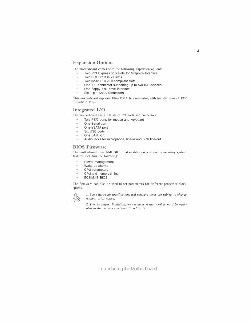
• Two PCI Express x16 slots for Graphics Interface• Two PCI Express x1 slots• Two 32-bit PCI v2.3 compliant slots• One IDE connector supporting up to two IDE devices• One floppy disk drive interface• Six 7-pin SATA connectors
Expansion Options
Integrated I/O
The motherboard comes with the following expansion options:
• Two PS/2 ports for mouse and keyboard• One Serial port• One eSATA port• Six USB ports• One LAN port• Audio jacks for microphone, line-in and 8-ch line-out
BIOS Firmware
• Power management• Wake-up alarms• CPU parameters• CPU and memory timing• ECS M.I.B. BIOS
1. Some hardware specifications and software items are subject to changewithout prior notice.
The motherboard has a full set of I/O ports and connectors:
The motherboard uses AMI BIOS that enables users to configure many systemfeatures including the following:
The firmware can also be used to set parameters for different processor clockspeeds.
2. Due to chipset limitation, we recommend that motherboard be oper-ated in the ambiance between 0 and 50 °C.
4
Introducing the Motherboard
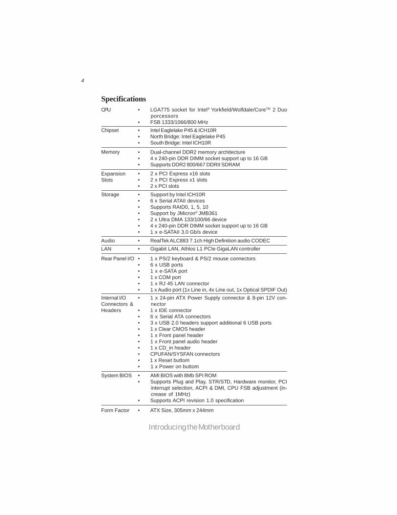
• Intel Eaglelake P45 & ICH10R• North Bridge: Intel Eaglelake P45• South Bridge: Intel ICH10R
• LGA775 socket for Intel® Yorkfield/Wolfdale/CoreTM 2 Duoporcessors
• FSB 1333/1066/800 MHz
• Dual-channel DDR2 memory architecture• 4 x 240-pin DDR DIMM socket support up to 16 GB• Supports DDR2 800/667 DDRII SDRAM
• 2 x PCI Express x16 slots• 2 x PCI Express x1 slots• 2 x PCI slots• Support by Intel ICH10R• 6 x Serial ATAII devices• Supports RAID0, 1, 5, 10• Support by JMicron® JMB361• 2 x Ultra DMA 133/100/66 device• 4 x 240-pin DDR DIMM socket support up to 16 GB• 1 x e-SATAII 3.0 Gb/s device
• RealTek ALC883 7.1ch High Definition audio CODEC• Gigabit LAN, Athlos L1 PCIe GigaLAN controller
• 1 x PS/2 keyboard & PS/2 mouse connectors• 6 x USB ports• 1 x e-SATA port• 1 x COM port• 1 x RJ 45 LAN connector• 1 x Audio port (1x Line in, 4x Line out, 1x Optical SPDIF Out)• 1 x 24-pin ATX Power Supply connector & 8-pin 12V con-
nector• 1 x IDE connector• 6 x Serial ATA connectors• 3 x USB 2.0 headers support additional 6 USB ports• 1 x Clear CMOS header• 1 x Front panel header• 1 x Front panel audio header• 1 x CD_in header• CPUFAN/SYSFAN connectors• 1 x Reset buttom• 1 x Power on buttom
Chipset
Memory
ExpansionSlots
Storage
AudioLAN
Rear Panel I/O
Internal I/OConnectors &Headers
• AMI BIOS with 8Mb SPI ROM• Supports Plug and Play, STR/STD, Hardware monitor, PCI
interrupt selection, ACPI & DMI, CPU FSB adjustment (in-crease of 1MHz)
• Supports ACPI revision 1.0 specification
System BIOS
Form Factor • ATX Size, 305mm x 244mm
CPU
Specifications

5
Introducing the Motherboard
Table of Motherboard Components
This concludes Chapter 1. The next chapter explains how to install the motherboard.
LABEL CO MPO NENTS
1. CPU SocketLGA775 socket Intel® Yorkfield/Wolfdale/CoreTM 2 Duo processors
2. CPU_FAN1 CPU cooling fan connector3. DDR2_DIMM1~4 240-pin DDR2 SDRAM slots4. ATX_POWER Standard 24-Pin ATX Power connector5. SATA1~6 Serial ATA connectors6. RST_BOT Reset button7. PWR_BOT Power on button8. F_PANEL Front Panel Switch/LED header9. CASE_FAN Case cooling fan connector10. F_USB1~3 Front Panel USB headers11. USBPWR_F1~2 Front Panel USB Power Select jumpers12. SPK Speaker header13. CLR_CMOS Clear CMOS jumper14. IDE Primary IDE connector15. FDD Floppy disk drive connector16. F_AUDIO Front Panel Audio header17. CD_IN Analog Audio Input connector18. SPDIFO SPDIF out header19. PCI2~3 32-bit add-on card slots20. PCIE16X_1~2 PCI Express x16 graphics card slots21. PCIE1/3 PCI Express x1 slots22. USBPWR_R1~2 Rear USB/PS2 Power Select jumpers23. ATX12V 4-pin +12V power connector24. SYS_FAN1 System cooling fan connector
Motherboard Components

6
Introducing the Motherboard
Memo

7
Installing the Motherboard
Chapter 2Installing the Motherboard
Safety Precautions• Follow these safety precautions when installing the motherboard• Wear a grounding strap attached to a grounded device to avoid dam-
age from static electricity• Discharge static electricity by touching the metal case of a safely
grounded object before working on the motherboard• Leave components in the static-proof bags they came in• Hold all circuit boards by the edges. Do not bend circuit boards
Choosing a Computer CaseThere are many types of computer cases on the market. The motherboard complieswith the specifications for the ATX system case. Firstly, some features on themotherboard are implemented by cabling connectors on the motherboard to indica-tors and switches on the system case. Make sure that your case supports all thefeatures required. Secondly, this motherboard supports one floppy diskette drive andtwo enhanced IDE drives. Make sure that your case has sufficient power and space forall drives that you intend to install.
Most cases have a choice of I/O templates in the rear panel. Make sure that the I/Otemplate in the case matches the I/O ports installed on the rear edge of themotherboard.
This motherboard carries an ATX form factor of 305 x 244 mm. Choose a case thataccommodates this form factor.
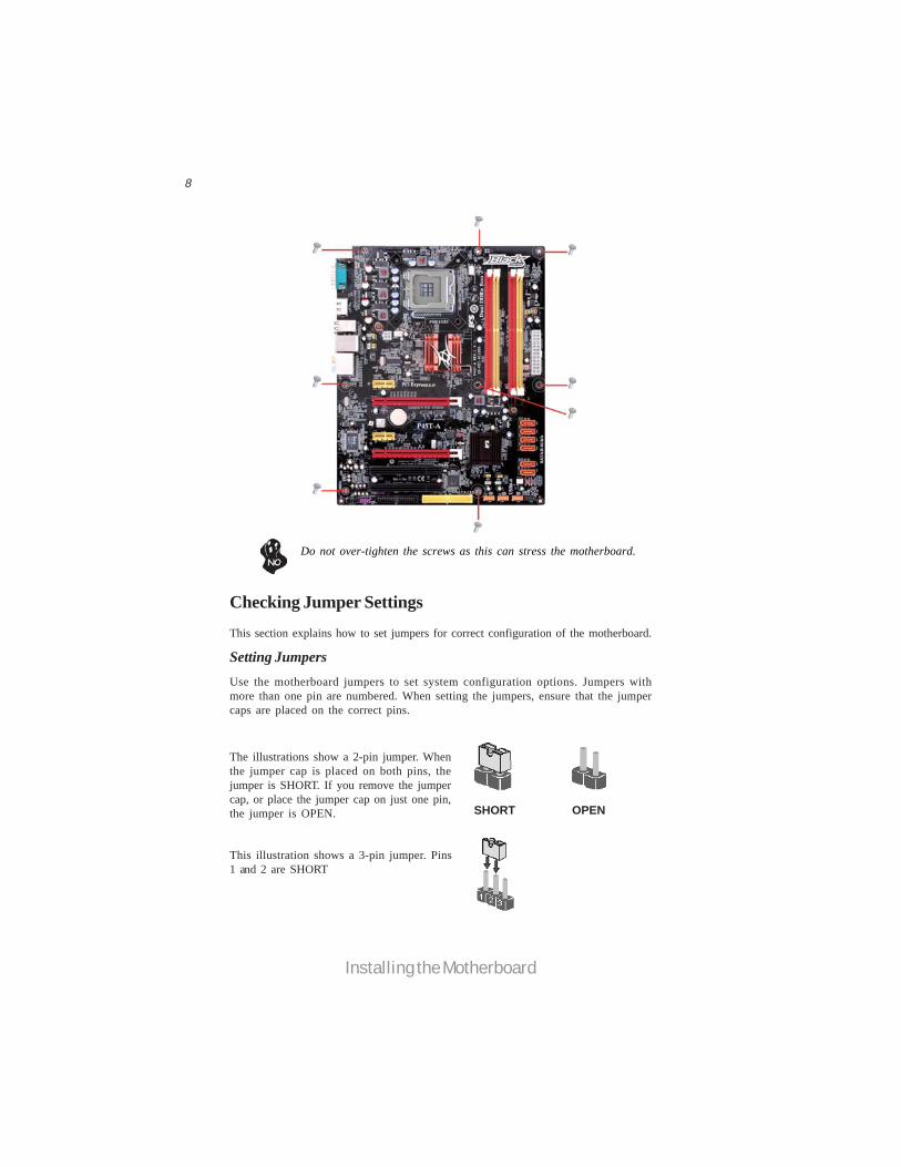
Installing the Motherboard in a CaseRefer to the following illustration and instructions for installing the motherboard ina case.
Most system cases have mounting brackets installed in the case, which correspondthe holes in the motherboard. Place the motherboard over the mounting bracketsand secure the motherboard onto the mounting brackets with screws.
Ensure that your case has an I/O template that supports the I/O ports and expansionslots on your motherboard.
8
Installing the Motherboard
Checking Jumper SettingsThis section explains how to set jumpers for correct configuration of the motherboard.
Setting JumpersUse the motherboard jumpers to set system configuration options. Jumpers withmore than one pin are numbered. When setting the jumpers, ensure that the jumpercaps are placed on the correct pins.
The illustrations show a 2-pin jumper. Whenthe jumper cap is placed on both pins, thejumper is SHORT. If you remove the jumpercap, or place the jumper cap on just one pin,the jumper is OPEN.
This illustration shows a 3-pin jumper. Pins1 and 2 are SHORT
SHORT OPEN
Do not over-tighten the screws as this can stress the motherboard.

9
Installing the Motherboard
Checking Jumper SettingsThe following illustration shows the location of the motherboard jumpers. Pin 1 islabeled.
To avoid the system instability after clearing CMOS, we recommendusers to enter the main BIOS setting page to “Load Default Settings”and then “Save & Exit Setup”.
1.
2. Make sure the power supply provides enough 5VSB voltage before se-lecting the 5VSB function.
3. It is required that users place the USBPWR_F1~2 & USBPWR_R1~2cap onto 2-3 pin rather than 1-2 pin as default if you want to wake upthe computer by USB/PS2 KB/Mouse.
Jumper Settings
Jumper Type Description Setting (default)
CLR_CMOS 3-pin CLEAR CMOS
1-2: NORMAL2-3: CLEARBefore clearing theCMOS, make sure toturn the system off.
3-pinUSBPWR_R1~2 1-2: VCC52-3: 5VSB
Rear USB/PS2Power SelectJumper
3-pinUSBPWR_F1~21-2: VCC52-3: 5VSB
Front PanelUSB PowerSelect Jumper
USBPWR_F1~2
CLR_CMOS
USBPWR_R1~2
1
1
1
10
Installing the Motherboard
Installing HardwareInstalling the Processor
Caution: When installing a CPU heatsink and cooling fan make sure thatyou DO NOT scratch the motherboard or any of the surface-mount resis-tors with the clip of the cooling fan. If the clip of the cooling fan scrapesacross the motherboard, you may cause serious damage to the motherboardor its components.
This motherboard has an LGA775 socket. When choosing a processor, consider theperformance requirements of the system. Performance is based on the processordesign, the clock speed and system bus frequency of the processor, and the quantityof internal cache memory and external cache memory.
On most motherboards, there are small surface-mount resistors near theprocessor socket, which may be damaged if the cooling fan is carelesslyinstalled.
Avoid using cooling fans with sharp edges on the fan casing and the clips.Also, install the cooling fan in a well-lit work area so that you can clearlysee the motherboard and processor socket.
Before installing the Processor
This motherboard automatically determines the CPU clock frequency and systembus frequency for the processor. You may be able to change the settings in the systemSetup Utility. We strongly recommend that you do not over-clock processors orother components to run faster than their rated speed.
Warning:1. Over-clocking components can adversely affect the reliability of thesystem and introduce errors into your system. Over-clocking can perma-nently damage the motherboard by generating excess heat in componentsthat are run beyond the rated limits.
2. Always remove the AC power by unplugging the power cord from thepower outlet before installing or removing the motherboard or other hard-ware components.

11
Installing the Motherboard
A. Read and follow the instructions shown on the sticker on the CPU cap.
B. Unload the cap· Use thumb & forefinger to hold the lifting tab of the cap.· Lift the cap up and remove the cap completely from the socket.
C. Open the load plate· Use thumb & forefinger to hold the hook of the lever, pushing down and pulling aside unlock it.· Lift up the lever.· Use thumb to open the load plate. Be careful not to touch the contacts.
D. Install the CPU on the socket· Orientate CPU package to the socket. Make sure you match triangle marker to pin 1 location.
E. Close the load plate· Slightly push down the load plate onto the tongue side, and hook the lever.· CPU is locked completely.
F. Apply thermal grease on top of the CPU.
G. Fasten the cooling fan supporting base onto the CPU socket on the motherboard.
H. Make sure the CPU fan is plugged to the CPU fan connector. Please refer to the CPU cooling fan user’s manual for more detail installation procedure.
CPU Installation ProcedureThe following illustration shows CPU installation components.
1. To achieve better airflow rates and heat dissipation, we suggestthat you use a high quality fan with 3800 rpm at least. CPU fan andheatsink installation procedures may vary with the type of CPU fan/heatsink supplied. The form and size of fan/heatsink may also vary.
2. DO NOT remove the CPU cap from the socket before installing aCPU.
3. Return Material Authorization (RMA) requests will be acceptedonly if the motherboard comes with the cap on the LGA775 socket.
12
Installing the Motherboard
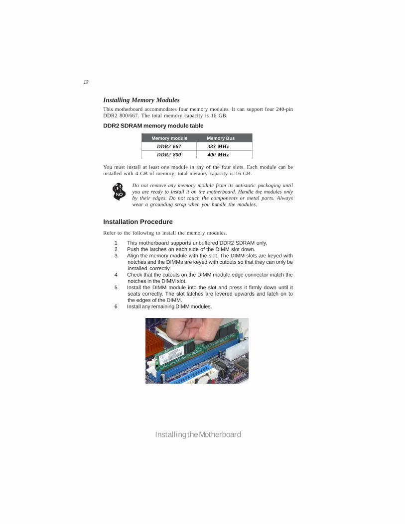
Installation ProcedureRefer to the following to install the memory modules.
1 This motherboard supports unbuffered DDR2 SDRAM only.2 Push the latches on each side of the DIMM slot down.3 Align the memory module with the slot. The DIMM slots are keyed with
notches and the DIMMs are keyed with cutouts so that they can only beinstalled correctly.
4 Check that the cutouts on the DIMM module edge connector match thenotches in the DIMM slot.
5 Install the DIMM module into the slot and press it firmly down until itseats correctly. The slot latches are levered upwards and latch on tothe edges of the DIMM.
6 Install any remaining DIMM modules.
Installing Memory ModulesThis motherboard accommodates four memory modules. It can support four 240-pinDDR2 800/667. The total memory capacity is 16 GB.
DDR2 SDRAM memory module table
Do not remove any memory module from its antistatic packaging untilyou are ready to install it on the motherboard. Handle the modules onlyby their edges. Do not touch the components or metal parts. Alwayswear a grounding strap when you handle the modules.
You must install at least one module in any of the four slots. Each module can beinstalled with 4 GB of memory; total memory capacity is 16 GB.
Memory module Memory Bus
DDR2 667 333 MHz DDR2 800 400 MHz
13
Installing the Motherboard
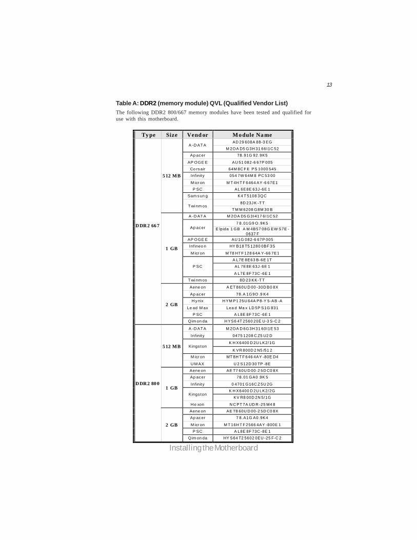
Table A: DDR2 (memory module) QVL (Qualified Vendor List)The following DDR2 800/667 memory modules have been tested and qualified foruse with this motherboard.
Ty pe Size Vend or Mo dule Na me AD 29 608A 88-3 EG
A -D AT A M 2OA D5 G3H 31 66I1C 52
Ap ac er 78.91G 92.9K5
AP OGE E AU 51 082-6 67P 005
Co rs air 64M 8C F E PS 1000 545 Inf inity 054 7W 64M 8 PC 53 00
M icr on M T 4H T F 6464 AY-6 67E1 P SC AL 6E8E 63J -6E 1
Sam s un g K4 T 5108 3QC
8D 23J K -T T
5 12 MB
T wi nm os T M M 6208 G8M 30 B
A -D AT A M 2OA D5 G3I417 6I1C 52
7 8.01G9 O.9K5 Ap ac er E lpida 1 GB A M 4B57 08G EW S7E -
0637 F AP OGE E AU 1G 082-6 67P 005 Inf ineo n HY B18 T5 1280 0BF 3S
M icr on M T8 HT F 128 64A Y-66 7E1
A L7E 8E63 B-6E 1T AL 7E8E 63J -6E 1 P SC
A L7E 8F 73C -6E 1
1 GB
T wi nm os 8D 23 KK-T T
Aene on A ET 860U D 00 -30D B0 8X
Ap ac er 78.A 1G9O .9 K4
H y nix H YM P1 25U 64A P8-Y 5-AB -A
Le ad M ax Lea d Ma x LD 5P S1G 831
P SC A L8E 8F 73C -6E 1
DDR2 66 7
2 GB
Qim on da H YS6 4T 2560 20E U-3 S-C 2
A -D AT A M 2OA D 6G3H 31 60I1E 53
Inf inity 0475 1208 C Z5 U2 D
K H X6400 D 2U LK2/1G Kings ton
K VR 800D 2 N5 /51 2 M icr on MT 8H T F 646 4AY -80E D4
5 12 MB
U M AX U 2 S12D 30 TP -8E
Aene on AE T7 60U D 00-2 5D C0 8X Ap ac er 78.01 GA0 .9K 5
Inf inity 0 4701 G16C Z 5U 2G K H X6400 D 2U LK2/2G
Kings ton KV R8 00D 2N 5/1G
1 GB
H e xon N C PT 7A UD R -25 M4 8
Aene on AE T8 60U D 00-2 5D C0 8X
Ap ac er 7 8.A1G A0.9K4
M icr on M T 16H T F 2566 4AY -800E 1
P SC A L8E 8F 73C -8E 1
DDR2 80 0
2 GB
Qim on da HY S64 T2 5602 0EU -25 F-C 2
14
Installing the Motherboard
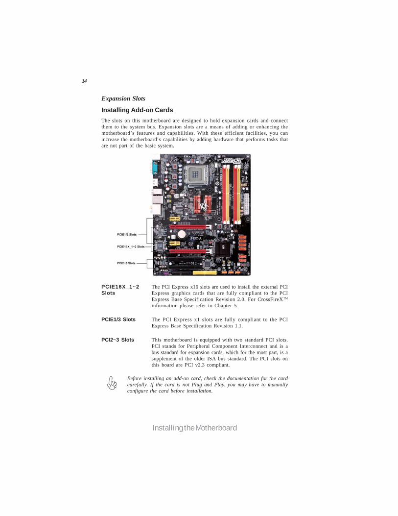
PCIE16X_1~2Slots
The PCI Express x16 slots are used to install the external PCIExpress graphics cards that are fully compliant to the PCIExpress Base Specification Revision 2.0. For CrossFireXTM
information please refer to Chapter 5.
PCI2~3 Slots This motherboard is equipped with two standard PCI slots.PCI stands for Peripheral Component Interconnect and is abus standard for expansion cards, which for the most part, is asupplement of the older ISA bus standard. The PCI slots onthis board are PCI v2.3 compliant.
The PCI Express x1 slots are fully compliant to the PCIExpress Base Specification Revision 1.1.
PCIE1/3 Slots
Before installing an add-on card, check the documentation for the cardcarefully. If the card is not Plug and Play, you may have to manuallyconfigure the card before installation.
The slots on this motherboard are designed to hold expansion cards and connectthem to the system bus. Expansion slots are a means of adding or enhancing themotherboard’s features and capabilities. With these efficient facilities, you canincrease the motherboard’s capabilities by adding hardware that performs tasks thatare not part of the basic system.
Installing Add-on Cards
Expansion Slots

15
Installing the Motherboard
Follow these instructions to install an add-on card:
1 Remove a blanking plate from the system case corresponding to theslot you are going to use.
2 Install the edge connector of the add-on card into the expansion slot.Ensure that the edge connector is correctly seated in the slot.
3 Secure the metal bracket of the card to the system case with a screw.
For some add-on cards, for example graphics adapters and networkadapters, you have to install drivers and software before you can beginusing the add-on card.

16
Installing the Motherboard
Connecting Optional DevicesRefer to the following for information on connecting the motherboard’s optionaldevices:
F_AUDIO: Front Panel Audio headerThis header allows the user to install auxiliary front-oriented microphone and line-out ports for easier access.
SPDIFO: SPDIF out headerThis is an optional header that provides an S/PDIF (Sony/Philips Digital Interface)output to digital multimedia device through optical fiber or coaxial connector.
Pin Signal Name Function1 PORT 1L 2 AUD_GND3 PORT 1R 4 PRESENCE#5 PORT 2R 6 SENSE1_RETURN7 SENSE_SEND 8 KEY
Pin Signal Name
9 PORT 2L 10 SENSE2_RETURN
Pin Signal Name
1 SPDIF SPDIF digital output2 +5VA 5V analog Power
3 Key No pin4 GND Ground
Pin Signal Name Function
17
Installing the Motherboard
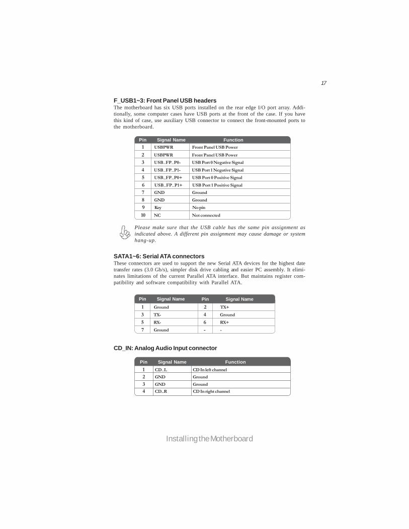
F_USB1~3: Front Panel USB headersThe motherboard has six USB ports installed on the rear edge I/O port array. Addi-tionally, some computer cases have USB ports at the front of the case. If you havethis kind of case, use auxiliary USB connector to connect the front-mounted ports tothe motherboard.
Please make sure that the USB cable has the same pin assignment asindicated above. A different pin assignment may cause damage or systemhang-up.
1 USBPWR Front Panel USB Power2 USBPWR Front Panel USB Power3 USB_FP_P0- USB Port 0 Negative Signal4 USB_FP_P1- USB Port 1 Negative Signal5 USB_FP_P0+ USB Port 0 Positive Signal6 USB_FP_P1+ USB Port 1 Positive Signal7 GND Ground8 GND Ground9 Key No pin10 NC Not connected
FunctionPin Signal Name
SATA1~6: Serial ATA connectorsThese connectors are used to support the new Serial ATA devices for the highest datetransfer rates (3.0 Gb/s), simpler disk drive cabling and easier PC assembly. It elimi-nates limitations of the current Parallel ATA interface. But maintains register com-patibility and software compatibility with Parallel ATA.
1 Ground 2 TX+3 TX- 4 Ground5 RX- 6 RX+7 Ground - -
Pin Signal Name Pin Signal Name
CD_IN: Analog Audio Input connector
Pin Signal Name Function1 CD_L CD In left channel2 GND Ground3 GND Ground4 CD_R CD In right channel

18
Installing the Motherboard
IDE devices enclose jumpers or switches used to set the IDE device as MASTER orSLAVE. Refer to the IDE device user’s manual. Installing two IDE devices on onecable, ensure that one device is set to MASTER and the other device is set to SLAVE.The documentation of your IDE device explains how to do this.
Installing a Hard Disk Drive/CD-ROM/SATA Hard DriveThis section describes how to install IDE devices such as a hard disk drive and a CD-ROM drive.
About IDE DevicesYour motherboard has one IDE interface. An IDE ribbon cable supporting two IDEdevices is bundled with the motherboard.
You must orient the cable connector so that the pin1 (color) edge of thecable corresponds to the pin 1 of the I/O port connector.
About SATA ConnectorsYour motherboard features six SATA connectors supporting a total of six drives.SATA refers to Serial ATA (Advanced Technology Attachment) is the standard inter-face for the IDE hard drives which are currently used in most PCs. These connectorsare well designed and will only fit in one orientation. Locate the SATA connectors onthe motherboard and follow the illustration below to install the SATA hard drives.
Installing Serial ATA Hard DrivesTo install the Serial ATA (SATA) hard drives, use the SATA cable that supports theSerial ATA protocol. This SATA cable comes with a SATA power cable. You canconnect either end of the SATA cable to the SATA hard drive or the connector on themotherboard.
SATA cable (optional) SATA power cable (optional)
IDE: IDE ConnectorThis motherboard supports six high data transfer SATA ports with each runs up to 3.0Gb/s. To get better system performance, we recommend users connect the CD-ROMto the IDE channel, and set up the hard drives on the SATA ports.
19
Installing the Motherboard
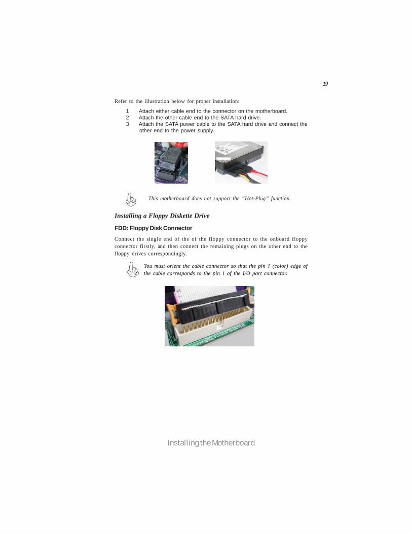
Refer to the illustration below for proper installation:
This motherboard does not support the “Hot-Plug” function.
1 Attach either cable end to the connector on the motherboard.2 Attach the other cable end to the SATA hard drive.3 Attach the SATA power cable to the SATA hard drive and connect the
other end to the power supply.
Installing a Floppy Diskette Drive
You must orient the cable connector so that the pin 1 (color) edge ofthe cable corresponds to the pin 1 of the I/O port connector.
FDD: Floppy Disk Connector
Connect the single end of the of the floppy connector to the onboard floppyconnector firstly, and then connect the remaining plugs on the other end to thefloppy drives correspondingly.

20
Installing the Motherboard
Connecting I/O DevicesThe backplane of the motherboard has the following I/O ports:
PS2 Mouse Use the upper PS/2 port to connect a PS/2 pointing device.
PS2 Keyboard Use the lower PS/2 port to connect a PS/2 keyboard.
Serial Port Use the COM port to connect serial devices such as mice or(COM) fax/modems.
USB Ports Use the USB ports to connect USB devices.
The above port definition can be changed to audio input oraudio output by changing the driver utility setting.
Audio Ports Use the audio jacks to connect audio devices. The D port isfor stereo line-in signal, while the F port is for microphonein signal. This motherboard supports 8-channel audio de-vices that correspond to the A,B, C, and E port respec-tively. In addition, all of the 3 ports, B, C, and E provideusers with both right & left channels individually. Usersplease refer to the following note for specific port functiondefinition.
LAN Port Connect an RJ-45 jack to the LAN port to connect your computer to the network.
eSATA Port Use this port to connect to an external SATA box or aSerial ATA port multiplier.
Before connecting the eSATA cable, make sure to turn offthe power of the external enclosure.
A: Center & Woofer D: Line-in B: Back Surround E: Front Out C: Side Surround F: Mic_in Rear

21
Installing the Motherboard
Connecting Case ComponentsAfter you have installed the motherboard into a case, you can begin connecting themotherboard components. Refer to the following:
1 Connect the CPU cooling fan cable to CPU_FAN1.2 Connect the system cooling fan connector to SYS_FAN1.3 Connect the case cooling fan connector to CASE_FAN.4 Connect the standard power supply connector to ATX_POWER.5 Connect the auxiliary case power supply connector to ATX12V.6 Connect the case switches and indicator LEDs to the F_PANEL.7 Connect the case speaker cable to SPK.
24-pin power cable
With ATX v2.x power supply, users pleasenote that when installing 24-pin powercable, the latches of power cable and theATX_POWER match perfectly.
The ATX 24-pin connector allows you to connect to ATX v2.x powersupply.
Connecting 24-pin power cable

22
Installing the Motherboard
When installing 4-pin power cable, thelatches of power cable and the ATX12Vmatch perfectly.
4-pin power cable
Connecting 4-pin power cableThe ATX12V power connector is used to provide power to the CPU.
Users please note that the fan connector supports the CPU cooling fan of1.1A ~ 2.2A (26.4W max) at +12V.
ATX_POWER: ATX 24-pin Power Connector
CPU_FAN1/SYS_FAN1: Cooling FAN Power Connector
1 GND System Ground
3 Sense Sensor4 Control CPU FAN control
Pin Signal Name Function
2 +12V Power +12V
CASE_FAN: Case cooling FAN Power Connector
Pin Signal Name Pin Signal Name1 +3.3V 13 +3.3V2 +3.3V 14 -12V3 Ground 15 Ground4 +5V 16 PS_ON5 Ground 17 Ground6 +5V 18 Ground7 Ground 19 Ground8 PWRGD 20 -5V9 +5VSB 21 +5V
10 +12V 22 +5V11 +12V 23 +5V12 +3.3V 24 Ground
1 GND System Ground
3 Sense Sensor
Pin Signal Name Function
2 +12V Power +12V
23
Installing the Motherboard
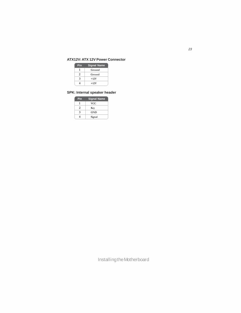
SPK: Internal speaker header
4 Signal3 GND2 Key1 VCC
Pin Signal Name
ATX12V: ATX 12V Power ConnectorPin Signal Name
4 +12V3 +12V2 Ground1 Ground

24
Installing the Motherboard
Front Panel HeaderThe front panel header (F_PANEL) provides a standard set of switch and LED headerscommonly found on ATX or Micro ATX cases. Refer to the table below for informa-tion:
Reset Switch
Supporting the reset function requires connecting pins 5 and 7 to a momentary-contact switch that is normally open. When the switch is closed, the board resets andruns POST.
Power/Sleep/Message waiting LED
Connecting pins 2 and 4 to a single or dual-color, front panel mounted LED providespower on/off, sleep, and message waiting indication.
Hard Drive Activity LED
Connecting pins 1 and 3 to a front panel mounted LED provides visual indicationthat data is being read from or written to the hard drive. For the LED to functionproperly, an IDE drive should be connected to the onboard IDE interface. The LEDwill also show activity for devices connected to the SCSI (hard drive activity LED)connector.
Pin Signal Function Pin Signal Function1 HD_LED_P Hard disk LED (+) 2 FP PWR/SLP *MSG LED (+)3 HD_LED_N Hard disk LED (-)5 RST_SW_N Reset Switch (-)7 RST_SW_P Reset Switch (+)9 RSVD Reserved
4 FP PWR/SLP *MSG LED (-)6 PWR_SW_P Power Switch (+)8 PWR_SW_N Power Switch (-)10 Key No pin
* MSG LED (dual color or single color)
Power Switch
Supporting the power on/off function requires connecting pins 6 and 8 to a momen-tary-contact switch that is normally open. The switch should maintain contact for atleast 50 ms to signal the power supply to switch on or off. The time requirement isdue to internal de-bounce circuitry. After receiving a power on/off signal, at least twoseconds elapses before the power supply recognizes another on/off signal.
This concludes Chapter 2. The next chapter covers the BIOS.

25
Using BIOS
Chapter 3
Using BIOS
About the Setup UtilityThe computer uses the latest “American Megatrends Inc. ” BIOS with support forWindows Plug and Play. The CMOS chip on the motherboard contains the ROMsetup instructions for configuring the motherboard BIOS.
The BIOS (Basic Input and Output System) Setup Utility displays the system’sconfiguration status and provides you with options to set system parameters. Theparameters are stored in battery-backed-up CMOS RAM that saves this informationwhen the power is turned off. When the system is turned back on, the system isconfigured with the values you stored in CMOS.
The BIOS Setup Utility enables you to configure:
• Hard drives, diskette drives and peripherals• Video display type and display options• Password protection from unauthorized use• Power Management features
The settings made in the Setup Utility affect how the computer performs. Beforeusing the Setup Utility, ensure that you understand the Setup Utility options.
This chapter provides explanations for Setup Utility options.
The Standard ConfigurationA standard configuration has already been set in the Setup Utility. However, werecommend that you read this chapter in case you need to make any changes in thefuture.
This Setup Utility should be used:• when changing the system configuration• when a configuration error is detected and you are prompted to make
changes to the Setup Utility• when trying to resolve IRQ conflicts• when making changes to the Power Management configuration• when changing the password or making other changes to the Security
Setup
Entering the Setup UtilityWhen you power on the system, BIOS enters the Power-On Self Test (POST)routines. POST is a series of built-in diagnostics performed by the BIOS. After thePOST routines are completed, the following message appears:
Press DEL to enter SETUP

26
Using BIOS
Press the delete key to access the BIOS Setup Utility.
Resetting the Default CMOS Values
When powering on for the first time, the POST screen may show a “CMOSSettings Wrong” message. This standard message will appear following a clearCMOS data at factory by the manufacturer. You simply need to Load DefaultSettings to reset the default CMOS values. Note: Changes to system hardware such as different CPU, memories, etc. may alsotrigger this message.
CMOS Setup Utility -- Copyright (C) 1985-2008, American Megatrends, Inc.
v02.61 (C)Copyright 1985-2008, American Mega trends, Inc.
: Move F10: Save ESC: Exit+/-/: ValueEnter : SelectF9: Load Default Settings F1:General Help
Standard CMOS SetupAdvanced SetupAdvanced Chipset SetupIntegrated PeripheralsPower Management SetupPCI/PnP SetupPC Health Status
M.I.B. (MB Intelligent BIOS)Load Default SettingsSupervisor PasswordUser PasswordSave & Exit SetupExit Without Saving
< >
CMOS Setup Utility -- Copyright (C) 1985-2008, American Megatrends, Inc.
: Move F10: Save ESC: Exit+/-/: ValueEnter : SelectF9: Load Default Settings F1:General Help
Standard CMOS SetupAdvanced SetupAdvanced Chipset SetupIntegrated PeripheralsPower Management SetupPCI/PnP SetupPC Health Status
M.I.B. (MB Intelligent BIOS)Load Default SettingsSupervisor PasswordUser PasswordSave & Exit SetupExit Without Saving
< >
Load Default Setting?
v02.61 (C)Copyright 1985-2008, American Mega trends, Inc.
[OK] [Cancel]

27
Using BIOS
Enter Select
BIOS Navigation KeysThe BIOS navigation keys are listed below:
KEY FUNCTION
Scrolls through the items on a menu +/-/ Modifies the selected field’s values
F10 Saves the current configuration and exits setup
F1 Displays a screen that describes all key functions
F9 Load a default optimized setting
ESC Exits the current menu
< >
Using BIOSWhen you start the Setup Utility, the main menu appears. The main menu of theSetup Utility displays a list of the options that are available. A highlight indicateswhich option is currently selected. Use the cursor arrow keys to move the highlightto other options. When an option is highlighted, execute the option by pressing<Enter>.
Some options lead to pop-up dialog boxes that prompt you to verify that you wish toexecute that option. Other options lead to dialog boxes that prompt you for infor-mation.
Some options (marked with a triangle ) lead to submenus that enable you to changethe values for the option. Use the cursor arrow keys to scroll through the items in thesubmenu.
In this manual, default values are enclosed in parenthesis. Submenu items are denotedby a triangle .
The default BIOS setting for this motherboard applies for most conditionswith optimum performance. It is not suggested to change the defaultvalues in the BIOS setup and the manufacture takes no responsibility toany damage caused by changing the BIOS settings.
For the purpose of better product maintenance, the manufacture reservesthe right to change the BIOS items presented in this manual. The BIOSsetup screens shown in this chapter are for reference only and may differfrom the actual BIOS. Please visit the manufacture’s website for updatedmanual.

28
Using BIOS
Standard CMOS SetupThis option displays basic information about your system.
Date Tue 03/25/2008
SATA1 Not Detected SATA2 Not Detected SATA3 Not Detected SATA4 Not Detected SATA5 Not Detected SATA6 Not Detected
Help Item
CMOS Setup Utility -- Copyright (C) 1985-2008, American Megatrends, Inc.
Time Alarm (hh:mm:ss) 00:02:19
Use [Enter], [TAB]or [SHIFT-TAB] toselect a field.
Use [+] or [-] toconfigure system Date.
Standard CMOS Setup
Date & TimeThe Date and Time items show the current date and time on the computer. If you arerunning a Windows OS, these items are automatically updated whenever you makechanges to the Windows Date and Time Properties utility.
SATA1
CMOS Setup Utility - - Copyright (C) 1985-2008, American Megatrends, Inc.
SATA1
Type LBA/Large Mode Auto
Block (Multi-Sector Transfer Auto PIO Mode Auto
DMA Mode Auto S.M.A.R.T Auto
32Bit Data Transfer Enabled
Help Item
Select the typeof device connectedto the system.
Device : Not Detected
IDE BusMaster Enabled
Auto
Drive A: 1.44 MB 31/2”
: Move F10: Save ESC: ExitEnter : Select +/-/: ValueF9: Load Default settingsF1: General Help
< >
: Move F10: Save ESC: ExitEnter : Select +/-/: ValueF9: Load Default settingsF1: General Help
< >
This motherboard supports six SATA channels and each channel allows one SATAdevice to be installed. Use these items to configure each device on the SATA channel.
SATA1
29
Using BIOS
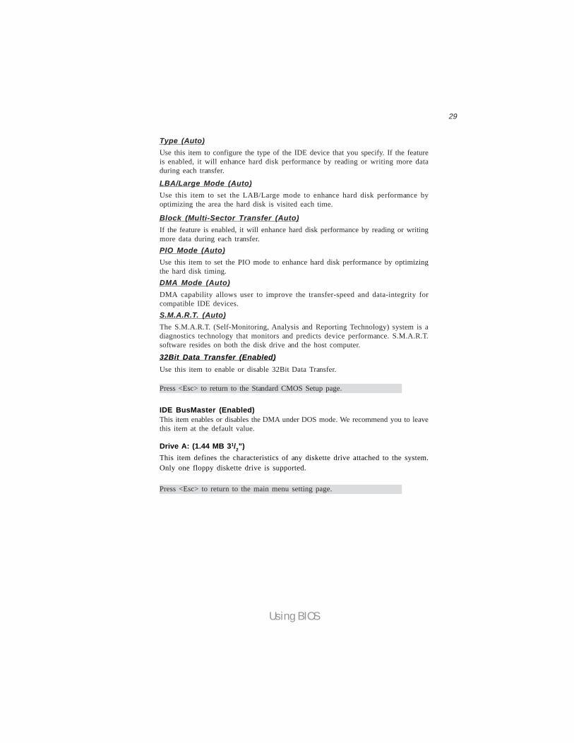
IDE BusMaster (Enabled)This item enables or disables the DMA under DOS mode. We recommend you to leavethis item at the default value.
Press <Esc> to return to the main menu setting page.
Block (Multi-Sector Transfer (Auto)If the feature is enabled, it will enhance hard disk performance by reading or writingmore data during each transfer.PIO Mode (Auto)Use this item to set the PIO mode to enhance hard disk performance by optimizingthe hard disk timing.DMA Mode (Auto)DMA capability allows user to improve the transfer-speed and data-integrity forcompatible IDE devices.S.M.A.R.T. (Auto)The S.M.A.R.T. (Self-Monitoring, Analysis and Reporting Technology) system is adiagnostics technology that monitors and predicts device performance. S.M.A.R.T.software resides on both the disk drive and the host computer.
32Bit Data Transfer (Enabled)Use this item to enable or disable 32Bit Data Transfer.
Press <Esc> to return to the Standard CMOS Setup page.
Drive A: (1.44 MB 31/2”)This item defines the characteristics of any diskette drive attached to the system.Only one floppy diskette drive is supported.
LBA/Large Mode (Auto)Use this item to set the LAB/Large mode to enhance hard disk performance byoptimizing the area the hard disk is visited each time.
Type (Auto)Use this item to configure the type of the IDE device that you specify. If the featureis enabled, it will enhance hard disk performance by reading or writing more dataduring each transfer.
30
Using BIOS
Limit CPUID MaxVal (Disabled)
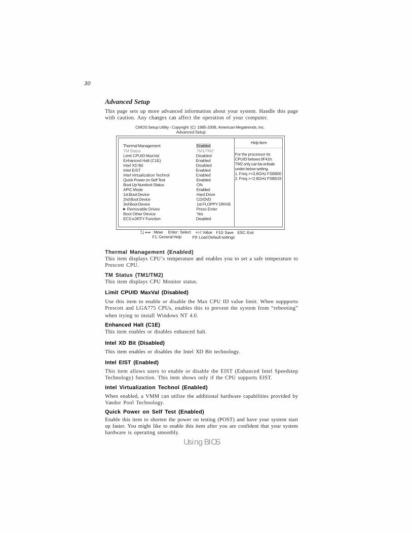
Advanced SetupThis page sets up more advanced information about your system. Handle this pagewith caution. Any changes can affect the operation of your computer.
CMOS Setup Utility - Copyright (C) 1985-2008, American Megatrends, Inc. Advanced Setup
TM Status TM1/TM2Limit CPUID MaxVal DisabledEnhanced Halt (C1E) EnabledIntel XD Bit DisabledIntel EIST EnabledIntel Virtualization Technol EnabledQuick Power on Self Test EnabledBoot Up Numlock Status ONAPIC Mode Enabled1st Boot Device Hard Drive2nd Boot Device CD/DVD3rd Boot Device 1st FLOPPY DRIVE Removable Drives Press EnterBoot Other Device YesECS eJIFFY Function Disabled
For the processor itsCPUID belows 0F41h.TM2 only can be enbaleunder below setting.1. Freq.>=3.6GHz FSB8002. Freq.>=2.8GHz FSB533
Help ItemThermal Management Enabled
: Move F10: Save ESC: ExitEnter : Select +/-/: ValueF9: Load Default settingsF1: General Help
< >
Enhanced Halt (C1E)
Intel XD Bit (Disabled)
Intel EIST (Enabled)
Intel Virtualization Technol (Enabled)
Thermal Management (Enabled)This item displays CPU’s temperature and enables you to set a safe temperature toPrescott CPU.
TM Status (TM1/TM2)This item displays CPU Monitor status.
Use this item to enable or disable the Max CPU ID value limit. When suppportsPrescott and LGA775 CPUs, enables this to prevent the system from “rebooting”when trying to install Windows NT 4.0.
This item enables or disables enhanced halt.
This item enables or disables the Intel XD Bit technology.
When enabled, a VMM can utilize the additional hardware capabilities provided byVandor Pool Technology.
This item allows users to enable or disable the EIST (Enhanced Intel SpeedstepTechnology) function. This item shows only if the CPU supports EIST.
Quick Power on Self Test (Enabled)Enable this item to shorten the power on testing (POST) and have your system startup faster. You might like to enable this item after you are confident that your systemhardware is operating smoothly.
31
Using BIOS
Boot Other Device (Yes)When enabled, the system searches all other possible locations for an operatingsystem if it fails to find one in the devices specified under the First, Second and Thirdboot devices.
Press <Esc> to return to the main menu setting page.
Press <Esc> to return to the Advanced Setup page.
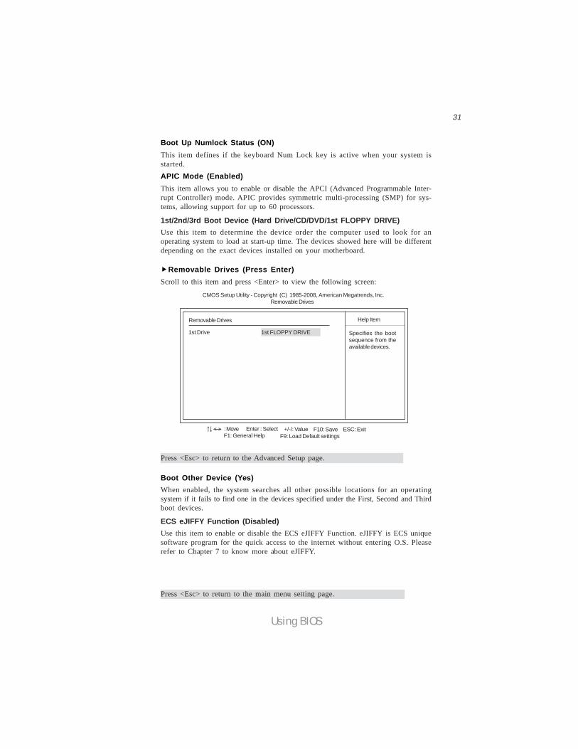
Removable Drives (Press Enter)Scroll to this item and press <Enter> to view the following screen:
Removable Drives
1st Drive 1st FLOPPY DRIVE
Help Item
Specifies the bootsequence from theavailable devices.
CMOS Setup Utility - Copyright (C) 1985-2008, American Megatrends, Inc.Removable Drives
: Move F10: Save ESC: ExitEnter : Select +/-/: ValueF9: Load Default settingsF1: General Help
< >
Boot Up Numlock Status (ON)This item defines if the keyboard Num Lock key is active when your system isstarted.APIC Mode (Enabled)This item allows you to enable or disable the APCI (Advanced Programmable Inter-rupt Controller) mode. APIC provides symmetric multi-processing (SMP) for sys-tems, allowing support for up to 60 processors.
1st/2nd/3rd Boot Device (Hard Drive/CD/DVD/1st FLOPPY DRIVE)Use this item to determine the device order the computer used to look for anoperating system to load at start-up time. The devices showed here will be differentdepending on the exact devices installed on your motherboard.
ECS eJIFFY Function (Disabled)Use this item to enable or disable the ECS eJIFFY Function. eJIFFY is ECS uniquesoftware program for the quick access to the internet without entering O.S. Pleaserefer to Chapter 7 to know more about eJIFFY.
32
Using BIOS
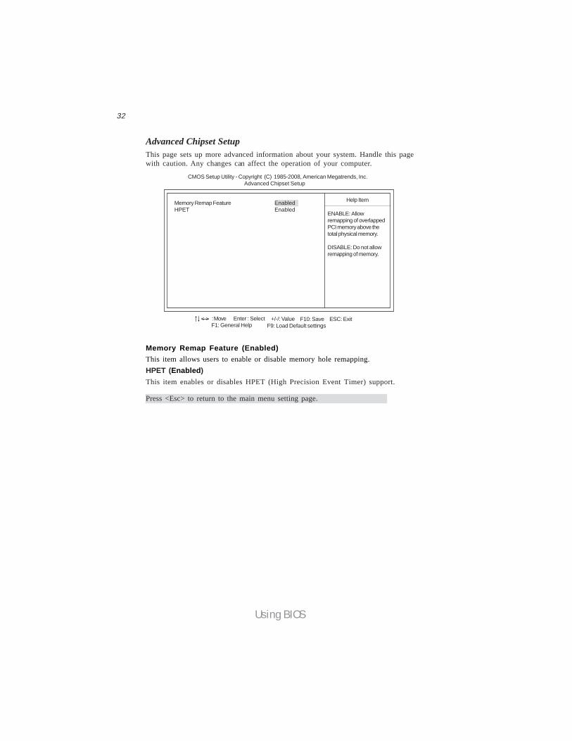
Memory Remap Feature (Enabled)This item allows users to enable or disable memory hole remapping.
Advanced Chipset SetupThis page sets up more advanced information about your system. Handle this pagewith caution. Any changes can affect the operation of your computer.
CMOS Setup Utility - Copyright (C) 1985-2008, American Megatrends, Inc. Advanced Chipset Setup
Memory Remap Feature EnabledHPET Enabled
Help Item
: Move F10: Save ESC: ExitEnter : Select +/-/: ValueF9: Load Default settingsF1: General Help
< >
ENABLE: Allowremapping of overlappedPCI memory above thetotal physical memory.
DISABLE: Do not allowremapping of memory.
Press <Esc> to return to the main menu setting page.
HPET (Enabled)This item enables or disables HPET (High Precision Event Timer) support.
33
Using BIOS
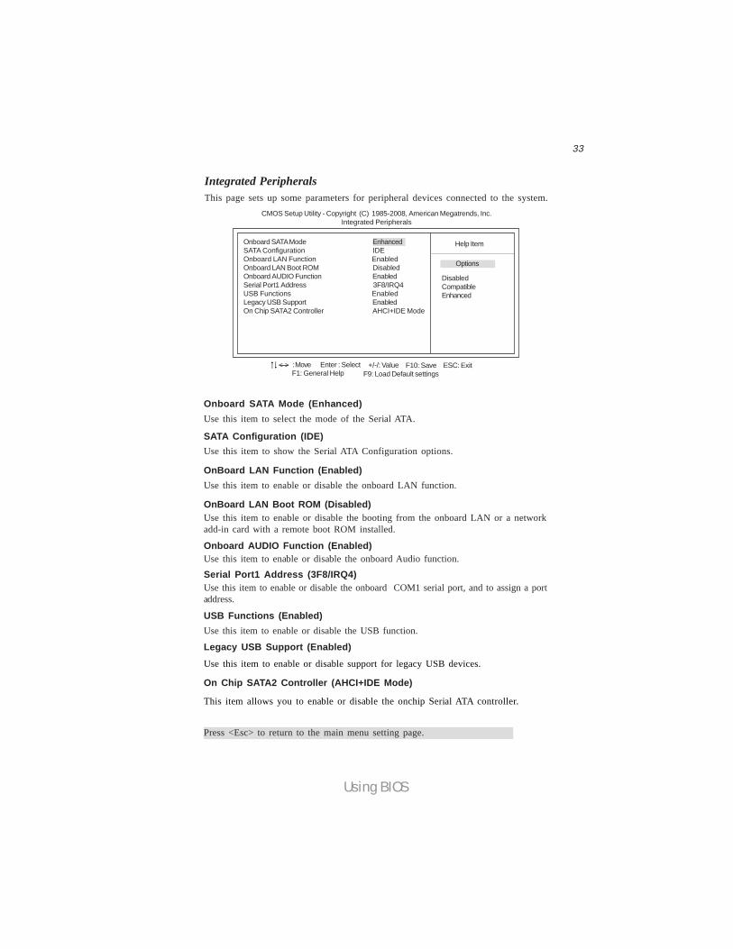
Onboard SATA Mode (Enhanced)
SATA Configuration (IDE)
Onboard AUDIO Function (Enabled)
USB Functions (Enabled)
On Chip SATA2 Controller (AHCI+IDE Mode)
This item allows you to enable or disable the onchip Serial ATA controller.
OnBoard LAN Function (Enabled)Use this item to enable or disable the onboard LAN function.
OnBoard LAN Boot ROM (Disabled)Use this item to enable or disable the booting from the onboard LAN or a networkadd-in card with a remote boot ROM installed.
Serial Port1 Address (3F8/IRQ4)Use this item to enable or disable the onboard COM1 serial port, and to assign a portaddress.
Legacy USB Support (Enabled)Use this item to enable or disable support for legacy USB devices.
Press <Esc> to return to the main menu setting page.
Use this item to enable or disable the onboard Audio function.
Use this item to enable or disable the USB function.
Use this item to select the mode of the Serial ATA.
Use this item to show the Serial ATA Configuration options.
Integrated PeripheralsThis page sets up some parameters for peripheral devices connected to the system.
CMOS Setup Utility - Copyright (C) 1985-2008, American Megatrends, Inc. Integrated Peripherals
Onboard SATA Mode EnhancedSATA Configuration IDEOnboard LAN Function EnabledOnboard LAN Boot ROM DisabledOnboard AUDIO Function EnabledSerial Port1 Address 3F8/IRQ4USB Functions EnabledLegacy USB Support EnabledOn Chip SATA2 Controller AHCI+IDE Mode
Help Item
: Move F10: Save ESC: ExitEnter : Select +/-/: ValueF9: Load Default settingsF1: General Help
< >
Options
DisabledCompatibleEnhanced

34
Using BIOS
Soft-off by PWR-BTTN (Instant off)Under ACPI (Advanced Configuration and Power management Interface) you cancreate a software power down. In a software power down, the system can be resumedby Wake Up Alarms. This item lets you install a software power down that is con-trolled by the power button on your system. If the item is set to Instant-Off, then thepower button causes a software power down. If the item is set to Delay 4 Sec, thenyou have to hold the power button down for four seconds to cause a software powerdown.
PWRON After PWR-Fail (Power Off)This item enables your computer to power off, automatically restart or return to itsprevious status after abnormal power lost.
Resume By Ring (Disabled)The system can be turned off with a software command. If you enable this item, thesystem can automatically resume if there is an incoming call on the Modem. Youmust use an ATX power supply in order to use this feature.
Resume By PCI/PCI-E/Lan PME (Disabled)The system can be turned off with a software command. If you enable this item, thesystem can automatically resume if there is an incoming call on the PCI Modem orPCI LAN card. You must use an ATX power supply in order to use this feature. Usethis item to do wake-up action if inserting the PCI card.
Resume By PS2 KB (S3) (Disabled)This item enables or disables you to allow keyboard activity to awaken the systemfrom S3 mode.
ACPI Suspend Type (S3)Use this item to define how your system suspends. In the default, S3, the suspendmode is a suspend to RAM, i.e, the system shuts down with the exception of a refreshcurrent to the system memory.
Power Management SetupThis page sets up some parameters for system power management operation.
Select the ACPIstate used forSystem Suspend.
Help Item
CMOS Setup Utility - Copyright (C) 1985-2008, American Megatrends, Inc. Power Management Setup
ACPI Suspend Type S3 (STR)Soft-off by PWR-BTTN Instant OffPWRON After PWR-Fail Power OffResume by Ring DisabledResume By PCI/PCI-E/Lan PME DisabledResume by USB (S3) DisabledResume By PS2 KB (S3) DisabledResume By PS2 MS (S3) DisabledResume on RTC Alarm Disabled
: Move F10: Save ESC: ExitEnter : Select +/-/: ValueF9: Load Default settingsF1: General Help
< >
35
Using BIOS
Resume By PS2 MS (S3) (Disabled)This item enables or disables you to allow mouse activity to awaken the system fromS3 mode.
Resume on RTC Alarm (Disabled)The system can be turned off with a software command. If you enable this item, thesystem can automatically resume at a fixed time based on the system’s RTC (realtimeclock). Use the items below this one to set the date and time of the wake-up alarm.You must use an ATX power supply in order to use this feature.
Resume By USB (S3) (Disabled)This item allows you to enable/disable the USB device wakeup function from S3mode.
Press <Esc> to return to the main menu setting page.
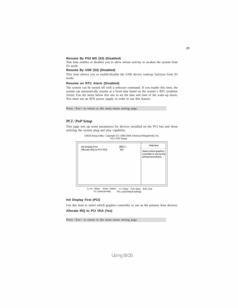
PCI / PnP SetupThis page sets up some parameters for devices installed on the PCI bus and thoseutilizing the system plug and play capability.
Help Item
CMOS Setup Utility - Copyright (C) 1985-2008, American Megatrends, Inc. PCI / PnP Setup
Init Display First PCIAllocate IRQ to PCI VGA Yes
Init Display First (PCI)Use this item to select which graphics controller to use as the primary boot devices.
Select which graphicscontroller to use as theprimary boot device.
: Move F10: Save ESC: ExitEnter : Select +/-/: ValueF9: Load Default settingsF1: General Help
< >
Press <Esc> to return to the main menu setting page.
Allocate IRQ to PCI VGA (Yes)

36
Using BIOS
PC Health StatusOn motherboards support hardware monitoring, this item lets you monitor theparameters for critical voltages, temperatures and fan speeds.
Smart Fan Function Press EnterSystem Temperature : 32°C/89°FCPU FAN Speed : 2576 RPMSYS FAN Speed : N/ACPU Core : 1.040 VVDIMM : 1.792 V -=- PECI Mode -=-Offset to TCC Activation Temp. : -70
Help Item
CMOS Setup Utility - Copyright (C) 1985-2008, American Megatrends, Inc. PC Health Status
CMOS Setup Utility - Copyright (C) 1985-2008, American Megatrends, Inc. Smart Fan Function
Help ItemCPU SMART FAN Control DisabledSYS SMART FAN Control Disabled
Smart Fan FunctionScroll to this item and press <Enter> to view the following screen:
DisabledEnabled
Options
: Move F10: Save ESC: ExitEnter : Select +/-/: ValueF9: Load Default settingsF1: General Help
< >
: Move F10: Save ESC: ExitEnter : Select +/-/: ValueF9: Load Default settingsF1: General Help
< >
-=- System Hardware Monitor -=-
CPU/SYS SMART FAN Control (Disabled)
Press <Esc> to return to the PC Health Status page.
These items enable you to define the CPU/System temperatur by smartly adjustingtheCPU/System fan. When it is set at certain temperature, the CPU/SYS Fan PWMvalue will change accordingly.
37
Using BIOS
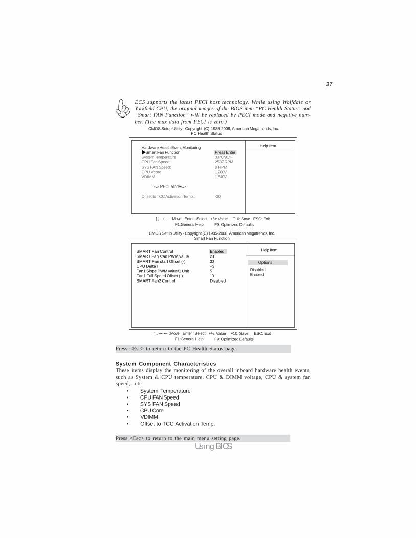
ECS supports the latest PECI host technology. While using Wolfdale orYorkfield CPU, the original images of the BIOS item “PC Health Status” and“Smart FAN Function” will be replaced by PECI mode and negative num-ber. (The max data from PECI is zero.)
Hardware Health Event Monitoring Smart Fan Function Press EnterSystem Temperature 33°C/91°FCPU Fan Speed: 2537 RPMSYS FAN Speed: 0 RPMCPU Vcore: 1.280VVDIMM: 1.840V
-=- PECI Mode-=-
Offset to TCC Activation Temp.: -20
Help Item
CMOS Setup Utility - Copyright (C) 1985-2008, American Megatrends, Inc. PC Health Status
F10: Save ESC: Exit+/-/: ValueEnter : SelectF9: Optimized DefaultsF1:General Help
: Move
Press <Esc> to return to the PC Health Status page.
CMOS Setup Utility - Copyright (C) 1985-2008, American Megatrends, Inc. Smart Fan Function
Help ItemSMART Fan Control EnabledSMART Fan start PWM value 28SMART Fan start Offset (-) 30CPU DeltaT +3Fan1 Slope PWM value/1 Unit 5Fan1 Full Speed Offset (-) 10SMART Fan2 Control Disabled
DisabledEnabled
F10: Save ESC: Exit+/-/: ValueEnter : SelectF9: Optimized DefaultsF1:General Help
: Move
Options
System Component CharacteristicsThese items display the monitoring of the overall inboard hardware health events,such as System & CPU temperature, CPU & DIMM voltage, CPU & system fanspeed,...etc. • System Temperature • CPU FAN Speed • SYS FAN Speed • CPU Core • VDIMM • Offset to TCC Activation Temp.
Press <Esc> to return to the main menu setting page.
38
Using BIOS
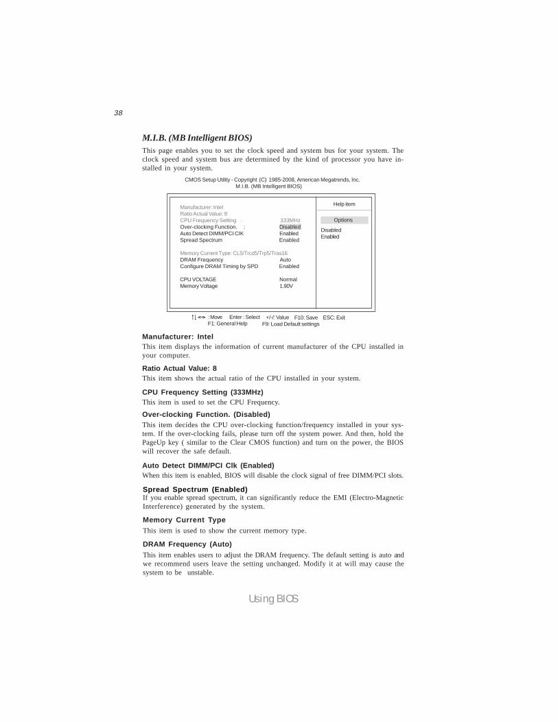
M.I.B. (MB Intelligent BIOS)This page enables you to set the clock speed and system bus for your system. Theclock speed and system bus are determined by the kind of processor you have in-stalled in your system.
CMOS Setup Utility - Copyright (C) 1985-2008, American Megatrends, Inc. M.I.B. (MB Intelligent BIOS)
Help itemManufacturer: IntelRatio Actual Value: 8CPU Frequency Setting : 333MHzOver-clocking Function. : DisabledAuto Detect DIMM/PCI CIK EnabledSpread Spectrum Enabled
Memory Current Type: CL5/Trcd5/Trp5/Tras16DRAM Frequency AutoConfigure DRAM Timing by SPD Enabled
CPU VOLTAGE NormalMemory Voltage 1.90V
DisabledEnabled
Options
: Move F10: Save ESC: ExitEnter : Select +/-/: ValueF9: Load Default settingsF1: General Help
< >
Manufacturer: IntelThis item displays the information of current manufacturer of the CPU installed inyour computer.
Ratio Actual Value: 8This item shows the actual ratio of the CPU installed in your system.
CPU Frequency Setting (333MHz)This item is used to set the CPU Frequency.
Over-clocking Function. (Disabled)This item decides the CPU over-clocking function/frequency installed in your sys-tem. If the over-clocking fails, please turn off the system power. And then, hold thePageUp key ( similar to the Clear CMOS function) and turn on the power, the BIOSwill recover the safe default.
Auto Detect DIMM/PCI Clk (Enabled)When this item is enabled, BIOS will disable the clock signal of free DIMM/PCI slots.
Spread Spectrum (Enabled)If you enable spread spectrum, it can significantly reduce the EMI (Electro-MagneticInterference) generated by the system.
Memory Current TypeThis item is used to show the current memory type.
DRAM Frequency (Auto)This item enables users to adjust the DRAM frequency. The default setting is auto andwe recommend users leave the setting unchanged. Modify it at will may cause thesystem to be unstable.

39
Using BIOS
CPU VOLTAGE (Normal)This item allows users to adjust the CPU voltage.
Press <Esc> to return to the main menu setting page.
Configure DRAM Timing by SPD (Enabled)This item allows users to enable or disable the DRAM timing defined by the SerialPresence Detect electrical. User please note that if setting this item to auto, thefollowing two items are not available.
Memory Voltage (1.90V)This item allows users to adjust the DDR memory voltage.
40
Using BIOS
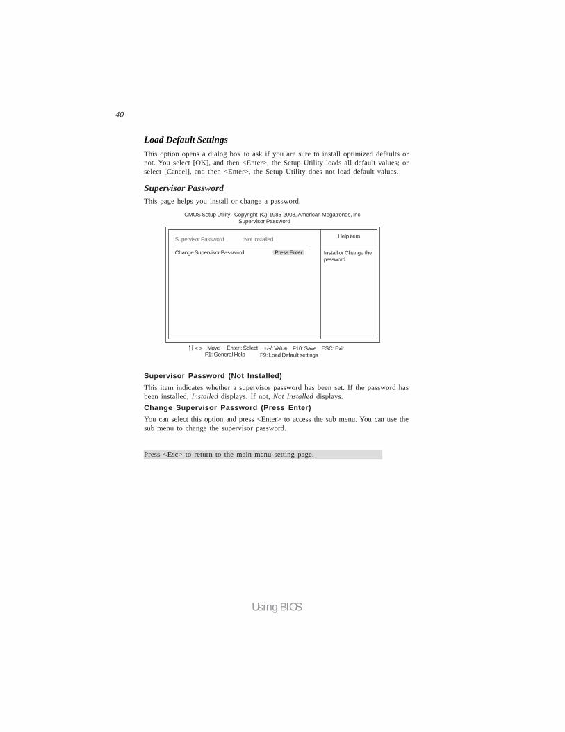
Supervisor Password (Not Installed)This item indicates whether a supervisor password has been set. If the password hasbeen installed, Installed displays. If not, Not Installed displays.Change Supervisor Password (Press Enter)You can select this option and press <Enter> to access the sub menu. You can use thesub menu to change the supervisor password.
Supervisor PasswordThis page helps you install or change a password.
CMOS Setup Utility - Copyright (C) 1985-2008, American Megatrends, Inc. Supervisor Password
Install or Change thepassword.
Help itemSupervisor Password :Not Installed
Change Supervisor Password Press Enter
Press <Esc> to return to the main menu setting page.
Load Default SettingsThis option opens a dialog box to ask if you are sure to install optimized defaults ornot. You select [OK], and then <Enter>, the Setup Utility loads all default values; orselect [Cancel], and then <Enter>, the Setup Utility does not load default values.
: Move F10: Save ESC: ExitEnter : Select +/-/: ValueF9: Load Default settingsF1: General Help
< >

41
Using BIOS
Save & Exit SetupHighlight this item and press <Enter> to save the changes that you have made in theSetup Utility and exit the Setup Utility. When the Save and Exit dialog box appears,select [OK] to save and exit, or select [Cancel] to return to the main menu.
Exit Without SavingHighlight this item and press <Enter> to discard any changes that you have made inthe Setup Utility and exit the Setup Utility. When the Exit Without Saving dialogbox appears, select [OK] to discard changes and exit, or select [Cancel] to return tothe main menu.
User Password (Not Installed)This item indicates whether a user password has been set. If the password has beeninstalled, Installed displays. If not, Not Installed displays.Change User Password (Press Enter)You can select this option and press <Enter> to access the sub menu. You can use thesub menu to change the user password. This item will show if Supervisor Password isset.
User PasswordThis page helps you install or change a password.
Install or Change thepassword.
Help item
CMOS Setup Utility - Copyright (C) 1985-2008, American Megatrends, Inc. User Password
Press <Esc> to return to the main menu setting page.
User Password : Not Installed
Change User Password Press Enter
If you have made settings that you do not want to save, use the “Exit WithoutSaving” item and select [OK] to discard any changes you have made.
: Move F10: Save ESC: ExitEnter : Select +/-/: ValueF9: Load Default settingsF1: General Help
< >

42
Using BIOS
This concludes Chapter 3. Refer to the next chapter for information on the softwaresupplied with the motherboard.
Updating the BIOSYou can download and install updated BIOS for this motherboard from themanufacturer’s Web site. New BIOS provides support for new peripherals, improve-ments in performance, or fixes for known bugs. Install new BIOS as follows:
1 If your motherboard has a BIOS protection jumper, change the setting toallow BIOS flashing.
2 If your motherboard has an item called Firmware Write Protect in Ad-vanced BIOS features, disable it. (Firmware Write Protect preventsBIOS from being overwritten.)
3 Create a bootable system disk. (Refer to Windows online help forinformation on creating a bootable system disk.)
4 Download the Flash Utility and new BIOS file from the manufacturer’sWeb site. Copy these files to the bootable device.
5 Turn off your computer and insert the bootable device in your com-puter. (You might need to run the Setup Utility and change the bootpriority items on the Advanced BIOS Features Setup page, to forceyour computer to boot from the bootable device first.)
6 At the C:\ or A:\ prompt, type the Flash Utility program name and the filename of the new bios and then press <Enter>. Example: AMINF340.EXE040706.ROM
7 When the installation is complete, remove the bootable device from thecomputer and restart your computer. If your motherboard has a FlashBIOS jumper, reset the jumper to protect the newly installed BIOS frombeing overwritten. The computer will restart automatically.

43
Using the Motherboard Software
Chapter 4
Using the Motherboard Software
If the opening screen does not appear; double-click the file “setup.exe” inthe root directory.
About the Software DVD-ROM/CD-ROMThe support software DVD-ROM/CD-ROM that is included in the motherboard pack-age contains all the drivers and utility programs needed to properly run the bundledproducts. Below you can find a brief description of each software program, and thelocation for your motherboard version. More information on some programs isavailable in a README file, located in the same directory as the software. Beforeinstalling any software, always inspect the folder for files named README.TXT orsomething similar. These files may contain important information that is notincluded in this manual.
Never try to install all software from folder that is not specified for use withyour motherboard.The notice of Intel HD audio installation (optional): The Intel High Defi-nition audio functionality unexpectedly quits working in Windows Server2003 Service Pack 1 or Windows XP Professional x64 Edition. Users needto download and install the update packages from the Microsoft DownloadCenter “before” installing HD audio driver bundled in the Driver disk.Please log on to http://support.microsoft.com/default.aspx?scid=kb;en-us;901105#appliesto for more information.
1.
2.
Auto-installing under Windows XP/Vista/7The Auto-install DVD-ROM/CD-ROM makes it easy for you to install the drivers andsoftware for your motherboard.
The support software DVD-ROM/CD-ROM disc loads automatically under WindowsXP/Vista/7. When you insert the DVD-ROM/CD-ROM disc in the DVD-ROM/CD-ROM drive, the autorun feature will automatically bring up the install screen. Thescreen has three buttons on it, Setup, Browse CD and Exit.
If the Auto-install DVD-ROM/CD-ROM does not work on your system,you can still install drivers through the file manager for your OS (forexample, Windows Explorer). Refer to the Utility Folder Installation Noteslater in this chapter.
44
Using the Motherboard Software
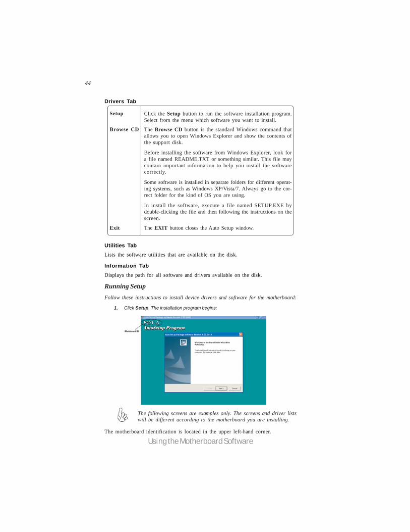
Drivers Tab
Setup Click the Setup button to run the software installation program.Select from the menu which software you want to install.
Browse CD
Exit The EXIT button closes the Auto Setup window.
Utilities TabLists the software utilities that are available on the disk.
Information TabDisplays the path for all software and drivers available on the disk.
Running SetupFollow these instructions to install device drivers and software for the motherboard:
1. Click Setup. The installation program begins:
The following screens are examples only. The screens and driver listswill be different according to the motherboard you are installing.
The motherboard identification is located in the upper left-hand corner.
The Browse CD button is the standard Windows command thatallows you to open Windows Explorer and show the contents ofthe support disk.
Before installing the software from Windows Explorer, look fora file named README.TXT or something similar. This file maycontain important information to help you install the softwarecorrectly.
Some software is installed in separate folders for different operat-ing systems, such as Windows XP/Vista/7. Always go to the cor-rect folder for the kind of OS you are using.
In install the software, execute a file named SETUP.EXE bydouble-clicking the file and then following the instructions on thescreen.

45
Using the Motherboard Software
2. Click Next. The following screen appears:
3. Check the box next to the items you want to install. The default options are recom-
4. Click Next run the Installation Wizard. An item installation screen appears:
5. Follow the instructions on the screen to install the items.
mended.
Drivers and software are automatically installed in sequence. Follow theonscreen instructions, confirm commands and allow the computer torestart a few times to complete the installation.
46
Using the Motherboard Software
Manual InstallationInsert the disk in the DVD-ROM/CD-ROM drive and locate the PATH.DOC file in theroot directory. This file contains the information needed to locate the drivers foryour motherboard.
Look for the chipset and motherboard model; then browse to the directory and pathto begin installing the drivers. Most drivers have a setup program (SETUP.EXE) thatautomatically detects your operating system before installation. Other drivers havethe setup program located in the operating system subfolder.
If the driver you want to install does not have a setup program, browse to theoperating system subfolder and locate the readme text file (README.TXT orREADME.DOC) for information on installing the driver or software for your oper-ating system.
Utility Software ReferenceAll the utility software available from this page is Windows compliant. They areprovided only for the convenience of the customer. The following software is fur-nished under license and may only be used or copied in accordance with the terms ofthe license.
These software(s) are subject to change at anytime without prior notice.Please refer to the support disk for available software.
This concludes chapter 4.
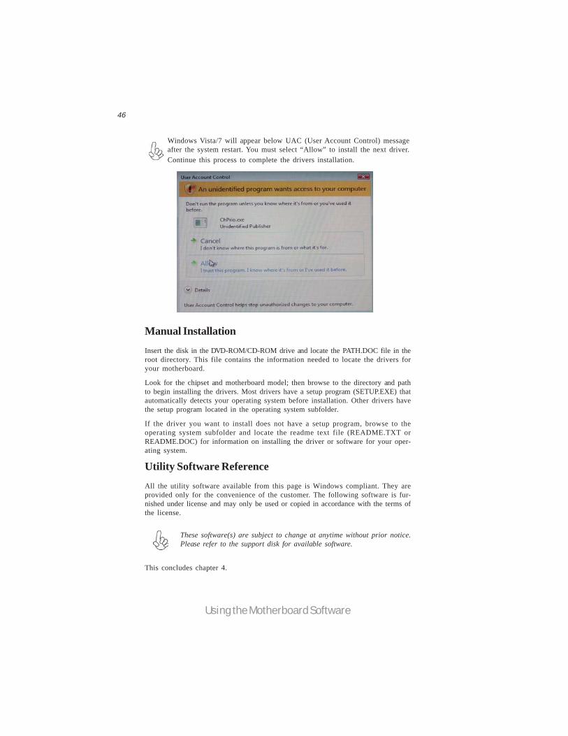
Windows Vista/7 will appear below UAC (User Account Control) messageafter the system restart. You must select “Allow” to install the next driver.Continue this process to complete the drivers installation.

47
ATI CrossFireXTM Technology Support
Chapter 5
ATI CrossFireXTM Technology SupportThis motherboard supports the ATI CrossFireXTM Technology that allows you toinstall multi-graphics processing units (GPU) graphics cards. Follow the installationprocedures in this section.
Requirements1 You should have a CrossFireXTM Ready motherboard, a CrossFireXTM Edi-
tion graphics card and a CrossFireXTM ready graphics card.2 Visit the ECS website (www.ecs.com.tw) for a list of qualified CrossFireXTM
ready graphics card for this motherboard.3 Make sure that your graphics card driver supports the ATI CrossFireXTM
technology. Download the latest driver from the ATI website(www.ati.com).
4 Make sure that your power supply unit (PSU) can provide at least theminimum power required by your system.
Installing a single graphics card1. Install a PCI Express x16 graphics card on the PCIE16X_1 slot.
2. Connect one end of the external cable to the graphics card.
3. Connect the loose end to the corresponding port on your monitor.
4. Connect an auxiliary power source from the power supply to the graphics card.

48
ATI CrossFireXTM Technology Support
Installing CrossFireXTM graphics cards1. Insert the CrossFireXTM graphics cards into the PCIE16X_1 and PCIE16X_2 slots.Make sure that the card is properly seated on the slot.
3. Connect the two CrossFireXTM Edition graphics cards installed on PCIE16X_1 andPCIE16X_2 slots with the CrossFire Bridge.
5. Connect an auxiliary power source from the power supply to the graphics cards.
2. Connect an external cable to the CrossFireXTM ready graphics card installed on thePCIE16X_2 slot.
External Cable
4. Connect the external cable to the corresponding port on your monitor.

49
ATI CrossFireXTM Technology Support
Table A: Supported PCI Express VGA Card List for CrossFireXTM Func-tion
Vender
MSI RX1300 TD256E (256M) Radeon X1300Pro
ATI X1600XT (256M) Radeon X1600XT
PowerColor X1900XTX (512M) Radeon X1900XTX
ASUS EAX1950PRO/HTDP/256M/A (256M) Radeon X19500Pro
MSI RX2600XT (256MB) Radeon HD2600XT
MSI RX3850-T2D256E-OC (256MB) Radeon HD3850
POWER Color AX3870 512MD-PH Radeon HD3870
ATI
PCI-E Card

50
ATI CrossFireXTM Technology Support
The CatalystTM Control Center Dialog BoxViewThe CatalystTM Control Center provides two views; one is Standard view for begin-ners, the other is Advance view for advanced users to access and configure thecomplete features of the software.
Set to Advanced View to enable the CrossFireXTM function.
To enable CrossFireXTM:• Set the view to Advance.• Click the CrossFireXTM item in Graphics Settings.• In the CrossFireXTM Setting dialog, tick the box opposite Enable
CrossFireXTM.• Click OK to effect the setting.

51
Intel® Matrix Storage Manager RAID Configurations
The Intel® Matrix Storage Manager allows you to configure RAID 0, and 1 sets on theexternal Serial ATA hard disk drives.
Complete the following steps before you create a RAID set:
1. Install the external Serial ATA hard disk drive (HDD) on your system.
2. Set the Onboard SATA Mode item in the BIOS to .RAID..
See section “Integrated Peripherals” for details.
Before creating a RAID setPrepare the following items:
1. One SATA HDD.2. A write-enabled floppy disk.3. Microsoft® Windows® OS installation disk (Windows XP/Vista).4. Motherboard support CD with Intel® Matrix Storage Manager driver.
Chapter 6
Intel® Matrix Storage Manager RAID Configurations
3. Enter the Intel® Matrix Storage Manager option to set up your RAIDconfiguration.
4. Create an Intel® Matrix Storage Manager driver disk for Windows® OSinstallation. See section “Creating a RAID driver disk” for details.
5. Install the Intel® Matrix Storage Manager driver after the Windows® OShad been installed.
52
Intel® Matrix Storage Manager RAID Configurations
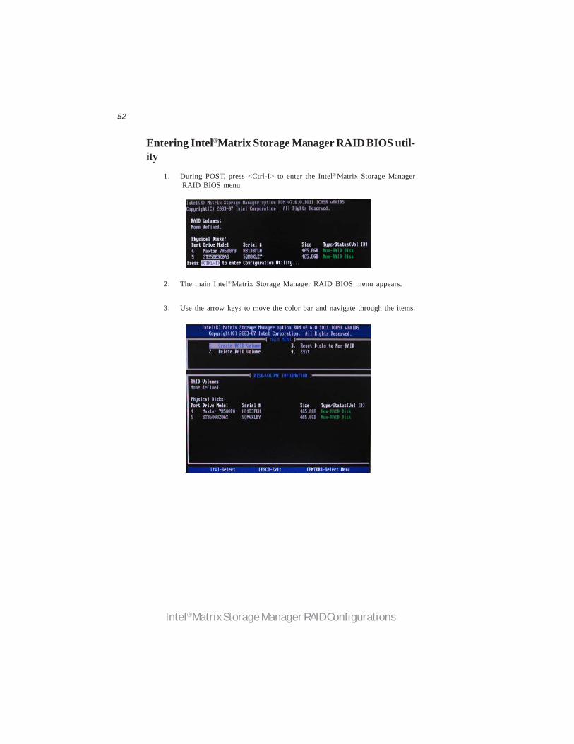
2. The main Intel® Matrix Storage Manager RAID BIOS menu appears.
Entering Intel® Matrix Storage Manager RAID BIOS util-ity
1. During POST, press <Ctrl-I> to enter the Intel® Matrix Storage ManagerRAID BIOS menu.
3. Use the arrow keys to move the color bar and navigate through the items.

53
Intel® Matrix Storage Manager RAID Configurations
2. When the RAID Level item is highlighted, use the up/down arrow key toselect the RAID set that you want to create.
Creating a RAID set1. In the main Intel® Matrix Storage Manager RAID BIOS menu, highlight
Create RAID Volume using the up/down arrow key then press <Enter>.
3. Key in the RAID volume capacity. Use the up/down arrow to choose theCapacity. The default value indicates the maximum capacity using theselected disks. Entering a lower capacity allows you to create a secondvolume on these disks.
When more than two HDDs are installed in your computer, the Disks itemwill be selectable. Then users can select the HDD that you want to belongto the RAID set. Please be noticed that selecting a wrong disk will result inlosing the original data of the HDD.

54
Intel® Matrix Storage Manager RAID Configurations
Pressing <Y> deletes all the data in the HDDs.5. The following screen appears, displaying the relevant information about
the RAID set you created.
Users please be noted that RAID 0 (Stripe) is set to accelerate the dataaccess, and RAID 1 (Mirror) is set to provide the data backup. If you wantto set RAID 0, you need to set the 2nd Boot Device item in the BIOS toIntel Volume0. See section “Advanced Setup” for details.
4. When done, press <Enter> to confirm the creation of the RAID set. Adialogue box appears to confirm the action. Press <Y> to confirm; other-wise, press <N>.

55
Intel® Matrix Storage Manager RAID Configurations
Deleting a RAID set1. In the main Intel® Matrix Storage Manager RAID BIOS menu, highlight
Delete RAID Volume using the up/down arrow key then press <Enter>.
2. Use the space bar to select the RAID set you want to delete.
Press the <Del> key to delete the set.
3. A dialogue box appears to confirm the action. Press <Y> to confirm;otherwise, press <N>.
Pressing <Y> deletes all the data in the HDDs.
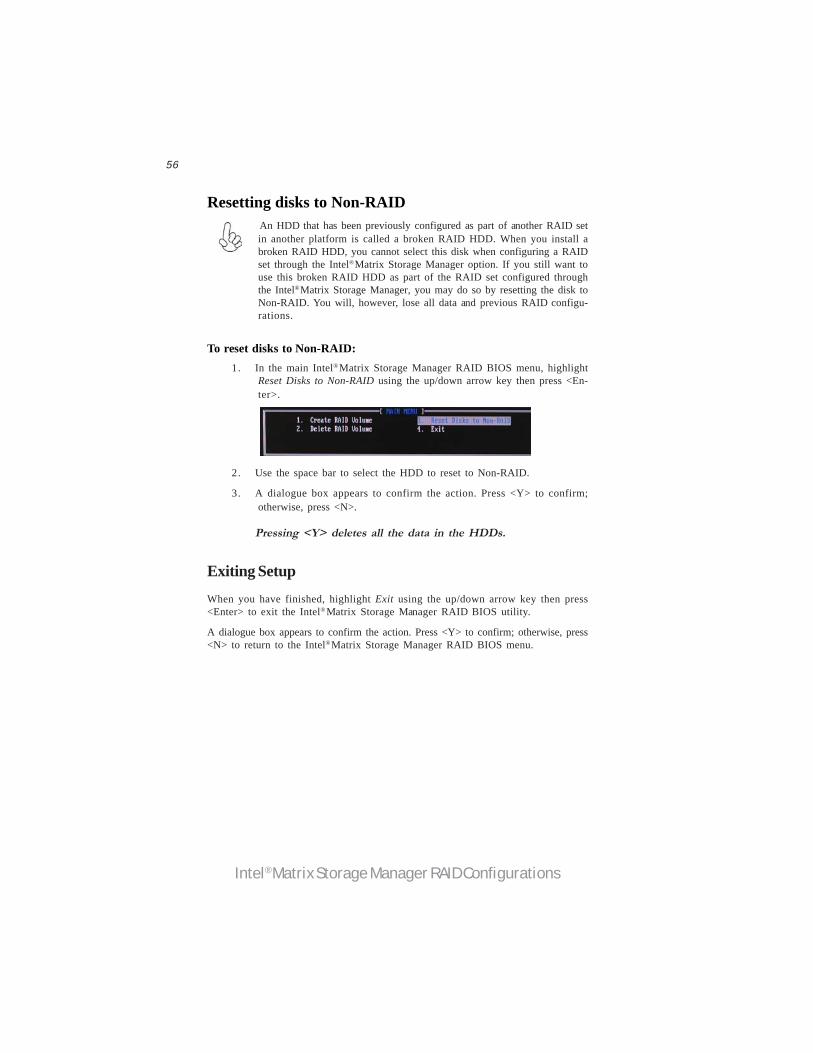
56
Intel® Matrix Storage Manager RAID Configurations
Resetting disks to Non-RAID An HDD that has been previously configured as part of another RAID setin another platform is called a broken RAID HDD. When you install abroken RAID HDD, you cannot select this disk when configuring a RAIDset through the Intel® Matrix Storage Manager option. If you still want touse this broken RAID HDD as part of the RAID set configured throughthe Intel® Matrix Storage Manager, you may do so by resetting the disk toNon-RAID. You will, however, lose all data and previous RAID configu-rations.
To reset disks to Non-RAID:1. In the main Intel® Matrix Storage Manager RAID BIOS menu, highlight
Reset Disks to Non-RAID using the up/down arrow key then press <En-ter>.
2. Use the space bar to select the HDD to reset to Non-RAID.
3. A dialogue box appears to confirm the action. Press <Y> to confirm;otherwise, press <N>.
Pressing <Y> deletes all the data in the HDDs.
Exiting SetupWhen you have finished, highlight Exit using the up/down arrow key then press<Enter> to exit the Intel® Matrix Storage Manager RAID BIOS utility.
A dialogue box appears to confirm the action. Press <Y> to confirm; otherwise, press<N> to return to the Intel® Matrix Storage Manager RAID BIOS menu.

Setting Up eJIFFY
57
IntroductioneJIFFY is a fast boot program under Linux. Instead of waiting Windows O.S to startexecution, eJIFFY is ready to provide users the instant enjoyment on web browsing,photo review and online chat just within several seconds after boot up.
Version: 5.0
Note: eJIFFY is ECS optional feature utility corresponding to the DVD activation andBIOS setup. Please check the hard copy user’s guide or product color-box to see if the model has embodded eJIFFY feature. (eJIFFY icon on color-box )
Chapter 7
Setting Up eJIFFY

Setting Up eJIFFY
58
Installation and BIOS Setup
DVD ActivationFinish the DVD utility setup, and then set the BIOS to complete eJIFFY activation.
1. Insert ECS software utility DVD and enter below “Utilities” screen. Click eJIFFY
feature item to install.
2. Follow the onscreen instructions to finish eJIFFY setup.

Setting Up eJIFFY
59
3. After setting up eJIFFY under Windows, you can switch eJIFFY display/keyboardlanguage from English to your local language. The changes will be applied afterrebooting.
Note: The keyboard language selection list offers several more regional keyboardsetups to switch with the default English typing. Please refer to the usage FAQ formore tips.
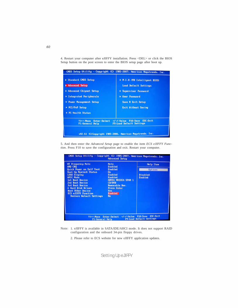
Setting Up eJIFFY
60
4. Restart your computer after eJIFFY installation. Press <DEL> or click the BIOSSetup button on the post screen to enter the BIOS setup page after boot up.
5. And then enter the Advanced Setup page to enable the item ECS eJIFFY Func-tion. Press F10 to save the configuration and exit. Restart your computer.
2. Please refer to ECS website for new eJIFFY application updates.
1. eJIFFY is available in SATA/IDE/AHCI mode. It does not support RAIDconfiguration and the onboard 34-pin floppy drives.
Note:
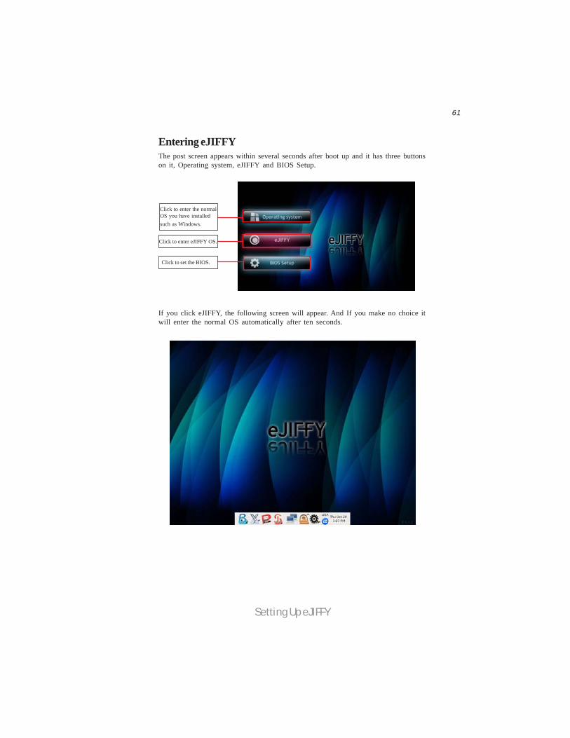
Setting Up eJIFFY
61
Entering eJIFFYThe post screen appears within several seconds after boot up and it has three buttonson it, Operating system, eJIFFY and BIOS Setup.
If you click eJIFFY, the following screen will appear. And If you make no choice itwill enter the normal OS automatically after ten seconds.
Click to enter the normalOS you have installedsuch as Windows.
Click to enter eJIFFY OS.
Click to set the BIOS.

Setting Up eJIFFY
62
Feature IconsThe following illustration shows the main feature icons that eJIFFY provides on themenu.
ePix: Photo viewing.
eWeb: Firefox for web browsing/webmail and watching flash video.
Shows ePal on-line connection status.
Shut Down/Restart: Ends your session and turns off the computer./Endsyour session and restart the computer..
Click once to connect the storage disk to your computer. Click for the secondtime to remove your storage disk safely. (please refer to the FAQ for moreusage information.)
Shows the network connection status.
ePal: On-line chat tool to use the most popular IMs in the world. (MSN,ICQ, AIM, etc.)
Language Control Panel
Switch Keyboard Languages

Setting Up eJIFFY
63
to open the language control panel.
Keyboard Language Setup
Usage FAQLanguage Control Panel: Besides setting English as the default interface,eJIFFY offers multi-language displays and keyboard settings for language-switch. Open the language control panel to select a preferable language setting.
Step1. Click
Step 2: Click “Keyboard Language” icon to open the keyboard selection
list, which offers several regional keyboard settings besides default English keyboard.Step 3: Click the selected keyboard language (e.g. French) and press “OK”.

Setting Up eJIFFY
64
Click the language bar here.
Move your mouse pointer onthe text box and pressCtrl+Space. The languagebar will then appear as fol-lows.
Select your desiredlanguage
Click to enable all possible language inputs you want to apply, and click
“Apply”:

Setting Up eJIFFY
65
How to change display language?
Open the Language Control Panel and click to show the display language
list. Check your desired display language. Your selected display language will beapplied after rebooting.
Note: Details about eJIFFY please refer to eJIFFY in disk.

Setting Up eJIFFY
66
Memo
67
Trouble Shooting
Chapter 8
Trouble Shooting
Start up problems during assembly
After assembling the PC for the first time you may experience some start upproblems. Before calling for technical support or returning for warranty, this chaptermay help to address some of the common questions using some basic troubleshootingtips.
a) System does not power up and the fans are not running.
1.Disassemble the PC to remove the VGA adaptor card, DDR memory, LAN, USBand other peripherals including keyboard and mouse. Leave only the motherboard,CPU with CPU cooler and power supply connected. Turn on again to see if theCPU and power supply fans are running.
2. Make sure to remove any unused screws or other metal objects such as screwdriversfrom the inside PC case. This is to prevent damage from short circuit.
3. Check the CPU FAN connector is connected to the motherboard.
4. For Intel platforms check the pins on the CPU socket for damage or bent. A bentpin may cause failure to boot and sometimes permanent damage from short circuit.
5. Check the 12V power connector is connected to the motherboard.
6. Check that the 12V power & ATX connectors are fully inserted into themotherboard connectors. Make sure the latches of the cable and connector arelocked into place.
b) Power is on, fans are running but there is no display
1. Make sure the monitor is turned on and the monitor cable is properly connectedto the PC.2. Check the VGA adapter card (if applicable) is inserted properly.3. Listen for beep sounds. If you are using internal PC speaker make sure it isconnected. a. continuous 3 short beeps : memory not detected b. 1 long beep and 8 short beeps : VGA not detected

68
Trouble Shooting
c) The PC suddenly shuts down while booting up.
1. The CPU may experience overheating so it will shutdown to protect itself.Ensure the CPU fan is working properly.2. From the BIOS setting, try to disable the Smartfan function to let the fan run atdefault speed. Doing a Load Optimised Default will also disable the Smartfan.
Maintenance and care tips
Your computer, like any electrical appliance, requires proper care and maintenance.Here are some basic PC care tips to help prolong the life of the motherboard andkeep it running as best as it can.
Start up problems after prolong useAfter a prolong period of use your PC may experience start up problems again.This may be caused by breakdown of devices connected to the motherboard such asHDD, CPU fan, etc. The following tips may help to revive the PC or identify thecause of failure.1. Clear the CMOS values using the CLR_CMOS jumper. Refer to CLR_CMOSjumper in Chapter 2 for Checking Jumper Settings in this user manual. Whencompleted, follow up with a Load Optimised Default in the BIOS setup.
2. Check the CPU cooler fan for dust. Long term accumulation of dust will reduceits effectiveness to cool the processor. Clean the cooler or replace a new one ifnecessary.
3. Check that the 12V power & ATX connectors are fully inserted into themotherboard connectors. Make sure the latches of the cable and connector arelocked into place.
4. Remove the hard drive, optical drive or DDR memory to determine which ofthese component may be at fault.
1. Keep your computer in a well ventilated area. Leave some space between the PC and the wall for sufficient airflow.
2. Keep your computer in a cool dry place. Avoid dusty areas, direct sunlight and areas of high moisture content.
3. Routinely clean the CPU cooler fan to remove dust and hair.
4. In places of hot and humid weather you should turn on your computer once every other week to circulate the air and prevent damage from humidity.
5. Add more memory to your computer if possible. This not only speeds up the system but also reduces the loading of your hard drive to prolong its life span.
6. If possible, ensure the power cord has an earth ground pin directly from the wall outlet. This will reduce voltage fluctuation that may damage sensitive devices.
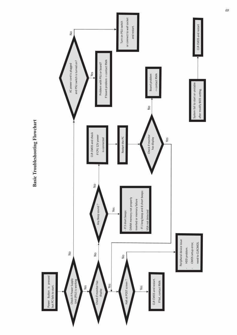
Pow
er
Buon
is
pr
esse
d bu
t PC
fails
to st
art.
Yes
Chec
k if
Pow
er S
uppl
y U
nit (
PSU
) is
wor
king
No
No
Any
Beep
sou
nd?
N
o CL
R CM
OS
and
chec
k
if CP
U 1
2V p
ower
is c
onne
cted
art t
he P
C st
Re
Prob
lem
with
PSU
or b
oard
?
If bo
ard
prob
lem
-> c
onta
ct R
MA
AC p
ower
cor
d is
plu
ed
gg
and
PSU
switc
h is
turn
ed o
n?
Yes
oble
m
rBo
ard
p
-> c
onta
ct R
MA
No
- If 3
sho
rt b
eeps
:
DIM
M m
emor
y no
t pro
perly
inse
rted
or m
emor
y fa
ilure
- If 1
long
bee
p an
d 8
shor
t bee
ps:
VGA
not d
etec
ted
Yes
Yes
Hal
t at P
OST
scr
een?
Yes
R CM
OLC
S an
d re
star
t.
If fa
il, c
onta
ct R
MA
Yes
No
Perip
hera
l dev
ice
issu
e
-H
DD
pro
blem
.
-CM
OS
setu
p er
ror,
dne
e to
CLR
CMO
S.
Syst
em fa
il to
sta
rt o
r uns
tabl
e
aer
mod
ify B
IOS
seng
. M
CLR
CO
S an
d re
star
t
Turn
on
PSU
sw
itch
or c
onne
ct to
wal
l soc
ket
star
t. e
and
rNo
Chec
k if
mon
itor h
sadi
s pla
y
Chec
k if
mon
itor
has
dis
play
69
Basic
Tro
uble
shoo
ting
Flow
char
t

70
Trouble Shooting
Memo


