PhD Thesis by Nawzad Al-Salihi Brunel University
Precise Positioning in Real-Time using GPS-RTK
Signal for Visually Impaired People Navigation
System
A Thesis Submitted for the Degree of Doctor of Philosophy
By
Nawzad Kameran Al-Salihi
School of Engineering and Design
Brunel University
London, United Kingdom
September 2010
i
PhD Thesis by Nawzad Al-Salihi Brunel University
Abstract
This thesis presents the research carried out to investigate and achieve highly
reliable and accurate navigation system of guidance for visually impaired
pedestrians. The main aim with this PhD project has been to identify the limits
and insufficiencies in utilising Network Real-Time Kinematic Global Navigation
Satellite Systems (NRTK GNSS) and its augmentation techniques within the
frame of pedestrian applications in a variety of environments and circumstances.
Moreover, the system can be used in many other applications, including
unmanned vehicles, military applications, police, etc. NRTK GNSS positioning is
considered to be a superior solution in comparison to the conventional standalone
Global Positioning System (GPS) technique whose accuracy is highly affected by
the distance dependent errors such as satellite orbital and atmospheric biases.
Nevertheless, NRTK GNSS positioning is particularly constrained by wireless
data link coverage, delays of correction and transmission and completeness, GPS
and GLONASS signal availability, etc., which could downgrade the positioning
quality of the NRTK results.
This research is based on the dual frequency NRTK GNSS (GPS and
GLONASS). Additionally, it is incorporated into several positioning and
communication methods responsible for data correction while providing the
position solutions, in which all identified contextual factors and application
requirements are accounted.
The positioning model operates through client-server based architecture consisted
of a Navigation Service Centre (NSC) and a Mobile Navigation Unit (MNU).
Hybrid functional approaches were consisting of several processing procedures
allowing the positioning model to operate in position determination modes.
NRTK GNSS and augmentation service is used if enough navigation information
was available at the MNU using its local positioning device (GPS/GLONASS
receiver).
ii
PhD Thesis by Nawzad Al-Salihi Brunel University
The positioning model at MNU was experimentally evaluated and centimetric
accuracy was generally attained during both static and kinematic tests in various
environments (urban, suburban and rural). This high accuracy was merely affected
by some level of unavailability mainly caused by GPS and GLONASS signal
blockage. Additionally, the influence of the number of satellites in view, dilution
of precision (DOP) and age corrections (AoC) over the accuracy and stability of
the NRTK GNSS solution was also investigated during this research and
presented in the thesis.
This positioning performance has outperformed the existing GPS service. In
addition, utilising a simulation evaluation facility the positioning model at MNU
performance was quantified with reference to a hybrid positioning service that
will be offered by future Galileo Open Service (OS) along with GPS. However, a
significant difference in terms of the service availability for the advantage of the
hybrid system was experienced in all remaining scenarios and environments more
especially the urban areas due to surrounding obstacles and conditions.
As an outcome of this research a new and precise positioning model was
proposed. The adaptive framework is understood as approaching an integration of
the available positioning technology into the context of surrounding wireless
communication for a maintainable performance. The positioning model has the
capability of delivering indeed accurate, precise and consistent position solutions,
and thus is fulfilling the requirements of visually impaired people navigation
application, as identified in the adaptive framework.
iii
PhD Thesis by Nawzad Al-Salihi Brunel University
Acknowledgment
Pursuing this research has meant many challenges; it has been a painful but also
an enjoyable journey. Bitterness, frustration, and difficulties have been
compensated by encouragement, trust and help. My sincere gratefulness goes
firstly to my honorific supervisor Professor Wamadeva Balachandran, his
continuous support, advice and guidance throughout this research project has
made it possible to finish this thesis. I will always be appreciative of the patient
and outstanding supervision he provided me along this strive.
I would like to thank my second supervisor Dr. Vanja Garaj for his valuable
suggestion and discussions. I am also grateful to Ms Jowan Mahmod for her
important editorial support and creative ideas. Her inspiring and motivating words
have made it easier. I would like to give my sincere thanks to Dr. Philip Collins
for supporting this research work by providing with important equipment. Special
thanks are also given to my friend and research partner Dr. Mohammad AL
Nabhan for all his help and assistance in transferring very useful knowledge. I am
also grateful to Dr. Ziad Hunaiti for his inspiring comments and guidance. I thank
Mr Sarmad Saleh for all practical and supporting help.
Finally, my deepest appreciation to my family, especially my father Dr. Kameran
Al-Salihi, and my mother, Mrs Elham Ramadhan Al-Salihi, I really could not
have done it without their love and endless support. I am very grateful to my sister
Dr. Avin Al-Salihi for advising me and passing me her valuable experience in
accomplishing a PhD.
Many thanks are also passed on to all my friends and colleagues in the UK for
their encouragement during this remarkable period.
iv
PhD Thesis by Nawzad Al-Salihi Brunel University
Abbreviations and Acronyms
3G Third Generation mobile systems
3GPP 3rd Generation Partnership Project
3GPP2 3rd Generation Partnership Project 2
A-GPS Assisted-GPS
AOA Angle Of Arrival
bps bit per second
BNG British National Grid
BNSB Brunel Navigation System for Blind
BOC Binary Offset Carrier
CDMA Code Division Multiple Access
CN Core Network
CoO Cell of Origin
CS Commercial Service
DAB Digital Audio Broadcast
DGPS Differential GPS
DL Down-Link
DoD Department of Defence
DOP Delusion Of Precision
DRMS Distance Root Mean Square
DR Dead Reckoning
DS2DC Data Server to Data Client Protocol
ECEF Earth-centred Earth-fixed
EC European Commission
EDGE Enhanced Data Rate for GSM Evolution
EDAS EGNOS Data Access System
EGNOS European Geostationary Navigation Overlay Service
ESA European Space Agency
ESRG Electronic Systems Research Group
E-OTD Enhanced Observed Time Difference
GALILEO the European global navigation satellite system
GBAS Ground-Based Augmentation System

v
PhD Thesis by Nawzad Al-Salihi Brunel University
GDOP Geometric Dilution of Precision
GDGPS Global Differential GPS System
GEO Geostationary
GIS Geographical Information Systems
IVE Ionospheric Vertical Error
GIVE Grid Vertical Ionospheric Errors
GLONASS Global Navigation Satellite System
GNSS Global Navigation Satellite Systems
GPRS General Packet Radio Service
GPS Global Positioning System
GSM Global System for Mobile
GSSF Galileo Simulation Service Facility
HDOP Horizontal Delusion Of Precision
HS-GPS High Sensitivity GPS
HSCSD High Speed Circuit Switched Data
HSDPA High Speed Downlink Packet Access
HSGPS High Sensitivity GPS
HSPA High Speed Packet Access
HSUPA High Speed Uplink Packet Access
HTML Hypertext Markup Language
HOW Hand Over Word
ICMP Internet Control Message Protocol
ICT Information and Communication Technology
IDGPS Inverse DGPS
IF Integrity Flag
IGPs Ionospheric Grid Points Mask
IIS Internet Information Service
IMT-2000 International Mobile Telecommunication in the year 2000
INS Inertial Navigation System
IOD Issue Of Data
IMS Integrity Monitoring Station.
IPP Ionospheric Pierce Point
IRM Intelligent Resource Monitor
ITU International Telecommunication Union
vi
PhD Thesis by Nawzad Al-Salihi Brunel University
JPL Jet Propulsion Laboratory
Kbps kilobits per second
KB/s Kilo byte per second
KF Kalman Filter
LAN Local Area Network
LADGPS Local Area DGPS
LBS Location Based Service
LORAN Long Range Aid to Navigation
LS Localisation Server
LTE Long Term Evolution
MCS Master Control Stations
MCC Mission Control Centres
Mbps Mega bit per second
MB/s Mega byte per second
MEMS Micro-Electro Mechanical Sensor
MEO Medium-Earth Orbit
ME Mobile Equipment
MI Misleading Information
MOPS Minimum Operational Positioning Standards
MoBIC Mobility of Blind and Elderly People Interacting with Computers
MT Mobile Terminal
MU Mobile Unit
Node B Base Station
NLES Land Earth Stations.
NMEA National Marine Electronics Association
NRTK Network Real Time Kinematics
NSP Navigation System Precision.
Ntrip Network Transport of RTCM via Internet Protocol
OGC International OpenGeospatial Consortium
OS NET Ordinance Survey network
OS Open Service
PA Precision Approach
PDA Personal Digital Assistant
PDOP Position Delusion Of Precision

vii
PhD Thesis by Nawzad Al-Salihi Brunel University
PGS Personal Guidance System
PE Positioning Error
PRR Position Response Rate
PRS Public Regulated Service
PRC Pseudo-Range Corrections
PS Packet Switched
QoS Quality of Service
QPSK Quadrature Phase Shift Keying
RDS Radio Data System
RDG Raw Data Generation
RFMD Russian Federation
RFID Radio Frequency Identification
RMS: Root Mean Square
RINEX Receiver Independent Exchange
RNIB Royal National Institute for Blind
RSSI Received Signal Strength Indicator
RSA Russian Space Agency
RTK Real Time Kinematics
RTCA Radio Technical Commission for Aeronautics
RTCM Radio Technical Commission for Maritime
RTT Round-Trip Time
SAR Search and Rescue
SBAS Satellite Based Augmentation Systems
SPS Standard Positioning Service
SISNET Signal in Space through the Internet
SISA Single in Space Accuracy
SISE Single in Space Error
SISMA Signal-In-Space Monitoring Accuracy
SINCA SISNET Compression Algorithm
SLS Safety-of-Life Service
SMS Short Message Service
SVS Service Volume Simulation
TDMA Time Division Multiple Access
TDOA Time Difference Of Arrival
viii
PhD Thesis by Nawzad Al-Salihi Brunel University
TOA Time Of Arrival
TTFF Time to First Fix
TVE Tropospheric Vertical Error
UAS User Application Software
UDRE User Data Range Error
UERE User Equivalent Range Error
UIRE User Inospheric Range Error
UL Up-Link
UMTS Universal Mobile Telecommunication System
UTRAN UMTS Terrestrial Radio Access Network
VDOP Vertical Delusion Of Precision
VPL Vertical Protection Levels
VRS Virtual Reference Station
WADGPS Wide Area DGPS
WAAS Wide Area Augmentation System
WAP Wireless Application Protocol
WCDMA Wideband Code Division Multiple Access
WiMAX Worldwide Interoperability for Microwave Access
WLAN Wireless Local Area Network
WML Wireless Markup Language
WPAN Wireless Personal Area Networks
WWAN Wireless Wide Area Network
ix
PhD Thesis by Nawzad Al-Salihi Brunel University
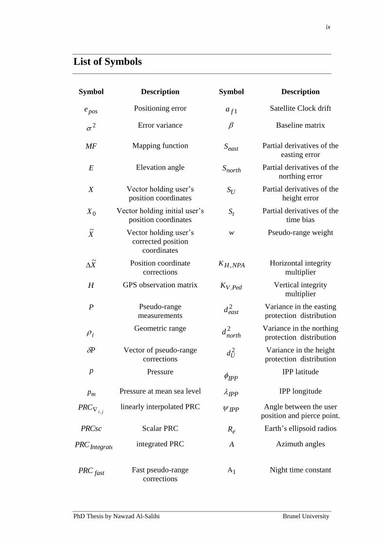
List of Symbols
Symbol Description Symbol Description
pose Positioning error 1fa Satellite Clock drift
2 Error variance Baseline matrix
MF Mapping function eastS Partial derivatives of the
easting error
E Elevation angle northS Partial derivatives of the
northing error
X Vector holding user‟s
position coordinates US Partial derivatives of the
height error
0X Vector holding initial user‟s
position coordinates tS Partial derivatives of the
time bias
X~
Vector holding user‟s
corrected position
coordinates
w Pseudo-range weight
X~
Position coordinate
corrections NPAHK , Horizontal integrity
multiplier
H GPS observation matrix PedVK . Vertical integrity
multiplier
P Pseudo-range
measurements
2eastd Variance in the easting
protection distribution
i Geometric range 2
northd
Variance in the northing
protection distribution
P Vector of pseudo-range
corrections
2Ud Variance in the height
protection distribution
p Pressure IPP
IPP latitude
mp Pressure at mean sea level IPP IPP longitude
jiPRC
, linearly interpolated PRC IPP Angle between the user
position and pierce point.
PRCsc Scalar PRC eR Earth‟s ellipsoid radios
iIntegratedPRC ,
integrated PRC A Azimuth angles
fastPRC Fast pseudo-range
corrections 1A Night time constant

x
PhD Thesis by Nawzad Al-Salihi Brunel University
ionoPRC Ionospheric pseudo-range
corrections 2A Amplitude term
tropoPRC Tropospheric pseudo-range
corrections 3A Phase term of cosine wave
clockPRC Clock pseudo-range
corrections 4A Period term of cosine
wave
Ih Height of the maximum
electron density ppF Obliquity factor
sh height of the observation
station
Water vapor lapse rate
dh Height of dry troposphere
layer
c Speed of light
wh Height of wet troposphere
layer
e relative humidity
mh Height above mean sea
level v Interpolated GIVE
GDT Group delay correction vpp Final interpolated zenith
ionospheric delay (UIVE )
T Temperature trop Tropospheric zenith delay
mT Temperature at mean sea
level dtrop, Dry component
tropospheric zenith delay
Td Slant tropospheric delay wtrop, Wet component
tropospheric zenith delay
ionT User slant ionospheric delay I Filtered ionospheric delay
vionT Vertical ionospheric delay
(Klobuchar model) IC Final ionospheric
correction
0t Time applicability of the
day kx KF process state
ut User‟s time offset 1kw KF process noise vector
svt SV code phase time kv Measurement-noise vector
svt SV code phase time offset DRp DR position solution
rt Relativistic effects DRv DR velocity solution
oct GPS Reference time kz KF measurement vector
a Matrix holding reference
station coordinates dryz Zenith dry delay at mean
sea level
0fa Satellite Clock bias wetz Zenith wet delay at mean
sea level

xi
PhD Thesis by Nawzad Al-Salihi Brunel University
Table of Content
Abstract ...................................................................................................... i
Acknowledgment ..................................................................................... iii
Abbreviations and Acronyms ................................................................ iv
List of Symbols ........................................................................................ ix
Table of Content ...................................................................................... xi
List of Figures ........................................................................................ xvi
List of Tables ......................................................................................... xix
Chapter 1 ................................................................................................... 1
1. Introduction ........................................................................................ 1
1.1 Introduction ............................................................................................................... 1
1.2 Motivation and Background ...................................................................................... 5
1.3 Research Aim and Objectives ................................................................................... 9
1.4 Contribution to Knowledge ..................................................................................... 11
1.5 Thesis Structure ...................................................................................................... 12
Chapter 2 ................................................................................................. 14
2. Technical Background ..................................................................... 14
2.1 Introduction ............................................................................................................. 14
2.2 Global Navigation Satellite Systems (GNSS) ......................................................... 15
2.2.1 Technical Features of GPS ............................................................................... 15
2.2.2 Differential GPS (DGPS) Systems .................................................................. 19
2.2.3 Wide Area Differential GPS (WADGPS) ........................................................ 21
2.2.4 Future GNSS .................................................................................................... 24
2.2.4.1 Modernised GNSS .................................................................................... 24

xii
PhD Thesis by Nawzad Al-Salihi Brunel University
2.2.5 Galileo .............................................................................................................. 26
2.2.6 GLONASS (GLObal'naya NAvigatsionnaya Sputnikovaya Sistema) ............. 29
2.3 GNSS Augmentation Systems Positioning Performances ...................................... 31
2.3.1 Network-based DGPS ...................................................................................... 31
2.3.1.1 GNSS Augmentation Systems in Pedestrian Applications ....................... 33
2.4 Summary ................................................................................................................. 34
Chapter 3 ................................................................................................. 36
3. Review of GPS Based Navigation Systems for Visually
Impaired People ..................................................................................... 36
3.1 Introduction ............................................................................................................. 36
3.2 Visually impaired people‟s Navigation system ....................................................... 37
3.2.1 Electronic Orientation Aids ............................................................................. 37
3.2.2 Brunel Project .................................................................................................. 39
3.2.3 Other Related Electronic Orientation Aids Projects ........................................ 45
3.4 Summary ................................................................................................................. 55
Chapter 4 ................................................................................................. 57
4. Precise Positioning in Real-Time using Navigation Satellites ..... 57
4.1 Introduction ............................................................................................................. 57
4.2 Real Time Kinematic (RTK) ................................................................................... 58
4.3 Network Real Time Kinematic (NRTK) ................................................................. 60
4.3.1 RTK in Visually Impaired Navigation System ................................................ 65
4.4 Processing Procedures for Real-Time GNSS Positioning ...................................... 66
4.4.1 Message Decoding ........................................................................................... 66
4.4.2 Position Calculation and Data Correction ........................................................ 71
4.4.2.1 Coordinate Domain Positioning ................................................................ 71
4.4.2.2 Integer Ambiguity Resolution in Real-Time GNSS Positioning .............. 73
4.5 Precise Positioning in Real-Time using GPS-RTK Signal for Visually Impaired
People Navigation System ............................................................................................ 76

xiii
PhD Thesis by Nawzad Al-Salihi Brunel University
4.6 Summary ................................................................................................................. 77
Chapter 5 ................................................................................................. 79
5. System Design ................................................................................... 79
5.1 Introduction ............................................................................................................. 79
5.2 System Model Prototype ......................................................................................... 80
5.3 Integration between GNSS and Mobile Communications ...................................... 84
5.3.1 The Performance of Mobile Networks ............................................................. 85
5.4 System Model Operational Architecture ................................................................. 88
5.5 System Functions .................................................................................................... 90
5.6 The Operational Methods of the System ................................................................. 91
5.6.1 Mobile Navigation Unit (MNU) Operational Method ..................................... 91
5.6.2 Navigation Service Centre (NSC) Operational Method ................................... 95
5.7 Summary ................................................................................................................. 97
Chapter 6 ................................................................................................. 99
6. An Assessment Methodology of Network-Based RTK (NRTK)
GNSS and Galileo System Performance .............................................. 99
6.1 Introduction ............................................................................................................. 99
6.2 Positioning System Performance .......................................................................... 100
6.2.1 Positioning Performance Parameters Definitions .......................................... 101
6.2.2 Coverage ........................................................................................................ 103
6.2.3 Service Availability ....................................................................................... 104
6.2.4 Continuity ...................................................................................................... 105
6.2.5 Reliability ....................................................................................................... 105
6.2.6 Integrity .......................................................................................................... 106
6.2.7 Accuracy and Precision .................................................................................. 107
6.2.8 Positioning Performance Scenarios and Requirements .................................. 111
6.3 Experimental Evaluation ....................................................................................... 113

xiv
PhD Thesis by Nawzad Al-Salihi Brunel University
6.3.1 Configuration of the Experiments .................................................................. 114
6.3.2 Environment Setup and Quality Assessment Methodology ........................... 116
6.3.3 Experiment Trials ........................................................................................... 120
6.4 Simulation Evaluation Methodology .................................................................... 131
6.4.1 The GALILEO System Simulation Facility (GSSF) ..................................... 131
6.4.2 Simulation Scenarios and Setup ..................................................................... 133
6.5 Summary ............................................................................................................... 135
Chapter 7 ............................................................................................... 136
7. Results Analysis and Discussion ................................................... 136
7.1 Introduction ........................................................................................................... 136
7.2 Experimental Results ............................................................................................ 137
7.2.1 Static Measurements Results ......................................................................... 138
7.2.1.1 Observation Sites .................................................................................... 139
7.2.1.2 Benchmark Points ................................................................................... 146
7.3.1 Dynamic Measurement Results ..................................................................... 149
7.3.1.1 Dynamic Test 1 (DT1): Rural and Suburban Environment .................... 150
7.3.1.2 Dynamic Test 2 (DT2): Urban Environment .......................................... 154
7.4 Discussion ............................................................................................................. 158
7.5 Simulation Results ................................................................................................ 163
7.4 Summary ............................................................................................................... 167
Chapter 8 ............................................................................................... 169
Conclusions and Suggestions for Future Work ................................ 169
8.1 Conclusions ........................................................................................................... 169
8.2 Future Work .......................................................................................................... 173
List of References ................................................................................. 176
Appendix A: Experimental Testing Locations .................................. 187
Appendix B: Overall Experimental Results ...................................... 189

xv
PhD Thesis by Nawzad Al-Salihi Brunel University
Appendix C: List of Publications ........................................................ 190
Appendix D: Topcon Hiper Pro Receiver and FC-200 Controller . 191

xvi
PhD Thesis by Nawzad Al-Salihi Brunel University
List of Figures
Figure 1.1: Brunel Navigation System for the Blind (BNSB). ....................................... 7
Figure 2.1: DGPS System. ..................................................................................... 23
Figure 2.2: OS Net coverage map (Ordnance Survey, 2009). ...................................... 23
Figure 3.1: The visually impaired participant with all components during a trial
experiment at Brunel University (Hunaiti, 2005; Garaj 2006). ..................................... 40
Figure 3.2: A sequence of photographs showing the visually impaired participant during
the session of the trial (Garaj, 2006). ......................................................................... 41
Figure 3.3: The map of the walk in the trial session (Hunaiti, 2005; Garaj 2006). ......... 42
Figure 3.4: The MoBIC electronic orientation aid (Source: The MoBIC Consortium,
1997). ..................................................................................................................... 46
Figure 3.5: The GPS Talk (Sendero Group, 2000). ..................................................... 48
Figure 3.6: NOPPA architecture (VTT, 2010). ........................................................... 50
Figure 3.7: VoiceNote and BrailleNote GPS (Humanaware, 2010). ............................. 51
Figure 3.8: Trekker Talking GPS (Humanware, 2010). ............................................... 52
Figure 4.1: RTK system. ....................................................................................... 63
Figure 4.2: Network RTK system. ............................................................................. 63
Figure 4.2: RTCM words format (RTCM, 1994). ....................................................... 67
Figure 4.3: RTCM header format (RTCM, 1994). ...................................................... 68
Figure 4.4: RTCM Types.......................................................................................... 69
Figure 4.5: The double difference (Petovello and Takac, 2009). .................................. 75

xvii
PhD Thesis by Nawzad Al-Salihi Brunel University
Figure 5.1: System Model Prototype. ........................................................................ 81
Figure 5.2: The Navigation Service Centre (NSC) (Hunaiti, 2005; Garaj 2006). ........... 82
Figure 5.3: Display at NSC. ...................................................................................... 84
Figure 5.4: The main components and architecture for integration between GNSS
receivers and mobile communications. ...................................................................... 85
Figure 5.5: Packet loss comparison between different technologies. ............................ 87
Figure 5.6: Jitter comparison between different technologies. ..................................... 87
Figure 5.7: Delay comparison between different technologies. .................................... 87
Figure 5.8: System model operational architecture. .................................................... 88
Figure 5.9: The MNU operational method. ................................................................ 92
Figure 5.10: The NSC operational method. ................................................................ 96
Figure 6.1: Successive layers of performance parameters and their definitions. .......... 102
Figure 6.2: Accuracy and precision levels explanation. ............................................. 107
Figure 6.3: RTK GPS measuring units. .................................................................... 115
Figure 6.4: Experimental Flow Chart. ...................................................................... 118
Figure 6.5: Brunel University Campus (Bing Maps). ................................................ 121
Figure 6.6: Static measurements points in rural and suburban area (Brunel University).
............................................................................................................................. 124
Figure 6.7: Static measurements points in rural and suburban area (Bing Maps). ........ 125
Figure 6.8: Static measurements points in urban area (Brunel University). ................. 127
Figure 6.9: Static measurements points in rural and suburban area (Bing Maps). ........ 128
xviii
PhD Thesis by Nawzad Al-Salihi Brunel University
Figure 6.10: TopNET+ reference stations. ............................................................... 130
Figure 7.1a: Accuracy and Precision (Easting Error) for OS1. ................................... 139
Figure 7.1b: Accuracy and Precision (Northing Error) for OS1......................... 139
Figure 7.2a: Accuracy and Precision (Easting Error) for OS2. ................................... 141
Figure 7.3a: Accuracy and Precision (Easting Error) for OS3. ................................... 143
Figure 7.4a: Accuracy of solutions from each static test (ST1-ST20) for the East
coordinate component (cm). ................................................................................... 147
Figure 7.5: NRTK GNSS availability results of observation for ST1-ST20. ............... 148
Figure 7.6a: The East coordinate errors for benchmark points ST3-ST6 and ST8-ST10.
............................................................................................................................. 151
Figure 7.7: Tracked satellites and PDOP obtained during DT1. ................................. 152
Figure 7.8: 2D RMSE errors observed during DT1, represented over the route during the
test. ....................................................................................................................... 153
Figure 7.9a: The East coordinate errors for benchmark points ST13, ST15, ST17 and
ST19. .................................................................................................................... 155
Figure 7.10: Tracked satellites and PDOP obtained during DT1. ............................... 156
Figure 7.11: 2D RMSE errors observed during DT2, represented over the route during the
test. ....................................................................................................................... 157
Figure 7.12: Accuracy performance of the Static and Dynamic test obtained from GSSF.
............................................................................................................................. 166
Figure 8.1: Future system model operational architecture including EGONOS/SISNET.
............................................................................................................................. 174
xix
PhD Thesis by Nawzad Al-Salihi Brunel University
List of Tables
Table 2.1: GPS Standard Positioning Service typical UERE Budget (Kaplan and Hegarty,
2006). ................................................................................................................................ 18
Table 2.2: GPS Precise Positioning Service typical UERE Budget (Kaplan and Hegarty,
2006). ................................................................................................................................ 18
Table 6.1: Navigation service performance requirements level. ..................................... 113
Table 6.2: Performed test details for rural and suburban area. ....................................... 123
Table 6.3: Performed test details for urban/suburban area. ............................................ 126
Table 7.1: Measurements obtained during static tests for the OS1. ................................ 141
Table 7.2: Measurements obtained during static tests for the OS2 between 2pm-3pm. . 142
Table 7.3: Measurements obtained during static tests for the OS3. ................................ 144
Table 7.4: Accuracy and precision in centimetres obtained during static tests, for the East
and North coordinate components. ................................................................................. 145
Table 7.5: A summaries of accuracy, precision, tracked satellites and PDOP obtained
during static tests for benchmark points ST1-ST20. ....................................................... 146
Table 7.6a: Positioning performance simulating observation site 1 (OS1) in the rural
environment. ................................................................................................................... 164
Table 7.7a: Positioning performance simulating dynamic route 1 (DT1) in the
rural/suburban environment. ........................................................................................... 165

Chapter 1: Introduction 1
PhD Thesis by Nawzad Al-Salihi Brunel University
Chapter 1
1. Introduction
1.1 Introduction
Mobile and wireless communication technologies are undergoing rapid
advancements and moving towards a new age that is characterised by the seamless
cooperation of heterogeneous systems; the necessity of high speed communication
when being on the move and advanced services with quality guarantees. This has
been accompanied by the advancement and evolution of the Internet and satellite
communications, and motivated by the increasing demand to access more
compressed data.
As a result, mobile technology became a medium not only for voice and Short
Messages Services (SMS), but for rich data transmissions such as video, Web
browsing, and other multimedia contents. Moreover, in developing countries
where people require fast deployment and low expenses for broadband wireless
Internet services, hand mobile and wireless communications technology is
becoming more crucial. The arrival of broadband and multimedia mobile
networks along with effective handsets, embedded with location sensing
technologies, has produced a variety of new mobile services. Satellite-based
positioning is becoming increasingly important in our lives. It is used currently in
many sectors of transport, security, surveillance, industry, research and leisure.
In general terms, navigation service means determining a precise location and
providing required guidance on the route to a desired destination. Navigation
systems have been found useful in many applications; vehicles, marine
navigation, aviation, outdoor recreation, or guidance of visually impaired people.
Several techniques have been developed for position determination over the past
century. At the present time it can be said that the most popular techniques are
satellite-based radio-navigation systems. Due to the popularity of guidance

Chapter 1: Introduction 2
PhD Thesis by Nawzad Al-Salihi Brunel University
systems in various applications, many receivers have become smaller, their price
has become more affordable, and they provide better performance. Consequently,
recent applications in personal navigation systems have become interesting.
There are a number of position determination methods in existence that can be
divided into two main categories: network-based positioning systems utilising
short and wide range wireless networks, and handset-based positioning systems,
such as the Global Navigation Satellite Systems (GNSS). One of the most well-
known systems in GNSS is the Navstar Global Positioning System (GPS),
developed by the U.S. Department of Defense (DoD, 2004). It is considered to be
the most promising and widely-deployed positioning method in use. The GPS can
locate and guide you anywhere in the globe with a very high level of accuracy.
However, this situation, the dominance of GPS, is about to change: Russian
GLONASS (GLONASS, 2010) is being revitalised after a long period of
degradation. In addition, the European Union (EU), together with the European
Space Agency (ESA, 2010), has agreed to build its own GNSS, named Galileo
(European Commission, Enterprise and Industry, 2010). China has announced
plans to continue elaborating its regional BeiDou navigation system (BeiDou,
2010), and it is expected to expand and eventually provide global coverage.
Additionally, India and Japan are also establishing their own systems to
complement and augment existing and future GNSS.
Several applications require the integration of different technologies to become
reality. An excellent example is the vehicle tracking system. This system enables
users to track vehicles remotely on a digital map installed on their personal
computers. The system requires other types of technologies in conjunction with
the GPS, including mobile networks technologies, Geographical Information
Systems (GIS), and Information Technologies (IT). All of these technologies have
enabled the use of tracking systems (Hunaiti, 2005). Similar to the tracking
system idea, a new system has been designed and developed at Brunel University.
This system integrates GPS, 3rd
Generation mobile technology (3G), and
Geographic Information System (GIS). It enables remote tracking of visually-
impaired pedestrians based on GPS location and a live video image. The system‟s
Chapter 1: Introduction 3
PhD Thesis by Nawzad Al-Salihi Brunel University
primary goal is to assist in navigating visually-impaired people using visually able
people as guides. Such a system can also be used in many other highly-
complicated applications, such as unmanned vehicles, emergency tracking, fire
fighters, battlefield operations and many other applications that need both video
imagery and GPS location data (Hunaiti et al., 2004). The positioning
performance of GPS and wireless communication is a crucial attribute for the
quality of guidance. Therefore, it has become an accepted practice to continually
develop new techniques augmenting the positioning services of GPS to advanced
and sustainable levels.
The technology behind navigation, jointly with the development of
communication services, has received a considerable attention varying from the
improvement of positioning techniques, the prevalent and development of
geospatial databases, as well as Geo-visualisations and methods of data
presentation. This also exploited areas of developing accurate and more
sophisticated receivers for position determination using Real Time Kinematic or
the Network Real Time Kinematic GNSS.
GPS on its own do not guarantee accuracy in centimetres (Martin et al., 2000).
Differential GPS technique is required in order to have more accurate positioning
data. This technique allows even centimetre level accurate positioning using the
so-called „integer ambiguity resolution technique‟. The basic concept of
differential technique is to mitigate the main error sources, such as ionospheric
and tropospheric delay, orbit errors and satellite clock errors by receiving satellite
signals at a well-known location. All common errors between this reference
receiver and the user receiver are cancelled out (Landau et al., 2001). At the
moment, this differential technique is used in real time as well as after the actual
processing of data; and real-time data transfer is routinely possible, which enables
real time computation of baseline vectors (Hofmann-Wellenhof et al., 1997) and
has led to the Real-time Kinematic (RTK) technique.
Real Time Kinematic technique or RTK is a GPS mode that is broadly employed
for accurate positioning applications. It was invented in 1990‟s to find the optimal
way of processing reference receiver data, and then providing “correction”
Chapter 1: Introduction 4
PhD Thesis by Nawzad Al-Salihi Brunel University
information to users, in real time. This practice is known as RTK Surveying
(Rizos and Han, 2003). RTK has several requirements such as one reference
receiver to be located at a base station whose coordinates are known in a
geocentric reference frame, so that the second roving receiver's coordinates are
determined relative to this first reference receiver. Algorithms in the mobile
control devices merge the reference station data with the roving GPS
measurements to resolve the integer ambiguity that is essential for calculating
precise ranges from the GPS carrier phase measurements. RTK can provide
centimetre position accuracy, though the accuracy and reliability of the standard
RTK solution decreases with increasing distance from the reference station
(Wübbena et al., 1996). Network-based Real Time Kinematic (NRTK) GPS
positioning is regarded as an advanced solution as compared to the previous single
reference station based Real Time Kinematic (RTK) GPS positioning technique
and satellite orbital and atmospheric biases are greatly affected by the distance
reliant errors causing inaccuracy. NRTK GPS positioning uses unprocessed
measurements collected from a network of Continuously Operating Reference
Stations (CORS) one by one to produce more dependable error models that can
tone down the distance dependent errors inside the region enclosed by the CORS.
This procedure has been developed and checked significantly in recent years and
compared to the usual RTK GPS positioning technique. Its performance is better
in terms of precisions that can be achieved, dependability and mobility. This
procedure is referred to as augmentation technique.
The augmentation techniques, also known as Differential GPS (DGPS) systems,
operate in general over diverse coverage ranges, such as Local Area DGPS
(LADGPS) and Wide Area DGPS (WADGPS). By way of using a number of
interconnected DGPS references stations, or as Satellite-Based Augmentation
System (SBAS), using Geostationary (GEO) satellites, WADGPS can be
implemented as network-based DGPS systems. A number of empirical studies
have been conducted in order to study the positioning performances achieved after
employing these differential systems (Wolfson et al., 2003; Filjar and Huljenić,
2003; Oh et al., 2005; Filjar et al., 2007).

Chapter 1: Introduction 5
PhD Thesis by Nawzad Al-Salihi Brunel University
1.2 Motivation and Background
It has emerged that there is severe limitation in mobility found in the visually
impaired people, the main reason for this is the major reduction in the ability or
the complete inability, as found in many cases, in utilizing the sense of vision in
the process of perception and acquisition of the spatial information needed to
navigate the environment successfully (Jansson, 1995).
The visually impaired people require parallel support in both of the two basic
navigational domains in order to become mobile (Petrie et al., 1997; Guth and
Rieser, 1997). In the first place, there is a requirement of some form of assistance
in the domain of micro-navigation, which implies that in the immediate travel
environment, there should be avoidance of obstacles and other hazards. In the
second domain, there is a requirement of a type of assistance in the domain of
macro-navigation, which implies the directing of locomotion while being on a
route to a destination in a distant and not in the immediate detectable environment
(Garaj, 2006).
Over the period of time, there has been several methods proposed in order to
provide assistance in the mobility of visually impaired people; for example,
Design of the System for Remote Sighted Guidance of Visually Impaired
Pedestrians (Garaj, 2006) and A Remote Vision Guidance System for Visually
Impaired Pedestrians (Hunaiti, 2005). Although, up to present, there has not been
offered a totally suitable response for their mobility requirements. There are only
three methods, which have been established completely as well as been widely
utilized, they are the provision of guidance by a sighted human guide and the
guidance provided with the use of long cane and a guide dog. For centuries, these
three have been in use and also these methods are the oldest mobility-aiding
methods.
In order to enable efficient deliverability of a guidance system to mobile users, the
demand for reliable and exact position solutions has increased after the
proliferation of the wireless technology and the improvement of GNSS in various
important applications such as the mobile guides, emergency tracking and even

Chapter 1: Introduction 6
PhD Thesis by Nawzad Al-Salihi Brunel University
elderly people. This may also involve the delivery on-time of the medical services
in various locations and under different conditions. Thus, there is a persistent as
well as necessary requirement for assured alternatives and the enhanced
positioning services, which are able to deliver current as well as accurate
information needed for the fulfilment of the various prerequisites of these
essential applications.
Therefore, there has been several research projects carried out for the
development of the mobility aids for the pedestrian users, that is for the visually
impaired and elderly people, aiming to bring improvement in their mobility (Helal
et al., 2001; MoBIC, 2004; Jackson, 2006; Pressl & Weiser, 2006).
Additionally, the Electronic System Research Group (ESRG) at Brunel University
was one of the pioneering research groups with its visually impaired guidance
navigation project established in 1995 (Balachandran and Langtao, 1995). The
idea was to investigate the possibility of using GPS to navigate and guide visually
impaired pedestrians based on a client-server-based approach. Accordingly, a
novel system was developed, described as Brunel Navigation System for the Blind
(BNSB), as shown in Figure 1.1. BNSB consists of two main terminals: a client
(mobile terminal), which is located at the site of the visually impaired user and a
server (stationary terminal), which is located at the site of the sighted guide who
provides the client with location information and the routing to the destination.
The client consists of a GPS receiver, a digital camera, a speaker, a microphone
and a wireless communication interface. The server consists of a number of
workstations equipped with a customised GIS database. The BNSB has undergone
several development phases enhancing its usability, user localisation performance
and communication quality (Liu, 1997; Shah, 1999; Ptasinski et al., 2000;
Jirawimut et al., 2001; Garaj et al., 2003; Hunaiti et al., 2005; Hunaiti et al., 2006;
Garaj, 2006 and Al Nabhan, 2009).

Chapter 1: Introduction 7
PhD Thesis by Nawzad Al-Salihi Brunel University
GPS
GPS
Client
· Notebook
· GPS Receiver
· Data interface card
· Webcam
· Mic & Speaker
Base Station
Wireless communication
networks:
WiFi/UMTS/HSDPA
Network
Voice
GPS Data
Video Streaming
Server
· Navigation Personnel
· Desktop
· GIS database
· Data interface card
· Webcam
· Mic & Speaker
Figure 1.1: Brunel Navigation System for the Blind (BNSB).
In most of these fundamental studies, satellite positioning based on GPS was
considered the most widely deployed positioning method according to its service
availability and coverage, along with its simple and free accessibility compared to
other positioning techniques. However, satellite positioning is affected from the
navigation environments and physical surroundings, which limits the availability
of line-of-sight satellite signals required for fixing a position solution. A number
of augmentation solutions were developed allowing users to achieve different
levels of accuracy (Kaplan and Hegarty, 2006). At present, highest accuracies are
achieved in the relative positioning mode with observed carrier phases. Processing
Chapter 1: Introduction 8
PhD Thesis by Nawzad Al-Salihi Brunel University
a baseline vector requires the phases be simultaneously observed at both baseline
endpoints. Originally, relative positioning was only possible by post-processing
data. These days, it is routinely possible with real-time data transfer over short
baselines, which in turn allows real-time computation of baseline vectors, and has
led to the Real-Time Kinematic (RTK) technique.
In this research work, the need for a simple and reliable wireless technology and
augmentation method, which supports the required positioning performance for
crucial and accuracy demanding visually impaired guidance applications, was
established. Such a system would assist visually impaired people to access the
wider environment and make their life much easier. The system integrates a
wireless remote vision facility with a positioning and tracking unit based on the
RTK GPS and an application of the GIS into a technological platform enabling
the provision of sighted guidance to visually impaired people by remote.
The research evaluated the developed RTK positioning model‟s performance
under different environments and conditions to measure the advances in the
achieved position solutions. Extensive experimental trials were conducted for
observing and collecting GPS data in various navigation environments (urban,
rural and open space) and in different scenarios, dynamic and static. In addition, a
simulation study was conducted in order to investigate future Galileo positioning
performance in contrast with the developed positioning model.
Chapter 1: Introduction 9
PhD Thesis by Nawzad Al-Salihi Brunel University
1.3 Research Aim and Objectives
The main aim of this study is to pursue a research with an intention to establish
and develop a new positioning model, improving the performance of GNSS
positioning services and with wireless network to be used to guide visually
impaired pedestrians. The developed system can also be used in many other
applications, where video imagery and location are required together to perform
the guidance. This aim was achieved by performing the following specific
objectives:
· A comprehensive literature review of various wireless networks (HSDPA,
UMTS, WiFi etc) was conducted, along with a deep focus on the
positioning technology GNSS, especially GPS and its augmentation
techniques and other high-tech mobility aids for visually impaired people.
This provided the required understanding to critically investigative
wireless network components with a focus on the performance of satellite-
based positioning technology.
· The establishment of an efficient positioning model that incorporates RTK
GPS and its augmentation position solutions, fulfilling the identified
positioning requirements.
· Carrying out an inclusive investigation and field experiments in such as
urban, suburban and rural areas, on the limitations and shortcomings of
RTK and NRTK GPS and its augmentation service in these various
environments and scenarios. This was followed by identifying a set of
background factors affecting the positioning technology performance.

Chapter 1: Introduction 10
PhD Thesis by Nawzad Al-Salihi Brunel University
· Performance assessment based on the model (navigation system for
visually impaired people) and the existing wireless networks links for use
in transferring the navigational information, GPS data, and video and
voice data. The performance assessment was focused on the following link
features: delay, throughput, jitter and packet loss. The outcomes of the
assessments lead to a solution for the communication link, which enabled
the optimal performance of the system.
· Utilising a comprehensive evaluation methodology that was designed for
the purpose of testing the positioning model using several experimental
field trials and simulation sessions.
· Understand the future Galileo navigation systems and investigate its
positioning performance.
Chapter 1: Introduction 11
PhD Thesis by Nawzad Al-Salihi Brunel University
1.4 Contribution to Knowledge
This doctoral thesis will contribute to knowledge in the following ways:
Identification of the limits and insufficiencies in utilising NRTK GNSS
and its augmentation techniques within the frame of pedestrian
applications in a range of environments and circumstances. As this
has not been conducted before, this research attempts to bring light to
this aspect and generate a wider insight within this area. By
conducting experimental testing in different environment and
scenarios the aim is to contribute with more knowledge to the ongoing
investigation in the use of these applications, in particular with
regards to the mentioned aspects that have left a gap in existing
literature up to date.
A new and efficient positioning model which can provide highly
reliable and accurate position solutions for guidance and
communication applications, below 85 cm in a dynamic urban
environment. This included the following:
1. The design of efficient and hybrid functional approaches, operating
through client-server based architecture consisted of a Navigation
Service Centre (NSC) and a Mobile Navigation Unit (MNU). The
functional approaches are mainly responsible for establishing
wireless connection, processing augmentation and navigation data,
and monitoring the availability of the navigation and augmentation
information at the MNU (user), which is the main factor for
establishing a communication session with the NSC. Also,
establishing a connection for the availability of valid augmentation
data at the MNU.

Chapter 1: Introduction 12
PhD Thesis by Nawzad Al-Salihi Brunel University
2. Establishing the provision of an accurate final position solutions,
utilising several positioning and communication methods
responsible for data correction and guidance. This include, the
corrected positioning data, and video and voice guidance.
Designing and deploying an evaluation methodology, summarised as
followed:
1. Evaluating the overall performance of the developed positioning
model, a process taking place in different navigation environments
and scenarios.
2. Evaluating the overall performance assessment of different
wireless mobile technologies like (UMTS, and HSDPA) for
utilisation in the system. The features selected to be assessed were
based on their significant impact on the overall performance of the
navigation system.
3. Investigating the future Galileo system positioning and comparing
its achieved performance with the developed positioning model.
1.5 Thesis Structure
The layout of the thesis corresponds to the structure of the work as it was
undertaken throughout the PhD project. This thesis consists of eight chapters, the
list of references, the list of publications and four appendices, the first of which is
an introduction chapter. The following is a brief description of the remaining
chapters:

Chapter 1: Introduction 13
PhD Thesis by Nawzad Al-Salihi Brunel University
Chapter 2 presents the technical background of Global Navigation Satellite
Systems (GNSS) and foundation necessary for the full understanding of this
research work.
Chapter 3 provides critical appraisal of all necessary understandings concerning
GPS based navigation systems for visually impaired people.
Chapter 4 explains the process of precise positioning in real-time using GNSS.
Furthermore, this chapter describes technical features of RTK and NRTK and
discusses the potential benefits of the future implementation of the system for the
mobility of visually impaired people.
Chapter 5 describes the system design, including its operational architecture,
system functions and operational methods.
Chapter 6 provides with the assessment methodology, conducted based on
experimental and simulation studies, as a means to assess the positioning model.
Chapter 7 explores the results gained in terms of the positioning performance in
different environments of navigation and different measurement scenarios.
Chapter 8 concludes this work, with suggestions for future work.

Chapter 2: Technical Background 14
PhD Thesis by Nawzad Al-Salihi Brunel University
Chapter 2
2. Technical Background
2.1 Introduction
Global Positioning System (GPS) has been widely used worldwide for a variety of
applications such as air, land and sea, and it is the only fully operational Global
Navigation Satellite System (GNSS). Due to its several advantages, such as
simplicity of use, successful implementation and global availability, this has been
considered as the cornerstone of positioning in navigation system applications for
the people who are visually impaired (Filjar, 2003). However, due to standalone
single frequency service, described in section 2.2.1, the positioning performance
has not been sufficient for some accuracy and precision demanding applications
(Hughes, 2005; Nabhan et al., 2008; Almasri et al., 2009). The problems of
obtaining high accuracy real time positions in the field have led the navigation
community to develop a GNSS augmentation system. However, several questions
have been raised with this new development, such as how good the new method
is? During any satellite configuration, would it be able to provide the accuracy at
the same level? In a reliable way, would it be able to replace conventional GPS
method?
In this part of the thesis, a detailed review of all necessary understandings
concerning GNSS and with a focal point on the GPS, GLONASS, Galileo and
Wide Area Differential GPS (WADGPS), is provided.
The chapter is broken up into two interrelated parts. The first one is described in
Section 2.2 and offers a systematic overview of satellite-based positioning,
focusing on GNSS, WADGPS, modernised and future GNSS. The second part is
presented in Section 2.3, and offers comprehensive review of the augmentation
and improvement systems, followed by a number of up to date research studies
concerning augmentation system in pedestrian applications.

Chapter 2: Technical Background 15
PhD Thesis by Nawzad Al-Salihi Brunel University
2.2 Global Navigation Satellite Systems (GNSS)
GNSS is the standard general term for satellite navigation systems that provide
autonomous geo-spatial positioning with worldwide coverage. Particularly GPS
has received considerable attention in navigation applications. Several
augmentation systems were developed for the purpose of improving the
positioning performance achieved from this technology, and to integrate GPS with
another functioning satellite- based positioning system, such as the Russian
navigation system, GLONASS. Extensive efforts are currently being directed
towards establishing and lunching new navigation systems such as Galileo and the
modernised GNSS.
2.2.1 Technical Features of GPS
GPS signals are transmitted in two frequencies, L1 (1575.42 MHz) and L2
(1227.60 MHz). The carrier signals are modulated with a unique Pseudo-Random
Noise (PRN) sequence for each satellite. The signals from each satellite are
separated by the GPS receiver using CDMA technique. Currently, there are ranges
of PRN codes in use, which includes the Coarse/Acquisition (C/A) code, widely
used for the civil applications with L1 frequency modulation; secondly, the
Precise (P) code, served specifically for military applications, with L1 and L2
frequency modulations and last one is the Y-code, which has been used to replace
of P-code if activation of anti-spoofing has taken place. The navigation messages
are the modulated data onto these codes and are broadcasted from GPS satellite
and the messages received are common to all satellites but unique to the
transmitting satellite. The data from the navigation messages includes the time of
message transmission, clock corrections, and data relevance to health for all
satellites, coefficient for ionospheric delay model, coefficients to calculate
coordinated universal time (UTC) and a Hand Over Word (HOW) for the
transition from C/Y-code to P(Y). The satellite status could be known through the
almanac, which describes the details such as location of orbital, and PRN
numbers, which are valid for up to 180 days. The updated version of the almanac
is the ephemeris where the information obtained through this could be valid for

Chapter 2: Technical Background 16
PhD Thesis by Nawzad Al-Salihi Brunel University
only four hours but it allows the receiver to calculate the tracked satellite‟s current
position (DoD, 2004).
The GPS receiver estimates the spaces to the tracked satellites, and this is
explained as a pseudo-range- the range to the satellite and the receiver‟s clock
offset. These pseudo-ranges are the basic GPS observable that is attained by using
the C/A and/or P-codes transformed into the carrier signal. GPS receiver generates
a signal similar to the received PRN from the satellite. The generated signal by the
receiver keeps shift in time until a correlation is achieved between the two signals
(from the satellite and the receiver), but, this time shift is the time taken for the
signal to travel from satellite to receiver. As the signal of the satellite is akin to the
speed of light, the pseudo-range is established by multiplying the time difference
by the speed of light. At least four satellites are required in order to compute a
position solution. Based on the pseudo-range measurements ( i ), the position
calculations are described as the following:
uuiuiuii ctzzyyxx 222
(2.1)
Where:
),,( uuu zyx are the unknown user receiver position coordinates.
),,( iii zyx are the known satellite coordinates.
ut is the offset of receiver clock from the system time.
c is the speed of light.
At least four pseudo-ranges are required to obtain the unknown receiver‟s
coordinates:
uuuu ctzzyyxx 2
1
2
1
2
11

Chapter 2: Technical Background 17
PhD Thesis by Nawzad Al-Salihi Brunel University
uuuu ctzzyyxx 2
2
2
2
2
22 (2.2)
uuuu ctzzyyxx 2
3
2
3
2
33
uuuu ctzzyyxx 2
4
2
4
2
44
There can be a solution to the above-mentioned equations with the use of iterative
techniques or a solution can be arrived at with the use of least squares method.
The accuracy of the solution increases with a sophisticated solution and with the
use of four satellites. The carrier phase measurements can also be used for
computing distances to the satellites and while quantifying using this method, the
carrier signal is modulated with the use of C/A code. The number of complete
cycles can be decided which have occurred and also the distances of satellites can
be measured from the wavelength in addition to the integer uncertainty. Also,
satellites are locked while using this method of determination. The quality
solution is given with this and also, this is of help while solving ambiguity in
integrity.
The number of satellites tracked with a precise geometry is the main factor for
deciding the performance of the GPS system. There are three possibilities for the
occurrence of error as mentioned by Kaplan & Hegarty (2006). They are:
· Satellite-based
· Signal-based
· Receiver measurement errors
These errors mainly affect pseudo-range measurements and limited satellites
visibility. These errors are also described as satellite orbital shifting and clock
errors. Atmospheric delays and multipath effects cause errors in interpretation of
signals. There are also additional sources of errors like receiver measurement
errors are originated by the receiver noise, software resolution and stability.
Signal-based errors are the major contributor in the total measurement errors.
Chapter 2: Technical Background 18
PhD Thesis by Nawzad Al-Salihi Brunel University
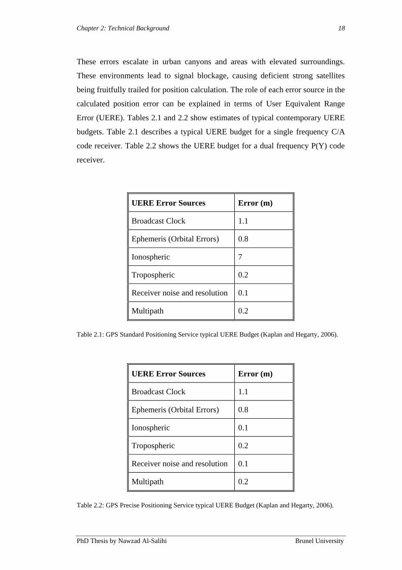
These errors escalate in urban canyons and areas with elevated surroundings.
These environments lead to signal blockage, causing deficient strong satellites
being fruitfully trailed for position calculation. The role of each error source in the
calculated position error can be explained in terms of User Equivalent Range
Error (UERE). Tables 2.1 and 2.2 show estimates of typical contemporary UERE
budgets. Table 2.1 describes a typical UERE budget for a single frequency C/A
code receiver. Table 2.2 shows the UERE budget for a dual frequency P(Y) code
receiver.
UERE Error Sources Error (m)
Broadcast Clock 1.1
Ephemeris (Orbital Errors) 0.8
Ionospheric 7
Tropospheric 0.2
Receiver noise and resolution 0.1
Multipath 0.2
Table 2.1: GPS Standard Positioning Service typical UERE Budget (Kaplan and Hegarty, 2006).
UERE Error Sources Error (m)
Broadcast Clock 1.1
Ephemeris (Orbital Errors) 0.8
Ionospheric 0.1
Tropospheric 0.2
Receiver noise and resolution 0.1
Multipath 0.2
Table 2.2: GPS Precise Positioning Service typical UERE Budget (Kaplan and Hegarty, 2006).
Chapter 2: Technical Background 19
PhD Thesis by Nawzad Al-Salihi Brunel University
These values are not fixed and are dependent on the conducted measurements‟
scenario and conditions.
In recent decades, substantial consideration has been paid to developing
Differential GPS (DGPS) (Section 2.2.2). The main aim of the research is to
eliminate or reduce the GPS error sources and achieve greater performance
positioning. The availability of DGPS systems is wide with different ranges of
coverage, different structure, differential data formats and several augmentation
data deliverability means. Conversely, Assisted GPS (A-GPS) is one of the DGPS
system that has been developed to increase the speed of position fixing, where it
helps to provide navigation information using GPS ephemeris from a station,
which are remote assisted to GPS users through a carrier network such as mobile
network (Hjelm, 2002). Beside, currently in the market, there are High Sensitivity
GPS (HS-GPS) receivers available, which are being used in support of positioning
accuracy of GPS.
This technology improves the positioning fixing rate and the overall GPS
positioning in challenging navigation areas, by enabling the acquisition of weak
GPS signals down to -190 dBW level. However, the problems of signals
availability are not solved till now, particularly during conditions where the
availability of satellites (<4 satellites) is insufficient such as in densely areas and
indoor environments (Esmond, 2007; Lachapelle, 2007).
2.2.2 Differential GPS (DGPS) Systems
The Differential GPS (DGPS) is the basic concept of correcting and augmenting
the GPS position solution. DGPS is based on the principle that all receivers in the
same vicinity will simultaneously experience common errors (Loomis et al., 1995;
Haider and Qishan, 2000). There are three elements, where DGPS system is
composed of, which includes firstly, at a known location, an antenna or GPS
receiver is present (base station), secondly, at an unknown location, another GPS
receiver (user receiver) and finally, between these two receivers, a communication
medium is present, as shown in Figure 2.1. In a known location, a reference
station is present and comparing these known locations, a correction vector could

Chapter 2: Technical Background 20
PhD Thesis by Nawzad Al-Salihi Brunel University
be generated with the calculated measurements at the reference station and these
signals in order to be integrated with its position solution are sent to the rover
(mobile) receiver. DGPS is applied in the code pseudo-rangers after estimating the
corrections or to the measurement domains, which are in carrier phase. The latter
process is described as Real Time Kinematics (RTK) (Lachapelle, et al., 2000).
However, RTK is an accurate navigation system, expensive and complex and it
requires the continuous tracking of satellites. A detailed review of RTK and its
constraints and advantages is described in Chapter 4.
In reference to the operational range of DGPS correction information, DGPS
systems are separated into two core categories: Local Area DGPS (LADGPS)
systems, with restricted coverage from the single DGPS reference station (e.g.
baseline <100 m); and Wide Area DGPS Systems (WADGPS), which covers a
complete region or country. WADGPS are in general developed providing
augmentation services to a large variety of users regardless of their location and
distances to the reference stations (baselines).
GPS Satellites GPS Satellites
Remote Corrected Position
Data Link/Range Corrections
GPS Satellites
GPS Satellites
Reference Station
Figure 2.1: DGPS System.
Chapter 2: Technical Background 21
PhD Thesis by Nawzad Al-Salihi Brunel University
2.2.3 Wide Area Differential GPS (WADGPS)
According to Raman and Garin (2007), in order to form a vector correction for
each and every satellite, DGPS extension, which is Wide Area Differential GPS
(WADGPS) has been used. This technology uses a broad network of reference
stations for the vector corrections which are individual for the ephemeris, satellite
clock and ionospheric delay model. The vector correction is considered to be
more valid than Local DGPS correction, since it covers wide geographical area. A
network-based DGPS system are described as the distribution of DGPS reference
stations only at certain geographical places and connected to a centralised point,
which forms a DGPS stations network.
One of the WADGPS‟s core advantages is the possibility to achieve a more
consistent accuracy throughout the region with support from the network. In the
case of DGPS with only one reference station, the accuracy reduces as a function
of distance from the reference station at a rate of approximately 1cm per 1km
(Hofmann-Wellenhof et al., 2001). Further advantages with WADGPS are the
possibilities to cover inaccessible regions, e.g. large bodies of water. Moreover,
the network will still maintain a comparatively high level of integrity and
reliability in case of a failure in one of the reference stations, in contrast with a
collection of individual DGPS reference stations. A large ground network of real-
time reference receivers is employed by DGPS, to trace the GPS civil signals on
the L1 and L2 frequencies. Network-based DGPS (Section 2.3.1) augmentation
data is broadcasted to users within the coverage capacity through radio and/or
wireless communication means; the mobile network is regarded as the main
communication means to transport the augmentation data to the user with longer
baselines. The Radio Technical Commission for Maritime (RTCM), (RTCM,
1994), is the generic format for transmitting DGPS corrections.
In the UK, there are several network based DGPS and DGNSS (Differential
Global Navigation Satellite System) solutions available and examples of such
network includes Ordnance Survey GNSS Network (OS Net) and commercial
partner Topcon‟s TopNET+. With the completion of the Ordnance Surveys
upgrade to the nationwide Continuously Operating Reference Stations (CORS)
Chapter 2: Technical Background 22
PhD Thesis by Nawzad Al-Salihi Brunel University
network, this covers entire Great Britain DGNSS reference stations of more than
100 reference stations. These stations constantly receive GPS and GLONASS
signals from satellites in near earth orbit. Topcon has been collaborated with the
Ordnance Survey and using data from OS Net, Figure 2.2 shows the network
coverage in UK. Throughout the UK, TopNET+ provides real-time L1 and L2
RTK corrections for carrier phase data for both GPS and GLONASS. With the use
of internet, mobile or radio communications, the services from TopNET+
augmentation could be delivered to the authorised users in real time from the
central processing station.
Alternatively, raw GPS data in the Receiver Independent Exchange (RINEX)
format is available from OS Net RINEX data server for any user (free of charge).
RINEX is a data format used to archive GPS navigation and observation data for
post-processing purposes (Gurtner and Estey, 2007).

Chapter 2: Technical Background 23
PhD Thesis by Nawzad Al-Salihi Brunel University
Figure 2.2: OS Net coverage map (Ordnance Survey, 2009).
The use of network as an alternative means for transmitting augmentation data has
been possible today mainly due to the increased capability of internet technology.
This allowed the development of the Network Transport of RTCM via Internet
Protocol (NTRIP), enabling the delivery of RTCM corrections from an NTRIP
caster to internet users (RTCM, 2004; Chen et al., 2004; Dammalage et al., 2006).

Chapter 2: Technical Background 24
PhD Thesis by Nawzad Al-Salihi Brunel University
Using TCP/IP, data streaming over mobile IP network was possible by the HTTP
server program of the NTRIP Caster. Through GPRS (General Packet Radio
Service) connection, transmission of the corrections from the NTRIP server to the
mobile device was also possible for mobile users through a data-enabled mobile
connection.
2.2.4 Future GNSS
The enormous demand to further improve positioning, navigation, and timing
capabilities for both civil and military users on existing GNSS systems has
directed efforts to modernise the GPS and GLONASS system and introduce new
systems such as Galileo navigation system.
2.2.4.1 Modernised GNSS
The modernisation program aims at improving positioning and timing accuracy,
signal availability and integrity monitoring support capability, and enhancement
to control system. GNSS undergoes modification and a transformation process on
a routine basis to provide better and sophisticated positioning services for the use
of both civilian and military forces.
GPS was launched on a complete basis in 1995, with a constellation of 24
satellites. During the operation of GPS several generations of satellite have come
up with improved features. In 2005, a major improvement to GPS infrastructure
was made by disengaging old satellites and adding improved satellites. Another
new mass of GPS satellites were launched, known as Block IIR-M satellites
subsequently (Shaw, 2002; Hughes, 2005). In addition to the above
improvements, a new positioning signal described as L2C was introduced
meanwhile, but it has to undergo further improvisations before being opened for
public use. Block IIR-M includes eight satellites, of these six of them were
launched before March 2008. Hence, the total number of GPS satellites orbiting
became 31 broadcasting satellites. Meanwhile another feature called the L5
safety-of-life civilian signal was initiated. The final satellite of this block series
was effectively instigated in August 2009. By 2012, the civilian L5 signal would
Chapter 2: Technical Background 25
PhD Thesis by Nawzad Al-Salihi Brunel University
be accessible for consumers with the total launch of GPS IIF satellites. Block IIF
is the final pushing step in the GPS block series that will highly modernise GPS
process (GPS III) (DoD, 2008). This final phase will also consist of twelve new
satellites, providing new military code (M-code) and civil signal frequency (L2C).
The Galileo and the Chinese Compass systems will undoubtedly be practical,
except these are not expected to be completely operational until beyond 2013 and
2015, respectively (Gibbons, 2008; Gibbons, 2009). In contrast, the GLONASS
system is currently being replenished and is nearly fully populated (20 satellites in
operation at time of writing).
At present GLONASS uses Frequency Division Multiple Access (FDMA)
technology. The long-debated CDMA question is expected to give a final decision
imminently, according to Revnivykh (Inside GNSS, 2009). During the
modernisation plan, CDMA signals would be established at L1 and L5
frequencies near GPS and Galileo signals, starting with the GLONASS-K
generation of satellites that has been launched in 2010. Beyond CDMA, signals
would increase potential interoperability with the other CDMA-based systems in
user equipment that would be able to process signals from satellites in multiple
GNSS systems (Inside GNSS, 2009).
The present process of modernisation of GNSS will improve navigation user
capabilities in various ways. There will be additional signals for civil use, which
will be more powerful and easier to obtain by receivers. They will also facilitate
interoperability between different systems (GPS, GLONASS and Galileo), by
transmitting inter-system clock corrections (Gratton et al., 2010). There will be
additional ground stations, and satellites will be able to communicate with each
other, allowing better ephemeris generation, failure monitoring, and a faster alarm
transmission in case a monitor triggers.
One of the predicted improvements is particularly significant to this work is the
additional civil signal, and the ability to use a larger number of satellites in view
at all times. This will translate into more precise accuracy; ionospheric delay is
eliminated using dual frequency measurements, better availability and greater
Chapter 2: Technical Background 26
PhD Thesis by Nawzad Al-Salihi Brunel University
redundancy. In addition, smaller size dual frequency RTK receivers will allow
GNSS to be used where DGPS is not practical, e.g. handheld navigation for the
pedestrians and visually impaired people. DGPS positioning, which has a standard
accuracy of 1-5m, will be mainly replaced by the RTK positioning, which will
then offer a better accuracy.
The data rate requirements of DGPS will be decreased, in recognition of the
modernisation. RTK applications that now use C/A-code and L1 and L2 carrier
will take complete benefit from the supplementary L5-code and carrier and permit
distances up to 100 km between the reference station and the rover, even when
accuracies of few cm are targeted.
2.2.5 Galileo
Galileo is a system of navigation that is supposed to be Europe‟s independent and
exclusive navigation system, offering better positioning services globally than
standalone GPS. The European Union (EU) and the European Space agency
(ESA), under civilian control were instrumental in launching this initiative. This
global system would simultaneously co-operate with the existing GPS and/or
GLONASS system, allowing users to gain from triple/hybrid satellite
constellations services. This kind of availability of two or more collective satellite
systems results in escalating the totality of available satellites in the sky. This will
also help to augment the overall superiority of the positioning services even in
urban areas and/or indoor environments. This will lead to a momentous boost in
the number of navigation applications (Richard, 2008).
The central theme of the Galileo space segment is the global constellation of 27
operational satellites over an area of spaced orbital planes, and orbital inclination
of 56º to the equator at about 23222 km above the Earth. Each plane comprises of
nine satellites, supposedly 40º apart. For each plane there is a plan to keep one
non-operational spare satellite, able to provide cover for any failed satellite in that
plane. Thus, a breakdown or malfunction in the constellation can be fixed rapidly
by substitution of the spare in place of the failed satellite. This can be time saving
so that there is no need to wait for a new launch to be arranged, which can take
Chapter 2: Technical Background 27
PhD Thesis by Nawzad Al-Salihi Brunel University
several months and take up a lot of the productive time. The orbit altitude above
Earth of 23222 km has been chosen to be appropriate; it would be convenient for
the constellation to have a repeat cycle of 10 orbits in 17 days (Kaplan and
Hegarty, 2006). The appropriate altitude of the satellites has to be in such a
manner that gravitational resonances could be avoided. In this way, subsequent to
primary orbit optimisation, station-keeping manoeuvres will not be required
during the entire life span of a satellite. The altitude chosen also guarantees a high
visibility of the satellites (ESA, 2007).
Satellite operations are supported by Galileo ground segment constructs of a
network of ground stations, consisting of sensor stations, control centres and
uplink stations. A worldwide network of Galileo Sensor Stations (GSS) will
continuously monitor the satellites. The accurate measurements of the navigation
signals will be sent to the two major Galileo ground segment. The Galileo ground
segment in turn encloses two major control centres, the Ground Control Segment
(GCS) and the Ground Mission Segment (GMS).
The Ground Control Segment (GCS) uses a global network of supposedly five
Telemetry, Tracking and teleCommand (TT&C) stations to interact with each and
every satellite on a plan combining regular, listed contacts, long-term test
campaigns and emergency contacts. Data transference to and from the satellites,
will be primarily performed through TT&C (Kaplan and Hegarty, 2006). TT&C
network is comprised of five ground stations with 13 metre antennas working in
the 2 GHz Space Operations frequency bands (S-band). A TT&C station network
is mainly involved in overhauling of the Galileo satellite collection and giving
access to global coverage. Nevertheless, general standard TTC modulation will
permit the employment of non-ESA TTC stations when the navigation system of a
satellite is not in process (during launch and early course operations or during a
contingency).
The Ground Mission Segment (GMS) implements the functions for providing the
main services of Galileo. Galileo Sensor Stations (GSS) supervises the navigation
signals of each satellite on a daily basis. The data obtained with these sensor
Chapter 2: Technical Background 28
PhD Thesis by Nawzad Al-Salihi Brunel University
stations will be used for orbit determination, time synchronisation, and integrity
monitoring.
The Galileo Sensor Stations (GSS) network will collect one-way pseudo-range
raw measurements orientated to a local atomic reference clock with navigation
messages received from the satellites. The Galileo Sensor Stations (GSS) network
provides this data along with narrow meteorological and other data like monitor
and control information and navigation data message to the Ground Control
Centre (GCC) (Kaplan and Hegarty, 2006).
The integrity data computed at the Galileo Control Centre (GCC) will be made
available to global users since they mainly use the dimensions from the worldwide
network of sensor stations.
Galileo will afford 10 radio navigation signals allotted within the following
frequency plans (Benedicto et al., 2000; Hein et al., 2001; Zimmermann et al.,
2004):
Four signals in the E5a and E5b bands (1164-1215 MHz), that includes
two navigation data signals (the data channels) and two signals carrying no
data (pilot channels).
Three signals in the E6 band (1215-1300 MHz), and one split spectrum
and one pair.
Three signals in the E2-L1-E1, also described as L1 band (1559-1592
MHz), as well as one split spectrum and one pair.
A degree of optimisation is reached by using multiple signals in Galileo to fulfil
the requirements of many kinds of applications that are accessed in diverse
settings and circumstances, such as indoor, outdoor, static and rapid moving. This
is presently unavailable in GPS because only one civilian signal is available and
accessible. But this problem would be overcome in the subsequent sophistication
of GPS. A particular advantage of having multiple signals in the ionosphere layer
is that after adding measurements obtained from at least two different signals, it is
possible to cancel the ionospheric delay.
Chapter 2: Technical Background 29
PhD Thesis by Nawzad Al-Salihi Brunel University
The Galileo navigation signals offer the following advantages to the end users
(Benedicto et al., 2000; Hein et al., 2001):
· Open Service (OS).
· Safety-of-Life Service (SoL).
· Commercial Service (CS).
· Public Regulated Service (PRS).
· Search and Rescue (SAR) Service.
Generally, the Open Service (OS) data signals are allocated at E5a, E5b, E2-L1-
E1 (L1) bands for either data or pilot channels allowing several signal
combinations for the single and dual frequency positioning services. The bottom
line of the single frequency OS is that they use signals which are in E2-L1-E1 and
might receive the GPS C/A code signal on L1. For enhanced precision, signals in
E5a and E5b bands might also be incorporated. The GPS L5 signal is included in
dual frequency services. The data carried by the OS signals are not in an
encrypted form and are usable for all. The OS service does not offer integrity
information, and no signal quality determination is assured to the user.
The safety-of-life (SoL) service relies on the data contained in the OS signals and
also uses reliability data carried in a special channel. The Commercial Service
(CS) is based on two supplementary signals within the E6 frequency band and the
capability of using the OS signals. This pair of signals is in encrypted form
offering higher performance for commercial users only. The Public Regulated
Service (PRS) operates at all times, even during emergencies, and will be used by
governmental authorities such as the police, coast-guards and customs, etc. For
this service two additional signals are also allocated, one in E6 band, and the other
in the L1 band. These signals are encrypted in order to have access control, so
access is restricted to PRS users.
2.2.6 GLONASS (GLObal'naya NAvigatsionnaya Sputnikovaya Sistema)
The GLONASS satellite system is currently under development with new
modernised GLONASS spacecraft to replenish the constellation. The GLONASS

Chapter 2: Technical Background 30
PhD Thesis by Nawzad Al-Salihi Brunel University
expect to have 24 satellites in orbit by 2011-2012. The GLONASS system and
GPS systems share similar principles in data transmission and positioning
methods. The difference between GLONASS and GPS is the segment;
GLONASS consists of 24 satellites (21 active and 3 spares) in three orbital planes.
The three orbital planes are separated by 120º and the satellites within the same
orbit plane by 45º. Each GLONASS satellite operates in circular 19100 km orbits
referenced to the Earth‟s surface with an inclination angle of 64.8º and each
satellite completes an orbit in approximately 11 hours and 15 minutes. Two L-
band navigation signals are transmitted by the satellites and the Russians are
planning to develop and add a third L-band signal near the radio frequency of the
new L5 signal planned for GPS (Kaplan and Hegarty, 2006). GLONASS offers
two types of services: Standard Positioning (SP) and High Precision navigation
signal (HP). SP service offered world-wide with horizontal accuracy of 57-70
meters, the vertical accuracy is within 70 meters (Hunaiti, 2006).
The Russian government has stated that, like GPS, GLONASS is a dual use
system and that there will be no direct user fees for civil users. The Russians are
working with the EU and the United States to achieve compatibility between
GLONASS and Galileo, and Galileo and GPS, respectively (Kaplan and Hegarty,
2006). The functions of the ground control segment of GLONASS are entirely
located within former Soviet Union. The ground control centre and time standards
are located in Moscow. At various locations across the continent, observations of
telemetry data and ranges are made and passed to ground control centre in
Moscow. The control information and ephemerides are computed and uploaded to
satellites. At least five satellites will be available at any location, at any time
worldwide under the full constellation (Miller, 2000).
With only 20 satellites currently operational (at time of writing), GLONASS does
not work well as an independent positioning solution for high accuracy
applications. However, if it is used as a supplement to GPS and the RTK,
GLONASS does provide more reliability, availability, accuracy and more
satellites in view throughout the day. The additional GLONASS visibility is often
enough to overcome suburban environments or mountainous areas and the
standard down times when using GPS-only for RTK.
Chapter 2: Technical Background 31
PhD Thesis by Nawzad Al-Salihi Brunel University
Nevertheless, the amount of GPS and GLONASS satellites that can be observed is
still often rather unsatisfactory for the attainment of a position solution. This is
partly due to the requirements of at least five visible satellites to determine a
position because of an offset between the timescales of GS and GLONASS to be
resolved (Cai and Gao, 2009).
2.3 GNSS Augmentation Systems Positioning Performances
A number of navigation applications have used augmentation and complementary
systems for the purpose of achieving enhanced positioning performance. Various
researchers have carried out the evaluation of such systems under different
conditions and scenarios. The following section presents different evaluation
studies, as well as the reported results of positioning performances, taking one
main augmentation system into account: the use of network-based DGPS.
2.3.1 Network-based DGPS
A number of regional DGPS networks are functioning worldwide, providing
pseudo-ranges corrections estimation based on multi-reference DGPS stations
being unified together forming a WADGPS solution. There are many advantages
associated with network-based DGPS compared to the standard single-reference
DGPS station approach. Several advantages are the advanced reliability of the
differential positioning service, increased strength, and higher positioning
accuracy levels. These advantages can be achieved for code-based DGPS and
RTK measurements (Lachapelle et al., 2000; Park et al., 2003; Raman and Garin,
2004; Oh et al., 2005).
Chang and Lin (1999) described a local navigation system consisting of a
medium-range DGPS network developed in Taiwan. The objective of this
network was to provide adequate positioning accuracy using GPS observations
based on C/A pseudo-ranges collected from a set of reference stations and then
processed at the central station obtaining a weighted average of the differential
corrections. The developed medium-range DGPS based positioning service has
achieved an improvement of 35% in terms of Root Mean Square (RMS) error

Chapter 2: Technical Background 32
PhD Thesis by Nawzad Al-Salihi Brunel University
comparing to the single reference station as shown by the testing results. The use
of single reference-based DGPS was very much dependent on the baseline
lengths; the horizontal accuracy ranged from 3.1 to 5 meters. However, when
utilising three reference stations, these measurements, provided an average of 1.3
meters‟ accuracy. These were achieved only in static scenario without a hint to the
surrounding environment.
The Jet Propulsion Laboratory (JPL) of the National Aeronautics Space
Administration (NASA) launched Internet-based Global Differential GPS (IGDG)
in spring 2001. A subset of 40 reference stations is available at NASA‟s Global
GPS Network (GGN). These reference satellites allow real-time streaming of data
to a processing centre, that determines and subsequently distributes accurate
satellite orbits and clocks errors, as global differential corrections to the GPS
broadcast ephemerides (as contained in the GPS navigation message) over the
open internet. This process could be done on a real time basis. An introduction to
IGDG can be found in Mullerschon et al. (2001a) and on IGDG (2004). Technical
details in Bar-Sever et al. 2001; Mullerschon et al., 2001b.
The low bandwidth correction data stream can be downloaded into a computer by
the internet users. It will then be combined with raw data from the user‟s GPS
receiver. The user‟s GPS receiver must be a dual frequency and be of geodetic
quality so as to extract the full potential from the accurate corrections. The
ultimate, but decisive, constituent that offers an end-to-end positioning and orbit
determination capability is the navigation software possessed by the user.
Raman and Garin (2005) assessed the performance of the Global Differential GPS
(GDGPS) system, provided by JPL, for particular specific frequency C/A GPS
receiver. This system makes use of a group of DGPS reference stations which are
continuously observing GPS measurements. The NTRIP protocol would be
utilised to measure the central processing stations and then to forward the
improvement messages to the users. At the processing stations, data is analysed to
produce measurement corrections of ionospheric delay and satellite state (orbit +
clock corrections). The corrections are then provided as an information vector
reliant on the user‟s location. The improvements in terms of horizontal position
Chapter 2: Technical Background 33
PhD Thesis by Nawzad Al-Salihi Brunel University
accuracy using GDGPS augmentation services were measured in open space
conditions. A horizontal accuracy average of 1.5 meters using GDGPS was
achieved in comparison to 4 meters using standards local DGPS. Nonetheless,
these accuracy levels were decreasing within the distance from the reference
stations and when the availability of corrections was reduced at the user side. A
linear combination algorithm was also developed by Oh et al. (2005) in order to
generate interpolated Pseudo-Range Corrections (PRC), which was the used to
enhance the DGPS positioning accuracy. The combination algorithm takes into
consideration PRC values from multiple DGPS reference stations sharing the
same satellites. The accomplished DGPS positioning accuracy was improved over
standard DGPS by 40% in static scenarios. When using PRC measurements from
two DGPS stations a position accuracy of 1.8 meters was achieved, and around
1.5 meters when using three or more DGPS reference stations.
2.3.1.1 GNSS Augmentation Systems in Pedestrian Applications
When taking the performance of GNSS and its augmentation methods of
pedestrian users into account, in densely urban and indoor environments, a
pedestrian navigation project was defined and described by Abwerzger et al.
(2004) and Ott et al. (2005). This project was named “Definition and
Demonstration of Special Handheld based Applications in Difficult Environment”
(SHADE), and was supported by the European Space Agency (ESA) in order to
explore different sets of navigation technologies employed for pedestrian
applications in difficult environments. Three autonomous navigation prototypes
were developed and tested in the SHADE project. The first prototype was formed
of an A-GPS received, EGNOS1 functionality included. The second prototype was
composed of and INS2 module, for the sake of pedestrians (a dead reckoning
module), as well as GPS/EGNOS receiver. The last prototype was encapsulated of
1 European Geostationary Navigation Overlay Service (EGNOS) is a satellite based augmentation
system (SBAS) under development by the European Space Agency, the European
Commission and EUROCONTROL. The primary goal of EGNOS is to provide augmentation
service for GPS, GLONASS and the future Galileo system.
2 Inertial Navigation System (INS) is a navigation facility that comprises several motion and
orientation sensors (e.g. accelerometers and compasses) which are integrated using a computer
application to sense and continuously calculate the position, speed and time.

Chapter 2: Technical Background 34
PhD Thesis by Nawzad Al-Salihi Brunel University
an Integrated GPS/Loran-C with EGNOS facility. The Long Range Aid to
Navigation (LORAN) is terrestrial radio navigation system utilising low
frequency radio transmitters. The present development of this technology is
presented as Enhanced LORAN (E-LORAN) (Abwerzger &Lechner, 2002;
Narins et al., 2004). The operational architecture of SHADE was designed to
evaluate and develop the availability of several positioning solutions to operate
even in dense urban and indoor environments. Field measurements were carried
out under good GPS visibility conditions, during the evaluation of the first
prototype, and then under light in-doors (partly covered areas) with a sampling
rate of one sample per second. An accuracy of 1.5 meters at 95% was achieved in
open space areas when using the first prototype. The worst scenario was
noticeable during indoor measurements, in which the achieved accuracy reached
39.22 m at a 95% confidence level. This positioning performance is considered
four times higher than GPS SPS horizontal levels (7.8-12.8 m) described by
Hughes (2005). Hence, the conclusions were that the first prototype is not suitable
for navigation applications taking place indoors. In addition, the second prototype
was evaluated permitting position determination to take place in GPS complicated
environments, in which a primarily absolute position was determined by the
GPS/EGNOS receiver, and constant position samples were compromised from the
dead reckoning module as well as the GPS/ENOS receiver using Kalman filtering.
However, one of the central drawbacks of the second prototype was the position
drift because of the attached magnetometer. The third prototype has made known
its capacity to increase the availability of position solutions and surmount the
blockage of GPS service in densely urban area. On the other hand, the position
solution‟s accuracy, obtained from the integrated Loran-C service, was lower than
the expectations. Furthermore, upon entering the buildings, the signal strength
from all Loran-C stations decreased considerably. Thus, the Loran-C was no
longer regarded as reliable.
2.4 Summary
This chapter presented a detailed review of Global Navigation Satellite System
(GNSS), such as GPS, GLONASS and Galileo, along with its most widely

Chapter 2: Technical Background 35
PhD Thesis by Nawzad Al-Salihi Brunel University
implemented augmentation technologies such as DGPS and network-based DGPS
was presented. Additionally, recent augmentation systems evaluation studies
conducted by previous researchers were reviewed, showing the achieved
positioning performance. The positioning performance of GPS is affected by the
capability and productivity of the linked augmentation systems, at present as
result of higher efficiency standards and better coverage competence, the
WADGPS systems like the network-based DGPS are the augmentation systems
which are mainly successful. However, this positioning performance is based on
the availability of up-to-date corrections, which is affected by the data
deliverability means, measurement scenario and navigation environments.
However, still the positioning performance achieved from GPS augmentation
system is considered not sufficient for these applications. Network-based DGPS
and DGNSS techniques have still not been looked at and made use of for the aid
of utilising GNSS system in significant pedestrian applications.
The analysis of the available methods to support the mobility of visually impaired
people also includes the descriptions of technologies employed in the methods,
including the GNSS and the augmentation technologies.
The information provided in this Chapter provides the state-of-the art in GNSS
and the augmentations technologies, some of which are used in the system
described in the next Chapter. Chapter 3 describes important studies with
reference to GPS based visually impaired people navigation systems.

Chapter 3: Review of GPS Based Navigation Systems for Visually Impaired People 36
PhD Thesis by Nawzad Al-Salihi Brunel University
Chapter 3
3. Review of GPS Based Navigation Systems for Visually
Impaired People
3.1 Introduction
In order to represent the services, in which location and direction are central
parameters, the navigation system is used as a concept for visually impaired
people. Several technical components, such as technology (to determine position),
communication technology, mobile device, application service, data content
providers (that includes geospatial database) and Geographical Information
Systems (GIS)3, have been widely integrated in the navigation systems for
visually impaired people applications. However, to explore the navigation system
development for the applications of visually impaired people, each technical
component and its limitation should be attentive for the researcher. The basic
positioning technique in the history of navigation system, are mobile
communication and satellite positioning, thus, it is essential to focus on those
techniques and its limitation for a better understanding.
In this part of the thesis, a detailed review of the basic concepts of navigation
system for visually impaired people is provided. The chapter is divided into two
interconnected parts. The first one is described in Section 3.2 and offers a
systematic overview of the most crucial mobility aids for visually impaired
employed up to present. This overview also comprises the analysis of the
functionality of the aids as well as the advantages and shortcomings of their
application. Section 3.3 describes the user requirements for designing electronic
orientation aids. Finally, section 3.4 concludes this chapter and summaries the
3 Geographic Information Systems is the term commonly used in reference to a wide range of
different applications of information technology with the function to process and manage
geographic data in the digital format (Kang-Tsung, 2001).

Chapter 3: Review of GPS Based Navigation Systems for Visually Impaired People 37
PhD Thesis by Nawzad Al-Salihi Brunel University
current limitations of electronic orientation aids with reference to satellite
navigation system.
3.2 Visually impaired people’s Navigation system
Over the past few decades, several wide ranges of models using high technology
mobility aids has been developed, which is also known as Electronic orientation
Aids (EOA) (Farmer and Smith, 1997). These aids were developed using several
advanced technologies that varied in purpose, but in common, all these aids have
been developed with the motivation for the need of more comprehensive reliable
mobility support. Additionally, in comparison to the support by long canes and
guide dogs, this technology was supported by independent journeys (Garaj, 2006).
Development of applications which are tailor made for guidance delivery and
emergency services, particularly for disable and visually impaired people, have
been studied by several researchers. However, these applications are considered to
be more demanding with regard to positioning performance, due to the sensitivity
and need for the timely delivered service. In order to facilitate and enhance their
mobility, GPS has played an important role in such applications for the purpose of
accurately locating the position of the users.
3.2.1 Electronic Orientation Aids
In 1985, Loomis from the University of California in Santa Barbara, USA, was
the first person to submit the first proposals to use the GPS and GIS for visually
impaired people in the provision of navigation assistance (Loomis, Golledge and
Klatzky, 1998). In addition, the first Electronic Orientation Aid (EOA) prototypes
project was designed, developed and tested by Loomis and his research team.
Subsequent research was carried out by Brusnighan, Strauss, Floyd and Wheeler
(1989), LaPierre (1993), Brunel University processing research (1995 to 2009)
(outlined in Section 3.2.2) and Makino, Ishii and Nakashizuka (1996) in the
prototype development with relevance to the field of EOA. The research on GPS
development was carried out at an early stage and during that period the main
concern was poor positioning accuracy and moreover, practical studies were
excluded with particular reference to blind subjects (Reginald et al., 2004).
Chapter 3: Review of GPS Based Navigation Systems for Visually Impaired People 38
PhD Thesis by Nawzad Al-Salihi Brunel University
Although, the GPS and GIS systems are potentially very effective technologies for
mobility, this has to be improved for better usability (Farmer and Smith, 1997).
However, the problems encountered by this technology could be classified into
three groups (Farmer and Smith, 1997), which initially includes applied
technology limitations, secondly, the system architecture and at last the related
user interfacing (Garaj, 2006). The blocking of reception of GPS signals in so-
called urban canyon areas and other environmental features such as tall buildings.
This will make the system disabled and for similar reasons, the system cannot be
implemented for indoor navigation. Moreover, other GPS receivers that are
commercially available restrict the reliability and the content of the provided
information due to its poor positioning accuracy. In addition, the GIS capacity do
not accommodate for dynamic changes that could represent the real life
environment and, thus, limited for only certain information (Garaj, 2006). All
these problems make the GIS system difficult to utilise by the visually impaired
users and therefore, the developed system should be flexible and user friendly
rather than simply focusing on content choice and the syntax, in order to suit the
needs of visually impaired.
The mobility aids, which were available in the past, were able to offer solutions to
the visually impaired pedestrians only to some degree. However, a new developed
mobility aid must be able to overcome all the problems, which were not solved by
former aids. Thus, two main criteria of usability (Garaj, 2006) should be
implemented by a „perfect mobility aid‟ (Wycherely and Nicklin, 1970).
First, the effectiveness should be improved. Using the „perfect‟ aid,
visually impaired pedestrian should be able to view identical or a similar
level of mobility as a sighted pedestrian.
Secondly, the „prefect mobility aid‟ should not be mentally demanding and
stressful and it should be as comparable or tolerable by pedestrians of
sighted person.
Development of GPS systems with increased accuracy has thrown light on a
number of new projects, specifically those addressing development of mobility
aid systems.

Chapter 3: Review of GPS Based Navigation Systems for Visually Impaired People 39
PhD Thesis by Nawzad Al-Salihi Brunel University
3.2.2 Brunel Project
In the year 1995, the pioneering research team from Brunel University, The
Electronic System Research Group (ESRG), initiated a guidance project for
visually impaired people (Balachandran and Liu, 1995). An international patent
was granted for the “Navigation System” project (Liu and Balachandran, 1998).
The aim of the project was to analyse the possibility of utilisation of GPS and GIS
using a centralised approach to navigate visually impaired pedestrians. Brunel
Navigation System for Blind (BNSB) was the system developed by the team,
which consists of two components; Mobile Navigation Unit (MNU), a device
carried by the user, and the Navigation Service Centre (NSC) where all users are
connected through remote centralised side. In addition, NSC has several features,
which include DGPS reference station, routine algorithms managed by a
computing facility, digital maps and receiving data to and from the MNU, and a
communication interface. In order to monitor the voice guidance information,
trained staff was recommended to be located at the NSC. For the use of blind
pedestrians, the MNU was simplified by understanding only the voice
communication provided by the trained staff at the NSC. MNU is a simple
prototype consisting of an electronic compass with microphone, a GPS receiver,
and a speaker, using mobile device. These were all integrated for the purpose of
examining the communication between the MNU and NSC, mobile channels were
utilised (Hunaiti et al., 2004; Hunaiti et al., 2006). Also, as part of the MNU, to
allow the system to provide information about obstacles and objects surrounding
the user, video camera was introduced (Garaj et al., 2003), shown in Figure 3.1 on
a visually impaired participant.

Chapter 3: Review of GPS Based Navigation Systems for Visually Impaired People 40
PhD Thesis by Nawzad Al-Salihi Brunel University
Figure 3.1: The visually impaired participant with all components during a trial experiment at
Brunel University (Hunaiti, 2005; Garaj 2006).
Several experimental trials were conducted at Brunel University to evaluate the
effectiveness of the System for visually impaired people navigation system
(Hunaiti, 2005; Garaj 2006). The visually impaired participant walked along an
unfamiliar route supported both by the guide dog and by the sighted participant,
who was remotely guiding him through from NSC. A sequence of photographs
showing the visually impaired participant walking along the final part of the route,
including the moment when he located the building entrance, is provided in
Figure 3.2.
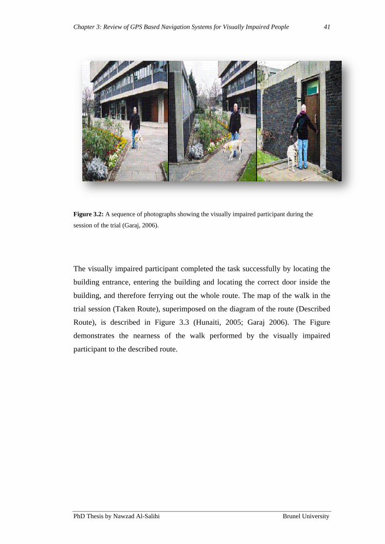
Chapter 3: Review of GPS Based Navigation Systems for Visually Impaired People 41
PhD Thesis by Nawzad Al-Salihi Brunel University
Figure 3.2: A sequence of photographs showing the visually impaired participant during the
session of the trial (Garaj, 2006).
The visually impaired participant completed the task successfully by locating the
building entrance, entering the building and locating the correct door inside the
building, and therefore ferrying out the whole route. The map of the walk in the
trial session (Taken Route), superimposed on the diagram of the route (Described
Route), is described in Figure 3.3 (Hunaiti, 2005; Garaj 2006). The Figure
demonstrates the nearness of the walk performed by the visually impaired
participant to the described route.

Chapter 3: Review of GPS Based Navigation Systems for Visually Impaired People 42
PhD Thesis by Nawzad Al-Salihi Brunel University
Figure 3.3: The map of the walk in the trial session (Hunaiti, 2005; Garaj 2006).
The visually impaired participant expressed the system as “highly valuable” when
asked his opinion on the effectiveness of the system; according to his belief, the
system made it possible for him to finish the walk along the route in the session
successfully. Moreover, the visually impaired participant pointed out that he
perceived the walk in the trial session less stressful than walking along an
unfamiliar route, i.e. through the unfamiliar travel environment supported by his
dog, thanks to the guidance by the sighted participant. The participant was also in
favour of the usefulness of the system in aiding micro-navigation; as the visually
impaired participant moved toward the entrance of the building in the ending part
of the route, the sighted participant at NSC provided him with a thoroughly verbal
Chapter 3: Review of GPS Based Navigation Systems for Visually Impaired People 43
PhD Thesis by Nawzad Al-Salihi Brunel University
description of the entrance layout and helped him locate the door handle on the
entrance door. The visually impaired participant qualified the micro-navigational
assistance as “impressive”. Nevertheless, when the blind participant was walking
along the tall building on his right hand-side, in the second half of the route
(Figure 3.3), the accuracy of the GPS positioning decreased considerably. During
that section, the blind participant‟s position, as traced by the GPS and presented
on the guide‟s display, was falling within the area of the building on the map (i.e.
it emerges as if the blind the blind person is walking on top of the building),
which was vague and unreliable information. The decrease of the GPS accuracy
(down to 15 metres) occurred as the building in question obstructed the line sight
between the GPS antenna carried by the blind participant and some of the GPS
satellites that were visible in the preceding part of the route situated in the area of
lawn, which was without obstacles. In this case, the guide was able to use the
video image of the environment in front of the blind participant in order to
determine the correct position of the blind participant.
Compared to other EOA systems, BNSB is easier to use since it includes an
option whereby the guidance is provided remotely by a human guide from NSC -
in addition to the automated guidance option. The video image of the immediate
environment of the visually impaired is vital to be able to provide appropriate
instruction by the guide, in order for the visually impaired to avoid obstacles in
the route.
Thus, to overcome this problem with positioning performance at BNSB, an
improvised method such as local DGPS was introduced along with the use of a
Dead Reckoning module, EGNOS/SISNET (Chapter 5, Section 5.6.1) and INS
were widely implemented (Shah et al., 1999; Jirawimut et al., 2001; Ptasinski et
al., 2002; Al Nabhan, 2009). The newly developed methods were not efficient
enough with regard to accuracy levels and the capacity and coverage according to
the requirements of the applications. Thus, it has become an established tradition
to constantly develop new techniques that augments the positioning services of
GPS to sophisticated and sustainable levels. The augmentation systems, also
known as Differential GPS (DGPS) systems, operate throughout diverse coverage
ranges, such as Wide Area DGPS (WADGPS) (Chapter 2, Section 2.2.3).

Chapter 3: Review of GPS Based Navigation Systems for Visually Impaired People 44
PhD Thesis by Nawzad Al-Salihi Brunel University
WADGPS can be applied as network-based DGPS systems by means of a number
of interrelated DGPS reference stations. The purpose of the augmentation system
is to condense or eliminate elements that weaken the quality of position,
navigation and timing services based on GNSS signals (Das, 2007).
This has led to the identification of new methods that could advance the
positioning performance. As noted by Mekik and Arslanoglu (2009), Real Time
Kinematic (RTK) and Network Real Time Kinematic (NRTK) (Chapter 4) could
be able to provide corrections that are differential in order to produce clear picture
on positioning of GPS. Due to its ability of code phase and the carrier phase,
observations are faster in accurate positioning compared to the code
measurements, and the combination of GLONASS satellites with GPS satellites
has been developed so that, simultaneously, five satellites could be easily tracked
in urban canyons crowded with high rise buildings. In order to obtain precise
results from this method at least five satellites should be observed at the same
time, which may be considered as a shortcoming.
The WADGPS are offering augmentation services to a wide range of NRTK users
regardless of their location and distances to the reference stations (baselines),
which could enhance the performance while navigating particularly in an urban
environment. At present, NRTK permits the transmission of coordinate
transformation parameters from the operators, which allows users to constantly
get hold of the current site grid transformation without any physical loading or
localisation on the rover, and consequently a better regularity in the quality of
coordinates can be maintained.
Taking advantage of NRTK‟s benefits, many NRTK commercial services have
been established in various countries in the last few years. TopNET+ has been the
example which had achieved very high centimetric precision. TopNET+ is
operated in the UK by Topcon (UK) in affiliation with Ordnance Survey Great
Britain (OSGB) since April 2009.
In this work, described in Chapter 5, the use of WADGPS Systems and Network
NRTK (Chapter 4, Section 4.3) was considered. The studies covered the analysis
Chapter 3: Review of GPS Based Navigation Systems for Visually Impaired People 45
PhD Thesis by Nawzad Al-Salihi Brunel University
of actual positional quality with regard to the TopNET+ service from the end
user‟s view point, that have considered accuracy, precision and availability. In
addition, how diverse factors such as the number of satellites in sight and their
geometry might affect the positioning accuracy. For the aim to evaluate the
service‟s quality, a number of static and kinematic tests have been conducted by
using the same sort of equipment and in the same way that the visually impaired
people would have used it (Chapter 5 and Chapter 7).
However, NRTK GNSS positioning is especially hold back by wireless data link
coverage, correction transmission delay and completeness, availability of GPS
and GLONASS signal etc., which could reduce the positioning quality of the
NRTK results. Although augmentation services have been implemented widely,
due to insufficient accuracy level, particularly in indoor and urban environment, it
has been still considered as a problem.
At present, GNSS has been widely used in various applications as the main
positioning component, which focuses mainly on delivering vital service with
reference to navigation to pedestrian users.
3.2.3 Other Related Electronic Orientation Aids Projects
This section is a review of other related EOA projects that employs the GPS for
navigation and orientation of visually impaired people.
Mobility of Blind and Elderly People Interacting with Computers (MoBIC) is one
of the major projects funded by the Technology for the Integration of Disabled
and Elderly People (TIDE) research-funding programme of the Directorate
General XIII of the Commission of the European Union, and the project lasted
between the beginning of 1994 and 1997. It was carried out by a consortium of
several universities based in the UK, Germany and Sweden (Petrie et al., 1996;
Petrie et al., 1997; The MoBIC Consortium, 1997). The project‟s purpose was to
enhance independent mobility for the visually impaired, partially impaired and
older people by working out an aid of orientation and navigation that enable them
to travel in familiar or unfamiliar environments. The MoBIC project was built on
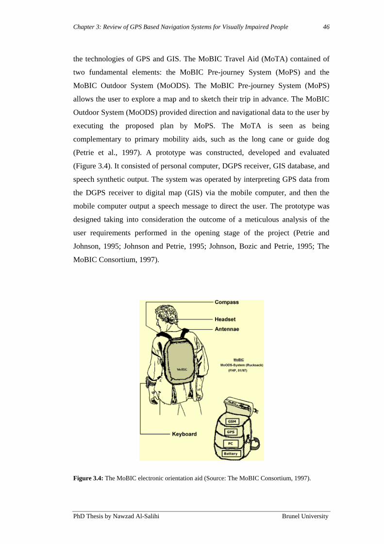
Chapter 3: Review of GPS Based Navigation Systems for Visually Impaired People 46
PhD Thesis by Nawzad Al-Salihi Brunel University
the technologies of GPS and GIS. The MoBIC Travel Aid (MoTA) contained of
two fundamental elements: the MoBIC Pre-journey System (MoPS) and the
MoBIC Outdoor System (MoODS). The MoBIC Pre-journey System (MoPS)
allows the user to explore a map and to sketch their trip in advance. The MoBIC
Outdoor System (MoODS) provided direction and navigational data to the user by
executing the proposed plan by MoPS. The MoTA is seen as being
complementary to primary mobility aids, such as the long cane or guide dog
(Petrie et al., 1997). A prototype was constructed, developed and evaluated
(Figure 3.4). It consisted of personal computer, DGPS receiver, GIS database, and
speech synthetic output. The system was operated by interpreting GPS data from
the DGPS receiver to digital map (GIS) via the mobile computer, and then the
mobile computer output a speech message to direct the user. The prototype was
designed taking into consideration the outcome of a meticulous analysis of the
user requirements performed in the opening stage of the project (Petrie and
Johnson, 1995; Johnson and Petrie, 1995; Johnson, Bozic and Petrie, 1995; The
MoBIC Consortium, 1997).
Figure 3.4: The MoBIC electronic orientation aid (Source: The MoBIC Consortium, 1997).

Chapter 3: Review of GPS Based Navigation Systems for Visually Impaired People 47
PhD Thesis by Nawzad Al-Salihi Brunel University
The performance of outdoor field trails was successful, and participants were
impressed by the accuracy and navigational data they can receive. MoBIC has
also achieved a complete analysis of the specifications, needed to meet the user
requirements. Despite successful demonstration the MoBIC system, the designed
prototype was never implemented and commercialised. The failure to implement
the prototypes is for the most part attributable to the absence of firmly established
links between academia, where all the projects were carried out, and the industry
that could potentially manufacture and market the EOA emerging from the
prototypes. Nevertheless, although the MoBIC project was not introduced in the
market, the outcome of the MoBIC was undoubtedly found to be a valuable
contribution in the field of mobility aids for visually impaired pedestrians,
including the aid developed within this PhD project.
The GPS Talk was the very first EOA made commercially (May, 2000; Misener
and Bowers, 2000). The GPS Talk (Figure 3.5) was developed within the industry
environment and was release by a small US-based company named Sendero
Group. The release of the GPS Talk took place in the beginning of 2000.
Nevertheless, the manufacturing and marketing was closed within two years after
the release due to unsatisfied sale figures.

Chapter 3: Review of GPS Based Navigation Systems for Visually Impaired People 48
PhD Thesis by Nawzad Al-Salihi Brunel University
Figure 3.5: The GPS Talk (Sendero Group, 2000).
A wireless navigation system for visually impaired and disabled people was
developed by University of Florida, (Helal et al., 2001). This was an additional
EOA and was named, Drishti, means vision in ancient Indian language Sanskrit. It
incorporates a number of technologies, such as mobile computers, voice
recognition and synthesis, wireless networks, GIS and GPS (Helal et al., 2001).
Drishti system is designed to enable the user to access dynamic and static data, by
using a wearable computer from a spatial database server. Drishti enhance related
information to the visually impaired and calculates optimised routes based on user
preference, temporal constrains and dynamic obstacles. Environmental conditions
and landmark information enquiries are provided along their routes from a spatial
database on the fly through comprehensive voice signals (Helal et al., 2001; Ran
et al., 2004). The GIS database server within the university campus has to be
updated continuously through various campus departments such as the University
Police, Physical Plant and Special Events, to provide various departments with the
ability of inserting and removing dynamic obstacles. Commercial Off-The-Shelf
Chapter 3: Review of GPS Based Navigation Systems for Visually Impaired People 49
PhD Thesis by Nawzad Al-Salihi Brunel University
(COTS) hardware and software were used to implement the Drishti system
prototype. The wearable computer along with the GPS receiver and electronic
compass are placed in the backpack, the system prototype weights about 3.6kg
(8lbs). A head mounted display, for visual tracking, is worn by disabled users and
the integrated headset for speech I/O is used by blind persons. Several wireless
network connections have been used. Drishti system prototype has been tested
around the University of Florida campus. However, Drishti systems require a
member of staff to constantly survey and update the remote server, this is costly
and unpractical, especially if a wider area coverage is implemented, i.e. covering
all dynamic and static obstacles in a city.
NOPPA was a navigation and guidance system for visually impaired pedestrians,
aimed to provide the visually impaired and sighted pedestrians with route
information. NOPPA was a project run by the VTT Industrial Systems (VTT,
2010) and Ministry of Transport and Communications (MINTC, 2010) in Finland
from June 2002 to 2004. The user can access public service databases over
internet by mobile devices with capabilities of speech and satellite positioning. A
prototype of the NOPPA system was designed to work outdoors by utilising an
integrated GPS mobile phone, GIS, communication links (i.e. GPRS), database,
internet, and speech recognition (Figure 3.6). In outdoor, the visually impaired
passenger will be able to receive navigational data regarding their journey based
on the GPS. NOPPA navigation and guidance system for visually impaired
pedestrians is useful for providing some information and navigational data during
the journey. The navigational data will be delivered to the blind user as a speech
message. Nevertheless, this system shares the same weakness as the Drishti
system that is mentioned earlier, it‟s expensive to use this service, especially for
the visually impaired pedestrians who constantly need to access it.

Chapter 3: Review of GPS Based Navigation Systems for Visually Impaired People 50
PhD Thesis by Nawzad Al-Salihi Brunel University
Figure 3.6: NOPPA architecture (VTT, 2010).
The VoiceNote GPS device was made by Humanware (Humanware, 2010)
(previously known as Pulse Data International), a company based in New
Zeeland. VoiceNote GPS (Figure 3.7) systems with maps were first introduced
late in 2003. The device combines computer technology, including digital voicing,
with the GPS device, which allows a person to pinpoint his or her location. The
device essentially makes an audio map. VoiceNote GPS has two main functions:
receiving and recording. In a receiving mode, the device receives signals that
determine a person‟s location via GPS. Then it connects the user to an enormous
database that has pre-programmed points of interest such as, hotels, restaurants
and parks. The receiving mode is used mainly for route planning along city streets
and previously mapped areas. VoiceNote GPS is subjected to the database
availability. However, the system can only provide information about a place if it
exists in the database. BrailleNote GPS has the same functions as the VoiceNote
GPS with the addition of a Braille display.
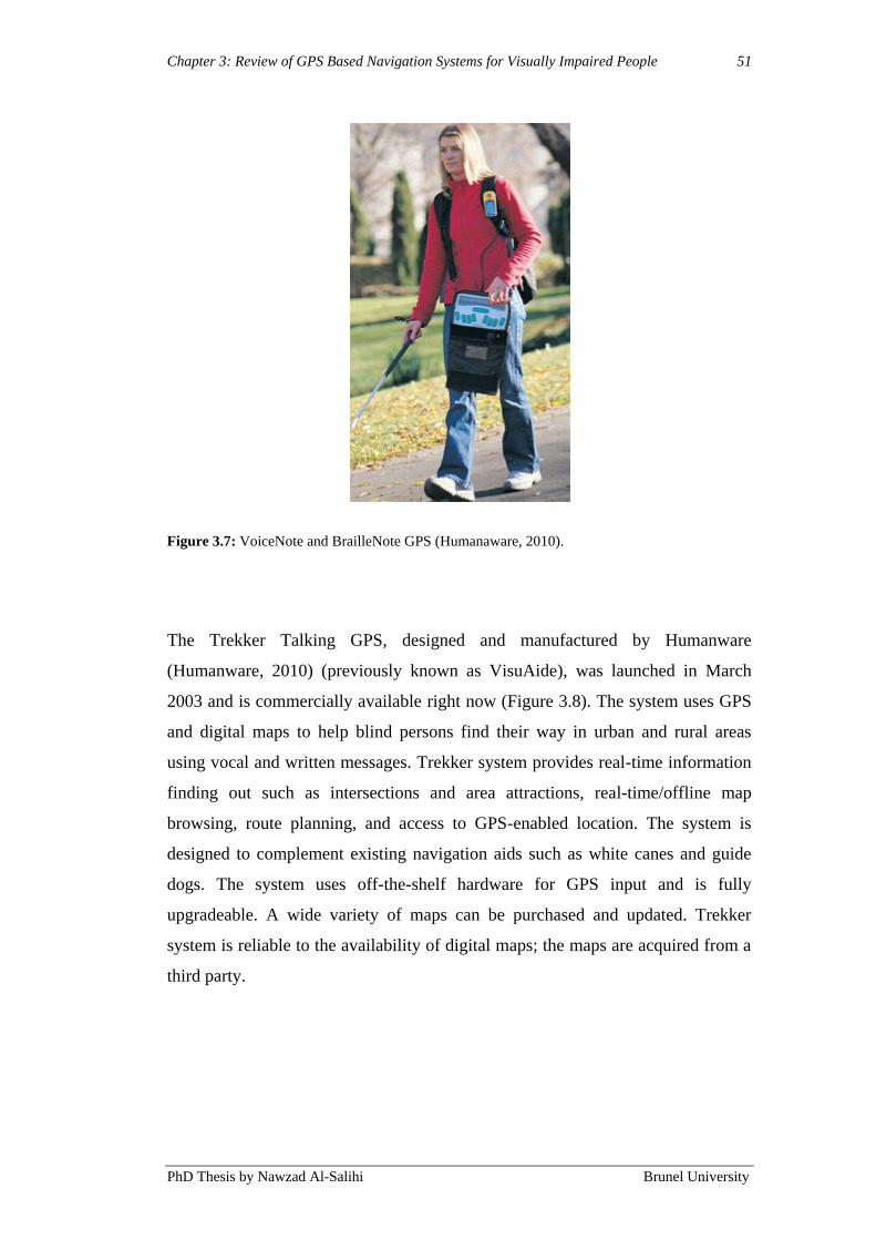
Chapter 3: Review of GPS Based Navigation Systems for Visually Impaired People 51
PhD Thesis by Nawzad Al-Salihi Brunel University
Figure 3.7: VoiceNote and BrailleNote GPS (Humanaware, 2010).
The Trekker Talking GPS, designed and manufactured by Humanware
(Humanware, 2010) (previously known as VisuAide), was launched in March
2003 and is commercially available right now (Figure 3.8). The system uses GPS
and digital maps to help blind persons find their way in urban and rural areas
using vocal and written messages. Trekker system provides real-time information
finding out such as intersections and area attractions, real-time/offline map
browsing, route planning, and access to GPS-enabled location. The system is
designed to complement existing navigation aids such as white canes and guide
dogs. The system uses off-the-shelf hardware for GPS input and is fully
upgradeable. A wide variety of maps can be purchased and updated. Trekker
system is reliable to the availability of digital maps; the maps are acquired from a
third party.
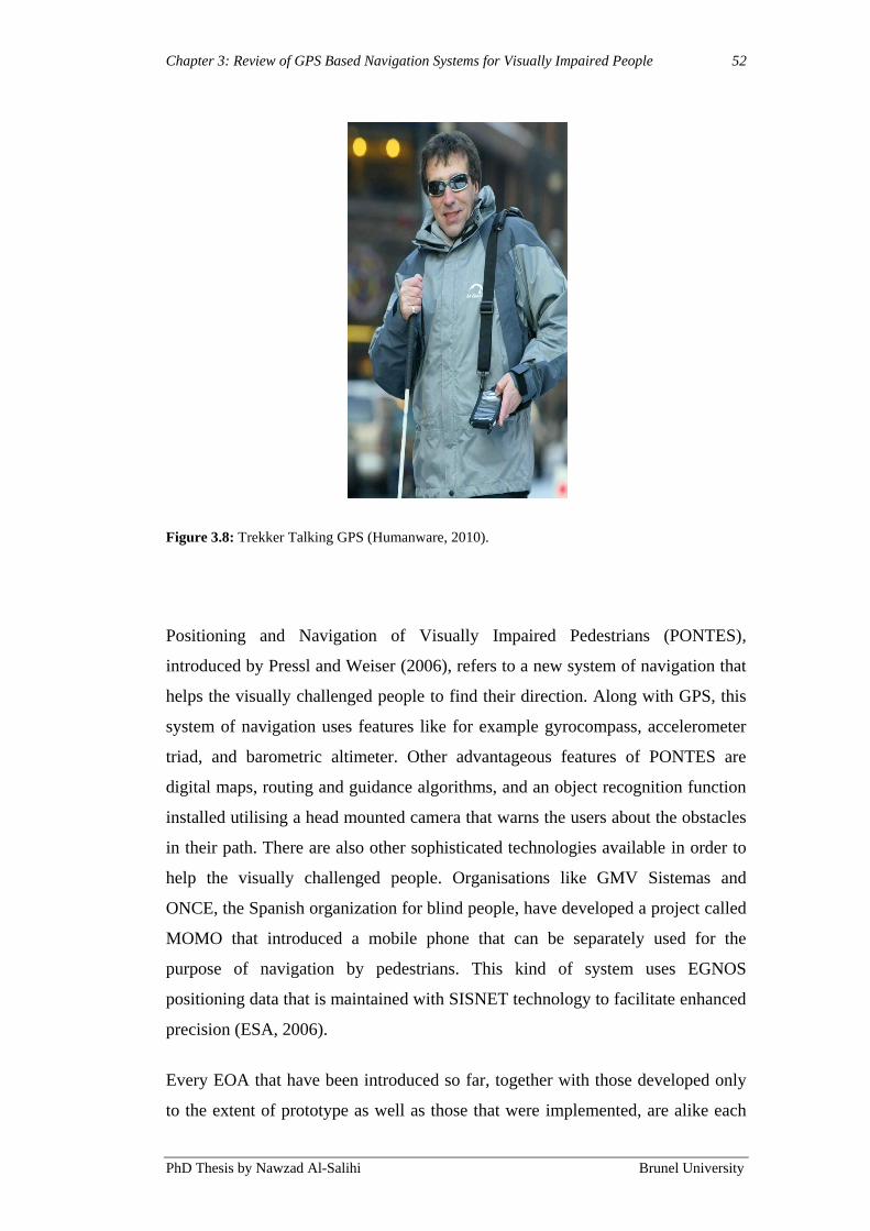
Chapter 3: Review of GPS Based Navigation Systems for Visually Impaired People 52
PhD Thesis by Nawzad Al-Salihi Brunel University
Figure 3.8: Trekker Talking GPS (Humanware, 2010).
Positioning and Navigation of Visually Impaired Pedestrians (PONTES),
introduced by Pressl and Weiser (2006), refers to a new system of navigation that
helps the visually challenged people to find their direction. Along with GPS, this
system of navigation uses features like for example gyrocompass, accelerometer
triad, and barometric altimeter. Other advantageous features of PONTES are
digital maps, routing and guidance algorithms, and an object recognition function
installed utilising a head mounted camera that warns the users about the obstacles
in their path. There are also other sophisticated technologies available in order to
help the visually challenged people. Organisations like GMV Sistemas and
ONCE, the Spanish organization for blind people, have developed a project called
MOMO that introduced a mobile phone that can be separately used for the
purpose of navigation by pedestrians. This kind of system uses EGNOS
positioning data that is maintained with SISNET technology to facilitate enhanced
precision (ESA, 2006).
Every EOA that have been introduced so far, together with those developed only
to the extent of prototype as well as those that were implemented, are alike each
Chapter 3: Review of GPS Based Navigation Systems for Visually Impaired People 53
PhD Thesis by Nawzad Al-Salihi Brunel University
other regarding functionality, system architecture and user interfacing. Moreover,
their functionality, system architecture and user interfacing is for the most part
comparable to the functionality, system architecture and user interfacing of the
mainstream devices for autonomous location and navigation information
acquisition based on the GPS and GIS (Vanja, 2006).
The following briefly describes the typical way of utilising EOA during travel. As
the visually impaired starts a journey and the EOA is “put on” 4
and activated, the
GPS receiver that is integrated in the EOA begins with capturing the signals from
the GPS satellites. The EOA processing unit determines the current location of the
EOA based on the information controlled by the signals, i.e. the starting location
of the journey of the EOA user. In the next step, the location is matched in
accordance with the digital map that is included in the GIS application enclosed in
the EOA and subsequently presented to the user as a synthesised voice message
through the EOA speaker. In general, the location is made available in a format
comparable to the first line of the standard postal address. For instance, “You are
at 110 Oxford Street.” Going along the determined starting position, the users
enters the selected location of the journey destination into the EOA utilisation the
EOA‟s keyboard. On the basis of this information, the processing unit together
with the route-planning algorithm within the GIS application, set up the most
favourable journey route between the starting position of the journey and the
destination, and supplies the user with the initial macro-navigational instructions
(as a set of exact directions along the route) in order to get on with the journey. In
similar ways as the information for location, the instructions are offered as
synthesised voice messages.
The EOA constantly updates the user‟s location as the user walks towards the
destination. Furthermore, using the position update and the information in the
user‟s heading, the EOA constantly generates further synthesised voice-based
macro-navigational instructions relevant to the launched route and presents to
them to the user. The information is either presented numerically, based on the
4 EOAs are designed to be wearable in order to allow for hands-free use and thus permit the user
to handle a long cane or a guide dog in parallel to using an EOA.

Chapter 3: Review of GPS Based Navigation Systems for Visually Impaired People 54
PhD Thesis by Nawzad Al-Salihi Brunel University
geographical coordinates of several past users‟ locations, or in some EOA, by the
incorporated electronic compass.
Besides enabling the provision of online macro-navigational assistance during
travelling (as described above) EOA enable off-line exploration of the digital map
contained in the integrated GIS application. An exploration like that, which is
supposed to be employed before starting a journey, is intended to facilitate the
planning of the journey by way of making it possible for the user to plan specific
journey routes as well as construct the cognitive map of the route area before
embarking.
The potential of EOA in adding visually impaired people in macro-navigation is
unquestionable. The potentiality of this was at first demonstrated through the
successful evaluation examinations of the early EOA prototypes (i.e.: Petrie et al.,
1997) and this was later re-demonstrated in different assessments of the
commercially available EOA, i.e. Humanware, 2010. However, there are a
number of “chronic” difficulties attached to the EOA utilisation that requires
being resolved in order for the devices to shift from being “gadgets” used by no
more than a handful of users- which is the case today- to become a widespread
standard mobility aid (Vanja, 2006). Critiques from Farmer and Smith (1997)5
suggest that the difficulties in question can be separated into two main categories,
of which the first refers to the functional problems taking place because of the
limitations of the technology applied in the EOA. The second category involves
the usefulness and usability limitations linked to the EOA system architecture,
operation and maintenance procedures and the macro navigational instructions
output of the aids.
The problems in the EOA utilisation concerning the functionality are caused by
the technological restrictions of the GPS. The EOA, similar to the mainstream
devices, are in the outdoor use within the urban environment often unsatisfactory
5 The critique by Farmer and Smith considers only the prototypes of EOAs developed until 1997.
Nevertheless, this critique can also be applied to the commercialised EOAs that are presently
available at the market because these devices, in terms of the functionality, system architecture and
user interfacing domains analysed within the critique, do not differ significantly from the
prototypes.
Chapter 3: Review of GPS Based Navigation Systems for Visually Impaired People 55
PhD Thesis by Nawzad Al-Salihi Brunel University
accurate or totally disabled in the provision of macro-navigational information (of
varying duration) – because of the blockage of the GPS signal response by objects
such as buildings and houses, a large quantity of which exist in the environments
of this kind. These problems are principally important to observe and solve since
it is in the outdoor urban environment the EOA are suppose to be used most of the
time – given the fact that an urban living for the majority of population in general
is required for a modern lifestyle, which logically includes the greatest proportion
of the visually impaired population as well.
The vital limitation existing both in long cane use and the guide dog guidance is
the lacking of dependability in the discovery of obstacles and other hazards within
their reach, like steps, tree branches or signs and lampposts. Other difficulties can
be dynamic obstacles such as motorcycles and bicycles. Moreover, long canes do
not reveal obstacles overhanging the ground at heights above that waist level,
since the detection of obstacles range is relatively short (maximum 1m, depending
on the type of cane), and mobility supported by a long cane is not efficient either
as it is short in gracefulness.
3.4 Summary
This chapter presents the summary of the series of literature review-based studies
that were conducted in the early phases of the PhD project. The outcomes of the
studies were subsequently implemented as the foundation for the design of the
Precise Positioning in Real-Time using GPS-RTK Signal for Visually Impaired
People Navigation System.
A comprehensive depiction of the various technologies has been given in this
chapter, with its related factors concerning visual impaired navigation. An
analysis is presented of the functionality, usefulness and limitations of the, at
present, main available methods to support the mobility of visually impaired
people and a compilation is provided of the requirements for the design of EOA.
The emphasis has been on the positioning technology.
Chapter 3: Review of GPS Based Navigation Systems for Visually Impaired People 56
PhD Thesis by Nawzad Al-Salihi Brunel University
Further research and development work is required in order for the current
situation in the area of mobility aids for visually impaired people can be
improved. Currently, relevant for the situation is that improvements are in need in
aiding both micro-navigation and macro-navigation.
Chapter 4: Precise Positioning in Real-Time using Navigation Satellites 57
PhD Thesis by Nawzad Al-Salihi Brunel University
Chapter 4
4. Precise Positioning in Real-Time using Navigation
Satellites
4.1 Introduction
Over the years, the GPS has evolved into a significant tool with which to meet
civilian navigation and positioning requirements worldwide. All GPS-based
positioning techniques operate under a set of constraints. These constraints may
be baseline length, attainable accuracy, assured reliability, signal availability,
time-to-solution, and so on.
Today, there are different possibilities for the use of satellites for positioning and
navigation: not only the well-known American system GPS, but also GPS
combined with the Russian system GLONASS or, in future, with the European
system GALILEO.
As in all navigation procedures, inaccuracies and even errors, which impair the
measured values, occur in GNSS positioning. These effects can be eliminated by
the formation of differences. Using Wide Area Differential GNSS (DGNSS)
technique, GNSS reference stations installed at a known position, calculates
correction parameters and sends them to a mobile GNSS rover over the wireless
communication networks.
In order to achieve centimetre- or even millimetre-level accuracies, calculation of
a position is based on code pseudo-ranges and carrier phase measurements.
However, this Real Time Kinematic (RTK) positioning application is limited by
ionospheric errors, tropospheric errors, satellite orbital errors and multipath.
During periods of extremely high ionospheric activity, the maximum distance of
the rover (user) from the reference station is less than 20 km (Lachapelle 2000).
Unlike single reference station RTK approaches, where positioning accuracy
Chapter 4: Precise Positioning in Real-Time using Navigation Satellites 58
PhD Thesis by Nawzad Al-Salihi Brunel University
decreases while the baseline increases, Network RTK (NRTK) approaches ideally
provide positioning with errors independent of the rover position within the
network. Moreover, by integrating and optimising the information from multiple
reference stations, NRTK covers the desired area with fewer reference stations,
compared with the single reference station approach.
This work focuses on NRTK applications related to pedestrian use. The intention
is to improve positioning performance and ensure the availability of reliable and
highly accurate position solutions, taking into consideration the performance of
NRTK GNSS and its augmentation methods for users in various outdoor
environments.
4.2 Real Time Kinematic (RTK)
In the mid 1990‟s investigations related to Real Time Kinematic (RTK) GPS
surveying began, focusing on optimal way of processing reference receiver data
and then in real-time, providing “correction” information to users (Rizos and Han,
2003). Today, a common surveying and navigation technique is the RTK
positioning with GNSS as it enables the utilisation of a static base station at a
recognised spot and for real-time data collection utilises mobile rover unit. The
process of data are transmitted from the reference station, where in the roving
receiver, the computer processor combines its measurement with the data. RTK
positioning is a system that allows centimetre level accuracy positioning in real-
time. Through efficiently differencing away similar errors and biases that are
caused by atmospheric effects and GNSS satellite orbit errors and clock bias in
carrier phase interpretation of the receivers at both ends of a baseline, a reference
station and a rover.
A conventional RTK positioning system typically comprises of a single reference
station which transmits formatted information such as code and carrier phase
observations to one or mobile rover units in the field, shown in Figure 4.1. The
reference station data is combined with local measurements collected at the rover
using proprietary differential processing techniques to yield precise relative
coordinate estimates.

Chapter 4: Precise Positioning in Real-Time using Navigation Satellites 59
PhD Thesis by Nawzad Al-Salihi Brunel University
GPS Satellites GPS Satellites
RTK Rover
Data Link/Corrections
GPS Satellites
GPS Satellites
RTK Reference Station
Figure 4.1: RTK system.
The reference station as well as the rover station is equipped with dual frequency
receiver. Reference receiver has a radio transmitter to send phase observation
corrections to rover receiver which is also equipped with radio modem to
ascertain a link with the reference station (El-Mowafy, 2000). The data volume
sent by the reference receiver increases because of density if data update rate; as a
result of this, RTK GPS requires the data link to have an optimal capacity of
24,00 bps (bytes per second) or at least 9,600 bps or even in some cases 19,200
bps. According to Langley (1997), this kind of data could be supported by the
VHF of UHF bands which have a wide spectrum of bandwidths.
An initialisation procedure uses a process called double differencing that the
receiver must undergo to begin with and this process helps to aid the unknown
number computation of different wavelength between the receiver and a satellite,
where measurement of both GPS receiver could be done simultaneously.

Chapter 4: Precise Positioning in Real-Time using Navigation Satellites 60
PhD Thesis by Nawzad Al-Salihi Brunel University
According to Roberts (2005), this process of simultaneous measurement was
known as “ambiguity resolution”. The rover receiver produces centimetre level
position once ambiguities have been resolved, mainly to the base receiver station.
From each satellite, the whole number of wavelengths is counted by the receiver
in order to eliminate the error sources, which are large enough, particularly
addressing the receiver clock bias and satellite. Once a successful initialisation has
been performed, the rover is free to move about collecting centimetre accurate 3-
dimensional data in real-time. Any loss of lock on the satellites will require the
receivers to undergo this initialisation procedure again.
However, this differential positioning method is suitable only for a short baseline
lengths (<20 km). The errors from both receivers become less common as the
baseline length increases and hence cannot be cancelled out (Wanninger 2004).
This sort of occurrence is called spatial decorrelation of errors and is the main
restraint of RTK GPS positioning (Aponte et al 2009). Furthermore, due to
constraint of a radio modem that transmits the data from the reference station to
the rover, the recommended maximum baseline length for RTK GPS is about 10
km (Wegener and Wanninger 2005). These restrictions have constrained the
application scope of RTK positioning, for instance, in precise vehicle tracking and
pedestrian navigation system where mobility is a priority.
4.3 Network Real Time Kinematic (NRTK)
The drawbacks of RTK are overcome by the Network RTK GNSS, currently a
dual system combined of GPS and GLONASS positioning system and it increases
the positioning accuracy by precisely modelling the errors that depend on the
distance at the rover position using the raw measurements of an array of
Continuously Operating Reference Stations (CORS) neighbouring the rover site
(Wanninger 2004).
NRTK technology, based on the Virtual Reference Station (VRS) approach, was
accepted and became a confirmed technology that is extensively employed today
in a great amount of installations all around the world. Developments over the
past years (Chen et al., 2003, 2004, 2005; Kolb et al., 2005; Landau et al., 2002;
Chapter 4: Precise Positioning in Real-Time using Navigation Satellites 61
PhD Thesis by Nawzad Al-Salihi Brunel University
Vollath et al., 2000, 2001) have resulted in a solution, which is named as
GPSNetTM since 1999 (Vollath et al., 2000). By contrast to traditional single
base RTK technology, NRTK removes a noteworthy quantity of spatially
correlated errors because of the troposphere, ionosphere and satellite orbit errors,
hence permits performing RTK positioning in reference stations networks with
distances of 40 km or more from the next reference station while supplying, the
performance of short baseline positioning (Landau et al., 2007).
The joint use of GPS and GLONASS has attracted an increased interest recently
among the navigation community because of the firm progress in the revitalisation
of the GLONASS system. Combined GPS/GLONASS navigation can offer many
benefits for users of navigation, such as enhanced availability, improved accuracy
and integrity. Navigation users are very often in environments with limited
satellite visibility such as in urban or mountainous areas. In these kind of
situations, navigation users will benefit significantly from the combined use of
GPS and GLONASS. However, the amount of GPS and GLONASS satellites that
can be observed is still rather often deficient for deriving a position solution partly
because an additional unknown has to be solved as there is a system time
difference between GPS and GLONASS. As a result, a fifth satellite is necessary
for the achievement of navigation solution. The advantages of augmenting GPS
with GLONASS are:
There are two independent systems.
There is a significant increase in redundancy with the increase in the
number of available satellites, and therefore more checks on the
integrity/quality of the position solution can be carried out.
An increase in the number of satellites results in a valid position being
computed in more situations, for example when the antenna experiences
uneven masking such as by motion, in forest and buildings.
The geometry of the constellation (PDOP) improves as the number of
available satellites increases. The result is an improved consistency in
'valid' position computations over time.
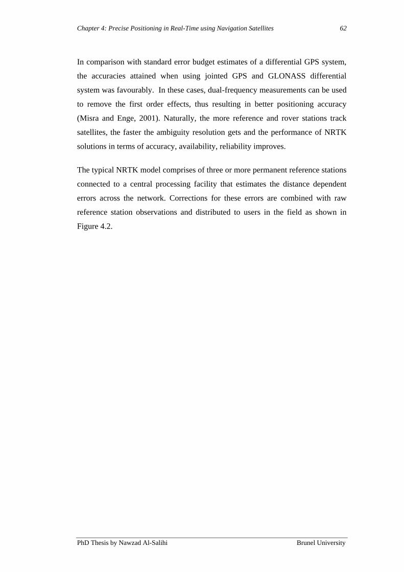
Chapter 4: Precise Positioning in Real-Time using Navigation Satellites 62
PhD Thesis by Nawzad Al-Salihi Brunel University
In comparison with standard error budget estimates of a differential GPS system,
the accuracies attained when using jointed GPS and GLONASS differential
system was favourably. In these cases, dual-frequency measurements can be used
to remove the first order effects, thus resulting in better positioning accuracy
(Misra and Enge, 2001). Naturally, the more reference and rover stations track
satellites, the faster the ambiguity resolution gets and the performance of NRTK
solutions in terms of accuracy, availability, reliability improves.
The typical NRTK model comprises of three or more permanent reference stations
connected to a central processing facility that estimates the distance dependent
errors across the network. Corrections for these errors are combined with raw
reference station observations and distributed to users in the field as shown in
Figure 4.2.
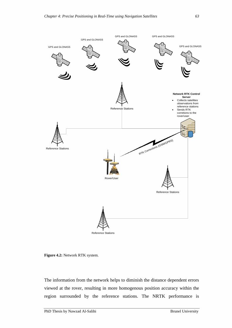
Chapter 4: Precise Positioning in Real-Time using Navigation Satellites 63
PhD Thesis by Nawzad Al-Salihi Brunel University
Rover/User
RTK Corrections (G
SM/GPRS)
Reference Stations
Reference Stations
Reference Stations
Reference Stations
Network RTK Control
Server
· Collects satellites
observations from
reference stations
· Sends RTK
corretions to the
rover/user
GPS and GLONASS
GPS and GLONASS
GPS and GLONASS GPS and GLONASS
GPS and GLONASS
Figure 4.2: Network RTK system.
The information from the network helps to diminish the distance dependent errors
viewed at the rover, resulting in more homogenous position accuracy within the
region surrounded by the reference stations. The NRTK performance is
Chapter 4: Precise Positioning in Real-Time using Navigation Satellites 64
PhD Thesis by Nawzad Al-Salihi Brunel University
dependent, to some extent, on the number of available satellites (Takac and
Walford, 2006). On the other hand, the network software might not be able to
supply with corrections for all satellites in sight. A usual case is low elevation
satellites for which the network software has not resolved the corresponding
ambiguities. Nonetheless, the raw reference observations still contain valuable
information that can be useful for RTK positioning. But, network RTK is usually
regarded as an all-or-nothing solution (Alves, 2004). That is to say, raw and
corrected observations should not be mixed in the position solution.
In a most favourable solution, the rover software should take into consideration all
of the available observation information and account for any residual observation
errors remaining after modelling (Takac and Lienhart, 2008).
RTK positioning is a much more complex and vulnerable process, with the
intention to achieve the accuracy as high as centimetres with as few as possible
data epochs, in real-time for any user in static and dynamic environment. Thus, a
better care has to be taken in order to characterise the performance and to address
the concern of liability-critical positioning. Users are worried about not only
accuracy, but also availability and integrity of the solutions in many applications.
RTK positioning technologies are employed most commonly for outdoor
navigation, such as surveying, data acquisitions, machine automation in precision
agriculture, mining and construction. However, RTK positioning has not been
implemented for pedestrian or visually impaired navigation systems so far (at time
of writing).
In this contribution, the novel concept of a precise positioning in real-time using
GPS-RTK Signal for visually impaired people navigation system of combining
raw and corrected observations in various environments is examined using dual
frequency receivers and the TopNET+ network RTK in the UK. The practical
benefit of this approach for RTK positioning is tested using real-time data. The
results (Chapter 7) demonstrate increased availability of position, better precision
and more homogeneous accuracy throughout the network. However, there are
some constraints in various environments for both static and dynamic tests.
Chapter 4: Precise Positioning in Real-Time using Navigation Satellites 65
PhD Thesis by Nawzad Al-Salihi Brunel University
4.3.1 RTK in Visually Impaired Navigation System
Visually impaired navigation services require constant positioning and tracing of
the mobile user with a certain accuracy of positioning and reliability, in particular
navigating in urban of the reception of the weak GPS signals being blocked by
nearby buildings. As a result, neither EOAs nor the BNSB (Chapter 3) can in such
situations provide enough precise macro-navigational instructions. In addition, in
some cases, the obstruction of the GPS signal reception is periodically severe to
the extent that the location of the user is entirely undeterminable and the macro-
navigational assistance can consequently not take place at all. Highlighting the
restrictions of EOAs and BNSB components enables a full understanding of
matters affecting its QoS. Taking the experienced scenarios with the BNSB into
account, several research studies (Hunaiti, 2005; Garaj, 2006; Al-Salihi et al.,
2008; Alhajri et al., 2008; Al Nabhan, 2009) have examined the limitations of
BNSB to gain an understanding of GPS performance, wireless networks, and
mobile devices capabilities, employed in a macro and micro navigation
environment. The outcome in toto of these studies shows that BNSB application
are still facing a number of challenges linked to the availability of optimal
positioning solutions, mobile devices processing, visualising capabilities, and
network resources.
With the rapid improvements in satellite constellation and the availability of
precise products, such as augmentation services from network-based DGNSS, it
should now be feasible to derive accurate solutions for guidance systems utilised
by visually impaired people by using NRTK. Aponte et al (2009) conducted
several static and dynamic tests using NRTK. The availability of the static NRTK
observations without an indication to the surrounding environment was above
97.74%, which ensured an average accuracy better than 5 cm over 98% of the
time. Furthermore, dynamic tests showed a much lower availability of the NRTK
solution, and resulted in accuracy being better than 5 cm only about 50% of the
time. The dynamic test was performed by driving a car around in a mixed route
environment surrounded by obstacles, such as flyover bridges, buildings, etc.
However, the lack of availability during the dynamic tests was mainly caused by
Chapter 4: Precise Positioning in Real-Time using Navigation Satellites 66
PhD Thesis by Nawzad Al-Salihi Brunel University
satellite signal disturbances and possibly the interruptions of the GPRS
communication link. In addition, multipath and mobile obstacles (e.g. bus, lorries,
etc) affected the availability by causing disruption of the NRTK solution.
Multipath disturbance affects solutions derived by precise point positioning,
relative positioning and dynamic positioning. It is difficult to model multipath
disturbance mathematically because of its localised nature and also because of
being environmentally dependent.
4.4 Processing Procedures for Real-Time GNSS Positioning
The integer uncertainties in GNSS carrier measurements and the successful
resolution of it is important but a challenging undertaking at the same time, in
particular regarding RTK positioning. The main issue and challenge for high
precision RTK survey and navigation is at the present still the carrier phase
ambiguity resolution. The calculation efficiency is of major importance, due to the
speed and memory limits, as it can take into consideration the elapsed time prior
to the ambiguities can be resolved. The dependability of the ambiguity resolution
process is indeed an important concern as well. In order to reach accurate and
dependable position solutions under different conditions and navigation
environments, the system entails a certain number of procedures. These main
procedures are: inter ambiguity resolution in real-time, message decoding, GNSS
positioning, navigation and augmentation data availability monitoring, data
correction and position calculation.
4.4.1 Message Decoding
The Radio Technical Commission for Maritime Services (RTCM) message
decoding handles with every data type separately and afterwards begins with
retrieving and synchronizing the necessary data fields, taking in to account the
GPS and GLONASS time of the measurements the user receives. These
measurements are the position observations of the user, and these are as standard
position solutions in the NMEA format. The decoding process of the message
comprises of three independent decoding tasks:

Chapter 4: Precise Positioning in Real-Time using Navigation Satellites 67
PhD Thesis by Nawzad Al-Salihi Brunel University
The RTCM message decoding that deals with DGNSS RTCM SC-104
messages received from TopNET+ server.
The RTCM 10410.1 message decoding, this handles GNSS data
corrections from RTCM via Networked Transport of RTCM via Internet
Protocol (Ntrip).
User and navigation data decoding, which deal with satellite ephemeris
information and user‟s measurements.
Several message types are considered while decoding the RTCM messages,
containing pseudo-range corrections (PRC), along with the rate of change for the
pseudo-range corrections (RRC) for visible healthy satellites observed at the
corresponding DGNSS reference station. In addition, another message type is
considered for obtaining ECEF coordinates of the corresponding DGNSS station.
RTCM messages are made of a number of blocks known as RTCM words, every
word is 30-bit length (five RTCM bytes), containing 24 data bits and 6 parity bits
(see Figure 4.2).
Figure 4.2: RTCM words format (RTCM, 1994).
Each RTCM message consists of a body and a header. While the body keeps data
for each corresponding message type, the header is contained in the first and
second RTCM words; it composed of message type, reference time, reference
station identification, time, and length of message as shown in Figure 4.3.
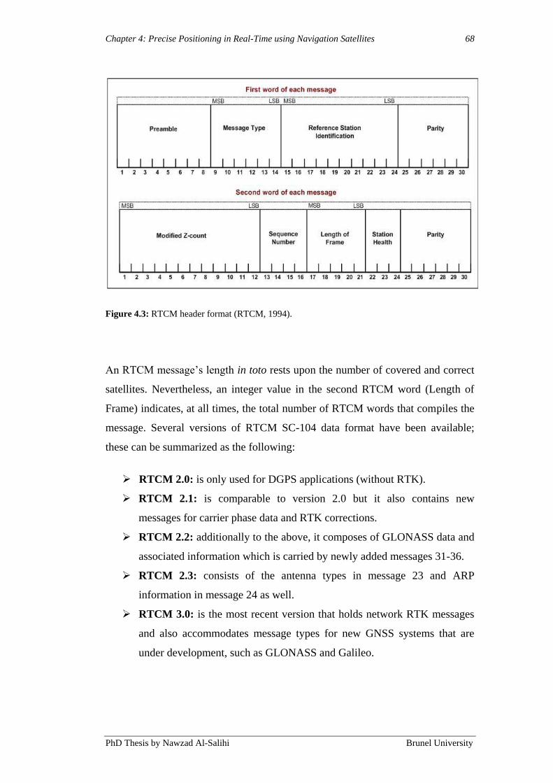
Chapter 4: Precise Positioning in Real-Time using Navigation Satellites 68
PhD Thesis by Nawzad Al-Salihi Brunel University
Figure 4.3: RTCM header format (RTCM, 1994).
An RTCM message‟s length in toto rests upon the number of covered and correct
satellites. Nevertheless, an integer value in the second RTCM word (Length of
Frame) indicates, at all times, the total number of RTCM words that compiles the
message. Several versions of RTCM SC-104 data format have been available;
these can be summarized as the following:
RTCM 2.0: is only used for DGPS applications (without RTK).
RTCM 2.1: is comparable to version 2.0 but it also contains new
messages for carrier phase data and RTK corrections.
RTCM 2.2: additionally to the above, it composes of GLONASS data and
associated information which is carried by newly added messages 31-36.
RTCM 2.3: consists of the antenna types in message 23 and ARP
information in message 24 as well.
RTCM 3.0: is the most recent version that holds network RTK messages
and also accommodates message types for new GNSS systems that are
under development, such as GLONASS and Galileo.

Chapter 4: Precise Positioning in Real-Time using Navigation Satellites 69
PhD Thesis by Nawzad Al-Salihi Brunel University
The types of messages described in RTCM 3.0 are employed in this work. There
are four groups of RTCM 3.0 GNSS RTK messages (RTCM 2004), which are
shown below in Table 4.1.
Figure 4.4: RTCM Types.
Group Name Message Type Message Description
Observations 1001 L1-only GPS RTK Observables
1002 Extended L1-Only GPS RTK Observables
1003 L1 & L2 GPS RTK Observables
1004 Extended L1 & L2 GPS RTK Observables
1005 L1 Only GLONASS RTK Observables
1006 Extended L1-Only GLONASS RTK
Observables
1007 L1 & L2 GLONASS RTK Observables
1008 Extended L1 & L2 GPS RTK Observables
Station Coordinates 1009 Stationary RTK Reference Station ARP
1010 Stationary RTK Reference ARP with
Antenna Height
Antenna Description 1011 Antenna Descriptor
1012 Antenna Descriptor & Serial Number
Auxiliary Operation Information 1013 System Parameters

Chapter 4: Precise Positioning in Real-Time using Navigation Satellites 70
PhD Thesis by Nawzad Al-Salihi Brunel University
User‟s measurements, as described earlier, obtained at the MNU are in the
NMEA. The message decoder merely considers the messages of GGA, which
include the GPS and GLONASS essential time and position fixing information.
This message contains the list of satellites being tracked and applied for
computing the positioning coordinates at the MNU as well.
RTCM has upgraded to Version 2.0 for Networked Transport of RTCM via
Internet Protocol (Ntrip), designated as RTCM Standards 10410.1.
The new standard defined by TRCM‟s Special Committee 104 (SC104), along
with other things, supply a protocol for streaming differential correction data to
stationary or mobile users though the Internet. Usually, differential correction
have been broadcasted over the radio links from either a single or networked
reference stations situated in familiar settings to improve the mobile receivers‟
(rovers) real-time accuracy. The majority of these services supply with GPS and
GLONASS corrections. The design of Ntrip is to allocate the GNSS streaming
data to mobile or stationary clients though the Internet, allowing simultaneous PC,
PDA or receiver connections to a broadcasting host. Through the mobile IP
networks, such as GSM, GPRS, EDGE, UMTS or HSDPA, Ntrip can support the
wireless Internet access.
The navigation message includes a number of data pages, of which each holds
five sub-frames. Each and every frame has two data words of 30 bits. In order to
extract pertinent information about each observed satellites with respect to the
user‟s measurement the following sub-frames are considered in the decoding
process:
Sub-frame 1, containing the Satellite Vehicles (SVs) clock parameters.
This information is utilised to correct the code phase time received from
the SVs, with respect to the relativistic effects. This also permits the
compensation of the SVs‟ group delay effects.
Sub-frames 2 and 3 consist of ephemeris parameters which are used to
determine the SVs orbits within two hours interval. This information is
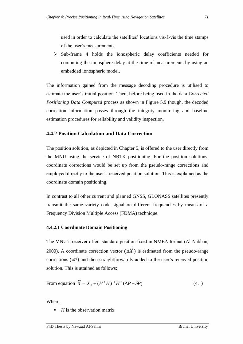
Chapter 4: Precise Positioning in Real-Time using Navigation Satellites 71
PhD Thesis by Nawzad Al-Salihi Brunel University
used in order to calculate the satellites‟ locations vis-à-vis the time stamps
of the user‟s measurements.
Sub-frame 4 holds the ionospheric delay coefficients needed for
computing the ionosphere delay at the time of measurements by using an
embedded ionospheric model.
The information gained from the message decoding procedure is utilised to
estimate the user‟s initial position. Then, before being used in the data Corrected
Positioning Data Computed process as shown in Figure 5.9 though, the decoded
correction information passes through the integrity monitoring and baseline
estimation procedures for reliability and validity inspection.
4.4.2 Position Calculation and Data Correction
The position solution, as depicted in Chapter 5, is offered to the user directly from
the MNU using the service of NRTK positioning. For the position solutions,
coordinate corrections would be set up from the pseudo-range corrections and
employed directly to the user‟s received position solution. This is explained as the
coordinate domain positioning.
In contrast to all other current and planned GNSS, GLONASS satellites presently
transmit the same variety code signal on different frequencies by means of a
Frequency Division Multiple Access (FDMA) technique.
4.4.2.1 Coordinate Domain Positioning
The MNU‟s receiver offers standard position fixed in NMEA format (Al Nabhan,
2009). A coordinate correction vector ( X~
) is estimated from the pseudo-range
corrections ( P ) and then straightforwardly added to the user‟s received position
solution. This is attained as follows:
From equation )()(~ 1
0 PPHHHXX TT (4.1)
Where:
H is the observation matrix
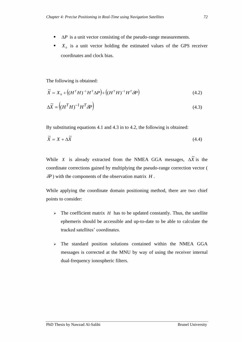
Chapter 4: Precise Positioning in Real-Time using Navigation Satellites 72
PhD Thesis by Nawzad Al-Salihi Brunel University
P is a unit vector consisting of the pseudo-range measurements.
0X is a unit vector holding the estimated values of the GPS receiver
coordinates and clock bias.
The following is obtained:
PHHHPHHHXX TTTT 11
0 )()(~ (4.2)
PHHHX TT 1)(~ (4.3)
By substituting equations 4.1 and 4.3 in to 4.2, the following is obtained:
XXX~~
(4.4)
While X is already extracted from the NMEA GGA messages, X~
is the
coordinate corrections gained by multiplying the pseudo-range correction vector (
P ) with the components of the observation matrix H .
While applying the coordinate domain positioning method, there are two chief
points to consider:
The coefficient matrix H has to be updated constantly. Thus, the satellite
ephemeris should be accessible and up-to-date to be able to calculate the
tracked satellites‟ coordinates.
The standard position solutions contained within the NMEA GGA
messages is corrected at the MNU by way of using the receiver internal
dual-frequency ionospheric filters.

Chapter 4: Precise Positioning in Real-Time using Navigation Satellites 73
PhD Thesis by Nawzad Al-Salihi Brunel University
4.4.2.2 Integer Ambiguity Resolution in Real-Time GNSS Positioning
The difficult part in making an RTK system lies in aligning the signals
appropriately. In order to align them easily, the navigation signals are
intentionally encoded, but each cycle of the carrier is similar to every other. Thus,
this makes it enormously difficult to know if the signals are aligned properly or if
they are “of by one” and are hence introducing an error of 20 cm, or a larger
multiple of 20 cm. The problem of the integer ambiguity problem can be attended
to, to some extent, with sophisticated statistical methods that compare the
measurements from the C/A signals and by comparing the resulting ranges
between multiple satellites. On the other hand, none of these methods can
decrease this error to zero.
The prerequisites for RTK are Integer ambiguity resolution, for instance, as
instantaneous ambiguity resolution and ambiguity resolution On-The-Fly (OTF).
Along with many specifications of the RTK, three of them are most significant,
these are: ambiguity resolution initialisation time, ambiguity resolution reliability
and RTK accuracy, which are all related to each other. The ambiguity resolution
initial time is important for the real-time applications. The accuracy of the RTK
depends on the carrier phase measurement accuracy. Nonetheless, it is still a
challenge for the single-frequency case to resolve the ambiguities rapidly and
reliably (Han, 1997; Wang et al., 2003). Because of variations in propagation
delay of the code and carrier, and those are unpredictable due to the ionosphere
and other error sources, it is practically impossible to obtain ambiguity resolution
with single-receiver positioning. Consequently, carrier phase measurements are
almost always relegated to high-accuracy applications in which errors of such
kind are cancelled out by differential operation with a supplementary receiver
(base-station) (Mohinder, et al., 2007).
Even though using pseudorange measurements, C/A-code are the most frequently
employed a much higher level of measurement precision can be achieved by
measuring the received phase of the GPS L1 or L2 carrier. Because of the short
period of the carrier waveform (6.35 × s at the L1 frequency), the noise-
induced error in measuring signal delay by the methods of phase measurements is

Chapter 4: Precise Positioning in Real-Time using Navigation Satellites 74
PhD Thesis by Nawzad Al-Salihi Brunel University
generally 10–100 times smaller than that encountered in code delay measurements
(Mohinder, et al., 2007).
Nevertheless, carrier phase measurements are extremely ambiguous since the
phase measurements are simply modulo 2π numbers. With no additional
information, such measurements determine merely the fractional part of the
pseudorange when measured in carrier wavelengths. Further measurements are
necessary to have an effect on ambiguity resolution, in which the integer of
wavelengths in the pseudorange measurement can be decided. The link between
the measured signal phases and the unambiguous pseudoranges can be
formualted as (Mohinder, et al., 2007):
(4.5)
where n is the number of satellites observed, λ is the carrier wavelength, and is
the unidentified integral number of wavelengths contained in the pseudorange.
The further measurements needed for determination of the may contain C/A
and/ or P(Y)-code pseudorange measurements from the same satellites used for
the phase measurements. The range of admissible integer values for the is
narrowed significantly since the code measurements are unambiguous. Moreover,
phase measurements, made on both the L1 and L2 signals, can be employed to
attain a virtual carrier frequency equivalent to the dissimilarity of the two carrier
frequencies (1575.42 − 1227.60 = 347.82 MHz). The 86.3 cm wavelength of this
virtual carrier reduces the density of pseudorange ambiguities by a factor of about
4.5, facilitating the ambiguity resolution process a great deal (Mohinder, et al.,
2007).
GPS ambiguities connected to Double Difference (DD) carrier phase observations
are generally resolved in GPS data processing schemes. The double-difference

Chapter 4: Precise Positioning in Real-Time using Navigation Satellites 75
PhD Thesis by Nawzad Al-Salihi Brunel University
technique efficiently alleviates common errors brought in by the receiver and
satellite hardware, together with satellite clocks and the receiver, and also the
Earth‟s atmosphere. By subtracting two inter-station single difference
observations, double-difference observations can be shaped (Lee et al., 2005).
Moreover, the inter-state single-difference is derived, by subtracting
measurements to the same satellite observed simultaneously at two stations. The
single-difference and double-difference involve reference station m, rover station
k and GNSS satellites (Petovello and Takac, 2009), as shown in Figure 4.5.
GNSS Satellites
GNSS SatellitesGNSS Satellite
m k m kInter-Station
Single-DifferenceDouble-Difference
Figure 4.5: The double difference (Petovello and Takac, 2009).
Chapter 4: Precise Positioning in Real-Time using Navigation Satellites 76
PhD Thesis by Nawzad Al-Salihi Brunel University
4.5 Precise Positioning in Real-Time using GPS-RTK Signal for
Visually Impaired People Navigation System
A reliable navigation system for visually impaired people necessitates the
determination of the current position of the user, by means of different
components that are integrated into the system design. The below tasks are dealt
with:
The ability to lead the visually impaired user in real-time with the use of
diverse suitable location components and to gain an optimal estimate of
the present user‟s position.
The possibility to find the user in 3 dimensions with high precision.
The ability to complete a faultless transition for continuous positioning
determination between urban, suburban and open field areas.
To achieve above mentioned tasks a novel system has been designed and
developed at Brunel University. As mentioned in Chapter 3, one of the
weaknesses that prevent BNSB from being standard mobility support is the
functional unreliability of the devices deriving in technological limits of the GPS.
These limitations rise in urban environments and densely areas since there is a
significant possibility for the signals to be jammed and interfered because of high
obstructing buildings and difficult landscapes. These boundaries have carried
great attention during the last decades attempting to augment GPS positioning
services among multiple signal error sources. Consequently, a variety of methods
have appeared, such as DGNSS systems allowing GPS and GLONASS signal
errors to be reduced or abolished based on pseudo-range or carrier-phase
differential correction procedures (Kaplan and Hegarty, 2006). Various
researchers under different circumstances and settings have shown that NRTK can
achieve accuracy below 5 cm in static tests. However, there are some constraints
in dynamic tests, mentioned earlier in this chapter.
This work focuses on a precise positioning in a real-time navigation system
related to visually impaired people. The purpose was to improve the positioning
performance and ensure the availability of reliable and highly accurate position
Chapter 4: Precise Positioning in Real-Time using Navigation Satellites 77
PhD Thesis by Nawzad Al-Salihi Brunel University
solutions. This new system, Precise Positioning in Real-Time using GPS-RTK
Signal for Visually Impaired People Navigation System, was designed by applying
the principles of maximum effectiveness in a functioning of a system
methodology, following the outcome of the literature review studies that were
summarised in Chapters 2, 3 and 4. The conceptual framework for the design of
the system was adopted from the Brunel Navigation System for the Blind
(BNSB), a mobility aid also developed within the Electronic Systems Research
Centre (ESRC) at Brunel University, where this PhD project was carried out.
Precise Positioning in Real-Time using GPS-RTK Signal for Visually Impaired
People Navigation System consists of two main terminals (Chapter 5, Figure 5.1).
A client, Mobile Navigation Unit (MNU), which is located at the site of the
visually impaired user and a Navigation Service Centre (NSC), which is located at
the site of the sighted guide who guides the client to the destination using audio
communication via wireless networks. The client consists of a high precision dual
frequency GNSS receiver (NRTK), a digital camera, a speaker, a hands-free set
containing a microphone and earpiece is used by the user for voice
communication with the guide and a wireless communication interface
(3G/HSDPA). The server consists of a number of workstations equipped with a
customized GIS database. It enables remote tracking of visually impaired
pedestrians based on NRTK GNSS location and a live video image and voice
communication. The system‟s primary goal is to assist in navigating visually
impaired people in macro and micro navigation environment. The positioning
performance of NRTK and wireless communication is a crucial attribute for the
quality of guidance.
4.6 Summary
This chapter illustrates Network-based Real Time Kinematic (NRTK) GNSS
positioning is regarded as an advanced solution as compare to the standalone GPS
positioning and previous single reference station based Real Time Kinematic
(RTK) positioning technique. NRTK GPS positioning uses unprocessed
measurements collected from a network of Continuously Operating Reference
Stations (CORS) one by one to produce more dependable error models that can
Chapter 4: Precise Positioning in Real-Time using Navigation Satellites 78
PhD Thesis by Nawzad Al-Salihi Brunel University
tone down the distance dependent errors inside the region enclosed by the CORS.
This procedure has been developed and checked significantly in recent years and
compared to the usual RTK positioning technique, its performance is better in
terms of precisions that can be achieved, dependability and mobility.
Like any other GNSS technique, NRTK is adversely influenced by the satellite
line-of-sight obstructions. Even the most exact orbit and clock data is ineffectual
if the user is not able to track particular satellites. By way of using the full range
of satellites from both the GPS and GLONASS systems, a best possible service
can be warranted if satellite visibility is partially blocked. This can occur in
suburban environments, it is a very demanding undertaking since pedestrians
move in spaces where no one of the familiar location methods works continuously
in standalone GPS/DGPS mode or conventional RTK GPS.
The increase in the number of available GNSS satellites can offer many
advantages for navigation users, such as enhanced availability, improved accuracy
and integrity.
In this work, a precise positioning in a real-time navigation system for visually
impaired people was designed, taking into consideration a set of related
parameters affecting the positioning performance. The novel system is responsible
for integrating the available positioning methods within the surrounding
environment. This system was demonstrated within an efficient positioning model
that was designed and developed based on NRTK GNSS services ensuring the
availability of reliable, highly accurate and precise position solutions for
pedestrian applications in different environments. The latest positioning
mechanism developed was adopted as a client-server-based architecture
incorporating both the user side known as Mobile Navigation Unit of MNU and
the other being the remote one known as the Navigation Service Centre of NSC.

Chapter 5: System Design 79
PhD Thesis by Nawzad Al-Salihi Brunel University
Chapter 5
5. System Design
5.1 Introduction
The main objective of this PhD project is achieving an improved navigation
positioning performance to be utilised in applications covering users with a visual
impairment. The system, entitled the Precise Positioning in Real-Time using GPS-
RTK Signal for Visually Impaired People Navigation System, was designed and
its prototype developed within the Centre for Electronic Systems Research
(CESR), a research group based at the School of Engineering and Design, Brunel
University. This chapter presents the overall process of the system design, the
architecture and functionality of the developed system prototype, and the
integration of the correction services from network-based DGNSS systems. User-
centred system design methodology guided the system design process.
Besides the studies associated with the system design, the architecture, and the
functionality of the system and the integration of correction services from
network-based DGNSS systems, an extensive study was undertaken of the various
technologies with actual relevance to the navigation system for visually impaired
people and the technologies deemed as potentially relevant to the novel system.
The technologies taken into account include the UMTS and HSDPA (Section 5.3),
all belonging to the domain of wireless communication technologies.
Sections 5.1 and 5.2 describe the positioning model‟s prototype and components.
Section 5.4 presents the main system model operational architecture. The system
functions and the operational methods implemented at both the Mobile Navigation
Unit (MNU) and the Navigation Service Centre (NSC) are presented in Sections
5.5 and 5.6. Section 5.7 summaries this chapter.

Chapter 5: System Design 80
PhD Thesis by Nawzad Al-Salihi Brunel University
5.2 System Model Prototype
As the prototype of the BNSB, the prototype of the Precise Positioning in Real-
Time using GPS-RTK Signal for Visually Impaired People Navigation System
comprises one mobile and one stationary terminal. The mobile terminal, the
MNU, and the stationary terminal, the NSC, are the two important terminals
associated with this new system. The MNU is situated within the vicinity of the
visually impaired user, and the NSC is located with the sighted guide who is
involved in guiding the user to the destination. These are connected via a wireless
two-channel voice and data communication link between the terminals. The
prototype system model describing its main components, such as communication
links and data transmissions are shown in Figure 5.1.
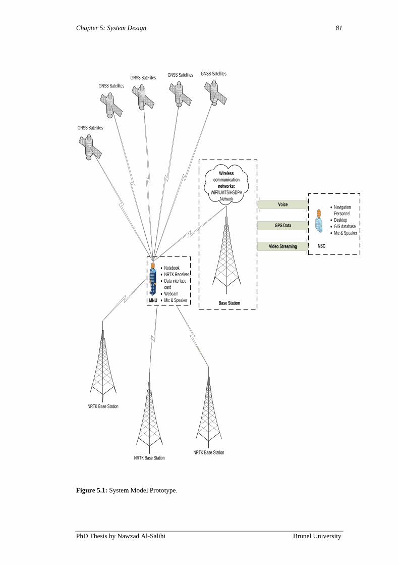
Chapter 5: System Design 81
PhD Thesis by Nawzad Al-Salihi Brunel University
GNSS Satellites GNSS Satellites
MNU
· Notebook
· NRTK Receiver
· Data interface
card
· Webcam
· Mic & SpeakerBase Station
Wireless
communication
networks:
WiFi/UMTS/HSDPA
NetworkVoice
GPS Data
Video Streaming NSC
· Navigation
Personnel
· Desktop
· GIS database
· Mic & Speaker
GNSS Satellites
GNSS Satellites
GNSS Satellites
NRTK Base Station
NRTK Base StationNRTK Base Station
Figure 5.1: System Model Prototype.
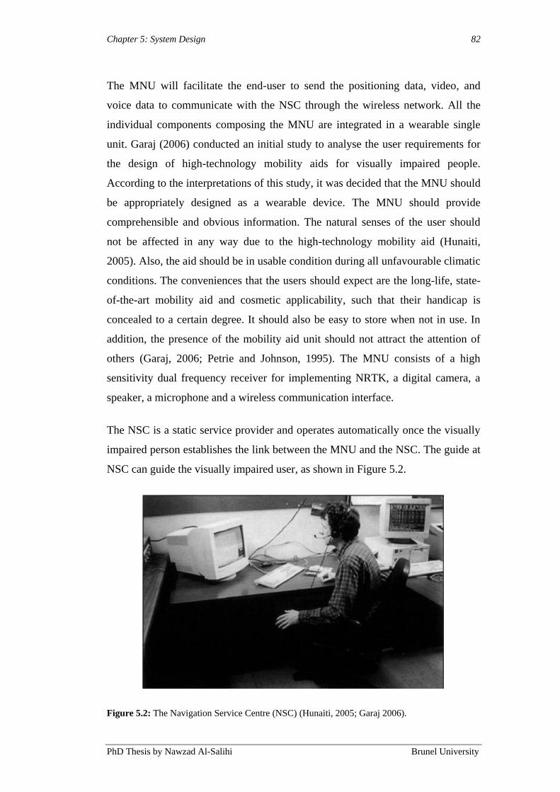
Chapter 5: System Design 82
PhD Thesis by Nawzad Al-Salihi Brunel University
The MNU will facilitate the end-user to send the positioning data, video, and
voice data to communicate with the NSC through the wireless network. All the
individual components composing the MNU are integrated in a wearable single
unit. Garaj (2006) conducted an initial study to analyse the user requirements for
the design of high-technology mobility aids for visually impaired people.
According to the interpretations of this study, it was decided that the MNU should
be appropriately designed as a wearable device. The MNU should provide
comprehensible and obvious information. The natural senses of the user should
not be affected in any way due to the high-technology mobility aid (Hunaiti,
2005). Also, the aid should be in usable condition during all unfavourable climatic
conditions. The conveniences that the users should expect are the long-life, state-
of-the-art mobility aid and cosmetic applicability, such that their handicap is
concealed to a certain degree. It should also be easy to store when not in use. In
addition, the presence of the mobility aid unit should not attract the attention of
others (Garaj, 2006; Petrie and Johnson, 1995). The MNU consists of a high
sensitivity dual frequency receiver for implementing NRTK, a digital camera, a
speaker, a microphone and a wireless communication interface.
The NSC is a static service provider and operates automatically once the visually
impaired person establishes the link between the MNU and the NSC. The guide at
NSC can guide the visually impaired user, as shown in Figure 5.2.
Figure 5.2: The Navigation Service Centre (NSC) (Hunaiti, 2005; Garaj 2006).
Chapter 5: System Design 83
PhD Thesis by Nawzad Al-Salihi Brunel University
The NSC is equipped with a number of services, consisting of a standard personal
computer, a communication interface to transmit and receive data to and from the
MNU, a customised GIS, and a screen, which displays the GIS applications‟
contained digital map of the user‟s travel environment and captured video image
simultaneously. The captured video image is transmitted to the NSC from the
MNU through a video image transmission channel. In the NSC, the starting
location is displayed on the screen, and plotted on the digital map of the user‟s
travel environment together with the received video image (Figure 5.3). In the
next stage, the user provides the guide with the details of the travel destination of
choice; the provision is carried out verbally through the voice communication
channel. The details can be given as an exact location, for example, the address of
a particular restaurant in the neighbourhood, or as a description of the destination,
for example, the nearest restaurant in the neighbourhood, in which case, the guide
determines the exact location. Based on the information on the starting location
and the location of the destination, the processing unit in the guide‟s terminal, in
conjunction with the route-planning module inside the GIS application, calculates
the optimal route connecting the starting location and the destination. As the route
is calculated, the digital map display presents it as a diagram. The dual frequency
RTK receiver at the MNU and the GIS application, combined with the digital map
display in the NSC, structure the system‟s positioning and tracking unit. This
design simplifies the hand-held device and its user interface using voice
communication between the trained navigation staff and the visually impaired
person.
Evaluation of the wireless communication features is an important part of the
system and could greatly affect the functioning of the Precise Positioning in Real-
Time using GPS-RTK Signal for Visually Impaired People Navigation System as
a whole, and this is explained in detail in following sections.

Chapter 5: System Design 84
PhD Thesis by Nawzad Al-Salihi Brunel University
Figure 5.3: Display at NSC.
5.3 Integration between GNSS and Mobile Communications
Generally, the most common guidance systems‟ illustration is presented as a
client-server-based architecture comprising a mobile device with a positioning
capability, which is remotely attached via communication channels to the service
providers. The integration between GPS/GNSS receivers and mobile
communications is necessary and takes into consideration commercial, as well as
technical reasons. Figure 5.4 shows the main components and architecture.
Currently, several companies are integrating a GNSS receiver, computing
technologies, and mobile phones into a single mobile device. When there is a need
to send the positioning data and messages through mobile units to base stations,
the standard mobile networks, such as GSM or third generation mobile
technologies (3G) are used.
Generally, a process followed by the application user takes place by sending the
service request via a communication network to the application server. For this
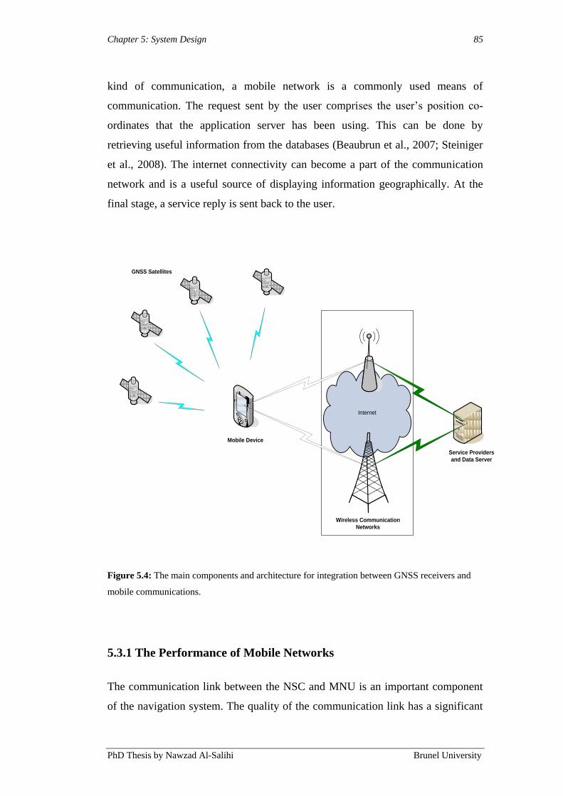
Chapter 5: System Design 85
PhD Thesis by Nawzad Al-Salihi Brunel University
kind of communication, a mobile network is a commonly used means of
communication. The request sent by the user comprises the user‟s position co-
ordinates that the application server has been using. This can be done by
retrieving useful information from the databases (Beaubrun et al., 2007; Steiniger
et al., 2008). The internet connectivity can become a part of the communication
network and is a useful source of displaying information geographically. At the
final stage, a service reply is sent back to the user.
Internet
Service Providers
and Data Server
Wireless Communication
Networks
Mobile Device
GNSS Satellites
Figure 5.4: The main components and architecture for integration between GNSS receivers and
mobile communications.
5.3.1 The Performance of Mobile Networks
The communication link between the NSC and MNU is an important component
of the navigation system. The quality of the communication link has a significant

Chapter 5: System Design 86
PhD Thesis by Nawzad Al-Salihi Brunel University
impact on the overall performance of the navigation system. The communication
between the sites of the visually impaired user‟s MNU and the site of the guide‟s
NSC is a real-time bi-directional communication, as shown in Figure 5.1.
Furthermore, the communication between the NRTK receiver at the MNU and the
TopNET+ network for augmentation of the positioning data is also in real-time.
A performance assessment was carried out of different wireless mobile
technologies, such as UMTS and HSDPA, for utilisation in the system. The
performance assessment focused on the following link features: delay, jitter, and
packet loss. Three service provider‟s networks in the UK, Orange, T-mobile, and
Vodafone, were tested at Brunel University‟s campus.
As reported by Al-Salihi et al. (2007) and Alhajri et al. (2008) the comparison
between Orange‟s UMTS, T-mobile and Vodafone‟s HSDPA with ITU standard
in terms of packet loss, jitter, and delay is presented in Figures 5.5, 5.6, and 5.7,
respectively. In terms of packet loss, the only technology that satisfied the
condition of ITU6 standard (packet loss < 150 ms) was HSDPA. In the jitter
comparison, the HSDPA matched the standard while the UMTS network was
unsuccessful because of very high packet loss. In delay comparison, all of these
technologies fitted the standard.
6 ITU (International Telecommunication Union), Cisco (Howald, 2003,(Szigeti and Hattingh,
2004), and other organisations define standard requirements for video and voice transmission, as
follows:
· Delay: < 150ms - acceptable; 150 – 400ms – bordering acceptable (some quality
issues may occur); > 400ms – unacceptable.
· Packet Loss: should not be more than 1%.
· Jitter: < 30ms – acceptable; > 30ms – unacceptable (significant voice degradation).

Chapter 5: System Design 87
PhD Thesis by Nawzad Al-Salihi Brunel University
Figure 5.5: Packet loss comparison between different technologies.
Figure 5.6: Jitter comparison between different technologies.
Figure 5.7: Delay comparison between different technologies.
Packet loss
0 2 4 6 8 10 12 14 16
ITU standard
UMTS (Orang)
HSDPA (T-mobile)
HSDPA (Vodafone)
(%)
Jitter (ms)
30
46
13.5
16.5 ITU standard
UMTS (Orang)
HSDPA (T-mobile)
HSDPA (vodafone)
0
20
40
60
80
100
120
140
160
ms
ITU standard UMTS (Orange) HSDPA (T-mobile) HSDPA (Vodafone)
Delay

Chapter 5: System Design 88
PhD Thesis by Nawzad Al-Salihi Brunel University
5.4 System Model Operational Architecture
A new sophisticated positioning model, based on the above depicted concept, has
been designed and developed as a multi-thread user-server based approach (Figure
5.8). A new provision was introduced at the MNU, described as the Network
RTK real-time positioning corrections. The availability of the WADGPS
correction data from the network-DGNSS (CORS) system, TopNET+, was
received at the MNU for positioning data corrections. This could be attained by
way of using wireless devoted communication channels for the corresponding
correction sources, such as TopNET+ data servers.
Co
mm
un
ica
tio
n M
od
em
Mobile Network/WLAN
Co
mm
un
ica
tio
n M
od
em
Maps and GIS
Software
Navigation Service Centre
(NSC)
Communication Link Mobile Navigation Unit
(MNU)
Voice
Positioning Data
Video Streaming
Application Server
Service and Content
Providers
Data Base Server
Dual Frequency
Receiver / RTK
Network RTK
Server
Augmentation Sources
NTRIP Server
Maps and GIS
Software
Figure 5.8: System model operational architecture.
Chapter 5: System Design 89
PhD Thesis by Nawzad Al-Salihi Brunel University
As mentioned earlier, the MNU maintains the dedicated wireless mobile
connections with augmentation data sources of GPS and GLONASS. The source
for the MNU was the TopNET+ NTRIP, and in the RTCM format, a network-
based DGNSS correction was provided. Through a wireless connection,
transmission of corrections from the server of the NTRIP to the mobile through
the GPRS connection would take place using a data enabled mobile connection.
TCP/IP connections to the assigned IP addresses handle the communication
channels to both sources. This is implemented in this system because accurate
positioning information is urgently required to provide critical remote services for
a visually impaired pedestrian.
The communication link acts as a middleware element, linking the NSC and its
components, such as service and content providers (application server and data
base server) with the MNU, allowing the augmentation source directly to utilise
the user‟s position data, which are available at the NSC. This scenario is mostly
implemented when accurate positioning information is required by the application
server to track a pedestrian or a car/truck in a non real-time application.
A dual frequency RTK receiver is implemented at the MNU and is used to
continuously download up-to-date positioning data from satellites and
augmentation data from more than 100 reference stations across UK, shown in
Figure 2.2. Components, such as notebook, RTK receivers, data-interface cards,
cameras, microphones, and speakers are also attached to the MNU. As explained
in Chapter 3 and Chapter 4, these components are responsible for the navigation
system contextual adaption.
The most frequently used characteristic features of RTK positioning devices at
present are the augmentation functionality, tracking sensitivity, data output
formats, the quantity of channels, and the Time To First Fix (TTFF). The focus of
this work is on dual frequency RTK GNSS receivers supporting DGNSS
capability and corrections throughout the UK. This type of dual constellation
tracking (GPS and GLONASS) is an added advantage as it enhances performance,
more satellite coverage, and moreover, its precision is improved. Standard GPS

Chapter 5: System Design 90
PhD Thesis by Nawzad Al-Salihi Brunel University
positioning format is the form in which receiver data output is being considered
(NMEA GGA).
In a scenario where there is an unavailable signal from the satellites, and when the
visually impaired person is outdoor in an urban environment, as well as indoor,
only video and voice guidance can occur, transmitted through the network of
wireless communication. From the MNU, one-way video communication to the
NSC and the bi-directional mode for the voice communication would take place.
This is described in more detail in Section 5.6.1. Digital maps and GIS resources
would be included in the MNU in some cases, depending on the type of
navigation applications. Using wireless mobile communication, the MNU
transmits the positioning information through the communication link to the NSC.
In the case of remote service, the accurate coordinates could be forwarded directly
to the application server, where services are remotely delivered to users (clients)
from a remote service provider.
5.5 System Functions
The system model is composed of two main functions:
Data communication
Data processing
A bi-directional wireless communication link between the MNU and the NSC is
utilised by the data communication function. The bi-directional channel is
initiated based on positioning data availability restrictions at the MNU; this is
described in more detail in Section 5.6. The MNU perceives user and application
requirements from the attached profiles and starts supporting the required
navigation solution. When the correction data is made available, an advanced
positioning method will be performed at the MNU. The MNU can transmit the
appropriate coordinates (NMEA GGA data) to the NSC. The data processing level
provides a summary of the different procedures taking place at the MNU. These
procedures are required for executing the overall positioning model functionality.
At the MNU, this includes data acquisition and accessibility verification, data

Chapter 5: System Design 91
PhD Thesis by Nawzad Al-Salihi Brunel University
transmission, and corrections. In addition, if only video and voice module was
used, then a manual guidance is performed, and this is described in more detail in
Section 5.6.1. Finally, the MNU is responsible for providing the navigation
service provision to the end-user. This mainly incorporates data filtering, data
validity checking, and integrity monitoring, correction data processing, and
position correction and computation. Chapter 6 illustrates these procedures in
more detail. At the NSC, several procedures are performed in order to efficiently
decide users‟ positioning method selections and to navigate the visually impaired
pedestrian to an accurate position solution.
5.6 The Operational Methods of the System
The navigation system model is composed of two main operational methods
processes, and both the MNU and the NSC components plan and execute these
processes. These approaches are accountable for including both components to
obtain a better solution for positioning and to navigate the user at the MNU.
5.6.1 Mobile Navigation Unit (MNU) Operational Method
To find a particular user‟s location, the MNU largely focuses on the attached dual
frequency RTK receiver with DGNSS capability. In case the positioning
information and augmentation data at the MNU are unavailable, then an
alternative source of direction is utilised, which consists of the NSC and the
integration with live streaming video and voice. In Figure 5.9, a flowchart of the
MNU operational method is shown, which depicts the order of procedures taking
place at the MNU to find out the essential positioning coordinates.
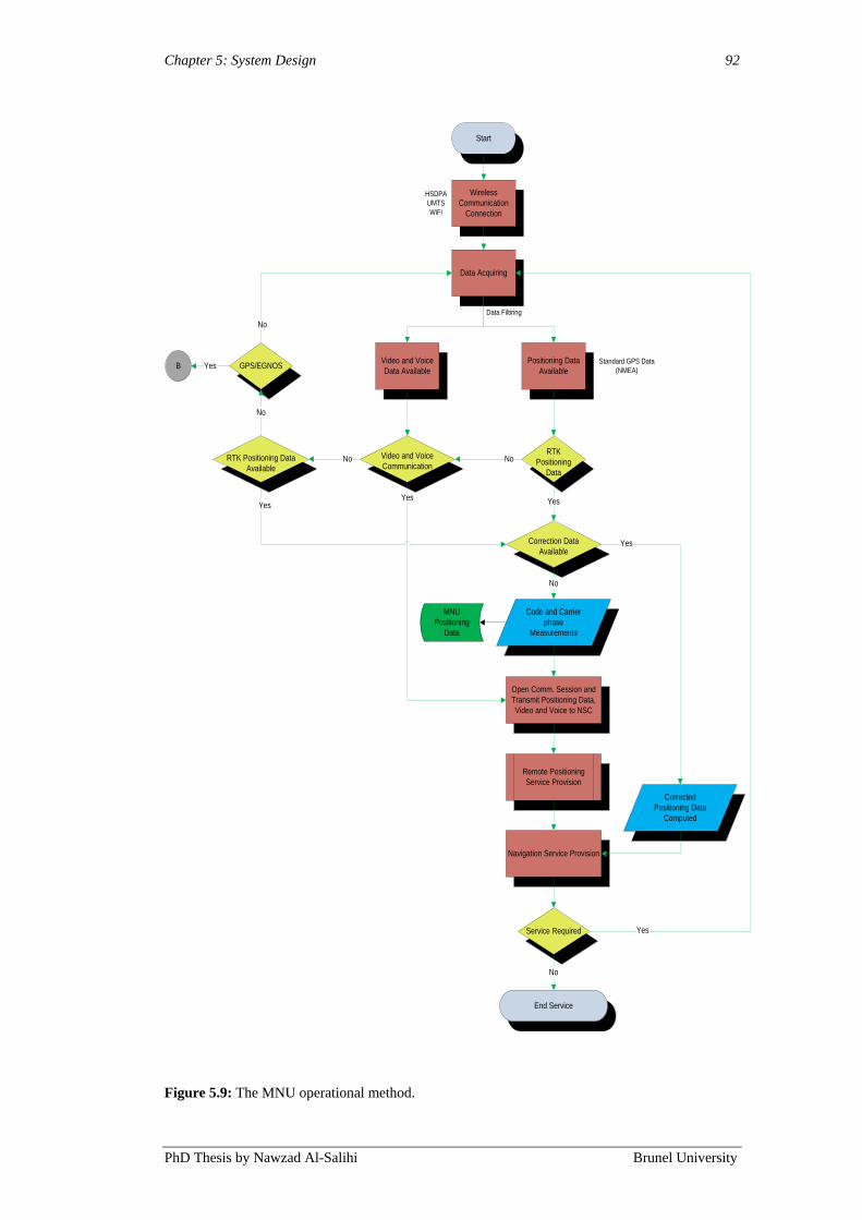
Chapter 5: System Design 92
PhD Thesis by Nawzad Al-Salihi Brunel University
Start
Data Acquiring
RTK
Positioning
Data
GPS/EGNOS
No
Yes
Correction Data
Available
Code and Carrier
phase
Measurements
Corrected
Positioning Data
Computed
Open Comm. Session and
Transmit Positioning Data,
Video and Voice to NSC
Remote Positioning
Service Provision
Navigation Service Provision
Service Required
End Service
No
No
Standard GPS Data
(NMEA)
Yes
Yes
Wireless
Communication
Connection
Positioning Data
Available
Video and Voice
Communication
Yes
HSDPA
UMTS
WiFi
Video and Voice
Data Available
Yes
No
No
No
YesB
RTK Positioning Data
Available
Data Filtiring
MNU
Positioning
Data
Figure 5.9: The MNU operational method.
Chapter 5: System Design 93
PhD Thesis by Nawzad Al-Salihi Brunel University
As shown in Figure 5.9, the operational method executed at the MNU includes
several processes. This starts with connection of wireless communication, which
is accountable to search and connect to an existing wireless communication
network (e.g., HSDPA or UMTS). Another process is data acquisition, which is
involved for acquiring the augmentation data from the dual frequency RTK
receiver and video, and the voice data from the intergraded components at the
MNU. As mentioned already, two types of positioning data are acquired for the
dual frequency RTK receiver: the code and carrier from L1 and L2 of the GPS and
GLONASS signals (Chapter 4). The data update rate is 20 times per second (20
Hz). The memory of MNU accumulates these data types and then they are
retrieved on the biases of the correction data update time intermissions.
Subsequently, two important processes are performed to verify the validity and
integrity of the augmentation data and to select the applicable DGNSS reference
stations. Based on the user‟s initial estimated position, this allows only valid and
reliable augmentation data to be utilised.
In situations, for example, if inadequate positioning data is available at the MNU
or the GPS and GLONASS satellites cannot be seen properly and no applicable
DGNSS stations exist, the system gives an alternative directional solution based
on video and voice communication. This is called the manual guidance method,
and is the second position guiding method proposed by the navigation model
system. The MNU would function in a server-based positioning mode, in which a
communication session is opened with the NSC to transmit a video image of the
immediate environment of the visually impaired person, carry out one-way
communication, and to receive voice data from NSC in the bi-directional
communication, in order for the visually impaired to avoid obstacles in the route.
The video camera built into the user‟s terminal (MNU) and the video display in
the guide‟s terminal (NSC) make up the system‟s remote vision facility – utilised
to assist in micro-navigation. Both the macro- and micro-navigational assistance
(together constituting remote sighted guidance) are provided as verbal macro- and
micro-navigational instructions (the guidance instructions). The use of the manual
guiding method is not restricted on the GNSS signals availability constraints, only
on video and voice communications limitations. However, it can be utilised for

Chapter 5: System Design 94
PhD Thesis by Nawzad Al-Salihi Brunel University
reliable and continuous positioning if the user continuously indicates in-door or
densely urban environments.
The above descriptions belong to the first and second scenarios. In the third
scenario, when NRTK positioning, video, and voice data are unavailable at the
MNU, the system has an option to activate a different system for guidance,
demonstrated as symbol B in Figure 5.9.
The alternative system is the already established Adaptive, Reliable, and Accurate
Positioning Model for Location-Based Services model, applying GPS
augmentation techniques, such as EGNOS/SISNET by Al Nabhan (2009).
The model is based on the single frequency GPS Standard Positioning Service
(SPS). The positioning model operates over a client-server architecture, including
two main components, described as the Localisation Server (LS) and the Mobile
Unit (MU), and the positioning model operates in two position determination
modes. The stand-alone mode is used if enough navigation information is
available at the MU using its local positioning device (GPS/EGNOS receiver).
Otherwise, the server-based mode is utilised, in which the LS intervenes and starts
providing the required position solutions. At the LS, multiple sources of GPS
augmentation services are received using the Internet as the sole augmentation
data transportation medium. The augmentation data is then processed and
integrated for guaranteeing the availability of valid and reliable information
required for the provision of accurate and precise position solutions (Al Nabhan,
2009).
In Al Nabhan‟s (2009) research, the results showed that the LS, through the
developed position computation methods, was able to provide position samples
with an accuracy of less than 2 m, with high precision at the 95% confidence
level. This was achieved in urban, rural, and open space (clear satellite view)
navigation environments.
The last position solution used in navigation service provision is received from the
NSC using the RTK positioning corrections and the video and voice
communication received from MNU. Alternatively, as already mentioned in this

Chapter 5: System Design 95
PhD Thesis by Nawzad Al-Salihi Brunel University
chapter, in the absence of a positioning correction or unavailable satellites, the
navigation service provision will be obtained from the NSC using the visual
image captured and transmitted by the user at the MNU; therefore, employing the
manual guiding method solely.
The MNU performs the position calculation by using one advanced method:
coordinate domain positioning. In this work, real-time navigation guidance has
been used; therefore, the coordinate domain positioning method has been
operated. The real-time augmented positioning data is significant for the visually
impaired user at the MNU. A detailed description of the processing procedures for
real-time GNSS positioning is presented in the following chapter.
5.6.2 Navigation Service Centre (NSC) Operational Method
The NSC is the main component of the positioning model‟s functioning design. It
is primarily for the visually able person to provide direction to the visually
impaired person while travelling. The positioning data for every tracked satellite
are received from the associated RTK receiver at the MNU. Additionally, the
audio and visual data are also obtained. All of these types of data experience
dispensation steps so that the user can be guided to the accurate position using the
appropriate positioning method. Figure 5.10 shows the flowchart diagram of the
NSC operational method.
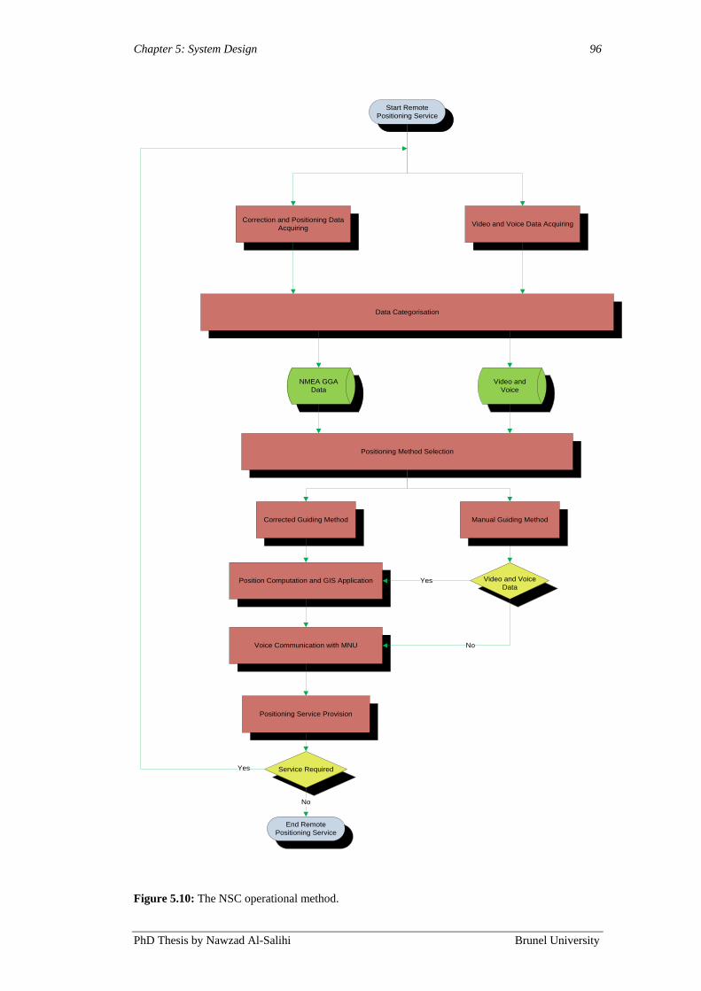
Chapter 5: System Design 96
PhD Thesis by Nawzad Al-Salihi Brunel University
Start Remote
Positioning Service
Correction and Positioning Data
Acquiring
Data Categorisation
NMEA GGA
Data
Position Computation and GIS Application
Positioning Service Provision
Service Required
End Remote
Positioning Service
No
Yes
Video and Voice Data Acquiring
Video and
Voice
Positioning Method Selection
Video and Voice
Data
Corrected Guiding Method
Voice Communication with MNU No
Yes
Manual Guiding Method
Figure 5.10: The NSC operational method.

Chapter 5: System Design 97
PhD Thesis by Nawzad Al-Salihi Brunel University
The first procedures in the NSC functional approach are responsible for data
acquisition and data categorisation. This includes the perception of the data of the
audio, visual data, and augmentation data in NMEA GGA formats. This
information is then sorted into different corresponding files. The positioning
method selection process is responsible for extracting the required data fields
from each file. From these, a guiding model will be determined based on the
reliance of obtainable augmented positioning data or only video and voice data.
This process will automatically choose an appropriate method.
The user‟s position can be obtained and plotted in the GIS application once all
data fields have been attained and positioning method has been selected. The
sighted user at the NSC will be able to see the present position on a digital map
(e.g. Google map) of the visually impaired person. In addition, the sighed user at
the NSC can see a video image of the surrounding area to assist the visually
impaired person to keep away from static obstacles located above ground level,
such as tree branches, which primary aids (the cane or guide dog) cannot avoid. In
order to detect dynamic obstacles, the use of the real-time video image allows the
guide to see the environment in front of the user, including moving objects, such
as bicycles or new construction work. This was not possible with the other EOAs
described in Chapter 3, where static obstacles are pre-programmed in the
databases.
5.7 Summary
This chapter describes the process of design of the Precise Positioning in Real-
Time using GPS-RTK Signal for Visually Impaired People Navigation System
and presents the details of the architecture and functionality of the developed
system prototype.
By applying the principles of user-centred system design methodology, the system
was designed, following the outcome of the literature review-based studies
summaries in chapters 2 and 4. The conceptual framework for the design of the
system was implemented from the Brunel Navigation System for the Blind
(BNSB), a mobility aid developed within the Centre for Electronic Systems

Chapter 5: System Design 98
PhD Thesis by Nawzad Al-Salihi Brunel University
Research at Brunel University as well, where this PhD project was carried out.
The Precise Positioning in Real-Time using GPS-RTK Signal for Visually
Impaired People Navigation System has the ability to offer the visually impaired
system user with support in micro- and macro-navigation.
The Mobile Navigation Unit (MNU) and the Navigation Service Centre (NSC) are
the two significant elements that make up the functioning structure of the
positioning model. The new model integrates two functional approaches for
switching the MNU from a standalone position determination to a server-based
positioning mode in case of positioning and correction data unavailability. The
NSC applies in such conditions and starts to provide the the MNU with accurate
location solutions and/or physical guidances by verbal methods after obtaining the
positioning and visual data of the user. The position correction at the MNU and
the NSC is performed using WADGNSS augmentation messages received from
the network-DGNSS via TopNET+. Moreover, with a situation of non-
accessibility of the positioning data at the mobile device due to a signal blockade,
the operational method at the MNU has the possibility of having a manual
guidance from the NSC. In view of that, the proposed positioning model offers
and maintains an optimal position solution by taking into account all navigation
and mobile wireless communication architectural components and the surrounding
conditions.
Chapter 6: An Assessment Methodology of Network-Based RTK (NRTK) GNSS and Galileo System
Performance 99
PhD Thesis by Nawzad Al-Salihi Brunel University
Chapter 6
6. An Assessment Methodology of Network-Based RTK
(NRTK) GNSS and Galileo System Performance
6.1 Introduction
This chapter offers a thoroughly portrayal of the assessment methodology utilised
in order to make the developed positioning model valid, as presented in Chapter 4
and 5. The methodology has been divided into two sections. The first part
involves experimental work; conducting field measurement trials to study and
collect Network RTK (NTRK) GNSS data- considering different navigation
settings and measurement scenarios. The second part of the methodology included
a quantification of the developed positioning model vis-à-vis the accurate and
reliable positioning services provided by an upcoming Galileo system.
In the first part of the experiment methodology, positioning data measurements
were processed and analysed from the performance achieved from the NRTK
GNSS positioning service implemented at the MNU. The estimation was
conducted in terms of the positioning performance parameters depicted in the
section 6.2; this comprises the position solution accuracy and precision as well as
the service availability. Furthermore, the experimental performance comparison
took place in accordance with the desired positioning performance scenarios and
requirements levels summarised in Section 6.2.8 and Table 6.1.
As for the second part, it was achieved by conducting a simulation study using the
Galileo Simulation Service Facility (GSSF) software. The GSSF allows the
investigative and analysis of future Galileo‟s Open Service (OS) performance in
different scenarios and conditions similar to the experimental work.
The experimental work is explained in the Section 6.3, which elucidates all
utilised hardware and software components. Moreover, the section illustrates the

Chapter 6: An Assessment Methodology of Network-Based RTK (NRTK) GNSS and Galileo System
Performance 100
PhD Thesis by Nawzad Al-Salihi Brunel University
settings and locations where the static and dynamic measurements took place. The
next section, Section 6.4, presents the simulation part, together with details of the
GSSF functionality, and; finally, Section 6.5 summarises the whole chapter.
6.2 Positioning System Performance
A precise definition of performance requirements is critical during the design
phase of any navigation system. Accurate requirements elicitation is especially
important when selecting an appropriate technology to meet both functional and
non-functional requirements. Furthermore, an assessment process of the technical
capability is essential to meet performance requirements. The desired system
requirements can be quantified by metrics to represent its overall effectiveness. A
comparison of these metrics for performance assessment with respect to actual
system characteristics assists in describing the system usability and its limitations.
In fact, comprehensive performance standards should provide performance
definitions, as well as assessment methodologies. The shortage of performance
standards across industries makes the comparison for systems in diverse
publication or product specifications very challenging. Hence, a standardised
approach for defining parameters is critical for comparing the performances of
different navigation systems.
Many ways of assessing and presenting performance parameters do exist,
although conversion between them is sometimes difficult. Often, positioning
system performance is specified in terms of system availability and accuracy,
despite the fact that different parameters are exchangeable by setting different
system configuration parameters. This means, for instance, that it is possible to
improve precision at the expense of reducing availability and vice versa.
Similarly, by modifying the system availability or accuracy, better system
reliability can be achieved with certain performance trade-off decisions during the
requirement analysis.

Chapter 6: An Assessment Methodology of Network-Based RTK (NRTK) GNSS and Galileo System
Performance 101
PhD Thesis by Nawzad Al-Salihi Brunel University
6.2.1 Positioning Performance Parameters Definitions
The proposed definition of performance parameters for the end-user side follows
the methodology used by the US Department of Defense (DoD, 1996). The
methodology defines five primary parameters: (1) coverage; (2) service
availability; (3) continuity; (4) service reliability and integrity; (5) positioning
accuracy.
All the parameters are organised in successive layers of performance definitions.
Performance definition begins with coverage, and each successive one is
conditioned on the preceding layers, shown in Figure 6.1. This means that
coverage must be provided before the service may be considered available.
Similarly, it must be available before it can support reliability and integrity, or
reliability must be demonstrated before estimating the accuracy (Ptasinski, 2002;
Hughes, 2005).

Chapter 6: An Assessment Methodology of Network-Based RTK (NRTK) GNSS and Galileo System
Performance 102
PhD Thesis by Nawzad Al-Salihi Brunel University
Coverage
The surface area or volume in which the
satellites are operational and visible over the
horizon in the sky.
Service Availability
The availability is the percentage of time
over a specified interval in which a position
can be obtained within the service volume.
Service Reliability
Given coverage and service availability, the
percentage of time when the service is
available with specified tolerance reliability
error threshold.
Positioning Accuracy
Given coverage, service availability, and
service reliability, the percentage of time
when the service is reliable that the
difference between the measured and
expected user position is within a specified
tolerance.
System Integrity
Includes the reliability definition and also
describes the ability of the navigation
system to produce specified warning to the
users when the system is unreliable.
System Continuity
Given coverage, the probability that service
outage will not occur for a certain period of
time.
Figure 6.1: Successive layers of performance parameters and their definitions.

Chapter 6: An Assessment Methodology of Network-Based RTK (NRTK) GNSS and Galileo System
Performance 103
PhD Thesis by Nawzad Al-Salihi Brunel University
6.2.2 Coverage
Coverage represents the area in which the service can be provided, operational of
satellites and their visibility over the horizon in the sky. Since the dynamically
changing nature of coverage with respect to time affects navigation systems used
by various satellite systems, GPS coverage changes must also be taken as a
function of time for appropriate correlation. Thus, dynamic coverage can be
defined as the percentage of time over a given coverage area when the system
coverage is provided. For satellite navigation systems, service coverage is
provided at a given moment in time and a location, but only if the current position
of a given satellite with respect to the user‟s location enables a fix on the user‟s
position. To obtain a 3D position fix, at least four healthy satellites transmitting
usable ranging information should be in the view of the receiver. The fourth
satellite is used to account for the delay due to the incompatibility of clock
accuracy between the atomic clocks onboard satellites and the mobile receiver
clocks. Theoretically, the GPS SPS service provides a global, four-satellite
coverage of more than 99% and a global average of 95.87% in the worst 24-hour
interval (Al Nabhan, 2009). These locations are predominantly located close to
the North and South Poles.
The US Department of Defense (DoD, 1996) provides the definition of coverage
as the percentage of time over a specified time interval that a sufficient number of
satellites be above a specified mask angle of elevation. They also provide
acceptable position triangulation at any point on or near the earth. Satellite
visibility is affected by constraints in terms of mask angle and Dilution of
Precision (DOP). This is to minimise the possibility of a positioning service
generating a marginal position solution. In fact, the values should be selected to
support the required level of positioning service performance. The elevation mask
threshold values and DOP are correlated to the expected accuracy and reliability
of a system, that is, by decreasing the value of the elevation mask, the coverage
and accuracy can be improved. Thus, deploying an increased number of visible
satellites can provide better coverage and improved DOP for position
triangulation. On the other hand, the reliability might be degraded due to the

Chapter 6: An Assessment Methodology of Network-Based RTK (NRTK) GNSS and Galileo System
Performance 104
PhD Thesis by Nawzad Al-Salihi Brunel University
multipath effect, which is increased by the use of satellites with low elevation.
Similarly, by increasing the threshold value of the DOP parameter, the cost of
degrading the overall accuracy of the system can improve availability.
Whenever GPS is used as a primary positioning sensor, the definition by the US
Department of Defense (DoD, 1996) can be useful in the case of a location or
navigation system. When considering a positioning system that relies on data
transmissions, where a base station serves as a communication node, the coverage
of a communication transmission link must also be taken into account in addition
to the coverage of the GPS satellites.
In a scenario where the coverage of correction data is not available, the user can
choose a stand-alone GPS triangulation system according to his or her needs. The
coverage of a centralised system, where remote users can report its location to a
base station, is also dependent on data transmission links and its coverage.
A full GLONASS constellation (21 satellites plus 3 active spares) is theoretically
designed of providing a global coverage of 94.7% for civilian navigational
information. Performance for the Galileo services (Kaplan and Hegarty, 2006)
provides statistical coverage of 99.5% and expected minimum coverage with an
elevation mask angle constraint of 5°.
6.2.3 Service Availability
Service availability represents the percentage of time that the position can be
obtained when the system is in operation. SPS defines availability with a given
coverage as the percentage of time over a specified time interval that a sufficient
number of satellites are transmitting a usable ranging signal within view of any
point on or near the earth. This definition represents a signal in space performance
perspective. Taking into account the end-user performance, GPS availability is
defined here as the percentage of time over the time when the system is in use that
the user receiver can track a sufficient number of satellites. In order to determine a
position, these dynamic objects serve as platforms for transmitting usable ranging
Chapter 6: An Assessment Methodology of Network-Based RTK (NRTK) GNSS and Galileo System
Performance 105
PhD Thesis by Nawzad Al-Salihi Brunel University
signals. In this case, certain constraints upon the GPS geometry of the satellites
also need to be taken into account.
Just because the satellites are operational and currently visible over the horizon
does not necessarily mean that a receiver would be able to determine a position,
especially when affected by factors, such as maintenance issues and transmission
signal blockage.
6.2.4 Continuity
Continuity expresses the ability of the system to perform its function without
interruption during an intended period of operation. Continuity represents in a
different way the availability. More specifically, continuity is the probability that
the specified system performance will be maintained for the duration of a phase of
operation, presuming that the system was available at the beginning of that phase
of operation. “Continuity Risk” is the probability that the system will be
interrupted and will not provide positioning information for the intended period of
time.
This definition was based on the requirement to provide uninterrupted position
update considering GPS applications in aviation such as aircraft automatic
approach and landing systems. In land navigation or location systems, the
positioning module is expected to periodically provide position information with
different time intervals. Based on the application, it is important for users to know
how long the service may be unavailable. Hence, continuity needs to be
determined according to the probability that service outage will not occur for a
certain period of time.
6.2.5 Reliability
Reliability is a factor that represents that amount of trust that can be placed in the
correctness of the information, taking into account how consistently the system
can provide accurate position information. It is defined as the percentage of time
when the service is available with a specified tolerance reliability error threshold.
The reliability error threshold can be defined as the maximum positioning error.
Chapter 6: An Assessment Methodology of Network-Based RTK (NRTK) GNSS and Galileo System
Performance 106
PhD Thesis by Nawzad Al-Salihi Brunel University
The selection of an appropriate value is based on an application and the expected
user accuracy. However, the threshold must be larger than the practical limit on
the normal positioning system accuracy.
Positioning system failure can be caused by factors that include equipment faults
and environmental degradation.
Although GNSS system failure is very rare, this system characteristic is important
to considering for mission-critical applications. In fact, the system reliability can
degrade significantly due to the multipath effects, which requires higher accuracy,
when the multipath error is of the order of tens of meters.
6.2.6 Integrity
Integrity represents an aspect of reliability such that the navigation system is able
to provide timely warning to users when the system is experiencing faults that
compromise functionality. The service reliability standard is based on the
assumption that the user does not perform integrity checking. In the case of user
equipment that employs integrity checking algorithms, its performance can be
described and quantified by using two parameters, namely availability of integrity
functions and detection of probability.
Integrity algorithms require the system robustness and additional data, which
indicates that integrity functions may not be provided indefinately when the
positioning service is available. The availability of integrity is defined as the
percentage of time the system can perform integrity functions when the
positioning service is considered available. For safety critical applications
constraints on service availability may also be used, so it would only be
considered available if the integrity functions can be performed. The probability
of detection failure multiplied by the probability of occurrence (reliability) yields
an overall reliability of the system with integrity checking functions.
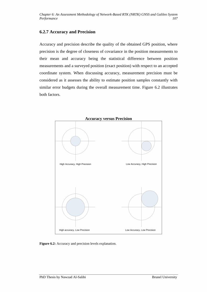
Chapter 6: An Assessment Methodology of Network-Based RTK (NRTK) GNSS and Galileo System
Performance 107
PhD Thesis by Nawzad Al-Salihi Brunel University
6.2.7 Accuracy and Precision
Accuracy and precision describe the quality of the obtained GPS position, where
precision is the degree of closeness of covariance in the position measurements to
their mean and accuracy being the statistical difference between position
measurements and a surveyed position (exact position) with respect to an accepted
coordinate system. When discussing accuracy, measurement precision must be
considered as it assesses the ability to estimate position samples constantly with
similar error budgets during the overall measurement time. Figure 6.2 illustrates
both factors.
Accuracy versus Precision
High Accuracy, High Precision
High accuracy, Low Precision
Low Accuracy, High Precision
Low Accuracy, Low Precision
Figure 6.2: Accuracy and precision levels explanation.
Chapter 6: An Assessment Methodology of Network-Based RTK (NRTK) GNSS and Galileo System
Performance 108
PhD Thesis by Nawzad Al-Salihi Brunel University
Generally, two quantities compose the accuracy of a GPS system; the User
Equivalent Range Error (UERE) and the DOP. The total UERE measures the
horizontal position accuracy and the satellite, signals, given by user error budgets
combined into a single quantity measuring the error in the user-satellite range.
The UERE can be calculated as the sum of errors from atmospheric effects,
receiver noise, ephemeris and satellite clocks, and multipath error contributions.
By taking the square root of the sum of the squares of the measurements errors‟
standard deviations the UERE can be computed:
i
iUERE 2 (6.1)
i is the standard deviation of the thi error budget.
The DOP gives a simple characterisation of user to satellite geometry and refers to
the position of the satellites in relation to each other with respect to the user. It can
be exposed by using measures, such as the Position DOP (PDOP), indicating the
error in the satellites coordinates used to triangulate the calculated position; the
Horizontal position DOP (HDOP) and Vertical position DOP (VDOP) make up
the PDOP. Time DOP (TDOP) can describe a clock-offset quantifier. TDOP and
PDOP form the Geometric Dilution of Precision (GDOP) used to represent the
geometric strength of the position solution. As the value of GDOP increases, there
is a greater possible error in the obtained position. GDOP quantifiers can be used
as measures of system availability since most receivers allow the determination of
a threshold level of GDOP (e.g. PDOP mask, satellite elevation angle mask)
above which data cannot be collected (AL Nabhan, 2009). Here, PDOP is
regarded as a measure of availability and accuracy, because it is the only dilution
of precision value associated with the horizontal and vertical positional portion of
the navigation solution.
The DOP values computation is achieved as follows: As a first step in computing
DOP, the covariance of the measurement error can be approximated as
(Jirawimut, 2003):
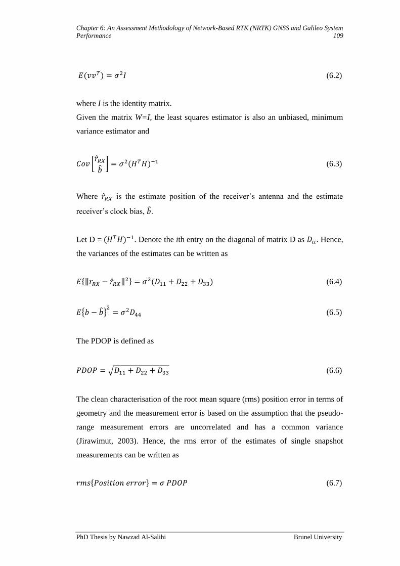
Chapter 6: An Assessment Methodology of Network-Based RTK (NRTK) GNSS and Galileo System
Performance 109
PhD Thesis by Nawzad Al-Salihi Brunel University
(6.2)
where I is the identity matrix.
Given the matrix W=I, the least squares estimator is also an unbiased, minimum
variance estimator and
(6.3)
Where is the estimate position of the receiver‟s antenna and the estimate
receiver‟s clock bias, .
Let D = . Denote the ith entry on the diagonal of matrix D as . Hence,
the variances of the estimates can be written as
(6.4)
(6.5)
The PDOP is defined as
(6.6)
The clean characterisation of the root mean square (rms) position error in terms of
geometry and the measurement error is based on the assumption that the pseudo-
range measurement errors are uncorrelated and has a common variance
(Jirawimut, 2003). Hence, the rms error of the estimates of single snapshot
measurements can be written as
(6.7)
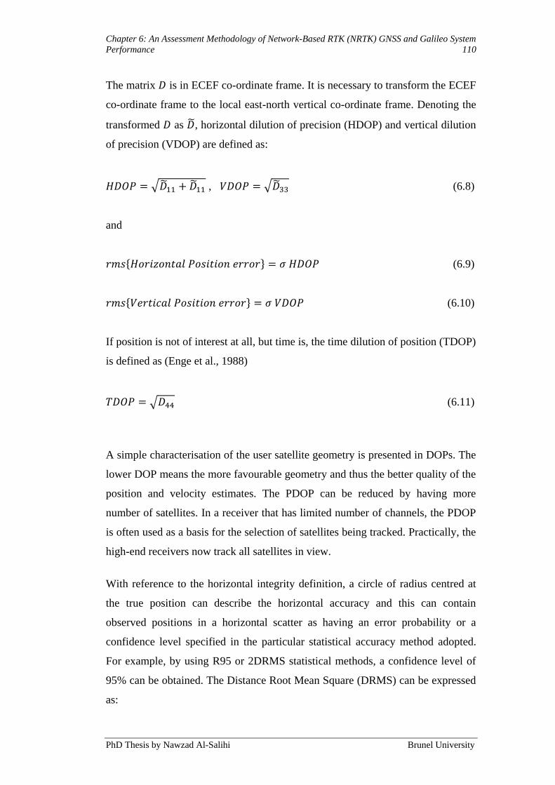
Chapter 6: An Assessment Methodology of Network-Based RTK (NRTK) GNSS and Galileo System
Performance 110
PhD Thesis by Nawzad Al-Salihi Brunel University
The matrix is in ECEF co-ordinate frame. It is necessary to transform the ECEF
co-ordinate frame to the local east-north vertical co-ordinate frame. Denoting the
transformed as , horizontal dilution of precision (HDOP) and vertical dilution
of precision (VDOP) are defined as:
, (6.8)
and
(6.9)
(6.10)
If position is not of interest at all, but time is, the time dilution of position (TDOP)
is defined as (Enge et al., 1988)
(6.11)
A simple characterisation of the user satellite geometry is presented in DOPs. The
lower DOP means the more favourable geometry and thus the better quality of the
position and velocity estimates. The PDOP can be reduced by having more
number of satellites. In a receiver that has limited number of channels, the PDOP
is often used as a basis for the selection of satellites being tracked. Practically, the
high-end receivers now track all satellites in view.
With reference to the horizontal integrity definition, a circle of radius centred at
the true position can describe the horizontal accuracy and this can contain
observed positions in a horizontal scatter as having an error probability or a
confidence level specified in the particular statistical accuracy method adopted.
For example, by using R95 or 2DRMS statistical methods, a confidence level of
95% can be obtained. The Distance Root Mean Square (DRMS) can be expressed
as:
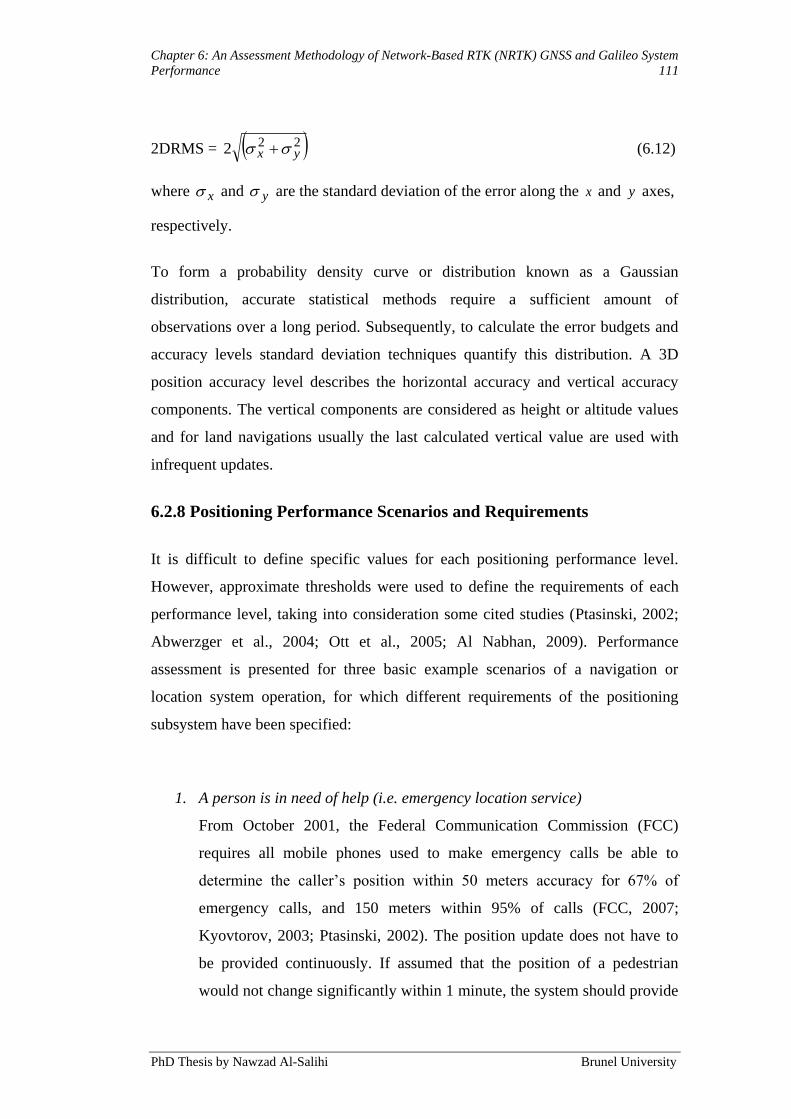
Chapter 6: An Assessment Methodology of Network-Based RTK (NRTK) GNSS and Galileo System
Performance 111
PhD Thesis by Nawzad Al-Salihi Brunel University
2DRMS = 222 yx (6.12)
where x and y are the standard deviation of the error along the x and y axes,
respectively.
To form a probability density curve or distribution known as a Gaussian
distribution, accurate statistical methods require a sufficient amount of
observations over a long period. Subsequently, to calculate the error budgets and
accuracy levels standard deviation techniques quantify this distribution. A 3D
position accuracy level describes the horizontal accuracy and vertical accuracy
components. The vertical components are considered as height or altitude values
and for land navigations usually the last calculated vertical value are used with
infrequent updates.
6.2.8 Positioning Performance Scenarios and Requirements
It is difficult to define specific values for each positioning performance level.
However, approximate thresholds were used to define the requirements of each
performance level, taking into consideration some cited studies (Ptasinski, 2002;
Abwerzger et al., 2004; Ott et al., 2005; Al Nabhan, 2009). Performance
assessment is presented for three basic example scenarios of a navigation or
location system operation, for which different requirements of the positioning
subsystem have been specified:
1. A person is in need of help (i.e. emergency location service)
From October 2001, the Federal Communication Commission (FCC)
requires all mobile phones used to make emergency calls be able to
determine the caller‟s position within 50 meters accuracy for 67% of
emergency calls, and 150 meters within 95% of calls (FCC, 2007;
Kyovtorov, 2003; Ptasinski, 2002). The position update does not have to
be provided continuously. If assumed that the position of a pedestrian
would not change significantly within 1 minute, the system should provide

Chapter 6: An Assessment Methodology of Network-Based RTK (NRTK) GNSS and Galileo System
Performance 112
PhD Thesis by Nawzad Al-Salihi Brunel University
a position update without outage longer than 1 minute through 95% of
time.
2. A person is tracked to continuously provide positions (e.g. Police or
security personnel tracking)
The position has to be updated periodically (e.g. every 5 seconds). Position
solution within ≥7 meter of actual true position would allow finding out
where the person is currently located. This constraint exists, so that the
system can differentiate, between closely spaced roads.
3. A person is continuously navigated by the system
For navigation purposes, the position update should be provided
continuously at least every second. If navigation information requires
position resolution related to which street the person is currently on, 2
meter accuracy should be sufficient. If the guide is providing more
detailed information regarding which side of street, the person is currently
walking on, 1-2 meter accuracy would be required. To find the position of
a person, e.g. visually impaired people, in relation to a pavement, on
which the visually impaired person walks, 0.5-1 meter accuracy is
considered necessary.
With reference to each scenario, several positioning performance features were
described and appointed for each performance level. The summary of the
requirements is shown in Table 6.1.
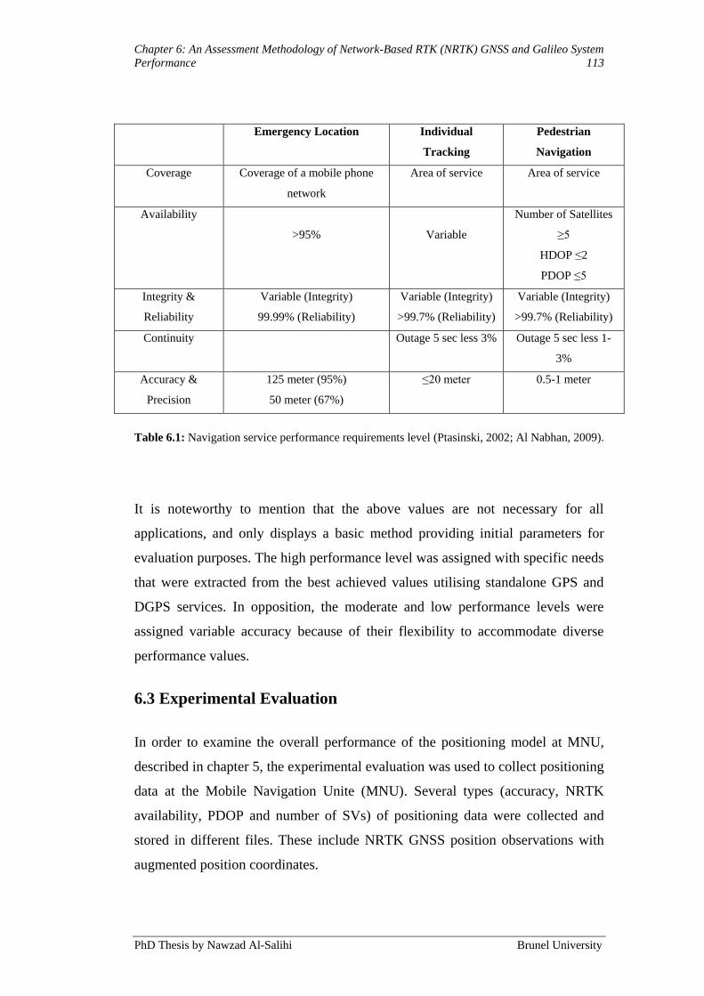
Chapter 6: An Assessment Methodology of Network-Based RTK (NRTK) GNSS and Galileo System
Performance 113
PhD Thesis by Nawzad Al-Salihi Brunel University
Emergency Location Individual
Tracking
Pedestrian
Navigation
Coverage Coverage of a mobile phone
network
Area of service Area of service
Availability
>95%
Variable
Number of Satellites
≥5
HDOP ≤2
PDOP ≤5
Integrity &
Reliability
Variable (Integrity)
99.99% (Reliability)
Variable (Integrity)
>99.7% (Reliability)
Variable (Integrity)
>99.7% (Reliability)
Continuity Outage 5 sec less 3% Outage 5 sec less 1-
3%
Accuracy &
Precision
125 meter (95%)
50 meter (67%)
≤20 meter 0.5-1 meter
Table 6.1: Navigation service performance requirements level (Ptasinski, 2002; Al Nabhan, 2009).
It is noteworthy to mention that the above values are not necessary for all
applications, and only displays a basic method providing initial parameters for
evaluation purposes. The high performance level was assigned with specific needs
that were extracted from the best achieved values utilising standalone GPS and
DGPS services. In opposition, the moderate and low performance levels were
assigned variable accuracy because of their flexibility to accommodate diverse
performance values.
6.3 Experimental Evaluation
In order to examine the overall performance of the positioning model at MNU,
described in chapter 5, the experimental evaluation was used to collect positioning
data at the Mobile Navigation Unite (MNU). Several types (accuracy, NRTK
availability, PDOP and number of SVs) of positioning data were collected and
stored in different files. These include NRTK GNSS position observations with
augmented position coordinates.
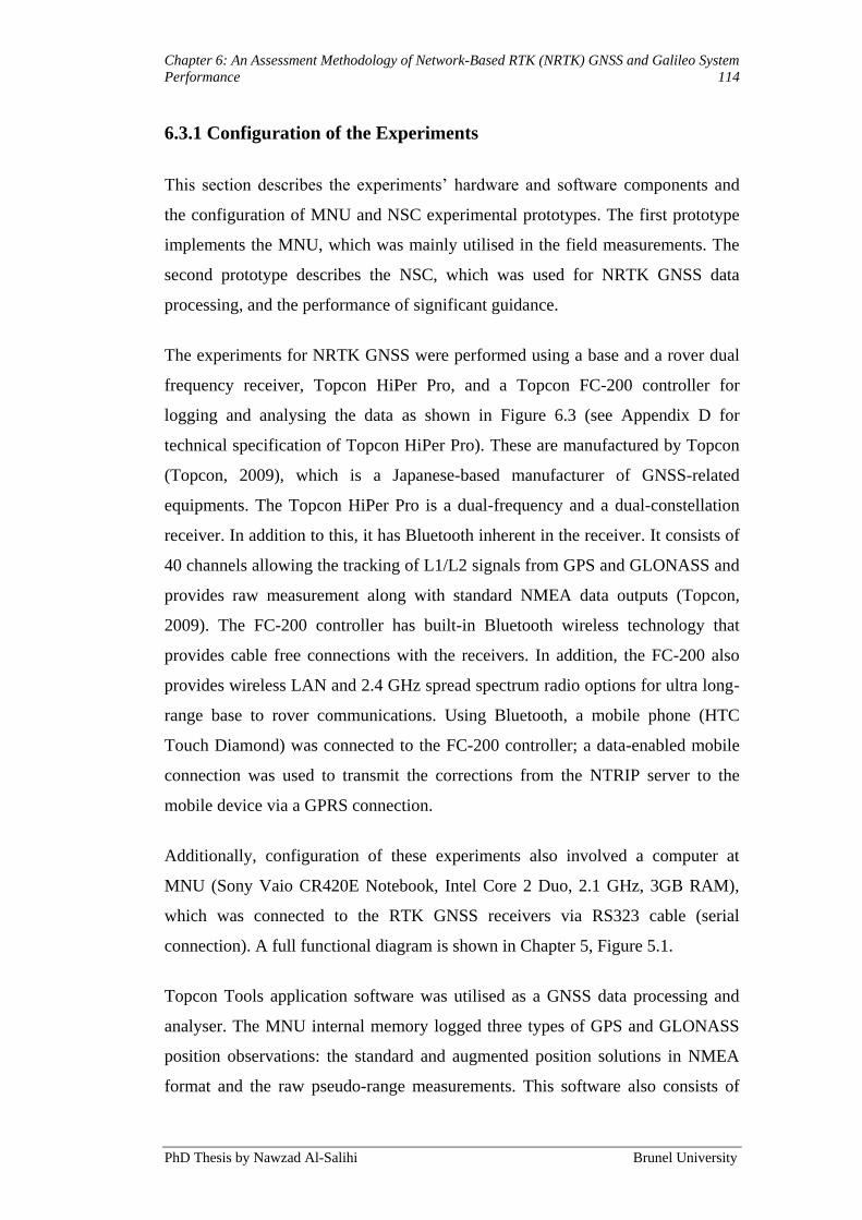
Chapter 6: An Assessment Methodology of Network-Based RTK (NRTK) GNSS and Galileo System
Performance 114
PhD Thesis by Nawzad Al-Salihi Brunel University
6.3.1 Configuration of the Experiments
This section describes the experiments‟ hardware and software components and
the configuration of MNU and NSC experimental prototypes. The first prototype
implements the MNU, which was mainly utilised in the field measurements. The
second prototype describes the NSC, which was used for NRTK GNSS data
processing, and the performance of significant guidance.
The experiments for NRTK GNSS were performed using a base and a rover dual
frequency receiver, Topcon HiPer Pro, and a Topcon FC-200 controller for
logging and analysing the data as shown in Figure 6.3 (see Appendix D for
technical specification of Topcon HiPer Pro). These are manufactured by Topcon
(Topcon, 2009), which is a Japanese-based manufacturer of GNSS-related
equipments. The Topcon HiPer Pro is a dual-frequency and a dual-constellation
receiver. In addition to this, it has Bluetooth inherent in the receiver. It consists of
40 channels allowing the tracking of L1/L2 signals from GPS and GLONASS and
provides raw measurement along with standard NMEA data outputs (Topcon,
2009). The FC-200 controller has built-in Bluetooth wireless technology that
provides cable free connections with the receivers. In addition, the FC-200 also
provides wireless LAN and 2.4 GHz spread spectrum radio options for ultra long-
range base to rover communications. Using Bluetooth, a mobile phone (HTC
Touch Diamond) was connected to the FC-200 controller; a data-enabled mobile
connection was used to transmit the corrections from the NTRIP server to the
mobile device via a GPRS connection.
Additionally, configuration of these experiments also involved a computer at
MNU (Sony Vaio CR420E Notebook, Intel Core 2 Duo, 2.1 GHz, 3GB RAM),
which was connected to the RTK GNSS receivers via RS323 cable (serial
connection). A full functional diagram is shown in Chapter 5, Figure 5.1.
Topcon Tools application software was utilised as a GNSS data processing and
analyser. The MNU internal memory logged three types of GPS and GLONASS
position observations: the standard and augmented position solutions in NMEA
format and the raw pseudo-range measurements. This software also consists of

Chapter 6: An Assessment Methodology of Network-Based RTK (NRTK) GNSS and Galileo System
Performance 115
PhD Thesis by Nawzad Al-Salihi Brunel University
statistical functions for determining the availability of GPS and GLONASS
services and can conduct post-processing of GPS, GLONASS and RINEX data. In
addition, during the measurements trials it visualises positions on 2D map,
including the calculation of PDOP values and number of SVs.
For the experiments of NRTK GPS, only one of the receivers was required with
the hand controller, FC-200. The RTK GNSS receiver was operational in the
WADGPS system, receiving augmentation data from TopNET+, via a GPRS
connection. The corrected positioning data was processed with Topcon Tools
application software and the position of the user was visualised on the screen
using 2D map integrated in the software.
Figure 6.3: RTK GPS measuring units.
Topcon FC-200 Field Controller Topcon HiPer Pro Receiver

Chapter 6: An Assessment Methodology of Network-Based RTK (NRTK) GNSS and Galileo System
Performance 116
PhD Thesis by Nawzad Al-Salihi Brunel University
The NSC was compiled from the following hardware and software components:
Intel Dual Xeon computer, 3.2 GHz, 12 MB cache, 1600 FSB, and 8GM;
Topcon Tools software, as described above.
This configuration can be used in various static and dynamic navigation
applications. Positioning data and satellite navigation data were logged directly
into the receiver for static and dynamic experiments. The data was transferred
from the receiver to a PC for post-processing, or alternatively, real-time
positioning with the help of augmentation data from TopNET+, calculated the
corrected positioning.
6.3.2 Environment Setup and Quality Assessment Methodology
RTK GPS faces various challenges when being run in environments comprising
of different obstacles; especially under and/or near urban environments, thus,
creating problems such as multipaths by trees and buildings and signal
derangements. Therefore, it is necessary to test the functionality of the NRTK
GNSS in a realistic environment, which will bear a purpose in the future. This
experimental testing investigates the accuracy performance of NRTK GNSS for
pedestrians in real-time scenarios. Realistic environments and real-time scenarios
are defined here as locations in which a reasonable person using the NRTK GNSS
would position him or herself in. These positions involve various landscapes,
which contain a mixture of rural, suburban, and urban areas as these create an
ordinary environment in which a GNSS user lives.
To facilitate the evaluation of the positional quality of TopNET+, several static
and dynamic tests were carried out. The dedicated static tests were to assess the
accuracy, precision, and availability of the TopNet+ NRTK GNSS solutions while
the dynamic tests were intended to assess only their accuracy (when compared
with a more accurate solution) and availability.
All the tests had a common objective, that is, to examine the influence of several
factors, such as the number of GPS and GLONASS satellites in view, their

Chapter 6: An Assessment Methodology of Network-Based RTK (NRTK) GNSS and Galileo System
Performance 117
PhD Thesis by Nawzad Al-Salihi Brunel University
geometry, and the age of the NRTK corrections (AoC) when received at the rover
receiver on the TopNET+ solutions.
For the simulation part, similar conditions and scenarios as the NRTK GNSS
experimental work were conducted. The simulation experiments were performed
using the Galileo System Simulation Facility (GSSF) software, developed by
VEGA Group PLC for the European Space Agency (ESA). The GSSF is
conceived as a simulation environment that reproduces the functional and
performance behaviour of the Galileo satellite navigation system.
The experimental flow chart of the real scenarios and the simulation test consisted
of the following components and conditions, as shown in Figure 6.4:

Chapter 6: An Assessment Methodology of Network-Based RTK (NRTK) GNSS and Galileo System
Performance 118
PhD Thesis by Nawzad Al-Salihi Brunel University
Setup Equipment
Configuration
Experiment Trial
Data Analysis
Evaluation
Results
RTK GNSS
· Real
Galileo
Simulation
GPS + Galileo
Simulation
Rural Area
No obstacles
Suburban Area
1-2 obstacles
Urban Area
3-4 obstacles
Condition A Condition B
· Accuracy
· Availability
· Reliability
· Coverage
---------------------
· Static
· Dynamic
Main
X2
Figure 6.4: Experimental Flow Chart.
Condition A and B:
1. Real Scenario (RTK GNSS):
The RTK GNSS signal performance parameters were monitored and
computed in different positions and environments. The performance of the
signal was evaluated using static and dynamic experiments in rural,
suburban and urban areas. It was planned that a participant would walk
Chapter 6: An Assessment Methodology of Network-Based RTK (NRTK) GNSS and Galileo System
Performance 119
PhD Thesis by Nawzad Al-Salihi Brunel University
along a predefined trajectory for the dynamic testing. For the static testing,
different positions in various environments were chosen. The experimental
environments are described in section 6.3.3.
2. Virtual Scenario:
The described experiment above was conducted in a similar manner in
simulation software for Galileo and for a hybrid system of GPS and
Galileo.
Main:
1. Setup Equipment:
Connected hardware (RTK GNSS receiver, laptop, etc.) and
communication link.
2. Testing:
Various testing performance of hardware and software was undertaken.
3. Experiment Trial:
Experiments performed in both real-time and simulated scenarios (static
and dynamic) in order to evaluate the four main variables for a comparison
between RTK GPS, Galileo and the hybrid system. The variables were
accuracy, availability, reliability and coverage.
The trials were arranged to be repeated two times. The first series of trials
were intended to be conducted to collect the initial data, whereas the data
collected during the second series was used as a reference to determine
possible errors in the first series and to approve the repeatability of the
experiment.
4. Data Analysis:
The outcome of the data from various scenarios was analysed in this stage.

Chapter 6: An Assessment Methodology of Network-Based RTK (NRTK) GNSS and Galileo System
Performance 120
PhD Thesis by Nawzad Al-Salihi Brunel University
5. Evaluation:
With the results from the data analysis, an evaluation of the variables was
carried out.
6. Results:
In this last step, the results of the experiments were discussed.
6.3.3 Experiment Trials
Using the experimental setup, comprehensive field measurement trials observed
and collected RTK GNSS data in static and dynamic scenarios over several
dynamic routes and sites. All equipments were during the measurements trials
arranged in the same way to ensure a similar testing condition. Two routes
(pedestrian paths), three static observation sites and twenty benchmark points
(static test) were carefully selected at different locations within Brunel University
Campus, Uxbridge, UK (Figure 6.5). The experiential field locations represented
diverse navigational environments with a range of diverse conditions, from open
spaces to densely built-up areas.

Chapter 6: An Assessment Methodology of Network-Based RTK (NRTK) GNSS and Galileo System
Performance 121
PhD Thesis by Nawzad Al-Salihi Brunel University
Figure 6.5: Brunel University Campus (Bing Maps).
A static experiment gives an advantage of conducting a long period measurement
when a GNSS antenna is placed in an accurately surveyed location and data are
collected over 24 hours. When dynamic tests are conducted in a real environment
under real scenarios where the system will possibly be used, the tests may give
better results. However, it is problematic to conduct 24-hour experiments for
practical reasons. Therefore, it was decided that measurements for a specified
location be repeated at different times during a 24-hour period, so tests with
different satellite configurations could be carried out.
The configuration of GPS satellites continuously changes in relation to each
user‟s position. The satellites complete one orbit in approximately 11 hours and

Chapter 6: An Assessment Methodology of Network-Based RTK (NRTK) GNSS and Galileo System
Performance 122
PhD Thesis by Nawzad Al-Salihi Brunel University
58 minutes. Since the earth is rotating, the satellites trace a track over the earth‟s
surface, which repeats every 23 hours and 56 minutes. For assessing the accuracy
measurement of a dynamic test, a person needs to walk exactly along a marked
route assuming a constant velocity. Along this route, different benchmark points
(static tests) were marked, accurately surveyed as the reference points over several
days at a centimetre accuracy level, using the dual frequency receiver-measuring
unit described earlier in Section 6.3.1. When passing by each point, the actual
time synchronised with GPS time was logged, together with a group of GPS
measurements. This allowed a quantifying of the positional accuracy at each
point, as well as along the whole path.
The satellites‟ elevation mask was set to 5 which is a commonly used value for
performance assessment. The elevation mask is a filter, which exclude any signal
from a satellite that is under a certain described angle as it is recorded in the
satellite's ephemeris. Essentially, if the satellite is below the suggested 5° above
the horizon, the receiver will not make use of this satellite in determining the final
solution. Because of structural interference, the elevation mask is set to 5° to ward
off atmospheric distortion and possible multipath errors. High multipath effects
can decrease the time coefficient used to decide the solution and decrease the of
data‟s positional accuracy. The maximum PDOP value was set to 6. Hughes
(2005) presented these settings on satellite visibility and they were used to
minimise the possibility of having a positioning service generating erroneous
position solutions. Table 6.2 also summarises the surveyed points‟ easting and
northing coordinates, with reference to the Ordinance National Grid (OS Net,
2009).
The first testing was carefully selected to simulate a typical rural and suburban
area; the tests taking place between different buildings. The distance covered by
the dynamic route was approximately 625 meters. As Table 6.2 shows, ten static
tests (benchmark points) and the coordinates of the points (Easting and Northing):
ST1 to ST10. One of the performance test, ST7, was carried out under a tree
canopy. The dynamic test, DT1, were designed to estimate the accuracy and
NRTK availability of TopNET+, on a road segment using the static points ST1 to
ST10 at Brunel University campus.

Chapter 6: An Assessment Methodology of Network-Based RTK (NRTK) GNSS and Galileo System
Performance 123
PhD Thesis by Nawzad Al-Salihi Brunel University
Test Network
Service
Obs.
Method
Elevation
Mask
Angle
Environment Easting
Coordinates
Northing
Coordinates
ST1 TopNET+ Static 5º Rural 506143.800 182452.040
ST2 TopNET+ Static 5º Suburban 506216.007 182474.256
ST3 TopNET+ Static 5º Suburban 506279.799 182603.845
ST4 TopNET+ Static 5º Suburban 506204.211 182688.177
ST5 TopNET+ Static 5º Suburban 506060.601 182688.574
ST6 TopNET+ Static 5º Suburban 506059.599 182690.407
ST7 TopNET+ Static 5º Tree Canopy 506050.617 182659.006
ST8 TopNET+ Static 5º Suburban 506024.638 182573.785
ST9 TopNET+ Static 5º Suburban 506020.037 182526.405
ST10 TopNET+ Static 5º Rural 506071.634 182474.018
OS1 TopNET+ Static 5º Suburban 506041.341 182521.596
OS2 TopNET+ Static 5º Rural 506024.139 182634.656
OS3 TopNET+ Static 5º Urban 506178.861 182572.991
DT1 TopNET+ Dynamic 5º Rural/Suburban Various Various
Table 6.2: Performed test details for rural and suburban area.
Figure 6.6 presents the testing points for the static positioning measurements and
the distance from buildings. The 2D map of Brunel University campus was in a
scale of 1:1000 and was drawn by the Department of Estates at Brunel University.
Figure 6.7 provides a general description of the first tests and the surrounding
objects in bird view. Furthermore, the route for the dynamic tests (DT1), with
Start and End points, are shown in Figure 6.7 (yellow line).
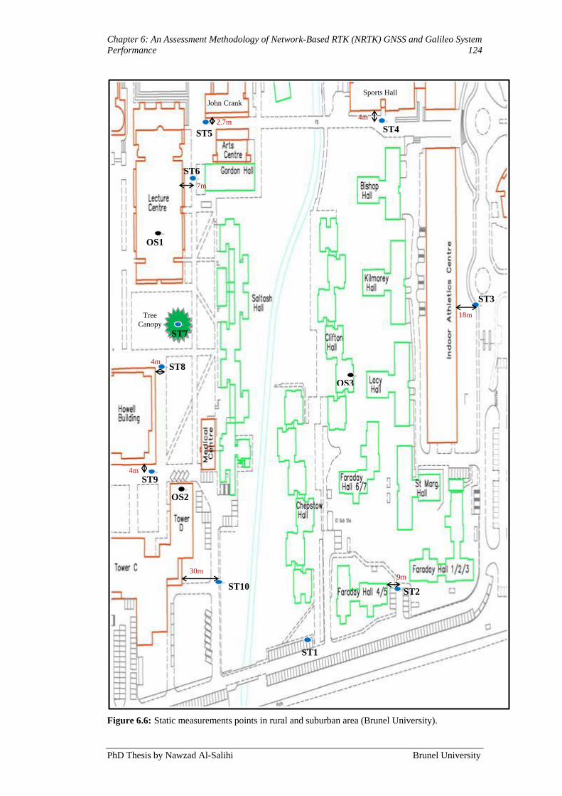
Chapter 6: An Assessment Methodology of Network-Based RTK (NRTK) GNSS and Galileo System
Performance 124
PhD Thesis by Nawzad Al-Salihi Brunel University
Figure 6.6: Static measurements points in rural and suburban area (Brunel University).
Tree
Canopy
4m
30m
18m
2.7m 4m
4m
7m
ST1
ST2
ST3
ST4 ST5
ST6
ST7
ST8
ST9
ST10 9m
OS2
OS1
OS3
Sports Hall
John Crank

Chapter 6: An Assessment Methodology of Network-Based RTK (NRTK) GNSS and Galileo System
Performance 125
PhD Thesis by Nawzad Al-Salihi Brunel University
Figure 6.7: Static measurements points in rural and suburban area (Bing Maps).
The second testing for static and dynamic was selected within the most densely
sited build-up area, making an urban area in the university campus with parts
where signals from the satellites were very likely to be blocked by surrounding
buildings. This route was selected in-between eight-storey accommodation
buildings (Bishop Complex), shown in Figure 6.9 (yellow line) with Start and End
points. The total distance covered was approximately 155 meters for DT2. As
Start Point
End Point
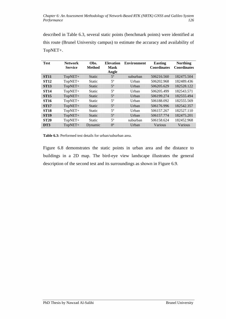
Chapter 6: An Assessment Methodology of Network-Based RTK (NRTK) GNSS and Galileo System
Performance 126
PhD Thesis by Nawzad Al-Salihi Brunel University
described in Table 6.3, several static points (benchmark points) were identified at
this route (Brunel University campus) to estimate the accuracy and availability of
TopNET+.
Test Network
Service
Obs.
Method
Elevation
Mask
Angle
Environment Easting
Coordinates
Northing
Coordinates
ST11 TopNET+ Static 5º suburban 506216.560 182475.504
ST12 TopNET+ Static 5º Urban 506202.968 182489.436
ST13 TopNET+ Static 5º Urban 506205.629 182528.122
ST14 TopNET+ Static 5º Urban 506205.499 182543.571
ST15 TopNET+ Static 5º Urban 506199.274 182555.494
ST16 TopNET+ Static 5º Urban 506188.092 182555.569
ST17 TopNET+ Static 5º Urban 506176.996 182542.357
ST18 TopNET+ Static 5º Urban 506157.267 182527.110
ST19 TopNET+ Static 5º Urban 506157.774 182475.201
ST20 TopNET+ Static 5º suburban 506158.624 182452.968
DT3 TopNET+ Dynamic 0º Urban Various Various
Table 6.3: Performed test details for urban/suburban area.
Figure 6.8 demonstrates the static points in urban area and the distance to
buildings in a 2D map. The bird-eye view landscape illustrates the general
description of the second test and its surroundings as shown in Figure 6.9.
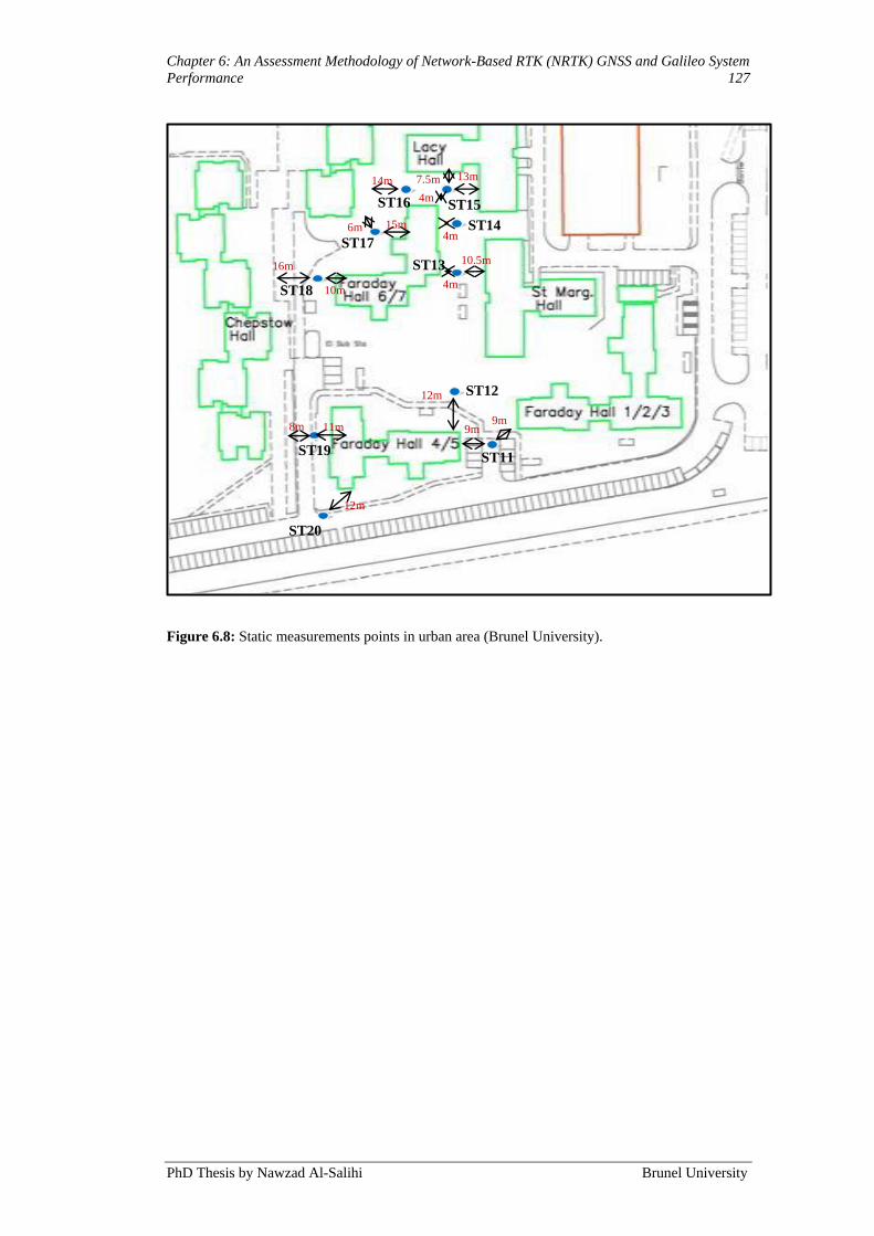
Chapter 6: An Assessment Methodology of Network-Based RTK (NRTK) GNSS and Galileo System
Performance 127
PhD Thesis by Nawzad Al-Salihi Brunel University
Figure 6.8: Static measurements points in urban area (Brunel University).
ST11
9m 9m
12m
4m
4m
10.5m
4m
7.5m
10m
13m 14m
15m 6m
16m
11m 8m
ST13
ST14
ST12
ST15 ST16
ST17
ST18
ST19
ST20
12m
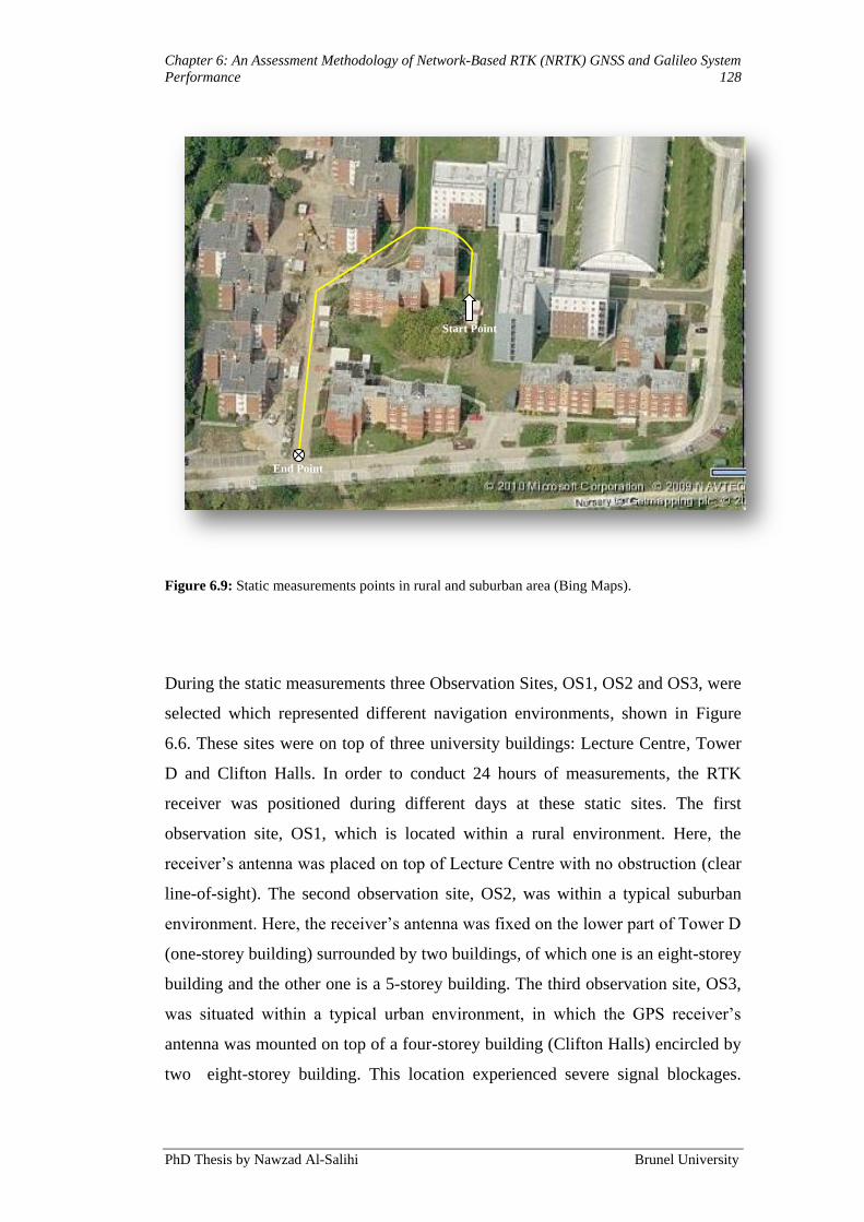
Chapter 6: An Assessment Methodology of Network-Based RTK (NRTK) GNSS and Galileo System
Performance 128
PhD Thesis by Nawzad Al-Salihi Brunel University
Figure 6.9: Static measurements points in rural and suburban area (Bing Maps).
During the static measurements three Observation Sites, OS1, OS2 and OS3, were
selected which represented different navigation environments, shown in Figure
6.6. These sites were on top of three university buildings: Lecture Centre, Tower
D and Clifton Halls. In order to conduct 24 hours of measurements, the RTK
receiver was positioned during different days at these static sites. The first
observation site, OS1, which is located within a rural environment. Here, the
receiver‟s antenna was placed on top of Lecture Centre with no obstruction (clear
line-of-sight). The second observation site, OS2, was within a typical suburban
environment. Here, the receiver‟s antenna was fixed on the lower part of Tower D
(one-storey building) surrounded by two buildings, of which one is an eight-storey
building and the other one is a 5-storey building. The third observation site, OS3,
was situated within a typical urban environment, in which the GPS receiver‟s
antenna was mounted on top of a four-storey building (Clifton Halls) encircled by
two eight-storey building. This location experienced severe signal blockages.
Start Point
End Point

Chapter 6: An Assessment Methodology of Network-Based RTK (NRTK) GNSS and Galileo System
Performance 129
PhD Thesis by Nawzad Al-Salihi Brunel University
Appendix A shows photographs taken from different locations in both the static
sites and dynamic measurements routes.
These tests were primarily planned to evaluate the quality of the TopNET+
services from the end users‟ standpoint; thus, the majority were conducted using
the service as is. This means that as TopNET+ is a commercial NRTK service in
Great Britain the corrections arriving throughout the tests were the same as any
other subscriber would have received if using the service at the same location and
time.
Figure 6.10 shows the TopNET+ CORS (described in Chapter 2, Section 2.2.3)
configuration used during the tests for rural, suburban and urban environments.
The nearest Reference Station (RS) to the rover site at Brunel University campus
(yellow circle) was the station at Teddington (TEDD) and was located about 15
km away, the farthest (STEE) located at about 45 km. This could be considered as
a typical configuration for a NRTK GPS application. 36.23 Km
80.47 Km
46.60 Km
33.98 Km
27.89 Km
41.77 Km
42.07 Km
31.77 Km
54.19 Km
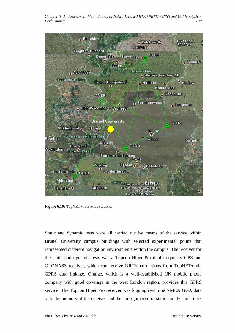
Chapter 6: An Assessment Methodology of Network-Based RTK (NRTK) GNSS and Galileo System
Performance 130
PhD Thesis by Nawzad Al-Salihi Brunel University
Figure 6.10: TopNET+ reference stations.
Static and dynamic tests were all carried out by means of the service within
Brunel University campus buildings with selected experimental points that
represented different navigation environments within the campus. The receiver for
the static and dynamic tests was a Topcon Hiper Pro dual frequency GPS and
GLONASS receiver, which can receive NRTK corrections from TopNET+ via
GPRS data linkage. Orange, which is a well-established UK mobile phone
company with good coverage in the west London region, provides this GPRS
service. The Topcon Hiper Pro receiver was logging real time NMEA GGA data
onto the memory of the receiver and the configuration for static and dynamic tests
Brunel University
Chapter 6: An Assessment Methodology of Network-Based RTK (NRTK) GNSS and Galileo System
Performance 131
PhD Thesis by Nawzad Al-Salihi Brunel University
was similar. During all static and dynamic testing trials, the navigation messages
and augmentations data were simultaneously downloaded and stored at the NSC.
The stored data files were processed at the NSC and these considered data types,
navigation environments and measurement scenarios. To assess the performance
levels achieved the computed position solutions were analysed and exported into
an Excel file.
6.4 Simulation Evaluation Methodology
The GALILEO System Simulation Facility (GSSF) was used to conduct the
simulation study. An international consortium lead by VEGA (GSSF, 2004) on
behalf of ESA/ESTEC was responsible for primarily developing this tool.
Quantifying the developed positioning model performance against accurate and
reliable positioning services that Galileo and GPS wish to offer in the future was
the goal behind the simulation study. This also helped to identify areas of
compatibility and integration between the developed model and the future
navigation system.
6.4.1 The GALILEO System Simulation Facility (GSSF)
The GSSF was developed to support the understating of the definition stages and
longer-term development phases of the Galileo project. The GSSF V2.1.11 is the
current version and allows the simulation of Galileo‟s functionalities and
performance behaviour during different reference scenarios. The GSSF allows the
implementation of real system components, including the space, ground and
control segments to be integrated for the support of Galileo system understanding
and validation. It operates in two main capability modes: Service Volume
Simulation (SVS) and Raw Data Generation (RDG), (GSSF, 2005; Zimmermann
et al., 2004).
The RDG is responsible for generating raw data that is used in validating the
GSSF‟s processing algorithms. By including all navigation signals and satellite
constellations within the simulation scenario, the SVS offers the flexibility of
combining GPS, EGNOS and Galileo navigation systems. By using predefined
Chapter 6: An Assessment Methodology of Network-Based RTK (NRTK) GNSS and Galileo System
Performance 132
PhD Thesis by Nawzad Al-Salihi Brunel University
UERE error budgets and integrity factors, different sets of error interferences can
be added into these systems (GSSF, 2005 and 2006).
Using two modes, standard and stand-alone, the SVS allows analysis of the data
and this will measure the positioning performance achieved from simulating
Galileo and GPS. In stand-alone mode, the analysis was conducted manually
without running the simulation again. However, in the standard mode several
analysis functions are available which allow automatic data processing. The
following is a list of standard analysis functions:
Visibility Analysis: provides satellite visibility information, including the
number of satellites in view of the user or ground segment at each time
step during the simulation time. This process looks at the elevation angle
to see if the receiver can see the satellite.
Coverage Analysis: describes the number of ground stations in view for
the satellite locations.
Geometry Analysis: responsible for computing the geometry components
between the ground receivers and the corresponding satellite at each time
step, including elevation, azimuth angle determination and the geometric
range.
Dilution of Precision (DOP) Analysis: responsible for computing all
DOP quantifiers for each user or ground segment element.
Accuracy Analysis: this option includes two main parts:
1. Navigation System Precision (NSP): describes the dispersion of
user‟s estimated position around its mean. This is ascertained from
the UERE budgets identified within simulation environment. Time
NSP (TNSP), Horizontal NSP (HNSP), Vertical NSP (VNSP) and
overall NSP (ONSP) can be computed by this function for each
user over the simulation period.
Signal-In-Space Monitoring Accuracy (SISMA): determines the level of
accuracy described by the satellite‟s Signal-In-Space Error (SISE) at each
simulation time step.

Chapter 6: An Assessment Methodology of Network-Based RTK (NRTK) GNSS and Galileo System
Performance 133
PhD Thesis by Nawzad Al-Salihi Brunel University
Integrity Analysis: the user can select from a number of integrity
parameters and equations describing relevant integrity monitoring
approaches. The GSSF integrity monitoring concept includes the
computation of the Probability of Hazardous Misleading Information
(PHMI), also known as the integrity risk, and the computation of the
Protection Levels (PL) based on SBAS or Galileo data. Galileo offers the
following integrity information:
1. Single in Space Error (SISE) describes the maximum standard
deviation for the signal error in the range domain caused by
satellite data. This cannot be measured directly and is obtained
after providing an estimated SISE (SISEest).
2. Single in Space Accuracy (SISA) is a method that provides with a
prediction of the standard deviation for a Gaussian distribution that
bounds the SISE distribution (the distribution of difference between
SISE and SISEest). The system is considered sending hazardous
misleading information to the user if SISE is greater than SISA.
The Integrity Flag (IF): the IF threshold is used to determine whether to
use the corresponding satellite or not and is computed from the SISE
distribution. For example, if SISE is larger than threshold, the integrity
flag then indicates that it is not recommended to use the satellite.
6.4.2 Simulation Scenarios and Setup
To investigate the positioning performance achieved from a future Galileo
navigation system together with the developed positioning model the use of the
GSSF was considered. Only the Galileo Open Service (OS) was focused on,
primarily because:
The OS is planned to be free of charge and available to all types of users and
applications, therefore it will be widely deployed in future navigation systems.
Chapter 6: An Assessment Methodology of Network-Based RTK (NRTK) GNSS and Galileo System
Performance 134
PhD Thesis by Nawzad Al-Salihi Brunel University
The OS is the most applicable service to GPS standard positioning
services.
According to the current development challenges of the Galileo
programme, the OS can be considered as the most possibly achievable
Galileo positioning service (Fylor, 2009).
In order to benefit from its integrity advantage several satellite constellations were
utilised, including Galileo and GPS, during the simulation study. By utilising
Galileo OS single frequency within one of the frequency bands (E5a, E5b, E2-L1-
E1, or E5-AltBoc), together with GPS CA signal within the L1 frequency band, a
hybrid positioning service was made available. The simulation study was
conducted in dynamic and static scenarios that only considered urban and rural
environments as the GSSF only offers UERE budgets for these two environments.
For a dynamic scenario (mobile user), the system requires the route information
for the aimed testing route. The Define Trajectory option available within GSSF
can define this. This option allows entering a set of longitude, latitude and height
coordinates which define the testing routes. The coordinates of the static points‟,
applied in the experimental assessments routes, were entered into GSSF and these
were used to identify the rural and urban trajectories in the simulation study.
Conversely, the static scenarios were simulated at two different points using
different UERE budgets that represented both rural and urban environments.
Both static and dynamic scenarios, defined by the simulation time intervals,
follow the same intervals employed in the experimental work. During all
simulation sessions, the position-sampling rate was set to 1 second. The SVS
standard analysis functions analysed the data obtained from the static and
dynamic simulation scenarios and this provided the mean, maximum and
minimum values of the achieved positioning performance parameters. For further
analysis, these parameters were exported into an Excel file. To quantify the
positioning model‟s achievable performance with reference to future Galileo and
GPS systems, the results from the simulation study were compared to the
experimental measurements.

Chapter 6: An Assessment Methodology of Network-Based RTK (NRTK) GNSS and Galileo System
Performance 135
PhD Thesis by Nawzad Al-Salihi Brunel University
6.5 Summary
The chapter has described the evaluation methodology that has been employed to
explore and assess the effectiveness of the positioning model concerning position
sample accuracy, precision, NRTK service availability and number of GNSS
satellites. The first part of the evaluation methodology focused on performing
experimental measurement trails in order to observe and gather GPS and
GLONASS data within a number of navigation environments (rural, suburban,
and urban).
The second part of the methodology dealt with simulation of a hybrid positioning
service offered by Galileo OS single frequency, alongside GPS standards
frequency services. The simulation study utilized both dynamic and static
scenarios by way of using points in both urban and rural settings.
The experimental results analysis and discussion of the assessment methodology
of NRTK GNSS and GSSF are presented in next chapter (Chapter 7).
Chapter 7: Results Analysis and Discussion 136
PhD Thesis by Nawzad Al-Salihi Brunel University
Chapter 7
7. Results Analysis and Discussion
7.1 Introduction
The evaluation methodology depicted in Chapter 6 was used in order to perform
the following tasks:
Evaluating the performance of the developed positioning model taken as a
whole, presented in Chapter 5, in the course of the experimental
measurements. This included the following:
1. Evaluating the positioning performance attained from the
developed positioning methods, augmented NRTK GNSS dual
frequency service, proceeding at the MNU. This step entails the
following constraints:
The positioning solutions determine the positioning
performance, also described as position samples, accuracy and
precision, number of GPS and GLONASS satellites, as well as
the service availability.
2. Quantifying the achieved positioning performance against the
proposed minimum performance requirements level associated
with pedestrian navigation application groups, as described in
Chapter 6. In which, the identified maximum position error margin
was 0.5-1 meter, and the maximum allowable DOP quantifiers
were (HDOP ≤2.5 and PDOP ≤5).
3. Determining the effect of the environment (rural, suburban and
urban) on the obtained position accuracy.

Chapter 7: Results Analysis and Discussion 137
PhD Thesis by Nawzad Al-Salihi Brunel University
Examining the future Galileo Open Service (OS) positioning using
GSSF and comparing its accomplished performance in opposition to the
developed positioning model.
This chapter is split up into two key sections: Section 7.2 presents and discusses
the outcome of the experimental measurements for the static and dynamic tests,
which were employed to illustrate the performance achieved from the developed
positioning model. Besides, Section 7.3 describes the results attained from the
simulation examination, appraising the performance realised from future Galileo
OS services.
7.2 Experimental Results
With the intention of evaluating the quality of the NRTK service, the assembled
data were analysed with the subsequent assumptions: the navigation environments
(urban, suburban and rural) and measurement scenarios (dynamic and static), the
overall errors in GPS and GLONASS observation results from the total of
different error components (for instance, the receiver clock offset, the satellite
clock offset, the orbit error, the ionospheric and the tropospheric biases, etc.) and
the amount of total errors have more or less a normal distribution, regardless of
the component errors are distributed normally. Consequently, common formulae
for normal distributed data were used in the analysis. The initial step was to filter
outliers. The data was processed at a 95% confidence level to exclude all outliers.
The definition of the accuracy can be understood as how far the coordinates that
are calculated during the testing are from the true values (Feng and Wang, 2007).
For that reason, the accuracy for each coordinate component, East and North, was
calculated. The entire accuracy of respective test was determined as the typical of
the accuracy values at each epoch. In contrast, precision is a matter of degree of
repeatability (or closeness) that repeated measurements display, and is therefore
employed as a way to illustrate the quality of the data with regards to random
errors (Rizos, 1999). It was represented by the standard deviation (SD) of the
solutions (2-sigma, about 95% of solutions).

Chapter 7: Results Analysis and Discussion 138
PhD Thesis by Nawzad Al-Salihi Brunel University
The real-time coordinate streams, produced by the rover receivers during the data
collection utilising data sets that were concurrently gathered by the reference
stations in the vicinity of these testing sections and the 3D coordinate times series
in WGS84, a global reference system in which the locations that are determined
with the GNSS positioning is displayed, are converted to the 3D coordinate time
series referred to a local coordinate system such as OSGB36, the national datum
of UK.
The positioning results, of the coordinate domain positioning methods, represent
the core solution gained from the system model presented in this project.
Referring to the measurements scenarios, the experimental outcome are explained
in the following sub-sections.
7.2.1 Static Measurements Results
This section describes the results obtained from the experimental measurements
conducted at the fixed observation sites OS1, OS2, OS3 and the benchmark points
ST1-ST20. As explained in Section 6.3.4, these sites were located in urban,
suburban, and rural area environments as shown in Figure 6.7 and 6.10. The
results described in this section present only the performance during the testing
trial conducted between 2:00pm to 3:00pm. This measurement period was chosen
because it was more appropriate to conduct the dynamic experiments during that
time and not for 24 hours due to practical reasons. The measurement period is in
itself of no greater significance so long as the experiment is conducted at the same
time throughout the trials in order to encompass the same satellite constellations.
It may still be argued that longer measurement periods equal more accurate
results. However, due to the impracticability of conducting 24 hour dynamic
testing, the measurement period between 2:00pm and 3:00pm was chosen and
followed. The overall results obtained from 24-hours of static measurements,
including all testing trials are demonstrated in Appendix B.
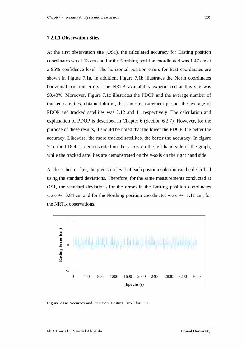
Chapter 7: Results Analysis and Discussion 139
PhD Thesis by Nawzad Al-Salihi Brunel University
7.2.1.1 Observation Sites
At the first observation site (OS1), the calculated accuracy for Easting position
coordinates was 1.13 cm and for the Northing position coordinated was 1.47 cm at
a 95% confidence level. The horizontal position errors for East coordinates are
shown in Figure 7.1a. In addition, Figure 7.1b illustrates the North coordinates
horizontal position errors. The NRTK availability experienced at this site was
98.43%. Moreover, Figure 7.1c illustrates the PDOP and the average number of
tracked satellites, obtained during the same measurement period, the average of
PDOP and tracked satellites was 2.12 and 11 respectively. The calculation and
explanation of PDOP is described in Chapter 6 (Section 6.2.7). However, for the
purpose of these results, it should be noted that the lower the PDOP, the better the
accuracy. Likewise, the more tracked satellites, the better the accuracy. In figure
7.1c the PDOP is demonstrated on the y-axis on the left hand side of the graph,
while the tracked satellites are demonstrated on the y-axis on the right hand side.
As described earlier, the precision level of each position solution can be described
using the standard deviations. Therefore, for the same measurements conducted at
OS1, the standard deviations for the errors in the Easting position coordinates
were +/- 0.84 cm and for the Northing position coordinates were +/- 1.11 cm, for
the NRTK observations.
Figure 7.1a: Accuracy and Precision (Easting Error) for OS1.
-1
0
1
0 400 800 1200 1600 2000 2400 2800 3200 3600
East
ing E
rro
r (c
m)
Epochs (s)

Chapter 7: Results Analysis and Discussion 140
PhD Thesis by Nawzad Al-Salihi Brunel University
Figure 7.1b: Accuracy and Precision (Northing Error) for OS1.
Figure 7.1c: PDOP and Tracked Satellites obtained during the static test OS1.
Below are the accuracy, precision, availability, tracked satellites and PDOP
obtained during the test for OS1 and is summarised in Table 7.1. The computed
measurements for accuracy and precision are described in Chapter 4 (Section
4.4.2) and Chapter 6 (Section 6.2.7). Furthermore, NRTK availability and PDOP
calculations are described in Chapter 6 (Section 6.2.3).
-1
0
1
0 400 800 1200 1600 2000 2400 2800 3200 3600
No
rth
ing
Err
or
(cm
)
Epochs (s)
6
8
10
12
14
1.8
1.9
2
2.1
2.2
2.3
0 400 800 1200 1600 2000 2400 2800 3200 3600T
rack
ed S
ate
llit
es
PD
OP
Epochs (s)
PDOP Tracked Satellites

Chapter 7: Results Analysis and Discussion 141
PhD Thesis by Nawzad Al-Salihi Brunel University
Test East –
Accuracy
Average
(cm)
North –
Accuracy
Average
(cm)
East –
Precision
SD
(+/- cm)
North –
Precision
SD
(+/- cm)
NRTK
Availability
(%)
Tracked
Satellites
Average
PDOP
OS1 1.13 1.47 0.84 1.11 98.43 11 2.12
Table 7.1: Measurements obtained during static tests for the OS1.
At same confidence levels, 95%, the position accuracy computed at site OS2 for
the Easting coordinates was -21.32 cm and for the Northing coordinates was 33.13
cm. The Easting and Northing horizontal position errors are shown in Figure 7.2a
and 7.2b In addition, Figure 7.2c illustrates the PDOP and the average number of
tracked satellites, the average of PDOP was 2.44 and the average of tracked
satellites was 9. The availability for OS2 was 86.51%.
The standard deviations for the errors in Easting and Northing position
coordinates were summarised as +/- 2.32 cm and +/- 3.43 cm, for the samples
obtained from NRTK positioning methods. Table 7.2 summaries all obtained
measurements obtained at OS2.
Figure 7.2a: Accuracy and Precision (Easting Error) for OS2.
-40
-30
-20
-10
0
10
20
30
40
0 400 800 1200 1600 2000 2400 2800 3200 3600
Ea
stin
g E
rro
r (c
m)
NRTK GNSS Epochs (s)
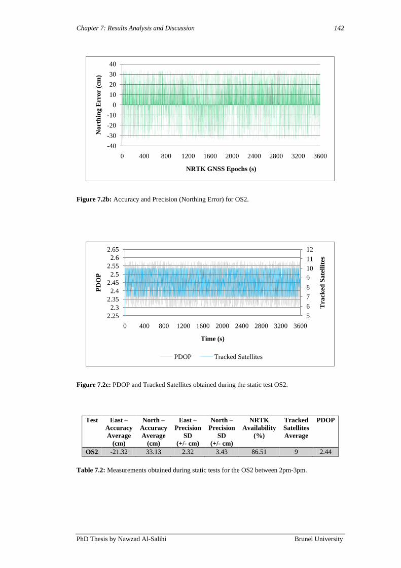
Chapter 7: Results Analysis and Discussion 142
PhD Thesis by Nawzad Al-Salihi Brunel University
Figure 7.2b: Accuracy and Precision (Northing Error) for OS2.
Figure 7.2c: PDOP and Tracked Satellites obtained during the static test OS2.
Test East –
Accuracy
Average
(cm)
North –
Accuracy
Average
(cm)
East –
Precision
SD
(+/- cm)
North –
Precision
SD
(+/- cm)
NRTK
Availability
(%)
Tracked
Satellites
Average
PDOP
OS2 -21.32 33.13 2.32 3.43 86.51 9 2.44
Table 7.2: Measurements obtained during static tests for the OS2 between 2pm-3pm.
-40
-30
-20
-10
0
10
20
30
40
0 400 800 1200 1600 2000 2400 2800 3200 3600
No
rth
ing
Err
or
(cm
)
NRTK GNSS Epochs (s)
5
6
7
8
9
10
11
12
2.25
2.3
2.35
2.4
2.45
2.5
2.55
2.6
2.65
0 400 800 1200 1600 2000 2400 2800 3200 3600T
rack
ed S
ate
llit
es
PD
OP
Time (s)
PDOP Tracked Satellites
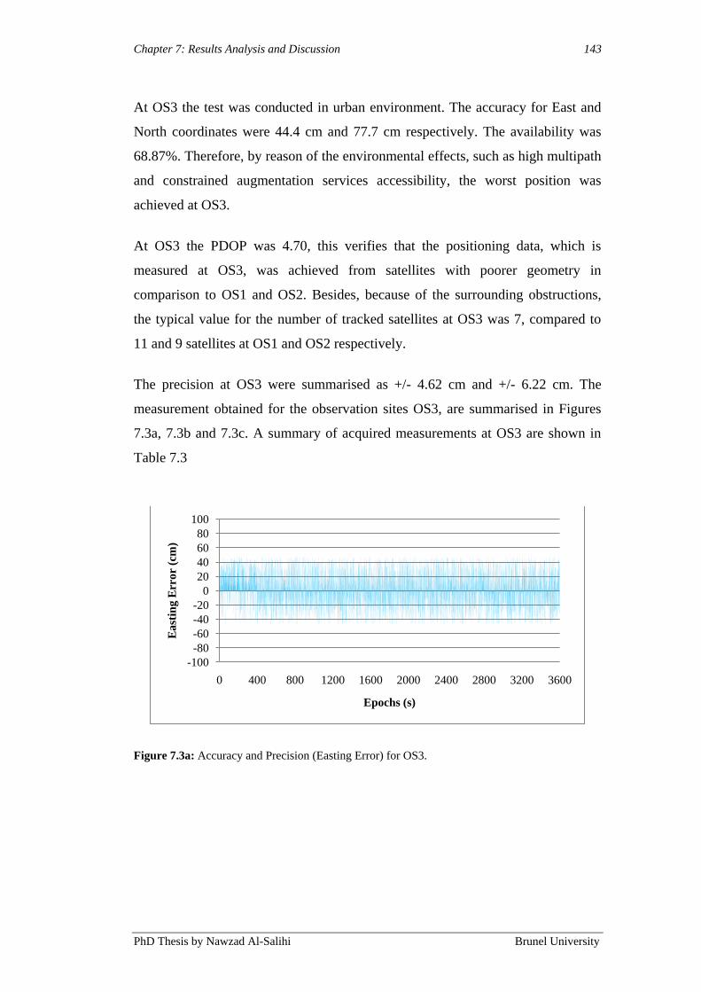
Chapter 7: Results Analysis and Discussion 143
PhD Thesis by Nawzad Al-Salihi Brunel University
At OS3 the test was conducted in urban environment. The accuracy for East and
North coordinates were 44.4 cm and 77.7 cm respectively. The availability was
68.87%. Therefore, by reason of the environmental effects, such as high multipath
and constrained augmentation services accessibility, the worst position was
achieved at OS3.
At OS3 the PDOP was 4.70, this verifies that the positioning data, which is
measured at OS3, was achieved from satellites with poorer geometry in
comparison to OS1 and OS2. Besides, because of the surrounding obstructions,
the typical value for the number of tracked satellites at OS3 was 7, compared to
11 and 9 satellites at OS1 and OS2 respectively.
The precision at OS3 were summarised as +/- 4.62 cm and +/- 6.22 cm. The
measurement obtained for the observation sites OS3, are summarised in Figures
7.3a, 7.3b and 7.3c. A summary of acquired measurements at OS3 are shown in
Table 7.3
Figure 7.3a: Accuracy and Precision (Easting Error) for OS3.
-100
-80
-60
-40
-20
0
20
40
60
80
100
0 400 800 1200 1600 2000 2400 2800 3200 3600
Ea
stin
g E
rro
r (c
m)
Epochs (s)
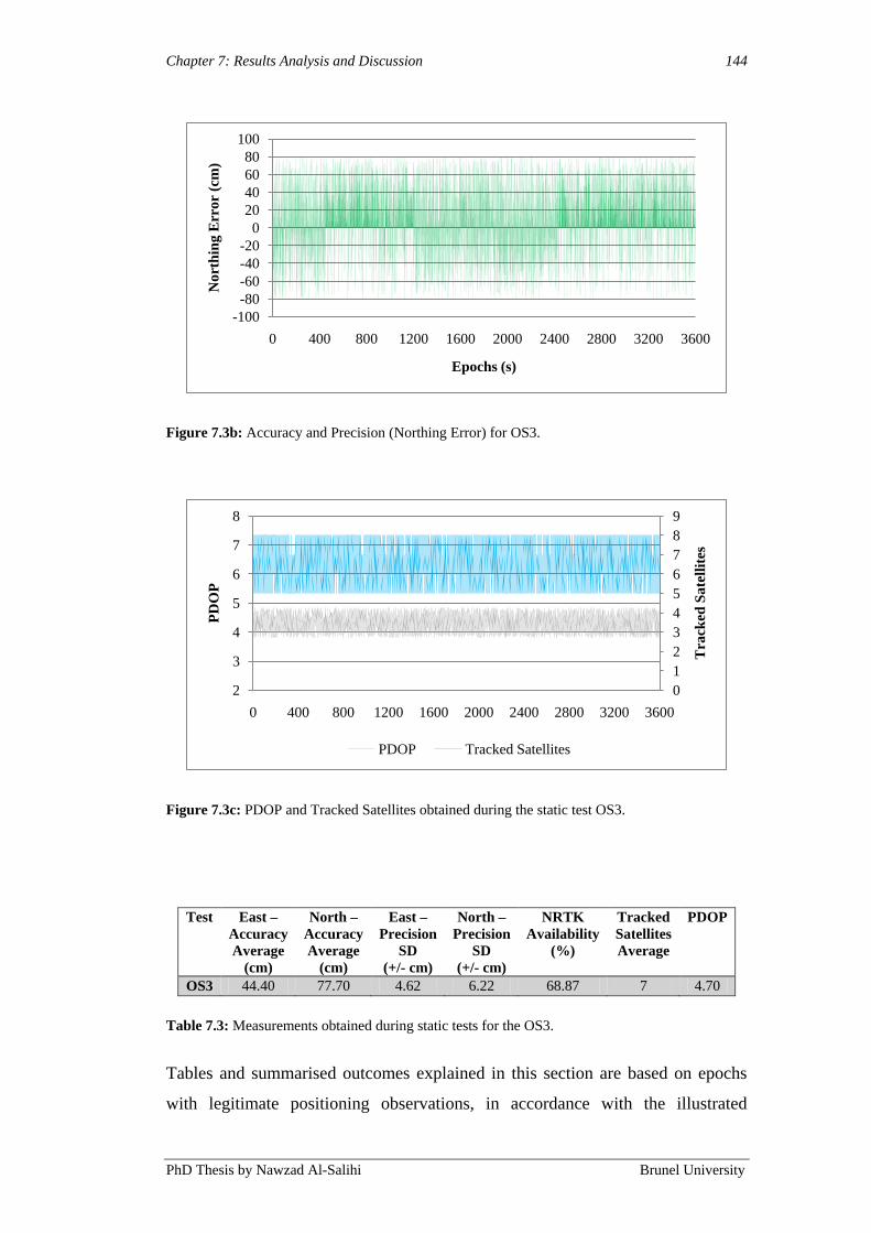
Chapter 7: Results Analysis and Discussion 144
PhD Thesis by Nawzad Al-Salihi Brunel University
Figure 7.3b: Accuracy and Precision (Northing Error) for OS3.
Figure 7.3c: PDOP and Tracked Satellites obtained during the static test OS3.
Test East –
Accuracy
Average
(cm)
North –
Accuracy
Average
(cm)
East –
Precision
SD
(+/- cm)
North –
Precision
SD
(+/- cm)
NRTK
Availability
(%)
Tracked
Satellites
Average
PDOP
OS3 44.40 77.70 4.62 6.22 68.87 7 4.70
Table 7.3: Measurements obtained during static tests for the OS3.
Tables and summarised outcomes explained in this section are based on epochs
with legitimate positioning observations, in accordance with the illustrated
-100
-80
-60
-40
-20
0
20
40
60
80
100
0 400 800 1200 1600 2000 2400 2800 3200 3600
No
rth
ing
Err
or
(cm
)
Epochs (s)
0
1
2
3
4
5
6
7
8
9
2
3
4
5
6
7
8
0 400 800 1200 1600 2000 2400 2800 3200 3600T
rack
ed S
ate
llit
es
PD
OP
PDOP Tracked Satellites
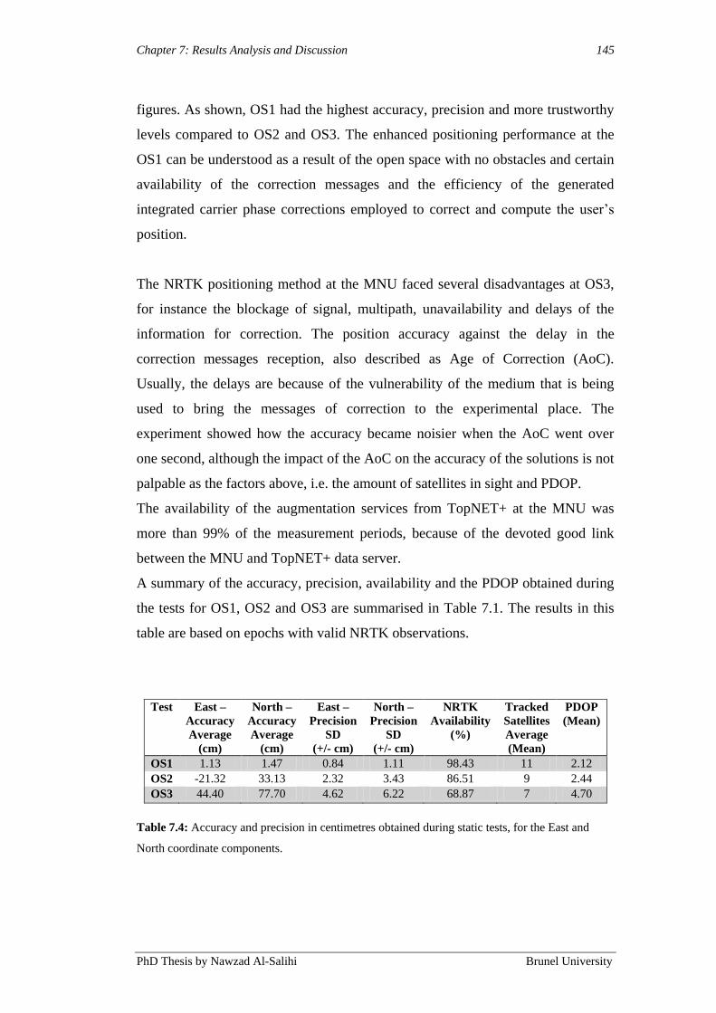
Chapter 7: Results Analysis and Discussion 145
PhD Thesis by Nawzad Al-Salihi Brunel University
figures. As shown, OS1 had the highest accuracy, precision and more trustworthy
levels compared to OS2 and OS3. The enhanced positioning performance at the
OS1 can be understood as a result of the open space with no obstacles and certain
availability of the correction messages and the efficiency of the generated
integrated carrier phase corrections employed to correct and compute the user‟s
position.
The NRTK positioning method at the MNU faced several disadvantages at OS3,
for instance the blockage of signal, multipath, unavailability and delays of the
information for correction. The position accuracy against the delay in the
correction messages reception, also described as Age of Correction (AoC).
Usually, the delays are because of the vulnerability of the medium that is being
used to bring the messages of correction to the experimental place. The
experiment showed how the accuracy became noisier when the AoC went over
one second, although the impact of the AoC on the accuracy of the solutions is not
palpable as the factors above, i.e. the amount of satellites in sight and PDOP.
The availability of the augmentation services from TopNET+ at the MNU was
more than 99% of the measurement periods, because of the devoted good link
between the MNU and TopNET+ data server.
A summary of the accuracy, precision, availability and the PDOP obtained during
the tests for OS1, OS2 and OS3 are summarised in Table 7.1. The results in this
table are based on epochs with valid NRTK observations.
Test East –
Accuracy
Average
(cm)
North –
Accuracy
Average
(cm)
East –
Precision
SD
(+/- cm)
North –
Precision
SD
(+/- cm)
NRTK
Availability
(%)
Tracked
Satellites
Average
(Mean)
PDOP
(Mean)
OS1 1.13 1.47 0.84 1.11 98.43 11 2.12
OS2 -21.32 33.13 2.32 3.43 86.51 9 2.44
OS3 44.40 77.70 4.62 6.22 68.87 7 4.70
Table 7.4: Accuracy and precision in centimetres obtained during static tests, for the East and
North coordinate components.
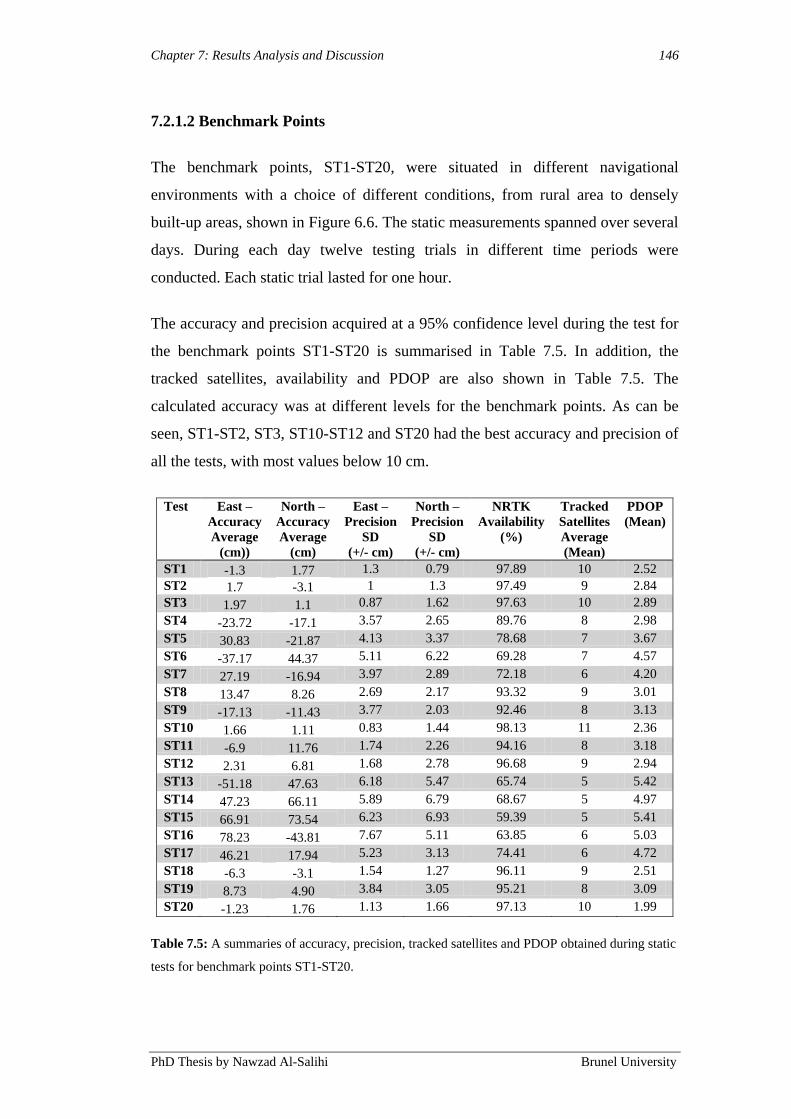
Chapter 7: Results Analysis and Discussion 146
PhD Thesis by Nawzad Al-Salihi Brunel University
7.2.1.2 Benchmark Points
The benchmark points, ST1-ST20, were situated in different navigational
environments with a choice of different conditions, from rural area to densely
built-up areas, shown in Figure 6.6. The static measurements spanned over several
days. During each day twelve testing trials in different time periods were
conducted. Each static trial lasted for one hour.
The accuracy and precision acquired at a 95% confidence level during the test for
the benchmark points ST1-ST20 is summarised in Table 7.5. In addition, the
tracked satellites, availability and PDOP are also shown in Table 7.5. The
calculated accuracy was at different levels for the benchmark points. As can be
seen, ST1-ST2, ST3, ST10-ST12 and ST20 had the best accuracy and precision of
all the tests, with most values below 10 cm.
Test East –
Accuracy
Average
(cm))
North –
Accuracy
Average
(cm)
East –
Precision
SD
(+/- cm)
North –
Precision
SD
(+/- cm)
NRTK
Availability
(%)
Tracked
Satellites
Average
(Mean)
PDOP
(Mean)
ST1 -1.3 1.77 1.3 0.79 97.89 10 2.52
ST2 1.7 -3.1 1 1.3 97.49 9 2.84
ST3 1.97 1.1 0.87 1.62 97.63 10 2.89
ST4 -23.72 -17.1 3.57 2.65 89.76 8 2.98
ST5 30.83 -21.87 4.13 3.37 78.68 7 3.67
ST6 -37.17 44.37 5.11 6.22 69.28 7 4.57
ST7 27.19 -16.94 3.97 2.89 72.18 6 4.20
ST8 13.47 8.26 2.69 2.17 93.32 9 3.01
ST9 -17.13 -11.43 3.77 2.03 92.46 8 3.13
ST10 1.66 1.11 0.83 1.44 98.13 11 2.36
ST11 -6.9 11.76 1.74 2.26 94.16 8 3.18
ST12 2.31 6.81 1.68 2.78 96.68 9 2.94
ST13 -51.18 47.63 6.18 5.47 65.74 5 5.42
ST14 47.23 66.11 5.89 6.79 68.67 5 4.97
ST15 66.91 73.54 6.23 6.93 59.39 5 5.41
ST16 78.23 -43.81 7.67 5.11 63.85 6 5.03
ST17 46.21 17.94 5.23 3.13 74.41 6 4.72
ST18 -6.3 -3.1 1.54 1.27 96.11 9 2.51
ST19 8.73 4.90 3.84 3.05 95.21 8 3.09
ST20 -1.23 1.76 1.13 1.66 97.13 10 1.99
Table 7.5: A summaries of accuracy, precision, tracked satellites and PDOP obtained during static
tests for benchmark points ST1-ST20.

Chapter 7: Results Analysis and Discussion 147
PhD Thesis by Nawzad Al-Salihi Brunel University
The accuracy obtained from each test for the East coordinate component can be
seen in Figure 7.4a. During NRTK static tests the East accuracy was better than
40 cm for an average of 62% of the NRTK GNSS epochs.
The same pattern could also be also perceived in the North coordinate component
results as presented in Figure 7.4b. Generally, NRTK GNSS results were more
correct in rural and suburban areas than urban areas.
Figure 7.4a: Accuracy of solutions from each static test (ST1-ST20) for the East coordinate
component (cm).
Figure 7.4b: Accuracy of solutions from each static test (ST1-ST20) for the East coordinate
component (cm).
-60
-40
-20
0
20
40
60
80
100
ST
1
ST
2
ST
3
ST
4
ST
5
ST
6
ST
7
ST
8
ST
9
ST
10
ST
11
ST
12
ST
13
ST
14
ST
15
ST
16
ST
17
ST
18
ST
19
ST
20
Ea
st E
rro
r (c
m)
Static Test ST1-ST20
-60
-40
-20
0
20
40
60
80
ST
1
ST
2
ST
3
ST
4
ST
5
ST
6
ST
7
ST
8
ST
9
ST
10
ST
11
ST
12
ST
13
ST
14
ST
15
ST
16
ST
17
ST
18
ST
19
ST
20
No
rth
Err
or
(cm
)
Static Test ST1-ST20

Chapter 7: Results Analysis and Discussion 148
PhD Thesis by Nawzad Al-Salihi Brunel University
The availability was determined as the percentage of observations from which a
NRTK GPS solutions (integer ambiguities resolved) was gained during a test
(Brown et al. 2005a). This is an important index for the high-quality performance
of the TopNET+ service.
The NRTK service availability during static tests was 84.91% on average for all
tests ST1-ST20 as can be seen in Table 7.5. The availability with the lowest levels
for static tests was detected during ST15 (59.39%). All results for all benchmark
point are shown in Figure 7.5. All these tests were performed by using the CORS
configuration, which may point to the additional problems that NRTK meets when
resolving opacities at the rover side (MNU) for CORS configurations (Chapter 2,
Section 2.2.3).
Figure 7.5: NRTK GNSS availability results of observation for ST1-ST20.
A distinct feature of the TopNET+ service is that of when a NRTK solution is not
possible because of the uncertainties not being attended to, the solution switches
to DGPS; of course, only if the corrections continue to be received. It can be
inferred that problems with the GPRS data link did not cause the availability to
drop during ST1-ST20.
Nevertheless, DGPS solutions and its presence are not indicating whether all
necessary corrections messages are received or not. In GSM/GPRS (TCP),
0%
20%
40%
60%
80%
100%
ST
1
ST
2
ST
3
ST
4
ST
5
ST
6
ST
7
ST
8
ST
9
ST
10
ST
11
ST
12
ST
13
ST
14
ST
15
ST
16
ST
17
ST
18
ST
19
ST
20
Availability ST1-ST20

Chapter 7: Results Analysis and Discussion 149
PhD Thesis by Nawzad Al-Salihi Brunel University
communication data is Cyclic Redundancy Check (CRC) checked, it is not error
checked. Thus, the data can still be received; however, it might be incorrect or
incomplete. The pseudo-ranges and phases can form the correction messages. At
times when pseudo-ranges are utilised, every epoch provides a solution
independently of pre- or post-observations. Phase solutions require more
observation data to resolve integer uncertainties. Hence, this will have a bigger
impact on integer fixing if some phase data of satellites are absent because of
communication link.
The ambiguity resolution process could have been affected by aspects, such as
few satellites in sight, constellation geometry, and undependable observations,
during these tests.
7.3.1 Dynamic Measurement Results
The results that are attained from the measurements conducted at the dynamic
routes 1 (DT1) and 2 (DT2), are presented in this section. These were located in
urban, suburban, and rural area environments respectively (see Chapter 6, Section
6.3.3). The dynamic measurements were conducted during several days. Twelve
testing trials in different time periods took place each day, and the duration was
approximately one hour for each trial. For the purpose of quantifying the
positioning performance gained at each dynamic route, the collected GPS and
GLONASS data were processed and analysed concerning the horizontal position
accuracy, precision and the experienced service availability.
The results described in this section, alike the results obtained from static
measurements, present the performance attained while one testing trials that took
place during the measurement period (2:00pm to 3:00pm), at a number of selected
benchmark points identifying every path. These benchmark points were selected
when showing diverse levels of positioning performance at each one testing route.
The performance results are summarised in Table 7.5 in section 7.2.1.2
(Benchmark Points), and illustrated in Figures 7.4 and 7.5. With reference to
benchmark points noticed in each route, also described in Section 6.3.3, the
subsequent points were selected:

Chapter 7: Results Analysis and Discussion 150
PhD Thesis by Nawzad Al-Salihi Brunel University
Benchmark Points ST3 ST4 ST5 ST6 ST8 ST9 ST10
on route 1 (DT1).
Benchmark Points ST13 ST15 ST17 ST19 on route 2 (DT2).
7.3.1.1 Dynamic Test 1 (DT1): Rural and Suburban Environment
This section presents the positioning performance achieved at different locations
(benchmark points ST3, ST4, ST5, ST6, ST8, ST9 and ST10) on route 1. As
shown in Figure 6.5 (Chapter 6), this route simulated a combine of rural and
suburban navigation area, in which GPS and GLONASS signals were
occasionally blocked by an adjacent building at benchmark points, ST4 (Sports
Hall), ST8 and ST9 (Howell Building), from one side during the measurements.
At benchmark point ST5 the signals were blocked from three sides, Art Centre,
John Crank and Lecture Centre building. In addition, point ST6 was blocked from
two sides, Gordon Hall and Lecture Centre. The testing areas at Brunel University
contain excellent mobile communication coverage.
The accuracy and precision were computed in 95% confidence level, and the
NRTK GNSS availability for the position samples in DT1 obtained are shown in
Table 7.5 (Section 7.2.1.2). Furthermore, the East and North position errors for
benchmark points ST3-ST6 and ST8-ST10 are shown in Figure 7.6a and 7.6b.
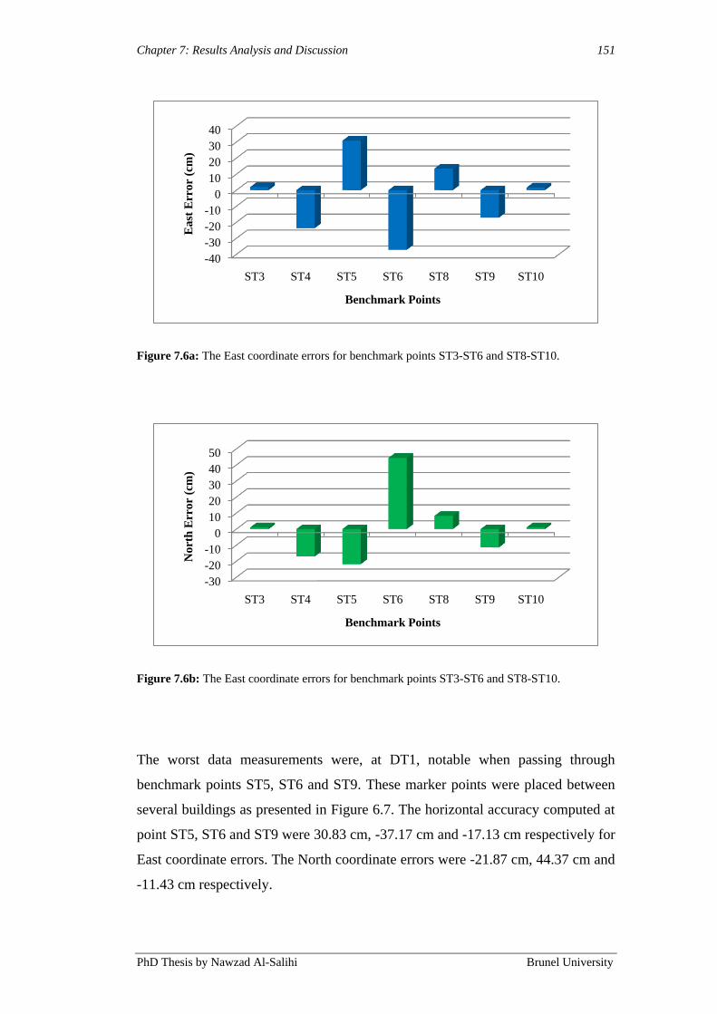
Chapter 7: Results Analysis and Discussion 151
PhD Thesis by Nawzad Al-Salihi Brunel University
Figure 7.6a: The East coordinate errors for benchmark points ST3-ST6 and ST8-ST10.
Figure 7.6b: The East coordinate errors for benchmark points ST3-ST6 and ST8-ST10.
The worst data measurements were, at DT1, notable when passing through
benchmark points ST5, ST6 and ST9. These marker points were placed between
several buildings as presented in Figure 6.7. The horizontal accuracy computed at
point ST5, ST6 and ST9 were 30.83 cm, -37.17 cm and -17.13 cm respectively for
East coordinate errors. The North coordinate errors were -21.87 cm, 44.37 cm and
-11.43 cm respectively.
-40
-30
-20
-10
0
10
20
30
40
ST3 ST4 ST5 ST6 ST8 ST9 ST10
Ea
st E
rro
r (c
m)
Benchmark Points
-30
-20
-10
0
10
20
30
40
50
ST3 ST4 ST5 ST6 ST8 ST9 ST10
No
rth
Err
or
(cm
)
Benchmark Points

Chapter 7: Results Analysis and Discussion 152
PhD Thesis by Nawzad Al-Salihi Brunel University
As shown in Table 7.5, the availability of the NRTK GNSS service during DT1
for benchmark points (ST3-ST6 and ST8-ST10) had numerous number of NRTK
availability levels due to the environment. While the availability level with the
highest outcome was obtained during ST10 (98.13%), the lowest was ST6
(69.28%). The location of the start and end points ST3 and ST10 could take place
at a clear view location in comparison to the rest of the benchmark points during
this route. The PDOP values computed at point ST3 were somewhat higher, even
though the number of tracked satellites at both ST3 and ST10 were high (10 and
11). This increased the position errors at ST3 compared to ST10.
The benchmark points ST4, ST5, ST6, ST8 and ST9 identify the middle/end of
dynamic test 1 (DT1). These points were located at a built-up area compared to
the rest of the marker points at this route. The route for DT1 is shown in Figure
6.7 (Chapter 6). The average numbers of tracked satellites were 7 and 8. The
highest average of PDOP values was at ST6, 4.57. The lowest average of PDOP
was at ST4 2.98. These values decreased compared to points ST3 and ST10. The
tracked satellites and PDOP for DT1 are shown in Figure 7.7.
Figure 7.7: Tracked satellites and PDOP obtained during DT1.
The performance that was attained at points ST3 and ST10 were best compared to
benchmark points (ST4, ST5, ST6, ST8 and ST9) along DT1.
0
2
4
6
8
10
12
ST3 ST4 ST5 ST6 ST8 ST9 ST10
Benchmark Points
Tracked Satellites
PDOP

Chapter 7: Results Analysis and Discussion 153
PhD Thesis by Nawzad Al-Salihi Brunel University
The 2D Root Mean Square Error (RMSE) that was observed during DT1 is
presented in Figure 7.8. The measured path, which depicts the DT1, was
determined from the traces of the position samples, computed at all benchmark
points by means of the coordinate domain and the NRTK GNSS augmentation
service.
The horizontal accuracy along each measured path achieved from the coordinate
domain was better than 20 cm, with reference to the surveyed path. The gaps were
apparent when a NRTK solution was not available, which can be seen in Figure
7.8. Aspects such as low amount of satellites in view, constellation geometry, and
no reliable observations, could have influenced on the ambiguity resolutions
process throughout these tests. Especially, the availability in the built-up area is
far lower than for the rest of the route.
On average, NRTK solutions were obtained only about 88.44% of the time, which
are lower than that which was achieved during static test for OS1 (98.43%).
Figure 7.8: 2D RMSE errors observed during DT1, represented over the route during the test.
Chapter 7: Results Analysis and Discussion 154
PhD Thesis by Nawzad Al-Salihi Brunel University
7.3.1.2 Dynamic Test 2 (DT2): Urban Environment
In this section the positioning performance that is achieved at different locations
(benchmark points ST13, ST15, ST17 and ST19) on route 2, throughout the
measurement period (2:00pm to 3:00pm), is presented. As already explained in
Section 6.3.3, this route was selected at indeed the densest and built up area
around Brunel University campus, in which signals from satellites were expected
to be blocked by surrounding buildings. Some of these routes were chosen in-
between eight-storey accommodation buildings (Bishop Complex). The summary
of the positioning performance results gained at benchmark points for dynamic
tests can be seen in Table 7.5 in Section 7.2.1.2. The testing areas held
exceptional mobile communication coverage at Brunel University.
The satellite availability of GPS and GLONASS signals were limited for ST13
and ST15, in which the average value of the number of tracked satellites were 5
for both ST13 and ST15. The PDOP values for ST15 decreased compared to ST13
due to the poor line-of-sight to the satellites, blockage and high multipath.
Additionally, the benchmark points ST17 had a better accuracy and availability
than S13 and ST15. In addition, benchmark point ST19 had the best accuracy and
precision of all the benchmark points in DT2. All the performance results are
summaries in Table 7.5 in Section 7.2.1.2.
Furthermore, the East and North position errors for benchmark points ST3-ST6
and ST8-ST10 are shown in Figure 7.9a and 7.9b.

Chapter 7: Results Analysis and Discussion 155
PhD Thesis by Nawzad Al-Salihi Brunel University
Figure 7.9a: The East coordinate errors for benchmark points ST13, ST15, ST17 and ST19.
Figure 7.9b: The North coordinate errors for benchmark points ST13, ST15, ST17 and ST19.
As explained earlier in Figure 7.7, benchmark points ST13 and ST15 were
encircled by buildings. Hence, the availability of GPS and GLONASS signals
were restricted at these points, and a large interference to the received signals
could be observed.
The unavailability of GPS and GLONASS satellites at benchmark points ST13
and ST15 degraded the accuracy achieved from NRTK positioning service, in
which, the accuracy reached below 80 centimetres.
-60
-40
-20
0
20
40
60
80
ST13 ST15 ST17 ST19
Ea
st E
rro
r (c
m)
Benchmark Points
0
10
20
30
40
50
60
70
80
ST13 ST15 ST17 ST19
No
rth
Err
or
(cm
)
Benchmark Points

Chapter 7: Results Analysis and Discussion 156
PhD Thesis by Nawzad Al-Salihi Brunel University
With regards to the amount of visible satellites tracked, the variation of PDOP
was examined. The DOP is a measure of the quality of the GPS and GLONASS
data that is being received from the satellites and is a mathematical representation
for the quality of the navigation positioning solution, described in Chapter 6,
Section 6.2.7. A number tracked satellites and where these satellites are located in
the sky, are the main factors affecting DOP.
The highest average of PDOP values was 5.42 for benchmark point ST13 and for
ST15 it was 5.41. The best PDOP value was at ST19 (3.09). The tracked satellites
and PDOP for DT2 are illustrated in Figure 7.10.
Figure 7.10: Tracked satellites and PDOP obtained during DT1.
Like DT1, the measured path was decided by way of using the traces of the
position data, computed from the dynamic measurements that were conducted at
DT2, during the period (2:00 to 3:00pm). The paths that were measured, along
with the surveyed measured one, are demonstrated in Figure 6.9 (Chapter 6). The
horizontal accuracy average for every measured path attained from the NRTK
GNSS, with reference to the surveyed path, was below 85 cm.
0
1
2
3
4
5
6
7
8
ST13 ST15 ST17 ST19
Tracked Satellites
PDOP

Chapter 7: Results Analysis and Discussion 157
PhD Thesis by Nawzad Al-Salihi Brunel University
Figure 7.11: 2D RMSE errors observed during DT2, represented over the route during the test.
It is rather obvious that gaps appear when a NRTK solution is not available,
which can be discerned in Figure 7.11. Low numbers of satellites in line-of-sight,
no dependable observations, constellation geometry and other factors could have
had influence on the ambiguity resolution when these tests took place. The
availability in built-up area in particular is lower than for the remaining route.
In general, NRTK solutions for the dynamic test DT2 were gained about no more
than 73.68% of the time, and this is lower than the one achieved during static test
for DT1 (88.44%). The standard accuracy in the most compactly built-up area
during DT2 for benchmark points ST13, ST15 and ST17 were 66.51% of the time.
And that is to some extent below the static observation site OS1 (68.87%).
Various aspects could be seen to cause the lack of availability in the course of the
dynamic test for DT1 as well as DT2.
The satellite signals (GPS and GLONASS) blockage and multipath when passing
densely built-up areas, which were very common along the route 1 (DT1) and
Chapter 7: Results Analysis and Discussion 158
PhD Thesis by Nawzad Al-Salihi Brunel University
route 2 (DT2), as shown in Figures 6.5 and 6.6. The signal blockage and multipath
caused the ambiguity fix to be lost and therefore the NRTK solution could not be
obtained.
7.4 Discussion
As described in Section 7.2, the experimental results have explored the achieved
positioning performance during the testing trial (2:00pm to 3:00pm). From the end
user‟s point of view, the performance analysis of TopNET+ NRTK GNSS service
was concerning the positioning samples accuracy, precision, number of GPS and
GLONASS satellites and PDOP and the service availability. The discussion in this
section includes the main conclusions achieved from the results presented in
Section 7.2. The results depict the performance on the whole, achieved from the
24-hours measurements at each observation site, OS1-OS3. The assessments, for
the static measurements ST1-ST20, took place during several days. Twelve testing
trials in different time periods were conducted during each day. Each and every
static trial took one hour. Additionally, concerning the dynamic tests, DT1 and
DT2, the measurements that took place spanned over several days. Every day
twelve testing trials were conducted in different time periods.
The main contributor to the measurement errors was the navigation environment.
It caused the increasing of the Dilution of Precision (DOP) values and was also
responsible for degrading the availability of GPS and GLONASS satellites.
Simultaneously, this factor in this context was also responsible for inducing
multipath and atmospheric delays on measurements of GPS and GLONASS, thus,
in turn, increasing the magnitude of the position error. It could be observed from
the results that the positioning performance in built-up areas (urban
environments), was the lowest in comparison to the other environments, suburban
and rural areas. This was noticeable clearly when using the existing NRTK GNSS
positioning method at the MNU. In the built-up area environment in which the
experimental tests DT2 and DT1 where taking place, the availability was really
affected by the typical factors found in an urban canyon environment when using
GNSS. Tall buildings, narrow roads and tree canopies caused signal blockage,
Chapter 7: Results Analysis and Discussion 159
PhD Thesis by Nawzad Al-Salihi Brunel University
shadowing and multipath. The NRTK solution could not be obtained as the signal
blockade and multipath were responsible for the loss of NRTK solution.
The effect of the number of GPS and GLONASS satellites in view on the NRTK
GNSS solutions, clearly display the relationship between the numbers of satellites
employed in the solution and the accuracy of the positioning solutions. That is, the
solutions were less noisy when the number of satellites increased, and the
accuracy decreased when the number of satellites was ≤6. For example, at OS1,
the number of satellites was 11 and the solutions were evidently more accurate,
and at ST13-ST15 the numbers of satellites were 5. Nevertheless, the NRTK dual
frequency receiver (rover) at the MNU has been affected (low NRTK availability)
from the real-time GPS and GLONASS augmentation data and AoC. This
happened because of the efficiency of the receiver, which secured the availability
of real-time GNSS augmentation data at the MNU. Hence, it provided an effective
integrated carrier phase correction components in real-time, employed in the error
correction process. Consequently, the rover combined its local carrier phase
observations with the real-time corrections from the reference stations to output
position solutions at the centimetre-level for positioning service provision when
having the dedicated remote positioning component at MNU. The system
presented the following advantages:
The influence of the AoC on the final position solution accuracy was
considerably reduced or removed.
The opportunity of receiving and processing GPS and GLONASS
navigation and augmentation data was made available.
The roving receiver location and its correlation with the correction
information, which was used to augment the user‟s position.
In all environments and measurement scenarios, the establishment of
reliable and highly accurate position solutions, satisfying the associated
application requirements, was ensured.

Chapter 7: Results Analysis and Discussion 160
PhD Thesis by Nawzad Al-Salihi Brunel University
The second main proper aspect that influenced the achieved positioning
performance was the capability of the dual frequency receiver, the wireless
transmission channel and the supported output data formats. The standard solution
outputs that were provided in NMEA formats made the foundation for the
coordinate domain method. An advanced performance was demonstrated by the
positioning method. This is used to derive from the ability to realise the
corrections directly on the positioning data, gaining a highly accurate position
solution, even if the amount of tracked satellites at the rover side (MNU) are not
enough. The wireless transmission channel is an important component of the
application of NRTK. The data server, in an NRTK GNSS facility, assembles the
raw observations from a number of reference stations and then sends corrections
wirelessly to a rover positioning terminal, after it has carried out an integrated
processing. The rover at MNU combines the local navigation positioning (carrier
phase) observations with the real-time corrections from the reference stations to
yield position solutions. There are a number of possible transmission methods that
can be employed for NRTK GNSS positioning. Along with the different mobile
networks in today‟s market, the GPRS (EDGE) or HSDPA mobile networks are
the best alternatives and the latter has additional advantages in the bandwidth and
service trustworthiness.
Viewing the experimental results, the greatest performance attained from the static
measurements, was at OS1 because of the clear line-of-sight to the satellites that
was experienced at this position. The overall position accuracy average was 1.13
cm in East coordinate component and 1.47 cm in North coordinate component for
the position samples obtained from the NRTK GNSS positioning methods.
Subsequently, irrelevant dissimilarities between the accuracy and NRTK
availability levels were seen between different times of observations, and all
average values were under the maximum error threshold 0.5-1 m, as shown in
Table 7.1.
The lowest positioning accuracy derived from the static measurements was
observed at site 3 (OS3), due to blockage of signals and interference triggered by
surrounding environment. Therefore, throughout the 24-hours measurements at
this site, the GPS and GLONASS NRTK availability at the MNU was 68.87% of
Chapter 7: Results Analysis and Discussion 161
PhD Thesis by Nawzad Al-Salihi Brunel University
the measurement time. The average of the overall accuracy during the 24-hours of
measurements at OS3 was 44.40 cm for the East coordinate component and 77.70
cm for North coordinate component for the position samples obtained from the
NRTK GNSS positioning methods. In addition, the average of PDOP values and
tracked satellites corresponding to the position solutions computed at the MNU
was 4.70 and 7 respectively. The NRTK is sensitive to interference caused by
surrounding obstacles in a suburban environment (buildings, trees, bridges etc.).
Consequently, the NRTK availability decreases. This creates complications as
regards to the accuracy, thus, making it problematic for the user at MNU to obtain
an accurate position.
The best positioning performance gained from the dynamic measurements was at
part of DT1 (ST3 and ST10), where clear GPS and GLONASS satellites‟ views
were somewhat affected from the immediate environment. Satellites could be
tracked with good geometry, in which the general average of PDOP during the 12
testing trials for ST3 and ST10 were 2.89 and 2.36 respectively. These two
averages were below the availability threshold values (PDOP ≤5) identified earlier
in Table 6.1. Moreover, not more than a minor difference between corresponding
accuracy levels were computed at all benchmark points during the 12 testing trials
at DT1. The accuracy on the whole was below 20 cm for the samples obtained
from the NRTK GNSS positioning methods. The availability of NRTK solutions
were available for about 88.44% of the experimental time between 2:00pm to
3:00pm, and this is lower than the one which was achieved during the static test
for OS1 (98.43%).
Correspondingly, when looking at the experimental results obtained from the 12
trials of dynamic measurements, the worst positioning accuracy was at DT2,
which was situated within an urban area. A substantial difference between the
positioning accuracy and availability values was obtained at the benchmark
points, identifying this route 2. The accuracy ranged from 8.73 cm (East
coordinate error) and 4.90 cm (North coordinate error) at benchmark point ST19
to 66.91 cm (East coordinate error) and 83.54 cm (North coordinate error) at
benchmark point ST15. The overall position accuracy average for all marker
points at DT2 was below 85 cm. Thus, accurate position data (below the

Chapter 7: Results Analysis and Discussion 162
PhD Thesis by Nawzad Al-Salihi Brunel University
threshold), at this route, were computed by way of only using the advanced
positioning methods developed and implemented at the MNU. Based on the
results and discussion provided in the above sections, the following main points
are summarised below:
The great precision positioning method at the MNU was possible to bring
highly accurate position solutions with improved accuracy, throughout all
testing trials and measurement periods in all navigation environments
considered in this study. This was due to two principal reasons; the
availability of valid correction information with very low delay, as well as,
the effectiveness of the rovers (NRTK receiver) functional approaches in
perceiving and correcting the measurement errors and computing the
position solution.
The NRTK GNSS positioning method has achieved the performance
requirements identified for applications demanding high accuracy, such as
a navigation system for visually impaired people.
Discarding the urban environment, improved positioning performance was
attained from the static measurements in contrast to dynamic
measurements; this was because the multipath effects and lack of visibility
of the satellites.
When the dynamic measurements were conducted, a variation in the
computed accuracy and availability was noticeable between the
benchmark points that identified each testing route based on the GPS
and GLONASS service availability restrictions.
The positioning performance can be best achieved in the open space
environments, either in dynamic or static measurement scenarios.
Nonetheless, the NRTK GNSS positioning methods at MNU were
affected significantly by the environmental conditions.

Chapter 7: Results Analysis and Discussion 163
PhD Thesis by Nawzad Al-Salihi Brunel University
As explained in Chapters 3, 4, and 5, the background elements, more
specifically the navigation environment, the measurement scenario,
receiver output capability, and the entitled positioning requirements
constituted indeed the main factors affecting the positioning performance.
Taking these factors into account, the advanced positioning methods
(NRTK GNSS) were developed, in which every positioning method
worked based on diverse data formats, and supplied different performance
levels, which were either considered sufficient or insufficient on the basis
of the performance requirements.
NRTK GNSS service depends strongly on the type of environment in
which the system is used. Although NRTK provides excellent performance
characteristics (rural area) and can be easily accessible by unlimited users,
service availability analysis in urban canyon areas have shown that the
availability requirement is not met for visually impaired people navigation
system services. The satisfactory accuracy levels were achieved if the
NRTK GNSS service proved to be available more than 90% of the
measurement time for the dynamic test in suburban/urban environments.
This then confirms the idea of having NRTK GNSS availability limitations
as the main trigger to establish the communication session between the
MNU and NSC, as explained in Chapter 4. Therefore, the video and voice
access would enable visually impaired people to start utilising the remote
sighted guidance service immediately whenever the NRTK is unavailable
and when they need it and benefit from guidance by a remote sighted
guide at NSC and for however long it is required.
7.5 Simulation Results
The simulation scenarios were conducted in similar scenarios as the “real test”
(NRTK) environments using Galileo System Simulation Facility (GSSF). It offers
several UERE error budgets for different environments (rural, suburban and
urban). The benchmark points that were recognised in the experimental testing
were used in the simulation facility in order to depict static and dynamic
environments. In addition, hybrid satellite constellations were employed in the

Chapter 7: Results Analysis and Discussion 164
PhD Thesis by Nawzad Al-Salihi Brunel University
simulation scenarios, comprising Galileo and GPS constellations. The aim with
the simulation study was to explore the positioning performance achievement
from the future Galileo OS dual frequency service (E5a-E1, E5b-E1, or E5-
AltBoc-E1), described in Section 2.2.5 (Chapter 2), and joined by the present GPS
standard L1 signal, described in Section 2.2.1 (Chapter 2).
The results presented in this section constitute the outcome of 24-hours of
simulation runtime for static scenarios and one hour runtime repeated in 12
varying periods for dynamic scenarios. The positioning sampling rate that was
used was 1 second. The positioning performance achieved in the rural reference
environment during static test (OS1, OS2 and OS3) are depicted in Tables 7.6a-c.
Frequency Band Accuracy
Average
(95%)
(m)
Precision
SD
(+/- m)
Availability
(%)
Tracked
Satellites
Average
(Mean)
PDOP
(Mean)
E5a-E1/L1 3.95 0.33 100 17 1.67
E5b-E1/L1 3.94 0.33 100 17 1.67
E5-AltBoc-E1/L1 3.80 0.21 100 17 1.67
Table 7.6a: Positioning performance simulating observation site 1 (OS1) in the rural environment.
Frequency Band Accuracy
Average
(95%)
(m)
Precision
SD
(+/- m)
Availability
(%)
Tracked
Satellites
Average
(Mean)
PDOP
(Mean)
E5a-E1/L1 4.34 0.36 98.78 16 1.87
E5b-E1/L1 4.31 0.36 98.78 16 1.87
E5-AltBoc-E1/L1 4.17 0.26 98.78 16 1.87
Table 7.6b: Positioning performance simulating observation site 2 (OS2) in the suburban
environment.
Frequency Band Accuracy
Average
(95%)
(m)
Precision
SD
(+/- m)
Availability
(%)
Tracked
Satellites
Average
(Mean)
PDOP
(Mean)
E5a-E1/L1 5.17 0..43 96.25 12 2.14
E5b-E1/L1 5.13 0.43 96.25 12 2.14
E5-AltBoc-E1/L1 4.86 0.37 96.25 12 2.14
Table 7.6c: Positioning performance simulating observation site 3 (OS3) in the urban
environment.
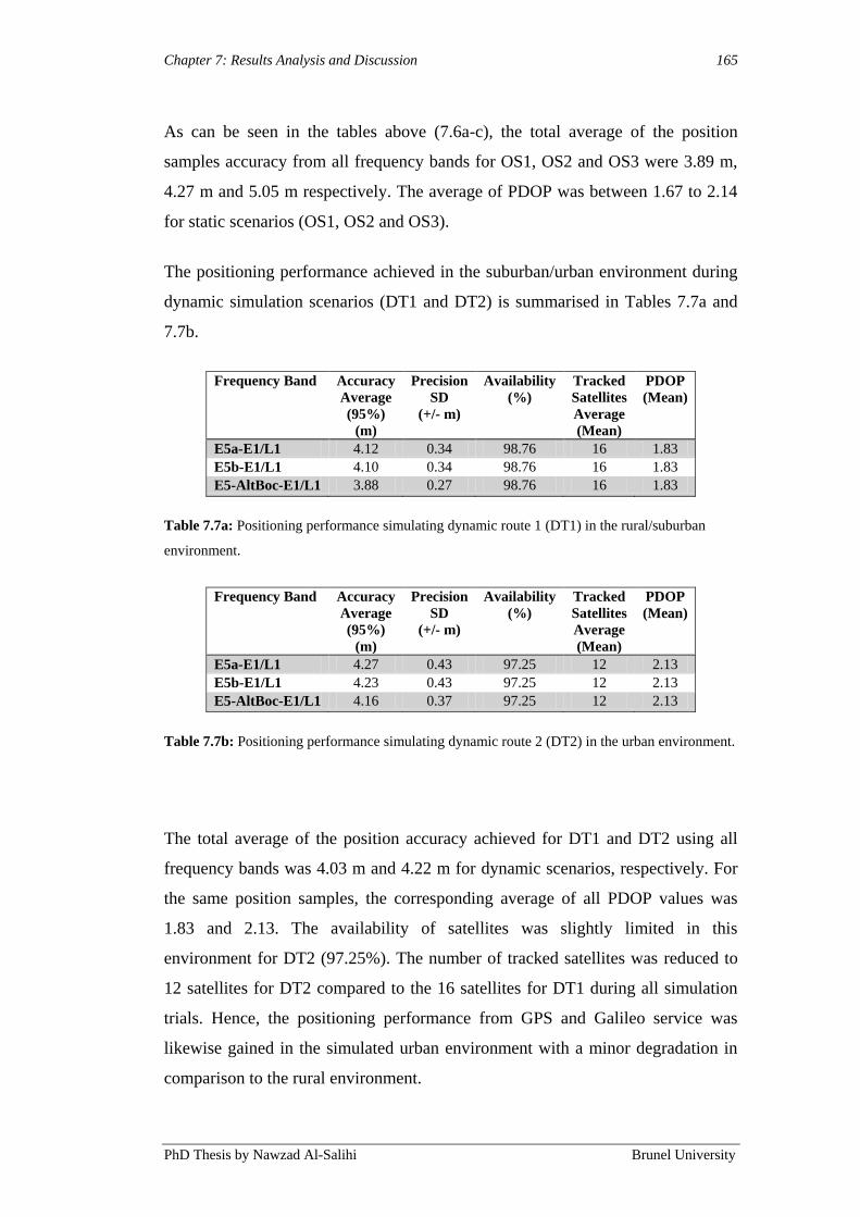
Chapter 7: Results Analysis and Discussion 165
PhD Thesis by Nawzad Al-Salihi Brunel University
As can be seen in the tables above (7.6a-c), the total average of the position
samples accuracy from all frequency bands for OS1, OS2 and OS3 were 3.89 m,
4.27 m and 5.05 m respectively. The average of PDOP was between 1.67 to 2.14
for static scenarios (OS1, OS2 and OS3).
The positioning performance achieved in the suburban/urban environment during
dynamic simulation scenarios (DT1 and DT2) is summarised in Tables 7.7a and
7.7b.
Frequency Band Accuracy
Average
(95%)
(m)
Precision
SD
(+/- m)
Availability
(%)
Tracked
Satellites
Average
(Mean)
PDOP
(Mean)
E5a-E1/L1 4.12 0.34 98.76 16 1.83
E5b-E1/L1 4.10 0.34 98.76 16 1.83
E5-AltBoc-E1/L1 3.88 0.27 98.76 16 1.83
Table 7.7a: Positioning performance simulating dynamic route 1 (DT1) in the rural/suburban
environment.
Frequency Band Accuracy
Average
(95%)
(m)
Precision
SD
(+/- m)
Availability
(%)
Tracked
Satellites
Average
(Mean)
PDOP
(Mean)
E5a-E1/L1 4.27 0.43 97.25 12 2.13
E5b-E1/L1 4.23 0.43 97.25 12 2.13
E5-AltBoc-E1/L1 4.16 0.37 97.25 12 2.13
Table 7.7b: Positioning performance simulating dynamic route 2 (DT2) in the urban environment.
The total average of the position accuracy achieved for DT1 and DT2 using all
frequency bands was 4.03 m and 4.22 m for dynamic scenarios, respectively. For
the same position samples, the corresponding average of all PDOP values was
1.83 and 2.13. The availability of satellites was slightly limited in this
environment for DT2 (97.25%). The number of tracked satellites was reduced to
12 satellites for DT2 compared to the 16 satellites for DT1 during all simulation
trials. Hence, the positioning performance from GPS and Galileo service was
likewise gained in the simulated urban environment with a minor degradation in
comparison to the rural environment.
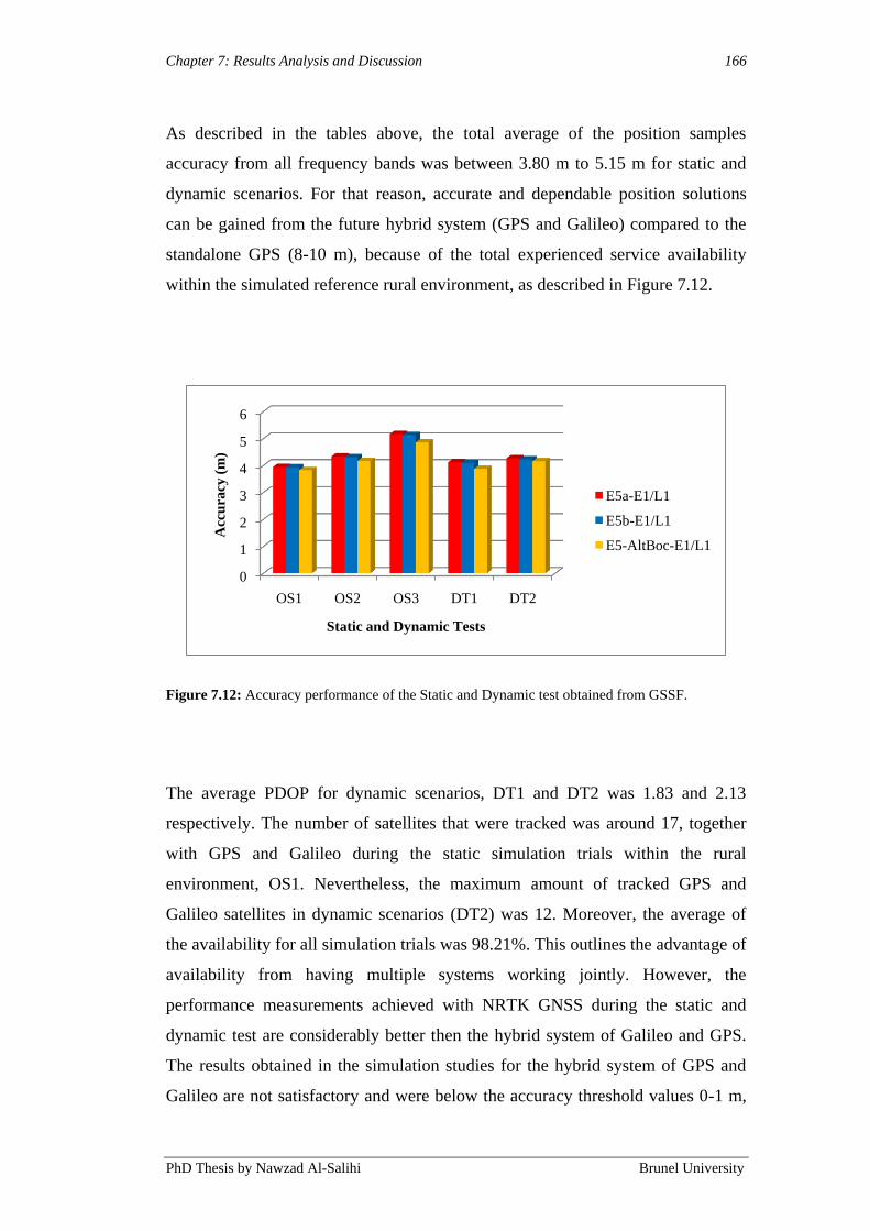
Chapter 7: Results Analysis and Discussion 166
PhD Thesis by Nawzad Al-Salihi Brunel University
As described in the tables above, the total average of the position samples
accuracy from all frequency bands was between 3.80 m to 5.15 m for static and
dynamic scenarios. For that reason, accurate and dependable position solutions
can be gained from the future hybrid system (GPS and Galileo) compared to the
standalone GPS (8-10 m), because of the total experienced service availability
within the simulated reference rural environment, as described in Figure 7.12.
Figure 7.12: Accuracy performance of the Static and Dynamic test obtained from GSSF.
The average PDOP for dynamic scenarios, DT1 and DT2 was 1.83 and 2.13
respectively. The number of satellites that were tracked was around 17, together
with GPS and Galileo during the static simulation trials within the rural
environment, OS1. Nevertheless, the maximum amount of tracked GPS and
Galileo satellites in dynamic scenarios (DT2) was 12. Moreover, the average of
the availability for all simulation trials was 98.21%. This outlines the advantage of
availability from having multiple systems working jointly. However, the
performance measurements achieved with NRTK GNSS during the static and
dynamic test are considerably better then the hybrid system of Galileo and GPS.
The results obtained in the simulation studies for the hybrid system of GPS and
Galileo are not satisfactory and were below the accuracy threshold values 0-1 m,
0
1
2
3
4
5
6
OS1 OS2 OS3 DT1 DT2
Acc
ura
cy (
m)
Static and Dynamic Tests
E5a-E1/L1
E5b-E1/L1
E5-AltBoc-E1/L1

Chapter 7: Results Analysis and Discussion 167
PhD Thesis by Nawzad Al-Salihi Brunel University
identified in Chapter 6 (Table 6.1). Nonetheless, the availability, reliability and
the PDOP are within the threshold values.
The finding from this section are summarised as follows:
A hybrid system, combining future Galileo OS along with GPS standard
positioning are more precise, accurate and dependable than standalone
GPS. This is because of the utilisation of multiple satellite constellations
and numerous frequencies in the positioning fixing process.
A basic positioning performance is obtainable from all Galileo signals that
are identified with diverse frequency bands. A small performance
difference was observed between the signals though. This is accounted in
GSSF, using different UERE budgets allotted for every frequency band.
The NRTK GNSS outperforms the hybrid standard services offered by
future Galileo OS and GPS. The hybrid system using the pseudo-range of
the signals compared to NRTK using both carrier-phase and pseudo-range.
However, the availability and reliability of the hybrid positioning services
are significantly better than the NRTK GNSS positioning model in
suburban and urban scenarios and environments. Therefore, this
recognises areas of compatibility and integration between the NRTK
GNSS positioning model and future systems.
7.4 Summary
In this chapter, the results obtained from the overall evaluation process conducted
to quantify the performance of the developed positioning model, has been
described. Different related factors have been taken into account in the
description. The positioning performance obtained from the advanced methods
NRTK GNSS was measured and contrasted concerning the positioning solutions
accuracy and precision, laterally with augmentation data availability. From the
NRTK GNSS positioning method, the best performance was achieved while
having clear satellite view and high augmentation data availability. However, the

Chapter 7: Results Analysis and Discussion 168
PhD Thesis by Nawzad Al-Salihi Brunel University
NRTK GNSS positioning methods had service availability difficulties in urban
environments.
Furthermore, this chapter also explored the positioning performance that was
attained from simulating a future hybrid system comprising of Galileo OS and
GPS, in varied scenarios and environments. Comparisons were made between the
performances obtained from the hybrid services, along with the performance that
was attained from the developed positioning model by way of using the NRTK
GNSS method. It was concluded that the NRTK GNSS positioning method was
able to provide a significantly higher accuracy levels. However the availability
was lower than the hybrid system (GPS and Galileo).
Simulation scenarios of the Galileo system were carried out. However, due to the
unavailability of the Galileo system these scenarios were not experimentally
validated.
Chapter 8: Conclusions and Suggestions for Future Work 169
PhD Thesis by Nawzad Al-Salihi Brunel University
Chapter 8
Conclusions and Suggestions for Future Work
In this thesis a presentation of the research work, which has been conducted in
enhancing the performance of the positioning technology utilised within visually
impaired people navigation application, has been offered. A new and precise
positioning model was proposed. The adaptive framework is understood as
approaching an integration of the available positioning technology into the context
of surrounding wireless communication for a maintainable performance. The
positioning model has the capability of delivering indeed accurate, precise and
consistent position solutions, and thus is fulfilling the requirements of visually
impaired people navigation application, as identified in the adaptive framework.
The conclusions of the key tasks that were undertaken are presented in this
chapter, which furthermore presents the identified main outcomes of this research
work. The conclusions made from the literature review and initial investigations
of EOA, GNSS and NRTK positioning performance are summarised below.
Additionally, the adaptive framework‟s main features are presented, along with
the positioning model. The central findings gained from the extensive evaluation
of the positioning model are described with several related aspects as a reference
point. Finally, this chapter concludes with some suggestions for future work in
order to develop and enhance the positioning model that provides further accurate
positioning services and extend its capability for in-door environments.
8.1 Conclusions
The central points of conclusion drawn from the literature review and the initial
research investigation can be summarised as follows:
The most crucial component in the navigation system for visually impaired
people is the positioning technology. Important information about when and

Chapter 8: Conclusions and Suggestions for Future Work 170
PhD Thesis by Nawzad Al-Salihi Brunel University
where the services are delivered is derived from the positioning technology.
GPS is the most commonly deployed positioning technology.
Nevertheless, the performance is influenced by numerous error sources that is
degrading the accuracy of the position solutions accuracy, and also restraining
its service integrity and availability. Even though several GPS augmentation
techniques have been presented and employed in different applications, yet,
the attained positioning performance was based on the availability of up-to-
date and dependable correction information. This is affected by the data
transmission means, measurement scenarios and navigation environments.
Moreover, a deep deliberation of visually impaired people navigation system
applications architecture and positioning needs is required when utilising
NRTK GNSS and its augmentation systems.
A set of preliminary performance experiments of different mobile wireless
technologies were conducted, such as UMTS and HSDPA, for utilisation in
the system. The performance assessment was focused on the following link
features: delay, jitter and packet loss of the GPS data and the live voice and
video streaming. These features were chosen to be assessed because they
have a significant impact on the overall performance of the navigation
system. The outcome of these preliminary experimental studies have
confirmed that the HSDPA is the only technology that matches the ITU
standards in navigation environments, such as urban, suburban, rural and
indoor. Therefore, these contextual factors were considered in the developed
positioning model for sustainable and efficient performance.
The applied strategy to address the conclusions above and enhance the positioning
performance of GPS for visually impaired people navigation system applications,
was presented in this thesis in two different steps as explained below:
1. A new precise positioning model that raises the positioning accuracy and
service reliability of the applications for visually impaired people was
suggested and developed. The establishment of an efficient positioning
model that incorporates NRTK GNSS and its augmentation position
Chapter 8: Conclusions and Suggestions for Future Work 171
PhD Thesis by Nawzad Al-Salihi Brunel University
solutions. The positioning model was applied as client-server architecture
comprising two main components, the Navigation Service Centre (NSC)
and the Mobile Navigation Unit (MNU). The new model has incorporated
both components for the purpose of switching the MNU from position
determination to server-based positioning mode grounded on the NSC, in
case of positioning and augmentation data unavailability. The MNU
utilises WADGNSS sources supplying networked-DGNSS correction data
with the aim of efficiently augmenting the GPS and GLONASS
measurements accumulated at the MNU, and compute an advanced
position solution.
In order to explore the positioning model performance in terms of the achieved
position solutions accuracy, precision, and service availability and reliability, a
comprehensive evaluation methodology was illustrated and utilised. The
evaluation process entailed experimental and simulation studies which were
carried out while taking into account several contextual aspects identified within
the adaptive framework. This embraces the navigation environment,
measurements scenarios and available position sensing resources. The central
conclusions drawn from the evaluation process are summarised as follows:
The results from the experiments have shown and thus confirmed that the
positioning model‟s position computation methods NRTK GNSS, applied at
the MNU, were capable of delivering position solutions with enhanced
accuracy levels in contrast to the existing GPS positioning service, throughout
all navigation environments and measurement scenarios. The NRTK
positioning method has satisfied the performance requirements for high
accuracy demanding applications. Therefore, the positioning model is capable
of delivering precise positioning in real-time using GPS-RTK Signal for
visually impaired people.
The average of position accuracy achieved from NRTK GNSS within the
urban environment and during a dynamic measurement scenario was below 85

Chapter 8: Conclusions and Suggestions for Future Work 172
PhD Thesis by Nawzad Al-Salihi Brunel University
cm. In the same concern, the corresponding NRTK availability values
computed using NRTK GNSS data at the MNU was 73.68% comparing to
88.44% computed at the rural/suburban environment. During the best
measurement conditions in rural area, the average of the position accuracy
achieved from NRTK GNSS was below 2 cm for the static measurement, in
comparison to below 35 cm and below 80 cm achieved using static
measurements in suburban and urban areas respectively. Hence, the NRTK
GNSS positioning methods at MNU have outperformed the existing GPS
services in worst and best conditions for accuracy measurements. This can be
explained due to the high precision dual frequency receiver and the assured
high availability of up-to-date and reliable augmentation data at the MNU
alongside with the effectiveness of the functional lines in processing and
correcting navigation data.
The conclusions from the simulation results showed that appropriately
accurate and reliable position samples can be obtained from the combination
of future Galileo OS with GPS standard positioning services. The hybrid
positioning service outperformed by the NRTK GNSS positioning model at
MNU in terms of the positions service accuracy in all scenario and navigation
environments. Furthermore, the hybrid system of Galileo and GPS could not
be verified in a “real” experimentation because Galileo system is yet not fully
functional, therefore a simulation study was conducted. However, the satellite
availability in all scenarios and navigation environments was higher than the
positioning model at MNU using NRTK GNSS. This recognises the need for
further work on development of the positioning model and the exploration of
the possibility of incorporating the future services within the same platform
including the positioning model.
In this research the experiments of NRTK GNSS at MNU and the quality of
service (QoS) of the transmission of video, voice and positioning data over

Chapter 8: Conclusions and Suggestions for Future Work 173
PhD Thesis by Nawzad Al-Salihi Brunel University
various wireless mobile networks (Chapter 5, Section 5.3.1) were not
conducted in a combined system. As it is outside the scope of this thesis.
However, HSDPA technology is sufficient to transmit video streams of micro
environment of the visually impaired person with sufficient resolution to the
NSC. With improved accuracy with NRTK, the system will be able to guide
the blind to avoid obstacles with better accuracy.
8.2 Future Work
With regard to the conclusions of this research project, an advanced performance
was attained from the developed positioning model. On the other hand, this
achievement might be perceived as insufficient for applications demanding high
availability of GPS and GLONASS satellites. Additionally, the indoor
environment was not considered within the navigation environments during the
system evaluation. This platform can be employed for further research activities in
order to guarantee the best use of the system in providing help for visually
impaired people, as well as aging population with some disability. The subsequent
steps are proposed:
Follow the development of GPS, GLONASS and Galileo systems enabling
to incorporate future broadcasted navigation signals, correction messages
and integrity information within the positioning model. This will in turn
permit the provision of more reliable and accurate positioning services in
all navigation environments.
Investigate the possibility of using NRTK GNSS and EGNOS/SISNET
(Signal in Space through the Internet) data for correction at the MNU, as
described in Chapter 5, Section 5.6.1 and shown in Figure 8.1. The
accuracy that can be obtained would in a combined system of applying
GPS augmentation techniques, such as NRTK and EGNOS/SISNET
improve significantly with the already established Adaptive, Reliable, and
Accurate Positioning Model for Location-Based Services model, by Al

Chapter 8: Conclusions and Suggestions for Future Work 174
PhD Thesis by Nawzad Al-Salihi Brunel University
Nabhan (2009). These data are included within RTCM v3 messages and
can be received from networked-based DGPS systems using the Ntrip
communication protocol.
Figure 8.1: Future system model operational architecture including EGNOS/SISNET.
Utilise additional navigation information built on a pedestrian Dead
Reckoning (DR) model as a means to extend the positioning model‟s
capability for indoor environments. This step involves the implementation
of the integrated domain positioning method at the MNU, using an
Extended Kalman Filtering (EKF) approach, or any effective algorithm for
navigation data fusion.
Co
mm
un
ica
tio
n M
od
em
Mobile Network/WLAN
Co
mm
un
ica
tio
n M
od
em
Maps and GIS
Software
Navigation Service Centre
(NSC)
Communication Link Mobile Navigation Unit
(MNU)
Voice
Positioning Data
Video Streaming
Application Server
Service and Content
Providers
Data Base Server
Dual Frequency
Receiver / RTK
Network RTK
Server
Augmentation Sources
NTRIP Server
Maps and GIS
Software
Video Camera
GPS-EGNOS ReceiverSISNet Data Server
Service and Content
Providers
NTRIP Server
Chapter 8: Conclusions and Suggestions for Future Work 175
PhD Thesis by Nawzad Al-Salihi Brunel University
Since the system only tested as a prototype, a fully functional system
prototype needs to be constructed, based on the previous research
outcomes in order to perform further testing of the system under the best
degree of achievement that satisfies both the technical and user
requirements. This requires the establishment of the system using the
proposed design of the communication link, MNU and NSC as proposed
in the mentioned Chapters 3 to 7.
Further future work can be accomplished by modifying the system to be
used in other applications, such as unmanned vehicles, military
applications, police, etc.
List of References 176
PhD Thesis by Nawzad Al-Salihi Brunel University
List of References
Abwerzger G., Hofmann-Wellenhof B., Ott B. and Wasle E. (2004) „GPS/SBAS
and Additional Sensor Integration for Pedestrian Applications in Difficult
Environments‟, Proceeding of National Technical Meeting of Institute of
Navigation- ION- GNSS 2004, September 21-24, Long Beach, California.
Abwerzger G. and Lechner W. (2002) „GPS and Loran-C – A raw data based
integration method‟, 3rd International Symposium in Integration of Loran-
C/Eurofix and EGNOS/Galileo, 11-12 June, Munich, Germany.
Ackroyd, N. and Cruddace, P. (2006) „OS Net-Positioning accuracy at the Heart
of Great Britain‟, Technical report, Ordnance Survey, Southampton
Almasri, S. (2009) „Zone-Based Concept for Managing the Data Flow in Mobile
Networking: Pedestrian Location-Based Services‟, PhD thesis, School of
Science and Technology, Anglia Ruskin University.
Alhajri, K., Al-Salihi, N., Garaj, V., Hunaiti, Z. and Balachandran, W. (2008)
„The Performance of HSDPA (3.5 G) Network for Application in a Navigation
System for Visually Impaired People‟, Proceeding of 6th Annual IEEE
Communication Networks and Services Research Conference (CNSR), Halifax,
Nova Scotia, Canada May 5 - 8, 2008: pp.440-446
Al Nabhan, M. (2009) „Adaptive, Reliable, and Accurate Positioning Model for
Location-Based Services‟, PhD Thesis, Department of Systems Engineering,
Brunel University, United Kingdom.
Al-Salihi, N., Alhajri, K., Garaj, V., Hunaiti, Z. and Balachandran, W. (2007)
„The Performance Comparison of 3G and WLAN Network for Application in a
Navigation System for Visually Impaired People‟, The Navigation conference
(NAV-07), “Are We There Now?”, Royal Institute of Navigation (RIN), 30th
of
October - 1st of November, Church House, London, UK.
Aponte, J., Xiaolin, M., Hill, C., Moore, T., Burbidge, M. and Dodson, A. (2009)
„Quality assessment of network-based RTK GPS service in the UK‟, Journal of
Applied Geodesy 3, pp.25-34.
Benedicto, J., Dinwiddy, S.E., Gatti, G. Lucas, R. and Lugert, M. (2000)
„GALILEO: Satellite System Design and Technology Developments‟, European
Space Agency (ESA), [Online], available at:
http://www.esa.int/esaNA/galileo.html
[Access on January 2008]
List of References 177
PhD Thesis by Nawzad Al-Salihi Brunel University
Balachandran, W. and Langtao, L. (1995) „Personal Navigation System‟, Patent
GB 2 287 535, UK
Beaubrun, R., Moulin B. and Jabeur, N. (2007) „An Architecture for Delivering
Location-Based Services‟, International Journal of Computer Science and
Network (IJCSNS), 7(7) pp.160-166.
BeiDou (2010) „BeiDou (COMPASS) Satellite Navigation System‟, [online]
Available at http://www.beidou.gov.cn/
[Accessed on January 2010]
Brusnighan, D., Strauss, M., Floyd, J. and Wheeler, B. (1989) „Orientation aid
implementing the Global Positioning System‟, Proceedings of the Fifteenth
Annual Northeast Bioengineering Conference, Boston, pp.33–34
Chang, C. and Lin, H. (1999) „Testing a Medium-Range DGPS Network for the
Taiwan Area‟, The Journal of Navigation, 52, pp.279-288
Chen R., Tora´n, F. and Ventura-Traveset, J. (2003) „Access to the EGNOS signal
in space over mobile-IP‟, GPS Solutions 7(1) pp.16–22
Chen, R., Li, X. and Weber, G. (2004) „Test results of an Internet RTK system
based on the NTRIP protocol‟, In Proceedings of the GNSS 2004 conference,
16–19 May, Rotterdam.
Chen, R. and Li, X. (2004) „Virtual differential GPS based on SBAS signal‟, GPS
Solutions 8(4), pp.238–244
Chen, G. and KotZ, D. (2000) „A survey of context-aware mobile computing
research‟, Technical Report R2000-381, Department of Computer Science,
Dartmouth College, November 2000.
Collins, C. „On mobility aids for the blind‟, In: Warren D. H. and Strelow, E. R.
(Eds.), Electronic spatial sensing for the blind, Boston, 1985, pp. 35–64
Department of Defence (DoD), (2008) Federal Radionavigation Plan, Department
of Transportation, National Technical Information, Service, Springfield,
Virginia 22161 [online], available at: http://www.navcen.uscg.gov/pubs/
[Accessed on January 2009]
Department of Defence (DoD), (2000) „Interface Control Document (ICD 200c)‟,
Department of Transportation, IRN-GPS-200c, April 2000.
Department of Defence (DoD) (2004) „NAVSTAR Global Positioning System
Interface Specifications Document‟, Department of Transportation IS-GPS-
200D-7, December 2004.
List of References 178
PhD Thesis by Nawzad Al-Salihi Brunel University
Dammalage, T., Srinuandee P., Samarakoon, L., Susaki, J., Srisahakit, T. (2006):
Potential Accuracy and Practical Benefits of NTRIP Protocol Over
Conventional RTK and DGPS Observation Methods, Proceeding of Map Asia
2006, Bangkok, Thailand 29th of August to 1st September.
European Commission's Joint Research Centre (EC-JRC), (2007) „SESAMONET
- A Secure and Safe Mobility Network‟ [online],
Available at: http://ec.europa.eu/dgs/jrc/index.cfm?id=4210&lang=en
[Accessed on November 2007]
ESA, (2006) „Satellite guidance for the visually impaired‟, [online]
Accessed online at:
http://www.esa.int/esaNA/SEM4MWK8IOE_index_0.html
[Accessed on March 2008]
ESA, (2007) „Galileo‟, [online] Accessed online at:
http://www.esa.int/esaNA/galileo.html
[Accessed on April 2007]
Esmond, M. (2007) „2007 Ubiquitous Positioning Technologies and LBS‟,
Location Magazine, [online], available at:
http://www.location.net.in/magazine/2007/july-august/36_1.htm
[Accessed on July 2008]
Federal Communications Commission (FCC), 1999. FCC Acts to Promote
Competition and Public Safety on Enhanced 911 Services, News Release,
September 15, 1999.
Feng, Y. And Wang, J. (2007) „Exploring GNSS RTK Performance Benefits with
GPS and Virtual Galileo Measurements, Proceedings of ION NTM, San Diego,
CA, USA, January 22-24, 2007.
Filjar, R., Jezic, G. and Matijasevic, M. (2008a) „Location-Based Services: A
Road towards Situation Awareness‟, The Journal of Navigation, 61, pp.573–
589.
Filjar, R., Bušić, L., Dešić, S., and Huljenić. D. and Balandin S. (2008b) „LBS
Position Estimation by Adaptive Selection of Positioning Sensors Based on
Requested QoS‟, Proceedings of the 8th international conference, NEW2AN
and 1st Russian Conference on Smart Spaces, Petersburg, Russia, pp. 101 – 109.
Filjar, R., Bušić, L. and Pikija, P. (2008c) „Algorithm Improving the LBS QoS
through Implementation of QoS Negotiation Algorithm‟, Proceedings 31st
International Convention MIPRO, Opatija, Croatia May 26-30 2008, pp. 211-
214

List of References 179
PhD Thesis by Nawzad Al-Salihi Brunel University
Filjar, R., Bušić, L. and Kos, T. (2007) „A Case Study of DGPS Positioning
Accuracy for LBS‟, Automatika, 48(1-2), pp.53-57
Filjar, R., Dešić, S. and Huljenić, D. (2004) „Satellite positioning for LBS: A
Zagreb field positioning performance study‟, The Journal of Navigation, 57(3),
pp.441- 447.
Filjar, R. (2003) „Satellite positioning as the foundation of LBS development‟.
Revista del Instituto de Navegación de España, 19: pp 4-20.
Fuente, C. (2008) „Location-Based Services‟, IET Designs on the games, Savoy
Place, London, UK, 7th of October 2008.
Fylor, T. (2009) „The Galileo Open Services-One size fits all?‟, The magazine of
the Royal Institute of Navigation (RIN).
Galileo, (2008) „European Satellite Navigation System‟, [online] Available at:
http://ec.europa.eu/enterprise/policies/space/galileo/index_en.htm
[Accessed on April 2010]
Grewal, M. S. Weill, L.R. Andrews, A.P. (2007): „Global Positioning Systems,
Inertial Navigation, and Integration‟, second edition, John Wiley & Sons Inc.
Garaj, V., Jirawimut, R., Ptasinski, P., Cecelja, F. and Balachandran, W. (2003)
„A System for Remote Sighted Guidance of Visually Impaired Pedestrians‟, The
British Journal of Visually Impairment, 21(2), pp.55 - 63.
Garaj, V. (2006) „Design of the System for Remote Sighted Guidance of Visually
Impaired Pedestrians‟, PhD Thesis, Department of Systems Engineering, Brunel
University, United Kingdom.
GLONASS (2010) „Federal Space Agency Information-Analytical Centre‟,
[online] Available at: http://www.glonass-
ianc.rsa.ru/pls/htmldb/f?p=202:1:7437278080171217
[Accessed on March 2010]
Gurtner, W. and Estey, L. (2007) „The Receiver Independent Exchange Format
Version 3.00‟, Central Bureau of the EUREF Permanent Network (EPN),
[online]
Available at: ftp://epncb.oma.be/pub/data/format/rinex300.pdf
[Accessed on January 2008]
GSSF (2006) „GALILEO System Simulation Facility – Reference Scenarios‟,
document reference: GSSFP3.OM.003, Issue 1, Revision 2.
GSSF (2005), „Galileo System Simulation Facility – Validation Testing
Specification‟, document reference: GSSFP2.REP.035, Issue 9, Revision 3.

List of References 180
PhD Thesis by Nawzad Al-Salihi Brunel University
GSSF (2004) „Galileo System Simulation Facility – Algorithms and Models‟,
Operations Manual, document reference: GSSFP2.OM.002, Issue 3, Revision 1.
Golledge, R. G. Klatzky, R. L. Loomis, J. M. Speigle, J. and Tietz, J. „A
geographical information system for a GPS based personal guidance system,‟
International Journal of Geographical Information Science, pp 727-749, 1998
Haider, M. and Qishan, Z. (2000) „Comparative Study on OEM-Based
Differential GPS‟, Proceedings of the 13th International Technical Meeting of
the Satellite Division of the Institute of Navigation ION GPS 2000, September
19 - 22, Salt Palace Convention Centre, Salt Lake City, UT, pp. 305 - 310
Helal, A., Moore, S. and Ramachandran, B. (2001) „Drishti: An Integrated
Navigation System for Visually Impaired and Disabled‟ Proceedings of the 5th
International Symposium on Wearable Computer, October 2001, Zurich,
Switzerland.
Hein, G. W., J. Godet, J.-L. Issler, J.-Chr. Martin, R. Lucas-Rodriguez and T.
Pratt (2001): The Galileo Frequency Structure and Signal Design, Proc. of ION
GPS 2001, Salt Lake City, September, pp. 1273-1282.
Hjelm, J. (2002) „Creating Location Services for the Wireless‟. New York: John
Wiley & sons.
Hofmann-Wellenhof, B., Lichtenegger, H. and Collins, J. (1997) GPS: Theory
and Practice, pp. 100–138, Springer-Verlag, Wien New York.
Hofmann-Wellenhof, B., Lichtenegger, H. and Collins, J. (2001) „Global
Positioning System‟, Theory and Practice, 5th edition, Austria: Springer-Verlag.
Hunaiti, Z. (2005) „A Remote Vision Guidance System for Visually Impaired
Pedestrians‟, PhD Thesis, Department of Systems Engineering, Brunel
University, United Kingdom.
Hunaiti, Z., Garaj, V. and Balachandran, W. (2006) „A Remote Vision Guidance
System for Visually Impaired Pedestrians‟, The Journal of Navigation, 59:
pp.497–504.
Hunaiti, Z., Rahman, A., Huneiti, Z. and Balachandran, W. (2005) „Evaluating
the Usage of Wireless Broadband Hotspots‟, Proceeding of the 2nd International
Conference on E-Business and Telecommunication Networks (ICETE), October
3-7, Reading UK, pp.138-141
Hunaiti, Z., Garaj, V., Balachandran, W. and Cecelja, F. (2005) „An Assessment
of 3G Link in a Navigation System for Visually Impaired Pedestrians‟,
Proceedings of the 15th International Conference on Electronics,
Communications and Computers, 28 February 2005 - 2 March 2005, Puebla,
Mexico, pp.180 -186.
List of References 181
PhD Thesis by Nawzad Al-Salihi Brunel University
Hunaiti, Z., Garaj, V., Balachandran, W. and Cecelja, F. (2004) “A Navigation
System for Visually Impaired Pedestrians”, IEEE; the International Conference on
Telecomputing and Information Technology (ICTIT 2004), Amman Jordan, Sep
2004.
Hughes, W., Technical Center NSTB/WAAS T&E Team, 2005, Global
Positioning System (GPS) Standard Positioning Service (SPS) Performance
Analysis Report, March 2005, Washington, DC: Federal Aviation
Administration (FAA) GPS Product Team.
Inside GNSS (2009) “Russia Dwells on Glonass Future” [online], Available at:
http://www.insidegnss.com/node/591
[Accessed on April 2009]
Jackson, M. (2006) „Location-based Services Technology and its Potential as an
Aid for Navigation‟, PhoneAbility in collaboration with COST219ter, Ask-It,
BCS HCI Group,
London, [online], Available at:
http://www.tiresias.org/phoneability/location_based_proceedings/index.htm
[Accessed on September 2007]
Jirawimut, R., Ptasinski, P., Garaj, V., Cecelja, F. and Balachandran, W. (2001)
„A Method for Dead Reckoning Parameter Correction in Pedestrian Navigation
System‟, IEEE Instrumentation and Measurement Technology Conference, 21-
23 May, Budapest, Hungary, pp.1554-1558
Jirawimut, R. (2003) „“Integrated Positioning System for Pedestrians Navigation".
PhD, Thesis. London, UK: Brunel University, 2003.
Kaplan, E. and Hegarty, C. (2006) Understanding GPS: principles and
applications, Second Edition, Noorwood, MA: Artech House.
Kamarudin, m. and Zulkarnaini, M. (2004) „Multipath Error Detection Using
Different GPS Receiver‟s Antenna‟, The 3rd FIG Regional Conference, October
3-7, Jakarta, Indonesia
Kee, C., Park, B., Kim, J., Cleaveland, A., Parsons M. and Wolfe, D. (2008) „A
guideline to establish DGPS reference stations requirements‟, The Journal of
navigation, 61 (1), pp.99-115.
Krishnamurthy, P. and Pahlavan, K. (2004) „Wireless Communications‟, In:
Karimi, H. A., Hammad, A. „Telegeoinformatics CRC Press‟, pp. 111-142.
Lachapelle, G. (2007) „Pedestrian navigation with high sensitivity GPS receivers
and MEMS‟, Journal of Personal and Ubiquitous Computing, 11, pp.481-488

List of References 182
PhD Thesis by Nawzad Al-Salihi Brunel University
Lachapelle, G., Alves, P., Fortes, LP., Cannon, ME. and Townsend, B. (2000)
„DGPS RTK positioning using a reference network‟, Proceeding of the 13th
International Technical Meeting Satellite Division US Institute of Navigation
(ION), Salt Lake City, UT, 19–22 September, pp 1165–1171.
LaPierre, C. (1998) „Personal Navigation System for the Visually Impaired‟, PhD
thesis, Faculty of Engineering, Carleton University.
Leeuwen, S. (2002) „GPS Point Position Calculation‟, GPS Solutions, 6(1),
pp.115-117
Lee, H.K., Wang, J., Rizos, C. (2005) “An Integer Ambiguity Resolution
Procedure for GPS/Pseudolite/INS Integration”, The Journal of Geodesy, 79 (4-
5), pp. 242-255.
Lee, Y., Kim, H., Hong, J., Jee, G. Lee, Y. and Park, C. (2005), „Internet based
DGPS for mobile communication users‟, Proceeding of the 13th International
Technical Meeting Satellite Division US Institute of Navigation (ION), 19–22
September, Salt Lake City, UT, pp 586–590
Liu, L. and Balachandran, W., “Navigation System”, International Patent No. WO
98/04885, 1998.
Liu, L. (1997), „An Intelligent Differential GPS Navigation System‟, PhD Thesis,
department of Manufacturing and Engineering Systems, Brunel University,
Untied Kingdom.
Loomis, P., Sheynblatt, L. and Muller, T., (1995), „Differential GPS Network
Design‟, Proceeding of National Technical Meeting of Institute of Navigation
(ION)-GPS '95, Alexandria, VA, U.S.A., pp.511-520.
Miller, K. (2000) Review of GLONASS, The Hydrographic Journal, [online],
available at: http://www.hydrographicsociety.org/Articles/welcome.html
[Accessed on October 2008]
Mohinder, S.G., Lawrence, R.W., Angus, P.A. (2007) Global positioning systems,
inertial navigation, and integration, Second Edition, Wiley & Sons, Inc.,
Hoboken, New Jersey, USA.
Narins, J. (2004) „Loran‟s Capability to Mitigate the Impact of a GPS Outage on
GPS Position, Navigation, and Time Applications‟, Federal Aviation
Administration (FAA). [Online], available at:
http://www.locusinc.com/pdf/press/2004
[Accessed on July 2008]
Oh, K-R., Kim, J-C. and Nam, G-W. (2005) „Development of Navigation
Algorithm to Improve Position Accuracy by Using Multi-DGPS Reference
List of References 183
PhD Thesis by Nawzad Al-Salihi Brunel University
Station- PRC information‟, Journal of Global Positioning Systems, 4 (2),
pp.144-150
Ott, B., Wasle, E., Weimann, F., Branco, P. and Nicole, R. (2005) „Pedestrian
Navigation in Difficult Environments: Results of the ESA Project SHADE‟, In:
Oosterom, P., Zlatanova, S., Fendel, M., „Geo-information for Disaster
Management‟, Springer Berlin Heidelberg, pp.1113-1126
OS Net (2008) „A guide to coordinate systems in Great Britain‟, v1.9 March 2008,
[online], Available at:
http://www.ordnancesurvey.co.uk/oswebsite/gps/information/coordinatesystems
info/guidecontents/index.html
[Accessed on June 2008]
Park Y.H., Oh K.R. and Kim, J.C. (2003) „Development of Linearly Interpolated
PRC Generating Algorithm to Improve Navigation Solution Using Multi-DGPS
Reference Stations‟, Proceeding of the 10th GNSS workshop, 21-22 Nov,
phoenixpark, Republic of Korea, pp.360-363.
Petovello, M. and Takac, F. (2009) GNSS Solution: GLONASS inter-frequency
biases and ambiguity resolution, Inside GNSS.
Pressl, B., and Weiser, M. (2006) „Positioning and Navigation of Visually
Impaired Pedestrians in an Urban Environment (PONTES)‟, 10th International
Conference on Computers for Handicapped Persons (ICCHP), July 11-13, Linz,
Austria.
Ptasinski, P. (2002) „Inverse DGPS Positioning Augmented with Digital Altitude
Map Dataset‟, PhD Thesis, Department of Systems Engineering, Brunel
University, United Kingdom.
Raman, S. and Garin, L. (2005) „Performance Evaluation of Global Differential
GPS (GDGPS) for Single Frequency C/A Code Receivers‟, Proceedings of the
18th International Technical Meeting of the Satellite Division of the Institute of
Navigation ION/GNSS-05, September 13 - 16, 2005, Long Beach, California,
pp. 1465 - 1469
Radio Technical Commission for Aeronautics (RTCA) Special Committee 159
Working Group 2, (2006) „Minimum Operational Performance Standards for
Global Positioning System / Wide Area Augmentation System Airborne
Equipment, Document Number DO-229A‟, Washington DC: RTCA Inc.
Retscher, G. and. Chao, C. H. (2000) „Precise Real-time Positioning in WADGPS
Networks‟, GPS Solutions, 4(2), pp.68-75.
Retscher, G. (1999) „RTK-GPS Positioning and Navigation in Marine Geodesy‟,
The Geomatics Journal of Hong Kong, 2, pp.39-48

List of References 184
PhD Thesis by Nawzad Al-Salihi Brunel University
Richard, P. (2008) „Galileo, Essential Infrastructure or European „vanity project?‟,
Royal Institute of Navigation (RIN), Galileo workshop, 28th February, London,
UK.
Rizos, C. and Han, S. (2003) „Reference station network based RTK systems -
Concepts & progress‟. Wuhan University Journal of Nature Sciences, 8(2B),
pp.566-574.
Rizos, C. (1999) „How Good is GPS?‟ The university of New South Wales,
Sydney, Australia, available at:
http://gmat.unsw.edu.au/snap/gps/gps_survey/chap2/241relb.htm
[Accessed on August, 2008]
RTCM Special Committee No. 104, „Ntrip Broadcasters list‟, RTCM SC-104
Ntrip, [online] available at: http://www.rtcm-ntrip.org/home
[Accessed on October 2008]
RTCM Special Committee No. 104, (RTCM SC-104), 1994, RTCM
Recommendation Standard for Differential NAVSTAR FPS Service, Version
2.1, Jan 1994.
RTCM Special Committee No. 104, (RTCM SC-104), (2004) „RTCM Standard
for Networked Transport of RTCM via Internet Protocol (Ntrip)‟, Version 1, Jan
2004
RTCM SC-104 Ntrip, [online] available at: http://www.rtcm.org/orderinfo.php
[Accessed on October 2008]
Russian Space Agency (RSA) (2008) „GLONASS constellation status for
18.01.08 under the analysis of the almanac and accepted in IANC (UTC)‟, The
Ministry of Defence of the Russian Federation
Shaw, M., Turner, D. A., and Sandhoo, K., (2002) „Modernization of the Global
Positioning System‟, Proceeding of the Japanese Institute of Navigation, GPS
Symposium 2002, Tokyo, Japan, pp.3–12.
Shah, A., Ptasinski, P,. Cecelja, F., Hudson C, and Balachandran, W. (1999)
„Accuracy and Performance of Brunel Differential GPS System for Blind
Navigation‟, Proceeding of International Technical Meeting of the Satellite
Division of the U.S. Institute of Navigation ION-GPS 1999, 14-17 September,
Nashville, USA, pp.1901-1905
Steiniger, S., Neun, M. and Edwardes, A. (2008) „Foundations of Location Based
Services- Lecture Notes on LBS‟,
Available at: http://www.geo.unizh.ch/publications/cartouche/
[Accessed on August 2008]
List of References 185
PhD Thesis by Nawzad Al-Salihi Brunel University
Strothotte, T., Petrie, H., Johnson, V. and Reichert, L. MoBIC, „An aid to increase
the independent mobility of blind and elderly travellers,‟ proceeding of the 2nd
TIDE Congress, ,26 – 28 of April 1995, Paris, La Villette.
Teunissen, P.J.G. (1993). “Least-Squares Estimation of the Integer GPS
Ambiguities”. Invited lecture, Section IV Theory and Methodology, IAG
General Meeting, Beijing, China. Also in Delft Geodetic Computing Centre
LGR series, No. 6, 16pp.
Theiss, A. David, C., Yuan, C. (2005) „Global Positioning Systems: an analysis of
applications, current development and future implementations‟, Computer
Standards& Interfaces, 27(2), pp. 89-100
Topcon, (2009) „Topcon HiperPro‟, [online] available at:
http://www.topconpositioning.com
[Accessed on October 2009]
Vollath, U., Buecherl, A., Landau, H., Pagels, C. and Wager, B. (2000) „Multi-
base RTK positioning using virtual reference stations‟ Proceeding of the 13th
International Technical Meeting Satellite Division US Institute of Navigation
(ION), 19–22 September, Salt Lake City, UT, pp.123–131.
Wanninger, L. (2004) „Introduction to Network RTK‟, International Association
of Geodesy, Working Group 4.5.1: Network RTK, Dresden, Germany, available
at: http://www.network-rtk.info/intro/introduction.html
[Accessed on October 2008]
Wegener, V. And Wanninger, L. (2005) „Communication Options for Network
RTK‟, International Association of Geodesy, Working Group 4.5.1: Network
RTK, Dresden, Germany, available at: http://www.network-
rtk.info/wegener/communication.html
[Accessed on January 2009]
WiMAX Forum. (2006) Mobile WiMAX – Part I- A Technical Overview and
Performance Evaluation, [online], Available at:
http://www.wimaxforum.org/technology/downloads/
[Accessed on April 2008]
Wolfson O., Yin. H. and Hadzilacos, T. (2003) „Accuracy and Resource
Consumption in Tracking and Location Prediction‟, In the preceding of the 8th
International Symposium, On Advances in Spatial and Temporal Databases
(SSTD 2003), July 24-27, Santorini Island, Greece, pp.325-343.
Yun-Chun, Y., Sharp, Y.R.T and Hatch, R.R. (2002). “A Fast Ambiguity
Resolution Technique for RTK Embedded Within a GPS Receiver”. 15th

List of References 186
PhD Thesis by Nawzad Al-Salihi Brunel University
International Technical Meeting of the Satellite Division of the Institute of
Navigation (ION GPS 2002), 24-27 September, 945-952.
Zimmermann, F., Haak, T. and Hill, C. (2004) „Galileo System Simulation
Facility (GSSF)‟, Proceedings of the 8th International Workshop on Simulation
for European Space Programmes (SESP), October 19-21, Noordwijk Holland.

Appendix A 187
PhD Thesis by Nawzad Al-Salihi Brunel University
Appendix A: Experimental Testing Locations
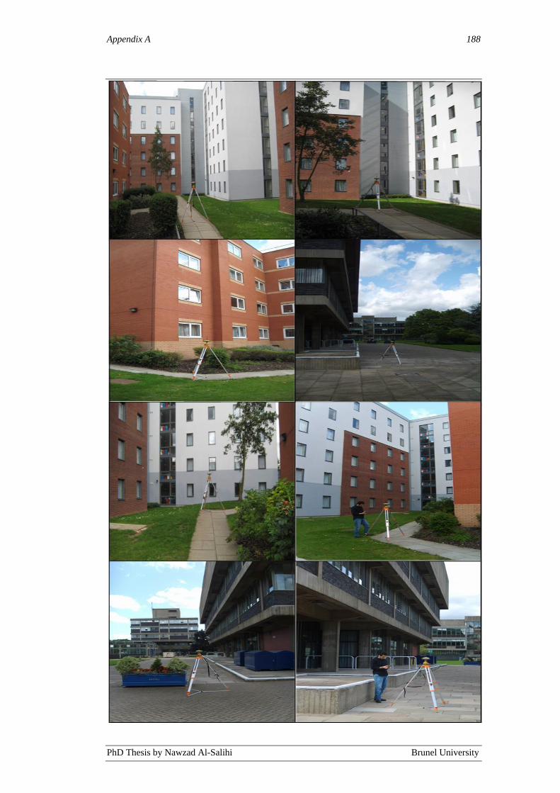
Appendix A 188
PhD Thesis by Nawzad Al-Salihi Brunel University

Appendix B 189
PhD Thesis by Nawzad Al-Salihi Brunel University
Appendix B: Overall Experimental Results
Overall positioning performance at all benchmark points on static testing routes
OS1, OS2 and OS3:
Test East –
Accuracy
Average
(cm)
North –
Accuracy
Average
(cm)
East –
Precision
SD
(+/- cm)
North –
Precision
SD
(+/- cm)
NRTK
Availability
(%)
Tracked
Satellites
Average
(Mean)
PDOP
(Mean)
OS1 1.09 1.42 0.78 1.04 98.68 11 2.10
OS2 -21.28 33.05 2.28 3.38 88.12 9 2.39
OS3 39.65 75.89 3.76 5.89 69.69 7 4.38
Overall positioning performance at all benchmark points on dynamic testing DT1,
and DT2 (averages of 12 dynamic testing trials):
Test East –
Accuracy
Average
(cm))
North –
Accuracy
Average
(cm)
East –
Precision
SD
(+/- cm)
North –
Precision
SD
(+/- cm)
NRTK
Availability
(%)
Tracked
Satellites
Average
(Mean)
PDOP
(Mean)
ST1 -1.3 1.77 1.3 0.79 97.89 10 2.52
ST2 1.7 -3.1 1 1.3 97.49 9 2.84
ST3 1.97 1.1 0.87 1.62 97.63 10 2.89
ST4 -23.72 -17.1 3.57 2.65 89.76 8 2.98
ST5 30.83 -21.87 4.13 3.37 78.68 7 3.67
ST6 -37.17 44.37 5.11 6.22 69.28 7 4.57
ST7 27.19 -16.94 3.97 2.89 72.18 6 4.20
ST8 13.47 8.26 2.69 2.17 93.32 9 3.01
ST9 -17.13 -11.43 3.77 2.03 92.46 8 3.13
ST10 1.66 1.11 0.83 1.44 98.13 11 2.36
ST11 -6.9 11.76 1.74 2.26 94.16 8 3.18
ST12 2.31 6.81 1.68 2.78 96.68 9 2.94
ST13 -51.18 47.63 6.18 5.47 65.74 5 5.42
ST14 47.23 66.11 5.89 6.79 68.67 5 4.97
ST15 66.91 73.54 6.23 6.93 59.39 5 5.41
ST16 78.23 -43.81 7.67 5.11 63.85 6 5.03
ST17 46.21 17.94 5.23 3.13 74.41 6 4.72
ST18 -6.3 -3.1 1.54 1.27 96.11 9 2.51
ST19 8.73 4.90 3.84 3.05 95.21 8 3.09
ST20 -1.23 1.76 1.13 1.66 97.13 10 1.99

Appendix C 190
PhD Thesis by Nawzad Al-Salihi Brunel University
Appendix C: List of Publications
Nawzad Al-Salihi, Khalid Alhajri, Vanja Garaj, and Wamadeva Balachandran,
‘The performance comparison of 3G and WLAN network for application in a
navigation system for visually impaired people’, The Navigation Conference &
Exhibition – Are We There Now, (NAV 07), London, UK, Oct 2007.
Khalid Alhajri, Nawzad Al-Salihi, Vanja Garaj, Ziad Hunaiti and Wamadeva
Balachandran ‘The performance of HSDPA (3.5 G) network for application in a
navigation system for visually impaired people,, Sixth Annual Conference on
Communication Networks and Services Research (CNSR 2008), 5-8 May 2008,
Halifax, Nova Scotia, Canada. IEEE Computer Society 2008.
Khalid Alhajri, Nawzad Al-Salihi, Vanja Garaj and Wamadeva Balachandran,
‘The performance of WiFi network for application in a navigation system for
visually impaired people’, The 7th Annual Wireless Telecommunications
Symposium, April 24-26 2008, Pomona, California, USA. IEEE Communications
Society 2008.
Nawzad Al-Salihi and Wamadeva Balachandran, „A Comparison of GPS and
Galileo Signals for Application in a Navigation System for Visually Impaired
People’, The Navigation Conference & Exhibition – We Are Here! (NAV 08),
London, UK, Oct 2008.
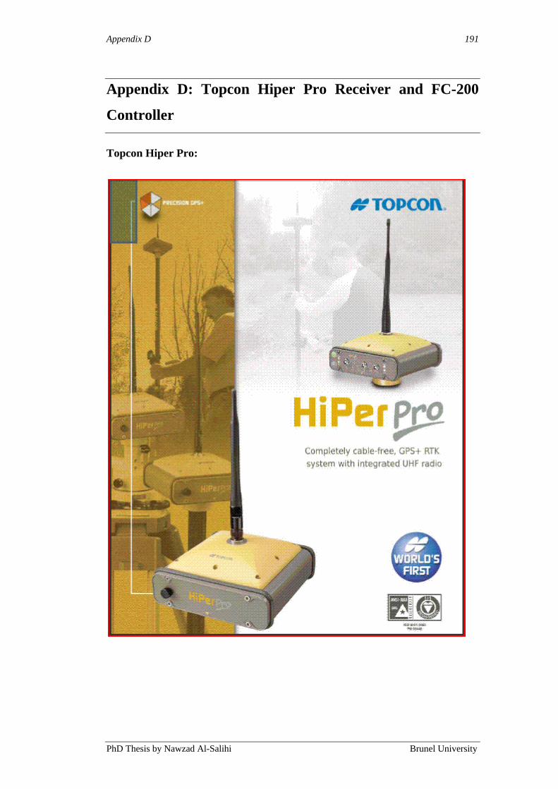
Appendix D 191
PhD Thesis by Nawzad Al-Salihi Brunel University
Appendix D: Topcon Hiper Pro Receiver and FC-200
Controller
Topcon Hiper Pro:

Appendix D 192
PhD Thesis by Nawzad Al-Salihi Brunel University
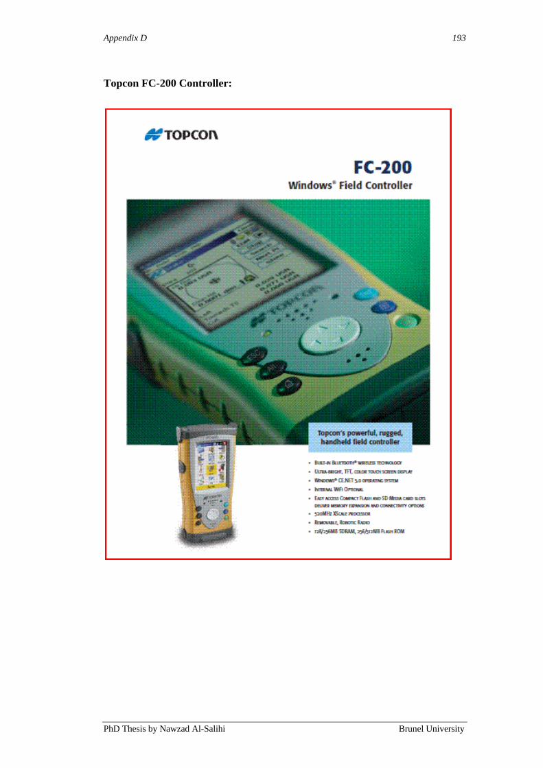
Appendix D 193
PhD Thesis by Nawzad Al-Salihi Brunel University
Topcon FC-200 Controller:

Appendix D 194
PhD Thesis by Nawzad Al-Salihi Brunel University
![Golden Code PBIS Program Golden Ring Middle School Syretta James [PBIS Coach] Gina Peller [PBIS Team Member] Linda Salihi [PBIS Team Leader] Kevin Roberts](https://cdn.vdocuments.us/doc/165x107/56649f305503460f94c4b850/golden-code-pbis-program-golden-ring-middle-school-syretta-james-pbis-coach.jpg)


