
Proactive Inspections Program Findings:Buildings
P R AC T I T I O N E R E D U C AT I O N S E R I E S

Goce GorgievskiManagerProactive Inspections Services
Mathew FithallTechnical AdvisorTechnical & Regulations
Stuart DraffinDirectorAudits and Inspections
WELCOME

Before we begin
Recording Questions
Feedback Survey

In today’s session
ProactiveInspections
Program
Case studies of common issues
Recent Q4 findings

Proactive Inspections
Program

Proactive Inspection ProgramWH AT I S I T ?
• Involving teams of building and plumbing inspectors, who are VBA Authorised Officers.
• Inspections of building and plumbing works under construction through Victoria
WH Y WE D O I T ?
• It aims to reduce number of non-compliant work.
• Enforce compliance with the Building Act 1993 (the Act), Building Regulations 2018 and Plumbing Regulations 2018,
prior to occupation taking place.
• Able to address significant failures early, rectification is often easier, avoids impacting the safety, health, and amenity of
future residents.
GOAL: INSPECT AT LEAST 10 PER CENT OF ALL BUILDING PERMITS ISSUED PER YEAR
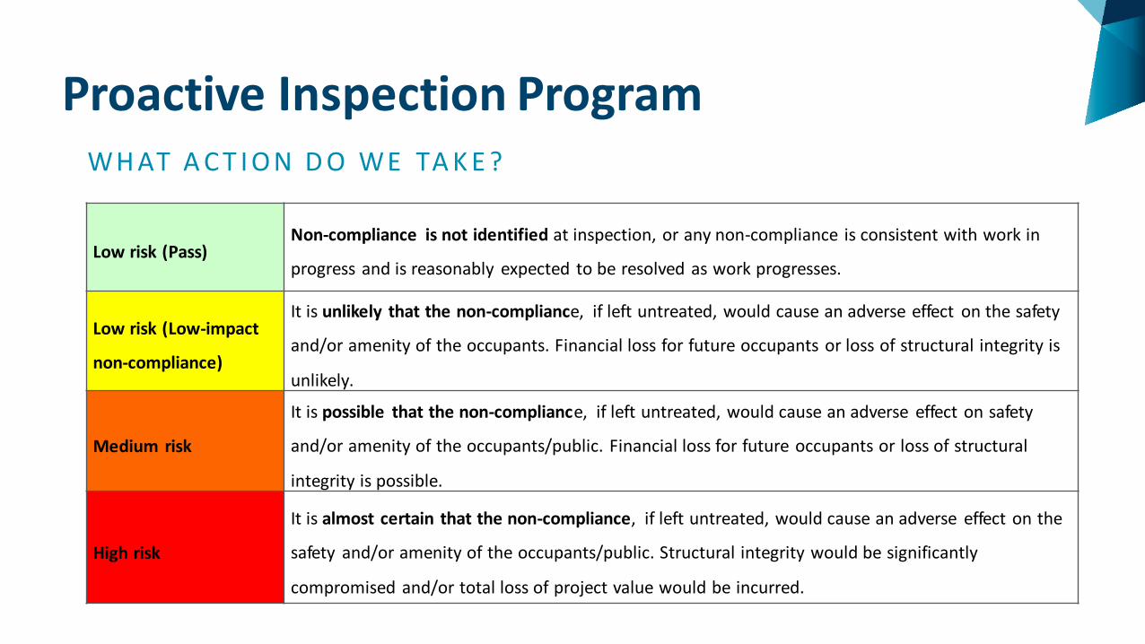
Proactive Inspection ProgramWH AT A C T I O N D O WE TA K E ?
Low risk (Pass)Non-compliance is not identified at inspection, or any non-compliance is consistent with work in
progress and is reasonably expected to be resolved as work progresses.
Low risk (Low-impact
non-compliance)
It is unlikely that the non-compliance, if left untreated, would cause an adverse effect on the safety
and/or amenity of the occupants. Financial loss for future occupants or loss of structural integrity is
unlikely.
Medium risk
It is possible that the non-compliance, if left untreated, would cause an adverse effect on safety
and/or amenity of the occupants/public. Financial loss for future occupants or loss of structural
integrity is possible.
High risk
It is almost certain that the non-compliance, if left untreated, would cause an adverse effect on the
safety and/or amenity of the occupants/public. Structural integrity would be significantly
compromised and/or total loss of project value would be incurred.

Recent findings
The most common non compliances issue that were
found on site where to do with:
• Timber framing
329
• Unreinforced brickwork & accessories
112
• Footings/slab construction and subfloor
ventilation
119
• Damp and weatherproofing
112

Common issues in timber framing

Bottom Plates that overhang concrete slabs
• Under AS1684.2 there are no prescribed allowance for timber frame overhangs.
• The Guide to Standards and Tolerances (currently under review) only allows a 90mm wide stud to overhang a maximum of 10mm
• Areas that exceed the allowed tolerance require a review from the relevant registered civil engineer to provide evidence that compliance with the NCC 2019 Volume 2 Part 2.1 is being achieved.
• Reinforcement starter bars into edge of concrete and bulk pour concrete

Bottom Plates that overhang concrete slabs

Notching / Trenching / Holes in studs and plates
• AS1684 allows for a maximum hole diameter of 25mm on the face of the bottom plate.
• Part 6.2.1.4 must be followed.
• Where the notch exceeds this in a braced wall, consideration must be given to be Part 8.3.6 noting that sheet braced walls require a continuous bottom plate
• Studs are required to be evenly spaced and extend from the underside of the top plate down to the bottom plate.
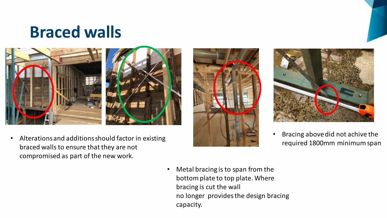
Braced walls
• Alterations and additions should factor in existing braced walls to ensure that they are not compromised as part of the new work.
• Bracing above did not achive the required 1800mm minimum span
• Metal bracing is to span from the bottom plate to top plate. Where bracing is cut the wall no longer provides the design bracing capacity.

Location of Braced walls
• Where bracing is cut to allow for ducting/toilet fittings the wall is no longer working towards providing the initial assumed bracing capacity.
• When considering the location of braced walls, it is important to factor in the proposed services/fittings to ensure they will not be compromised.

Notching / Trenching / Holes in sheet braced walls
• Penetrations have occurred within the sheet bracing contrary to the manufacturers installation guidelines.
• It is critical to ensure that the manufacturers installation guides are being followed.
• Unless otherwise specified the sheet bracing must span a minimum of 900mm wide

Installation of Floor joists
• The manufacturers installation guides must be followed so that they are installed the correct way up.
• Posi Struts require the web starts at the top chord at each support point unless clearly identified otherwise.

Damaged Floor Joists
• Web of Posi Strut was damaged which required replacement
• Flange of Smart Joist was damaged. Materials should be good and suitable for their purpose for which they are used.

Cuts / Holes and Notches within the Floor joists
• New support running vertically and laterally across joists to provide further stability.• Posi strut was notched
resulting in a rectification design provided from the manufacturer.
• Timber floor joist has top-chord and web notching to allow for plumbing pipe
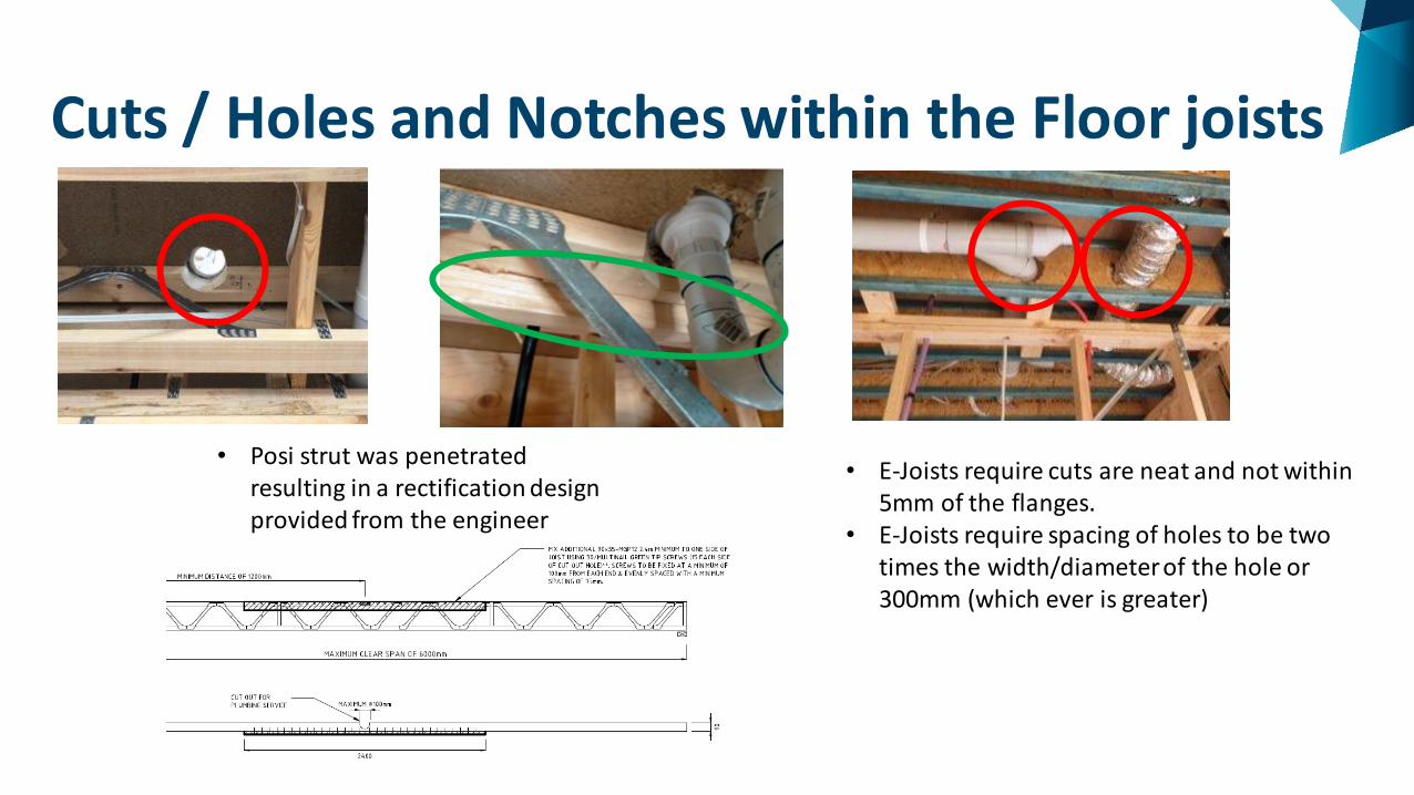
Cuts / Holes and Notches within the Floor joists
• Posi strut was penetrated resulting in a rectification design provided from the engineer
• E-Joists require cuts are neat and not within 5mm of the flanges.
• E-Joists require spacing of holes to be two times the width/diameter of the hole or 300mm (which ever is greater)
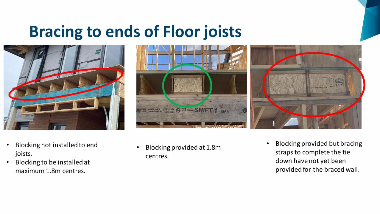
Bracing to ends of Floor joists
• Blocking not installed to end joists.
• Blocking to be installed at maximum 1.8m centres.
• Blocking provided at 1.8m centres.
• Blocking provided but bracing straps to complete the tie down have not yet been provided for the braced wall.

Bracing to ends of Floor joists
• Timber diagonal bracing provided at 1200mm centres however no Trip-L-Grips were not installed. Required to have at least one per braced panel.
• No end support bracing provided.
• Timber diagonal blocking required at 1200 centrs.
• No internal end support bracing provided
• Trip-L-Grips are required if using speed brace or diagonal timber bracing.

Strong backs
• Metal L-Bracket installed across 3 joists as per engineers rectification design and certification process
• Inspection identified strongback had been cut to allow for plumbing pipe

Fixing of trusses to internal walls
• Slotted L-Brackets not installed at 1.8m centres(internal non-loadbearing).
• No shear blocks installed to internal non-loadbearing braced wall.
• Refer to Table 8.22 for various methods

Half Trusses
• No bracing to the ends of cut-off/half trusses
• Timber diagonal bracing installed to cut-off/half trusses
• Speed bracing installed to half trusses
• Blocking and fixing not provided as per manufacture's details

Other Structural Issues
• Blocking not provided with double studs to transfer the concentrated loads through the structure. Additional support blocking provided
between the ground / first floor to transfer the concentrated loads through the structure

Other Structural issues
• Double studs/jamb studs required to ends of lintels
• Tie downs at jamb studs.• Waling plate cut.

PIP Quarterly Report
More information regarding The PIP Quarterly report can be found on the VBA website:
• For the website go to https://www.vba.vic.gov.au/plumbing/complaints-compliance-enforcement/proactive-inspections-program/quarterly-reports

Q & A

Thank you
P R AC T I T I O N E R E D U C AT I O N S E R I E S


