
PQC-STATCON
Installation, operation and maintenance
manual

2 Manual PQC-STATCON | Table of contents
This page has been left blank intentionally

Manual PQC-STATCON | Table of contents 3
Table of contents
PQC-STATCON ........................................................................................................ ERROR! BOOKMARK NOT DEFINED.
INSTALLATION, OPERATION AND MAINTENANCE MANUAL ....................................................................................... 1
TABLE OF CONTENTS .................................................................................................................................................. 3
1 INTRODUCTION TO THIS MANUAL ........................................................................................................................ 6
1.1 WHAT THIS CHAPTER CONTAINS ........................................................................................................................ 6 1.2 INTENDED AUDIENCE ......................................................................................................................................... 6 1.3 ABBREVIATIONS & USEFUL TERMS ..................................................................................................................... 6 1.4 COMPATIBILITY................................................................................................................................................... 6 1.5 CONTENTS .......................................................................................................................................................... 7 1.6 RELATED PUBLICATIONS ..................................................................................................................................... 7
2 SAFETY INSTRUCTIONS .......................................................................................................................................... 8
3 UPON RECEPTION .................................................................................................................................................. 9
3.1 WHAT THIS CHAPTER CONTAINS ........................................................................................................................ 9 3.2 DELIVERY INSPECTION ........................................................................................................................................ 9 3.3 LIFTING AND TRANSPORTATION GUIDELINES .................................................................................................... 9 3.4 IDENTIFICATION TAG ........................................................................................................................................ 10 3.5 STORAGE .......................................................................................................................................................... 10
4 HARDWARE DESCRIPTION ................................................................................................................................... 11
4.1 WHAT THIS CHAPTER CONTAINS ...................................................................................................................... 11 4.2 TYPICAL PQC-STATCON PANEL LAYOUT ............................................................................................................ 11 4.3 THE PQC POWER HARDWARE ........................................................................................................................... 13 4.4 THE PQC MAIN CONTROLLER ............................................................................................................................ 14 4.5 THE PQC-MANAGER / USER INTERFACE ........................................................................................................... 16 4.6 LOCATION OF THE MAIN PQC COMPONENTS ................................................................................................... 17
4.6.1 PWM REACTOR AND SWITCH GEAR COMPARTMENT .............................................................................. 17 4.6.2 CONVERTER COMPARTMENT - CONTROLLER ........................................................................................... 18
5 MECHANICAL DESIGN AND INSTALLATION .......................................................................................................... 20
5.1 WHAT THIS CHAPTER CONTAINS ...................................................................................................................... 20 5.2 INSTALLATION LOCATION REQUIREMENTS ...................................................................................................... 20 5.3 AIRFLOW AND COOLING REQUIREMENTS ........................................................................................................ 21 5.4 MECHANICAL PREPARATION OF A COMMON CABLE ENTRY ............................................................................ 23
6 ELECTRICAL DESIGN AND INSTALLATION ............................................................................................................. 24
6.1 WHAT THIS CHAPTER CONTAINS ...................................................................................................................... 24 6.2 CHECKING THE INSULATION OF THE ASSEMBLY - EARTH RESISTANCE ............................................................. 24 6.3 EARTHING GUIDELINES ..................................................................................................................................... 25 6.4 SELECTION OF THE POWER CABLE SIZE............................................................................................................. 26 6.5 SELECTION OF THE POWER CABLE PROTECTION/PQC INPUT PROTECTION SCHEME ....................................... 26 6.6 CONNECTION OF THE PQC-SYSTEM TO THE NETWORK .................................................................................... 27 6.7 SELECTION OF THE CURRENT TRANSFORMERS ................................................................................................ 29 6.8 CURRENT TRANSFORMER INSTALLATION......................................................................................................... 31
6.8.1 BASIC RULES FOR CORRECT CT INSTALLATION ......................................................................................... 31 6.8.2 CASE 1: CT LOCATIONS FOR THE CASE OF GLOBAL COMPENSATION – ONE FEEDING TRANSFORMER ... 33 6.8.3 CASE 2: CT LOCATIONS FOR THE CASE OF INDIVIDUAL COMPENSATION – ONE FEEDING TRANSFORMER 34 6.8.4 CASE 3: CT LOCATIONS FOR THE CASE OF GLOBAL COMPENSATION – TRANSFORMER BUSBAR NOT ACCESSIBLE .......................................................................................................................................................... 34 6.8.5 CASE 4: CT LOCATIONS FOR THE CASE OF TWO INDEPENDENT FEEDING TRANSFORMERS ..................... 35 6.8.6 CASE 5: CT LOCATIONS FOR THE CASE OF FEEDING TRANSFORMER AND BACKUP GENERATOR ............ 37 6.8.7 CASE 6: CT CONNECTIONS FOR THE CASE THAT PASSIVE FILTERS AND PQC-STATCONS ARE INSTALLED IN THE SAME NETWORK ........................................................................................................................................... 38

4 Installation Table Of Contents
6.8.8 CASE 7: CT CONNECTIONS FOR THE CASE THAT PASSIVE FILTERS AND PQC-STATCONS ARE INSTALLED IN THE SAME NETWORK AT DIFFERENT VOLTAGE LEVELS ....................................................................................... 39
6.9 ELECTRICAL INTERCONNECTION OF PQC CUBICLES .......................................................................................... 39 6.9.1 MECHANICAL CONNECTION ...................................................................................................................... 40 6.9.2 CONTROL BOARD CABLE INTERCONNECTION ........................................................................................... 40 6.9.3 EARTH POINTS INTERCONNECTION .......................................................................................................... 41 6.9.4 CT CABLE INTERCONNECTION ................................................................................................................... 41
6.10 ELECTRICAL CONNECTIONS TO THE PQC-MANAGER / USER INTERFACE .......................................................... 42
7 THE PQC-MANAGER USER INTERFACE ................................................................................................................. 43
7.1 WHAT THIS CHAPTER CONTAINS ...................................................................................................................... 43 7.2 UI / PQC-MANAGER OVERVIEW AND NAVIGATION .......................................................................................... 43 7.3 MAIN MENU STATUS ........................................................................................................................................ 46
7.3.1 THE ‘STATCON SYSTEM STATUS’ ............................................................................................................... 46 7.3.2 SETTINGS MENU ........................................................................................................................................ 47 7.3.3 FAULT LOGGER .......................................................................................................................................... 50
8 COMMISSIONING INSTRUCTIONS ........................................................................................................................ 52
8.1 WHAT THIS CHAPTER CONTAINS ...................................................................................................................... 52 8.2 STEP 1: VISUAL AND INSTALLATION CHECK ...................................................................................................... 52 8.3 STEP 2: VOLTAGE RATING AND PHASE ROTATION CHECK ................................................................................ 53 8.4 STEP 3: BASIC COMMISSIONING PARAMETERS SET UP (USING PQC MANAGER / UI) ....................................... 54 8.5 STEP 4: SENSING CT SETUP ............................................................................................................................... 55
8.5.1 CT SETUP PROCEDURE .............................................................................................................................. 55 8.5.2 PQC CONNECTION DIAGRAM .................................................................................................................... 56 8.5.3 MATERIAL NEEDED AND HYPOTHESES FOR CORRECT MEASUREMENTS ................................................. 57 8.5.4 CHECKING THE CORRECT CONNECTION OF THE CTS WITH A TWO-CHANNEL SCOPEMETER ................... 57 8.5.5 CHECKING THE CORRECT CONNECTION OF THE CTS WITH A FLUKE 41B ................................................. 61
8.6 STEP 5: STARTING THE PQC............................................................................................................................... 61 8.7 COMMISSIONING REPORT ................................................................................................................................ 61
8.7.1 PQC IDENTIFICATION*............................................................................................................................... 62 8.7.2 INSPECTION ON SITE – VERIFICATION OF THE PQC-STATCON AFTER INSTALLATION ............................... 63 8.7.3 PROGRAMMING ........................................................................................................................................ 64 8.7.4 TESTING (WITH LOAD) ............................................................................................................................... 65 8.7.5 COMMENTS ............................................................................................................................................... 65
9 OPERATING INSTRUCTIONS ................................................................................................................................. 66
9.1 WHAT THIS CHAPTER CONTAINS ...................................................................................................................... 66 9.2 STARTING AND STOPPING THE PQC ................................................................................................................. 66
9.2.1 STARTING THE PQC WITH THE PQC-MANAGER ........................................................................................ 66 9.2.2 STOPPING THE PQC WITH THE PQC-MANAGER ........................................................................................ 67
9.3 CONSULTING PQC MEASUREMENTS ................................................................................................................ 67
10 MAINTENANCE INSTRUCTIONS ........................................................................................................................... 68
10.1 WHAT THIS CHAPTER CONTAINS ...................................................................................................................... 68 10.2 MAINTENANCE INTERVALS ............................................................................................................................... 68 10.3 STANDARD MAINTENANCE PROCEDURE .......................................................................................................... 68
10.3.1 STEP 1: CHECK THE AMBIENT TEMPERATURE CONDITIONS ..................................................................... 68 10.3.2 STEP 2: RECORD THE PQC OPERATING STATUS ........................................................................................ 68 10.3.3 STEP 3: SHUT DOWN THE PQC .................................................................................................................. 69 10.3.4 STEP 4: INSPECT AND CLEAN THE PQC ...................................................................................................... 69 10.3.5 STEP 5: CHECK THE CONDITION OF THE PQC BREAKERS, CONTACTORS AND MCBS ................................ 70 10.3.6 STEP 6: CHECK THE TIGHTNESS OF THE ELECTRICAL AND MECHANICAL CONNECTIONS ......................... 70 10.3.7 STEP 7: CORRECT ANY ABNORMAL CONDITIONS FOUND ......................................................................... 70 10.3.8 STEP 8: RESTART THE PQC ......................................................................................................................... 70
10.4 FAN / BLOWER REPLACEMENT ......................................................................................................................... 70 10.5 DC CAPACITOR CHANGE ................................................................................................................................... 71 10.6 SERVICING REPORT ........................................................................................................................................... 71
10.6.1 PQC IDENTIFICATION*............................................................................................................................... 72 10.6.2 STANDARD MAINTENANCE PROCEDURE .................................................................................................. 73 10.6.3 SPECIAL SERVICE ACTIONS ........................................................................................................................ 74 10.6.4 COMMENTS ............................................................................................................................................... 75

Manual PQC-STATCON | Table of contents 5
11 TROUBLESHOOTING GUIDE ................................................................................................................................. 76
11.1 WHAT THIS CHAPTER CONTAINS ...................................................................................................................... 76 11.2 FAULT TREATMENT PROCEDURE ...................................................................................................................... 76 11.3 SPARE PART LIST FOR NORMAL AND DEDICATED PQC SERVICING ................................................................... 77 11.4 TROUBLESHOOTING GUIDE .............................................................................................................................. 77
11.4.1 VERIFICATION OF THE PQC-MANAGER STATUS ........................................................................................ 77 11.4.2 FAULT TRACING ......................................................................................................................................... 78
12 TECHNICAL SPECIFICATIONS ................................................................................................................................ 84
12.1 WHAT THIS CHAPTER CONTAINS ...................................................................................................................... 84 12.2 TECHNICAL SPECIFICATIONS ............................................................................................................................. 84
13 CONTACT US ........................................................................................................................................................ 88

6 Manual PQC-STATCON | Introduction to this manual
1 Introduction to this manual
1.1 What this chapter contains
This chapter gives basic information on this manual.
1.2 Intended audience
This manual is intended for all people that are involved in integrating, installing, operating
and/or maintaining the PQC-STATCON family products. People involved in the
integration, installation and maintenance of the equipment are expected to know the
standard electrical wiring practices, electronic components and electrical schematic
symbols. End users should focus on the Operating instructions (Cf. Chapter 9) and
Maintenance instructions (Cf. Chapter 10) of this manual.
1.3 Abbreviations & Useful terms
PQC Power Quality Compensator (When it is mentioned
anywhere in this manual it can refer any or all of the PQC STATCON family products.
STATCON STATic CONdenser
HMI / MMI / GUI / Manager Human Machine Interface / Man-Machine Interface /
Graphical User Interface
PQCT PQC Three Phase
PQCS PQC Single Phase
PQCT Light PQCT Light Version
IGBT Insulated Gate Bipolar Transistor
PWM Pulse Width Modulation
Unit An Individual PQC-STATCON Unit
System Individual / group of PQC-STATCON units
PE Protective Earth
AWG American Wire Gauge
Cu / Al Copper / Aluminium
ACB / MCCB Air Circuit Breaker / Moulded Case Circuit Breaker
CTTB ‘Current Transformer Terminal Block’ in the PQC
1.4 Compatibility
The manual is compatible with all types of PQC-STATCONs like PQCS, PQCT, PQCT-
Light etc., Technical specifications of this product range are given in Chapter 12 of this
manual. This product is not backward compatible with any other PQC Family Products
with analog control systems.

Manual PQC-STATCON | Introduction to this manual 7
1.5 Contents
Chapter 1: Introduction to this manual
Chapter 2: Safety instructions
Chapter 3: Upon reception
Chapter 4: Hardware description
Chapter 5: Mechanical design and installation
Chapter 6: Electrical design and installation
Chapter 7: The PQC-STATCON - Manager user interface / HMI
Chapter 8: Commissioning instructions
Chapter 9: Operating instructions
Chapter 10: Maintenance instructions
Chapter 11: Troubleshooting guide
Chapter 12: Technical specifications
1.6 Related publications
PQC-STATCON Catalogue [English]
Power Quality Compensator CAPACIT Paper [English]
Presentation ‘Better Power quality is a reality- Dynamic Reactive Power
Compensation – Automation and power world-2011, India
PQC-STATCON Video CD [English]
ABB PQC-STATCONs - Raising system reliability to unprecedented levels
[English]

8 Manual PQC-STATCON | Safety Instructions
2 Safety Instructions
These safety instructions are intended for all work on the PQC-STATCON.
Neglecting these instructions can cause physical injury and/or death.
All electrical installation and maintenance work on the PQC-STATCON should be
carried out by qualified electricians.
Do not attempt to work on a powered PQC-STATCON at any times.
After switching off the supply to the PQC-STATCON, always wait at least 10
minutes before working on the unit in order to allow the discharge of DC
capacitors through the discharge resistors. Always verify by measurement that
the capacitors have discharged. DC capacitors may be charged to more than
1000 Vdc.
Before manipulating current transformers, make sure that the secondary is short-
circuited. Never open the secondary of a loaded current transformer.
You must always wear isolating gloves and eye-protection when working on
electrical installations. Also make sure that all local safety regulations are fulfilled.
DANGER: To ensure safe access, supplies to each individual enclosure must be
isolated before entry / opening.
WARNING: A leakage current may flow during normal operation through.
Therefore, a good earth connection is essential and must be connected before
applying power to the PQC.
WARNING: Stored energy in capacitors: this equipment contains capacitors.
Check for residual DC voltage before working inside the equipment.
WARNING: Never discharge DC capacitors through short circuit. Always use a
current limiting resistor of minimum 100. Before touching the control board or DC
capacitors always respect a delay of at least 15minutes after the mains are opened.
WARNING: If the ground is defeated, certain fault conditions in the unit or in the
system to which it is connected can result in full line voltage between chassis and
earth. Severe injury and/or death can result if the chassis and earth are touched
simultaneously.

Manual PQC-STATCON Upon Reception 9
3 Upon Reception
3.1 What this chapter contains
This chapter gives basic information on how to inspect, transport, identify and store the
PQC-STATCON.
3.2 Delivery inspection
Each PQC-STATCON is delivered in an enclosure designed to protect adequately the
equipment during shipment. Upon reception of the equipment, make sure that the
packing is in good condition. Verify the state of the shock and tilting indicators (if mounted
on the enclosure).
After removal of the packing, check visually the exterior and interior of your PQC for
transportation damage.
Your PQC-STATCON equipment comes with an information package that is present in a
documentation holder attached at each PQC panel. Verify that all documentation is
present, i.e.:
this manual
the electrical drawing and connection diagram
Any loss or damage should be notified immediately to your ABB representative.
3.3 Lifting and transportation guidelines
Please note that PQC equipment weighs hundreds of kilograms. Care should be taken to
ensure that correct handling facilities are used. For individual cubicles the lifting lugs
should be employed. And while using trolley it is highly important that the manual
supports shall be provided while the STATCON is being moved and/or being loaded on to
the trolley.
Figure 1: Lifting a single PQC cubicle by using the lifting lugs & using the Trolley

10 Manual PQC-STATCON | Upon Reception
Table 1: Maximum allowed ambient conditions during transportation
Transportation (in the protected package)
Temperature -25 to 60°C (-13 to 158°F)
Relative humidity Max. 95%
Contamination levels (IEC 60721-3-3) Chemical class 3C3
(a)
Mechanical class 3S3(b)
Remarks:
(a) Locations with normal levels of contaminants, experienced in urban areas with industrial activities scattered over the whole area, or with heavy traffic. Also applies to locations with immediate neighborhood of industrial sources with chemical emissions.
(b) Locations without special precautions to minimize the presence of sand or dust. Also applies to locations in close proximity to sand or dust sources.
3.4 Identification tag
Each PQC is fitted with nameplates for identification purposes.
The main PQC nameplate is located at the top of the panel door, at the outside. Other
unit identification nameplates may be present at the inside of the cubicle.
The nameplate information should always remain readable to ensure proper identification
during the whole life of the PQC. The main PQC nameplate includes its type, the nominal
voltage range and frequency as well as a serial number and an ABB internal article code.
3.5 Storage
PQC-STATCON packing is made for a storage period of maximum six months (transport
time included from delivery date EXW ABB Bangalore factory). Packing for a longer
storage period can be done on request.
If your PQC is not installed once unpacked, it should be stored in a clean indoor, dry, dust
free and non-corrosive environment. The storage temperature must be between
-25°C (-13°F) and 70°C (158°F) with a maximum relative humidity of 95%, non-
condensing.
Table 2: Maximum allowed ambient conditions for storage
Storage (in the protected package)
Temperature -25 to 60°C (-13 to 158°F)
Relative humidity Max. 85%
Contamination levels (IEC 60721-3-3)
Chemical class 3C3(a)
Mechanical class 3S3(b)
Remarks:
(a) Locations with normal levels of contaminants, experienced in urban areas with industrial activities scattered over the whole area, or with heavy traffic.
(b) Locations without special precautions to minimize the presence of sand or dust. Also applies to locations in close proximity to sand or dust sources.

Manual PQC-STATCON Mechanical Design & Installation 11
4 Hardware description
4.1 What this chapter contains
This chapter describes a typical PQC-STATCON system and discusses its main
components.
4.2 Typical PQC-STATCON panel layout
The PQC-STATCON is basically composed of two parts (Figure 2):
A PQC controller that determines anti-reactive current component to be injected
based on the line current measurements and the user’s requirements. The line
current measurements are obtained from current transformers (CTs) provided by
the customer. The CTs must be connected upstream of the connection point of
the PQC and the loads. The user enters his requirements by means of the PQC-
Manager user interface. This device also acts as the user’s connection point for
the alarm/warning contacts, the remote control functionality, the other digital input
functionality and the interface for external communication.
A current generator (power unit) that converts the control signals generated by
the PQC controller into the compensation current. The current generator is
connected in parallel with the load(s). Up to eight power units may be connected
in parallel in one PQC unit. The enclosure(s) containing the/a PQC GUI controller
are referred to as master units. The other enclosures are referred to as the slave
units. In an PQC-STATCON system more than one master unit can be present.
Compensation current
Current measurements
Non-linear load(s) - Three-phase - Single-phase
Supply
PQC-STATCON panel
PQC main controller
PQC Power Converter Unit
PQC HMI / Manager
1 2
3
5
4
6
Figure 2: PQC schematic overview with user connections
The user connection description is given in Table 3.

12 Manual PQC-STATCON | Mechanical Design & Installation
Table 3: User connections for PQC
Item User connections Connection requirement
1 CT connections Mandatory
2 Power cable connection to the supply Mandatory
3 Programmable digital output (Contactor/Breaker…)
Not mandatory
4 Modbus communication connection or serial communication
Not mandatory
5 Earth connections from the enclosure to installation earth
Mandatory
Note: When a PQC system consists of more than one PQC unit, a communication cable
and earth interconnection cable must be installed between the different units.
Mandatory connections are connections that must be present to make the PQC-
STATCON operational. Connections that are not mandatory can be made to enhance the
PQC’s basic functionality. For more information on cabling the user connections, please
refer to Chapter 6.
Figure 3 shows a typical PQC panel.
Top part
Bottom part
5
4
2
3
1
Figure 3: Example of a typical PQC STATCON panel

Manual PQC-STATCON Mechanical Design & Installation 13
The input/output connections and protection description is given in Table 4.
Table 4: Input/Output connections
Item Explanation
1 HMI/MMI/GUI Touch Screen Interface
2 Power Stack
3 PQC-Controller
4 Shrouding for incoming busbar
5 PWM Reactor
As can be seen in Figure 3 the PQC units consist of 2 parts. The components of each
part will be discussed later in this chapter.
Up to 32 PQC panels can be connected in parallel providing full redundancy to
the customer.
4.3 The PQC Power Hardware
The power circuit of a PQC unit is represented hereafter.
1
2
3
4
5
6
7
Precharge circuit
Input Filter
IGBT
Inverter
Power Unit
AC power supply L L
8
Figure 4: Power circuit diagram of a PQC-STATCON
The description of the main components is given in Table 5.

14 Manual PQC-STATCON | Mechanical Design & Installation
Table 5: Main components of a PQC-STATCON
Item Main components of power circuit
1 IGBT Inverter
2 DC bus capacitors
3 PWM reactor
4 Input Filter
5 Pre-charging Circuit
6 Main Power Contactor
7 Auxiliary MCB
8 Incoming Power MCCB
A PQC-STATCON system can contain up to 32 individual PQC units. PQC units can be in
a master-master arrangement, giving full operational redundancy. The current ratings of
individual units in a PQC system will be the same. Please refer to Chapter 12 for more
information on the possible unit ratings.
In Figure 4 it may be seen that each power stack consists of an IGBT-inverter bridge (1)
that is controlled using PWM-switching technology. Information from the PQC controller is
sent to the IGBTs through Fibre Optical cables (Except for PQCT Light which uses
Electrical Cables). At the output of the inverter a voltage waveform is generated which
contains the desired spectral components (imposed by the PQC controller) as well as
high frequency noise (due to the IGBT switching technology). Coupling impedance
consisting of a reactor (3) and an input filter (4) ensures that the useful voltage
components are converted into a useful current while the high frequency noise is
absorbed. The IGBT-inverter is equipped with DC capacitors that act as energy storage
reservoirs (2).
In PQC System containing more than one unit the control information between different
units passes through a CAN control cable.
All units contain DC capacitors, pre-charging resistor (5) which charges the DC capacitors
of the PQC unit upon start. This approach ensures a smooth start-up without excessive
inrush currents by the PQC System.
4.4 The PQC main controller
The PQC main controller controls the complete PQC-STATCON system. Its tasks
include:
Accepting and executing users’ requests to stop and start the equipment.
Calculating and generating IGBT-inverter control references based on the line
current measurements and the user requirements.
Interface to the IGBT-inverters.
Measurement of system voltages and currents for control, protection and
presentation purposes.
Interface with the User interface / Fault Logging.

Manual PQC-STATCON Mechanical Design & Installation 15
Figure 5 depicts the controller interface diagram of the PQC STATCON system.
PQC UI
PQC Power Stage
Programmable Digital I/O
ModBus
Display Interface(touch screen) 3 AC Out
First unit
Second unit
User interface
CT signals
PQC Main
Controller
CAN bus (1)
PQC Power Stage
3 AC Out
PQC main
controller
PQC
UI
Figure 5: Controller interface diagram of the PQC-STATCON
When the PQC consists of a multiple units, the customer has to:
Wire the CT signals (on a designated terminal).
Adapt the auxiliary transformer tap settings to the network voltage.
Connect the AC power lines and earth connection.
Set up the installation parameters and user’s requirements with the PQC-
Manager/User Interface.
He may also want to wire the communication interface (Modbus or serial communication)
and the programmable digital I/O (e.g. Contactor contact).
When a second unit is added, it is connected to the first enclosure by means of a CAN
bus communication link (1). In addition, the CT measurements have to be supplied to
each unit, i.e. through a daisy chain link with return path. Also, the earth points of the
different units have to be interconnected.
A PQC-STATCON system may consists of up to 32 units. Additional units to the first
master unit shall be also master units.

16 Manual PQC-STATCON | Mechanical Design & Installation
4.5 The PQC-Manager / User interface
All user interaction with the PQC is channeled through the PQC-Manager.
In multi-unit PQC systems consisting of all master units, all the master units have a PQC-
Manager. However, only the PQC-Manager that is connected to the master unit which
has the overall control will be active. Figure 6 shows the front side of the PQC-Manager.
Figure 6: Front side of the PQC-Manager
Four main parts can be distinguished (see Table 6).
Table 6: Front side of the PQC-Manager
Item
Main components
1
Main Display Touch Screen
By navigating through the menus with the touch screen buttons, the PQC can be set-up and controlled (start/stop). On-line help is available by pressing the Help button.
2 Power Lamp
3 Communication Lamp which blinks during the communication times
4 Fixture Mouting holes
The PQC-Manager also acts as connection point for external user I/O communication.
Connections are made at the rear side of the PQC-Manager. Figure 9 depicts the
terminals that are present on the PQC-Manager rear side.
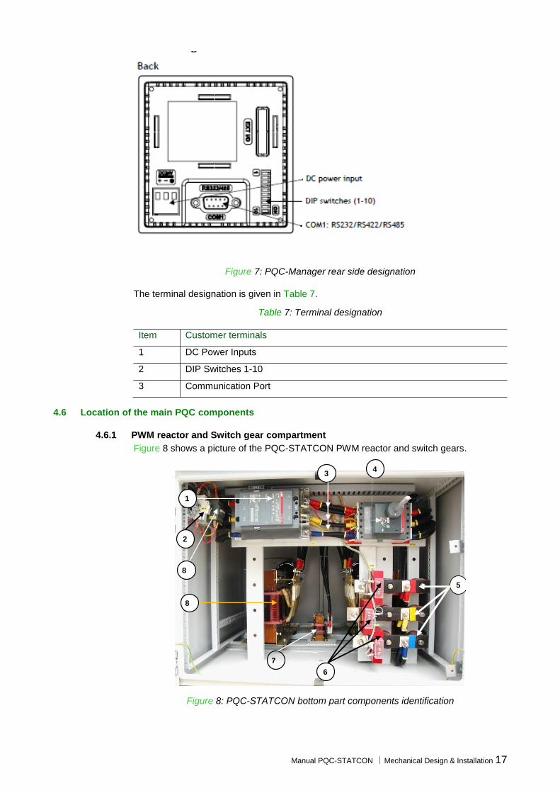
Manual PQC-STATCON Mechanical Design & Installation 17
Figure 7: PQC-Manager rear side designation
The terminal designation is given in Table 7.
Table 7: Terminal designation
Item Customer terminals
1 DC Power Inputs
2 DIP Switches 1-10
3 Communication Port
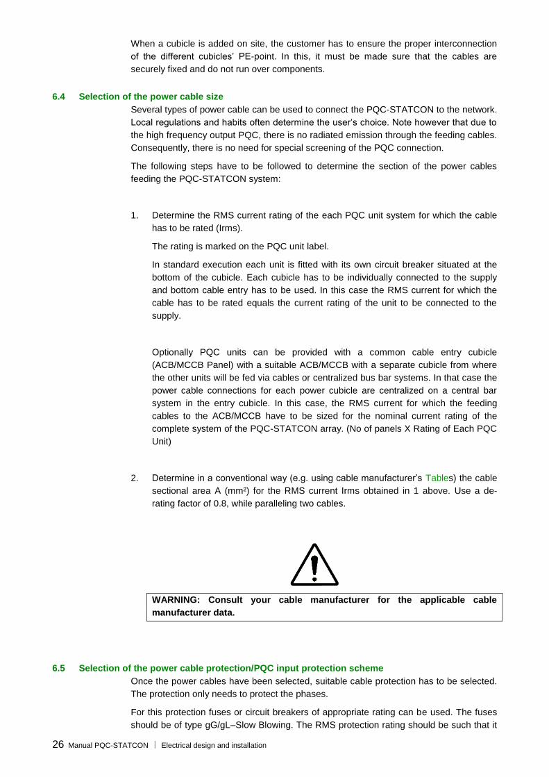
4.6 Location of the main PQC components
4.6.1 PWM reactor and Switch gear compartment
Figure 8 shows a picture of the PQC-STATCON PWM reactor and switch gears.
1
3 4
6
2
8
7
5
8
Figure 8: PQC-STATCON bottom part components identification

18 Manual PQC-STATCON | Mechanical Design & Installation
4.6.2 Converter compartment - Controller
Figure 9 shows a picture of the PQC Converter Compartment -Controller
1
2
3
4
Figure 9: PQC Controller
The component identification is given in Table 8.
PQC – STATCON Converter Compartment Overall View shows a picture of the PQC
Converter compartment with the IP protection removed.
3
1
2
Figure 10: PQC Converter Compartment
The PQC converter compartment description is given in Error! Reference source not
ound..

Manual PQC-STATCON Mechanical Design & Installation 19
Table 8: PQC Controller compartment description
Item Description
1 Optical Cable Connectors to PQC Controller
2 Hinges to the swingable PQC Door fixed with PQC Controller
3 PQC Controller
4 Hand operatable screws to open the swingable door
Table 9: PQC converter compartment description
Item Description
1 PQC Controller
2 IGBT converter
3 Illumination Lamp

20 Manual PQC-STATCON | Mechanical Design & Installation
5 Mechanical design and installation
5.1 What this chapter contains
This chapter gives the information required for the mechanical design and installation of
the PQC-STATCON system.
5.2 Installation location requirements
The PQC is suitable for indoor installation, on firm foundations, in a well-ventilated area
without dust and excessive aggressive gases where the ambient operating conditions do
not exceed the following values:
Table 10: Ambient operating conditions for PQC operation
Altitude Nominal output at 0 to 1000m (3300ft) above sea level (a)
Minimum temperature -10°C (23°F), non condensing
Maximum temperature 45°C (113°F) (b)
Maximum average temperature (over 24 h)
40°C (104°F)
Relative humidity Max. 95% non condensing
Contamination levels
(IEC 60721-3-3)
Chemical class 3C2 (c)
Mechanical class 3S2 (d)
Remarks:
(a) At sites over 1000m (3300ft) above sea level, the maximum output current must be
de-rated by 1% every additional 100m (330ft).
(b) Above 45°C (113°F), the maximum output current must be derated by 3.5% every
additional 1°C (1.8°F) up to 55°C (131°F) maximum limit.
(c) Locations with normal levels of contaminants, experienced in urban areas with industrial activities scattered over the whole area, or with heavy traffic.
(d) Locations without special precautions to minimize the presence of sand or dust, but
not situated in proximity to sand or dust sources.
The PQC installation must be indoor and it should be taken into account that the standard
protection class is IP30 closed door (IP20 open door). Upon request PQCs with IP41
protection class can be provided. This needs to be discussed with ABB. And this will also
incur significant amount of engineering changes in the panel
WARNING: Conductive dust may cause damage to this equipment. Ensure that the
PQC is installed in a room where no conductive dust is present.
The PQC foundations have to be leveled and must be able to support the weight of the
Panel. Table 16 gives the weight for one cubicle depending on the unit rating. Please
note that one cubicle contains always one unit. For multi-unit PQCs the total weight can
be obtained by multiplying the weight of one cubicle by the number of cubicles (ignoring
the base frame weight).

Manual PQC-STATCON Mechanical Design & Installation 21
Table 11: Weight of a single PQC for different unit ratings
VARIENT DETAIL Network voltage U (Vrms)
Unit rating (kVAr) Unit weight (kg) Without Packing
PQCT-70-V415(PQCT Light)
415V 70kVAr 120
PQCT-100-V415 415V 100kVAr 835
PQCT-150-V415 415V 150kVAr 835
PQCT-250-V415 415V 250kVAr 835
PQCs produce a certain level of noise when they operate. The noise level depends on
the operating conditions of the unit.. This value should be taken into account when
choosing a location for the PQC.
5.3 Airflow and cooling requirements
The PQC dissipates heat that has to be evacuated out of the room from where it is
located. Otherwise, excessive temperature rise may be experienced. Please note that life
of the electrical equipment decreases drastically if the operating temperature exceeds the
allowable limit (Total Life divided by 2 for every 10°C/23°F Increase).
Figure 11 shows the cooling air flow diagram for a PQC-STATCON Unit

22 Manual PQC-STATCON | Mechanical Design & Installation
IGBT Air OUT IGBT Air OUT
Reactor Cooling Air IN
Rea
cto
r C
oo
lin
g F
ans
Air
OU
T
IGBT Air Intake
IGBT Air
Intake
Figure 11: Cooling air flow for PQC Unit
Hea
t
Sin
k
Blo
wer
Hea
t
Sin
k
Blo
wer

Manual PQC-STATCON Mechanical Design & Installation 23
There are two different air flow circuits are there in PQC for cooling. One is for the reactor
compartment where the cooling air flow is on the lower part of the PQC. The other is for
the IGBT Stack where the cooling air is sucked from the upper fins provided in the front
and rear sides of the PQC and then they will be sucked out through the blowers provided
in the heat sink. A minimum of 2100 m3/h of air flow shall be considered.
5.4 Mechanical preparation of a common cable entry
As a standard practice the all the PQC-STATCON units will have their Cable entry via
bottom. And the cable entry plate opening will be 450mm X 300mm generally. Any
changes made in this will call for an additional engineering works to be done. Figure 21
shows an example of a single unit of a PQC-STATCON dimensions along with the
opening details at the bottom for Cable Entry.
Figure 12: Example of a common cable entry cubicle for a PQC
As can be seen in Figure 3 the cubicle has an elevated roof fixed by the lifting
L-Channel and underneath it has a protecting grid. In practice, a cable if the cable entry
has to be from the Top then accordingly the additional engineering works has to be done
at site or at the production level itself for the cable to pass through the Sometimes it
requires some mechanical modifications may have to be done on site to adapt the gland
plate to the cable size used.

24 Manual PQC-STATCON Electrical design and installation
6 Electrical design and installation
6.1 What this chapter contains
This chapter gives the data required for integrating the PQC-STACON successfully in an
electrical installation. It also gives electrical connection examples for popular PQC
options.
WARNING: The PQC is able to operate on networks with + 10% tolerance of rated
supply voltage (inclusive of harmonics but not transients). Since operation at the
upper limits of voltage and temperature may reduce its life expectancy, the PQC
should not be connected to systems for which it is known that the overvoltage will
be sustained indefinitely. Auxiliary circuits are designed to operate in a +/- 10 %
range of the equipment nominal auxiliary voltage (210V & 230 Vrms, internally
derived). Excessive (auxiliary) voltage levels may lead to damage of PQC.
The PQC-STATCON must be connected to the network in parallel with the loads.
Basic functionality can be obtained after connection of:
Ground (PE) (per cubicle).
Three power cables (per cubicle).
3 CTs (one per phase, to be connected to each PQC unit in a PQC system through a daisy chain method with return path).
WARNING: Ensure that the PQC supply is isolated upstream during PQC
installation. If the system has been disconnected from the supply recently then
wait for 15 mins after disconnecting the mains power in order to discharge the
capacitors. Always verify by measurement that the input filter capacitors & DC
Capacitors have been discharged completely. DC capacitors may be charged to
around 1000 Vdc.
The PQC control board carries dangerous voltages and shall not be touched once
the auxiliary circuit is energized, regardless of whether the PQC is switched off or
on. Once the auxiliary circuit is opened, high voltage levels can still be present on
the control board. Respect a delay of 15 minutes after disconnecting the mains
power before touching the control board.
6.2 Checking the insulation of the assembly - earth resistance
WARNING: Follow the procedure outlined below to check the insulation of the PQC
assembly. Applying other methods may damage the PQC-STATCON system.
Every PQC unit has been tested for insulation between the main circuit and the
chassis/frame at the factory. Therefore, do not make any voltage tolerance or insulation
resistance tests (e.g. hi-pot or megger) on the inverter units. Check the insulation of the
assembly by measuring the insulation resistance of the PQC between the Protective
Earth (PE) and all 3 phases shorted together, with MCCB shorted, and auxiliary circuit
open (MCB-1 open).
WARNING: Making the test with the auxiliary circuit closed may damage the
system.
Use a measuring voltage of 500 Vdc. The insulation resistance may be higher than
500 k per enclosure, keeping the incomer MCCB open / off position.

Manual PQC-STATCON Electrical design and installation 25
6.3 Earthing guidelines
Each PQC unit has a earth bar (PE-point/Earth symbol) in the bottom part of the unit
(Figure 13).
Back side of the Panel in the Bottom Part of the PQC-
STATCON
Earth bar (PE-point)
Figure 13: Identification of the earth bar in the PQC-STATCON
For safety reasons and for proper operation of the PQC-STATCON the earth bar of each
cubicle must be connected to the installation’s earth (PE-point). A copper (Cu) cable of
minimum size 16 mm² is required but local regulations should also be taken into account.
Remark: in P-E-N systems, the earth connection of the PQC must be connected to the
installation’s earth (PE) and not to the N-conductor.
Further, the following rules should be respected:
When the PQC consists of only one unit, the cubicle’s main PE-point must be
connected directly to the installation’s PE-point.
When the PQC consists of more than one cubicle, all cubicles’ PE-Points (
Earth Bars) must be interconnected by PE Links and later connected to the PE
Points on the either sides. This is illustrated in Figure 14.
PQC-1 PQC-2 PQC-n
PE PE
Earth bar in PQC
cubicles
PE Links
Figure 14: Earth connection guidelines for a multi-unit PQC-STATCON
26 Manual PQC-STATCON Electrical design and installation
When a cubicle is added on site, the customer has to ensure the proper interconnection
of the different cubicles’ PE-point. In this, it must be made sure that the cables are
securely fixed and do not run over components.
6.4 Selection of the power cable size
Several types of power cable can be used to connect the PQC-STATCON to the network.
Local regulations and habits often determine the user’s choice. Note however that due to
the high frequency output PQC, there is no radiated emission through the feeding cables.
Consequently, there is no need for special screening of the PQC connection.
The following steps have to be followed to determine the section of the power cables
feeding the PQC-STATCON system:
1. Determine the RMS current rating of the each PQC unit system for which the cable
has to be rated (Irms).
The rating is marked on the PQC unit label.
In standard execution each unit is fitted with its own circuit breaker situated at the
bottom of the cubicle. Each cubicle has to be individually connected to the supply
and bottom cable entry has to be used. In this case the RMS current for which the
cable has to be rated equals the current rating of the unit to be connected to the
supply.
Optionally PQC units can be provided with a common cable entry cubicle
(ACB/MCCB Panel) with a suitable ACB/MCCB with a separate cubicle from where
the other units will be fed via cables or centralized bus bar systems. In that case the
power cable connections for each power cubicle are centralized on a central bar
system in the entry cubicle. In this case, the RMS current for which the feeding
cables to the ACB/MCCB have to be sized for the nominal current rating of the
complete system of the PQC-STATCON array. (No of panels X Rating of Each PQC
Unit)
2. Determine in a conventional way (e.g. using cable manufacturer’s Tables) the cable
sectional area A (mm²) for the RMS current Irms obtained in 1 above. Use a de-
rating factor of 0.8, while paralleling two cables.
WARNING: Consult your cable manufacturer for the applicable cable
manufacturer data.
6.5 Selection of the power cable protection/PQC input protection scheme
Once the power cables have been selected, suitable cable protection has to be selected.
The protection only needs to protect the phases.
For this protection fuses or circuit breakers of appropriate rating can be used. The fuses
should be of type gG/gL–Slow Blowing. The RMS protection rating should be such that it

Manual PQC-STATCON Electrical design and installation 27
is able to protect the cable to the units while also ensuring sufficient selectivity between
the cable protection and the circuit breaker internal to the PQC-STATCON. The circuit
breaker data can be found in the following Section. When the customer protection is in
place, the following PQC input protection will result.
The PQC-STATCON’s power circuit is internally connected to the network by means of a
circuit breaker (MCCB).
For units using a common cable entry cubicle, the cable section has to be rated for the
total PQC system current and the protection devices have to be rated accordingly.
6.6 Connection of the PQC-SYSTEM to the network
WARNING: The PQC-SYSTEM has to be installed in parallel with the loads,
preferably on a free feeder in order avoid the phase angle intervention due to the
load. Local regulations and requirements prevail in determining how the equipment
has to be connected to the network. In accordance with good cabling practices,
ABB strongly suggests that the feeding cables to the PQC-SYSTEM are protected
by their own cable protection device.
NOTE: When installing a PQC-STATCON in installations containing power factor
correction capacitor banks, PQC will improve the efficiency of the capacitor banks
to a smooth correction facility. For further details please discuss with the ABB.
Three power cables (L1, L2, L3) have to be connected to each units circuit breaker
(in each cubicle). The breaker is situated at the bottom right side of each cubicle.
Make sure that the phase rotation of the feeding supply is anti-clockwise and that
the L1, L2 and L3 terminal in each cubicle is connected to the same phase for all
cubicles. Failure to do so may lead to the PQC being damaged upon startup.
Note for common cable entry PQC: if the PQC is fitted with an additional cubicle for
common cable entry, the feeding power cables have to be connected to the busbar
installed in the connection cubicle. In that case, the necessary mechanical preparation of
the cable entry cubicle has to be done first. Refer to Section 5.4 for more information on
this subject.
Remarks:
In case of regenerative loads (e.g. loads that may inject active energy to the
network, usually called 4Q-loads), it is very important to connect the PQC outside
the protection of this load. Indeed, consider Figure 15 where a common
protection is installed for both the regenerative load and for the PQC. When the
load re-injects energy to the network and the mains protection trips, the whole
energy may be pushed into the PQC, which may become severely damaged.
Figure 16 shows the correct protection scheme for regenerative loads. In this
case, if the breaker of the load trips, the PQC is isolated from the energy fed
back by the drive.

28 Manual PQC-STATCON Electrical design and installation
PQC 4Q load
PQC 4Q load
Figure 15: Incorrect connection Figure 16: Correct connection in the case of 4Q-loads in the case of 4Q-loads
When sizing the protection of the power cables, it should be taken into account
that the power circuit of the PQC-STATCON is protected by its own circuit
breaker.
The control circuit is also protected by MCB. Figure 17 shows a symbolic
representation of the PQC input protection.
L1
L2 L3
MCCB
To PQC power stage
To PQC control circuit
2.5mm²/1.5mm² reinforced
MCB-1 (DPMCB)
Figure 17: Symbolic representation of the PQC power and control protection scheme
Depending on the PQC type and version different breakers are used. Table 21 gives an
overview of the breaker type as a function of the cubicle unit rating and PQC version.
Table 12: Breaker type for different unit ratings
Variant Unit rating (Arms) Short Circuit Capacity
PQCS-100-V240 420A 35kA
PQCS-100-V415 240A 35kA
PQCS-150-V415 360A 35kA
PQCS-250-V415 600A 35kA
PQCT-70-V415
(PQCT Light) 100A 35kA
PQCT-100-V415 140A 35kA
PQCT-150-V415 210A 35kA
PQCT-250-V415 350A 35kA
Central connection in cable entry cubicle 50kA
Note: For good operation, the breaker settings must be set at maximum.

Manual PQC-STATCON Electrical design and installation 29
6.7 Selection of the current transformers
Each PQC unit in a PQC system has to monitor the line current in order to determine the
reactive & negative sequence current and function correctly. This is done by three current
transformers (CTs). For proper operation of the PQC standard accuracy CTs with the
following minimum specifications have to be used:
5 A secondary current rating.
15 VA burden for up to 30 meters of 2.5 mm² cable. For longer cables lengths
refer to the chart in Figure 18. In case the CTs are shared with other loads, the
VA burden shall be adapted accordingly. Note that the burden requirement for a
complete PQC system (consisting of up to 32 PQC units) is 15 VA, excluding
connecting cables.(Adapt accordingly with the change in the no of PQC Units)
Class 1 accuracy or better.
Primary side current rating sufficient to monitor the total line current (including
transient phenomena such as drive/motor starts …).
It is strongly recommended that the three CTs have the same characteristics.
WARNING: The connection of different PQC units in a PQC system, as well as
other loads, on the same CT must be in series.
Remark: In some applications two or more power supplies exist (e.g. a network
transformer supply and a generator supply). When the current into both supplies has to
be compensated, summing CTs have to be used. All summing CTs must have the same
ratio. More information on how to install the summing CTs is given in next section.
In order to determine the suitable CTs for your application, please refer to the chart in
Figure 18 considering only one panel is been fed. For other numbers adapt accordingly.

30 Manual PQC-STATCON Electrical design and installation
M
axim
um
rm
s c
urr
ent of th
e
dow
nstr
eam
loads (
inclu
din
g s
tart
ing
curr
ent of D
C d
rives):
X1 =
….. A
rms
Multip
ly X
1 b
y
1.6
:
X2 =
…. A
rms
CT
cable
s >
30 m
ete
rs ?
Sele
ct 3 identical C
T’s
such that:
- ra
tin
g a
t p
rim
ary
X
2
- ra
tin
g a
t seco
nd
ary
: 5A
- B
urd
en
1
5 V
A
- C
lass 1
accu
racy o
r b
ett
er
NO
Section o
f C
T c
able
s:
2.5
mm
²? (
recom
mended)
Dete
rmin
e the length
of
CT
cable
s (
mete
rs)
L =
… m
X3 =
(L x
0.0
07 x
25)
+ 1
0
X3 =
… V
A
Sele
ct 3 identical C
T’s
such that:
- ra
tin
g a
t p
rim
ary
X
2
- ra
tin
g a
t seco
nd
ary
: 5A
- B
urd
en
X
3 V
A
- C
lass 1
accu
racy o
r b
ett
er
Dete
rmin
e the length
(m
) and
resis
tance (
/m)o
f
CT
cable
s (
mete
rs)
L =
… m
R =
…
/m
X4 =
(L x
R x
25)
+ 1
0
X4 =
… V
A
Sele
ct 3 identical C
T’s
such that:
- ra
tin
g a
t p
rim
ary
X
2
- ra
tin
g a
t seco
nd
ary
: 5A
- B
urd
en
X
4 V
A
- C
lass 1
accu
racy o
r b
ett
er
NO
YE
S
YE
S
Figure 18: Flow chart for CT determination
Manual PQC-STATCON Electrical design and installation 31
6.8 Current transformer installation
6.8.1 Basic rules for correct CT installation
The location of the CTs is critical to ensure the proper operation of the PQC-STATCON.
The CTs are the “eyes” of the PQC and it will react in accordance with the information
supplied by them.
WARNING: Special care has to be taken for the connection and location of the CTs:
wrong CT installation is the most common source of problems found at the
commissioning stage.
WARNING: In a PQC system consisting of more than one unit, the CT information
has to be supplied to all the units. This must be done through a daisy chain
connection with return path configuration.
By default, the PQC-STATCON is provided with CT terminals that are not shorted. A set
of shorting links is provided with the PQC.
WARNING: When connecting the CTs to the PQC, the secondaries of the CTs have
to be shorted. Failure to do so may result in CT explosion and consequent damage
to the installation. Once the connections to the PQC have been made, the shorting
links must be opened.
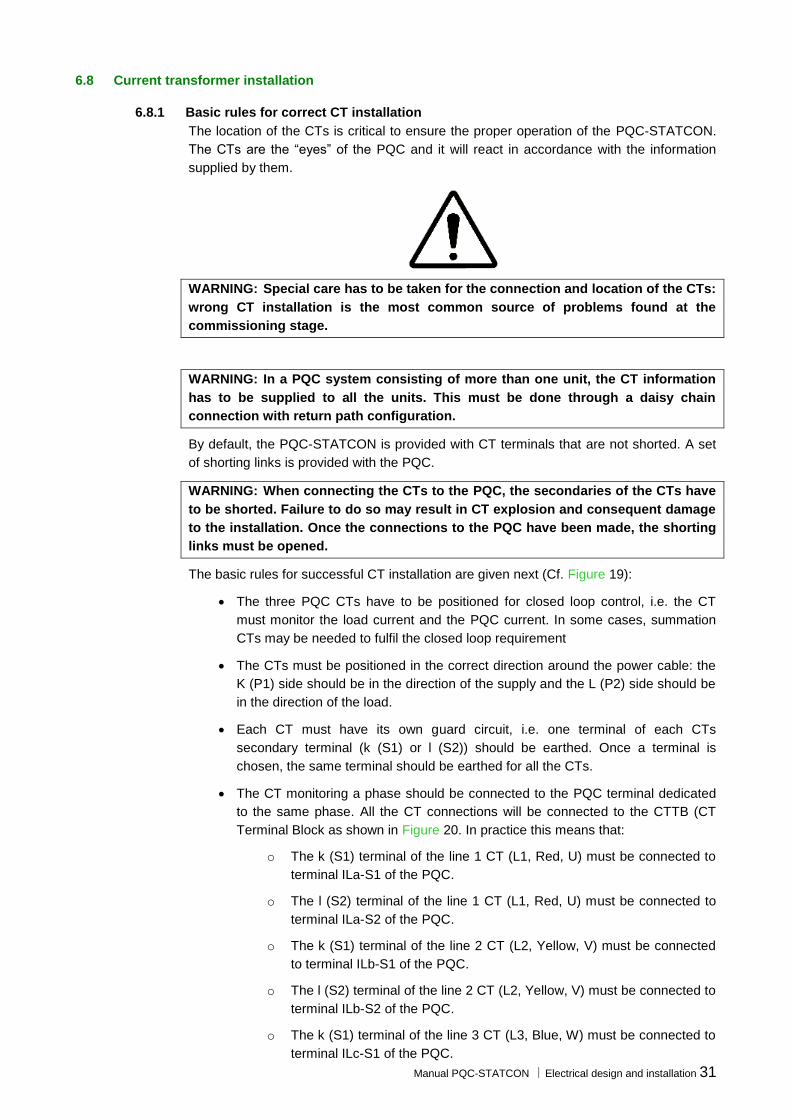
The basic rules for successful CT installation are given next (Cf. Figure 19):
The three PQC CTs have to be positioned for closed loop control, i.e. the CT
must monitor the load current and the PQC current. In some cases, summation
CTs may be needed to fulfil the closed loop requirement
The CTs must be positioned in the correct direction around the power cable: the
K (P1) side should be in the direction of the supply and the L (P2) side should be
in the direction of the load.
Each CT must have its own guard circuit, i.e. one terminal of each CTs
secondary terminal (k (S1) or l (S2)) should be earthed. Once a terminal is
chosen, the same terminal should be earthed for all the CTs.
The CT monitoring a phase should be connected to the PQC terminal dedicated
to the same phase. All the CT connections will be connected to the CTTB (CT
Terminal Block as shown in Figure 20. In practice this means that:
o The k (S1) terminal of the line 1 CT (L1, Red, U) must be connected to
terminal ILa-S1 of the PQC.
o The l (S2) terminal of the line 1 CT (L1, Red, U) must be connected to
terminal ILa-S2 of the PQC.
o The k (S1) terminal of the line 2 CT (L2, Yellow, V) must be connected
to terminal ILb-S1 of the PQC.
o The l (S2) terminal of the line 2 CT (L2, Yellow, V) must be connected to
terminal ILb-S2 of the PQC.
o The k (S1) terminal of the line 3 CT (L3, Blue, W) must be connected to
terminal ILc-S1 of the PQC.
32 Manual PQC-STATCON Electrical design and installation
o The l (S2) terminal of the line 3 CT (L3, Blue, W) must be connected to
terminal ILc-S2 of the PQC.
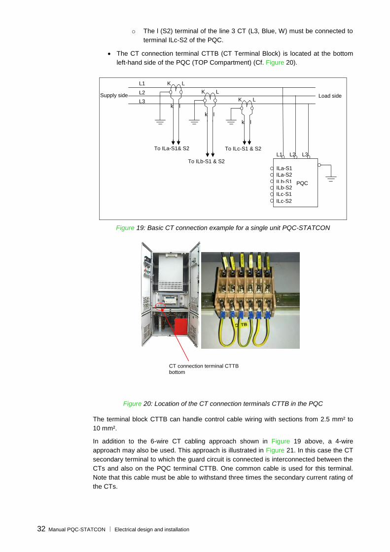
The CT connection terminal CTTB (CT Terminal Block) is located at the bottom
left-hand side of the PQC (TOP Compartment) (Cf. Figure 20).
L1
L2
L3 Load side Supply side
K L
k l
K L
k l
K L
k l
PQC
ILc-S1
ILb-S2
ILb-S1
ILa-S2 ILa-S1
ILc-S2
L1 L2 L3 To ILa-S1& S2
To ILb-S1 & S2
To ILc-S1 & S2
Figure 19: Basic CT connection example for a single unit PQC-STATCON
CT connection terminal CTTB bottom
Figure 20: Location of the CT connection terminals CTTB in the PQC
The terminal block CTTB can handle control cable wiring with sections from 2.5 mm² to
10 mm².
In addition to the 6-wire CT cabling approach shown in Figure 19 above, a 4-wire
approach may also be used. This approach is illustrated in Figure 21. In this case the CT
secondary terminal to which the guard circuit is connected is interconnected between the
CTs and also on the PQC terminal CTTB. One common cable is used for this terminal.
Note that this cable must be able to withstand three times the secondary current rating of
the CTs.

Manual PQC-STATCON Electrical design and installation 33
L1
L2 L3
Load side Supply side
K L K L
K L
PQC
L1 L2 L3 To ILa-S1 To ILb-S1
To ILc-S1
ILc-S1
ILb-S2
ILb-S1
ILa-S2 ILa-S1
ILc-S2
Figure 21: Four wires CT wiring approach that may be used with a single unit PQC-STATCON
In case a PQC system consists of more than one unit, all units have to be supplied with
the CT measurement information. This is done by cabling the CTs in a daisy chain
fashion between the different units, and looping the last PQC, CT-terminal back to the
CT. This is illustrated in Section 6.9.4.
In the next sections typical circuit topologies and appropriate corresponding CT locations
are described. The cases considered are:
Case 1: Global compensation – one feeding transformer.
Case 2: Individual compensation – one feeding transformer.
Case 3: Global compensation – transformer busbar not accessible.
Case 4: Two independent feeding transformers.
Case 5: Back-up generator.
Case 6: CT connection location when passive filters & plain capacitors are present in the
network
Case 7: CT connections for the case that PQC is installed in LV side compensating for
the total loads
6.8.2 Case 1: CT locations for the case of global compensation – one feeding transformer
This case handles the most frequent configuration: one transformer feeds several loads.
The PQC-STATCON is installed at a central position and compensates the reactive &
unbalance currents of all the loads. This configuration is shown in Figure 22.
PQC LOAD LOAD LOAD
Supply
Figure 22: CT connections for the case of global compensation – one feeding transformer
The connection method for the three CTs to the PQC is described in Section 6.8.1.

34 Manual PQC-STATCON Electrical design and installation
6.8.3 Case 2: CT locations for the case of individual compensation – one feeding transformer Instead of installing one PQC-STATCON in a central position, it is also possible to
connect the PQC-STATCON and its CTs so that it compensates one particular load only.
In the example hereafter, the PQC-STATCON is connected to compensate load 1 only. It
does not see load 2.
LOAD 2
LOAD 1 PQC
Figure 23: CT connections for the case of individual compensation – one feeding transformer
The connection method for the three CTs to the PQC-STATCON is described in Section
6.8.1.
6.8.4 Case 3: CT locations for the case of global compensation – transformer busbar not accessible The PQC-STATCON is required to compensate the loads of side A and side B (Cf. Figure
40) but the transformer bus bar is not accessible. As a result, the CTs cannot be installed
in a central position.
LOADS LOADS (Side A) (Side B)
PQC
Figure 24: Case of multiple loads and transformer busbar not accessible
For this configuration, three CTs (one per phase) have to be installed on side A and on
side B (i.e. in total 6 CTs). Those CTs will then feed 3 summation CTs (one per phase)
that are connected to the PQC-STATCON. This CT topology is represented in Figure 25.

Manual PQC-STATCON Electrical design and installation 35
LOADS (Side A)
LOADS (Side B)
PQC
Summation CT
(one per phase)
Primary 1: 5 A Primary 2: 5A Secondary: 5A
CT 1 (one per phase) Primary: X Secondary: 5A
CT 2 (one per phase) Primary: X Secondary: 5A
Figure 25: CT connections for the case of multiple loads and transformer busbar not accessible (to be done for each phase)
The CTs installed in each phase of side A and Side B (CT1 and CT2) must be identical
(X/5A) and feed a summation CT whose secondary is 5A (5+5/5A). The summation CT is
then connected to the PQC-STATCON in accordance with Section 6.8.1. A total of 3
summation CTs (one per phase) must be used.
The CT ratio to be programmed in the PQC is: 2X/5 where X is the primary side current
rating of the main measurement CTs (CT1 and CT2 in Figure 25 above).
The connection diagram of the main measurement CTs to the summation CTs and from
the summation CTs to the PQC terminals is represented in Figure 26. This diagram has
to be implemented for the three phases.
S1, k
S2, l
S1, k
S2, l
P1
P2
P1
P2
S1
S2
k
l
PQC
Side A Side B
P1, K
P2, L
P1, K
P2, L
Figure 26: CT connections for the case of connections between CT1, CT2 , the summation CT and the PQC for one phase
6.8.5 Case 4: CT locations for the case of two independent feeding transformers
Two independent transformers (the tie is normally open) feed two different sets of loads.
One PQC-STATCON is connected to each LV busbar. The system may also have to work
in degraded mode, i.e. the tie is closed and only one transformer feeds the whole LV
system. This case is illustrated in Figure 27.

36 Manual PQC-STATCON Electrical design and installation
PQC PQC
T1 T2
Figure 27: Case of two independent feeding transformers
By connecting the CTs as described in Figure 28 it is possible to compensate the reactive
component and to correct the power factor under the aforementioned conditions.
S1, k
S2, l
P1 P2 P1 P2
S1 S2
S1, k
S2, l
S1
k S2
l
P1 P2 P1 P2
S1 S2
I1 I2 I0
I’1-I’0
PQC 1
I’2+I’0
PQC 2
k l k l
T1 T2
P2, L
P1, K P1, K
P2, L
P1
K
P2
L
Figure 28: CT connections for the case of two independent transformers (to be done for each phase)
For each phase, 3 CTs must be installed:
one to measure I1
one to measure I2
one to measure I0.
The CTs must be identical: X/5 A.
CT I1 and CT I0 feed a summation CT which is connected to PQC1.
CT I2 and CT I0 feed a summation CT which is connected to PQC2.
The summation CTs must be rated 5+5 / 5 A.

Manual PQC-STATCON Electrical design and installation 37
Condition 1: the tie is open.
The PQC1 sees I1 and the PQC2 sees I2 (I0 = 0). The two transformers work
independently and the total current to be compensated is I1 + I2.
Condition 2: the tie is closed but both transformers feed the loads.
In this configuration, the PQC1 sees (I1-I0) and the PQC2 sees (I2+I0). The total current
seen by the two PQCs is I1 + I2.
Condition 3: the tie is closed but only one transformer feeds the loads (degraded mode).
If only T1 feeds the loads with the tie closed, PQC1 sees (I1-I0) and PQC2 sees I0 (I2 is
zero). If only T2 feeds the load, I1 will be zero.
Please note that the above described connection must be done for each phase. The CT
ratio to be programmed in the PQC is: 2X/5.
6.8.6 Case 5: CT locations for the case of feeding transformer and backup generator
Many installations are fitted with backup generators to ensure the proper operation of the
installation in case of a mains supply outage.
A typical configuration is given in Figure 29.
G
LOAD PQC
Figure 29: Single line diagram of an installation with a backup generator
The CT connection must be such that the PQC-STATCON works whatever the type of
supply: generator or transformer-MV network.
For each phase, one CT is installed in the transformer branch and one in the generator
branch. Those two CTs must be identical (X / 5 A) and must be connected to a
summation CT rated 5+5 / 5 A.
The CT ratio to be programmed in the PQC is: 2X/5. Figure 30 gives the corresponding
connection diagram per phase.

38 Manual PQC-STATCON Electrical design and installation
S1, k
S2, l
S1, k
S2, l
P1
P2
P1
P2
S1
S2
k
L
PQC
G
P1, K
P2, L
P1, K
P2, L
Figure 30: CT connections for the case of a feeding transformer with backup generator (to be done for each phase)
6.8.7 Case 6: CT connections for the case that passive filters and PQC-STATCONs are
installed in the same network
Figure below shows the Plain Capacitor in the system with the PQC taking to the total
feedback from the mains. Generally this is not recommended as the plain capacitors will
have reception for the harmonics and also create parallel resonance with the system
which is not desirable
Feeding transformer
Filter CTs
Linear and non-linear
loads
PQC
Plain capacitor bank
Figure 31: Plain Capacitor with the system (solution to be avoided)
Feeding
transformer
Filter CTs
Linear and non-linear
loads
PQC
Passive filter
Figure 32: Alternative for Error! Reference source not found.
NOTE: ABB advises for best performance to always replace plain capacitor banks
by appropriately sized detuned capacitor banks in installations where harmonics
are present and where filtering devices are used.

Manual PQC-STATCON Electrical design and installation 39
6.8.8 Case 7: CT connections for the case that passive filters and PQC-STATCONs are
installed in the same network at different voltage levels
This is one of the most commonly used configurations of PQC, where the versatility of
well utilized. In installations where both passive filters and PQC-STATCONs are present
but in different levels of voltages, the CT connection scheme of Error! Reference source
ot found. must be used. Unlike other systems PQC-STATCON can compensate for the
total loads from the HV side itself using a Step-down transformer.
PQC Loads Passive
HT filter
bank
HT BUS
Figure 33: Connection diagram of PQC STATCON working with an existing Capacitor Bank at HT
6.9 Electrical interconnection of PQC cubicles
This section explains how to electrically interconnect different PQC units.
Figure 34 shows schematically which interconnections have to be made between two
PQC units.
Precharge circuit
Input filter
Unit 1
Unit 2
Input filter
PQC Unit 1
PQC Unit 2
AC power supply L L
(2)
(1)
(3)
Precharge circuit
Figure 34: Overview of the connections to be made between two PQC cubicles
The interconnection description is given in Table 13.

40 Manual PQC-STATCON Electrical design and installation
Table 13: Interconnections between two PQC units
Item Description
1 Control board intercommunication cable through CAN bus (RJ45 cable, straight interconnection)
2 CT interconnection cable (not provided)
3 Earth interconnection (not provided)
Five steps have to be followed to electrically interconnect a new PQC unit with an existing
PQC. They are outlined in the next five paragraphs.
6.9.1 Mechanical connection
Ensure that the new unit is mechanically connected with the existing platform or ground.
6.9.2 Control board cable interconnection
WARNING: Failure to interconnect the control boards in an appropriate way will
result in PQC malfunctioning and possibly severe damage of the unit.
Interconnect the control boards of a following unit with a previous PQC unit by an RJ45-
based communication cable (straight interconnection). This cable is provided with each
unit.
Figure 35: shows the way to interconnect the control boards.
Control board in the Unit #N
From previous unit (if present)
To next unit (if present)
Control board in the Unit # (N-1)
P-CAN IN P-CAN IN
P-CAN OUT P-CAN OUT
Figure 35: Control board interconnection cable connection method.
The RJ45 control cable coming from the preceding PQC unit is plugged in the ‘P-CAN
IN’ RJ45-socket at the bottom right side of the PQC control board.
The RJ45 control cable leaving for the next PQC unit is plugged in the bottom right
hand side ‘P-CAN-OUT’ RJ45-socket of the PQC control board.
Repeat the same procedure for any other PQCs to be connected.

Manual PQC-STATCON Electrical design and installation 41
Notes:
In the first unit of a PQC system, the ‘P-CAN-IN’ RJ45-socket will always be empty.
In the last unit of a PQC system, the ‘P-CAN-OUT’ RJ45-socket will always be empty.
6.9.3 Earth points interconnection
Interconnect the earth points of the different units (Cf. Figure 34 item 3) and earth the
new unit individually. Refer to Section 6.3 for more information on this topic.
6.9.4 CT cable interconnection
WARNING: Failure to connect the CT’s to all units in a PQC system, in an
appropriate way will result in PQC malfunctioning.
In a multi-unit PQC-system, all units have to be supplied with the CT – measurement. In
order to do this the CT’s had to be cabled to each unit in a daisy chain fashion. The
connection principle is shown in
Figure 36 for the CT of ONE phase which is fed to four PQC units. The same approach
has to be implemented for the other two phases. A maximum of 32 PQC units can work in
parallel in this fashion.
Unit 1
CT terminal ILA
1 2
Unit 2
CT terminal ILA
1 2
Unit 3
CT terminal ILA
1 2
Unit 4
CT terminal ILA
1 2
CT in phase 1 (L1/R)
Figure 36: Principle of the CT interconnection circuit for multi-unit PQCs.
Note that the overall burden requirement for a complete PQC system is 15 VA. This value
has to be added to the burden requirement of the interconnection cables to obtain the
total burden requirement of the CT’s to be used.
42 Manual PQC-STATCON Electrical design and installation
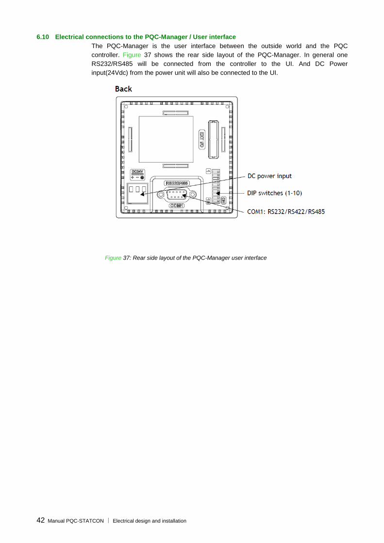
6.10 Electrical connections to the PQC-Manager / User interface
The PQC-Manager is the user interface between the outside world and the PQC
controller. Figure 37 shows the rear side layout of the PQC-Manager. In general one
RS232/RS485 will be connected from the controller to the UI. And DC Power
input(24Vdc) from the power unit will also be connected to the UI.
Figure 37: Rear side layout of the PQC-Manager user interface

Manual PQC-STATCON PQC-Manager Interface 43
7 The PQC-Manager user interface
7.1 What this chapter contains
This chapter presents the features and operating instructions for the PQC-Manager user
interface (Figure 38). Use the contents of this chapter as background information for the
next chapters, which explain how to commission, operate and troubleshoot the PQC-
STATCON.
1
2
Figure 38: Front view of the PQC-Manager user interface
The item description is given in Table 14.
Table 14: Front view of the PQC-Manager
Item Description
1 Touch Screen Display
2 Blinking LEDs during operation
7.2 UI / PQC-Manager overview and navigation
All user inter-action with the PQC is channeled through the UI / PQC-Manager. It
provides for the following main functions (Cf. Figure 38):
PQC starting, PQC stopping and acknowledgement of faults:
The PQC-Manager is the default device to be used to start and stop the PQC
system (only in PQCT Light). It is used to acknowledge and reset faults reported
by the system.
Refer to following sections for detailed information on how to start, stop and reset
the PQC.
Measuring, analyzing and logging of characteristic parameters:
The parameters that can be monitored include its voltages, PQC currents &
system temperatures.
Refer to the following sections for detailed information on the monitoring of
variables.

44 Manual PQC-STATCON PQC- Manager Interface
Setting up the PQC:
Setting up the PQC consists of various aspects such as defining the customer’s
requirements for operating mode, CT ratio, network frequency ect… at the
moment of first use.
Refer to Section 7.3 for detailed information on setting up the PQC.
Monitoring the PQC load, event logging and status of individual units:
The PQC load can be monitored to get an idea of its operating point compared.
In addition, logged warnings and faults can be retrieved for troubleshooting the
PQC operation and any abnormal network conditions.
For multi-unit PQCs, the status of each individual unit can be retrieved and
individual units can be reset when in error.
Refer to following sections for detailed information on the monitoring of the PQC
load and the analysis of warning and error conditions.
All main functions of the PQC-Manager can be accessed through the ‘Main Menu’
screen.
Figure 39 outlines the principle menus that are accessible through the ‘Main Menu’
screen.

Manual PQC-STATCON PQC-Manager Interface 45
Figure 39: Principle menus of the PQC-Manager

46 Manual PQC-STATCON PQC- Manager Interface
7.3 MAIN MENU Status
Figure 40: STATCON Main Menu
The ‘Main Menu’ [/Welcome/Settings] has three main levels:
The STATCON system status which allows the user to view the status of the
PQC-STATCON, The DC Bus Voltage (Vdc), Reactive Current Components(Iq),
Temperature of the stacks (C).
The Settings menu which allows the commissioning engineer to set up the
equipment according to the customer’s installation. Typical parameters that need
to be entered are the frequency, CT parameters, mode of operation and
protection settings. At the commissioning level possibility also exists to set up the
main and auxiliary target power factor settings based on user requirement.
The Fault Logger Menu allows for the commissioning engineer to access the
fault log history during commissioning and troubleshooting.
The three main functions will be discussed in detail as below.
7.3.1 The ‘STATCON system status’
As mentioned in the Figure 40 above the PQC-STATCON ‘Status screen shows the
following data,
Network Voltage
Network Frequency
Vdc DC Bus Voltage
Iq Reactive Current by PQC-STATCON
°C Stack Temperature

Manual PQC-STATCON PQC-Manager Interface 47
7.3.2 SETTINGS Menu
Figure 41: SETTINGS Menu Tree Diagram
In the Settings menu there are three major divisions as Configuration, Date & Time and
Protection settings.
Year ## + -
Month ## + -
Day ## + -
Hour ## + -
Min ## + -
Sec ## + -

48 Manual PQC-STATCON PQC- Manager Interface
7.3.2.1 Configuration Settings:-
In the configuration settings the following steps can be followed.
STEP 1. Frequency: Select the nominal network frequency
50Hz/60Hz
STEP 2. Mode: There are three modes available
a. Fixed/Test Mode: For Testing purpose only
b. Load CT Mode: Open loop Compensation, when the
sensing CT is connected on the load side.
c. Grid CT Mode: Closed loop Compensation, when the
sensing CT is connected on the source side.
STEP 3. Compensation Priority: Select the natural priority,
for the role of master
STEP 4. Parallel Panels #: Select the number of parallel PQC
units connected in the PQC system.
STEP 5. CT ratio: Choose the sensing CT Ratio. (Example:- If
the CT is of 1000A/5A then CT Ratio is 200)
STEP 6. Energy Save Mode: Enabling this mode the PQC will
operate in such a way that whenever there is no
significant load in the system, the IGBTs are turned
off in 2 minutes, followed by the IGBT cooling
system and then system enters a sleep mode/hot
standby mode. When the requirement comes back
the PQC system will be able to deliver the rated
compensation within 8power cycles.
STEP 7. Once all the configuration are done, press the
‘Apply’ button for the settings to take effect. Finally it
is required to restart the system, which would start
the PQC with the configured settings.. (Note: The
restarting of the system can be done by turning off
the MCCB main incomer and then turn on after a
delay of at-least 15 seconds).
7.3.2.2 Date & Time:-
In this screen we can set /edit the PQC date & time. This is a mandatory
setting during commissioning, as the unit events are logged are time
stamped.

Manual PQC-STATCON PQC-Manager Interface 49
7.3.2.3 Protection Settings (User Settings level only)
Thermal Trip Point The temperature at which the PQC is tripped to
protect against over temperature fault condition.
Thermal Restart The temperature at which the PQC resumes operation
after a thermal trip condition. (Generally it will be 10 - 15˚C lesser than the
thermal over temperature limit)
DIL Door InterLock. This feature of the PQC-STATCON when enabled, it
trips the unit, when the PQC door is opened.
Note: The temperature unit shall be °C. Once all the protection settings are configured,
press the ‘Apply’ button for the settings to take effect. Finally it is required to restart the
system, which would start the PQC with the configured settings.. (Note: The restarting of
the system can be done by turning off the MCCB main incomer and then turn on after a
delay of at-least 15 seconds). The levels for important protections like DC & AC Over
voltages, over current, gate driver faults etc are embedded in the PQC-Controller.

50 Manual PQC-STATCON PQC- Manager Interface
7.3.3 Fault Logger
Fault logger menu has fault indicators. It can record up-to 250 faults with the date and
time stamping information. After 250 faults the first fault is refreshed with the new fault. It
works in the ‘First In - First Out’ mechanism.
Figure 15: Fault Logger Screen
The faults mentioned in the above screens are abbreviations which are explained in the
below.
OCT1 Over current 1 Fault (Front Stack)
GD1_1 Gate Drive 1 Fault (Front Stack)
GD1_2 Gate Drive 2 Fault (Front Stack)
GD1_3 Gate Drive 3 Fault (Front Stack)
CSF1 Cooling system failure (Front Stack)
DC_OV1 DC Over Voltage Fault (Front Stack)
STK 1 Stack Failure (Front Stack)
OT 1 Over Temperature (Front Stack)
OCT2 Over current 2(Rear Stack)
GD2_1 Gate Drive 1 Fault (Rear Stack)
GD2_2 Gate Drive 2 Fault (Rear Stack)
GD2_3 Gate Drive 3 Fault (Rear Stack)
CSF2 Cooling system failure (Rear Stack)
DC_OV2 DC Over Voltage Fault (Rear Stack)
STK 2 Stack Failure (Rear Stack)
OT 2 Over Temperature (Rear Stack)

Manual PQC-STATCON PQC-Manager Interface 51
ACOV AC Over Voltage.
ACUV AC Under Voltage.
PLL Phase Locked Loop fault
PCHG Precharge Contactor Failure
MCTR Main Contactor Failure
DIL Door Interlock
OFF User off
For detailed analysis on the each fault above please see the Chapter 11 : Trouble
Shooting Guide.

52 Manual PQC-STATCON Commissioning Instructions
8 Commissioning instructions
8.1 What this chapter contains
This chapter presents the steps to follow to commission the PQC-STATCON. The
commissioning of your PQC should be conducted in strict accordance with this
procedure.
Before applying the commissioning procedure, make sure that you are familiar with:
The PQC hardware (discussed in Chapter 4).
The mechanical installation requirements (discussed in Chapter 5).
The electrical installation requirements (discussed in Chapter 6).
The PQC programming interface PQC-Manager (discussed in Chapter 7).
The commissioning procedure consists of 9 steps that should be strictly followed.
Table 16: Steps to follow for commissioning the PQC-STATCON
Steps Actions
Step 1 Visual and installation check
Step 2 Voltage rating and phase rotation check
Step 3 Basic commissioning parameters setup
Step 4 Sensing CT setup
Step 5 Starting the PQC
Section 8.7 presents the commissioning report to be filled in when commissioning
the PQC.
8.2 Step 1: Visual and installation check
WARNING: Make sure that the PQC supply is isolated during the visual and
installation check. For safety reasons, this should be done upstream of the PQC-
STATCON and before removing the protective internal grid. Open the auxiliary
power fuse holder. In multi-unit PQCs, ensure that all units are disconnected from
the supply. Verify that the PQC DC capacitors are discharged before touching
them. Failure to adhere to these guidelines may result in lethal electric shock
and/or PQC damage.

Manual PQC-STATCON Commissioning Instructions 53
WARNING: Make sure that the PQC is installed at a location where no conductive
dust is present. Conductive dust when distributed in the PQC panel may lead to
equipment failure.
Check that the mechanical and electrical installation fulfils the requirements
described in Chapter 5 and Chapter 6 of this manual.
Pay attention to the ambient temperature, where the PQC STATCON is installed.
Check visually the condition of the PQC (e.g. for transportation damage).
Remove the anti-corrosion pouches, which is inside of PQC-STATCON panels.
Check the tightness of all connections including power cable connections, CT
connections, connections on the PQC-Manager and the control board
connections inside the PQC.
Ensure that the feeding cables and protection devices are rated appropriately.
Check that the PQC cooling fan is free running.
WARNING: Failing to terminate the communication bus properly will lead to
equipment malfunction and equipment damage.
8.3 Step 2: Voltage rating and phase rotation check
Ensure that, the PQC system voltage is within the operating voltage range.
WARNING: The PQC is able to operate on networks with + 10% tolerance of rated
supply voltage (inclusive of harmonics but not transients). Since operation at the
upper limits of voltage and temperature may reduce its life expectancy, the PQC
should not be connected to systems for which it is known that the overvoltage will
be sustained indefinitely. Auxiliary circuits are designed to operate in a +/- 10 %
range of the equipment nominal auxiliary voltage (210V & 230 Vrms, internally
derived). Excessive (auxiliary) voltage levels may lead to damage of PQC.
WARNING: The tap setting of the auxiliary transformer’s secondary should be
adapted according to the network voltage to avoid a too high or too low auxiliary
voltage. If the tap setting for your network voltage is not available, then choose a
tap just above the network voltage present. Excessive (auxiliary) voltage levels will
lead to PQC damage.
The voltage phase rotation at the PQC-STATCON incoming power supply
terminals must be ant-clockwise (L1 (R,U) -> L2 (Y,V) -> L3 (B,W) -> L1 (R,U)).

54 Manual PQC-STATCON Commissioning Instructions
WARNING: Applying voltage to the PQC to check the phase rotation, may only be
done after ensuring that the network voltage level is in the operating range. Also
ensure that PQC is not mechanically nor electrically damaged, before applying
voltage.
When checking the phase rotation with a phase rotation meter on the PQC power supply
terminals, ensure that the auxiliary MCB box is open during the measurement process.
WARNING: In a multi-unit PQC arrangement, care must be taken to connect all
units to the power supply in an identical way (individual phases and phase
rotation). Otherwise, the PQC may trip immediately after start-up, and leading to
the damages.
If the voltage rating and phase rotation check is successful, and the auxiliary transformer
tap setting has been adapted to the network voltage, auxiliary power can be applied to
the PQC-STATCON. It is advised however to first install the other control cabling if
required.
When the auxiliary MCB is closed and power is applied to the PQC:
The PQC fans will start running.
The PQC controllers will be activated.
The PQC-Manager will initialize and show the Welcome-screen.
If the voltage level or phase rotation is incorrect, the installation should be corrected
before applying power to the PQC to avoid potential PQC malfunctioning and/or damage.
8.4 Step 3: Basic commissioning parameters set up (Using PQC Manager / UI)
The complete commissioning must be done at the first installation of a PQC system and
each time a PQC unit is added to an existing PQC system.
In the configuration settings the following steps can be followed.
STEP 1. Frequency: Select the nominal network frequency 50Hz/60Hz
STEP 2. Mode: There are three modes available
a. Fixed/Test Mode: For Testing purpose only
b. Load CT Mode: Open loop Compensation, when the sensing CT is connected
on the load side.
c. Grid CT Mode: Closed loop Compensation, when the sensing CT is connected
on the source side.
STEP 3. Compensation Priority: Select the natural priority, for the role of master
STEP 4. Parallel Panels #: Select the number of parallel PQC units connected in the
PQC system.
STEP 5. CT ratio: Choose the sensing CT Ratio. (Example:- If the CT is of 1000A/5A
then CT Ratio is 200)

Manual PQC-STATCON Commissioning Instructions 55
STEP 6. Energy Save Mode: Enabling this mode the PQC will operate in such a way that
whenever there is no significant load in the system, the IGBTs are turned off in 2
minutes, followed by the IGBT cooling system and then system enters a sleep
mode/hot standby mode. When the requirement comes back the PQC system
will be able to deliver the rated compensation within 8power cycles.
STEP 7. Once all the configurations are done, press the ‘Apply’ button for the settings to
take effect. Finally it is required to restart the system, which would start the PQC
with the configured settings.. (Note: The restarting of the system can be done by
turning off the MCCB main incomer and then turn on after a delay of at-least 15
seconds).
STEP 8. Thermal Trip Point: Set the temperature at which the PQC has tripped to
protect against over temperature fault condition
STEP 9. Thermal Restart: Set the temperature at which the PQC has to resume
operation after a thermal trip condition. (Generally it is set to 10 - 15˚C lesser
than the thermal over temperature limit)
STEP 10. DIL (Door Inter-Lock): Enable or Disable this protection
If the CTs have been set up not set correctly at this stage then go to the next step
8.5 Step 4: Sensing CT setup
WARNING: Do not select the Dynamic GridCT/ Dynamic LoadCT modes, when the
CTs have not been set up correctly. Failure to adhere to this guideline will result in
erratic PQC operation and result in damage to the PQC system and also for the
network.
WARNING: Before programming or detecting the CTs, make sure that:
- The CTs have been connected to the PQC CT terminal CTTB. For multi-PQC
configurations all the units of a PQC system have to be supplied with the same
CT information (daisy chain principle with return path as shown in Figure 36).
- All shorting links in the CT path have been opened (i.e. on the CTs, on the
PQC CTTB).
8.5.1 CT setup procedure
The following procedure will allow you to check the CT connection. This step has to be
executed every time before commissioning. For PQCs consisting of more than one unit, it
is necessary to check the CT connections for each individual unit.

56 Manual PQC-STATCON Commissioning Instructions
WARNING: The secondary circuit of a loaded CT must never be opened. Otherwise
extremely high voltages may appear at its terminals which can lead to physical
danger or destruction of the CT/the equipments around etc
8.5.2 PQC connection diagram
Figure 42 shows the standard connection diagram for the PQC (Cf. Section 6.7 Current
transformer installation). It must be noted that:
L1, L2 and L3 rotation must be anti-clockwise.
The CTs must be on the supply (grid) side of the PQC, for closed loop operation
and on the load side for open loop operation.
The CT monitoring a phase must be connected to the PQC CTTB terminal
dedicated to the same phase.
L1
L2
L3 Load side Supply side
K L
k l
K L
k l
K L
k l
PQC
ILc-S1
ILb-S2
ILb-S1
ILa-S2 ILa-S1
ILc-S2
L1 L2 L3 To ILa-S1& S2
To ILb-S1 & S2
To ILc-S1 & S2
Figure 42: Basic CT connection diagram
In a multi-unit PQC-system, all units have to be supplied with the CT – measurement. In
order to do this the CT’s had to be cabled to each unit in a daisy chain fashion. The
connection principle is shown in figure below for the CT of phase, which is fed to four
PQC units. The same approach has to be implemented for the other two phases. A
maximum of 32 PQC units can work in parallel in this fashion.

Manual PQC-STATCON Commissioning Instructions 57
Unit 1
CT terminal ILA
1 2
Unit 2
CT terminal ILA
1 2
Unit 3
CT terminal ILA
1 2
Unit 4
CT terminal ILA
1 2
CT in phase 1
Figure 43: Basic CT configuration in the case of a multi-unit PQC arrangement (only shown for one phase)
Note that the overall burden requirement for a complete PQC system is 15 VA. To this
value has to be added the burden requirement of the interconnection cables to obtain the
total burden requirement of the CT’s to be used.
8.5.3 Material needed and hypotheses for correct measurements
A two-channel scope-meter with one voltage input and one current input is needed.
Adequate probes are also needed. A power analyzer like the Fluke 41B can also be
used.
Some minor knowledge of the load is also required. For instance, the method explained
below is based on the fact that the load is inductive and not regenerative (i.e. the load
current lags by less than 90° the phase voltage). If a capacitor bank is present, it is better
to disconnect it before making measurements in order to ensure an inductive behavior of
the load. It is also assumed that the load is approximately balanced.
8.5.4 Checking the correct connection of the CTs with a two-channel scopemeter
The first channel of the scopemeter must be connected to the phase voltage
referenced to the neutral or to the ground if the neutral is not accessible
The second channel must measure the associated current flowing from the
network to the load as seen by the CT input of the PQC
8.5.4.1.1 Measurement of the CT in phase L1 (Figure 44)
For the voltage measurement (channel 1), the positive (red) clamp must be
connected to the phase L1 and the negative clamp (black) must be connected to
the neutral (ground)
For the current measurement (channel 2), the clamp should be inserted into the
wire connected on terminal CTTB/ILa-S1 and the arrow indicating positive
direction of the current should point towards the PQC. Do not forget to remove
the shorts on the CT secondary (if present) before making the measurement.

58 Manual PQC-STATCON Commissioning Instructions
L1
L2
L3 Load side Supply side
K L
k l
K L
k l
K L
k l
PQC
L1 L2 L3 To ILa-S1& S2
To ILb-S1& S2
To ILc-S1& S2
Positive direction
Ch1 Ch2
ILc-S1
ILb-S2
ILb-S1
ILa-S2 ILa-S1
ILc-S2
Figure 44: Connection of the scopemeter for checking the CT in phase L1
On the scope-meter screen, two waveforms should appear. The voltage waveform should
be approximately a sine wave and the current waveform would normally be a well-
distorted wave because of harmonic distortion. Usually, it is quite easy to extrapolate the
fundamental component as it is the most important one (Figure 45)
Remark: If the earthing of the system is bad, the phase to ground voltage may appear like
a much distorted waveform. In this case, it is better to measure the phase-to-phase
voltage (move the black clamp to the phase L2) and subtract 30° on the measured phase
shift.
Figure 45: Extrapolation of the fundamental component from a distorted waveform
From the fundamental component of both signals, the phase shift must then be evaluated
(Figure 46). The time ΔT between zero crossing of the rising (falling) edge of both traces
must be measured and converted to a phase shift Ф by the following formula:
360*
Τ1
ΔΤφ
where T1 is the fundamental period duration.
I
I1

Manual PQC-STATCON Commissioning Instructions 59
For an inductive and non-regenerative load, the current signal should lag the voltage by a
phase shift lower than 90°.
Figure 46: Phase shift evaluation between two waveforms
8.5.4.1.2 Measurement of the CT in phase L2 and L3 (Figure 47 and Figure 48)
The same operations as those described in the previous paragraph must be repeated
with the phase L2 (Figure 47) and phase L3 (Figure 48).
For a balanced load (which is usually the case in most of the three phase systems), the
phase shift should be approximately the same for all the three phases.
L1
L2
L3 Load side Supply side
K L
k l
K L
k l
K L
k l
PQC
L1 L2 L3
Positive direction
Ch1 Ch2
To ILa-S1& S2
To ILb-S1& S2
To ILc-S1& S2
ILc-S1
ILb-S2
ILb-S1
ILa-S2 ILa-S1
ILc-S2
Figure 47: Connection of the scopemeter for checking CT in phase L2
DT
T1
U
I1

60 Manual PQC-STATCON Commissioning Instructions
L1
L2
L3 Load side Supply side
K L
k l
K L
k l
K L
k l
PQC
L1 L2 L3
Positive direction
Ch1 Ch2
To ILa-S1& S2
To ILb-S1& S2
To ILc-S1& S2
ILc-S1
ILb-S2
ILb-S1
ILa-S2 ILa-S1
ILc-S2
Figure 48: Connection of the scopemeter for checking CT in phase L3
8.5.4.1.3 Checking the correct connection of the CTs with two current probes
If the main bus bar is available and all security rules are taken, it is possible to use the
two-channel scopemeter in order to see if the current measured through the CT is
matching the real current in the bus. Connect the current probes as shown on Figure 49.
The two traces must be in phase and of the same shape (the magnitude could be
different as the gains are different) if the wiring is correct.
L1
L2
L3 Load side Supply side
K L
k l
K L
k l
K L
k l
PQF
L1 L2 L3
Positive direction
Ch1 Ch2
Positive direction
To ILa-S1& S2
To ILb-S1& S2
To ILc-S1& S2
ILc-S1
ILb-S2
ILb-S1
ILa-S2 ILa-S1
ILc-S2
Figure 49: Connection of the scopemeter for checking the CT in phase L1 by comparing the currents
This operation has to be repeated for the remaining two phases for a complete check.
The current probes have to be changed accordingly.

Manual PQC-STATCON Commissioning Instructions 61
8.5.5 Checking the correct connection of the CTs with a Fluke 41B
The Fluke 41B is a power analyzer that allows measurements of one voltage and one
current wave. Unfortunately, the device does not allow simultaneous display of both
waveforms on the screen. However, it is possible to synchronize the triggering on either
the voltage or on the current. All phase shift measurements are then referenced to the
chosen origin. To read directly the phase shift between the fundamental components, just
select the spectrum window of the signal which is not chosen as the origin.
The instrument must be configured for single-phase measurements.
The probes must be connected as shown in Figure 44, Figure 47 and Figure 48.
8.6 Step 5: Starting the PQC
1. Ensure the (L1, L2, L3) phase rotation is in anti-clockwise direction.
2. Ensure CT setup is done as per Step-4.
3. Ensure any erection, installation tools are not left inside the PQC system.
4. Switch on the unit by closing the incomer MCCB.
5. Ensure the configuration and protection settings are setup based on application
requirement.
6. Start the PQC system
7. Observe the proper functioning of PQC system based on the settings and load variation
8.7 Commissioning report
The commissioning report is designed to help the person in charge of the commissioning.
Before installation and operation of the PQC, read the relevant sections of the Instruction
Manual.

Project:
LV PQC-STATCONS PQC ISSUED BY:
COMMISSIONING REPORT DATE: PAGE 1 OF 7
62 Manual PQC-STATCON Commissioning Instructions
8.7.1 PQC identification*
PQC-STATCON type(a)
Global ratings(a)
Maximum voltage (V)
Total current (A)
System serial number(a)
Common ACB Present/not present
Unit ratings/serial number(b)
Rating (A) Serial number Article code(b)
Unit 1
Unit 2
Unit 3
Unit 4
Unit 5
Unit 6
Unit 7
Unit 8
Unit 9
Unit 10
Installation location
Remarks:
(a) Read from main identification name plate located on the PQC.
(b) Read from identification Plate or drawings provided in the PQC.
(c) After the PQC has been commissioned, navigate with the PQC-Manager or the drawing provided.
* The sheets shall be repeated for the PQC system having more than 10 nos of PQC Units

Project:
LV PQC-STATCONS PQC ISSUED BY:
COMMISSIONING REPORT DATE: PAGE 2 OF 7
Manual PQC-STATCON Commissioning Instructions 63
8.7.2 Inspection on site – verification of the PQC-STATCON after installation
Ambient conditions OK/NOK
Check the ambient temperature (< 45°C/113°F) (if > 45°C/113°F, derating is required)
Check the installation altitude (< 1000m/3300ft) (if > 1000m/3300ft, derating is required)
Check the ventilation (room and enclosure)
Ensure that no sources of conductive dust are present
Internal connections
Disconnect the PQC from the supply including the auxiliary circuit (disconnection recommended by upstream protection)
Remove PQC internal protection grid
DC capacitor voltage low enough to operate safely (DC voltage measurement)
Change auxiliary transformer secondary tap setting to correspond to network nominal voltage rating
(b)
Settings of breaker (MCCB)
Wiring of main and auxiliary circuit
Tightness of all electrical connections
Connectors properly plugged in
Fixation of components
Remove anti-corrosion pouches inside of the PQC (If still present)
Clearances
Cooling fans running freely
Address of each PQC unit in a multi-unit system set to a different value and ‘main’ master has the lowest address
CAN bus terminated properly on each unit of a multi-unit system
CAN bus communication cable between the different units properly installed
Earth interconnection between the different units installed
Installation
Check cross-sections of power supply cables (L1-L2-L3)
Check cross-section of protective conductors (PE) (> = 16 mm²)
Check tightness of conductor fixations
The material of bus bars, terminals and conductors must be compatible
Check the setting and operation of the protective apparatus
Check rated current of the power supply cable fuses (if applicable)
Check the cabling of the controller
Check the voltage in accordance with the specification
Check the phase rotation order at the PQC power terminals (with PQC auxiliaries and incomer MCCB off) (anti-clockwise)
For multi-unit PQCs, check that the same phases are connected to the same PQC power terminals for the individual units
Check visually the current transformers
- Ratio
- Installed at the left side (feeding-side of the PQC-STATCON)
For multi-unit PQCs, check that the CTs of all units are cabled in a daisy chain fashion with return path
Open all the shorting links of all current transformers (CTs)

Project:
LV PQC-STATCONS PQC ISSUED BY:
COMMISSIONING REPORT DATE: PAGE 3 OF 7
64 Manual PQC-STATCON Commissioning Instructions
8.7.3 Programming
Apply voltage to the PQC
Close the auxiliary circuit MCB (MCB-1/ DP MCB)
Close PQC door
Apply voltage to the PQC-STATCON
PQC-Manager booting and showing ‘Welcome’ screen (or standby screen on master units running as slave)
Fans start running
Program equipment(b)
Network characteristics
- Supply voltage (V)
- Supply frequency (Hz)
CT position and ratio
- Sensing CT setup YES/NO
- Ratio of CT installed
CT position and ratio for other units of a multi-unit PQC system is ok?
Rating factor (temp > 45°C/113°F or altitude > 1000m/3300ft or…)
- Rating (%)

Project:
LV PQC-STATCONS PQC ISSUED BY:
COMMISSIONING REPORT DATE: PAGE 7 OF 7
Manual PQC-STATCON Commissioning Instructions 65
8.7.4 Testing (with load)
OK/NOK
Before starting the PQC
Start the PQC
While the PQC is running
8.7.5 Comments
Commissioning Engineer Customer’s representative
Name
Signature
Date

66 Operating Instructions Manual PQC-STATCON
9 Operating instructions
9.1 What this chapter contains
This chapter contains the user operating instructions for the PQC-STATCON. It is
assumed that the PQC has been installed and commissioned correctly (cf. previous
chapters). The following operations are discussed:
Starting and stopping the PQC
Changing the system temperature
Consulting PQC measurements
Note that in the context of this manual, the PQC-Manager/UI is used to operate the PQC.
Background information on the PQC-Manager can be found in Chapter 7.
WARNING: High AC and DC voltage may be present in the PQC panel. Do not
touch any PQC parts unless you have ascertained that they do not carry dangerous
voltage levels.
9.2 Starting and stopping the PQC
The PQC contains a circuit breaker (MCCB) that is controlled manually.
Normally, the commissioning engineer has to set-up the PQC and the desired PQC
requirements. As a result, the user only has to start and stop the PQC. Detailed
information on the PQC start/stop menu can be found in the previous chapters.
9.2.1 Starting the PQC with the PQC-Manager
In order to start the PQC with the PQC-Manager follow the instructions given below:
Ensure that power is supplied to the PQC.
Energize the PQC by turning on the incomer MCCB.
Press ‘START’ button in the front door of the PQC. In case of PQCT Light, use
the ‘START” button in the ‘Main Menu’ of the PQC-Manager. Additionally the
Auto/Manual switch can be kept in ‘Auto’ position, if the user desires the PQC to
auto restart after a power failure.

Manual PQC-STATCON Operating instructions 67
When power is applied to the PQC and it is started, the following startup sequence is
conducted:
Precharging
DC capacitors
Operation as
programmed
Close
Contactor
Start IGBTs
Start PQC
Start-up sequence
Controllers and fan(s)
running,
Apply power to PQC auxiliaries, by Main
MCCB
Figure 50: PQC start-up sequence when power is applied and the start command is given
In Figure 50 it may be seen that:
The fan starts running as soon as the auxiliary circuit power is switched on.
The start-up sequence consists of the precharging of the DC capacitors, the
closure of the PQC contactor and the starting of the IGBTs.
At the end of the start up procedure, the PQC will work as programmed.
9.2.2 Stopping the PQC with the PQC-Manager
In order to stop the PQC with the PQC-Manager follow the instructions given below:
Place the ‘Auto/Manual’ switch in ‘Manual’ position. This step is not applicable in
PQCT Light.
Press ‘STOP’ button in the front door of the PQC. In case of PQCT Light, use the
‘STOP” button in the ‘Main Menu’ of the PQC-Manager.
The user may de-energize the PQC unit, by turning off the incomer MCCB.
WARNING: After stopping the PQC, very high voltages may be present on
the DC capacitors for about 15 minutes. Do not touch any live parts unless
you have ascertained that no dangerous voltage levels exist in the PQC.
9.3 Consulting PQC measurements
In order to consult the measurements done by the PQC system, go to [/Main Menu/
STATCON status].

68 Maintenance instructions Manual PQC-STATCON
10 Maintenance instructions
10.1 What this chapter contains
This chapter contains the maintenance instructions for the PQC-STATCON. Although
your PQC has been designed for minimum maintenance, the following procedure should
be carefully followed to ensure the longest possible lifetime of your investment.
WARNING: All maintenance work described in this chapter should only be
undertaken by a qualified electrician. The safety instructions presented in Chapter
2 of this manual must be strictly adhered to.
WARNING: High AC and DC voltages may be present in the PQC panel. Do not
touch any PQC parts unless you have ascertained that they do not carry dangerous
voltage levels.
10.2 Maintenance intervals
Table 17 lists the routine maintenance intervals recommended by ABB. Depending on the
operating and ambient conditions, the intervals of Table 17 may have to be reduced.
Announced intervals assume that the equipment is operating under ABB approved
operating conditions (Cf. Chapter 12).
Table 17: PQC maintenance intervals recommended by ABB
Maintenance Intervals Instructions
Standard maintenance procedure Depending on the dustiness/dirtiness of the environment, every 6 to 12 months.
Section 10.3
Cooling fan(s)/Blower(s) change Every 2 years (17000 hours) Section 10.4
DC capacitor change
Every 8 years Section 10.5
For convenience Section 10.6 presents a maintenance template that can be used by the
maintenance engineer.
10.3 Standard maintenance procedure
10.3.1 Step 1: Check the ambient temperature conditions
With the PQC running, check the ambient temperature conditions and make sure that
they are similar to the conditions at the commissioning stage. If higher temperatures are
present, this may indicate a problem with the switch room cooling/ventilation system. If
the ambient temperature is higher than 45°C/113°F, the PQC will have to be derated.
10.3.2 Step 2: Record the PQC operating status
With the PQC running, check and note the PQC load and fault behaviours [Main
Menu/Fault Logging/Fault History]).

Manual PQC-STATCON Maintenance instructions 69
Browse the ‘fault logging’ menu to spot any abnormal events that may have
occurred.
10.3.3 Step 3: Shut down the PQC
Place the ‘Auto/Manual’ switch in ‘Manual’ position. This step is not applicable in
PQCT Light.
Press ‘STOP’ button in the front door of the PQC. In case of PQCT Light, use the
‘STOP” button in the ‘Main Menu’ of the PQC-Manager.
De-energize the PQC unit, by turning off the PQC incomer MCCB and the
incoming power to PQC.
Wait for 15 minutes to ensure the discharge of DC capacitors, before proceeding
to step 4.
10.3.4 Step 4: Inspect and clean the PQC
Inspect the PQC visually for any condition that could indicate an abnormal PQC
stress (e.g. bulbs not on if they have to be, abnormal noises, abnormal
appearance/colour of components and wires).
Remove all dust deposits in and around the PQC. Pay special attention to the fan
and the heat sink. Indeed, the heat sink picks up dust from the cooling air and the
PQC might run into over temperature faults if the heat sink is not cleaned
regularly. Pay special attention to this item if the PQC has experienced shut
downs due to over temperature in the past.
A special attention should be given to the cleaning of air inlet and air outlet filters
if present. As per procedure here below (both valid for IP21 and IP41):
Remove all dust deposits with a vacuum cleaner or a soft dry cotton cloth (do not use wire brush) on:
o the door grid on top (both front and rear); (1) as per Figure 51
o the roof grid on bottom; (2) as per Figure 51
1
2
Figure 51

70 Maintenance instructions Manual PQC-STATCON
In case of air filter on front door (IP41), replace the air filter regularly
Ensure that no loose particles are left in the fan that could obstruct their free
rotation.
Ensure that the control cards are free of dust. If necessary remove dust from
them with a soft brush or vacuum cleaner with very less suction pressure so that
it will spoil any control card components.
10.3.5 Step 5: Check the condition of the PQC breakers, contactors and MCBs
Ensure that the breakers are OK and that the contactors can move freely.
If bad MCBs are found, replace them.
10.3.6 Step 6: Check the tightness of the electrical and mechanical connections
Ensure that all electrical connections are properly fixed and that connectors are
properly plugged in. Remove oxidation traces of pin connectors if present. To this
effect a small stiff brush can be used.
Check the mechanical fixation of all components and retighten if necessary
10.3.7 Step 7: Correct any abnormal conditions found
If required, refer to Chapter 11 for advice on troubleshooting the PQC.
10.3.8 Step 8: Restart the PQC
Re-apply power to the PQC.
Energize the PQC by turning on the incomer MCCB.
Press ‘START’ button in the front door of the PQC. In case of PQCT Light, use
the ‘START” button in the ‘Main Menu’ of the PQC-Manager. Additionally the
Auto/Manual switch can be kept in ‘Auto’ position, if the user desires the PQC to
auto restart after a power failure
10.4 Fan / Blower replacement
The cooling fan/blower lifespan is between 2 and 4 years typically, depending on the
usage and ambient temperature. The blower start up capacitor has to be replaced every
year.
Fan failure is often preceded by increasing noise from the bearings and rise of the heat
sink temperature despite cleaning. It is recommended to replace the fan once these
symptoms appear. Contact your ABB service provider for replacement fans for your
system.
In order to exchange the main IGBT cooling fan, follow the instructions below:
Ensure that the power to the PQC is switched off and that there is no residual
voltage left in the PQC panel (e.g. DC capacitors).
Remove the electrical connection of the fan by unplugging the relevant wires of
the terminal. Figure 52 can be used to locate the relevant items.
Remove the fan mechanically by unscrewing its fixation screws which are located
at the left and right side of the fans in the aluminium fan outlet.
Remove the relevant fan capacitor by unscrewing it from the PQC base plate.
Replace the components, fix them mechanically and make the electrical
connections. Refer to the fan label to know which fan wire has to be connected to

Manual PQC-STATCON Maintenance instructions 71
which terminal. Ensure that the electrical connections of the fan and the fan
capacitor are correct before powering on the system.
1
2
Blower
behind this
cover
Figure 52: Overview of IGBT cooling fan related items
The components description is given in Table 18.
Table 18: IGBT cooling fan related items description
Apart from the main IGBT cooling blowers, the PQC may incorporate a small air cooling
fans in the PQC rear bottom door. These fans have an operating life of about 17000
hours. In order to replace these fans switch off the power to the cubicle, remove the
electrical connections and subsequently remove the fan physically. Fix the fans
mechanically. Make the electrical connections.
10.5 DC capacitor change
The PQC-STATCON DC link contains DC capacitors. Their service lifetime is 8 years
depending on PQC loading and ambient temperature. Announced service lifetime
assumes that the PQC is operating under ABB recommended conditions (Cf. Chapter
12).
It is not possible to predict a capacitor failure. Contact your ABB service provider if
capacitor failure is suspected. Replacement kits are available from ABB. Do not use other
than ABB-specified spare parts. In case of usage of other capacitors or anyother part
from other suppliers other than ABB, this shall void your warranty and any further
assistance from ABB. This may even damage the PQC system and the network.
10.6 Servicing report
The Servicing report is designed to help the person in charge of servicing.
The report can be used for each individual unit of a multi-unit PQC.
Item Description
1 Starter Capacitor
2 Power Supply Terminal Block

Project:
LV PQC-STATCONS PQC ISSUED BY:
SERVICING REPORT DATE: PAGE 1 OF 4
72 Maintenance instructions Manual PQC-STATCON
10.6.1 PQC identification*
PQC-STATCON type(a)
Global ratings(a)
Maximum voltage (V)
Total current (A)
System serial number(a)
Common ACB Present/not present
Unit ratings/serial number(b)
Rating (A) Serial number Article code(b)
Unit 1
Unit 2
Unit 3
Unit 4
Unit 5
Unit 6
Unit 7
Unit 8
Unit 9
Unit 10
Installation location
Remarks:
(a) Read from main identification name plate located on the PQC.
(b) Read from identification Plate or drawings provided in the PQC.
(c) After the PQC has been commissioned, navigate with the PQC-Manager or the drawing provided.
* The sheets shall be repeated for the PQC system having more than 10 nos of PQC Units

Project:
LV PQC-STATCONS PQC ISSUED BY:
SERVICING REPORT DATE: PAGE 2 OF 4
Manual PQC-STATCON Maintenance instructions 73
10.6.2 Standard maintenance procedure
Ambient conditions and derating condition (PQC running)
Check the ambient temperature (< 45°C/113°F) (if > 40°C/104°F, derating will happen)
Check the installation altitude (< 1000m/3300ft) (if > 1000m/3300ft, derating will happen)
Check the ventilation (room and enclosure)
Ensure that no conductive dust is present in and around the PQC panel
Rating factor (temperature > 45°C/113°F or altitude > 1000m/3300ft)
o Rating (%)
PQC operating record (PQC running)
PQC STATCON status
o Vdc load
o Iq load
o Temp
Fault logging window
o Abnormal events present? (Y/N)
If ‘Y’, describe them in the ‘comments’ section of this report.
Describe them in the ‘comments’ section of this report.
Shut down the PQC, remove supply to the unit and open auxiliary MCB
Ensure that components do not carry dangerous voltage levels anymore.
Inspect and clean the PQC
All components/cabling looks OK? (Y/N)
IF ‘N’, describe the problems in the ‘comments’ section of this report.
Remove all dust deposits in and around the PQC (fans, heatsinks, control board, …)
Remove fan obstructions. Fans running freely? (Y/N)
If ‘N’, fans may have to be replaced.
Condition of PQC breaker and contactors
Breaker is OK? (Y/N)

Project:
LV PQC-STATCONS PQC ISSUED BY:
SERVICING REPORT DATE: PAGE 3 OF 4
74 Maintenance instructions Manual PQC-STATCON
Contactors can move freely? (Y/N)
MCBs are OK? (Y/N)
If ‘N’, describe the problems in the ‘comments’ section of this report.
Tightness of electrical and mechanical connections
Check tightness of all electrical connections
Check the mechanical fixation of all components
Retighten connections/fixations if necessary
Correct the outstanding problems
Restart the PQC
Close the auxiliary circuit MCB and apply power to the unit
o Control board LEDs light up
o PQC-Manager booting
o Fan(s) start(s) running
Start the PQC
If major servicing work has been done, follow the commissioning instructions to start the PQC.
10.6.3 Special service actions
Fan replacement
Which fan?
Fan operating hours?
DC capacitor replacement
Ambient PQC conditions?
Describe in the ‘comments’ section of this report.

Project:
LV PQC-STATCONS PQC ISSUED BY:
SERVICING REPORT DATE: PAGE 4 OF 4
Manual PQC-STATCON Maintenance instructions 75
10.6.4 Comments
Servicing Engineer Customer’s representative
Name
Signature
Date

76 Manual PQC-STATCON Troubleshooting Guide
11 Troubleshooting guide
11.1 What this chapter contains
This chapter presents the troubleshooting guide for the PQC-STATCON. The PQC
fault treatment procedure is described. Also, an overview of possible errors is given.
Finally, recommendations are made on how problems may be resolved.
WARNING: All troubleshooting and repair work described in this chapter should
only be undertaken by a qualified electrician. The safety instructions presented
in Chapter 2 of this manual must be strictly adhered to.
WARNING: High AC and DC voltages may be present in the PQC panel. Do not
touch any PQC parts unless you have ascertained that they do not carry
dangerous voltage levels.
WARNING: Some checks may have to be made with the supply on and the PQC
doors opened. These tests must be carried out only by authorized and qualified
personnel, in accordance with the local regulations. Apply the safety guidelines
that are presented in Chapter 2. Failure to adhere with the safety guidelines may
result in lethal physical injury and/or death.
11.2 Fault treatment procedure
All faults that occur are stored in the PQC fault log and are analyzed by the PQC
controller. The fault log is of the circular type and can store up to 250 events. It can be
accessed through [/Main Menu/Fault Logger/Fault History/]. Background information
on the event logging display is given in relevant topics on the manual.
A fault can either be non-critical or critical.
A non-critical fault is a transient fault (e.g. a voltage spike). When a non-
critical fault occurs the PQC may stop the switching of the IGBTs momentarily
but they will automatically restart. The only way to pick up this type of fault is
to analyze the fault history. Given the transient/random character of this type
of fault, the PQC performance will hardly deteriorate when it occurs.
A critical fault is a fault that after occurrence cannot be successfully
automatically cleared by the system within a reasonable time. The time frame
considered depends on the error type. If the fault is considered critical by the
system. Note however that if the fault disappears fast, then the system
restores automatically.
Depending on the type of critical fault and the number of occurrences, the PQC, when
running, may either:
Stop (open the main contactor) and await user intervention. In this condition
the fault logger in the current status menu the corresponding fault(s) will blink
in respect with the current situation.

Manual PQC-STATCON Troubleshooting Guide 77
Stop (open the contactor) and restart automatically if the fault disappears.
(E.g: Over current, over temperature)
In general the occurrence of transient faults does not affect the proper operation of the
PQC-STATCON. Only when an error becomes ‘critical’, a problem may exist.
11.3 Spare part list for normal and dedicated PQC servicing
A standard set of spare parts should include the parts presented in Table 19.
Table 19: Standard set of spare parts for normal and dedicated PQC servicing
Ref. Description Recommended
Quantity
Unit
0B1 IGBT for Power Stack 6 PC
1B2 Gate Drive Cards 3 PC
2B3 Parlleling boards for IGBT 3 PC
3B4 FO cables 3 Sets
4B5 Blower for heat sink 2 PC
5B6 Filtr Cap 222MFD 1 PC
6B7 Main Contactor-AF460-30-11 100-250V 1 PC
7B8 MCCB-T5S630 FF 3P TMA R500 1 PC
8B9 RHE on door for FIXED & PI MCCB T4-T5 1 PC
9B10 Contactor A26-30-10 230-240VAC 50Hz 1 PC
10B11 MCB-SP-S271-C16 1 PC
11B12 10 OHM,200W Wire wound resistor(Silicon) 1 PC
12B13 6 inch FAN 2 PC
14 Contactor-N40E 220-230V 50Hz, 230-240V 60Hz
2 PC
15 MCB-DP-S262-D16 1 PC
16 MCB-SP-S271-C6 3 PC
17 10 OHM, 10W, RESISTOR 4 PC
18 Capacitor 0.22 MFD 1KV 4 PC
19 Hall Effect Current Transducer 4 PC
20 LV25-1000 Voltage Sensor 5 PC
21 24VDC, Power supply 2 PC
22 15V, SMPS power supply 3 PC
23 5VDC, SMPS power supply 1 PC
24 PQCT Controller 1 SET
25 HMI Control Panel with RS485 Link 1 PC
26 PCB Housing (RTD Card ) 1 PC
11.4 Troubleshooting guide
11.4.1 Verification of the PQC-Manager status
As a first phase of troubleshooting make a record of the information provided by the
PQC-Manager:
PQC fault log information messages.
The most recent messages are shown first in the event log.
Refer to tables below for an overview of the possible messages and the
corresponding troubleshooting tips. Note that for troubleshooting it may be
necessary to open the door. Always remove power to the units and allow time
for the DC capacitors to discharge (min. 15 mins) before opening the door.
WARNING: Only apply power to a PQC with open door if there is no physical
damage in the PQC panel. Failure to adhere to this guideline may result in
physical injury and/or death.

78 Manual PQC-STATCON Troubleshooting Guide
11.4.2 Fault tracing
Table 20: Power supply problems
Symptom Cause What to do
No display on PQC-Manager. Fan(s) not running.
All the indicator LEDs on
the electronic cards remain
OFF.
The PQC-STATCON (auxiliaries) is/ (are) not energized or no power supplied to the PQC.
Check if the protection (MCCB, disconnector …) feeding the PQC-STATCON are OK.
Check if the auxiliary MCB (MCB1) is closed and it is OK.
Check if the DC power supply indications are OK.
Check the mains and auxiliary supply voltages.
After applying the auxiliary power to the system, all controller board LEDs are functioning normally but the blowers/fans does not start or they run at low speed. The fans do not exhibit mechanical failure problems.
Blower/Fan voltage supply is too low
The tap setting on the auxiliary voltage transformer is set at a too low level.
Check the tap setting of the auxiliary voltage transformer and adapt if necessary & accordingly.
Check the MCB feeding the FAN/Blower (MCB-3,4, & 5)
Check the supply voltage to see that it is within the tolerance range of the nominal PQC settings.
After applying the auxiliary power to the system, the PQC fans/blowers runs properly but the controller boards’ LEDs are not functioning.
The +15Vdc, -15Vdc, +5Vdc power supplies feeding the controller board. One of these might have failed.
Check the +15Vdc, -15Vdc, +5Vdc power supplies feeding the control board.
Check the feeding cable between the main power and the DC power supply.
Check the feeding cable from the +15Vdc, -15Vdc, +5Vdc power supplies to the control board.
Fans are ok, Control cards are Ok. But the HMI is not working.
24Vdc Power Supply Check the 24Vdc Power Supply Unit
Check the cable between Auxiliary transformers to the DC power supply unit.
Check the cable between DC supply unit to the HMI.
After applying auxiliary power to the system, the fan is running, the PQC-Manager shows the Initializing screen ’ABB’. none of the LEDs of the main controller board is functioning.
No power supply to the main controller board
Check the +15Vdc, -15Vdc, +5Vdc power supplies feeding the control board.
Check the feeding cable between the main power and the DC power supply.
Check the feeding cable from the +15Vdc, -15Vdc, +5Vdc power supplies to the control board.

Manual PQC-STATCON Troubleshooting Guide 79
Table 21: Fault messages reported by the DSP controller / UI Fault History of the PQC and its troubleshooting tips
Fault message Cause What to do
OCT1 Over current 1 Fault(Front side Stack)
Check the L1,L2,L3 (R,Y,B) phase rotation of the PQC incoming power cables
L1,L2, L3 (RYB) CT phase sequences. Please see the chapter Manual CT detection procedure for more details.
Check the Current Sensors feed backs to PQC Controller are OK
Check the Gate driver card power supply for the respective stack(+15V)
Check the fibre optic I/O from and to the controller & driver card separately
Check the all connection tightness of the cables in the power stack
GD1_1 Gate Drive 1 Fault (Front Stack)
Check the Gate driver card power supply for the respective stack(+15V)
Check the fibre optic I/O from and to the controller & driver card separately
Check the all connection tightness of the cables in the power stack
GD1_2 Gate Drive 2 Fault (Front Stack)
GD1_3 Gate Drive 3 Fault (Front Stack)
CSF1 Cooling system failure (Front Stack)
Check the IGBT Blower fans are OK. Check the Blower Capacitor is OK.
May require replacements. Check the RTD Connection to relay
card. Check the 24V power supply to the
relay card Check the contactor(K4) & MCB-3
which is feeding the blower is OK
DC_OV1 DC Over Voltage Fault (Front Stack)
The DC software overvoltage protection has been triggered.
Check the connection between the DC voltage sensing card & the controller.
Check the connections between current sensor output to PQC-controller

80 Manual PQC-STATCON Troubleshooting Guide
STK 1 Stack Failure (Front Stack) Check the connection between the DC voltage sensing card & the controller.
Check the connections between current sensor output to PQC-controller
Check the MCB-2 is OK and the connection between MCB-2 & Pre-charge contactor is OK
Check for any physical damages in the IGBT, DC Bus etc., related to the respective power stack.
Contact ABB for further assistance
OT 1 Over Temperature (Front Stack)
Check the IGBT Blower fans are OK. Check the Blower Capacitor is OK.
May require replacements. Check the RTD Connection to relay
card. Check the 24V power supply to the
relay card Check the contactor(K4) & MCB-3
which is feeding the blower is OK
Fault message Cause What to do
OCT2 Over current 2 Fault(Rear side Stack)
Check the L1,L2,L3 (R,Y,B) phase rotation of the PQC incoming power cables
L1,L2, L3 (RYB) CT phase sequences. Please see the chapter Manual CT detection procedure for more details.
Check the Current Sensors feed backs to PQC Controller are OK
Check the Gate driver card power supply for the respective stack(+15V)
Check the fibre optic I/O from and to the controller & driver card separately
Check the all connection tightness of the cables in the power stack
GD2_1 Gate Drive 2 Fault (Rear side Stack)
Check the Gate driver card power supply for the respective stack(+15V)
Check the fibre optic I/O from and to the controller & driver card separately
Check the all connection tightness of
GD2_2 Gate Drive 2 Fault (Rear side Stack)

Manual PQC-STATCON Troubleshooting Guide 81
GD2_3 Gate Drive 3 Fault (Rear side Stack)
the cables in the power stack
CSF2 Cooling system failure (Rear side Stack)
Check the IGBT Blower fans are OK. Check the Blower Capacitor is OK.
May require replacements. Check the RTD Connection to relay
card. Check the 24V power supply to the
relay card Check the contactor(K4) & MCB-5
which is feeding the blower is OK
DC_OV2 DC Over Voltage Fault (Rear side Stack)
The DC software overvoltage protection has been triggered.
Check the connection between the DC voltage sensing card & the controller.
Check the connections between current sensor output to PQC-controller
STK2 Stack Failure (Rear side Stack)
Check the connection between the DC voltage sensing card & the controller.
Check the connections between current sensor output to PQC-controller
Check the MCB-2 is OK and the connection between MCB-2 & Pre-charge contactor is OK
Check for any physical damages in the IGBT, DC Bus etc., related to the respective power stack.
Contact ABB for further assistance
OT 2 Over Temperature (Rear side Stack)
Check the IGBT Blower fans are OK. Check the Blower Capacitor is OK.
May require replacements. Check the RTD Connection to relay
card. Check the 24V power supply to the
relay card Check the contactor(K4) & MCB-5
which is feeding the blower is OK

82 Manual PQC-STATCON Troubleshooting Guide
Fault message Cause What to do
ACOV AC Over Voltage. Check the network line voltages, whether the line voltages are within the +10% specified tolerance.
ACUV AC Under Voltage. Check the network line voltages, whether the line voltages are within the -10% specified tolerance.
PLL Phase Locked Loop error Check for the frequency settings Check incoming network frequency is
within the + 5% specified tolerance Check whether the network frequency
fluctuations are too high
PCHG Pre –charge Contactor Failure
Check the pre-charging contactor feedback (K1)
Check the 26-pin FRC (Flat Ribbon Cable) cable connection between relay card and controller.
MCTR Main Contactor Failure Check the main contactor feedback (K3) and the auxiliary contactor (K2) connections.
Check the 26-pin FRC (Flat Ribbon Cable) cable connection between relay card and controller.
DIL Door Interlock fault Check whether the all the doors are properly closed.
Check the door limit switches (DLS-F & DLS-R) connections to the relay card.
Check the 26-pin FRC (Flat Ribbon Cable) cable connection between relay card and controller.
OFF User Off The main’ stop’ switch has been turned off accidentally.

Manual PQC-STATCON Troubleshooting Guide 83
Table 22: Other PQC indications and behavior with corresponding troubleshooting tips
Symptom Cause / State What to do
The PQC is working at 100% of its rated capacity while the load is only at a fraction of the PQC rating.
There is a problem in the CT connections or a hardware problem.
Check the CT installation (CT location, CT shorts, …)
Check the connection between the CT terminal block CTTB and the main controller terminals ILa, ILb & ILc.
There is a software problem.
Stop the PQC, and switch it on again. Restart the PQC and see if the problem is solved.
If the problem persists, contact your ABB service provider.
The PQC might be working in FIXED mode with 100%.
Goto the UI [Main menu/Statcon Settings/configuration/Mode] and check if it is set to FIXED mode & reconfigure to the desired mode
The PQC is running but it is unstable (oscillating behavior).
There is a problem in the CT connections or a hardware problem.
Check the CT installation (CT location, CT shorts, …)
Check the connection between the CT terminal block CTTB and the main controller terminals ILa, ILb & ILc.
Remark:
If the problems persist, contact your ABB service provider. Provide him with all the relevant information, i.e. PQC serial number and type, status of the control LEDs, error messages displayed and PQC behavior.

84 Manual PQC-STATCON Technical Specifications
12 Technical specifications
12.1 What this chapter contains
This chapter contains the technical specifications of the PQC-STATCON PQC.
12.2 Technical specifications
The PQC is an PQC-STATCON for three phase networks with or without neutral for
PQCing of non zero-sequence harmonics and reactive power compensation including
balancing between phases.
Table 23: Technical Specifications
Installation location
Indoor installation on firm foundation in a clean environment
Altitude Nominal output at 0 to 1000m (3300ft) above sea level (for derating refer to Table 10)
Minimum temperature -10°C (23°F) non condensing
Maximum temperature 45°C (113°F) (for derating refer to Table 10)
Recommended maximum average temperature (over 24 h)
40°C (104°F)
Relative humidity Max. 95% non condensing during operation. Max. 85% non condensing during storage.
PQC installation information
Standard degree of protection Cubicle version: IP30 (IP20 open door)
For other protection classes see options.
Dimensions per power unit (appr.)
W x D x H: 1000 x 900 x 2200 mm (without base frame)
Note: Tolerance between 0 and 10 mm is applicable
Weight per power unit of PQC-STATCON (unpacked)
Color RAL 7035 (light gray)
Mechanical installation Floor fixation, lifting lugs provided.
Cable Entry Bottom cable entry
Common/top cable entry cubicle on request
CT requirements 3 CTs are required (Class 1.0 or better)
CT burden: 5 VA for upto 8 units
15 VA burden for up to 30 m of 2.5 mm² cable
5 A secondary rating
CTs must be installed in closed loop configuration
Airflow requirements A minimum of 2100 m³/h cooling air has to be supplied to each cubicle.
Network voltage characteristics
Network voltage ratings 415 V between phases
Network voltage tolerance +/- 10 %
Network frequency 50 Hz or 60 Hz

Manual PQC-STATCON Contact Us 85
Network frequency tolerance +/- 5 %
Maximum rate of frequency variation 20%/s
Maximum phase jump of network voltage 30°
Network voltage distortion Maximum 20% phase to phase
Minimum network fault level 2 MVA
Voltage notch limits According to IEEE519-1992, dedicated systems category
Notch depth: 50%
Notch area: 76*U V*µs
Connection requirement:
zload (%) Sload/Strafo * ztrafo (%)
where: Sload : Notch producing load power
Strafo: Transformer nominal power
ztrafo: Transformer impedance in %
zload : Impedance between notch producing load and PQC connection point (% in load base)
Line voltage imbalance Maximum 2% of phase to phase voltage
Insulation voltage (Ui)
Network voltage: 415V
Auxiliary circuit voltage (internally derived) 210V, 230V
Neutral connection systems Not applicable
PQC characteristics
RMS output current per power unit type (50Hz or 60Hz network).
Network voltage:: 415V
PQCT-70-V415 100A
PQCT-100-V415 140A
PQCT-150-V415 210A
PQCT-250-V415 350A
Modularity Up to 32 PQC units of the same rating.
Redundancy For full redundancy combine individual units of same rating.
If any unit in a master-master PQC system fails, the other units can keep running.
Response time < 2 mS instantaneous
20-30mS
Reactive power Static/dynamic
Power factor programmable from 0.6 (inductive) to 0.6 (capacitive);
Programmable dual power factor settings
Load balancing 3 phase Line to line balancing
Start and stop settings PQC Energy save mode functionality / standby functionality
Auto restart after power outage functionality.

86 Manual PQC-STATCON Contact Us
Digital outputs 1 input and 1 Output
Maximum continuous ac rating: 230 Vac/1A
Common rating: 9A/terminal, totaling 18 A
Can be used to disconnect/connect the CBs of the Capacitor banks for better efficiency. Refer the operation with parallel capacitors for more information.
PQC losses (maximum values)
Network voltage: 415V 3%
Noise intensity
Communication Through PQC-Manager display.
Configuration Through PQC-Manager display.
Main options
IP41 execution (PQC derating of 10% has to be applied)
Base frame (100 mm height) for single unit

Manual PQC-STATCON Contact Us 87

13 Contact us
ABB Ltd, Power Quality Solutions
4A, 5 & 6 Peenya Industrial Area, Phase-II Bangalore, Karnataka India, Pin:- 560058 Phone : +91(0) 80 2294 9334 : +91(0) 80 2294 9391 Fax : +91(0) 80 2294 9339 E-Mail: [email protected] www.abb.com
© C
opyright 2011 A
BB
. 1H
YC
470006 –
Decem
ber
2011


