
Post-Print This is the accepted version of: P. Masarati, G. Quaranta, A. Bernardini, G. Guglieri Voluntary Pilot Action Through Biodynamics for Helicopter Flight Dynamics Simulation Journal of Guidance Control and Dynamics, Vol. 38, N. 3, 2015, p. 431-441 doi:10.2514/1.G000837 The final publication is available at http://dx.doi.org/10.2514/1.G000837 Access to the published version may require subscription. When citing this work, cite the original published paper.

Voluntary Pilot Action Through Biodynamics for
Helicopter Flight Dynamics Simulation
Pierangelo Masarati∗, Giuseppe Quaranta†
Dipartimento di Scienze e Tecnologie Aerospaziali, Politecnico di Milano,
via La Masa 34 20156 Milano, Italy
Andrea Bernardini‡, Giorgio Guglieri§
Dipartimento di Ingegneria Meccanica e Aerospaziale, Politecnico di Torino,
corso Duca degli Abruzzi 24, 10129 Torino, Italy
This work presents the integration of detailed models of a pilot controlling a heli-
copter along the heave axis through the collective control inceptor. The action on the
control inceptor is produced through a biomechanical model of the pilot’s limbs, by
commanding the activation of the related muscle bundles. Such activation, in turn, is
determined by defining the muscle elongations required to move the control inceptor in
order to obtain the control of the vehicle according to a high-level model of the volun-
tary action of the pilot acting as a regulator for the vehicle. The biomechanical model
of the pilot’s limbs and the aeromechanical model of the helicopter are implemented
in a general-purpose multibody simulation. The helicopter model, the biomechanical
model of the pilot’s limbs, the cognitive model of the pilot and their integration are dis-
cussed. The integrated model is applied to the simulation of simple, yet representative
mission task elements.
Nomenclature
a non-dimensional muscular activation
aref non-dimensional reference muscular activation
∗Associate Professor, Dipartimento di Scienze e Tecnologie Aerospaziali; AIAA member; correspondingauthor
†Assistant Professor, Dipartimento di Scienze e Tecnologie Aerospaziali‡Graduate Student, Dipartimento di Ingegneria Meccanica e Aerospaziale§Associate Professor, Dipartimento di Ingegneria Meccanica e Aerospaziale
1 of 29

b0 static gain of involuntary pilot model (see Hηz(s)), radian/m
ez vertical position error (ez = zd − z), m
fm muscle force, N
fm0muscle maximum isometric force, N
f1, f2, f3 non-dimensional configuration-dependent contributions to muscle force
g gravity acceleration, m/s2
ℓ muscle length, m
ℓ0 reference muscle length, mm
ℓd desired muscle length, m
me friction moment applied to the control inceptor, N·mp swashplate actuator time constant (first-order approximation), s
s Laplace operator, 1/s
t time, s
v non-dimensional muscle elongation rate
x non-dimensional muscle length
xref reference non-dimensional muscle length
x1, x2 x component of muscle insertion point positions, mm
y1, y2 y component of muscle insertion point positions, mm
z vertical position, m
z1, z2 z component of muscle insertion point positions, mm
zd desired vertical position, m
A reference amplitude in vertical maneuver, m
C1 threshold torque of the simplified control inceptor friction model, N·mC2 slope of the simplified control inceptor friction model, s/radian
G gearing ratio non-dimensional scaling parameter (nominal: G = 1)
Gc gearing ratio between control inceptor and blade pitch rotation, radian/radian
Hff(s) feedforward control transfer function, radian/m
HL(s) loop transfer function
HNMD(s) neuro-muscular electromechanical delay transfer function
Hzθ(s) control to motion transfer function (vehicle model), m/radian
Hzθ(s) approximated, low-pass filtered vehicle model, m/radian
Hηz(s) biodynamic feedthrough transfer function, radian·s2/mHθez(s) error to control transfer function (voluntary pilot model), radian/m
J inertia of control device, kg·m2
KA pilot’s gain (Szabolcsi’s pilot model), radian/m
Kd derivative coefficient of reflexive activation quasi-steady approximation, 1/m
2 of 29

Kp proportional coefficient of reflexive activation quasi-steady approximation, s/m
M vehicle mass, kg
T reference time in vertical maneuver, s
T1, T2, T3 time constants (Szabolcsi’s pilot model), s
V0 reference muscle elongation rate, m/s
Z net vertical force (main rotor thrust minus weight), N
α1, α2 low-pass filter coefficients (used with McRuer’s crossover pilot model), s, s2
η collective control inceptor rotation, radian
θ blade collective pitch, radian
ξa swashplate actuator damping factor (second-order approximation)
ξf low-pass filter damping factor
ξp damping factor of involuntary pilot model (see Hηz(s))
τe equivalent time delay (McRuer’s crossover pilot model), s
ωa swashplate actuator cut frequency (second-order approximation), radian/s
ωc crossover frequency (McRuer’s crossover pilot model), radian/s
ωf low-pass filter cut frequency, radian/s
ωp characteristic frequency of involuntary pilot model (see Hηz(s)), radian/s
∆(·) finite perturbation operator
(♠)/(♣) partial derivative of (♠) with respect to (♣)
I. Introduction
Pilot-vehicle interaction may impact the operation of vehicles as well as health and even
safety of the occupants. This work focuses on specific aspects of pilot-helicopter interac-
tion, addressing diverse fields that include vehicle dynamics and aeroelasticity analysis, pilot
biomechanics, and pilot behavioral models. The problem is formalized and analyzed using
general-purpose multibody dynamics, which provides the capability to deal with its most
important aspects in a monolithic formulation and implementation, with comparable detail
levels.
The problem of adverse Aircraft-Pilot Couplings (APCs) surfaced from the very beginning
of human flight, but it only received significant attention from the late 1970s [1]. Focus has
been mainly placed on adverse effects of voluntary pilot action, the so-called Pilot-Induced
Oscillations (PIO), which are caused by a mismatch between the actual vehicle dynamics
and the mental model the pilot uses to anticipate the control action.
3 of 29

However, involuntary interactions may occur as well, often resulting in so-called Pilot-
Augmented Oscillations (PAO). Those phenomena typically occur at frequencies that are
too high to be effectively contrasted by the pilot’s intentional action on the controls. The
involuntary action is a direct consequence of the cockpit vibrations, which are filtered by the
human limbs’ biomechanics before being involuntarily fed into the control system.
Models of the voluntary pilot action for the investigation of piloted aircraft dynamics
date back to the works of McRuer and Jex (see for example [2]), with the crossover model.
Significant contributions came for example from the work of Hess with the structural pilot
model [3], which takes the biomechanics into account in a simplified manner.
Several studies have investigated the effects of fixed-wing aircraft cockpit manipulators
while performing compensatory tracking tasks (for example Magdaleno and McRuer [4] and
McRuer and Magdaleno [5]). Subsequent work addressed the impact of vibration on pilot
control, focusing on the feedthrough of vibration from the pilot to the control inceptors (for
example Allen et al. [6], and Jex and Magdaleno [7]; see also the review by McLeod and
Griffin [8], the work by Merhav and Idan [9] and the work of Hohne [10]). The effects of
lateral stick characteristics on pilot dynamics were further investigated from flight data by
Mitchell et al. [11].
Rotorcraft-Pilot Couplings (RPCs) did not receive as much attention in the open lit-
erature as their fixed-wing counterpart. This is especially true for involuntary couplings,
despite the evidence of occurrences since the 1960s. In 1968 Gabel and Wilson [12] discussed
the problem of external sling load instabilities, considering the case of vertical bounce of the
sling load interacting with the pilot through the collective control system. In 1992, Prouty
and Yackle [13] discuss RPC as a possible cause of an accident that occurred to the AH-56
Cheyenne during its troubled development. In 2007, Walden [14] presented an extensive
discussion of aeromechanical instabilities that occurred with several rotorcraft during devel-
opment and acceptance by the US Navy, including CH-46, UH-60, SH-60, CH-53, RAH-66,
V-22 and AH-1. The history of tiltrotor development has seen several PAO events, from the
early design and testing of the XV-15 technology demonstrator [15] to the aeroservoelastic
pilot-in-the-loop couplings encountered during the development of the V-22 [16]. A complete
database of PIO and PAO incidents occurred to fixed- and rotary-wing aircraft is reported
in [1].
In the last decade, research efforts flourished in Europe; the coordinated activities of the
GARTEUR HC AG-16 [17] and the ARISTOTEL 7th Framework Programme project [18,19]
deserve a mention, along with other, independent activities (e.g. [20]).
The present work originates from the need to analyze the behavior of helicopters in in-
teraction with the involuntary action of the pilot. Detailed multibody models of the vehicle
and of the pilot’s left arm have been developed for this purpose [21] using an original multi-
4 of 29

body dynamics formulation that is implemented in the free software MBDyn [22, 23], and
used to numerically characterize the biodynamic feedthrough (BDFT) and neuromuscular
admittance of the pilot [24].
The goal of this investigation is to simulate complex aeromechanical systems and their
interaction with the human operator without the undue simplifications that are typically
applied in pure flight mechanics analysis, like limiting the helicopter model to rigid blade
dynamics and the pilot model to first- or second-order linear approximations of the biody-
namics.
The innovative aspect of this work, to the authors’ knowledge, is the use of a detailed
biomechanical model of the pilot’s arm that holds the collective control inceptor to actuate
that control device. As a consequence, the voluntary action produced by the behavioral
model with the aim of performing a tracking or regulatory task is naturally and intrinsically
combined with the involuntary action that results from the environment, significantly from
the vibrations of the cockpit. In previous work (e.g. [24]), the involuntary control inceptor ro-
tation resulting from the biomechanical model of the pilot was added to the voluntary contri-
bution before being fed to the control system actuators, bypassing the limbs’ neuromuscular
dynamics. Such approach is deemed insufficient because BDFT was experimentally [25, 26]
as well as numerically [21,24] observed to depend, among other parameters, on the reference
position of the control inceptor, which may significantly change as a consequence of volun-
tary control action. The proposed model fills such gap, by ensuring consistency between
control inputs and overall system configuration.
The work is organized as follows: in the first part, the structure of the piloted simulation
problem is introduced; the biomechanical model originally presented in [21] is illustrated;
the pilot’s voluntary action model and its adaptation to time marching multibody analysis
(direct integration of an initial value problem) are discussed, and simple applications of the
isolated pilot model are presented. In the second part, the vehicle model and its integration
with the pilot model are presented; the coupled model is used to analyze realistic problems.
The proposed approach is rather general, with respect to both pilot and vehicle modeling.
Since the objective is the introduction of the voluntary action through the neuromuscular
system, the analysis has been simplified by considering only the left arm holding the collective
control inceptor, and limiting the overall motion of the vehicle to displacement along the
vertical axis, focusing on a vertical maneuver in hover inspired by aircraft design standards.
It is worth noticing that often formulations and software implementations are specialized
for given problem types. In the present case, a general-purpose formulation and implementa-
tion has been successfully used to model the details of both vehicle aeromechanics and pilot
biomechanics, with few straightforward modifications, like user-defined constitutive laws for
the muscles.
5 of 29

II. Pilot-Vehicle Modeling
The action of the pilot on the control inceptors originates from the combination of two
logically distinct sources, shown in the block diagram of Fig 1, where ∆θ is the control input
(the collective control inceptor motion in the present context) and z is the motion of the
vehicle (the heave motion in the present context), being zd its desired value. One contribution
aircraft
voluntary
involuntary
action
action z
z
zd
∆θ
+
+
Figure 1. Abstract pilot model block diagram.
to ∆θ is voluntary; in many cases it can be formulated as an attempt to perform a desired
task by cancelling the error between a desired and an actual measure of the state of the
vehicle, as perceived by the pilot through appropriate cues (cognitive input). The other
contribution is involuntary; it is a consequence of the acceleration of the cockpit, which is
fed through the pilot’s body and filtered by the pilot’s biodynamics (BDFT).
Both contributions, sent to the vehicle through a suitable control device (e.g. an inceptor),
produce a response. Such response is further interpreted by the pilot to formulate the
voluntary action and, at the same time, indirectly produces further involuntary action.
The scheme of Fig. 1 was used in [21, 24] to combine the voluntary contribution to
the control input that is required to perform a maneuver with the involuntary one. In
that model, the motion of the control inceptor caused by the involuntary action was added
to a contribution originated by the cognitive action of the pilot. The mixing occurred
downstream, as if the latter contribution came from an automatic flight control system.
In reality, however, the voluntary action originates at the pilot’s cognitive level and is
transformed into the corresponding motion of the control device by the pilot’s neuromuscular
system, through an appropriate muscular action. Figure 2 schematically illustrates how a
neuromuscular model of the pilot action transforms a generic cue (e.g. a visual cue represented
by the difference between the desired, zd, and the actual position, z, as perceived by the pilot)
into the muscle elongations, ℓid , and activations, ai, that are required to compensate it.
The function of the block called ‘neuromuscular model’ can be split in a sequence of
tasks:
◦ the motion ∆η required of the control inceptor to accomplish the desired task is de-
6 of 29

aircraft
control
device
neuromuscularmodel
biodynamic
feedthrough
z
z
zd
muscle
1
ℓ1d
ℓ1
a1fm1
muscle
n
ℓnd
ℓn
anfmn
. . . ∆θ
+
+
−
−
Figure 2. Neuromuscular pilot model block diagram.
termined, according to a ‘mental’ model of the vehicle dynamics that pilots typically
acquire through training and experience;
◦ the limbs’ motion required to produce the desired motion of the control inceptor is
determined;
◦ the muscle action (the elongation ℓid and required force fmi, or better muscular acti-
vation ai) needed to produce the motion of the limbs is determined.
Usually, biodynamic models of the pilot’s limbs produce the actual muscle elongations, ℓi,
as functions of cockpit motion, z, the so-called BDFT effect. The difference between the
desired and the actual elongation of each muscle, and the corresponding activation, produce
a change in the muscle force fmi. To this end, a muscle force model is needed. The Hill-
like one proposed in [27] is used in the present work. The combination of synergistic and
antagonistic muscle forces produces torques about the motor joints of the pilot’s limbs and,
in the end, about the hinge of the control device. As a consequence of such torque, the device
rotates of an angle ∆η, which is transformed by the control system (e.g. the control chain,
which includes actuators in augmented controls aircraft, and may include an automatic flight
control system) into the corresponding control input ∆θ that is fed to the aircraft. The
voluntary and involuntary feedback loops the pilot represents are closed by the resulting
aircraft motion in terms of visual cues, exemplified and summarized in this work by the
vertical position, z, and vibration, z.
7 of 29
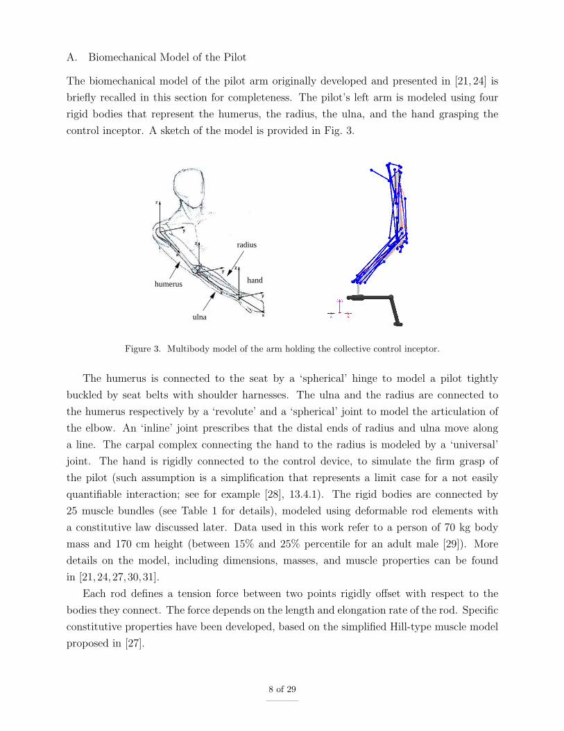
A. Biomechanical Model of the Pilot
The biomechanical model of the pilot arm originally developed and presented in [21, 24] is
briefly recalled in this section for completeness. The pilot’s left arm is modeled using four
rigid bodies that represent the humerus, the radius, the ulna, and the hand grasping the
control inceptor. A sketch of the model is provided in Fig. 3.
radius
humerus
ulna
hand
Figure 3. Multibody model of the arm holding the collective control inceptor.
The humerus is connected to the seat by a ‘spherical’ hinge to model a pilot tightly
buckled by seat belts with shoulder harnesses. The ulna and the radius are connected to
the humerus respectively by a ‘revolute’ and a ‘spherical’ joint to model the articulation of
the elbow. An ‘inline’ joint prescribes that the distal ends of radius and ulna move along
a line. The carpal complex connecting the hand to the radius is modeled by a ‘universal’
joint. The hand is rigidly connected to the control device, to simulate the firm grasp of
the pilot (such assumption is a simplification that represents a limit case for a not easily
quantifiable interaction; see for example [28], 13.4.1). The rigid bodies are connected by
25 muscle bundles (see Table 1 for details), modeled using deformable rod elements with
a constitutive law discussed later. Data used in this work refer to a person of 70 kg body
mass and 170 cm height (between 15% and 25% percentile for an adult male [29]). More
details on the model, including dimensions, masses, and muscle properties can be found
in [21,24,27,30,31].
Each rod defines a tension force between two points rigidly offset with respect to the
bodies they connect. The force depends on the length and elongation rate of the rod. Specific
constitutive properties have been developed, based on the simplified Hill-type muscle model
proposed in [27].
8 of 29

Table 1. Arm muscles’ properties: reference length (ℓ0); max isometric force (fm0); coordinates of insertionpoints 1 & 2 (x1, y1, z1; x2, y2, z2).
ℓ0 fm0 x1 y1 z1 x2 y2 z2
mm N mm mm mm mm mm mm
Muscles connecting the humerus to the rest of the body
1 Coracobrachialis 197 242.5 20 30 35 174 21 0
2 Deltoid — anterior fascicles 179 1142.6 35 25 35 136 -12 10
3 Deltoid — middle fascicles 159 1142.6 35 -22 20 136 -24 18
4 Deltoid — posterior fascicles 148 259.9 -35 10 0 136 -24 18
5 Latissimus dorsi 380 1059.2 -65 110 -290 75 25 9
6 Pectoralis major 147 1270.3 45 110 10 36 0 25
7 Supraspinatus 108 487.8 -36 80 35 -32 2 -13
8 Infraspinatus 111 1210.8 -32 80 -40 -26 0 -20
Muscles connecting the radius to the rest of the body
9 Biceps brachii caput longus 388 624.3 0 -15 10 34 16 0
10 Biceps brachii caput brevis 324 435.6 20 30 25 3 16 0
Muscles connecting the ulna to the rest of the body
11 Triceps brachii caput longus 290 798.5 -35 20 -20 -15 0 -22
Muscles connecting the humerus to the ulna
12 Anconeus 55 350.0 300 -5 -12 -14 7 -11
13 Triceps brachii caput laterale/mediale 211 1248.6 112 0 -28 -27 0 -6
14 Brachialis 140 987.3 196 -8 16 17 15 5
Muscles connecting the humerus to the radius
15 Brachioradialis 306 261.3 246 -7 0 238 -18 13
16 Pronator teres 148 566.2 270 33 -7 55 -18 12
Muscles connecting the humerus to the hand
17 Flexor carpi ulnaris 317 128.9 265 27 -5 5 30 23
18 Extensor carpi ulnaris 290 93.2 269 -27 -5 5 30 -18
19 Extensor digitorum 387 100.7 269 -20 -20 8 0 -16
20 Flexor digitorum superficialis 380 226.6 275 27 -10 7 18 26
21 Flexor carpi radialis 307 74.0 275 27 -7 3 -20 32
22 Extensor carpi radialis 305 405.4 245 -20 0 5 -23 -11
Muscles connecting the ulna to the radius
23 Pronator quadratus 33 75.5 200 7 14 236 27 23
24 Supinator 61 476.0 13 17 -8 28 13 -24
Muscle connecting the ulna to the hand
25 Abductor pollicis longus 202 59.5 115 -21 -5 3 -18 23
9 of 29

According to [27], the force of the ith muscle is formulated as
fmi= fm0i (f1(xi)f2(vi)ai + f3(xi)) (1)
where xi = ℓi/ℓ0i and vi = ℓi/V0i are the non-dimensional muscle elongation and elongation
rate, the former referred to a specific reference length of the muscle and the latter to a
common conventional reference velocity [27]; ai is the non-dimensional activation parameter,
constrained by 0 ≤ ai ≤ 1.
The reference activation of the muscles is computed by solving the cascaded problem
discussed in [21, 32]. An underdetermined inverse kineto-statics problem is solved first,
to find the configuration of the limbs that complies with the boundary constraints and
minimizes some ergonomy cost function (usually consisting in maximizing the distance from
extreme joint positions). An inverse dynamics problem is then solved to find the joint
torques that guarantee the equilibrium of the system. Since the inverse dynamics problem
is overdetermined in terms of muscle forces, the force required of each muscle to provide the
previously estimated joint torques is computed by minimizing the activation of the muscles,
minai
∑
i a2i , constrained by 0 ≤ ai ≤ 1. As an example, the muscular activations required to
hold the collective control inceptor at 10%, 50% and 90% are reported in Fig. 4. Some of the
muscle bundles only activate for specific reference configurations; some do not activate at all,
suggesting that in the given configuration they should push rather than pull to contribute
to the required joint torques. However, all of them may be needed when reflexive activation
and cognitive action are considered, as detailed later.
0
0.1
0.2
0.3
1 2 3 4 5 6 7 8 9 10 11 12 13 14 15 16 17 18 19 20 21 22 23 24 25
activ
atio
n
muscle number
10%50%90%
Figure 4. Muscular activation parameters for 10%, 50% and 90% collective control device reference position(muscles numbered according to Table 1).
As discussed in [21, 24], based on considerations made by Stroeve [33], a simple quasi-
steady approximation of the reflexive contribution to the actuation based on the muscle
length and elongation rate is considered,
ai = airef −Kp (xi − xiref)−Kdvi, (2)
where, as discussed later, the reference length xiref is modified to produce the control inceptor
motion requested by the voluntary pilot model. The use of a quasi-steady approximation
10 of 29

is justified by the consideration that the dynamics of muscular activation is characterized
by relatively high frequencies (time constants between 10 and 40 ms, [34]) compared to the
mechanical phenomena under consideration, which occur well below 10 Hz.
In [24], a relation between the approximate reflexive activation parameterKp and the task
a pilot is performing was established by comparing the results obtained from the numerical
model and corresponding experimental results presented by Venrooij et al. in [35]. In that
experiment, pilots were asked to perform a position task (PT), consisting in keeping the
control inceptor in a prescribed position as accurately as possible, resisting forces; a relax
task (RT), consisting in loosely keeping the control inceptor about a prescribed position;
a force task (FT), consisting in yielding to forces without trying to keep the inceptor in a
specific position.
Each task required human operators to attain different levels and combinations of mus-
cular activation. The PT requires a significant amount of reflexive activation in addition to
the reference amount required to counteract the own weight of the arm, whereas the other
tasks require a much lower level of reflexive activation. High reflexive activation can be
intuitively associated with pilot’s reactivity and promptness in responding to perturbations
and external stimuli in general. BDFT appears to be most prone to causing RPCs when
the reflexive muscular activation related to PT is considered [24, 36]. Indeed, it has been
assessed that reflexive activation parameters associated with less aggressive pilot behavior
(e.g. RT) lead to less prompt and slightly more damped response. For this reason, only the
parameters related to PT are used in the coupled pilot-vehicle analyses presented in this
work.
In [25], Mayo reported significant dependence of BDFT gain on collective inceptor refer-
ence position; no attempt was made at transfer function identification parametrized in the
inceptor position. In [26], Masarati et al. presented experimental BDFT frequency responses
and reported significant dependence of gain and poles of identified pilots’ BDFT transfer
functions on collective inceptor reference position. Specifically, the frequency and the damp-
ing factor reduced when the collective was increased. In [24], Masarati and Quaranta, using
the same biomechanical model discussed in the present work, obtained numerical trends
in BDFT that were consistent with those of [26], and were subsequently extended in [37]
by Zanlucchi et al. These considerations support the opportunity to preserve consistency
between the control input and the actual position of the control inceptor.
B. Cognitive Pilot Model
According to the block diagram of Fig. 5, the voluntary control of the pilot is
∆θ = Hθez(s) (zd − z) +Hff(s)zd. (3)
11 of 29
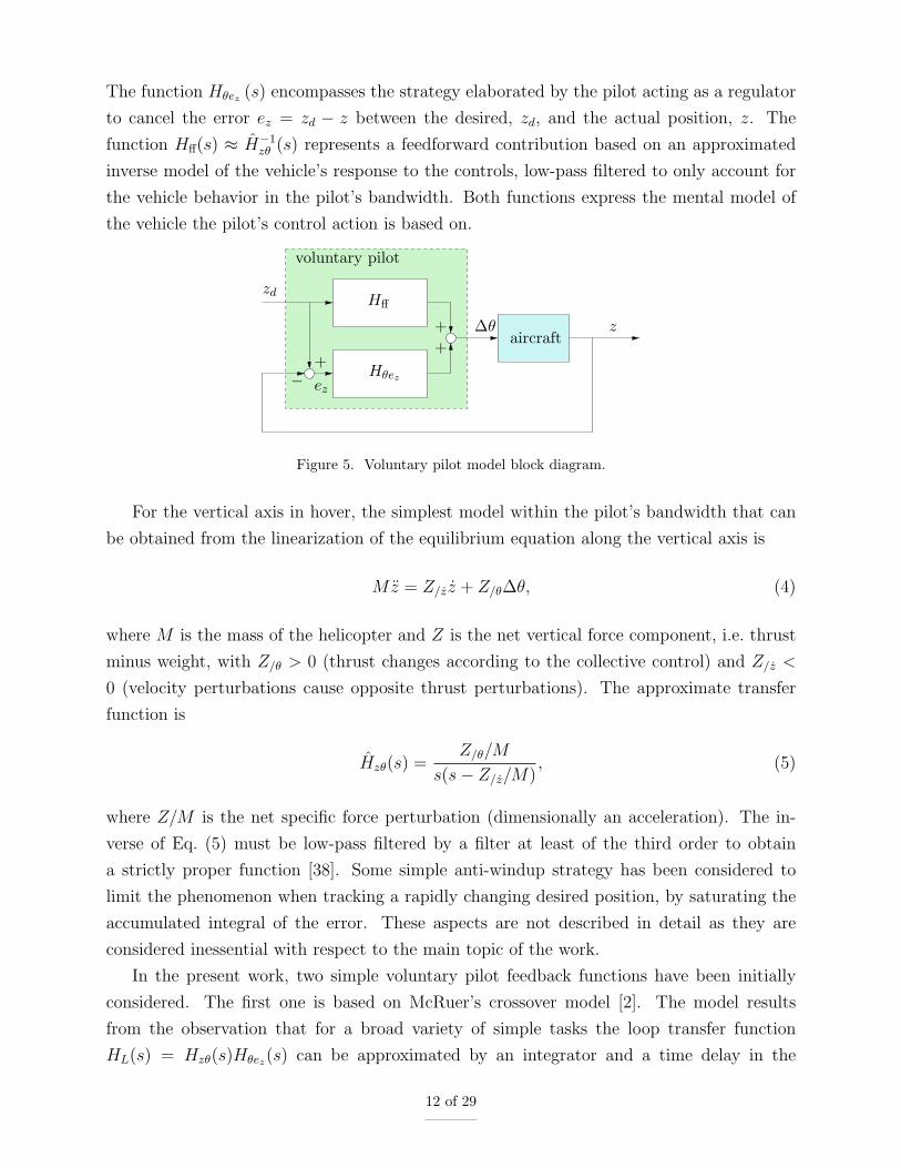
The function Hθez (s) encompasses the strategy elaborated by the pilot acting as a regulator
to cancel the error ez = zd − z between the desired, zd, and the actual position, z. The
function Hff(s) ≈ H−1zθ (s) represents a feedforward contribution based on an approximated
inverse model of the vehicle’s response to the controls, low-pass filtered to only account for
the vehicle behavior in the pilot’s bandwidth. Both functions express the mental model of
the vehicle the pilot’s control action is based on.
aircraft
Hff
Hθez
voluntary pilot
ez
z
zd
∆θ
++
+
−
Figure 5. Voluntary pilot model block diagram.
For the vertical axis in hover, the simplest model within the pilot’s bandwidth that can
be obtained from the linearization of the equilibrium equation along the vertical axis is
Mz = Z/z z + Z/θ∆θ, (4)
where M is the mass of the helicopter and Z is the net vertical force component, i.e. thrust
minus weight, with Z/θ > 0 (thrust changes according to the collective control) and Z/z <
0 (velocity perturbations cause opposite thrust perturbations). The approximate transfer
function is
Hzθ(s) =Z/θ/M
s(s− Z/z/M), (5)
where Z/M is the net specific force perturbation (dimensionally an acceleration). The in-
verse of Eq. (5) must be low-pass filtered by a filter at least of the third order to obtain
a strictly proper function [38]. Some simple anti-windup strategy has been considered to
limit the phenomenon when tracking a rapidly changing desired position, by saturating the
accumulated integral of the error. These aspects are not described in detail as they are
considered inessential with respect to the main topic of the work.
In the present work, two simple voluntary pilot feedback functions have been initially
considered. The first one is based on McRuer’s crossover model [2]. The model results
from the observation that for a broad variety of simple tasks the loop transfer function
HL(s) = Hzθ(s)Hθez(s) can be approximated by an integrator and a time delay in the
12 of 29

vicinity of the crossover frequency of the function, ωc, namely
HL(s) = Hzθ(s)Hθez(s) =ωc
se−sτe . (6)
According to this model, and considering the approximated vehicle transfer function Hzθ(s)
of Eq. (5) under the assumption that it captures the behavior of the vehicle in the vicinity
of the crossover frequency, the pilot feedback function is
Hθez(s) ≈ H−1zθ (s)
ωc
se−sτe =
s− Zz/M
Z/θ/Mωce
−sτe . (7)
To be usable in a time marching simulation, such model needs to be made strictly proper by
adding a low-pass filter at least of second order, which is characterized by two poles,
Hθefiltered(s) =α2
s2 + α1s+ α2
s− Zz/M
Z/θ/Mωce
−sτe (8)
that for 0 < α1 ≤ 2√α2 (i.e. when they are complex conjugated) produce a cut frequency
√α2 slightly higher than ωc.
The second voluntary pilot feedback function is the one derived from the work of Szabolcsi
[39] and used in [40],
Hθez(s) = KA(T3s+ 1)
(T1s+ 1)(T2s+ 1)e−sτe . (9)
According to [40], the parameters of the model are:
◦ KA: the pilot’s gain;
◦ T1: the lag time constant, describing “the ease with which the pilot generates the
required input”;
◦ T2: the neuromuscular lag time constant;
◦ T3: the lead time constant, which represents the ability of the pilot in predicting the
behavior of the vehicle within the pilot’s bandwidth;
◦ τe: a time delay that represents the time that lapses between the sensing of a cue and
the voluntary reaction of the pilot.
Note that Eq. (9) of the second model has the same structure of Eq. (8) of the first one, with
KA = −ωcZz/Zθ, T3 = −M/Zz, and T1 + T2 = 1/α2, T1T2 = α1/α2. In practice, the model
of Eq. (9) gives a specific physical meaning to the poles of the low-pass filter, purposely
13 of 29

introduced in Eq. (8) to make it suitable for time marching analysis, which are assumed to
be real rather than complex conjugated.
The pole characterized by T2 in the model of Eq. (9) plays the role (and is a gross
approximation) of the low-pass filtering effect of the pilot limbs’ biomechanics (it is worth
noticing that in the original work of Szabolcsi [39], an alternative second-order approximation
was proposed using two complex-conjugate poles; a similar approach was proposed by Hess
in his fundamental work on the structural pilot model [3]). Clearly, in the present work such
role is played by the detailed biomechanical model of the pilot.
For both models, the time delay has been approximated using a second-order Pade form,
e−sτe ∼=1−
τe
2s+
τ 2e
12s2
1 +τe
2s+
τ 2e
12s2
, (10)
and the whole transfer function has been transformed in the time domain in form of a linear,
time invariant state-space system that produces the desired intentional control inceptor
rotation as a function of the altitude error. Given the clear similarity between the two
models, only results obtained with the crossover model are presented in the following.
More sophisticated voluntary pilot models can be used, for example when specific tasks
need to be addressed (e.g. models derived from Gray’s work on Boundary Avoidance Task
(BAT) [41–43]). The previously discussed simple models are preferred in this context since
the focus is on producing the effect of the pilot’s intentional behavior throughout the same
detailed biomechanical model that is used to simulate the involuntary behavior. However, the
opportunity to take into account a voluntary change in control strategy and/or an involuntary
change in biodynamic properties of the limbs triggered by a change in control demand of the
task will be investigated in the future as a potential source of RPC.
C. Pilot Voluntary Action Through the Biomechanical Model
The voluntary action of the pilot defined by Eq. (3) in terms of blade collective pitch as a
function of the desired and actual state of the vehicle must be transformed into appropriate
commands to the muscles by means of a neuromuscular model.
Consider a linear map between the collective control perturbation, ∆η, and the muscle
elongation perturbations, ∆ℓ,
∆ℓ = ℓ/η∆η (11)
In the simplest case, a (linear) mapping can be defined between the rotation of the collective
14 of 29

control inceptor, η (the control throw), and the static blade collective pitch rotation, θ,
namely
∆θ = Gc∆η (12)
(in the case at hand, Gc ≈ 0.5 radian/radian, since a typical control inceptor end to end
rotation is about 35 deg, whereas the blade collective pitch range is between 16 and 20 deg).
A more realistic model also considers the dynamics of the control system actuators. In
this work, they are approximated using either first- or second-order low-pass filters, e.g.
∆θ = Gc1
1 + ps∆η (13)
with a time constant p of about 0.012 s, or
∆θ = Gc1
1 + 2ξas/ωa + (s/ωa)2∆η, (14)
with a cut frequency ωa of about 12 Hz and a damping factor ξa of about 0.4.
In advanced rotorcraft, a sophisticated flight control system (FCS) may further modify
the pilot controls prior to feeding them to the actual pitch control mechanism. Although the
details of such systems are beyond the scope of the current work, a net effect they could have
on the pilot’s commanded control is a further delay of up to 100 ms caused by the digital
filtering and processing of the control inceptor motion [1,44]. Such delay may play a critical
role in reducing the phase margin of the closed loop system.
The blade collective pitch demand can be mapped onto the corresponding muscle elon-
gation perturbation demand,
∆ℓ = ℓ/η1
Gc
((
Hθez (s) + H−1zθ (s)
)
zd −Hθez (s) z)
(15)
The actual muscle elongation demand is filtered by a low-pass filter that includes an elec-
tromechanical delay of about 50 ms, HNMD(s) (values between 10 and 120 ms are reported
in the literature, see for example [45]).
The filtered muscle elongation demand is added to the reference muscle elongation used
in the quasi-steady approximation of the reflexive activation of Eq. (2), which becomes
ai = airef −Kp (xi − xiref −HNMD(s)∆xiref)−Kdvi. (16)
The modified reference length is used to produce the control inceptor motion requested by
the voluntary pilot model.
15 of 29

Rather than resorting to a complex inverse model of the pilot biomechanics, given the
simplicity of the specific problem, a numerical linearization has been considered. The ap-
proach used in this work assumes that only small perturbations of the limbs’ motion about a
steady reference configuration are required, involving limited amount of muscular activation.
The value of ℓ/η is computed according to the procedure:
◦ prescribe a small rotation ∆η to the control inceptor;
◦ measure the length change of each muscle, ∆ℓi;
◦ measure the activation change of each muscle, ∆ai.
The force change in each muscle is
∆fmi= fm0i (f1(xiref +∆xi)(airef −Kp∆xi) + f3(xiref +∆xi)− f1(xiref)airef − f3(xiref)) ,
(17)
considering that in isometric conditions vi = 0 and f2(0) ≡ 1. Assuming the elongation
change ∆xi is small enough that a local linearization of f1(x), f3(x) is an acceptable approx-
imation, the force perturbation becomes
∆fmi= fm0i
(
(f1/xairef + f3/x − f1(xiref)Kp)∆xi − f1/xKp∆x2i
)
(18)
Consider now a change of reference length such that ∆ℓiref ≡ ∆ℓi, thus ∆ai = ∆airef , since
the reflexive change of activation is zero. Then, the change of muscle force is
∆fmi= fm0i
(
(f1/xairef + f3/x)∆xi + (f1(xiref) + f1/x∆xi)∆airef)
(19)
If the change of reference length (and of reference activation) is applied to an otherwise
unloaded arm, assuming that the change of configuration is small enough, no first-order
change of muscular force is needed. As a consequence, ∆fmi
∼= 0, which requires a change
of reference activation
∆airef∼= −f1/xairef + f3/x
f1(xiref +∆xi)∆xi. (20)
This implies that when the simple reflexive model of Eq. (2) is considered for the muscular
activation, to prescribe a rotation of the control inceptor both the desired reference length
of the muscles, ∆ℓiref , and the corresponding reference activation, ∆airef , must be modified
accordingly.
16 of 29

D. Basic Voluntary/Involuntary Pilot-Control Device Interaction Results
BDFT has been estimated using system identification from detailed multibody simulation.
According to functions proposed in the literature, either identified from experiments [25,26]
or from numerical models [24], the BDFT between the collective control inceptor motion and
the acceleration of the cockpit can be represented by a second-order low-pass filter,
Hηz(s) =b0ω
2p
s2 + 2ξpωps+ ω2p
. (21)
In the case of the ‘position task’ (PT) pilot, with the collective control inceptor held about
the 50% position, the function (shown in Fig. 6) is characterized by a natural frequency ωp =
16.7 radian/s (2.66 Hz), a damping factor ξp = 0.251, and a static gain b0 = 1.47 radian/m.
0.001
0.01
1 10
radi
an/(
m/s
2 )
-180
-135
-90
-45
0
1 10
deg
Hz
estimatedidentifiedharmonic
Figure 6. Biodynamic feedthrough: transfer functions ‘estimated’, ‘identified’ and obtained using ‘harmonic’excitation.
Data have been obtained by applying a random vertical acceleration, band-pass filtered
in the 1–10 Hz range, to the multibody model of the pilot’s arm. The transfer function
estimated from the input and the resulting collective control inceptor rotation is labeled
‘estimated’. The corresponding identified transfer function is labeled ‘identified’; the formula
is that of Eq. (21). The analogous function obtained from the response to limited amplitude
harmonic excitation is labeled ‘harmonic’.
The subsequent applications verify how the actual rotation of the control inceptor,
sketched in Fig. 7, resembles the demanded one.
The result is shown in Figs. 8 and 9. Figure 8 shows the actual motion when a large
step input (6 deg) is demanded. Figure 9 shows the actual motion when the the collective
control inceptor rotation measured during flight simulator tests originally presented in [46] is
demanded. The neuromuscular model is able to accurately track the motion demand, with
17 of 29

me
pilot’s action
z
Jη
Figure 7. Sketch of collective control device.
12
14
16
18
20
22
4.5 5 5.5 6 6.5 7 7.5
Col
lect
ive,
deg
Time, s
demandactual
actual, friction
Figure 8. Step input: collective control inceptor demanded and actual rotation.
minimal delay and small, damped oscillations occurring when the input variation is exces-
sively abrupt. In Fig. 8, the curve obtained with a ‘loose’ inceptor, i.e. without any reaction
moment, is labeled ‘actual’. Additionally, the curve labeled ‘actual, friction’ illustrates the
response obtained also considering a moment of the form
me = −C1 tanh(C2η), (22)
that contrasts the rotation of the control inceptor, emulating the friction that often charac-
terizes the collective control inceptor, with C1 = 0.3 N·m and C2 = 300 s/radian.
21
22
23
24
25
26
27
0 5 10 15 20 25 30 35 40
Col
lect
ive,
deg
Time, s
demandactual
Figure 9. Input from measured data: collective control inceptor demanded and actual rotation.
18 of 29

III. Analysis of Piloted Vehicle Model
This section presents the analysis of a detailed multibody model of a vehicle controlled by
the previously described pilot model. Both models are developed within the same multibody
analysis following a monolithic approach.
A. Aeromechanical Model of the Vehicle
A multibody model of a generic medium weight helicopter, with articulated main rotor, has
been developed using the free general-purpose multibody solver MBDyn [23]. The aerome-
chanical data of the helicopter is loosely related to that of the Sud Aviation (now Airbus
Helicopters) SA330 Puma. The multibody model has been presented first in [47], where it
was correlated to an independently developed model based on the same data, and on limited
experimental data. The same model was used in [24], where the involuntary biomechanics
of the pilot was used to analyze the effect of BDFT.
The choice of this specific helicopter was dictated by the broad availability of aeroelastic
data in the open literature. The aeromechanical model is briefly described in the following
for completeness, and to give the reader an indication of its complexity and detail.
The aspects of the vehicle that according to [48] are essential for aeroelastic RPCs have
been considered. The main rotor aeroelasticity is modeled in detail. The structural dynamics
of the 4 rotor blades are described using the original Geometrically Exact Beam Formulation
(GEBF) presented in [49]. Each blade is modeled using five three-node beam elements.
Figure 10 shows a detail of the rotor hub. The root of each blade is connected to the hub
by a sequence of ‘revolute’ hinges that reproduce the exact kinematics of the lag and flap
hinges and of the pitch bearing. A rigid body that can lag (i.e. rotate about an axis that
is parallel to the rotation axis of the rotor) is connected to the rotor hub for each blade. A
linear viscous element models the viscous damper that acts between the lagging body and
the hub. Another ‘revolute’ hinge models the connection between the rigid body that can
flap (i.e. rotate about an axis that is orthogonal to both the blade and the rotation axes) and
the lagging body of each blade. The root of the blade is connected to the flapping body by
a third ‘revolute’ hinge that models the bearing that allows the pitching of the blade. The
root of the blade, right after the pitch bearing, is also connected to the rotating swashplate
by a pitch link, namely an elastic rod loosely directed along the rotation axis of the rotor
and offset from the blade axis, that transmits the pitch control to the blade, also accounting
for the mechanical compliance of the pitch control mechanism.
The main rotor is connected to a Component Mode Synthesis (CMS) model of the air-
frame by a joint that prescribes the angular velocity of the hub. The fixed part of the
swashplate, including the linear actuators that command its position and orientation, is also
19 of 29
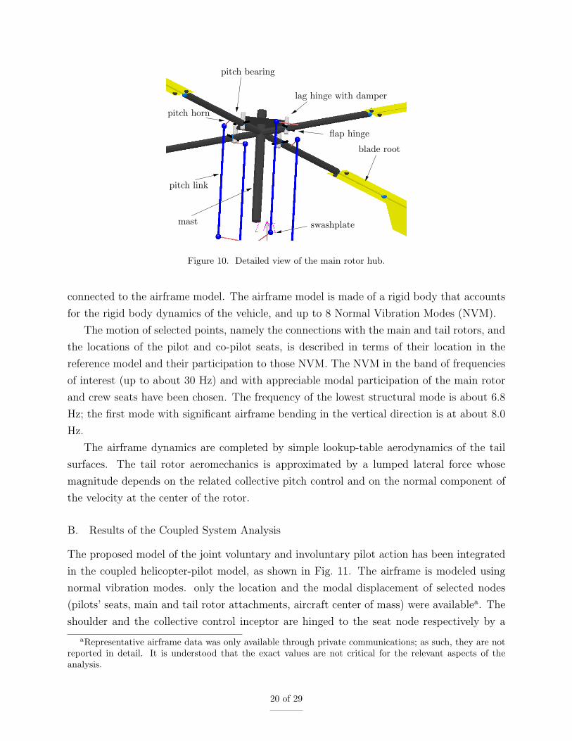
pitch bearing
pitch horn
pitch link
mast
lag hinge with damper
flap hinge
blade root
swashplate
Figure 10. Detailed view of the main rotor hub.
connected to the airframe model. The airframe model is made of a rigid body that accounts
for the rigid body dynamics of the vehicle, and up to 8 Normal Vibration Modes (NVM).
The motion of selected points, namely the connections with the main and tail rotors, and
the locations of the pilot and co-pilot seats, is described in terms of their location in the
reference model and their participation to those NVM. The NVM in the band of frequencies
of interest (up to about 30 Hz) and with appreciable modal participation of the main rotor
and crew seats have been chosen. The frequency of the lowest structural mode is about 6.8
Hz; the first mode with significant airframe bending in the vertical direction is at about 8.0
Hz.
The airframe dynamics are completed by simple lookup-table aerodynamics of the tail
surfaces. The tail rotor aeromechanics is approximated by a lumped lateral force whose
magnitude depends on the related collective pitch control and on the normal component of
the velocity at the center of the rotor.
B. Results of the Coupled System Analysis
The proposed model of the joint voluntary and involuntary pilot action has been integrated
in the coupled helicopter-pilot model, as shown in Fig. 11. The airframe is modeled using
normal vibration modes. only the location and the modal displacement of selected nodes
(pilots’ seats, main and tail rotor attachments, aircraft center of mass) were availablea. The
shoulder and the collective control inceptor are hinged to the seat node respectively by a
aRepresentative airframe data was only available through private communications; as such, they are notreported in detail. It is understood that the exact values are not critical for the relevant aspects of theanalysis.
20 of 29

‘spherical’ and a ‘revolute’ hinge; the corresponding muscle bundles are connected to the
seat node accordingly. The rotation of the collective control inceptor is logically fed into the
swashplate actuators as actuator displacement demand.
η
airframe NVM
Figure 11. Multibody model of main rotor and pilot.
In the present analysis, the rigid-body motion of the helicopter is only allowed along and
about the vertical axis. Such restriction has been introduced because only the left arm is
modeled, the one that commands the collective control inceptor and thus directly determines
the vertical thrust produced by the rotor.
The intentional action of the pilot has been modeled using McRuer’s crossover model.
The parameters of what corresponds to the pilot’s mental model of the helicopter are listed
in Table 2 (adapted from [50] with reference to the IAR330, a ‘heavy’ version of the SA330),
along with those of the pilot (from [2]) and of the low-pass filter, a second-order low-pass
Butterworth filter with the cut frequency set to 3.1 radian/s.
Table 2. Parameters of the voluntary pilot model.
M 7345.0 kg
Z/z/M −0.8 s−1
Z/θ/M 113.0 m·s−2·radian−1
ωc 1.0 radian·s−1
τe 0.38 s
ωf =√α2 3.10 radian·s−1
ξf = α1/(2ωf ) 1/√2 n.d.
Figure 12 presents the results of the simulation of a task inspired by the vertical maneuver
specified in the United States rotorcraft handling qualities performance design specification,
21 of 29

-2
0
2
4
6
8
10
12
0 5 10 15 20 25 30
Dis
plac
emen
t, m
Time, s
G = 1.0G = 1.8
(a) Helicopter vertical displacement.
10
12
14
16
0 5 10 15 20 25 30
Col
lect
ive,
deg
Time, s
G = 1.0 demandG = 1.0 η
G = 1.8 demandG = 1.8 η
(b) Collective stick motion.
-3
-2
-1
0
1
2
3
0 5 10 15 20 25 30
Acc
eler
atio
n, m
/s2
Time, s
G = 1.0G = 1.8
(c) Helicopter vertical acceleration.
0.205
0.210
0.215
0.220
0 5 10 15 20 25 30
Mus
cula
r ac
tivat
ion,
n.d
.Time, s
G = 1.0G = 1.8
(d) Brachialis muscle activation.
Figure 12. Helicopter vertical maneuver, ‘loose’ control inceptor.
-2
0
2
4
6
8
10
12
0 5 10 15 20 25 30
Dis
plac
emen
t, m
Time, s
G = 1.0G = 2.1
(a) Helicopter vertical displacement.
10
12
14
16
0 5 10 15 20 25 30
Col
lect
ive,
deg
Time, s
G = 1.0 demandG = 1.0 η
G = 2.1 demandG = 2.1 η
(b) Collective stick motion.
-3
-2
-1
0
1
2
3
0 5 10 15 20 25 30
Acc
eler
atio
n, m
/s2
Time, s
G = 1.0G = 2.1
(c) Helicopter vertical acceleration.
0.205
0.210
0.215
0.220
0 5 10 15 20 25 30
Mus
cula
r ac
tivat
ion,
n.d
.
Time, s
G = 1.0G = 2.1
(d) Brachialis muscle activation.
Figure 13. Helicopter vertical maneuver, control inceptor with emulated friction.
22 of 29
ADS-33E-PRF [51]. During the maneuver, the pilot changes the altitude of the helicopter
by 25 ft (about 8 m) starting and ending in hover condition, to rapidly unmask an at-
tack/scout helicopter or to assess the heave axis controllability of a utility/cargo helicopter
with precision station keeping. Since the specification only prescribes the purpose of the
maneuver, the desired trajectory of the aircraft is arbitrarily chosen as a vertical motion
zd = (1− cos(πt/T ))A/2 with T = 5 s and A = 25 ft, for 0 ≤ t ≤ T .
In the following, the gearing ratio is modified to act as a sort of a physical “feedback gain”.
Rather than changing Gc, an amplification factor G is considered, such that ∆θ = GGc∆η,
with G = 1 corresponding to nominal gearing ratio. Figure 12(a) compares the vertical
displacement of the helicopter with nominal and nearly doubled gearing ratio (G = 1.8); the
latter makes the coupled vehicle-pilot system barely stable. Figure 12(c) shows the vertical
acceleration of the helicopter. Figure 12(b) shows the collective control inceptor rotation
demand and the actual rotation after the action of the biomechanical model. Note that
when the gearing ratio is increased from 1.0 to 1.8, the inceptor rotation demand reduces by
a factor 1/G = 5/9, since the maneuver requires the same amount of blade pitch rotation,
which is obtained with a smaller rotation of the control inceptor. Figure 12(d) shows the
muscular activation of the ‘brachialis’ muscle (which is significantly involved in the flexure
of the elbow, see Table 1). The brachialis muscle shows the largest activation level for this
specific maneuver.
Figure 13 is similar to Fig. 12; only, in this case the control inceptor is not loose. On
the contrary, friction is emulated according to Eq. (22), with C1 = 0.3 N·m and C2 = 300
s/radian. The trends are quite similar. The main difference, when G = 1.0, is that the
presence of emulated friction increases the difference between the demanded and the actual
control inceptor rotation (Fig. 13(b) vs. Fig. 12(b)). Another important difference is that
with emulated friction the coupled pilot-vehicle system remains stable at a value of G about
15% higher than in case of loose control.
-3
-2
-1
0
1
2
-4 -3 -2 -1 0
Acc
eler
atio
n, m
/s2
Time, s
G = 1.0G = 1.8G = 2.0
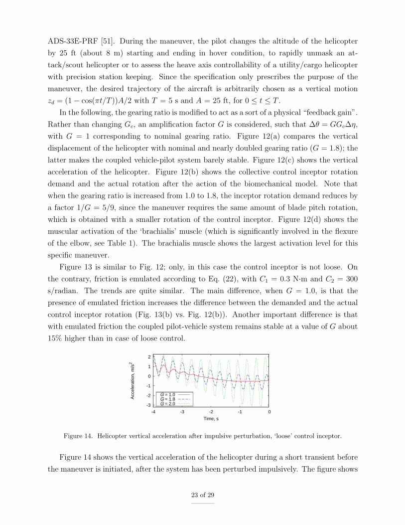
Figure 14. Helicopter vertical acceleration after impulsive perturbation, ‘loose’ control inceptor.
Figure 14 shows the vertical acceleration of the helicopter during a short transient before
the maneuver is initiated, after the system has been perturbed impulsively. The figure shows
23 of 29

that for nominal gear ratio (G = 1.0) the oscillations associated with the interaction between
the main rotor coning mode (a major playing factor in collective bounce, as pointed out in
[52]) and the pilot biodynamics quickly vanish. For G = 1.8 the oscillations persist, whereas
for G = 2.0 they diverge. Moreover, the frequency of the oscillations slightly increases with
G, from about 2.9 Hz with 10% damping for G = 1.0 to about 3.1 Hz and slightly negative
damping for G = 2.0. Such increase is mainly a consequence of the fact that the coupling
of the pilot’s limb biomechanics (whose pole is at about 2.6 Hz) with the main rotor coning
aeromechanics (at about 4 Hz) increases with G.
-3
-2
-1
0
1
2
-4 -3 -2 -1 0
Acc
eler
atio
n, m
/s2
Time, s
G = 1.0G = 2.1G = 2.2
Figure 15. Helicopter vertical acceleration after impulsive perturbation, control inceptor with emulatedfriction.
Figure 15 is analogous to Fig. 14, with emulated friction instead of the loose control
inceptor. It shows that the presence of friction makes the coupled system stable for larger
values of G (about 15% larger). Also, for G set to the nominal value of 1.0, the initial
oscillations triggered by the impulsive perturbations vanish more quickly.
This section showed how the introduction of the pilot’s voluntary action by means of the
biomechanical model of the arm preserves consistency between the position of the inceptor,
which determines the input of the control system, and the biodynamic feedthrough charac-
teristics of the pilot. As discussed previously, there is indirect numerical and experimental
evidence that such consistency can play a role in determining the actual BDFT. Further in-
vestigation is needed to determine its importance, with the ultimate goal of contributing to
practical procedures to define pilot BDFT envelopes, boundaries, and most critical operating
conditions, to support the development of rotorcraft that are RPC-free by design.
Thorough validation of the biomechanical model is needed, to improve its reliability in
predicting biodynamic feedthrough. Other directions for improvement encompass statistical
considerations on inter-subject (e.g. height, weight), as well as intra-subject (reflexive acti-
vation, control inceptor configuration) variability of biomechanical properties. Finally, the
same analysis should be formulated for the right arm holding the cyclic control inceptor.
24 of 29

IV. Conclusions
This work presented the analysis of the pilot interaction with the aeromechanics of a he-
licopter in relation with hover and precision repositioning maneuvers along the vertical axis.
The voluntary action of the pilot that determines the collective pitch control is formulated
using McRuer’s crossover model, a simple behavioral model that characterizes the control
of simple tasks by human subjects. Such action is transformed into the actuation of the
collective control inceptor by prescribing the corresponding desired muscle elongation in a
detailed biomechanical model of the pilot’s left arm. The desired elongation of each mus-
cle is tracked using a quasi-steady approximation of the muscular activation that simulates
response to reflexive stimuli. The coupled pilot-vehicle model is formulated and applied to
the simulation of standard maneuvers. The results showed that the proposed biomechanical
model can be successfully used to transform the voluntary action of the pilot in realistic
motion of the control inceptors. As a consequence, when that signal is used as input of the
control system, consistency is preserved between the control input and the configuration of
the pilot’s arm, providing consistent feedthrough of cockpit vibrations to the control system.
Acknowledgments
The authors gratefully acknowledge the contributions of Vincenzo Muscarello (helicopter
modeling) and Andrea Zanoni (development of the pilot’s biomechanical model). The first
two authors have received funding for the research leading to these results from the Euro-
pean Community’s Seventh Framework Programme (FP7/2007–2013) under grant agreement
N. 266073.
References
[1] Pavel, M. D., Jump, M., Dang-Vu, B., Masarati, P., Gennaretti, M., Ionita, A., Zaichik, L.,
Smaili, H., Quaranta, G., Yilmaz, D., Jones, M., Serafini, J., and Malecki, J., “Adverse rotor-
craft pilot couplings — Past, present and future challenges,” Progress in Aerospace Sciences,
Vol. 62, October 2013, pp. 1–51, doi:10.1016/j.paerosci.2013.04.003.
[2] McRuer, D. T. and Jex, H. R., “A Review of Quasi-Linear Pilot Models,” Human Factors
in Electronics, IEEE Transactions on, Vol. HFE-8, No. 3, September 1967, pp. 231–249,
doi:10.1109/THFE.1967.234304.
[3] Hess, R. A., “Theory for Aircraft Handling Qualities Based Upon a Structural Pilot Model,” J.
of Guidance, Control, and Dynamics, Vol. 12, No. 6, 1989, pp. 792–797, doi:10.2514/3.20483.
[4] Magdaleno, R. E. and McRuer, D. T., “Effects of Manipulator Restraints on Human Operator
25 of 29

Performance,” AFFDL TR-66-72, 1966.
[5] McRuer, D. T. and Magdaleno, R. E., “Human Pilot Dynamics with Various Manipulators,”
AFFDL-TR 66-138, 1966.
[6] Allen, R. W., Jex, H. R., and Magdaleno, R. E., “Manual Control Performance and Dynamic
Response During Sinusoidal Vibration,” AMRL-TR 73-78, October 1973.
[7] Jex, H. R. and Magdaleno, R. E., “Biomechanical models for vibration feedthrough to hands
and head for a semisupine pilot,” Aviation, Space, and Environmental Medicine, Vol. 49, No.
1–2, 1978, pp. 304–316.
[8] McLeod, R. W. and Griffin, M. J., “Review of the effects of translational whole-body vibration
on continuous manual control performance,” Journal of Sound and Vibration, Vol. 133, No. 1,
1989, pp. 55–115, doi:10.1016/0022-460X(89)90985-1.
[9] Merhav, S. J. and Idan, M., “Effects of biodynamic coupling on the human operator model,” J.
of Guidance, Control, and Dynamics, Vol. 13, No. 4, 1990, pp. 630–637, doi:10.2514/3.25380.
[10] Hohne, G., “Computer aided development of biomechanical pilot models,” Aerospace Science
and Technology, Vol. 4, No. 1, January 2000, pp. 57–69, doi:10.1016/S1270-9638(00)00117-6.
[11] Mitchell, D. G., Aponso, B. L., and Klyde, D. H., “Effects of cockpit lateral stick characteristics
on handling qualities and pilot dynamics,” CR 4443, NASA, 1992.
[12] Gabel, R. and Wilson, G. J., “Test Approaches to External Sling Load Instabilities,” Journal
of the American Helicopter Society, Vol. 13, No. 3, 1968, pp. 44–55, doi:10.4050/JAHS.13.44.
[13] Prouty, R. W. and Yackle, A. R., “The Lockheed AH-56 Cheyenne — Lessons learned,” AIAA
Aircraft Design Systems Meeting, Hilton Head, SC, USA, August 24–26 1992, AIAA-1992-
4278.
[14] Walden, R. B., “A Retrospective Survey of Pilot-Structural Coupling Instabilities in Naval
Rotorcraft,” American Helicopter Society 63rd Annual Forum, Virginia Beach, VA, May 1–3
2007, pp. 1783–1800.
[15] Bilger, J., Marr, R., and Zahedi, A., “Results of Structural Dynamic Testing of the XV-15 Tilt
Rotor Research Aircraft,” Journal of the American Helicopter Society, Vol. 27, No. 2, 1982,
pp. 58–65.
[16] Parham, Jr., T., Popelka, D., Miller, D. G., and Froebel, A. T., “V-22 Pilot-in-the-loop
Aeroelastic Stability Analysis,” American Helicopter Society 47th Annual Forum, Phoenix,
Arizona (USA), May 6–8 1991.
[17] Dieterich, O., Gotz, J., DangVu, B., Haverdings, H., Masarati, P., Pavel, M. D., Jump, M., and
Gennaretti, M., “Adverse Rotorcraft-Pilot Coupling: Recent Research Activities in Europe,”
34th European Rotorcraft Forum, Liverpool, UK, September 16–19 2008.
26 of 29

[18] “ARISTOTEL: Aircraft and Rotorcraft Pilot Couplings — Tools and Techniques for Allevia-
tion and Detection,” http://www.aristotel.progressima.eu/ (last accessed June 2014).
[19] Pavel, M. D., Malecki, J., DangVu, B., Masarati, P., Gennaretti, M., Jump, M., Smaili, H.,
Ionita, A., and Zaicek, L., “A Retrospective Survey of Adverse Rotorcraft Pilot Couplings in
European Perspective,” American Helicopter Society 68th Annual Forum, Fort Worth, Texas,
May 1–3 2012.
[20] Mariano, V., Guglieri, G., and Ragazzi, A., “Application of pilot induced oscillations prediction
criteria to rotorcraft,” American Helicopter Society 67th Annual Forum, Virginia Beach, VA,
May 3–5 2011.
[21] Masarati, P., Quaranta, G., and Zanoni, A., “Dependence of helicopter pilots’ biodynamic
feedthrough on upper limbs’ muscular activation patterns,” Proc. IMechE Part K: J. Multi-
body Dynamics, Vol. 227, No. 4, December 2013, pp. 344–362, doi:10.1177/1464419313490680.
[22] “MBDyn: Multibody Dynamics,” http://www.mbdyn.org/ (last accessed June 2014).
[23] Masarati, P., Morandini, M., and Mantegazza, P., “An efficient formulation for general-purpose
multibody/multiphysics analysis,” J. of Computational and Nonlinear Dynamics, Vol. 9, No. 4,
2014, pp. 041001, doi:10.1115/1.4025628.
[24] Masarati, P. and Quaranta, G., “Bioaeroservoelastic Analysis of Involuntary Rotorcraft-
Pilot Interaction,” J. of Computational and Nonlinear Dynamics, Vol. 9, No. 3, July 2014,
pp. 031009, doi:10.1115/1.4025354.
[25] Mayo, J. R., “The Involuntary Participation of a Human Pilot in a Helicopter Collective Con-
trol Loop,” 15th European Rotorcraft Forum, Amsterdam, The Netherlands, 12–15 September
1989, pp. 81.1–12.
[26] Masarati, P., Quaranta, G., and Jump, M., “Experimental and Numerical Helicopter Pi-
lot Characterization for Aeroelastic Rotorcraft-Pilot Couplings Analysis,” Proc. IMechE,
Part G: J. Aerospace Engineering, Vol. 227, No. 1, January 2013, pp. 124–140,
doi:10.1177/0954410011427662.
[27] Pennestrı, E., Stefanelli, R., Valentini, P. P., and Vita, L., “Virtual musculo-skeletal model for
the biomechanical analysis of the upper limb,” Journal of Biomechanics, Vol. 40, No. 6, 2007,
pp. 1350–1361, doi:10.1016/j.jbiomech.2006.05.013.
[28] Griffin, M. J., Handbook of Human Vibration, Academic Press, London, 1990.
[29] McDowell, M. A., Fryar, C. D., Ogden, C. L., and Flegal, K. M., “Anthropometric Refer-
ence Data for Children and Adults: United States, 2003–2006,” National Health Statistics
Reports n. 10, US Department of Health and Human Services, Centers for Disease Control
and Prevention, National Center for Health Statistics, October 22 2008.
27 of 29

[30] Cheverud, J., Gordon, C. C., Walker, R. A., Jacquish, C., Kohn, L., Moore, A., and Ya-
mashita, N., “1988 anthropometric survey of US Army personnel: correlation coefficients and
regression equations. Part 1: Statistical Techniques, Landmark, and Mesurement Definitions,”
TR 90/032, NATICK, 1990.
[31] Cheverud, J., Gordon, C. C., Walker, R. A., Jacquish, C., Kohn, L., Moore, A., and Yamashita,
N., “1988 anthropometric survey of US Army personnel: correlation coefficients and regression
equations. Part 4: Bivariate Regression Tables,” TR 90/035, NATICK, 1990.
[32] Masarati, P., “Computed Torque Control of Redundant Manipulators Using General-Purpose
Software in Real-Time,” Multibody System Dynamics, in press, doi:10.1007/s11044-013-9377-
4.
[33] Stroeve, S., “Impedance characteristics of a neuromusculoskeletal model of the human
arm I. Posture control,” Biological Cybernetics, Vol. 81, No. 5–6, 1999, pp. 475–494,
doi:10.1007/s004220050577.
[34] Zajac, F. E., “Muscle and tendon: properties, models, scaling, and application to biomechanics
and motor control,” Critical Reviews in Biomedical Engineering, Vol. 17, No. 4, 1989, pp. 359–
411.
[35] Venrooij, J., Abbink, D. A., Mulder, M., van Paassen, M. M., and Mulder, M., “Bio-
dynamic feedthrough is task dependent,” 2010 IEEE International Conference on Sys-
tems Man and Cybernetics (SMC), Istanbul, Turkey, October 10–13 2010, pp. 2571–2578,
doi:10.1109/ICSMC.2010.5641915.
[36] Quaranta, G., Masarati, P., and Venrooij, J., “Impact of pilots’ biodynamic feedthrough on
rotorcraft by robust stability,” Journal of Sound and Vibration, Vol. 332, No. 20, September
2013, pp. 4948–4962, doi:10.1016/j.jsv.2013.04.020.
[37] Zanlucchi, S., Masarati, P., and Quaranta, G., “A Pilot-Control Device Model for Helicopter
Sensitivity to Collective Bounce,” ASME IDETC/CIE 2014, Buffalo, NY, August 17–20 2014,
DETC2014-34479.
[38] Skogestad, S. and Postlethwaite, I., Multivariable Feedback Control, John Wiley & Sons,
Chichester, 2005.
[39] Szabolcsi, R., “Modeling of the human pilot time delay using Pade series,” Academic and
Applied Research in Military Science, Vol. 6, No. 3, 2007, pp. 405–428.
[40] Boril, J. and Jalovecky, R., “Effect of the pilot behavior model on the helicopter stability in the
auto-stabilization system failure,” 2012 IEEE First AESS European Conference on Satellite
Telecommunications (ESTEL), 2012, pp. 1–4, doi:10.1109/ESTEL.2012.6400107.
28 of 29

[41] Gray, III, W. R., “Boundary Avoidance Tracking: A New Pilot Tracking Model,” AIAA
Atmospheric Flight Mechanics Conference and Exhibit, San Francisco, California, August 15–
18 2005, AIAA 2005-5810 doi:10.2514/6.2005-5810.
[42] Brinkerink, N. and Pavel, M. D., “Capturing the switch between point tracking and boundary
avoiding pilot behaviour in a PIO event,” Rotorcraft Handling Qualities Conference, Liverpool,
UK, November 4–6 2008.
[43] Padfield, G. D., Lu, L., and Jump, M., “Tau Guidance in Boundary-Avoidance Tracking - New
Perspectives on Pilot-Induced Oscillations,” J. of Guidance, Control, and Dynamics, Vol. 35,
No. 1, 2012, pp. 80–92, doi:10.2514/1.54065.
[44] Ockier, C. J., “Pilot induced oscillations in helicopters — Three case studies,” Tech. Rep. IB
111-96/12, German Aerospace Center (DLR), Braunschweig, Germany, 1996.
[45] Zhou, S., Lawson, D. L., Morrison, W. E., and Fairweather, I., “Electromechanical delay in
isometric muscle contractions evoked by voluntary, reflex and electrical stimulation,” European
Journal of Applied Physiology and Occupational Physiology, Vol. 70, No. 2, 1995, pp. 138–145,
doi:10.1007/BF00361541.
[46] Masarati, P., Quaranta, G., Lu, L., and Jump, M., “A Closed Loop Experiment of Collective
Bounce Aeroelastic Rotorcraft-Pilot Coupling,” Journal of Sound and Vibration, Vol. 333,
No. 1, January 2014, pp. 307–325, doi:10.1016/j.jsv.2013.09.020.
[47] Muscarello, V., Masarati, P., and Quaranta, G., “Multibody Analysis of Rotorcraft-Pilot
Coupling,” 2nd Joint International Conference on Multibody System Dynamics, edited by
P. Eberhard and P. Ziegler, Stuttgart, Germany, May 29–June 1 2012.
[48] Gennaretti, M., Serafini, J., Masarati, P., and Quaranta, G., “Effects of Biodynamic
Feedthrough in Rotorcraft-Pilot Coupling: Collective Bounce Case,” J. of Guidance, Con-
trol, and Dynamics, Vol. 36, No. 6, 2013, pp. 1709–1721, doi:10.2514/1.61355.
[49] Ghiringhelli, G. L., Masarati, P., and Mantegazza, P., “A Multi-Body Implementation of Finite
Volume Beams,” AIAA Journal, Vol. 38, No. 1, January 2000, pp. 131–138, doi:10.2514/2.933.
[50] Padfield, G. D., Helicopter Flight Dynamics: The Theory and Application of Flying Qualities
and Simulation Modelling, Blackwell Publishing, 2007.
[51] Anonymous, “Performance Specification, Handling Qualities Requirements for Military Ro-
torcraft,” ADS 33-E-PRF, US Army AMCOM, Redstone, Alabama, 2000.
[52] Muscarello, V., Quaranta, G., and Masarati, P., “The Role of Rotor Coning in Helicopter
Proneness to Collective Bounce,” Aerospace Science and Technology, Vol. 36, July 2014,
pp. 103–113, doi:10.1016/j.ast.2014.04.006.
29 of 29


