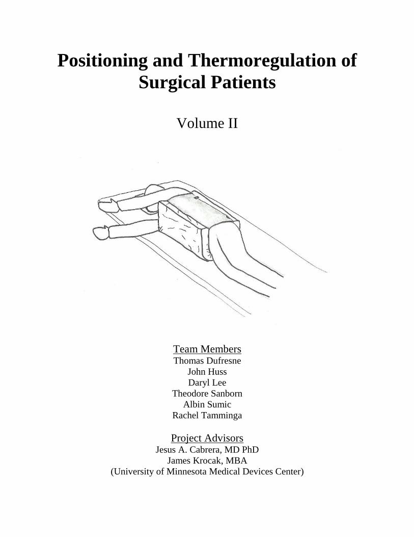
Positioning and Thermoregulation of
Surgical Patients
Volume II
Team Members Thomas Dufresne
John Huss
Daryl Lee
Theodore Sanborn
Albin Sumic
Rachel Tamminga
Project Advisors Jesus A. Cabrera, MD PhD
James Krocak, MBA
(University of Minnesota Medical Devices Center)
ii
Table of Contents
1. Problem Definition Supporting Documents
1.1 Annotated Bibliography………………………………………………………1
1.2 Patent Search……………………………………………………………….…2
1.3 User Need Research………………………………………………………..…4
1.4 Concept Alternatives………………………………………………………….9
1.5 Concept Selection……………………………………………………………13
2. Design Description Supporting Documents
2.1 Manufacturing Plan (Product)
2.1.1 Manufacturing Overview…………………………………….…….18
2.1.2 Part Drawings………………………………………………………19
2.1.3 Bill of Materials……………………………………………………26
2.1.4 Manufacturing Procedure…………………………………………..26
3. Evaluation Supporting Documents
3.1 Evaluation Reports
Safety……………………………………………………………….……27
Effective Warming……………………………………………………….29
ANSYS………………………………………………………………….31
Effective Positioning………………………………………………….….34
Ease of Use………………………………………………………………36
3.2 Cost Analysis……………………………………...…………………………37
3.3 Environmental Impact Statement…………………………………………….38
3.4 Regulatory and Safety Considerations…….....................................................39
References………………………………………………………………………………40
1
1.1 Annotated Bibliography
As the field currently stands, there is no single device being utilized to both position and
thermally regulate a patient during surgical procedures under general anesthesia. This leaves us
room to generate a new product that can fill in the gap. Thorough research of the product market
was performed in order to understand the products that are available, as well as to understand
what people and companies have tried to do, and will try to do in the future to improve the
patient experience while under the knife. Current positioning devices range in size and shape
from pillows and blankets to large mechanical systems designed to limit the motion of the body.
The most widely used positioning device is the surgical vacuum beanbag. Heating systems
include forced air warmers, IV fluid warmers, and electric resistance blankets. Currently, the
most widely used warmer is the forced air warmer.
The team gained valuable insight into the methods of positioning currently in use by observing
several videos of the patient positioning process. All aspects of the problem were considered
while performing research. This is important because by understanding all nuances of the
problem the team was able to more clearly approach an appropriate solution. Topics researched
include hypothermia, operating room temperatures and humidities, surgical positions, anesthesia
and temperature control, as well as a host of other topics.
J. T. Martin and M. A. Warner, Positioning in anesthesia and surgery, 3rd ed.
Philadelphia: Saunders, 1997.
This book covers the general surgical positions, their risks, as well as patient physiology in
the various positions.
The reference is a good resource for the risks of the lateral decubitus position.
D. J. Knight and R. P. Mahajan, “Patient positioning in anaesthesia,” Contin Educ
Anaesth Crit Care Pain, vol. 4, no. 5, pp. 160–163, Oct. 2004.
This journal article covers general complications in patient positioning, as well as
complications specific to a patient position.
The reference is another good resource for the risks of the lateral decubitus position.
L. Stenhouse, Anatomy, 4th ed. Edinburgh ; New York: Mosby/Elsevier, 2012.
This book covers basic anatomy.
When anatomical terms come up in other literature, this book provides a good reference.
“Lateral Positioning in Surgery,” youtube.com. [Online]. Available:
http://www.youtube.com/watch?v=z4mSCrmHpbw. [Accessed: 06-Mar-2013].
This video shows a patient being properly moved from the supine to the lateral positions.
The video includes a discussion of padding necessary to protect the patient.
The video provides a good reminder of the lateral positioning sequence.
L. F. Macksey, Surgical Procedures and Anesthetic Implications: A Handbook for
Nurse Anesthesia Practice, 1st ed. Jones & Bartlett Learning, 2011.
This book provides another good reference for the risks involved in placing a patient in
various positions. The section on the lateral decubitus position is thorough.
This book is a good reference for the risks in lateral positioning.
T. H. Kuehn, J. W. Ramsey, and J. L. Threlkeld, Thermal Environmental Engineering,
3rd ed. Prentice Hall, 1998.
2
1.2 Patent Search
Objective
A thorough search was performed using Google patent in order to better understand the current
technology in the market that catered to both surgical thermoregulation and positioning, as well
as to establish the boundaries for the creation of new intellectual property. Searches were
performed for surgical thermoregulation devices, patient positioning devices, as well as devices
that combined the two. Research was also performed to understand the fundamental technologies
associated with heating and positioning devices. For example, the design team looked into the
elements of current surgical thermoregulatory devices such as the feedback control systems used
to regulate the temperature of the devices and the heating elements in the devices (e.g electrical
resistance heating).
After a thorough and extensive patent search, there was a noticeable lack of devices which could
both safely and securely position a patient for surgery while providing thermoregulation for the
patient. In order to fill the existing market need for such a device, the design team came up with
a design that reconfigures existing surgical beanbags used for surgical positioning with memory
foam on the surface while incorporating a resistive heating element within the structure. The
heating system is controlled using patient feedback, relying upon the preexisting body core
temperature sensors already in use during all operations that require general anesthesia.
When the entire system is taken into consideration, the device, as well as the control systems
used in tandem can potentially be patented.
Search Criteria
Table 1 provides the search criteria of the different patents used to describe major and minor
risks related to the position team’s design.
Table 1: Search Criteria Patent Publication # Classification # Search Word Search Site
Surgical
Positioning System US2011/0047706 A1 5/623; 5/600; 5/621
Positioning
Beanbag
Surgical
Heating Device for
heating patient’s
body
US7709770 H05B 1/02; 3/34; 3/56
A61F 7/02 Patient Heating Google
Surface pad system
for a surgical table US6401283
5/740; 5/503.1; 5/600;
5/694; 5/731; 5/737
Thermoregulati
on surgical Google
Electric warming
blanket having
optimized
temperature zones
7851729
: 219/549; 219/212; 219/217; 219/528; 219/545; 219/548
Scott
Augustine Google
Heating pad
system for patient
warming
US6924467
219/528; 5/421;
219/212; 219/217;
219/218; 219/521;
607/96
Patient Heating Google
3
Major Findings
A major concern to the patentability for the position team’s design is the Surgical Positioning
System patent application (US2011/0047706 A1). The system is made from a flexible air-
impermeable shell, filled with beads, which can be wrapped against a patient and hold the patient
in position when air is vacuumed out of the device. The bag is about 1.5 to 2.5 inches thick,
made of a polyvinyl waterbed film, and has joined together walls for extra strength and
airtightness. The bag is secured by attaching straps to the operating table, which helps prevent
sliding. The main issue of concern is from the additional support structures, a laterally extending
midline around the patient’s torso and a shoulder supporting region. The claims have a
significant number of strengthened supports that could interfere with improving the position
team’s design.
Minor Findings
The heating device for heating a patient’s body (US7709770) is a concern since it can heat the
surface of a patient’s body. The device is made of an electrical heating element powered by an
external source. The heating element constructed using two conductors. The conductors are
placed in a parallel circuit using the first conductor as the heat source and the second conductor
as the heat diffuser, which allows for a temperature gradient between the surface of the
conductors and the body. The first and second conductors are made of relatively high and low
specific resistivity, respectively. The concern is that a very low temperature gradient can be
produced and controlled. This system could be a cause of concern because a low temperature
gradient might be desirable and this is a simple way of creating it.
The surface pad system for a surgical table (US6401283) is a minor concern to the patentability
for the position team’s design. The surface pad is made of two electrical heating elements. The
first elements is connected to the power and provides the heating source, the second element has
a lower resistivity and a larger surface area than the first to operate as the heat-diffuser. The
concern here is that the system can provide a uniform distribution and transfer of heat to the area
touching the patient.
The heating pad system (US6924467) for patient warming applies a foam layer of pads with a
thermal-electric heating element between the layers. The system has two layers of foam pad and
an electric heating element between the two layers, with and external power unit. The foam is
covered by a waterproof antimicrobial cover and sealed to secure the cover. The main issues that
could arise from this patent are the foams that are being used to transfer the thermal energy from
the electrical circuit, and the cover that is secured over the design. Foam could be used as a
material to convert the desired thermal energy for farming a body from an electrical circuit. The
cover is also an issue since the material for the cover could conflict with the cover in the position
team’s design.
The Electric warming blanket having optimized temperature zones (7851729) uses a temperature
sensor that is in contact with the body. The system uses a flexible sheet-like heating element
with uniform electrical resistance per unit area. The temperature sensor system has two sides,
the first side has a temperature sensor coupled to a defined first temperature zone heating
4
element and the second side maintains the temperature of the first side. The temperature sensor
could be a problem because of the way it is arranged to both sense the temperature change and
maintain a heat.
1.3 User Needs Research
User needs are critical to consider during concept selection and product design. They enable the
design team to create design specifications on which potential concepts can be evaluated. They
are the guidelines for creating a new product that will have a meaningful impact. User needs
were obtained through interviews and meetings with various surgical staff, including trained
anesthesiologists, post-anesthesia care unit (PACU) nurses, and project advisors.
Ratings were chosen for each need on a 1-5 scale, with 5 being “very important”. For this
project, the highest ratings were awarded to the needs associated with safety and surgical access.
Current devices are very effective in these categories, and it is important that the new concept is
competitive. Low ratings were given to the needs that are possible nice to have, but not required.
An example of a 1 is being compatible with multiple surgical positions. While this property
would be nice to have from a business standpoint, it does not affect the patient and is therefore
given a low rating.
# User Need Importance
Rating (1-5)
1 Positioning needs to be faster than with current technology1 3
2 Heating is more effective than with current technology1 5
3 The cost of this system must be competitive in the device market2 5
4 Has a disposable component2 4
5 Allows access to airway1, 3
5
6 Allows access to surgical site1, 3
5
7 Easy to transport1 1
8 Cleaning is easier or comparable to current technology1, 4
2
9 Compatible with multiple surgical positions1 1
10 Has variable settings for patient warming temperature1 3
11 Stable enough to hold the patient in place1, 3
5
12 Safe to use on an unconscious patient1, 3, 4
5
5
13 Generates limited waste1 3
14 Useful for many patient sizes1, 3
3
15 Compatible with the lateral position1, 2
5
Sources 1 Informal interviews and meetings with project advisor Jesus M. Cabrera, MD PhD.
2 Informal interviews and meetings with project advisor James Krocak.
3 Interview with University of Minnesota hospital anesthesiologist Dr. Barbara Gold and PACU
nurses. 4 Interview with Anesthesiologist Resident Nick Sanborn, MD.
Customer Interview Transcripts
Nick Sanborn, MD
Anesthesiology Resident
2/13/13
Interviewer: TS
Interview Questions
a. How long does it take to set up a patient for operation?
Once asleep, 1-5 minutes to position. Usually doesn’t take very long. Patients usually start at a
normal temp., so you just keep them from losing heat. Don’t normally heat patient until surgical
drapes are up and the surgeons are ready to start. About 10-15 minutes when patients are not
heated, unless they’re on a heat pad, which is turned on right away. Would also turn the Bair
Hugger on once drapes were up.
b. What would you say could be important to take note of during the set-up procedure?
Make sure the patient is well padded, so there are no pressure points. You want to avoid a nerve
injury. Make sure to pad any hard bony areas. The patient could be lying for 6+ hours.
c. How long does it take to clean the operation set-up?
1-2 min. It’s usually very fast. Don’t know what is disposed of. Wiping down the pads and
machine is very quick. Unless things are all bloody, they are just wiped down.
d. How long does it take to get the patient out of the OR?
6
You usually wait until the patient is awake enough to breathe on his own, unless moving the
patient to the ICU. Patients usually wake up 5-20 min. after surgery is completed.
e. What do you like about the positioning devices you are currently using? What don’t you
like?
A lot of positioning is with foam padding and blankets. He likes the vacuum ban bag--it’s fast
and easy to use. It seems to not hurt patients as much as the peg board. He thinks the Bair
Hugger works well. It keeps patient warm, and is easy to use.
f. How often do patients come out shivering due to being cold? Did you notice any common
trends in the setup, operation type, heating methods used?
Patients usually complain of being cold going in, not usually going out. The operating room is
kept 65-70 deg. Shivering would be more a reaction to the drugs than being cold. Blankets from
a warmer are provided to patients who complain of being cold going in or after waking up.
Shivering is not a common experience. Patients are usually more concerned about pain than
temperature.
g. Do you find the price of current technology reasonable?
He is not sure about the prices.
h. How often have you noticed burns on patients? Where do they typically occur?
He has never seen a burn on a patient. He has heard of the pad from a cauterizing device causing
burns, but not a heating device.
i. How long does it take patients who are cold to get back to 36.9°C
It all depends on surface area exposed, temp. of room, and how the patient is warmed. It could
take a couple of hours, or it could take 20 min. Some people with the Bair Hugger alone don’t
warm up.
Dr. Barbara Gold and PACU nurses
2/14/13
Interviewer: Group
o The nurse provided a demonstration of the Bair Hugger and Bair Paw technology.
o The Bair Hugger went up to a maximum temperature of 43°C.
o She also mentioned that it took at most 30 minutes to clean the operating room
after a surgery.
o When questioned on how long it took patients to get back to their regular
temperatures while in the PACU she said it took about 1 ½ hours.
7
o She also added that incorporating a positioning device that was capable of moving
the patient’s limbs slightly during an operation would be very helpful.
Meetings with Advisors
Relevant Portions of Meeting Minutes Jesus Cabrera, James Krocak
1/31/13
Interviewer: Group
Pros and Cons of Product History
Positioning
o Discussed importance of keeping airway channel protected at all times as well as
IV, ECG, etc.
Care should be given to watching the extremities
o Most challenging position to consider: lateral or prone position surgery
Thermoregulation
A lot of the heating isn’t optimally distributed to the patient
o Current products do not create an ideal situation for both heating and
thermoregulation
o Discussed chemical warming- might not possess a consistent temperature
distribution and heat dissipation rate
Ideally we want circumferential heating, light, and easy to integrate into
existing systems if necessary
Open Discussion
o How important is a feedback mechanism for heating?
Advisors mentioned that feedback was not very critical as the maximum
allowable temperature was 40ºC and it would be hard to control
temperature of the air directly.
Suggested using a water reservoir at a set temperature to maintain patient
temperature.
o How common are heating devices (using circulatory water) used to cool the
patient?
Not very common.
Suggested using circulatory water for heating instead of cooling
o What were the disadvantages of the Bair Hugger?
Not circumferential
There could be a better system
Not warm enough
Air and gasses in general have poor thermal capacities and can only
transfer limited amounts of heat to the patient
8
Inventor of the Bair Hugger using different heating technology now
suggesting better possibilities
o Another heating option discussed was to keep heat in using thermally reflective
material (eg: OMNIHEAT technology by Columbia)
o While thinking about positioning, consider ease of cleaning apparatus
o Focus on prone/lateral position, considering both heating and positioning
Relevant Portions of Meeting Minutes Jesus Cabrera, James Krocak
2/7/13
Interviewer: Group
Concept Selection
Bair Hugger demo-made from paper. Paper also absorbs sweat.
Beanbags used to position since it can conform to patient position.
Suck out air from the Styrofoam and then it conforms to patient’s body.
Concept: create a beanbag with heating abilities.
o Could be heated using resistive heating or fluid flow.
o With resistive heating, a fluid/thermal reflector could be used to line the beanbag.
This component will be disposable.
o With water, need pressurized and circulating flow.
o Consideration will need to be given to the materials used to make the beanbag if
we are using resistive heating.
o Beanbag should still be at a similar weight and price with current products.
o There should be a way to securely attach the disposable part of the beanbag.
o The max/min range of the heating element should be clearly defined and
controlled in other to avoid burns.
9
1.4 Concept Alternatives
Several concepts for the design were considered, encompassing three heating methods: electrical
resistance, infrared, and water heating. Concept alternatives that were considered are as follows:
Electrical Resistance Heating
Beanbag with Electrical Resistance Heating
The beanbag is airtight and filled with fine granules. It can be wrapped around a patient
to position him or her for surgery. When a vacuum pump is used to remove the air from
the beanbag it becomes rigid and holds the patient in place. The electrical resistance
heating element is embedded in a layer of foam which distributes the heat.
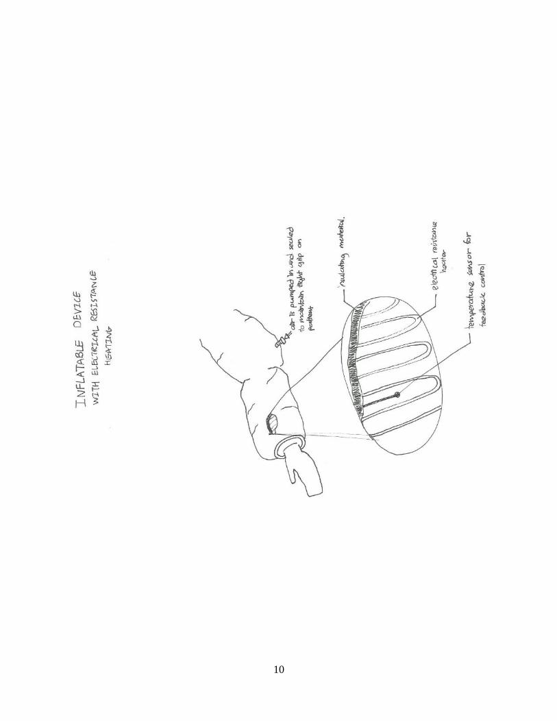
Inflatable Device with Electrical Resistance Heating
This device is shaped to fit around the patient’s body and can be inflated to secure the
patient in place. Similar to the beanbag, it uses an electrical resistance heating element on
the surface to warm the patient. A sketch of this concept is appended to this section.
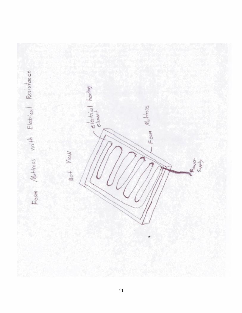
Foam Mattress with Electrical Resistance Heating
In this device the heating element is embedded within the mattress. The softness of the
foam causes the patient to sink into the mattress which helps to hold the patient in
position. A sketch of this concept is appended to this section.
Infrared Heating
Beanbag with Infrared Heating
The beanbag, as described above, can be wrapped around the patient and the air
vacuumed out to hold the patient in place. This device has a heating element embedded
within the device which uses infrared radiation to warm the patient.
Water Heating
Beanbag with Water Heating
The beanbag is as described above. It uses water, heated in an external reservoir, flowing
through flexible tubing to provide warmth to the patient. The water tubing is positioned
on the surface of the beanbag nearest the patient
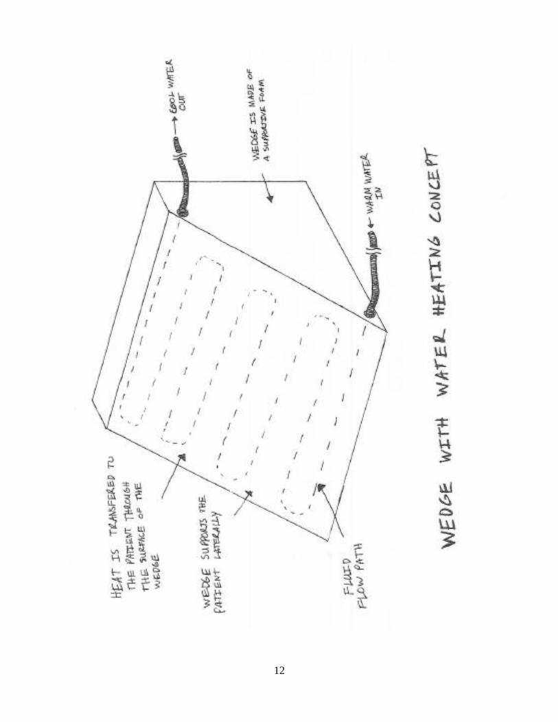
Wedge with Water Heating
A solid foam wedge is used to support the patient in a lateral position. Tubing with warm
flowing water is embedded within the wedge to warm the patient. Again, the water is
heated in an external reservoir and circulated through the device. A sketch of this concept
is appended to this section.
10
11
12
13
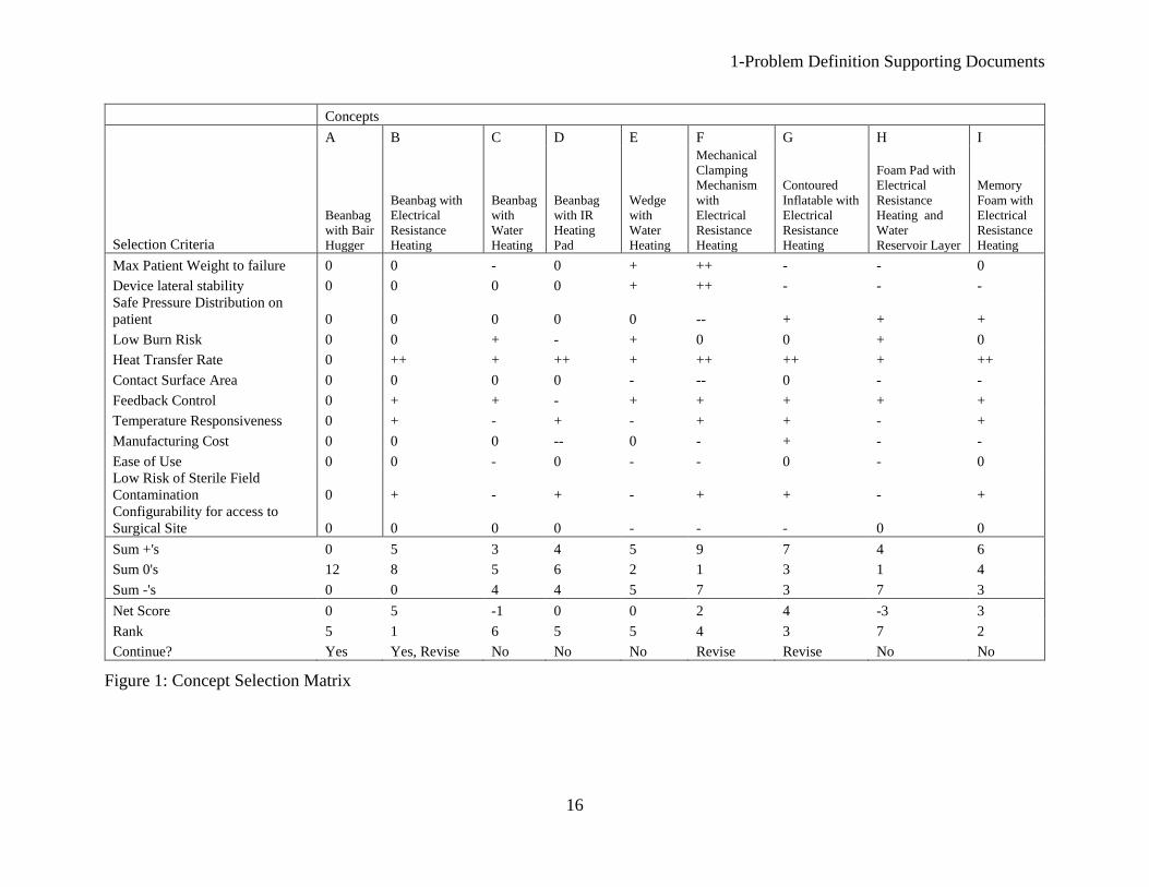
1.5 Concept Selection
To evaluate eight different concepts in a systematic manner, a concept selection chart was
utilized. By comparing each concept against a set of twelve key criteria, each concept’s strengths
and weaknesses were assessed using a plus, minus and zero scoring system. All eight concepts
were assessed relative to a baseline product on the market today—a beanbag with a Bair Hugger.
After evaluating all concepts, they were ranked according to the net score obtained. Four
concepts stood out as potentially superior to the others. These four were then considered in turn
to determine if a redesign of the original concept could make it even stronger. Three concepts
were redesigned. One original concept and the three redesigned concepts were then ranked
against the baseline product using a concept scoring matrix with ten of the same criteria. This
matrix included a weighting factor for each criterion. Also, the concepts were scored using a
value from one to five for each criterion, with five being the strongest. The weighting factors
were adjusted three times to determine the sensitivity of the weighting factor on the concept
ranking. In all three resultant matrices, the same concept received the number one ranking.
The twelve criteria used in the concept screening matrix are as follows:
Maximum Patient Weight to Failure measured the patient’s weight at which a concept
would stop functioning. For instance, the weight at which a plastic tube would collapse
and water would no longer flow through it is the maximum patient weight. This criterion
ensured the sturdiness of the selected concept.
Device Lateral Stability gauged the lateral force at which the concept would deform or
tip. Since the concept must support a patient in the lateral position, this criterion ensured
a patient would not tip over from the lateral position.
Safe Pressure Distribution on Patient determined whether the concept would produce any
localized pressure points. An uneven pressure distribution could lead to pressure sores or
nerve damage on a patient. This criterion guarded against these risks.
Low Burn Risk estimated the likelihood the concept could burn a patient. A concept with
an even surface temperature and easily controllable maximum temperature received a
high score.
Heat Transfer Rate gauged the ability of the concept to quickly move heat from the
concept to the patient. A higher transfer rate is better, as it would allow a patient to be
warmed quickly if needed.
Contact Surface Area measured the size of the concept that would be in direct physical
contact with the patient. A larger surface area was better, as it would allow more heat to
be transferred to the patient
Temperature Responsiveness determined the speed at which the actual temperature of the
concept (not the control input) could be changed. If a patient’s temperature were to fall
quickly, a fast change in the temperature output would be important.
Feedback Control gauged the ease with which the temperature output from the concept
could be measured and controlled in order to maintain a set patient temperature.
Manufacturing Cost estimated the price of materials and the construction of the concept.
A low cost was preferable, as this would ensure the retail price of the concept would be
similar to current market technology
14
Ease of Use gauged the difficulty in using the concept during patient surgery. This
criterion included setup of the concept prior to surgery, operation of the concept during
surgery, clean up of the concept after surgery, and stowage of the concept.
Low Risk of Sterile Field Contamination determined the danger the device would pose if
inadvertently cut open during surgery.
Configurability for Access to Surgical Site gauged the number of shapes the concept
could assume. Lateral positioning from patient to patient is slightly different each time,
as no two bodies are the same. A more versatile concept received a higher score.
All concepts included both a heating and a positioning element. The concepts varied by heating
mode, shape and material. The heating modes considered were electrical resistance, infrared, and
flowing water (heated in a separate reservoir and passed through plastic tubing). Three concepts
used a beanbag, each of which was matched with a different heating mode. The beanbag
contained a vacuum port, used to remove the air from the beanbag and make it rigid after a
patient was moved into the lateral position. Two concepts used a memory foam base with either
electrical resistance or water and electrical resistance heating. As the foam compressed under the
weight of a patient, the foam would provide lateral support. A sixth concept used electrical
resistance heating with an inflatable component. The concept would wrap around a patient when
inflated and become rigid when sealed. A seventh concept contained electrical resistance heating
with a mechanical clamping mechanism. The mechanism applied a normal force on the patient’s
front and back in order to provide lateral stability. The final concept consisted of two wedges
with water heating. The wedges provided lateral stability by being placed on either side of a
patient in the lateral position. Figure 1 (appended) shows the results of the first selection matrix
evaluating all eight concepts.
The beanbag with electrical resistance heating, memory foam with electrical resistance heating,
contoured inflatable with electrical resistance heating, and clamping mechanism received the
highest ranking. Concepts with infrared or water heating fell out of considerations as a result of
the matrix. The memory foam concept proved difficult to redesign, as its weaknesses (lateral
stability, contact area, and cost) could not easily be improved upon. The other concepts were all
changed. To add more lateral stability to the contoured inflatable, rigid sides were included. To
improve the pressure distribution of the clamping mechanism, a foam surface was added. Finally,
foam was also added to the beanbag with electrical resistance heating to potentially improve the
pressure distribution and decrease the burn risk. These three redesigned concepts were then
carried forward to the concept scoring matrix, along with the original bean-bag-with-electrical-
resistance-heating concept. In the concept scoring matrix, the ‘Feedback Control’ and ‘Low Risk
of Sterile Field Contamination’ criteria were removed, as they provided no differentiation among
the remaining concepts. Using knowledge of heat transfer, fluid dynamics, and solid mechanics
as well as general engineering knowledge, a rating was determined for each criterion for all
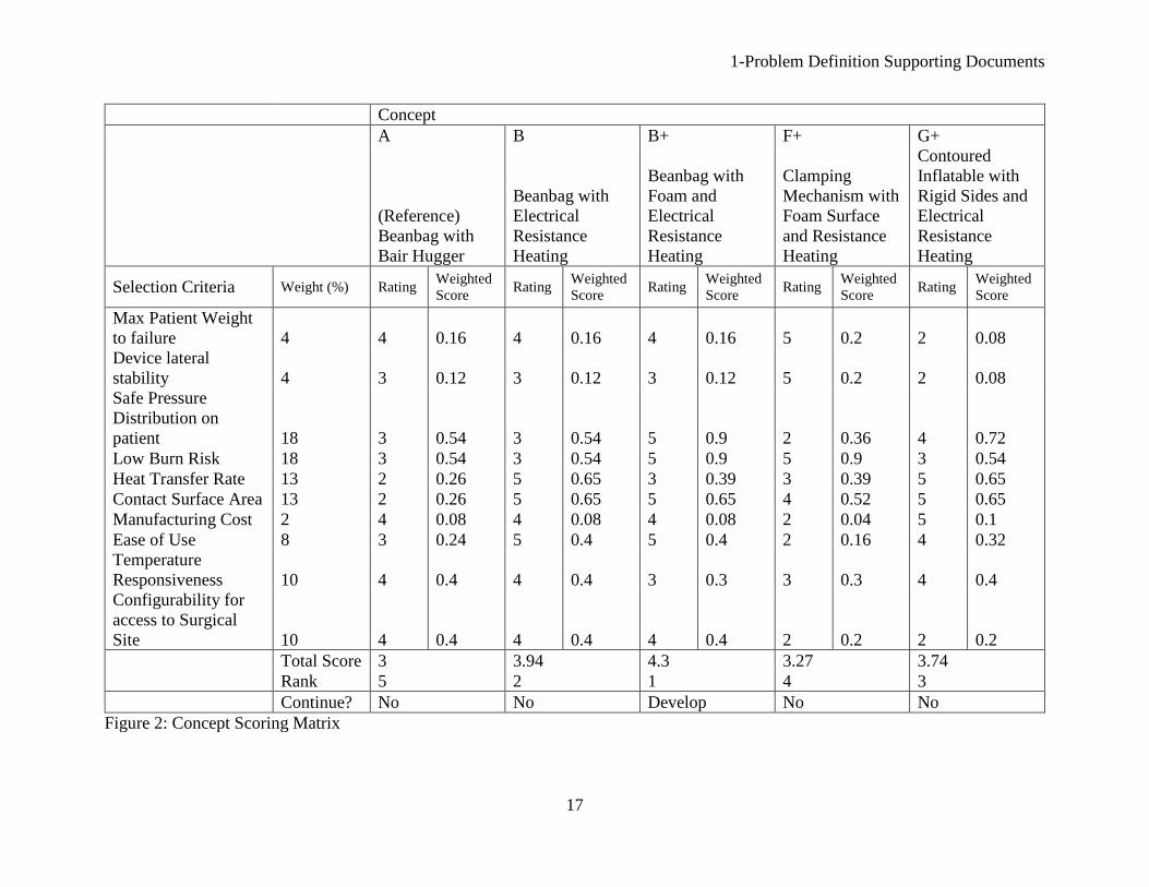
concepts. Figure 2 (appended) presents the concept scoring matrix.
After adjusting the weighting factors in the concept scoring matrix, the weighting factor
sensitivity was determined to be negligible: The beanbag with foam and electrical resistance
heating received the number one ranking each time, and no other concept came close to its total
score in the matrix. The clamping mechanism received the lowest non-reference ranking. An
uneven pressure distribution from the clamping force on either side of the patient and a relatively
difficult setup relegated this concept to its low ranking. The contoured inflatable device suffered
15
from a reduced overall lateral stability and maximum patient weight. Also, it was determined that
it would be difficult to design the device to both cover a large surface area and be configurable to
multiple different patients.
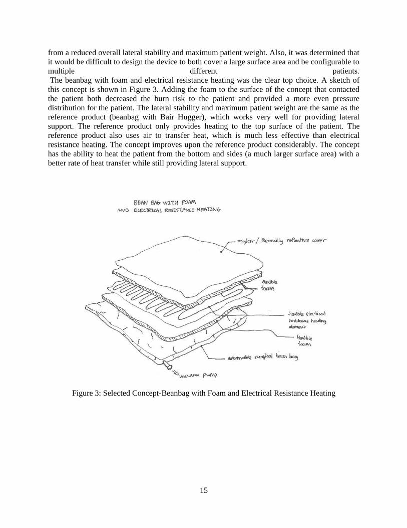
The beanbag with foam and electrical resistance heating was the clear top choice. A sketch of
this concept is shown in Figure 3. Adding the foam to the surface of the concept that contacted
the patient both decreased the burn risk to the patient and provided a more even pressure
distribution for the patient. The lateral stability and maximum patient weight are the same as the
reference product (beanbag with Bair Hugger), which works very well for providing lateral
support. The reference product only provides heating to the top surface of the patient. The
reference product also uses air to transfer heat, which is much less effective than electrical
resistance heating. The concept improves upon the reference product considerably. The concept
has the ability to heat the patient from the bottom and sides (a much larger surface area) with a
better rate of heat transfer while still providing lateral support.
Figure 3: Selected Concept-Beanbag with Foam and Electrical Resistance Heating
1-Problem Definition Supporting Documents
16
Concepts
Selection Criteria
A B C D E F G H I
Beanbag
with Bair
Hugger
Beanbag with
Electrical
Resistance
Heating
Beanbag
with
Water
Heating
Beanbag
with IR
Heating
Pad
Wedge
with
Water
Heating
Mechanical
Clamping
Mechanism
with
Electrical
Resistance
Heating
Contoured
Inflatable with
Electrical
Resistance
Heating
Foam Pad with
Electrical
Resistance
Heating and
Water
Reservoir Layer
Memory
Foam with
Electrical
Resistance
Heating
Max Patient Weight to failure 0 0 - 0 + ++ - - 0
Device lateral stability 0 0 0 0 + ++ - - -
Safe Pressure Distribution on
patient 0 0 0 0 0 -- + + +
Low Burn Risk 0 0 + - + 0 0 + 0
Heat Transfer Rate 0 ++ + ++ + ++ ++ + ++
Contact Surface Area 0 0 0 0 - -- 0 - -
Feedback Control 0 + + - + + + + +
Temperature Responsiveness 0 + - + - + + - +
Manufacturing Cost 0 0 0 -- 0 - + - -
Ease of Use 0 0 - 0 - - 0 - 0
Low Risk of Sterile Field
Contamination 0 + - + - + + - +
Configurability for access to
Surgical Site 0 0 0 0 - - - 0 0
Sum +'s 0 5 3 4 5 9 7 4 6
Sum 0's 12 8 5 6 2 1 3 1 4
Sum -'s 0 0 4 4 5 7 3 7 3
Net Score 0 5 -1 0 0 2 4 -3 3
Rank 5 1 6 5 5 4 3 7 2
Continue? Yes Yes, Revise No No No Revise Revise No No
Figure 1: Concept Selection Matrix
1-Problem Definition Supporting Documents
17
Concept
A B B+ F+ G+
(Reference)
Beanbag with
Bair Hugger
Beanbag with
Electrical
Resistance
Heating
Beanbag with
Foam and
Electrical
Resistance
Heating
Clamping
Mechanism with
Foam Surface
and Resistance
Heating
Contoured
Inflatable with
Rigid Sides and
Electrical
Resistance
Heating
Selection Criteria Weight (%) Rating Weighted
Score Rating
Weighted
Score Rating
Weighted
Score Rating
Weighted
Score Rating
Weighted
Score
Max Patient Weight
to failure 4 4 0.16 4 0.16 4 0.16 5 0.2 2 0.08
Device lateral
stability 4 3 0.12 3 0.12 3 0.12 5 0.2 2 0.08
Safe Pressure
Distribution on
patient 18 3 0.54 3 0.54 5 0.9 2 0.36 4 0.72
Low Burn Risk 18 3 0.54 3 0.54 5 0.9 5 0.9 3 0.54
Heat Transfer Rate 13 2 0.26 5 0.65 3 0.39 3 0.39 5 0.65
Contact Surface Area 13 2 0.26 5 0.65 5 0.65 4 0.52 5 0.65
Manufacturing Cost 2 4 0.08 4 0.08 4 0.08 2 0.04 5 0.1
Ease of Use 8 3 0.24 5 0.4 5 0.4 2 0.16 4 0.32
Temperature
Responsiveness 10 4 0.4 4 0.4 3 0.3 3 0.3 4 0.4
Configurability for
access to Surgical
Site 10 4 0.4 4 0.4 4 0.4 2 0.2 2 0.2
Total Score 3 3.94 4.3 3.27 3.74
Rank 5 2 1 4 3
Continue? No No Develop No No
Figure 2: Concept Scoring Matrix
2-Design Description Supporting Documents
18
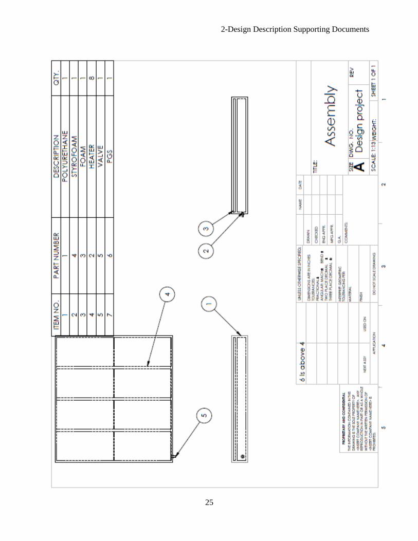
2.1 Manufacturing Plan
2.1.1 Manufacturing Overview
In manufacturing the device, polystyrene beads are inserted in a pocket in a urethane case to
form the beanbag. A valve is installed which will allow the air to be evacuated from the device.
A layer of flexible foam is mounted on top of the beanbag, with the electrical resistance heating
element on top of that. These layers are sealed inside the urethane case so the device is a single
unit. A disposable cover made from a thermoreflective material is manufactured separately.
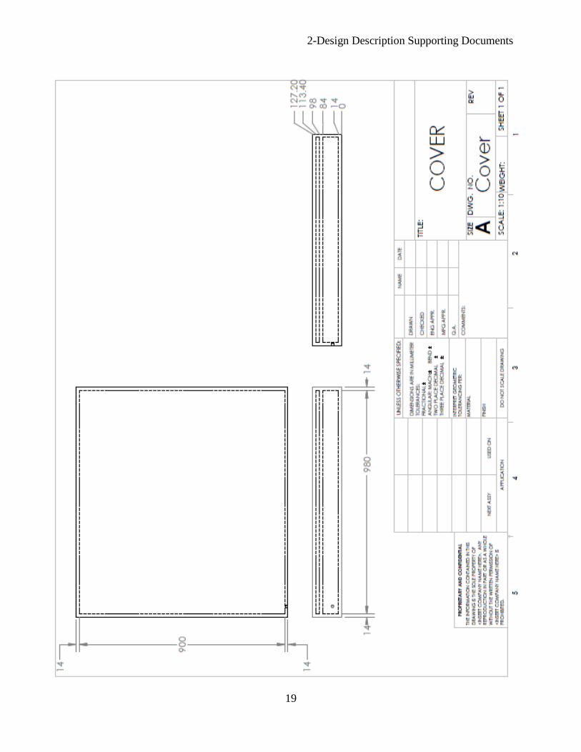
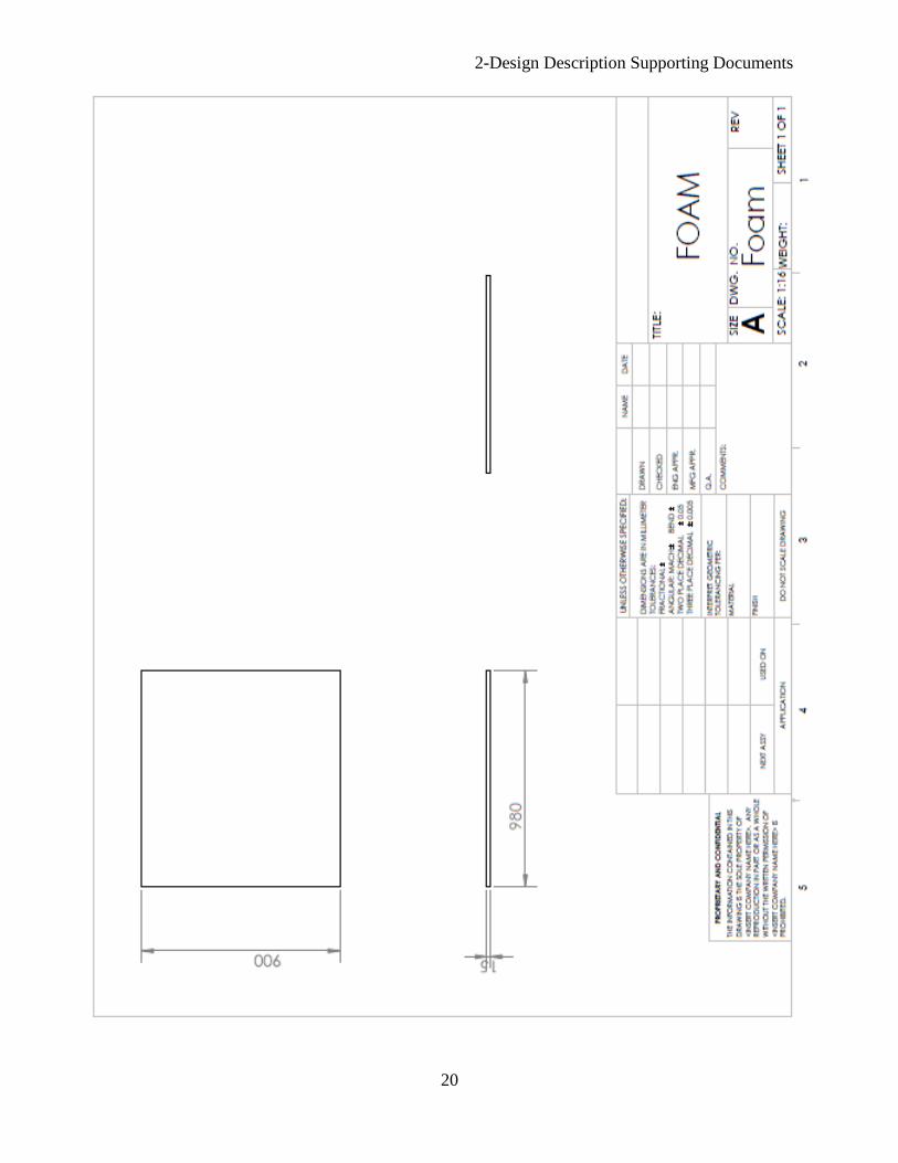
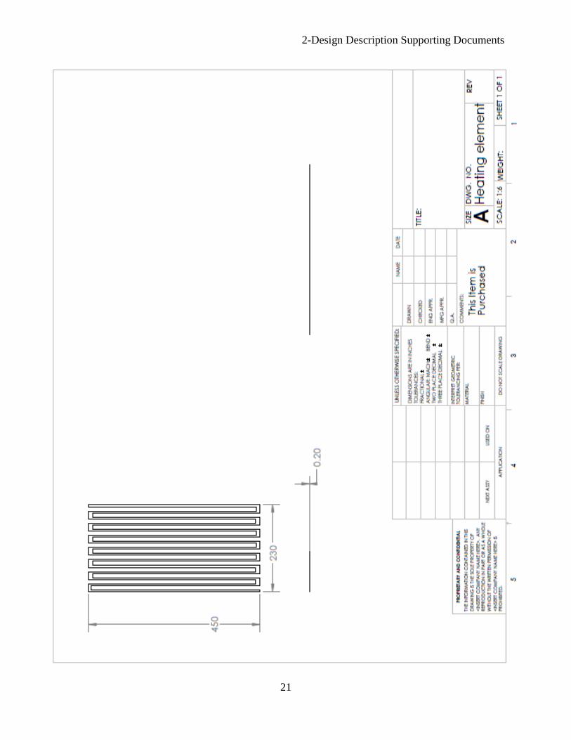
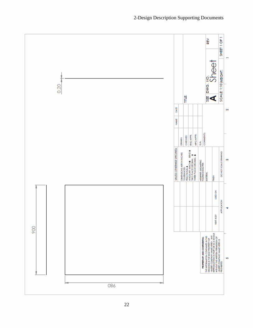
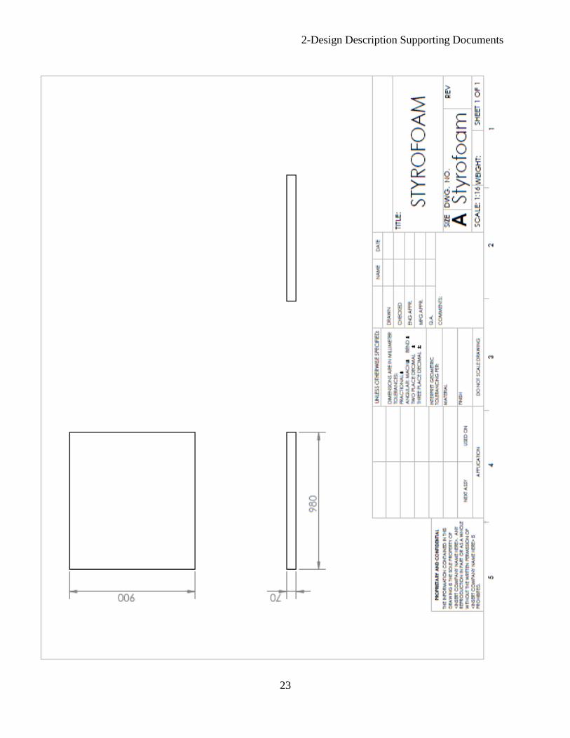
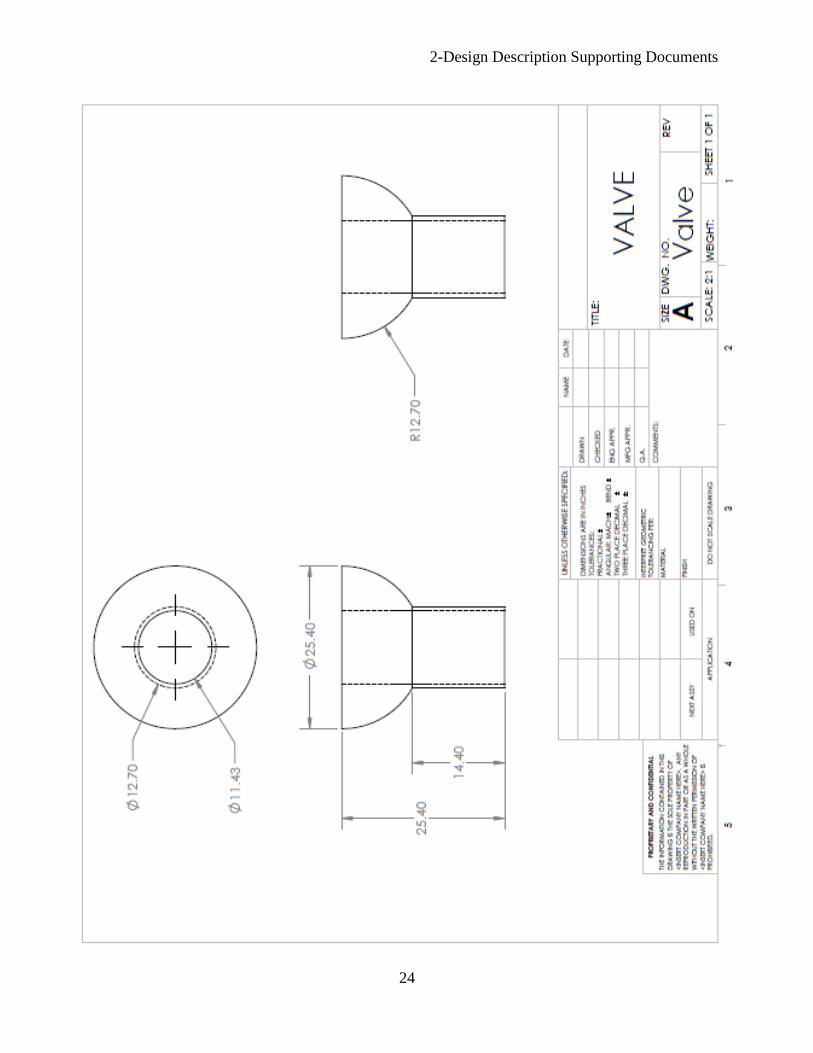
2.1.2 Part Drawings
Drawings of each part from a CAD model of the design are included in the following pages.
2-Design Description Supporting Documents
19
2-Design Description Supporting Documents
20
2-Design Description Supporting Documents
21
2-Design Description Supporting Documents
22
2-Design Description Supporting Documents
23
2-Design Description Supporting Documents
24
2-Design Description Supporting Documents
25
2-Design Description Supporting Documents
26
2.1.3 Bill of Materials
Table 2: Bill of Materials
Part Name Quantity Thickness
(mm)
Width
(mm)
Length
(mm) Manufacturer
Cost
($/Quantity)
Part
Number
Polyurethane 2 14 1008 928
Dongguan Tianyi
Film Material
Co., Ltd.
1.00 1
Electric
Heater 8 0.2 203.2 457.2 Omega 57.5 2
Foam Layer 1 15 980 900
Hangzhou
Xiaoshan
Huafeng Feather
& Down Products
Co. Ltd
10.56 3
Polystyrene 2 ft3 N/A N/A N/A
Bluesea Dream
LTD. 20 4
Vacuum
Valve 1 N/A N/A N/A
Shenzhen Homefun Plastic Co., Ltd. 0.50 5
Pyrolytic
Graphite
Sheet
1 0.2 980 900 Panasonic 174 6
Total Cost=$667.06
2.1.4 Manufacturing Procedure
As shown in figure 3, the final concept for the device will consist of a series of different layers,
superimposed on top of each other to meet the product design specifications. The final product
will be manufactured according to the procedure outlined below:
Spherical beads used in conventional beanbags are inserted into a urethane case which
will be manufactured to the design team’s geometrical specifications. This will form the
beanbag layer of the design team’s concept. The casing will be heat sealed on both the
shorter edges and one of the longer edges, leaving the 4th
edge open for inserting the
beads and vacuum pump valve. After the required amount of beads (according to the
calculated volume) has been inserted into the casing, a valve is inserted into the casing
with one end clearly protruding out of the bag. The valve will allow for a vacuum pump
to be connected to the beanbag. A sieve is installed on the end of the valve that will be
located within the beanbag in order to prevent the beads from being lodged in the valve.
The 4th
side of the urethane casing is then heat sealed.
15 mm thick Polyurethane foam is then inserted into the casing, resting on top of the
beanbag. Subsequently, the flexible resistive heating elements are placed on top of it
with the pyrolytic graphite layer on top of that. The electrical power wires of the flexible
resistive heating elements run through the foam layer and protrude adjacent to the
vacuum valve.
Once step the preceding step is completed, the main urethane casing is heat sealed. Both
the vacuum tube and electrical power wires should be protruding from the body of the
device.
3-Evaluation Supporting Documents
27
3.1 Evaluation Reports
Safe Temperature Distribution Report
Introduction
In order to determine the temperature profile of the heating elements used in the surface of
the device an experiment involving an infrared camera was set up. The camera took
temperature profile images of a representative 8” by 8” electrical resistance heater under
representative, but unloaded, conditions. This was compared to a small 2” by 2” heater of
the same type. Hot spots are areas of the heating element that are significantly above the
average temperature of the element. Hot spots are important to avoid because it is a critical
design requirement that this device be safe to use. Burn risk must be minimized.
Methods
The heater was set up in one of two conditions. Under condition one, each of the heaters was
set up like they would be in the device. A layer of foam was placed on the table, followed by
the heating element. On top of the heating element was the vinyl surface covering of the
device. Condition two involved placing a layer of aluminum foil between the heating
element and the vinyl to see how this affects the evenness of the surface temperature. A
thermal imaging IR camera was used to take a picture of each heater under conditions 1 and
2 for each voltage setting. The results were images of the temperature profile over a range of
settings. The results from each setup were compared for each voltage setting.
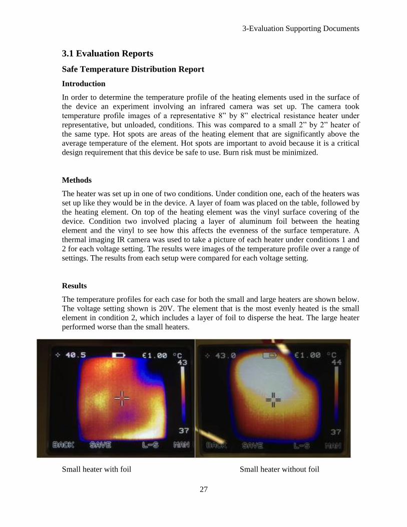
Results
The temperature profiles for each case for both the small and large heaters are shown below.
The voltage setting shown is 20V. The element that is the most evenly heated is the small
element in condition 2, which includes a layer of foil to disperse the heat. The large heater
performed worse than the small heaters.
Small heater with foil Small heater without foil
3-Evaluation Supporting Documents
28
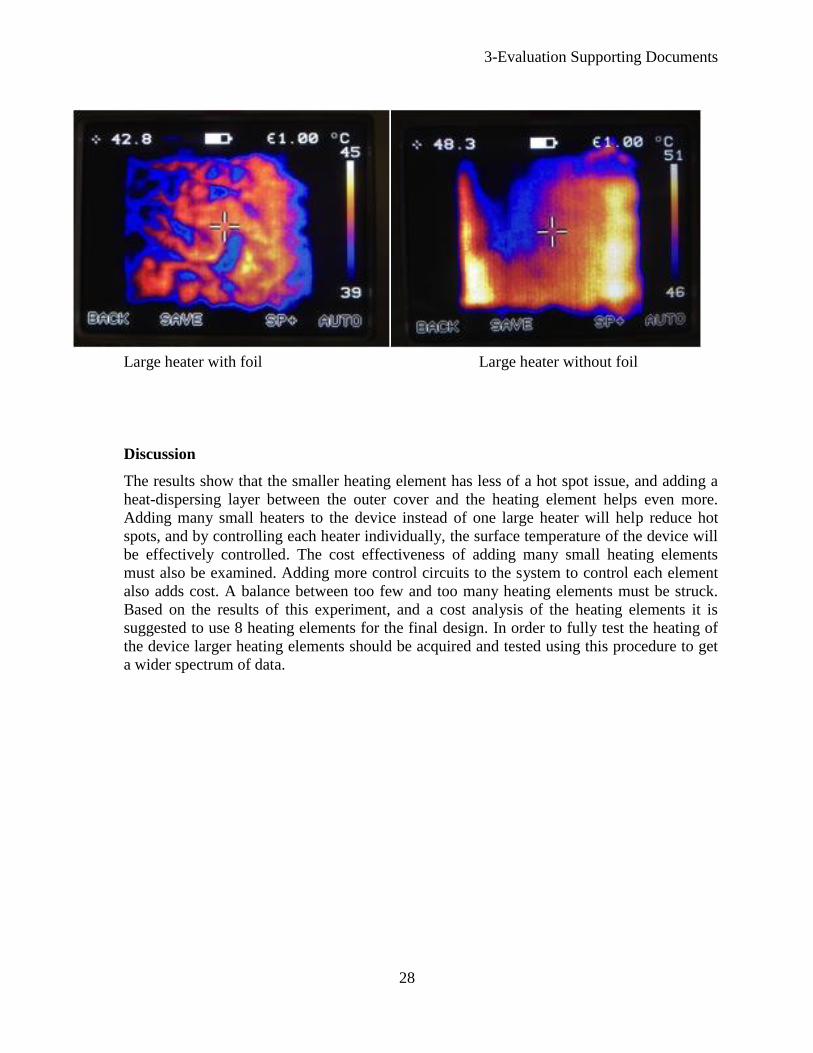
Large heater with foil Large heater without foil
Discussion
The results show that the smaller heating element has less of a hot spot issue, and adding a
heat-dispersing layer between the outer cover and the heating element helps even more.
Adding many small heaters to the device instead of one large heater will help reduce hot
spots, and by controlling each heater individually, the surface temperature of the device will
be effectively controlled. The cost effectiveness of adding many small heating elements
must also be examined. Adding more control circuits to the system to control each element
also adds cost. A balance between too few and too many heating elements must be struck.
Based on the results of this experiment, and a cost analysis of the heating elements it is
suggested to use 8 heating elements for the final design. In order to fully test the heating of
the device larger heating elements should be acquired and tested using this procedure to get
a wider spectrum of data.
3-Evaluation Supporting Documents
29
Effective Warming Report
Introduction
During surgery, a patient loses heat to the surrounding atmosphere thereby lowering their core
body temperature. Thus, it is necessary that a heating device provides enough energy to
overcome the amount of heat lost in order to warm and maintain a safe core body temperature.
This experiment was performed to test the effectiveness of the heating element by warming a bag
of water from ambient temperature to normal body temperature.
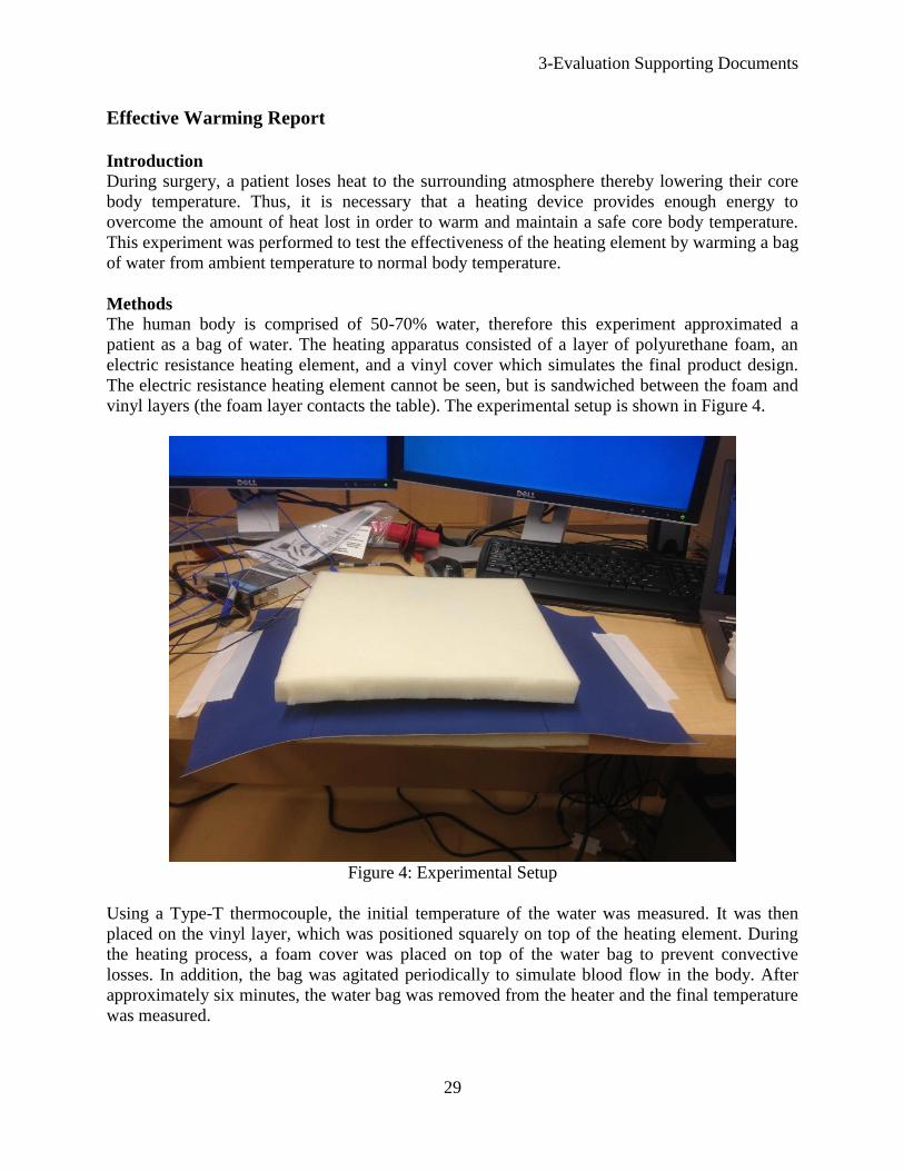
Methods
The human body is comprised of 50-70% water, therefore this experiment approximated a
patient as a bag of water. The heating apparatus consisted of a layer of polyurethane foam, an
electric resistance heating element, and a vinyl cover which simulates the final product design.
The electric resistance heating element cannot be seen, but is sandwiched between the foam and
vinyl layers (the foam layer contacts the table). The experimental setup is shown in Figure 4.
Figure 4: Experimental Setup
Using a Type-T thermocouple, the initial temperature of the water was measured. It was then
placed on the vinyl layer, which was positioned squarely on top of the heating element. During
the heating process, a foam cover was placed on top of the water bag to prevent convective
losses. In addition, the bag was agitated periodically to simulate blood flow in the body. After
approximately six minutes, the water bag was removed from the heater and the final temperature
was measured.
3-Evaluation Supporting Documents
30
In addition, theoretical values were found using the finite element analysis software, ANSYS.
Results
To determine the amount of heat that was gained by the water, the heat equation was used as
shown in Equation 1.
Equation 1
Where q is the energy gained or lost by the water, m is the mass of the water, C is the specific
heat of the water, is the change in temperature of the water, and t is the time of the overall
process.
The net amount of heat transferred into the bag was found. These results are shown in Table 3.
Table 3: Experimental Results
Quantity Value
0.355
4181
21.9
31.9
375
39.58
As shown in Table 3, the resulting heat into the water was 39.58 W. This value indicates that a
heating element will provide at least 39.58 W into the body.
Discussion The body produces approximately 86 W through metabolism. Using some basic heat transfer
equations, the losses due to radiation, convection, and natural convection were found to be
approximately 175 W. Note that the assumptions used to find this value are for the most extreme
cases, thus this value denotes the maximum possible losses. Therefore, the maximum amount of
input heat needed to counteract the heat loss is 89 W.
The amount of heated surface area is important for any heating device that is used on a patient.
Obviously the amount of heat provided by the heating element in this experiment is smaller than
the requirement. By using a larger heating element, and thus increasing the heated surface area,
there would be a larger heat input into the body. With a larger heater and the fact that the actual
required input heat would be smaller, it can be concluded that the design team’s device will
provide enough heat to warm a patient.
3-Evaluation Supporting Documents
31
ANSYS Report
Introduction
To determine the ideal temperature distribution of prototype ANSYS was used to model the
temperature profiles when in contact with convection and conduction heat sources. The models
represented ideal cases when using ANSYS. The free convection used for air, to simulate the
operating room environment, is a high end value because it will represent lower operating room
temperatures.
Methods
The model used in ANSYS represents the Water Experiment model used in the previous
evaluation. This model takes into account all the different material that will be used in the final
concept. The model is equivalent to the Water Experiment because the layers that are between
the heating element and the water are the same for both the ANSYS and Water Experiment. An
assumption was made that the only energy lose to the outside edge of the modal was due to air.
The free air convection was calculated using equation 2.
Equation 2
q is the heat transfer, A is the heat transfer area of the surface, hc is the heat transfer coefficient,
and ΔT is the temperature difference. The heat transfer was put into ANSYS to demonstrate the
heat loss due to air. The heating element is controlled by an expression that sets the amount of
energy inputted into the system based on a limiting temperature which was 42 Celsius. 40 watts
per volume of the heating element was put into the system, this was determined using equation 3.
Equation 3
P is the power , V is the voltage , and R is the resistance of the heating element. The first test
was conducted with a starting temperature for water of 34 Celsius. The 34 Celsius is picked
because this is a very low human body temperature. This analysis is done to show the amount of
time required to reach normal body temperature, 37 Celsius. The next test was done to see how
what temperature the water will arrive at after 200 seconds. 200 seconds is a limiting factor
because ANSYS could not solve for longer time periods. This test was compared to the actual
data for water experiment to see the difference between ideal and experimental values.
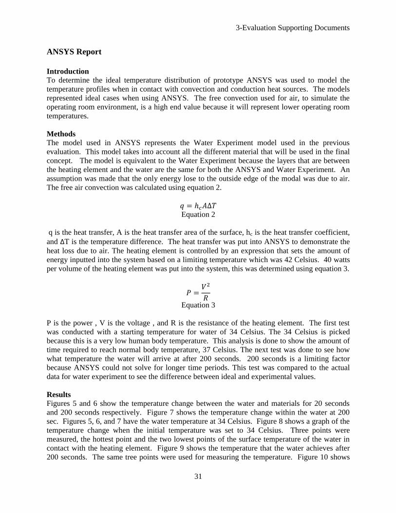
Results
Figures 5 and 6 show the temperature change between the water and materials for 20 seconds
and 200 seconds respectively. Figure 7 shows the temperature change within the water at 200
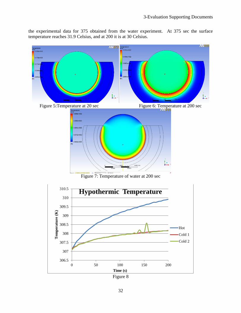
sec. Figures 5, 6, and 7 have the water temperature at 34 Celsius. Figure 8 shows a graph of the
temperature change when the initial temperature was set to 34 Celsius. Three points were
measured, the hottest point and the two lowest points of the surface temperature of the water in
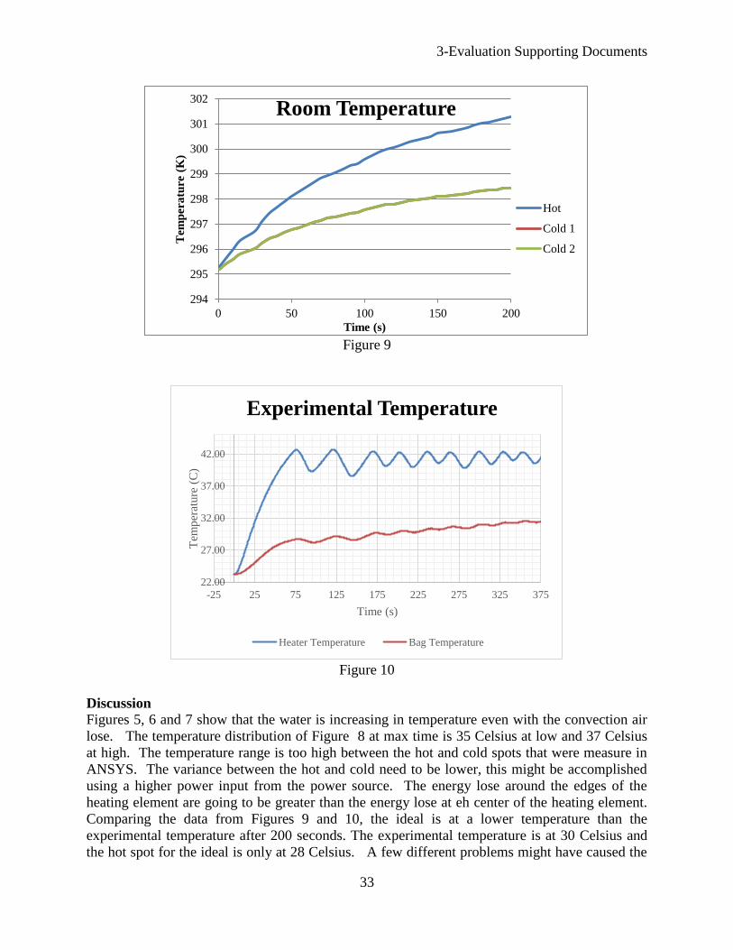
contact with the heating element. Figure 9 shows the temperature that the water achieves after
200 seconds. The same tree points were used for measuring the temperature. Figure 10 shows
3-Evaluation Supporting Documents
32
the experimental data for 375 obtained from the water experiment. At 375 sec the surface
temperature reaches 31.9 Celsius, and at 200 it is at 30 Celsius.
Figure 5:Temperature at 20 sec Figure 6: Temperature at 200 sec
Figure 7: Temperature of water at 200 sec
Figure 8
306.5
307
307.5
308
308.5
309
309.5
310
310.5
0 50 100 150 200
Tem
per
atu
re (
K)
Time (s)
Hypothermic Temperature
Hot
Cold 1
Cold 2
3-Evaluation Supporting Documents
33
Figure 9
Figure 10
Discussion
Figures 5, 6 and 7 show that the water is increasing in temperature even with the convection air
lose. The temperature distribution of Figure 8 at max time is 35 Celsius at low and 37 Celsius
at high. The temperature range is too high between the hot and cold spots that were measure in
ANSYS. The variance between the hot and cold need to be lower, this might be accomplished
using a higher power input from the power source. The energy lose around the edges of the
heating element are going to be greater than the energy lose at eh center of the heating element.
Comparing the data from Figures 9 and 10, the ideal is at a lower temperature than the
experimental temperature after 200 seconds. The experimental temperature is at 30 Celsius and
the hot spot for the ideal is only at 28 Celsius. A few different problems might have caused the
294
295
296
297
298
299
300
301
302
0 50 100 150 200
Tem
per
atu
re (
K)
Time (s)
Room Temperature
Hot
Cold 1
Cold 2
22.00
27.00
32.00
37.00
42.00
-25 25 75 125 175 225 275 325 375
Tem
per
ature
(C
)
Time (s)
Experimental Temperature
Heater Temperature Bag Temperature
3-Evaluation Supporting Documents
34
difference between the two experiments. The power used for ANSYS is an ideal model where
the experimental data might have been had greater variances of power input over time. The
energy lose comes from the convection with air and conduction of the fluid and materials inside
the system, the ANSYS model might have had large values for convection and conduction heat
loss. The set up for the ANSYS model might not have been created correctly. More analysis
and data needs to be done before determining that the ANSYS simulation was faulty.
Effective Positioning Report
Introduction
A standard surgical beanbag consists of polystyrene beads covered by a thin layer of vinyl or
urethane. Adding a layer of memory foam on top of a standard beanbag might affect its overall
stability. If adding a layer of foam increases the lateral deflection of a folded beanbag subjected
to an external force, the current heating and positioning design will be unusable. To test the
lateral stability of the current design relative to a surgical beanbag, a torque versus lateral
deflection curve will be created for each. If the deflection of the current design is within 2cm of
the deflection of a surgical beanbag subjected to the same loading, the device will be deemed
effective at positioning. 2cm was selected as a conservative estimate above which a device
would start to become unstable.
Methods
The positioning effectiveness test was conducted using a single surgical beanbag and a 2.5cm
memory-foam layer. For the test of the surgical beanbag, a person was wrapped in the beanbag in
the supine position. Next, air was removed from the beanbag, making it rigid. A rope was then
wrapped around side of the beanbag, forming a loop. The rope was placed 152mm above the
base of the beanbag. A force transducer was then attached to the rope, and a smart phone was
placed on top of the beanbag to measure angular deflection using an application. Figure 11
shows the general test setup, with the force transducer out of the frame on the right side. A
tensile force up to 90N was applied to the rope, in 10N increments, and the angular deflection
was recorded at each increment.
Figure 11:Test Setup
3-Evaluation Supporting Documents
35
The same procedure was repeated with the memory foam layer placed on top of the surgical
beanbag. The force transducer measurements were converted to a torque on the beanbag using
Eq. 4.
Equation 4
is the force applied to the beanbag via the rope, measured by the force transducer; is the
lever arm, the distance from the beanbag base to the point of application of the force at the rope;
and is the torque on the beanbag. The lateral deflection of the beanbag was calculated using Eq.
5.
Equation 5
is the lateral deflection, is the height from the base to the top of the beanbag, and is the
displacement angle measured by the smart phone. Using the results from Eqs. 4 and 5, a torque
versus displacement plot was produced.
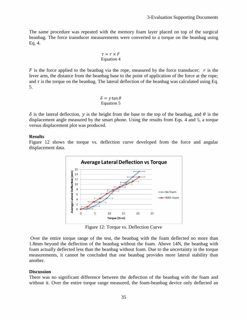
Results
Figure 12 shows the torque vs. deflection curve developed from the force and angular
displacement data.
Figure 12: Torque vs. Deflection Curve
Over the entire torque range of the test, the beanbag with the foam deflected no more than
1.8mm beyond the deflection of the beanbag without the foam. Above 14N, the beanbag with
foam actually deflected less than the beanbag without foam. Due to the uncertainty in the torque
measurements, it cannot be concluded that one beanbag provides more lateral stability than
another.
Discussion
There was no significant difference between the deflection of the beanbag with the foam and
without it. Over the entire torque range measured, the foam-beanbag device only deflected an
3-Evaluation Supporting Documents
36
additional 1.8mm past the deflection of the beanbag without foam. Once uncertainty is factored
in, this difference is even more negligible. The only significant uncertainty in the measurement
arose from the person applying a load to the side of the beanbag. It proved very difficult to
manually apply a discrete load (10N, 20N, etc.) to the beanbag. At each applied force, the force-
transducer readout varied ±2N from the discrete load desired. If repeating the test in the future, a
mechanical device with a load cell would be constructed to apply the known load. Nonetheless,
the measured data showed that there is no significant difference in the lateral deflection between
the two devices. As a result, the foam-beanbag device is as effective at positioning as the
beanbag without foam.
Ease of Use Report
Introduction
One of the design requirements is that be easy for healthcare professionals to use; hence the
concept was designed to be user-friendly and intuitive. However, the measure of the concept’s
ease of use is subjective as it varies from person to person and was evaluated qualitatively.
Methods
Using a prototype to demonstrate how the concept would be used as well as explaining its key
differences when compared to existing beanbag and heating technologies, the design team asked
a small panel of doctors to rate the concept on a scale of 1-5 to obtain feedback on its ease of use
relative to the standard practice of using a beanbag in conjunction with a Bair Hugger.
Results
From the surveys, the panel unanimously agreed that the concept was no harder to use when
compared to the existing Bair Hugger and surgical beanbag technologies, as no major structural
changes were implemented. On a scale of 1-5 (3 being comparable to the standard beanbag and
Bair Hugger,1 being much worse and 5 being much better), the concept averaged a 3.25 in terms
of ease of use. This score corresponded to the concept being generally as easy to use as the Bair
Hugger and beanbag combination.
Discussion
The results indicate that the concept is as easy to use as the existing Bair Hugger and surgical
beanbag technologies with no immediately obvious difficulties observed by the panel of
healthcare professionals. The evaluation also provided insight for the design team for possible
future work. For example, one of the panel members commented that “it was difficult to displace
the Bair Hugger as it is cheap and versatile.” Future work could possibly involve finding cheaper
materials to address this issue while still being able to compete with the Bair Hugger and
beanbag in terms of warming and positioning capabilities.
3-Evaluation Supporting Documents
37
3.2 Cost Analysis
The total cost of the materials/components necessary to make the design is $667.06 (see the Bill
of Materials in section 2.1.3 of this document). In estimating the manufacturing cost an
assumption is being made that the fixed cost of purchasing the manufacturing equipment does
not contribute significantly to the cost per beanbag due to the fact that a very large number of
beanbags could be produced without need to replace the equipment. With labor and maintenance
of the machines, the estimated manufacturing cost is $20 per beanbag. The total cost to produce
one beanbag according to our design is $687.06 including material and production costs. It
should be noted that the heating elements are listed as being purchased at retail price. A contract
for a bulk supply of heating elements would likely reduce the cost. In the future it may be wise to
consider manufacturing the heating elements as well, instead of purchasing them.
There are approximately 45 million surgeries performed under general anesthesia in the US each
year. If 20% of these (9 million surgeries) use a beanbag for positioning, and a beanbag can be
used for approximately 1000 procedures before needing to be replaced, 9,000 devices could be
sold each year. Furthermore, a disposable component will need to be purchased each time the
beanbag is used. It is reasonable for this to be priced similarly to the gown for the Bair Hugger at
approximately $50. If used for 9 million surgeries each year this would generate $450 million of
revenue.
This device would appeal to hospitals because it saves valuable time of surgical staff. It is not
uncommon for up to three people to be needed in the OR just to keep the patient warm. A device
that warms the patient with very little effort from surgical staff would reduce or eliminate the
need for extra personnel in the operating room which is expensive for the hospital. Additionally,
patients are not discharged from the Post-Anesthesia Care Unit (PACU) unless they are at
normal body temperature. If the PACU is full, patients cannot be moved there from the operating
rooms which in turn cannot be used for another procedure. If patients do not need to be warmed
up after surgery the hospital system runs more efficiently, allowing for more procedures to be
performed. Every additional procedure performed means thousands of dollars in revenue for the
hospital.
3-Evaluation Supporting Documents
38
3.3 Environmental Impact Statement
As stated in the problem scope, there is an existing need to simultaneously both effectively
position and keep a patient warm during surgery. The design team’s concept will greatly improve
the patient experience during surgical procedures as it caters to both these needs.
Due to the clean environment required during surgery the concept will be designed with a
disposable component that will be used to line the upper surface of the concept as well as wrap
around the patient. The disposable component is made out of both high-density-polyethylene
(HDPE) and Mylar, a thermally reflective material which functions as a means of passive
warming for the patient. After a surgical procedure has been completed, the disposable lining can
be discarded easily thus increasing efficiency and improving operating room turnaround times
while still maintaining the necessary clean levels. Although this creates a viable business model
as the sale of the disposable lining to clients would provide a flow of steady revenue, both HDPE
and Mylar are not biodegradable and could potentially pollute the environment. Even though
both these materials are recyclable, safety and cleanliness standards required in operating
theatres require that all materials which have been contaminated with bodily fluids be labeled as
a biohazard and subsequently, sent for incineration.
In terms of the manufacturing process and logistics for transporting the product, there are no
outstanding, major environmental concerns involved with the design team’s concept. The final
concept (excluding the disposable lining) consists of base materials such as polyurethane foam
and surgical grade polyurethane which can be easily recycled at the end of the product’s life.
There are two alternatives considered in order to create a more environmentally friendly design:
1) Replacing the Mylar component with a biodegradable, thermal insulator. There are
existing cellulosic based thermal insulators which are biodegradable and can be used to
replace the Mylar lining [2]. The HDPE layer can also be substituted with existing
biodegradable plastics with similar properties.
2) Completely eliminating the use of Mylar from the design. If (1) is an unviable option, the
used of Mylar in the design can be completely eliminated to produce a more
environmentally friendly design.
With the proposed alternatives, additional cost and tradeoffs should be taken into account. For
alternative (1), although the cellulosic based thermal insulator is biodegradable, it lacks the
thermally reflective properties of Mylar. This results in it being slightly less effective at
providing passive warming for the patient. Similarly, alternative number (2) which has no Mylar
lining at all will result in a greater inability to keep the patient warm. Also, due to the lack of a
disposable lining, the design will have to be decontaminated with strong chemical agents in order
to refit it for further use in the operating room. However, the design will be no worse than the
Bair Hugger (which also has a disposable component) in terms of environmental impact.
It should be noted that with the use of Mylar, the required heat input from the electrical
resistance heaters will be significantly less after achieving steady state. This indirectly reduces
electrical power consumption and throughout the concept’s life cycle would reduce the
environmental impact of the concept.
3-Evaluation Supporting Documents
39
The design could be improved further in future by designing a biodegradable thermal insulator
which is also capable of reflecting heat back to the patient. This would enable the
implementation of alternative 1) without having to compromise on patient comfort.
3.4 Regulatory and Safety Considerations
There are a few regulations found in 21 Code of Federal Regulations which apply to the device.
First, the device must be registered electronically with the FDA on an annual basis. Additionally,
the device must be listed with the FDA. This listing must include items like the name of all
manufacturers, specification developers, and device distributors. On the device itself, all labels
must adhere to FDA labeling requirements. If the device should ever injure someone, a report
must be filed with the FDA. [3].
The main safety concern for the device is burning the patient. If the surface temperature of the
beanbag exceeds 42°C, there is a burn risk to the patient. This risk is mitigated by incorporating
both a fuse and control system. The fuse trips the heater circuit if excessive current is detected.
This would shut off all electrical resistance heaters in the device until the system was reset. The
control system continually polls all device thermocouples and shuts off any area of the device at
or above 42°C. With both the fuse and control system in place, it is very unlikely the device
would burn a patient.
A secondary concern is pressure points on the beanbag. Folding a beanbag creates multiple
ridges along the beanbag surface which could act as pressure points on a patient. To reduce this
risk, a foam layer was added to more evenly distribute pressure from the beanbag to the patient.
The foam also protects the resistance heaters from the same ridges. Visual inspection of a folded
beanbag with and without the foam confirmed that adding the foam significantly increased the
radius of curvature of each ridge. With an increased radius of curvature, pressure is more evenly
distributed. Because of this, there is little risk that the beanbag will create pressure points on a
patient or damage the heaters.
40
References
[1] B. R. Kingma, “Human Thermoregulation - A synergy between physiology and
mathematical modelling,” Ph.D. dissertation, Dept. Human Bio., Maastricht Univ., Maastricht,
Netherlands, 2011.
[2] V. Yachmenev, D, Parikh and T. Calamari Jr, “Thermal Insulation Properties of
Biodegradable, Cellulosic-Based Nonwoven Composites for Automotive Applications”, Journal
of Industrial Textiles, 2002.
[3] U. S. Department of Health & Human Services, “Overview of Device Regulation.”
[Online]. Available:
http://www.fda.gov/MedicalDevices/DeviceRegulationandGuidance/Overview/default.htm.
[Accessed: 30-Apr-2013].

![Neonatal Thermoregulation - University of · PDF fileNeonatal Thermoregulation Julia Petty. ... A care study. Journal of Neonatal Nursing. ... 5 Thermoregulation [Compatibility Mode]](https://cdn.vdocuments.us/doc/165x107/5aafe83f7f8b9a6b308de3c0/neonatal-thermoregulation-university-of-thermoregulation-julia-petty-a-care.jpg)


