
P o l a r i z e r s

I N D E XP o l a r i z e r s
Po
larizing
Be
amsp
litters
Plate-type Polarizing Beamsplitters
PBS-CB074
Wave
plate
s
Broadband Quartz Waveplates
WPQWB084
B082
B092
Air Gap Type Waveplates
WPQGB086
Quartz Waveplates
WPQB087
Quartz Depolarizers
DEQB089
Mica Waveplates
WPMB090
Fresnel Rhomb Waveplates
FRBB091
High Power Polarizing Beamsplitters
PBSHPB076
Broadband Polarizing Beamsplitters
PBSWB077
Polarizing Beamsplitters
PBSB079
Polarizers Selection Guide B073
Po
larizers
Glan Thompson Prisms
GTPB/GTPCB094
Sheet Polarizers
SPF/NSPFU/SPFNB099
Wire grid polarizing filter
WGPFB100
Polarcor Polarizers
PLCB101
Plastic polarizer
USPB102
Glan Laser Prisms
GLPB/GLPCB095
Glan Tayler Prisms
GYPB/GYPCB096
Wollaston Prisms
WPPB/WPPCB097
Roshon polarizing Prism
RSPCQ/RSPMFB098
Z-polarizer
Custom-madeB103
Contact sheet for polarization beamsplitter B081
Application Note
Application Note

B073W�� http://www.sigma-koki.com/english/ E-mail [email protected] TEL +81-3-5638-8228 FAX +81-3-5638-6550
P��������Beamsplitters
Waveplates
Polarizers
Application Systems
Optics & Optical Coatings
Holders
Bases
Manual Stages
Actuators
Motoeized Stages
Light Sources
Index
Guide
Mirrors
Beamsplitters
Polarizers
L���
Multi-Element Optics
Filters
Prisms
Substrates/Windows
Optical Data
Maintenance
Selection Guide
��������� ��������� �����
Human eyes have no ability to perceive the polarization of light. Also, the most of the optical detectors
A typical applications for polarized light
λ w
λ w
λ w
λ w
λ w
T��� ! " #$%&'�%( T��� ! )$*��#$+�( "% ,-.+( /�$+-%�( 0..-%$.� 0��#&.$+& 1
Plastic Sheet Polarizers(USP)
2345Low cost, Lightweight Inferior
Variable adjustment of laser intensity
Mica Waveplates(WPM)
2464
Substitute use as optical retarderSubstitute use as phase sensitive color plate (visually intensify the retardance distribution)
Observation of stress (birefrin-gence) distribution
Polarizing Beamsplitters
(PBS)2476
Combine or separate the polarized beam
A simple polarization experimental setup, Polarizing optical systems (Variable attenuator, Polarization interferometer, Optical isolator)
Visible Sheet Polarizers(SPF)
2466
Provide stationary linear polarization light in visible region
Quartz Waveplates(WPQ)
2487
Provide exact optical retarda-tion for each wavelength of laser
Glan Thompson Prisms(GTPC)
2469
Provide linearly polarized light with excellent extinction ratio in visible region
Polarization measurements (Extinction ratio, Optical retarda-tion)
Fresnel Rhombs Retarders(FRB)
2463
Provide stationary optical retardation in a broad wave-length range.
Superior

B074
Opt ics & Opt ica l Coat ings
S:;<=>� ?@=A
Waveplates
Polarizers
Application Systems
Optics & Optical Coatings
Holders
Bases
Manual Stages
Actuators
Motoeized Stages
Light Sources
Index
Guide
Mirrors
Beamsplitters
Polarizers
L���
Multi-Element Optics
Filters
Prisms
Substrates/Windows
Optical Data
Maintenance
Polarizing Beamsplitter
����B�CD� ��������E F��G�D������� PBS-C
Hat Brewster�s angle.
●The losses of input beam of these products are minimized because of no absorption of dielectric coating.
●
IJKMNOMQRN RUJKVXYXZ[ \NK]^RJXMMNV^ KVN UZN U_ RJKMN M`KM X^ aUKMNb cXM` RUJKVXYXZ[ aUKMXZ[d
▶Please contact our International Sales Division for customized products.
(Customized on size, wavelength,extinction ratio etc.)
▶If the surface accuracy is required after coating, please contact our
International Sales Divison.
▶before coating.
▶Be sure to wear laser safety goggles when checking optical path and
adjusting optical axis.
▶Rear surface is no coating.
efghi
jkkilkgml
Schematic
Outline Drawing
n$+�%&$# opqr s�1+t�+&. !-(�, (&#&.$λ/10
Extinction ratio of transmission Ts : Tp = 1 : 200
Beam Deviation <5″
CoatingFront surface: Dielectric multi-layer polarization coatingRear surface: No coating
Surfac
Clear aperture 90% of the diameter
(in mm)
"$%+ NumberWavelength
Range[nm]
DiameterφD[mm]
Maximum diameter of transmitted beam
[mm]Material
Incident angle[ ° ]
Transmittance of P polarized light
[%]S polarized light
[%]
Laser Damage Threshold*
[J/cm2]
PBS-20C03-10-266 266 φ20 φ10.0 Synthetic fused silica 56.3 >92 >95 2
PBS-25.4C03-10-266 266 φ25.4 φ12.7 Synthetic fused silica 56.3 >92 >95 2
PBS-30C03-10-266 266 φ30 φ15.0 Synthetic fused silica 56.3 >92 >95 2
PBS-20C03-10-355 355 φ20 φ10.1 Synthetic fused silica 55.9 >94 >95 2
PBS-25.4C03-10-355 355 φ25.4 φ13.1 Synthetic fused silica 55.9 >94 >95 2
PBS-30C03-10-355 355 φ30 φ15.7 Synthetic fused silica 55.9 >94 >95 2
PBS-20C03-10-532 532 φ20 φ9.9 BK7 56.6 >95 >98 5
PBS-25.4C03-10-532 532 φ25.4 φ12.9 BK7 56.6 >95 >98 5
PBS-30C03-10-532 532 φ30 φ15.4 BK7 56.6 >95 >98 5
PBS-20C03-10-1064 1064 φ20 φ10.0 BK7 56.4 >96 >98 7
PBS-25.4C03-10-1064 1064 φ25.4 φ12.9 BK7 56.4 >96 >98 7
PBS-30C03-10-1064 1064 φ30 φ15.5 BK7 56.4 >96 >98 7
φ
u v1.&,�1+ $1w#�xyr z$(�% �-#(� {&,+t |x1(r %���+&+& 1 !%�}-�1.� ~x�'
�ToleranceDiameter φD+0

B075W�� http://www.sigma-koki.com/english/ E-mail [email protected] TEL +81-3-5638-8228 FAX +81-3-5638-6550
S:;<=>� ?@=A
Waveplates
Polarizers
Application Systems
Optics & Optical Coatings
Holders
Bases
Manual Stages
Actuators
Motoeized Stages
Light Sources
Index
Guide
Mirrors
Beamsplitters
Polarizers
L���
Multi-Element Optics
Filters
Prisms
Substrates/Windows
Optical Data
Maintenance
Polarizing Beamsplitter
�����CatalogCode
���g��� ���l��gkk�l�i ��k� T: Transmission
λ
λ
λ
λ
Compatible Optic Mounts
�������� � �������� � ��������

B076
Opt ics & Opt ica l Coat ings
S:;<=>� ?@=A
Waveplates
Polarizers
Application Systems
Optics & Optical Coatings
Holders
Bases
Manual Stages
Actuators
Motoeized Stages
Light Sources
Index
Guide
Mirrors
Beamsplitters
Polarizers
L���
Multi-Element Optics
Filters
Prisms
Substrates/Windows
Optical Data
Maintenance
Polarizing Beamsplitter
"$%+ NumberWavelength Range
[nm]A=B=C[mm]
Material S polarized light[%]
Laser Damage Threshold*[J/cm2]
PBSHP-10-3550 355 10 Synthetic fused silica >97 2
PBSHP-12.7-3550 355 12.7 Synthetic fused silica >97 2
PBSHP-15-3550 355 15 Synthetic fused silica >97 2
PBSHP-20-3550 355 20 Synthetic fused silica >97 2
PBSHP-10-5320 532 10 BK7 >97 5
PBSHP-12.7-5320 532 12.7 BK7 >97 5
PBSHP-15-5320 532 15 BK7 >97 5
PBSHP-20-5320 532 20 BK7 >97 5
PBSHP-10-10640 1064 10 BK7 >97 7
PBSHP-12.7-10640 1064 12.7 BK7 >97 7
PBSHP-15-10640 1064 15 BK7 >97 7
PBSHP-20-10640 1064 20 BK7 >97 7
High Power Polarizing Beamsplitters PBSHP �����CatalogCode
HPolarizing beamsplitters split monochromatic beam entering at zero degrees into p-polarization as transmitted and
●●The losses of input beam of these products are minimized because of no absorption of dielectric coating.
●For cube beamsplitters, unlike plate beamsplitters, beam deviations of transmitted beams and ghosts rarely occur.
�X[` IUcNV IUJKVXYXZ[ �NK]^RJXMMNV^ `K�N ]UVN JK^NV b�VK\XJXMQ aU]RKVNb MU U�V ^MKZbKVbPolarizing Beamsplitters (PBS). Polarizing beamsplitters consist of two right angle prisms.One of them is coated with dielectric multi-layer polarizing coating on the hypotenuse surface.
▶Please contact our International Sales Division for customized products.
(Customized on size, wavelength etc.)
▶There is also a high extinction ratio Glan-Thompson prism (GTPB/
GTPC). �� ¡
▶Input beam from the prism on the side indicated by ○. When the light
is incident from the side of the prism without mark, there is a possibility
that the characteristics of the transmittance and extinction ratio
changes.
▶before coating.
▶Be sure to wear laser safety goggles when checking optical path and
adjusting optical axis.
efghi
jkkilkgml
Schematic
Outline Drawing
n$+�%&$# opqr s�1+t�+&. !-(�, (&#&.$λ/4
Angular deviation of transmitted beam <10′
CoatingHypotenuse Surface: Dielectric multi-layer polarizing coating
Incident angle 0°
transmittance of P polarized light >97%
Extinction ratio of transmission Ts : Tp = 1 : 200
Surfac
Clear apertureCircle inscribed in a square of 85% of the dimensions
●ToleranceLength A・B±0.2Height C±0.1
(in mm)
���g��� ���l��gkk�l�i ��k� T: Transmission
λ λλ
◯
u v1.&,�1+ $1w#� xyr #$(�% �-#(� {&,+t |x1(r %���+&+& 1 !%�}-�1.� ~x�'
Compatible Optic Mounts
�¢����£ �¡� � ¤¥¥�����¦O, -40PHRO / MHG12.7PAD + MHG-MP30-NL / MHG-20PAD + MHG-MP30-NL

B077W�� http://www.sigma-koki.com/english/ E-mail [email protected] TEL +81-3-5638-8228 FAX +81-3-5638-6550
S:;<=>� ?@=A
Waveplates
Polarizers
Application Systems
Optics & Optical Coatings
Holders
Bases
Manual Stages
Actuators
Motoeized Stages
Light Sources
Index
Guide
Mirrors
Beamsplitters
Polarizers
L���
Multi-Element Optics
Filters
Prisms
Substrates/Windows
Optical Data
Maintenance
Polarizing Beamsplitter
"$%+ NumberWavelength Range
[nm]A=B=C[mm]
MaterialTransmittance ofP polarized light
[%]S polarized light
[%]
Extinction ratio of transmission*
Ts : Tp
PBSW-10-250 10 Synthetic fused silica >85 >90 1:100
PBSW-12.7-250 12.7 Synthetic fused silica >85 >90 1:100
PBSW-15-250 15 Synthetic fused silica >85 >90 1:100
PBSW-20-250 20 Synthetic fused silica >85 >90 1:100
PBSW-10-350 10 Synthetic fused silica >85 >95 1:100
PBSW-12.7-350 12.7 Synthetic fused silica >85 >95 1:100
PBSW-15-350 15 Synthetic fused silica >85 >95 1:100
PBSW-20-350 20 Synthetic fused silica >85 >95 1:100
PBSW-10-550 10 BK7 >85 > Average 85 1:200
PBSW-12.7-550 12.7 BK7 >85 > Average 85 1:200
PBSW-15-550 15 BK7 >85 > Average 85 1:200
PBSW-20-550 20 BK7 >85 > Average 85 1:200
PBSW-10-800 10 BK7 >92 >97 1:200
PBSW-12.7-800 12.7 BK7 >92 >97 1:200
PBSW-15-800 15 BK7 >92 >97 1:200
PBSW-20-800 20 BK7 >92 >97 1:200
PBSW-10-3/7 10 SK2 > Average 92 > Average 95 1:500*
PBSW-12.7-3/7 12.7 SK2 > Average 92 > Average 95 1:500*
PBSW-15-3/7 15 SK2 > Average 92 > Average 95 1:500*
PBSW-20-3/7 20 SK2 > Average 92 > Average 95 1:500*
PBSW-10-4/10 10 SF15 > Average 92 > Average 95 1:500*
PBSW-12.7-4/10 12.7 SF15 > Average 92 > Average 95 1:500*
PBSW-15-4/10 15 SF15 > Average 92 > Average 95 1:500*
PBSW-20-4/10 20 SF15 > Average 92 > Average 95 1:500*
PBSW-10-10/20 10 SF15 > Average 94 > Average 95 1:300*
PBSW-12.7-10/20 12.7 SF15 > Average 94 > Average 95 1:300*
PBSW-15-10/20 15 SF15 > Average 94 > Average 95 1:300*
PBSW-20-10/20 20 SF15 > Average 94 > Average 95 1:300*
Broadband Polarizing Beamsplitters PBSW ����§CatalogCode
HPolarizing beamsplitters split the light entering at zero degrees into p-polarization as transmitted and s-polarization as
●●For cube beamsplitters, unlike plate beamsplitters, beam deviations of transmitted beams and ghosts rarely occur.
�VUKb\KZb IUJKVXYXZ[ �NK]^RJXMMNV^ ^NM �R K RUJKVXYXZ[ \KZb cXbNJQdPolarizing beamsplitters consist of two right angle prisms.One of them is coated with dielectric multi-layer polarizing coating on the hypotenuse surface.
▶Please contact our International Sales Division for customized products.
(Customized on size, wavelength etc.)
▶There is also a high extinction ratio Glan-Thompson prism (GTPB/
GTPC). �� ¡
▶Input beam from the prism on the side indicated by ○. When the light
is incident from the side of the prism without mark, there is a possibility
that the characteristics of the transmittance and extinction ratio
changes.
▶before coating.
▶Be sure to wear laser safety goggles when checking optical path and
adjusting optical axis.
efghi
jkkilkgml
Schematic
Outline Drawing
n$+�%&$# opqr sp~r s/|¨r s�1+t�+&. !-(�, (&#&.$λ/4
Angular deviation of transmitted beam <10′
CoatingHypotenuse Surface: Dielectric multi-layer polarizing coating
Incident angle 0°
Laser Damage Threshold0.3J/cm2
(Laser pulse with 10ns,repetition frequency 20Hz)
Surfac
Clear apertureCircle inscribed in a square of 85% of the dimensions
●ToleranceLength A・B±0.2Height C±0.1
(in mm)
◯
u v+ &( +t� $*�%$w� �©+&1.+& 1 %$+& +%$1(ª&((& 1 &1 +t� {$*�#�1w+t %$1w�«

B078
Opt ics & Opt ica l Coat ings
S:;<=>� ?@=A
Waveplates
Polarizers
Application Systems
Optics & Optical Coatings
Holders
Bases
Manual Stages
Actuators
Motoeized Stages
Light Sources
Index
Guide
Mirrors
Beamsplitters
Polarizers
L���
Multi-Element Optics
Filters
Prisms
Substrates/Windows
Optical Data
Maintenance
Polarizing Beamsplitter
F����¬��� ��������E F��G�D������� PBSW
���g��� ���l��gkk�l�i ��k� T: Transmission
λλ
λ
λ
λ
λ
λ
Compatible Optic Mounts
�¢����£ �¡� � ¤¥¥�����¦O, -40PHRO / MHG12.7PAD + MHG-MP30-NL / MHG-20PAD + MHG-MP30-NL

B079W�� http://www.sigma-koki.com/english/ E-mail [email protected] TEL +81-3-5638-8228 FAX +81-3-5638-6550
S:;<=>� ?@=A
Waveplates
Polarizers
Application Systems
Optics & Optical Coatings
Holders
Bases
Manual Stages
Actuators
Motoeized Stages
Light Sources
Index
Guide
Mirrors
Beamsplitters
Polarizers
L���
Multi-Element Optics
Filters
Prisms
Substrates/Windows
Optical Data
Maintenance
Polarizing Beamsplitter
��������E F��G�D������� PBS ����CatalogCode
H●The losses of input beam of these products are minimized because of no absorption of dielectric coating.
●For cube beamsplitters, unlike plate beamsplitters, beam deviations of transmitted beams and ghosts rarely occur.
Polarizing beamsplitters consist of two right angle prisms.One of them is coated with dielectric multi-layer polarizing coating on the hypotenuse surface.Polarizing beamsplitters split monochromatic beam entering at zero degrees into p-polarization as
▶Please contact our International Sales Division for customized products. (Customized on size, wavelength etc.)▶Plate-type of Polarizing Beamsplitters (PBS-C) is also available upon
your request. ��®¡▶There is also a high extinction ratio Glan-Thompson prism (GTPB/
GTPC). �� ¡
▶Input beam from the prism on the side indicated by ○. When the light
is incident from the side of the prism without mark, there is a possibility
that the characteristics of the transmittance and extinction ratio changes.
▶The transmittance curves are based on actual measurements and might be different with manufacturing lots.▶
before coating.▶Be sure to wear laser safety goggles when checking optical path and
adjusting optical axis.
efghi
jkkilkgml
Schematic
Outline Drawing
n$+�%&$# opqλ/4
Angular deviation of transmitted beam <10′
CoatingHypotenuse Surface: Dielectric multi-layer polarizing coating
Incident angle 0°
transmittance of P polarized light >97% (405nm: >90%)
Extinction ratio of transmission Ts : Tp = 1 : 1000
Laser Damage Threshold0.3J/cm2
(Laser pulse with 10ns,repetition frequency 20Hz)
Surfac
Clear apertureCircle inscribed in a square of 85% of the dimensions
(in mm)
◯
�ToleranceLength A・B±0.2Height C±0.1
"$%+ NumberWavelength
Range[nm]
A=B=C[mm]
S polarized light[%]
PBS-10-4050 405 10 >97
PBS-15-4050 405 15 >97
PBS-20-4050 405 20 >97
PBS-10-4416 441.6 10 >97
PBS-15-4416 441.6 15 >97
PBS-20-4416 441.6 20 >97
PBS-10-4579 457.9 10 >97
PBS-15-4579 457.9 15 >97
PBS-20-4579 457.9 20 >97
PBS-10-4880 488 10 >98
PBS-15-4880 488 15 >98
PBS-20-4880 488 20 >98
PBS-10-5320 532 10 >98
PBS-12.7-5320 532 12.7 >98
PBS-15-5320 532 15 >98
PBS-20-5320 532 20 >98
PBS-5-6328 632.8 5 >98
PBS-10-6328 632.8 10 >98
PBS-12.7-6328 632.8 12.7 >98
PBS-15-6328 632.8 15 >98
PBS-20-6328 632.8 20 >98
PBS-5-6700 670 5 >98
PBS-10-6700 670 10 >98
PBS-12.7-6700 670 12.7 >98
PBS-15-6700 670 15 >98
PBS-20-6700 670 20 >98
"$%+ NumberWavelength
Range[nm]
A=B=C[mm]
S polarized light[%]
PBS-5-7800 780 5 >98
PBS-10-7800 780 10 >98
PBS-12.7-7800 780 12.7 >98
PBS-15-7800 780 15 >98
PBS-20-7800 780 20 >98
PBS-5-8300 830 5 >98
PBS-10-8300 830 10 >98
PBS-12.7-8300 830 12.7 >98
PBS-15-8300 830 15 >98
PBS-20-8300 830 20 >98
PBS-10-10640 1064 10 >97
PBS-15-10640 1064 15 >97
PBS-20-10640 1064 20 >97
PBS-5-15500 1550 5 >97
PBS-10-15500 1550 10 >97
PBS-12.7-15500 1550 12.7 >97
PBS-15-15500 1550 15 >97
PBS-20-15500 1550 20 >97
B080
Opt ics & Opt ica l Coat ings
S:;<=>� ?@=A
Waveplates
Polarizers
Application Systems
Optics & Optical Coatings
Holders
Bases
Manual Stages
Actuators
Motoeized Stages
Light Sources
Index
Guide
Mirrors
Beamsplitters
Polarizers
L���
Multi-Element Optics
Filters
Prisms
Substrates/Windows
Optical Data
Maintenance
Polarizing Beamsplitter
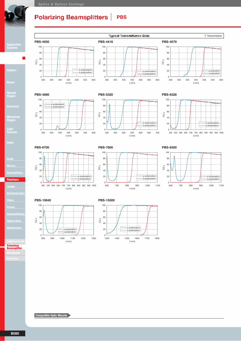
��������E F��G�D������� PBS
���g��� ���l��gkk�l�i ��k� T: Transmission
λ
λ λ
λλ λ
λ
λ
λ
λ
λ
Compatible Optic Mounts
�¢����£ �¡� � ¤¥¥�����¦O, -40PHRO / MHG-12.7PAD + MHG-MP30-NL / MHG-20PAD + MHG-MP30-NL

B081W�� http://www.sigma-koki.com/english/ E-mail [email protected] TEL +81-3-5638-8228 FAX +81-3-5638-6550
S:;<=>� ?@=A
Waveplates
Polarizers
Application Systems
Optics & Optical Coatings
Holders
Bases
Manual Stages
Actuators
Motoeized Stages
Light Sources
Index
Guide
Mirrors
Beamsplitters
Polarizers
L���
Multi-Element Optics
Filters
Prisms
Substrates/Windows
Optical Data
Maintenance
Polarizing Beamsplitter
¯������ �°���
Contact sheet for polarization beamsplitter ■Estimation ■Order
λ
□
□
≧ ≦
□ □ □
□
□ □
λ=
B082
Opt ics & Opt ica l Coat ings
S:;<=>� ?@=APolarizing Beamsplitters
Polarizers
Application Systems
Optics & Optical Coatings
Holders
Bases
Manual Stages
Actuators
Motoeized Stages
Light Sources
Index
Guide
Mirrors
Beamsplitters
Polarizers
L���
Multi-Element Optics
Filters
Prisms
Substrates/Windows
Optical Data
Maintenance
Waveplates
±DD�ication Note
■²³´µ¶·µ¶ ¸³¹ º»¼´½·¾´¸·»µ ¿·½¹À¸·»µ Á³·¼¹ Â÷µ¶ ¸³¹
■ÄÅÆÇÈÉÊ ËÌÍ ÎÈÊÌË ÈÉËÍÉÏÈËÇ
■Ðô
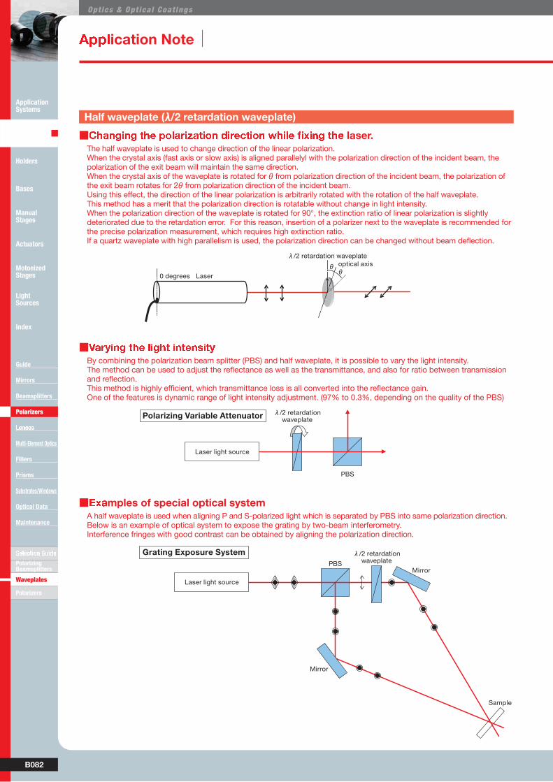
The half waveplate is used to change direction of the linear polarization.When the crystal axis (fast axis or slow axis) is aligned parallelyl with the polarization direction of the incident beam, the polarization of the exit beam will maintain the same direction.When the crystal axis of the waveplate is rotated for θ from polarization direction of the incident beam, the polarization of the exit beam rotates for 2θ from polarization direction of the incident beam.Using this effect, the direction of the linear polarization is arbitrarily rotated with the rotation of the half waveplate.This method has a merit that the polarization direction is rotatable without change in light intensity.When the polarization direction of the waveplate is rotated for 90°, the extinction ratio of linear polarization is slightly deteriorated due to the retardation error. For this reason, insertion of a polarizer next to the waveplate is recommended for the precise polarization measurement, which requires high extinction ratio.
By combining the polarization beam splitter (PBS) and half waveplate, it is possible to vary the light intensity.
One of the features is dynamic range of light intensity adjustment. (97% to 0.3%, depending on the quality of the PBS)
A half waveplate is used when aligning P and S-polarized light which is separated by PBS into same polarization direction.Below is an example of optical system to expose the grating by two-beam interferometry.Interference fringes with good contrast can be obtained by aligning the polarization direction.
Half waveplate (λ/2 retardation waveplate)
Ñ`N cK�NRJKMN aKZ ]KZXR�JKMN M`N RUJKVXYKMXUZ ^MKMN cXM`U�M K a`KZ[N XZ JX[`M XZMNZ^XMQdCommonly used applications for the waveplate are described in this section.
λ
θθ
λ
λ

B083W�� http://www.sigma-koki.com/english/ E-mail [email protected] TEL +81-3-5638-8228 FAX +81-3-5638-6550
S:;<=>� ?@=APolarizing Beamsplitters
Polarizers
Application Systems
Optics & Optical Coatings
Holders
Bases
Manual Stages
Actuators
Motoeized Stages
Light Sources
Index
Guide
Mirrors
Beamsplitters
Polarizers
L���
Multi-Element Optics
Filters
Prisms
Substrates/Windows
Optical Data
Maintenance
Waveplates
ÒÓ ÔÕ ÖÕ×Ø ÓÙ ÚÙÛÜ×ÝÓ ÞÔÛ×ßÝ àÙÞßÝÔáßÓÔÙÛ ÔÛÓÙ ÚÔÝÚular polarization, but also commonly used for the polarization measurements.
■â㹿 ¸» º½¹ä¹µ¸ ¸³¹ å´Àæ ½¹ç¹À¸·»µ
■èÏÍé êëÆ ìëÎÅÆÈíÅËÈëÉ îÍÅÏïÆÍîÍÉË ðñÍÉÅÆîëÉË îÍËÌëéò
■Ðô
the laser.An optical isolator is used to prevent this returning light.A typical optical isolators are composed of quarter waveplate and a polarizer.
degrees is obtained from phase difference amount of twice passed through the quarter waveplate.
Feature of quarter waveplate is that it is possible to convert incident linear polarization into circular polarization, but also into other state of linear polarization or various elliptical polarization.Conversely, when elliptical axis of incident light is accurately aligned against quarter waveplate optical axis, arbitrary elliptical polarization can be converted into linear polarization.The azimuth γ
The polarization measurement using this principle is named Senarmont method.Senarmont method is commonly used when measuring minute stress (birefringence).
A Michelson interferometer using a PBS and quarter waveplate is introduced.
Incident light is collected on the observation side without a loss, but in order to observe polarization, insertion of the polarizer is demanded with 50% reduction of light intensity.
Quarter waveplate (λ/4 retardation waveplate)
λ
λ
= γ
γ
λ
λ
λ

B084
Opt ics & Opt ica l Coat ings
S:;<=>� ?@=APolarizing Beamsplitters
Polarizers
Application Systems
Optics & Optical Coatings
Holders
Bases
Manual Stages
Actuators
Motoeized Stages
Light Sources
Index
Guide
Mirrors
Beamsplitters
Polarizers
L���
Multi-Element Optics
Filters
Prisms
Substrates/Windows
Optical Data
Maintenance
Waveplates
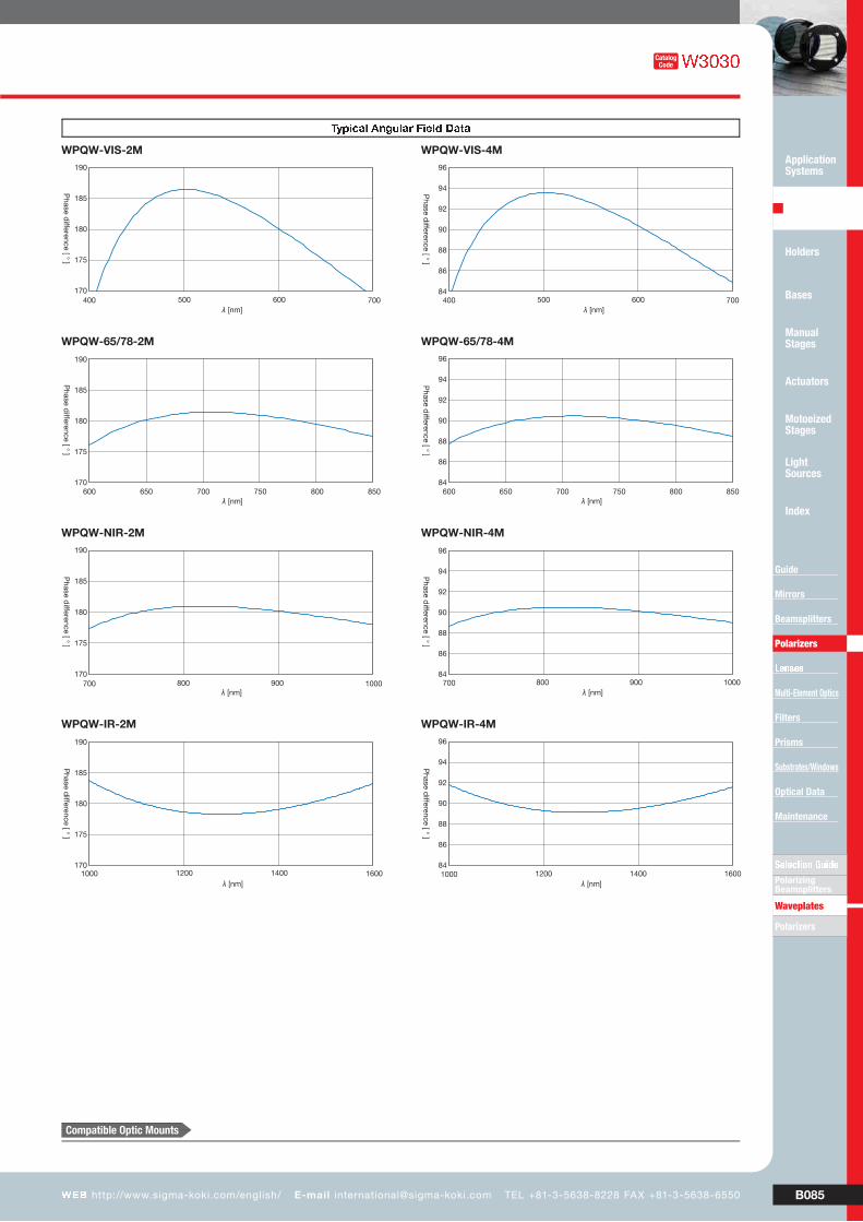
F����¬��� ó����� ô�õ�D����� WPQW
Hof crystalline quartz plates and are mounted on aluminum frames.
Air spaced type two-piece waveplates. Compatible with high-energy lasers (no optical contact occurs). These products utilize birefringence of quartz and give phase difference of λor λ λ/4 retarders convert linearly polarization to circularly and circularly polarization to linearly. λ/2 retarders convert the direction of polarization arbitrarily.
▶Custom-made air spaced type broadband quartz waveplates for
other wavelengths are also available. Please feel free to contact us.
▶Standard thickness of Aluminum frame is 6mm (subject to differ
without notice).
▶Optical axis is parallel to the edge of 14mm squared plate.
▶These products can be used for the beams which wavelengths are in
▶before coating.
▶Be sure to wear laser safety goggles when checking optical path and
adjusting optical axis.
efghi
jkkilkgml
Schematic
Outline Drawing
n$+�%&$# ö�+&.$# w%$,� .%�(+$##&1� }-$%+(r nw/2
Material of frame Aluminum Finishing: Black anodized
Clear aperture 14!14mm
Transmitted wavefront distortion λ/4 (per one surface)
Angular deviation of beam <5″
CoatingBoth surfaces: Narrowband multi-layer
Transmittance > Average 98%
(in mm)
"$%+ Number TypeWavelength Range λ
[nm]
Theoretical retardation [nm] Laser Damage Threshold*[J/cm2]λ=1000nm λ=1200nm λ=1400nm λ=1600nm
λ/2 510.2 595.4 696.3 814.3 7
λ/4 255.1 297.7 348.1 407.1 7
"$%+ Number TypeWavelength Range λ
[nm]
Theoretical retardation [nm] Laser Damage Threshold*[J/cm2]λ=700nm λ=800nm λ=900nm λ=1000nm
λ/2 344.8 402.0 450.4 494.4 7
λ/4 172.4 201.0 225.2 247.2 7
"$%+ Number TypeWavelength Range λ
[nm]
Theoretical retardation [nm] Laser Damage Threshold*[J/cm2]λ=650nm λ=700nm λ=750nm λ=800nm
WPQW-65/78-2M λ/2 325.3 352.7 376.9 398.8 7
WPQW-65/78-4M λ/4 162.2 175.9 188.0 198.9 7
Visible
"$%+ Number TypeWavelength Range λ
[nm]
Theoretical retardation [nm] Laser Damage Threshold*[J/cm2]λ=400nm λ=500nm λ=600nm λ=700nm
λ/2 184.6 259.0 300.3 328.9 4
λ/4 92.8 130.0 150.6 164.9 4
●λ
●λ
÷øùúû üýúþ ÿ�üþù�
��������� ������ ������ �������
÷øùúû üýúþ ÿþ����
φ
u z$(�% �-#(� {&,+t |x1(r %���+&+& 1 !%�}-�1.� ~x�'
B085W�� http://www.sigma-koki.com/english/ E-mail [email protected] TEL +81-3-5638-8228 FAX +81-3-5638-6550
S:;<=>� ?@=APolarizing Beamsplitters
Polarizers
Application Systems
Optics & Optical Coatings
Holders
Bases
Manual Stages
Actuators
Motoeized Stages
Light Sources
Index
Guide
Mirrors
Beamsplitters
Polarizers
L���
Multi-Element Optics
Filters
Prisms
Substrates/Windows
Optical Data
Maintenance
Waveplates
�����CatalogCode
���g��� jlTf��� �gi�h ��k�
λ λ
λ λ
λ λ
λ λ
Compatible Optic Mounts
���30-ARS / SPH-30-ARS
B086
Opt ics & Opt ica l Coat ings
S:;<=>� ?@=APolarizing Beamsplitters
Polarizers
Application Systems
Optics & Optical Coatings
Holders
Bases
Manual Stages
Actuators
Motoeized Stages
Light Sources
Index
Guide
Mirrors
Beamsplitters
Polarizers
L���
Multi-Element Optics
Filters
Prisms
Substrates/Windows
Optical Data
Maintenance
Waveplates
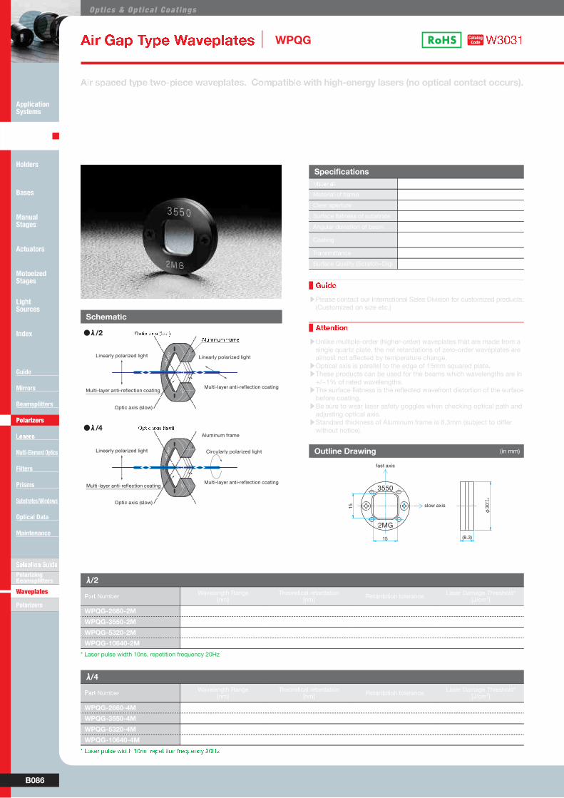
±�� ��D ACD� ô�õ�D����� WPQG ����WCatalogCode
HThese products utilize birefringence of quartz and give phase difference of λ λλ/4 retarders convert linearly polarization to circularly and circularly polarization to linearly. λ/2 retarders convert the direction of polarization arbitrarily.
●of crystalline quartz plates and are mounted on aluminum frames.
●Custom-made air spaced type waveplates for other wavelengths (248nm, 257nm, 308nm etc.) are also available.
�XV ^RKaNb MQRN McUORXNaN cK�NRJKMN^d �U]RKMX\JN cith high-energy lasers (no optical contact occurs).
▶Please contact our International Sales Division for customized products.
(Customized on size etc.)
▶Unlike multiple-order (higher-order) waveplates that are made from a
single quartz plate, the net retardations of zero-order waveplates are
almost not affected by temperature change.
▶Optical axis is parallel to the edge of 15mm squared plate.
▶These products can be used for the beams which wavelengths are in
▶before coating.
▶Be sure to wear laser safety goggles when checking optical path and
adjusting optical axis.
▶Standard thickness of Aluminum frame is 8.3mm (subject to differ
without notice).
efghi
jkkilkgmlSchematic
Outline Drawing
n$+�%&$# ö�+&.$# w%$,� .%�(+$##&1� }-$%+(Material of frame Aluminum Finishing: Black anodized
Clear aperture 15!15mm
λ/10
Angular deviation of beam <5″
CoatingBoth surfaces: Narrowband multi-layer
Transmittance >98%
(in mm)
λ/2
"$%+ NumberWavelength Range
[nm]Theoretical retardation
[nm]Retardation tolerance
Laser Damage Threshold*[J/cm2]
WPQG-2660-2M 266 133.0 <λ/50 1.4
WPQG-3550-2M 355 177.5 <λ/50 4
WPQG-5320-2M 532 266.0 λ λ/200 4
WPQG-10640-2M 1064 532.0 λ λ/500 7
λ/4
"$%+ NumberWavelength Range
[nm]Theoretical retardation
[nm]Retardation tolerance
Laser Damage Threshold*[J/cm2]
WPQG-2660-4M 266 66.5 <λ/50 1.4
WPQG-3550-4M 355 88.8 <λ/50 4
WPQG-5320-4M 532 133.0 λ λ/200 4
WPQG-10640-4M 1064 266.0 λ λ/500 7
●λ
●λ
����� ���� � ���!
����� ���� � ���!
"#$%�&$% '�%(
φ
u z$(�% �-#(� {&,+t |x1(r %���+&+& 1 !%�}-�1.� ~x�'
* Laser pulse width 10ns, repetition frequency 20Hz
B087W�� http://www.sigma-koki.com/english/ E-mail [email protected] TEL +81-3-5638-8228 FAX +81-3-5638-6550
S:;<=>� ?@=APolarizing Beamsplitters
Polarizers
Application Systems
Optics & Optical Coatings
Holders
Bases
Manual Stages
Actuators
Motoeized Stages
Light Sources
Index
Guide
Mirrors
Beamsplitters
Polarizers
L���
Multi-Element Optics
Filters
Prisms
Substrates/Windows
Optical Data
Maintenance
Waveplates
ó����� ô�õ�D����� WPQ
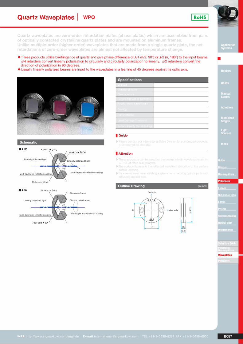
H/)ese products utilize birefringence of quartz and give phase difference of λ λλ/4 retarders convert linearly polarization to circularly and circularly polarization to linearly. λ/2 retarders convert the direction of polarization in 90 degrees.
●Usually linearly polarized beams are input to the waveplates in a leaning of 45 degrees against its optic axis.
Q�KVMY cK�NRJKMN^ KVN YNVUOUVbNV VNMKVbKMXUZ RJKMN^ *R`K^N RJKMN^+ c`Xa` KVN K^^N]\JNb _VU] RKXV^of optically contacted crystalline quartz plates and are mounted on aluminum frames.Unlike multiple-order (higher-order) waveplates that are made from a single quartz plate, the net retardations of zero-order waveplates are almost not affected by temperature change.
▶Please contact our International Sales Division for customized products.
(Customized on size etc.)
▶These products can be used for the beams which wavelengths are in
▶before coating.
▶Be sure to wear laser safety goggles when checking optical path and
adjusting optical axis.
efghi
jkkilkgml
Schematic
Outline Drawing (in mm)
●λ
●λ
,-.01 2304 5624.7
,-.01 2304 5489:7
;8<=0><= 6?2=@
φ
n$+�%&$# ö�+&.$# w%$,� .%�(+$##&1� }-$%+(Material of frame Aluminum Finishing: Black anodized
Clear aperture 15!15mm
λ/10
Angular deviation of beam <5″
CoatingBoth surfaces: Narrowband multi-layer
Transmittance >98.5%
Laser Damage Threshold1J/cm2
(Laser pulse width 10ns, repetition frequency 20Hz)
Compatible Optic Mounts
���30-ARS / SPH-30-ARS


