Download - Pneumatic Muscle
HandlingMachiningAssemblyControl
PneumaticsElectronicsMechanicsSensoricsSoftware
ChineseEnglishFrenchGermanRussianSpanish
Blue Digeston Automation
54178
HesseThe Fluidic Musclein Application
330,5 mm
160 mm
120 mm 42 mm10,5 mm
47
,3 m
m8
8,5
mm
15
8,5
mm
19
5 m
m2
25
mm
Ha
nd
ling
Pn
eu
ma
ticsE
ng
lishB
lue
Dig
est
He
sseT
he
Fluid
ic Mu
scle in
Ap
plica
tion
��
�
150 practical examples using the Pneumatic Muscle

Hesse
The Fluidic Muscle in Application

Blue Digeston Automation
HandlingPneumatics
Stefan Hesse
The Fluidic Muscle in Application150 practical examples using the Pneumatic muscle
Blue Digest on Automation
© 2003 by Festo AG & Co.KGRuiter Straße 82D-73734 EsslingenFederal Republic of GermanyTel. 0711 347-0Fax 0711 347 2155
All texts, representations, illustrations and drawings included in this book arethe intellectual property of Festo AG & Co.KG, and are protected by copyrightlaw. All rights reserved, including translation rights. No part of this publication may be reproduced or transmitted in any form or by any means, electronic,mechanical, photocopying or otherwise, without the prior written permission of Festo AG & Co.KG
How does a muscle actually function? Is it technically possible to reproduce a muscle? This question has already robbed many an inventor and project manager of sleep. What is possible mechanically and is it chemically and physically feasible?
As far back as 1872, the German professor Franz Reuleaux (1829-1905) described a flexible, pneumatic actuator. Since then all sorts of things have beentried: Muscles on the basis of memory metal, electrochemical actuators, polymergels and electric motors combined with high ratio subminiature gears. To date,only very few solutions have found their way into everyday industrial life. Many are on hold in laboratories. Amongst the few durable solutions is theFluidic Muscle from Festo, which is the principle performer in this book. It consists of an advanced high performance material and creates powerful andfast movements in a new way. An old idea has caught on in a high-tech era.Since the muscle can also be operated using water, it is probably more apt tospeak of a fluidic actuator in general rather than a pneumatic muscle, eventhough compressed air will primarily be the medium used.
In this book, a disproportionate view of the Fluidic Muscle will generally beshown in order to highlight its importance. In reality, a Muscle with an internaldiameter of, for example, 10 mm takes up relatively little space. This is also anadvantage when it comes to subsequent installation into existing machine structures. It is probably too early to fathom all the areas where the FluidicMuscle will one day be in use. Nevertheless, this artificial Muscle is an actuatorwith a very interesting future for various reasons and there are already a numberof applications with encouraging positive results. All the same, it is still in a status nascendi.
This book is intended to provide suggestions for the use of the Muscle and toexplain its function, point out the advantages and disadvantages and to providean idea of suitable areas of application. I should like to thank Thomas Dehli,B.Sc. (Civil Engineering) and Manfred Moritz (both Festo) for their kind supportwith writing of this book.
Stefan Hesse
Preface

Contents
Preface
1 Membrane construction in nature and technology . . . . . . . . . . . . . . . . . . . . . 9
2 Example: Biological muscle . . . . . . . . . . . . . . . . . . . . . . . . . . . . . . . . . . . . . . 13
3 Technology and characteristics of the Fluidic Muscle . . . . . . . . . . . . . . . . . . 20
4 Muscle-type construction . . . . . . . . . . . . . . . . . . . . . . . . . . . . . . . . . . . . . . . . 34
5 Applications . . . . . . . . . . . . . . . . . . . . . . . . . . . . . . . . . . . . . . . . . . . . . . . . . . . 45
5.1 Lifting . . . . . . . . . . . . . . . . . . . . . . . . . . . . . . . . . . . . . . . . . . . . . . . . . . 455.2 Gripping . . . . . . . . . . . . . . . . . . . . . . . . . . . . . . . . . . . . . . . . . . . . . . . . 535.3 Pressing and punching . . . . . . . . . . . . . . . . . . . . . . . . . . . . . . . . . . . . . 585.4 Pumping . . . . . . . . . . . . . . . . . . . . . . . . . . . . . . . . . . . . . . . . . . . . . . . . 635.5 Clamping . . . . . . . . . . . . . . . . . . . . . . . . . . . . . . . . . . . . . . . . . . . . . . . . 655.6 Adjusting and positioning . . . . . . . . . . . . . . . . . . . . . . . . . . . . . . . . . . 765.7 Handling . . . . . . . . . . . . . . . . . . . . . . . . . . . . . . . . . . . . . . . . . . . . . . . . 855.8 Arm and leg movements . . . . . . . . . . . . . . . . . . . . . . . . . . . . . . . . . . . . 935.9 Checking and testing . . . . . . . . . . . . . . . . . . . . . . . . . . . . . . . . . . . . . . 985.10 Driving . . . . . . . . . . . . . . . . . . . . . . . . . . . . . . . . . . . . . . . . . . . . . . . . . 1005.11 Oscillation systems . . . . . . . . . . . . . . . . . . . . . . . . . . . . . . . . . . . . . . . 1075.12 Braking and stopping . . . . . . . . . . . . . . . . . . . . . . . . . . . . . . . . . . . . . 1125.13 Transporting . . . . . . . . . . . . . . . . . . . . . . . . . . . . . . . . . . . . . . . . . . . . 1155.14 Distributing and branching . . . . . . . . . . . . . . . . . . . . . . . . . . . . . . . . . 1215.15 Machining . . . . . . . . . . . . . . . . . . . . . . . . . . . . . . . . . . . . . . . . . . . . . . 1235.16 Unwinding . . . . . . . . . . . . . . . . . . . . . . . . . . . . . . . . . . . . . . . . . . . . . . 1295.17 Dosing and portioning . . . . . . . . . . . . . . . . . . . . . . . . . . . . . . . . . . . . 130
Glossary . . . . . . . . . . . . . . . . . . . . . . . . . . . . . . . . . . . . . . . . . . . . . . . . . . . . . . . 134
Literature . . . . . . . . . . . . . . . . . . . . . . . . . . . . . . . . . . . . . . . . . . . . . . . . . . . . . . 139
Index of technical terms . . . . . . . . . . . . . . . . . . . . . . . . . . . . . . . . . . . . . . . . . . 140

1 Membrane constructions in nature and technology
By membrane we understand a thin, two-dimensional structure of a certain elasticity, which can be subjected to tension and stabilised by means of a gas airor fluid (water). The sheathing, outer medium and filler form a constructionalsystem. In biology, a membrane refers to a skin, which for the most part growsinto a porous septum and permits the movement of matter in both directions. All cell walls for example, are grown in the form of a membrane. Blood vesselsare an example of this. More “constructional” membranes for example, are the vocal sacs of the aquatic frog. These consist of very strong cellular tissueand are pressurised by internal pressure, thereby forming an inflated sphericalshape. The soft bodies of snails, worms and caterpillars typify tubular construc-tions stiffened by internal pressure. The sealing skins in this case are formed in such a way that when combined with the internal excess pressure, a shape typical of a particular species is produced. Membranes therefore play an extremely important role in living things.
In the case of plants, there are for instance the epidermal water blisters (part of the epidermis) of the stems of crystalline plants. These cells are also subject to high internal pressure and they stabilise their form in this way. Pneumaticinflatable buildings are designed according to this principle.
In technology, the term “pneu” refers to a system, whereby a sheathing which ispurely subject to tension covers a filling. Typical pneus are air balloons, soapbubbles, inflated buildings, tyres, firehoses and domed membranes in the formof canopies for highly sensitive radar scanners. In these cases a state of tensionexists in the homogenous membrane which is equal in all directions. Pneumaticlifting cushions in ring-shaped or rectangular form also come under this heading.These expand if compressed air is applied. This expansion effect is for instanceused for lifting, gripping, sealing and pressing. Cushions of this type are made of synthetic reinforced rubber, polyurethane, neoprene coated polyamide, alsoreinforced with steel-cord or aramide, as well as other materials and fillers. How-ever, the function of such cushions different to that of the Fluidic Muscle fromFesto, because in this case the action of expansion is converted into tensileforce, as you will see.
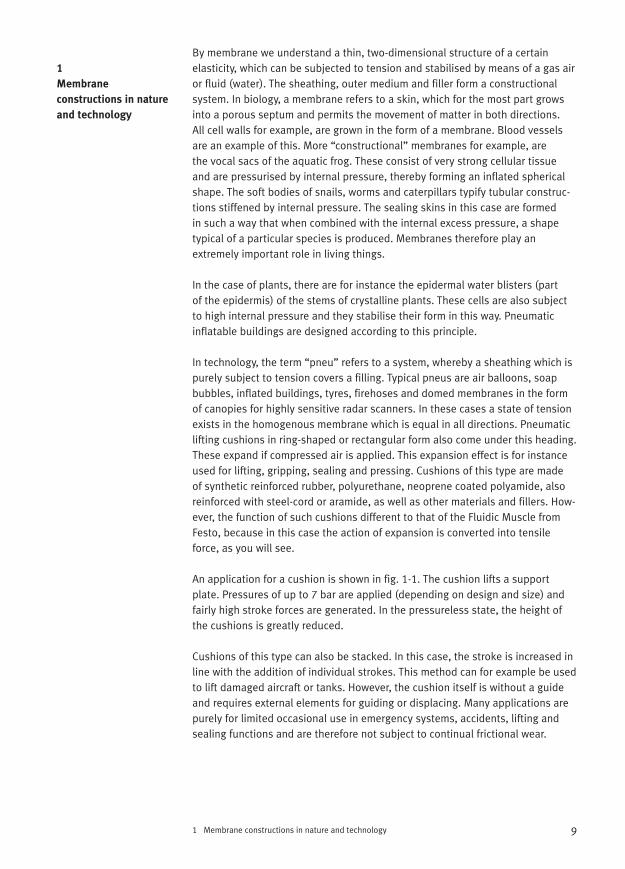
An application for a cushion is shown in fig. 1-1. The cushion lifts a support plate. Pressures of up to 7 bar are applied (depending on design and size) andfairly high stroke forces are generated. In the pressureless state, the height ofthe cushions is greatly reduced.
Cushions of this type can also be stacked. In this case, the stroke is increased inline with the addition of individual strokes. This method can for example be usedto lift damaged aircraft or tanks. However, the cushion itself is without a guideand requires external elements for guiding or displacing. Many applications arepurely for limited occasional use in emergency systems, accidents, lifting andsealing functions and are therefore not subject to continual frictional wear.
9
1
Membrane
constructions in nature
and technology
Wherever objects are retained with the help of frictional forces, frictional wear to a lesser or greater extent is the result, with a corresponding effect on servicelife.
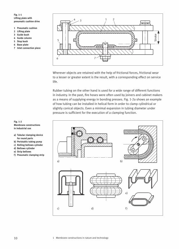
Rubber tubing on the other hand is used for a wide range of different functionsin industry. In the past, fire hoses were often used by joiners and cabinet makersas a means of supplying energy in bonding presses. Fig. 1-2a shows an exampleof how tubing can be installed in helical form in order to clamp cylindrical orslightly conical objects. Even a minimal expansion in tubing diameter underpressure is sufficient for the execution of a clamping function.
1 Membrane constructions in nature and technology10
Fig. 1-1
Lifting plate with
pneumatic cushion drive
1 Pneumatic cushion
2 Lifting plate
3 Guide bush
4 Guide column
5 Stop bush
6 Base plate
7 Inlet connection piece
Fig. 1-2
Membrane constructions
in industrial use
a) Tubular clamping device
for round parts
b) Peristaltic tubing pump
c) Rolling bellows cylinder
d) Bellows cylinder
e) Strip bellows
f) Pneumatic clamping strip
1 234
5
6
Stro
ke
7
a) b)
c) d)
e)
f )
1 Membrane constructions in nature and technology
In the case of the pump shown in fig. 1-2b, rollers create a peristaltic effect by pressing the tubing using a floating pressure point. Diaphragm and rollingbellows cylinders are often used to generate a pressing force or motion. Like bellows cylinders (fig. 1-2d), these can be purchased off the shelf. Bellows cylinders are also often used in pneumatic spring systems or installed to generate high press forces. They are attached via connecting parts made ofmetal or plastic, which also facilitate the supply of air. Bellows cylinders do not require any seals which require replacing due to wear and are absolutelymaintenance-free. Compressed air cushions in elongated form on the other hand are used for retaining, gripping and pressing, e.g. in special devices.
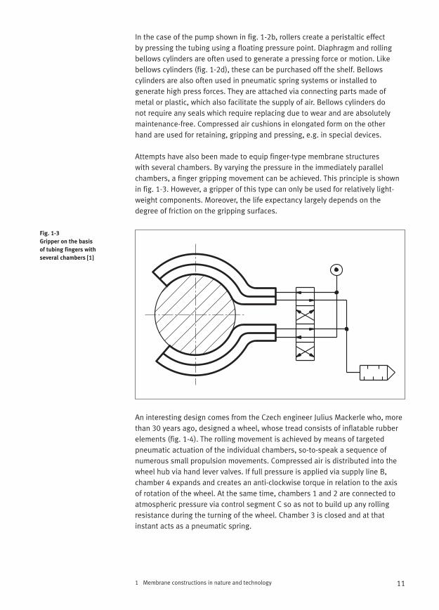
Attempts have also been made to equip finger-type membrane structures with several chambers. By varying the pressure in the immediately parallelchambers, a finger gripping movement can be achieved. This principle is shownin fig. 1-3. However, a gripper of this type can only be used for relatively light-weight components. Moreover, the life expectancy largely depends on thedegree of friction on the gripping surfaces.
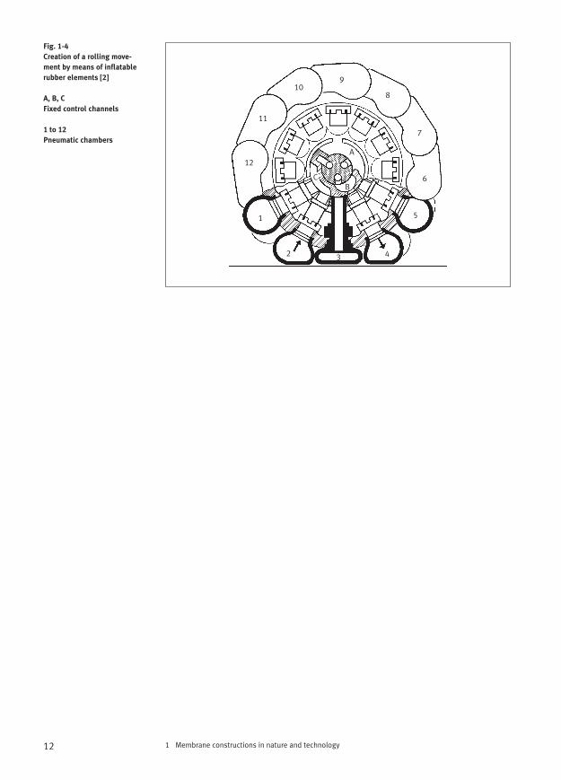
An interesting design comes from the Czech engineer Julius Mackerle who, morethan 30 years ago, designed a wheel, whose tread consists of inflatable rubberelements (fig. 1-4). The rolling movement is achieved by means of targetedpneumatic actuation of the individual chambers, so-to-speak a sequence ofnumerous small propulsion movements. Compressed air is distributed into thewheel hub via hand lever valves. If full pressure is applied via supply line B,chamber 4 expands and creates an anti-clockwise torque in relation to the axisof rotation of the wheel. At the same time, chambers 1 and 2 are connected toatmospheric pressure via control segment C so as not to build up any rollingresistance during the turning of the wheel. Chamber 3 is closed and at thatinstant acts as a pneumatic spring.
11
Fig. 1-3
Gripper on the basis
of tubing fingers with
several chambers [1]
1 Membrane constructions in nature and technology12
Fig. 1-4
Creation of a rolling move-
ment by means of inflatable
rubber elements [2]
A, B, C
Fixed control channels
1 to 12
Pneumatic chambers
1
2 3 4
5
6
7
8
910
11
12
C
A
B
2 Example: The biological muscle
The automation of production has brought major changes in its wake, which are intended to replace brains and muscles by means of technical constructs.This requires computers robots, machines of all types and also artifical muscles.Biological muscles serve as the model construction here, because they have anadvantageous mass/performance ratio. They are capable of flexible and smoothmovements and the connection of levers (bones) via the tendons is effected inan extremely compact way and because in the human body for example, theyexist in great numbers in sustained working order. The altogether 656 muscles in a human being make up 40% of body weight. The eye muscles for example,contract more than 100 000 times a day. Hence there is a great deal of researchand also some success on the way to developing an efficient artificial muscle.
As long as 50 years ago, the discovery of polymer gels and their extraordinarycharacteristics was made. Stimulation by means of external stimuli due to ionicdiffusion did in part cause dramatic differences in concentration and as such osmotic pressure differences. This causes a solvent to be created in or emittedby the gel, which is associated with changes in form.
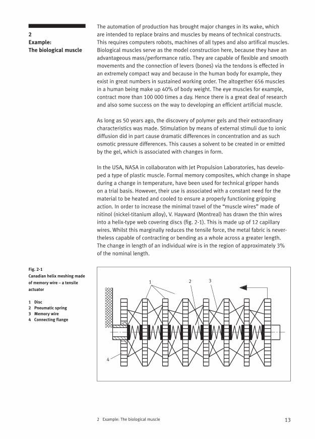
In the USA, NASA in collaboraton with Jet Propulsion Laboratories, has develo-ped a type of plastic muscle. Formal memory composites, which change in shapeduring a change in temperature, have been used for technical gripper hands on a trial basis. However, their use is associated with a constant need for thematerial to be heated and cooled to ensure a properly functioning grippingaction. In order to increase the minimal travel of the “muscle wires” made of nitinol (nickel-titanium alloy), V. Hayward (Montreal) has drawn the thin wiresinto a helix-type web covering discs (fig. 2-1). This is made up of 12 capillarywires. Whilst this marginally reduces the tensile force, the metal fabric is never-theless capable of contracting or bending as a whole across a greater length. The change in length of an individual wire is in the region of approximately 3%of the nominal length.
13
2
Example:
The biological muscle
Fig. 2-1
Canadian helix meshing made
of memory wire – a tensile
actuator
1 Disc
2 Pneumatic spring
3 Memory wire
4 Connecting flange
1 2 3
4
Even artificial muscles for nanorobots of the future have already been con-sidered. Imagine a number of nano tubes bundled into a fibreous web and thenmaking use of their expansion as they are electrically charged. In the case ofsome of these projects, their applicability is probably still far off in the distantfuture because of far too limited service life.
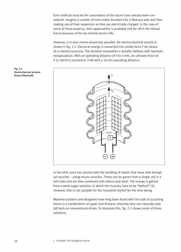
However, it is also chemo-physically possible. An electrochemical muscle isshown in fig. 2-2. Electrical energy is converted into stroke force F by means of a chemical process. The element ressembles a metallic bellows with hermeticencapsulation. With an operating distance of 0 to 5 mm, an ultimate force of 0 to 300 N is reached or 3 kN with a 16 mm operating distance.
In the USA, work has started with the building of robots that move with biologi-cal muscles – using mouse muscles. These can be grown from a single cell in atest tube and are then combined with silicon and steel. The energy is gainedfrom a weak sugar solution, in which the muscles have to be “bathed” [3].However, this is not suitable for the industrial market for the time being.
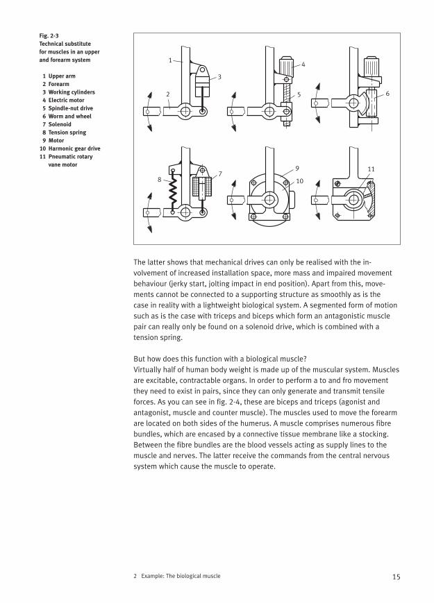
Machine builders and designers have long been faced with the task of actuatinglevers in a combination of upper and forearm, whereby they can naturally onlyfall back on conventional drives. To illustrate this, fig. 2-3 shows some of thesesolutions.
2 Example: The biological muscle14
Fig. 2-2
Electrochemical actuator
(Friwo Silberkraft)
R
F
H2O
H2
2 Example: The biological muscle
The latter shows that mechanical drives can only be realised with the in-volvement of increased installation space, more mass and impaired movementbehaviour (jerky start, jolting impact in end position). Apart from this, move-ments cannot be connected to a supporting structure as smoothly as is the case in reality with a lightweight biological system. A segmented form of motionsuch as is the case with triceps and biceps which form an antagonistic musclepair can really only be found on a solenoid drive, which is combined with a tension spring.
But how does this function with a biological muscle?Virtually half of human body weight is made up of the muscular system. Musclesare excitable, contractable organs. In order to perform a to and fro movementthey need to exist in pairs, since they can only generate and transmit tensile forces. As you can see in fig. 2-4, these are biceps and triceps (agonist and antagonist, muscle and counter muscle). The muscles used to move the forearmare located on both sides of the humerus. A muscle comprises numerous fibrebundles, which are encased by a connective tissue membrane like a stocking.Between the fibre bundles are the blood vessels acting as supply lines to themuscle and nerves. The latter receive the commands from the central nervoussystem which cause the muscle to operate.
15
Fig. 2-3
Technical substitute
for muscles in an upper
and forearm system
1 Upper arm
2 Forearm
3 Working cylinders
4 Electric motor
5 Spindle-nut drive
6 Worm and wheel
7 Solenoid
8 Tension spring
9 Motor
10 Harmonic gear drive
11 Pneumatic rotary
vane motor
1
2
3
4
5 6
78
9
10
11
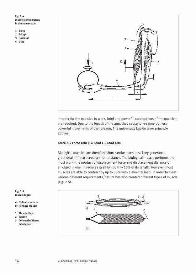
In order for the muscles to work, brief and powerful contractions of the musclesare required. Due to the length of the arm, they cause long-range but lesspowerful movements of the forearm. The universally known lever principleapplies
Force K • Force arm k = Load L • Load arm l
Biological muscles are therefore short-stroke machines. They generate a great deal of force across a short distance. The biological muscle performs themost work (the product of displacement force and displacement distance of an object), when it reduces itself by roughly 10% of its length. However, mostmuscles are able to contract by up to 30% with a minimal load. In order to meetvarious different requirements, nature has also created different types of muscle(Fig. 2-5).
2 Example: The biological muscle16
Fig. 2-4
Muscle configuration
in the human arm
1 Bicep
2 Tricep
3 Humerus
4 Ulna
Fig. 2-5
Muscle types
a) Ordinary muscle
b) Pennate muscle
1 Muscle fibre
2 Tendon
3 Connective tissue
membrane
L
l
4
K
k
1
3
2
a)
b)
2
3 1 2
2
2 Example: The biological muscle
With an ordinary muscle, the muscle fibres run from the tendon at one end to the tendon at the other end. The pennate muscle on the other hand is madeup of short transversely running fibres, which produces a large force with a small distance. Muscles of this type are particularly prevalent in insects and crustaceans, e.g. for the powerful actuation of the claws of a lobster.
But how is it possible to come anywhere near to an industrially (and also medicinally) applicable replication of biological muscles?
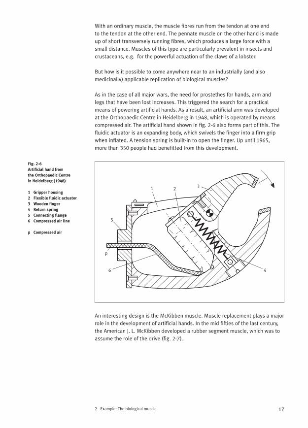
As in the case of all major wars, the need for prostethes for hands, arm and legs that have been lost increases. This triggered the search for a practicalmeans of powering artificial hands. As a result, an artificial arm was developedat the Orthopaedic Centre in Heidelberg in 1948, which is operated by meanscompressed air. The artificial hand shown in fig. 2-6 also forms part of this. Thefluidic actuator is an expanding body, which swivels the finger into a firm gripwhen inflated. A tension spring is built-in to open the finger. Up until 1965, more than 350 people had benefitted from this development.
An interesting design is the McKibben muscle. Muscle replacement plays a majorrole in the development of artificial hands. In the mid fifties of the last century,the American J. L. McKibben developed a rubber segment muscle, which was toassume the role of the drive (fig. 2-7).
17
Fig. 2-6
Artificial hand from
the Orthopaedic Centre
in Heidelberg (1948)
1 Gripper housing
2 Flexible fluidic actuator
3 Wooden finger
4 Return spring
5 Connecting flange
6 Compressed air line
p Compressed air
1 2 3
4
p
5
6
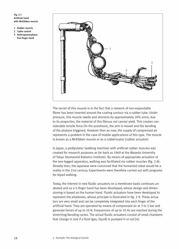
The secret of this muscle is in the fact that a network of non-expandable fibres has been inserted around the coating contour via a rubber tube. Underpressure, this muscle swells and shortens by approximately 20% since, due to its properties, the material of this fibrous net cannot yield. This creates con-siderable tensile force.On the prosthesis, the arm is moved and the bending of the phalanx triggered. However then as now, the supply of compressed airrepresents a problem in the case of mobile applications of this type. The muscleis known as a McKibben muscle or as a rubbertuator (rubber actuator).
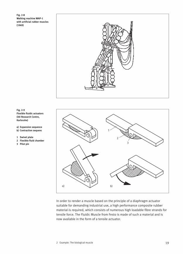
In Japan, a pedipulator (walking machine) with artificial rubber muscles wascreated for research purposes as far back as 1969 at the Waseda University of Tokyo (Humanoid Robotics Institute). By means of appropriate actuation ofthe two-legged apparatus, walking was facilitated via rubber muscles (fig. 2-8).Already then, the Japanese were convinced that the humanoid robot would be areality in the 21st century. Experiments were therefore carried out with programsfor biped walking.
Today, the interest in new fluidic actuators on a membrane basis continues un-abated and so a 5-finger hand has been developed, whose design and dimen-sioning is based on the human hand. Fluidic actuators have been developed torepresent the phalanxes, whose principle is illustrated in fig. 2-9. These actua-tors are very small and can be completely integrated into each finger of the artificial hand. They are operated by means of compressed air at 3 to 5 bar andgenerate forces of up to 10 N. Frequencies of up to 10 Hz are reached during thestretching/bending cycles. The actual fluidic actuators consist of small chambersthat change in size if a fluid (gas, liquid) is pumped in or out [4].
2 Example: The biological muscle18
Fig. 2-7
Artificial hand
with McKibben muscle
1 Rubber muscle
2 Cable control
3 Anthropomorphous
five-finger hand
1
2
3
2 Example: The biological muscle
In order to render a muscle based on the principle of a diaphragm actuator suitable for demanding industrial use, a high performance composite rubbermaterial is required, which consists of numerous high loadable fibre strands fortensile force. The Fluidic Muscle from Festo is made of such a material and isnow available in the form of a tensile actuator.
19
Fig. 2-8
Walking machine WAP-1
with artificial rubber muscles
(1969)
Fig. 2-9
Flexible fluidic actuators
(IAI Research Centre,
Karlsruhe)
a) Expansion sequence
b) Contraction sequenc
1 Swivel plate
2 Flexible fluid chamber
3 Pilot pin
1
2
3
a) b)
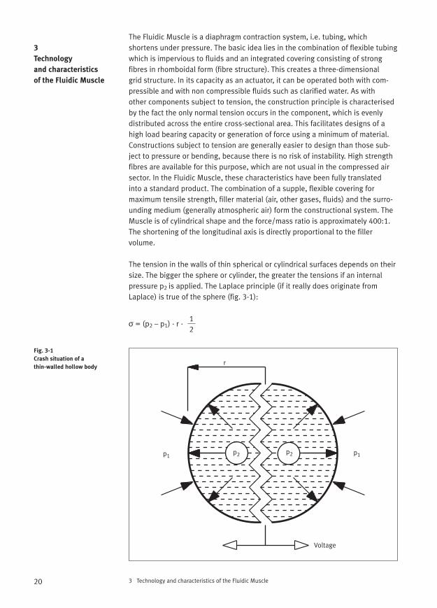
The Fluidic Muscle is a diaphragm contraction system, i.e. tubing, which shortens under pressure. The basic idea lies in the combination of flexible tubingwhich is impervious to fluids and an integrated covering consisting of strong fibres in rhomboidal form (fibre structure). This creates a three-dimensional grid structure. In its capacity as an actuator, it can be operated both with com-pressible and with non compressible fluids such as clarified water. As with other components subject to tension, the construction principle is characterisedby the fact the only normal tension occurs in the component, which is evenly distributed across the entire cross-sectional area. This facilitates designs of ahigh load bearing capacity or generation of force using a minimum of material.Constructions subject to tension are generally easier to design than those sub-ject to pressure or bending, because there is no risk of instability. High strengthfibres are available for this purpose, which are not usual in the compressed airsector. In the Fluidic Muscle, these characteristics have been fully translated into a standard product. The combination of a supple, flexible covering for maximum tensile strength, filler material (air, other gases, fluids) and the surro-unding medium (generally atmospheric air) form the constructional system. TheMuscle is of cylindrical shape and the force/mass ratio is approximately 400:1.The shortening of the longitudinal axis is directly proportional to the filler volume.
The tension in the walls of thin spherical or cylindrical surfaces depends on theirsize. The bigger the sphere or cylinder, the greater the tensions if an internalpressure p2 is applied. The Laplace principle (if it really does originate fromLaplace) is true of the sphere (fig. 3-1):
3 Technology and characteristics of the Fluidic Muscle20
3
Technology
and characteristics
of the Fluidic Muscle
Fig. 3-1
Crash situation of a
thin-walled hollow bodyr
p1
Voltage
p1p2 p2
12
σ = (p2 – p1) · r ·
∆U∆L
∆FU∆FL
tan α = =
3 Technology and characteristics of the Fluidic Muscle
The same law applies for a cylinder, but without factor 1/2. Cylinders are curvedin one direction and spheres in two directions. Since the pressure is thereforeheld in one direction as a result of the tension, double the tension is created. Acylinder with a hemispherical end piece usually cracks at its ends if it is inflatedto the point of bursting [5].
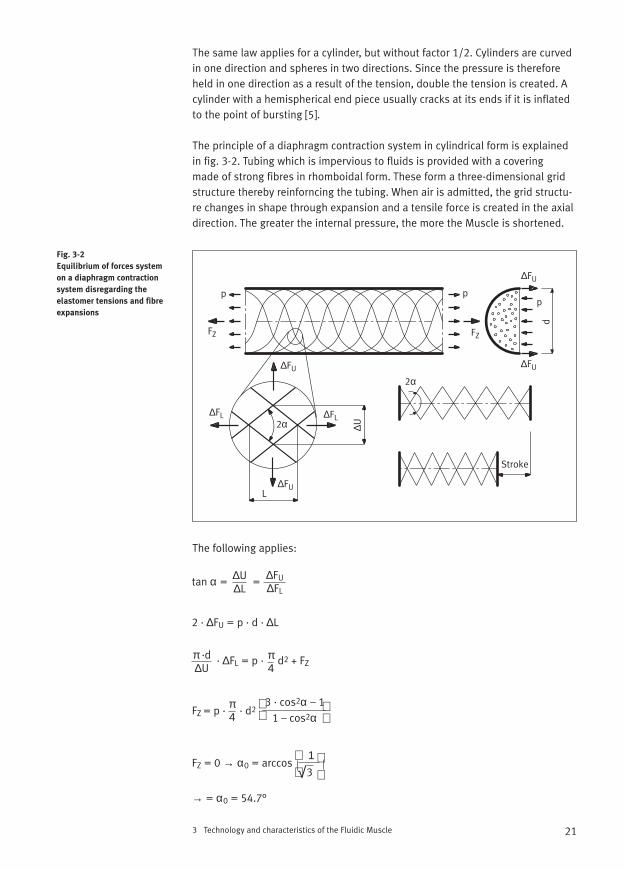
The principle of a diaphragm contraction system in cylindrical form is explainedin fig. 3-2. Tubing which is impervious to fluids is provided with a covering made of strong fibres in rhomboidal form. These form a three-dimensional gridstructure thereby reinforncing the tubing. When air is admitted, the grid structu-re changes in shape through expansion and a tensile force is created in the axialdirection. The greater the internal pressure, the more the Muscle is shortened.
The following applies:
21
Fig. 3-2
Equilibrium of forces system
on a diaphragm contraction
system disregarding the
elastomer tensions and fibre
expansions
p pp
FZ
∆FL
∆U
L
d
Stroke
FZ
∆FL
∆FU
∆FU
∆FU
2α
2α
∆FU
2 · ∆FU = p · d · ∆L
π ·d∆U
· ∆FL = p · d2 + FZπ4
3 · cos2α – 11 – cos2α
FZ = p · · d2π4
FZ = 0 → α0 = arccos √3
1
→ = α0 = 54.7°
Symbol definition:d Muscle diameterFZ Tensile force∆FL Change in tensile force∆FU Circumferential force∆L Change in lengthp Internal pressure of Muscle∆U Change in circumferenceα Semirhomboidal angleαo Neutral rhomboidal anglel
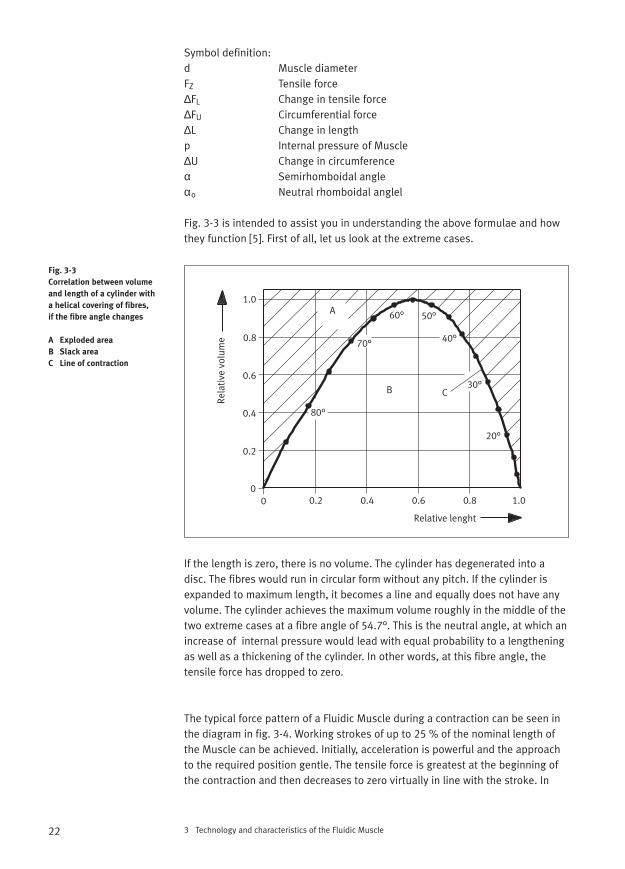
Fig. 3-3 is intended to assist you in understanding the above formulae and howthey function [5]. First of all, let us look at the extreme cases.
If the length is zero, there is no volume. The cylinder has degenerated into adisc. The fibres would run in circular form without any pitch. If the cylinder isexpanded to maximum length, it becomes a line and equally does not have anyvolume. The cylinder achieves the maximum volume roughly in the middle of thetwo extreme cases at a fibre angle of 54.7°. This is the neutral angle, at which anincrease of internal pressure would lead with equal probability to a lengtheningas well as a thickening of the cylinder. In other words, at this fibre angle, the tensile force has dropped to zero.
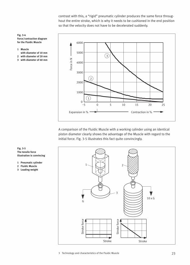
The typical force pattern of a Fluidic Muscle during a contraction can be seen inthe diagram in fig. 3-4. Working strokes of up to 25 % of the nominal length ofthe Muscle can be achieved. Initially, acceleration is powerful and the approachto the required position gentle. The tensile force is greatest at the beginning ofthe contraction and then decreases to zero virtually in line with the stroke. In
3 Technology and characteristics of the Fluidic Muscle22
Fig. 3-3
Correlation between volume
and length of a cylinder with
a helical covering of fibres,
if the fibre angle changes
A Exploded area
B Slack area
C Line of contraction
A
B C
Rela
tive
vol
ume
Relative lenght
0.2
0.2
0.4
0.4
0.6
0.6
0.8
0.8
1.0
1.000
60° 50°
40°70°
80°
30°
20°
3 Technology and characteristics of the Fluidic Muscle
contrast with this, a “rigid” pneumatic cylinder produces the same force throug-hout the entire stroke, which is why it needs to be cushioned in the end positionso that the velocity does not have to be decelerated suddenly.
A comparison of the Fluidic Muscle with a working cylinder using an identical piston diameter clearly shows the advantage of the Muscle with regard to theinitial force. Fig. 3-5 illustrates this fact quite convincingly.
23
Fig. 3-4
Force/contraction diagram
for the Fluidic Muscle
1 Muscle
with diameter of 10 mm
2 with diameter of 20 mm
3 with diameter of 40 mm
Fig. 3-5
The tensile force
illustration is convincing
1 Pneumatic cylinder
2 Fluidic Muscle
3 Loading weight
3
2
1
6000
5000
4000
3000
2000
1000
0–5 0 5 10 15 20
Expansion in % Contraction in %
Forc
e in
N
25
1 2
3
G10 x G
Stroke Stroke
Stro
ke fo
rce
Stro
ke fo
rce
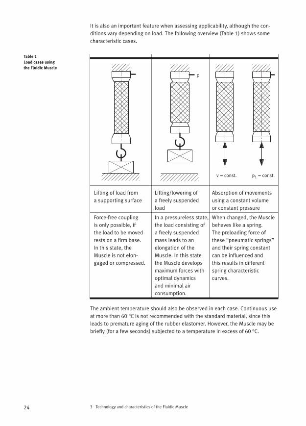
It is also an important feature when assessing applicability, although the con-ditions vary depending on load. The following overview (Table 1) shows somecharacteristic cases.
Lifting of load from Lifting/lowering of Absorption of movements a supporting surface a freely suspended using a constant volume
load or constant pressure
Force-free coupling In a pressureless state, When changed, the Muscle is only possible, if the load consisting of behaves like a spring. the load to be moved a freely suspended The preloading force of rests on a firm base. mass leads to an these “pneumatic springs” In this state, the elongation of the and their spring constant Muscle is not elon- Muscle. In this state can be influenced andgaged or compressed. the Muscle develops this results in different
maximum forces with spring characteristic optimal dynamics curves. and minimal air consumption.
The ambient temperature should also be observed in each case. Continuous useat more than 60 °C is not recommended with the standard material, since thisleads to premature aging of the rubber elastomer. However, the Muscle may bebriefly (for a few seconds) subjected to a temperature in excess of 60 °C.
3 Technology and characteristics of the Fluidic Muscle24
Table 1
Load cases using
the Fluidic Muscle
p
v = const. p1 = const.
3 Technology and characteristics of the Fluidic Muscle
In the case of dynamic use, the Muscle can also be operated at temperatures below + 5 °C, since it warms up after a few stress cycles due to the compressedair. However, if the Muscle is subjected to static load, lesser force values will beachieved than those within the recommended temperature range, since moreenergy needs to be generated in order to expand the more rigid diaphragm. The composition of rubber and elastomer can be changed by the manufacturerin exceptional cases in order to facilitate its use in temperatures below 5 °C orover 60 °C. However, this may also change other Muscle characteristics such asmaterial resistance.
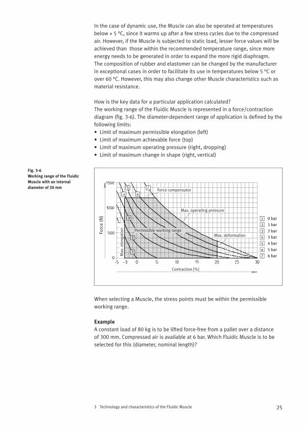
How is the key data for a particular application calculated?The working range of the Fluidic Muscle is represented in a force/contractiondiagram (fig. 3-6). The diameter-dependent range of application is defined by thefollowing limits:• Limit of maximum permissible elongation (left)• Limit of maximum achievable force (top)• Limit of maximum operating pressure (right, dropping)• Limit of maximum change in shape (right, vertical)
When selecting a Muscle, the stress points must be within the permissible working range.
Example
A constant load of 80 kg is to be lifted force-free from a pallet over a distance of 300 mm. Compressed air is available at 6 bar. Which Fluidic Muscle is to beselected for this (diameter, nominal length)?
25
Fig. 3-6
Working range of the Fluidic
Muscle with an internal
diameter of 20 mm
Forc
e (N
)
Force compensator
Max. operating pressure
Max. deformation
Max
. elo
ngat
ion Permissible working range
Contraction [%]

Step 1
Determine the size according to the maximum load to be lifted.Given a force of F = 800 N, a Fluidic Muscle 20-... can be used.
Step 2
Enter the two load points in the diagram. These are points F = 0 N at pressure p1 = 0 bar and F = 800 N at pressure p2 = 6 bar.
Step 3
From the diagram, read the contraction of the Muscle in percentage. The change in length corresponds to a contraction of 10%.
Step 4
Calculate the nominal length of the Muscle. The nominal length NL is obtainedfrom the stroke divided by the contraction (as factor). Therefore NL = 300 : 0.1 = 3000 mm.
With this result, you would need to ascertain that the room height is in fact available. If lifting is envisaged via a loose roller, then the necessary Muscle stroke and force are doubled. Conversely this means that a 1.5 m Muscle wouldbe sufficient, although it would need to generate twice the force. This solution is shown in fig. 3-7. However, this is immediately associated with additionalmechanical expenditure.
3 Technology and characteristics of the Fluidic Muscle26
Fig. 3-7
Alternative solution
to reduce the nominal length
Stroke
Stroke
3 Technology and characteristics of the Fluidic Muscle
Designers should use the calculation program “MuscleSIM” to configure aMuscle. Due to the Muscle’s hysteresis behaviour, the graphic configurationusing the force/contraction diagram may vary when compared with the resultsdetermined via the software tool. The calculation with the use of the simulationsoftware is simple:• Definition of load• Input of project data (stroke, forces, pressure)• Suggested Muscle data (nominal length, degree of contraction,
total mass, assembly length)• Output of parts list data
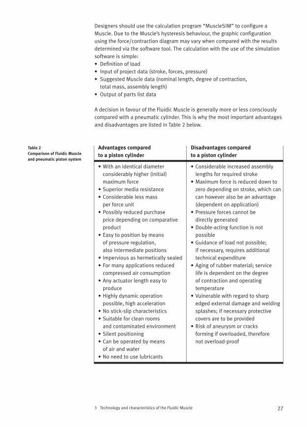
A decision in favour of the Fluidic Muscle is generally more or less consciouslycompared with a pneumatic cylinder. This is why the most important advantagesand disadvantages are listed in Table 2 below.
Advantages compared Disadvantages compared
to a piston cylinder to a piston cylinder
• With an identical diameter • Considerable increased assembly considerably higher (initial) lengths for required strokemaximum force • Maximum force is reduced down to
• Superior media resistance zero depending on stroke, which can• Considerable less mass can however also be an advantage
per force unit (dependent on application)• Possibly reduced purchase • Pressure forces cannot be
price depending on comparative directly generatedproduct • Double-acting function is not
• Easy to position by means possibleof pressure regulation, • Guidance of load not possible; also intermediate positions if necessary, requires additional
• Impervious as hermetically sealed technical expenditure• For many applications reduced • Aging of rubber material; service
compressed air consumption life is dependent on the degree • Any actuator length easy to of contraction and operating
produce temperature• Highly dynamic operation • Vulnerable with regard to sharp
possible, high acceleration edged external damage and welding • No stick-slip characteristics splashes; if necessary protective • Suitable for clean rooms covers are to be provided
and contaminated environment • Risk of aneurysm or cracks • Silent positioning forming if overloaded, therefore • Can be operated by means not overload-proof
of air and water • No need to use lubricants
27
Table 2
Comparison of Fluidic Muscle
and pneumatic piston system
In addition, the resistance of the elastomer base material (chloroprene) is to betaken into account. The following rough estimation can be used as a basis:
Media resistance
Good: Aging, weather, flame retardanceUsable: Acetone, petrol, alkaline solutions, mineral oils, ozone,
hot air, cold, acids, water (warm)Poor: Benzene, chlorine, steam, ester, tetrachloroethylene, pyralene
Mechanical characteristics
Good: Wear, bending, expanding, viscosity, tensile strengthUsable: Elasticity, deformation resistancePoor: Electrical insulation
The maximum operating frequency depends on numerous parameters:• The stroke required• Contraction (degree) of the Muscle• Load, pressure, temperature, valves and air supply• Design of the application (cushioning of load, stop, mechanical springs
for return stroke, etc.)
Subject to correct configuration, frequencies of 3 Hz are possible without impairing service life. In order to achieve high stress cycle figures, the Muscleshould on the one hand be configured in a way that contraction of 10% is notexceeded and on the other hand that it is provided with open interfaces at bothends so as to facilitate flushing as well as quick exhausting of the Muscle.Otherwise the Muscle would overheat as a result of the permanent compressionof the same air volume. IncidentaIly, in living things too each muscle movementis associated with heat generation which already starts at the beginning of acontraction and outlasts this.
For velocity characteristic values, the same as for frequency applies. Tests wereconducted under nominal conditions (room temperature, Ln = 10 x internal diameter, 6 bar, Muscle unattached at one end without additonal load).Minimum speed is approx. 0 m/s, maximum speed is 1.5 m/s for MAS–10 and 2 m/s for MAS–20 and MAS–40.
Service life is dependent on load, which is obtained from the thermal load, the set change in deformation and the additional load. The load component(thermal) can be reduced by means of specific pressurising at both ends and the service life is significantly extended as a result of this.
3 Technology and characteristics of the Fluidic Muscle28
3 Technology and characteristics of the Fluidic Muscle
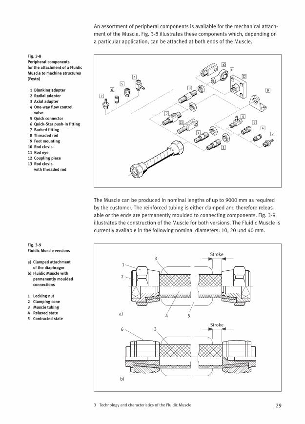
An assortment of peripheral components is available for the mechanical attach-ment of the Muscle. Fig. 3-8 illustrates these components which, depending on a particular application, can be attached at both ends of the Muscle.
The Muscle can be produced in nominal lengths of up to 9000 mm as requiredby the customer. The reinforced tubing is either clamped and therefore releas-able or the ends are permanently moulded to connecting components. Fig. 3-9illustrates the construction of the Muscle for both versions. The Fluidic Muscle iscurrently available in the following nominal diameters: 10, 20 und 40 mm.
29
Fig. 3-8
Peripheral components
for the attachment of a Fluidic
Muscle to machine structures
(Festo)
1 Blanking adapter
2 Radial adapter
3 Axial adapter
4 One-way flow control
valve
5 Quick connector
6 Quick-Star push-in fitting
7 Barbed fitting
8 Threaded rod
9 Foot mounting
10 Rod clevis
11 Rod eye
12 Coupling piece
13 Rod clevis
with threaded rod
Fig. 3-9
Fluidic Muscle versions
a) Clamped attachment
of the diaphragm
b) Fluidic Muscle with
permanently moulded
connections
1 Locking nut
2 Clamping cone
3 Muscle tubing
4 Relaxed state
5 Contracted state
Stroke
Stroke
1
2
3
3
4 5
6
a)
b)
The actuation of Fluidic Muscles is simple and yet quite fascinating. The Musclereacts to the smallest of pressure changes and can be operated at pressures of between 0 bar and pmax. = 6 bar (with a Muscle of 10 mm diameter up to 8 bar). The proportional correlation between length change and filling volumepermits intermediate positioning without costly control electronics simply by means of controlling the internal pressure. Because of the hysteresis pheno-menon, the positioning accuracy can if anything be described as approximate. A good way of describing this is low-tech/low-cost positioning.
The Fluidic Muscle is ideally suitable for sensitive application since it does not have any built-in electrical or electronic components and the actuator is hermetically sealed. This is particularly important for applications in areas subject to explosion hazard. The control system too can be realised purely withpneumatics.
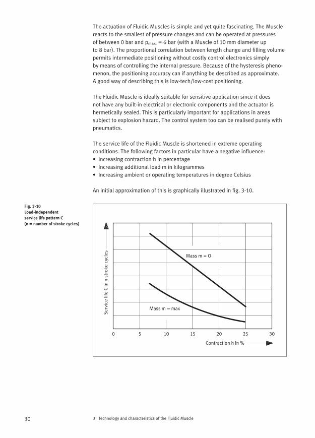
The service life of the Fluidic Muscle is shortened in extreme operating conditions. The following factors in particular have a negative influence:• Increasing contraction h in percentage• Increasing additional load m in kilogrammes• Increasing ambient or operating temperatures in degree Celsius
An initial approximation of this is graphically illustrated in fig. 3-10.
3 Technology and characteristics of the Fluidic Muscle30
Fig. 3-10
Load-independent
service life pattern C
(n = number of stroke cycles)
Mass m = O
Mass m = max
0 5 10 15 20 25 30
Contraction h in %
Serv
ice
life
C in
n s
trok
e cy
cles
3 Technology and characteristics of the Fluidic Muscle
The following generally applicable advice can be derived from this:• Do not economise with the nominal length of the Muscle!• Service life is contraction-dependent. Less contraction extends
life expectancy.• Pressure applied at opposite ends (“flushing”) reduces the operating
temperature of the Muscle (recommended for frequencies greater than 2 Hz;Muscle MAS-...-MO...).
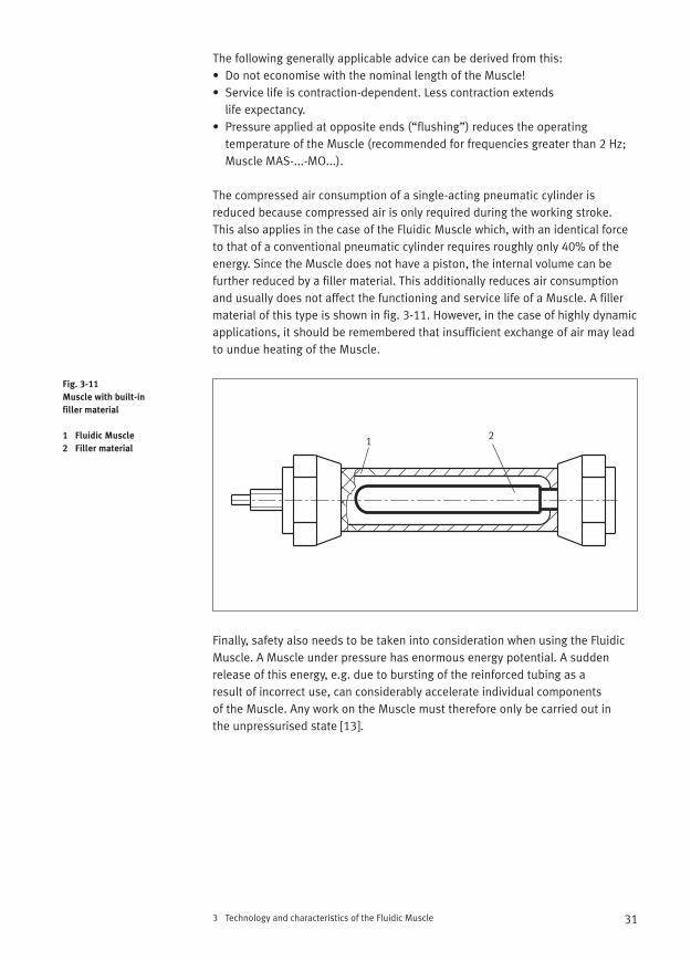
The compressed air consumption of a single-acting pneumatic cylinder is reduced because compressed air is only required during the working stroke. This also applies in the case of the Fluidic Muscle which, with an identical forceto that of a conventional pneumatic cylinder requires roughly only 40% of theenergy. Since the Muscle does not have a piston, the internal volume can be further reduced by a filler material. This additionally reduces air consumptionand usually does not affect the functioning and service life of a Muscle. A fillermaterial of this type is shown in fig. 3-11. However, in the case of highly dynamicapplications, it should be remembered that insufficient exchange of air may leadto undue heating of the Muscle.
Finally, safety also needs to be taken into consideration when using the FluidicMuscle. A Muscle under pressure has enormous energy potential. A sudden release of this energy, e.g. due to bursting of the reinforced tubing as a result of incorrect use, can considerably accelerate individual components of the Muscle. Any work on the Muscle must therefore only be carried out in the unpressurised state [13].
31
Fig. 3-11
Muscle with built-in
filler material
1 Fluidic Muscle
2 Filler material1 2
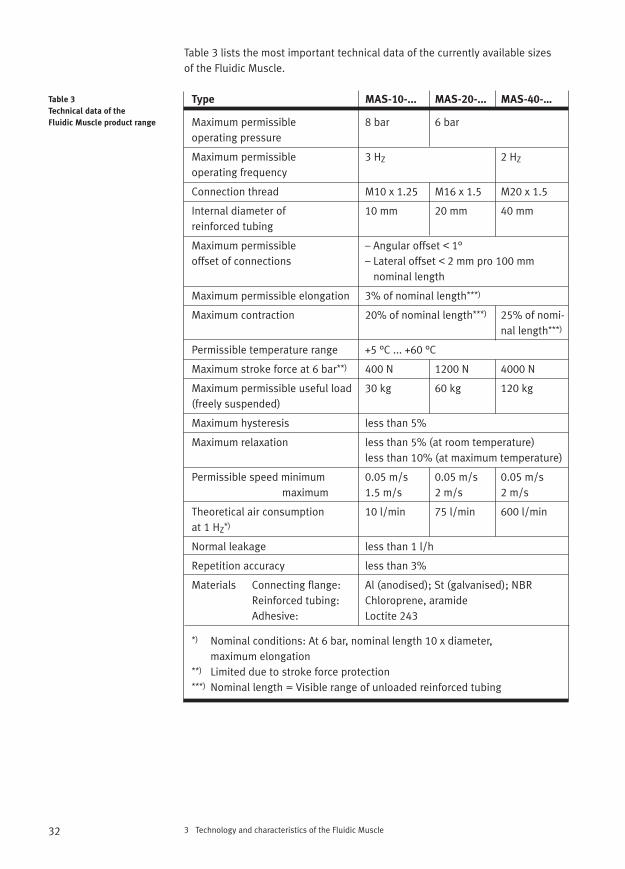
Table 3 lists the most important technical data of the currently available sizes of the Fluidic Muscle.
Type MAS-10-... MAS-20-... MAS-40-…
Maximum permissible 8 bar 6 baroperating pressure
Maximum permissible 3 HZ 2 HZ
operating frequency
Connection thread M10 x 1.25 M16 x 1.5 M20 x 1.5
Internal diameter of 10 mm 20 mm 40 mmreinforced tubing
Maximum permissible – Angular offset < 1°offset of connections – Lateral offset < 2 mm pro 100 mm
nominal length
Maximum permissible elongation 3% of nominal length***)
Maximum contraction 20% of nominal length***) 25% of nomi-nal length***)
Permissible temperature range +5 °C ... +60 °C
Maximum stroke force at 6 bar**) 400 N 1200 N 4000 N
Maximum permissible useful load 30 kg 60 kg 120 kg(freely suspended)
Maximum hysteresis less than 5%
Maximum relaxation less than 5% (at room temperature)less than 10% (at maximum temperature)
Permissible speed minimum 0.05 m/s 0.05 m/s 0.05 m/smaximum 1.5 m/s 2 m/s 2 m/s
Theoretical air consumption 10 l/min 75 l/min 600 l/minat 1 HZ*)
Normal leakage less than 1 l/h
Repetition accuracy less than 3%
Materials Connecting flange: Al (anodised); St (galvanised); NBRReinforced tubing: Chloroprene, aramideAdhesive: Loctite 243
*) Nominal conditions: At 6 bar, nominal length 10 x diameter, maximum elongation
**) Limited due to stroke force protection***) Nominal length = Visible range of unloaded reinforced tubing
3 Technology and characteristics of the Fluidic Muscle32
Table 3
Technical data of the
Fluidic Muscle product range
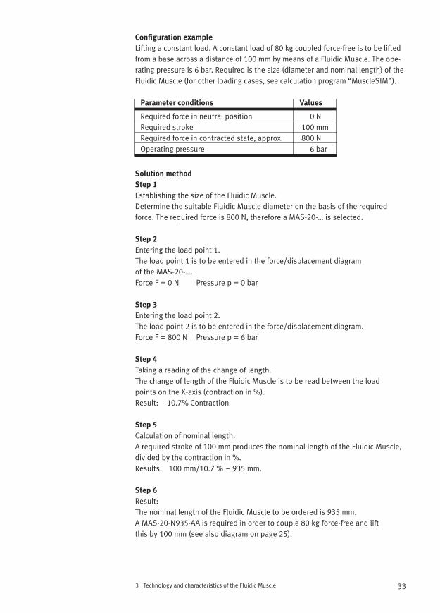
Configuration example
Lifting a constant load. A constant load of 80 kg coupled force-free is to be liftedfrom a base across a distance of 100 mm by means of a Fluidic Muscle. The ope-rating pressure is 6 bar. Required is the size (diameter and nominal length) of theFluidic Muscle (for other loading cases, see calculation program “MuscleSIM”).
Parameter conditions Values
Required force in neutral position 0 N Required stroke 100 mmRequired force in contracted state, approx. 800 NOperating pressure 6 bar
Solution method
Step 1
Establishing the size of the Fluidic Muscle.Determine the suitable Fluidic Muscle diameter on the basis of the requiredforce. The required force is 800 N, therefore a MAS-20-… is selected.
Step 2
Entering the load point 1.The load point 1 is to be entered in the force/displacement diagram of the MAS-20-….Force F = 0 N Pressure p = 0 bar
Step 3
Entering the load point 2.The load point 2 is to be entered in the force/displacement diagram.Force F = 800 N Pressure p = 6 bar
Step 4
Taking a reading of the change of length.The change of length of the Fluidic Muscle is to be read between the load points on the X-axis (contraction in %).Result: 10.7% Contraction
Step 5
Calculation of nominal length.A required stroke of 100 mm produces the nominal length of the Fluidic Muscle,divided by the contraction in %.Results: 100 mm/10.7 % ~ 935 mm.
Step 6
Result:The nominal length of the Fluidic Muscle to be ordered is 935 mm. A MAS-20-N935-AA is required in order to couple 80 kg force-free and lift this by 100 mm (see also diagram on page 25).
3 Technology and characteristics of the Fluidic Muscle 33
34 4 Muscle-type construction
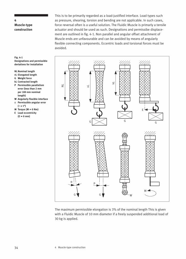
This is to be primarily regarded as a load-justified interface. Load types such as pressure, shearing, torsion and bending are not applicable. In such cases,force reversal often is a useful solution. The Fluidic Muscle is primarly a tensileactuator and should be used as such. Designations and permissibe displace-ment are outlined in fig. 4-1. Non parallel and angular offset attachment ofMuscle ends are unfavourable and can be avoided by means of angularly flexible connecting components. Eccentric loads and torsional forces must beavoided.
The maximum permissible elongation is 3% of the nominal length This is givenwith a Fluidic Muscle of 10 mm diameter if a freely suspended additional load of30 kg is applied.
4
Muscle-type
construction
Fig. 4-1
Designations and permissible
deviations for installation
NL Nominal length
vL Elongated length
G Weight force
kL Contracted length
P Permissible parallelism
error (less than 2 mm
per 100 mm nominal
length)
W Angularly flexible interface
α Permissible angular error
(< ± 1°)
M Torque (M = 0 Nm)
E Load eccentricity
(E = 0 mm)
NL
vL
kL
Pα
G G
G G W
G
E
M
35
If the Muscle is subject to a static load for an extended period (more than 500 hrs), a relaxation effect sets in. This means that the Muscle lengthens, i.e. that at a constant internal pressure and given position, the force slightlydecreases. At room temperature, this relaxation is less than 5% for all three diameters, at 60 °C it is less or equal to 10%.
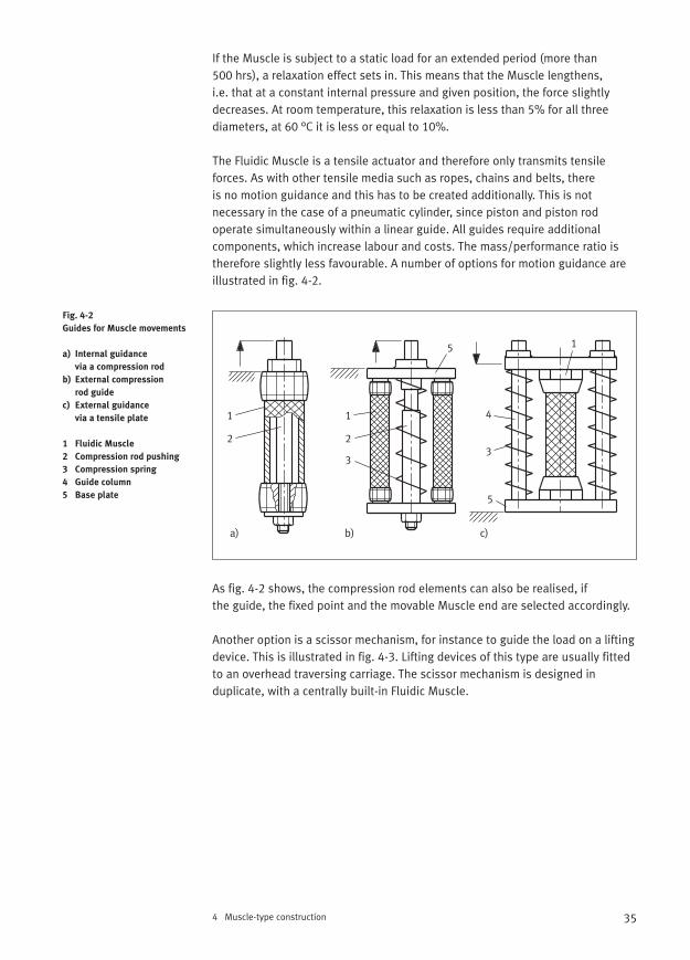
The Fluidic Muscle is a tensile actuator and therefore only transmits tensile forces. As with other tensile media such as ropes, chains and belts, there is no motion guidance and this has to be created additionally. This is not necessary in the case of a pneumatic cylinder, since piston and piston rod operate simultaneously within a linear guide. All guides require additional components, which increase labour and costs. The mass/performance ratio istherefore slightly less favourable. A number of options for motion guidance areillustrated in fig. 4-2.
As fig. 4-2 shows, the compression rod elements can also be realised, if the guide, the fixed point and the movable Muscle end are selected accordingly.
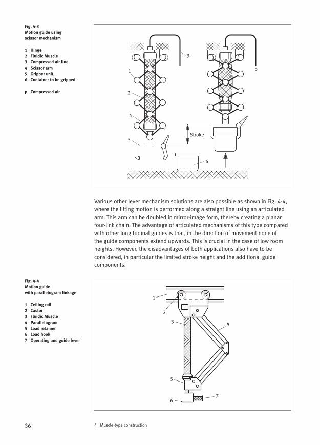
Another option is a scissor mechanism, for instance to guide the load on a liftingdevice. This is illustrated in fig. 4-3. Lifting devices of this type are usually fittedto an overhead traversing carriage. The scissor mechanism is designed in duplicate, with a centrally built-in Fluidic Muscle.
4 Muscle-type construction
Fig. 4-2
Guides for Muscle movements
a) Internal guidance
via a compression rod
b) External compression
rod guide
c) External guidance
via a tensile plate
1 Fluidic Muscle
2 Compression rod pushing
3 Compression spring
4 Guide column
5 Base plate
a) b) c)
1 1
1
2 2
33
4
5
5
36 4 Muscle-type construction
Various other lever mechanism solutions are also possible as shown in Fig. 4-4,where the lifting motion is performed along a straight line using an articulatedarm. This arm can be doubled in mirror-image form, thereby creating a planarfour-link chain. The advantage of articulated mechanisms of this type comparedwith other longitudinal guides is that, in the direction of movement none of the guide components extend upwards. This is crucial in the case of low roomheights. However, the disadvantages of both applications also have to be considered, in particular the limited stroke height and the additional guide components.
Fig. 4-3
Motion guide using
scissor mechanism
1 Hinge
2 Fluidic Muscle
3 Compressed air line
4 Scissor arm
5 Gripper unit,
6 Container to be gripped
p Compressed air
Fig. 4-4
Motion guide
with parallelogram linkage
1 Ceiling rail
2 Castor
3 Fluidic Muscle
4 Parallelogram
5 Load retainer
6 Load hook
7 Operating and guide lever
p1
2
3
4
5
6
Stroke
1
2
3 4
5
67
37
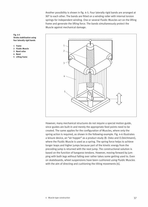
Another possibility is shown in fig. 4-5. Four laterally rigid bands are arranged at90° to each other. The bands are fitted on a winding roller with internal torsionsprings for independent winding. One or several Fluidic Muscles act on the liftingframe and generate the lifting force. The bands simultaneously protect theMuscle against mechanical damage.
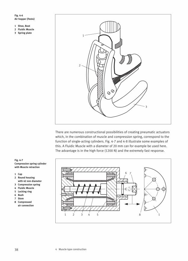
However, many mechanical structures do not require a special motion guide,since guides are built-in and merely the appropriate feed points need to be created. The same applies for the configuration of Muscles, where only thespring action is required, as shown in the following example. Fig. 4-6 illustrates a leisure device, an “air hopper” as a product study (B. Osko and O.Deichmann),where the Fluidic Muscle is used as a spring. The spring force helps to achievelonger leaps and higher jumps because part of the kinetic energy from the preceding jump is returned with the next jump. The constructional solution isbased on the function of kangaroo tendons. However, moving forward by jum-ping with both legs without falling over rather takes some getting used to. Evenon skateboards, wheel suspensions have been cushioned using Fluidic Muscleswith the aim of directing and cushioning the tilting movements [6].
4 Muscle-type construction
Fig. 4-5
Stroke stabilisation using
four laterally rigid bands
1 Frame
2 Fluidic Muscle
3 Band roller
4 Band
5 Lifting frame
1
2
3
4
5
38 4 Muscle-type construction
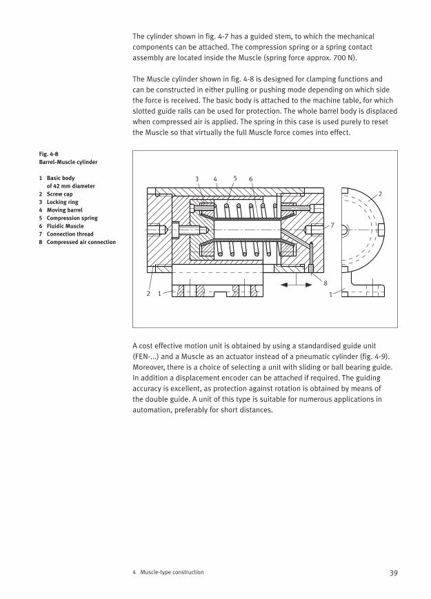
There are numerous constructional possibilities of creating pneumatic actuatorswhich, in the combination of muscle and compression spring, correspond to thefunction of single-acting cylinders. Fig. 4-7 and 4-8 illustrate some examples ofthis. A Fluidic Muscle with a diameter of 20 mm can for example be used here.The advantage is in the high force (1200 N) and the extremely fast response.
Fig. 4-6
Air hopper (Festo)
1 Shoe, Boot
2 Fluidic Muscle
3 Spring plate
Fig. 4-7
Compression spring cylinder
with Muscle retraction
1 Cap
2 Round housing
with 42 mm diameter
3 Compression spring
4 Fluidic Muscle
5 Locking ring
6 Bush
7 Stem
8 Compressed
air connection
1
2
3
1 2 3 54
6 7
18
39
The cylinder shown in fig. 4-7 has a guided stem, to which the mechanical components can be attached. The compression spring or a spring contact assembly are located inside the Muscle (spring force approx. 700 N).
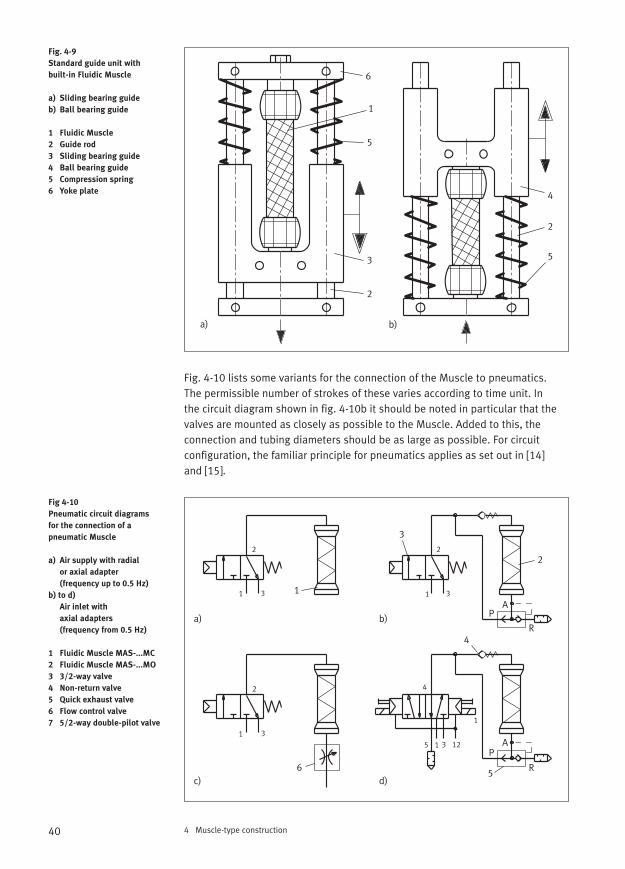
The Muscle cylinder shown in fig. 4-8 is designed for clamping functions and can be constructed in either pulling or pushing mode depending on which sidethe force is received. The basic body is attached to the machine table, for which slotted guide rails can be used for protection. The whole barrel body is displacedwhen compressed air is applied. The spring in this case is used purely to resetthe Muscle so that virtually the full Muscle force comes into effect.
A cost effective motion unit is obtained by using a standardised guide unit (FEN-...) and a Muscle as an actuator instead of a pneumatic cylinder (fig. 4-9).Moreover, there is a choice of selecting a unit with sliding or ball bearing guide.In addition a displacement encoder can be attached if required. The guidingaccuracy is excellent, as protection against rotation is obtained by means of the double guide. A unit of this type is suitable for numerous applications inautomation, preferably for short distances.
4 Muscle-type construction
Fig. 4-8
Barrel-Muscle cylinder
1 Basic body
of 42 mm diameter
2 Screw cap
3 Locking ring
4 Moving barrel
5 Compression spring
6 Fluidic Muscle
7 Connection thread
8 Compressed air connection
112
2
3 4 5 6
7
8
40 4 Muscle-type construction
Fig. 4-10 lists some variants for the connection of the Muscle to pneumatics. The permissible number of strokes of these varies according to time unit. In the circuit diagram shown in fig. 4-10b it should be noted in particular that the valves are mounted as closely as possible to the Muscle. Added to this, theconnection and tubing diameters should be as large as possible. For circuit configuration, the familiar principle for pneumatics applies as set out in [14] and [15].
Fig. 4-9
Standard guide unit with
built-in Fluidic Muscle
a) Sliding bearing guide
b) Ball bearing guide
1 Fluidic Muscle
2 Guide rod
3 Sliding bearing guide
4 Ball bearing guide
5 Compression spring
6 Yoke plate
Fig 4-10
Pneumatic circuit diagrams
for the connection of a
pneumatic Muscle
a) Air supply with radial
or axial adapter
(frequency up to 0.5 Hz)
b) to d)
Air inlet with
axial adapters
(frequency from 0.5 Hz)
1 Fluidic Muscle MAS-...MC
2 Fluidic Muscle MAS-...MO
3 3/2-way valve
4 Non-return valve
5 Quick exhaust valve
6 Flow control valve
7 5/2-way double-pilot valve
6
1
2
5
3
4
2
5
a) b)
a)
c) d)
b)
1
2
3
4
56
1 1
11
1
2 2
2
3 3
3
3
A
AP
P
R
R
4
5 12
41
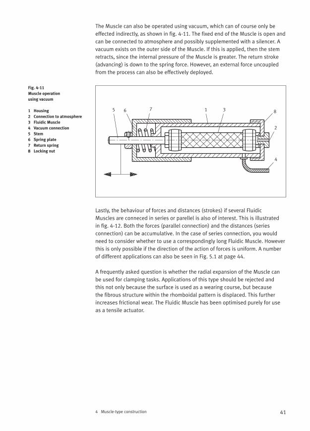
The Muscle can also be operated using vacuum, which can of course only be effected indirectly, as shown in fig. 4-11. The fixed end of the Muscle is open andcan be connected to atmosphere and possibly supplemented with a silencer. Avacuum exists on the outer side of the Muscle. If this is applied, then the stemretracts, since the internal pressure of the Muscle is greater. The return stroke(advancing) is down to the spring force. However, an external force uncoupledfrom the process can also be effectively deployed.
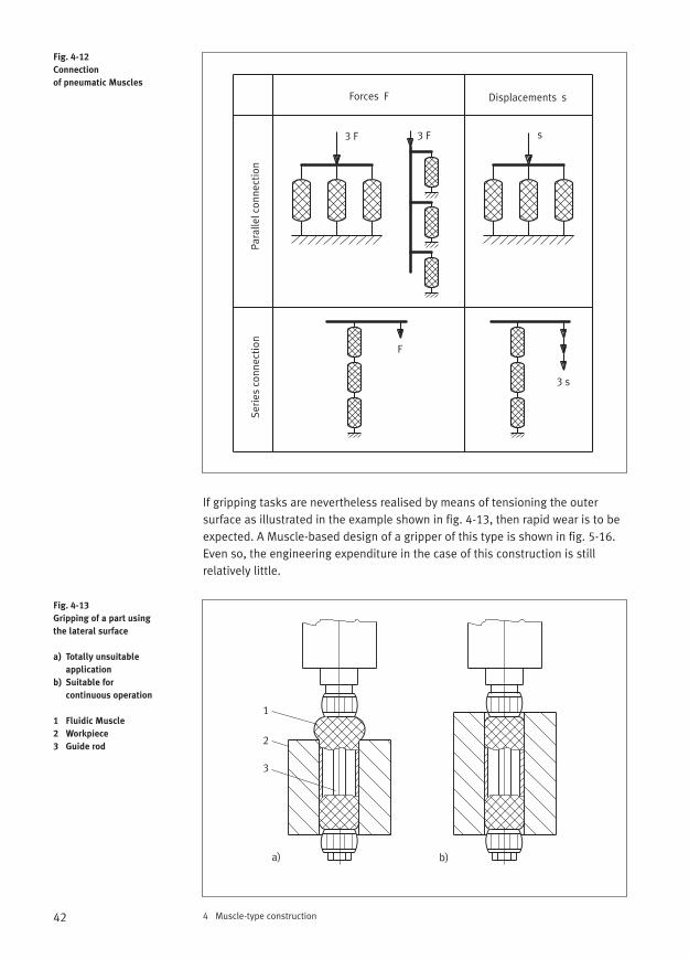
Lastly, the behaviour of forces and distances (strokes) if several Fluidic Muscles are conneced in series or parellel is also of interest. This is illustrated in fig. 4-12. Both the forces (parallel connection) and the distances (series connection) can be accumulative. In the case of series connection, you wouldneed to consider whether to use a correspondingly long Fluidic Muscle. Howeverthis is only possible if the direction of the action of forces is uniform. A numberof different applications can also be seen in Fig. 5.1 at page 44.
A frequently asked question is whether the radial expansion of the Muscle canbe used for clamping tasks. Applications of this type should be rejected and this not only because the surface is used as a wearing course, but because the fibrous structure within the rhomboidal pattern is displaced. This furtherincreases frictional wear. The Fluidic Muscle has been optimised purely for useas a tensile actuator.
4 Muscle-type construction
Fig. 4-11
Muscle operation
using vacuum
1 Housing
2 Connection to atmosphere
3 Fluidic Muscle
4 Vacuum connection
5 Stem
6 Spring plate
7 Return spring
8 Locking nut
1
2
3
4
5 6 7 8
42 4 Muscle-type construction
If gripping tasks are nevertheless realised by means of tensioning the outer surface as illustrated in the example shown in fig. 4-13, then rapid wear is to beexpected. A Muscle-based design of a gripper of this type is shown in fig. 5-16.Even so, the engineering expenditure in the case of this construction is still relatively little.
Fig. 4-12
Connection
of pneumatic Muscles
Fig. 4-13
Gripping of a part using
the lateral surface
a) Totally unsuitable
application
b) Suitable for
continuous operation
1 Fluidic Muscle
2 Workpiece
3 Guide rod
Forces F Displacements s
Para
llel c
onne
ctio
nSe
ries
con
nect
ion
F
3 F 3 F s
3 s
1
2
3
a) b)
43
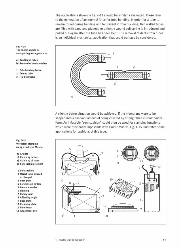
The applications shown in fig. 4-14 should be similarly evaluated. These refer to the generation of an internal force for tube bending. In order for a tube toremain round during bending and to prevent it from buckling, thin walled tubesare filled with sand and plugged or a tightly wound coil spring is introduced andpulled out again after the tube has been bent. The removal of dents from tubesis an individual mechanical application that could perhaps be considered.
A slightly better situation would be achieved, if the membrane were to be shaped into a cushion instead of being covered by strong fibres in rhomboidalform. An inflatable “semicushion” could then be used for clamping functionswhich were previously impossible with Fluidic Muscle. Fig. 4-15 illustrates someapplications for cushions of this type.
4 Muscle-type construction
Fig. 4-14
The Fluidic Muscle as
a supporting force generator
a) Bending of tubes
b) Removal of dents in tubes
1 Tube bending device
2 Dented tube
3 Fluidic Muscle
Fig. 4-15
Workpiece clamping
using a pad-type Muscle
a) Gripper
b) Clamping device
c) Clamping of tubes
d) Semicushion element
1 Semicushion
2 Object to be gripped
or clamped
3 Base plate
4 Compressed air line
5 Bar code reader
6 Lighting
7 Rotary joint
8 Adjusting angle
9 Base plate
10 Retaining plate
11 Inner body
12 Attachment eye
1
23
a)
b)
a)
b)
c)
d)
1
1
1
1
2
2
2
2
3
4
4
4
5
6
7
8
9
9
10
10
11
11
12
44 4 Muscle-type construction
Gripping as shown in fig. 4-15a does not cause the gripped object to be accurately centred in the gripper device. The contact force can be regulated via pressure. Idle strokes without counterforce are to be avoided. The grippedobject must not have any burrs or sharp edges.Other than that, cushion ele-ments of this type are maintenance-free and thus occasional visual inspectionssuffice. If these pad-type Muscles are attached to a suitable multifacetted body,then internal gripping of tubes for example, can also be realised as shown in fig. 4-15d.
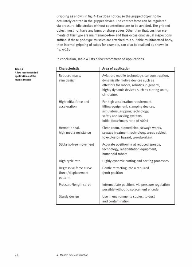
In conclusion, Table 4 lists a few recommended applications.
Characteristic Area of application
Reduced mass, Aviation, mobile technology, car construction, slim design dynamically motive devices such as
effectors for robots, robotics in general,highly dynamic devices such as cutting units, simulators
High initial force and For high acceleration requirement, acceleration lifting equipment, clamping devices,
simulators, gripping technology, safety and locking systems, initial force/mass ratio of 400:1
Hermetic seal, Clean room, biomedicine, sewage works, high media resistance sewage treatment technology, areas subject
to explosion hazard, woodworking
Stickslip-free movement Accurate positioning at reduced speeds, technology, rehabilitation equipment, humanoid robots
High cycle rate Highly dynamic cutting and sorting processes
Degressive force curve Gentle retracting into a required (force/displacement (end) positionpattern)
Pressure/length curve Intermediate positions via pressure regulation possible without displacement encoder
Sturdy design Use in environments subject to dust and contamination
Table 4
A few recommended
applications of the
Fluidic Muscle
45
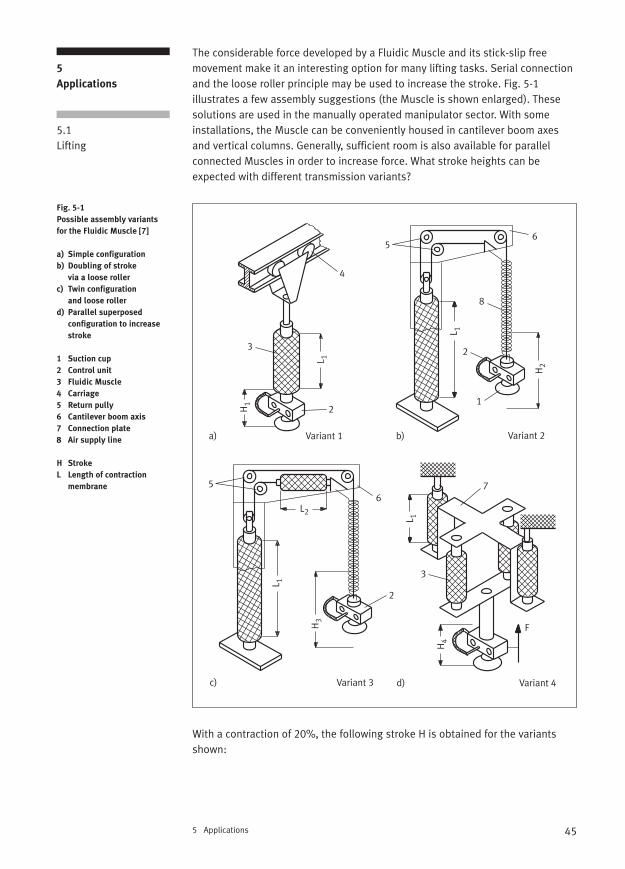
The considerable force developed by a Fluidic Muscle and its stick-slip free movement make it an interesting option for many lifting tasks. Serial connectionand the loose roller principle may be used to increase the stroke. Fig. 5-1 illustrates a few assembly suggestions (the Muscle is shown enlarged). Thesesolutions are used in the manually operated manipulator sector. With someinstallations, the Muscle can be conveniently housed in cantilever boom axesand vertical columns. Generally, sufficient room is also available for parallelconnected Muscles in order to increase force. What stroke heights can be expected with different transmission variants?
With a contraction of 20%, the following stroke H is obtained for the variantsshown:
5 Applications
5
Applications
5.1Lifting
Fig. 5-1
Possible assembly variants
for the Fluidic Muscle [7]
a) Simple configuration
b) Doubling of stroke
via a loose roller
c) Twin configuration
and loose roller
d) Parallel superposed
configuration to increase
stroke
1 Suction cup
2 Control unit
3 Fluidic Muscle
4 Carriage
5 Return pully
6 Cantilever boom axis
7 Connection plate
8 Air supply line
H Stroke
L Length of contraction
membrane
H3
L2
L 1
5
2
6
1
23
2
4
56
7
8
H1
H2
H4
F
L 1
L 1
L 1
a) b)
c) d)
Variant 2Variant 1
Variant 3 Variant 4
3
46 5 Applications
H1 = 0.2 ⋅ L1
H2 = 2 ⋅ 0.2 ⋅ L1
H3 = [(0.2 ⋅ L1) + (0.2 ⋅ L2)] ⋅ 2H4 = (0.2 ⋅ L1) + (0.2 ⋅ L2)
The following should be used to compare all the assembly variants of the loadbalancers shown in fig. 5-1 during their lifting actions:
L1 = 2000 mm, L2 = 1400 mmMuscle size MAS 40 (= 40 mm internal diameter)Operating pressure 6 barContraction 9% or 20% of initial length
With these assumptions, the following data is obtained if the load is not freelysuspended:
Contraction 9% Contraction 20%
Variant Stroke in mm Force F in N Stroke in mm Force F in N
1 (Fig. 5-1a) H1 = 180 3900 400 1800
2 (Fig. 5-1b) H2 = 360 1950 800 1800
3 (Fig. 5-1c) H3 = 612 1950 1360 1800
4 (Fig. 5-1d) H4 = 360 7800 800 3600
Forces can be increased by the simple method of using several parallel bundledMuscles. Even in this case, movements can still be finely reproduced.
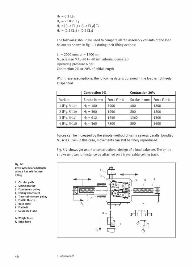
Fig. 5-2 shows yet another constructional design of a load balancer. The entirestroke unit can for instance be attached on a traversable ceiling track.
Fig. 5-2
Drive system for a balancer
using a flat belt for load
lifting
1 Circular guide
2 Siding bearing
3 Fixed return pulley
4 Ceiling attachment
5 Traversable return pulley
6 Fluidic Muscle
7 Base plate
8 Flat belt
9 Suspensed load
FG Weight force
FA Drive force
FA
FG
1 2
3
4
5 6 7
8
9
47
The suspended load can be balanced by means of pressure regulation therebycreating a seemingly weightless state for the handling object. The less the massof the moving part, the more dynamic the operation and this is further facilitatedby the Fluidic Muscle. A Fluidic Muscle working in parallel has been attached infront of and behind each of the roller devices. The Muscles are inserted in aguide barrel and mounted on the right of the base plate. With this design, themaximum stroke height of the load is four times the Muscle stroke. It should bepointed out that the stroke force decreases over the distance, which is why theMuscles are provided in pairs in the example shown.
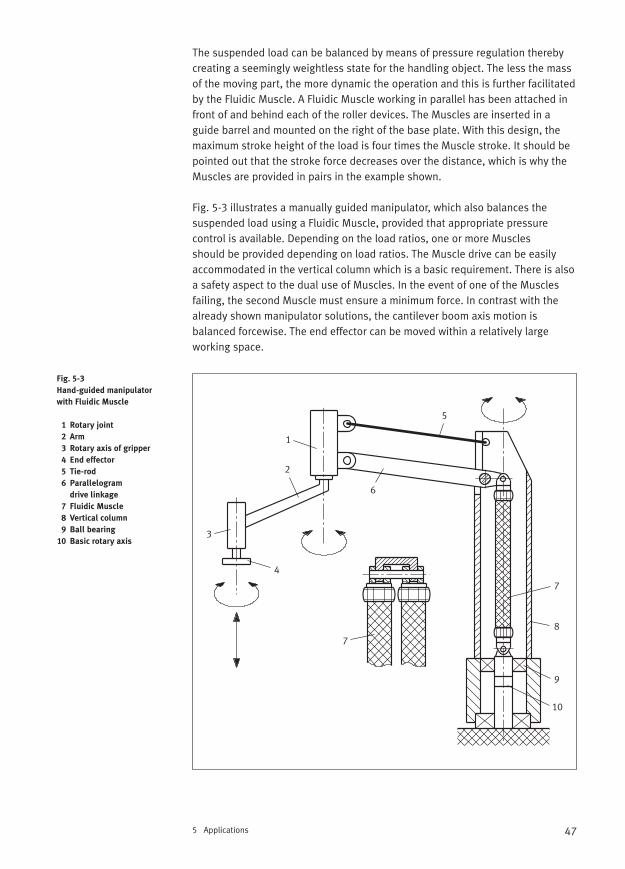
Fig. 5-3 illustrates a manually guided manipulator, which also balances the suspended load using a Fluidic Muscle, provided that appropriate pressure control is available. Depending on the load ratios, one or more Muscles should be provided depending on load ratios. The Muscle drive can be easilyaccommodated in the vertical column which is a basic requirement. There is alsoa safety aspect to the dual use of Muscles. In the event of one of the Musclesfailing, the second Muscle must ensure a minimum force. In contrast with thealready shown manipulator solutions, the cantilever boom axis motion is balanced forcewise. The end effector can be moved within a relatively large working space.
5 Applications
Fig. 5-3
Hand-guided manipulator
with Fluidic Muscle
1 Rotary joint
2 Arm
3 Rotary axis of gripper
4 End effector
5 Tie-rod
6 Parallelogram
drive linkage
7 Fluidic Muscle
8 Vertical column
9 Ball bearing
10 Basic rotary axis
1
2
3
4
5
6
7
7
8
9
10
48 5 Applications
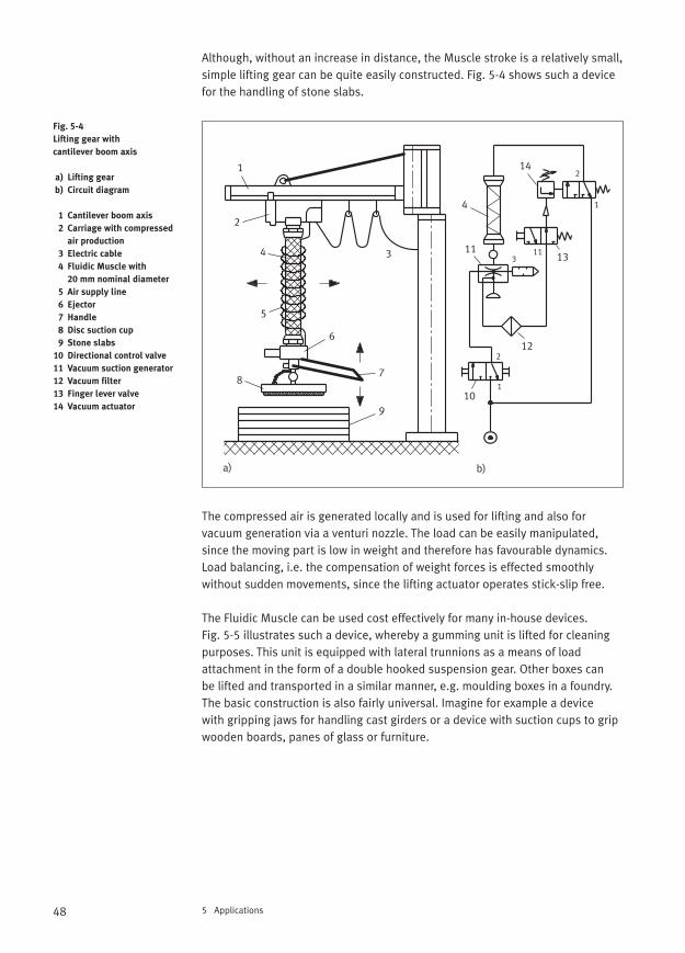
Although, without an increase in distance, the Muscle stroke is a relatively small,simple lifting gear can be quite easily constructed. Fig. 5-4 shows such a devicefor the handling of stone slabs.
The compressed air is generated locally and is used for lifting and also for vacuum generation via a venturi nozzle. The load can be easily manipulated,since the moving part is low in weight and therefore has favourable dynamics.Load balancing, i.e. the compensation of weight forces is effected smoothly without sudden movements, since the lifting actuator operates stick-slip free.
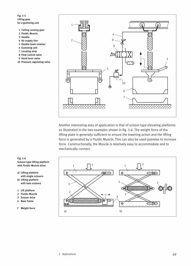
The Fluidic Muscle can be used cost effectively for many in-house devices. Fig. 5-5 illustrates such a device, whereby a gumming unit is lifted for cleaningpurposes. This unit is equipped with lateral trunnions as a means of load attachment in the form of a double hooked suspension gear. Other boxes can be lifted and transported in a similar manner, e.g. moulding boxes in a foundry.The basic construction is also fairly universal. Imagine for example a device with gripping jaws for handling cast girders or a device with suction cups to gripwooden boards, panes of glass or furniture.
Fig. 5-4
Lifting gear with
cantilever boom axis
a) Lifting gear
b) Circuit diagram
1 Cantilever boom axis
2 Carriage with compressed
air production
3 Electric cable
4 Fluidic Muscle with
20 mm nominal diameter
5 Air supply line
6 Ejector
7 Handle
8 Disc suction cup
9 Stone slabs
10 Directional control valve
11 Vacuum suction generator
12 Vacuum filter
13 Finger lever valve
14 Vacuum actuator
1
2
34
5
6
78
910
11
4
12
13
14
1
1
3
2
2
11
a) b)
49
Another interesting area of application is that of scissor-type elevating platformsas illustrated in the two examples shown in fig. 5-6. The weight force of the lifting plate is generally sufficient to ensure the lowering action and the liftingforce is generated by a Fluidic Muscle. This can also be used pairwise to increaseforce. Constructionally, the Muscle is relatively easy to accommodate and tomechanically connect.
5 Applications
Fig. 5-5
Lifting gear
for a gumming unit
1 Ceiling running gear
2 Fluidic Muscle
3 Handle
4 Air supply line
5 Double-hook retainer
6 Gumming unit
7 Locating strip
8 Flow control valve
9 Hand lever valve
10 Pressure regulating valve
Fig. 5-6
Scissor-type lifting platform
with Fluidic Muscle drive
a) Lifting platform
with single scissors
b) Lifting platform
with twin scissors
1 Lift platform
2 Fluidic Muscle
3 Scissor drive
4 Base frame
F Weight force
1
2
3
4
5
6
7
8
9
10
F F1 1
22
33 2
4
a) b)
50 5 Applications
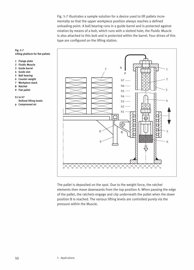
Fig. 5-7 illustrates a sample solution for a device used to lift pallets incre-mentally so that the upper workpiece position always reaches a defined unloading point. A ball bearing runs in a guide barrel and is protected againstrotation by means of a bolt, which runs with a slotted hole; the Fluidic Muscle is also attached to this bolt and is protected within the barrel. Four drives of thistype are configured on the lifting station.
The pallet is deposited on the spot. Due to the weight force, the ratchet elements then move downwards from the top position A. When passing the edgeof the pallet, the ratchets engage and clip underneath the pallet when the downposition B is reached. The various lifting levels are controlled purely via the pressure within the Muscle.
Fig. 5-7
Lifting platform for flat pallets
1 Flange plate
2 Fluidic Muscle
3 Guide barrel
4 Guide slot
5 Ball bearing
6 Counter weight
7 Workpiece stack
8 Ratchet
9 Flat pallet
h1 to h7
Defined lifting levels
p Compressed air
B
A
h1
h2
h3
h4
h5
h6
h7
1
2
3
4
5
6
7
8
9
p
51
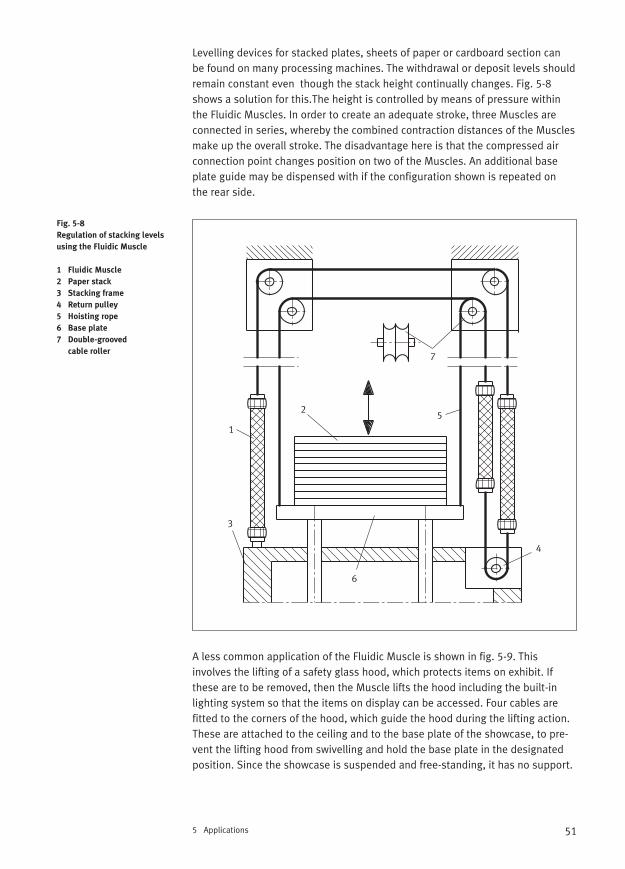
Levelling devices for stacked plates, sheets of paper or cardboard section can be found on many processing machines. The withdrawal or deposit levels shouldremain constant even though the stack height continually changes. Fig. 5-8shows a solution for this.The height is controlled by means of pressure withinthe Fluidic Muscles. In order to create an adequate stroke, three Muscles areconnected in series, whereby the combined contraction distances of the Musclesmake up the overall stroke. The disadvantage here is that the compressed airconnection point changes position on two of the Muscles. An additional baseplate guide may be dispensed with if the configuration shown is repeated on the rear side.
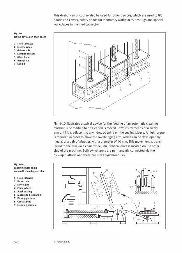
A less common application of the Fluidic Muscle is shown in fig. 5-9. This involves the lifting of a safety glass hood, which protects items on exhibit. Ifthese are to be removed, then the Muscle lifts the hood including the built-inlighting system so that the items on display can be accessed. Four cables are fitted to the corners of the hood, which guide the hood during the lifting action.These are attached to the ceiling and to the base plate of the showcase, to pre-vent the lifting hood from swivelling and hold the base plate in the designatedposition. Since the showcase is suspended and free-standing, it has no support.
5 Applications
Fig. 5-8
Regulation of stacking levels
using the Fluidic Muscle
1 Fluidic Muscle
2 Paper stack
3 Stacking frame
4 Return pulley
5 Hoisting rope
6 Base plate
7 Double-grooved
cable roller
1
2
3
4
5
6
7
52 5 Applications
This design can of course also be used for other devices, which are used to lifthoods and covers, safety hoods for laboratory workplaces, test rigs and specialworkplaces in the medical sector.
Fig. 5-10 illustrates a swivel device for the feeding of an automatic cleaning machine. The module to be cleaned is moved upwards by means of a swivel arm until it is adjacent to a window opening on the sealing sleeve. A high torqueis required in order to move the overhanging arm, which can be developed bymeans of a pair of Muscles with a diameter of 40 mm. This movement is trans-ferred to the arm via a chain wheel. An identical drive is located on the otherside of the machine. Both swivel arms are permanently connected via the pick-up platform and therefore move synchronously.
Fig. 5-9
Lifting devices on show cases
1 Fluidic Muscle
2 Electric cable
3 Guide cable
4 Lighting system
5 Glass hood
6 Base plate
7 Exhibit
Fig. 5-10
Loading device on an
automatic cleaning machine
1 Fluidic Muscle
2 Drive chain
3 Swivel arm
4 Chain wheel
5 Steel bearing
6 Module to be cleaned
7 Pick-up platform
8 Contact seal
9 Cleaning nozzles
1
2
3
4
5
6
7
1
2
3
4
5
6
7
89
5
3
53
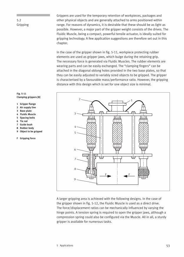
Grippers are used for the temporary retention of workpieces, packages andother physical objects and are generally attached to arms positioned withinrange. For reasons of dynamics, it is desirable that these should be as light aspossible. However, a major part of the gripper weight consists of the drives. TheFluidic Muscle, being a compact, powerful tensile actuator, is ideally suited forgripping technology. A few application suggestions are therefore set out in thischapter.
In the case of the gripper shown in fig. 5-11, workpiece protecting rubber elements are used as gripper jaws, which bulge during the retaining grip. The necessary force is generated via Fluidic Muscles. The rubber elements arewearing parts and can be easily exchanged. The “clamping fingers” can be attached in the diagonal oblong holes provided in the two base plates, so thatthey can be easily adjusted to variably sized objects to be gripped. The gripper is characterised by a favourable mass/performance ratio. However, the grippingdistance with this design which is set for one object size is minimal.
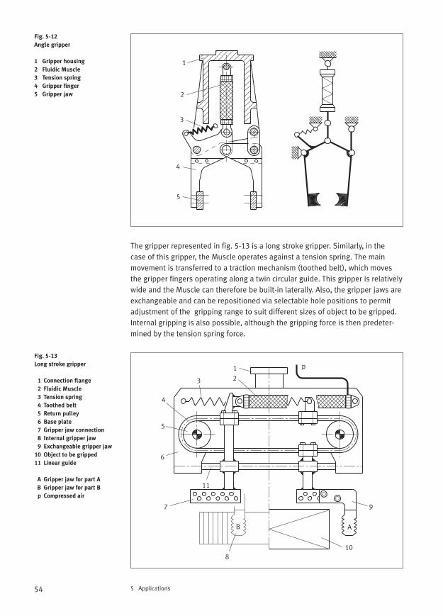
A larger gripping area is achieved with the following designs. In the case of the gripper shown in fig. 5-12, the Fluidic Muscle is used as a direct drive. The force/displacement ratios can be mechanically influenced by varying thehinge points. A tension spring is required to open the gripper jaws, although a compression spring could also be configured via the Muscle. All in all, a sturdygripper is available for numerous tasks.
5 Applications
5.2Gripping
Fig. 5-11
Clamping grippers [8]
1 Gripper flange
2 Air supply line
3 Base plate
4 Fluidic Muscle
5 Spacing bolts
6 Tie rod
7 Guide bush
8 Rubber body
9 Object to be gripped
F Gripping force
12
3
4
5
6
7
8
9
F F
54 5 Applications
The gripper represented in fig. 5-13 is a long stroke gripper. Similarly, in the case of this gripper, the Muscle operates against a tension spring. The mainmovement is transferred to a traction mechanism (toothed belt), which movesthe gripper fingers operating along a twin circular guide. This gripper is relativelywide and the Muscle can therefore be built-in laterally. Also, the gripper jaws areexchangeable and can be repositioned via selectable hole positions to permitadjustment of the gripping range to suit different sizes of object to be gripped.Internal gripping is also possible, although the gripping force is then predeter-mined by the tension spring force.
Fig. 5-12
Angle gripper
1 Gripper housing
2 Fluidic Muscle
3 Tension spring
4 Gripper finger
5 Gripper jaw
Fig. 5-13
Long stroke gripper
1 Connection flange
2 Fluidic Muscle
3 Tension spring
4 Toothed belt
5 Return pulley
6 Base plate
7 Gripper jaw connection
8 Internal gripper jaw
9 Exchangeable gripper jaw
10 Object to be gripped
11 Linear guide
A Gripper jaw for part A
B Gripper jaw for part B
p Compressed air
1
2
3
4
5
11
12
p
3
4
5
6
7
8
9
10
AB
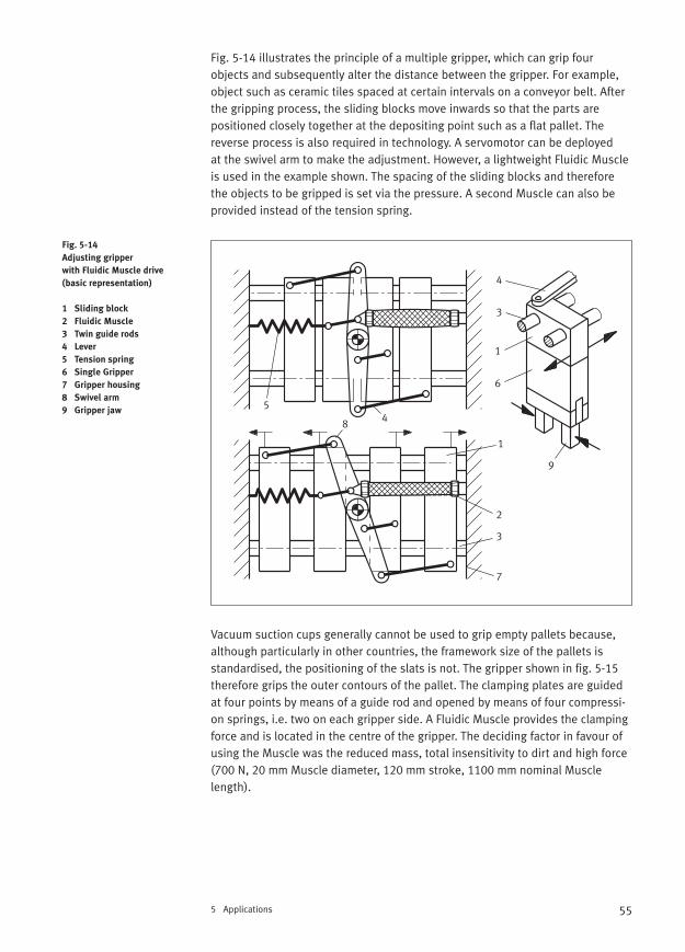
55
Fig. 5-14 illustrates the principle of a multiple gripper, which can grip four objects and subsequently alter the distance between the gripper. For example,object such as ceramic tiles spaced at certain intervals on a conveyor belt. Afterthe gripping process, the sliding blocks move inwards so that the parts are positioned closely together at the depositing point such as a flat pallet. Thereverse process is also required in technology. A servomotor can be deployed at the swivel arm to make the adjustment. However, a lightweight Fluidic Muscleis used in the example shown. The spacing of the sliding blocks and thereforethe objects to be gripped is set via the pressure. A second Muscle can also beprovided instead of the tension spring.
Vacuum suction cups generally cannot be used to grip empty pallets because,although particularly in other countries, the framework size of the pallets isstandardised, the positioning of the slats is not. The gripper shown in fig. 5-15therefore grips the outer contours of the pallet. The clamping plates are guidedat four points by means of a guide rod and opened by means of four compressi-on springs, i.e. two on each gripper side. A Fluidic Muscle provides the clampingforce and is located in the centre of the gripper. The deciding factor in favour ofusing the Muscle was the reduced mass, total insensitivity to dirt and high force(700 N, 20 mm Muscle diameter, 120 mm stroke, 1100 mm nominal Musclelength).
5 Applications
Fig. 5-14
Adjusting gripper
with Fluidic Muscle drive
(basic representation)
1 Sliding block
2 Fluidic Muscle
3 Twin guide rods
4 Lever
5 Tension spring
6 Single Gripper
7 Gripper housing
8 Swivel arm
9 Gripper jaw
1
1
2
3
3
4
45
6
7
8
9
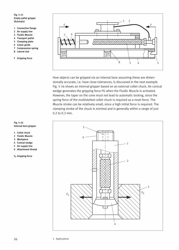
56 5 Applications
How objects can be gripped via an internal bore assuming these are dimen-sionally accurate, i.e. have close tolerances, is discussed in the next example.Fig. 5-16 shows an internal gripper based on an external collet chuck. An conicalwedge generates the gripping force FG when the Fluidic Muscle is activated.However, the taper on the cone must not lead to automatic locking, since thespring force of the multislotted collet chuck is required as a reset force. TheMuscle stroke can be relatively small, since a high initial force is required. Theclamping stroke of the chuck is minimal and is generally within a range of just0.2 to 0.3 mm.
Fig. 5-15
Empty pallet gripper
(Schmalz)
1 Connection flange
2 Air supply line
3 Fluidic Muscle
4 Transport pallet
5 Clamping plate
6 Linear guide
7 Compression spring
8 Lateral slat
F Gripping force
Fig. 5-16
Internal bore gripper
1 Collet chuck
2 Fluidic Muscle
3 Workpiece
4 Conical wedge
5 Air supply line
6 Attachment thread
FG Gripping force
1 2
3 4 5
67
FF
8
1
2
3
5
6
FGFG
4
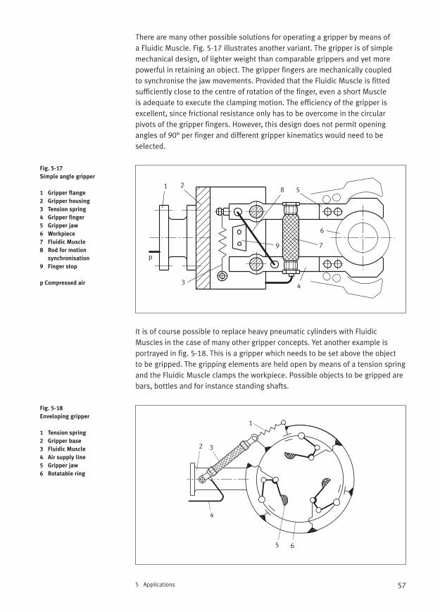
57
There are many other possible solutions for operating a gripper by means of a Fluidic Muscle. Fig. 5-17 illustrates another variant. The gripper is of simplemechanical design, of lighter weight than comparable grippers and yet morepowerful in retaining an object. The gripper fingers are mechanically coupled to synchronise the jaw movements. Provided that the Fluidic Muscle is fitted sufficiently close to the centre of rotation of the finger, even a short Muscle is adequate to execute the clamping motion. The efficiency of the gripper isexcellent, since frictional resistance only has to be overcome in the circularpivots of the gripper fingers. However, this design does not permit openingangles of 90° per finger and different gripper kinematics would need to be selected.
It is of course possible to replace heavy pneumatic cylinders with FluidicMuscles in the case of many other gripper concepts. Yet another example is portrayed in fig. 5-18. This is a gripper which needs to be set above the object to be gripped. The gripping elements are held open by means of a tension springand the Fluidic Muscle clamps the workpiece. Possible objects to be gripped arebars, bottles and for instance standing shafts.
5 Applications
Fig. 5-17
Simple angle gripper
1 Gripper flange
2 Gripper housing
3 Tension spring
4 Gripper finger
5 Gripper jaw
6 Workpiece
7 Fluidic Muscle
8 Rod for motion
synchronisation
9 Finger stop
p Compressed air
Fig. 5-18
Enveloping gripper
1 Tension spring
2 Gripper base
3 Fluidic Muscle
4 Air supply line
5 Gripper jaw
6 Rotatable ring
1 2
3 4
5
6
8
79
p
1
2 3
4
5 6
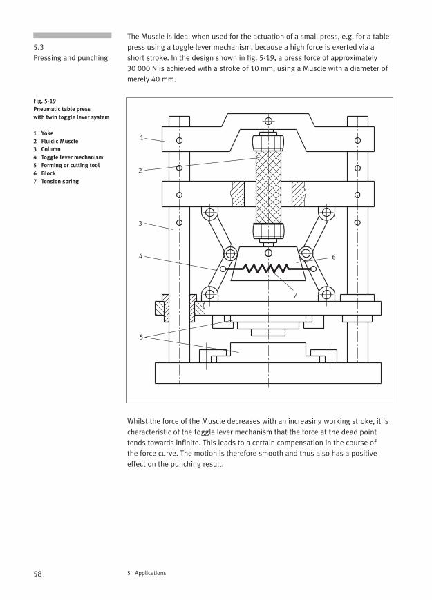
58 5 Applications
The Muscle is ideal when used for the actuation of a small press, e.g. for a tablepress using a toggle lever mechanism, because a high force is exerted via ashort stroke. In the design shown in fig. 5-19, a press force of approximately 30 000 N is achieved with a stroke of 10 mm, using a Muscle with a diameter ofmerely 40 mm.
Whilst the force of the Muscle decreases with an increasing working stroke, it ischaracteristic of the toggle lever mechanism that the force at the dead pointtends towards infinite. This leads to a certain compensation in the course of the force curve. The motion is therefore smooth and thus also has a positiveeffect on the punching result.
5.3Pressing and punching
Fig. 5-19
Pneumatic table press
with twin toggle lever system
1 Yoke
2 Fluidic Muscle
3 Column
4 Toggle lever mechanism
5 Forming or cutting tool
6 Block
7 Tension spring
1
2
3
4
5
6
7
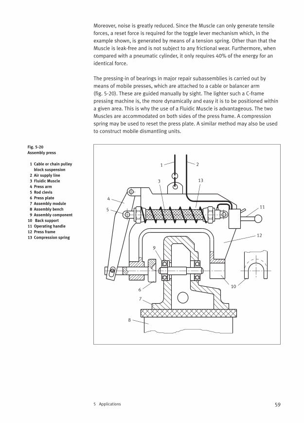
59
Moreover, noise is greatly reduced. Since the Muscle can only generate tensileforces, a reset force is required for the toggle lever mechanism which, in the example shown, is generated by means of a tension spring. Other than that theMuscle is leak-free and is not subject to any frictional wear. Furthermore, whencompared with a pneumatic cylinder, it only requires 40% of the energy for anidentical force.
The pressing-in of bearings in major repair subassemblies is carried out bymeans of mobile presses, which are attached to a cable or balancer arm (fig. 5-20). These are guided manually by sight. The lighter such a C-frame pressing machine is, the more dynamically and easy it is to be positioned withina given area. This is why the use of a Fluidic Muscle is advantageous. The twoMuscles are accommodated on both sides of the press frame. A compressionspring may be used to reset the press plate. A similar method may also be usedto construct mobile dismantling units.
5 Applications
Fig. 5-20
Assembly press
1 Cable or chain pulley
block suspension
2 Air supply line
3 Fluidic Muscle
4 Press arm
5 Rod clevis
6 Press plate
7 Assembly module
8 Assembly bench
9 Assembly component
10 Back support
11 Operating handle
12 Press frame
13 Compression spring
1 2
3
4
5
6
7
8
9
10
11
12
13
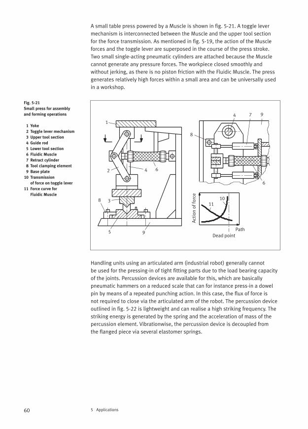
60 5 Applications
A small table press powered by a Muscle is shown in fig. 5-21. A toggle lever mechanism is interconnected between the Muscle and the upper tool section for the force transmission. As mentioned in fig. 5-19, the action of the Muscleforces and the toggle lever are superposed in the course of the press stroke. Two small single-acting pneumatic cylinders are attached because the Musclecannot generate any pressure forces. The workpiece closed smoothly and without jerking, as there is no piston friction with the Fluidic Muscle. The pressgenerates relatively high forces within a small area and can be universally usedin a workshop.
Handling units using an articulated arm (industrial robot) generally cannot be used for the pressing-in of tight fitting parts due to the load bearing capacityof the joints. Percussion devices are available for this, which are basically pneumatic hammers on a reduced scale that can for instance press-in a dowelpin by means of a repeated punching action. In this case, the flux of force is not required to close via the articulated arm of the robot. The percussion deviceoutlined in fig. 5-22 is lightweight and can realise a high striking frequency. Thestriking energy is generated by the spring and the acceleration of mass of thepercussion element. Vibrationwise, the percussion device is decoupled from the flanged piece via several elastomer springs.
Fig. 5-21
Small press for assembly
and forming operations
1 Yoke
2 Toggle lever mechanism
3 Upper tool section
4 Guide rod
5 Lower tool section
6 Fluidic Muscle
7 Retract cylinder
8 Tool clamping element
9 Base plate
10 Transmission
of force on toggle lever
11 Force curve for
Fluidic Muscle
1
2
3
4
4
5
6
6
7
8
8
9
9
1011
PathDead point
Act
ion
of fo
rce
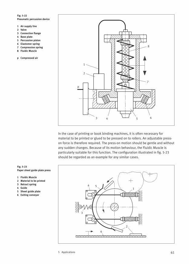
61
In the case of printing or book binding machines, it is often necessary for material to be printed or glued to be pressed on to rollers. An adjustable press-on force is therefore required. The press-on motion should be gentle and withoutany sudden changes. Because of its motion behaviour, the Fluidic Muscle is particularly suitable for this function. The configuration illustrated in fig. 5-23should be regarded as an example for any similar cases.
5 Applications
Fig. 5-22
Pneumatic percussion device
1 Air supply line
2 Valve
3 Connection flange
4 Base plate
5 Percussion piston
6 Elastomer spring
7 Compression spring
8 Fluidic Muscle
p Compressed air
Fig. 5-23
Paper sheet guide plate press
1 Fluidic Muscle
2 Material to be printed
3 Retract spring
4 Guide
5 Sheet guide plate
6 Exiting conveyor
1
2
3 4 5 6
7
8
p
1
2
3
4 5
6
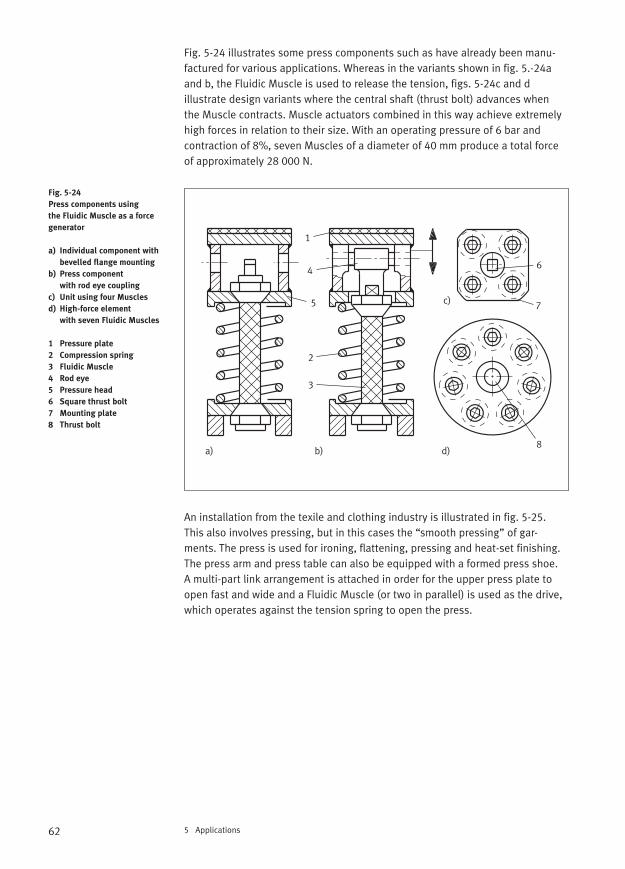
62 5 Applications
Fig. 5-24 illustrates some press components such as have already been manu-factured for various applications. Whereas in the variants shown in fig. 5.-24aand b, the Fluidic Muscle is used to release the tension, figs. 5-24c and d illustrate design variants where the central shaft (thrust bolt) advances when the Muscle contracts. Muscle actuators combined in this way achieve extremelyhigh forces in relation to their size. With an operating pressure of 6 bar and contraction of 8%, seven Muscles of a diameter of 40 mm produce a total forceof approximately 28 000 N.
An installation from the texile and clothing industry is illustrated in fig. 5-25. This also involves pressing, but in this cases the “smooth pressing” of gar-ments. The press is used for ironing, flattening, pressing and heat-set finishing.The press arm and press table can also be equipped with a formed press shoe. A multi-part link arrangement is attached in order for the upper press plate toopen fast and wide and a Fluidic Muscle (or two in parallel) is used as the drive,which operates against the tension spring to open the press.
Fig. 5-24
Press components using
the Fluidic Muscle as a force
generator
a) Individual component with
bevelled flange mounting
b) Press component
with rod eye coupling
c) Unit using four Muscles
d) High-force element
with seven Fluidic Muscles
1 Pressure plate
2 Compression spring
3 Fluidic Muscle
4 Rod eye
5 Pressure head
6 Square thrust bolt
7 Mounting plate
8 Thrust bolt
a) b)
c)
d)
1
2
3
4 6
5 7
8
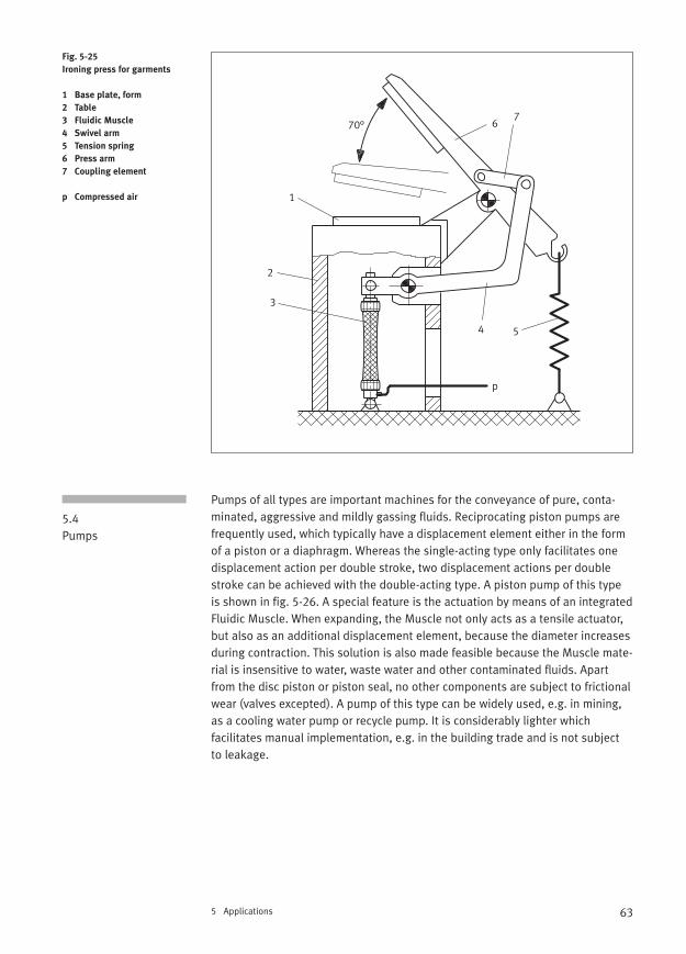
63
Pumps of all types are important machines for the conveyance of pure, conta-minated, aggressive and mildly gassing fluids. Reciprocating piston pumps are frequently used, which typically have a displacement element either in the formof a piston or a diaphragm. Whereas the single-acting type only facilitates onedisplacement action per double stroke, two displacement actions per doublestroke can be achieved with the double-acting type. A piston pump of this typeis shown in fig. 5-26. A special feature is the actuation by means of an integratedFluidic Muscle. When expanding, the Muscle not only acts as a tensile actuator,but also as an additional displacement element, because the diameter increasesduring contraction. This solution is also made feasible because the Muscle mate-rial is insensitive to water, waste water and other contaminated fluids. Apartfrom the disc piston or piston seal, no other components are subject to frictionalwear (valves excepted). A pump of this type can be widely used, e.g. in mining,as a cooling water pump or recycle pump. It is considerably lighter which facilitates manual implementation, e.g. in the building trade and is not subject to leakage.
5 Applications
Fig. 5-25
Ironing press for garments
1 Base plate, form
2 Table
3 Fluidic Muscle
4 Swivel arm
5 Tension spring
6 Press arm
7 Coupling element
p Compressed air
5.4Pumps
1
2
3
4 5
67
70°
p
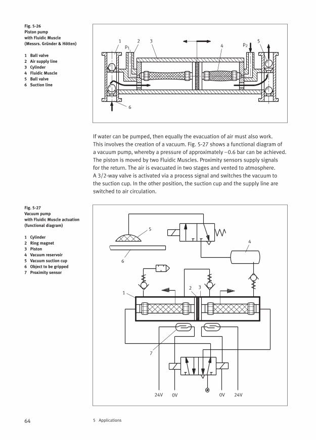
64 5 Applications
If water can be pumped, then equally the evacuation of air must also work. This involves the creation of a vacuum. Fig. 5-27 shows a functional diagram of a vacuum pump, whereby a pressure of approximately –0.6 bar can be achieved.The piston is moved by two Fluidic Muscles. Proximity sensors supply signals for the return. The air is evacuated in two stages and vented to atmosphere. A 3/2-way valve is activated via a process signal and switches the vacuum to the suction cup. In the other position, the suction cup and the supply line areswitched to air circulation.
Fig. 5-26
Piston pump
with Fluidic Muscle
(Messrs. Gründer & Hötten)
1 Ball valve
2 Air supply line
3 Cylinder
4 Fluidic Muscle
5 Ball valve
6 Suction line
Fig. 5-27
Vacuum pump
with Fluidic Muscle actuation
(functional diagram)
1 Cylinder
2 Ring magnet
3 Piston
4 Vacuum reservoir
5 Vacuum suction cup
6 Object to be gripped
7 Proximity sensor
1 2 34
5
6
p1p2
0V0V24V 24V
12 3
4
5
6
7
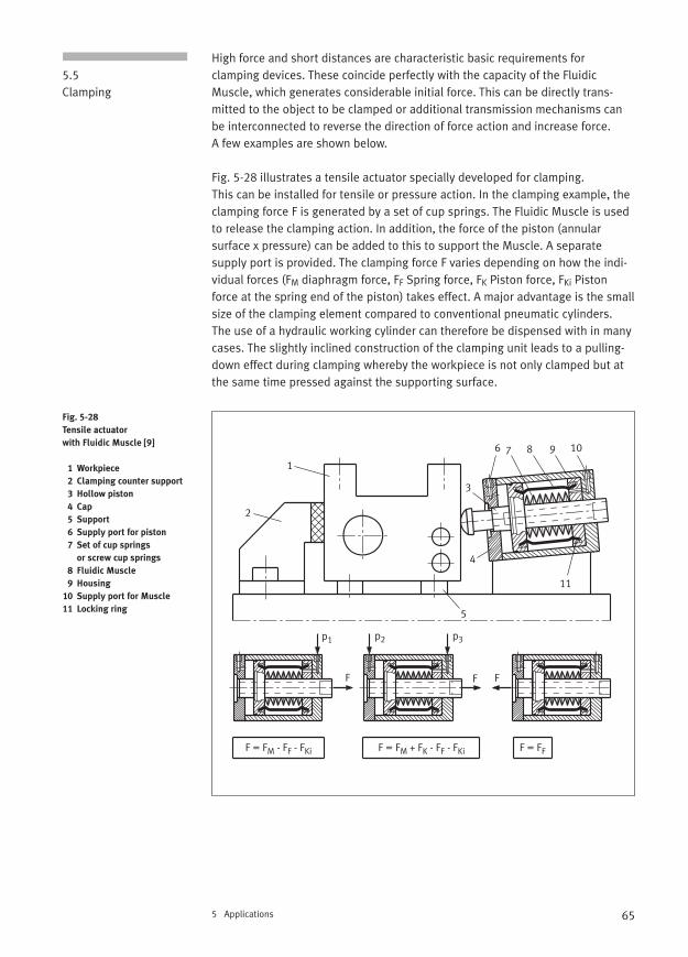
65
High force and short distances are characteristic basic requirements for clamping devices. These coincide perfectly with the capacity of the FluidicMuscle, which generates considerable initial force. This can be directly trans-mitted to the object to be clamped or additional transmission mechanisms canbe interconnected to reverse the direction of force action and increase force. A few examples are shown below.
Fig. 5-28 illustrates a tensile actuator specially developed for clamping. This can be installed for tensile or pressure action. In the clamping example, theclamping force F is generated by a set of cup springs. The Fluidic Muscle is usedto release the clamping action. In addition, the force of the piston (annular surface x pressure) can be added to this to support the Muscle. A separate supply port is provided. The clamping force F varies depending on how the indi-vidual forces (FM diaphragm force, FF Spring force, FK Piston force, FKi Pistonforce at the spring end of the piston) takes effect. A major advantage is the smallsize of the clamping element compared to conventional pneumatic cylinders. The use of a hydraulic working cylinder can therefore be dispensed with in manycases. The slightly inclined construction of the clamping unit leads to a pulling-down effect during clamping whereby the workpiece is not only clamped but atthe same time pressed against the supporting surface.
5 Applications
5.5Clamping
Fig. 5-28
Tensile actuator
with Fluidic Muscle [9]
1 Workpiece
2 Clamping counter support
3 Hollow piston
4 Cap
5 Support
6 Supply port for piston
7 Set of cup springs
or screw cup springs
8 Fluidic Muscle
9 Housing
10 Supply port for Muscle
11 Locking ring
1
2
3
4
5
6 7 8 9 10
11
F F F
p1 p2 p3
F = FM - FF - FKi F = FM + FK - FF - FKi F = FF
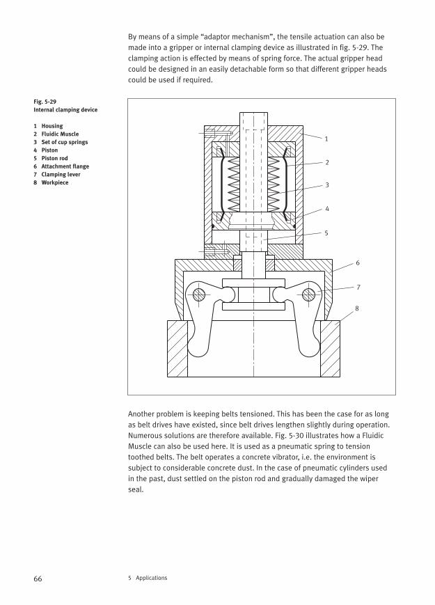
66 5 Applications
By means of a simple “adaptor mechanism”, the tensile actuation can also bemade into a gripper or internal clamping device as illustrated in fig. 5-29. Theclamping action is effected by means of spring force. The actual gripper headcould be designed in an easily detachable form so that different gripper headscould be used if required.
Another problem is keeping belts tensioned. This has been the case for as longas belt drives have existed, since belt drives lengthen slightly during operation.Numerous solutions are therefore available. Fig. 5-30 illustrates how a FluidicMuscle can also be used here. It is used as a pneumatic spring to tension toothed belts. The belt operates a concrete vibrator, i.e. the environment is subject to considerable concrete dust. In the case of pneumatic cylinders used in the past, dust settled on the piston rod and gradually damaged the wiperseal.
Fig. 5-29
Internal clamping device
1 Housing
2 Fluidic Muscle
3 Set of cup springs
4 Piston
5 Piston rod
6 Attachment flange
7 Clamping lever
8 Workpiece
1
2
3
4
5
6
7
8
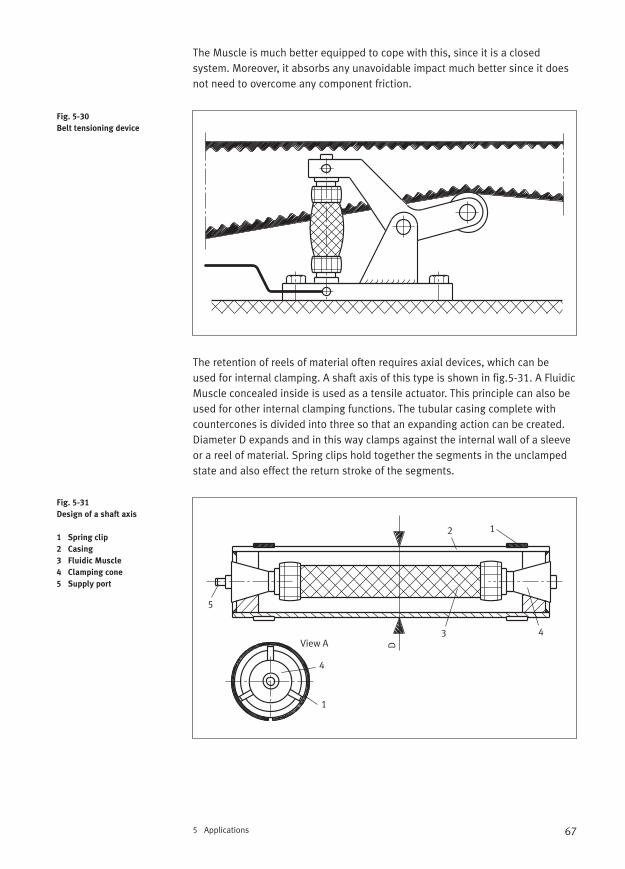
67
The Muscle is much better equipped to cope with this, since it is a closedsystem. Moreover, it absorbs any unavoidable impact much better since it doesnot need to overcome any component friction.
The retention of reels of material often requires axial devices, which can be used for internal clamping. A shaft axis of this type is shown in fig.5-31. A FluidicMuscle concealed inside is used as a tensile actuator. This principle can also beused for other internal clamping functions. The tubular casing complete withcountercones is divided into three so that an expanding action can be created.Diameter D expands and in this way clamps against the internal wall of a sleeveor a reel of material. Spring clips hold together the segments in the unclampedstate and also effect the return stroke of the segments.
5 Applications
Fig. 5-30
Belt tensioning device
Fig. 5-31
Design of a shaft axis
1 Spring clip
2 Casing
3 Fluidic Muscle
4 Clamping cone
5 Supply port
12
D
3 4
5
View A
1
4
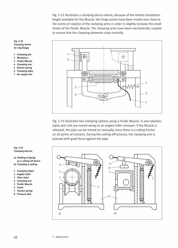
68 5 Applications
Fig. 5-32 illustrates a clamping device where, because of the limited installationlength available for the Muscle, the hinge points have been moved very close tothe centre of rotation of the clamping arms in order to slightly increase the smallstroke of the Fluidic Muscle. The clamping arms have been mechanically coupledto ensure that the clamping elements close centrally.
Fig. 5-33 illustrates two clamping options using a Fluidic Muscle. In one solution,pipes and rods are moved along on an angled roller conveyor. If the Muscle isreleased, the pipe can be moved on manually, since there is a rolling friction on all points of contacts. During the cutting-off process, the clamping arm ispressed with great force against the pipe.
Fig. 5-32
Clamping device
for ring flange
1 Clamping jaw
2 Workpiece
3 Fluidic Muscle
4 Clamping arm
5 Retract spring
6 Clamping table
7 Air supply line
Fig. 5-33
Clamping devices
a) Holding of piping
on a cutting off device
b) Clamping a casting
1 Clamping object
2 Angled roller
3 Plain roller
4 Clamping arm
5 Fluidic Muscle
6 Frame
7 Tension spring
8 Pressure disk
1
2
3
4
5
6
7
1 1
a) b)
2
3 4
5
6
7
8
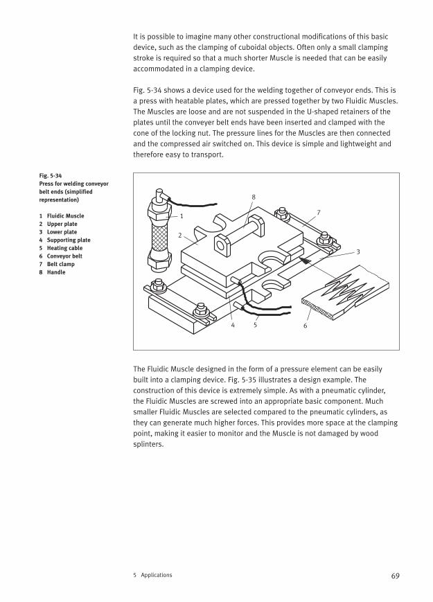
69
It is possible to imagine many other constructional modifications of this basicdevice, such as the clamping of cuboidal objects. Often only a small clampingstroke is required so that a much shorter Muscle is needed that can be easilyaccommodated in a clamping device.
Fig. 5-34 shows a device used for the welding together of conveyor ends. This isa press with heatable plates, which are pressed together by two Fluidic Muscles.The Muscles are loose and are not suspended in the U-shaped retainers of theplates until the conveyer belt ends have been inserted and clamped with thecone of the locking nut. The pressure lines for the Muscles are then connectedand the compressed air switched on. This device is simple and lightweight andtherefore easy to transport.
The Fluidic Muscle designed in the form of a pressure element can be easily built into a clamping device. Fig. 5-35 illustrates a design example. The construction of this device is extremely simple. As with a pneumatic cylinder, the Fluidic Muscles are screwed into an appropriate basic component. Muchsmaller Fluidic Muscles are selected compared to the pneumatic cylinders, asthey can generate much higher forces. This provides more space at the clampingpoint, making it easier to monitor and the Muscle is not damaged by wood splinters.
5 Applications
Fig. 5-34
Press for welding conveyor
belt ends (simplified
representation)
1 Fluidic Muscle
2 Upper plate
3 Lower plate
4 Supporting plate
5 Heating cable
6 Conveyor belt
7 Belt clamp
8 Handle
1
2
3
4 5 6
7
8
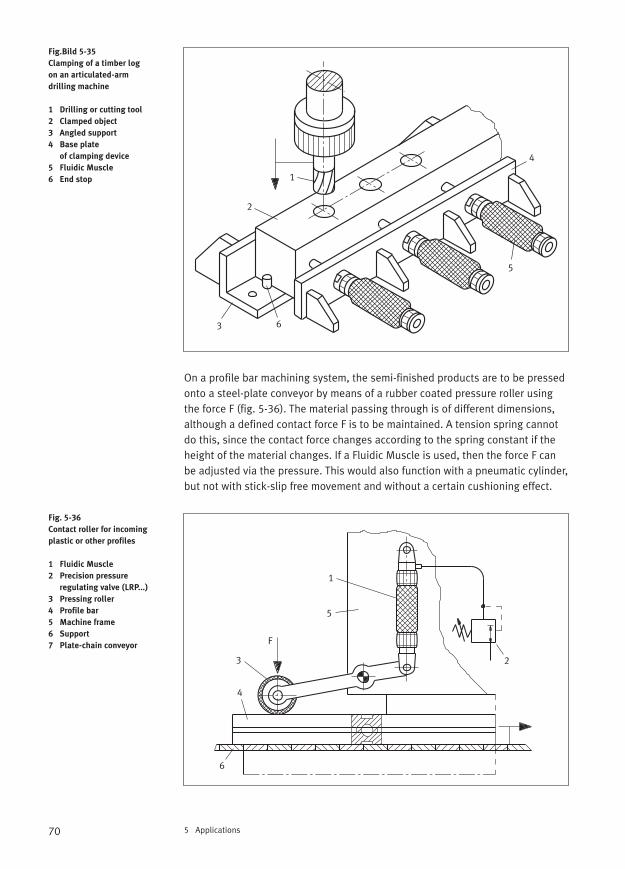
70 5 Applications
On a profile bar machining system, the semi-finished products are to be pressedonto a steel-plate conveyor by means of a rubber coated pressure roller usingthe force F (fig. 5-36). The material passing through is of different dimensions,although a defined contact force F is to be maintained. A tension spring cannotdo this, since the contact force changes according to the spring constant if theheight of the material changes. If a Fluidic Muscle is used, then the force F canbe adjusted via the pressure. This would also function with a pneumatic cylinder,but not with stick-slip free movement and without a certain cushioning effect.
Fig.Bild 5-35
Clamping of a timber log
on an articulated-arm
drilling machine
1 Drilling or cutting tool
2 Clamped object
3 Angled support
4 Base plate
of clamping device
5 Fluidic Muscle
6 End stop
Fig. 5-36
Contact roller for incoming
plastic or other profiles
1 Fluidic Muscle
2 Precision pressure
regulating valve (LRP...)
3 Pressing roller
4 Profile bar
5 Machine frame
6 Support
7 Plate-chain conveyor
1
2
4
5
63
1
23
4
6
5
F
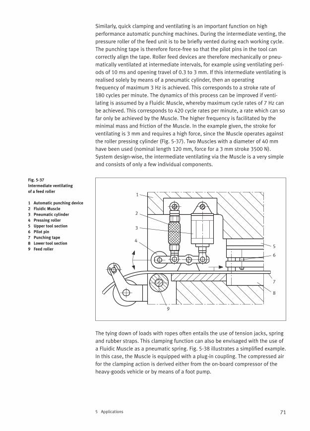
71
Similarly, quick clamping and ventilating is an important function on high performance automatic punching machines. During the intermediate venting, thepressure roller of the feed unit is to be briefly vented during each working cycle.The punching tape is therefore force-free so that the pilot pins in the tool cancorrectly align the tape. Roller feed devices are therefore mechanically or pneu-matically ventilated at intermediate intervals, for example using ventilating peri-ods of 10 ms and opening travel of 0.3 to 3 mm. If this intermediate ventilating isrealised solely by means of a pneumatic cylinder, then an operating frequency of maximum 3 Hz is achieved. This corresponds to a stroke rate of 180 cycles per minute. The dynamics of this process can be improved if venti-lating is assumed by a Fluidic Muscle, whereby maximum cycle rates of 7 Hz canbe achieved. This corresponds to 420 cycle rates per minute, a rate which can sofar only be achieved by the Muscle. The higher frequency is facilitated by theminimal mass and friction of the Muscle. In the example given, the stroke forventilating is 3 mm and requires a high force, since the Muscle operates againstthe roller pressing cylinder (Fig. 5-37). Two Muscles with a diameter of 40 mmhave been used (nominal length 120 mm, force for a 3 mm stroke 3500 N).System design-wise, the intermediate ventilating via the Muscle is a very simpleand consists of only a few individual components.
The tying down of loads with ropes often entails the use of tension jacks, springand rubber straps. This clamping function can also be envisaged with the use ofa Fluidic Muscle as a pneumatic spring. Fig. 5-38 illustrates a simplified example.In this case, the Muscle is equipped with a plug-in coupling. The compressed airfor the clamping action is derived either from the on-board compressor of theheavy-goods vehicle or by means of a foot pump.
5 Applications
Fig. 5-37
Intermediate ventilating
of a feed roller
1 Automatic punching device
2 Fluidic Muscle
3 Pneumatic cylinder
4 Pressing roller
5 Upper tool section
6 Pilot pin
7 Punching tape
8 Lower tool section
9 Feed roller
1
2
3
45
6
7
8
9
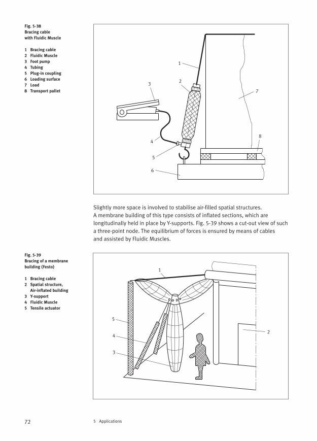
72 5 Applications
Slightly more space is involved to stabilise air-filled spatial structures. A membrane building of this type consists of inflated sections, which are longitudinally held in place by Y-supports. Fig. 5-39 shows a cut-out view of sucha three-point node. The equilibrium of forces is ensured by means of cables and assisted by Fluidic Muscles.
Fig. 5-38
Bracing cable
with Fluidic Muscle
1 Bracing cable
2 Fluidic Muscle
3 Foot pump
4 Tubing
5 Plug-in coupling
6 Loading surface
7 Load
8 Transport pallet
Fig. 5-39
Bracing of a membrane
building (Festo)
1 Bracing cable
2 Spatial structure,
Air-inflated building
3 Y-support
4 Fluidic Muscle
5 Tensile actuator
1
23
4
5
6
7
8
1
2
3
4
5
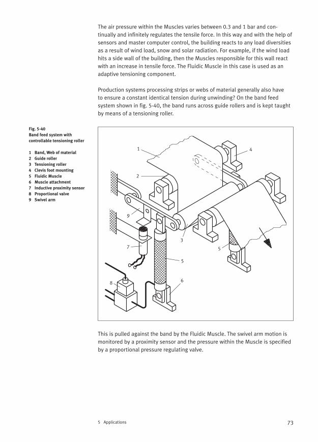
73
The air pressure within the Muscles varies between 0.3 and 1 bar and con-tinually and infinitely regulates the tensile force. In this way and with the help ofsensors and master computer control, the building reacts to any load diversitiesas a result of wind load, snow and solar radiation. For example, if the wind loadhits a side wall of the building, then the Muscles responsible for this wall reactwith an increase in tensile force. The Fluidic Muscle in this case is used as anadaptive tensioning component.
Production systems processing strips or webs of material generally also have to ensure a constant identical tension during unwinding? On the band feedsystem shown in fig. 5-40, the band runs across guide rollers and is kept taughtby means of a tensioning roller.
This is pulled against the band by the Fluidic Muscle. The swivel arm motion ismonitored by a proximity sensor and the pressure within the Muscle is specifiedby a proportional pressure regulating valve.
5 Applications
Fig. 5-40
Band feed system with
controllable tensioning roller
1 Band, Web of material
2 Guide roller
3 Tensioning roller
4 Clevis foot mounting
5 Fluidic Muscle
6 Muscle attachment
7 Inductive proximity sensor
8 Proportional valve
9 Swivel arm
1
2
3
4
5
6
7
8
9
5
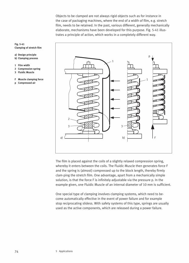
74 5 Applications
Objects to be clamped are not always rigid objects such as for instance in the case of packaging machines, where the end of a width of film, e.g. stretchfilm, needs to be retained. In the past, various different, generally mechanicallyelaborate, mechanisms have been developed for this purpose. Fig. 5-41 illus-trates a principle of action, which works in a completely different way.
The film is placed against the coils of a slightly relaxed compression spring, whereby it enters between the coils. The Fluidic Muscle then generates force Fand the spring is (almost) compressed up to the block length, thereby firmlyclam-ping the stretch film. One advantage, apart from a mechanically simplesolution, is that the force F is infinitely adjustable via the pressure p. In theexample given, one Fluidic Muscle of an internal diameter of 10 mm is sufficient.
One special type of clamping involves clamping systems, which need to be-come automatically effective in the event of power failure and for example stop reciprocating slidess. With safety systems of this type, springs are usually used as the active components, which are released during a power failure.
Fig. 5-41
Clamping of stretch film
a) Design principle
b) Clamping process
1 Film width
2 Compression spring
3 Fluidic Muscle
F Muscle clamping force
p Compressed air
a) b) F
1
2
1
3 3
p
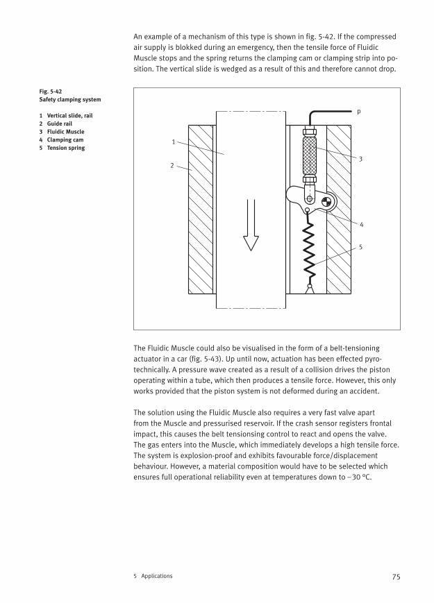
75
An example of a mechanism of this type is shown in fig. 5-42. If the compressedair supply is blokked during an emergency, then the tensile force of FluidicMuscle stops and the spring returns the clamping cam or clamping strip into po-sition. The vertical slide is wedged as a result of this and therefore cannot drop.
The Fluidic Muscle could also be visualised in the form of a belt-tensioningactuator in a car (fig. 5-43). Up until now, actuation has been effected pyro-technically. A pressure wave created as a result of a collision drives the pistonoperating within a tube, which then produces a tensile force. However, this onlyworks provided that the piston system is not deformed during an accident.
The solution using the Fluidic Muscle also requires a very fast valve apart from the Muscle and pressurised reservoir. If the crash sensor registers frontalimpact, this causes the belt tensionsing control to react and opens the valve.The gas enters into the Muscle, which immediately develops a high tensile force.The system is explosion-proof and exhibits favourable force/displacement behaviour. However, a material composition would have to be selected whichensures full operational reliability even at temperatures down to –30 °C.
5 Applications
Fig. 5-42
Safety clamping system
1 Vertical slide, rail
2 Guide rail
3 Fluidic Muscle
4 Clamping cam
5 Tension spring1
2
p
3
4
5
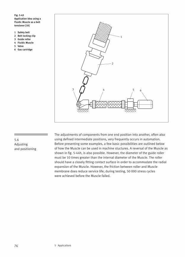
76 5 Applications
The adjustments of components from one end position into another, often alsousing defined intermediate positions, very frequently occurs in automation.Before presenting some examples, a few basic possibilities are outlined below of how the Muscle can be used in machine stuctures. A reversal of the Muscle asshown in fig. 5-44h, is also possible. However, the diameter of the guide rollermust be 10 times greater than the internal diameter of the Muscle. The rollershould have a closely fitting contact surface in order to accommodate the radialexpansion of the Muscle. However, the friction between roller and Muscle membrane does reduce service life; during testing, 50 000 stress cycles were achieved before the Muscle failed.
Fig. 5-43
Application idea using a
Fluidic Muscle as a belt
tensioner [10]
1 Safety belt
2 Belt locking clip
3 Guide roller
4 Fluidic Muscle
5 Valve
6 Gas cartridge
5.6 Adjusting and positioning
1
2
3 4 5 6
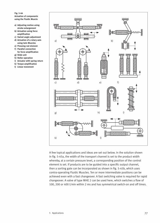
77
A few topical applications and ideas are set out below. In the solution shown in fig. 5-45a, the width of the transport channel is set to the product width whereby, at a certain pressure level, a corresponding position of the control element is set. If products are to be guided into a specific output channel, then a sorting gate can be incorporated as shown in fig. 5-45b, which uses contra-operating Fluidic Muscles. Ten or more intermediate positions can beachieved even with a fast changeover. A fast switching valve is required for rapidchangeover. A valve of type MHE 2 can be used here, which switches a flow of100, 200 or 400 l/min within 2 ms and has symmetrical switch-on and off times.
5 Applications
Fig. 5-44
Actuation of components
using the Fluidic Muscle
a) Adjusting motion using
stroke enlargement
b) Actuation using force
amplification
c) Swivel angle adjustment
d) Actuation of a rotary axis
using twin Muscles
e) Pressing rod element
f ) Parallel connection
for force amplification
g) Slide unit
h) Roller operation
i) Actuator with spring return
k) Torque amplification
l) Linear movement
a) b)
c) d) f )
g) h) i)
k) l)
e)
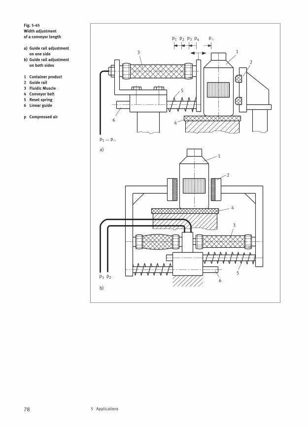
78 5 Applications
Fig. 5-45
Width adjustment
of a conveyor length
a) Guide rail adjustment
on one side
b) Guide rail adjustment
on both sides
1 Container product
2 Guide rail
3 Fluidic Muscle
4 Conveyor belt
5 Reset spring
6 Linear guide
p Compressed air
1
1
2
2
3
3
4
4
5
5
6
6
p1 ... p∩
p1 p2 p3 p4 p∩
p1 p2
a)
b)
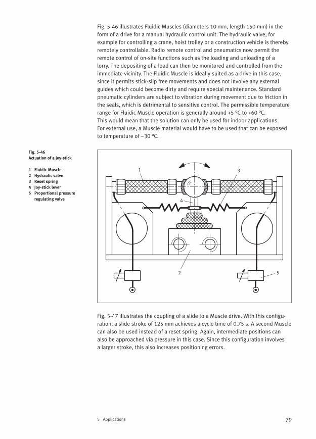
79
Fig. 5-46 illustrates Fluidic Muscles (diameters 10 mm, length 150 mm) in theform of a drive for a manual hydraulic control unit. The hydraulic valve, for example for controlling a crane, hoist trolley or a construction vehicle is therebyremotely controllable. Radio remote control and pneumatics now permit theremote control of on-site functions such as the loading and unloading of a lorry. The depositing of a load can then be monitored and controlled from theimmediate vicinity. The Fluidic Muscle is ideally suited as a drive in this case,since it permits stick-slip free movements and does not involve any external guides which could become dirty and require special maintenance. Standardpneumatic cylinders are subject to vibration during movement due to friction inthe seals, which is detrimental to sensitive control. The permissible temperaturerange for Fluidic Muscle operation is generally around +5 °C to +60 °C. This would mean that the solution can only be used for indoor applications. For external use, a Muscle material would have to be used that can be exposedto temperature of –30 °C.
Fig. 5-47 illustrates the coupling of a slide to a Muscle drive. With this configu-ration, a slide stroke of 125 mm achieves a cycle time of 0.75 s. A second Musclecan also be used instead of a reset spring. Again, intermediate positions canalso be approached via pressure in this case. Since this configuration involves a larger stroke, this also increases positioning errors.
5 Applications
Fig. 5-46
Actuation of a joy-stick
1 Fluidic Muscle
2 Hydraulic valve
3 Reset spring
4 Joy-stick lever
5 Proportional pressure
regulating valve
1
2
3
4
5
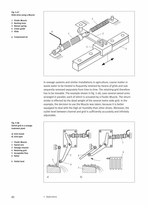
80 5 Applications
In sewage systems and similar installations in agriculture, coarse matter inwaste water to be treated is frequently retained by means of grids and sub-sequently removed separately from time to time. The retaining grid therefore has to be movable. The example shown in fig. 5-48, uses several swivel armsarranged in parallel, each of which is actuated by a Fluidic Muscle. The returnstroke is effected by the dead weight of the several metre wide grid. In theexample, the decision to use the Muscle was taken, because it is better equipped to deal with the high air humidity than other drives. Moreover, the outlet level between channel and grid is sufficiently accurately and infinitelyadjustable.
Fig. 5-47
Slide drive using a Muscle
1 Fluidic Muscle
2 Rocking lever
3 Retract spring
4 Linear guide
5 Slide
p Compressed air
Fig. 5-48
Swivel grid in a sewage
treatment plant
a) Grid closed
b) Grid open
1 Fluidic Muscle
2 Swivel arm
3 Sewage channel
4 Retaining grid
5 Acceptable flow
6 Roller
h Outlet level
1p
2
3
45
1
2
3
4
4
5
6
a) b)
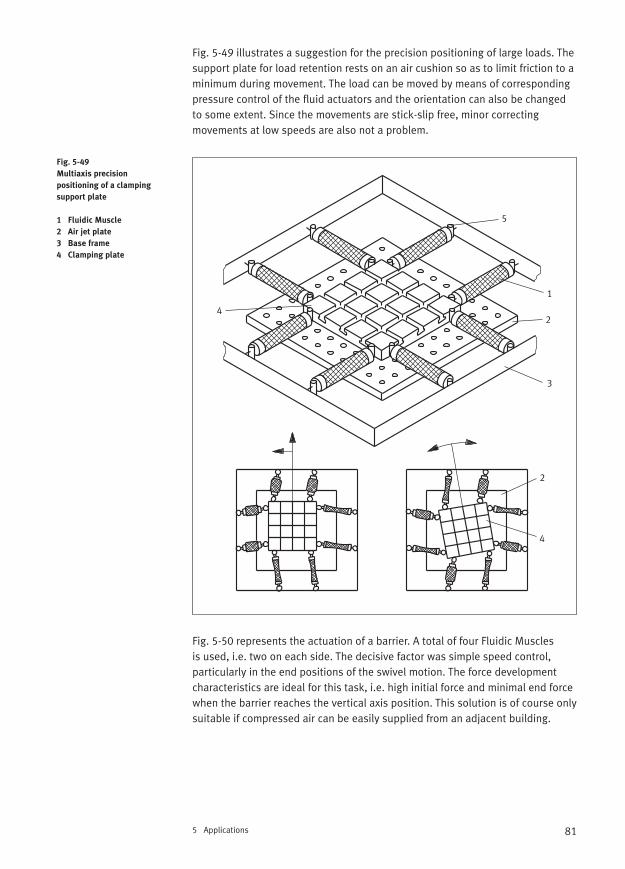
81
Fig. 5-49 illustrates a suggestion for the precision positioning of large loads. Thesupport plate for load retention rests on an air cushion so as to limit friction to aminimum during movement. The load can be moved by means of correspondingpressure control of the fluid actuators and the orientation can also be changedto some extent. Since the movements are stick-slip free, minor correcting movements at low speeds are also not a problem.
Fig. 5-50 represents the actuation of a barrier. A total of four Fluidic Muscles is used, i.e. two on each side. The decisive factor was simple speed control, particularly in the end positions of the swivel motion. The force developmentcharacteristics are ideal for this task, i.e. high initial force and minimal end forcewhen the barrier reaches the vertical axis position. This solution is of course onlysuitable if compressed air can be easily supplied from an adjacent building.
5 Applications
Fig. 5-49
Multiaxis precision
positioning of a clamping
support plate
1 Fluidic Muscle
2 Air jet plate
3 Base frame
4 Clamping plate
1
2
3
4
5
2
4
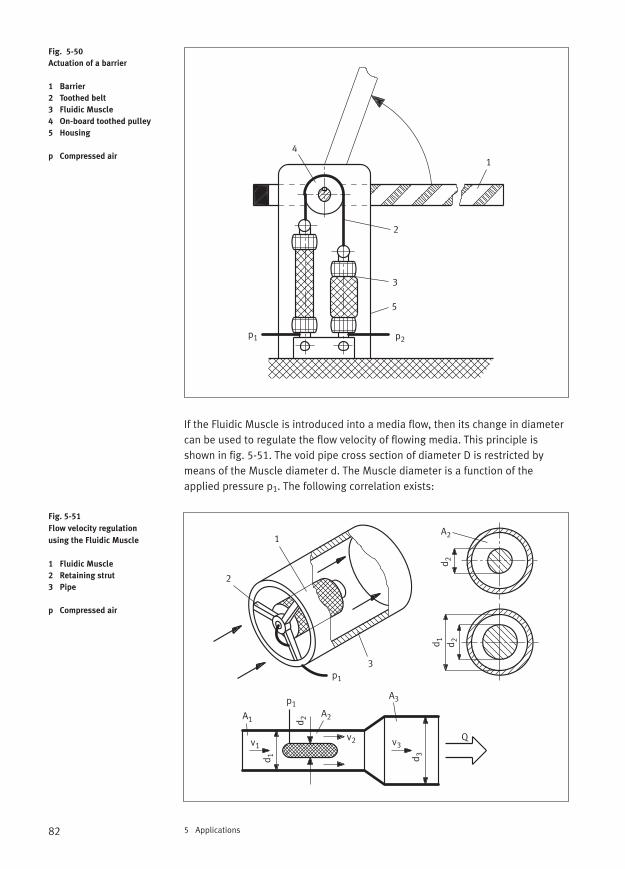
82 5 Applications
If the Fluidic Muscle is introduced into a media flow, then its change in diameter can be used to regulate the flow velocity of flowing media. This principle isshown in fig. 5-51. The void pipe cross section of diameter D is restricted bymeans of the Muscle diameter d. The Muscle diameter is a function of theapplied pressure p1. The following correlation exists:
Fig. 5-50
Actuation of a barrier
1 Barrier
2 Toothed belt
3 Fluidic Muscle
4 On-board toothed pulley
5 Housing
p Compressed air
Fig. 5-51
Flow velocity regulation
using the Fluidic Muscle
1 Fluidic Muscle
2 Retaining strut
3 Pipe
p Compressed air
1
2
3
4
5
p2p1
A1A2
A3
A21
2
3
d 2d 2
p1
d 1
d 2
p1
d 3
v1v2 v3
Q
d 1
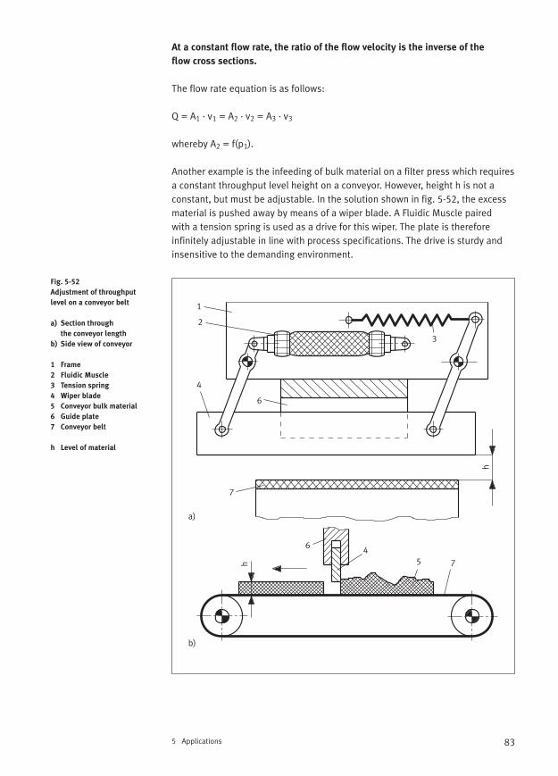
83
At a constant flow rate, the ratio of the flow velocity is the inverse of the
flow cross sections.
The flow rate equation is as follows:
Q = A1 · v1 = A2 · v2 = A3 · v3
whereby A2 = f(p1).
Another example is the infeeding of bulk material on a filter press which requiresa constant throughput level height on a conveyor. However, height h is not aconstant, but must be adjustable. In the solution shown in fig. 5-52, the excessmaterial is pushed away by means of a wiper blade. A Fluidic Muscle paired with a tension spring is used as a drive for this wiper. The plate is therefore infinitely adjustable in line with process specifications. The drive is sturdy andinsensitive to the demanding environment.
5 Applications
Fig. 5-52
Adjustment of throughput
level on a conveyor belt
a) Section through
the conveyor length
b) Side view of conveyor
1 Frame
2 Fluidic Muscle
3 Tension spring
4 Wiper blade
5 Conveyor bulk material
6 Guide plate
7 Conveyor belt
h Level of material
h
h
1
2
3
4
5
6
6
4
7
7
a)
b)
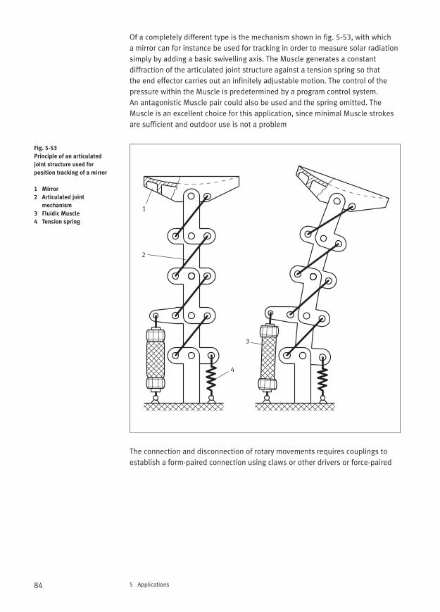
84 5 Applications
Of a completely different type is the mechanism shown in fig. 5-53, with which a mirror can for instance be used for tracking in order to measure solar radiationsimply by adding a basic swivelling axis. The Muscle generates a constant diffraction of the articulated joint structure against a tension spring so that the end effector carries out an infinitely adjustable motion. The control of thepressure within the Muscle is predetermined by a program control system. An antagonistic Muscle pair could also be used and the spring omitted. TheMuscle is an excellent choice for this application, since minimal Muscle strokesare sufficient and outdoor use is not a problem
The connection and disconnection of rotary movements requires couplings toestablish a form-paired connection using claws or other drivers or force-paired
Fig. 5-53
Principle of an articulated
joint structure used for
position tracking of a mirror
1 Mirror
2 Articulated joint
mechanism
3 Fluidic Muscle
4 Tension spring
1
2
3
4
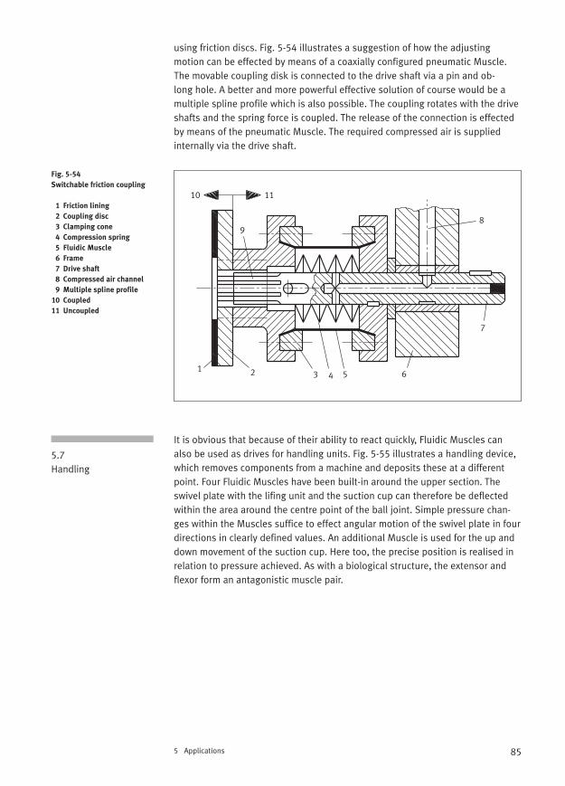
85
using friction discs. Fig. 5-54 illustrates a suggestion of how the adjusting motion can be effected by means of a coaxially configured pneumatic Muscle.The movable coupling disk is connected to the drive shaft via a pin and ob-long hole. A better and more powerful effective solution of course would be a multiple spline profile which is also possible. The coupling rotates with the driveshafts and the spring force is coupled. The release of the connection is effectedby means of the pneumatic Muscle. The required compressed air is suppliedinternally via the drive shaft.
It is obvious that because of their ability to react quickly, Fluidic Muscles canalso be used as drives for handling units. Fig. 5-55 illustrates a handling device,which removes components from a machine and deposits these at a differentpoint. Four Fluidic Muscles have been built-in around the upper section. The swivel plate with the lifing unit and the suction cup can therefore be deflectedwithin the area around the centre point of the ball joint. Simple pressure chan-ges within the Muscles suffice to effect angular motion of the swivel plate in fourdirections in clearly defined values. An additional Muscle is used for the up anddown movement of the suction cup. Here too, the precise position is realised inrelation to pressure achieved. As with a biological structure, the extensor andflexor form an antagonistic muscle pair.
5 Applications
Fig. 5-54
Switchable friction coupling
1 Friction lining
2 Coupling disc
3 Clamping cone
4 Compression spring
5 Fluidic Muscle
6 Frame
7 Drive shaft
8 Compressed air channel
9 Multiple spline profile
10 Coupled
11 Uncoupled
5.7Handling
1 2 3 4 5 6
7
89
10 11
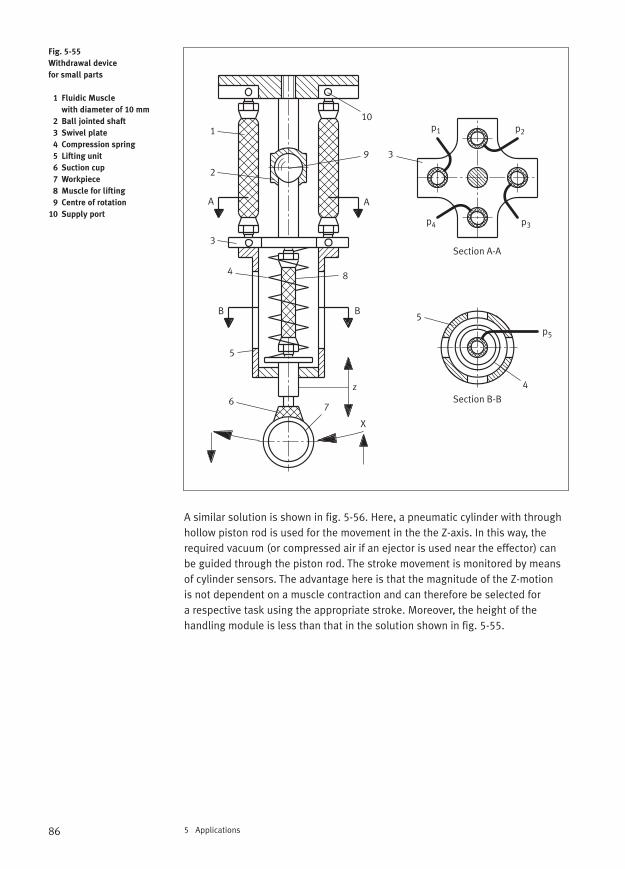
86 5 Applications
A similar solution is shown in fig. 5-56. Here, a pneumatic cylinder with throughhollow piston rod is used for the movement in the the Z-axis. In this way, therequired vacuum (or compressed air if an ejector is used near the effector) canbe guided through the piston rod. The stroke movement is monitored by meansof cylinder sensors. The advantage here is that the magnitude of the Z-motionis not dependent on a muscle contraction and can therefore be selected for a respective task using the appropriate stroke. Moreover, the height of the handling module is less than that in the solution shown in fig. 5-55.
Fig. 5-55
Withdrawal device
for small parts
1 Fluidic Muscle
with diameter of 10 mm
2 Ball jointed shaft
3 Swivel plate
4 Compression spring
5 Lifting unit
6 Suction cup
7 Workpiece
8 Muscle for lifting
9 Centre of rotation
10 Supply port
z
1
2
3
4
5
67
8
9
10
3
5
4
p1 p2
p3p4
p5
A A
Section A-A
B
Section B-B
B
X
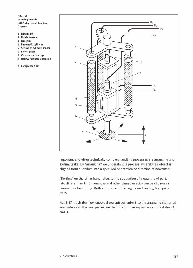
87
Important and often technically complex handling processes are arranging andsorting tasks. By “arranging” we understand a process, whereby an object is aligned from a random into a specified orientation or direction of movement .
“Sorting” on the other hand refers to the separation of a quantity of parts into different sorts. Dimensions and other characteristics can be chosen as parameters for sorting. Both in the case of arranging and sorting high piecerates.
Fig. 5-57 illustrates how cuboidal workpieces enter into the arranging station ateven intervals. The workpieces are then to continue separately in orientation Aand B.
5 Applications
Fig. 5-56
Handling module
with 3 degrees of freedom
(Tripod)
1 Base plate
2 Fluidic Muscle
3 Ball joint
4 Pneumatic cylinder
5 Sensor or cylinder sensor
6 Swivel plate
7 Vacuum suction cup
8 Hollow through piston rod
p Compressed air
p1p2
p3
p5p6
p4
1
2 3
4
5
6
7Z
8

88 5 Applications
An optical sensor senses the incoming workpieces and supplies a signal to a fast switching valve MHE 2 via a PLC. This actuates the two Fluidic Muscles,which then move the slide. Incorrectly orientated parts are immediately pushedon to the parallel conveyor. Since the Fluidic Muscle is capable of extremelyquick contraction and relaxation, very high throughput rates can be achieved. In a similar experimental setup, a maximum operating frequency of 47 Hz hasbeen achieved, i.e. 47 arranging sequences per second. Highly dynamic motionsequences of this type are not achievable with piston drives.
The automatic joining of matching pairs “bolts in holes” generally requires the compensation of small angle and position errors. Joining mechanisms aretherefore used which are equipped with elastomer elements and which ensure a passive compensation. Because of its excellent characteristics, the FluidicMuscle could also be used.
Fig. 5-57
Arranging of workpieces
1 Feed conveyor
2 Workpiece queue
3 Sensor
4 Fluidic Muscle
5 Oscillating arm
6 Parallel conveyor
7 Frame
A and B
Workpiece orientation
1
2
3
4
5
6 7
A
B

89
Fig. 5-58 demonstrates a design solution for this. The compensation mechanisms consists of two function units. The upper row of bearings permitsthe compensation of positional errors x and the lower ones of angular errors β.
In passive mode, the Fluidic Muscles act as springs whose characteristic is changeable. This could even change its characteristic during a joining action,which is not not possible with conventional joining mechanisms. The functioningof joining aids of this type is always dependent on the availability of a joiningchamfer on the base part and/or on the joining part.
5 Applications
Fig. 5-58
Joining mechanism
1 Basic body
2 Fluidic Muscle
3 Positional compensation x
4 Angular compensation β5 Gripper
6 Joining part
7 Basic assembly part
p Supply port
1
2
3
4
5
6
7
3
4
p
x
β
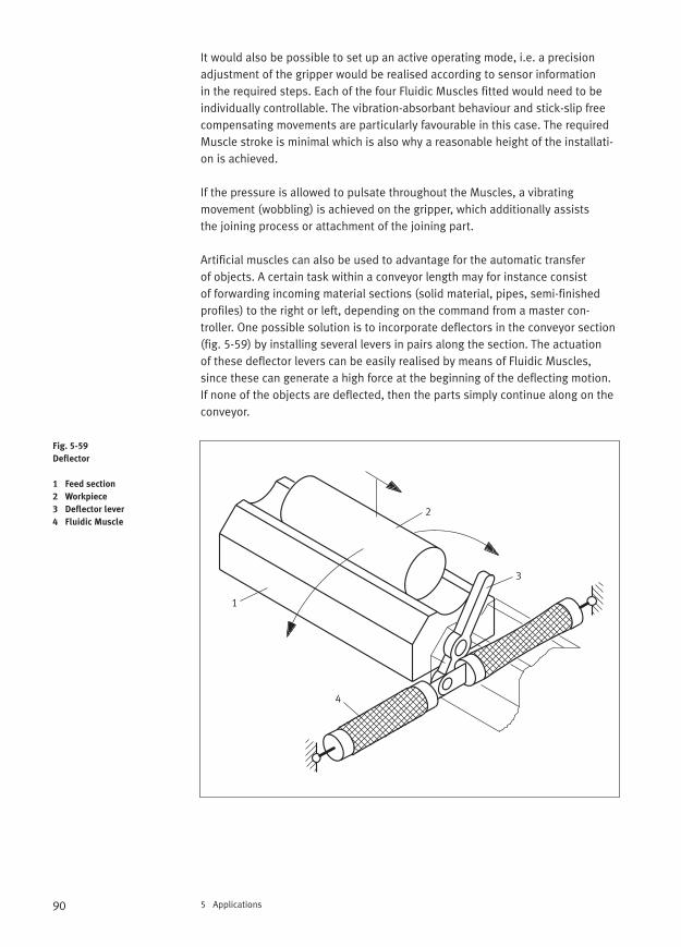
90 5 Applications
It would also be possible to set up an active operating mode, i.e. a precision adjustment of the gripper would be realised according to sensor information in the required steps. Each of the four Fluidic Muscles fitted would need to beindividually controllable. The vibration-absorbant behaviour and stick-slip freecompensating movements are particularly favourable in this case. The requiredMuscle stroke is minimal which is also why a reasonable height of the installati-on is achieved.
If the pressure is allowed to pulsate throughout the Muscles, a vibrating movement (wobbling) is achieved on the gripper, which additionally assists the joining process or attachment of the joining part.
Artificial muscles can also be used to advantage for the automatic transfer of objects. A certain task within a conveyor length may for instance consist of forwarding incoming material sections (solid material, pipes, semi-finished profiles) to the right or left, depending on the command from a master con-troller. One possible solution is to incorporate deflectors in the conveyor section (fig. 5-59) by installing several levers in pairs along the section. The actuation of these deflector levers can be easily realised by means of Fluidic Muscles,since these can generate a high force at the beginning of the deflecting motion.If none of the objects are deflected, then the parts simply continue along on theconveyor.
Fig. 5-59
Deflector
1 Feed section
2 Workpiece
3 Deflector lever
4 Fluidic Muscle
1
2
3
4
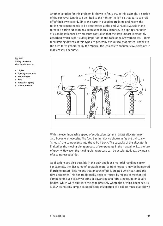
91
Another solution for this problem is shown in fig. 5-60. In this example, a sectionof the conveyor length can be tilted to the right or the left so that parts can rolloff of their own accord. Since the parts in question are large and heavy, the rolling movement needs to be decelerated at the end. A Fluidic Muscle in theform of a spring function has been used in this instance. The spring characteri-stic can be influenced by pressure control so that the stop impact is smoothlyabsorbed which is particularly important in the case of heavy workpieces. Tiltingfeed limiting devices of this type are generally hydraulically operated. Thanks tothe high force generated by the Muscle, the less costly pneumatic Muscles are inmany cases adequate.
With the ever increasing speed of production systems, a fast allocator may also become a necessity. The feed limiting device shown in fig. 5-61 virtually“shoots” the components into the roll-off track. The capacity of the allocator islimited by the moving-along process of components in the magazine, i.e. the lawof gravity. However, the moving-along process can be accelerated, e.g. by meansof a compressed air jet.
Applications are also possible in the bulk and loose material handling sector. For example, the discharge of pourable material from hoppers may be hamperedif arching occurs. This means that an arch effect is created which can stop theflow altogether. This has traditionally been corrected by means of mechanicalcomponents such as swivel arms or advancing and retracting round or squarebodies, which were built-into the zone precisely where the arching effect occurs[11]. A technically simple solution is the installation of a Fluidic Muscle as shown
5 Applications
Fig. 5-60
Tilting separator
with Fluidic Muscle
1 Object
2 Tipping receptacle
3 Roll-off track
4 Stop
5 Muscle as spring
6 Fluidic Muscle
1
2 3 4
5
6

92 5 Applications
in fig. 5-62. Continual contractions of the Muscle regularly disturb the force patterns within the bulk material and thus prevent an arching effect. However,bulk material must not be inclined to agglomorate into lumps under pressuresurges since this would lead to the opposite effect. Trials should therefore becarried out beforehand and the bulk material must not exhibit any visible ab-rasive characteristics.
Fig. 5-61
Fast allocator
1 Magazine chute
2 Workpiece
3 Roll-off track
4 Allocating segment
5 Stop
6 Frame
7 Fluidic Muscle
Fig. 5-62
Bulk material vibrator
in a funnel-type hopper
1 Hopper
2 Fluidic Muscle
3 Arch effect zone
4 Bulk material
1
2
3
4
5
67
1
2
3
4
p
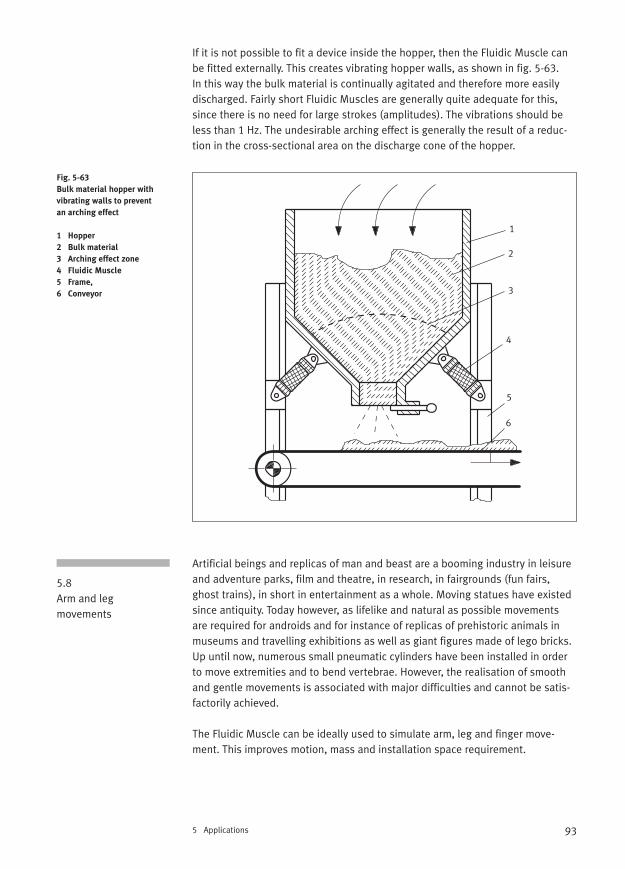
93
If it is not possible to fit a device inside the hopper, then the Fluidic Muscle canbe fitted externally. This creates vibrating hopper walls, as shown in fig. 5-63. In this way the bulk material is continually agitated and therefore more easilydischarged. Fairly short Fluidic Muscles are generally quite adequate for this,since there is no need for large strokes (amplitudes). The vibrations should beless than 1 Hz. The undesirable arching effect is generally the result of a reduc-tion in the cross-sectional area on the discharge cone of the hopper.
Artificial beings and replicas of man and beast are a booming industry in leisureand adventure parks, film and theatre, in research, in fairgrounds (fun fairs,ghost trains), in short in entertainment as a whole. Moving statues have existedsince antiquity. Today however, as lifelike and natural as possible movementsare required for androids and for instance of replicas of prehistoric animals inmuseums and travelling exhibitions as well as giant figures made of lego bricks.Up until now, numerous small pneumatic cylinders have been installed in orderto move extremities and to bend vertebrae. However, the realisation of smoothand gentle movements is associated with major difficulties and cannot be satis-factorily achieved.
The Fluidic Muscle can be ideally used to simulate arm, leg and finger move-ment. This improves motion, mass and installation space requirement.
5 Applications
Fig. 5-63
Bulk material hopper with
vibrating walls to prevent
an arching effect
1 Hopper
2 Bulk material
3 Arching effect zone
4 Fluidic Muscle
5 Frame,
6 Conveyor
5.8Arm and leg movements
1
2
3
4
5
6
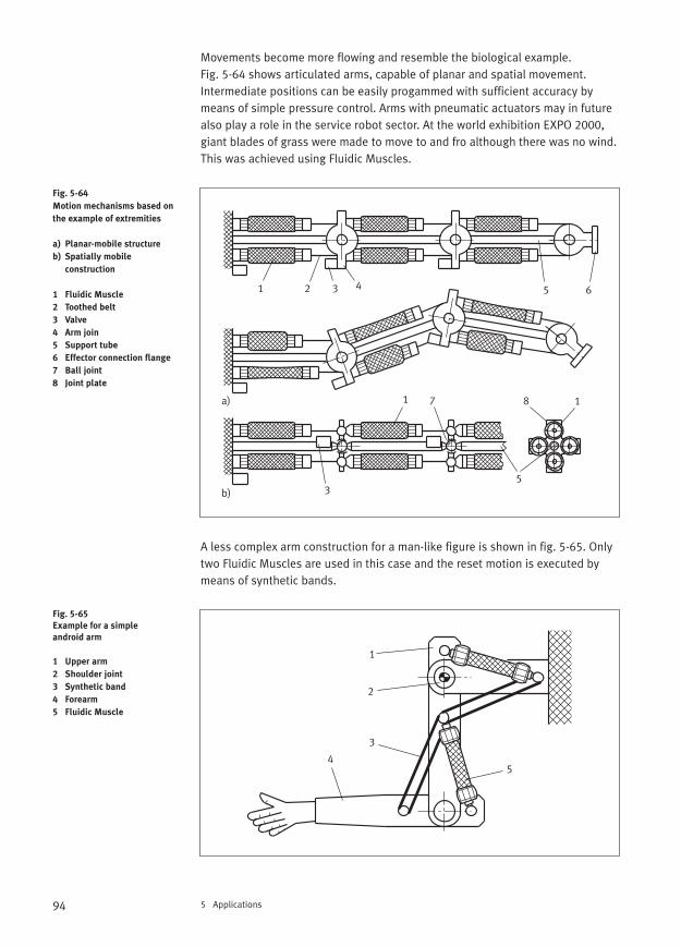
94 5 Applications
Movements become more flowing and resemble the biological example. Fig. 5-64 shows articulated arms, capable of planar and spatial movement.Intermediate positions can be easily progammed with sufficient accuracy bymeans of simple pressure control. Arms with pneumatic actuators may in futurealso play a role in the service robot sector. At the world exhibition EXPO 2000,giant blades of grass were made to move to and fro although there was no wind.This was achieved using Fluidic Muscles.
A less complex arm construction for a man-like figure is shown in fig. 5-65. Onlytwo Fluidic Muscles are used in this case and the reset motion is executed bymeans of synthetic bands.
Fig. 5-64
Motion mechanisms based on
the example of extremities
a) Planar-mobile structure
b) Spatially mobile
construction
1 Fluidic Muscle
2 Toothed belt
3 Valve
4 Arm join
5 Support tube
6 Effector connection flange
7 Ball joint
8 Joint plate
Fig. 5-65
Example for a simple
android arm
1 Upper arm
2 Shoulder joint
3 Synthetic band
4 Forearm
5 Fluidic Muscle
a)
b)
1 2 3 4 5 6
71 8 1
53
1
2
3
45

95
Likewise, android hands can be actuated via a Fluidic Muscle [12]. In fig. 5-66,the finger movements are created pneumatically. The phalanxes bend each articulated finger uniformly in line with a gripping contour. A stiff elastic bandtransmits the movement and a tension spring represents the counterforce to the Fluidic Muscle. The fingers close via the tensile spring force.
5-Finger gripper hands with articulated fingers have already been created forlaboratory trials. In this case, the actuation is effected by several Fluidic Muscles,whose movements are transmitted to the fingers via cables. The motion se-quences are extremely smooth and quiet thanks to the use of proportional controllers in use and the hand model can even be remotely controlled via theInternet since it is coupled with an embedded web server. This is illustrated inthe block diagram shown in fig. 5-67. A compressor can be used as a possiblesource of compressed air or a compressed-air bottle in the case of mobile devices.
The forward movement of legs is also a topical object for research. Walking machines are currently being constructed at many research institutes and uni-versities for study to determine how four-legged animaloids behave in normaland extreme situations and how leg movements can best be coordinated.
5 Applications
Fig. 5-66
Android hand
1 Flat rigid synthetic band
2 Phalanx
3 Joint
4 Linear guide
5 Fluidic Muscle
p Compressed air
Fig. 5-67
Block diagram for a hand
model (as per Grunz)
TCP/IP
Transmission Control
Protocol/Internet Suit
of Protocols
Network protocol
Standard for data
exchange in heterogenous
networks
1
2
34
5 p
Proportionalcontroller
pneumatic
Articulatedfinger hand
TCP/IP mechanical
electrical
EmbeddedWeb-Server
ClientBrowser
Airsupply
Finger
Compressed air
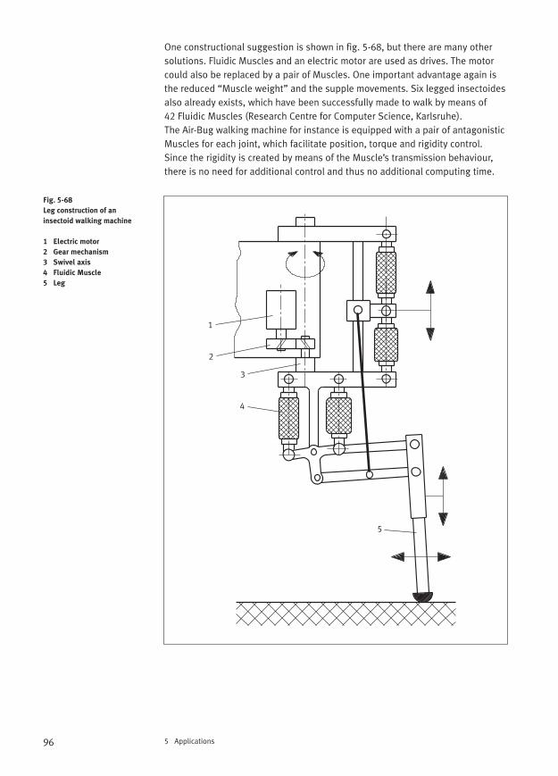
96 5 Applications
One constructional suggestion is shown in fig. 5-68, but there are many othersolutions. Fluidic Muscles and an electric motor are used as drives. The motorcould also be replaced by a pair of Muscles. One important advantage again isthe reduced “Muscle weight” and the supple movements. Six legged insectoidesalso already exists, which have been successfully made to walk by means of 42 Fluidic Muscles (Research Centre for Computer Science, Karlsruhe). The Air-Bug walking machine for instance is equipped with a pair of antagonisticMuscles for each joint, which facilitate position, torque and rigidity control.Since the rigidity is created by means of the Muscle’s transmission behaviour,there is no need for additional control and thus no additional computing time.
Fig. 5-68
Leg construction of an
insectoid walking machine
1 Electric motor
2 Gear mechanism
3 Swivel axis
4 Fluidic Muscle
5 Leg
1
2
3
4
5
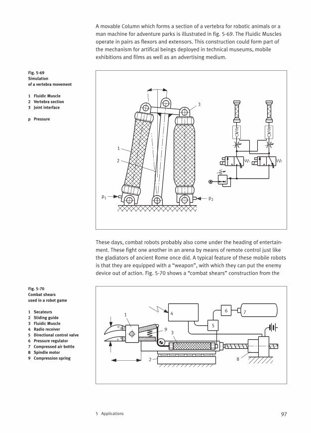
97
A movable Column which forms a section of a vertebra for robotic animals or aman machine for adventure parks is illustrated in fig. 5-69. The Fluidic Musclesoperate in pairs as flexors and extensors. This construction could form part ofthe mechanism for artifical beings deployed in technical museums, mobile exhibitions and films as well as an advertising medium.
These days, combat robots probably also come under the heading of entertain-ment. These fight one another in an arena by means of remote control just likethe gladiators of ancient Rome once did. A typical feature of these mobile robotsis that they are equipped with a “weapon”, with which they can put the enemydevice out of action. Fig. 5-70 shows a “combat shears” construction from the
5 Applications
Fig. 5-69
Simulation
of a vertebra movement
1 Fluidic Muscle
2 Vertebra section
3 Joint interface
p Pressure
Fig. 5-70
Combat shears
used in a robot game
1 Secateurs
2 Sliding guide
3 Fluidic Muscle
4 Radio receiver
5 Directional control valve
6 Pressure regulator
7 Compressed air bottle
8 Spindle motor
9 Compression spring
1
2
3
p2p1
1
2
3
4
5
6 7
8
9
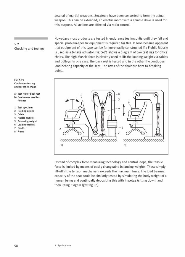
98 5 Applications
arsenal of martial weapons. Secateurs have been converted to form the actualweapon. This can be extended; an electric motor with a spindle drive is used forthis purpose. All actions are effected via radio control.
Nowadays most products are tested in endurance testing units until they fail andspecial problem-specific equipment is required for this. It soon became apparentthat equipment of this type can be far more easily constructed if a Fluidic Muscleis used as a tensile actuator. Fig. 5-71 shows a diagram of two test rigs for officechairs. The high Muscle force is cleverly used to lift the loading weight via cablesand pulleys. In one case, the back rest is tested and in the other the contiuousload bearing capacity of the seat. The arms of the chair are bent to breakingpoint.
Instead of complex force measuring technology and control loops, the tensileforce is limited by means of easily changeable balancing weights. These simplylift-off if the tension mechanism exceeds the maximum force. The load bearingcapacity of the seat could be similarly tested by simulating the body weight of ahuman being and continually depositing this with impetus (sitting down) andthen lifting it again (getting up).
5.9Checking and testing
Fig. 5-71
Continuous testing
unit for office chairs
a) Test rig for back rest
b) Continuous load test
for seat
1 Test specimen
2 Holding device
3 Cable
4 Fluidic Muscle
5 Balancing weight
6 Loading weight
7 Guide
8 Frame
a) b)
1
2
3
4
5
6
7
8
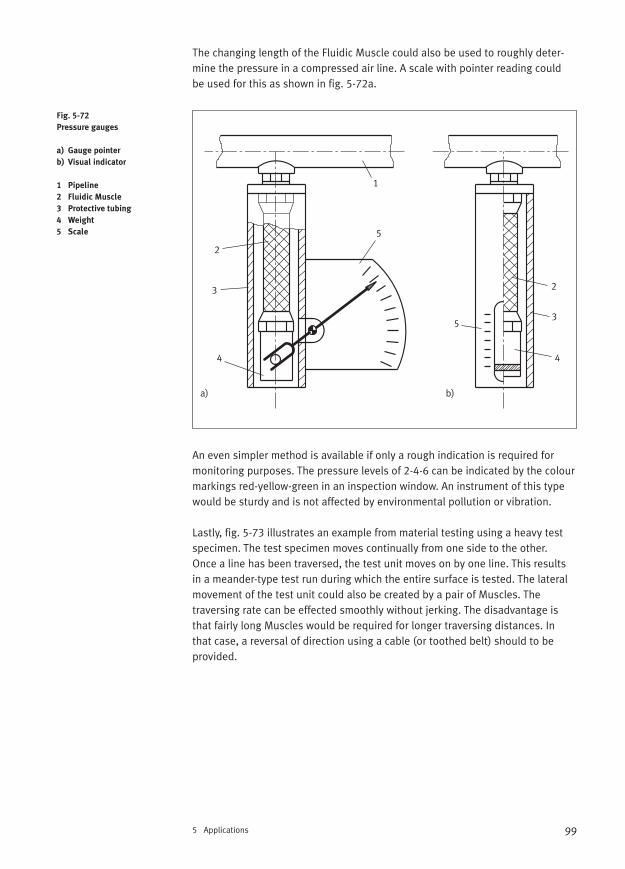
99
The changing length of the Fluidic Muscle could also be used to roughly deter-mine the pressure in a compressed air line. A scale with pointer reading could be used for this as shown in fig. 5-72a.
An even simpler method is available if only a rough indication is required for monitoring purposes. The pressure levels of 2-4-6 can be indicated by the colourmarkings red-yellow-green in an inspection window. An instrument of this typewould be sturdy and is not affected by environmental pollution or vibration.
Lastly, fig. 5-73 illustrates an example from material testing using a heavy testspecimen. The test specimen moves continually from one side to the other. Once a line has been traversed, the test unit moves on by one line. This resultsin a meander-type test run during which the entire surface is tested. The lateralmovement of the test unit could also be created by a pair of Muscles. The traversing rate can be effected smoothly without jerking. The disadvantage isthat fairly long Muscles would be required for longer traversing distances. In that case, a reversal of direction using a cable (or toothed belt) should to be provided.
5 Applications
Fig. 5-72
Pressure gauges
a) Gauge pointer
b) Visual indicator
1 Pipeline
2 Fluidic Muscle
3 Protective tubing
4 Weight
5 Scale
1
2
3
4
5
5
4
2
3
a) b)
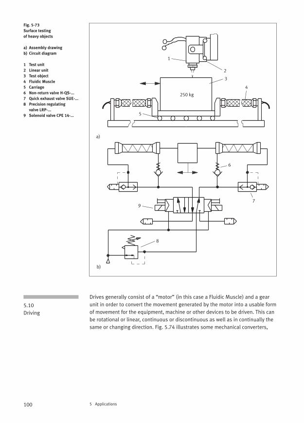
100 5 Applications
Drives generally consist of a “motor” (in this case a Fluidic Muscle) and a gearunit in order to convert the movement generated by the motor into a usable formof movement for the equipment, machine or other devices to be driven. This canbe rotational or linear, continuous or discontinuous as well as in continually thesame or changing direction. Fig. 5.74 illustrates some mechanical converters,
Fig. 5-73
Surface testing
of heavy objects
a) Assembly drawing
b) Circuit diagram
1 Test unit
2 Linear unit
3 Test object
4 Fluidic Muscle
5 Carriage
6 Non-return valve H-QS-...
7 Quick exhaust valve SUE-...
8 Precision regulating
valve LRP-...
9 Solenoid valve CPE 14-...
5.10Driving
1
2
3
4
5
b)
a)
6
7
8
9
250 kg
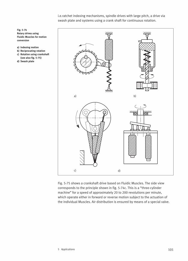
101
i.e.ratchet indexing mechanisms, spindle drives with large pitch, a drive viaswash plate and systems using a crank shaft for continuous rotation.
Fig. 5-75 shows a crankshaft drive based on Fluidic Muscles. The side view corresponds to the principle shown in fig. 5-74c. This is a “three-cylinder machine” for a speed of approximately 20 to 200 revolutions per minute, which operate either in forward or reverse motion subject to the actuation of the individual Muscles. Air distribution is ensured by means of a special valve.
5 Applications
Fig. 5-74
Rotary drives using
Fluidic Muscles for motion
conversion
a) Indexing motion
b) Reciprocating rotation
c) Rotation using crankshaft
(see also fig. 5-75)
d) Swash plate
a) b)
c) d)
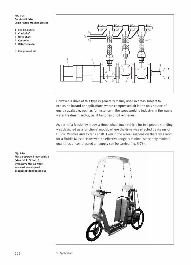
102 5 Applications
However, a drive of this type is generally mainly used in areas subject to explosion hazard or applications where compressed air is the only source ofenergy available, such as for instance in the woodworking industry, in the wastewater treatment sector, paint factories or oil refineries.
As part of a feasibility study, a three-wheel town vehicle for two people standingwas designed as a functional model, where the drive was effected by means ofFluidic Muscles and a crank shaft. Even in the wheel suspension there was roomfor a Fluidic Muscle. However the effective range is minimal since only minimalquantities of compressed air supply can be carried (fig. 5-76).
Fig. 5-75
Crankshaft drive
using Fluidic Muscles (Festo)
1 Fluidic Muscle
2 Crankshaft
3 Drive shaft
4 Controller
5 Rotary encoder
p Compressed air
Fig. 5-76
Muscle-operated town vehicle
(Viererbl, F., Scholl, P.)
with active Muscle wheel
suspension and speed
dependent tilting technique
1
2
3
45
p1p2
p3
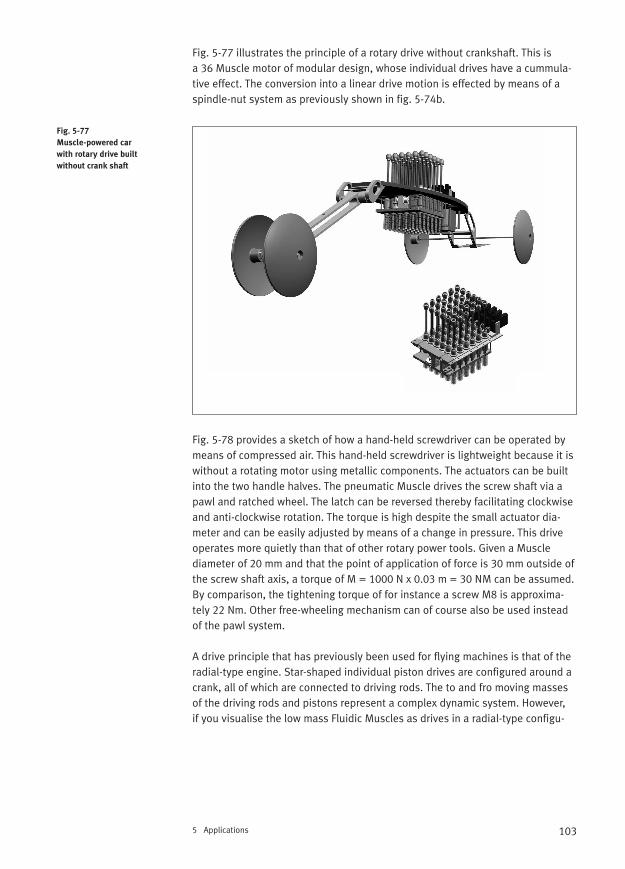
103
Fig. 5-77 illustrates the principle of a rotary drive without crankshaft. This is a 36 Muscle motor of modular design, whose individual drives have a cummula-tive effect. The conversion into a linear drive motion is effected by means of aspindle-nut system as previously shown in fig. 5-74b.
Fig. 5-78 provides a sketch of how a hand-held screwdriver can be operated bymeans of compressed air. This hand-held screwdriver is lightweight because it iswithout a rotating motor using metallic components. The actuators can be builtinto the two handle halves. The pneumatic Muscle drives the screw shaft via apawl and ratched wheel. The latch can be reversed thereby facilitating clockwiseand anti-clockwise rotation. The torque is high despite the small actuator dia-meter and can be easily adjusted by means of a change in pressure. This drive operates more quietly than that of other rotary power tools. Given a Muscle diameter of 20 mm and that the point of application of force is 30 mm outside ofthe screw shaft axis, a torque of M = 1000 N x 0.03 m = 30 NM can be assumed.By comparison, the tightening torque of for instance a screw M8 is approxima-tely 22 Nm. Other free-wheeling mechanism can of course also be used insteadof the pawl system.
A drive principle that has previously been used for flying machines is that of theradial-type engine. Star-shaped individual piston drives are configured around acrank, all of which are connected to driving rods. The to and fro moving massesof the driving rods and pistons represent a complex dynamic system. However, if you visualise the low mass Fluidic Muscles as drives in a radial-type configu-
5 Applications
Fig. 5-77
Muscle-powered car
with rotary drive built
without crank shaft
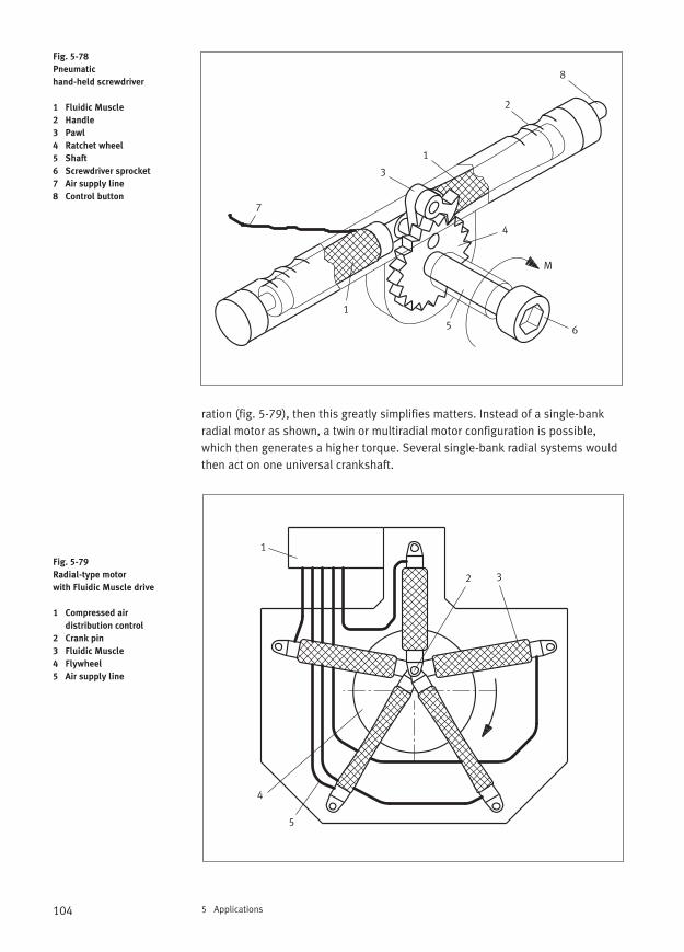
104 5 Applications
ration (fig. 5-79), then this greatly simplifies matters. Instead of a single-bankradial motor as shown, a twin or multiradial motor configuration is possible,which then generates a higher torque. Several single-bank radial systems wouldthen act on one universal crankshaft.
Fig. 5-78
Pneumatic
hand-held screwdriver
1 Fluidic Muscle
2 Handle
3 Pawl
4 Ratchet wheel
5 Shaft
6 Screwdriver sprocket
7 Air supply line
8 Control button
Fig. 5-79
Radial-type motor
with Fluidic Muscle drive
1 Compressed air
distribution control
2 Crank pin
3 Fluidic Muscle
4 Flywheel
5 Air supply line
1
1
2
3
4
5 6
M
7
8
1
2 3
4
5
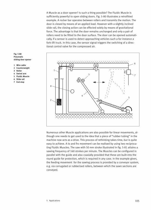
105
A Muscle as a door opener? Is such a thing possible? The Fluidic Muscle is sufficiently powerful to open sliding doors. Fig. 5-80 illustrates a retrofittedexample. A rocker bar operates between rollers and transmits the motion. Thedoor is closed by means of an applied load. However with a slightly inclinedslide rail, the closing action can be effected solely by means of gravitationalforce. The advantage is that the door remains unchanged and only a pair of rollers need to be fitted to the door surface. The door can be opened automati-cally, if a sensor is used to detect approaching vehicles such a for instance afork-lift truck. In this case, the sensor signal triggers the switching of a direc-tional control valve for the compressed air.
Numerous other Muscle applications are also possible for linear movements, al-though one needs to get used to the idea that a piece of “rubber tubing” in themachine now acts as a drive. This process of rethinking takes time, but is quiteeasy to achieve. A to and fro movement can be realised by using two reciproca-ting Fluidic Muscles. The saw with 50 mm stroke illustrated in fig. 5-81 attains asawing frequency of 160 strokes per minute. The Muscles can be configured inparallel with the guide and also coaxially provided that these are built-into theround guide for protection, which is required in any case. In the example given,the feeding movement for the sawing process is provided by a conveyor system,e.g. via corrugated or rubberised rollers, between which the sawn sections areconveyed.
5 Applications
Fig. 5-80
Pneumatic
sliding door opener
1 Wire cable
2 Counterweight
3 Roller
4 Swivel arm
5 Fluidic Muscle
6 Slide rail
7 End stop
1
2
3
45
6
7
8
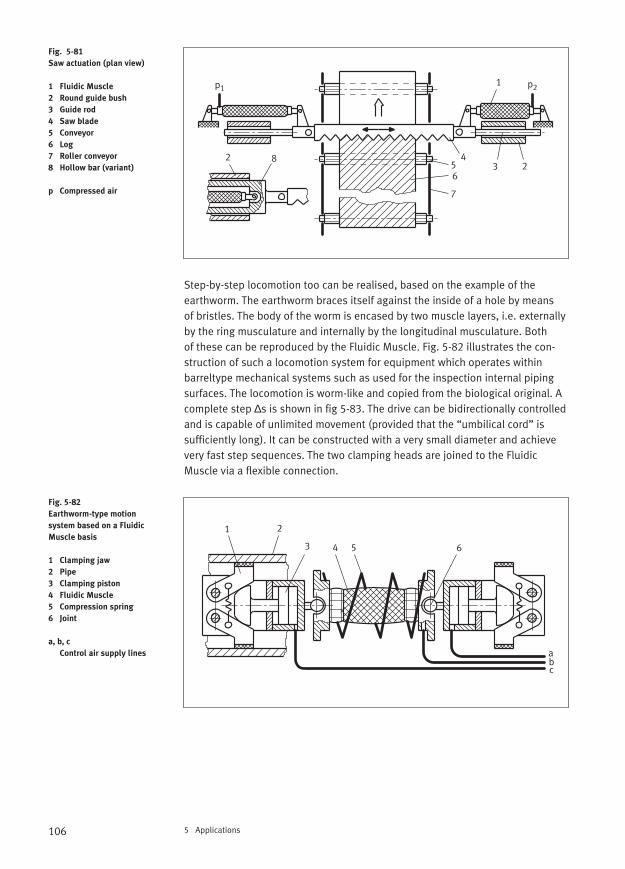
106 5 Applications
Step-by-step locomotion too can be realised, based on the example of the earthworm. The earthworm braces itself against the inside of a hole by means of bristles. The body of the worm is encased by two muscle layers, i.e. externallyby the ring musculature and internally by the longitudinal musculature. Both of these can be reproduced by the Fluidic Muscle. Fig. 5-82 illustrates the con-struction of such a locomotion system for equipment which operates within barreltype mechanical systems such as used for the inspection internal pipingsurfaces. The locomotion is worm-like and copied from the biological original. Acomplete step ∆s is shown in fig 5-83. The drive can be bidirectionally controlledand is capable of unlimited movement (provided that the “umbilical cord” is sufficiently long). It can be constructed with a very small diameter and achievevery fast step sequences. The two clamping heads are joined to the FluidicMuscle via a flexible connection.
Fig. 5-81
Saw actuation (plan view)
1 Fluidic Muscle
2 Round guide bush
3 Guide rod
4 Saw blade
5 Conveyor
6 Log
7 Roller conveyor
8 Hollow bar (variant)
p Compressed air
Fig. 5-82
Earthworm-type motion
system based on a Fluidic
Muscle basis
1 Clamping jaw
2 Pipe
3 Clamping piston
4 Fluidic Muscle
5 Compression spring
6 Joint
a, b, c
Control air supply lines
1
22
34
56
7
8
p1 p2
1 2
3 4 5 6
abc
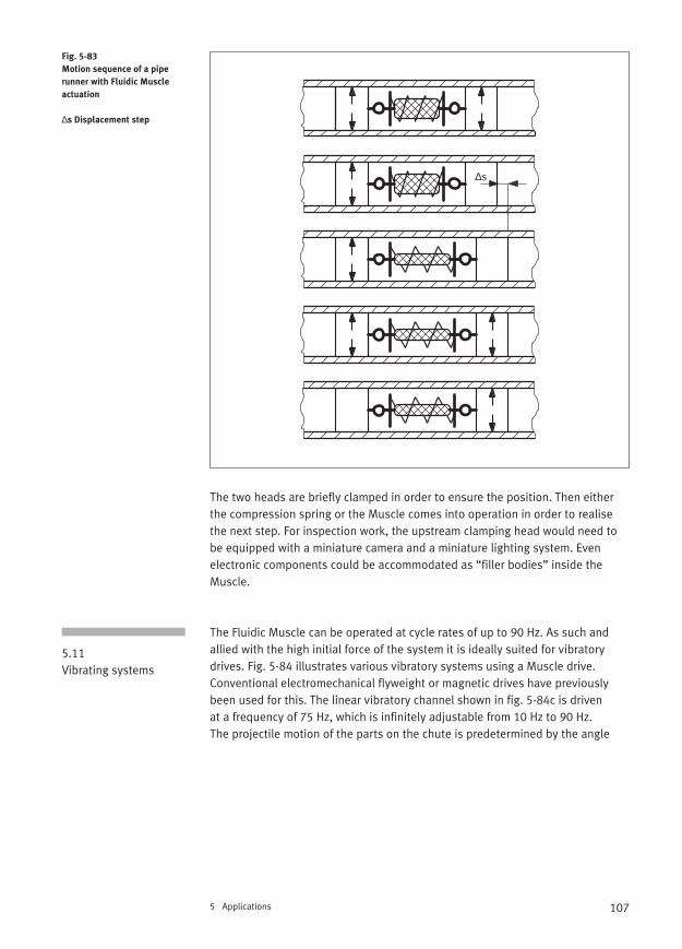
107
The two heads are briefly clamped in order to ensure the position. Then eitherthe compression spring or the Muscle comes into operation in order to realisethe next step. For inspection work, the upstream clamping head would need tobe equipped with a miniature camera and a miniature lighting system. Even electronic components could be accommodated as “filler bodies” inside theMuscle.
The Fluidic Muscle can be operated at cycle rates of up to 90 Hz. As such andallied with the high initial force of the system it is ideally suited for vibratory drives. Fig. 5-84 illustrates various vibratory systems using a Muscle drive.Conventional electromechanical flyweight or magnetic drives have previouslybeen used for this. The linear vibratory channel shown in fig. 5-84c is driven at a frequency of 75 Hz, which is infinitely adjustable from 10 Hz to 90 Hz. The projectile motion of the parts on the chute is predetermined by the angle
5 Applications
Fig. 5-83
Motion sequence of a pipe
runner with Fluidic Muscle
actuation
∆s Displacement step
5.11 Vibrating systems
∆s
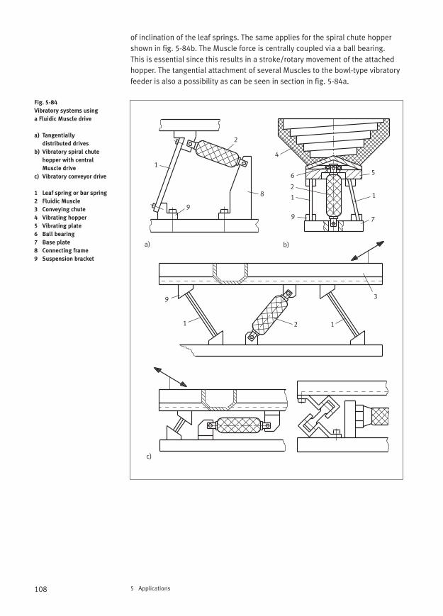
108 5 Applications
of inclination of the leaf springs. The same applies for the spiral chute hoppershown in fig. 5-84b. The Muscle force is centrally coupled via a ball bearing. This is essential since this results in a stroke/rotary movement of the attachedhopper. The tangential attachment of several Muscles to the bowl-type vibratoryfeeder is also a possibility as can be seen in section in fig. 5-84a.
Fig. 5-84
Vibratory systems using
a Fluidic Muscle drive
a) Tangentially
distributed drives
b) Vibratory spiral chute
hopper with central
Muscle drive
c) Vibratory conveyor drive
1 Leaf spring or bar spring
2 Fluidic Muscle
3 Conveying chute
4 Vibrating hopper
5 Vibrating plate
6 Ball bearing
7 Base plate
8 Connecting frame
9 Suspension bracket
1
1 1
1 1
2
2
2
3
a) b)
4
56
7
8
9
99
c)
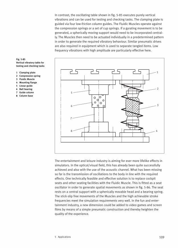
109
In contrast, the oscillating table shown in fig. 5-85 executes purely vertical vibrations and can be used for testing and checking tasks. The clamping plate isguided via four low-friction column guides. The Fluidic Muscles operate againstthe compression springs or a set of cup springs. If a gyrating movement is to begenerated, a spherically moving support would need to be incorporated central-ly. The Muscles then need to be actuated individually in a predetermined patternin order to generate the required vibratory behaviour. Similar pneumatic drivesare also required in equipment which is used to separate tangled items. Low frequency vibrations with high amplitude are particularly effective here.
The entertainment and leisure industry is aiming for ever more lifelike effects insimulators. In the optical/visual field, this has already been quite successfullyachieved and also with the use of the acoustic channel. What has been missingso far is the transmission of oscillations to the body in line with the requiredeffects. One technically feasible and effective solution is to replace cockpit seats and other seating facilities with the Fluidic Muscle. This is fitted as a seatoscillator in order to generate spatial movements as shown in fig. 5-86. The seatrests on a central support with a spherically movable head and a bearing spring.The stick-slip free movements of the Muscles and the high achievable stroke frequencies meet the simulation requirements very well. In the fun and enter-tainment industry, a new dimension could be added to video games and screenfilms by means of a simple pneumatic construction and thereby heighten thequality of the experience.
5 Applications
Fig. 5-85
Vertical vibratory table for
testing and checking tasks
1 Clamping plate
2 Compression spring
3 Fluidic Muscle
4 Mounting flange
5 Linear guide
6 Ball bearing
7 Guide column
8 Column base
1
2
3
4
5
6
7
8
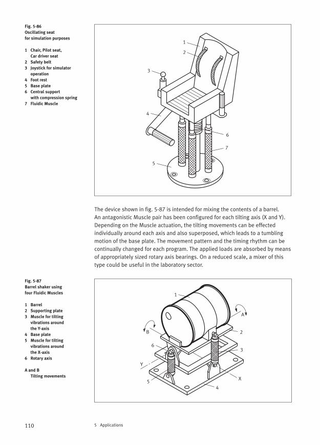
110 5 Applications
The device shown in fig. 5-87 is intended for mixing the contents of a barrel. An antagonistic Muscle pair has been configured for each tilting axis (X and Y).Depending on the Muscle actuation, the tilting movements can be effected individually around each axis and also superposed, which leads to a tumblingmotion of the base plate. The movement pattern and the timing rhythm can becontinually changed for each program. The applied loads are absorbed by meansof appropriately sized rotary axis bearings. On a reduced scale, a mixer of thistype could be useful in the laboratory sector.
Fig. 5-86
Oscillating seat
for simulation purposes
1 Chair, Pilot seat,
Car driver seat
2 Safety belt
3 Joystick for simulator
operation
4 Foot rest
5 Base plate
6 Central support
with compression spring
7 Fluidic Muscle
Fig. 5-87
Barrel shaker using
four Fluidic Muscles
1 Barrel
2 Supporting plate
3 Muscle for tilting
vibrations around
the Y-axis
4 Base plate
5 Muscle for tilting
vibrations around
the X-axis
6 Rotary axis
A and B
Tilting movements
1
2
3
4
5
6
7
1
2
3
45
6
Y
X
A
B
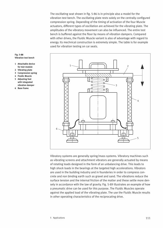
111
The oscillating seat shown in fig. 5-86 is in principle also a model for the vibration test bench. The oscillating plate rests solely on the centrally configuredcompression spring. Depending of the timing of activation of the four Muscleactuators, different types of oscillation are achieved for the vibrating plate. Theamplitudes of the vibratory movement can also be influenced. The entire testbench is buffered against the floor by means of vibration dampers. Comparedwith other drives, the Fluidic Muscle variant is also of advantage with regard toenergy. Its mechnical construction is extremely simple. The table is for exampleused for vibration testing on car seats.
Vibratory systems are generally spring/mass systems. Vibratory machines suchas vibrating screens and attachment vibrators are generally actuated by meansof rotating loads designed in the form of an unbalancing drive. This leads to high shock loads in the bearings at the targeted high accelerations. Vibrators are used in the building industry and in founderies in order to compress con-crete and non binding earth such as gravel and sand. The vibrations reduce thesurface tension and the internal friction of the matter and these settle more den-sely in accordance with the law of gravity. Fig. 5-89 illustrates an example of howa pneumatic drive can be used for this purpose. The Fluidic Muscles operateagainst the applied load of the vibrating plate. The use the Fluidic Muscle resultsin other operating characteristics of the reciprocating drive.
5 Applications
Fig. 5-88
Vibration test bench
1 Attachable device
for test module
2 Vibrating plate
3 Compression spring
4 Fluidic Muscle
5 Adjusting foot
with integrated
vibration damper
6 Base frame
1 2
3
4
5
6
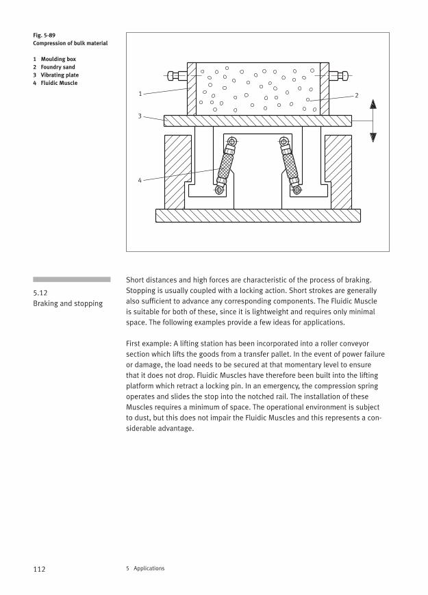
112 5 Applications
Short distances and high forces are characteristic of the process of braking.Stopping is usually coupled with a locking action. Short strokes are generallyalso sufficient to advance any corresponding components. The Fluidic Muscle is suitable for both of these, since it is lightweight and requires only minimalspace. The following examples provide a few ideas for applications.
First example: A lifting station has been incorporated into a roller conveyor section which lifts the goods from a transfer pallet. In the event of power failureor damage, the load needs to be secured at that momentary level to ensure that it does not drop. Fluidic Muscles have therefore been built into the liftingplatform which retract a locking pin. In an emergency, the compression springoperates and slides the stop into the notched rail. The installation of theseMuscles requires a minimum of space. The operational environment is subject to dust, but this does not impair the Fluidic Muscles and this represents a con-siderable advantage.
Fig. 5-89
Compression of bulk material
1 Moulding box
2 Foundry sand
3 Vibrating plate
4 Fluidic Muscle
5.12Braking and stopping
1 2
3
4
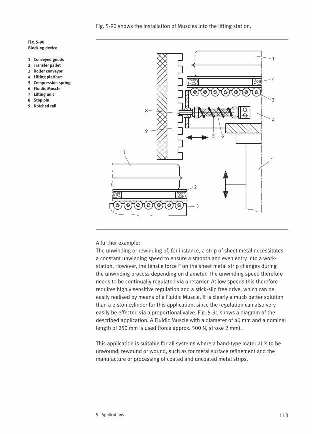
113
Fig. 5-90 shows the installation of Muscles into the lifting station.
A further example:The unwinding or rewinding of, for instance, a strip of sheet metal necessitates a constant unwinding speed to ensure a smooth and even entry into a work-station. However, the tensile force F on the sheet metal strip changes during the unwinding process depending on diameter. The unwinding speed thereforeneeds to be continually regulated via a retarder. At low speeds this thereforerequires highly sensitive regulation and a stick-slip free drive, which can be easily realised by means of a Fluidic Muscle. It is clearly a much better solutionthan a piston cylinder for this application, since the regulation can also veryeasily be effected via a proportional valve. Fig. 5-91 shows a diagram of thedescribed application. A Fluidic Muscle with a diameter of 40 mm and a nominallength of 250 mm is used (force approx. 500 N, stroke 2 mm).
This application is suitable for all systems where a band-type material is to beunwound, rewound or wound, such as for metal surface refinement and themanufacture or processing of coated and uncoated metal strips.
5 Applications
Fig. 5-90
Blocking device
1 Conveyed goods
2 Transfer pallet
3 Roller conveyor
4 Lifting platform
5 Compression spring
6 Fluidic Muscle
7 Lifting unit
8 Stop pin
9 Notched rail
1
1
2
2
4
3
3
5 6
7
8
9
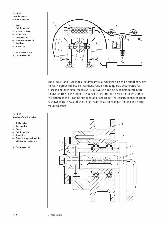
114 5 Applications
The production of sausages requires artificial sausage skin to be supplied whichmoves via guide rollers. So that these rollers can be quickly decelerated for process engineering purposes, A Fluidic Muscle can be accommodated in thehollow bearing of the roller. The Muscle does not rotate with the roller so thatthe compressed air can be supplied at a fixed point. The constructional solutionis shown in fig. 5-92 and should be regarded as an example for similar bearingmounted cases.
Fig. 5-91
Retarder on an
unwinding device
1 Reel
2 Fluidic Muscle
3 Diverter pulley
4 Roller lever
5 Force sensor
6 Proportional sensor
7 Reel hub
8 Brake jaw
F Withdrawal force
p Compressed air
Fig. 5-92
Braking of a guide roller
1 Guide roller
2 Ball bearing
3 Frame
4 Fluidic Muscle
5 Brake disc
6 Protection against rotation
with torque resistance
p Compressed air
12
3
45
6
p
p1
7 8
F
1
2
3
p
4
5
6

115
Fig. 5-93 illustrates a drum brake whose brake force is generated by means ofcompression springs or a set of cup spring. The brake is vented by means ofFluidic Muscles, which can generate high forces across a short distance. Thismechanism can also be used as an emergency brake system. In the event ofenergy failure, the pneumatic actuators become de-energised and the springthen act as brake actuators.
In-house transport generally involves the transporting of packaged goods for the purpose of storage and removal from storage or temporary storage. In manycases belt conveyors are used for this. Although installations of this type are relatively simple mechanically, they nevertheless require actuators and tensioning drives of different types. This also includes maintaining the tension of pulleys and conveyor belts. If the tension is incorrectly set, then the frictionalentrainment of the belt is impaired. Fig. 5-94 illustrates some solutions wherethe Fluidic Muscle has been used as an actuator.
The use of the Muscle for belt tensioning has been considered because it is extremely durable and provides adaptable cushioning.
5 Applications
Fig. 5-93
Braking mechanism
for drum brakes
1 Brake lining
2 Brake disc, drum
3 Compression spring,
set of cup springs
4 Fluidic Muscle
5 Frame
5.13Transporting
3 321 45
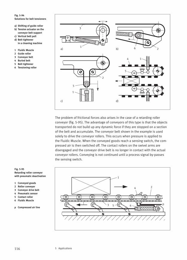
116 5 Applications
The problem of frictional forces also arises in the case of a retarding roller conveyor (fig. 5-95). The advantage of conveyors of this type is that the objectstransported do not build up any dynamic force if they are stopped on a sectionof the belt and accumulate. The conveyor belt shown in the example is usedsolely to drive the conveyor rollers. This occurs when pressure is applied to the Fluidic Muscle. When the conveyed goods reach a sensing switch, the com-pressed air is then switched off. The contact rollers on the swivel arms are disengaged and the conveyor drive belt is no longer in contact with the actualconveyor rollers. Conveying is not continued until a process signal by-passes the sensing switch.
Fig. 5-94
Solutions for belt tensioners
a) Shifting of guide roller
b) Tension actuator on the
conveyor belt support
c) Vertical belt pull
d) Belt tightener
in a cleaning machine
1 Fluidic Muscle
2 Guide roller
3 Conveyor belt
4 Burled belt
5 Belt tightener
6 Tensioning roller
Fig. 5-95
Retarding roller conveyor
with pneumatic deactivation
1 Conveyed goods
2 Roller conveyor
3 Conveyor drive belt
4 Pneumatic sensor
5 Contact roller
6 Fluidic Muscle
p Compressed air line
a) b)
c) d)
1
1
1
2
2
3
4
5
5
6
1
2
3
4
5 6 p
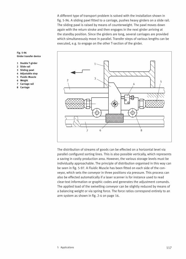
117
A different type of transport problem is solved with the installation shown in fig. 5-96. A sliding pawl fitted to a carriage, pushes heavy girders on a slide rail.The sliding pawl is raised by means of counterweight. The pawl moves downagain with the return stroke and then engages in the next girder arriving at the standby position. Since the girders are long, several carriages are providedwhich simultaneously move in parallel. Transfer steps of various lengths can beexecuted, e.g. to engage on the other T-section of the girder.
The distribution of streams of goods can be effected on a horizontal level viaparallel configured sorting lines. This is also possible vertically, which representsa saving in costly production area. However, the various storage levels must beindividually approachable. The principle of distribution organised in this way canbe seen in fig. 5-97. A Fluidic Muscle has been fitted on each side of the con-veyor, which sets the conveyor in three positions via pressure. This process canalso be effected automatically if a laser scanner is for instance used to readclear-text information or graphic codes and generates the adjustment comands.The applied load of the swivelling conveyor can be slightly reduced by means ofa balancing weight or via spring force. The force ratios correspond entirely to anarm system as shown in fig. 2-4 on page 16.
5 Applications
Fig. 5-96
Girder transfer device
1 Double T-girder
2 Slide rail
3 Sliding pawl
4 Adjustable stop
5 Fluidic Muscle
6 Weight
7 Carriage rail
8 Carriage
1
23
45
67 8
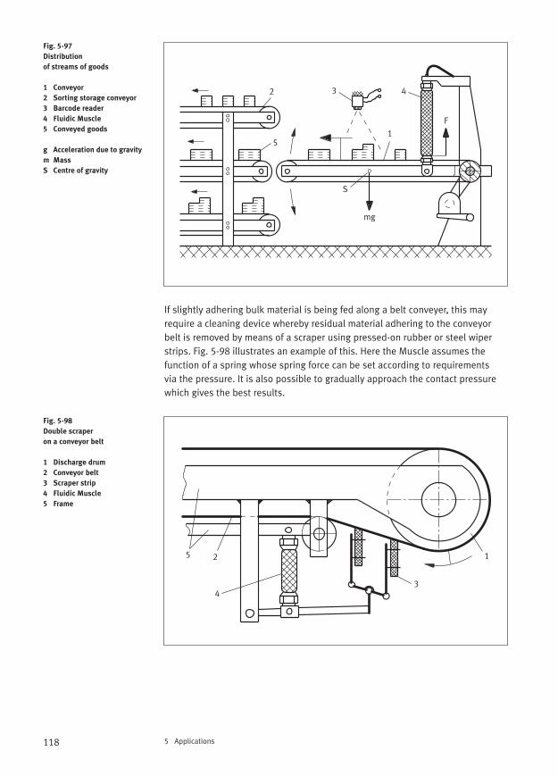
118 5 Applications
If slightly adhering bulk material is being fed along a belt conveyer, this mayrequire a cleaning device whereby residual material adhering to the conveyorbelt is removed by means of a scraper using pressed-on rubber or steel wiperstrips. Fig. 5-98 illustrates an example of this. Here the Muscle assumes the function of a spring whose spring force can be set according to requirements via the pressure. It is also possible to gradually approach the contact pressurewhich gives the best results.
Fig. 5-97
Distribution
of streams of goods
1 Conveyor
2 Sorting storage conveyor
3 Barcode reader
4 Fluidic Muscle
5 Conveyed goods
g Acceleration due to gravity
m Mass
S Centre of gravity
Fig. 5-98
Double scraper
on a conveyor belt
1 Discharge drum
2 Conveyor belt
3 Scraper strip
4 Fluidic Muscle
5 Frame
1
2 3 4
mg
F
5
S
12
34
5
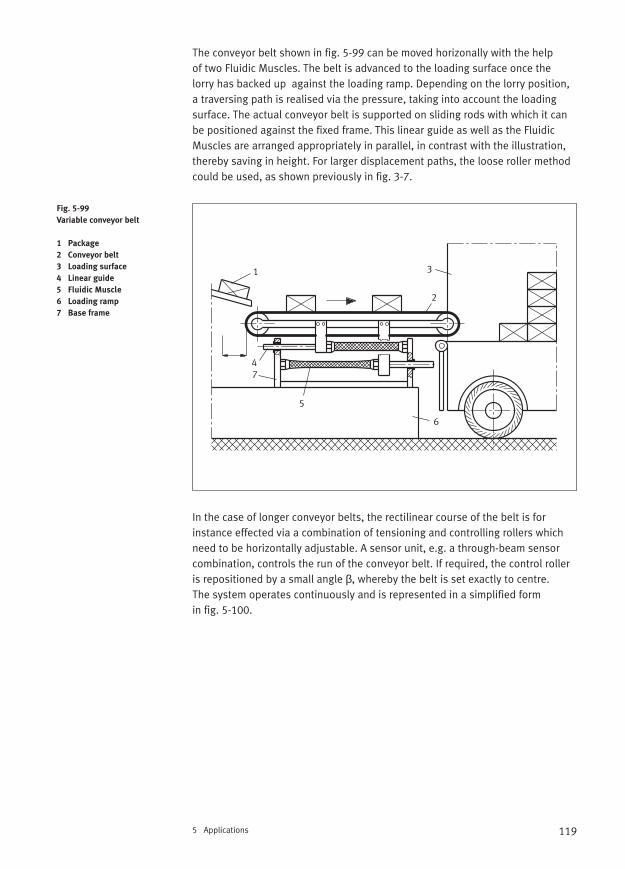
119
The conveyor belt shown in fig. 5-99 can be moved horizonally with the help of two Fluidic Muscles. The belt is advanced to the loading surface once the lorry has backed up against the loading ramp. Depending on the lorry position,a traversing path is realised via the pressure, taking into account the loadingsurface. The actual conveyor belt is supported on sliding rods with which it canbe positioned against the fixed frame. This linear guide as well as the FluidicMuscles are arranged appropriately in parallel, in contrast with the illustration,thereby saving in height. For larger displacement paths, the loose roller methodcould be used, as shown previously in fig. 3-7.
In the case of longer conveyor belts, the rectilinear course of the belt is for instance effected via a combination of tensioning and controlling rollers whichneed to be horizontally adjustable. A sensor unit, e.g. a through-beam sensorcombination, controls the run of the conveyor belt. If required, the control rolleris repositioned by a small angle β, whereby the belt is set exactly to centre. The system operates continuously and is represented in a simplified form in fig. 5-100.
5 Applications
Fig. 5-99
Variable conveyor belt
1 Package
2 Conveyor belt
3 Loading surface
4 Linear guide
5 Fluidic Muscle
6 Loading ramp
7 Base frame
1
2
3
4
5
6
7

120 5 Applications
In fig. 5-101, a different solution is suggested for the same problem. In this case, the discharge roller of the conveyor is variably configured. The slide hassufficient play to facilitate a slight inclination of the roller axis which does notget jammed. A Fluidic Muscle is fitted on both sides of the belt which clamps the roller via a lever and at the same time ensures a rectilinear motion by meansof unequal movement at either end.
Fig. 5-100
Rectilinear control
of a conveyor belt
a) Design of controlling
roller system
b) Conveyor course
c) Belt edge sensing
1 Control roller
2 Return roller
3 Conveyor belt
4 Through-beam sensor
5 Swing frame
6 Fluidic Muscle
Fig. 5-101
Rectilinear motion
of belt edge
1 Optical Band feed sensor
2 Conveyor belt
3 Tensioning roller
4 Slide
5 Lever
6 Fluidic Muscle
p Compressed air
1 1
2
3
45
6
a) b) c)
+ β
– β
12 3
4
56
7
p
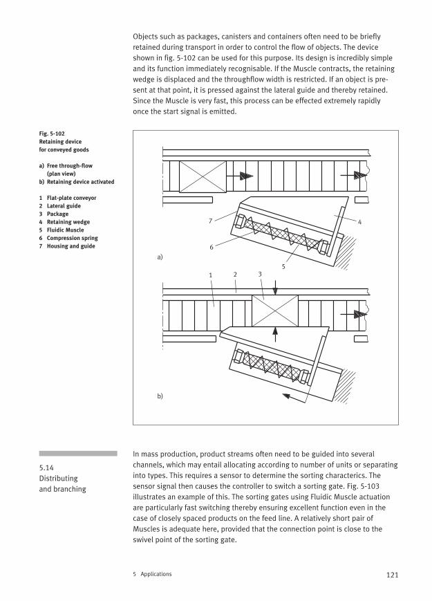
121
Objects such as packages, canisters and containers often need to be brieflyretained during transport in order to control the flow of objects. The deviceshown in fig. 5-102 can be used for this purpose. Its design is incredibly simpleand its function immediately recognisable. If the Muscle contracts, the retainingwedge is displaced and the throughflow width is restricted. If an object is pre-sent at that point, it is pressed against the lateral guide and thereby retained.Since the Muscle is very fast, this process can be effected extremely rapidly once the start signal is emitted.
In mass production, product streams often need to be guided into several channels, which may entail allocating according to number of units or separatinginto types. This requires a sensor to determine the sorting characterics. The sensor signal then causes the controller to switch a sorting gate. Fig. 5-103 illustrates an example of this. The sorting gates using Fluidic Muscle actuationare particularly fast switching thereby ensuring excellent function even in thecase of closely spaced products on the feed line. A relatively short pair ofMuscles is adequate here, provided that the connection point is close to the swivel point of the sorting gate.
5 Applications
Fig. 5-102
Retaining device
for conveyed goods
a) Free through-flow
(plan view)
b) Retaining device activated
1 Flat-plate conveyor
2 Lateral guide
3 Package
4 Retaining wedge
5 Fluidic Muscle
6 Compression spring
7 Housing and guide
5.14Distributing and branching
a)
b)
1 2 3
4
5
6
7
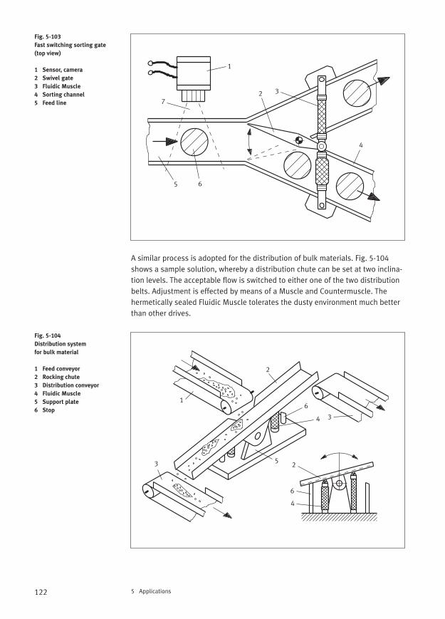
122 5 Applications
A similar process is adopted for the distribution of bulk materials. Fig. 5-104shows a sample solution, whereby a distribution chute can be set at two inclina-tion levels. The acceptable flow is switched to either one of the two distributionbelts. Adjustment is effected by means of a Muscle and Countermuscle. The hermetically sealed Fluidic Muscle tolerates the dusty environment much betterthan other drives.
Fig. 5-103
Fast switching sorting gate
(top view)
1 Sensor, camera
2 Swivel gate
3 Fluidic Muscle
4 Sorting channel
5 Feed line
Fig. 5-104
Distribution system
for bulk material
1 Feed conveyor
2 Rocking chute
3 Distribution conveyor
4 Fluidic Muscle
5 Support plate
6 Stop
1
2 3
4
5 6
7
1
2
34
5
6
3
6
2
4
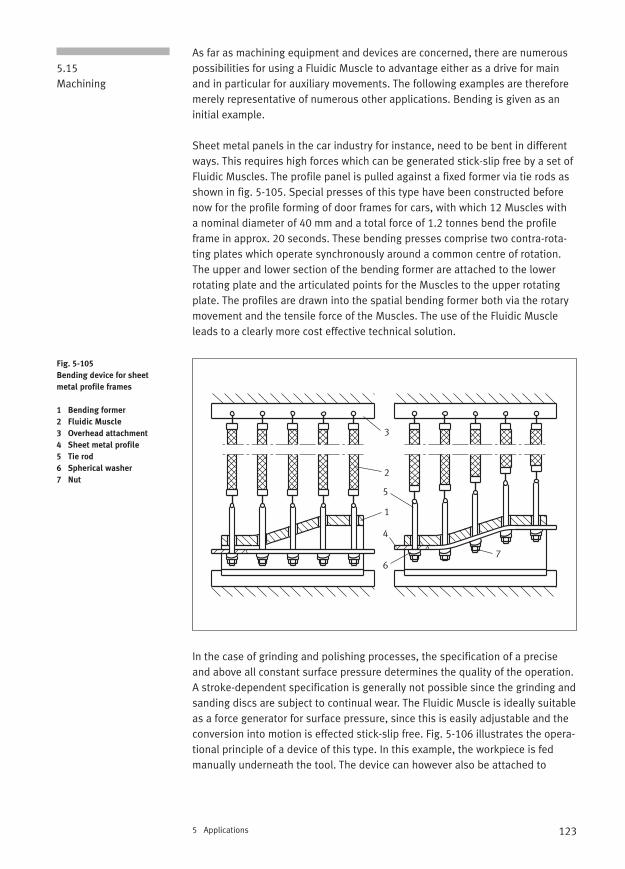
123
As far as machining equipment and devices are concerned, there are numerouspossibilities for using a Fluidic Muscle to advantage either as a drive for main and in particular for auxiliary movements. The following examples are thereforemerely representative of numerous other applications. Bending is given as aninitial example.
Sheet metal panels in the car industry for instance, need to be bent in differentways. This requires high forces which can be generated stick-slip free by a set ofFluidic Muscles. The profile panel is pulled against a fixed former via tie rods asshown in fig. 5-105. Special presses of this type have been constructed beforenow for the profile forming of door frames for cars, with which 12 Muscles with a nominal diameter of 40 mm and a total force of 1.2 tonnes bend the profileframe in approx. 20 seconds. These bending presses comprise two contra-rota-ting plates which operate synchronously around a common centre of rotation.The upper and lower section of the bending former are attached to the lowerrotating plate and the articulated points for the Muscles to the upper rotatingplate. The profiles are drawn into the spatial bending former both via the rotarymovement and the tensile force of the Muscles. The use of the Fluidic Muscleleads to a clearly more cost effective technical solution.
In the case of grinding and polishing processes, the specification of a preciseand above all constant surface pressure determines the quality of the operation.A stroke-dependent specification is generally not possible since the grinding andsanding discs are subject to continual wear. The Fluidic Muscle is ideally suitableas a force generator for surface pressure, since this is easily adjustable and theconversion into motion is effected stick-slip free. Fig. 5-106 illustrates the opera-tional principle of a device of this type. In this example, the workpiece is fedmanually underneath the tool. The device can however also be attached to
5 Applications
5.15 Machining
Fig. 5-105
Bending device for sheet
metal profile frames
1 Bending former
2 Fluidic Muscle
3 Overhead attachment
4 Sheet metal profile
5 Tie rod
6 Spherical washer
7 Nut
1
2
3
4
5
67
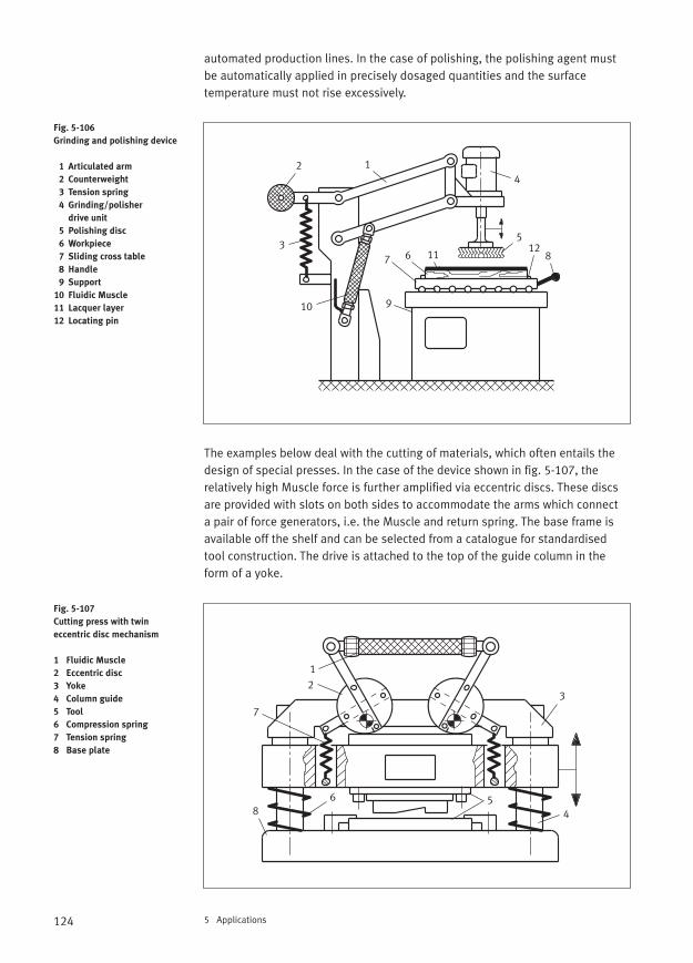
124 5 Applications
automated production lines. In the case of polishing, the polishing agent mustbe automatically applied in precisely dosaged quantities and the surface temperature must not rise excessively.
The examples below deal with the cutting of materials, which often entails thedesign of special presses. In the case of the device shown in fig. 5-107, the relatively high Muscle force is further amplified via eccentric discs. These discsare provided with slots on both sides to accommodate the arms which connect a pair of force generators, i.e. the Muscle and return spring. The base frame isavailable off the shelf and can be selected from a catalogue for standardisedtool construction. The drive is attached to the top of the guide column in theform of a yoke.
Fig. 5-106
Grinding and polishing device
1 Articulated arm
2 Counterweight
3 Tension spring
4 Grinding/polisher
drive unit
5 Polishing disc
6 Workpiece
7 Sliding cross table
8 Handle
9 Support
10 Fluidic Muscle
11 Lacquer layer
12 Locating pin
Fig. 5-107
Cutting press with twin
eccentric disc mechanism
1 Fluidic Muscle
2 Eccentric disc
3 Yoke
4 Column guide
5 Tool
6 Compression spring
7 Tension spring
8 Base plate
12
3
4
5
67 8
910
1112
1
23
456
7
8
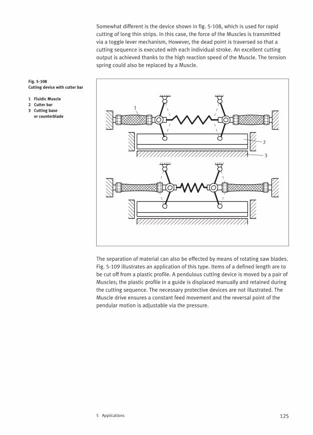
125
Somewhat different is the device shown in fig. 5-108, which is used for rapid cutting of long thin strips. In this case, the force of the Muscles is transmitted via a toggle lever mechanism, However, the dead point is traversed so that a cutting sequence is executed with each individual stroke. An excellent cuttingoutput is achieved thanks to the high reaction speed of the Muscle. The tensionspring could also be replaced by a Muscle.
The separation of material can also be effected by means of rotating saw blades.Fig. 5-109 illustrates an application of this type. Items of a defined length are tobe cut off from a plastic profile. A pendulous cutting device is moved by a pair ofMuscles; the plastic profile in a guide is displaced manually and retained duringthe cutting sequence. The necessary protective devices are not illustrated. TheMuscle drive ensures a constant feed movement and the reversal point of thependular motion is adjustable via the pressure.
5 Applications
Fig. 5-108
Cutting device with cutter bar
1 Fluidic Muscle
2 Cutter bar
3 Cutting base
or counterblade
1
2
3
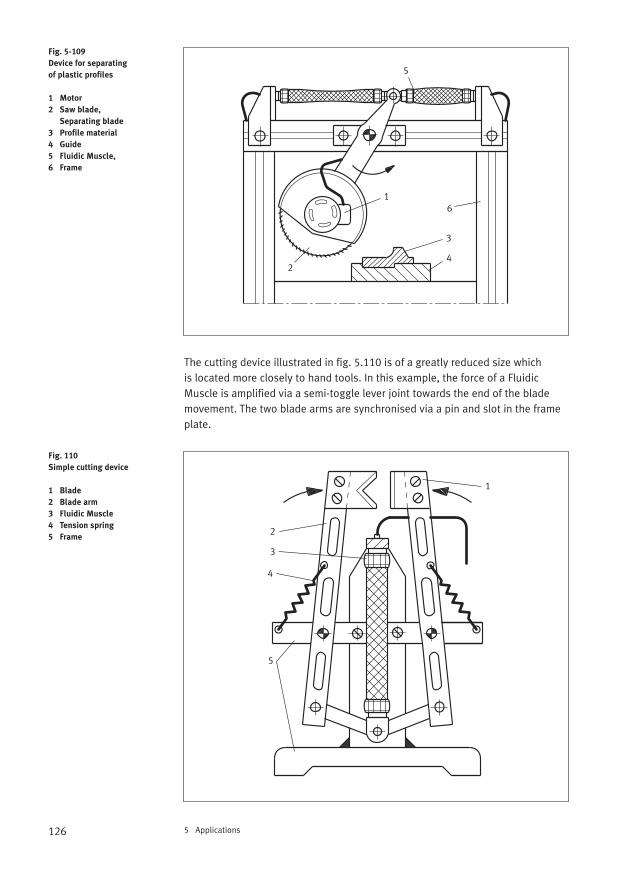
126 5 Applications
The cutting device illustrated in fig. 5.110 is of a greatly reduced size which is located more closely to hand tools. In this example, the force of a FluidicMuscle is amplified via a semi-toggle lever joint towards the end of the blademovement. The two blade arms are synchronised via a pin and slot in the frameplate.
Fig. 5-109
Device for separating
of plastic profiles
1 Motor
2 Saw blade,
Separating blade
3 Profile material
4 Guide
5 Fluidic Muscle,
6 Frame
Fig. 110
Simple cutting device
1 Blade
2 Blade arm
3 Fluidic Muscle
4 Tension spring
5 Frame
1
24
3
6
5
1
2
3
4
5
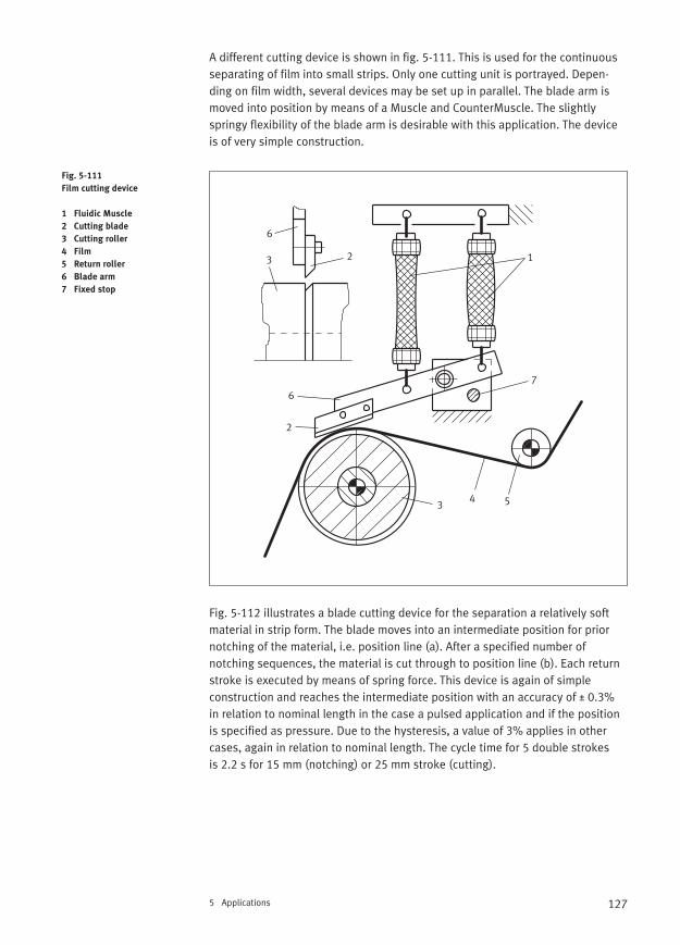
127
A different cutting device is shown in fig. 5-111. This is used for the continuousseparating of film into small strips. Only one cutting unit is portrayed. Depen-ding on film width, several devices may be set up in parallel. The blade arm ismoved into position by means of a Muscle and CounterMuscle. The slightlyspringy flexibility of the blade arm is desirable with this application. The deviceis of very simple construction.
Fig. 5-112 illustrates a blade cutting device for the separation a relatively softmaterial in strip form. The blade moves into an intermediate position for priornotching of the material, i.e. position line (a). After a specified number of notching sequences, the material is cut through to position line (b). Each returnstroke is executed by means of spring force. This device is again of simple construction and reaches the intermediate position with an accuracy of ± 0.3% in relation to nominal length in the case a pulsed application and if the positionis specified as pressure. Due to the hysteresis, a value of 3% applies in othercases, again in relation to nominal length. The cycle time for 5 double strokes is 2.2 s for 15 mm (notching) or 25 mm stroke (cutting).
5 Applications
Fig. 5-111
Film cutting device
1 Fluidic Muscle
2 Cutting blade
3 Cutting roller
4 Film
5 Return roller
6 Blade arm
7 Fixed stop
12
2
3
34 5
6
6
7
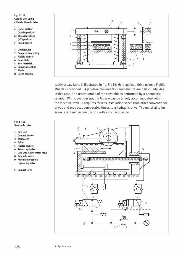
128 5 Applications
Lastly, a saw table is illustrated in fig. 5-113. Here again, a drive using a FluidicMuscle is provided. Its jerk-free movement characteristics are particularly idealin this case. The return stroke of the saw table is performed by a pneumaticcylinder. With clever design, the Muscle can be largely accommodated within the machine table. It requires far less installation space than other conventionaldrives and produces comparable forces to a hydraulic drive. The material to besawn is retained in conjunction with a contact device.
Fig. 5-112
Cutting unit using
a Fluidic Muscle drive
a) Upper cutting
(notch) position
b) Through cutting
(off ) position
c) Rest position
1 Lifting plate
2 Compression spring
3 Fluidic Muscle
4 Base plate
5 Soft material
6 Conveyor section
7 Blade
8 Guide column
Fig. 5-113
Saw table drive
1 Saw unit
2 Contact device
3 Workpiece
4 Table
5 Fluidic Muscle
6 Retract cylinder
7 One-way flow control valve
8 Solenoid valve
9 Precision pressure
regulating valve
F Contact force
1
2
3
4
5 6
7 7 1
ab
c
8
12
34
5
6
7
8
9
F
2 2
12 1282 82 10/12 1 33311
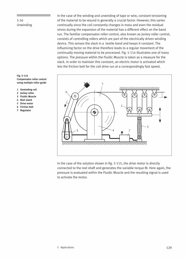
129
In the case of the winding and unwinding of tape or wire, constant tensioning of the material to be wound is generally a crucial factor. However, this variescontinually since the coil constantly changes in mass and even the residualstress during the expansion of the material has a different effect on the bandrun. The familiar compensator roller control, also known as jockey roller control,consists of controlling rollers which are part of the electrically driven windingdevice. This senses the slack in a textile band and keeps it constant. The influencing factor on the drive therefore leads to a regular movement of the continually moving material to be processed. Fig. 5-114 illustrates one of manyoptions. The pressure within the Fluidic Muscle is taken as a measure for theslack. In order to maintain this constant, an electric motor is activated which lets the friction belt for the coil drive run at a correspondingly fast speed.
In the case of the solution shown in fig. 5-115, the drive motor is directlyconnected to the reel shaft and generates the variable torque M. Here again, thepressure is evaluated within the Fluidic Muscle and the resulting signal is usedto activate the motor.
5 Applications
5.16Unwinding
Fig. 5-114
Compensator roller control
using multiple roller guide
1 Unwinding coil
2 Jockey roller
3 Fluidic Muscle
4 Reel stand
5 Drive motor
6 Friction belt
7 Regulator
1
2
345
6
7
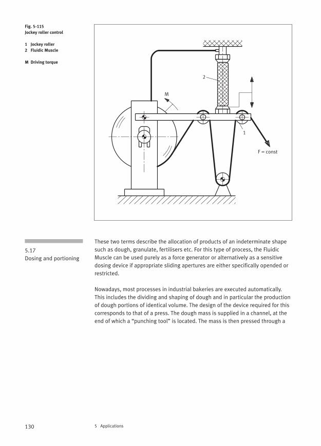
130 5 Applications
These two terms describe the allocation of products of an indeterminate shapesuch as dough, granulate, fertilisers etc. For this type of process, the Fluidic Muscle can be used purely as a force generator or alternatively as a sensitivedosing device if appropriate sliding apertures are either specifically opended orrestricted.
Nowadays, most processes in industrial bakeries are executed automatically.This includes the dividing and shaping of dough and in particular the productionof dough portions of identical volume. The design of the device required for thiscorresponds to that of a press. The dough mass is supplied in a channel, at theend of which a “punching tool” is located. The mass is then pressed through a
Fig. 5-115
Jockey roller control
1 Jockey roller
2 Fluidic Muscle
M Driving torque
5.17Dosing and portioning
F = const
1
2
M
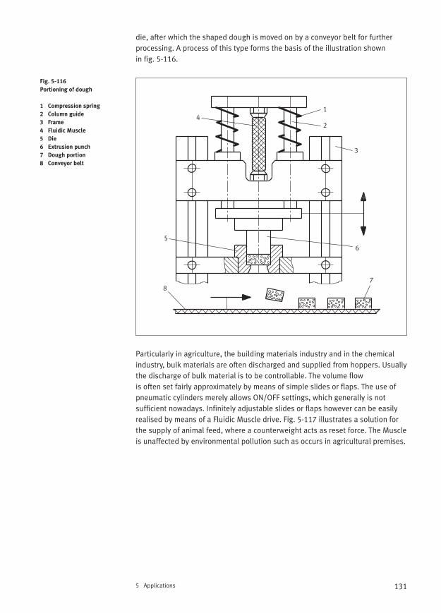
131
die, after which the shaped dough is moved on by a conveyor belt for furtherprocessing. A process of this type forms the basis of the illustration shown in fig. 5-116.
Particularly in agriculture, the building materials industry and in the chemicalindustry, bulk materials are often discharged and supplied from hoppers. Usuallythe discharge of bulk material is to be controllable. The volume flow is often set fairly approximately by means of simple slides or flaps. The use ofpneumatic cylinders merely allows ON/OFF settings, which generally is not sufficient nowadays. Infinitely adjustable slides or flaps however can be easilyrealised by means of a Fluidic Muscle drive. Fig. 5-117 illustrates a solution forthe supply of animal feed, where a counterweight acts as reset force. The Muscleis unaffected by environmental pollution such as occurs in agricultural premises.
5 Applications
Fig. 5-116
Portioning of dough
1 Compression spring
2 Column guide
3 Frame
4 Fluidic Muscle
5 Die
6 Extrusion punch
7 Dough portion
8 Conveyor belt
1
2
3
4
56
78
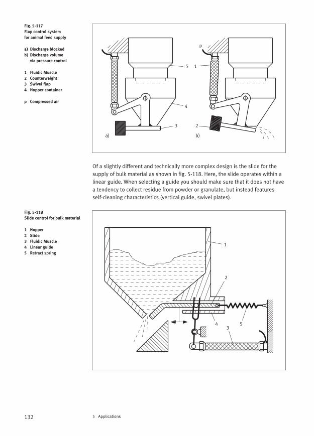
132 5 Applications
Of a slightly different and technically more complex design is the slide for thesupply of bulk material as shown in fig. 5-118. Here, the slide operates within alinear guide. When selecting a guide you should make sure that it does not havea tendency to collect residue from powder or granulate, but instead featuresself-cleaning characteristics (vertical guide, swivel plates).
Fig. 5-117
Flap control system
for animal feed supply
a) Discharge blocked
b) Discharge volume
via pressure control
1 Fluidic Muscle
2 Counterweight
3 Swivel flap
4 Hopper container
p Compressed air
Fig. 5-118
Slide control for bulk material
1 Hopper
2 Slide
3 Fluidic Muscle
4 Linear guide
5 Retract spring
1
23
4
5
a) b)
p
1
2
34 5
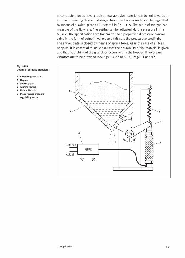
133
In conclusion, let us have a look at how abrasive material can be fed towards anautomatic sanding device in dosaged form. The hopper outlet can be regulatedby means of a swivel plate as illustrated in fig. 5-119. The width of the gap is ameasure of the flow rate. The setting can be adjusted via the pressure in theMuscle. The specifications are transmitted to a proportional pressure controlvalve in the form of setpoint values and this sets the pressure accordingly. The swivel plate is closed by means of spring force. As in the case of all feedhoppers, it is essential to make sure that the pourability of the material is givenand that no arching of the granulate occurs within the hopper. If necessary,vibrators are to be provided (see figs. 5-62 and 5-63), Page 91 and 92.
5 Applications
Fig. 5-119
Dosing of abrasive granulate
1 Abrasive granulate
2 Hopper
3 Swivel plate
4 Tension spring
5 Fluidic Muscle
6 Proportional pressure
regulating valve
1
2
3
4
5
6
Setpoint
Actual
MPPE
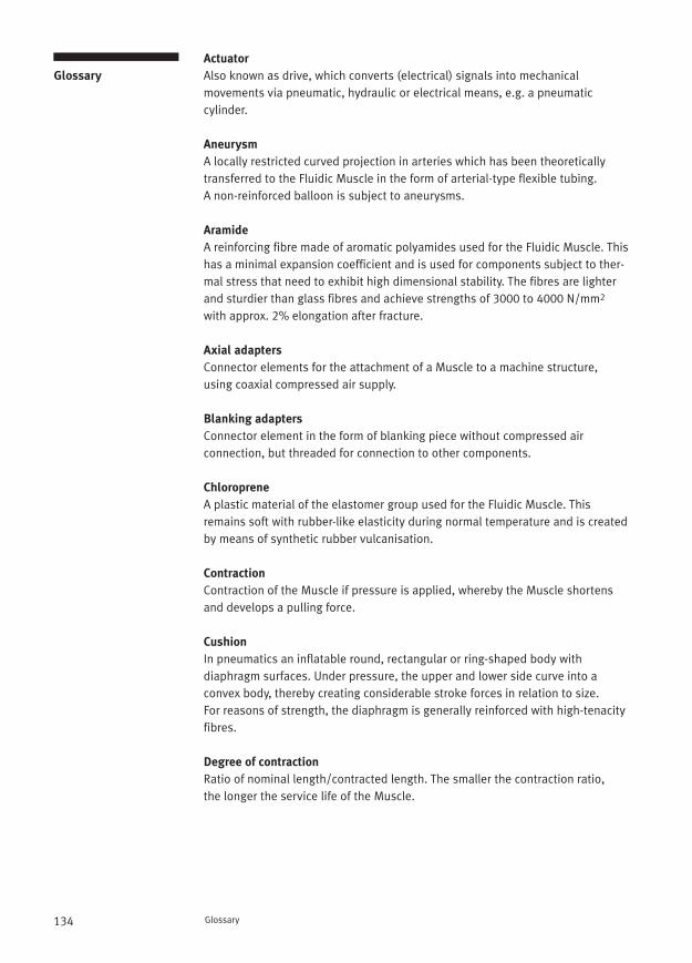
134 Glossary
Actuator
Also known as drive, which converts (electrical) signals into mechanical movements via pneumatic, hydraulic or electrical means, e.g. a pneumatic cylinder.
Aneurysm
A locally restricted curved projection in arteries which has been theoreticallytransferred to the Fluidic Muscle in the form of arterial-type flexible tubing. A non-reinforced balloon is subject to aneurysms.
Aramide
A reinforcing fibre made of aromatic polyamides used for the Fluidic Muscle. Thishas a minimal expansion coefficient and is used for components subject to ther-mal stress that need to exhibit high dimensional stability. The fibres are lighterand sturdier than glass fibres and achieve strengths of 3000 to 4000 N/mm2
with approx. 2% elongation after fracture.
Axial adapters
Connector elements for the attachment of a Muscle to a machine structure,using coaxial compressed air supply.
Blanking adapters
Connector element in the form of blanking piece without compressed air connection, but threaded for connection to other components.
Chloroprene
A plastic material of the elastomer group used for the Fluidic Muscle. Thisremains soft with rubber-like elasticity during normal temperature and is createdby means of synthetic rubber vulcanisation.
Contraction
Contraction of the Muscle if pressure is applied, whereby the Muscle shortensand develops a pulling force.
Cushion
In pneumatics an inflatable round, rectangular or ring-shaped body with diaphragm surfaces. Under pressure, the upper and lower side curve into a convex body, thereby creating considerable stroke forces in relation to size. For reasons of strength, the diaphragm is generally reinforced with high-tenacityfibres.
Degree of contraction
Ratio of nominal length/contracted length. The smaller the contraction ratio, the longer the service life of the Muscle.
Glossary
135
Diaphragm
Thin-walled, flexural, tension-susceptible covering which is often stabilised by means of gas pressure (air pressure) and as a result, capable of acceptingexternal loads or of delivering forces. The cover, external medium and fillingcombine to form a construction system. In the case of the Muscle the covering is combined with a fibreous grid.
Elongation
Synonym for an expansion of the Muscle
Expansion
A Muscle expands if an external force is applied which leads to an elongation(lengthening). The external force is for example a freely suspended load.
Force compensator
A set of cup springs integrated into the Muscle connection, which are permanently preset to a maximum force value. If this force is exceeded, this causes the excess compressed air to be released.
Hysteresis behaviour
Behaviour of a material which, during a reversible process such as being loadedor unloaded, exhibits a direction-governed change, for example a change inlength.
Installation length
Length of a Muscle in a pressureless state with connecting elements at bothends (nominal length plus 2 times length of connector elements) or specified as “installation length contracted”.
Interface
Type of connection of a Muscle to a machine structure using connectors, adapters or similar.
Motor
Generic term for motion-generating machines (lat. “mover”), which convert a given type of energy into a mechanical kinetic energy. Every pneumatic cylin-der is therefore also a motor. In the narrower sense, a motor these days is understood to be a revolving rotary actuator, e.g. an electric motor. Revolvingmovements can also be achieved pneumatically, i.e. via a Fluidic Muscle, if thecontractions act upon a crankshaft.
Glossary
136 Glossary
Muscle contraction, biological
The conversion of chemical energy into a mechanical operation. During the process of contraction a connection is established between two muscle proteins(actin and myosin form actomyosin).
Operating frequency
Number of load changes per time unit in an application using the Muscle. In thisbook, it is specified in Hertz (Hz), i.e. in actions per second.
Overload protection
See force compensator
Peristaltic
A medical term. A movement carried out by the walls of hollow muscular organs,whereby the individual sections of an organ contract in a wave-like sequence, thereby transporting forward the contents of the hollow organ.
Pneu
A system, also a constructional system, whereby a covering which is subjectedsolely to tension envelops a filling. Typical pneus are air balloons, air bladders,soap bubbles, skin sections of man and beast, inflatable buildings, tyres, fire hoses and of course the Fluidic Muscle.
Preload force
Force on a non-activated Fluidic Muscle, which leads to lengthening by a maximum of 3% of the nominal length and a constriction of the Muscle.
Radial adapter
Connector elements for the attachment of a Muscle to a machine structure withlateral compressed air supply.
Relaxation effect
Time-delayed effect after a cause, such as a slight elongation of the Muscle with a static load and after a certain time.
Spring characteristic curve
This indicates the dependence of the spring travel s on the spring force F and can be progressive, linear or degressive. Springs with a progressive characteristic curve become “harder” with increasing load and those with adegressive characteristic curve “softer” with increasing load.
137
Spring constant
This indicates the required spring force F in order to reach a spring travel f of 1 mm with a particular spring, e.g. a pneumatic spring G. In the past this wasreferred to as spring rate.
Stick-slip effect
Juddery or jerky movement of slides and rotary tables during very slow move-ment, which, in conjunction with elastic deformation, is created as a result of achange between static and sliding friction.
Stroke length
A change in Muscle length between two mechanically fixed load points. The stroke length is smaller than the distance possible during maximum contraction.
Surface Muscle
Designation for a “semi” compressed air cushion. The surface muscle consists of a solid flat base plate with mounting holes, through which a round or oval diaphragm protrudes if pressure is applied, thereby developing a pressing force.
Glossary

138
139Literature
[1] Kato, W.: Mechanical Hands Illustrated, Survey, Tokyo 1982
[2] Litinetzkij, I. B.: Bionika (russ.), Verlag Bildung, Moskau 1976
[3] Brooks, R.: Menschmaschinen, Campus Verlag, Frankfurt/New York 2002
[4] Pylatiuk, Ch.: Entwicklung flexibler Fluidaktoren und ihre Anwendung in der Medizintechnik, Med. Orth. Techn. 120(2000)6, S. 186-189
[5] Vogel, S.: Von Grashalmen und Hochhäusern – Mechanische Schöpfungen in Natur und Technik, Wiley-VCH, Weinheim/New York 2000
[6] Dale-Hampstead, A.: Der pneumatische Muskel von Axel Thallemer, Verlag Form, Frankfurt am Main 2001
[7] Hesse, S.; Schmidt, U.; Schmidt, H.: Manipulatorpraxis, Braunschweig/Wiesbaden, Vieweg Verlag 2001
[8] Hesse, S.: 99 Beispiele für Pneumatikanwendungen, Festo, Esslingen 2000
[9] Hesse, S.; Krahn, H.; Eh, D.: Betriebsmittel Vorrichtung, Carl Hanser Verlag, München 2002
[10] Zeichen, G. u.a.: Case Studie Pneumatischer Muskel, TU Wien 2001
[11] Hesse, S.: Praxiswissen Handhabungstechnik in 36 Lektionen, expert verlag, Renningen 1996
[12] Iovine, J.: Robots, Androids, and Animatrons, McGraw-Hill, New York 2002
[13] Bedienungsanleitung Fluidic Muscle, Festo, Esslingen 2001
[14] Deppert, W.; Stoll, K.: Pneumatische Steuerungen, Vogel Buchverlag, Würzburg 1994
[15] Deppert, W.; Stoll, K.: Pneumatik-Anwendungen, Vogel Buchverlag, Würzburg 1990
Literature
140
A Adjusting gripper . . . . . . . . . . . . . . . . . . . . . . . . . . . . . . . . . . . . . . . . . . . . . 55Agonist . . . . . . . . . . . . . . . . . . . . . . . . . . . . . . . . . . . . . . . . . . . . . . . . . . . . . 15Allocator . . . . . . . . . . . . . . . . . . . . . . . . . . . . . . . . . . . . . . . . . . . . . . . . . . . . 91Android arm . . . . . . . . . . . . . . . . . . . . . . . . . . . . . . . . . . . . . . . . . . . . . . . . . 94Angle gripper . . . . . . . . . . . . . . . . . . . . . . . . . . . . . . . . . . . . . . . . . . . . . . . . 54Antagonist . . . . . . . . . . . . . . . . . . . . . . . . . . . . . . . . . . . . . . . . . . . . . . . . . . 15Arching effect . . . . . . . . . . . . . . . . . . . . . . . . . . . . . . . . . . . . . . . . . . . . . . . . 91Arranging . . . . . . . . . . . . . . . . . . . . . . . . . . . . . . . . . . . . . . . . . . . . . . . . . . . 87Articulate joint structure . . . . . . . . . . . . . . . . . . . . . . . . . . . . . . . . . . . . . . . 84Articulated finger . . . . . . . . . . . . . . . . . . . . . . . . . . . . . . . . . . . . . . . . . . . . . 95Artificial being . . . . . . . . . . . . . . . . . . . . . . . . . . . . . . . . . . . . . . . . . . . . . . . 97Artificial hand . . . . . . . . . . . . . . . . . . . . . . . . . . . . . . . . . . . . . . . . . . . . . . . . 17Assembly press . . . . . . . . . . . . . . . . . . . . . . . . . . . . . . . . . . . . . . . . . . . . . . 59Attachment vibrators . . . . . . . . . . . . . . . . . . . . . . . . . . . . . . . . . . . . . . . . . 111Automatic sanding device . . . . . . . . . . . . . . . . . . . . . . . . . . . . . . . . . . . . . 133
B Balancer . . . . . . . . . . . . . . . . . . . . . . . . . . . . . . . . . . . . . . . . . . . . . . . . . . . . 46Barrel shaker . . . . . . . . . . . . . . . . . . . . . . . . . . . . . . . . . . . . . . . . . . . . . . . 110Barrel-Muscle cylinder . . . . . . . . . . . . . . . . . . . . . . . . . . . . . . . . . . . . . . . . . 38Barrier . . . . . . . . . . . . . . . . . . . . . . . . . . . . . . . . . . . . . . . . . . . . . . . . . . . . . 81Bellows cylinders . . . . . . . . . . . . . . . . . . . . . . . . . . . . . . . . . . . . . . . . . . . . . 11Belt tensioning device . . . . . . . . . . . . . . . . . . . . . . . . . . . . . . . . . . . . . . . . . 67Belt-tensioning actuator . . . . . . . . . . . . . . . . . . . . . . . . . . . . . . . . . . . 75, 116Bending device . . . . . . . . . . . . . . . . . . . . . . . . . . . . . . . . . . . . . . . . . . . . . 123Biological muscle . . . . . . . . . . . . . . . . . . . . . . . . . . . . . . . . . . . . . . . . . . . . . 13Blocking device . . . . . . . . . . . . . . . . . . . . . . . . . . . . . . . . . . . . . . . . . . . . . .113Bracing cable . . . . . . . . . . . . . . . . . . . . . . . . . . . . . . . . . . . . . . . . . . . . . . . . 72Bulk material vibrator . . . . . . . . . . . . . . . . . . . . . . . . . . . . . . . . . . . . . . . . . 92
C Cantilever boom axis . . . . . . . . . . . . . . . . . . . . . . . . . . . . . . . . . . . . . . . . . . 47Clamped attachment . . . . . . . . . . . . . . . . . . . . . . . . . . . . . . . . . . . . . . . . . . 29Clamping device . . . . . . . . . . . . . . . . . . . . . . . . . . . . . . . . . . . . . . . . . . 65, 68Clamping gripper . . . . . . . . . . . . . . . . . . . . . . . . . . . . . . . . . . . . . . . . . . . . . 53Combat robot . . . . . . . . . . . . . . . . . . . . . . . . . . . . . . . . . . . . . . . . . . . . . . . . 97Compensation mechanism . . . . . . . . . . . . . . . . . . . . . . . . . . . . . . . . . . . . . 89Compensator roller control . . . . . . . . . . . . . . . . . . . . . . . . . . . . . . . . . . . . 129Compressed air consumption . . . . . . . . . . . . . . . . . . . . . . . . . . . . . . . . . . . 31Contact roller . . . . . . . . . . . . . . . . . . . . . . . . . . . . . . . . . . . . . . . . . . . . . . . . 70Conveyor belt . . . . . . . . . . . . . . . . . . . . . . . . . . . . . . . . . . . . . . . . . . . . 83, 119Counter muscle . . . . . . . . . . . . . . . . . . . . . . . . . . . . . . . . . . . . . . . . . . . . . . 15Coupling . . . . . . . . . . . . . . . . . . . . . . . . . . . . . . . . . . . . . . . . . . . . . . . . . . . . 84Crankshaft drive . . . . . . . . . . . . . . . . . . . . . . . . . . . . . . . . . . . . . . . . . . . . . 101Cushion . . . . . . . . . . . . . . . . . . . . . . . . . . . . . . . . . . . . . . . . . . . . . . . . . . . . . 9Cutter bar . . . . . . . . . . . . . . . . . . . . . . . . . . . . . . . . . . . . . . . . . . . . . . . . . . 125Cutting device . . . . . . . . . . . . . . . . . . . . . . . . . . . . . . . . . . . . . . . . . . . . . . 126Cutting press . . . . . . . . . . . . . . . . . . . . . . . . . . . . . . . . . . . . . . . . . . . . . . . 124
Index of technical terms
Index
of technical terms
141Index of technical terms
D Deflector . . . . . . . . . . . . . . . . . . . . . . . . . . . . . . . . . . . . . . . . . . . . . . . . . . . . 90Diaphragm contraction system . . . . . . . . . . . . . . . . . . . . . . . . . . . . . . . . . . 21Dismantling unit . . . . . . . . . . . . . . . . . . . . . . . . . . . . . . . . . . . . . . . . . . . . . . 59Distribution belts . . . . . . . . . . . . . . . . . . . . . . . . . . . . . . . . . . . . . . . . . . . . 122Door opener . . . . . . . . . . . . . . . . . . . . . . . . . . . . . . . . . . . . . . . . . . . . . . . . 105Double scraper . . . . . . . . . . . . . . . . . . . . . . . . . . . . . . . . . . . . . . . . . . . . . . 118Doubling of stroke . . . . . . . . . . . . . . . . . . . . . . . . . . . . . . . . . . . . . . . . . . . . 45Dough portion . . . . . . . . . . . . . . . . . . . . . . . . . . . . . . . . . . . . . . . . . . . . . . 130Drum brake . . . . . . . . . . . . . . . . . . . . . . . . . . . . . . . . . . . . . . . . . . . . . . . . 115
E Emergency brake system . . . . . . . . . . . . . . . . . . . . . . . . . . . . . . . . . . . . . . 115Empty pallet gripper . . . . . . . . . . . . . . . . . . . . . . . . . . . . . . . . . . . . . . . . . . 56Endurance testing unit . . . . . . . . . . . . . . . . . . . . . . . . . . . . . . . . . . . . . . . . . 98Enveloping gripper . . . . . . . . . . . . . . . . . . . . . . . . . . . . . . . . . . . . . . . . . . . . 57External collet chuck . . . . . . . . . . . . . . . . . . . . . . . . . . . . . . . . . . . . . . . . . . 56
F Fast switching valve . . . . . . . . . . . . . . . . . . . . . . . . . . . . . . . . . . . . . . . . . . . 88Feed roller . . . . . . . . . . . . . . . . . . . . . . . . . . . . . . . . . . . . . . . . . . . . . . . . . . 71Filler material . . . . . . . . . . . . . . . . . . . . . . . . . . . . . . . . . . . . . . . . . . . . . . . . 31Film cutting device . . . . . . . . . . . . . . . . . . . . . . . . . . . . . . . . . . . . . . . . . . . 127Filter press . . . . . . . . . . . . . . . . . . . . . . . . . . . . . . . . . . . . . . . . . . . . . . . . . . 83Flap control system . . . . . . . . . . . . . . . . . . . . . . . . . . . . . . . . . . . . . . . . . . 132Flow velocity regulation . . . . . . . . . . . . . . . . . . . . . . . . . . . . . . . . . . . . . . . . 82Fluidic actuator . . . . . . . . . . . . . . . . . . . . . . . . . . . . . . . . . . . . . . . . . . . . . . 19Force/contraction diagram . . . . . . . . . . . . . . . . . . . . . . . . . . . . . . . . . . . . . 23Friction coupling . . . . . . . . . . . . . . . . . . . . . . . . . . . . . . . . . . . . . . . . . . . . . 85
G Girder transfer device . . . . . . . . . . . . . . . . . . . . . . . . . . . . . . . . . . . . . . . . 117Gripper . . . . . . . . . . . . . . . . . . . . . . . . . . . . . . . . . . . . . . . . . . . . . . . . . . . . . 53Gripper head . . . . . . . . . . . . . . . . . . . . . . . . . . . . . . . . . . . . . . . . . . . . . . . . 66Guide rail adjustment . . . . . . . . . . . . . . . . . . . . . . . . . . . . . . . . . . . . . . . . . 78Guide roller . . . . . . . . . . . . . . . . . . . . . . . . . . . . . . . . . . . . . . . . . . . . . 76, 114
H Hand-held screwdriver . . . . . . . . . . . . . . . . . . . . . . . . . . . . . . . . . . . . . . . . 103Handling module . . . . . . . . . . . . . . . . . . . . . . . . . . . . . . . . . . . . . . . . . . . . . 87Handling unit . . . . . . . . . . . . . . . . . . . . . . . . . . . . . . . . . . . . . . . . . . . . . . . . 85
I Intermediate ventilating . . . . . . . . . . . . . . . . . . . . . . . . . . . . . . . . . . . . . . . 71Internal bore gripper . . . . . . . . . . . . . . . . . . . . . . . . . . . . . . . . . . . . . . . . . . 56Internal clamping device . . . . . . . . . . . . . . . . . . . . . . . . . . . . . . . . . . . . . . . 66Internal gripper . . . . . . . . . . . . . . . . . . . . . . . . . . . . . . . . . . . . . . . . . . . . . . 56Ironing press . . . . . . . . . . . . . . . . . . . . . . . . . . . . . . . . . . . . . . . . . . . . . . . . 63
J Jockey roller . . . . . . . . . . . . . . . . . . . . . . . . . . . . . . . . . . . . . . . . . . . . . . . . 129Joining mechanism . . . . . . . . . . . . . . . . . . . . . . . . . . . . . . . . . . . . . . . . . . . . 88
L Larger stroke . . . . . . . . . . . . . . . . . . . . . . . . . . . . . . . . . . . . . . . . . . . . . . . . 79
142
Leg construction . . . . . . . . . . . . . . . . . . . . . . . . . . . . . . . . . . . . . . . . . . . . . 96Lever principle . . . . . . . . . . . . . . . . . . . . . . . . . . . . . . . . . . . . . . . . . . . . . . . 16Lifting gear . . . . . . . . . . . . . . . . . . . . . . . . . . . . . . . . . . . . . . . . . . . . . . . . . . 48Lifting plate . . . . . . . . . . . . . . . . . . . . . . . . . . . . . . . . . . . . . . . . . . . . . . . . . 10Lifting platform . . . . . . . . . . . . . . . . . . . . . . . . . . . . . . . . . . . . . . . . . . . . . . 50Linear vibratory channel . . . . . . . . . . . . . . . . . . . . . . . . . . . . . . . . . . . . . . 107Load case . . . . . . . . . . . . . . . . . . . . . . . . . . . . . . . . . . . . . . . . . . . . . . . . . . . 24Loading device . . . . . . . . . . . . . . . . . . . . . . . . . . . . . . . . . . . . . . . . . . . . . . . 52Long stroke gripper . . . . . . . . . . . . . . . . . . . . . . . . . . . . . . . . . . . . . . . . . . . 54
M Manipulator . . . . . . . . . . . . . . . . . . . . . . . . . . . . . . . . . . . . . . . . . . . . . . . . . 45Manual hydraulic control unit . . . . . . . . . . . . . . . . . . . . . . . . . . . . . . . . . . . 79McKibben muscle . . . . . . . . . . . . . . . . . . . . . . . . . . . . . . . . . . . . . . . . . . . . . 17Media resistance . . . . . . . . . . . . . . . . . . . . . . . . . . . . . . . . . . . . . . . . . . . . . 28Membrane . . . . . . . . . . . . . . . . . . . . . . . . . . . . . . . . . . . . . . . . . . . . . . . . . . . 9Membrane building . . . . . . . . . . . . . . . . . . . . . . . . . . . . . . . . . . . . . . . . . . . 72Membrane contraction system . . . . . . . . . . . . . . . . . . . . . . . . . . . . . . . . . . 21Motion guidance . . . . . . . . . . . . . . . . . . . . . . . . . . . . . . . . . . . . . . . . . . . . . 35Multiple gripper . . . . . . . . . . . . . . . . . . . . . . . . . . . . . . . . . . . . . . . . . . . . . . 55Muscle/work . . . . . . . . . . . . . . . . . . . . . . . . . . . . . . . . . . . . . . . . . . . . . . . . 16MuscleSIM . . . . . . . . . . . . . . . . . . . . . . . . . . . . . . . . . . . . . . . . . . . . . . . . . . 27Muscle motor . . . . . . . . . . . . . . . . . . . . . . . . . . . . . . . . . . . . . . . . . . . . . . . 103
O Oscillating seat . . . . . . . . . . . . . . . . . . . . . . . . . . . . . . . . . . . . . . . . . . . . . 110Oscillating table . . . . . . . . . . . . . . . . . . . . . . . . . . . . . . . . . . . . . . . . . . . . . 109
P Pad-type Muscle . . . . . . . . . . . . . . . . . . . . . . . . . . . . . . . . . . . . . . . . . . . . . 43Paper sheet guide plate . . . . . . . . . . . . . . . . . . . . . . . . . . . . . . . . . . . . . . . . 61Parallel connection . . . . . . . . . . . . . . . . . . . . . . . . . . . . . . . . . . . . . . . . . . . 41Parallelogram linkage . . . . . . . . . . . . . . . . . . . . . . . . . . . . . . . . . . . . . . . . . 36Pedipulator . . . . . . . . . . . . . . . . . . . . . . . . . . . . . . . . . . . . . . . . . . . . . . . . . 18Percussion device . . . . . . . . . . . . . . . . . . . . . . . . . . . . . . . . . . . . . . . . . . . . 60Pipe runner . . . . . . . . . . . . . . . . . . . . . . . . . . . . . . . . . . . . . . . . . . . . . . . . 107Piston pump . . . . . . . . . . . . . . . . . . . . . . . . . . . . . . . . . . . . . . . . . . . . . . . . . 64Pneu . . . . . . . . . . . . . . . . . . . . . . . . . . . . . . . . . . . . . . . . . . . . . . . . . . . . . . . . 9Pneumatic hammer . . . . . . . . . . . . . . . . . . . . . . . . . . . . . . . . . . . . . . . . . . . 60Polishing device . . . . . . . . . . . . . . . . . . . . . . . . . . . . . . . . . . . . . . . . . . . . . 124Precision positioning . . . . . . . . . . . . . . . . . . . . . . . . . . . . . . . . . . . . . . . . . . 81Press component . . . . . . . . . . . . . . . . . . . . . . . . . . . . . . . . . . . . . . . . . . . . . 62Press-on motion . . . . . . . . . . . . . . . . . . . . . . . . . . . . . . . . . . . . . . . . . . . . . . 61Pressure gauges . . . . . . . . . . . . . . . . . . . . . . . . . . . . . . . . . . . . . . . . . . . . . 99
R Radial-type motor . . . . . . . . . . . . . . . . . . . . . . . . . . . . . . . . . . . . . . . . . . . 104Rectilinear control . . . . . . . . . . . . . . . . . . . . . . . . . . . . . . . . . . . . . . . . . . . 120Rectilinear motion of belt edge . . . . . . . . . . . . . . . . . . . . . . . . . . . . . . . . . 120
Index of technical terms
143Index of technical terms
Relaxation effect . . . . . . . . . . . . . . . . . . . . . . . . . . . . . . . . . . . . . . . . . . . . . 35Retaining device . . . . . . . . . . . . . . . . . . . . . . . . . . . . . . . . . . . . . . . . . . . . 121Retarder . . . . . . . . . . . . . . . . . . . . . . . . . . . . . . . . . . . . . . . . . . . . . . . . . . . 114Retarding roller conveyor . . . . . . . . . . . . . . . . . . . . . . . . . . . . . . . . . . . . . 116
S Safety clamping system . . . . . . . . . . . . . . . . . . . . . . . . . . . . . . . . . . . . . . . . 75Saw actuation . . . . . . . . . . . . . . . . . . . . . . . . . . . . . . . . . . . . . . . . . . . . . . 106Saw blade . . . . . . . . . . . . . . . . . . . . . . . . . . . . . . . . . . . . . . . . . . . . . . . . . 125Saw table . . . . . . . . . . . . . . . . . . . . . . . . . . . . . . . . . . . . . . . . . . . . . . . . . . 128Scissor mechanism . . . . . . . . . . . . . . . . . . . . . . . . . . . . . . . . . . . . . . . . . . . 35Scissor-type elevating platform . . . . . . . . . . . . . . . . . . . . . . . . . . . . . . . . . . 49Scraper . . . . . . . . . . . . . . . . . . . . . . . . . . . . . . . . . . . . . . . . . . . . . . . . . . . . 118Series connection . . . . . . . . . . . . . . . . . . . . . . . . . . . . . . . . . . . . . . . . . . . . 41Service life . . . . . . . . . . . . . . . . . . . . . . . . . . . . . . . . . . . . . . . . . . . . . . . . . . 28Shaft axis . . . . . . . . . . . . . . . . . . . . . . . . . . . . . . . . . . . . . . . . . . . . . . . . . . . 67Simulator . . . . . . . . . . . . . . . . . . . . . . . . . . . . . . . . . . . . . . . . . . . . . . . . . . 109Single-bank radial motor . . . . . . . . . . . . . . . . . . . . . . . . . . . . . . . . . . . . . . 104Slide drive . . . . . . . . . . . . . . . . . . . . . . . . . . . . . . . . . . . . . . . . . . . . . . . . . . 80Small press . . . . . . . . . . . . . . . . . . . . . . . . . . . . . . . . . . . . . . . . . . . . . . . . . 60Sorting . . . . . . . . . . . . . . . . . . . . . . . . . . . . . . . . . . . . . . . . . . . . . . . . . . . . . 87Sorting gate . . . . . . . . . . . . . . . . . . . . . . . . . . . . . . . . . . . . . . . . . . . . . . . . 122Sorting gate using Fluidic Muscle actuation . . . . . . . . . . . . . . . . . . . . . . . 121Sorting storage conveyor . . . . . . . . . . . . . . . . . . . . . . . . . . . . . . . . . . . . . 118Spatial structure . . . . . . . . . . . . . . . . . . . . . . . . . . . . . . . . . . . . . . . . . . . . . 72Spindle-nut system . . . . . . . . . . . . . . . . . . . . . . . . . . . . . . . . . . . . . . . . . . 103Standard guide unit . . . . . . . . . . . . . . . . . . . . . . . . . . . . . . . . . . . . . . . . . . . 40Stretch film . . . . . . . . . . . . . . . . . . . . . . . . . . . . . . . . . . . . . . . . . . . . . . . . . . 74Stroke stabilisation . . . . . . . . . . . . . . . . . . . . . . . . . . . . . . . . . . . . . . . . . . . 37Supply of bulk material . . . . . . . . . . . . . . . . . . . . . . . . . . . . . . . . . . . . . . . 132Support plate . . . . . . . . . . . . . . . . . . . . . . . . . . . . . . . . . . . . . . . . . . . . . . . . 81Supporting force generator . . . . . . . . . . . . . . . . . . . . . . . . . . . . . . . . . . . . . 43Swivel device . . . . . . . . . . . . . . . . . . . . . . . . . . . . . . . . . . . . . . . . . . . . . . . . 52Swivel grid . . . . . . . . . . . . . . . . . . . . . . . . . . . . . . . . . . . . . . . . . . . . . . . . . . 80
T Table press . . . . . . . . . . . . . . . . . . . . . . . . . . . . . . . . . . . . . . . . . . . . . . . . . . 58Tensile actuator . . . . . . . . . . . . . . . . . . . . . . . . . . . . . . . . . . . . . . . . . . . . . . 65Test unit . . . . . . . . . . . . . . . . . . . . . . . . . . . . . . . . . . . . . . . . . . . . . . . . . . . . 99Tilting separator . . . . . . . . . . . . . . . . . . . . . . . . . . . . . . . . . . . . . . . . . . . . . . 91Toggle lever mechanism . . . . . . . . . . . . . . . . . . . . . . . . . . . . . . . . . . . . . . . 58Town vehicle . . . . . . . . . . . . . . . . . . . . . . . . . . . . . . . . . . . . . . . . . . . . . . . . 102Tripod . . . . . . . . . . . . . . . . . . . . . . . . . . . . . . . . . . . . . . . . . . . . . . . . . . . . . . 87
U Unwinding device . . . . . . . . . . . . . . . . . . . . . . . . . . . . . . . . . . . . . . . . . . . 114
V Vacuum pump . . . . . . . . . . . . . . . . . . . . . . . . . . . . . . . . . . . . . . . . . . . . . . . 64Vertical vibratory table . . . . . . . . . . . . . . . . . . . . . . . . . . . . . . . . . . . . . . . 109Vibrating wall . . . . . . . . . . . . . . . . . . . . . . . . . . . . . . . . . . . . . . . . . . . . . . . . 93
144
Vibration test bench . . . . . . . . . . . . . . . . . . . . . . . . . . . . . . . . . . . . . . . . . 111Vibratory conveyor drive . . . . . . . . . . . . . . . . . . . . . . . . . . . . . . . . . . . . . . 108Vibratory spiral chute hopper . . . . . . . . . . . . . . . . . . . . . . . . . . . . . . . . . . 108
W Walking machine . . . . . . . . . . . . . . . . . . . . . . . . . . . . . . . . . . . . . . . . . . 18, 96Width adjustment . . . . . . . . . . . . . . . . . . . . . . . . . . . . . . . . . . . . . . . . . . . . 78Wiper blade . . . . . . . . . . . . . . . . . . . . . . . . . . . . . . . . . . . . . . . . . . . . . . . . . 83Withdrawal device . . . . . . . . . . . . . . . . . . . . . . . . . . . . . . . . . . . . . . . . . . . . 86Working range . . . . . . . . . . . . . . . . . . . . . . . . . . . . . . . . . . . . . . . . . . . . . . . 25


