
CRANFIELD INSTITUTE OF TECHNOLOGY
DEPARTMENT OF FLUID ENGINEERING AND INSTRUMENTATION
Ph. D. Thesis'(Total Technology)
Academic Year 1983 - 84
E. G. Arato
'Separation with the aid of surface and interfacial tensions'
Supervisor: Dr. K. Enever
April 1984

.
PAGE
NUMBERS
CUT OFF
IN
ORIGINAL

SUMMARY
The investigations described in this thesis were aimed at developing or laying the foundation of novel techniques of liquid/solid and liquid/liquid separation by utilising the capillary effect.
In Part I the studies related to the extraction of water from an agglomerate of particulate solids and water (i. e. dewatering) by means of ceramic elements are described. These studies clearly showed that although water can be extracted from the agglomerate by ceramic elements and evaporated to atmosphere, the rate of extraction is generally too low for commercial application of the technique.
Part II of this thesis deals with the separation of two immiscible liquids (i. e. water and oil) using a ceramic filter tube either as a 'threshold pressure' separator or a coalescer. It was found that diesel fuel, for instance, could be separated to practically 100% efficiency from a secondary dispersion of oil/water, provided the applied pressure across the tube is maintained below a critical value. This technique could form the basis of a very efficient commercial oil/water separator.

ACKNOWLEDGEMENTS
The author gratefully acknowledges the advice and encouragement by his supervisor, Dr. K. Enever, and is indebted to BHRA Flurd Engineering and SERC who jointly supported this undertaking.
The author also wishes to express his thanks to Mrs. Jayne Luya- Ames for typing the manuscript.

TABLE OF CONTENTS
Page
SUMMARY
ACKNOWLEDGEMENTS
LIST OF FIGURES
LIST OF SYMBOLS
PART I
CHAPTER 1 INTRODUCTION 1.1 Background to the Project 1.2 Scope and Long-term Objectives 2 1.3 Overall Review of Separation Technology 3
CHAPTER 2 THE FUNDAMENTAL PRINCIPLES OF LIQUID/SOLID SEPARATION 5 2.1 Settling of Solids in Liquid 5
2.1.1 Single particle 5 2.1.2 Multi-particle system 6
2.2 Coagulation and Flocculation 7 2.2.1 General description of coagulation 7 2.2.2 Electrostatic repulsion 8 2.2.3 Repulsive potential due to the intersection
of two flat double layers 14 2.2.4 Van der Waals attraction between particles 16 2.2.5 The total potential between two flat particles 17
CHAPTER 3 REVIEW OF RELEVANT DEWATERING TECHNIQUES 18 3.1 Filtration 18 3.2 Electro-osmosis 19
CHAPTER 4 CAPILLARY EVAPORATIVE DEVICE 27 4.1 Preliminary Studies 27
4.1.1 Preliminary feasýbility studies 28 4.2 Investigations Related to the Full Size
Capillary/Evaporative Device 29 4.2.1 Small scale experiments 29
4.3 initial Design of the Full Size Device 31 4.3.1 Pore size and extraction rate 32 4.3.2 Estimated rate of evaporation from the
surface of a cylinder 35 4.4 Mathematical Model 37 4.5 The Finite Element Technique 39 4.6 Considered Variations on the Original Design 40 4.7 Alternative Design of the Dewatering Device 41
4.7.1 General Description 41 4.7.2 Experimental arrangement 42 4.7.3 Observations 43
CHAPTER 5 CONCLUDING REMARKS 44

TABLE OF CONTENTS continued
Page
PART II
CHAPTER 6 THE USE OF CERAMIC TUBES FOR OIL/WATER SEPARATION 45 6.1 Introduction 45 6.2 Existing Coalescer/Filters 46
CHAPTER 7 PRINCIPLES UTILISED FOR OIL/WATER SEPARATION 48 7.1 Two-phase Flow in Porous Medium 48
7.1.1 General comments on a porous ceramic coalescer 51
7.1.2 'Threshold' pressure oil/water separator 52
CHAPTER 8 EXPERIMENTAL ARRANGEMENT 53 8.1 Coalescer/Separator 53
8.1.1 Test conditions 53 8.1.2 Prediction of flow rates 53
CHAPTER 9 EXPERIMENTAL OBSERVATIONS 57 9.1 Tests I- Lubrication Oil 57 9.2 Tests 2- Diesel Oil 58
9.2.1 Feasibility Studies 58 9.2.2 Additional Studies 60
9.3 Miscellaneous Tests 62
CHAPTER 10 THEORETICAL CONSIDERATIONS 63
CHAPTER 11 DESIGN SUGGESTIONS 65
CHAPTER 12 SUMMARY AIM DISCUSSION OF RESULTS 68
CHAPTER 13 'THRESHOLD' PRESSURE OIL/WATER SEPARATOR 69 13.1 Preliminary Considerations 69 13.2 Test Conditions 69 13.3 Experimental Observations 69 13.4 Discussion of Results 70
CHAPTER 14 CONCLUSIONS
CHAPTER 15 OVERALL ASSESSMENT OF THE PROJECT
CHAPTER 16 REFERENCES
APPENDIX I MARKET SURVEY
APPENDIX II SURFACE AND INTERFACIAL TENSIONS
71
72
74
I
xiii
APPENDIX III PROPOSALS FOR RESEARCH IN LIQUID/SOLID SEPARATION Xv
APPENDIX IV PATENT SPECIFICATION XX
APPENDIV V CONSORTIUM PROPOSAL XXXIII
APPENDIX VI REDUCING HEAD OR PRESSURE LOSSES ACROSS A HYDROCYCLONE XLIV

LIST OF FIGURES
Fig. I Colloidal model.
Fig. 2 Dewatering china clay.
Fig. 3 Full size capillary device.
Fig. 4 Finite element scheme/capillary device.
Fig. 5 Plan view of alternative device.
Fig. 5a Dewatering by the alternative device.
Fig. 6 Evaporation rate by the alternative device.
Fig. 7A typical capillary pressure/saturation curve.
Fig. 8 Relative permeability/saturation curves.
Fig. 9 Diagrammatic layout of test rig.
Fig. 10 Experimental arrangement.
Fig. 11 Flow rate of emulsion of 60% diesel and 40% water (V/V).
Fig. 12 Variation of contamination rates with applied pressure.
Fig. 13 Treated diesel fuel.
Fig. 14 Contact angle.

LIST OF SYMBOLS
a A
b
C d
D
e E
9 h I
K
it
L
n Ap
p
p
q Q
r R R- VPD
e li S t
T U
V
w
x
y
z
Radius of particle.
Cross-sectional area.
Reciprocal of Debye length.
Concentration or correction factor.
Particle diameter.
Diffusivity.
Elementary charge. Electric potential gradient. Gravitational acceleration.
Head or elevation.
Electric current.
Boltzmann constant, permeability or shape correction factor.
Length.
Length.
Number of ions.
Pressure drop.
Pressure.
Pressure or porosity.
Electrostatic charge or flow rate.
Flow rate.
Radius or capillary radius.
Radius of rotation.
Reynolds number.
Streaming potential
Time.
Absolute temperature or tortuosity.
Mean velocity.
Velocity, valency or voltage.
Mass transfer rate.
Coordinate.
Coordinate.
See page 11

tIST OF SYMBOLS continued
a B
C
E
11
p
a
11)
(A)
A
Contact angle. Empirical constant. Thickness of flat plate. Dielectric constant. Zeta potential. Dynamic viscos ity. Fluid density or charge density.
Surface, or interfacial tension or surface charge. Shear stress. Velocity potential or mass transfer flux.
Electric potential. Angular velocity. See page 11.

1
P ART I
CHAPTER 1. INTRODUCTION
1.1 Background to the Project
In a continuous search for new research activities, a decision was made by
BHRA Fluid Engineering to become involved in areas of liquid/solid separation,
where a specific need exists either to improve existing techniqtfes or to
develop new techniques.
In order to identify suitable areas, discussions were held with clients and
representatives of members of the Association involved in related
activities. These discussions revealed the need for developing an effective
but inexpensive method of dewatering settling lagoons which are filled up with
sediment.
Settling lagoons can be used for discharging dredged material, treated sewage,
effluent from processes or mining industries and normally cover large areas.
Due to the very low through velocity of the flow and the consequent long
residence time, most of the suspended particles will settle out, leaving the
overflow discharging from the-lagoon relatively free of particulate matter.
After several years of continuous use the lagoon becomes full of sediment,
which needs to be extracted prior to re-use of the lagoon. According to the
information received by BHRA during the preliminary enquiries, filled up
lagoons tend to develop an impermeable surface crust, which effectively
prevents further dewatering by evaporation, consequently a high water content
is retained in the settled material, rendering it unsuitable for mechanical
extraction. For dewatering of this material, BHRA suggested the possibility
of developing a technique utilising the natural effects of capillary rise and
evaporation. This technique would be inexpensive as no energy consumption or
maintenance would be required.
NRDC was approached to support the development of a capillary/evaporative
technique suitable*for dewatering settling lagoons. The financial support for
the preliminary feasibility studies was granted in 1977. The main objective
of these studies was to identify a commercially available material which would

z
extract water from a suspension of fine particles without appreciable blockage
of the pores. In-addition the material selected should not deteriorate under
the influence of weather conditions and likely biological and physical
attacks. Of the several materials examined only ceramic filter tubes appeared
to have satisfied these requirements.
The author of this report carried out the technical work associated with this
project and following the completion of these studies enrolled with the Fluid
Engineering Unit for a course of studies leading to a PhD in Total Technology.
As a result of the reasonably positive outcome of the preliminary studies,
further financial support was received from NRDC towards the commercial
development of the capillary/evaporative technique of dewatering. It was
envisaged that the extension of this project would supply the technical
material and the finance, for at least the first year of the Total Technology
course and additional work in a related field would be forthcoming as a result
of this project.
1.2 Scope and Long-term Objectives
Apart from the short-term objectives of developing a commercial device for
dewatering filled-up lagoons and deriving income from feasibility studies and
licence fees, the long-term objective was to participate in research and
development activities in somq major areas of liquid/solid separation
technology.
The need for this type of research was clearly demonstrated in a major article
by J. H. Krieger in the Chemical and Engineering News titled 'Separation
Technology Faces Crisis' (Ref. 1). The writer of this article suggested that
the main reason for the crisis situation was the shortage of knowledgeable
personnel, due to the absence of educational courses dealing with the subject
in depth.
The article identifies a range of processes, where the need to improve
existing techniques is particularly acute, some of which are sludge
filtration, dewatering of cakes, flocculation and thickening. Furthermore,
investigations on the use of hydrocyclones and the basic mechanisms governing
the operation of froth flotation cells would also be desirable.

3
In view of the technological need for research and development it was
anticipated that, 'including a relatively minor income from the capillary
evaporative device, an overall income of 50,000 pounds sterling could be
achieved in the long-term from work associated with liquid/solid separation.
1.3 Overall Review of Separation Technology
Liquid/solid separation can be defined as an activity where a liquid (e. g.
water) is being extracted from a mixture containing liquid and particulate
solids. This activity covers a wide variety of techniques and some or other
of the techniques are used in almost every major industry. In. some industrial
processes, liquid/solid separation forms a major part of the process. In
these processes the particulate end product prepared with the aid of large
quantities of process water, needs to be relatively dry prior to marketing or further use. In addition the process water is required to be relatively free
of particulate matter before being recycled, as failure to achieve this would
result in an inferior product quality and in a likely pollution of close-by
streams or rivers, due to the subsequent discharge of contaminated process
water.
In these process plants, the unit performing liquid/solid separation consists
of a variety of equipment, each designed for a certain function in a chain of
operations starting from the input of a dilute suspension and ending with the
recovery of a relatively dry particulate product.
In the liquid/solid separation processes indicated above, the mixture to be
treated is always conveyed to the equipment. On the other hand, extraction of
water may also be required 'in-situ' , as in the case of land reclamation and
ground consolidation. The techniques employed in these applications are
referred to as 'in-situ' dewatering techniques.
The separation of two immiscible liquids (e. g. oil and water) is basically
similar to liquid/solid separation, as gravity or centrifugal acceleration is
generally used as a basic mechanism for the separation of the two phases. However the main difference between the two areas of the separation technology lies in the methods employed for enhancing the gravity processes.

4
In the case of liquid/solid separation, a flocculating reagent is added to
accelerate coagulation of particles, while in oil/water separation,
coalescence of the droplets of a dispersion is promoted either by an
electrostatic field or by a mechanical coalescer.
The studies described in this report cover aspects of liquid/solid and liquid/liquid separation technology. Initially, the technical feasibility,
then the marketing potential of a novel technique of 'in-situ' dewatering was
assessed. These investigations were followed by feasibility studies of two
suggested methods of oil/water separation, which were derived from the nature
of two-phase flow in a porous medium. All three techniques utillse the interfacial tension effect to produce separation of the phases.

5
CHAPTER 2. THE FUNDAMENTAL PRINCIPLES OF LIQUID/SOLID SEPARATION
In practice, the first stage of liquid/solid separation usually involves
gravity or centrifugal separation of suspended particles from the liquid.
This stage is then followed by some dewatering process, where the water is
being extracted from a concentrated suspension or from the pores of granular
material. The principles employed in these processes are reviewed below.
2.1 Settling of Solids in Liquid
2.1.1 Single particle
A single, spherical particle in still liquid is affected by buoyancy, drag and
inertia forces and its settling velocity in the Stokes region, (where Re < 1)
can be evaluated from the following equation.
4 7rr3 g(p -p6 7prV =
ý- wr3 (p -p )g-
5' pw3pw dt
A constant terminal velocity is reached, when
dV 0 a -t
then
v 4r2 g(p p
PW d2 g(p p- Pw)
18 18 p
(2.1)
(2.2)
where
V= terminal velocity
d=A= particle diameter
pp = density of particle

6
pw = density of liquid (water)
p= dynamic viscosity
Re = Reynolds number
If a centrifugal acceleration is applied to a particle (e. g. as in centri- fuges or hydrocyclones), 'g' is replaced by a much larger RW2, thus the
terminal settling velocity is increased by a factor of Rw2/g
where
R= radius of rotation
w= angular velocity
2.1.2 Multi-particle system
The settling velocity discussed above also applies to very dilute
suspensions. However in the case of most industrial effluents or suspensions
the solids concentration is high enough for 'hindered settling' to prevail.
Here, the settling velocity of the individual particles will be reduced as a
result of the upward velocity. of the displaced fluid. An empirical formula
for the settling of solids in suspensions proposed by Richardson and Zaki,
quoted by Svarovsky in Ref. 2, is: -
C)a
where
Vs - actual settling velocity
V- settling velocity of a single particle
C- concentration by volume
0= empirical constant
(2.3)

7
2.2 Coagulation and Flocculation
The gravity settling (or hindered settling) of individual particles in liquid
is generally too slow for commercial application in continuous processes. The
settling rate, however, can be dramatically increased by promoting coagulation
of individual particles into clusters of particles, whose equivalent diameter
(de) is much larger than the individual diameters (d). As a result the
settling velocity will increase by a factor of (de/d)2. Coagulation is
promoted by neutralising the electrostatic repulsion forces acting between the
particles. The nature of the repulsive force and the mechanism--involved in
providing coagulation is described in the following section.
2.2.1 General description of coagulation
Most suspended particles present in suspensions carry negative charges on
their surface. These charges will attract positively charged ions from the bulk of the liquid, resulting in the formation of an ionic cloud or ionic
atmosphere around each particle. The ionic atmosphere consists of two
distinct parts and is generally referred to as a double layer. The first part
of the double layer is about one ion thick and is rigidly fixed to the
particle (Stern layer). The second part extends to some distance into the liquid and is characterised by a gradual fall in concentration of positive ions until electrical neutrality is reached. This is called the diffuse part
of the double layer and the potential drop across his layer is called the zeta (; ) potential which is a measurable quantity. (For illustration see Fig. 1).
Although the overall electric charge of a particle/double layer system is
zero, as soon as the double layers of two particles overlap, a repulsive force
is exerted on the particles, which tends to keep them apart. The magnitude of
this force depends on the potential distribution around the particles.
In addition to the electrostatic repulsion between particles, an attraction force, named after its discoverer Van der Waals, also exists between
particles. If we consider a suspension or sol containing electrically charged particles, collision and subsequent adherence between particles will depend - apart from statistical probability - on the relative magnitude of the
repulsive and attractive forces. Neutralisation of the electrostatic repulsive forces would therefore result in the formulation of agglomerates of
particles held together by the Van der Waals attraction forces.

8
2.2.2 Electrostatic repulsion
The distribution of electric potential around a charged particle can be described by Poisson's equation: -
V2* =
where
p ee
V2 = Laplace operator
(2.4)
p= charge density
C= dielectric constant of liquid
Co = permitivity of space
= electric potential
This charge density can be expressed with the aid of Boltzmann's Theorem in
the following way: -
and
if
n_ =n exp (V (-) eý/KT)
n+ =n exp (-V (+) eý/KT)
V(-) = V(+)
then
where
9
P= Ve(n+ - n_) = -2n Ve sinh (Ve*/KT)
n- = number of negative ions per unit volume
n+ = number of positive ions per unit volume
valency, negative
V(+) = valency, positive
e- elementary charge
K- Boltzmann constant
T- absolute temperature
After substitution of (2.5) into (2.4), Poisson's equation becomes: -
V2* . 2nVe sinh (VeV/KT)
ce 0
(2.5)
(2.6)
Equation (2.6) can not be solved analytically without simplifying
assumptions. However, there are two basic theories dealing with the
evaluation of potential distribution around a particle which are: - (see
Ref. 3)
I.
(i) Debye-liuckel Theory: Spherical Double Layer
This theory considers a spherically symetric distribution of an ionic
atmosphere formed around a simple central ion. A solution of equation (2.6) is obtained by assuming a very dilute solution where the thermal
energy is much greater than the electrical energy.

10
Ve*/KT <<l
Poisson's equation for a spherically symmetric distribution then
becomes: -
1d2 dý = (r ýf_ b2ý
r2 dr r)
where
b2 =2 ne2 v2 cc KT
0
(2.7)
and b-I = Debye length and is an approximate measure of the thickness of
the ionic atmosphere.
The general solution of (2.7) is: -
a ar
where
Va potential at 'a'
r radial distance
a radius of particle
Total charge (q) on a particle is given by: -
d* CY q1+ ba
dr cc 471a2 ccaa r-a 00

11
0
where
aeý surface charge per unit surface area
and
q= 4w aCC0 (1+ ba) Va
(ii) Gouy-Chapman Theory, Flat Double Layer
The potential distribution in a flat, one-dimensional double layer can be evaluated from equation (2.6), using the following substitutions: - (see Ref. 3).
y- Veý/KT
Z- VO 0
/KT
b2 . 2n 2 v2 ee KT
0
and
X= bx
where x is the linear co-ordinate.
Hence, equation (2.6) is simplified to: -'

12
d2y = sinh
dX2
which after integration and application of boundary conditions at
dy =0 jx-
and y=0 gives: -
ýX =- V2 cosh y-2 2 sinh (Y)
62 (2.8)
Applying further boundary conditions of 0, y=Z the solution of
(2.8) is obtained as: -
y/2 =e_ Z/2 +1+ (e Z/2_ 1) e -x
(2.9)
e Z/2 +1 (e Z/2
e
This expression is simplified for special cases, i. e.
(a) when Z << 1, y= Ze-X
or
-bx
at bx = 1, V= Vo/e
(2.10)
or, the potential drops to I
of its value at x= b-1 which is the Debye e
length and characterises the thickness of the diffuse layer.

13
(b) For ZD1 and A small, equation (2.9) is simplified to: -
Ze Z/2 I
I
(2.11)
(c) In the case of X >> 1, the appromixation of equation (2.9) is: -
e Z/2
Z/2 +1
(2.12)
The surface charge per unit surface area (a e) of the double layer is
expressed as: -
CT --CC (0
eo dx 0
By using equation (2.8), the potential gradient will be: -
d* /2n KT V'2 cosh y 'ýTx- /cc0
Therefore
n KT (ýt - --/ 1-
sinh dx) cc0
(2.13)
(2.14)
The surface charge ae is obtained by substituting (2.14) into (2.13): -
Ce -- sinh (2 "1 5)

14
For small double layer potentials, 0e is modified to: -
cr =ec (2.16)
1 Hence, the double layer behaves as a condenser with plates -ýý apart.
The above relationship also applies to spherical particles whose radii
are much greater than the thickness of the double layer.
2.2.3 Repulsive potential due to the intersection of two flat double layers
As two particles surrounded by their double layers approach each other a
repulsive force is set up which tends to keep the particles apart. The
derivation of the magnitude of this force for general cases is extremely
complex. However for small interactions (i. e. X >> 1) which is applicable to
most practical situations, the magnitude of this force can be expressed by the
following considerations.
For small interactions it can be assumed that the potential midway between the
two plates (u) is built up additively from the two double layers, hence: -
2yd
In equation (2.12) it was shown that for X >> 1,
-X YX = 4y e
where
Z/2 -1 Z/2+ 1

15
Consequently
u- 8ye-X
The force acting on I cm2 of the phase boundary of any plate is: -
Pý Pd - Pw
where
distance between plates
(2.17)
Pd ý pressure at d
p. = pressure at infinity
The equilibrium condition between hydrostatic pressure and space charge
requires that: -
- fVd Pd* Pý Pd- P007 0
After substituting for P and integrating (2.18), we obtain: -
p= 2n KT (cosh u- 1)
For small interactions (u < 1) equation (2.19) simplifies to: -
(2.18)
(2.19)
p-n KT u2 (2.20)

16
Hence, substitution of (2.17) into (2.20) gives: -
p- 64 y2 e -2X n KT
The potential energy or repulsive potential (VR) between the plates (or
particles) in terms of p is: -
_fd, 3 dx = 64 n KT y2 e R 4: 0 b
2.2.4 Van der Waals attraction between particles
Van der Whals' attractive forces are universal and act between atoms,
molecules, Ions etc.
(2.21)
The magnitude of the attractive potential (or potential energy) between flat
plates of thickness 6 at a distance of 2d apart is: -
VA 12
+122 d (d + (d + 6/2)ý
(2.22)
where A is related to the number of atoms in 1 cm3 of the particle material
(see Ref. 3).
Equation (2 . 22) can be simplified for cases where either d >> 6 or 6 >> d,
to: -
and = -.
62 A
32 7r d4
A 48 ir d2
respectively
(2.23)
(2.24)

17
2.2.5 The total potential between two flatparticles
The summation of the repulsive and attractive potential VR + VA represents the
total potential acting between the particles or plates.
Equation (2-22) shows that the attractive potential approaches -- as the
distance between the particles (or parallel plates) is reduced to zero, at the
same time the repulsive potential approaches a finite positive value (equation
2.21). Consequently, at very small distances, the attractive potential will
predominate over the repulsive potential. In addition, due to exponential
decrease of the repulsive potential with distance compared with the quadratic
decrease of the attractive potential, VA will also be greater than VR at very
large distances. At intermediate distances between the charged surfaces, two
types of conditions can occur: -
(a) For positive values of VR + VA an 'energy barrier' exists between the
particles, which prevents them approaching each other. This condition
represents a stable suspension.
(b) For negative or zero values of VR + VA the particles approaching each
other due to their Brownian motion will attach and form aggregates.
This condition prevails in flocculated suspensions.
Flocculation of a stable suspension can be achieved by an addition of an
electrolyte which produces coýdition (b), i. e.
VR w- VA (2.25)
The concentration of electrolyte (n) to produce flocculation can be expressed
by substituting equations (2.21) and (2.24) together with the condition bd -1
into equation (2.25).

18
CHAPTER 3. REVIEW OF RELEVANT DEWATERING TECHNIQUES
In addition to flocculation used in water clarification some existing
dewatering techniques which in application and/or method of operation bear
some resemblance to the proposed capillary/evaporative technique are also
governed or influenced by the interaction of electrostatic and Van der Waals
forces. A brief description of these processes are as follows: -
3.1 Filtration
Filtration is a major liquid/solid separation process and according to the
mechanism involved, it can be divided into two distinct types, i. e.: -
(i) Deep bed filtration. With deep bed filtration, the particles of the
suspension are retained within the pores of the filter bed. Since the
particles are normally much smaller than the cross-sectional area of the
pores, the retention is not caused by mechanical wedging in the pores,
but by the Van der Waals' attractive forces acting between the particles
and the filter material. A deep bed filter works effectively until, due
to the blockage, the increased viscous. drag prevents further deposition
of particles. At this stage the filter bed needs to be regenerated,
which is normally achieved by back-flushing with clean water at a
pressure in excess of the filtration pressure.
Cake filtration. In this process, the openings of the filter material
are generally smaller than the size of the suspended particles to be
separated. Consequently, the particles do not enter the pores, but form
layers on the surface, called filter cake, which increases in thickness
as the operation progresses.
As a first approximation the flow characteristics of this process can be
described by Darcy's formula, i. e.

19
where
K- permeability of cake
P- viscosity of liquid
A= cross-sectional area
Ap = pressure drop
L- thickness of cake
The filtration of a certain suspension is basically dependent on the
permeability of the filter cake. This in turn depends on the size
distribution of suspended solids and also on the double layer potential.
Flocculated slurries where the electrostatic repulsion is neutralised,
generally form higher permeability cakes than the pure slurries,
unflocculated.
3.2 Electro-osmosis
Dewatering by means of electro-osmosis has been used successfully on a variety
of projects. However, due to the relatively large power consumption. of the
operation, electro-osmosis is only considered where, due to the very low
permeability of the soil, the more conventional methods of dewatering (i. e.
gravity or vacuum well points) are ineffective. In practical applications a
diesel driven generator is supplying the power to an array of electrodes, with
the negative electrodes normally situated in wells. The water collected is
discharged by pumps (see Ref. 4). The underlying hypothesis of electro-
osmotic flow is as described below.
Flow through a rigid capillary
The capillary system of a low permeability soil, typically a clay
material, has a nett negative charge. This charge attracts exchangeable
positive ions from the pore water. As discussed in Chaper 2, these ions
will form a fixed layer on the solid surface. The rest of the ions in
the water will form the diffuse part of the double layer with the
positive ions predominant near the solid boundary. Towards the centre

20
of the pore the concentration of the positive ions will reduce while the
concentration of negative ions will increase until the charge
distribution becomes uniform.
A potential difference applied at the ends of the capillary will produce
an electrical force which will act on the concentrated positive ions
near the solid boundary and propel it towards the cathode.
The diffuse part of the double layer can be treated as a parallel plate
condenser: -
qct KcA
c0
where
I-e- charge per unit surface area A
e-8.85 x 10⁻¹² COU12 0N- m2
KC - dielectric coefficient of liquid
t = zeta potential
Hence, in simplified form: -
rw ed (3.1) c0
The electric force acting on the layer of liquid adjacent to the solid boundary is: -

21
Ee (N .
m 2)
where,
E= electric potential gradient
The frictional force (or shear stress) opposing this force--is: -
U t
where
p= dynamic viscosity of liquid
u- mean velocity
For. steady state conditions: -
Ee u d
Hence ea - )u E
After substitution of (3.3) into (3.1) we have: -
Ilu Kc
c0
(3.2)
(3.3)
(3.4)

22
Since the flow rate through a single capillary tube is: -
Q= r2. ff p
equation (3.4) can be expressed as
r2 ir Kcc0
Poiseuille's equation for flow in a capillary tube is: -
71 r4 p
where
P- pressure drop
length
Substituting into(3.5) we have: -
(3.5)
(3.6)
8ý Kc e0EX (3.7)
r2
which is the magnitude of static pressure produced by the electric field
under no flow rate.
Conversely if a static pressure difference is applied between the two
ends of a capillary tube, a streaming potential will be produced, the
magnitude of which can be evaluated as follows: -

23
i. e. the velocity at a distance (r - x) from the centre of the capillary
is: -
p (r2 X2) rxP x42pI
(3.8)
The flow of charges constitute a current, i. e. e 2w rL- total
charge within the capillary tube
velocit. y. -x xt
and I-I-2 ir re u t-
Substituting (3.8) into (3.9) we get: -
w r2 ex pk
from Ohm's law: -
.E. I t ir r2
where: -
S- streaming potential
K= specific conducte4nce of liquid
substitution of (3.10) into (3-11) yields: -
(3.9)
(3.10)
(3.11)

24
exP pK.
since e, ýc =ýKC
Ccc0 b=
V
which is an expression for the streaming potential.
(ii) Flow through porous Tnedium
(3.12)
, The flow rate through a single capillary (see equation 3.5) is: -
r2 it Ke
However, if we consider a porous material instead of a single capillary,
the flow rate through a section of this material can be expressed as: -
Kcc0PrxExA
11
where
Pr =a quantity related to the porosity and the cross section
(3.14)
of the pore space
A= cross sectional areas of the material
The form of equation (3*14) is similar to Darcy's equation; for instance
assume that: -
KC 1: 0
p
11

25
which is the electro-osmotic permeability and
v E= ýV-
= electrical potential gradient x
the electro-osmotic flow rate is then: -
K dV A (3.15) Qe ýeX
Or, in general form: -
K av
ex ex ax
av and U
ey K
ey ýy , etc
For isotropic soil Kex - Key
Hence U=-K aV
=- ao
ex e ax ax
and UK ýv
=-" ey e Dy ay
Similarly to flows induced by pressure difference, the velocity potential (0) of electro-osmotic flow can be evaluated by the Laplace
equation if: -
a2 0+ 32 0
a X2 ay2

26
The magnitude of the electro-osmotic permeability depends on the
permeability and the total pore area available for the flow, but it is
practically independent of the size and shape of the pores. The
hydrostatic permeability on the other hand depends mainly on the size
and shape of the pores of the particular porous material.
(iii) Electrophoresis
If a suspension or dispersion containing charged particles is subjected
to an electrical potential difference the particles will migrate towards
the appropriate electrode, while the liquid remains still. This
phenomenon is the reverse of electro-osmosis and is referred to as
electrophoresis.

27
CHAPTER 4. CAPILLARY EVAPORATIVE DEVICE
4.1 Preliminary Studies
It is known that water wetting porous materials will draw water from the
surroundings by capillary action until they become fully saturated. This
process can take place against gravity (i. e. when water is being passed above
the static water surface) provided: -
r<h Cos a
where
r= capillary radius
a- surface tension of water
p= density of water
ho = elevation above water surface
a- contact angle
Evaporation of the raised water will take place. The water raised by
capillary action will evaporate from the surface and the body of the porous
material under the effect of wind and concentration gradient between the wet
surface and the surrounding atmosphere. Thus the porous material becomes
undersaturated. The capillary effect tends to restore the original degree of
saturation of the medium. This way a continuous process of water extraction
is produced. although at a very low rate.
The continuous evaporation and replenishment by the capillary action provides
a method of water extraction at a slow rate but without the input of external
energy.

28
Preliminary feasibility studies
The original intention regarding the function of a capillary/evaporative
device was to extract water from a concentrated suspension (e. g. as in process
lagoons) and thus provide the required degree of consolidation of the
solids. With this view in mind the preliminary feasibility studies were
undertaken with the following main objectives: -
To identify a suitable porous material which may be used for the
construction of a capillary/evaporative device.
(2) To assess whether or not the pores of this material would be blocked by
solid particles, thereby preventing the extraction of water.
For objective (1), it was considered that the porous material should satisfy
the following requirements: -
(i) Small contact angle with water (i. e. water wetting).
Made to controlled pore size and porosity in order to enable the
performance of the device to be optimised.
(iii) Should be relatively inexpensive.
(iv) Should be physically strong and not deteriorate under the influence of
weather conditions and likely biological and chemical attaAs.
Commercially available porous plastics are non-wetting to water, therefore
they were discounted from considerations.
The 'wood pulp' tested demonstrated extremely good wetting property, however
it tended to disintegrate. On the other hand 'cardboard' showed a slow rate
of capillary rise, while 'compressed wood chippings' showed virtually no
capillary property. Only porous ceramics have satisfied broadly all
requirements specified above.
The preliminary tests were conducted using ceramic filter elements. A brief
summary of the experiments and results obtained are given below.

29
The test apparatus consisted of a variable speed fan, a beaker containing
water or suspension and ceramic element(s) to extract the water. The top of
the beaker was sealed by a plastic sheet to prevent evaporation from the
surface of the liquid. The loss of weight due to evaporation through the
porous device was measured on accurate scales. A typical test conducted at
62% relative humidity and 2 m/s air velocity showed an extraction rate by a
ceramic tube of 15 Pm mean pore size of about 430 gm/hr/m2 of water from the
beaker containing water only (i. e. no solids). The extraction rate seemed to
increase in proportion to the air velocity, and did not diminish significantly by clamping two ceramic elements together.
Dewatering tests on a china clay suspension control using 4-7. clay by weight
also showed encouraging results. It was found that the suspension was
eventually completely dewatered by the ceramic tube; consequently the pores
remained largely free of blockage. The rate of water extraction however was
substantially lower than observed previously with the beaker containing water
only.
4.2 Investigations Related to the Full Size Capillary/Evaporative Device
4.2.1 Small scale experiments
The outcome of the preliminary studies were considered to be sufficiently
favourable to continue the design of a full size device. This device should be capable of extracting water from a suspension at a commercially acceptable
rate.
Prior to undertaking costly and time-consuming full scale tests, the
performance of a small scale device in deVatering a -concentrated suspension of
china clay in water (i. e. 58% by weight) was investigated. Apart from the
total extraction rate of water, the range of influence of the device was also
examined by taking and analysing samples for water content . at certain
distances from the device, at the end of the test. The small device consisted
of two 25 cm long by 5 cm outside and 3 cm inside diameter tubes clamped
together and with a 17.4 cm diameter disc fixed concentrically at the upper
end. The average pore size of the tubes was 15 Um and that of the disc
70 pm. The use of the large pore size disc was due to the unavailability of
smaller pore size discs or tiles on the British market. It was subsequently discovered however, that tiles or discs of a range of pore size Could be
obtained from a German manufacturer.

30
Theabove device was 'primed' by saturating it with water and then placed into
the centre of a rectangular container of 32.5 cm by 12.5 cm. by 15.0 cm high,
filled with a suspension containing 58% of clay by weight (see Fig. 2).
The surface of the container was covered with a plastic sheet, to prevent
evaporation from the free surface. A fan equipped with an adjustable speed drive was used to provide an air flow of 4 m/s velocity at the device. The
rate of extraction of water was determined by periodically weighing the entire
apparatus on an accurate scale.
The history of the weight loss recorded is as follows: -
First day (2 hour period) 67.5 gm/hr
Second day (3 hour period) 19.2 gm/hr
(after weekend)
Fifth day (2 hour period) 17.6 gm/hr
Fifth day (2 hour period) 20.3 gm/hr
Sixth day (2 hour period) 27.5 gm/hr
1 Sixth day (1-1 hour period) 25.7 gm/hr
The initially high rate of 67.5 gm/hr was due to the gradual removal of
moisture from the disc, which owing to its large pore size had not been re-
saturated by capillary action, hence it took no part in the extraction of
water from the suspension. The low rates on the second and fifth day
coincided with a high level of atmospheric humidity.
Following these tests samples were collected by inserting a brass tube into
the full depth of the suspension at 4.5 cm, 7.5 cm and 13.5 cm from the centre
of the container and the solids concentration of these samples was determined
by heating them in an oven at 1000 C and measuring the loss of weight as
described by the appropriate British Standard (see Ref. 5).

31
The solids concentration of the sample closest to the device was found to be
64.9% and 62.2% at 7 .5 cm and 59.7% at 13.5 cm away from the centre of the
container. Since the initial solids concentration was 58%, a significant
quantity of water was extracted from a suspension which can be considered to
be virtually unfilterable by mechanical means.
The results indicate a definite concentration gradient away from the device
which is likely to be steeper in the immediate vicinity of the tube, although
no sample was taken due to practical difficulties, to confirm this.
In these tests the section of the evaporative disc was dictated by the
availability rather than by the technical requirements. Consequently the
results obtained gave a qualitative rather than a quantitative indication of
the performance of a purpose designed full size device.
4.3 Initial Design of the Full Size Device
Following the completion of the preliminary studies, a tentative design for a full size device was drawn up, consisting of a vertical hollow cylinder or
tube for raising water by capillary action and ceramic discs or tiles, fixed
horizontally to the top of the tube, acting as evaporative surfaces (see
Fig. 3). This arrangement was chosen basically for its simplicity of
construction and installation. The principle of operation of this device is
as follows-
Design is based on the assumption that under 'normal' atmospheric conditions
(i. e. 3-4 m/s wind velocity, 50-60% relative humidity and 200 C air
temperature) the evaporative surfaces become partially saturated. In this
wayV due to the large surface area being available for evaporation, a
sufficient rate of water extraction can be achieved. This condition can only
prevail if the appropriate flow . rate can be supplied through the ceramic tube
by capillary action. Therefore, in order to assess the feasibility of the
proposed design, the maximum flow rate which could be raised by capillary
action in the ceramic tube was estimated. The method of analysis is described
in the following sections.

32
4.3.1 Pore size and extraction rate
Ceramic tubes are available in a variety of pore sizes ranging from 2 pm to
about 300 Pm in mean pore diameter. The first question is what pore size
ceramic tube is able to deliver the maximum rate of flow to the evaporative
surfaces located at hi = . 75 m above the water surface?
As an approximation let us consider the ceramic cylinder to be analogous to a
bundle of capillary tubes of radius rm, which is equivalent to the mean pore
radius of the ceramic. on this basis, the height to which the water will rise
(h. ) in a long ceramic tube can be expressed as: -
= 2a
cos a 0rm pg
where
a= surface tension
p- density of water
g- gravitational acceleration
a= contact angle, i. e.. for ceramic a=0
hence cos a1
The height of the ceramic tube (hi) has to be substantially less than (ho) to
facilitate water to be delivered to the evaporative surfaces.
In an attempt to estimate the optimum pore size, the capillary flow rate
through the ceramic tube has to be estimated. For the actual device this
cannot be defined with any accuracy, because evaporation takes place along the
whole length of the ceramic tube and an undefinable gradient in saturation
concentration will form in both radial and longitudinal directions. For
simplicity however, we can consider an ideal case, where all the flow rate
drawn up by capillary action is delivered to the top end of the tube. This
consideration leads to the following general assumptions, which facilitate the
estimation of capillary flow rate:

33
M The top horizontal face of the ceramic tube is completely de-saturated.
(ii) The rest of the tube remains fully saturated.
In view of assumptions (i) and (ii) the pressure difference responsible for
the flow along the vertical tube is: -
Ap = (pgh 2a
m (4.1)
Darcy's equation, which describes the flow through a porous medium in one
direction (i. e. longitudinal) is:
K Ap 11 x
where
(4.2)
q= flow rate per unit cross sectional area
K= permeability
V= dynamic viscosity
x- length
The flow induced by the capillary effect in a vertical ceramic tube then is: -
(! a p g1l rm j)
The permeability can be expressed in general terms as: -
K Pr 2
mx
8 T2 m
(4.3)
(4.4)
where

34
porosity
tortuosity
S length of flow path
X linear length
Equation (4.4) substituted into (4.3) gives:
Pr 2 2a qm (- - Pgh, )
8PT2h irm
For maximum flow, dq .0 dr
m
(4.5)
After differentiating and assuming that the porosity and the tortuosity of the
range of ceramics considered are identical, i--- P constant we obtain: -
T2
a pgh
for hi - .75m, and cr = 73 x 10-3 N m
the optimum radius, rm - 9.92 um.
The Aerolith grade ceramic with rm - 9.5 um is therefore the most suitable for
this application.
In view of the complexity of the capillary flow combined with evaporation, the
actual flow rate delivered to the evaporative surfaces can not be defined with
any accuracy. It can safely be assumed, however, that the actual flow rate
will always be less than the ideal flow given in equation 4.3. The
determination of the ideal flow rate would therefore provide a useful guide
ragarding the capacity of a given ceramic tube, consequently the feasibility
of the proposed design.

35
i. e., for the proposed ceramic tube
hi = . 75 m
rM = 9.5 Pm and K=1.8 x 10⁻¹² m2
The value of K was determined experimentally by measuring the radial pressure drop across an Aerolith grade tube and the flow rate. It was then assumed
that the permeability in the radial direction was the same as the longitudinal
permeability.
The flow rate from equation 4.3 was found to be:
q- 68.53 (1/hr)/m2
Since the largest commercially available ceramic tube is of 70 mm outside and 40 mm inside diameter, the ideal flow rate for this tube is:
. 18 Jt/hr
This value is very small compýred with the desired 1 1/hr extraction rate,
consequently the evaporative surfaces will only be marginally utilized.
4.3.2 Estimated rate of evaporation from the surface of a cylinder
The rate at which the water is removed from the surface of the ceramic
cylinder by a stream of air can be evaluated with the aid of an empirical
relationship for the mass transfer from the surface of a wet cylinder (as in
assumption (ii) in the previous section) given in Ref. 6 as: -
(Sh) - . 24 (Re)* c DAB
provided the Reynolds number (Re) is between: -

36
where
and
103 < (Re) < 105
Re = ud v
u- air velocity
d= diameter of cylinder
V- kinematic viscosity
Sh - Sherwood number
he = coefficient of mass transfer
DAB ý diffusivity
We have selected a 'design' air velocity of 4 m/s, which for ad- 70 mm
cylinder gives an (Re) of 18,543.
For water vapour in air at 200 C,
D AB ý 2.49 x 10--5 m2/s
hence
and
C
6 . 24 (Re) *xD
AB d
h in . 03106 m2/r, c
The saturation concentration of water vapour at 200 C is: -ý

37
c= 17.3 x 10⁻³ kg/M3 sat
If we assume that the relative humidity of the air is 50%, then the
concentration of water vapour at 20' C is: -
C= .5x 17.3 x 10-3 kg/M3
The mass transfer flux 0 is: - -1- -
oc = (C sat - C) Hc
. 967 kg
c m2 hr
The mass transfer from a . 75 m long and 70 mm diameter cylinder, provided it
is wet or fully saturated, is:
. 16 kg/hr
This value is considered to be an overestimate of the actual evaporation rate,
because the surface of the, tube could not remain fully saturated under the
above atmospheric conditions. Furthermore, due to the evaporation from the
surface of the tube, the flow rate delivered to the evaporative surface would
be substantially less than estimated in the previous section.
4.4 Mathemý! tjcal Model
The small scale preliminary tests and the order of magnitude estimates
described in sections 4.2 and 4.3 indicated that the proposed device would be
unlikely to provide a commercially acceptable extraction rate. For this
reason, costly full scale tests, extending over a period of several months
could not be JUstified. Instead, a simplified mathematical model of the
device including 7 0-m outside diameter ceramic tubes and a 60 cm diameter disc
as the evaporative surface was adopted. The first of the ceramics was chosen
to be 18 11m, which would provide maximum extraction rate from a depth of

38
0.75 m (see section 4.3.1). The above depth was 'Considered to be the most likely for practical dewatering problems utilizing this device (ie- dewatering
through impermeable crust in process lagoons).
The velocity potentials and the extraction rate by a typical capillary device
were evaluated by solving Laplace's equation using the finite element
method. A two dimensional section (i. e. the axisymmetric case) of the device
together with the finite element grid and the permeable and non-permeable
boundaries indicated are shown in Fig. 4.
The boundary conditions and the appropriate simplifying assumptions enabling a
relatively simple solution to be achieved were as follows: -
The permeability of the ceramic was the same in all directions (i. e. isotropic).
(2) The surface of the device above ground level was at a constant negative
potential.
i. e. K' (L- + h) constant P9
The maximum height of the device (h) above the water level was 77 cm (see Fig. 4) and the P- term expressed as the capillary head 2a
P9 rpg
The permeability K' was related to the measured permeability
of K-1.8 x 10⁻¹² m2
Kl - Kp9
- 1.748 m/s 11
In order to avoid a substantial overestimate of the velocity potential
due to the capillary effect a correction factor CiM0.85 was used to
compensate for the non-circularity of the pores of the ceramic. The
constant negative potential along the exposed parts of the device was
therefore as follows: -
K' (- -j 2a
x Cj + h) - -. 1108 x 10-4 m2/s P8

39
(3) The velocity potential along the surface of the lower part of the
device, which protruded into a reservoir of water was 00 = 0. Hence the
flow was produced by the potential difference 0 0-
01.
The part of the ceramic tube extending from this water surface to the
ground level was considered to form an impermeable boundary.
(5) The flow produced by the potential difference was assumed to discharge
into an infinite reservor (i. e. atmosphere) ýithout any further
resistance.
4.5 The Finite Element Technique
The flow regime in an isotropic porous medium can be described by the Laplace
equation i. e.:
+ 32ý ý2 0
X2 3 Y2 (4.6)
The Dirichlet boundary conditions for part of the boundary discussed above
were: -
0$ and 0=00 (4.7)
The Neumann conditions for the remaining boundary (i. e. impermeable boundary)
were: -
BO .0 for X- Xj, and ý -x
ao .0 for X-X ý -x 2
For the finite element analysis the Laplace equation was not directly used, instead the following function which minimises the functional was employed (see Ref 7), i. e.:

40
02+ (ao 2 ff x
dx dy 2DI (4.8)
where 0 (x, y) are admissible trial functions over the domain D, which satisfy
the principal boundary conditions (4.7). The Neumann boundary conditions were
satisfied automatically by the function in equation (4.8).
The capillary device may subdivide into triangular elements shown in Fig. 4
and the velocity potential (0) in the interior of the element is approximated by a linear function of x and y, i. e.:
0= al x+ a2 y+ a3 (4.9)
The parameters al, a2 and a3 were chosen in a way that at the three corner
points ým 019ý m 02 and ýý 03 - The resulting system of three equations
enabled a unique solution of coefficients al, a2 and a3 for an element to be
obtained. Substitution of the evaluated coefficients into equation (4.9) and differention of the resulting equation yielded values of (30 and (4). These ax) Ty-
values were then substituted back into the original function which provided
the element matrix. This matrix for the axisymmetric solution had to be
multiplied by the mean radial distance of the nodes of the triangle (see Ref.
8). The element matrices were then assembled and the resulting system matrix
solved on a digital computer.
From the above analysis the total extraction rate of this device for a typical
application would be about 0.16 t/hr, which would probably be too low for
commercial application.
4.6 Considered Variations on the original Design
Considering the difference in surface 'areas and physical height, the results
obtained on the small scale tests discussed in section 4.2 were consistent
with those predicted by the mathematical model. Therefore in spite of the
simplifying assumptions employed the target extraction rate of 1 I/hr could
not be obtained with the envisaged device. The reason for this is that most

41
of the evaporative surfaces would not be utilized because of the inability of
the single tube to supply sufficient quantities of water to those surfaces.
In order to overcome this shortcoming, two variations on the basic design were
considered, i. e.: -
(1) To incorporate several additional ceramic tubes into the device.
To settle for smaller capacity units, by using a small evaporative
surface on a single ceramic tube.
Variation (1) seemed to be impractical due to difficulties of assembling and installing such a device and would also be too costly.
Variation (2) would deviate from our original idea of providing a dewatering
device, which under ideal conditions could extract water at a rate of
about 1 I/hr. The need to install 4 or 5 times as many devices for a given
duty as originally envisaged does not appear to be an attractive commercial
proposition.
In view of the above considerations an alternative design for a dewatering
device was sought.
4.7 Alternative Design of the Dewatering Device
4.7.1 General description
The proposed device consists of ceramic tiles arranged vertica Ily in a star
shape configuration. No horizontal evaporative surfaces are required in this
design. The tiles are mounted in a metal frame, which is fixed to the central
tube (see Figs. 5 and 5a). The lower part of this frame is constructed from
IT' sections, giving a sharp leading edge so that the whole frame can easily
be lowered into the material to be dewatered.
It is known that, apart from the area, the geometry of the evaporative
surfaces facing the wind direction will influence the rate of evaporation.
This star shape arrangement, due to its symmetry, is expected to be relatively
insensitive to wind direction. In this respect, therefore, the new
arrangement is similar in behaviour to the initial device. However,

42
disregarding the extraction rate under ideal condition, this arrangement seems to have two distinct advantages over the initial design, which are: -
In view of its much larger equivalent diameter (i. e. 750 mm. compared to 70 mm) the range of influence of the new device in wet soils or in semi-
consolidated suspensions is likely to be much greater than that of the initial device.
(2) The horizontal evaporative surfaces of the initial arrangement have to be joined to the ceramic tubes. As a result, each device would have at least three joints. These joints always provide additio a ri'ý resistance
which would further reduce the extraction rate of the device. At
present, the tiles of the new arrangement are supplied in 500 mm lengths, therefore one Joint per limb is required above the water
surface. However, it is likely that in future the tiles can be acquired in 1m lengths which would eliminate the need for joints.
The total surface area of the proposed device is approximately the same as
that of the initial arrangement and is expected to extract water at a rate of 1 1/hr (from water) under ideal atmospheric conditions.
4.7.2 Experiment 1 arrangement
A full scale device has been tonstructed using Aerolith grade ceramic tiles of 500 mm x 250 mm x 20 mm. The device was placed in a plastic container filled
with tap water and tested in the laboratory.
Air flow was provided by a fan fitted with a variable speed drive and measured by hot wire anemometer. The atmospheric humidity was determined with the aid
of a wet and dry bulb thermometer.
Prior to the tests, a lid was placed over the plastic container to prevent
evaporation from the free water surface. The rate of extraction of water was determined by measuring the drop of water level in the container with time, by
means of a point gauge set in a measuring well.

43
4.7.3 Observations
The results shown in Fig. 6 were obtained on the same day, during which the
atmospheric humidity remained approximately constant.
The extraction rate was found to vary substantially during the day, and the
reasons for this are not clear. However, the overall performance of the
device was found to be satisfactory. In fact, at some intermediate stage, the
anticipated maximum extraction rate of 1 X/hr has actually been exceeded. It
is interesting to note that when no air flow was applied, between 5.25 pm and
9.15 am next morning an average extraction rate of 80 cm3/hr was-obtained,
which was about 1/13 of the maximum rate obtained with an air flow of 2.5 m/s.
The device was then left to operate without air flow being applied for a long
time (i. e. several months) and periodically examined. It was found that salts
left behind by the evaporating water deposited on the surface of the ceramic
tiles. The quantity of these white, f laky deposits has increased with time,
however it must be emphasised that these deposits did not seem to have
affected the capillary property of the ceramic. In other words, the capillary
passages remained free from blockage.

44
CHAPTER 5. CONCLUDING REMARKS
The originally considered dewatering device, consisting of ceramic tubes
for raising the water and a ceramic disc as an evaporative surface would
yield very low extraction rates, and would be unlikely to be suitable for the intended application.
(2) Although the star shaped arrangement, due to its much greater cross
sectional area, would be capable of 1 I/hr extraction rate under ideal
conditions, the cost combined with the difficulty of installation would
generally rule out the commercial application of this device.
(3) Market survey on dewatering techniques substantially ruled out the use
of capillary/evaporative devices for dewatering process lagoons,
although raised the possibility of applying this technique for the
stabilisation of embankments and slopes in road cuttings. The findings
of the market survey are described in Appendix I.

45
PART II
CHAPTER 6. THE USE OF CERAMIC TUBES FOR OWWATER SEPARATION
6.1 Introduction
On the basis of the technical conclusions and the market survey the commercial
exploitation of the capillary/evaporativi technique of dewatering cannot be
envisaged. However, the capillary or water wetting property of industrial
ceramics can in principle be employed for the separation of two immiscible
fluids such as oil and water and may have commercial potential. The arguments
and investigations undertaken are discussed below.
Oil/water separation is a major area of separation technology and covers a
wide variety of techniques.
Most techniques employ the density difference between water and oil as a means
of separation. The equipment which employs buoyancy without any further
measures is referred to as a gravity separator. However, this type of
separation is often inadequate and techniques are available to speed up the
gravity process either by enforced coalescence or by employing a centrifugal
acceleration much greater than gravity. Coalescence can be promoted either by
applying an electrostatic field (i. e. electrostatic separator), or by passing
the mixture through a coalescer material. Equipment using centrifugal
acceleration is mostly restricted to centrifuges; however, the application of
hydrocyclones is being promoted at present.
Flotation cells which utilise the surface property of the oil droplets in
water (i. e. attachment of air bubbles) in addition to buoyancy are also used
frequently to separate small quantities of oil from waters
The separation technique to be employed depends mainly on the size of the
droplets present) on phase continuity (i. e. oil in water, or water in oil
emulsion) and, to some extent, on the physical properties of the oil (i. e.
density, interfacial tension and viscosity). The mixtures are classified into
three distinct categories according to the size range of the dispersed phase,
i. e.:

46
1) primary dispersions +50 ijm
2) secondary dispersions 20-50 )jm
true emulsions -20 jim
Crude oil often emerges from a production well as a primary dispersion, with
the dispersed phase being brine (formation water). The equipment for
aewatering is, basically, a gravity separator employing heat, or enforced
coalescence, to speed up separation. These devices are extremely large and
occupy valuable space on a production platform.
Electrostatic separators and centrifuges are often used for coarse separation
of secondary dispersions (e. g. fuel oil), while the fine separation of these
dispersions is usually undertaken by fibrous bed coalescers. These devices
used in large ships are required to remove the water contamination from fuel
oil to a level below 50 ppm (see Ref. 9).
The main objective of the studies described in this part of the thesis is to
evaluate the technical feasibility of two suggested techniques of oil/water
separation, putýforward in Chapter 7.
6.2 Existing Coalescer/Filters
Although coalescers are relatively recent separation devices, they are
extensively used throughout industry for removal of traces of water from
petroleum products and for the separation of traces of organic compounds from
water. Their most common application is to remove small quantities of
emulsified oil from water. The principle of separation is that, as the
influent is passed through a porous bed, which in commercial coalescers is
almost exclusively some type of fibrous material (e. g. glass-fibre), the
dispersed phase is attached to the fibres. The droplets captured on the
fibres will grow, or coalesce, as more droplets will impinge on the original
droplets. Eventually the viscous drag force acting on the droplets will
exceed the cohesion force to the fibres; hence, large droplets of the
dispersed phase will emerge from the coalescer column. These droplets can be
separated easily from the continuous phase by gravity.

47
A survey of the relevant literature revealed the following operational
characteristics of the commercial coalescers: -
The efficiency of a coalescer in removing oil increases with increasing
saturation until a critical saturation is reached (see Ref. 10). Beyond
this saturation the efficiency of the device diminishes. At this stage,
the cartridge containing the fibrous material is either discarded or
regenerated, which occurs after about 6 hours of operation with an inlet
oil concentration of about 200 ppm (see Ref. 11).
2) The head loss across the device increases with increasing. -Saturation. The saturation increases with time of operation, flow rate and
concentration of the dispersed phase (see Refs. 10 and 12).
An oil wetting, porous material demonstrates higher efficiency in
removing oil than a water wetting material (Ref. 10).
4) The efficiency of a given device increases with increasing interfacial
tension between the phases to be separated (Ref. 10).
5) Increase in the depth of coalescer bed generallv results in improved
separation efficiency (Ref. 10).
6) The relationship between pressure drop, flow rate and dispersed phase
concentration is not understood at present; the empirical formulae
available are valid only for a particular bed material and dispersed
phase (Ref. 12).

48
CHAPTER 7. PRINCIPLES UTILISED FOR OIL/WATER SEPARATION
7.1 Two-phase Flow in Porous Medium
Instead of fibrous materials, let us consider the behaviour of a rigid, porous
material (i. e. natural rock, ceramic, etc. ) under two-phase flow conditions.
Assume thatin; tially the porous material is saturated with wetting fluid and a
mixture of wetting and non-wetting fluid is introduced under pressure at one
end (i. e. inlet) of the material. If the pressure is less than-the capillary
pressure corresponding to 100% saturation of the wetting fluid, the non-
wetting fluid will not enter the pores. The wetting fluid passing through the
material will obey Darcy's law, i. e.: -
K Qw =A
Ap 11 wL
where
Qw - flow rate
K- permeability
A- cross-sectional area
AP - pressure drop
L= length
jjw = viscosity (wetting fluid)
As the pressure is increased above the 'threshold' capillary pressure, the
non-wetting fluid will enter the pores; however, no non-wetting fluid will
emerge at the downstream face of the porous material until the critical non-
wetting fluid saturation, Scnw, is achieved, which corresponds to the
establishment of a continuous phase of non-wetting fluid in interconnecting
channels.

49
A typical capillary pressure saturation curve is shown in Fig. 7. 1
Scw. is the critical value of wetting fluid concentration which cannot be
reduced by injection of non-wetting fluid.
Let us consider the case when a given proportion of wetting and non-wetting
fluid is pumped through the porous material continuously. Following a period
of establishment of equilbrium saturation, the composition of the outflow
becomes the same as that of the inflow. Since the two fluids will pass
through different passages, Darcy's formula will apply to each of the phases (see Refs. 13 and 14): -
Q, w
and
Kw ap w
-A l1w ax
Qnw ý- nw .
ap nw
li nw
ax
suffices wand nw represent the wetting and non-wetting phases
respectively. However,
'Pnw - PW = PC
(7.1)
(7.2)
(7.3)
After, differentiating (7.3) with respect to the distance X measured from the
inlet, face, and substituting into (7.2), we obtain: -
Qnw =-
(see Ref- 13).
K nw A(
ap w
dp as
xC W)
TS -ýX- Tnw '3ý w
(7.4)
Before examining the significance of equation (7-4), it is desirable to
introduce the concept of relative permeability, i. e.: -

K nw
rnw K
and
K
rw R
50
Typical relative permeability curves for oil/water are shown in Fig.
The sum of the relative permeabilities (Krnw + Krw) is always less than 1 for
two-phase flows.
It is known that, in the presence of a non-wetting fluid, no wetting fluid
would cross the outlet face until the saturation there is Sw =1- Scnw* This
phenomenon is called the 'end effect' and the above saturation corresponds to
zero capillary pressure on the imbition curve. However, since the
permeability of the non-wetting fluid is zero there, the required Q nw could
only be passed if an infinite pressure gradient and an infinite saturation
gradient exist at the outflow face. This implies that the flow passages of
the non-wetting phase must converge, or, in other words, the non-wetting phase
will accelerate towards the outlet face in order to satisfy the saturation
requirement.
The experimental results of Richardson et al quoted by Collins (Ref. 13)
showed basically good agreement with the above theory. They found that,
during a steady state flow of Qw and Qnw through a porous medium, the
saturation gradient occurred only in a short region, close to the outlet
face. It is known that the extent of this region reduces with increasing flow
rates of the two phases, therefore, in the event of high flow rates, the end
effect may be ignored, as Sw, Kw, Knw and pc are independent of X. Hence,
equations (7.1) and (7.4) are simplified to: -
% Ap
ljw E- (7.5)
and

51
K Ap nw A
nw 11 nw L
consequently
QW Kwil nw
Qnw K nw 11 w
(7.6)
(7.7)
Kw and Knw are determined by laboratory measurements and expressed as functions of the wetting fluid saturation. For two given fluids passing
through a porous medium, the saturation is defined by the flow xatio of the
two phases.
On the basis of the above discussion, it appears that the wetting property,
and the subsequent nature of the two-phase f low in a porous medium, may facilitate the development of two different types of oil/water separators. In
the first instance, coalescence would be produced as a result of the
continuous flow of the dispersed phase in separate channels, followed by
gravity separation. Alternatively, separation of the dispersed phase (i. e.
wetting fluid) could be achieved by applying pressures below the threshold
pressure of a given porous material, which could be a fine ceramic, or some
other suitable filter material.
General comments on a porous ceramic coalescer
The flow regime in fibrous beds and the subsequent coalescence of the droplets
(see Ref. 12), seem to be substantially different from the two-phase flow in
porous materials, described in the previous section. It appears that fibrous
bed coalescers (when treating emulsions) are restricted to very low dispersed
phase concentrations, mainly because the separating efficiency falls off as
the bed becomes saturated. This would occur very rapidly at high dispersed
phase concentrations. According to theoretical consideration, this
restrictive operating feature should not apply to ceramic coalescers, because
an equilibrium saturation would be established there, with the two fluids
flowing in separate channels. For this reason it is conceivable that ceramic
coalescers could be employed for a wide range of dispersed phase
concentrations.

TT-1 -
52
7.1.2 'Threshold' ]Rressure oil/water separator
It has been discussed previously that, provided the 'threshold' pressure is
not exceeded, only wetting fluid will pass through a porous material saturated
with wetting fluid, while the non-wetting fluid is excluded from the pores.
The threshold pressure is given by the following expression: -
w, nw r
where
r, C. 0 bw
a w, nw - interfacial tension (for definition, see Appendix II)
r= pore radius
K- shape correction factor
= contact angle between solid and wetting fluid
(7.8)
It is clear from the above expression that the contact angle for water should
be small (i. e. strongly wetting) and the maximum pore size less than 1 Um to
enable an adequately high pressure to be applied to the mixture.
With this arrangement, the mixture would be introduced through a manifold
arrangement containing a large number of openings. The jets issuing through
these openings would impinge on the interior surface of the porous tube, thus
ensuring contact between dispersed phase and tube. The pressure applied to
the incoming mixture would result in the discharge of the wetting phase.
The main advantage of this process, compared with a conventional coalescer,
would be that only the wetting phase would have to be passed through the
porous material resulting in a substantial saving in pumping costs. In
addition, no gravity separation would be required to separate the two phases*
2a w, nw

53
CHAPTER. 8. EXPERIMENTAL ARRANGEMENT
In view of the fact that these investigations were considered to be of an
exploratory nature, only moderate funds were allocated to this project. For
this reason, a simple, functional rig was constructed to allow both methods of
oil/water separation to be appraised, mainly by qualitative observations. A
diagrammatic sketch of the experimental arrangement is shown in Fig. 9, and a
photograph of the rig in Fig. 10.
8.1 Coalescer/Separator
Test conditions
Basically, two different sets of experiments were carried out on this
arrangement. In the first instance, Shell Vitrea 68 grade oil was employed,
while in the second instance commercial grade diesel oil was used.
The white, milky emulsion, produced by the mixing action of the Jabsco pump,
was introduced to the interior of the tube through a manifold arrangement
containing 30,5 mm diameter holes. The Jets issuing through the holes were
designed to impinge on the surface of the tube, in order to prevent
accumulation of debris and reduce the tendency for blockage. The device was
submerged in water in the separating vessel.
Aerolith grade ceramic with an average pore diameter of 18 Um. was used in both
tests. Initially, a 55 cm, long, 7 cm. outside diameter and 4 cm inside
diameter tube was used; then, in the second tests, a 50 cm. long tube with 6 cm,
outside diameter and 4 cm, inside diameter was used.
8.1.2 Prediction of flow rates
Darcy's formula for radial flow through a porous tube of length, L, can be
expressed as: -
27rKLr dp (8.1)
p dr

54
after re-arranging and integrating (8.1) we obtain: -
where
27rLK r
Ap
ln (=Oý) ri
ro = outside radius
ri = inside radius of tube
L- length
(8.2)
The single phase permeability of an Aerolith grade ceramic tube was measured
and was found to be K=1.8 x 1(y-12 m2. For a pressure drop of 1 bar
(i. e. 105 N/M2) the flow rate of water through the tube would be: -
Q
thus
= 100 I/min
Q- 955 X/min/M2 of tube area
However, if both water and oil are passed through the tube, the relationship
between the flow rates of wetting and non-wetting fluids after equilibrium
becomes: -
QW KJ' nw
Km? w
(see
Although the relationships between the relative permeabilities and wetting
fluid saturations for the ceramic tube are not known, an order of magnitude
estimate of the permeabilities can 'be made by utilising the expressions given
by Jones quoted in Ref. 15, which are: -
K nw
K(l - 1.11 s W)
and Krw Sw 3 (8.3)

55
It is claimed that the above expressions apply reasonably well to most porous
rocks where water is the wetting and oil the non-wetting fluid. The two-phase
permeabilities would therefore be: -
K nw = K(l 11 S
W) K= KS 3
ww
(8.4)
Assuming a 10% volumetric concentration of oil and a viscosity ratio of 5, and
substituting equations (8.4) into (7.7), we obtain: -
9Q 5Q nw nw K (1 - 1.11 S
hence,
S
and
s 0.72 w
therefore
K 1.8 x lor-12 (1 - f-11 x . 72) - 3.6 x 10⁻¹³ m2 nw
and
1.8 x 10⁻¹² x . 723 = 6.7 x 10⁻¹³ M2 w
KS
The flow rates of the two phases through the ceramic tube at a pressure
difference of 1 bar should be approximately: -

56
QW n
21r IK
ln r
and
Q nw
27t IX nw
AP- 37 £/min
-Ap= £/min
llnw In

57
CHAPTER 9. EXPERIMENTAL OBSERVATIONS
9.1 Tests 1- Lubrication Oil
These tests were conducted with valve (2) (see Fig. 9) being closed and all
the mixture was passed through the ceramic tube. The applied pressure was
about 1.36 bar and was controlled by the bypass valve (6). The oil content of
the mixture was about 10%.
The performance of the coalescer was found to be encouraging. Oil droplets
emerged on the surface of the ceramic tube which rose rapidly to the surface
of the water in the separating vessel. These droplets collapsed on the
surface, creating pools of oil 2-10 mm in diameter. Eventually the whole
liquid surface in the vessel was covered with a layer of oil. This oil,
however, was found to contain about 0.57. water by volume in emulsified form.
Samples were collected from the emulsion upstream of the ceramic device and
from the liquid near the surface of the separating vessel. Both samples
stratified into three distinct layers after a relatively short period.
In the case of the emulsion sample, the oil layer at the top, containing a
small proportion of emulsified water, was followed by a grey layer of
flocculated oil and by a white, hazy liquid (predominantly water) at the
bottom. The latter layer behaved as a very stable emulsion and remained
'hazy' for several weeks in a test tube. The top two layers of the sample
collected from the separating vessels seemed qualitatively similar to those in
the previous sample. However, the bottom layer became clear water very soon
af ter the sample had been collected. This observation indicated that,
although a substantial proportion of the oil emerged from the tube in the form
of very fine droplets, these droplets coagulated almost immediately, leaving
clear water behind. This phenomenon is not recorded in the relevant
literature and is thought to be caused by the flocculating effect (i. e.
neutralisation of the diffuse double layer) imparted to the droplets as a
result of the flow through the ceramic tube.
it was also found that only minute traces of oil were present, in the samples
collected from the drain, although the arrangement was not designed to provide
clear underflow.

58
The relatively high initial flow rate had diminished rapidly with time to
aboutý1-2 k/min in about 10 minutes. This drastic reduction in flow rate was
caused by blockage of the pores by dirt particles in the mixture, rather than
by non-wetting fluid saturation. In an attempt to free the pores, the
pressure across the ceramic tube was reversed by connecting the interior of
the tube to the suction side of the pump (i. e. backflushing). The applied
pressure difference of an order of 0.8 bar produced a flow rate of 12 I/min,
indicating that a substantial amount of pore area had been freed from blockage
as I a, result of the pressure reversal.
The inclusion of an oil filter downstream of the pump resulted in a gradual
drop'of pressure across the ceramic tube due to the blockage of the filter
element. Complete blockage occurred after about 10 minutes of operation.
The - excessive amount of dirt present in the liquid was partly due to
atmospheric pollution through the free surfaces and partly to the inherent
design and construction of the low-budget experimental facility (e. g. rust).
A"comparable degree of contamination is not expected to be present in
oil/water mixtures of refined products.
Observations of coalesced oil droplets during partial blockage of the ceramic
tube revealed that the droplets on the surface of the liquid were smaller
(i. e. 1-3 mm diameter) than during the initial stage of operation (i. e. just
after separation). However, jpdging by their colour, they seemed to be
relatively free of water. This observation seems to indicate that, as the
effective pore size reduced due to blockage, the selectivity of the ceramic
had'improved.
9.2 ' Tests 2- Diesel Fuel
9.2.1 Feasibility studies
In these tests, a new ceramic tube (i. e. uncontaminated by other oils) was
used, with the mixture being continuously recirculated into tank (1). The
bead differential across the tube was set to 1.2 m and the initial
concentration of the mixture was about 60% of oil by volume.
The performance of the device in breaking down the white emulsion was found to
be very encouraging. The relatively large droplets of oil emerging from the

59
tube, completely spread on the surface of the liquid in the separating vessel, forming a film of oil, which increased in thickness as the test proceeded.
Samples of the treated oil and that of the emulsified feed were collected in
test tubes during the run, for visual assessment. The oil appeared to be
clean and transparent, completely free of water, while the emulsion sample
gradually stratified into two layers with a light coloured, opaque liquid on
top and a slightly 'milky' liquid below. Both resulting emulsions (i. e. water
in'oil and oil in water) remained stable for several weeks.
The quantitative assessment of the efficiency of separation by the device is
based on particle counts carried out on a Hiac particle counter. Although
this, instrument is unable to distinguish between solid particles (i. e. dirt)
and emulsified droplets, the ceramic tube also acts as a filter, thus allowing
accurate interpretation of the results.
The-above instrument provides accurate results in the low and intermediate
range of contamination levels, until the counter becomes 'saturated'.
However, it ignores very fine particles (i. e. below 3.6 Pm diameter).
Generally, the contribution of these particles to the VOlumetric contamination
level in parts per million is negligible.
Two separate samples of the treated oil were collected straight after the test
run and the samples were analysed by BHRA staff experienced in contamination
studies. The results of this analysis were very favourable. The particle
counts showed the oil to be very clean, with an estimated overall
contamination level of less than 1 part per million. Even if all the
contaminant present was water, the separation efficiency would still be
practically 100%.
The emulsion in the feed tank was sampled three days after the above tests, in
order to allow the majority of the water droplets and solid particles to be
separated from the oil by gravity. The result of the particle count of this
sample showed a relatively high contamination level, corresponding to about 33
parts per million of contaminant. The particle counts of the samples are
shown in Table 1.
k

60
In addition to the above studies, the flow rate through the device was
measured by timing the rise of the liquid level in the separating vessel. It
was, found that initially the flow rate of the mixture through the ceramic tube
was, 2.5 k/min, which gradually reduced to 1.0 I/min after 10 minutes of
operation (see Fig. 11).
At this stage the experiments on diesel fuel were discontinued as the
feasibility of the technique was clearly demonstrated. These tests were
followed by studies on Vitrea 68 Lubricating Oil under low operating
pressures. The outcome of these were consistent with the earlier
observations, described in section 9.1 -
9.2.2 Additional studies
Following a further attempt to achieve efficient separation of water from
Vitrea 68 oil, tests on diesel fuel were resumed. Prior to introducing the
diesel fuel, the arrangement was flushed with clean water, in order to remove
traces of lubricating oil as far as possible.
The main objective of these studies was to assess the effect of operating
pressure on the performance of this device, both by measurements and by visual
observations.
In, the first test, the operating pressure was set to correspond to a head
difference of 1.9 m across the device. However, soon after the start of the
test, a phenomenon was observed which was not evident in the initial set of
experiments. In the first instance, large Iflocs' or precipitates were found
on the surface of the oil in the feed tank, and later a layer Of flocs had
collected at the oil/water surface, in the separating vessel. Samples of the
feed after stratification showed floc formation throughout the depth of the
oil. These flocs seemed to have settled gradually, and collected at the
interface, although a substantial amount of flocs remained suspended in the
Oil, for several weeks.
The above phenomenon was probably caused by the action of some of the
additives in Vitrea 68 Lubricating Oil, which could not be completely removed
from the experimental arrangement. However, since the treated oil seemed to
be free from visible contaminants, it was decided to carry on with the
experimental programme as intended, bearing in mind the implication of the
above phenomenon.

61
The apparatus was run at a range of supply pressures, with corresponding flow
rates measured and particle analysis carried out on samples of the treated
oil. _
The results of the particle analysis confirmed the findings of the
preliminary test. At a moderately higher pressure (i. e. Ah - 1.9 m) the
treated oil was even less contaminated than previously, with an estimated
volumetric contamination level of 0.1 parts per million. However, this
improvement was operationally insignificant because it was due to the
replacement of the steel tiebars of the separating device with brass units,
thus'preventing rust particles contaminating the cleaned oil,
The, results of the particle counts are shown in Table 2. In view of the very high. counts in the oil sample obtained at 4.7 m head difference, the
instrument probably reached its saturation, thus giving an underestimate of
the contamination level.
Ilt is clear from these results that the overwhelming proportion of the
contaminants were water droplets, as the filtration efficiency of the
1811m pore size ceramic would not change significantly with pressure
differences within the range tested. Particularly, no significant amount of
+20 Um solids could pass through this device.
The variation of contamination factor, defined as the ratio of particle counts
between the contaminated and clean oil (i. e. that of Ah- 1.9 m) plotted
against the mean particle sizý of each fraction for oil treated under
different applied pressures, is shown in Fig. 12. These curves indicate the
distribution and magnitude of contamination of the treated oil by water
The volumetric contamination levels of the analysed samples were evaluated
with the aid of a simple computer program, assuming linear distribution-of
spherical droplets within each size fraction. These values were plotted
against the diffential heads across the device (see Fig. 13). The graph
clearly shows that a rapid rise in contamination level starts from about 4.0 m
differential pressure, indicating a rapid breakdown of the mechanism
responsible for separation of the two phases.
Flow rates of the mixture through the device were measured at differential
heads of 1.92 m, 3.33 m and 4.73 m across the device, and the variation of
flow rates per Im head was plotted against time (see 'Fig. 11).

62
The flow rates achieved in these experiments were disappointingly low. Less
than 1/3 of the preliminary flow rate per m head was passed through the device
during the initial period of the run. However, the flow rate diminished at a
smaller rate than previously. After backflushing the device for about 30
seconds, the initial flow rate indicated in curve (B) could be re-
established. This showed no irreversible mechanical clogging of the pores of
the device occurred throughout the test runs.
A sample of water taken from the drain during the operation of the device
at Ah = 1.92 m was found to be relatively clean (see Table 2). Most of the
contaminants were below 20 um, giving an estimated contaminatioll-level of 3
parts per million.
9. - Miscellaneous Tests
An'exploratory test was conducted on a chemically stabilised emulsion
containing Walker's emulsifying Oil in about 3% volumetric concentration.
The outcome of the experiment was quite unexpected. Three distinct layers
were formed in the separating vessel, with quite clear water at the bottom,
followed by a distinct layer of dilute emulsion and a concentrated emulsion at
the top. The fact that the water remained quite clear during the operation
indicated a strong flocculating effect associated with the operation of the
'device.
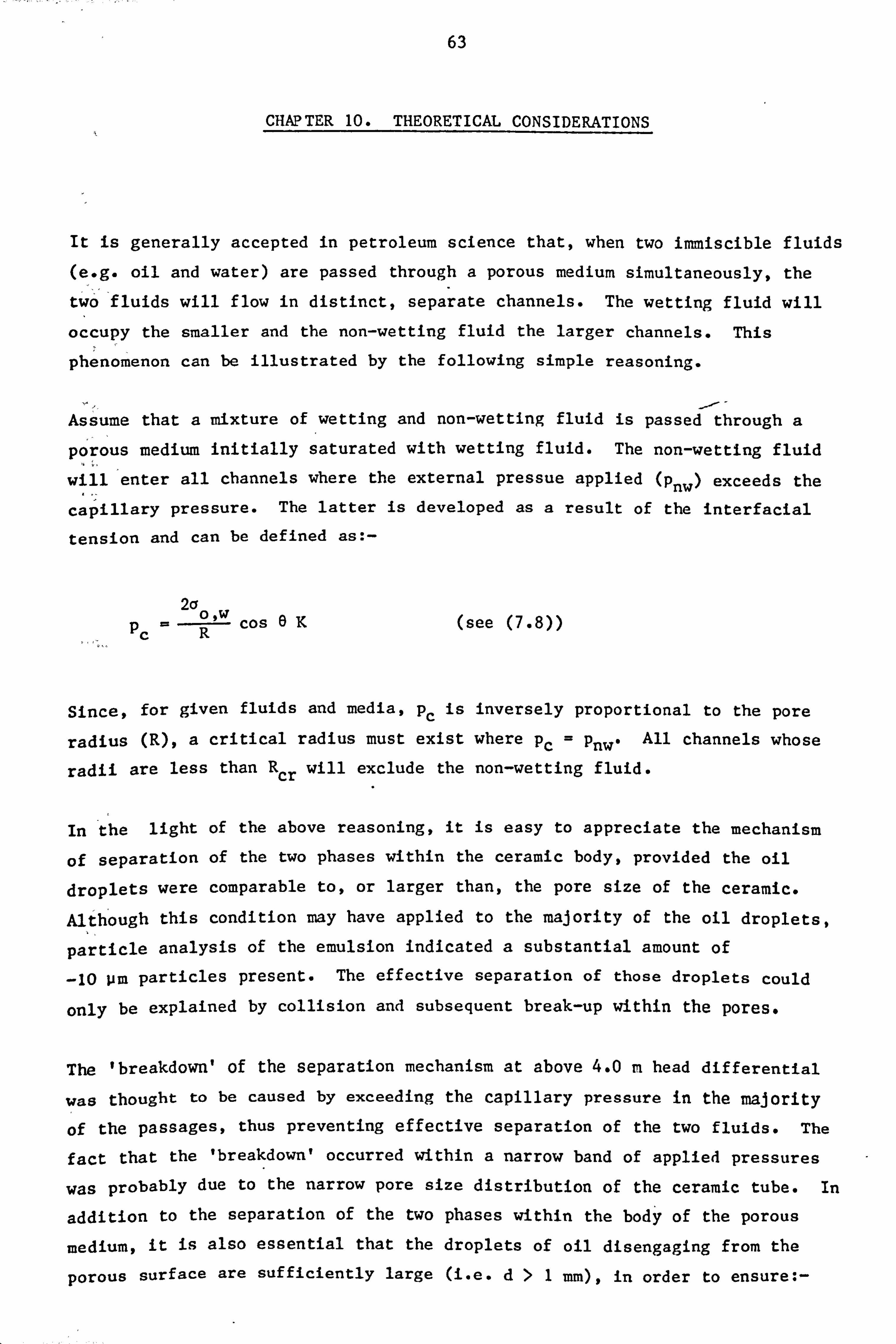
63
CHAPTER 10. THEORETICAL CONSIDERATIONS
It is generally accepted in petroleum science that, when two immiscible fluids
(e. g. oil and water) are passed through a porous medium simultaneously, the
two fluids will flow in distinct, separate channels. The wetting fluid will
occupy the smaller and the non-wetting fluid the larger channels. This
phenomenon can be illustrated by the following simple reasoning.
Assume that a mixture of wetting and non-wetting fluid is passed through a
porous medium initially saturated with wetting fluid. The non-wetting fluid
will enter all channels where the external pressue applied (Pnw) exceeds the
capillary pressure. The latter is developed as a result of the interfacial
tension and can be defined as: -
2a PC Cos 6K (see
Since, for given fluids and media, pc is inversely proportional to the pore
radius (R), a critical radius must exist where Pc ý Pnw, All channels whose
radii are less than R cr will exclude the non-wetting fluid.
In the light of the above reasoning, it is easy to appreciate the mechanism
of separation of the two phases within the ceramic body, provided the oil
droplets were comparable to, or larger than, the pore size of the ceramic.
Although this condition may have applied to the majority of the oil droplets,
particle analysis of the emulsion indicated a substantial amount of
-10 pm particles present. The effective separation of those droplets could
only be explained by collision and subsequent break-up within the pores.
The 'breakdown' of the separation mechanism at above 4.0 m head differential
was thought to be caused by exceeding the capillary pressure in the majority
of the passages, thus preventing effective separation of the two fluids. The
fact that the 'breakdown' occurred within a narrow band of applied pressures
was probably due to the narrow pore size distribution of the ceramic tube. In
addition to the separation of the two phases within the body of the porous
medium, it is also essential that the droplets of oil disengaging from the
porous surface are sufficiently large (i. e. d>1 mm), in order to ensure: -
O, W

64
1) Rapid gravity separation in the vessel.
Coalescence of droplets on impact with each other or with the oil/water interface.
Conversely, small droplets tend to coagulate and resist rupture for a long
time, thus retaining some of the water within the clusters, precluding
efficient separation.
The size of a disengaged droplet can only be estimated for an ideal condition
when the droplet is f ormed very slowly at the end of a capillary tube. In
this case the droplets will break off when the interfacial tension is balanced
by the buoyancy, i. e.: -
4 IrR3 (pw -p)g- 2wr a 17 0cO, W
(see Ref. 16) (10.1)
where
R- radius of droplet
rc m capillary radius
and R can be evaluated from equation (7-8), provided ao, w
is known.
However, in the case of the ceramic tube, the droplets are formed rapidly,
consequently inertia and viscous forces will also affect the size of the
disengaging droplets. In addition, overlap can occur between adjacent
droplets on the surface of the tube, resulting in coalescence prior to
disengagement. The size of the droplets could therefore be assessed by
observations only.

65
CHAPTER 11. DESIGN SUGGESTIONS
The head discharge relationship of the two-phase flow through a ceramic tube
can be assessed provided the two-phase permeabilities and the viscosities of
the fluids are known. The performance of a coalescer however, depends on the
size of the droplets emerging from the ceramic tube, which cannot be predicted
for a given oil/water dispersion from available data.
A method utilising similarity considerations between two systems (1) and (2),
might be employed for designing ceramic coalescers. The suggested method
assumes that system (1) is known and it performs efficiently while system (2)
(to be designed) is required to produce similar size droplets as system (1).
According to dimensional analysis, the size of the emerging droplets (in terms R
of ý) is primarily a function of four non-dimensional groups of variables,
which are: -
Reynolds number;
Weber number;
Densimetric Froude number;
Pressure coefficient;
R Vdp ep
V2dP We ýa
F- V2p 0 dgAp
C= V2p p Ap
where;
V- velocity at exit
d= mean pore diameter
p= density of oil
a= interfacial tension
Ap - density'difference between water and oil

Ap = pressure drop across tube
66
R= radius of emerging droplets
In designing system (2), it is not possible to ensure the similarity of all four non-dimensional numbers. However. on the basis of theoretical
considerations (see Chapter 10) it is reasonable to assume that the separation
within the pores and the emerging droplet size will mainly depend on We and
Fo. Consequently Re and CP could be disregarded and the similarity
requirement between systems (1) and (2) are simplified to: -
li ei = We2
hence
Cr2 Pl dl V22.61 T2- Z -2 V12
and
F01 ' F02
which gives
Pl AP2 d2 2 V2 2.
T--T vi ý72 Pl ýl
(11.1)
(11.2)
The two unknowns V2 and d2 can be found from the above equations. However,
the exit velocities cannot be related simply to the flow rates of the oil,
because of the end effect. The saturation of non-wetting fluid at the outlet
face is reduced to the critical level (Scnw)s consequently VI needs to be
estimated, prior to evaluating d2 and V2. from the following relationship: - Qnwj
vi = Al P1 S
cnwl (11.3)
where;
Al - surface area
P1 - porosity

67
The flow rate in system (2) is also related to the exit velocity by a similar
relationship,
Q nw2 ý V2A2P2Scnw2 (11.4)
It is considered that an adequate estimate of Q nw2 can be obtained by assuming
that S cnwj =S CnW2 , in which case;
V2P2A2 Qnw2 ý VlPlAl Qnwj (11.5)
From the viscosity of the oil in system (2) and the two-phase permeability of
the ceramic (Knw2 ) the pressure drop required to pass a flow rate of Q nwZ can
be predicted from Darcy's equation (see 7.2).
The design suggestions, discussed, above would require further investigations to
test their validity with regard to scale effects.

68
CHAPTER 12. SUMARY AND DISCUSSION OF RESULTS
The oil in water emulsion of Vitrea 68 oil could not be separated
efficiently with the 18 Pm pore size ceramic tube. However, a strong flocculating effect was observed in the separating vessel, which was
apparent throughout the full range of operating heads across the device
(i. e. 2-15 m), resulting in a relatively-clear underflow. This effect
was also apparent when a chemically stabilised emulsion was passed
through the device, resulting in the formation of three distinct layers
of fluid in the separating vessel.
in the case of the diesel fuel a different behaviour was observed.
Although the water in the separating vessel was clear at low operating
heads, it became 'milky' and remained so when the breakdown of the
separation mechanism was reached at Ah - 4.73 m.
2)
3)
4)
The diesel oil/water emulsion was very efficiently separated by the
device when operated at low differential heads. However, the start of
the breakdown of the separation mechanism was reached at just over 4m
differential head, with a complete breakdown occurring at Ah - 4.73 m.
The substantial reduction of the flow rate observed in the subsequent
tests (after contamination by Vitrea 68) was thought to be due to the
effect of the traces of additives present in the system. This
assumption, however, could not be verified as no new ceramic tube was
available and the delivery period of these tubes was beyond the
scheduled time-scale of these investigations.
Backflushing of the ceramic tube after 15-20 minutes of operation seemed
to have restored the original flow rate, implying that the solid
particles which were deposited in the pores were removed and, in
addition, the saturation level of the oil in the tube had reduced to
about the critical level.

69
CHAPTER 13. 'THRESHOLD' PRESSURE OIL/WATER SEPARATOR
13.1 Preliminary Considerations
In order to achieve a relatively high 'threshold' pressure, the porous
material used here needs to be of very fine pore size (i. e. 1 Pm or less) and
strongly wetting to the dispersed phase. -Due to the small pore size, the
permeability of this material would also be very low, consequently this method
is envisaged for applications only where a very small amount of the wetting
phase needs to be removed. In addition, to avoid blockage of the pores, the
mixture to be treated should be relatively free from solid particles.
The rate of water extraction by this device in a single pass cannot be
estimated with any accuracy, because only a small proportion of the water
within the device is in contact with a small proportion of the surface area of
the porous tube in any instance during the passage of the fluid. It is
likely, therefore, that the mixture would need to be recirculated to achieve
the required level of purity.
13.2 Test Conditions
The white, 'milky', oil/water emulsion to be dewatered was produced by the
mixing action of the Jabsco pump and contained Vitrea 68 Lubricating Oil.
The porous material tested was a diapore grade ceramic tube, 600 mm long, with
an average pore diameter of I Um and 90 mm and 80 mm outside and inside
diameters respectively. The manifold in the interior of the tube was 32 mm
diameter, thin-walled copper tube, extending to 80% of the length of the
ceramic tube, contained 30 holes of 5 mm diameter uniformly distributed along
the length. The ceramic tube was saturated with water prior to the tests, in
order to prevent oil from entering the pores.
13.3 Experimental Observations
Although this technique was envisaged to treat oil/water mixtures containing
only a small proportion of water, for practical convenience the experiment was
started with an emulsion containing only about 10% oil by volume. it was

70
intended to reduce the water content of the mixture gradually, by continuous
recirculation through the device.
The arrangement was operated at 2m head differential and initially it was
found to perform effectively in removing water from the emulsion. However,
the pores of the ceramic became gradually clogged by dirt particles and after
about 15 minutes of operation a virtually complete blockage occurred.
13.4 Discussion of Results
Since this technique was intended for the separation of small quantities of
water from oil, the need for frequent backflushing with water to relieve
blockage would clearly be undesirable, as extra water would be added to the
oil. This consideration, combined with the tight time schedule and finances
available, led to the decision to discontinue the experimental work on this
technique.
However, the suitability of this technique to treat clean, refined products
cannot be ruled out from the above observations. It is likely that blockage
would be very infrequent in these applications and a suitable backflushing
method could be devised to relieve blockage.

71
CHAPTER 14. CONCLUSIONS
Although the experimental work on the 'threshold' pressure separator was discontinued after some initial test runs, the feasibility of the
technique for removing small quantities of water from refined products has not been ruled out.
2) The ceramic tube coalescer produced a very efficient separation of a diesel fuel/water emulsion, ýprovided the applied head did. not exceed the
critical value (i. e. 4.0 m).
3) The lubrication oil/water emulsion was not separated to an acceptable
degree by the ceramic coalescer, due to the unfavourable physical
properties of the oil.
The brief experiment on a chemically stabilised emulsion suggested that
this technique may also be suitable for 'creaming' emulsions.

72
CRAPTER 15. OVERALL ASSESSMENT OF THE PROJECT
The objectives set out in the proposal for research in liquid/solid separation
shown in Appendix III could not be achieved mainly because the commercial
exploitation of the capillary/evaporative technique of dewatering could not be
realised. As a result no further funds could be obtained from NRDC. However,
an article published in the Filtration and Separation (see Ref. 18) regarding
oil/water separation by a ceramic tube generated a substantial interest and the technique may well provide. the foundation for a very efficignt oil/water
separator.
It was clear from the onset (see Appendix III) that in order to open up new
areas of activities for BHRA, namely in liquid/solid separation a wide range
of research effort not connected to the capillary evaporative technique of dewatering needed to be undertaken. Unfortunately due to the economic climate
prevailing during the time of the studies, financial contribution to explore
some of the ideas indicated in the original proposal (Appendix III) could not be attracted. Nevertheless the Idea of flotation in a centrifugal field
produced by air injection into a hydrocyclone through. a porous material has
been patented by BHRA in 1983 (see Appendix IV). Unfortunately soon after the
patent application, it was found that an almost identical technique had been
developed in the U. S. A. for the treatment of fine coal.
The relevant U. S. patent was dated about 2 years after the original proposal
in Appendix III and subsequent articles claim that this process is more
efficient than the conventional gravity flotation and requires only 1/7 power
consumption and 1/30 space of conventional flotation process, at the same
throughput.
Following the completion of the studies on the 'passive' capillary device, the
performance of which could not be controlled, the effort was diverted towards
hydrocyclones. These devices are very widely used, mechanically simple, but
operationally extremely complex and their performance depends on a wide
variety of geometric and operational parameters. A consortium project (see
Appendix V) on hydrocyclones supported jointly by the Department of Trade and
Industry and commercial organisations is a going concern. An article, to be

73
published in the next issue of Filtration and Separation, which describes
methods of head recovery or energy saving related to hydrocyclones is shown in
Appendix VI.
In addition to the consortium and a number of enquiries related to separation technology, a large research contract was recently obtained from the CEGB for
the study of a cyclone system used for the removal of contaminated particles from the gas coolant.
Although the work in the capillary/evaporative technique of dewatering was not
a commercial success, nevertheless on an extended time scale, it'provided the
foundation for substantial research income in wider areas of separation
technology, as indicated above.

74
1) Krieger, J. H.
Svarovsky, L.
3) Verwey, E. J. W. and
overbeek, J. T. G.
4) Cedergren, H. R.
5) BS 1016
6) Leyton, L.
7)
8)
Verruijt, A.
Owen, D. R. J. and
Hinton, E.
Smyth, I. C.
CHAPTER 16. REFERENCES
'Separation technology faces crises'. Chemical and Engineering News, 22nd
August 1977.
'Solid-liquid separation'. Second
Edition, Butterworths Publ., 1981.
'Theory of the stability of lyophobic
colloids'. Elsener Publ. Co.,
Amsterdam - New York, 1948.
'Seepage, drainage and flow nets'. John Wiley & Sons Inc., New York, 1967.
Analysis and testing of coal and coke. BSI, 1960.
'Fluid behaviour in biological
systems'. Clarendon Press, Oxford,
1975.
'Theory of ground water flow'.
Mac, Millan Publ., 1969.
'A simple guide to finite elements'. Pineridge Press Ltd., Swansea, U. K.
'Small scale experiments on hydrocyclones for dewatering light
oils'. Int. Conf. on Hydrocyclones,
Cambridge, BHRA, Paper no. 14, October
1980.

75
10) Van Chieu, J. et al
Shah, B., Langdon, W.
& Wasan, D.
'Device for evaluating coalescence of
oil emulsion'. Proc. ASCE Jnl. of the
Env. Eng. Div., Vol. 103, April 1977.
'Regeneration of fibrous bed coalescers for oil/water separation'. Environ. Sci. & Tech., Vol. 11. February 1977.
12) Jeater, 0., Rushton, E. 'Coalescence in fibre beds'.
& Davies, G. A. Filtration & Separation, March/April
1980.
13) Collins, R. E.
14) Bear,
15) Scheidegger, A. E.
16) Sherman, P.
17) Becker, P.
18) Arato, E. G.
'Flow of fluids through porous
material'. Textbook, Reinhold Publ.
Corp., 1961.
'Dynamics of fluids in porous media'. Textbook, Elsevier Publ. Co., 1972.
'The physics of flow through porous media'. Textbook, Elsevier Publ. Co., 1972.
'Emulsion science'. Textbook,
University of Toronto Press, 1974.
'Emulsions, theory and practice'. Textbook, Reinhold Publ. Corp., 1966.
'Oil/water separation by means of a ceramic filter tube'. Filtration and Separation, Vol. 19, No. 4, July/August 1982.

- Ptern -
Shec! rplane Laypr
I
Total Potential ZetQ Potenticil
+
FIG. 1 COLLOIDAL MODEL

FIG. 2 DEWATERING CHINA CLAY
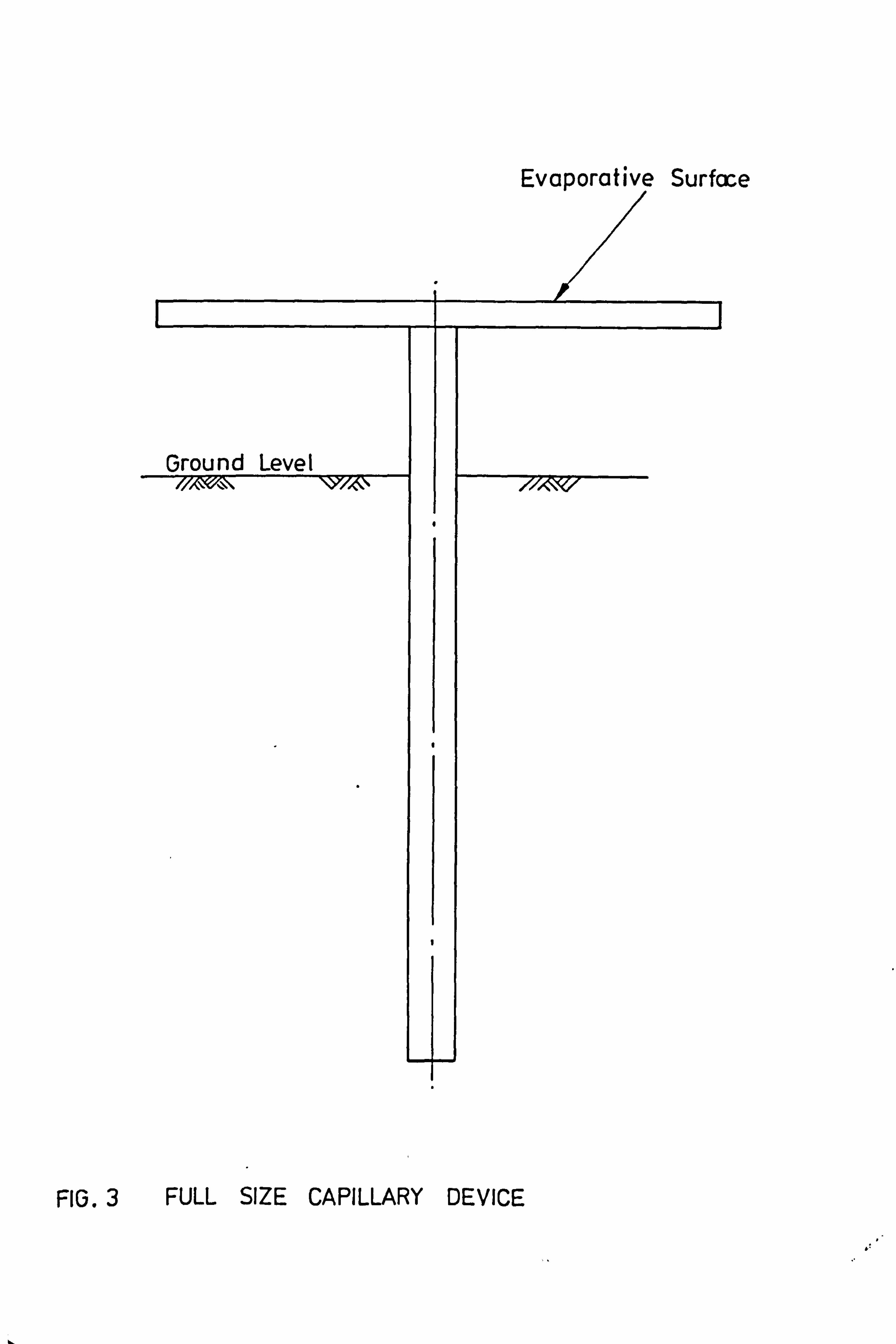
Evaporative Surfcce
Ground Level 7/lX, l; oc\N \Yl"61\
4
/r/A-\NV
FIG. 3 FULL SIZE CAPILLARY DEVICE

Nodes: 1-60 Elements: 76
Ground Level
Impermeable Boundary
I
Ground Water Level
T
Permeable Boundary
ci, C) > ci) 0
0,
-J
a) C-)
FIG. 4 FINITE ELEMENT SCHEME-- CAPILLARY DEVICL

FrH
m
ILLII Lý
Ceramic Tiles
FIG. 5 PLAN VIEW OF ALTERNATIVE DEVICE

FIG. 5o DEWATERING BY THE ALTERNATIVE DEVICE

II
C) C) C)
C: ) Lr)
[ jqkw: )] aj% uollt)jodt)A3 II
LD-7
Ln --ý
-4
M-1
" -1
T-
tn
c

(1) DISPLACEMENT
(2) IMBIBITION
100% Snw Scnw 0
c %% THRESHOLD of
Scw Sw
FIG. 7 A TYPICAL CAPILLARY PRESSURE SATURATI ON CURVE.
100%

100% 1.0 r--
Krw
Krnw
Krnw
Krw
sc nw
I
Scw SATURATION (Sw) -100%
FIG. 8 RELATIVE PERMEABILITY -SATURATION CURVES.

ct * LLI P-
-J 0
(- - -am- L
I
=Z
co
i; 0- - Dar
ca-
Z;
I
I
LL
0
-0- v
I I I
I I II
II II II -J
z
cr- 0
(
V) w
LL 0
I-
0 >-
-J
a)
(is LL

FIG. 10 EXPERIMENTAL ARRANGEMENT

3 @UNCONTAMINATED TUBE AND OIL @ CONTAMINATED TUBE AND OIL
0 Ah = 1.92m Ah=3.33m Ah= 4.7 3m
w L) z w a: w LL LL 0 0 LLI r
z
2
I
N N
N",
I
N
0 0
II 46
TIME ý( MINS. ]
A 8 10
FIG. 11 FLOW RATE OF EMULSION OF 60% DIESEL AND 40% WATER lv/vl.

0 Ah = 4.03rn (@ Ah = 4.73m
C: ) 10 - 2D 30 -40 so
PARTICLE SIZE [p I
FIG. 12 VARIATION OF CONTAMINATION RATIO WITH APPLIED PRESSURE.

90
801-
70
60
5W-
40
30
20
IW-
01 L-49 01
661 2
Ahýfmj
1. 5
FIGJý TREATED DiESEL FUEL.

GAS / LIQUID
A E)
SOLID
FIG. 14 CONTACT ANGLE.

Z cl, (D r: w cr ci (D
,1 5
-1 0
cle C-f (D (D (D (D >I 13 w w w m (D (D Cil ce Clt> cli» w P) (D (D (D (D cli, rt a CL (D (D 91 CL 0 0 0 0 (D
H. kl. F,. H. 0 0
Co 0
w m 9
, _t Mt (D rt rt Z% (D (D cli» >I Co
No. of counts/50 mt sample
CD CD i», Ul CD C% til N. ) il
- . i, - zn Co t. n CY% Ul C (: "0
--4 w OD -L- t,
Co C) ýD
OD Ul w CO Co 0 >O
4. n ru (D (li zo
- N') w -L- ýD 0 flu ON --4 ru u N
C: ) w Ul w
0
Co
N) r1) Li Olt Ul ýA A. 0 - 1-- 1-. CO Ai -4 %Z N) 13 N
C%
-L- CD ýO OD CY% w Ei
w : ýA . Z, Ul C: ) CD OD C: ) Z-
Z EI

(D
41 4-1 X, 41 cr (I : 1 CD
4 4 6 6 zo zo zo
10 w LA) LI) W L. ) N) rv N) W
, 0 g . 1 0 C/) C/I
-3 -3 -3 -3 t: i tj -3 -3 Is Is Is "S Is 11 13 "S (D (D (D (D 9) w (D (D PL) w ID w H. P. 0) P) A) c1t C-t* c1t c1t z :3 01 ct, a CD (D 0 (D 0 (D ri ci CL cl ý4 ic CL a
ID A) (D 0 0 0 0 CII Ct 0 0 H. P. 1. - 1-1. (D (D P. P.
0 9
(D :S CIr
No. of co unts /50 mt sample
a, C7\ a, --4 ko 4-n
ýP 'F ýn ý- ýý so : - v ru w t_n W Li In co M r- N) vi --4 --j CN -P, %0 CN 0 I'D X, 0 M 41 0ý
C: ) i Li L, )
co %D C -4 -
0 I'D w Li k)
c 0c) : -3
: -4 L- 00 "t- Zn Zo 7- t-n - 00 - %C - --4 --4 0 t-n - OD K) 0 -q VI OD , 110
0
w 0 Li N) N) N) (D
cc) -, I Li ro r, ) Zo un o, o LI) t-n --4 -. 4 LI) N) - N) L-j Li N) In %D ON Li
0 J. - -PI
ýu CD C-e
OD %. D 4- cc) ro r\) - ro ca K) OD LA) ON I'D ko I-- J-
Cn LA) v N (D
X, N) C) CP% --4 w ON N) N t-n 0 -4 tn as OD q1D w
N) %. n 0 Li C> N
El
Lý

I
APPENDIX I
MARKET SURVEY
1. Background
In order to expand BHRA's research and development activities, the Marketing
Group conducted a preliminary market survey in the field of liquid/solid
separation. This survey consisted of discussions with the representatives of BHRA members and clients from the process industries, where liquid/solid
separation is a major activity. The discussions indicated the need for an
effective and inexpensive technique of dewatering settling lagoons which have
been filled up with sediment and are no longer in use. These lagoons can
cover large areas (i. e. 50 acres per lagoon), and the sediment cannot be
extracted unless some means of 'in-situ' dewatering is used, because the
interior of the lagoons cannot be reached by heavy excavating equipment. The
reason for this is that the natural processes of dewatering, such as seepage
and evaporation, are thought to be ineffective beyond a certain stage due to
the blockage of the strata underlying the lagoon and to the formation of an impermeable crust on the surface of the lagoon.
As a result of these discussions, it was decided to examine the feasibility of
utilising the natural effects of capillary rise and evaporation for dewatering
lagoons. It was considered by BHRA's Marketing Group that the development of
a suitable 'artificial reed' was possible, and the technique would be
inexpensive, as no power consumption and maintenance would be required. With
these considerations in mind an application was made to NRDC for financial
support of the development of a commercial device. This was granted initially
for Stage I studiet, which included the selection of a suitable material for
the 'artificial reed' and some small scale dewatering experiments. In view of
the promising results obtained, a provisional patent application was filed,
and further funds were made available by NRDC for the Stage II studies, which included theoretical assessments and the design and some laboratory
experiments on a full size device. From Stage I on, all the work involved in
this study was undertaken by the author of this report.

ii
During the course of the studies, it was discovered from an article in 'World
Dredging & Marine Construction', April 1976, that a large scale research
programme of 5 years' duration was being undertaken in the U. S. A. by the Army
Corps of Engineers at that time, covering all aspects of dredged material
disposal areas, including dewatering. Since this type of dewatering in
essence is identical to dewatering settling lagoons, all available information
on the above work was requested and subsequently received in the form of a
preliminary summary report. This report described both laboratory and site
tests conducted on a variety of innovative and conventional dewatering
techniques, including progressive trenching, underdrains, low-voltage gradient
electro-osmosis, vacuum well points, surface agitation, pressure injected sand
slurry drains and capillary enhancement devices or wicks. With the exception
of surface agitation, all techniques showed some degree of success, however,
no other conclusions were drawn as the studies were still in progress.
The information regarding the capillary wicks was very brief, stating that
these devices were made of wood fibre and plastic and the preliminary results
seemed promising. It was not considered that this discovery should inhibit
the development of a capillary device by BIIRA, mainly because the above wicks had not yet been proved successful. In addition, both the performance and the
preferred application of these wicks was expected to be substantially
different from those developed by BHRA, due to the basic differences in the
materials of construction.
Recently some final reports, including the 'Executive Overview, and 'Detailed
Summary' of the whole project were received. The latter report concludes that
the two most promising techniques for general dewatering applications are
progressive trenching and underdrains. The final report on the evaluation of
capillary enhancement devices has not yet been received.
2. Scope
In view of the diversity of dewatering activities, it was decided at the
outset that the survey need only cover activities where the requirements in
terms of extraction rate and degree of dewatering were thought to fall within
the capability of capillary devices. On the basis of the preliminary market
survey and relevant literature, discussed in section 1 of this Appendix, those
activities were identified to be as follows: -
t

III
Dewatering semi-consolidated suspensions as occur in settling lagoons,
or in dredged material disposal areas.
ii) Dewatering waterlogged grounds.
Objectives
The research funds received from the NRDC covered the laboratory studies
only. The availability of further funds for site tests was conditional on
finding an industrial sponsor who was prepared to share the costs and, at the
same time, show that a substantial market would be available p! lovided the
device performed according to prediction. For the reasons discussed above,
the market survey was conducted soon after the completion of the laboratory
studies, with the following main objectives in mind: -
To explain the technique to potential users and thereby create an interest, which might result in financial contribution to site tests.
2)
3)
To identify specific areas of dewatering, where the
capillary/evaporative technique could be a commercially viable
proposition.
Assess the, potential size of the market identified in (2).
Discussions with Potential Users
From the outcome of the preliminary market survey (discussed in section 1 of
the Appendix), it was assumed that the main application of the proposed device
would be for dewatering settling lagoons. With this application in mind, two
questionnaires were prepared (see this Appendix), to enable the size of the
market to be appraised. However, it soon became apparent that these
questionnaires were far too elaborate for use either in discussions or in
written communications and, in addition, they were basically irrelevant as
very little activity (if any) had been going on with regard to dewatering
settling lagoons.
A brief summary of the visits and telephone conversations with potential users
of dewatering apparatus is given below.

IV
Notes on a meeting with Sykes Construction Services Ltd., at Slough on Wednesday, 23rd April 1980
Present: Mr. P. M. Cashman; Sykes Construction Services
Mr. E. Bearup; Sykes Construction Services
Mr. E. G. Arato; BHRA Fluid Engineering
Purpose of visit: To discuss questionnaires on market survey of-the
capillary/evaporative dewatering technique.
Discussion: Sykes expressed the view that the questionnaires were too
elaborate at this stage and suggested that only questions 1-4 from the
questionnaire for industrial users should be sent to appropriate
organisations. The questionnaire should be accompanied by a letter which
should include a statement saying that we have developed (or are developing) a
low cost dewatering technique and need their co-operation for market
evaluation. A positive answer to question 4 would lead to further Contacts.
Mr. Cashman stated that in the past ten years they have received only two
enquiries for dewatering lagoons, but no firm orders. In his view, dewatering
of lagoons is only considered for purely commercial, rather than
environmental, reasons at present. However, if a low cost technique could be
developed, markets would be available because large organisations are
embarrassed about the effect of their activities on the environment.
Sykes were interested in the possibility of using PFA material bound into
suitable porous blocks with the aid of a binder, instead of ceramics, as the
reduction in cost could substantially improve the marketability of the
technique.
Mr. Cashman suggested that in dewatering road foundations it may be possible
to use the capillary device instead of the present tsurchargel technique. In
this application, the rate of extraction of water need not be high as the
proposed road location is known for years in advance of construction and steps can be taken to initiate dewatering. Sykes gave the name of an official at

V
the South Eastern Road Construction Unit, Department of the Environment, as a
possible contact.
Mr. Bearup suggested that, as in road construction, the area of peat to be
excavated for use as power station fuel is known well in advance, therefore
the relatively slow capillary technique might be applicable for dewatering.
Visit to Westminster Dredging CompanX Ltd., Bentley, 16th May, 1980
Present: Mr. P. G. Clutterbuck; Westminster Dreding Company
Mr. K. Back; Westminster Dredging Company
Mr. E. G. Arato; BHRA Fluid Engineering
Purpose of visit: Market survey.
After describing BHRA's involvement in dewatering and the development of a
capillary/evaporative device, Mr. Clutterbuck explained that WDC's interest in
dewatering is restricted to increasing the volumetric capacity of their
dredged material disposal areas. At present one area is used for about. 7-8
years) during which time the depth of sediment deposited is about 4-5
metres. If necessary, the capacity of the disposal area is increased by
raising the height of the perimeter dykes around the area. Dewatering of the dredged material would increase the life of the disposal area.
The capillary/evaporative device could not be used for this application due to
its low extraction rate and relatively high capital cost. Mr. Clutterbuck
also commented that installation of these devices would be a major operation,
as the dredged material cannot support any weight.
The view of both Mr. Clutterbuck and Mr. Back was that, in the event that
these areas are reclaimed for building purposes, the capillary/evaporative
technique could be a commercially viable proposition. Most likely sites for
this type of land reclamation would be around the Manchester Ship Canal and Southampton disposal areas.

vi
It was indicated that, at present, Land and Marine engineering, a subsidiary
of WDC, is involved in reclaiming settling lagoons for the ICI Mond
Division. However no further details were given.
Visit to South Eastern Road Construction Unit (Dorking)
Ministry of Transport, 22nd May, 1980
Present: Mr. J. Wrightman; M. O. T.
Mr. S. J. Barnes; M. O. T.
Mr. E. G. Arato; BHRA Fluid Engineering
Purpose of visit: Market survey.
Mr. Wrightman and Mr. Barnes expressed interest in the capillary technique of
dewatering and indicated that the most likely application would be for
stabilising slopes (i. e. road cuttings, embankments) in low permeability
ground. For a typical application the cost of dewatering should not exceed
two pounds per m2 dewatered. At present, a test site could be made available
by Mr. Wrightman, covering an area of about 1000 m2. For financing the site
tests the Engineering Intelligence Unit of the M. O. T. could be approached.
A variety of other possible applications of this technique were suggested,
which are: -
Increasing the thickness of the hard crust over soft ground to enable buildings to be erected.
2) Stabilising the landward side of embankments
3) Dewatering silt in port areas (e. g. 2,000 acres at CEGB, Peterborough).
I

Vil
Telephone c2nversation with Mr. Walton, Manager of Land Reclamation Scheme,
CEGB Peterborough
To the question of dewatering filled up PFA (Pulverised Fly Ash) lagoons, Mr.
Walton replied that no problems exist, as these lagoons after some time are
covered with top soil and returned to agriculture. The natural processes of
dewatering are adequate for the requirement.
Visit to Eastern Road Construction Unit (Bedford)
Ministry of Transport, 13th June, 1980
Present: Mr. R. Edwards; M. O. T.
Mr. E. G. Arato; BHRA Fluid Engineering
Purpose of visit: Market survey.
Mr. Edwards was very interested in the capillary/evaporative technique of
dewatering and stated that there is a definite need for a new technique of
dewatering soils whose permeabilities lie within the range of 10-5 to
10-7 m/s. At present, electro-osmosis may be used, however this technique is
very costly and, in addition, is not suitable for every type of soil.
Alternatively, ground freezing may be employed instead of dewatering in
special cases (i. e. for an NCB mine shaft, ground freezing cost 3,000,000
pounds).
Mr. Edwards indicated that a possible application of the capillary technique
would be for stabilising slopes, which is an operation frequently required in
road construction. As an example he quoted the cost of a mechanical method of
stabilisation (i. e. backfill) of an area of 640 m2 as being 20,000 pounds.
This could have been achieved equally by lowering the water table to 1m below
the surface, possibly by employing the capillary method of dewatering at a
substantially lower cost.
At present a new and improved method of dewatering, called counterfort drainage, is used for stabilising slopes where the permeability of the soil is

viii
normally about 10-5 m/s or greater. Mr. Edwards, however, suspects that this
method of drainage may produce long term instability in the slope. A typical
flow rate extracted by these drains from an area of 160 m2 was observed to be
I gall/hr. This extraction rate could probably be achieved by the use of an
estimated 10-15 capillary devices.
Two big operations are being undertaken at present by the Eastern Road
Construction Unit: -
i) The Bell Common tunnel on the M25 at Epping.
ii) The AI(M) tunnel at Hatfield.
The dewatering operation using deep, sand-filled drains arranged along the
whole length of the cut, costs about 250,000 pounds for each scheme.
5. Appraisal of the Survey
5.1 Semi-consolidated suspensions
The outcome of the survey with regard to dewatering semi-consolidated
suspension with capillary devices was not encouraging. Although relatively
few organisations were consulted, informal discussions with employees of ICI
Mond Division, where large areas of lagoons are awaiting reclamation,
confirmed this impression.
It appears from the discussions that active dewatering is only carried out
when dictated by commercial factors. Otherwise, the filled-up lagoons are
left to the natural processes of seepage and evaporation, and after a long
period (i. e. many years) the lagoons are gradually covered with soil to
facilitate landscaping or agricultural use. In view of the relatively low
rate of dewatering by the capillary devices, it is unlikely that this method
would be suitable when the need for dewatering is dictated by commercial
factors. On the other hand, the cost of the devices and installation would
probably be considered excessive when the reclamation is carried out for
purely environmental reasons. An illustrative example, showing the estimated
cost and time-scale of dewatering is given below.

Ix
Example: Let us assume that we need to dewater a lagoon 100 mx 100 mxIm deep, whose solid concentration is 40% by volume. A thin crust is formed on
the top which effectively prevents surface evaporation and also prevents
recharge due to rainfall.
If we employ simple capillary devices, consisting of two ceramic tubes and one
tile, it is anticipated that we would require at least one device for every 10
M2 of the lagoon; hence, the total number of devices would be 1,000.
If one device removes an estimated 0.25 X/hr water as an average, the required
time and costs for the 1,000 devices to increase the solids concentration from
40% to 60% would be as follows.
In order to increase the solids concentration to 60% we would have to remove
3,300 m3 of water, hence:
0.25 x 24 xt-3,3000
3,330 555 days 6
years
Cost of a simple device, including likely discount for bulk supply
- 40.00 pounds
Pounds
1,000 devices - 40,000
cost of installation a 4,000
cost of removal and cleaning devices = 6,000
Total - 50,000
Since devices are re-usable, charge 50% to project; the total cost would
reduce to 30,000 pounds

x
Hence, cost per M3 of water removed = 30,000 :: 10.00 pounds 3,330
The preliminary report of the dredged material research programme in the
U. S. A. gives estimated costs for dewatering disposal areas in terms of cubic
yard space created, as ranging from 1.5 dollars to 4 dollars at 1975 prices.
This, adjusted to m3 and for inflation, would be 3.2 dollars to 8.5 dollars,
or about 1.5 pounds to 3.9 pounds. In this type of dewatering, the cost of
10.00 pounds per m3 of space created would be excessive.
5.2 Low Pemeability Soils
Discussions conducted with senior engineers of the Department of Transport
Road Construction Units revealed a need for an inexpensive technique of
dewatering low permeability soils (i. e. 10-5 to 10-7 m/s) in connection with
stabilising slopes. In these operations the rate of extraction required to
maintain slope stability can be sufficiently low to fall within the capability
of capillary devices.
The suggestion of contacting the Engineering Intelligence Unit of the
Department of Transport was followed up and resulted in further discussions
and eventually in an offer of sites and partial financing of the site tests,
by providing and installing the necessary instrumentation. Negotiations are
going on at present with NRDC for additional funds to carry out the site
tests.
In addition to stabilising slopes, a number of other possible applications of
the capillary device were mentioned (see section 4). Specificially, both the
Transport and Road Research Establishment and the Building Research
Establishment expressed interest in the outcome of the site test, when
contacted by Mr. Jones of the Engineering Intelligence Unit of the Department
of Transport. Further enquiries were received by BHRA from Civil Engineering
Consultants, who are also awaiting the results of the proposed site tests.
5.2.1 Estimate of the potential market
This survey resulted in identifying one specific dewatering activity - namely
slope stabilisation - where the capillary technique of dewatering can become a
viable proposition.

xi
The potential size of the market in slope stabilisation can only be estimated
to an order of magnitude because no specific data could be obtained. However,
from statements made during the discussions, and from site visits, an estimate
of the market segment where the capillary technique of dewatering may be a
feasible alternative to present techniques was attempted in the following
manner.
It is reasonable to assume that 30% of the roads constructed in the U. K. are
made in cuts, and in 10% of those cuts some means of slope stabilisation is
required. This means that, for an estimated 1,000 miles of roads constructed in the U. K. per year, slope stabilisation is employed along 30 miles length of
road, with slopes on both side. Frequently this is achieved by 'Counterfort'
drainage at a cost of about 2 pounds per m2 of slope area. This method,
however, is not always effective, particularly when the permeability of the
ground is less than 10-5 m/s, therefore costlier methods of slope
stabilisation are required (e. g. backfill, retaining wall), where the cost may
exceed 30 pounds per m2 of slope area (i. e. 20,000 pounds for 640 m2).
It may be assumed that a substantial market segment exists between the above
extremes where, although gravity drainage is ineffective, slope stabilisation
may be achieved by dewatering devices capable of exerting suction on the
water-bearing strata. If we assume that this market segment covers about 20%
of the market in slope stabilisation at an intermediate value of 15 pounds
per m2, then for 6 miles, or 10 km, length of road with slopes on both sides
(10 m wide), this represents a market of approximately 3 million pounds per
annum.
The survey described here did not cover all major organisations in the U. K.
involved in relevant dewatering activities. The reason for this was that the
field performance of a capillary device could not be predicted with confidence
from laboratory studies, consequently the viability of the device had not been
established. It was felt, therefore, that a costly market survey could not be
justified at that stage, particularly bearing in mind that the technical
aspects of the work were carried out on a low budget (total 12,400 pounds).
However, in spite of this, the major objectives set out in section 3 were broadly achieved.
Lý
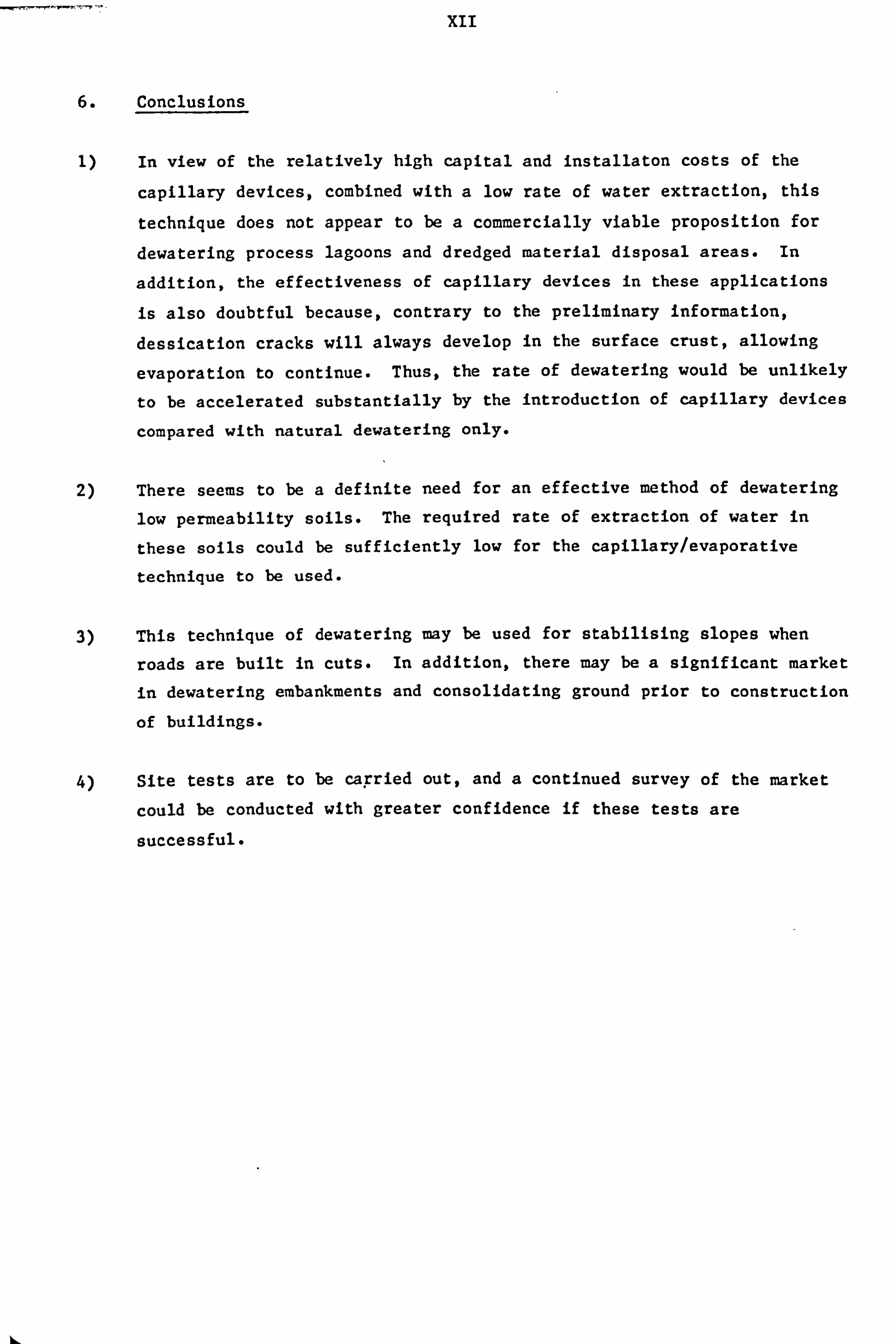
xii
Conclusions
In view of the relatively high capital and installaton costs of the
capillary devices, combined with a low rate of water extraction, this
technique does not appear to be a commercially viable proposition for
dewatering process lagoons and dredged material disposal areas. In
addition, the effectiveness of capillary devices in these applications
is also doubtful because, contrary to the preliminary information,
dessication cracks will always develop in the surface crust, allowing
evaporation to continue. Thus, the rate of dewatering would be unlikely
to be accelerated substantially by the introduction of capillary devices
compared with natural dewatering only.
2) There seems to be a definite need for an effective method of dewatering
low permeability soils. The required rate of extraction of water in
these soils could be sufficiently low for the capillary/evaporative
technique to be used.
3) This technique of dewatering may be used for stabilising slopes when
roads are built in cuts. In addition, there may be a significant market
in dewatering embankments and consolidating ground prior to construction
of buildings.
4) Site tests are to be capried out, and a continued survey of the market
could be conducted with greater confidence if these tests are
successful.
bý

QUESTIONNAIRE FOR INDUSTRIAL USERS
PART I (Lagoons)
1. Estimated total acreage of sludge lagoons presently in active use in your industry
2. Estimated total acreage of dis-used lagoons in your industry, which are full of sediment at present
3. Estimated rate at which "filled up" lagoons are produc-ed in your industry (i. e. acre/year)
Is it necessary to reclaim dis-used lagoons?
Iý answer is YES, what does this involve?
5.
6.
i extraction of sediment ............
ii dewatering only
If answer to 4(1) is YES
........... *
Does the sediment need to be dewe-tered prior to extraction?
........................
If the answer to 4(11) or to 5 is YES
What means of dewatering have been used in the past?
i Natural processes (i. e. evaporation, seepage) ......
ii Active dewatering (i. e. mechanical means) .........
iii Combination of (i) and (ii) ......................
Please indicate the proportions in terms of percentages of the three types used in the boxes above.
If the answer to 6(1) is 100%, have the natural processes been adequate in terms of
I
I
speed of dewatering .......................
dryness of dewatered product ..............

If the answer to 7(i) and/or 7(ii) is NO:
Have the application of 6(ii) and/or 6(iii) been considered?
If the answer to 8 is YES:
(a) Why have 6 (ii) and/or 6 (iii) not been employed?
i due to high costs ........................
ii available techniques not considered suitable ......................
Please tick appropriate boX
10.
I
I
(b) What would be an acceptable cost in terms of m3 of sediment dewatered? ic
If answer to 6 (i) is less than 1000/6,
(a) please indicate:
i the process(es) used ........................... 00 ii the firms employed
iii acreage dewatered
.............................
.............................
iv depth of sediment dewatered .......................
v total cost of dewatering ..........................
vi reduction of liquid content achieved
from ..... % (v/v)
to ...... % (v/v)
vii approximate duration of the dewatering operation
from .............
to ............... (dates)
viii type and size range of material dewatered
................ o.. 90000a................

QUESTIONNAIRE FOR CONTRACTORS
Dewatering Sludge Lagoons
Please provide the following information regarding the enquiries you received in the last 5 years for dewatering sludge lagoons:
a) Number of enquiries received:
From the UK
(ii) From overseas
b) Total acreage to be dewatered:
In the UK
(ii) Overseas
C) Approximate total amounts quoted in present value:
d)
W For the UK enquiries 9
(ii) For the overseas enquiries 9
Industries and Organisations involved:
(i) In the UK:
(ii) Overseas

2 Please give the following particulars of past dewatering contracts:
i
3
ii iii.
Method or process used
Acreage dewatered
Depth of pediment dewatered
Liquid content at start '/o (v/v)
Liquid content at end O/o (v/v)
Duration of operation (months)
Type of material dewatered
Size range of material dewatered
Present value of contract
Location of site
Are you aware of other methods or processes, not included in (2), which are employed commercially to dewater sludge lagoons? If yest please state.
4 please identify UK firms involved in dewatering sludge lagoons

xiii
APPENDIX II
SURFACE AND INTERFACIAL TENSIONS
The surface tension between a liquid and Its vapour or a gas is due to an imbalance of the molecular forces acting along the surface of the liquid. The
combined action of these forces gives rise to an internal pressure, which induces the liquid to move, in order to attain an equilibrium condition (i. e.
capillary rise).
The surface tension is analogous to the work required to generate a unit area
of new surface (i. e. N/m) and is designated 0.
If a liquid is placed in contact with a plane solid surface, interfaces will form between each of the phases (see Fig. 14). The three phases will meet at
a point where a contact angle 0 exists between the liquid and the solid. If
this angle is smaller than 900 the liquid wets the solid, and if 0-0 the
liquid will spread on the solid surface, forming a thin film. On the other hand, if 6> 900 , the liquid is referred to as non-wetting to the particular
solid.
The contact angle 0 can be expressed from the following relationship: -
as-a sL -aL Cos 0
where
Cy s- interfacial tension between solid and gas (or vapour)
a sL m interfacial tension between liquid and solid
0L 'a surface tension of liquid
1)
If the gas (or vapour) phase is replaced by another liquid (2), which is
i=iscible with the original liquid (1), the work of adhesion between the two liquids can be expressed as: -

x1v
W= cr -+a-a a L, L2 L, L2
where
(see Ref. 17)
a LI and a L2 are surface tensions of liquids (1) and (2)
a LIL2 -2 interfacial tension between the two liquids
The contact angle between liquid (1) and solid will be analogous to that in
equation (A-1), i. e.: -
a sL2 -a sLI '2 a LjL2 Cos 6
The spreading of one liquid over the other can be defined by the spreading coefficient (Sc): -
ScWa-Wc
where Wc work of cohesion.
Wc is defined as the work required to produce a new surface of unit area and is:
wc- 2CF LZ
For spreading liquid (2), i. e. oil, on liquid (1), i. e. water: -
sc =a Ll -a L2 -a LjL2 (see Ref. 17) (A. 2)
if sc > 0, liquid (2) will spread on liquid (1), but if Sc < 0, the droplets
of liquid (2) remain intact.

xv
APPENDIX III
PROPOSALS FOR RESEARCH IN LIQUID/SOLID SEPARATION
The following proposals were prepared in July 1978.
1. Backgr und
BHRA intends to establish an expertise in some areas within the broad field of liquid/solid separation, where a specific need exists either to improve the
existing techniques or to develop new techniques.
In order to identify these areas, discussions were held between BHRA and
representatives of various process industries. These discussions revealed the
existence of such an area, i. e. where semi-consolidated suspensions of very
fine particles are to be dewatered in disused lagoons. In response to this
need a technique, based on the principle of capillary rise and evaporation is
being developed at BHRA with financial support from NRDC. Preliminary studies
of this technique have been completed and proposals for the design and testing
of a full size device will be submitted to NRDC in the near future. This
device is capable of extracting water from a semi-consolidated suspension
without power input, although at a relatively low rate.
An alternative technique which may produce a much greater rate of extraction
of water from a semi-consolidated suspension is thought to be electro-
osmosis. This method requires some power input and it has been used in
similar applications with various degrees of success. In order to assess the
applicability of electro-osmosis for dewatering semi-consolidated suspensions,
some exploratory tests were carried out at BHRA. In these tests a hollow
porous cylinder, fitted with wire mesh electrodes along the inside and outside
surfaces, was introduced into a concentrated suspension of clay in water. The
bottom of the cylinder was sealed from the suspension and a small flow rate of
water was maintained through the porous wall of the cylinder by the
hydrostatic head of the suspension. This observation seems to indicate the
applicability of electro-osmosis to dewatering of semi-consolidated
suspensions.

xvi
An article by J. H. Krieger, titled 'Separation Technology Faces Crises' and
published in the Chemical and Engineering News, dated 22.8.77 describes, as the title indicates, the crisis situation in the field of liquid/solid
separation. The author suggests that the main reason for this situation is
the shortage of knowledgeable personnel, which is the direct consequence of
the absence of educational courses dealing with the subject in depth. The
article identifies a range of processes where the need to improve existing
techniques is particularly acute, some of which are sludge filtration,
dewatering of cakes, flocculation and thickening. All these processes are
controlled by particle-fluid interactions which, in turn, are governed by
electro-kinetics, therefore the study of this basic field is es---sential in
order to improve these processes. The author also suggests investigations on
the use of hydrocyclones and on the basic mechanisms governing the operation
of froth flotation cells.
2. Objective
To establish a new area of activity within BHRA, which, after three years is
aimed to yield an annual income of about 50,000 pounds.
Suggested Investigations - Preliminary Proposals
The proposals listed below have been prepared without the benef it of a
comprehensive market and literature survey, hence they are necessarily
speculative at this stage.
Since most of the processes used in separating fine particles from
liquid are either governed or affected by particle electro-kinetics, the
study of this area of particle science is clearly necessary if progress is to be achieved in the separation technology.
(ii) Electro-osmosis is considered to be a specific area of electro-kinetics, for which a possible application - with regard to dewatering of lagoons
- has already been identified. It is conceivable that electro-osmosis
can be applied successfully to a variety of dewatering problems, some of which are: -
(a) Dewatering rigid porous materials, e. g. mosaic tiles, removing dampness from old houses, etc.

xvii
(b) Lowering the moisture content of loose granular materials. This
method may be applied in conjunction with a capillary evaporative
device.
(iii) The process of filtration is governed to a large extent by electro-
kinetics, therefore it may be possible to identify the conditions under
which blockage occurs in filters and to provide remedial action.
(iv) It is proposed to examine a novel process where hydrocyclones would be
used in similar applications as froth flotation cells at present. In
this process, two different types of solids would be separated according
to surface properties rather than according to size and/or density.
This could be achieved by injecting air in the form of small bubbles
with a method similar to that employed in the BHRA re-aerating device.
Air bubbles would then attach to the hydrophobic particles only and they
would be discharged through the overflow, while the hydrophylic
particles would be passed through the underflow.
This process, if successful, would have very wide applications.
3. Method.
3.1 Stage I
The need to develop a satisfactory technique which can be used to dewater
semi-consolidated suspensions in disused lagoons has been established from a
preliminary market survey. This type of investigation, however, is outside
the main stream of liquid/solid separation, consequently it would not provide
sufficient scope to achieve the objective. For this reason, it is considered
essential to conduct a comprehensive market and literature survey in order to
identify additional areas where specific problems exist, which need to be
rectified. The article by J. H. Krieger will serve as a useful guide to
identifying these problems.

xviii
3.2 Stage II
The suggested investigations listed above will be re-examined in the light of the completed market and literature survey and definitive proposals
prepared. However, in view of the importance of electro-kinetics in
separation technology, it can safely be assumed that a theoretical study of
this field will be carried out. At the same time, efforts will be made to
obtain research contracts from industry and also from NRDC- The possibility
of conducting joint research with TNO will also be considered.
This stage is expected to cover a period of about six months.
3.3 Stage III
Experimental work, relating to the research and development contracts
obtained, will be carried out during this stage. It is anticipated that by
this time, sufficient expertise will have been built up to obtain long term
research contracts from the Chemical and Minerals Requirement Board.
This stage will cover the rest of the 3 year period of the Total Technology
Course.
Costing
Pounds
The cost of market and literature survey (Stage 1) assuming
50% utilisation for a period of 12 weeks would amount to about 5,000
The cost of Stage II covering a period of about 26 weeks, at 40% utilisation would be about 7,300
Total 12,300
hý

xix
These costs would be offset by: -
Existing Requirements Board Fund 5,000
SRC Fund 2,500
Possible further work from NRDG 5,000
12,500
It is anticipated that some research contracts will be awarded during Stage II
and Stage III work will be entirely financed by research contracts.

AA
APP ENDIX IV
PATENT SPECIFICATION
British Patent Application No. 8315334
in the name of:
THE BRITISH HYDROMECHANICS RESEARCH ASSOCIATION
for an invention entitled:
SEPARATING PARTICLES FROM A LIQUID SUSPENSION
made by:
EMIL GYORGY ARATO
EDWARD EVANS & CO., Chartered Patent Aggents and European Patent Attorneys, Chancery flouse, 53-64 Chancery Lane, London h'C2A 1SD.

xxi
Separating Particles from a Liquid Suspension
5
Field of the Invention
The invention relates to a method and apparatus for the separation of
particles from a liquid suspension, where said particles more readily
attach themsclves to gas bubbles than other particles forming part of the liquid suspension.
Background Art
In conventional flotation processes for the separation of hydrophobic
particles from a suspension of hydrophobic and hydrophilic particles 10 in water or for the separation of hydrophobic liquid particles from a
15
dispersion of such particles in water, air bubbles attach to the
hydrophobic particles and thus produce composite particles with densities much lower than the densities of the original hydrophobic
particles. As a result, the composite particles rise to the surface
of the water, under the effect of gravity.
However, this separating effect is proportional to the difference in density between the -composite particles and the remaining particles
of the water suspension '
or dispersion and, where the density of the
original hydrophobic particles is high relative . to the remaining
20 particles, the resultant differential density is not so high and the
separating effect is relatively low and is reduced still further in
viscous liquids which retard the upward migration of the lighter
composite particles.
One known way to overcome this deficiency in separating particles
.5 from a liquid suspension is to provide apparatus including
30
hydrocyclone comprising a circular-section first chamber, a tangential inlet to the first chanber, a first outlet extending upwardly from the centre of the first chamber, a convergent second chanber extending downwardly from the first chamber) and a second outlet extending downwardly from the second chamber. However,
although the use of this form of apparatus multiplies the effect of differences in the densities of the particles, the separating effect

xxii
is limited by the actual differences in the densities of tile
particles.
5
Disclosure of the Invention
It is the purpose of the present invention to modify the known
apparatus so as to avoid the deficiencies of this apparatus.
This is achieved by providing means for generating gas bubbles within
the liquid suspension and by providing the second outlet from the
hydrocyclone in the form of a divergent draft tube.
10
15
Thus, according to the invention, there is provided apparatus, for
separating particles from a liquid suspension in which said particles
more readily attach themselves to gas bubbles than other particles
forming part of the liquid suspension, comprising a hydrocyclone and
means for generating gas bubbles within the liquid suspension, the
hydrocyclone comprising a circular-section first chamber, a tangential inlet to said first chamber, a first outlet extending
upwardly from the centre of the first chamber, for removal of the
separated particles and gas bubbles, a convergent second chamber
extending downwardly from the first chamber, and a second outlet
extending downwardly from the second chamber.
20 The invention also provides a method of separating particles from a
liquid suspension, where said particles more readily attach
themselves to gas particles than other particles forming part of the
liquid suspension, comprising the steps of feeding the liquid
suspension into a hydrocyclone through a tangential inlet to a
25 circular-section first chamber, generating gas bubbles within the
liquid suspension, removing separated particles and gas bubbles from
a first outlet extending upwardly from the centre of the first
chamber) and removing the remainder of the liquid suspension through
a second outlet extending downwardly from a convergent second chamber
30 extending downwardly from the first chamber. The volumetric gas flow
rate, at atmospheric pressure, is preferably less than 5% of the flow
rate of the liquid dispersion.

xxiii
It is understood that, by providing the second outlet in the form of
a divergent draft tube and, at the same time, replacing the
cylindrical vortex finder by a similar overflow arrangement, most of
the kinetic energy which would otherwise constitute the outlet head
5 losses can be converted into a pressure head. As a result, the
upstream pressures, including the pressure drop across the device,
will reduce and thus reduce the power required for operation by up to
20% and the maximum flow through the second outlet is increased from
20% to more than 60% of the flow of liquid suspension through the
10 apparatus -
15
In one form of apparatus according to the invention, the hydrocyclone
has a wal-1 formed with at least one aperture and the gas bubble
generating means comprise an insert of porous material fitted within
the or each said aperture and means for feeding, gas through each said
insert for the formation of gas bubbles as a result of fluid shear at
the interior surface of each said insert. The size of the pores in
the porous material of the or each insert is preferably in the range
10 to 100/1 (10 to 100 x 10-6 m).
In an alternative form 9f apparatus, the gas bubble generating means 20 comprise a pressure vessel supplied with pressurised gas for solution
within the liquid suspension, a supply line connecting the pressure
vessel to the tangential inlet to the first chamber of the
hydrocyclone) a control valve in the supply line., and a orifice in
the supply line for reducing pressure in the liquid suspension 25 passing through the orifice to effect the formation of gas bubbles in
the liquid suspension. In operation of this form of apparatus, the
30
liquid suspension and gas are kept within the pressure vessel until
an appreciable amount of gas is dissolved in the liquid suspension
and preferably until the liquid suspension is saturated with
dissolved gas. The pressure within the vessel is preferably between
two and three bars.
Two embodiments of apparatus according to the invention are hereinafter described, by way of example, with reference to the

xxiv
accompanying drawings.
Brief Description of the Drawings
Figures I and 2 are a plan view and sectional elevation of a first
form of apparatus according to the present invention; and
Figure 3 is a schematic elevation of a second form of apparatus
according to the invention.
Modes for Carrying Out the Invention
As shown in Figures 1 and 2, a hydrocyclone 3 has a first cylindrical
chamber 5, with a tangentially extending inlet 6 and an upwardly
10 extending first outlet 7 coaxial with the first chamber S. A second
frusto-conically shaped chamber 8 extends convcrgently downwards frorn
the first chamber 5 and merges with a divergent draft tube 9 forming
a second outlet from the hydrocyclone 3-
Elongate inserts 10 of porous material are fitted within
15 longitudinally extending apertures formed in the wall 17 of the
hydrocyclone .3 and each of these inserts 10 is surrounded by a
manifold jacket 11 supplied with pressurised. air through a supply
line 12.
A suspension of more hydrophobic particles and more hydrophilic
20 particles is supplied to the hydrocyclone 3 through the tangential
inlet 6 and follows a spiral path around the interior of the
hydrocyclone 3 and flows downwardly through the second outlet 9.
This flow of suspension over the interior surfaces of the inserts lo
causes air forced through the inserts 10 from the manifolds 11 to
25 break up into small bubbles which attach themselves preferentially to
the more hydrophobic particles of the suspension which then migrate
to the centre of the hydrocyclone 3 and flow out of the hydrocyclone
3 through the first outlet 7.
In the apparatus shown in Fi&njre 3, air and a liquid suspension
30 comprising a disperson of oil droplets in water are pressurised

xxv
within a pressure vessel 13 and kept in contact until the liquid
suspension is saturated with dissolved air. Control valve 15 is then
opened so as to allow liquid suspension with dissolved air to
flow along supply line to orifice 16 and then through tangential
5 inlet 6 to a hydrocyclone 4 having the same general arrangement as the hydrocyclone 3 shown in Figures 1 and 2 with a first cyclindrical
chamber 5, a frusto-conically shaped second chamber 8 extending
convergently downward from the first chamber 5, a first outlet 7
extending upwardly from the centre of the first chamber 5 and a. 10 second outlet 9 in the form of a divergent draft tube 9 extending
downwardly from the second chamber 8.
As the liquid suspension and dissolved air passes through the
orifice 16, there is a reduction in pressure resulting in the
generation of small air bubbles which attach themselves
15 preferentially to the more hydrophobic particles of the liquid
suspension to form relatively light composite particles which migrate to the centre of the hydrocyclone 4 and are removed through the first
outlet 7 whereas the remaining particles of the liquid suspension are
removed through the second outlet 9 in the form of the convergený- 20 divergent nozzle.

xxvi
Claims
1. Apparatus (I or 2), for separating particles from a liquid
suspension in which said particles more readily attach themselves to
gas bubbles than other particles forming part of the liquid
5 suspension, including a hydrocyclone (3 or 4) comprising a
circular-section first chamber (5); a tangential inlet (6) to said first chamber a first outlet (7) extending upwardly from the
centre of the first chamber for removal of the separated
particles; a convergent second chamber (8) extending downwardly from
10 the first chamber (5); and a second outlet (9) extending downwardly
from the second chamber (8);
characterised in that:
means (10 to 12 or 13 to 16) are provided for generating gas bubbles
within the liquid suspension.
15 2. Apparatus (1 or. 2), according to Claim 1., in uhich the second outlet-(9) from the hydrocyclone (3 or 4) is a divergent draft tube.
3. Apparatus (1), according to Claim I or Claim 2., in which the hydrocyclone (3) has a wall (17) formed with at least one aperture and the gas bubble generating means (10 to 12) comprise an
20 insert (10) of porous material fitted within the or each said aperture and means (11 and' 12) for feeding gas through each said insert (10) for the formation of gas bubbles as a result of f luid
shear at the interior surface of each said insert (10).
Apparatus (1), according to Claim 3) in which the size of the

xxvii
pores in the porous material of the or each insert (10) is in the
range 10 to 100ýi (10 to 100 x 10-6m).
5
5. Apparatus (2), according to Claim I or Claim 2, in which the
gas bubble generating means (13 to 16) comprise a pressurc vessel
(13) supplied with pressurised gas for solution within- the liquid
suspension, a supply line (14) connecting the pressure vessel (13) to
the tanog-ential inlet (6) to the first chamber (5) of the hydrocyclone
(4), a control valve (15) in the supply line (14), and an orifice
(16) in the supply line (14) for reducing pressure in the liquid
10 suspension passing through the orifice (16) to effect the formation
of gas bubbles in the liquid suspension.
6. A method of separating particles from a liquid suspension in
which said particles more readily attach themselves to gas particles
than other particles forming part of the liquid suspension, 15 comprising the steps . of feeding the liquid suspension into a
hydrocyclone (3 or- 4) through a tangential inlet (6) to a circular-
section first chamber (5), removing separated particles through a
first outlet (7) extending upwardly from the centre of the first
chamber (5) t and removing the remainder of the . liquid suspension
20 through a second outlet (9) extending downwardly f rom a convergent
second chamber (8) extending downwardly from the first chamber (5);
characterised in that:
gas bubbles are generated within the liquid suspension.
7. A method, according to Claim 6, in which the volumetric gas 25 flow, at atmospheric pressure, is less than 5% of the flow rate of

xxviii
the liquid suspension.
8. A method, according to Claim 6 or Claim 7, in which kinetic
energy in the remainder of the liquid suspension removed through the
second outlet (9) is converted into static pressure by passing the
remainder of the liquid suspension through a divergent- draft tube
forming the second outlet (9).
9. A method, according to Claim 8, in ui-iich the maximum flow
through the divergent draft tube (9) is more than 60% of the flow of
liquid suspension through the tangential inlet (6).
1010. A method, according to any one of Claims 6 to 9, in which the
gas bubbles are generated by feeding gas through at least one insert
(10) of porous material fitted within an aperture in the wall (17)
of the hydrocyclone (3) and by fluid shear at the interior surface of
each said insert (10).
15 11. A method, according to any one of Claims 6 to 9, in which the
gas bubbles are generated by keeping the liquid suspension and
pressurised gas in a pressure vessel (13) until the gas dissolves in
the liquid suspension and then allowing the liquid suspension and dissolved to flow through an orifice (16) in a supply line (14)
20 connected to the tangential inlet (6) to the first chamber (5) of the
hydrocyclone (4) so as to reduce pressure in the suspension to effect the formation of gas bubbles in the liquid suspension.

xxix
12. A method, according to Claim 11, in which the liquid
suspension and pressurised gas are held in the pressure vessel (13)
at a pressure of two to three bars until saturation concentration of the gas in the liquid suspension is reached.
5 13. Apparatusý for separating particles from a liquid suspension in which said particles more readily attach themselves to gas bubbles
than other particles forming part of the liquid smspension, substantially as hereinbefore described with reference to and as illustrated in the apparatus illustrated in Figures I and 2 and in
10 Figure 3.
14. A method of separating particles from a liquid suspension in which sai
'd particles more readily attach themselves to gas particles
than other particles forming part of the liquid suspension, substantially as hereinbefore described with reference to the
15 accompanying drawings. .

xxx
Abstract
Separating Particles from a Liquid Suspension
A water suspension flows through a cylindrical first chamber (5) and
a downwardly convergent, frusto-conical second chamber (8) of a
S hydrocyclone (3) from a inlet (6) directed tangentially into the
first chamber (5) to a first outlet (7) extending upwardly from the
centre of the first chamber (5) and to a second outlet... (9) in the
form of a divergent draft tube extending downwardly from the second
chamber (8). Two inserts (10) of porous material are fitted within
lo longitudinally extending apertures formed in the wall (17) of the
hydrocyclone (3) and pressurised air from manifolds (11) fed from
supply line (12) passes through the inserts (10) and is formed into
small bubbles as a result of fluid shear at the interior surfaces of
the inserts (10). These bubbles attach themselves preferentially to
15 the more hydrophobic particles of the liquid suspension to form
relatively light composite particles which migrate towards the centre
of the hydrocyclone (3) and are discharged through the first outlet M-

- v1/fx7Y, e, a A/A' /'uI-', V
-06-
F-
/
51, C)'10AI A
Alo 7- 74,3, ý-A Z'r
, OAT, 6' 71YACCW1fS3 A1,44V 2
F161.
11ý- 1-ý

--
I
N
I-t
1<41
--., I
N
--_
1I
tI
I
e
llý! 1-4 3i
@Q)
Ily)

APP ENDIX V
CONSORTIUM PROPOSAL
HYDROCYCLONE RESEARCH
1. BACKGROUND
BHRA over its thirty-five years of existence, has acquired a substantial
expertise in investigating and solving technical problems related to fluid
flow, in experimental techniques and in the design and construction of
experimental facilities. BHRA is closely associated with the Fluid
Engineering Unit of Cranfield Institute of Technology, which has several years
of experience in laser-Doppler anemometry and in the associated signal
processing techniques. It is intended to utilise the combined expertise of
the two organisations to investigate the operation of hydrocyclones.
2. INTRODUCTION
Hydrocyclones are very widely used throughout industry, mainly for
liquid/solid and solid/solid separation. In addition, special cyclones have
been developed recently for the separation of two immiscible fluids (ioe.
oil/water) and for de-gassing crude oils.
Although hydrocyclones are simple and inexpensive devices* with no moving
parts involved, operationally they are very complex and the effects of a
number of geometric and operational variables on the performance of these
devices are not well understood at present. The main purpose of this proposed
undertaking is, therefore, to improve the understanding of the operation of
these devices and, at the same time, to provide hitherto unavailable design
information for hydrocyclones treating high concentration suspensions.
PROCEDURE
BHRA Fluid Engineering proposes to set up a consortium which would
include suppliers and users of hydrocyclones and research organisations. The
research programme would be overseen by a Steering Committee, composed of a
member from each organisation participating in the consortium.

xxxiv
FINANCE
The project will be included in BHRA's General Research programme and
will be financed jointly by the Department of Industry and the participating
organisations.
Consortium members will be asked to contribute E4,000 for the studies
described in this proposal, or to commit staff time and/or facilities equiv-
alent to E4,000, valued at the company's external charge rate.
5. SCOPE OF THE PROJECT
The proposed project will include both Stage I, where the fundamental
aspects of hydrocyclone operation using clear water and dilute suspensions
will be investigated, and Stage II studies, where the effect of geometric and
operational variables on the performance of hydrocylones treating high concen-
tration suspensions will be evaluated. These studies will lead to better
understanding of the operation of hydrocyclones and provide hitherto unavail-
able information for the design of hydrocyclone installations, dealing with
high concentration suspensions.
6.
6.1
a)
b)
TECHNICAL PROPOSALS - STAGE I
Main Objectives
The main objectives of Stage I studies would be as follows: -
to evaluate the effect of geometric changes on the velocity distribution
and turbulence levels in a hydrocyclone,
to relate velocity distributions and turbulence levels to the perform-
ance of a hydrocyclone treating a dilute suspension.
In addition to the mean velocity field and centrifugal acceleration,
fluid turbulence is thought to have a major effect on the separation in a
hydrocyclone. The effect of turbulence however has not been quantified exper-
imentallY so far. The latest theory by Schubert and Neesse claims that the
equilibrium state between the turbulent diffusion and centrifugal sediment-
ation defines the grade efficiency curve, including the cut size (d 50) in a

xxxv
hydrocyclone. The validity of this theory would be examined in the light of
the Stage I results.
6.2 Experimental Studies
6.2.1 Hydrocyclone geometry
Overflow tDo
UncerflaN
A transparent hydrocyclone, with diameter Dc = 15 cm, which is a typical
practical size, will be used in the, tests. The geometric parameters of the
basic hydrocyclone, selected broadly in line with Dr. Trawinski's recommenda-
tions are as follows:
Dc/Di = 4, hence Di = 3.75 cm,
Dc 2/(DixDo) = 16, Do = 3.75 cm,

xxxvi
U- = 1.5, Du = 2.5 cm u
Lc = 0.75 Dc, Lc = 11.25 cm,
Lv = 0.5 Dc, Lv = 7.5 cm,
and 0= 20*.
A rectangular cross-section inlet with an aspect ratio of 2: 1 would be
Di 27r
used, with an area equivalent to: 4
Following the tests on the basic configuration specified above, the main
geometric parameters will be varied so that only one dimension at a time will
differ from that in the basic hydrocyclone. The modifications to the para-
meters will be as follows:
Do is increased from 3.75 to 5.0 cm, which gives
D2 c
Di = IL
D (2) Du is reduced form 2.5 to 1.5 cm giving Dýl - 2.5, which is considered to
u
be the lower practical limit for avoiding blockage of the underflow.
The length of the cylindrical section is increased from 11.25 to
L 22.5 cm, or from Dc- . 75 to 1.5.
C D
(4) Di is reduced from 3.75 to 3.0 cm, giving -ýý - 5, which is considered to Di
be the highest value for economical design of hydrocyclones.
The cone angle is reduced from 20* to 10%
Alteration of the length of the vortex f inder is not envisaged at pre-
sent, although this will be reviewed in the light of the experimental results,
i. e. if excessive recirculation is found.

xxxvil
6.2.2 Test programme
Task (i) - Clear water would be passed through the basic hydrocyclone at a
predetermined inlet pressure (i. e. 1 bar) and a detailed survey
of velocity distributions and turbulence levels undertaken by a
laser Doppler anemometer. With this device, the three compon-
ents of the velocity vector and the turbulent fluctuations
would be measured at a sufficient number of positions to enable
a complete picture of velocity distributions and turbulence
levels inside the hydrocyclone to be built up.
Task (ii) - Each of the five configurations, obtained by altering one
parameter of the basic hydrocyclone, will be examined initially
by flow visualisation. Areas in the device, where the flow
patterns had changed significantly as a result of modification,
will be investigated by the Laser Doppler Anemometer.
Task (iii) - The separation efficiency of the basic hydrocyclone treating
dilute suspensions of fine silt in water, at volumetric concen-
trations of 1,3 and 5% will be evaluated. Attempts will be
made to relate the efficiencies to the velocity field and turbulence levels measured in Task (i).
6.3 Exploratory Tests
It is known from the technical literature that the throughput of a
hydrocyclone increases, or the operating pressure reduces at the same through-
put, if measures are applied which retard the spin velocities in the device.
Ignoring the effect of solids, this can be achieved either by artificially
roughening the surface of the cyclone and/or by increasing the viscosity of
the fluid. The amount of increase in the flow rate suggests that the larger
part of the head losses across a hydrocyclone are due to exit losses, with the
internal friction losses being the smaller proportion. The exit losses con-
sist mainly of tangential velocity heads and, to a small extent, axial
velocity heads, at both outlets. It is anticipated that, by incorporating
specially designed draft tubes (or diffusers) at both outlets, a significant
part of the outlet velocity heads could be recovered (i. e. converted to pres-
sure heads), which would result in energy saving and/or improved separation at
the same pressure drop.

xxxviii
In view of the relatively small amount of work involved in exploring the
possibility of head recovery and the substantial benefits obtained if success- ful, it is proposed to evaluate the effect of specially designed draft tubes
incorporated at the outlets of the basic hydrocyclone.
TECHNICAL PROPOSALS - STAGE II
7.1 Test Conditions
Apart form the geometric parameters discussed in section 6.2.1., the size distribution and volumetric concentration of the solids in suspension, and the
inlet pressures, will be varied. It is proposed to use silt as a solid mater-
ial, which is easily available in different size ranges, has a density similar
to most solids treated in hydrocyclones and, due to its hardness, will not
degrade during test runs involving recirculation.
A typical fine silt (i. e. -150p) and a coarse silt (i. e. -500p) would be
used, with volumetric concentrations ranging from 10 to 30% and the inlet
(i. e. operating) pressure would be varied between 1 and 3 bars.
7.2 Experimental Studies - Stage II
All required measurements for the evaluation of the grade efficiency
curves will be carried out for each test. The proposed experimental work is
as follows:
Task (i)
(1)
- In addition to the basic hydrocyclone, five further configur-
ations, each of which will differ from the basic device by one
geometric parameter, as specified in section 6.2.1, will be
tested under the following operating conditions:
10% volumetric concentration of both types of silt in water.
(2) Both suspensions at inlet pressures of 1,2 and 3 bar respec- tively. The total number of tests in Task (i) will amount to 36 and the
results will allow the geometric and operational parameters to be identified, which tend to improve the efficiency of separa- tion of some typical high concentration slurries.

xxxix
Task (ii) - Following the careful examination of the results of Task (i)
studies, some of the geometric parameters (i. e. wre than one
at a time) which have a beneficial effect in the separation
will be incorporated into a new device. Since the combined
effect of these parameters on the efficiency of separation
cannot be predicted with certainty, it is envisaged that four
different hydrocyclone configurations will be tested with each
type of suspension. The concentration of the suspensions would
be maintained at 10% (v/v) and the tests carried out at two
different inlet pressures*
The total number of tests in Task (ii) would be 16 and the
results will show the optimum hydrocyclone geometry for classi-
fication of some typical suspensions. In addition, the inter-
action effect of several geometric parameters with respect to
the efficiency of separation could also be assessed from these
tests.
Task (iii) - An optimum hydrocyclone design for each of the suspensions, as found in Task (ii) will be selected for further tests on higher
concentration suspensions of the same two materials. In ad- dition, it is envisaged that a further design for each suspen-
sion, based on both Task (i) and Task (ii) results, will also
be tested. In these tests the concentration of the two types
of silt will be increased to 20 and then to 30% (v/v) and each
suspension tested at two different inlet pressures* The total
number of tests in Task (iii) will be 16.
It is anticipated that the optimum geometric configuration of a hydro-
cyclone treating a typical high concentration suspension can be predicted from
the results of these studies. At the same time an economical operating pres-
sure can also be evaluated. Although the high concentration of the solids
will inevitably influence the flow regime in the hydrocyclone, the possibility
of relating Stage II and Stage I results will be examined,

XL
B. TIME-SCALE
Due to practical considerations and to the need for speedy results, the
Stage I and Stage II studies will be carried out on separate test facilities.
Stage I
Commissioning of test facility
Task (i): laser Doppler measurements
Task (ii): geometric variations Task (iii): dilute suspensions
Exploratory tests
Total
StAge
Commissioning test facility
Task (i): geometric effects
Task (ii): selected geometries
Task (iii): optimised geometries
Analysis of results and report
Total
5 weeks 3 weeks 3 weeks 2 weeks
1 week 14 weeks
8 weeks 6 weeks 3 weeks 3 weeks 4 weeks
24 weeks
The duration of the project should not exceed six months because, when-
ever possible, the work on the two stages will be carried out in parallel.
A summary report would be prepared af ter the completion of each task and
submitted to the steering committee for comment, and a combined report would be prepared after completion of the project.
9. RULES FOR ENTRY IN BHRA CONSORTIA
Consortia entry is open to all industrial and governmental organisations
and is subject to the following rules:
The participating organisations shall be designated as the company paying the consortium entry fee.

XLI
10.
The results of the project will remain confidential to the participating
organisations for a period of two years after publication of the report.
Property rights will be retained by BHRA.
BHRA will not be liable for any loss resulting from the application of
any part of the results or content of the project.
Organisations wishing to join the consortium after project initiation
will be accepted on terms no more favourable than those for the original
participants. Acceptance of additional participants may_result in an
expansion of the scope of the project.
Wholly owned subsidiaries of a participating organisation, will be en-
titled to the results on payment of 20% of the entry fee.
Organisations which represent groups, confederations or associations of independent companies will be accepted as participants subject to pay-
ment of a negotiable multiple of the cost of consortium entry to indiv-
idual companies.
REFERENCES
Schubert, H. & "A Hydrocyclone Separation Model in Consideration of Neesse, T. H. the Turbulent Multi-phase Flow"
Intl. Conf. on Hydrocyclones, Cambridge, 1980.
2) Bloor, M. I. G. & "Turbulent Spin in a Cyclone" Ingham, B. D. Trans. Inst. of Chem. Eng., Vol. 53, No. 1, Jan. 1975.

XLII
APPENDIX TO PROPOSAL
Effect of Turbulence
Fluid turbulence causes diffusion of sediment in the direction of lower
concentration. An equilibrium condition exists when the rate of sedimentation
is equal to the rate of turbulent diffusion and can be described by the fol-
lowing equation:
De WC m-- ay
where w- terminal settling velocity of particles
c= concentration at y
y- distance from boundary
e- turbulent diffusion coefficient
(1)
According to Schubert and Neesse (Ref. 1), equilibrium conditions prev-
ail in a hydrocyclone, consequently the entire grade efficiency curve,
including the cut size, can be determined with the aid of equation (1),
provided e is known.
The value of e is equivalent to the kinematic eddy viscosity of turbul-
ent flows, which for a parallel flow can be expressed as:
p2lCVI , jy
where X- Prandtl's mixing length
V- mean velocity in x direction
y- distance
dV is also referred to as the rate of strain, which for flows in a dy
hydrocyclone becomes:
av v aR it (see Ref. 2)
The value of 'W' in parallel flows has been shown to be a linear func-
tion of a characteristic length, however, no similar information is available

XLIII
for "V' which could be justifiably used for flows in a strong centrifugal f ield.
With the aid of velocity and turbulence measurements, c and X can be
evaluated from the following relationships:
and c. E2 laavRt
-
IR t t
where Tt - turbulent shear stress
VtI and VrI - fluctuating velocity components in tangential and radial directions respectively
Tt p VtVrl pe 8vt
-t t
I
3R R
Vt'Vr' = mean product R- radial distance
(2)
(3)

XLIV
APP ENDIX VI
Reducing head or pressure losses across a hydrocyclone
E. G. Arato, BSc, _MSc,
Principal Engineer, BHRA, the Fluid Engineering Centre (Paper submitted to Filtration and Separation)
Published results on hydrocyclones indicate that for a typical hydrocyclone
the outlet losses will generally amount to more than 50% of the total head
requirement. Since the majority of these losses are, in principle, recoverable,
substantial savings in energy costs or increased throughput could be achieved by
the use of a simple but effective head recovery arrangement.
With this objective in mind, BHRA designed and tested two different outlet
configurations for a conventional hydrocyclone. The experimental results revealed
a 27% reduction in the total head loss across the cyclone as a result of using
either of the two outlet configurations proposed.
In theory, the total head loss across a hydrocyclone can be expressed as the
sum of the internal and outlet losses,
ie.,, hf +he
The internal losses (h f) at a given flow rate are determined by the boundary
roughnesst geometry and the viscosity of the fluid (ignoring solids content)
and cannot be altered for any device performing a specific duty. However, '
outlet losses (h e), which are associated with the kinetic or velocity head of
the f luid at exit, can, in principle, be reduced by converting some of the
kinetic head into pressure head. Any pressure recovery would enable power
requirements at the original flow rate to be reduced, or a higher throughput
combined with more efficient separation could be achieved at the original power
requirement. Measures aimed at pressure recovery would only be justifiable
commercially if the outlet losses, which are partly recoverable, constitute a
substantial part of the total head losses across a cyclone. Therefore, prior
to experimental work, the magnitude of outlet losses in a typical hydrocyclone
were estimated, with the aid of some well-known operational features and
previously reported, experimental results.

XLV
Estimating outlet losses for a typical hydrocyclone
Any measure which retards the tangential velocities in a hydrocyclone will
result in an increased flow rate or in a reduced head loss at the original
flow rate. For instance, an increase in the surface roughness of the interior
of a cyclone would provide a small but noticeable increase in the flow rate.
However, a substantial increase in fluid viscosity has a dramatic effect on the
capacity of a hydrocyclone. At a constant upstream pressure, the flow rate
through a conical cyclone would increase by as much as 35% according to Fonteýin
et al as a result of a 25-fold increase in the fluid viscosity (ie. from 1 to
25 cp) (ref. 1). This increased flow rate and viscosity will inevitably result
in increased internal losses and a proportionate reduction in the outlet losses whet
compared with the same hydrocyclone operating with a low viscosity fluid. This
redistribution of the head losses could only occur if the tangential component
of the velocity heads, which constitutes the bulk of the outlet losses, has been,
virtually eliminated by the effect of fluid viscosity. Under these conditions
the cyclone could no longer be considered as an effective centrifugal separator.
The outlet losses in a hydrocyclone can be generally expressed as the
algebraic sum of the axial and tangential velocity heads,
ie.,
2v2 4&
2g (1)
If we consider a cyclone (1) operating with water and an identical cyclone (2)
with a viscous fluid, then for the same total head loss (or upstream pressure)
in the two cyclones we have;
-u2v2u22v22 h++h+
fI 2g 2g f2 9 (2)

XLVI
By accepting the result given by (Ref. 1) that the flow rate through (2) will
be Q2=1.35Q, then, u22u12
2g 2g
(3)
In addition, since the flow rate could not be increased any further by raising
fluid viscosity beyond 25 cp (Ref. 1), it is reasonable to assume that the
tangential component of the outlet velocity in (2) has become negligible, hence
V2 2
2g (4)
The internal losses in a cyclone under turbulent flow conditions are proportional
to the square of the inlet velocity, consequently,
ix
and
2
f2v 2x 2.1.35 2 1.7 Ix (5)
Due to viscous effects. ý;
ý 0<_but, for simplicity, let us assume that/9 - Oe-
which will lead to an underestimate of the outlet losses. By substituting equations
(3), (4) and (5) into equation (2) the tangential component of the outlet losses 2ý U -Ij -
will be: 557 ý 11) 1ý -t-
I- C
ýj T3 )
2-q and 9, ý) 57 7-- 1
0. 14- In addition, the outlet losses also include a significant but much smaller axial
velocity head loss. Consequently, the outlet losses, which are partially
recoverable, should generally amount to mcre than 50% of the total head. It is
anticipated that by using relatively inexpensive methods, 60% of the outlet losses,
amounting to about 30% of the total head, could be recovered.

XLVII
Methods of head recovery lw
For purely axial flows in pipelines, straight wall conical diffusers are used
for recovering part of the kinetic head and these are generally placed near the
outlet of the pipeline. However, in hydroelectric practice, where both axial
and tangential velocity components are present downstream of the turbine,
curved wall conical diffusers or draft tubes are preferred. The shape of
these diffusers is designed to ensure that no flow separation takes place as
a result of diffusion, and the curved wall is generally defined by a hyperbolic
relationship, that is,
rd 2Z=a
constant, or rdZ =a constant.
Although curved wall diffusers are not claimed to be effective in recovering
tangential velocity heads, nevertheless, owing to their very gradual initial
expansion, they can be more effective than the equivalent straight wall diffusers.
Theoretically, a volute-shaped outlet configuration designed for constant
velocity should provide the highest recovery, but it would be substantially
more expensive to install than a simple draft tubelbend combination.
Experimental studies
A 15 cm diameter conventional hydrocyclone, see Fig. 1 for geometric details,
was tested with the following outlet configurations:
(a) the overflow arrangement consisted of an outlet pipe of the same size
as the vortex finder followed by an r/d -2 bend and a 4-diameter long
pipe-I The under-flow outlet included a short (ie. 5-diameter long)
pipe attached to the apex as shown in Fig. 2;
(b) the vortex finder and the overflow pipe were replaced by a curved wall
diffuser of 2: 1 diameter ratio followed by an r/d =2 bend and 4-diameter
long outlet pipe. The short underflow pipe was replaced by a curved

XLVIII
diffuser (see Fig. 3); and
(c) a volute shape configuration was attached to the curved diffuser at the
overflow while the underflow outlet was retained as in (b), as can be
seen in Fig. 4.
The experiments to evaluate the head losses and the head recoveries achieved
by outlet arrangements (b) and (c) were carried out using air as the fluid instead
of water. The results obtained are entirely representative of all gas and
hydrocylones which are similar in geometry and Reynolds number to the device
tested, provided the outlets of the hydrocylone are submerged, thus preventing
the formation of an air core. In practice, however, the similarity requirements
for Reynolds numbers could be relaxed without incurring significant deviations
in the results. For instance, above reasona. bly high Reynolds numbers (ie. 5000),
the loss coefficients would be substantially independent of Reynolds number.
The loss coefficient of the cyclone was defined in terms of the inlet velocity
head, Ltt
ie. ,N=ý + \Iix S- ;
.9-= /0 I ýo v 9,
vl, X72ý9 V. 7-/ ix From appropriate pressure and flow rate measurements, the loss coefficients
of the cyclone for the three different inlet configurations were evalvated and*
the results plotted against the inlet Reynolds numbers, as shown in Fig. 5. The
values obtained show a consistent 27% reduction in the loss coefficient (or
upstream pressure) as a result of incorporating either (b) or W outlet
configurations into the cyclone.
Discussion and comments
Since all efficient gas and hydrocyclones are characterised by high tangential
exit velocities, a substantial saving in energy costs would be achieved by
converting part of the exit velocity head into pressure head. For instance, a

XLIX
27% reduction in the loss coefficient would represent either a similar
reduction in power requirement at the same flow rate or an approximately 11%
increase in the throughput at the same power.
It is surprising that the head recovery achieved by the simple curved wall
diffuser (or draft tube) was as substantial as with the more complex volute
shaped configuration. It should be noted however, that both configurations
represented the first attempt in design, and further significant reductions
in loss coefficients are likely to be achieved by systematic investigations.
The applicability of these results to hydrocyclones with free outlets,
where an air core is allowed to form along the centre, is not knownat present.
It is likely that some deviations in head recovery from the measured value would
occur as a result of two-phase flow.
Conclusion
The experimental results clearly showed that substantial head recoveries, resulting
either in savings in energy cost or increased throughputs, could be achieved by
the use of some special outlet configurations with both gas and hydrocyclones.
It is anticipated that further investigations on head recovery on hydrocyclones
will be undertaken by BURA as part of a broad research programme on hydrocyclones.
Reference
1. Fontein "The influencd of SoMe variables upon hydrocyclone
van Kooy, J. G. performance" British Chemical EngineerGg June, 1982
and Leniger, H. A. Vol. 7. No. 6.
A

L
Table 1: SYMBOLS USED
Total head upstream of the cyclone
Upstream head
Internal losses
Outlet losses
Axial velocity
Tangential velocity
Inlet velocity
Gravitational acceleration
Sectional radius of curved wall diffuser
Sectional elevation of curved wall diffuser
r Radius of bend
CL Pipe diameter
Loss coefficient
Upstream pressure
Proportionality constants
Density-of Fluid

Ll
C. ) -J
I
Di z 3-75 Cm
Do m 3-75 Cm
Du x 2- 5 Cm
Lv -7-5 Cm
Lc = 11-25 Cm
QZ 200
FIG. 1 CYCLONE GEOMETRY

LT I
FIG. 2 BASIC OUTLET ARRANGEMENT

FIG. 3 CURVED WALL DTFFUSFR OUTLETS
L IT I

FIG. 4 VOLUTE SHAPED OUTLET
LIV

LV
C) (b
C) Lb
(P cv)
(Pl (I)
S 0 6A
Lfl
d
'1
I-


