Centre d'Études des Tunnels
www.cetu.developpement-durable.gouv.fr
PASSIVE FIRE PROTECTION SYSTEMSJustification of performance for road tunnel structures
Updated version of March 2017
Les guides

2
DISCLAIMERThis guide is the result of a process of synthesis, methodological assessment, research and feedback, either carried out or commissioned by CETU. It is designed to be used as a reference for the design, construction and operation of underground structures. As the guide takes stock of the state of the art at a particular time, the information it contains may become outdated, either due to developments in technology or regulations, or to developments of more efficient methods.
3
Les guides
Passive fire protection systemsJustification of performance for road tunnel structures
Updated version of March 2017
Centre d’Études des Tunnels25, avenue François MitterrandCase n° 169674 BRON - FRANCEPh. +33 (0)4 72 14 34 00Fax +33 (0)4 72 14 34 30
cetu@developpement-durable.gouv.frwww.cetu.developpement-durable.gouv.fr
4
Foreword 5
Definitions� 6
1�Introduction� 7
2�General�principles�for�fire�protection� 8
3�Passive�fire�protection�systems�and�their�implementation�on-site� 9 3.1Boardtypeorsprayedtypefireprotectionmaterials 9 3.2ConstructionProductsRegulationandCEmarking 9 3.3Considerationoftheentirefireprotectionsystem 10 3.4On-siteapplication 11
4�Acceptance�conditions�for�passive�fire�protection�systems�on�the�construction�site� 12 4.1“Conventional”testingaccordingtoEuropeanstandards 13 12 4.2Overviewsandcurrentpractices 12 4.3DevelopmentsandrecommendationsinthecontextofHCMtests 13 4.4Validityandacceptabilityoffireresistancetests 13
5�Bibliographic�references� 15
A�Appendix�A�–�HCM�TEST�METHOD� 16
B�Appendix�b�–�Documents�to�produce�/�to�request� 24
C�Appendix�C�–�Optional�additional�testing� 25
TABLE�OF�CONTENTS
APPENDICES

5
FOREWORDThisdocumentsupersedestheguideon“Passivefireprotectionsystems”publishedinMarch2013.
Incomparisonwiththeversionof2013,thefollowingsignificantchangeshavebeenmade:
• the guide and in particular the appendix A “HCM testmethod”havebeenbroughtintocompliancewithNFEN13381-3publishedinMay2015;
• theparagraph3.2ofthisdocumenthasbeenbroughtintocompliance with the Construction Products Regulationwhichentered into force the1st of July 2013, repealingtheConstructionProductsDirective89/106/EEC;
• theperiodofvalidityofa“Procès-Verbal”assessingtheperformance of a fire passive protection system underHCMisnowoneyear;
• ambienttemperatureinthefurnaceisnowmeasuredwithplatethermocouplesonly(paragraphA.9ofappendixA);
• thedurationofaHCMtesthasbeenspecifiedinfunctionofthewatercontentofthefirepassiveprotectionproductundertest(paragraphA.11ofappendixA);
• limitsofapplicabilityoftheresultsoftheHCMassessmenthavebeendefineddependingonthestrengthclassofthetestedconcretespecimenandthecharacteristictemper-atureattheexposedsurfaceoftheconcretebehindthefireprotectionsystemduringthefiretest(paragraphA.14ofappendixA);
• follow-up tests necessary for the annual renewal of a“Procès-Verbal” assessing the performance of a firepassiveprotectionsystemunderHCMhavebeendefined(paragraphA.15ofappendixA).
ThisdocumentisavailableinFrenchandinEnglish.
6
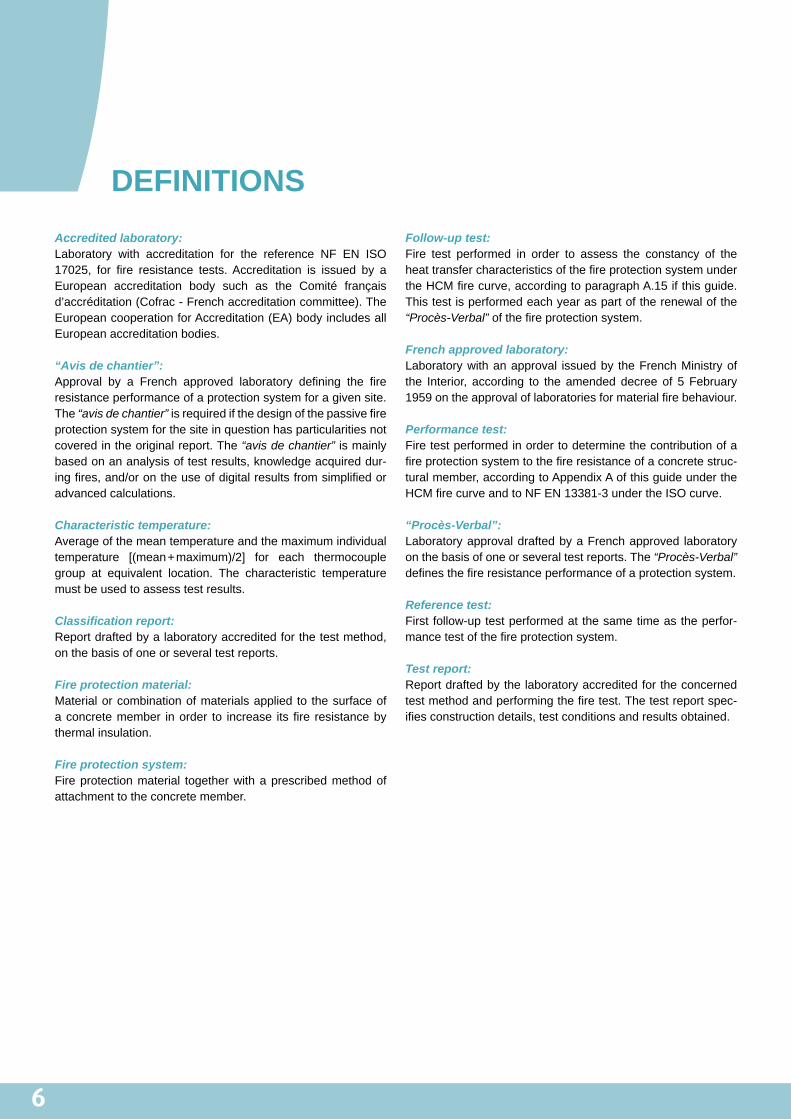
DEFINITIONSAccredited laboratory: Laboratory with accreditation for the reference NF EN ISO17025, for fire resistance tests.Accreditation is issued by aEuropean accreditation body such as the Comité françaisd’accréditation(Cofrac-Frenchaccreditationcommittee).TheEuropeancooperationforAccreditation(EA)bodyincludesallEuropeanaccreditationbodies.
“Avis de chantier”: Approval by a French approved laboratory defining the fireresistanceperformanceofaprotectionsystemforagivensite.The“avis de chantier”isrequiredifthedesignofthepassivefireprotectionsystemforthesiteinquestionhasparticularitiesnotcoveredintheoriginalreport.The“avis de chantier”ismainlybasedonananalysisoftestresults,knowledgeacquireddur-ingfires,and/orontheuseofdigitalresultsfromsimplifiedoradvancedcalculations.
Characteristic temperature: Averageofthemeantemperatureandthemaximumindividualtemperature [(mean+maximum)/2] for each thermocouplegroup at equivalent location. The characteristic temperaturemustbeusedtoassesstestresults.
Classification report: Reportdraftedbyalaboratoryaccreditedforthetestmethod,onthebasisofoneorseveraltestreports.
Fire protection material: Materialorcombinationofmaterialsapplied to thesurfaceofaconcretemember inorder to increase itsfire resistancebythermalinsulation.
Fire protection system: Fireprotectionmaterial togetherwithaprescribedmethodofattachmenttotheconcretemember.
Follow-up test: Fire test performed in order to assess the constancy of theheattransfercharacteristicsofthefireprotectionsystemundertheHCMfirecurve,accordingtoparagraphA.15ifthisguide.Thistestisperformedeachyearaspartoftherenewalofthe“Procès-Verbal”ofthefireprotectionsystem.
French approved laboratory: Laboratorywithanapproval issuedby theFrenchMinistryofthe Interior, according to the amended decree of 5 February1959ontheapprovaloflaboratoriesformaterialfirebehaviour.
Performance test: Firetestperformedinordertodeterminethecontributionofafireprotectionsystemtothefireresistanceofaconcretestruc-turalmember,accordingtoAppendixAofthisguideundertheHCMfirecurveandtoNFEN13381-3undertheISOcurve.
“Procès-Verbal”: LaboratoryapprovaldraftedbyaFrenchapproved laboratoryonthebasisofoneorseveraltestreports.The“Procès-Verbal” definesthefireresistanceperformanceofaprotectionsystem.
Reference test: Firstfollow-uptestperformedatthesametimeastheperfor-mancetestofthefireprotectionsystem.
Test report: Reportdraftedbythelaboratoryaccreditedfortheconcernedtestmethodandperformingthefiretest.Thetestreportspec-ifiesconstructiondetails,testconditionsandresultsobtained.
7
INTRODUCTIONTocomplywiththeFrenchregulationrelatedto“Thesafetyofroad tunnelswith a length ofmore than 300metres” (called«Instruction Technique» in French) [1, 2], implementation ofpassivefireprotectionsystemsisoftenrequiredtoguaranteean adequate level of fire resistance for existing structures.Thismethodofprotectioncanalsobeusedfornewstructures.However, the “Instruction Technique”definesneither the typeofproducttobeusedinordertoachieveagivenperformancelevel,northemethodologytobeappliedtospecifyorquantifythefireprotectionsystemstobeused.Someinformationispro-videdintheFrenchGovernmentamendeddecreeof22March20041[3].Indeed,thisdecreeconcerning“Thefireresistanceofproducts,constructionandstructuralcomponents”,definesmethods and performance criteria, which refer to FrenchRegulationsonfiresafety.
Since the publication of the “Instruction Technique”, someinformationconcerningfire testsandpreparationof technicalspecifications(CCTP)hasbeendescribedinotherdocuments.Thesedocumentsareintendedtosimplifytheapplicationofthe“Instruction Technique”butdonotincludeacompletesummaryofthesubject.Forinstance,onecouldmentiontheGuidetofirebehaviourofroadtunnelspublishedbytheCETUin2005,itsAddendumsin2011,theguidelinesoftheWorkingGroup37oftheAFTES2 in2008,andthecatalogueofpassiveprotectionsystemsavailable on thewebsite of theCETUand regularlyupdated[4,5,6,7].
Theexperienceacquiredduring the last tenyears, thepubli-cationof standardsonfire testsand informationprovidedbyproductsuppliers,taketheleadinmeetingarealneedofthetunnelindustry.TogetherwiththeFrenchapprovedlaboratories:CSTB,EFECTISFrance andCERIB,CETUhas drafted thisguideinordertoclarifytheprocedurejustifyingtheperformanceof passive fire protection systems for concrete road tunnelstructures.Inparticular, thisguidespecifiesatestmethodforHCMfireexposure.Thisguideiswritteninaccordancewiththeamendeddecreeof22March2004[3].
This�guide�is�intended�for�companies,�fire�resistance�test�laboratories,� suppliers� and� installers� of� passive�fire�pro-tection�systems,�as�well�as�project�managers�and� tunnel�owners,� in� order� to� provide� assistance� in� justifying� and�accepting�passive�fire�protection�systems�for�road�tunnel�structural�components.
In�addition,�appendix�A�defines�a�test�method�for�applied�protection� to� concrete� members� exposed� to� the� HCM�curve�and� is�particularly� intended� for�fire� resistance� test�laboratories.
1.Thedecreeof22March2004,afterbeingconsolidatedon6October2006,wasamendedbythedecreeof14March2011.2.AFTES:FrenchAssociationforTunnelsandUndergroundSpace(AssociationFrançaisedesTunnelsetdel’EspaceSouterrain).
1

8
2GENERAL�PRINCIPLES FOR�FIRE�PROTECTION�
TheapplicationofafireprotectionsystemontunnelstructuralcomponentsaimstosatisfythefireresistanceratingsrequiredbytheFrenchRegulations.Itlimitsdamagestostructuralcom-ponents toensure theirability to fulfil their intended function.Thisdamagecanbecausedby:
• an increase of temperature of materials leading to adowngradingoftheirmechanicalproperties,
• thermaldeformationsinducingstresses,• materiallossduetoconcretespalling.
In this guide, the term “spalling” refers to all phenomena(explosive spalling, progressive spalling, falling-off, etc.) withtheeffectofdetachingsuperficialconcreteofstructuralcompo-nentsexposedtofire.Formoredetailsonthedefinitionsofthedifferentphenomena,onecanrefer,forinstance,totheCETUguideonthefirebehaviourofroadtunnels[4].
Thetwotemperature-timecurvesusedtodesignthestructuresofroadtunnelsarethestandardtemperature-timecurve,called“ISO”andtheModifiedHydrocarboncurvecalled“HCM”3(seefigure1).Inaccordancewiththe“Instruction Technique”[1],theeffectsofspallingareconsideredasnegligibleforordinarycon-creteexposedtotheISOcurve4.SpallingshouldbeexplicitlytakenintoaccountforalltypesofconcreteexposedtotheHCMfire curve and for high-performance concrete exposed to theISOfirecurve.However,nosimplerulehasasyetbeendeter-minedinordertoestimatethethicknessofconcretespallingasafunctionoftimeorasafunctionoftemperaturewhateverthetypeofconcretesis.
Thefirebehaviourofstructuresprotectedbypassivefirepro-tectionsystemsisassessedonthebasisofthermo-mechanicalcalculationstakingintoaccounttheprofilesoftemperaturevs.depth within concrete structural components. For numericalsimulationofroadtunnelfirebehaviour,theCETUguide“Firebehaviourofroadtunnels”anditsaddendumsshouldbeused[4,5].
Thefireresistancecriterioncanbedefinedasamaximumchar-acteristictemperatureontheexposedsurfaceoftheconcreteinthetechnicalspecificationsoftheproject.Thetechnicalspeci-ficationsmayalsomentionamaximumcriticaltemperatureofthestructuralreinforcement.ThistemperaturecanbedefinedwithreferencetoEurocode2part1.2(NFEN1992-1-2).
A thermal insulation criterionmaybe requiredonunexposedsurfacesinsomecases(e.g.innerpanelofashelterorwallofanevacuationroute).
Inpractice,passivefireprotectionsystemsarecurrentlyusedwhen:
• therequiredfireresistanceisnotachievedbytheexistingstructure,
• it is not possible to experimentally assess the risk andquantifytheamountofspallingforexistingstructures,
• spallingassessment resultsarenotcompatiblewith therequiredfireresistance.
The installation of a passive fire protection system on struc-turereducesthe increaseof theconcretetemperature.Then,despite HCM fire exposure, the surface temperature of theprotectedconcretewillgenerallyremainfarbelowtheISOfirecurve.Onthisbasis,andonlyinthecontextoftheassessmentof thermal transfers, spalling phenomenamay be ignored inthe presence of passive fire protection materials. In fact, inthiscase,thematerialsremaininpositionandcontributetothethermalinsulationofthestructure.
Fire�resistance�tests�therefore�aim�to�ensure�the�integrity�of�the�passive�protection�system.�Furthermore,�characteri-sation�can�be�carried�out�on�the�basis�of�the�characteristic�temperatures�of�the�exposed�surface�of�the�concrete�behind�the�protection.
Figure 1: temperature-time curve
3.Insomepublications,theModifiedHydroCarboncurve(HCM)isalsocalledtheIncreasedHydrocarboncurveandisnotedHCinc.4.The“Instruction Technique”isbasedonENV1992-1-2,whichonlyconsideredspallingundertheISOcurveforhigh-performanceconcretes.Sincethisdate,Eurocode2part1-2(EN1992-1-2)includingthe3%watercontentrule(see.article4.5.1)hastakeneffect.Therefore,thequestionofstudyingthespallingofconcretewithawatercontentofmorethan3%undertheISOcurveshouldnormallybeconsideredindependentlytoitsmechanicalstrength.
9
PASSIVE�FIRE�PROTECTION�SYSTEMS�AND�THEIR�IMPLEMENTATION�ON-SITE
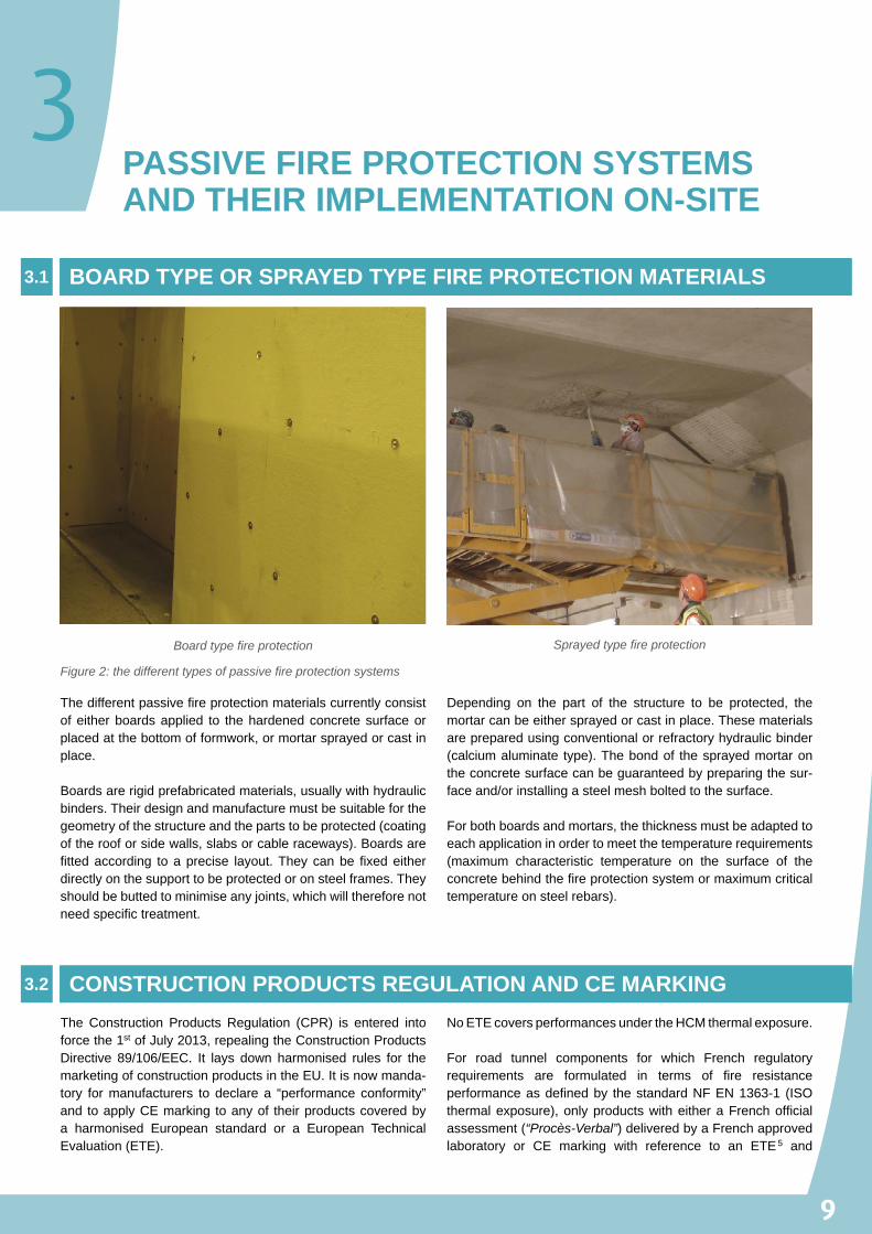
Thedifferentpassivefireprotectionmaterialscurrentlyconsistofeitherboardsapplied to thehardenedconcretesurfaceorplacedatthebottomofformwork,ormortarsprayedorcastinplace.
Boardsarerigidprefabricatedmaterials,usuallywithhydraulicbinders.Theirdesignandmanufacturemustbesuitableforthegeometryofthestructureandthepartstobeprotected(coatingoftherooforsidewalls,slabsorcableraceways).Boardsarefittedaccording toaprecise layout.Theycanbefixedeitherdirectlyonthesupporttobeprotectedoronsteelframes.Theyshouldbebuttedtominimiseanyjoints,whichwillthereforenotneedspecifictreatment.
Depending on the part of the structure to be protected, themortarcanbeeithersprayedorcastinplace.Thesematerialsarepreparedusingconventionalorrefractoryhydraulicbinder(calciumaluminate type).Thebondof thesprayedmortarontheconcretesurfacecanbeguaranteedbypreparingthesur-faceand/orinstallingasteelmeshboltedtothesurface.
Forbothboardsandmortars,thethicknessmustbeadaptedtoeachapplicationinordertomeetthetemperaturerequirements(maximum characteristic temperature on the surface of theconcretebehindthefireprotectionsystemormaximumcriticaltemperatureonsteelrebars).
The Construction Products Regulation (CPR) is entered intoforcethe1stofJuly2013,repealingtheConstructionProductsDirective 89/106/EEC. It lays down harmonised rules for themarketingofconstructionproductsintheEU.Itisnowmanda-tory formanufacturers to declare a “performance conformity”and toapplyCEmarking toanyof theirproductscoveredbya harmonised European standard or a European TechnicalEvaluation(ETE).
NoETEcoversperformancesundertheHCMthermalexposure.
For road tunnel components for which French regulatoryrequirements are formulated in terms of fire resistanceperformanceasdefinedby thestandardNFEN1363-1 (ISOthermalexposure),onlyproductswitheitheraFrenchofficialassessment(“Procès-Verbal”)deliveredbyaFrenchapprovedlaboratory or CE marking with reference to an ETE5 and
BOARD�TYPE�OR�SPRAYED�TYPE�FIRE�PROTECTION�MATERIALS3.1
Board type fire protection
Figure 2: the different types of passive fire protection systems
Sprayed type fire protection
CONSTRUCTION�PRODUCTS�REGULATION�AND�CE�MARKING3.2
3
10
3
associated classification reports translated in French can beused.
When higher fire resistance levels are required: N1+HCMt6,N2 orN3, French regulations consider a fire scenario corre-spondingtoaHCMthermalexposureandarethereforeoutsideof thescopeof theEuropeanTechnicalApprovalGuidelines:ETAG018.Nevertheless,someapproachesdescribedinETAG018canbetakenasreferencesfortheassessmentoftheper-formancesofproductsexposedtoHCMthermalexposure,andproductsexposedto ISOthermalexposurewithoutETE(seeabove).
This guide recommends the priority use of fire protectionsystemshavingfollowedtheprocessesdefinedtoensuretheconformityoftheproductinthecontextofaconformitycertifi-cationsystemi.e.:
• the test laboratory must apply the specific samplingprocedurebeforecharacterisationtestsforfireprotectionmaterials.Thissamplingprocedureisintendedtoassess
the material as manufactured continuously, and not toassess amaterial sample specifically produced for thecharacterisationtest,
• aFactoryProductionControl (FPC)proceduremustbeapplied. This procedure is intended to check that thematerialsproducedandimplementedonthesiteremaininconformitywith thematerialsused for the test-basedassessment.Thispointlimitsperformancedeviationfromtheinitialtypetest.Furthermore,inthespecificcaseofamaterial subjected toa limitedproduction run, theFPCtype procedure can be carried out via a thermal trans-fer testonasample inorder tocheck initialproperties.Finally, if the material is a prototype, the formulationcharacteristicsorthermalcharacteristicscanbeusedastracers tocheck theperformanceof thematerialduringroutineproductionchecks.
Itisalsorecommendedthepriorityuseoffireprotectionsystemswhereconstantperformancelevelsareguaranteedbyatleastaqualification forexposureandageingeffects inaccordancewithETAG018.
In addition to the characterisation of the material itself, theentire passive fire protection system must be characterised.ThereforepassivefireprotectionsystemsmustprovetheirfireresistanceunderISOorHCMthermalexposureswithreferencetoaclassificationreportassociatedwiththeCEmarkinginclud-ing the fire resistance requirement or to a French approval“Procès-Verbal”.Thesedocumentsaredraftedonthebasisofoneorseveraltestreports(seeparagraph4.4andfigure3ofthisguide).
The followingpoints inparticularmustbe taken intoaccountwhendefiningthesystem:
• the thickness of the protection and multi-layers ifapplicable,
• typeoftheconcretemembers7,• the type of attachment and implementation (type offixation, number and spacing, any joint backing strips,jointcoverstripsorsliders incaseofboardsprotectionmaterial;presenceofasteelmesh,attachments,prepa-rationoftheconcretesurfacesifnecessaryinthecaseofsprayedorcastinplaceprotectionmaterial).
Boarddimensionsand loadingmayalsohaveconsequencesonthesystemperformance.
Finally, it isnecessarytopayattentionto thetypeandrepre-sentativeness of the materials tested (regular performancesandproperties,waterstabilisation,etc.),and theconstructionand preparation of the concrete member (concrete strengthclassandmixdesign,hygrometricstabilisation,etc.).
CONSIDERATION�OF�THE�ENTIRE�FIRE�PROTECTION�SYSTEM3.3
5.Withoutharmonizedstandards,CEmarkingonprotectionproductsrelatetoanETEgenerallyestablishedonthebasisoftheEuropeanTechnicalApprovalGuidelines:ETAG018.6.LevelN1(definedbytheISOcurve)issometimescompletedbycheckingthefireresistanceofthestructureunderafastdevelopingfire(HCMthermalexposure)foragivenperiodt.Thisrequirementisthenwritten“HCMt”,withtexpressedinminutes.7.Acertaindegreeoftolerancecanbeacceptedfortheconcretememberhoweverthissupportmustremainofthesametypeandhaveathicknessinaccordancewiththisguide(seeparagraphs4.2and4.3).

11
Whentheperformanceofthefireprotectionsystemhasbeenassessed, it is necessary to check the representativenessofthesystemtestedwithrespecttoactualsiteconditions(typeofconcretemember,implementationconditions,etc.).
Article 18of theamendeddecreeof 22March2004 [3] liststhedifferentoptions tocertify thefireresistanceperformanceofaproduct,aconstructionorastructuralcomponent, in thespecificcontextofitsimplementationonagivensite.
In application of this article for a given structure, it may notbe possible to justify the fire resistance performances of theprotectionsystemdirectlyonthebasisofaclassificationreportoraFrenchapproval “Procès-Verbal” (due,e.g. toexcessivedeviationbetweenthetypeofsystemtestedandthatactuallyimplemented,orbetweentestconditionsandsiteconditions).In thiscase,anapprovalbyaFrenchapproved laboratory isrequested.This official laboratory approvalwill then take theform of either an extended application of the classificationreport,oranextendedapplicationofthe“Procès-Verbal”,oraspecificapprovalcalled“Avis de chantier”validexclusivelyforthegiventunnel.
Paragraph4.4ofthisguideincludesdetailsontheprocessanddocumentsusedtocertifythefireresistanceperformanceofapassiveprotectionsystemon theconstructionsite inaccord-ancewiththeamendeddecreeof22March2004.
ON-SITE�APPLICATION3.4

12
ACCEPTANCE�CONDITIONS�FOR�PASSIVE�FIRE�PROTECTION�SYSTEMS�ON�THE�CONSTRUCTION�SITE
Appendix 1 of the amended decree of 22 March 2004 [3]definesconventionaltestsaccordingtostandardisedEuropeanmethodsononehand,andaccordingtonationalmethodsontheotherhand (doors,dampers,structuralcomponents,con-trolledmechanical ventilation fans, fire resistant ceilings andfiredampers).Conventionaltestsmustbedifferentiatedbasedonthetypeofcomponent.
Various European standards apply to passive fire protectionsystems(standardsinthefollowingseries:NFEN1364,NFEN1365,NFEN13381).For� the�specific�case�of�passive�fire�protection�systems�for�concrete�structures,�the�applicable�reference�is�the�standard�NF�EN�13381-3.Foralltheothersit-uations(steelstructures,verticalmembranes,etc.),referencetotheappropriateEuropeanstandardsshouldbemade.
Theacceptanceofapassivefireprotectionsystemforagivensiteistheresponsibilityoftheprojectmanager.Thiswilldependon the characterisation of the entire system and its on-siteapplicationasspecifiedinparagraphs3.3and3.4.
Generally,theprojectmanagerwillcheckthefollowingpoints:
• thesupplyofdocumentscertifyingthefireresistanceper-formanceoftheprotectionsystem,asdefinedinarticle18oftheamendeddecreeof22March2004(seeparagraph4.4andfigure3ofthisguide),
• compliance with the criterion defined in the technicalspecifications when applicable. This criterion may bedefinedbythesurfacetemperatureoftheconcreteortheallowabletemperatureofreinforcement(seeparagraph2ofthisguide).
The project manager will also check the conformity of thesystem implemented on the construction sitewith the testedsystem.Thisconformitywillrelatetothefollowingpoints:
• theconcretetypeofthemembers,• thethicknessofthefireprotectionmaterialanditsmaincharacteristics(dimensionsforboardprotectionmaterial,density,watercontent),
• the implementationprocedure(steelmesh,attachmentsfor sprayed protection material or those cast in place;layout diagram, type of fixations, joint backing strips,joint cover strips or sliders in case of board protectionmaterials).
Differencesbetweentestsandsiteconditionscanhoweverbeaccepted.Theyrelateto:
• theconcretetypeofthemember:intherangeoftemper-aturesfortheexposedsurfaceoftheconcretebehindtheprotection (250°C–400°C), it isassumed that the typeofconcretewillnotaffectthebehaviouroftheprotectionmaterial,
• the thickness of the concrete member used for tests:this thickness isusually lower than the thicknessof thestructure.However, in the rangeof temperaturesof theexposedsurfaceoftheconcrete(behindprotection)andconsideringthemechanicalloads,thistestconfigurationwould appear unfavourable as the support slab willdeformmoreduringthetestthaninthetunnel,
• the loading of the concrete member: in real circum-stances,loadingwillvaryinfunctionoflocationandtime.Loadingduringthetests,whateveritsvalue,isnotthere-foregenerallyrepresentativeofthestructure.TheCETUguide [4] therefore recommends the loadingdefinedbystandard NF EN 13381-3, which has the advantage ofbeingstandardised,
• some characteristics of sprayed protection material: inpractice, it ismoredifficult tocheck the implementationprocedure for this typeofprotection,particularly for thedensity, thewatercontentand the thicknessapplied foreachlayer.
“CONVENTIONAL”�TESTING�ACCORDING�TO�EUROPEAN�STANDARDS4.1
OVERVIEWS�AND�CURRENT�PRACTICES4.2
4
13
SomedeviationfromthetestconditionsaccordingtostandardNFEN13381-3havealsobeenacceptedinthepastbasedonthedelayrequiredtodevelopexperimentalresources.Strictlyspeaking, as standard NF EN 13381-3 only applies to testsunderISOthermalexposure,thedeviationfromtestconditionsforthisstandardwhenperformingHCMtestscouldhavebeentolerated.Thesedeviationsrelatedto:
• the loading of the support slab: loads other than thatdefinedinthestandardNFEN13381-3(seeabsenceofloading)couldhavebeenapplied,
• the dimensions of the concrete member: even if theCETUguide[4]recommendsthedimensionsofstandardNFEN13381-3,sometestswerecarriedoutinorderto
reproduceaspecificstructurewithdimensionsotherthanthoseofthestandard.Itwasacceptedthatthedimensionsoftheconcretememberhadlittleeffectonthebehaviourof thefireprotectionsystemasdeformationmattersthemost.
Thisguiderecommendsrejectingdeviationfromtestconditionswhenassessingtheperformancesofafireprotectionsystem.ConcerningHCMtests,paragraph4.3andappendixAofthisguidenowspecifythemethodtoperformHCMtest.Deviationmay however be authorised in some cases, when they areintendedtorepresentrealconditionsinthecontextofapplica-tiontoaspecificconstructionsite.
According to theamendeddecreeof22March2004 [3], thefire resistance performances of a protection system testedunderHCMthermalexposuremustbedefinedinthe“Procès-Verbal”(seearticle11ofthedecree).Inordertoestablishthis“Procès-Verbal”,thisguiderecommendstheHCMtestmethoddescribedbelow.
HCM tests for passive fire protection systems applied toconcrete structures are performed in accordance with thegeneralconditionsofstandardNFEN1363-1andthespecificconditionsofstandardNFEN13381-3,plusorreplacedbythe
complementaryprovisionsindicatedinappendixAofthisguide.Someoftheseprovisions,suchastheHCMthermalprogram,havebeendraftedbyanalogywiththeproceduredescribedinstandardNFEN1363-2.
To accept the performance of products assessedwith a testunderRWSthermalexposure8(inthesamewayasunderHCMthermalexposure),thisguiderecommendsthatRWStestsbeperformedinaccordancewiththeHCMtestmethoddescribedabove,withtheonlyexceptionofthethermalprogramme.
Thevalidityandacceptabilityoffireresistancetests justifyingtheperformanceofpassiveprotectionsystemsaredescribedbelowforISOandHCMtests,inaccordancewiththeamendeddecreeof22March2004[3].
Accordingtothedefinitionsoftheamendeddecreeof22March2004,ISOandHCMtestsareconsideredasconventionalfireresistance tests (testsperformedwithpredetermined thermalactions).
ISO and HCM tests must be performed by an accreditedlaboratory. For ISO tests, the laboratory must be accreditedfor thetestmethodsdefinedinthestandardNFEN13381-3.ForHCMtests,thelaboratorymustbeaccreditedfortheHCMtest method described in this guide (see paragraph 4.3 andappendixA).
Theaccreditedlaboratorywilldraftatestreportforeachtest.
Fireresistanceperformanceswillthenbedefinedby:
• a classification report, in French, provided that it isattached to the conformity declaration through CEmarking;
• a “Procès-Verbal” drafted by a French approvedlaboratory.
Ifthesystemtestedismodified,aFrenchapprovedlaboratorymustberequestedtocarryoutanapprovalinviewofextendingtheapplicationoftheclassificationreportorthe“Procès-Verbal”.
If the construction site hasparticularities not identified in theclassificationreportorthe“Procès-Verbal”,aFrenchapprovedlaboratory has to establish an “Avis de chantier” for the fireprotection system. On the contrary to the extension of theapplicationof the classification report or the “Procès-Verbal”,the“Avis de chantier”isonlyvalidfortheconsideredtunnel.
DEVELOPMENTS�AND�RECOMMENDATIONS IN�THE�CONTEXT�OF�HCM�TESTS
4.3
VALIDITY�AND�ACCEPTABILITY�OF�FIRE�RESISTANCE�TESTS4.4
8.TheRWScurveisaregulatorycurveusedintheNetherlands,whichisverysimilartotheHCMcurve(see[9]).
14
4
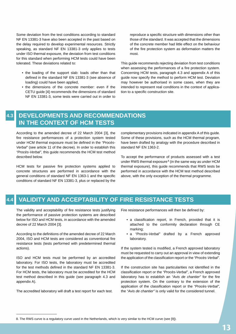
Document required for on-site acceptance of passive fire protection system
Characterisation of a fire protectionsystem in preliminary design
Predetermined ISO curve Predetermined HCM curve
NO
YES
Establishment of“Procès-Verbal”
Extension of scope For a construction sitewith particularities
Follow up tests for renewalof HCM “Procès-Verbal”
(every year)
Combination of different tests,analyses and calculation
Extension of the the“Procès-Verbal” issued by aFrench approved laboratoryor new classification reportfor an extended application
Specific analysisaccording to the site
(tests, calculation, analyses)
“Procès-Verbal” delivered bya French approved laboratory
(valid 1 year for HCM)
Classification report + CE marking
Sampling
Test according toNF EN 13381-3 by a laboratory
accredited for this method
Test reports
CE markingissued by a
Notified Body?
Test reports
Tests according to this guideby a laboratory accredited
for this method + Reference tests
“Avis de chantier” issuedby a French approved
laboratory
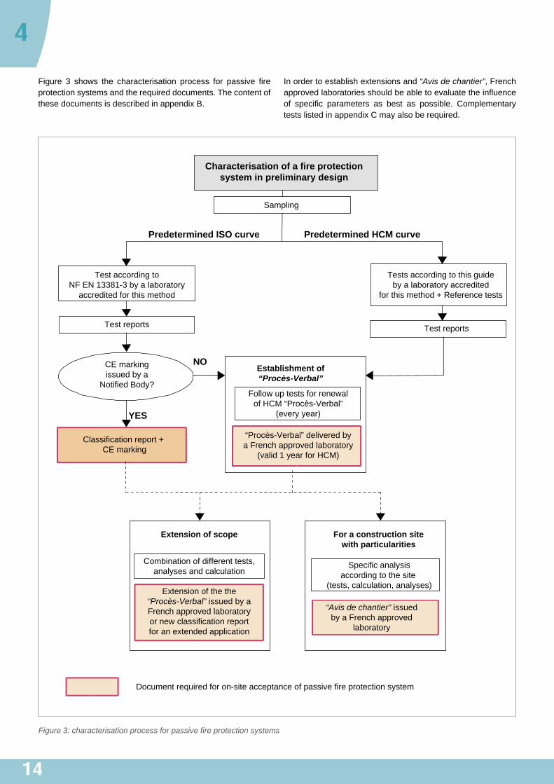
Figure 3 shows the characterisation process for passive fireprotectionsystemsandtherequireddocuments.ThecontentofthesedocumentsisdescribedinappendixB.
Inordertoestablishextensionsand“Avis de chantier”,Frenchapprovedlaboratoriesshouldbeabletoevaluatetheinfluenceof specific parameters as best as possible. ComplementarytestslistedinappendixCmayalsoberequired.
Figure 3: characterisation process for passive fire protection systems
15
[1] «InstructionTechnique»relativeauxdispositionsdesécuritédanslesnouveauxtunnelsroutiers,annexéeàlacirculaireinterministériellen°2000-63du25août2000 relativeà lasécuritédanslestunnelsduréseauroutiernational.(Frenchregulationsforroadtunnelsafety)
[2] Frenchgovernmentcircularno.2006-20of29March2006onthesafetyofroadtunnelswithalengthofmorethan300metres.
[3] French government decree of 22March 2004 on the fireresistanceof products, construction and structural compo-nents,amendedbytheorderof14March2011.
[4] GuideduComportementaufeudestunnelsroutiers(Guideforthefirebehaviourinroadtunnels),CETU,March2005.
[5] AddendumtotheGuideforthefirebehaviourinroadtunnels,CETU,March2011.
[6] Roadtunnels:fireresistance,AFTESGT37recommendation,Tunnelsetouvragessouterrains(Tunnelsandundergroundstructures),no.205,January/February2008.
[7] Catalogueofpassiveprotectionsystems,CETU,December2005, updated on-line on the CETU website: www.cetu.developpement-durable.gouv.fr.
[8] Frenchgovernmentdecreeof19October2006applicabletofireprotectionproductsandenforcingdecreeno.92-647of8July1992onthesuitabilityforuseofconstructionproducts,amended by decrees no. 95-1051 of 20September 1995andno.2003-947of3October2003.
[9] Fireandsmokecontrolinroadtunnels,PIARC,1999.
[10] NF EN 13381-3, Testmethods for determining the contri-butiontothefireresistanceofstructuralmembers–Part3:Appliedprotectiontoconcretemembers.
BIBLIOGRAPHIC�REFERENCES
5
16
APPENDICES
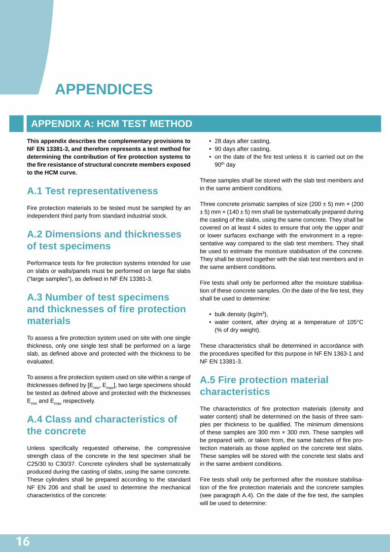
This�appendix�describes�the�complementary�provisions�to�NF�EN�13381-3,�and�therefore�represents�a�test�method�for�determining�the�contribution�of�fire�protection�systems�to�the�fire�resistance�of�structural�concrete�members�exposed�to�the�HCM�curve.
A.1�Test�representativenessFireprotectionmaterialstobetestedmustbesampledbyanindependentthirdpartyfromstandardindustrialstock.
A.2�Dimensions�and�thicknesses�of�test�specimensPerformancetestsforfireprotectionsystemsintendedforuseonslabsorwalls/panelsmustbeperformedonlargeflatslabs(“largesamples”),asdefinedinNFEN13381-3.
A.3�Number�of�test�specimens�and�thicknesses�of�fire�protection�materialsToassessafireprotectionsystemusedonsitewithonesinglethickness,onlyonesingle testshallbeperformedona largeslab,asdefinedaboveandprotectedwiththethicknesstobeevaluated.
Toassessafireprotectionsystemusedonsitewithinarangeofthicknessesdefinedby[Emin,Emax],twolargespecimensshouldbetestedasdefinedaboveandprotectedwiththethicknessesEminandEmaxrespectively.
A.4�Class�and�characteristics�of�the�concreteUnless specifically requested otherwise, the compressivestrength class of the concrete in the test specimen shall beC25/30 toC30/37.Concretecylindersshallbesystematicallyproducedduringthecastingofslabs,usingthesameconcrete.These cylinders shall be prepared according to the standardNF EN 206 and shall be used to determine themechanicalcharacteristicsoftheconcrete:
• 28daysaftercasting,• 90daysaftercasting,• onthedateofthefiretestunlessitiscarriedoutonthe90th day
Thesesamplesshallbestoredwiththeslabtestmembersandinthesameambientconditions.
Threeconcreteprismaticsamplesofsize(200±5)mm×(200±5)mm×(140±5)mmshallbesystematicallypreparedduringthecastingoftheslabs,usingthesameconcrete.Theyshallbecoveredonatleast4sidestoensurethatonlytheupperand/or lowersurfacesexchangewith theenvironment ina repre-sentativewaycomparedtotheslabtestmembers.Theyshallbeusedtoestimatethemoisturestabilisationoftheconcrete.Theyshallbestoredtogetherwiththeslabtestmembersandinthesameambientconditions.
Firetestsshallonlybeperformedafterthemoisturestabilisa-tionoftheseconcretesamples.Onthedateofthefiretest,theyshallbeusedtodetermine:
• bulkdensity(kg/m3),• water content, after drying at a temperature of 105°C(%ofdryweight).
Thesecharacteristicsshallbedetermined inaccordancewiththeproceduresspecifiedforthispurposeinNFEN1363-1andNFEN13381-3.
A.5�Fire�protection�material�characteristicsThe characteristics of fire protection materials (density andwatercontent)shallbedeterminedonthebasisofthreesam-ples per thickness to be qualified.Theminimum dimensionsofthesesamplesare300mm×300mm.Thesesampleswillbepreparedwith,ortakenfrom,thesamebatchesoffirepro-tectionmaterialsas thoseappliedon theconcrete testslabs.Thesesampleswillbestoredwiththeconcretetestslabsandinthesameambientconditions.
Firetestsshallonlybeperformedafterthemoisturestabilisa-tionof thefireprotectionmaterialsand theconcretesamples(seeparagraphA.4).Onthedateofthefiretest,thesampleswillbeusedtodetermine:
APPENDIX�A:�HCM�TEST�METHOD

17
• bulkdensity(kg/m3),• water content, after drying at a temperature of (105±5)°C,or (50±5)°C forgypsum-basedproducts (%ofdryweight).Thetestdurationcandependonthiswatercontent(seeparagraphA.11).
Thesecharacteristicsshallbedetermined inaccordancewiththeproceduresspecifiedforthispurposeinNFEN1363-1andNFEN13381-3.
A.6�Conditioning�of�concrete�test�slabsTheminimum conditioning time of 90 days recommended inNFEN13381-3maybereducedto85dayssubjecttothemois-turestabilisationofallthethreeconcretesamples(200±5)mm×(200±5)mm×(140±5)mmpreparedforthispurposewiththesameconcreteastheconcretetestslabs.
A.7�Instrumentation�of�concrete�test�slabsThe instrumentation of concrete test slabs recommended byNFEN13381-3isnotsufficienttoproperlyassessthemechan-icalresistanceofthefireprotectionsystemunderHCMthermalexposure, the temperatureupon theexposedsurfacesof theconcretebeneaththefireprotectionmaterial,and,ifapplicable,the temperature upon the exposed surfaces of the concretebeneaththe jointsofboardtypefireprotectionmaterials. It isthereforenecessarytoincreasethenumberofmeasuringsec-tionsatthelocationsdescribedinparagraphsA.7.1andA.7.2dependingonwhethersprayed,castmortarorboardtypefireprotectionmaterialsareused.
Themeasuredtemperaturesmaybeusedtointerpolateresultsfor intermediatefireprotectionmaterial thicknesses,betweenthemaximumandminimum thicknessesactually tested.Thiscanbedonebyusingthermaltransfersimulations.
A.7.1�For�sprayed�renderings�or�casted�mortars
For sprayed or casted passive type fire protection material,instrumentationforthemeasurementofthetestspecimentem-peratureshallconsistof7setsofthermocoupleslocatedinthecentralpartoftheslab(3setsatmid-widthandquarter-widthonthesmallestmedian,and4setsatthecentreofeachquarterpartoftheslab(seefigureA.1-setsS1toS7)).
Eachofthe7setsofthermocouplesshallinclude7measuringpointsasgivenbelowandshowninfigureA.2:
• 5thermocouplesinthethicknessoftheconcreteslabasrequested in paragraph 9.3.2 – sub-paragraph v of thestandard NF EN 13381-3 (see figureA.2 - positions BtoF),
• 1thermocoupleontheexposedsurfaceof theconcretebeneaththefireprotectionmaterial(seefigureA.2-posi-tionA),
• 1thermocoupleontheunexposedsurfaceoftheconcreteslab(seefigureA.2-positionG).
Thermocouplesontheexposedsurfaceof theconcreteshallbeplacedat thebottomof theformworkasrequested inNFEN13381-3.Particularattentionshallbepaidafterremovingtheformworkconcerningtracesofconcrete laitanceonther-mocouples.Thecopperdiscshallbecleaned,andifnecessaryshallbere-fixedtotheconcreteslabwithglue.Aphotoofeachthermocouplebeforetheapplicationofthefireprotectionsys-temshallbeincludedinthetestreport.
A.7.2�For�Board�type�fire�protection�materials
Forboardtypefireprotectionmaterial,instrumentationforthemeasurementofthetestspecimentemperatureshallconsistof:
• 7setsof thermocouples locatedintheexposedsurfaceoftheslab(3setsatmid-widthandquarter-widthonthesmallestmedian,and4setsatthecentreofeachquarterpartof theslab (seefigureA.1 - setsS1 toS7)).Eachofthe7setsofthermocouplesshallinclude7measuringpoints(seefigureA.2)asgivenbelow: ▪ 5thermocouplesinthethicknessoftheconcreteslabas specified inparagraph9.3.2– sub-paragraphvofthestandardNFEN13381-3(seefigureA.2-positionsBtoF),
▪ 1thermocoupleontheexposedsurfaceoftheconcretebeneath the fire protection material (see figureA.2 -positionA),
▪ 1thermocoupleontheunexposedsurfaceofthecon-creteslab(seefigureA.2-positionG),
• 3 additional sets of thermocouples in the middle of 3protection boards, not in the immediate proximity ofboardfixations (minimumspacingof100mm)and ina3,000mm×3,000mmsquarecentredontheslab(seefigureA.3-setsS8toS10).Intheselocations,tempera-turesshallbemeasuredasfollow: ▪ ontheexposedsurfaceoftheconcretebeneaththefireprotectionmaterial(seefigureA.4-positionA),
▪ at15mmand30mmfromtheexposedsurfaceoftheconcrete(seefigureA.4-positionsBandC),
▪ on the unexposed surface of the concrete slab (seefigureA.4-positionG).
Ifoneoftheselocationsislessthan200mmfromasetofthermocouplesasdescribedinthepreviouspoint,thenthisadditionalsetofthermocouplesisomitted.
18
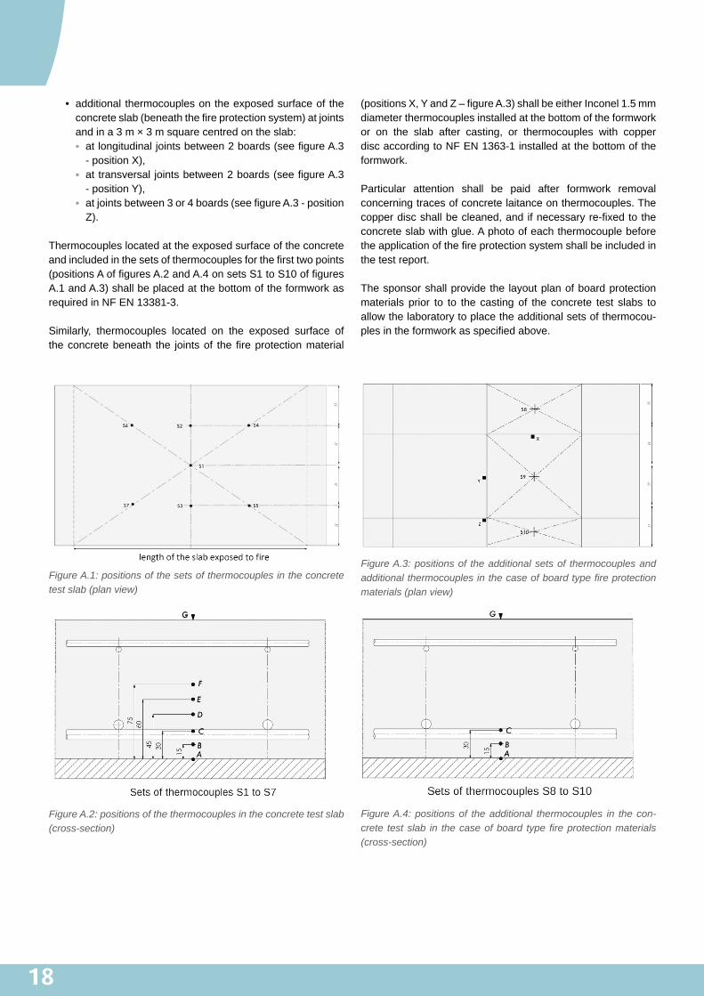
• additionalthermocouplesontheexposedsurfaceoftheconcreteslab(beneaththefireprotectionsystem)atjointsandina3m×3msquarecentredontheslab: ▪ atlongitudinaljointsbetween2boards(seefigureA.3-positionX),
▪ attransversal jointsbetween2boards(seefigureA.3-positionY),
▪ atjointsbetween3or4boards(seefigureA.3-positionZ).
Thermocoupleslocatedattheexposedsurfaceoftheconcreteandincludedinthesetsofthermocouplesforthefirsttwopoints(positionsAoffiguresA.2andA.4onsetsS1toS10offiguresA.1andA.3)shallbeplacedatthebottomoftheformworkasrequiredinNFEN13381-3.
Similarly, thermocouples located on the exposed surface oftheconcretebeneath the jointsof thefireprotectionmaterial
(positionsX,YandZ–figureA.3)shallbeeitherInconel1.5mmdiameterthermocouplesinstalledatthebottomoftheformworkor on the slab after casting, or thermocouples with copperdiscaccordingtoNFEN1363-1installedatthebottomoftheformwork.
Particular attention shall be paid after formwork removalconcerningtracesofconcretelaitanceonthermocouples.Thecopperdiscshallbecleaned,andifnecessaryre-fixedtotheconcreteslabwithglue.Aphotoofeachthermocouplebeforetheapplicationofthefireprotectionsystemshallbeincludedinthetestreport.
Thesponsorshallprovidethe layoutplanofboardprotectionmaterials prior to to the castingof the concrete test slabs toallowthelaboratorytoplacetheadditionalsetsofthermocou-plesintheformworkasspecifiedabove.
Figure A.1: positions of the sets of thermocouples in the concrete test slab (plan view)
Figure A.2: positions of the thermocouples in the concrete test slab (cross-section)
Figure A.3: positions of the additional sets of thermocouples and additional thermocouples in the case of board type fire protection materials (plan view)
Figure A.4: positions of the additional thermocouples in the con-crete test slab in the case of board type fire protection materials (cross-section)
19
A.8�Loading�of�test�specimenUnless loadingconditionsare representativeof thestructure,theyshallcomplywiththerequirementsofNFEN13381-3.
Thetest loadcanalsobeappliedusingdeadweightsdistrib-utedevenlyovertheentiresurfaceofthetestspecimen,whichcorrespondstothewidthmultipliedbythespanoftheslab.
Thetestloadshallbecalculatedinordertoproduceabendingmoment inducing a tensile stress in the lower reinforcementbarsoftheconcretetestslabequalto300MPaaccordingtoNFEN13381-3.Thedead-weightoftheslabandthefireprotectionsystemshallbetakenintoaccountwhencalculatingtheloadtobeapplied.
TheloadshallbeapplieduntiladeformationofLspan/30atmid-spanoftheslabisreached.Oncethismaximumdeformationisreached,theloadshallbetotallyremoved;theassessmentiscompleted.Thefiretestmaybecontinuedforinformationalpurposesonly.
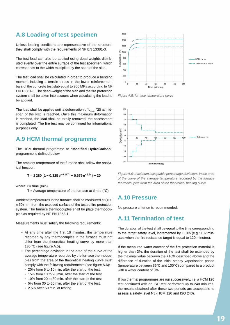
A.9�HCM�thermal�programmeThe HCM thermal programme or “Modified� HydroCarbon” programmeisdefinedbelow.
Theambienttemperatureofthefurnaceshallfollowtheanalyt-icalfunction:
T = 1 280 1 − 0.325e− 0.167t − 0.675 e− 2.5t + 20
where:t=time(min) T=Averagetemperatureofthefurnaceattimet(°C)
Ambienttemperaturesinthefurnaceshallbemeasuredat(100±50)mmfromtheexposedsurfaceofthetestedfireprotectionsystem.Thefurnacethermocouplesshallbeplatethermocou-plesasrequiredbyNFEN1363-1.
Measurementsmustsatisfythefollowingrequirements:
• At any time after the first 10minutes, the temperaturerecordedbyanythermocouples inthefurnacemustnotdiffer from the theoretical heating curve by more than130°C(seefigureA.5).
• Thepercentagedeviationintheareaofthecurveoftheaveragetemperaturerecordedbythefurnacethermocou-plesfromtheareaofthetheoreticalheatingcurvemustcomplywiththefollowingrequirements(seefigureA.6): ▪ 20%from5to10min.afterthestartofthetest, ▪ 15%from10to20min.afterthestartofthetest, ▪ 10%from20to30min.afterthestartofthetest, ▪ 5%from30to60min.afterthestartofthetest, ▪ 2.5%after60min.oftesting.
A.10�PressureNopressurecriterionisrecommended.
A.11�Termination�of�testThedurationofthetestshallbeequaltothetimecorrespondingtothetargetsafetylevel,incrementedby+10%(e.g.:132min-uteswhenthefireresistancetargetisequalto120minutes).
Ifthemeasuredwatercontentofthefireprotectionmaterialishigherthan3%,thedurationof thetestshallbeextendedbythemaximalvaluebetweenthe+10%describedaboveandthedifferenceof durationof the initial steady vaporisationphase(temperaturebetween85°Cand100°C)comparedtoaproductwithawatercontentof3%.
Iftwothermalprogrammesarerunsuccessively,i.e.aHCM120testcontinuedwithanISOtestperformedupto240minutes,theresultsobtainedafterthesetwoperiodsareacceptabletoassessasafetylevelN3(HCM120andISO240).
0
200
400
600
800
1000
1200
1400
1600
0 20 40 60 80 100 120
Tem
pera
ture
(°C
)
Time (minutes)
HCM curve
Tolerances ± 130°C
Figure A.5: furnace temperature curve
-25
-20
-15
-10
-5
0
5
10
15
20
25
0 20 40 60 80 100 120
Dev
iatio
n (%
)
Time (minutes)
Tolerances
Figure A.6: maximum acceptable percentage deviations in the area of the curve of the average temperature recorded by the furnace thermocouples from the area of the theoretical heating curve
20
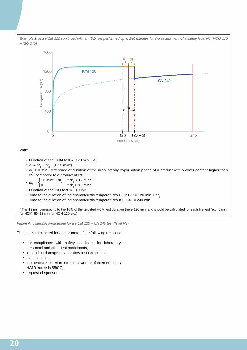
Example 1: test HCM 120 continued with an ISO test performed up to 240 minutes for the assessment of a safety level N3 (HCM 120 + ISO 240):
0
400
800
1200
1600
0 120 240
Tem
péra
ture
(°C
)
Time (minutes)
CN 240
dt1 dt2
120 + Δt
Δt
HCM 120
With:
• DurationoftheHCMtest=120min+Δt• Δt = dt1+dt2 (≥12min*)• dt1≥0min:differenceofdurationoftheinitialsteadyvaporisationphaseofaproductwithawatercontenthigherthan3%comparedtoaproductat3%
• dt2 =12min*–dt1 ifdt1<12min*
{0 ifdt1≥12min*• DurationoftheISOtest=240min• TimeforcalculationofthecharacteristictemperaturesHCM120=120min+dt1 • TimeforcalculationofthecharacteristictemperaturesISO240=240min
*The12mincorrespondtothe10%ofthetargetedHCMtestduration(here120min)andshouldbecalculatedforeachfiretest(e.g.6minforHCM60,12minforHCM120etc.)
Figure A.7: thermal programme for a HCM 120 + CN 240 test (level N3)
Thetestisterminatedforoneormoreofthefollowingreasons:
• non-compliance with safety conditions for laboratorypersonnelandothertestparticipants,
• impendingdamagetolaboratorytestequipment,• elapsedtime,• temperature criterion on the lower reinforcement barsHA10exceeds550°C,
• requestofsponsor.
21
A.12�Determination�of�reference�temperatures�of�the�fire�protection�systemReference temperatures correspond to the characteristictemperaturesasdefinedinparagraph13.1ofNFEN13381-3.Thesetemperaturesaremeasuredontheexposedsurfaceoftheconcretebehindthefireprotectionsystem(inthemainareaoftheboardsforboard-basedprotection),at15mmand30mmintheconcreteandontheunexposedsurfaceofthetestslab.
With board type fire protection materials, the temperaturesmeasuredupontheexposedsurfaceoftheconcretebehindthejointsarenottakenintoconsiderationinthecalculationofthecharacteristic temperatureof theexposedsurfaceof thecon-crete(behindthefireprotectionsystem).Indeed,theconcretetemperatures behind the joints can be substantially affectedby significant contraction of board near the joints during firetests.Thesetemperaturesshallonlybeusedtohighlightanyparticularpointsoverthejoints.
Ifthemeasuredwatercontentofthefireprotectionmaterialishigher than3%,characteristic temperaturesat time thave tobedeterminedwiththemeasurementsatthetimet +dt1wheredt1isthedifferenceofdurationoftheinitialsteadyvaporisationphasecomparedtoaproductwithawatercontentof3%(see.ParagraphA.11).
Example 2
Thefireprotectionmaterialundertesthasawatercontentof5%.Thedurationoftheinitialsteadyvaporisationphaseofthematerialat5%is10min.Then,thecharacteristictemper-atureat60minshouldbecalculatedwiththetemperaturesmeasuredat64min(60min+10minx(5%-3%)/5%).
A.13�Test�reportThetestreportshallpresentthedataandresultsaccordingtoparagraph12ofNFEN13381-3.
Inparticular,thisreportshallincludethefollowingdata:
• the generic description and accurate detail of the fireprotectionsystem,
• thecharacteristicsoftheconcrete,• thecharacteristicsofthefireprotectionmaterial,• stickability criteria as defined in paragraph 13.5 of NFEN13381-3,
• a table summarizing the characteristic temperatures at1h,2h,andifapplicable4h(seeparagraphA.12),
• resultsofthereferencetests(seeparagraphA.15),• allresultsoftheadditionaltestingdescribedinappendixC,ifperformed,
• photosofthedifferentfittingphasesincluding: ▪ thephotosofeachthermocouplesontheexposedsur-faceoftheconcreteslabduringtheformworkremovalphase,
▪ thephotosoftheexposedsurfaceofthetestspecimenaftertesting.
22
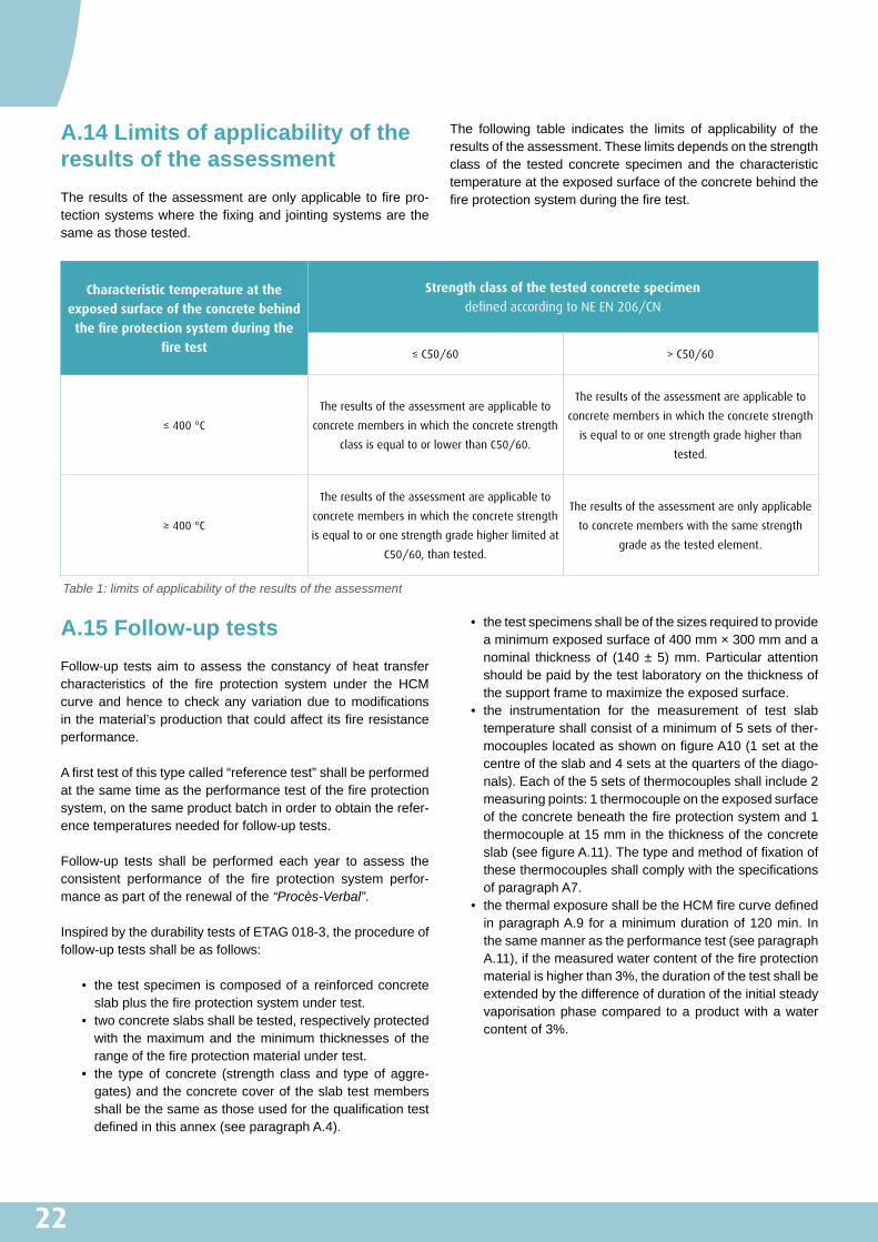
A.14�Limits�of�applicability�of�the�results�of�the�assessmentTheresultsof theassessmentareonlyapplicabletofirepro-tectionsystemswherethefixingandjointingsystemsarethesameasthosetested.
The following table indicates the limits of applicability of theresultsoftheassessment.Theselimitsdependsonthestrengthclass of the tested concrete specimen and the characteristictemperatureattheexposedsurfaceoftheconcretebehindthefireprotectionsystemduringthefiretest.
Characteristic temperature at the
exposed surface of the concrete behind
the fire protection system during the
fire test
Strength class of the tested concrete specimen
defined according to NE EN 206/CN
≤ C50/60 > C50/60
≤ 400 °C
The results of the assessment are applicable to
concrete members in which the concrete strength
class is equal to or lower than C50/60.
The results of the assessment are applicable to
concrete members in which the concrete strength
is equal to or one strength grade higher than
tested.
≥ 400 °C
The results of the assessment are applicable to
concrete members in which the concrete strength
is equal to or one strength grade higher limited at
C50/60, than tested.
The results of the assessment are only applicable
to concrete members with the same strength
grade as the tested element.
Table 1: limits of applicability of the results of the assessment
A.15�Follow-up�testsFollow-up testsaim toassess theconstancyofheat transfercharacteristics of the fire protection system under the HCMcurveandhence to checkany variationdue tomodificationsinthematerial’sproductionthatcouldaffectitsfireresistanceperformance.
Afirsttestofthistypecalled“referencetest”shallbeperformedatthesametimeastheperformancetestofthefireprotectionsystem,onthesameproductbatchinordertoobtaintherefer-encetemperaturesneededforfollow-uptests.
Follow-up tests shall be performed each year to assess theconsistent performance of the fire protection system perfor-manceaspartoftherenewalofthe“Procès-Verbal”.
InspiredbythedurabilitytestsofETAG018-3,theprocedureoffollow-uptestsshallbeasfollows:
• thetestspecimeniscomposedofareinforcedconcreteslabplusthefireprotectionsystemundertest.
• twoconcreteslabsshallbetested,respectivelyprotectedwith themaximumand theminimumthicknessesof therangeofthefireprotectionmaterialundertest.
• the typeof concrete (strength classand typeof aggre-gates)andtheconcretecoveroftheslabtestmembersshallbethesameasthoseusedforthequalificationtestdefinedinthisannex(seeparagraphA.4).
• thetestspecimensshallbeofthesizesrequiredtoprovideaminimumexposedsurfaceof400mm×300mmandanominal thicknessof (140±5)mm.Particularattentionshouldbepaidbythetestlaboratoryonthethicknessofthesupportframetomaximizetheexposedsurface.
• the instrumentation for the measurement of test slabtemperatureshallconsistofaminimumof5setsofther-mocoupleslocatedasshownonfigureA10(1setatthecentreoftheslaband4setsatthequartersofthediago-nals).Eachofthe5setsofthermocouplesshallinclude2measuringpoints:1thermocoupleontheexposedsurfaceoftheconcretebeneaththefireprotectionsystemand1thermocoupleat15mminthethicknessoftheconcreteslab(seefigureA.11).ThetypeandmethodoffixationofthesethermocouplesshallcomplywiththespecificationsofparagraphA7.
• thethermalexposureshallbetheHCMfirecurvedefinedinparagraphA.9 foraminimumdurationof120min. Inthesamemannerastheperformancetest(seeparagraphA.11),ifthemeasuredwatercontentofthefireprotectionmaterialishigherthan3%,thedurationofthetestshallbeextendedbythedifferenceofdurationoftheinitialsteadyvaporisationphasecompared toaproductwithawatercontentof3%.

23
The assessment of the constancy of the heat transfer char-acteristicsof thefireprotectionsystemshallbebasedonthetime required to reach theaverage temperatureat15mm intheconcreteslabdeterminedat120minduringthereferencetest.This temperature is called “reference temperature”.Thetime obtained to reach this temperature during the follow-uptest shall be longer than 102min (which represents 85% of120min).
Ifthemeasuredwatercontentvalueofthefireprotectionmate-rialismorethan3%:
a) whenusingthismaterialforthereferencetest,thecharacter-istictemperatureat120minshallbecalculatedinaccordancewithparagraphA.12;
b) whenusingthismaterialforannualfollow-uptest,thetimewhen the reference temperature at 15 mm in the concreteslabisreachedshallbecalculatedbytakingofffromthetimeobtainedduringthefollow-uptest,thedifferenceofdurationoftheinitialsteadyvaporisationphasecomparedtoaproductwithawatercontentof3%.
Example 3
Thefireprotectionmaterialundertesthasawatercontentof5%.Thedurationoftheinitialsteadyvaporisationphaseat5%is10min.Then:
a) if theprotectionmaterial isused for the reference test:Thecharacteristictemperatureat120minshouldbecalcu-latedwiththetemperaturesmeasuredat124min(120min+10min×(5%–3%)/5%);
b) iftheprotectionmaterialisusedfortheannualfollow-uptest: During the follow-up test, the reference temperatureat 15 mm was reached at 116 min. This time should becorrectedasfollow:116min–(10min–(5%–3%)/5%)=111min.Inthisexample,weobtain111minwhichissupe-riorto102min.Theperformancecriteriaofthefollow-uptestisthereforesatisfied.
Figure A.8: positions of the sets of thermocouples in the concrete slab for follow-up test (plan view)
Figure A.9: positions of the thermocouples in the concrete slab for follow-up test (cross-section)

24
The documents to be produced by the French approvedlaboratory and requiredby theprojectmanager to justify theperformanceof thepassive fireprotection systemsaremen-tionedinparagraph4.4ofthisguide.Theircontentisdescribedbelow,withtheexceptionoftheclassificationreport,forwhichitisnecessarytorefertotheamendeddecreeof22March2004.
B.1�“Procès-verbal”Onthebasisofthetestreportsissuedbyanaccreditedlabo-ratory,theFrenchapprovedlaboratorywilldraftareportcalled“Procès-Verbal”describingthefollowingpoints:
• name of the test laboratory having issued the“Procès-Verbal”,
• nameandaddressofthesponsor,• referencenumberofthetestreport(s),• briefdescriptionofthepassivefireprotectionsystem,• method of assembly and installation of the passive fireprotectionsystem,asrequiredforon-sitechecks,
• representativenessofthecomponent,• table of results for characteristic temperatures takingwatercontentintoconsideration,
• table of maximum temperatures over joints (for boardprotectionmaterial),
• scopeofvalidity,• expirydateforvalidity,• dateofissueoftheminutes,• nameandsignatureoftheissuer.
ForHCMtests,the“Procès-Verbal”isvalidfor1-year,renew-ableprovided to the justificationof theconstancyof theheattransfercharacteristics(seeparagraphA.15ofAppendixA).
B.1�Extended�application�and�“Avis de chantier”Reminder: the “avis de chantier” is required if there is slightdeviationbetweentheactuallyimplementeddesignandthetestconfigurationorconditions.Thesemodificationsmayrelatetothefollowingpointsinparticular:
• layout,• fixationtypeanddensity,• boarddimensions,• boardthickness,• typeofconcretesupport,• fireresistancecriterion.
An “avis de chantier” is determined in accordance with theamendeddecreeof22March2004[3],onthebasisof:
• oneorseveraltestreports,• oneorseveral“Procès-Verbaux”,• availableexperimentaldata,• additionalnumericalassessments.
Thelaboratorywillcarryoutchecksonthebasisofknowledgeacquired on the date of issue of the “avis de chantier”. Thisknowledgecanbetheresultofacombinationbetweenexistingtestsorteststobeperformedandcalculationsorexpertise.
Asdefinedintheamendeddecreeof22March2004,an“avis de chantier”isvalidexclusivelyforthesiteindicated.
If the request is generic and likely to affect several sites, alaboratoryapprovalcanbedraftedinordertoextendthefieldofapplicationoftheresults(seeparagraph4.4ofthisguide).Extensionsinrelationtotheabovereasonsmustbejustified.The combinationwith tests on small test specimensmay betakenintoconsideration.
A significant difference can be highlighted between the testconfiguration and the behaviour of the concrete within thestructure (type, mechanical characteristics, loading, etc.).Shouldanydoubtariseonthetranspositionoffireresistanceperformanceofthetestedprotectionsystemtothestructureinquestion,additionaltestingmayberequired.
APPENDIX�B:�DOCUMENTS�TO�PRODUCE�/�TO�REQUEST
2525
Reminder:onthedateofthetest,thebulkdensity(kg/m3)andwatercontentoffireprotectionmaterial,afterdryingat105°C(%ofdryweight),oreven50°C forgypsum-basedproducts,(seeparagraphsA.4andA.5ofappendixA)mustbesystemat-icallymeasured.
In order to establish extensions and “avis de chantier” (seeparagraph4.4of thisguide), theFrenchapproved laboratorymay require to perform the following additional testing tocharacteriseother thermal andphysical propertiesof the fireprotectionmaterialsuchas:
• thermal conductivity (W/m·°C) over 10 temperaturepointsbetween20and1,250°C,
• specific heat (J/kg·°C) over the temperature rangingbetween20and1,250°C,
• heatdiffusion,• the contraction/expansion coefficient over the tempera-turerangingbetween20and1,250°C.
Thetemperaturepointsforthermalconductivitydeterminationwill cover the interval between 20 and 1,250°C.A DTA/TGA(DifferentialThermalAnalysis /Thermo-GravimetricAnalysis)willbecarriedoutbeforehandtodeterminewhichtemperaturesindicateachangeinthefireprotectionmaterial.Thesamplesused for these testswill be taken from the samebatches offire protection materials as those implemented on the fireresistancetestsperformedinaccordancewiththestandardNFEN13381-3.Thecharacterisation testswill beperformed foreachfireprotectionmaterialthicknessrequiredforextensionsand“avis de chantier”.
The thermal conductivity and specific heat will be used forthermaltransfersimulationsbasedonafiniteelementmodaltodeterminethethermalinsulationperformanceofanintermedi-atethicknessforthefireprotectionmaterial,includingbetweentheminimumandmaximumthicknessesactuallytested.
The thermal expansion/contraction coefficient curve may beusedtocorrelatewiththehotmechanicalbehaviourofthefireprotectionmaterial, as recorded during tests, aswell as anycontractionalongjointsbetweenboardsifapplicable.
For the concrete, the density and water content taken intoaccount in calculations will correspond to those determinedbasedon(200±5)mm×(200±5)mm×(140±5)mmref-erence samples prepared for this purpose when casting theconcreteslabs.Thethermalconductivityandspecificheatwillcorrespond to those indicated in the standard EN 1992- 1-2Eurocode2:“Designofconcretestructures–Part1-2:Generalrules–Structuralfiredesign”:December2004.
APPENDIX�C:�OPTIONAL�ADDITIONAL�TESTING

26
NOTES

27
Contributors
This guide was updated by a working group led by Bérénice MOREAU (CETU), comprising CETU (Lætitia D’ALOIA), CSTB (Romuald AVENEL, Pierre PIMIENTA), EFECTIS France (Roman CHIVA, Daniel JOYEUX, Regis KORYLUK) and CERIB (Nathalie BRIAND, Cédric COLLIGNON, Christophe TESSIER).

www.cetu.developpement-durable.gouv.fr
Centre d’Études des Tunnels25 avenue François Mitterrand69674 BRON - FRANCETél. +33 (0)4 72 14 34 00Fax. +33 (0)4 72 14 34 [email protected]
Couv
ertu
re: N
ys -
AirT
ech
Phot
o. C
rédi
ts p
hoto
s : C
ETU
- Ré
dact
ion
et c
oord
inat
ion
: col
labo
rate
urs
CETU
- R
éalis
atio
n : C
omm
un
iqu
ez -
Impr
essio
n : V
ASSE
L GR
APHI
QUE


