RJ-45
RJ-45
SPI Flash/NOR-Flash/
Micro SD
24 VDC-DC
Converter
DDR3 SRAM
EEPROM
TPS65910(Power
Management IC)
AM3359 (Processor)
TLK110(Ethernet
PHY)
Clock
TLK110(Ethernet
PHY)
ARM® Cortex®-A8
PRU-ICSS
PRU
PRU
MII/RMII
MII/RMII
I2C
EMIF
3.3-VLDO
Copyright © 2016, Texas Instruments Incorporated
1TIDUBN6–June 2016Submit Documentation Feedback
Copyright © 2016, Texas Instruments Incorporated
Parallel Redundancy Protocol (PRP) Ethernet Reference Design forSubstation Automation
TI DesignsParallel Redundancy Protocol (PRP) Ethernet ReferenceDesign for Substation Automation
SmartReflex, Sitara, Code Composer Studio are trademarks of Texas Instruments.PHYTER is a registered trademark of Texas Instruments.Cortex is a registered trademark of ARM Limited.ARM is a registered trademark of ARM.All other trademarks are the property of their respective owners.
Design OverviewThis TI Design is a solution for high reliability,low-latency network communications forsubstation-automation equipment in smart gridtransmission and distribution networks. It supports theParallel Redundancy Protocol (PRP) specification inthe IEC 62439 standard. This solution is a lower-costalternative to FPGA approaches and provides theflexibility and performance to add features such asIEC 61850 support without additional components.
Design Resources
TIDEP0054 Design FolderAM3359 Product FolderTLK110 Product FolderTPS65910 Product FolderTMDSICE3359 Tools FolderSYSBIOSSDK-IND-SITARA Tools Folder
ASK Our E2E Experts
Design Features• Compliant to IEC 62439-3 Clause 4 Specification
for PRP-Ethernet Communications• Traffic Filtering Based on Virtual Local-Area
Network (VLAN) IDs, Multicast and BroadcastSupport, and Built-in Storm Prevention andSupervision Mechanism
• Zero Recovery Time in Case of Network Failure• Dual-Ported Full-Duplex 100-Mbps Ethernet• Fully Programmable Solution Provides Platform for
Integration of Additional Applications
Featured Applications• Substation and Distribution Automation• Protection Relays• Smart-Grid Communication• Factory Automation
An IMPORTANT NOTICE at the end of this TI reference design addresses authorized use, intellectual property matters and otherimportant disclaimers and information.
Background www.ti.com
2 TIDUBN6–June 2016Submit Documentation Feedback
Copyright © 2016, Texas Instruments Incorporated
Parallel Redundancy Protocol (PRP) Ethernet Reference Design forSubstation Automation
1 BackgroundA substation is a key component of the electricity-grid infrastructure, located everywhere from powergeneration facilities throughout the distribution network to the low-voltage feeders serving residences andbusinesses. Substations are a primary factor in transforming voltage levels for transmission andperforming important functions such as switching, monitoring, and protecting sub-systems in order tomaintain grid efficiency and reliability. Traditional-substation systems focused on fault monitoring that canbe manually fixed by switching to backup subsystems.
Consumers, regulators, and grid operators demand increasing reliability of electricity delivery. Theintroduction of automatic switching and protection of subsystems increases the demand for the automationof substation operations and communications to monitor grid conditions and communicate information togrid operators.
Operators need to continually monitor the health of networks and take action to maintain the operationwith efficiency. This need leads to the requirement for reliable and low-latency communications betweenthe control center of the operator and high-value nodes such as substations.
The International Electro-Technical Commission (IEC) released specifications for industrial-Ethernetcommunications under the IEC 62439 standard. The PRP specification is one of the IEC 62439-3standards that provides a static redundancy Ethernet-based protocol that supports critical real-timesystems that require continuous monitoring.
www.ti.com System Description
3TIDUBN6–June 2016Submit Documentation Feedback
Copyright © 2016, Texas Instruments Incorporated
Parallel Redundancy Protocol (PRP) Ethernet Reference Design forSubstation Automation
2 System DescriptionThis design details a reliable high-speed PRP communication solution that is compliant with IEC 62439-3Clause 4 for substation automation.
This is a cost-effective alternative to ASIC- or FPGA-based Ethernet solutions while delivering equalperformance. The programmable nature of the solution allows operating different redundancy Ethernetprotocols without hardware modification and adding applications such as IEC 61850 without requiringadditional system costs.
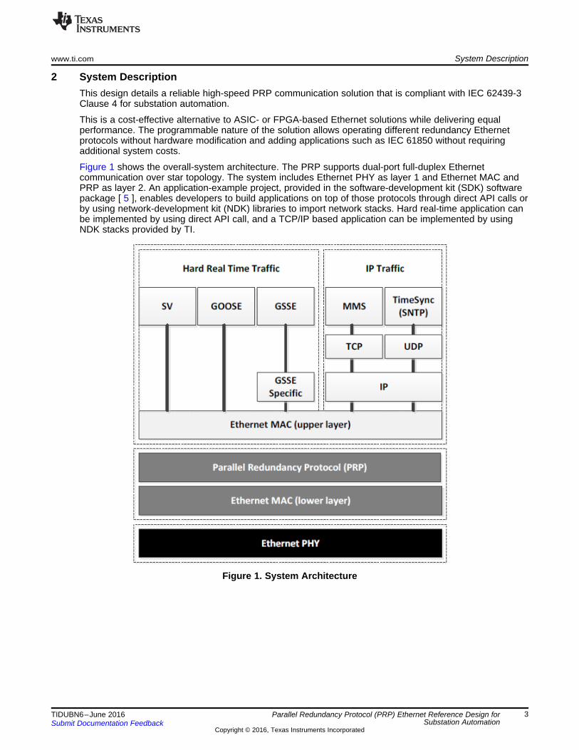
Figure 1 shows the overall-system architecture. The PRP supports dual-port full-duplex Ethernetcommunication over star topology. The system includes Ethernet PHY as layer 1 and Ethernet MAC andPRP as layer 2. An application-example project, provided in the software-development kit (SDK) softwarepackage [ 5 ], enables developers to build applications on top of those protocols through direct API calls orby using network-development kit (NDK) libraries to import network stacks. Hard real-time application canbe implemented by using direct API call, and a TCP/IP based application can be implemented by usingNDK stacks provided by TI.
Figure 1. System Architecture
x xxx x
xNode 2Node 1
Node 4 Node 3
xx
xxxxxxxxxxxx
xxxxxx
xx
xxxxxxxxxxxx
xxxxxx
Switch Switch
LAN A LAN B
System Description www.ti.com
4 TIDUBN6–June 2016Submit Documentation Feedback
Copyright © 2016, Texas Instruments Incorporated
Parallel Redundancy Protocol (PRP) Ethernet Reference Design forSubstation Automation
2.1 Parallel Redundancy Protocol (PRP)PRP is a redundancy protocol for Ethernet networks (standardized using IEC 62439-3 Clause 4) that isselected as one of the redundancy protocols for substation automation in the IEC 61850 standard. PRP isapplication-protocol independent and can be used by most industrial-Ethernet applications that requirereliable high-speed communications.
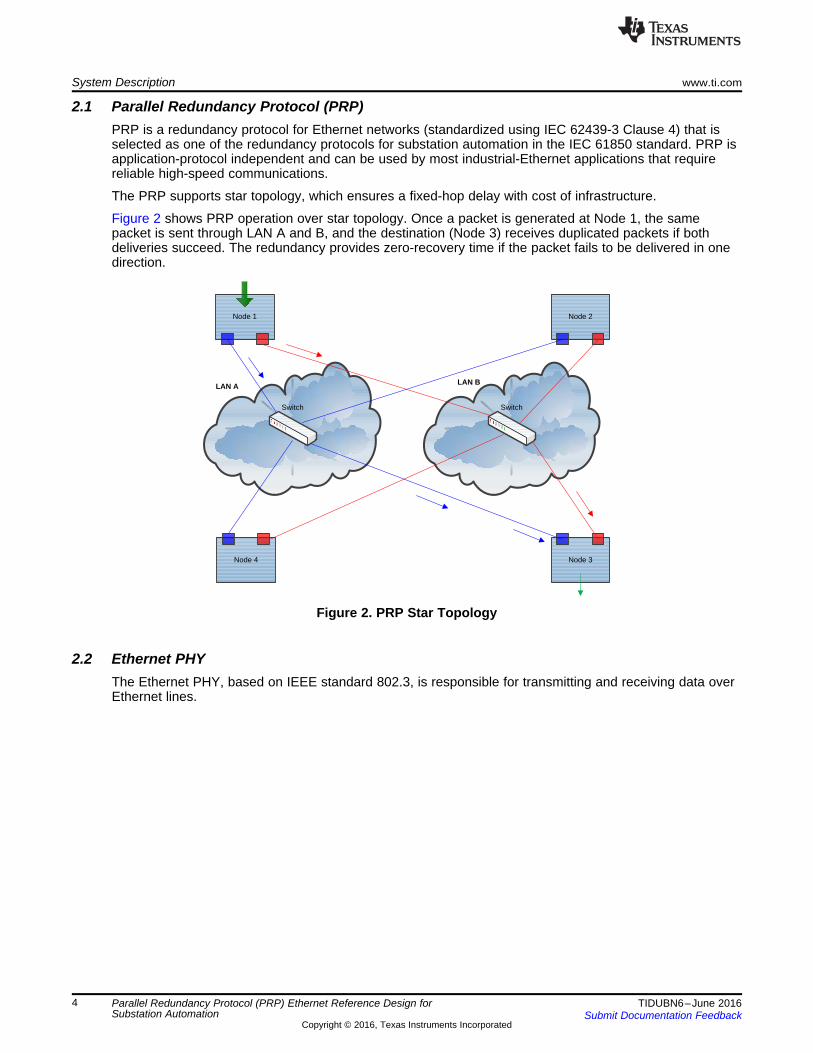
The PRP supports star topology, which ensures a fixed-hop delay with cost of infrastructure.
Figure 2 shows PRP operation over star topology. Once a packet is generated at Node 1, the samepacket is sent through LAN A and B, and the destination (Node 3) receives duplicated packets if bothdeliveries succeed. The redundancy provides zero-recovery time if the packet fails to be delivered in onedirection.
Figure 2. PRP Star Topology
2.2 Ethernet PHYThe Ethernet PHY, based on IEEE standard 802.3, is responsible for transmitting and receiving data overEthernet lines.
RJ-45
RJ-45
SPI Flash/NOR-Flash/
Micro SD
24 VDC-DC
Converter
DDR3 SRAM
EEPROM
TPS65910(Power
Management IC)
AM3359 (Processor)
TLK110(Ethernet
PHY)
Clock
TLK110(Ethernet
PHY)
ARM® Cortex®-A8
PRU-ICSS
PRU
PRU
MII/RMII
MII/RMII
I2C
EMIF
3.3-VLDO
Copyright © 2016, Texas Instruments Incorporated
www.ti.com Block Diagram
5TIDUBN6–June 2016Submit Documentation Feedback
Copyright © 2016, Texas Instruments Incorporated
Parallel Redundancy Protocol (PRP) Ethernet Reference Design forSubstation Automation
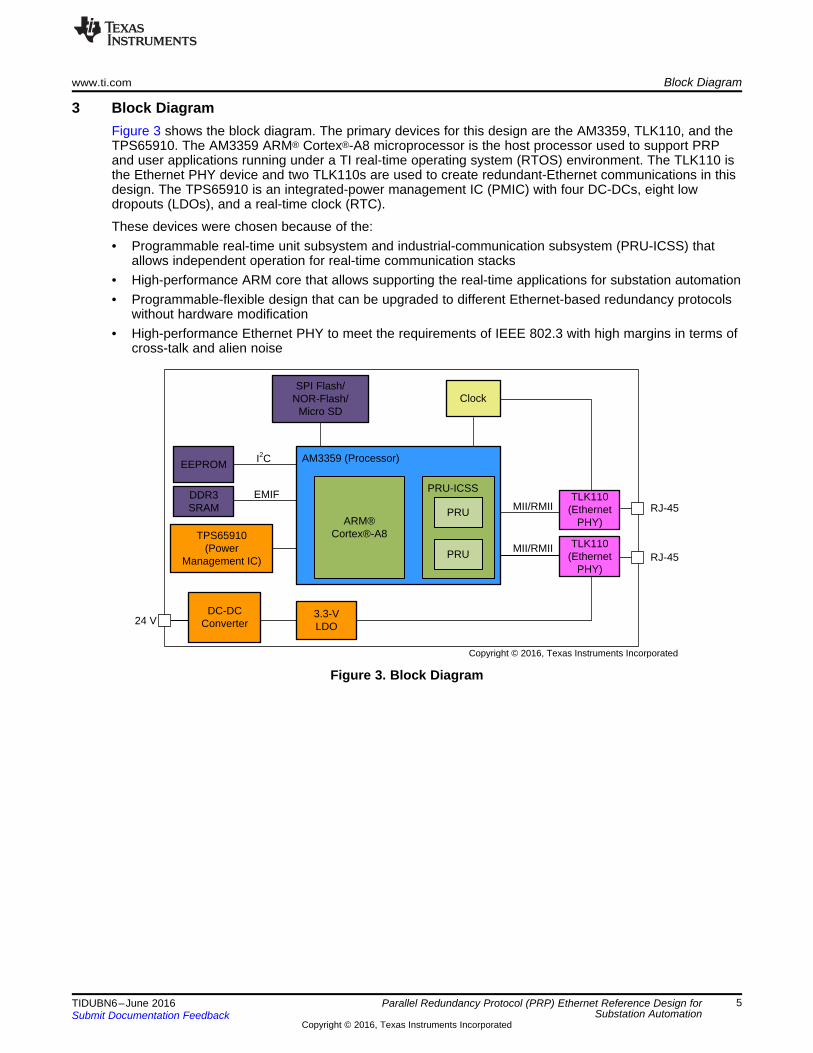
3 Block DiagramFigure 3 shows the block diagram. The primary devices for this design are the AM3359, TLK110, and theTPS65910. The AM3359 ARM® Cortex®-A8 microprocessor is the host processor used to support PRPand user applications running under a TI real-time operating system (RTOS) environment. The TLK110 isthe Ethernet PHY device and two TLK110s are used to create redundant-Ethernet communications in thisdesign. The TPS65910 is an integrated-power management IC (PMIC) with four DC-DCs, eight lowdropouts (LDOs), and a real-time clock (RTC).
These devices were chosen because of the:• Programmable real-time unit subsystem and industrial-communication subsystem (PRU-ICSS) that
allows independent operation for real-time communication stacks• High-performance ARM core that allows supporting the real-time applications for substation automation• Programmable-flexible design that can be upgraded to different Ethernet-based redundancy protocols
without hardware modification• High-performance Ethernet PHY to meet the requirements of IEEE 802.3 with high margins in terms of
cross-talk and alien noise
Figure 3. Block Diagram
Block Diagram www.ti.com
6 TIDUBN6–June 2016Submit Documentation Feedback
Copyright © 2016, Texas Instruments Incorporated
Parallel Redundancy Protocol (PRP) Ethernet Reference Design forSubstation Automation
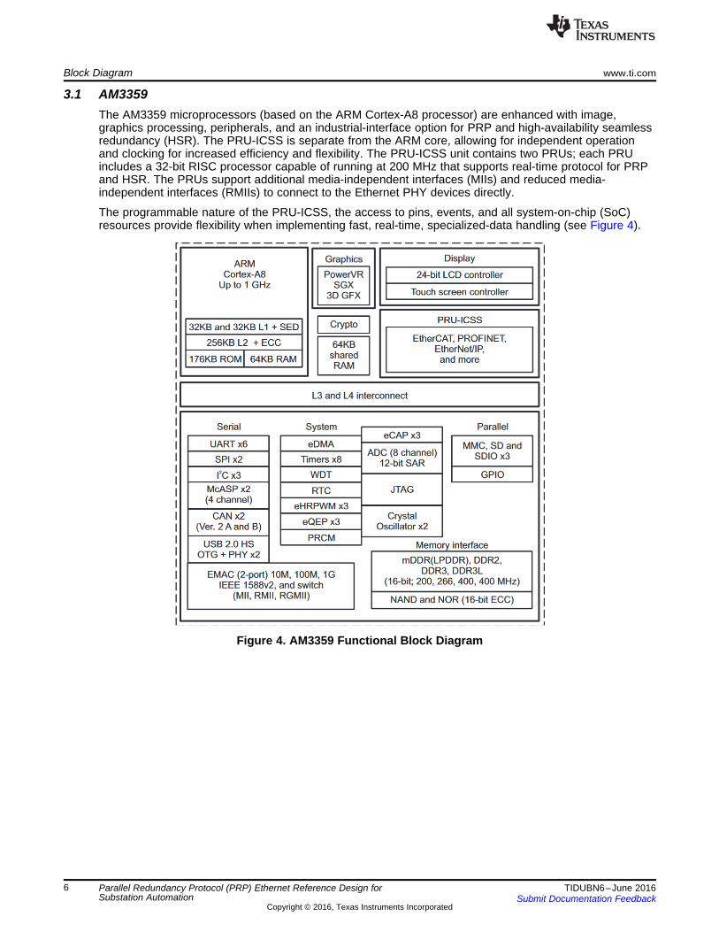
3.1 AM3359The AM3359 microprocessors (based on the ARM Cortex-A8 processor) are enhanced with image,graphics processing, peripherals, and an industrial-interface option for PRP and high-availability seamlessredundancy (HSR). The PRU-ICSS is separate from the ARM core, allowing for independent operationand clocking for increased efficiency and flexibility. The PRU-ICSS unit contains two PRUs; each PRUincludes a 32-bit RISC processor capable of running at 200 MHz that supports real-time protocol for PRPand HSR. The PRUs support additional media-independent interfaces (MIIs) and reduced media-independent interfaces (RMIIs) to connect to the Ethernet PHY devices directly.
The programmable nature of the PRU-ICSS, the access to pins, events, and all system-on-chip (SoC)resources provide flexibility when implementing fast, real-time, specialized-data handling (see Figure 4).
Figure 4. AM3359 Functional Block Diagram
www.ti.com Block Diagram
7TIDUBN6–June 2016Submit Documentation Feedback
Copyright © 2016, Texas Instruments Incorporated
Parallel Redundancy Protocol (PRP) Ethernet Reference Design forSubstation Automation
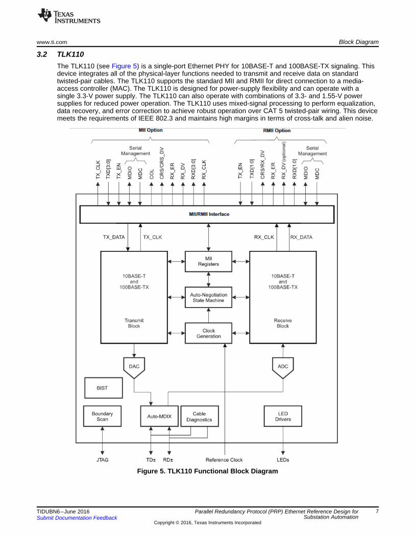
3.2 TLK110The TLK110 (see Figure 5) is a single-port Ethernet PHY for 10BASE-T and 100BASE-TX signaling. Thisdevice integrates all of the physical-layer functions needed to transmit and receive data on standardtwisted-pair cables. The TLK110 supports the standard MII and RMII for direct connection to a media-access controller (MAC). The TLK110 is designed for power-supply flexibility and can operate with asingle 3.3-V power supply. The TLK110 can also operate with combinations of 3.3- and 1.55-V powersupplies for reduced power operation. The TLK110 uses mixed-signal processing to perform equalization,data recovery, and error correction to achieve robust operation over CAT 5 twisted-pair wiring. This devicemeets the requirements of IEEE 802.3 and maintains high margins in terms of cross-talk and alien noise.
Figure 5. TLK110 Functional Block Diagram
Block Diagram www.ti.com
8 TIDUBN6–June 2016Submit Documentation Feedback
Copyright © 2016, Texas Instruments Incorporated
Parallel Redundancy Protocol (PRP) Ethernet Reference Design forSubstation Automation
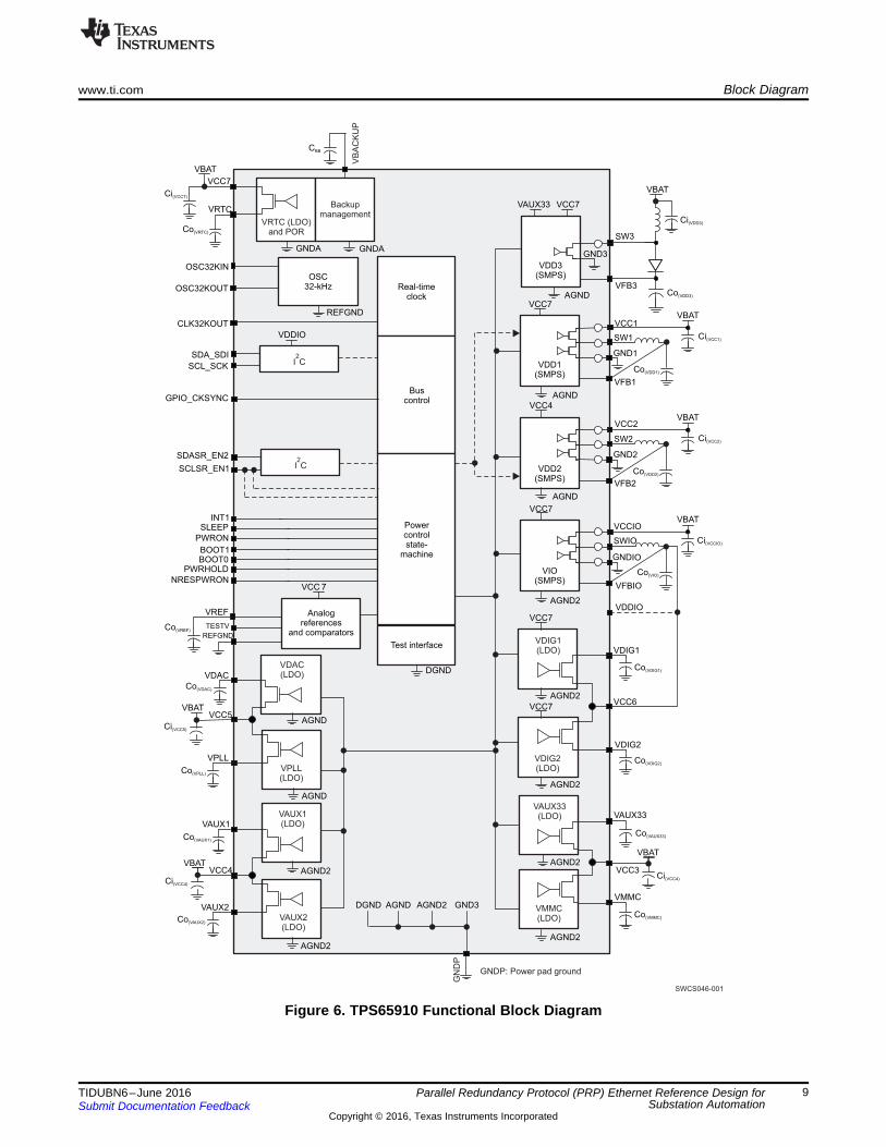
3.3 TPS65910The TPS65910 (see Figure 6) is an integrated power-management IC that provides three step-downconverters, one step-up converter, eight LDOs, and is designed to support the specific powerrequirements of OMAP-based applications. Two of the step-down converters provide power for dualprocessor cores and are controllable by a dedicated class-3 SmartReflex™ software for optimum-powersavings. The third converter provides power for the IOs and memory in the system. The device includeseight general-purpose LDOs providing a wide range of voltage and current capabilities. The LDOs arecontrollable by the I2C interface. The use of the LDOs is flexible; they are intended to be used in thefollowing ways:• Two LDOs are designated to power the phase-locked loop (PLL) and video digital to analog converter
(DAC) supply rails on the OMAP-based processors• Four general-purpose auxiliary LDOs are available to provide power to other devices in the system• Two LDOs are provided to power double-data rate (DDR) memory supplies in applications requiring
these memories
The device contains an embedded-power controller (EPC) to manage the power sequencing requirementsof the OMAP systems and an RTC.
VFB1
INT1
PWRON
VREF
REFGND
Test interface
CLK32KOUT
VAUX33
VMMC
OSC32KIN
OSC32KOUT
TESTV
SLEEP
NRESPWRON
PWRHOLD
BOOT1BOOT0
SDASR_EN2
SCLSR_EN1
SDA_SDI
VDAC
VPLL
VAUX1
VRTC
Real-timeclock
VFB3
SW3
VDIG2
VAUX2
VDIG1
VDD1(SMPS)
VCC1
GND1
SW1
VFBIO
VBAT
VCC7
VCC7
VCC7
VBAT
VBAT
VBATVCC6
VCC3VCC4
VCC5
VCC 7
VBAT
VCC7
VDDIO
VDDIO
AGND2
AGND
AGND
GNDAGNDA
DGND
VAUX33
REFGND
GND3
OSC32-kHz
SCL_SCK
BuscontrolGPIO_CKSYNC
Powercontrolstate-
machine
Analogreferences
and comparators
VB
AC
KU
P
Backupmanagement
VRTC (LDO)and POR
VFB2
VCC2
GND2
SW2
VCCIO
GNDIO
SWIO
GN
DP
AGND
AGND2
AGND2
VDAC(LDO)
VPLL(LDO)
VAUX1(LDO)
VAUX2(LDO)
VDIG1(LDO)
AGND2
AGND2
AGND2
VDIG2(LDO)
VAUX33(LDO)
VMMC(LDO)
I C2
I C2
AGND2
AGND
AGND
VCC7
VCC7
VCC4
VDD2(SMPS)
VIO(SMPS)
VDD3(SMPS)
SWCS046-001
GNDP: Power pad ground
Ci(VCC7)
Co(VRTC)
Co(VREF)
Co(VDAC)
Ci(VCC5)
CBB
Co(VPLL)
Co(VAUX1)
Ci(VCC4)
Co(VAUX2)
DGND AGND AGND2 GND3Co(VMMC)
VBAT
Ci(VCC4)
Co(VAUX33)
Co(VDIG2)
Co(VDIG1)
Co(VIO)
Ci(VCCIO)
VBAT
Ci(VCC2)
Co(VDD2)
VBAT
Ci(VCC1)
Co(VDD1)
Co(VDD3)
Ci(VDD3)
www.ti.com Block Diagram
9TIDUBN6–June 2016Submit Documentation Feedback
Copyright © 2016, Texas Instruments Incorporated
Parallel Redundancy Protocol (PRP) Ethernet Reference Design forSubstation Automation
Figure 6. TPS65910 Functional Block Diagram
xx
xx
x
UART
xx
xx
x
UART
Host Interface
NOR Flash
Rotary Switch
Eight LEDsTLK110DDR324-V I/O
LCD
Power
SPI Flash
MMC
USB JTAG
Pin 1Pin 2
Pin 3J5- Boot Jumper
CPSW and ICSS Jumpers
D1D2
Pin 1Pin 2Pin 3
Port 0Port 1
Getting Started Hardware www.ti.com
10 TIDUBN6–June 2016Submit Documentation Feedback
Copyright © 2016, Texas Instruments Incorporated
Parallel Redundancy Protocol (PRP) Ethernet Reference Design forSubstation Automation
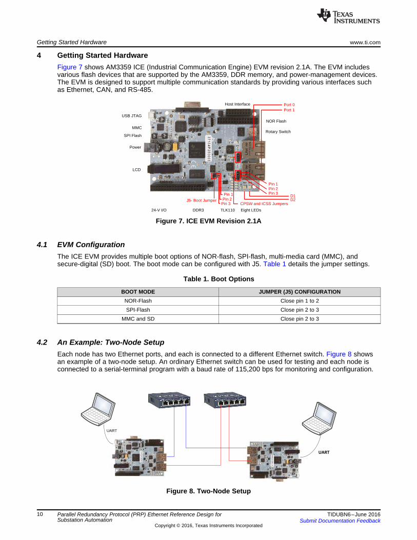
4 Getting Started HardwareFigure 7 shows AM3359 ICE (Industrial Communication Engine) EVM revision 2.1A. The EVM includesvarious flash devices that are supported by the AM3359, DDR memory, and power-management devices.The EVM is designed to support multiple communication standards by providing various interfaces suchas Ethernet, CAN, and RS-485.
Figure 7. ICE EVM Revision 2.1A
4.1 EVM ConfigurationThe ICE EVM provides multiple boot options of NOR-flash, SPI-flash, multi-media card (MMC), andsecure-digital (SD) boot. The boot mode can be configured with J5. Table 1 details the jumper settings.
Table 1. Boot Options
BOOT MODE JUMPER (J5) CONFIGURATIONNOR-Flash Close pin 1 to 2SPI-Flash Close pin 2 to 3
MMC and SD Close pin 2 to 3
4.2 An Example: Two-Node SetupEach node has two Ethernet ports, and each is connected to a different Ethernet switch. Figure 8 showsan example of a two-node setup. An ordinary Ethernet switch can be used for testing and each node isconnected to a serial-terminal program with a baud rate of 115,200 bps for monitoring and configuration.
Figure 8. Two-Node Setup
www.ti.com Getting Started Firmware
11TIDUBN6–June 2016Submit Documentation Feedback
Copyright © 2016, Texas Instruments Incorporated
Parallel Redundancy Protocol (PRP) Ethernet Reference Design forSubstation Automation
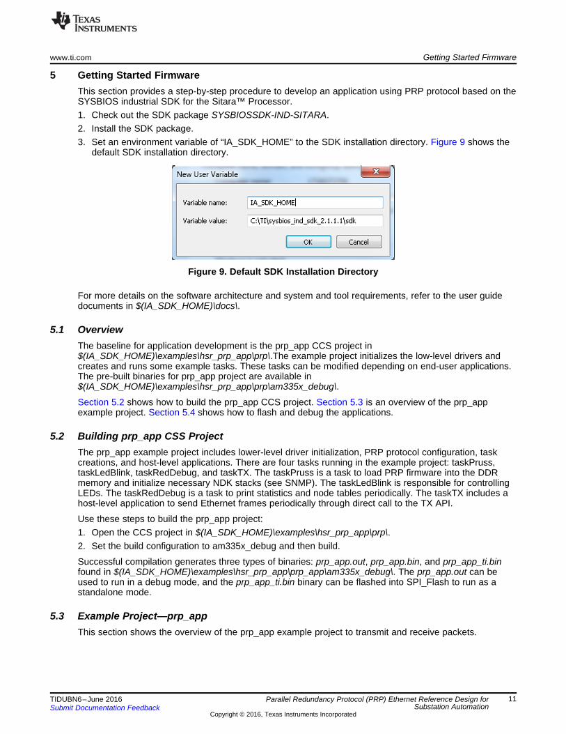
5 Getting Started FirmwareThis section provides a step-by-step procedure to develop an application using PRP protocol based on theSYSBIOS industrial SDK for the Sitara™ Processor.1. Check out the SDK package SYSBIOSSDK-IND-SITARA.2. Install the SDK package.3. Set an environment variable of “IA_SDK_HOME” to the SDK installation directory. Figure 9 shows the
default SDK installation directory.
Figure 9. Default SDK Installation Directory
For more details on the software architecture and system and tool requirements, refer to the user guidedocuments in $(IA_SDK_HOME)\docs\.
5.1 OverviewThe baseline for application development is the prp_app CCS project in$(IA_SDK_HOME)\examples\hsr_prp_app\prp\.The example project initializes the low-level drivers andcreates and runs some example tasks. These tasks can be modified depending on end-user applications.The pre-built binaries for prp_app project are available in$(IA_SDK_HOME)\examples\hsr_prp_app\prp\am335x_debug\.
Section 5.2 shows how to build the prp_app CCS project. Section 5.3 is an overview of the prp_appexample project. Section 5.4 shows how to flash and debug the applications.
5.2 Building prp_app CSS ProjectThe prp_app example project includes lower-level driver initialization, PRP protocol configuration, taskcreations, and host-level applications. There are four tasks running in the example project: taskPruss,taskLedBlink, taskRedDebug, and taskTX. The taskPruss is a task to load PRP firmware into the DDRmemory and initialize necessary NDK stacks (see SNMP). The taskLedBlink is responsible for controllingLEDs. The taskRedDebug is a task to print statistics and node tables periodically. The taskTX includes ahost-level application to send Ethernet frames periodically through direct call to the TX API.
Use these steps to build the prp_app project:1. Open the CCS project in $(IA_SDK_HOME)\examples\hsr_prp_app\prp\.2. Set the build configuration to am335x_debug and then build.
Successful compilation generates three types of binaries: prp_app.out, prp_app.bin, and prp_app_ti.binfound in $(IA_SDK_HOME)\examples\hsr_prp_app\prp_app\am335x_debug\. The prp_app.out can beused to run in a debug mode, and the prp_app_ti.bin binary can be flashed into SPI_Flash to run as astandalone mode.
5.3 Example Project—prp_appThis section shows the overview of the prp_app example project to transmit and receive packets.
Getting Started Firmware www.ti.com
12 TIDUBN6–June 2016Submit Documentation Feedback
Copyright © 2016, Texas Instruments Incorporated
Parallel Redundancy Protocol (PRP) Ethernet Reference Design forSubstation Automation
5.3.1 Transmit PacketThere are two ways to transmit packets: call the TX API directly or use the NDK stack lib [ 4 ]. An exampleof direct API call-to-transmit packet is given in the prp_app example. The taskTX is the primary task totransmit Ethernet frames, which creates a 100-B broadcast Ethernet frame and sends the frame throughTX API every one second. The TX API is registered in the main(), shown in the following code.((((ICSSEMAC_Object *)emachandle->object)->callBackHandle)->txCallBack)->callBack= (ICSS_EmacCallBack)RedTxPacket;
The first argument to be set for the API call is the port number; this indicates the port number to be usedfor transmission. The PRP firmware ignores this because it transmits a packet through both ports.
The queue priority ranges from 0 (ICSS_EMAC_QUEUE1) to 3 (ICSS_EMAC_QUEUE4). Lower queuenumbers are higher priority, and transmission occurs in the order of priority. The packet length is the MACPDU frame size. The txArg.srcAddress leads to the address where the TX packet is located. The TXpacket is in forms of Ethernet MAC frame that consist of the Ethernet MAC header and payload. TheEthernet MAC header includes a 6-byte destination address, a 6-byte source address, and a 2-byteEthernet Type. The 4-byte cyclic-redundancy check (CRC) is not required at the application level. Theunderlying PRP appends the CRC after adding the PRP trailer to the MAC frame. In this example, a 2-byte Ethernet type is set to 0x0800 (IPv4).
The Ethernet type can be set to a VLAN tagged frame with an optional 802.1-Q header. Using a VLAN tagallows prioritized packet reception based on the PCP (priority-code point) subfield in the 802.1Q header.When a packet is received in the PRP firmware, the 3-bit PCP subfield of a VLAN tag is read and thepacket is copied to the appropriate RX queue based on fixed mapping that maps two levels (out of eight)of quality of service (QoS) to one queue. When the Ethernet type is set to 0x0800, the packet is receivedat RX queue three.
5.3.2 Receive PacketSimilar to the TX packet, there are two ways to receive packets: hook the RX callback directly or use aNDK stack lib [ 7 ]. Using the NDK stack lib allows the application to hook the RX callback when the NDKlib stacks automatically. If the application is time-critical and there is not a need for network stacks, it isrecommended to use the RX callback directly. An example of how to use the direct RX callback is given inthe prp_app example.
There are three steps to hook the RX callback directly. Typically, the first two steps can be completed inthe initialization routine (in the main). In the first step, the ethPrioQueue allows the PRP firmware todetermine whether the RX interrupts to the NDK lib stacks or the RX callback when the RX receivesframes. The RX maintains four RX queues, and in this example the ethPrioQueue is set to four.
This means that the PRP firmware alerts the packet reception to the RX callback when the frames arereceived in a queue number less than four. Because the RX maintains four queues, this configurationforces the received frames to send to the direct RX callback. However, if the ethPrioQueue is set to 0, thePRP RX sends all of the received frames to NDK stacks. This provides an effective way to enable theapplication to handle the mixed traffic of hard real-time traffic (through direct call) and TCP/IP traffic(through NDK stacks).
www.ti.com Getting Started Firmware
13TIDUBN6–June 2016Submit Documentation Feedback
Copyright © 2016, Texas Instruments Incorporated
Parallel Redundancy Protocol (PRP) Ethernet Reference Design forSubstation Automation
Step two is to hook the RX callback as shown in the following code, which can be found in taskPruss inthe prp_app example codes. Step three is to copy the RX packet into a local buffer when an interruptoccurs. In this step, it is mandatory to call the RX API as shown in the following code to flush and copy theRX Queue. Otherwise, it blocks subsequent-packet receptions.
The prp_app example includes some codes to handle both precision time protocol (IEEE 1588 PTP orPTP) frames and application data through address comparison (shown in the processHighPrioPackets).//Register packet processing callback (in taskPruss)
((((ICSSEMAC_Object *)emachandle->object)->callBackHandle)->rxRTCallBack)->callBack =
(ICSS_EmacCallBack)processHighPrioPackets;
// RX API call to copy/flush the RX Queue (in processHighPrioPackets)((((ICSSEMAC_Object *)
emachandle->object)->callBackHandle)->rxCallBack)->callBack =(ICSS_EmacCallBack)RedRxPktGet;
NOTE: The SYSBIOSSDK-IND-SITARA v2.1.2-software package does not support PTP for the PRPprotocol. For the PTP, refer to 9.
5.4 Flashing Binaries to SPI Flash on ICE v2.1 Using Code Composer Studio™This section covers how to flash prp_app_ti.bin binary to SPI flash using Code Composer Studio™software. More flashing options can be found in 4.
5.4.1 Launching and Debugging Applications in CCSThis section shows the step-by-step procedure to run the application in debug mode. For product-relatedquestions or bug reports, contact the TI E2E™ online community.1. Connect the USB cable to the ICE EVM2. Select View, then Target Configurations3. Right-click on the required configuration in the list and select Launch Selected Configuration4. Right-click on the Cortex A9/A8 listed in the Debug View and select Connect (Click View→Debug to
view the debug window if it is not visible)5. Select System Reset by clicking Run→Reset→System Reset6. Select Suspend by clicking Run→Suspend in the menu7. Load the GEL file and execute initialization script
(a) Click Tools→GEL Files(b) Remove the existing GEL file (TMDXICE3359.gel) and load the GEL file TMDXICE3359_v2_1A.gel
in the directory $(IA_SDK_HOME)\tools\gel\AM335x. Once the GEL file is loaded, the availablescripts are shown in Menu→Scripts
(c) Click the initialization script by selecting Menu→Scripts→AM335x SystemInitialization→AM3359_ICE_Initialization
8. Select Run→Load→Load Program once the initialization is completed
Once step 8 is completed, the application binary (for example: prp_app.out) can be loaded to run in theCCS debug mode. When a user begins this step with a new ICEv2 EVM, the user must select CPURESET (HW) by clicking Run→Reset→CPU RESET (HW) between steps 5 and 6. This is a one-timerequirement.
5.4.2 Erasing and Flashing Binaries to SPI Flash on ICE v2.11. Complete steps 1 through 8 in Section 5.4.12. Load the pre-built isdk_spi_flasher.out in the directory $(IA_SDK_HOME)\tools\flasher\spi_flasher\3. Run isdk_spi_flasher.out
Test Setup www.ti.com
14 TIDUBN6–June 2016Submit Documentation Feedback
Copyright © 2016, Texas Instruments Incorporated
Parallel Redundancy Protocol (PRP) Ethernet Reference Design forSubstation Automation
The CCS console window shows what steps to follow. Refer to the section titled Flashing Binaries to SPIFlash on ICE V1 and V2 Using CCS in 4 for more details.
The pre-built bootloader binary can be found in$(IA_SDK_HOME)\starterware\binary\bootloader\bin\am335x-evm\gcc\.
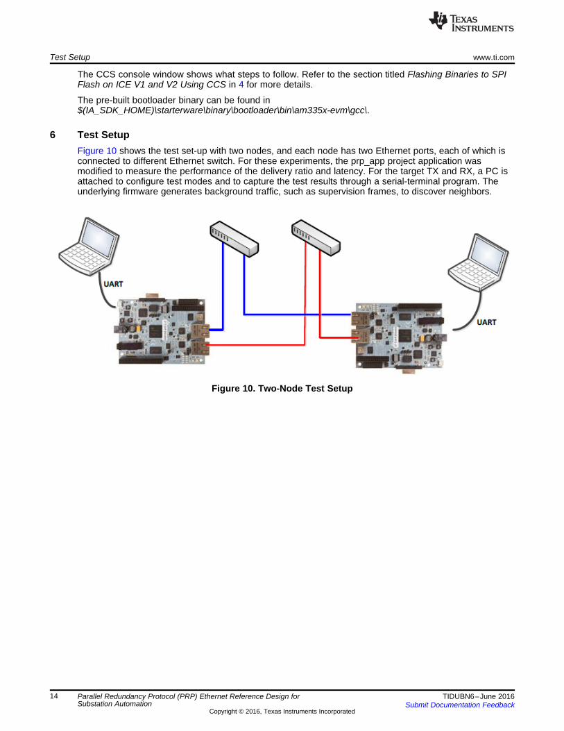
6 Test SetupFigure 10 shows the test set-up with two nodes, and each node has two Ethernet ports, each of which isconnected to different Ethernet switch. For these experiments, the prp_app project application wasmodified to measure the performance of the delivery ratio and latency. For the target TX and RX, a PC isattached to configure test modes and to capture the test results through a serial-terminal program. Theunderlying firmware generates background traffic, such as supervision frames, to discover neighbors.
Figure 10. Two-Node Test Setup
www.ti.com Test Data
15TIDUBN6–June 2016Submit Documentation Feedback
Copyright © 2016, Texas Instruments Incorporated
Parallel Redundancy Protocol (PRP) Ethernet Reference Design forSubstation Automation
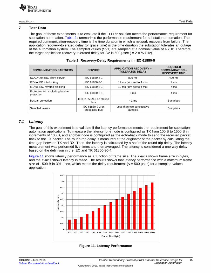
7 Test DataThe goal of these experiments is to evaluate if the TI PRP solution meets the performance requirement forsubstation automation. Table 2 summarizes the performance requirement for substation automation. Therequired communication-recovery time is the time duration in which a network recovers from failure. Theapplication recovery-tolerated delay (or grace time) is the time duration the substation tolerates an outageof the automation system. The sampled values (SVs) are sampled at a nominal value of 4 kHz. Therefore,the target application recovery-tolerated delay for SV is 500 µsec ( = 2 × ¼ kHz).
Table 2. Recovery-Delay Requirements in IEC 61850-5
COMMUNICATING PARTNERS SERVICE APPLICATION RECOVERY –TOLERATED DELAY
REQUIREDCOMMUNICATION –
RECOVERY TIMESCADA to IED, client-server IEC 61850-8-1 800 ms 400 msIED to IED interlocking IEC 61850-8-1 12 ms (trim set to 4 ms) 4 msIED to IED, reverse blocking IEC 61850-8-1 12 ms (trim set to 4 ms) 4 msProtection trip excluding busbarprotection IEC 61850-8-1 8 ms 4 ms
Busbar protection IEC 61850-9-2 on stationbus < 1 ms Bumpless
Sampled values IEC 61850-9-2 onprocessed bus
Less than two consecutivesamples Bumpless
7.1 LatencyThe goal of this experiment is to validate if the latency performance meets the requirement for substation-automation applications. To measure the latency, one node is configured as TX from 100 B to 1500 B inincrements of 100 B, and another node is configured as the echo-back mode to send the received packetback to the TX packet. The round-trip delay is measured at the originator of the packet by calculating thetime gap between TX and RX. Then, the latency is calculated by a half of the round-trip delay. The latencymeasurement was performed five times and then averaged. The latency is considered a one-way delaybased on the definition in the IEC and TR 61850-90-4.
Figure 11 shows latency performance as a function of frame size. The X-axis shows frame size in bytes,and the Y-axis shows latency in msec. The results shows that latency performance with a maximum framesize of 1500 B in 391 usec, which meets the delay requirement (< = 500 µsec) for a sampled-valuesapplication.
Figure 11. Latency Performance

Test Data www.ti.com
16 TIDUBN6–June 2016Submit Documentation Feedback
Copyright © 2016, Texas Instruments Incorporated
Parallel Redundancy Protocol (PRP) Ethernet Reference Design forSubstation Automation
7.2 Delivery RatioThe goal of this experiment is to verify the zero network-recovery time requirements for substationautomation. The delivery ratio performance was measured while emulating the link failures bydisconnecting a link intentionally in the middle of data transmissions.
For this experiment, TX node sent 10,000 packets with a 1528-B frame size and a 1-msec packet interval.During the experiment, one of links was disconnected to emulate link failure. To further verify the impact ofpacket types on delivery ratio, the same experiment was performed for unicast and broadcast traffic. Thedelivery ratio was calculated by the number of TX packets divided by the number of RX packets.
Table 3 shows delivery ratio performance. For all scenarios, the results show a 100% delivery ratio withlink failure. This result means that link failure is recovered immediately. This result is expected becauseredundant communication recovers the link failure immediately.
Table 3. Delivery Ratio Performance
TEST SCENARIO DELIVERY RATIOUnicast 100%
Broadcast 100%
www.ti.com Design Files
17TIDUBN6–June 2016Submit Documentation Feedback
Copyright © 2016, Texas Instruments Incorporated
Parallel Redundancy Protocol (PRP) Ethernet Reference Design forSubstation Automation
8 Design Files
8.1 SchematicsTo download the schematics, see the design files at TIDEP0054.
white space
8.2 Bill of MaterialsTo download the bill of materials (BOM), see the design files at TIDEP0054.
8.2.1 Layout PrintsTo download the layer plots, see the design files at TIDEP0054.
8.2.2 Assembly DrawingsTo download the assembly drawings, see the design files at TIDEP0054.
9 Software FilesTo download the software files, see the design files at sysbiossdk-ind-sitara.
10 References
1. AM335x Sitara™ Processors (AM3359)2. Texas Instruments, PHYTER ® Industrial Temperature 10/100Mbs Ethernet Physical Layer
Transceiver, PHYTER® data sheet (TLK110)3. Texas Instruments, TPS65910x Integrated Power-Management Unit Top Specification, TPS65910x
data sheet (SWCS046)4. Texas Instruments, SYSBIOS Industrial SDK Getting Started Guide, SYSBIOS guide (SYSBIOS)5. Texas Instruments, SYSBIOS Industrial Software Development Kit (SDK) for Sitara™ Processors,
Software-development kit (SYSBIOSSDK-IND-SITARA)6. Texas Instruments, ICSS EMAC LLD Developers Guide, ICSS EMAC guide (ICSS_EMAC_LLD)7. Texas Instruments, Network Developer's Kit (NDK) Support Package Ethernet Driver, Design guide
(SPRUFP2)8. Texas Instruments, High-availability Seamless Redundancy (HSR) Ethernet for Substation Automation
Reference Design, TI Design (TIDUB08)9. Texas Instruments, 10/100 Mbps Industrial Ethernet Brick with IEEE 1588 Precision Time Protocol
(PTP) Transceiver, TI Design (TIDUAT6)
11 About the AuthorWONSOO KIM is a systems engineer at Texas Instruments, where he is responsible for driving systemsolutions for Smart Grid applications, defining future requirements in TI product roadmaps, and providingsystem-level support and training focusing on communication software and systems for Smart Gridcustomers. He received his Ph.D. degree in Electrical and Computer Engineering from the University ofTexas at Austin in Austin, TX.

IMPORTANT NOTICE FOR TI REFERENCE DESIGNS
Texas Instruments Incorporated (‘TI”) reference designs are solely intended to assist designers (“Designer(s)”) who are developing systemsthat incorporate TI products. TI has not conducted any testing other than that specifically described in the published documentation for aparticular reference design.TI’s provision of reference designs and any other technical, applications or design advice, quality characterization, reliability data or otherinformation or services does not expand or otherwise alter TI’s applicable published warranties or warranty disclaimers for TI products, andno additional obligations or liabilities arise from TI providing such reference designs or other items.TI reserves the right to make corrections, enhancements, improvements and other changes to its reference designs and other items.Designer understands and agrees that Designer remains responsible for using its independent analysis, evaluation and judgment indesigning Designer’s systems and products, and has full and exclusive responsibility to assure the safety of its products and compliance ofits products (and of all TI products used in or for such Designer’s products) with all applicable regulations, laws and other applicablerequirements. Designer represents that, with respect to its applications, it has all the necessary expertise to create and implementsafeguards that (1) anticipate dangerous consequences of failures, (2) monitor failures and their consequences, and (3) lessen thelikelihood of failures that might cause harm and take appropriate actions. Designer agrees that prior to using or distributing any systemsthat include TI products, Designer will thoroughly test such systems and the functionality of such TI products as used in such systems.Designer may not use any TI products in life-critical medical equipment unless authorized officers of the parties have executed a specialcontract specifically governing such use. Life-critical medical equipment is medical equipment where failure of such equipment would causeserious bodily injury or death (e.g., life support, pacemakers, defibrillators, heart pumps, neurostimulators, and implantables). Suchequipment includes, without limitation, all medical devices identified by the U.S. Food and Drug Administration as Class III devices andequivalent classifications outside the U.S.Designers are authorized to use, copy and modify any individual TI reference design only in connection with the development of endproducts that include the TI product(s) identified in that reference design. HOWEVER, NO OTHER LICENSE, EXPRESS OR IMPLIED, BYESTOPPEL OR OTHERWISE TO ANY OTHER TI INTELLECTUAL PROPERTY RIGHT, AND NO LICENSE TO ANY TECHNOLOGY ORINTELLECTUAL PROPERTY RIGHT OF TI OR ANY THIRD PARTY IS GRANTED HEREIN, including but not limited to any patent right,copyright, mask work right, or other intellectual property right relating to any combination, machine, or process in which TI products orservices are used. Information published by TI regarding third-party products or services does not constitute a license to use such productsor services, or a warranty or endorsement thereof. Use of the reference design or other items described above may require a license from athird party under the patents or other intellectual property of the third party, or a license from TI under the patents or other intellectualproperty of TI.TI REFERENCE DESIGNS AND OTHER ITEMS DESCRIBED ABOVE ARE PROVIDED “AS IS” AND WITH ALL FAULTS. TI DISCLAIMSALL OTHER WARRANTIES OR REPRESENTATIONS, EXPRESS OR IMPLIED, REGARDING THE REFERENCE DESIGNS OR USE OFTHE REFERENCE DESIGNS, INCLUDING BUT NOT LIMITED TO ACCURACY OR COMPLETENESS, TITLE, ANY EPIDEMIC FAILUREWARRANTY AND ANY IMPLIED WARRANTIES OF MERCHANTABILITY, FITNESS FOR A PARTICULAR PURPOSE, AND NON-INFRINGEMENT OF ANY THIRD PARTY INTELLECTUAL PROPERTY RIGHTS.TI SHALL NOT BE LIABLE FOR AND SHALL NOT DEFEND OR INDEMNIFY DESIGNERS AGAINST ANY CLAIM, INCLUDING BUT NOTLIMITED TO ANY INFRINGEMENT CLAIM THAT RELATES TO OR IS BASED ON ANY COMBINATION OF PRODUCTS ASDESCRIBED IN A TI REFERENCE DESIGN OR OTHERWISE. IN NO EVENT SHALL TI BE LIABLE FOR ANY ACTUAL, DIRECT,SPECIAL, COLLATERAL, INDIRECT, PUNITIVE, INCIDENTAL, CONSEQUENTIAL OR EXEMPLARY DAMAGES IN CONNECTION WITHOR ARISING OUT OF THE REFERENCE DESIGNS OR USE OF THE REFERENCE DESIGNS, AND REGARDLESS OF WHETHER TIHAS BEEN ADVISED OF THE POSSIBILITY OF SUCH DAMAGES.TI’s standard terms of sale for semiconductor products (http://www.ti.com/sc/docs/stdterms.htm) apply to the sale of packaged integratedcircuit products. Additional terms may apply to the use or sale of other types of TI products and services.Designer will fully indemnify TI and its representatives against any damages, costs, losses, and/or liabilities arising out of Designer’s non-compliance with the terms and provisions of this Notice.IMPORTANT NOTICE
Mailing Address: Texas Instruments, Post Office Box 655303, Dallas, Texas 75265Copyright © 2016, Texas Instruments Incorporated


