
Phased array UT Probes and Wedges
Product Catalog
www.zetec.com
Standardized Designs and Advanced Technology

ZeTec, founded in 1968, is the leading provider of nondestructive evaluation (NDE) inspection solutions based on integrated multi-method technologies - eddy current, ultrasonic (UT), phased array UT, remote field, and magnetic flux leakage. The company portfolio includes a complete line of systems, instrumentation, software products, supplies, calibration, repair, training, and inspection services, all offered worldwide. ZeTec, a trusted partner in mission critical inspection applications, is headquartered in Snoqualmie, Washington with offices in Quebec City, Quebec, Canada; Seoul, Korea; Beijing, China; and Paris, France.
ZeTec’s innovative approach has completly redefined the potential of phased array UT technology by enabling highly efficient and more flexible inspection solutions. With a wealth of high-quality phased array UT instruments, ZeTec offers a complete line of standard phased array UT probes and wedges in order to get the most out of your system.
ZeTec has the expertise and engineering skills to support you for any challenging inspections with dedicated custom designs for your phased array UT probes and wedges.
For more information about ZeTec’s products and services:visit www.zetec.com or contact us at [email protected]
About ZETEC
ii www.zetec.com

Table of Contents
2 » UT » Systems » [email protected] iii
INTroDUCTIoN To PhaSED array UT...................................................................ivPhysical PrinciPles.................................................................................................ivPa Probe configUraTions......................................................................................ivbenefiTs of beam simUlaTion...................................................................................v
STaNDarD PhaSED array ProBES aND WEDgES..............................................vi
CUSTom PhaSED array ProBES aND WEDgES.................................................vii
gloSSSary................................................................................................................viii
NomENClaTUrE.........................................................................................................x
ProBES For aZImUThal SCaNNINg........................................................................1 as-5mhz..................................................................................................................2 as-7.5mhz................................................................................................................4 as-10mhz.................................................................................................................6 am-2.25mhz............................................................................................................8 am-3.5mhz.............................................................................................................10 am-5mhz................................................................................................................12 am-10mhz...............................................................................................................14 al-3.5mhz...............................................................................................................16 al-5mhz..................................................................................................................18 axl-1.5mhz.............................................................................................................20 axl-2.25mhz..........................................................................................................22
ProBES For lINEar SCaNNINg...........................................................................25 lm-2.25mhz...........................................................................................................26 lm-3.5mhz.............................................................................................................30 lm-5mhz................................................................................................................34 lm-10mhz...............................................................................................................38 ll-2.25mhz.............................................................................................................42 ll-3.55mhz.............................................................................................................46 ll-5mhz..................................................................................................................50 ll-10mhz................................................................................................................54
WEDgES For aZImUThal SCaNNINg....................................................................58
WEDgES For lINEar SCaNNINg............................................................................60
aDaPTErS, SPlITTErS aND oThEr aCCESSorIES................................................62

Introduction to Phased Array UT
iv www.zetec.com
Phased array (PA) technology allows to control the acoustic characteristics (refracted angle, focal distance, aperture, etc.) of ultrasonic beams through software. Compared to conventional ultrasonic testing (UT) methods, this opens a series of new possibilities:
• Multiple refracted angles and focal distances can be generated simultaneously by a single search unit;
• Ultrasonic beams can be electronically moved over the length of the PA probe, without any mechanical movement;
• By using multiple ultrasonic beams, the probability of detection can be increased;• Automated or semi-automated inspection methods can be implemented more
efficiently.
Zetec offers a complete line of inspection systems and probes which allow you to fully exploit the capabilities of PA UT and help you perform more efficient and reliable inspections.
PhySICal PrINCIPlESA phased array probe consists of a series of piezo-composite elements, which can be excited independently one from the others. By precisely controlling the time delays between the excita-tion of the individual elements, ultrasonic beams of various angles, focal distances and aperture can be transmitted in the inspected specimen. The returning echo from a reflector is detected by each elements of the PA probe at a slightly dif-ferent time. The individual echo signals are then time-shifted before being summed up. The result of this process is an a-scan that emphasizes the response from the desired focal point.
Beam Emission
Signal Reception
Focal point
Trigger signal
Elements
Beam generationDelayed trigger signals
TotalA-scan signal
Applied delays
Pa ProBE CoNFIgUraTIoNSZetec’s standard probes are offered in two main configurations:
• Azimuthal:Probesthatareoptimizedtoproducemultiplerefractedbeamangles
Linear scanning direction
1 27...
• Linear:Longtransducersthatareoptimizedforelectronicallymovingtheactiveaperturealongtheprobe
Active group
Active group
Multiple refracted beam angles

2 » UT » Systems » [email protected] v
BENEFIT oF BEam SImUlaTIoNAcoustic beam simulation allows you to compute, visualize and characterize the energy distribution of the acoustic beam generated by your phased array probe.
The UltraVision® software offers all the tools to validate your acoustic beam characteristics for inspection of both simple specimens and more complex surfaces.
In order to make it easy for you to select the phased array probe(s) that you need for your specific inspections, this catalog shows acoustic beam simulations of typical LW and SW configurations with each of our standard phased array probes, in the case of natural focusing conditions, and relevant quanti-tative information about the acoustic field is provided.

Standard Phased Array Probes and Wedges
vi www.zetec.com
ProBESZetec’s standard phased array UT probes are offered in 6 different sizes. Special care was put in their design in order to provide you with an ergonomic casing with captive skrews for easy fixation on wedges or scanning mechanism.
The frequencies of the standard probes range from 1.5 to 10 MHz, covering a wide spectrum of applica-tions: inspection of thin welded parts, inspection of thick stainless steel specimens, efficient corrosion mapping for large inspection surfaces, etc.
When used with Zetec’s ZIRCON™ 32/128PR PA equipment and the UltraVision® software, you can take advantage of the auto probe recognition in order to quickly and easily upload all your essential probe parameters thus simplifying your setup creation process.
All probes come with a standard 5-meter (16.4-foot) cable and can be equipped with various types of connectors. A series of connector adaptors and splitters are also available to allow the operation of the probes on multiple equipments.
WEDgESZetec also offers a complete line of wedges to complement its phased array UT probes. Designed to tackle a number of applications, the wedges come equipped with irrigation and easy fixation points for easy interface with a scanning mechanism.
Although all wedges listed here are designed for flat specimens, you can ask for custom contouring of the contact surface for cylinder shape parts.
Irrigation
Probe Fixationpoints
Wedge Grip Points

2 » UT » Systems » [email protected] vii
Custom Phased Array Probes and Wedges
In addition to the standard probe models, Zetec can provide you with engineering services for design and manufacturing of custom phased array probes and wedges or minor modifica-tions to standard probes and wedges.
Zetec has the expertise and experience to assist you in deter-mining the most appropriate transducers and wedges for your inspection.
Regardless of the application, Zetec is able to provide you the probes and wedges you need:
• 1D Linear and 2D Matrix arrays• Dual configuration of 1D Linear and 2D Matrix arrays• Low-frequency probes• Dedicated contour wedges• And much more...
Flexible Probes
Dual Array Configurations
2D Matrix Arrays

viii www.zetec.com
Glossary
The following definitions contain all the essential information necessary to understand the different parameters of phased array probes and wedges.
• FrequencyTheoretical central frequency of the ultrasonic pulse generated by your probe
• Primary axisAxis along which the individual elements are aligned for 1D linear probe
• Secondary axisAxis perpendicular to the primary axis of a probe
• Number of Elements (Primary axis)Total number of elements aligned along the primary axis
• Number of Elements (Secondary axis)Total number of elements aligned along the secondary axis (2D Matrix Array only)
• Primary axis Pitch
Center-to-center distance between two consecutive elements along the primary axis
• Secondary axis PitchCenter-to-center distance between two consecutive elements along the secondary axis (2D Matrix Array only)
• Primary axis apertureDimension of the probe surface along the primary axis
• Secondary axis apertureDimension of the probe surface along the secondary axis
Primary axis
Secondary axis
Primary axis pitch
First element
Seco
ndar
y ax
is w
idth
1D linear array
2D matrix array
Primary axis
Secondary axis
Primary axis pitch
First element
Seco
ndar
y ax
is p
itch
Primary axisactive aperture
Secondary axisactive aperture
Primary Axis Aperture
Secondary Axis Aperture

• active apertureGroup of elements effectively used for the generation and reception of an ultrasonic beam
• Near Field lengthDistance along the beam axis from the probe surface to the position where the maximum sound field intensity is reached
• maximum Sound Field Depth
Depth at which the maximum sound field intensity on the beam axis is reached
• Focal Zone length
Distance along the beam axis between the positions before and beyond the focal point (maximum intensity) where the sound field intensity is reduced by 6 dB
• Wedge angleAngle between the primary axis of the probe and the flat projection of the specimen surface along the mechanical axis (scan or index)
• height at the middle of the First Element (h1)Height of the first element of the probe when placed on a wedge
• Primary axis offset at the middle of the First Element (X1)Position along the primary axis of the first element of the probe from the wedge reference
• Secondary axis offset at the middle of the First Element (y1)Position along the secondary axis of the first element of the probe from the wedge reference
Maximum Sound Field Depth
Focal Zone Length
Beam Axis
Surface Projection
Primary Axis
Center of FirstElement
Wedge Angle > 0°
Height at the Middleof the First Element
MechanicalReference
WedgeReference
Secondary Axis Position of
Wedge Reference
Primary Axis Offset of the Middle of the First Element > 0
Primary Axis Position of
Wedge Reference
Secondary Axis Offset of the Middle of the
First Element > 0
Center of First Element

x www.zetec.com
Nomenclature
ProbesA S - 5MHz - YYYY
Probe Type Casing Type Probe Frequency Connector Type
AzimuthalLinear
SmallMedium
LargeX-Large
ZIRCONDYNARAY
WedgesA S - 55 LW
Probe Type Casing Type Nominal Refracted Angle in Steel Optimized Wave Type
AzimuthalLinear
SmallMedium
LargeX-Large
Longitudinal WavesShear Waves
Probe Type Casing Type Frequency(MHz)
Number of Elements
Page
Type A Small 5.0 12 2
7.5 12 4
10.0 16 6
Type A Medium 2.25 16 8
3.5 16 10
5.0 16 12
10.0 32 14
Type A Large 3.5 32 16
5.0 32 18
Type A X-Large 1.5 32 20
2.25 32 22
Type L Medium 2.25 64 26
3.5 64 30
5.0 64 34
10.0 64 38
Type L Large 2.25 128 42
3.5 128 46
5.0 128 50
10.0 128 54


2 www.zetec.com
Probes for Azimuthal Scanning
Probe Specifications and Dimensions
Part IDFrequency
(MHz)Number of elements
Primary axisPitch
Primary axis aperture
Secondary axis aperture
External dimensions
L W H
AS-5MHz-* 5.0 120.6 mm
(0.024 in.)7.2 mm
(0.283 in.)7.2 mm
(0.283 in.)11.0 mm
(0.433 in.)30.0 mm(1.181 in.)
25.0 mm(0.984 in.)
Type A - Small - 5 MHz
LW
H
recommended Wedges
Part ID Wave type Name Nominal angle in steelOptimized refracted beam
angle range (in steel)
AS-55LW LW Type A - Small / 55LW 55° 30° to 70°
AS-55SW SW Type A - Small / 55SW 55° 40° to 70°
16.3 mm(0.642 in.)
10.17 mm(0.400 in.)
30.00 mm(1.181 in.)
30.00 mm(1.181 in.)
17.2 mm(0.677 in.)
16.86 mm(0.664 in.)
Type a - Small / 55SW Type a - Small / 55lW(*) : -ZIrCoN or -DyNaray
Features & Benefits• Smallfootprint
• Optimizedforthinweldedparts
• WavelayerswithacousticadaptationtoRexolite®
• Probecablelength:5m(16ft.)
• Twoconnectortypesavailable:ZIRCONandDYNARAYcompatible

acoustic Beam Simulation
Longitudinal Waves Shear Waves
0
25
5045°
60°
acoustic Beam Characteristics (from Simulation Data)
Considered active aperture 12 elements (1 to 12)
angle 45° 60°
Wave Type LW SW LW SW
maximum Sound Field Depth 5.00mm(0.197in.)
12.00mm(0.472in.)
2.00mm(0.079in.)
7.00mm(0.275in.)
Focal Zone length 20.49mm(0.807in)
44.55mm(1.754in.)
16.10mm(0.634in.)
40.92mm(1.611in.)
Dimension in the Incident Plane 2.40mm(0.094in.)
2.45mm(0.085in.)
2.64mm(0.096in.)
2.77mm(0.109in.)
Dimension in the Perpendicular Plane
4.00mm(0.157in.)
4.00mm(0.157in.)
4.00(mm)(0.157in.)
4.00mm(0.157in.)
0 25 50
0
25
5045°
60°
0 25 50(mm) (mm)

4 www.zetec.com
Probes for Azimuthal Scanning
Probe Specifications and Dimensions
Part IDFrequency
(MHz)Number of elements
Primary axisPitch
Primary axis aperture
Secondary axis aperture
External dimensions
L W H
AS-7.5MHz-* 7.5 120.6 mm
(0.024 in.)7.2 mm
(0.283 in.)7.2 mm
(0.283 in.)11.0 mm
(0.433 in.)30.0 mm(1.181 in.)
25.0 mm(0.984 in.)
Type A - Small - 7.5 MHz
LW
H
Features & Benefits• Smallfootprint
• Optimizedforthinweldedparts
• WavelayerswithacousticadaptationtoRexolite®
• Probecablelength:5m(16ft.)
• Twoconnectortypesavailable:ZIRCONandDYNARAYcompatible
Type a - Small / 55SW Type a - Small / 55lW
16.3 mm(0.642 in.)
10.17 mm(0.400 in.)
30.00 mm(1.181 in.)
30.00 mm(1.181 in.)
17.2 mm(0.677 in.)
16.86 mm(0.664 in.)
(*) : -ZIrCoN or -DyNaray
recommended Wedges
Part ID Wave type Name Nominal angle in steelOptimized refracted beam
angle range (in steel)
AS-55LW LW Type A - Small / 55LW 55° 30° to 70°
AS-55SW SW Type A - Small / 55SW 55° 40° to 70°

[email protected] [email protected] 5
acoustic Beam Simulation
Longitudinal Waves Shear Waves
0
25
5045°
60°
acoustic Beam Characteristics (from Simulation Data)
Considered active aperture 12 elements (1 to 12)
angle 45° 60°
Wave Type LW SW LW SW
maximum Sound Field Depth 10.00mm(0.394in.)
20.00mm(0.787in.)
2.00mm(0.079in.)
7.00mm(0.275in.)
Focal Zone length 33.94mm(1.336in.)
64.35mm(2.533in.)
25.72mm(1.013in.)
58.85mm(2.317in.)
Dimension in the Incident Plane 2.27mm(0.089in.)
2.40mm(0.094in.)
2.50mm(0.098in.)
2.66mm(0.105in.)
Dimension in the Perpendicular Plane
4.00mm(0.157in.)
4.00mm(0.157in.)
5.00(mm)(0.197in.)
5.00mm(0.197in.)
0 25 50
0
25
5045°
60°
0 25 50(mm) (mm)

6 www.zetec.com
Probes for Azimuthal Scanning
Probe Specifications and Dimensions
Part IDFrequency
(MHz)Number of elements
Primary axisPitch
Primary axis aperture
Secondary axis aperture
External dimensions
L W H
AS-10MHz-* 10.0 160.31 mm(0.012 in.)
4.96 mm(0.195 in.)
5.00 mm(0.197 in.)
11.0 mm(0.433 in.)
30.0 mm(1.181 in.)
25.0 mm(0.984 in.)
Type A - Small - 10 MHz
LW
H
Type a - Small / 55SW Type a - Small / 55lW
16.3 mm(0.642 in.)
10.17 mm(0.400 in.)
30.00 mm(1.181 in.)
30.00 mm(1.181 in.)
17.2 mm(0.677 in.)
16.86 mm(0.664 in.)
(*) : -ZIrCoN or -DyNaray
Features & Benefits• Smallfootprint
• Optimizedforthinweldedparts
• WavelayerswithacousticadaptationtoRexolite®
• Probecablelength:5m(16ft.)
• Twoconnectortypesavailable:ZIRCONandDYNARAYcompatible
recommended Wedges
Part ID Wave type Name Nominal angle in steelOptimized refracted beam
angle range (in steel)
AS-55LW LW Type A - Small / 55LW 55° 30° to 70°
AS-55SW SW Type A - Small / 55SW 55° 40° to 70°

[email protected] [email protected] 7
acoustic Beam Simulation
Longitudinal Waves Shear Waves
0
25
5045°
60°
acoustic Beam Characteristics (from Simulation Data)
Considered active aperture 16 elements (1 to 16)
angle 45° 60°
Wave Type LW SW LW SW
maximum Sound Field Depth 4.50mm(0.177in.)
11.00mm(0.433in.)
2.00mm(0.079in.)
6.50mm(0.256in.)
Focal Zone length 18.73mm(0.737in.)
42.07mm(1.656in.)
14.31mm(0.563in.)
38.26mm(1.506in.)
Dimension in the Incident Plane 1.55mm(0.061in.)
1.87mm(0.074in.)
1.84mm(0.072in.)
1.91mm(0.075in.)
Dimension in the Perpendicular Plane
2.00mm(0.079in.)
2.00mm(0.079in.)
3.00(mm)(0.118in.)
3.00mm(0.118in.)
0 25 50
0
25
5045°
60°
0 25 50(mm) (mm)

8 www.zetec.com
Probes for Azimuthal Scanning
Probe Specifications and Dimensions
Part IDFrequency
(MHz)
Number of elements
(Primary axis)
Primary axisPitch(mm)
Primary axis aperture
Secondary axis aperture
External dimensions
L W H
AM-2.25MHz-* 2.25 160.75 mm(0.030 in.)
12.00 mm(0.472 in.)
12.00 mm(0.472 in.)
16.0 mm(0.630 in.)
30.0 mm(1.181 in.)
25.0 mm(0.984 in.)
recommended Wedges
Part ID Wave type Name Nominal angle in steelOptimized refracted beam
angle range (in steel)
AM-55LW LW Type A - Medium / 55LW 55° 30° to 70°
AM-55SW SW Type A - Medium / 55SW 55° 40° to 70°
23.50 mm(0.925 in.)
12.48 mm(0.491 in.)
30.00 mm(1.181 in.)
30.00 mm(1.181 in.)
25.00 mm(0.984 in.)
23.26 mm(0.916 in.)
Type a - medium / 55SW Type a - medium / 55lW
Type A - Medium - 2.25 MHz
LW
H
Features & Benefits• Smallfootprint
• Widerangeofapplications
• WavelayerswithacousticadaptationtoRexolite®
• Probecablelength:5m(16ft.)
• Twoconnectortypesavailable:ZIRCONandDYNARAYcompatible
(*) : -ZIrCoN or -DyNaray

[email protected] [email protected] 9
acoustic Beam Simulation
Longitudinal Waves Shear Waves
0
25
50
75 45°
60°
acoustic Beam Characteristics (from Simulation Data)
Considered active aperture 16 elements (1 to 16)
angle 45° 60°
Wave Type LW SW LW SW
maximum Sound Field Depth 5.50mm(0.217in.)
20.00mm(0.787in.)
2.00mm(0.079in.)
11.00mm(0.433in.)
Focal Zone length 26.47mm(1.042in.)
61.53mm(2.422in.)
20.90mm(0.823in.)
56.53mm(2.226in.)
Dimension in the Incident Plane 4.45mm(0.175in.)
4.50mm(0.177in.)
4.44mm(0.175in.)
4.90mm(0.193in.)
Dimension in the Perpendicular Plane
7.00mm(0.276in.)
6.00mm(0.236in.)
8.00(mm)(0.315in.)
8.00mm(0.315in.)
0 25 50 75 100
0
25
50
75 45°
60°
0 25 50 75 100(mm) (mm)

10 www.zeteccom
Probes for Azimuthal Scanning
Probe Specifications and Dimensions
Part IDFrequency
(MHz)Number of elements
Primary axisPitch
Primary axis aperture
Secondary axis aperture
External dimensions
L W H
AM-3.5MHz-* 3.5 160.60 mm(0.024 in.)
9.60 mm(0.378 in.)
10.00 mm(0.374 in.)
16.0 mm(0.630 in.)
30.0 mm(1.181 in.)
25.0 mm(0.984 in.)
Type a - medium / 55SW Type a - medium / 55lW
Type A - Medium - 3.5 MHz
LW
H
23.50 mm(0.925 in.)
12.48 mm(0.491 in.)
30.00 mm(1.181 in.)
30.00 mm(1.181 in.)
25.00 mm(0.984 in.)
23.26 mm(0.916 in.)
(*) : -ZIrCoN or -DyNaray
Features & Benefits• Smallfootprint
• Widerangeofapplications
• WavelayerswithacousticadaptationtoRexolite®
• Probecablelength:5m(16ft.)
• Twoconnectortypesavailable:ZIRCONandDYNARAYcompatible
recommended Wedges
Part ID Wave type Name Nominal angle in steelOptimized refracted beam
angle range (in steel)
AM-55LW LW Type A - Medium / 55LW 55° 30° to 70°
AM-55SW SW Type A - Medium / 55SW 55° 40° to 70°

[email protected] [email protected] 11
acoustic Beam Simulation
Longitudinal Waves Shear Waves
0
25
50
75 45°
60°
acoustic Beam Characteristics (from Simulation Data)
Considered active aperture 16 elements (1 to 16)
angle 45° 60°
Wave Type LW SW LW SW
maximum Sound Field Depth 6.50mm(0.256in.)
19.00mm(0.748in.)
1.00mm(0.039in.)
6.00mm(0.236in.)
Focal Zone length 28.25mm(1.112in.)
65.41mm(2.575in.)
22.91mm(0.902in.)
56.11mm(2.209in.)
Dimension in the Incident Plane 3.86mm(0.152in.)
3.88mm(0.153in.)
3.73mm(0.147in.)
3.89mm(0.153in.)
Dimension in the Perpendicular Plane
6.00mm(0.236in.)
6.00mm(0.236in.)
7.00(mm)(0.276in.)
6.00mm(0.236in.)
0 25 50 75 100
0
25
50
75 45°
60°
0 25 50 75 100(mm) (mm)

12 www.zetec.com
Probes for Azimuthal Scanning
Probe Specifications and Dimensions
Part IDFrequency
(MHz)Number of elements
Primary axisPitch
Primary axis aperture
Secondary axis aperture
External dimensions
L W H
AM-5MHz-* 5.0 160.60 mm(0.024 in.)
9.60 mm(0.378 in.)
10.00 mm(0.374 in.)
16.0 mm(0.630 in.)
30.0 mm(1.181 in.)
25.0 mm(0.984 in.)
Type a - medium / 55SW Type a - medium / 55lW
Type A - Medium - 5 MHz
LW
H
23.50 mm(0.925 in.)
12.48 mm(0.491 in.)
30.00 mm(1.181 in.)
30.00 mm(1.181 in.)
25.00 mm(0.984 in.)
23.26 mm(0.916 in.)
(*) : -ZIrCoN or -DyNaray
Features & Benefits• Smallfootprint
• Widerangeofapplications
• WavelayerswithacousticadaptationtoRexolite®
• Probecablelength:5m(16ft.)
• Twoconnectortypesavailable:ZIRCONandDYNARAYcompatible
recommended Wedges
Part ID Wave type Name Nominal angle in steelOptimized refracted beam
angle range (in steel)
AM-55LW LW Type A - Medium / 55LW 55° 30° to 70°
AM-55SW SW Type A - Medium / 55SW 55° 40° to 70°

[email protected] [email protected] 13
acoustic Beam Simulation
Longitudinal Waves Shear Waves
0
25
50
75 45°
60°
acoustic Beam Characteristics (from Simulation Data)
Considered active aperture 16 elements (1 to 16)
angle 45° 60°
Wave Type LW SW LW SW
maximum Sound Field Depth 12.00mm(0.472in.)
26.00mm(1.024in.)
2.50mm(0.098in.)
9.50mm(0.374in.)
Focal Zone length 43.83mm(1.726in.)
93.69mm(3.689in.)
32.40mm(1.276in.)
77.64mm(3.057in.)
Dimension in the Incident Plane 3.68mm(0.145in.)
4.24mm(0.167in.)
3.47mm(0.137in.)
3.92mm(0.154in.)
Dimension in the Perpendicular Plane
6.00mm(0.236in.)
7.00mm(0.276in.)
7.00(mm)(0.276in.)
7.00mm(0.276in.)
0 25 50 75 100
0
25
50
75 45°
60°
0 25 50 75 100(mm) (mm)

14 www.zetec.com
Probes for Azimuthal Scanning
Probe Specifications and Dimensions
Part IDFrequency
(MHz)Number of elements
Primary axisPitch
Primary axis aperture
Secondary axis aperture
External dimensions
L W H
AM-10MHz-* 10.0 320.31 mm(0.012 in.)
9.92 mm(0.391 in.)
10.00 mm(0.394 in.)
16.0 mm(0.630 in.)
30.0 mm(1.181 in.)
25.0 mm(0.984 in.)
Type a - medium / 55SW Type a - medium / 55lW
Type A - Medium - 10 MHz
LW
H
23.50 mm(0.925 in.)
12.48 mm(0.491 in.)
30.00 mm(1.181 in.)
30.00 mm(1.181 in.)
25.00 mm(0.984 in.)
23.26 mm(0.916 in.)
(*) : -ZIrCoN or -DyNaray
Features & Benefits• Smallfootprint
• Widerangeofapplications
• WavelayerswithacousticadaptationtoRexolite®
• Probecablelength:5m(16ft.)
• Twoconnectortypesavailable:ZIRCONandDYNARAYcompatible
recommended Wedges
Part ID Wave type Name Nominal angle in steelOptimized refracted beam
angle range (in steel)
AM-55LW LW Type A - Medium / 55LW 55° 30° to 70°
AM-55SW SW Type A - Medium / 55SW 55° 40° to 70°

[email protected] [email protected] 15
acoustic Beam Simulation
Longitudinal Waves Shear Waves
0
25
50
75 45°
60°
acoustic Beam Characteristics (from Simulation Data)
Considered active aperture 32 elements (1 to 32)
angle 45° 60°
Wave Type LW SW LW SW
maximum Sound Field Depth 29.00mm(1.142in.)
32.00mm(1.260in.)
7.00mm(0.276in.)
21.50mm(0.846in.)
Focal Zone length 95.81mm(3.772in.)
191.63mm(7.544in.)
69.14mm(2.722in.)
158.69mm(6.248in.)
Dimension in the Incident Plane 4.60mm(0.181in.)
5.30mm(0.209in.)
3.35mm(0.132in.)
4.37mm(0.172in.)
Dimension in the Perpendicular Plane
6.00mm(0.236in.)
7.00mm(0.276in.)
7.00(mm)(0.276in.)
8.00mm(0.315in.)
0 25 50 75 100
0
25
50
75 45°
60°
0 25 50 75 100(mm) (mm)

16 www.zetec.com
Probes for Azimuthal Scanning
Probe Specifications and Dimensions
Part IDFrequency
(MHz)Number of elements
Primary axisPitch
Primary axis aperture
Secondary axis aperture
External dimensions
L W H
AL-3.5MHz-* 3.5 320.60 mm(0.024 in.)
19.20 mm(0.756 in.)
15.00 mm(0.591 in.)
24.0 mm(0.945 in.)
33.0 mm(1.299 in.)
25.0 mm(0.984 in.)
recommended Wedges
Part ID Wave type Name Nominal angle in steelOptimized refracted beam
angle range (in steel)
AL-55LW LW Type A - Large / 55LW 55° 30° to 70°
AL-55SW SW Type A - Large / 55SW 55° 40° to 70°
38.20 mm(1.504 in.)
21.98 mm(0.865 in.)
33.00 mm(1.299 in.)
33.00 mm(1.299 in.)
41.40 mm(1.630 in.)
41.17 mm(1.621 in.)
Type a - large / 55SW Type a - large / 55lW
Type A - Large - 3.5 MHz
LW
H
Features & Benefits• Largeactiveapertureforhighacoustic
energy
• Adaptedforinspectionofthickcarbonsteelspecimens
• WavelayerswithacousticadaptationtoRexolite®
• Probecablelength:5m(16ft.)
• Twoconnectortypesavailable:ZIRCONandDYNARAYcompatible
(*) : -ZIrCoN or -DyNaray

[email protected] [email protected] 17
acoustic Beam Simulation
Longitudinal Waves Shear Waves
0
50
100
150 45°
60°
acoustic Beam Characteristics (from Simulation Data)
Considered active aperture 32 elements (1 to 32)
angle 45° 60°
Wave Type LW SW LW SW
maximum Sound Field Depth 24.00mm(0.945in.)
54.50mm(2.146in.)
11.00mm(0.433in.)
29.00mm(1.142in.)
Focal Zone length 81.31mm(3.201in.)
165.46mm(6.514in.)
67.25mm(2.647in.)
145.42mm(5.725in.)
Dimension in the Incident Plane 6.39mm(0.252in.)
6.72mm(0.265in.)
5.64mm(0.222in.)
6.02mm(0.237in.)
Dimension in the Perpendicular Plane
6.00mm(0.236in.)
6.00mm(0.236in.)
8.00(mm)(0.315in.)
8.00mm(0.315in.)
0 50 100 150 200
45°
60°
0 50 100 200150
0
50
100
150
(mm) (mm)

18 www.zetec.com
Probes for Azimuthal Scanning
Probe Specifications and Dimensions
Part IDFrequency
(MHz)Number of elements
Primary axisPitch
Primary axis aperture
Secondary axis aperture
External dimensions
L W H
AL-5MHz-* 5.0 320.60 mm(0.024 in.)
19.20 mm(0.756 in.)
15.00 mm(0.591 in.)
24.0 mm(0.945 in.)
33.0 mm(1.299 in.)
25.0 mm(0.984 in.)
Type a - large / 55SW Type a - large / 55lW
Type A - Large - 5 MHz
LW
H
38.20 mm(1.504 in.)
21.98 mm(0.865 in.)
33.00 mm(1.299 in.)
33.00 mm(1.299 in.)
41.40 mm(1.630 in.)
41.17 mm(1.621 in.)
(*) : -ZIrCoN or -DyNaray
Features & Benefits• Largeactiveapertureforhighacoustic
energy
• Adaptedforinspectionofthickcarbonsteelspecimens
• WavelayerswithacousticadaptationtoRexolite®
• Probecablelength:5m(16ft.)
• Twoconnectortypesavailable:ZIRCONandDYNARAYcompatible
recommended Wedges
Part ID Wave type Name Nominal angle in steelOptimized refracted beam
angle range (in steel)
AL-55LW LW Type A - Large / 55LW 55° 30° to 70°
AL-55SW SW Type A - Large / 55SW 55° 40° to 70°

[email protected] [email protected] 19
acoustic Beam Simulation
Longitudinal Waves Shear Waves
0
50
100
150 45°
60°
acoustic Beam Characteristics (from Simulation Data)
Considered active aperture 32 elements (1 to 32)
angle 45° 60°
Wave Type LW SW LW SW
maximum Sound Field Depth 39.00mm(1.535in.)
73.50mm(2.894in.)
18.00mm(0.709in.)
43.50mm(1.713in.)
Focal Zone length 120.56mm(4.746in.)
221.68mm(8.728in.)
99.95mm(3.935in.)
208.55mm(8.211in.)
Dimension in the Incident Plane 6.39mm(0.252in.)
6.03mm(0.237in.)
5.90mm(0.232in.)
6.52mm(0.257in.)
Dimension in the Perpendicular Plane
7.00mm(0.276in.)
6.00mm(0.236in.)
9.00(mm)(0.354in.)
9.00mm(0.354in.)
0 50 100 150 200
45°
60°
0 50 100 200150
0
50
100
150
(mm) (mm)

20 www.zetec.com
Probes for Azimuthal Scanning
Probe Specifications and Dimensions
Part IDFrequency
(MHz)
Number of elements
(Primary axis)
Primary axisPitch
Primary axis aperture
Secondary axis aperture
External dimensions
L W H
AXL-1.5MHz-* 1.5 321.00 mm(0.039 in.)
32.00 mm(1.260 in.)
20.00 mm(0.787 in.)
36.0 mm(1.417 in.)
38.0 mm(1.496 in.)
25.0 mm(0.984 in.)
recommended Wedges
Part ID Wave type Name Nominal angle in steelOptimized refracted beam
angle range (in steel)
AXL-55LW LW Type A - Xlarge / 55LW 55° 30° to 70°
AXL-55SW SW Type A - Xlarge / 55SW 55° 40° to 70°
58.70 mm(2.311 in.)
33.77 mm(1.330 in.)
38.00 mm(1.496 in.)
38.00 mm(1.496 in.)
62.40 mm(2.457 in.)
65.57 mm(2.581 in.)
Type a - Xlarge / 55SW Type a - Xlarge / 55lW
Type A - X-Large - 1.5 MHz
LW
H
(*) : -ZIrCoN or -DyNaray
Features & Benefits• Largeactiveapertureforhighacoustic
energy
• Adaptedforinspectionofthickstainlesssteelspecimens
• WavelayerswithacousticadaptationtoRexolite®
• Probecablelength:5m(16ft.)
• Twoconnectortypesavailable:ZIRCONandDYNARAYcompatible

[email protected] [email protected] 21
acoustic Beam Simulation
Longitudinal Waves Shear Waves
0
50
100 45°
60°
acoustic Beam Characteristics (from Simulation Data)
Considered active aperture 32 elements (1 to 32)
angle 45° 60°
Wave Type LW SW LW SW
maximum Sound Field Depth 18.00mm(0.709in.)
56.50mm(2.224in.)
6.50mm(0.256in.)
29.00mm(1.142in.)
Focal Zone length 85.95mm(3.384in.)
175.75mm(6.919in.)
61.50mm(2.421in.)
161.46mm(6.357in.)
Dimension in the Incident Plane 13.75mm(0.541in.)
14.65mm(0.577in.)
8.98mm(0.354in.)
8.65mm(0.341in.)
Dimension in the Perpendicular Plane
10.00mm(0.394in.)
10.00mm(0.394in.)
8.00(mm)(0.315in.)
8.00mm(0.315in.)
0 50 100-50 150
45°
60°
0 50 100-50 150
0
50
100
(mm) (mm)

22 www.zetec.com
Probes for Azimuthal Scanning
Probe Specifications and Dimensions
Part IDFrequency
(MHz)
Number of elements
(Primary axis)
Primary axisPitch
Primary axis aperture
Secondary axis aperture
External dimensions
L W H
AXL-2.25MHz-* 2.25 321.00 mm(0.039 in.)
32.00 mm(1.260 in.)
20.00 mm(0.787 in.)
36.0 mm(1.417 in.)
38.0 mm(1.496 in.)
25.0 mm(0.984 in.)
Type a - Xlarge / 55SW Type a - Xlarge / 55lW
Type A - X-Large - 2.25 MHz
LW
H
58.70 mm(2.311 in.)
33.77 mm(1.330 in.)
38.00 mm(1.496 in.)
38.00 mm(1.496 in.)
62.40 mm(2.457 in.)
65.57 mm(2.581 in.)
(*) : -ZIrCoN or -DyNaray
Features & Benefits• Largeactiveapertureforhighacoustic
energy
• Adaptedforinspectionofthickstainlesssteelspecimens
• WavelayerswithacousticadaptationtoRexolite®
• Probecablelength:5m(16ft.)
• Twoconnectortypesavailable:ZIRCONandDYNARAYcompatible
recommended Wedges
Part ID Wave type Name Nominal angle in steelOptimized refracted beam
angle range (in steel)
AXL-55LW LW Type A - Xlarge / 55LW 55° 30° to 70°
AXL-55SW SW Type A - Xlarge / 55SW 55° 40° to 70°

[email protected] [email protected] 23
acoustic Beam Simulation
Longitudinal Waves Shear Waves
0
50
100
150
(mm)
45°
60°
acoustic Beam Characteristics (from Simulation Data)
Considered active aperture 32 elements (1 to 32)
angle 45° 60°
Wave Type LW SW LW SW
maximum Sound Field Depth 33.00mm(1.299in.)
88.00mm(3.465in.)
14.50mm(0.571in.)
40.00mm(1.575in.)
Focal Zone length 124.46mm(4.900in.)
235.83mm(9.285in.)
82.94mm(3.265in.)
181.44mm(7.143in.)
Dimension in the Incident Plane 12.37mm(0.487in.)
12.70mm(0.500in.)
8.00mm(0.315in.)
8.02mm(0.316in.)
Dimension in the Perpendicular Plane
9.00mm(0.354in.)
10.00mm(0.394in.)
8.00(mm)(0.315in.)
8.00mm(0.315in.)
0 50 100 150 200-50(mm)
45°
60°
0 50 100-50 200150
0
50
100
150

24 www.zetec.com


26 www.zetec.com
Probes for Linear Scanning
Probe Specifications and Dimensions
Part IDFrequency
(MHz)
Number of elements
(Primary axis)
Primary axisPitch
Primary axis aperture
Secondary axis aperture
External dimensions
L W H
LM-2.25MHz-* 2.25 640.60 mm(0.024 in.)
38.40 mm(1.512 in.)
10.00 mm(0.394 in.)
43.0 mm(1.693 in.)
28.0 mm(1.102 in.)
25.0 mm(0.984 in.)
recommended Wedges
Part ID Wave type Name Nominal angle in steelOptimized refracted beam
angle range (in steel)
LM-0LW LW Type L - Medium / 0LW 0° -25° to 25°
LM-55LW LW Type L - Medium / 55LW 55° 40° to 70°
LM-55SW SW Type L - Medium / 55SW 55° 40° to 70°
Type L - Medium - 2.25 MHz
LW
H
(*) : -ZIrCoN or -DyNaray
Features & Benefits• Largeapertureforlinearscan
• Widerangeofapplications
• WavelayerswithacousticadaptationtoRexolite®
• Probecablelength:5m(16ft.)
• Twoconnectortypesavailable:ZIRCONandDYNARAYcompatible

Wedges Dimensions
30.00 mm(1.181 in.)
Type l - medium / 0lW
51.00 mm(2.037 in.)
Type l - medium / 55lW
57.70 mm(2.272 in.)
28.00 mm(1.102 in.)
28.00 mm(1.102 in.)
39.97 mm(1.574 in.)
28.00 mm(1.102 in.)
34.19 mm(1.346 in.)
63.80 mm(2.512 in.)
Type l - medium / 55SW

28 www.zetec.com
Probes for Linear Scanning
Type L - Medium - 2.25 MHz (continued)
0° - acoustic Beam Simulation
0
25
50
100
(mm) 0-25-50 25 50
45° - acoustic Beam Simulation
Longitudinal Waves Shear Waves
0
25
50
75
(mm)
45°
0
50
75
25
(mm)
45°
0 05025 5025-50 -25 -50 -25
0°

acoustic Beam Characteristics (from Simulation Data)
Considered active aperture 32 elements (17 to 48)
angle 0° 45° 60°
Wave Type LW LW SW LW SW
maximum Sound Field Depth 1.00mm(0.039in.)
10.00mm(0.394in.)
11.00mm(0.433in.)
4.00mm(0.157in.)
13.00mm(0.512in.)
Focal Zone length 46.50mm(1.831in.)
46.02mm(1.812in.)
93.37mm(3.676in.)
29.38mm(1.157in.)
69.23mm(2.726in.)
Dimension in the Incident Plane 14.00mm(0.551in.)
9.16mm(0.361in.)
10.62mm(0.418in.)
5.64mm(0.222in.)
7.53mm(0.296in.)
Dimension in the Perpendicular Plane
6.00mm(0.236in.)
6.00mm(0.236in.)
6.00mm(0.236in.)
4.00(mm)(0.157in.)
6.00mm(0.236in.)
60° - acoustic Beam Simulation
Longitudinal Waves Shear Waves
0
50
25
75
(mm)
60°
0-50 -25 5025
0
50
75
25
(mm)
60°
0-50 -25 5025

30 www.zetec.com
Probes for Linear Scanning
Probe Specifications and Dimensions
Part IDFrequency
(MHz)Number of elements
Primary axisPitch
Primary axis aperture
Secondary axis aperture
External dimensions
L W H
LM-3.5MHz-* 3.5 640.60 mm(0.024 in.)
38.40 mm(1.512 in.)
10.00 mm(0.394 in.)
43.0 mm(1.693 in.)
28.0 mm(1.102 in.)
25.0 mm(0.984 in.)
Type L - Medium - 3.5 MHz
(*) : -ZIrCoN or -DyNaray
Features & Benefits• Largeapertureforlinearscan
• Widerangeofapplications
• WavelayerswithacousticadaptationtoRexolite®
• Probecablelength:5m(16ft.)
• Twoconnectortypesavailable:ZIRCONandDYNARAYcompatibleLW
H
recommended Wedges
Part ID Wave type Name Nominal angle in steelOptimized refracted beam
angle range (in steel)
LM-0LW LW Type L - Medium / 0LW 0° -25° to 25°
LM-55LW LW Type L - Medium / 55LW 55° 40° to 70°
LM-55SW SW Type L - Medium / 55SW 55° 40° to 70°

Wedges Dimensions
30.00 mm(1.181 in.)
Type l - medium / 0lW
51.00 mm(2.037 in.)
Type l - medium / 55lW
57.70 mm(2.272 in.)
28.00 mm(1.102 in.)
28.00 mm(1.102 in.)
39.97 mm(1.574 in.)
28.00 mm(1.102 in.)
34.19 mm(1.346 in.)
63.80 mm(2.512 in.)
Type l - medium / 55SW

32 www.zetec.com
Probes for Linear Scanning
Type L - Medium - 3.5 MHz (continued)
0° - acoustic Beam Simulation
0
50
100
1500-50-100 50 100
45° - acoustic Beam Simulation
Longitudinal Waves Shear Waves
0
50
100
150 45°
0
50
100
150 45°
0 050 75 100 150 50 100 150 200-50 -50
0°
(mm)
(mm) (mm)

acoustic Beam Characteristics (from Simulation Data)
Considered active aperture 32 elements (17 to 48)
angle 0° 45° 60°
Wave Type LW LW SW LW SW
maximum Sound Field Depth 10.00mm(0.394in.)
18.00mm(0.709in.)
43.00mm(1.693in.)
8.00mm(0.315in.)
20.00mm(0.787in.)
Focal Zone length 82.00mm(3.228in.)
68.63mm(2.702in.)
142.85mm(5.624in.)
43.79mm(1.724in.)
97.49mm(3.838in.)
Dimension in the Incident Plane 14.00mm(0.551in.)
9.22mm(0.363in.)
10.59mm(0.417in.)
5.31mm(0.209in.)
7.08mm(0.279in.)
Dimension in the Perpendicular Plane
6.00mm(0.236in.)
6.00mm(0.236in.)
6.00mm(0.236in.)
4.00(mm)(0.157in.)
6.00mm(0.236in.)
60° - acoustic Beam Simulation
Longitudinal Waves Shear Waves
0
50
100
60°
0-50 50 100
0
50
100
60°
0-50 10050
(mm) (mm)

34 www.zetec.com
Probes for Linear Scanning
Probe Specifications and Dimensions
Part IDFrequency
(MHz)
Number of elements
(Primary axis)
Primary axisPitch
Primary axis aperture
Secondary axis aperture
External dimensions
L W H
LM-5MHz-* 5.0 640.60 mm(0.024 in.)
38.40 mm(1.512 in.)
10.00 mm(0.394 in.)
43.0 mm(1.693 in.)
28.0 mm(1.102 in.)
25.0 mm(0.984 in.)
Type L - Medium - 5 MHz
(*) : -ZIrCoN or -DyNaray
Features & Benefits• Largeapertureforlinearscan
• Widerangeofapplications
• WavelayerswithacousticadaptationtoRexolite®
• Probecablelength:5m(16ft.)
• Twoconnectortypesavailable:ZIRCONandDYNARAYcompatibleLW
H
recommended Wedges
Part ID Wave type Name Nominal angle in steelOptimized refracted beam
angle range (in steel)
LM-0LW LW Type L - Medium / 0LW 0° -25° to 25°
LM-55LW LW Type L - Medium / 55LW 55° 40° to 70°
LM-55SW SW Type L - Medium / 55SW 55° 40° to 70°

Wedges Dimensions
30.00 mm(1.181 in.)
Type l - medium / 0lW
51.00 mm(2.037 in.)
Type l - medium / 55lW
57.70 mm(2.272 in.)
28.00 mm(1.102 in.)
28.00 mm(1.102 in.)
39.97 mm(1.574 in.)
28.00 mm(1.102 in.)
34.19 mm(1.346 in.)
63.80 mm(2.512 in.)
Type l - medium / 55SW

36 www.zetec.com
Probes for Linear Scanning
Type L - Medium - 5 MHz (continued)
0° - acoustic Beam Simulation
0-50-100 50 100
45° - acoustic Beam Simulation
Longitudinal Waves Shear Waves
0
50
100
150
45°
0
50
100
150
45°
0 050 50-50 100-100 -50 100 150
0°
(mm)
(mm) (mm)
0
50
100
150

acoustic Beam Characteristics (from Simulation Data)
Considered active aperture 32 elements (17 to 48)
angle 0° 45° 60°
Wave Type LW LW SW LW SW
maximum Sound Field Depth 18.50mm(0.728in.)
28.00mm(1.102in.)
65.00mm(2.559in.)
12.00mm(0.472in.)
31.00mm(1.220in.)
Focal Zone length 126.50mm(4.980in.)
95.48mm(3.759in.)
199.41mm(7.851in.)
56.81mm(2.237in.)
130.23mm(5.127in.)
Dimension in the Incident Plane 14.00mm(0.551in.)
9.22mm(0.363in.)
10.60mm(0.417in.)
4.97mm(0.196in.)
6.61mm(0.260in.)
Dimension in the Perpendicular Plane
7.00mm(0.276in.)
6.00mm(0.236in.)
6.00mm(0.236in.)
4.00(mm)(0.157in.)
4.00mm(0.157in.)
60° - acoustic Beam Simulation
Longitudinal Waves Shear Waves
0
50
100
60°
0-50 50 100
60°
0-50 10050
0
50
100
(mm) (mm)

38 www.zetec.com
Probes for Linear Scanning
Probe Specifications and Dimensions
Part IDFrequency
(MHz)
Number of elements
(Primary axis)
Primary axisPitch
Primary axis aperture
Secondary axis aperture
External dimensions
L W H
LM-10MHz-* 10.0 640.60 mm(0.024 in.)
38.40 mm(1.512 in.)
10.00 mm(0.394 in.)
43.0 mm(1.693 in.)
28.0 mm(1.102 in.)
25.0 mm(0.984 in.)
Type L - Medium - 10 MHz
(*) : -ZIrCoN or -DyNaray
Features & Benefits• Largeapertureforlinearscan
• Widerangeofapplications
• WavelayerswithacousticadaptationtoRexolite®
• Probecablelength:5m(16ft.)
• Twoconnectortypesavailable:ZIRCONandDYNARAYcompatibleLW
H
recommended Wedges
Part ID Wave type Name Nominal angle in steelOptimized refracted beam
angle range (in steel)
LM-0LW LW Type L - Medium / 0LW 0° -25° to 25°
LM-55LW LW Type L - Medium / 55LW 55° 40° to 70°
LM-55SW SW Type L - Medium / 55SW 55° 40° to 70°

Wedges Dimensions
30.00 mm(1.181 in.)
Type l - medium / 0lW
51.00 mm(2.037 in.)
Type l - medium / 55lW
57.70 mm(2.272 in.)
28.00 mm(1.102 in.)
28.00 mm(1.102 in.)
39.97 mm(1.574 in.)
28.00 mm(1.102 in.)
34.19 mm(1.346 in.)
63.80 mm(2.512 in.)
Type l - medium / 55SW

40 www.zetec.com
Probes for Linear Scanning
Type L - Medium - 10 MHz (continued)
0° - acoustic Beam Simulation
45° - acoustic Beam Simulation
Longitudinal Waves Shear Waves
45° 45°
050 150 250 5025-50 -50 -25
0-50-150 50 150
0°
(mm)
0
100
200
300
0
100
200
(mm) (mm)
0
100
200

acoustic Beam Characteristics (from Simulation Data)
Considered active aperture 32 elements (17 to 48)
angle 0° 45° 60°
Wave Type LW LW SW LW SW
maximum Sound Field Depth 50.50mm(1.988in.)
60.00mm(2.362in.)
123.00mm(4.843in.)
26.00mm(1.024in.)
63.00mm(2.480in.)
Focal Zone length 267.00mm(10.512in.)
181.74mm(7.155in.)
296.28mm(11.665in.)
111.88mm(4.405in.)
209.12mm(8.233in.)
Dimension in the Incident Plane 15.00mm(0.591in.)
9.19mm(0.362in.)
7.80mm(0.307in.)
4.68mm(0.184in.)
5.17mm(0.204in.)
Dimension in the Perpendicular Plane
8.00mm(0.315in.)
4.00mm(0.157in.)
6.00mm(0.236in.)
4.00mm(0.157in.)
4.00mm(0.157in.)
60° - acoustic Beam Simulation
Longitudinal Waves Shear Waves
0
50
100
150
60°
0-50 50 100 150 200
60°
0-50 100 15050
0
50
100
150
(mm) (mm)

42 www.zetec.com
Probes for Linear Scanning
Probe Specifications and Dimensions
Part IDFrequency
(MHz)
Number of elements
(Primary axis)
Primary axisPitch
Primary axis aperture
Secondary axis aperture
External dimensions
L W H
LL-2.25MHz-* 2.25 1280.75 mm(0.030 in.)
96.00 mm(3.780 in.)
10.00 mm(0.394 in.)
100.0 mm(3.937 in.)
28.0 mm(1.102 in.)
25.0 mm(0.984 in.)
recommended Wedges
Part ID Wave type Name Nominal angle in steelOptimized refracted beam
angle range (in steel)
LL-0LW LW Type L - Large / 0LW 0° -25° to 25°
LL-55LW LW Type L - Large / 55LW 55° 40° to 70°
LL-55SW SW Type L - Large / 55SW 55° 40° to 70°
Type L - Large - 2.25 MHz
(*) : -ZIrCoN or -DyNaray
Features & Benefits• Largeapertureforlinearscan
• Optimizedforthicknessmeasurementandcorrosionmapping
• WavelayerswithacousticadaptationtoRexolite®
• Probecablelength:5m(16ft.)
• Twoconnectortypesavailable:ZIRCONandDYNARAYcompatible
L
W
H

[email protected] [email protected] 43
Wedges Dimensions
50.00 mm(1.969 in.)
Type l - large / 0lW
110.00 mm(4.331 in.)
Type l - large / 55lW
120.60 mm(4.748 in.)
28.00 mm(1.102 in.)
28.00 mm(1.102 in.)
63.86 mm(2.514 in.)
28.00 mm(1.102 in.)
71.74 mm(2.824 in.)
141.20 mm(5.559 in.)
Type l - large / 55SW

44 www.zetec.com
Probes for Linear Scanning
Type L - Large - 2.25 MHz (continued)
0° - acoustic Beam Simulation
45° - acoustic Beam Simulation
Longitudinal Waves Shear Waves
0-50-100 50 100
0°
(mm)
0
50
100
150
45° 45°
00 50 100 50-50-100 -50-100
0
50
100
(mm) (mm)
0
50
100

acoustic Beam Characteristics (from Simulation Data)
Considered active aperture 32 elements (49 to 80)
angle 0° 45° 60°
Wave Type LW LW SW LW SW
maximum Sound Field Depth 1.00mm(0.039in.)
1.00mm(0.039in.)
3.00mm(0.118in.)
5.50mm(0.217in.)
15.00mm(0.591in.)
Focal Zone length 52.50mm(2.067in.)
60.55mm(2.384in.)
114.59mm(4.511in.)
45.68mm(1.798in.)
100.05mm(3.939in.)
Dimension in the Incident Plane 18.00mm(0.709in.)
12.57mm(0.495in.)
14.12mm(0.556in.)
8.32mm(0.323in.)
10.84mm(0.428in.)
Dimension in the Perpendicular Plane
5.00mm(0.197in.)
9.00mm(0.354in.)
8.00mm(0.315in.)
7.00(mm)(0.276in.)
9.00mm(0.354in.)
60° - acoustic Beam Simulation
Longitudinal Waves Shear Waves
0
100
200
60°
0-100 100 200
60°
0-100 100 200
0
100
200
(mm) (mm)

46 www.zetec.com
Probes for Linear Scanning
Probe Specifications and Dimensions
Part IDFrequency
(MHz)
Number of elements
(Primary axis)
Primary axisPitch
Primary axis aperture
Secondary axis aperture
External dimensions
L W H
LL-3.5MHz-* 3.5 1280.75 mm(0.030 in.)
96.00 mm(3.780 in.)
10.00 mm(0.394 in.)
100.0 mm(3.937 in.)
28.0 mm(1.102 in.)
25.0 mm(0.984 in.)
Type L - Large - 3.5 MHz
(*) : -ZIrCoN or -DyNaray
L
W
H
recommended Wedges
Part ID Wave type Name Nominal angle in steelOptimized refracted beam
angle range (in steel)
LL-0LW LW Type L - Large / 0LW 0° -25° to 25°
LL-55LW LW Type L - Large / 55LW 55° 40° to 70°
LL-55SW SW Type L - Large / 55SW 55° 40° to 70°
Features & Benefits• Largeapertureforlinearscan
• Optimizedforthicknessmeasurementandcorrosionmapping
• WavelayerswithacousticadaptationtoRexolite®
• Probecablelength:5m(16ft.)
• Twoconnectortypesavailable:ZIRCONandDYNARAYcompatible

[email protected] [email protected] 47
Wedges Dimensions
50.00 mm(1.969 in.)
Type l - large / 0lW
110.00 mm(4.331 in.)
Type l - large / 55lW
120.60 mm(4.748 in.)
28.00 mm(1.102 in.)
28.00 mm(1.102 in.)
63.86 mm(2.514 in.)
28.00 mm(1.102 in.)
71.74 mm(2.824 in.)
141.20 mm(5.559 in.)
Type l - large / 55SW

48 www.zetec.com
Probes for Linear Scanning
Type L - Large - 3.5 MHz (continued)
0° - acoustic Beam Simulation
45° - acoustic Beam Simulation
Longitudinal Waves Shear Waves
0-50-100 50 100
0°
(mm)
0
50
100
45° 45°
00 50 100 150 50-50-100 -50 100 150-100
0
50
100
150
(mm) (mm)
0
50
100
150

acoustic Beam Characteristics (from Simulation Data)
Considered active aperture 32 elements (49 to 80)
angle 0° 45° 60°
Wave Type LW LW SW LW SW
maximum Sound Field Depth 1.50mm(0.059in.)
6.00mm(0.236in.)
8.00mm(0.315in.)
10.50mm(0.413in.)
28.00mm(1.102in.)
Focal Zone length 84.00mm(3.307in.)
89.14mm(3.509in.)
179.62mm(7.072in.)
67.62mm(2.662in.)
147.97mm(5.826in.)
Dimension in the Incident Plane 18.00mm(0.709in.)
13.34mm(0.525in.)
14.15mm(0.557in.)
8.90mm(0.350in.)
11.05mm(0.435in.)
Dimension in the Perpendicular Plane
4.00mm(0.157in.)
8.00mm(0.315in.)
8.00mm(0.315in.)
6.00(mm)(0.236in.)
8.00mm(0.315in.)
60° - acoustic Beam Simulation
Longitudinal Waves Shear Waves
0
50
100
150
60°
0-100 -50 50 100
60°
0-100 -50 50 100
0
50
100
150
(mm) (mm)

50 www.zetec.com
Probes for Linear Scanning
Probe Specifications and Dimensions
Part IDFrequency
(MHz)
Number of elements
(Primary axis)
Primary axisPitch
Primary axis aperture
Secondary axis aperture
External dimensions
L W H
LL-5MHz-* 5.0 1280.75 mm(0.030 in.)
96.00 mm(3.780 in.)
10.00 mm(0.394 in.)
100.0 mm(3.937 in.)
28.0 mm(1.102 in.)
25.0 mm(0.984 in.)
Type L - Large - 5 MHz
(*) : -ZIrCoN or -DyNaray
L
W
H
recommended Wedges
Part ID Wave type Name Nominal angle in steelOptimized refracted beam
angle range (in steel)
LL-0LW LW Type L - Large / 0LW 0° -25° to 25°
LL-55LW LW Type L - Large / 55LW 55° 40° to 70°
LL-55SW SW Type L - Large / 55SW 55° 40° to 70°
Features & Benefits• Largeapertureforlinearscan
• Optimizedforthicknessmeasurementandcorrosionmapping
• WavelayerswithacousticadaptationtoRexolite®
• Probecablelength:5m(16ft.)
• Twoconnectortypesavailable:ZIRCONandDYNARAYcompatible

[email protected] [email protected] 51
Wedges Dimensions
50.00 mm(1.969 in.)
Type l - large / 0lW
110.00 mm(4.331 in.)
Type l - large / 55lW
120.60 mm(4.748 in.)
28.00 mm(1.102 in.)
28.00 mm(1.102 in.)
63.86 mm(2.514 in.)
28.00 mm(1.102 in.)
71.74 mm(2.824 in.)
141.20 mm(5.559 in.)
Type l - large / 55SW

52 www.zetec.com
Probes for Linear Scanning
Type L - Large - 5 MHz (continued)
0° - acoustic Beam Simulation
45° - acoustic Beam Simulation
Longitudinal Waves Shear Waves
0-50-100 50 100
0°
(mm)
0
50
100
150
45° 45°
00 100 200-100 100 200-100
0
100
200
(mm) (mm)
0
100
200

acoustic Beam Characteristics (from Simulation Data)
Considered active aperture 32 elements (49 to 80)
angle 0° 45° 60°
Wave Type LW LW SW LW SW
maximum Sound Field Depth 10.50mm(0.413in.)
11.00mm(0.433in.)
22.00mm(0.866in.)
17.00mm(0.669in.)
41.00mm(1.614in.)
Focal Zone length 143.50mm(5.650in.)
126.60mm(4.984in.)
260.22mm(10.245in.)
91.18mm(3.590in.)
200.43mm(7.891in.)
Dimension in the Incident Plane 18.00mm(0.709in.)
12.75mm(0.502in.)
14.16mm(0.557in.)
8.51mm(0.335in.)
10.57mm(0.416in.)
Dimension in the Perpendicular Plane
6.00mm(0.236in.)
6.00mm(0.236in.)
8.00mm(0.315in.)
6.00(mm)(0.236in.)
6.00mm(0.236in.)
60° - acoustic Beam Simulation
Longitudinal Waves Shear Waves
0
50
100
150
200
60°
0-100 -50 50 100 150
60°
0-100 -50 50 100 150 200
0
50
100
150
200
(mm) (mm)

54 www.zetec.com
Probes for Linear Scanning
Probe Specifications and Dimensions
Part IDFrequency
(MHz)
Number of elements
(Primary axis)
Primary axisPitch
Primary axis aperture
Secondary axis aperture
External dimensions
L W H
LL-10MHz-* 10.0 1280.75 mm(0.030 in.)
96.00 mm(3.780 in.)
10.00 mm(0.394 in.)
100.0 mm(3.937 in.)
28.0 mm(1.102 in.)
25.0 mm(0.984 in.)
Type L - Large - 10 MHz
(*) : -ZIrCoN or -DyNaray
L
W
H
recommended Wedges
Part ID Wave type Name Nominal angle in steelOptimized refracted beam
angle range (in steel)
LL-0LW LW Type L - Large / 0LW 0° -25° to 25°
LL-55LW LW Type L - Large / 55LW 55° 40° to 70°
LL-55SW SW Type L - Large / 55SW 55° 40° to 70°
Features & Benefits• Largeapertureforlinearscan
• Optimizedforthicknessmeasurementandcorrosionmapping
• WavelayerswithacousticadaptationtoRexolite®
• Probecablelength:5m(16ft.)
• Twoconnectortypesavailable:ZIRCONandDYNARAYcompatible

Wedges Dimensions
50.00 mm(1.969 in.)
Type l - large / 0lW
110.00 mm(4.331 in.)
Type l - large / 55lW
120.60 mm(4.748 in.)
28.00 mm(1.102 in.)
28.00 mm(1.102 in.)
63.86 mm(2.514 in.)
28.00 mm(1.102 in.)
71.74 mm(2.824 in.)
141.20 mm(5.559 in.)
Type l - large / 55SW

56 www.zetec.com
Probes for Linear Scanning
Type L - Large - 10 MHz (continued)
0° - acoustic Beam Simulation
45° - acoustic Beam Simulation
Longitudinal Waves Shear Waves
0-200 -100 100 200
0°
(mm)
0
100
200
300
45° 45°
00 100 200 300-100 100 200 300-100
0
100
200
300
(mm) (mm)
0
100
200
300
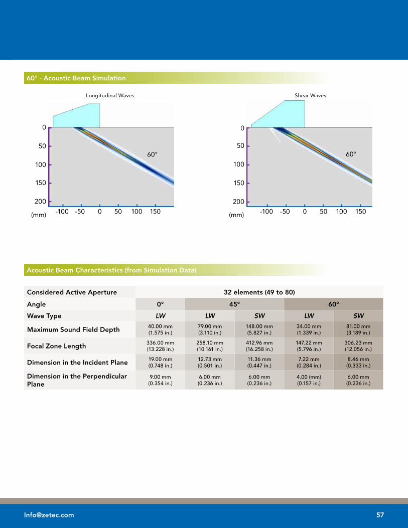
acoustic Beam Characteristics (from Simulation Data)
Considered active aperture 32 elements (49 to 80)
angle 0° 45° 60°
Wave Type LW LW SW LW SW
maximum Sound Field Depth 40.00mm(1.575in.)
79.00mm(3.110in.)
148.00mm(5.827in.)
34.00mm(1.339in.)
81.00mm(3.189in.)
Focal Zone length 336.00mm(13.228in.)
258.10mm(10.161in.)
412.96mm(16.258in.)
147.22mm(5.796in.)
306.23mm(12.056in.)
Dimension in the Incident Plane 19.00mm(0.748in.)
12.73mm(0.501in.)
11.36mm(0.447in.)
7.22mm(0.284in.)
8.46mm(0.333in.)
Dimension in the Perpendicular Plane
9.00mm(0.354in.)
6.00mm(0.236in.)
6.00mm(0.236in.)
4.00(mm)(0.157in.)
6.00mm(0.236in.)
60° - acoustic Beam Simulation
Longitudinal Waves Shear Waves
0
50
100
150
200
60°
0-100 -50 50 100 150
60°
0-100 -50 50 100 150
0
50
100
150
200
(mm) (mm)

58 www.zetec.com
Wedges for Azimuthal Scanning
For Type a - Small
Part ID Type Wedge Angle
Length Width Height H1 X1 Length - X1 Y1
AS-55SW Type A - Small / 55SW 36.0° 16.30 mm(0.642 in.)
30.00 mm(1.181 in.)
10.17 mm(0.400 in.)
5.00 mm(0.197 in.)
1.78 mm(0.070 in.)
14.52 mm(0.572 in.)
15.00 mm(0.591 in.)
AS-55LW Type A - Small / 55LW 19.0° 17.20 mm(0.677 in.)
30.00 mm(1.181 in.)
16.86 mm(0.642 in.)
14.00 mm(0.551 in.)
3.03 mm(0.119 in.)
14.17 mm(0.558 in.)
15.00 mm(0.591 in.)
Small / 55SW Small / 55lW
For Type a - medium
Part ID Type Wedge Angle
Length Width Height H1 X1 Length - X1 Y1
AM-55SW Type A - Medium / 55SW 36.0° 23.50 mm(0.925 in.)
30.00 mm(1.181 in.)
12.48 mm(0.491 in.)
4.00 mm(0.157 in.)
2.73 mm(0.107 in.)
20.77 mm(0.818 in.)
15.00 mm(0.591 in.)
AM-55LW Type A - Medium / 55LW 19.0° 25.00 mm(0.984 in.)
30.00 mm(1.181 in.)
23.26 mm(0.916 in.)
18.50 mm(0.728 in.)
3.19 mm(0.126 in.)
21.81 mm(0.859 in.)
15.00 mm(0.591 in.)
medium / 55SW medium / 55lW

For Type a - large
Part ID Type Wedge Angle
Length Width Height H1 X1 Length - X1 Y1
AL-55SW Type A - Large / 55SW 36.0° 38.20 mm(1.504 in.)
33.00 mm(1.299 in.)
21.98 mm(0.865 in.)
8.00 mm(0.315 in.)
2.99 mm(0.118 in.)
35.21 mm(1.386 in.)
16.50 mm(0.650 in.)
AL-55LW Type A - Large / 55LW 19.0° 41.40 mm(1.630 in.)
33.00 mm(1.299 in.)
41.17 mm(1.621 in.)
33.00 mm(1.299 in.)
3.50 mm(0.138 in.)
37.90 mm(1.492 in.)
16.50 mm(0.650 in.)
large / 55SW large / 55lW
For Type a - X-large
Part ID Type Wedge Angle
Length Width Height H1 X1 Length - X1 Y1
AXL-55SW Type A - Xlarge / 55SW 36.0° 58.70 mm(2.311 in.)
38.00 mm(1.496 in.)
33.77 mm(1.330 in.)
11.00 mm(0.433 in.)
2.83 mm(0.111 in.)
55.87 mm(2.120 in.)
19.00 mm(0.748 in.)
AXL-55LW Type A - Xlarge / 55LW 19.0° 62.40 mm(2.457 in.)
38.00 mm(1.496 in.)
65.57 mm(2.581 in.)
53.00 mm(2.087 in.)
3.31 mm(0.130 in.)
59.09 mm(2.326 in.)
19.00 mm(0.748 in.)
X-large / 55SW X-large / 55lW

60 www.zetec.com
Wedges for Linear Scanning
For Type l - medium
Part ID Type Wedge Angle
Length Width Height H1 X1 Length - X1 Y1
LM-0LW Type L - Medium / 0LW 0° 51.00 mm(2.037 in.)
28.00 mm(1.102 in.)
30.00 mm(1.181 in.)
30.00 mm(1.181 in.)
6.60 mm(0.260 in.)
44.40 mm(1.748 in.)
14.00 mm(0.551 in.)
LM-55SW Type L - Medium / 55SW 36.0° 63.80 mm(2.512 in.)
28.00 mm(1.102 in.)
34.19 mm(1.346 in.)
8.00 mm(0.315 in.)
2.91 mm(0.115 in.)
60.89 mm(2.397 in.)
14.00 mm(0.551 in.)
LM-55LW Type L - Medium / 55LW 19.0° 57.70 mm(2.272 in.)
28.00 mm(1.102 in.)
39.97 mm(1.574 in.)
26.00 mm(1.024 in.)
3.40 mm(0.134 in.)
54.30 mm(2.138 in.)
14.00 mm(0.551 in.)
medium / 55SW
medium / 55lW
medium / 0lW

For Type l - large
large / 55SW
large / 55lW
large / 0lW
Part ID Type Wedge Angle
Length Width Height H1 X1 Length - X1 Y1
LL-0LW Type L - Large / 0LW 0° 110.0 mm(4.331 in.)
28.00 mm(1.102 in.)
50.00 mm(1.969 in.)
50.00 mm(1.969 in.)
7.38 mm(0.291 in.)
102.62 mm(4.040 in.)
14.00 mm(0.551 in.)
LL-55SW Type L - Large / 55SW 36.0° 141.2 mm(5.559 in.)
28.00 mm(1.102 in.)
71.74 mm(2.824 in.)
9.00 mm(0.354 in.)
2.73 mm(0.107 in.)
138.47 mm(5.452 in.)
14.00 mm(0.551 in.)
LL-55LW Type L - Large / 55LW 19.0° 120.6 mm(4.748 in.)
28.00 mm(1.102 in.)
63.86 mm(2.514 in.)
31.00 mm(1.220 in.)
3.19 mm(0.126 in.)
117.41 mm(4.622 in.)
14.00 mm(0.551 in.)

62 www.zetec.com
Adapters, Splitters and Other Accessories
adapter boxes
Part ID Description
ADPBOX-ZIRCON-DYNARAY Adapter Box - Connect one DYNARAY compatible PA probe connector (Hypertronics) to the ZIRCON (ZIRCON male connector to DYNARAY female connector, 128 connections)
ADPBOX-ZIRCON-OMNI Adapter Box - Connect one Omni-type PA probe connector to the ZIRCON (ZIRCON male connector to Omni-type female connector, 128 connections)
ADPBOX-DYNARAY-ZIRCON Adapter Box - Connect one ZIRCON compatible PA probe connector to the DYNARAY (Hypertronics) (DYNARAY male connector to ZIRCON female connector, 128 connections)
ADPBOX-DYNARAY-OMNI Adapter Box - Connect one OMNI-type PA probe connector to the DYNARAY (Hypertronics) (DYNARAY male connector to OMNI-type female connector, 128 connections)
aDPBoX-ZIrCoN-DyNaray aDPBoX-ZIrCoN-omNI
Zetec offers a series of connection adapters which allows operation of its standard PA probes on different hardware platforms or of other PA probes on Zetec’s equipment. In order to allow simultaneous operation of multiple PA probes, we also offer a series of splitter cables.
Should you need special connection solutions, don’t hesitate to contact us for any custom design.
aDPBoX-DyNaray-ZIrCoN aDPBoX-DyNaray-omNI

Splitters
SPlTBoX-ZIrCoN-2ZIrCoN64 SPlTCBl-ZIrCoN-2DyNaray64
Part ID Description
SPLTBOX-ZIRCON-2ZIRCON64 Splitter Box - Connect simultaneously 2 ZIRCON compatible PA probes to the ZIRCON (ZIRCON male connector to 2 ZIRCON female connectors, 1-64 and 65-128)
SPLTCBL-ZIRCON-2DYNARAY64 Splitter Cable - Connect simultaneously 2 DYNARAY compatible PA probes (Hypertronics) to the ZIRCON (ZIRCON male connector to 2 DYNARAY female connectors, 1-64 and 65-128)
Zetec also offers accessories to use with your phased array probes and wedges. This includes handheld encoders and scanners for position feedback when acquiring your UT signals.
For generic or custom scanner designs, Zetec can provide you with scanning mechanisms that will improve your examinations. Don’t hesitate to contact us for any scanning needs.
handheld Encoder
Part ID Description
ACC-ZIRCON-ENC-5M-DE15 Mini encoder - 5 m cable - waterproof - DE15 connector compatible with ZIRCON systems - includes bracket kit to attach on Zetec wedges
ACC-ZIRCON-ENC-5M-DE15

[email protected] free: 800.643.1771P: 418.266.3020F: 418.263.3742
875 boul. Charest Ouest, Suite 100Québec, Qc, CANADA G1N 2C9
ZetecholdsISO 9001:2008andISO/IEC 17025:2005 certifications
© Zetec, Inc. 2011. Rev 06/11 Printed in Canada. All rights reserved. All the information herein is subject to change without prior notification. 10040686-R01
To order, contact us:


