
Overview: ray transfer matrices
optical axis
Propagation through uniform space: Refraction at spherical interface: distance d, index of refraction nleft radius R, indices nleft, nright
By using these elemental matrices, we may ray trace through an arbitrarily long cascade of optical elements (provided the paraxial approximation remains valid throughout.)
MIT 2.71/2.710 02/25/09 wk4-b- 1
1

Overview: thin lens and object/image at infinityobject at infinity image at infinity
MIT 2.71/2.710 02/25/09 wk4-b- 2
2

Overview: composite optical elements
MIT 2.71/2.710 02/25/09 wk4-b- 3
FFP
1st PP
BFP
2nd PP
FFL BFL
EFL EFL
ray from infinity bends at
2nd PP
then goes through the BFP
ray from the FFP
bends at 1st PP
FFP
1st PP
BFP
2nd PP
then goes on to infinity
object FFP
BFP image
1st PP 2nd PP
EFL EFL
3

Overview: real and virtual images
BFP
object
image
FFP BFP
object
image
FFP
+ +
image: real & inverted; MT<0 image: virtual & erect; MT>1
image image– – objectobject
FFP BFP FFPBFP
image: virtual & erect; 0<MT<1 image: virtual & erect; 0<MT<1
MIT 2.71/2.710 02/25/09 wk4-b- 4
4
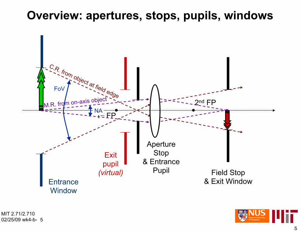
Overview: apertures, stops, pupils, windows
Field Stop
2nd FP
1st FP
Exit pupil
(virtual)
Aperture Stop
& Entrance Pupil
M.R. from on-axis object
C.R. from object at field edge
NA
FoV
Entrance & Exit Window Window
MIT 2.71/2.710 02/25/09 wk4-b- 5
5

Today
• Ray optics of mirrors • [[ Some terminology:
– catoptric ≡ utilizing mirrorsκάτοπτρον (kátoptron) = mirror
– dioptric ≡ utilizing refractive lenses δίοπτρον (díoptron) = lens
– catadioptric ≡ utilizing both mirrors and refractive lenses]] • The basic optical imaging systems
– magnifier lens – eyepiece – microscope – telescope
• refractive: Keppler (dioptric) • reflective: Cassegrain (catoptric) • Schmidt (catadioptric)
MIT 2.71/2.710 02/25/09 wk4-b- 6
6

Sign conventions for catoptric optics
• Light travels from left to right before reflection and from right to left after reflection
• A radius of curvature is positive if the surface is convex towards the left • Longitudinal distances before reflection are positive if pointing to the right;
longitudinal distances after reflection are positive if pointing to the left • Longitudinal distances are positive if pointing up • Ray angles are positive if the ray direction is obtained by rotating the +z axis
counterclockwise through an acute angle
positive direction
(after reflection)
positive ray elevation
positive ray angle
positive ray angle
positive direction (before positive
reflection) curvature
MIT 2.71/2.710 02/25/09 wk4-b- 7
7

Object/image at infinity with spherical mirror
MIT 2.71/2.710 02/25/09 wk4-b-
⇒Focal length
object at ∞
image
Object at infinity
image at ∞
object
Image at infinity 8
8

Catoptric imaging formulae
object imageimage/ object at ∞
object/ image
Object/image at infinity Object, image at finite distances
Imaging conditionFocal length
Ray transfer Magnificationmatrix
MIT 2.71/2.710 02/25/09 wk4-b- 9
9

The single lens magnifier
MIT 2.71/2.710 02/25/09 wk4-b-10
object at near point (25cm) ➙maximum unaided magnification eye
lens
real image
at retina
virtual image (erect and magnified)
real image
at retina
(magnified)
magnifier lens
Magnifying power
Near point
10
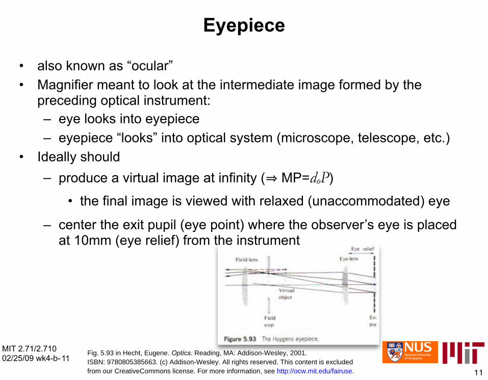
Eyepiece
• also known as “ocular” • Magnifier meant to look at the intermediate image formed by the
preceding optical instrument: – eye looks into eyepiece – eyepiece “looks” into optical system (microscope, telescope, etc.)
• Ideally should – produce a virtual image at infinity (⇒ MP=doP)
• the final image is viewed with relaxed (unaccommodated) eye
–
MIT 2.71/2.710 02/25/09 wk4-b-11
center the exit pupil (eye point) where the observer’s eye is placed at 10mm (eye relief) from the instrument
11
Fig. 5.93 in Hecht, Eugene. Optics. Reading, MA: Addison-Wesley, 2001.ISBN: 9780805385663. (c) Addison-Wesley. All rights reserved. This content is excludedfrom our CreativeCommons license. For more information, see http://ocw.mit.edu/fairuse.
MIT 2.71/2.710 02/25/09 wk4-b-12
Field Stop
Eyepiece
Entrance Pupil
Exit Pupil
Aperture Stop
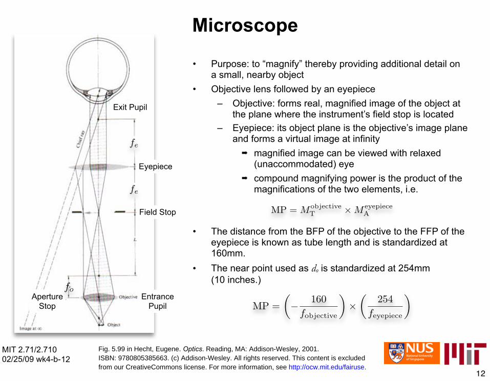
Microscope
• Purpose: to “magnify” thereby providing additional detail on a small, nearby object
• Objective lens followed by an eyepiece – Objective: forms real, magnified image of the object at
the plane where the instrument’s field stop is located – Eyepiece: its object plane is the objective’s image plane
and forms a virtual image at infinity ➡ magnified image can be viewed with relaxed
(unaccommodated) eye ➡ compound magnifying power is the product of the
magnifications of the two elements, i.e.
• The distance from the BFP of the objective to the FFP of the eyepiece is known as tube length and is standardized at 160mm.
• The near point used as do is standardized at 254mm (10 inches.)
12
Fig. 5.99 in Hecht, Eugene. Optics. Reading, MA: Addison-Wesley, 2001.ISBN: 9780805385663. (c) Addison-Wesley. All rights reserved. This content is excludedfrom our CreativeCommons license. For more information, see http://ocw.mit.edu/fairuse.

MIT OpenCourseWarehttp://ocw.mit.edu
2.71 / 2.710 Optics Spring 2009
For information about citing these materials or our Terms of Use, visit: http://ocw.mit.edu/terms.


