
1
Overview of enhancement cavity work at LAL/Orsay
INTRO: Optical cavity developments at LAL
Results on optical cavity in picosecond regimePolarised positron source R&D effortDevelopments for compact Compton X-ray source (ThomX)
ECFA Linear Collider Workshop, Hambourg, may 2013

2
Introduction
• Instrumentation developments around laser-electron beam interaction at LAL since ~2000 (accelerator physics applications)– 2000: cw 30000 cavity finesse for the 30GeV
electron beam at HERA/DESY (Coll. DESY, CEA)– ~2005 we started an R&D on Optical cavities in
picosecond regime for a polarised positron source• 2006: start collaboration with ATF group of KEK• 2008: optical cavity for gamma-ray production on ATF/KEK
– Coll. CELIA/KEK/LMA
– 2011: optical cavity for X-ray production for the equipex ThomX/LAL
3
High Finesse Fabry-Perot cavity in 2ps & 200fs regime
Experiments at LALwith E. Cormier & K. Osvay

4
1ps Pulsed laser
Fabry-Perot cavitywith Super mirrors
Electron beam
Fabry-Perot cavity in pulsed regime
Difference between continuous and pulsed regime

5
T. Udem et al. Nature 416 (2002) 233
Pulsed_laser/cavity feedback technique
Specificity properties of passive mode locked laser beams
Frequency comb all the combmust be locked to the cavity Feedback with 2 degrees of freedom : control of the Dilatation (frep) & translation (CEP phase)
wn= nwr+w0
n~106
T=2p/wr
State of the art (Garching MPI) : ~70kW, 2ps pulses @78MHz, stored in a 6000 finesse cavity (O.L.35(2010)2052) ~20kW, 200fs pulses @78MHz
DjCEP phase

n2-Mirror Fabry-Perot cavity
Finesse ~ 30000
Orsay setup: Picosecond/High FinesseTi:sapph oscillator (~0.4nm spectrum)
DAQ
VERDI 6W532nm
MIRA
AOM
SerialRS232
Driver
+/-
Amplifier
TRANSFront-end
EOM
Driver
+/-
PDH #1Front end
grating
AOM
M2PZT
M1MOTOR
Pound-Drever-Hall Scheme
Transmission Signal
Laser Length Control
Laser Δφce Control
Driver
SLITS
Feedback
PDH #2Front end
Driver

7
2-Mirror Fabry-Perot cavity
FI
EOM
AOM
Chiller GTI
Ti:Sapph
Lyotfilter Starter
PZT
IDW Slit
Pump laser
Ti:sapphoscillator
PDF2
PDF1PDR
Slit
Multiple Beam Interferometer
PDT
Water cooling
Digital Feedback
PDH PZT filterAOM filter
SM
CCD
Stabilized He-Ne
Feedback loop to piezo
ImagingSpectrograph
FrequencyCounter
CEP effects measurement in picosecond/high finesse regimeCELIA, LAL, SZEGED Univ.
2ps Ti:Sapph (75MHz) Locked to a ~30000 finesse cavityNo control of the CEP drift in the feedback loop
CEP measured with Karoly’s interferometer
Numerical feedback loopBW=100-200kHzBW ~1MHz under development
8
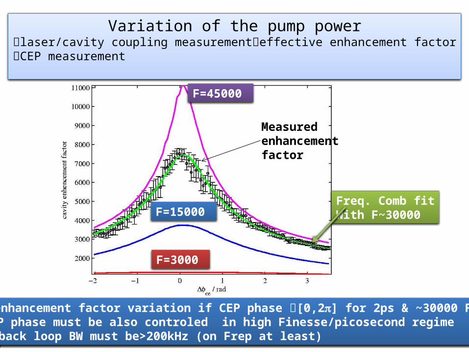
Measuredenhancementfactor
Variation of the pump powerlaser/cavity coupling measurementeffective enhancement factorCEP measurement
Freq. Comb fitWith F~30000
60% enhancement factor variation if CEP phase [0,2p] for 2ps & ~30000 FinesseCEP phase must be also controled in high Finesse/picosecond regime
Feedback loop BW must be>200kHz (on Frep at least)
F=45000
F=15000
F=3000
9
Fiber yb laser
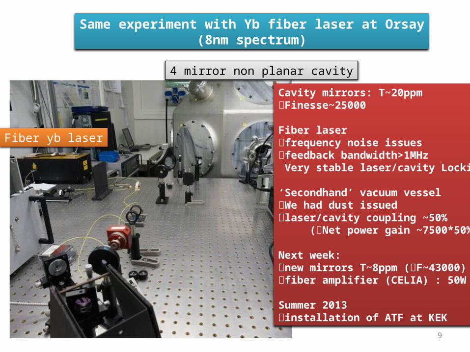
Same experiment with Yb fiber laser at Orsay(8nm spectrum)
4 mirror non planar cavity
Cavity mirrors: T~20ppmFinesse~25000
Fiber laser frequency noise issuesfeedback bandwidth>1MHz Very stable laser/cavity Locking
‘Secondhand’ vacuum vesselWe had dust issuedlaser/cavity coupling ~50% (Net power gain ~7500*50%)
Next week: new mirrors T~8ppm (F~43000)fiber amplifier (CELIA) : 50W
Summer 2013installation of ATF at KEK

E. Cormier ICAN 2012 (CERN)
Towards 1 MW average power
G = 10000
150 W fiber laser
CELIA F = 30 000
FP cavityLAL
Stored average power of 100 kW to 1 MW

11
Polarised positron source
Experiment at KEKCollaboration with ATF/KEK and CELIA
to provide Yb fibre amplifier(10W60W average power)

•12
KEK cavity French Japanese Collaboration
Araki-san
+I. Chaikovska, N. Delerue, R. Marie LAL+ J. Lhermite from CELIA

Results at KEK
2 flat mirrors
2 spherical mirrorse-
laser
12 encapsulated Motors
Non planar 4-mirrorcavity
mechanical stability 4-mirror cavitycircularely polarised eigenmodesNon-planar geometry

Four mirror non-planarcavity
Results before the earthquake Finesse 3000 & 10W incident laser powerDetection of ~30MeV gamma-rays
Re installation during summer 2013New fiber Laser•Cavity Finesse 2500045000•Laser power 50W100W

15
Monochromatic X-ray sourceThomX
Experiment at OrsayCELIA in charge of high average
power amplifier

ThomX
~7m
~10m
IN2P3 Les deux infinis
Résonateur optique

Geometry for ThomX
Mechanical stability4-mirror cavity
Linear polarised modesPlanar geometry
Point d’interaction

Summary
Ti:sapph76 MHz1ps
1.6mORSAY KEK cavity
4mYb35.7MHz~15ps
Yb180 MHz0.2ps
ThomX
8m
Achieved Gain~10000Laser coupling ~80%Low laser power <1W
Achieved at ATF in 2011-2012Gain~1000Laser coupling ~60%laser 10W-50WLaser amplification stability
Achieved at Orsay with new laser Finesse 25000Coupling ~50%Laser power<100mWImmediate improvement Finesse 43000Coupling >50%Laser power>50W Expected stored power>300kW
Foreseen end 2013-2014Gain ~10000Laser coupling ~80%Laser power 50-100W400kW

19
results
F=3000
F=15000F=30000
F=45000
Measurement
Only 3 free parameters in the fit: a normalisation factor, an offset and the Finesse

20
We observed strong free running laser/cavity coupling variations(Finesse~30000)
Fit:Frequency comb+Dfce variations
Only 3 free parameters in the fit: a normalisation, an offsetthe Finesse
Laser/cavitycoupling
25% coupling variationover ~15min
CEP measurement

21
A technological issue:huge requested laser power
Priority : High X/g ray Flux(spectral purity ~few %) Electron ring (ThomX)
Priority : High X/g ray spectral purity <1% (jn applications)LINAC (ELI-NP)
~20MHz e-beam/laser collision frequencyOptical resonator to increase the laser power High cavity gain & High laser average power
~100Hz e-beam/laser collision frequencyOptical recirculator of a high peak powerlaser pulseHigh laser peak power & high nb of passes


