
Cognition and the Engineering Design Requirement
i
Cognition and the Engineering Design Requirement
Submitted by Mansur Darlington
for the degree of Ph.D.
of the University of Bath
2002
COPYRIGHT
Attention is drawn to the fact that copyright of this thesis rests with its author. A copy of
this thesis has been supplied on condition that anyone who consults it is understood to
recognise that its copyright rests with the author and they must not copy it or use material
from it except as permitted by law or with the consent of the author.
This thesis may be made available for consultation within the University Library. It may
be photocopied, lent to other libraries and released to online thesis systems or otherwise
made available online for the purposes of consultation.

Cognition and the Engineering Design Requirement
ii
Summary
This thesis is concerned with the engineering design requirement and the process by
which it is elicited, evolved and recorded. The experience of industry shows that the
design requirement is an important part of the design activity. When failure in the capture
process occurs and shortcomings in the design requirement follow, it leads to the design
of artefacts that are unsafe, unsatisfactory, uneconomic or inappropriate.
The purpose of the research reported in this thesis is to achieve a more complete
understanding of the engineering design requirement, and to apply that understanding to
the better support of designers during the design requirement capture phases of the
design process.
Two perspectives dominate the approach to the research. The first concerns the relation
between the design process and human cognition. The research subject is seen as being
fundamentally a product of the human mind and that such things as knowledge, language
and meaning – the things commonly associated with cognition – are crucial to its proper
understanding. The second perspective is informed by the view that the development of
the design requirement can be seen as a knowledge-intensive process of communication.
Thus, understanding communication between humans and some aspects of
communication failure can assist in understanding and remedying failure in design
requirement capture. Since the process is knowledge-intensive, questions arise
concerning the content and nature of the knowledge needed in developing the design
requirement and applying it in the design process.
A number of disparate elements of the subject have been investigated. These include
consideration of the process of design requirement capture as carried out by practising
engineers; identification of the knowledge that is required in carrying out the process and
ways in which it might be codified, shared and reused; and analysis of the conceptual and
descriptive content of the design requirement. The findings from these different
investigations have been drawn together in order to achieve the research aim of achieving
a better understanding of the engineering design requirement and applying that
understanding to the support of design requirement capture.

Cognition and the Engineering Design Requirement
iii
Acknowledgements
The author would like to thank a number of people for the contributions they have made
to the work reported in this thesis. First is Steve Culley who brought enthusiasm for and
knowledge of Design to his supervision of the investigations, the findings of which
constitute this thesis. Second is Steve Potter, whose academic rigour and clarity of
expression provided a standard to which to aspire, and who bravely read and commented
on an early draft of the thesis.
I should also like to thank my colleagues at the Engineering Design Centre at the
University of Bath who provided support and advice over a five-year period of
investigation, and the Engineering and Physical Sciences Research Council which funded
the research.
Mentioned last, because they are the most important, are my wife Sarah and sons Ben
and Lindsay, who have supported me and patiently put up with my mental absences and
dereliction of family duty during the writing-up task.

Cognition and the Engineering Design Requirement
iv
Table of Contents
1 INTRODUCTION 1
1.1 THE DESIGN REQUIREMENT ............................................................................................ 2
1.2 TERMINOLOGY ................................................................................................................ 3
1.2.1 An Ontology for the Engineering Design Requirement.............................................. 4
1.3 DESIGN REQUIREMENT CAPTURE.................................................................................... 6
1.3.1 Requirement Capture in the Design Process ............................................................. 6
1.3.2 Failure in the Design Requirement Capture Process ................................................ 7
1.4 THE MOTIVATION FOR THIS RESEARCH........................................................................... 9
1.4.1 Design as Cognition................................................................................................. 10
1.4.2 Automating the Design Process ............................................................................... 10
1.5 AIMS OF THE RESEARCH ............................................................................................... 11
1.5.1 Hypotheses ............................................................................................................... 11
1.6 STRUCTURE OF THE THESIS ........................................................................................... 13
2 ENGINEERING DESIGN REQUIREMENT RESEARCH 16
2.1 RESEARCH APPROACHES............................................................................................... 17
2.2 ENGINEERING DESIGN AND SOFTWARE ENGINEERING .................................................. 18
2.2.1 Requirements Engineering and the Engineering Design Requirement .................... 19
2.2.2 Automatic Design and the Design Requirement....................................................... 21
2.3 CLASSIFICATION OF DESIGN REQUIREMENT RESEARCH................................................ 21
2.4 PRESCRIPTIVE RESEARCH ............................................................................................. 22
2.4.1 Methodology-based Design Support ........................................................................ 23
2.4.2 Design Requirement Theory..................................................................................... 28
2.4.3 Miscellaneous .......................................................................................................... 29
2.5 DESCRIPTIVE RESEARCH ............................................................................................... 30
2.5.1 Design Process Analysis .......................................................................................... 30
2.5.2 Knowledge in Design ............................................................................................... 31
2.5.3 Language- and Concept-based Research................................................................. 34
2.6 REQUIREMENTS FOR AUTOMATIC DESIGN .................................................................... 37
2.7 SUMMARY ..................................................................................................................... 38
2.8 THE AUTHOR’S RESEARCH – CATEGORIZATION ............................................................ 39
3 DESIGN AND THE HUMAN 40

Cognition and the Engineering Design Requirement
v
3.1 TO DESIGN IS HUMAN ................................................................................................... 40
3.1.1 Design and Cognition .............................................................................................. 42
3.1.2 Human Knowledge and Automatic Design .............................................................. 43
3.2 COGNITIVE THEORY...................................................................................................... 44
3.2.1 The Central Rôle of Knowledge ............................................................................... 45
3.2.2 The Cognitive Design Process ................................................................................. 46
3.2.3 Elucidation of the design process ............................................................................ 47
3.3 SUMMARY ..................................................................................................................... 48
4 DESIGN REQUIREMENT CAPTURE IN PRACTICE 50
4.1 INVESTIGATION METHODOLOGY................................................................................... 51
4.1.1 Document Analysis................................................................................................... 53
4.1.2 Subject Companies................................................................................................... 53
4.2 THE INTERVIEWS........................................................................................................... 55
4.2.1 Company A Interviews ............................................................................................. 55
4.2.2 Company A Document Analysis ............................................................................... 70
4.2.3 Company A Interviews: Overall Conclusions .......................................................... 72
4.2.4 Company B interview – Eng. Manager B................................................................. 72
4.2.5 Company C Interview............................................................................................... 75
4.3 VARIATIONS IN DESIGN REQUIREMENT DEVELOPMENT................................................ 76
4.3.1 The General Nature of the Product.......................................................................... 77
4.3.2 The Case-Specific Nature of the Product-Development Project .............................. 78
4.3.3 ‘Customer’/’Designer’ Relationship........................................................................ 78
4.3.4 The Multiple Rôle of the Design Requirement ......................................................... 79
4.4 A MODEL OF FACTORS INFLUENCING DESIGN REQUIREMENT DEVELOPMENT. ............ 80
4.4.1 Type of Company ..................................................................................................... 82
4.4.2 Design Requirement Maturity and Phase of Capture .............................................. 84
4.4.3 Stakeholder Relationship ......................................................................................... 85
4.4.4 New Product Type.................................................................................................... 88
4.4.5 Design Activity Type ................................................................................................ 89
4.4.6 Product Effective Complexity................................................................................... 90
4.4.7 Design Requirement Capture Methodology............................................................. 91
4.4.8 Contract Formality .................................................................................................. 91
4.4.9 Level of Design and Design Requirement Development Expertise .......................... 92
4.5 CONCLUSIONS ............................................................................................................... 92
4.6 SUMMARY ..................................................................................................................... 93
5 COMMUNICATION AND KNOWLEDGE IN DESIGN REQUIREMENT
CAPTURE 95
5.1 FAILURE IN COMMUNICATING THE DESIGN REQUIREMENT........................................... 95
5.1.1 Human Communication ........................................................................................... 96

Cognition and the Engineering Design Requirement
vi
5.2 COMMUNICATING THE DESIGN REQUIREMENT ............................................................. 99
5.3 SOME FACTORS WHICH CONTRIBUTE TO FAILURE IN THE DESIGN REQUIREMENT ...... 102
5.3.1 Selection of Medium............................................................................................... 102
5.3.2 Variety of Expression ............................................................................................. 103
5.3.3 Accuracy of Expression.......................................................................................... 104
5.3.4 Content................................................................................................................... 105
5.3.5 Summary ................................................................................................................ 109
5.4 COMMUNICATIVE FREEDOM AND CONTEXT................................................................ 109
5.4.1 The Rôle of Context................................................................................................ 109
5.5 KNOWLEDGE AND INFORMATION IN COMMUNICATION............................................... 112
5.6 KNOWLEDGE AND MEMORY ........................................................................................ 114
5.7 KNOWLEDGE, CONCEPTS AND COMMUNICATION........................................................ 117
5.7.1 Concepts................................................................................................................. 117
5.7.2 Concept Sharing..................................................................................................... 119
5.8 CONCEPTUAL SCHEMATA AND THE POWER OF CONTEXT............................................ 120
5.9 A SIMPLE COGNITIVE MODEL OF CONCEPTUAL CONTEXT.......................................... 121
5.10 SUMMARY ................................................................................................................... 122
6 THE FORMALIZATION OF KNOWLEDGE 124
6.1 THE HUMAN-MACHINE RELATIONSHIP: PART I .......................................................... 124
6.2 INFORMATION AND KNOWLEDGE IN HUMAN-COMPUTER INTERACTION ..................... 126
6.3 IDENTIFYING DOMAIN KNOWLEDGE ........................................................................... 128
6.4 ONTOLOGIES ............................................................................................................... 129
6.4.1 Why Use Ontologies?............................................................................................. 129
6.4.2 What is an Ontology?............................................................................................. 130
6.4.3 Basic Ontology Structure ....................................................................................... 131
6.4.4 Ontological Semantics ........................................................................................... 134
6.4.5 Ontology Development Support ............................................................................. 137
6.5 ONTOLOGY USE AND APPLICATION ............................................................................ 138
6.5.1 Communication ...................................................................................................... 138
6.5.2 Knowledge Bases ................................................................................................... 139
6.5.3 Software Application Development........................................................................ 140
6.5.4 Search .................................................................................................................... 140
6.5.5 Problem solving ..................................................................................................... 142
6.6 CHOOSING AN ONTOLOGY DEVELOPMENT METHODOLOGY ....................................... 142
6.7 SUMMARY ................................................................................................................... 144
7 DEVELOPING ONTOLOGIES FOR ENGINEERING DESIGN REQUIREMENT
CAPTURE SUPPORT 146
7.1 ONTOLOGY DEVELOPMENT......................................................................................... 147
7.1.1 Application and Evaluation of the Methodology.................................................... 148

Cognition and the Engineering Design Requirement
vii
7.1.2 Step 1: Determining the Domain and Scope of the Ontology ................................ 148
7.1.3 Step 2: Considering Reuse of Existing Ontologies................................................. 150
7.1.4 Step 3: Enumerating Important Terms................................................................... 151
7.1.5 Step 4: Defining the Classes and the Class Hierarchy........................................... 153
7.1.6 Step 5: Defining the Properties of Classes............................................................. 154
7.1.7 Step 6: Defining the Values for the Properties....................................................... 155
7.1.8 Step 7: Creating Class Instances ........................................................................... 155
7.2 ONTOLOGIES FOR SUPPORTING DESIGN REQUIREMENT CAPTURE .............................. 155
7.2.1 The Engineering Design Requirement Ontology.................................................... 156
7.2.2 The Product Finish Ontology................................................................................. 163
7.2.3 The Machine Motion Ontology .............................................................................. 169
7.3 BUILDING AND USING ONTOLOGIES FOR USE IN THE ENGINEERING DESIGN DOMAIN. 175
7.3.1 Assessment of the Ontology-Building Task ............................................................ 175
7.3.2 Assessment of the Usefulness of Ontologies........................................................... 176
7.4 THE HUMAN-MACHINE RELATIONSHIP: PART II ......................................................... 178
7.5 SUMMARY ................................................................................................................... 180
8 A CONTEXT-SENSITIVE DESIGN REQUIREMENT ELICITATION SCHEME
182
8.1 REVIEW OF THE STATIC DESIGN REQUIREMENT ELICITATION SCHEME ...................... 183
8.1.1 DREF1 Limitations ................................................................................................ 184
8.2 REVIEW OF COMMUNICATIVE FAILURE....................................................................... 185
8.3 THE DESCRIPTIVE SCOPE OF THE CADRES IMPLEMENTATION..................................... 186
8.3.1 The Tasks ............................................................................................................... 187
8.4 A SCHEME FOR CONSTRAINING DIALOGUE ................................................................. 188
8.4.1 The Concept Association Mechanism .................................................................... 188
8.4.2 The Conceptual Structure ...................................................................................... 189
8.5 DEVELOPING THE CONCEPTUAL STRUCTURES ............................................................ 191
8.6 A CONTEXT-SENSITIVE REQUIREMENT CAPTURE ENVIRONMENT .............................. 192
8.6.1 The Implementation of CaDRes ............................................................................. 195
8.6.2 The Process of Eliciting the Design Requirement.................................................. 197
8.7 A REPRESENTATIVE DESIGN REQUIREMENT ELICITATION EPISODE............................ 199
8.7.1 System Output ........................................................................................................ 203
8.8 ASSESSING CADRES ................................................................................................... 204
8.8.1 Concept-Association Methodology and Knowledge Sharing ................................. 205
8.8.2 CaDRes and DREF1 Limitations ........................................................................... 206
8.8.3 CaDRes and Communicative Failure .................................................................... 209
8.8.4 Conclusions............................................................................................................ 211
8.9 SUMMARY ................................................................................................................... 212
9 THE DESIGN REQUIREMENT AND AUTOMATIC DESIGN 214

Cognition and the Engineering Design Requirement
viii
9.1 THE DESIGN REQUIREMENT(S).................................................................................... 215
9.1.1 The Design Requirement Record ........................................................................... 215
9.1.2 The Conceptual Design Requirement and Design Knowledge............................... 216
9.1.3 Description versus Meaning .................................................................................. 218
9.2 SUMMARY ................................................................................................................... 220
10 CONCLUSIONS AND FUTURE WORK 221
10.1 CONCLUSIONS ............................................................................................................. 222
10.1.1 The Relation between Humans and the Design Process.................................... 222
10.1.2 The Design Requirement Capture Process in Practice ..................................... 223
10.1.3 Flexibility and Failure in Design Requirement Capture ................................... 224
10.1.4 The Design Requirement(s) ............................................................................... 224
10.1.5 Knowledge in Context........................................................................................ 225
10.1.6 Identifying and Codifying Domain Knowledge.................................................. 226
10.1.7 A Dynamic and Context-Sensitive Elicitation Environment. ............................. 227
10.1.8 Automatic Design .............................................................................................. 227
10.2 SUMMARY ................................................................................................................... 228
10.3 FUTURE WORK............................................................................................................ 229
10.3.1 Ontologies.......................................................................................................... 229
10.3.2 Context-sensitive Design Requirement Support Environments.......................... 229
10.3.3 Design Requirement Capture in the Field ......................................................... 230
10.3.4 Requirements Engineering and the Engineering Design Requirement.............. 230
10.3.5 Automatic Design and the implementation of Intelligent Processes.................. 231
10.4 OVERALL CONCLUSIONS............................................................................................. 231
AUTHOR’S PUBLICATIONS 233
APPENDIX A: DREF1 – DESIGN REQUIREMENTS ELICITATION QUESTIONNAIRE
243
APPENDIX B: LEXICON OF TERMS FOR THE IMPLEMENTATION OF A DOMAIN
SPECIFICATION RELATING TO MACHINE ACTIVITY 247
APPENDIX C: DOMAIN SPECIFICATION FOR THE IMPLEMENTATION OF
CADRES 253
APPENDIX C (CONT). DOMAIN SPECIFICATION TREE STRUCTURE 263
APPENDIX D: CADRES ELICITATION EPISODE USER-SYSTEM INTERACTION
265
APPENDIX E: ISSUES CONCERNING AUTOMATIC INTERPRETATION OF THE
DUTY CYCLE PROFILE 270

Cognition and the Engineering Design Requirement
ix
Table of Figures
Figure 1. Engineering Design’s position at the intersection of the technical and cultural streams.
After Pahl & Beitz (1996). ............................................................................................................................. 1
Figure 2. A model of the parallel and co-evolving conceptual and physical entities related to
design requirement evolution......................................................................................................................... 5
Figure 3. Identification of customer needs and establishing target specifications as part of the
conceptual development during the design process. After Ulrich & Eppinger (1995). ................................. 7
Figure 4. The relative cost of rectifying errors in systems design at various stages in the design
process as a result of assumptions in the design requirement (data from Boehm, 1981). ............................. 9
Figure 5. The structure of the thesis ............................................................................................................ 13
Figure 6. The information model of design requirements capture. After Wootton, et al. (1997)................. 17
Figure 7. A taxonomy of engineering design requirement research. ........................................................... 22
Figure 8. An incomplete model of the design requirement development process within Company
A, showing the divergence between the mechanical and electrical streams................................................ 59
Figure 9. The design development process for Project A. ........................................................................... 66
Figure 10. The design development process for Project B, showing the concurrent engineering
flavour.......................................................................................................................................................... 69
Figure 11. The principal and interconnected factors that affect the design requirement
development process and the design requirement. ...................................................................................... 82
Figure 12. The basic design requirement development process (A) elaborated in Wootton, et al.’s
(1997) model (B) to show the important information transformation stage. ............................................... 85
Figure 13. The design requirement development process shown as an activity model which
identifies the importance of the stakeholder throughout the development of the design requirement
(Wootton, et al., 1998) ................................................................................................................................. 87

Cognition and the Engineering Design Requirement
1
1 Introduction
The world in which humans live is largely one of their own construction – it is artificial
(Simon, 1996). At the centre of the construction of this artificial world is the activity of
design.
Drawing on work from Dixon (1966) and Penny (1970), Pahl & Beitz (1996) in their
influential treatise place engineering design at the intersection of two cultural and technical
streams, as shown in Figure 1. It is difficult to overstate the extent to which engineering
design both draws on and also contributes to these two distinct streams of human activity. It is
implicated in the production of every technical artefact from the most mundane and
unregarded, such as the washer in a tap, to the most conspicuous manifestation of technical
virtuosity and cultural confidence such as the Channel Tunnel. Even in what are ostensibly
entirely artistic endeavours, engineering design often makes a contribution without which
successful realization would be impossible – the Angel of the North (Gateshead, 2002) comes
to mind as a contemporary example, in which Ove Arup and Partners’ expertise played an
important part (Gateshead Council, 2002). Arguably, it is engineering design above all other
human activities that has done most since the industrial revolution to transformed the shape of
the world and provided new means by which humans can interact with it
Engineering
TechnologyProductionScience
Engineering
Science
Social
Psychology
Economics
Engineering
Design
Industrial Design
Artistic Design
Art
Politics
Figure 1. Engineering Design’s position at the intersection of the technical and cultural
streams. After Pahl & Beitz (1996).

Cognition and the Engineering Design Requirement
2
The engineering design process starts with some expression of need that is to be satisfied by
the creation of a physical artefact or system. The need may be voiced in a number of ways; for
example by a single individual in response to a problem, or by a group in response to
prevailing market forces. As the design episode proceeds the often informally expressed need
is explored, developed and expanded into a more complete and formally expressed
representation, generally referred to as the design requirement. The engineering design
process then becomes one of transforming the needs expressed in that design requirement into
the description of a physical entity that meets the requirement and constraint goals expressed
therein, before the description is transformed into the physical artefact itself.
1.1 The Design Requirement
The purpose of the design requirement is to convey the design needs to the designer in such a
way as to allow creation of a design that once manifest as a physical solution does, indeed,
satisfy the needs that were expressed. Failure to convey these design needs effectively must
leave the success of the design to chance, and thus the success of design is dependent first on
effectiveness of establishing and capturing the design requirement.
Arriving at the design requirement demands not merely that the initial needs be recorded.
These needs must be elicited, analysed and understood, and then restated in a way best fitted
for design to be carried out. Thus the design requirement process is one where information
must be gathered – frequently from a variety of sources – sifted, discarded, augmented,
organized, transformed and recorded.
As will be illustrated later, experience has shown that incorrect, incomplete or ambiguous
expression of the design requirement can lead to the design of artefacts that are unsafe,
unsatisfactory, uneconomic or inappropriate.
As engineering enterprises become more complex, both as regards the technical complexity of
the product and the design process itself, so too does the process of capturing the design
requirement become more difficult. At the same time, these enterprises become more sensitive
to failure, and the penalties increase. For this reason, improving the design requirement
capture process, and so ensuring that the design requirement supports successful design, is a
worthwhile pursuit.

Cognition and the Engineering Design Requirement
3
The research reported in this thesis is concerned with gaining a better understanding of the
process of design requirement development and capture1 so that designers can be better
supported in this important part of the design process. In addition, a better understanding is
sought of the content and expression of the design requirement, not only in the context of
conventional, human-related, design, but also in the context of ‘automatic’ design.
As has been stated, the purpose of the design requirement is to convey meaning from one
person to another – or in the case of automatic design between human and machine. A great
deal of the design requirement capture process is involved in achieving an understanding
through the communication of ideas of what should be represented in the design requirement
itself, and how it can best be represented. Because of this, the research perspective taken in
this work is one that characterizes the activity of developing the design requirement as a
knowledge and information intensive process of communication.
1.2 Terminology
Discussion of ‘the design requirement’ is attended by certain terminological difficulties. The
principal difficulty arises because the labels adopted within industry and design research to
signify ‘design needs’ at various stages in the evolution of the design requirement and the
design process have not been standardized, and they are used indiscriminately with varying
levels of imprecision. Examples of terms that are used widely and have been noted during this
research are: design requirement, problem statement, product description, technical
specification, product design specification and engineering specification. This list is not
exhaustive. Without some consistency in terminology, good communication is frustrated. Not
only does inconsistency make discussion of the topic amongst interested parties rather
difficult, but rather more importantly it inhibits attempts at bringing method to the practice of
design requirement capture and rigour to its formal discussion.
Difficulties associated with word usage are exacerbated by the particular nature of the design
requirement: it is variable in expression, content and character depending on the specific
prevailing circumstances, and these dimensions change in character as the design requirement
1 Within the process that results in the design requirement can be seen elements of
requirement development and elements of requirement capture. Nevertheless, for simplicity’s
sake, throughout this thesis the term Design Requirement Capture Process (DRCP) will be
used indiscriminately.

Cognition and the Engineering Design Requirement
4
is evolved during a particular design episode. Also, the rôle that an individual fulfils in
relation to the design activity will affect the way that they understand the design requirement.
For example, for an individual customer (however defined) the design requirement might be
an expression of their need, expressed in terms that are natural to them. As such it is seen as a
general, probably informal entity. For the designer, the design requirement is an instrument
that controls the design process and, perhaps, provides a means by which the final design can
be measured. In order to do this it must conform to a certain level of precision and
completeness, being couched in terms appropriate to this. Thus, what the design requirement
is understood to mean depends on viewpoint and what it is called depends upon custom.
A further difficulty has become apparent to the author in the course of his research. The
‘design requirement’ actually refers to two different entities, which co-exist and are developed
in parallel as the design problem is elaborated. On the one hand is the design problem as it
exists in the mind of the individual; on the other is the written record of the design problem as
it exists at some particular stage of the design requirement capture process. Things that exist in
the mind are, of course, unique to the individual, and so, for a particular design episode, what
is understood as ‘the design problem’ by one person will be different from the understanding
of ‘the design problem’ by another.
The design problem record is a physical document which records – perhaps imperfectly – the
overlap of the individual understandings of the design problem, and represents some sort of
consensus between the interested parties regarding the nature and salient detail of the design
problem.
1.2.1 An Ontology for the Engineering Design Requirement
In an attempt to ameliorate the problems of underspecification of the terms used to discuss the
design requirement topic, the author has developed an ontology which seeks to identify,
organize and define the terms associated with this subject. Although the ontology constitutes a
part of the original work reported in this thesis, because it provides the means by which the
subject matter can be discussed clearly, it is introduced here.
The ontology, which consist of 118 related concepts and their definitions, can be found on the
CD which accompanies this volume (Engineering_Design_Requirement_Ontology.html), and
the terminology used in this thesis will be in accordance with this ontology and the definitions
given therein.
In the ontology the term design requirement is prescribed as the most general term to be used
in referring to the design ‘problem’. Its inclusion acknowledges that a term is required that

Cognition and the Engineering Design Requirement
5
assigns no particular level of detail, completeness and content to the object to which it refers.
This general term embraces all types of expression of the design requirement at a variety of
levels of qualitative and quantitative description and completion. The term design requirement
will be used in this non-specific way throughout this work.
N.B. When terms from this ontology are used in this work in the sense defined therein, they
are underlined to signify the fact.
The ontology has been developed around a model of the core concepts which acknowledges
the existence of parallel conceptual and physical entities relating to the design requirement.
The physical entities constitute a record of the meeting-of-minds in the communication
between two individuals as the design requirement is evolved. This model, conceived by the
author and shown below in Figure 2, used in conjunction with the ontology, helps to clarify
and disambiguate some of the issues that are raised above.
Figure 2. A model of the parallel and co-evolving conceptual and physical entities related to
design requirement evolution.
The terms shown in the model within the central rectangle (demarked by the broken line) are
those that have been adopted to signify the important distinguishable components or entities
that can be found in the sphere or ‘envelope’ of the design requirement. The arrows suggest
the time aspect of the design requirement capture process and how the character of the design

Cognition and the Engineering Design Requirement
6
requirement changes as its development proceeds. This model is later extended to take in the
design process and the product which is evolved.
1.3 Design Requirement Capture
The design process as a whole has been characterized by many engineering design
methodologists as consisting of a series of stages. Representative of, and influential in
derivative models, is the design process model developed by Pahl & Beitz (1996) which
identifies four major stages of design, viz.:
1. Conceptual design
2. Embodiment design
3. Planning and clarifying the task
4. Detail design
For convenience these stages are shown as distinct, although it is recognized widely that the
design process is an iterative one and much of the synthesis carried out as design proceeds
means that the junctions between the stages are largely artificial. So where does the design
requirement capture process occur?
1.3.1 Requirement Capture in the Design Process
Pahl & Beitz identify it as occurring during the first stage of design, prior to the stage where
conceptual design occurs. Pugh (1991) identifies two separate stages prior to conceptual
design, this being identification of market/user needs, followed by development of the Product
Design Specification. He notes however (p. 44) that ‘ … the PDS is dynamic rather than static.
If, during the design of a product, there is good reason for changing the basic PDS, then
change it. It must be considered as an evolutionary, comprehensively written document which,
upon completion of the design activity, has itself evolved to match the characteristics of the
final product.’
Ulrich & Eppinger (1995) adopt a model that explicitly identifies the two stages of capturing
customer needs and establishing target specifications as being part of the conceptual
development. They are quite clear about this, illustrating it by drawing a distinction between
customer needs – which are ‘largely independent of any particular product …’ – and
specifications – which ultimately ‘do depend on the concept’ that is selected. The Ulrich &
Eppinger and Pugh models recognize the fact that the design requirement process is one that
occurs concurrently with the design process, and is part of conceptual design. This is the view

Cognition and the Engineering Design Requirement
7
adopted in this work, which focuses on the initial capture of the customer need and its
transformation into a technical requirement specification.
Figure 3. Identification of customer needs and establishing target specifications as part of the
conceptual development during the design process. After Ulrich & Eppinger (1995).
1.3.2 Failure in the Design Requirement Capture Process
Few would argue about the importance of design requirement capture phase of the design
process in ensuring that a design episode results in a successful product. The importance of
‘getting it right’ at an early stage in the design process is reflected in the content of the text
books available to engineering students and professional practitioners (Pahl & Beitz, 1996,
p.130; Hales, 1993, p.84, Reinertsen, 1997, p74, Hollins & Hollins, 1999, p.65 et seq.), and
the increasing number of design support tools of different styles that provide computer-based
assistance in managing and maintaining the design requirement. Such tools include amongst
others, DOORS (Telelogic AB, 2002), QFD/Capture (ITI, 2002) and ICAD (KTI, 2002)
Failure in capturing, expressing or transmitting the design needs in an effective way has been
cited variously as leading to the production of poor or inappropriate products; inability to
perform the desired function; failure; unreliability and lack of safety; and – by no means least
– extra cost. Failure in capturing the design requirement can be categorized in a number of
ways. There are, however, two main classes into which failure can be partitioned : procedural
and communicative. Procedural failure occurs because the approach to capturing the design
requirement has been unsystematic, or because the method adopted is inadequate or not
completely followed. Recognition that a systematic approach to the design requirement
capture phase of the design process is necessary for its successful completion is universal
amongst design methodologists, each of whom commends some appropriate methodology by
which the risk of failure may be minimized. It should be noted, however, that design
requirement development is carried on successfully without the adoption of explicit methods
or procedures (see Chapter 4). Because of its widespread treatment procedural failure is not
considered in any depth in this work.
Communicative failure can, of course, occur within the framework of some method, but is
quite separate conceptually. By communication is meant merely the transmission of ideas

Cognition and the Engineering Design Requirement
8
from one person to another. This type of failure can occur either because necessary
information is not transmitted for some reason, or the information is inadequate or interpreted
incorrectly. It is this type of failure that is of principal interest in the research reported in this
work, since hitherto it has received the least attention.
Examples of poor design stemming from poor design requirement capture abound in the
design literature including those that can be categorized as failure through some form of
miscommunication. Smith & Reinertsen (1995, p.83/4) cite two cases where design failure
was due directly to communication breakdown between the ‘customer’ and the ‘designer’.
Unsatisfactory development of design requirements can result in manufacture of the wrong
artefact (e.g. the Sinclair C5 – see Pugh, p.29), one that does not meet the need (frequently
found in software systems, which simply do not do what the user wants), fails to perform
adequately because the performance parameters were not expressed fully, is not safe (see, e.g.,
Hales, p.4), or costs too much.
Failure in communicating ideas arises for a number of reasons. One particular root cause is
considered in some depth in Chapter 5. By way of illustration, two examples of failure of the
design requirement by miscommunication are given here.
Following the loss of the Mars Climate Orbiter (JPL, 1991), the peer review preliminary
findings observed that ‘one team used English units (e.g. inches, feet and pounds) while the
other used metric units ...’. This is an archetypal example of failure by miscommunication.
Failure of communication through making unwarranted – although entirely natural –
assumptions also occurs. Illustrating this is the following anecdote provided by a senior
engineering manager to the author. Some part of the functionality of a new product was to be
controlled using a real time clock. The designer – a mechanical engineer – was tasked with
providing the necessary functionality using the quartz crystal that can be found in many wrist
watches. This is commonly referred to as the 32 KHz crystal. Accordingly he designed the
interface based on this frequency. ‘Everybody’ – except, as it turned out, the mechanical
engineer involved –knows that this crystal actually has a natural frequency of 32,768 cycles
per second. Unsurprisingly the desired functionality was not forthcoming, and in fact had to be
‘patched’ using a correction algorithm.
The cost of rectifying design failure due to shortcomings in the design requirement can be
high. In an analysis of software development projects Boehm (1981) was able to estimate the
ratio of costs in remedying errors at various stages in the design process. The relative costs are
shown in Figure 4. Although these costs relate specifically to failure due to ambiguity and

Cognition and the Engineering Design Requirement
9
false assumptions in the design requirement, the same ratios would, of course, apply
irrespective of the reason for failure. The cost ratios were derived from projects that ultimately
reached fruition; Boehm observed that some projects fail completely as a result of
shortcomings in the design requirement capture process.
Requirements phase
Design Phase
Coding Phase
Development Testing Phase
Acceptance Testing Phase
Operation
Cost Ratio
40-1000 times
30-70 times
15-40 times
10 times
3-6 times
1 times
Figure 4. The relative cost of rectifying errors in systems design at various stages in the
design process as a result of assumptions in the design requirement (data from Boehm, 1981).
1.4 The Motivation for this Research
It has been said earlier in the introduction that the design requirement capture component of
the design process is important and that shortcomings in the capture process result in failure in
the central undertaking which is the design of artefacts and systems. Clearly, the need to
prevent failures of the sort described is a motivation for attempting to understand the design
requirement capture process and for formalizing the design requirement and the way that it is
elicited. Thus the research reported in this thesis concerns various aspect of eliciting, evolving
and capturing the Design Requirement for engineering design.
The focus on the design requirement grew out of other work engaged in by the author and
colleagues principally relating to the automation of configuration design of fluid power
systems (e.g. Darlington, et al., 1998; Culley, et al., 1999; Darlington, et al., 2001b; Potter, et
al., 2001). The approach taken to automation in that work was based on the hypothesis that
expertise is in some way embodied in the product of that expertise, which in the context of
engineering design is, of course, the design itself. In attempting to apply machine learning
algorithms to capturing the expertise from examples of expert design, questions arose as to

Cognition and the Engineering Design Requirement
10
what might constitute the design requirement in an automatic design system, how it might be
properly represented, and what might its relation be to the design requirement that ‘drove’ the
original design episode. It became clear that finding the very necessary answer to these
questions was not trivial, and in fact asking the question opened the door on a large area of
investigation, of which this thesis forms part.
1.4.1 Design as Cognition
The design requirement as an object of investigation has many facets, which suggests that
there is a good deal of scope in what is researched and the approach taken. The literature
review in Chapter 2 bears this out as well as suggesting that the subject of the design
requirement is under researched. In particular, the development of the design requirement as a
process of communication has been largely ignored, as too has been the content of the design
requirement and the rôle it fulfils as a part of the knowledge that the designer uses in arriving
at a design.
Because cognitive capacities are implicated in the process of communication and, of course,
the disposition of knowledge, and because design is firstly a human activity it is the author’s
view that research into design requirement capture can most profitably be carried out from a
cognitive perspective. It hardly need be said, too, that full- or semi-automation of any process
requires first that the process be understood in some way. As shown earlier, capture of the
design requirement is part of conceptual design. Concepts are intimately and inextricably
related to the entities that hold them; in this case humans. But the motivation for a cognitive
approach goes deeper than this. Design is not just a human activity, utilizing at a high level all
the intellectual and cognitive facilities that human beings have, but it is uniquely a human
activity because humans are essential to design. The execution of design requires
characteristics and expertise that are uniquely human, and a knowledge base that can only be
acquired by entities situated in and connected to the physical world as understood by the
human (Clarke, 1997)). The rationale for taking the cognitive view is developed in Chapter 3.
1.4.2 Automating the Design Process
‘Automation’ in practice means implementing some part of the design process on a digital
computer. This embraces both the idea of carrying out design by machine, and the idea of
automation for the purpose of assisting designers in their design work. To avoid confusion the
term automatic design (AD) will be used to refer specifically to the process where the design
itself is generated by computational means. The term automated design will be used more

Cognition and the Engineering Design Requirement
11
generally, to mean the process of using computers to assist in any part of the design process,
including supporting a designer during the activity of designing.
As noted above, considerations about how automatic design (AD) might be achieved raises
questions about how the design requirement (i.e. the design problem) might best be expressed
for input into the automatic design system. This raises questions about design requirement
content and representation. The central question here is: what, precisely, constitutes the
drivers that result in the end product? Without an answer to this question – which turns out to
be very elusive – it is difficult to know how automatic design might be accomplished. This in
turn raises questions about the design requirement in general, as it relates to conventional,
human-prosecuted, design and highlights the fact that shortcomings in the design requirement
frequently reduces the efficacy of the design process, leading to shortcomings in the final
product. The central question here is equally broad: how can knowledge about the content of
the design requirement be used to support engineering designers in capturing the design
requirement?
1.5 Aims of the Research
In consideration of the general issues that have been introduced above, the aims of this
research are to:
1. Research the process of design requirement development in an industry setting to better
understand the variation in both the design requirement capture process and the design
requirement content and to isolate the influences that cause the variation.
2. Investigate the knowledge content of the design requirement to achieve a better
understanding of the process of design requirements capture.
3. Apply design requirement domain knowledge to supporting designers in capturing the
design requirement.
4. Consider issues arising from the research which relate to automatic design.
1.5.1 Hypotheses
The principal research objective(s) of this investigation are summed up in the following linked
hypotheses:
H1. Human competencies are central to the performance of the engineering design process
including the development of the design requirement.

Cognition and the Engineering Design Requirement
12
H2. One class of shortcomings in design requirement elicitation and capture can be explained
in terms of the flexibility of human communicative competence.
H3. Context, as part of domain knowledge, is a basic constraint mechanism which provides
the guidance about appropriate boundaries of discourse.
H4. The domain knowledge can be identified and usefully represented artificially in the form
of conceptual structures or knowledge models. These can be harnessed to provide designer
support, to aid the process of design requirement capture, and eliminate some of the errors in
the capture process.
H5. The domain knowledge identified is a starting-point from which to define design
requirements for automatic design, but the design requirement for automatic design cannot be
represented solely in the terms used for conventional human design.
To test these hypotheses, the following research tasks have been identified:
• Review current research investigating the elicitation, capture and representation of the
design requirement.
• Present the rationale supporting a cognitive approach to the research of conceptual phases
of the design process, of which the design requirement capture process is part.
• Through case studies, establish the principal factors that influence the development of the
design requirement and its content.
• Identify failure in design requirement capture that relate to discourse and communication.
• Identify a method for capturing and representing domain knowledge for assisting human
designers in the design requirement capture process.
• Demonstrate through computer implementation the validity of this approach.
• Identify the limitations of this approach for automatic design.

Cognition and the Engineering Design Requirement
13
1.6 Structure of the Thesis
This thesis consists of two main parts the contents of which are introduced in Chapter 1 and
reviewed in Chapter 10. In the first main part, consisting of Chapters 2, 3, 4 & 5, the author
presents some issues that he believes are important in achieving a better understanding of the
character of the design requirement capture process and the design requirement. In the second
main part, consisting of Chapters 6, 7, 8 & 9, the understanding gained is applied in
investigating a number of approaches to designer support and to considering the design
requirement in the context of automatic design. The structure of the thesis is illustrated in
Figure 5.
Figure 5. The structure of the thesis

Cognition and the Engineering Design Requirement
14
Chapter 2 is a review of recent research in the engineering design requirement. The purpose
of the review is to illustrate the diversity of research interests which is a reflection of the many
facets and nature of the subject area. In addition a comparison is made between the
engineering design requirement – which, given its diversity, is under researched – and the
design requirement for software systems, which has been the subject of extensive research
over a long period. A discussion is initiated which considers whether and to what extent the
methods which have been developed for supporting software development might be applicable
to supporting the engineering design requirement given the similarities that exist in between
the two disciplines.
Chapter 3 discusses the relationship between design and the humans who practise it. An
argument is presented that an understanding of design – which includes the design
requirement capture process – requires that a cognitive approach be taken, since design when
divorced from the human has little meaning.
Chapter 4 presents a series of case studies of design requirement development episodes from
a number of companies representative of the mechanical engineering sector. The findings are
analysed and a model developed which identifies the principal influences which dictate the
way in which the design requirement is developed, and its eventual format and content.
Chapter 5 considers the design requirement capture process as one where the design
requirement is developed as a process of communication between a number of interested
parties or ‘stakeholders’. The rôle of communication failure is considered as the cause of
shortcomings in the design requirement, and a number of factors associated with
communicative freedom are identified as contributing to this failure. Context is introduced as
a means by which the process of communication is facilitated and failure minimized. The
importance of information and shared knowledge between stakeholders is discussed. From the
discussions, a cognitive model of communication is developed.
Chapter 6 develops the idea of knowledge sharing, extending the discussion to
communication between the human and the computer as a means of designer support. The
importance of domain knowledge is explored and the idea of the ontology is introduced as a
means of identifying and codifying the domain knowledge necessary in developing the
engineering design requirement. The usefulness of ontologies is explored and a ontology
development methodology introduced and adopted.
Chapter 7 illustrates the application of the chosen methodology in the development of a
number of ontologies for supporting discussion and execution of the design requirement

Cognition and the Engineering Design Requirement
15
capture process. A comparison is drawn between static and dynamic elicitation methods,
which are illustrated using the example ontologies.
Chapter 8 draws together the elements of the investigations discussed in Chapters 5, 6 & 7;
these include communication failure, the idea of context and the use of domain knowledge.
These elements are applied in the development of a design requirement elicitation support
scheme based on the cognitive model of communication introduced in Chapter 5. The scheme
is implemented in a prototype dynamic design requirement elicitation tool, and its usefulness
discussed
Chapter 9 considers the contribution of the research work and the insights gained into the
nature of the design requirement in the context of automatic design.
Chapter 10 reviews the research reported in the thesis and its contribution to the subject area,
and proposes avenues for further research based on what has been learned.

Cognition and the Engineering Design Requirement
16
2 Engineering Design Requirement Research
As has been stated, the engineering design process starts with some expression of need that is
to be satisfied first by the description of a physical artefact or system and then by the
realization of that physical artefact or system. As the design episode proceeds, the often
informally expressed need is explored, developed and expanded into a more complete and
formally expressed representation from which the design may eventuate. These
representations – irrespective of maturity – can be thought of as the ‘design problem’ to which
the designer will respond in order to produce a ‘design solution’ (Newell & Simon, 1972).
To be effective, the design problem must be elaborated to whatever extent is necessary to
allow a clear and unambiguous understanding of what is required in the design solution. As
Ullman (1997, p102) observes: ‘the goal in understanding the design problem is to translate
the customers’ requirements into a technical description of what needs to be designed’. The
task of taking the customer needs and translating them into agreed understanding that can be
used as the basis for design is the design requirement capture process.
The importance of the rôle played in successful design by the design requirement capture
process and the resulting design requirement, as discussed in Section 1.2.2, is widely
acknowledged amongst design practitioners and by researchers. This importance is reflected in
a body of research that has been undertaken to understand the process, the rôle it plays in
design, and how it might be improved to better support the design practitioner. This research
is reviewed in the following sections.
The review serves a number of purposes. First is the intention to collate recent and current
work on this topic and try to illustrate, by describing representative work, the range of
research interests and how the work contributes to the understanding of the subject area. The
review is intended to give an insight into diversity of the research, including its impact on the
development of design support tools, where they result from a theoretical approach. In doing
so, the dimensions of the process referred to as design requirements capture will begin to
become apparent, as too will the nature of the design requirement itself.

Cognition and the Engineering Design Requirement
17
It becomes clear that, although perhaps not incoherent, certainly research into the design
requirement is fragmentary. This is a reflection of the different motivations and backgrounds
of the researchers, and the nature of the design requirement itself. Indeed at opposing ends of
the research spectrum, it could almost be the case that the objects under scrutiny are quite
different entities, such is the differences in the approach and the focus of investigation.
Given the scope of possible research, it can be said that the subject of design requirement
capture is under researched. It is this situation that has motivated the second purpose of this
review. This is to consider to what extent the highly researched field of requirements
engineering (RE) for software design and information systems might inform the relatively
poorly researched area of the design requirements capture process (DRCP) for engineering
design requirements (EDR).
In the following chapter, consideration is given first to the similarities of the character of the
design requirement capture process for engineering design and for software design. This is
followed by a review of representative recent and current work in the EDR, augmented where
appropriate with work from RE.
2.1 Research Approaches
The process of evolving the design requirement is a process of communication, which consists
of the capture of the (often informal) expression of need and its transformation into the (often
formal) representation from which generation of a design can follow. This process is
encapsulated as an information model (Wootton, et al., 1997) which can be seen in Figure 6.
Figure 6. The information model of design requirements capture. After Wootton, et al. (1997).
This review of research work shows that some research into this process is clearly aimed at
illuminating design requirement capture and evolution as method, some as a social, cognitive
or psychological activity, whilst other research is focused on the design requirement’s
informational and knowledge content. Furthermore, the intended purpose of the newly gained
knowledge will tend to influence the research direction. Is the new knowledge, for example, to
be used principally for making the design process more rigorous, for the production of a
computer-based design support tool, or for application in automatic design? – or is it merely to

Cognition and the Engineering Design Requirement
18
illuminate some aspect of human performance or cognition? Clearly, conditions obtain for
diversity in research.
2.2 Engineering Design and Software Engineering
Over the last thirty years or so, the commercial demands on software development have
motivated a considerable amount of research into the capture, expression and management of
the design requirement for software and information systems (see van Lamsweerde (2000) for
a contemporary review, and, e.g. Sommerville & Sawyer (1997) for current industry best
practice and a compact overview). The subject to which this research has contributed, which is
a sub-discipline within software engineering, is referred to generally as requirements
engineering (RE). The term requirements engineering is used to refer to the early stages of the
software engineering process during which the requirements for the system to be developed
are gathered and documented before being passed onto the system designer (Bolton, et al.,
1992). It is, thus, the process in software engineering for which the equivalent in engineering
design is the design requirement capture process (DRCP). At the very least, the question must
be asked to what extent findings in requirements engineering research can be helpful in the
understanding the design requirement capture process and the engineering design requirement.
It is generally acknowledged that engineering as a mature practice was the foundational
influence on the development of software creation as an engineering discipline. Indeed the
term Software Engineering was adopted provocatively at the 1968 NATO Conference on
Software Engineering as a reflection of the crisis then facing that developing software industry
(Naur & Randell, 1969). ‘This notion was meant to imply that software manufacture should be
based on the types of theoretical foundations and practical disciplines that are established in
the traditional branches of engineering’ (Randell, 1996).
Kotonya & Sommerville (1998) identify some common requirements problems in software
specification as being:
1. the requirements do not reflect the real needs of the customer for the system
2. requirements are inconsistent and/or incomplete.
3. it is expensive to make changes to requirements after they have been agreed.
4. there are misunderstandings between customers, those developing the system
requirements and the software engineers developing or maintaining the system.

Cognition and the Engineering Design Requirement
19
Although the processes may be different in execution, the problems that bedevil the
development of software requirements are essentially little different from those of engineering
design. This is readily apparent if the above list is compared with the discussions about design
requirement failure to be found in any one of a number of design methodology text books.
Smith & Reinertsen (1995, p.82-84) for example give three representative examples of where
weak specification has resulted in poor design, stemming from exactly these types of problem.
However, the author has been unable to identify any research work specifically aimed at
identifying the scope for practice transfer from RE to the DRCP. Whilst a full discussion of
the transferability of RE to the DRCP is beyond the remit of this review, a number of papers
from the domain of RE are discussed in the review (in Sections 2.3 and 2.4) where there is a
suggestion that further scrutiny by researchers in the engineering design requirement or
practitioners might be worthwhile.
2.2.1 Requirements Engineering and the Engineering Design Requirement
Clearly, the starting point for the design of a software system and for an engineering design
will be very similar, since the task at this stage is the same: the capture and expression of
customers’ needs in relation to solving problems in the real world. Also shared is the
requirement for transformation of information from the informal to the formal (see Table 2,
below). This suggests that the processes will be similar. However, closer inspection shows
that the process of design requirement evolution in the two domains diverge, or at least the
terms do in which the evolution is discussed, making the relevance of one to the other difficult
to apprehend. Precisely why this divergence occurs is elusive; certainly there is no single
explanation. From careful analysis of the literature, some of which is presented later in this
review, and consideration of the character of the two domains of activity, the author has
developed the comparison of the salient differences between the engineering design and
software engineering domains shown in Table 1.
The final entry in the table gives a clue as to why the design requirement evolution in the two
disciplines differs; in essence the tasks are different as is the meaning of the term
formalization. In engineering design, the purpose of the design requirement evolution process
is to arrive at a description of the design need, expressed essentially in natural language, from
which a design can result that meets the description. In software engineering, the task is
similar, but the development process does not stop at completion of the full design
requirement. Rather it invites a further metamorphosis where the description of the problem is
transformed into a description of the solution, by way of successive redescriptions in different

Cognition and the Engineering Design Requirement
20
language formalisms. Table 2 characterizes loosely the transformation process in terms of
language.
Engineering Design Domain Software Engineering Domain
Customer needs refer to a mixture of concrete and abstract objects. The engineered solutions will always reside in concrete objects.
Customer needs predominantly refer to abstract objects. The engineered solutions tend to reside in abstract objects.
Mapping between the ‘problem’ and ‘solution’ cannot be expressed as direct logical relations. The description of the solution is a conceptualization (i.e. is abstract) and is not the solution itself.
Mapping between ‘problem’ and ‘solution’ can be described as logical relations. This is because both the problem and solution reside in the domain of language. The solution & the description of the solution are the same thing.
The formalization process substantially retains the use of natural languages.
The formalization process consists of redescription of the problem using different languages
Nature of the domain rebuffs attempts at proof-supporting formalisms.
Logic structure of the domain problems promotes the use of formalisms that provide automatic consistency-, completeness- and ambiguity-checking (i.e. proof systems) and a drive toward compilable redescription
Practitioners are accustomed to the use of natural language for description of domain objects.
Practitioners are accustomed to the use of formal languages for the description of domain objects.
The formalization process does not itself result in any part of the solution.
The formalization process can result in description of the solution.
Table 1. Differences in the nature of Engineering Design and Software Engineering
An example of the progression identified by the author (Table 2) as being characteristic of a
software-related design requirement evolution can be found described in Herlea, et al. (1999),
although as described there it stops short of metamorphosis of the formal representation of the
requirement into the solution proper. In that paper the distinction and necessity for
representations that are informal, semi-formal and formal are illustrated. The progression is
implied too in Zave’s assertion (Zave, 1997) that requirements engineering ‘concerns
translation from informal observations of the real world to mathematical specification
languages’. In developing the engineering design requirement, on the other hand, the
formalization process resides in the use of natural language alone (augmented frequently, to be
sure, by the use of graphical representations) – hence no reference is made in the right hand
column of Table 2 to any non-natural language representation. Clearly, if RE is to inform the
DRCP, then it will be toward the beginning of the process where it will be most useful, both

Cognition and the Engineering Design Requirement
21
because of the shared language used (i.e. natural language) and because it is at this stage that
each are rooted in the real world of customer need.
Transformation Process Languages
Software Engineering Engineering Design
Natural language Natural language
Constrained natural language Constrained natural language
Pseudo-natural language Formally structured constrained natural
language
Formal descriptive language –
Pseudo-code –
Formal code –
Table 2 Language usage in the transformation of the design need toward the solution.
2.2.2 Automatic Design and the Design Requirement
Associated with this analysis is the distinction between evolution of the design requirement
for conventional engineering design and that for use in automatic design. Automatic design
can be compared with software engineering in the sense that it, too, consists of the
redescription and metamorphosis through language formalization of the problem into the
solution. To what extent does the nature of automatic design align it more naturally with
describing the design requirement for software engineering rather than for engineering design
proper? And, does this suggest that lessons learned in RE research will be more applicable in
relation to automatic design than it is to conventional design?
2.3 Classification of Design Requirement Research
Unsurprisingly, perhaps, given the above appraisal of diversity, attempts at classifying the
research material related to design requirement capture for engineering design has proved
problematical. Engineering Design research has customarily been partitioned into prescriptive
and descriptive work (e.g. Cross, 1994; Finger & Dixon, 1989). This division will be
perpetuated here for the purpose of placing representative work in this review, with the caveat
that work done in the latter category may later be subsumed as a canon of a design process

Cognition and the Engineering Design Requirement
22
methodology. An example of this is where theories of psychology or cognition motivate a
prescriptive approach (e.g. Ullman, 1997). Design support tools will be allocated under the
two main headings as seems appropriate to their provenance. An additional partition of
‘design automation’ has been added, since this seems to the author to be a quite separate
research focus. A taxonomy of the categorizations is shown in Figure 7. The structure of this
chapter follows this taxonomy.
Figure 7. A taxonomy of engineering design requirement research.
Zave’s (1997) paper which proposes a categorization scheme for research in the domain of
Requirements Engineering provides evidence of a similar problem in that area of interest, due
to the heterogeneity of the research area.
Here papers sourced from the software domain are discussed in brief. The basic categorization
for EDR papers is inappropriate for use with RE papers, simply because requirements
engineering has developed essentially as a prescriptive discipline – thus these papers are
inserted according to their principal research focus.
For unambiguous identification by the reader, the textual references to software requirements
engineering (RE) papers are henceforth shown in italics.
2.4 Prescriptive Research
The prescriptive approach to design concerns the formalization of the process as a means of
encouraging better or more efficient performance by practising engineers. Such terms as
design methodology and systematic design are more or less synonymous with the approach.
There are a number of ‘design process methodologies’ that are currently influential as
repositories of methodological wisdom and which are used widely as standard works in design
studies, although exactly to what extent they have influenced engineering practice is arguable
(see e.g. Shaw, et al., 2001; Frost, 1999). Representative of these are the works of Pugh
(1991), Ulrich & Eppinger (1995), Pahl & Beitz (1996) and Ullman (1997). Each, in its own

Cognition and the Engineering Design Requirement
23
manner, provides a coherent framework for the development of the complete design through
the logical phases identified by the particular methodologist. In addition there are national
standards (e.g. BS7373 in the UK, and VDI2221 in Germany) that provide formal,
prescriptive, guidance on design development, based on a distillation of methods prescribed in
the standard works. Within the prescriptive approaches are presented various models of the
design process, which contain stages that embrace the evolution of the design requirement, for
example that proposed by Ulrich & Eppinger, introduced in Section 1.2.1. These
methodologies have been influence by the design experience of their progenitors and, as noted
above, also by both prescriptive and descriptive research.
2.4.1 Methodology-based Design Support
Although there is some doubt (see above) about the extent of influence of prescriptive
methods in the daily activity of engineering, it is clear that they have provided the springboard
for research in support of the development of design support methods, as summarized below.
Quality Function Deployment
Embraced by the main process methodologies are methods or tools appropriate for the better
execution of specific design phases. One method of particular interest here is the that of
Quality Function Deployment (QFD) (Clausing, 1998) by which a design requirement can be
developed and analysed. Its purpose is to provide a systematic method for translating the
customer needs (frequently qualitative) into characteristics of the final product via a quantified
technical specification. Limitations of this method have resulted in the development of a
number of design tools which support QFD indirectly or directly.
Fung & Popplewell (1995), for example, provide a means by which the QFD method can be
enhanced to better capture the customer needs as characterised in the expression Voice of the
Customer. This work resulted (Harding, et al., 2001) in a system – known as the Market
Driven Design System (MDDS) – which embraces and enhances QFD and provides a
development environment for meeting the broader concerns of product development. The
process of transforming informally presented customer wishes or needs into useable data is
complicated by the fact that a producer’s ‘design team’ frequently consists of a variety of
stakeholders whose data needs are significantly different. It is not unusual, for example, to
find that a team will consist of not only designers, but those involved in production,
manufacturing, marketing, etc, and their interpretation of the data, and requirements for its
evolution differs accordingly. Nevertheless, the design requirement must remain integrated
and shareable during its evolution. The MDDS aids the designer during the interpretation

Cognition and the Engineering Design Requirement
24
process to produce a product model. This includes on the one hand assisting in converting
inexact natural language statements of customer needs into precise, quantified product
attributes, and on the other allowing market information to be defined. The market-driven
system provides a means for the collection and capture of the customer needs information, the
design specification, related product characteristics and the design analysis (using QFD and
other techniques). Central to this approach is the use of fuzzy logic by which inexact
expression is transformed into precise quantitative specificational values.
A taxonomic approach to requirements definition
An alternative approach to answering similar problems is provided by Gershenson & Stauffer
(1999a,b). Here the use of taxonomies of requirements is developed as a means of controlling
the capture process. The taxonomies recognize four basic requirement types, derived from the
requirements’ source. These include the end-user (customer), corporate (the product
producer), technical (nature) and regulatory (society). These taxonomies allow for an
organized method of gathering requirements – by detailing the issues that need to be covered;
and managing and retrieving the requirements – by adding logic and structure to the product.
The taxonomies are developed according to a well-established set of criteria: completeness (an
impossible goal, but useful nonetheless as a target); perceptual orthogonality (each element or
‘taxon’ being mutually exclusive to the others); and parallel structure (equal abstractness of
breadth-wise elements across hierarchy). These constraints do not necessarily hold for other
classification schemes, ontologies for example.
The taxonomies are developed (Gershenson & Stauffer, 1995) expressly for use in a
methodology for managing product definition information known as MOOSE (Methodology
of Organizing Specifications in Engineering). Limitations in QFD prompted the development
of this methodology, which, like QFD, provides a structure for the guidance and management
of the customer requirement. However, the knowledge content of the taxonomies help in
establishing what the requirement content should be, and MOOSE embraces all customer
requirements, which in QFD is usually limited to those of the end-user. In addition, MOOSE
ameliorates some of the graphical limitation of the House of Quality by which visual means
QFD is principally implemented. It also encourages the inclusion of all customer requirements
together, in a single form, in a way that is understandable by all facets of the organization and
ready for comparisons and trade-offs.
The concept of stakeholders as individual ‘voices’ contributing their own demands to a
complete requirement description has been extended in requirements engineering, by the
development of the ‘viewpoints’ orientated method. A viewpoint is an assembly of

Cognition and the Engineering Design Requirement
25
information about the current design problem as seen from a particular perspective. The
perspective may be that of an individual (i.e. a stakeholder), some constraining system or
regulatory framework or, say, the basic functional and performance requirements of the
system to be designed. A number of methods for integrating these viewpoints into a complete
design requirement have been developed (e.g. Somerville & Sawyer, 1996; Kotonya &
Somerville, 1997). White (1997) extends the concept in the RE-Views Research Project, by
developing a detailed taxonomy of views in support of requirements analysis. By way of
illustration, a single top-level view (the Capture View) is taken and defined in detail with
reference to its six sub-views or facets. Different viewpoints apply equally to the engineering
design domain, and thus this research approach suggests itself as being usefully transferable to
the engineering design domain. See also, in Chapter 4, the author’s considerations of the
influence of stakeholders, and by implication, their ‘viewpoints’, on the content of the design
requirement.
Key Characteristics
A means proposed for identifying critical elements in product specification, is the Key
Characteristics method pioneered in the 1980s by a number of large US corporations such as
General Motors and the Vought Corporation. The method agues that amongst a complete
design requirement are elements – consisting of product features, manufacturing process
parameters and assembly features – that significantly effect a product’s performance, function
and form. Identification of these critical elements – in a process akin to a sensitivity analysis –
is provided by this method. In Lee & Thornton (1996) limitations of the method are
considered and remedies suggested in the context of two case studies. Key characteristics fall
into a number of types, of which the product key characteristic is the most important in regard
to the design requirement. This type is associated with the important physical properties of the
product that are instrumental in satisfying the overall customer requirement. In functional
terms, the product key characteristics for a particular product are those that are highly
constrained, or for which minute deviation from nominal specifications have a significant
impact on the product’s performance, function or form at each assembly level. The effects of
product key characteristics can be categorized, in order of importance, into the following:
safety issues & statutory regulations; customer product requirements and desires; and internal
corporate requirements. In extending the concept of key characteristics the authors have
developed an enhanced set of definitions and methods for systematically identifying and
classifying sensitive characteristics. In addition a method is proposed for identifying high-risk
characteristics (termed StatKCs) which add a significant risk to successful product delivery,
because of sensitivity in terms of cost, reliability, and the production schedule.

Cognition and the Engineering Design Requirement
26
Methodologically inspired support tools
An early attempt at a methodology inspired support tool is that of Fothergill, et al. (1991). The
tool is based on the work reported in Cartmell, et al. (1993) which provides a theoretical
foundation embracing Pahl & Beitz’s philosophy of the first stage of the design process,
where the initial design brief is expanded carefully into a complete requirements specification,
disregarding any consideration of possible solution methods. The support tool, known as the
Design Brief Expansion tool (DBEsys), implements the theory. The system provides support
in the form of a windowing system which allows text input. Using this the user can elaborate
the design brief at will into a more complete design requirement, from which the design
proper can be developed. Although the system was developed in the context of mechanical
engineering design, domain knowledge is absent. Limited support is given to what action the
user might take next to expand the detail.
Like the work reported above, the Kurukawa, et al. (2000) design support tool is used to
structure and control the design requirement during the product definition phase of Pahl &
Beitz’s model of the design process. This tool, which consist of a ‘green browser’ is, as its
name suggests, expressly provided to aid in the development of environmentally conscious
design. The implementation is based on two models: the ReqC (Requirement-Centred Model)
– which provides a structure for design discourse; and the Green Life-Cycle Model – which
represents the product information specific to the environmentally conscious design. The
Green Browser assists the designer by helping to a) identify requirement for the product life
cycle, and b) determine priorities for requirements in trade-off relationships. In does so
principally by allowing chunking and assigning content-identification types to design
discourse. Of interest here are the types applicable to requirement discourse, which include
conditional, absolute, analytical and neutral.
Information types and completeness
One criteria for judging the likelihood of a design requirement resulting in a successful
product is that it is in some sense ‘complete’ (although precisely what the term might mean in
the context of design requirement investigation is an open research question). Yet, there is
currently no method for prescribing even what the informational content of the design
requirement or specification should be for a given design episode. To help provide a better
guiding framework and to suggest areas for further work to this end, Mendis, et al. (2000)
have carried out a review and analysis of six existing guidance formalisms for developing the
design requirement including a number cited in this review (e.g. Cartmell, et al. (1993);
BS7373). The analysis indicates there are three main types of information required. These are:

Cognition and the Engineering Design Requirement
27
general types of specification elements; information areas which aid the establishment of each
of these types; and contents (functions, sub-assemblies and parts, or performance
characteristics). They observe that published literature provides information on the first types,
but the information for the last category remains ill-defined. For an integrated framework to
be established which incorporates all three information types, further work in this area remains
to be done. The author’s own work, reported in this thesis, tries to answer questions of a
similar sort, which relate to the detailed content of the design requirement, how it might be
structured and what circumstantial conditions influence it.
Functional decomposition
Clarkson, et al. (1999) describes a systematic approach to requirements capture, taking in the
needs of all stakeholders in the medical domain, including the patient, general practitioner and
production engineer. Although the context of the research is the medical domain, it is clear
that the approach developed is, in fact, domain independent. The requirements capture method
put forward comprises the four stages of functional analysis: use of a requirements checklist; a
review of regulatory requirements; and drafting of the requirements specification. The first
three stages are an elaboration of a model of information gathering centred on establishing the
problem definition (in short answering the questions relating directly to the product: who?,
what?, where?, when? and why?).
Functional analysis (of the user need) is supported by and represented in a FAST (Functional
Analysis Systems Technique) diagram (Fox, 1993) which reveals the functionality of the
product as a hierarchy. (The FAST approach was first conceived by Charles W. Bytheway in
1965 (Fowlkes, et al., 1972) as a way to systematically organize and represent the functional
relationships of a technical system.) Important functions in the diagram can be expanded into
functional diagrams of a type which identify input parameter(s) and output response of each
function. The requirements checklist – presented as a matrix tracing life-cycle against
particular requirement areas – identifies requirements not captured by functional analysis.
Another approach to the expansion of the design requirement by functional decomposition can
be found in Andersson, et al. (2000). Here they propose control of the interactive aspect of
requirement-product conceptualization by means of a requirement-concept model based on a
functional decomposition of mechanical systems. The method embraces the co-evolutionary
nature of requirement and solution (cf. Suwa, et al., 2000) through the use of the Functional
Requirement and Design Parameter representation developed by Suh (1990). Functional
decomposition in this manner is motivated by the fact that functional modules are more easily
designed than complete complex products, and decomposition enables simultaneous design

Cognition and the Engineering Design Requirement
28
across a design team, thereby reducing product development time. The proposed model is
intended to underpin a design support tool that structures the formalization of requirements
whilst co-evolving the conceptual layout. The modelling methodology is derived from the use
of an enhanced function-means tree consisting of three different concept types: functional
requirements, means and constraints. The proposed model creates a framework where sources
for implied requirements can be handled, and where validation of requirement overlap and
control of conflicts, omission and inconsistency can be accomplished. In addition requirement
verification – requirement satisfaction by the evolved concepts – can be evaluated.
2.4.2 Design Requirement Theory
Two recent theories – both of which might be described as over-arching of their domains, but
which are entirely different in focus – illustrate how design can support such a diversity of
investigation. Though very different in focus, both are significant in developing an
understanding of the design requirement capture process and the objects that are related to it.
Wootton, et al. (1997) make an analysis of the design requirement capture process (DRCP) in
terms of the stakeholders and information sources involved in the complexity of developing
new products as a corporate activity. This analysis results in a full theoretical model of the
requirements capture process from this perspective. The model is based on the three distinct
stages identified in the introduction to this Section, these being: information gathering,
information transfer, and requirements generation. The relevance in the DRCP of each stage
and the data and knowledge requirements for each are identified and discussed, and woven
into the final theory. The theory provides the foundation for a prescriptive guide to the process
of requirement capture (Wootton, et al., 1998) for industry use. (See Chapter 4, Figure 13 for
a representation of the DRCP depicted as a model of stakeholder activity.)
In complete contrast to this is the approach of Zeng & Gu (1999). As they assert, the success
of design research is inextricably linked to the success with which ideas about design can be
represented, communicated and manipulated. Design research has been informed and
influenced by a range of disciplines such as engineering, computer science, information
theory, psychology, sociology and philosophy. Unsurprisingly, representation of the design
process bears the hallmarks of these disciplines, as illustrated by the research cited in this
review. Zeng & Gu argue that, whilst a number of systematic design theories have been
presented, research in the field is still essentially in a pre-theory stage, and that a properly
constituted science-based theory is now necessary. Achieving this requires – as it does with all
other scientific disciplines – the formulation of laws by means of an adequate and accurate
language. The laws reveal fundamental verities about the process, whilst the language

Cognition and the Engineering Design Requirement
29
provides a medium for expressing the ideas relating to the laws. Currently, as a result of
disparate influences, there is frequently confusion and vagueness in the representation and
communication of ideas. In this work the authors propose a set-theory based representation
scheme for the representation of the design objects that evolve during the design process.
Although Zeng & Gu’s theory considers the design process as a whole, it embraces all design
objects, which include design requirements and product descriptions. The mathematical
language is defined based on the structural and behavioural properties in the domain, with the
power to describe entities at different levels of complexity and abstraction.
2.4.3 Miscellaneous
Establishing methods of eliciting what the customer wants has to do with both explicit and
implicit needs. In relation to the latter, Johansson, et al. (2000), evaluate a number of current
tools and methods that lead to a better understanding of what, in the finished product, will
truly delight the customer, even though the customer (and indeed the producer) may be
unaware at the outset of these ‘delighting’ features. Identifying such features provides a means
of keeping one step ahead of the competition. In particular this research investigates how these
tools perform within the European Union, and how they may effectively be deployed within
such cross-cultural markets.
Original equipment manufacturers routinely ‘farm out’ component design and testing to third-
party companies. This so-called ‘black-box’ engineering is to engineering design what
encapsulation is to software design; the design specification consists of a description of the
functional requirements and constraints on the product – exactly how these are satisfied is left
to the black-box supplier. In this work, Karlsson, et al. (1998) identify particular problems that
are associated with this ‘arm’s length’ type of approach in terms of the flow of specificational
information. The problems arise because of the redefinition of the role of specifications
brought about by the OEM-supplier relationship and the realities of remote product
development, which must be a highly interactive process. Accordingly, it is no longer possible
to treat the specification as a fixed prescriptive document, it must become an open medium,
capable of transmitting the functional and performance requirements and necessary technical
adjustments. The problems attendant with this are identified and analysed in depth. They are
categorized as relating to: technical content and the level of detail in requirements; changes to
specifications; cost; interpretation and understanding; and supplier participation in the
specification process.
The issue of explicit and implicit information is related, in different ways, to both these pieces
of research. Again, part of the author’s own research, discussed in this thesis (predominantly

Cognition and the Engineering Design Requirement
30
in Chapters 5 & 6), is concerned with the rôles played in the design requirement by these two
classes of information, how they are related to knowledge, and what basis there might be for
making what is implicit accessible.
2.5 Descriptive Research
Descriptive design research consists of empirical and observational investigations of the
performance of the design process by engineers. Because this involves the activities,
behaviour and competencies of human beings, the research possibilities are extended into the
domain of psychology, cognition, sociology, etc. The avenues for exploration would thus
seem to be almost limitless. In particular, however, the designer’s knowledge content and
problem-solving processes become of interest. Understanding the designer and the design
process in this way provides a basis by which not only may the designer be better supported,
but also the solution of design problems by automatic means may be informed.
2.5.1 Design Process Analysis
Observing and understanding what is happening during a design episode is made difficult
because much of what goes on does so in the head of the designer. Various techniques have
been developed for observing, collecting and analysing these protocols (e.g. Ericksson &
Simon, 1993; van Someren, 1994).
Iteration and co-evolution
In Suwa, et al. (2000) techniques of this type are used in the investigation of the iterative
character of design requirement development. The idea that development of the design
requirement is an iterative process is one that is increasing in currency, although evidence to
support the view is more anecdotal than empirical. It is quite clear that the specification of a
complete requirement at the beginning of a design episode is impossible; revision and addition
to the requirement is necessary as a progressively fuller understanding of the design problem
takes shape and tentative solutions are put forward. But by what means does this
understanding unfold? Suwa, et al. (2000) undertake a cognitive analysis of the design
performance of a single designer which throws some light on what is, after all, a private (in-
the-head) activity. The chosen situation for this is free-hand sketching. They find that
sketching encourages the discoveries of unintended features and consequences. These
discoveries prompt the ‘invention’ by the designer of design requirements for the current
design problem. This type of response to cues or information that is situated in the design
setting (in this instance the sketch) and in the acts of representing and perceiving, is termed by

Cognition and the Engineering Design Requirement
31
the author as ‘situated-invention’ (S-invention). This is put forward as empirical evidence to
support the view that problem-space and solution-space co-evolve.
The idea of this iterative co-evolution provides a focus for Nidamarthi, et al. (1997). As
implied above, development of the initial design requirement belongs to the problem
understanding stage of the design process, rather than the problem-solving stage, which
features predominantly in design process research. In an effort to illuminate how the
designers’ understanding evolves, the authors apply a qualitative and quantitative analysis to
the activity of two designers throughout a single design brief. They identify the nature of the
iteration of requirement-solution-requirement, and consider how it can be used or modified to
improve the overall process. In particular it was found that designers tend to use tentative
solutions to get a better understanding of the given (initial) requirements; but that commitment
to these tentative solutions generated further requirements. Importantly, these solution-
generated requirements tended to be more influential in the problem-solving than the given
requirements, to the detriment of the end solution. Greater exploration of the given
requirements, without commitment to solutions, is suggested as a means not only to better
problem understanding but also to better problem solving.
Uncertainty and ambiguity
Globerson (1997) uses a laboratory-based experiment to investigate the ideas associated with
uncertainty and ambiguity in the communication process between customer and designer.
Satisfaction of customer needs is dependent on the conceptualization of the design problem in
the mind of the customer being transmitted faithfully to the designer, and then being embodied
in the solution. Some of the causes which lead to dissatisfaction have been identified, and to
some extend remedied by the use of prescriptive methodologies (e.g. QFD) but, since
conceptualization is essentially a private process, much remains to be discovered. Uncertainty
is taken here to be the common situation where the structure of the problem is ill-defined (a
characteristic and well-documented feature of design). Ambiguity, on the other hand, relates
to the condition where the variables in the solution are unknown or, where known, the
relationships are poorly defined or not defined at all. This work underlines the view that
uncertainty and change is characteristic of the process, a characteristic that must be embraced
rather than excluded in design process methodologies and organizational thinking.
2.5.2 Knowledge in Design
Engineering design is a process by which humans solve problems by the intelligent
manipulation of knowledge. Clearly, then, identifying the types and content of the knowledge

Cognition and the Engineering Design Requirement
32
involved and how it is used becomes central to understanding the process. This is necessary
not only for the better support of designers, but also to provide a basis for the automation of
some or all of design (see, e.g. Potter, 1998, Chapter 3 for a detailed discussion of knowledge
in design relating to automation). Much of the work that might inform design has occurred
outside the design domain, relating as it does to investigations of human performance,
understanding and intelligence carried out under the broad umbrella of cognitive science and
in some artificial intelligence work. The application of knowledge to design requirement
development can be found in a number of investigations.
Design as reflection
Dzbor (2000), for example, provides a knowledge-based support tool for the iterative
development of the design requirement. It is based on the philosophy that design is a reflective
process, where change in the current perspective is triggered by identification of unexpected
‘surprise’ elements in the current perception (cf. Suwa, et al., 2000)). These include the
implicit elements of the requirement, which must be ‘discovered’ during the design. A model
is presented of a reflective design process, upon which the support tool is founded. The author
identifies as a chief requirement in design support tools, the embodiment of knowledge in a
way that it can be shared between the mediating parties: in this case the human and the
computer. Knowledge in this system, relating especially to the design requirement, is provided
by ontologies. These are explicit representations of conceptualizations, which clarify the
content and structure of knowledge, and provide means for its sharing, re-use, and
communication. This communication may be between agents internal to the system, or
between the user and the machine. The design knowledge is classified across a number of
dimensions, e.g. problem domain knowledge – including ontologies of terms used for
representation of requirement and solutions, and their relations; and indexing knowledge –
which keeps an unambiguous structure in the knowledge base, and relates design terms
through reference ontologies. (The usefulness of ontologies in supporting the design
requirement is discussed in some depth in Chapters 6 & 7 of this thesis.)
Using design experience
Gomes & Bento (1997) use case-based reasoning to apply domain knowledge to designer
support. The case-based reasoning paradigm is a strong and healthy branch of the research
into the use of artificial intelligence methods for design automation (Maher & Gomez de Silva
Garza, 1997). The approach – which is analogous to the human one of using experience of
past design episodes to suggest solutions to the current problem – has been researched widely

Cognition and the Engineering Design Requirement
33
as a basis for the generation of solutions to new design problems; here it is used to aid
problem definition and expansion.
The tool (CREATOR) is used in two phases. In the first, a graphical editor is used to help the
user identify the desired design functionalities. The second phase, carried out by the system,
uses it memory structure to perform problem elaboration to complete the design requirements.
Problem elaboration is supported by two types of domain knowledge, consisting of a
hierarchy of functionality and a case-base of problem descriptions. The latter representation is
based on the component-substance ontology developed by Bylander and Chandrasekaran
(1985).
Tseng & Jiao (1997) too, adopt a case-based reasoning method to the development of the
design requirement. This methodology is derived from recognizing patterns of functional
requirements (FRs) (as defined by Suh, 1990) from past design episodes. FR patterns consists
of a structure of FR topology, FR classification and FR templates. The authors characterize the
problem domain as being data-rich, but knowledge-poor. Acquisition of knowledge in the
system is achieved using machine learning techniques. Like conventional CBR, a two phase
methodology is developed, where a similar FR pattern is recognized from earlier design
experience, and then FR adaptation takes place, taking into account such influences as product
migration, technological trends and product competition. The methodology is implemented
(Tseng & Jiao, 1998) as a prototype requirements management tool based on a FR database in
the electronics domain.
The blackboard approach
Butterfield, et al., use another method from AI for requirements evolution, that of the
‘blackboard’. The term blackboard is used to suggest a collaborative problem-solving
environment where the problem-solving capacities of individual specialists can be pooled in a
central forum to carry out a common task. The key concepts in the application are a number of
knowledge sources, which provide the information and skills needed, a blackboard data
structure, in which is maintained the current problem knowledge state and some control
mechanism responsible for controlling the co-ordination of the knowledge sources as they
respond to the changing knowledge state. The authors identify two chief problems in
requirements analysis, these being a) understanding and defining the artefact to be designed
and b) eliciting from stakeholders ideas and information and integrating these into a coherent
and comprehensive design specification. This they characterize as cognitive conflict. This
paper explores the problem of cognitive conflict, and how a blackboard system can be utilized
in its amelioration. The BARDs blackboard system is introduced as a design support tool.

Cognition and the Engineering Design Requirement
34
Knowledge types and acquisition
As part of the GMARC (Generic Modelling Approach to Requirements Capture) project,
Bolton, et al. (1992) discuss the use and types of knowledge required for requirements
capture, and how this knowledge might be acquired and represented. Although ostensibly
concerned with requirements engineering for information systems, it is clear that the
knowledge types identified and the mechanisms available for representation are equally valid
for the engineering design domain. This paper makes a useful introduction to some of the
techniques available for use in knowledge-based support taken from the artificial intelligence
domain.
2.5.3 Language- and Concept-based Research
Language plays an important part in the communication of the ideas involved in design
requirement; it is, therefore, featured frequently in design requirement research. As a means of
communication, language can be investigated from at least three distinct perspectives. The
first is to facilitate the expression and evolution of the design requirement; the second as a
means by which the discussion can be constrained. The product of the underlying tension
between these two opposing ideas is the use of a variety of language types by virtue of their
different useful characteristics. Facilitation and constraint have important implications both
for design support and for automation. Natural language allows design requirements to be
discussed with enormous semantic richness easily and naturally by non-specialists. However,
it promotes informality and imprecision and currently defies machine understanding. Formal
language promotes precision and systematicity, but can be difficult to understand, is limited in
expression, and does not handle imprecision well. Much of the current work, reported below,
concerns how language use and the specification of languages can be improved to aid
intercourse between humans and between humans and computers.
Closely related to language is the topic of concepts, since language is the descriptive medium
by which can be conveyed meanings aggregated as concepts, in other word, ideas. Thus, the
third perspective from which language can be explored concerns the identification and
structuring of concepts in relation to the design requirement. Consideration of the linguistic
component of language and the concepts underlying it represent an obvious way by which
knowledge in design may be first explored and then embedded in design support or
automation systems. To some extent these issues are intertwined in terms of research, and they
are intimately related to considerations of communication, by which the author of this thesis
principally characterizes the process of design requirement capture.

Cognition and the Engineering Design Requirement
35
Language as constraint
The idea of some form of constraint of the elicitation process using language-based
knowledge is considered by Lecoeuche, et al. (1998). Here Natural Language Constraints are
discussed as a means of guiding the elicitation between a user and a support system. The
constraints are provided by means of a theory which characterizes the structure of natural
language discourse. In addition the idea of mixed-initiative dialogue is introduced. This refers
to the ability of the user to divert the course of the dialogue between the user and the machine
by volunteering ‘strategic’ information, i.e. information that changes the contextual focus of
the elicitation episode. This latter characteristic helps obviate the sort of ‘fixedness’ found in
some computer-based support tools.
Another language-based approach can be found in Kott & Peasant (1995), where they attempt
to solve the underlying problems in an existing requirements specification framework. This
work relates to specifying the Requirements Process in Design for Weapons Systems
(RAPID-WS), which formerly had relied on the information systems paradigm. This
information systems approach was found to have shortcomings for the specification of mixed
hardware/IS systems. This work concentrates on the provision of a mechanism for the semi-
formal representation and capture of requirements. It attempts, on the one hand, to avoid
assumptions that restrict the domain to information processing systems, and on the other, tries
to provide a specifications medium that does not force the user to adopt anything that looks
like programming in a formal language. This is, perhaps, an illustration of the different
‘agendas’ of the engineering designer and the software or information systems designer. The
authors found that the requirements specified in a typical requirements document can be
classified into a relatively small set of formal types. Furthermore requirements can be
decomposed into simple requirements statements, most of which have the same generalized
structure. These finding lead to the development of a frame-based requirements specification
language, which is semi-formal in the sense that it contains elements in the form of textual
descriptions, which require human interpretation. The language is used as a computationally-
manipulated foundation for a capture system that responds to the specific shortcomings of
earlier requirements capture systems, which had been identified in the paper.
Modelling concepts
Reconciling the use of natural language to capture the customer need and other, more formal
languages, at later stages in the development process, has preoccupied a number of researchers
in requirements engineering. Boyd (2000) discusses the general problem in some detail, and
identifies the task as finding ways of ‘systematically map[ping] our rich and meaningful ideas

Cognition and the Engineering Design Requirement
36
into the limited form of expression supported by programming languages’. Although the
problems are more acute in software engineering these considerations clearly transfer to those
in engineering design requirements. Here he discusses the power of conceptualization
underlying language, and describes techniques for transforming natural language into rhetoric
suitable for conceptual modelling.
A formal approach to the analysis of informal requirements using natural language by means
of conceptual modelling is provided by Burg & van de Riet (1996a). The analysis
demonstrates how an informally presented requirement can be re-expressed in standard
sentence structures, using linguistic knowledge from a lexicon. Central to the process is the
Conceptual Prototyping Language, which provides a basis for integrating structured sentences,
lexical information and conceptual structures. This formal approach provides a basis for the
automatic syntactic and semantic analysis that is required for re-expressing natural language.
In a paper discussing associated work, Burg & van de Riet (1996b) consider the role of
scenarios in conveying design requirement information, and how the information contained
therein might be formalized. Scenarios, or use-cases, are informally expressed examples of
interactions between the user and the planned system. They are widely used in requirements
engineering (see, e.g., Somerville, 1997) as a means of uncovering and conveying to the
designer, requirements associated with the representative interaction. Their use makes it easier
for the stakeholders involved in expressing and capturing the design requirement to
characterize and communicate the full range of requirements likely to be associated with the
system. As such, scenario use lends itself to engineering design requirement evolution.
Herlea, et al.(1999), discuss a method by which the transition from informal to formal
expression of the design requirement can be achieved by the parallelled refinement of
scenarios and requirements, these two entities being accorded the same importance. As noted
above, this paper also provides a good example of the transition process between informal,
semi-formal and formal representations in requirements engineering.
Constrained natural language
An alternative approach to using natural language in all its richness, is to provide a
constrained or controlled language that is sufficiently powerful to get across the needs relating
to the design domain, but structured in such a way that it is computationally tractable, that is,
it promotes verification, simulation, and validation of the requirement specification. An
example of this is Attempto Controlled English (ACE) (Fuchs & Schwitter, 1996). The
language is specified in such a way that it allows the natural and intuitive expression of
requirement concepts in the domain of interest, which can then be parsed using the Attempto
system into a formal representation (a structured form of first-order logic). This can then, if

Cognition and the Engineering Design Requirement
37
required, be represented as clauses in the declarative programming language of Prolog. ACE
provides a set of principles and recommendations to constrain the grammar for a specification
text. This reduces the complexity of the language, thus helping to minimize lexical, structural
and semantic ambiguity and also encourages the use of a clear style of writing for
communication between the domain specialist and the systems analyst. Once again, these
benefits are possibly transferable to the domain of engineering design requirement capture.
2.6 Requirements for Automatic Design
As noted in Chapter 1, the research reported in this thesis grew out of work relating to
automatic design and the concomitant consideration of the design requirement. There has,
however, been little work done which considers the status of the design requirement as it
relates to automatic design rather than to designer support. This is perhaps not surprising
given the quite limited amount of work on this subject as a whole.
The capture and expression of the design requirement for input into automatic design systems
adds another dimension to research in this area. Now the communication of requirements
takes place not solely between humans, but between humans and computer. There are
particular implications for the representation, interpretation and transformation of requirement
data without information loss, in a manner that is computationally tractable. Critically, the
interpretation of design requirements that hitherto would be left to the human designer now
becomes a computational task. This in itself raises questions as to what extent knowledge used
in design that is so human in character – and which is becoming increasingly recognized as a
‘situated’ activity – can be meaningfully recast in computational terms. As acknowledged by
the work covered in this review, a full design requirement, properly conveyed and interpreted,
is necessary for successful design, yet computational systems constitute mechanisms that
convey and interpret only very imperfectly. It is clear that attempts at automation increases
greatly both the syntactic and semantic burden on the information and knowledge frameworks
and representations that are available. Discussion of this and other matters related to the
difficulties of developing design requirement formalisms for automatic design is pursued in
Chapter 9.
Case-based reasoning, being a computationally implemented process, is one example of where
design requirement data must be captured and presented in such a way as to be suitable for the
computational medium involved in the manipulation of the data. In order to be able to match a
new design problem with that of the existing design cases, old and new cases are described by
some indexing system appropriate to the case domain. The indexing method chosen must be
expressive enough to differentiate between important aspects of the design solutions, capture a

Cognition and the Engineering Design Requirement
38
useful representation of the design requirement or specification and also be computable.
Ideally, capture of the requirement for a system like this (indeed all AI systems) should be
through a natural language interface. Unfortunately, competent natural language machine
interpretation and parsing remains an elusive goal. Dandekar, et al. (1997) discuss the
limitations of currently available methods of representing design requirements for automatic
systems, and introduce the use of a mechanical design specification language implemented
through a graphical user system. The specification language represents domain knowledge in a
feature/attribute form that is suitable for indexing in a CBR system. Syntactic and semantic
checking of the input is provided by means of a parser built using the specification language
grammar.
2.7 Summary
The review of research identifies a wide area for investigation that comes broadly under the
heading of design requirement research for engineering design, showing it to consist of the
processes of elicitation, expression, capture, analysis and management, and the character of
the design requirement itself. The review has provided an overview of the research effort,
illustrating a rich diversity in research motivation, approach and focus of interest, which is
reflected in a diversity and variation in the terminology used to discuss the subject. In addition
the review has given some insight into the nature and breadth of character of the ‘design
requirement’.
A discussion has been initiated concerning the extent to which research from the allied field of
Requirements Engineering for software and information systems might prove of interest to
researchers in the engineering design requirement field. This is motivated by the fact that the
research investment and development of formal practice in requirements engineering is
substantial, and considerably greater than that directed at the design requirement for
engineering design. To this end an initial characterization has been attempted (Tables 1&2) at
where the differences in nature lie between the design requirement for, on the one hand,
software and information systems, and, on the other, for engineering design; and why, as a
result, transferability of work from one domain to another may be useful, albeit in a limited
way. The main factor that contributes to this difference in nature appears to be the character of
the formality of the two domains, which has influenced formality of the processes and the
languages used to develop the design requirement. Work from requirements engineering has
been cited where it is felt that insights gained in one sphere may be beneficial to the other.
Whilst the research work is diverse, it is clear that the research so far embarked upon has only
touched lightly on the subject as whole, and that the subject is under researched. In particular,

Cognition and the Engineering Design Requirement
39
little work has been done in understanding the activity of design requirement capture as the
application of expertise rather than the application of a formal procedure, nor of the
knowledge that might underpin that expertise. Also, only a little work has been done in
attempting to understand the content of the design requirement at a detailed level, and to
consider how it is related to the design activity both for conventional and automatic design. It
is hoped that the work presented in this thesis will contribute to a better understanding of these
aspects of the subject area.
2.8 The Author’s Research – categorization
In the review, no mention has been made of how the author’s research work might be
categorized. This work, reported both here and in the publications cited on page 233, is
concerned principally with understanding the domain knowledge that the designer brings to
the development of the design requirement and how it might be used. It is assumed that a
better understanding of the knowledge underpinning expert practice will assist in developing
more effective designer support, by way of design practice guidance and computer-based
support tools. In addition revealing this knowledge will provide insights into exactly which
elements of the design requirement are salient in developing the design solution, which are
perhaps redundant, and which are hidden, yet important to the process. This understanding is
important if the design requirement capture process is ever to be understood fully, and is vital
if automatic conceptual design is to be successful. The approach taken is that knowledge at the
conceptual level can be revealed through the identification and structuring of the terminology
used during the discussions that lead to the development and capture of the design
requirement. The approach is motivated by the view that only by approaching design research
from a cognitive point of view can a full understanding of the process ever hope to be gained.
This being the case, the author’s research can clearly be categorized as descriptive, and could
justifiably be categorized under the headings of Knowledge in Design or Language- and
Concept-based Research. Clearly, too, it is associated with considerations of automatic design
In the next chapter, the design process as a whole is considered from a cognitive perspective,
and an argument presented that supports the view put forward that the perspective is necessary
if a full understanding of the synthetic aspects of the design process is ever to be achieved.

Cognition and the Engineering Design Requirement
40
3 Design and the Human
The review of research in the design requirement shows that there are a number of ways that
this research can be approached. The perspective taken throughout the research presented in
this thesis is a cognitive one. By this is meant that the research subject is seen as being
fundamentally a product of the human mind and that such things as knowledge, language and
meaning – the things commonly associated with cognition – are crucial to its proper
understanding.
Taking this perspective is based on the view that the act of designing is both characteristically
human and unique to humans and thus neither as process, nor activity nor purpose does design
have meaning when divorced from the human.
The research subject is the design requirement; however, it is customary for the design
requirement capture process to be incorporated in formal models of the design process itself.
Also, this activity of ‘problem elaboration’ can be said to be the activity of ‘designing the
design specification’ (Kolodner & Wills, 1993). Thus trying to understand the design
requirement capture process is part of trying to understand design as a whole.
The following discussion establishes why a cognitive perspective has been taken, presenting
an argument why it is necessary if the process of design is to be understood fully.
3.1 To Design is Human
Design is both essential to humans and essentially human. On the one hand its difficult to
conceive of what it would mean to be human without design, and on the other it is difficult to
see how design can exist independently of the individual who executes the design. Thus,
Coyne, et al. (1997) are surely right when they say that ‘the study of design is intimately
linked to the study of the agents of design’.
Essentially, it is these ‘agents of design’ who have made the world the way it is:

Cognition and the Engineering Design Requirement
41
‘The world we live in today is much more a man-made, or artificial2 world than it is a natural
world. Almost every element in our environment shows evidence of man’s artifice’ (Simon,
1969).
The construction of the world has been not so much a matter of choice, rather a matter of the
way humans are. Design comes naturally, and in fact designing is something that all people
do; something that distinguishes us from other animals (Cross, 1994). In fact, ‘Everyone
designs who devises courses of action aimed at changing existing situations into preferred
ones.’ (Simon, 1969) and, of course, every individual from the earliest age learns to do this.
To be able to do design is to be aware of how things now are and how they might be and to
postulate what might be done to change the current situation into a better (or, perhaps, a
worse) one. Furthermore, the activity of design implies not only the capacity for constructive
imagination implied in this characterization, but also the motivation necessary to bring about
change. So, the world that humans inhabit is essentially one of their own construction, brought
about by the ability and the desire to make change, brought about, indeed, by design.
The process of design is an intellectual activity in which change is wrought through an act of
synthesis3 the end product of which is an artificial thing, an artefact. Simon characterizes the
‘artefact’ as:
‘A meeting point – an interface between an ‘inner’ environment, the substance and
organization of the artefact itself, and an ‘outer’ environment, the surrounding in which it
operates’
He cites as the most interesting of all artificial systems the human mind. In carrying out the
activity of design, certainly in the conceptualization of concrete artefacts, the human mind is
operating on the physical world. But even when it is doing so it is doing so by the
manipulation of internal models of the world which are themselves artificial.
As has been asserted, the world in which humans live is to a great extent artificial; even what
we consider to be the ‘natural’ world has been shaped by humans. In addition to this,
2 This is the sense in which the term ‘artificial’ is used throughout, that is, taken to mean
merely that it is man-made rather than occurring naturally.
3 Building up separate elements, especially ideas, into a connected whole, especially into a
theory or system.
Cognition and the Engineering Design Requirement
42
conceptually what the individual mind knows of the world is of its own construction and is
therefore artificial. Although this constructivist view is by no means universally held it is
implied above by Simon and has soundly argued antecedents as can be seen in the works of
Bishop George Berkeley (for example, see Berkeley, 1709) and rather more recently Jean
Piaget in his work on child development (for example, Piaget, 1954). The view is expressed
here by von Glasersfeld (1995, p.1): ‘ … knowledge, no matter how it be defined, is in the
heads of persons, and that the thinking subject has no alternative but to construct what he or
she knows on the basis of his or her own experience. What we make of experience constitutes
the only world we consciously live in.’ And knowledge is ‘about belief and commitment …
about action … about meaning’ (Nonaka & Takeuki, 1995).
By this analysis it can be seen, therefore, that design is an activity operating on an artefactual
system by an artefactual system, both of which exist only with reference to the practitioner –
the human.
3.1.1 Design and Cognition
Setting these consideration about the activity of design aside, it is clear also that the
performance of design uniquely reflects the cognitive capacities of the practitioner. The
human performance of design, particularly at the expert level, clearly requires the disposition
of highly complex and subtle cognitive processes. The ability to contemplate in the way
necessary to design requires knowledge and understanding of the world. By knowledge is
meant ‘being in a state of knowing’ (Machlup, 1980), whilst ‘understanding is the ability to
make associations and inferences to apply existing knowledge to new situations or
applications’ (Marsh, 1997). Both understanding and knowledge are acquired as a result of
learning through experience of the world. As applied to design this is not any knowledge, it is
knowledge of the world as constructed by the human. Expertise is the exercising of expert
skill, by the application of expert judgement based on expert knowledge. In a sense all design
is brought about by the application of expertise. This expertise is hard learnt. As Norman
(1981) observes “no magic dose of knowledge in the form of a pill, or lecture” can provide
this expertise; rather it involves:
‘Just a lot of slow, continual exposure to the topic, probably accompanied by several bouts of
restructuring of the underlying mental representations, reconceptualization of the concepts,
plus many hours of the accumulation of a large number of facts.’

Cognition and the Engineering Design Requirement
43
The restructuring and reconceptualization is the building of a world that is known only to the
human mind. Furthermore, expertise is the fruit of experience; which implies making mistakes
– what could be more human?
3.1.2 Human Knowledge and Automatic Design
The argument that has been put forward characterizes design as being essentially human. If
correct it has important ramifications for the successful development of automatic design. The
task of automating design is one that comes within the general umbrella of artificial
intelligence (AI). Although there have been many subsequent attempts at defining AI, Marvin
Minsky’s early (1968) definition remains useful:
‘Artificial Intelligence is the science of making machines do things that would require
intelligence if done by men.’
Although some success had been achieved in simulating some classes of intelligent activity –
such as games playing, speech recognition and learning from examples – and a very great deal
has been learned about the foundational requirements for intelligent behaviour, it is certainly
the case that optimistic promise of AI in emulating human higher cognitive and intellectual
activities has been largely unfulfilled, particularly the sorts of processes that underpin design
as synthetic activity (interesting commentaries on AI’s current position can be found in
Hayes-Roth (1997) and Hearst & Hirsch (2000)). What has been revealed is the complexity,
subtlety and power of human intellectual performance and the attendant problems of its
artificial embodiment. In short, success in the AI endeavour has been largely in defining the
problems associated with simulating intelligent activity rather than achieving the solutions.
If the process of design requires a human viewpoint where motivation results in directed
change using knowledge derived from a uniquely human experience, then what does this
imply for design automation? Certainly it implies that little progress can be made in
automation until the design process as a human cognitive activity is well understood, since
automating a process requires that the process be well understood. That would seem to be the
first goal. Even given this, success would require it to be possible to embody the human
knowledge and world view in a computer.
The remaining sections of this chapter review briefly some relevant aspects of cognitive
theory, the complexity of design in cognitive terms, and suggest why there may be some hope
for understanding the design process if a cognitive approach is taken.

Cognition and the Engineering Design Requirement
44
3.2 Cognitive Theory
The principal aim of cognitive science is to provide a formal explanation of human mental
phenomena (e.g. thinking, understanding language, learning and remembering). The
motivations for this differ, ranging from the desire to allow better design of traffic signs, to
improving human-computer interaction, to improving remediation for those with cognitive
deficits, to providing an explanation for consciousness.
Also, and of chief interest here, is the idea that insight into the processing mechanisms
underlying human intelligence can directly inform attempts at reproducing some aspects of
that intelligence in computer systems.
Artificial Intelligence research has been largely founded on the theory that human cognition
can be explained in terms of information processing alone. The origins of this theory lie in
work by Newell, Shaw and Simon (1967) in characterizing problem-solving. This work was
developed later by Newell and Simon (1976) into their Physical Symbol System Hypothesis
(PSSH). This hypothesis, which is at the heart of traditional or ‘classical’ cognitive science,
asserts that “a physical symbol system [of sufficient size] has the necessary and sufficient
means for general intelligent action”. A corollary to embracing this hypothesis is that
intelligent behaviour is independent of the hardware (in this case, the brain) on which the
formal processes of symbol manipulation are implemented – a view given strong support by
other work (e.g. Putnam, 1975; Fodor and Pylyshyn, 1988). This position is embraced also by
those who eschew the necessity and sufficiency of the explicit representation of symbols as a
basis for intelligence, and who adopt the connectionist approach.
For those who take the ‘strong AI’ or functionalist view, human cognition is essentially the
implementation of ‘programs’ on some hardware platform. Thus any characterization of
cognitive processes must be both constrained and encompassed by limitations of
computability. This implies a ‘closed’, and thus tractable, system, amenable to exploration.
Taken together (irrespective of classical or connectionist leanings) these views give grounds
for the belief that, in principle, the formal processes underlying human cognition can be
implemented on other ‘computational machines’.
Although the nature of cognitive processes may lend themselves to formal description
independent of embodiment, this does not support exploration of these processes completely
independent of the physical implementation. Clark (1990) suggests that no serious study of the
mind can be conducted in a biological vacuum because constraints that are to be found in
naturally evolved intelligent systems are relevant to any attempt to model or understand the

Cognition and the Engineering Design Requirement
45
nature of human thought. This argument extends both to the medium of implementation and to
the manifested performance. This is clearly important in the search for implementations which
seek to emulate intelligent processes.
3.2.1 The Central Rôle of Knowledge
Exploration of the totality of human cognitive behaviour has resulted in some agreement about
the sort of basic capacities and structures, and the character of the manipulating procedures,
implicated in the underlying processes (see, for example, Stillings, et al.1995, Chapter 2).
There is, though, no unifying theory of cognition, no comforting functional model available
for explanatory reference. However, since cognition concerns knowledge-based processes,
knowledge and memory play central rôles in the understanding of any cognitive ability or
performance. In information-processing terms, a given cognitive task will be dependent on the
ability to acquire, transform, store, retrieve, associate and distribute information appropriate
to that task. How that information is represented as knowledge and how it is manipulated are
closely interconnected concepts, since the character of the representation will dictate the
character of the procedures that can be used (Glass & Holyoak, 1986). Furthermore, the
representation will be determined by the character of the content.
The complexity of knowledge becomes clear in the way that it is commonly conceptualized as
consisting of distinct sub-systems. This strategy is both an intellectual convenience (frequently
the classification adopted is dictated by the context in which knowledge is being considered)
and, in certain cases, one based on psychological evidence. A principal distinction is that of
knowledge that is held in short-term memory or working memory, which has the potential for
being transferred into long-term memory. Long-term memory is the repository for both
declarative and procedural knowledge.
Declarative knowledge can be thought of as facts; static information that is acted on by
appropriate processes. These facts can either be of a semantic nature, or episodic. It has been
hypothesized that declarative knowledge is represented both propositionally in some
language-like way and also schematically as images (Paivio, 1986). Procedural knowledge, on
the other hand, consists of the knowledge of how to do things, both explicitly and implicitly.
Part of the task of cognitive science is to develop models of the way that this knowledge is
carved up, represented and used; similarly, part of AI’s task is to make this knowledge
operational for the purpose of problem solving in intelligent artificial systems.
The sheer quantity and diversity of detailed knowledge that is required in complex situations
is such that it can neither be learned nor retained in memory in its entirety. As a result humans

Cognition and the Engineering Design Requirement
46
resort to a strategy of extending internal knowledge by links to knowledge stored externally in
the form of books or other documentation (Pugh, 1990). This external knowledge can be both
declarative and procedural. Viewing human knowledge as being potentially extensible in this
way leads to the characterization of cognition, and thus the design process, as involving not
just the designer, but the designer and the environment (Reed, 1994). This has important
implications when attempting implementation of problem-solving in machines, which have
little or no sensory connection with the external environment.
In explaining a particular cognitive task, the complicity of, or balance between, one type of
knowledge or another may be difficult to ascertain since, like the relationship between
representation and process, one type of knowledge can be traded off for another.
The subject of knowledge requirements specifically relating to the design process and the
capture of the design requirement is explored further in the context of modelling the process in
Chapters 5 and 7.
3.2.2 The Cognitive Design Process
In simple terms, the engineering design process can be thought of as one of transforming the
needs expressed in some specification into the description of a physical entity that meets the
requirement and constraint goals expressed in the specification. This process is highly
complex and difficult, involving the application of a set of problem-solving strategies to
search large problem spaces across multiple knowledge domains.
According to Simon and Newell (1958) a well-structured problem conforms to three criteria:
(1) it can be completely described in quantitative terms; (2) the goal of the task can be
described by an objective function, and; (3) there exist algorithms which permit the solution to
be found and stated quantitatively. Since engineering design problems are typically stated in
both qualitative and quantitative terms, the goal is some abstract description of a physical
artefact, and there exists no objective algorithm for producing solutions, then they are clearly
ill-structured. Simon and Newell go on to say that any automation of an ill-structured process
cannot rely on traditional ‘hard’ computational techniques, but must embrace more flexible,
heuristic techniques postulated by the AI and cognitive science communities. They discuss the
place of heuristic search in being fundamental to how intelligent action is brought about in
Newell & Simon (1976).
The problem-solving strategies that must be brought to bear will depend upon the exact nature
of the design problem, thus implicating different cognitive processes and demanding different
sub-sets of the reasoning and knowledge domains. Also, since the design process is essentially

Cognition and the Engineering Design Requirement
47
a personal one, the precise course that it will take will be dictated by experience of the
designer and the context of the design problem. Norman (1981) observes the essential
distinctions between the expert and non-expert are both the qualitative and the quantitative
differences in their performance. There is evidently (Dreyfus and Dreyfus, 1986) a distinct
difference in expert-level knowledge and sub-expert knowledge, which implies dissimilarity
in the underlying knowledge-disposal processes. Novices tend to use received rules to solve
problems; in comparison, the procedural knowledge of experts has been refined to a set of
personal heuristics – providing greater efficiency and flexibility – acting upon augmented and
restructured declarative knowledge. This of course raises questions about what process,
exactly, is to be investigated (and, perhaps, emulated) if, indeed, there is some common and
identifiable process that is the design process.
3.2.3 Elucidation of the design process
Analysis of the process by which a design is achieved is fundamentally difficult because it
bears the hallmark of all cognitive processes: it is a private process of which only a few
elements are ‘externally visible’, manifested when there is interaction with the ‘outside’
world. The externally visible elements include such things as performance and recording of
communication between designer and customer, reference to external sources of information
and the use of graphical representations. Some elements of the process may be available to
introspection by the practitioner for external reporting, but it is clear, particularly at the level
of expert competence, that this is not always the case. As has become apparent in the
elicitation of knowledge for expert-system building, considerable doubt surrounds the
question of whether experts are able to access the processes that they use in performance of
their speciality: in achieving expert competence, the process by which design reasoning
proceeds has become hidden (Dreyfus & Dreyfus, 1986). As Gillies (1996) puts it: ‘… the
experts may simply not know how they perform their skilled task, even though they perform it
very well’.
Nevertheless, headway has been made in illuminating some aspects of the design process. One
approach is to try to access the designer’s knowledge directly. This can be attempted, in
general, by having designers self-report as they perform their task, or by conducting structured
interviews, in which prompts are used to elicit the designer’s knowledge.
Progress has also been made by considering the nature of design performance, rather than the
design process itself. Whilst certain elements of design seem susceptible to explicit serial
goal-based search using logical reasoning and numerical manipulation, there are essential,
perhaps predominant, aspects (observable in the performance) which suggest a more holistic

Cognition and the Engineering Design Requirement
48
and emergent character (Coyne, et al., 1997). Design is also characterized by creativity
(creating a solution to a new problem); innovation (generating a solution that is novel within a
given context); insight and intuition; the generation and assessment of partial, exploratory
solutions and the capacity to deal with uncertainty and incomplete information.
An alternative approach is to focus on the basic cognitive processes - design being just one
specialist application of these - through the investigation of individual cognitive tasks. This is
the domain of the cognitive psychologist who characterizes cognitive behaviour (e.g. speaking
or reading) or cognitive tasks (e.g. object recognition or reasoning) in terms of information
processes at the level of transformational functions. The presence and character of functions
necessary to a particular behaviour or competence are inferred by close and painstaking
observation of both normal and abnormal functioning. This then provides evidence for
generating hypotheses about the sort of general information capabilities which must be
available for the mind to work as it does. It also suggests computational paradigms that
display most closely the characteristics of the observed performance.
The complexities of designing make the understanding and automation of the cognitive
processes daunting. Encouragement that progress can be made comes from Simon (1996). He
regards complex systems (as is the human cognitive system) as both hierarchically structured
and ‘nearly decomposable’, since whilst they operate only as completely integrated systems,
they can be hierarchically decomposed into functional sub-systems for the purposes of
exposition and understanding. The productivity of this approach stems from the fact that
problems which would otherwise be wholly incomprehensible, become ‘nearly-
decomposable’, susceptible to division and solution by simplification. If this is truly the case it
suggest that far from being incomprehensible, the processes that provide the foundation for
intelligent behaviour are, perhaps, susceptible to investigation.
3.3 Summary
The evidence presented in this chapter suggests that design as an activity is so intimately
related to the – constructed – human world, human knowledge and human cognitive processes
that it is, in effect meaningless when taken out of this human context. It is essentially an
intellectual artefact existing in an artificial world. Thus, in this chapter it has been argued that
the need for taking a cognitive approach in the investigation of the design process is
compelling. This is particularly so if sufficient understanding is to be gained to provide the
basis for design methodology, design support using computer tools, and ultimately complete
automation of part or all of the design process.

Cognition and the Engineering Design Requirement
49
The process of designing is portrayed as being a private one – predominantly contained within
the head of the designer – and thus not easily accessible to scrutiny. There are however,
theoretical and practical reasons given why the design process might, in fact, be susceptible to
scrutiny and analysis.
Therefore, when attempting to support the designer in the design process and when attempting
to achieve automatic design, it is necessary to understand and interpret the cognitive behaviour
of design experts and, from this, postulate plausible cognitive processes – including the
knowledge that is brought to bear – providing this behaviour. If correct, the proper modelling
of these processes will result in a system emulating more closely some of the key activities of
human designers.

Cognition and the Engineering Design Requirement
50
4 Design Requirement Capture in Practice
Methods for improving the way that the design requirement is developed have been sought,
and are advocated, because of the widespread experience over many years of inefficiency or
failure in the design process which can be traced to the design requirement capture phase (see
Chapter 1, Section 1.3.2). As reported in Chapter 2, with reference to such formalisms as Key
Characteristics and Quality Function Deployment, formal requirement capture methods have
been adopted by some companies.
In spite of this, in the course of research into the design requirement over a number of years,
(e.g. Darlington & Potter, 1998a,b; Darlington, Culley & Potter, 2001a,b; and generally in the
course of conversations with design engineers) it has become clear to the author that there
continues to be a disparity between the idealized notion of design requirement capture as it is
prescribed by the methodologist and the reality of its capture in everyday practice. The same
applies to the object of the development, that is, the design requirement itself. Common sense
suggests that there will be found a continuum of practice. At one end of continuum will be
represented the sort of company that has embraced to the greatest possible extent formal
methods for developing the design requirement (e.g. those working in the aerospace industry),
and in which the design requirement tends to conform to strict criteria of content and form. At
the other end is represented by the sort of company whose design requirement development is
entirely ad hoc and where the design requirement is largely dictated by the events that form
the context of its development. Certainly, it has already been established that the extent to
which design methodologies in general have been adopted in industry is quite limited (Shaw,
et al., 2001; Frost, 1999).
It may well be the case – as suggested by the author’s experience – that the nature of the
design process is such that specifying the requirements does not lend itself to easy (nor
perhaps ultimately to genuinely advantageous) standardization or systematization, or that, if
such an approach is to be advantageous, it can be applied only to particular aspects of the
process or outcome. Be that as it may, if a more complete understanding of the design
requirement is to be achieved then it is first necessary to understand better – amongst other
things – the factors or circumstances which tend to make the design requirement development

Cognition and the Engineering Design Requirement
51
process and its result differ from case to case. Without identifying these variables it is difficult
to see how effective designer support can be developed, since any support methodology must
take into account the nature of the things encountered in the real world of design, rather than
in an idealization.
In order to get a better understanding of how design engineers in industry actually go about
developing the design requirement, how the circumstances in which they operate have a
bearing on this process, and how the discipline in which the design is being carried out
influences the process and the content of the resulting design requirement, a series of design
cases were investigated by the author.
The findings of this investigation, together with insights gained from scrutiny of the work of
design methodologists and the researchers reviewed in Chapter 2, are combined to derive a
model that attempts to identify the chief factors that influence the design requirement
development process and the design requirement itself.
The next section of this chapter introduces the method adopted in the investigation. Section
4.2 details individually the interviews that were carried out. Although some elements of the
interviews are only peripherally associated with design requirement development, they have
not been deleted since they form part of the context in which development occurs. In Section
4.3 the variations in design requirement development are discussed in general terms. Section
4.4 introduces a model of the principal factors that influence design requirement development
placing them in the context of the type of company that is carrying out the design activity.
4.1 Investigation Methodology
In order to investigate the design requirement development process, a series of interviews was
carried out with a senior engineering manager and three engineering designers from one
company, with single supporting interviews from the engineering designer managers of two
others. The three companies were selected as being rather different in their core activities.
They are representative of three different types of engineering design enterprise within the
broad spectrum of companies working ostensibly in the mechanical engineering sector. The
interviews carried out are summarized in the following table.
In the interviews carried out between the author and the design engineers the general areas of
scrutiny and the topics of interest were identified before starting the interview, but the
interviews were allowed to develop as promising lines of enquiry were revealed. This
approach was taken to encourage the interviewees to expand upon the areas that they, in their

Cognition and the Engineering Design Requirement
52
own experience, felt to be important in influencing the development and content of the design
requirement.
Company Identity Interview Number Interviewee Identity
Company A 1 Engineering Manager A
Company A 2 Engineering Manager A
Company A 3 Mech. Eng. A & Mech. Eng. B
Company A 4 Elec. Eng. A
Company A 5 Mech. Eng. A &
Company A 6 Mech. Eng. A
Company A 7 Mech. Eng. B
Company B 1 Engineering Manager B
Company C 1 Engineering Manager C
Table 3. Summary of the interviews with the three participating mechanical engineering
companies.
Although nominally concerned with mechanical engineering the products of all three
companies, as is frequently the case, include mechanical systems integrated with electrical and
electronics elements. Thus this study provided the opportunity for comparison between
developing the design requirement for the mechanical and electronic artefacts that are
integrated in a single product. In Chapter 2, the discussion was initiated concerning the
similarities and differences between the task of developing the design requirement for
mechanical engineering and that for software engineering (which together with hardware
engineering forms part of electronics design). Although the initial – conceptual – stages of
these two tasks have much in common, the design processes diverge because of the
differences in the nature of the two types of design.
It is clear from the current investigation that the two streams of mechanical and electronics
engineering design requirement capture differ too, both because of the nature of the designed
product, but also the circumstances of the design activity. Unsurprisingly, developing the

Cognition and the Engineering Design Requirement
53
design requirement for electronics design bears similarities with that of requirements
engineering for software design, because of their inter-related characteristics.
4.1.1 Document Analysis
As part of the investigation, a selection of representative design requirement-related
documents was gathered together. An analysis has been made of the general contents of the
documents (shown in Section 4.2.2). The names of the documents have been changed to
obscure their provenance for the purposes of confidentiality, without changing the important
detail. Of particular interest are mechanical engineering design requirement Technical Reports
TR02 and TR03, and the electronics engineering design requirement Engineering Report
(TR07). Each one of these represents a mature design requirement upon which design activity
was predicated. These were used as the focus for interviews with the originating design
engineers, and provided a method of eliciting information about the circumstances in which
the documents were developed.
4.1.2 Subject Companies
The companies, which have quite different areas of activity, represent a small sample of the
many involved in design for mechanical engineering and are probably representative of a large
number of companies of similar type. It is thus likely, that whilst unique in detail, the
experiences reported by the interviewees, and the influences and approaches to design
requirement capture will be universal in character, and thus can be usefully generalized, at
least to the types of company represented in the sample.
The companies are profiled below. In the interests of maintaining confidentiality the
companies and their employees area not explicitly identified, and their products will be
described only in general terms.
Company A
Company A is a market-leading international engineering manufacturer the principal activity
of which is the design and manufacture of a range of high-quality modular, semi-customized
stand-alone assemblies. The product base now and for many years has consisted
predominantly of electromechanical units that provide a controlled torque input. In general the
assemblies consist of an electric motor, reduction gearing, reversing facility and turn- and
torque-limiting controls. These are housed in a watertight casing.

Cognition and the Engineering Design Requirement
54
The company can be characterized as one where the fundamental product requirement
function has changed little over time. Thus most of the company’s engineering design effort is
in incremental improvement as technical and market opportunities are recognized and
responded to. As is the case with many companies, the performance, usability and
maintainability of the product has been enhanced by the application of developments in
electronics, particularly for control purposes. Thus, what was once an entirely mechanical
assembly has now become electromechanical. Mechanical design (and manufacture/assembly)
is carried out predominantly in house. The design of electronics components is predominantly
executed by external contractors. However, the development of the design requirement for
both streams is initiated and controlled, and chiefly executed – independently by mechanical
and electronics engineers as appropriate –within the company.
Company B
Company B is a small specialist design and manufacturing enterprise that provides one-off test
and measurement equipment mostly for the aircraft and automotive industries. Like Company
A, mechanical, electronics and electrical design is called for; the requirements for these
however are handled by the same design engineer.
Considerable in-house expertise in the key areas is applied frequently to quite new customer
design requirements. Very little of the work can be considered adaptive or variant design (see
Section 4.4.5 for definitions). Although supported by general design experience, often the
design projects are quite new departures for the company. As a result the design requirement
for each project tends to be developed ad hoc in response to the prevailing circumstances.
Company C
Company C is a well-established in providing the design and manufacture of a diverse range
of machinery and equipment to a wide variety of customer including those from the aerospace,
automotive, pharmaceutical and original equipment manufacturing industries. Typical design
experience is in automated assembly machinery, prototype systems, pneumatic and hydraulic
control and washing/cleaning plant. Included in the company activity is the provision of ‘turn
key’ solutions. Design requirement development is controlled by the project design engineer
who is passed the project brief as it is accepted by the company.

Cognition and the Engineering Design Requirement
55
4.2 The Interviews
The following sections reports separately each of the interviews by company, identifying the
position within the company of the interviewees. The style adopted here consists largely of
paraphrasing of the interviewees own observations about the design development process, the
part it plays in the design process as a whole and the circumstances that influence the
development of the design requirement as a instrument for controlling and directing design.
This reporting approach is adopted to preserve the flavour of the interviewees’ views as well
as the content, and the comments should by interpreted as being the viewpoint of the
interviewee as understood by the author unless explicitly indicated otherwise.
4.2.1 Company A Interviews
Seven interviews were carried out with employees from this company. The interviewees were
the engineering R&D director (an electronics engineer); two mechanical design engineers
(identified hereafter as Mech. Eng. A and Mech. Eng. B); and an electronics design engineer
(Elec. Eng. A).
Interview I – Managing Engineer A
This was an introductory meeting between the author and the company’s engineering R&D
Director (identified here as Eng. Manager A). The following topics and ideas were discussed.
• There are two distinct classes of new product within the company, these being
‘evolutionary products’ and ‘innovatory products’. The first class is driven predominantly
by the Sales and Marketing teams in the company responding to perceived needs of the
end-user customer, the second class as a result of recognition either corporately or by an
influential individual of technical opportunities that might be exploited. An example of an
innovation in design is where the use of a hand-held infra-red command control has been
adopted to allow non-intrusive function modification of the product by the user. Prior to
this, access to the product had to be made by some form of assembly dismantling before
adjustment could be made. Here new technology is being used to enhance the product in a
way that had not been identified as useful by the end-user customer. It uses new
technology in an innovative way.
• When developing a new product there are two distinct design streams, these being
mechanical design and electrical/electronics design. The approach to design requirement

Cognition and the Engineering Design Requirement
56
capture in the two streams is customarily quite different which results in different
outcomes.
• The differences in the mechanical stream and electronics stream is probably because the
former design effort is carried out in-house, whilst the latter design effort is predominantly
contracted out. In-house design is reliant on in-house expertise, and an understanding by
colleagues of each others strengths and weaknesses. The design process for mechanical
engineering very swiftly moves from expression of the design need by the Sales
Department to the production of a prototype with only a limited amount of formal
interchange in the middle. Electronics engineering is driven more by the need for
recordable and testable technical specifications because of contractual needs. This makes
the recording of the requirements more formal and more detailed. (This topic is elaborated
on and discussed further throughout this series of interviews).
• The outcome of the design requirement in the electrical/electronics stream tends to be
satisfactory; that is the design requirement fulfils its principle function in driving the
design in an effective and efficient manner. In the case of the mechanical design, there
have been occasionally failures in the design process or finished product that might have
be caused by shortcomings in the design requirement development process.
• The large investment in time and resources that is currently required for the evolution of
the design requirement for a single design project is an issue for concern. This was
illustrated by a substantial stack of paper on the desk at this meeting which represented
only part of the design requirement ‘paper trail’ for a single project (see the document
analysis relating to Project D in Section 4.2.2). Making the process more manageable and
efficient would, thus, be of benefit.
• Changes in design during the design development is one cause of project overrun. It is
possible that changes are found to be necessary because the design requirement has been
insufficiently well specified or improperly expressed.
• Most new design work is initiated/driven by the Sales/marketing team. They act as a
‘filter’ for information on product improvement provided by their end-user customers,
which results in an initial and informal ‘wish list’ of functions, reliability and maintenance
issues, cost, etc. This constitutes the first item in what will be a series of paper items
describing the ‘design requirement’. Engineering responds to this wish list by producing a
‘product specification’ that is intended to meet the requirements in the wish list.

Cognition and the Engineering Design Requirement
57
Interview 2 – Engineering Manager A
This is the second interview between the author and the Eng. Manager A. The interviewee
reiterated some of the comments recorded earlier and added the following salient points.
• One reason for the difference in the way that the mechanical engineering and electronics
engineering design requirement development differs is because of the difference in
complexity and nature. It is within the scope of a single human to envisage even very
complex mechanical conceptualizations, thus limiting the need for exhaustive and detailed
recording of the elements of the design requirement. This may be because of the physical
nature of mechanical engineering design. Electronics engineering, on the other hand, is
more abstract, and has great complexity of detail, which may militate against relatively
informal development.
• The sales ‘wish list’ (representing in the company the first record of design need in the
development of a new product) is expressed at a very ‘conceptual’ level. This implies that
it is predominantly a qualitative expression of the design requirement.
• The engineering response to the wish list is referred to in the company as the ‘Technical
Requirements Specification’ (TRS), which is expressed in ‘engineering-speak’ (i.e. at a
more technical and formal level than the wish list). This document is ‘owned’ by
engineering, that is they take responsibility for the validity of the content and use it as the
means by which subsequent design work can be judged. It represents the beginning of the
design process as well as the beginning of the formal ‘paper trail’ of design
requirement/design documents that are associated with an individual project. (During this
interview the same document was also referred to as the ‘product specification’.)
• The TRS is expressed predominantly in terms of non-prescriptive functional requirements
(i.e. the function to be fulfilled is stated without reference to any particular physical
method of fulfilling it).
• The detail in the design requirement documents increases as the design requirement
evolves.
• It was recorded (contrary to the understanding gained in the first meeting) that
‘evolutionary products’ were principally technology driven, and innovative products
sales/marketing driven.

Cognition and the Engineering Design Requirement
58
• The mechanical design process tends to be ‘test-driven’; that is, the satisfactory outcome
of the design process is dependent on the knowledge by the designers of what tests the
product must satisfy in order to be considered satisfactory, and in due course the
satisfactory performance of the product when subjected to those tests. On the other hand,
the electronics design tends to be ‘specification driven’, since it is predominantly in terms
of specification that the design requirement is couched and by which the electronics
design will be judged as fulfilling the contract.
Author’s interim observations on Interviews 1 & 2
The two interviews with Eng. Manager A established clearly that there are two separate design
streams characterized by rather different design requirement capture and design processes.
The ‘wish list’ was identified as the starting point from which the new product design
requirement was evolved; from this ‘engineering’ responded with a provisional formal
document in the form of an initial TRS. Subsequent developments of the design requirement
increase in detail as the design requirement evolves. The discussions suggested the design
requirement evolution partial model shown in Figure 8. This analysis was agreed to be
essentially correct by Eng. Manager A. The question marks represent stages of the evolution
that are not clearly brought out in the preceding interviews, and upon which it was hoped that
the following interviews might cast light. In the event the findings did not provide any basis
by which the question marks might be removed with any real confidence, nor by which a
representative model might be achieved. In other words, the design requirement development
process was insufficiently consistent between cases to allow a single model to be developed
which properly reflects a consistent applied methodology.

Cognition and the Engineering Design Requirement
59
Figure 8. An incomplete model of the design requirement development process within
Company A, showing the divergence between the mechanical and electrical streams
Interview 3 – Mech. Eng. A and Mech. Eng. B
This initial meeting provided the opportunity to discuss in general terms with two experienced
mechanical design engineers (Mech. Eng. A and Mech. Eng B), the process of developing the
design requirement, how it fits in with the activity of designing, and how the two are related.
These points of interest were recorded:
• Whilst the level of detail in the mechanical stream design requirement documents is lower
than for the electronics stream, the ‘paper trail’ is, nonetheless, complex. That is, there are
a lot of documents, generated as need arises during the course of the design episode. The
documents include technical requirements documents, engineering meeting documents

Cognition and the Engineering Design Requirement
60
(resulting from meetings called, as necessary, to review the design progress and resolve
issues) and emails which are an ad hoc means of raising and resolving questions. (Note:
Because of this it was agreed that no attempt would be made to acquire and organise the
paper trail for a particular project. This decision was made partly in recognition of the
practical difficulties and resources required in tracing, assembling and collating the
documents.)
• Engineering relies heavily on references to specifications and standards within technical
requirements specification documents. ‘This is a specification-driven industry’.
• The idea of technology-driven v. sales-driven new product development (NPD) was
raised. However, it was agreed that there was not necessarily any clear distinction about
what type of NPD (i.e. evolutionary or innovatory) was influenced by which driver.
• The specificational content of a TRS is strongly influenced by existing aspects of the
company’s products. For example, the fact that a particular type of gearbox has been used
in the past will influence the range of torques that will be specified for a new product.
This applies more to the mechanical stream than it does to the electronics stream. Also, a
new product may have to be specified with backward compatibility of existing customers’
equipment in mind.
• Within the company, the formalization of requirements documents by the inclusion of
technical specifications (rather than ‘qualitative’ design requirements) has improved the
process in recent years.
• The process of developing the early revisions of the design requirement was characterized
thus:
1. The sales department requests specific conceptual improvements in the current
product. This is the starting point fro thinking about a new product.
2. The engineering department responds by proposing achieving improvements by
reference to a formal specification which, when incorporated as a design, will bring
about the improvements.
3. Sales agrees (or not) that the formal specification is an acceptable restatement of their
needs.
4. Design begins.

Cognition and the Engineering Design Requirement
61
The first stage can be very informal, with the requirement to improve this or that aspect of
the product expressed in a very unspecific way. The designer has to interpret the wishes of
Sales given his/her own knowledge of the product, and then formalize this in the
responding document.
• The design requirement document at any point in the development process should not be
thought of as necessarily conveying completely the desires of any particular individual or
the company as a whole. Nor should the design requirement document be thought of
solely as a means of expressing the technical requirements for a product. It also is used as
the means by which the influence of different individuals be brought to bear. Also, it
should not be assumed that there are not unrecorded requirements in a document, that the
designer nevertheless knows he will have to satisfy, nor perhaps recorded requirements
that it is ‘known’ that the product will not be expected or cannot be expected to satisfy. It
should be realized that the design requirement documents have a political component in
addition to their principal rôle of a technical document. Neither should it be assumed that
a design requirement document is necessarily correct or complete, merely because it has
been used as the basis for a successful design.
Interview 4 – Elec. Eng. A
This interview was conducted between an electronics design engineer (Elec. Eng. A) and the
author. The purpose was to get some idea of the design requirement development process
from the perspective of the electronics engineer as a basis for comparison with the mechanical
engineering stream. The associated design requirement document is referred to in the
document analysis (Section 4.2.2) as TR07 Project C.
• Software and electronics hardware design is very similar conceptually, since the modules
that go to provide the functionality are both conceptual. The hardware is more directly
linked to the functionality than is the case with mechanical design.
• Electronics design is ‘very specification led’. This means that there tends to be greater
detail in the specifications.
• In electronics design the development of the design requirement is ‘multi-layered’. At
each layer the description of the functionality required in the design requirement becomes
progressively more detailed.
• In the company the basic functionality of the core product is controlled by legacy
hardware/software. Since the basic functionality is always required in new products, then

Cognition and the Engineering Design Requirement
62
the hardware/software can frequently be reused. Additional functionality, which is
required for product development is provided by add-on boards (known as option boards)
and bespoke software.
• When developing specifications, specificational content tends to get left out of the design
work that is to be done by the originator of the design requirement. This is simply because
the originator’s own knowledge can be used to determine what was necessary based on
their own expertise. Thus is would not be necessary (nor, perhaps very efficient) to record
these specifications. Design work that is to be done by others, however, demands much
more complete/rigorous specifications. This applies particularly to work that is to be out-
sourced. There are two main reasons for this: a) there is a contractual element to this:
contracts can’t be fulfilled unless their fulfilment is measurable, and b) assumptions
cannot safely be made about the competence of those that one has not worked with before.
There seems to be a continuum of risk when specifying the design requirement, where the
detail increases with perceived risk, and where risk is proportional to ignorance of others’
competence. ‘Outsourcing increases sensitivity to the risk of assumptions’.
• When out-sourcing the design work it is customary that a specification is draw up in great
detail and ‘revised throughout the project to make things clear for the contractor as the
need arises’.
• During projects emails constitute a part of the (revised) design requirement as expansion
and explanation demands.
• Even when the intention is to make a ‘watertight’ design requirement it is still possible to
omit or place the wrong emphasis on the content. The following episode reported from
Project C illustrates this powerfully.
In the design requirement for a new options board it had been intended by the design
engineer handling the design requirement development that a particular EEPROM was to
be used in the design, because it had a particular functionality. This EEPROM was implied
in the specification, because some of the required functionality was specified, and the
EEPROM was named informally in the original design proposal. The design contractor,
however, used a very similar, but slightly different EEPROM in the design, probably,
because the control code for it has already been written, and thus could be imported into
the main code as an existing module – thus reducing design effort. As it happened the
EEPROM didn’t fulfil all the functions that were in the design requirement. At the same

Cognition and the Engineering Design Requirement
63
time it didn’t satisfy some of the functionality that was necessary in the design, but which
had not been specified because the intention had been to use a particular EEPROM.
Interview 4 – requirement development process model exercise
Author: In order to provide a direct comparison with similar models (Figures 9 & 10) elicited
from the mechanical engineering design stream, Elec. Eng A was asked to provide a visual
model of the ‘paper trail’ for the design requirement evolution stages for this project, starting
with details of the ‘wish list’ that had been referred to a number of times by other employees
of this company. The response, however, was verbal, and does not lend itself to representation
as a flow chart without losing the important detail; thus, it is given here verbatim.
I have had a long look at the documentation for the options board project and have not
come up with a specific document that you would call a ‘wish list’. This project started
from a request from an external end-user customer I believe, and what happened after that
appears to have been a lot of e-mail conversations that resulted in sales requesting that
the product be built.
From this ‘request’ (I suspect that an order was placed) the specification was developed –
with lots of involvement from the sales department (mostly the systems department – who
tend to deal with bus systems, etc.) and the electronics department.
The paper trail is not ideal, but we have a lot of e-mails that should be filled in our
electronic document management system – I am actually in the middle of trying to get all
my e-mails onto the system.
During the development of the spec. a number of contractors were visited (I was not
involved in this) to find who we would task to do the project. After selecting the
contractor, meetings were set up to discuss the project – again these minutes are (or
should be!) on the document management system.
During the development stage there are a lot of e-mails mainly between the contractor and
myself, i.e. to discuss the finer points of the project. The spec was continually updated
during this process –- just fine-tuning really, i.e. making sure all info required by the
contractor was in one place. So we are actually at a stage where the product is pretty
much finished and the spec does relate very well to what we have.

Cognition and the Engineering Design Requirement
64
Author’s interim observations on Interview 4
This interview and the paper trail document are most interesting in that they reveal a number
of important things about how the design requirement is actually developed, how it relates to
the design process itself, and how the administration of the requirement development process
is influenced by contract status, the communication and archive media available, and by the
originator’s knowledge of the designer’s capacity. In particular the note relating to the ‘paper
trail’ is very revealing, since it implies an almost completely ad hoc, unstructured and
responsive character to the design requirement capture process. It is also interesting to note
that the design requirement and the product development seem to be partially concurrent.
Interview 5 – Mech. Eng. A and Mech. Eng. B
This was a brief interview with Mech. Eng. A and Mech. Eng. B which continued the
conversation between the author and these two mechanical engineers and which added some
useful insights.
• Both designers said that that on their two most recent projects for which they had written
the design requirement, it was always the intention that they should also act as the project
design engineer, thus, the content of the design requirement would be influenced
accordingly. It is usual within the company for this to be the case. They were, at one and
the same time, writing the design requirement that satisfied the needs of the originating
customer (the Sales Director) and themselves as the designer. Since they were specifying
the design requirement for their own design task, a great deal could be left unsaid. This
echoes exactly the observation made by Elec. Eng. A in interview 3.
• Mech. Eng. B observed that all the company’s (mechanical) products had to pass a bank
of mandatory performance tests. In spite of this the test specifications were routinely
omitted from the design requirement. Thus, in carrying out the design work, the product is
being designed to unexpressed but nevertheless influential requirements.
Interview 6 – Mech. Eng. A, Project A
This interview was conducted between the author and Mech. Eng. A. In this interview the
focus of interest was the design requirement document for a specific project, referred to here
as Project A. The associated design requirement document is referred to as TR03 Project A.
(see Section 4.2.2)

Cognition and the Engineering Design Requirement
65
• Mech. Eng. A developed the design requirement for this project in the knowledge that he
would be the designer. The design requirement document was a response to enquiries
made by the Sales department in an informal manner for a product to replace an existing
product with a similar one combining the electronic control system already in place in
another of the companies mainstream products. Thus this new product could be considered
to be an evolution of existing products using new, but familiar, technology.
• The desire for a replacement for the existing product had been in the background for some
time, but had got no further because of such things as other work and because of a long-
held feeling that a replacement was unlikely to be economically feasible. At some point,
Mech. Eng. A was asked to ‘go away and think about it for a bit’ whilst carrying out other
design duties. As a result he had 8-10 months to ‘mull over’ the possibilities for the design
before responding formally to the Sales department in the initial engineer response
document (TR03 Project A).
• In developing the design requirement Mech. Eng. A wanted to provide detail specific
enough to meet the demands of the Sales department, but to be sufficiently general to give
himself design flexibility – this, he said, is the ideal situation for a designer.
• Because of the above circumstances, much of the design requirement is implicit (i.e.
unspoken). For example, the need for test for water ingress of the product casing was
recorded, but the details of that test were not given. This is an example of the requirement
detail being based on legacy knowledge or expertise. As an addendum to this, Mech. Eng.
A noted that when design solution differ from the previous legacy solutions, it may be
necessary to alter the test procedure details. But, since the details are not recorded in the
design requirement, the testing that does take place may be inappropriate or insufficiently
rigorous. For example, in Project B (see Interview 6) the design specified a plastic casing
access cover, where previously a metal cover had always been used. Since the metal used
previously is not temperature sensitive within the service temperature range of the actuator
no temperature testing requirement had been considered necessary, yet for a plastic cover
testing water ingress at different temperatures may be necessary to ensure operational
integrity across the operating temperature range.
• Also in considering whether what Sales wanted was feasible (given the economic
constraints) by the time that the design requirement was written, Mech. Eng. A had
thoroughly considered the conceptual design possibilities. These thus influenced the
design requirement, and would constitute some part of the design. In effect, partial design
preceded the first formal design requirement document, but those elements of the

Cognition and the Engineering Design Requirement
66
conceptual design that were the basis for making the formal response were not recorded in
the design requirement, although their associated functionality and performance
parameters might be. Mech. Eng. A noted that at this stage he had in mind such things as
the motor, the gears and the general layout.
• Mech. Eng. A made the enlightening observation that ‘provided that the design
requirement has been met in the design, if product failure occurs it can only be because of
some inadequacy in the design requirement’.
• The design requirement development process that was associated with Project A is
characterized in the following flow diagram (Figure 9).
PROJECT A
DESIGN
PROCESS
STAGES
CONCEPTUALIZATION
OF SALES NEED
DESIGNER MULLS
IT OVER (for 8-10
months) &
DESIGN STARTS
GENERATION
OF TR03 for
PROJECT A
ACCEPTEDBY
SALES
DESIGN
(DRAWINGS
GENERATED
PROTOTYPE
DEVELOPMENT
PRODUCTION
DESIGN
GENERATION
OF WISH LIST
Figure 9. The design development process for Project A.
Interview 7 – Mech. Eng. B, Project B
Like the previous interview this interview was conducted with a mechanical engineer (Mech.
Eng. B) using a specific new-product design project as a focus of discussion (referred to here
as Project B). From the outset, Mech. Eng. B was to act as both originator of the design
requirement and as design engineer.

Cognition and the Engineering Design Requirement
67
• Company A’s product range consists mainly of very high quality products with high
control functionality. Project B was a response to the Sales department’s desire for a low-
cost limited-function product as a means of extending the market base.
• Because of the requirement for a low-cost product, from the designer’s point of view this
is characterized as a ‘value engineering’ project.
• The design was instigated by a ‘woolly’ wish list from the sales department, that is it was
very informal and incomplete. The wish list was based on a ‘product specification
questionnaire’ by which means the Sales department canvassed the opinion of their end-
user customers as to what they might want in a low-cost product of the type the sales
department had in mind. The statistical results of the questionnaire were provided to the
Mech. Eng. B so that he could make a formal response in the form of a Design
requirement.
• The first response to the wish list was a document responding to a request from the
company board to come up with a ‘technical description’ of the new product. Because the
new product was driven by a need for economy and short time-to-market it was to be
‘concocted’ by using elements from existing products where possible, synthesized into a
single product using a new casing. As a results this document referred extensively to
elements of the solution in its content. It by-passes the ‘normal’ design requirement
evolution process. (Author: The term ‘normal’ is placed within quotes in order to question
whether there is such a thing in reality).
• A draft specification was issued for circulation and comment, by which time the
engineering design had proceeded to the point where it was possible to make a prototype
of such things a the new casing that were to house the existing and revised components.
• TR02 Project B is a more formal development of the preceding technical description
document referred to earlier. It appears to be a design requirement document of a type
similar to that used in used in Project A. It incorporates however, not only requirements
content, but also conceptual design suggestions, which in themselves implied certain
functionality. In addition, because the design represented a departure from usual company
products, some of the functionality that the product would not incorporate is included. In
addition the document contains improvements – volunteered by the designer – on the
characteristics that were asked for in the wish list.
• TR02 Project B has only 5 pages. As was the case with TR03 Project A, much can remain
unsaid because of the double rôle played by the design engineer, and by the level of

Cognition and the Engineering Design Requirement
68
expertise available to the designer both as a designer and in terms of developing the design
requirement. It is neither necessary nor necessarily desirable to ‘spell everything out’. On
the one hand the technical specification is only as detailed as it needs to be, on the other
hand the opportunity for error by omission presents itself.
• It should be noted that although TR02 Project B is Rev 1, it is in fact the synthesis of a
number of draft documents that were circulated for comment and amendment. Thus, the
revision history is obscured.
• Mech. Eng. B noted that in relation to another new product project, he had previously
rewritten a design requirement originated by another, managing engineer, so that it was
more easily digested by other individuals in the company who had to have a overview of
the project as it developed. The original document was too detailed to be useful. The
rewritten document is identified in the analysis as TR04.
• Mech. Eng. B asserted that the design requirement (i.e. the general requirements) and the
technical specification (measurable elements of the design requirement) are developed as
‘concurrent engineering’. By this is meant that the transformation from design requirement
elements to technical specification elements is made only as the design progressed, and
based on need. Thus if one aspect of the design were being consolidated it would be the
technical specifications relating to that aspect that were confirmed first. Other elements of
the design requirement were confirmed only as the aspect of the design with which they
were associated was being synthesized. This is a reflection of system complexity and the
fact that ‘you can’t do everything at once’. This does not necessarily imply the application
of formal prioritisation, being much more reactive in flavour. Mech. Eng. B noted also,
that even at a time when the design was essentially complete (indeed after the product had
been made), there were still questions outstanding relating to the design requirement. In
other words, the design requirement document trailed the design process and the last
design requirement document was, technically speaking, not necessarily correct with
respect to the finished product.
• The concurrent design flavour of the design requirement for Project B can be seen in
Figure 10 which shows the design stages. This reflects Mech. Eng. B’s view that things
don’t happen in any neat order, and that the realities of complex design mean that things
get done as needed. TR02 Project B which, in principle, is the design requirement for the
design to follow, actually is consolidated after much of the design has been done. Mech.
Eng. B: ‘the technical specification is always out of date’, in as much as the design is
always ahead of it.

Cognition and the Engineering Design Requirement
69
PROJECT B
DESIGN
PROCESS
STAGES
CONCEPTUALIZATION
OF SALES NEED
DESIGNER MULLS
IT OVER (for about
2 weeks) &
DESIGN STARTS
GENERATION OF
TR02 for
PROJECT B
GENERATION
OF WISH LIST
CANVASSING OF
CUSTOMER
REQUIREMENTS
(QUESTIONNAIRE)
TECHNICAL
DESCRIPTION OF
NEW PRODUCT
CONCEPTUAL
DESIGN
DRAFT
SPECIFICATION
released for
comment
DESIGN
SPECIFICATION
REVIEW
MEETING
Engineering
Design ready
for prototype
production
Figure 10. The design development process for Project B, showing the concurrent engineering
flavour.
• Mech. Eng. B said that it was not unusual to ‘design in’ certain facilities in the current
product that would allow expansion or modification in future, although not expressly
asked for in the design requirement. The motivation for this is the designer’s prediction
that something is going to be asked for in the future, although it may not have been
explicitly requested. An example of this is allowing ‘just a bit more room than currently
necessary [within a casing]’ so that it will be easy and cheap to incorporate addition
functionality. This category of ‘implicit’ design requirements, may include functional
elements that certain stakeholders feel are important, but are unable to have written into
the design requirement because of their lack of influence within the current design
process. The designer’s gambit of responding to predictions of product evolution is
profitable in economic terms, but is also good for the designer’s credibility since it is
evidence of considerable expertise and results in the designer acquiring kudos.

Cognition and the Engineering Design Requirement
70
• Mech. Eng. B: ‘the technical specification/design requirement doesn’t drive the design; it
is merely a basis for checking design. What drives the design is the designer’s
knowledge.’ This assertion almost implies that there is something trivial about the design
requirement as a component of the knowledge that is necessary to bring about the design.
Or that the design requirement (as a paper record) itself is trivial in relation to the
knowledge that is required merely to understand it in a way that allows it to be acted on.
• Mech. Eng. B asserted that ‘if a contract designer was asked to do the job the technical
specification would have to be much more detailed’. Knowledge of in-house design
practice and custom means that much design requirement detail can remain implicit.
4.2.2 Company A Document Analysis
Ten documents were scrutinized during this investigation. An analysis of the document
content is shown in the attached table. All but the ultimate document were originated in-
house; that document being generated by a participating external contractor.
As can be seen in the table, the documents vary in length and content. Clearly, documents
associated with the electronics/software side are generally substantially larger than those for
mechanical engineering products; this supports the view that the design requirement tends to
be more explicitly recorded for electronics design.
The variation is indicative of the different circumstances of each project, which is reflected in
the functions that the design requirement as a document is required to fulfil. These functions
are not the same for each project. The most striking similarity in the documents is the title
pages of the design requirements, which carry project names and document history including
revisions.
Each title page also carries the names (and signatures) of company officers responsible for
signing-off the document as accepted. This is the only part of these documents in which a
consistent structure is obvious.

Cognition and the Engineering Design Requirement
71
Document Title/identification Rev
No.
No of
Pages
No of words in
Synopsis/Intro
No. of Heads
main/sub
No of
figs/tables
No. of regs/specs/cert.
Project A
Design Requirement TR03. Project A design requirement.
0 9 @45/120 7/21 0/3 12 off regs
10 off certification for enclosure + vibration, operating temp, shock, paint finish
Project B, Product Specification Questionnaire Analysis.
n/a 3 n/a n/a 3, document in
tabular form
n/a
Technical Description for Project B new product. 0 3.5 200 2/14 0/1 0
Project B
Technical Report TR02. Project B design requirement.
1
1st doc
5 0/@150 10/10 0/3 1 off certification for enclosure.
7off directives/approvals
Project C Engineering Report TR07. Project C options board design requirement.
2 38 n/a n/a n/a n/a
Technical Report TR01. Project D new product specifications.
1 @ 20 revs
9 0/@160 16/0 0/5 9 off hazardous area certification
2 of enclosure certification
5 off directives/ approvals
2 of paint standards
Engineering Report TR04-abr . Abridged Functional Specifications for Project D Main PCB Assembly
0 17 @280/30 17/30 2/1 0
Engineering Report TR05. Specification of the Control Logic for the IQ Mark II Actuator for Project D.
1 @ 6 revs
20 @350/45 18/0 18/3 0
Engineering Report TR06. Software Specification for Project D.
0 66 @150/0 17/40 4/36 0
Project D
Engineering Specification for Project D control sensor.
1 @ 7 revs
19 none 7/0 8/0 Corrosion test spec.
Table 3. Analysis of design requirement documents from Company A.

Cognition and the Engineering Design Requirement
72
4.2.3 Company A Interviews: Overall Conclusions
This investigation consisted of general discussion with the Director of Research and
Development (an electronics engineer) and a number of discussions with three practising
engineers in the context of recent/current projects.
The case studies tell the story of how the design requirement was arrived at for three different
products. Although they have things in common, they are characterized by an ad hoc nature, and
the fact that the paper trail, and document content and size vary greatly. The differences in the
way the design requirement has been developed reflect the differences in the nature of
mechanical and electronics/software engineered products, and the influence of the real world on
the activity of the design process.
4.2.4 Company B interview – Eng. Manager B
The interviewee was the company senior engineering director (Eng. Manager B) who also
carries out the duties of a design engineer for both mechanical and electrical/electronics
engineering. The interview constituted a general discussion on how the design requirement was
handled customarily by this company. Salient points of interest that were raised are as follows:
• Because of the nature of the company and the small number of employees the project design
engineer is also responsible for developing the design requirement.
• The process of developing the design requirement is always carried out directly between the
company and the end-user customer. As a result developing the design requirement is
usually a one-to-one dialogue.
• Because the company acts as both design consultant and (frequently the manufacturer) the
design requirement has to be regarded as a contractual matter between the customer and the
company.
• When developing the design requirement, design requirements that have been expressed in
qualitative terms must be transformed into quantitative statements as soon as possible. In
other words the general design requirement is transformed into a technical specification
document. This is necessary to allow the designer to consolidate issues concerned with
design requirement content, time scale, resources, cost, etc., all of which will be
considerations that will be incorporated into what must become a contractual document.

Cognition and the Engineering Design Requirement
73
• Once a clear understanding has been achieved of the customer’s fundamental requirements,
the process of design requirement development moves as soon as possible to an initial
attempt at conceptualising a potential design solution.
• The design requirement re-expressed as a technical specification and the provisional design
solution is incorporated into a ‘design proposal document’ for consideration by the
customer. This document constitutes the ‘conceptual design phase’ of the design process,
since it contains some solution, and also represents a re-iteration of the initial design
requirement. It contains also other details of a contractual nature, such as time schedules,
penalty matters and costs to customer. If accepted the design proposal will form the basis for
the design contract.
• In developing the design proposal, in effect, the customer is being sold a ‘solution’ idea, so
the initial discussions that assist in developing the design requirement are focused on getting
‘hard data’ necessary to develop a successful proposal. A successful proposal is one that
satisfies the customer in terms of solution, cost and time, but for the company minimizes
technical and commercial risk whilst maximizing profit.
• Company B relies little on formal methods for developing the design requirement. As aids
to development, a simple check list is frequently used, together with existing design
requirements which are similar to those of the current design task. This is an ad hoc case-
based method, relying on the legacy experience of the company. Eng. Manager B referred to
this as a ‘template’ method, and said that the approach is based on his own experience and
ability in matching new design briefs with old design cases, and then making appropriate
changes as necessary to satisfy the new case.
• In spite of using this informal approach, Eng. Manager B could think of no occasion on
which failure in the design requirement development process had resulted in errors (and
their associated cost to the company) in the design proposal associated with the design
requirement, technical specifications, costings, etc. Empirically, the current system is
satisfactory.
Customer Types
In the experience of Eng. Manager B, customers approach the company with varying degrees of
clarity about the design task that they are asking to be executed. In this regard, customers can be
broadly subdivided into three categories, although strictly speaking they form a continuum. The
categories are:

Cognition and the Engineering Design Requirement
74
‘Haven’t got a clue’. These customers bring to Company B problems that are expressed in
the simplest of ways, with very little prior thought as to the detail requirements. As a result
the company is required to expend considerable effort in developing the requirement from
the initial statement of need into a design requirement that can form the basis of a contract.
This sort of design brief is often expressed initially in terms of the problem that has been
experienced by the customer, for which the new design must achieve a solution. An
example problem of this type might be: ‘We’ve been trying to attach optical fibres to a
chip, but our usual production process can’t cope with the latest size of miniaturized
components’. All that follows does so as a result of a process of elicitation orchestrated by
the design engineer.
Developing design requirements for this sort of customer constitutes a considerable
financial burden, particularly since very often the resulting project proposal of which the
design requirement forms a part constitutes a tender the success of which cannot be
guaranteed.
Semi-developed. Here sufficient though has been given to the design requirement as to
provide a useful starting brief. The design requirement might include references to solution
domains or specific physical aspects of the solution. An example of this type of design task
might be for the specification and development of a dynamometer for new engine, where
engine manufacture and testing is a core element of the customer’s activity.
Full specification. This type of design requirement is fully specified by the customer, and
expressed in contractual terms. There is no requirement for further development of the
design requirement before design work can begin, although clarification of elements may
be required. This sort of design requirement is likely to originate from a larger company
where development of the design requirement is handled as a discrete specialist activity
within the company; and, for example, where sub-contracting design work is customary.
In respect of the customer type, Eng. Manager B made the observation that ‘the maturity of the
customer’s initial design need reflects the investment of time, money and thought that has been
made by the customer in the new idea.’ In addition he also observed that ‘a well developed
specification almost dictates the design. The design almost falls out of the specification’.
(Author: this suggests, perhaps, that as the design requirement becomes more prescriptive it
constrains the possible forms that the solution might take, and that in the extreme case the form
of the solution emerges almost directly from the design requirement.)

Cognition and the Engineering Design Requirement
75
Author’s interim observations
There is a material difference in the circumstances of design requirement development within
Company B when compared with Company A. In Company B’s case the designer is always in
direct communication with the customer, who has a design problem to be solved. The
development of the design requirement consists of eliciting a clear understanding directly from
the customer as to what is required. The effort and expertise that is brought to this process is
dependent on the level of ‘investment’ in the design requirement that has been made by the
customer. The approach to developing the design requirement is substantially dependent for its
success on the expertise of the design engineer, who tailors the design requirement elicitation
process as necessary to achieve the final full ‘design proposal’.
4.2.5 Company C Interview
The interviewee for this company is a senior managing engineer (identified here as Eng.
Manager C) of considerable mechanical and electrical design experience.
This brief interview constituted a general discussion on how the design requirement was
handled customarily by this company. Salient points of interest that were raised are as follows:
• Each new project is handled by a nominated design engineer, who is responsible for
developing the design requirement from the first approach by the customer company.
• The company activity means that the range of variety and complexity in the work
undertaken is very high. This variation is reflected in the work required to develop a design
requirement.
• Predominantly, the customers are engineering-based and because of this communication
between the customer and the company tends to be pitched at a level concomitant with good
engineering knowledge.
• An initial design brief can be couched in very simple terms, from which the design
requirement must be developed. An example of a design brief might be something like:
‘Make and fill a gasket sealant tube as a single, continuous process’. The company places
considerable emphasis on ‘ownership’ of a project being taken by those involved in it; the
project design engineer assumes this relationship with the project from the outset. The
development of the design requirement is characterized by the designer’s particular
approach.

Cognition and the Engineering Design Requirement
76
• Overspecification in the design requirement can be a positive hindrance to a good design
solution. Attempting to fulfil unnecessary, marginal or too tightly constrained requirement
can compromise the core requirements of the design. Developing a parsimonious design
requirement is dependent on the judgement of the project design engineer.
• It is unusual for the design need to be expressed by the customer entirely free from
references to the solution, since the design task is almost always related to the core activity
of the customer: ‘the design task is always anchored in the real world’ (Eng. Manager C).
• When making an approach to Company C, customers often already have in mind a
particular approach to how the problem should be solved. Sometimes the approach is
prescriptive (often being part of the contractual arrangements). This has the effect of
limiting the engineering response, sometimes to the disadvantage of the ultimate
engineering solution.
4.3 Variations in Design Requirement Development
The comments elicited from the design engineers during the preceding interviews provides
interesting insights into the variability of the design requirement development process, and the
circumstances that might account for that variability.
Based on the investigations, it seems that the design requirement development process and the
content of the resulting design requirement is influenced by a range of factors concerning the
expertise available, the general nature of the product and the case-specific circumstances in
which the design problem is being developed.
Variation in case-specific circumstances are influenced by such things as how the need for the
new product arises, who raises the requirement and in what manner, and the relationship
between the ‘customer’ and the designer. These variations can be seen by making a comparison
between the design requirement development stages for Projects A and B and C. For example,
in Project A the designer had 8-10 months in which do decide whether the project was feasible
and how, in principle, it might be done. Only then did he respond to the initial Sales department
inquiry. On the other hand, the case of Project B, the designer responded to a quite different
form of approach, his response occurring within two weeks. When he did so his proposal was
couched in terms substantially based on the use of functional components from existing
products. That is the proposal was made with reference to the solution, not the required
functionality.

Cognition and the Engineering Design Requirement
77
In Project C, Company A is developing a design requirement to be responded to by an external
design contractor. In effect, here Company A is playing the rôle of the customer in the sort of
design requirement relationships that Company B always has with its customers. This
relationship is influenced heavily by contractual concerns, which dictates the level of detail and
exactitude by which the design requirement is expressed.
Within Company A, the development of new mechanical products is always an evolutionary
process, involving the large amounts of legacy knowledge and prior knowledge of the design
possibilities in terms of the existing physical solutions. This is a mixture of adaptive and variant
design (see Section 4.4.5 for definitions). On the other hand, the development of a new
electronics/software product means starting from scratch, and to a much lesser extent is the
design requirement specified in terms of existing physical solutions. It is at the functional level
that the description more generally takes place. Likewise, in Company B, and to an extent
Company C, new projects may take them into hitherto uncharted waters, where the solution
draws upon engineering experience in general, but particular expertise in the specific area of
activity for which a ‘one-off’ design solution is being sought. Here the design is neither
adaptive nor variant, but substantially original from the point of view of the designer. The
requirement must reflect the uncertainty of the customer in the contractor, and the uncertainty of
the contractor in the work being carried out. Both these prevailing conditions militate toward a
more comprehensively expressed design requirement.
4.3.1 The General Nature of the Product
The difference in the nature of the mechanical design and electronics/software design products
has been made clear by all those involved in these interviews.
Eng. Manager A cited a number of reasons why there are differences between the evolution of
the design requirement for mechanical and electrical engineering. These are borne out by
discussions with the three designer engineers involved.
Reasons for differences between the two streams
1. Mechanical Design is both specified and carried out in house, whereas electronic design is
specified in house, but the design work is subcontracted.
2. In-house work has no contractual element, whereas subcontracted work does. Wherever
contracts exist the relationship between the ‘design specifier’ and the designer becomes
more formal, the detail required in the specification becomes greater, etc.

Cognition and the Engineering Design Requirement
78
3. Mechanical engineering products designed with ‘validation by test’ in mind. In electronics
products are ‘design-based’ and validated according to the specification. This is a difference
in practice brought about by characteristics of the designed artefact.
4. The design of mechanical elements of the product is achieved using in-house expertise, that
is using in-house knowledge. The sort of knowledge that is needed can be found embodied
in a single individual.
5. Mechanical elements tend to be less complex than electrical elements. Because of this it is
possible for the conceptualization of the design to be ‘seen’ in its entirety by an individual
designer. This is in contrast to the electronics elements, which are beyond the capacity of an
individual to envisage or model mentally, due to their complexity. Furthermore, the
development of the electronics design requirement appears to be a step-wise increase in
detail, as the specification is fleshed out resulting in a series of new specification
documents. This process is similar to that seen in software engineering, where the design
requirement is developed into the design solution through a series of re-statements at
progressively greater levels of abstraction. This is quite different from mechanical design
where the conceptual solution seems to be generated in a more holistic manner, once the
basic functionality is understood.
4.3.2 The Case-Specific Nature of the Product-Development Project
Projects A and B illustrate how case-specific differences can occur that make the design
requirement development process and the documentation quite different. For example, Project
A, from the outset, demanded economy and short time-to-market, and thus was always going to
be dependent on using parts from existing products. As a result the description of the
functionality could be at a much lower detail than it would have to have been when those
components were first designed. That is, much of the detail of the design requirement was
implicit in the components and thus did not have to be defined explicitly. Necessarily, much of
the requirement was expressed in terms of the solution.
4.3.3 ‘Customer’/’Designer’ Relationship
The level of detail expressed in a design requirement is dictated by the prevailing
circumstances. As an instrument for driving design, achieving the right amount of detail is a
matter of judgement. The judgement is made based on the originator’s perception of the
knowledge and capacity of the person or people who will carry out the design work. If an error
is made in assessing the designer’s knowledge (of the requirements and the product) then the

Cognition and the Engineering Design Requirement
79
design requirement will not match the designer. The optimal situation is where the design
requirement is matched to the designer. Too little information in the design requirement means
that provides an opportunity for error to occur in the design; too much information is inefficient
given the investment in time in developing, digesting and maintaining a design requirement.
Perhaps this is the crux of defining best practice, since in order to do so, a method must be
established by which the matching can take place. The relationship described here exists both
within companies and between companies.
The problem of matching the design requirement detail is overcome to some extent when the
origination of the design requirement and the subsequent design is carried out by the same
person. Here, naturally, a match between design requirement content and designer knowledge is
likely to be achieved. However, this relationship invites the possibility of important omissions
from the design requirement record
The detail in the design requirement documentation in Company A for the mechanical and
electronics streams is very different; for mechanical elements it is quite low-resolution, for
electronics components it is high-resolution. This is to some extent caused by the different
relationship that customarily exists between the originator of the design requirement, which in
both cases is within the company, and the designer, which in the case of mechanical engineering
is in-house, but in the case of electronics is contracted out. The underlying difference in the
relationships can be generalized in terms of trust and risk. Trust is a measure of confidence in
ability of the designer to carry out the design work successfully at a given level of detail in the
design requirement. Trust can vary because of perceived confidence in a number of things,
which involves personal knowledge of those others involved in the process, and an
understanding of the commercial or contractual risk if things go wrong. Risk is the measure of
penalty when failure occurs. Thus where trust is high and risk is low, the detail in the design
requirement tends to be minimized, and where trust is low and risk is high the detail in the
requirement tends to be maximized.
4.3.4 The Multiple Rôle of the Design Requirement
It is not clear from the existing literature that the multiple rôles of the design requirement are
recognized as being important in the way it is developed. The case studies suggest that the
design requirement has two principal identifiable rôles, these being:
• serving as an agreement about what is desired in an end product, and
• providing a basis upon which the designer can proceed in synthesizing a solution.

Cognition and the Engineering Design Requirement
80
As shown by the case studies, both these rôles influence the way that the design requirement is
developed and recorded. However, it became clear to the author from the comments made by
the interviewees during these interviews that other factors are brought to bear on the design
requirement that are not related to these rôles and which mean that the content of the design
requirement content cannot be interpreted as conveying solely information that is sufficient to
meet the principal – technical – rôles of the design requirement.
Design requirement development and the resulting requirement documents are not the result of
activities that occur in a vacuum, rather they result from activities within a dynamic,
commercial environment, which has as much a bearing on process and outcome as do the
strictly technical considerations. Development of the design requirement always involves at
least two people, frequently many more, who may have different – perhaps, conflicting –
interests in the outcome and the purpose of developing the design requirement. Whilst the
design requirement’s content may be predominantly influenced by technical needs, it is also
influenced by the politics and social context in which the development takes place. It is clear
that the design requirement may contain more information or less information than is strictly
necessary to the principal purpose of design, not because of technical reasons, but because of
prevailing political and social influences and the rôle that a design requirement document might
fulfil in satisfying the political and social needs.
4.4 A Model of Factors Influencing Design Requirement
Development.
Interviews with six experienced design engineers from three different companies suggest that
the design development process, which is empirically seen to be largely successful, is an ad hoc
process which can be influenced as much by the prevailing and very variable circumstantial
factors as by the application of any adopted formal and structured methodology.
The chief purpose of the investigation was to try to identify the general factors that have a
bearing on the design requirement development process and, as a result, the content of the
design requirement. The companies involved in the investigation are representative of a large
number of companies in the engineering sector and therefore the factors and the way in which
they bear are a likely to be universal.
From the interviews and the forgoing discussion it is possible to isolate the following principal
separate factors which influence the development and detail of the design requirement.
The initial content of the design requirement, concerning:

Cognition and the Engineering Design Requirement
81
• Maturity of initial design brief.
• The extent to which the solution is part of the requirement.
Design engineer expertise:
• Expertise in design requirement development.
• Expertise in relation to the current type of design project or product.
Relationship between the ‘customer’ and the design company, involving:
• Contractual issues (contract type).
• Confidence in the designer by the ‘customer’.
Relationship between the company and the artefact or product:
• Type of design activity (adaptive, original, etc).
• Type of new product development (innovative, evolutionary, etc.).
• Current expertise with the type of artefact or product.
Relationship between the originator of the design requirement and the design engineer:
• Knowledge of designer’s competence and knowledge.
The nature of the product:
• Effective complexity of the product.
• Abstractness or concreteness of the problem and solution.
The general political and social context in which the design requirement is being developed.
• Prevailing company organizational hierarchy.
• Customer-company history.
Figure 11 depicts a model which attempts to consolidate important factors that influence the
development of the design requirement, and will be present to some extent in the development
of all design requirements. The model is arranged to reflect the dominant rôle played by the
design company in which factors affect design requirement development in a give situation, and
the extent of their influence. It should be recognized, however, that the factors are strongly
interdependent in their influences, indeed it might be argued that they are completely coupled.
This is reflected in the model by the manifold and multi–directional connecting arrows, which
are included to suggest this interconnectivity.
The factors that have been identified above can be seen in, but are only occasionally recognized
explicitly, in the work of design methodologists and researchers in the field. Each of the main
factors shown in the model and the more formal terminology adopted is reviewed in the
following sections of this chapter. Where appropriate, supporting material is included, derived
from the methodologies and existing research.

Cognition and the Engineering Design Requirement
82
Figure 11. The principal and interconnected factors that affect the design requirement
development process and the design requirement.
4.4.1 Type of Company
The model of factors influencing the design requirement places the design company as being
central to the way that the factors influence design requirement development. There are a
number of ways in which the type of company and the business that it is involved in will bear
on the nature of the design requirement that will be commonly developed for their new
products. Whilst enterprises fall into distinguishable categories, no two are exactly the same in
the way they conduct their business; the affect on the design requirement development process
will vary accordingly. The two following hypothetical cases, created to exemplify variation in
company type, illustrate this.
Company Example 1. A designer of one-off specialist test rigs for gas turbines. This company
has a small team of designers headed by a senior design engineer. The relationship between the
senior designer and the customer is one-to-one, so that the designer is responsible for eliciting
the customer’s need directly from the customer and generating a design requirement document
that is both an agreement as to the customer’s exact wishes, and a document to control the
design and production activity. Principally, the customer will be interested in the functionality
of the test rig, and such things as cost, precision and reliability. The discussion will take place

Cognition and the Engineering Design Requirement
83
using language appropriate to these topics, and couched in terms that are familiar to both the
customer and designer. Whilst some of the functions that the test rig will satisfy will be similar
to those found in the company’s earlier designs a new design brief is likely to result in a
completely new product. The design requirement will be incorporated into and form the core of
a legally binding contract.
Company Example 2. A company that mass-produces mountain bikes. Although a company of
this sort has a customer base in the general public, the chief influences on new product design is
internal, coming from its own sales and marketing departments. These departments make
predictions about the expectations of and the needs that have to be satisfied in a new product,
‘filtering’ information gathered from the end user. This includes not only the general public and
the company racing team but also their franchised sales outlets. Also influential in developing
the design requirement will be those in the company responsible for strategic planning,
including the finance and even the legal department. Discussion will take place at various levels.
In addition to functional requirements, such things as aesthetics, safety and maintainability will
have to be considered, as too might company constraints such as the synergy with existing
products. Whilst the product itself must ultimately satisfy the end user, the completed design
requirement will reflect the needs or demands of each of the individual internal ‘customers’, and
it is these needs expressed in formal terms that the completed design must satisfy.
Identifiable in these two examples, and of particular importance to this discussion, are two
entirely different types of ‘customer’, the characteristics of which influence centrally the way
that the design requirement is developed. The first type of customer is represented by the
individual who has a design problem that requires solution. The individual has a view of the
problem, and the context in which it occurs, that can be discussed with the individual
responsible for development of the design requirement, or the designer himself. Direct dialogue
can occur between the individual who is eliciting the required information upon which to
develop the design requirement, and the customer who can provided the information. This
identifiable and real customer (seen in the first example) can be contrasted with that found in
the second example. Here, the ‘customer’ is not real but ‘virtual’, being constructed to represent
a class of individuals who might be satisfied by some product the design of which will satisfy a
collection of design requirements. Both virtual customer and associated design requirement can
be seen as hypotheses proposed by the company; the first of the sort of end-user that the
company might satisfy in the development of a new product, and the second a description of the
requirements that the new product must fulfil to achieve that satisfaction. These hypotheses are
directly tested in the success or failure of the new product.

Cognition and the Engineering Design Requirement
84
Scrutiny of the work of the design requirement methodologist suggests that it is the virtual
customer that is chiefly considered in prescribing design process methods. However, there
seems to be no explicit recognition of the two important classes of customer. What is clear is
that – whilst there are intersecting elements – the actual design requirement process is quite
different in developing the design requirement for each class of customer, and this difference
must be reflected in design process methodologies.
4.4.2 Design Requirement Maturity and Phase of Capture
The interviews show that one factor that influences the detail and character of expression in the
design requirement is the stage of maturity of the design requirement. As identified in the
interviews, the initial discussions between a ‘customer’ and designer can be initiated with a
design requirement at any degree of maturity. Even where the requirement is developed in-
house, the starting point for requirement development conceptually and as a record is arbitrary.
Design maturity is often related to the formal stage of development that the design requirement
has reached. Design methodologists are universal in their understanding of the design
requirements development process as being one where raw customer needs are gathered,
elaborated and then translated into terms appropriate to ‘driving’ the design, and this is reflected
in their process models. Ulrich & Eppinger (1995, p18), for example, make this explicit in their
model (see Chapter 1, Figure 3), and with respect to establishing target specifications say:
‘Specifications are a precise (my italics) description of what the product has to do. They are the
translation of the customer needs into technical terms.’ They are, according to Hales (1993,
p84): ‘a set of requirements and constraints against which to evaluate the proposed solution’.
Ullman (1997, p100) exemplifies the difference between the expression of customer needs and
what he terms measurable design targets for identified critical design parameters by saying:
‘you cannot design a car door that is “is easy to open” when you do not know what the meaning
of “easy” is. If force is the critical parameter, then is “easy” 20N or 30N?
Notwithstanding the differences in terminology, the concepts central to this are that information
presented in brief and expressed in terms appropriate to the customer must be elaborated in a
structured way and re-expressed in different, more precise terms suited to the task of design.
The information model that results appears quite simple as shown in element A in Figure 12.
Wootton, et al. (1997), in their information model (element B in Figure 12) suggest the true
complexity of the process by the simple expedient of inserting a middle stage, that of
information transformation.
The term ‘information transformation’ suggests a great deal of complexity in terms of the
knowledge that must be brought to bear to effect the transformation. Not only must the designer

Cognition and the Engineering Design Requirement
85
be able to re-present and restructure essential but subjective information in a formal manner, but
using knowledge of the domain, the designer must be able to ask and answer such questions as
‘what’s missing from the customer’s demands?’, ‘how can this qualitative statement be
rephrased in a quantitative manner?’ and ‘what implicit information might be relevant?’.
Figure 12. The basic design requirement development process (A) elaborated in Wootton, et
al.’s (1997) model (B) to show the important information transformation stage.
Implicit also in the idea of information translation is the use of different ‘languages’. Ulrich &
Eppinger (1995, p.55) observe that ‘customer needs are generally expressed in the language of
the customer’, typically characterized by subjective phrases. This leaves too much room for
subjective interpretation, hence the need for translation into the quantitative language of
technical specifications. Thus the way that the design requirement is expressed is dictated by the
phase of development that the requirement has reached.
4.4.3 Stakeholder Relationship
A completed design requirement fulfils the rôle of an understanding between ‘customer’ and
‘designer’: an agreement about what it is that is wanted in a product. These terms are placed in
quotation marks to highlight the fact that the entities referred to may take a number of forms. As
revealed in the interviews, the ‘customer’ may be internal or external to the design company and
may be consist of one or more sources. Likewise, the designer may be an individual, or a team
of individuals. Wootton, et al. (1998) (amongst others, see Chapter 2) use the term stakeholder
to identify any individual or corporate entity that has an interest in a new product, defining them
as being ‘Any party (both external and internal to the company) who has a significant influence
over the design, development, manufacturing, distribution and use of a product’. Stakeholders
are exemplified as including the following classes:
• Customers, users, suppliers, distributors, subcontractors (external stakeholders).
• Marketing, engineering, manufacturing, sales, services, purchasing, finance (internal
stakeholders).

Cognition and the Engineering Design Requirement
86
Each one of these classes can represent a ‘customer’ in the sense that it is their needs that
influence the design requirement and which must be satisfied in some manner by the designer in
developing the design solution. Interestingly, although the importance of the designer in design
requirement development is generally recognized – since it is the designer to whom the task of
‘elicitation’ of the requirement often falls – Wootton, et al. do not explicitly identify the class
‘designer’ or ‘design team’, who can qualify equally as being a stakeholder according to the
definition.
Wootton, et al.’s (1998) activity model of the design requirements development process (Figure
13) shows the importance of the contribution of the stakeholders throughout the requirements
development process.
In developing the design requirement, discussion can take place between any two or more of
these ‘interested parties’, couched in whatever terms are familiar and appropriate to those
involved. Nevertheless, irrespective of the number and mix or stakeholders and the way in
which their needs are presented, the final design requirement must be presented in terms that
fulfil the multiple rôles identified for the design requirement. Principally the design requirement
must be understandable to the designer such that a design can eventuate that will satisfy the
customer’s or stakeholders’ needs, and that the design requirement can serve as a contractual
instrument. The design requirement will always need to fulfil both these rôles. The development
of the design requirement is influenced extensively by the relationship between the stakeholders
who are involved in the project. As discussed in Section 4.3.3, detail in and contractual
formality relating to the design requirement is dictated by the balance between risk and trust.
Even where the design requirement does not constitute part of a legal contractual document, for
example when the customer is ‘virtual’ and all other stakeholders are within the same company,
it nevertheless performs a contractual rôle.

Cognition and the Engineering Design Requirement
87
Figure 13. The design requirement development process shown as an activity model which
identifies the importance of the stakeholder throughout the development of the design
requirement (Wootton, et al., 1998)

Cognition and the Engineering Design Requirement
88
4.4.4 New Product Type
Ulrich & Eppinger (1995) put forward their design requirement development process in the
context of a generic product development process. Within this they identify a number of new
product types that require application of variations in the development process. These new
product are defined below:
• Market pull products. These products are considered ‘generic’ in terms of the design
process, that is they ‘begin with a market opportunity, then find an appropriate technology
to meet customer needs’. The ‘customer’ here may be external to the company or internal,
consisting for example of the company’s sales or marketing department.
• Technology push products. These products start with identification of the technology by the
producer, who then looks for an appropriate ‘external’ market and will set about the
development of a ‘virtual customer’. Whist the market itself may be external the
stakeholders themselves are predominantly ‘internal’ to the company. This type of product
was identified explicitly by Eng. Manager A in the interview as a ‘technology-driven’
product.
• Platform products. The assumption is made that the new product will be, built around the
same technology as an existing product. This type of product was identified by Eng.
Manager A in the interview, referring to it as an ‘evolutionary product’.
• Process-intensive products. The product must be developed from the very beginning
together with the production process, or an existing production process must form part of
the design requirement.
• Customized products. New products are slight variations of an existing product.
Ullman (1997, p.79) similarly distinguishes between different types of design project. He
however, also, introduces the idea of differences in production run size as having a bearing on
the nature of the design requirement content and the way it is developed. Production run size
constrains at the outset a range of things such as decisions about materials, whether sub-
assemblies are out-sourced or designed from scratch and manufacturing issues. Production run
size is frequently dependent on the type of company involved in the design and manufacture a
consideration which, itself, has a bearing on the nature of the design requirement.
Identifying these different types of new product is just a formalization of the common-sense
understanding that new product development has different motivations and beginnings

Cognition and the Engineering Design Requirement
89
depending on the practical circumstances. It is clear from this, that the basis upon which a new
product is to be developed will have a bearing on the stakeholders involved and thus the terms
in which the design requirement will be discussed.
4.4.5 Design Activity Type
The existence of a number of different types of design activity is recognized (see, for example,
Ullman (1997) and Pahl & Beitz (1996) for categorization; and Black & Shaw (1991) and
Boston (1998) for estimates of design activity type distribution). The design activity type as a
factor influencing the design requirement development is closely related to the new product
development type. The activity type is classified with respect to the customary activity of the
engineering designer or the company involved in the design and the type of product that will
satisfy the design requirement. Some of the variations relating to both design activity type and
also new product type, are evident in and have been alluded to in the case studies. Clearly, if the
new product type is of the ‘platform’ type, then the executing designer is likely to be intimately
familiar with the product type, and the design requirement will be developed in the light of this
prevailing experience. Similarly, if the new product is of the ‘customized’ type, then it is likely
that the design requirement will be described to some extent with reference to existing design
solutions. Both situations have been reported in relation to case studies of Company A.
Design Activity Types that have been identified, that are relevant in this context, are defined as:
• Original: the creation of an original solution principle to solve the functions and sub-
functions of a problem.
• Adaptive: the adaptation of existing design solution principles to solve the functions and
sub-functions of a problem.
• Variant or Redesign: the variation of the details of an existing design to solve a problem.
• Parametric: finding values for features that characterize the object being studied.
• Configuration: the assembly of 'design complete' components into the complete product.
The last two categories have, perhaps, not been embraced in the forgoing discussion yet,
nevertheless, in common with the others, these design activities would necessarily have a
bearing on the design requirement development and content.

Cognition and the Engineering Design Requirement
90
4.4.6 Product Effective Complexity
Its is clearly the case that the actual complexity of the product that is to be designed will have a
bearing on the complexity of the design requirement development process and on the level of
detail required in the design requirement itself. Thus the design requirements for say, a new
drawer handle and a new aircraft will be qualitatively quite different, as will the processes by
which the design requirement is attained. In a discussion of technical systems in their treatise on
engineering design Pahl & Beitz (1996) consider the differences in complexity of technical
artefacts. They, for example, suggest plant, equipment, machines, assemblies and components
as being a useful approximate division of artefacts in terms of complexity. However, no matter
what that actual complexity of the product the circumstances surrounding a design episode will
have a bearing on what might be termed effective complexity.
For example, the character of the solution domain will have a bearing on effective complexity,
as suggested by differences identified and explored in the case studies between mechanical and
electronics design. Part of the effective complexity lies in the extent to which the problem can
be explored in concrete terms, and thus the extent to which the problem can be embraced,
visualized and considered and recorded as a whole. There is a qualitative dichotomy between
problems and solutions that reside in the physical world, and those that are largely expressed in
the abstract both as a problem and as a solution.
In addition to this, the experience that a particular company has in respect of a new product will
affect the effective complexity of a product. As noted in the case studies, familiar design
territory allows the use of implicit information, so tending to reduce the level of detail in which
the design requirement must be expressed (this applies equally to the customer’s familiarity
with the product). Prior experience means that much will be left unsaid (for better or worse) or
expressed in shorthand, and may mean that the expression of the design requirement can be
‘chunked’ by reference to existing solutions. Implicit in an existing artefact is much of the
design requirement detail that would have been expressed when the artefact was first conceived
as a solution.
The extent to which the solution plays a part in the expression of the design requirement is itself
influenced by a number of factors, and can be represented by a continuum for which the term
‘problem/solution bias’ is adopted here. Every design requirement development episode will be
influenced by problem/solution bias. Some design methodologies (e.g. VDI2221, 1986; Ulrich
& Eppinger, 1995; Clarkson, et al., 1999) advocate explicitly or imply that the expression of
design need – especially in the early stages of design requirement development – be couched in
terms that are entirely independent of the solution. Indeed this is fundamental to some

Cognition and the Engineering Design Requirement
91
approaches to engineering design such as TRIZ (Salamatov, 1999) and axiomatic design (Suh,
1990). Decoupling the problem from the solution may have clear advantages. For example, not
invoking a known solution leaves open the possibility of a fresh approach and the discovery of a
‘better mousetrap’, in the form of such things as a more functionally effective solution, one that
is more attractive or costs less to produce. Disregarding possible solution principles also leads to
a more investigative approach to understanding the basic needs of the customer. Yet, as shown
by the case studies, defining the design requirement in terms of the solution – even right at the
beginning of the process – is often not only a natural consequence of the prevailing
circumstances but may have clear benefits.
It can be seen then, that the extent to which the solution is referred to in the design requirement
and that point at which the solution appears in the design requirement development process is
circumstance dependent.
4.4.7 Design Requirement Capture Methodology
It has been noted in the above discussion that the extent to which formal design requirement
capture methodologies have been embraced in industry is varied, and it has been shown from
the case studies that in some companies a nearly ‘ad hoc’ approach is adopted. This in itself is a
methodology, if only by default. It has to be recognized, however, that even where an ad hoc
approach is apparent, the designer’s training and experience may account for the application of
formal methodologies that are not explicit.
The idea of methodology also embraces such things as company custom. This includes very
informal practices consisting of doing things in a particular way because ‘that is the way they
are done’, to following informal in-house guidance notes, which might be unique to the
company, and the adoption of formal codes of practice. Again, these codes of practice may or
may not bear the influence of formal practice methods.
Clearly, the application of any method – formal or informal – by a company will influence the
way the design requirement is developed.
4.4.8 Contract Formality
One of the themes to emerge from the interviews is how the prevailing circumstances of a
design episode dictate the extent to which a formal contract is considered necessary, and how its
adoption colours the whole process of design requirement development and content. Contract
formality can be considered a continuum, one end of which is represented by a verbal agreement
sealed by a handshake, where risk is low or is accepted without further safeguard. The other end
is represented by a legally-binding contract where the details of the design requirement are

Cognition and the Engineering Design Requirement
92
described in minute detail, in order to minimize both design failure itself and the economic
ramifications of such failure. This type of formality is required where trust (in the terms
discussed in Section 4.3.3) is at a minimum and penalties for failure constitute a high risk.
4.4.9 Level of Design and Design Requirement Development Expertise
Whatever the other factors influencing the way the design requirement is developed it is
manifestly the case that the expertise of the originator of the design requirement will be central
to the way the design requirement is developed. After all, it is the design requirement originator
who must interpret the needs of design requirement development in the light of all the
prevailing circumstances, which include those factors identified above, together with knowledge
of the expertise and needs of all other stakeholders. In some circumstances the design
requirement originator is also the individual who will be responsible for executing the design.
Irrespective of whether this is the case, not only must knowledge of product design be brought
to bear to produce a useful design requirement document, but so must knowledge about the
activity of design requirement development itself. Thus the level of expertise that is available
will affect the performance and outcome of the task.
4.5 Conclusions
Both the design requirement development process and the resulting design requirement are
subject to considerable variability. This variability is brought about by a number of important
influences that have been identified relating to the rôles played by the design requirement and
the particular circumstances in which the design requirement is developed. These general
variations can be found wherever the design process is applied.
Application of systematic design methods has been advocated by a number of design
methodologists as a means of improving the performance of engineering design. The purpose of
applying these methods, which include prescriptions for better development of the design
requirements, is to make design more effective, efficient and profitable.
Whilst the details of the methods may be very different, being methods, they are naturally
characterized by such things as uniformity of activity, executed by stages by the application of
structured methods and procedures. Uniformity of activity suggests that there might be a
standard starting point from which the design requirement development process will start, and
some sort of uniformity of circumstances in which the process will unfold. Whilst it is possible
to imagine conditions in which the starting point for design is a blank sheet of paper from which
the design requirement can be developed in a clinical manner, this does not seem to be a

Cognition and the Engineering Design Requirement
93
situation in which any of the companies represented in the case studies would find themselves.
The real world of engineering appears to be very untidy, and at odds with the well-regulated and
ideal scenarios presented by the methodologists. It may be that this is one of the reasons that the
influence of systematic design techniques has been limited.
The method of working illustrated by these companies contrasts markedly with the approach
taken by those who present methodologies for executing the design process and for developing
the design requirement in a formal manner. Nevertheless, all the companies concerned in the
interviews are profitable and well-established concerns with consistently good trading
performance, and occupy respected positions in the engineering world. Whilst their design
requirement development processes appear to be largely unstructured with only a limited
influence from methodological prescriptions there is nothing to suggest empirically that they are
not broadly successful. In this sense and judged by performance they represent ‘best practice’ at
least for companies of which they are representative. This is not to say, of course, that better
practice (resulting in, for example, greater profit) might not result from adopting more
structured methods. Also, it is acknowledged, that the interviews give no indication of the extent
to which formal methods (perhaps studied during the a designer’s professional education) are
implicitly adopted as part of professional practice.
The approaches that the companies do adopt rely for their success to a considerable degree on
the expertise of the employees involved in the design process. Without this expertise, the
flexibility and ‘respond-to-circumstance’ approach could not be supported and a more formal
and structured approach would have to be adopted to ensure design success. In a sense the
ability to work in this way is a definitive manifestation of expertise. The implication of this is
that more formal methods might be used with greatest benefit where general or specific
expertise were lacking, for example where novice designers are involved, or where experienced
designers find themselves in unfamiliar territory (as, for example, is often the case with contract
design engineers).
4.6 Summary
In this chapter, interviews with a number of experienced design engineers – together with the
work of design methodologists and other researchers – have been considered in order to identify
the factors that result both in variations in the way that design requirement development is
carried out and differences in the design requirement itself. Analysis of the interviews and
associated design requirement documents has provided the basis for a model of the principal
factors involved in variability in the process and outcome.

Cognition and the Engineering Design Requirement
94
The assertion that a disparity exists between the well-ordered idealized representation of the
design requirement capture as put forward by design methodologists and the untidy
circumstance found in the real world has been supported, at least in respect of the types of
companies represented by those involved in the case studies. Rather than being explicitly
methodology based, the design requirement development activity is characterized as a
responsive ad hoc approach. Success of design requirement development – judged by the
engineered products and commercial success of the companies involved – is dependent here not
on adherence to methodology, but to a large extent on the expertise of those responsible for
developing the design requirement. This expertise includes knowledge of design, knowledge of
design requirement development, knowledge about other stakeholders and knowledge of
company practice. It allows the designer to develop the design requirement successfully in spite
of the great variability in the factors which dictate the prevailing circumstances.
Thus, it is expertise rather than formal methodology that seems to characterize the design
requirement development process as executed by the companies involved, and which is
necessary to the successful application of an ad hoc design requirement development process.
In this context it should be noted that the factors that influence design requirement capture and
its outcome are fundamentally and essentially related to the humans involved and characterizing
the process would be difficult if divorced from their interactions, behaviour, motivations,
performance and knowledge.
In the next chapter consideration turns to the activity of developing the design requirement as a
process of communication, and how failure in communication can contribute to shortcomings in
the design requirement and failure in the design process as a whole. Context is identified as
playing an important yet flawed rôle in facilitating communication.

Cognition and the Engineering Design Requirement
95
5 Communication and Knowledge in Design Requirement
Capture
In this chapter the elicitation and development of the design requirement will be considered as
a process of communication. In particular, consideration will be given as to how
communication is achieved, principally through the sharing of knowledge, and how failure in
communication can occur as a result of the freedom humans have when transmitting and
interpreting information. This communicative freedom allows on the one hand a rich
description of the design requirement to be achieved, but on the other provides the opportunity
for communicative failure to occur, resulting in shortcomings in the design requirement. A
number of factors that contribute to failure in the process of design requirement development
will be identified. Context will be considered also, as a means by which communication is
facilitated and by which failure is minimized; this leads to the development of a model of
communication through shared knowledge and context.
5.1 Failure in Communicating the Design Requirement
The topic of failure in the development of the design requirement was introduced in Chapter 1,
Section 1.3.2, where two classes of failure were identified, these being procedural failure and
failure of communication.
Procedural failure occurs because the approach to capturing the design requirement has been
unsystematic, or because the method adopted is inadequate or not completely followed.
Dealing with procedural failure has been the main focus of those involved in developing
methodologies and in what has been referred to as prescriptive research. Procedural failure has
been the subject of research not only in the sphere of engineering design, but as recorded in
Chapter 2 also in the allied field of software engineering. The work reported in this thesis,
however, focuses predominantly on shortcomings in design requirement development as a
result of some failures in the process of communication.
Communicative failure can, of course, occur within the framework of some procedure or
method. It has been shown, however, (in Chapter 4) that the design requirement development

Cognition and the Engineering Design Requirement
96
process tends to be an ad hoc one by the nature of the circumstances in which it is carried out,
and is somewhat resistant to practice formalization. Of interest in this thesis is developing a
more complete understanding of how communicative failures can occur in the environment in
which the design requirement is customarily developed. A better understanding may suggest
better designer-support strategies for failure prevention which take into account the nature of
design requirement development as a human activity.
Communicative failure occurs when necessary information is not transmitted, or because the
information is insufficient, is improperly expressed or is interpreted incorrectly. As noted in
Chapter 1, arriving at the design requirement demands not merely that the initial needs be
recorded. These needs must first be elicited, analysed and understood, and then restated in a
way best fitted for design to be carried out. Thus the design requirement capture process can
be seen as a series of tasks in which information must be gathered sifted, discarded,
augmented, organized, transformed and recorded. To achieve this, communicative interactions
take place between individuals; individuals who have a mixed capacity for clear
communication and a wide variation in technical understanding and terminology. The process
of developing the design requirement, as discussed in Chapter 4, occurs between at least two
people, and frequently more, each of whom has a different motivation for and viewpoint on
the development of the design requirement. Clearly there is ample scope for communicative
failure in the complex task of design requirement development.
5.1.1 Human Communication
The subject of communication between humans has received a considerable amount of
attention from the academic community over many years. This has resulted during the last
four or five decades in a very large body of work and a number of theories of communication
(Heath & Bryant, 2000). The diversity within this work – reflected in the diversity of
approaches, theories and models – is great, and much of it outwith the scope of the work
reported in this thesis; because of this and because of space limitations the work will not be
discussed here except where directly relevant to the specific issues raised for discussion.
As a means by which the design requirement is developed as a co-operative activity, the
purpose of communication can be seen as that of the transmission of ideas from one person to
another. Defining communication more rigorously turns out to be a problem. Lin (1974)
acknowledges the antiquity of the problem – tracing it as far back as Plato, Aristotle and
Cicero – and recognizes that the definition depends upon the framework in which
communication is being considered and the function of the definition. Lin counsels that the
best way to define communication is by ‘implicit definition’, that is, in terms of a description

Cognition and the Engineering Design Requirement
97
of the process. That is the approach adopted here, where a number of models of
communication are cited which assist in identifying the important elements, stages and
activities which constitute the process.
Central to the process of communication – and universally identified in communication
models – are the elements of transmitter (or source) of a communication and the receiver.
These elements are identified, for example, in the Shannon & Weaver (1949) model of
communication. This model is often cited as being the most influential model of
communication (e.g. Severin with Tankard; 1988; McQuail, 1984; Lin, 1974) and is
frequently referred to in the context of information theory. The model depicts a ‘basic
sequence that begins with a source, from which a message is passed by a transmitter where it
is encoded into a signal, which is subjected to noise on its way to a receiver, where it is
decoded and then passed to a destination’ (McQuail, 1984. p.26).
Corner & Hawthorne (1989. p.7) refer to communication as ‘the complex interaction of
intentions, sign-forms and interpretive activity’. In the term intentions is combined the ideas
of ‘motivation and purpose’ of both the transmitter and receiver, in sign-forms the means by
which information is conveyed, and in interpretive activity the task of taking the transmitted
information and transforming into something that is meaningful to the receiver. Shannon and
Weaver, however, explicitly exclude meaning from their definition of information in their
model. As will be seen later in this chapter, meaning is so central to issues surrounding human
communication that its omission is unsatisfactory in the context of design requirement
development. In addition to this, the Shannon and Weaver model imply separate entities for
transmitter and receiver, whereas the human combines both elements. Osgood (1954) asserted
that the Shannon and Weaver model was never intended for human communications.
Osgood’s model embraces both elements of sender and receiver in one entity and recognizes
in it the importance of meaning.
Gerbner’s general model of communication (1956), identifies the elements of the
communication process, as viewed as a dynamic social process exactly of the sort depicted in
the case studies in Chapter 4. It is depicted in Figure 14. In this model an observer perceives
an event. The perception of the event is a process of interpretation mediated by such things as
the context and the assumptions, attitudes, knowledge and communication skills in the
observer. The observer, now as the transmitter, will select channels and media by which
means the message will be conveyed. The statement of events will be partly a product of the
means chosen for conveying the message (channel and media) and partly that of the skill of
the transmitter (control) in applying the means. Receipt of the message by the receiver will

Cognition and the Engineering Design Requirement
98
constitute an event, which will be mediated by the perceptual processes represented the first
part of the model, resulting in a transformation of the statement into a further perception.
Figure 14. Gerbner’s generalized model of communication.(Gerbner, 1956). The flow of
events is from right to left.
The Gerbner model is a very general one, being applicable to any communication event –
including that between machines as well as between humans. There are, however, a number of
aspects of communication that Gerbner discusses in relation to this model that are of particular
interest in the context of communicating the design requirement. These aspects can be
paraphrased as follows:
• The open nature of human communication. ‘Human communication is open in that events
and objects in the environment do not automatically generate signals or communicative
reactions and the whole process of communication is open at many points to unpredictable
events and human choice (author’s italics). Amongst the elements available for choice are
the means used for communicating the message (the channel or medium).
• The importance of the situation and the context in which the stimulus to communication
and the actual process occurs, in the sense both of physical as well as social
circumstances.
• The great variability in the perception of an event by the transmitter and the perception of
a message by a receiver. Perception is the process of ‘making something’ of the sensory

Cognition and the Engineering Design Requirement
99
inputs that are received. This process involves active interpretation, using knowledge
(Sekuler & Blake, 1985), which is influenced importantly by context.
The importance of choice, interpretation and context in developing the design requirement
began to emerge during the author’s earlier investigation into the automation of configuration
design of fluid power systems. The work included a number of attempts at formalizing the
design requirement for input into a series of exploratory automatic configuration design
systems. In addition, a formal method of representing the design requirement was required as
an indexing mechanism for an archive of fluid power designs (Darlington & Potter, 1998a).
The archive consists of a set of fluid power circuits. Each circuit is paired with the design
requirement that it satisfies. To achieve the task of automating design it is would seem
necessary to identify unique dimensions about which a design requirement can be consistently
described. Similarly, the archiving task requires a defined set of terms to be identified with
which the design requirement for each design case in the archive can be indexed. Formalizing
the design requirement was found to be intractable because the permutations of legitimate
means (that is, legitimate choices) for conveying design requirement information are infinite.
In addition there is no guide as what might constitute necessary and sufficient information for
a design to be executed, since the interpretation of the expression of the design requirement is
similarly variable. It was found that quite different design requirements appeared to result in
the same solution, suggesting that important elements of the design requirement – that is to
say, the ‘design drivers’ – might be unexpressed or unrecorded (indeed, might be
inexpressible or unrecordable). For details of the initial design requirement formalism see
Darlington & Potter (1998b). For a discussion of two of the associated automatic design
systems, see Darlington, et al.(2001b).
5.2 Communicating the Design Requirement
In the course of his research the author has identified that the design requirement, at any stage
in its development, exists simultaneously as two classes of object (see Section 10.1.4 for a
further discussion). It exists in the head of the individual as a private mental object – for which
the term conceptual design requirement4 (CDR) has been adopted here – and it exists as a
written record in a variety of forms of design requirement record (DRR).
To a ‘customer’ with a practical problem that requires solution, for example, the CDR might
represent some mental picture of design need; to the designer it represents an understanding of
4 Underlined terms are defined in the Engineering Design Requirements Ontology.

Cognition and the Engineering Design Requirement
100
that need expressed in terms appropriate to synthesizing a design. If it is agreed that no two
minds can be identical, then since the CDR is a conceptual object it is unlikely that two
designers would share the same conception of the design requirement. Clearly, the CDR is
unique to each individual, and is in a state of continual flux as cogitation takes place. The
CDR is what the individual knows about the design problem and is thus knowledge. As
discussed in Section 5.3.4, this knowledge takes a number of forms, of which some is
inaccessible in principle. Thus the DRR, which is always explicitly represented, cannot be
identical with the CDR. Furthermore, language as the means by which meaning is conveyed is
limited. It is necessary only to consider how language falls short in the description of the
object when trying to describe adequately for differentiation a familiar face or a particular
sunset to see that the description of a conceptual entity in its entirety is impossible. This
limitation relates both to the descriptive power of language and to the level of abstraction that
is used (see Severin with Tankard, 1988, p.54 et seq.).
During the design requirement development process the CDR is modified by reasoning and by
communication between the interested parties, and recorded in an incomplete way (for the
reasons given above) in the current version of the design requirement record (see Figure 15).
This design requirement record constitutes an agreement between the interested parties as
reflecting what it is hoped are the important and overlapping elements of their own unique
CDRs.
Figure 15. Communication in the development of the design requirement record as an
agreement of overlapping conceptual design requirements.
One way of viewing the CDR is to see it as constituted in the meaning of the design problem,
that is to say, the ‘pattern of feelings’ with which it is associated (Phillips, 1979). In
comparison, the DRR is the description through which (partial) meaning is conveyed through

Cognition and the Engineering Design Requirement
101
the use of symbols. As a message the design requirement record provides the means by which
a conceptual design requirement can be regenerated in the mind, according to the
interpretation placed upon it by the receiver.
Viewed in this way, the important aspects of the process of communicating and then using the
design requirement can be represented a shown in Figure 16. In the process depicted, meaning
and conceptualization are private to the individuals concerned. Meaning is first conveyed by
description which is then interpreted to form a basis for recording of the DRR. In order to be
utilized the DRR, interpretation is again needed to allow a conceptualization to occur from
which meaning can be regenerated.
Both choice and interpretation are important in the process of communication and
consideration of design requirement failure because of the flexibility and facility with which
humans apply these two aspects of communication. Context is important since it influences
‘intentions, (choice of) sign-forms – for both conveying and recording information – and
interpretive activity.’
In the next section some factors will be discussed which contribute to failure in the
communication process during design requirement development, each one of which represents
choices that have to be made in the expression and communication of the design requirement.
Later sections will discuss the rôle of knowledge and context in the interpretation of the
design requirement.

Cognition and the Engineering Design Requirement
102
Figure 16. Communication during design requirement capture and use.
5.3 Some Factors which Contribute to Failure in the Design
Requirement
A number of factors that play a part in design requirement failure have been identified in the
course of the author’s work. These include selection of medium, variety of expression,
accuracy of expression, and content. Subsumed in the last category are consideration of
completeness which itself concerns extension by the designer and inappropriateness.
Essentially, each of the main categories represents explicit or implicit choices to be made at
some stage in communicating the design requirement. The following attempts to define and to
label these factors.
5.3.1 Selection of Medium
Humans communicate through the use of languages (sign-forms) in verbal and graphical
symbols, in pictorial communication and through non-verbal means (paralanguage) such as
gesture and body language. Whilst the non-verbal communication is considered to make a
fundamentally important contribution in general, interpersonal, communication (see e.g.

Cognition and the Engineering Design Requirement
103
Argyle, 1978) it is the symbolic languages or sign-forms that are basic to communication.
These can be expressed using different media.
Ullman (1997) refers to the ‘languages’ that can be used to describe a mechanical object,
citing these as being semantic, graphical, analytical and physical. He observes however that in
most mechanical design problems the initial need is expressed in a semantic language as a
written specification or a verbal request by a customer or supervisor. Nevertheless, graphical
representations, for example, are frequently used in communicating and expanding ideas in the
design process (see Cross, 1999; Goel, 1995) often when reference is being made in the design
requirement development process to elements of the solution, since it is physical elements of a
design that lend themselves to graphical representation.
Whilst the availability of different languages provides the potential for great variety and
richness in expressing the same idea, there is also the potential for selecting a medium that is
not optimal for the purpose. For example, sketching a desired process might be a better way of
conveying the important ideas than a verbal description. Very often graphical representations
are easier to interpret than verbal ones, yet precision can often be achieved in words (or
numbers) that would impossible in an image. Selection of a particular medium can be made
for the wrong reasons, perhaps because it is familiar to the transmitter, even though its
interpretation may prove more difficult for the receiver.
It is one thing to convey an idea, and another to record it as a basis for future activity. Thus,
translation of need expressed in one medium may be necessary for purposes of recording. This
process constitutes part of the information transformation stage of the design requirement
development process.
In short, selection of a medium may be inappropriate, either because it does not lend itself to
conveying the idea clearly, because it makes interpretation difficult, or because it is not
suitable for recording the design need.
5.3.2 Variety of Expression
Having selected a medium for conveying the message in a communication, the terms in which
the message is expressed must be chosen. Humans have an enormously powerful ability for
conveying the same idea in a variety of different ways. This is accomplished by referring to
entities at different conceptual levels using different levels of abstraction in the chosen
language, and in verbal communication using different linguistic registers (e.g. idiom, jargon,
technical) and figures of speech (for example in the use of analogy, metaphor, simile).
Variation in expression can be illustrated simply by considering the variation possible within a

Cognition and the Engineering Design Requirement
104
single linguistic register, say that of the technical register. The technical register chosen might
be dictated, for example, by how comfortable the customer is with a particular mode of speech
or how knowledgeable the customer is about the domain.
For example, in trying to convey the need for rotational movement, one customer might ask
for a load to be turned, another might use the term rotate, and another might ask specifically
for the use of an electric motor. Yet another customer might refer only to a hydraulic motor
model number in the knowledge that it is meaningful to the designer. These differences of
technical register – which are all legitimate ways of conveying the idea of rotation – not only
provide variation in conceptual level (for example, whether a need is expressed in terms only
relating to the function or purpose that must be satisfied or as part of the solution) but
contribute to differences in informational content. These examples show that there is little to
constrain the choice of how essentially the same idea is communicated. There is nothing
abstruse about this; the variation found is simply a reflection of the normal use of language in
every day life. This lack of constraint means that inconsistency in expression can easily occur,
leading perhaps to omission in what is said, and variation in the information that is expressed
and recorded. Again, choice of expression may not be appropriate for best communication.
Fundamentally, the use of such variation places a heavy burden on inference capacities, which
can lead to ambiguity and misinterpretation.
5.3.3 Accuracy of Expression
During the act of communication, choices have to be made about the precision with which
information is to be transmitted, and what are the best means to achieve that precision
appropriate to the prevailing circumstances. As suggested above, the medium chosen for
information expression will constrain the accuracy that is possible, as will the terms in which
the information is couched.
Consider, for example, the expression of ideas about a duty cycle. Graphs are commonly used
to specify the duty cycle of a machine, since they readily represent the important elements of
cycle such as the forces, loads and accelerations involved, and can be interpreted easily by the
experienced eye (see Appendix E for an extended discussion). In some circumstances,
however, where a load cycle is repetitive and predictable, it might be better to convey the
cycle as an equation.
Should a graph to be chosen as a means of conveying the duty cycle, it might be represented
as an informal sketch, or a carefully plotted graph complete with labelled axes. Which of these

Cognition and the Engineering Design Requirement
105
is selected will depend on the prevailing circumstances, not least consideration of to whom the
communication is directed, and the stage of design requirement development.
Selecting the correct level of accuracy requires that assumption be made about the knowledge
of the receiver of the information. For example, in a familiar context the use of fuzzy,
qualitative, expressions such as fast, medium and slow might be entirely appropriate and
convey adequately the performance requirements of a solution. Taken out of context, these
terms are meaning free and, thus, their inappropriate use can contribute to communicative
failure. Choice of accuracy relates to the level of abstraction of the language, or the way in
which categorization of entities is used to select the level of detail used to convey information.
The idea of accuracy also embraces the use of qualitative and quantitative information. As
recognized, for example, in the Ulrich & Eppinger model of design requirement development
(see Figure 3 in Chapter 1) it is necessary for the design requirement to evolve from what is at
first characteristically approximate information (the design requirement specification5) into
information that is measurable (the technical requirement specification). Qualitative
information provides richness of expression; quantitative information has the potential for
greater precision. Both qualitative information and quantitative information have their place in
communication, but there is a trade-off to be made between richness of expression and
precision in choosing one rather than the other.
5.3.4 Content
As suggested by the foregoing, the content of the design requirement is the result of the
choices made during the design requirement development process. As, for example, illustrated
in Chapter 4, Figure 13, the design requirement becomes more complete as the result of a
process of communication between a number of stakeholders interested in the development of
a new product or design solution. Nevertheless, the concept of completeness in the context of
the design requirement is problematic. In considering fully the idea of completeness, the
design requirement must be viewed in its two manifestations; as a written record and as a
conceptual entity.
5 Underlined terms are defined in the Engineering Design Requirement Ontology.

Cognition and the Engineering Design Requirement
106
Completeness
By saying that a design requirement is complete can mean merely that, as record of design
intent, it has fulfilled some predefined criteria of practice: the form has been filled in and all
the boxes ticked. Ensuring that this occurs is the province of design requirement process
methodologies and methods of professional practice. Completeness in this restricted sense
should not be dismissed as of no practical use, and indeed, some means of limiting ‘errors of
omission’ in a design requirement document should be a prerequisite of any design
requirement capture method.
Completeness in this restricted sense, however, says nothing about the content of the design
requirement – either as a conceptual or physical entity – fulfilling the necessary or sufficient
conditions from which successful design can result. Although the designer can know when a
design requirement is incomplete there can never be general certainty about its being
complete. There are a number of reasons for this. For example, the designer cannot be certain
exactly what the customer has in mind, a problem which becomes more acute when the design
requirement being developed represents the view of the ‘virtual’ customer. Measurement of
the completeness in this sense is not possible because there is no ready metric for establishing
whether the design requirement (either as a mental construct or a record) is sufficient for
driving the design.
Furthermore, even where the conceptualization of the design requirement in the designer’s
mind is complete (in the sense that what is in his mind is all there is to drive the design) any
external description of the design requirement can be only an approximation of what is in the
designer’s mind, and thus must be incomplete. This is more than a philosophical nicety, since
the disparity between meaning and description is at the heart of communicative failure.
Inappropriateness
Much information is transmitted and received during generation of a design requirement.
Because there are few constraints on the information that can be transmitted and recorded in
developing the design requirement, and given an unstructured and informal elicitation process,
it is self-evident – such being the nature of human discourse – that some of this will be
irrelevant or duplicated. Part of the designer's expertise resides in the ability to filter this
information efficiently discarding or retaining it as appropriate. This process is, of course,
assisted by formalization of the design requirement capture process.

Cognition and the Engineering Design Requirement
107
Extension by the Designer
Consideration about when a design requirement might be complete raises a further question
also associated with the notion of completeness, which itself has a number of facets. It will
always be the case that the designer brings additional information to the design requirement
that is private, and of which the customer will have no knowledge. This is one of the ways the
designer brings expertise to bear on the problem, and is part of the iterative character of
determining a requirement. This extensive knowledge can be explicit, implicit and tacit. These
types of knowledge are identified in the Iceberg Model of Paul Quintus (e.g. see Quintus,
2000) in respect of the management of corporate knowledge.
Figure 17. The Iceberg Model of visible and hidden knowledge. (After Quintus, 2000.)
The knowledge types can be defined thus:
Explicit knowledge is knowledge that is readily accessible and amenable to precise and clear
expression. This knowledge is may already be codified or is codifiable in principle.
Implicit knowledge is knowledge that is currently not easily revealed and organized but is in
principle available to introspection, and by careful enquiry may be made explicit and thus
‘raised above the surface’.
Tacit knowledge is inherently difficult, even impossible, to reveal, organize and codify. This
type of knowledge includes ‘know how’ which is gained by experiential learning – and it
cannot be communicated directly to others and is not susceptible to being ‘raised above the
surface’ by introspection.
An example of explicit knowledge might be in the specification of a fork lift truck, where the
designer knows that, perhaps because of an EU directive, some safety function must be met on

Cognition and the Engineering Design Requirement
108
all vehicles of this type. This is knowledge that is entirely private to the designer inasmuch as
it has no formal expression during the design episode, yet it exists in a codified form.
Nonetheless, it is a functional part of the design requirement if it influences the solution. A
similar example was identified in the case studies for Company A reported in Chapter 4,
where the designer included in his mental construct of the design requirement the need for
satisfaction of standard test requirements, although these were not explicitly recorded in the
written design requirement. In both cases it would be possible in principle to identify this
fragment of knowledge as being part of the overall ‘design driver’ and record it as part of the
design requirement.
Implicit knowledge can take a number of forms. For example, frequently things go unsaid
because they are (or seem to be) common-sense, and assumed by both customer and designer.
This knowledge may be implicit in the sense that it is never considered at a conscious level.
Similarly, solutions that are based on common practice (for, example, the handedness of a
corkscrew, or the fact the car tyres are customarily black in colour) result from unexpressed
assumptions. Nevertheless, the assumption has an influence on the design, and therefore is
properly part of the complete design requirement. Assumptions, by their very nature tend to go
unrecognised and unrecorded, only coming to light when design failure occurs. However,
since implicit knowledge can be ‘raised above the surface’ and made accessible, by so doing
steps can be taken to minimize communicative failure due to assumptions.
The most intractable aspect of extension by designer concerns tacit knowledge. That expertise
is characterized by the use of this type of knowledge is widely recognized (see, the discussion
in Chapter 3 on expertise and, e.g., Dreyfus & Dreyfus, 1986). The performance of expertise
is the application of experience-gained skilled behaviour based on unconscious mental
processes. Tacit knowledge by its nature is not directly accessible even by the holder of the
knowledge and, perhaps, can never be made so. This places an intractable theoretical obstacle
in the path of ever fully understanding the knowledge by which some rational decisions are
taken. This is important in the general understanding of the design process, but particularly so
in relation to making design fully automatic (see Chapter 9).
From the foregoing it can be seen that there is ample opportunity for the design requirement to
fail due to that fact that communication ceases before the design requirement is, in some
(apparently rather vague) sense, complete.

Cognition and the Engineering Design Requirement
109
5.3.5 Summary
The above discussion has identified a number of factors related to communicating the design
requirement. Together they constitute a form of communicative freedom, that provides a
largely unconstrained environment in which communication about the design need occurs and
provides the opportunity for shortcomings to occur in the design requirement as a result of
communication failure.
5.4 Communicative Freedom and Context
During the process of communication the way that the information is expressed within the
dimensions of communicative freedom is unconstrained, as discussed above. However, to the
extent that constraints do exists in expression and interpretation, they are, as suggested by the
Gerbner model of communication (Figure 14) influenced to a substantial extent by the
prevailing context The term context is used in its conventional sense to mean the conditions
and circumstances that are relevant to an event, the event, in this instance, being the
development of a design requirement. Figure 18 shows context overlaid onto the
communication process identified in Figure 15.
5.4.1 The Rôle of Context
Interpretation of information can occur only if there is some context in which to do so. When
information is presented, the receiver of the information selects the most appropriate context
in which that information is to be interpreted, so that the information can be conceptualised
and the meaning intended in the description correctly apprehended. Context, however, does
not impinge only on interpretation of received information. It also influences the selection of
the topics appropriate for reasoning or consideration in the current circumstance and also
influences the choice of means by which the content of the discourse is presented.

Cognition and the Engineering Design Requirement
110
Figure 18. The influence of context in description, interpretation and recording during
information communication.
It might be said, then, that context provides the environment in which reasoning and
communication takes place. The environment has boundaries that constrain what is said, how
it is said, the means by which it is transmitted and how it is interpreted. Fuzziness in defining
those boundaries or mistakes in constructing the context result in errors in the process of
communication.
Humans are good at interpreting information based on context cues although these cues are
often subtle. When a misunderstanding of the context does occur ambiguity results (the wrong
conceptualization occurs), or the information becomes meaningless (the concept simply
doesn’t fit in). Although in normal communications context errors are rare, they do occur, as
expressed in the expression ‘getting the wrong end of the stick’.
An example of miscommunication as a result of ambiguity was given in Chapter 1. This sort
of error occurs because of freedom of expression and interpretation. Whilst it is possible to
minimize ambiguity by formalization and good practice, by its nature it is difficult to
eradicate. The following simple example highlights its insidious nature.
A customer requiring a hydraulic sub-system to be incorporated into an existing power
distribution installation had requested a sub-system pressure of 280 bar plus or minus 7 bar.
The requirement in the customer's mind was for a steady system pressure set between 273 and

Cognition and the Engineering Design Requirement
111
287 bar, since – as established in earlier system development – the critical aspect was the
invariance of the pressure rather than that precise magnitude. The designer interpreted the
requirement as being a tolerance, so designed a system the pressure which was controlled
accurately between the two extremes. The designer’s (mis)interpretation of the specification
only became apparent when the variably pressure in the sub-system was found to cause
instability in the working of the existing installation into which the sub-system had been
integrated. A great deal of work in analysing the problem and rectifying it through system
modification was required to achieve the customer’s original intention. Even then the solution
was sub-optimal6.
The ambiguity in this case was the result of imprecision in expression on the part of the
transmitter of the message. Because the context was insufficiently well defined in the mind of
the receiver of the message it was possible for an unwarranted assumption to influence its
interpretation.
Different aspects of a design problem are influenced by different sub-contexts and it is
possible for error to occur because of this. Contradiction in the design requirement can occur
when reasoning about separate parts of the design requirement which are not integrated. For
example, the materials context of the design requirement might call for a ferrous metal
(perhaps based on strength/cost considerations), and the environmental context call for high
corrosion resistance.
In conclusion then, context provides a framework in which communication can take place
about a number of dimensions. These dimensions provide the potential for developing a rich
description of the design requirement, but also provide potential for communicative error to
occur.
In the remaining sections of this chapter a picture is built up of the way that shared knowledge
and information is used to support communication between humans. Context is considered
further in relation to knowledge and concepts, and a simple model of conceptual context is
introduced.
6 Provided during an informal discussion with Dr Edmund Hughes at the EDC, University of Bath, for whom it forms the basis of a case study and a resulting confidential report.

Cognition and the Engineering Design Requirement
112
5.5 Knowledge and Information in Communication
Communication involves the application of knowledge to the transfer, interpretation and
transformation of information. These terms are interpreted differently by different people, and
frequently used interchangeably. In spite of the difficulties associated with agreeing a
definition of these terms, it is important to assist this discussion by drawing some distinction
between what is knowledge, and what is information. Nonaka & Takeuchi (1995) contend that
knowledge is ‘context-specific and relational’ and is about meaning. Machlup (1980) asserts
that ‘by knowledge is meant ‘being in a state of knowing’, a state resulting ‘from mental
activity’ and ‘ consisting of an awareness of facts and an assimilation of related information
addressed in the context of a frame of reference’.
In contrast to the definition of knowledge, Losee, (1997), for example, defines information in
a domain-independent way as the ‘characteristics of the output of a process’, expressed as
explicit symbols, and being ‘informative of the process and the input’. Information is neutral,
and can be interpreted only in an existing context because ‘information is indifferent with
respect to meaning’ (Bruner,1990). Information is then, from the point of view of the
transmitter, that which conveys meaning (or at least, given the right interpretation, has the
potential to convey meaning), and from the point of view of the receiver, that from which can
be constructed meaning. Information is the content of the description alluded to earlier in the
chapter. Clearly knowledge is something that happens in the head of the person and is distinct
from information, a distinction encapsulated in Clarke’s (Clarke, 1992) attempt to find a
working definition of knowledge: ‘knowledge is the matrix of impressions within which an
individual situates newly acquired information’.
Figure 19 is proposed to illustrates knowledge transfer as this two-stage process, and shows
the relationship between the transmitter and the receiver and between information and
knowledge. Any context (as defined above) is an internal mental construct, which must be
constructed using current knowledge and is itself knowledge. The ‘knowledge contexts’ refer
to the prevailing conditions, environment or knowledge state by which an interpretation is
made of the information; the content of these contexts is explored further in Sections 5.7 and
5.8. The transmitter applies knowledge from appropriate knowledge contexts and knowledge
about the receiver to derive an information package from the knowledge selected for sharing.
The receiver, similarly, uses knowledge contexts and knowledge of the transmitter to
assimilate the information as new and additional knowledge. It is important to note that the
knowledge contexts of the transmitter and the receiver are not the same, although (as
illustrated in Section 5.7.2). for communication to take place they must overlap. Insufficient
overlap will result in communicative failure occurring, of the sort described in Sections 1.3.2

Cognition and the Engineering Design Requirement
113
and 5.3. Context is shown surrounding the information package because there are clues in
such things as the source, medium and tone of transmission of the information – as suggested
by Losee – which assist in the construction of an appropriate context for interpretation.
transmitter
Kreceiver +Kcontexts
K
receiver
Ktransmitter
+ K’contexts
transmitter
Kreceiver +Kcontexts
K
receiver
Ktransmitter
+ K’contexts
K
context
I
Informationpackage
context
I
Informationpackage
Knowledge Transfer
Step 1-The transmitter
converts knowledgeinto an information
package informed byknowledge of thereceiver and the
prevailing contexts.
Step 2-The receiverconverts the
information intoknowledge based on
knowledge of thetransmitter and
prevailing contexts.
Figure 19. The two-stages of information transmission and reception in the process of
knowledge transfer.
The discussion has concerned itself with the question of how information and knowledge is
used in the process of human communication. How communication occurs in this way is,
however, of equal importance when it is considered in relation to communication between
humans and machines, for example, in design support systems. This is discussed in Chapter 8.
Elicitation of the design requirement from the customer (however defined) and evolving and
translating it into a representation appropriate for driving design is a knowledge-intensive
activity which requires the transmission of information. As suggested by the model of
information transfer (Figure 19), and as will be seen shortly, the interpretation of the
information is reliant on a shared knowledge-base, shared between the participants in a
process of communication.
The process of interpretation is one of deriving meaning from description. It is the content and
the structure of this shared knowledge base that is seen as important in this research. The
hypothesis is that identification of these elements, even at a low level of resolution, can assist

Cognition and the Engineering Design Requirement
114
in developing an understanding of the process, which will provide the basis for practical
support of the process.
5.6 Knowledge and memory
No matter what knowledge is used in the process of communicating and elaborating the design
requirement during the capture process, it has to be stored somewhere so that it can be
accessed, used and added to. The process of communication and elaboration can be placed in
the context of a simple model of the human cognitive system as shown in Figure 20.
Sensory Buffer
Spoken
Output
Input Working
Memory
Long-term
Memory
Inference
Figure 20. A simple model of the human cognitive system showing the relationship between
the memory and input and output channels used in the design requirement capture (after
Baddeley & Hitch, 1974).
This model, illustrates the conventional view (Baddeley & Hitch, 1974) in that it identifies
two types of memory, accessed via a sensory input buffer (for a full discussion of memory see
Baddeley, 1999). Long-term memory is the part of memory where knowledge is stored more
or less permanently. The sensory buffer allows the information from external sources to be
inducted into the cognitive system. Working memory (or short-term memory as it is
sometimes called) is where currently active information and knowledge is contained.
Information and knowledge is retrieved from long-term memory and is placed in working
memory to modify the current knowledge state and to be used for reasoning based on current
or working knowledge. Reasoning is attributed here to an ‘inference’ module, separate from
memory which manipulates inference knowledge (see below) stored in long-term memory.
Following the earlier discussion, the arrows in the diagram represent the flow of knowledge,

Cognition and the Engineering Design Requirement
115
excepting input and output where information is represented. Output from working memory
can be channelled into the inference module, into long-term memory, and as a basis for
communication, such as illustrated here in the speech act.
A number of different sorts of knowledge have been identified as being implicated in the
design process as a whole (Darlington, et al. 2001b.; Schreiber, Wielinga & de Hoog, 1994).
These categories of knowledge and their disposition within a design system are shown in
Figure 21. As implied in the illustration the knowledge types are closely related and
interconnected in their influence upon one another. In particular the distinction between
domain knowledge and inference knowledge can become blurred, when the inference
knowledge is intimately linked with knowledge about a domain derived through experience.
Nevertheless, it is convenient and productive to distinguish between these knowledge types.
They can be described in the context of the design requirement as follows:
Domain knowledge. This category of knowledge consists of elements of knowledge about a
specific domain or interrelated sub-domains. The term domain is used here to mean ‘a field or
subject area of interest’. In relation to the design process the domain knowledge consists of
knowledge about the product being designed, including its physical form and structure and
how this relates to its function. It also consists of knowledge about what sorts of design
requirement are appropriate to the product or solution, how different aspect of the requirement
relate to different aspects of the product, and how different descriptions of the same aspect of
the design requirement map from one to another. This knowledge is stored as long-term
knowledge (in long-term memory) and is retrieved into working memory during a design
episode, as appropriate to that episode.
Inference Knowledge. This knowledge is any 'reasoning' knowledge that allows new
knowledge states to be inferred based on causal relations and the prevailing knowledge. It is
the knowledge that allows new facts to be derived causally from old ones.
Strategic Knowledge. This is knowledge of how elements of inference knowledge can be
arranged and controlled so as to provide a complete strategy for producing a design
requirement This amounts to a set of high level procedures for applying the inference
knowledge in the system.
Working Knowledge. The three types of knowledge noted above share the characteristic that
they are all embodied in long-term memory. Wielinga & Schreiber (1997) in their work on
knowledge in configuration design categorize this as persistent and generally applicable
knowledge. Working knowledge, in contrast, is shorter term, contains the knowledge that is

Cognition and the Engineering Design Requirement
116
unique to the current problem-solving episode, and is thus retrieved into working memory. In
relation to the design requirement, it will contain knowledge about the design requirement as
it has thus far been developed, reasons why a particular requirement has been generated, and
what transformations from one representation of a design requirement element has been made.
This category represents a ‘pool’ of knowledge about the current design activity, from which
elements may be retrieved when they are necessary for invoking or applying elements from
the other categories of knowledge.
Figure 21. Knowledge categories in the design process (Darlington, et al., 2001).
As recognized there, it is domain knowledge that is principally implicated in the design
requirement, since it is in this category that entities that exist in the domain and facts about the
domain are placed. Dzbor (2000) characterises domain knowledge as having a ‘static
character, often available in advance and specialised to a narrow domain’ and incorporating
‘theoretical foundations of a domain and relations amongst concepts.’ In eliciting the design
requirement as an interactive process, the customer and the designer must have knowledge of
the domain in which they are working, and have overlapping sets of this knowledge. Domain
knowledge constitutes part of the knowledge with which are constructed contexts for
interpretation. Without this overlap, communication would be impossible as would the ability
to reason. In considering what the domain knowledge might consist of, the questions being
asked are of the sort:
1. About what sorts of things must the stakeholders know in order to communicate about the
design requirement?’ – that is, what is the content of the domain knowledge?

Cognition and the Engineering Design Requirement
117
2. How might that knowledge be organized?’– that is, what is the structure of the domain
knowledge?
This prompts three further interrelated and more general questions in the context of design
requirement capture, which must be answered first.
3. How is the knowledge about the world organized for mental modelling?
4. How is the knowledge about the world shared?
5. How is communication achieved between those involved in the design process?
The remainder of this chapter will set the scene for answering the first two questions by
seeking answers to the last three, and proposing a simple cognitive model of the architecture
and knowledge requirements needed to support communication.
5.7 Knowledge, Concepts and Communication
Humans gain their knowledge of the world not all at one go but incrementally, through their
experience (see, for example, Piaget, 1954). Additions to the knowledge of an individual is a
function of new experience applied to current knowledge. By this means a complex
conceptual structure is built up which constitutes the internal model of the individual’s world
(von Glasersfeld, 1995).
5.7.1 Concepts
When thinking or reasoning about the world it is not the world itself that is changed but the
mental model of the world. Mental models are constructed upon a foundation of concepts, and
transformed by the manipulation of concepts. In fact ‘reasoning is a system of artificial
causation that transforms models in the head.’ (Sowa, 1984, p6). The artificial causation
allows a causal understanding of how options in transforming the model will bring about
particular outcomes. The outcomes are then compared. This sort of prediction of outcome as a
result of reasoning is, of course, central to the idea of design.
The term ‘concept’ is widely used, in a number of ways, and definitions abound. The author
has formulated this definition:
A concept is a collection of propositions about a separable component of the world and is
designated by a label.

Cognition and the Engineering Design Requirement
118
Concepts may relate to concrete or abstract objects, and can be more or less complex
depending on the entity to which they refer and the totality of meanings agglomerated in the
concept. The concept apple, for example, is associated with an indefinite number of
propositions that relate to that concept such as, for example, that 'apples are round', that
'apples are sometimes red', that 'apples have mass', 'apples and pears are similar things' etc.
Each proposition itself contains references to other concepts. This cluster of propositions that
'support' a concept is referred to as the conceptual schema for that concept. Strictly,
differentiation between concepts and conceptual schemata is academic, since concepts don’t
exist independently of the meanings that define them. However it is convenient to have the
term ‘concept’ which refers to the mental object, and ‘conceptual schema’ that contains the
idea of a collection of propositions that constitute the mental object known as the concept. Of
course, the propositions themselves must be linked to the concepts to which they themselves
refer.
Schemata can be extended to embrace whole clusters of concepts that are associated with a
larger aspect of the world. Thus, the conceptual schema for apple can be incorporated into a
conceptual schema for fruit, which in turn can be incorporated in the conceptual schema
which relates to the individual's knowledge about fruit-growing, and so on. Conceptual
schemata embody the general knowledge that the individual has about the world, and thus its
meaning to the individual (Stillings et al, 1995).
Ogden & Richards (1923) provide an exemplary clarification of the relationships between
concepts, labels (symbols) and referents in their 'meaning triangle'. Thus, a concept refers to a
referent (an entity in the world). The symbol or label is used to point to the referent and
symbolizes the meaning of the concept.
SYMBOL REFERENT
CONCEPT
sym
boliz
es refers to
stands for
Figure 22. Ogden & Richards’ (1923) ‘Meaning Triangle’.
In a sense, the meaning triangle encapsulates the basic questions that must be asked if a
mental-based process is to be understood, that is, what are the relationships between the

Cognition and the Engineering Design Requirement
119
knowledge in the head, the world and the language used to express knowledge about the
world.
5.7.2 Concept Sharing
Although concepts are private and unique to each individual, where they are developed as a
result of similar experience, a basis is provided for sharing in knowledge and meaning, and
thus mutual understanding.
Communication between individuals is possible just because common experience assigns an
overlapping (although not isomorphic) meaning to a referent that is assumed to exist in the
‘real’ world, which by agreement is given a label. By agreeing labels for common concepts,
the foundation is laid for communication through the use of language. The differences in
meaning associated with concepts in different individuals can result in misunderstanding.
Some of these misunderstandings are implicated in failures in the design requirement process,
as discussed earlier in this chapter.
The existence of a concept in the mind of an individual shows that the thing in the world to
which it refers is demonstrating a perceivable regularity that makes it stand out from other
things in the world and makes it recognizable from one encounter to another – in other words
it is a separable component of the world. Importantly, this supports the view that the concept
may be recognized, and thus meaningful and shareable, by others.
SHARED
KNOWLEDGE
Communication
Experience
- derived
knowledge
Experience
- derived
knowledge
Figure 23. Shared knowledge through shared experience is the basis for communication

Cognition and the Engineering Design Requirement
120
5.8 Conceptual Schemata and the Power of Context
Complex schemata are important in the way that people deal with the world. Once a schema
has been activated by stimuli from the outside world, or through mental activity, it provides a
focus for further activity. In particular it allows irrelevant information to be discarded or put in
the background, and brings into focus that which is relevant to current processing. It is this
constraining mechanism that underpins the intuitive notion that given some 'seed' stimulus:
'one idea leads to another (related) idea', rather than one idea leading to just some random
idea. The exact mechanism by which this is association is accomplished remains unclear,
nevertheless, conceptual association remains a powerful idea. This ability to shift the focus of
attention from one sub-area of one’s internal world knowledge to another is vital: without it
the individual would become swamped with conflicting and irrelevant information, and a
coherent train of thought could not be developed. The totality of an individual’s conceptual
world can be thought of as an extended net embracing all concepts in which the meaning or
semantics of the world is encoded. This is conceptualisation is sometimes referred to as a
semantic network (e.g. Sowa, 1984; Quillian, 1968). The ‘knots’ in the net represent the point
at which propositions (meanings) associate in such a way as to support a ‘concept’. The
connections between the knots represent the association between supporting concepts
contained within the propositions. Shifting attention from one part of the world to another is
analogous to grasping the net at a single point, which represents the focus of interest, where
the relative importance of concepts are related to their distance from the focal point.
The complex schemata that are locally contiguous to the focal point can be thought of as
providing a meaning-full context for reasoning and communication. In communication – such
as the dialogue between a customer and designer – clues to what is the currently appropriate
context (that is, where the current focal point might be) are provided by the background
information that the listener and speaker tacitly assume. Context doesn’t provide a fixed
boundary, but some graduated measure of appropriateness or appositeness based on meaning.
By circumscribing the conceptual ‘locality’, context is vital in providing a basis for making
judgements about the likely meaning of terms when used by others, gives clues about the
mental states of others, and suggests what might be appropriate and relevant for discussion
and deliberation (Lenat, 1998). Indeed ‘the power of contexts is that they greatly restrict the
possible inferences so that it is easier to deduce the relevant facts about any particular
situation. In addition the context may provide extra facts to be used in any such inference’
(Edmonds, 1997). Without context, the intelligent inferences required for communication
would be difficult to achieve, because context provides the means by which information as
description achieves meaning through interpretation.

Cognition and the Engineering Design Requirement
121
In summary, then, and as a short answer to the questions 3-5 posed in Section 5.6, the
following is proposed:
1. Modelling the world mentally – i.e. in thinking and in reasoning – involves the
construction and manipulation of concepts.
2. Individuals acquire concepts through experience, which is the basis for their
knowledge.
3. At any time all the concepts held by an individual are potentially available for use in
thinking, but only those that seem useful or appropriate for the nonce are used.
4. Appropriate concepts are constrained by a context of associated concepts.
5. Common experience develops overlapping concepts and conceptual schemata in
different individuals, by which means is constructed intersecting internal models of
their reality.
6. Identifying and labelling these overlaps provides a means of communication.
5.9 A Simple Cognitive Model of Conceptual Context
There is extensive research devoted to concepts, concept acquisition and schemata (see, for
example, Neisser, 1987; Lambert & Shanks, 1997; or Barsalou, 1987, for a variety of views).
This work clearly indicates that the structures and mechanisms with which they are associated
are extremely complex and, so far, incompletely understood – indeed there continues to be
considerable – and apparently irreconcilable disagreement on the subject (see, for example,
Fodor, 1998). Nevertheless, it is possible, based on the foregoing discussion in this chapter, to
propose a basic model (Figure 24) for the association of concepts by which context might be
generated and communication allowed to take place. This model is an elaboration of the one
previously shown in Figure 20.
By the term ‘cognitive model’ is meant a model that identifies informational and functional
elements in some process associated with knowledge, belief or understanding; it is a fragment
of a theory about knowledge. The purpose of the proposed model is to identify in general the
functional architecture and knowledge that can, in principal, support simple contextual
reasoning. In this model, the individual has a ‘network’ of interrelated concepts which support
one another. The importance of particular concepts in relation to one another is governed by
the prevailing conditions, so that a shift in ‘attention’ brings certain concepts into sharp mental
focus, whilst others are consigned to the attentional fringes. This allows the association that
supports the intuition that one idea leads to another (related) idea. The requirements for this
process are experience-derived domain knowledge from which to construct conceptual

Cognition and the Engineering Design Requirement
122
structures; inference rules and an inference mechanism to allow the concepts and conceptual
schemata to be constructed on the fly, sometimes for retention as long-term knowledge; and a
facility for modifying the conceptualizations in working memory according to recent
experience based on information provided from the outside world. The input will consist of
description through one or more appropriate modes of communication, that is the spoken or
written word, graphical representations, etc.
Figure 24. A cognitive model of the architecture and knowledge requirements needed to
support conceptual context.
It has been proposed that discourse between two individuals is possible only by virtue of a
shared understanding of the ‘external’ world. The potential for understanding relates to the
extent to which the conceptual schemata of one individual overlaps with that of another.
During a given episode of discourse a mutual understanding of what is appropriate for
discussion, and of the general context which informs that discussion, is dependent on the
concurrent activation of similar (though not identical) conceptual schemata, that is, similar
contexts residing in working memory. For communication to occur a mechanism would be
necessary which would transfer information about the current state of knowledge in the
conceptualization of one individual in order to update that represented in the conceptualization
in another individual. Thus when one idea leads to another idea, it can do so appropriately
both within the individual and across individuals. To achieve this, descriptive output achieved
through appropriate modes of communication is required.
5.10 Summary
In this chapter, the design requirement development process has been considered as one of
human communication. A number of factors have been identified and characterized as

Cognition and the Engineering Design Requirement
123
‘communicative freedom’. This freedom in communication has contradictory attributes. On
the one hand it allows the rich description of a design requirement to be developed, but on the
other provides the potential for communicative failure, leading to shortcomings in the design
requirement. Constraint in the way that these dimensions are utilized has been considered, and
the idea of context introduced as providing a framework for communication and a means by
which expressiveness and interpretation is to some extent constrained.
Through a discussion of the rôle played by knowledge and concepts in communication, a
simple cognitive model of conceptual context has been developed. As will be discussed in the
following chapters, the idea of context and the cognitive model can be used as the basis for a
logical step forward in design requirement capture support.
Omitted from the discussion so far has been any attempt to deal with questions 1 & 2 posed in
Section 5.6 concerning the content and structure of the knowledge that is incorporated as
concepts, and by what mechanism concepts might be associated to form the context. These
questions will be returned to in Chapter 7. In laying the foundation to answering these
questions, the next chapter will consider the relationship between the human and the computer
in solving problems, and the conditions necessary for communication between the two. The
ontology will be introduced as a general means of identifying and capturing knowledge for
knowledge sharing.

Cognition and the Engineering Design Requirement
124
6 The Formalization of Knowledge
In Chapters 2 to 5 the nature of the design requirement has been explored as have some of the
reasons for failure in the design requirement capture process. These chapters have been
developed to achieve a better understanding of the design requirement and the process by
which it is developed. The following three chapters are concerned with investigating how this
understanding can be applied to supporting the design requirement capture process in order to
ameliorate some of the problems identified in communication of the design requirement
during its development. Thus, these three chapters are concerned chiefly with how the
understanding of the design process can be applied to computer-supported means of capturing
the design requirement.
This chapter considers the interaction between the human and the machine, and the general
means by which knowledge might be shared between them. To this end, the use of ontologies
is introduced as one approach to identifying and formalizing knowledge content and structure.
The intention is that this approach be adopted for use in formalizing parts of the domain
knowledge associated with the engineering design requirement.
6.1 The Human-Machine Relationship: Part I
Figure 25 proposes one way in which the relationship between humans and machines might be
viewed. It introduces the idea of ‘relative inferential burden’ which merely reflects where the
task of reasoning is carried out, and shows how the reasoning task is shifted progressively
from human to machine as inferential power of the computer increases. On the far left is
represented the situation where, since the machine has no inferential power, the human alone
has the reasoning burden. On the far right, ‘System X’ represents the situation where machine
inference is sufficiently powerful that the human can sit back and let the machine do all the
work.

Cognition and the Engineering Design Requirement
125
Figure 25. The human -machine relationship in the context of designer support.
It remains to be shown whether System X will ever eventuate. Even then, it might be argued,
the use of System X alone would not be desirable. There are number of reasons for this. First:
for all its power and subtlety, human reasoning is faulty. If machine reasoning must be based
on human reasoning (for the reasons expressed in Chapter 3) there is nothing to suggest that
machine reasoning will any more perfect. Secondly, machine reasoning must be the product of
a machine and all machines have limitations. Nevertheless, machines have demonstrated some
strengths, not least of which is prodigious memory and rate of data processing. The ideal
human/machine relationship, then, becomes one where the inferential powers of the combined
systems is greater than the sum of the parts, the machine supplying reasoning and
computational power in those areas where human weakness requires support, and vice versa.
For this to occur communication between human and machine is a prerequisite. For
communication between human and machine to be meaningful, in the sense that it is
meaningful between humans (that is, something of the meaning in one mind is successfully
reconstructed in the other), the basis for inference about the world must be similar. As argued
in Chapter 5, for this to be the case the knowledge must be shareable in some way.
It has been shown in Chapter 5 how knowledge is built up through experience, and how
shared experience promotes shared knowledge as the basis for communication. Humans gain
their experience of the world through the five senses supported by a human body, and develop
and refine their knowledge through the use of their human mind. The acquisition and use of
knowledge is thus an activity that is structured by the body and situated in an environment that
consists of both physical and psychological worlds. This is sometimes referred to as situated
or embodied cognition (see, e.g. Varella, et al., 1991; Clark, 1997). Clearly, since computers
are not situated in the world in this way – having neither the same senses, nor the same
intellectual faculties with which to develop their knowledge – they cannot acquire, embody
and share knowledge through the conventional channels. Thus, if communication is to be
effected then artificial ways must be found by which ‘sharing’ of knowledge becomes

Cognition and the Engineering Design Requirement
126
possible, in which context provides the means by which information as description achieves
common meaning through interpretation (see Figure 18).
The task, here, then is to find ways first of identifying and formalizing and then embodying
domain knowledge (in a machine) in such a way as to shift the inferential burden shared
between humans and machines rightwards towards the target of ideal shared inference shown
in Figure 25. The long-term objective is to achieve the situation in which communication is
such that ‘the computer should be asking questions of the designer, seeking from him those
decisions which it is not competent to handle itself’ (Cross, 2001). The model of human-
machine relationship is returned to at the end of Chapter 7 where different applications of
domain knowledge are overlaid onto the model to indicate their relative power in supporting
shared inferential burden.
6.2 Information and Knowledge in Human-Computer Interaction
The treatment in the preceding chapter of information and knowledge as it relates to
communication between humans provides also an insight into similar considerations relating
to the emulation of human ‘information processes’ on computers, of the sort associated with
designer support and automatic design.
It has been argued that, whilst information can be described as conveying meaning,
information is, in itself, meaningless, and only acquires meaning through its interpretation in a
knowledge context. This becomes important when considering how knowledge, as opposed to
information, can be embodied in a computer in order to carry out some task associated with
human intelligent activity, and how communication (that is, the knowledge-changing
transmission of information, as characterized in Chapter 5) can be achieved between human
and computer. The computer upon which this thesis is now being word processed contains
many millions of pieces of information. This, however, consists only of description. In what
sense, if any, though can there said to exist within the computer the concomitant of description
– that is to say, the meaning necessary for knowledge? Potter (2000) observes, since
computers can’t actually ‘know’ anything in the human sense, that it may be better to look
upon knowledge for this purpose as ‘the information necessary to support intelligent
reasoning’. Thus, in Artificial Intelligence terms, the task of emulating a human knowledge-
intensive activity becomes one of identifying the information and functions that together result
in some process occurring. In this view, the term knowledge comes to mean (Potter, 2000)
‘information stored on a computer, which, when manipulated by appropriate mechanisms,
result in apparently intelligent behaviour.’ This could be said to be the conventional AI
position.

Cognition and the Engineering Design Requirement
127
Yet it has been argued (in Chapter 5) that communication can only be achieved between
humans if knowledge is shared, which requires both description and meaning. Logically, the
same constraint applies to achieving human-machine communication, which implies that
methods must be found of achieving meaning where currently there exists mere description.
The approach investigated here attempts to provide a measure of ‘meaning’ in a computer, by
providing in the computer a knowledge context which bears some resemblance to that of the
human with which it is communicating, so promoting better knowledge sharing. The
knowledge context will be provided by the implementation of an analogue of the cognitive
model of conceptual context (Chapter 5, Figure 24). This will use a representation of domain
knowledge which has been acquired by the human through experience and which has been
identified and structured using an ontological approach. In implementing the ‘information and
appropriate mechanisms’ in the computer in this way it is hope that the ‘knowledge gap’
which thwarts attempts at human-machine communications can be narrowed (see Figure 26
and Figure 27).
Figure 26. Human-machine communication currently hindered by lack of shared knowledge.
Figure 27. Identification, formalization and embodiment of experience-derived knowledge
provides the basis for human-machine communication.

Cognition and the Engineering Design Requirement
128
6.3 Identifying Domain Knowledge
The first task in achieving shared knowledge is to identify in some way the domain knowledge
that a human uses when reasoning about a particular area of interest. The term adopted here
for any field or sub-field of knowledge is ‘domain’.
The existence of a label or a symbol provides some evidence that an entity – either physical or
abstract – has been recognized in common experience. Thus, if labels can be identified which
characterize a particular area of interest (sometimes referred to a domain or universe of
discourse), it can be assumed – subject to certain provisos7 – that they symbolize concepts that
are sufficiently similar across individuals to be shareable. It follows that the association or
relationships between concepts will also have some commonality. Labels in themselves
provide some evidence of shared associations of meaning.
Not only does labelling provide a means of achieving communication, but the very fact of
linguistic competence of humans ‘entails that most, if not all, their concepts have to be
associated with words. This opens a window on conceptual structures’ (von Glasersfeld, 1995)
by which the concepts and their relations used in communication and thought might be
revealed.
By considering the language used in discussing a subject area, clues should be available that
allow the underlying concepts to be revealed and, by considering the relationship between the
concepts, the organization of the concepts may be suggested. These together suggest a means
by which can be mapped the conceptual structures that relate to a particular subject area or
domain of discourse. The conceptual structures will provide a gross definition of the scope of
domain knowledge that is required in modelling the domain or area of interest.
The insights gained from the above discussion, following on from the discussion in Chapter 5,
are:
• That since computers are not situated in the world in the same way as humans, acquiring
knowledge through the shared experience is not possible. Thus, for meaningful
7 It is recognized by the author that it is possible for an individual to formulate a concept that
will not be recognized by others, and that some concepts may be formulated by an individual
but not given a linguistic label. This, however, does not invalidate the general approach since
neither could be the basis for sharing knowledge.

Cognition and the Engineering Design Requirement
129
interactions to take place between humans and computer ‘knowledge’ of appropriate
structure and content must be introduced a priori.
• Through the labels used to refer to them and an analysis of their use it may be possible to
build up clusters of concepts (defined in Section 5.7.1) into contexts (defined and
discussed in Section 5.4) that reflect the sort of knowledge and its organization that is
shared in developing the engineering design requirement. By doing this the knowledge
content of the domains can be mapped at a low level of resolution.
• The content and organization of the conceptualizations might constitute a basis for
providing artificial ‘contexts’, analogous to and usefully conformal with aspects of the
contexts used in the real world.
• Making the content explicit in this way, and agreeing a commitment to its use in the form
agreed, would providing a basis for supporting communication between humans during
the elicitation process. It would, similarly, provide the basis for knowledge sharing
between user and machine upon which meaningful interaction can take place.
6.4 Ontologies
The method adopted in this research for revealing, organizing and structuring domain
knowledge in the domains of interest uses is that of ontology development. Much of the
literature on ontologies is rather opaque – especially to those without some special knowledge
of the subject – which makes the discussion of the subject and its practical application
difficult. The mere use of the term is apt to cause confusion, not least because there is still hot
debate about which definition amongst many should be adopted. This state of affairs has
prompted one eminent group of researchers (Schreiber, et al., 1995) to allude provocatively to
the ‘′O′ word’. Accordingly, the remaining sections in this chapter attempt to clarify, by
giving examples, some general issues relating to ontologies, such as definition, content,
representation languages and usefulness. Methodologies for developing ontologies are then
discusssed, and a representative methodology introduced which was used to guide ontology
development for this research (as discussed in Chapter 7).
6.4.1 Why Use Ontologies?
The two views on ontologies given below suggest why ontologies might be useful in the
identification of domain knowledge used in providing contexts both for human and machine
communication.

Cognition and the Engineering Design Requirement
130
‘In artificial intelligence, ontology deals with how concepts might be expressed and related
amongst one another.’ (Rich & Knight, 1991).
‘An (AI-) ontology is a theory of what entities can exist in the mind of a knowledgeable agent.’
(Wielinga and Schreiber 1993).
Noy & McGuinness (2000) identify five reasons for the development of an ontology:
• To share common understanding of the structure of information amongst people or
software agents
• to enable reuse of domain knowledge
• to make domain assumptions explicit
• to separate domain knowledge from the operational knowledge
• to analyse domain knowledge
Each one of these reasons seems to be entirely appropriate to the task of identifying and
formalizing domain knowledge for application of support in the development of the design
requirement.
The usefulness of ontologies in general as a means of formalizing the content of a subject area
has been widely discussed. It is, for instance, generally acknowledged the construction of
some domain model (for that is what an ontology is) is, amongst other things, a prerequisite
for building knowledge-based systems of any sort. The interest and usefulness in general of
ontologies is reflected in the wide diversity of research into the subject as a whole. A recently
completed bibliography of the research area made by Guarino and Carrara (1999) includes
over twenty pages of citations. Even then, the authors chose for bevity to exclude references to
specific research projects which concern ontology applications.
6.4.2 What is an Ontology?
Ontologies appear to mean different things to different people, to some extent dictated by the
use to which they are to be put. Understanding what an ontology is can best be attempted by
looking at it from various viewpoints. As asserted above an ontology can be thought of as a
domain model and as a content theory. But of what does it consist?

Cognition and the Engineering Design Requirement
131
Although there is no universally agreed definition of ontology (and there continues to be much
debate, see, e.g. Guarino, 1997), one that is frequently cited is that of Tom Gruber (Gruber
1993):
‘An ontology is an explicit specification of a conceptualization.’
A conceptualization is a organized, structured interpretation of a part of the world that is used
to think and communicate about the world: it is an internal mental model. So an ontology
specifies the characteristics of the model and by doing so makes them explicit. Ontologies are
sometimes referred to also as examples of knowledge models.
Another definition, by Knowledge Systems Laboratory (KSL) at the University of Stanford,
helps develop an understanding of what an ontology consists:
‘… it is a formal and declarative representation which includes the vocabulary (or names) for
referring to the terms in that subject area and the logical statements that describe what the
terms are, how they are related to each other, and how they can or cannot be related to each
other. Ontologies therefore provide a vocabulary for representing and communicating
knowledge about some topic and a set of relationships that hold among the terms in that
vocabulary.’
The main purpose of an ontology is, however, not to specify the vocabulary relating to an area
of interest (as does, for example, a lexicon) but to capture the underlying conceptualizations. It
is conceptualization that is the organizing basis for meaning; and it is meaning that is the basis
of knowledge. Without entering into the debate on how the use of language might modify
meaning, it is assumed that the conceptualizations exist independently of the language in
which they are expressed. After all, meaning exists independently of language. For example,
the relationship in meaning that is represented in force = mass x acceleration, is not a
relationship between the labels, but between the abstract referents. Thus, the
conceptualizations relating to, say, the engineering domain, will be fundamentally the same
whether the vocabulary used for its expression is English or Urdu. It is because of this that an
ontology can be considered a content theory: it principally identifies specific classes of objects
and their relations that are agreed to comprise the content of some domain or area of interest.
6.4.3 Basic Ontology Structure
The content of ontologies differ, depending on the needs of the originator; however, the basic
components that are generally specified are included in order to capture the subject content,
consisting of the following:

Cognition and the Engineering Design Requirement
132
• Objects which exist in the real world (modelled by concepts). The objects that are referred
to can be concrete (that is, they exist in a material, physical form) or abstract (existing in
thought rather than matter). Each object must carry a label so that reference to it (and
objects of that class) can be made.
• Objects have properties or attributes that can take values. For example all physical objects
have the property ‘mass’, and a specific instance of a physical object will have a mass of a
specific value. Clearly, whether the property of mass is captured in an ontology will be
dependent on whether it is useful for the purpose for which the ontology is intended.
• Objects exist in various relations with each other. For example, for human objects, where
x and y are people, the relation ‘x employs y’ can exist. Again, whether this relation is
actually represented in a particular ontology is dependent on its usefulness.
In addition objects can exist in different states, can be subject to events, as part of processes,
which can be implicated as causes, which change states, etc. any of which it may be desirable
to represent in an ontology.
The KSL definition refers to the representation as being formal. By this is meant only that the
terms in which the content of the ontology is couched are defined and systematic. By being
declarative, it means that the assertions about the ontology content are prescriptive statements
about truth or falsity; that is, the assertions serve a normative purpose. The actual level of
formality adopted will vary between ontologies. Uschold and Gruninger (1996, p6) identifies
four arbitrary points along a continuum of formality, giving example formalism for each. Each
level of formality is are illustrated here using the abstract entity RESOURCE (defined in the
Enterprise Ontology (Uschold, et al., 1998)) and using content from the example formalisms.
(The examples are not semantically equivalent.)
Highly informal: expressed loosely in natural language. e.g.:
A RESOURCE is a means that is available to achieve an end. A resource may be consumed
during an activity, or may have a capacity which is finite but not diminished by use. For
example, fuel is a means by which potential energy can be converted into mechanical energy;
a drafting office is a means by which working engineering drawings may be achieved.
Semi-informal: expressed in a restricted and structured form of natural language,
greatly increasing clarity by reducing ambiguity, e.g.:
RESOURCE: the Role of an Entity in a Relationship with an ACTIVITY or ACTIVITY
SPECIFICATION whereby the Entity is or can be used or consumed during the performance
of the ACTIVITY or the ACTIVITIES as specified in the ACTIVITY SPECIFICATION.

Cognition and the Engineering Design Requirement
133
Semi-formal: expressed in an artificial formally defined language, e.g.:
;;; Resource
(Define-Frame Resource :Own-Slots ((Documentation "The Entity that is used or consumed
in the Can-Use-Resource relationship") (Instance-Of Class) (Subclass-Of Qua-Entity))
:Axioms ((<=> (Resource ?Resource) (Exists (?Activity-Or-Spec) (Can-Use-Resource
?Activity-Or-Spec ?Resource)))))
Rigorously formal: meticulously defined terms with formal semantics, theorems and
proofs of such properties as soundness and completeness. This example is from TOVE
(Toronto Virtual Enterprise) ontology:
A resource ?r is reusable by an activity ?a if any other activity that also requires ?r is still
possible to perform after ?a completes its occurrence, in every possible future.
(defrelation reusable (?r ?a1)
(forall (?a2 ?s1 ?s2)
(=> (and (common ?a1 ?a2 ?r)
(Do ?a1 ?s1 ?s2))
(forall (?b)
(=> (forall (?s3)
(=> (and (branch ?s3 ?b)
(< ?s2 ?s3))
(poss ?a2 ?s3)))))))
The four examples given above show how the same (or similar) bits of the world can be
modelled at different levels of formality by being implemented in different representation
languages.
Ontologies are useful because they bring structure to the knowledge about a subject area and
make it explicit. By doing this the knowledge content of an area is made quite clear, and it
becomes a basis for communication, knowledge sharing and problem solving. This applies
equally whether the knowledge task is human- or machine-based. Even at a very basic level,
organizing information about the world makes dealing with the world easier than if the
information presented is free form. A simple example of this might be the representation of
company employees. Information of jobs, job titles, office holders, chains of command and
duties could, no doubt, be found distributed within the filing cabinets of the Personnel
Department. Accessing that unstructured information, however, would require a large
investment in time and energy for it to provide easily integrable knowledge about the
company. Organize and represent this information based on a hierarchy of management

Cognition and the Engineering Design Requirement
134
responsibility, and the entire structure of the company becomes explicit. New employees
would understand their position in the company at a glance, understand the posts and duties
throughout the company, have ready access to further information, and be able to make useful
inferences, in a way that would be quite impossible with unstructured information.
The way that the ontology is represented (and the representation language that is used for this)
is dependent on the needs of the user or the system. To a certain extent the level of formality
(an attribute of the representation language) that is chosen depends upon the level of
automation that is required in the ontology application, and also, perhaps, the criticality of the
application. If an ontology is developed that is to be used to assist in communication between
people then it makes sense to represent it in an informal way –which is the manner in which
humans use natural language – and does not require that the humans involved learn a new,
logic-based, language. This does not mean that the content should not be as well formulated as
possible given the limitations of the language.
On the other hand, if an ontology is to be the foundation for a computer system that is required
to base inferences on the ontology, then it must be represented in a manner that a) is machine
readable and b) is formally strict. Where an ontology must be accessible to the human user,
and at the same time it is necessary for it to be interpreted by a machine then a more formal
representation may have to be augmented by natural language definitions and notes.
The idea underlying formality in an ontology is that inference is based on the semantics that is
specified in the ontology, and the greater the inferential precision required then the greater the
precision that is required in representing the semantics. Precision is supported by the
representation language. Humans excel at reasoning based on ‘fuzzy’ concepts and
representations and incomplete information; at the other extreme computers, by and large, rely
on precise and complete data for reasoning.
6.4.4 Ontological Semantics
The semantics of an ontology is the means by which the objects in the ontology are given
meaning. Meaning in an ontology is provided by associating the objects referred to with other
objects and by statements of fact. This is analogous to the way in which concepts are given
meaning in the mind of an individual, as discussed in Chapter 5 (Section 5.7). For example,
the object apple in the real world is represented by a concept ‘apple’. The concept of apple is
given meaning by being associated with such things as the English (or French or Greek)
language label or name associated with the object, the taste of the flesh, the possibilities of the
colour of the skin, the shape possibilities, being caught scrumping as a child, knowledge about

Cognition and the Engineering Design Requirement
135
maggots, etc. To the individual for whom the concept of apple is elaborated in this way, the
object ‘apple’ has meaning only by virtue of these associations.
Semantics in an ontology is provided by making declarative statements of association of one
sort or another using the chosen ontological language: the terms of this ‘meta-ontology’ will,
to a lesser or greater degree, have some attached semantics which allow the proper
interpretation of the stated facts. Providing semantics in this way through structured
information means that both humans and machines can interpret the ontology content as if it
were knowledge. Knowledge provides the basis for reasoned action.
Ontologies generally appear as taxonomies of the captured conceptualizations. That is to say,
the conceptualizations are categorized and organized according to hierarchically related
classes. Whilst it is possible to organize the conceptual content in a number of ways,
taxonomies provide a powerful way of organizing the world, and are easy for human being to
work with, because they mirror the way the humans organize their world conceptually.
Categorization is one of the most fundamental and pervasive cognitive activities, because
categorization allows us to understand and make predictions about objects and events in the
world. For example, if the fact is known that ‘Dogs bite’, and later the new fact ‘The
picuahaha is a breed of dog’ is learned, it is not then necessary to learn by painful experience
that ‘picuahahas bite’, the fact can be inferred from the existing knowledge and, as a
consequence, appropriate behaviour adopted.
The taxonomic approach provides a basic semantics to an ontology by providing a particular
sort of structure. The most usual taxonomic relation is the specialization relation, which is
sometimes referred to as the is-a or a-kind-of relation. Here the generalization of categories
increases toward the top of the hierarchy and specialization increases further down the
hierarchy. The specialization relation, in particular, supports inference through inheritance (as
exemplified above). In other words any class of object that is a sub-class of another class will
inherit its properties, and this fact allows inferences to be supported.
Alternative taxonomic relations can adopted such as the part-whole relation (mereological),
topological (connectivity) relations and similar-subject-matter. Within mereological
categorization can be distinguished at least six kinds (Winston, et al.,1987) of part-whole
relations including component/integral object, object/material, activity/sub-activity of process
and member/set. It can be seen that any one type of mereological relationship might be
selected as the most useful for a specific application, and thus motivate its adoption as the
structure underlying the whole or part of an ontology.

Cognition and the Engineering Design Requirement
136
In addition to the basic organizational structure, semantics can be enforced in an ontology
through, for example:
• Legal relationships between entities. Arbitrary relations can be defined for entities in the
domain. For example, given the entity container and substance, the relation holds can
legitimately be declared thus, holds(container,substance). A relation is thus a predicate
that holds for all the objects implicated in the relation. In addition to this there are a
number of generic relations such as disjunction, inversion and negation. In disjunction for
example, two classes can be declared as being disjoint if they cannot have an instance in
common. An example of this might be in a hierarchy of humans where the sub-classes of
man and lorry might be disjoint. Generic relations of this type also support inference.
• Properties or attributes for entities and relations. Things have properties, and the more
that is known about them the greater the reasoning potential.
• Legal data types for arguments or values by type or classification. Thus arguments or
values for relationships are typed, either by the simple data that can fill the argument, or
with the classification a data entity must fall under in order to fill an argument. An
example of a legal data type might be for the property name, where the legal data type
would be string (rather than, say, integer or Boolean). In addition to this constraints can be
declared which limit the value or value range of arguments. An example of constraint by
classification might be where the value for the property object_purpose might be
constrained to any entities of the class function.
• Axioms. An axiom is an assertion that holds as being incontrovertibly true in the domain
of interest specified by the ontology, and can be used to provide logical constraints on the
entities in the ontology.
• Inference Rules. Inference rules are used to determine what additional facts can be
inferred if other facts are known. Examples of simple inference rules are:
Truth statement: Performing work is engaging in a type of activity.
If performs(a,w) then engagesIn(a,w).
Truth statement: Encloses is transitive.
If encloses(x,y) and encloses(y,z), then encloses(x,z).

Cognition and the Engineering Design Requirement
137
6.4.5 Ontology Development Support
Specifying ontologies directly in formal representation languages (such as those exemplified
at the beginning of this section) is difficult simply because using languages of this type
requires considerable familiarity with them, and they do not necessarily represent the content
(for example, the hierarchical relations between classes) transparently. For this reason a
number of ontology editors have been developed, which assist the ontology author in evolving
an ontology and divorce them from the formal ‘code’ which underlies the ontology. This is
similar to the way that web page editors are used to construct web pages without the user
requiring an understanding of the underlying HTML mark-up. Sometimes an editor will
represent the ontology content graphically which makes the hierarchical structure visually
explicit. A comparative study of ontological engineering tools can be found in Duinveld, et al.
(2000). Although these editors differ in detail, their fundamental purpose it the same: to
support the development of useful ontologies.
Representative of these editors, and the one selected in this work, is the Protégé 2000 ontology
editor (Protégé, 2000). The purpose of the editor is to assist an ontology author or developer to
specify the hierarchical class structure, relations and properties of a domain ontology. The
visual interface promotes the easy development of taxonomic hierarchies of classes and
supports the specification of relations, properties, property values, etc. In addition, the
ontology can be exported in a number of different representation languages to make easier the
use of the ontology in a particular application. The two built-in export formalisms supported
by Protégé 2000 are CLIPS (Giarrantano, (1998) and RDFS (Klein, 2001) which support
respectively application-specific implementations in the CLIPS expert system shell and use in
documents interpreted by semantic web technologies.
In Protégé 2000 semantics support is provided by the is-a class hierarchies, including
inheritance of properties by a sub-class from more than one superclass (multiple inheritance),
and the declaration or arbitrary relations, properties and attribute values. In addition provision
is made for declaring the inverse relation, and constraint is provided in principle through the
use of axioms written in PAL (Protégé Axiom Language), although the language is currently
undocumented which makes its application difficult. The semantics supported in Protégé 2000
is representative of the semantics supported by other editors, which vary in detail. A
documentation facility is also provided that allows prescriptive definitions of the entities to be
provided and for content notes. This has the effect of providing human readable extensions to
the ontology which is formally represented in the chosen representation language.

Cognition and the Engineering Design Requirement
138
6.5 Ontology Use and Application
In a sense the uses to which ontologies can be put are limitless, since so too are the uses to
which structured information can be put. There are, however, a number of general purposes
for which ontologies are especially useful. Uschold & Gruninger (1996) identify the following
general rôles for ontologies:
� Communication between and among people and organizations.
� Inter-operability among systems.
� System Engineering Benefits: Ontologies also assist in the process of building and
maintaining software systems, both knowledge-based and otherwise. In particular,
Re-Usability: the ontology, when represented in a formal language can be (or become so
by automatic translation) a re–usable and/or shared component in a software system.
Reliability: a formal representation facilitates automatic consistency checking.
Specification: the ontology can assist the process of identifying a specification for an IT
system.
The following general examples will, it is hoped, make clearer the practical uses to which an
ontology might be put which illustrate some of the rôles identified above.
6.5.1 Communication
Good communication depends in part on the symbols used being interpreted in the same way
by those involved. Variation of usage leading to ambiguity is very common. As discussed in
Chapter 5, this is one of the principal causes for failure in communicating the design
requirement. In addition, related areas of activity, such as in scientific research, often use
different terminology for what are similar underlying ideas. By providing a normative model
of a domain of discourse, ontologies provide a means by which clarity can be brought to
communication because the content is made explicit, term definitions are specified and
assumption minimized.
Also, the ontology can provide a bridge by which translation can occur between different
terminology and different languages. Since an ontology is an agreement between interested
parties as to what concepts exist in a domain of interest, an ontology can serve as the means

Cognition and the Engineering Design Requirement
139
by which the labels in one language (which symbolize the concepts captured in the ontology)
can be mapped directly to the labels in another.
This ability to act as a inter-lingua applies not only in the context of human languages, but
also as a means of mediating between artificial, machine-based, languages. A number of
special representational languages have been devised to assist in modelling shareable domain
knowledge. These include KIF (Knowledge Interchange Format; Genesereth & Fikes, 1992)
Ontolingua (Gruber, 1992), and the CommonKADS language (CML2; Schreiber, et al., 1994).
All of these languages use varieties of predicate calculus as the underlying formalism.
Knowledge sharing in this way is one example of what is referred to as inter-operability.
6.5.2 Knowledge Bases
The structure of knowledge is clarified during the process of ontological analysis that is
carried out during ontology development. Once an ontology has been specified it is possible to
use the structure as a means of assembling a knowledge base of instances of the objects that
are classified in the ontology. (It is argued by some that a relational database is implicitly an
ontology. This may well be the case, however, the rationale for developing a database and an
ontology are quite different, which colours the character of the finished article. A database is
developed as a structured repository for information, the natures and types of which (i.e. the
ontology) are implicit in the database. An ontology on the other hand is an explicit
specification of the types of information that might, for example, need to be captured in a
database. A well-specified database may well have an accompanying meta-data specification
that is, indeed, an ontology)
The instances are defined along the dimensions specified in the ontology, and inherit the
relations that have been defined. In the example above, the entities container and substance
were defined, together with the relation holds(container, substance). Properties for containers
and substances could be defined in the ontology specification such as material type and, say,
flammability. It would also be possible, for example, to associate particular safety standards
and directives with particular containers, so that for example, the safety properties of the
container material was stated formally.
This framework could now be used to capture real-world knowledge of instances of containers
and substance. In this way knowledge can be captured and a knowledge base specified. It
would be possible to include consistency checking in the knowledge base by specifying
axioms, which would either reveal inconsistencies in the data or enforce constraints on
undesirable combinations of entities occurring in the real world. For example a constraint

Cognition and the Engineering Design Requirement
140
could be placed on liquid substances so that they could not be associated with permeable
containers. It can be seen that by these means reasoning can be built into the acquisition of
knowledge. In addition, the knowledge base could be used to support a tool used to select
appropriate combinations of substances and containers.
6.5.3 Software Application Development
There are a number of ways that ontologies can assist in the development of software
systems. Of particular interest is the way that an ontology of a particular domain serves the
purpose of identifying and specifying the data objects and structures that are needed for a
particular task-dependent application. This is the case because software systems are dynamic
models of things in the real world. Ontologies identify objects and their hierarchical
classification, the properties of the objects, their data types and legal values, and the logical
relations between objects. These map exactly onto the data requirement for an application that
will model the objects. Object-oriented modelling is particularly well supported by ontological
specification since hierarchical classification and thus inheritance is built into the approach.
Having a single specification of a special domain means, also, that a common language is
available by which different tools that model separate aspects of the same domain can be
integrated. An example of an existing ontology that supports this is the Enterprise Ontology
(Uschold, et al., 1998) which formalizes the objects that are common to the activities of
business enterprises. There are many different tools that support different processes within
business. These tools, however, manipulate models of the same basic entities. An ontology
allows these entities to be identified, organized and named conventionally on a one-off basis.
The knowledge about the domain, once codified in the ontology, is available to be used again
in other applications which manipulate models of the same domain. This is what is meant by
the term knowledge re-use.
6.5.4 Search
Search consists of the (sometimes expert) activity of finding and retrieving information and
documents. This activity is increasingly being carried out using computers, frequently in
locations remote from that where the search is initiated. Efficient retrieval of the right
information becomes progressively more important as the amount of information and the
number of locations increase. Except when restricted to a single computer, search using
computers represents a situation in which machines must communicate effectively, as argued
in Chapter 5. To do so some form of ‘knowledge sharing’ – analogous to that which is the
basis to human communication – must be achieved.

Cognition and the Engineering Design Requirement
141
One form of knowledge is how the world is organized logically. Classification has long been
used as a means of enabling efficient and effective search. The conventional library is a good
example, where the books are placed on shelves according to subject matter. Knowledge of
the method of classification allows an intelligent approach to a) storing a book and b) finding
it once stored. Knowledge that the library is structured in such a way that all books on food
will in fact be classified under the same heading ‘food’, rather than say, at random or by
ethnic origin, makes finding a book easier.
Ontologies provide a basis for search for two reasons. Firstly, by applying structure to
information in a particular field, search mechanisms can be constructed that use the structure
to improve search in exactly the way described for libraries. In addition to this, the semantics
supplied by an ontology can be used to help guide search. It is this that has prompted the use
of ontologies as the most important building block of the Semantic Web. Currently, as the web
exists today search is dependent predominantly on pattern matching and syntactic information.
In other words the search is reliant on matching the symbols given in the search interface with
pattern of similar symbols. Syntactic help is provided by knowing that relevant information
might be found in a particular place on the page. Some semantic help is given by tagging
keywords explicitly with labels that, in effect, say ‘this is a keyword’. In fact the use of the
term symbol in this context is instructively incorrect. For a mark to be a symbol it must
represent (to symbolize) something else; to the search engine the letters of the alphabet and
the words they make up symbolize nothing, they are merely marks which have no association
with anything, except the noughts and ones with which they are represented by the computer:
they are effectively meaningless to the search engines.
By associating symbols groups (that is, words and phrases) in documents with particular
ontologies, search technologies can be developed that use primitive semantics (provided by
the structure and content of the ontologies) to improve performance. Consider an example
search that might be undertaken for information on cooking. Currently if the word ‘cook’ is
entered into a search engine then there will be a substantial number of returns relating to such
things as food cooking, the historical figure Captain Cook, Thomas Cook holidays etc.
Elaborating the search by including such words as ‘food’ and ‘recipe’ might help to reduce the
number of irrelevant returns. This, however, would be dependent on the document containing,
by chance, the terms specified, and the terms being ‘visible’ to the search engine. If however,
a document is associated with an ontology residing at a specified web location then search
becomes much easier. A search agent can be constructed that will expressly look for any
attached ontology as a means of disambiguating meaning. For example, in an ontology of
cooking the terms ‘recipe’ and ‘food’ would certainly occur. So, by associating a document

Cognition and the Engineering Design Requirement
142
about food cooking with an appropriate ontology, these words would not have to occur in the
document itself for the document to be returned correctly. Other aspects of ontology content
are also useful. For example, in a food ontology it would be quite feasible to express the fact
as an axiom that the subject was specifically not related to Captain Cook or Thomas Cook.
Also, simple inference rules embodied in the ontology could provide a means of inferring
missing information. For example a food ontology might contain the rule: ‘If a recipe uses red
meat it is usual to serve red wine; otherwise serve white wine. It would be simple for a
intelligent program to recommend (and suggest competitively priced sources for) red or white
wines as appropriate when developing a menu. It can be seen, then, that when using ontologies
in this way, the labels used in documents can acquire semantics which support reasoned
search through meaning.
Because similar-subject documents at geographically distributed locations can be associated
with the same ontology it would be possible for search engines to process separate archives as
if they were located in a single archive. This is another example of inter-operability.
6.5.5 Problem solving
From the above it can be seen that ontologies support reasoning about the entities in the
specified domain in a number of ways, namely, through organization and structure, through
the assertion of relations and the nomination of properties and attributes.
6.6 Choosing an Ontology Development Methodology
The process of developing an ontology – sometimes referred to as Ontological Engineering, to
draw a comparison with it and the allied field of knowledge engineering – continues to be
considered more an art than a science (Jones, Capon, et al, 1998; Gomez-Perez, et al., 1996).
That there are aspirations toward proper systematization is clear from the work by a number of
researchers who have suggested methods by which an effective and useful ontology might
best be developed, and there has been considerable discussion on the theoretical problems that
beset the activity of ‘carving the world at its joints’. Jones, et al. (1998) provide a survey of
the current work which has tried to lay down methodologies and guidance for those attempting
to build ontologies. Although they identify differences in the approaches there are core points
in common that emerge, not least of which is that selecting a suitable methodology is
dependent on the use to which an ontology is to be put. Currently, and perhaps partly because
of this, there is no standard adopted method of ontology development.

Cognition and the Engineering Design Requirement
143
Two methods that commend themselves for clarity and for application in a practical way are
those presented by Uschold and Gruninger (1996) and Noy and McGuinness (2000). Both are
informed by those authors’ own experiences in trying to build ontologies for a range of
purposes. It is these methodologies that were adopted principally as guidance when exploring
the use of ontologies for the elicitation and capture of the engineering design requirement. The
basis for selection was a purely practical one. On the one hand, these methodologies are
presented clearly and are the most accessible (for which read ‘understandable’) by the domain
specialist who has little or no prior knowledge of ontologies. The Uschold and Gruninger
work provides an in-depth analysis of the requirements that a good methodology should fulfil,
and proposes approaches that might meet these requirements, and the Noy and McGuinness
work – influenced by a number of methods – puts this into practice. On the other hand,
consideration of the merits of the ontology development editors reviewed in Duinveld, et
al.(2000) resulted in selection of the Protégé 2000 editor for use in this investigation. The
methodology that is presented by Noy and McGuinness is done so in the context of the use of
this particular ontology development environment or editor.
Uschold and Gruninger (in common with some others) distinguish between informal and
formal ontology development and, as illustrated above (Section 6.4) the formality that is
selected is dictated largely by intended use. Within this context they present a ‘skeletal
methodology’ which they then elaborate based on their own experience gained in developing
the Enterprise Ontology (Uschold, et al., 1998). The basic methodology consists of the
following steps:
� Identifying the purpose and the scope of the ontology.
� Building the ontology (including ontology capture, coding and integrating of existing
ontologies).
� Evaluation
� Documentation
The approach taken by Noy & McGuinness overlaps with and is influenced by the Uschold &
Gruninger work. It provides for the development of a declarative frame-based ontology, the
key elements of the methodology being as follows:
� Determining the domain and the scope of the ontology.
� Considering reuse of existing ontologies
� Enumerating important terms in the ontology
� Defining the classes and the class hierarchy
� Defining the properties of classes
� Defining the values for the properties

Cognition and the Engineering Design Requirement
144
� Creating instances of classes
This methodology was adopted by the author for the development of three ontologies with
which to investigate and formalize the domain knowledge relating to each of three selected
domains of discourse. These ontologies, the rationale for their development and their
application are discussed in the next chapter.
6.7 Summary
In this chapter the notion of ‘shared inferential burden’ has been introduced and the ideal
situation postulated where the design process becomes a co-operative activity carried out
between human and machine. Co-operation requires communication, a process that can occur
only if knowledge is shared. Because computers are not ‘situated’ in and connected with the
world in the same way as humans, an artificial means must be found of providing a knowledge
context in the machine that is analogous to that of the human, containing some representation
of the same domain knowledge.
In Chapter 5, Section 5.6 five questions concerning knowledge and communication were
posed. Questions 3-5 were answered in the last sections of Chapter Five, leaving the first two
unanswered. These questions were: 1) ‘about what sorts of things must the stakeholders know
in order to communicate about the design requirement?’ and 2) ‘how might that knowledge be
organized?’. However, if the task in hand is to try to support a human cognitive process by its
partial or complete emulation on a computer, in due course the questions must become ‘about
what sorts of things must a computer ‘know’ in order to communicate about the design
requirement?’ and ‘how might that knowledge (i.e. information and transforming functions)
be organized?’.
In this chapter Ontologies are introduced as a way of identifying and making explicit the sort
of domain knowledge used by humans in capturing the design requirement and of formalizing
that knowledge for reuse in a computer. The structure, representation and organization of
ontologies is discussed and a methodology adopted and ontology development environment
selected for ontology development. This, chapter then, goes some way to answering the
question of how knowledge embodied in both human and machine might be identified and
organized.
In the next chapter application of the adopted methodology will be described. Three
ontologies relating to the engineering design requirement and developed using this
methodology will be discussed and their use in supporting design requirement capture

Cognition and the Engineering Design Requirement
145
considered. In doing this, some of the knowledge that human and machine must have to
communicate is revealed and codified in a way that promotes knowledge sharing.

Cognition and the Engineering Design Requirement
146
7 Developing Ontologies for Engineering Design
Requirement Capture Support
The previous chapter outlined an ontology development method (Section 6.6). This chapter
concerns the application of the method to the development of three ontologies which specify
at different levels of detail three representative ‘domains of discourse’ associated with
engineering design requirement capture.
The ontologies have been developed for a number of reasons. In general, development was
carried out in part to gain a better understanding of the practical considerations and difficulties
of ontology development with engineering design content, and in part to investigate the
application of the ontologies in design support. In addition to this, as discussed in Chapter 1,
Section 1.2, the Engineering Design Requirement Ontology (see Section 7.2.1) was developed
in response to the need for clarifying the terminology used in discussing the research subject
of this thesis, and to provide a foundation for an ontology that could be adopted for clearer
discussion of the subject in research and in industry. The Product Finish Ontology and
Machine Motion Ontology were developed in order to reveal domain knowledge in these
subject areas which could then be applied in developing artificial ‘contexts’ as a basic for
support of the design requirement capture process. The ontologies are not presented as being
the definitive ontologies of the domains nor as being complete, but only as prototypes to be
used as tools for and subjects of the research.
This chapter, then, constitutes an investigation into the general usefulness of ontologies for the
purpose of identifying the content and structure of domain knowledge to assist the task of
design requirement development. First, the application of the methodology will be illustrated
and evaluated, using examples from one of the ontologies that were developed, and in the light
of the author’s experience of developing the ontologies.
Then each of the ontologies will be described in turn, consideration being given to the
rationale for choice of subject domain, development of the ontology and evaluation of the
potential for application. Finally, consideration is given to the extent to which some sort of

Cognition and the Engineering Design Requirement
147
‘context’ can be provided by some of the applications discussed, by which design requirement
capture can be supported.
Finally, the co-operative model of human-computer interaction (introduced in Chapter 6) is
returned to, where a contrast is drawn between static and dynamic elicitation methods, and the
dynamic approach recommended for assisting in achieving a more ideal sharing of the
‘inferential burden’ in the design task.
7.1 Ontology Development
In order to begin investigation and organization of the subject content of the engineering
design requirement, a hierarchical framework of related topics was formulated. Because of
space constraints only the top level of the hierarchy is shown here (Figure 28), together with
an elaboration of the aesthetics branch8, a subordinate leaf of which is product finish.
DESIGN
REQUIREMENT
QUALITY
SAFETY
FUNCTIONAL
TIMING
ECONOMIC
ECOLOGICAL
AESTHETIC
LEGAL
ENVIRONMENTAL
LIFE_CYCLE
ERGONOMIC
MANUFACTURING
AESTHETICS
CUSTOMER
APPEALFASHION
PRODUCT
FINISH
FUTURE
EXPECTATIONS
Figure 28. The design requirement hierarchy with the aesthetics branch elaborated.
The complete hierarchy represents a starting-point in identifying the areas of interest that
might be mapped ontologically when attempting to provide a full set of conceptual areas for
supporting discourse during design requirement capture. The hierarchy represents an amalgam
of the topics identified as being crucial for development of the design requirement by
influential engineering design methodologists (Hales, 1993; Pugh, 1991; Pahl & Beitz, 1996;
Ullman, 1997; Bath 2001). It constituted the first stage of enumerating important terms (see
Figure 29 below) in the associated ontologies. The hierarchy is intended only as a gross
indication of the main subject areas within the overall domain which might be usefully
included in a comprehensive ontological treatment. Each one of these main subject areas
might be a candidate for elaboration into a full ontology specifying that particular domain of
8 A complete visualization of the hierarchy is provided in the CD included with this thesis.

Cognition and the Engineering Design Requirement
148
discourse. Although it is not one itself (since the elements are incompletely specified) the
hierarchy represents the basis for a top-level ontology which specifies the scope of the sub-
domains embraced by the engineering design requirement.
7.1.1 Application and Evaluation of the Methodology
The methodology developed by Noy & McGuinness (2000), introduced in the last chapter and
adopted here, consists of the steps shown in Figure 29. This methodology is further elaborated
here based on the Noy & McGuinness work, and its application illustrated using the domain of
product finish as an example. For clarity, it should be noted that the Product Finish Ontology
is used here only to illustrate the development methodology; the ontology itself is discussed in
detail Section 7.2.2.
Figure 29. The ontology development method (Noy & McGuinness, 2000).
7.1.2 Step 1: Determining the Domain and Scope of the Ontology
Crucial to the success of the ontology development is determining the domain and the scope
of the ontology. Establishing this can be assisted by answering the following three questions:

Cognition and the Engineering Design Requirement
149
• What domain of interest will the ontology cover?
In this case the domain is that of product and component finish, the content of which relates to
such things as surface coatings, treatments and finishes and the materials of which they consist
or upon which they are placed.
For what will the ontology be used?
The purpose of the Product Finish Ontology is to provide a knowledge context which can
assist in raising and answering all the questions appropriate to completing the design
requirements relating to the finish of a manufactured product.
• For what types of question will the information in the ontology provide answers?
These questions are referred to as competency questions (Gruninger & Fox, 1995). They are
considered to be of immense importance in focusing on what the ontology is to be used for,
and providing guidance as to the structure and content of the ontology. The use to which the
ontology is to be put is critically important in deciding the level of description for the entities
in the conceptual space (that this is the case can be seen from the examples given in Step 4).
Competency questions assist in clarifying what the entities are, their natures, and at what level
they might best be described. In addition, the competency questions provide a means by which
the ontology, and its implementation in some problem-solving method, can be validated, since
they can be used to query an application’s performance.
The competency questions need not be exhaustive, merely indicative of the sorts of questions
that could require answering by a knowledge base founded on the ontology. However, in order
to formulate the questions it is necessary that predictions be made about the use to which the
ontology is to be put; it is difficult to see how the competency questions could be derived
without having some sort of use in mind
The competency questions for the ‘Product Finish’ ontology are given in their entirety in
Section 7.2.2. The classes of concept suggested by the questions are given in square brackets;
they will appear as main categories or classes. It is possible that changes in the labelling will
occur since the process of ontology development includes the careful consideration of exactly
what label is most appropriate for a given concept, as well as exactly how that concept should
be defined. The questions can be grouped loosely under a number of headings relating to
‘finish’, at various levels of generality, for example type, function, properties, aesthetics,
performance, safety, contractual and regulatory. These, too, represent candidates for inclusion
as elements of the ontology.

Cognition and the Engineering Design Requirement
150
7.1.3 Step 2: Considering Reuse of Existing Ontologies
Development of ontologies is motivated by, amongst other things, the idea of knowledge reuse
and shareability. It is certainly the case that a powerful argument for the investment in time
that is a concomitant of ontology building is that once the wheel has been invented it doesn’t
have to be reinvented. This applies in principle to all ontologies, but in practice particularly to
what are termed ‘upper-level’ ontologies that attempt to codify universally occurring and basic
objects. For example, an ontology that formalizes the objects and relations concerning time is
likely to be more susceptible to re-use than, say, an ontology of specific corporate
organization (which is likely to be only a local phenomenon). Clearly, ontologies relating to
the design requirement have a potential for reuse that falls somewhere between these two. It is
also the case that an ontology that is developed with a specific application task in mind is less
likely to lend itself to reuse than a general ontology.
There are a growing number of ontology libraries from which can be imported existing
ontological structures. For example, reusable ontologies can be found in the Ontolingua
library which is a component of the Ontolingua Server (Farquhar, et al., 1997) and the DAML
library (Hendler & McGuinness, 2000). The language in which the ontology is expressed need
not be a problem when importation of an existing ontology into a new one is required, since
ontology development support tools commonly support import conversion. However, the
reuse of existing ontology elements raises a number of important issues. Benjamin, et al.
(1996) observe that a single library may contain a number of ontologies that codify the same
part of the world, but from a different viewpoint, at different levels of abstraction and
concerning different, but intersecting, entities. The problem then becomes one of identifying
which, if any, is the ontology most appropriate for inclusion in the new ontology. Central to
decision making in this regard is the fact the distinction that are enshrined in an existing
ontology may be very subtle, and may only have become evident, and be useful, in the context
of developing the original ontology. Because an ontology is only a partial model of the world,
decisions must be made about what to model and how to model it, and this can only be done if
a particular viewpoint is taken. When adopting a part or whole of an existing ontology
identifying that viewpoint may be very difficult. This problem, and others relating to ontology
size, and accessibility, may prove to undermine the estimable intention of knowledge sharing
through ontology reuse.
Currently, the number of existing and available formally represented ontologies is very small
when compared with the subject matter potentially available for formalization (the entire
conceptual world). It is not surprising then, when looking for a suitable donor ontology, to
find that no ontology exists which relates to the current area of formalization, or that an

Cognition and the Engineering Design Requirement
151
ontology does exist, but the viewpoint from which it was constructed disqualifies its use, or
even that an ontology does exist but that the language in which it is implemented hinders
ready translation or importation. No source ontologies were judged to be useful in contributing
to the ontologies developed in this study, so each one was constructed from scratch.
7.1.4 Step 3: Enumerating Important Terms
Having established the scope of a ontology this step constitutes the starting-point for building
a new ontology, and consists of the two tasks of a) identification of the key concepts and
relationships in the domain of interest and b) production of unambiguous text definitions for
such concepts and relationships. These two tasks are included in the Uschold and Gruninger
(1996) methodology as ontology capture.
The process of developing an ontology is one of generation and revision and, as such, means
that this step and the next two tend to be intertwined and revisited as the ontology
development process proceeds. The approach adopted for enumerating the terms for the
Product Finish Ontology was to apply conceptual mapping and then definition.
Conceptual mapping. This term is used here to refer to an informal process –assisted by
brainstorming and discussion with others who have knowledge of the domain – which seeks to
identify important concepts in the domain of interest. At the same time, as the process
proceeds, important associations with other concepts will begin to emerge. Conceptual
mapping is assisted by access to domain knowledge in the form of the expertise of the
ontology author or authors, or expert knowledge which is indirectly available to the author
through subject literature such as text books and interaction with other practitioners in the
domain of interest. This process is transparently one of capturing and formalizing knowledge
of the domain from any authoritative source.
Definition. This process includes selecting the label or term which is to be used to symbolize
each concept, defining the label and identifying synonyms. For some purposes the inclusion of
synonyms in an ontology can be useful, however they must be identified as such, and listed
against the term selected as the principal label for the concept. Importantly, definition helps
eradicate the ambiguity and contradiction that is inherent in human discourse, as discussed in
Chapter 5.
In the case study, conceptual mapping resulted, after a number of revisions, in a second-level
hierarchy for Product Finish, shown in Figure 30. The entities identified here were considered
to be those relating to product finish that are candidates for exploration during elicitation of
the design requirement for this aspect of a new product.

Cognitio
n and th
e Engineerin
g D
esign Req
uirem
ent
152
Figure 30. This hierarchy of concepts is the first elaboration of a product finish leaf in the main
Design Requirements hierarchy (Figure 28). It constitutes the starting point for the iterative
process of developing the Product Finish Ontology.
Figure 3
0. E
laboratio
n of p
roduct fin
ish in
the D
esign Req
uirem
ents h
ierarch
y.

Cognition and the Engineering Design Requirement
153
7.1.5 Step 4: Defining the Classes and the Class Hierarchy
This step consists of placing the selected concepts into some sort of hierarchical organization.
As Noy and McGuinness recognize: ‘there is no one correct way to model a domain – there
are always viable alternatives’. As a result of this the content and the structure of the ontology
are based upon contiguity relationships between concepts considered in relation to the use for
which the ontology is being built.
Chandrasekeran, et al. (1999) discuss the point that in principle, because things in the world
exist independently of the tasks with which they are associated, it should be possible to
construct task-independent ontologies. In practice, however, the task that we have in mind will
influence which particular parts are selected for modelling, and the relations and attributes that
are important to that task will be the ones selected for specification in the ontology. This is
simply a function of the fact that one cannot ‘code the whole world’ and thus decisions have
to be made about what subset of the world is to be codified in this instance. Nevertheless, the
extent to which ontologies are task-dependent or independent varies a great deal, for the
reasons discussed in the previous development step.
Finally, no matter what aspect of the world is to be captured in the ontology, to be useful the
ontology must capture the intuitions that people familiar with the domain of interest have
about that domain, and from the viewpoint from which they are familiar with it. These points
are reiterated here to highlight the fact that ontology building is not a process which attempts
to fix the truth about the world by revealing some eternal verities, but to describe some aspects
of the meaning of the world from a particular (preferably shared) viewpoint. Reinforced here
is the fact that no matter the extent of agreement about the content and structure of an
ontology, alternative views will always be possible. Specifically, the purpose in this research
is to extend the shareability of the viewpoint, be that in order to support agreement about
terminological usage amongst humans involved in design, or to allow communication between
humans and machines engaged in that process.
Uschold and Gruninger (1996) identify three approaches to the development of the class
hierarchy: top-down, middle-out, bottom-up. Each one of these has its advantages and
disadvantages. Typically, working bottom-up (from the ‘leaves’ of an inverted tree) means
that a very high level of detail is achieved. This may not be desirable for a given application.
Using this approach also can make it difficult to see how best to categorize the fine detail into
more general classes. A top-down approach means that control of the level of detail is better,
but results in choosing and imposing arbitrary general categories. These may turn out to
restrict the paths available for development at a more detailed level. Although no approach is

Cognition and the Engineering Design Requirement
154
inherently better, the middle-out approach where the ontology is developed from basic
categories has been found to be of benefit, not least because it is at this level that the most
descriptive concepts in the domain tend to be clustered (Rosch, 1978, on categorization).
To some extent the chosen approach taken may be based on personal preference. In practice it
was found by the author that expansion or elaboration of the ontology was actually
characterized by insights that were not constrained by applying some particular approach, and
that the level of detail in different ‘branches’ of the ontology reflected an understanding of the
purpose to which the ontology was to be put. For example, in an ontology of paint finishes the
concept of paint colour might usefully be represented either as a relation or a property. If this
were the case it would then be necessary to make some decision as to the level of abstraction
at which the paint colour might be most usefully defined. If however, the ontology was being
developed specifically as a basis for reasoning about the safety of paint use then the concept of
colour might be considered redundant, and excluded accordingly. However, where knowledge
sharing motivates the specification of an ontology then its content will be more inclusive,
predicting a universality of use. This experience rather supports the view that ontology
building continues to be more an art than a science.
7.1.6 Step 5: Defining the Properties of Classes
Classes or objects on their own provide only a limited amount of information about a domain,
and it is usually insufficient to ensure that the competency questions can be answered. For
example, merely saying that the domain of farming includes horses and sheep doesn’t give
very much away. Being told what the properties of horses and sheep are (for example that they
are or are not wool-bearing, that they are or are not load-carrying and – at a pinch – both can
be eaten) provides extra information that is useful in problem solving and allows inference to
take place. The addition of properties allows the internal structure of the domain to be added
to the external – classification – structure. In a hierarchy the property should be attached to the
most general example in a class structure, subordinate classes acquiring the property by
inheritance.
There are a number of types of property that can in general be assigned to objects or classes.
� Intrinsic properties, including such things as mass, hardness and melting point.
� Extrinsic properties, including such things as the name of materials or the price.
� Parts, where an object has a decomposable structure. The ‘parts’ can be physical (e.g. in
decomposing an assembly into components) or abstract (e.g. the stages of a process).
� Relational properties. These are relationships between individual members of a class and
other objects. For example, in the Product Finish Ontology, the class

Cognition and the Engineering Design Requirement
155
FINISH_DESIGN_REQUIREMENT has the property substrate material. A specific
instance of substrate material will of one of the classes: METAL, CERAMIC,
COMPOSITE. Thus there is a relationship between the
FINISH_DESIGN_REQUIREMENT and a specified substrate material.
7.1.7 Step 6: Defining the Values for the Properties
Properties in the real world are described by value type, allowed values or perhaps ranges of
values, the number of values (the cardinality) and other features that the property has. These
are sometimes (as is the case in Protégé terminology) known as facets. Thus, the METAL
property melting point can take the value type integer, be allowed values greater than 100, and
have a cardinality of 1.
7.1.8 Step 7: Creating Class Instances
Creating an individual instance of a class consists of specifying the actual value of each of the
properties of a specific instance of the class. When this is done knowledge about the real
world can be captured. It is by repeating this process that a knowledge base can be developed,
since a knowledge base is a collection of instances of classes of interest for a given task. In the
Product Finish Ontology, the class of principal interest is that of the
FINISH_DESIGN_REQUIREMENT, since the application task in mind during ontology
development was that of specifying design requirements for specific finishes. The
FINISH_DESIGN_REQUIREMENT class definition and an instance of that class can be seen
in Figure 33 and Figure 34 respectively.
7.2 Ontologies for Supporting Design Requirement Capture
In the course of the investigation into the use of ontologies for design requirement capture
support, three ontologies of different character were constructed as investigative tools and to
provide vehicles for the formalization of the domain knowledge relating to each of the three
selected domains of discourse. The ontologies are:
Engineering Design Requirement Ontology. This is a ‘top-level’ ontology for the subject of
‘the design requirement’. It attempts to identify and specify the objects that exist in the
domain of the design requirement.
Product Finish Ontology. An ontology which identifies the technical entities that relate to
manufactured product surface coatings, treatments and finishes.

Cognition and the Engineering Design Requirement
156
Machine Motion Ontology. A detailed ontology which explores the concepts and their
relationships associated with the physical activity and function of machine motion.
Each one of these explores a sphere of the engineering design requirement from a different
viewpoint, at different levels of abstraction and definition.
Essentially, the rationale for the development of each can be found within the rôles for
ontologies outlined by Uschold and Gruninger (1996) as given in Chapter 6, Section 6.5, and
in principal each of the ontologies can be used as the basis for fulfilling all of the rôles
mentioned. However, as observed above, when developing an ontology, it is necessary to take
a particular viewpoint and this is dictated to some extent by the intended use of the ontology.
The rationale and development of these ontologies based on their intended use is given below.
Each one was developed using for guidance the methodologies discussed in Chapter 6, Section
6.6.
7.2.1 The Engineering Design Requirement Ontology
The engineering design requirement ontology can be considered a special case. The domain of
interest in this case is that of the design requirement and design requirement capture. Thus an
ontology related to this topic will concern itself with such things as the definition of the term
‘design requirement’, how the concept underlying this might differ from the concept ‘product
specification’, what sort of properties are common to these things, and so on. This sort of
ontology is sometime referred to as a top-level ontology.
Rationale
The rationale for developing the Engineering Design Requirement ontology was introduce in
Chapter 1, Section 1.2. and will not be repeated in full here. However, a review of the
rationale is included.
In the process of carrying out research into the engineering design requirement related to the
automation of conceptual design (see for example Darlington & Potter, 1998b and Potter, et
al., 2001) and during this research project it became clear that the terminology that is used has
shortcomings that impede good communication and understanding, viz:
• The lexicon is incomplete. Without a complete lexicon it is difficult to think clearly about
a subject and impossible to describe objects with precision (does not allow differentiation
between different concepts).

Cognition and the Engineering Design Requirement
157
• Inconsistent usage occurs. This leads to ambiguity, imprecision and misunderstanding.
• Many of the terms are ‘fuzzily’ defined. This compounds the two problems identified
above, and means in practice that people don’t always know what others are talking about.
Indeed, sometimes they, themselves, don’t know what it is they are talking about.
In addition to this, as recorded in Chapter 1, and discussed further in Chapters 4, 5 & 9, the
design requirement exists both as a mental or conceptual object as well as a physical record.
Disambiguating these two entities and providing a means by which they can be considered and
discussed is of importance not only in consideration of the conventional design process, but
also when automation of the design process is being considered, since in order to implement
any process computationally (i.e. as an information-processing operation) the underlying
functions, information and knowledge content must be made explicit.
In addition to this, the development of software tools that support the engineering design
requirement capture process is dependent on having models of the domain. The ontological
approach provides a sound basis for developing the models of the design requirement domain
that are required for specifying software tools, especially when these tools must support inter-
operability.
These observations provide the rationale for the construction of a general ‘top-level’ ontology
which more completely captures the concepts and terms associated with the design
requirement than has hitherto been the case.
Activity related to the design requirement falls broadly into two categories, these relating to:
1. The need to describe and communicate about the design requirement as the object of
research. This is of particular concern to researchers in the area of engineering design.
2. The need to prescribe the way in which the design requirement is elicited, evolved,
recorded and maintained as a part of engineering design professional practice. This is the
domain of engineering design teachers, methodologists and those involved in directing
engineering activity.
The terminology used in these two activities differ slightly, since the underlying concepts of
interest differ somewhat, but to a great extent the two domains of interest intersect. Therefore
a single ontology can be developed which captures the concepts central to both domains and
for specifying the elements of the design requirement and the design requirement capture
process.

Cognition and the Engineering Design Requirement
158
Development
The purpose of the Engineering Design Requirement Ontology is to provide a prescriptive
standard by which discussion of and communication about the engineering design requirement
can be improved. Specifically, in developing the Engineering Design Requirement Ontology
an attempt has been made to identify and specify the objects that exist in the domain of the
design requirement important to this task. It is reiterated here that identification of the objects
in the domain is concerned as much with clarifying issues of conceptualization as it is with
providing normative labels by which ideas can be defined and shared.
Identification of these objects was made by developing a set of competency questions,
analysis of the literature associated with research into the engineering design requirement
(reviewed in Chapter 2), the standard text books on design methodology (e.g. Pahl & Beitz,
1996; Pugh, 1991; Hales, 1993) and in-house design guides (for example Bath Engineering
Design Group, 2001) and standards on the design requirement (for example BS7373,
VDI2221). These works were augmented by the author’s own research into the design
requirement capture process. In particular, the core terms in the ontology are derived from the
author’s conceptual model of the design requirement capture process (Figure 31). This model,
first introduced in Chapter 1, Section 1.2.1, has been extended here to take in the additional
conceptual entity of target product and the physical entities of (the) design and product.
Figure 31. A model of the design requirement capture process which identifies the internal
and external manifestations of the design requirement as the process develops.

Cognition and the Engineering Design Requirement
159
In addition to this, revision to the content and structure of the ontology occurred as a result of
a workshop on the Engineering Design Requirement Ontology attended by a group of expert
engineering design practitioners. It should be noted that a top-level ontology by its very nature
is task independent, in that its construction and content stand independently of any particular
task for which it might be adopted. As suggested earlier, this makes development of
competency questions difficult. Nevertheless, a set of competency questions was developed,
as follows. The competency questions are those that suggest themselves as resolving the sorts
of ambiguities that the author has encountered during his work into the design requirement.
Competency Questions for the Engineering Design Requirement Ontology
The following shows the competency questions that are indicative of the sorts of questions
that should be supported by the ontology. The rationale for inclusion of related concepts in the
ontology is given in square brackets.
1. Do the content of a design requirement and a technical specification differ?
[classification of design requirement documents required].
2. Is the term ‘design need’ synonymous with the term ‘design brief’?
3. Is this design requirement document a technical requirement specification or a product
specification? [definitions of distinguishing terms required]
4. Is satisfaction of this element of the design requirement mandatory or optional in the
design solution? [classification of design requirement status required].
5. What is the tolerance on this element of the design requirement? [classification of
quantitative elements required].
6. Which internal company department is the source of this element of the design
requirement? [classification of sources required].
7. What category of influence, dictated the inclusion of this aspect of the design
requirement? [classification of influence on the design requirement content required].
8. How was this design requirement captured? [classification of formal elicitation and
capture methods required].
9. By the authority of which entity is this part of the design requirement included?
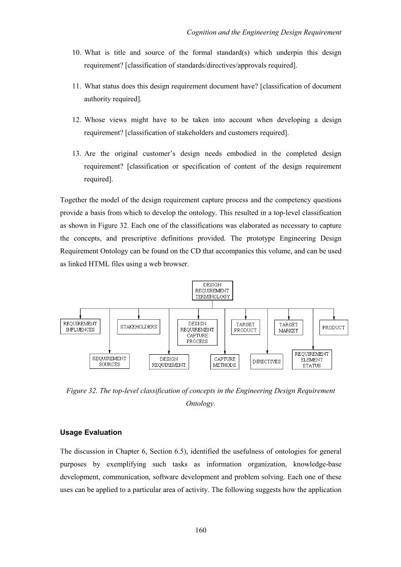
Cognition and the Engineering Design Requirement
160
10. What is title and source of the formal standard(s) which underpin this design
requirement? [classification of standards/directives/approvals required].
11. What status does this design requirement document have? [classification of document
authority required].
12. Whose views might have to be taken into account when developing a design
requirement? [classification of stakeholders and customers required].
13. Are the original customer’s design needs embodied in the completed design
requirement? [classification or specification of content of the design requirement
required].
Together the model of the design requirement capture process and the competency questions
provide a basis from which to develop the ontology. This resulted in a top-level classification
as shown in Figure 32. Each one of the classifications was elaborated as necessary to capture
the concepts, and prescriptive definitions provided. The prototype Engineering Design
Requirement Ontology can be found on the CD that accompanies this volume, and can be used
as linked HTML files using a web browser.
Figure 32. The top-level classification of concepts in the Engineering Design Requirement
Ontology.
Usage Evaluation
The discussion in Chapter 6, Section 6.5), identified the usefulness of ontologies for general
purposes by exemplifying such tasks as information organization, knowledge-base
development, communication, software development and problem solving. Each one of these
uses can be applied to a particular area of activity. The following suggests how the application

Cognition and the Engineering Design Requirement
161
of the Engineering Design Requirement Ontology can be applied to the task of supporting
design requirement capture for engineering design.
Communication
One of the principal rôles for an ontology is to aid communication between people and
organizations. Good communication is dependent to a large extent on an overlap of knowledge
between the communicating parties and a shared understanding of the terminology used. The
shared understanding may come about by conventional usage or by the sort of formal
agreement that is enshrined in standards and codes of practice. As identified in the section
dealing with the rationale for this ontology, neither have been sufficient in the case of this area
of interest to ensure standard canonical usage of terminology, or clarity about the underlying
conceptualizations.
To the extent that an ontology is a domain model of an area of interest, then the Engineering
Design Requirement Ontology provides also the basis for a unifying theory of this subject
area, in which has been identified and specified all the objects of interest.
The development, evolution and analysis of the design requirement both as a product of the
engineering design process and as a subject of discussion has been hampered by this lack of
standardization of the terms within the domain and the general ‘fuzziness’ associated with the
subject matter. For example the terms design requirement and technical specification are in
common use and yet there is no standard definition for either, and their meaning is not clear
even when used in context. The Engineering Design Requirement Ontology, which identifies
the conceptual entities in this domain and defines the terms associated with the concepts,
provides for the first time a base ontology the use of which will promote clearer
communication on this subject. This communication extends both to researchers within the
same and different disciplines, and to those providing guidance to practitioners of engineering
design.
Software Application Development
The Engineering Design Requirement Ontology provides a basis for the specification for the
objects and data structures necessary for the development of tools for modelling models of the
Design Requirement. This includes the development of design requirement capture support
software as well as intelligent agents for reasoning with design requirement related documents
and data across company intranets and the world wide web. In addition to this, the content and
structure of the ontology provides a blueprint for structuring any database related to existing
examples of design requirements. This for example might be used in a case-base for case-base

Cognition and the Engineering Design Requirement
162
reasoning (CBR) about the design requirement itself, or in an application where the design
requirement constitutes part of the indexing mechanism for a CBR system for generating
designs.
Search
The benefits of ontology-based search discussed above (Chapter 6, Section 6.5) apply in
principle to any search tasks related to design requirement capture support issues. An extreme
example could be where design requirement and design solution database exist which is
distributed through the many sites and groups within a large international corporation. Full or
partial matching of an new design requirement with an existing one would mean ready access
could be made to the existing design solution, and thus reinvention of the wheel would not be
necessary. In this way the corporate design requirement/design legacy knowledge could be
used as a distributed case-base to improve design efficiency.
Although ontologies in general have the capacity to support distributed search, an engineering
design requirement top-level ontology can provide the most fundamental building-block to
disparate systems that might be integrated in this way. It can do this because it provides the
foundation model of the entities common to engineering design requirements and thus can be
adopted in any application that manipulates models of these entities.
Additional Uses
In addition to the specific items discussed above, the Engineering Design Requirement
Ontology suggests itself as being useful in the following design requirement related rôles:
• Much of the early expression of design need is couched in qualitative terms, which must
be converted into technical specification in order the satisfy the needs of a complete
‘design requirement specification’. Methodologists (for example, Ulrich & Eppinger,
1995) distinguish between the qualitative character of the ‘design requirement’ and the
more formal content of the ‘technical specification’ and recognize the different rôles they
play in the development of the design requirement as a whole. This change in character of
elements of the design requirement is also recognized in industry practice to some extent.
The process of formalizing the design requirement in this way is clearly an important part
of the design requirement capture process as a whole. The Engineering Design
Requirement ontology formally specifies these different entities, supporting procedures
and support tools that manage the systematic conversion of qualitative components into
quantitative ‘technical specifications’.

Cognition and the Engineering Design Requirement
163
• The Engineering Design Requirement Ontology identifies and codifies the co-developing
conceptual and physical entities that constitute the developing design requirement. The
ontology thus provides a means of revealing and making explicit the implicit elements that
drive the design. This may turn out to be important particularly in the context of automatic
design, where prior identification and representation of the ‘design drivers’ is necessary in
order to implement automation.
7.2.2 The Product Finish Ontology
The subject of product finish is a small, yet important and complex, part of engineering
design. It is rare that the finish of a product can be disregarded entirely in considering the
design requirement since the finish has a bearing on how the product will look and behave,
and indeed, the selection of the finish for a product may dictate its ultimate success or failure.
Finish concerns not only aesthetic aspects, but also usability, life span and function. These
aspects of the product can be modified by a number of methods including coating and
colouring, surface working, and chemical changes, much of which is subsumed within the
term surface engineering.
The purpose of the Product Finish Ontology is to identify the conceptual elements and their
labels related to the specification of the component and product surface finish, working and
conversion. In particular the ontology was developed to support an implementation that will
ensure that between them a customer and a designer will raise and answer all the questions
necessary to complete the design requirements relating to the finish of a manufactured
product. The questions can be grouped loosely under a number of headings relating to ‘finish’,
at various levels of generality, for example type, function, properties, aesthetics, performance,
safety, contractual and regulatory. Although a particular task was in mind during development
of the ontology, it is nevertheless constructed principally as a task-independent ontology, since
no specific application influenced its construction and an attempt has been made to make the
content as universally applicable as possible.
Rationale
As is readily apparent, and is hinted at in the hierarchies shown in Figures 3 and 4, the
conceptual content of the subject areas related to specifying the design requirement is very
large. Clearly, exploring the subject in its entirety is not a practical strategy, rather sub-areas
must be identified which suggest that their investigation will prove instructive.

Cognition and the Engineering Design Requirement
164
Development of this ontology was undertaken to establish whether a distinct and clearly
complex sub-area of the subject could be mapped in a practical manner. When modelling the
real world simplification is required; and thus it is necessary to make decisions about how to
structure the model so that important elements are retained but too much detail is excluded.
Product finish suggested itself as sufficiently complex and detailed to provide a good test. In
addition, it was considered useful to develop an ontology with technical content of the sort
associated with surface engineering, since this typifies the engineering design activity, and it
is in sub-areas such as this that designer support in capturing the design requirement might be
most useful.
Development
The Product Finish Ontology was introduced in Section 7.1.1 as a means as exemplifying the
general ontology development methodology. The ontology is a logical development of the
aesthetics branch of the initial design requirement hierarchy identified in Figure 28 and
elaborated in a further exploration of the subject area in Figure 29. These two hierarchies
constituted the starting point for developing this ontology, following which initial exploration
a set of competency questions was devised to help identify the scope of the ontology.
The finish of a product spans a number of distinct conceptual viewpoints. As noted above
finish is closely related to the aesthetics of a product, which is, of course, important in making
the product appealing, and often in making it pleasant to use. However, from an engineering
design point of view it is function and performance, rather than aesthetics, that is of
predominant importance. As a result of this the viewpoint in developing the ontology was
changed from ascetics to that of function, and this aspect explored further by the development
of additional terminological hierarchies. The purpose of developing hierarchies of this type is
to explore concepts and their relationships before adopting a particular structure. An example
of one hierarchy, emphasizing the purpose and application method of product finishes, can be
seen in the visualization of the Surface Engineering Taxonomy that is provided in the CD
included with this volume.
The shift of emphasis illustrates one of the key practical aspects of ontology development;
some viewpoint must be selected from which to build the ontology. Without this, the ontology
developer is unanchored in a sea of concepts. Making rational decisions about content and
structure without the anchor of viewpoint makes the task impossible. The shift in emphasis
and the viewpoint taken is reflected in the tenor of the competency questions.

Cognition and the Engineering Design Requirement
165
Competency Questions for the Product Finish Ontology
The rationale for inclusion of related concepts in the ontology is given in square brackets
Function
1. What is the function of the finish? [function entities required]
2. Does the finish have to satisfy part of the product functional design requirement?
3. Does any aspect of the finish expressed as a design requirement conflict with any other
aspect of the product’s design requirement?
4. Is the finish functional performance quantified? [metrics required].
Type
5. Is a particular specific finish method or process a design requirement? [finish application
method entities required.]
6. Does the finish have to comply with a formally designated specification? [specification
entity required]
7. Is a particular surface material (e.g. paint) a design requirement? [material type entities
required].
Properties
8. What are the required properties of the finish? [property entities required].
9. What operating conditions must the finish withstand? [facility for defining operating
condition specifications required].
10. Are the product operating conditions quantified?
Aesthetics
11. Are specific aesthetic features part of the design requirement? [If so, what are they?].
12. Do aesthetic features also constitute part of the function design of the product?
Safety and use
13. Is user safety an issue in relation to the finish? [hazard entities required]?
14. Do environmental considerations during manufacture constitute part of the finish design
requirement?
15. Do environmental considerations relating to product use constitute part of the finish
design requirement?
16. Does the finish have to conform to a specific safety standard
Contractural and regulatory
17. Does the finish have to comply with a regulation?

Cognition and the Engineering Design Requirement
166
18. Does the finish have to meet a designated regulatory standard/specification?
19. Does the finish have to meet a designated contractural standard?
20. Do special regulations apply to use of the finish?
21. Do special regulations apply to application of the finish?
Practical
22. Do the customer’s manufacturing considerations constrain the finish or method of
application?
Using the hierarchies as an indicator of the content and structure of the subject area, and the
competency questions as guidance, the Product Finish Ontology was then developed and
definitions and relations assigned. A basic understanding of finish methods and types and
surface engineering technology was augmented by technical reference works on the subject
(e.g. Gabe, 1972; Durney, 1984) and reference to a industry available expert system for finish
selection (APTICOTE-ISIS, 2001). Publications were referred to also on the Metal Finishers
Association web site.
The class structure for the ontology contains 177 related concepts. The prototype Product
Finish Ontology can be viewed on the CD included with this volume.
Usage Evaluation
The applications of the ontology in promoting good communication and for software
development cited for the Engineering Design Requirement Ontology apply equally for the
Product Finish Ontology in the sense that entities in the domain are identified and defined. In
addition, further possible uses are discussed below.
Check List
Checklists are frequently used as an aide-memoire to ensure the inclusion of items in a
particular activity. The use of ontology content to populate a checklist is the most basic use to
which an ontology can be put as a means of assisting designers in drawing up a design
requirement. Not only can the ontology provide the content of a checklist, its organization can
suggest the structure that at checklist should take. Although its use in this way is, in a sense,
trivial nevertheless the usefulness of checklists should not be overlooked. They are still used
universally in safety critical environments such as aircraft cockpits, and Rolls-Royce have in
the past relied on checklists to help engineers develop their design requirements. Although
checklists are conventionally static and paper-based, dynamic checklists that respond to
context are also possible (and represent more interesting and intelligent applications of this
technology). A mechanism which exhibits characteristics of this sort is explored using the

Cognition and the Engineering Design Requirement
167
Machine Motion Ontology as domain knowledge, implemented using a knowledge context
inspired by the cognitive model of conceptual context referred to earlier. See Chapter 8 for
details.
Knowledge-Base Development
Populating a knowledge base with instances of a class specified in an ontology was described
in Step 7 of the methodology. If the class specified is the design requirement for a particular
application, then by specifying an instance of the design requirement class, a specific design
requirement can be captured. Protégé 2000 provides a knowledge acquisition tool by which
instances of classes in an ontology may be specified. Shown below (in Figure 33) is the
specification for the FINISH_DESIGN_REQUIREMENT class from the Product Finish
Ontology represented in Protégé 2000.
Figure 33. The FINISH_DESIGN_REQUIREMENT class as specified for a design
requirement capture tool implemented in Protégé 2000.
The details of the design requirement are variable in that the class properties can be changed
in order to suit the application and the design environment. An example of how a design
requirement class of this sort can be used to capture a specific design requirement is shown
(Figure 34) represented in the knowledge capture tool within Protégé 2000. This tool aids the

Cognition and the Engineering Design Requirement
168
capture of a requirement by providing an interface for entering appropriate property values for
the instance of the class. The tool promotes consistency and completeness (in terms of what
has been specified) in capturing the design requirement. In addition, legality of content can be
supported by imposing the constraints afforded by axioms and facets. This approach does not,
perhaps, provide ‘communication’ between the human and machine but, nevertheless, the
Protégé knowledge acquisition tool provides a powerful means by which ontologically-
structured knowledge can be captured, and illustrates the potential of this class of knowledge
acquisition tool. The approach illustrated here demonstrates how a subject-specific ontology
within the general sphere of the design requirement can be used successfully to define
formally a context in which to specify a design requirement. A review of the competency
questions shows that, provided that the knowledge elicitation tool is configured in an
appropriate way (i.e. the interface is designed specifically to ask these questions), the ontology
itself can support the sort of questions exemplified therein.
The limitation of this approach is that the knowledge acquisition is essentially static. By this is
meant that the data that is elicited is to a large extent situation independent and the context in
which the information is elicited remains fixed. For example, if the characteristics of the
product finish requires that the surface be worked rather than, say, provided by a deposited
coating, then eliciting information relating to coating becomes redundant, but information
relating to finish texture, roughness, etc. become of central importance to the design
requirement. In a static application, the system is inherently unable to respond to the specific
circumstances of the design requirement episode.

Cognition and the Engineering Design Requirement
169
Figure 34. The design requirement for an instance of product design captured using the
Product Finish Ontology implemented in the Protégé 2000 knowledge acquisition tool.
In the next section the Machine Motion Ontology is discussed. This ontology has been
implemented (see Chapter 8) in an application developed to explore one approach to the
dynamic elicitation of the design requirement. In that application the response is more
sensitive to the prevailing situation because the context changes as the episode develops.
7.2.3 The Machine Motion Ontology
When developing the design requirement for a specific design episode many different aspects
of the world have to be considered. As identified in the initial hierarchy in Figure 28, these
range from safety and legal matters, to marketing and environmental considerations. In
engineering design, however, over-riding all other concerns are those associated with the
function of the artefact and the way it performs. Pugh (1991, p.48) for example says that ‘in
discussing specifications most engineers think primarily in terms of performance, since
performance achievement forms a major part of their activity’. In simple terms, if the
engineered product doesn’t possess the right functionality, then any other properties become
uninteresting. This is particularly the case when the design solution is intended to carry out
work; i.e. it is a system or mechanism which constitutes a machine. The concept of motion is

Cognition and the Engineering Design Requirement
170
an elaboration of the functional concept identified in the base design requirement hierarchy
shown in Figure 28.
Rationale
The Machine Motion Ontology was developed to explore the use of an ontology at a very
detailed level of description in an area that is fundamental to design, that is to say, the
purpose, function, behaviour and activity of the machine. In particular, the purpose of the
ontology is to provide semantic content sufficient to support a design tool. Specifically, the
intention of the design tool would be to guide dialogue between a customer (who wishes to
convey a design need) and designer (who wishes to develop and record the design
requirement) in such a way that a design requirement can be developed specifying in detail the
motion requirements of a machine.
This ontology is, therefore, very task-specific; unlike, for example the Engineering Design
Requirement Ontology, which was developed with general usage in mind. This influences the
organization of the concepts within the class hierarchies. Nevertheless, in spite of this, the
ontology content is general in the sense that its domain concerns aspects of motion, which are
anchored in the real world and whose relations are constrained by physical laws.
The approach taken to the development of a computer-based environment for aiding design
requirement elicitation uses the idea of context, as discussed in Chapter 5, as the basic
underlying mechanism. To achieve this, the main structure of the ontology, has been
augmented by a set of relations specific to the task of achieving context by association of
concepts.
The following paragraphs treat specifically the content and structure of the Machine Motion
Ontology; further considerations about the content and a full discussion of the application of
the ontology in the design support tool can be found in the following chapter.
Development
As suggested by some of the above discussions, attempting to develop some form of artificial
conceptual structures which are analogous to the mental picture that an individual may have,
means that arbitrary decisions have to be taken about the best representation. This stems from
the fact that concepts can be organised in whatever manner is appropriate for the (mental) task
in hand, that is to say, the structure of meanings is malleable or fluid, not fixed. In this case,
however, there are physical constraints on some of the entities in the domain which must be
observed in their conceptualisation. So the task is to find some logical structure that suggests

Cognition and the Engineering Design Requirement
171
itself as being useful (in this case for a particular computer-based task). This structure, of
course, can be modified as the result of analysis and testing during development.
Conceptually, the Machine Motion Ontology concerns at one level the purpose and function of
a machine, and at another level the way that purpose and function are achieved by the physical
activity of the machine. Thus, on the one hand the ontology will identify concepts related to
intention and on the other will be concerned with concepts related to objects and the relations
that concern them in the physical world.
As a starting point for defining a 'closed' domain of concepts relating to machine function, the
author chose a simple categorization scheme that reflects these different aspects of machine
motion, and which distinguishes three levels or dimensions of description which seem
intuitively to be useful when discussing machine motion. The two most basic levels are
referred to here as the Object level (O_level), which relates to the description of physical
objects, and the Action Level (A_level), which concerns the effect of natural phenomena on
objects. The third level, the Function level (F_level) is a higher conceptual level, which can be
redescribed conceptually in terms of the lower levels.
In the A_level, concepts concern the effects of natural phenomena (e.g. force, torque, etc),
without implicating intention. At the F_level, however, the activity becomes redescribed in
terms of intention or requirement. The concepts at the action level are represented by the
structures in S1 and S2.
The object state is defined by the values of object property attributes. The object state and
state change are dictated by natural phenomena. The structures in S3 relate to F_level
concepts. Each heading effectively represents a potential concept class structure diagram or
tree.
S1 Object description concepts
A. Object properties (quantitative), e.g. mass, momentum, rigidity, etc.
B. Object qualities, e.g. fragility, heaviness, bulk, balance.
S2 Object state concepts
C. Motion
D. Speed
E. Position
F. Natural phenomena, e.g. force, pressure, inertia, resistance, etc.
G. Machine activity concepts, e.g. over-running, under load, slippage, etc.
H. Object state-change
S3 Function level concepts

Cognition and the Engineering Design Requirement
172
I. Control F_concepts
J. State-change F_concepts. This suggests action to satisfy a functional requirement.
These structures were used as a starting point to suggest the best organization for a set of
hierarchies defining the design requirement domain to be developed. Augmenting the analysis
of the domain were a set of competency questions which assisted in defining the scope of the
ontology for the intended purpose.
Competency Questions for the Machine Motion Ontology
1. What is the purpose of the machine activity?
2. Does the activity involve a work piece/object?
3. What is the direction of the motion?
4. Is the movement over a fixed distance?
5. Is the movement for a fixed duration?
6. How fast is the movement to be?
7. Is variation in the velocity required?
8. What is the character of velocity variation?
9. Does the effort involve free movement of an object?
10. Does the movement of the machine involve force applied against a restrained object?
11. Is motion to be controlled manually or automatically?
12. How precise must the motion be?
13. How responsive must the control be?
14. What character of movement is required?
15. What is the mass of the load to be moved?
16. Is the mass fixed or variable?
17. What force(s) is required to carry out the desired function?
As a starting point for identifying important terms in the domain, the lexicon developed in an
earlier investigation into representing the design requirement for automatic design (see
Darlington & Potter, 1998b) was used. From this were taken those words which were
appropriate for this restricted purpose. Additional words were adopted as seemed appropriate
in order to increase the richness of the expression. In addition the existing general lexical
ontology WordNet (Miller, et al. 1990) was used as a principal source of words and
definitions for this specialist lexicon. In particular, WordNet was used as a means of
eliminating synonyms. From this was evolved, through content analysis and revision, the
exploratory Machine Motion Ontology. This can be seen in the CD included with this volume.
Special ‘Context’ Relations

Cognition and the Engineering Design Requirement
173
As noted above, in addition to the conventional hierarchical arrangement of the concepts
within the Machine Motion Ontology, a further set of additional associative relations are
defined which support machine reasoning for the special purpose of providing a ‘context’ in
which dialogue can occur between human and machine which is appropriate to a particular
conversation or elicitation episode. The mechanism that has been chosen for this is to specify
a special relation between objects in the ontology based on the Boolean operators. The
operators used are the AND_RELATION, OR_RELATION and XOR_RELATION, each of
which can take any class in the total domain class hierarchy. Those actually assigned define
the logical relations between the classes. The way in which the concepts are related logically
(i.e. using the Boolean operators) can be seen in Figure 35, where a fragment of the hierarchy
related to movement is shown.
movement
translation rotation
rate spinning turning reorientation
speed acceleration skewing tipping
Figure 35. A fragment of the motion hierarchy, showing concept labels, AND relations (solid
lines) and XOR relations (hatched lines)
Here, for example, the concepts of translation and rotation are associated with the concept
movement by the XOR relation, because conceptually the concepts are mutually exclusive. On
the other hand the concept rate is associated with speed and acceleration by the AND relation,
since the former concept logically entails both subordinate concepts.
A fuller visualization showing the sort of classification structure defined by the Boolean
operators is shown in the motion conceptual hierarchy (motion_concept_representation.ppt)
which can be found on the CD accompanying this volume. In this organization the concepts
are classified in the groups: function, motion, object attribute, force and control. This
arrangement was adopted purely on pragmatic grounds in order to facilitate administration of
the concepts when implementing the design requirement support environment; the grouping is
not explicit in the ontology. This organizational structure, therefore, is highly task related.

Cognition and the Engineering Design Requirement
174
Thus, the approach to developing the Machine Motion Ontology combines a conventional
taxonomic hierarchy, which supports semantics, and a logical relational hierarchy which
supports a task-related inference and, thus, additional semantics. These two types of
relationship co-exist. The provision of the Boolean relations allows the objects in the ontology
to be organized in a secondary inferential structure. The structure associates objects, not by the
conventional taxonomic relations, but by context association. The use of these two essentially
independent classification structures illustrates the power of ontology to capture
simultaneously more than a single conceptualization of a domain.
In Chapter 5, a simple cognitive model of conceptual context was introduced by the author
which attempts to identify the functional architecture and knowledge requirements that
support conceptual context. Missing from this model is some general means by which the
concepts in long-term memory can be placed in working memory in a manner appropriate to
the needs of the current cognitive task. Context association in the manner described using
Boolean operators is proposed by the author as a simple means by which this association can
be achieved and thus provide an artificial context analogous to that which is necessary for
human communication. Operational details of this mechanism, and the extent to which it is
successful in providing a basis for conceptual context, can be found in the next chapter.
Usage Evaluation
As discussed above the Machine Motion Ontology was developed expressly as a task-related
ontology with a particular application in mind; that of providing a ‘context’ for dialogue.
In addition to this, the ontology also serves to identify at a very detailed level the general
conceptual entities which relate to and must be taken into account when specifying the design
requirement for this specialize area of the engineering design requirement. Currently the
definitions for the classes in the ontology have not been fully specified (because definition
was not necessary to the investigation, and this process had been carried out for the
Engineering Design Requirement Ontology). However, given these definitions it will serve as
a general ontology of machine motion and can be used as the basis for communication
enhancement and also for problem solving applications in this domain. For example, a static
design requirement of the sort exemplified by use of the Product Finish Ontology could be
captured using a knowledge acquisition tool of the sort available in Protégé 2000.

Cognition and the Engineering Design Requirement
175
7.3 Building and Using Ontologies for use in the Engineering
Design Domain
As cited in the introduction, a considerable amount of work has been done recently and is
currently in progress relating to ontologies (Guarino & Carrara, 1999). This would imply that
on the one hand there are many theoretical and practical problems to be solved associated with
developing and using ontologies, but on the other the promise of the long-term usefulness of
ontologies will make the labour worthwhile. Both sides of this coin have been experience by
the author of this report whilst investigating the construction and use of ontologies in relation
to the engineering design requirement capture process.
7.3.1 Assessment of the Ontology-Building Task
It is quite clear that task of building an ontology is a non-trivial one. This view has been
expressed informally by, amongst others, investigators in the design research community who
have had cause to be involved in ontology building. It is certainly the experience of the author,
who found that ontology building requires not only an intimate and comprehensive
understanding of a domain, but the commitment of substantial amounts of time in its
conceptual exploration. Furthermore, producing well-founded ontologies is an activity that
demands the involvement of groups of people, usually experts whose time is valuable.
Nevertheless, as reported here, it is clear that the use of systematically constructed ontologies
hold promise in a number of practical ways that might assist in the daily practice of
engineering design. It is also clear that much work remains to be done both regarding the
development of ontologies in general, and in the application of the common wisdom about
ontologies specifically to the domain of engineering design.
The way that individuals organize the world conceptually – that is to say, in their heads – is
almost entirely implicit. There is usually no need for it to be any other way. The world is
learned about and organized through direct or indirect experience, but the individual’s
knowledge and its organization is always incomplete: conceptually the world is ‘fuzzy’ to the
observer. It is only on inspection that it is possible begin to analyse how individuals relate
various distinguishable and shareable entities and through description attempt organization.
Attempts at systematization of information and knowledge of the sort found in an ontology
makes it necessary to make decisions about how to ‘carve the world at its joints’ in an explicit
way. In this respect, there is an interesting comparison to be drawn here between the Machine
Motion Ontology, which represents a domain where physical laws provide some natural
structure to the ontology, and, for example, the Design Requirement and Product Finish

Cognition and the Engineering Design Requirement
176
Ontologies, where the structure is more arbitrary, since no physical constraints of this type
exist between the concepts. As a result, in the latter two cases, the choices about how the
ontology is to be constructed is less constrained. The methodology that was used to develop
the ontologies in this research was certainly helpful in guiding the process of development.
Nevertheless, it is clear from the experience of building these ontologies that the difficult part
is making decisions about what concepts to represent and how they should be related. It is
difficult to see how methodology could ever assist much in this respect.
Furthermore, for an ontology to be useful (indeed, for an ontology to be recognised as such) it
must constitute a consensus between users about how the world is codified. Agreement has to
be made between individuals about how their disparate but overlapping views of the world,
hitherto fuzzy and implicit, can be reconciled into an explicit representation. This, and the
demands of time (usually that of experts) is why the task is ‘non-trivial’.
The task of ontology development is assisted currently by a number of methodologies and
support tools, representative examples being discussed in this thesis and used to guide
ontology development. There is, however, no widely adopted or ‘standard’ methodology and
the ontology development tools take different approaches. Given the immaturity of the
endeavour of ontology building and application, the methodologies and technologies that do
exist can be considered as ‘first generation’ and therefore, understandably limited in
usefulness. It can be expected that more substantial help will be available in future in both
areas as further research work is done, and as a result ontology application for supporting the
engineering design process will become more practicable.
7.3.2 Assessment of the Usefulness of Ontologies
The general case for the usefulness of ontologies is quite forcibly expressed by the amount of
current research and application activity. In particular, the adoption of ontologies as the
foundation of the Semantic Web (Berners-Lee, et al., 2001) provides ample proof of the
confidence placed in the use of ontologies as the means by which ‘intelligence’ can be
embodied in documents and search systems. If this represented all that ontologies could offer
to the engineering design process, then even so there would seem to be ample scope. The
scope, however, seems much greater than this.
Ontologies have already been adopted for use in the domain of engineering in some important
undertakings, for example in the STEP (ISO 10303-1:1994) and KACTUS (KACTUS, 2002))
projects, both of which impinge upon the design activity. STEP’s objective is to provide an
implementation-independent method of achieving inter-operability between different systems

Cognition and the Engineering Design Requirement
177
and environments where product data is to be exchanged. STEP must be able to provide a
means where product information can be represented in a complete and consistent manner
when exchanged across different computer systems, and throughout the entire life-cycle of the
product. Clearly, the underpinning of this must be ontological.
The KACTUS project has endeavoured to provide a complete methodology for reusing and
sharing knowledge about the entire life-cycle of technical systems which, of course, embraces
the design requirement development phase of the design process. The purpose is to integrate
the design process in such a way that the same information about a product can be used
throughout the entire design, diagnosis, operation, maintenance, redesign, and disposal of a
product. KACTUS uses computer based manufacturing and engineering methods and
knowledge engineering methods to integrate the process. Domain ontologies are used
extensively in this integration.
The ontologies presented in this thesis have been developed as the means of investigating the
usefulness of ontologies in supporting design requirement development and are not
represented as being ‘complete’ in some sense. In any event, by its nature, any ontology is
susceptible to continuous revision, by addition, deletion and reorganization of the content and,
therefore, the term complete is rather unhelpful. Perhaps the term complete should be
interpreted as indicating that the ontology has been agreed by two or more individuals as
representing a self-consistent and comprehensive conceptualization of the domain of interest
useful for a specified purpose. Given that interpretation, each of the ontologies is presented as
an exploration of the conceptual ‘space’ in a domain of discourse concerning the design
requirement, and represents a basis for agreement.
The usefulness of ontologies for assisting in some general tasks was discussed in Chapter 6,
Section 6.5; these include the enhancing of communication between individuals and
organizations; use in developing knowledge-bases and software applications; and in search
and problem solving. These uses have been exemplified and demonstrated (Sections 7.2.1 to
7.2.3) when applied to design requirement development in relation to the three exploratory
ontologies developed during this investigation. It can be seen by the examples given that
ontologies can be applied in a number of different ways which assist in capturing the design
requirement. Evidence is thus provided that development of ontologies for this task is of
benefit and can support the process of design requirement capture. In conclusion of this
discussion, the next section reviews the uses of ontologies as providing some form of artificial
‘context’ for design requirement capture support, and returns to consideration of the
relationship between human and machine and sharing knowledge as a means of sharing the
inferential burden.

Cognition and the Engineering Design Requirement
178
7.4 The Human-Machine Relationship: Part II
The task of formalizing domain knowledge, using ontologies in order to support design
requirement development as discussed above, consists of:
• Identification at a low level of resolution the knowledge content needed when talking
about the domain of interest; and,
• Structuring the knowledge content in such a way that it provides a constraining ‘context’
when talking about the subject when eliciting the design requirement for this aspect of a
new product.
There are various ways in which the artificial ‘context’ provided by the ontology can be used,
a number of which are reviewed below. The simplest way in which the ontology can be
applied is as a basic paper-based checklist. When used as a checklist, the ontological approach
to defining the ‘context’ helps ensure that the content of the list is specified in a coherent and
agreed manner, which means that the resulting design requirement record accords with some
prespecified structure and content. The basic checklist is, however, entirely dependent for its
best use on the human that is using it. It is not regarded here as an elicitation method since it
lacks the interactivity that seems an essential part of the process. Making the best of the
ontology – shifting the inferential burden so that it is to some extent shared by human and
machine, and achieving some form of elicitation proper – requires a more sophisticated
implementation in some support system.
Built into the Product Finish Ontology is the class concept:
FINISH_DESIGN_REQUIREMENT, which is specified in terms of a set of attributes and
relations (see Section 7.2.2). An instance of this concept represents a single product finish
design requirement. The general entity ‘design requirement’ can be specialized as necessary to
any sub-domain of the design requirement as a whole by changing the attributes and relations.
By doing this the content of what is to be elicited during the design requirement capture
episode can be specified at will (within the constraints of a static method). Thus, rather than
capture, say, the design requirement for the finish of a product, it would be possible to specify
and capture the design requirement for the functional aspect of a product.
Protégé 2000 (Protégé 2000), the ontology editor used to develop the context ontologies,
incorporates a knowledge acquisition mechanism that allows instances of concepts classes in
the ontology to be instantiated. A single instantiation of the class
FINISH_DESIGN_REQUIREMENT represents a design requirement for a single design

Cognition and the Engineering Design Requirement
179
episode. It has been shown that this mechanism can be used to elicit and record a design
requirement in a structured way.
Nonetheless, using the knowledge acquisition approach is clearly an improvement over the
basic checklist. Another example of providing what is a static elicitation scheme can be found
in an earlier investigation carried out by the author (Darlington & Potter, 1998b) where the
description of the design requirement was required for input into an automatic design system
for configuring fluid power systems. These methods of capturing the requirement are
representative of those that are essentially static elicitation methods, in that the means for
eliciting case-specific responses is limited. The second approach is analysed in some detail in
the next chapter (Section 8.1), since it provided the impetus for investigating a dynamic
method of elicitation, resulting in the work reported here.
Dynamic elicitation is a more satisfactory approach for capturing the design requirement,
since a system of this sort can guide the elicitation not only within the context, but be sensible
of the developing current situation and modify the context for discussion accordingly. This is
analogous to the way that conceptual context is used by humans. One approach to achieving
this has been introduced in the section on Machine Motion Ontology, and is elaborated in the
next chapter.
Another approach to developing dynamic context is suggested by one of the uses for
ontologies cited by Noy & McGuinness (2000): ‘to share common understanding of the
structure of information amongst people or software agents’. As well as defining concepts by
means of relations, it is also possible to extend the inferential potential of ontologies by means
of embedding constraints (through the use of axioms) and by applying inference rules. By this
means additional knowledge can be embedded in and imparted by the ontological ‘contexts’.
In addition to providing an enhanced basis for dynamic implementations of ‘context’, this
approach raises the prospect of using a cohort of intelligent agents (each one of which is
specialized to the acquisition and manipulation of specific data) to co-develop, with the human
user, a design requirement during an elicitation episode.
The three types of capture approach – basic checklist, static elicitation and dynamic
elicitation – can be overlaid onto the model of human-machine inference introduced earlier
and shown here in Figure 36, indicating how sharing knowledge can progressively move the
inferential burden between humans and machines rightwards towards the ideal.

Cognition and the Engineering Design Requirement
180
Figure 36. A comparison of the suggested context-based design requirement capture
mechanisms in terms of inference sharing.
7.5 Summary
In this chapter the use of an ontology development methodology has been illustrated and three
different types of ontology developed. Each ontology captures concepts and relationships
associated with different aspects of the engineering design requirement. By constructing the
ontologies, part of the domain knowledge needed when developing the design requirement has
been identified and formalized. It is possible, as a result, to begin to answer more fully the
questions posed in Chapter 5 and elaborated at the end of Chapter 6, that is: 1) ‘about what
sorts of things must stakeholders and machines know in order to communicate about the
design requirement?’ and 2) ‘how might that knowledge be organized?’ At the same time,
identification of these entities provides the means by which artificial ‘contexts’ can be
provided which assist in guiding and constraining the design requirement capture process.
The Engineering Design Requirement Ontology identifies the concepts associated with and
the data entities which constitute a design requirement itself. By identifying these entities,
their relationships and definitions the basis is provided for a more prescriptive and normative
use of terminology within the domain. It is hoped that this will promote clearer
communication of the subject in research and in industry. For the first time, the two co-
evolving aspects of the design requirement – the conceptual and the physical – have been
identified, and an initial specification of the associated entities drawn up.
The Product Finish Ontology and Machine Motion Ontology have been constructed to specify
the conceptualizations of their respective domains in a detailed way. The general application
of each of these ontologies is discussed, and the means by which some sort of ‘context’ can be
provided is illustrated by which design requirement capture can be supported. A contrast is
drawn between static and dynamic elicitation methods, and the dynamic approach

Cognition and the Engineering Design Requirement
181
recommended for moving towards a more ideal sharing of the ‘inferential burden’ in the
design task.
In the next chapter, the implementation of a specific dynamic design requirement elicitation
support tool will be discussed, which combines in one application the domain knowledge
captured in the Machine Motion Ontology and the notion of conceptual context developed in
earlier chapters.

Cognition and the Engineering Design Requirement
182
8 A Context-Sensitive Design Requirement Elicitation
Scheme
The work reported in this chapter concerns the application of the Machine Motion Ontology to
a prototype design requirement capture support tool that uses the idea of ‘conceptual context’
as its underlying methodology. The method developed by the author for achieving ‘conceptual
context’ is referred to as the concept activation Design Requirement elicitation scheme
(caDRes) and is implemented in a prototype software application of the same name. The
caDRes method of capturing the design requirement and the purpose of the implementation
draw together three elements of the author’s research which have been discussed in the earlier
part of this thesis and which provide a rationale for development.
The three main elements of the investigation are as follow:
1. The first element (considered in Chapter 5) concerns the nature of the design requirement
capture process and how some of the failures that have been recorded in capturing the
design requirement are the result of the flexibility with which ideas about the design
requirement are communicated.
2. The second element concerns domain knowledge and investigates how ontologies can be
used to codify the conceptual and semantic content of an area of interest (Chapter 6), and
how by doing so knowledge about that area of interest can be made explicit, accessible
and shareable (Chapter 7).
3. The third investigative strand concerns the idea of ‘conceptual context’ (discussed in
Chapter 5) as being central to enabling communication between humans, and how an
analogous mechanism implementable on a computer might be provided that guides the
dialogue between humans and machines. Associated with this is the goal of sharing the
inferential burden of an intelligent task between the human and a machine for the reasons
given in Chapter 6.
The purpose of implementing caDRes as a prototype design capture tool is to provide a means
for exploring the caDRes approach to combining domain knowledge with a context-sensitive

Cognition and the Engineering Design Requirement
183
environment for its application. The intention is to show that it is possible to ameliorate some
of the problems identified in the first element of the investigation by applying this novel
approach (based on what has been learned in the second and third elements of the
investigation). In addition, the intention is to remedy some of the limitation of a design
requirement elicitation scheme that was developed in earlier work by the author. This earlier
work (Darlington & Potter, 1998b) provided much of the impetus for the work reported in this
thesis; thus it seems appropriate to discuss the earlier scheme’s shortcomings and the extent to
which the caDRes approach contributes to their amelioration as well as to amelioration of the
problems associated with communicative failure discussed earlier.
In Chapter 4, in discussion of the case studies of design requirement capture in practice, the
author suggested that if formalization of the design requirement process were to be adopted,
then the class of user that would benefit most would be the novice designer or equally the
experienced designer working in an unfamiliar field or environment. It is for this type of user
that a design support tool based on the caDRes approach would be of most benefit. In
principle, the caDRes approach can be used for the generation of a design requirement that
fulfils some predefined style and format, and to meet some notion of ‘completeness’; the way
in which it does this is illustrated in this chapter. Thus it can be applied to support the
customer with a design need in such a way that a design requirement of a particular character
can be developed which will suit the requirements of a particular designer or design team.
8.1 Review of the Static Design Requirement Elicitation Scheme
In Darlington & Potter (1998b) the author developed a design requirement elicitation scheme
that could be used both as a method of representing the requirement for archiving existing
fluid power circuit designs, and capturing a uniform design requirement needed for an
automatic configuration design system.
That design requirement elicitation formalism (referred to hereafter for clarity as DREF1)
consists of a ‘flow-chart’ for eliciting the functional design requirements, descriptions of
aspects of duty cycles, and a number of characterizing elements such as speed, load, etc. It is
currently implemented in a paper Design Requirement Elicitation Questionnaire (see
Appendix A) which, for pragmatic and applications reasons, limits further the questions and
response modes. In both formalism and implementation however, the questions and the terms

Cognition and the Engineering Design Requirement
184
specified for response constitute a simple and constrained language9 in which the DR can be
discussed. Consideration of the assumptions underlying the development of the scheme and
shortcomings of what is a static elicitation method motivated the search for a dynamic
scheme, resulting in development of the caDRes approach. The implementation is essentially a
checklist, but it has a measure of interactivity which allows the design requirement content to
be modified in a limited way according to the prevailing context.
The DREF1 scheme is considered static, because (like the ontologically derived schemes
discussed in Chapter 7) it is essentially unable to respond intelligently to the context of the
design requirement currently being developed. Because of the static nature of the system,
irrelevant or inappropriate information is sought and important paths may be left unexplored.
A dynamic system, on the other hand, should exhibit behaviour where the topics explored
during elicitation are selected in the light of the prevailing and changing circumstances. This
motivates the search for a ‘context-sensitive’ method of eliciting the design requirement.
The limitations of DREF1 are discussed below.
8.1.1 DREF1 Limitations
DREF1 consists of elicitation questions, together with structure for ordering those questions,
and a response vocabulary. There are clear limitations with each of these aspects of the
formalism.
1. Mixed Content Level. An attempt was made to develop a ‘domain-neutral’ framework, in
which the design requirement could be described independently of the solution. The
advantage of this is that the design requirement can be expressed without constraining the
design to a specific solution domain thus avoiding exclusion of the best solution.
However, the need to achieve a working formalism for the purposes of testing an
automated system resulted in a scheme which has mixed content, including domain-
specific allusions and reference to the solution.
2. Rigidity. The scheme disregards the iterative, interactive and incremental nature of DR
elicitation.
9 By language is meant any formalism consisting of a vocabulary and grammar (the rules for
their agreed use).

Cognition and the Engineering Design Requirement
185
3. Too constrained. Constraint can occur in two ways: by a) restricting what ideas can be
talked about, and by b) restricting the ways in which those ideas can be talked about.
When using natural language, expression is limited (setting aside discussion of the
ineffable) only by the domain knowledge and the language competence of the speaker. A
successful constrained language should in a) provide a mechanism by which every chosen
aspect of the requirement can be discussed effectively, and in b) restrict the ways in which
the discussion can take place, to enforce simplicity and reduce ambiguity. Achieving a
useful constraining framework requires a fine balance between over- and under-constraint
of these two characteristics. The nature of the DREF1 scheme encourages unhelpful over-
constraint of what can be talked about, and the manner in which it can be expressed, even
within the chosen focus for discussion (i.e. the functional aspects of a machine).
4. Terms incorrect and poorly defined. The terms are not necessarily the most useful, and not
defined clearly, leading to misunderstanding and ambiguity. Also, there is little contextual
support to suggest correct interpretation by the user. User notes can be provided as
guidance, but this is unwieldy: ideally, elicitation prompts should be disambiguated and
the meaning established first by documented definition, then by context of use, and only
when this fails by additional documentation.
5. One-dimensional. In the real world, the design requirement embraces a wide variety of
topics. With the exception of functionality, these are largely disregarded in the current
formalism.
6. Temporal aspects of performance poorly catered for. Provides little guidance for
capturing duty-cycle information.
Some of the shortcomings identified above, particularly items 2, 3, 4 and 6, are inherent in any
static method for eliciting the design requirement. For example, the method of design
requirement capture illustrated by the knowledge acquisition tool discussed in Chapter 7
(Section 7.2.2) also has these limitations. However, since that tool is ontology based, and
therefore in general, well founded in terms of structure and definition, it does overcome the
difficulties associated with definition and, to a large extent, semantics related to item 4.
8.2 Review of Communicative Failure
In Chapter 5 it was asserted that flexibility in the expression and interpretation of information
– the communicative freedom – about the design requirement results in communicative

Cognition and the Engineering Design Requirement
186
failure, of which the result is often ambiguity and uncertainty in meaning. In developing the
caDRes approach an attempt has been made to eliminate some of these problems.
The ‘dimensions of communicative freedom’ that contribute to miscommunication have been
identified (Chapter 5, Section 5.3) as:
1. Selection of medium.
2. Variety of expression.
3. Accuracy of expression.
4. Content (incorporating completeness, inappropriateness and extension by the designer).
By applying an ontological approach to the formalization of domain knowledge and providing
a means by which context can be used to constrain interpretation, some of these dimensions of
communicative freedom can be controlled. For example, in using an ontology, where the
domain content is specified by prior agreement, the variety and accuracy with which ideas are
expressed can be constrained, as too can the incidence of inappropriateness in the content.
As discussed earlier (in Chapter 5, Section 5.3.4) dealing with completeness in general is
intractable. However, in a practical sense some agreement can be made in a formal design
environment about what constitutes a complete record of a design requirement, this being the
basis upon which the design itself proceeds. In this sense completeness concerns the content
of the design requirement and its extent in relation to what is appropriate in the current
episode. As will be shown in the implementation of the dynamic caDRes approach it is
possible to use ontological content and ‘context’ to arrive at a design requirement that is
complete in the sense that it satisfies some agreed notion of completeness on both these
counts.
8.3 The Descriptive Scope of the caDRes Implementation
In the development of a design requirement elicitation scheme the investigation has been
limited to consideration of a solution-independent verbal language and to one that is
appropriate to discussing the function of a machine (at a number of different levels of
description). As acknowledge earlier, verbal language is not alone as a means of conveying
ideas in the design process, since other means are also commonly used (see, e.g. Cross, 1994,
on sketching). Nevertheless restricting the area of investigation limits the complexity, and is
made on the presumption that verbal language is basic to the discussion of design need.
Similarly, as discussed in relation to the development of ontologies, there are many domains
of discourse in which discussion may be appropriate, indeed necessary, when developing the
design requirement. The current investigation is limited to the viewpoints embodied in the

Cognition and the Engineering Design Requirement
187
Machine Motion Ontology, the presumption being that function is the basic need in
engineering design, and that machine motion is basic to achieving functionality in mechanical
engineering design.
For the purposes of this investigation the function of a machine taken to be its purpose, and is
described from the point of view of the user. For example, the purpose of a machine might be
to ‘raise’ a load. The action of a machine is the physical activity or evolutions carried out by
the machine to achieve the increase in elevation of the load. The action may be described in
terms of function, together with temporal and spatial descriptive content. (The behaviour of
machine will be the action in particular conditions). In order to clarify this notion of function
the following constraints have been applied:
1. When considering the tasks a (limited class of10) machine can carry out, the following
basic functions can be performed:
• moving an object.
• acting on an object (e.g. when clamping or drilling).
• acting on itself (e.g. in moving a mechanism).
2. The requirements that a mechanical system may be required to meet can be expressed in
terms of the function (the purpose) of the machine and in terms of the action of the
machine.
3. The actions that a machine can perform can be redescribed or ‘chunked’ as functions..
8.3.1 The Tasks
A number of tasks suggest themselves as being central to developing a dynamic DR elicitation
scheme. First is the identification of the vocabulary for use in talking about the design need;
second is a method for implementation that will allow guided elaboration of a design
requirement in a controlled way using the specified vocabulary. Implementation on a
computer means interaction between the user and the machine, thus implying some 'shared'
understanding of the terms available for use, as discussed in Chapters 5 and 6; this introduces
the requirement for identifying the concepts that underpin the vocabulary.
For the purposes outlined above, the tasks can be summarized as:
10 the limited class of machine being considered is of the type characterised by those in which
power is used to move an end-effector of one sort or another.

Cognition and the Engineering Design Requirement
188
a) identifying the concepts that are needed to think and talk about the domain.
b) identifying the words needed to label these concepts.
c) establishing a method for constraining the use of vocabulary to that which is appropriate
at the time.
d) developing a structure to allow the words to be represented and used.
Questions about what needs to be represented have been discussed generally throughout
Chapter 6 and specifically in Chapter 7, Section 7.2.3 in the development of the Machine
Motion Ontology. Here consideration is turned to how the ontological content can be
controlled and organized which satisfies items c) and d). These issues are dealt with in the
next section.
8.4 A Scheme for Constraining Dialogue
In the interaction between humans and computers, – at least in its current manifestations – the
interpretative power is very one-sided. Computers, having no intelligence, can interpret input
only in a limited manner, and only where the mechanism has been pre-specified. However, if
contextual constraint can be provided in humans by an implicit network of concepts, then why
should it not be provided to some extent in a machine by making the network explicit, by pre-
defining the concepts and their interdependent relationships? By defining an explicit network
of concepts a basic ‘locality’ of concepts would be provided for a particular task. This would
allow the behaviour of the computer to be constrained and fix the context for the interaction
between it and the human operator.
8.4.1 The Concept Association Mechanism
Introduced in Chapter 7 in association with the Machine Motion Ontology is a basic
associative mechanism based on Boolean operators of the sort that is necessary to complete
the cognitive model introduced at the end of Chapter 5. A number of these operators have
been integrated into the ontology as a secondary structure by which, in principle, the
associative relations between each concept can be defined.
Because the associative mechanism is central to the method of implementing a context for
communication, it is reviewed and elaborated here in the context of the implementation.
The relations adopted between the concepts are: parent, child and co-activee, elaborated as
follows.

Cognition and the Engineering Design Requirement
189
Parent. Each concept, excepting the root concept, will have a single parent. This relations is
implicit in the sense that the concept with which another concept is associated as a child must
be the parent. The parent relation is implicitly an AND relation. The parent relation is stated
explicitly in the implementation but not in the ontology.
Child. Any concept can have one or more child concepts. These may be associated by the
logical relations:
AND, where all child concepts are logically entailed if the parent concept exists.
OR, where one or more of the child concepts may be logically entailed if the parent
concept exists.
XOR, where one child concept only is logically entailed if the parent concept exists, that
is, the existence of a child concepts excludes all others.
Co-activee. To make the approach manageable this additional ‘housekeeping’ relation has
been devised. This relation is used in the implementation entirely on pragmatic grounds, to
facilitate administration and maintenance of a complex and large conceptual domain. For the
purposes of the implementation the conceptual content is sub-divided into the five conceptual
groups (force, function, motion, object attribute, and control). As a result; some concepts that
are considered to be semantically contiguous are distributed in separate groups. The relation
co-activee allows distributed location of concepts at the same time as retaining the notion of
close semantic proximity.
8.4.2 The Conceptual Structure
The concepts and their associations gathered into groups constitute what can be thought of as
conceptual structures. These structures can be represented visually as simple trees consisting
of leaves (representing the concepts/labels) and branches representing a direct relation.
The conceptual structure is based on the idea that concepts cannot stand alone, they must be
supported in terms of meaning by other, related concepts. For example, in the fragment of a
conceptual structure relating to motion shown in Figure 37, the concept of movement is
represented as being closely related to the concepts of translation and rotation.

Cognition and the Engineering Design Requirement
190
Figure 37. A parent concept (Movement) supported by two logically contiguous child
concepts.
The idea of movement is meaningless independent of other ideas, that is, if the other concepts
are not held in mind simultaneously. Indeed, it can be argued that the leaf for which
‘movement' is the label, has no meaning itself but is merely a marker for a network of
associated concepts which defines its meaning and of which it is the central point, each other
concept having a reciprocal relationship for meaning support. Thus, as White (1975) says, the
meaning of a concept is its position in a network of concepts.
The tree structure includes also information about the logical relationship between concepts.
For example, in the tree shown in Figure 38 (below) the supporting concepts of translation
and rotation related to movement are defined as being mutually exclusive. In the interpretation
of the domain captured in the ontology, movement can be either translational or rotational, not
both. In the Machine Motion Ontology these logical relations are functionally equivalent to a
set of inference rules of the sort that are discussed in Chapter 6, Section 6.4.4. since they allow
extra information to be inferred.
This inference capability is the basis for providing an artificial context that allows guidance of
dialogue between human and computer. In the example given in Figure 38; if movement is
active (i.e. part of the current conceptual context) then it can be inferred that it is a topic
suitable for inclusion in the conversation. Similarly, given that movement is part of the current
context then one or the other of the two other concepts (translation, rotation) must be
candidates for consideration in the developing dialogue, since they are closely related
concepts that bring meaning to the concept of reorientation. Extra information is necessary for
a choice to be made about which of the two candidate concepts are appropriate in the current
circumstances. This information may be available within the current context (for example if
concepts associated with rotation are already active it can be inferred that the concept
‘rotation’ is appropriate) or from an external source (for example by a human exercising a
choice or preference).

Cognition and the Engineering Design Requirement
191
The mechanism described above provides a structure to allow inter-related words (a
vocabulary of concept labels) to be represented and the means by which the use of the
vocabulary can be constrained to that which is appropriate at the time. Thus the means are
available for achieving items c) and d) in Section 8.3.1.
8.5 Developing the Conceptual Structures
As stated earlier, the domain to be mapped for exploratory purposes is that of machine motion,
with the focal point being the place at which the load is applied.
As noted above, to control complexity and facilitate administration and maintenance, the
domain is described using a number of conceptual groupings, although, in principle, a single
group might be used. This reflects the organization of, and constitutes a sub-set of, the root
classes in the Machine Motion Ontology. Each group of concepts relates to a different
descriptive dimension of the domain as a whole, by which the design requirement description
can be elaborated, viz.:
• Function
• Motion
• Force
• Object Attribute
• Control
The function group represents the entry-point conceptually for the domain, in that it is as a
function that the embryonic design need11 is expressed. The two groups of force and motion
are conceptually closely related since in order to achieve a particular function, force (of a
specified type and magnitude) is required in order to achieve motion (of a desired character
and magnitude).
A separate group, control, contains concepts relating aspects of controlling the activity of the
solution system. The object attribute group contains concepts and associations relating to
physical objects and their attributes. A fragment of a tree showing movement-related concepts
is illustrated as an example in Figure 38.
11 Defined in the Engineering Design Requirement Ontology.

Cognition and the Engineering Design Requirement
192
movement
translation rotation
rate spinningturningreorientation
skewingtippingaccelerationspeed
Figure 38. A fragment of a tree of movement-related concepts showing concept labels, AND
relations (solid lines) and XOR relations (dotted lines).
Appendix B provides working definitions for the concept labels used in the implementation.
Appendix C shows two views of the entire domain expressed as related concepts. The first
view shows the concepts in the form of an indented list for each sub-division of the domain.
The second view represents the concepts in a tabular form, showing the concept relations, and
also additional data necessary for the implementation. The table, therefore, represents a
domain specification for application of the appropriate elements of the Machine Motion
Ontology in caDRes. A graphical representation of the complete domain
(motion_concept_representation.ppt) can be found on the CD that accompanies this volume.
8.6 A Context-Sensitive Requirement Capture Environment
In Chapter 5 a cognitive model was introduced that attempts to identify the knowledge and
functional components necessary to provide conceptual context. This model (Figure 39) will
be used as a basis for developing an analogous computational environment in which the
concept association mechanism and conceptual structure can be implemented as the concept
activation Design Requirement elicitation scheme.

Cognition and the Engineering Design Requirement
193
Figure 39. The cognitive model of conceptual context
Figure 40 shows the computational architecture proposed for implementing concept
association integrated with the means for domain knowledge capture The architecture is
shown segmented both horizontally and vertically. The vertical segments divide the
architecture into elements associated with inference, those that constitute information
(‘knowledge’) in the system, and those associated with the interface between the human user
and the machine.
Figure 40. Computational architecture for a ‘context-sensitive’ elicitation environment.

Cognition and the Engineering Design Requirement
194
The elements above the broken line are concerned with capturing the domain knowledge for
use by the system during design requirement elicitation episodes. The content editor allows
the domain specification (as represented by the table in Appendix C) to be written by the
domain expert. The content of the domain specification combines a number of important
elements. It is here that the concepts, relations and attributes that constitute domain knowledge
and captured in the ontology are specified. The consistency checker provides functions that
allow the content of the domain specification to be validated for such things as self-
consistency, duplicate use of concept labels, and concept associations that would cause loops
to develop in the inference functions.
The elements of the architecture below the broken line are those that are analogues of the
elements represented in the cognitive model. They are those associated with knowledge use
and information capture during a design requirement elicitation episode. The elements of the
cognitive model are represented in the computational model as follows:

Cognition and the Engineering Design Requirement
195
Inference Mechanism:
• Domain knowledge interpreter. This provides a means by which the knowledge of the
domain (specified in the computational representation of the domain specification) can be
acted on using inference rules.
• Elicitation controller. A means for integrating domain-knowledge and current episode
knowledge, and updating the current context representation. Also a means for eliciting
information (that the system is unable to infer from the knowledge internal to the system)
and accepting response input from the user.
Long-term Memory:
• Domain knowledge representation. A representation in the computer system of the domain
specification as a conceptual structure.
• Inference rules. These are the rules that are used by the elements of the inference
mechanism to interpret the domain knowledge and interpret and update the episode
specific knowledge.
Working Memory:
• Current context representation A representation of the episode-specific knowledge as a
conceptual structure.
Descriptive Input:
• User input through the keyboard responding to system queries.
Descriptive Output:
• Design requirement representation.
• System queries presented on screen (elicitation interface).
8.6.1 The Implementation of CaDRes
All the elements identified in the cognitive model have been implemented in a prototype
design requirement elicitation tool (caDRes). The function of the tool is to provide an
environment in which pre-specified domain knowledge can be used to guide a design
requirement elicitation episode when carried out as a dialogue between a human (perhaps
representing a customer with a design need) and the computer system (representing a designer
who wishes to develop a design requirement from the embryonic design need). Pre-
specification of the domain knowledge by an expert or experts (in an ontology) means that the
knowledge is available to be shared between the human and the machine. Implementation of
caDRes, as an analogue of the cognitive model, allows the domain knowledge to be made
operational in the computer. By doing this, the effective meaning of the domain to the

Cognition and the Engineering Design Requirement
196
computer intersects to some limited degree with the meaning of the domain to the human, and
guided interaction is promoted.
The system elements identified relating to knowledge capture (i.e. above the broken line in
Figure 40) are outside the scope of the cognitive model and, with the exception of the domain
specification have not been implemented. A simple text editor was used to edit the content of
the domain specification. The consistency checker has not been implemented because, whilst
desirable in a fully-functioning software tool, it is not necessary for the purposes of
investigating the caDRes approach.
As noted above, the source of the system’s domain knowledge is the domain specification.
Principally, the domain specification contains ontological details about the concepts in the
domain and their relations and attributes. In addition, however, the domain specification
contains details of such things as attribute data types related to particular concepts. For
example, for the concept mass to be useful in a design requirement some means must be made
available to capture specific values of mass, measured in an appropriate unit. Provision of this
extra information, together with suitable inference rules, provides the means by which the
system can elicit from the user numerical and text values to be associated with specific
concepts as necessary to develop a design requirement. Additional to this in the domain
specification is ‘housekeeping’ data that the system requires for correct operation of the
implemented inference algorithms which manipulate the ontological data.
When the system is initialized, contained within system memory is a representation of all the
concepts that have been defined in the domain specification as being appropriate to the
domain, together with the relationship between each concept and other associated concepts.
This is a conceptual structure which constitutes a ‘context’ in which reasoning can take place.
It is analogous to the conceptual structures that provide context in the human (see Chapter 5)
and which are retained in long-term memory. By virtue of this context, the initialized system
can be thought of as ‘knowing’, in a general way, what constitutes relevant topics of
discussion within the domain, and (through the association relations) what topics might
become appropriate in a particular episode should a particular area of the domain become the
centre of focus. Again, this is analogous to the way that a human knows which of its own
concepts are relevant in general to a given topic of discussion, how the topics are related
semantically, and which, in principal, might become more or less relevant during a particular
conversation. However, unlike in a human, in the initialised system these topics have no
meaning except in respect of their labels, and their relationship with other labels.
Nevertheless, this framework or conceptual structure of concepts provides a context by which
discussion of the domain can be constrained. At the same time, it provides a conceptual

Cognition and the Engineering Design Requirement
197
environment which to some extent mirrors that of the user (within the closed world) and thus,
the concepts can said to be shared. This extends to the definitions of the concepts, which are
specified prescriptively by the ontology.
8.6.2 The Process of Eliciting the Design Requirement
The purpose of an elicitation episode is to gather sufficient, unambiguous, information about
the customer’s design need and to develop it into a design requirement that will allow the
designer to complete a design that will satisfy the customer’s needs.
The initialized caDRes system can be thought of as taking the part of the designer, about to
embark on a information-gathering episode. At this stage the current system knowledge
consists of the general knowledge about the domain (derived from the domain specification),
but none about any specific episode. The process that ensues can be seen in two ways. It can
be seen as one of progressively – by inference and by eliciting user-input – eliminating from
consideration irrelevant elements of the closed domain. Alternatively, it can be seen as
progressively following a path of most relevance, based on the developing current context
contained in working memory. In the prototype implementation, the design requirement
elicitation episode is initiated by the system prompting the user to enter a single concept
which represents the principal functional requirement that the user desires to be satisfied by
the design. Eligible concepts are those in the conceptual structure representing function
concepts, which includes:
• move
• translate
• rotate
• reorientate
• skew
• tip
• turn
• spin
• clamp
• bend
• break
• compress
• crush
• form
• stretch
• snap
• tie
• twist
• shear

Cognition and the Engineering Design Requirement
198
The system ‘activates’ the initial concept by placing it as the first entry in a concept-list (the
current context) in the system memory. The system now ‘knows’ that the design requirement
concerns the activated functional concept and that elaboration of the requirement will concern
only associated concepts. This knowledge represents episode-specific knowledge, analogous
to that held by a human in working memory. Based on the system’s domain knowledge, the
system now identifies in the conceptual structure the next most closely related concept to the
one activated. By closely related is meant any concept that is defined in the domain
specification as a child or parent of the current concept.
A judgement must now be made as to whether the identified concept is appropriate to the
current episode. In order to do this the system searches the complete current episode
knowledge– the domain knowledge, augmented by the growing episode-specific knowledge –
and applies to it a set of activation-rejection criteria in the form of inference rules. These
inferences may result in the concept being rejected as not appropriate to the current situation,
or its being selected as appropriate and added to the concept list, thus developing the current
context. Identification, consideration and activation or rejection of each next most closely
related concept continues until the choices presented to the system cannot be reconciled using
the current knowledge (in which case it prompts the user to provide the information necessary
to continue) or until all concepts that are judged to be appropriate to the current episode have
been activated (in which case the elicitation episode is at an end).
During elicitation, the system will prompt the user for information where it has insufficient
information to continue. There are a number of instances in which this can occur:
1. Where a group of child concepts are associated with a common parent by the XOR or
OR relation and the current episode knowledge provides insufficient information to
the system for a activation-rejection judgement. In such a case the user is asked to
make a selection of one or more concepts (as appropriate) based on preference.
2. Where an attribute is associated with a concept that has been activated. In this case the
user is prompted to supply a value of the appropriate data type for the attribute.
Shown below is the user-machine interaction representative of the first few steps from a
typical caDRes episode. For clarity the system output is shown in roman type
(additionally enclosed in a box where it is a prompt to the user) and the user input in bold
italic.
Rotate
rotate
Input Function Concept:

Cognition and the Engineering Design Requirement
199
‘rotate’ is activated
‘rotational effort’ is activated
‘rotational’ is activated
‘rotational acceleration’ is activated
‘temporal property’ is activated’
‘property’ is activated
‘physical property’ is activated
‘mass’ is activated
1
‘variable mass’ is activated
25
‘minimum mass’ is activated
:
75
‘maximum mass’ is activated
The above fragment illustrates the activation of sequences of concepts by the system, with
input elicited from the user where a choice is necessary or where it is necessary to acquire
attribute values. A record of a complete elicitation episode can be seen in Appendix D. This
can be compared with the contents of Table 4 and Figure 41 below from the same elicitation
episode.
On completion of an elicitation episode the system’s episode memory contains a conceptual
structure that contains all the concepts appropriate to the current episode together with
associated attribute value information.
8.7 A Representative Design Requirement Elicitation Episode
Shown below are two representations of the output from a design requirement elicitation
episode. The episode (Test No. 7) is one of a set of ten tests the outcome of which can be seen
in Figure 42. The first representation (Table 4) is of the conceptual structure represented as
indented text, with associated numerical and textual values. This is a representation of the
design requirement which could serve, edited as chosen, as a technical requirements
Enter value for ‘Minimum mass’ in kilograms:
Enter value for ‘Maximum mass’ in kilograms:
Choose one concept by which you wish to elaborate ‘mass’:
0. Fixed mass
1. Variable mass

Cognition and the Engineering Design Requirement
200
specification12. The header details refer to the initiating function concept followed by details
of the number of concepts that have been ‘activated’ by the system. The ‘added value’ figure
is the ratio between the number of concepts that are a selected for activation solely by the
system, and the number chosen by the user. Those chosen by the user are selected when the
system has insufficient information to continue, as discussed in the previous section. Thus,
this is a rough measure of the value added to the ‘dialogue’ by the system during an elicitation
episode.
TEST No. 7: Initiating function concept: skew; concepts activated: 66; user-selected
concepts: 20: added value: 3
12 Defined in the Engineering Design Requirement Ontology.

Cognition and the Engineering Design Requirement
201
Function related requirements are:
63 initiate_activity
62 move_object
61 move
21 rotate
4 reorientate
0 skew
Force related requirements are:
55 force_change
22 rotational_effort
56 torque
57 variable_torque
58 step_change
59 inst_torque: 500 N
60 inst_torque: 2000 N
Motion related requirement are:
37 movement
23 rotation
3 reorientation
2 move_sense
1 skewing
65 max_angle: 120 degrees
64 loadpoint_displacement: Data Unknown
38 manner
39 continuous
40 varying
41 cyclic
42 rate
43 rotate_speed: deg/sec
44 speed
45 absolute_speed
46 variable_speed
47 set_speeds
48 load_ind
49 inst_speed: 5
50 inst_speed: 10
51 acceleration
52 all_fixed
53 fixed_accel_val: Data Unknown
54 fixed_decel_val: Data Unknown
Attribute related requirements are:
28 property
27 temporal_property
26 acc_prop
25 rotational_acc
36 speed_prop
24 rotational
29 material_property
30 rigid
31 physical_property
32 mass
33 variable_mass
34 min_mass: 2500 kg
35 max_mass: 10000 kg
Control related requirements are:
8 operation
7 object_state
6 freedom
5 free
9 automatic
10 control_precision
11 high
12 load_control
13 hold_stationary
14 hold_on_failure
15 inertia_control
16 smooth_accelerations
17 energy_efficiency
18 high_efficiency
19 actuator
20 rotary_actuator
Table 4. The conceptual structure of a design requirement elicitation episode shown as an
indented table.

Cognitio
n and th
e Engineerin
g D
esign Req
uirem
ent
202
37 movement
23 rotation
3 reorientation
2 move_sense
1 skewing65 max_angle
64 loadpoint_displacement
38 manner
39 continuous
40 varying
41 cyclic
42 rate
43 rotate_speed
44 speed
45 absolute_speed
46 variable_speed
47 set_speeds
48 load_ind 49 inst_speed 50 inst_speed
51 acceleration
52 all_fixed
53 fixed_accel_val 54 fixed_decel_val
55 force_change
22 rotational_effort
56 torque
57 variable_torque
58 step_change
59 inst_torque 60 inst_torque
63 initiate_activity
62 move_object
61 move
21 rotate
4 reorientate
0 SKEW
28 property
27 temporal_property
26 acc_prop
25 rotational_acc
36 speed_prop
24 rotational
29 material_property
30 rigid
31 physical_property
32 mass
33 variable_mass
34 min_mass
35 max_mass
8 operation
7 object_state
6 freedom
5 free
9 automatic
10 control_precision
11 high
12 load_control
13 hold_stationary14 hold_on_failure 15 inertia_control
16 smooth_accelerations
17 energy_efficiency
18 high_efficiency
19 actuator
20 rotary_actuator
Figure 4
1. D
esign req
uirem
ent elicita
tion ep
isode co
ncep
tual stru
cture.
Figure 41. The conceptual structure of a design requirement elicitation episode, showing the
concepts and the concept search and selection sequence.

Cognition and the Engineering Design Requirement
203
The second representation (Figure 41) is of the same conceptual structure, but shown
graphically to better illustrate the relations between the selected concepts. Boxes with a plain
background indicate that the system alone selected the concept, by inference based on domain
knowledge and episode-specific knowledge. Shaded boxes indicate that the system prompted
the user to provide a decision or further information. Concepts connected by a light arrow are
those associated within the same conceptual group, whereas those connected by a dark
arrowed line indicate that the target concept is associated as a co-activee (see Section 8.4.1.).
In both representations, the number preceding each concept label indicates the order of
concept selection during the episode.
8.7.1 System Output
Output from the system on completion of an elicitation episode consists of reporting the
content of the episode-specific knowledge in the form of a set of concepts, ordered in a
relational hierarchy. In addition, numerical or textual data, associated with particular concepts,
are included. As indicated in the representations of the conceptual structures, this record could
include many concepts necessary to the task of concept association, but which are strictly
redundant in a design requirement itself. The system output can be modified or augmented
manually so that the unnecessary concepts are deleted to form a design requirement proper. It
would, of course, be possible to implement a filter which would assist in automatically
eliminating concepts that are considered unnecessary. Shown below is how the output content
might look from the example elicitation episode, presented as a design requirement and when
only those concepts important to the design task remain. The content constitutes a design
requirement record13 being an incomplete record of the conceptualization of the design
requirement in the machine.
Function related requirements:
Reorientate: skew
Force related requirements:
Variable torque: step change
torque 1: 500 N, torque 2: 2000 N
Motion related requirements:
maximum angle: 120 degrees
loadpoint displacement: Data Unknown
manner: continuous, varying, cyclic
rotation speed: deg/sec
variable speed
set speeds: speed 1: 5, speed 2: 10
13 Defined in the Engineering Design Requirement Ontology

Cognition and the Engineering Design Requirement
204
load independent speed
acceleration: all fixed
fixed acceleration value: Data Unknown
fixed deceleration value: Data Unknown
Attribute related requirements:
Material property: rigid
variable mass
minimum mass: 2500 kg, maximum mass: 10000 kg
Control related requirements:
Object state: free
Operation: automatic
control precision: high
load control: hold stationary
hold on failure
inertia control
smooth accelerations
energy efficiency: high
8.8 Assessing CaDRes
The purpose of the caDRes system is to take an initial, terse, design brief (currently expressed
as a single functional requirement) and, using guided input from the user, to expand the design
requirement until is serves as the design requirement record referred to in previous sections. It
then can be used as input into the design process.
It might be argued that the only sure way of assessing a design requirement capture method is
to take the representative output (the design requirement) and have a designer evolve a design
that satisfies the requirement. It very soon becomes clear that there are problems attendant
with this approach not least because failure in the design might, for example, have much to do
with shortcomings in the designer; and success in the design might obscure failings in the
design requirement. Furthermore, it is not application software that is being assessed here, but
the general approach that is demonstrated by means of the software. In assessing the caDRes
method, there are a number of issues that can be considered which will throw light on the
method, without involving the process of design itself nor the limitations of prototype
software.
First is the manner in which caDRes operates as means of guiding a dialogue through a
domain by making context-sensitive selection of what must be appropriate topics; second is
the extent to which the dynamic elicitation method improves upon DREF1; third is the extent
to which the approach helps ameliorate the problems identified with communicative failure.
The CaDRes context-association method will, therefore, be assessed in consideration of these
issues.

Cognition and the Engineering Design Requirement
205
8.8.1 Concept-Association Methodology and Knowledge Sharing
The previous sections illustrate the way that caDRes performs the elicitation process, and
examples are provided of representative output. It is clear from repeated operation of the
software that the CaDRes concept-association method provides a principled way of
developing a theme logically, and that it also provides a basic mechanism where some
approximation of knowledge sharing between human and machine can be achieved.
Concept Selection
The test domain consists of 207 concepts associated with machine motion. Figure 42 shows
the results from a representative selection of ten test cases.
Figure 42. User-system concept selection across ten test cases.
Taken across these cases, the average number of concepts chosen in an episode is 61% of the
207 concept labels in the domain specification. This is the proportion of the total domain that
has been chosen by the system as being appropriate to the episode. Of these, the average
percentage of concepts chosen by the system is 69%, the user being required to input the
remaining content on request in response to suggested options presented by the system. Of the
remaining 31% chosen during an episode (that is those chosen by the user) on average 3.5%
are ‘blind’ concepts. These are those concepts that, given the domain knowledge, might be
expected to be known by the system as being appropriate for activation, but have yet to be
considered and activated at the current decision point. Thus they, and alternatives, have to be
presented to the user for choice. This is a function of the linear nature of the algorithm used
System/user Input Ratio
0
10
20
30
40
50
60
70
80
testca
se 1
testca
se 2
testca
se 3
tesc
ase
4
testca
se 5
testca
se 6
testca
se 7
testca
se 8
testca
se 9
testca
se 1
0
epis
ode-s
ele
cte
d c
oncepts
user-selected
system-selected

Cognition and the Engineering Design Requirement
206
for navigating the domain knowledge: unlike in a human, where elements of domain
knowledge are effectively accessible simultaneously, the system’s domain knowledge is
accessible only by serial search. As a result of this there will be times during an elicitation
episode when concepts which would provide activation-supporting association are themselves
not yet activated. Optimization of the efficiency of the navigating algorithm would improve
this situation; however, the problem cannot be eradicated without a system that implements
parallel simultaneous search.
Knowledge Sharing
Irrespective of the effectiveness of the concept-associating method, for the system to be useful
when implemented as a design support tool, the domain content must represent a consensus
between interested and probably expert parties as to what constitutes a well-formulated
representation of the domain of discourse. It is precisely for this purpose that ontologies are so
well suited. Whilst it is possible to develop a representation of the content of a domain of
discourse in an ad hoc manner, application of the methods and technologies available in
ontology development can clearly assist in a successful outcome.
The method of providing a conceptual content as introduced in caDRes is completely
dependent on two elements: first on the coherence of the underlying ontology, and then in the
way in which the ontology is applied in the caDRes implementation. Currently, the elements
of the ontology are selected as appropriate for inclusion in a domain specification. A closer
relation between the ontology and the implementation could be envisaged, in which the
support tool would be implemented in such a way as to support direct interrogation of the
ontology.
As shown by caDRes output of the sort illustrated in Table 4, Figure 41 and Appendix D,
provided that the conceptual content is an effective reflection of the domain (that is
ontologically sound) and is internally self-consistent, then in concert with the concept
association mechanism, and within the constraints of the user interface, the system is able
respond to the user's inputs in a coherent way, and generate a design requirement of concepts
that are appropriate to the elicitation episode.
8.8.2 CaDRes and DREF1 Limitations
The limitations considered in Section 8.1.1 relating to DREF1 will be reviewed here, with
comments concerning the way in which caDRes may have met those limitations.

Cognition and the Engineering Design Requirement
207
1. Mixed Content Level. Specifying the domain using separate, but interrelated, conceptual
structures means that domain-independent or a mixture of domain-independent and
domain-related concepts can be specified. During development of the test domain
specification, both pure and mixed domain14 models have been developed. An example of
a concept structure – concerning system control – that contains mixed concepts can be
seen in Figure 43. Broadly the concepts concern functional requirements demanded in the
system to be built (lower element of figure), and characterization of the designed system
that provides data for the design of the control aspect of the system.(upper elements).
Figure 43. A mixed-domain concept structure.
2. Rigidity. The scheme disregards the iterative, interactive and incremental nature of DR
elicitation. This aspect has been addressed to some extent in caDRes. On the one hand, the
current system is iterative and interactive because development takes place as a dialogue
14 In this context, domain-independent means that the requirements are discussed in terms that
do not concern the solution domain.
control
control_precision
high low
speed_control position_control acceleration_control force_control
medium
system_character
system_order
first_orderthird secondhigher
overdampedunderdamped
damping
linearity
linear non−linear
activity_style
cyclic irregular
cycle_time
absolute_timerelative
low high
per centper cent tolerance
absolute_value1
per cent tolerance
absolute_value2
desired_bandwidth
open_loop_bandwidth stability
stableunstable

Cognition and the Engineering Design Requirement
208
between the system and the user, and the current system knowledge is used to develop the
design requirement. However, no facility is available for reviewing and modifying the
conceptual structures in the light of ‘changes-of-mind’. To achieve this a back-tracking
revision mechanism would be required, which is largely an implementational issue. Nor
does the system allow for, or provide inferential power that takes into account, how
decisions taken at a particular time may have ramifications that have a bearing on
decisions already taken. It should be acknowledged that humans, too, are prone to error in
this regard.
3. Too constrained. Embodying what it is appropriate to talk about in a domain specification
and providing a mechanism that allows system guidance of the content of a discussion
during elicitation provides a useful dialogue constraint mechanism. This approach clearly
provides a more flexible constraint mechanism than the static constraint found in DREF1.
Currently, the conceptual domain specified concerns a closed world governed by the
physical laws and associations that hold in the real world. Extending the domains to those
that are constrained by consent and practice alone, as is the case with some other domains
(for example, safety issues, costs, legislation, etc) would prove interesting area for further
research.
4. Terms incorrect and poorly defined. The syntax adopted for specifying the domain and the
requirement for defining the domain concepts mean that limitations associated with poor
or incorrect definition is largely eliminated. This, however, is dependent on the care with
which the domain is specified, and to what extent a specified domain reflects the world as
apprehended not only by the domain specification author, but also by other users of the
system. This aspect of the new scheme is largely dependent on the care that is taken in
developing the initial domain ontology, and the way it is modified in order to code it as
conceptual structures for implementation of caDRes.
5. One-dimensional. In the real world, the design requirement embraces a wide variety of –
interdependent – topics. This limitation has not been remedied in the current
implementation of caDRes, since the test domain specification concerns primarily
functional requirement concepts, although the conceptual content also embraces activity
and behaviour. Nevertheless, as indicated in items 1 and 3, there is scope in principle for
extending the dimensionality of the domains considered.
6. Temporal aspects of performance poorly catered for. Currently, single operational
segments of a duty cycle can be specified, or references can be made to general changes in
operating requirements of a system. Which approach is taken depends on the way in which

Cognition and the Engineering Design Requirement
209
the domain specification is constructed. There is currently no method for specifying a duty
cycle, which consists of a series of operational segments which characterize system
activity. There is no reason, however, why an extension to caDRes should not be
constructed that uses the conceptual content to elicit information from which can be
constructed a series of operational segments, which together define the complete duty
cycle of a machine system. The current implementation of caDRes shows that this is
possible in principle.
8.8.3 CaDRes and Communicative Failure
The dimensions of communicative freedom and their contribution to failure in communication
were defined in Chapter 5, Section 5.3. The extent to which caDRes can be said to assist in
constraining these dimensions of freedom to ameliorate communicative failure have been
considered already to some extent, since some of the limitations of DREF1 (specifically, items
1, 3 and 4) are associated with these. However, the following reviews the implementation of
the caDRes approach in respect of each of the dimensions of freedom in turn.
7. Selection of Media. It has been agreed earlier that it is useful, natural and perhaps
necessary to use a variety of media in which to express the developing design requirement.
However, it has also been noted that inappropriate use of a particular medium can result in
error in communication. The caDRes implementation limits the medium for expression of
the design requirement to that of written text, on the presumption that this (and the spoken
word for which it stands) is the basic medium in which engineering design requirements
are stated. Clearly, then caDRes is able to constrain the elicitation and recording of the
design requirement to this one medium. It is also the case that, since the content of the
domain knowledge is conceptual, it is possible in principle to visualize an extension to
caDRes that could handle input of a graphical nature, where that might be appropriate. For
example, the conceptual structures could be arranged to control the elicitation of the
graphical input of duty cycle information using the metrics and scale appropriate to a
given situation. A preliminary examination by the author of the rôle, representation and
interpretation of the duty cycle as a means of conveying design requirement information
can be found in Appendix E.
8. Variety of expression. The framework provided by caDRes provides a means by which the
expression of a design requirement can be constrained within closely controlled and pre-
specified linguistic boundaries, thereby controlling variety of expression. The success of
this facility is, however, dependent on the most appropriate modes of expression being
identified (and identifiable) in advance in order that they may be captured in the ontology

Cognition and the Engineering Design Requirement
210
and the domain specification. This limitation is, however, present to a greater or lesser
extent in all formalisms that provide a framework for discourse.
9. Accuracy of expression. The facility of constraining accuracy in expression is supported in
caDRes in a similar way to that of variety of expression, that is to say, the precision
required (or agreed during a given elicitation episode) and the appropriate metrics to use
can be closely controlled by pre-specification of these elements of the design requirement.
It is also possible for the status of metrics to be distinguished, thus reducing ambiguity in
intention. For example, the Engineering Design Requirement Ontology identifies the class
technical specification element of which sub-classes are tolerance, nominal value and
range.
10. Completeness. In the discussion of the subject of completeness in Chapter 5, Section
5.3.4. a means of establishing ‘completeness’ in the restricted sense of eradicating errors
by omission was proposed as being a minimal requirement for all design requirement
capture methods. Although other more problematic aspects of ‘completeness’ were
discussed, it seems to the author that this is the only sense in which completeness can be
treated in an elicitation method.
The caDRes method relies on the ontological approach to ensure that those elements that
might in principle become the content of a design requirement are identified in advance and
codified. It then relies on the concept-association method to ensure that from the potential
concepts, those appropriate to the current elicitation episode are selected. In addition to this,
elicitation of appropriate attributes and values is supported.
In caDRes, then, the context-sensitive environment in which the design requirement is
developed provides a powerful means in principle for ensuring completeness (in the restricted
sense) that is appropriate to the current elicitation episode.
11. Extension by designer. As discussed in Chapter 5, the designer augments the design
requirement with implicit elements derived from private knowledge, or from common
assumption. It was argued that reducing assumption would assist in limiting
communicative error. One of the five reasons for ontology development cited by Noy &
McGuinness (2000) is ‘to make domain assumptions explicit’. The ontological approach
expressly assists in minimizing the assumptions made about the entities in the domain of
discourse. Simply, the process of constructing a domain ontology helps in identifying and
voicing elements of the domain that in normal discourse may remain implicit and which
by so remaining may provide the basis for communicative failure.

Cognition and the Engineering Design Requirement
211
12. Inappropriateness. In allowing pre-specification of the domain of discourse and then
applying a context-sensitive mechanism to the selection of topics appropriate to a
developing elicitation episode, caDRes demonstrates the capacity to assist significantly in
eliminating inappropriate elements of information from the discourse and the design
requirement record. This facility is at the heart of the caDRes approach.
8.8.4 Conclusions
Development of the design requirement has been characterized in this research as a process of
communication in which context provides the means by which information as description
achieves meaning through interpretation. Failure in communication has been analysed as
arising from inappropriate or impoverished description, uncertainty of meaning and incorrect
interpretation as a result of the flexibility in the way humans are able to communicate.
The caDRes approach employs an ontological method and a concept-association scheme.
When combined in a dynamic elicitation environment – which is sensitive to the current
circumstances – the approach attempts to ameliorate some of the failures through
communication that have been identified. The two main elements of the approach contribute
to the reduction in communicative failure in the following ways:
The Ontological Approach
• Provides a principled means of identifying and specifying the entities and relations in a
domain of discourse, which by agreement becomes a means of knowledge sharing.
• Supports elimination of ambiguity and uncertainty in meaning through prior specification
of definitions and usage.
• Identifies attributes and values associated with concepts.
• Helps in making implicit knowledge explicit and thereby minimizing assumptions about
the entities in the domain.
• Supports inference through the inclusion of relations, axioms and inference rules,
including that concerned with concept association.
Concept-association
• Supports elimination of ambiguity and uncertainty in meaning through the enforcement of
correct usage.

Cognition and the Engineering Design Requirement
212
• Helps eliminate irrelevant and inappropriate elements in the design requirement, including
conflicting requirements.
• Helps ensure that consistent terminology and metrics are used within a specific elicitation
episode.
• Helps ensure that consistent terminology and metrics are used between different elicitation
episodes.
• Helps ensure that pre-defined levels of description are used.
• Helps ensure completeness in the sense that elements, including attribute values, are not
omitted.
• Assists in guiding the expression in both qualitative and quantitative terms as considered
appropriate by pre-specification and according to the current circumstances.
8.9 Summary
The work reported in this chapter demonstrates how an ontology which captures knowledge in
the domain of machine motion is applied in concert with an implementation of the caDRes
method to provide a prototype design elicitation support tool. The tool is then used to explore
the caDRes approach.
CaDRes is based on an insight into the way humans use context as a means of constraining
dialogue. The way that humans share experiences of the world is central to the way that they
build up intersecting internal models of the external reality, which is represented by
conceptual schemata. Agreement on the intersections allows the use of labels, which not only
are the means by which communication occurs, but also point to the underlying concepts.
Communication between individuals is assisted by the grouping of concepts together which
provide context, enhancing inference and constraining the train of thought.

Cognition and the Engineering Design Requirement
213
A computational architecture inspired by a cognitive model embodying context has been
developed. The resulting implementation provides a means by which some measure of
communication occurs between the user and the system in such a way that the dialogue in a
design requirement elicitation episode can be guided in an appropriate manner. This provides
a means by which a design requirement record can be generated that is consistent, ‘complete’
in a restricted sense, and in which the ‘dimensions of communicative freedom’ are constrained
in such a way as to limit communicative failure.

Cognition and the Engineering Design Requirement
214
9 The Design Requirement and Automatic Design
As noted previously, the initial motivation for the research reported in this thesis came from
an investigation of the representation and capture of the design requirement for automatic
design, specifically the configuration of fluid power systems. To reiterate the distinction
defined in Chapter 1, automatic design concerns the process in which designing is made
automatic, whereas automated design concerns the use of computers to assist the designer in
any part of the design process, including that of capturing the design requirement.
The research path diverged, however, into a more general investigation aimed at achieving a
more complete understanding of the design requirement as a whole, which might then be
applied to assist engineering designers in design requirement capture.
Nevertheless, questions remain concerning the best way of representing the design
requirement for automatic design, and indeed they have been augmented in the course of the
research. It seems sensible, then to record here the insights gained and issues identified during
the course of this work, which might contribute to the discussion about how best to develop
the automatic design process.
Automatic design implies that there exists some system into which input is fed (presumably
some representation of the design requirement) and out of which is generated some output
(ideally a complete description of an artefact that satisfies the constraints of the input). In this
sort of system the inferential burden of the sort discussed in Chapter 6, and explored in
Chapters 7 and 8, would rest entirely on the automatic system. Since no automatic design
system of this type exists, how exactly it might look or behave is difficult to predict. However,
the ‘information processing’ paradigm which currently informs the collective viewpoint
suggests that the system will be computer based and attempting to emulate the ‘functions’
currently carried out as part of the human design process. Of particular interest here is the task
of conceptual design, since this is the part of the design process with which the design
requirement is so closely associated. Also, as argued in Chapter 3, it is this part of the task is
the most intimately entangled with human cognitive competences, and is thus, perhaps, the
most intractable as a subject of automation.

Cognition and the Engineering Design Requirement
215
This chapter reviews briefly some of the issues that have emerged from considering the design
requirement as related to conventional design and how they might bear upon the nature of the
design requirement for automatic design. Once again, as so often been the case in the search
for solutions to intelligent problem solving through artificial intelligence, the following
discussion does more to clarify problems associated with the task than it does to find
solutions. Nevertheless, the author believes that discussion of these issues is necessary if
progress is to be made.
9.1 The Design Requirement(s)
In Chapter 1, and then again in Chapter 5, the idea was presented of the ‘design requirement’
as representing two quite different but intimately related entities: the design requirement
record15 (DRR) and the conceptual design requirement (CDR). The DDR is a physical entity
constructed from the CDR as an agreement between interested parties of the intention
contained within a design requirement. In addition, it can serves as an aide-memoire for the
designer from which can be constructed in his mind a CDR, from which a design episode can
follow. The process of constructing the design requirement record from the conceptual design
requirement, and how the conceptual design requirement is used are suggested in Chapter 5, in
Figure 15, and Chapter 6, in Figure 31, respectively.
9.1.1 The Design Requirement Record
For any design to be successfully carried out the 'designer' must be presented with an
expression of the design need in an appropriate form. In conventional design, this need is
recorded and communicated as the design requirement – it appears to constitute the 'input' to
the design process. In automating design the question arises as to what might constitute an
appropriate analogue to the conventional design requirement. The reasonable assumption is
made that the design requirement contains the information that is necessary and sufficient for
a successful design to proceed. This is clearly the case for humans. It follows that scrutiny of
the design requirement may be the most productive strategy in establishing a format for the
automatic design requirement. It quickly becomes clear, however, that adoption of the design
requirement directly for automated design may prove to be an injudicious approach. Indeed,
this approach was taken by the author and colleagues in the investigation into the automation
of fluid power system, which resulted in the development of DREF1 (see Chapter 8). This
15 Underlined concepts are defined in the Engineering Design Requirement Ontology.

Cognition and the Engineering Design Requirement
216
formalism has been shown to be wanting as a means of capturing the design requirement for
humans. As a basis for the input into an automatic design system it seems entirely inadequate,
simply because of the gap left by its use between the information it contains and the
knowledge needed to prosecute the design.
9.1.2 The Conceptual Design Requirement and Design Knowledge
Though it may be natural to think of it as doing so, the design requirement record is not itself
what drives the design; it is merely an externally manifested aid or prompt for the designer's
use in formulating her or his own apprehension or conceptualization of the design problem.
The design requirement record constitutes nothing more than an impoverished description of
the design problem. It is the internal representation (the conceptual design requirement) that is
used in formulating a solution, and which constitutes the meaning or understanding of the
design problem. The designer's understanding of the design problem (represented by the CDR,
and a sort of knowledge in itself) is arrived at by applying her or his own private knowledge to
the information contained in the design requirement. Private knowledge is taken to mean any
domain knowledge, design knowledge, common sense, expertise, world knowledge, indeed
any other knowledge, that is necessary for design. The DRR can, thus, be used as an aide-
memoire, to regenerate a current understanding of the design problem. The DRR can be used
also for 'sharing' the information necessary for two or more individual designers to formulate
their own individual – but presumably overlapping and therefore 'shareable' – understanding
of the design problem. Without this sharing, the solution that satisfies the needs of one is
unlikely to satisfy the needs of the other and, furthermore, the ability for a design team to
function in developing a single solution would be impossible. The ability to share is based on
conceptualizations of the world that are founded in shared experience, in other words in
shared knowledge, as discussed in Chapter 5.
The relationship between the design requirement entities and the design solution in human and
machine contexts are shown below in Figure 44 (developed from Figure 15).
The purpose of an automatic design system is to provide a design that satisfies the design
requirements as understood by the human. If the arguments presented throughout this work are
sustainable, then the design requirement record must stand in the same relationship with the
automatic system as it does with the human. In order to achieve this it is necessary to a)
develop a system that embodies a generalization of the designer’s private knowledge (and thus
meaning) or b) achieve the design function by some entirely different means, whilst
maintaining the shareability of the design requirement between the two interested parties. Of

Cognition and the Engineering Design Requirement
217
the two approaches, the first seems least intractable (indeed, according to the intuitions
expressed in Chapter 3, the only tenable one).
Figure 44. The relationship between the design requirement record (DRR), the conceptual
design requirement (CDR) and the designer’s own knowledge.
The questions marks in the lower right-hand element in Figure 44 indicate where current
understanding is lacking. If approach a) is taken to automation then, in principle, private
knowledge (whatever that turns out to be) could substitute the ‘system knowledge’, but what
could substitute the ‘design drivers’?
In Chapter 5 the mechanism was introduced by which knowledge is shared through
intersecting conceptual schemata, and in Chapter 6 a means illustrated by which some
approximation of the concepts relating to domain knowledge might be identified. The purpose
of this was to try to identify the domain knowledge relating to aspects of the design
requirement content so that it could be structured in a useful way and thus made available for
reuse. Yet here, even in achieving some approximation of the conceptual content, all that has
been arrived at is labels for concepts, which constitutes description, where what is required for
interpretation is meaning. This is helpful in guiding the design requirement capture process for
conventional, human, design since the interpretative power of the human is available to bring
meaning to the description. Nevertheless, the question remains: what is it in the designer’s
mind the response to which is the design? – of what does the conceptual design requirement
consist? Until this is clear it cannot be used as a substitute in an automatic system. Of
particular importance here is the part of the conceptual design requirement that may consist of
tacit knowledge. As discussed in Chapter 5, this knowledge is inaccessible in principle, and

Cognition and the Engineering Design Requirement
218
thus cannot be identified, analysed and assessed. Attempting approach b) is more difficult,
since until it is clear how the design function is to be emulated (for which first is needed an
understanding of the human design function), suggesting what the content and representation
of the design drivers might be is merely guesswork. In short, whichever approach to design
automation is taken, in order to understand the necessary and sufficient knowledge for
automating the design, it is necessary to identify the necessary and sufficient knowledge for
design to be carried out by the human.
The research undertaken and described in the previous chapters allow the following
observations to be made which are important in the context of automatic design:
1. The input to the human design process is the design requirement record.
2. The designing process, however, is driven not by the design requirement record itself but
by the understanding of the design problem: the conceptual design requirement.
3. Given the appropriate design knowledge, a current conceptual design requirement can be
constructed and reconstructed in the designer’s mind using the design requirement record.
4. The same design requirement record can be used to generate overlapping conceptual
design requirements in the minds of individuals who have overlapping knowledge. This
provides the means for agreement about design outcome.
5. For automatic design, use of a conventional DRR demands that entities analogous to the
designer’s private knowledge and the conceptual design requirement are available by
which the means a design solution can be formulated.
6. It follows from 5 that the analogous CDR that will be required will be dictated by the
content and structure of a conventional DRR and whatever design knowledge is embodied
in the automated system.
7. It continues to be unclear of what a representative conventional DRR consists in terms of
content, completeness, detail and style of expression (see Chapter 5).
9.1.3 Description versus Meaning
Since the process of design is an intelligent activity, then success in making the design process
automatic will be dependent on the success achieved in general in the field of artificial
intelligence. As noted in Chapter 3, however, this success has been limited. Carrying out
intelligent tasks in a computer is the process of manipulating information. That is to say, the

Cognition and the Engineering Design Requirement
219
manipulation of symbols that stand for things which have meaning, but which in themselves
are meaningless. Nevertheless, it is the conventional cognitive science view that cognitive
functions – that support intelligent activity including the design process – can be emulated
entirely by information processing. Information processing is fundamentally a descriptive
process. The assertion seems to be that all intelligent activity can be performed through
description, and if only the process can be redescribed in the right way, carried out on a
machine. The conventional AI view, then is that what ever can be done intelligently by
humans can, in principle be achieved by processing information on a computer.
Clearly, description is necessary in the design process for the purposes of communication, and
description can be used alone to solve certain problems (e.g. mathematical ones). Yet,
observation of the designers carrying out design and talking about the design process –
reinforced by the case studies in Chapter 4 – suggests strongly to the author that design cannot
be characterized merely a process of description. On the contrary, design seems fundamentally
to be a meaningful process carried out by humans, whose minds are embodied and situated in
a world that has meaning. This meaning is associated not directly with the physical world, but
with the world that is constructed by the individual mind (as discussed in Chapter 3) as a
result of experience. It is has been argued above, that it is not the description (in the form of
the DRR) that drives the design but the meaning of the problem, that is to say the
conceptualization of the problem. This suggests that for success to be achieved in automating
intelligent activity, of which design is eminently representative, a change in approach may be
required where description gives way to meaning as being the focus of enquiry and
‘information processing’ gives way to ‘knowledge processing’. Furthermore, if the activity of
the machine is to be truly useful, then the meaning of the world as constructed by the human
must in some way be constructed by the machine.
The change in approach, resulting in a greater success in AI, may already be occurring. In a
recent paper Lenart & Paszor (2002) observe that in both design and AI there is beginning a –
thus far generally unrecognised – shift from the traditional Positivist paradigm towards a
Constructivist one. The Positivist paradigm is an objective one in which there is a single
reality, which is ultimately accessible. On the other hand the Constructivist paradigm sees
reality as being invented and ‘co-constructed by communicating our experiences’. It sees
intelligent activity in a fundamentally anthropocentric way where the agents of intelligent
activity (whether human or machine) can achieve this activity only by being situated,
embodied, imbued with emotion and engaged in social activity. The view that meaning is
central to intelligent activity, of which design is a manifestation, and therefore necessary in a

Cognition and the Engineering Design Requirement
220
machine for intelligent activity to be achieved appears to be embraced by the constructivist
approach.
9.2 Summary
When considering how the design process might be fully automated as information processing
on a computer, the question arises as to what form the design requirement should take. It is
clear that in conventional design as carried out by humans the design requirement record
constitutes the ‘input’ to the process. For a number of reasons, using this same record as an
input to the automatic systems seems to be unsatisfactory. One reason is that it remains
unclear what might constitute a generalized completely specified design requirement record, if
indeed there can ever be such a thing. Furthermore, it seems clear that it is not the design
requirement record itself that ‘drives’ the design but what has been characterizes as the
understanding of the design problem in the mind of the designer, that is to say, the conceptual
design requirement. This understanding constitutes part of the designer’s knowledge, which
together with other aspects of knowledge necessary to successful design is private to (in the
head of) the designer, and is based on the ‘constructed’ meaning of the world. Without a better
understanding of the constituents and structure of these related elements of knowledge it is
difficult to see how specifying an automatic design system, of which the design requirement is
part, can be achieved.
At the same time, it would seem necessary, if the machine is carry out an activity that is
meaningful to the human, that an intersection of knowledge must be achieved between human
and machine. To do this meaning must, in some manner, be constructed in the machine, which
can be achieved only by a shift in how intelligence is viewed and how it might be achieved in
a machine.
Cognition and the Engineering Design Requirement
221
10 Conclusions and Future Work
Engineering Design is central to the artificial world that humans have constructed and in
which they live. In order to achieve reliably successful design it is necessary first to express
clearly the need or problem that is to be satisfied by the designed artefact or system. The
expression of that need is encapsulated in the design requirement. Like the process of design,
of which it forms an integral and important part, the design requirement capture process is a
complex and non-uniform one, characterized by great variation in detail which is dependent
on the prevailing circumstances. These circumstances influence attendant variation in the
content of the output of the design requirement capture process, that is to say the design
requirement itself.
The purpose of the research undertaken by the author has been to:
1. Research the process of design requirement development in an industry setting to
better understand the variation in both the design requirement capture process and the
design requirement content and to isolate the influences that cause the variation.
2. Investigate the knowledge content of the design requirement to achieve a better
understanding of the process of design requirements capture.
3. Identify and apply design requirement domain knowledge to supporting designers in
capturing the design requirement.
4. Consider issues arising from the research which relate to automatic design.
The following section will discuss the work reported in this thesis and, in supporting the
hypotheses presented in Chapter 1, how it has contributed to a more complete understanding
of the engineering design requirement. The five hypotheses that were proposed are identified
below. Given in parentheses are the chapters which discussed the research associated with
each hypothesis and provided evidence in their support. The work will then be reviewed.
H1. Human competencies are central to the performance of the engineering design process
including the development of the design requirement (Chapters 3, 5 and 9).

Cognition and the Engineering Design Requirement
222
H2. One class of shortcomings in design requirement elicitation and capture can be explained
in terms of the flexibility of human communicative competence: (Chapter 5).
H3. Context, as part of domain knowledge, is a basic constraint mechanism which provides
the guidance about appropriate boundaries of discourse (Chapter 5).
H4. The domain knowledge can be identified and usefully represented artificially in the form
of conceptual structures or knowledge models. These can be harnessed to provide designer
support, to aid the process of design requirement capture, and eliminate some of the errors in
the capture process (Chapters 6, 7 and 8).
H5. The domain knowledge identified is a starting-point from which to define design
requirements for automatic design, but the design requirement for automatic design cannot be
represented solely in the terms used for conventional human design (Chapters 5 and 9).
10.1 Conclusions
Supporting the designer in achieving a design requirement of a type that will assure a
successful design outcome requires that the nature of the design process be properly
understood. A number of different aspects of the design requirement have been investigated in
the course of the research, which contribute to the better understanding of the subject area.
10.1.1 The Relation between Humans and the Design Process
Design is central to human life, and humans are inextricably linked to the activity of design.
Executing design can be considered as human behaviour brought about by the application of
the armoury of cognitive capacities that can be brought to bear on what is a pre-eminent
example of intellectual activity and one of which the hallmark is expertise. Expertise can be
thought of as sound performance based on the application of skill and judgement supported by
knowledge gained through repeated experience of a domain of activity. It is difficult,
therefore, to conceive of the design process and the activity of design separately from the
humans who carry it out or, in the broadest sense, from the knowledge that is applied in
achieving the design solution. The approach to the research has been guided by the belief that
understanding the design requirement (and indeed the early stages of design) requires that a
constructivist viewpoint be taken that places the human and human cognitive capacities at the
centre of the enquiry. A corollary to this is that successfully emulating the intelligent
processes bound up in design on a computer requires that a move from information processing
to ‘knowledge processing’ be made, and in order to achieve this description must be
substituted in the machine by meaning and understanding. An argument to support this view

Cognition and the Engineering Design Requirement
223
(expressed as Hypothesis 1) has been put forward in Chapters 3 and 5, with further discussion
in Chapter 9 in the context of automatic design.
10.1.2 The Design Requirement Capture Process in Practice
That failure in the design requirement capture process resulting in shortcomings in the design
requirement leads to failure in the design process is widely recognized. This recognition has
prompted development of a number of design process methodologies which attempt to
formalize the capture process and which incorporate methods for arriving at and prescribing
the contents of the design requirement. Whilst these methods may contribute to success of
design requirement capture where applied, the adoption of design process methodologies
within industry is limited and very varied. This may be accounted for in part by the fact the
methods do not take into account the full variability in the design process as practised within
industry and the circumstances in which it is conducted. In the investigation carried out in a
selection of companies representative of one sector of mechanical engineering enterprise it
was shown (Chapter 4) that the design requirement capture process was characterized by an ad
hoc approach within the companies under scrutiny. This is reliant for its success on the
expertise of the engineering design practitioners involved. The track record of the companies
involved suggests that, provided the necessary expertise is available, embracing a formal
design requirement capture methodology is not always necessary to ensure success in the
market place. Whilst it may be the case that a single instance of successful design may hide a
poor associated design requirement, it is unlikely that sustained success can be achieved based
on consistently poor design requirement development practice.
Design methodologies tend to idealize the design process, presuming that it is, or can be made
uniform, and starts from some predefined point. The investigation has drawn attention to the
fact that the conditions in which a design exercise may be embarked upon are very varied. For
instance, in the investigation carried out it was shown how the approach to developing the
design requirement for mechanical and electrical elements of a design were very different. A
new general model has been presented in Chapter 4 (Figure 11) that identifies the principal
influences that have a bearing on the way that the design requirement capture process is
carried out, and the content of the associated design requirement. Crucial to this is the rôle
played by the company type, and identification of two distinct classes of customer that have a
strong influence on the complexity and character of the DRCP and the DR content. These two
classes are the individual, identifiable customer (referred to as the real customer), and the
virtual customer who is constructed to represent a class of individuals who might be satisfied
by some product the design of which will satisfy a set of design requirements elements. The

Cognition and the Engineering Design Requirement
224
design requirement development process when associated with these two distinct classes of
‘customer’ appears to be very different in character and complexity, yet that this is the case
has not formerly been acknowledged, and the two classes of ‘customer’ have not explicitly
been identified in design requirement capture methods.
10.1.3 Flexibility and Failure in Design Requirement Capture
Failure in the design requirement capture process leading to design failure can be can be
identified as resulting from procedural failure (where some formal method has been adopted
but is not properly applied) or from communicative failure. Communicative failure occurs
when during the development of the design requirement, necessary information is not
transmitted between individuals, or information is insufficiently or improperly expressed or is
interpreted incorrectly. The failure in communication leads to such things as incompleteness,
uncertainty and ambiguity in the design requirement. Consideration of the flexibility in the
way in which humans are able to converse and the diversity of entirely legitimate means for
conveying design requirement information, provides the basis for identifying a number of
factors (investigated in Chapter 5, and supporting Hypothesis 2) associated with
‘communicative freedom’ which lead to communicative failure. The factors identified by the
author are: selection of medium, variety of expression, accuracy of expression, and content.
The last category includes consideration of completeness which itself concerns extension by
the designer and also the idea of inappropriateness. Controlling the way in which these factors
are disposed during the design requirement capture process is one way that designer support to
minimize failure might be usefully achieved, as explored and demonstrated in Chapters 7 and
8 (supporting Hypothesis 4).
10.1.4 The Design Requirement(s)
The development of the design requirement is a process of communication in which
information is transmitted, received and used by the ‘stakeholders’ involved. Conventionally,
the design requirement that is the result of the process is conceived as being a written record.
This record, fulfils a number of rôles. It serves as an agreement between interested parties as
to what need is to be satisfied in the resulting design and can be used as a formal contractual
entity in this respect. It can be used as a means by which the design of the final artefact can be
measured, to ensure compliance with the original intent.
The design requirement, however, is also manifested in a quite different way. Rather than as a
written record, it is as a conceptual entity in the mind of each of the individuals concerned that
the design requirement is initially constituted. It is this mind-based design requirement that is

Cognition and the Engineering Design Requirement
225
fundamental in the execution of design. For the designer, the conceptual design requirement
constitutes an understanding of what is needed in the designed artefact and thus is the ‘design
driver’. For the customer, the conceptual design requirement constitutes an understanding of
her or his own needs that require satisfaction. These understandings will overlap to some
extent. It is from the conceptual design requirement that the written record is generated as an
incomplete agreement of the shared understanding of the design need that is in the minds of
the individuals involved. This shared understanding is developed as a result of the exchange of
ideas that is part of the process of communication.
No explicit recognition of these two different entities is apparent in the subject literature. The
author has shown that recognition of the design requirement as two quite distinct, but
intimately related, entities is necessary if a complete understanding of the design process is
ever to be achieved. Conflating these two entities as one means that there is no terminology
for separating them conceptually, and none by which clear discussion can take place. Having
established the existence of two entities of quite different nature it is then difficult to ignore
the implication that they fulfil quite different functions in the design process as a whole. The
relationship between the entities, and the way in which they develop is shown in Chapter 5,
Figure 15 and Chapter 6, Figure 31.
Making the distinction also becomes important when automation of the design process is
being considered, since in order to implement any process computationally the underlying
functions, information and knowledge content must be made explicit. If, as argued in Chapter
9 (supporting Hypothesis 5), it is the design requirement at a conceptual level that actually
drives the design – rather than the written record – then it becomes this that must be explored
if correct input into the automatic design process is to be revealed.
10.1.5 Knowledge in Context
The ability for individuals to have a shared understanding, and to construct in their minds
quite separate but overlapping conceptual entities stems from the capacity to share knowledge
in general. Knowledge is acquired through experience, which is used to construct mental
models of the way that the external ‘real’ world appears to be. As explored in Chapter 5 (in
support of Hypothesis 3), these mental models are constructed upon foundation of concepts
and are transformed by the manipulation of concepts. Shared knowledge is possible because of
shared experience of the same external world by which these internal models are constructed
from similar and overlapping conceptual structures.

Cognition and the Engineering Design Requirement
226
During communication, it is necessary to isolate appropriate parts of one’s own conceptual
universe in order to be able to interpret information in an manner appropriate to the current
context. The facility that humans have of ‘localizing’ their conceptual world in this way, and
the ability to share experience-derived knowledge is necessary for communication to take
place.
The design process, including that of developing the design requirement, is inseparable from
human knowledge and communication is dependent on that knowledge. In order to better
understand the design requirement capture process, it is necessary to understand the means by
which communication is achieved. In invoking the assistance of information processing
systems for supporting the designer and when considering making design fully automatic, it
become necessary to establish what sorts of ‘knowledge’ must be embodied in the computer
and how that knowledge might be represented and manipulated in such a way that
communication can be achieved between the human and the machine. One approach to this –
the approach taken in this work and demonstrated in Chapters 6 and 7 (supporting Hypothesis
4) – is to consider methods for identifying and codifying domain knowledge used in
generating a design requirement and the way that conceptual context might be achieved. This
can then provide the basis for analogous artificial knowledge contexts embodied in a machine
(as illustrated in Chapter 8, in further support of Hypothesis 4).
10.1.6 Identifying and Codifying Domain Knowledge
One way of identifying and codifying the knowledge used in reasoning and thinking about a
particular area of interest is to use an ontological approach. As demonstrated in Chapter 6
(supporting Hypothesis 4), ontologies are useful because they bring structure to knowledge
and make its content explicit and accessible. Three ontologies have been developed by the
author as investigative tools. The Engineering Design Requirement Ontology attempts to
specify the concepts relating to the subject of the design requirement itself. It provides a
means by which the design requirement as a subject can be discussed in a way that has been
impossible hitherto because of the lack of standardization of terminology in this area of
research and because of the imprecision with which terms are generally used. In addition to
this, by identifying and specifying the entities and their types which constitute a design
requirement, the ontology provides a basis for the specification of the data types for software
applications that model the design requirement.
The Product Finish Ontology and Machine Motion Ontology are used to demonstrate one
approach to developing domain content models and are used to illustrate how context can be
used in a number of computer-based applications to assist in supporting the design

Cognition and the Engineering Design Requirement
227
requirement capture process. The development of these ontologies has also demonstrated a
representative methodology for, and illustrated some of the issues concerned with, ontology
development. Not least of these issues is that ontology development, whilst supporting design
requirement capture, is a non-trivial activity requiring a substantial investment in time (often
of groups of, expert, individuals). In addition, because ontology development is in its infancy
(‘still more an art than a science’) and the support for ontology building is limited, a certain
amount of ontology-building expertise is still demanded if the successful construction of an
ontology is to be achieved.
10.1.7 A Dynamic and Context-Sensitive Elicitation Environment.
The idea of context is combined with domain knowledge revealed through identification and
codification of concepts relating to machine motion to develop a knowledge context that can
be shared between the human and the computer. This provides an environment that allows an
interaction between the user and the machine in developing the design requirement where
there is some measure of shared knowledge. This approach is demonstrated in a design
requirement elicitation support tool (Chapter 8) which implements the novel concept
activation Design Requirement elicitation scheme (caDRes) proposed by the author. The use
of a context-sensitive elicitation method based on ontologically supported content helps
ameliorate some of the problems that were identified relating to communicative freedom, and
thus encourages the development of a design requirement in which incompleteness,
inconsistency and ambiguity is reduced (supporting Hypothesis 4). In addition, the caDRes
approach demonstrates a general means by which human-machine knowledge can be shared
and communication enhanced.
10.1.8 Automatic Design
In considering the correct design requirement content and representation for a fully automatic
design system, it has been shown (Chapters 5 & 9, in support of Hypothesis 5) that it is the
content of the conceptual design requirement – that is, the meaning of the design problem –
that must be identified and represented, not merely the concept labels, which constitute only
description. Thus as input into an automatic design system, the design requirement as it is
conventionally seen – as a written record – is insufficient for the purpose.
The idea of supporting the designer in design requirement capture entails the use of the
information processing power that is now available. The information processing approach, the
way that design is sometimes represented as problem-solving, and the AI and conventional
cognitive science stance embodied in the Positivist paradigm of traditional Al combine to

Cognition and the Engineering Design Requirement
228
enforce the view that design as a process can be understood in information terms alone.
However, design as a human endeavour is carried out not at the level of information – which
is descriptive – but at a level of knowledge – which implies meaning and understanding.
When humans conceive of a design solution it is not by virtue of processing information, but
principally by knowing about the world in which they are situated and how this affects that.
An understanding of the knowledge necessary to the design process, then, becomes central to
an understanding of the nature of design. By the same token, an understanding of how
knowledge might be identified and transferred into a computational domain (assuming that
this is possible), is necessary if design support using computer systems is to reach its full
potential.
10.2 Summary
The research has been carried out in order to provide a better understanding of the design
requirement capture process and the design requirement. The work is motivated principally by
the desire to provide a basis for better support for the designer, with a subsidiary focus on the
requirements for making the design process automatic. In particular the emphasis has been on
investigating design requirement capture as a knowledge intensive cognitive activity executed
using expertise, and studying the content of the design requirement at a detailed level. To
achieve this, and to find evidence to support five hypotheses, a variety of very different
aspects of the subject have been successfully investigated. Frequently, as indicated in the
foregoing concluding sections, a number of aspects of the work together contribute to the
better understanding of each particular aspect of the subject area. Thus it is not always
possible to draw a direct one-to-one correspondence between a hypothesis and a particular
aspect of the supporting research.
In addition a number of insights have been gained which make a material addition to the
understanding of the subject area. Two in particular should be highlighted. First is the
identification of the two manifestations of the design requirement which co-exist but play
quite different rôles in the design process; these are the ‘conceptual design requirement’ and
the ‘design requirement record’. Second is the recognition that there are two quite distinct
classes of customer, for which the terms ‘real customer’ and the ‘virtual customer’ have been
adopted. The existence of one or other of these types of customer in a given design case will
have a dominant influence on the character of the requirement development process and the
content of the resulting design requirement.

Cognition and the Engineering Design Requirement
229
10.3 Future Work
The research reported in this thesis has explored a number of the many facets of a complex
research field. This is, however, an under-researched subject (as established in Chapter 2) and
even within the bounds of the areas of investigation visited in this work there is a great deal
more to understand. The following identifies avenues of further research work.
10.3.1 Ontologies
Taking an ontological approach to revealing and formalizing domain knowledge has been
demonstrated as being useful in supporting the design, and in beginning to answer questions
about the conceptual content of design knowledge. Research in ontologies, however, both in
their construction and their use is in its infancy. Currently, the construction of ontologies
requires the laborious analysis of a domain of interest, and the painstaking assembly of a
structure that specifics the domain in a consistent and coherent way. However, research into
the automatic construction of ontologies shows promise, and success in this will make the use
of ontologies more practical. As shown by the exploratory development of ontologies in this
work, the domains relating to the engineering design requirement is conceptually large and
complex. There is considerable further scope for investigating the use of ontologies in
supporting the design requirement. Of particular interest is the way that ontologies may be
able to support the operation of intelligent agents which can be used for gathering together and
assembling a design requirement from disparate and geographically dispersed sources. This
sort of activity would be well suited to, for example, the demands of concurrent engineering in
collaborative environments. Also of considerable interest is the way that ontologies of
engineering subject domains might be used to embed semantic content into engineering
documents to aid search, administration and intelligent processes. This area of research
embraces the support of design requirement capture but extends also into other areas of
engineering practice.
10.3.2 Context-sensitive Design Requirement Support Environments
The research has shown that the idea of using a context-sensitive environment based on
concept association has the potential for supporting the designer in developing the design
requirement. The general approach has been limited, however, to exploring a domain
constrained by natural physical laws. Further investigation would show whether the approach
can be usefully extended to guiding dialogue and developing parts of the design requirement
associated with other equally important areas of the general domain, such as safety, reliability
and environmental considerations.

Cognition and the Engineering Design Requirement
230
Success in this would invite the application and assessment of the caDRes approach in an
industry context, using a more mature software implementation than the prototype one
developed for this investigation.
The caDRes approach of identifying and associating concepts in a dynamic system that is
sensitive to the (changing) context is a general one. Its potential use is not limited to elicitation
and capture of the design requirement, but could be adopted to guide the development of any
other aspects of the design process in which information and codifiable knowledge is applied.
The opportunity therefore exists to investigate the potential of caDRes in other design support
environments.
10.3.3 Design Requirement Capture in the Field
Investigation within a number of companies representative of a sector of the mechanical
engineering industry has shown the design requirement capture process to be ad hoc in nature.
Further work would establish to what extent this type of activity is performed in this way
within enterprises in other sectors of engineering, and to what extent formal methodologies
have been embraced. It has been shown that success in the market place can be achieved
without the explicit application of formal methods. Formalization is advocated (and has been
embraced) in many parts of industry, yet its application has a cost in terms of method
development and implementation, and the constraints placed on activity that is inherent in any
formal system. In the investigation carried out in this work, the explicit application of formal
methods appeared to be absent from the capture process; yet the question remains to what
extent implicit formal methods – perhaps engendered during the designer’s early training or
acquired as expertise through experience – are being applied. Whilst not readily visible, it is
possible that useful methods are, in fact, being applied as part of the expertise which appears
to be supporting an ad hoc process.
10.3.4 Requirements Engineering and the Engineering Design Requirement
A debate has been initiated herein concerning the extent to which findings in and methodology
applicable to requirements engineering for software systems might be transferable to the field
of the engineering design requirement. In particular, the suggestion has been made that if the
one is applicable to the other, then it will be in the early stages of developing the requirement
that this would be the case. However, there has been a very considerable amount of work done
in requirement engineering, and to gain a full picture of the usefulness or otherwise of transfer
from the one discipline to the other will require further work. In particular, although a
preliminary comparison has been developed by the author, a fuller understanding of the

Cognition and the Engineering Design Requirement
231
similarities and differences between the two fields is required before the potential for transfer
can be properly assessed.
10.3.5 Automatic Design and the implementation of Intelligent Processes
The discussion on issues relating to making the design automatic is really a general one
concerning the means by which intelligent processes are emulated on computers. The
assertion has been made that the traditional AI and conventional cognitive science approach to
information processing must be substituted by a ‘knowledge processing’ approach if the poor
record of AI in emulating intelligent processes is to be improved. This implies a radical shift
in thinking and a change in research approach to achieve an understanding of what might be
required. Lenart & Pasztor (2002) have identified that a new anthropocentric and
constructivist approach is developing which constitutes a ‘new AI’. This approach is based on
new principles of ‘situatedness, embodiment, emotions and social interaction’. Yet, they
observe that the paradigm shift (in the true Kuhnian sense) has been neither recognized nor
acknowledged either in AI or in Design. Research influenced by this new paradigm is just
beginning.
10.4 Overall Conclusions
In engineering design the task of capturing the design requirement is an important and difficult
part of the design process as a whole. Failure in the process leading to incorrect, incomplete or
ambiguous expression of the design requirement leads in turn to artefacts that are unsafe,
unsatisfactory, uneconomic or inappropriate. In short the product fails.
The process of arriving at a design requirement is a complex one, characterized by the
application of expertise in circumstances that vary about a multitude of dimensions. This
makes managing the process and consistently achieving a satisfactory design requirement
difficult. As engineering becomes more complex and the penalties for failure in design
increase, so too does the need to ensure that the design requirement is captured effectively.
The research reported in this thesis has considered a number of different aspects of design
requirement capture and the design requirement in order to achieve a better understanding of
the subject area. The investigations carried out have included a number of case studies of
design requirement development in industry, resulting in a new model of factors influencing
the design requirement; an analysis of knowledge and communication in the design
requirement process; the construction of three ontologies revealing and codifying part of
design requirement domain knowledge; and the development and implementation of a novel

Cognition and the Engineering Design Requirement
232
method of supporting the design requirement capture process which embodies one of the
ontologies.
The principal purpose of this has been to provide a better basis for designer support in
eliciting, evolving and capturing the design requirement for engineering design.

Cognition and the Engineering Design Requirement
233
Author’s Publications
The following lists publications in which the work reported in this thesis has been published:
Journals
Darlington, M. J. & Culley, S. J. (2002). Current Research in the Engineering Design Requirement. Proceedings of the Institute of Mechanical Engineers, Vol. 216, Part B:J
Engineering Manufacture, pp. 375-388.
Darlington, M. J., Culley, S. J. & Potter, S. (2001). Knowledge and Reasoning: Issues Raised in Automating the Conceptual Design of Fluid Power Systems. International Journal of Fluid Power, 2, No 2, pp. 75-85.
Potter, S., Darlington, M. J., Culley, S. J. & Chawdhry, P. K., (2001). Design Synthesis Knowledge and Inductive Machine Learning. Artificial Intelligence for Engineering Design, Analysis and Manufacture Journal (2001), 15, pp. 233-249.
Potter, S., Darlington, M. J., Culley, S. J. & Chawdhry, P. K. (1999). A Constructive-CBR approach to Configuration Design. British Computer Society SGES Expert Update:
knowledge-based systems and applied artificial intelligence, Vol. 3, No.3, pp17-25.
Potter, S., Darlington, M. J., Culley, S. J.& Chawdhry, P. K. Automatic Conceptual Design Using Experience Derived Heuristics. Accepted for publication in Research in Engineering Design.
Book Chapter
Potter, S., Darlington, M. J., Culley, S. J. and Chawdhry, P. K. (2000). The Development of Case-Based Reasoning for Design: techniques and issues. In Rajkumar Roy (ed), Industrial Knowledge Management – A Micro Level Approach. Springer-Verlag, London, pp. 233-248.
Conference Proceedings
Darlington, M. J. & Culley, S. J. (2002). Elucidating the Design Requirement for Conventional and Automated Conceptual Design. In John S. Gero (ed), Artificial Intelligence in Design ’02. Kluwer Academic Publishers, Dordrecht, The Netherlands, pp. 431-452.
Darlington, M., Culley, S. J. & Potter, S. (2001). Using Domain Knowledge to Support Design Requirements Elicitation. Proceedings of 13th Int. Conference on Engineering Design (ICED 01). Professional Engineering Publishing, Bury St Edmunds, pp. 83-90.
Darlington, M. J., Potter, S., Culley, S. J. and Chawdhry, P. K. (1998). Cognitive Theory as a Guide to Automating the Design Process. In John S. Gero and Fay Sudweeks (eds), Artificial Intelligence in Design ’98. Kluwer Academic Publishers, Dordrecht, The Netherlands, pp. 209-228.
Culley, S. J., Darlington, M. J., Potter, S. and Chawdhry, P. K.(1999). A Stage Model Approach to the Automatic Configuration of Fluid Power Circuits Based on Machine Learning. Proceedings of the Fourth JHPS
International Symposium on Fluid Power, Tokyo, ’99.

Cognition and the Engineering Design Requirement
234
References
Andersson, F., Nilsson, P. & Johannesson, H. (2000). Computer Based Requirements and Concept Modelling – Information gathering and classification. Proceedings of DETC’00. ASME Design
Engineering Technical Conference, Baltimore, Maryland, 2000. Paper DETC2000/DTM-14561.
APTICOTE-ISIS (2000). Surface engineering selection expert system. URL: http://www.poeton.co.uk/fr-pands.htm
Argyle, M. (1978). Bodily Communication. Methuen, London.
Baddeley, A. D (1999). The Essentials of Human Memory. Psychology Press, Hove, Sussex.
Baddeley, A. D. & Hitch, G. (1974). Working Memory. In G. A. Bowyer (ed.), Recent Advances in Learning and Motivation, Vol.,. Academic Press, New York.
Bath Engineering Design Group (2001). Design Requirements Guidelines. Department of Mechanical Engineering, University of Bath.
Barsalou, L. (1987). The instability of Graded Structure: implications for the nature of concepts. In U. Neisser (ed.) Concepts & Conceptual Development. Cambridge, CUP, pp101-140.
Benjamin, J, Borst, P., Akkermans, H. & Wielinga, B. J. (1996). Ontology Construction for Technical Domains. Proceedings of the European Knowledge Acquisition Workshop 1996 (EKAW 96),
Lecture Notes in AI, No. 1076, Springer-Verlag, Berlin, pp. 98-114.
Berkeley, G. (1709). A Treatise Concerning the Principles of Human Knowledge. In A.A Luce and T.E. Jessop, (eds), Berkeley, George: The Works of George Berkeley Bishop of Cloyne. Vol. II, Thomas Nelson & Sons, London, 1948.
Berners-Lee, T., Hendler, J. & Lassila, O. (2001). The Semantic Web. Scientific American, May 2001, pp. 29-37.
Black, I. & Shaw, W. N. (1991). Oganisational and Management Aspects of CAD in Mechanical Design. Design Studies, Vol. 1, No 2, pp. 96-101.
Boehm, B.W. (1981). Software Engineering Economics. Prentice-Hall, Englewood Cliffs, NJ.
Bolton, D, Jones, S., Till, D., Furber, D. & Green, S. (1992). Knowledge-Based Support for Requirements Engineering. Int. Journal. of Software Engineering and Knowledge Engineering, vo2(2), pp. 293-319.
Boston, O. (1998). Technical Liaisons in Engineering Design: understanding by modelling. Phd Thesis, University of Bath.
Boyd, N. (2000). Using Natural Language in Software Development. Journal of Object-Oriented
Programming: Report on Object Analysis and Design, Vol. 11(9), pp. 45-55.
BS 7373-2: 2001. Guide to The Preparation of Specifications. British Standards Publishing Ltd, London.
Burg, J.R.M. & van de Riet, R.P. (1996a). A Natural Language and Scenario-based Approach to Requirements Engineering. Proceedings of Workshop in Natuerlichsprachlicher Entwurf von
Informationssystemen (NEI’96). Tutzing, Germany.

Cognition and the Engineering Design Requirement
235
Burg, J.R.M. & van de Riet, R.P. (1996b). Analysing Informal Requirements Specifications: a first step towards conceptual modeling. Proceedings of 2nd International Workshop on Applications of
Natural Language to Information Systems, IOS Press, Amsterdam, Netherlands. pp. 15-17.
Butterfield, J., Cooprider, J. G. & Rathnam, S. (1994). Resolving Cognitive Conflict in Requirements Definition: a blackboard-based model and system architecture. Proceedings ACM SIGCPR
Conference, pp. 105-115.
Bylander, T. & Chandrasekaran, B. (1985). Understanding Behavior using Consolidation. Proceedings of the 9th Int. Joint Conference on Artificial Intelligence.
Cartmell, M.P., Fothergill, A.P. & Forster, J.K.W. (1993). Theoretical Foundations for a Design Brief Expansion System. Journal of Engineering Design, Vol. 4(3).
Chandrasekaran, B., Josephson, J. R. & Benjamins, R.V. (1999). What are Ontologies and Why Do We Need Them? IEEE Intelligent Systems, January/February 1999, pp. 20-26.
Clark, A. (1990). Microcognition: Philosophy, Cognitive Science and Parallel Distributed Processing.
Bradford, London.
Clark, A. (1997). Being There: putting brain, body and world together again. Bradford/MIT Press, Cambridge, Mass.
Clarke, R. (1992). Knowledge. URL: http://www.anu.edu.au/people/Know.html
Clarkson, J., Blessing, L., Shefelbine, S. & Eason, S. (1999). Requirements Capture. Spring Medical
Device Technology Conference, London, 1, pp. 57-64.
Clausing, D. (1998).Total Quality Development, 4th Ed. ASME Press, New York.
Corner, J. & Hawthorn, J. (1989). Communication Studies, 3rd Edition.
Court, A. W. (1996). Analysis of the Design Requirements for Fluid Power Systems. Internal Report No. 023/96, Engineering Design Centre in Fluid Power Systems, University of Bath.
Coyne, R. D., Newton, S. and Sudweeks, F. (1997). A Connectionist View of Creative Design Reasoning. In J. Gero and M.L. Maher (eds), Modeling Creativity And Knowledge-Based Creative
Design, Lawrence Erlbaum, N.J, pp. 177-209.
Cross, N. (1994). Engineering Design Methods: strategies for product design, 2nd Edition. John Wiley & Sons, Chichester.
Cross, N. (1999). Natural Intelligence in Design. Design Studies, 20, pp. 20-39.
Cross, N. (2001). Can a Machine Design? Design Issues, Vol. 17, pp. 44-50.
Culley, S. J., Darlington, M. J., Potter, S. & Chawdhry, P. K. (1999). A Stage Model Approach to the Automatic Configuration of Fluid Power Circuits Based on Machine Learning. Proceedings of the Fourth JHPS International Symposium on Fluid Power, Tokyo, ’99.
Dandekar, A., Zeid, I. & Bardasz, T. (1997). User Interface Specification Language for Cased-based Mechanical Design. AI for Engineering Design, Analysis and Manufacturing. 11, pp. 17-31.
Darlington, M. J. (2002a). Using Ontologies to improve Engineering Design Requirement Capture,
Part A: an introduction and development of three investigative ontologies. Internal Report No. 09/02, Department of Mechanical Engineering, University of Bath.
Darlington, M. J. (2002b). Using Domain Ontologies to Improve the Capture of the Engineering Design
Requirement, Part B:. using a domain ontology in the development and implementation of a context-
sensitive scheme for the elicitation of the design requirement. Internal Report No. 10/02, Department of Mechanical Engineering, University of Bath,.
Darlington, M. J. (2002c). Design Requirement Capture in Practice: a comparison of experiences in
mechanical and electronics engineering. Internal Report No. 08/02, Department of Mechanical Engineering, University of Bath,.

Cognition and the Engineering Design Requirement
236
Darlington, M. J & Culley, S. J. (2002). Elucidating the Design Requirement for Conventional and Automated Conceptual Design. In John S. Gero (ed), Artificial Intelligence in Design ’02, Kluwer Academic Publishers, Dordrecht, The Netherlands, pp. 431-452.
Darlington, M. J. & Culley, S. J. (2001). Current Research in the Engineering Design Requirement. Proceedings of Inst. Of Mechanical Engineers, IMechE, Vol. 216 Part B: Journal of Engineering Manufacture.
Darlington, M. J. and Potter, S. E., (1998a). Fluid Power Systems Design Archive. Internal Report No. 049/98, Engineering Design Centre in Fluid Power Systems, University of Bath.
Darlington, M. J. and Potter, S. E., (1998b). Engineering Design Requirements Formalization: the
development of a constrained natural language and an elicitation scheme formalizing aspects of the
design requirement. Internal Report No. 041/98, Engineering Design Centre in Fluid Power Systems, University of Bath.
Darlington, M., Culley, S. J. & Potter, S. (2001a). Using Domain Knowledge to Support Design Requirements Elicitation. In Proceedings of 13th Int. Conference on Engineering Design (ICED
01), Professional Engineering Publishing, Bury St Edmunds, pp. 83-90.
Darlington, M. J., Culley, S. J. and Potter, S.(2001b). Knowledge and Reasoning: issues raised in automating the conceptual design of fluid power systems. International Journal of Fluid Power, 2 (2001) No.2 pp. 75-85.
Darlington, M. J., Potter, S., Culley, S. J. and Chawdhry, P. K. (1998). Cognitive Theory as a Guide to Automating the Design Process. Proceedings of the Artificial Intelligence in Design ’98 Conference, 18-24 July 1998, Lisbon, Portugal.
Dixon, J.R. (1966). Design Engineering Inventiveness, Analysis and Decision Making. McGraw-Hill, NY.
Dreyfus, H. L. and Dreyfus, S. E. (1986). Mind Over Machine. Free Press, N.Y.
Duinveld, A. J., Stoter, R., Weiden, M. R. Kenepa, B, & Benjamins, V. R. (2000). Wondertools? A comparative study of ontological engineering tools. International Journal of Human-Computer
Studies, 52(6), pp. 1111-1133.
Durney, L. J. (1984). Electroplating Engineering Handbook, 4th Edition. Chapman Hall, London.
Dzbor, M. (2000). Explication of the Design Requirements through Reflection on Solutions. Fourth IEEE Conference on Knowledge-based Intelligent Engineering Systems & Allied Technologies, Brighton, UK.
Edmonds, B. (1997) A Simple-Minded Network Model with Context-like Objects. In Proceedings of European Conference on Cognitive Science, Manchester, UK.
Eriksson, K. A. & Simon, H. A. (1993). Protocol Analysis: verbal reports as data (revised edition). MIT Press, Cambridge, Mass.
Finger, S. & Dixon, J. R. (1989). A Review of Research in Mechanical Engineering Design. Part I: descriptive, prescriptive, and computer-based models of design processes. Research in Engineering Design, Vol. 1, pp. 51-67.
Fodor, J. (1998).Concepts: where cognitive science went wrong. Clarendon Press, London.
Fodor, J. and Pylyshyn, Z. (1988). Connectionism and Cognitive Architecture: a critical analysis. Cognition, 28, 3-71
Fothergill A .P,. Van Nest, P., Cartmell, M. & Forster J. (1991). Design Brief Expansion Tool. In G. Rzevsik & R A Adey (eds), Proceedings of the Sixth International Conference on the Application of Artificial Intelligence in Engineering, Computational Mechanics Publications/Elsevier Applied Science, pp. 95-110.
Fowlkes, J.K., Ruggles, W.F. &. Groothuis, J.D (1972). Advanced Fast Diagraming. Proceedings of the SAVE Conference, 1972

Cognition and the Engineering Design Requirement
237
Fox, J. (1993). Quality through Design. McGraw-Hill, London.
ftp://ftp.cogsci.princeton.edu/pub/wordnet/5papers.ps.
Frost, R. B. (1999). Why Does Industry Ignore Design Science?. Journal of Engineering Design, Vol. 10, No. 4.
Fuchs, N. E. & Schwitter, R. (1996). Attempto Controlled English (ACE). CLAW 96, First International Workshop on Controlled Language Applications, University of Leuven, Belgium, March 1996.
Fung, R.Y.K. & Popplewell, K. (1995). The Analysis of Customer Requirements for Effective Rationalization of Product Attributes in Manufacturing. Proceedings of 3rd International Conf. on Manufacturing Technology, Hong Kong.
Gabe, D. R. (1972). Principles of Metal Surface Treatment and Protection. Pergamon Press, Oxford.
Gateshead Council (2002). The Angel of the North. URL: http://www.gateshead.gov.uk/angel/arup.htm.
Gause, D.C & Weinberg, G.M. (1989). Exploring Requirements: Quality before Design. Dorset House, New York.
Genesereth, M. R. & Fikes, R. E. (1992). Knowledge Interchange Format, version 3 reference manual. Technical Report Logic-92-1, Computer Science Department, Stanford University, San Francisco, CA.
Gerbner, g. (1956). Towards a Genearl Model of Communication. Audio-visual Communication Review 4, pp. 171199.
Gershenson, J.K. & L.A. Stauffer (1999a). Assessing the Usefulness of a Taxonomy for Design Requirements for Manufacturing. Journal of Concurrent Engineering Research and Applications, Vo 7, No. 2, June, pp. 147-158.
Gershenson, J.K. & L.A. Stauffer (1999b). A Taxonomy for Design Requirements from Corporate Customers. Journal of Research in Engineering Design, Vol. 11, No 2, pp. 103-115.
Gershenson, J.K. & Stauffer, L. (1995). The Creation of a Taxonomy for Manufacturability Design Requirements. Proceedings of the 1995 ASME DETC – 7th Int. Conf. on Design Theory and
Methodology, Boston Mass.
Giarrantano, J. C. (1998). Expert Systems: principles and programming. Brooks/Cole Publishing Co.
Gillies, (1996). Artificial Intelligence and Scientific Method. OUP, Oxford.
Glass, A. L. and Holyoak, K. J. (1986). Cognition. McGraw-Hill, London.
Globerson, S. (1997). Discrepancies Between Customer Expectations and Product Configuration. Int. Journal of Project Management, Vol. 15, No. 4, pp. 199-203.
Goel, V. (1995). Sketches of Thought. MIT, Cambride, MA.
Gomes, P. & Bento, C. (1997). A Case-Based Approach for Elaboration of Design Requirements. Int. Conf. on Case-Based Reasoning, 1997 (ICCBR 97). Springer Verlag, Berlin, pp. 33-42.
Gomez-Perez, A., Fernandez, M. & de Vincente, A. J. (1996). Towards a Method to Conceptualize Domain Ontologies. Working Notes, 1996 European Conference on AI (ECAI ’96), Workshop on
Ontological Engineering ECCAI, Budapest, Hungary, pp. 41-52.
Gruber, T. R. (1992). Ontolingua: a mechanism to support portable ontologies. Technical Report, KSL 91-666, Computer Science Department, Stanford University, San Fransisco, CA.
Gruber, T. (1993). A Translation Approach to Portable Ontologies. Knowledge Acquisition, 5(2) pp199-220.
Gruninger, M. & Fox, M. S. (1995). Methodology for the Design and Evaluation of Ontologies. Proceedings of the Workshop on Basic Ontological Issues in Knowledge Sharing, IJCA1-95, Montreal.

Cognition and the Engineering Design Requirement
238
Guarino, N. & Carrara, M. (1999). Formal Ontology and Conceptual Analysis: A Structured
Bibliography. V2.5. URL: http://www.ladseb.pd.cnr.it/infor/ontology/Papers/Ontobiblio/TOC.html
Guarino, N. (1997). Understanding, Building and Using Ontologies. International Journal of Human
Computer Studies, 46(2), pp. 293-310.
Hales, C. (1993). Managing Engineering Design. Longman, Harlow, UK.
Harding, J.A., Popplewell, K., Fung, R.Y.K. & Omar, A.R. (2001). An Intelligent Information Framework relating Customer Requirements and Product Characteristics. Computers in Industry, 44 (2001) pp. 51-65.
Hayes-Roth, F. (1997). Artificial Intelligence: What Works and What Doesn't? AI Magazine, 18 (2), pp. 99-113.
Hearst, M & Hirsch, H. (2000). AI’s Greatest Trends and Controversies. IEEE: Intelligent Systems, Vol. 15, 1, Jan/Feb, pp. 8-17.
Heath, R.L. & Bryant, J. (2000). Human Communications Theory and Research: concepts, contexts and
challenges, 2nd edition. Lawrence Erlbaum Associates, Hillside, N.J.
Hendler, J. & McGuinness, D. L. (2000). The DARPA Agent Markup Language. IEEE Intelligent Systems, 16(6), pp. 67-73.
Herlea, D. E., Jonker, C. M., Treur, J. & Wijngaards, N. J. E. (1999). Integration of a Behavioural Requirements Specification within a Knowledge Engineering Methodology. In Knowledge,
Acquisition, Modelling and Management, Procs. of 11th European Workshop EKAW’ 99, Dagstuhl Castle, Germany.
Hollins, B. & Hollins, G. (1999). Over the Horizon: planning products today for success tomorrow. John Wiley & Sons Ltd, Chichester, England.
ISO 10303-1:1994. Industrial automation systems and integration: product data representation and
exchange, part 1. Overview of fundamental principles.
ITI (2002). QFD/Capture. URL: http://www.iti-oh.com.
Johansson, C., Burns, A., Evans, S. & Barrett, R. (2000) Delighting the Customer across Cultural Settings. In S. Sivaloganathan and P.T.J. Andrews (eds) Design for Excellence: Engineering Design
Conference 2000. pp. 517-532.
Jones, D. M., Bench-Capon, T. J. M. & Visser, P. R. S. (1998). Methodologies for Ontology Development. Proceedings of IT and Knowledge Conference of the 15th IFIP World Computer
Congress. Chapman-Hall.
KACTUS (2002). ESPIRIT project No. 8145. http://www.swi.psy.uva.nl/projects/NewKACTUS/home.html.
Karlsson, C., Nellore, R. & Soderquist, K. (1998). Black Box Engineering: redefining the role of product specifications. Journal of Product Innovative Management Vol. 15, pp. 534-549.
Klien, M. (2001). XML, RDF & Relatives. IEEE Intelligent Systems, 16(2), pp. 26-28.
Kolodner, K. & Wills, L. (1993). Case-Based Creative Design. AAAI Spring Symposium on AI &
Creativity,. Stanford, CA.
Kotonya, G. & Somerville, I. (1998). Requirements Engineering: processes and techniques. John Wiley & Sons, Chichester.
Kott, A. & Peasant, J. L. (1995). Representation and Management of Requirements: the RAPID-WS. Concurrent Engineering-Research & Applications, Vol. 3(2), pp. 93-106.
KTI (2002). ICAD. http://www.ktiworld.com/our_products/icad.shtml.
Kurukawa, K., Nakakoji, K. & Kiriyama, T. (2000). A Requirement-Centered Design Support System for the Environmentally Conscious Product. Proceedings of DETC’00. 2000 ASME Design
Engineering Technical Conference, Baltimore, Maryland. Paper DETC2000/CIE-14616.

Cognition and the Engineering Design Requirement
239
Lamberts, K. & Shanks, D. (1997). Knowledge, Concepts & Categories. Psychology Press, Hove.
Lecoeuche, R., Mellish, C. & Roberston, D. (1998). A Framework for Requirements Elicitation through Mixed-Initiative Dialogue. Proceedings of International Conference on Requirements Engineering
(ICRE’98), Colorado Springs, USA.
Lee, D.J. & Thornton, A. C. (1996). The Identification and use of Key Characteristics in the Product Development Process. Proceedings of 1996 ASME Design Engineering Technical Conferences and
Computers in Engineering Conference, Irvine, California.
Lenart, M. & Pasztor, A. (2002). Constructing Design Worlds. In John S. Gero (ed), Artificial Intelligence in Design ’02, pp. 65-88. Kluwer Academic Publishers, Dordrecht, The Netherlands.
Lenat, D. (1998). The Dimensions of Context-Space. Cycorp, http://www.cyc.com/publications.html.
Lin, N. (1974).The Study of Human Communication. The Bobbs-Merrill Company, Inc., Indianapolis, IN.
Losee, Robert M. (1997). A Discipline Independent Definition of Information. Journal of the American
Society for Information Science, 48, pp. 254-269. http://www.ils.unc.edu/~losee/b5/book5.html
Machlup, F. (1980). Knowledge: its creation, distribution, and economic significance, Vol. I.
Knowledge and Knowledge Production. Princeton University Press, Princeton, N.J
Maher, M. L. & Gomez de Silva Garza, A. (1997). Case-based Reasoning in Design. IEEE Expert Magazine, March-April 1997, pp. 34-41.
Marsh, J.R. (1997). The Capture and Utilization of Experience in Engineering Design. PhD thesis, University of Cambridge.
McQuail, D (1984). Communication, 2nd Edition. Longman, London.
Mendis, M.V., Calder, N., Sivaloganathan, S. & Andrews, P.T.J. (2000). An Investigation on Specifications – component, source information areas, and contents. In S. Sivaloganathan and P.T.J. Andrews (eds), Design for Excellence: Engineering Design Conference 2000, pp. 533-544.
Miller, G. A., Beckwith, R., Fellbaum, C., Gross, D. & Miller, K.J. (1990). Introduction to WordNet: an on-line lexical database. International Journal of Lexicography, 3 (4), pp. 235 - 244.
Minsky, M.L. (1968). Semantic Information Processing. MIT Press, Cambridge, Mass.
Naur, P, & Randell, B (1969). Software Engineering: Report on a Conference sponsored by the NATO Science Committee, Garmisch, Germany, 7th to 11th October 1968. Brussels, Scientific Affairs Division, NATO, January 1969.
Neisser, U. (1987). Concepts and Conceptual Development: ecological and intellectual factors in
categorization. Cambridge University Press. Cambridge.
Newell, A. & Simon, H. (1976). Computer Science as Empirical Enquiry. In J. Haugeland (ed.), Mind
Design. MIT Press, Cambridge, Ma., pp. 35-66.
Newell, A. & Simon, H. A. (1972). Human Problem Solving. Prentice-Hall, Englewood Cliffs, New Jersey.
Newell, A., Shaw, J. C. and Simon, H. (1967). The Process of Creative Thinking. In H. Gruber, G. Terrell and M. Wertheimer (eds), Contemporary Approaches to Creative Thinking. Atherton, New York, pp. 63-119.
Nidamarthi, S, Chakrabarti, A & Bligh, T. P. (1997). The Significance of Co-evolving Requirements and Solutions in the Design Process. In Riitahuhta, A. (Ed), Proceedings of 11th International Conference on Engineering Design (ICED 97), Tampere, Finland, 1, pp. 227-231.
Nonaka, I., Takeuchi, H. (1995). The Knowledge-Creating Company. Oxford University Press, New York.
Norman, D. A. (1981). Perspectives on Cognitive Science. Ablex, Norwood, N.J.

Cognition and the Engineering Design Requirement
240
Noy, N & McGuinness, D .L. (2000). Ontology Development 101: A guide to Creating your First
Ontology. Stanford Medical Informatics Technical Report No. SMI-2001-0880.
URL: http://smi-web.stanford.edu/pubs/SMI_Abstracts/SMI-2001-0880.html
Ogden, C.K. & Richards, I.A. (1923). The Meaning of Meaning. Harcourt, Brace & World, New York.
Osgood, C. E. (1954). Psycholinguistics: a survey of theory and research problems. Journal of Abnormal and Social Psychology, 49.
Pahl, G. & Beitz, W. (1996). Engineering Design – A Systematic Approach (2nd Edition). Springer-Verlag, London.
Paivio, A. (1986). Mental Representations. OUP, Oxford.
Penny, R.K. (1970). Principles of Engineering Design. Postgraduate 46, pp. 344-349.
Piaget, J(1954). The Construction of Reality in The Child. Ballantine, New York.
Phillips, S. E. G. (1974). Value Logic. Collation Research, Dover.
Potter, S. (2000). Artificial Intelligence and Conceptual Design Synthesis. PhD thesis, University of Bath.
Potter, S., Darlington, M. J., Culley, S. J. and Chawdhry, P. K. (2001). Design Synthesis Knowledge and Inductive Machine Learning. Artificial Intelligence for Engineering Design, Analysis and
Manufacture Journal (2001), 15, pp. 233-249.
Potter. S. (1998). Representing Knowledge: a discussion of knowledge types and representations and a scheme for its distribution in a design system. Internal Report No. 50/98, Department of Mechanical Engineering, University of Bath.
Protégé (2000). Protégé 2000 ontology editor and knowledge acquisition tool.
URL: http://protege.stanford.edu/index.shtml.
Pugh, S. (1991). Total Design: integrated methods for successful product engineering. Addison-Wesley, Wokingham, England.
Putnam, H. (1975). The Meaning of ‘Meaning’. In H. Putnam (ed.), Mind, Language and Reality: philosophical papers of Hilary Putnam, Vol. 2. CUP, Cambridge, pp. 215-271.
Quillian, R.M. (1968). Semantic Memory. In M. Minsky (ed.), Semantic Information Processing. The MIT Press, Cambridge, MA, pp. 216-70.
Quintus, P. (2000). The Wealth of Notions: knowledge, management and organizational contexts. Science Policy Research Unit Seminar, University of Sussex, 15 December 2000.
Randell, B. (1996). Seminar 9635, History of Software Engineering, Shloss Dagstuhl, August 26-30, 1996.URL: http://www.dagstuhl.de/DATA/Reports/9635/randell.html.
Reed, E. S. (1994). Perception is to Self as Memory is to Selves. In U. Neisser and R. Fivush (eds), The Remembering Self. CUP, Cambridge, pp. 278-292.
Reinertsen, D. G. (1997). Managing the Design Factory. Free Press, New York.
Rich, E. & Knight, K. (1991). Artificial Intelligence, 2nd Edition. McGraw-Hill, NY.
Rosch, E. (1978). Principles of Categorization. In R. E. and B. B. Lloyd (eds.), Cognition and
Categorization. Lawrence Erlbaum Publishers, Hillside, NJ, pp. 27-48.
Salamatov, Y. (1999). TRIZ: the solution at the right time: a guide to innovative problem solving. Insytec BV, Hattem, Netherlands.
Schreiber, A. Th., Wielinga, B. J. & de Hoog, R. (1994). CommonKADS: a comprehensive methodology for KBS development. IEEE Expert Magazine, December 1994, pp. 28-37
Schreiber, A. Th., Wielinga, B. J., & Jansweijer, W. H. J. (1995). The KACTUS view on the ‘O’ word. IJCAI Workshop on Basic Ontological Issues in Knowledge Sharing, 1995. Also in: J. C. Bioch and

Cognition and the Engineering Design Requirement
241
Y.-H. Tan (eds.). Proceedings 7th Dutch National Conference on Artificial Intelligence NAIC’95,
EURIDIS, Erasmus University, Rotterdam, The Netherlands, pp. 159–168.
Sekuler, R.& Blake, R. (1985). Perception. Alfred A. Knopf, New York.
Severin, W. J. with Tankard, J. W, (1988). Communication Theories, 2nd Edition. Longman, New York.
Shannon, C. E & Weaver, W, (1949). The Mathematical Theory of Communication. Urbana III. University of Illinois Press.
Shaw, A., Aitchison, D.R., Raine, J.K. & Whybrew, K. (2001). Rapid Product Development for World
Class Manufacturing. Technical Report No. 58. University of Canterbury, NZ.
Simon, H. A. (1969). The Sciences of the Artificial. MIT, Cambridge, Ma.
Simon, H. A. (1996). The Sciences of the Artificial, 3rd Edition. MIT, Cambridge, Ma.
Simon, H. A. and Newell, A. (1958). Heuristic Problem Solving: the next advance in operations research. Operations Research, 6(1), 1-10.
Smith, P.G & Reinertsen, D.G. (1995). Developing Products in Half the Time. Van Nostrand Reinhold, NY.
Sommerville, I. & Sawyer, P. (1997). Requirements Engineering: a good practice guide. John Wiley & Sons, Chichester.
Sowa, J.F., (1984). Conceptual Structures: information processing in mind and machine. Addison-Wesley Publishing, Reading, Mass.
Stillings, N. A., Feinstein, M. H., Garfield, J. L., Rissland, E. L., Rosenbaum, D. A., Weisler, S. E. & Baker-Ward, L. (1987). Cognitive Science: an introduction. MIT Press, Cambridge, MA., USA.
Suh, N. P. (1990). The Principles of Design. Oxford University Press, Inc, New York, USA.
Suwa, M., Gero, J. & Purcell, T. (2000). Unexpected Discoveries and S-invention of Design Requirements: important vehicles for a design process. Design Studies, 21 (2000) pp. 539-567.
Telelogic AB (2002). DOORS. Quality Systems & Software, Inc;
URL: http://www.telelogic.com/products/doorsers/index.cfm.
Tseng, M. M. & Jiao, J (1997). A variant approach to Product Definition by Recognizing Functional Requirement Patterns. The 20th International Conference on Computers and Industrial Engineering, Vol. 1, Kyongju, Korea, October 1996, pp. 313-316.
Tseng, M. M. & Jiao, J. (1998). Computer-Aided Requirement Management for Product Definition: a methodology and implementation. Concurrent Engineering: Research and Application, Vol. 6(2), pp. 145-160.
Ullman, D. G. (1997). The Mechanical Design Process, 2nd Edition. McGraw-Hill Inc, New York, USA.
Ulrich, K. T. & Eppinger, S. D. (1995). Product Design and Development. McGraw-Hill Inc, New York, USA.
Uschold, M. & Gruninger, M. (1996). Ontologies: principles, methods and applications. Knowledge Engineering Review, Vol. 11, No. 2, June 1996.
Uschold, M., King, M., Moralee, S. & Zorgios, Y. (1998). The Enterprise Ontology. The Knowledge Engineering Review, Vol. 13, Special Issue on Putting Ontologies to Use.
Van Lamsweerde, A. (2000). Requirements Engineering in the Year 00; A research perspective. Proceedings 22nd International Conference on Software Engineering, Limerick, ACM Press.
Van Someren, M.W., Barnard, Y.F. & Sandberg, J.A.C. (1994). The Think Aloud Method: a practical
guide to modelling cognitive processes. Academic Press, London.

Cognition and the Engineering Design Requirement
242
Varela, F., Thompson, E. & Rosch, E. (1991). The Embodied Mind: cognitive science and human
Experience. MIT Press, Cambridge, Mass.
VDI 2221 (1986) Systematic Approach to the Design of Technical Systems and Products. VDI Society for Product Development, Design and Marketing.
von Glasersfeld, E. (1995). Radical Constructivism: a way of knowing and learning. The Falmer Press, London.
White, A. R. (1975). Conceptual Analysis. In C.J. Bontempo and S.J. Odell (eds), The Owl of Minerva. McGraw-Hill, New York, pp. 103-117.
White, S. (1997). Requirements Capture and Analysis prior to Modelling. Proceedings International Symposium and Workshop on Engineering of Computer Based Systems, pp. 10-17.
Wielinga, B & Schreiber, G (1997). Configuration Design Problem Solving. IEEE Expert Magazine, March-April 1997, pp. 49-56.
Winston M. E.,. Chaffin, R & Hermann, D. J. (1987) A taxonomy of part-whole relations. Cognitive Science, 11. Norwood NJ: Ablex Publ. Corp., pp. 417-444.
Wootton, A. B, Cooper, R & Bruce, M. (1998). A Generic Guide to Requirements Capture. University of Salford.
Wootton, A. B., Cooper, R. & Bruce, M. (1997). Requirements Capture: where the front end begins. Proceedings of 11th Int. Conference on Engineering Design (ICED 97), Vol. 1, pp. 75-80.
Zave, P. (1997). Classification of Research Efforts in Requirements Engineering. ACM Computing
Surveys, XXXIX (4), pp. 315-321.
Zeng, Y. & Gu, P. (1999). A Science-based Approach to Product Design Theory – Part II: formulation of design requirements and products. Robotics and Computer Integrated Manufacturing, 15, pp. 341-352.

Cognition and the Engineering Design Requirement
243
Appendix A: DREF1 – Design Requirements Elicitation Questionnaire
The questionnaire shown on the following pages constitutes an implementation of the Design
Requirement Elicitation Formalism (DREF1) discussed in Chapter 8. The following
definitions are for use in conjunction with the Design Requirements Elicitation Questionnaire.
Functional Requirements:
Continuously variable speed. Theoretically allows the speed of the load to be controlled
during operation at any point in a continuum between zero and some maximum (fixed by the
system sizing).
Hold load stationary. Float or creep of the actuator is prevented when the control is at the
zero-speed setting. In horizontally disposed systems actuator movement is restrained bi-
directionally. In non-horizontal systems the restraint is against gravity or load reaction.
Hold load on system failure. ‘Hold the load stationary’ against gravity if accidental pressure
loss occurs.
Load independent speed. The selected speed is maintained independent of a change in the
magnitude of the load.
Control extend speed. The speed of the actuator on extension is preset to a single specific
load-related speed. (The assumption is made that some speed-control component must appear
in the solution for this requirement to be satisfied, even though in the real world a specified
speed may be attainable through sizing alone).
Control retract speed. Definition as for Control Extend Speed.

Cognition and the Engineering Design Requirement
244
Qualitative Requirements:
Control inertia. Limit the effects of an ‘overrunning’ load* on the system, thereby
minimizing cavitation and pressure peaks within the system, and loss of control of the load.
(*An overrunning load is one where the load reaction is in the same direction as the actuator
movement.)
Smooth accelerations. Limit the rate of speed change in the system during speed control
operation to minimize jolting.
Control accuracy. A measure of the exactness required in satisfying other requirements such
as control of inertia, speed control and smoothness of acceleration.
Efficiency. This is an artificial requirement introduced explain the use of both variable
displacement pumps and proportional valves in satisfying ‘Continuously variable speed’.
Environmental Requirements:
Load. The force required to accelerate a mass, or to compress a workpiece.
Speed. Distance/time
Plane. Coarse measure of the influence of gravity on the actuator movement.

Cognition and the Engineering Design Requirement
245

Cognition and the Engineering Design Requirement
246

Cognition and the Engineering Design Requirement
247
Appendix B: Lexicon of Terms for the Implementation of a Domain Specification Relating to Machine Activity
This lexicon constitutes a specialized vocabulary of terms or labels that are used in the
prototype domain specification for the implementation of caDRes. They have been developed
from the Machine Motion Ontology, taking into account the practical requirements that are
demanded by the implementation of the application.
Each label (in bold) refers to either a concept or a concept attribute that contributes to the
definition of a concept. Concepts are defined in one or more of a number of ways, as follows:
• explicitly by textual definition. The definitions are strictly prescriptions, since the concepts referred to by the labels are to be interpreted under the definitions given.
• explicitly by reference to concepts that qualify or extend the definition.
• explicitly by attribute. Each attribute takes a numerical or textual value.
• implicitly by the position of the concept in the conceptual structure, and thus the conceptual 'support' given by the contiguous concepts.
Strictly speaking the same concept cannot occur in two different contexts, since concepts are
defined by their contexts. Nevertheless, it is possible and customary in normal dialogue to use
the same name (concept label) for concepts related to different contexts. It is possible because
disambiguation comes from the context of use itself. For example, the concept referred to as
dog when used in the context of 'Walkies!', is not the same concept dog when used in the
context of 'Mmm, that was delicious!'. Disambiguation by context is not possible in the
current implementation (see Lenat (1998) for a discussion of disambiguation by context in a
computational environment). Thus, for implementational purposes, to distinguish between
concepts in different contexts which would normally have the same name, the concept labels
are followed by a distinguishing numeral. Thus, for example, the concept relating to 'load
independence' in the context of speed might have the label 'load_independence1', whilst a
similar concept relating to acceleration might have the label 'load_independence2'. Whilst, in
principle, it should be possible to disambiguate concepts by the conceptual structure, this is
incomplete in the lexicon, and therefore additional disambiguating textual material is included
where necessary.

Cognition and the Engineering Design Requirement
248
Many concepts are defined partly in terms of a set of qualifiers. These are represented as sets
within curly brackets. Qualifier concepts may by defined separately where necessary.
For implementational purposes the concept labels are extended to take in labels which serve as
attributes to concepts proper. These labels, indicated by '(attrib.)', are defined in the domain
specification to take values. For example, the label entry horiz_axis refers to a concept which
has an attribute which defines its angular position in space. The attribute label defined for this,
angle4, takes a value in degrees. Some attribute labels bear the prefix 'inst_'. This indicates
that an indeterminate (until run time) number of attribute values will be required to complete
the definition of the concept. At run time, the user selects the number of instances necessary
for defining the concept in the current context. For example, the attribute 'inst_speed' might
represent an attribute of the concept 'set_speed.

Cognition and the Engineering Design Requirement
249
movement: a natural event that involves a change in the position or location of something.
translation: movement along a linear path.
rotation: movement about a centre or axis.; {spinning, reorientation, turning}.
manner1: the style of movement; {plane,extend/retract,sideways, up/down}.
distance: the length of (linear) movement path.
move_sense1: characterization of direction of (linear) movement
rate: a magnitude relative to a time unit.
speed: distance travelled per unit time.
acceleration: the rate of change of speed, both increasing and decreasing.: {all_fixed, fixed_acc/var_decel , fixed_decel/var_accel, all_variable}.
all_fixed: {fixed_accel_val1, fixed_decel_val1}.
fixed_accel_val1: (attrib.).
fixed_decel_val1: (attrib.).
fixed_acc/var_decel: {fixed_accel_val2, var_decel}.
fixed_accel_val2: (attrib.).
var_decel: {set_decel2, cont_var_decel2}.
set_decel2: the deceleration values constitute a set.
cont_var_decel2: the deceleration value is variable between an upper and lower limit.
min_decel2: (attrib.).
max_decel2: (attrib.).
inst_deceleration3: (attrib.).
fixed_decel/var_accel:
fixed_decel_val4: (attrib.).
var_accel: {set_accel4, cont_var_accel}.
set_accel4: the acceleration values constitute a set.
cont_var_accel: the acceleration values are continuous between an upper and a lower limit.
min_accel4: (attrib.).
max_accel4: (attrib.).
inst_acceleration5: (attrib.).
all_variable: {set_accel/cont_var_decel, both_set, cont_var_accel/set_decel, both_cont_var}.
set_accel/cont_var_decel:
inst_acceleration6: (attrib.).
min_decel6: (attrib.).
max_decel6: (attrib.).
both_set: the acceleration and deceleration values both constitute sets.
inst_acceleration7: (attrib.).
inst_deceleration7: (attrib.).
cont_var_accel/set_decel:
max_accel8: (attrib.).
min_accel8: (attrib.).
inst_deceleration8: (attrib.).
both_cont_var: both acceleration and deceleration take variable values.
min_accel9: (attrib.).
max_accel9: (attrib.).
min_decel9: (attrib.).
max_decel9: (attrib.).
load_depend: relates to whether the acceleration achieved by the system is dictated by load variability; {load_dependent2, load_independent}.
load_dependent2:
load_independent:
linear_speed: object attribute (dictated by movement type).
rotate_speed: object attribute (dictated by movement type).
extent1: of movement; {limited, unlimited}.
limited: (attrib.) value of extent of rotation in turns.
unlimited: movement of indefinite duration.
sideways1: movement toward one side or the other. Implies movement is in a non-vertical plane.
extend/retract: a motion in a horizontal plane, suggesting a single identifiable and repeatable starting point.
extend_control1: the control of extension speed.
retract_control1: the control of retraction speed.
left1/right1: movement toward one or both sides. Implies movement is in a non-vertical plane.
up/down: movement in a non-horizontal plane.
plane: an unbounded imaginary flat surface by which, when it passes through it, the path of a movement is constrained. {horizontal, non-horizontal}.

Cognition and the Engineering Design Requirement
250
horizontal: the plane normal to the vertical.
non-horizontal: any plane that is not horizontal.
absolute_speed: speed measured using specified units.
fixed_speed: (attrib.) a single-speed system; {load_dep, load_ind1}.
duration1: length of time of movement.
load_ind1: fixed_speed is to be achieved regardless of load.
load_dep1: fixed_ speed is target at specified load, but varies as load varies.
finite: movement of specifiable duration.
continuous: movement of unspecifiable duration.
variable_speed: a system where the speed can be varied; {cont_variable, set_speeds}.
cont_variable: the speed values are continuous between an upper and a lower limit
min_speed: (attrib.).
max_speed: (attrib.).
set_speeds: the speed values constitute a set.
gradient: a graded change in the magnitude of some physical quantity or dimension.
inst_speed: (attrib.).
load_ind2: the speeds specified are independent of load.
load_dep2: the speeds specified are dependent on load.
gradiant_character: character of change of gradient. {linear2, parabolic, load_dependent}.
linear2:
parabolic: the gradient of the speed variation can be represented by a parabolic curve.
load_dependent:
load_ind3: the gradient is independent of the load.
load_dep3: the gradient is dependent on the load.
relative_speed: speed measurement with reference to a datum; {fast, medium, slow}.
fast: speed value greater than datum value.
medium: speed value greater than one value but less than another.
slow: speed value less than a datum value.
continuous2: movement that continues without reducing to zero during an operating cycle.
intermittent2: movement that stops and starts at irregular intervals.
varying3: movement the speed of which is variable.
constant3: movement the speed of which is invariant.
sporadic: movement that recurs in scattered and unpredictable instances.
incremental1: movement that increases or decreases in speed in equal steps.
cyclic1: movement that changes according to a regularly occurring pattern.
fluctuating: having unpredictable ups and downs.
cyclic2:
intermittent3:
direction1: path of rotational movement relative to a specified datum; {forward/reverse, clock/anticlock}.
forwards1/reverse:
clock/anticlock:
move_sense3: characterization of direction of (rotational) movement; {skewing, tipping}.
loadpoint_displacement: the straight-line distance that load-point moves when a linear force is applied to effect a rotational movement.
skewing: see 'skew'.
tipping: see 'tip'.
max_angle2: (attrib.) the value of the angle of skew about the vertical axis, measured from a central datum point define as zero.
left2/right2:
sideways2:
backwards/forwards2: a tilting movement fore or aft of a central datum point.
max_angle3: (attrib) the value of the angle of tilt about a horizontal axis, measured from a central datum point defined as 90 degrees.
horiz_axis: the angle of the horizontal tipping axis given relative to a datum point or as an azimuth value.

Cognition and the Engineering Design Requirement
251
angle4: (attrib.) the value of the angle of the horizontal tipping axis measured from some specified datum point.
force_change: relates to change in value of force or torque applied.
linear_effort: use of physical energy along a linear path.
rotational_effort: use of physical energy along a rotational path.
force: the physical influence that produces a change in a physical quantity (force equals mass times acceleration).
single_force: (attrib.) a single-force system.
variable_force: a system where the force can be varied; {step_change1, gradient2}.
step_change1: the force values constitute a set.
inst_force2: (attrib.).
gradient2:
gradient_character1: character of change of gradient
start_force: (attrib.).
end_force: (attrib.).
linear3:
parabolic2:
torque: a twisting force (torque equals force times lever length).
single_torque: (attrib.) a single-torque system.
variable_torque: a system where the torque can be varied; {step_change2, gradient3}.
step_change2:
inst_torque1: (attrib.)
gradient3:
gradient_character2:
start_torque: (attrib.).
end_torque: (attrib.).
linear4:
parabolic3:
initiate_activity: result of introducing effort into a system.
move_object: inference entailed by application of force to free object.
load_object: inference entailed by application of force to restrained object.
move: change position in space.
linear_loading: result of applying force to restrained object.
torque_loading: result of applying rotational force to restrained object.
translate: change the position of an object in space without rotation.
rotate: cause to move about an axis or centre.
reorientate: reposition by rotating to a specified angle. Suggests movement is limited to less than one complete rotation.
turn: rotate. Suggests movement is limited to a finite (thought, perhaps, unspecified) number of rotations where precise position is unspecified.
skew: rotate to some angle about a vertical axis.:
tip: rotate to some angle about a horizontal axis. Synonyms: tilt.
spin: rotate. Cause to revolve quickly and repeatedly around an axis. Suggests rotation is of unlimited or indeterminate duration or extent.
clamp: fasten or fix an object with a clamp so that it is immobile.
shear: breaking action due to application of a torsional force where one end of the object is restrained (fixed or limited in movement).
shear1: breaking action due to application of a translational force parallel to the plane of the material.
bend: cause to produce a curve in an object by flexing the material (suggests an elastic material); or cause to produce a crooked or angular form in an object (suggests a plastic material).
break: destroy the integrity of an object; cause to separate it into pieces or fragments.:
compress: temporarily make more compact by pressing. Suggests an elastic material. Synonym, compact.
crush: permanently make more compact by pressing. Suggests a plastic material.:
form: cause to assume permanently a different shape by the application of pressure. Suggests a plastic material.
stretch: cause to change length or area permanently (suggests a plastic material) or temporarily (suggests an elastic material).
snap: cause to break. Suggests a bending load or tensile load applied to a rigid object.:
tie: limit movement by the application of a rotational force to an object, where one end of the object is fixed. Suggests a rigid material.

Cognition and the Engineering Design Requirement
252
twist: rotational motion where one end of the workpiece is restrained. Suggests an elastic or plastic material.
property: a basic or essential attribute of an object; {material_property, physical_property, termporal_property}.
material_property: {rigid, elastic, plastic, compressible}.
physical_property: {mass, .., …, …}.
temporal_property: {speed_prop, acc_prop}.
mass: the property of a body that causes it to have weight in a gravitational field); {fixed_mass, variable_mass, min_mass, max_mass}.
fixed_mass: indicates that the object mass involved is invariant.
variable_mass: indicates that the object mass involved is variable. {min_mass, max_mass}.
speed_prop: {linear, rotational}.
acc_prop: {linear_acc, rotational_acc}.
operation: relating to the functioning of the desired system.
manual: control effected by user manipulation.
automatic: control effected by the system.
freedom: object state. {free, constrained}.
control_precision1: the target control accuracy {high, low}.
control_precision2: {high2, low2}.
free: object moves when force/torque is applied to it.
constrained: object remains static when force is applied to it.
load_control: domain-specific {none, hold_stationary, hold_on_failure, inertia_control, smooth_accelerations, energy_efficiency}.
hold_stationary: the load object should remain stationary when the directional control is in the neutral position.
hold_on_failure: the load object should remain stationary in the event of line rupture or loss of flow.
inertia_control: the effects of load over-run should be contained by the system components.
smooth_accelerations: the rate of change of speed requires controlling so that object movement is smooth.
energy_efficiency: this requirement allows a distinction to be made between styles of design solution. {high_efficiency, low_efficiency}.
actuator: the solution element that converts fluid power energy into mechanical energy. {linear_actuator, rotary_actuator}.

Cognition and the Engineering Design Requirement
253
Appendix C: Domain Specification for the Implementation of CaDRes
Shown on following pages is a domain specification of a representative Design Requirement
Domain, that is the motion of a machine. The relations are based on those specified in the
machine motion ontology with modifications made as necessary for implementational
purposes. In the left-hand column of the table below are the labels chosen for the concepts
agreed to exist in the 'closed' world of the domain. It will be noted that many concepts have
the same name, being qualified by a number. These represent multiple instances of the same
concept. Humans are able to apply the same label to a number of instances of the same
concept, differentiation being retained by context alone. This is difficult to achieve in a
computational system, and the current implementation demands that a distinction is made
between every single concept in the domain for the purposes of inference. The numbering is
hidden from the system user, since the numbers are stripped from the label when they are
output. The second and third columns identify the concepts with which the concept in the left-
hand column (parent) is associated. Taking the seventh column first, this identifies child
relations as follows according to the syntax used below:
a. $, indicates an XOR relation between the parent and two or more child concepts. Thus if
the parent concept is accepted as being appropriate to the current discussion, exactly one
child concept must be selected for activation.
b. |, indicates an OR relation between the parent and two or more child concepts. Thus if the
parent concept is accepted as being appropriate to the current discussion, at least one child
concept must be selected for activation.
c. Any child concept that is not qualified by the above symbols is interpreted as having an
AND relation between it and its parent and therefore must be activated by default. Thus, if
the parent concept is accepted as being appropriate to the current discussion, every child
in this set must be activated.
The entry 'terminal' in the seventh column indicates that the parent concept has no children,
and is thus a leaf node in a conceptual tree.

Cognition and the Engineering Design Requirement
254
Appendix C (cont) The Domain Specification
Concept Name Data
Type
Unit Graph
Name
Parent Co-activee(s) Logical Child Relations
movement none none motion root operation manner1,rate:$translation,rotation
translation none none motion movement linear_effort,linear distance,move_sense1
rotation none none motion movement rotational_effort,rotational $spinning,reorientation,turning
manner1 none none motion movement none $continuous2,intermittent2
distance real metres motion translation none terminal
move_sense1 none none motion translation none plane:$extend/retract,left1/right1,up/down,sideways1
rate none none motion movement none speed,acceleration:$linear_speed,rotate_speed
speed none none motion rate none $absolute_speed,relative_speed
acceleration none none motion rate none $all_fixed,fixed_acc/var_decel,fixed_decel/var_accel,all_variable,load_depend
all_fixed none none motion acceleration none fixed_accel_val1,fixed_decel_val1
fixed_accel_val1 none none motion all_fixed none terminal
fixed_decel_val1 none none motion all_fixed none terminal
fixed_acc/var_decel none none motion acceleration none fixed_accel_val2:$set_decel2,cont_var_decel2
fixed_accel_val2 none none motion fixed_acc/var_decel none terminal
set_decel2 none none motion fixed_acc/var_decel none decel_instances3
cont_var_decel2 none none motion fixed_acc/var_decel none min_decel2,max_decel2
min_decel2 none none motion cont_var_decel2 none terminal
max_decel2 none none motion cont_var_decel2 none terminal
decel_instances3 none none motion set_decel2 none min_decel3,inter_decel_instances3,max_decel3
min_decel3 none none motion decel_instances3 none terminal
inter_decel_instances3 none none motion decel_instances3 none decel_instA3,decel_instN3
max_decel3 none none motion decel_instances3 none terminal
decel_instA3 none none motion inter_decel_instances3 none terminal
decel_instN3 none none motion inter_decel_instances3 none terminal

Cognition and the Engineering Design Requirement
255
fixed_decel/var_accel none none motion acceleration none fixed_decel_val4:$set_accel4,cont_var_accel
fixed_decel_val4 none none motion fixed_decel/var_accel none terminal
set_accel4 none none motion fixed_decel/var_accel none accel_instances5
cont_var_accel none none motion fixed_decel/var_accel none min_accel4,max_accel4
min_accel4 none none motion cont_var_accel none terminal
max_accel4 none none motion cont_var_accel none terminal
accel_instances5 none none motion set_accel4 none min_accel5,inter_accel_instances5,max_accel5
min_accel5 none none motion accel_instances5 none terminal
inter_accel_instances5 none none motion accel_instances5 none accel_instA5,accel_instN5
max_accel5 none none motion accel_instances5 none terminal
accel_instA5 none none motion inter_accel_instances5 none terminal
accel_instN5 none none motion inter_accel_instances5 none terminal
all_variable none none motion acceleration none $both_set,set_accel/cont_var_decel,cont_var_accel/set_decel,both_cont_var
set_accel/cont_var_decel none none motion all_variable none accel_instances6,min_decel6,max_decel6
accel_instances6 none none motion set_accel/cont_var_decel none min_accel6,inter_accel_instances6,max_accel6
min_decel6 none none motion set_accel/cont_var_decel none terminal
max_decel6 none none motion set_accel/cont_var_decel none accel_instA6,accel_instN6
min_accel6 none none motion accel_instances6 none terminal
inter_accel_instances6 none none motion accel_instances6 none accel_instA6,accel_instN6
max_accel6 none none motion accel_instances6 none terminal
accel_instA6 none none motion inter_accel_instances6 none terminal
accel_instN6 none none motion inter_accel_instances6 none terminal
both_set none none motion all_variable none accel_instances7,decel_instances7
accel_instances7 none none motion both_set none min_accel7,inter_accel_instances7,max_accel7
min_accel7 none none motion accel_instances7 none terminal
inter_accel_instances7 none none motion accel_instances7 none accel_instA7,accel_instN7
max_accel7 none none motion accel_instances7 none terminal
accel_instA7 none none motion inter_accel_instances7 none terminal
accel_instN7 none none motion inter_accel_instances7 none terminal

Cognition and the Engineering Design Requirement
256
decel_instances7 none none motion both_set none min_decel7,inter_decel_instances7,max_decel7
min_decel7 none none motion decel_instances7 none terminal
inter_decel_instances7 none none motion decel_instances7 none decel_instA7,decel_instN7
max_decel7 none none motion decel_instances7 none terminal
decel_instA7 none none motion inter_decel_instances7 none terminal
decel_instN7 none none motion inter_decel_instances7 none terminal
cont_var_accel/set_decel none none motion all_variable none max_accel8,decel_instances8,min_accel8
max_accel8 none none motion cont_var_accel/set_decel none terminal
min_accel8 none none motion cont_var_accel/set_decel none terminal
decel_instances8 none none motion cont_var_accel/set_decel none decel_instA8,decel_instN8
min_decel8 none none motion decel_instances8 none terminal
inter_decel_instances8 none none motion decel_instances8 none decel_instA8,decel_instN8
max_decel8 none none motion decel_instances8 none terminal
decel_instA8 none none motion inter_decel_instances8 none terminal
decel_instN8 none none motion inter_decel_instances8 none terminal
both_cont_var none none motion all_variable none min_accel9,max_accel9,min_decel9,max_decel9
min_accel9 none none motion both_cont_var none terminal
max_accel9 none none motion both_cont_var none terminal
min_decel9 none none motion both_cont_var none terminal
max_decel9 none none motion both_cont_var none terminal
load_depend none none motion acceleration none load_dependent2,load_independent
load_dependent2 none none motion load_depend none terminal
load_independent none none motion load_depend none terminal
linear_speed unit text motion rate linear terminal
rotate_speed unit text motion rate rotational terminal
spinning none none motion rotation free,spin direction1
reorientation none none motion rotation reorientate move_sense3,loadpoint_displacement
turning none none motion rotation turn,constrained extent1
extent1 none none motion turning none $limited,unlimited

Cognition and the Engineering Design Requirement
257
limited int turns motion extent1 none terminal
unlimited none none motion extent1 none terminal
sideways1 none none motion move_sense1 none terminal
extend/retract datum none motion move_sense1 horizontal |extend_control1,retract_control1
extend_control1 none none motion extend/retract none terminal
retract_control1 none none motion extend/retract none terminal
left1/right1 none none motion move_sense1 none terminal
up/down datum none motion move_sense1 non-horizontal Terminal
plane none none motion move_sense1 none $horizontal,non-horizontal
horizontal none none motion plane none terminal
non-horizontal none none motion plane none terminal
absolute_speed none none motion speed none $fixed_speed,variable_speed
fixed_speed real none motion absolute_speed none duration1:$load_ind1,load_dep1
duration1 none none motion fixed_speed none $finite,continuous
load_ind1 none none motion fixed_speed none terminal
load_dep1 none none motion fixed_speed none terminal
finite real seconds motion duration1 none terminal
continuous none none motion duration1 none terminal
variable_speed none none motion absolute_speed none min_speed,max_speed:$cont_variable,set_speeds,gradient
min_speed real none motion variable_speed none duration2
max_speed real none motion variable_speed none duration3
cont_variable none none motion variable_speed none terminal
set_speeds none none motion variable_speed none $load_ind2,load_dep2
gradient none none motion variable_speed none progression
load_ind2 none none motion set_speeds none terminal
load_dep2 none none motion set_speeds none terminal
progression none none motion gradient none $linear2,parabolic,load_dependent
linear2 none none motion progression none $load_ind3,load_dep3
parabolic none none motion progression none terminal

Cognition and the Engineering Design Requirement
258
load_dependent none none motion progression none terminal
duration2 real seconds motion min_speed none terminal
duration3 real seconds motion max_speed none terminal
load_ind3 none none motion linear2 none terminal
load_dep3 none none motion linear2 none terminal
relative_speed none none motion speed none $fast,medium,slow
fast datum none motion relative_speed none terminal
medium datum none motion relative_speed none terminal
slow datum none motion relative_speed none terminal
continuous2 none none motion manner1 none $varying3,constant3
intermittent2 none none motion manner1 none $sporadic,incremental1,cyclic1
varying3 none none motion continuous2 none $fluctuating,cyclic2,intermittent3
constant3 none none motion continuous2 none terminal
sporadic none none motion intermittent2 none terminal
incremental1 none none motion intermittent2 none terminal
cyclic1 none none motion intermittent2 none terminal
fluctuating none none motion varying3 none terminal
cyclic2 none none motion varying3 none terminal
intermittent3 none none motion varying3 none terminal
direction1 none none motion spinning none $forwards1/reverse,clock/anticlock
forwards1/reverse datum none motion direction1 none terminal
clock/anticlock datum none motion direction1 none terminal
move_sense3 none none motion reorientation none $skewing,tipping
loadpoint_displacement real metres motion reorientation none terminal
skewing none none motion move_sense3 skew max_angle2
tipping none none motion move_sense3 tip $left2/right2,backwards/forwards2,sideways2,max_angle3&horiz_axis
max_angle2 int degrees motion skewing none terminal
left2/right2 none none motion tipping none terminal
sideways2 none none motion tipping none terminal

Cognition and the Engineering Design Requirement
259
backwards/forwards2 none none motion tipping none terminal
max_angle3 int degrees motion tipping none terminal
horiz_axis none none motion tipping none angle4
angle4 int degrees motion horiz_axis none terminal
force_change none none force root none $linear_effort,rotational_effort
linear_effort none none force force_change translation force
rotational_effort none none force force_change rotation torque
force none none force linear_effort none $single_force,variable_force
single_force real N force force none terminal
variable_force none none force force none $step_change1,gradient2
step_change1 none none force variable_force none force_instances2
force_instances2 none none force step_change1 none min_force,inter_force_instances2,max_force
min_force real N force force_instances2 none terminal
inter_force_instances2 none none force force_instances2 none force_inst2A,force_inst2N
force_inst2A none none force inter_force_instances2 none terminal
force_inst2N none none force inter_force_instances2 none terminal
max_force real N force force_instances2 none terminal
gradient2 none none force variable_force none gradient_character1,start_force,end_force
gradient_character1 none none force gradient2 none $linear3,parabolic2
start_force real N force gradient2 none terminal
end_force real N force gradient2 none terminal
linear3 none none force gradient_character1 none terminal
parabolic2 none none force gradient_character1 none terminal
torque none none force rotational_effort none $single_torque,variable_torque
single_torque real Nm force torque none terminal
variable_torque none none force torque none $step_change2,gradient3
step_change2 none none force variable_torque none force_instances1
force_instances1 none none force step_change2 none min_torque,inter_force_instances1,max_torque
min_torque real Nm force force_instances1 none terminal

Cognition and the Engineering Design Requirement
260
inter_force_instances1 none none force force_instances1 none force_inst1A,force_inst1N
force_inst1A none none force inter_force_instances1 none terminal
force_inst1N none none force inter_force_instances1 none terminal
max_torque real Nm force force_instances1 none terminal
gradient3 none none force variable_torque none gradient_character2,start_torque,end_torque
gradient_character2 none none force gradient3 none $linear4,parabolic3
start_torque real Nm force gradient3 none terminal
end_torque real Nm force gradient3 none terminal
linear4 none none force gradient_character2 none terminal
parabolic3 none none force gradient_character2 none terminal
initiate_activity none none function root none $load_object,move_object
move_object none none function initiate_activity none move
load_object none none function initiate_activity none $linear_load,torque_load
move none none function move_object none $translate,rotate
linear_load none none function load_object linear_effort,linear_speed $clamp,shear1,bend,break,compress,crush,form,stretch,snap
torque_load none none function load_object rotational_effort,rotate_speed $tie,twist,shear
translate none none function move linear_effort terminal
rotate none none function move rotational_effort $spin,reorientate,turn
reorientate none none function rotate reorientation,free $skew,tip
turn none none function rotate turning,constrained terminal
skew none none function reorientate skewing,free terminal
tip none none function reorientate tipping,free terminal
spin none none function rotate spinning,free terminal
clamp none none function linear_load constrained terminal
shear1 none none function linear_load constrained terminal
bend none none function linear_load constrained terminal
break none none function linear_load constrained terminal
compress none none function linear_load constrained,compressible terminal
crush none none function linear_load constrained,compressible terminal

Cognition and the Engineering Design Requirement
261
form none none function linear_load constrained,plastic terminal
stretch none none function linear_load constrained,elastic terminal
snap none none function linear_load constrained terminal
tie none none function torque_load limited,constrained terminal
twist none none function torque_load limited,constrained terminal
shear none none function torque_load limited,constrained terminal
property none none attribute root none material_property,physical_property,temporal_property
material_property none none attribute property none $rigid,elastic,plastic,compressible
physical_property none none attribute property none mass
temporal_property none none attribute property none speed_prop,acc_prop
rigid none none attribute material_property none terminal
elastic none none attribute material_property none terminal
plastic none none attribute material_property none terminal
compressible none none attribute material_property none terminal
mass none none attribute physical_property none $fixed_mass,variable_mass
fixed_mass real kgs attribute mass none terminal
variable_mass none none attribute mass none min_mass,max_mass
min_mass real kgs attribute variable_mass none terminal
max_mass real kgs attribute variable_mass none terminal
speed_prop none none attribute temporal_property none $linear,rotational
acc_prop none none attribute temporal_property none $linear_acc,rotational_acc
linear none none attribute speed_prop linear_acc,linear_effort terminal
rotational none none attribute speed_prop rotational_acc terminal
linear_acc none none attribute acc_prop linear terminal
rotational_acc none none attribute acc_prop rotational terminal
operation none none control root none object_state,load_control,energy_efficiency,actuator:$manual,automatic
object_state none none control operation none freedom
manual none none control operation none control_precision1
automatic none none control operation none control_precision2

Cognition and the Engineering Design Requirement
262
freedom none none control object_state none $free,constrained
control_precision1 none none control manual none |high,low
control_precision2 none none control automatic none |high2,low2
free none none control freedom none terminal
constrained none none control freedom none terminal
high none none control control_precision1 none terminal
low none none control control_precision1 none terminal
high2 none none control control_precision2 none terminal
low2 none none control control_precision2 none terminal
load_control none none control operation none |none,hold_stationary,hold_on_failure,inertia_control,smooth_accelerations
none none none control load_control none terminal
hold_stationary none none control load_control none terminal
hold_on_failure none none control load_control none terminal
inertia_control none none control load_control none terminal
Smooth_accelerations none none control load_control none terminal
Energy_efficiency none none control operation none $high_efficiency,low_efficiency
Actuator none none control operation none $linear_actuator,rotary_actuator
high_efficiency none none control energy_efficiency none terminal
low_efficiency none none control energy_efficiency none terminal
linear_actuator none none control actuator none terminal
rotary_actuator none none control actuator none terminal

Cognition and the Engineering Design Requirement
263
Appendix C (cont). Domain Specification Tree Structure
Function graph structure:
initiate_activity
move_object
move
translate
rotate
reorientate
skew
tip
turn
spin
load_object
linear_loading
clamp
shear1
bend
break
compress
crush
form
stretch
snap
torque_loading
tie
twist
shear
Attribute graph
structure:
property
material_property
rigid
elastic
plastic
compressible
physical_property
mass
fixed_mass
variable_mass
min_mass
max_mass
temporal_property
speed_prop
linear
rotational
acc_prop
linear_acc
rotational_acc
Motion graph structure:
movement
translation
distance
move_sense1
sideways1
extend/retract
extend_control1
retract_control1
left1/right1
up/down
plane
horizontal
non-horizontal
rotation
spinning
direction1
forwards1/reverse
clock/anticlock
reorientation
move_sense3
skewing
max_angle2
tipping
left2/right2
sideways2
backwards/forwards2
max_angle3
horiz_axis
angle4
loadpoint_displacement
turning
extent1
limited
unlimited
manner1
continuous2
varying3
fluctuating
cyclic2
intermittent3
constant3
intermittent2
sporadic
incremental1
cyclic1
rate
speed
absolute_speed
fixed_speed
duration1
finite
continuous
load_ind1
load_dep1
variable_speed
cont_variable
min_speed
max_speed
set_speeds
inst_speed
load_ind2
load_dep2
gradient
progression
linear2
load_ind3
load_dep3
parabolic
load_dependent
relative_speed
fast
medium
slow
acceleration
all_fixed
fixed_accel_val1
fixed_decel_val1
fixed_acc/var_decel
fixed_accel_val2

Cognition and the Engineering Design Requirement
264
set_decel2
inst_deceleration3
cont_var_decel2
min_decel2
max_decel2
fixed_decel/var_accel
fixed_decel_val4
set_accel4
inst_acceleration5
cont_var_accel
min_accel4
max_accel4
all_variable
set_accel/cont_var_decel
inst_acceleration6
min_decel6
max_decel6
both_set
inst_acceleration7
inst_deceleration7
cont_var_accel/set_decel
max_accel8
min_accel8
inst_deceleration8
both_cont_var
min_accel9
max_accel9
min_decel9
max_decel9
load_depend
load_dependent2
load_independent
linear_speed
rotate_speed
Force graph structure:
force_change
linear_effort
force
single_force
parabolic2
start_force
end_force
rotational_effort
torque
single_torque
variable_torque
step_change2
inst_torque1
gradient3
gradient_character2
linear4
parabolic3
start_torque
end_torque
Control graph structure:
operation
object_state
freedom
free
constrained
manual
control_precision1
high
low
automatic
control_precision2
high2
low2
load_control
none
hold_stationary
hold_on_failure
inertia_control
smooth_accelerations
energy_efficiency
high_efficiency
low_efficiency
actuator
linear_actuator
rotary_actuator
rotary_actuator

Cognition and the Engineering Design Requirement
265
Appendix D: CaDRes Elicitation Episode User-System Interaction
The following is a record of the user-system interaction from a representative elicitation
episode guided by the caDRes system. For clarity each instance of user input in response to a
system request is shown in bold. The record of this elicitation episode can be seen also in
Table 4.
C:\design1
Input seed concept:
skew
`Skew' is activated
`Skewing' is activated
`Move_sense' is activated
`Reorientation' is activated
`Reorientate' is activated
`Free' is activated
`Freedom' is activated
`Object_state' is activated
`Operation' is activated
Choose one concept by which you wish to elaborate `Operation'
0. `Manual'
1. `Automatic'
1
`Automatic' is activated
`Control_precision' is activated
Choose one concept by which you wish to elaborate `Control_precision'
0. high2
1. low2
1
`Low' is activated
`Load_control' is activated

Cognition and the Engineering Design Requirement
266
Choose one or more concepts by which you wish to elaborate `Load_control'
0. none
1. hold_stationary
2. hold_on_failure
3. inertia_control
4. smooth_accelerations
Enter selection separated by commas
1,2,3,4
`Hold_stationary' is activated
`Hold_on_failure' is activated
`Inertia_control' is activated
`Smooth_accelerations' is activated
`Energy_efficiency' is activated
Choose one concept by which you wish to elaborate `Energy_efficiency'
0. `High_efficiency'
1. `Low_efficiency'
0
`High_efficiency' is activated
`Actuator' is activated
Choose one concept by which you wish to elaborate `Actuator'
0. `Linear_actuator'
1. `Rotary_actuator'
1
`Rotary_actuator' is activated
`Rotate' is activated
`Rotational_effort' is activated
`Rotation' is activated
`Rotational' is activated
`Rotational_acc' is activated
`Acc_prop' is activated
`Temporal_property' is activated
`Property' is activated
`Material_property' is activated
Choose one concept by which you wish to elaborate `Material_property'
0. `Rigid'
1. `Elastic'
2. `Plastic'
3. `Compressible'
0

Cognition and the Engineering Design Requirement
267
`Rigid' is activated
`Physical_property' is activated
`Mass' is activated
Choose one concept by which you wish to elaborate `Mass'
0. `Fixed_mass'
1. `Variable_mass'
1
`Variable_mass' is activated
Enter value for `Min_mass' in kgs
(Enter `u', if data is not known)
2500
`Min_mass' is activated
Enter value for `Max_mass' in kgs
(Enter `u', if data is not known)
10000
`Max_mass' is activated
`Speed_prop' is activated
`Movement' is activated
`Manner' is activated
Choose one concept by which you wish to elaborate `Manner'
0. `Continuous'
1. `Intermittent'
0
`Continuous' is activated
Choose one concept by which you wish to elaborate `Continuous'
0. `Varying'
1. `Constant'
0
`Varying' is activated
Choose one concept by which you wish to elaborate `Varying'
0. `Fluctuating'
1. `Cyclic'
2. `Intermittent'
1
`Cyclic' is activated
`Rate' is activated
Choose one concept by which you wish to elaborate `Rate'
0. `Linear_speed'
1. `Rotate_speed'
1

Cognition and the Engineering Design Requirement
268
Enter suitable units related to `Rotate_speed' as text.
deg/sec
`Rotate_speed' is activated
`Speed' is activated
Choose one concept by which you wish to elaborate `Speed'
0. `Absolute_speed'
1. `Relative_speed'
0
`Absolute_speed' is activated
Choose one concept by which you wish to elaborate `Absolute_speed'
0. `Fixed_speed'
1. `Variable_speed'
1
`Variable_speed' is activated
Choose one concept by which you wish to elaborate `Variable_speed'
0. `Cont_variable'
1. `Set_speeds'
2. `Gradient'
1
`Set_speeds' is activated
Choose one concept by which you wish to elaborate `Set_speeds'
0. `Load_ind'
1. `Load_dep'
0
`Load_ind' is activated
Enter value for `Inst_speed'
How many instances of speed are required?
2
Enter value of speed number 1:
5
Enter value of speed number 2:
10
`Acceleration' is activated
Choose one concept by which you wish to elaborate `Acceleration'
0. `All_fixed'
1. `Fixed_acc/var_decel'
2. `Fixed_decel/var_accel'
3. `All_variable'
4. `Load_depend'
0

Cognition and the Engineering Design Requirement
269
`All_fixed' is activated
Enter value for `Fixed_accel_val' in m/s/s
(Enter `u', if data is not known)
u
`Fixed_accel_val' is activated
Enter value for `Fixed_decel_val' in m/s/s
(Enter `u', if data is not known)
u
`Fixed_decel_val' is activated
`Force_change' is activated
`Torque' is activated
Choose one concept by which you wish to elaborate `Torque'
0. `Single_torque'
1. `Variable_torque'
1
`Variable_torque' is activated
Choose one concept by which you wish to elaborate `Variable_torque'
0. `Step_change'
1. `Gradient'
0
`Step_change' is activated
Enter value for `Inst_torque' in N
How many instances of torque are required?
2
Enter value of torque number 1:
500
Enter value of torque number 2:
2000
`Move' is activated
`Move_object' is activated
`Initiate_activity' is activated
Enter value for `Loadpoint_displacement' in metres
(Enter `u', if data is not known)
u
`Loadpoint_displacement' is activated
Enter value for `Max_angle' in degrees
120
`Max_angle' is activated
Input Design Record Number: Test 7

Cognition and the Engineering Design Requirement
270
Appendix E: Issues Concerning Automatic Interpretation Of The Duty Cycle Profile
The duty cycle is a representation of the activity of a piece of machinery whilst it performs its
function. When represented in an appropriate way an indication will be given of the
requirements of a system in terms of such things as speed, direction, displacement, force and
power. The duty cycle seems to be a powerful means of both conveying the design
requirement and of providing a driver for design solutions.
The duty cycle can be represented in a number of ways, including numerically and
graphically. In both representations the duty cycle can be used in a specificational sense,
where it represents what is required of the system.
Perhaps of more interest is the facilitating aspect that a visual representation of the duty cycle
has to the designer. It is the visual aspect that is discussed here. When represented in the form
of a graph, the duty cycle profile is often used by the designer as a shorthand method of
characterizing the system visually as an aid in arriving at some part of the design solution. In
this way it might be considered to be a sort of ‘static’ mental simulation.
In either case to be useful the duty cycle must be drawn up to illustrate a representative cycle
of work for the system in question. Where the duty cycle is automated or repetitive it is
straightforward to provide a complete 'history' of the operation of the system. Where the
sequence and content of operations in a duty cycle is variable (for example, can be operator
selected) care must be taken by the designer to provide as fully a representative duty cycle as
possible, including all worse-case conditions.
What seems to be clear is that the duty cycle profile provides a representation that (in
conjunction with other specificational information) in some way a) uniquely defines the
functional character of a system and b) is consistently and recognizably similar to systems of
similar character.
The question arises as to whether the information both explicitly contained in the duty cycle,
and, more interestingly, implicitly contained, could be extracted automatically for the
purposes of automatic design. The task would be to extract information, ideally without loss,

Cognition and the Engineering Design Requirement
271
from the duty cycle that uniquely represents the character of the system and is appropriate to
the automatic classification of the system. It would then be necessary find mechanisms for
classifying systems based upon duty cycle descriptions.
The extraction of the explicit information might turn out to be relatively straightforward, since
the data is effectively a numerical representation. One can imagine, perhaps, a piece of
interactive sketching software being able to capture a hand-input graph, from which could be
extracted automatically some cardinal aspects of the performance directly from the
representation.
Extracting the implicit information, that is the information used by a designer which
characterizes the systems performance, is another matter. Whilst explicit data may be
quantitative, intuitively, it would seem that the implicit data is qualitative. The principal
hurdle is that it is not known what are the elements of the representation that so clearly
facilitate design, by identifying the conceptualized machine as belonging to this or that class,
and thus, requiring this or that solution.
This appendix identifies for discussion some issues relating to the automatic extraction of duty
cycle data for the purposes of automated design.
E1 Duty Cycle Data
In general duty cycles provide explicit information about:
• time/duration of operations
• forces
• speeds/velocity
• distance/displacement/direction
• accelerations
• ordering of operations
Each of the variables in a duty cycle can be plotted against any other element. Vertical
samples of a graph give an indication of the simultaneous requirements of the system.
Horizontal interpretation provides information about the temporal characteristics of the
system.
In fluid power system design two graphs are commonly used, those of:
13. The force/time duty cycle.

Cognition and the Engineering Design Requirement
272
14. The velocity/time duty cycle.
The representations are useful because by sizing components, force and velocity can be
directly superimposed onto the pressure and flow curves respectively. A third representation is
that of the load locus which characterizes the load by plotting force against velocity over the
duration of the duty cycle. The load locus diagram contains the information provided by the
force and velocity duty cycles together with information that can be inferred by interpreting
the two diagrams together. The Acceleration/time duty cycle provides implicit information
about acceleration, time, the power or torque requirements and the state that occurs in which
the system is being driven.
The acceleration duty cycle provides explicit information about variability and extent of rate
of velocity change and implicit information about loading, internal stress and power
requirements.
There is information that is not contained within the duty cycle, although it is an important
part of the overall design requirement. For example, there is no information about the
relationship between one operation and another nor any concerning accuracy, type or
character of control.
Some information in the duty cycles is meaningful only in conjunction with data from the
remainder of the specification. For example, instantaneous stopping, or reversal of direction,
may indicate the possibility of overrun or cavitation, but only if a large mass is in motion.
Power information is strictly only represented during system movement. Since the duty cycle
represents only the output end of the system where max force zero speed conditions can
obtain, the assumption is implicit that max power at max force and zero speed is equal to max
power when speed is greater than zero.
E.2 Usefulness of the Duty Cycle Representation
A graphical representation of a duty cycle (duty cycle profile) may be generated in two ways:
1. As an original explanatory or enabling representation (say a sketch).
2. When constructed from existing numerical/textual information.
The duty cycle profile seems to facilitate human problem solving irrespective of its origination
mechanism. This could be for one or more of the following reasons, each of which provides
avenues for exploration.

Cognition and the Engineering Design Requirement
273
3. Because this representation is particularly suited to interpretation with human cognitive
processing (it may not be suited to current computational interpretation). This could be
because a duty cycle representation has a qualitative character, lending itself to human
judgement-making more readily than a purely quantitative representation.
4. Information implicit in the original numeric/textual representation becomes explicit only
by transformation of the representation to a graphical one.
5. New explicit and implicit information is generated by the association of hitherto separate
information.
6. A part of the solution 'emerges' as a result of transforming one representational type into
another.
7. Thus, the felicity of the duty cycle profile may lie in its ability to better represent a
problem, and to embody or encode some aspect of the solution.
E.2.1 Cognitive Usefulness
If generating a profile is natural, useful or necessary to a designer's problem solving, then the
requirement for preservation of the facility is suggested. It may be, however, that the
usefulness of the duty cycle to the human cognitive system is due to a cognitive limitation,
one that is not a burden to the digital computer.
E.2.2 Computational usefulness
A duty cycle profile is computationally useful:
a) if the salient information embodied in it can be extracted. This information may be explicit
or implicit.
b) if, when it is constructed from existing numerical/textual information, extra knowledge is
made available/explicit and this extra knowledge cannot be generated by more tractable
computational means. (there is no point in converting a numerical/textual representation into a
graphical one, just to convert it back to a numerical representation, without 'added value').
c) because it might allow temporal/dynamic characteristics of a system to be pre-processed
into static data.

Cognition and the Engineering Design Requirement
274
E.2.3 MechanismS Available for Feature Extraction
Actual suitability of these methods depends on the nature of the duty cycle profile
(characteristically it is rather short and coarse) and what turns out to be the salient aspects of
the curve. Broadly profile analysis can be classified into 'feature extraction/compression' and
'shape description' although the boundaries are rather blurred.
1. manual feature extraction based on expert knowledge (derived, perhaps through protocol
analysis).
2. integration/differentiation. This would allow derivative (implicit) information to be
extracted, e.g. gradients.
3. descriptive statistical analysis, for describing the character of a curve.
4. wavelets and other transforms, for making more distinctive and compressing the data in a
curve.
5. simple comparative algorithms for extracting useful point value information, e.g. maxima.
6. signal analysis.
7. shape description. For example, Kota's curve comparison methods, UFF or lattice
descriptions.
E.2.4 Uses of Extracted Features
Extracted features might be used in a number of different ways in automation. In each of
these the features would constitute all or part of the Design Requirement expressed at some
level of representation.
1. as whole or part of input patterns to an associative neural network for training and solution
generation
2. as input to a clustering mechanism (e.g. a self-organizing map) so that like problems can
be classified. These classifications can then be used within an associative engine.
3. as input to an expert rules system.
4. as input to a design support tool (i.e. not a fully automated system).

Cognition and the Engineering Design Requirement
275
E.2.5 Issues in Duty Cycle Generation and Feature Extraction
There are a number of issues that require consideration concerning automatic characterization of systems based on duty cycle information.
1. A graphical representation of a duty cycle may be generated in two ways. The first is as an
original explanatory representation which may assist the human designer by facilitating
inference which leads to some problem solution. The second way, is to construct the duty
cycle from existing numerical information. In the first case the usefulness of extracting
characterizing descriptive information is clear. In the second case, extracting descriptive
information is only of benefit if the intermediate, graphical representation, makes explicit
some aspects of the problem which hitherto were only implicit, and which cannot readily
be extracted by some other computational method. In short, there is no point in converting
a numerical/textual representation into a graphical one, just to convert it back to a
numerical representation, without 'added value'.
2. The usefulness of exploring the extraction of useful meaning from the duty cycle is based
on the following hypotheses:
a) The duty cycle represents the functional character of the system, and that recognizable
features in the duty cycle provide a unique 'footprint' of that character; and,
b) the value of the features that characterise one system will be similar to those that
characterize a similar system.
From these it follows that one system will be classifiably similar to or different from any other
system. This can only be established empirically at present. It does, however, depend for
success on a good choice of the 'necessary & sufficient' data, and its representation without
damaging information loss.
3. There is clearly enough information in the duty cycle profile for useful decisions to be
made about a design solution (otherwise human designers couldn't do it). Duty cycles
profiles are characteristically short and coarse-grained, and the techniques available for
information transformation and extraction (e.g. fourier analysis) may be insensitive to
'signals' of this type.
4. Assigning meanings to features/feature clusters, requires a prior basis for selecting salient
features. Salient features are those features that have a bearing on the selection of the
physical solution (i.e. are in the design domain). The process by which a human interprets
a duty cycle profile is in the nature of satisfying soft constraints and working with fuzzily

Cognition and the Engineering Design Requirement
276
defined boundaries. This suggests that trying to come up with explicit if-then rules would
be highly intractable.
5. Can useful reasoning about duty cycles be made independently of other specificational
information, and if so, at what point is it necessary to integrate features/clusters with data
outside the duty cycle representation?
6. How does consideration of the duty cycle as a qualitative representation affect the
approach to feature extraction? This avenue is largely unexplored.
E.2.6 The Interpretation of the Duty Cycle Profile
The duty cycle characterizes the required functions of the system. These functions must be
satisfied by the selection and disposal of the components. All information which characterizes
the load and the behaviour of the system is required. Explicit information is quite clear, but
how the designer interprets this and the implicit information is not.
There are, however, some elements that can be readily identified as being important to the
human designer when interpreting a duty cycle diagram:
• absolute maxima and minima of variables
• rate of change of velocity and force
• change of direction of motion
• repeated operations/conditions
• extremes in magnitude of individual variables
• simultaneous conditions of variables: minima, maxima, equality, crossing, divergence,
opposite polarity.
• extended periods of activity & inactivity.
• pattern of variability in variable values
• Sequence of conditions, operations or variable values, i.e. the operational history.
In addition there are some specific coincident variables and their possible interpretation.
Vertical Samples (variables' state during a particular operation)
• Coincident high force and velocity, i.e. high power requirement.
• Coincident max force and no velocity, i.e. stall thrust condition (max power requirement).

Cognition and the Engineering Design Requirement
277
• System output force and velocity of opposing polarity, i.e. system being driven by load
Horizontal Samples (variables' change plotted over the entire cycle time)
• Change of sign of velocity, i.e. reversal of load/force direction
• Frequency and interval of velocity sign change, i.e. repetition of operations in duty cycle.
• Rapid force changes, i.e. high rate of change of acceleration, implying, for example, high
pressure conditions.
• Marked variation in operating speed, implying some control requirement.
• Extreme coincident force/velocity conditions for limited percentage of total cycle time,
implying intermittent peak power demands and the potential for inefficiency in system.
• Repeated extreme variation in velocity requirement with continuously variable
intermediate requirements. In fluid power systems this might suggest the need for a
variable displacement pump
The interpretation of a duty cycle by the human designer comes from a simultaneous
observation of not only the static values of the variable for each profile, but also the trend,
direction and sign of the values. In addition, knowledge about the static and dynamic states of
the system are derived from the direction and rate of vergence of the curves. When viewing a
duty cycle profile consisting of force and velocity variables, the expert can view the curves
separately, and also integrate them on the fly to derive a load locus representation.
The following explicit features are available to the observer from which to interpret the
system's character.
List A, Features available from a single variable profile:
gradient
maxima
minima
repetition
extremes
low/high activity
sign (direction)
zero crossings (point of change of vector direction)
variability
relative sequence of forces (ordering of changes)
shape of the profile

Cognition and the Engineering Design Requirement
278
List B, Features available from multi-variable profiles.
the above, and:
crossing points (point at which proportions of variables are transiently the same relative to the maxima)
zero-crossings
difference
zero change (steady state)
concurrent lows
concurrent highs
direction and rate of vergence
opposing signs (direction component of variable vectors in opposition)
E.2.7 Elements of interest in Interpretation of a Profile
Interpretation requires that the individual (static) values be observed for any index in the time
series, simultaneous with information being derived about the movement and ordering of
variable values, both singly and in comparison with other variable profiles.
When interpreting a set of profiles, the following elements are available for integration as a
basic description of the 'shape' of the profile:
For a Single Profile:
Maximum value of variable
Minimum value of variable
Rough average of values
Rough assessment of variability of values
Location of the centre of the distribution of the values
Rough assessment of maximum rate of change
Rough assessment of variability in rate of change
For each index in the time series:
Variable value
Sign of variable (direction)
For succession of values:
Direction of change
Rate of change
History of sequence of changes
Frequency of key value changes

Cognition and the Engineering Design Requirement
279
For comparison between variable profiles:
For each index in the time series:
Distance between values
Offset or location of the values
For succession of values:
direction of vergence
rate of vergence
opposition of directional component of vectors
It is these elements that require to be preserved during information extraction and
transformation in whatever representation is to be chosen.
E.2.8 Strategies for Presentation of Information
The information must satisfy two requirements. It must be sufficient (in conjunction with
other specificational information) and ideally necessary, to define the design goal, and it must
provide distinguishing evidence such that system classification (and thus learning from
example) can occur. There are two types of information of interest in the duty cycle profile:
interesting features (given in Lists A & B above); and salient features, which are those
interesting features and features derived there from that are influential in design decision-
making. There are three approaches that suggest themselves for arriving at the salient features.
1. Elicitation from experts as to what constitutes 'salient' features in a duty cycle and how
these are applied in decision-making. This approach is tied in with manual feature
extraction. This process is an expert one and as such, extracting the functional 'rules' from
the expert is likely to be intractable. Additionally, the rules are domain-dependent, and
thus application of the method to other domains will require the process to be repeated.
This approach does have the advantage that the reasons for making particular design
decision must be made explicit, in order to be embodied in a rule system. It is the only
method suggested here that will make the decision-making process explicit.
2. Presentation of the raw data (in, say, the form of n-dimensional point vectors) to the
system uninterpreted on the assumption that it is a description at some level of the
characteristics of the desired system that is a) unique to that system; and b) similar in the
salient respects to those systems whose functional requirements are similar.
Unpreprocessed data of this kind has the advantage that there is no information loss.
Conversely, the noise implied by unfiltered information places great demands on learning

Cognition and the Engineering Design Requirement
280
and reasoning mechanisms. It also tells us little about what might be necessary and
sufficient information for the learning/distinguishing mechanisms.
3. Presentation in its totality of the duty cycle feature information (in lists A & B above).
Identify the subjectively most interesting features in duty cycles and present these alone,
on the assumption that the salient features must be amongst those that are interesting.
E.2.9 Statistically Interesting Elements of a Duty Cycle Profile
There are a number of statistically interesting aspects of any duty cycle which might reward
scrutiny:
Mean
Maximum
Minimum
Relative Frequency Distribution -- the curve of a variable can be characterised as a relative frequency distribution of values over the time domain. This can be further refined into some measure of variability of the distribution (the deviation) and the central tendency (where the centre of the distribution is located.) Both methods of description can be used to compare example curves for similarity. If the assumption is made that absolute values of the variable is not related to component selection, then the distribution can be based on proportional values or percentages. similarly the time series can be normalised by representing in terms of proportion of duty cycle duration.
Variability – the extent to which the values differ.
Standard deviation – the positive square root of the variance. This measure emphasises extremes.
E.2.10 Possible Approaches to Representing Duty Cycle Character
Whatever method is adopted to describe the duty cycle profile, it will be necessary to describe
force and velocity curves individually as well as in respect of each other.
1. Extraction of simple point values. The following point values could be extracted as
characterizing description of a combined force/velocity profile.
Maximum and minimum values of each variable together with sign
Maximum gradient of curve for each variable.
Maximum rate of change of gradient for each curve.
Maximum and minimum distance between the curves.
Maximum rate of divergence, and convergence
Instances of opposing direction sign
Duration of maximum and minimum force/velocity state

Cognition and the Engineering Design Requirement
281
These features are essential static, giving little insight into the dynamic or temporal character
of the system. It is easy to see that two very different systems might have the same or similar
values at this level of description but, none the less have important differences. These duty
cycles contain information on steady-state (uniform motion, state of rest, including dwell)
conditions, but also on highly characterizing transient conditions in which accelerations occur.
2. Description of the profile qualitatively in terms of basic qualitative characteristics. To do
this the time-series should be represented in a normalized way (e.g. indexed by proportion). A
set of descriptive terms should then be devised for describing the profile at each time point
with respect to each value and the relationship between each value. This would result in a
qualitative descriptive array. For example, for each variable the following might be described:
Direction change = 0/1
Value = static/rising/falling
Rate of change = static/rising/falling
At maximum = 0/1
At minimum = 0/1
At zero = 0/1
And the relationship between the point values in each curve described as:
Distance = static/rising/falling
Rate of vergence = static/rising/falling
Location (offset) of centre point of values
Opposing direction = 0/1
3. Transform the force and velocity curves using a waveform transform, thus compressing the
data series. This would preserve the temporal nature of the data, emphasise the variations and
rate of change in the variables, and maintain directional and ordering information. Comparison
of two curves having the same essential variations in values, but ordered differently may be
difficult, without further processing.
The waveform transform method of signal analysis is essentially an averaging and
differencing technique which compresses the data series into numerical array, from which the
original signal can be recovered. The co-efficients in the array represent the data series filtered
at different levels of granularity.
This approach does not lend itself to representing the comparative character of two time-
coincident curves.

Cognition and the Engineering Design Requirement
282
4. Normalize the force and velocity data series and the time-domain so that the proportions
are indexed linearly. Plot the distributions of each permutation of force/velocity proportion
over, say, 10 per cent intervals of time. This will provide a characterization of the variable
values and comparative values which will preserve the descriptive features describing each
individual variable, and the comparative character of the time-coincident curves, as well as the
directional information. Opposing direction information and ordering will be lost.
This information could be represented as an array in which the time proportion is taken by the
slot position, and each slot takes two values, one for force proportion and one for velocity
proportion. A time series divided into 10 per cent increments would require a 27x2 place
array, and one of 5 per cent increments a 66x2 place array. Since the force and velocity values
are integers, each force/velocity pair could be compressed into a single recoverable integer
(using say, (2x+1)2y.). This, however, would mean that the direction of the variable values
would be lost (since, whilst the sign would be available, it would no longer be clear to what
the sign related).
The information in the distribution could be further condensed by taking the location (central
tendency) and the standard deviation of the plot to represent the curve.
E.2.11 Conclusions
This discussion document has raised for consideration the possibility of the automatic
extraction of design-driving data from the graphical representation of the duty cycle.
Preliminary consideration of duty cycle profile analysis identifies as important areas of further
investigation isolation of suitable duty cycle features, establishing a method for generation of
consistent duty cycles, and selecting suitable feature extraction/curve description methods.
Progress in these areas would be prerequisites for implementation of a prototype ‘curve
characterization’ system, which would be necessary to test the efficacy of the general
approach. In addition, the most useful application of the extracted data must also be
considered.


