
Page 1OptiLedge® Implementation Handbook
OptiLedge® Implementation
Handbook

Page 2OptiLedge® Implementation Handbook
Introduction to the OptiLedge® 3
OptiLedge® Product Sheets 4
OptiLedge® Specifications 5
OptiLedge® Load Capacities 5
Solution Development and the Implementation Process 6
Guidelines and Basic OptiLedge® Solutions 7
Unit Load Design 8
Unit Load Specifications 10
Shipping Container Data 13
TOPS Analysis 14
Corner Board Recommendations 15
Strapping Recommendations 16
Manual Strapping Equipment 17
Handling Equipment, Stacking and Racking Practices 18
OptiTray® – An OptiLedge Corrugated Tray Subassembly 20
OptiTray® Solutions 21
Point of Purchase Displays 22
Assembly Fixtures 24
Automated Application 24
OptiTray® Appendix 25
Support 31
Index
The OptiLedge® Implementation Handbook

Page 3
An Introduction to the OptiLedge®
The OptiLedge was created by IKEA to improve the unitization of goods by providing a low cost, lightweight,
unit load base. Extensive studies have proven that fully unitized goods reduce damage and significantly
reduce the costs related both to labor during unloading and when palletizing shipments from import DCs into
the general supply chain. The OptiLedge replaces other loading systems including floor loading, slip sheets
and pallets.
Product Benefits
Environmentally Sustainable - The OptiLedge is made of strong, light and durable polypropylene which is
easily recycled. The lightweight OptiLedge requires less fuel for transport thereby reducing the carbon
footprint.
Lower Costs – OptiLedge users consistently save hundreds of dollars—mainly in fuel and labor costs—per
container by unitizing goods on the OptiLedge. Significant savings result from dramatic reduction of labor
required to handle imported goods and reduced fuel expenses due to the lighter weight of the OptiLedge.
Other savings include reduced packaging costs and reduced damages.
Efficient Cube Utilization in Containers and in DCs - The OptiLedge, when not in use, nests together
taking up dramatically less storage space than a traditional pallet. As an example, one truckload of
OptiLedges would be the equivalent of 23 truckloads of traditional pallets. Goods unitized on the OptiLedge
can reduce storage space requirements by up to 30%. The OptiLedge becomes a "custom-sized" unit load
base as it fits your product and becomes integral to the unit load. The OptiLedge eliminates costly under-
hang and increases container fill rates. Custom pallets are far too expensive for use with today’s consumer
goods and standard pallet sizes seldom "fit" your product and unit loads. This results in costly waste of
space in containers and in DCs.
Lightweight -The OptiLedge weighs under two pounds compared with 50 to 75 pounds for a traditional
pallet.
OptiLedge® Implementation Handbook

Page 4
OptiLedge® Product Sheet: LP45 and HP85 Series
www.optiledge.com
OptiLedge® Implementation Handbook

Page 5
Product Length
Clearance Height
Load Conditions
Pair of
LP45-760s
Pair of
LP45-991s
Pair of
HP85-760s
Pair of
HP85-991s
Warehouse (Floor)
Stacking
3,846 kg
8,500 lb
3,846 kg
8,500 lb
3,167 kg
7,000 lb
3,167 kg
7,000 lb
Transport
Mode
1,357 kg
3,000 lb
1,357 kg
3,000 lb
1,357 kg
3,000 lb
1,357 kg
3,000 lb
The OptiLedge is designed for excellent performance under load in a wide variety of environments. Evaluations
conducted by independent ISTA and ISO certified laboratories coupled with field experience indicate that the
OptiLedge performs well in warehouse (floor) stacking environments and in transport mode when the load limits do not
exceed those shown in the table above. As products and use conditions vary widely, it is always best to conduct
product specific trials to observe actual performance.
OptiLedge® Performance Range
xx-760 xx-991
Lengths760 mm
29.92 in
991 mm
39.02 in
LP45-xx HP85-xx
Heights45 mm
1.77 in
85 mm
3.35 in
OptiLedge® Specifications
Weights Gxx-760 xx-760 xx-991
LP45-xxx 365 g
0.81 lb
408 g
0.90 lb
495 g
1.09 lb
HP85-xxx 454 g
1.00 lb
463 g
1.02 lb
549 g
1.21 lb
Injection Molded, High Impact
Co-Polymer Polypropylene
Short
Sidewall
Tall
Sidewall
Tall
Sidewall
OptiLedge® Implementation Handbook

Page 6
1. Evaluation of the Product Candidate
Analyze the product components and how they are packaged. The goal is to reduce packaging
components to take advantage of the OptiLedge as a unit load base. Consider handling and storage
practices throughout the entire supply chain. Ideally, emphasis should be placed on using the OptiLedge
as a unit load base that is handled with fork-lift trucks and pallet trucks thereby reducing damage caused
by clamp trucks.
2. Development of Unitization Solution
Establish a viable solution based on available OptiLedge sizes and unit load size or quantity
requirements. Be sure to take into consideration standard OptiLedge unit load recommendations as
covered in this document, handling equipment requirements, and container yield impact throughout the
distribution process.
3. Controlled Environment Trialing
Develop a test plan outlining the number of product samples required for each phase of static and/or
dynamic testing including laboratory-based and/or field testing. This stage may consist of simple unit load
warehouse stack testing, advanced laboratory performance tests or closed-loop handling tests in order to
confirm proper solution design.
4. Distribution Ship Test
This phase, a macro-impact stage of testing, consists of larger scale field trials. By this stage, the unit
load solution has been proven. This phase allows for a monitored opportunity to view how the unit load
solution will actually flow through the various stages of the distribution environment and allows for a field-
based introduction to the unitizing concept.
5. Full Scale Production Implementation
This phase may require final documentation and personnel training.
Solution Development and Implementation Process
Note that these steps do not necessarily represent individual, chronological stages. In many situations, multiple
steps can be combined; and in some situations, steps can be skipped. These steps represent a full spectrum
view to aid in implementing an OptiLedge solution.
OptiLedge® Implementation Handbook

Page 7
These guidelines represent recommendations for use in
the development of unit loads utilizing the OptiLedge®
System. Each supply chain is different. It is essential that
every unit load concept be thoroughly tested under actual-
use conditions to ensure that the appropriate unitization
solution is chosen.
Basic Solutions - Base Layer Sub-assemblies
Standard Pair Tandem Perimeter
Guidelines for use of the OptiLedge® System
The OptiLedge® System consists of the OptiLedge (typically used in pairs) aligned and strapped to the bottom carton
of a unit load; this creates the base layer: a self-contained, product-conformed shipping platform for which to stack
more product. Appropriate corner board should be utilized when strapping the base layer carton to the OptiLedge
and when strapping the full unit load pieces to the top of the unit load to allow for multi-unit-load stacking. (See
strapping and corner board sub-sections in this document.) This will minimize slack in the strapping due to
product/package compression. The sub-assembly step of using a base layer is recommended on all unit load solutions.
For some products, it may be beneficial to utilize a solid wooden (or other similar
material) substrate sheet to provide additional unit load bearing distribution and
center support on the underside of the unit loads.
Step 1
Base Layer
Step 2
Full Unit Load
Materials on this page are covered by various International Patents and are U.S. Patent Pending
OptiLedge® Implementation Handbook

Page 8
Unit Load Design
Basic unit load design should always take into consideration product characteristics, packaging
performance capabilities, handling and distribution environment requirements, and shipping container
yields. Maximizing each of these constraints in balance with one another will result in a successful
OptiLedge solution.
Basic Product/Package Requirements for Successful Unit Load Design
Rigid Spanning
Non-Compressible
Air in the Box
The product/package should be capable of supporting itself in a
rigid fashion across spans between OptiLedge devices. It must
also be able to withstand interaction with handling equipment
across the bottom surface of the unit. If necessary, substrate
materials can be used to strengthen the span and the bottom
surface.
The combination of the packaging and the
internal contents (product and dunnage) must be
able to withstand strapping and stacking
pressures without excessive damage or
compression. The increased weight associated
with stacking multiple unit loads may cause
vertical compression that then loosens previously
tight straps. It’s imperative that the straps remain
taut to securely hold the OptiLedge devices in
place.
Empty spaces or easily compressible materials such as Styrofoam or EPS
result in air in the box. These voids greatly increase the likelihood of the
packaging materials collapsing; therefore these scenarios are not good
candidates for OptiLedge solutions. When considering the OptiLedge,
excessive air in the box should be removed from the overall design or
accommodated by materials such as wooden substrate sheets. Air is
costly to transport and should be designed out of the packaging.
Materials on this page are covered by various International Patents and are U.S. Patent Pending
OptiLedge® Implementation Handbook

Page 9
Unit Load Design
Under-Hang
Over-Hang
Geometrically Feasible
Product should not be allowed to under-hang the
OptiLedge devices in any way.
Over-hang is a critical issue when developing an
OptiLedge solution and should be carefully considered
and tested as necessary. Excessive over-hang, typically
greater then 7.5" can cause product deflection at the
ends of the unit load. A perimeter solution can often
alleviate this. Note that carton corners provide a
substantial portion of the unit load stacking strength,
and long-term storage may impart forces on the unit
load that short-term viewing doesn’t always convey.
Although it is possible to design intermediary packaging
components when configuring an OptiLedge solution for
odd-shaped products, it is recommended that geometric
friendliness be observed. For the OptiLedge device to work
properly, it’s critical that it be integral to the unit load by
being securely attached to a solid 90° angle of a rigid item
across its full length. Lack of support or freedom due to gaps
or flexibility can damage the OptiLedge devices and the
product.
OptiLedge® Implementation Handbook

Page 10
LENGTH Between Use OptiLedge Configuration
30"- 38" HP85-760 (30") Single Pair
39"- 53" HP85-991 (39") Single Pair
54"- 59" HP85-1200 (47")* Single Pair
60"- 80" HP85-760 (30") Double Pair
81"- 105" HP85-991 (39") Double Pair
If WIDTH Greater than Use OptiLedge
30" HP-760 (30")
44" HP-991 (39")
DOUBLE PAIR (side-by-side)SINGLE PAIR
Unit Load Specifications
PERIMETER (on WIDTH side)
Optional
Anatomy of a Unit Load
A. Two to three ½" wide, 500-600 lb. break-strength
polypropylene straps placed next to feet.
B. Two L x 2" x 4" x ¼"-thick corner board
• L = 30" for xx-760
• L = 40" for xx-991
• L = 48" for xx-1200
• 3" x 3" corner board option for non-
multiple boxes
A
B
ITEMS REQUIRING BOTTOM PROTECTION – Width greater than 47"
Board material can be OSB, plywood, fiberboard, or any rigid suitable material.
Size is dependant on width of unit load
* Not available in all markets
OptiLedge® Implementation Handbook

Page 11
Unit Load Design
Examples of OptiLedge® Unit Load Solutions
Unit load solutions come in a wide variety of orientations and configurations based on the package size,
the number of pieces per unit load, handling requirements, automated assembly techniques and the
OptiLedge design used. The OptiLedge offers a method of unitizing that is adaptable to the product
instead of adapting the product to conform to standard shipping platforms. It becomes a component of
the packaging solution. Solutions are normally evaluated and tested to confirm proper synergy
throughout the supply chain.
Materials on this page are covered by various International Patents and are U.S. Patent Pending
OptiLedge® Implementation Handbook

Page 12
Unit Load Design - Tandem Unit Loads
In some cases, unit load solutions may result in tall narrow unit
loads. When coupled with the need to stack multiple units high,
the result can be unstable stacks and an unsafe work
environment. It is recommended that all unit loads pass a 27°
friction test to ensure stability.
One way to overcome narrow unit issues is to tie two unit loads
together side-by-side, aka a Tandem Solution. When two unit
loads are fully assembled, they can be strapped or stretch-
wrapped tightly together into a single unit. This unit load now
possesses a footprint twice as wide as the original, adding
stability to both the stacking and handling processes. Tandem unit
loads are easy to break down into multiple units without
disassembling the unitization packaging.
Materials on this page are covered by various International Patents and are U.S. Patent Pending
OptiLedge® Implementation Handbook

Page 13
W 1"
Shipping Container Data
H 3"
L 1"
Rear Top View
Space Allowances for Container
For material handling equipment to move product in and out of the container, enough space must be allowed
between unit loads and the inner walls. Below is the recommended space allowances also used for
calculating cube efficiency.
Length Width Height
1 inch 1 inch 3 inches
Rear View
Trailer/Container Dimensions
Below are the standard inside dimensions used for analysis of trailer and container units.
H
W
L
Type L (in) W (in) H (in) W (lbs)
53' Trailer 630 98 110 45,000
40' OC 474 92 93 42,000
40' HC OC 474 92 105 42,000
20' OC 233 92 93 35,000
OptiLedge® Implementation Handbook

Page 14
TOPS®Pro software
TOPS®Pro software has been found be a useful tool to assist customers in developing optimal package
design and unit load parameters. It can also be used to calculate packaging size, configuration, stacking
strength, and truck configuration. TOPS®Pro uses a powerful real-time 3D graphics engine to produce
visual images to analyze loading patterns.
TOPS®Pro software includes the OptiLedge as an alternative shipping platform.
Analyze it…
Ship it…
Load the
OptiLedg
e
By selecting one of OptiLedge options within the software, we
can generate multiple unit load patterns to optimize the cube.
We can also create mixed loads for more efficient shipments
and for retail store display.
Using this proven software, we then develop container and
trailer loading solutions.
OptiLedge® Implementation Handbook
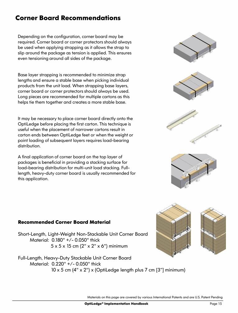
Page 15
Recommended Corner Board Material
Short-Length, Light-Weight Non-Stackable Unit Corner Board
Material: 0.180" +/- 0.050" thick
5 x 5 x 15 cm (2" x 2" x 6") minimum
Full-Length, Heavy-Duty Stackable Unit Corner Board
Material: 0.220" +/- 0.050" thick
10 x 5 cm (4" x 2") x (OptiLedge length plus 7 cm [3“] minimum)
Corner Board Recommendations
Materials on this page are covered by various International Patents and are U.S. Patent Pending
Depending on the configuration, corner board may be
required. Corner board or corner protectors should always
be used when applying strapping as it allows the strap to
slip around the package as tension is applied. This ensures
even tensioning around all sides of the package.
Base layer strapping is recommended to minimize strap
lengths and ensure a stable base when picking individual
products from the unit load. When strapping base layers,
corner board or corner protectors should always be used.
Long pieces are recommended for multiple cartons as this
helps tie them together and creates a more stable base.
It may be necessary to place corner board directly onto the
OptiLedge before placing the first carton. This technique is
useful when the placement of narrower cartons result in
carton ends between OptiLedge feet or when the weight or
point loading of subsequent layers requires load-bearing
distribution.
A final application of corner board on the top layer of
packages is beneficial in providing a stacking surface for
load-bearing distribution for multi-unit load stacking. Full-
length, heavy-duty corner board is usually recommended for
this application.
OptiLedge® Implementation Handbook

Page 16
Recommended Strap Material
Polypropylene Strap (PP) "Poly-strap"
Material: 13 x 0.6 mm (½" x 0.022")
135-205 kg (300-450lb) ABS
(typical recommendation)
Strapping Recommendations
Polyester Strap (PET) "Nylon"
Potentially usable, though not usually recommended unless
there is zero compression in the packaging and no air.
Steel Strap, Not Recommended
Strapping is the primary way to attach the OptiLedge to products and
packages. Because of the importance of securely and tightly attaching
the OptiLedge, proper strapping is essential. Polypropylene strapping is
recommended because of its physical properties. Polypropylene will
stretch and recover (referred to as “elasticity”), providing a more secure
attachment of the OptiLedge to the product.
Base-layer strapping is always recommended to minimize strap
lengths. Should unit loads of product compress when stacked, (a
likely occurrence under heavy weights) base-layer strapping
minimizes the amount of slack that could occur within the straps
thereby assuring the OptiLedges remain in place. It also ensures a
safe base for order picking once the unit load strap is cut. Base-
layer sub-assembly is one of the most important keys to building
successful unit loads.
Note that when applying strapping, a minimum of two
straps per OptiLedge pair should be used and they
should always be positioned as close to the outer feet as
possible. In some cases, a third strap, placed on either
side of the center foot, may be necessary as well.
Materials on this page are covered by various International Patents and are U.S. Patent Pending
OptiLedge® Implementation Handbook

Page 17
Strapping Application Equipment
Battery operated all-in-one hand-held tensioner and sealers.
Uses friction generated heat for strap sealing, no clips required.
Price range: $1,000-$3,000 USD, numerous manufacturers
Two piece Hand-held Tensioner and Hand-Crimper
Requires metal crimp-clips for strap sealing
Price range: $100-$300 USD per set, numerous manufacturers
Manual Strapping Equipment
There are a number of ways to apply strapping and the method is typically determined by volume
requirements and labor cost/availability. Numerous automated strapping solutions are commercially
available for large volume production. In lower volume situations, the following options may result in
more economical solutions.
OptiLedge® Implementation Handbook

Page 18
Handling Equipment, Stacking and Racking
Customers can take advantage of how the OptiLedge “fits their product” to
create efficient floor stack storage. The load-bearing capacity of the
OptiLedge permits high multiple unit load storage.
The OptiLedge is designed to allow the use of fork style
handling equipment while minimizing the overall impact
made by the devices themselves on the distribution
environment; i.e. weight, material, etc. The high profile (HP)
OptiLedge is designed for use with most fork lift truck and
pallet jack handling equipment. The low profile (LP)
OptiLedge is designed for use with fork lift trucks and low
profile pallet jacks.
The OptiLedge can be used in racking systems with the addition of wire mesh or wood decking or
custom designed rack support systems. Many customers maintain open rack systems and use wooden
slave pallets.
Materials on this page are covered by various International Patents and are U.S. Patent Pending
OptiLedge® Implementation Handbook

Page 19
Handling Equipment, Stacking and Racking
The learning curve associated with proper handling of OptiLedge unitized products is very short.
However, habits developed during years of handling wooden pallets─such as spinning the unit
load or bulldozing units across the floor─can damage the OptiLedge. While the OptiLedge does
not require gentle care, proper handling practices should be employed to provide maximum
benefit. This also results in damage reduction and greater economic benefits.
OptiLedge® Implementation Handbook

Page 20
The OptiTray® is…
• A single-wall, simple fold-up, die-cut corrugated tray with print capability
• When assembled, a self-contained customizable shipping platform
• Extremely lightweight, efficient, recyclable and sustainable
• Ergonomically friendly, clean and nesting capable
• A simple self-assembly fixture for properly positioning the OptiLedge devices within
• A quick and secure means for attaching the OptiLedge devices to a product by means of various
ways …
Encapsulation Adhesives
Strapping Stretch wrapping
OptiTray® - An OptiLedge Corrugated Tray Sub-assembly
The OptiTray corrugated tray sub-assembly provides an alternative means for utilizing the
OptiLedge, widening the scope of potential applications as well as assembly and attachment
techniques.
Materials on this page are covered by various International Patents and are U.S. Patent Pending
OptiLedge® Implementation Handbook

Page 21
OptiTray® Solutions
One important characteristic of the OptiTray is that the tray
depth is equal to or greater than the height of the OptiLedge
device sidewall. This, along with flaps folding over the
OptiLedge horizontal surface, creates the geometry that
encapsulates the OptiLedge devices and provides the basic
strength of the design. This also allows for quick and proper
placement of the devices as well as a secure means to hold
them in place throughout distribution. Using these simple
guidelines, the tray designer is able to customize the tray into a
wide variety of shapes and sizes and to focus on load-bearing
and handling requirements.
Once the basic design and performance traits of the system are understood, designs can
be customized in a near limitless assortment of ways, optimizing the solution for the
specific application. Using various internally positioned substrate materials, additional
corrugated assemblies, and/or internally assembled corner board, the standard
OptiTray can be customized for additional benefits.
Materials on this page are covered by various International Patents and are U.S. Patent Pending
OptiLedge® Implementation Handbook

Page 22
Point of Purchase Displays
POP displays are an entire market segment directly suited for the
OptiTray. Such displays frequently utilize a bottom tray or can
easily be adapted to do so. As always, proper attention to load
distribution during the design process is required.
Column load bearing within the display needs to vertically align
with OptiLedge support. Consequently, it is critical that use of the
OptiLedge be considered during the initial design of the display as
opposed to attempting a retrofit.
In some cases involving larger displays, centrally located
OptiLedges or wooden substrates may be required to bridge
load-bearing gaps or to insure flat level surfaces in the bottom
shelf cavities.
When designing the display, be sure to consider load-bearing
support for the display when the OptiLedge feet are resting on the
floor as well as during handling when fork-tine engagement occurs
between the OptiLedge feet.
Materials on this page are covered by various International Patents and are U.S. Patent Pending
OptiLedge® Implementation Handbook

Page 23
Point of Purchase Displays – Load Bearing
Consider load-bearing distribution both during static display, when the product weight is
distributed down through the OptiLedge feet, and during dynamic movement, when the product
weight is distributed down between the OptiLedge feet to the handling equipment fork tines.
Materials on this page are covered by various International Patents and are U.S. Patent Pending
OptiLedge® Implementation Handbook

Page 24
Assembly Fixtures
Automated Application
Assembly fixtures can be used to make the proper alignment
and placement of the OptiLedge a quick and measurement-
free process. They can also be used to hold the devices in
place during product placement if necessary, or as a form of
conveyor-based slave pallet, allowing for use of the
OptiLedge without mechanical line modifications. Adjustable
fixtures, pallet jack friendly fixtures, even corrugated tray
assembly fixtures can be quickly fabricated from wood,
metal, or even off-the-shelf components.
Automated application of the OptiLedge devices is
accomplished through a variety of proven and
established methods including robotics. If you require
assistance due to the complexity of automated
application, please contact your OptiLedge
representative directly.
Materials on this page are covered by various International Patents and are U.S. Patent Pending
OptiLedge® Implementation Handbook

Page 25
OptiTray® - Appendix
Standard Tandem
Pair Solution
Standard Perimeter
Solution
Standard Single
Pair Solution
Materials on this page are covered by various International Patents and are U.S. Patent Pending
OptiLedge® Implementation Handbook

Page 26
Unit Load Outer
Dimensions
+1/2"
Unit Load Outer
Dimension + 32-1/2"
Unit Load Outer
Dimension + 18-1/2"
OptiTray® - Appendix
Materials on this page are covered by various International Patents and are U.S. Patent Pending
OptiLedge® Implementation Handbook

Page 27
Cutouts for 760 Series Devices
Cutouts for 991 Series Devices
Line-Type Legend for
Standard Tray Design
Standard OptiLedge Tray Layout
Foot Cut-out Dimensioning
Single Pair Design Shown
Black – Cut
Green – Score
Blue – Perf-Score
OptiTray® - Appendix
Materials on this page are covered by various International Patents and are U.S. Patent Pending
OptiLedge® Implementation Handbook

Page 28
OptiTray® - Appendix
Single Pair 991mm OptiLedge Tray Dimensions (1 of 3)
Standard Design
Materials on this page are covered by various International Patents and are U.S. Patent Pending
OptiLedge® Implementation Handbook

Page 29
OptiTray® - Appendix
Single Pair 991mm OptiLedge Tray Dimensions (2 of 3)
Standard Design
Materials on this page are covered by various International Patents and are U.S. Patent Pending
OptiLedge® Implementation Handbook

Page 30
OptiTray® - Appendix
Single Pair 991mm OptiLedge Tray Dimensions (3 of 3)
Standard Design
Materials on this page are covered by various International Patents and are U.S. Patent Pending
OptiLedge® Implementation Handbook

Page 31
OptiLedge® Website www.optiledge.com
Support / Resources
OptiLedge® Implementation Handbook
![Series Section...s 6015-SS [630 lbf] 2800 N 1/4-20 202943 (supplied) l 6015-MSS M6 202916-M (supplied) s 6015-R [560 lbf] 2500 N 1/4-20 205203 l 6015-MR M6 205203-M HC = Holding Capacity,](https://cdn.vdocuments.us/doc/165x107/5f479492eeaf6f47f0599064/series-s-6015-ss-630-lbf-2800-n-14-20-202943-supplied-l-6015-mss-m6-202916-m.jpg)


