
OPG POWER GENERATION PVT
LIMITED
UNIT – V & VI - 2 x 360 MW COAL BASED
THERMAL POWER PROJECT
AT GUMMIDIPOONDI, TAMILNADU STATE
PRE FEASIBILITY REPORT
APRIL 2015
PREPARED BY:
Aquatherm Engineering Consultants (India) Pvt. Ltd.,
II Floor, St. Thomas Building,
#68, Luz Church Road,
Mylapore,
Chennai - 600 004, India

Project : Unit V & VI – 2 x 360 MW Thermal Power Plant Client : M/s. OPG Power Generation Pvt Ltd Pre-Feasibility Report
2
TABLE OF CONTENTS
1. EXECUTIVE SUMMARY ......................................................................................... 3
2. INTROUDCTION OF THE PROJECT/BACKGROUND INFORMATION ................. 4
3. PROJECT DESCRIPTION ......................................................................................11
4. SITE ANALYSIS .....................................................................................................44
5. PLANNING BRIEF .................................................................................................47
6. PROPOSED INFRASTRUCTURE ..........................................................................50
7. REHABILITATION AND RESETTLEMENT (R & R) PLAN ....................................61
8. PROJECT SCHEDULE & COST ESTIMATES .......................................................61
9. ANALYSIS OF PROPOSAL (FINAL RECOMMENDATIONS) ...............................64
10. ANNEXURES – AS DETAILED BELOW ................................................................67
ANNEXURE – 1 PROJECT INFORMATION & METEOROLOGICAL DATA
ANNEXURE – 2 FUEL ANALYSIS
ANNEXURE – 3 RAW WATER ANALYSIS
ANNEXURE – 4 STATUTORY CLEARANCES
ANNEXURE – 5 PLOT PLAN
ANNEXURE – 6 PROCESS FLOW & WATER BALANCE DIAGRAM
ANNEXURE – 7 DRAWINGS FOR EIA
ANNEXURE – 8 SITE LOCATION

Project : Unit V & VI – 2 x 360 MW Thermal Power Plant Client : M/s. OPG Power Generation Pvt Ltd Pre-Feasibility Report
3
1. EXECUTIVE SUMMARY
OPG Power Generation Pvt Ltd (OPGPGPL) a Subsidiary of OPG Power Ventures PLC
presently has 2 x 77 MW units, 1 x 80 MW unit in operation and under Phase - III, 1 x
180 MW unit is in the advanced stages of installation and expected to be commissioned
by April 2015. The Company has proposed to install 2 x 360 MW Units Coal based
thermal Power plant in Periya Obulapuram Village, Nagaraja Kandigai, Madharpakkam
Road, Gummidipoondi, Tamil Nadu State after decommissioning the existing Sponge
and Iron plant located in that site.
Aquatherm Engineering consultants India Pvt Ltd, Chennai, has been appointed as
Technical Consultant by OPG for undertaking the Pre-feasibility Study preparation for 2
x 360 MW Coal fired Thermal Power project. The project would be based on Sub-critical
technology.
This Pre- Feasibility report has been prepared taking into consideration of availability of
land, water, fuel, power evacuation facilities, and other basic infrastructures and
evaluated the technology available and suitable for establishment of such large thermal
power station of capacity in the order of 2 x 360MW.
The project site is located about 3 kms away from Gummudipoondi town and 55
kilometers from Chennai. The site is aptly located to serve industrial customers and is
close to the ports of Ennore and Chennai. The project site is located 3 km away from
Chennai - Nellore High way. The nearest airport is located at Chennai.
The newly proposed 2 x 360 MW Units will be brought up in a location just adjacent to
the operating units of 414 MW Power Plant owned by OPG Power group. An old
abandoned sponge iron plant (owned by sister concern of OPG Group) adjacent to
operating units of the power plant existed already and it was decided to bring the new
units in that plant area of about 45.4 acres. The land is already retrieved by demolishing
and clearing all plant equipment after decommissioning the sponge iron plant. The
retrieved land along with newly acquired land from private parties, to an extent of 32.1
acres in adjacent area will be utilized to accommodate the construction of the proposed
2 x 360 MW unit.
Primary fuel of the project would be imported coal which shall be obtained from
Indonesia. At present, only Sea cum Road transportation is envisaged for Coal
transportation. Rail transportation may also be made feasible by creating a Railway
siding, for which necessary facilities can be developed. It can be taken up only under a
long term planning in future. But not envisage at present.

Project : Unit V & VI – 2 x 360 MW Thermal Power Plant Client : M/s. OPG Power Generation Pvt Ltd Pre-Feasibility Report
4
Secondary fuel for the startup and stabilization of the power plant shall be High Speed
Diesel (HSD) / HFO and shall be brought from nearest depot.
Raw water for the plant will be sourced from Borewells inside the plant area. The Co.,
has already obtained from Tamil Nadu WRD/ PWD approval for drawl of ground water to
the extent of 1000m³/day. Requirement of fresh water inlet for all the proposed 2 x 360
MW units put together will be about 425 m³/day. It is proposed to recirculate and
reutilize 567 m³/day from the reject generated and collected in collection tank after
treatment of plant effluent water. The total requirement of water for the new units will be
992 m³/day.
Since the plant is proposed to use air-cooled condenser for turbine steam cooling, water
required will be far less than conventional water cooled condensers.
Electrical Energy from the station is proposed to be wheeled through a dedicated 400
kV double circuit transmission line to the nearest TANTRANSCO S.S at Thervoikandigai
for further transmission to the prospective buyers of power.
The project shall have one unit of coal fired thermal power plant units of 2 x 360 MW
capacity based on Sub-critical parameters. The First unit shall achieve commercial
operation in 33 months respectively calculated from the award of contract for Boiler,
Turbine and Generator (BTG) package and Second unit 4 months thereafter.
The project cost is estimated as INR 43200 Million, which shall be funded by 70:30 debt
equity ratio. The debt portion shall be arranged from various lenders funding the power
projects. Loan repayment period of 10 years has been considered in the financial
analysis.
The capacity of the project, fuel comfort, availability of water and power evacuation
arrangement can make this project a success, which shall bring benefit to the nation as
a whole and Tamilnadu state in particular.
2. INTROUDCTION OF THE PROJECT/BACKGROUND INFORMATION
2.1. IDENTIFICATION OF THE PROJECT AND PROJECT PROPONENT
The proposed coal fired thermal power project shall have two units each with 360
MW capacity based on sub critical parameters.
The proposed project site lies in an existing Sponge and Iron plant in an area of about
45.4 acres and in the additional land already procured adjacent to it of around 32.1

Project : Unit V & VI – 2 x 360 MW Thermal Power Plant Client : M/s. OPG Power Generation Pvt Ltd Pre-Feasibility Report
5
acres. The site is about 55 km from Chennai. The plant will be adjacent to the existing 2
x 77 MW + 1 x 80 MW + 1 x 180 MW Thermal Power Plants
The Geodetic co-ordinates for the site will be latitude 13025’55.74” N and longitude
80006’00.49” E.
PROJECT PROPONENT
OPG GROUP
OPG Power Generation Pvt Ltd is a Subsidiary of OPG Power Ventures PLC with the
main objective of setting up Group Captive Power Plant for the use of the promoters and
others as permitted under the law.
OPG Power Ventures PLC is developing and operating Power plants in India. The
Company is committed to building shareholder value and to being the first choice
provider of reliable, uninterrupted power at competitive rates to its customers. OPG's
customers include hotels, hospitals, commercial companies and industries. OPG's
model allows power supply directly to such customers through the state grid, generally
at attractive prices, benefiting them on cost and being able to receive reliable and
uninterrupted power. Transporting coal from the coal mines by truck or train can be
expensive due to the distance and sometimes it is not possible due to inadequate
transport infrastructure. OPG's principal plant sites have been chosen to be in close
proximity to port e.g. Gujarat site is 30 kilometers from the port and Gummidipoondi is
55 kilometers away from Chennai Port. This allows OPG to bring Indian coal and
imported coal by sea to the nearest port - thereby reducing significant land logistics cost.
Following are the Power plants successfully run or under implementation by OPG group
OPG Energy - Mayavaram - (25.4MW) a natural gas based power plant and the same
is operating successfully under the Group Captive Power Policy. This natural gas based
plant is near Mayavaram in Tamil Nadu
OPG Power Generation – is already operating 2 x 77 MW + 1 x 80 MW Coal based
Power projects successfully at Gummidipoondi in adjacent premises and to the newly
commissioned unit of 1 x 180 MW Coal based unit under the expansion scheme.
OPG POWER Gujarat in Bhadreshwar, Kutch, Gujarat is constructing a 2 x 150 MW
Coal based Power project. The first unit is already commissioned and COD was
declared by end of Mar 2015. The second 150 MW Unit is in advanced stage of
commissioning and is going to be synchronized by end of Apr 2015.

Project : Unit V & VI – 2 x 360 MW Thermal Power Plant Client : M/s. OPG Power Generation Pvt Ltd Pre-Feasibility Report
6
OPG Power Generation has also proposed to construct 1 x 350 MW Coal based Power
project near Bellary in Karnataka. Preliminary works like obtaining approval / permits
from various agencies are underway.
OPG Renewable Energy - A 10 MW waste heat recovery plant is located at
Gummidipoondi, The plant uses waste heat from the contiguous sponge iron facility of
an associate, Kanishk Steel, and a blend of coal and dolochar which is a process
residue in sponge iron production with residual calorific value. The present proposal of
constructing a 2 x 360 MW unit will be taken up at the same premises after
decommissioning the existing sponge iron & power plant
2.2. BRIEF DESCRIPTION OF NATURE OF THE POWER PROJECT
The Project is a Coal based Thermal Plant with 2 units of 360 MW capacities each
based on Sub-critical Technology.
Main fuel of the project would be imported coal. High Speed Diesel / HFO will be used
for startup and stabilization of the unit.
Water requirement for the project shall be met from Bore wells existing inside the plant.
Power shall be evacuated through a dedicated 400 kV double circuit transmission line to
the nearest TANTRANSCO S.S. at Thervoikandigai.
The project shall comply with all the environment regulations and guidelines as
prescribed by MOEF and State Pollution Control Board. The plant will operate as zero-
discharge plant.
2.3. NEED FOR THE PROJECT AND ITS IMPORTANCE TO THE COUNTRY AND OR
REGION
The economic growth of any country depends upon the availability and consumption of
energy. The level of development of a country is measured in terms of per capita energy
consumption. Presently, India's per capita energy consumption at 704.2 kWh/year (for
year 2007 - 2008) is less than that of other developing countries like China (1,891) and
Malaysia (1,000). The per capita energy consumption of the developed countries are very
much higher as can be seen from the figures of such countries like United States of
America (13,338), Sweden (16,665) and Canada (18,117). World average per capita
energy consumption is 2,596 kWh / year.
It is a well-known fact that electricity is the most essential input for growth and
development of any State. The rapid growth in industrial and agricultural sectors in
India has consequently resulted in rising trend of demand for power. However the

Project : Unit V & VI – 2 x 360 MW Thermal Power Plant Client : M/s. OPG Power Generation Pvt Ltd Pre-Feasibility Report
7
growth in installed power generating capacity has not kept pace with the projected
demand.
As per the approach paper of Planning Commission to the Eleventh Five Year Plan, the
growth in power sector needs to be 10% annually to support GDP growth rate of 8-9 %
per annum. This target has since been increased to 10% for the terminal year of the
Plan.
2.3.1. Power Situation
The installed generating capacity by the end of 31st of March 2014. In the country has
been as follows as per CEA statistics:
Type MW %
Coal 145273.39 59.776
Gas 21781.85 8.962
Oil 1199.75 0.493
Total Thermal 168254.90 69.231
Hydro 40531.41 16.677
Renewable 29462.55 12.126
Nuclear 4780 1.966
Total 243028.95 100
The sectoral distribution of the above is given below:
Sector MW %
State sector 68125.95 28.032
Central Sector 92187.7 37.932
Private sector 82715.3 34.035
Total 243028.95 100
(Source: CEA)
2.3.2. Demand & Supply Scenario
The demand – supply position in the country with regard to electricity has been as
follows during the month of March 2014
Demand Supply Deficit %
Energy 84958 MU 81860 MU (-) 3.6
Peak Demand 131945 MW 126793 MW (-) 3.9

Project : Unit V & VI – 2 x 360 MW Thermal Power Plant Client : M/s. OPG Power Generation Pvt Ltd Pre-Feasibility Report
8
(Source: CEA)
It can be seen that the demand for power has been outstripping the supply. Substantial
peak and energy shortages prevail in the country. The shortfall in Energy during the
twelve months of the previous financial year is 42431 MU and the shortfall in Peak
Demand during the same period has been 6103 MW.
2.3.3. Indian Electricity Act 2003
Government policies are now in favour of private entities investing and building &
operating power plants. Indian Electricity Act 2003 has put in place the rules and
regulations that encourage private investment power generation. The Act also put in
place Regulators in Center and in States which are vested with authority to regulate the
power tariff and provide equitable and level playing ground to private investors.
2.3.4. Power Scenerio in Tamilnadu
The demand for electrical energy has been steadily growing in the State of Tamilnadu
owing to the IT sector, industrial growth, Tourism and increased demand for rural
electrification & for irrigation as well as growing population. The state has been adding
new power generation projects to cope with the demand, but the demand for power
always outstrips the availability.
Tamilnadu State depends on a mix of hydro, thermal and non-conventional energy
generation for power development with thermal portion catering to about 29%, Hydro 21
%, Gas 5%, Non-conventional energy 5 % and Private sector Power plants about 12 %
and Central assistance 28 %. Unreliable Wind energy forms 98% of Non-conventional
energy produced. However unpredictable monsoon resulting in reduced hydel storage
and growing demand for power accompanied with coal shortages in thermal plants force
the State to look for other fast track opportunities for further augmentation of power to
match with the industrial development. Combined Generation plants with gas engine
based power plants is an easy and economic solution, for quick relief and augmentation
under the present power situation.
2.3.4.1. Power Position in Tamilnadu State
Installed capacity as on 31-03-2014
S. No Description Capacity in MW
1 THERMAL 10411.06
2 HYDEL 2182.2
3 NUCLEAR 1024 (Including-Koodankulam)
4 RES 7946.13

Project : Unit V & VI – 2 x 360 MW Thermal Power Plant Client : M/s. OPG Power Generation Pvt Ltd Pre-Feasibility Report
9
S. No Description Capacity in MW
5 Total 21043.39
DEMAND Vs. SUPPLY as on 31.03.2014:
S. No Item Demand Supply Deficit
1 ENERGY in MU 8425 7974 (-) 5.4%
2 PEAK POWER in MW 13489 12355 (-) 8.4%
The proposed project of 2 x 360 MW would help in bridging the gap of growing power
demand. Setting up of project in the area would definitely result in improvement of social
structure of in and around the project area besides direct and indirect employment.
Data sourced from CEA reports.
2.4. IMPORTS VS INDIGENOUS PRODUCTION
This equipment for the proposed power plant project may or may not involve any
imports component from any competitive foreign suppliers or may be completely by
Indigenous Production, in spite of several issues related to cost of importing Electrical
energy equipment and quality of products in comparison.
2.5. EXPORT POSSIBILITY
This power plant project does not involve any Export Possibility issues to other
countries.
The energy produced will be delivered to prospective buyers through TANTRANSCO
substation at Thervoikandigai.
2.6. DOMESTIC / EXPORT MARKET
2.6.1. Export Market
This Project does not have any Export Market as of now for the reasons stated.
2.6.2. Domestic Market and Concept of Independent Power Producers
The Union Power Ministry is encouraging Independent power producers (IPP’s) across
the country as a means to create additional generating capacity at a faster rate through
private sector participation.

Project : Unit V & VI – 2 x 360 MW Thermal Power Plant Client : M/s. OPG Power Generation Pvt Ltd Pre-Feasibility Report
10
Power plants usually sign long-term power purchase agreements (PPAs) with state
governments under which they agree to sell power to state-owned distribution utilities at
a fixed rate for a specified period.
Independent power producers will cater to different uses in the market – to supply
electricity regularly to the grid or to meet peak loads. IPP’s shall sign long-term power
purchase agreements with a single buyer, also alternately they can commit a certain
percentage of their capacity to such agreements and sell the balance generation in the
open market to licensed power traders who needs the power at that particular time.
Past few years have seen many players entering the Power Trading market both on the
buy- side as well as the seller-side. A few players have also received license to act as
intermediaries
Gridco, West Bengal State Electricity Board (WBSEB), Damodar Valley Corporation
(DVC), Tripura Electricity Department, HP Government, Malana Hydro Power Station,
Jindal Tract etc. are among the notable suppliers, while Maharashtra State Electricity
Board (MSEB), Madhya Pradesh State Electricity Board (MPSEB), Uttar Pradesh Power
Corporation Limited (UPPCL) etc are among the major buyers of power
Power Trading Corporation (PTC), Adani Exports, NTPC Vidyut Vyapar Nigam Ltd.
(NVVN), Reliance Power, Tata Power are some of the established intermediaries in the
Power Trading Business.
The Electricity Act, 2003 recognized the concept of trading as a distinct licensed activity
and CERC is identified as the regulator. CERC have issued guidelines for trade
licensing, power trading and for setting up power exchanges. CERC have issued power
trading licenses to many trading companies and setting up of power exchanges is in the
process.
To facilitate sale of power to power traders and third parties, the government has
established an open access policy in power transmission. Introduced in the Electricity
Act, 2003, open access basically refers to the right to transmit power over a system
belonging to a third party. CERC have laid down procedures open access in distribution.
SERC of many states have followed up by laying down of provisions for open access.
Limited power flow on open access basis has already started.
With such concerted efforts in all areas, IPP’s are considered a favorable option to meet
the power demand.

Project : Unit V & VI – 2 x 360 MW Thermal Power Plant Client : M/s. OPG Power Generation Pvt Ltd Pre-Feasibility Report
11
Under such a favourable condition, putting up a power plant of 2 X 360 MW capacity by
OPG Power Generation Pvt Ltd in Gummidipoondi is justified in all aspects, since this
will only meet a fraction of the projected power demand of the country.
2.7. EMPLOYMENT GENERATION (DIRECT AND INDIRECT DUE TO THE PROJECT)
This power plant project generates direct as well as indirect employment and will have
at least 450 employees in the operation phase. During construction, around 200 persons
will be working with a peak strength of 1000 persons. Contractors will have their own
employees. During annual overhaul time the employment opportunities will be still more.
Due to the employees ,contractors and Professionals, Manufactures and dealers visiting
the project, the indirect employment potential thro’ Schools, markets, Shops hospitals
,lodges, clubs , post office, Banks and Cinema theaters will increase in the adjacent
area.
3. PROJECT DESCRIPTION
3.1. TYPE OF THE PROJECT INCLUDING INTERLINKED AND INTERDEPENDENT
PROJECTS (IF ANY)
This 2 x 360 MW Unit Coal fired Thermal Power Project shall be a pulverized fuel fired
unit and adopt sub critical technology.
There are many Power projects operating in the nearby area like ARS, TCPL,
SURYADEV etc., and the area is fast emerging as a Power hub. Likewise, there are
many Power consuming Industries around.
3.2. PROJECT LOCATION
OPG has proposed to decommission the existing sponge iron and waste heat recovery
power plant in Gummidipoondi in Thiruvallore District of Tamilnadu to establish this
Project.
The location of the project site has facilities of National Highway, Railway and Airport
National Highway is running within 3 KM from the site. Gummidipoondi railway station is
within 4 KM from this site. And the nearest airport is at Chennai around 55 km from
project site. Nearest port will be Ennore and Chennai.
A 400 kV Sub-station of TANTRANSCO is proposed to be constructed at about 10 km
from site at Thervoikandigai.
The nearest town is Gummidipoondi and the nearest city is Chennai.

Project : Unit V & VI – 2 x 360 MW Thermal Power Plant Client : M/s. OPG Power Generation Pvt Ltd Pre-Feasibility Report
12
The nearest meteorological station of Indian meteorological department is at Chennai
Available infrastructure at Chennai is adequate for handling the offshore equipment
including major power plant equipment.
Plot Plan indicating project details is enclosed as Annexure-4
Map Showing Site location, is also enclosed as Annexure- 8
3.3. DETAILS OF ALTERNATE SITES, CONSIDERED
OPG has inspected various sites in and around the area for the project and selected the
site, as the site falls within an industrial area and has sufficient infrastructural facility to
develop a Power plant.
3.3.1. Selection of Site
Basis of Selection of above site
• Adequate land
• Adequate water supply
• Adequate infrastructure for fuel & water supply and its transportation system
• Facilities like road, rail, Airport etc., available in the neighborhood.
• Construction water and construction power facilities.
• Power evacuation facilities
3.3.2. Siting Guidelines
A. Following siting guidelines will be followed in land acquisition
• As far as possible prime agricultural land/forest land will not be converted into an
industrial site.
• Land acquired should be minimum but sufficient to provide for a green belt
wherein the treated wastewater, if possible/suitable, could be utilised from
wastewater treatment systems.
• Enough space may be provided for storing solid wastes. The space and the waste
can be made available for possible reuse in future.
• Layout and form of the project must conform to the landscape of the area without
unduly affecting the scenic features of that place.

Project : Unit V & VI – 2 x 360 MW Thermal Power Plant Client : M/s. OPG Power Generation Pvt Ltd Pre-Feasibility Report
13
• Associated township of the project if any to be created must provide for space for
phyto graphic barrier between the project and the township and should take into
account predominant wind direction.
B. In addition the following distances will be maintained:
• Coastal Areas: at least 0.5 km from the high tide line (within 0.5 km of High Tide
Line (HTL), specified activities as per CRZ notification, 1991 are permitted) (The
HTL is to be delineated by the authorized agency only.)
• Estuaries: At least 200 metres from the estuary boundaries
• Flood Plains of the Riverine systems: at least 500 metres from flood plain or
modified flood plain or by flood control systems
• Transport/Communication System: at least 500 metres from highway and railway
• Major Settlements (3, 00,000 population) at least 25 km from the projected growth
boundary of the settlement.
C. In addition to the siting criteria listed above, the proposed project location will
be reviewed in relation to the following salient issues:
• Ambient air, water and noise quality standards
• Critically polluted areas
• Natural disaster prone areas
• Ecologically sensitive areas
• Availability of water and other critical infrastructures like electricity, roads with
adequate width and capacity
• Facilities for Power evacuation—proximity to EHV sub-stations
Based on the above guide lines, additional land required is proposed to be purchased
from Land owners.
3.4. SIZE OR MAGNITUDE OF OPERATION
Presently Two units of 360 MW capacities each with sub critical Parameters have been
selected.
The annual generation will be 5676.4 M.U. at a plant load factor of 90%. This Project will
use about 2.645 Million Tons per annum of imported coal & 5676 KL per annum of Light
Diesel oil / HFO for the above generation.

Project : Unit V & VI – 2 x 360 MW Thermal Power Plant Client : M/s. OPG Power Generation Pvt Ltd Pre-Feasibility Report
14
Water requirement will be 425 m³ per day for cooling and consumptive use for the
proposed units.
3.4.1. Unit Size Selection
Following major criteria are given utmost considerations while selecting unit size and
plant configuration:
• Cost of generation
• Load demand
• Power cycle efficiency
• Proven 'unit' generating set
• Reduction in size of the equipment due to adoption of Sub-critical Technology.
• Lesser Environmental effects
• The contribution of bigger unit sizes has been increasing over the years and
today 200/210 MW and 500 MW, 660 MW & 800 MW units constitute about
maximum percentage of total thermal capacity. With the progressive increase in
installed capacity, higher share of thermal generation and large peak to off peak
ratios, backing down (part load operation) and cyclic operation of thermal units
would become imminent.
• From consideration of stability, the system should be able to withstand
contingencies involving outage of one such unit without loss of grid stability. The
stability studies show that the system planned for 10th and 11th Plan periods,
can generally withstand outage of units up to 1000 MW and 1300 MW
respectively. At present, Eastern Region, North Eastern Region and Western
Region are already in synchronous operation and as such, the “K” factor (Power
Number) of this network is quite large- in the range of 2000 to 3000 MW/Hz. In
such system dip in frequency following outage of 1000 MW unit would be less
than 0.5 Hz. Accordingly the present grid system can support larger units.
• Considering the above and availability of land and other resources, 2 X 360 MW
units on Sub-Critical parameters with Pulverized Coal fired power plant has been
selected based on the above.
• Sub-Critical Technology has been a proven and time tested one for units above
200 MW. A large population of thermal units in India is adopting this technology
and the metallurgy has also been successful so far. Further present day
manufacturing units can easily supply spares and other services.
• Initial cost of Sub Critical units is also lower compared to Super Critical unit cost.

Project : Unit V & VI – 2 x 360 MW Thermal Power Plant Client : M/s. OPG Power Generation Pvt Ltd Pre-Feasibility Report
15
CEA has emphasized the urgent need for introduction of large scale thermal plants in
environmentally friendly manner. Thus, in order to achieve the twin objective of quick
capacity addition and better efficiency, unit size of 2 x 360 MW Sub-critical Power Plant
is ideally suitable.
Thus, for this project, 2 x 360 MW generating set operating in Sub-critical pressure /
temperature range with single reheat has emerged as a favorable configuration.
Selected 2 x 360 MW Unit Parameters
The parameters for the aforesaid proven selected thermodynamic cycle are as follows:
• Superheater Outlet : 170 Bar / 565 °C
• Reheater Outlet : 45 Bar / 565 °C
• Turbine ESV inlet : 165 Bar / 560 °C
• Condenser Vacuum : 0.18 Bar a
• Output @ generator terminal : 360 MW excluding excitation loss
3.5. PROJECT DESCRIPTION WITH PROCESS DETAILS
3.5.1. Power Equipment and Systems
The 2 x 360 MW Power Plant Process Flow Diagram is enclosed as Annexure – 6.
The 2 x 360 MW unit shall consist of the Sub-critical Steam Generator with natural
circulation; single reheat, condensing, extraction type steam turbine and generator, air
cooled condenser, condensate extraction and feed water systems, heaters and all
equipment for reheat regenerative feed heating
The unit shall be provided with adequately sized HP and LP turbine bypass stations for
quick hot start-up and to provide stability during large load throw-off conditions.
Process Flow Diagram indicating project components details is enclosed as Annexure-
6
Plot Plan indicating project Layout details is enclosed as Annexure - 4.
3.5.2. Mechanical Equipment and Systems
3.5.2.1. Steam Generator and Accessories
The Steam Generator shall be of natural circulation with Subcritical steam parameters,
drum type, single reheat arrangement for firing pulverized coal.

Project : Unit V & VI – 2 x 360 MW Thermal Power Plant Client : M/s. OPG Power Generation Pvt Ltd Pre-Feasibility Report
16
The Steam Generator shall be designed to fire 100% imported coal having the
characteristics as shown in fuel analysis.
The steam generator will have the following accessories:
• Soot Blowing System
• Air Pre-heaters
• Draft System
• Milling system with Coal Pulverizing Mills
• Support Fuel Oil System
3.5.2.2. Electrostatic Precipitators
Each steam generating unit shall be provided with the required electrostatic precipitators
(ESP). Each ESP shall have four parallel gas paths. Each gas path can be isolated for
maintenance while the other path being in operation. Each path shall comprise of the
required number of fields in series for collection of fly ash. The ESP will have efficiency
of around 99.9%. The ESP will have adequate number of ash hoppers provided with
electric heaters. ESP will be provided with Microprocessor based controller. The design
of ESP shall be such that the outlet dust burden or solid particulate matter (SPM)
content at its outlet does not exceed 50 mg/Nm3 at 100% MCR with worst coal, with one
field out of service.
3.5.3. Steam Turbine and Accessories
3.5.3.1. Steam Turbine
The steam turbine would be tandem compounded, single reheat, condensing,
horizontally split machine with uncontrolled extractions for Four (4) LP heaters, Three
(3) HP heaters and One(1) Deaerator. The steam turbine will consist of proven HP
turbine, IP turbine, and LP turbine modules. However the final number of heaters will
depend upon the steam turbine supplier selected for this project.
The turbine will have a lubricating oil system for supplying oil to turbine and generator
bearings and also to hydrogen seal oil system of the generator. The lubricating oil will be
cooled by closed circuit cooling water system water as cooling medium.
Necessary protective & supervisory system will be provided to ensure trouble-free, safe
and efficient operation of the turbine generator. Each unit will be guaranteed to generate
360 MW at generator terminals continuously.

Project : Unit V & VI – 2 x 360 MW Thermal Power Plant Client : M/s. OPG Power Generation Pvt Ltd Pre-Feasibility Report
17
3.5.3.2. Air cooled Condenser
The condenser will be air cooled condenser designed as per the requirements of Heat
Exchange Institute Standards for Steam Condensers and ASME. The materials used
will be conforming to acceptable and reputed material specifications and standards. The
condenser will be sized to condense the maximum quantity of exhaust steam. The
exact condenser parameters will be optimized on the basis of site data and most
economical combination of cooling surface and cooling air requirement. The condenser
will be designed as per HEI. The ACC will be suitable for outdoor installation. The ACC
will be direct air cooled type with forced draft. The noise levels will meet with the OSHA
requirements. The ACC will be of 'A' frame type supported on RCC columns or steel
frame. The arrangement of the ACC will be in single row preferably, with number of
modules. (Number of modules may be finalized during detailed design). The air flow
control through the ACC will be through fan's speed control with two speed motors or
single speed motor with VFD.
For each unit, 3 x 50% vacuum pumps will be provided to maintain the vacuum in the
condenser by expelling the non-condensable gases.
3.5.3.3. HP / LP Turbine Bypass System
HP and LP turbine bypass system will be provided along with the steam turbine and
auxiliaries. The bypass station will be sized for a flow corresponding to 60% of steam
generator MCR.
3.5.3.4. High Pressure Steam turbine driven Feed Pumps & Deaerator
Each unit shall be equipped with 3 x 50% (2 no. turbine driven working + 1 no. motor
driven as standby) feed pumps with the booster pumps mounted on the common shaft.
For deaerating and heating of the feed water the unit will be provided with a spray-cum-
tray type deaerating heater with a horizontal feed water storage tank of 6 minutes
capacity of steam generator MCR condition. The deaerator will be designed to keep the
oxygen content of the condensate below 0.005 cc/litre with zero free carbon dioxide.
3.5.3.5. Condensate Extraction pumps & Regenerative system
3 x 50 % capacity Condensate Extraction Pumps & Regenerative Feed Water Heating
System will also be provided as a part of turbine auxiliaries
3.5.3.6. Coal Unloading, Transportation and Feeding System
Coal handling plant (CHP) will be consisting of 2 nos. hydraulic truck tipplers), 2 nos
self-tippling platforms, crushers / stacker cum reclaimers and conveyors from the

Project : Unit V & VI – 2 x 360 MW Thermal Power Plant Client : M/s. OPG Power Generation Pvt Ltd Pre-Feasibility Report
18
stockyard and conveying the same to steam generator bunkers. The scheme of coal
handling system comprises of:
• Hydraulic truck tipplers
• Hoppers
• Vibratory feeder
• Belt Conveyor
• Belt Scales
• Magnetic separators
• Metal detector
• Coal Sampling Units
• Crusher & screens
• Stacker cum reclaimer
• Reclaimer
• Travelling Tripper
• Dust suppression system
• Dust extraction system in enclosed areas like transfer point, bunkers
• Hoists/ Equipment handling facilities
• Control and instrumentation
• Electrical System
• Ventilation System
• In-motion weigh bridge
• Safety and protective instrumentation
The coal handling system shall be designed for:
• Imported coal requirement for 2 x 360 MW unit at Turbine MCR
condition (@ 90 % PLF & GCV of 5100 Kcal/Kg – 8054 T / day
• 12 hours operation
• The maximum lump size of the coal received from coal block or linkage at power
plant site will be 250mm.

Project : Unit V & VI – 2 x 360 MW Thermal Power Plant Client : M/s. OPG Power Generation Pvt Ltd Pre-Feasibility Report
19
• Coal stockyard for stacking of crushed coal will be for 15 days at full load
considering this as a pithead station.
• For conveying coal from unloading area to the stockpile and from stockpile to SG
bunkers, two streams of conveyors and equipment will be provided.
3.5.3.7. Fuel Oil Handling System
HSD shall be used as supporting fuel for boiler cold start-ups and HFO for hot start up
and flame stabilization during low loads. HSD / HFO shall be brought to plant by road
tankers and shall be unloaded and stored in storage tanks of adequate capacity by
means of 3 x 50% unloading pumps. 2 nos of 1000 T capacity each for HFO and 2 nos
of 500 T capacity each for HSD will be provided. The HSD / HFO forwarding system
having 3 x 50% forwarding pumps will feed the boiler burner at the required pressure
and temperature.
3.5.4. Ash Handling System
Bottom ash & fly ash will be collected in dry form to facilitate utilization and the un-
utilized fly ash will be disposed in ash dyke. The system adopted for bottom ash removal
would be Dry Bottom ash handling system and for fly ash removal, pneumatic system
will be used. Ash disposal would be carried out in dry form using trucks from the ash silo
for external agencies.
3.5.5. Mill Rejects Handling System
Mill rejects will be handled by 1 no. belt / pneumatic conveyor system for each unit. Mill
rejects / pyrites discharged from the mills will be fed to the steel storage silo of 24 hour
capacity through conveyor and auto operated gates provided at the outlet of mill reject
hoppers. The silo will be located adjacent to the mill bunker building. The rejects from
the silo will be disposed off-site by trucks.
3.5.6. Plant Water System
The plant water system will be designed to supply cooling water makeup and other
consumptive water requirement for the proposed plant. A closed cooling water system
partially employing fin fan coolers and adiabatic coolers has been envisaged for the
proposed unit to minimize the plant water intake requirement. The proposed scheme of
water system comprises of the following.
The plant water requirement will be around 425 m3/day met by a number of bore wells
inside the site. Separate pumps from each bore well will be pumping water into a raw
water reservoir which will have storage capacity adequate to meet the plant water
requirement for around 7 days.

Project : Unit V & VI – 2 x 360 MW Thermal Power Plant Client : M/s. OPG Power Generation Pvt Ltd Pre-Feasibility Report
20
3.5.6.1. Pre-Treatment Plant and Raw Water Distribution System
Two (2) raw water supply pumps will supply raw water from reservoir to pre-treatment
plant to cater to the needs of the following primary water circuits:
a. Demineralization Plant
b. Cooling Tower Make up and Closed Circuit Cooling Water Make Up
c. Plant Service Water and Fire Water Requirement
The raw water is expected to have high turbidity / suspended solids during monsoon
and with the quality of water required for various systems in the plant being clarified
water, it is proposed to include a pre-treatment system to treat the raw water.
Now the raw water is pumped with the help of raw water pumps to the pressure sand
filter. Then the filtered water from PSF is fed into the Activated carbon Filter which in
turn feeds the filtered water into the Softener. The backwash water of PSF & ACF shall
be routed back to the Sedimentation Tank (Client’s scope) with 90 minutes retention
time. The clear water from the sedimentation tank shall be circulated back to the raw
water storage tank with the help of dedicated pumps. Finally, the feed water passes
through micron cartridge filters, where the fine suspended impurities are kept below
limits to ensure that RO membranes are not clogged. The Micron cartridge filter
discharge header shall be provided with an on-line Oxidation Reduction Potential meter
(ORP) for detection of any free chlorine in the water.
3.5.6.2. RO - MB Plant
The pre-treated soft water is pumped by High pressure RO module – 1 feed pumps of a
rated capacity to the RO module – 1 system.
The two modules of the RO system shall consist of set of cleaning system consisting of
RO cleaning tank, RO cleaning pump & cartridge filter. The cleaning system shall be
used for membrane cleaning, whenever required.
The product water obtained from the RO module – 1 system is pumped by High
pressure RO module – 2 feed pumps of a rated capacity to the RO module – 2 system.
The dissolved solids in the water are reduced in the RO system.
The Post treatment system consists of single stream of Degasser Tower, Degasser
Blower, Degassed Water Storage Tank, Degassed Water pumps & two streams of
Mixed Bed Exchangers provided for final polishing of water to render desired quality of
DM water, Mixed Bed Blowers with both acid measuring tank and caustic dilution tank.
The degassed water collected in the degassed water storage tank, shall be pumped by

Project : Unit V & VI – 2 x 360 MW Thermal Power Plant Client : M/s. OPG Power Generation Pvt Ltd Pre-Feasibility Report
21
degassed water transfer pumps to the MB and to the DM water storage tank. The head
of the degassed water pumps to be selected in such a way that the DM water to be
pumped upto the DM water storage tank of 750 m3 capacity (24 hrs’ requirement of the
plant). The three nos. of (3 x 50%) DM water Transfer pumps of suitable capacity will be
provided to transfer the DM Water from the DM plant storage tank to Condensate
storage tanks which will feed power cycle make up, CCW system make up, chemical
dosing requirements, Hydrogen gas plant, Stator water cooling system etc.
Two (2) nos (@ x 100%) SG fill pump shall also be provided in the DM tank. The SG fill
pump shall draw water from the tank and fill the SG unit before start-up.
3.5.7. Auxiliaries Cooling Water System
The cooling water requirement of the main / auxiliary equipment is taken care by the
closed cooling water system for each unit separately. The cooling medium for CCW
system is DM water. The major equipment requiring cooling water is as follows:
a. Steam Turbine Lube Oil Coolers
b. Auxiliary turbine for BFP lube oil coolers
c. Generator gas Coolers, Stator water coolers
d. PA,FD & ID Fans
e. Boiler Feed Water Pump Bearings, Hydraulic Coupling Oil Coolers
f. SWAS Sample Coolers
g. Coal Mills
h. Air Heater Bearings
i. Eco / APH Hoppers if required
With a view to reduce water consumption, CCW system will be proposed with a partial
dry cooling system using fin fan coolers and another wet cooling system with adiabatic
coolers which will consume minimum raw water for spray. The return cooling water from
each cooler is collected & pumped through a header to the radiator cooler (Fin Fan
Cooler) where fans circulate air and remove the heat / adiabatic cooler, where water
sprayed air will be forced thru’ the heat exchanger to remove the heat. The cooled
water is then distributed to all coolers, where it removes the heat from the lube oil /
equipment etc. Both systems will be provided with 3 nos circulating pumps separately. A
CCW expansion tank is provided in each system, where the makeup water is added and
ensures a flooded suction to the closed cooling water pumps located below. No of fin
fan coolers / adiabatic coolers will be decided during detailed engineering.

Project : Unit V & VI – 2 x 360 MW Thermal Power Plant Client : M/s. OPG Power Generation Pvt Ltd Pre-Feasibility Report
22
3.5.8. Service Water and Potable Water System
The service water system covers supply of water ash dust conditioner, air heater
washing, air washer and miscellaneous water requirements such as fire protection
system, dust suppression system in coal handling plant, plant washing & gardening etc.
Two (2) horizontal, centrifugal pumps, (1 no. working and 1 no. standby) will pump water
from the clarified water storage tank to the service water overhead tank located at an
elevation of about 30 m. Water from the overhead tank to the different consumer points
would be distributed by gravity.
Requirements of the plant potable water system will be met from the filtered water
storage tank located on the roof of the DM plant building. Two (1 no. working and 1 no.
standby) horizontal, centrifugal type potable water pumps dedicatedly for plant and Two
(1 no. working and 1 no. standby) horizontal, centrifugal type potable water pumps for
colony shall be envisaged. The above potable water pumps will draw suction from the
filtered water tank for further distribution of potable water to various consumption points
in the plant and colony.
3.5.9. Effluent Treatment Plant
a. The plant is designed for zero liquid effluent discharge. The liquid effluents will be
collected in ETP and treated / recycled generally as per the following:
b. Effluents from steam generator, turbine, transformer yard and other areas, which
may contain oil traces, will be sent to oil / water separator. The oil will be pumped
out periodically and trucked offsite for disposal. The treated water of significantly
low quantity will be directed to central monitoring basin.
c. Rainfall runoff from the coal pile will contain mainly suspended solids. This runoff
will be routed to the settling basin for retention and settling of suspended solids,
and the clear water from there will be used for dust suppression in the coal pile
area.
d. Filter backwash waste, which is generated in raw water pre-treatment system and
contains high-suspended solids, will be directed to waste water tank for further re-
use and to minimize wastewater effluent.
e. All chemical feed and storage areas will be contained by curbing, which will have
sufficient volume to contain the chemicals stored within the area. All chemical
area drains and demineralization regeneration wastes are directed to the
neutralization basin. The neutralized effluent will be sent to Waste water
treatment plant and the treated effluent will be reused.

Project : Unit V & VI – 2 x 360 MW Thermal Power Plant Client : M/s. OPG Power Generation Pvt Ltd Pre-Feasibility Report
23
f. The neutralized effluent from DM plant and CPU and WTP RO stage-1 rejects will
be passed thru’ a chain of clarifier, filters and RO modules where the product
water will be sent to Raw water reservoir and the rejects will be reused or sent to
evaporation ponds for final disposal.
g. Boiler blow down will be very minimum. However blow down water will be mixed
with raw water and sent to ETP for further treatment and disposal. Blow down
from adiabatic coolers, if any, will also be added to this.
h. CMB will have a guard pond of 24 hrs’ capacity where effluents from item i to item
above will be mixed, treated and reused.
3.5.10. Fire Detection and Protection System
a. A comprehensive fire detection and protection system is envisaged for the
complete power station. This system will generally conform to the
recommendations of TAC guidelines and NFPA - 850.
b. The following fire detection and protection systems are envisaged,
c. Hydrant system for complete power plant covering the entire power station area
d. Automatic high velocity water spray system for all transformers located in
transformer yard and those of rating 10 MVA and above located within the
boundary limits of plant, main and unit turbine oil tanks and purifier, lube oil piping
(zoned) in turbine area, generator seal oil system, lube oil system for boiler feed
pumps
e. Automatic medium velocity water spray system for cable vaults and cable
galleries of main plant, switchyard control room, CHP control room and ESP
control room, conveyors, galleries, transfer points and crusher house, un-
insulated fuel oil tanks storing fuel oil having flash point 65°C and below
f. Foam injection system for fuel oil storage tanks
g. Clean Agent Extinguishing system for protection of control room, equipment
room, computer room and other electrical and electronic equipment rooms
h. Fire detection and Alarm system to cover the complete power plant
i. Portable and mobile extinguishers, such as pressurized water type, carbon-
dioxide type, foam type, dry chemical powder type, will be located at strategic
locations throughout the plant.
j. Required fire tenders/engines of water type, DCP / foam type, trailer pump with
fire jeep etc will be provided in the fire station.
Fire hydrant & spray pumps will be installed in the raw water pump house.

Project : Unit V & VI – 2 x 360 MW Thermal Power Plant Client : M/s. OPG Power Generation Pvt Ltd Pre-Feasibility Report
24
Horizontal type fire hydrant pumps (1 no electric driven +1 no diesel driven) will be
installed in the pump house for hydrant and Horizontal type spray pumps (1 no electric
driven +1 no diesel driven) for spray system as per TAC guidelines. The water for foam
system will be tapped off from the hydrant system pumps. Separate booster pumps (1
no electric driven +1 no diesel driven) near Boiler area will be provided as the boiler
height will be about 60-70m. For the above system, automatic pressurization system
consisting of jockey pumps and air compressors will be provided.
3.5.11. Plant Air and Instrument Air System
Plant / service air and instrument air system shall include suitable capacity and duty
rotary screw / centrifugal compressors having a discharge pressure of 8.5 kg/cm2. Air
drying plants of adequate capacity will be provided near main plant
The air-drying plants will be capable of achieving a dew point of (-) 40°C at atmospheric
pressure. Suitable number of air receivers will be provided near each air compressor
and further unit air receivers will be provided near main plant of each unit.
Total 3 (2W+1S) Screw type air compressors shall be installed for both the units. 2 Nos
compressors shall be sized to meet Instrument and service air requirements under
normal condition. Interconnection will be made from service air to the instrument air
system to provide back-up for instrument air system.
3.5.12. Air Conditioning System
Inside design conditions of 24.5 ± 1.5 °C dry bulb temperature and relative humidity not
exceeding 60% is proposed to be maintained in all air-conditioned areas.
Air conditioning system will be provided for all those areas, which require close control
of environment conditions and will cover the following areas:
• Central Control Room consisting of Control Rooms,
• Control Equipment rooms,
• Telecommunication Rooms,
• Microprocessor,
• Computer and Programmers Rooms,
• Data Storage Rooms,
• UPS Rooms,
• Instrumentation Laboratory and Steam and Water Analysis Rooms,
• Conference Room,

Project : Unit V & VI – 2 x 360 MW Thermal Power Plant Client : M/s. OPG Power Generation Pvt Ltd Pre-Feasibility Report
25
• Shift Charge Engineer's Room (if applicable),
• Relay Rooms.
• Other areas like control rooms of Switchyard / ESP /AHP / CHP / Administrative
building / WTP / ETP etc will be provided with package type / split type air
conditioning units.
3.5.13. Ventilation System
Ventilation system will be designed to supply fresh outdoor air and will be selected for
maintaining inside conditions for those areas where close control of temperature is not
required, but nevertheless have a stipulated maximum temperature.
The following areas will be provided with forced ventilation system with filtered supply air
and exhaust fans / roof exhausters:
• All floors of turbine building other than the area which is air -conditioned.
• Switchgear rooms and cable galleries of main plant
• Non air conditioned area of ESP control room
• Any other areas where equipment heat load is high.
• Battery rooms, chemical stores and toilets will be provided with exhaust
ventilation with minimum 15 air changes.
All other buildings / areas will be ventilated by mechanical ventilation process using
combination of supply air fans and roof exhausters or wall mounted exhaust fans.
3.5.14. Piping System
Piping, valves, fittings, supports, for steam, condensate, water, oil, air and others etc.
will be provided as per the requirement of the systems. Pipelines running outside the
powerhouse will be routed on pipe trestles to the extent possible. However large
diameter raw water and cooling water pipes will be buried. Proper protection by
wrapping coating and/ or other necessary corrosion protection devices will be taken.
3.5.15. Chemical Feed System
Although high purity water will be used as heat cycle make-up, careful chemical
conditioning of the feed steam condensate cycle is essential as a safeguard against
corrosion and possible scale formation due to ingress of contaminants in the make-up
system. High Pressure dosing using phosphate to the drum and Low pressure dosing
with hydrazine and ammonia in deaerator / suction of feed pump / condensate pipe have
been envisaged.

Project : Unit V & VI – 2 x 360 MW Thermal Power Plant Client : M/s. OPG Power Generation Pvt Ltd Pre-Feasibility Report
26
HP dosing system will inject sodium phosphate in the boiler water for water conditioning
to suppress corrosion of the plant components/ material and to maintain the required
water quality.
The purpose of LP dosing system is to maintain the pH of condensate and feed water
and to effectively deal with residual dissolved oxygen in condensate and feed water.
Both systems complete with dosing pumps, tanks, associated piping, supports, fittings,
valves along with all necessary instrumentation and controls etc. shall be provided
accordingly.
3.5.16. Hydrogen Generation Plant
A hydrogen generation plant has been envisaged in order to fill up high-pressure
hydrogen cylinders, which are required for generator initial fill up and regular make up
required for generator rotor cooling. Hydrogen generation is accomplished by water
electrolysis process. The plant will be designed as per the regulations of the Explosives
Authority with all the required safety aspects, instrumentation control, including on-line
hydrogen purity analyzer system and control panel.
3.5.17. Thermal Insulation
All equipment / pipes / ducts whose surface temperature is higher than 60°C, will be
provided with thermal insulation for personnel protection and heat conservation. The
insulation material will be chemically inert, non-combustible and will be harmless.
3.5.18. Elevators
Following elevators shall be envisaged for this plant .
• 1 no Passenger-cum-freight lift in power house building of 1000 kg Cap
• 1 no Passenger-cum-freight lift in Boiler of 2000 kg Cap
• Chimney (Stack) elevator
• Any other areas where necessary
3.5.19. Cranes and Hoisting Equipment
Two (2) EOT cranes of suitable capacity will be provided in the Turbine Hall, which will
be used for lifting/ unloading of heavy equipment at the unloading bay and also for
erection and maintenance of heavy equipment.
Conventional and special type of cranes required for maintenance of certain SG and TG
equipment will be supplied by the respective equipment supplier.

Project : Unit V & VI – 2 x 360 MW Thermal Power Plant Client : M/s. OPG Power Generation Pvt Ltd Pre-Feasibility Report
27
Miscellaneous hoist shall be provided in all areas under the scope of BOP packages
(except the area covered by EOT cranes for turbine hall).The exact requirement of EOT
cranes shall be decided during detailed engineering. Suitable rails will be provided on
floor for bringing the horizontal feed water heaters under the approach of EOT cranes.
3.5.20. Painting and Corrosion Protection
All mechanical and electrical equipment including piping system and structures will be
painted with international standards / IS standard colour code for ease of identification.
All steel structures will be painted with epoxy resin based paints. All buried piping will be
provided with bitumen paint based coating and wrapping.
3.5.21. Workshop and Laboratory
The power plant will be equipped with a work shop capable of catering to the routine
maintenance requirements of the plant.
A central chemical laboratory adjacent to the DM plant building is envisaged for the
station. This will have necessary equipment and facilities to test and analyze steam,
water, oil, coal etc. required to ensure satisfactory operation and maintenance of the
station.
3.5.22. Electrical Equipment and Systems
General Design Philosophy and Design Features
Considering the capacity of project as 2 x 360 MW and availability of State Transmission
systems, it is proposed to adopt the evacuation voltage level as 400 kV. Power
generated from unit would be stepped up to the evacuation voltage level through
suitably rated Generator Transformer and will be evacuated through 400 kV
transmission lines.
Presently one no. 400 kV Double Circuit outgoing line has been considered for
evacuation of generated power. Accordingly provision for 2 Nos. of 400 kV line bays has
been kept in switchyard. 400 kV Gas Insulated Switchyard will be designed with one and
1/2 breaker scheme.
3.5.23. Auxiliary System
The voltage adopted for the AC auxiliary systems are:
• 415 V for motors rated up to 200 kW.
• 6.6 kV for motors above 200 kW and above.
All electrical equipment shall be rated for an ambient temperature of 50 °C.

Project : Unit V & VI – 2 x 360 MW Thermal Power Plant Client : M/s. OPG Power Generation Pvt Ltd Pre-Feasibility Report
28
3.5.23.1. DG Sets (Emergency Back-up)
For the safe shut down of plant under emergency conditions two diesel generating sets,
each of 750 kVA shall be provided, one each for one unit. The diesel generating sets
shall supply power to all essential AC auxiliaries of the plant including emergency lube
oil pump, seal oil pump, jacking oil pump and turning gear, battery chargers, firefighting
system, UPS and ac emergency lighting system etc.
3.5.23.2. Generator and Excitation System
Generator
The main parameters of Generator would be as follows:
Nominal rating : 360 MW
Rated output : 424 MVA
Power factor : 0.85 (lag) - 0.95 (leading)
Rated voltage : As per manufacturer's Standard (in the range of 18 - 24 kV)
Speed : 3000 rpm
Short circuit ratio : Not less than 0.48
The Generator shall be capable of continuous safe operation at rated output and
power factor under any of the following conditions:
• Terminal voltage variation of ± 5% of the rated value.
• Frequency variation within 47.5 to 51.5 Hz.
• Absolute sum of combined voltage & frequency variation of 5%.
The Generator winding will be star connected with the phase & neutral terminals brought
out for connection to isolated phase bus duct. The star point will be connected to earth
through a transformer having the secondary shunted by a resistor. The generator shall
be provided with Class 155 (F) insulation. The Generator shall generally comply with the
requirements specified in I EC – 60034-1, 60034-3, etc.
The stator winding of the Generator shall be cooled by means of de-mineralized water,
passing through hollow stator conductor. The core and the stator shall be cooled by
hydrogen gas which in turn shall be cooled in hydrogen gas coolers with DM water as
coolant.

Project : Unit V & VI – 2 x 360 MW Thermal Power Plant Client : M/s. OPG Power Generation Pvt Ltd Pre-Feasibility Report
29
Generator auxiliary system like stator water system, hydrogen cooling system, seal oil
system and CO2 system for purging of hydrogen and fire protection system with suitable
capacity shall be provided.
The excitation system shall be static / brushless type with DVR.
Power Transformers
Generator Transformer
Each 2 X 360 MW unit shall have three (3) single phase transformers with combined
rating of 424 MVA, for the Generator Transformer. One no. single phase unit shall be
provided as spare.
The transformer will be mineral oil filled, 'OFAF' cooled. Generator transformer will be
provided with on line circuit tap changer. The transformer winding will have vector group
Ynd11.Transformers will be provided with requisite protection devices and accessories.
Unit Transformer (UT)
Two number Unit Transformers will be provided for each unit. Each unit transformer will
be three phase, two winding, outdoor, Dyn1, oil filled with 'ONAF' cooling. The
transformer will be provided with Off Circuit tap changer. The capacity of the unit
transformer shall be selected on the basis of the unit auxiliary load with due
consideration to the starting of the largest motor, available circuit breaker capacity and
voltage regulation requirement.
Station Transformer (ST)
The Station Transformers shall be of three phase, three winding 400/6.6/6.6 kV, outdoor
oil filled, 'ONAF' cooled. The Station Transformers supply the 6.6 kV station switchgear.
The transformers will be provided with On-load tap changer with ±10% tapping on the
HV side. One number Station transformer is envisaged in the Power station.
Low Voltage Auxiliary Transformers
Required quantity of 6.6kV / 433 V adequately rated transformers for supplying the unit
loads and station low voltage loads shall be provided. The transformers shall be sized
on 2 x 100% or 3x50% rating basis. These transformers will be provided with off circuit
tap changer ± 5%. The auxiliary transformers will be DYn11 connected and the neutral
will be effectively grounded.

Project : Unit V & VI – 2 x 360 MW Thermal Power Plant Client : M/s. OPG Power Generation Pvt Ltd Pre-Feasibility Report
30
These transformers shall be mineral oil filled (ONAN cooled) for outdoor installation or
epoxy cast resin/resin encapsulated type in case of indoor installation
3.5.23.3. 400 kV Gas Insulated Switchyard
400 kV GIS shall be designed with one and a half breaker scheme. 400 kV switchyard
shall be provided with the following fully equipped bays.
2 – Generator transformer bays
2 – 400 kV line feeder bays
2 – Station transformers bay
1 – Reactor bay
The switchyard will be provided with necessary circuit breakers, disconnectors, earthing
switches, current transformers, capacitor voltage transformers, surge arrestors,
lightening arrestors, protective relays etc. The control and supervision signaling of the
400kV switchyard will be through SCADA in the switchyard control room. All
operationally important control commands and signals for reporting system status, fault
and abnormal condition for electrical auxiliary system will be available in the SCADA.
There will be a separate room in the switchyard control room building for the DC system
consisting of battery, battery charger and DC distribution boards for the 400 kV
switchyard.
One set of dedicated instrument transformers and Electronic (KWH / KVARh) meters
compatible to CEA's Metering code for each metering point shall be provided on the 400
KV feeders to measure Active and reactive power and energy delivered to the Grid and
also active and reactive power and energy received from grid. The meters shall be
suitable for working in ABT regime. The meters, current transformer and voltage
transformers will have an accuracy class of 0.2S.
3.5.23.4. Other Electrical Equipment
BUS DUCTS
Generator Bus Duct (Isolated Phase)
Project : Unit V & VI – 2 x 360 MW Thermal Power Plant Client : M/s. OPG Power Generation Pvt Ltd Pre-Feasibility Report
31
The generator shall be directly connected to the generator transformer through isolated
phase bus duct. Current transformer and Voltage transformer for AVR, protection,
metering etc., shall be provided in the generator bus duct.
6.6kV & Low Voltage Bus Ducts
Unit transformers and Station transformers will be connected to the 6.6 kV switchgears
by phase segregated bus duct or by cables depending on the layout.
For connection of low voltage side of the Low voltage auxiliary transformer to the 415 V
Switchgear, non-segregated phase bus duct of adequate rating will be used as
permitted by the layout.
SWITCHGEAR
6.6kV Switchgear
The unit transformer or the Station transformers will supply to the respective 6.6 kV
switchgears through suitably rated circuit breakers for further distribution to the 6.6kV
voltage motors and to the Low voltage auxiliary transformers.
415 Volt Switchgear
415 Volt system consist of Power Control Centre (PCC), Motor control centers (MCC)
and AC Distribution boards (ACDB) for distribution of low voltage power supply to
motors and other plant consumers.
Plant DC System
The DC power system will supply power to DC emergency pumps, emergency lighting,
protection, annunciation, control, indication etc. Each battery will have its own float /
boost charger. Each of the unit batteries shall be sized for supplying the total DC load of
the unit for a period of 30 minutes under a complete black out condition The 220 V
system will be unearthed. Each unit will have a 220V DC system comprising of one no.
of Nickel-Cadmium / Lead acid plant batteries, and two nos. of float cum boost chargers.
The battery charger will be of solid-state control rectifier type. One battery set for Station
auxiliaries in BOP areas has been considered. Separate batteries for 400kV switchyard
have been envisaged.
Uninterruptible Power Supply (UPS) System

Project : Unit V & VI – 2 x 360 MW Thermal Power Plant Client : M/s. OPG Power Generation Pvt Ltd Pre-Feasibility Report
32
The uninterruptible power supply (UPS) system provides a reliable and interruption free
source of required voltage, three/single phase power to the vital part of the plant control
system for plant control and emergency shutdown. 2x100%, 240 V UPS sized to supply
the Power Plant DDCS critical equipment is envisaged.
Illumination and Small Power Supply System
The plant lighting system will comprise of normal AC lighting and emergency lighting.
The lighting from the luminaires supplied from the normal AC and emergency AC power
supply will provide 100% illumination. The AC emergency lighting will provide 20% of
the total illumination required in the area. DC emergency lighting will be provided in
selected areas of the plant. HP mercury vapour, sodium vapour (LP and HP), compact
fluorescent lamps (CFL), incandescent lighting fixtures etc. Energy efficient lamps will
be used for energy conservation.
The illumination level in the different parts of the power stations shall be as
recommended in IS 3646.The choice of the type of luminaire (lighting source) will
depend upon the area to be illuminated.
3.5.23.5. Neutral Grounding System
400kV system is considered as solidly grounded as per the prevailing practice.
Generator Neutral will be grounded through distribution transformer resistor loaded
secondary limiting the earth fault current to 10 Amps.
For having selective tripping on earth fault and limiting the over-voltages and also
damage to equipment due to incidence of the earth fault, medium resistance grounding
of 6.6 kV systems neutral is envisaged. The 6.6kV system neutral will be grounded
through resistance with fault current limiting to 300 amperes.
415 V system is envisaged as solidly grounded as per Indian Electricity Rules.
Safety Grounding
The equipment body grounding is adopted to provide protection to personnel from
potential hazards caused by ground faults and lightning discharges through low
resistance conducting path to the ground. A stable ground grid will be provided for
grounding equipment and structures maintaining the step and touch potentials within
safe limits.

Project : Unit V & VI – 2 x 360 MW Thermal Power Plant Client : M/s. OPG Power Generation Pvt Ltd Pre-Feasibility Report
33
The plant grounding system will be designed as per the requirements of IEEE-80 / IEEE
665/IS-3043. The plant grounding will utilize Mild Steel Rods. Equipment grounding
conductor will be of galvanised steel flats/GI wire.
Lightning Protection
The chimney and powerhouse building including switch yard will be equipped with
lightning protection. Lightning protection conductors located on the top of the structures
will be connected to the ground loop surrounding the structures with down comers as
per the provisions contained in the latest issues of Indian Electricity Rules and IS 2309.
Plant Electrical Control system
The complete electrical system of Power Plant shall be controlled and monitored from
the Plant DDCS system. A Backup Electrical Control panel will be provided, if required.
• Generator System
• 6.6 kV System
• 415 V System
All operationally important control commands and signals for reporting system status,
fault and abnormal condition for electrical auxiliary system will be available in the DDCS.
Synchronising facility shall be provided for each 400 kV generator circuit breaker. Check
synchronizing relay shall be provided for synchronized closing of each 6.6 kV unit
transformer incomer circuit breaker and unit to station bus tie 6.6 kV circuit breakers.
The emergency DG Set will be started automatically in case of failure of the normal AC
auxiliary supply. Manual starting facility from the DDCS will also be provided in addition
to automatic starting.
Electrical Protection System
For protection of equipment against abnormal system conditions, state -of-the-art
protective devices will be installed in the respective switchgear and / or relay panels.
Each equipment shall be provided with a unit as well as backup protection. Also,
protection against lightning surges will be provided with lightning arresters at suitable
locations for outdoor equipment over and above the shielding wires and lightning masts.
The protective relays shall be of numerical type.
All protective relay panels will be of free standing, floor mounting, and sheet steel
enclosed. The panels will be located in air-conditioned rooms.

Project : Unit V & VI – 2 x 360 MW Thermal Power Plant Client : M/s. OPG Power Generation Pvt Ltd Pre-Feasibility Report
34
Clock System
A master clock panel will be installed in the switchyard control room for correct time
keeping and frequency monitoring. The master clock will drive a number of slave clocks
located at key points throughout the power plant. The clock system will have its own DC
battery and charger.
Plant Communication System
The following communication facilities would be provided for fast communication
between the plant personnel for efficient operation, maintenance and handling of
emergency conditions.
An EPABX telephone system covering entire main and auxiliary plants and colony.
Dedicated distributed public address systems party and paging channel for unit and one
common public address system for main plant, one public address system for coal
handling plant.
3.5.24. CONTROL & INSTRUMENTATION
EQUIPMENT AND SYSTEMS
Design Philosophy
The control and instrumentation system for the generating unit of the plant will be
designed to ensure safe, efficient and reliable operation of the plant under all regimes of
operation viz. start up, shutdown, normal operation, part load operation and under
emergency conditions resulting in cost effective power generation with optimum fuel
consumption and reduced emission levels.
The operation, control and monitoring system would be based on a state of the art
microprocessor based Distributed Digital Control Monitoring and Information System
(DDCMIS). The DDCS will provide a comprehensive integrated control and monitoring
system to operate, control and monitor the Steam Generator and auxiliaries, Steam
Turbine-Generator and auxiliaries and Balance Of Plant (BOP) systems including all
main plant equipment and auxiliaries with a hierarchically and functionally distributed
structure.
Monitoring and control, Data acquisition, alarm annunciation, fast response time, fail
safe design, sequence of events recording, online diagnostic and online maintenance

Project : Unit V & VI – 2 x 360 MW Thermal Power Plant Client : M/s. OPG Power Generation Pvt Ltd Pre-Feasibility Report
35
are some of the inherent features of the DDCS to be designed for the proposed Power
Plant.
Plant operation and control will be through the Operator Interface Units (OIU) located on
the Unit Control Desk (UCD) in the Central Control Room which will consist of colour
graphic LCD (TFT) monitor, keyboard/Mouse and also through Large Video Screen
(LVS) connected to dedicated LVS work stations.
The main plant unit controls will be located in one central control room. DDCS will
include the sequential control and protection of the steam generator, steam generator
auxiliaries, turbine, turbine auxiliaries and the modulating controls of the main plant
process of the air and flue gas cycle and steam and water cycle including Co-ordinated
Master control. DDCS would also include the Turbine governing and other Turbine
modulating controls.
All sequential control functions for the main plant including Steam Generator and the
Steam Turbine Generator and their auxiliaries along with Balance of Plant (BOP)
equipment and systems controls will be interfaced into the DDCS so that centralized
drive operation for the main plant, the auxiliaries and the Balance of Plant is possible.
The control functions will be backed up by protection, interlocks and safety functions.
This would cause pre-planned actions in cases where unsafe conditions develop faster
than the control capability of modulating controls or before the operator can be expected
to respond to the plant upset conditions in any regime of plant operation.
Operation and Monitoring of Plant Electrical and downstream System will be performed
through DDCS. Additionally, DDCS will have a redundant Software link with SCADA
System for monitoring of Switchyard electrical system.
Sequence of Event Recording function will be provided for recording and printing
occurrence of events in a chronological order for quick diagnostic of fault and remedial
action.
DDCS will perform online performance calculations to determine plant/equipment
efficiency and to detect and alarm unit/equipment malfunctions.
The plant offsite systems like Water treatment, Coal handling, Ash handling, Instrument
and Service air system etc. will be controlled and monitored through the respective
Local Control panels and control systems. Independent and Stand-alone PLCs in hot
redundant configuration will be used for control and monitoring of these offsite systems.
PC based Operator Interface Units (OIU) with LCD (TFT)/ KBD/ Mouse will be provided
for these offsite systems, which will be kept in the respective Local Control Areas.

Project : Unit V & VI – 2 x 360 MW Thermal Power Plant Client : M/s. OPG Power Generation Pvt Ltd Pre-Feasibility Report
36
Additionally, control and monitoring of these offsite packages shall be possible from
DDCS Operator Interface unit and Large Video Screen (LVS) from Central Control
Room.
Plant abnormal conditions will be alarmed through the Operator Interface Units. Alarm
printer will be provided to print out all alarms with time tagging and in the chronological
order. Additionally the signals, critical in nature, will also be connected to Plant main
DDCS by hardwired connection.
Steam and Water Analysis System (SWAS)
Recognizing the importance of water chemistry in the power plant operations, a
centralized comprehensive Steam and Water Analysis System (SWAS) for each unit will
be provided for continuous on line monitoring of water and steam purity in the plant
cycle. Measurements of Conductivity, pH, Hydrazine, Dissolved Oxygen, Silica, Sodium
and Phosphate will be provided.
Stack Emission Monitoring System
Continuous Emissions Monitoring System (CEMS) for monitoring of Flue gas Emissions
from the Stack of the Plant will be provided, which will consist of the following analyzer
Instruments:
• Oxides of Nitrogen NOx
• Sulphur Dioxide SO2,
• Carbon Monoxide CO
• Stack Opacity Monitor.
CEMS will be complete with in situ flue gas analyzers. PC based Emissions Monitoring
System with 21" Colour Graphic LCD / TFT Monitor with Keyboard, Mouse along with
Laser jet Printer. A software link will be provided to hook up the Emission Monitoring
System to the plant DDCS.
Closed Circuit Television System (CCTV)
Closed Circuit Television System (CCTV) with all equipment and accessories will be
provided for the purpose of surveillance of major Electrical Drive areas e.g. Steam
generator feed Pumps, ID Fans, FD and PA fans, Mills, Condensate Extraction Pumps
and critical areas like Turbine hall, firing floor, ACW, CHP, Switch Yard, Main Gate,
Pump House, Ash Plant areas etc. so that, by and large, all important areas and

Project : Unit V & VI – 2 x 360 MW Thermal Power Plant Client : M/s. OPG Power Generation Pvt Ltd Pre-Feasibility Report
37
equipment can be brought under surveillance. Also, cameras shall be installed at the
Main Gate and other common auxiliary plants.
3.6. RAW MATERIAL AND FINISHED PRODUCT
Raw material required for the power project is the fuel and Process medium. i.e. coal ,
High Speed Diesel / HFO and water
Finished product is electrical energy.
3.6.1. Primary Fuel and Secondary Fuel
The primary fuel shall be coal and secondary fuel shall be fuel oil i.e. HSD / HFO.
Primary Fuel Requirement, Estimated Quantity and Source
The primary fuel of the proposed power plant (2 X 360 MW) shall be imported coal. The
power plant shall require coal of around 2.645 Million Tonnes per annum (MTPA) based
on the following:
• Plant Load Factor - 90%
• Station Heat Rate - 2377 kCal / kWh (as per CERC norms – design
Heat rate x 1.065 )
• Gross Calorific Value of Imported Design Coal - 5100 kCal / kg
• Imported coal shall be purchased from Indonesia
Mode of Transport of Coal
Domestic coal would be transported from the mines to the site by road. Coal will be
received at Chennai / Ennore Port wherefrom trucks will transport coal to the Station
Coal yard.
Indonesian coal analysis is tabulated in Annexure – 2.
Secondary Fuel Requirement, Estimated Quantity and Source
Secondary fuel for the startup and stabilization of the power plant upto 30% BMCR
conditions shall be High Speed Diesel (HSD) / HFO and shall be brought from nearest
Oil depot. The annual requirement of HSD / HFO will be 5676 kL.
Fuel oil analysis is tabulated in Annexure -2.

Project : Unit V & VI – 2 x 360 MW Thermal Power Plant Client : M/s. OPG Power Generation Pvt Ltd Pre-Feasibility Report
38
Mode of Transport of Fuel Oil – HSD:
HSD / HFO shall be brought from nearest depot .to main plant site by road tankers for
unloading and storage at site.
3.6.2. Raw Material Water Requirement, Estimated Quantity and Source
Consumptive and cooling water requirement for the station comprising adiabatic cooler
make-up, heat cycle make-up, other process water requirement along with evaporation
and drift loss with recommended design margin works out about 17.7 m3/ hr for the 2 X
360 MW TPS. The system design would consider maximum recirculation of wastewater
for use in less priority areas.
S. No. Item Estimated Quantity
Quality m
3/hr m
3/day
1 CW make up for adiabatic coolers 2.66 64 Raw water
2 DM water for SG makeup, ACW makeup 24 576 DM water
DM plant effluent 14.67 352
3 Total 41.33 992 Bore well water
4 Treated water from ETP available for
reuse 23.63 567 Treated water
6 Net water required from Bore wells 17.7 425 Bore well water
Water shall be sourced from BORE WELLS inside the plant.
3.6.3. MODE OF TRANSPORT OF WATER
The Raw water from various Bore wells shall be pumped to a raw water reservoir within
the plant area thru’ a dedicated water pipeline to be laid. The raw water reservoir shall
cater to the requirement of the station for any disruption in water drawl /supply system.
The reservoir shall have two chambers for a total reserve capacity of 7days’
consumptive water requirement.
3.6.4. Finished Product
3.6.4.1. Marketing of Finished Product – Power
The finished product power shall be shall be evacuated thru’ state Grid and sold to
prospective buyers.
3.6.5. Mode of Transport of Finished Product - Power Evacuation
In view of large number of Power projects in the area as well as Power augmentation
programmes by some of the Projects, TANGEDCO, the Transmission arm of TNEB has

Project : Unit V & VI – 2 x 360 MW Thermal Power Plant Client : M/s. OPG Power Generation Pvt Ltd Pre-Feasibility Report
39
planned to construct a 400 kV substation at Thervoikandigai near Gummidipoondi which
shall be used for evacuating power from the proposed 2 x 360 MW Power project. The
power plant shall be connected with the substation through a 400kV double circuit
transmission line.
As per the details available from the report on development of transmission system for
the upcoming generation projects in Tamil Nadu. The above Substation will be
interconnected with TANGEDCO network for transfer of power to other areas including
interstate transmission.
3.7. RESOURCE OPTIMIZATION / RECYCLING AND REUSE ENVISAGED
Coal consumption will be optimized by the use of Sub-critical parameters for steam
generator.
Process Water consumption will also be reduced with the adopted cooling process i.e.
air cooling arrangement for condenser and auxiliaries. Air cooled condenser will reduce
the water consumption by about 75%.
The process medium water will be converted to steam in boiler and will deliver
mechanical power thru’ turbine and be cooled in an Air cooled condenser. The
condensed water will be recycled back to the boiler through regenerative system and
reused in the process. Only startup quantity and makeup water shall be drawn from
water system thus ensuring minimum use of water in the process.
Similarly Closed Cooling Water System for the auxiliaries will be adopted. In this system
hot water from a part of the auxiliaries will be cooled in a Fin fan cooler and for the
balance auxiliaries, adiabatic coolers will be used minimizing the CW consumption,
since only startup losses will be made up.
Waste water emanating from DM plant, Oil water separator, Coal pile run off, blow down
etc, will be suitably treated in ETP and reused
3.8. AVAILABILITY OF WATER, ITS SOURCE, ENERGY/ POWER REQUIREMENT
The power project requires water for various purposes such as process medium, cooling
medium, various services for equipment and staff including Firefighting and for drinking
purposes in the power plant as well as in colony.
Water shall be sourced from Bore wells to be dug inside the plant. The plant water
requirement will be around 17.7 m3/hr Water shall be pumped to a raw water reservoir
within the plant area and dedicated water pipeline shall be laid up to the reservoir. The
raw water reservoir shall cater to the requirement of the station for any disruption in

Project : Unit V & VI – 2 x 360 MW Thermal Power Plant Client : M/s. OPG Power Generation Pvt Ltd Pre-Feasibility Report
40
water drawl / supply system. The reservoir shall have two chambers for a total reserve
capacity of 7 days consumptive water requirement
Approval for tapping the required consumptive water is being obtained from the
concerned authorities
3.9. QUANTITY OF WASTES TO BE GENERATED (LIQUID AND SOLID) AND SCHEME
FOR MANGEMENT AND DISPOSAL
3.9.1. Liquid Waste Generated & Management and Disposal Scheme
The plant is designed for zero liquid effluent discharge.
Break up for the effluents:-
S. No. Item Estimated Quantity
m3/hr m3/day
1 Flash steam to Atmosphere from
IBD tank 7.2 172.8
2 Blow down from IBD tank 16.8 403.2
3 DM plant effluent including RO
rejects 14.67 352
4 Adiabatic cooler make up 2.66 64
5 Total water required 41.33 992
6 Effluent available for treatment (
item 2 + item 3) 31.66 755.2
7 Treated water from ETP available
for reuse 23.63 567
8 Rejects to Solar pond 7.84 188.2
Water for gardening and other uses like dust suppression, washing etc, will be met from
the treated effluent available from the existing units
The liquid effluents will be collected and treated / recycled generally as per the following
A. Effluents from steam generator, turbine and other areas
Effluents from steam generator, turbine and other areas, which may contain oil traces,
will be sent to oil / water separator. The oil will be pumped out periodically and trucked

Project : Unit V & VI – 2 x 360 MW Thermal Power Plant Client : M/s. OPG Power Generation Pvt Ltd Pre-Feasibility Report
41
offsite for disposal. The treated water of significantly low quantity will be directed to
central monitoring basin.
B. Rainfall runoff from the coal pile
Rainfall runoff from the coal pile will contain mainly suspended solids. This runoff will be
routed to the settling basin for retention and settling of suspended solids, and the clear
water from there will be used for dust suppression in the coal pile area. Provision will
also be kept for disposal of coal pile runoff to ash pond via central monitoring basin
C. Chemical area drains and demineralization regeneration wastes
All chemical feed and storage areas will be contained by curbing, which will have
sufficient volume to contain the chemicals stored within the area. All chemical area
drains and demineralization regeneration wastes in DM plant area are directed to the
neutralization basin .The neutralized effluent along with WTP RO rejects will be sent to
Waste water treatment plant where a 2 stage RO plant will be used to treat the effluent
and the treated effluent will be reused. Final reject from 2nd
stage RO module in ETP will
be sent to evaporating pond
D. Boiler blow down
Boiler blow down water which will be generated during start up and all load conditions
will be quenched with cold water and reused in the plant
3.9.2. Sewerage System
Sewerage from the Project shall be led into a sewerage treatment plant through a
sewerage network using concrete pipe. Manholes shall be provided at every 30m and
at all junctions. A permanent sewerage treatment plant shall be provided to cater to
the sewerage discharge of the plant. The treated effluent shall be utilized for the
irrigation of the landscaped areas.
Sewerage waste - 1000 l/hr (considering 300 persons to be employed)
3.10. SOLID WASTE GENERATED & MANGEMENT AND DISPOSAL SCHEME
3.10.1. Ash
• Total ash generated - 396 TPD
• Fly ash - 316 TPD
• Bottom ash - 80 TPD
The ash generated from Boiler will be of two fold. One will be bottom ash collected at
the bottom of the furnace, economizer and air heaters in dry form. The other type will be
Project : Unit V & VI – 2 x 360 MW Thermal Power Plant Client : M/s. OPG Power Generation Pvt Ltd Pre-Feasibility Report
42
fly ash escaping from furnace along with flue gas and will be collected under
Electrostatic precipitator, duct and stack. The design of ESP shall be such that the outlet
dust burden or solid particulate matter (SPM) content at its outlet does not exceed 50
mg / Nm3 at 100% MCR with worst coal, with one field out of service.
A maximum of 20% of the total ash produced by the Steam Generator would be
collected in the refractory lined furnace hopper as bottom ash (BA) in dry form. Dry
bottom ash handling system .such as, one detailed below shall be provided. The bottom
headers of the water wall in the pulverized fuel fired boiler will be at 4m above ground
level to facilitate incorporation of the dry bottom ash handling system with a
mechanically flexible sealing arrangement. The Dry bottom ash handling system shall
include dry bottom hopper, surge hopper, S.S. conveyor, Crushers, surge hopper II and
suitable conveying system upto bottom ash silo. Ash in silo will be unloaded to trucks for
further disposal.
One (1) silo shall be used for storing bottom ash of 2 units (24 hrs’ storage capacity)
considering difficulties in off-site disposal to external agencies).The capacity of bottom
ash silo will be 80 T. Space provision will be made for future extension.
Fly ash will be collected in dry form to facilitate utilization and the un-utilized fly ash will
be disposed in dry form. A dense phase ash handling system shall take care of fly ash
from various boiler ash generation points and up to the outlet of fly ash silo including ash
conditioning arrangement.
The fly ash collected in ESP hoppers shall be gravity fed into individual ash vessels
provided below each hoppers. The fly ash shall be further conveyed to the fly ash silo
with the help of compressed air through transport piping. The conveying air required for
the system shall be drawn from conveying air compressors.
1 no fly ash silo of 320T Capacity will be provided to store about 24 hrs’ collection of
ash. Vent filters will be provided on top of the silos and unloading arrangement will be
provided at the bottom of the silo
3.10.2. Mill Rejects
Tramps, stones and other extraneous materials escaped from the coal yard will be
separated in the Mill and collected in the tramp iron chute. Mill rejects will be handled
by 1 no. belt/pneumatic conveyor system. Mill rejects / pyrites discharged from the mills
will be fed to a steel storage silo of 24 hour capacity through conveyor and auto
operated gates provided at the outlet of mill reject hoppers. The silo will be located
adjacent to the mill bunker building. The rejects from the silo will be disposed off-site by
trucks

Project : Unit V & VI – 2 x 360 MW Thermal Power Plant Client : M/s. OPG Power Generation Pvt Ltd Pre-Feasibility Report
43
Rejects - 2 - 3 TPH
3.10.3. Clarifier Sludge
The clarifier sludge generated in ETP treatment system will be further thickened and
dried in thickener and drying bed. The dry sludge from the sludge drying bed will be
manually sent through truck for offsite disposal
Dry sludge - 1.5 TPH
3.10.4. Sewerage System
Sewerage from the Project shall be led into a sewerage treatment plant through a
sewerage network using concrete pipe. A permanent sewerage treatment plant shall
be provided to cater to the sewerage discharge of the plant. The treated effluent shall
be utilized for the irrigation of the landscaped areas and the dry sludge collected over a
long period will be disposed thru’ trucks for offsite disposal
3.10.5. Liquid and Solid Waste Disposal Provisions in the Plant
The Plant is designed for zero liquid effluent discharge. For this purpose following shall
be provided:
• Oil / water separator pit in boiler, turbine, transformer yard, fuel oil handling areas
• Coal settling basins in coal handling plant area
• Filter back wash waste water tanks in the pre-treatment plant area.
• Neutralization basin in the DM plant and CPU Regeneration areas.
• Sewerage treatment plant.
• Central Monitoring Basin with effluent treatment plant.
• Cooling water pond for evaporative cooling
The treated water from the neutralization basin and other settling tanks shall be used for
plant use and other purposes like green belt development, dust suppression etc.
3.10.5.1. Waste Management – Environmental Management plan
A project of the proposed scale is bound to exert certain adverse as well as beneficial
impacts on the immediate surroundings. Primary impact on environment due to
installation of a power plant comes from the combustion of fuel and discharge of
chemicals and effluents from the plant through wastewater.
Environmental management plan (EMP) is proposed to be established for the plant to
detail out the environmental quality measures to be undertaken during the construction

Project : Unit V & VI – 2 x 360 MW Thermal Power Plant Client : M/s. OPG Power Generation Pvt Ltd Pre-Feasibility Report
44
and operational phases. EMP will also address the post project monitoring measures to
be adopted by the plant authorities in order to maintain the effluent qualities within the
acceptable limits specified by the MP State Pollution Control Board and the Ministry of
Environment and Forests (MOEF).
The environmental monitoring programme will be provided with trained and qualified
staff who will monitor the ambient air as well as stack flue gas quality to ensure that the
quality of effluents are maintained within the permissible limit. The main stack will be
provided with potable monitors to periodically monitor the SPM, CO, NOx and SOx
constituents in the flue gas on daily basis.
The plant effluents will be periodically analyzed on a weekly basis so that the effluents
are maintained within the permissible levels of the pollution control board regulations.
3.11. SCHEMATIC OF REPRESENTATION OF FEASIBILITY DRAWING
Schematic drawings for information to EIA purposes are attached as Annexure – 7
4. SITE ANALYSIS
4.1. PROJECT SITE CONNECTIVITY
The project site is falling in the village of Periya Obulapuram Village, Nagaraja Kandigai,
Madharpakkam Road, Gummidipoondi, Tamilnadu State.
The nearest town to project site is Gummidipoondi
The nearest city to project site is Chennai which is at a distance of around 55 km from
project site.
The location of the project site has facilities of National Highway, Railway and Air port
National Highway is running within 3 KM from the site. Gummidipoondi railway station is
within 4 KM from this site and the nearest airport is at Chennai around 70 KM.
Power shall be evacuated through a dedicated 400 kV double circuit transmission line to
the 400 kV Sub-station of TANTRANSCO at Thervoikandigai at a distance of 15 KM.
4.2. LAND FORM, LAND USE AND LAND OWNERSHIP
4.2.1. Land Form
The total identified area of 77.5 acres for plant site falls in the village of Periya
Obulapuram & Pappankuppam and the type of land is Flat and leveled. The above land

Project : Unit V & VI – 2 x 360 MW Thermal Power Plant Client : M/s. OPG Power Generation Pvt Ltd Pre-Feasibility Report
45
area is sufficient for locating the power plant associated facilities, coal storage yard, and
coal handling system, in plant Raw water Reservoir, Green Belt Development, Ash Dyke
Further, the preliminary geo-technical investigations are being conducted to ascertain
the nature of soil parameter and bearing capacity. Foundation system shall be designed
on the basis of findings and recommendations of geo-technical investigation
4.2.2. Land Use
The type of use of land is industrial. As the area is not inhabited, no major
displacement and rehabilitation of local population is foreseen.
4.2.3. Land Ownership
45 acres of land is already owned by the Proponent. Additional land required has also
been acquired for the project by the Proponent. However, land for corridor pertaining to
transmission line etc. is to be acquired separately based on the alignment and routing of
the corridor to be determined at later stage on detailing the engineering for the same.
4.3. TOPOGRAPHY
The Topography of the land is flat. Grade level of the land is approximately level.
Depending upon the topographical survey and area drainage study, the formation levels
of various blocks shall be finalized. Formation level shall be optimized by balancing the
cutting and filling as far as possible. The roads / storm water / sewage system will be
planned by taking care of all relevant data.
Topography map will be enclosed after topographical survey
4.4. EXISTING LAND USE PATTERN
National park, wild life sanctuary, eco sensitive areas, water bodies and forests are not
located in the nearby areas.
4.4.1. Features of the Site
The features of the selected site for the project are briefly as follows:
• No structure of archaeological importance
• Availability of Airport nearby
• Availability of railway line and National Highway nearby
• No populated city in vicinity
• No reserve forest nearby

Project : Unit V & VI – 2 x 360 MW Thermal Power Plant Client : M/s. OPG Power Generation Pvt Ltd Pre-Feasibility Report
46
• No Rehabilitation & Resettlement issues
4.5. EXISTING INFRASTRUCTURE
Availability of Land
The land area is sufficient for locating the power plant including associated facilities.
Availability of Coal and Water
Coal is to be sourced from Indian mines and Indonesia.
Ground Water is available and will be tapped from Bore wells
Infrastructure facilities like workshops, fabricating shops, etc available at Chennai are
adequate for handling the major power plant equipment. Minor works can be carried out
at Gummidipoondi.
The nearest meteorological station of Indian meteorological department is at Chennai.
4.5.1. Transport
The location of the project site has facilities of National Highway, Railway and Airport at
a distance of 70 kms. The site can be easily reached by a well laid 4 lane road / double
track rail.
4.5.2. Construction Power
The construction power shall be supplied at 11kV level from the nearest 110/11 kV
substation of the state power distribution company. Owner will provide a distribution
substation of 11/0.415 kV for further internal distribution of construction power at the
site.
4.6. CONSTRUCTION WATER
The maximum requirement of construction water is estimated to be 30 m³/hr for potable
and service purposes, which would be catered to by digging bore wells to be located in
plant site and having an overhead steel tank with distribution network.
4.7. SOIL CLASSIFICATION
The preliminary geo-technical investigations are being conducted to ascertain the nature
of soil parameter and bearing capacity. Foundation system shall be designed on the
basis of findings and recommendations of geo-technical investigation

Project : Unit V & VI – 2 x 360 MW Thermal Power Plant Client : M/s. OPG Power Generation Pvt Ltd Pre-Feasibility Report
47
4.8. CLIMATIC DATA FROM SECONDARY SOURCE
The nearest meteorological station of Indian meteorological department is at Chennai.
The available data will be furnished separately.
4.9. SOCIAL INFRASTRUCTURE AVAILABLE
The project site have social infrastructure facilities of transport only i.e; National
Highway, Railway and Airport. The other social infrastructure facilities such as hospitals,
schools etc are available in Gummidipoondi near the project area since project site
falls in rural areas with less population (No R&R issues in the project area) Major Social
infrastructure are available at Chennai city. But the proposed power project will help
further develop necessary social infrastructures in the project area.
5. PLANNING BRIEF
5.1. PLANNING CONCEPT
Type of industry – Power Plant
Site Facilities
The location of the project site have facilities of National Highway, Railway and Airport
fuel availability and transport ,,Plant water availability Power Evacuation, construction
power and construction water,
Existing power plant projects in the proposed plant area are OPG owned 3 units of 2 x
77 MW & 1 x 80 MW.
Transportation
Transportation of Raw Material - COAL
Coal would be sourced from the Indonesian mines & would be transported from the
mines thru’ Sea cum Road.
Transportation of Raw Material- Fuel Oil (HSD /HFO):
Oil shall be brought from nearest depot .to main plant site by road tankers for unloading
and storage at site.
Transportation of Men, Materials and Equipment for Construction:

Project : Unit V & VI – 2 x 360 MW Thermal Power Plant Client : M/s. OPG Power Generation Pvt Ltd Pre-Feasibility Report
48
The project site is well connected by National Highway, Railway and Airport and got
provision of drawl of electrical power facilities. This enables easy transport of Raw
materials. Equipment and spares, Lube-oil, chemicals to plant site for erection,
commissioning and operation activities. Man power including professionals, can reach
the plant site by using above the facilities beneficially.
5.1.1. Town and Country Planning / Development Authority Classification
The project site is located in the villages of Periya Obulapuram. The project area is
purely a village area.
Hence the concerned Village, Taluk and District Authorities and Town and Country
Planning Authorities are the basic authorities for Building, Road, Water and other
amenities and facilities.
Further the Directorate of Town Planning and Water Board, Pollution Control Board
Authorities of Government of Tamil Nadu and Govt. of India are to be approached for
approvals for civil, building and road facilities water drawl to plant site.
Statutory Clearances to be obtained for this power project are tabulated in Annexure –
5
5.2. POPULATION PROJECTION
The proposed site is occupied by Sponge & Iron plant ( to be decommissioned) and
adjacent land proposed to be procured is barren and flat and have no population.
5.3. LAND USE PLANNING (BREAKUP ALONG WITH GREEN BELT ETC)
Land use planning
The area identified of 80 acres has sufficient area for locating the power plant including
associated facilities, coal storage yard and coal handling system, in-plant raw water
reservoir, green belt development and ash dyke breakup along with green belt.
The land required for putting up 2 x 360 MW Power Plant is furnished below:
Description Area in Acres
Power Block Area 24.1
Plant Water System 3
Ash Dyke / Bund 3
Coal Handling Plant 18
Switchyard & Transformers 0.4
Other Facilities 3

Project : Unit V & VI – 2 x 360 MW Thermal Power Plant Client : M/s. OPG Power Generation Pvt Ltd Pre-Feasibility Report
49
Description Area in Acres
Green Belt 26
Total Area 77.5
5.4. ASSESSMENT OF INFRASTRUCTURE DEMAND (PHYSICAL & SOCIAL)
5.4.1. Assessment of Infrastructure Demand – Physical
The power plant requires following physical Infrastructure facilities:-
• Availability of suitable and sufficient land for power station
• Making the land ready for power plant construction (Topographical survey after
decommissioning the existing steel & power plant) and cutting and filling the land
accordingly.
• Development of Buildings Facilities for various plants(Geo –Technical survey and
soil investigation and drawing building foundation accordingly)
• Development of Transport Facilities for transport of Men, Materials and
Equipment (laying approach roads and railway lines to site from the existing
facilities)
• Development of Drinking water ,power availability ,construction power and water
i.e laying transmission lines to site from existing Sub-station if required
• Development of Sub-Station at site, laying water lines to site from water source
• Development of Road ,Drainage, and Sewerage Facilities
• Development of Storage Facilities for Materials and Equipment
• Development of Communication Facilities
• Development of Effluent Treatment and final disposal Facilities
• Power Evacuation facilities
5.4.2. Assessment of Infrastructure Demand –Social
The power plant requires following Social Infrastructure facilities:-
The OPGPGL already has developed a small township for their employees 3- 4 kms
away from the site. Further activities planned are as follows:
• Development of Township
• Development of Hospital

Project : Unit V & VI – 2 x 360 MW Thermal Power Plant Client : M/s. OPG Power Generation Pvt Ltd Pre-Feasibility Report
50
• Development of Schools
• Power and Water for Township
• Development of Shopping and Hotels
• Development of Club, Community Centre and Guest Houses
• Development of Bank, Post Office Parks, Estate Office, Telephone Exchange,
Transport Centre
5.5. AMENITIES / FACILITIES
Approach roads to plant site, Development of buildings at site and Township,, drinking
water to plant site and colony,, sanitary facilities in site and colony. Storage facilities for
materials in site, internal roads and drainage systems of the plant and colony,
Communication, transport, power availability in plant site and colony, hospitals, schools
are some of the basic amenities / facilities to be developed from the existing
Infrastructure.
6. PROPOSED INFRASTRUCTURE
6.1. PROPOSED INFRASTRUCTURE IN INDUSRIAL AREA (PROCESSISING AREA)
6.1.1. Civil Structural and Architectural Works
This Civil work for plant shall cover design and construction works, including site
formation, foundation, super-structure, all required buildings, building services, all
necessary infrastructural works required and associated works that are necessary for
the construction, operation and maintenance of the Power Plant.
The civil work shall also include all excavation, back filling, piling work (if required),
concrete work (plain and reinforced), structural steel work, water proofing, architectural
work, sanitary, plumbing, roads, paving, drainage and finishes including and other
building services as required for the Project.
The building and equipment foundations shall be suitably designed considering the
loads and bearing capacity of the soil.
6.1.2. Land Development
The topographical survey is being conducted and the general information on land terrain
will be ascertained to plan necessary infrastructure facilities and the necessary
formation level. Depending upon the topographical survey and area drainage study, the
formation levels of various blocks shall be finalized. Formation level shall be optimized

Project : Unit V & VI – 2 x 360 MW Thermal Power Plant Client : M/s. OPG Power Generation Pvt Ltd Pre-Feasibility Report
51
by balancing the cutting and filling as far as possible. The roads / storm water /
sewerage system will be planned by taking care of all relevant data.
Green Belt development shall be done in line with MOEF guidelines. However, the total
green belt area to be provided around the plant periphery and in plant shall be around
one-third of the total area within the plant boundary.
6.1.3. Geo- Technical Investigations
The preliminary geo-technical investigations are being conducted to ascertain the nature
of soil parameter and bearing capacity. Foundation system shall be designed on the
basis of findings and recommendations of geo-technical investigation.
6.1.4. Topographical Survey
The topographical survey will be conducted and the general information on land terrain
will be ascertained to plan necessary infrastructure facilities and the necessary
formation level.
6.1.5. Boundary Wall, Gate House & Watch Towers
A permanent boundary wall with barbed wire security fencing at top shall be provided
around the periphery of total plant area towards security of the power plant. Gate house
shall be provided at the main entry point to the plant.
Separate PVC coated chain link fencing shall be provided for switchyard, transformer
yard, storage areas etc.
Watch towers along the boundary of the plant shall be provided at the vulnerable
locations for security purpose.
6.1.6. Plant Roads and Drainage
Plant shall be connected to National Highway through approach road. All internal plant
roads (Double lane roads) shall be 7.0 m wide black topping with 2.5 m wide shoulders
on both sides of the road. Single lane roads shall be of 3.75 m wide black topping over
WBM sub-base and base with 1.0 m wide shoulders on both sides of the road. Access
roads to building/facilities shall generally be single lane roads without shoulders.
Rain water for the power plant areas shall be collected through a network of drains, all
storm water shall be discharged through gravity flow. Surface drains shall be open
drains of either RCC rectangular drains or brick lined drains trapezoidal in section. All
drains in the power plant area and around Buildings shall be covered drains. However,
the entire plant drainage system shall be finalized once the area drainage study has
been carried out.

Project : Unit V & VI – 2 x 360 MW Thermal Power Plant Client : M/s. OPG Power Generation Pvt Ltd Pre-Feasibility Report
52
6.1.7. Plant Buildings / Power Block Area
Plant buildings / power block area shall comprise of:
6.1.7.1. Main Plant Building
Main Plant Building in the Power Block area will comprise of Main Power House Building
(turbo generator bay, and the other one as Electrical, SG Feed Pump, Heater and
Deaerator bay). The building would be a non-basement structure.
The building shall be of steel-framed structures with RCC floor slabs and in-filled brick
masonry wall up to initial height of 3m. Above the initial height, colour coated metal
cladding shall be provided. EOT cranes shall be provided in the TG Bay. Roof of TG bay
shall be provided with metal decking sheet. In all other areas roof and floor shall be
provided with cast-in-situ RCC slab. The central control room shall be provided adjacent
to the TG hall at operating floor level.
6.1.7.2. Boiler and ESP Structure
Boiler and ESP shall be supported on steel structure, which shall generally rest on raft
foundation. Boiler and ESP shall be on the back side of control room as shown in
general layout plan. The boiler's structure shall have intermediate connecting corridors
with the main plant building.
6.1.7.3. Mill and Bunker Building
Mill and bunker building would be preferably placed on both sides of the Boiler. But
alternatively front mill arrangement may also be envisaged based on type of Boiler. It
shall be made of steel structure with RCC floor. Tripper floor area of the building shall be
provided with colour coated metal cladding.
Bunker shall be circular shape with a conical hopper portion. Conical Portion of the
bunker shall be provided with stainless steel lining.
6.1.7.4. Auxiliary Buildings
Auxiliary buildings in the main plant area shall include compressor house, Diesel
Generator Set building, ESP & VFD building, Air washer room, CPU regeneration
building, Service building etc.
6.1.7.5. Non Plant and Offside Buildings
Non Plant Buildings such as administrative building, canteen building, gate complex,
workshop, permanent stores, fire station etc shall be constructed of RCC frame
structure having in-filled brickworks.

Project : Unit V & VI – 2 x 360 MW Thermal Power Plant Client : M/s. OPG Power Generation Pvt Ltd Pre-Feasibility Report
53
Hydrogen generation plant shall be located away from common facilities as per the
explosive requirement.
6.1.8. Paving / Plinth Protection
Plinth protection around building and paving in entire main plant area from Transformer
yard up to Chimney shall be provided. Paving/hard surface shall be provided for vehicle
parking. Covered vehicle parking for cycles, scooters and cars/jeeps near service and
administrative buildings shall be provided.
6.1.9. Foundation System
All foundations shall be designed in accordance with provisions of the relevant Indian
Standards. Type and arrangement of foundation system shall be based on the soil
investigation report being carried out at project site.
For the foundations of Steam Turbo-generator, Boiler feed pumps, Fans, Mills, Crushers
etc detailed static and dynamic analysis shall be carried out.
Steam Turbo-generator, Boiler feed pumps, Fans (ID, FD and PA), Mills, Crushers shall
generally be supported on vibration isolation system or solid foundation which will be
ascertained during detailed engineering stage.
As per present information and as per preliminary site reconossaince, foundation can be
provided with open type foundation. Foundation system shall be designed on the basis
of finding and recommendation of geotechnical investigation.
6.1.10. Transformer Areas
RCC Foundation for all the Transformers supported on suitable foundation together with
fire wall, drainage, containment arrangements for spillage of oil shall be provided.
Transformer foundations shall be provided with necessary rail tracks from the generator
stator-handling rail track to its place for handling and removal from their foundation
without disturbing the other transformer(s). Fencing shall also be provided around
transformer area as per Indian Electricity Norms.
6.1.11. Switchyard
Galvanised steel structures with bolted connection shall be used for supporting gantry
and the towers structures. Concrete raft foundation shall be provided for this structure.
Outgoing line shall be routed towards proposed 400 kV pooling TANTRANSCO Sub-
station near Gummidipoondi.
While the main switchyard will be indoor type gas insulated, tariff metering arrangement
will be constructed on outdoor structure.

Project : Unit V & VI – 2 x 360 MW Thermal Power Plant Client : M/s. OPG Power Generation Pvt Ltd Pre-Feasibility Report
54
The switchyard control building shall be a RCC framed structure housing all equipment
including MCC and switchgears.
The switchyard shall be provided with a separate PVC coated fencing with entry gate,
150 mm thick gravel filling with anti-weed treatment and road, cable trench & drain
inside of the switchyard.
6.1.12. Chimney
The Chimney shall be a twin flue reinforced concrete chimney. The flue gas emission
point shall be 275 meters above the plant grade level. Internal and external platforms
shall be of structural steel construction. The other components of the chimney include a
large roll up door and a personnel access door at grade level, doors at all platform
levels, rain water drainage system, flue liner drainage system, louvers with bird screens
for ventilation openings, stair and platform lighting, and aviation obstruction lighting.
Rack and pinion elevator shall be provided in the Chimney.
Wind and seismic conditions will be taken care of in structural design as per relevant
sections of the Bureau of Indian Standards.
6.1.13. Raw Water Pre-Treatment Plant
Raw water reservoir, Clariflocculators, chemical house, filtered water storage tank etc.
shall be provided to meet the treated water requirement of the power plant.
6.1.14. DM Plant
Demineralization Plant building shall be a framed RCC structure with unfilled brick work.
Underground RCC neutralization pit shall be constructed in two compartments with
concrete of suitable grade. The inside face of pit shall be provided with acid/ alkali
resistant lining.
Degasser and acid storage tanks being out door type installations, R.C.C. foundation
along with dyke wall is envisaged. This shall be of RCC pedestals in suitable grade of
concrete.
Suitable foundation for the DM tanks shall be provided. Neutralization pit, drain and
floors likely to be subjected by corrosive effluent shall be provided with acid/ alkali
resistant brick / tile lining with applicable mortar.
6.1.15. Effluent Treatment and Final Disposal
The following shall be provided:
• Oil / water separator pit in boiler, turbine, fuel oil handling etc areas.

Project : Unit V & VI – 2 x 360 MW Thermal Power Plant Client : M/s. OPG Power Generation Pvt Ltd Pre-Feasibility Report
55
• Sludge draw out & stilling chamber cum aerator and cooling
towers areas.
• Coal settling basins in coal handling plant area
• Filter back wash waste water tanks in the pre-treatment plant area.
• Neutralization basin in the DM plant and CPU Regeneration areas.
• Sewerage treatment plant.
• Central Monitoring Basin with holding tanks and acid & alkali storage tanks etc.
• Cooling water pond for evaporative cooling
6.1.16. Coal Handling System
6.1.16.1. Truck Tipplers and Associated Structures
Two Nos of Hoppers for two truck tipplers (1W+1S) and two nos for truck unloading with
associated structures shall be of RCC construction. The pit shall accommodate the
hoppers along with feeder and conveyors below. Truck tippler pits shall be designed as
a water retaining structure. Steel liners will be provided on the hopper surfaces which
will be in contact with coal. Control room for wagon tipplers located nearby shall be of
RCC construction.
6.1.16.2. Transfer Points
Transfer points shall be provided at every change of direction of the conveyors. Transfer
points shall have structural steel frameworks with RCC roof and floors. Cladding shall be
of colour coated metal sheet.
6.1.16.3. Conveyor Galleries
Overhead conveyor galleries shall be of structural steel frame with colour coated metal
sheet roofing and cladding. Walkways shall be provided by the sides and between
conveyors. The galleries shall be supported on steel trestles which shall have RCC
foundations.
6.1.16.4. Crusher House
A separate building shall be provided for housing the crushers. This building shall be of
structural steel framework with RCC flooring and colour coated metal cladding. The
crushers shall utilize a vibration isolation system with spring assembly and visco
dampers.

Project : Unit V & VI – 2 x 360 MW Thermal Power Plant Client : M/s. OPG Power Generation Pvt Ltd Pre-Feasibility Report
56
6.1.16.5. Control and MCC Room Building
The control and MCC Room buildings shall have RCC framed structures with brick
cladding. In addition, a separate CHP maintenance building and bulldozer shed shall be
provided.
6.1.16.6. Stacker cum Reclaimer Foundation
This shall be of rigid type RCC continuous strip foundation provided under each rail. The
ground conveyor shall be supported by concrete pedestals. The edges of the area
adjacent to the ground conveyor shall be paved with concrete.
6.1.16.7. Drainage in Coal Stack Area
RCC drains shall be provided by the side of the stacker cum reclaimer. The drain shall
have pre-cast RCC covers.
6.1.16.8. Underground Conveyor with Reclaim Hopper
RCC tunnels shall be provided for underground conveyors. Reclaim hoppers shall be
made of RCC.
6.1.17. Fuel Oil Handling
Fuel oil for the plant is envisaged for transportation through road route using road tanker
and / or through rail using rail tankers. The following civil works are to be provided for
the Fuel oil handling system:
• RCC / Steel frame structure building for the pump house with in filled brick walls
to house the oil pressurizing pumps etc.
• A raised platform with ramp for unloading the fuel oil from road tankers, if
applicable.
• RCC ring wall / flexible foundations as per IS 803 for Storage tanks
• RCC dyke wall with suitable paving around the tank area along with Oil separator
pit and peripheral drains.
• Miscellaneous foundations for pumps, pipe racks, pipelines trenches fencing etc.
• Unloading trench for rail tankers, if applicable.
6.1.18. Ash Handling System
RCC silos for storage of fly ash will be constructed at a height of 5m above grade level
to facilitate easy movement of trucks for ash disposal

Project : Unit V & VI – 2 x 360 MW Thermal Power Plant Client : M/s. OPG Power Generation Pvt Ltd Pre-Feasibility Report
57
Pipe racks and compressor house shall be provided for fly ash handling system. Pipe
trenches as required shall be provided in compressor house. A separate office building
shall be provided in ash silo area for controlling the transportation of ash through trucks.
All equipment foundations, trestles for belt conveyors etc. as shall be required for the
entire ash handling system shall be designed suitably and accordingly provided.
Ash Dyke
A properly designed Ash Bund shall be constructed along the periphery of ash disposal
area. The bund shall be constructed in two stages.
The ash disposal area shall be provided with HDPE liner. All necessary measures shall
be provided for protection as well as to ensure proper functioning of liner against ground
water table / pressures that are likely to be encountered.
Necessary drains for disposing the storm / rain water shall also be provided. The ash
disposal area shall be fenced to protect the area from trespassing.
6.1.19. Pipe and Cable Rack / Trenches
LP pipes and cables shall be laid either underground in trench or over ground on the
rack. Trench shall be constructed with RCC with suitable water proofing arrangement.
Racks shall be constructed of structural steel supported on RCC foundation.
6.1.20. Miscellaneous Civil, Structural & Architectural Works
Any other civil, structural and architectural work not specified but necessary to render
the Project complete shall be carried out.
6.1.21. Design Basis
Dead and live loads will be considered as per relevant IS codes and standard
engineering practices.
The basic wind speed and design of buildings / structures shall be considered as per IS:
875: Part III.
The power plant is located in Seismic zone III as per IS: 1893 -2002 and seismic forces
will be considered accordingly for the structures / buildings.
6.1.22. Landscaping
Landscape of the entire Power plant area shall be provided with a soft and hard
treatment including supply of plants, maintenance and sprinkling of water through

Project : Unit V & VI – 2 x 360 MW Thermal Power Plant Client : M/s. OPG Power Generation Pvt Ltd Pre-Feasibility Report
58
distribution pipe network shall be provided. Landscaped areas shall be irrigated by
sprinklers with the treated water from the sewerage treatment unit.
6.2. PROPOSED INFRASTRUCTURE-RESIDENTIAL AREA (NON-PROCESSISING
AREA)
6.2.1. Township
A small township has been already developed located at about 4 kms from the site.
Township shall be developed further to provide modern amenities.
6.3. GREEN BELT
Green Belt development shall be done in line with MOEF guidelines. However, the total
green belt area to be provided around the plant periphery and in plant shall be around
one-third of the total area within the plant boundary.
6.4. SOCIAL INFRASTRUCTURE
Township, barracks for securities staff and field hostel and associated facilities/ non-
residential buildings like Bank, Post office, Club, Community centre, Medical centre,
Guest house, Sports complex, Parks, Estate office, telephone exchange, transport
centre, shopping centre and primary school and a temporary labour colony shall be
developed
6.5. CONNECTIVITY (TRAFFIC & TRANSPORT)
A four lane highway connects Chennai on one side and Nellore on the other side. A two
way electrified rail track connecting Chennai and Delhi is 4 km away. At present the
traffic density is normal on the highway without posing any problem to Vehicle
movement and is suitable for Cargo movement.
Two nos Sea port one at Chennai and other at Ennore are available for fuel handling.
6.6. DRINKING WATER MANAGEMENT (SOURCE AND SUPPLY)
Requirements of the plant potable water system will be met from filtered water storage
tank through Two (2) (1 no. working and 1 no. standby) horizontal, centrifugal type
potable water pumps for further distribution of potable water to various consumption
points in the plant and colony.
Drinking water shall be supplied from this source after proper treatment.
During construction phase also, drinking water shall be catered by bore -wells located in
at plant site and an overhead steel tank with distribution network arrangement.

Project : Unit V & VI – 2 x 360 MW Thermal Power Plant Client : M/s. OPG Power Generation Pvt Ltd Pre-Feasibility Report
59
6.7. SEWERAGE SYSTEM
Sewerage from the Project shall be led into a sewerage treatment plant through a
sewerage network using concrete pipe. Manholes shall be provided at every 30m and
at all junctions.
6.8. INDUSTRIAL WASTE MANAGEMENT
Industrial waste from power plant:
Air
• Dust particulates from fly ash in flue gas
• Sulphur dioxide in flue gas
• Nitrogen oxides in flue gas
• Coal dust particles during storage / handling of coal
• Ash dust in ash handling area
Water
• Effluent from ash disposal area
• Effluent from water treatment (WT) plant
• Cooling tower blow down
• Plant drains
Equipment and systems to manage Industrial waste
• The proposed plant will be provided with necessary equipment and systems to
meet all applicable environmental regulations. The plant has been envisaged to
have the following features, which will help in reducing emissions and effluents.
• The design of ESP shall be such that the outlet dust burden of solid particulate
matter (SPM) content at its outlet does not exceed 50 mg/Nm3 at 100% MCR with
worst coal, with one field out of service.
• Low NOx burners have been envisaged to reduce the NOx generation and
consequent emission.
• High efficiency Electrostatic Precipitators has been envisaged to limit the
particulate emissions to meet MoEF and / or CPCB regulations.
• 275 metres tall twin flue chimney has been envisaged for the plant, in line with the
MoEF guidelines, which will help dispersion of air borne emissions over lager
area and thus reducing the impact of the power plant on ground level
concentrations.

Project : Unit V & VI – 2 x 360 MW Thermal Power Plant Client : M/s. OPG Power Generation Pvt Ltd Pre-Feasibility Report
60
• Dust extraction and dust suppression systems have been envisaged in the coal
handling plant.
• Zero liquid effluent discharge scheme has been envisaged for the Plant. All
effluents in the plant will be treated and recycled as explained in Clause 3.9.1 of
this Report.
The environmental monitoring programme will be provided with trained and qualified
staff who will monitor the ambient air as well as stack flue gas quality to ensure that the
quality of effluents are maintained within the permissible limit. The main stack will be
provided with potable monitors to periodically monitor the SPM, CO, NOx and SOx
constituents in the flue gas on daily basis.
The plant effluents will be periodically analyzed on a weekly basis so that the effluents
are maintained within the permissible levels of the pollution control board regulations.
6.9. SOLID WASTE MANAGEMENT
Ash
The ESP outlet dust burden or solid particulate matter (SPM) content at its outlet does
not exceed 50 mg/Nm3 at 100% MCR with worst coal, with one field out of service.
Fly ash will be collected in dry form to facilitate utilization and the un-utilized fly ash will
be disposed in wet form
Bottom ash will be collected in wet form the system adopted for bottom ash removal
would be an intermittent jet pump system
Dust extraction and dust suppression systems have been envisaged in the
Crusher house, Coal unloading area, transfer points, Coal stock pile and bunker area in
the Coal Handling plant
In the Ash Handling plant, bag filters will be provided in silos and sprinklers for ash dyke.
Mill Rejects
Mill rejects will be transported to the silo which will be located adjacent to the mill bunker
building. The rejects from the silo will be disposed off-site by trucks
Clarifier Sludge

Project : Unit V & VI – 2 x 360 MW Thermal Power Plant Client : M/s. OPG Power Generation Pvt Ltd Pre-Feasibility Report
61
The clarifier sludge generated in effluent treatment will be further thickened and dried in
thickener and drying bed. The dry sludge from the sludge drying bed will be manually
sent through truck for offsite disposal
6.10. POWER REQUIREMENT-& SUPPLY AND SOURCE
The power required for construction of the power plant will be supplied at 11 kV level
from the nearest substation of the state power distribution company. OPG will construct
a distribution substation of 11 / 0.415 kV for further distribution of construction power at
the site.
Regarding Power supply for the production process, Startup power will be availed from
the TANTRANSCO Network and operational power will be tapped from the electrical
energy produced in the plant.
7. REHABILITATION AND RESETTLEMENT (R & R) PLAN
7.1. POLICY TO BE ADOPTED
No R & R issues are involved in this project
8. PROJECT SCHEDULE & COST ESTIMATES
8.1. PROJECT SCHEDULE (TIME SCHEDULE)
Project schedule indicates the likely date of start of construction and likely date of
completion of the project (time schedule)
In the current 2 x 360MW Power project, the first and second units shall achieve
commercial operation in 33 & 37 months respectively calculated from the award of
contract for Boiler, Turbine and Generator (BTG) package
8.1.1. Project Execution
The project is proposed to be executed on multiple EPC package contracts basis
8.1.2. Project Execution Heads
The major phases of the project during its implementation are classified under the
following heads:
• Planning and contract packaging
• Design, engineering, tendering and contract award

Project : Unit V & VI – 2 x 360 MW Thermal Power Plant Client : M/s. OPG Power Generation Pvt Ltd Pre-Feasibility Report
62
• Manufacturing, inspection and expediting phase
• Transportation / Handling of equipment
• Construction / Erection and commissioning
• Operation & Maintenance and manpower training and placement
8.1.3. Project Management
A project management system for close monitoring of the project for quality, schedule
and environment shall be created to complete the project within the scheduled period
The project will be managed by the project company under the overall direction and
control of a managing director. Full time project management responsibility shall vest in
CEO of the project company. The project company’s site establishment shall be headed
by a construction manager who shall be responsibility for all site works and shall report
to the CEO.
CEO shall be responsible for overall project planning and monitoring, obtaining
necessary clearances, all preliminary project works, coordination with concerned
agencies, contract administration, certification of bills, liaison and coordination with
statutory agencies, monitoring of project cost, recruitment of personnel etc.
The project company’s site establishment, headed by construction manager shall
comprise three basic groups viz., civil, mechanical and electrical / instrumentation. In
addition, a separate group shall be established for project monitoring and control. The
site establishment shall also have necessary administration and accounts departments.
Some of the project company site engineers shall be initially posted at the corporate
office and moved to site progressively as construction / erection activities pick up at the
site. After commissioning of the power Plant, most of these engineers would be
seconded to the O and M contractor and would occupy suitable positions in the
operations and maintenance (O and M) organisation for the power station.
Man Power required for this project is estimated to be 660 persons including contract
employees.
A brief methodology adopted for executing the project is as detailed below.

Project : Unit V & VI – 2 x 360 MW Thermal Power Plant Client : M/s. OPG Power Generation Pvt Ltd Pre-Feasibility Report
63
8.1.4. Planning Phase
8.1.4.1. Contract Packaging
The company intends to implement the project through well-defined multiple contracts or
packages, which shall be mutually exclusive as well as collectively exhaustive.
The initial site development, enabling works and other miscellaneous works will be
carried out by the company through local contractors. Indicative scope of the packages
envisaged is as below
8.1.5. Master Project Implementation Programme – Master Network
A master network (MNW), which is the overall programme of project implementation
shall be finalized. It identifies the key milestone dates for each package in the areas
of engineering, procurement, manufacturing, dispatch, construction, erection,
testing and commissioning. The date of order of the BTG package is the zero date of
the master network. The MNW forms the basis of all detailed physical scheduling for all
contract packages.
8.1.6. Quality Assurance
All Package Contractors would be asked to follow a comprehensive quality assurance
and control programme developed by an independent quality assurance group. The
quality plans after discussions and finalization with the Contractor will form a part of the
contract.
8.2. PROJECT COST ESTIMATE
The estimated works cost of the project consisting of plant and equipment including civil
works, land and site development and establishment charges including consultancy
services and margin on working capital amount to INR 38211.8 million. Interest during
construction (IDC) is estimated at INR 4989.2 million. The total project cost including
IDC thus works out to INR 43201 million, specific cost of the project thus arrives at INR
6 Crores per MW.
The estimated breakdown of project cost is presented in Table 8.1.
TABLE 8.1
ESTIMATED BREAKDOWN OF PROJECT COST
S. No Item Description Total in INR
Million
1. Civil Works including Land & Site Development 10008

Project : Unit V & VI – 2 x 360 MW Thermal Power Plant Client : M/s. OPG Power Generation Pvt Ltd Pre-Feasibility Report
64
S. No Item Description Total in INR
Million
2. Plant & Equipment 24185
3. Other expenses 4018.8
4. Project Cost excl. IDC (3 to 4) 38211.8
5. Interest During Construction (IDC) 4989.2
6. Project Cost incl. IDC 43201
8.2.1. Economic Viability Of the Project
The financial analysis of the project has been carried out based on the project cost
estimated to calculate the levelised tariff as below:
It can thus be concluded that the project cost compares well with the prevailing projects
awarded and commensurate with Subcritical technology adopted. The levelised tariff
also is comparable with the ongoing tariffs of other projects of similar capacity.
In view of the above, the project can be considered as techno- economically viable.
9. ANALYSIS OF PROPOSAL (FINAL RECOMMENDATIONS)
In this Concluding chapter, the financial and social benefits to the local people including
to tribal population are discussed as below.
9.1. FINANCIAL AND SOCIAL BENEFITS TO THE LOCAL PEOPLE
9.1.1. Financial Benefits to local People through the Plant Employment
The Project shall provide employment potential under unskilled, semiskilled and skilled
categories. The employment potential shall increase with the start of construction
activities, reach a peak during construction phase and then reduce with completion of
construction activities. During operation phase also there will be employment
opportunities, mainly in service sector, although its magnitude will be much less. The
direct employment opportunities are limited and the opportunities exist mainly with the
contractors and sub-contractors. These agencies will be persuaded to provide the jobs
to local persons on a preferential basis wherever feasible.

Project : Unit V & VI – 2 x 360 MW Thermal Power Plant Client : M/s. OPG Power Generation Pvt Ltd Pre-Feasibility Report
65
9.1.2. Social Benefits to Local People through the Plant Employment
Construction and operation of the project would benefit local people with respect to the
following:-
• Increase in employment opportunity in skilled, semi-skilled and un-skilled
categories.
• Increase in employment/ self-employment avenues in service sector.
• Availability of large quantities of ash for the cement and construction industries,
helping in conservation of land resources.
• Better amenities to the local people by way of providing hospitals, schools,
drainage systems, roads, ambulance facilities etc.,
9.1.3. Financial Benefits and Social Benefit to Local People other than Plant Employees
During power plant construction and then regular operation, the employees require
Housing, market facilities, schools for their children and medical facilities. Upto the
period of construction of the power plant colony, employees depend upon the outside
local facilities for school, shopping, and hospital. Even after the completion of
construction phase, there will be continuing need for the basic amenities. This will
generate more self-employment in the area which will lead to their financial growth.
During construction phase, due to the need for a large amount of vehicular traffic
bringing in equipments etc, new approach roads / railways will have to be laid by the
concerned agencies which will also result in employment generation & financial
upliftment and easy accessibility to the nearest town.
Development of green field in and around the site will lead to a better environment.
9.2. FINAL RECOMMENDATIONS
In view of the discussions in various chapters of this Pre-Feasibility report,, the capacity
of the project, fuel comfort, availability of water & power evacuation arrangement and
financial viability makes the project as techno-economically viable. Also the financial
benefits and social benefits to local people have also been enumerated in the above
chapters.
The Project will enhance the installed capacity of the State and may bring great relief to
a power starved state. The high Capacity (2 x 360 MW) proposed may also help Grid
managers to tide over Peaking demand Crisis very often faced by them.

Project : Unit V & VI – 2 x 360 MW Thermal Power Plant Client : M/s. OPG Power Generation Pvt Ltd Pre-Feasibility Report
66
The improved power supply will reduce the dependence of general public and
commercial establishments on DG Sets thereby reducing the noise pollution as well as
air pollution at local levels.
Thus it is concluded that the 2 x 360 MW power plant project at Periya Obulapuram
Village, Nagaraja Kandigai, Madharpakkam Road, Gummidipoondi, Tamilnadu Stat
proposed to be constructed by OPGGPL will bring benefit to the nation as a whole and
Tamilnadu state in particular.

Project : Unit V & VI – 2 x 360 MW Thermal Power Plant Client : M/s. OPG Power Generation Pvt Ltd Pre-Feasibility Report
67
10. ANNEXURES – AS DETAILED BELOW
ANNEXURE – 1
PROJECT INFORMATION & SITE DATA
1 Owner M/s. OPG Power Generation Pvt. Limited,
2 Project Title UNITS - V & VI - 2 X 360 MW TPP, Gummidipoondi.
3 Location OPG Nagar, Periya Obulapuram Village, Nagaraja Kandigai,
Madharpakkam Road, Gummidipoondi, TN State
4 Nearest Railway Station Gummidipoondi
5 Road Approach Chennai - Nellore Highway
6 Altitude + 10 m above MSL
7 Nearest Airport Chennai Airport
8 Data for Seismic Design As per IS: 1893
9 Rainfall (Annual) 900mm
10 Ambient Air Temperature
a Maximum 44° C
b Minimum 18° C
11 Soil Bearing Capacity later
12 Relative Humidity
a Maximum 70% - 75%
b Minimum 60%
13 Climatic Conditions Tropical Climate
14 Lattitude / Longitude 13025’55.74” N/80
006’00.49” E
The site is 8 km from Gummidipoondi town. National Highway is 3 km from the site and all the
plant equipment are proposed to be transported by road only. The existing roads need to be
extended to connect to the proposed site.
15 Tropicalisation
All equipment supplied against this specification shall be given
tropical and fungicidal treatment considering the climatic
conditions prevailing at site as described above.

Project : Unit V & VI – 2 x 360 MW Thermal Power Plant Client : M/s. OPG Power Generation Pvt Ltd Pre-Feasibility Report
68
Tropical protection shall conform to IS: 3202 titled “Climatic-
proofing of electrical equipment” or BS: CP-1014, titled
“protection of electrical power equipment against climatic
conditions”.
16 Design wind pressure In accordance with provisions of Indian Standards IS: 875.
17 Construction Power
Will be provided at a particular point by purchaser. Vendor has to
take power supply from that point, for which the total load
requirements to be specified by vendor.
18 General Description
The power plant is of regenerative cycle design and mainly
consists of steam generator and auxiliaries with coal as fuel,
regenerative feed heat system with condensing steam turbine
and auxiliaries and all other equipment associated.

Project : Unit V & VI – 2 x 360 MW Thermal Power Plant Client : M/s. OPG Power Generation Pvt Ltd Pre-Feasibility Report
69
ANNEXURE – 2
COAL & ASH ANALYSIS
COAL ANALYSIS – (AS RECEIVED BASIS)
Proximate Analysis Units Indonesian Coal
Fixed carbon % 36.9
Volatile matter % 34.70
Total Moisture % 23.49
Inherent moisture % 12.95
Ash % 4.91
Grindability index HGI 48
GCV Kcal / kg 5100
SIZING ( % WT) 0-50mm 95.09
2.38mm 14.59
Ultimate Analysis Units Indonesian Coal
Carbon % 53.19
Hydrogen % 3.16
Sulphur % 0.69
Nitrogen % 1.07
Oxygen % 13.47
ASH ANALYSIS
SiO2 % 45.6
AI2O3 % 16.2
Fe2O3 % 11.00
CaO % 9.81.
MgO % 3.48.
Na2O % 4.52
K2O % 1.118
P2O5 % 0.961
SO3 % 6.00
TiO2 % 0.60
Mn3O4 % 0.096
ASH FUSION TEMPERAURE
°C Reducing Oxidising
Initial Deformation
°C 1110 1200
Softening °C 1140 1250
Flow °C 1260 1380
FUEL OIL ANALYSIS (HIGH SPEED DIESEL
Sl. No. Characteristics
1 Pour Point (Max.) 12 Deg.C & 18 Deg.C for
Summer and Winter

Project : Unit V & VI – 2 x 360 MW Thermal Power Plant Client : M/s. OPG Power Generation Pvt Ltd Pre-Feasibility Report
70
Sl. No. Characteristics
respectively
2 Kinematic viscosity in Centistokes at 38
Deg.C
2.5 to 15.7
3 Water content, percent by volume (Max.) 0.25
4 Sediment percent by mass (MAX.) 0.10
5 Total sulfur percent by mass (Max.) 1.8
6 Ash percent by mass (Max.) 0.02
7 Carbon residue (Rans bottom) percent by wt.
(Max.)
1.50
8 Acidity in organic Nil
9 Flash point (Min.)
(Pensky Martens) closed cup
66 Deg.C
10 Acidity, total, mg of KOH/g (Max.) Nil
11 Copper strip corrosion for 3 hours at 100
Deg.C.
Not worse than No.2
12 Gross Calorific Value About 10,000 kCal/kg

Project : Unit V & VI – 2 x 360 MW Thermal Power Plant Client : M/s. OPG Power Generation Pvt Ltd Pre-Feasibility Report
71
HEAVY FUEL OIL
Sl. No Characteristics (IS – 1953, Grade HV)
1 Total Sulphur content 4.5% (Max)
2 Gross Calorific Value About 11,000
3 Flash Point (Min.) 66 Deg C
4 Water content by Volume (Max.) 1.0%
5 Sediment by weight (Max.) 0.25%
6 Asphaltene content by weight (Max.) 2.5%
7
Kinematic Viscosity in centistokes
at 50 Deg.C
at 98 Deg.C
180
20 – 30
8 Ash Content by weight (Max.) 0.1%
9 Acidity (in inorganic) Nil
10 Pour Point (Max.) 24 Deg.C (Max.)
11 Sodium Content --
12 Vanadium Content 25 ppm
13 Specific heat (kCal/kg. Deg.C) 0.5

Project : Unit V & VI – 2 x 360 MW Thermal Power Plant Client : M/s. OPG Power Generation Pvt Ltd Pre-Feasibility Report
72
ANNEXURE – 3
RAW WATER ANALYSIS (AS FURNISHED BY OPG)
Parameters Unit Worst Value Design Value
Colloidal Silica mg/L 0.22 0.33
pH at 25oC 8.10 8.10
Conductivity µs/cm 945 1417.5
Turbidity NTU 2.0 3.0
TDS mg/L 640 960
Total Hardness as CaCO3 mg/L 361.0 540
Nitrate as NO3 Ppm 1.3
Calcium as Ca mg/L 87.0 130.5
Magnesium as Mg mg/L 35 52.5
Chloride as Cl mg/L 75.0 112.5
Sulphate as SO4 mg/L 51.0 76.5
Total Silica mg/L 78.0 78
Sodium as Na mg/L 34.0 51.0
Potassium mg/L 9.00 9.0
Fluoride as F mg/L BDL (D.L=0.1)
Iron as Fe^3+ Ions mg/L BDL (D.L=0.01)

Project : Unit V & VI – 2 x 360 MW Thermal Power Plant Client : M/s. OPG Power Generation Pvt Ltd Pre-Feasibility Report
73
ANNEXURE – 4
STATUTORY CLEARANCES
Sl.
No
Clearance Agency
1 Pollution Control State Government
2 Environment and Forests Central Government
3 Civil Aviation Clearance for Chimney
Height
Airports Authority of India
4 Registration of Company Registrar of Companies
5 Commencement of Business Registrar of Companies
6 Publication Publication of scheme. State Govt.
Clearance
7 Water Availability State Government
8 Pollution clearance, including emission,
chimney height, and water discharge
approvals. Details of public hearing.
State Government / Public hearing
9 Rehabilitation & resettlement of displaced
families by land acquisition
State Government
10 Import licenses & formalities Equipment Supplier / Contractor to
furnish
11 Consent of relevant Panchayat for
Development of project site and township
site
Directorate of Town Planning of
Government of Tamilnadu
12 Consent to Establish
MOEF / state level Environmental
Board.
OTHERS
1 Land availability About 45.4 acres of land is utilized
by demolishing existing spong iron
plant . Additional land to the extent
of 32.1 acres purchased from
Private parties. Total land required
land of 77.5 acre is available in
possession.
2 Fuel linkage approval Fuel purchase agreement with
imported coal supplier

Project : Unit V & VI – 2 x 360 MW Thermal Power Plant Client : M/s. OPG Power Generation Pvt Ltd Pre-Feasibility Report
74
Sl.
No
Clearance Agency
3 Permission/clearance and construction of
rail/road crossings
Ministry of Railways / State
Government
4 Frequency allocation for Power Line
Carrier Communication (PLCC) equipment
Will be obtained during construction
phase.
5 Power Purchase Agreement MOU with TANGEDCO authorities,
/ Others to be signed

Project : Unit V & VI – 2 x 360 MW Thermal Power Plant Client : M/s. OPG Power Generation Pvt Ltd Pre-Feasibility Report
75
ANNEXURE – 5
PLOT PLAN


Project : Unit V & VI – 2 x 360 MW Thermal Power Plant Client : M/s. OPG Power Generation Pvt Ltd Pre-Feasibility Report
76
ANNEXURE – 6
PROCESS FLOW & WATER BALANCE DIAGRAM


17
2.8
56
7
567
Raw water tank
Bore wells
Water Treatment
Plant
DM
Storage
Condensate Storage
Tank
OPG POWER GENERATION PRIVATE LIMITED, UNIT- V & VI (2 X 360 MW)
WATER BALANCE DIAGRAM
ACC
Adiabatic
Cooler
BOILER
TURBINE
Neutralisation
Pit
Solar Pond Effluent Treatment
Plant
992
640
576
64
35
2
188.2
425
Fla
sh
ste
am
755.2
40
3.2
**All values are in m3/day
576
To
ta
l E
fflu
en
t

Project : Unit V & VI – 2 x 360 MW Thermal Power Plant Client : M/s. OPG Power Generation Pvt Ltd Pre-Feasibility Report
77
ANNEXURE – 7
SCHEMATIC REPRESENTATION OF FEASIBILITY
DRAWINGS FOR INFORMATION FOR EIA PURPOSES

80°6'0"E
80°6'0"E
80°5'30"E
80°5'30"E13
°26'30
"N
13°26
'30"N
13°26
'0"N
13°26
'0"N
Project:
Project Developer:
Graphic Scale:
GREENCINDIA Consulting Private Limited
Co-ordinate MapFigure :
Environment Consultant:
Source:
Drafted By: Approved By:
Mr. Ankur Agarwal
Checked By:
Ms. Nandini ChoudhuryDateRevision
07/08/201400
(An ISO:9001 QMS, ISO: 14001 EMS & OHSAS: 18001 H&S MS Certified by BSI)QCI-NABET Accrediate Environment Consultant Certificate No. NABET/EIA/RA 014/041
© GREENCINDIA Consulting Private Limited, 2014 Path: D:\Projects\OPG_Gummidipoondi\Shp\Form-I\2 Co-ordinate.mxd
Key Map of Tamil Nadu
Scale: Not to ScaleSource: http://www.tamilnadunursingcouncil.com/images/TN_Districts_Map.jpg ¯
150 0 150 300 45075m
Software Used:
±Legend
Project Site
1. Google Satellite Imagery, 20142. Project Layout Plan, OPGPL3. Data Provided by FAE (LU)
1. ArcGIS 10, 2. AutoCAD 2011, 3. ER Mapper 7, 4. Erdas Imagine 10
Project Site!P
Mr. Rahul Singh
Expansion of OPG TPP by Installion of 2x360 MWPeriya Obulapuram, Tehsil: Gummidipoondi, District:Thiruvallur, Tamil Nadu
M/s. OPG Power Generation Pvt. Ltd.
A
B
C
DE
F
G
04/04/201501

Pannamgadu Salt Farming and Production Area
MadarpakkamManallur
Palaya Gummidipundi
Gummidipundi
Annanagar
Elavur RS
Pallavada
Kavarapettal
Edur
Netaji Nagar
Balakrishnapuram
Sunnambukulam
Tandalachari
Ramapuram
Arurti
KogiliPeriya NattamSurapundi
Kannambakkam
Sitturnattam
Iguvarpalayam
Verkadu
Chinna Nattam
Tanipundi
Swamireddikandigal
Venkatarajapalayam
Rekkampalayam
Vanyamalli
Obasamudram
Arambakkam
Mangavaram
Gumpuchintola
Sanaputtur
GattanamalAyyarkandigal
Chinna Obalapuram
Billakuppam
Elavur
Ponnur
Gumpuahintola
Vatudalambedu
Kuruttambedu
Pondavakkam
Sirupulalpettai
Pariyavidu
Kalayarmedu
Panapakkam
Nagarajakandigal
Megapalayam
Pappankuppam
Melpakkam
Govindarajakandigal
Palayapalaiyam
Puvalal
Peddikuppam
Siddarajakondigal
Muttureddikandigal
Narasingapuram
Ayanallur
Kondamanallur
Manali Kanalur
Periya Obalapuram
Medipalayam
Periya Puliyur
Sombattu
AmarambeduAgraharam
Taliyaripalaiyam
Tambureddipalayam
Thallam
Kilmalur
EnadhimelpakkamEdapalayam
Kuppam
Kattapavaram
Kavalimitta
Chinna PuliyurRajutakandigal
Periyavedukuppam
SennavaramMahalligamallur
KillikodiAnnappanayakkankuppam
Guruvarajukondigal
Vetukaddu
Ramachandrapuram
Bodireddikondigal
Periya Soliyabakkam
Mettupalayakuppam
Siruvarkal
Reddipalayam
Arukandiriga
Baratambedu
Annappa Naichankuppam
Rettambedu
Pungulam
Arani
Allipulagunta
Periyandavar
Chengachulamedu
Puvalambedu
Katukullam
Chinnasozhiambakkam
Savundapuram
Shankaranarayanapuram
Melakalani
Devambattu
SIPCOT SEZSRF Limited
ECL
Ars Metals
Bhatia Coke & Energy
Pulicat Lake
Arani River
Pallavada LakeRakkambalayam Lake
Poo Vilambedu Pond
Eguvarpalayam
Kannambakkam Lake
Gummidipundi LakeEduppalayam lake
Peria Puliyur Forest
RF
Palavakkam RF
Thervoy RF
NH-5SH-52
OPG Power Plant
Suryadev Alloye and Power Limited
Kamachi Sponge and Power LimitedThamarai Eaari
Puliyur Forest
80°12'0"E
80°12'0"E
80°10'0"E
80°10'0"E
80°8'0"E
80°8'0"E
80°6'0"E
80°6'0"E
80°4'0"E
80°4'0"E
80°2'0"E
80°2'0"E
80°0'0"E
80°0'0"E13
°32'0"
N13
°30'0"
N
13°30
'0"N
13°28
'0"N
13°28
'0"N
13°26
'0"N
13°26
'0"N
13°24
'0"N
13°24
'0"N
13°22
'0"N
13°22
'0"N
Project:
Project Developer:
Graphic Scale:
Landuse Pattern of Study AreaFigure :
Source:
Drafted By: Approved By:
Mr. Ankur Agarwal
Checked By:
Ms. Nandini ChoudhuryDateRevision
05/02/201500
© GREENCINDIA Consulting Private Limited, 2014 Path: D:\Projects\OPG_Gummidipoondi\Shp\LU.mxd
Key Map of Tamil Nadu
Scale: Not to ScaleSource: http://www.tamilnadunursingcouncil.com/images/TN_Districts_Map.jpg ¯
1,600 0 1,600 3,200 4,800800m
Software Used:
±Legend
State BoundaryMajor RoadsRailwayProject SiteStudy AreaBuiltupIndustriesWaste Land
Open ScrubMarshy LandSalt PaneForestWaterbodyPlantationAgriculture Land
1. ArcGIS 10, 2. AutoCAD 2011, 3. ER Mapper 7, 4. Erdas Imagine 10
Project Site!P
Mr. Rahul Singh
Periya Obulapuram, Tehsil: Gummidipoondi, District:Thiruvallur, Tamil Nadu
Tamil NaduAndhra Pradesh
1. Google Satellite Imagery, 20142. Project Layout Plan, OPGPL3. Data Provided by FAE (LU)
Expansion of OPG TPP by Installion of 2x360 MW
M/s. OPG Power Generation Pvt. Ltd.
GREENCINDIA Consulting Private LimitedEnvironment Consultant:
(An ISO:9001 QMS, ISO: 14001 EMS & OHSAS: 18001 H&S MS Certified by BSI)QCI-NABET Accrediate Environment Consultant Certificate No. NABET/EIA/RA 014/041
04/04/201501
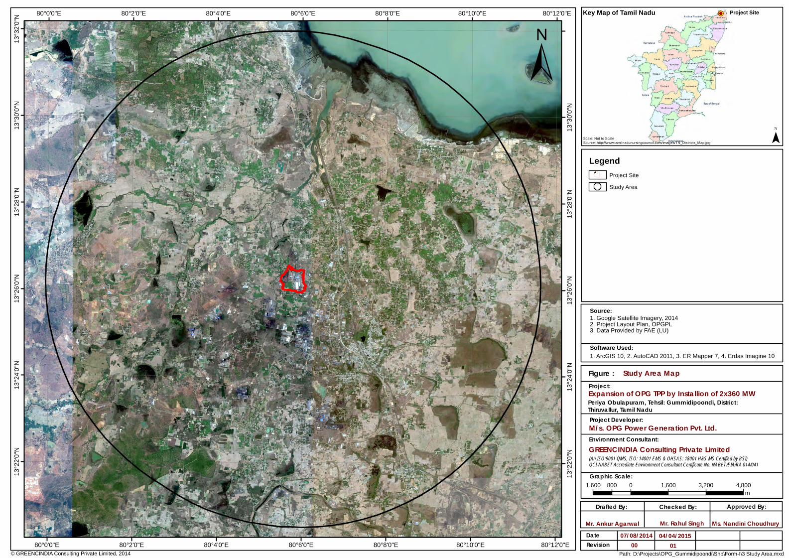
80°12'0"E
80°12'0"E
80°10'0"E
80°10'0"E
80°8'0"E
80°8'0"E
80°6'0"E
80°6'0"E
80°4'0"E
80°4'0"E
80°2'0"E
80°2'0"E
80°0'0"E
80°0'0"E13
°32'0"
N13
°30'0"
N
13°30
'0"N
13°28
'0"N
13°28
'0"N
13°26
'0"N
13°26
'0"N
13°24
'0"N
13°24
'0"N
13°22
'0"N
13°22
'0"N
Project:
Project Developer:
Graphic Scale:
Study Area MapFigure :
Source:
Drafted By: Approved By:
Mr. Ankur Agarwal
Checked By:
Ms. Nandini ChoudhuryDateRevision
07/08/201400
© GREENCINDIA Consulting Private Limited, 2014 Path: D:\Projects\OPG_Gummidipoondi\Shp\Form-I\3 Study Area.mxd
Key Map of Tamil Nadu
Scale: Not to ScaleSource: http://www.tamilnadunursingcouncil.com/images/TN_Districts_Map.jpg ¯
1,600 0 1,600 3,200 4,800800m
Software Used:
±Legend
Project SiteStudy Area
1. Google Satellite Imagery, 20142. Project Layout Plan, OPGPL3. Data Provided by FAE (LU)
1. ArcGIS 10, 2. AutoCAD 2011, 3. ER Mapper 7, 4. Erdas Imagine 10
Project Site!P
Mr. Rahul Singh
Periya Obulapuram, Tehsil: Gummidipoondi, District:Thiruvallur, Tamil Nadu
M/s. OPG Power Generation Pvt. Ltd.
Expansion of OPG TPP by Installion of 2x360 MW
GREENCINDIA Consulting Private LimitedEnvironment Consultant:
(An ISO:9001 QMS, ISO: 14001 EMS & OHSAS: 18001 H&S MS Certified by BSI)QCI-NABET Accrediate Environment Consultant Certificate No. NABET/EIA/RA 014/041
04/04/201501

80°12'0"E
80°12'0"E
80°10'0"E
80°10'0"E
80°8'0"E
80°8'0"E
80°6'0"E
80°6'0"E
80°4'0"E
80°4'0"E
80°2'0"E
80°2'0"E
80°0'0"E
80°0'0"E13
°32'0"
N13
°30'0"
N
13°30
'0"N
13°28
'0"N
13°28
'0"N
13°26
'0"N
13°26
'0"N
13°24
'0"N
13°24
'0"N
13°22
'0"N
13°22
'0"N
Project:
Project Developer:
Graphic Scale:
GREENCINDIA Consulting Private Limited
Distance of Project Site from Eco SensitiveZone of Pulicat Lake
Figure :
Environment Consultant:
Source:
Drafted By: Approved By:
Mr. Ankur Agarwal
Checked By:
Ms. Nandini ChoudhuryDateRevision
05/02/201500
(An ISO:9001 QMS, ISO: 14001 EMS & OHSAS: 18001 H&S MS Certified by BSI)QCI-NABET Accrediate Environment Consultant Certificate No. NABET/EIA/RA 014/041
© GREENCINDIA Consulting Private Limited, 2014 Path: D:\Projects\OPG_Gummidipoondi\Shp\WLS.mxd
Key Map of Tamil Nadu
Scale: Not to ScaleSource: http://www.tamilnadunursingcouncil.com/images/TN_Districts_Map.jpg ¯
1,600 0 1,600 3,200 4,800800m
Software Used:
±Legend
State Boundary/ Eco Sensitive Zone of Pulicat Bird SanctuaryProject SiteStudy Area
1. Google Satellite Imagery, 20142. Project Layout Plan, OPGPL3. Data Provided by FAE (LU)
1. ArcGIS 10, 2. AutoCAD 2011, 3. ER Mapper 7, 4. Erdas Imagine 10
Project Site!P
10.0 km
Mr. Rahul Singh
Expansion of OPG TPP by Installion of 2x360 MWPeriya Obulapuram, Tehsil: Gummidipoondi, District:Thiruvallur, Tamil Nadu
M/s. OPG Power Generation Pvt. Ltd.
Tamil NaduAndhra Pradesh
5.0 km Settlements
StreamsRoadsRailwayForestPondsVegetationContoursLocations
A BC
DEFG
04/04/201501
Points Latitude Longitude A 13 26’ 32.99” N 80 05’ 40.90” E B 13 26’ 26.92” N 80 06’ 03.36” E C 13 26’ 05.06” N 80 06’ 05.79” E D 13 25’ 55.74” N 80 06’ 00.49” E E 13 25’ 56.09” N 80 05’ 51.72” E F 13 26’ 00.59” N 80 05’ 32.92” E G 13 26’ 13.23” N 80 05’ 32.07” E

Project : Unit V & VI – 2 x 360 MW Thermal Power Plant Client : M/s. OPG Power Generation Pvt Ltd Pre-Feasibility Report
78
ANNEXURE – 8
LOCATION MAP
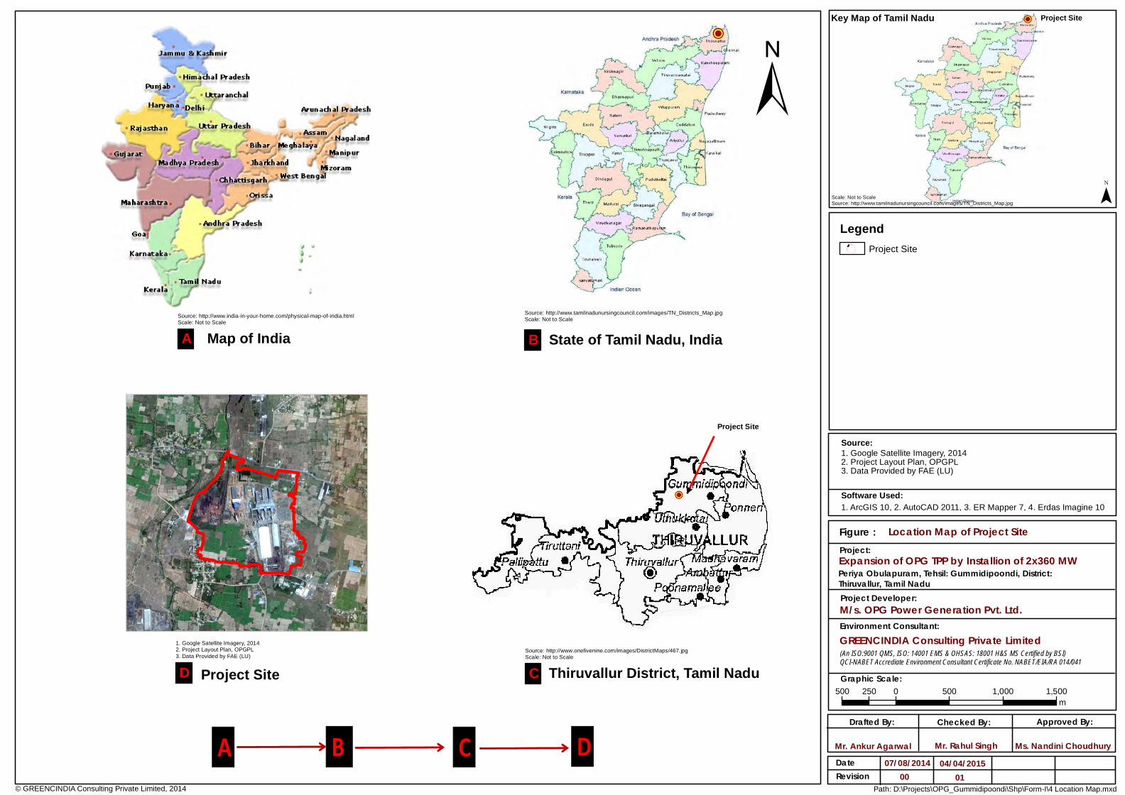
© GREENCINDIA Consulting Private Limited, 2014
±
Map of India State of Tamil Nadu, India
Project Site Thiruvallur District, Tamil Nadu
A B C D
A B
CD
Source: http://www.india-in-your-home.com/physical-map-of-india.htmlScale: Not to Scale
Source: http://www.tamilnadunursingcouncil.com/images/TN_Districts_Map.jpgScale: Not to Scale
Source: http://www.onefivenine.com/images/DistrictMaps/467.jpgScale: Not to Scale
1. Google Satellite Imagery, 20142. Project Layout Plan, OPGPL3. Data Provided by FAE (LU)
Project Site
!P
Project:
Project Developer:
Graphic Scale:
Location Map of Project SiteFigure :
Source:
Drafted By: Approved By:
Mr. Ankur Agarwal
Checked By:
Ms. Nandini ChoudhuryDateRevision
07/08/201400
Path: D:\Projects\OPG_Gummidipoondi\Shp\Form-I\4 Location Map.mxd
Key Map of Tamil Nadu
Scale: Not to ScaleSource: http://www.tamilnadunursingcouncil.com/images/TN_Districts_Map.jpg ¯
500 0 500 1,000 1,500250m
Software Used:
LegendProject Site
1. Google Satellite Imagery, 20142. Project Layout Plan, OPGPL3. Data Provided by FAE (LU)
1. ArcGIS 10, 2. AutoCAD 2011, 3. ER Mapper 7, 4. Erdas Imagine 10
Project Site!P
Mr. Rahul Singh
Expansion of OPG TPP by Installion of 2x360 MWPeriya Obulapuram, Tehsil: Gummidipoondi, District:Thiruvallur, Tamil Nadu
M/s. OPG Power Generation Pvt. Ltd.
GREENCINDIA Consulting Private LimitedEnvironment Consultant:
(An ISO:9001 QMS, ISO: 14001 EMS & OHSAS: 18001 H&S MS Certified by BSI)QCI-NABET Accrediate Environment Consultant Certificate No. NABET/EIA/RA 014/041
04/04/201501
!P


