Download - Operating Manual_ PacDrive PS-4 and PD-8.pdf

8/10/2019 Operating Manual_ PacDrive PS-4 and PD-8.pdf
http://slidepdf.com/reader/full/operating-manual-pacdrive-ps-4-and-pd-8pdf 1/66
Operating manual
PacDrive TM
PS-4 and PD-8
PD_OperaManPS-4_usArticle number : 17130094-001Edition: 08.2003
8/10/2019 Operating Manual_ PacDrive PS-4 and PD-8.pdf
http://slidepdf.com/reader/full/operating-manual-pacdrive-ps-4-and-pd-8pdf 2/66
8/10/2019 Operating Manual_ PacDrive PS-4 and PD-8.pdf
http://slidepdf.com/reader/full/operating-manual-pacdrive-ps-4-and-pd-8pdf 3/66
P D
_ O p e r a
M a n
P S - 4
_ u s I V
Z . f m
ELAU AG PacDrive PS-4 / PD-8 page 3
Contents
K o r r e
k t u r a u s
d r u c
k
Contents
1 On this manual 51.1 Introduction ............................................................................................ 51.2 Symbols, Signs and Forms of Depiction ................................................ 6
2 General Safety Notes 72.1 Basics .................................................................................................... 72.2 Depiction of Safety Notes ...................................................................... 82.3 Use as Directed ..................................................................................... 92.4 Selection and Qualification of Staff ...................................................... 102.5 Residual Risks ..................................................................................... 10
2.5.1 Installation and Handling ..................................................................... 112.5.2 Protection against Touching Electrical Parts ....................................... 122.5.3 "Safely Separated Low Voltages" ........................................................ 132.5.4 Potentially Dangerous Movements ...................................................... 14
3 System Overview 153.1 Drive Concepts for Packaging Machines ............................................. 153.2 Structure of the PacDrive™ Automation System ................................. 173.3 Structure .............................................................................................. 183.4 Components ........................................................................................ 19
4 Transportation, Storage, Unpacking 214.1 Transportation ...................................................................................... 214.2 Storage ................................................................................................ 214.3 Unpacking ............................................................................................ 21
5 Maintenance 255.1 Spare Parts, Components ................................................................... 255.2 Repair .................................................................................................. 26
5.3 Service Addresses ............................................................................... 265.4 Exchanging units ................................................................................. 275.5 Cleaning ............................................................................................... 295.6 EMC Rules ........................................................................................... 305.7 Commissioning .................................................................................... 315.7.1 Slaves in the SERCOS ring ................................................................. 355.8 Configuration / Programming / Diagnosis ............................................ 355.8.1 Diagnosis LEDs ................................................................................... 365.8.2 Combination of PacDrive SCL and PacDrive PS-4 ............................. 37
8/10/2019 Operating Manual_ PacDrive PS-4 and PD-8.pdf
http://slidepdf.com/reader/full/operating-manual-pacdrive-ps-4-and-pd-8pdf 4/66
P D
_ O p e r a
M a n
P S - 4
_ u s I V
Z . f m
page 4 PacDrive PS-4 / PD-8 ELAU AG
Contents
K o r r e
k t u r a u s
d r u c
k
5.9 Order numbers ..................................................................................... 385.9.1 PacDrive PS-4 ...................................................................................... 385.9.2 Cables .................................................................................................. 39
6 Project definition 416.1 Creation of a PacDrive PS-4/PD-8, SCL055 application ...................... 416.2 PacDrive PS-4 ...................................................................................... 416.2.1 Mains Connection of PacDrive PS-4 .................................................... 416.2.2 Transformer dimensioning .................................................................... 446.3 Electricity Supply via Slip Ring ............................................................. 46
7 Technical Data 47
7.1 PacDrive PS-4 ...................................................................................... 477.1.1 General ................................................................................................. 477.1.2 Electrical connections ........................................................................... 487.1.3 Dimensions ........................................................................................... 517.2 PacDrive PD-8 ...................................................................................... 527.2.1 General ................................................................................................. 527.2.2 Electrical connections ........................................................................... 537.2.3 Dimensions ........................................................................................... 547.3 Declaration by the manufacturer .......................................................... 577.4 Modifications ........................................................................................ 58
8 APPENDIX 598.1 Contact ................................................................................................. 598.2 Further Literature .................................................................................. 608.3 Product Training ................................................................................... 628.4 Index ..................................................................................................... 638.5 Form for Error Report ........................................................................... 65

8/10/2019 Operating Manual_ PacDrive PS-4 and PD-8.pdf
http://slidepdf.com/reader/full/operating-manual-pacdrive-ps-4-and-pd-8pdf 5/66
P D M
_ V e r w e n
d S t d
_ u s .
F M
ELAU AG PacDrive EPAS-4 page 5
1.1 Introduction
K o r r e
k t u r a u s
d r u c
k
1 On this manual
1.1 Introduction
Before using ELAU components for the first time, you shouldfamiliarize yourself with this operating manual.
In particular, observe the safety notes described in chapter 2.
Only persons who meet the criteria for "Selection and Qualificationof Staff" (see chapter 2.4) are allowed to work on ELAUcomponents.
One copy of this manual has to be available for staff working on thecomponents with access at any time.
This manual is to help you use the component safely and expertlyand to use it as directed.
Observe this manual. This will help to avoid risks, reduce repaircosts and down times and increase the lifetime and reliability of theproducts.You also need to observe the valid rules for the prevention ofaccidents and for environmental protection in the country and placewhere the device is used.
8/10/2019 Operating Manual_ PacDrive PS-4 and PD-8.pdf
http://slidepdf.com/reader/full/operating-manual-pacdrive-ps-4-and-pd-8pdf 6/66
P D M
_ V e r w e n
d S t d
_ u s .
F M
page 6 PacDrive EPAS-4 ELAU AG
1 On this manual
K o r r e
k t u r a u s
d r u c
k
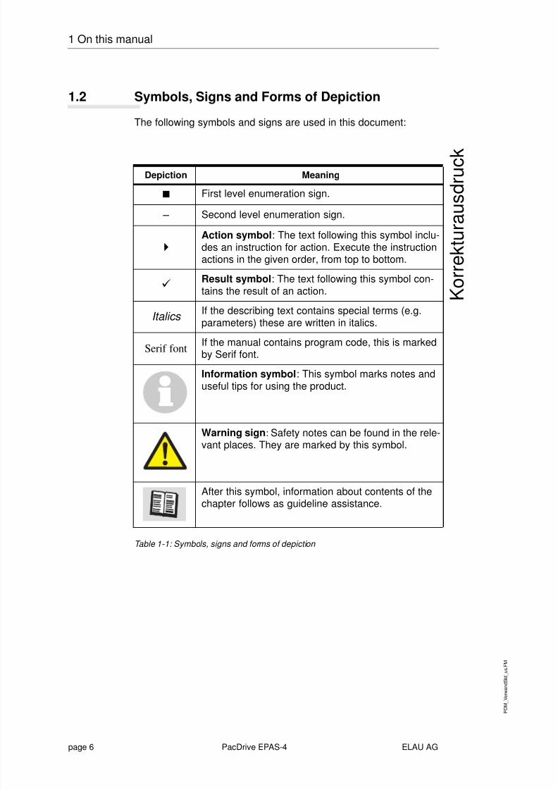
1.2 Symbols, Signs and Forms of Depiction
The following symbols and signs are used in this document:
Table 1-1: Symbols, signs and forms of depiction
Depiction Meaning
First level enumeration sign.
– Second level enumeration sign.
Action symbol : The text following this symbol inclu-des an instruction for action. Execute the instructionactions in the given order, from top to bottom.
Result symbol : The text following this symbol con-tains the result of an action.
Italics If the describing text contains special terms (e.g.parameters) these are written in italics.
Serif font If the manual contains program code, this is markedby Serif font.
Information symbol : This symbol marks notes anduseful tips for using the product.
Warning sign : Safety notes can be found in the rele-vant places. They are marked by this symbol.
After this symbol, information about contents of thechapter follows as guideline assistance.

8/10/2019 Operating Manual_ PacDrive PS-4 and PD-8.pdf
http://slidepdf.com/reader/full/operating-manual-pacdrive-ps-4-and-pd-8pdf 7/66
P D M
_ S i c h e r h
M a x_ u s_ n e u . f m
ELAU AG PacDrive page 7
2.1 Basics
K o r r e
k t u r a u s
d r u c
k
2 General Safety NotesThis chapter contains general requirements for working safely.
Every person using ELAU components or working on ELAUcomponents has to read and observe these general safety notes.If activities involve a residual risk, you will find a clear note in therespective places. The note describes the risk that may occur andpreventive measures to avoid that risk.
2.1 Basics
The ELAU components are built according to the state oftechnology and generally accepted safety rules. Nevertheless, theiruse may cause a risk to life and limb or material damage if:
you do not use the components as directedwork on the components is not done by experts or instructedstaffyou inexpertly alter or modify a componentyou fail to test the protective measures in place after installation,commissioning or servicingyou do not observe the safety notes and regulations.
Only operate the components in perfect technical condition, asdirected, with regard to safety and risks and observe this manual.
The flawless and safe operation of the components requiresappropriate transport, storage, mounting and installation as well ascareful maintenance.
In case of any circumstances that impair the safety and causechanges in the operating behavior, immediately put thecomponent(s) to a stop and inform the service staff in charge.
In addition to this manual, observethe prohibiting, warning and mandatory signs on the component,the connected components and in the switching cabinetthe relevant laws and regulationsthe operating manuals of the other componentsthe universally valid local and national rules for safety and theprevention of accidents.
8/10/2019 Operating Manual_ PacDrive PS-4 and PD-8.pdf
http://slidepdf.com/reader/full/operating-manual-pacdrive-ps-4-and-pd-8pdf 8/66
P D M
_ S i c h e r h
M a x_ u s_ n e u . f m
page 8 PacDrive ELAU AG
2 General Safety Notes
K o r r e
k t u r a u s
d r u c
k
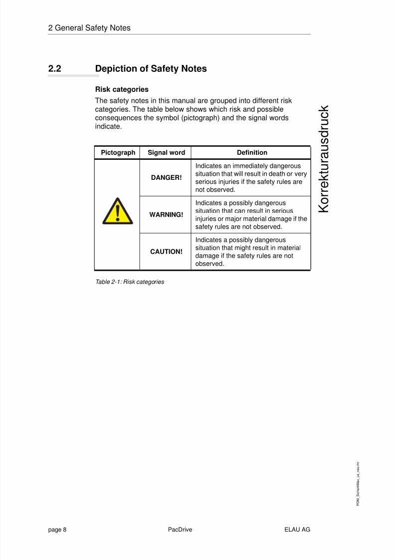
2.2 Depiction of Safety Notes
Risk categories
The safety notes in this manual are grouped into different riskcategories. The table below shows which risk and possibleconsequences the symbol (pictograph) and the signal wordsindicate.
Table 2-1: Risk categories
Pictograph Signal word Definition
DANGER!
Indicates an immediately dangeroussituation that will result in death or veryserious injuries if the safety rules arenot observed.
WARNING!
Indicates a possibly dangeroussituation that can result in seriousinjuries or major material damage if thesafety rules are not observed.
CAUTION!
Indicates a possibly dangeroussituation that might result in materialdamage if the safety rules are notobserved.

8/10/2019 Operating Manual_ PacDrive PS-4 and PD-8.pdf
http://slidepdf.com/reader/full/operating-manual-pacdrive-ps-4-and-pd-8pdf 9/66
P D M
_ S i c h e r h
M a x_ u s_ n e u . f m
ELAU AG PacDrive page 9
2.3 Use as Directed
K o r r e
k t u r a u s
d r u c
k
2.3 Use as Directed
The ELAU components are designed for installation in a machine/
plant or for combination with other components to form a machine/ plant. The components may only be used under the installation andoperating conditions described in this documentation. You must usethe accessories and ancillary parts (components, cables, etc.)mentioned in the documentation. You must not use any foreignobjects or components that are not explicitly approved by ELAU.
"Use as directed" also means that youobserve the Operating Manuals and other documentations (seeappendix),observe the instructions for inspection and maintenance.
Use other than directed
The operating conditions at the place where the device is usedmust be checked on the basis of the given technical data(performance information and ambient conditions) and observed.
The device must not be put into operation until it is guaranteed thatthe useable machine or the plant in which the motor is installedmeets in its entirety EC directive 98/37/EC (machine directive).
In addition, observe the following norms, directives and regulations:DIN EN 60204 Safety of machines:Electrical equipment of machines.DIN EN 292 part 1 and part 2 Safety of machines:Basics, general design guidelines.DIN EN 50178 Equipment of high-voltage plants with electronicoperating means.EMC directive 89/336/EEC

8/10/2019 Operating Manual_ PacDrive PS-4 and PD-8.pdf
http://slidepdf.com/reader/full/operating-manual-pacdrive-ps-4-and-pd-8pdf 10/66
P D M
_ S i c h e r h
M a x_ u s_ n e u . f m
page 10 PacDrive ELAU AG
2 General Safety Notes
K o r r e
k t u r a u s
d r u c
k
2.4 Selection and Qualification of Staff
This manual is aimed exclusively at technically qualified staff with
detailed knowledge in the field of automation technology.Only qualified staff can recognize the significance of safety notesand implement them accordingly.This manual is aimed in particular at design and applicationengineers in the fields of mechanical and electrical engineering, atprogrammers, service and commissioning engineers.
Working on electrical
equipment
Work on electrical equipment must only be done by qualifiedelectricians or by instructed staff supervised by an electricianaccording to the electrotechnical rules.
An electrician is a person who, due to his vocational training, know-how and experience as well as knowledge of the valid regulations,is able to:
evaluate the work he is supposed to doidentify potential risksimplement suitable safety measures.
2.5 Residual Risks
We minimized the health risk for people by means of appropriateconstruction and safety technology. Nevertheless, there is aresidual risk, since the components work with electrical current andvoltage.

8/10/2019 Operating Manual_ PacDrive PS-4 and PD-8.pdf
http://slidepdf.com/reader/full/operating-manual-pacdrive-ps-4-and-pd-8pdf 11/66
P D M
_ S i c h e r h
M a x_ u s_ n e u . f m
ELAU AG PacDrive page 11
2.5 Residual Risks
K o r r e
k t u r a u s
d r u c
k
2.5.1 Installation and Handling
WARNING!Risk of injury while handling the unit!Risk of injury due to squeezing, cutting or hitting!
Observe the universally valid construction and safety rules forhandling and installation.Use suitable installation and transport facilities and use themprofessionally. If necessary, use special tools.Take precautions against squeezing.If necessary, use suitable protective clothing (e.g. safetyglasses, safety shoes, protective gloves).Do not stay under pending loads.Remove any leaking liquids from the floor immediately to avoidskidding.
8/10/2019 Operating Manual_ PacDrive PS-4 and PD-8.pdf
http://slidepdf.com/reader/full/operating-manual-pacdrive-ps-4-and-pd-8pdf 12/66
P D M
_ S i c h e r h
M a x_ u s_ n e u . f m
page 12 PacDrive ELAU AG
2 General Safety Notes
K o r r e
k t u r a u s
d r u c
k
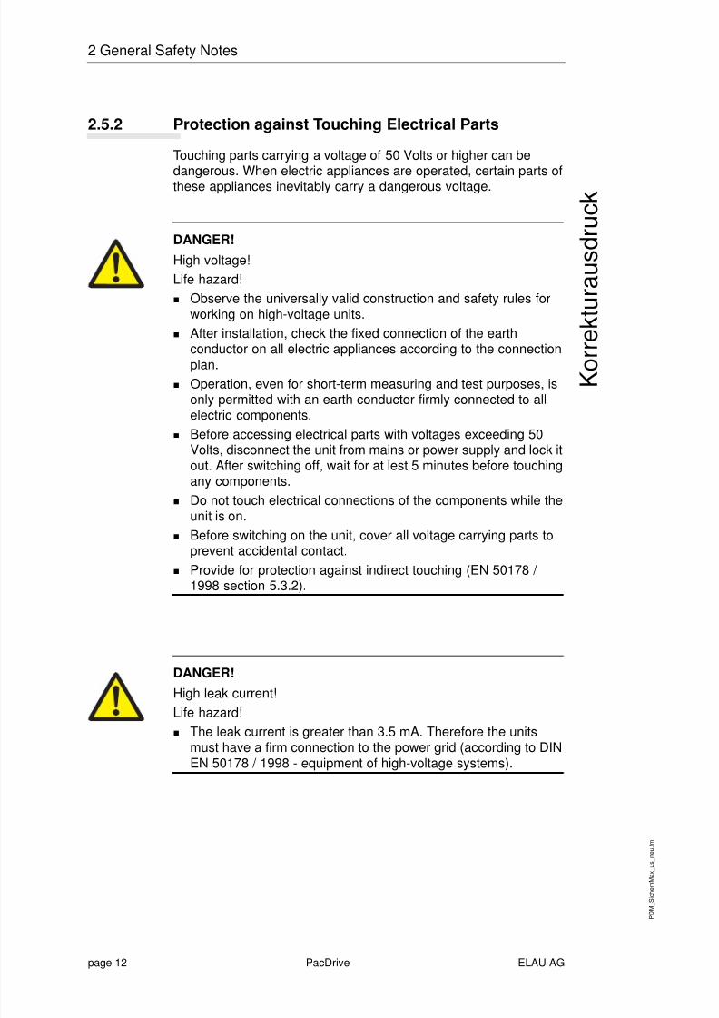
2.5.2 Protection against Touching Electrical Parts
Touching parts carrying a voltage of 50 Volts or higher can bedangerous. When electric appliances are operated, certain parts ofthese appliances inevitably carry a dangerous voltage.
DANGER!High voltage!Life hazard!
Observe the universally valid construction and safety rules forworking on high-voltage units.After installation, check the fixed connection of the earthconductor on all electric appliances according to the connectionplan.Operation, even for short-term measuring and test purposes, isonly permitted with an earth conductor firmly connected to allelectric components.Before accessing electrical parts with voltages exceeding 50Volts, disconnect the unit from mains or power supply and lock itout. After switching off, wait for at lest 5 minutes before touchingany components.Do not touch electrical connections of the components while theunit is on.
Before switching on the unit, cover all voltage carrying parts toprevent accidental contact.Provide for protection against indirect touching (EN 50178 /1998 section 5.3.2).
DANGER!High leak current!
Life hazard!The leak current is greater than 3.5 mA. Therefore the unitsmust have a firm connection to the power grid (according to DINEN 50178 / 1998 - equipment of high-voltage systems).

8/10/2019 Operating Manual_ PacDrive PS-4 and PD-8.pdf
http://slidepdf.com/reader/full/operating-manual-pacdrive-ps-4-and-pd-8pdf 13/66
P D M
_ S i c h e r h
M a x_ u s_ n e u . f m
ELAU AG PacDrive page 13
2.5 Residual Risks
K o r r e
k t u r a u s
d r u c
k
2.5.3 "Safely Separated Low Voltages"
PELV P rotective- E xtra-
Low- V oltage
Signal voltage and control voltage of the PacDrive units are <33 V.In this range the specification as PELV system according to IEC364-4-41 includes a protective measure against directly anddirectly touching dangerous voltages by means of a "safeseparation" from the primary to the secondary side in the plant/ machine. ELAU urgently recommends to execute the plant/ machine with safe separation.
DANGER!High voltage due to wrong connection!Life hazard or risk of serious injury!
Only units, electric components or cables with a sufficient safeseparation of the connected power supplies according to EN50178 / 1998 (equipment of high-voltage systems with electronicoperating means) may be connected to the signal voltageconnections of these components.Make sure that the existing safe separation is retainedthroughout the entire current circuit.
FELV Functional- Extra-Low-
Voltage
When using ELAU components in systems that do not include asafe separation as a means of protection against directly orindirectly touching dangerous voltages, all connections andcontacts (e.g. MAx-4, Sub-D connector, serial inerface) that do notcomply with protection class IP2X must be permanently covered.The cover or device connection must be such that it can only beremoved with the help of a tool. The protective measure must beobserved on all connected devices.

8/10/2019 Operating Manual_ PacDrive PS-4 and PD-8.pdf
http://slidepdf.com/reader/full/operating-manual-pacdrive-ps-4-and-pd-8pdf 14/66
P D M
_ S i c h e r h
M a x_ u s_ n e u . f m
page 14 PacDrive ELAU AG
2 General Safety Notes
K o r r e
k t u r a u s
d r u c
k
2.5.4 Potentially Dangerous Movements
There can be different causes for potentially dangerousmovements:
mistakes in wiring or cable connectionsoftware errorsfaulty componentserrors in measuring value and signal encodersoperating mistakes
The protection of people must be insured by superior means ormonitoring on the plant side. You must not rely on the internalmonitoring in the drive components alone. Monitoring or measures
are to be provided according to a risk and error analysis by theplant builder according to the specific conditions of the plant. Thevalid safety rules for the plant are to be included in this process.
DANGER!Potentially dangerous movements!Life hazard, serious injury or material damage!
No persons are allowed within the motion range of the machine.This is to be ensured by means of devices like protective fences,
grids, covers or photoelectric barriers.The fences and covers must be sufficiently strong to withstandthe maximum possible motion energy.The emergency stop switch must be located very close to theoperator. Check the operation of the emergency stop beforestarting up the plant.Secure against unintentional start by enabling the mainscontactor of the drives via an emergency off circuit or by meansof the function 'safe stop'.Before accessing the danger zone, bring the drives to a safestop.To work on the plant, power must be turned off and locked out.Avoid operating high-frequency, remote-control and radiodevices in the vicinity of the plant's electronics and connectingwires. If the use of those devices is inevitable, check system andplant for possible malfunctions before first operation. In somecases a special EMT check may be necessary.
8/10/2019 Operating Manual_ PacDrive PS-4 and PD-8.pdf
http://slidepdf.com/reader/full/operating-manual-pacdrive-ps-4-and-pd-8pdf 15/66

8/10/2019 Operating Manual_ PacDrive PS-4 and PD-8.pdf
http://slidepdf.com/reader/full/operating-manual-pacdrive-ps-4-and-pd-8pdf 16/66
P D
_ S y s U e
b e r s S
C L
_ u s .
f m
page 16 PacDrive ELAU AG
3 System Overview
Fig. 3-1: Sketch of a packaging machine
8/10/2019 Operating Manual_ PacDrive PS-4 and PD-8.pdf
http://slidepdf.com/reader/full/operating-manual-pacdrive-ps-4-and-pd-8pdf 17/66
P D
_ S y s U e
b e r s S
C L
_ u s .
f m
ELAU AG PacDrive page 17
3.2 Structure of the PacDrive™ Automation System
H a r d - c o p y
f o r c o r r e c t i o n
3.2 Structure of the PacDrive™ Automation System
The PackDrive™ automation system offers a technically and
economically ideal solution for electronic packaging machines.PacDrive™ consists of an efficient PC-based control, the PacDriveController and the digital motor controllers, which include the mainsconnection unit, the end-stage power and the servo regulator of theindividual axes( Fig. 3-2 ).
The PacDrive controller is the intelligent head of the system, and isbased on an industrial PC. The PacDrive controller synchronizesand coordinates the motion functions of the packaging machine.Using an IEC 61131-3 soft-PLC, the PacDrive Controller venturesinto applications previously reserved to classical PLCs. Theindividual PLC or positioning tasks can be broken down into several
parallel tasks, which are implemented with the EPAS-4programming environment according to IEC 61131-3 standard.
The ring-shaped digital real-time bus SERCOS ensures safe dataexchange with the motor controllers. Even in applications on rotarytables etc., the distributed motor controllers are reliably suppliedwith new set values. All internal states of the axes can be checkedvia the real-time bus and processed by the PacDrive controller.
In addition to digital and analog inputs and outputs, the PacDriveController has two serial interfaces and one Ethernet interface. Avariety of process visualization and control systems can beconnected to PacDrive™ via the integrated OPC interface. Further
peripheral components can be connected via field bus interfacemodules. The PacDrive Controller can act as field bus master orslave. The built-in interfaces enable remote diagnosis via telephonemodem or Internet.
Particularly in the beverage sector (bottle cappers, bottle labelingmachines) it is necessary to install servo motors on a rotary table.The small dimensions of the rotary table require innovativesolutions, as the switching cabinet with the standard productsPacDrive Controller and PacDrive MC-4 can usually not bemounted on the rotary table. To keep additional wiring to the rotarytable down to a minimum, ELAU developed the PacDrive SCL-055
for such applications - a compact servo motor with integrated motorcontroller that is suitable for aseptic closing/sealing machines. ThePacDrive SCL-055 Aseptic has a special surface coating thatmakes it resistant against many cleaners and disinfectants.
To keep the size of the SCL drives down to a minimum, the powersupply is arranged centrally via the external power supply unitPacDrive PS-4 in combination with PacDrive PD-8.

8/10/2019 Operating Manual_ PacDrive PS-4 and PD-8.pdf
http://slidepdf.com/reader/full/operating-manual-pacdrive-ps-4-and-pd-8pdf 18/66
P D
_ S y s U e
b e r s S
C L
_ u s .
f m
page 18 PacDrive ELAU AG
3 System Overview
3.3 Structure
Fig. 3-2: System overview of the PackDrive™ Automation System
8/10/2019 Operating Manual_ PacDrive PS-4 and PD-8.pdf
http://slidepdf.com/reader/full/operating-manual-pacdrive-ps-4-and-pd-8pdf 19/66
P D
_ S y s U e
b e r s S
C L
_ u s .
f m
ELAU AG PacDrive page 19
3.4 Components
H a r d - c o p y
f o r c o r r e c t i o n
3.4 Components
Automation Toolkit EPAS-4
EPAS-4 has extensive and proven functions and tools. A keyadvantage of EPAS-4 is that all components are tuned to eachother.
For you as a user, this means:
Quick familiarization, easy handling, all tools integrated.Libraries Extensive libraries, tailored to the target group, help to save costs
and improve the quality of user programs.
HighlightsRuns under Windows (Windows XP Professionalrecommended)IEC 61131-3 programming languagesSCOPE tool (oscilloscope functions)Diagnosing toolVery good debugging featuresSerial or TCP/IP connection to the PacDrive controller
PacDrive ControllerThe PacDrive controller, a Pentium-based control hardware withthe real-time operating system VxWorks, centrally realizes the PLCand motion functions.
A PacDrive controller synchronizes, coordinates and generates thepositioning functions for the drives of a food and packagingmachine.
A variety of standard HMIs are used for HMI tasks. Whether low-cost clear text or IPC - no problem for the flexible PacDriveController.Highlights
Pentium controller hardwareReal-time operating system VxWorksIEC 61131 PLC and Motion ControlScalable performanceStandard interfaces to low-cost operating units or PC-based HMICompact book-size formEthernet interfaceStandard field busesVarioCam® Motion ControlSERCOS drive bus
8/10/2019 Operating Manual_ PacDrive PS-4 and PD-8.pdf
http://slidepdf.com/reader/full/operating-manual-pacdrive-ps-4-and-pd-8pdf 20/66
P D
_ S y s U e
b e r s S
C L
_ u s .
f m
page 20 PacDrive ELAU AG
3 System Overview
PacDrive SCLMotor with integrated
MotorController
The compact size of the PacDrive SCL combines motor and powerelectronics in the smallest space. The innovative SCL has the
motor, the power output level and the digital servo controller for anaxis in one casing, which saves space. Thanks to the compact sizewith integrated controller, it is perfectly suited for distributedinstallation. It is available with single- or multi-turn encoder andconfigures itself with the help of the electronic type plate inside theSCL.
HighlightsCompact size3.5-fold peak torqueIntegrated SERCOS interfaceHigh-resolution single- or multi-turn encodersIP65 / IP67 protection meansEasy wiringHigh failure proofnessTrapezoid shapeAseptic variant IP67 (with positive pressure option)
PacDrive PS-4Centralized
supply The power supply unit PS-4 is characterized by a compact andautonomous structure for switching cabinet installation plus highlymodern technology. All PacDrive SCLs are served on just one line
via the PacDrive PS-4, which is quick to install. PS-4 thus fitssmoothly into the extremely flexible modular drive concept.
Highlights1- or 3-phase power supplyIntegrated mains filter and bleeder5 kW permanent power / 10 kW peak powerDC-circuit power for up to 32 SCL-055s (depending on theapplication)Integrated SERCOS interfaceFull diagnosis facilities thanks to integrated controller
Easy installationPacDrive PD-8
Flexible distributor
The PacDrive PD-8 power distribution box is the link between PS-4and SCL. One "distributor" to which 1 to 8 SCL hybrid cables canbe connected, depending on the number of drives. If more than 8drives are operated, simply extend the system by one or severalPD-8 distributors. Like the SCL, the PacDrive PD-8 is available instandard and aseptic variants.
Information on further components is available in the operatingmanual PacDrive PS-4 and PacDrive PD-8. Information on furthercomponents is available in the Project Manual.
8/10/2019 Operating Manual_ PacDrive PS-4 and PD-8.pdf
http://slidepdf.com/reader/full/operating-manual-pacdrive-ps-4-and-pd-8pdf 21/66
P D
_ O p
M a n
P S - 4
_ 0 4
_ u s .
F M
ELAU AG PacDrive PS-4 / PD-8 page 21
4.1 Transportation
H a r d - c o p y
f o r c o r r e c t i o n
4 Transportation, Storage, Unpacking
4.1 Transportation
Avoid shocks.Check units for transport damage and immediately inform yourtransport company, if necessary.
4.2 Storage
Store the units in a clean, dry place.
Storage conditions:Air temperature between -25°C and +70°CTemperature fluctuations max. 30 K per hour.
4.3 Unpacking
Check whether the consignment is complete.Check all units for transport damage.
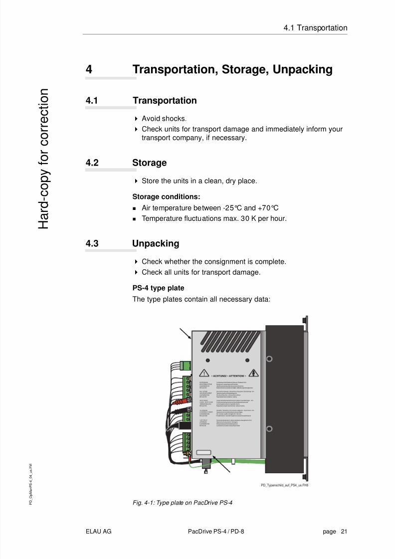
PS-4 type plateThe type plates contain all necessary data:
Fig. 4-1: Type plate on PacDrive PS-4

8/10/2019 Operating Manual_ PacDrive PS-4 and PD-8.pdf
http://slidepdf.com/reader/full/operating-manual-pacdrive-ps-4-and-pd-8pdf 22/66
P D
_ O p
M a n
P S - 4
_ 0 4
_ u s .
F M
page 22 PacDrive PS-4 / PD-8 ELAU AG
4 Transportation, Storage, Unpacking
H a r d - c o p y
f o r c o r r e c t i o n
Fig. 4-2: Logistic type plate of a PacDrive PS-4
Fig. 4-3: Technical type plate of a PacDrive PS-4
PD-8 type plate
Fig. 4-4: Type plate on PD-8
Fig. 4-5: Logistic type plate of a PacDrive PD-8
Fig. 4-6: Technical type plate of a PacDrive PD-8
8/10/2019 Operating Manual_ PacDrive PS-4 and PD-8.pdf
http://slidepdf.com/reader/full/operating-manual-pacdrive-ps-4-and-pd-8pdf 23/66
P D
_ O p
M a n
P S - 4
_ 0 4
_ u s .
F M
ELAU AG PacDrive PS-4 / PD-8 page 23
4.3 Unpacking
H a r d - c o p y
f o r c o r r e c t i o n
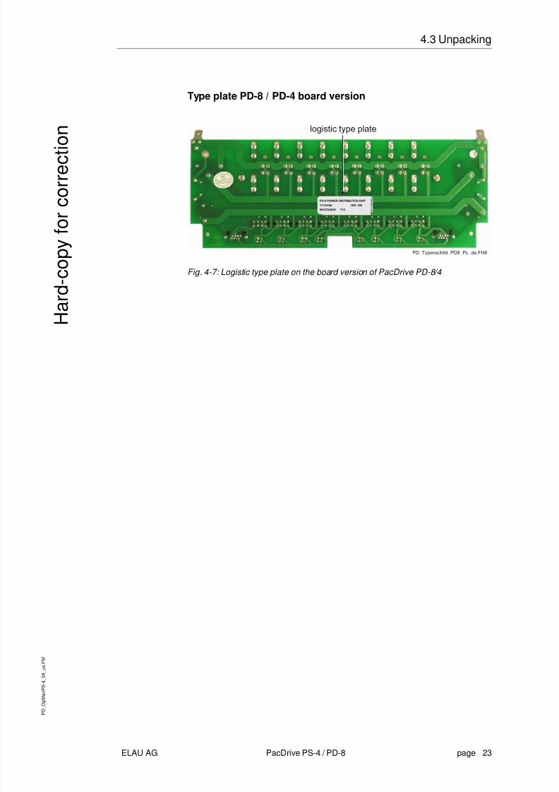
Type plate PD-8 / PD-4 board version
Fig. 4-7: Logistic type plate on the board version of PacDrive PD-8/4
8/10/2019 Operating Manual_ PacDrive PS-4 and PD-8.pdf
http://slidepdf.com/reader/full/operating-manual-pacdrive-ps-4-and-pd-8pdf 24/66
P D
_ O p
M a n
P S - 4
_ 0 4
_ u s .
F M
page 24 PacDrive PS-4 / PD-8 ELAU AG
4 Transportation, Storage, Unpacking
H a r d - c o p y
f o r c o r r e c t i o n
8/10/2019 Operating Manual_ PacDrive PS-4 and PD-8.pdf
http://slidepdf.com/reader/full/operating-manual-pacdrive-ps-4-and-pd-8pdf 25/66
P D
_ O p
M a n
P S - 4
_ 0 5
_ u s .
f m
ELAU AG PacDrive PS-4 / PD-8 page 25
5.1 Spare Parts,
H a r d - c o p y
f o r c o r r e c t i o n
5 MaintenanceRecognizing and clearing an error quickly helps to keep the relatedproduction loss down to a minimum.The diagnosis messages of the PacDrive™ system, which can bechecked using the Automation Toolkit EPAS-4, make it possible tolook for errors deliberately and effectively.In case of an error, defective components can easily beexchanged. This ensures that the problem can be solved quicklyand operation can be resumed soon. This work must be done byqualified service staff only.
When returning a defective unit to the ELAU customer service,please complete the attached error report form.
5.1 Spare Parts, Components
Stock keeping of spare parts:Keeping a stock of the essential components is a key prerequisitefor the permanent functionality of the equipment.
NOTE
Only devices with identical hardware configuration and softwareversion may be exchanged. This ensures that the plant will workcorrectly after the component change.
When ordering spare parts, please give the following data:
Article name: e.g. PS-4/10/16/230/00Article number: e.g. 13 13 02 59-001
NOTEYou can find this information on the type plate of the equipment (seeFig. 4-1)or in the configuration of the PacDrive™ system.

8/10/2019 Operating Manual_ PacDrive PS-4 and PD-8.pdf
http://slidepdf.com/reader/full/operating-manual-pacdrive-ps-4-and-pd-8pdf 26/66
P D
_ O p
M a n
P S - 4
_ 0 5
_ u s .
f m
page 26 PacDrive PS-4 / PD-8 ELAU AG
5 Maintenance
H a r d - c o p y
f o r c o r r e c t i o n
5.2 Repair
By all means complete the attached error report form when
returning defective components.You can also make a photocopy of the error report form and use itas a fax message.
CAUTION!Electro static discharge!Components may be damaged!
Return electronic components in original or equivalentpackaging only.
Always use ESD packaging/foil.
5.3 Service Addresses
For ordering spare parts
ELAU AGPostfach 1255D-97821 Marktheidenfeld
Phone: +49 (0) 93 91 / 606 - 0Fax: +49 (0) 93 91 / 606 - 300
Repairs and customer service
Please send the components to be repaired or checked, along withthe error report, to this address:
ELAU AGAbt. Kundendienst street address:Postfach 1255 Dillberg 12D-97821 Marktheidenfeld D-97828 Marktheidenfeld
Phone: +49 (0) 93 91 / 606 - 142
Fax: +49 (0) 93 91 / 606 - 340
Service teamShould you need to talk to a member of our service team or requireon-site service, please contact:
ELAU AGAbt. ApplikationPostfach 1255D-97821 Marktheidenfeld
Phone: +49 (0) 93 91 / 606 -0Fax: +49 (0) 93 91 / 606 -300

8/10/2019 Operating Manual_ PacDrive PS-4 and PD-8.pdf
http://slidepdf.com/reader/full/operating-manual-pacdrive-ps-4-and-pd-8pdf 27/66
P D
_ O p
M a n
P S - 4
_ 0 5
_ u s .
f m
ELAU AG PacDrive PS-4 / PD-8 page 27
5.4 Exchanging units
H a r d - c o p y
f o r c o r r e c t i o n
5.4 Exchanging units
In addition to the notes below, please observe the information of
the machine producer when exchanging the PacDrive PS-4.
DANGER!
High voltage!Life hazard!High voltage possible with servo motors in generator operation!
Before working on electrical units, disconnect from mains supplyand lock out.Make sure that the drives are standing still.
Do not disconnect connector plugs while they are carryingvoltage.Before working on the unit, discharge the DC-circuit and use avoltmeter to check that there is no voltage.
CAUTION!Electro static discharge!Components may be damaged!
Only touch the boards on the edges.Do not touch any connections or components.Existing static charges can be discharged by touching agrounded metallic surface, e.g. a grounded equipment casing.Prevent the formation of electrostatic charge by using suitableclothing, carpets or furniture and by moving the boards as littleas possible.
8/10/2019 Operating Manual_ PacDrive PS-4 and PD-8.pdf
http://slidepdf.com/reader/full/operating-manual-pacdrive-ps-4-and-pd-8pdf 28/66
8/10/2019 Operating Manual_ PacDrive PS-4 and PD-8.pdf
http://slidepdf.com/reader/full/operating-manual-pacdrive-ps-4-and-pd-8pdf 29/66
P D
_ O p
M a n
P S - 4
_ 0 5
_ u s .
f m
ELAU AG PacDrive PS-4 / PD-8 page 29
5.5 Cleaning
H a r d - c o p y
f o r c o r r e c t i o n
Insert the SERCOS in/out cable in the corresponding cable duct,snap the connector into the outlet and fix the strain relief on thecable duct while the cable is relieved.
Insert the SCL connections in the corresponding cable duct,snap the connector into the outlet and fix the strain relief on thecable duct while the cable is relieved.
Exchanging cablesOpen main switch.Lock out main switch.
DANGER!
High voltage!Life hazard!
Disconnect and connect power supply only when the plant isvoltage-free!Do not insert the connectors unless both sides are dry andclean!If no ready made ELAU cables are used, make sure theassignment of the new cables matches the wiring diagram of themachine manufacturer!
Remove cables from the PS-4 / fix them back (see ExchangingPacDrive PS-4).Remove cables from the PD-8 / fix them back (see ExchangingPacDrive PD-8).When exchanging cables, also observe the instructions of themachine manufacturer.
5.5 Cleaning
If installed as directed, the units are to a large extent maintenance-free.To remove dust and foreign objects brought in by the cooling airflow, disconnect the units from the power supply, remove them anduse dry compressed air (max. 1 bar) to blow away the pollution.
8/10/2019 Operating Manual_ PacDrive PS-4 and PD-8.pdf
http://slidepdf.com/reader/full/operating-manual-pacdrive-ps-4-and-pd-8pdf 30/66
P D
_ O p
M a n
P S - 4
_ 0 5
_ u s .
f m
page 30 PacDrive PS-4 / PD-8 ELAU AG
5 Maintenance
H a r d - c o p y
f o r c o r r e c t i o n
5.6 EMC Rules
To control and regulate motors, the mains voltage is stored in the
DC-circuit of the PS-4 by means of rectification. This DC-circuitvoltage supplies all connected SCL-055s. In the SCL-055, thisstored energy is fed to the motor by deliberately activating anddeactivating six semiconductor switches. The steep rise and fall ofthe voltage puts high demands on the insulation strength of themotor winding. Another essential aspect to be considered is ElectroMagnetic Compatibility (EMC) with other system components. Theflank steepness of the clocked voltage generates harmonicoscillation of great intensity, up into the high-frequency range.
Therefore observe the following EMC rules:Choose the grounding option with the lowest possible ohm ratefor the PS-4 (e.g. unpainted mounting board of switchingcabinet) for installation.Contact the largest possible surface (skin effect). If necessary,remove existing paint to achieve large-surface contact.From the Central Earthing Point, lay the grounding wires to therespective connections in a star structure. Earthing loops are notallowed and can cause unnecessary distortions.Use shielded cables only.
Only large-surface shield transitions are allowed.By all means observe the switching proposals.Do not lay any cable loops inside the switching cabinet.

8/10/2019 Operating Manual_ PacDrive PS-4 and PD-8.pdf
http://slidepdf.com/reader/full/operating-manual-pacdrive-ps-4-and-pd-8pdf 31/66
P D
_ O p
M a n
P S - 4
_ 0 5
_ u s .
f m
ELAU AG PacDrive PS-4 / PD-8 page 31
5.7 Commissioning
H a r d - c o p y
f o r c o r r e c t i o n
CAUTION!
Electromagnetic fields!
Disturbances or failure of the system possible!The rules described below must be observed for installation, inorder to rule out the consequences of excessive disturbance effectsas far as possible.
In correlation with electronic controls, no inductive loads must beswitched without suitable interference elimination.For DC operation, suitable interference elimination can beachieved by arranging recovery diodes. For AC operation,commercially available erasing elements matching theconnector type can be used.Only the interference elimination element mounted immediatelyat the point of inductivity serves its purpose. Otherwise, theswitching pulse may even emit increased interference via theinterference elimination elements. It is much easier to avoidsources of interference in the first place, than to eliminate theeffects of existing interference.In no case must the contacts switching unerased inductive loadsbe arranged in the same room as the PacDrive™ components.The same goes for cables carrying unerased, switchedinductivity and cables running parallel to them. The controllermust be separated from such "disturbers" by a Faraday cage(own section in the switching cabinet).
5.7 Commissioning
We urgently recommend that you use ELAU staff forcommissioning.
You should do so not only for warranty reasons. At the same timethe equipment is checked,the optimum configuration is determined,
and the operating staff are instructed.
DANGER!High leakage current!Life hazard!
The leakage current is greater than 3.5 mA. Therefore the unitsmust have a firm connection to the power grid (according to DINEN 50178 - equipment of high-voltage systems).
8/10/2019 Operating Manual_ PacDrive PS-4 and PD-8.pdf
http://slidepdf.com/reader/full/operating-manual-pacdrive-ps-4-and-pd-8pdf 32/66
P D
_ O p
M a n
P S - 4
_ 0 5
_ u s .
f m
page 32 PacDrive PS-4 / PD-8 ELAU AG
5 Maintenance
H a r d - c o p y
f o r c o r r e c t i o n
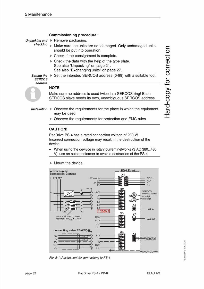
Commissioning procedure:Unpacking and
checking Remove packaging.Make sure the units are not damaged. Only undamaged units
should be put into operation.Check if the consignment is complete.Check the data with the help of the type plate.See also "Unpacking" on page 21.See also "Exchanging units" on page 27.
Setting the SERCOS address
Set the intended SERCOS address (0-99) with a suitable tool.
NOTE
Make sure no address is used twice in a SERCOS ring! EachSERCOS slave needs its own, unambiguous SERCOS address.
Installation Observe the requirements for the place in which the equipmentmay be used.Observe the requirements for protection and EMC rules.
CAUTION!PacDrive PS-4 has a rated connection voltage of 230 V!Incorrect connection voltage may result in the destruction of thedevice!
When using the devi8ce in rotary current networks (3 AC 380...480V), use an autotransformer to avoid a destruction of the PS-4.
Mount the device.
Fig. 5-1: Assignment for connections to PS-4

8/10/2019 Operating Manual_ PacDrive PS-4 and PD-8.pdf
http://slidepdf.com/reader/full/operating-manual-pacdrive-ps-4-and-pd-8pdf 33/66
P D
_ O p
M a n
P S - 4
_ 0 5
_ u s .
f m
ELAU AG PacDrive PS-4 / PD-8 page 33
5.7 Commissioning
H a r d - c o p y
f o r c o r r e c t i o n
Electrical connections of
PS-4
Make connections for X1 and X2 according to the wiringdiagram. (Wiring examples: See also "Electrical connections" onpage 53. )
Connect the prefabricated cable (PS-4/PD-8) with X4.Insert the prefabricated SERCOS cable into X8 and snap it on.
Fig. 5-2: Assignment for connections to PD-8
Electrical connections of PD-8
Remove the blind plugs ("power in" and SECOS in) from thecable ducts on the PD-8.
Fig. 5-3: PD-8 cable ducts
Insert the PS-4/PD-8 connection cables in the "power in"opening.Insert the SECOS cable in the opening "SERCOS in".

8/10/2019 Operating Manual_ PacDrive PS-4 and PD-8.pdf
http://slidepdf.com/reader/full/operating-manual-pacdrive-ps-4-and-pd-8pdf 34/66
P D
_ O p
M a n
P S - 4
_ 0 5
_ u s .
f m
page 34 PacDrive PS-4 / PD-8 ELAU AG
5 Maintenance
H a r d - c o p y
f o r c o r r e c t i o n
Fig. 5-4: Wire the PS-4/
connection cable PS-4/PD-8 and fix the strain relief on the cableduct while the cable is relieved.Insert the prefabricated SERCOS cable into the outlet and snapit on. Fix the strain relief on the cable duct while the cable isrelieved.If more PD-8s are connected, connect prefabricated "PD-8/PD-8" connection cable with the power in/out connections and thenext SERCOS cable with SERCOS in/out as described above.
CAUTION!Penetrating liquid due to inexpert installation of cable ducts ormissing blind plugs!Damage to electrical parts!
Check if the cable ducts are tight.Immediately replace missing or defective blind plugs on unusedcable ducts. Do not run the PD-8 without having fixed the blindplugs and checked if they are tight.Do not run the PD-8 while the cover is open. Before starting theplant, close the cover and check if it is tight.
See also "Technical Data" on page 47.

8/10/2019 Operating Manual_ PacDrive PS-4 and PD-8.pdf
http://slidepdf.com/reader/full/operating-manual-pacdrive-ps-4-and-pd-8pdf 35/66
P D
_ O p
M a n
P S - 4
_ 0 5
_ u s .
f m
ELAU AG PacDrive PS-4 / PD-8 page 35
5.8 Configuration /
H a r d - c o p y
f o r c o r r e c t i o n
NOTE
The two jumpers must be placed in "closed" position over the
SERCOS connector only at the connection of the last PacDriveSCL-055, even if several PD-8s are used. This closes the SERCOSring.The physical order of the SERCOS slaves is different from thenumbers on the PD-8 cable ducts.
Check safety functions such as the EMERGENCY OFF switch.Continue
commissioning.the plant according to the operating manual of the packagingmachine producer.
Information on the connection of the PacDrive SCL to the PacDrivePD-8 is available in the "PacDrive SCL" operating manual. Further
information on the slaves in the SERCOS ring and system solutionswith air barriers can also be found in the "PacDrive SCL" operatingmanual.
5.7.1 Slaves in the SERCOS ring
Removing a single PacDrive SCL from the SERCOS ring
For test purposes, single PacDrive SCLs can be removed from theSERCOS ring during commissioning or when exchanging units.Proceed as follows:
Remove the connector of the corresponding SCL.Insert a SERCOS jumper (Art. no. 53150032) in the free place.The SCL in the SERCOS ring has now been substituted.
Fig. 5-5: SERCOS jumper as SCL substitute
5.8 Configuration / Programming / Diagnosis
The PacDrive PS-4 is matched by ELAU. The customer needs notmatch them.
Error diagnosis and monitoring of operating states are done in thePacDrive controllers. For information, consult the correspondingmanuals.In addition, diagnosis is possible by means of the LEDs on thePacDrive PS-4.

8/10/2019 Operating Manual_ PacDrive PS-4 and PD-8.pdf
http://slidepdf.com/reader/full/operating-manual-pacdrive-ps-4-and-pd-8pdf 36/66
P D
_ O p
M a n
P S - 4
_ 0 5
_ u s .
f m
page 36 PacDrive PS-4 / PD-8 ELAU AG
5 Maintenance
H a r d - c o p y
f o r c o r r e c t i o n
5.8.1 Diagnosis LEDs
Fig. 5-6: Diagnosis LEDs of the PacDrive PS-4
reset Button to reset the PacDrive PS-4. Only the PacDrive PS-4 isrestarted.
pow Green control voltage indicatorOff: Control voltage (24 V) missing or too low
On: Normal operation; control voltage in normal range
err Red error LED (indicated by the PacDrive system)

8/10/2019 Operating Manual_ PacDrive PS-4 and PD-8.pdf
http://slidepdf.com/reader/full/operating-manual-pacdrive-ps-4-and-pd-8pdf 37/66
P D
_ O p
M a n
P S - 4
_ 0 5
_ u s .
f m
ELAU AG PacDrive PS-4 / PD-8 page 37
5.8 Configuration /
H a r d - c o p y
f o r c o r r e c t i o n
The error indicator signals the operating state of the PacDrive PS-4based on the following states:
Fig. 5-7: Display state of diagnosis LED "err"
S1/S2 address setting rotary switch
The double-digit SERCOS (00 - 99) must be unabmiguous for eachSERCOS slave.
S1: Tens digit of the SERCOS addressS2: Ones digit of the SERCOS address
buserr SERCOS bus error indicator (signalled from SERCOS bus)
Display that shows errors of the SERCOS bus. It is on, if a buserror occurs. This state can also occur for a short time and cannotbe quitted.
5.8.2 Combination of PacDrive SCL and PacDrive PS-4
SCL signals in the m PS-4All Ready signals of the individual PacDrive SCLs come together inthe PS-4, where they are evaluated. The Ready contact on the PS-4 is not set until all SCLs and the PS-4 supply a Ready signal.
8/10/2019 Operating Manual_ PacDrive PS-4 and PD-8.pdf
http://slidepdf.com/reader/full/operating-manual-pacdrive-ps-4-and-pd-8pdf 38/66
P D
_ O p
M a n
P S - 4
_ 0 5
_ u s .
f m
page 38 PacDrive PS-4 / PD-8 ELAU AG
5 Maintenance
H a r d - c o p y
f o r c o r r e c t i o n
Influence of the PS-4 signals on the SCLThere is no HardwareEnable input on the SCL. However, the inputHardwareEnable , the signal PowerSupplyEnable and error
messages of the PS-4 have to lead to reactions in the SCL.Therefore the following signals are sent from the PacDrive PS-4 tothe MAx-4:
PS-4 is activeClass 1 error message from PS-4Error message with error reaction A from PS-4.
The ramping-down of the motor (error reaction B) is initiated in theSCL if the PS-4 is reported to be inactive or an error message witherror reaction B is reported from the PS-4.
In case of error messages with error reaction A from the PS-4, the
final stages of the corresponding SCL are switched off immediately.The motor coasts to a stop. The SCL behaves like an MC-4 onwhich CoastEnable is set and HardwareEnable is deactivated. Noerror message is triggered.
NOTEThe function "InverterEnable" is not integrated in the PacDrive PS-4.A safety connection has to be implemented by means of a RDYcontact.
5.9 Order numbers
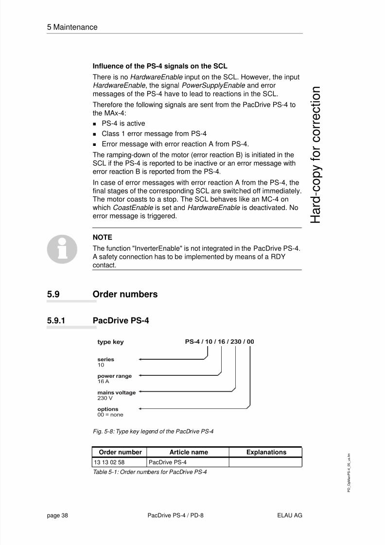
5.9.1 PacDrive PS-4
Fig. 5-8: Type key legend of the PacDrive PS-4
Table 5-1: Order numbers for PacDrive PS-4
Order number Article name Explanations13 13 02 58 PacDrive PS-4
8/10/2019 Operating Manual_ PacDrive PS-4 and PD-8.pdf
http://slidepdf.com/reader/full/operating-manual-pacdrive-ps-4-and-pd-8pdf 39/66
P D
_ O p
M a n
P S - 4
_ 0 5
_ u s .
f m
ELAU AG PacDrive PS-4 / PD-8 page 39
5.9 Order numbers
H a r d - c o p y
f o r c o r r e c t i o n
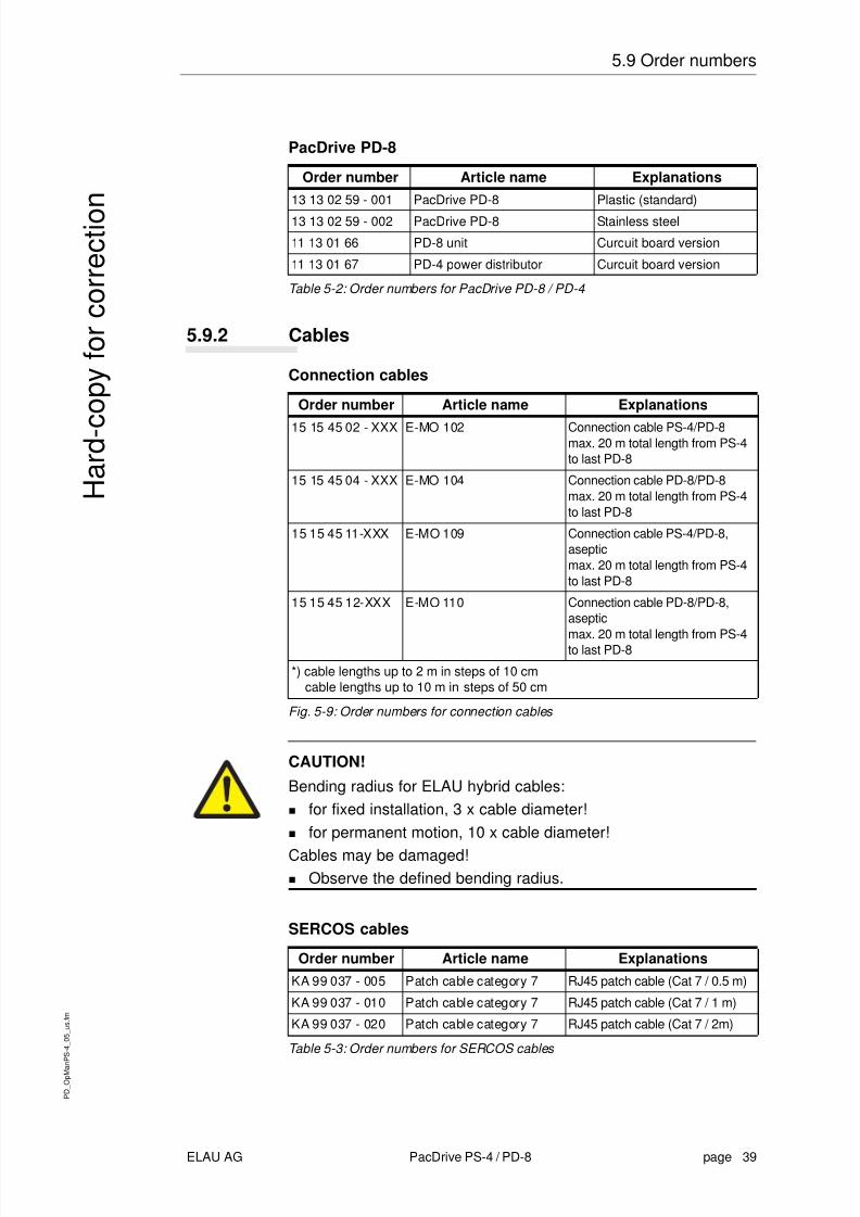
PacDrive PD-8
Table 5-2: Order numbers for PacDrive PD-8 / PD-4
5.9.2 Cables
Connection cables
Fig. 5-9: Order numbers for connection cables
CAUTION!
Bending radius for ELAU hybrid cables:for fixed installation, 3 x cable diameter!for permanent motion, 10 x cable diameter!
Cables may be damaged!Observe the defined bending radius.
SERCOS cables
Table 5-3: Order numbers for SERCOS cables
Order number Article name Explanations13 13 02 59 - 001 PacDrive PD-8 Plastic (standard)
13 13 02 59 - 002 PacDrive PD-8 Stainless steel
11 13 01 66 PD-8 unit Curcuit board version
11 13 01 67 PD-4 power distributor Curcuit board version
Order number Article name Explanations
15 15 45 02 - XXX E-MO 102 Connection cable PS-4/PD-8max. 20 m total length from PS-4to last PD-8
15 15 45 04 - XXX E-MO 104 Connection cable PD-8/PD-8max. 20 m total length from PS-4to last PD-8
15 15 45 11-XXX E-MO 109 Connection cable PS-4/PD-8,asepticmax. 20 m total length from PS-4to last PD-8
15 15 45 12-XXX E-MO 110 Connection cable PD-8/PD-8,aseptic
max. 20 m total length from PS-4to last PD-8
*) cable lengths up to 2 m in steps of 10 cmcable lengths up to 10 m in steps of 50 cm
Order number Article name ExplanationsKA 99 037 - 005 Patch cable category 7 RJ45 patch cable (Cat 7 / 0.5 m)
KA 99 037 - 010 Patch cable category 7 RJ45 patch cable (Cat 7 / 1 m)
KA 99 037 - 020 Patch cable category 7 RJ45 patch cable (Cat 7 / 2m)
8/10/2019 Operating Manual_ PacDrive PS-4 and PD-8.pdf
http://slidepdf.com/reader/full/operating-manual-pacdrive-ps-4-and-pd-8pdf 40/66
P D
_ O p
M a n
P S - 4
_ 0 5
_ u s .
f m
page 40 PacDrive PS-4 / PD-8 ELAU AG
5 Maintenance
H a r d - c o p y
f o r c o r r e c t i o n
8/10/2019 Operating Manual_ PacDrive PS-4 and PD-8.pdf
http://slidepdf.com/reader/full/operating-manual-pacdrive-ps-4-and-pd-8pdf 41/66
P D
_ O p
M a n
P S - 4
_ 0 6
_ u s .
f m
ELAU AG PacDrive PS-4 / PD-8 page 41
6.1 Creation of a PacDrive PS-4/PD-8, SCL055 application
H a r d - c o p y
f o r c o r r e c t i o n
6 Project definition
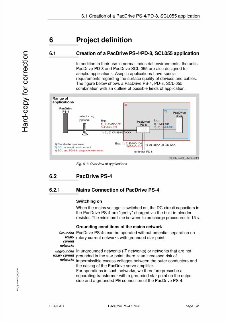
6.1 Creation of a PacDrive PS-4/PD-8, SCL055 application
In addition to their use in normal industrial environments, the unitsPacDrive PD-8 and PacDrive SCL-055 are also designed foraseptic applications. Aseptic applications have specialrequirements regarding the surface quality of devices and cables.The figure below shows a PacDrive PS-4, PD-8, SCL-055combination with an outline of possible fields of application.
Fig. 6-1: Overview of applications
6.2 PacDrive PS-4
6.2.1 Mains Connection of PacDrive PS-4
Switching onWhen the mains voltage is switched on, the DC-circuit capacitors inthe PacDrive PS-4 are "gently" charged via the built-in bleederresistor. The minimum time between to precharge procedures is 15 s.
Grounding conditions of the mains networkGrounded
rotary current
networks
PacDrive PS-4s can be operated without potential separation onrotary current networks with grounded star point.
ungrounded rotary current
networks
In ungrounded networks (IT networks) or networks that are notgrounded in the star point, there is an increased risk ofimpermissible excess voltages between the outer conductors andthe casing of the PacDrive servo amplifier.For operations in such networks, we therefore prescribe aseparating transformer with a grounded star point on the output
side and a grounded PE connection of the PacDrive PS-4.

8/10/2019 Operating Manual_ PacDrive PS-4 and PD-8.pdf
http://slidepdf.com/reader/full/operating-manual-pacdrive-ps-4-and-pd-8pdf 42/66
P D
_ O p
M a n
P S - 4
_ 0 6
_ u s .
f m
page 42 PacDrive PS-4 / PD-8 ELAU AG
6 Project definition
H a r d - c o p y
f o r c o r r e c t i o n
Adjustment of the Mains VoltageIf the mains voltage is outside the range indicated in the technicaldata, a transformer is required to adjust it to the power intake of the
plant.In star point grounded networks, the voltage is adjusted by meansof an autotransformer.In all other networks, a separating transformer is required.
CAUTION!PacDrive PS-4 has a rated connection voltage of 230 V!Incorrect connection voltage may result in the destruction of thedevice!
For wiring and installation, make sure that the DC-bus of
PacDrive MC-4 units with a rated connection voltage of 400 V isnot coupled with a PacDrive PS-4 unit with a rated voltage of230 V.When using the unit in rotary current networks (3 AC 380...480V), use a transformer to prevent the destruction of thePS-4.
Wiring examplesThe PacDrive PS-4 can be directly connected to grounded rotarycurrent networks with 3 x AC 230 V, +/- 10%. For lower
requirements, a single-phase power connection 1 x AC 230 V ispossible.
Fig. 6-2: Wiring examples for direct mains connection
8/10/2019 Operating Manual_ PacDrive PS-4 and PD-8.pdf
http://slidepdf.com/reader/full/operating-manual-pacdrive-ps-4-and-pd-8pdf 43/66
P D
_ O p
M a n
P S - 4
_ 0 6
_ u s .
f m
ELAU AG PacDrive PS-4 / PD-8 page 43
6.2 PacDrive PS-4
H a r d - c o p y
f o r c o r r e c t i o n
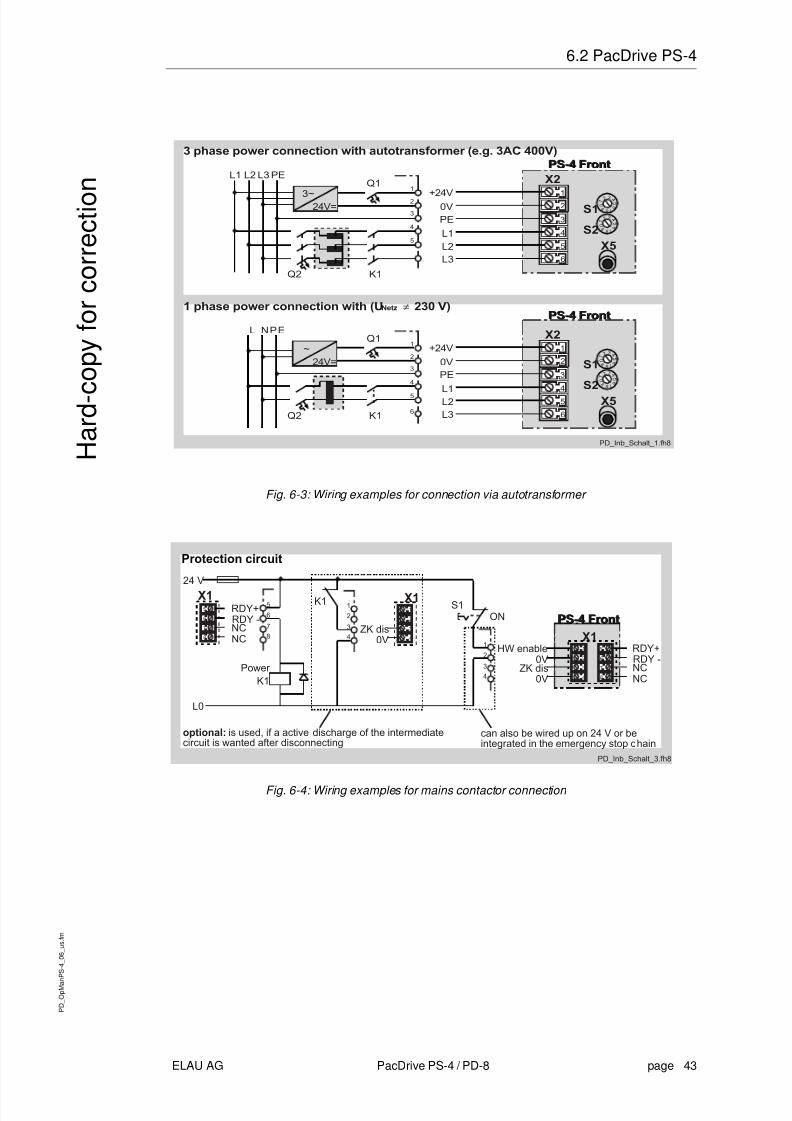
Fig. 6-3: Wiring examples for connection via autotransformer
Fig. 6-4: Wiring examples for mains contactor connection
8/10/2019 Operating Manual_ PacDrive PS-4 and PD-8.pdf
http://slidepdf.com/reader/full/operating-manual-pacdrive-ps-4-and-pd-8pdf 44/66
P D
_ O p
M a n
P S - 4
_ 0 6
_ u s .
f m
page 44 PacDrive PS-4 / PD-8 ELAU AG
6 Project definition
H a r d - c o p y
f o r c o r r e c t i o n
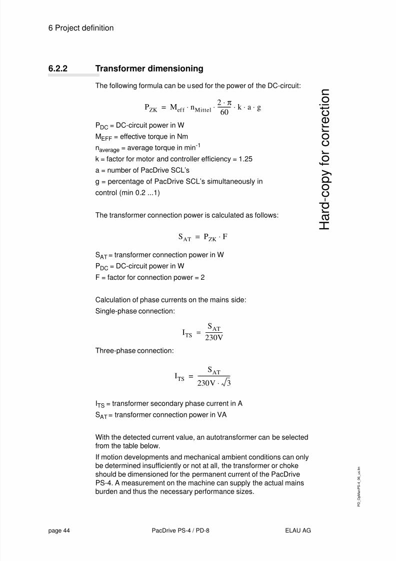
6.2.2 Transformer dimensioning
The following formula can be used for the power of the DC-circuit:
P DC = DC-circuit power in W
MEFF = effective torque in Nm
naverage = average torque in min -1
k = factor for motor and controller efficiency = 1.25
a = number of PacDrive SCL’s
g = percentage of PacDrive SCL’s simultaneously in
control (min 0.2 ...1)
The transformer connection power is calculated as follows:
S AT = transformer connection power in W
P DC = DC-circuit power in W
F = factor for connection power = 2
Calculation of phase currents on the mains side:
Single-phase connection:
Three-phase connection:
ITS = transformer secondary phase current in A
S AT = transformer connection power in VA
With the detected current value, an autotransformer can be selectedfrom the table below.
If motion developments and mechanical ambient conditions can onlybe determined insufficiently or not at all, the transformer or chokeshould be dimensioned for the permanent current of the PacDrivePS-4. A measurement on the machine can supply the actual mains
burden and thus the necessary performance sizes.
PZK M ef f nMittel2 π
60---------- k a g =
SAT PZK F=
ITSSAT
230V-------------=
ITS
SAT
230V 3-------------------------=

8/10/2019 Operating Manual_ PacDrive PS-4 and PD-8.pdf
http://slidepdf.com/reader/full/operating-manual-pacdrive-ps-4-and-pd-8pdf 45/66
P D
_ O p
M a n
P S - 4
_ 0 6
_ u s .
f m
ELAU AG PacDrive PS-4 / PD-8 page 45
6.2 PacDrive PS-4
H a r d - c o p y
f o r c o r r e c t i o n
In addition, you can use the tool ECAM-4 version V2.3 or higher forthe calculation. This makes it possible to take almost any possiblecombination into account.
Selection table for autotransformers by Block (third-party products)
Table 6-1: Selection table for autotransformers
If no transformer is used, you have to select and used a mainschoke from the following table:
Table 6-2: Selection table for mains chokes
Type DSP 400/1,5 DSP 400/3 DSP 400/6 DSP 400/9 DSP 400/15
Output current 3 x 1.5 A 3 x 3 A 3 x 6 A 3 x 9 A 3 x 15 A
Order number Article name Permanentcurrent
FI 078 80 NKD 10 / 2.93 10 A
FI 078 74 NKD 25 / 1.17 25 A
8/10/2019 Operating Manual_ PacDrive PS-4 and PD-8.pdf
http://slidepdf.com/reader/full/operating-manual-pacdrive-ps-4-and-pd-8pdf 46/66
P D
_ O p
M a n
P S - 4
_ 0 6
_ u s .
f m
page 46 PacDrive PS-4 / PD-8 ELAU AG
6 Project definition
H a r d - c o p y
f o r c o r r e c t i o n
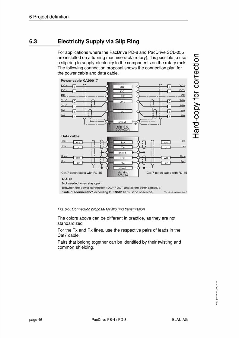
6.3 Electricity Supply via Slip Ring
For applications where the PacDrive PD-8 and PacDrive SCL-055
are installed on a turning machine rack (rotary), it is possible to usea slip ring to supply electricity to the components on the rotary rack.The following connection proposal shows the connection plan forthe power cable and data cable.
Fig. 6-5: Connection proposal for slip ring transmission
The colors above can be different in practice, as they are notstandardized.
For the Tx and Rx lines, use the respective pairs of leads in the
Cat7 cable.Pairs that belong together can be identified by their twisting andcommon shielding.
8/10/2019 Operating Manual_ PacDrive PS-4 and PD-8.pdf
http://slidepdf.com/reader/full/operating-manual-pacdrive-ps-4-and-pd-8pdf 47/66
P D
_ O p
M a n
P S - 4
_ 0 7
_ u s .
f m
ELAU AG PacDrive PS-4 / PD-8 page 47
7.1 PacDrive PS-4
H a r d - c o p y
f o r c o r r e c t i o n
7 Technical Data7.1 PacDrive PS-4
7.1.1 General
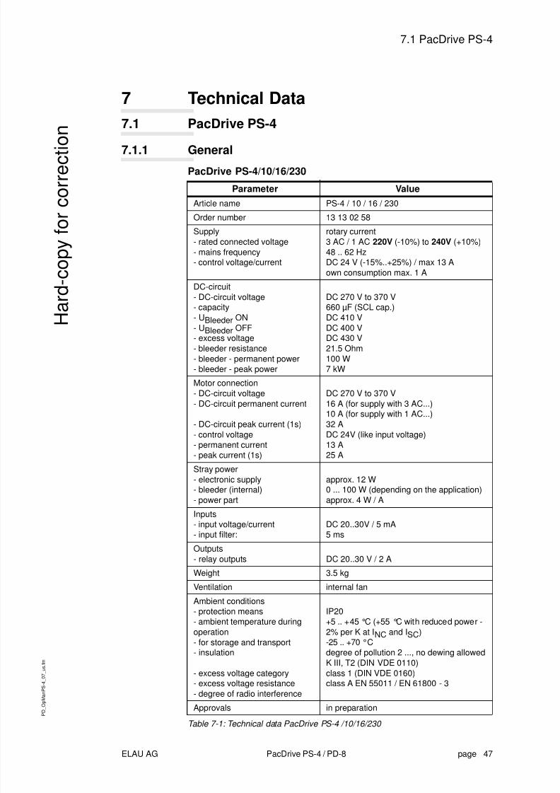
PacDrive PS-4/10/16/230
Table 7-1: Technical data PacDrive PS-4 /10/16/230
Parameter ValueArticle name PS-4 / 10 / 16 / 230
Order number 13 13 02 58
Supply- rated connected voltage- mains frequency- control voltage/current
rotary current3 AC / 1 AC 220V (-10%) to 240V (+10%)48 .. 62 HzDC 24 V (-15%..+25%) / max 13 Aown consumption max. 1 A
DC-circuit- DC-circuit voltage- capacity- UBleeder ON- UBleeder OFF- excess voltage- bleeder resistance- bleeder - permanent power- bleeder - peak power
DC 270 V to 370 V660 µF (SCL cap.)DC 410 VDC 400 VDC 430 V21.5 Ohm100 W7 kW
Motor connection- DC-circuit voltage- DC-circuit permanent current
- DC-circuit peak current (1s)- control voltage- permanent current- peak current (1s)
DC 270 V to 370 V16 A (for supply with 3 AC...)
10 A (for supply with 1 AC...)32 ADC 24V (like input voltage)13 A25 A
Stray power- electronic supply- bleeder (internal)- power part
approx. 12 W0 ... 100 W (depending on the application)approx. 4 W / A
Inputs- input voltage/current- input filter:
DC 20..30V / 5 mA5 ms
Outputs- relay outputs DC 20..30 V / 2 A
Weight 3.5 kg
Ventilation internal fan
Ambient conditions- protection means- ambient temperature duringoperation- for storage and transport- insulation
- excess voltage category- excess voltage resistance
- degree of radio interference
IP20+5 .. +45 °C (+55 °C with reduced power -2% per K at I NC and I SC )-25 .. +70 °Cdegree of pollution 2 ..., no dewing allowedK III, T2 (DIN VDE 0110)class 1 (DIN VDE 0160)class A EN 55011 / EN 61800 - 3
Approvals in preparation
8/10/2019 Operating Manual_ PacDrive PS-4 and PD-8.pdf
http://slidepdf.com/reader/full/operating-manual-pacdrive-ps-4-and-pd-8pdf 48/66

8/10/2019 Operating Manual_ PacDrive PS-4 and PD-8.pdf
http://slidepdf.com/reader/full/operating-manual-pacdrive-ps-4-and-pd-8pdf 49/66
P D
_ O p
M a n
P S - 4
_ 0 7
_ u s .
f m
ELAU AG PacDrive PS-4 / PD-8 page 49
7.1 PacDrive PS-4
H a r d - c o p y
f o r c o r r e c t i o n
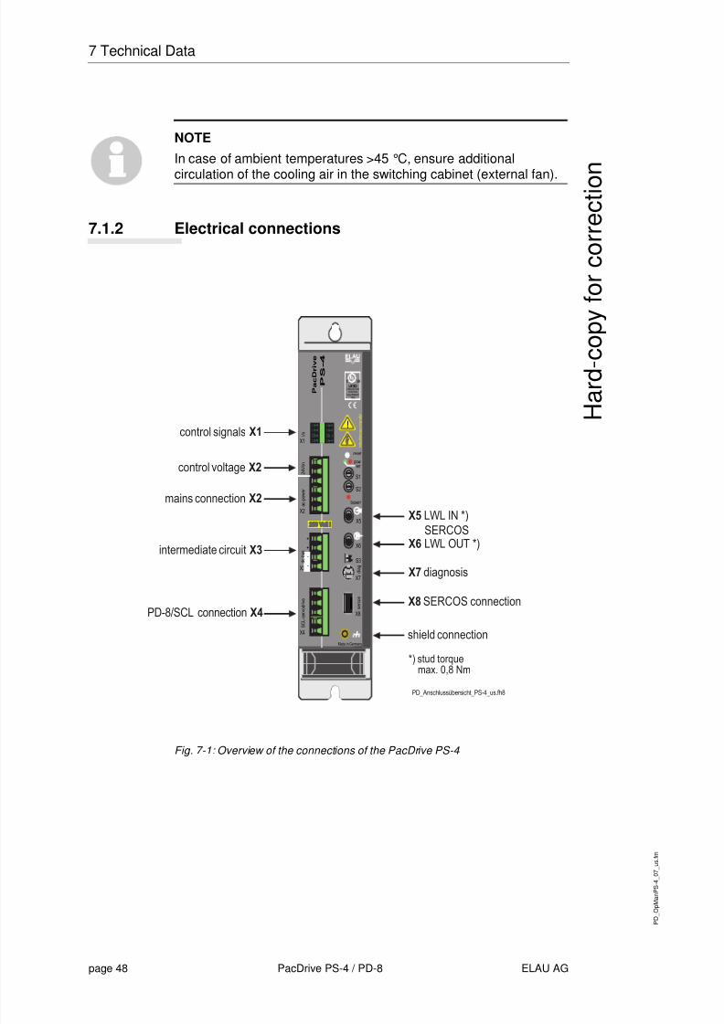
X1 - Control signals
Table 7-2: Connection X1 - control signals
X2 - Control Voltage and Mains Connection
Table 7-3: Connection X2 - control voltage and mains connection
Pin Designation Meaning Range max. cross
section1 HW enable Hardware enable DC24V (pursuant to
IEC61131-2 type I)1.5 mm 2
2 0 V 1.5 mm 2
3 DC dis DC-circuit discharge DC24V (pursuant toIEC61131-2 type I)
1.5 mm 2
4 0 V 1.5 mm 2
5 *) RDY + Ready contact (opensin case of an error)
DC 20...30 V / 2 A 1.5 mm 2
6*)
RDY - Ready contact DC 20...30 V / 2 A 1.5 mm2
7 NC not connected 1.5 mm 2
8 NC not connected 1.5 mm 2
*) The Ready contact indicates that the PS-4 and the connected components areready for operation. If the Ready contact is closed, the system is ready formains connection. In case of an error, the Ready contact opens.The ready contact has to be included in the mains contactor control, so that themains is switched off in case of an error.
Pin Designation Meaning Rangemax.cross
section
1 24 V 24 V control voltage -15%..+25% 4 mm 2
2 0 V 0 V control voltage 4 mm 2
3 PE Protective conductorconnection
4 mm 2
4 L1 Phase L1 3AC/1AC 220..240 V 4 mm 2
5 L2 Phase L2 3AC/1AC 220..240 V 4 mm 2
6 L3 Phase L3 3AC/1AC 220..240 V 4 mm 2

8/10/2019 Operating Manual_ PacDrive PS-4 and PD-8.pdf
http://slidepdf.com/reader/full/operating-manual-pacdrive-ps-4-and-pd-8pdf 50/66
P D
_ O p
M a n
P S - 4
_ 0 7
_ u s .
f m
page 50 PacDrive PS-4 / PD-8 ELAU AG
7 Technical Data
H a r d - c o p y
f o r c o r r e c t i o n
X3 - DC-Circuit
Table 7-4: Connection X3 - DC-circuit
CAUTION!
PacDrive PS-4 has a rated connection voltage of 230 V!
Wrong connection voltage can destroy the unit!For wiring and installation, make sure that the DC-bus of PacDriveMC-4 units with a rated connection voltage of 400 V is not coupledwith a PacDrive PS-4 unit with a rated voltage of 230 V.
X4 PD-8 / SCL Connection
Table 7-5: Connection X4 PD-8 / SCL connection
X7 - Diagnosis
Table 7-6: Connection X7 - diagnosis
Pin Designation Meaning Range max. cross
section1 DC+ DC-circuit + DC 270..370 V 4 mm 2
2 DC + DC-circuit + DC 270..370 V 4 mm 2
3 DC - DC-circuit - DC 270..370 V 4 mm 2
4 DC - DC-circuit - DC 270..370 V 4 mm 2
Pin Designation Meaning Range max. crosssection
1 24 V 24 V control voltage -15%..+25% 4 mm 2
2 0 V 0 V control voltage 4 mm 2
3 PE Protective conductorconnection
4 mm 2
4 DC + DC-circuit + DC 270..370 V 4 mm 2
5 DC - DC-circuit - DC 270..370 V 4 mm 2
Pin Designation Meaning Range max. crosssection
1 PRO_SEL 0.25 mm 2
2 RxD receive data 0.25 mm 2
3 TxD transmit data 0.25 mm 2
4 GND signal ground 0.25 mm 2
5 RS232_SEL 0.25 mm 2
6 VCC 0.25 mm 2

8/10/2019 Operating Manual_ PacDrive PS-4 and PD-8.pdf
http://slidepdf.com/reader/full/operating-manual-pacdrive-ps-4-and-pd-8pdf 51/66
P D
_ O p
M a n
P S - 4
_ 0 7
_ u s .
f m
ELAU AG PacDrive PS-4 / PD-8 page 51
7.1 PacDrive PS-4
H a r d - c o p y
f o r c o r r e c t i o n
X8 - SERCOS
Table 7-7: Connection X8 - SERCOS connection
7.1.3 Dimensions
Fig. 7-2: Connections of the PacDrive PS-4
PinDesignatio
n Meaning Range
max.
crosssection
1 SEROUT+ SERCOS Out +
2 SEROUT- SERCOS Out -
3 SERIN+ SERCOS In +
4 NC not connected
5 NC not connected
6 SERIN- SERCOS In -
7 NC not connected
8 NC not connected
8/10/2019 Operating Manual_ PacDrive PS-4 and PD-8.pdf
http://slidepdf.com/reader/full/operating-manual-pacdrive-ps-4-and-pd-8pdf 52/66

8/10/2019 Operating Manual_ PacDrive PS-4 and PD-8.pdf
http://slidepdf.com/reader/full/operating-manual-pacdrive-ps-4-and-pd-8pdf 53/66
P D
_ O p
M a n
P S - 4
_ 0 7
_ u s .
f m
ELAU AG PacDrive PS-4 / PD-8 page 53
7.2 PacDrive PD-8
H a r d - c o p y
f o r c o r r e c t i o n
7.2.2 Electrical connections
Fig. 7-3: Overview of the connections of the PacDrive PD-8
Control Signals IN
Table 7-9: Connection - control signals IN
Control Signals OUT
Table 7-10: Connection - control signals OUT
Power Supply IN/OUT
Table 7-11: Connection - power supply IN/OUT
Pin Designation Meaning Range max. crosssection
1 24 V 24V control voltage -15%..+25% 4 mm 2
2 0 V 0V control voltage 4 mm 2
Pin Designation Meaning Range max. crosssection
1 24 V 24V control voltage -15%..+25% 4 mm 2
2 0 V 0V control voltage 4 mm 2
Pin Designation Meaning Range max. crosssection
1 DC + Power supply DC+ DC 270V-370V 4 mm 2
2 DC- Power supply DC- DC 270V-370V 4 mm 2
3 PE Protective conductorconnection
4 mm 2

8/10/2019 Operating Manual_ PacDrive PS-4 and PD-8.pdf
http://slidepdf.com/reader/full/operating-manual-pacdrive-ps-4-and-pd-8pdf 54/66
P D
_ O p
M a n
P S - 4
_ 0 7
_ u s .
f m
page 54 PacDrive PS-4 / PD-8 ELAU AG
7 Technical Data
H a r d - c o p y
f o r c o r r e c t i o n
Power supply SCL
Table 7-12: Connection - power supply SCL
SERCOS Connection SCL
Table 7-13: Connection - SERCOS SCL
7.2.3 Dimensions
Fig. 7-4: Dimensions of the PacDrive PD-8 (standard version)
Pin Designation Meaning Range max. cross
section1 PE protective conductor 1 mm²
2 PE shield 1 mm²3 DC- DC-circuit - DC 270V-370V 1 mm²
4 DC+ DC-circuit + DC 270V-370V 1 mm²
Pin Designation Meaning Range max. crosssection
1 24 V 24V control voltage -15%..+25% 0.5 mm²2 SERCOS Out + SERCOS Transmit + 0.5 mm²
3 shield shield SERCOS Out 0.5 mm²
4 SERCOS In + SERCOS Receive + 0.5 mm²
5 0 V 0V control voltage 0.5 mm²6 SERCOS Out - SERCOS Transmit - 0.5 mm²
7 shield shield SERCOS In 0.5 mm²
8 SERCOS IN - SERCOS Receive - 0.5 mm²

8/10/2019 Operating Manual_ PacDrive PS-4 and PD-8.pdf
http://slidepdf.com/reader/full/operating-manual-pacdrive-ps-4-and-pd-8pdf 55/66
P D
_ O p
M a n
P S - 4
_ 0 7
_ u s .
f m
ELAU AG PacDrive PS-4 / PD-8 page 55
7.2 PacDrive PD-8
H a r d - c o p y
f o r c o r r e c t i o n
Fig. 7-5: Dimensions of the PacDrive PD-8 (aseptic version)
Fig. 7-6: Dimensions of the PacDrive PD-8 (board version)

8/10/2019 Operating Manual_ PacDrive PS-4 and PD-8.pdf
http://slidepdf.com/reader/full/operating-manual-pacdrive-ps-4-and-pd-8pdf 56/66
P D
_ O p
M a n
P S - 4
_ 0 7
_ u s .
f m
page 56 PacDrive PS-4 / PD-8 ELAU AG
7 Technical Data
H a r d - c o p y
f o r c o r r e c t i o n
Fig. 7-7: Dimensions of the PacDrive PD-4 (board version)
8/10/2019 Operating Manual_ PacDrive PS-4 and PD-8.pdf
http://slidepdf.com/reader/full/operating-manual-pacdrive-ps-4-and-pd-8pdf 57/66
P D
_ O p
M a n
P S - 4
A e n
_ u s .
F M
ELAU AG PacDrive PS-4 /PD-8 Seite 57
7.3 Declaration by the manufacturer
K o r r e
k t u r a u s
d r u c
k
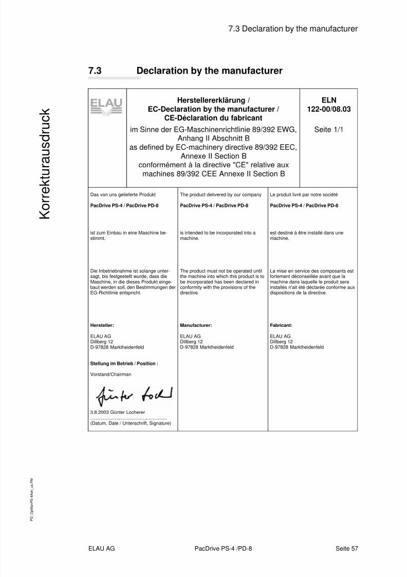
7.3 Declaration by the manufacturer
Herstellererklärung /EC-Declaration by the manufacturer /
CE-Déclaration du fabricantim Sinne der EG-Maschinenrichtlinie 89/392 EWG,
Anhang II Abschnitt Bas defined by EC-machinery directive 89/392 EEC,
Annexe II Section Bconformément à la directive "CE" relative aux
machines 89/392 CEE Annexe II Section B
ELN122-00/08.03
Seite 1/1
Das von uns gelieferte Produkt
PacDrive PS-4 / PacDrive PD-8
ist zum Einbau in eine Maschine be-stimmt.
Die Inbetriebnahme ist solange unter-sagt, bis festgestellt wurde, dass dieMaschine, in die dieses Produkt einge-baut werden soll, den Bestimmungen derEG-Richtlinie entspricht.
Hersteller:
ELAU AGDillberg 12D-97828 Marktheidenfeld
Stellung im Betrieb / Position :
Vorstand/Chairman
3.8.2003 Günter Locherer...........................................................(Datum, Date / Unterschrift, Signature)
The product delivered by our company
PacDrive PS-4 / PacDrive PD-8
is intended to be incorporated into amachine.
The product must not be operated untilthe machine into which this product is tobe incorporated has been declared inconformity with the provisions of thedirective.
Manufacturer:
ELAU AGDillberg 12D-97828 Marktheidenfeld
Le produit livré par notre société
PacDrive PS-4 / PacDrive PD-8
est destiné à être installé dans unemachine.
La mise en service des composants estfortement déconseillée avant que lamachine dans laquelle le produit serainstallés n'ait été déclarée conforme auxdispositions de la directive.
Fabricant:
ELAU AGDillberg 12D-97828 Marktheidenfeld
8/10/2019 Operating Manual_ PacDrive PS-4 and PD-8.pdf
http://slidepdf.com/reader/full/operating-manual-pacdrive-ps-4-and-pd-8pdf 58/66
P D
_ O p
M a n
P S - 4
A e n
_ u s .
F M
Seite 58 PacDrive PS-4 / PD-8 ELAU AG
Appendix
K o r r e
k t u r a u s
d r u c
k
7.4 Modifications
08 / 2003
Operating manual newly written
04 / 2005Aseptic variant, PD-8 connectors and cables updatedVarious error Corrections and supplementsDocument structure updatedProduct names, definitions and layout updated
NOTE
The latest documentation of the modification service for this pro-duct can be found on ELAU's homepage (http://www.elau.de).
8/10/2019 Operating Manual_ PacDrive PS-4 and PD-8.pdf
http://slidepdf.com/reader/full/operating-manual-pacdrive-ps-4-and-pd-8pdf 59/66
P D M
_ A n h a
n g
S t d
_ u s . F
M
ELAU AG PacDrive page 59
8.1 Contact
K o r r e
k t u r a u s
d r u c
k
8 Appendix
8.1 Contact
For repair
Please send the components to be repaired or checked, along withthe error report, to this address:ELAU AGAbt. Kundendienst house address:Postfach 1255 Dillberg 1297821 Marktheidenfeld 97828 MarktheidenfeldPhone: +49 (0) 93 91 / 606-142Fax: +49 (0) 93 91 / 606-340
Service teamShould you need to talk to a member of our service team or requireon-site service, please contact:ELAU AGDillberg 12D-97828 MarktheidenfeldPhone: +49 (0) 9391 / 606 - 0Fax: +49 (0) 9391 / 606 - 300e-mail: [email protected]: www.elau.deELAU, Inc.4201 West Wrightwood AvenueChicago, Illinois 60639 - USAPhone: +1 773 342 8400Fax: +1 773 342 8404e-mail: [email protected]: www.elau.comELAU SYSTEMS ITALIA S.r.l.Via Tosarelli 300
I-40050 Villanova di Castenaso (BO)Phone: +39 051 / 7818 70Fax: +39 051 / 7818 69e-mail: [email protected]: www.elau.it
NOTEFurther contact addresses you can find on the ELAU homepage(www.elau.de).
8/10/2019 Operating Manual_ PacDrive PS-4 and PD-8.pdf
http://slidepdf.com/reader/full/operating-manual-pacdrive-ps-4-and-pd-8pdf 60/66
P D M
_ A n h a
n g
S t d
_ u s . F
M
page 60 PacDrive ELAU AG
8 Appendix
K o r r e
k t u r a u s
d r u c
k
8.2 Further Literature
ELAU can provide you with these manuals and instructions on the
PacDrive™ System:1
Project Manual
Art.No. 17 13 00 58 - 00x (DE, EN, FR)
Programming ManualArt.No. 17 13 00 61 - 00x (DE, EN)
Operating Manual MC-4 MotorControllerArt.No. 17 13 00 62 - 00x (DE, EN, IT, FR)
Operating Manual CAN L2Art.No. 17 13 00 66 - 00x (DE, EN)
Operating Manual PROFIBUS-DPArt.No. 17 13 00 67 - 00x (DE, EN)
Operating Manual SM MotorArt.No. 17 13 00 68 - 00x (DE, EN, IT, FR)
Operating Manual EPAS-4Art.No. 17 13 00 70 - 00x (DE, EN)
Operating Manual PacDrive Controller
Art.No. 17 13 00 71 - 00x (DE, EN, IT, FR)
Operating Manual OPC-Server
Art.No. 17 13 00 73 - 00x (DE, EN)
Operating Manual Device NetArt.No. 17 13 00 76 - 00x (DE, EN)
Operating Manual HMI Libraries
Art.No. 17 13 00 77 - 00x (DE, EN)
Operating Manual INC-4 Incremental Encoder ModuleArt.No. 17 13 00 78 - 00x (DE, EN)
Operating Manual CANopen
Art.No. 17 13 00 79 - 00x (DE, EN)
Operating Manual VarioCam® Editor ECAM-4Art.No. 17 13 00 80 - 00x (DE, EN)
Operating Manual PacNet Module PN-4Art.No. 17 13 00 81 - 00x (DE, EN)
Operating Manual SR MotorArt.No. 17 13 00 82 - 00x (DE, EN)
1. Art.No. -000 (DE) german -001 (EN) english -002 (IT) italian -003 (FR) french
8/10/2019 Operating Manual_ PacDrive PS-4 and PD-8.pdf
http://slidepdf.com/reader/full/operating-manual-pacdrive-ps-4-and-pd-8pdf 61/66
P D M
_ A n h a
n g
S t d
_ u s . F
M
ELAU AG PacDrive page 61
8.2 Further Literature
K o r r e
k t u r a u s
d r u c
k
Operating Manual BusTerminal BT-4/DIO1Art.No. 17 13 00 83 - 00x (DE, EN)
Operating Manual TTSArt.No. 17 13 00 88 - 00x (DE)
User Manual Automatic Controller OptimizationArt.No. 17 13 00 89 - 00x (DE, EN)
Operating Manual PacDrive SCLArt.No. 17 13 00 93 - 00x (DE, EN)
Operating Manual PacDrive PS-4 und PacDrive PD-8
Art.No. 17 13 00 94 - 00x (DE, EN)
Operating Manual Evaluation KitArt.No. 17 13 00 95 - 00x (DE)
Operating Manual PacDrive Controller P600
Art.No. 17 13 00 96 - 00x (DE)

8/10/2019 Operating Manual_ PacDrive PS-4 and PD-8.pdf
http://slidepdf.com/reader/full/operating-manual-pacdrive-ps-4-and-pd-8pdf 62/66
P D M
_ A n h a
n g
S t d
_ u s . F
M
page 62 PacDrive ELAU AG
8 Appendix
K o r r e
k t u r a u s
d r u c
k
8.3 Product Training
We offer practical workshops and seminars.
Our experienced seminar leaders will enable you to make optimumuse of the vast possibilities of the PacDrive™ system.
NOTE
Please contact us for further information or to order our seminarprogram. See also our homepage (www.elau.de).
8/10/2019 Operating Manual_ PacDrive PS-4 and PD-8.pdf
http://slidepdf.com/reader/full/operating-manual-pacdrive-ps-4-and-pd-8pdf 63/66
P D
_ O p e r a
M a n
P S - 4
_ u s S
I X . f m
ELAU AG PacDrive PS-4 / PD-8 Seite 63
Index
K o r r e
k t u r a u s
d r u c
k
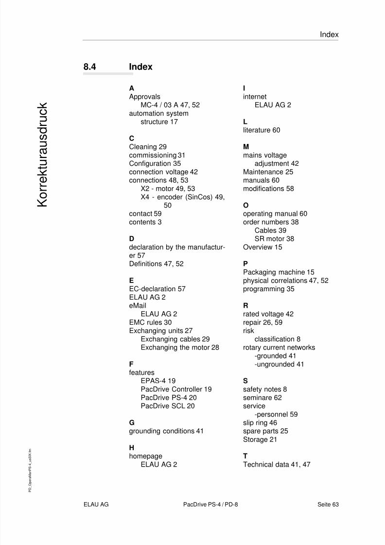
8.4 Index
AApprovals
MC-4 / 03 A 47 , 52automation system
structure 17
CCleaning 29commissioning 31Configuration 35connection voltage 42connections 48 , 53
X2 - motor 49 , 53X4 - encoder (SinCos) 49 ,50
contact 59contents 3
Ddeclaration by the manufactur-er 57Definitions 47 , 52
EEC-declaration 57ELAU AG 2eMail
ELAU AG 2EMC rules 30Exchanging units 27
Exchanging cables 29Exchanging the motor 28
Ffeatures
EPAS-4 19PacDrive Controller 19PacDrive PS-4 20PacDrive SCL 20
Ggrounding conditions 41
Hhomepage
ELAU AG 2
Iinternet
ELAU AG 2
Lliterature 60
Mmains voltage
adjustment 42Maintenance 25manuals 60
modifications 58
Ooperating manual 60order numbers 38
Cables 39SR motor 38
Overview 15
PPackaging machine 15physical correlations 47 , 52programming 35
Rrated voltage 42repair 26 , 59risk
classification 8rotary current networks
-grounded 41-ungrounded 41
Ssafety notes 8seminare 62service
-personnel 59slip ring 46spare parts 25Storage 21
TTechnical data 41 , 47

8/10/2019 Operating Manual_ PacDrive PS-4 and PD-8.pdf
http://slidepdf.com/reader/full/operating-manual-pacdrive-ps-4-and-pd-8pdf 64/66
P D
_ O p e r a
M a n
P S - 4
_ u s S
I X . f m
Seite 64 PacDrive PS-4 / PD-8 ELAU AG
Index
K o r r e
k t u r a u s
d r u c
k
trademarks 2training 62Transportation 21Type plate 21 , 22
UUnpacking 21
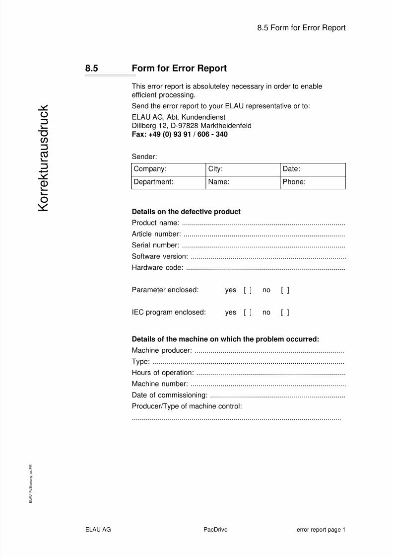
8/10/2019 Operating Manual_ PacDrive PS-4 and PD-8.pdf
http://slidepdf.com/reader/full/operating-manual-pacdrive-ps-4-and-pd-8pdf 65/66
E L A U
_ F o S
t o e r u n g
_ u s .
F M
ELAU AG PacDrive error report page 1
8.5 Form for Error Report
K o r r e
k t u r a u s
d r u c
k
8.5 Form for Error Report
This error report is absoluteley necessary in order to enable
efficient processing.Send the error report to your ELAU representative or to:
ELAU AG, Abt. KundendienstDillberg 12, D-97828 MarktheidenfeldFax: +49 (0) 93 91 / 606 - 340
Sender:
Details on the defective productProduct name: ..................................................................................
Article number: .................................................................................
Serial number: ..................................................................................
Software version: ..............................................................................
Hardware code: ................................................................................
Parameter enclosed: yes [ ] no [ ]
IEC program enclosed: yes [ ] no [ ]
Details of the machine on which the problem occurred:Machine producer: ...........................................................................
Type: ................................................................................................Hours of operation: ...........................................................................
Machine number: ..............................................................................
Date of commissioning: ....................................................................Producer/Type of machine control:
.........................................................................................................
Company: City: Date:
Department: Name: Phone:
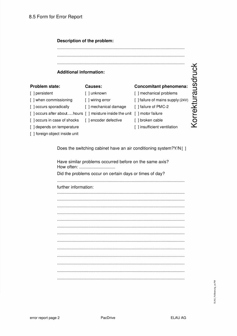
8/10/2019 Operating Manual_ PacDrive PS-4 and PD-8.pdf
http://slidepdf.com/reader/full/operating-manual-pacdrive-ps-4-and-pd-8pdf 66/66
8.5 Form for Error Report
K o r r e
k t u r a u s
d r u c
k
Description of the problem:..........................................................................................................
..........................................................................................................
..........................................................................................................
Additional information:
Does the switching cabinet have an air conditioning system?Y/N [ ]
Have similar problems occurred before on the same axis?How often: ..............................
Did the problems occur on certain days or times of day?
..........................................................................................................
further information:..........................................................................................................
..........................................................................................................
..........................................................................................................
..........................................................................................................
..........................................................................................................
..........................................................................................................
..........................................................................................................
..........................................................................................................
..........................................................................................................
..........................................................................................................
..........................................................................................................
Problem state: Causes: Concomitant phenomena:[ ] persistent [ ] unknown [ ] mechanical problems
[ ] when commissioning [ ] wiring error [ ] failure of mains supply (24V)
[ ] occurs sporadically [ ] mechanical damage [ ] failure of PMC-2
[ ] occurs after about.....hours [ ] moisture inside the unit [ ] motor failure
[ ] occurs in case of shocks [ ] encoder defective [ ] broken cable
[ ] depends on temperature [ ] insufficient ventilation
[ ] foreign object inside unit


