AND UTOMATION OLUTIONSA SI PNDUSTRY ROCESS
ACTIVE
Operating Instructions
GB
0.55 kW ... 65.0 kW
Frequency Inverter 230V / 400V

02/06 1
General Information about the Documentation
The present documentation refers to the frequency inverters ACT 201 and ACT 401
series. With their factory settings, both series of devices are suited for a wide range of applications. The modular hardware and software structure enables customer-specific adaptation of the frequency inverters. Applications with high functionality and dyna-mism requirements can be realized easily.
For better clarity, the documentation is structured according to the customer-specific
requirements made on the frequency inverter. Brief Instructions The Brief Instructions describe the basic steps required for mechanical and electrical
installation of the frequency inverter. The guided commissioning supports you in the selection of necessary parameters and the configuration of the frequency inverter by the software.
Operating Instructions The Operating Instructions describe and document all functions of the frequency in-
verter. The parameters required for adapting the frequency inverter to specific appli-cations as well as the wide range of additional functions are described in detail.
Application Manual The application manual supplements the documentation for purposeful installation and
commissioning of the frequency inverter. Information on various subjects connected with the use of the frequency inverter are described specific to the application.
Installation Instructions Complementing the Brief Instructions and the Operating Instructions, the Installation
Instructions provide information on how to install and use the additional/optional components.
If you need a copy of the documentation or additional information, contact your local
representative of BONFIGLIOLI. The following pictograms and signal words are used in the documentation:
Danger! Danger refers to an immediate threat. Non-compliance with the precaution described may result in death, serious injury or material damage.
Warning! Warning refers to a possible threat. Non-compliance with the warning may result in death, serious injury or material damage.
Caution! Caution refers to an indirect threat. Non-compliance may result in personal or material damage.
Attention!
Attention refers to a possible operational behavior or an undesired condition that can occur in accordance with the reference text.
Note
Note and the related text provide useful information which supplements the corre-sponding part of the documentation.

2 02/06
TABLE OF CONTENTS
1. General Safety Instructions and Information on Use.................................................... 9 1.1 General Information ...................................................................................... 9 1.2 Purpose of the Frequency Inverters ............................................................ 10 1.3 Transport and Storage ................................................................................. 10 1.4 Handling and Installation ............................................................................ 10 1.5 Electrical Connection ................................................................................... 11 1.6 Information on Use...................................................................................... 11 1.7 Maintenance and Service............................................................................. 11
2 Scope of Supply............................................................................................................ 12 2.1 Frequency Inverter (0.55 up to 4.0 kW)...................................................... 12 2.2 Frequency Inverter (5.5 up to 15.0 kW)...................................................... 13 2.3 Frequency Inverter (18.5 up to 30.0 kW).................................................... 14 2.4 Frequency Inverter (37.0 up to 65.0 kW).................................................... 15
3 Technical Data.............................................................................................................. 16 3.1 Frequency Inverter 230 V (0.55 up to 3.0 kW)............................................ 16 3.2 Frequency Inverter 400 V (0.55 up to 4.0 kW)............................................ 17 3.3 Frequency Inverter 400 V (5.5 up to 15.0 kW)............................................ 18 3.4 Frequency Inverter 400 V (18.5 up to 30.0 kW) ......................................... 19 3.5 Frequency Inverter 400 V (37.0 up to 65.0 kW) ......................................... 20 3.6 Operation Diagrams..................................................................................... 21
4 Mechanical Installation................................................................................................ 22 4.1 Frequency Inverter (0.55 up to 4.0 kW)...................................................... 23 4.2 Frequency Inverter (5.5 to 15.0 kW)........................................................... 24 4.3 Frequency Inverter (18.5 up to 30.0 kW).................................................... 25 4.4 Frequency inverter (37.0 up to 65.0 kW) .................................................... 26
5 Electrical Installation ................................................................................................... 27 5.1 EMC Information.......................................................................................... 28 5.2 Block diagram .............................................................................................. 29 5.3 Mains Connection......................................................................................... 30
5.3.1 Frequency Inverter (0.55 up to 4.0 kW) ............................................................... 30 5.3.2 Frequency Inverter (5.5 up to 15.0 kW) ............................................................... 31 5.3.3 Frequency Inverter (18.5 up to 30.0 kW) ............................................................. 32 5.3.4 Frequency Inverter (37.0 up to 65.0 kW) ............................................................. 33
02/06 3
TABLE OF CONTENTS
5.4 Motor Connection ........................................................................................ 34 5.4.1 Frequency Inverter (0.55 up to 4.0 kW) ............................................................... 35 5.4.2 Frequency Inverter (5.5 up to 15.0 kW) ............................................................... 36 5.4.3 Frequency Inverter (18.5 up to 30.0 kW) ............................................................. 37 5.4.4 Frequency Inverter (37.0 up to 65.0 kW) ............................................................. 38
5.5 Connection of a Brake Resistor.................................................................... 39 5.5.1 Frequency Inverter (0.55 up to 4.0 kW) ............................................................... 39 5.5.2 Frequency Inverter (5.5 up to 15.0 kW) ............................................................... 40 5.5.3 Frequency Inverter (18.5 up to 30.0 kW) ............................................................. 40 5.5.4 Frequency Inverter (37.0 up to 65.0 kW) ............................................................. 41
5.6 Control Terminals ........................................................................................ 42 5.6.1 Relay Output ..................................................................................................... 43 5.6.2 Control Terminals – Terminal Diagram ................................................................. 44
5.6.2.1 Configuration 110 – Sensorless Control ................................................................ 44 5.6.2.2 Configuration 111 – Sensorless Control with Technology Controller......................... 45 5.6.2.3 Configuration 410 – Sensorless Field-Oriented Control ........................................... 45 5.6.2.4 Configuration 411 –
Sensorless Field-Oriented Control with Technology Controller................................. 46 5.6.2.5 Configuration 430 –
Sensorless Field-Oriented Control, speed or torque controlled ................................ 46 5.6.2.6 Configuration 210 – Field-Oriented Control, speed controlled ................................. 47 5.6.2.7 Configuration 230 – Field-Oriented Control, speed and torque controlled................. 47
5.7 Optional Components .................................................................................. 48
6 Control Unit KP500 ...................................................................................................... 49 6.1 Menu Structure ............................................................................................ 50 6.2 Main Menu ................................................................................................... 50 6.3 Actual Value Menu (VAL) ............................................................................. 51 6.4 Parameter Menu (PARA).............................................................................. 52 6.5 Copy Menu (CPY) ......................................................................................... 53
6.5.1 Reading the Stored Information........................................................................... 53 6.5.2 Menu Structure .................................................................................................. 53 6.5.3 Selecting the Source........................................................................................... 54 6.5.4 Selecting the Destination .................................................................................... 55 6.5.5 Copy Operation.................................................................................................. 55 6.5.6 Error Messages .................................................................................................. 56
6.6 Read data from the KP 500 control unit ...................................................... 57 6.6.1 Activating .......................................................................................................... 57 6.6.2 Transfer data..................................................................................................... 58 6.6.3 Reset to Normal Mode ........................................................................................ 59
6.7 Control Menu (CTRL) ................................................................................... 59 6.8 Controlling the Motor via the Control Unit .................................................. 60

4 02/06
TABLE OF CONTENTS
7 Commissioning of the Frequency Inverter................................................................... 62 7.1 Switching on Mains Voltage......................................................................... 62 7.2 Setup Using the Control Unit ....................................................................... 62
7.2.1 Configuration..................................................................................................... 63 7.2.2 Data Set............................................................................................................ 64 7.2.3 Motor Type........................................................................................................ 64 7.2.4 Machine Data..................................................................................................... 65 7.2.5 Speed Sensor Data............................................................................................. 65 7.2.6 Plausibility check ................................................................................................ 66 7.2.7 Parameter identification ...................................................................................... 67 7.2.8 Application data ................................................................................................. 69
7.2.8.1 Acceleration and deceleration.............................................................................. 69 7.2.8.2 Set points at multi-functional input ...................................................................... 70 7.2.8.3 Selection of an actual value for display................................................................. 70
7.3 Check direction of rotation .......................................................................... 70 7.4 Set-up via the Communication Interface .................................................... 71
8 Inverter Data ............................................................................................................... 73 8.1 Serial Number .............................................................................................. 73 8.2 Optional Modules ......................................................................................... 73 8.3 Inverter Software Version ........................................................................... 74 8.4 Set Password ............................................................................................... 74 8.5 Control Level................................................................................................ 74 8.6 User Name.................................................................................................... 74 8.7 Configuration ............................................................................................... 75 8.8 Language ..................................................................................................... 77 8.9 Programming ............................................................................................... 77
9 Machine Data ............................................................................................................... 78 9.1 Rated Motor Parameters.............................................................................. 78 9.2 Further motor parameters ........................................................................... 78
9.2.1 Stator Resistance ............................................................................................... 78 9.2.2 Leakage Coefficient ............................................................................................ 79 9.2.3 Magnetizing Current ........................................................................................... 79 9.2.4 Rated Slip Correction Factor ................................................................................ 80
9.3 Internal values............................................................................................. 80 9.4 Speed sensor 1............................................................................................. 80
9.4.1 Operation mode speed sensor 1 .......................................................................... 80 9.4.2 Division marks, speed sensor 1............................................................................ 81
10 System Data ................................................................................................................. 82 10.1 Actual Value System .................................................................................... 82 10.2 Volume Flow and Pressure .......................................................................... 82

02/06 5
TABLE OF CONTENTS
11 Operational Behavior ................................................................................................... 83 11.1 Starting Behavior......................................................................................... 83
11.1.1 Starting Behavior of Sensorless Control System..................................................... 83 11.1.1.1 Starting Current ................................................................................................. 85 11.1.1.2 Frequency Limit ................................................................................................. 85
11.1.2 Flux Formation................................................................................................... 85 11.2 Stopping Behavior........................................................................................ 86
11.2.1 Switch-Off Threshold .......................................................................................... 88 11.2.2 Holding Time ..................................................................................................... 88
11.3 Direct current brake..................................................................................... 88 11.4 Auto Start..................................................................................................... 89 11.5 Search Run................................................................................................... 90 11.6 Positioning ................................................................................................... 91
11.6.1 Reference Positioning ......................................................................................... 92 11.6.2 Axis Positioning.................................................................................................. 95
12 Error and warning behavior ......................................................................................... 97 12.1 Overload Ixt................................................................................................. 97 12.2 Temperature ................................................................................................ 97 12.3 Controller Status.......................................................................................... 98 12.4 IDC Compensation Limit .............................................................................. 98 12.5 Frequency Switch-Off Limit ......................................................................... 98 12.6 Motor Temperature...................................................................................... 99 12.7 Phase Failure ............................................................................................... 99 12.8 Automatic Error Acknowledgment............................................................. 100
13 Reference Values........................................................................................................ 101 13.1 Frequency Limits........................................................................................ 101 13.2 Slip Frequency ........................................................................................... 101 13.3 Percentage Value Limits ............................................................................ 101 13.4 Frequency Reference Channel ................................................................... 102
13.4.1 Block Diagram ................................................................................................. 103 13.5 Reference Percentage Channel.................................................................. 105
13.5.1 Block Diagram ................................................................................................. 105 13.6 Fixed Reference Values.............................................................................. 107
13.6.1 Fixed Frequencies ............................................................................................ 107 13.6.2 JOG-Frequency ................................................................................................ 107 13.6.3 Fixed Percentages ............................................................................................ 108
13.7 Frequency ramps ....................................................................................... 108 13.8 Percentage Value Ramps ........................................................................... 111 13.9 Block Frequencies ...................................................................................... 111

6 02/06
TABLE OF CONTENTS
13.10 Motor Potentiometer ................................................................................. 112 13.10.1 Motorpoti (MP)................................................................................................. 113 13.10.2 Motorpoti (KP) ................................................................................................. 113 13.10.3 Controlling the Motor via the Control Unit........................................................... 114
13.11 Repetition frequency input ........................................................................ 115
14 Control Inputs and Outputs ....................................................................................... 116 14.1 Multi-function input MFI1.......................................................................... 116
14.1.1 Analog Input MFI1A ......................................................................................... 116 14.1.2 Characteristic................................................................................................... 116
14.1.2.1 Scaling ............................................................................................................ 118 14.1.2.2 Tolerance Band and Hysteresis.......................................................................... 118 14.1.2.3 Filter Time Constant ......................................................................................... 119 14.1.2.4 Error and warning behavior............................................................................... 120
14.2 Multi-function output MFO1 ...................................................................... 120 14.2.1 Analog Output MFO1A ...................................................................................... 121
14.2.1.1 Output Characteristic........................................................................................ 122 14.2.2 Frequency Output MFO1F ................................................................................. 122
14.2.2.1 Scaling ............................................................................................................ 122 14.3 Digital Outputs........................................................................................... 123
14.3.1 Setting Frequency ............................................................................................ 124 14.3.2 Reference value reached................................................................................... 124 14.3.3 Flux Formation Ended....................................................................................... 124 14.3.4 Open brake ..................................................................................................... 125 14.3.5 Current Limitation ............................................................................................ 125 14.3.6 External Fan .................................................................................................... 125 14.3.7 Warning Mask.................................................................................................. 126
14.4 Digital Inputs ............................................................................................. 128 14.4.1 Start command ................................................................................................ 131 14.4.2 3-Wire-Control ................................................................................................. 131 14.4.3 Error Acknowledgment ..................................................................................... 132 14.4.4 Timer .............................................................................................................. 132 14.4.5 Thermo-contact ............................................................................................... 132 14.4.6 n-/T-Control Change-Over................................................................................. 132 14.4.7 Data Set Change-Over ...................................................................................... 132 14.4.8 Fixed Value Change-Over.................................................................................. 133 14.4.9 Motor Potentiometer......................................................................................... 133
14.5 Function Modules....................................................................................... 134 14.5.1 Timer .............................................................................................................. 134
14.5.1.1 Time Constant ................................................................................................. 135 14.5.2 Comparator ..................................................................................................... 136 14.5.3 Logic Modules .................................................................................................. 137
15 V/f - Characteristic..................................................................................................... 142 15.1 Dynamic Voltage Pre-Control .................................................................... 143
02/06 7
TABLE OF CONTENTS
16 Control Functions ....................................................................................................... 144 16.1 Intelligent current limits ........................................................................... 144 16.2 Voltage controller ...................................................................................... 145 16.3 Technology Controller................................................................................ 149 16.4 Functions of Sensorless Control ................................................................ 152
16.4.1 Slip compensation ............................................................................................ 152 16.4.2 Current limit value controller ............................................................................. 152
16.5 Functions of Field-Orientated Control ....................................................... 153 16.5.1 Current Controller ............................................................................................ 153 16.5.2 Torque Controller ............................................................................................. 154
16.5.2.1 Limit Value Sources .......................................................................................... 155 16.5.3 Speed controller............................................................................................... 155
16.5.3.1 Limitation of Speed Controller ........................................................................... 156 16.5.3.2 Limit Value Sources .......................................................................................... 157
16.5.4 Acceleration Pre-Control ................................................................................... 158 16.5.5 Field Controller ................................................................................................ 158
16.5.5.1 Limitation of field controller............................................................................... 159 16.5.6 Modulation Controller ....................................................................................... 159
16.5.6.1 Limitation of Modulation Controller .................................................................... 160
17 Special Functions ....................................................................................................... 161 17.1 Pulse Width Modulation............................................................................. 161 17.2 Fan ............................................................................................................. 162 17.3 Bus controller............................................................................................. 162 17.4 Brake Chopper and Brake Resistance........................................................ 164
17.4.1 Dimensioning of Brake Resistor ......................................................................... 165 17.5 Motor Circuit Breaker................................................................................. 166 17.6 V-belt Monitoring....................................................................................... 167 17.7 Functions of Field-Orientated Control ....................................................... 168
17.7.1 Motor Chopper................................................................................................. 168 17.7.2 Temperature Adjustment .................................................................................. 169 17.7.3 Encoder Monitoring .......................................................................................... 170
18 Actual Values.............................................................................................................. 171 18.1 Actual Values of the Frequency Inverter ................................................... 171 18.2 Actual Values of the Machine..................................................................... 172 18.3 Actual Value Memory ................................................................................. 173 18.4 Actual Values of the System ...................................................................... 174
18.4.1 Actual Value System......................................................................................... 174 18.4.2 Volume Flow and Pressure ................................................................................ 175
8 02/06
TABLE OF CONTENTS
19 Error Protocol ............................................................................................................. 176 19.1 Error List .................................................................................................... 176
19.1.1 Error Messages ................................................................................................ 176 19.2 Error Environment ..................................................................................... 178
20 Operational and Error Diagnosis ................................................................................ 180 20.1 Status Display ............................................................................................ 180 20.2 Status of Digital Signals............................................................................. 180 20.3 Controller Status........................................................................................ 181 20.4 Warning Status .......................................................................................... 182
21 Parameter List............................................................................................................ 183 21.1 Actual Value Menu (VAL) ........................................................................... 183 21.2 Parameter Menu (PARA)............................................................................ 186
02/06 9
1. General Safety Instructions and Information on Use
Warning! The specifications and instructions contained in the documentation must be complied with strictly during installation and commissioning. Only qualified staff who has read the documentation and, in particular, the safety instructions carefully is allowed to carry out installation or com-missioning work or to operate the frequency inverters. The term „Quali-fied Staff“ refers to anybody who is familiar with the installation, assem-bly, commissioning and operation of the frequency inverter and has the proper qualification for the job.
The present documentation was prepared with great care and it was subjected to
extensive and repeated reviews. For reasons of clarity, it was not possible to include all details of all types of the product in the documentation. Neither was it possible to consider all conceivable installation, operation or maintenance situations. If you re-quire further information or if you meet with specific problems which are not dealt with in sufficient detail in the documentation, contact your local BONFIGLIOLI agent. We would also like to point out that the contents of this documentation do not form part of any previous or existing agreement, assurance or legal relationship. Neither are they intended to supplement or replace such agreements, assurances or legal relationships. The manufacturer's obligations are exclusively specified in the relevant purchase contract. This contract also contains all and any warranty regulations which may apply to the relevant scope of supply. These contractual warranty provisions are neither extended nor limited by the specifications contained in this documentation. The manufacturer reserves the right to correct or amend the specifications, product information and omissions in these operating instructions without notice. The manu-facturer shall not be liable for any damage, injuries or costs which may be caused by the aforementioned reasons.
1.1 General Information
Warning! The DC-link circuit of the frequency inverter is charged during operation, i.e. there is always the risk of contact with high voltage. Frequency in-verters are used for driving moving parts and they may become hot at the surface during operation. Any unauthorized removal of the necessary covers, improper use, wrong installation or operation may result in serious injuries or material dam-age. In order to avoid such injuries or damage, only qualified staff may carry out the transport, installation, setup or maintenance work required. The standards EN 50178, IEC 60364 (Cenelec HD 384 or DIN VDE 0100), IEC 60664-1 (Cenelec HD 625 or VDE 0110-1), BGV A2 (VBG 4) as well as the applicable national regulations must be complied with. The term „Qualified Staff“ refers to anybody who is familiar with the installation, assembly, commissioning and operation of the frequency inverter as well as the possible hazards and has the proper qualification for the job.
10 02/06
1.2 Purpose of the Frequency Inverters
Warning! The frequency inverters are electrical drive components intended for installation in industrial plants or machines. Commissioning and start of operation is not allowed until it has been verified that the machine meets the requirements of the EC Machinery Directive 98/37/EEC and EN 60204. In accordance with the CE marking requirements, the fre-quency inverters also comply with the Low Voltage Directive 72/23/EEC as well as EN 50178 / DIN VDE 0160 and EN 61800-2. The user shall be responsible for making sure that the requirements of the EMC Directive 89/336/EEC are met. Frequency inverters are only available at special-ized dealers and are exclusively intended for professional use as per EN 61000-3-2. The frequency inverters are also marked with the UL label according to UL508c, which proves that they also meet the requirements of the CSA Standard C22.2-No. 14-95. The technical data, connection specifications and information on ambi-ent conditions are indicated on the name plate and in the documentation and must be complied with in any case. Anyone involved in any kind of work at the device must have read the instructions carefully and under-stood them before starting the work.
1.3 Transport and Storage The frequency inverters must be transported and stored in an appropriate way. Dur-
ing transport and storage the devices must remain in their original packaging. The units may only be stored in dry rooms which are protected against dust and moisture and are exposed to little temperature deviations only. Observe the climatic conditions according to EN 50178 and the marking on the packaging. The frequency inverters must not be stored for more than one year without connecting them to nominal volt-age.
1.4 Handling and Installation
Warning! Damaged or destroyed components must not be put into operation be-cause they may be a health hazard.
The frequency inverters are to be used in accordance with the documentation as well as the applicable directives and standards. They must be handled carefully and pro-tected against mechanical stress. Do not bend any components or change the isolat-ing distances. Do not touch any electronic components or contacts. The devices are equipped with components which are sensitive to electrostatic energy and can easily be damaged if handled improperly. Any use of damaged or destroyed components shall be considered as a non-compliance with the applicable standards. Do not re-move any warning signs from the device.

02/06 11
1.5 Electrical Connection
Warning! Before any assembly or connection work, discharge the frequency in-verter. Verify that the frequency inverter is discharged. Do not touch the terminals because the capacitors may still be charged. Comply with the information given in the operating instructions and on the frequency inverter label.
When working at the frequency inverters, comply with the applicable standards BGV
A2 (VBG 4), VDE 0100 and other national directives. Comply with the electrical instal-lation instructions given in the documentation as well as the relevant directives. The manufacturer of the industrial machine or plant is responsible for making sure that the limit values specified in the EMC product standard EN 61800-3 for electrical vari-able-speed drives are complied with. The documentation contains information on EMC-conforming installation. The cables connected to the frequency inverters may not be subjected to high-voltage insulation tests unless appropriate circuitry meas-ures are taken before. Otherwise the unit may be damaged.
1.6 Information on Use
Warning! The frequency inverter may be connected to power supply every 60 s. Consider this for a jog operation of a mains contactor. For commission-ing or after an emergency stop, a non-recurrent, direct restart is permis-sible. After a failure and restoration of the power supply, the motor may start unexpectedly if the AutoStart function is activated. Install protective equipment if personal injury or material damage is possible. Before commissioning and start of normal operation, make sure to fix all covers and check all terminals. Check the additional monitoring and protective devices according to EN 60204 and applicable the safety di-rectives (e.g. Working Machines Act, Accident Prevention Directives etc.). No connection work may be performed, while the system is in operation.
1.7 Maintenance and Service
Warning! Unauthorized opening and improper interventions can lead to personal injury or material damage. Repairs on the frequency inverters may only be carried out by the manufacturer or persons authorized by the manu-facturer. Check protective equipment regularly.
12 02/06
2 Scope of Supply Thanks to the modular hardware components, the frequency inverters can be inte-
grated in the automation concept easily. The scope of delivery described can be sup-plemented by optional components and adapted to the customer-specific require-ments. The plug-in type connection terminals enable a safe function and an economi-cal assembly.
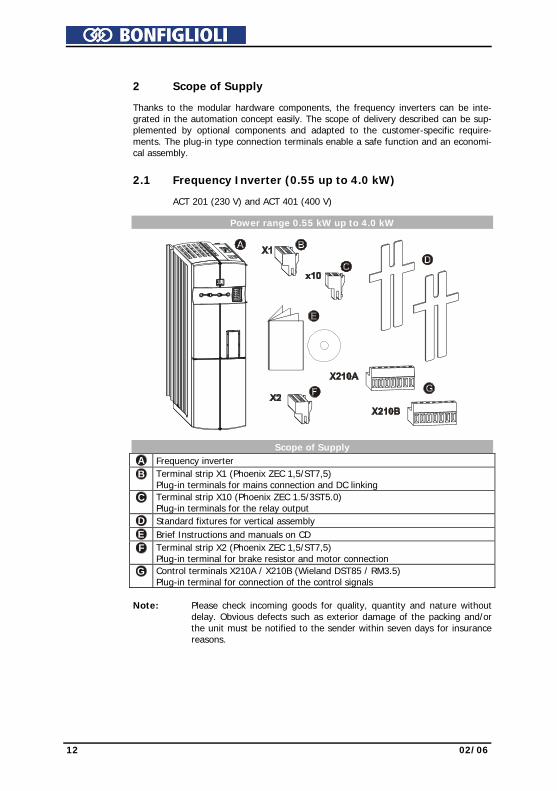
2.1 Frequency Inverter (0.55 up to 4.0 kW) ACT 201 (230 V) and ACT 401 (400 V) Power range 0.55 kW up to 4.0 kW
Scope of Supply A Frequency inverter B Terminal strip X1 (Phoenix ZEC 1,5/ST7,5)
Plug-in terminals for mains connection and DC linking C Terminal strip X10 (Phoenix ZEC 1.5/3ST5.0)
Plug-in terminals for the relay output D Standard fixtures for vertical assembly
E Brief Instructions and manuals on CD F Terminal strip X2 (Phoenix ZEC 1,5/ST7,5)
Plug-in terminal for brake resistor and motor connection G Control terminals X210A / X210B (Wieland DST85 / RM3.5)
Plug-in terminal for connection of the control signals Note: Please check incoming goods for quality, quantity and nature without
delay. Obvious defects such as exterior damage of the packing and/or the unit must be notified to the sender within seven days for insurance reasons.

02/06 13
2.2 Frequency Inverter (5.5 up to 15.0 kW) ACT 401 (400 V) Power range 5.5 kW up to 15.0 kW
Scope of Supply A Frequency inverter B Terminal strip X10 (Phoenix ZEC 1.5/3ST5.0)
Plug-in terminals for the relay output C Standard fixtures with fixing screws (M4x20, M4x60)
for vertical assembly D Brief Instructions and manuals on CD E Control terminals X210A / X210B (Wieland DST85 / RM3.5)
Plug-in terminal for connection of the control signals Note: Please check incoming goods for quality, quantity and nature without
delay. Obvious defects such as exterior damage of the packing and/or the unit must be notified to the sender within seven days for insurance rea-sons.

14 02/06
2.3 Frequency Inverter (18.5 up to 30.0 kW) ACT 401 (400 V) Power range 18.5 kW up to 30.0 kW
Scope of Supply A Frequency inverter B Terminal strip X10 (Phoenix ZEC 1.5/3ST5.0)
Plug-in terminals for the relay output C Standard fixtures with fixing screws (M4x20, M4x70)
for vertical assembly D Brief Instructions and manuals on CD E Control terminals X210A / X210B (Wieland DST85 / RM3.5)
Plug-in terminal for connection of the control signals Note: Please check incoming goods for quality, quantity and nature without
delay. Obvious defects such as exterior damage of the packing and/or the unit must be notified to the sender within seven days for insurance rea-sons.

02/06 15
2.4 Frequency Inverter (37.0 up to 65.0 kW) ACT 401 (400 V) Power range 37.0 kW up to 65.0 kW
Scope of Supply A Frequency inverter B Terminal strip X10 (Phoenix ZEC 1.5/3ST5.0)
Plug-in terminals for the relay output C Standard fixtures with fixing screws (M5x20)
for vertical assembly D Brief Instructions and manuals on CD E Control terminals X210A / X210B (Wieland DST85 / RM3.5)
Plug-in terminal for connection of the control signals Note: Please check incoming goods for quality, quantity and nature without
delay. Obvious defects such as exterior damage of the packing and/or the unit must be notified to the sender within seven days for insurance rea-sons.

16 02/06
3 Technical Data 3.1 Frequency Inverter 230 V (0.55 up to 3.0 kW) Type ACT 201 -05 -07 -09 -11 -13 -15 Output. motor side Recommended shaft output P kW 0.55 0.75 1.1 1.5 2.2 3.0 4) Output current I A 3.0 4.0 5.4 5) 7.0 9.5 12.5 4) 5)
Long-term overload current (60 s) I A 4.5 6.0 7.3 10.5 14.3 16.2 Short-term overload current (1 s) I A 6.0 8.0 8.0 14.0 19.0 19.0 Output voltage U V 3 x 0 ... mains voltage Degree of protection - - Short circuit / earth fault proof Rotary field frequency f Hz 0 ... 1000, depending on switching frequency Switching frequency f kHz 2. 4. 8. 12. 16 Output brake resistor min. brake resistor (UdBC = 385 V) R Ω 230 160 115 75 55 37 Input, mains side Mains current 3) , 3ph/PE 1ph/N/PE ; 2ph/PE
I A 3 5.4
4 7.2
5.5 1)
9.5 2) 7
13.2 9.5
16.5 2) 10.5 1)
16.5 2) 4)
Mains voltage U V 184 ... 264 Mains frequency f Hz 45 ... 66 Fuse 3ph/PE 1ph/N/PE ; 2ph/PE
I A 6 10
10 16
16 20
16 20
UL Type 250 VAC RK5, 3ph/PE 1ph/N/PE; 2ph/PE
I A 6 10
10 15
15 20
15 20
Mechanics Dimensions HxWxD mm 190x60x175 250x60x175 Weight (approx.) m kg 1.2 1.6 Degree of protection - - IP20 (EN60529) Terminals A mm2 0.2 ... 1.5 Form of assembly - - vertical Ambient conditions Energy dissipation (2 kHz switching frequency)
P W 43 53 73 84 115 170
Coolant temperature Tn °C 0 ... 40 (3K3 DIN IEC 721-3-3) Storage temperature TL °C -25 ... 55 Transport temperature TT °C -25 ... 70 Rel. air humidity - % 15 ... 85; not condensing If required by the customer, the switching frequency may be increased if the output current is reduced at thesame time. Comply with the applicable standards and regulations for this operating point. Output current Switching frequency Frequency inverter nominal power
2 kHz 4 kHz 8 kHz 12 kHz 16 kHz 0.55 kW 3.0 A 3.0 A 3.0 A 2.5 A 2.0 A 0.75 kW 4.0 A 4.0 A 4.0 A 3.4 A 2.7 A 1.1 kW 5.4 A 2) 5.4 A 2) 5) 5.4 A 2) 5) 4.5 A 2) 5) 3.7 A 5) 1.5 kW 7.0 A 7.0 A 7.0 A 5.9 A 4.8 A 2.2 kW 9.5 A 2) 9.5 A 2) 9.5 A 2) 8.0 A 2) 6.5 A 3.0 kW 2) 4) 12.5 A 1) 12.5 A 1) 5) 12.5 A 1) 5) 10.5 A 1) 5) 8.5 A 5)
1) Three-phase connection requires a commutating choke. 2) One- and two-phase connection requires a commutating choke. 3) Mains current with relative mains impedance ≥ 1% (see chapter„Electrical installation“) 4) Maximum output current is 9.5 A for one- and two-phase connection. 5) Switching frequency is reduced in thermal limit range

02/06 17
3.2 Frequency Inverter 400 V (0.55 up to 4.0 kW) Type ACT 401 -05 -07 -09 -11 -12 -13 -15 -18 Output. motor side Recommended shaft output P kW 0.55 0.75 1.1 1.5 1.85 2.2 3.0 4.0 Output current I A 1.8 2.4 3.2 3.8 3) 4.2 5.8 7.8 9.0 3) Long-term overload current (60 s) I A 2.7 3.6 4.8 5.7 6.3 8.7 11.7 13.5 Short-term overload current (1 s) I A 3.6 4.8 6.4 7.6 8.4 11.6 15.6 18.0 Output voltage U V 3 x 0 ... mains voltage Degree of protection - - Short circuit / earth fault proof Rotary filed frequency f Hz 0 ... 1000, depending on switching frequency Switching frequency f kHz 2. 4. 8. 12. 16 Output brake resistor min. brake resistor (UdBC = 770 V) R Ω 930 634 462 300 300 220 148 106 Input, mains side Mains current 2) 3ph/PE I A 1.8 2.4 2.8 1) 3.3 1) 4.2 5.8 6.8 1) 7.8 1) Mains voltage U V 320 ... 528 Mains frequency f Hz 45 ... 66 Fuse 3ph/PE I A 6 10 UL-Type 600 VAC RK5. 3ph/PE I A 6 10 Mechanics Dimensions HxWxD mm 190x60x175 250x60x175 Weight (approx.) m kg 1.2 1.6 Degree of protection - - IP20 (EN60529) Terminals A mm2 0.2 ... 1.5 Form of assembly - - vertical Ambient conditions Energy dissipation (2 kHz Switching frequency)
P W 40 46 58 68 68 87 115 130
Coolant temperature Tn °C 0 ... 40 (3K3 DIN IEC 721-3-3) Storage temperature TL °C -25 ... 55 Transport temperature TT °C -25 ... 70 Rel. air humidity - % 15 ... 85; not condensing If required by the customer, the switching frequency may be increased if the output current is reduced at thesame time. Comply with the applicable standards and regulations for this operating point. Output current Switching frequency Frequency inverter nominal power
2 kHz 4 kHz 8 kHz 12 kHz 16 kHz 0.55 kW 1.8 A 1.8 A 1.8 A 1.5 A 1.2 A 0.75 kW 2.4 A 2.4 A 2.4 A 2.0 A 1.6 A 1.1 kW 3.2 A 1) 3.2 A 1) 3.2 A 1) 2.7 A 1) 2.2 A 1.5 kW 1) 3.8 A 3.8 A 3) 3.8 A 3) 3.2 A 3) 2.6 A 3) 1.85 kW 4.2 A 4.2 A 4.2 A 3.5 A 2.9 A 2.2 kW 5.8 A 5.8 A 5.8 A 4.9 A 3.9 A 3.0 kW 7.8 A 1) 7.8 A 1) 7.8 A 1) 6.6 A 1) 5.3 A 4.0 kW 9.0 A 1) 9.0 A 1) 3) 9.0 A 1) 3) 7.6 A 1) 3) 6.1 A 3) 1) Three-phase connection requires a commutating choke. 2) Mains current with relative mains impedance ≥ 1% (see chapter„Electrical installation“) 3) Switching frequency is reduced in thermal limit range

18 02/06
3.3 Frequency Inverter 400 V (5.5 up to 15.0 kW) Type ACT 401 -19 -21 -22 -23 -25 Output. motor side Recommended shaft output P kW 5.5 7.5 9.2 11.0 15.0 Output current I A 14.0 18.0 22.0 3) 25.0 32.0 Long-term overload current (60 s) I A 21.0 26.3 30.3 37.5 44.5 Short-term overload current (1 s) I A 28.0 33.0 33.0 50.0 64.0 Output voltage U V 3 x 0 ... mains voltage Degree of protection - - Short circuit / earth fault proof Rotary filed frequency f Hz 0 ... 1000, depending on switching frequency Switching frequency f kHz 2. 4. 8. 12. 16 Output brake resistor min. brake resistor (UdBC = 770 V) R Ω 80 58 48 48 32 Input, mains side Mains current 2) 3ph/PE I A 14.2 15.8 1) 20.0 1) 26.0 28.2 1) Mains voltage U V 320 ... 528 Mains frequency f Hz 45 ... 66 Fuse 3ph/PE I A 16 25 35 UL-Type 600 VAC RK5. 3ph/PE I A 20 30 40 Mechanics Dimensions HxWxD mm 250x100x200 250x125x200 Weight (approx.) m kg 3.0 3.7 Degree of protection - - IP20 (EN60529) Terminals A mm2 0.2 ... 6 0.2 ... 16 Form of assembly - - vertical Ambient conditions Energy dissipation (2 kHz Switching frequency)
P W 145 200 225 240 310
Coolant temperature Tn °C 0 ... 40 (3K3 DIN IEC 721-3-3) Storage temperature TL °C -25 ... 55 Transport temperature TT °C -25 ... 70 Rel. air humidity - % 15 ... 85; not condensing If required by the customer, the switching frequency may be increased if the output current is reduced at thesame time. Comply with the applicable standards and regulations for this operating point. Output current Switching frequency Frequency inverter nominal power
2 kHz 4 kHz 8 kHz 12 kHz 16 kHz 5.5 kW 14.0 A 14.0 A 14.0 A 11.8 A 9.5 A 7.5 kW 18.0 A 1) 18.0 A 1) 18.0 A 1) 15.1 A 1) 12.2 A 9.2 kW 1) 23.0 A 22.7 A 3) 22.0 A 3) 18.5 A 3) 15.0 A 3) 11 kW 25.0 A 25.0 A 25.0 A 21.0 A 17.0 A 15 kW 32.0 A 1) 32.0 A 1) 32.0 A 1) 26.9 A 1) 21.8 A 1) Three-phase connection requires a commutating choke. 2) Mains current with relative mains impedance ≥ 1% (see chapter„Electrical installation“) 3) Switching frequency is reduced in thermal limit range

02/06 19
3.4 Frequency Inverter 400 V (18.5 up to 30.0 kW)
Type ACT 401 -27 -29 -31 Output. motor side Recommended shaft output P kW 18.5 22.0 30.0 Output current I A 40.0 45.0 60.0 Long-term overload current (60 s) I A 60.0 67.5 90.0 Short-term overload current (1 s) I A 80.0 90.0 120.0 Output voltage U V 3 x 0 ... mains voltage Degree of protection - - Short circuit / earth fault proof Rotary filed frequency f Hz 0 ... 1000, depending on switching frequency Switching frequency f kHz 2. 4. 8 Output brake resistor min. brake resistor (UdBC = 770 V) R Ω 16 Input, mains side Mains current 2) 3ph/PE I A 42.0 50.0 58.0 1) Mains voltage U V 320 ... 528 Mains frequency f Hz 45 ... 66 Fuse 3ph/PE I A 50 63 UL-Type 600 VAC RK5. 3ph/PE I A 50 60 Mechanics Dimensions HxWxD mm 250x200x260 Weight (approx.) m kg 8 Degree of protection - - IP20 (EN60529) Terminals A mm2 up to 25 Form of assembly - - vertical Ambient conditions Energy dissipation (2 kHz Switching frequency)
P W 445 535 605
Coolant temperature Tn °C 0 ... 40 (3K3 DIN IEC 721-3-3) Storage temperature TL °C -25 ... 55 Transport temperature TT °C -25 ... 70 Rel. air humidity - % 15 ... 85; not condensing If required by the customer, the switching frequency may be increased if the output current is reduced at the same time. Comply with the applicable standards and regulations for this operating point.
Output current Switching frequency Frequency inverter nominal power
2 kHz 4 kHz 8 kHz 18.5 kW 40.0 A 40.0 A 40.0 A 22 kW 45.0 A 45.0 A 45.0 A 30 kW 60.0 A 1) 60.0 A 1) 60.0 A 1) 1) Three-phase connection requires a commutating choke. 2) Mains current with relative mains impedance ≥ 1% (see chapter„Electrical installation“)
20 02/06
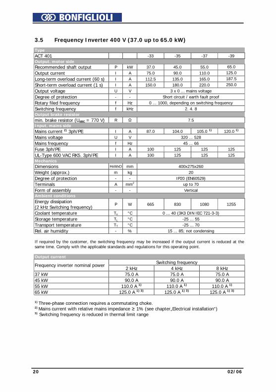
3.5 Frequency Inverter 400 V (37.0 up to 65.0 kW)
Type ACT 401 -33 -35 -37 -39 Output. motor side Recommended shaft output P kW 37.0 45.0 55.0 65.0 Output current I A 75.0 90.0 110.0 125.0 Long-term overload current (60 s) I A 112.5 135.0 165.0 187.5 Short-term overload current (1 s) I A 150.0 180.0 220.0 250.0 Output voltage U V 3 x 0 ... mains voltage Degree of protection - - Short circuit / earth fault proof Rotary filed frequency f Hz 0 ... 1000, depending on switching frequency Switching frequency f kHz 2. 4. 8 Output brake resistor min. brake resistor (UdBC = 770 V) R Ω 7.5 Input, mains side Mains current 2) 3ph/PE I A 87.0 104.0 105.0 1) 120.0 1) Mains voltage U V 320 ... 528 Mains frequency f Hz 45 ... 66 Fuse 3ph/PE I A 100 125 125 125 UL-Type 600 VAC RK5. 3ph/PE I A 100 125 125 125 Mechanics Dimensions HxWxD mm 400x275x260 Weight (approx.) m kg 20 Degree of protection - - IP20 (EN60529) Terminals A mm2 up to 70 Form of assembly - - Vertical Ambient conditions Energy dissipation (2 kHz Switching frequency)
P W 665 830 1080 1255
Coolant temperature Tn °C 0 ... 40 (3K3 DIN IEC 721-3-3) Storage temperature TL °C -25 ... 55 Transport temperature TT °C -25 ... 70 Rel. air humidity - % 15 ... 85; not condensing If required by the customer, the switching frequency may be increased if the output current is reduced at the same time. Comply with the applicable standards and regulations for this operating point.
Output current Switching frequency Frequency inverter nominal power
2 kHz 4 kHz 8 kHz 37 kW 75.0 A 75.0 A 75.0 A 45 kW 90.0 A 90.0 A 90.0 A 55 kW 110.0 A 1) 110.0 A 1) 110.0 A 1) 65 kW 125.0 A 1) 3) 125.0 A 1) 3) 125.0 A 1) 3) 1) Three-phase connection requires a commutating choke. 2) Mains current with relative mains impedance ≥ 1% (see chapter„Electrical installation“) 3) Switching frequency is reduced in thermal limit range

02/06 21
3.6 Operation Diagrams The technical data of the frequency inverters refer to the nominal point which was
selected to enable a wide range of applications. A functionally and efficient dimension-ing (de-rating) of the frequency inverters is possible based on the following diagrams.
Site altitude
100
85
60
40
20
55
45
30001000 2000 400030001000 2000 4000
Power reduction (Derating),5%/1000 m above sea level,h = 4000 mmax
max. coolant temperature,3.3 °C/1000 m above sea level,
Mounting altitude in m above sea level Mounting altitude in m above sea level
Out
put c
urre
nt in
%
Coo
lant
tem
pera
ture
in °
C
Coolant temperature
100
80
63
40
20
0 10 20 30 40 50 55
Power reduction (Derating)2.5%/K upper 40 °C, T = 55 °Cmax
Out
put c
urre
nt in
%
Coolant temperature in °C Mains voltage
100
83
63
40
20
0 400 420 440 460 480
Out
put c
urre
nt in
%
Mains voltage equal output voltage in V
Reduction of output current at constant output power (Derating)0.22%/ V upper 400 V, U = 480 Vmax

22 02/06
4 Mechanical Installation
The frequency inverters of degree of protection IP20 are designed, as a standard, for installation in electrical cabinets.
• During installation, both the installation and the safety instructions as well as the
device specifications must be complied with.
Warning! To avoid serious physical injuries or major material damage, only quali-fied persons are allowed to work on the devices.
Warning! During assembly, make sure that no foreign particles (e.g. filings, dust, wires, screws, tools) can get inside the frequency inverter. Otherwise there is the risk of short circuits and fire. The frequency inverters comply with protection class IP20 only if the covers and terminals are mounted properly. The units may only be used if these requirements are met.
Caution! Mount the devices with sufficient clearance to other components so that the cooling air can circulate freely. Avoid soiling by grease and air pollu-tion by dust, aggressive gases, etc.
02/06 23
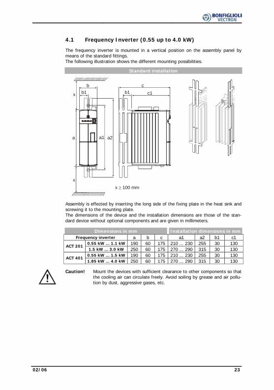
4.1 Frequency Inverter (0.55 up to 4.0 kW) The frequency inverter is mounted in a vertical position on the assembly panel by
means of the standard fittings. The following illustration shows the different mounting possibilities.
Standard installation
b
b1
a1a a2
cc1x
xx 100 mm≥
b1
Assembly is effected by inserting the long side of the fixing plate in the heat sink and
screwing it to the mounting plate. The dimensions of the device and the installation dimensions are those of the stan-
dard device without optional components and are given in millimeters. Dimensions in mm Installation dimensions in mm Frequency inverter a b c a1 a2 b1 c1 0.55 kW ... 1.1 kW 190 60 175 210 ... 230 255 30 130
ACT 2011.5 kW ... 3.0 kW 250 60 175 270 ... 290 315 30 130
0.55 kW ... 1.5 kW 190 60 175 210 ... 230 255 30 130
ACT 4011.85 kW ... 4.0 kW 250 60 175 270 ... 290 315 30 130
Caution! Mount the devices with sufficient clearance to other components so that the cooling air can circulate freely. Avoid soiling by grease and air pollu-tion by dust, aggressive gases, etc.
24 02/06
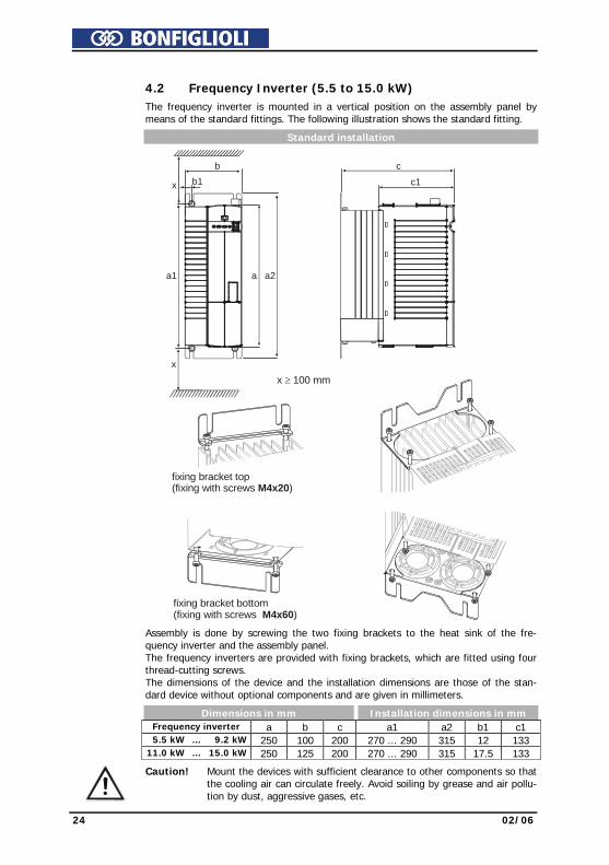
4.2 Frequency Inverter (5.5 to 15.0 kW)
The frequency inverter is mounted in a vertical position on the assembly panel by means of the standard fittings. The following illustration shows the standard fitting.
Standard installation
b
b1
aa1 a2
c
x
x
c1
x 100 mm≥
fixing bracket bottom (fixing with screws ) M4x60
fixing bracket top (fixing with screws ) M4x20
Assembly is done by screwing the two fixing brackets to the heat sink of the fre-quency inverter and the assembly panel. The frequency inverters are provided with fixing brackets, which are fitted using four thread-cutting screws. The dimensions of the device and the installation dimensions are those of the stan-dard device without optional components and are given in millimeters.
Dimensions in mm Installation dimensions in mm Frequency inverter a b c a1 a2 b1 c1 5.5 kW ... 9.2 kW 250 100 200 270 ... 290 315 12 133 11.0 kW ... 15.0 kW 250 125 200 270 ... 290 315 17.5 133
Caution! Mount the devices with sufficient clearance to other components so that the cooling air can circulate freely. Avoid soiling by grease and air pollu-tion by dust, aggressive gases, etc.
02/06 25
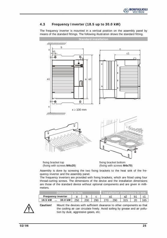
4.3 Frequency Inverter (18.5 up to 30.0 kW) The frequency inverter is mounted in a vertical position on the assembly panel by
means of the standard fittings. The following illustration shows the standard fitting.
Standard installation
c
c1
x 100 mm≥ x
aa1 a2
bb1
x
fixing bracket top (fixing with screws ) M4x20
fixing bracket bottom (fixing with screws ) M4x70
Assembly is done by screwing the two fixing brackets to the heat sink of the fre-quency inverter and the assembly panel. The frequency inverters are provided with fixing brackets, which are fitted using four thread-cutting screws. The dimensions of the device and the installation dimensions are those of the standard device without optional components and are given in milli-meters.
Dimensions in mm Installation dimensions in mm Frequency inverter a b c a1 a2 b1 c1 18.5 kW ... 30.0 kW 250 200 290 270 … 290 315 20 165
Caution! Mount the devices with sufficient clearance to other components so that the cooling air can circulate freely. Avoid soiling by grease and air pollu-tion by dust, aggressive gases, etc.
26 02/06
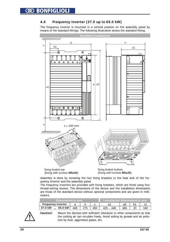
4.4 Frequency inverter (37.0 up to 65.0 kW)
The frequency inverter is mounted in a vertical position on the assembly panel by means of the standard fittings. The following illustration shows the standard fitting.
Standard installation
fixing braket top (fixing with screws ) M5x20
fixing braket bottom (fixing with screws )M5x20
aa1
a2
x x 100 mm≥
bb1x
c
c1
Assembly is done by screwing the two fixing brackets to the heat sink of the fre-quency inverter and the assembly panel. The frequency inverters are provided with fixing brackets, which are fitted using four thread-cutting screws. The dimensions of the device and the installation dimensions are those of the standard device without optional components and are given in milli-meters.
Dimensions in mm Installation dimensions in mm Frequency inverter a b c a1 a2 b1 c1 37.0 kW ... 65.0 kW 400 275 260 425 .. 445 465 20 160
Caution! Mount the devices with sufficient clearance to other components so that the cooling air can circulate freely. Avoid soiling by grease and air pollu-tion by dust, aggressive gases, etc.

02/06 27
5 Electrical Installation The electrical installation must be carried out by qualified staff according to the gen-
eral and regional safety and installation directives. For a safe operation of the fre-quency inverter it is necessary that the documentation and the device specifications be complied with during installation and commissioning. In the case of special applica-tions, you may also have to comply with further guidelines and instructions.
Danger! When the frequency inverter is disconnected from power supply, the mains, DC-link voltage and motor terminals may still be live for some time. Wait for some minutes until the DC link capacitors have discharged before starting to work at the unit.
The connecting cables must be protected externally, considering the maximum volt-age and current values of the fuses. The mains fuses and cable cross-sections are to be selected according to EN 60204-1 and DIN VDE 0298 Part 4 for the nominal oper-ating point of the frequency inverter. According to UL/CSA, the frequency inverter is suitable for operation at a supply network of a maximum of 480 VAC which delivers a maximum symmetrical current of 5000 A (effective value) if protected by fuses of class RK5. Only use copper cables with a temperature range of 60/75 °C.
Warning! The frequency inverters are to be grounded properly, i.e. large connec-tion area and with good conductivity. The leakage current of the fre-quency inverters may be > 3.5 mA. According to EN 50178 a permanent connection must be provided. The protective conductor cross-section required for grounding the fixing plate must be at least 10 mm², or a second protective conductor must be installed electrically parallel to the first one. In these applications, the cross-section must correspond to the recommended cross-section of the wire.
Connection conditions − The frequency inverter is suited for connection to the public or industrial supply
mains according to the technical data. If the transformer output of the supply mains is ≤ 500 kVA, the optional mains commutation choke is only necessary for the frequency inverters identified in the technical data. The other frequency in-verters are suitable for connection without a mains commutating choke with a relative mains impedance ≥ 1%.
− It must be checked, based on the specifications of EN 61000-3-2, if the devices can be connected to the public supply means without taking additional measures. The frequency inverters ≤ 9.2 kW with integrated EMC filter comply with the emission limits of the product standard EN 61800-3 up to a motor cable length of 10 m, without additional measures being required. Increased requirements in connection with the specific application of the frequency inverter are to be met by means of optional components. Commutating chokes and EMC filters are option-ally available for the series of devices.
− Operation on unearthed mains (IT mains) is admissible after disconnection of the Y capacitors in the interior of the device.
− Interference-free operation with residual-current device is guaranteed at a trip-ping current ≥ 30 mA if the following points are observed: − Pulse-current and alternating-current sensitive residual current devices (Type
A to EN 50178) in the case of a connection of frequency inverters with one-phase power supply (L1/N)
1. All-current sensitive residual current devices (Type B to EN 50178) in the case of a connection of frequency inverters with two-phase (L1/L2) or three-phase (L1/L2/L3) power supply.
2. Use EMC filters with reduced leakage current or, if possible, do not use EMC filters at all.
3. The length of the shielded motor cable is ≤ 10 m and there are no additional capacitive components between the mains or motor cables and PE.
28 02/06
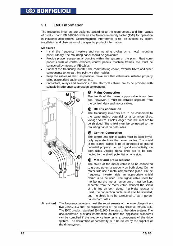
5.1 EMC Information The frequency inverters are designed according to the requirements and limit values
of product norm EN 61800-3 with an interference immunity factor (EMI) for operation in industrial applications. Electromagnetic interference is to be avoided by expert installation and observation of the specific product information.
Measures • Install the frequency inverters and commutating chokes on a metal mounting
panel. Ideally, the mounting panel should be galvanized. • Provide proper equipotential bonding within the system or the plant. Plant com-
ponents such as control cabinets, control panels, machine frames, etc. must be connected by means of PE cables.
• Connect the frequency inverter, the commutating choke, external filters and other components to an earthing point via short cables.
• Keep the cables as short as possible, make sure that cables are installed properly using appropriate cable clamps, etc.
• Contactors, relays and solenoids in the electrical cabinet are to be provided with suitable interference suppression components.
A Mains Connection The length of the mains supply cable is not lim-ited. However, it must be installed separate from the control, data and motor cables.
B DC link connection The frequency inverters are to be connected to the same mains potential or a common direct voltage source. Cables longer than 300 mm are to be shielded. The shield must be connected to the mounting panel on both sides.
C Control Connection The control and signal cables must be kept physi-cally separate from the power cables. The shield of the control cables is to be connected to ground potential properly, i.e. with good conductivity, on both sides. Analog signal lines are to be con-nected to the shield potential on one side.
D Motor and brake resistor
A
B
CD
The shield of the motor cable is to be connected to ground potential properly on both sides. On the motor side use a metal compression gland. On the frequency inverter side an appropriate shield clamp is to be used. The signal cable used for monitoring the motor temperature must be kept separate from the motor cable. Connect the shield of this line on both sides. If a brake resistor is used, the connection cable must also be shielded, and the shield is to be connected to earth poten-tial on both sides.
Attention! The frequency inverters meet the requirements of the low-voltage direc-tive 73/23/EEC and the requirements of the EMC directive 89/336/EEC. The EMC product standard EN 61800-3 relates to the drive system. The documentation provides information on how the applicable standards can be complied if the frequency inverter is a component of the drive system. The declaration of conformity is to be issued by the supplier of the drive system.
02/06 29
5.2 Block diagram
+10 V / 4 mA MFI1
GND 10 V
6
X210A+20 V / 180 mA
GND 20 V
S4IND
X210B
5
6
7
123
S3OUTX10
AD
5 S3IND4 S2IND
2
S1IND
7 S5IND
3
1
1 S6IND
GND 20 V2
4MFO1S1OUT3
CPU
+ -
L2 L3L1X1
V WU Rb1X2
+ -
Rb2
I
U, I
A
BC
DE
F
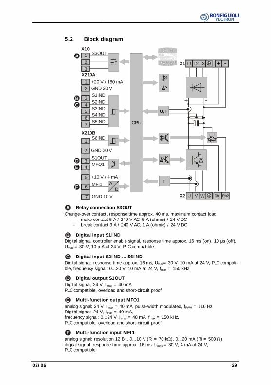
A Relay connection S3OUT Change-over contact, response time approx. 40 ms, maximum contact load:
− make contact 5 A / 240 V AC, 5 A (ohmic) / 24 V DC − break contact 3 A / 240 V AC, 1 A (ohmic) / 24 V DC
B Digital input S1IND Digital signal, controller enable signal, response time approx. 16 ms (on), 10 μs (off),
Umax = 30 V, 10 mA at 24 V, PLC compatible C Digital input S2IND ... S6IND Digital signal: response time approx. 16 ms, Umax= 30 V, 10 mA at 24 V, PLC compati-
ble, frequency signal: 0...30 V, 10 mA at 24 V, fmax = 150 kHz D Digital output S1OUT Digital signal, 24 V, Imax = 40 mA,
PLC compatible, overload and short-circuit proof E Multi-function output MFO1 analog signal: 24 V, Imax = 40 mA, pulse-width modulated, fPWM = 116 Hz
Digital signal: 24 V, Imax = 40 mA, frequency signal: 0...24 V, Imax = 40 mA, fmax = 150 kHz, PLC compatible, overload and short-circuit proof
F Multi-function input MFI1 analog signal: resolution 12 Bit, 0...10 V (Ri = 70 kΩ), 0...20 mA (Ri = 500 Ω),
digital signal: response time approx. 16 ms, Umax = 30 V, 4 mA at 24 V, PLC compatible

30 02/06
5.3 Mains Connection
The mains fuses and cable cross-sections are to be selected according to EN 60204-1 and DIN VDE 0298 Part 4 for the nominal operating point of the frequency inverter. According to UL/CSA, approved Class 1 copper lines with a temperature range of 60/75°C and matching mains fuses are to be used for the power cables. The electrical installation is to be done according to the device specifications and the applicable standards and directives.
Caution! The control, mains and motor lines must be kept physically separate from one another. The cables connected to the frequency inverters may not be subjected to high-voltage insulation tests unless appropriate cir-cuitry measures are taken before. Otherwise the unit may be damaged.
5.3.1 Frequency Inverter (0.55 up to 4.0 kW) The mains connection of the frequency inverter is via plug-in terminal X1. Degree of
protection IP20 (EN60529) is only guaranteed if terminal X1 is plugged in.
Danger! Switch off power supply before connecting or disconnecting the keyed plug-in terminal X1. Dangerous voltage may be present at the mains terminals and the DC terminals even after the frequency inverter has been disconnected safely from power supply. Wait for some minutes until the DC link capacitors have discharged before starting the work.
• The unit may only be connected with the power supply switched off. • Make sure that the frequency inverter is discharged.
Mains power connection 0.55 kW up to 4.0 kW
X1
1ph / 230V AC
+ -
L1
L2 L3L1
N PE3ph / 230V AC3ph / 400V AC
+ -
L1
L2 L3L1
L2 L3 PE2ph / 230V AC
+ -
L1 L2 PE
L2 L3L1550 W … 1.1 kW
Phoenix ZEC 1,5/ .. ST7,5
0.2 … 1.5 mmAWG 24 … 16
2
0.2 … 1.5 mmAWG 24 … 16
2
0.25 … 1.5 mmAWG 22 … 16
2
0.25 … 1.5 mmAWG 22 … 16
2
2ph / 230V AC1ph / 230V AC
1.5 kW … 3.0 kW
L1 N PE
+ - L1 L2 L3L1
3ph / 230V AC3ph / 400V AC
PE
1.5 kW … 3.0 kW 1.5 kW … 4.0 kW+ - L1 L2 L3L1
L1 L2 PE L1
+ - L1 L2 L3L1
L2 L3
1 With a mains current above 10 A, the mains power connection 230 V 1ph/N/PE
and the mains power connection 230 V 2ph/N/PE are to be done on two termi-nals.
02/06 31
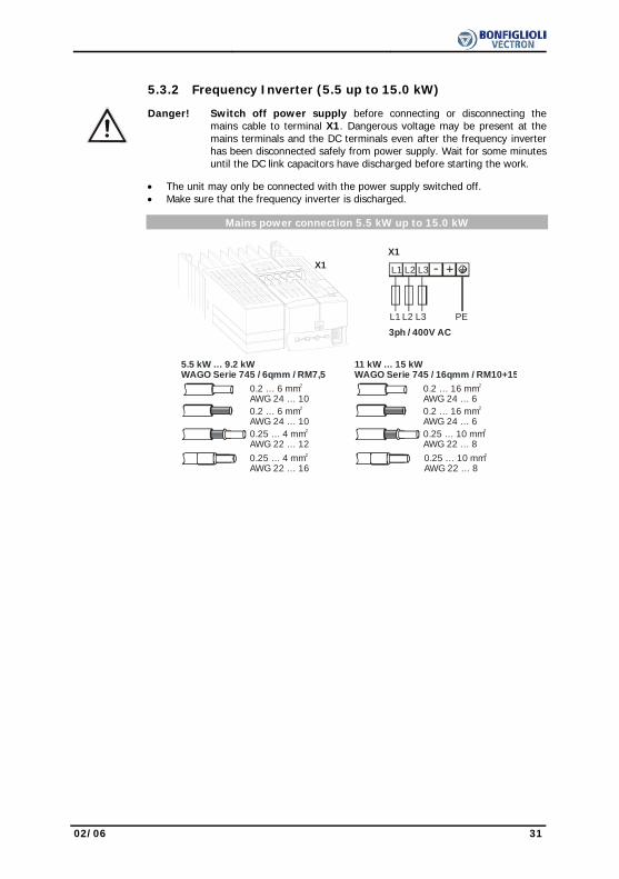
5.3.2 Frequency Inverter (5.5 up to 15.0 kW)
Danger! Switch off power supply before connecting or disconnecting the mains cable to terminal X1. Dangerous voltage may be present at the mains terminals and the DC terminals even after the frequency inverter has been disconnected safely from power supply. Wait for some minutes until the DC link capacitors have discharged before starting the work.
• The unit may only be connected with the power supply switched off.
• Make sure that the frequency inverter is discharged. Mains power connection 5.5 kW up to 15.0 kW
0.2 … 6 mmAWG 24 … 10
2
5.5 kW … 9.2 kWWAGO Serie 745 / 6qmm / RM7,5
0.2 … 6 mmAWG 24 … 10
2
0.25 … 4 mmAWG 22 … 12
2
0.25 … 4 mmAWG 22 … 16
2
+-
L1
L2 L3L1
L2 L3 PE
3ph / 400V AC
X1
0.2 … 16 mmAWG 24 … 6
2
11 kW … 15 kWWAGO Serie 745 / 16qmm / RM10+15
0.2 … 16 mmAWG 24 … 6
2
0.25 … 10 mmAWG 22 … 8
2
0.25 … 10 mmAWG 22 … 8
2
X1

32 02/06
5.3.3 Frequency Inverter (18.5 up to 30.0 kW)
Danger! Switch off power supply before connecting or disconnecting the mains cable to terminal X1. Dangerous voltage may be present at the mains terminals and the DC terminals even after the frequency inverter has been disconnected safely from power supply. Wait for some minutes until the DC link capacitors have discharged before starting the work.
• The unit may only be connected with the power supply switched off.
• Make sure that the frequency inverter is discharged. Mains power connection 18.5 kW up to 30.0 kW
0.5 … 35 mmAWG 20 … 2
2
18.5 kW … 30.0 kWPHOENIX MKDSP 25/ 6-15,00-F
0.5 … 25 mmAWG 20 … 4
2
1.00 … 25 mmAWG 18 … 4
2
1.5 … 25 mmAWG 16 … 4
2
+-
L1
L2 L3L1
L2 L3 PE
3ph / 400V AC
X1
X1
2.5 Nm22.1 lb-in

02/06 33
5.3.4 Frequency Inverter (37.0 up to 65.0 kW)
Danger! Switch off power supply before connecting or disconnecting the mains cable to terminal X1. Dangerous voltage may be present at the mains terminals and the DC terminals even after the frequency inverter has been disconnected safely from power supply. Wait for some minutes until the DC link capacitors have discharged before starting the work.
• The unit may only be connected with the power supply switched off.
• Make sure that the frequency inverter is discharged. Mains power connection 37.0 kW up to 65.0 kW
wire cross section up to 70 mm
37.0 kW … 65.0 kWthreaded bolt M8x25
+-
L1
L2 L3L1
L2 L3 PE
3ph / 400V AC
X1
X1
8 Nm70.8 lb-in
2

34 02/06
5.4 Motor Connection The connection of the motor and the brake resistor to the frequency inverter is to be
done using shielded cables. The shield is to be connected to PE potential properly, i.e. with good conductivity, on both sides. The control, mains and motor lines must be kept physically separate from one another. The user must comply with the applicable limits stipulated in the relevant national and international directives as regards the application, the length of the motor cable and the switching frequency.
Permissible length of motor cable without output filter Frequency inverter unshielded cable shielded cable 0.55 kW … 1.5 kW 50 m 25 m 1.85 kW … 4.0 kW 100 m 50 m 5.5 kW … 9.2 kW 100 m 50 m 11.0 kW … 15.0 kW 100 m 50 m 18.5 kW … 30.0 kW 150 m 100 m 37.0 kW … 65.0 kW 150 m 100 m The specified lengths of the motor cables must not be exceeded if no output filter is
installed. Upon request, we will check if longer motor cables can be used after taking appropri-
ate technical measures, e.g. use of low-capacitance cables and output filters. The following table includes standard values if an output filter is used
Permissible length of motor cable with output filter Frequency inverter unshielded cable shielded cable 0.55 kW … 1.5 kW on inquiry on inquiry 1.85 kW … 4.0 kW 150 m 100 m 5.5 kW … 9.2 kW 200 m 135 m 11.0 kW … 15.0 kW 225 m 150 m 18.5 kW … 30.0 kW 300 m 200 m 37.0 kW … 65.0 kW 300 m 200 m Note: The frequency inverters ≤ 9.2 kW with integrated EMC filter comply with
the emission limits stipulated in EN 61800-3 if the motor cable is not longer than 10 m. Customer-specific requirements can be met by means of an optional filter.

02/06 35
5.4.1 Frequency Inverter (0.55 up to 4.0 kW) The connection of the motor and the brake resistor to the frequency inverter is to be
done via plug-in terminal X2. Degree of protection IP20 (EN60529) is only guaranteed if terminal X2 is connected.
Danger! Switch off power supply before connecting or disconnecting the keyed plug-in terminal X2. Dangerous voltage may be present at the motor terminals and the terminals of the brake resistor even after the frequency inverter has been disconnected safely from power supply. Wait for some minutes until the DC link capacitors have discharged be-fore starting to work at the unit.
• The unit may only be connected with the power supply switched off.
• Make sure that the frequency inverter is discharged.
Motor power connection 0.55 kW up to 4.0 kW Phoenix ZEC 1,5/ .. ST7,5
0.2 … 1.5 mmAWG 24 … 16
2
0.2 … 1.5 mmAWG 24 … 16
2
0.25 … 1.5 mmAWG 22 … 16
2
0.25 … 1.5 mmAWG 22 … 16
2
X2
Star connection
V WU
Delta connection
V WU
V WURb2Rb1
M3~
36 02/06
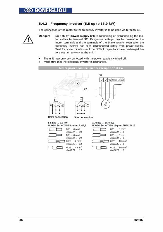
5.4.2 Frequency Inverter (5.5 up to 15.0 kW) The connection of the motor to the frequency inverter is to be done via terminal X2.
Danger! Switch off power supply before connecting or disconnecting the mo-tor cables to terminal X2. Dangerous voltage may be present at the motor terminals and the terminals of the brake resistor even after the frequency inverter has been disconnected safely from power supply. Wait for some minutes until the DC link capacitors have discharged be-fore starting to work at the unit.
• The unit may only be connected with the power supply switched off.
• Make sure that the frequency inverter is discharged. Motor power connection 5.5 kW up to 15.0 kW
Star connection
V WU
Delta connection
V WU
5.5 kW … 9.2 kWWAGO Serie 745 / 6qmm / RM7,5
0.2 … 6 mmAWG 24 … 10
2
0.2 … 6 mmAWG 24 … 10
2
0.25 … 4 mmAWG 22 … 12
2
0.25 … 4 mmAWG 22 … 16
2
11.0 kW … 15.0 kWWAGO Serie 745 / 16qmm / RM10+15
0.2 … 16 mmAWG 24 … 6
2
0.2 … 16 mmAWG 24 … 6
2
0.25 … 10 mmAWG 22 … 8
2
0.25 … 10 mmAWG 22 … 8
2
X2
X2
V WU Rb2Rb1
M3~
02/06 37
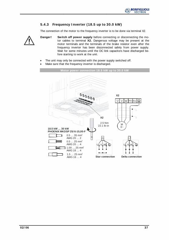
5.4.3 Frequency Inverter (18.5 up to 30.0 kW) The connection of the motor to the frequency inverter is to be done via terminal X2.
Danger! Switch off power supply before connecting or disconnecting the mo-tor cables to terminal X2. Dangerous voltage may be present at the motor terminals and the terminals of the brake resistor even after the frequency inverter has been disconnected safely from power supply. Wait for some minutes until the DC link capacitors have discharged be-fore starting to work at the unit.
• The unit may only be connected with the power supply switched off.
• Make sure that the frequency inverter is discharged. Motor power connection 18.5 kW up to 30.0 kW
Star connection
V WU
Delta connection
V WU
0.5 … 35 mmAWG 20 … 2
2
18.5 kW … 30 kWPHOENIX MKDSP 25/ 6-15,00-F
0.5 … 25 mmAWG 20 … 4
2
1.00 … 25 mmAWG 18 … 4
2
1.5 … 25 mmAWG 16 … 4
2
X2
V WU Rb2Rb1
M3~
X2
2.5 Nm22.1 lb-in
38 02/06
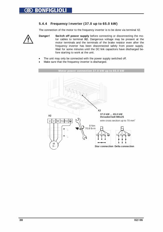
5.4.4 Frequency Inverter (37.0 up to 65.0 kW) The connection of the motor to the frequency inverter is to be done via terminal X2.
Danger! Switch off power supply before connecting or disconnecting the mo-tor cables to terminal X2. Dangerous voltage may be present at the motor terminals and the terminals of the brake resistor even after the frequency inverter has been disconnected safely from power supply. Wait for some minutes until the DC link capacitors have discharged be-fore starting to work at the unit.
• The unit may only be connected with the power supply switched off.
• Make sure that the frequency inverter is discharged. Motor power connection 37.0 kW up to 65.0 kW
Star connection
V WU
Delta connection
V WU
wire cross section up to 70 mm 2
37.0 kW … 65.0 kWthreaded bolt M8x25
X2
V WU Rb2Rb1
M3~
X2
8 Nm70.8 lb-in
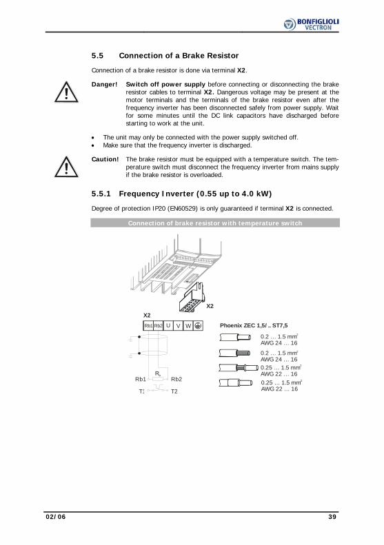
02/06 39
5.5 Connection of a Brake Resistor Connection of a brake resistor is done via terminal X2.
Danger! Switch off power supply before connecting or disconnecting the brake resistor cables to terminal X2. Dangerous voltage may be present at the motor terminals and the terminals of the brake resistor even after the frequency inverter has been disconnected safely from power supply. Wait for some minutes until the DC link capacitors have discharged before starting to work at the unit.
• The unit may only be connected with the power supply switched off.
• Make sure that the frequency inverter is discharged.
Caution! The brake resistor must be equipped with a temperature switch. The tem-perature switch must disconnect the frequency inverter from mains supply if the brake resistor is overloaded.
5.5.1 Frequency Inverter (0.55 up to 4.0 kW) Degree of protection IP20 (EN60529) is only guaranteed if terminal X2 is connected. Connection of brake resistor with temperature switch
X2
V WURb2Rb1
Rb
T1
Rb1 Rb2
T2
X2
Phoenix ZEC 1,5/ .. ST7,5
0.2 … 1.5 mmAWG 24 … 16
2
0.2 … 1.5 mmAWG 24 … 16
2
0.25 … 1.5 mmAWG 22 … 16
2
0.25 … 1.5 mmAWG 22 … 16
2
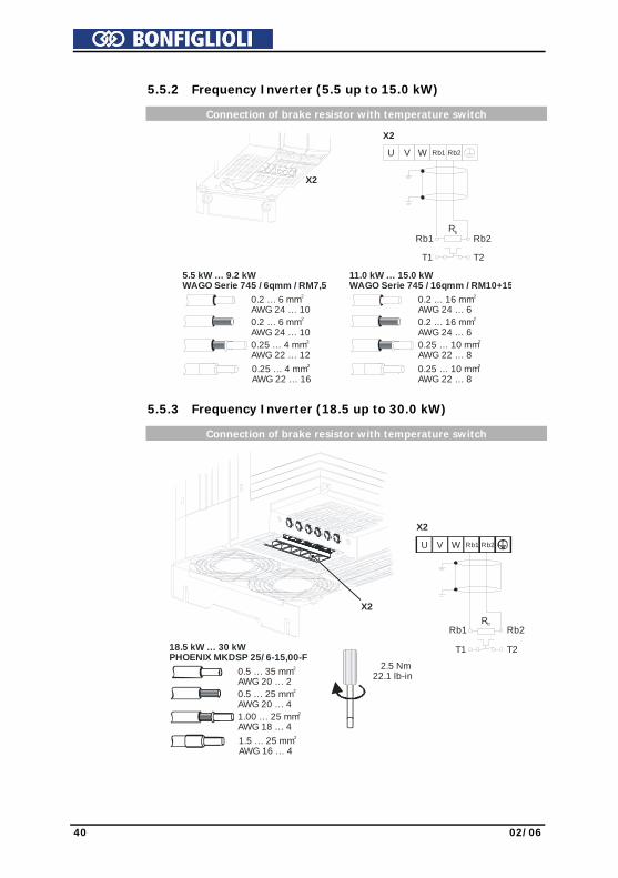
40 02/06
5.5.2 Frequency Inverter (5.5 up to 15.0 kW) Connection of brake resistor with temperature switch
X2
Rb
T1
Rb1 Rb2
T2
V WU Rb2Rb1
X2
5.5 kW … 9.2 kWWAGO Serie 745 / 6qmm / RM7,5
0.2 … 6 mmAWG 24 … 10
2
0.2 … 6 mmAWG 24 … 10
2
0.25 … 4 mmAWG 22 … 12
2
0.25 … 4 mmAWG 22 … 16
2
11.0 kW … 15.0 kWWAGO Serie 745 / 16qmm / RM10+15
0.2 … 16 mmAWG 24 … 6
2
0.2 … 16 mmAWG 24 … 6
2
0.25 … 10 mmAWG 22 … 8
2
0.25 … 10 mmAWG 22 … 8
2
5.5.3 Frequency Inverter (18.5 up to 30.0 kW) Connection of brake resistor with temperature switch
0.5 … 35 mmAWG 20 … 2
2
18.5 kW … 30 kWPHOENIX MKDSP 25/ 6-15,00-F
0.5 … 25 mmAWG 20 … 4
2
1.00 … 25 mmAWG 18 … 4
2
1.5 … 25 mmAWG 16 … 4
2
X2
2.5 Nm22.1 lb-in
Rb
T1
Rb1 Rb2
T2
V WU Rb2Rb1
X2

02/06 41
5.5.4 Frequency Inverter (37.0 up to 65.0 kW) Connection of brake resistor with temperature switch
Wire cross section up to 70 mm 2
37.0 kW … 65.0 kWthreaded bolt M8x25
X2
8 Nm70.8 lb-in
Rb
T1
Rb1 Rb2
T2
V WU Rb2Rb1
X2

42 02/06
5.6 Control Terminals
The control and software functionality can be freely configured to ensure a reliable and economical operation. The operating instructions describe the factory settings of the standard connections in the relevant Configuration 30 as well as the software parameters to be set up.
Caution! Switch off power supply before connecting or disconnecting the keyed control inputs and outputs. Otherwise, components may be damaged.
• The unit may only be connected with the power supply switched off. • Make sure that the frequency inverter is discharged.
Control Terminals
0.14 … 1.5 mmAWG 30 … 16
2
Wieland DST85 / RM3,5
0.14 … 1.5 mmAWG 30 … 16
2
0.25 … 1.0 mmAWG 22 … 18
2
0.25 … 0.75 mmAWG 22 … 20
2
0.2 … 0.3 Nm1.8 … 2.7 lb-in
Control terminal X210A Ter. Description 1 Voltage output 20 V, Imax=180 mA 1) 2 Ground / GND 20 V 3 Digital input S1IND, Umax=30 V, 10 mA at 24 V, PLC compatible,
response time approx. 16ms (on), 10 μs (off) 4 Digital input EM-S2IND, Umax=30 V, 10 mA at 24 V, PLC compatible,
response time approx. 16 ms 5 Digital input EM-S3IND, Umax=30 V, 10 mA at 24 V, PLC compatible,
response time approx. 16 ms 6 Digital input S4IND, Umax = 30 V, 10 mA at 24 V, PLC compatible,
frequency signal: 0...30 V, 10 mA at 24 V, fmax = 150 kHz 7 Digital input S5IND, Umax = 30 V, 10 mA at 24 V, PLC compatible,
frequency signal: 0...30 V, 10 mA at 24 V, fmax = 150 kHz Control terminal X210B Ter. Description 1 Digital input S6IND, Umax=30 V, 10 mA at 24 V, PLC compatible,
response time approx. 16 ms 2 Ground / GND 20 V 3 Digital output S1OUT, U=24 V, Imax=40 mA, overload and short-circuit proof 4 Multi-function output MFO1,
analog signal: U=24 V, Imax=40 mA, pulse-width modulated, fPWM=116 Hz digital signal: U=24 V, Imax=40 mA, overload and short-circuit proof, frequency signal: 0...24 V, Imax=40 mA, fmax=150 kHz
5 Reference output 10 V, Imax=4 mA 6 Multi-function input MFI1,
analog signal: resolution 12 Bit, 0...+10 V (Ri = 70 kΩ), 0...20 mA (Ri = 500 Ω), digital signal: response time approx. 16 ms, Umax= 30 V, 4 mA at 24 V, PLC compatible
7 Ground / GND 10 V
1) The power supply at terminal X210A.1 may be loaded with a maximum current of Imax = 180 mA. The maximum current available is reduced by the digital output S1OUT and multi-functional output MFO1.

02/06 43
5.6.1 Relay Output
By default, the freely programmable relay output is linked to the monitoring function (factory setting). The logic link to various functions can be freely configured via the software parameters. Connection of the relay output is not absolutely necessary for the function of the frequency inverter.
Relay Output
123
0.2 … 1.5 mmAWG 24 … 16
2Phoenix ZEC 1,5/3ST5,0
0.2 … 1.5 mmAWG 24 … 16
2
0.25 … 1.5 mmAWG 22 … 16
2
0.25 … 1.5 mmAWG 22 … 16
2
S3OUT
X10
X10
Control terminal X10 Ter. Description 1 .. 3 Relay output, floating change-over contact, response time approx. 40 ms,
max. contact load, make contact 5 A / 240 V AC, 5 A (ohmic) / 24 V DC max. contact load, break contact 3 A / 240 V AC, 1 A (ohmic) / 24 V DC

44 02/06
5.6.2 Control Terminals – Terminal Diagram
The control hardware and the software of the frequency inverter are freely configur-able to a great extent. Certain functions can be assigned to the control terminals, and the internal logic of the software modules can be freely selected.
Thanks to the modular design, the frequency inverter can be adapted to a great range of different driving tasks.
The demands made of the control hardware and software are well known in the case of standard driving tasks. This control terminal logic and internal function assign-ments of the software modules are available in standard configurations. These as-signments can be selected via parameter Configuration 30. For information on other configurations, please contact us.
5.6.2.1 Configuration 110 – Sensorless Control
Configuration 110 contains the functions for variable-speed control of a 3-phase ma-chine in a wide range of standard applications. The motor speed is set according to the selected ratio of the reference frequency to the necessary voltage.
Control terminal X210A X210A.1 Supply voltage +20V X210A.2 Ground 20 V X210A.3 Controller release / error acknowl-
edgment X210A.4 Start of clockwise operation X210A.5 Start of anticlockwise operation X210A.6 Data set change-over 1 X210A.7 Data set change-over 2 Control terminal X210B X210B.1 Motor thermal contact X210B.2 Ground 20 V X210B.3 Operating message X210B.4 Analog signal of actual frequency X210B.5 Supply voltage +10V
Reference value potentiometer X210B.6 Reference speed 0 ...+10 V
GND 20 VS1OUTMFO1A+10 V/ 4 mA MFI1AGND 10 V
1234567
X210A+20 V/180 mAGND 20 VS1INDS2INDS3INDS4INDS5IND
S6INDX210B
1234567
M
V+-
+-
X210B.7 Ground 10 V

02/06 45
5.6.2.2 Configuration 111 – Sensorless Control with Technology Controller
Configuration 111 extends the functionality of the sensorless control by software func-tions for easier adaptation to the customer's requirements in different applications. The Technology Controller enables flow rate, pressure, level or speed control.
Control terminal X210A X210A.1 Supply voltage +20V X210A.2 Ground 20 V X210A.3 Controller release / error acknowl-
edgment X210A.4 Fixed percentage value
change-over 1 X210A.5 Fixed percentage value
change-over 2 X210A.6 Data set change-over 1 X210A.7 Data set change-over 2 Control terminal X210B X210B.1 Motor thermal contact X210B.2 Ground 20 V X210B.3 Operating message X210B.4 Analog signal of actual frequency X210B.5 Supply voltage +10V X210B.6 Actual percentage value 0 ...+10 V
GND 20 VS1OUTMFO1A+10 V/4 mA MFI1AGND 10 V
1234567
X210A+20 V/180 mAGND 20 VS1INDS2INDS3INDS4INDS5IND
S6INDX210B
1234567
M
V+-
+-
-
+
X210B.7 Ground 10 V
5.6.2.3 Configuration 410 – Sensorless Field-Oriented Control
Configuration 410 contains the functions for sensorless, field-oriented control of a 3-phase machine. The current motor speed is determined from the present currents and voltages in combination with the machine parameters. Separate control of torque and flux-forming current enables a high drive dynamism at a high load moment.
Control terminal X210A X210A.1 Supply voltage +20V X210A.2 Ground 20 V X210A.3 Controller release / error acknowl-
edgment X210A.4 Start of clockwise operation X210A.5 Start of anticlockwise operation X210A.6 Data set change-over 1 X210A.7 Data set change-over 2 Control terminal X210B X210B.1 Motor thermal contact X210B.2 Ground 20 V X210B.3 Operating message X210B.4 Analog signal of actual frequency X210B.5 Supply voltage +10V
Reference value potentiometer X210B.6 Reference speed 0 ...+10 V
GND 20 VS1OUTMFO1A+10 V/4 mA MFI1AGND 10 V
1234567
X210A+20 V/180 mAGND 20 VS1INDS2INDS3INDS4INDS5IND
S6INDX210B
1234567
M
V+-
+-
X210B.7 Ground 10 V
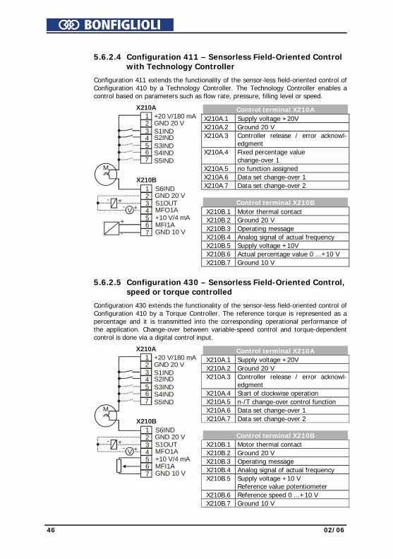
46 02/06
5.6.2.4 Configuration 411 – Sensorless Field-Oriented Control with Technology Controller
Configuration 411 extends the functionality of the sensor-less field-oriented control of
Configuration 410 by a Technology Controller. The Technology Controller enables a control based on parameters such as flow rate, pressure, filling level or speed.
Control terminal X210A X210A.1 Supply voltage +20V X210A.2 Ground 20 V X210A.3 Controller release / error acknowl-
edgment X210A.4 Fixed percentage value
change-over 1 X210A.5 no function assigned X210A.6 Data set change-over 1 X210A.7 Data set change-over 2
Control terminal X210B X210B.1 Motor thermal contact X210B.2 Ground 20 V X210B.3 Operating message X210B.4 Analog signal of actual frequency X210B.5 Supply voltage +10V X210B.6 Actual percentage value 0 ...+10 V
GND 20 VS1OUTMFO1A+10 V/4 mA MFI1AGND 10 V
1234567
X210A+20 V/180 mAGND 20 VS1INDS2INDS3INDS4INDS5IND
S6INDX210B
1234567
M
V+-
+-
-
+
X210B.7 Ground 10 V
5.6.2.5 Configuration 430 – Sensorless Field-Oriented Control,speed or torque controlled
Configuration 430 extends the functionality of the sensor-less field-oriented control of
Configuration 410 by a Torque Controller. The reference torque is represented as a percentage and it is transmitted into the corresponding operational performance of the application. Change-over between variable-speed control and torque-dependent control is done via a digital control input.
Control terminal X210A X210A.1 Supply voltage +20V X210A.2 Ground 20 V X210A.3 Controller release / error acknowl-
edgment X210A.4 Start of clockwise operation X210A.5 n-/T change-over control function X210A.6 Data set change-over 1 X210A.7 Data set change-over 2
Control terminal X210B X210B.1 Motor thermal contact X210B.2 Ground 20 V X210B.3 Operating message X210B.4 Analog signal of actual frequency X210B.5 Supply voltage +10 V
Reference value potentiometer X210B.6 Reference speed 0 ...+10 V
GND 20 VS1OUTMFO1A+10 V/4 mA MFI1AGND 10 V
1234567
X210A+20 V/180 mAGND 20 VS1INDS2INDS3INDS4INDS5IND
S6INDX210B
1234567
M
V+-
+-
X210B.7 Ground 10 V

02/06 47
5.6.2.6 Configuration 210 – Field-Oriented Control, speed controlled
Configuration 210 contains the functions for speed-controlled, field-oriented control of a 3-phase machine with speed sensor feedback. The separate control of torque and flux-forming current enables high drive dynamism with a high load moment. The nec-essary speed sensor feedback results in a precise speed and torque performance.
Control terminal X210A X210A.1 Supply voltage +20V X210A.2 Ground 20 V X210A.3 Controller release / error acknowl-
edgment X210A.4 Start of clockwise operation X210A.5 Start of anticlockwise operation X210A.6 Speed sensor track B X210A.7 Speed sensor track A Control terminal X210B X210B.1 Motor thermal contact X210B.2 Ground 20 V X210B.3 Operating message X210B.4 Analog signal of actual frequency X210B.5 Supply voltage +10 V
Reference value potentiometer X210B.6 Reference speed 0 ...+10V
GND 20 VS1OUTMFO1A+10 V/4 mA MFI1AGND 10 V
1234567
X210A+20 V/180 mAGND 20 VS1INDS2INDS3INDS4INDS5IND
S6INDX210B
1234567
M
V+-
+-
AB+ -
X210B.7 Ground 10 V
5.6.2.7 Configuration 230 – Field-Oriented Control, speed and torque controlled
Configuration 230 extends the functionality of Configuration 210 by functions for torque-dependent, field-oriented control. The reference torque is represented as a percentage and it is transmitted into the corresponding operational performance of the application. Change-over between variable-speed control and torque-dependent control is done via a digital control input.
Control terminal X210A X210A.1 Supply voltage +20V X210A.2 Ground 20 V X210A.3 Controller release / error acknowl-
edgment X210A.4 Start of clockwise operation X210A.5 n-/T change-over control function X210A.6 Speed sensor track B X210A.7 Speed sensor track A Control terminal X210B X210B.1 Motor thermal contact X210B.2 Ground 20 V X210B.3 Operating message X210B.4 Analog signal of actual frequency X210B.5 Supply voltage +10 V
Reference value potentiometer X210B.6 Reference speed 0 ...+10V
GND 20 VS1OUTMFO1A+10 V/4 mA MFI1AGND 10 V
1234567
X210A+20 V/180 mAGND 20 VS1INDS2INDS3INDS4INDS5IND
S6INDX210B
1234567
M
V+-
+-
AB+ -
X210B.7 Ground 10 V
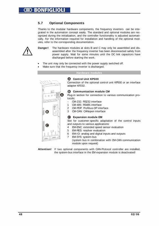
48 02/06
5.7 Optional Components
Thanks to the modular hardware components, the frequency inverters can be inte-grated in the automation concept easily. The standard and optional modules are rec-ognized during the initialization, and the controller functionality is adjusted automati-cally. For the information required for installation and handling of the optional mod-ules, refer to the corresponding documentation.
Danger! The hardware modules at slots B and C may only be assembled and dis-assembled after the frequency inverter has been disconnected safely from power supply. Wait for some minutes until the DC link capacitors have discharged before starting the work.
• The unit may only be connected with the power supply switched off. • Make sure that the frequency inverter is discharged. Hardware modules
A Control Unit KP500 Connection of the optional control unit KP500 or an interface adapter KP232. B Communication module CM Plug-in section for connection to various communication pro-tocols: − CM-232: RS232 interface 1 CM-485: RS485 interface 2 CM-PDP: Profibus-DP interface 3 CM-CAN: CANopen interface C Expansion module EM
A
B
C
Slot for customer-specific adaptation of the control inputs and outputs to various applications: 4 EM-ENC: extended speed sensor evaluation 5 EM-RES: resolver evaluation 6 EM-IO: analog and digital inputs and outputs 7 EM-SYS: system-bus
(system bus in combination with CM-CAN communication module upon request)
Attention! If two optional components with CAN-Protocol controller are installed,
the system-bus interface in the EM expansion module is deactivated!

02/06 49
6 Control Unit KP500
The optional KP500 control unit is a practical tool for controlling the frequency inverter and setting and displaying the frequency inverter parameters. The control unit is not absolutely necessary for the operation of the frequency inverter and can be plugged on when required.
A
B C D E
F G HI
J
Keys A RUN Used for starting the drive and opening the CTRL menu.
Press the RUN key to open the motor potentiometer function. STOP Used for opening the CTRL menu, stopping the drive and acknowledging
faults J Used for navigating in the menu structure and selecting parameters.
Used for increasing/decreasing parameter values. ENT Used for opening parameters or switching to another menu within the menu
structure. Confirmation of the selected function or the set parameter. ESC Used for aborting parameters or switching back to the previous menu within
the menu structure. Canceling the function or resetting the parameter value. FUN Used for switching over the key function, access to special functions.
Display B Three-digit 7-segment display to show the parameter number C One-digit 7-segment display for display of the active data record, direction of rota-
tion etc. D Display of the selected menu branch: VAL Display actual values PARA Select parameters and adjust parameter values. CTRL Select a function for adjustment and/or display via the control unit:
SEtUP guided commissioning CtrL motor potentiometer and jog function
CPY Copy parameters via the control unit: ALL All the parameter values are copied. Act Only the active parameter values are copied. FOr Control unit memory is formatted and deleted.
E Status and operating messages: WARN Warning about a critical operating behavior FAULT Message indicating that the unit was switched off due to a fault RUN Flashing: signals readiness for operation
Lights up: signals that the unit is operating and the output stage is enabled REM Active remote control via interface connection F Function switch-over with the FUN key F Five-digit 7-segment display for display of parameter value and sign G Physical unit of the parameter value displayed H Active acceleration or deceleration ramp I Current direction of rotation of the drive
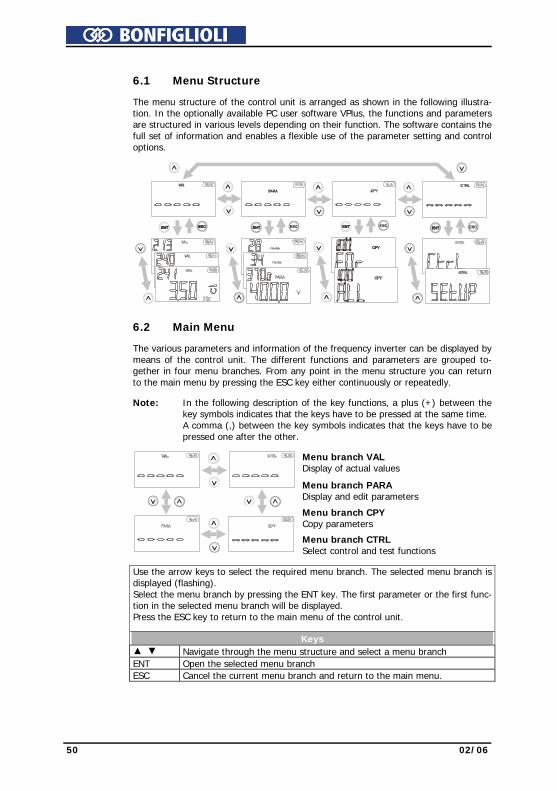
50 02/06
6.1 Menu Structure The menu structure of the control unit is arranged as shown in the following illustra-
tion. In the optionally available PC user software VPlus, the functions and parameters are structured in various levels depending on their function. The software contains the full set of information and enables a flexible use of the parameter setting and control options.
6.2 Main Menu The various parameters and information of the frequency inverter can be displayed by
means of the control unit. The different functions and parameters are grouped to-gether in four menu branches. From any point in the menu structure you can return to the main menu by pressing the ESC key either continuously or repeatedly.
Note: In the following description of the key functions, a plus (+) between the
key symbols indicates that the keys have to be pressed at the same time. A comma (,) between the key symbols indicates that the keys have to be pressed one after the other.
Menu branch VAL Display of actual values
Menu branch PARA Display and edit parameters
Menu branch CPY Copy parameters
Menu branch CTRL
Select control and test functions
Use the arrow keys to select the required menu branch. The selected menu branch is displayed (flashing). Select the menu branch by pressing the ENT key. The first parameter or the first func-tion in the selected menu branch will be displayed. Press the ESC key to return to the main menu of the control unit.
Keys Navigate through the menu structure and select a menu branch ENT Open the selected menu branch ESC Cancel the current menu branch and return to the main menu.

02/06 51
6.3 Actual Value Menu (VAL) In the VAL menu branch, the control unit displays a variety of actual values, depend-
ing on the configuration selected and the options installed. The parameters and basic software functions linked to the corresponding actual value are documented in the operating instructions.
ENT
ESC
ENT
ESC
A
B CD
E
A Use the arrow keys to select the required number from the actual values dis-played in numerical order. In the current record, the record-related actual value parameters are displayed, including the corresponding data record number. The seven-segment display shows data record 0 if the actual values in the four data sets are identical.
Keys + Display the actual value parameter upon switch-on. FUN , Display last actual value parameter (highest number). FUN , Display first actual value parameter (lowest number).
B Use the ENT key to select the parameter. The parameter is displayed including its current value, unit and the active data record.
C During commissioning, operation and error analysis, it is possible to monitor
each actual value parameter specifically. Some of the actual value parameters are arranged in the four available data records. If the parameter values in the four data records are identical, the actual value is displayed in data record 0. If the actual values in the four data records are different, diFF is displayed in data record 0.
Keys , Switch to another of the data set in the case of related actual
values. FUN , Determine minimum value and display it permanently. FUN , Determine maximum value and display it permanently. FUN , ENT Display of mean value of the actual value during the
monitoring period.
D Use the ENT key to save the selected actual value as a parameter displayed at switch-on. The message SEt (with parameter number) is displayed for a short time. When the frequency inverter is switched on the next time, this actual value will be displayed automatically.
E After saving the parameter, you can monitor and display the value again. Use
the ESC key to switch to the parameter selection of the VAL menu branch.
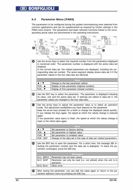
52 02/06
6.4 Parameter Menu (PARA) The parameters to be configured during the guided commissioning were selected from
common applications and can be supplemented as required by further settings in the PARA menu branch. The parameters and basic software functions linked to the corre-sponding actual value are documented in the operating instructions.
ENT
ESC
ENT
ESC
A
B CD
E
A Use the arrow keys to select the required number from the parameters displayed
in numerical order. The parameter number is displayed with the active data set (flashes). In the current data set, the related parameters are displayed, including the cor-responding data set number. The seven-segment display shows data set 0 if the parameter values in the four data sets are identical.
Keys + Change to the last parameter edited. FUN , Display of last parameter (highest number). FUN , Display of first parameter (lowest number).
B Use the ENT key to select the parameter. The parameter is displayed including its value, unit and the active data set. If settings are edited in data set 0, the parameter values are changed in the four data sets.
C Use the arrow keys to adjust the parameter value or to select an operation
mode. The adjustment possibilities you have depend on the parameter. Keep the arrow keys pressed for a while to change the displayed values quickly. If you release the keys again, the speed at which the values change is reduced again. If the parameter value starts to flash, the speed at which the values change is reset to the initial value again.
Keys + Set parameter to factory setting. FUN , Set parameter to highest value. FUN , Set parameter to smallest value. FUN , ENT Change of the data set in the case of data set related parameters.
D Use the ENT key to save the parameter. For a short time, the message SEt in-cluding the parameter number and the data set is displayed. To leave the pa-rameter unchanged, press the ESC key.
Messages Err1: EEPrO Parameter has not been saved. Err2: StOP Parameter can only be read (i.e. not edited) when the unit is in
operation. Err3: Error Other error
E After saving the parameter, you can edit the value again or return to the pa-rameter selection menu by pressing the ESC key.
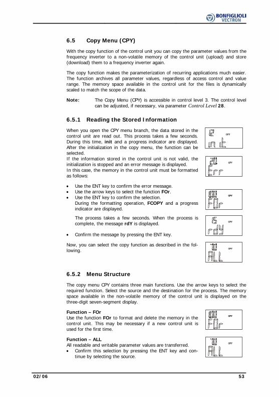
02/06 53
6.5 Copy Menu (CPY) With the copy function of the control unit you can copy the parameter values from the
frequency inverter to a non-volatile memory of the control unit (upload) and store (download) them to a frequency inverter again.
The copy function makes the parameterization of recurring applications much easier.
The function archives all parameter values, regardless of access control and value range. The memory space available in the control unit for the files is dynamically scaled to match the scope of the data.
Note: The Copy Menu (CPY) is accessible in control level 3. The control level
can be adjusted, if necessary, via parameter Control Level 28.
6.5.1 Reading the Stored Information
When you open the CPY menu branch, the data stored in the control unit are read out. This process takes a few seconds. During this time, init and a progress indicator are displayed. After the initialization in the copy menu, the function can be selected.
If the information stored in the control unit is not valid, the initialization is stopped and an error message is displayed. In this case, the memory in the control unit must be formatted as follows:
• Use the ENT key to confirm the error message. • Use the arrow keys to select the function FOr.
• Use the ENT key to confirm the selection. During the formatting operation, FCOPY and a progress indicator are displayed.
The process takes a few seconds. When the process is complete, the message rdY is displayed.
• Confirm the message by pressing the ENT key.
Now, you can select the copy function as described in the fol-lowing.
6.5.2 Menu Structure The copy menu CPY contains three main functions. Use the arrow keys to select the
required function. Select the source and the destination for the process. The memory space available in the non-volatile memory of the control unit is displayed on the three-digit seven-segment display.
Function – FOr
Use the function FOr to format and delete the memory in the control unit. This may be necessary if a new control unit is used for the first time.
Function – ALL
All readable and writable parameter values are transferred. • Confirm this selection by pressing the ENT key and con-
tinue by selecting the source.

54 02/06
Function – Act Only the active parameter values of the frequency inverter are copied to the control unit. The number of active parameter values depends on the current selected configuration of the frequency inverter. When data are copied from the control unit to the frequency inverter, all parameter values stored are transferred, like in the case of the ALL function. • Confirm the selection Act by pressing the ENT key and
continue by selecting the source.
6.5.3 Selecting the Source
The parameters of the ALL and Act sub-functions in the CPY menu branch can be parameterized to meet the requirements of the specific application. The available memory space of the control unit is shown on the seven-segment display.
• Use the arrow keys to select the data source (Src.) for the copy operation (up-load). You can use either the data sets of the frequency inverter (Src. x) or the files of the control unit (Src. Fy) as the data source.
• Confirm the selected data source by pressing the ENT key and continue by select-ing the destination.
Display Description Src. 0 The data of the four data records of the frequency inverter are copied. Src. 1 The data of data record 1 of the frequency inverter are copied. Src. 2 The data of data record 2 of the frequency inverter are copied. Src. 3 The data of data record 3 of the frequency inverter are copied. Src. 4 The data of data record 4 of the frequency inverter are copied. Src. E An empty data record for deletion of a file in the control unit. Src. F1 File 1 is transferred from the memory of the control unit. 1) Src. F2 File 2 is transferred from the memory of the control unit. 1) Src. F3 File 3 is transferred from the memory of the control unit. 1) Src. F4 File 4 is transferred from the memory of the control unit. 1) Src. F5 File 5 is transferred from the memory of the control unit. 1) Src. F6 File 6 is transferred from the memory of the control unit. 1) Src. F7 File 7 is transferred from the memory of the control unit. 1) Src. F8 File 8 is transferred from the memory of the control unit. 1) 1) Empty files which are not filled with data yet cannot be used as signal sources. The
control unit memory is managed dynamically (see Chapter “Copy Menu (CPY)”)

02/06 55
6.5.4 Selecting the Destination Select the destination (dSt.) of the copy operation (application-specific). The data
source is transferred to the selected target (download). • Use the arrow keys to select the destination (dSt.) for the copied data
(download). Depending on the data source selected, either the data records of the frequency inverter (dSt. x) or empty files of the control unit (dSt. F y) can be used as the target.
• Confirm the selection by pressing the ENT key. The copy process is started and COPY is displayed.
Display Description dSt. 0 The four data records of the frequency inverter are overwritten. dSt. 1 The data are copied to data record 1 of the frequency inverter. dSt. 2 The data are copied to data record 2 of the frequency inverter. dSt. 3 The data are copied to data record 3 of the frequency inverter. dSt. 4 The data are copied to data record 4 of the frequency inverter. dSt. F1 The data are copied to file 1 of the control unit. 1) dSt. F2 The data are copied to file 2 of the control unit. 1) dSt. F3 The data are copied to file 3 of the control unit. 1) dSt. F4 The data are copied to file 4 of the control unit. 1) dSt. F5 The data are copied to file 5 of the control unit. 1) dSt. F6 The data are copied to file 6 of the control unit. 1) dSt. F7 The data are copied to file 7 of the control unit. 1) dSt. F8 The data are copied to file 8 of the control unit. 1) 1) Already existing files are not offered as possible targets.
6.5.5 Copy Operation
Attention! Before the parameter settings are transferred to the frequency inverter, the individual parameter values are checked. The value range and the parameter settings can differ according to the power range of the frequency inverter. If parameter values are outside of the value range, an error message will be displayed.
During the copy operation, the message COPY and the num-
ber of the currently copied parameter are displayed to indicate the progress. In the case of the Act function, only the active parameter val-ues are copied. With the ALL function, parameters which are not relevant to the selected configuration are copied, too.
Depending on the selected copy function (ALL or Act), the
copy operation is completed after some 100 seconds and the display reads rdY. Press the ENT key to switch to the copy menu. Use the ESC key to switch to the target selection menu.
If the ESC key is pressed during the copy operation, the copy
operation is aborted before the transmission of the data is complete. The message Abr and the number of the last pa-rameter which was copied are displayed. Press the ENT key to return to the selection in the copy menu. Use the ESC key to switch to the target selection menu.
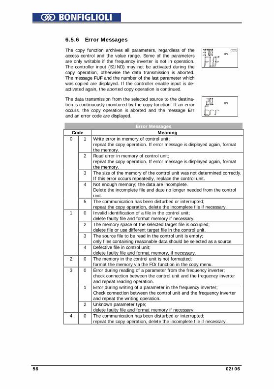
56 02/06
6.5.6 Error Messages
The copy function archives all parameters, regardless of the access control and the value range. Some of the parameters are only writable if the frequency inverter is not in operation. The controller input (S1IND) may not be activated during the copy operation, otherwise the data transmission is aborted. The message FUF and the number of the last parameter which was copied are displayed. If the controller enable input is de-activated again, the aborted copy operation is continued.
The data transmission from the selected source to the destina-
tion is continuously monitored by the copy function. If an error occurs, the copy operation is aborted and the message Err and an error code are displayed.
Error Messages
Code Meaning 1 Write error in memory of control unit;
repeat the copy operation. If error message is displayed again, format the memory.
2 Read error in memory of control unit; repeat the copy operation. If error message is displayed again, format the memory.
3 The size of the memory of the control unit was not determined correctly.If this error occurs repeatedly, replace the control unit.
4 Not enough memory; the data are incomplete. Delete the incomplete file and date no longer needed from the control unit.
0
5 The communication has been disturbed or interrupted; repeat the copy operation, delete the incomplete file if necessary.
0 Invalid identification of a file in the control unit; delete faulty file and format memory if necessary.
2 The memory space of the selected target file is occupied; delete file or use different target file in the control unit.
3 The source file to be read in the control unit is empty; only files containing reasonable data should be selected as a source.
1
4 Defective file in control unit; delete faulty file and format memory, if necessary.
2 0 The memory in the control unit is not formatted; format the memory via the FOr function in the copy menu.
0 Error during reading of a parameter from the frequency inverter; check connection between the control unit and the frequency inverter and repeat reading operation.
1 Error during writing of a parameter in the frequency inverter; Check connection between the control unit and the frequency inverter and repeat the writing operation.
3
2 Unknown parameter type; delete faulty file and format memory if necessary.
4 0 The communication has been disturbed or interrupted; repeat the copy operation, delete the incomplete file if necessary.
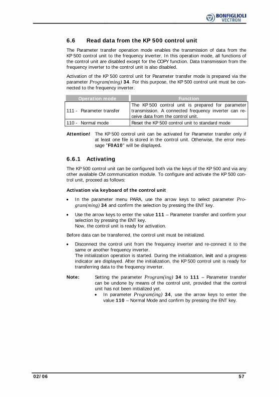
02/06 57
6.6 Read data from the KP 500 control unit
The Parameter transfer operation mode enables the transmission of data from the KP 500 control unit to the frequency inverter. In this operation mode, all functions of the control unit are disabled except for the COPY function. Data transmission from the frequency inverter to the control unit is also disabled.
Activation of the KP 500 control unit for Parameter transfer mode is prepared via the parameter Program(ming) 34. For this purpose, the KP 500 control unit must be con-nected to the frequency inverter.
Operation mode Function
111 - Parameter transfer The KP 500 control unit is prepared for parameter transmission. A connected frequency inverter can re-ceive data from the control unit.
110 - Normal mode Reset the KP 500 control unit to standard mode Attention! The KP 500 control unit can be activated for Parameter transfer only if
at least one file is stored in the control unit. Otherwise, the error mes-sage "F0A10" will be displayed.
6.6.1 Activating
The KP 500 control unit can be configured both via the keys of the KP 500 and via any other available CM communication module. To configure and activate the KP 500 con-trol unit, proceed as follows:
Activation via keyboard of the control unit
• In the parameter menu PARA, use the arrow keys to select parameter Pro-gram(ming) 34 and confirm the selection by pressing the ENT key.
• Use the arrow keys to enter the value 111 – Parameter transfer and confirm your selection by pressing the ENT key. Now, the control unit is ready for activation.
Before data can be transferred, the control unit must be initialized.
• Disconnect the control unit from the frequency inverter and re-connect it to the same or another frequency inverter. The initialization operation is started. During the initialization, init and a progress indicator are displayed. After the initialization, the KP 500 control unit is ready for transferring data to the frequency inverter.
Note: Setting the parameter Program(ing) 34 to 111 – Parameter transfer
can be undone by means of the control unit, provided that the control unit has not been initialized yet. • In parameter Program(ing) 34, use the arrow keys to enter the
value 110 – Normal Mode and confirm by pressing the ENT key.

58 02/06
Activation via CM Communication Module • Establish a communication connection to the frequency inverter • Start the communication and select parameter Program(ing) 34 via the commu-
nication interface • Via the communication interface, enter and confirm the value 111 in parameter
Program(ing) 34. • Via the communication interface, enter and confirm the value 123 in parameter
Program(ing) 34. Frequency inverter is initialized again. The display of the control unit reads "rESEt". Then, the initialization operation is started.
Attention! Activation of the control unit via a communication connection is only
possible if the frequency inverter is equipped with an optional CM com-munication module and the communication is effected via this module. For this purpose, the control unit must be connected to the frequency inverter.
6.6.2 Transfer data In order to transmit a file from the control unit to the frequency inverter, proceed as
follows: • Connect the KP 500 control unit to the frequency inverter.
After the initialization, the data sources which are available for download are dis-played.
• Use the arrow keys to select the data source (Src.F.y) for the copy operation from the control unit to the frequency inverter. The files stored in the control unit can be used as data sources.
Note: The files stored in the control unit contain all information and pa-rameters stored in the control unit according to the selected copy function ALL or Act (see Chapter “Copy Menu (CPY)”).
• Confirm the selection by pressing the ENT key. The copy operation is started. The message COPY and the number of the cur-rently processed parameter will be displayed to indicate the progress of the opera-tion.
After the copy operation is complete, the control unit is initialized again.

02/06 59
6.6.3 Reset to Normal Mode A KP 500 control unit which was activated as a Download Keypad can be reset to
standard operation mode with full functionality via a special key sequence on the con-trol unit or via any available CM communication module.
Resetting at control unit • Press the control unit keys RUN and STOP at the same time for about 1 second.
The display shows – – – – – . Subsequent the topmost operation level of the control unit display is available.
• In the parameter menu PARA, use the arrow keys to select parameter Pro-gram(ming) 34 and confirm the selection by pressing the ENT key.
• Use the arrow keys to enter the value 110 – Normal Mode and confirm your se-lection by pressing the ENT key.
• Disconnect the control unit from the frequency inverter and re-connect it. After the initialization, the control unit is ready for operation with its full function-ality.
Resetting via CM communication module and/or control software VPlus
Attention! Resetting the control unit via a communication connection is only possi-ble if the frequency inverter is equipped with an optional CM communi-cation module and the communication is effected via this module.
• Establish a communication connection to the frequency inverter • Start the communication and select parameter Program(ing) 34 via the commu-
nication connection • Via the communication connection, enter and confirm the value 110 in parameter
Program(ing) 34. • Via the communication connection, enter and confirm the value 123 in parameter
Program(ing) 34. The frequency inverter is reset. The display of the control unit reads "rESEt". After reset, the control unit is ready for operation with its full functionality.
6.7 Control Menu (CTRL)
Note: In order to be able to control the drive via the control unit, the digital controller input S1IND must be connected and set to "High-Signal" in order to enable the output stage.
Warning! • Switch off power supply before connecting and disconnecting control terminal S1IND.
• The unit may only be connected with the power supply switched off • Make sure that the frequency inverter is discharged. • When the frequency inverter is disconnected from power supply, the
mains, DC-link voltage and motor terminals may still be live for some time. Wait for some minutes until the DC link capacitors have discharged before starting to work at the unit.
The frequency inverters can be controlled by means of the control unit and/or a com-
munication module. In the CTRL menu branch, various functions are available which make commissioning easier and enable the control of the inverter via the control unit.
If you want to control the frequency inverter via an optional communication module, the necessary adjustments can be made via parameter Local/Remote 412. Via this parameter, you can specify which functions will be available to the controller. Depend-ing on the operation mode selected, only some of the control menu functions are available. Refer to Chapter “Bus controller” for a detailed description of the parameter Local/Remote 412.

60 02/06
6.8 Controlling the Motor via the Control Unit The control unit enables controlling the connected motor in accordance with the se-
lected operation mode of parameter Local/Remote 412.
Note: In order to be able to control the drive via the control unit, the digital controller input S1IND (controller release) must be connected and set to "High-Signal" in order to enable the output stage.
Warning! • Switch off power supply before connecting and disconnecting control terminal S1IND.
• The unit may only be connected with the power supply switched off. • Make sure that the frequency inverter is discharged. • When the frequency inverter is disconnected from power supply, the
mains, DC-link voltage and motor terminals may still be live for some time. Wait for some minutes until the DC link capacitors have discharged before starting to work at the unit.
: When the RUN key was pressed, the drive was in operation already.
The CTRL menu branch can be accessed via the navigation within the menu structure. The CtrL function contains sub-functions which are displayed according to the operating point of the frequency inverter. Press the RUN key anywhere within the menu structure to access the motor potentiometer function PotF. for clockwise operation or Potr for anti-clockwise operation directly.
If the drive is running already, the display reads intF (clock-
wise operation) / intr (anti-clockwise operation) for the func-tion internal reference value or inPF (clockwise operation) / inPr (anti-clockwise operation) for the function "Motorpoti (KP)". The function Motorpoti (KP) enables a link to other reference value sources in the frequency reference value channel. The function is described in Chapter “Motorpoti (KP)”.
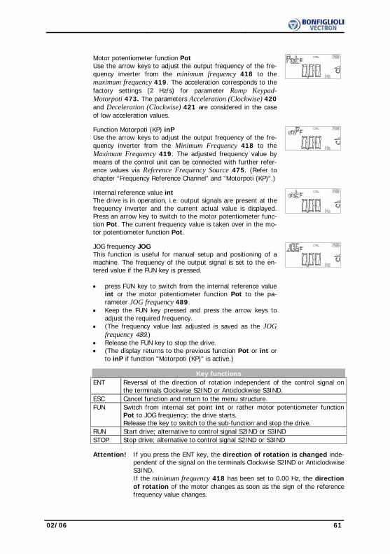
02/06 61
Motor potentiometer function Pot Use the arrow keys to adjust the output frequency of the fre-quency inverter from the minimum frequency 418 to the maximum frequency 419. The acceleration corresponds to the factory settings (2 Hz/s) for parameter Ramp Keypad-Motorpoti 473. The parameters Acceleration (Clockwise) 420 and Deceleration (Clockwise) 421 are considered in the case of low acceleration values.
Function Motorpoti (KP) inP
Use the arrow keys to adjust the output frequency of the fre-quency inverter from the Minimum Frequency 418 to the Maximum Frequency 419. The adjusted frequency value by means of the control unit can be connected with further refer-ence values via Reference Frequency Source 475. (Refer to chapter “Frequency Reference Channel” and "Motorpoti (KP)".)
Internal reference value int
The drive is in operation, i.e. output signals are present at the frequency inverter and the current actual value is displayed. Press an arrow key to switch to the motor potentiometer func-tion Pot. The current frequency value is taken over in the mo-tor potentiometer function Pot.
JOG frequency JOG
This function is useful for manual setup and positioning of a machine. The frequency of the output signal is set to the en-tered value if the FUN key is pressed. • press FUN key to switch from the internal reference value
int or the motor potentiometer function Pot to the pa-rameter JOG frequency 489.
• Keep the FUN key pressed and press the arrow keys to adjust the required frequency.
• (The frequency value last adjusted is saved as the JOG frequency 489.)
• Release the FUN key to stop the drive. • (The display returns to the previous function Pot or int or
to inP if function "Motorpoti (KP)" is active.)
Key functions
ENT Reversal of the direction of rotation independent of the control signal on the terminals Clockwise S2IND or Anticlockwise S3IND.
ESC Cancel function and return to the menu structure. FUN Switch from internal set point int or rather motor potentiometer function
Pot to JOG frequency; the drive starts. Release the key to switch to the sub-function and stop the drive.
RUN Start drive; alternative to control signal S2IND or S3IND STOP Stop drive; alternative to control signal S2IND or S3IND
Attention! If you press the ENT key, the direction of rotation is changed inde-
pendent of the signal on the terminals Clockwise S2IND or Anticlockwise S3IND. If the minimum frequency 418 has been set to 0.00 Hz, the direction of rotation of the motor changes as soon as the sign of the reference frequency value changes.

62 02/06
7 Commissioning of the Frequency Inverter
7.1 Switching on Mains Voltage
After completion of the installation work, make sure to check all control and power connections again before switching on the mains voltage. If all electrical connections are correct, make sure that the frequency inverter is not enabled (control input S1IND open). After power-up, the frequency inverter carries out a self-test and the relay output (X10) reports "Fault". After a few seconds, the self-test is complete, the relay (X10) picks up and signals "no fault ". If the unit is in "as-delivered" condition or after resetting the unit to the factory set-tings, the guided commissioning procedure is started automatically. On the control unit, the “SetUP“ menu from the menu branch CTRL is displayed.
7.2 Setup Using the Control Unit
The guided commissioning of the frequency inverter determines all parameter settings relevant to the required application. The available parameters were selected based on known standard drive applications. This facilitates the selection of the important pa-rameters. After successful completion of the SETUP routine, the actual value Actual frequency 241 from the VAL menu branch is displayed on the control unit. Now, the user should check whether further parameters are relevant for the application.
Note: The guided commissioning contains the function for parameter identifica-tion. The parameters are determined by way of measurement and set accordingly. In the case of higher requirements as regards the accuracy of the speed/torque control, you should carry out the guided commissioning procedure once again under operating conditions because part of the machine data depends on the operating temperature.
When the unit is in "as-delivered" condition, the guided commis-sioning procedure is started automatically. After successful commis-sioning, the guided commissioning can be carried out again later via the sub-menu CTRL.
• Use the ENT key to switch to the CTRL sub-menu.
• In the CTRL sub-menu, select the menu item "SEtUP" and con-firm by pressing the ENT key.
• Use the ENT key to select parameter Configuration 30. The available configurations are displayed automatically depending on the selected Control level 28. • Use the arrow keys to enter the number of the required con-
figuration. (for a description of the configurations, refer to the following chapter)
If the setup was changed, the hardware and software functionality will be configured. The message "SEtUP" is displayed again. Confirm this message by pressing the ENT key in order to continue the commissioning procedure.
• Switch to the next parameter.
• After initialization, confirm the selected configuration by press-ing the ENT key.
• Continue the guided commissioning procedure according to the following chapters.
ENT
ENT

02/06 63
7.2.1 Configuration
Parameter Configuration 30 determines the assignment and basic function of the control inputs and outputs as well as the software functions. The software of the fre-quency inverter offers several configuration options. These differ with respect to the way in which the drive is controlled. Analog and digital inputs can be combined and complemented by optional communication protocols as further reference value sources. The operating instructions describe the configurations and the relevant pa-rameters in the third Control level 28 (adjustment of parameter Control level 28 to value 3).
Configuration 110, sensorless control Configuration 110 contains the functions for variable-speed control of a 3-phase ma-chine in a wide range of standard applications. The motor speed is set according to the V/f characteristic in accordance with the voltage/frequency ratio.
Configuration 111, sensorless control with technology controller Configuration 111 extends the functionality of the sensor-less control by software functions for easier adaptation to the customer's requirements in different applica-tions. The Technology Controller enables flow rate, pressure, level or speed control.
Configuration 410, sensorless field-oriented control Configuration 410 contains functions for sensor-less, field-oriented control of a 3-phase machine. The current motor speed is determined from the present currents and voltages in combination with the machine parameters. In this configuration, parallel connection of several 3-phase motors is possible to a limited extent only.
Configuration 411, sensorless field-oriented control with Technology Controller Configuration 411 extends the functionality of Configuration 410 by a Technology Controller. The Technology Controller enables a control based on parameters such as flow rate, pressure, filling level or speed.
Configuration 430, sensorless field-oriented control with speed/torque control Configuration 430 extends the functionality of Configuration 410 by functions for torque-dependent, field-oriented control. The reference torque is represented as a percentage and it is transmitted into the corresponding operational performance of the application. Change-over between variable-speed control and torque-dependent control is done via a digital control input.
Configuration 210, field-oriented control Configuration 210 contains the functions for speed-controlled, field-oriented control of a 3-phase machine with speed sensor feedback. The separate control of torque and flux-forming current enables high drive dynamism with a high load moment. The nec-essary speed sensor feedback results in a precise speed and torque performance.
Configuration 230, field-orientated control with speed/torque control Configuration 230 extends the functionality of Configuration 210 by functions for torque-dependent, field-oriented control. The reference torque is represented as a percentage and it is transmitted into the corresponding operational performance of the application. Change-over between variable-speed control and torque-dependent control is done via a digital control input.

64 02/06
7.2.2 Data Set
The data set change-over function enables the selection of one of four data sets for storing parameter settings. If data set 0 is selected (factory setting), the parameter values stored in data set 0 are copied to data sets 1 through 4. In this way, all values determined during the guided commissioning procedure are saved in all data sets. In the factory settings, the fre-quency inverter uses data set 1 as the active data set. (For information on data set change-over via logic signals, refer to the chapter "Data Set Change-Over") For example, if data set 2 is selected for guided commissioning ("SETUP"), all values which were determined or entered are saved in this data set. In this case, the other data sets do not contain any defined values. For the operation of the frequency in-verter, data set 2 must be selected as the active data set in this case.
Data Set Setup
dS Function 0 All data sets (DS0) 1 Data set 1 (DS1) 2 Data set 2 (DS2) 3 Data set 3 (DS3) 4 Data set 4 (DS4)
7.2.3 Motor Type
The properties of the control functions and methods to be set vary depending on the motor which is connected. The parameter Motor type 369 offers a range of motor variants with the corresponding table values. The verification of the entered rated val-ues and the guided commissioning are carried out on the basis of the parameterized motor type. The selection of motor types varies depending on the requirements of the different control methods. In operating instructions the functionality and operating performance are described for 3-phase motors.
Operation mode Function 0 - Unknown The motor is not a standard type. 1 - Asynchronous Three-phase asynchronous motor, squirrel cage 2 - Synchronous Three-phase synchronous motor 3 - Reluctance Three-phase reluctance motor 10 - Transformer Transformer with three primary windings
Caution! Polling and presetting of parameter values depends on the operation mode selected for parameter Motor type 369. If the motor type is not entered correctly, the drive may be damaged.
When the motor type is specified, the machine data must be entered. This is described
in the following chapter. The data are polled in accordance with the table below.

02/06 65
7.2.4 Machine Data
The machine data to be entered during the guided commissioning procedure are indi-cated on the type plate or the data sheet of the motor. The factory settings of the machine parameters are based on the nominal data of the frequency inverter and the corresponding four-pole three-phase motor. The entered and calculated machine data are checked for plausibility during the guided commissioning procedure. The user should verify the factory-set rated data of the three-phase motor. UFIN, IFIN, PFIN are rated values of the frequency inverter.
Parameter Settings No. Description Min. Max. Fact. sett. 370 Rated Voltage 0.17⋅UFIN 2⋅UFIN UFIN 371 Rated Current 0.01⋅IFIN 10⋅o ⋅ IFIN IFIN 372 Rated Speed 96 min-1 60 000 min-1 nN 374 Rated Cosinus Phi 0.01 1.00 cos(ϕ)N 375 Rated Frequency 10.00 Hz 1000.00 Hz 50.00 376 Rated mechanical power 0.01⋅PFIN 10⋅PFIN PFIN • Use the arrow keys to select the required parameter and edit the parameter
value. • Use the ENT key to confirm the selected parameter and the parameter values
entered.
Attention! The rated data of the motor are to be entered according to the specifica-tions on the rating plate for the motor connection type used (star or delta connection). If the data entered deviate from the rating plate, the parameters will not be identified correctly. Parameterize the rated data according to the specifications for the motor winding connection indi-cated on the rating plate. Take the higher rated current of the connected asynchronous motor into account.
7.2.5 Speed Sensor Data
For configurations 210 and 230 of the field-orientated control, an incremental speed sensor must be connected. The track signals of the speed sensor are to be connected to digital inputs S5IND (track A) and S4IND (track B). The speed sensor type and the evaluation required are adjusted via the Operation Mode Speed Sensor 1 490.
Operation mode Function 0 - Off Speed measurement is not active; the digital inputs
are available for other functions.
1 - Single Evaluation Two-channel speed sensor with recognition of direc-tion of rotation via track signals A and B;one signal edge is evaluated per division mark.
4 - Quadruple Evaluation
Two-channel speed sensor with recognition of direc-tion of rotation via track signals A and B;four signal edges are evaluated per division mark.
11 - Single evaluation with-out sign
One-channel speed sensor via track signal A. The actual speed value is positive. One signal edge is evaluated per division mark. The digital input S4IND is available for further functions.
12 - Double evaluation with-out sign
One-channel speed sensor via track signal A. The actual speed value is positive. Two signal edges are evaluated per division mark. The digital input S4IND is available for further functions.
Table "Operation modes for speed sensor" continued on next page.
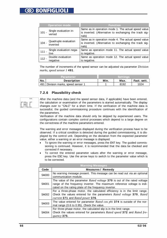
66 02/06
Operation mode Function
101 - Single evaluation in-verted
Same as in operation mode 1. The actual speed value is inverted. (Alternative to exchanging the track sig-nals)
104 - Quadruple evaluation
inverted
Same as in operation mode 4. The actual speed value is inverted. (Alternative to exchanging the track sig-nals)
111 - Single evaluation nega-tive
Same as operation mode 11. The actual speed value is negative.
112 - Double evaluation negative
Same as operation mode 12. The actual speed value is negative.
The number of increments of the speed sensor can be adjusted via parameter Division
marks, speed sensor 1 491. Parameter Settings No. Description Min. Max. Fact. sett. 491 Division marks, speed sensor 1 1 8192 1024
7.2.6 Plausibility check
After the machine data (and the speed sensor data, if applicable) have been entered, the calculation or examination of the parameters is started automatically. The display changes over to "CALC" for a short time. If the verification of the machine data is successful, the guided commissioning procedure continues with the identification of the parameters. Verification of the machine data should only be skipped by experienced users. The configurations contain complex control processes which depend to a large degree on the correctness of the machine parameters entered.
The warning and error messages displayed during the verification process have to be
observed. If a critical condition is detected during the guided commissioning, it is dis-played by the control unit. Depending on the deviation from the expected parameter value, either a warning or an error message is displayed. • To ignore the warning or error messages, press the ENT key. The guided commis-
sioning is continued. However, it is recommended that the data be checked and corrected if necessary.
• To correct the entered parameter values after the warning or error message, press the ESC key. Use the arrow keys to switch to the parameter value which is to be corrected.
Warning Messages
Code Measures / Remedy SA000 No warning message present. This message can be read out via an optional
communication module.
SA001 The value of the parameter Rated voltage 370 is out of the rated voltage range of the frequency inverter. The maximum reference voltage is indi-cated on the rating plate of the frequency inverter.
SA002
For a three-phase motor, the calculated efficiency is in the limit range. Check the values entered for the parameters Rated voltage 370, Rated current 371 and Rated power 376.
SA003 The value entered for parameter Rated cos phi 374 is outside of the nor-
mal range (0.6 to 0.95). Check the value.
SA004 For three-phase motor, the calculated slip is in the limit range. Check the values entered for parameters Rated speed 372 and Rated fre-quency 375.
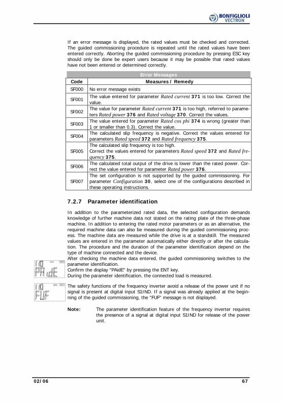
02/06 67
If an error message is displayed, the rated values must be checked and corrected. The guided commissioning procedure is repeated until the rated values have been entered correctly. Aborting the guided commissioning procedure by pressing ESC key should only be done be expert users because it may be possible that rated values have not been entered or determined correctly.
Error Messages
Code Measures / Remedy SF000 No error message exists
SF001 The value entered for parameter Rated current 371 is too low. Correct the value.
SF002
The value for parameter Rated current 371 is too high, referred to parame-ters Rated power 376 and Rated voltage 370. Correct the values.
SF003 The value entered for parameter Rated cos phi 374 is wrong (greater than
1 or smaller than 0.3). Correct the value.
SF004 The calculated slip frequency is negative. Correct the values entered for parameters Rated speed 372 and Rated frequency 375.
SF005
The calculated slip frequency is too high. Correct the values entered for parameters Rated speed 372 and Rated fre-quency 375.
SF006
The calculated total output of the drive is lower than the rated power. Cor-rect the value entered for parameter Rated power 376.
SF007
The set configuration is not supported by the guided commissioning. For parameter Configuration 30, select one of the configurations described in these operating instructions.
7.2.7 Parameter identification
In addition to the parameterized rated data, the selected configuration demands knowledge of further machine data not stated on the rating plate of the three-phase machine. In addition to entering the rated motor parameters or as an alternative, the required machine data can also be measured during the guided commissioning proc-ess. The machine data are measured while the drive is at a standstill. The measured values are entered in the parameter automatically either directly or after the calcula-tion. The procedure and the duration of the parameter identification depend on the type of machine connected and the device. After checking the machine data entered, the guided commissioning switches to the parameter identification. Confirm the display "PAidE" by pressing the ENT key. During the parameter identification, the connected load is measured.
The safety functions of the frequency inverter avoid a release of the power unit if no signal is present at digital input S1IND. If a signal was already applied at the begin-ning of the guided commissioning, the "FUF" message is not displayed.
Note: The parameter identification feature of the frequency inverter requires
the presence of a signal at digital input S1IND for release of the power unit.

68 02/06
Warning! Switch off power supply before connecting and disconnecting control terminal S1IND. When the frequency inverter is disconnected from power supply, the mains, DC-link voltage and motor terminals may still be live for some time. Wait for some minutes until the DC link capacitors have discharged before starting to work at the unit.
• The unit may only be connected with the power supply switched off. • Make sure that the frequency inverter is discharged.
Confirm the final "rEAdY" message by pressing the ENT key. Canceling the operation with the ESC key or withdrawing the release signal S1IND results in an incomplete take-over of the values.
Note: In the case of higher requirements as regards the accuracy of the
speed/torque control, you should carry out the guided commissioning procedure once again under operating conditions because part of the machine data depends on the operating temperature. During this procedure, confirm the machine data already entered.
After completion of the parameter identification, warning messages may be displayed.
Depending on the warning message code, the following instructions should be fol-lowed and the measures indicated should be taken.
Warning Messages
Code Measures / Remedy SA0021 The stator resistance is very high. The following causes are possible:
− The motor cable cross-section is not sufficient. − The motor cable is too long. − The motor cable is not connected correctly. − The contacts are not in a proper condition (corrosion).
SA0022 The rotor resistance is very high. The following causes are possible: − The motor cable cross-section is not sufficient. − The motor cable is too long. − The motor cable is not connected correctly. − The contacts are not in a proper condition (corrosion).
SA0041 The slip speed was not determined correctly. Check the values entered for parameters Rated speed 372 and Rated frequency 375.
SA0042 The slip speed was not determined correctly. Check the values entered for parameters Rated speed 372 and Rated frequency 375.
SA0051 The machine data for star connection were entered, the motor, however, is connected in delta. For star operation, change the motor cable connection. For delta operation, check the entered rated motor values. Repeat the parameter identification
SA0052 The machine data for delta connection were entered, the motor, however, is connected in star. For delta operation, change the motor cable connec-tion. For star operation, check the entered rated motor values. Repeat the parameter identification
SA0053 A phase asymmetry was measured. Check the cables at the terminals of the motor and the frequency inverter for proper connection and check the con-tacts for corrosion.

02/06 69
After completion or during the parameter identification, error messages may be dis-
played. Depending on the error code, the following instructions should be followed and the measures indicated should be taken.
Error Messages
Code Measures / Remedy SF0011 The main inductance measurement has failed because the motor has a high
slip. Correct the rated motor values in parameters 370, 371, 372, 374, 375 and 376. Carry out the guided commissioning once again. In case an error message is displayed again, enter the value 110 for parameter Con-figuration 30 (sensorless regulation according to U/f-characteristic) if value 410 was set so far. Carry out the guided commissioning once again.
SF0012 The leakage inductance measurement has failed because the motor has a high slip. Correct the rated motor values in parameters 370, 371, 372, 374, 375 and 376. Carry out the guided commissioning once again. In case an error message is displayed again, enter the value 110 for parame-ter Configuration 30 (sensorless regulation according to U/f-characteristic) if value 410 was set so far. Carry out the guided commissioning once again.
SF0021 The measurement of the stator resistance did not deliver a plausible value. Check the cables at the terminals of the motor and the frequency inverter for proper connection and check the contacts for corrosion and safe con-tact. Repeat the parameter identification
SF0022 The measurement of the rotor resistance did not deliver a plausible value. Check the cables at the terminals of the motor and the frequency inverter for proper connection and check the contacts for corrosion and safe con-tact. Repeat the parameter identification
7.2.8 Application data
Due to the wide range of drive applications with the resulting parameter settings it is necessary to check further parameters. The parameters polled during the guided commissioning procedure were selected from standard applications. After completion of commissioning, further parameters can be set in the PARA menu branch.
7.2.8.1 Acceleration and deceleration The settings define how fast the output frequency changes after a reference value
change or a start, stop or brake command. Parameter Settings No. Description Min. Max. Fact. sett. 420 Acceleration (Clockwise) 0.00 Hz/s 999.99 Hz/s 5.00 Hz/s 421 Deceleration (Clockwise) 0.00 Hz/s 999.99 Hz/s 5.00 Hz/s
Attention! The deceleration of the drive is monitored in the default parameter set-ting Voltage controller operation mode 670. The deceleration ramp can be extended in the case of an increase in the DC link voltage during regenerative operation and/or during the braking process.
70 02/06
7.2.8.2 Set points at multi-functional input The multi-functional input MFI1 can be parameterized for a reference value signal in
Operation mode 452. Operation mode 3 should only be selected by expert users for drive control via Fixed frequency 1 480 and Fixed frequency 2 481.
Operation mode Function 1 - Voltage Input Voltage signal (MFI1A), 0V ... 10V 2 - Current Input Current signal (MFI1A), 0mA ... 20mA 3 - Digital Input Digital signal (MFI1D), 0V ...24V
Confirm the "End" display by pressing the ENT key. The guided commissioning of the frequency inverter is terminated via a reset and the initialization of the frequency inverter. The relay output X10 signals a fault.
After successful initialization of the frequency inverter, the factory-set parameter Ac-tual frequency 241 is displayed. If a signal is present at digital inputs S1IND (control-ler release) and S2IND (start clockwise operation) or at digital inputs S1IND (control-ler release) and S3IND (start of anti-clockwise operation), the drive is accelerated to the adjusted minimum frequency 418 (default value 3.50 Hz).
7.2.8.3 Selection of an actual value for display After commissioning, the value of parameter Actual frequency 241 is displayed at the
control unit KP500. If another actual value is to be displayed after a restart, make the following settings: • Use the arrow keys to select the actual value to be displayed as from now. • Use the ENT key to display the value of the parameter. • Press the ENT key again. "SEt" is displayed for confirmation. As from now, the selected actual value is displayed after each restart. If the parameter settings were made via the optional control software or in the PARA menu branch of the control unit, the display of the selected actual value must be acti-vated manually. Use the ESC key to switch to the selection of the actual value for display again.
7.3 Check direction of rotation
Warning! Dangerous voltage may be present at the motor terminals and the ter-minals of the brake resistor even after the frequency inverter has been disconnected from power supply. Wait for some minutes until the DC link capacitors have discharged before starting to work at the unit.
• The unit may only be connected with the power supply switched off. • Make sure that the frequency inverter is discharged. To check if the reference value and the actual direction of rotation of the drive corre-
spond to one another, proceed as follows: • Operate the drive at low speed, i.e. specify a reference value of approx. 10%. • Release the frequency inverter briefly signal at digital inputs S1IND (controller
release) and S2IND (start of clockwise operation) or S1IND (controller release) and S3IND (start of anti-clockwise operation).
• Check if the motor shaft turns in the required direction.

02/06 71
In case the sense of rotation is wrong, exchange two motor phases, e.g. U and V at the terminals of the frequency inverter. The mains-side connection of the frequency inverter does not affect the sense of rotation of the drive. In addition to checking the drive, the corresponding actual values and operating messages can be read out by means of the control unit.
Note: The commissioning of the frequency inverter is complete and can be
complemented by further settings in the PARA menu. The set parame-ters have been selected in such a way that they are sufficient for com-missioning in most applications. The other settings which are relevant to the application can be checked according to the operating instructions.
7.4 Set-up via the Communication Interface
Parameter-setting and commissioning of the frequency inverter via one of the optional communication interfaces include the plausibility check and the parameter identifica-tion functions. The parameters can be adjusted by qualified users. The parameter selection during the guided commissioning procedure includes the basic parameters. These are based on standard applications of the corresponding configuration and are therefore useful for commissioning.
Caution! Parameter settings may only be changed by qualified staff. Before starting the commissioning process, read the documentation carefully and comply with the safety instructions.
The parameter SETUP Selection 796 defines the function which is carried out directly
after the selection (if controller release signal is present at digital input S1IND). The operation modes include functions which are also carried out automatically one after the other during the guided commissioning procedure.
Operation mode Function 0 - Clear Status The auto set-up routine does not perform a function 1 - Continue The warning message is acknowledged and the
auto set-up routine is continued. 2 - Abort The auto set-up routine is stopped and a RESET of
the frequency inverter is performed.
10 - Complete Setup, DS0 The auto set-up routine is performed in data set 0 and the parameter values are stored in all of the four data sets identically.
11 - Complete Setup, DS1 The parameter values of the auto set-up are stored in data set 1.
12 - Complete Setup, DS2 The parameter values of the auto set-up are stored in data set 2.
13 - Complete Setup, DS3 The parameter values of the auto set-up are stored in data set 3.
14 - Complete Setup, DS4 The parameter values of the auto set-up are stored in data set 4.
20 - Check Machine Data, DS0 The auto set-up routine checks the rated motor parameters in the four data sets.
21 - Check Machine Data, DS1 The rated motor parameters in data set 1 are checked for plausibility.
22 - Check Machine Data, DS2 The rated motor parameters in data set 2 are checked for plausibility.
23 - Check Machine Data, DS3 The rated motor parameters in data set 3 are checked for plausibility.
Table "Operation modes for set up" continued on next page.

72 02/06
Operation mode Function 24 - Check Machine Data, DS4 The rated motor parameters in data set 4 are
checked for plausibility.
30 - Calculation and Para-Ident., DS0
The auto set-up routine determines extended motor data via the parameter identification feature, calcu-lates dependent parameters and stores the parame-ter values in all of the four data sets identically.
31 - Calculation and Para-
Ident., DS1
Further motor data are measured, dependent pa-rameters are calculated and the parameter values are saved in data set 1
32 - Calculation and Para-
Ident., DS2
Further motor data are measured, dependent pa-rameters are calculated and the parameter values are saved in data set 2
33 - Calculation and Para-
Ident., DS3
Further motor data are measured, dependent pa-rameters are calculated and the parameter values are saved in data set 3
34 - Calculation and Para-
Ident., DS4
Further motor data are measured, dependent pa-rameters are calculated and the parameter values are saved in data set 4
The individual steps of the auto set-up routine can be monitored and checked via
parameter SETUP Status 797. The setup routine via the communication interface continuously updates the status parameter which can be read out via the interface.
Status Messages Message Meaning Ok Auto set-up routine has been carried out. PC Phase 1 The plausibility check of the motor data is active. PC Phase 2 The calculation of dependent parameters is active.
FUF The parameter identification requires a controller release signal at digital input S1IND.
Parameter identifica-tion
The rated motor values are checked by the parameter identi-fication feature.
Setup already active The setup routine via the control unit is being carried out.
No release signal The parameter identification requires a controller release signal at digital input S1IND.
Error Error during the auto set-up routine
Warning phase asymmetry
The parameter identification feature diagnosed an unbalance during the measurements in the three motor phases.
Warning Messages Code Message Meaning
SA0001 Rated Voltage
The value of the parameter Rated voltage 370 is out of the rated voltage range of the frequency inverter. The maximum reference voltage is indicated on the rating plate of the fre-quency inverter.
SA0002 Efficiency
For a three-phase motor, the calculated efficiency is in the limit range. Check and correct, if necessary, the values en-tered for the parameters Rated voltage 370, Rated current 371 and Rated power 376.
SA0003 Rated Cos Phi
The value entered for parameter Rated cos phi 374 is out-side of the normal range (0.6 to 0.95). Correct the value.
SA0004 Slip Frequency
For three-phase motor, the calculated slip is in the limit range. Check and, if necessary, correct Rated speed 372 and Rated frequency 375.
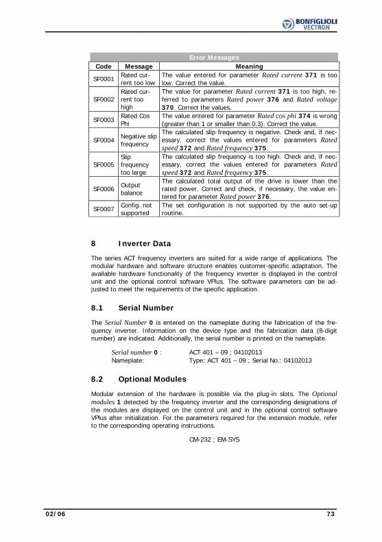
02/06 73
Error Messages Code Message Meaning
SF0001 Rated cur-rent too low
The value entered for parameter Rated current 371 is too low. Correct the value.
SF0002 Rated cur-rent too high
The value for parameter Rated current 371 is too high, re-ferred to parameters Rated power 376 and Rated voltage 370. Correct the values.
SF0003 Rated Cos Phi
The value entered for parameter Rated cos phi 374 is wrong (greater than 1 or smaller than 0.3). Correct the value.
SF0004 Negative slip frequency
The calculated slip frequency is negative. Check and, if nec-essary, correct the values entered for parameters Rated speed 372 and Rated frequency 375.
SF0005 Slip frequency too large
The calculated slip frequency is too high. Check and, if nec-essary, correct the values entered for parameters Rated speed 372 and Rated frequency 375.
SF0006 Output balance
The calculated total output of the drive is lower than the rated power. Correct and check, if necessary, the value en-tered for parameter Rated power 376.
SF0007 Config. not supported
The set configuration is not supported by the auto set-up routine.
8 Inverter Data The series ACT frequency inverters are suited for a wide range of applications. The
modular hardware and software structure enables customer-specific adaptation. The available hardware functionality of the frequency inverter is displayed in the control unit and the optional control software VPlus. The software parameters can be ad-justed to meet the requirements of the specific application.
8.1 Serial Number The Serial Number 0 is entered on the nameplate during the fabrication of the fre-
quency inverter. Information on the device type and the fabrication data (8-digit number) are indicated. Additionally, the serial number is printed on the nameplate.
Serial number 0 : ACT 401 – 09 ; 04102013 Nameplate: Type: ACT 401 – 09 ; Serial No.: 04102013
8.2 Optional Modules Modular extension of the hardware is possible via the plug-in slots. The Optional
modules 1 detected by the frequency inverter and the corresponding designations of the modules are displayed on the control unit and in the optional control software VPlus after initialization. For the parameters required for the extension module, refer to the corresponding operating instructions.
CM-232 ; EM-SYS

74 02/06
8.3 Inverter Software Version The firmware stored in the frequency inverter defines the available parameters and
functions of the software. The software version is indicated in parameter Inverter software version 12. In addition to the version, the 6-digit software key is printed on the name plate of the frequency inverter.
Inverter software version 12 : 4.2.3 Nameplate: Version: 4.2.3 ; Software: 140 012
8.4 Set Password As a protection against unauthorized access, the parameter Set password 27 can be
set such that anyone who wants to change parameters must enter this password be-fore. A change of parameter is only possible if the password in entered correctly. If the Set password 27 parameter is set to zero, no password is required for access to the parameters. The previous password is deleted.
Parameter Settings No. Description Min. Max. Fact. sett. 27 Set Password 0 999 0
8.5 Control Level The Control level 28 defines the scope of the functions to be parameterized. The
operating instructions describe the parameters on the third control level. These pa-rameters should only be set by qualified users.
Parameter Settings No. Description Min. Max. Fact. sett. 28 Control Level 1 3 1
8.6 User Name The User name 29 can be entered via the optional control software VPlus. The plant
or machine designation cannot be displayed completely via the control unit. 32 alpha-numerical characters
02/06 75
8.7 Configuration The Configuration 30 determines the assignment and basic function of the control
inputs and outputs as well as the software functions. The software of the frequency inverters offers various configuration options. These differ with respect to the way in which the drive is controlled. Analog and digital inputs can be combined and comple-mented by optional communication protocols. The operating instructions describe the following configurations and the relevant parameters in the third Control level 28 (adjustment of parameter Control level 28 to value 3).
Configuration 110, sensorless control
Configuration 110 contains the functions for variable-speed control of a 3-phase ma-chine in a wide range of standard applications. The motor speed is set according to the V/f characteristic in accordance with the voltage/frequency ratio.
Configuration 111, sensorless control with technology controller
Configuration 111 extends the functionality of the sensor-less control by software functions for easier adaptation to the customer's requirements in different applica-tions. Depending on the application, the technology controller may be used, which enables the control of flow rate, pressure, contents level or speed.
Configuration 410, sensorless field-oriented control
Configuration 410 contains the functions for sensor-less, field-oriented control of a 3-phase machine. The current motor speed is determined from the present currents and voltages in combination with the machine parameters. In this configuration, parallel connection of several 3-phase motors is possible to a limited extent only.
Configuration 411, sensorless field-oriented control
with Technology Controller Configuration 411 extends the functionality of Configuration 410 by a Technology Controller, which enables the control of flow rate, pressure, contents level or speed
Configuration 430, sensorless field-oriented control
with speed/torque control Configuration 430 extends the functionality of Configuration 410 by functions for torque-dependent, field-oriented control. The reference torque is represented as a percentage and it is transmitted into the corresponding operational performance of the application. Change-over between variable-speed control and torque-dependent control is done via a digital control input.
Configuration 210, field-oriented control
Configuration 210 contains the functions for speed-controlled, field-oriented control of a 3-phase machine with speed sensor feedback. The separate control of torque and flux-forming current enables high drive dynamism with a high load moment. The nec-essary speed sensor feedback results in a precise speed and torque performance.
Configuration 230, field-orientated control with speed/torque control
Configuration 230 extends the functionality of Configuration 210 by functions for torque-dependent, field-oriented control. The reference torque is represented as a percentage and it is transmitted into the corresponding operational performance of the application. Change-over between variable-speed control and torque-dependent control is done via a digital control input.

76 02/06
In the table, you will find a list of functions which are available in the different con-
figurations. Configuration
V/f - char-acteristic field-oriented control
sensorless sensorless sensor Function Chapter 110 111 410 411 430 210 230 Speed control 16.5.3 x x x x Torque control 16.5.2 x x
Switch-over speed/torque con-trol 14.4.6 x x
Dynamic Voltage Pre-Control 15.1 x x Intelligent current limits 16.1 x x x x x x x Voltage controller 16.2 x x x x x x x Technology controller: 16.3 x x − pressure control 16.3 x x − flow rate control 16.3 x x − Contents level control 16.3 x x − Speed control 16.3 x x Slip compensation 16.4.1 x Current limit value controller 16.4.2 x x Current Controller 16.5.1 x x x x x Limit Value Sources 16.5.2.1 x x x x x Acceleration Pre-Control 16.5.4 x x x x x Field Controller 16.5.5 x x x x x Modulation Controller 16.5.6 x x x x x Starting behavior: 11.1 x x x x x x x − Starting current impression 11.1.1.1 x x x x x − Flux Formation 11.1.2 x x x x x Stopping behavior: 11.2 x x x x x x x − Direct current brake 11.3 x x Auto Start 11.4 x x x x x x x Search Run 11.5 x x x 1) x 1) x 1) x x Reference point positioning 11.6.1 x x x Axis Positioning 11.6.2 x Frequency Reference Channel 13.4 x x x x x Reference percentage channel 13.5 x x x x Fixed Frequencies 13.6.1 x x x x x x x Fixed Percentages 13.6.3 x x x x Block Frequencies 13.9 x x x x x x x Repetition frequency input 13.11 x x x x x x x Brake Chopper 17.4 x x x x x x x Motor Circuit Breaker 17.5 x x x x x x x V-belt Monitoring 17.6 x x x x x x x Motor Chopper 17.7.1 x x x x x Temperature Adjustment 17.7.2 x x x x x Encoder Monitoring 17.7.3 x x 1) Search Run not available for devices > 18.5 kW

02/06 77
8.8 Language The parameters are stored in the frequency inverter in various languages. The pa-
rameter description is displayed in the selected Language 33, e.g. by the PC program VPlus,.
Operation mode Function 0 - Deutsch Parameter description in German 1 - English Parameter description in English 2 - Italiano Parameter description in Italian
8.9 Programming The parameter Program(ming) 34 enables acknowledgment of a fault message and
resetting to the factory settings. The display of the control unit reads "dEFLt" or "rE-SEt" and the LEDs indicate the status of the frequency inverter.
Settings Function
111 - Parameter transferThe KP 500 control unit is prepared for parameter trans-mission. A connected frequency inverter can receive data from the control unit.
110 - Normal mode Reset the KP 500 control unit to standard mode
123 - RESET The current error message can be acknowledged via digital input S1IND or the software parameter. The dis-play of the control unit reads "rESEt".
4444 - Default
The parameters of the selected configuration are over-written - except for a few exceptions - by the default settings. The display of the control unit reads "dEFLt".
Note: The parameters Control Level 28, Language 33 as well as Configura-
tion 30 are not changed during the reset to the default settings (Pro-gram(ing) 34 = 4444).

78 02/06
9 Machine Data
The input of the machine data is the foundation for the functionality of the control functions and methods. In the course of the guided commissioning, the necessary parameters are inquired according to the selected Configuration 30.
9.1 Rated Motor Parameters
Set the rated parameters of the three-phase asynchronous machine according to the name plate or the data sheet of the motor. The default settings of the machine pa-rameters are based on the nominal data of the frequency inverter and the corre-sponding four-pole three-phase motor. The machine data required for the control functions and methods are checked for plausibility and calculated in the course of the commissioning. The user should check the rated values specified by default.
Parameter Settings No. Description Min. Max. Fact. sett. 370 Rated Voltage 0.17⋅UFIN 2⋅UFIN UFIN 371 Rated Current 0.01⋅IFIN 10⋅o ⋅ IFIN IFIN 372 Rated Speed 96 min-1 60 000 min-1 nN 373 No. of Pole Pairs 1 24 2 374 Rated cosine (ϕ) 0.01 1.00 cos(ϕ)N 375 Rated Frequency 10.00 Hz 1000.00 Hz 50.00 376 Rated mechanical power 0.01⋅PFIN 10⋅PFIN PFIN In the case of three-phase machines, the speed can be increased at a constant torque
if the motor winding can be switched over from star to delta connection. The change-over results in a change of the dependent parameters by a factor of square root of 3.
Attention! The rated data of the motor are to be entered according to the specifi-cations on the rating plate for the motor connection type used (star or delta connection). If the data entered deviate from the rating plate, the parameters will not be identified correctly. Parameterize the rated data according to the specifications for the motor winding connection indi-cated on the rating plate. Take the higher rated current of the con-nected asynchronous motor into account.
9.2 Further motor parameters
In particular the field-oriented control requires the determination of further data which
cannot be read off the name plate of the 3-phase machine for the precise calculation of the machine model. In the course of the guided commissioning, the parameter identification was carried out to measure the further motor parameters.
9.2.1 Stator Resistance The resistance of the stator winding was measured during the guided commissioning.
The measured value is stored as a phase value in parameter Stator resistance 377 and is 3 times smaller than the winding resistance in delta connection. By default, the equivalent stator resistance of a standard motor is entered to match the nominal power of the frequency inverter.
Parameter Settings No. Description Min. Max. Fact. sett. 377 Stator Resistance 0 mΩ 65.535 mΩ RsN
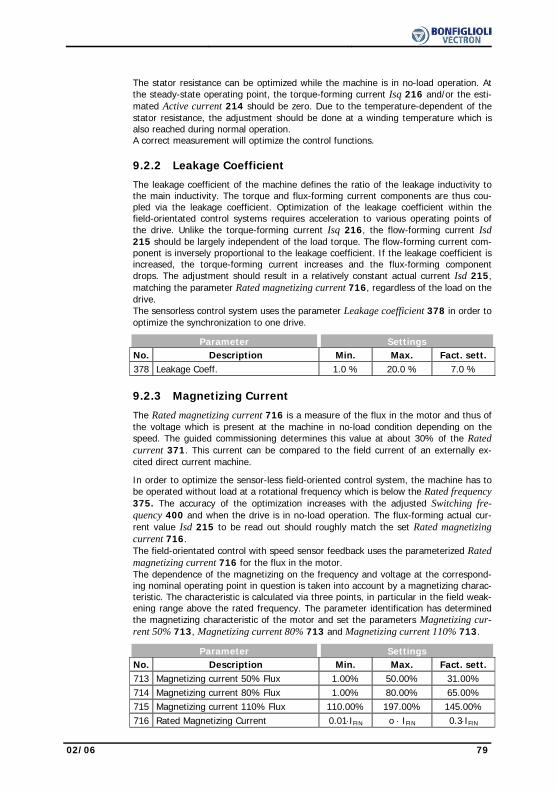
02/06 79
The stator resistance can be optimized while the machine is in no-load operation. At
the steady-state operating point, the torque-forming current Isq 216 and/or the esti-mated Active current 214 should be zero. Due to the temperature-dependent of the stator resistance, the adjustment should be done at a winding temperature which is also reached during normal operation. A correct measurement will optimize the control functions.
9.2.2 Leakage Coefficient
The leakage coefficient of the machine defines the ratio of the leakage inductivity to the main inductivity. The torque and flux-forming current components are thus cou-pled via the leakage coefficient. Optimization of the leakage coefficient within the field-orientated control systems requires acceleration to various operating points of the drive. Unlike the torque-forming current Isq 216, the flow-forming current Isd 215 should be largely independent of the load torque. The flow-forming current com-ponent is inversely proportional to the leakage coefficient. If the leakage coefficient is increased, the torque-forming current increases and the flux-forming component drops. The adjustment should result in a relatively constant actual current Isd 215, matching the parameter Rated magnetizing current 716, regardless of the load on the drive. The sensorless control system uses the parameter Leakage coefficient 378 in order to optimize the synchronization to one drive.
Parameter Settings No. Description Min. Max. Fact. sett. 378 Leakage Coeff. 1.0 % 20.0 % 7.0 %
9.2.3 Magnetizing Current
The Rated magnetizing current 716 is a measure of the flux in the motor and thus of
the voltage which is present at the machine in no-load condition depending on the speed. The guided commissioning determines this value at about 30% of the Rated current 371. This current can be compared to the field current of an externally ex-cited direct current machine.
In order to optimize the sensor-less field-oriented control system, the machine has to be operated without load at a rotational frequency which is below the Rated frequency 375. The accuracy of the optimization increases with the adjusted Switching fre-quency 400 and when the drive is in no-load operation. The flux-forming actual cur-rent value Isd 215 to be read out should roughly match the set Rated magnetizing current 716. The field-orientated control with speed sensor feedback uses the parameterized Rated magnetizing current 716 for the flux in the motor. The dependence of the magnetizing on the frequency and voltage at the correspond-ing nominal operating point in question is taken into account by a magnetizing charac-teristic. The characteristic is calculated via three points, in particular in the field weak-ening range above the rated frequency. The parameter identification has determined the magnetizing characteristic of the motor and set the parameters Magnetizing cur-rent 50% 713, Magnetizing current 80% 713 and Magnetizing current 110% 713.
Parameter Settings No. Description Min. Max. Fact. sett. 713 Magnetizing current 50% Flux 1.00% 50.00% 31.00% 714 Magnetizing current 80% Flux 1.00% 80.00% 65.00% 715 Magnetizing current 110% Flux 110.00% 197.00% 145.00% 716 Rated Magnetizing Current 0.01⋅IFIN o ⋅ IFIN 0.3⋅IFIN

80 02/06
9.2.4 Rated Slip Correction Factor
The rotor time constant results from the inductivity of the rotor circuit and the rotor resistance. Due to the temperature-dependence of the rotor resistance and the satu-ration effects of the iron, the rotor time constant is also dependent on temperature and current. The load behavior and thus the rated slip depend on the rotor time con-stant. The guided commissioning determines the machine data during the parameter identification and sets the parameter Rated slip correction factor 718 accordingly. For the fine adjustment or a check of the rotor time constant, proceed as follows: Load the machine at fifty percent of the Rated frequency 375. As a result, the voltage must be approximately fifty percent of the Rated voltage 370, with a maximum tolerance of 5 %. If this is not the case, the correction factor must be changed accordingly. The larger the correction factor is set, the stronger the voltage drop when the machine is loaded. The value calculated by the rotor time constants can be read out via the ac-tual value Current rotor time constant 227. The adjustment should be done at a winding temperature which is also reached during normal operation of the motor.
Parameter Settings No. Description Min. Max. Fact. sett. 718 Rated Slip Correction Factor 0.01% 300.00% 100.00%
9.3 Internal values The following parameters are used for the internal processing of motor data. An ad-
justment is not necessary. Parameter Parameter No. Description No. Description 399 Internal value 01 705 Internal value 07
402 Internal value 02 706 Internal value 08
508 Internal value 03 707 Internal value 09
702 Internal value 04 708 Internal value 10
703 Internal value 05 709 Internal value 11
704 Internal value 06 745 Internal value 12
9.4 Speed sensor 1
The frequency inverters are to be adapted to the application depending on the re-quirements. A part of the available Configurations 30 demand continuous measure-ment of the actual speed for the control functions and methods. The necessary con-nection of an incremental speed sensor is done on the digital control terminals S5IND (track A) and S4IND (track B) of the frequency inverter.
9.4.1 Operation mode speed sensor 1
Operation mode speed sensor 1 490 can be selected according to the connected in-cremental speed sensor. A unipolar speed sensor is to be connected to the standard control terminals.
Operation mode Function
0 - Off Speed measurement is not active; the digital inputs are available for other functions.
1 – Single Evaluation Two-channel speed sensor with recognition of direction of rotation via track signals A and B; one signal edge is evaluated per division mark.
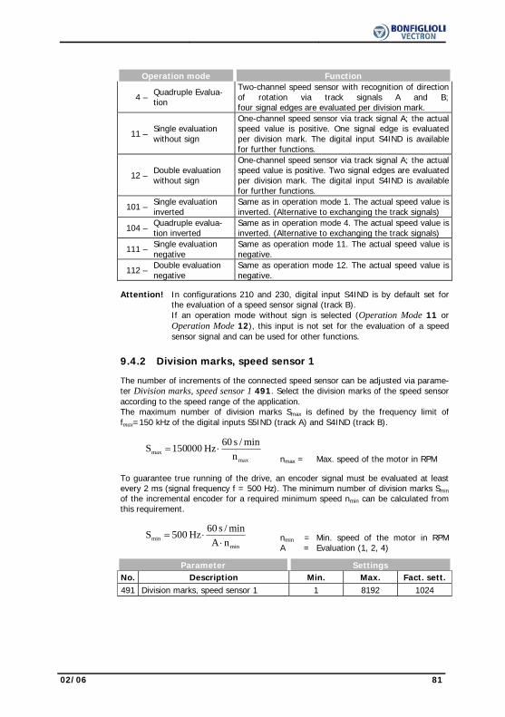
02/06 81
Operation mode Function
4 – Quadruple Evalua-tion
Two-channel speed sensor with recognition of direction of rotation via track signals A and B;four signal edges are evaluated per division mark.
11 – Single evaluation without sign
One-channel speed sensor via track signal A; the actual speed value is positive. One signal edge is evaluated per division mark. The digital input S4IND is available for further functions.
12 – Double evaluation without sign
One-channel speed sensor via track signal A; the actual speed value is positive. Two signal edges are evaluated per division mark. The digital input S4IND is available for further functions.
101 – Single evaluation inverted
Same as in operation mode 1. The actual speed value is inverted. (Alternative to exchanging the track signals)
104 – Quadruple evalua-tion inverted
Same as in operation mode 4. The actual speed value is inverted. (Alternative to exchanging the track signals)
111 – Single evaluation negative
Same as operation mode 11. The actual speed value is negative.
112 – Double evaluation negative
Same as operation mode 12. The actual speed value is negative.
Attention! In configurations 210 and 230, digital input S4IND is by default set for
the evaluation of a speed sensor signal (track B). If an operation mode without sign is selected (Operation Mode 11 or Operation Mode 12), this input is not set for the evaluation of a speed sensor signal and can be used for other functions.
9.4.2 Division marks, speed sensor 1 The number of increments of the connected speed sensor can be adjusted via parame-
ter Division marks, speed sensor 1 491. Select the division marks of the speed sensor according to the speed range of the application.
The maximum number of division marks Smax is defined by the frequency limit of fmax=150 kHz of the digital inputs S5IND (track A) and S4IND (track B).
maxmax n
min/s 60Hz 000150S ⋅= nmax = Max. speed of the motor in RPM
To guarantee true running of the drive, an encoder signal must be evaluated at least
every 2 ms (signal frequency f = 500 Hz). The minimum number of division marks Smin of the incremental encoder for a required minimum speed nmin can be calculated from this requirement.
minmin nA
min/s 60Hz 500S⋅
⋅= nmin =A =
Min. speed of the motor in RPMEvaluation (1, 2, 4)
Parameter Settings No. Description Min. Max. Fact. sett. 491 Division marks, speed sensor 1 1 8192 1024

82 02/06
10 System Data The various control functions and methods according to the selected Configuration
30 are supplemented by control and special functions. For monitoring the application, process parameters are calculated from electrical control parameters.
10.1 Actual Value System The parameter Factor Actual Value System 389 can be used if the drive is monitored
via the parameter Actual Value System 242. The Actual Frequency 241 to be monitored is multiplied by the Factor Actual Value System 389 and can be read out via the parameter Actual Value System 242, i.e. Actual Frequency 241 x Factor Actual Value System 389 = Actual Value System 242.
Parameter Settings No. Description Min. Max. Fact. sett. 389 Factor Actual Value System -100.000 100.000 1.000
10.2 Volume Flow and Pressure The parameterization of the factors Nominal Volumetric Flow 397 and Nominal
Pressure 398 is necessary if the matching actual values Volumetric flow 285 and Pressure 286 are used to monitor the drive. The conversion is done using the electri-cal control parameters. Volume Flow 285 and Pressure 286 are referred to the Effective Current 214 in the case of the sensor-less control methods. In the case of the field-oriented control methods, they are referred to the torque-forming current component Isq 216.
Parameter Settings No. Description Min. Max. Fact. sett. 397 Nominal Volumetric Flow 1 m3/h 99999 m3/h 10 m3/h 398 Nominal Pressure 0.1 kPa 999.9 kPa 100.0 kPa Line mains or channel characteristic:
HkPa
Qm /h3
bad point method
P - methodconst.
A
B2
B1
Point A in the figure describes the rating point of a pump. The transition to partial
load operation mode B1 can be effected at a constant pressure H (change of convey-ing flow Q, pressure H remains constant). The transition to partial load operation mode B2 can be effected according to the bad point method (change of pressure H and conveying flow Q). Both methods can be realized with the integrated technology controller in configuration 111. The actual values displayed are calculated according to the bad point method independently of the selected Operation Mode 440 of the technology controller.
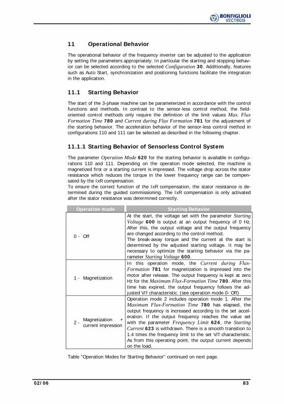
02/06 83
11 Operational Behavior The operational behavior of the frequency inverter can be adjusted to the application
by setting the parameters appropriately. In particular the starting and stopping behav-ior can be selected according to the selected Configuration 30. Additionally, features such as Auto Start, synchronization and positioning functions facilitate the integration in the application.
11.1 Starting Behavior The start of the 3-phase machine can be parameterized in accordance with the control
functions and methods. In contrast to the sensor-less control method, the field-oriented control methods only require the definition of the limit values Max. Flux Formation Time 780 and Current during Flux Formation 781 for the adjustment of the starting behavior. The acceleration behavior of the sensor-less control method in configurations 110 and 111 can be selected as described in the following chapter.
11.1.1 Starting Behavior of Sensorless Control System The parameter Operation Mode 620 for the starting behavior is available in configu-
rations 110 and 111. Depending on the operation mode selected, the machine is magnetized first or a starting current is impressed. The voltage drop across the stator resistance which reduces the torque in the lower frequency range can be compen-sated by the IxR compensation. To ensure the correct function of the IxR compensation, the stator resistance is de-termined during the guided commissioning. The IxR compensation is only activated after the stator resistance was determined correctly.
Operation mode Starting Behavior
0 - Off
At the start, the voltage set with the parameter Starting Voltage 600 is output at an output frequency of 0 Hz. After this, the output voltage and the output frequency are changed according to the control method. The break-away torque and the current at the start is determined by the adjusted starting voltage. It may be necessary to optimize the starting behavior via the pa-rameter Starting Voltage 600.
1 - Magnetization
In this operation mode, the Current during Flux-Formation 781 for magnetization is impressed into the motor after release. The output frequency is kept at zero Hz for the Maximum Flux-Formation Time 780. After this time has expired, the output frequency follows the ad-justed V/f characteristic. (see operation mode 0- Off)
2 - Magnetization + current impression
Operation mode 2 includes operation mode 1. After the Maximum Flux-Formation Time 780 has elapsed, the output frequency is increased according to the set accel-eration. If the output frequency reaches the value set with the parameter Frequency Limit 624, the Starting Current 623 is withdrawn. There is a smooth transition to 1.4 times the frequency limit to the set V/f characteristic. As from this operating point, the output current depends on the load.
Table "Operation Modes for Starting Behavior" continued on next page.
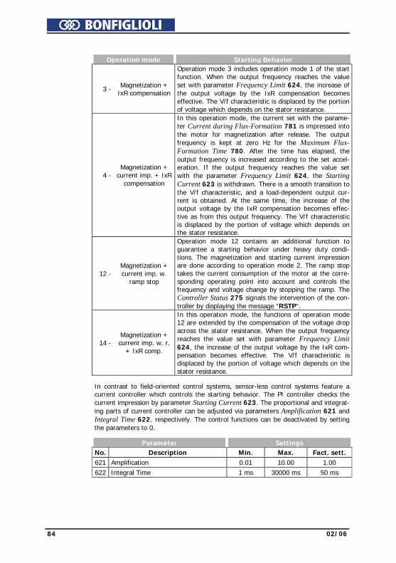
84 02/06
Operation mode Starting Behavior
3 - Magnetization + IxR compensation
Operation mode 3 includes operation mode 1 of the start function. When the output frequency reaches the value set with parameter Frequency Limit 624, the increase of the output voltage by the IxR compensation becomes effective. The V/f characteristic is displaced by the portion of voltage which depends on the stator resistance.
4 - Magnetization +
current imp. + IxR compensation
In this operation mode, the current set with the parame-ter Current during Flux-Formation 781 is impressed into the motor for magnetization after release. The output frequency is kept at zero Hz for the Maximum Flux-Formation Time 780. After the time has elapsed, the output frequency is increased according to the set accel-eration. If the output frequency reaches the value set with the parameter Frequency Limit 624, the Starting Current 623 is withdrawn. There is a smooth transition to the V/f characteristic, and a load-dependent output cur-rent is obtained. At the same time, the increase of the output voltage by the IxR compensation becomes effec-tive as from this output frequency. The V/f characteristic is displaced by the portion of voltage which depends on the stator resistance.
12 - Magnetization + current imp. w.
ramp stop
Operation mode 12 contains an additional function to guarantee a starting behavior under heavy duty condi-tions. The magnetization and starting current impression are done according to operation mode 2. The ramp stop takes the current consumption of the motor at the corre-sponding operating point into account and controls the frequency and voltage change by stopping the ramp. The Controller Status 275 signals the intervention of the con-troller by displaying the message “RSTP“.
14 - Magnetization + current imp. w. r.
+ IxR comp.
In this operation mode, the functions of operation mode 12 are extended by the compensation of the voltage drop across the stator resistance. When the output frequency reaches the value set with parameter Frequency Limit 624, the increase of the output voltage by the IxR com-pensation becomes effective. The V/f characteristic is displaced by the portion of voltage which depends on the stator resistance.
In contrast to field-oriented control systems, sensor-less control systems feature a
current controller which controls the starting behavior. The PI controller checks the current impression by parameter Starting Current 623. The proportional and integrat-ing parts of current controller can be adjusted via parameters Amplification 621 and Integral Time 622, respectively. The control functions can be deactivated by setting the parameters to 0.
Parameter Settings No. Description Min. Max. Fact. sett. 621 Amplification 0.01 10.00 1.00 622 Integral Time 1 ms 30000 ms 50 ms

02/06 85
11.1.1.1 Starting Current Configurations 110, 111 and 410, 411 and 430 for control of a 3-phase machine use
the starting current impression in operation modes 2, 4, 12 and 14 for the parameter Operation Mode 620. The Starting Current 623 guarantees, in particular for heavy starting, sufficient torque until the Frequency Limit 624 is reached. Applications in which high current is permanently needed at a low speed are to be realized using forced-ventilated motors for thermal reasons.
Parameter Settings No. Description Min. Max. Fact. sett. 623 Starting Current 0.0 A o ⋅ IFIN IFIN
11.1.1.2 Frequency Limit The Starting current 623 is impressed in configurations 110, 111, 410, 411 and 430
for control of a 3-phase machine until the Frequency Limit 624 is reached. Permanent operating points below the frequency limit are only admissible if forced-ventilated mo-tors are used. The transition to the control method of the selected configuration 30 takes place above the frequency limit.
Parameter Settings No. Description Min. Max. Fact. sett. 624 Frequency Limit 0.00 Hz 100.00 Hz 2.60 Hz
11.1.2 Flux Formation Field-oriented control in the configurations 210, 230, 410, 411 and 430 are based on
separate regulation of the flux-forming and torque-forming current components. Upon startup, the machine is magnetized and a current is impressed first. With the parame-ter Current during Flux-Formation 781 the magnetization current Isd is set, with the parameter Maximum Flux-Formation Time 780 the maximum time for the current impression is set. The current impression is done until the reference value of the rated magnetizing cur-rent is reached or the Maximum Flux-Formation Time 780 is exceeded.
Parameter Settings No. Description Min. Max. Fact. sett. 780 Maximum Flux-Formation Time 1 ms 10000 ms - 1) 781 Current during Flux Formation 0.1⋅IFIN o ⋅ IFIN IFIN 1) The factory setting of the parameter Maximum Flux-Formation Time 780 depends
on the selected parameter Configuration 30.
- Configurations 1xx => Maximum Flux-Formation Time 780 = 300 ms - Configurations 1xx / 4xx => Maximum Flux-Formation Time 780 = 1000 ms
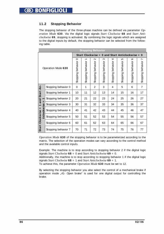
86 02/06
11.2 Stopping Behavior The stopping behavior of the three-phase machine can be defined via parameter Op-
eration Mode 630. Via the digital logic signals Start Clockwise 68 and Start Anti-clockwise 69, stopping is activated. By combining the logic signals which are assigned to the digital inputs by default, the stopping behavior can be selected from the follow-ing table.
Stopping Behavior
Start Clockwise = 0 and Start Anticlockwise = 0
Operation Mode 630
Stop
ping
beh
avio
r 0
Stop
ping
beh
avio
r 1
Stop
ping
beh
avio
r 2
Stop
ping
beh
avio
r 3
Stop
ping
beh
avio
r 4
Stop
ping
beh
avio
r 5
Stop
ping
beh
avio
r 6
Stop
ping
beh
avio
r 7
Stopping behavior 0 0 1 2 3 4 5 6 7
Stopping behavior 1 10 11 12 13 14 15 16 17
Stopping behavior 2 20 21 22 23 24 25 26 27
Stopping behavior 3 30 31 32 33 34 35 36 37
Stopping behavior 4 40 41 42 43 44 45 46 47
Stopping behavior 5 50 51 52 53 54 55 56 57
Stopping behavior 6 60 61 62 63 64 65 66 67
Star
t C
lock
wis
e =
1 a
nd S
tart
An
-ti
cloc
kwis
e =
1
Stopping behavior 7 70 71 72 73 74 75 76 77
Operation Mode 630 of the stopping behavior is to be parameterized according to the
matrix. The selection of the operation modes can vary according to the control method and the available control inputs.
Example: The machine is to stop according to stopping behavior 2 if the digital logic
signals Start Clockwise 68 = 0 and Start Anticlockwise 69 = 0. Additionally, the machine is to stop according to stopping behavior 1 if the digital logic signals Start Clockwise 68 = 1 and Start Anticlockwise 69 = 1. To achieve this, the parameter Operation Mode 630 must be set to 12.
By selecting the stopping behavior you also select the control of a mechanical brake if
operation mode „41- Open brake“ is used for one digital output for controlling the brake.

02/06 87
Stopping Behavior
Stopping behavior 0
Free stopping
The inverter is disabled immediately. The drive deener-gized immediately and coasts freely.
Stopping behavior 1
Stop + Switch off
The drive is brought to a standstill at the set deceleration. As soon as the drive is at a standstill, the inverter is dis-abled after a holding time. The holding time can be set via the parameter Holding Time 638. Depending on the setting of the parameter Starting Func-tion 620, the Starting Current 623 is impressed or the Starting Voltage 600 is applied for the duration of the holding time.
Stopping behavior 2
Stop + Hold
The drive is brought to a standstill at the set deceleration and remains permanently supplied with current. Depending on the setting of the parameter Starting func-tion 620, the Starting Current 623 is impressed as from standstill or the Starting Voltage 600 is applied.
Stopping behavior 3
Stop + DC brakes
The drive is brought to a standstill at the set deceleration. As from standstill, the direct current set via parameter Braking Current 631 is impressed for the Braking Time 632. Comply with the notes in chapter "DC brake". Stopping behaviors 3, 6 and 7 are only available in the configurations for sensor-less control.
Stopping behavior 4
Emergency stop + switch off
The drive is brought to a standstill at the emergency stop deceleration. As soon as the drive is at a standstill, the inverter is disabled after a holding time. The holding time can be set via the parameter Holding Time 638. Depending on the setting of the parameter Starting Function 620, the Starting Current 623 is im-pressed as from standstill or the Starting Voltage 600 is applied.
Stopping behavior 5
Emergency stop + Hold
The drive is brought to a standstill at the set emergency stop deceleration and remains permanently supplied with current. Depending on the setting of the parameter Starting Func-tion 620, the Starting Current 623 is impressed as from standstill or the Starting Voltage 600 is applied.
Stopping behavior 6
Emergency stop + Brake
The drive is brought to a standstill at the set emergency stop deceleration. As from standstill, the direct current set via parameter Braking Current 631 is impressed for the Braking Time 632. Comply with the notes in chapter "DC brake". Stopping behaviors 3, 6 and 7 are only available in the configurations for sensor-less control.
Stopping behavior 7
Direct current brake
Direct current braking is activated immediately. The direct current set with the parameter Braking Current 631 is impressed for the die Braking Time 632. Comply with the notes in chapter "DC brake". Stopping behaviors 3, 6 and 7 are only available in the configurations for sensor-less control.
88 02/06
11.2.1 Switch-Off Threshold The Switch-off Threshold Stop Function 637 defines the frequency as from which a
standstill of the drive is recognized. This percentage parameter value is applied to the set Maximum Frequency 419. The switch-off threshold is to be adjusted according to the load behavior of the drive and the device output, as the drive must be controlled to a speed below the switch-off threshold.
Parameter Settings No. Description Min. Max. Fact. sett. 637 Switch-Off Threshold 0.0 % 100.0 % 1.0 %
Attention! If the motor builds up a stopping torque, it may be possible that the switch-off threshold stop function is not reached due to the slip fre-quency and the standstill of the drive is not recognized. In this case, increase the value of the Switch-off Threshold Stop Function 637.
11.2.2 Holding Time The Holding Time Stop Function 638 is considered in stopping behaviors 1, 3, 4 and
6. Controlling to zero speed results in the motor heating up and should only be done for a short period in the case of internally ventilated motors.
Parameter Settings No. Description Min. Max. Fact. sett. 638 Holding Time 0.0 s 200.0 s 1.0 s
11.3 Direct current brake
Stopping behaviors 3, 6, 7 and the search run function include the direct current brake.
Depending on the setting of the stop function, a direct current is impressed into the motor either directly or, when it is at a standstill, after the demagnetization time. The impression of the Braking current 631 results in the motor heating up and should only be done for a short period in the case of internally ventilated motors.
Parameter Settings No. Description Min. Max. Fact. sett. 631 Braking Current 0.00 A √2⋅IFIN √2⋅IFIN
The setting of the parameter Braking Time 632 defines the time-controlled stopping
behavior. Contact-controlled operation of the direct current brake is activated by enter-ing the value zero for the Braking Time 632.
Time controlled:
The direct current brake is controlled by the status of signals Start clockwise and Start anticlockwise. The current set by the parameter Braking Current 631 flows until the time set by the parameter Braking Time 632 has expired. During the braking time the status of both signals Start clockwise and Start anticlockwise are logical 0 (low) or logical 1 (high).

02/06 89
Contact-controlled:
If the parameter Braking Time 632 is set to the value 0.0 s, the direct current brake is controlled by the Start clockwise and Start anticlockwise signals. The time monitoring and limitation by Braking Time 632 are deactivated. The braking current flows up to the logical status 0 (low) of the controller release (S1IND).
Parameter Settings No. Description Min. Max. Fact. sett. 632 Braking Time 0.0 s 200.0 s 10.0 s
To avoid current surges, which can possibly lead to a fault switch-off of the frequency
inverter, a direct current may only be impressed into the motor after the motor has been demagnetized. As the demagnetization time depends on the motor used, it can be set with the parameter Demagnetizing Time 633. The selected demagnetizing time should be approximately three times the Act. Rotor Time Constant 227.
Parameter Settings No. Description Min. Max. Fact. sett. 633 Demagnetizing Time 0.1 s 30.0 s 5.0 s
The selected stopping behavior is supplemented by a current controller to control the
direct current brake. The PI controller checks the current impression of the set Brak-ing Current 631. The proportional and integrating parts of current controller can be adjusted via parameters Amplification 634 and Integral Time 635, respectively. The control functions can be deactivated by setting the parameters to 0.
Parameter Settings No. Description Min. Max. Fact. sett. 634 Amplification 0.00 10.00 1.00 635 Integral Time 0 ms 1000 ms 50 ms
11.4 Auto Start The Auto Start function is suitable for applications which permit a start at mains volt-
age by their function. By activation of the auto-start function via parameter Operation Mode 651, the frequency inverter accelerates the drive after connection of the mains voltage. The controller release signal and the start command are necessary according to the regulations. When the motor is switched on, it is accelerated according to the parameterization and the reference value signal.
Operation mode Function
0 - Off The drive is accelerated, after application of the mains voltage, as soon as the controller release signal and the start command are present.
1 - Switched on The drive is accelerated by the frequency inverter as soon as the mains voltage is applied.
Warning! Comply with VDE provision 0100 part 227 and provision 0113, in particu-lar Sections 5.4, protection against automatic after main line voltage failure and voltage recovery, and Section 5.5, undervoltage protection. Appropriate measures must be taken to exclude any risk for staff, ma-chines and production goods. In addition to that, all specific regulations relevant to the application as well as all national directives are to be complied with.
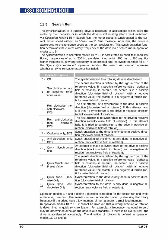
90 02/06
11.5 Search Run The synchronization to a rotating drive is necessary in applications which drive the
motor by their behavior or in which the drive is still rotating after a fault switch-off. Via Operation Mode 645 = Search Run, the motor speed is synchronized to the cur-rent motor speed without an "Overcurrent" fault message. After this, the motor is accelerated to the reference speed at the set acceleration. This synchronization func-tion determines the current rotary frequency of the drive via a search run in operation modes 1 to 5. The synchronization in operation modes 10 to 15 is accelerated by short test impulses. Rotary frequencies of up to 250 Hz are determined within 100 ms to 300 ms. For higher frequencies, a wrong frequency is determined and the synchronization fails. In the "Quick synchronization" operation modes, the search run cannot determine whether an synchronization attempt has failed.
Operation mode Function 0 - Off The synchronization to a rotating drive is deactivated.
1 - Search direction acc. to specified refer-ence value
The search direction is defined by the sign in front of the reference value. If a positive reference value (clockwise field of rotation) is entered, the search is in a positive direction (clockwise field of rotation), with a negative reference value, the search is in a negative direction (an-ticlockwise field of rotation).
2 - First clockwise, then anti-clockwise, DCB
The first attempt is to synchronize to the drive in positive direction (clockwise field of rotation). If this attempt fails, it is tried to synchronize to the drive in negative direction (anticlockwise field of rotation).
3 - First anti-clockwise, then clockwise, DCB
The first attempt is to synchronize to the drive in negative direction (anticlockwise field of rotation). If this attempt fails, it is tried to synchronize to the drive in positive di-rection (clockwise field of rotation).
4 - Clockwise only, DCB Synchronization to the drive is only done in positive direc-tion (clockwise field of rotation).
5 - Anti-clockwise only, DCB
Synchronization to the drive is only done in negative di-rection (anticlockwise field of rotation).
10 - Quick Synchroniza-
tion
An attempt is made to synchronize to the drive in positive direction (clockwise field of rotation) and in negative di-rection (anticlockwise field of rotation).
11 - Quick Synch. acc. to Preset Value
The search direction is defined by the sign in front of the reference value. If a positive reference value (clockwise field of rotation) is entered, the search is in a positive direction (clockwise field of rotation), with a negative reference value, the search is in a negative direction (an-ticlockwise field of rotation).
14 - Quick Sync., Clock-wise Only
Synchronization to the drive is only done in positive direc-tion (clockwise field of rotation).
15 - Quick Sync., Anti-clockwise Only
Synchronization to the drive is only done in negative di-rection (anticlockwise field of rotation).
Operation modes 1, 4 and 5 define a direction of rotation for the search run and avoid
a deviating direction. The search run can accelerate drives by checking the rotary frequency if the drives have a low moment of inertia and/or a small load moment. In operation modes 10 to 15, it cannot be ruled out that a wrong direction of rotation is determined in quick synchronization. For example, a frequency not equal to zero may be determined although the drive is at a standstill. If there is no overcurrent, the drive is accelerated accordingly. The direction of rotation is defined in operation modes 11, 14 and 15.

02/06 91
The synchronization changes the parameterized starting behavior of the selected con-figuration. First, the start command activates the search run in order to determine the rotary frequency of the drive. In operation modes 1 to 5, the Current / Rated motor current 647 is used for synchronization as a percentage of the Rated current 371.
Parameter Settings No. Description Min. Max. Fact. sett. 647 Current / Rated Motor Current 1.00 % 100.00 % 70.00 %
The sensor-less control is extended for the search run by a PI-Controller, which regu-
lates the parameterized Current / Rated Motor Current 647. The proportional and integrating part of the current controller can be set via the parameters Amplification 648 and Integral Time 649. The control functions can be deactivated by setting the parameters to 0.
Parameter Settings No. Description Min. Max. Fact. sett. 648 Amplification 0.00 10.00 1.00 649 Integral Time 0 ms 1000 ms 20 ms If the parameter for synchronization Operation Mode 645 was set to operation mode
1 to 5 (search run), the search run is not started before the Demagnetizing Time 633 has elapsed.
If synchronization to the drive is not possible, the Braking Current 631 is impressed into the motor in operation modes 1 to 5 for the duration of the Break.-Time after Search Run 646. The impression of the direct current set in the parameters of the direct current brake results in the motor heating up and should only be done for a short period in the case of internally ventilated motors.
Parameter Settings No. Description Min. Max. Fact. sett. 646 Break. Time after Search Run 0.0 s 200.0 s 10.0 s
11.6 Positioning Positioning is done in operation mode "Reference positioning" via the definition of the
positioning distance or in operation mode "Axis positioning" via the definition of the position angle. Reference positioning uses a digital reference signal from a selectable signal source for positioning the drive independent of the speed. Axis positioning uses a digital reference signal from a speed sensor. The function "Reference positioning" is available in configurations 110, 410 and 210 and is activated by selecting operation mode 1 for parameter Operation Mode 458. The function "Axis positioning" is available in configuration 210 (Operation mode 210 for parameter Configuration 30) and is activated by selecting operation mode 2 for parameter Operation Mode 458.
Operation mode Function 0 - Off Positioning switched off.
1 - Reference positioning Positioning from reference point via definition of positioning distance (rotations). The reference point is acquired via a Signal Source 459.
2 - Axis Positioning Positioning from reference point via definition of the positioning angle, reference signal from speed sensor

92 02/06
11.6.1 Reference Positioning The feedback of the current position is referred to the revolutions of the motors rela-
tive to the time of the reference signal. The accuracy of the positioning for the applica-tion to be realized is dependent on the current Actual Frequency 241, the Decelera-tion (Clockwise) 421, the No. of Pole Pairs 373, the selected Positioning distance 460 and the parameterized control behavior.
The distance between the reference point and the required position is to be defined in
motor revolutions. The calculation of the distance covered is done with the selected Positioning distance 460 according to the application. The setting 0,000 U for the Positioning distance 460 causes an immediate stop of the drive according to the selected stopping behavior for Operation Mode 630.
Parameter Settings No. Description Min. Max. Fact. sett. 460 Positioning Distance 0.000 U 1000000.000 U 0.000 U The actual value parameter Rotations 470 facilitates the setting and optimization of
the function. The revolutions of the motor displayed should correspond to the Posi-tioning distance 460 at the required position.
The minimum number of revolutions needed until the required position is reached de-
pends on the Actual Frequency 241 and Deceleration (Clockwise) 421 (or Decelera-tion Anticlockwise 423) as well as the No. of Pole Pairs 373 of the motor.
Umin = min. number of rotations f = Actual frequency 241 a = Deceleration 421 (423)
pafU
⋅⋅=
2
2
min
p = No. of Pole Pairs 373 of motor Example: f = 20 Hz, a = 5 Hz/s, p = 2 ⇒ Umin = 20 At an actual frequency of 20 Hz and a deceleration of 5 Hz/s, at least 20 revolutions
are required until the drive stops at the required position. This is the minimum value for the Positioning distance 460, a shorter positioning distance is not possible. If the number of revolutions to the required position is to be lower, either the frequency must be reduced, the deceleration must be increased or the reference point must be shifted.
The digital signal for acquisition of the reference point and the logic link can be se-
lected by the parameter Signal Sources 459. The link of the digital inputs S2IND, S3IND and S6IND to further functions is to be checked according to selected Configu-ration 30 (e.g., in configurations 110 and 210, digital input S2IND is linked to the function "Start of clockwise operation"). The signals for positioning and a stopping behavior should not be assigned to the same digital input.
Operation mode Function 2 - S2IND, falling edge 3 - S3IND, falling edge 6 - S6IND, falling edge
The positioning starts with the change of the logic signal from 1 (HIGH) to 0 (LOW) at the reference point.
1x - SxIND, rising edge The positioning starts with the change of the logic signal from 0 (LOW) to 1 (HIGH)
2x - SxIND, rising/falling edge The positioning begins with the change of the logic signal
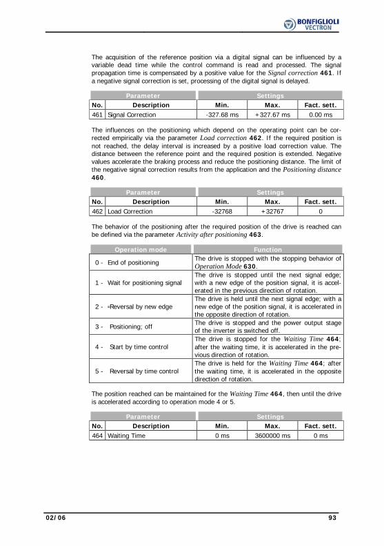
02/06 93
The acquisition of the reference position via a digital signal can be influenced by a
variable dead time while the control command is read and processed. The signal propagation time is compensated by a positive value for the Signal correction 461. If a negative signal correction is set, processing of the digital signal is delayed.
Parameter Settings No. Description Min. Max. Fact. sett. 461 Signal Correction -327.68 ms +327.67 ms 0.00 ms The influences on the positioning which depend on the operating point can be cor-
rected empirically via the parameter Load correction 462. If the required position is not reached, the delay interval is increased by a positive load correction value. The distance between the reference point and the required position is extended. Negative values accelerate the braking process and reduce the positioning distance. The limit of the negative signal correction results from the application and the Positioning distance 460.
Parameter Settings No. Description Min. Max. Fact. sett. 462 Load Correction -32768 +32767 0 The behavior of the positioning after the required position of the drive is reached can
be defined via the parameter Activity after positioning 463. Operation mode Function
0 - End of positioning The drive is stopped with the stopping behavior of Operation Mode 630.
1 - Wait for positioning signal
The drive is stopped until the next signal edge; with a new edge of the position signal, it is accel-erated in the previous direction of rotation.
2 - Reversal by new edge
The drive is held until the next signal edge; with a new edge of the position signal, it is accelerated in the opposite direction of rotation.
3 - Positioning; off The drive is stopped and the power output stage of the inverter is switched off.
4 - Start by time control
The drive is stopped for the Waiting Time 464; after the waiting time, it is accelerated in the pre-vious direction of rotation.
5 - Reversal by time control
The drive is held for the Waiting Time 464; after the waiting time, it is accelerated in the opposite direction of rotation.
The position reached can be maintained for the Waiting Time 464, then until the drive
is accelerated according to operation mode 4 or 5. Parameter Settings No. Description Min. Max. Fact. sett. 464 Waiting Time 0 ms 3600000 ms 0 ms

94 02/06
Positioning, Operation Mode 458 = 1 The diagram shows how the positioning to the set positioning distance is effected. The
positioning distance remains constant at different frequency values. At the reference point, the position signal SPosi is generated. Starting from frequency fmax, the positioning is effected at the set Deceleration (Clockwise) 421. At a lower frequency value f1, the frequency remains constant for some time before the drive is stopped at the set decel-eration. If, during acceleration or deceleration of the machine, positioning is started by the signal SPosi, the frequency at the time of the positioning signal is maintained.
f
fmax
f1
Spos i
UUmin
t
Digital Input 6
Deceleration (Clockwise) 421
Examples of reference positioning as a function of the parameter settings selected. − The reference point is registered according to the parameter Signal Sources 459
in operation mode 16–S6IND, rising edge by a signal on digital input 6. − The Positioning distance 460 with parameter value 0.000U (default) defines a
direct stop of the drive with the deceleration behavior selected in parameter Op-eration Mode 630 and the selected Deceleration (Clockwise) 421. If a Position-ing distance 460 is set, the positioning is effected at the set deceleration.
− The Signal correction 461 of the signal propagation time from the measurement
point to the frequency inverter is not used if it is set to 0ms. − The Load correction 462 can compensate a faulty positioning by the load behav-
ior. By default, this function is deactivated, i.e. set to 0. − The Activity after positioning 463 is defined by operation mode 0–End of position-
ing. − The Waiting Time 464 is not considered because operation mode 0 is selected for
the parameter Activity after positioning 463. − The actual value Rotations 470 enables a direct comparison to the required Posi-
tioning distance 460. In the case of deviations, a Signal correction 461 or Load correction 462 can be carried out.
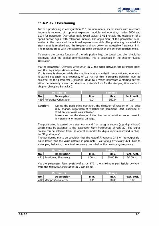
02/06 95
11.6.2 Axis Positioning For axis positioning in configuration 210, an incremental speed sensor with reference
impulse is required. An optional expansion module and operating modes 1004 and 1104 for parameter Operation mode speed sensor 2 493 enable the evaluation of a speed sensor signal with reference impulse. The adjustment of this parameter is de-scribed in the manual of the optional expansion module. The positioning is started if a start signal is received and the frequency drops below an adjustable frequency limit. The machine stops with the selected stopping behavior at the entered position angle.
To ensure the correct function of the axis positioning, the speed controller should be
optimized after the guided commissioning. This is described in the chapter "Speed Controller".
Via the parameter Reference orientation 469, the angle between the reference point
and the required position is entered. If this value is changed while the machine is at a standstill, the positioning operation is carried out again at a frequency of 0.5 Hz. For this, a stopping behavior must be selected for the parameter Operation Mode 630 which impresses a starting current either permanently when the drive is at a standstill or for the stopping time (refer to chapter „Stopping Behavior“).
Parameter Settings No. Description Min. Max. Fact. sett. 469 Reference Orientation 0.0° 359.9° 0.0° Caution! During the positioning operation, the direction of rotation of the drive
may change, regardless of whether the command Start clockwise or Start anticlockwise was activated. Make sure that the change of the direction of rotation cannot result in any personal or material damage.
The positioning is started by a start command from a signal source (e.g. digital input)
which must be assigned to the parameter Start Positioning of Axle 37. The signal source can be selected from the operation modes for digital inputs described in chap-ter "Digital Inputs". The positioning starts on condition that the Actual Frequency 241 of the output sig-nal is lower than the value entered in parameter Positioning Frequency 471. Due to a stopping behavior, the actual frequency drops below the positioning frequency.
Parameter Settings No. Description Min. Max. Fact. sett. 471 Positioning Frequency 1.00 Hz 50.00 Hz 50.00 Hz Via the parameter Max. positional error 472, the maximum permissible deviation
from the Reference orientation 469 can be set. Parameter Settings No. Description Min. Max. Fact. sett. 472 Max positional error 0.1° 90.0° 3.0°

96 02/06
Via parameter time constant positioning contr. 479, the time constant for controlling
the positional error can be set. The value of the time constant should be increased if oscillations of the drive around the reference orientation occur during the positioning.
Parameter Settings No. Description Min. Max. Fact. sett.
479 time constant positioning controller 1.00 ms 9999.99 ms 20.00 ms
To make sure that the set position is maintained if a load torque is applied, a stopping
behavior should be selected for parameter Operation Mode 630 which impresses a starting current either permanently when the drive is at a standstill or for the stopping time.
The status message „60-Arrived at desired Position“ which is displayed when the ref-
erence orientation is reached can be assigned to a digital output. The message is output on the following conditions: − Operation mode 2 (axis positioning) for parameter Operation Mode 458 is se-
lected. − The controller release signal at digital input S1IND is switched on. − Start Positioning of Axle 37 is activated. − The speed sensor monitoring is activated, i.e. operation mode 2 (error message)
for parameter Operation Mode 760 of the speed sensor monitoring is selected. − Operation mode 1004 or 1104 (quadruple evaluation with reference impulse) is
selected for the speed sensor input. − The Actual Frequency 241 is lower than 1 Hz. − The deviation of the current position from the reference orientation is lower than
the Max positional error 472. The current position after Start Positioning of Axle 37 is recognized by the frequency
inverter as follows: − During commissioning, after switching on the frequency inverter, a search mode is
performed for 3 rotations at a rotational frequency of 1 Hz in order to detect the reference signal. As soon as the reference signal was recognized twice, the drive is positioned to the Reference orientation 469.
− If the motor was already rotating before axis positioning was enabled, the posi-tioning to the Reference orientation 469 is performed without search mode be-cause the position of the reference point was already detected by the frequency inverter.
If the positioning is carried out, after controller enabling and start command, when
the motor is at a standstill: − The motor is positioned clockwise to the reference orientation if the value for the
reference orientation is higher than the value adjusted before. − The motor is positioned anticlockwise to the reference orientation if the value for
the reference orientation is lower than the value adjusted before. The sense of rotation during the positioning is independent of whether Start Clockwise
or Start Anticlockwise was activated. The time required until the reference orientation is reached depends on:
− Actual Frequency − Frequency ramp for deceleration − Rotational angle to reference orientation − Max positional error − time constant positioning controller

02/06 97
12 Error and warning behavior
Operation of the frequency inverter and the connected load are monitored continu-ously. The monitoring functions are to be parameterized with the corresponding limit values specific to the application. If the limits were set below the switch-off limit of the frequency inverter, a fault switch-off can be prevented by suitable measures if a warning message is issued. The warning message is displayed by the LED's of the frequency inverter and can be read out on the control unit via the parameter Warnings 269 or output via one of the digital control outputs.
12.1 Overload Ixt
The admissible load behavior depends on various technical data of the frequency in-verters and the ambient conditions. The selected Switching Frequency 400 defines the nominal current and the available overload for one second and sixty seconds, respectively. The Warning Limit Short-Term Ixt 405 and Warning Limit Long-Term Ixt 406 are to be parameterized accord-ingly.
Parameter Settings No. Description Min. Max. Fact. sett. 405 Warning Limit Short Term Ixt 6 % 100 % 80 % 406 Warning Limit Long Term Ixt 6 % 100 % 80 %
12.2 Temperature
The ambient conditions and the power dissipation at the current operating point result
in the frequency inverter heating up. In order to avoid a fault switch-off of the fre-quency inverter, the Warning Limit Heat Sink Temperature 407 for the heat sink temperature limit and the Warning Limit Inside Temperature 408 as an internal tem-perature limit are to be parameterized. The temperature value at which a warning message is output is calculated from the type-dependent temperature limit minus the adjusted warning limit. The switch-off limits of the frequency inverter are an internal temperature of 65 °C and a heat sink temperature range of 80°C up to 90°C.
Parameter Settings No. Description Min. Max. Fact. sett. 407 Warning Limit Heat Sink Temp. -25 °C 0 °C -5 °C 408 Warning Limit Inside Temp. -25 °C 0 °C -5 °C

98 02/06
12.3 Controller Status The intervention of a controller can be indicated via the control unit or LEDs. The
selected control method and the matching monitoring functions prevent a switch-off of the frequency inverter. The intervention of the function changes the operating be-havior of the application and can be displayed by the status messages with parameter Controller Status 275. The limit values and events which result in the intervention by the corresponding controller are described in the corresponding chapters.
The behavior during the intervention of a controller is configured with the parameter
Controller Status Message 409. Operation mode Function
0 - No Message The intervention of a controller is not reported. The controllers influencing the operating behavior are displayed in the Controller status 275 parameter.
1 – Warning Status The limitation by a controller is displayed as a warning by the control unit.
11 – Warning Status and LED
The limitation by a controller is displayed as a warning by the control unit and the LEDs.
12.4 IDC Compensation Limit At the output of the frequency inverter a DC component can occur in the output cur-
rent due to unbalances. This DC voltage component can be compensated by the fre-quency inverter. The maximum output voltage of the compensation is set with pa-rameter IDC Compensation Limit 415. If a higher voltage than the set limit is needed for the compensation of a DC voltage component, error “F1301 IDC COMPENSATION“ is triggered. If this fault occurs, it should be checked whether the load is defective. Possibly the voltage limit may have to be increased. If the parameter IDC Compensation Limit 415 is reduced to zero, the DC compensa-tion is deactivated.
Parameter Settings No. Description Min. Max. Fact. sett. 415 IDC Compensation Limit 0.0 V 1.5 V - 1) 1) The factory setting of the parameter IDC Compensation Limit 415 depends on the
selected parameter Configuration 30. - Configurations 1xx => IDC Compensation Limit 415 = 1.5 V - Configurations 1xx / 4xx => IDC Compensation Limit 415 = 0.0 V
12.5 Frequency Switch-Off Limit The maximum permissible output frequency of the frequency inverter can be set with
parameter Frequency Switch-Off Limit 417. If this frequency limit is exceeded by the Stator frequency 210 or the Actual Frequency 241, the frequency inverter is switched off and the fault message “F1100“ is displayed.
Parameter Settings No. Description Min. Max. Fact. sett. 417 Frequency Switch-Off Limit 0.00 Hz 999.99 Hz 999.99 Hz
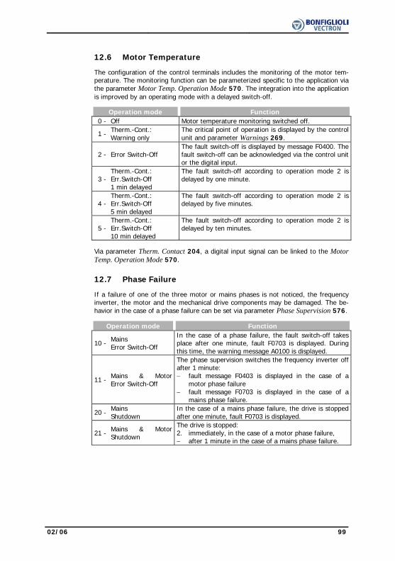
02/06 99
12.6 Motor Temperature The configuration of the control terminals includes the monitoring of the motor tem-
perature. The monitoring function can be parameterized specific to the application via the parameter Motor Temp. Operation Mode 570. The integration into the application is improved by an operating mode with a delayed switch-off.
Operation mode Function 0 - Off Motor temperature monitoring switched off.
1 - Therm.-Cont.: Warning only
The critical point of operation is displayed by the control unit and parameter Warnings 269.
2 - Error Switch-Off
The fault switch-off is displayed by message F0400. The fault switch-off can be acknowledged via the control unit or the digital input.
3 -
Therm.-Cont.: Err.Switch-Off 1 min delayed
The fault switch-off according to operation mode 2 is delayed by one minute.
4 -
Therm.-Cont.: Err.Switch-Off 5 min delayed
The fault switch-off according to operation mode 2 is delayed by five minutes.
5 -
Therm.-Cont.: Err.Switch-Off 10 min delayed
The fault switch-off according to operation mode 2 is delayed by ten minutes.
Via parameter Therm. Contact 204, a digital input signal can be linked to the Motor
Temp. Operation Mode 570.
12.7 Phase Failure If a failure of one of the three motor or mains phases is not noticed, the frequency
inverter, the motor and the mechanical drive components may be damaged. The be-havior in the case of a phase failure can be set via parameter Phase Supervision 576.
Operation mode Function
10 - Mains Error Switch-Off
In the case of a phase failure, the fault switch-off takes place after one minute, fault F0703 is displayed. During this time, the warning message A0100 is displayed.
11 - Mains & MotorError Switch-Off
The phase supervision switches the frequency inverter off after 1 minute: − fault message F0403 is displayed in the case of a
motor phase failure − fault message F0703 is displayed in the case of a
mains phase failure.
20 - Mains Shutdown
In the case of a mains phase failure, the drive is stopped after one minute, fault F0703 is displayed.
21 - Mains & MotorShutdown
The drive is stopped: 2. immediately, in the case of a motor phase failure, − after 1 minute in the case of a mains phase failure.

100 02/06
12.8 Automatic Error Acknowledgment The automatic error acknowledgment enables acknowledgment of the faults Overcur-
rent F0500, Overcurrent F0507 and Overvoltage F0700 without intervention by an overriding control system or the user. If one of the these errors occurs, the frequency inverter switches off the power semi-conductors and waits for the time defined by the parameter Restart Delay 579. If the error must be acknowledged, the speed of the machine is determined via the quick catching function and it is synchronized to the rotating machine. The automatic error acknowledgment makes use of quick catching operation mode, regardless of the parameter for search run, Operation Mode 645. The information given on this function in chapter "Search run" must be observed. With parameter Allowed No. of Auto-Acknowl. 578, you can define the number of automatic error acknowledgements which are permitted within 10 minutes.
An acknowledgement repeated above the permissible number within 10 minutes will
result in the frequency inverter being switched off. The errors Overcurrent F0500, Overcurrent F0507 and Overvoltage F0700 have a separate error acknowledgement counter.
Parameter Settings No. Description Min. Max. Fact. sett. 578 Allowed No. of Auto-Acknowl. 0 20 5 579 Restart Delay 0 ms 1000 ms 20 ms

02/06 101
13 Reference Values The ACT series frequency inverters can be configured specific to the application and
enable customer-specific adaptation of the module hardware and software structure.
13.1 Frequency Limits The output frequency of the frequency inverter and thus the speed setting range are
defined by the parameters Minimum Frequency 418 and Maximum Frequency 419. The corresponding control methods use these two limit values for scaling and calculat-ing the frequency.
Parameter Settings No. Description Min. Max. Fact. sett. 418 Minimum Frequency 0.00 Hz 999.99 Hz 3.50 Hz 419 Maximum Frequency 0.00 Hz 999.99 Hz 50.00 Hz
13.2 Slip Frequency The torque-forming current component and thus the slip frequency of the 3-phase
machine depend on the required torque in the case of the field-oriented control meth-ods. The field-oriented control method also includes the parameter Slip Frequency 719 to limit the torque in the calculation of the machine model. The rated slip calcu-lated from the rated motor parameters is limited in accordance with the Slip Fre-quency 719 which is parameterized as a percentage.
Parameter Settings No. Description Min. Max. Fact. sett. 719 Slip Frequency 0 % 10000 % 250 %
13.3 Percentage Value Limits The setting range of the percentages is defined by the parameters Minimum Refer-
ence Percentage 518 and Maximum Reference Percentage 519. The relevant control methods use these two limit values for scaling and calculating the frequency.
Parameter Settings No. Description Min. Max. Fact. sett. 518 Minimum Reference Percentage 0.00 % 300.00 % 0.00 % 519 Maximum Reference Percentage 0.00 % 300.00 % 100.00 %
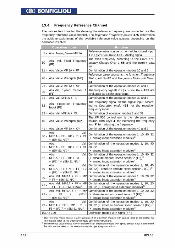
102 02/06
13.4 Frequency Reference Channel
The various functions for the defining the reference frequency are connected via the frequency reference value channel. The Reference Frequency Source 475 determines the additive assignment of the available reference value sources depending on the hardware installed.
Operation mode Function
1 - Abs. Analog Value MFI1A Reference value source is the multifunctional input 1 in Operation Mode 452 - Analog signal.
10 - Abs. Val. Fixed Frequency (FF)
The fixed frequency according to the Fixed Fre-quency Change-Over 1 66 and the current data set
11 - Abs. Value MFI1A + FF Combination of the operation modes 10 and 1
20 - Abs. Value Motorpoti (MP) Reference value source is the function Frequency Motorpoti Up 62 and Frequency Motorpoti Down 63
21 - Abs. Value MFI1A + MP Combination of the operation modes 20 and 1
30 - Abs.Val. Speed Sensor 1 (F1)
The frequency signals in Operation Mode 490 are evaluated as a reference value.
31 - Abs. Val. MFI1A + F1 Combination of the operation modes 30 and 1
32 - Abs. Repetition Frequency Input (F3)
The frequency signal on the digital input accord-ing to Operation mode 496 for the repetition frequency input.
33 - Abs. Val. MFI1A + F3 Combination of operation modes 1 and 32
40 - Abs. Value Motorpoti (KP) The KP 500 control unit is the reference value source, with keys for increasing the frequency and for reducing the frequency.
41 - Abs. Value MFI1A + KP Combination of the operation modes 40 and 1
80 - Abs. Val.MFI1A + FF + KP + F1 + F3+ (EM-S1INA)1)
Combination of the operation modes 1, 10, 40, 32 (+ analog input extension module)1)
81 - Abs. Val.MFI1A + FF + KP + F1 + F3+ (EM-S1INA)1)
Combination of the operation modes 1, 10, 40, 30, 32 (+ analog input extension module)1)
82 - Abs. Val.MFI1A + FF + KP + F3 + (F2)2) + (EM-S1INA)1)
Combination of the operation modes 1, 10, 40, 32 (+ absolute amount speed sensor 2 (F2))2) (+ analog input extension module)1
89 - Abs. Val.MFI1A + FF + KP + F1 + F3 + (F2)2) + (EM-S1INA)1)
Combination of the operation modes 1, 10, 40, 30, 32(+ absolute amount speed sensor 2 (F2))2) (+ analog input extension module)1)
90 - Abs. Val. MFI1A + FF + MP + F3 + (EM-S1INA)1)
Combination of the operation modes 1, 10, 20, 32 (+ analog input extension module)1)
91 - Abs. Val. MFI1A + FF + MP + F1 + F3+ (EM-S1INA)1)
Combination of the operation modes 1, 10, 20, 30, 32 (+ analog input extension module)1)
92 - Abs. Val. MFI1A + FF + MP + F3 + (F2)2) + (EM-S1INA)1)
Combination of the operation modes 1, 10, 20, 32 (+ absolute amount speed sensor 2 (F2))2) (+ analog input extension module)1)
99 - Abs. Val.MFI1A + FF + MP + F1 + F3 + (F2)2) + (EM-S1INA)1)
Combination of the operation modes 1, 10, 20, 30, 32 (+ absolute amount speed sensor 2 (F2))2) (+ analog input extension module)1)
101 to 199 Operation modes with signs (+/-)
1) The reference value source is only available if an extension module with analog input is connected. For information, refer to the extension module operating instructions.
2) The reference value source is only available if an extension module with speed sensor input is connected. For information, refer to the extension module operating instructions.
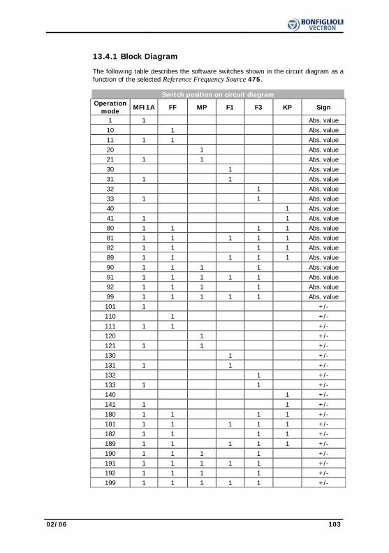
02/06 103
13.4.1 Block Diagram The following table describes the software switches shown in the circuit diagram as a
function of the selected Reference Frequency Source 475. Switch position on circuit diagram
Operation
mode MFI1A FF MP F1 F3 KP Sign
1 1 Abs. value 10 1 Abs. value 11 1 1 Abs. value 20 1 Abs. value 21 1 1 Abs. value 30 1 Abs. value 31 1 1 Abs. value 32 1 Abs. value 33 1 1 Abs. value 40 1 Abs. value 41 1 1 Abs. value 80 1 1 1 1 Abs. value 81 1 1 1 1 1 Abs. value 82 1 1 1 1 Abs. value 89 1 1 1 1 1 Abs. value 90 1 1 1 1 Abs. value 91 1 1 1 1 1 Abs. value 92 1 1 1 1 Abs. value 99 1 1 1 1 1 Abs. value 101 1 +/- 110 1 +/- 111 1 1 +/- 120 1 +/- 121 1 1 +/- 130 1 +/- 131 1 1 +/- 132 1 +/- 133 1 1 +/- 140 1 +/- 141 1 1 +/- 180 1 1 1 1 +/- 181 1 1 1 1 1 +/- 182 1 1 1 1 +/- 189 1 1 1 1 1 +/- 190 1 1 1 1 +/- 191 1 1 1 1 1 +/- 192 1 1 1 1 +/- 199 1 1 1 1 1 +/-
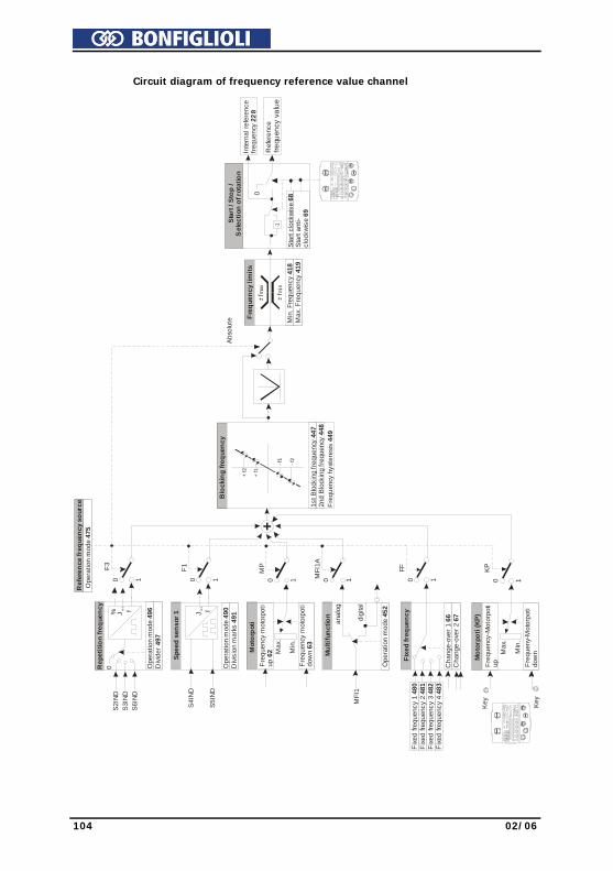
104 02/06
Circuit diagram of frequency reference value channel
Rep
etiti
on fr
eque
ncy
Ope
ratio
n m
ode
496
Divi
der
497
S2IN
DS3
IND
S6IN
D
0
Mot
orpo
ti
Freq
uenc
y m
otor
poti
dow
n 63
anal
og
digi
tal
MFI
1
Cha
nge-
over
1 6
6C
hang
e-ov
er 2
67
Fixe
d fre
quen
cy 1
480
Fixe
d fre
quen
cy 2
481
Fixe
d fre
quen
cy 3
482
Fixe
d fre
quen
cy 4
483
Ope
ratio
n m
ode
475
Ref
eren
ce fr
eque
ncy
sour
ce
0 1
FF
0 1MFI
1A
0 1
MP
0 1
F1
0 1
F3
+
1st B
lock
ing
frequ
ency
447
2nd
Bloc
king
freq
uenc
y 44
8Fr
eque
ncy
hyst
eres
is 4
49
Blo
ckin
g fre
quen
cy
- f2
- f1
+ f1
+ f2
Abso
lute M
in. F
requ
ency
418
Max
. Fre
quen
cy 4
19
Freq
uenc
y lim
its
-+ fm
ax
+ -fm
in
Star
t / S
top
/ S
elec
tion
of ro
tatio
n
-1
0In
tern
al re
fere
nce
freq
uenc
y 22
8
Star
t clo
ckwi
se 6
8St
art a
nti-
cloc
kwis
e 69
f% Jre
l.
Mul
tifun
ctio
n
Ope
ratio
n m
ode
452
Freq
uenc
y m
otor
poti
up 6
2 Max
.
Min
.
f
Spee
d se
nsor
1
Ope
ratio
n m
ode
490
Divi
sion
mar
ks 4
91
S5IN
D
S4IN
D
Fixe
d fr
eque
ncy
Ref
eren
cef re
quen
cy v
alue
Jre
l.
Mot
orpo
ti (K
P)
Freq
ueny
-Mot
orpo
tido
wn
0 1
KP
Freq
uenc
y-M
otor
poti
up
Max
.
Min
.
Key Key
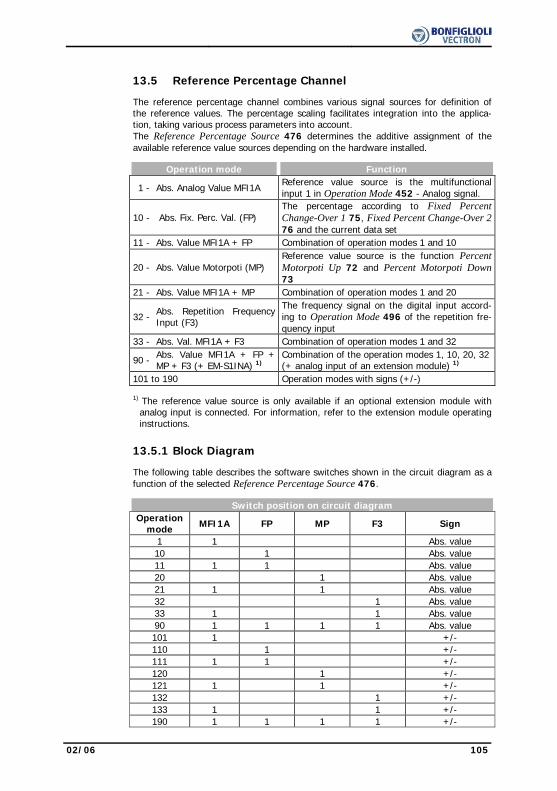
02/06 105
13.5 Reference Percentage Channel The reference percentage channel combines various signal sources for definition of
the reference values. The percentage scaling facilitates integration into the applica-tion, taking various process parameters into account. The Reference Percentage Source 476 determines the additive assignment of the available reference value sources depending on the hardware installed.
Operation mode Function
1 - Abs. Analog Value MFI1A Reference value source is the multifunctional input 1 in Operation Mode 452 - Analog signal.
10 - Abs. Fix. Perc. Val. (FP) The percentage according to Fixed Percent Change-Over 1 75, Fixed Percent Change-Over 276 and the current data set
11 - Abs. Value MFI1A + FP Combination of operation modes 1 and 10
20 - Abs. Value Motorpoti (MP) Reference value source is the function Percent Motorpoti Up 72 and Percent Motorpoti Down 73
21 - Abs. Value MFI1A + MP Combination of operation modes 1 and 20
32 - Abs. Repetition Frequency Input (F3)
The frequency signal on the digital input accord-ing to Operation Mode 496 of the repetition fre-quency input
33 - Abs. Val. MFI1A + F3 Combination of operation modes 1 and 32
90 - Abs. Value MFI1A + FP + MP + F3 (+ EM-S1INA) 1)
Combination of the operation modes 1, 10, 20, 32 (+ analog input of an extension module) 1)
101 to 190 Operation modes with signs (+/-) 1) The reference value source is only available if an optional extension module with
analog input is connected. For information, refer to the extension module operating instructions.
13.5.1 Block Diagram The following table describes the software switches shown in the circuit diagram as a
function of the selected Reference Percentage Source 476. Switch position on circuit diagram
Operation
mode MFI1A FP MP F3 Sign
1 1 Abs. value 10 1 Abs. value 11 1 1 Abs. value 20 1 Abs. value 21 1 1 Abs. value 32 1 Abs. value 33 1 1 Abs. value 90 1 1 1 1 Abs. value 101 1 +/- 110 1 +/- 111 1 1 +/- 120 1 +/- 121 1 1 +/- 132 1 +/- 133 1 1 +/- 190 1 1 1 1 +/-
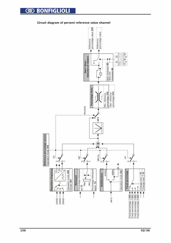
106 02/06
Circuit diagram of percent reference value channel
Rep
etiti
on fr
eque
ncy
Div
ider
497
S2I
ND
S3I
ND
S6I
ND
0
Mot
orpo
ti
Perc
enta
ge-M
otor
poti
dow
n 7
3
anal
og
digi
tal
MFI
1
Cha
nge-
over
1 7
5C
hang
e-ov
er 2
76
Fixe
d pe
rcen
tage
1 5
20
Ope
ratio
n m
ode
476
Ref
eren
ce p
erce
ntag
e so
urce
0 1
FP
0 1
MP
+
Abso
lute M
ax. r
efer
ence
perc
enta
ge 5
19
Perc
enta
ge li
mits
%m
ax
%m
in
Star
t / S
top
/ Se
lect
ion
of ro
tatio
n
-1
0
Ref
eren
cepe
rcen
tage
val
ue
Star
t clo
ckw
ise
68St
art a
nti-
cloc
kwis
e 69
f% ϑre
l.
Mul
tifun
ctio
n
Ope
ratio
n m
ode
452
Perc
enta
ge-M
otor
poti
up 7
2 Max
.
Min
.
Fixe
d pe
rcen
tage
Fixe
d pe
rcen
tage
2 5
21Fi
xed
perc
enta
ge 3
522
Fixe
d pe
rcen
tage
4 5
23
Ref
eren
cepe
rcen
tage
val
ue 2
29

02/06 107
13.6 Fixed Reference Values The fixed reference values are to be parameterized as fixed frequencies or fixed per-
centages according to the configuration and function. The signs of the fixed reference values determine the direction of rotation. A positive sign means a clockwise rotation, a negative sign means an anticlockwise rotation. The direction can only be changed via the sign if the Reference Frequency Source 475 or Reference Percentage Source 476 is parameterized to an operation mode with sign (+/-). The direction of rotation can also be stated with the digital signal sources as-signed to the parameters Start Clockwise 68 and Start Anticlockwise 69. The fixed reference values are to be parameterized in four data sets and are assigned to further sources via the reference value channel. The use of the functions Data Set Change-Over 1 70 and Data Set Change-Over 2 71 thus enables the setting of 16 fixed reference values.
13.6.1 Fixed Frequencies The four fixed frequencies define reference values which are selected via the parame-
ters Fixed Frequency Change-Over 1 66 and Fixed Frequency Change-Over 2 67. The parameter Reference Frequency Source 475 defines the addition of the various sources in the reference frequency channel.
Parameter Settings No. Description Min. Max. Fact. sett. 480 Fixed Frequency 1 -999.99 Hz 999.99 Hz 0.00 Hz 481 Fixed Frequency 2 -999.99 Hz 999.99 Hz 10.00 Hz 482 Fixed Frequency 3 -999.99 Hz 999.99 Hz 25.00 Hz 483 Fixed Frequency 4 -999.99 Hz 999.99 Hz 50.00 Hz By combining the logic states of the fixed frequency change-over modes 1 and 2,
fixed frequencies 1 through 4 can be selected:
Fixed Frequency Control
Fixed Frequency
Change-Over 1 66 Fixed Frequency
Change-Over 2 67 Function / active fixed value
0 0 Fixed Frequency 1,480 1 0 Fixed Frequency 2,481 1 1 Fixed Frequency 3,482 0 1 Fixed Frequency 4,483 0 = contact open 1 = contact closed
13.6.2 JOG-Frequency The JOG function forms part of the functions for controlling the drive mechanism via
the control unit. Use the arrow keys to change the JOG frequency within the function. The frequency of the output signal is set to the entered value if the FUN key is pressed. The drive starts and the machine turns at the set JOG-Frequency 489. If the JOG frequency has been changed using the arrow keys, this value is stored.
Parameter Settings No. Description Min. Max. Fact. sett. 489 JOG-Frequency -999.99 Hz 999.99 Hz 5.00 Hz
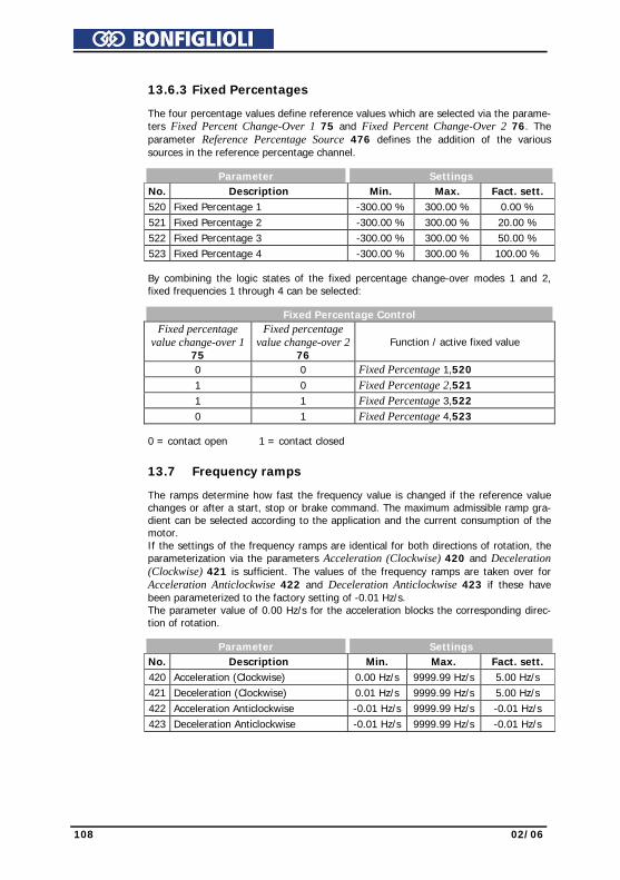
108 02/06
13.6.3 Fixed Percentages The four percentage values define reference values which are selected via the parame-
ters Fixed Percent Change-Over 1 75 and Fixed Percent Change-Over 2 76. The parameter Reference Percentage Source 476 defines the addition of the various sources in the reference percentage channel.
Parameter Settings No. Description Min. Max. Fact. sett. 520 Fixed Percentage 1 -300.00 % 300.00 % 0.00 % 521 Fixed Percentage 2 -300.00 % 300.00 % 20.00 % 522 Fixed Percentage 3 -300.00 % 300.00 % 50.00 % 523 Fixed Percentage 4 -300.00 % 300.00 % 100.00 % By combining the logic states of the fixed percentage change-over modes 1 and 2,
fixed frequencies 1 through 4 can be selected:
Fixed Percentage Control
Fixed percentage
value change-over 1 75
Fixed percentage value change-over 2
76 Function / active fixed value
0 0 Fixed Percentage 1,520 1 0 Fixed Percentage 2,521 1 1 Fixed Percentage 3,522 0 1 Fixed Percentage 4,523 0 = contact open 1 = contact closed
13.7 Frequency ramps The ramps determine how fast the frequency value is changed if the reference value
changes or after a start, stop or brake command. The maximum admissible ramp gra-dient can be selected according to the application and the current consumption of the motor. If the settings of the frequency ramps are identical for both directions of rotation, the parameterization via the parameters Acceleration (Clockwise) 420 and Deceleration (Clockwise) 421 is sufficient. The values of the frequency ramps are taken over for Acceleration Anticlockwise 422 and Deceleration Anticlockwise 423 if these have been parameterized to the factory setting of -0.01 Hz/s. The parameter value of 0.00 Hz/s for the acceleration blocks the corresponding direc-tion of rotation.
Parameter Settings No. Description Min. Max. Fact. sett. 420 Acceleration (Clockwise) 0.00 Hz/s 9999.99 Hz/s 5.00 Hz/s 421 Deceleration (Clockwise) 0.01 Hz/s 9999.99 Hz/s 5.00 Hz/s 422 Acceleration Anticlockwise -0.01 Hz/s 9999.99 Hz/s -0.01 Hz/s 423 Deceleration Anticlockwise -0.01 Hz/s 9999.99 Hz/s -0.01 Hz/s

02/06 109
The ramps for Emergency Stop Clockwise 424 and Emergency Stop Anticlockwise
425 of the drive to be activated via the parameter for stopping behavior Operation Mode 630 must be selected according to the application. The non-linear (S-shaped) course of the ramps is not active in the case of an emergency stop of the drive.
Parameter Settings No. Description Min. Max. Fact. sett. 424 Emergency Stop Clockwise 0.01 Hz/s 9999.99 Hz/s 5.00 Hz/s 425 Emergency Stop Anticlockwise 0.01 Hz/s 9999.99 Hz/s 5.00 Hz/s
Rotary fieldclockwise
Rotary fieldanticlockwise
+fm ax
-fma x
t
Acceleration (Clockwise) 420
Deceleration (Clockwise)
Emergency Stop
or
421
424Clockwise
Accelerationanticlockwise( ) 422
Deceleration anticlockwise
Emergency Stop anticlockwise
or
423
425
The parameter Maximum Leading 426 limits the difference between the output of the ramp and the current actual value of the drive. The set maximum deviation is a dead time for the control system which should be kept as low as possible. In case the drive is loaded heavily and high acceleration and deceleration values are selected it is possible, that a set controller limit is reached while the drive is acceler-ated or decelerated. In this case, the drive cannot follow the defined acceleration or deceleration ramps. With Maximum Leading 426, you can limit the max. leading of the ramp.
Parameter Settings No. Description Min. Max. Fact. sett. 426 Maximum Leading 0.01 Hz 999.99 Hz 5.00 Hz Example: Fixed value at ramp output = 20 Hz, current actual value of drive = 15 Hz,
selected Maximum Leading 426 = 5 Hz The frequency at the ramp output is increased to 15 Hz only and it is not increased further. The difference (leading) between the frequency value at the ramp output and the current actual frequency of the drive is limited to 5 Hz in this way.
The load occurring in a linear acceleration of the drive is reduced by the adjustable modification speeds (S curve). The non-linear course of the frequency is defined as a ramp and states the time range in which the frequency is to be guided to the set ramp. The values set with parameters 420 to 423 are maintained regardless of the selected ramp times.
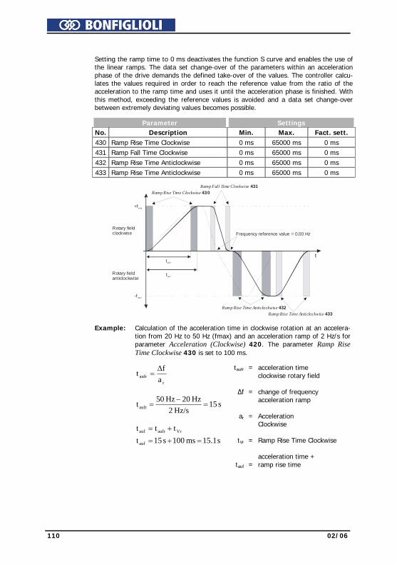
110 02/06
Setting the ramp time to 0 ms deactivates the function S curve and enables the use of
the linear ramps. The data set change-over of the parameters within an acceleration phase of the drive demands the defined take-over of the values. The controller calcu-lates the values required in order to reach the reference value from the ratio of the acceleration to the ramp time and uses it until the acceleration phase is finished. With this method, exceeding the reference values is avoided and a data set change-over between extremely deviating values becomes possible.
Parameter Settings No. Description Min. Max. Fact. sett. 430 Ramp Rise Time Clockwise 0 ms 65000 ms 0 ms 431 Ramp Fall Time Clockwise 0 ms 65000 ms 0 ms 432 Ramp Rise Time Anticlockwise 0 ms 65000 ms 0 ms 433 Ramp Rise Time Anticlockwise 0 ms 65000 ms 0 ms
Rotary fieldclockwise
Rotary fieldanticlockwise
+fm ax
-fma x
Ramp Rise Time Clockwise 430Ramp Fall Time Clockwise 431
Ramp Rise Time Anticlockwise 432Ramp Rise Time Anticlockwise 433
ttau fr
tau f
Frequency reference value = 0.00 Hz
Example: Calculation of the acceleration time in clockwise rotation at an accelera-tion from 20 Hz to 50 Hz (fmax) and an acceleration ramp of 2 Hz/s for parameter Acceleration (Clockwise) 420. The parameter Ramp Rise Time Clockwise 430 is set to 100 ms.
raufr a
Δft =
s 15Hz/s2
Hz 20Hz 50taufr =−
=
s 15.1ms 100s 15tttt
auf
Vraufrauf
=+=+=
taufr
∆f
ar
tVr
tauf
= = = = =
acceleration time clockwise rotary field change of frequency acceleration ramp Acceleration Clockwise Ramp Rise Time Clockwise acceleration time + ramp rise time
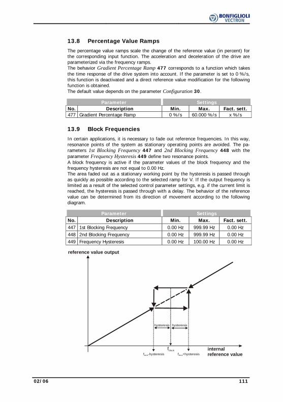
02/06 111
13.8 Percentage Value Ramps
The percentage value ramps scale the change of the reference value (in percent) for the corresponding input function. The acceleration and deceleration of the drive are parameterized via the frequency ramps. The behavior Gradient Percentage Ramp 477 corresponds to a function which takes the time response of the drive system into account. If the parameter is set to 0 %/s, this function is deactivated and a direct reference value modification for the following function is obtained. The default value depends on the parameter Configuration 30.
Parameter Settings No. Description Min. Max. Fact. sett. 477 Gradient Percentage Ramp 0 %/s 60.000 %/s x %/s
13.9 Block Frequencies
In certain applications, it is necessary to fade out reference frequencies. In this way, resonance points of the system as stationary operating points are avoided. The pa-rameters 1st Blocking Frequency 447 and 2nd Blocking Frequency 448 with the parameter Frequency Hysteresis 449 define two resonance points. A block frequency is active if the parameter values of the block frequency and the frequency hysteresis are not equal to 0.00 Hz. The area faded out as a stationary working point by the hysteresis is passed through as quickly as possible according to the selected ramp for V. If the output frequency is limited as a result of the selected control parameter settings, e.g. if the current limit is reached, the hysteresis is passed through with a delay. The behavior of the reference value can be determined from its direction of movement according to the following diagram.
Parameter Settings No. Description Min. Max. Fact. sett. 447 1st Blocking Frequency 0.00 Hz 999.99 Hz 0.00 Hz 448 2nd Blocking Frequency 0.00 Hz 999.99 Hz 0.00 Hz 449 Frequency Hysteresis 0.00 Hz 100.00 Hz 0.00 Hz
internalreference value
reference value output
fblock
hysteresis hysteresis
f +hysteresisblockf -hysteresisblock
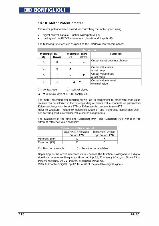
112 02/06
13.10 Motor Potentiometer The motor potentiometer is used for controlling the motor speed using • digital control signals (Function Motorpoti MP) or
• the keys of the KP 500 control unit (Function Motorpoti KP) The following functions are assigned to the Up/Down control commands: Activation Motorpoti (MP) Motorpoti (KP) Function Up Down Up Down 0 0 – – Output signal does not change
1 0 – Output value rises
at set ramp 0 1 – Output value drops
at set ramp 1 1 + Output value is reset
to initial value 0 = contact open 1 = contact closed
= arrow keys at KP 500 control unit The motor potentiometer function as well as its assignment to other reference value
sources can be selected in the corresponding reference value channels via parameters Reference Frequency Source 475 or Reference Percentage Source 476. Refer to Chapters "Frequency Reference Channel" and "Reference percentage chan-nel" for the possible reference value source assignments.
The availability of the functions "Motorpoti (MP)" and "Motorpoti (KP)" varies in the
different reference value channels: Reference value channel
Reference Frequency
Source 475 Reference Percent-
age Source 476
Motorpoti (MP) X X Motorpoti (KP) X 0 X = Function available 0 = Function not available Depending on the active reference value channel, the function is assigned to a digital
signal via parameters Frequency Motorpoti Up 62, Frequency Motorpot. Down 63 or Percent Motorpo. Up 72, Percent Motorpoti Down 73. Refer to Chapter "Digital Inputs" for a list of the available digital signals.

02/06 113
The Operation Mode 474 of the motor potentiometer function defines the behavior of
the function at various operating points of the frequency inverter. Operation mode Function
0 - Not Latching In the operation mode motor potentiometer non-storing (not latching), the drive goes to the set minimum reference value at each start.
1 - latching
In the operation mode storing (latching) the motor goes to the reference value selected before the switch-off at the start. The reference value is also stored when the device is switched off.
2 - Taking Over
The operation mode Motorpoti taking over is to be used for the data set change-over of the reference value channel. The current reference value is used by changing to the motorpoti function.
3 - Taking Over and Latching This operation mode combines the behavior in op-eration mode 1 and 2
13.10.1 Motorpoti (MP) The Function "Motorpoti (MP)" can be parameterized via the parameters Reference
Frequency Source 475 or Reference Percentage Source 476. Frequency Reference Channel
Via the digital control inputs, the required functions Frequency Motorpoti Up 62 and Frequency Motorpot. Down 63 are activated. The reference values are limited via parameters Minimum Frequency 418 and Maxi-mum Frequency 419.
Reference percentage channel
Via the digital control inputs, the required functions Percentage Motorpoti Up 72 and Percentage Motorpot. Down 73 are activated. The reference values are limited via parameters Minimum Percentage 518 and Maximum Percentage 519.
13.10.2 Motorpoti (KP) The function "Motorpoti (KP)" is only available in the reference frequency channel.
The function and its assignment to other reference value sources can be selected via parameter Reference Frequency Source 475.
Via the keys of the KP 500 control unit, the required functions Frequency Motorpoti
Up 62 and Frequency Motorpot. Down 63 are activated. The reference values are limited via parameters Minimum Frequency 418 and Maxi-mum Frequency 419.
The function is used as described in Chapter
"Controlling the Motor via the Control Unit". When the function Motorpoti (KP) is active "inPF" will be dis-played for clockwise operation and "inPr" will be displayed for anti-clockwise operation.

114 02/06
The control unit keys have the following functions: Key functions
/ Increase / reduce frequency
ENT Reversal of the direction of rotation independent of the control signal on the terminals Clockwise S2IND or Anticlockwise S3IND.
ENT (1 sec)
Save the selected function as default value. The direction of rotation is not exchanged.
ESC Cancel function and return to the menu structure.
FUN Switch from internal set point inP to JOG frequency; the drive starts. Release the key to switch to the sub-function and stop the drive.
RUN Start drive; alternative to control signal S2IND or S3IND
STOP Stop drive; alternative to control signal S2IND or S3IND
13.10.3 Controlling the Motor via the Control Unit
The parameter Reference Frequency Source 475 enables the assignment of the refer-ence value sources in the frequency reference value channel. Operation modes can be set without the function "Motorpoti (KP)". If an operation mode is selected without "Motorpoti (KP)", it is still possible to control a connected motor via the keys of the KP 500 control unit. The function is activated as described in "Control Unit KP500, Controlling the Motor via the Control Unit". The speed of the modification of the reference value is limited by the parameter Ramp Keypad-Motorpoti 473.
Parameter Settings No. Description Min. Max. Fact. sett. 473 Ramp Keypad-Motorpoti 0.00 Hz/s 999.99 Hz/s 2.00 Hz/s
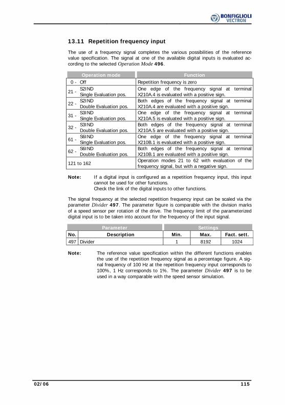
02/06 115
13.11 Repetition frequency input The use of a frequency signal completes the various possibilities of the reference
value specification. The signal at one of the available digital inputs is evaluated ac-cording to the selected Operation Mode 496.
Operation mode Function 0 - Off Repetition frequency is zero
21 - S2IND Single Evaluation pos.
One edge of the frequency signal at terminal X210A.4 is evaluated with a positive sign.
22 - S2IND Double Evaluation pos.
Both edges of the frequency signal at terminal X210A.4 are evaluated with a positive sign.
31 - S3IND Single Evaluation pos.
One edge of the frequency signal at terminal X210A.5 is evaluated with a positive sign.
32 - S3IND Double Evaluation pos.
Both edges of the frequency signal at terminal X210A.5 are evaluated with a positive sign.
61 - S6IND Single Evaluation pos.
One edge of the frequency signal at terminal X210B.1 is evaluated with a positive sign.
62 - S6IND Double Evaluation pos.
Both edges of the frequency signal at terminal X210B.1 are evaluated with a positive sign.
121 to 162 Operation modes 21 to 62 with evaluation of the frequency signal, but with a negative sign.
Note: If a digital input is configured as a repetition frequency input, this input
cannot be used for other functions. Check the link of the digital inputs to other functions.
The signal frequency at the selected repetition frequency input can be scaled via the
parameter Divider 497. The parameter figure is comparable with the division marks of a speed sensor per rotation of the drive. The frequency limit of the parameterized digital input is to be taken into account for the frequency of the input signal.
Parameter Settings No. Description Min. Max. Fact. sett. 497 Divider 1 8192 1024 Note: The reference value specification within the different functions enables
the use of the repetition frequency signal as a percentage figure. A sig-nal frequency of 100 Hz at the repetition frequency input corresponds to 100%, 1 Hz corresponds to 1%. The parameter Divider 497 is to be used in a way comparable with the speed sensor simulation.

116 02/06
14 Control Inputs and Outputs The modular structure of the frequency inverters enables a wide spectrum of applica-
tions on the basis of the available hardware and software functionality. The control inputs and outputs of terminals X210A and X210B described in the following can be linked to software modules freely via the described parameters.
14.1 Multi-function input MFI1 Multifunction input MFI1 can either be configured as a voltage, current or a digital
input. Depending on the selected Operation Mode 452 for the multifunction input, a link to various functions of the software is possible. The unused operation modes are assigned the signal value 0 (LOW).
Operation mode Function 1 - Voltage Input voltage signal (MFI1A), 0 V ... 10 V 2 - Current Input current signal (MFI1A), 0 mA ... 20 mA 3 - Digital Input digital signal (MFI1D), 0 V ... 24 V
14.1.1 Analog Input MFI1A Multifunction input MFI1 is configured by default for an analog reference value source
with a voltage signal of 0V to 10V. Alternatively, you can select the operation mode for an analog current signal of 0 mA to 20 mA. The current signal is continuously monitored and the fault message "F1407" displayed if the maximum figure is exceeded.
14.1.2 Characteristic Mapping of the analog input signal onto a reference frequency value or a reference
percentage value is possible for various requirements. Parameterization can be done via two points of the linear characteristic of the reference value channel. Point 1 with coordinates X1 and Y1 and point 2 with coordinates X2 and Y2 can be set in four data sets.
Parameter Settings No. Description Min. Max. Fact. sett. 454 Point X1 0.00 % 100.00 % 2.00 % 455 Point Y1 -100.00 % 100.00 % 0.00 % 456 Point X2 0.00 % 100.00 % 98.00 % 457 Point Y2 -100.00 % 100.00 % 100.00 % The coordinates of the points relate, as a percentage, to the analog signal with 10 V
or 20 mA and parameter Maximum Frequency 419 or parameter Maximum Reference Percentage 519. The direction of rotation can be changed via the digital inputs and/or by selection of the points.
Attention! The monitoring of the analog input signal via the parameter Er-
ror/Warning Behavior 453 demands the examination of the parameter Point X1 454.
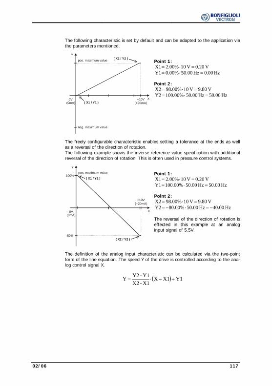
02/06 117
The following characteristic is set by default and can be adapted to the application via
the parameters mentioned.
pos. maximum value
neg. maximum value
( X1 / Y1 )0V
(0mA)+10V
(+20mA)
( X2 / Y2 )Y
X
Point 1:
V 0.20V 102.00%X1 =⋅= Hz 0.00Hz 50.000.00%Y1 =⋅=
Point 2:
V 9.80V 1098.00%X2 =⋅= Hz 0.005Hz 50.000.00%10Y2 =⋅=
The freely configurable characteristic enables setting a tolerance at the ends as well
as a reversal of the direction of rotation. The following example shows the inverse reference value specification with additional reversal of the direction of rotation. This is often used in pressure control systems.
pos. maximum value
( X1 / Y1 )
0V(0mA)
+10V(+20mA)
( X2 / Y2 )
Y
X
-80%
100%
Point 1:
V 0.20V 102.00%X1 =⋅= Hz 50.00Hz 50.000.00%10Y1 =⋅=
Point 2:
V 9.80V 1098.00%X2 =⋅= Hz 0.004Hz 50.000.00%8Y2 −=⋅−=
The reversal of the direction of rotation is effected in this example at an analog input signal of 5.5V.
The definition of the analog input characteristic can be calculated via the two-point
form of the line equation. The speed Y of the drive is controlled according to the ana-log control signal X.
( ) Y1X1X
X1-X2Y1-Y2 Y +−⋅=
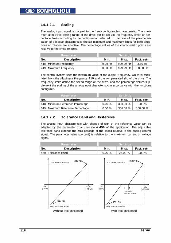
118 02/06
14.1.2.1 Scaling The analog input signal is mapped to the freely configurable characteristic. The maxi-
mum admissible setting range of the drive can be set via the frequency limits or per-centage limits according to the configuration selected. In the case of the parameteri-zation of a bipolar characteristic, the set minimum and maximum limits for both direc-tions of rotation are effective. The percentage values of the characteristic points are relative to the limits selected.
Parameter Settings No. Description Min. Max. Fact. sett. 418 Minimum Frequency 0.00 Hz 999.99 Hz 3.50 Hz 419 Maximum Frequency 0.00 Hz 999.99 Hz 50.00 Hz The control system uses the maximum value of the output frequency, which is calcu-
lated from the Maximum Frequency 419 and the compensated slip of the drive. The frequency limits define the speed range of the drive, and the percentage values sup-plement the scaling of the analog input characteristic in accordance with the functions configured.
Parameter Settings No. Description Min. Max. Fact. sett. 518 Minimum Reference Percentage 0.00 % 300.00 % 0.00 % 519 Maximum Reference Percentage 0.00 % 300.00 % 100.00 %
14.1.2.2 Tolerance Band and Hysteresis The analog input characteristic with change of sign of the reference value can be
adapted by the parameter Tolerance Band 450 of the application. The adjustable tolerance band extends the zero passage of the speed relative to the analog control signal. The parameter value (percent) is relative to the maximum current or voltage signal.
Parameter Settings No. Description Min. Max. Fact. sett. 450 Tolerance Band 0.00 % 25.00 % 2.00 %
pos. maximum value
neg. maximum value
(X1 / Y1)
0V(0mA)
+10V(+20mA)
(X2 / Y2)
Without tolerance band
pos. maximum value
neg. maximum value
(X1 / Y1)
0V(0mA)
+10V(+20mA)
(X2 / Y2)
zero pointtolerance band
With tolerance band
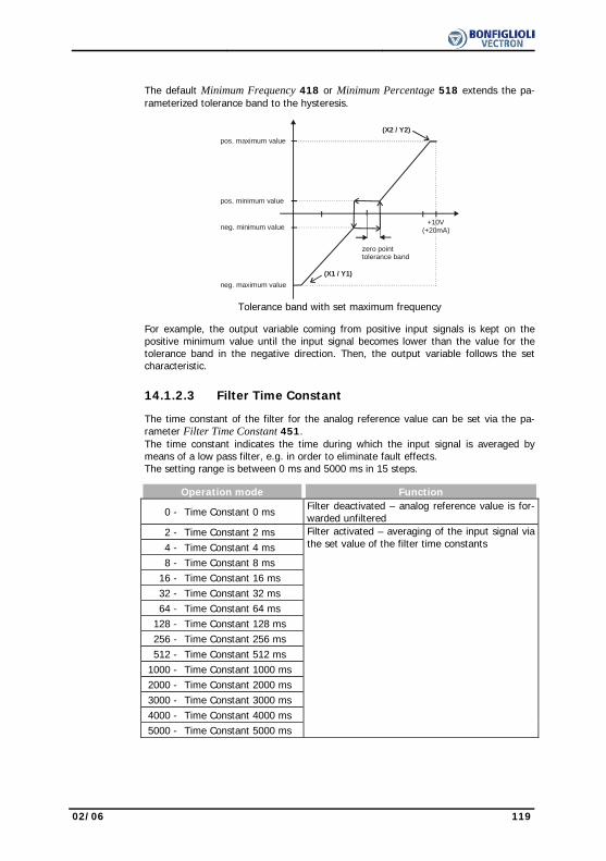
02/06 119
The default Minimum Frequency 418 or Minimum Percentage 518 extends the pa-
rameterized tolerance band to the hysteresis.
pos. maximum value
neg. maximum value(X1 / Y1)
+10V(+20mA)
(X2 / Y2)
pos. minimum value
neg. minimum value
zero pointtolerance band
Tolerance band with set maximum frequency
For example, the output variable coming from positive input signals is kept on the
positive minimum value until the input signal becomes lower than the value for the tolerance band in the negative direction. Then, the output variable follows the set characteristic.
14.1.2.3 Filter Time Constant The time constant of the filter for the analog reference value can be set via the pa-
rameter Filter Time Constant 451. The time constant indicates the time during which the input signal is averaged by means of a low pass filter, e.g. in order to eliminate fault effects. The setting range is between 0 ms and 5000 ms in 15 steps.
Operation mode Function
0 - Time Constant 0 ms Filter deactivated – analog reference value is for-warded unfiltered
2 - Time Constant 2 ms 4 - Time Constant 4 ms 8 - Time Constant 8 ms 16 - Time Constant 16 ms 32 - Time Constant 32 ms 64 - Time Constant 64 ms 128 - Time Constant 128 ms 256 - Time Constant 256 ms 512 - Time Constant 512 ms 1000 - Time Constant 1000 ms 2000 - Time Constant 2000 ms 3000 - Time Constant 3000 ms 4000 - Time Constant 4000 ms 5000 - Time Constant 5000 ms
Filter activated – averaging of the input signal via the set value of the filter time constants
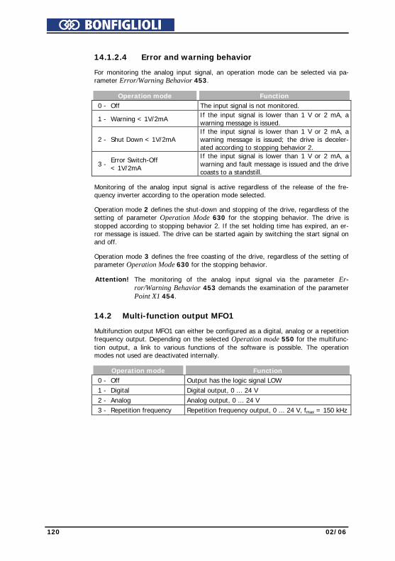
120 02/06
14.1.2.4 Error and warning behavior For monitoring the analog input signal, an operation mode can be selected via pa-
rameter Error/Warning Behavior 453. Operation mode Function 0 - Off The input signal is not monitored. 1 - Warning < 1V/2mA If the input signal is lower than 1 V or 2 mA, a
warning message is issued.
2 - Shut Down < 1V/2mA If the input signal is lower than 1 V or 2 mA, a warning message is issued; the drive is deceler-ated according to stopping behavior 2.
3 - Error Switch-Off
< 1V/2mA
If the input signal is lower than 1 V or 2 mA, a warning and fault message is issued and the drive coasts to a standstill.
Monitoring of the analog input signal is active regardless of the release of the fre-
quency inverter according to the operation mode selected. Operation mode 2 defines the shut-down and stopping of the drive, regardless of the
setting of parameter Operation Mode 630 for the stopping behavior. The drive is stopped according to stopping behavior 2. If the set holding time has expired, an er-ror message is issued. The drive can be started again by switching the start signal on and off.
Operation mode 3 defines the free coasting of the drive, regardless of the setting of
parameter Operation Mode 630 for the stopping behavior. Attention! The monitoring of the analog input signal via the parameter Er-
ror/Warning Behavior 453 demands the examination of the parameter Point X1 454.
14.2 Multi-function output MFO1 Multifunction output MFO1 can either be configured as a digital, analog or a repetition
frequency output. Depending on the selected Operation mode 550 for the multifunc-tion output, a link to various functions of the software is possible. The operation modes not used are deactivated internally.
Operation mode Function 0 - Off Output has the logic signal LOW 1 - Digital Digital output, 0 ... 24 V 2 - Analog Analog output, 0 ... 24 V 3 - Repetition frequency Repetition frequency output, 0 ... 24 V, fmax = 150 kHz
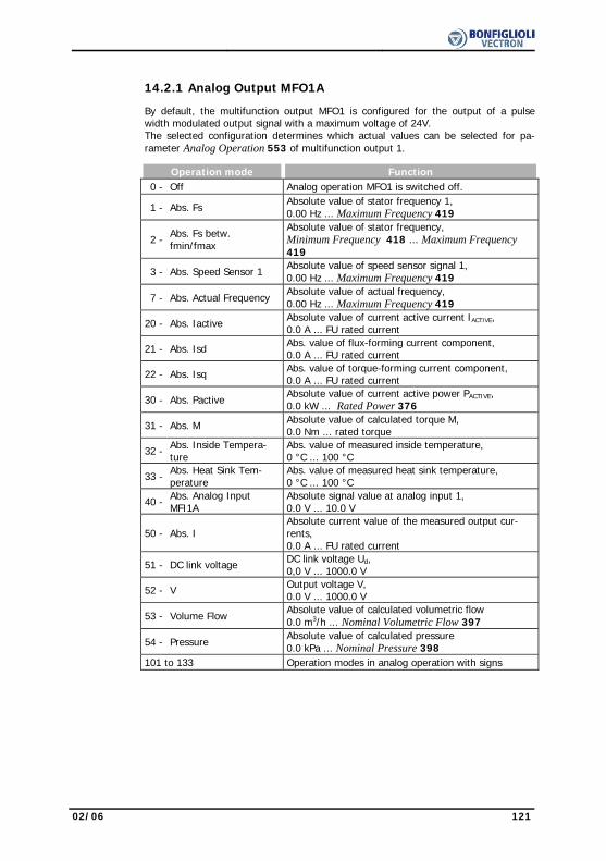
02/06 121
14.2.1 Analog Output MFO1A By default, the multifunction output MFO1 is configured for the output of a pulse
width modulated output signal with a maximum voltage of 24V. The selected configuration determines which actual values can be selected for pa-rameter Analog Operation 553 of multifunction output 1.
Operation mode Function 0 - Off Analog operation MFO1 is switched off.
1 - Abs. Fs Absolute value of stator frequency 1, 0.00 Hz ... Maximum Frequency 419
2 - Abs. Fs betw. fmin/fmax
Absolute value of stator frequency, Minimum Frequency 418 ... Maximum Frequency 419
3 - Abs. Speed Sensor 1
Absolute value of speed sensor signal 1, 0.00 Hz ... Maximum Frequency 419
7 - Abs. Actual Frequency
Absolute value of actual frequency, 0.00 Hz ... Maximum Frequency 419
20 - Abs. Iactive Absolute value of current active current IACTIVE, 0.0 A ... FU rated current
21 - Abs. Isd Abs. value of flux-forming current component, 0.0 A ... FU rated current
22 - Abs. Isq Abs. value of torque-forming current component, 0.0 A ... FU rated current
30 - Abs. Pactive
Absolute value of current active power PACTIVE, 0.0 kW ... Rated Power 376
31 - Abs. M Absolute value of calculated torque M, 0.0 Nm ... rated torque
32 - Abs. Inside Tempera-ture
Abs. value of measured inside temperature, 0 °C ... 100 °C
33 - Abs. Heat Sink Tem-perature
Abs. value of measured heat sink temperature, 0 °C ... 100 °C
40 - Abs. Analog Input MFI1A
Absolute signal value at analog input 1, 0.0 V ... 10.0 V
50 - Abs. I
Absolute current value of the measured output cur-rents, 0.0 A ... FU rated current
51 - DC link voltage DC link voltage Ud, 0,0 V ... 1000.0 V
52 - V Output voltage V, 0.0 V ... 1000.0 V
53 - Volume Flow
Absolute value of calculated volumetric flow 0.0 m3/h ... Nominal Volumetric Flow 397
54 - Pressure
Absolute value of calculated pressure 0.0 kPa ... Nominal Pressure 398
101 to 133 Operation modes in analog operation with signs

122 02/06
14.2.1.1 Output Characteristic The voltage range of the output signal at multifunction output 1 can be adjusted. The
value range of the actual value selected via parameter Analog Operation 553 is as-signed to the value range of the output signal which is adjusted via the parameters Voltage 100% 551 and Voltage 0% 552.
Parameter Settings No. Description Min. Max. Fact. sett. 551 Voltage 100% 0.0 V 22.0 V 10.0 V 552 Voltage 0% 0.0 V 22.0 V 0.0 V
Actual abs. value Analog Operation 553: Analog Operation 553 with signs:
0V
+10V
+24V
50%0% 100% 0V
+5V
+24V
0%-100% 100%
+10V
With the parameters Voltage 100% 551 and Voltage 0% 552, the voltage range at 100% and 0% of the output parameter is set. If the output value exceeds the refer-ence value, the output voltage also exceeds the value of the parameter Voltage 100% 551 up to the maximum value of 24V.
14.2.2 Frequency Output MFO1F
The multifunctional output MFO1 can be used as a frequency output if the corre-sponding Operation Mode 550 is selected. The 24V output signal is assigned to the abs. value of the speed or frequency via the parameter Repetition Frequency Output 555. The selection of the operation modes depends on the expansion modules in-stalled as an option.
Operation mode Function 0 - Off Repetition frequency operation MFO1 switched off 1 - Actual Frequency Abs. value of the Actual Frequency 241 2 - Stator Frequency Abs. value of the Stator Frequency 210 3 - Encoder 1 Frequency Abs. value of the Encoder 1 Frequency 217
5 - Repetition Frequency Input Abs. value of the Repetition Frequency Input 252
14.2.2.1 Scaling
The repetition frequency mode for the multifunction output corresponds to the emula-tion of an incremental sensor. The parameter Division Marks 556 must be param-eterized according to the frequency to be output.
Parameter Settings No. Description Min. Max. Fact. sett. 556 Division marks 30 8192 1024
The frequency limit of fmax=150 kHz must not be exceeded in the calculation of the parameter Division marks 556, i.e. the requirement
Smax ∗ abs. frequency value ∗ 150 kHz must be met. valueFrequency
Hz 150000Smax =

02/06 123
14.3 Digital Outputs
The OP. Mode Digital Output 1 530 and the relay output with the parameter Op. Mode Digital Output 3 532 link the digital outputs to various functions. The selection of the functions depends on the parameterized configuration. The use of the multi-functional output MFO1 as a digital output demands selection of an Operation Mode 550 and linking via parameter Digital Operation 554.
Operation mode Function 0 - Off Digital output is switched off
1 - Ready or Standby Signal Frequency inverter is initialized and on stand-by or in operation
2 - Run Signal Controller release signal and a start command are present, output frequency available
3 - Error Signal Message is displayed via the parameter Current Error 259 or Warnings 269.
4 - Setting Frequency The Stator Frequency 210 is higher than the parameterized Setting Frequency 510
5 - Reference Frequency reached
The Actual Frequency 241 of the drive has reached the Internal Reference Frequency 228.
6 - Reference Percentage Reached
The Actual Percentage Value 230 has reached the Reference Percentage Value 229.
7 - Ixt warning The Warning Limit Short-Term Ixt 405 or Warn-ing Limit Long-Term Ixt 406 has been reached.
8 - Warning Heat sink temperature
Max. heat sink temperature TK of 80 °C minus the Warning Limit Heat Sink Temp. 407 reached.
9 - Warning Inside temperature
Max. inside temperature Ti of 65 °C minus the Warning Limit Inside Temperature 408 reached.
10 - Warning Motor TemperatureWarning behavior according to parameterized Motor Temp. Operation Mode 570 at max. motor temperature TPTC.
11 - Warning General The message is displayed via parameter Warnings 269.
12 - Warning over temperature
The selected limit values Warning Limit Heat Sink Temp. 407, Warning Limit Inside Temp 408 or the maximum motor temperature have been ex-ceeded.
13 - Mains Failure Failure of the mains voltage and power regulation active according to Operation Mode 670 for the voltage controller.
14 - Warning Motor Protect. Switch
Parameterized Operation Mode 571 for the motor protection switch has triggered.
15 - Warning Current Limitation A controller or the Operation Mode 573 of the intelligent current limits limit the output current.
16 - Controller Current Limit. Long Term Ixt
The overload reserve for 60 s has been used up and the output current is being limited.
17 - Controller Current Limit. Short Term Ixt
The overload reserve for 1 s has been used up and the output current is being limited.
18 - Controller Current Limit. TK Max. heat sink temperature TK reached, intelli-gent current limits of Operation Mode 573 active.
19 - Controller Current Limit. Motor Temp.
Max. motor temperature reached, intelligent cur-rent limits of Operation Mode 573 active.
20 - Comparator 1 The comparison according to the selected OP. mode Comparator 1,540 is true.
Table "Operation Modes for Digital Outputs" continued on next page.
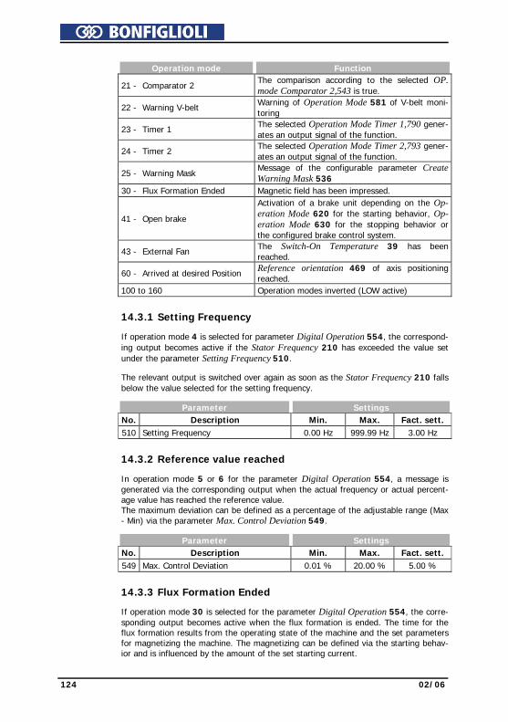
124 02/06
Operation mode Function
21 - Comparator 2 The comparison according to the selected OP. mode Comparator 2,543 is true.
22 - Warning V-belt Warning of Operation Mode 581 of V-belt moni-toring
23 - Timer 1 The selected Operation Mode Timer 1,790 gener-ates an output signal of the function.
24 - Timer 2 The selected Operation Mode Timer 2,793 gener-ates an output signal of the function.
25 - Warning Mask Message of the configurable parameter Create Warning Mask 536
30 - Flux Formation Ended Magnetic field has been impressed.
41 - Open brake
Activation of a brake unit depending on the Op-eration Mode 620 for the starting behavior, Op-eration Mode 630 for the stopping behavior or the configured brake control system.
43 - External Fan The Switch-On Temperature 39 has been reached.
60 - Arrived at desired Position Reference orientation 469 of axis positioning reached.
100 to 160 Operation modes inverted (LOW active)
14.3.1 Setting Frequency If operation mode 4 is selected for parameter Digital Operation 554, the correspond-
ing output becomes active if the Stator Frequency 210 has exceeded the value set under the parameter Setting Frequency 510.
The relevant output is switched over again as soon as the Stator Frequency 210 falls
below the value selected for the setting frequency. Parameter Settings No. Description Min. Max. Fact. sett. 510 Setting Frequency 0.00 Hz 999.99 Hz 3.00 Hz
14.3.2 Reference value reached In operation mode 5 or 6 for the parameter Digital Operation 554, a message is
generated via the corresponding output when the actual frequency or actual percent-age value has reached the reference value. The maximum deviation can be defined as a percentage of the adjustable range (Max - Min) via the parameter Max. Control Deviation 549.
Parameter Settings No. Description Min. Max. Fact. sett. 549 Max. Control Deviation 0.01 % 20.00 % 5.00 %
14.3.3 Flux Formation Ended If operation mode 30 is selected for the parameter Digital Operation 554, the corre-
sponding output becomes active when the flux formation is ended. The time for the flux formation results from the operating state of the machine and the set parameters for magnetizing the machine. The magnetizing can be defined via the starting behav-ior and is influenced by the amount of the set starting current.
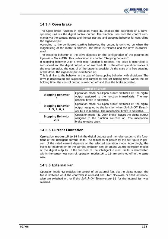
02/06 125
14.3.4 Open brake The Open brake function in operation mode 41 enables the activation of a corre-
sponding unit via the digital control output. The function uses both the control com-mands via the contact inputs and the set starting and stopping behavior for controlling the digital output. According to the configured starting behavior, the output is switched on when the magnetizing of the motor is finished. The brake is released and the drive is acceler-ated. The stopping behavior of the drive depends on the configuration of the parameters Operation Mode 630. This is described in chapter "Stopping Behavior". If stopping behavior 2 or 5 with stop function is selected, the drive is controlled to zero speed and the digital output is not switched off. In the other operation modes of the stop behavior, the control of the brake is possible. At the start of a free coasting of the drive, the digital output is switched off. This is similar to the behavior in the case of the stopping behavior with shutdown. The drive is decelerated and supplied with current for the set holding time. Within the set holding time, the control output is switched off and thus the brake activated.
Control of Brake
Stopping Behavior 0
Operation mode "41-Open brake" switches off the digital output assigned to the function immediately. The me-chanical brake is activated.
Stopping Behavior 1, 3, 4, 6, 7
Operation mode "41-Open brake" switches off the digital output assigned to the function when Switch-Off Thresh-old 637 is reached. The mechanical brake is activated.
Stopping Behavior 2, 5
Operation mode "41-Open brake" leaves the digital output assigned to the function switched on. The mechanical brake remains open.
14.3.5 Current Limitation Operation modes 15 to 19 link the digital outputs and the relay output to the func-
tions of the intelligent current limits. The reduction of power by the set figure in per-cent of the rated current depends on the selected operation mode. Accordingly, the event for intervention of the current limitation can be output via the operation modes of the digital outputs. If the function of the intelligent current limits is deactivated within the sensor-less control, operation modes 16 to 19 are switched off in the same way.
14.3.6 External Fan Operation mode 43 enables the control of an external fan. Via the digital output, the
fan is switched on if the controller is released and Start clockwise or Start anticlock-wise are switched on, or if the Switch-On Temperature 39 for the internal fan was reached.

126 02/06
14.3.7 Warning Mask The logic signals of various monitoring and control functions can be set via the opera-
tion mode for parameter Create Warning Mask 536. According to the application, any number of warnings and controller status messages can be combined. This enables internal or external control via a common output signal.
Operation mode Function 0 - No Change Configured warning mask is not modified.
1 - Activate everything The warnings and controller status messages stated are linked in the warning mask.
2 - Activate all Warnings The warnings reports stated are linked in the warn-ing mask.
3 - Activate all Controller States
The controller status reports stated are linked in the warning mask.
10 - Warning Ixt The frequency inverter is overloaded
11 - Warning Short-Term Ixt Overload reserve for 1 s minus the Warning Limit Short-Term Ixt 405 has been reached.
12 - Warning Long-Term Ixt Overload reserve for 60 s minus the Warning Limit Long-Term Ixt 406 has been reached.
13 - Warning Heat Sink Tem-perature
Max. heat sink temperature TK of 80 °C minus the Warning Limit Heat Sink Temperature 407 has been reached.
14 - Warning Inside Temperature
Max. inside temperature Ti of 65 °C minus the Warning Limit Inside Temperature 408 reached.
15 - Warning Limit The controller stated in Controller Status 355 limits the reference value.
16 - Warning Init Frequency inverter is initialized
17 - Warning Motor Tempera-ture
Warning behavior according to parameterized Mo-tor Temp. Operation Mode 570 at max. motor temperature TPTC.
18 - Warning Phase Failure Phase Supervision 576 reports a phase failure.
19 - Warning Motor Protection Switch
Operation Mode 571 for the motor protective switch has triggered.
20 - Warning Fmax The Maximum Frequency 419 has been exceeded. The frequency limitation is active
21 - Warning Analog Input MFI1A
The input signal is lower than 1V/2mA according to the operation mode Error/Warning Behavior 453
22 - Warning
Analog Input EM-S1INA The input signal is lower than 1V/2mA according to the operation mode Error/Warning Behavior 453
23 - Warning System bus
A Slave at the system bus signals a fault;Warning is only relevant with option EM-SYS.
24 - Warning Udc The DC link voltage has reached the type-dependent minimum value.
25 - Warning V-belt The Operation Mode 581 for V-belt monitoring
signals no-load operation of the application.
30 - Controller Udc Dynamic Operation
Controller is active according to the Operation Mode 670 for the voltage controller.
31 - Controller Shutdown
The output frequency in the case of a mains failure is below the Shutdown Threshold 675.
32 - Controller Mains Failure
Failure of the mains voltage and power regulation active according to Operation Mode 670 for the voltage controller.

02/06 127
Operation mode Function
33 - Controller Udc Limitation The DC link voltage has exceeded the Reference DC-Link Limitation 680.
34 - Controller
Voltage Pre-Control The Dyn. Voltage Pre-Control 605 accelerates the control characteristics.
35 - Controller I abs The output current is limited 36 - Controller
Torque Limitation The output power or the torque are limited on the speed controller
37 - Controller Torque Control
Switch-over of field-orientated control between speed and torque-controlled
38 - Ramp Stop The Operation Mode 620 selected in starting be-
havior limits the output current 39 - Contr. Intel. Curr. Lim.
LT-Ixt Overload limit of the long-term Ixt (60s) reached, intelligent current limits active
40 - Contr. Intel. Curr. Lim. ST-Ixt
Overload limit of the short-term Ixt (1s) reached, intelligent current limits active
41 - Contr. Intel. Curr. Lim.
Tc Max. heat sink temperature TK reached, Operation Mode 573 for the intelligent current limits active.
42 - Contr. Intel. Curr. Lim.
Motor Temp. Max. motor temperature TPTC reached, Operation Mode 573 for the intelligent current limits active.
43 - Controller
Torque Limitation The reference frequency has reached the Maximum Frequency 419. The frequency limitation is active.
101 to 143 Removal or deactivation of the operation mode within the warning mask
The selected warning mask can be read out via the parameter Actual Warning Mask 537. The above operation modes, which can be set in the configurable Create Warn-ing Mask 536 are encoded in the Actual Warning Mask 537. The code results from hexadecimal addition of the individual operation modes and the matching abbrevia-tion.
Warning code Operation mode 536 A FFFF FFFF - 1 - Activate everything A 0000 FFFF - 2 - Activate all Warnings A FFFF 0000 - 3 - Activate all Controller States A 0000 0001 Ixt 10 - Warning Ixt A 0000 0002 IxtSt 11 - Warning Short-Term Ixt A 0000 0004 IxtLt 12 - Warning Long-Term Ixt A 0000 0008 Tc 13 - Warning Heat Sink Temperature A 0000 0010 Ti 14 - Warning Inside Temperature A 0000 0020 Lim 15 - Warning Limit A 0000 0040 INIT 16 - Warning Init A 0000 0080 MTemp 17 - Warning Motor Temperature A 0000 0100 Mains 18 - Warning Phase Failure A 0000 0200 PMS 19 - Warning Motor Protection Switch A 0000 0400 Flim 20 - Warning Fmax A 0000 0800 A1 21 - Warning Analog Input MFI1A A 0000 1000 A2 22 - Warning Analog Input MFI2A A 0000 2000 Sysbus 23 - Warning System bus A 0000 4000 UDC 24 - Warning Udc A 0000 8000 BELT 25 - Warning V-belt Table "Operation Modes of Warning Mask" continued on next page.
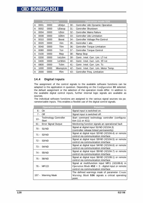
128 02/06
Warning code Operation mode 536 A 0001 0000 UDdyn 30 - Controller Udc Dynamic Operation A 0002 0000 UDstop 31 - Controller Shutdown A 0004 0000 UDctr 32 - Controller Mains Failure A 0008 0000 UDlim 33 - Controller Udc Limitation A 0010 0000 Boost 34 - Controller Voltage Pre-Control A 0020 0000 Ilim 35 - Controller I abs A 0040 0000 Tlim 36 - Controller Torque Limitation A 0080 0000 Tctr 37 - Controller Torque Control A 0100 0000 Rstp 38 - Ramp Stop A 0200 0000 IxtLtlim 39 - Contr. Intel. Curr. Lim. LT-Ixt A 0400 0000 IxtStlim 40 - Contr. Intel. Curr. Lim. ST-Ixt A 0800 0000 Tclim 41 - Contr. Intel. Curr. Lim. Tc A 1000 0000 MtempLim 42 - Contr. Intel. Curr. Lim. Motor Temp. A 2000 0000 Flim 43 - Controller Freq. Limitation
14.4 Digital Inputs
The assignment of the control signals to the available software functions can be adapted to the application in question. Depending on the Configuration 30 selected, the default assignment or the selection of the operation mode differ. In addition to the available digital control inputs, further internal logic signals are available as sources. The individual software functions are assigned to the various signal sources via pa-rameterizable inputs. This enables a flexible use of the digital control signals.
Operation mode Function 6 - On Signal input is switched on. 7 - Off Signal input is switched off.
13 - Technology Controller Start
Start command technology controller (configura-tion 111 or 411)
61 - Error Signal Output Monitoring function signals an operational fault
70 - S1IND Signal at digital input S1IND (X210A.3) (controller release linked permanently)
71 - S2IND Signal at digital input S2IND (X210A.4) or remote control via communication interface
72 - S3IND Signal at digital input S3IND (X210A.5) or remote control via communication interface
73 - S4IND Signal at digital input S4IND (X210A.6) or remote control via communication interface
74 - S5IND Signal at digital input S5IND (X210A.7) or remote control via communication interface
75 - S6IND Signal at digital input S6IND (X210B.1) or remote control via communication interface
76 - MFI1D Signal at multifunction input MFI1 (X210B.6) in Operation Mode 452 = 3 - digital input or remote control via communication interface
157 - Warning Mask The defined warnings mask of parameter Create Warning Mask 536 signals a critical operating point.
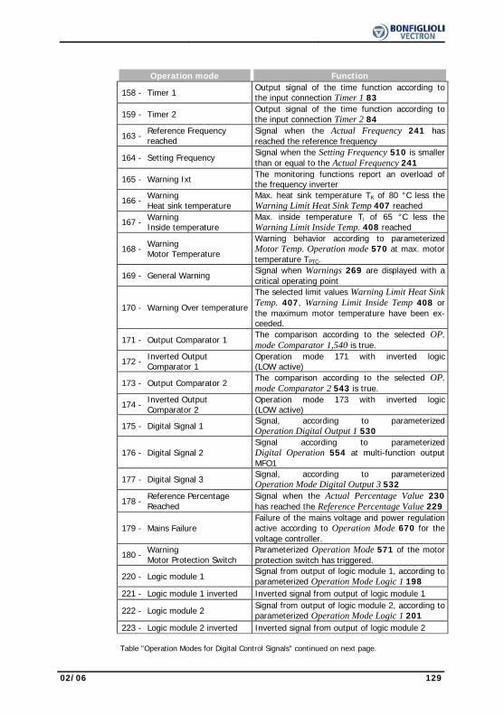
02/06 129
Operation mode Function
158 - Timer 1 Output signal of the time function according to the input connection Timer 1 83
159 - Timer 2
Output signal of the time function according to the input connection Timer 2 84
163 - Reference Frequency
reached Signal when the Actual Frequency 241 has reached the reference frequency
164 - Setting Frequency
Signal when the Setting Frequency 510 is smaller than or equal to the Actual Frequency 241
165 - Warning Ixt The monitoring functions report an overload of the frequency inverter
166 - Warning
Heat sink temperature Max. heat sink temperature TK of 80 °C less the Warning Limit Heat Sink Temp 407 reached
167 - Warning
Inside temperature Max. inside temperature Ti of 65 °C less the Warning Limit Inside Temp. 408 reached
168 - Warning
Motor Temperature
Warning behavior according to parameterized Motor Temp. Operation mode 570 at max. motor temperature TPTC.
169 - General Warning Signal when Warnings 269 are displayed with a
critical operating point
170 - Warning Over temperature
The selected limit values Warning Limit Heat Sink Temp. 407, Warning Limit Inside Temp 408 or the maximum motor temperature have been ex-ceeded.
171 - Output Comparator 1
The comparison according to the selected OP. mode Comparator 1,540 is true.
172 - Inverted Output Comparator 1
Operation mode 171 with inverted logic(LOW active)
173 - Output Comparator 2
The comparison according to the selected OP. mode Comparator 2 543 is true.
174 - Inverted Output Comparator 2
Operation mode 173 with inverted logic(LOW active)
175 - Digital Signal 1 Signal, according to parameterized Operation Digital Output 1 530
176 - Digital Signal 2 Signal according to parameterized Digital Operation 554 at multi-function output MFO1
177 - Digital Signal 3 Signal, according to parameterized Operation Mode Digital Output 3 532
178 - Reference Percentage Reached
Signal when the Actual Percentage Value 230 has reached the Reference Percentage Value 229
179 - Mains Failure Failure of the mains voltage and power regulation active according to Operation Mode 670 for the voltage controller.
180 - Warning Motor Protection Switch
Parameterized Operation Mode 571 of the motor protection switch has triggered.
220 - Logic module 1 Signal from output of logic module 1, according to parameterized Operation Mode Logic 1 198
221 - Logic module 1 inverted Inverted signal from output of logic module 1
222 - Logic module 2 Signal from output of logic module 2, according to parameterized Operation Mode Logic 1 201
223 - Logic module 2 inverted Inverted signal from output of logic module 2
Table "Operation Modes for Digital Control Signals" continued on next page.

130 02/06
Operation mode Function
224 - Logic module 3 Signal from output of logic module 3, according to parameterized Operation Mode Logic 1 205
225 - Logic module 3 inverted Inverted signal from output of logic module 3
226 - Logic module 4 Signal from output of logic module 4, according to parameterized Operation Mode Logic 1 503
227 - Logic module 4 inverted Inverted signal from output of logic module 4
270 to 276 Operation modes 70 to 76 of the digital inputs inverted (LOW active)
282 - Arrived at desired Position Reference orientation 469 of axis positioning reached.
320 - EM-S1IND 2) Signal at digital input 1 of an EM extension mod-ule or remote control via communication interface
321 - EM-S2IND 2) Signal at digital input 2 of an EM extension mod-ule or remote control via communication interface
322 - EM-S3IND 2) Signal at digital input 3 of an EM extension mod-ule or remote control via communication interface
520 - EM-S1IND inverted Operation mode 320 inverted 521 - EM-S2IND inverted Operation mode 321 inverted 522 - EM-S3IND inverted Operation mode 322 inverted 525 - S1IND (Hardware) 1) Digital input S1IND (X210A.3) 526 - S2IND (Hardware) 1) Digital input S2IND (X210A.4) 527 - S3IND (Hardware) 1) Digital input S3IND (X210A.5) 528 - S4IND (Hardware) 1) Digital input S4IND (X210A.6) 529 - S5IND (Hardware) 1) Digital input S5IND (X210A.7) 530 - S6IND (Hardware) 1) Digital input S6IND (X210B.1)
531 - MFI1D (Hardware) 1) Multifunction input MFI1 (X210B.6) in Operation Mode 452 = 3 - digital input
532 - EM-S1IND (Hardware) 1) Digital input 1 of an EM extension module 533 - EM-S2IND (Hardware) 1) Digital input 2 of an EM extension module 534 - EM-S3IND (Hardware) 1) Digital input 3 of an EM extension module
537 to 545 Operation modes 525 to 533 of the digital inputs inverted (LOW active)
700 - RxPDO1 Boolean1 3) Signal if an optional expansion module EM with system bus is used
701 - RxPDO1 Boolean2 3) Signal if an optional expansion module EM with system bus is used
702 - RxPDO1 Boolean3 3) Signal if an optional expansion module EM with system bus is used
703 - RxPDO1 Boolean4 3) Signal if an optional expansion module EM with system bus is used
710 to 713 3) Operation modes 700 to 703 for RxPDO2 with an expansion module EM
720 to 723 3) Operation modes 700 to 703 for RxPDO3 with an expansion module EM
730 - Sysbus Emergency 3) Signal if an optional expansion module EM with system bus is used
1) The digital signal is independent of the setting of parameter Local/Remote 412. 2) Refer to operating instructions of extension modules EM-IO 3) Refer to operating instructions "System bus EM-SYS extension module“

02/06 131
14.4.1 Start command The parameters Start Clockwise 68 and Start Anticlockwise 69 can be linked to the
available digital control inputs or the internal logic signals. The drive is only acceler-ated according to the control method after a start command.
The logic functions are used for the specification of the direction of rotation, but also
for using the parameterized Operation Mode 620 for the starting behavior and the Operation Mode 630 for the stopping behavior.
14.4.2 3-Wire-Control In the case of the 3-wire control, the drive is controlled by means of digital pulses.
The drive is prepared for the start via the logic state of the signal Start 3-Wire Con-trol 87 and started by a Start Clockwise (Parameter Start Clockwise 68) or a Start Anti-Clockwise (Parameter Start Anti-Clockwise 69) pulse. The drive is stopped by switching the signal Start 3-Wire Control 87 off.
The control signals for Start Clockwise and Start Anticlockwise are pulses. The func-
tions Start Clockwise and Start Anticlockwise are latching signals if the signal Start 3-Wire Control 87 is switched on. The lock is released if the stop signal is switched off.
Start
Machine
Start anticlockwise
Start clockwise
12
t
R R
L
(R) Clockwise (1) Signals are ignored (L) Anti-clockwise (2) Time t < 32 msec The drive is started according to the configured starting behavior when the signal
Start 3-Wire-Control 87 is switched on and a positive signal edge for Start Clockwise or Start Anti-Clockwise is detected.
Once the drive has been started, new edges (1) on the start signals are ignored.
If the start signal is shorter than 32 msec (2) or if both start signals were switched on within 32 msec (2), the drive will be stopped according to the configured stopping behavior.
3-wire control is activated via parameter Local/Remote 412: Operation mode Function
5 - Ctrl. 3-Wire, direc-tion Cont.
3-wire; control of direction of rotation and signal3-Wire Control 87 via contacts
46 - Ctrl. 3-Wire + KP, Dir. Cont. + KP
3-wire and control unit; control of direction of rotation and signal 3-Wire Control 87 via contacts or control unit.
For further operation modes of parameter Local/Remote 412, refer to Chapter “Bus
controller”.

132 02/06
14.4.3 Error Acknowledgment The frequency inverters feature various monitoring functions which can be adapted
via the error and warning behavior. Switching the frequency inverter off at the various operating points should be avoided by an application-related parameterization. If there is a fault switch-off, this message can be acknowledged via the parameter Pro-gram(ming) 34 or the logic signal connected with the parameter Error Acknowledg-ment 103.
14.4.4 Timer The time functions can be selected via the parameters Operation Mode Timer 1 790
and Operation Mode Timer 2 793. The sources of the logic signals are selected with the parameters Timer 1 83 and Timer 2 84 and processed according to the config-ured timer functions.
14.4.5 Thermo-contact The monitoring of the motor temperature is a part of the error and warning behavior
which can be configured as required. The parameter Thermo contact 204 links the digital input signal to the defined Motor Temp. Operation Mode 570 which is de-scribed in chapter "Motor Temperature". The temperature monitoring via a digital input checks the input signal for the threshold value. Accordingly, a thermo contact or an additional circuit must be used if a temperature-dependent resistor is used.
14.4.6 n-/T-Control Change-Over The field-orientated control procedures in configurations 230 and 430 contain the
functions for speed or torque-dependent control of the drive. The change-over can be done during running operation of the drive, as an additional functionality monitors the transition between the two control procedures. The speed controller or the torque controller is active, depending on the n-/T Control Change-Over 164.
14.4.7 Data Set Change-Over Parameter values can be stored in four different data sets. This enables the use of
various parameter values depending on the current operation point of the frequency inverter. The change-over between the four data sets is done via the logic signals assigned to the parameters Data Set Change-Over 1 70 and Data Set Change-Over 2 71. The actual value parameter Active Data Set 249 shows the selected data set.
Activation
Data Set Change-
Over 1 70 Data Set Change-
Over 2 71 Function/active data set
0 0 Data set 1 (DS1) 1 0 Data set 2 (DS2) 1 1 Data set 3 (DS3) 0 1 Data set 4 (DS4) 0 = contact open 1 = contact closed
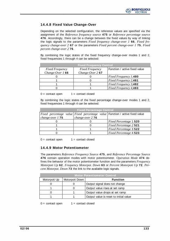
02/06 133
14.4.8 Fixed Value Change-Over Depending on the selected configuration, the reference values are specified via the
assignment of the Reference frequency source 475 or Reference percentage source 476. Accordingly, there can be a change between the fixed values by way of linking the logic signals to the parameters Fixed frequency change-over 1 66, Fixed fre-quency change-over 2 67 or the parameters Fixed percent change-over 1 75, Fixed percent change-over 2 76.
By combining the logic states of the fixed frequency change-over modes 1 and 2,
fixed frequencies 1 through 4 can be selected:
Fixed Frequency Control Fixed Frequency
Change-Over 1 66 Fixed Frequency
Change-Over 2 67 Function / active fixed value
0 0 Fixed Frequency 1,480 1 0 Fixed Frequency 2,481 1 1 Fixed Frequency 3,482 0 1 Fixed Frequency 4,483
0 = contact open 1 = contact closed By combining the logic states of the fixed percentage change-over modes 1 and 2,
fixed frequencies 1 through 4 can be selected:
Fixed Percentage Control Fixed percentage value
change-over 1 75 Fixed percentage value change-over 2 76
Function / active fixed value
0 0 Fixed Percentage 1 520 1 0 Fixed Percentage 2 521 1 1 Fixed Percentage 3 522 0 1 Fixed Percentage 4 523 0 = contact open 1 = contact closed
14.4.9 Motor Potentiometer The parameters Reference Frequency Source 475, and Reference Percentage Source
476 contain operation modes with motor potentiometer. Operation Mode 474 de-fines the behavior of the motor potentiometer function and the parameters Frequency Motorpoti Up 62, Frequency Motorpot. Down 63 or Percent Motorpoti Up 72, Per-cent Motorpot. Down 73 the link to the available logic signals.
Motor Potentiometer Control
Motorpoti Up Motorpoti Down Function 0 0 Output signal does not change 1 0 Output value rises at set ramp 0 1 Output value drops at set ramp 1 1 Output value is reset to initial value 0 = contact open 1 = contact closed
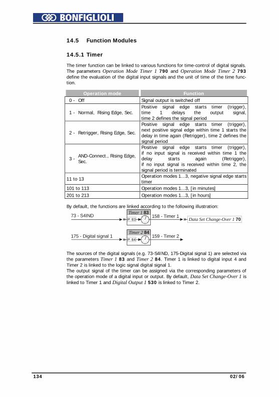
134 02/06
14.5 Function Modules
14.5.1 Timer The timer function can be linked to various functions for time-control of digital signals.
The parameters Operation Mode Timer 1 790 and Operation Mode Timer 2 793 define the evaluation of the digital input signals and the unit of time of the time func-tion.
Operation mode Function 0 - Off Signal output is switched off
1 - Normal, Rising Edge, Sec. Positive signal edge starts timer (trigger),time 1 delays the output signal,time 2 defines the signal period
2 - Retrigger, Rising Edge, Sec.
Positive signal edge starts timer (trigger),next positive signal edge within time 1 starts the delay in time again (Retrigger), time 2 defines the signal period
3 - AND-Connect., Rising Edge, Sec.
Positive signal edge starts timer (trigger),if no input signal is received within time 1 the delay starts again (Retrigger),if no input signal is received within time 2, the signal period is terminated
11 to 13 Operation modes 1...3, negative signal edge starts timer
101 to 113 Operation modes 1...3, [in minutes] 201 to 213 Operation modes 1...3, [in hours] By default, the functions are linked according to the following illustration:
158 - Timer 1Timer 1 83P. 83 Data Set Change-Over 1 70
73 - S4IND
175 - Digital signal 1 159 - Timer 2Timer 2 84
P. 84
The sources of the digital signals (e.g. 73-S4IND, 175-Digital signal 1) are selected via
the parameters Timer 1 83 and Timer 2 84. Timer 1 is linked to digital input 4 and Timer 2 is linked to the logic signal digital signal 1. The output signal of the timer can be assigned via the corresponding parameters of the operation mode of a digital input or output. By default, Data Set Change-Over 1 is linked to Timer 1 and Digital Output 1 530 is linked to Timer 2.

02/06 135
14.5.1.1 Time Constant The logic sequence of input and output signals is to be set separately for both timer
functions via the time constants. The default parameter values result in a direct link of the input and output signal without a delay.
Note: Before starting the timer, select the operation mode and set the times in
order to avoid non-defined states. Parameter Settings No. Description Min. Max. Fact. sett. 791 Time 1 Timer 1, signal delay 0.00 s/m/h 650.00 s/m/h 0.00 s/m/h 792 Time 2 Timer 1, signal duration 0.00 s/m/h 650.00 s/m/h 0.00 s/m/h 794 Time 1 Timer 2, signal delay 0.00 s/m/h 650.00 s/m/h 0.00 s/m/h 795 Time 2 Timer 2, signal duration 0.00 s/m/h 650.00 s/m/h 0.00 s/m/h Examples of the timer function depending on the selected operation mode and the
input signal: Normal, positive edge Parameter Operation mode Timer = 1
Input
Output
Time 2Time 1
As soon as the positive signal edge is received at the input, time 1 starts. After the
expiry of the delay, the output signal is activated for signal duration time 2.
Retrigger, positive edge Parameter Operation mode Timer = 2
Input
Output
Time 2Time 1Time 1
As soon as the positive signal edge is received at the input, time 1 is started. If a posi-
tive signal edge is detected within the delay, time 1 starts again. After the expiry of the delay, the output signal is switched for the signal duration time 2.
: Time not run out completely
: Time run out completely
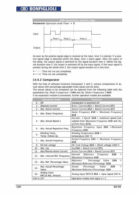
136 02/06
AND connection, positive edge Parameter Operation mode Timer = 3
Input
Output
Time 2Time 1Time 1
As soon as the positive signal edge is received at the input, time 1 is started. If a posi-tive signal edge is detected within the delay, time 1 starts again. After the expiry of the delay, the output signal is switched for the signal duration time 2. Within the sig-nal duration time 2, the output is switched off by the input signal. If the input signal is present during the whole time 2, the output signal remains on in this time.
: Time not run out completely : Time run out completely
14.5.2 Comparator
With the help of software functions Comparator 1 and 2, various comparisons of ac-tual values with percentage-adjustable fixed values can be done. The actual values to be compared can be selected from the following table with the parameters Op. Mode Comparator 1 540 and Op. Mode Comparator 2 543. If an expansion module is connected, further operation modes are available.
Operation mode Function 0 - Off Comparator is switched off. 1 - Absolute current R.m.s Current 211 > Rated Current 371 2 - Abs. Active Current Active Current 214 > Rated Current 371
3 - Abs. Stator Frequency Stator Frequency 210 > Maximum Frequency 419
4 - Abs. Actual Speed 1 Encoder 1 Speed 218 > maximum speed (cal-culated from Maximum Frequency 419 and No. of Pole Pairs 373)
5 - Abs. Actual Repetition Freq. Repetition Frequency Input 252 >Maximum Frequency 419
6 - Winding Temp., Temp. Follow-Up.
Winding Temperature 226 > temperature 100 °C
7 - Abs. Actual Frequency Actual Frequency 241 > Maximum Frequency 419
9 - DC link voltage DC Link Voltage 222 > Direct voltage 1000 V 10 - Abs. Isq Isq 216 > Rated Current 371 11 - Abs Filtered Active Current Active Current 214 > Rated Current 371
12 - Abs. Internal Ref. FrequencyInternal Reference Frequency 228 >Maximum Frequency 419
13 - Abs. Ref. Percentage Value Reference Percentage Value 229 > Maximum Reference Percentage 519
14 - Abs. Actual Percentage Value
Actual Percentage Value 230 > Maximum Reference Percentage 519
15 - Analog Input MFI1A Abs. Amount Analog Input MFI1A 251 > input signal 100 %
100 to 107 Operation modes with signs (+/-)

02/06 137
The switch-on and switch-off thresholds for compactors 1 and 2 are set by the pa-rameters Comparator On above 541, 544 and Comparator Off below 542, 545. The percentage limits of the corresponding reference values are indicated.
Parameter Settings No. Description Min. Max. Fact. sett. 541 Comparator 1 On above - 300.00 % 300.00 % 100.00 % 542 Comparator 1 Off below - 300.00 % 300.00 % 50.00 % 544 Comparator 2 On above - 300.00 % 300.00 % 100.00 % 545 Comparator 2 Off below - 300.00 % 300.00 % 50.00 % The setting of the percentage limits of the comparators enables the following logical
links. The comparison with signs is possible in the corresponding operation modes of the comparators.
1
onabove
0
offbelow
%
1
onabove
0
offbelow
%
14.5.3 Logic Modules With the Logic Modules function, it is possible to link external digital signals and inter-
nal logic signals of the frequency inverter to one another. Four identical logic modules are available. These modules can be parameterized independent of one another. The results of the logic operations can be used for further functions within and outside of the frequency inverter. In addition to the combinatory logic functions AND, OR and EXOR, the sequential logic functions RS flip-flop, D flip-flop and Toggle flip-flop are available.
Each module has two logic inputs and one logic output. The inputs can be parameter-
ized and can be assigned to different signal sources. The signal sources are listed in the logic table in chapter "Digital Inputs". Additionally, the logic modules can be inter-connected to each other via the corresponding parameterization. The functionality of the parameters is the same in each of the four logic modules.
Note: The logic modules are processed internally in the frequency inverter one
after the other depending on their number. For example, logic module 1 is processed before logic module 2. When designing application-specific logic links, e.g. in the case of time-critical applications, make sure to comply with the correct order of the logic modules.
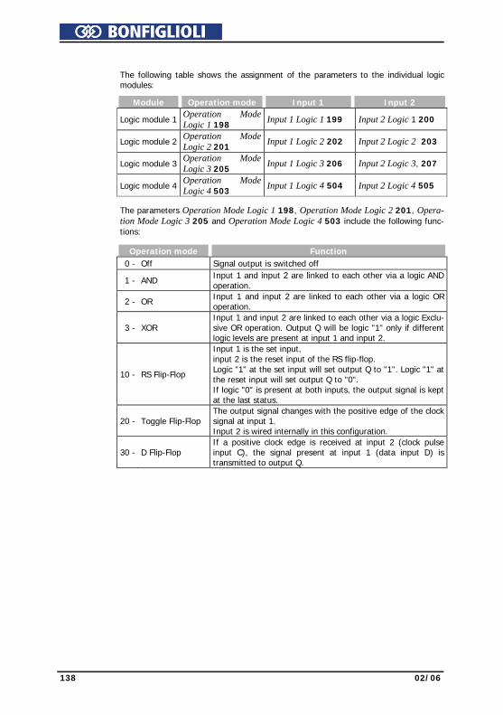
138 02/06
The following table shows the assignment of the parameters to the individual logic
modules:
Module Operation mode Input 1 Input 2
Logic module 1 Operation Mode Logic 1 198
Input 1 Logic 1 199 Input 2 Logic 1 200
Logic module 2
Operation Mode Logic 2 201
Input 1 Logic 2 202 Input 2 Logic 2 203
Logic module 3
Operation Mode Logic 3 205
Input 1 Logic 3 206 Input 2 Logic 3, 207
Logic module 4
Operation Mode Logic 4 503
Input 1 Logic 4 504 Input 2 Logic 4 505
The parameters Operation Mode Logic 1 198, Operation Mode Logic 2 201, Opera-
tion Mode Logic 3 205 and Operation Mode Logic 4 503 include the following func-tions:
Operation mode Function 0 - Off Signal output is switched off
1 - AND Input 1 and input 2 are linked to each other via a logic AND operation.
2 - OR Input 1 and input 2 are linked to each other via a logic OR operation.
3 - XOR Input 1 and input 2 are linked to each other via a logic Exclu-sive OR operation. Output Q will be logic "1" only if different logic levels are present at input 1 and input 2.
10 - RS Flip-Flop
Input 1 is the set input, input 2 is the reset input of the RS flip-flop. Logic "1" at the set input will set output Q to "1". Logic "1" at the reset input will set output Q to "0". If logic "0" is present at both inputs, the output signal is kept at the last status.
20 - Toggle Flip-Flop The output signal changes with the positive edge of the clock signal at input 1. Input 2 is wired internally in this configuration.
30 - D Flip-Flop If a positive clock edge is received at input 2 (clock pulse input C), the signal present at input 1 (data input D) is transmitted to output Q.

02/06 139
Examples of the logic functions depending on the selected operation mode:
AND Operation
Parameter Operation Mode Logic = 1
E1
E2Q
E1 E2 Q0011
0101
0001 Q
E1
E2&
E1: input 1; E2: input 2; Q: output If logic "1" is present at input 1 and input 2, output Q is logic "1". If both inputs or
either one input are logic "0", output Q will be logic "0", too. OR Operation
Parameter Operation Mode Logic = 2
E1
E2Q
E1 E2 Q0011
0101
0111 Q
E1
E2=1>
E1: input 1; E2: input 2; Q: output If logic "1" is present at input 1 or input 2 or at both inputs, output Q is "1". If both
inputs are "0", output Q will be logic "0", too.
EXOR Operation
Parameter Operation Mode Logic = 3
E1
E2Q
E1 E2 Q0011
0101
0110 Q
E1
E2=1
E1: input 1; E2: input 2; Q: output Output Q is logic "1" if inputs 1 and 2 have different logic states. If both inputs have
the same logic state, output Q will be logic "0".
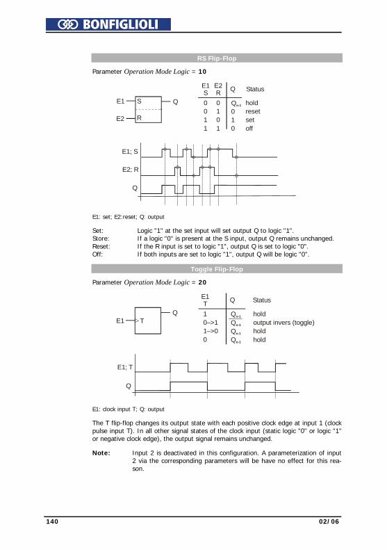
140 02/06
RS Flip-Flop
Parameter Operation Mode Logic = 10 E1
S Q
0011
0101
Qn-1
010
Status
holdresetsetoff
E1
E2
QS
R
Q
E1; S
E2; R
E1: set; E2:reset; Q: output Set: Logic "1" at the set input will set output Q to logic "1". Store: If a logic "0" is present at the S input, output Q remains unchanged. Reset: If the R input is set to logic "1", output Q is set to logic "0". Off: If both inputs are set to logic "1", output Q will be logic "0". Toggle Flip-Flop
Parameter Operation Mode Logic = 20
E1Q
T
E1T Q
10–>11–>00
Q
n-1
n-1
n-1
Qn-1
Status
holdoutput invers (toggle)holdhold
Q
E1; T
E1: clock input T; Q: output The T flip-flop changes its output state with each positive clock edge at input 1 (clock
pulse input T). In all other signal states of the clock input (static logic "0" or logic "1" or negative clock edge), the output signal remains unchanged.
Note: Input 2 is deactivated in this configuration. A parameterization of input
2 via the corresponding parameters will be have no effect for this rea-son.

02/06 141
D Flip-Flop
Parameter Operation Mode Logic = 30
Q
E2; C
E1; D
E1; D
E2; C
Q
E1D Q
0101
000–>10–>1
Qn-1
Q01
n-1
Status
hold
samplehold
sample
E1: data input D; E2: clock input C; Q: output If logic "0" is present at input 2 (clock input C), the previous logic state is maintained
at the output independent of the status of input 1 (data input D). If a positive clock edge is received at clock pulse input C, the signal present at data input D is transmitted to the output. The output maintains its state Qn-1 until the next positive clock edge is received. If a negative clock edge is received, the output signal remains unchanged.

142 02/06
15 V/f - Characteristic The sensor-less control in configurations 110 and 111 is based on the proportional
change of output voltage compared to the output frequency according to the config-ured characteristic. By setting the V/f-characteristic, the voltage of the connected 3-phase motor is con-trolled according to the frequency. The torque to be applied by the motor at the cor-responding operating point demands the control of the output voltage proportional to the frequency. At a constant output voltage / output frequency ratio of the frequency inverter, the magnetization is constant in the nominal operating range of the 3-phase motor. The rating point of the motor or end point of the V/f-characteristic is set via the guided commissioning with the parameter Cut-Off Voltage 603 and the parame-ter Cut-Off Frequency 604. The lower frequency range, where an increased voltage is necessary for the start of the drive, is critical. The voltage at output frequency = zero is set with the parameter Starting Voltage 600. An increase in voltage deviating from the linear course of the V/f-characteristic can be defined by the parameters Voltage Rise 601 and Rise Fre-quency 602. The percentage parameter figure is calculated from the linear V/f-characteristic. Via the parameters Minimum Frequency 418 and Maximum Frequency 419, the working range of the machine or the V/f-characteristic is defined.
603 (UC)
601 (UK)
600 (US)
U 418 (FMIN) 419 (FMAX)
602 (FK) 604 (FC) f
Working range
(FMIN): Minimum Frequency 418, (FMAX): Maximum Frequency 419
(US): Starting Voltage 600,(UK): Voltage Rise 601, (FK): Rise Frequency 602(UC): Cut-Fff Voltage 603, (FC): Cut-Off Frequency 604
Parameter Settings No. Description Min. Max. Fact. sett. 600 Starting Voltage 0.0 V 100.0 V 5.0 V 601 Voltage Rise -100 % 200 % 10 % 602 Rise Frequency 0 % 100 % 20 % 603 Cut-Off Voltage 60.0 V 560.0 V 400.0 V 604 Cut-Off Frequency 0.00 Hz 999.99 Hz 50.00 Hz
Note: The guided commissioning takes the parameterized rated motor values
and reference data of the frequency inverter into account when it comes to pre-setting the V/f-characteristic. In the case of three-phase ma-chines, the speed can be increased at a constant torque if the motor winding can be switched over from star to delta connection. If the data for delta connection indicated on the name plate of the three-phase motor were entered, the cut-off frequency is increased automatically by the square root of three.
02/06 143
The default Cut-Off Voltage 603 (UC) and Cut-Off Frequency 604 (FC) are derived
from the motor data Rated Voltage 370 and Rated Frequency 375. With the param-eterized Starting Voltage 600 (US), the linear equation of the V/f-characteristic re-sults.
V 5,0fHz 0,00Hz 50,00
V 5,0-V 400,0USf0FC
USUCU +⋅⎟⎟⎠
⎞⎜⎜⎝
⎛−
=+⋅⎟⎠⎞
⎜⎝⎛
−−
=
The Rise Frequency 602 (FK) is entered as a percentage of the Cut-Off Frequency 604 (FC), the default value is f=10Hz. The output voltage for the default Voltage Rise 601 (UK) is calculated as U=92.4V.
( ) ( ) ( ) V 92,41,1V 5Hz 500,2Hz 0Hz 50V 5-V 400UK1USFCFK
0FCUSUCU =⋅⎥
⎦
⎤⎢⎣
⎡+⋅⋅⎟
⎠⎞
⎜⎝⎛
−=+⋅⎥
⎦
⎤⎢⎣
⎡+⋅⋅⎟
⎠⎞
⎜⎝⎛
−−
=
15.1 Dynamic Voltage Pre-Control The Dyn. Voltage Pre-Control 605 accelerates the control behavior of the current
limit controller (parameter Operation Mode 610) and the voltage controller (parame-ter Operation Mode 670). The output voltage value resulting from the V/f character-istic is changed by addition of the calculated voltage pre-control.
Parameter Settings No. Description Min. Max. Fact. sett. 605 Dyn. Voltage Pre-Control 0 % 200 % 100 %
144 02/06
16 Control Functions
The frequency inverters provide a selection of established control methods in Con-figuration 30. The selected control structure can parameterized as required and opti-mized for the application by further functions.
16.1 Intelligent current limits
The current limits to be set according to the application avoid inadmissible loading of the connected load and prevent a fault switch-off of the frequency inverter. The func-tion extends the current controller available in the control system. The overload re-serve of the frequency inverter can be used optimally by means of the intelligent cur-rent limits, in particular in applications with dynamic load alternations. The criterion to be selected via the parameter Operation Mode 573 defines the threshold to the acti-vation of the intelligent current limit. The parameterized rated motor current or the reference current of the frequency inverter is synchronized as the limit value of the intelligent current limits.
Operation mode Function 0 - Off The function is switched off. 1 - Ixt Limitation to the overload of the frequency inverter (Ixt) 10 - Tc Limitation to the maximum heat sink temperature (TC) 11 - Ixt + Tc Operation mode 1 and 10 (Ixt + TC) 20 - Motor Temp. Limitation to the motor temperature (TMotor) 21 - Motor Temp.+ Ixt Operation mode 20 and 1 (TMotor + Ixt) 30 - Tc + Motor Temp. Operation mode 10 and 20 (TC + TMotor)
31 - Tc + Motor Temp. + Ixt Operation mode 10, 20 and (TC + TMotor+ Ixt)
The threshold value selected via the parameter Operation Mode 573 is monitored by the intelligent current limits. In the operation modes with motor and heat sink tem-perature monitoring, the reduction of power selected with the parameter Power Limit 574 is done when the threshold value has been reached. This is achieved by a reduc-tion of the output current and the speed in motor operation. The load behavior of the connected machine must be a function of the speed to ensure a sensible use of the intelligent current limits. The total time of the power reduction as a result of an in-creased motor or heat sink temperature contains not only the cooling time, but also the additionally defined Limitation Time 575. The definition of the power limit should be selected as small as possible in order to give the drive sufficient time to cool down. The reference value is the nominal power of the frequency inverter or the set rated power of the motor.
Parameter Settings No. Description Min. Max. Fact. sett. 574 Power Limit 40.00 % 95.00 % 80.00 % 575 Limitation Time 5 min 300 min 15 min
In the operation modes with overload reserve (Ixt) there is a reduction of the output current when the threshold value is exceeded, with a distinction being made between long and short-term overload reserve. After the short-term overload (1s) has been used up, the output current is reduced to the long-term overload current matching the present switching frequency. After the long-term overload current has been used up (60s), the output current is reduced to the rated current which also depends on the switching frequency. If the output current has already been reduced due to the fact that the long-term overload has used up, the short-term overload is no longer avail-able even if it has not been used up beforehand. The defined overload reserve (Ixt) of the frequency inverter is available again after a power reduction lasting 10 minutes.

02/06 145
16.2 Voltage controller The voltage controller contains the functions necessary for monitoring the DC link
voltage. − The DC link voltage which rises in generator operation or in the braking process of
the 3-phase machine is controlled to the set limit value by the voltage controller. − The mains failure regulation uses the rotation energy of the drive to bridge short-
term power failures. The voltage controller is set with the parameter Operation Mode 670 in accordance with the application.
Operation mode Function 0 - Off The function is switched off
1 - Udc-Limitation active Overvoltage controller switched on, with motor chopper
2 - Mains Support active Mains failure regulation switched on, with motor chopper, for quick shutdown
3 - Udc-Limit. & Mains Supp. active
Overvoltage controller and mains failure regulation switched on, with motor chopper
12 - Mains Support active, Chopper not active
Mains failure regulation switched on, without motor chopper
13 - Udc-Limit. & Mains Supp. active, without Chopper
Overvoltage controller and mains failure regulation switched on, without motor chopper
The function motor chopper is available in the field-oriented control methods (in con-
figurations 210, 230, 410, 411 and 430). When an operation mode with motor chopper is selected, set the Trigger Threshold
507 to the Reference DC-Link Limitation 680. Operation mode Overvoltage control,
Voltage controller: Parameter Operation Mode 670 = 1
Ud
Ud, f
681f
t
421 or 423
680
Overvoltage controller active
The overvoltage controller prevents a switch-off of the frequency inverter in generator
operation. The reduction of the drive speed by a ramp gradient selected via the pa-rameter Deceleration Clockwise 421 or Deceleration Anticlockwise 423 can lead to an overvoltage in the DC link.

146 02/06
If the voltage exceeds the value set by the parameter Reference DC-Link Limitation
680, the deceleration is reduced in such a way that the DC link voltage is regulated to the set value. If the DC link voltage cannot be regulated to the set reference value by the reduction of the deceleration, the deceleration is stopped and the output fre-quency raised. The output frequency is calculated by addition of the parameter value Max. Frequency Rise 681 to the frequency at the operating point of the controller intervention.
Parameter Settings No. Description Min. Max. Fact. sett. 680 Reference DC-Link Limitation Udmin+25V Udmax-25V Ud 681 Max. Frequency Rise 0.00 Hz 999.99 Hz 10.00 Hz
Operation mode mains failure regulation. Voltage controller: Parameter Operation Mode 670 = 2
Ud, f
f
671672
Mains voltage
Standard rampor 674
Resumption of powerPower failure t
Ud
Gradient limitedby 673 or 683
With the mains failure regulation, short-term mains failures can be bridged. A mains
failure is recognized if the DC link voltage has fallen below the set value of the pa-rameter Mains Failure Threshold 671. If a mains failure is recognized, the controller tries to regulate the DC link voltage to the value set with the parameter Reference Mains Support Value 672. For this, the output frequency is continuously reduced and the motor with its rotating masses put into generator operation. The reduction of the output frequency is done according to the configuration with a maximum of the cur-rent set by the parameter Gen. Ref. Current Limit 683 or the ramp Mains Support Deceleration 673. The threshold values of the voltage controller are calculated starting with the current DC link voltage leading from the parameters Mains Failure Threshold 671 and Refer-ence Mains support Value 672. If the mains voltage is restored before a switch-off is effected by the mains undervolt-age detection system, the drive is accelerated to its reference frequency at the set acceleration or according to the parameter Acceleration on Mains Resumption 674. If the value of parameter Acceleration on Mains Resumption 674 is set to the default value of 0.00 Hz/s, the drive is accelerated at the values set for the ramp parameters Acceleration (Clockwise) 420 or Acceleration Anticlockwise 422.
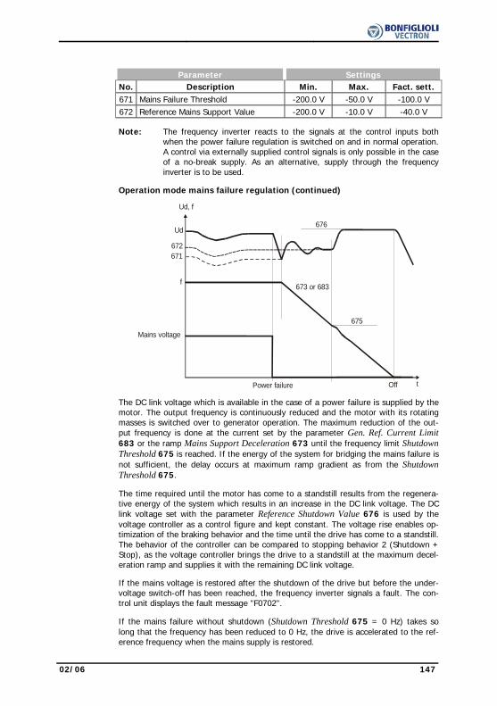
02/06 147
Parameter Settings No. Description Min. Max. Fact. sett. 671 Mains Failure Threshold -200.0 V -50.0 V -100.0 V 672 Reference Mains Support Value -200.0 V -10.0 V -40.0 V
Note: The frequency inverter reacts to the signals at the control inputs both when the power failure regulation is switched on and in normal operation. A control via externally supplied control signals is only possible in the case of a no-break supply. As an alternative, supply through the frequency inverter is to be used.
Operation mode mains failure regulation (continued)
f
671
676
672
Mains voltage
Power failure Off t
Ud
Ud, f
675
673 or 683
The DC link voltage which is available in the case of a power failure is supplied by the
motor. The output frequency is continuously reduced and the motor with its rotating masses is switched over to generator operation. The maximum reduction of the out-put frequency is done at the current set by the parameter Gen. Ref. Current Limit 683 or the ramp Mains Support Deceleration 673 until the frequency limit Shutdown Threshold 675 is reached. If the energy of the system for bridging the mains failure is not sufficient, the delay occurs at maximum ramp gradient as from the Shutdown Threshold 675.
The time required until the motor has come to a standstill results from the regenera-
tive energy of the system which results in an increase in the DC link voltage. The DC link voltage set with the parameter Reference Shutdown Value 676 is used by the voltage controller as a control figure and kept constant. The voltage rise enables op-timization of the braking behavior and the time until the drive has come to a standstill. The behavior of the controller can be compared to stopping behavior 2 (Shutdown + Stop), as the voltage controller brings the drive to a standstill at the maximum decel-eration ramp and supplies it with the remaining DC link voltage.
If the mains voltage is restored after the shutdown of the drive but before the under-
voltage switch-off has been reached, the frequency inverter signals a fault. The con-trol unit displays the fault message "F0702".
If the mains failure without shutdown (Shutdown Threshold 675 = 0 Hz) takes so
long that the frequency has been reduced to 0 Hz, the drive is accelerated to the ref-erence frequency when the mains supply is restored.

148 02/06
If the mains failure with or without shutdown takes so long that the frequency in-
verter shuts off completely (LEDs = OFF), the frequency inverter will be in the "Standby" state when the mains supply is restored. If the inverter is released again, the drive will start. If the drive is to start automatically after restoration of the mains supply and if the inverter is released permanently, Operation Mode 651 of Auto Start must be switched on.
Parameter Settings No. Description Min. Max. Fact. sett. 675 Shutdown Threshold 0.00 Hz 999.99 Hz 0.00 Hz 676 Reference Shutdown Value Udmin+25 V Udmax-25 V Ud
The voltage controller uses the limit values of the DC link voltage. The frequency
change necessary for this is parameterized by the generator reference current value or rather the ramp. The Gen. Ref. Current Limit 683 or the ramp Mains Support De-celeration 673 defines the maximum deceleration of the drive necessary in order to reach the voltage value Reference Mains Support Value 672. The Acceleration on Mains Resumption 674 replaces the set values of the ramp parameters Acceleration (Clockwise) 420 or Acceleration Anticlockwise 422 if the value set in the factory is changed. The voltage control in a mains failure changes from the frequency limit Shutdown Threshold 675 from Reference Mains Support Value 672 to the Reference Shutdown Value 676.
Parameter Settings No. Description Min. Max. Fact. sett. 683 Gen. Ref. Current Limit 0.0 A o ⋅ IFIN IFIN 673 Mains Support Deceleration 0.01 Hz/s 9999.99 Hz/s 50.00 Hz/s 674 Acceleration on Mains Resumption 0.00 Hz/s 9999.99 Hz/s 0.00 Hz/s
The proportional and integrating part of the current controller can be set via parame-
ters Amplification 677 and Integral Time 678. The control functions are deactivated by setting the parameters to 0. The controllers are P and I controllers in the corre-sponding settings.
Parameter Settings No. Description Min. Max. Fact. sett. 677 Amplification 0.00 30.00 - 1) 678 Integral Time 0 ms 10000 ms - 1)
1) The factory settings are depending on the selected control function. Corresponding
with the setting of the parameter Configuration 30 the following values are as-signed: Configuration 1xx: Amplification 677 = 1,0 / Integral Time 678 = 8 msConfiguration 4xx; 2xx: Amplification 677 = 2,0 / Integral Time 678 = 23 ms

02/06 149
16.3 Technology Controller The technology controller, the behavior of which corresponds to a PI controller, is
available as an additional function in configuration 111 and 411. The connection of reference and actual value of the application with the functions of the frequency in-verter enables process control without further components. In this way, applications such as pressure, volume flow or speed control can be implemented easily. The configuration of the reference percentage source and the assignment of the ac-tual percentage source are to be considered.
Structural image:
-
Technology controller
Referencepercentage source 476
Actual percentage source 478
Actual values:Actual percentage value 230Reference percentage value 229
For the reference value, the technology controller also demands the assignment of an
analog application value with the parameter Actual Percentage Source 478. The dif-ference between reference and actual value is used by the technology controller to control the drive system. The measured actual value is mapped via a signal converter onto the input signal of the reference percentage source.
Operation mode Function
1 - Analog Input MFI1A The analog signal on the multifunctional input 1 in Operation Mode 452 - analog operation
32 - Rep. Frequency Input
(F3) The frequency signal at the digital input according to the selected Operation Mode 496
Caution! The default assignment of parameter Start Clockwise 68 to the logic signal of the technology controller must be observed. The technology controller becomes active with the controller release at digital input S1IND. As soon as the signals Controller release and Start clockwise or Start Anti-clockwise are present, the drive will rotate.
The function selected via the parameter Operation Mode 440 defines the behavior of
the technology controller
Operation mode Function
0 - Off The technology controller is switched off, the refer-ence value specification is done via the reference per-centage channel.
1 - Standard For pressure and volume flow control with linear oper-ating behavior and actual value monitoring
2 - Liquid Level 1 Contents level control at defined motor speed with actual value missing
3 - Liquid Level 2 Contents level control at defined motor speed with actual value missing or high control deviation
4 - Speed controller Speed control with analog feedback of the actual speed
5 - Indirect volume flow control
Pressure or volume flow control with square rooted actual value

150 02/06
Operation mode standard, parameter Operation Mode 440 = 1
This operation mode can be used, for example, for pressure or volumetric flow control with linear operation behavior. If the actual value is missing (below 0.5%), the output frequency is guided to the frequency set with parameter Minimum Frequency 418 by the set parameter Deceleration (Clockwise) 421. With this function, an acceleration of the drive is prevented if the actual value is miss-ing. If the actual value is available again, the controller continues operation automati-cally. Via parameter Hysteresis 443, an overshoot of the technology controller can be pre-vented by limiting its output value with regard to the stator frequency, i.e. the output value of the controller cannot become larger or smaller than the current actual value plus the limit values of the set hysteresis.
Operation mode filling level 1, parameter Operation Mode 440 = 2
This operation mode can be used, for example, for contents level control. If the actual value is missing (below 0.5%), the output frequency is guided to the frequency set with the parameter Fixed Frequency 441 by the set parameter Deceleration (Clock-wise) 421. The Fixed Frequency 441 is to be parameterized larger than or equal to the set Minimum Frequency 418, otherwise the frequency is limited to the Minimum Frequency 418. Via this function, the drive is guided to an adjustable frequency if no actual value is available. The frequency can be in the control range Minimum Frequency 418 and Maximum Frequency 419. If the actual value is available again, the controller continues operation automatically.
Operation mode filling level 2, parameter Operation Mode 440 = 3
This operation mode can be used, for example, for contents level control. If the actual value is missing (below 0.5 %), the output frequency is guided to the Fixed Fre-quency 441 like in the case of operation mode contents level 1. If the control devia-tion becomes zero or negative, the output frequency is guided to the set Minimum frequency 418 with the set Deceleration (Clockwise) 421. With this function, an acceleration of the drive is prevented if the actual value is miss-ing. With a negative or zero control deviation and with a set Minimum Frequency 418 of 0 Hz, the drive is guided to a standstill. The power component is switched off, i.e. the motor is not supplied with current, until the actual value returns or the control deviation exceeds the positive Hysteresis 443.
Operation mode speed controller, parameter Operation Mode 440 = 4
This operation can be used, for example, for speed control systems with an analog actual value transmitter (e.g. analog speedometer). If the actual value is missing (be-low 0.5%) the output frequency is guided to the set Maximum Frequency 419 at the set Acceleration Clockwise 420. If the actual value is available again, the controller continues operation automatically.
Operation mode indirect volume flow control,
parameter Operation Mode 440 = 5 The functionality of the pressure or volume flow control in operation mode 1 is ex-tended in this operation mode. The actual value square rooted in operation mode 5 of the technology controller enables direct measurement e.g. of the active pressure in the system via the intake nozzle of the fan. The active pressure has a square propor-tion to the volume flow and thus forms the control figure for the volume flow control. The calculation corresponds to the "Law of Proportionality" which is generally valid for centrifugal machines. Adaptation to the application in question and measurement are done via the Ind. Vol-ume Flow Control Factor 446. The actual values are calculated from the system data to be parameterized, nominal pressure and volume flow, according to the bad point method, as described in chapter "Volume Flow and Pressure".

02/06 151
Structural image: Technology controller
Ind. volume flow control factor 446
Actual percentage source 478
Actual values:Volumetric flow 285Pressure 286
-Reference percentage source 476
x
The behavior of the technology controller corresponds to a PI controller. The propor-
tional component is optimized via parameter Amplification 444 and the integral com-ponent via parameter Integral Time 445. The sign of the amplification determines the direction of control, i.e. with a rising actual value and pos. sign of the amplification, the output frequency is reduced (e.g. in pressure control). With a rising actual value and neg. sign of the amplification, the output frequency is increased (e.g. in tempera-ture control systems, refrigerating machines, condensers). The parameter max. P-Component 442 limits the frequency change at the controller output. This prevents an oscillation of the system if large acceleration ramps were selected.
In the standard and contents level 2 operation modes, the Hysteresis 443 limits the
deviation of the output parameter of the technology controller to the current stator frequency of the motor.
Parameter Settings No. Description Min. Max. Fact. sett. 441 Fixed Frequency -999.99 Hz +999.99 Hz 0.00 Hz 442 max. P-Component 0.01 Hz 999.99 Hz 50.00 Hz 443 Hysteresis 0.01 % 100.00 % 10.00 % 444 Amplification -15.00 +15.00 1.00 445 Integral Time 0 ms 32767 ms 200 ms 446 Ind. Volume Flow Control Factor 0.10 2.00 1.00
Note: The parameterization of the technology controller in the individual data
sets enables an adaptation to various operating points of the application with the data set change-over via control contacts.
152 02/06
16.4 Functions of Sensorless Control
The configurations of the sensor-less control contain the following additional func-tions, which supplement the behavior according to the parameterized V/f characteris-tic.
16.4.1 Slip compensation
The load-dependent difference between the reference speed and the actual speed of the 3-phase motor is referred to as the slip. This dependency can be compensated by the current measurement in the output phases of the frequency inverter.
The activation of Operation Mode 660 for the slip compensation enables speed con-
trol without feedback. The stator frequency and speed are corrected depending on the load. Before the slip compensation can be activated, the guided commissioning has to be carried out. The Stator Resistance 377 is required to ensure a correct function and is measured during the guided commissioning.
Operation mode Function 0 - Off The slip compensation is deactivated. 1 - Switched on The load-dependent slip speed is compensated The control behavior of the slip compensation can only be optimized via the parame-
ters in the case of specific applications. The parameter Amplification 661 determines the correction of the speed and the effect of the slip compensation proportionally to the change of load. The Max. Slip Ramp 662 defines the max. frequency change per second in order to avoid an overload in the case of a load change. The parameter Minimum Frequency 663 determines the frequency as from which the slip compensation becomes active.
Parameter Settings No. Description Min. Max. Fact. sett. 661 Amplification 0.0 % 300.0 % 100.0 % 662 Max. Slip Ramp 0.01 Hz/s 650.00 Hz/s 5.00 Hz/s 663 Minimum Frequency 0.01 Hz 999.99 Hz 0.01 Hz
16.4.2 Current limit value controller
Via a load-dependent speed control, the current limit controller ensures that the drive
system is not overloaded. This is extended by the intelligent current limits described in the previous chapter. The current limit value controller reduces the load on the drive, e.g. during acceleration, by stopping the acceleration ramp. The switch-off of the frequency inverter which happens when the acceleration ramps have been set at an excessive gradient is prevented in this way.
The current limit value controller is switched on and off via parameter Operation Mode 610.
Operation mode Function
0 - Off The current limit controller functions and the intelligent current limits have been deactivated.
1 - Switched on The current limit controller is active.
Behavior in motor operation: If the current set via parameter Current Limit 613 is exceeded, the activated current limit controller will reduce the output frequency until the current limit is no longer exceeded. The output frequency is reduced, as a maximum, to the frequency set by parameter Frequency Limit 614. If the current is below the Current Limit 613, the output frequency increases to the reference value again.
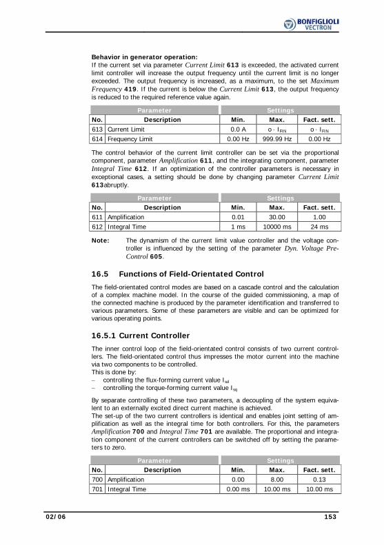
02/06 153
Behavior in generator operation:
If the current set via parameter Current Limit 613 is exceeded, the activated current limit controller will increase the output frequency until the current limit is no longer exceeded. The output frequency is increased, as a maximum, to the set Maximum Frequency 419. If the current is below the Current Limit 613, the output frequency is reduced to the required reference value again.
Parameter Settings No. Description Min. Max. Fact. sett. 613 Current Limit 0.0 A o ⋅ IFIN o ⋅ IFIN 614 Frequency Limit 0.00 Hz 999.99 Hz 0.00 Hz
The control behavior of the current limit controller can be set via the proportional component, parameter Amplification 611, and the integrating component, parameter Integral Time 612. If an optimization of the controller parameters is necessary in exceptional cases, a setting should be done by changing parameter Current Limit 613abruptly.
Parameter Settings No. Description Min. Max. Fact. sett. 611 Amplification 0.01 30.00 1.00 612 Integral Time 1 ms 10000 ms 24 ms
Note: The dynamism of the current limit value controller and the voltage con-troller is influenced by the setting of the parameter Dyn. Voltage Pre-Control 605.
16.5 Functions of Field-Orientated Control
The field-orientated control modes are based on a cascade control and the calculation of a complex machine model. In the course of the guided commissioning, a map of the connected machine is produced by the parameter identification and transferred to various parameters. Some of these parameters are visible and can be optimized for various operating points.
16.5.1 Current Controller
The inner control loop of the field-orientated control consists of two current control-
lers. The field-orientated control thus impresses the motor current into the machine via two components to be controlled. This is done by: − controlling the flux-forming current value Isd − controlling the torque-forming current value Isq
By separate controlling of these two parameters, a decoupling of the system equiva-lent to an externally excited direct current machine is achieved. The set-up of the two current controllers is identical and enables joint setting of am-plification as well as the integral time for both controllers. For this, the parameters Amplification 700 and Integral Time 701 are available. The proportional and integra-tion component of the current controllers can be switched off by setting the parame-ters to zero.
Parameter Settings No. Description Min. Max. Fact. sett. 700 Amplification 0.00 8.00 0.13 701 Integral Time 0.00 ms 10.00 ms 10.00 ms

154 02/06
The guided commissioning has selected the parameters of the current controller in such a way that they can be used without having to be changed in most applications. If, in exceptional cases, an optimization of the behavior of the current controllers is to be done, the reference value step-change during the flux-formation phase can be used for this. If parameterized appropriately, the reference value of the flux-forming current components jumps to the value Current During Flux-Formation 781 and then changes in a controlled way to the magnetizing current after the expiry of the Maximum Flux-Formation Time 780. The operating point necessary for the adjust-ment demands the setting of parameter Minimum Frequency 418 to 0.00 Hz, as the drive is accelerated after magnetizing. The measurement of the jump reply, which is defined by the ratio of the currents mentioned, should be done in the motor supply line by means of a measuring current transformer of a sufficient bandwidth.
Note: The internally calculated actual value for the flux-forming current compo-nent cannot be output via the analog output for this measurement as the time resolution of the measurement is not sufficient.
To set the parameters of the PI controller, the Amplification 700 is increased first until the actual value overshoots distinctly during the control process. Now, the ampli-fication is reduced to about a half again and then the Integral Time 701 is synchro-nized until actual value overshoots slightly during the control process. The settings of the current controllers should not be too dynamic in order to ensure a sufficient reserve range. The control tends to increased oscillations if the reserve range is reduced.
The dimensioning of the current controller parameters by calculation of the time con-stant is to be done for a switching frequency of 2 kHz. For other switching frequen-cies, the values are adapted internally so that the setting can remain unchanged for all switching frequencies. The dynamic properties of the current controller improve if the switching and scanning frequency increases.
The fixed time interval for the modulation results in the following scanning frequencies
of the current controller via parameter Switching Frequency 400.
Settings
Switching frequency Scanning Frequency
2 kHz 1) 2 kHz
4 kHz 4 kHz
8 kHz 8 kHz
12 kHz 8 kHz
16 kHz 8 kHz 1) This switching frequency can only be set for the parameter Min. Switching Fre-
quency 401.
16.5.2 Torque Controller
The torque-controlled configurations 230 and 430 often demand limitation of the speed in the operating points without load moment. The controller increases the speed in order to reach the reference torque until the Frequency Upper Limit 767 or the Frequency Lower Limit 768 is reached. As from the limit value the drive is con-trolled to maximum speed, which corresponds to the behavior of the speed controller. Thus, the controller is limited to the Maximum Frequency 419.
Parameter Settings No. Description Min. Max. Fact. sett. 767 Frequency Upper Limit -999.99 Hz 999.99 Hz 999.99 Hz 768 Frequency Lower Limit -999.99 Hz 999.99 Hz 999.99 Hz
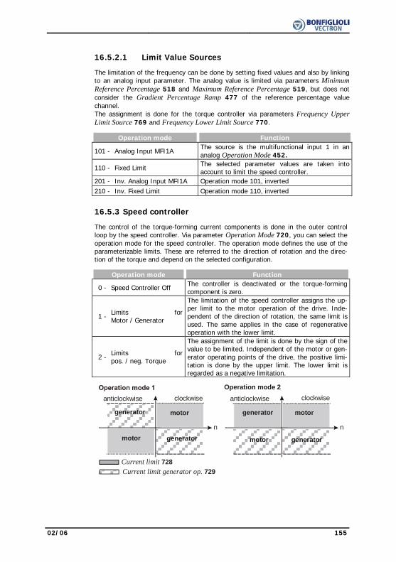
02/06 155
16.5.2.1 Limit Value Sources The limitation of the frequency can be done by setting fixed values and also by linking
to an analog input parameter. The analog value is limited via parameters Minimum Reference Percentage 518 and Maximum Reference Percentage 519, but does not consider the Gradient Percentage Ramp 477 of the reference percentage value channel. The assignment is done for the torque controller via parameters Frequency Upper Limit Source 769 and Frequency Lower Limit Source 770.
Operation mode Function
101 - Analog Input MFI1A The source is the multifunctional input 1 in an analog Operation Mode 452.
110 - Fixed Limit The selected parameter values are taken into account to limit the speed controller.
201 - Inv. Analog Input MFI1A Operation mode 101, inverted 210 - Inv. Fixed Limit Operation mode 110, inverted
16.5.3 Speed controller The control of the torque-forming current components is done in the outer control
loop by the speed controller. Via parameter Operation Mode 720, you can select the operation mode for the speed controller. The operation mode defines the use of the parameterizable limits. These are referred to the direction of rotation and the direc-tion of the torque and depend on the selected configuration.
Operation mode Function 0 - Speed Controller Off The controller is deactivated or the torque-forming
component is zero.
1 - Limits forMotor / Generator
The limitation of the speed controller assigns the up-per limit to the motor operation of the drive. Inde-pendent of the direction of rotation, the same limit is used. The same applies in the case of regenerative operation with the lower limit.
2 - Limits forpos. / neg. Torque
The assignment of the limit is done by the sign of the value to be limited. Independent of the motor or gen-erator operating points of the drive, the positive limi-tation is done by the upper limit. The lower limit is regarded as a negative limitation.
clockwiseanticlockwise
generator motor
motor generator
n
clockwiseanticlockwise
generator motor
motor generatorn
Operation mode 2
Current limit 728Current limit generator op. 729
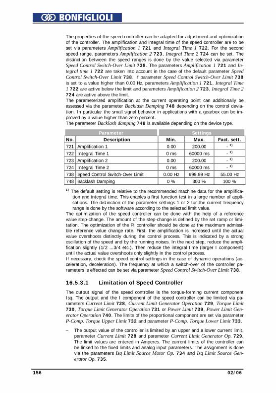
156 02/06
The properties of the speed controller can be adapted for adjustment and optimization
of the controller. The amplification and integral time of the speed controller are to be set via parameters Amplification 1 721 and Integral Time 1 722. For the second speed range, parameters Amplification 2 723, Integral Time 2 724 can be set. The distinction between the speed ranges is done by the value selected via parameter Speed Control Switch-Over Limit 738. The parameters Amplification 1 721 and In-tegral time 1 722 are taken into account in the case of the default parameter Speed Control Switch-Over Limit 738. If parameter Speed Control Switch-Over Limit 738 is set to a value higher than 0.00 Hz, parameters Amplification 1 721, Integral Time 1 722 are active below the limit and parameters Amplification 2 723, Integral Time 2 724 are active above the limit. The parameterized amplification at the current operating point can additionally be assessed via the parameter Backlash Damping 748 depending on the control devia-tion. In particular the small signal behavior in applications with a gearbox can be im-proved by a value higher than zero percent. The parameter Backlash damping 748 is available depending on the device type.
Parameter Settings No. Description Min. Max. Fact. sett. 721 Amplification 1 0.00 200.00 - 1) 722 Integral Time 1 0 ms 60000 ms - 1) 723 Amplification 2 0.00 200.00 - 1) 724 Integral Time 2 0 ms 60000 ms - 1) 738 Speed Control Switch-Over Limit 0.00 Hz 999.99 Hz 55.00 Hz 748 Backlash Damping 0 % 300 % 100 %
1) The default setting is relative to the recommended machine data for the amplifica-tion and integral time. This enables a first function test in a large number of appli-cations. The distinction of the parameter settings 1 or 2 for the current frequency range is done by the software according to the selected limit value.
The optimization of the speed controller can be done with the help of a reference value step-change. The amount of the step-change is defined by the set ramp or limi-tation. The optimization of the PI controller should be done at the maximum admissi-ble reference value change rate. First, the amplification is increased until the actual value overshoots distinctly during the control process. This is indicated by a strong oscillation of the speed and by the running noises. In the next step, reduce the ampli-fication slightly (1/2 ...3/4 etc.). Then reduce the integral time (larger I component) until the actual value overshoots only slightly in the control process. If necessary, check the speed control settings in the case of dynamic operations (ac-celeration, deceleration). The frequency at which a switch-over of the controller pa-rameters is effected can be set via parameter Speed Control Switch-Over Limit 738.
16.5.3.1 Limitation of Speed Controller
The output signal of the speed controller is the torque-forming current component Isq. The output and the I component of the speed controller can be limited via pa-rameters Current Limit 728, Current Limit Generator Operation 729, Torque Limit 730, Torque Limit Generator Operation 731 or Power Limit 739, Power Limit Gen-erator Operation 740. The limits of the proportional component are set via parameter P-Comp. Torque Upper Limit 732 and parameter P-Comp. Torque Lower Limit 733.
− The output value of the controller is limited by an upper and a lower current limit, parameter Current Limit 728 and parameter Current Limit Generator Op. 729. The limit values are entered in Amperes. The current limits of the controller can be linked to the fixed limits and analog input parameters. The assignment is done via the parameters Isq Limit Source Motor Op. 734 and Isq Limit Source Gen-erator Op. 735.

02/06 157
− The output value of the controller is limited by an upper and a lower torque limit,
parameter Torque Limit 730 and parameter Torque Limit Generator Op.. 731. The limit values are input as a percentage of the rated motor torque. The assign-ment of fixed values or analog limit values is done via the parameters Torque Limit Source Motor Op. 736 and Torque Limit Source Gen. Op 737.
− The output value of the P component is limited with parameter P-Comp. Torque Upper Limit 732 and P-Comp. Torque Lower Limit 733. The limit values are in-put as torque limits as a percentage of the rated motor torque.
− The power output by the motor is proportional to the product of speed and torque. This output power can be limited at the controller output with a Power Limit 739 and Power Limit Generator Operation 740. The power limits are en-tered in kW.
Parameter Settings No. Description Min. Max. Fact. sett. 728 Current Limit 0.0 A o ⋅ IFIN o ⋅ IFIN 729 Current Limit Generator Operation -0.1 A o ⋅ IFIN o ⋅ IFIN 730 Torque Limit 0.00 % 650.00 % 650.00 % 731 Torque Limit Generator Operation 0.00 % 650.00 % 650.00 % 732 P-Comp. Torque Upper Limit 0.00 % 650.00 % 100.00 % 733 P-Comp. Torque Lower Limit 0.00 % 650.00 % 100.00 % 739 Power Limit 0.00 kW 2⋅o⋅PFIN 2⋅o⋅PFIN 740 Power Limit Generator Operation 0.00 kW 2⋅o⋅PFIN 2⋅o⋅PFIN
16.5.3.2 Limit Value Sources As an alternative to limiting the output values by a fixed value, linking to an analog
input value is also possible. The analog value is limited via parameters Minimum Ref-erence Percentage 518 and Maximum Reference Percentage 519, but does not con-sider the Gradient Percentage Ramp 477 of the reference percentage value channel. The assignment is done with the help of the parameters Isq Limit Source Motor Op-eration 734 and Isq Limit Source Generator Op. 735 for the torque-forming current component Isq. The sources for torque limits are selectable via parameters Torque Limit Source Mo-tor Op 736 and Torque Limit Source Gen. Op.737
Operation mode Function
101 - Analog Input MFI1A The source is the multifunctional input 1 in an analog Operation Mode 452.
105 - Rep. Frequency Input (F3)
The frequency signal on the repetition frequency input corresponding to Operation Mode 496
110 - Fixed Limit The selected parameter values for limiting the speed controller are taken into account.
Note: The limit values and assignment to different limit value sources are data
set related in the configurations. The use of the data set change-over demands an examination of the parameters in question.
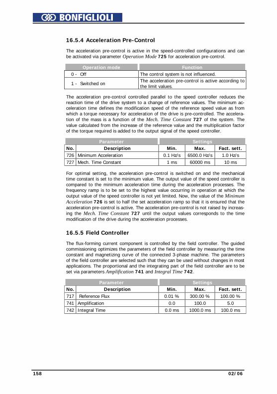
158 02/06
16.5.4 Acceleration Pre-Control The acceleration pre-control is active in the speed-controlled configurations and can
be activated via parameter Operation Mode 725 for acceleration pre-control. Operation mode Function 0 - Off The control system is not influenced.
1 - Switched on The acceleration pre-control is active according to the limit values.
The acceleration pre-control controlled parallel to the speed controller reduces the
reaction time of the drive system to a change of reference values. The minimum ac-celeration time defines the modification speed of the reference speed value as from which a torque necessary for acceleration of the drive is pre-controlled. The accelera-tion of the mass is a function of the Mech. Time Constant 727 of the system. The value calculated from the increase of the reference value and the multiplication factor of the torque required is added to the output signal of the speed controller.
Parameter Settings No. Description Min. Max. Fact. sett. 726 Minimum Acceleration 0.1 Hz/s 6500.0 Hz/s 1.0 Hz/s 727 Mech. Time Constant 1 ms 60000 ms 10 ms
For optimal setting, the acceleration pre-control is switched on and the mechanical time constant is set to the minimum value. The output value of the speed controller is compared to the minimum acceleration time during the acceleration processes. The frequency ramp is to be set to the highest value occurring in operation at which the output value of the speed controller is not yet limited. Now, the value of the Minimum Acceleration 726 is set to half the set acceleration ramp so that it is ensured that the acceleration pre-control is active. The acceleration pre-control is not raised by increas-ing the Mech. Time Constant 727 until the output values corresponds to the time modification of the drive during the acceleration processes.
16.5.5 Field Controller The flux-forming current component is controlled by the field controller. The guided
commissioning optimizes the parameters of the field controller by measuring the time constant and magnetizing curve of the connected 3-phase machine. The parameters of the field controller are selected such that they can be used without changes in most applications. The proportional and the integrating part of the field controller are to be set via parameters Amplification 741 and Integral Time 742.
Parameter Settings No. Description Min. Max. Fact. sett. 717 Reference Flux 0.01 % 300.00 % 100.00 % 741 Amplification 0.0 100.0 5.0 742 Integral Time 0.0 ms 1000.0 ms 100.0 ms
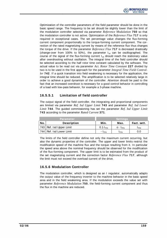
02/06 159
Optimization of the controller parameters of the field parameter should be done in the
basic speed range. The frequency to be set should be slightly lower than the limit of the modulation controller selected via parameter Reference Modulation 750 so that the modulation controller is not active. Optimization of the Reference Flux 717 is only required in exceptional cases. The set percentage value changes the flux-forming current component proportionally to the torque-forming current component. The cor-rection of the rated magnetizing current by means of the reference flux thus changes the torque of the drive. If the parameter Reference Flux 717 is decreased drastically (change-over from 100% to 50%), the parameter Isd can be oscillographed. The course of the signal of the flux-forming current Isd should reach the stationary value after overshooting without oscillation. The integral time of the field controller should be selected according to the half rotor time constant calculated by the software. The actual value to be read out via parameter Act. Rotor Time Constant 227 divided by two is to be used in the first approach for the parameter Integral Time Field Control-ler 742. If a quick transition into field weakening is necessary for the application, the integral time should be reduced. The amplification is to be selected relatively large in order to achieve a good dynamism of the controller. Attention should be paid to the fact that an increased overshoot is necessary for a good control behavior in controlling of a load with low-pass behavior, for example a 3-phase machine.
16.5.5.1 Limitation of field controller The output signal of the field controller, the integrating and proportional components
are limited via parameter Ref. Isd Upper Limit 743 and parameter Ref. Isd Lower Limit 744. The guided commissioning has set the parameter Ref. Isd Upper Limit 743 according to the parameter Rated Current 371.
Parameter Settings No. Description Min. Max. Fact. sett. 743 Ref. Isd Upper Limit 0.1⋅IFIN o ⋅ IFIN IFIN 744 Ref. Isd Lower Limit - IFIN IFIN 0.0
The limits of the field controller define not only the maximum current occurring, but also the dynamic properties of the controller. The upper and lower limits restrict the modification speed of the machine flux and the torque resulting from it. In particular the speed area above the nominal frequency should be observed for the modification of the flux-forming component. The upper limit is to be estimated from the product of the set magnetizing current and the correction factor Reference Flux 717, although the limit must not exceed the overload current of the drive.
16.5.6 Modulation Controller The modulation controller, which is designed as an I regulator, automatically adapts
the output value of the frequency inverter to the machine behavior in the basic speed area and in the field weakening area. If the modulation exceeds the value set with parameter Reference Modulation 750, the field-forming current component and thus the flux in the machine are reduced.

160 02/06
In order to make the best possible use of the voltage available, the figure selected via
parameter Operation mode 753 is put into proportion to the DC link voltage. That means that with a high mains voltage there is also a high output voltage available, the drive only reaches the field weakening area later and produces a higher torque.
Operation mode Function 0 - Usq-Control The modulation is calculated from the ratio of torque-
forming voltage component Usq to the DC link voltage. 1 - V-Absolute Value
Control The modulation is calculated from the absolute voltage value to the DC link voltage ratio.
The integrating part of the modulation controller is to be set via parameter Integral
Time 752. Parameter Settings No. Description Min. Max. Fact. sett. 750 Reference Modulation 3.00 % 105.00 % 102.00 % 752 Integral Time 0.0 ms 1000.0 ms 10.0 ms The percentage setting of the Reference Modulation 750 is basically depending on
the leakage inductivity of the machine. The default value was selected such that in most cases the remaining deviation of 5% is sufficient as a reserve range for the cur-rent controller. For the optimization of the controller parameters, the drive is acceler-ated with a flat ramp into the area of field weakening, so that the modulation control-ler intervenes. The limit is set via parameter Reference Modulation 750. Then, the control loop can be excited with a jump function by modifying the reference modula-tion (change-over between 95% and 50%). By means of an oscillographed measure-ment of the flux-forming current component on the analog output of the frequency inverter, the controlling process of the modulation controller can be assessed. The course of the signal of the flux-forming current Isd should reach the stationary value after overshooting without oscillation. An oscillating of the course of the current can be damped by increasing the integral time. The parameter Integral Time 752 should roughly correspond to the actual value Act. Rotor Time Constant 227.
16.5.6.1 Limitation of Modulation Controller The output signal of the modulation controller is the internal reference flux. The con-
troller output and the integrating part are limited via the parameter Reference Imr Lower Limit 755 and the product of Rated Magnetizing Current 716 with Reference Flux 717. The magnetizing current parameter forming the upper limit is to be set to the rated value of the machine. For the lower limit, select a value which also builds up an adequate flux in the machine in the field weakening area. The limitation of the control deviation at the output of the modulation controller prevents a possible oscilla-tion of the control loop in the case of load surges. The parameter Control Deviation Limitation 756 is stated as an absolute value and acts both as a positive and a nega-tive limit.
Parameter Settings No. Description Min. Max. Fact. sett. 755 Reference Imr Lower Limit 0.01⋅IFIN o ⋅ IFIN 0.01⋅IFIN 756 Control Deviation Limitation 0.00 % 100.00 % 10.00 %

02/06 161
17 Special Functions
The configurable functions of the corresponding control methods enable another field of application of the frequency inverters. The integration in the application is made easier by special functions.
17.1 Pulse Width Modulation
The motor noises can be reduced by changing over the parameter Switching Fre-quency 400. The maximum reduction of the switching frequency should not exceed a ratio of 1:10 to the frequency of the output signal for a sine-shaped output signal. The maximum possible switching frequency depends on the drive output and the ambient conditions. For the required technical data refer to the corresponding table and the device type diagrams.
Parameter Settings No. Description Min. Max. Fact. sett. 400 Switching frequency 2 kHz 16 kHz 4 kHz
1) The factory setting of the parameter Switching Frequency 400 depends on the selected parameter Configuration 30. - Configurations 1xx => Switching Frequency 400 = 2 kHz - Configurations 2xx / 4xx => Switching Frequency 400 = 4 kHz
The heat losses increase proportionally to the load point of the frequency inverter and the switching frequency. The automatic reduction adjusts the switching frequency to the current operating state of the frequency inverter in order to provide the output performance required for the drive task at the greatest possible dynamics and a low noise level. The switching frequency is adjusted between the limits which can be set via parame-ters Switching frequency 400 and Min. Switching Frequency 401. If the Min. Switch-ing Frequency 401 is larger than or equal to the Switching Frequency 400, the automatic reduction is deactivated.
Parameter Settings No. Description Min. Max. Fact. sett. 401 Min. Switching Frequency 2 kHz 16 kHz 2 kHz
The change of the switching frequency depends on the heat sink temperature switch-off limit and the output current. The temperature limit to be exceeded so that the switching frequency is reduced can be set via parameter Reduction Limit Heat Sink Temp. 580. If the heat sink tempera-ture falls below the threshold set via parameter Reduction Limit Heat Sink Temp. 580 by 5 °C, the switching frequency is increased again step by step.
Parameter Settings No. Description Min. Max. Fact. sett. 580 Reduction Limit Heat Sink Temp. -25 °C 0 °C -4 °C
Note: The limit for the switching frequency reduction is influenced by the intelligent current limits depending on the selected Operation Mode 573 and the output current. If they have been switched off or provide the full overload current, the switching frequency is reduced when the output current exceeds the limit of 87.5% of the long-term overload current (60s). The switching frequency is increased if the output cur-rent drops below the reference current of the next highest switching frequency.
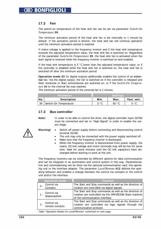
162 02/06
17.2 Fan
The switch-on temperature of the heat sink fan can be set via parameter Switch-On Temperature 39.
The minimum activation period of the heat sink fan is set internally to 1 minute by default. If the activation period is shorter, the heat sink fan will continue operation until the minimum activation period is reached.
If mains voltage is applied to the frequency inverter and if the heat sink temperature exceeds the adjusted temperature value, the heat sink fan is switched on. Regardless of the parameter Switch-On Temperature 39, the heat sink fan is activated when the start signal is received while the frequency inverter is switched on and enabled.
If the heat sink temperature is 5 °C lower than the adjusted temperature value, or if the controller is disabled while the heat sink fan is switched on, the heat sink fan is switched off after the minimum activation period.
Operation mode 43 for digital outputs additionally enables the control of an exter-nal fan. Via the digital output, the fan is switched on if the controller is released and Start clockwise or Start anticlockwise are switched on, or if the Switch-On Tempera-ture 39 for the internal fan was reached. The minimum activation period of the external fan is 1 minute.
Parameter Settings No. Description Min. Max. Fact. sett. 39 Switch-On Temperature 0 °C 60 °C 0 °C
17.3 Bus controller
Note: In order to be able to control the drive, the digital controller input S1IND must be connected and set to "High-Signal" in order to enable the out-put stage.
Warning! • Switch off power supply before connecting and disconnecting control terminal S1IND.
• The unit may only be connected with the power supply switched off. • Make sure that the frequency inverter is discharged. • When the frequency inverter is disconnected from power supply, the
mains, DC-link voltage and motor terminals may still be live for some time. Wait for some minutes until the DC link capacitors have dis-charged before starting to work at the unit.
The frequency inverters can be extended by different options for data communication
and can be integrate in an automation and control system in this way. Parameteriza-tion and commissioning can be done via the optional communication card, the operat-ing unit or the interface adapter. The parameter Local/Remote 412 defines the oper-ating behavior and enables a change between the control via contacts or the control unit and/or the interface.
Operation mode Function 0 - Control via
Contacts The Start and Stop commands as well as the direction of rotation are controlled via digital signals.
1 - Control via
Statemachine
The Start and Stop commands as well as the direction of rotation are controlled via the DRIVECOM State machine of the communication interface.
2 - Control via
remote contacts
The Start and Stop commands as well as the direction of rotation are controlled via logic signals through the communication protocol.
Table "Operation Modes for Local/Remote" continued on next page.
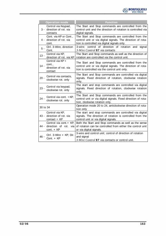
02/06 163
Operation mode Function
3 - Control via Keypad, direction of rot. via contacts
The Start and Stop commands are controlled from the control unit and the direction of rotation is controlled via digital signals.
4 -
Cont. via KP or Cont.,direction of rot. via cont.
The Start and Stop commands are controlled from the control unit or via digital signals. The direction of rota-tion is controlled via digital signals only.
5 - Ctrl. 3-Wire, direction Cont.
3-wire; control of direction of rotation and signal3-Wire Control 87 via contacts
13 - Control via KP, direction of rot. via KP
The Start and Stop commands as well as the direction of rotation are controlled via the control unit.
14 -
Control via KP + cont., direction of rot. via contact
The Start and Stop commands are controlled from the control unit or via digital signals. The direction of rota-tion is controlled via the control unit only.
20 - Control via contacts, clockwise rot. only
The Start and Stop commands are controlled via digital signals. Fixed direction of rotation, clockwise rotation only.
23 - Control via keypad, clockwise rot. only
The start and stop commands are controlled via digital signals. Fixed direction of rotation, clockwise rotation only.
24 - Control via cont. +KP, clockwise rot. only
The Start and Stop commands are controlled from the control unit or via digital signals. Fixed direction of rota-tion, clockwise rotation only.
30 to 34 Operation mode 20 to 24, anticlockwise direction of rota-tion only
43 - Control via KP, direction of rot. via contact + KP
The start and stop commands are controlled via digital signals. The direction of rotation is controlled from the control unit or via digital signals.
44 - Control via cont.+ KP,direction of rot. via cont. + KP
Both the Start and Stop commands as well as the sense of rotation can be controlled from either the control unit or via digital signals.
46 - Ctrl. 3-Wire + KP, Dir. Cont. + KP
3-wire and control unit; control of direction of rotation and signal 3-Wire Control 87 via contacts or control unit.
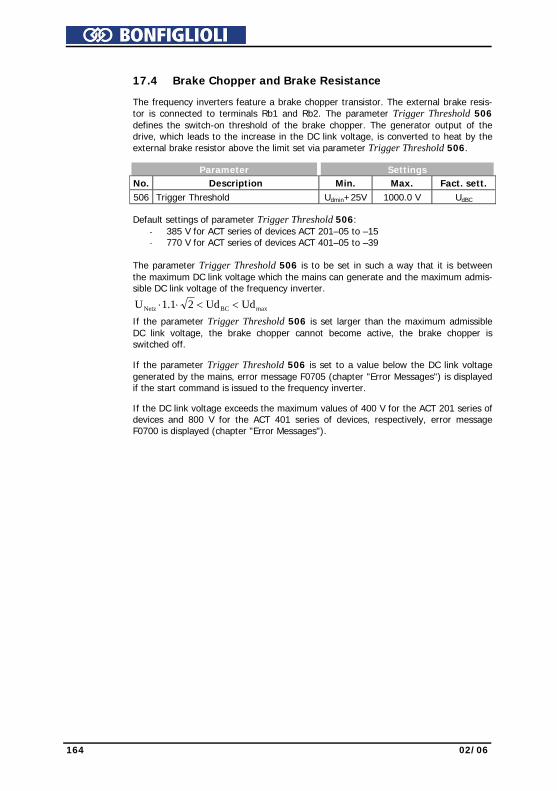
164 02/06
17.4 Brake Chopper and Brake Resistance The frequency inverters feature a brake chopper transistor. The external brake resis-
tor is connected to terminals Rb1 and Rb2. The parameter Trigger Threshold 506 defines the switch-on threshold of the brake chopper. The generator output of the drive, which leads to the increase in the DC link voltage, is converted to heat by the external brake resistor above the limit set via parameter Trigger Threshold 506.
Parameter Settings No. Description Min. Max. Fact. sett. 506 Trigger Threshold Udmin+25V 1000.0 V UdBC Default settings of parameter Trigger Threshold 506:
- 385 V for ACT series of devices ACT 201–05 to –15 - 770 V for ACT series of devices ACT 401–05 to –39
The parameter Trigger Threshold 506 is to be set in such a way that it is between
the maximum DC link voltage which the mains can generate and the maximum admis-sible DC link voltage of the frequency inverter.
maxBCNetz UdUd21.1U <<⋅⋅
If the parameter Trigger Threshold 506 is set larger than the maximum admissible DC link voltage, the brake chopper cannot become active, the brake chopper is switched off.
If the parameter Trigger Threshold 506 is set to a value below the DC link voltage
generated by the mains, error message F0705 (chapter "Error Messages") is displayed if the start command is issued to the frequency inverter.
If the DC link voltage exceeds the maximum values of 400 V for the ACT 201 series of
devices and 800 V for the ACT 401 series of devices, respectively, error message F0700 is displayed (chapter "Error Messages").

02/06 165
17.4.1 Dimensioning of Brake Resistor The following values must be known for dimensioning: − Peak braking power Pb Peak in W − Resistance Rb in Ω − Duty cycle DC in % • Calculation of peak braking power Pb Peak
Pb Peak = Peak braking power in W J = Moment of inertia of drive system kgm2 n1 = Speed of drive system before the braking op-
eration in min-1 n2 = Speed of drive system after the braking opera-
tion in min-1
( )b
22
21
Peak b t182nnJP
⋅−⋅
=
tb = Braking time in s • Calculation of resistance Rb
Rb = Resistance in Ω Ud BC = Switch-on threshold in V
Peak b
2BC d
b PUR =
Pb Peak = Peak braking power in W The switch-on threshold Ud BC is the DC link voltage at which the brake resistor is
switched on. The switch-on threshold can be set, as described above, via parameter Trigger Threshold 506.
Caution! The resistance of the brake resistor must not be less than the minimum value Rb min -10%. The values for Rb min are listed in chapter "Technical Data".
If the calculated resistance Rb of the brake resistor is between two standard series
values, the lower resistance is to be selected. • Calculation of duty cycle DC
DC = Duty cycle tb = Braking time
cycletbt
CD =
tcycle = Cycle time
Example: tb = 48 s, tcycle = 120 s
tcycle
tb
%404.0
cycletbtCD ===
In the case of infrequent short braking operations, typical values of the duty cycle DC
are at 10 %, for long braking operations (≥ 120 s) typical values are at 100%. In the case of frequent deceleration and acceleration operations, it is recommended that the duty cycle DC be calculated according to the above formula.
The calculated values for Pb Peak, Rb and DC can be used by the resistor manufacturers
for determining the resistor-specific permanent power.
Warning! The brake resistor is to be connected according to the specifications and instructions in chapter "Connection of a Brake Resistor".

166 02/06
17.5 Motor Circuit Breaker
Motor circuit breakers are used for protecting a motor and its supply cable against overheating by overload. Depending on the overload level, they disconnect the motor from mains supply immediately in the case of a short-circuit or they disconnect the motor if an overload has occurred for some time.
Conventional motor circuit breakers are commercially available for various applica-tions with different trigger characteristics (L, G/U, R and K), as shown in the diagram on the right. As frequency inverters in most cases are used for supplying motors which are classified as operating equipment with very high starting currents, only the K char-acteristic was realized in this function. Unlike the operation of a conventional motor Protection switch which disconnects the equipment to be protected immediately if the trigger threshold is reached, this func-tion provides the possibility of issuing a warning instead of disconnecting the equip-ment immediately. The rated current of the motor protection switch refers to the rated motor current stated via parameter Rated Current 371 of the corresponding data set. The rated values of the frequency inverter are to be considered accordingly when it comes to dimensioning the application.
1/10
00 s
econ
dsse
cond
sm
inut
es
x nominal current
The function of the motor circuit breaker can be linked to different data sets. In this way, it is possible to operate different motors via one frequency inverter. Thus, each motor can be equipped with its own motor protection switch.
In case a motor is operated via the frequency inverter for which some setting values, e.g. minimum and maximum frequency, are changed via the data set switch-over, only one motor circuit breaker may be installed. This functionality can be differenti-ated by selecting the parameter Operation Mode 571 for single motor operation or multiple motor operation.
Operation mode Function 0 - Off The function is deactivated
1 - K-Char.,Mul.Motor Op.,Err.Sw.Off
In each of the four data sets, the rated values are monitored. Overloading the drive is prevented by the fault switch-off "F0401".
2 - K-Char.,Sing.Motor,Err.Sw.-Off
The rated values in the first data set are used inde-pendently of the active data set. Overloading the drive is prevented by the fault switch-off "F0401".
11 - K-Char.,Multi-Motor Op.,Warning
In each of the four data sets, the rated values are monitored. Overloading the drive mechanism is sig-naled by a warning message "A0200".
22 - K-Char.,Single-Motor,Warning
The rated values in the first data set are used inde-pendently of the active data set. Overloading the drive mechanism is signaled by a warning message "A0200".
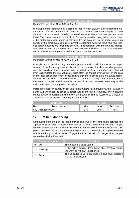
02/06 167
Multiple motor operation Parameter Operation Mode 571 = 1 or 11
In multiple motor operation, it is assumed that for each data set a corresponding mo-tor is used. For this, one motor and one motor protection switch are assigned to each data set. In this operation mode, the rated values of the active data set are moni-tored. The current output current of the frequency inverter is only taken into account if the motor protection switch is activated by the data set. In the motor protection switch of the other data sets, zero current is expected, with the result that the ther-mal decay functions are taken into account. In combination with the data set change-over, the function of the motor protection switches is similar to that of motors con-nected alternately to the mains with their own protection switches.
Single motor operation Parameter Operation Mode 571 = 2 or 22
In single motor operation, only one motor protection witch, which monitors the output current of the frequency inverter, is active. In the case of a data set change-over, only the switch-off limits derived from the rated machine parameters are changed over. Accumulated thermal values are used after the change-over as well. In the case of the data set change-over, please ensure that the machine data are stated identi-cally for all data sets. In combination with the data set change-over, the function of the motor protection switch is similar to that of motors connected alternately to the mains with one common protection switch.
Motor protection, in particular self-ventilation motors, is improved via the Frequency Limit 572 which can be set as a percentage of the rated frequency. The measured output current in operating points below the frequency limit is assessed by a factor of 2 higher in the calculation of the trigger characteristic.
Parameter Settings No. Description Min. Max. Fact. sett. 572 Frequency Limit 0 % 300 % 0 %
17.6 V-belt Monitoring
Continuous monitoring of the load behavior and thus of the connection between the 3-phase machine and the load is the task of the V-belt monitoring system. The pa-rameter Operation Mode 581 defines the function behavior if the Active Current 214 (sensor-less control) or the torque-forming current component Isq 216 (field-oriented control method) is below the set Trigger Limit Iactive 582 for longer than the pa-rameterized Delay Time 583.
Operation mode Function 0 - Off The function is deactivated
1 - Warning If the active current drops below the threshold value, the warning "A8000" is displayed.
2 - Error The unloaded drive is switched off and fault message "F0402" is displayed

168 02/06
The error and warning messages can be read out by means of the digital outputs or
reported to an overriding control system. The Trigger Limit Iactive 582 is to be pa-rameterized as a percentage of the Rated Current 371 for the application and the possible operating points.
Parameter Settings No. Description Min. Max. Fact. sett. 582 Trigger Limit Iactive 0.1% 100.0 % 10.0 % 583 Delay Time 0.1 s 600.0 s 10.0 s
17.7 Functions of Field-Orientated Control
The field-orientated control modes are based on a cascade control and the calculation
of a complex machine model. The various control functions can be supplemented by special functions specific to the application.
17.7.1 Motor Chopper
The field-orientated control modes contain the function for adapted implementation of the generator energy into heat in the connected three-phase machine. This enables the realization of dynamic speed changes at minimum system costs. The torque and speed behavior of the drive system is not influenced by the parameterized braking behavior. The parameter Trigger Threshold 507 of the DC link voltage defines the switch-on threshold of the motor chopper function.
Parameter Settings No. Description Min. Max. Fact. sett. 507 Trigger Threshold Udmin+25V 1000.0 UdMC
The parameter Trigger Threshold 507 is to be set in such a way that it is between the maximum DC link voltage which the mains can generate and the maximum admis-sible DC link voltage of the frequency inverter.
maxdMCMains UdU21.1U <<⋅⋅ If the parameter Trigger Threshold 507 is set larger than the maximum admissible
DC link voltage, the motor chopper cannot become active, the motor chopper is switched off.
If the set Trigger Threshold 507 is smaller than the maximum DC link voltage the
mains can generate, error message F0706 (chapter "Error Messages") is displayed when the frequency inverter is switched on.

02/06 169
17.7.2 Temperature Adjustment
The field-orientated control modes are based on the most precise calculation of the machine model possible. The rotor time constant is an important machine variable for the calculation. The value to be read out via the parameter Act. Rotor Time Constant 227 is calculated from the inductivity of the rotor circuit and the rotor resistance. The dependence of the rotor time constant on the motor temperature can be taken into account in the case of particularly high precision requirements via a suitable meas-urement. Via Operation Mode 465 for the temperature adjustment, you can select different methods and actual value sources for temperature measurement.
Operation mode Function 0 - Off The function is deactivated.
1 - Temp. Meas. on MFI1A
Temperature synchronization (0 ... 200 °C => 0 ... 10 V / 0 ... 20 mA), actual temperature value at multifunctional input 1
4 - Temp. Meas. at Start
Determination of temperature by frequency in-verter via measurement of the winding resistance without external temperature measurement
Operation mode 1 requires an external temperature measurement system which
evaluates the temperature sensor and maps the temperature range from 0...200 °C to an analog voltage or current signal. The Operation Mode 452 of multifunction input MFI1 must be selected accordingly. Operation mode 4 is available in configurations 210 and 230. When the signals Con-troller release and Start clockwise or Start anticlockwise are present, the motor tem-perature and the rotor time constant are synchronized by means of the measured winding resistance.
The material used for the rotor winding of the motor is taken into account via the
parameter Temperature Coefficient 466. This value defines the change of the rotor resistance as a function of the temperature for a certain material of the rotor winding. Typical temperature coefficients are 39%/100 °C for copper and 36%/100 °C for alu-minum at a temperature of 20°C. The temperature characteristic within the software is calculated via the aforemen-tioned temperature coefficient and the parameter Temperature Adjustment 467. The adjustment temperature enables an additional optimization of the rotor time constant alongside the parameter Rated Slip Correction Factor 718.
Parameter Settings No. Description Min. Max. Fact. sett. 466 Temperature Coefficient 0.00%/100 °C 300.00%/100 °C 39.00%/100 °C 467 Adjusting Temperature -50 °C 300 °C 35 °C The synchronization of the rotor time constant as a function of the winding tempera-
ture can be adjusted. The default values should normally be sufficiently precise so that neither an adjustment of the rotor time constants via the parameter Rated Slip Cor-rection Factor 718 nor an adjustment of the temperature synchronization via the parameter Temperature Coefficient 466 is necessary. If an adjustment is necessary, please remember that the rotor time constant is calculated by the guided commission-ing via the machine data. The Adjusting Temperature 467 is to be set to the tempera-ture at which the optimization of the extended machine data was carried out. The temperature can be read out via the actual value parameter Winding Temperature 226 and can be used in the optimization for the parameter.

170 02/06
17.7.3 Encoder Monitoring Failures of the speed sensor lead to a faulty behavior of the drive, as the measured
speed forms the foundation of the control mode. By default, the speed sensor moni-toring system continuously monitors the speed sensor signal, the track signal and the division marks. If, while the frequency inverter is released, a faulty signal is recog-nized for longer than the timeout, a fault switch-off is effected. If the parameter Op-eration Mode 760 is set to zero, the monitoring function is deactivated.
Operation mode Function 0 - Off The function is deactivated
2 - Error A fault message is displayed according to the timeouts set.
The speed sensor monitoring is to be parameterized in the sub functions according to
the application. The monitoring function becomes active with the release of the fre-quency inverter and the start command. The timeout defines a monitoring time in which the condition for the fault switch-off must be fulfilled without interruption. If one of the timeouts is set to zero, this monitoring function is deactivated.
Parameter Settings No. Description Min. Max. Fact. sett. 761 Timeout: Signal Fault 0 ms 65000 ms 1000 ms 762 Timeout: Channel fault 0 ms 65000 ms 1000 ms 763 Timeout: Direction fault 0 ms 65000 ms 1000 ms Timeout: Signal Fault
The actual speed measured is compared with the output value of the speed controller. If the actual speed value is exactly zero for the time selected with the parameter Timeout: Signal fault 761, although a reference value is available, the fault is dis-played with the message "F1430".
Timeout: Channel fault
The actual speed measurement monitors the sequence in time of the signals in the quadruple evaluation of the speed sensor operation mode. If the speed sensor signal is faulty for the time selected with the parameter Timeout: Channel fault 762, the fault is displayed with the message "F1431".
Timeout: Direction fault
The actual speed measured is compared with the reference speed. If the sign be-tween reference value and actual value differs for the time selected with the parame-ter Timeout: Direction fault 763, the fault is displayed with the message "F1432". The monitoring function is reset when the drive mechanism has moved in the refer-ence value direction by a quarter of a revolution.

02/06 171
18 Actual Values
The various control functions and methods include electrical control variables and various calculated actual values of the machine or system. The different actual values can be read out for operational and error diagnosis via a communication interface or in the VAL menu branch of the operating unit.
18.1 Actual Values of the Frequency Inverter
The modular hardware of the frequency inverter enables application-specific adapta-tion. Further actual value parameters can be displayed as a function of the selected configuration and the installed expansion cards.
Actual Values of the Frequency Inverter No. Description Function 222 DC link voltage Direct voltage in the DC link
223 Modulation Output voltage of the frequency inverter relative to the mains voltage (100% = UFIN)
228 Internal Reference FrequencySum of the Reference Frequency Sources 475 as a reference value from the frequency reference value channel
229 Reference Percentage Value Sum of the Reference Percentage Sources 476 as a reference value from the reference percent-age channel
230 Actual Percentage Value Actual value signal on the Actual Percentage Source 478
244 Working Hours Counter Operating hours in which the output stage of the inverter is active
245 Operation Hours Counter Operating hours of the frequency inverter in which supply voltage is available
249 Active data set The data set actively in use according to Data Set Change-Over 1 70 and Data Set Change-Over 2 71
250 Digital Inputs Decimally coded status of the six digital inputs and of multifunctional input 1 in Operation Mode 452 - digital input
251 Analog Input MFI1A Input signal on multifunctional input 1 in Opera-tion Mode 452 - analog input
252 Repetition frequency input Signal on repetition frequency input according to Operation Mode 496
254 Digital Outputs Decimally coded status of the two digital outputs and of multifunctional output 1 in Operation Mode 550 - digital
255 Heat Sink Temperature Measured heat sink temperature 256 Inside Temperature Measured inside temperature
257 Analog Output MFO1A Output signal on multifunctional output 1 in Op-eration Mode 550 – analog
259 Current Error Error message with error code and abbreviation
269 Warnings Warning message with error code and abbrevia-tion
275 Controller Status The reference value signal is limited by the con-troller coded in the controller status.
278 Repetition frequency output MFO1F
Output signal on multifunctional input 1 in Op-eration Mode 550 – repetition frequency
Note: The actual values can be read out and monitored in the VAL menu branch of the operating unit. The parameter Control Level 28 in the PARA menu branch defines the selection of the actual value parameters.

172 02/06
18.2 Actual Values of the Machine The frequency inverter controls the behavior of the machine in the various operating
points. As a function of the configuration selected and the expansion cards installed, control variables and further actual value parameters of the machine can be dis-played.
Actual Values of the Machine No. Description Function
210 Stator Frequency The output frequency (motor frequency) of the frequency inverter
211 R.m.s Current Calculated effective output current (motor cur-rent) of the frequency inverter
212 Output Voltage Calculated R.m.s. figure of the phase-to-phase voltage (motor voltage) of the frequency inverter
213 Active Power Active power calculated from the voltage, the current and the control variables
214 Active Current Active current calculated from the rated motor parameters, the control variables and the current
215 Isd Current component of the field-orientated control forming the magnetic flux
216 Isq Torque-forming current component of field-orientated control
217 Encoder 1 Frequency Calculated from the data on encoder 1, the No. of Pole Pairs 373 and the encoder signal
218 Encoder 1 Speed Calculation from encoder 1 frequency
221 Slip Frequency Difference from the synchronous frequency cal-culated from the rated motor parameters, the control variables and the current
224 Torque Torque at the current output frequency calcu-lated from the voltage, the current and the con-trol variables
225 Rotor Flux Current magnetic flux relative to the rated motor parameters
226 Winding Temperature Measured temperature of the motor winding according to Operation Mode 465 for tempera-ture adjustment
227 Act. Rotor Time Constant Time constant calculated for the operating point of the machine from the rated motor parameters, the rated and control variables
235 Flux-Forming Voltage Voltage component of the field-orientated control forming the magnetic flux
236 Torque-Forming Voltage Voltage component of the field-orientated control forming the torque
238 Flux Value Magnetic flux calculated according to the rated values and the operating point of the motor
239 Reactive Current Reactive current calculated from the rated motor parameters, the control variables and the current
240 Actual Speed Measured and/or calculated speed of drive 241 Actual Frequency Measured and/or calculated frequency of drive Note: The actual values can be read out and monitored in the VAL menu
branch of the operating unit. The parameter Control Level 28 in the PARA menu branch defines the selection of the actual value parameters to be selected.

02/06 173
18.3 Actual Value Memory The assessment of the operating behavior and the maintenance of the frequency in-
verter in the application is facilitated by storing various actual values. The actual value memory guarantees monitoring of the individual variables for a definable period. The parameters of the actual value memory can be read out via a communication interface and displayed via the operating unit. In addition, the operating unit provides monitor-ing of the peak and mean values in the VAL menu branch.
Actual value memory No. Description Function
231 Peak Value Long Term Ixt Utilization of the device-dependent overload of 60 seconds
232 Peak Value, Short Term Ixt Utilization of the device-dependent overload of 1 second
287 Peak Value Vdc The maximum DC link voltage measured
288 Average Value Vdc The average DC link voltage calculated in the period of observation
289 Peak Value Heat Sink Temp. The highest measured heat sink temperature of the frequency inverter
290 Average Value Heat Sink Temp.
The average heat sink temperature calculated in the period of observation
291 Peak Value Inside Tempera-ture
The maximum measured inside temperature in the frequency inverter
292 Average Value Inside Tem-perature
The average inside temperature calculated in the period of observation
293 Peak value Irms The highest absolute current calculated from the measured motor phases.
294 Average value Irms The average absolute current calculated in the period of observation
295 Peak Value Active Power pos. The largest calculated active power in motor operation
296 Peak Value Active Power neg.
Maximum generator active power calculated from the voltage, the current and the control variables
297 Average Value Active Power The average active power calculated in the pe-riod of observation
301 Energy, positive The calculated energy to the motor in motor operation
302 Energy, negative The calculated energy from the motor in genera-tor operation
Note: The actual values can be read out and monitored in the VAL menu
branch of the operating unit. The parameter Control Level 28 in the PARA menu branch defines the selection of the actual value parameters to be selected.
The Reset Memory 237 parameter to be selected in the PARA menu branch of the
operating unit enables purposeful resetting of the individual average and peak values. The peak value and the average value with the values stored in the period are over-written with the parameter value zero.

174 02/06
Operation mode Function 0 - No deleting Values of actual value memory remain unchanged.
1 - Peak Value Long Term Ixt Reset Peak Value Long-Term Ixt 231
2 - Peak Value Short Term Ixt Reset Peak Value Short-Term Ixt 232
3 - Peak Value Vdc Reset Peak Value Vdc 287 4 - Average Value Vdc Delete Average Value Vdc. 288 5 - Peak Value Tc Reset Peak Value Heat Sink Temp. 289 6 - Average Value Tc Delete Average Value Heat Sink Temp. 290 7 - Peak Value Ti Reset Peak Value Inside Temperature 291 8 - Average Value Ti Delete Average Value Inside Temperature 292 9 - Peak value Irms Reset Peak Value Irms 293 10 - Average value Irms Delete Average Value Irms 294 11 - Peak Value Pactive pos. Reset Peak Value Active Power pos. 295 12 - Peak Value Pactive neg. Reset Peak Value Active Power neg. 296 13 - Average Value Pactive Delete Average Value Active Power 297 16 - Energy, positive Reset parameter Energy, positive 301 17 - Energy, negative Reset parameter Energy, negative 302 100 - All Peak Values Reset all peak values stored 101 - All Average Values Delete average values and stored values 102 - All Values Delete the entire actual value memory
18.4 Actual Values of the System
The calculation of the actual values of the system is based on the parameterized sys-tem data. Specific to the application, the parameters are calculated from the factors, electrical variables and the controls. The correct display of the actual values is a func-tion of the data of the system to be parameterized.
18.4.1 Actual Value System The drive can be monitored via the actual value Actual Value System 242.
The Actual Frequency 241 to be monitored is multiplied by the Factor Actual Value System 389 and can be read out via the parameter Actual Value System 242, i.e. Actual Frequency 241 x Factor Actual Value System 389 = Actual Value System 242.
Actual Value System No. Description Function 242 Actual Value System Calculated frequency of drive

02/06 175
18.4.2 Volume Flow and Pressure
The parameterization of the factors Nominal Volumetric Flow 397 and Nominal Pressure 398 is necessary if the matching actual values Volumetric flow 285 and Pressure 286 are used to monitor the drive. The conversion is done using the electri-cal control parameters. Volume Flow 285 and Pressure 286 are referred to the Ef-fective Current 214 in the case of the sensor-less control methods. In the case of the field-oriented control methods, they are referred to the torque-forming current com-ponent Isq 216.
Volume Flow and Pressure No. Description Function 285 Volumetric Flow Calculated volume flow with the unit m3/h
286 Pressure Pressure calculated according to the characteris-tic with the unit kPa
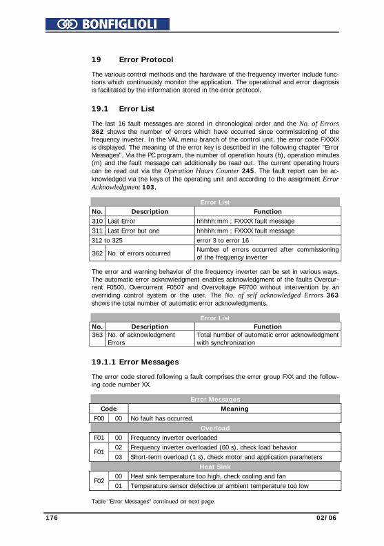
176 02/06
19 Error Protocol The various control methods and the hardware of the frequency inverter include func-
tions which continuously monitor the application. The operational and error diagnosis is facilitated by the information stored in the error protocol.
19.1 Error List The last 16 fault messages are stored in chronological order and the No. of Errors
362 shows the number of errors which have occurred since commissioning of the frequency inverter. In the VAL menu branch of the control unit, the error code FXXXX is displayed. The meaning of the error key is described in the following chapter "Error Messages". Via the PC program, the number of operation hours (h), operation minutes (m) and the fault message can additionally be read out. The current operating hours can be read out via the Operation Hours Counter 245. The fault report can be ac-knowledged via the keys of the operating unit and according to the assignment Error Acknowledgment 103.
Error List No. Description Function 310 Last Error hhhhh:mm ; FXXXX fault message 311 Last Error but one hhhhh:mm ; FXXXX fault message 312 to 325 error 3 to error 16
362 No. of errors occurred Number of errors occurred after commissioning of the frequency inverter
The error and warning behavior of the frequency inverter can be set in various ways.
The automatic error acknowledgment enables acknowledgment of the faults Overcur-rent F0500, Overcurrent F0507 and Overvoltage F0700 without intervention by an overriding control system or the user. The No. of self acknowledged Errors 363 shows the total number of automatic error acknowledgments.
Error List No. Description Function 363 No. of acknowledgment
Errors Total number of automatic error acknowledgment with synchronization
19.1.1 Error Messages The error code stored following a fault comprises the error group FXX and the follow-
ing code number XX. Error Messages
Code Meaning F00 00 No fault has occurred. Overload F01 00 Frequency inverter overloaded 02 Frequency inverter overloaded (60 s), check load behavior
F01 03 Short-term overload (1 s), check motor and application parameters
Heat Sink 00 Heat sink temperature too high, check cooling and fan
F02 01 Temperature sensor defective or ambient temperature too low
Table "Error Messages" continued on next page.

02/06 177
Inside Code Meaning 00 Inside temperature too high, check cooling and fan
F03 01 Inside temperature too low, check electrical cabinet heating
Motor Connection
00 Motor temperature too high or sensor defective, check connection S6IND
01 Motor circuit breaker tripped, check drive 02 V-belt monitoring reports no load on the drive.
F04
03 Phase failure, check motor and wiring Output current 00 Overloaded, check load situation and ramps 03 Short circuit or earth fault, check motor and wiring 04 Overloaded, check load situation and current value limit controller 05 Asymmetric motor current, check current and wiring 06 Motor phase current too high, check motor and wiring
F05
07 Message from phase monitoring, check motor and wiring DC link voltage
00 DC link voltage too high, check deceleration ramps and connected brake resistor
01 DC link voltage too low, check mains voltage 02 Power failure, check mains voltage and circuit 03 Phase failure, check mains fuses and circuit 04 Reference DC-Link Limitation 680 too low, check mains voltage 05 Brake chopper Trigger Threshold 506 too low, check mains voltage
F07
06 Motor chopper Trigger Threshold 507 too low, check mains voltage Electronics voltage 01 Electronics voltage 24 V too low, check control terminal
F08 04 Electronics voltage too high, check wiring of control terminals
Output frequency 00 Output frequency too high, check control signals and settings
F11
01 Max. frequency reached by control, check deceleration ramps and con-nected brake resistor
Motor Connection 00 Earth fault on output, check motor and wiring
01 Set IDC-Compensation Limit 415 reached, check motor and cabling, increase limit, if necessary
F13
10 Minimum current monitoring, check motor and wiring Control Connection 01 Reference value on multifunctional input 1 faulty, check signal 07 Overcurrent on multifunctional input 1, check signal 30 Speed sensor signal defective, check connections S4IND and S5IND 31 One track of the speed sensor signal is missing, check connections
F14
32 Direction of rotation of speed sensor wrong, check connections Optional Components
F0A 10 Data transmission from control unit KP 500 to inverter failed. In the control unit must be stored at least 1 file.
F0B 13 The communication module was fitted to slot B without disconnection of the mains voltage, switch mains voltage off.
In addition to fault messages mentioned, there are further fault messages. However
these messages are only used for internal purposes and are not listed here. If you receive fault messages which are not listed here, please contact us by phone.

178 02/06
19.2 Error Environment The parameters of the error environment help troubleshooting both in the settings of
the frequency inverter and also in the complete application. The error environment documents the operational behavior of the frequency inverter at the time of the last four faults.
Error Environment No. Description Function 330 DC link voltage Direct voltage in the DC link
331 output voltage Calculated output voltage (motor voltage) of the frequency inverter
332 Stator Frequency The output frequency (motor frequency) of the frequency inverter
333 Encoder 1 Frequency Calculated from the data on encoder 1, the No. of Pole Pairs 373 and the encoder signal
335 Phase Current Ia Measured current in motor phase U 336 Phase Current Ib Measured current in motor phase V 337 Phase Current Ic Measured current in motor phase W
338 R.m.s Current Calculated effective output current (motor cur-rent) of the frequency inverter
339 Isd / Reactive Current Current component forming the magnetic flux or the calculated reactive current
340 Isq / Active Current Current component forming the torque or the calculated active current
341 Rotor Magnetizing Current Magnetizing current relative to the rated motor parameters and the operating point
342 Torque Torque calculated from the voltage, the current and the control variables
343 Analog Input MFI1A Input signal on multifunctional input 1 in Opera-tion Mode 452 - analog input
346 Analog Output MFO1A Output signal on multifunctional output 1 in Op-eration Mode 550 – analog
349 Repetition Frequency Output Signal at repetition frequency output according to Operation Mode 550 – repetition frequency
350 Status of Digital Inputs Decimally coded status of the six digital inputs and of multifunctional input 1 in Operation Mode 452 - digital input
351 Status of Digital Outputs Decimally coded status of the two digital outputs and of multifunctional output 1 in Operation Mode 550 - digital
352 Time since Release The time of the error in hours (h), minutes (m) and seconds (s) after the release signal:hhhhh:mm:ss . sec/10 sec/100 sec/1000
353 Heat Sink Temperature Measured heat sink temperature 354 Inside Temperature Measured inside temperature
355 Controller Status The reference value signal is limited by the con-troller coded in the controller status.
356 Warning Status The warning messages coded in warning status Table "Error Environment" continued on next page.
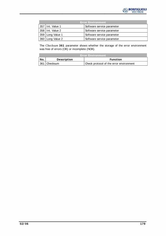
02/06 179
Error Environment 357 Int. Value 1 Software service parameter 358 Int. Value 2 Software service parameter 359 Long Value 1 Software service parameter 360 Long Value 2 Software service parameter The Checksum 361 parameter shows whether the storage of the error environment
was free of errors (OK) or incomplete (NOK). Error Environment No. Description Function 361 Checksum Check protocol of the error environment
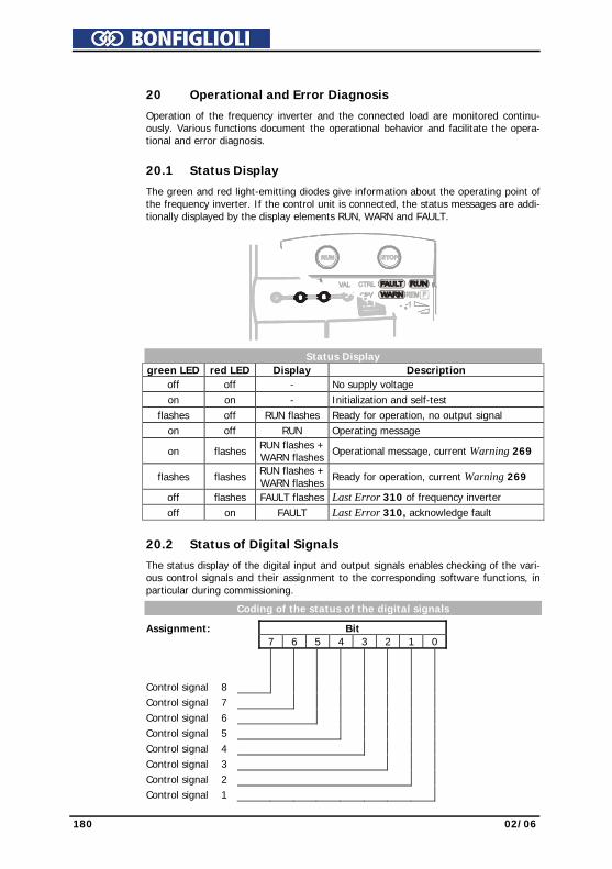
180 02/06
20 Operational and Error Diagnosis
Operation of the frequency inverter and the connected load are monitored continu-ously. Various functions document the operational behavior and facilitate the opera-tional and error diagnosis.
20.1 Status Display
The green and red light-emitting diodes give information about the operating point of the frequency inverter. If the control unit is connected, the status messages are addi-tionally displayed by the display elements RUN, WARN and FAULT.
Status Display green LED red LED Display Description
off off - No supply voltage on on - Initialization and self-test flashes off RUN flashes Ready for operation, no output signal on off RUN Operating message
on flashes RUN flashes + WARN flashes Operational message, current Warning 269
flashes flashes RUN flashes + WARN flashes Ready for operation, current Warning 269
off flashes FAULT flashes Last Error 310 of frequency inverter off on FAULT Last Error 310, acknowledge fault
20.2 Status of Digital Signals
The status display of the digital input and output signals enables checking of the vari-ous control signals and their assignment to the corresponding software functions, in particular during commissioning.
Coding of the status of the digital signals
Assignment: Bit 7 6 5 4 3 2 1 0 Control signal 8 Control signal 7 Control signal 6 Control signal 5 Control signal 4 Control signal 3 Control signal 2 Control signal 1
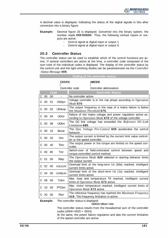
02/06 181
A decimal value is displayed, indicating the status of the digital signals in bits after
conversion into a binary figure. Example: Decimal figure 33 is displayed. Converted into the binary system, the
number reads OOIOOOOI. Thus, the following contact inputs or out-puts are active:
− Control signal at digital input or output 1 − Control signal at digital input or output 6
20.3 Controller Status
The controller status can be used to establish which of the control functions are ac-tive. If several controllers are active at the time, a controller code composed of the sum total of the individual codes is displayed. The display of the controller status by the control unit and the light-emitting diodes can be parameterized via the Controller -Status Message 409.
Coding of the controller status
CXXXX ABCDE
Controller code Controller abbreviation
Code Controller Status C 00 00 - No controller active
C 00 01 UDdyn Voltage controller is in the rise phase according to Operation Mode 670
C 00 02 UDstop The output frequency in the case of a mains failure is below the Shutdown Threshold 675.
C 00 04 UDctr Failure of the mains voltage and power regulation active ac-cording to Operation Mode 670 of the voltage controller
C 00 08 UDlim The DC link voltage has exceeded the Reference DC-Link Limitation 680.
C 00 10 Boost The Dyn. Voltage Pre-Control 605 accelerates the control behavior.
C 00 20 Ilim The output current is limited by the current limit value control-ler or the speed controller.
C 00 40 Tlim The output power or the torque are limited on the speed con-troller
C 00 80 Tctr Switch-over of field-orientated control between speed and torque-controlled control method.
C 01 00 Rstp The Operation Mode 620 selected in starting behavior limits the output current
C 02 00 IxtLtLim Overload limit of the long-term Ixt (60s) reached, intelligent current limits active
C 04 00 IxtStLim Overload limit of the short-term Ixt (1s) reached, intelligent current limits active
C 08 00 Tclim Max. heat sink temperature TK reached, intelligent current limits of Operation Mode 573 active.
C 10 00 PTClim Max. motor temperature reached, intelligent current limits of Operation Mode 573 active
C 20 00 Flim The reference frequency has reached the Maximum Frequency 419. The frequency limitation is active.
Example: The controller status is displayed C0024 UDctr Ilim
The controller status results from the hexadecimal sum of the controller codes (0004+0020 = 0024). At the same, the power failure regulation and also the current limitation of the speed controller are active.
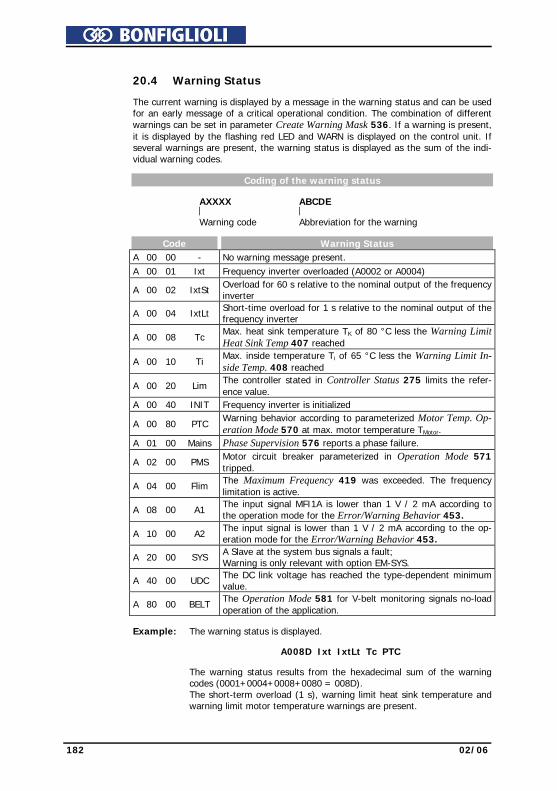
182 02/06
20.4 Warning Status The current warning is displayed by a message in the warning status and can be used
for an early message of a critical operational condition. The combination of different warnings can be set in parameter Create Warning Mask 536. If a warning is present, it is displayed by the flashing red LED and WARN is displayed on the control unit. If several warnings are present, the warning status is displayed as the sum of the indi-vidual warning codes.
Coding of the warning status
AXXXX ABCDE
Warning code Abbreviation for the warning Code Warning Status A 00 00 - No warning message present. A 00 01 Ixt Frequency inverter overloaded (A0002 or A0004)
A 00 02 IxtSt Overload for 60 s relative to the nominal output of the frequency inverter
A 00 04 IxtLt Short-time overload for 1 s relative to the nominal output of the frequency inverter
A 00 08 Tc Max. heat sink temperature TK of 80 °C less the Warning Limit Heat Sink Temp 407 reached
A 00 10 Ti Max. inside temperature Ti of 65 °C less the Warning Limit In-side Temp. 408 reached
A 00 20 Lim The controller stated in Controller Status 275 limits the refer-ence value.
A 00 40 INIT Frequency inverter is initialized
A 00 80 PTC Warning behavior according to parameterized Motor Temp. Op-eration Mode 570 at max. motor temperature TMotor.
A 01 00 Mains Phase Supervision 576 reports a phase failure.
A 02 00 PMS Motor circuit breaker parameterized in Operation Mode 571 tripped.
A 04 00 Flim The Maximum Frequency 419 was exceeded. The frequency limitation is active.
A 08 00 A1 The input signal MFI1A is lower than 1 V / 2 mA according to the operation mode for the Error/Warning Behavior 453.
A 10 00 A2 The input signal is lower than 1 V / 2 mA according to the op-eration mode for the Error/Warning Behavior 453.
A 20 00 SYS A Slave at the system bus signals a fault; Warning is only relevant with option EM-SYS.
A 40 00 UDC The DC link voltage has reached the type-dependent minimum value.
A 80 00 BELT The Operation Mode 581 for V-belt monitoring signals no-load operation of the application.
Example: The warning status is displayed.
A008D Ixt IxtLt Tc PTC
The warning status results from the hexadecimal sum of the warning
codes (0001+0004+0008+0080 = 008D). The short-term overload (1 s), warning limit heat sink temperature and warning limit motor temperature warnings are present.

02/06 183
21 Parameter List The parameter list is structured according to the menu branches of the control unit.
The parameters are listed in ascending numerical order.. A headline (shaded) can appear several times, i.e. a subject area may be listed at different places in the table. For better clarity, the parameters have been marked with pictograms:
The parameter is available in the four data sets.
The parameter value is set by the SETUP routine.
This parameter cannot be written when the frequency inverter is in operation. IFIN, UFIN, PFIN: rated values of the frequency inverter, o: overload capacity of frequency inverter
21.1 Actual Value Menu (VAL)
Actual Values of the Machine No. Description Unit Display range Chapter 210 Stator Frequency Hz 0.00 ... 999.99 18.2 211 R.m.s Current A 0.0 ... Imax 18.2 212 Output Voltage V 0.0 ... UFIN 18.2 213 Active Power kW 0.0 ... Pmax 18.2 214 Active Current A 0.0 ... Imax 18.2 215 Isd A 0.0 ... Imax 18.2 216 Isq A 0.0 ... Imax 18.2 217 Encoder 1 Frequency Hz 0.00 ... 999.99 9.4 218 Encoder 1 Speed 1/min 0 ... 60000 9.4 221 Slip Frequency Hz 0.0 ... 999.99 18.2 Actual Values of the Frequency Inverter 222 DC link voltage V 0.0 ... Udmax-25 18.1 223 Modulation % 0 ... 100 18.1 Actual Values of the Machine 224 Torque Nm ± 9999.9 18.2 225 Rotor Flux % 0 ... 100 18.2 226 Winding Temperature deg.C 0 ... 999 17.7.2 227 Act. Rotor Time Constant ms 0 ... τmax 18.2 Actual Values of the Frequency Inverter 228 Internal Reference Frequency Hz 0.00 ... fmax 18.1 229 Reference Percentage Value % ± 300.00 18.1 230 Actual Percentage Value % ± 300.00 18.1 Actual value memory 231 Peak Value Long Term Ixt % 0.00 ... 100.00 18.3 232 Peak Value Short Term Ixt % 0.00 ... 100.00 18.3 Actual Values of the Machine 235 Flux-Forming Voltage V 0.0 ... UFIN 18.2 236 Torque-Forming Voltage V 0.0 ... UFIN 18.2 238 Flux Value % 0.0 ... 100.0 18.2 239 Reactive Current A 0.0 ... Imax 18.2 240 Actual Speed 1/min 0 ... 60000 18.2 241 Actual Frequency Hz 0.0 ... 999.99 18.2 Actual Values of the System 242 Actual Value System Hz 0.0 ... 999.99 18.4.1
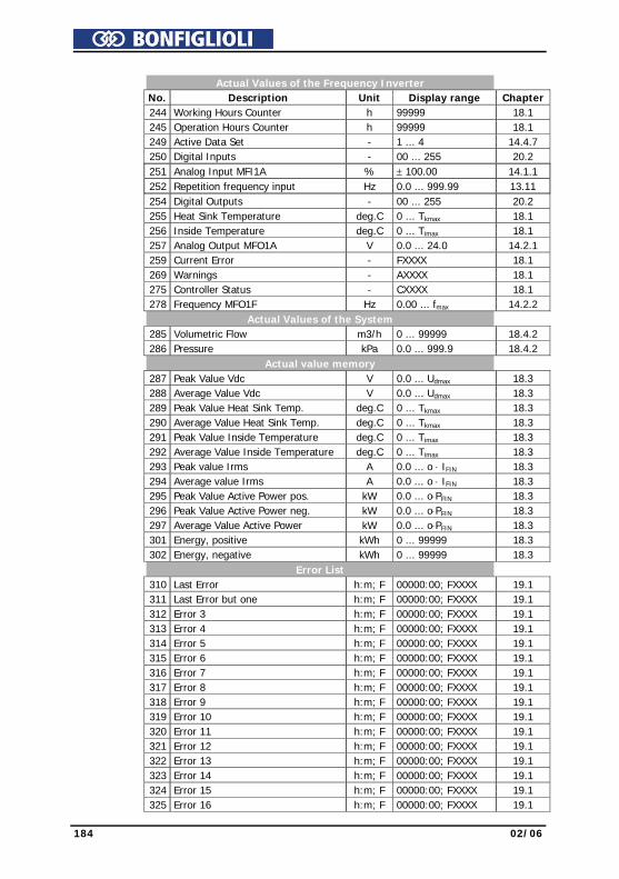
184 02/06
Actual Values of the Frequency Inverter No. Description Unit Display range Chapter 244 Working Hours Counter h 99999 18.1 245 Operation Hours Counter h 99999 18.1 249 Active Data Set - 1 ... 4 14.4.7 250 Digital Inputs - 00 ... 255 20.2 251 Analog Input MFI1A % ± 100.00 14.1.1 252 Repetition frequency input Hz 0.0 ... 999.99 13.11 254 Digital Outputs - 00 ... 255 20.2 255 Heat Sink Temperature deg.C 0 ... Tkmax 18.1 256 Inside Temperature deg.C 0 ... Timax 18.1 257 Analog Output MFO1A V 0.0 ... 24.0 14.2.1 259 Current Error - FXXXX 18.1 269 Warnings - AXXXX 18.1 275 Controller Status - CXXXX 18.1 278 Frequency MFO1F Hz 0.00 ... fmax 14.2.2 Actual Values of the System 285 Volumetric Flow m3/h 0 ... 99999 18.4.2 286 Pressure kPa 0.0 ... 999.9 18.4.2 Actual value memory 287 Peak Value Vdc V 0.0 ... Udmax 18.3 288 Average Value Vdc V 0.0 ... Udmax 18.3 289 Peak Value Heat Sink Temp. deg.C 0 ... Tkmax 18.3 290 Average Value Heat Sink Temp. deg.C 0 ... Tkmax 18.3 291 Peak Value Inside Temperature deg.C 0 ... Timax 18.3 292 Average Value Inside Temperature deg.C 0 ... Timax 18.3 293 Peak value Irms A 0.0 ... o ⋅ IFIN 18.3 294 Average value Irms A 0.0 ... o ⋅ IFIN 18.3 295 Peak Value Active Power pos. kW 0.0 ... o⋅PFIN 18.3 296 Peak Value Active Power neg. kW 0.0 ... o⋅PFIN 18.3 297 Average Value Active Power kW 0.0 ... o⋅PFIN 18.3 301 Energy, positive kWh 0 ... 99999 18.3 302 Energy, negative kWh 0 ... 99999 18.3 Error List 310 Last Error h:m; F 00000:00; FXXXX 19.1 311 Last Error but one h:m; F 00000:00; FXXXX 19.1 312 Error 3 h:m; F 00000:00; FXXXX 19.1 313 Error 4 h:m; F 00000:00; FXXXX 19.1 314 Error 5 h:m; F 00000:00; FXXXX 19.1 315 Error 6 h:m; F 00000:00; FXXXX 19.1 316 Error 7 h:m; F 00000:00; FXXXX 19.1 317 Error 8 h:m; F 00000:00; FXXXX 19.1 318 Error 9 h:m; F 00000:00; FXXXX 19.1 319 Error 10 h:m; F 00000:00; FXXXX 19.1 320 Error 11 h:m; F 00000:00; FXXXX 19.1 321 Error 12 h:m; F 00000:00; FXXXX 19.1 322 Error 13 h:m; F 00000:00; FXXXX 19.1 323 Error 14 h:m; F 00000:00; FXXXX 19.1 324 Error 15 h:m; F 00000:00; FXXXX 19.1 325 Error 16 h:m; F 00000:00; FXXXX 19.1
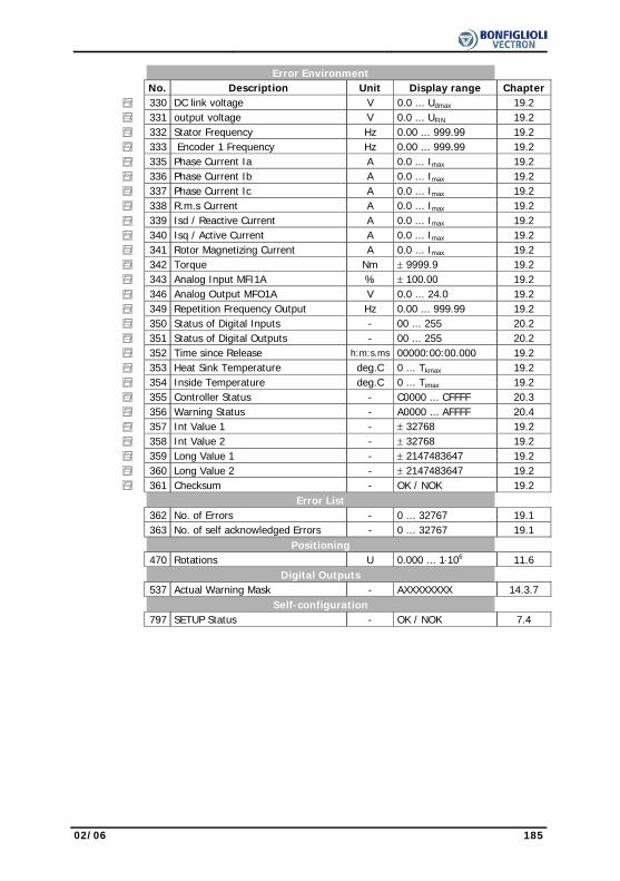
02/06 185
Error Environment No. Description Unit Display range Chapter 330 DC link voltage V 0.0 ... Udmax 19.2 331 output voltage V 0.0 ... UFIN 19.2 332 Stator Frequency Hz 0.00 ... 999.99 19.2 333 Encoder 1 Frequency Hz 0.00 ... 999.99 19.2 335 Phase Current Ia A 0.0 ... Imax 19.2 336 Phase Current Ib A 0.0 ... Imax 19.2 337 Phase Current Ic A 0.0 ... Imax 19.2 338 R.m.s Current A 0.0 ... Imax 19.2 339 Isd / Reactive Current A 0.0 ... Imax 19.2 340 Isq / Active Current A 0.0 ... Imax 19.2 341 Rotor Magnetizing Current A 0.0 ... Imax 19.2 342 Torque Nm ± 9999.9 19.2 343 Analog Input MFI1A % ± 100.00 19.2 346 Analog Output MFO1A V 0.0 ... 24.0 19.2 349 Repetition Frequency Output Hz 0.00 ... 999.99 19.2 350 Status of Digital Inputs - 00 ... 255 20.2 351 Status of Digital Outputs - 00 ... 255 20.2 352 Time since Release h:m:s.ms 00000:00:00.000 19.2 353 Heat Sink Temperature deg.C 0 ... Tkmax 19.2 354 Inside Temperature deg.C 0 ... Timax 19.2 355 Controller Status - C0000 ... CFFFF 20.3 356 Warning Status - A0000 ... AFFFF 20.4 357 Int Value 1 - ± 32768 19.2 358 Int Value 2 - ± 32768 19.2 359 Long Value 1 - ± 2147483647 19.2 360 Long Value 2 - ± 2147483647 19.2 361 Checksum - OK / NOK 19.2 Error List 362 No. of Errors - 0 ... 32767 19.1 363 No. of self acknowledged Errors - 0 ... 32767 19.1 Positioning 470 Rotations U 0.000 ... 1⋅106 11.6 Digital Outputs 537 Actual Warning Mask - AXXXXXXXX 14.3.7 Self-configuration 797 SETUP Status - OK / NOK 7.4

186 02/06
21.2 Parameter Menu (PARA) Inverter Data No. Description Unit Setting range Chapter 0 Serial Number - Characters 8.1 1 Optional Modules - Characters 8.2 12 Inverter Software Version - Characters 8.3 27 Set Password - 0 ... 999 8.4 28 Control Level - 1 ... 3 8.5 29 User Name - 32 characters 8.6 30 Configuration - Selection 8.7 33 Language - Selection 8.8 34 Program(ming) - 0 ... 9999 8.9 37 Start Positioning of Axle - Selection 11.6.2 Fan 39 Switch-On Temperature deg.C 0 ... 60 17.2 Digital Inputs 62 Frequency Motorpoti Up - Selection 14.4.9 63 Frequency Motorpot. Down - Selection 14.4.9 66 Fixed Frequency Change-Over 1 - Selection 14.4.8 67 Fixed Frequency Change-Over 2 - Selection 14.4.8 68 Start Clockwise - Selection 14.4.1 69 Start Anticlockwise - Selection 14.4.1 70 Data set change-over 1 - Selection 14.4.7 71 Data set change-over 2 - Selection 14.4.7 72 Percent Motorpoti Up - Selection 14.4.9 73 Percent Motorpoti Down - Selection 14.4.9 75 Fixed percentage value change-over 1 - Selection 14.4.8 76 Fixed percentage value change-over 2 - Selection 14.4.8 83 Timer 1 - Selection 14.4.4 84 Timer 2 - Selection 14.4.4 87 Start 3-wire-control - Selection 14.4.2 103 Error Acknowledgment - Selection 14.4.3 164 n-/T-Control Change-Over - Selection 14.4.6 Logic Modules 198 Operation mode Logic 1 - Selection 14.5.3 199 Input 1 Logic 1 - Selection 14.5.3 200 Input 2 Logic 1 - Selection 14.5.3 201 Operation mode Logic 2 - Selection 14.5.3 202 Input 1 Logic 2 - Selection 14.5.3 203 Input 2 Logic 2 - Selection 14.5.3 Digital Inputs 204 Therm. Contact - Selection 14.4.5 Logic Modules 205 Operation mode Logic 3 - Selection 14.5.3 206 Input 1 Logic 3 - Selection 14.5.3 207 Input 2 Logic 3 - Selection 14.5.3 Actual value memory 237 Reset Memory - Selection 18.3

02/06 187
Controlled commissioning No. Description Unit Setting range Chapter 369 Motor Type - Selection 7.2.3 Rated Motor Parameters 370 Rated Voltage V 0.17⋅UFIN ... 2⋅UFIN 9.1
371 Rated Current A 0.01⋅IFIN ... 10⋅o ⋅ IFIN
9.1
372 Rated Speed U/min 96 ... 60000 9.1 373 No. of Pole Pairs - 1 ... 24 9.1 374 Rated Cosinus Phi - 0.01 ... 1.00 9.1 375 Rated Frequency Hz 10.00 ... 1000.00 9.1 376 Rated Mech. Power kW 0.1⋅PFIN ... 10⋅PFIN 9.1 Further motor parameters 377 Stator Resistance mOhm 0 ... 65535 9.2 378 Leakage Coeff. % 1.0 ... 20.0 9.2 System data 389 Factor Actual Value System - -100.000 ... 100.000 10.1 397 Nominal Volumetric Flow m3/h 1 ... 99999 10.2 398 Nominal Pressure kPa 0.1 ... 999.9 10.2 Pulse Width Modulation 400 Switching frequency - Selection 17.1 401 Min. Switching Frequency - Selection 17.1 Error/warning behavior 405 Warning Limit Short Term Ixt % 6 ... 100 12.1 406 Warning Limit Long Term Ixt % 6 ... 100 12.1 407 Warning Limit Heat Sink Temp. deg.C -25 ... 0 12.2 408 Warning Limit Inside Temp. deg.C -25 ... 0 12.2 409 Controller-Status Message - Selection 12.3 Bus controller 412 Local/Remote - Selection 17.3 Error/warning behavior 415 IDC Compensation Limit V 0.0 ... 1.5 12.4 417 Frequency Switch-Off Limit Hz 0.00 ... 999.99 12.5 Frequency Limits 418 Minimum Frequency Hz 0.00 ... 999.99 13.1 419 Maximum Frequency Hz 0.00 ... 999.99 13.1 Frequency ramps 420 Acceleration (Clockwise) Hz/s 0.00 ... 9999.99 13.7 421 Deceleration (Clockwise) Hz/s 0.01 ... 9999.99 13.7 422 Acceleration Anticlockwise Hz/s -0.01 ... 9999.99 13.7 423 Deceleration Anticlockwise Hz/s -0.01 ... 9999.99 13.7 424 Emergency Stop Clockwise Hz/s 0.01 ... 9999.99 13.7 425 Emergency Stop Anticlockwise Hz/s 0.01 ... 9999.99 13.7 426 Maximum Leading Hz 0.01 ... 999.99 13.7 430 Ramp Rise Time Clockwise ms 0 ... 65000 13.7 431 Ramp Fall Time Clockwise ms 0 ... 65000 13.7 432 Ramp Rise Time Anticlockwise ms 0 ... 65000 13.7 433 Ramp Rise Time Anticlockwise ms 0 ... 65000 13.7
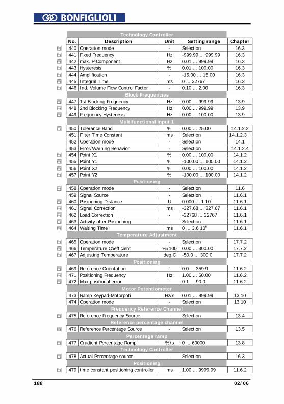
188 02/06
Technology Controller No. Description Unit Setting range Chapter 440 Operation mode - Selection 16.3 441 Fixed Frequency Hz -999.99 ... 999.99 16.3 442 max. P-Component Hz 0.01 ... 999.99 16.3 443 Hysteresis % 0.01 ... 100.00 16.3 444 Amplification - -15.00 ... 15.00 16.3 445 Integral Time ms 0 ... 32767 16.3 446 Ind. Volume Flow Control Factor - 0.10 ... 2.00 16.3 Block Frequencies 447 1st Blocking Frequency Hz 0.00 ... 999.99 13.9 448 2nd Blocking Frequency Hz 0.00 ... 999.99 13.9 449 Frequency Hysteresis Hz 0.00 ... 100.00 13.9 Multifunctional input 1 450 Tolerance Band % 0.00 ... 25.00 14.1.2.2 451 Filter Time Constant ms Selection 14.1.2.3 452 Operation mode - Selection 14.1 453 Error/Warning Behavior - Selection 14.1.2.4 454 Point X1 % 0.00 ... 100.00 14.1.2 455 Point Y1 % -100.00 ... 100.00 14.1.2 456 Point X2 % 0.00 ... 100.00 14.1.2 457 Point Y2 % -100.00 ... 100.00 14.1.2 Positioning 458 Operation mode - Selection 11.6 459 Signal Source - Selection 11.6.1 460 Positioning Distance U 0.000 ... 1 106 11.6.1 461 Signal Correction ms -327.68 ... 327.67 11.6.1 462 Load Correction - -32768 ... 32767 11.6.1 463 Activity after Positioning - Selection 11.6.1 464 Waiting Time ms 0 ... 3.6 106 11.6.1 Temperature Adjustment 465 Operation mode - Selection 17.7.2 466 Temperature Coefficient %/100 0.00 ... 300.00 17.7.2 467 Adjusting Temperature deg.C -50.0 ... 300.0 17.7.2 Positioning 469 Reference Orientation ° 0.0 ... 359.9 11.6.2 471 Positioning Frequency Hz 1.00 ... 50.00 11.6.2 472 Max positional error ° 0.1 ... 90.0 11.6.2 Motor Potentiometer 473 Ramp Keypad-Motorpoti Hz/s 0.01 ... 999.99 13.10 474 Operation mode - Selection 13.10 Frequency Reference Channel 475 Reference Frequency Source - Selection 13.4 Reference percentage channel 476 Reference Percentage Source - Selection 13.5 Percentage ramp 477 Gradient Percentage Ramp %/s 0 ... 60000 13.8 Technology Controller 478 Actual Percentage source - Selection 16.3 Positioning 479 time constant positioning controller ms 1.00 ... 9999.99 11.6.2
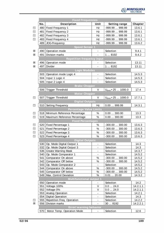
02/06 189
Fixed Frequencies No. Description Unit Setting range Chapter 480 Fixed Frequency 1 Hz -999.99 ... 999.99 13.6.1 481 Fixed Frequency 2 Hz -999.99 ... 999.99 13.6.1 482 Fixed Frequency 3 Hz -999.99 ... 999.99 13.6.1 483 Fixed Frequency 4 Hz -999.99 ... 999.99 13.6.1 489 JOG-Frequency Hz -999.99 ... 999.99 13.6.2 Speed Sensor 1 490 Operation mode - Selection 9.4.1 491 Division marks - 1 ... 8192 9.4.2 Repetition frequency input 496 Operation mode - Selection 13.11 497 Divider - 1 ... 8192 13.11 Logic Modules 503 Operation mode Logic 4 - Selection 14.5.3 504 Input 1 Logic 4 - Selection 14.5.3 505 Input 2 Logic 4 - Selection 14.5.3 Brake Chopper 506 Trigger Threshold V Udmin+25 ... 1000.0 17.4 Motor Chopper 507 Trigger Threshold V Udmin+25 ... 1000.0 17.7.1 Digital Outputs 510 Setting Frequency Hz 0.00 ... 999.99 14.3.1 Percentage Value Limits 518 Minimum Reference Percentage % 0.00 ... 300.00 13.3 519 Maximum Reference Percentage % 0.00 ... 300.00 13.3 Fixed Percentages 520 Fixed Percentage 1 % -300.00 ... 300.00 13.6.3 521 Fixed Percentage 2 % -300.00 ... 300.00 13.6.3 522 Fixed Percentage 3 % -300.00 ... 300.00 13.6.3 523 Fixed Percentage 4 % -300.00 ... 300.00 13.6.3 Digital Outputs 530 Op. Mode Digital Output 1 - Selection 14.3 532 Op. Mode Digital Output 3 - Selection 14.3 536 Create Warning Mask - Selection 14.3.7 540 Op. Mode Comparator 1 - Selection 14.5.2 541 Comparator On above % -300.00 ... 300.00 14.5.2 542 Comparator Off below % -300.00 ... 300.00 14.5.2 543 Op. Mode Comparator 2 - Selection 14.5.2 544 Comparator On above % -300.00 ... 300.00 14.5.2 545 Comparator Off below % -300.00 ... 300.00 14.5.2 549 Max. Control Deviation % 0.01 ... 20.00 14.3.2 Multifunctional output 1 550 Operation mode - Selection 14.2 551 Voltage 100% V 0.0 ... 24.0 14.2.1.1 552 Voltage 0% V 0.0 ... 24.0 14.2.1.1 553 Analog Operation - Selection 14.2.1 554 Digital Operation - Selection 14.3 555 Repetition Freq. Operation - Selection 14.2.2 556 Division marks - 30 ... 8192 14.2.2.1 Error/warning behavior 570 Motor Temp. Operation Mode - Selection 12.6
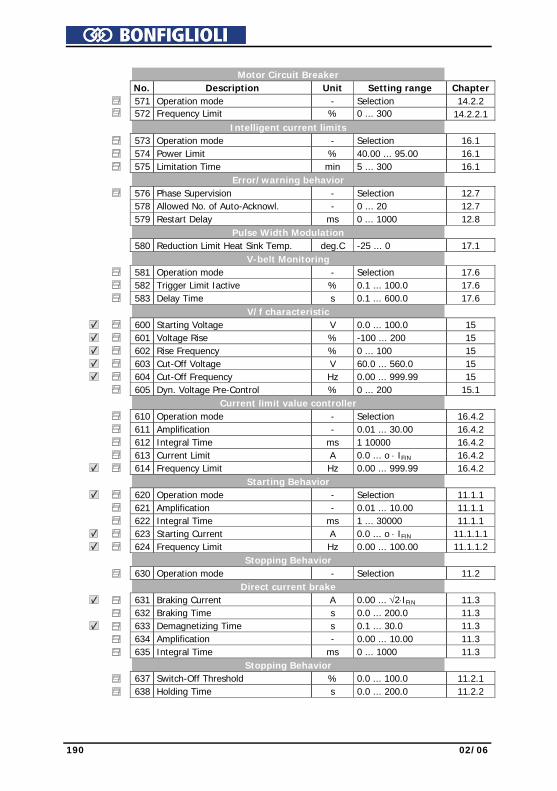
190 02/06
Motor Circuit Breaker No. Description Unit Setting range Chapter 571 Operation mode - Selection 14.2.2 572 Frequency Limit % 0 ... 300 14.2.2.1 Intelligent current limits 573 Operation mode - Selection 16.1 574 Power Limit % 40.00 ... 95.00 16.1 575 Limitation Time min 5 ... 300 16.1 Error/warning behavior 576 Phase Supervision - Selection 12.7 578 Allowed No. of Auto-Acknowl. - 0 ... 20 12.7 579 Restart Delay ms 0 ... 1000 12.8 Pulse Width Modulation 580 Reduction Limit Heat Sink Temp. deg.C -25 ... 0 17.1 V-belt Monitoring 581 Operation mode - Selection 17.6 582 Trigger Limit Iactive % 0.1 ... 100.0 17.6 583 Delay Time s 0.1 ... 600.0 17.6 V/f characteristic 600 Starting Voltage V 0.0 ... 100.0 15 601 Voltage Rise % -100 ... 200 15 602 Rise Frequency % 0 ... 100 15 603 Cut-Off Voltage V 60.0 ... 560.0 15 604 Cut-Off Frequency Hz 0.00 ... 999.99 15 605 Dyn. Voltage Pre-Control % 0 ... 200 15.1 Current limit value controller 610 Operation mode - Selection 16.4.2 611 Amplification - 0.01 ... 30.00 16.4.2 612 Integral Time ms 1 10000 16.4.2 613 Current Limit A 0.0 ... o ⋅ IFIN 16.4.2 614 Frequency Limit Hz 0.00 ... 999.99 16.4.2 Starting Behavior 620 Operation mode - Selection 11.1.1 621 Amplification - 0.01 ... 10.00 11.1.1 622 Integral Time ms 1 ... 30000 11.1.1 623 Starting Current A 0.0 ... o ⋅ IFIN 11.1.1.1 624 Frequency Limit Hz 0.00 ... 100.00 11.1.1.2 Stopping Behavior 630 Operation mode - Selection 11.2 Direct current brake 631 Braking Current A 0.00 ... √2⋅IFIN 11.3 632 Braking Time s 0.0 ... 200.0 11.3 633 Demagnetizing Time s 0.1 ... 30.0 11.3 634 Amplification - 0.00 ... 10.00 11.3 635 Integral Time ms 0 ... 1000 11.3 Stopping Behavior 637 Switch-Off Threshold % 0.0 ... 100.0 11.2.1 638 Holding Time s 0.0 ... 200.0 11.2.2
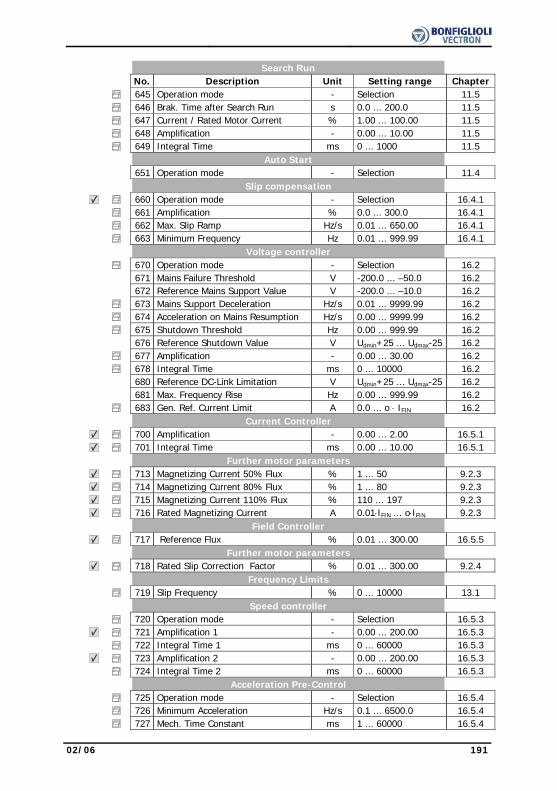
02/06 191
Search Run No. Description Unit Setting range Chapter 645 Operation mode - Selection 11.5 646 Brak. Time after Search Run s 0.0 ... 200.0 11.5 647 Current / Rated Motor Current % 1.00 ... 100.00 11.5 648 Amplification - 0.00 ... 10.00 11.5 649 Integral Time ms 0 ... 1000 11.5 Auto Start 651 Operation mode - Selection 11.4 Slip compensation 660 Operation mode - Selection 16.4.1 661 Amplification % 0.0 ... 300.0 16.4.1 662 Max. Slip Ramp Hz/s 0.01 ... 650.00 16.4.1 663 Minimum Frequency Hz 0.01 ... 999.99 16.4.1 Voltage controller 670 Operation mode - Selection 16.2 671 Mains Failure Threshold V -200.0 ... –50.0 16.2 672 Reference Mains Support Value V -200.0 ... –10.0 16.2 673 Mains Support Deceleration Hz/s 0.01 ... 9999.99 16.2 674 Acceleration on Mains Resumption Hz/s 0.00 ... 9999.99 16.2 675 Shutdown Threshold Hz 0.00 ... 999.99 16.2 676 Reference Shutdown Value V Udmin+25 ... Udmax-25 16.2 677 Amplification - 0.00 ... 30.00 16.2 678 Integral Time ms 0 ... 10000 16.2 680 Reference DC-Link Limitation V Udmin+25 ... Udmax-25 16.2 681 Max. Frequency Rise Hz 0.00 ... 999.99 16.2 683 Gen. Ref. Current Limit A 0.0 ... o ⋅ IFIN 16.2 Current Controller 700 Amplification - 0.00 ... 2.00 16.5.1 701 Integral Time ms 0.00 ... 10.00 16.5.1 Further motor parameters 713 Magnetizing Current 50% Flux % 1 ... 50 9.2.3 714 Magnetizing Current 80% Flux % 1 ... 80 9.2.3 715 Magnetizing Current 110% Flux % 110 ... 197 9.2.3 716 Rated Magnetizing Current A 0.01⋅IFIN ... o⋅IFIN 9.2.3 Field Controller 717 Reference Flux % 0.01 ... 300.00 16.5.5 Further motor parameters 718 Rated Slip Correction Factor % 0.01 ... 300.00 9.2.4 Frequency Limits 719 Slip Frequency % 0 ... 10000 13.1 Speed controller 720 Operation mode - Selection 16.5.3 721 Amplification 1 - 0.00 ... 200.00 16.5.3 722 Integral Time 1 ms 0 ... 60000 16.5.3 723 Amplification 2 - 0.00 ... 200.00 16.5.3 724 Integral Time 2 ms 0 ... 60000 16.5.3 Acceleration Pre-Control 725 Operation mode - Selection 16.5.4 726 Minimum Acceleration Hz/s 0.1 ... 6500.0 16.5.4 727 Mech. Time Constant ms 1 ... 60000 16.5.4
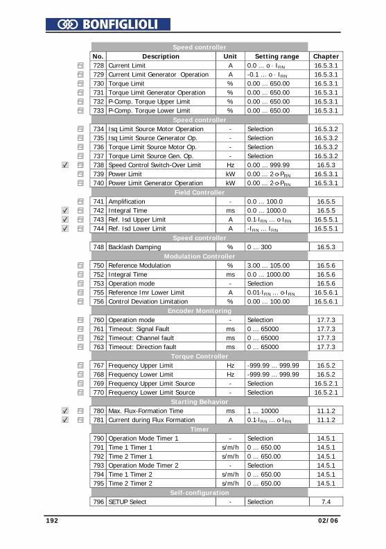
192 02/06
Speed controller No. Description Unit Setting range Chapter 728 Current Limit A 0.0 ... o ⋅ IFIN 16.5.3.1 729 Current Limit Generator Operation A -0.1 ... o ⋅ IFIN 16.5.3.1 730 Torque Limit % 0.00 ... 650.00 16.5.3.1 731 Torque Limit Generator Operation % 0.00 ... 650.00 16.5.3.1 732 P-Comp. Torque Upper Limit % 0.00 ... 650.00 16.5.3.1 733 P-Comp. Torque Lower Limit % 0.00 ... 650.00 16.5.3.1 Speed controller 734 Isq Limit Source Motor Operation - Selection 16.5.3.2 735 Isq Limit Source Generator Op. - Selection 16.5.3.2 736 Torque Limit Source Motor Op. - Selection 16.5.3.2 737 Torque Limit Source Gen. Op. - Selection 16.5.3.2 738 Speed Control Switch-Over Limit Hz 0.00 ... 999.99 16.5.3 739 Power Limit kW 0.00 ... 2⋅o⋅PFIN 16.5.3.1 740 Power Limit Generator Operation kW 0.00 ... 2⋅o⋅PFIN 16.5.3.1 Field Controller 741 Amplification - 0.0 ... 100.0 16.5.5 742 Integral Time ms 0.0 ... 1000.0 16.5.5 743 Ref. Isd Upper Limit A 0.1⋅IFIN ... o⋅IFIN 16.5.5.1 744 Ref. Isd Lower Limit A -IFIN ... IFIN 16.5.5.1 Speed controller 748 Backlash Damping % 0 ... 300 16.5.3 Modulation Controller 750 Reference Modulation % 3.00 ... 105.00 16.5.6 752 Integral Time ms 0.0 ... 1000.00 16.5.6 753 Operation mode - Selection 16.5.6 755 Reference Imr Lower Limit A 0.01⋅IFIN ... o⋅IFIN 16.5.6.1 756 Control Deviation Limitation % 0.00 ... 100.00 16.5.6.1 Encoder Monitoring 760 Operation mode - Selection 17.7.3 761 Timeout: Signal Fault ms 0 ... 65000 17.7.3 762 Timeout: Channel fault ms 0 ... 65000 17.7.3 763 Timeout: Direction fault ms 0 ... 65000 17.7.3 Torque Controller 767 Frequency Upper Limit Hz -999.99 ... 999.99 16.5.2 768 Frequency Lower Limit Hz -999.99 ... 999.99 16.5.2 769 Frequency Upper Limit Source - Selection 16.5.2.1 770 Frequency Lower Limit Source - Selection 16.5.2.1 Starting Behavior 780 Max. Flux-Formation Time ms 1 ... 10000 11.1.2 781 Current during Flux Formation A 0.1⋅IFIN ... o⋅IFIN 11.1.2 Timer 790 Operation Mode Timer 1 - Selection 14.5.1 791 Time 1 Timer 1 s/m/h 0 ... 650.00 14.5.1 792 Time 2 Timer 1 s/m/h 0 ... 650.00 14.5.1 793 Operation Mode Timer 2 - Selection 14.5.1 794 Time 1 Timer 2 s/m/h 0 ... 650.00 14.5.1 795 Time 2 Timer 2 s/m/h 0 ... 650.00 14.5.1 Self-configuration 796 SETUP Select - Selection 7.4
HEADQUARTERSBONFIGLIOLI RIDUTTORI S.p.A.
Via Giovanni XXIII, 7/A40012 Lippo di Calderara di Reno
Bologna (ITALY)Tel. (+39) 051 6473111Fax (+39) 051 6473126
SPARE PARTS BONFIGLIOLIB.R.T.
Via Castagnini, 2-4Z.I. Bargellino - 40012
Calderara di Reno - Bologna (ITALY)Tel. (+39) 051 727844Fax (+39) 051 727066
AUSTRALIABONFIGLIOLI TRANSMISSION (Aust) Pty Ltd.101, Plumpton Road, Glendenning NSW 2761, AustraliaLocked Bag 1000 Plumpton NSW 2761Tel. (+ 61) 2 8811 8000 - Fax (+ 61) 2 9675 6605www.bonfiglioli.com.au - [email protected]
AUSTRIA MOLL MOTOR GmbHIndustriestrasse 8 - 2000 StockerauTel. (+43) 2266 63421+DW - Fax (+43) 6342 180www.mollmotor.at - [email protected]
BELGIUM ESCO TRANSMISSION N.V./S.A.Culliganlaan 3 - 1831 Machelem DiegemTel. 0032 2 7176460 - Fax 0032 2 7176461www.esco-transmissions.be - [email protected]
BRASIL ATI BRASILRua Omlio Monteiro Soares, 260 - Vila Fanny - 81030-000Tel. (+41) 334 2091 - Fax (+41) 332 8669www.atibrasil.com.br - [email protected]
CANADABONFIGLIOLI CANADA INC.2-7941 Jane Street - Concord, ONTARIO L4K 4L6Tel. (+1) 905 7384466 - Fax (+1) 905 7389833www.bonfigliolicanada.com - [email protected]
CHINABONFIGLIOLI DRIVES (SHANGHAI) CO. LTD.No. 8 Building, 98 Tian Ying Road - Qingpu District, Shanghai, PRC 201700Tel. +86 21 69225500 - Fax +86 21 69225511www.bonfiglioli.cn - [email protected]
FRANCEBONFIGLIOLI TRANSMISSIONS S.A.14 Rue Eugène Pottier BP 19Zone Industrielle de Moimont II - 95670 Marly la VilleTel. (+33) 1 34474510 - Fax (+33) 1 34688800www.bonfiglioli.fr - [email protected]
GERMANYBONFIGLIOLI DEUTSCHLAND GmbHHamburger Straße 18 - 41540 DormagenTel. (+49) 2133 50260 - Fax (+49) 2133 502610www.bonfiglioli.de - [email protected]
GREAT BRITAINBONFIGLIOLI UK LtdUnit 3 Colemeadow Road - North Moons MoatRedditch. Worcestershire B98 9PBTel. (+44) 1527 65022 - Fax (+44) 1527 61995www.bonfiglioli.co.uk - [email protected]
BONFIGLIOLI (UK) LIMITED5 Grosvenor Grange - Woolston - Warrington, Cheshire WA1 4SFTel. (+44) 1925 852667 - Fax (+44) 1925 852668www.bonfiglioliuk.co.uk - [email protected]
GREECEBONFIGLIOLI HELLAS S.A.O.T. 48A T.O. 230 - C.P. 570 22 Industrial Area - ThessalonikiTel. (+30) 2310 796456 - Fax (+30) 2310 795903www.bonfiglioli.gr - [email protected]
HOLLAND ELSTO AANDRIJFTECHNIEKLoosterweg, 7 - 2215 TL VoorhoutTel. (+31) 252 219 123 - Fax (+31) 252 231 660www.elsto.nl - [email protected]
HUNGARY AGISYS AGITATORS & TRANSMISSIONS Ltd2045 Törökbálint, Tö u.2. HungaryTel. +36 23 50 11 50 - Fax +36 23 50 11 59www.agisys.hu - [email protected]
INDIABONFIGLIOLI TRANSMISSIONS PVT Ltd.PLOT AC7-AC11 Sidco Industrial EstateThirumudivakkam - Chennai 600 044Tel. +91(0) 44 24781035 / 24781036 / 24781037Fax +91(0) 44 24780091 / 24781904www.bonfiglioli.co.in - [email protected]
ITALYBONFIGLIOLI ITALIA srlVia Sandro Pertini lotto 7b20080 Carpiano (Milano)Tel. (+39) 02 985081 - Fax (+39) 02 [email protected] - www.bonfiglioli.com
NEW ZEALAND SAECO BEARINGS TRANSMISSION36 Hastie Avenue, MangerePo Box 22256, Otahuhu - AucklandTel. +64 9 634 7540 - Fax +64 9 634 [email protected]
POLAND POLPACK Sp. z o.o. - Ul. Chrobrego 135/137 - 87100 TorunTel. 0048.56.6559235 - 6559236 - Fax 0048.56.6559238www.polpack.com.pl - [email protected]
PORTUGAL BT BONFITEC Equipamentos Industriais, Lda.Largo do Colegio de Ermesinde,70Formiga 4445-382 Ermesinde
Tel. 00351 229759634/5/6 - Fax 00351 229752211 [email protected] - www.bonfitec.pt
RUSSIA FAM57, Maly prospekt, V.O. - 199048, St. PetersburgTel. +7 812 3319333 - Fax +7 812 3271454www.fam-drive.ru - [email protected]
SPAINTECNOTRANS BONFIGLIOLI S.A.Pol. Ind. Zona Franca sector C, calle F, n°6 08040 BarcelonaTel. (+34) 93 4478400 - Fax (+34) 93 3360402www.tecnotrans.com - [email protected]
SOUTH AFRICABONFIGLIOLI POWER TRANSMISSION Pty Ltd.55 Galaxy Avenue, Linbro Business Park - SandtonTel. (+27) 11 608 2030 OR - Fax (+27) 11 608 2631www.bonfiglioli.co.za - [email protected]
SWEDENBONFIGLIOLI SKANDINAVIEN ABKontorsgatan - 234 34 LommaTel. (+46) 40 412545 - Fax (+46) 40 414508www.bonfiglioli.se - [email protected]
THAILAND K.P.T MACHINERY (1993) CO.LTD.259/83 Soi Phiboonves, Sukhumvit 71 Rd. Phrakanong-nur,Wattana, Bangkok 10110Tel. 0066.2.3913030/7111998Fax 0066.2.7112852/3811308/3814905www.kpt-group.com - [email protected]
USABONFIGLIOLI USA INC1000 Worldwide Boulevard - Hebron, KY 41048Tel. (+1) 859 334 3333 - Fax (+1) 859 334 8888www.bonfiglioliusa.comindustrialsales@[email protected]
VENEZUELA MAQUINARIA Y ACCESSORIOS IND.-C.A.Calle 3B - Edif. Comindu - Planta Baja - Local BLa Urbina - Caracas 1070Tel. 0058.212.2413570 / 2425268 / 2418263Fax 0058.212.2424552 - Tlx 24780 Maica Vwww.maica-ve.com - [email protected]
Bonfiglioli Worldwide & BEST Partners
Worldwide
INDUSTRY PROCESSAND AUTOMATION SOLUTIONS

w w w. b o n f i g l i o l i . c o m
I PNDUSTRY ROCESSAND UTOMATION OLUTIONSA S
ACTIVE
COD. VEC 211 R1


