
Paweł Kapłański
Ontology-Aided Software Engineering
PhD Dissertation
Supervisor: prof. Krzysztof Goczyła, Faculty of Electronics,
Telecommunications and Informatics Gdańsk University of Technology
Gdańsk, 2012
GDAŃSK UNIVERSITY OF TECHNOLOGY
Faculty of Electronics,
Telecommunications and Informatics

praca współfinansowana przez Ministerstwo Nauki i Szkolnictwa Wyższego
w ramach grantu promotorskiego nr N N516 416438

This dissertation is dedicated to my wife Katarzyna.
It would not have happened
without her encouragement, support and love.

ACKNOWLEDGEMENT
First and foremost I want to thank my supervisor Professor Krzysztof Goczyła.
His support, insightful comments, constructive criticism and feedback were invalua-
ble. I have benefited from his guidance, great kindness and patience and I wish to
say a heartfelt thank you to him.
I would also like to sincerely thank my friends and colleagues Gabriela
Adamczyk, Paweł Zarzycki, Łukasz Milewski and Krzysztof Cieśliński for their
support.
I am also very thankful to all the programmers that have taken part in the valida-
tion experiment.
Finally, I would also like to acknowledge the financial assistance given to me by
the Polish Ministry of Science and Higher Education.

-i-
TABLE OF CONTENTS 1. Introduction.............................................................................................................................. 1
Hypothesis and Approach ......................................................................................... 3 1.1
Outline ............................................................................................................................... 6 1.2
2. Ontology Engineering ........................................................................................................... 8
Semiotics .......................................................................................................................... 8 2.1
Ontologies ...................................................................................................................... 10 2.2
Knowledge Expression ............................................................................................. 11 2.3
Controlled English ...................................................................................................... 17 2.4
Description logics ....................................................................................................... 17 2.5
2.5.1 Definition Of Description logic ...................................................................... 20
Dialects ........................................................................................................................... 22 2.6
Reasoning ...................................................................................................................... 23 2.7
2.7.1 Structural Subsumption .................................................................................. 23
2.7.2 Tableau Algorithm ............................................................................................. 23
2.7.3 Knowledge Cartography .................................................................................. 24
2.7.4 Explanations for reasoning in DL ................................................................ 24
2.7.5 Modular Structure Of DL ................................................................................. 25
Other important subsets of FOL ............................................................................ 25 2.8
Computer Semiotics ................................................................................................... 26 2.9
3. Software Development ...................................................................................................... 29
The Program For A Machine ................................................................................... 29 3.1
Software Models .......................................................................................................... 31 3.2
3.2.1 Model Driven Engineering .............................................................................. 33
3.2.2 Service Oriented Modeling ............................................................................. 36
3.2.3 Evolution ............................................................................................................... 37
Formal representations of UML ............................................................................ 38 3.3
3.3.1 Object Constraint Language ........................................................................... 39
3.3.2 Criticism of OCL .................................................................................................. 40
Software Engineering ................................................................................................ 41 3.4
-ii-
3.4.1 Criticism of RUP .................................................................................................. 42
Agile Methodologies .................................................................................................. 42 3.5
Quality assurance ........................................................................................................ 44 3.6
The Language Of Patterns........................................................................................ 44 3.7
4. OASE ......................................................................................................................................... 46
The Meaning Triangle Of Software Entities ...................................................... 46 4.1
Artifacts in Software Development ...................................................................... 47 4.2
Computability and Complexity of Software Structures ............................... 49 4.3
Classification Of Ontologies Of Software Artifacts ......................................... 49 4.4
OASE: Formal Semiotic System ............................................................................. 51 4.5
Motivating Examples ................................................................................................. 53 4.6
4.6.1 Singleton design-pattern ................................................................................. 53
4.6.2 Preserving Consistency Between Artifacts .............................................. 54
OASE-English ................................................................................................................ 55 4.7
4.7.1 Grammar and Semantics ................................................................................. 56
OASE-Transformations ............................................................................................. 60 4.8
Software Icons, Indexes and Symbols in OASE................................................ 60 4.9
Class Descriptors ......................................................................................................... 61 4.10
Direct-Mapping ............................................................................................................ 62 4.11
The OASE-Metamodel ............................................................................................... 64 4.12
4.12.1 The Model Of Part-Whole ................................................................................ 66
4.12.2 Class hierarchies ................................................................................................. 68
OASE-Mapping ............................................................................................................. 69 4.13
Programming With OASE-Annotations .............................................................. 70 4.14
Debugging With OASE-Assertions ........................................................................ 70 4.15
Discussion Of OASE Semiotic Framework ......................................................... 71 4.16
4.16.1 OASE Syntax layer .............................................................................................. 71
4.16.2 OASE Semantic layer ......................................................................................... 71
4.16.3 OASE Pragmatic layer ....................................................................................... 71
4.16.4 Evaluation ............................................................................................................. 72
Case studies ................................................................................................................... 72 4.17
4.17.1 Architectural Layers.......................................................................................... 72
4.17.2 Pipes & Filters...................................................................................................... 74
OASE as a Design Pattern Language .................................................................... 75 4.18

-iii-
4.18.1 Adapter .................................................................................................................. 76
5. OASE-Tools ............................................................................................................................ 77
OASE-Validator ............................................................................................................ 77 5.1
OASE-English Predictor ............................................................................................ 78 5.2
OASE-Transformation Processor ......................................................................... 79 5.3
OASE-Annotator .......................................................................................................... 80 5.4
OASE-Diagrammer ..................................................................................................... 81 5.5
6. OASE-Tools in Custom Applications ............................................................................ 82
Inferred-UI..................................................................................................................... 82 6.1
Self-Implemented Requirement ............................................................................ 85 6.2
6.2.1 Related Ontology Editors ................................................................................ 86
7. Summary ................................................................................................................................. 87
Results of the Thesis .................................................................................................. 87 7.1
Contribution To The Field ....................................................................................... 89 7.2
Future Work ................................................................................................................. 90 7.3
Appendix 1. Mapping Between OASE-English and DL ................................................. 92
Appendix 2. OASE-Transformations For OASE-Mapping ........................................... 94
Appendix 3. OASE-Transformation For Adapter Design Pattern ........................... 98
Appendix 4. The Survey ........................................................................................................ 104
Execution Of The Survey ..................................................................................................... 104
Interpretation Of Results Of The Survey ....................................................................... 107
Full Text of The Survey ........................................................................................................ 108
Appendix 5. 9Validation Experiment ............................................................................... 118
Refactoring task with OASE-Annotations ..................................................................... 118
Execution Of The Experiment ........................................................................................... 119
Interpretation Of Results Of The Experiment ............................................................. 121
Full Text Of The Task And Its Source Code .................................................................. 123
Appendix 6. CDSS ..................................................................................................................... 133
Appendix 7. The Web Page .................................................................................................. 137
8. Bibliography ....................................................................................................................... 138
-iv-
NOTATIONAL CONVENTIONS AND SYMBOLS
Attributive Concept Language
Attributive Concept Language with Complements
Description Logic Programs
EL Family of Description Logics
Description Logic SHIQ
Description Logic SHOIQ
Description Logic SROIQ
Description Logic SROIQ with Cheap Boolean Constructors
⊤ Top Concept
⊥ Bottom Concept
{a,b,..} Enumerated Individuals
C⊓D Intersection of Concepts/Roles
∃r.C Existential Restriction
C⊑D Concept/Role Subsumption
s○r Role Chain
¬C Negation of Concept/Role
C⊔D Union of Concepts/Roles
∀r.C Universal Restriction
∃r.Self Self Restriction
≤n r.C Number Restriction
r ⁻ Inverse Role
A-Box Assertion Box
EBNF Extended Backus–Naur Form
ExpTime solvable (deterministic) in O(2p(n)) time [p(n) is a polynomial]
LALR Look-Ahead Left To Right
N2ExpTime solvable (non-deterministic) in O( ) time [p(n) is a polynomial]
NExpTime solvable (non-deterministic) in O(2p(n)) time [p(n) is a polynomial]
PTime solvable (deterministic) in O(p(n)) time [p(n) is a polynomial]
R-Box Role-Box
T-Box Terminology-Box

-1-
1. INTRODUCTION Language is a part of social technology for enhancing the benefits of cooperation,
reaching agreements, making deals and coordinating our activities1. The program-
ming language is an artificial language, so it also fits into above definition - it allows
for sharing the benefits of collaborative programming, reaching business agree-
ments and coordinating the work of all the people involved in development of
software intensive systems [Elli96]. Moreover, the usage of language gives the pos-
sibility of sharing ideas which coined together provide the prosperity that we
couldn’t have before we acquired the language itself. The computer language allows
us additionally to communicate with the machine; however the existence of different
natural languages slows the flow of ideas between the groups and thus forces isola-
tion; differences in computer languages, their grammars and semantics, differentiate
groups of programmers.
Engineering can be defined as the creative application of scientific principles to
design or develop structures, machines, apparatus, or manufacturing processes. The
software engineering is defined as application of a systematic, disciplined, quantifia-
ble approach to the development, operation, maintenance of software, and the study
of these approaches; that is, the application of engineering to software [Abra04].
But even if software engineering was meant to be an application of scientific princi-
ples, at the end of 1960’s the Software Crisis [Dijk72] was identified and large IT
projects have been plagued by overcrowding and budget blackouts. In 1995, The
Standish Group published the “CHAOS” report [Stan95] that contained following ob-
servations:
- 31.1% of projects have been cancelled before they even got completed
- 52.7% of projects went over time and/or over budget, at an average cost of
89% of their original estimates
- 16.2% of software projects have been completed on time and on budget
- In larger companies only 9% of the projects came in on time and on budget
with approximately 42% of the originally proposed features and functions
- In small companies 78.4% of the software projects got deployed, with at least
74.2% of their original features and functions
To cope with the Software Crisis, researchers brought forth multiplication of
loosely-related software technologies, techniques, notations, paradigms, idioms and
methodologies. Nowadays, the industry practices focus on the software engineering,
trying to optimize it in both the quality and time dimensions. In the meantime, agile
software development [Larm03] methodology, that focuses on the sociological and
1 Mark Pagel: How language transformed humanity
http://www.ted.com/talks/mark_pagel_how_language_transformed_humanity.html

-2-
psychological aspects of software development process rather than on engineering
and (in the meantime), created the split between industry practice and academic
research in the field. Agile methodologies introduced the foundation for novel ap-
proach to software production process that is opposed to software engineering, but
(from the same reason) it lacks the ability to take advantages of formal methods
(which are essential in the software engineering). Without formal methods it is im-
possible to rise to the challenges appearing in modern (more and more) complex
software systems. Therefore, despite the progress in software development meth-
odologies, the critical situation in the field remained extensively unchanged.
Developers continue to produce monstrous complex systems that suffer from many
complications that came from (among the others):
1. Lack of understanding: In order to understand the software structure, one is
required to have a background knowledge in the field of a computer science,
especially in software modeling. Analytic documents (e.g.: requirement speci-
fication, software design) function as a formal basis and they are often directed
particularly to the systems designers. The business users, who may actually be
the owners of the systems, are not considered (within the process) as recipi-
ents of the analytic documents. In consequence, strategic decisions that are
made by the authorities2 often reveal a lack of information about the real state
of the software product that is developed within the organization (those deci-
sions are generally based on consultations). Going further, in a complex
software system, without the aid of methods and tools it is very difficult to
trace and understand the impact of even a slight design change.
2. Lack of knowledge management: Software industry is knowledge oriented in-
dustry. While experienced programmers are leaving, the inexperienced ones
are joining the company. In such an environment and without knowledge
management it is almost impossible to maintain and create software with good
quality in limited time and budget [Nata02]. The preservation of knowledge
about the software is often underestimated. This is mainly due to the unavail-
ability of tools that support the knowledge management in software houses.
3. Problems with quality assurance: Quality assurance has an important position
within the software development process nowadays. Writing automated tests
for a program requires the knowledge of programming and therefore pro-
grams that test other programs also suffer from the same problems as
programs to be tested.
Those problems can be solved only by using formal software development meth-
odologies and tools. Over thousands of years there evolved the only one, common
language of ideas – the formal symbolic language of Logics. Logics give us the possi-
bility to communicate in an unambiguous manner with the assistance of machines,
which can perform automated reasoning. (Formal) Methods & Tools are nowadays
widely recognized as a key macro-trend in modern Software engineering. This mac-
2 Authorities are understood here as all the people responsible for business related decisions (e.g.: project
managers, end-users that pay for the software product, private equity owners etc…)

-3-
ro-trend brought forth (among the others) the Unified Modeling Language (UML)
[Rumb05] which became a standard software modeling language. While UML is typ-
ically used as a graphical modeling language, it can be used with Object Constraint
Language OCL [Warm99] – the formal specification language.
The issue of bridging the gap between theoretical bases and industrial needs is
expected to be solved by Common, Object Oriented Software Engineering Language
(the formal language yet understandable by overall software engineering Communi-
ty) – a core idea of the SEMAT initiative [Jaco12]. Executable UML [Mell02] (a formal
subset of UML) is built over the set of tools that allow conversion of some of the
UML+OCL artifacts into mathematical formalism. However desired Common Soft-
ware Engineering Language (as it states in [Jaco12]) should also be able to express
relevant practices, patterns, and their composition and therefore should be an im-
plementation of a Pattern Language [Alex77] [Busc07a]. The Language should also
be extendible and customizable, allowing the description of individual practices. It
should allow preserving consistency between design and implementation of Soft-
ware System, support automatic verification of key aspects and design constraints of
Software System and increase traceability between requirements, design and im-
plementation. What is more, it should be cheap3 for organization that is going to use
it. Last but not least – its usage should improve the quality of the software products.
HYPOTHESIS AND APPROACH 1.1This thesis is located between the fields of research on Artificial Intelligence (AI),
Knowledge Representation and Reasoning (KRR), Computer-Aided Software Engi-
neering (CASE) and Model Driven Engineering (MDE). The modern offspring of KRR
- Description Logic (DL) [Baad03] is considered here as a formalization of the soft-
ware engineering Methods & Tools. The bridge between the world of formal
specification (governed by the mathematics) and the world of software development
is realized by the adaptation of Controlled Natural Language (CNL) as a verbalization
of DL. To establish the previously mentioned bridge we, are required to make a step
backwards to the Semiotics. We found out that software development process can
be represented by a formal semiotic system, that fulfills the laws of Semiotics and
allows for interpreting the semantics of signs in a formal way.
The aim of this thesis is to prove that:
1) It is possible to define a Common, Object Oriented Language by us-
ing the Controlled Natural Language as a verbalization of
Description Logic.
2) Introduced language is understandable for people and can be auto-
matically processed by machines. It can also be used in many areas
of software development where natural language is currently used.
3) The language can be used to aid the software production process
with ontology engineering.
3 The cost of introduction should be relatively small to the total cost of software product aided with the
language.

-4-
The invented formalism is named Ontology-Aided Software Engineering
(OASE). The language (combination of CNL and DL) that is a centre of OASE is called
OASE-English as it is a controlled subset of English that is designed especially for
OASE.
World Description (A-Box) Terminology (T-Box) Integrity Constraint (IC)
John is a man. Every man is an animal. John must be a programmer.
Sophie is a giraffe. Every giraffe is an herbi-
vore.
Leo must be carnivore.
Figure 1. Examples of World Description, Terminology and Integrity Constraints in
OASE-English
Modern, formal ontology engineering principle suggests the separation of ontol-
ogy into two parts:
- Terminology (T–Box), that contains the terminological knowledge in the form
of axioms defined by concepts and roles (conceptualization of terms in the
world – the global axioms and core taxonomy) and
- World Description (A–Box), that includes assertions on instances of concepts
coupled by roles (a set of expressions about instances that are related to the
particular entity of analyzed problem).
On the knowledge base that includes both T–Box and A–Box, it can be automati-
cally checked whether any of the Integrity Constraints (IC) is kept. IC is used to
ensure the accuracy and consistency of data in a relational database, however in
terms of knowledge representation it is a kind of modal expression, that can be vali-
dated by the theory prover (see Figure 1 for some examples).
Ontologies
Frontend
Controlled English (OASE-English)
Programming Language (Java/C#)
World Description
Description Logic
Model of ObjectObject Oriented
Methodology
UML
Integrity Constraints
Terminology
Figure 2. OASE Reference Model

-5-
The thesis proves that an object-oriented program built on top of the object-
oriented design ontology4 forms a World Description (A-Box) of the particular ob-
ject-oriented program5. The object-oriented design ontology is a Terminology (T-
Box), as it consists of general rules e.g.: polymorphism and encapsulation. The re-
quirements (e.g.: usage of the design patterns, architectural limitations, usage of
generic structures, etc…) are represented by Integrity Constraints (IC).
The OASE Reference Model forms a stack (see Figure 2) in the way that OASE ex-
tends the object-oriented method by adapting modern knowledge representation
methods. Description Logic in OASE is chosen as a formal specification language.
Object-oriented programming, if formalized in DL, forms strictly defined upper-level
ontology for subtyping, instantiation and other object-oriented constructs.
Figure 3. OASE-Toolkit in action
As a proof of the concept, the OASE-Toolkit has been implemented. Figure 3 pre-
sents the most typical use case that can be realized using the OASE-Toolkit. The
design of the program (created and maintained by the designer) in UML and its
source code (made by the programmer) are together transformed into DL via fully
automated process. The requirements (functional – in UML, and non-functional – in
OASE-English) are transformed into form of terminology (T-Box) and modal expres-
sions (IC) that need to be obeyed by the software products. The source code of the
program (developed by programmers) is transformed by the OASE-Toolkit into
world description (A-Box). The computer using DL reasoning services (a specialized
4 A hierarchical structure of design constructs. 5 In other words: program entities form a structure of design constructs (derived from object-oriented
design ontology) using various relations that may exist amongst these constructs. This structure can be seen as a model of knowledge about those entities and therefore it forms ontology.
OASE-Annotator
OASE-Diagrammer

-6-
theory prover) automatically maintains the overall knowledge base and communi-
cates with all of the stakeholders if any inconsistencies were found. OASE-English
(being the language of communication) allows for communication with the system,
furthermore it is integrated into both: programming language (via annotation and
assertions) and UML (in the form of UML notes). Such a system of tools given us the
opportunity to examine usability of OASE in software manufacturing process.
During the research on OASE, it was discovered that OASE-Toolkit forms a foun-
dation for applications and itself is useful for developing software components. The
following applications of OASE were recognized:
1. Inferred UI - the automatically generated user interface for data-centric ap-
plications (with algorithm that crawls over the inferred taxonomy).
2. Auto-implemented requirement - requirement specified in CNL can be auto-
matically used by the software system as a software component.
Within OASE method the architecture and design patterns are becoming clear
both in the terms of terminology and semantics. The other field of the usage of
OASE-English is a human-machine interface which works between the software sys-
tem and developers. The system can identify the errors that occur in the middle of
programmers-work, by using OASE-English to interact with the engineers, who can
fix the problems found by the system itself (with the full support of natural lan-
guage). This mission is supported by OASE-Annotations/OASE-Assertions which
have a form of formal annotations/assertions written in OASE-English directly with-
in the source code.
OUTLINE 1.2This paper starts with introduction presented in the current chapter (chapter 1).
In chapter number 2, we describe the Ontology Engineering with a special em-
phasis on semiotics and semantics. We present the state of the art in the formal
semiotic systems done so far. The description logic is presented here as a formal
semantics of the usable ontologies that have the property of being decidable. Rea-
soning tasks and algorithms used to deal with the description logic are presented.
Finally, we also discuss the semiotics of software artifacts.
In chapter number 3 we take a closer look at the software development method-
ologies. The first part focuses on the history and usability of programming languages
and their classifications. The software models and approaches to formalize them are
also discussed. Next part of this chapter takes into consideration software engineer-
ing vs. agile methodologies. Final part deals with the idea of the language of patterns,
that resulted from the Christopher Alexander’s concept of architectural pattern lan-
guage [Alex77].
Chapter number 4 introduces the Ontology-Aided Software Engineering (OASE)
– the method invented by us, that gives the possibility of dealing with the software-
design in means of knowledge engineering and tools (with a special focus on the de-
scription logic and OASE-English). OASE-English is a verbalization of DL which is

-7-
intended to deal with the software design. This chapter presents the software in
terms of semiotics, and defines the software in terms of formal semiotic system.
What is also discussed, is the computability and complexity of the software struc-
tures. The motivating examples illustrate the case-studies that resulted in the idea of
OASE. Next, we present the OASE-English grammar and semantics as well as the
OASE-Transformations that bridge the world of software design with the OASE. An-
other concept presented in this chapter is the OASE-Annotations – the enrichment of
programming, that makes use of formal annotations (verbalized in OASE-English).
Then, OASE-Assertions (forms of formal assertions useful in debugging purposes of
the running program) are presented. Then, the OASE is demonstrated and discussed
as a methodology able to describe software design-patterns.
Chapter number 5 presents the tools that were developed to support the OASE. It
describes how they work as well as the design and their pragmatic use.
Chapter number 6 presents the innovative components that make use of OASE:
Inferred UI – the way to automatically generate UI from the ontology and Self-
Implemented requirement – the way to reduce the cost of change in terms of the
business-requirements.
The summary of results and suggested future work is presented in chapter 7.
Additionally there are seven appendixes. In the first appendix the details of
mapping between OASE-English and description logic is provided. Appendix num-
ber 2 presented the details about OASE-Transformation used to convert the object-
oriented source code into OASE-English script. In appendix number 3 we present the
transformation of Adapter Design Pattern into OASE-English. In appendix number 4
we present the results of the survey that was performed on the group of designers
and programmers. Appendix number 5 presents the results of validation experiment
carried out on the population of designers and programmers that was aimed to
prove the usability of OASE method and exhibit the ways to its improvement. Ap-
pendix number 6 presents the description of the Clinical Decision Support System
that was implemented by us as a case study that was done to prove the usefulness of
OASE-Toolkit components as being useful in stand-alone applications. Appendix 7
presents the purpose of OASE web-page (www.oase-tools.net) that is an entry-point
for a community interested in OASE.

-8-
2. ONTOLOGY ENGINEERING The aim of this chapter is to show the related work done so far in the field of se-
miotics and formal knowledge modeling. This chapter presents the current state of
the art in the field and also defines the basic concepts that are going to be used with-
in the rest of this thesis.
SEMIOTICS 2.1The chart based on a drawing from Sir Roger Penrose book (see Figure 4)
[Penr05] schematically illustrates three worlds within which we live. The Physi-
cal World – our living place - can be thought of as a projection of a part of the
Platonic World – the world of eternal Truths.
Platonic world is the world of signs that we use to describe Physical World of
concepts that forms a model of reality. Those models are created by using signs
written in a specific way (syntax), equipped with formal meaning (semantics6) and
used by agents7 to refer to things in the world and to share their intentions about
those things with other agents (pragmatics8).
The Mental World is a projection of the Platonic World that exists in our brains9.
Mental world
Platonic mathematical
worldPhysical world
Figure 4. Three Worlds (based on [Penr05])
The common method, of gaining knowledge that we all use, starts with specifying
(using signs) its elements (that represents the physical beings) which can be as-
6 Semantics is the formal science of the conditions of the truth of representations. 7 Agent is the participant of a situation that carries out the action in the situation. 8 John F. Sowa: Ontology, Metadata, and Semiotics
[http://users.bestweb.net/~sowa/peirce/ontometa.htm] 9 The brain however is a part of Physical World, so the Platonic World can be grasped during mental activi-
ties.

-9-
cribed with some properties (analyzed in terms of relations and grouped in concepts
in our minds - classes/sets). Charles Sanders Peirce (1839–1914) founded semiotics
as the ‘formal doctrine of signs’ [Peir31]. The word ‘semiotics’ is derived from the
Greek sēmeiōtikos (σημειωτικός), (interpreter of signs, or sign reader) and semiot-
ics covers the whole cycle of a sign, from its creation, through its processing, to its
use, with a great emphasis on the effect of signs usage. It is common to divide signs
into three types [Chan07] (citation with examples):
1) Icon: that is linked to its object by qualitative characteristics. For example, a
map is an icon because it shares some quality (spatial organization) with its
object. A photograph is iconic because it is linked to its object.
2) Index: that denotes its object by being physically linked to it, or affected by it.
For example, smoke is an index of fire, and a knock at the door is an index of
someone's presence on the other side.
3) Symbol: that has no qualitative or physical link to its object. It is “convention-
al”; that is to say that it is defined by social conventions. Most of the words are
symbols. For example, if the word “dog” was replaced in English by the word
“cat” and vice versa, there would be no change in the meanings we could con-
vey. However it would be impossible to use a photograph (an icon) of a dog to
represent a “cat”.
There are three distinct fields of semiotics: syntax, semantics and pragmatics.
Charles W. Morris [Morr38] made semiotics more widely recognized as a science of
signs, to which he made many important contributions, largely from a behavioral
standpoint. According to Morris, pragmatics deals with the origin and effects of the
signs usage within the behavior in which they occur. Semantics deals with the signi-
fication of signs in all modes of signifying. Syntax deals with the combination of signs
with no regard for their specific signification or their relationship to the behavior in
which they occur. Semiotics treats the language, of which texts are composed, as a
system of signs which conveys the meaning to the reader.
Thought or Reference
Symbol ReferenceStands for(an imputted relation)
Refers to
(other casual relations)
Sym
boliz
es
(a c
asua
l rel
atio
n)
Figure 5. The semiotic triangle (based on Ogden and Richards 1923 [ORGR94])
The semiotic triangle (also known as the meaning triangle) is a model of how
symbols are related to the objects they represents. The symbol represents the

-10-
thought or the reference and stands for reference to physical object (see
Figure 5). Each corner of the meaning triangle came from one of those worlds.
ONTOLOGIES 2.2In philosophy or epistemology, knowledge is indefeasible, justified and true be-
lief [Brad79]. In Knowledge Representation (KR), knowledge is about ‘any kind of
belief a rational person might hold’ and it is considered subjective and evolving.
Formal Knowledge Representation allows to build complex Ontologies - Knowledge
Bases10 (KB), that nowadays attempts to be used in almost every area of endeavor
(everyday life), due to the fact that computers are intensively used to manage them.
The technological evolution brings KB from the human-readable form (where KB
acts as an archive of searchable information) into the more-and-more computer
readable form11 which allows automated, deductive reasoning (semantic knowledge
bases) and is caused by the ability of computers to provide formal methods and
tools to manage the knowledge. Important impact on this area is made by innovation
in the field of Knowledge Representation and Reasoning (KRR).
The version of the Semiotic Triangle developed by J.F.Sowa (called Sowa’s mean-
ing triangle) deals with Objects, Concepts and their Symbols, and allows us to
represent those three entities with corresponding relations between them in a form
of logical expressions or graphs that can be stored and processed by a machine.
Therefore, the Sowa’s meaning triangle brings the original semiotic triangle near to
the logic. It transforms the relationship between a symbol and a though or a refer-
ence, to a relation between a symbol, a concept and an object (see Figure 6). Sowa’s
meaning triangles can connect to each other [Sowa00].
Concept
YojoSymbol Object
Figure 6. The Sowa's meaning Triangle (based on [Sowa00])
10 A database that provides computerized collection of knowledge as well as its organization, and retriev-
al. 11 The Internet for example, long ceased to be a simple directory of pages; however today it is considered
to be a giant semiotic system. It is a set of streams of signs and meanings generated by ordinary peo-ple for other ordinary people, and processed by the huge number of computers.

-11-
The upper corner (the placeholder for the concept) of the meaning triangle from
the Figure 6, can be connected to the right-bottom corner (the placeholder for an
object) of the newly created meaning triangle. In such a case, the Concept from the
first triangle becomes the Object in the newly created one and in the second triangle
the Meta-Concept (the Concept about other Concepts) appears in the top corner. If,
in another case, the right-bottom corner (the placeholder for an object) of the newly
created meaning triangle is connected to the left-bottom corner of the triangle from
Figure 5 (the placeholder for a symbol), the symbol becomes the object of conceptu-
alization; therefore, in such a case it is possible to conceptualize the symbolism of
the original triangle.
The process of transformation of a textual archive into the semantic KB gener-
ates difficulties that we need to overcome in order to effectively exploit the benefits
of this trend and make use of the innovations that it creates. To understand the
structure of semantic KB, one is required to have a background in the field of an arti-
ficial intelligence, knowledge representations and knowledge modeling. It is also
recommended to know the supporting tools that are generally organized around the
graphical knowledge modeling tools (based on iconic representation, in a form of a
graph e.g. Protégé [Genn03]). It is difficult to identify a structure of knowledge for a
stakeholder that is not familiar with such a graphical knowledge modeling language.
On the other hand, without the support of formal methods it is almost impossible
to trace and understand the impact of knowledge parts on each other in complex KB.
Formal methods allow one for analyses of such a complex KB, however, obtained
results still require a special way of announcing it to the interested stakeholders.
Minsky’s Frames had a great impact on the area of KR in this field. Minsky says that
“When one encounters a new situation (or makes a substantial change in one's view
of the present problem) one selects from memory a structure called a Frame. This is
a remembered framework to be adapted to fit reality by changing details as neces-
sary” [Mins75].
KNOWLEDGE EXPRESSION 2.3Five primitives (see Table 1) are available in natural language and have direct
semantic correspondence in First Order Logic (FOL) [Barw77]. Any notation that is
capable of expressing those five primitives in all possible combinations must include
all of FOL axioms as a subset [Sowa00], therefore if equipped with the above five
primitives the language is powerful enough to represent every computation.
Existence is a way of providing the language with an ability to express the asser-
tions about the world – the number of truths that must be followed. In the Following
example developed by J. F. Sowa [Sowa00], one can say that e.g.: “Yoyo exists.”, w.r.t.
semiotic triangle it means that there exists an object, and the symbol ‘Yojo’ stands
for this object (or we can also say that the object is called12 ‘Yojo’). Mental represen-
12 If X stands for Y then Y is called X.

-12-
tation - a concept13 - of the object is symbolized by the symbol (name) ‘Yojo’ and
forms the relation between the symbol and the concept. What is more - due to the
relations mentioned in the preceding sentence - the concept relates to the object
(according to Sowa’s semiotic triangle). The symbol ‘Yojo’ is here an identifier for
the specific object – a name for a single instance. If we replace ‘Yojo’ with a symbol
‘cat’ then symbolized concept will change the meaning. The concept symbolized by
‘cat’ refers to many particular objects and we formally interpret this concept (in
terms of a set), as the logical function with one free variable (according to FOL), as a
class (according to UML) or as a Type (according to theory of types [Chur40]).
Primitive Informal Meaning English Example
Existence Something exists. Something is a dog.
Coreference Something is the same as some-
thing.
Woman means the same as a person
that is a female.
Relation Something is related to something. The dog has fleas.
Conjunction A and B. Mary and John.
Negation Not A. The dog is not a cat.
Table 1. Five semantic primitives (after [Sowa00])
Type-token distinction is a distinction that separates an abstract concept from
the objects which are particular instances of the concept. For example, the particular
bicycle is a token of the type of thing known as "The skateboard." whereas, the
skateboard in a particular place at a particular time, that is not true of "the skate-
board" as used in the sentence: "The skateboard has become more popular
recently." Types are usually understood ontologically as being abstract objects. The
symbol ‘Yojo’ stands for a single physical object, however there can also exist anoth-
er objects called ‘Yojo’, therefore the concept symbolized by ‘Yojo’ forms a set too.
Moreover, the particular object can have many other names e.g.: ‘Tom’, ‘Kitti’,… 14 so
it is necessary to explicitly provide the information about the way symbols are as-
signed to objects.
Both symbols, ‘Yojo’ and ‘cat’, symbolize the concepts that have semantics of sets.
The difference between these two concepts can be only seen if we apply the seman-
tics. Semantics of the first concept (related to the physical object) is connected with
the identification, while the semantics of second one (linked to an abstract object) is
related to generalization. There exist concepts associated with the most general ab-
stract objects – the top concepts - (symbolized by symbols like e.g.: ‘thing’), that
13 A concept (substantive term: conception) is a cognitive unit of meaning—an abstract idea or a mental symbol sometimes defined as a "unit of knowledge".
14 Some ontology engineering languages use UNA (Unique Name Assumption) to omit this limitation of symbols.

-13-
refer to every particular object (the set of objects that refers to all objects in the
world) and therefore they cannot be used in term of identification. Concepts that are
used to identify the physical (or virtual) objects (in ontology engineering discipline)
are called instances, leaving the place for concepts that are used for generalization.
Concept subsumption represents all cases where there is a need to specify the
order in terms of set inclusion, e.g.: “Every cat is a mammal.” We say that one con-
cept subsumes the other one if the set described by the first concept is a subset of
the other. We say "Every tree is a plant" and it means that every single object refer-
enced by a concept which is symbolized by ‘tree’ is also referenced by concept
symbolized by ‘plant’ (see Figure 7 where very simple ontology of plants and trees is
presented. Venn diagram in the figure represents concept subsumption between a
concept of a plant and a concept of a tree. Arrows represent part-whole relationship
between parts of a tree and the tree as a whole). One can say: “If something is a tree
then it is a plant too.”, or “All trees are plants”. Those three patterns of sentences
are equivalent; however sentence: “A tree is a plant.” can mean (regarding to con-
text) both: subsumption between trees and plants, or the fact that there exists an
object that is referenced to concept symbolized by the symbol ‘tree’ and this particu-
lar object is also referenced to concept symbolized by the symbol ‘plant’. Second
meaning is clearly in opposition to the concept subsumption case, as it deals with
single, particular instance, therefore we speak that “A x is a y”’ sentence pattern is
ambiguous. It is because its meaning depends on the default context that we agree
upon, and if used by autonomous agents, can lead to a misunderstanding15.
Figure 7. Concept subsumption and relations between objects (the case of trees)
The instance (as any other concept) can be subsumed by other concepts, e.g.:
“Yojo is a cat.” It is a correct sentence; however if one instance subsumes another,
then it means that they are equivalent - they must relate to the same object. It is not
a case for concepts. If we say that "Every tree is a plant" it does not implicate that
"Every plant is a tree". It is a common mistake to misuse the concept subsumption
where concept equivalence is appropriate. For example, sentence: "Every boy is a
young-male-man" expresses the case that all boys are young-male-men, however it
is also meant to mean that all young-male-man are boys . This is due to the fact that
in this case the language has limitations of expressiveness for equivalence and is
15 Other popular example of ambiguous expression in English is “I see the girl with a telescope”. It can be
interpreted either as: “I see [the girl with a telescope].” or “[I see the girl] with a telescope”. There is no way to determine what interpretation is correct without support of the surrounding context.

-14-
used with a great support of human (the agent that uses it) experience. Language is a
way of communication; therefore we tend to come short the message size and usual-
ly use only subsumption, leaving the place for the listeners intelligence to infer the
precise meaning of the sentence. The concept equivalence can be formularized as a
pair of concept subsumptions, e.g.: “Every boy is a young-male-man and every
young-male-man is a boy as well” or using the symbol correspondence: "The symbol
‘boy’ is equivalent to the symbol ‘young-male-man’." Sentence: “Every boy is equiva-
lent to every young-male-man.”, means that every single object represented by the
symbol ‘boy’ is equivalent to all of the objects represented by the symbol ‘young-
male-man’, what is not the case and we need to be aware of such misunderstanding
in order to be precise.
In opposite to the subsumption of concepts there is often a need for specifying
that two symbols stand for different objects. Disjoint concepts represent all those
cases where concepts are mutually-exclusive, e.g.: “No man is a woman” or “The dis-
jointness of a man and woman is a fact”. It can be visualized by the Venn diagram
(see Figure 8) where the fact of disjointness of herbivore and carnivore is present-
ed). The fact that two concepts are different might not appear to be as much
important as the subsumption is, however if not specified, there is no way to infer
some kind of implicit knowledge that results from facts. Databases are usually
equipped with a closed world assumption, which means that every fact that is not
deducted to be true, is false. In case of ontology engineering (and to some extend16
in case of the natural language) we are dealing with an open world assumption –
the situation when some fact is unknown and does not implicate any additional
facts.
Figure 8. Disjoint Concepts (the animal case)
Human mind interacts with the physical objects. It is also able to deal with the
virtual beings. The term “virtual”, in philosophy, has been defined as “that which is
not real” but may display the salient qualities of the real. Mental representations and
virtual object form concepts in our minds. A powerful method that allows us to link
abstract objects with the virtual objects is called “materialization”. We tend to use
the virtual being like tax, temperature, position etc. and make an assumption about
them in the same way as we do with the physical objects. Every property of an object
16 In communication with natural language we often tend to use understatements and we know how to
deal with them.

-15-
can be materialized as a standalone virtual being, e.g.: instead of saying that “The
Sun is hot”, we can say that: “The Sun has high temperature” and use a virtual object
called ‘temperature’. The software is made of virtual beings as there is no single way
in physical world to map the software artifacts. We can make computation on tran-
sistors, on DNA, or in quantum computing environment, still using the same virtual
beings like ‘procedure’, ‘stack’ or ‘database’. The materialization allows the abstract
objects to become the virtual objects e.g.: abstract object called ‘cat’, if materialized,
becomes a virtual being in a world of species like dogs, fishes etc… Due to the mate-
rialization, we can use a ‘cat’ as a single and unique appearance of particular species
and do the conceptualization around other ones as if it was an instance of some
more-general concept. The way that we materialize the concept is especially im-
portant in formal ontology engineering, where we need to make a decision what is
an instance and what is a concept basing on the pragmatic needs that stand behind
the scene.
Concepts can be linked to other ones by relations. A relation has the semiotic tri-
angle; however it is often difficult to find the physical representation of a relation17,
therefore they are frequently represented by the virtual beings. Relations link the
concepts to provide the meaning (semantics) of one in terms of the others. The most
commonly used relations are the binary ones. When we say “Tom loves Jerry” the
relationship “loves” connects the meanings of this two objects and adds a semantics
of “loving one by another” to this connection. The ternary relation “give” involves
three objects: the giver, the given and the gift. In natural language those two kinds
of relations are the most common ones, however it is possible to imagine the rela-
tionship that requires more stakeholders18. It is worth to note that DL
(considered here) deals solely with binary relations. This limitation can be omitted
by simulation n-ary relations as concepts.
Relations can apply to the concepts in a restricted way: “Pawel has two legs”,
“One cat (that is a brown-one) has red eyes”, “Mary is married to John” or “John
knows a programming-language”. We can say that “Pawel has two legs” which states
that Pawel is a subconcept of two-legged-thing, on the other hand we can say that
“Pawel has at-most two legs.”, which means that Pawel is a subconcept of objects
that has at most two legs. Both expressions are examples of number restrictions.
Every restriction can be seen as a special case of either a number restriction or a
restriction on negation of number restriction; two most commonly used are called:
“existential restriction” (one object is related to at least one other object of a spe-
cific kind) and “universal restriction” (objects can only be related to objects that
have a specific type). Logically, universal restriction is a complement in terms of De
Morgan’s laws of existential restriction.
Very important relationship that is commonly used is a part-whole relation. The
part-whole relation is transitive “If X is-part-of Y and Y is-part-of Z then X is-part-of
17 Relations mostly represent processes, collaborations 18E.g. the “proportion” relation requires four stakeholders e.g. in sentence: “Eggs to water and sugar to
milk must be added in the same proportions.”
-16-
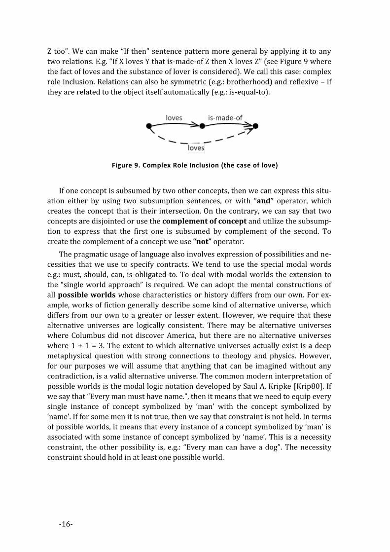
Z too”. We can make “If then” sentence pattern more general by applying it to any
two relations. E.g. “If X loves Y that is-made-of Z then X loves Z” (see Figure 9 where
the fact of loves and the substance of lover is considered). We call this case: complex
role inclusion. Relations can also be symmetric (e.g.: brotherhood) and reflexive – if
they are related to the object itself automatically (e.g.: is-equal-to).
Figure 9. Complex Role Inclusion (the case of love)
If one concept is subsumed by two other concepts, then we can express this situ-
ation either by using two subsumption sentences, or with “and” operator, which
creates the concept that is their intersection. On the contrary, we can say that two
concepts are disjointed or use the complement of concept and utilize the subsump-
tion to express that the first one is subsumed by complement of the second. To
create the complement of a concept we use “not” operator.
The pragmatic usage of language also involves expression of possibilities and ne-
cessities that we use to specify contracts. We tend to use the special modal words
e.g.: must, should, can, is-obligated-to. To deal with modal worlds the extension to
the “single world approach” is required. We can adopt the mental constructions of
all possible worlds whose characteristics or history differs from our own. For ex-
ample, works of fiction generally describe some kind of alternative universe, which
differs from our own to a greater or lesser extent. However, we require that these
alternative universes are logically consistent. There may be alternative universes
where Columbus did not discover America, but there are no alternative universes
where 1 + 1 = 3. The extent to which alternative universes actually exist is a deep
metaphysical question with strong connections to theology and physics. However,
for our purposes we will assume that anything that can be imagined without any
contradiction, is a valid alternative universe. The common modern interpretation of
possible worlds is the modal logic notation developed by Saul A. Kripke [Krip80]. If
we say that “Every man must have name.”, then it means that we need to equip every
single instance of concept symbolized by ‘man’ with the concept symbolized by
‘name’. If for some men it is not true, then we say that constraint is not held. In terms
of possible worlds, it means that every instance of a concept symbolized by ‘man’ is
associated with some instance of concept symbolized by ‘name’. This is a necessity
constraint, the other possibility is, e.g.: “Every man can have a dog”. The necessity
constraint should hold in at least one possible world.

-17-
CONTROLLED ENGLISH 2.4The history of Controlled English (CE) starts from Jorge Orwell’s idea of “new-
speak” described in famous novel “1984” [Orwe90]. Controlled English was
successfully used by large corporations to standardize the language used for internal
communication e.g.: Caterpillar Technical English [Kamp98], IBM Easy English
[Bern97], Boeing Simplified English [Wojc90] etc. The novel approach to CE sup-
ported by KRR requires that CE has restricted grammar and vocabulary, in order to
reduce the ambiguity and complexity inherent in natural language. In the last years,
this branch of CE established itself in various application fields (mostly as an inter-
face of knowledge bases) as a powerful knowledge representation language that is
readable for humans and processable by computers. Attempto Controlled English
(ACE) [Fuch90] is very expressive CE and it is the one that is mostly used. ACE can
be translated into a non-decidable subset of FOL. It also provides its subset called
ACEOWL [Kalj07] that can be translated into Description Logic (formal
foundation of OWL2).
This thesis presents the CE that was intended to be useful in software develop-
ment process, called OASE-English. The research for CE described here was
inspired by ACEOWL. The grammar of OASE-English was implemented using
LALR(1) top-down parser generator [Rose69] and equipped with additional features
that are not available within ACEOWL. Additional features include “A is equivalent of
B” construction that corresponds to AB DL expression, and allows the use of pa-
rentheses and also the production of more complex expressions in CE. The use of
LALR(1) top-down parser is burdened with limitations of readability offered by
ACEOWL, however those limitations are not as low according to the evaluation made
within this thesis. Even if there exist sentences of OASE-English that are not a valid
expressions in ACE (and even in English), the EBNF grammar of the OASE-English is
designed to be as close to the natural English as possible, and can be translated to
OWL2 format and back easily. Moreover, due to the fact that OASE-English is imple-
mented by using LALR(1) parser, the effective predictive editor that supports
OASE-English is applied in the efficient manner (however using Grammatical
Framework [Rant04] or Codeco [Kuhn10], that is a grammar framework behind
ACE, it is possible too).
DESCRIPTION LOGICS 2.5The foundation of Description Logic (DL) [Baad03] together with concept of the
Semantic Web was discussed by Tim Berners-Lee [Bern01] and was intended to
provide a mathematical background for the new wave of self-adapting services (suc-
cessors of web services) called the semantic services. DL was selected, because it is
able to describe knowledge about the world around us in a formal way, and it is yet
understandable by human – because it correspond to semiotic triangle approach
developed by Sowa [Sowa00]. There exists a variety of other formalisms, that have

-18-
the similar properties (e.g. F-Logic [Kife05]). All of them represent the knowledge of
its domain - „world” - by defining given concepts within one domain (its terminolo-
gy), so that later, by using these concepts, it can be described by these objects
(instances of concepts) and their properties. Nevertheless, from the pragmatic point
of view decidability is a fundamental property for us and DL is decidable. Decidabil-
ity ensures that reasoning tasks within DL can be made in finite time and space on
modern computers that follow the laws of Touring Machine. Reasoning tasks include
concept classification, which is a hierarchical arrangement of concepts within the
notion of inclusions. Another one is classification of instances to the certain con-
cepts. Some dialects of DL (e.g. ++ [Baad06]) ensure that they can be done in
polynomial time, other - more expressive ones (e.g. [Horr06b]) use optimiza-
tion techniques for most common cases so as to reduce the computation limits.
Nevertheless, the ontological framework, in order to be useful, needs to be respon-
sive19 and therefore the selection for the formalism is a curtail requirement for
ontology modeling with DL.
Formally DL is a subset of FOL, equipped with decidable reasoning tasks. In DLs,
the domain of interest is modeled by means of concepts, objects and relationships
between them, that are binary relations in-fact20. DL is made around semiotics in
terms of:
1. The syntax. The specification of the construction of complex concepts and rela-
tion expressions.
2. The semantics. The specification of the construction of knowledge base, in
which properties of concepts and relations are asserted,
3. The pragmatics. Provided by the DL toolkits implements algorithms of auto-
matic knowledge discovery and which were proved to be decidable.
19 Responsiveness is the ability of computer system to perform assigned function within the required time
interval. 20 This is a quite big limitation to the expressiveness e.g.: the ‘give’ relation presented earlier.

-19-
Figure 10. Overview of complexities and expressivity relationships of DLs
after [Rudo08]
Description logic dialects differ in syntax constructors that are to be used and the
names of the dialects come from the combination of constructor identifiers
(see Table 2). The more constructors are allowed, the more expressible DL dialect is;
however the more expressible DL is, the complexity of reasoning goes higher too21
(see Figure 10).
We define the static knowledge as knowledge that is decidable. Computability
separates what is a static structure from what is a dynamic behavior, in the terms of
properties of artifacts created during software development process. The static
structure must be decidable; otherwise the static structure will only be an initial
state of more complex dynamic behavior. In such a case static structure could not be
analyzed in separate to the behavior. The fact that the DL allows for separation be-
tween static and dynamic aspects of software systems is a fundamental assumption
of this thesis.
++
21 Description Logic Complexity navigator: http://www.cs.man.ac.uk/~ezolin/dl/
-20-
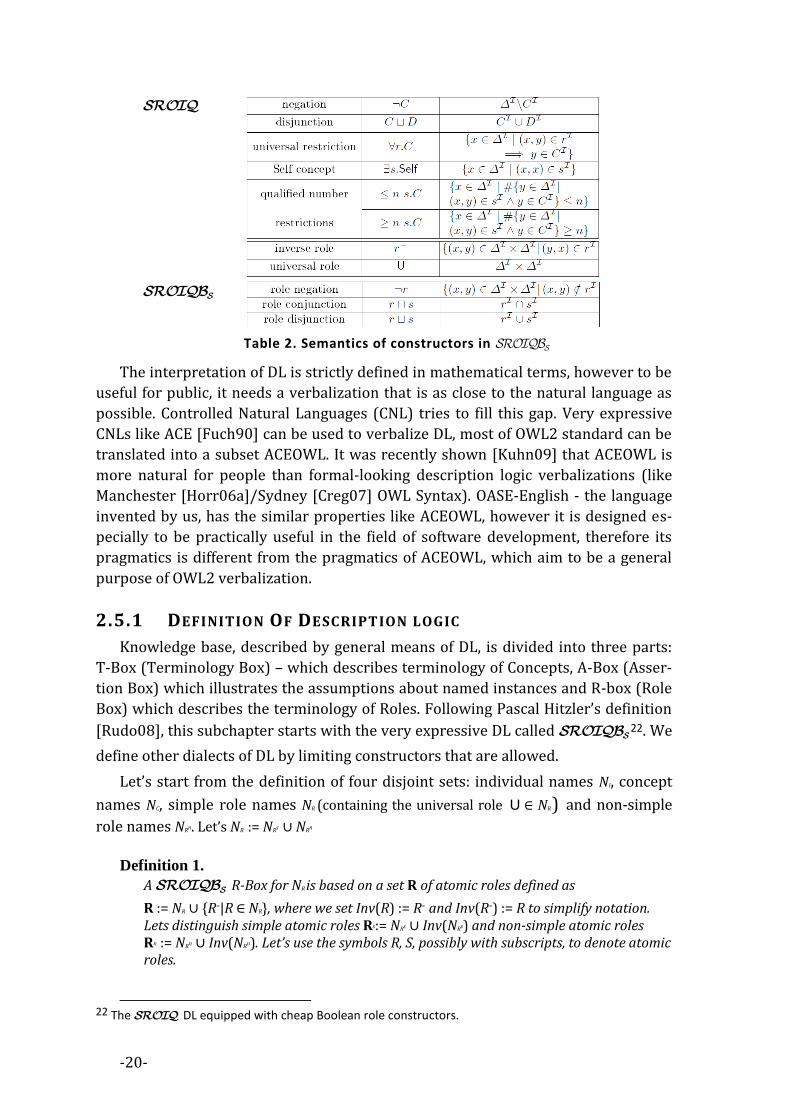
Table 2. Semantics of constructors in
The interpretation of DL is strictly defined in mathematical terms, however to be
useful for public, it needs a verbalization that is as close to the natural language as
possible. Controlled Natural Languages (CNL) tries to fill this gap. Very expressive
CNLs like ACE [Fuch90] can be used to verbalize DL, most of OWL2 standard can be
translated into a subset ACEOWL. It was recently shown [Kuhn09] that ACEOWL is
more natural for people than formal-looking description logic verbalizations (like
Manchester [Horr06a]/Sydney [Creg07] OWL Syntax). OASE-English - the language
invented by us, has the similar properties like ACEOWL, however it is designed es-
pecially to be practically useful in the field of software development, therefore its
pragmatics is different from the pragmatics of ACEOWL, which aim to be a general
purpose of OWL2 verbalization.
2.5.1 DEFINITION OF DESCRIPTION LOGIC
Knowledge base, described by general means of DL, is divided into three parts:
T-Box (Terminology Box) – which describes terminology of Concepts, A-Box (Asser-
tion Box) which illustrates the assumptions about named instances and R-box (Role
Box) which describes the terminology of Roles. Following Pascal Hitzler’s definition
[Rudo08], this subchapter starts with the very expressive DL called 22. We
define other dialects of DL by limiting constructors that are allowed.
Let’s start from the definition of four disjoint sets: individual names NI, concept
names NC, simple role names NR (containing the universal role U ∈ NR ) and non-simple
role names NRn. Let’s NR := NRs ∪ NRn
Definition 1.
A R-Box for NR is based on a set R of atomic roles defined as
R := NR ∪ {R-|R ∈ NR}, where we set Inv(R) := R- and Inv(R-) := R to simplify notation. Lets distinguish simple atomic roles Rs:= NRs ∪ Inv(NRs) and non-simple atomic roles Rn := NRn ∪ Inv(NRn). Let’s use the symbols R, S, possibly with subscripts, to denote atomic roles.
22 The DL equipped with cheap Boolean role constructors.

-21-
Definition 2.
For the set of Boolean role expressions B is defined as follows:
B := R|¬B|B ⊓ B|B ⊔ B. The set BS of simple role expressions comprises all those role expressions containing only simple role names. Moreover, a role expression will be called “safe”, if in its disjunctive normal form, every disjunction contains at least one non-negated role name.
Definition 3.
A generalized role inclusion axiom (RIA) is a statement of the form S1∘...∘Sn ⊑ R, where each Si is a simple role expression or a non-simple atomic role, and where R is a non-simple atomic role. A set of such RIAs is a generalized role hierarchy. A role hierarchy is regular, if there is a strict partial order ≺ on Rn such that S ≺ R⇐⇒Inv(S) ≺ R, and every RIA is of one of the forms: R∘R ⊑ R, R-⊑ R, S1∘...∘Sn ⊑ R,R ∘ S1 ∘ ... ∘ Sn⊑ R,S1 ∘ ... ∘ Sn ∘ R ⊑ R such that R ∈ NR is a(non-inverse) role name, and Si ≺ R for i = 1,...,n whenever Si is non-simple.
Definition 4.
A role assertion is a statement of the form Ref(R) (reflexivity), Asy(S) (asymmetry), or
Dis(S,S′) (role disjointness),where S and S′ are simple roles. A R-box is the
union of a set of role assertions together and a role hierarchy. A R-box is
regular if its role hierarchy is regular.
The knowledge specification mechanism (semantics) - the second component of
the description logic foundation - determines how to construct the DL knowledge
base. The DL knowledge base is made of DL expressions that indicate the logical
connection between different (possibly complex) concepts, instances and roles.
Definition 5.
Given a R-box, the set of concept expressions C is defined as follows:
- NC ⊆ C,⊤⊆ C,⊥⊆ C,
- if C,D ∈ C, R ∈ R a simple role expression or non-simple role, V ∈ BS a simple
role expression, a ∈ NI , and n a non-negative integer, then ¬C, C⊓D, C⊔D, {a},
∀R.C, ∃R.C, ∃V.Self, ≤ nV.C, and ≥ nV.C are also concept expressions.
Definition 6. The symbols C, D will be used to denote concept expressions. A T-box
is a set of general concept inclusion axioms (GCIs) of the form C ⊑ D. An indi-vidual assertion can have any of the following forms: C(a), R(a,b), ¬S(a,b), a≠b, with a,b ∈ NI individual names, C ∈ C a concept expression, and R,S ∈ R role switch S simple. A A-box is a set of individual assertions. A
knowledge base 𝔒 is the union of a regular R-box, and an A-box and T-box.
The formal interpretation of DL follows the interpretation of FOL:
Definition 7. An interpretation consists of a set Δ called domain (the elements of it being
called individuals) together with a function ⋅ mapping:

-22-
- individual names to elements of Δ,
- concept names to subsets of Δ, and
- role expressions to subsets of Δ×Δ.
The function ⋅ is inductively extended to a role and concept expressions, as shown
in Table 2. An interpretation satisfies an axiom ϕ if we find that ϕ:
– V ⊑ W if V⊆ W,
– V1 ∘ ... ∘ Vn ⊑ W if V1∘ ... ∘Vn
⊆ W (∘ being overloaded to denote the standard
composition of binary relations here), –Ref(R) if R, is a reflexive relation,
– Asy(V) if Vis antisymmetric and irreflexive,
– Dis(V,W) if V and W are disjoint,
– C ⊑ D if C⊆ D.
An interpretation satisfies a knowledge base 𝔒 (we also say that is a model of 𝔒
and write ), if it satisfies all axioms of 𝔒. A knowledgebase 𝔒 is satisfiable if it has
a model. Two knowledge bases are equivalent if they have exactly the same models,
and they are equisatisfiable if either both of them are unsatisfiable or both are satis-
fiable.
DIALECTS 2.6Going further with the definitions of subdialects, we obtain from
by disallowing all junctors in role expressions. Further details on
can be found in [Horr06b]. Several syntactic constructs, that can be ex-
pressed indirectly, (especially role assertions for transitivity, reflexivity of simple
roles, and symmetry) are omitted here. Moreover, the is obtained from
by discarding the universal role as well as reflexivity, asymmetry, role dis-
jointness statements and allowing only RIAs of the form R ⊑ S or R ∘ R ⊑ R. Then, we
obtain ++ from by disallowing conjunction in role expressions.
Definition 8. An atomic role of ++(⊓s) is a (non-inverse) role name. An ++(⊓s) role expres-
sion is a simple role expression containing only role conjunction. An ++(⊓s) R-
box is a set of generalized role inclusion axioms (using ++(⊓s) role expressions
and non-simple atomic roles), and an ++(⊓s) T-box is a T-box that
contains only the concept constructors: ⊓, ∃, ⊤, ⊥, and only ++(⊓s) role expres-
sions.

-23-
REASONING 2.7The third part of DL foundation (pragmatics) is an automated reasoning which
includes tasks like:
1. To form taxonomic DAG (Directed Acyclic Graph) of all atomic concepts in
terms of concept subsumption.
2. To determine subconcepts and individuals of specific complex concept.
3. To determine all direct atomic subconcepts (children) or direct individuals of
specific complex concept.
4. To check whether two complex concepts are in subsumption relation.
5. To check whether complex concept is satisfiable (can have instances).
6. To check whether instance is included in specific complex concept.
All these tasks are supported by specialized decidable theory provers called rea-
soners described in next sections.
2.7.1 STRUCTURAL SUBSUMPTION
Structural subsumption is based on syntax tree evaluators. Syntax tree evalua-
tors are usually very fast (in terms of computation), however they provide the
promising results (polynomial time of evaluation) only in certain (though very gen-
eral) situations. The reasoner for ++ [Baad06] has proven that the syntax-tree
evaluator, which has polynomial complexity, can be useful in wide area of interests.
Structural subsumption is an algorithm that tries to infer the implicit knowledge,
basing on comparison between the syntactical structure of normal forms of DL ex-
pressions. It is divided into two steps:
1) Normalization. Every DL expression from KB is rewritten into normal form
with the specific algorithm. It can be done in PTime for some DL dialects (e.g.:
23, ++).
2) Comparison. The direct comparison of the normal forms is performed (PTime
in terms of computation).
The good explanation of idea of subsumption algorithm over logic is presented
in [Gocz11], [Baad03]. For ++, it is presented in details in [Baad06]. Structural
subsumption algorithms for selected DLs are PTime. This property of the structural
subsumption has big implication in terms of its practical implementations, especially
in task of reasoning over big ontologies.
2.7.2 TABLEAU ALGORITHM
Every reasoning task can be transformed to the problem of checking for the ex-
istence of the model of KB. Tableau algorithm [Baad03] tries to build the model of
KB in a systematic way. The model of KB is understood here as a specific A-Box that
23 (Attributive language) is the core language for every DL which allows Atomic negation (negation of concept names that do not appear on the left hand side of axioms), Concept intersection, Universal re-strictions and Limited existential quantification

-24-
follows the strict algorithmic rules of its creation and is built basing on the structure
of KB. E.g. C⊑D is true if it can be transformed to C⊓¬D≡⊥ and it is true if the con-
cept C⊓¬D has no model w.r.t. KB. If during the creation of the model the clash oc-
occurs, then the reasoning task returns the success. Otherwise, if every possible
model created within the tableau algorithm does not result in a clash, the reasoning
task returns failure as a result. Tableau algorithm is very general and it is investigat-
ed in terms of its properties. It was proven that this algorithm allows for reasoning
over the [Horr06b], however in general, it is hard to do so (see Table 2) in
terms of computability. E.g. for DL, the Tableau algorithm is PSpace.
Plenty of implemented tableau-based reasoners are effective (mostly due to the
optimization techniques that build a set of heuristic in order to overcome the com-
mon situations). The nowadays, is a DL lying under the OWL2.024. The
pragmatic test for tableau-based Reasoners, that is equipped with optimization
techniques, shows that it is possible to make it in a reasonable.
Critics say that it is also possible to achieve the optimization techniques into FOL
and give a performance results similar to DL Reasoners by using the timeout mech-
anism.
2.7.3 KNOWLEDGE CARTOGRAPHY
Knowledge Cartography approach [Gocz06] [Gocz11] is a set-algebra heuristics
that can be easily adapted to modern distributed environment; even if a set of con-
structors is also limited. It can be implemented in Relational Database Management
System (RDBMS). The Cartographic Approach may be effective for the ontologies
with large number of assertions. The approach is based on the direct correspond-
ence between the DL and set-theory. It also treats the DL concept as a set and DL
instance as an element of the set.
The Knowledge Cartography algorithm first computes the ‘descriptors’ of all
concepts. Descriptors have a direct representation in the form of binary strings. Hav-
ing computed descriptors, the reasoning tasks are represented as simple matching
procedures between binary strings. The binary-string matching is a low-level opera-
tion, that can be efficiently implemented in the computer systems, therefore once
the descriptors are computed, the reasoning tasks are very effective. Cartographic
algorithms have a great possibility to be implemented in massively parallelized en-
vironments e.g.: on CUDA25 architecture.
2.7.4 EXPLANATIONS FOR REASONING IN DL
The idea of “Why?” button that is going to be implemented in semantic-web
browser [Sene08] is an answer for a natural, pragmatic need for the explanation of
24 http://www.w3.org/TR/owl2-primer/ 25 Compute Unified Device Architecture (CUDA) is a parallel computing architecture developed by Nvidia.
CUDA is the computing engine in Nvidia graphics processing units (GPUs) that is accessible to software developers through variants of industry standard programming languages.

-25-
specific implicitly reasoned knowledge. Explanations of DL reasoning tasks are real-
ized by de-facto constructed sets of DL statements that aim to reconstruct the proof
of the given theorem (result of the reasoning task) in the most meaningful way.
There exist two ways to produce reasoning justifications: black-box and glass-
box. Black-box algorithms use the reasoner solely as a sub-routine and therefore the
internals of the reasoner do not need to be modified. Black-box algorithms typically
require many satisfiability tests. Glass-box algorithms require non-trivial modifica-
tions of the reasoned internals. In other words: a glass-box implementation is
specific to a given reasoner and therefore also to a reasoning technique, while a
black-box method does not depend on a specific reasoner or reasoning technique.
The most widely used approach developed by A. Kalyanpur [Kaly07] is a combina-
tion of glass-box and black-box approach that can compute all the reasoning
justifications.
2.7.5 MODULAR STRUCTURE OF DL
Instead of considering the entire complex ontology, users may benefit more by
starting from a problem-specific set of concepts (signature of problem) from the
ontology and exploring logical modules that surround it. Due the fact that DL ontolo-
gies are monotonic26, DL supports modularity and allows for a separation of
complex ontologies into smaller pieces (modules), which are easier to maintain and
compute by isolated instances of the inference engine. The modularity of DL based
ontologies allows constructing the inference engines that are capable to compute large
ontologies [Kapl09].
OTHER IMPORTANT SUBSETS OF FOL 2.8There exists formal specification and modeling languages for object-oriented de-
sign which were tailored to allow tool support in software modeling, specification
and verification. Two important examples of such language are presented here. One
is F-Logic, second is LePUS3.
Minsky’s theory of Frames [Mins75] does not offer a formal system. Even though
it is worth notice that, there exists an implementation of theory of Frames called
F-Logic [Kife89], that directly combines the Frame approach with the object-
oriented approach. In contrast to DL, the semantics of F-logic is equipped with
closed world assumption, which is in opposition to the DL's open world assumption.
Closed world assumption is natural for object-oriented methods. F-logic (in opposi-
tion to DL) is generally undecidable [Kife05]. Here, in this thesis, the decidability is
considered as a key feature that allows for a distinction between the static structure
of the knowledge (and ultimately the software) and the dynamic behavior of running
software system.
LePUS3 [Gasp08] is designed to capture and convey the building-blocks of ob-
ject-oriented design. It is object-oriented design description language especially
26 Monotonicity of entailment is a property of many logical systems which states that the hypotheses of
any derived fact may be freely extended with additional assumptions.

-26-
designed for visualization of complex software structures. LePUS3 is a decidable
subset of FOL [Gasp08], and focuses on the vital object-oriented problems (e.g.: rep-
resentation, visualization and validation of Design Patterns.). In this terms LePUS3 is
similar to OASE.
Description Logic was not originally designed to support object-oriented pro-
gramming, but as it will be shown later, it allows one to deal with it. Reassuming:
1) DL is decidable in opposition to F-Logic.
2) DL is more expressive than LePUS3 (e.g.: DL supports
the number restrictions and role hierarchies), and DL has semantics of a
natural language.
Therefore; even if F-Logic and LePUS3 are intended to be used as a formal mod-
els of object-oriented systems, we decided to use DL as a formal semantic
for OASE.
COMPUTER SEMIOTICS 2.9Semiotics has been an area actively attended by scientists in media studies, edu-
cational science, anthropology, philosophy of language and linguistics. Computer
semiotics defined by Peter Andersen [Ande90] studies the special nature of comput-
er-based signs and their function. The map developed by P.Andersen shows the
areas where semiotics can be used in the field of computer science (see Figure 11).
Signs as art(efacts)
Signs as system
Signs as behaviour
Signs as knowledge
Aesthetics
Cognitive scienceCognitive ergonomics
Computer supported collaborative work
Work analisisOrganizational analysisTechnology assesment
Systems development
Systems description
Program developementInterface design
OASE
Figure 11. Map of a computer semiotics in context of OASE (based on [Ande90])
-27-
P.Andersen proposes viewing the signs as systems that occupy the center
[Ande90]. The agent is here considered as a creator, interpreter and referent of
signs, a user and reproducer of a common meaning potential and also as a code that
utilizes the results of a semiotic labor done by others. In the focus of this box are
sign systems as social phenomena. Software system analysis, design and implemen-
tation, aim at creating computer based sign systems that will typically be used by a
whole organization. In the signs-as-knowledge perspective, the agent is considered
as an assemblage of parts: his biological psychophysiological nature and the psycho-
logical mechanisms that enable the individual to learn, use and understand signs.
Signs-as-art(ifacts) consider agents as innovators of code and meaning potential, as
an explorers and inventors of signs. Signs-as-a-behavior view, consider agent as
a single, indivisible entity. What is more, the focus is on his interactions with the en-
vironment, especially on the part which consists of communication with other
agents.
Traditionally, semiotics has been divided into: syntax, semantics and pragmatics
which deal respectively with the structures, meanings and usage of signs. Stamper
[Stam73] [Liu00] has added another three layers (see Figure 12). After [Ande90]
– “Physics gives a handle to deal with the factors governing the economics of signs,
which have become important in business contexts. Physical properties can be stud-
ied with physics and engineering methods. As a branch of semiotics, empirics
studies are statistical properties of signs, in which the object of study is a collection
of signals or marks. Social world studies the effects of the use of signs in human af-
fairs, as the process of performing communication acts, which is sometimes a
complex process of invoking, violating, and altering social norms. ”
OASE focuses on software development; its design and collaborative work done
by the stakeholders (see Figure 11). It tries to implement social, pragmatic, semantic
and syntactic layer (see Figure 12) and pretend to be the semiotic system supported
by the formal methods.

-28-
Human information functions
The IT platform
SOCIAL WORLD: beliefs, expectations, functions, commitments, contracts, law, culture, …
PRAGMATICS: intentions, communications, conversations, negotiations, …
SEMANTICS: meanings, propositions, validity, truth, signification, denotations, …
SYNTACTICS: formal structure, language, logic, data, records deduction, software, files, …
EMPIRICS: pattern, variety, noise, entropy, channel capacity, redundancy, efficiency, codes, …
PHYSICAL WORLD: signals, traces, physical distinctions, hardware, component density, speed, economics, …
OASE
Figure 12. The Computer Semiotic Framework in the context of OASE
(base on Stamper [Stam73]).

-29-
3. SOFTWARE DEVELOPMENT The aim of this chapter is to show the range of possible applications of descrip-
tion logic in software development methodologies, and to place the research
activities taken in this PHD thesis in the current state of the art. It also presents the
relation of software development tasks with the formal knowledge modeling from
the previous chapter.
THE PROGRAM FOR A MACHINE 3.1The computer program is a specification of the machine behavior. To specify it,
one can describe how the machine should behave to realize the specified task. If it is
specified what the machine should do, then we can say that the computer program is
written in imperative manner rather than declarative. Declarative manner specifies
the goal in a formal way, leaving the realization to general and powerful automatic27
process that will invent the optimal way to approach it.
In the 1930s, Church and Turing proposed different ideas for a formal system.
Lambda Calculi [Hank04] and Touring Machine [Hopc79], which were ultimately
proven to be logically equivalent, are nowadays recognized as precursors of the two
main families of the programming languages: functional and imperative (see Figure
13). The von Neumann architecture, that is a model of modern computer, imple-
ments a universal Turing machine. Imperative programming languages were the
first that started the evolution and now they are the oldest well known ones. Imper-
ative programming describes the computation in terms of sequence of statements
that can change a machine state - in other words, program written in imperative
language is a specification for a sequence of commands. What is more, the possibility
of changing the state of the machine is the key feature here. The oldest imperative
programming language that is still used nowadays is FORTRAN, created in 1954
[Back54]. The rest of the history of imperative languages is as follows: BASIC (1964)
[Keme64], Pascal (1970) [Jens85], C (1972) [Kern88], Ada (1978) [Booc87], Small-
talk (1980) [Liu96], C++ (1985) [Stro00], PHP (1994) [Vasw08], Java (1994)
[Gosl05], C# (2002) [Herb10].
Good programming language has to keep pace with the progress of technology
and at the same time it must respond to market needs.
Object-oriented languages, the novel offspring of imperative languages, lead pro-
grammer to use objects as main conceptual constructs employed to build virtual
world, which can be easily understood by a human brain. A well written program in
object-oriented programming language, models algorithms and data, uses concepts
and relationships between them and raises them step-by-step to the next levels of
abstraction. At the same time it ensures that these concepts have the properties of
27 Automatic means here – able to be processed by a computer

-30-
physical objects. This approach is similar to the process of ontology engineering
based on virtual objects. Simula (1967) [Dahl66] is generally accepted as the first
language to support the primary features of an object-oriented language. Another
example is C++, a general purpose language developed as an offspring of C, that is
equipped (with some limitations) with object-oriented abilities. Platform independ-
ence was the motor for Java and C# language, the modern object-oriented languages
with the highest impact in the field nowadays.
Programming
languages
Declarative
Imperative
Logical
Functional
FORTRAN
BASIC
Pascal
C
C++
PHP
Java
C#
F#
Lisp
OCAML
Standard
ML
PROLOG
SQL
XSLT
Figure 13. Spectrum of Computer Languages
Object technology, invented in 1965 in a lab of the University of Oslo (together
with the Simula Language [Holm94]), is built around three basic concepts: instance,
class and superclass, and two basic relations: instance-of and inherits-from. In the
80's the exact meaning of these relations was widely discussed, including the con-
troversies between single and multiple-inheritance. Modern object-oriented
languages go beyond those basic concepts by providing more or less general meta-
class organization schemes (a class being itself an instance of a metaclass). As a
consequence, when we nowadays talk about an object (the instance of a class), the
context is (the most) important. In a general context, we usually mean an entity cor-
responding to the common scheme, but if we need to be more specific, we refer to a
C# object, a Java object, a C++ object, an Eiffel [Meye92] object, a CLOS (Common
Lisp Object System) [Stee90] object, etc., with respect to their additional properties.
Lisp [McCa65] was the first programming language that used the approach taken
from Church’s lambda calculus. Functional languages are nowadays adapted to the
common mainstream, as they were also processors of modern programming lan-
guages. Going back in the history of computer languages, the debates in the late
1960s and early 1970s (about declarative versus procedural representations of
knowledge in artificial intelligence) resulted in an introduction of the novel family of
programming languages: the logical ones. Logical programming is regarded as sepa-

-31-
rate from functional languages as far as functional language is still focused around
functions – recursive concepts that realize the task. One of logical languages widely
used in computer science is SQL [Date97], which is based on well behaved Codd’s
relational algebra [Codd70], and has a counterpart in logic. PROLOG [Cloc03] im-
plements the Horn Logic. The mixture of PROLOG and SQL resulted in DATALOG
language [Gall78] – subset of PROLOG oriented to databases.
Logic can be used as a computational formalism and also as a data specification
language. This fact pushed us to conclude that DL is a great example of formalism
that allows both the imperative and declarative languages to cooperate together. We
have implemented this idea within OASE methodology.
SOFTWARE MODELS 3.2The rapid development of software engineering methodologies that has occurred
with increasing complexity of computer programs is related to the need for a way to
ascribe and analyze the software intensive systems at the time of their formation. In
November 1997 the OMG consortium established the standard of software design
and analysis. This standard is nowadays well known as a Unified Modeling Language
(UML) [Rumb05], and is mainly focused on graphical modeling of software intensive
systems with diagrams. To support the design of large-scale industrial applications,
sophisticated CASE tools28, which provide a user-friendly environment for editing,
storing, and accessing multiple UML diagrams, are available on the market. The
spectrum of UML diagrams is divided into two main branches: structural and behav-
ioral (see Figure 14). Structural diagrams emphasize the things that must be present
in the system being modeled. The ‘must’ means here that we cannot say that the
software is realized fully, if it does not implement the diagram of structure. This is
dual to diagrams of behavior, which emphasize what must happen in the system be-
ing modeled. In the formal way we can distinguish those two classes of diagrams in
the meaning of time or modality. While structure diagrams must always be true, the
behavioral diagrams must be true in some – strictly defined - circumstances. There-
fore, while structural diagram represent specification for “ALWAYS MUST BE …” the
behavioral diagram is “IN A SPECIFIC SITUATION THE PROGRAM MUST SATISFY A
CONDITION THAT…”. This duality led us to think about separation of the diagrams
in strict, logical manner. The structural diagram specifies the terminology which
must be obeyed, while the behavioral diagram describes the situation that takes
place in specific space and time – the world (in terms of modality) description.
UML allows for modeling the structure of relationships between use cases, which
can be viewed as behavioral and structural projects requirements. In addition, UML
allows the modeling software, that is object-oriented in terms of classes, objects
their hierarchy and their collaboration as well. To build the bridge between use-
cases and classes (that are explicitly implemented by programmers) is a key task for
28 e.g.: Rational Rose (made by Rational Software Corporation - now IBM) is used for object-oriented
analysis and design), Telelogic TAU (made by Telelogic - now IBM) modeling tool supporting automat-ed code generation and model verification, StarUML (Open Source) – UML modeling tool, etc…
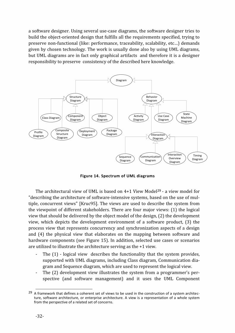
-32-
a software designer. Using several use-case diagrams, the software designer tries to
build the object-oriented design that fulfills all the requirements specified, trying to
preserve non-functional (like: performance, traceability, scalability, etc…) demands
given by chosen technology. The work is usually done also by using UML diagrams,
but UML diagrams are in fact only graphical artifacts and therefore it is a designer
responsibility to preserve consistency of the described here knowledge.
Diagram
Structure Diagram
Behavior Diagram
Class DiagramComponent
DiagramObject
DiagramActivity Diagram
Use Case Diagram
Profile Diagram
Composite Structure Diagram
Deployment Diagram
Package Diagram Interaction
Diagram
State Machine Diagram
Sequence Diagram
Communication Diagram
Interaction Overview Diagram
Timing Diagram
Figure 14. Spectrum of UML diagrams
The architectural view of UML is based on 4+1 View Model29 - a view model for
"describing the architecture of software-intensive systems, based on the use of mul-
tiple, concurrent views" [Kruc95]. The views are used to describe the system from
the viewpoint of different stakeholders. There are four major views: (1) the logical
view that should be delivered by the object model of the design, (2) the development
view, which depicts the development environment of a software product, (3) the
process view that represents concurrency and synchronization aspects of a design
and (4) the physical view that elaborates on the mapping between software and
hardware components (see Figure 15). In addition, selected use cases or scenarios
are utilized to illustrate the architecture serving as the +1 view.
- The (1) - logical view describes the functionality that the system provides,
supported with UML diagrams, including Class diagram, Communication dia-
gram and Sequence diagram, which are used to represent the logical view.
- The (2) development view illustrates the system from a programmer's per-
spective (and software management) and it uses the UML Component
29 A framework that defines a coherent set of views to be used in the construction of a system architec-
ture, software architecture, or enterprise architecture. A view is a representation of a whole system from the perspective of a related set of concerns.

-33-
diagram to describe system components. UML Diagrams are used to repre-
sent the development view, including the Package diagram.
- The (3) process view deals with the dynamic aspects of software, as it ex-
plains the system processes, how they communicate, and it also focuses on
the runtime behavior of the system. It addresses e.g.: concurrency, distribu-
tion, integrators, performance, and scalability. UML Diagrams that represent
process view are e.g.: the Activity/Collaboration diagram.
- The (4) physical view depicts the system from a system engineer's point-of-
view, as it is concerned with the topology of software components on the
physical layer and is represented with UML Diagrams, including the Deploy-
ment diagram. The description of architecture is illustrated by a small set of
use cases, or scenarios which become a
- +1 view that describes sequences of interactions between objects, and be-
tween processes. Those UML diagrams are used to identify architectural
elements, to illustrate and validate the architecture design and to serve as a
starting point for tests of an architecture prototype. UML Diagrams are used
to represent the scenario view, including the Use case diagram.
Logical ViewDevelopement
View
Process View Physical View
Scenarios
System & environment
Figure 15. 4+1 Architectural View Model
3.2.1 MODEL DRIVEN ENGINEERING
Modeling is essential to every engineering activity as every action here is pre-
ceded by the construction (implicit or explicit) of a model. If the model is incorrect,
the action may be inappropriate. According to the definition, a model is an abstrac-
tion of phenomena in the real world; a metamodel is yet another abstraction,
highlighting properties of the model itself. A model conforms to its metamodel in the
way that a computer program conforms to the grammar of the programming lan-
guage in which it is written.
Model Driven Engineering (MDE) is the successor of CASE tools as well as a unifi-
cation of methodologies based on UML approach. The architecture of metamodeling
(called Model Driven Architecture (MDA), introduced in 2001 by the Object Man-
agement Group (OMG)) is the basis for building MDE software systems. MDE can be
shortly ascribed in the following comparison: in object-oriented engineering “every-
thing is an object” and in MDE “everything is a model” (see Figure 16).

-34-
Instance
Class
SuperClass
System
Model
MetaModel
inst
ance
of
Inh
erit
s fr
om
rep
rese
nte
d b
yco
nfo
rms
to
Figure 16. Object-oriented vs. model driven engineering
Every model in software development forms a graph; therefore software model-
ing activity can be perceived as an activity that tries to construct graphs which
model the software conceptualization. The way to transform one graph into another
is the key idea that lies behind MDE. For transforming one graph into another there
is a requirement of unidirectional function which is realized with graph transfor-
mation languages. MDE transformations are realized in our approach by
OASE-Transformations.
Support for change propagation QVT is based on the Meta-Object Facility
(MOF)30. MOF is designed as a four-layered architecture that provides a meta-meta
model at the top layer (see Figure 17) called the M3 layer – that itself forms a lan-
guage used by MOF to build metamodels, (called M2-models) and it is also able to
describe itself, so no additional Mn... layers that are required to complete the unifica-
tion. The most prominent example of a model in M2 is the UML metamodel, the
model that describes the UML. These M2 models describe elements of the M1, and
thus M1 models as well. Those would be, for example, models written in UML. The
last layer is the M0, used to describe real-world objects. Because of the similarities
between the MOF M3 models and UML structure models, MOF metamodels are usu-
ally modeled as the UML class diagrams. A supporting standard of MOF is XMI31,
which defines an XML-based exchange format for models on the M3-, M2-, or M1-
Layer.
MDE requires systematic use of Model Transformation Languages (MTL)
[Mens06]. The OMG has proposed a standard called QVT for Que-
ries/Views/Transformations, that is an implementation of MTL, however the model
transformation is a general technique that tries to construct one model (lower) from
the another (higher) and therefore there exist other, very usable, transformation
30 http://www.omg.org/mof/ 31 http://www.omg.org/spec/XMI/

-35-
languages. As each model is a graph, model transformation is based on graph trans-
formation [Roze97]. The QVT transformation has a support of model integration
rules, model consistency checking and uni/bidirectional model transformations for a
declarative or operational specifications. It is also equipped with either textual or
graphical notation.
The modern MDE vision does not use models only as a simple documentation but
as a formal input for software tools implementing precise operations. As a conse-
quence model-engineering frameworks have progressively evolved towards solid
proposals like the MDA defined by the OMG. Carrier of information in here is the
OWL [HKP+09] which enables the exchange of models (or portions thereof) between
different systems, thus ensuring the implementation of the concept of re-use (in the
phase of modeling and design system). This approach is similar to the OASE ap-
proach. The Ontology Definition MetaModel (ODM) is to make the concepts of MDA
applicable to the engineering of ontologies. The features available in UML are
mapped here to OWL elements (OWL can be seen as XML representations of DL)
(see Figure 18).
The
mo
del
ling
wo
rld
M3
M2
M1
M0
Class
Attribute Class Instance
:aVideoVideo
title=’Miś’+title: String
<<instanceOf>>
<<instanceOf>>
<<instanceOf>><<instanceOf>>
<<instanceOf>>
<<instanceOf>><<instanceOf>>
<<instanceOf>>
classifier
<<snapshot>>
System
Model
Metamodel
Metametamodel
The
real
w
orl
d
represented by
conforms to
conforms to
conforms to
Figure 17. Four layers of the modeling hierarchy
In this thesis we present the viewpoint that this is a direct (usual) mapping.
Within OASE we have developed other mapping that e.g.: represents classes as in-
stances that are presented in the next chapter.
UML elements OWL elements Comment
class, property ownedAttrib-ute, type class
instance individual OWL individual independent of class

-36-
ownedAttribute, binary asso-ciation property OWL property can be global
subclass, generalization subclass , subproperty
N-ary association, association class class, property
enumeration oneOf
disjoint, cover disjointWith, unionOf
multiplicity minCardinality, maxCar-dinality OWL cardinality declared only for range
package ontology
dependency reserved name, RDF:property
Figure 18. More-or-Less Common Features between UML and OWL32
– the direct-mapping
3.2.2 SERVICE ORIENTED MODELING
Service-oriented modeling (SOM) [Bell08] is the discipline of modeling of ser-
vice-oriented systems within a variety of architectural styles. It encourages viewing
software entities as 'assets'. It refers to these assets collectively as 'services' that
have properties of physical objects e.g.: location, price…, which can replicate and
organize themselves. The Service Oriented Architecture (SOA) [Erl05] is an applica-
tion of SOM defined as “a paradigm for organizing and utilizing distributed
compatibilities that may be under the control of different membership domains. It
provides a uniform means to offer, discover, interact with and use capabilities to
produce desired consistent with measurable preconditions and expectations”33. Ser-
vices evolved as a result of observation, that nowadays we are occupied with loosely
coupled, interoperable software, available in a form of small pluggable units rather
than large, centralized software. Those pluggable units need to be fault-tolerant
pieces of software that are continuously improving their quality basing on business
demand. To tackle these challenges, a three-dimensional process of founding archi-
tecture is proposed:
I) TOP: Conceptual architecture
1) Technological Generalization
2) Metaphorical Application
3) Taxonomy Establishment
II) MIDDLE: Logical architecture
1) Asset Utilization and Reuse
2) Functional Solutions
3) Architecture Strategies
32 http://www.omg.org/spec/ODM/1.0/ 33 Web Services [Erl05] [Newc04] are the example of successful application of SOA - built upon the infra-
structure of WWW and HTTP protocol.
-37-
III) BOTTOM: Physical architecture.
1) Physical Addressing
2) Non-Functional Solutions
3) Business Continuity
Conceptual architecture offers mechanisms for describing the proposed techno-
logical solution; logical architecture discipline is chiefly concerned with asset reuse,
utilization and consumption, while the physical architecture is the resulting tangible
architecture construct (that itself is not a purpose of SOM). Architectural concepts in
SOM are related to the categories of “machines” like:
1) Workflow Machine: based on states of execution, each of which is assigned a
certain goal to fulfill.
2) Connecting Machine: describes communication methods and mediating
mechanisms between various software assets in a distributed technological
environment.
3) Time Machine: is characteristically associated with time and calendar sched-
uling of imperative business and technological missions.
4) Transformation Machine: fills incompatibility gap between operating systems,
communication protocols, data formats, etc.
5) Rendering Machine: describes presentation layer solutions that enable users
to communicate with backend services.
6) Data Machine: enables data manipulation and handling activities, data serv-
ing, such as data aggregation, validation, searching, and enrichment.
Each machine is ought to be implemented as a service that has lifecycle com-
posed of circular process: from design to runtime. Going further, services can be
seen as software assets analogous to living cell of complex biological organism. In
this case, the organism is a metaphor of a complex business system that involves
many services in order to satisfy its needs. Cloud computing [Mell09], the modern
offspring of grid computing [Li05] is nowadays considered as a field where service-
oriented modeling can be used as an effective modeling method. Service-oriented
modeling has much in common with object-oriented modeling and MDE, as all of
them are trying to use the metaphor of physical objects to represent the software
assets. Going further, we can say (paraphrasing MDE metaphor) that in SOM “every-
thing is a service”.
We propose the implementations of certain SOM machines in OASE e.g.: Inferred
UI developed by us implements Rendering Machine and Self-Implemented Require-
ment implements Workflow Machine to some extent.
3.2.3 EVOLUTION
Programming is a process of generating domain specific languages that create
words in other, higher level languages34. MDE is a methodology of building such the
domain-specific languages by using the language of MOF meta-metamodel. In SOM
34 A famous aphorism of David Wheeler is: “All problems in computer science can be solved by another
level of indirection.” [Spin07]

-38-
everything is service and every activity is a service activity, including activities of the
people involved.35. The language of SOM is a language of services, which is also used
by human-beings. We classify languages in the following manner:
1) Computer languages (used by programmers during service life-cycle) includ-
ing domain specific languages and general purpose ones,
2) Inter-service communication languages (used by services to communicate),
3) Human-service interaction languages (realized by User-Interface),
4) Natural languages (used to communicate between programmers and service
users)
The separation between human (the constructor) and machine (the material) is
blurred nowadays. In crowd-sourcing services people starts to be services, con-
trolled by machines within large service clusters36. To improve communication
between human and machine, the innovations in user-computer interactions is
needed, especially in natural language processing and human-machine interaction.
On the other hand, the software developer without support of machine is not able to
construct the software in a right way - moreover, it is starting to be clear that com-
plexity of software requires usage of formal methods, that can form sort of rails on
which programmer can be safely conducted over the software development process.
OASE tries to fill this gap.
FORMAL REPRESENTATIONS OF UML 3.3The expressiveness of the UML constructs can have implicit consequences that
may go unnoticed by the designer: like various forms of inconsistencies or redun-
dancies that result in software design breakdown [Bera03]. If used only for
documentation purposes, such inconsistencies do not cause a big problem for organ-
ization, but if they are used as a part of a MDE, then the quality of the models can
influence the quality of the implemented system. This problem is common for soft-
ware engineering and can be seen as in general consistency preserving problem
between software requirements and implementation. Those dangerous inconsisten-
cies are tried to be resolved with the aid of supporting methods&tools.
The Design by Contract (1986) [Mitc02] is aimed to be the most general ap-
proach to help software developers to deal with occurring inconsistencies. Design by
Contract prescribes that software designers should establish formal, precise and
verifiable interface specifications for software entities, including pre-conditions,
post-conditions and invariants. These specifications are referred to as "contracts", in
accordance with a conceptual metaphor that has conditions and obligations of busi-
ness contracts. Design By Contract can be used within any computer-language37;
35 E.g.: The Amazon Mechanical Turk (MTurk) is a crowdsourcing Internet marketplace that enables com-
puter programmers (known as Requesters) to co-ordinate the use of human intelligence to perform tasks that computers are unable to do yet. It is one of the suites of Amazon Web Services.
36 A collection of distributed and related services that are gathered because of their mutual business or technological commonalities.
37 To write program with constraints, it is required to have at least an “assert” instruction built into the language.

-39-
however there exist languages (e.g.: Eifel [Meye92]) that use design by contract as a
key concept. Benefits of using constraints include the increase of quality of docu-
mentation, increase of precision as well as reduced number of misunderstanding,
however the interpretations of the action that should be taken after constraint is
broken, are divided into two parts: declarative and operational. The operational
approach threads broken constraints as a rule to fire the actions [Grah94]. Declara-
tive approach requires that all constraints are hold, and if any of them is broken,
then it means that the system does not keep the design – it is critical situation that
needs to be corrected by a programmer.
3.3.1 OBJECT CONSTRAINT LANGUAGE
The Object Constraint Language (OCL) [Warm99] follows a declarative approach.
OCL is introduced as a formal tool that adds a constraint system on the top of UML.
Constraint itself is here a formal Boolean expression, which refers to the entities that
take a part that is invariant in time. In general, in working system, all constraints
should be preserved. If any particular constraint fails, then it is a signal that the cur-
rent implementation is not keeping the design assumptions and it is a clear warning
that the implementation has to be corrected in a specific area. OCL aims to capture
all UML diagrams, including state/activity diagrams, and therefore it allows to de-
scribe the runtime constraints of the system.
OCL extends UML and equips the graphical language with a system of con-
straints. It brings the formal specification language into UML. OCL is aimed to be
intuitive for software programmers that have a background in object-oriented pro-
gramming, so there should be no need for them to study the first order logic or any
other mathematical notation. OCL is meant to be adoptable in object-oriented meth-
odologies and to become a standard (provided OMG consortium).
An OCL constraint formulates restrictions on the semantics of the UML specifica-
tion. Constraints are side-effect-free, so they do not have an impact on the running
system, therefore OCL is not a programming language. A constraint (invariant) is an
expression that evaluates to Boolean condition and is bound to a specific type (class,
association class, and interface) in the UML model – its context. Constraints come
here in different forms, like: invariant (constraint on a class or type that must always
hold), pre-condition (constraint that must hold before the execution of an opera-
tion), post-condition (constraint that must hold after the execution of an operation),
guard (constraint on the transition from one state to another).
OCL has a formal semantics and it can be used to reduce the ambiguity in the
UML models. In other words, while UML diagrams can be used as a communication
channel between software developers, OCL makes it possible to reduce ambiguity in
a communication as a specification language for e.g.: invariants for classes and types,
pre- and post-conditions for methods, constraints on operations or requirements.
In the similar way OASE-Annotations and OASE-Assertions (see next chapters)
attempt to bridge the designer and programmer work. Moreover, because the
OASE-Annotations and OASE-Assertions are written in quasi-natural language, the

-40-
pragmatic restrictions on the use of formal specifications are limited to minimum
(while in the case of user that have read the OASE-Annotations or OASE-Assertions,
there is no need for any additional support, the writer has to be equipped with a
specific tool).
3.3.2 CRITICISM OF OCL
Despite the numerous benefits, OCL also has some limitations [Vazi00].
1) OCL allows to use operations inside constraints. This feature of OCL allows
for modeling of the system behavior in a precise manner; however it is possi-
ble to express infinite loop or operation that is undefined. It argues that OCL
is close to implementation language and itself needs a verification. Moreover,
it can be proven that OCL is Turing-complete language and therefore it is un-
decidable. Without computability we cannot provide the toolchain that will
allow to reason about any expressed model. We address this shortcoming by
the usage of Description Logic – a subset of FOL for which the key reasoning
tasks are decidable.
2) OCL is not a stand-alone language, but it is a complementary part of UML (the
graphical language), and therefore it is always used as a part of graphical
models. However there are many advantages of stand-alone constraint lan-
guage, where the graphical form can be obtained by specialized CASE tools,
preserving the access to a textual representation. In such languages, the se-
mantics of constraint language can be easier defined and analyzed by tools
e.g.: Alloy [Jack02], VDM++ [Mlle09] or LePus3 [Gasp08]. We address this
limitation by using textual representations in form of OASE-English, leaving
the graphical representation of knowledge to separate tools.
3) Creators of agile methodologies (e.g.: Martin Fowler [Fowl01]), refuse the us-
age of OCL, as too complex and non-intuitive. They prefer to use plain English
in UML diagram notes instead of OCL. It is worth to expose that the process of
bridging the gap between OCL and natural language is already approached
with Controlled Natural Languages e.g.: Kristofer Johannisson in [Hhnl02]
proves that it is possible to build the bridge between OCL and natural lan-
guage, using Grammar Framework (GF) [Rant04] approach.
Besides OCL, there aroused many alternative approaches to bridging the gap be-
tween MDE and formal methods for UML formalism. They depend on the UML
diagram that is going to be formalized (see Figure 19) e.g.:
- for State Machine, Activity, Collaboration or other diagrams that present the
behavior of modeled system, the process algebra (ACP, PAP, CCS, LOTOS
[Eijk89]), temporal or tree logic (CTL*,LTL) [Pnue77], Petri nets, Model trans-
formation, etc…
- for Class, Package, Use Case Diagram, or other diagrams of static software
structure, the ontologies are used in a form of subsets of First Order Logic
(e.g.: Description Logic), -Calculus [Cirs03], Lepus3/Class-Z [Gasp08], F-
Logic [Kife89] etc…

-41-
Interaction
Bahaviour
Executable UML
Structure
Class diagram: describes the structure of a system by showing the system's classes, their attributes, and the relationships among the classes.
Component diagram: describes how a software system is split up into components and shows the dependencies among these components.
Composite structure diagram: describes the internal structure of a class and the collaborations that this structure makes possible.
Object diagram: shows a complete or partial view of the structure of a modeled system at a specific time.
Package diagram: describes how a system is split up into logical groupings by showing the dependencies among these groupings.
Profile diagram: operates at the metamodel level to show stereotypes as classes with the <<stereotype>> stereotype, and profiles as packages with the <<profile>> stereotype. The extension relation (solid line with closed, filled arrowhead) indicates what metamodel element a given stereotype is extending.
Use case diagram: describes the functionality provided by a system in terms of actors, their goals represented as use cases, and any dependencies among those use cases.
Activity diagram: describes the business and operational step-by-step workflows of components in a system. An activity diagram shows the overall flow of control.
UML state machine diagram: describes the states and state transitions of the system.
Sequence diagram: shows how objects communicate with each other in terms of a sequence of messages. Also indicates the lifespans of objects relative to those messages.
Communication diagram: shows the interactions between objects or parts in terms of sequenced messages. They represent a combination of information taken from Class, Sequence, and Use Case Diagrams describing both the static structure and dynamic behavior of a system.
Interaction overview diagram: provides an overview in which the nodes represent communication diagrams.
Timing diagrams: a specific type of interaction diagram where the focus is on timing constraints.
Lepus3
OWL
OASE
CCS/LTL (LOTOS)
Figure 19. UML diagrams and formalisms that allow to model them in a formal way
(including OASE)
SOFTWARE ENGINEERING 3.4The engineering approach in software development can be seen as a top-down
process. Starting from the problem, first of all it has to be deeply understood by ana-
lytics before the solution is proposed by designers. Finally it is implemented as a
working thing by programmers in a selected programming language. A good exam-
ple of software engineering approach to software development is the Rational
Unified Process (RUP) [Kruc03] [Scha07]. RUP consists of four major steps, that if
followed, should result in a software system that fulfills specific technological and
market needs. Each step requires the stakeholders to be equipped with specific
competences (requirement engineers, analytics, designers, programmer and testers)
and tools. RUP was proven to be useful in the development of many complex sys-
tems; however it requires the high organizational level of the stakeholders. Even if it
is not specified explicitly, it is impossible to build a software by using RUP in organi-
zations that do not have strictly defined hierarchy and communication channels of
competitions. Moreover RUP requires knowledge management activities. Therefore
RUP is primarily used in big corporations that are able to handle such complex hier-
-42-
archies of stakeholders, and are able to effectively evaluate their outcome. Every
RUP based project (after [Kruc03]) requires four phases that result in specific arti-
facts:
1) Inception (requirement analysis) is used to identify the requirements as well as
the scope of the software solution that is going to be released. Tasks should de-
termine the needs or conditions required to meet the expectations, taking into
account the potential conflict of requirements of the various stakeholders, such
as beneficiaries or users.
2) Elaboration (architecture and design identification) tries to identify an architec-
ture that has a good chance of working. The architecture is often defined with
diagrams, which explore the technical infrastructure, the major business entities
and their relationships. The design is derived in a modeling session, in which is-
sues are explored until the team is satisfied that they understand what needs to
be delivered.
3) Construction (software implementation), where the main focus is on the devel-
opment of components and other features of the system. This is the phase in
which the majority of the coding takes place. In larger projects, several construc-
tion iterations may be developed in an effort to divide the use cases into
manageable segments that produce demonstrable prototypes.
4) Transition (integration and tests). The primary objective here is to 'transit' the
system from development into production, making it available to the end user
and understood by him. The activities of this phase include training the end us-
ers and maintainers, and beta testing the system to validate it against the end
users' expectations. The product is also checked if it satisfies the required quality
level.
3.4.1 CRITICISM OF RUP
Critics say that RUP is a ‘high ceremony methodology’ because it demands all the
requirements to be collected before starting the design phase. Once they are collect-
ed they need to be frozen before starting the development. However; it is very
common that the requirements are not known in details or even a customer may
require the features that are not needed at the end. Once the RUP process starts, all
change requirements are recognized as additional cost. Also the process that once
started, requires bureaucracy (every document must be approved in hierarchy of
stakeholders), therefore it is considered as a slow and demanding method of soft-
ware development.
AGILE METHODOLOGIES 3.5An emergent behavior or emergent property can appear when a number of sim-
ple entities (agents) operate in an environment, forming more complex behaviors as
a collective. This stream includes: neural networks, genetic programming, expert
systems and many others AI activities.

-43-
With emergence as a key concept, it is also easier to understand what agile
[Beck01] software development methodologies are proposing. If we take a look at a
software as a result of work of group of programmers, where each one has a differ-
ent background in field of software development and different psychological skills, it
starts to become clear why it is so difficult to build the system related to the specific
needs. Without consistent specification and prior educational task it is even harder.
The agile methodology approaches this problem by focusing on building the ground
for optimal cooperation between the stakeholders. The success of agile methodolo-
gies, that is currently observed, proves that even without specification and
education, we can still build effective programs - what a surprise, with smaller
budget and in a shorter time. Agile methods break tasks into small increments with
minimal planning, and do not directly involve long-term planning. Agile Manifesto
[Beck01] reads, in its entirety, as follows:
“We are uncovering better ways of developing software by doing it and helping
others do it. Through this work we have come to value:
o Individuals and interactions over processes and tools
o Working software over comprehensive documentation
o Customer collaboration over contract negotiation
o Responding to change over following a plan
That is, while there is value in the items on the right, we value the items on the left
more.”
Agile methodologies, even if it is not clearly stated in manifesto, try to develop
software products in emergent (self-organizing) way. Each agile programmer can be
seen as a process that produces the part of computer system which in the end is a
superposition of emergent work of the team. The core idea is the organization of the
environment that will allow for emergent work e.g.:
- Programming is made by teams of competitive programmers, that handle the
knowledge management inside the team
- The team produces programs as well as other programs that are to prove that
the earlier mentioned ones are working
- There is an automated process that verifies the core properties of the system
of programs that is going to emerge
It is worth notice that without a specification it is impossible to build the system
in any methodology based on engineering, while agile methods emphasize face-to-
face communication over written documents to overcome this limitation. This ob-
servation proves that agile methodologies are focused on psychological aspects
rather than formal ones. One can say that the computer language is used to com-
municate with a computer, however nowadays, computer language is becoming
more a communication language between stakeholders involved into software engi-
neering process. Agile methodology these days, tends to be the standard for
production of complex systems. This situation brought to life the task force that is
trying to formalize agile methods and provide the sufficient toolchain, which can
actively support stakeholders involved in the production process.
-44-
OASE have ambition to be useful in both software engineering and agile and
therefore to create the bridge between those methodologies, due to the use of se-
mantic technologies. Moreover, as it is proved by evaluation experiment, OASE can
be a useful tool for research on the psychological and sociological aspects of the
software development process.
QUALITY ASSURANCE 3.6Software testing is the process of analyzing a software item to uncover as many
defects as possible. There are two basic classes of software testing, black box testing
and white box testing:
- Black box testing (also called functional testing) is a way of testing that ig-
nores the internal mechanism of a system or component and focuses solely
on the outputs generated in response to selected inputs and execution condi-
tions.
- White box testing (also called structural testing or glass box testing) is a type
of testing that takes into account the internal mechanism of a system or com-
ponent.
Agile methodologies use white box testing approach called Test Driven Devel-
opment (TDD) [Beck02]. In TDD there should be no piece of software written, if the
test for it does not exist. While white box testing requires that tests are made on
software in every possible depth, the black box testing is created to test the software
from a customer’s perspective. Even if software is well written, it may not be ac-
ceptable for the customer that needs something different from what she already
specified. In agile development it is not a big problem as it preserves continuous
communication between the team that is developing the software and the customer.
In software engineering approach such communication happens sporadically, as the
process is based on assumption that requirements are well written and understood.
To overcome this limitation engineering approach uses the black box testing on two
levels: internal and external. Internal test needs to be made by the software produc-
er while external is made by a potential software consumer.
OASE adds here a possibility to test the design in the similar way to the TDD’s
(which does it for program runtime). The “design tester” specifies design constraint
that needs to be kept by the design of the program in order to become a part of TDD.
There is no such a role in the software development team as “design tester”, so we
can assume that the work of such stakeholder can be done by the software designer
or software architect.
THE LANGUAGE OF PATTERNS 3.7Christopher Alexander was an inventor of the idea of design patterns in urban
architecture, and the idea of the language of patterns [Alex77]. A design pattern is a
formal way of documenting a solution of a design problem in a particular field of
expertise. In software engineering, a design pattern describes a particular, recurring,
design problem that arises in the specific design contexts and also presents a well-

-45-
proved solution for the problem. In 1995, Gamma, Helm, Johnson and Vlissides pub-
lished [Gamm95] the first catalogue of software design patterns which was the
Alexander’s idea applied in the field of software development.
The vocabulary of The Language of Patterns is made of design patterns. The syn-
tax (and grammar) of the language is given by the web of applicable solutions that
the design pattern can fit into. The semantics of the language is given by the stand-
ard of documentation of design patterns, that includes its interconnections. Usually
it is specified informally in natural language. A pragmatic aspect of the language of
patterns in terms of designers (the core users of the language), is to allow them to
start from any part of the problem and work towards the unknown parts basing on
rails formed by the language of patterns. A reason to believe that though the design-
er may at first not completely understand the design problems and that the resulting
design will be usable, is based on the success-stories of the previous applications of
the language.
The language of patterns had been adopted in the field of software development.
Every technology and approach that is useful in software development has its own
language of patterns. Those informal definitions of software design patterns func-
tions are placed in a form of catalogues of good practices [Busc96] [Busc07a]
[Busc07b] [Schm00] [Kirc04]. To allow computers for automatic validation of lan-
guage of software design patterns it is required to formalize their semantics. There
exist a large number of approaches to formal description of specific aspects of soft-
ware design patterns [Taib07].
In the next chapter, we present the results of our research in this area. We show
by examples, that OASE can be seen as the language of software patterns. Using
OASE, the designer can quickly think of a one solution and then turn to a related,
needed solutions, and specify them in a formal way (that can be processed by the
validation algorithm), basing on the formal semantics of the OASE-English design
pattern language that is expressible in description logic.
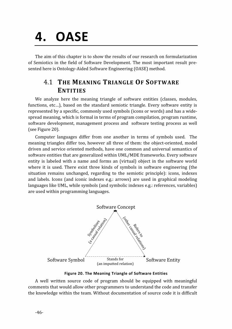
-46-
4. OASE The aim of this chapter is to show the results of our research on formularization
of Semiotics in the field of Software Development. The most important result pre-
sented here is Ontology-Aided Software Engineering (OASE) method.
THE MEANING TRIANGLE OF SOFTWARE 4.1ENTITIES
We analyze here the meaning triangle of software entities (classes, modules,
functions, etc…), based on the standard semiotic triangle. Every software entity is
represented by a specific, commonly used symbols (icons or words) and has a wide-
spread meaning, which is formal in terms of program compilation, program runtime,
software development, management process and software testing process as well
(see Figure 20).
Computer languages differ from one another in terms of symbols used. The
meaning triangles differ too, however all three of them: the object-oriented, model
driven and service oriented methods, have one common and universal semantics of
software entities that are generalized within UML/MDE frameworks. Every software
entity is labeled with a name and forms an (virtual) object in the software world
where it is used. There exist three kinds of symbols in software engineering (the
situation remains unchanged, regarding to the semiotic principle): icons, indexes
and labels. Icons (and iconic indexes e.g.: arrows) are used in graphical modeling
languages like UML, while symbols (and symbolic indexes e.g.: references, variables)
are used within programming languages.
Software Concept
Software Symbol Software EntityStands for(an imputted relation)
Refers to
(other casual relations)Sy
mbo
lizes
(a c
asua
l rel
atio
n)
Figure 20. The Meaning Triangle of Software Entities
A well written source code of program should be equipped with meaningful
comments that would allow other programmers to understand the code and transfer
the knowledge within the team. Without documentation of source code it is difficult

-47-
to perform knowledge management activities in the team consisting of program-
mers. The value of comments is underestimated in software methodologies38
nevertheless for pragmatic purposes there is often a need to equip the standard
programming language entities (classes, methods, properties, etc.) with additional
attributes. Those attributes form an input for additional tools that generate support-
ing code automatically. Such kind of code documentation is called code annotations
and nowadays it becomes the core mechanism for software organization.
The code equipped with comments and code-annotations is a mixture of symbols
and meanings from both: the natural and artificial languages. OASE (that is de-
scribed later) standardizes this mixture by introduction of OASE-English as a
language for OASE-Annotations, and therefore provides the way to document the
source code in a formal, machine processable way. OASE-English is a semi-natural
language with formal semantics, therefore it bridges the gap between natural and
artificial languages.
ARTIFACTS IN SOFTWARE DEVELOPMENT 4.2The artifacts that appear during software development project can be divided in-
to four groups:
1) Source code: the direct requirement for system behavior, written in pro-
gramming language.
2) Design: the indirect requirement on software entities, written in design lan-
guages e.g.: UML. It has a direct representation as a graph.
3) Test cases: the specification for acceptance of software system. Nowadays,
they have a form of program source code that tests the specific functionalities
of software system – dual to main source code, and informal specs.
4) Supporting documents: User requirement specification, project plan and many
other documents that specify the system requirements.
The Pragmatic Software Circle (see Figure 21) is common for every software de-
velopment scenario. It represents the cooperation between agents – programmers,
testers and designers, and defines the communication channels between them as
well. Software development is built over three basic steps that occur in cyclic man-
ner: Programming, Testing and Refactoring. Transitions between those steps require
the modification of corresponding software artifacts. It is worth notice that in such
circle the communication is directed and therefore programmer cannot directly in-
fluence the design nor tester can modify the software code. It is also true for a
designer, who cannot modify the test-cases; however the responsibilities of agents
are strictly separated. Supporting documents are forming the rails for such coopera-
tion as they must be realized by design as well as by test-cases (the source code
should realize the design and fulfill the test-cases, so that it is not considered here as
the one that has to fulfill the supporting documents too). The realize relationship
38 In RUP the underestimation begins at the late stages of the project (when the deadline of a project
approaches). In agile methodologies, documentation is an unimportant artifact as the face-to-face communication is a key factor that leads to success in agile methodology.

-48-
between design, test-cases and supporting documents means that the software must
realize the requirements of both – the business and technological ones. Each com-
munication channel in pragmatic software circle is a channel of communication
between agents. For every type of agents-relation, there is a separate information
transferred. Between a designer and programmer the design diagrams and design
constraints are transferred, between programmer and tester it is the running soft-
ware and between tester and designer, the test-results. Moreover, the system
requirements and other organizational requirements written in supporting docu-
ments are transferred to designer and tester in a form of (informal or formal)
specifications.
Test cases
Source codeDesign
Refactoring
Programing
TestingTesting the
new working version
Makeing the new design to
work
Appying lessons learned during tests
Supporting documents
realize
realize
Figure 21. The Pragmatic Software Cycle
The common communication languages can noticeably reduce the cost of com-
munication activities and allow for better understanding of the software system by
all stakeholders that are involved in the process [Kapl08]; unfortunately we suffer
from lack of standardization in this area.
To respond to this need, basing on semiotics, we propose to build the uni-
fied software development framework, that uses the CNL and DL as a common
language of communication between the involved agents.
Recently it was discovered that even if the DL has a different semantics than ob-
ject-oriented modeling languages have39 , it is still possible to emulate crucial parts
of object-oriented programming within DL [Koid05] [Bera03]. Moreover, models of
software in UML are made of graphs of icons that are equipped with semantics;
therefore software models can be treated as ontologies.
39 DL is equipped with open-world assumption and it lacks defaults, while object-oriented programming
uses closed-world assumption and defaults to describe a class-inheritance.

-49-
COMPUTABILITY AND COMPLEXITY OF 4.3SOFTWARE STRUCTURES
To discover the properties of computer programs we need to use the analysis of
software-structures hidden in software-artifacts. Software property is verifiable if it
is formally representable (has a representation in algebra or logic) and if its formal
representation is decidable. It is known that many properties (e.g.: see the halting
problem40) of software are not decidable in general; however it is possible to com-
pute them in certain situations. If a problem is dependent on computability of a
given property (that is not decidable in general), then we talk about a non-decidable
problem. Even if some property is decidable, it needs to have a complexity that al-
lows using it in pragmatic scenarios. It is known that only ≤ PTime complexity
allows for doing so in any scenario; however some problems can have a large subset
of problems that can be computed in a reasonable amount of time and space by us-
ing heuristics41.
When developing the OASE, we assumed that the computability property of DL
provides the means to separate the design from the runtime.
CLASSIFICATION OF ONTOLOGIES OF 4.4SOFTWARE ARTIFACTS
Object-oriented source code is created by using a hierarchical structure of design
constructs. It forms a World Description (A-Box) of a particular object-oriented pro-
gram. The structure of design constructs (that consists of general rules
e.g.: polymorphism and encapsulation) can be seen as a model of knowledge about
those entities and therefore it forms a Terminology (T-Box). Incorporating
OASE-English (see next subchapters) being a language that is able to model object-
oriented structures, enables us to use one and the same system for storing integrity
constraints, as well as the project and system architecture, which in turn ensures the
logical cohesion of artifacts created in different stages of software development.
The process of software development, if understood as knowledge engineering,
is a way of developing some sort of software specifications (see Figure 22) that form
ontologies. During the lifetime of software project, we can make a classification that
distinguishes four basic ontologies:
1) Requirements Specification Ontology: Obtaining the client’s needs is the basis
for the whole process of constructing information systems and this stage in-
fluences the further way of project realization. The process of requirements
specification and management is not easy. Each requirement is connected
40 Given a description of a computer program, decide whether the program finishes running or continues
to run forever. 41 One of the well-known problems in Software Development is a problem of Compilation. This problem
highly depends on the compiler of programming language and it is known that there exist languages that are non-decidable (e.g.: C++), while other are proven to be decidable (e.g.: Java, C#), There also exist languages that do not require compilation step at all (so called “dynamic-languages” e.g. JavaS-cript).

-50-
with many attributes [Wieg03], such as: completeness, correctness, feasibil-
ity, equivalence and verifiability. Determining the requirements as ontology,
written in description logic, proposed here, facilitates constant monitoring of
requirements attributes by maintaining their internal logical cohesion, which
is no trifle matter if there are a lot of them. It is specified (informally or for-
mally) within supporting documents.
2) Architecture Ontology: Software architecture [Bass03] [Elli96] is a high-level
description of information system. By the purposeful omission of the imple-
mentation details, it describes basic ideas necessary for its realization.
Architecture of information system consists of a high-level project and archi-
tectural style. High-level project implements functional requirements, while
architectural style provides infrastructure on which nonfunctional require-
ments can be fulfilled. Architectural style is a part of metaontology. UML
[Rumb05] provides a certain style, that can be seen as oriented to compo-
nents (symbols) and connectors (indexes), which is a result of object-
oriented methodologies (other architectural styles like stream programming
[Abel96], and it also requires an application of other metaontologies). Archi-
tecture ontology is usually specified within design artifact; however parts of
it appear also in supporting documents in informal way (in a form of non-
functional requirements).
3) Design Ontology: Object-oriented programming can be understood as the way
for a computational structures organization, similar to the way we organize
physical things. An “object” models a selected autonomous part of the physi-
cal system, which can be influenced by actions modeled by “methods”
[Abel96], thus causing a change in the system’s state, which in turn is mod-
eled as a sum of all states of individual objects.
4) Program Structure Ontology: Source code of a program can be interpreted as
a knowledge base that describes the structure of a program. If this ontology
reflects all important elements of programing language, then the machine-
code can be generated from it. Source code can be analyzed. One way to do it
is to use analysis of program static structure in order to find potential errors
in the program. Another examination includes analysis of program dynamics
in order to find run-time errors.

-51-
Static Design OntologyArchitecture OntologyRequirements Ontology
Requirement Specification
Static DesignArchitecture
Program Structure Ontology
Runtime Behaviour
Specifications
Software Structure
Specifications
Software Specifications
Runtime Constrains
Source-CodeDesign-Spec Test-SpecSupporting Documents
Design Constrains
Runtime Design & Algorithms
Figure 22. Software Specifications
OASE: FORMAL SEMIOTIC SYSTEM 4.5The invented here method of software development is called Ontology-Aided
Software Engineering (OASE), in reference to Computer-Aided Software Engineer-
ing (CASE). It is the main objective of this thesis.
OASE method realizes the total semiotic approach to software development by
extending the existing methodologies with an ability to express the supporting
knowledge in OASE-English (see next chapters). Software artifacts are the input of
the overall process that results in a variety of explanations about the properties of
current state of the software system. The Figure 23 is an overview of the OASE ap-
proach:
1) Software artifacts written with the support of OASE-English form an input of
the OASE automated process and are transformed into OASE-English scripts
via OASE-Transformations. The considered artifacts are:
a. Source-Code - made by programmers
b. Code-Annotations - made by designers (and programmers) in form of
OASE-Annotations and OASE-Assertions
c. UML-Diagrams – made by designers (with notes written in
OASE-English)
d. Other formal specifications in OASE-English – made by the customer,
requirement-engineer or made by the management team.
2) Resulting OASE-English script is then processed by separate OASE-Validator
that makes an intensive use of description logic reasoner. The reasoner takes
advantages of the DL computability and guarantees that results can be pro-
vided in the limited computational time and space.

-52-
3) Explanations are returned from OASE-Validator to the stakeholders in the
form of OASE-English. The acquired knowledge is aimed to be meaningful to
them and can form an important input for decision-makers. They are meant
to be usable within the improvement process of the considered program.
OASE is the languages of communication between all stakeholders and therefore
is has both: iconic and symbolic representation. The semiotic framework needs to be
equipped with all semiotic layers beside the syntax (icons and symbols), therefore it
needs the semantics and pragmatics to be an integral part of it. Pragmatics then,
needs to establish the connection between stakeholders and the framework, allow-
ing for the “new quality of work”, therefore it should be easily adapted by the
existing software development environments and should provide additional benefits
to the stakeholders. The iconic representation is considered in OASE because we
made an observation, that software-structures have many viewpoints where icons
are preferred over symbols. In “daily programmer’s work” the symbols are pre-
ferred – this is a “source code producer” point of view. In “daily designer’s work” the
icons are preferred – this is a “diagram painter” point of view. OASE-Toolkit makes
possible to convert UML (the iconic language) into OASE-English script.
OASE-Validator
Source Code
Code Annotations
General mapping OASE-Transformation
Problem Specific OASE-Transformation
UML Diagrams
UML mapping OASE-Transformation
Specifications in OASE-English
OASE-English Script
Reasoner Explanations
Explanations in OASE-English
Figure 23. The Overview of OASE automated process
OASE-English is a verbalization of Description Logic. As DL is a subset of First Order
Logic (FOL), for which the reasoning tasks are decidable, it is a perfect candidate to
describe the static structures that exist within the software entities (moreover, it has
a semantics that can be directly represented in Natural Languages). Moreover, DL is
a natural candidate for a formal semantic framework of decidable software struc-
tures because:
a) DL focuses on ontologies (many software structures form ontology – see Fig-
ure 22), therefore it enables the usage of one and the same storage system, for
requirements, project and system architecture.

-53-
b) DL is decidable by definition; moreover it has dialects that are tractable (have
polynomial complexity e.g.: ++).
c) Its reasoning-tasks (performed by reasoner) makes possible to ensure logical
cohesion of artifacts created on different stages of development, as well as be-
tween the different groups of people involved in the information project.
Software structures, if combined with knowledge (in a form of ontologies speci-
fied in DL) created by means of tools of reverse engineering and subjected to
automatic inference, would result in the knowledge that is not explicitly specified
but rather derived logically. It could be used for verification of design constraints or
modifications of software ontologies themselves or the program, thus ensuring a
cyclic continuation of the process and understanding of the problem by the analyst,
designer and programmer. Description logic is here: - a semantic formal system, that
can be computed by a machine in a limited time and space, - a knowledge represen-
tation language that is well understood and adopted by a large community of
researchers, and - a software modeling formalism that is able to represent the fun-
daments of software design in terms of the decidable structure of software.
The pragmatic layer of OASE is covered with tools e.g.: predictive editor, which
allows stakeholders to enter the correct OASE-English sentences after short training.
Tools allow for a seamless integration of OASE and existing software development
environments. Please note that predictive editing support is only needed in writing
(not reading) OASE-English texts (and for people not familiar with the OASE-English
syntax), therefore it is a usable tool for designers and programmers that deal with
OASE-Annotations and want to edit them. Predictive editor is also important for the
requirement engineers that are able to specify the requirement in the formal way by
using OASE-English. Description logic, itself, is hidden behind the tool-chain as the
tool-chains input and output are either in UML or in OASE-English.
OASE is not oriented on any particular software development (object-oriented)
method, which makes it possible to use it commonly.
MOTIVATING EXAMPLES 4.6To give some intuition that lies behind the OASE method some motivating exam-
ples are presented here.
4.6.1 SINGLETON DESIGN-PATTERN
The Singleton design-pattern can be described intuitively as a requirement made
on a specific class that is forced to have the one and only instance during the whole
life of the system. This restriction can be modeled in DL by using a single axiom:
∃have-type-that-is.{Class-Singleton}⊑{The-Instance-Of-Singleton} ⇔
⇔ Everything (that has-type-that-is Class-Singleton) is The-Instance-Of-Singleton.
We can specify it by using UML Notes on UML class diagram, using DL syntax or
OASE-English (see Figure 24).
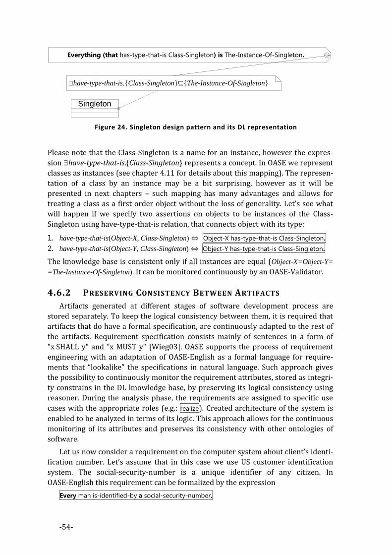
-54-
Singleton
∃have-type-that-is.{Class-Singleton}⊑{The-Instance-Of-Singleton}
Everything (that has-type-that-is Class-Singleton) is The-Instance-Of-Singleton.
Figure 24. Singleton design pattern and its DL representation
Please note that the Class-Singleton is a name for an instance, however the expres-
sion ∃have-type-that-is.{Class-Singleton} represents a concept. In OASE we represent
classes as instances (see chapter 4.11 for details about this mapping). The represen-
tation of a class by an instance may be a bit surprising, however as it will be
presented in next chapters – such mapping has many advantages and allows for
treating a class as a first order object without the loss of generality. Let’s see what
will happen if we specify two assertions on objects to be instances of the Class-
Singleton using have-type-that-is relation, that connects object with its type:
1. have-type-that-is(Object-X, Class-Singleton) ⇔ Object-X has-type-that-is Class-Singleton.
2. have-type-that-is(Object-Y, Class-Singleton) ⇔ Object-Y has-type-that-is Class-Singleton.
The knowledge base is consistent only if all instances are equal (Object-X=Object-Y=
=The-Instance-Of-Singleton). It can be monitored continuously by an OASE-Validator.
4.6.2 PRESERVING CONSISTENCY BETWEEN ARTIFACTS
Artifacts generated at different stages of software development process are
stored separately. To keep the logical consistency between them, it is required that
artifacts that do have a formal specification, are continuously adapted to the rest of
the artifacts. Requirement specification consists mainly of sentences in a form of
"x SHALL y" and "x MUST y" [Wieg03]. OASE supports the process of requirement
engineering with an adaptation of OASE-English as a formal language for require-
ments that “lookalike” the specifications in natural language. Such approach gives
the possibility to continuously monitor the requirement attributes, stored as integri-
ty constrains in the DL knowledge base, by preserving its logical consistency using
reasoner. During the analysis phase, the requirements are assigned to specific use
cases with the appropriate roles (e.g.: realize). Created architecture of the system is
enabled to be analyzed in terms of its logic. This approach allows for the continuous
monitoring of its attributes and preserves its consistency with other ontologies of
software.
Let us now consider a requirement on the computer system about client’s identi-
fication number. Let’s assume that in this case we use US customer identification
system. The social-security-number is a unique identifier of any citizen. In
OASE-English this requirement can be formalized by the expression
Every man is-identified-by a social-security-number.
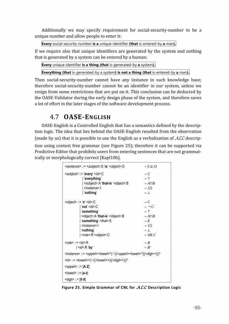
-55-
Additionally we may specify requirement for social-security-number to be a
unique number and allow people to enter it:
Every social-security-number is a unique-identifier (that is-entered-by a man).
If we require also that unique identifiers are generated by the system and nothing
that is generated by a system can be entered by a human:
Every unique-identifier is a thing (that is-generated-by a system).
Everything (that is-generated-by a system) is not a thing (that is-entered-by a man).
Then social-security-number cannot have any instance in such knowledge base;
therefore social-security-number cannot be an identifier in our system, unless we
resign from some restrictions that are put on it. This conclusion can be deducted by
the OASE-Validator during the early design phase of the system, and therefore saves
a lot of effort in the later stages of the software development process.
OASE-ENGLISH 4.7OASE-English is a Controlled English that has a semantics defined by the descrip-
tion logic. The idea that lies behind the OASE-English resulted from the observation
(made by us) that it is possible to use the English as a verbalization of descrip-
tion using context free grammar (see Figure 25); therefore it can be supported via
Predictive Editor that prohibits users from entering sentences that are not grammat-
ically or morphologically correct [Kapl10b].
<sentence> ::= <subject>:S ‘is’ <object>:O ⇢ S ⊑ O
<subject> ::= ’every’ <id>:C ⇢ C
| ’everything’ ⇢ ⊤
| <subject>:A ‘that-is’ <object>:B ⇢ A⊓B
| <instance>:I ⇢ {I}
| ’nothing’ ⇢ ⊥
<object> ::= ‘a’ <id>:C ⇢ C
| ’not’ <id>:C ⇢ ¬C
| ’something’ ⇢ ⊤
| <object>:A ‘that-is’ <object>:B ⇢ A⊓B
| ’something’ <that>:E ⇢ E
| <instance>:I ⇢ {I}
| ’nothing’ ⇢ ⊥
| <role>:R <object>:C ⇢ ∃R.C <role> ::= <id>:R ⇢ R
| <id>:R ‘by’ ⇢ R⁻
<instance> ::= <upperl><lowerl>*(‘-‘((<upperl><lowerl>*)|(<digt>+)))*
<id> ::= <lowerl>+(‘-‘((<lowerl>+)|(<digit>+)))*
<upperl> ::= [A-Z]
<lowerl> ::= [a-z]
<digit> ::= [0-9]
Figure 25. Simple Grammar of CNL for Description Logic

-56-
Predictive editor gives hints during the sentence writing, in the same way as the
IDE is supporting programmer with entering the correct statement of the program-
ming language. The ability to describe dialect of DL in terms of controlled
language that have the grammar expressive in LALR(1), motivated us to adopt it for
DL.
4.7.1 GRAMMAR AND SEMANTICS
The OASE-English compiler is composed of lexer, parser and semantic verifier.
Lexer tokenizes OASE-English sentences and produces the stream of symbols that
represents concepts, roles and instances on its output. Parser obtains input from the
output of the lexer (that composes the <id>, <bigid> and <num> tokens).
OASE-English has LALR(1), a context-free grammar [Aho88] (see Appendix 1).
Due to the limitations of LARL(1) there is a need to equip the OASE-English proces-
sor with an additional context-sensitive library, that can perform the morphological
activities around the OASE-English. The library is based on the dictionary of irregu-
lar forms of English verbs and supports past-participle or present-simple forms of
regular and irregular words.
OASE-English uses buzz-words to represent concepts, roles and instances.
Buzz-word is a concatenation of few words composed with ‘-‘ sign e.g.: beautiful-girl,
Pawel-Kaplanski, is-made-from). The morphology of buzz-words is applied if need-
ed, for both: concept identifiers (if plural form of symbol is required) and for role
names (if past-participate is required). There exist symbols that are reserved only
for a special purpose. Those carefully selected keywords support the grammar of the
language. Below is a list of buzz-word naming rules:
1) Each named individual (instance) identifier, is represented by a noun or a
name in a singular form. It is written as a sequence of words starting with a
capital letter and separated with ‘dash’ sign e.g.: Very-Beautiful-Girl, John-Dow.
2) Each concept identifier is represented by a noun in singular (or plural in the
case of being a part of a number restriction) form (possibly prefixed with ad-
jectives and other nouns). It is written as a sequence of words starting with a
small letter and separated with ‘dash’ sign e.g.: giraffe, low-temperature, smart-
guy, cats.
3) Each property (role, attribute) identifier is represented by a verb in past par-
ticiple form, each starting with a small letter separated with ‘dash’
e.g.: is-part-of, has-age.
4) Software entities are represented as string bordered with square brackets
e.g.: [Main.ServerClass], [System.String] or [System.Object.ToString], as they are
treaded in special way within OASE.
5) Every name that does not fulfill previous requirements to be a valid symbol,
needs to be prefixed with the-thing-called keyword, e.g.: the-thing-called “C++”,
the-thing-called “:)” or the-thing-called “猫”. If there is a need to express the
identifier that is a keyword in OASE-English, it is also required to express it in
this form e.g.: the-thing-called “the-thing-called”.

-57-
6) Additionally, the OASE-English supports ontology namespaces. If naming con-
flict exists within a ontology, there is a need to attach prefix in the form of
[in-terms-of <prefix>]. The prefix forms the namespace of symbols that allows
for the disambiguation of homonym identifiers. Namespaces are defined here
as symbols that represent context of other symbols e.g.: cloud [in-terms-of
Weather-Ontology] or cloud [in terms-of Grid-Computing] are two different con-
cepts that have nothing in common, except for the name. Namespaces are
very important in terms of programming languages that use them to separate
the semantics of symbols which are present in different libraries, however
OASE separates ontology namespaces from namespaces that exists within the
source code (second ones are directly represented in square brackets as a
part of the software entities).
To understand the grammar of OASE-English let’s consider some sentence patterns
that have a direct representation in DL:
1) Every <C> is <D>. , <I> is <D>. Those examples represent all cases where there
is a need to specify the fact about the particular concept (represented by <C>,
<D>) or instance (represented by <I>) (or expressions that evaluate the con-
cept or instance in the form of subsumption e.g.: Every cat is a mammal.,
Pawel has two legs. or Mary is married by John., John knows a programming-
language.). E.g.: Every tree is a plant. is equivalent to DL expression in the form
of tree⊑plant. Concept can be subsumed by the complex expression that in-
cludes roles and attributes:
a. The existential restriction e.g: Every branch is-part-of a tree. ⇔
branch⊑∃be-part-of.tree
b. The universal restriction e.g: Every lion eats nothing-but herbivore. ⇔
lion⊑∀eat. Herbivore .
Both (existential and universal) restrictions are complementary to each other
so the user needs to understand that the only difference between those limi-
tations lies in the usage of nothing-but keyword.
2) Restrictions can be arbitrarily complex if used with (that <…>) statement-
pattern e.g.: Every giraffe eats nothing-but thing (that is a leaf or is a twig). ⇔ gi-
raffe⊑∀eat.(leaf⊔twig). Here, the union of concepts is used as a range of a
restriction, however it is also possible to use the intersection e.g.:
Every tasty-plant is something (that is eaten by a carnivore and is eaten by an herbi-
vore). ⇔ tasty-plant⊑∃eat⁻.carnivore⊓∃eat⁻.herbivore. To use the
complementary part of the concept in the relation, it is helpful to make use of
a does-not keyword e.g.: Every palm-tree does-not have a part (that is a branch).
⇔ palm-tree⊑∃have.(part⊓¬branch). Every herbivore is-equivalent-of a thing
(that eats nothing-but plant or eats nothing-but thing (that is-part-of a plant)). ⇔
herbivore≡∀eat.plant⊔∀eat.∃be-part-of.plant . To specify the instance of con-
cept, the previously described simple class assertion is often enough
e.g.: Sophie is a giraffe. ⇔ {Sophie}⊑giraffe. However it is also possible to make
complex specifications about the instances and their relationship.

-58-
3) A need to specify that concepts are mutually-exclusive e.g.:
Every man and every woman are different. ⇔ man⊑¬woman,
Every herbivore and every omnivore are different. ⇔ herbivore⊑¬omnivore.
4) Roles can have applied axioms that modify their semantics, like:
a. transitivity e.g.: If X has-part something that has-part Y then X has-part Y.
⇔ have-part○have-part⊑have-part .
b. reflexivity e.g.: Everything is-part-of itself. ⇔⊤⊑∃be-part-of.Self
c. anty-reflexivity e.g.: Nothing is a thing (that is-proper-part-of itself). ⇔
⊥⊑∃be-proper-part-of.Self.
All of them are in fact a kind of semantic sugar and can be though as a special
case of general role inclusion and concept subsumption axioms.
5) Role inclusions are represented by If… expressions e.g.:
If X is-proper-part-of Y then X is-part-of Y. ⇔ be-proper-part-of⊑be-part-of . It is
possible to enter any complex role expression when using something that e.g.:
If X loves something that is-made-of Y then X loves Y. ⇔ love○be-made-of⊑love
useful e.g.: in definition of inverse roles e.g.:
If X is-type-of Y then Y has-type-that-is X.
6) Role equivalence is represented in the following manner e.g.:
X is-close-to Y and X is-near-to Y means-the-same. ⇔be-close-to≡be-near-to
7) Disjoint roles are opposite to equivalent ones e.g.:
X loves Y and X hates Y are different. ⇔ love⊑¬hate
8) It is possible to describe the role range or domain e.g.: Everything eats nothing-
but thing (that is an animal or is a plant or is-part-of an animal or is-part-of a plant).
⇔⊤⊑∀eat.(animal⊔plant⊔∃be-part-of.animal⊔∃be-part-of.plant)
OASE allows one to use requirement specifications that form a complementary
part of the design structure specifications of the software system. It is important to
state here that the OASE modalities differ in semantics from Saul Kripke modal logic.
In Kripke modal logic, all worlds need to be taken into a consideration to perform
reasoning. In OASE, we care only about specific worlds that the software system re-
alizes. Therefore, in OASE we are talking about pseudo-modal expressions. Pseudo-
modal expressions are valid OASE-English expressions that contain additional key-
word (must or should or can) or its negation in the middle of it, e.g.:
Every child should have parents. In OASE we assume three situations of alerts – outputs
from computation of pseudo-modal expressions:
a) Inconsistency - the meaning of inconsistency is the same as in DL reasoning
tasks – if the knowledge base is inconsistent, then it is not possible to make
any further computation within it. This is a critical situation.
b) Error – means that the pseudo-modal expression does not fit into the state of
the knowledge base, which from the pragmatic point of view is a critical situ-
ation and it requires a change of software’s system design structure.
c) Warning - means that the pseudo-modal expression does not fit into the state
of the knowledge base, but it is only a suggestion from the pragmatic point of

-59-
view and the situation should be solved somehow in the future (either by fix-
ing the design structure or by modifying the requirements).
ALGORITHM Validation(world-description, instance-knowledge, integrity-constraints)
Tell the reasoner about world-description
Tell the reasoner about instance-knowledge
IF(knowledge base is not consistent)
THEN
show inconsistency
STOP
ENDIF
FOR(icintegrity-constraints)
FOR(instanceLeftHandSide(ic))
IF(instanceRightHandSide(ic))
show error or warning depending on modality flag
STOP
END
END
Figure 26.The Integrity Constrain validation algorithm
The interpretation of must , should and can in OASE is then as follows (in terms of DL
reasoning tasks):
1) <A> is <B> – means that it is true that all instances of <A> are instances of
<B> – if there is a single instance model in the knowledge base that does not
apply to this requirement, then the knowledge base is inconsistent and addi-
tional reasoning cannot be performed42. This case includes also <A> is not
<C>: if we replace <B> with not <C>.
2) <A> must be <B> – means that for any single instance of <A> which at is not
an instance of <B> the error is generated.
3) <A> should be <B> – means that for any single instance of <A> which is not an
instance of <B> the warning is generated.
4) <A> can be <B> – means that if there is no single instance of <A> which is an
instance of <B> then the warning is generated.
5) <A> cannot be <B> – means that for any single instance of <A> which is an in-
stance of <B> the error is generated.
6) <A> should not be <B> – means that for any single instance of <A> which is an
instance of <B> the warning is generated.
7) <A> must not be <B> – means that if there is no single instance of <A> which is
not an instance of <B> then the warning is generated.
42 If <A> has no instances, it means that <A> is a bottom concept and it does not produce the incon-
sistency.

-60-
Pseudo-modal expressions can be calculated by the reasoner, using a simple algo-
rithm (see Figure 26). We adopted more efficient algorithm within the
implementation of OASE-Validator.
EBNF for of OASE-English grammar is specified in details in Appendix 1.
OASE-TRANSFORMATIONS 4.8StringTemplate is a domain-specific language, invented by T. J. Parr, for generat-
ing structured text from internal data structures. It is MDE model-transformation
engine that we selected due to its simplicity and its graph->text orientation. OASE-
Transformation is a StringTemplate that produces OASE-English script.
OASE-Transformations are intensively used within OASE method, to provide the
mapping between class descriptors (models of software structures - see chap-
ter 3.2.1) and OASE-English. For more details about StringTemplate please refer to
its detailed description presented in [Parr06].
SOFTWARE ICONS, INDEXES AND SYMBOLS IN 4.9OASE
In modern object-oriented languages (Java, C#) the class is considered as tem-
plate for creation of objects. The modern languages allow for an inspection of design
in the time of program execution (runtime). The mechanism that allows for such an
inspection is called reflexion. Moreover, it allows to create a class in the same man-
ner as an object. Old object-oriented languages separated object-oriented world into
two parts – the abstract one (made of classes) and the virtual one (made of objects),
now we use the only one (virtual), where everything, even the class is an object. The
pragmatic observation of usefulness of this approach led us to a conclusion that the
definition (and motivation) that lies behind the object-oriented paradigm must have
changed over the years. While at the very beginning of the history of object-oriented
languages, classes were mostly used as an abstract datatypes, nowadays classes be-
come the object-templates used to create other ones. In other words, classes evolved
from abstract objects into virtual ones; therefore the most appropriate ontological
representation of classes in DL (in terms of ontology of software entities) is an in-
stance (the instance of very general concept, that forms a creation pattern for other
objects, but it is still the instance – not a concept).
The subtyping mechanism can be then described as a form of transitive relation,
that moves properties and methods from base-class into the sub-class (– the partial
ordering of classes). In short, this mapping can be described as: “class⇔instance,
object⇔instance” leaving a place for higher level constructs to be mapped as con-
cepts e.g.: “pattern⇔class”. In the following subchapter (see 4.12) this mapping is
described in details.

-61-
CLASS DESCRIPTORS 4.10In object-oriented paradigm, software is represented by a system of objects that
cooperate with each other. The specification for object construction is called “a
class”. In other words: all objects are instances of classes created during the object
construction process.
The object-oriented paradigm assumes that object is a software entity that en-
capsulates its state and functionality for its own needs. State of the object is
specified by the values that fills attributes (the data-placeholders in the instantiated
class) and the functionality of an object is specified by functions that are assigned to
it (the method-placeholders in the instantiated class). Therefore, the object forms a
part-whole structure, where object is the whole and values and functions are parts
of it. To “access by name” the part-whole relationship, signatures that identify a spe-
cific part of an object are used.
+name+is-abstract+is-final
class
+name
base-class
+name+type-name
field
base-classes
fields
+name
constructor
constructors
+name+return-type?
nethod
methods
+method-name+context-name
call
+type-name
create
+name+type-name
get
+name+type-name
set
calls
creates
gets
sets
+method-name+context-name
call
+type-name
create
+name+type-name
get
+name+type-name
set
calls
creates
gets
sets
Figure 27. Simple structure of a class (in UML) is forming a composition tree of
symbols.
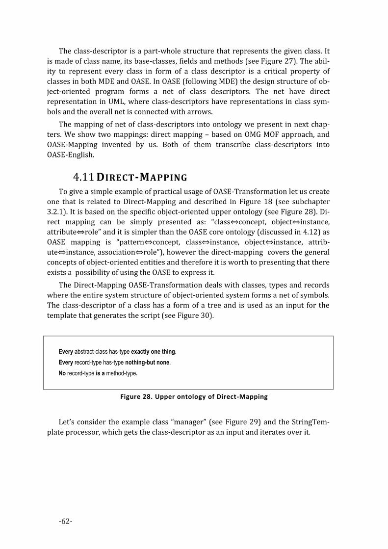
-62-
The class-descriptor is a part-whole structure that represents the given class. It
is made of class name, its base-classes, fields and methods (see Figure 27). The abil-
ity to represent every class in form of a class descriptor is a critical property of
classes in both MDE and OASE. In OASE (following MDE) the design structure of ob-
ject-oriented program forms a net of class descriptors. The net have direct
representation in UML, where class-descriptors have representations in class sym-
bols and the overall net is connected with arrows.
The mapping of net of class-descriptors into ontology we present in next chap-
ters. We show two mappings: direct mapping – based on OMG MOF approach, and
OASE-Mapping invented by us. Both of them transcribe class-descriptors into
OASE-English.
DIRECT-MAPPING 4.11To give a simple example of practical usage of OASE-Transformation let us create
one that is related to Direct-Mapping and described in Figure 18 (see subchapter
3.2.1). It is based on the specific object-oriented upper ontology (see Figure 28). Di-
rect mapping can be simply presented as: “class⇔concept, object⇔instance,
attribute⇔role” and it is simpler than the OASE core ontology (discussed in 4.12) as
OASE mapping is “pattern⇔concept, class⇔instance, object⇔instance, attrib-
ute⇔instance, association⇔role”), however the direct-mapping covers the general
concepts of object-oriented entities and therefore it is worth to presenting that there
exists a possibility of using the OASE to express it.
The Direct-Mapping OASE-Transformation deals with classes, types and records
where the entire system structure of object-oriented system forms a net of symbols.
The class-descriptor of a class has a form of a tree and is used as an input for the
template that generates the script (see Figure 30).
Every abstract-class has-type exactly one thing.
Every record-type has-type nothing-but none.
No record-type is a method-type.
Figure 28. Upper ontology of Direct-Mapping
Let’s consider the example class “manager” (see Figure 29) and the StringTem-
plate processor, which gets the class-descriptor as an input and iterates over it.

-63-
+name=manager+is-abstract=false
class
+name=human
base-class
+name=occupies+type-name=position
field
base-classes
fields
+name=employee
base-class
base-classes
Figure 29. Example of Class Descriptor
The OASE-English script output that is a product of processing (see Figure 31) is
an ontology written in OASE-English that together with upper-ontology
(see Figure 28) allows for a deductive reasoning in such a representation of object-
oriented program.
mapType(cls) ::= <<
Every class-<cls.name> has-type nothing-but type-<cls.name>.
Every type-<cls.name> is a record-type.
<if(cls.is_abstract)>
Every class-<cls.name> is an abstract-class.
<endif>
<cls.base_classes:{base_class |
Every class-<base_class.name> is a class.
Every class-<cls.name> is a class-<base_class.name>.
}>
<class.fields:{field |
Every type-<cls.name> field-<field.name>s exactly one thing.
Every type-<cls.name> field-<field.name>s nothing-but class-<field.type_name>.
}>
>>
Figure 30. OASE-Transformation for Direct-Mapping
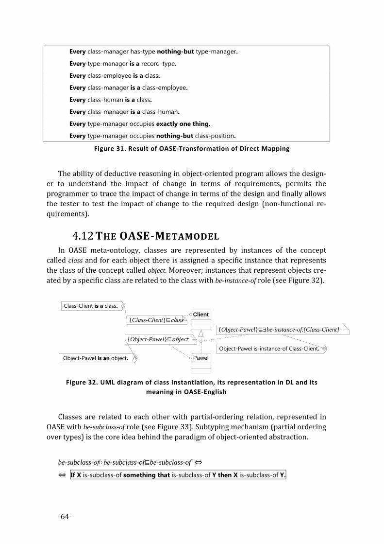
-64-
Every class-manager has-type nothing-but type-manager.
Every type-manager is a record-type.
Every class-employee is a class.
Every class-manager is a class-employee.
Every class-human is a class.
Every class-manager is a class-human.
Every type-manager occupies exactly one thing.
Every type-manager occupies nothing-but class-position.
Figure 31. Result of OASE-Transformation of Direct Mapping
The ability of deductive reasoning in object-oriented program allows the design-
er to understand the impact of change in terms of requirements, permits the
programmer to trace the impact of change in terms of the design and finally allows
the tester to test the impact of change to the required design (non-functional re-
quirements).
THE OASE-METAMODEL 4.12In OASE meta-ontology, classes are represented by instances of the concept
called class and for each object there is assigned a specific instance that represents
the class of the concept called object. Moreover; instances that represent objects cre-
ated by a specific class are related to the class with be-instance-of role (see Figure 32).
Pawel
Client
{Object-Pawel}⊑∃be-instance-of.{Class-Client}
{Object-Pawel}⊑object
Object-Pawel is-instance-of Class-Client.
Object-Pawel is an object.
{Class-Client}⊑class
Class-Client is a class.
Figure 32. UML diagram of class Instantiation, its representation in DL and its
meaning in OASE-English
Classes are related to each other with partial-ordering relation, represented in
OASE with be-subclass-of role (see Figure 33). Subtyping mechanism (partial ordering
over types) is the core idea behind the paradigm of object-oriented abstraction.
be-subclass-of○be-subclass-of⊑be-subclass-of ⇔
⇔ If X is-subclass-of something that is-subclass-of Y then X is-subclass-of Y.

-65-
Given be-subclass-of relationship we can define its inverse called be-superclass-of:
be-subclass-of≡be-superclass-of⁻ ⇔
⇔ X is-subclass-of Y and Y is-superclass-of X means-the-same.
Please note that be-subclass-of and be-superclass-of are DL roles. This is a great differ-
ence between OASE approach to Direct-Mapping (see chapter 4.11) and the
approach in which the partial ordering of classes in hierarchy is represented by con-
cept subsumption.
The “type of object” in object-oriented systems is understood as either explicit or
implicit super-class of class that created the object, together with the class designed
for the creation of the specific object. We can summarize above requirements (in
OASE) with the following script (see also Figure 34):
1) If X is-instance-of Y then Y is-type-of X. ⇔ be-instance-of⊑be-type-of⁻
2) If X is-instance-of something that is-subclass-of Y then Y is-type-of X. ⇔
⇔ be-instance-of○be-subclass-of⊑be-type-of⁻
3) X is-type-of Y and Y has-type-that-is X means-the-same. ⇔ be-type-of≡have-type-that-is⁻
4) X is-instance-of Y and Y has-instance-that-is X means-the-same. ⇔
⇔ be-instance-of≡have-instance-that-is⁻
Client
Firm Person
{Class-Person}⊑∃be-subclass-of.{Class-Client}{Class-Firm}⊑∃be-subclass-of.{Class-Client}
Class-Firm is-subclass-of Class-Client. Class-Person is-subclass-of Class-Client.
Figure 33. UML diagram of class inheritance and its representation in DL
With the given above OASE meta-ontology, we can formally describe the basic
properties of objects and classes that have to be followed, e.g.: to specify that class
Person is abstract (a class that cannot be materialized) we can chose direct DL repre-
sentation in a form of: {Class-Person}⊑∀have-instance-that-is.⊥ and to specify that Person
class is a root of a class hierarchy: {Class-Person}⊑∀be-subclass-of.⊥ . Moreover, we
prevent the class from being inherited (such classes are called “final” in Java) with:
{Class-Person}⊑∀be-superclass-of.⊥ (see Figure 36) statement.
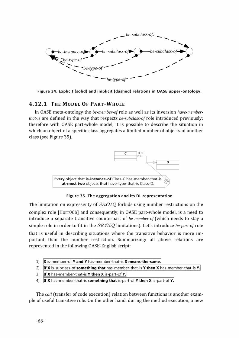
-66-
be-subclass-of be-subclass-of
be-subclass-of
be-instance-of
be-type-of
be-type-of
be-type-of
Figure 34. Explicit (solid) and implicit (dashed) relations in OASE upper -ontology.
4.12.1 THE MODEL OF PART-WHOLE
In OASE meta-ontology the be-member-of role as well as its inversion have-member-
that-is are defined in the way that respects be-subclass-of role introduced previously;
therefore with OASE part-whole model, it is possible to describe the situation in
which an object of a specific class aggregates a limited number of objects of another
class (see Figure 35).
C
D
0..2
Every object that is-instance-of Class-C has-member-that-is
at-most two objects that have-type-that-is Class-D.
Figure 35. The aggregation and its DL representation
The limitation on expressivity of forbids using number restrictions on the
complex role [Horr06b] and consequently, in OASE part-whole model, is a need to
introduce a separate transitive counterpart of be-member-of (which needs to stay a
simple role in order to fit in the limitations). Let's introduce be-part-of role
that is useful in describing situations where the transitive behavior is more im-
portant than the number restriction. Summarizing: all above relations are
represented in the following OASE-English script:
1) X is-member-of Y and Y has-member-that-is X means-the-same.
2) If X is-subclass-of something that has-member-that-is Y then X has-member-that-is Y.
3) If X has-member-that-is Y then X is-part-of Y.
4) If X has-member-that-is something that is-part-of Y then X is-part-of Y.
The call (transfer of code execution) relation between functions is another exam-
ple of useful transitive role. On the other hand, during the method execution, a new

-67-
object is created in the OASE and it is represented by create relation. Every object is
created as a product of construction process done by constructor (the function that
explicitly creates the object based on the given class) therefore when the object con-
struction occurs, the method calls the specific constructor. Those interconnections
between objects are represented by the following OASE script:
1) If X calls something that calls Y then X calls Y.
2) If X creates something that is constructed by Y then X calls Y.
State of the object is specified by the set of values of its attributes. The functionality
that object can provide is specified by the implementation of the method (function-
ality slots). Both, attributes and methods are parts of classes while attribute-values
and method-implementations are parts of objects.
To “access by name” (i.e. when the specific function needs to change the state of
the given attribute) the part-whole relationship in object-oriented languages, one
has to use the signatures that identify a specific part of an object. For example, let’s
assume that the class Client has an attribute Account. In OASE, the identification of an
attribute or a method is expressed with superimposition (a superimposition of a
class C and signature S is a complex expression that involves both of them) of signa-
ture and class (here signature is Account), together with identify and be-member-of
roles: ∃identify⁻.{Signature-Account}⊓∃be-member-of.{Attribute-Client}. The expression:
∃identify⁻.{Signature-Account}⊓∃be-member-of.{Class-Client}≡{Attribute-Client-Account} ⇔
Everything (that is identified by Signature-Account and
is-member-of Class-Client) is-equivalent-of Attribute-Client-Account.
states that the Client-Account attribute exists and expresses how to identify it unique-
ly. Having Client-Account attribute defined, one can put restrictions on the type of this
attribute e.g.:
∃fill. {Attribute-Client-Account)⊑∃have-type-that-is.{Class-Account}⇔
⇔ Everything that fills Attribute-Client-Account has-type-that-is Class-Account.
If, by an analogy to attribute, we assume that the method is a placeholder for a func-
tion that can be performed by all objects that have type of given class, then
expression:
∃identify⁻.{Signature-Login}⊓∃be-member-of.{Class-Client}≡{Method-Client-Login}

-68-
uniquely identifies the method Login of a class Client. Functions that fill placeholders
formed by methods are called method-implementations in object-oriented method-
ology. They are defined for the given parental classes and are assigned to the object
during the construction process. Therefore to deal with the methods and its imple-
mentations lets introduce the implement relation e.g.: we specify that Client-Login-Impl
function is an implementation of the Client-Login method (equivalent to
∃identify⁻.{Login}⊓∃be-member-of.{Client}) by using:
{Function-Client-Login-Impl}⊑∃implement.{Method-Client-Login}.
As every instance of Client class has a member of Client-Login-Impl we can specify that:
∃be-instance-of.{Class-Client}⊑∃have-member-that-is.{Function-Client-Login-Impl}.
The polymorphism of methods and inheritance of method implementation differ in
details within object-oriented languages. Especially when taken together into ac-
count, they create difficulties in describing them it in the DL. From the OASE point of
view, both mechanisms are solved by the OASE-Validator that use the reflexion
mechanism available in programming language itself, and therefore there is no ne-
cessity of additional support for the reasoning over their properties. In the OASE,
the equivalence of functions (implementations of the methods) is done explicitly by
the OAE supporting tools. The OASE tools specify which functions are the same and
which are different.
4.12.2 CLASS HIERARCHIES
OASE Metamodel maps classes and objects into DL instances and arranges them
in hierarchical order by using roles instead of subsumption between concepts. It
leaves the room for higher-level object-oriented constructions to be mapped as con-
cepts. One of a high-level object-oriented constructions is a class hierarchy.
Hierarchy of classes is a set that consists of all the classes related with the be-
subclass-of relationship, including the given class. To deal with hierarchies in OASE,
we assume that each class (the instance that it represents) need to be explicitly hier-
archized by some hierarchy (if a class is neither a super nor subclass of any other
class, then its hierarchy hierarchizes this class only). Hierarchies in OASE are repre-
sented by instances of some general concept hierarchy e.g.: using DL assertion
hierarchize(Hierarchy-H, Class-X). The hierarchize DL role has a hierarchy as a domain and
the class as a range. A hierarchize DL role should follow the relationship between sub-
classes. Those rules can be formulated in the following statements:
1) If X hierarchizes something that is-subclass-of Y then X hierarchizes Y. ⇔
⇔ hierarchize○be-subclass-of⊑hierarchize

-69-
2) If X is hierarchized by something that is-subclass-of Y then X hierarchizes Y. ⇔
⇔ hierarchize⁻○be-subclass-of⊑hierarchize
If each instance that represents a class in the system is related to some instance that
represents a hierarchy (possibly anonymous – if not specified directly) with a hier-
archize role, then it is possible to automatically determine the concept that contains
all of classes hierarchized by the same hierarchy as the given class e.g.: hierarchy-of-
class-x≡∃hierarchize⁻.∃hierarchize.{Class-X}.
In Figure 36 is presented the simple hierarchy of classes. The top class
(class A) is here an abstract class and a root for the class hierarchy. The class hier-
archy is connected via subclassing and is contained in hc concept.
OASE-MAPPING 4.13In Appendix 2 we present details of the OASE-Transformation which maps the
structure of object-oriented program into OASE-English w.r.t. OASE-Metamodel pre-
sented in the previous subchapter. It is assumed that the input of the
OASE-Transformation is a class-descriptor (see Figure 27) that represents the inter-
nal structure of classes within the object-oriented program (it is obtained either
from the UML specification and/or from the source code structure taken directly by
using mechanism of reflexion – introduced previously), therefore; OASE-Mapping
can be considered as a transformation from either the UML specification or/and ob-
ject-oriented source code into the OASE-English.
C
hC⊑∃hierarchize⁻.∃hierarchize⁻.{Class-C}
Every hC is equivalent to something that is
hierarchized by something that hierarchizes Class-C.
A<<abstract>>
D
<<final>>
Class-A has-instance-that-is
nothing and is-subclass-of
nothing.
{Class-A}⊑∀have-instance-that-is.⊥⊓∀be-subclass-of.⊥
Class-D is-superclass-of nothing.
{Class-D}⊑∀be-superclass-of.⊥
Figure 36. The class hierarchy for a given class C and its representation in DL

-70-
PROGRAMMING WITH OASE-ANNOTATIONS 4.14OASE-Annotations [Kapl11b] support the pragmatic-layer (in terms of semiotics)
of OASE and therefore they complete the OASE in terms of semiotic framework for
Software Development.
Modern object-oriented programming languages (e.g.: Java, C #) are equipped
with the capability of using annotations that comment on the entities of the pro-
gram. Previously mentioned languages provide access to these annotations through
the reflexion. OASE provides the means to annotate the source code with remarks in
the form of OASE-English statements. The resulting code looks like a mixture of
standard source code and English sentences. Once annotated with the code is there-
fore equipped with additional semantics, that allow to generate the formal
specification of the entire system.
The casual collaboration between the designer and the programmer is unidirec-
tional - what the former designs, the latter must implement. With the
OASE-Annotation, the collaboration becomes bidirectional – the output of program-
mer’s work can break the design, which will result in the inconsistency. This process
is called by programmers “the verification of design by the implementation”. Nor-
mally (in terms of casual collaboration between stakeholders), such a situation
would result in downgrading of the design over implementation; however, when
using OASE, it is possible to modify the design so that it still keeps the bidirectional
consistency. The programmer and designer use the same semantic background – the
description logic, which lies behind both: the annotated code and the UML models.
Finally, explanations in OASE-English instruct both, the designer and programmer,
about the cause of the problem that has occurred. OASE-Annotations allow for a
specification of the design constraints on static structure within the source code, due
to the fact that it is powerful enough to specify static structure of the code.
The usefulness of OASE-Annotations was verified by us in the experiment de-
scribed in details in Appendix 5.
DEBUGGING WITH OASE-ASSERTIONS 4.15OASE supports Design by Contracts paradigm, by allowing for take a usage of
OASE-Assertions. OASE-Assertions can be seen as a form of documentation that is
useful for verifying if an assumption made by the programmer (during the imple-
mentation of the program) remains valid (when the program is executed).
OASE-Assertions implement the assertions in terms of checking for fulfillment of the
contract that need to be preserved during program execution. They are verified in
the debug-mode (in the final release of the software they are omitted).
OASE-Assertions are discussed in Pipes & Filters case study described in
chapter 4.17.2.

-71-
DISCUSSION OF OASE SEMIOTIC 4.16FRAMEWORK
As the aim of OASE is to become the semiotic framework, therefore below we
discuss its three semiotic layers: Syntax, Semantics and Pragmatics.
4.16.1 OASE SYNTAX LAYER
The syntax of OASE provides the means to deal with basic software entities, in
terms of icons (UML) or symbols (OASE-English). The icons that exist in UML dia-
grams of software static structure are preserved within the OASE.
The main advantage of OASE in the area of syntax of the software is an ability to
describe the specification of design patterns.
The first general weakness of OASE syntax layer is the necessity of using
buzz-words in OASE-English. Buzz-words are mix of symbols that represent con-
cepts, roles and instances in ontologies; however they are not a part of natural
language. The second general disadvantage lies in the core characteristic of
OASE-English – it is a subset of English only. Even if English is a core language that
lies behind every modern computer language, there is a need to adapt the OASE for
other natural languages.
4.16.2 OASE SEMANTIC LAYER
Description logic (DL) forms a formal semantic layer of OASE. OASE allows to
present existing UML diagrams as the static structure of software, however the limi-
tations in semantic layer are caused by the DL itself. It is impossible to deal with
a runtime software behavior with DL and therefore with OASE (because runtime
behavior is non-decidable in general). This limitation allows for specifying and veri-
fying only those statements that are in the expressive power of . Even if
most of the structures that are essential (from the software development process
point of view) need to be decidable, there is still a necessity to describe and perform
reasoning over the runtime structures – that’s when the OCL becomes useful. Alt-
hough OCL is not intuitive, there exist approaches to build the semiotic framework
over the OCL formalism. The expressive-power of OASE can be extended in the fu-
ture with integration of a rule system. By now we support runtime structure by
OASE-Assertions that allows to preserve the runtime constraints of the running pro-
gram.
Future research needs to be made in order to permit for expressivity in e.g.: Ad-
jectives, Full Modal Logic, Temporal Logic etc... – afterwards it is not clear if it will be
possible to use LALR or any other context-free grammar anymore.
4.16.3 OASE PRAGMATIC LAYER
The pragmatic layer of OASE is a consequence of its usage by the stakeholders.
Proposed methodology has a number of advantages for all involved groups of con-

-72-
tributors. OASE is based on the same natural-looking language and the logic is hid-
den. Users do not need any training in formal logic formalisms nor the support from
computer specialties as long as they are able to use the predictive editor. Program-
mers are continuously checked by OASE-Validator whether the entered knowledge
fulfills the Integrity Constraints. Designers are provided with the ability to explore
the software, by using formal tools. They can also continuously adjust the Integrity
Constraints while the implementation is still in progress.
Common limitation of OASE-English is the need for predictive editor, from the
editor perspective. It is very difficult to create a correct OASE-English sentence
without such support, but the LALR context free grammar of OASE-English allows
one to build the predictive editor easily.
In comparison to Lepus3, the OASE is decidable and more focused on symbols
than icons. The ability to represent the complex structures in the Controlled Natural
Language is a valuable innovation, especially in the area dominated by the iconic
languages. This can lead to a better understanding of the complex software struc-
tures by all stakeholders involved in the software development process. It also
allows to employ the OASE-Validator as a part of continuous integration process –
the core part of the agile software development methodology.
4.16.4 EVALUATION
Semiotic layers of OASE were evaluated within the survey (see Appendix 4 and
the experiment (see Appendix 5). The experiment and survey were invented to
check:
1) If the syntax and semantic layers allow to use OASE in an understandable manner:
Evaluation proves that both semantics and syntax are understandable by English
speaker. An emphasis was put on the pseudo-modal expressions. We found out
that pseudo-modal expressions are ambiguous for the novice programmers and
can lead to misuse.
2) If the pragmatic layer provides usability in terms of software engineering:
The experiment proves that OASE improves the collaboration between designer
and programmer, by reducing the amount of necessary communication between
them. Instead of this communication, the OASE-Validator provides the program-
mer with meaningful explanations, leading him by hand via the design of the
program. This is a very important effect that has a great impact on distributed
workplaces, which are more and more popular nowadays.
CASE STUDIES 4.17Next subchapters present the case studies of the practice of programming with
OASE.
4.17.1 ARCHITECTURAL LAYERS
The layer separation paradigm manages usage relationship between the soft-
ware entities. Architectural layers label each software entity and force the correct
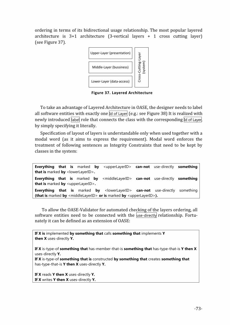
-73-
ordering in terms of its bidirectional usage relationship. The most popular layered
architecture is 3+1 architecture (3-vertical layers + 1 cross cutting layer)
(see Figure 37).
Upper-Layer (presentation)
Middle-Layer (bussiness)
Lower-Layer (data-access) Cro
ss-C
utt
ing-
Laye
r (s
yste
m)
Figure 37. Layered Architecture
To take an advantage of Layered Architecture in OASE, the designer needs to label
all software entities with exactly one Id of Layer (e.g.: see Figure 38) It is realized with
newly introduced label role that connects the class with the corresponding Id of Layer,
by simply specifying it literally.
Specification of layout of layers is understandable only when used together with a
modal word (as it aims to express the requirement). Modal word enforces the
treatment of following sentences as Integrity Constraints that need to be kept by
classes in the system:
Everything that is marked by <upperLayerID> can-not use-directly something
that is marked by <lowerLayerID>.
Everything that is marked by <middleLayerID> can-not use-directly something
that is marked by <upperLayerID>.
Everything that is marked by <lowerLayerID> can-not use-directly something
(that is marked by <middleLayerID> or is marked by <upperLayerID>).
To allow the OASE-Validator for automated checking of the layers ordering, all software entities need to be connected with the use-directly relationship. Fortu-nately it can be defined as an extension of OASE:
If X is implemented by something that calls something that implements Y
then X uses-directly Y.
If X is-type-of something that has-member-that-is something that has-type-that-is Y then X
uses-directly Y.
If X is-type-of something that is constructed by something that creates something that
has-type-that-is Y then X uses-directly Y.
If X reads Y then X uses-directly Y.
If X writes Y then X uses-directly Y.

-74-
Finally, using the verification algorithm (see Figure 26) one can always validate
the system design against the layer ordering, and therefore ensure that according to
the Integrity Constraints, classes in the system do not break the layered architecture.
Figure 38. Example of OASE-Annotation for Architectural Layers
We have made assessment of utilization of OASE-Annotation with Architectural
Layers within the evaluation of the survey described in details in Appendix 4.
4.17.2 PIPES & FILTERS
The Pipes & Filters [Busc96] is a well-known Design Pattern [Gamm95], that is
used to divide the task of a system into several sequential processing steps. Each
processing step is implemented by a filter component that consumes and delivers
data incrementally. The filters are connected sequentially by pipes. Filters are usual-
ly implemented as separate objects that use one common interface of a generic pipe
and therefore filters can be freely configured, however it is highly desirable to pre-
vent such a free-style by incorporating some design constraints. The solution
requires an incorporation of specification language, which would allow the designer
to exactly specify which pairs of filters are compatible with one other.
OASE-Annotations together with OASE-Assertions, allow the programmer to build a
Pipes & Filters design pattern validator, in a coherent way.
sourcemultiplexer
sink
sink
sourcegenerator
sourcefiltersin
k
source
demultiplexer
source
sin
k
sourcegenerator
resu
lt
eater
sink
resu
lt
eater
sink
Figure 39. Pipes & Filters.

-75-
If we equip every method with the pre-condition in a form of OASE-Assertion
and annotate the classes with supporting OASE-Annotations (see Figure 40), then it
is possible for OASE-Validator to perform reasoning. The OASE-English script, which
resulted from OASE-Transformation, is the formal specification of such
Pipes&Filters system. What is more, the verification of Pipes & Filters can be done
using OASE-Validator in runtime.
[module: OASE.Axiom("Pipe-A is-connectable-to Pipe-B.")]
public class Multiplexer
{
[OASE.Architecture.PipeConnector("Pipe-B")]
public IEnumerable<string> filter(IEnumerable<string> arg1, IEnumerable<string> arg2)
{
OASE.Debugging.Assert(arg1.GetPipeID() + " must be-connectable-to Pipe-A.");
OASE.Debugging.Assert(arg2.GetPipeID() + " must be-connectable-to Pipe-A.");
foreach (var a1 in arg1)
{
yield return a1 + "f";
}
}
}
Figure 40. OASE-Annotations in Pipes&Filters.
We have made an appraisal of utilization of OASE-Annotation and
OASE-Assertions with Pipes & Filters within the evaluation of the survey described
in Appendix 4.
OASE AS A DESIGN PATTERN LANGUAGE 4.18Design pattern shows the promising way (in terms of pragmatics of software de-
velopment process) of organizing the software entities. The design pattern can be
treated in two ways: first - as a requirement put on software design and second - as
a repetitive software structure that occurs unintentionally in software. The solution
described by the design pattern, is specified by the roles of its constituent partici-
pants, their responsibilities and relationships, and the ways in which they
collaborate. To approach the design pattern one is required to focus on each of these
three areas:
1) The participating classes and objects
2) Relationships between the classes and objects
3) The overall collaboration of participants
Even if design pattern is not formally defined, the fulfillment of the above rules
makes it possible to formalize it using formal methods. The software design pattern
language [Alex77] [Busc07a], which can be used to describe each aspect of the soft-
ware architecture, if formalized, can become a language that will allow for the
requirement and discovery of essential software aspects. Common semiotic frame-
work which lies behind the pattern language, functions as a background for the
development of tools, that can deal with the design pattern language. DL and
OASE-English together can provide such a framework.

-76-
4.18.1 ADAPTER
Adapter design pattern [Gamm95] translates one interface of a class into a com-
patible interface. It allows classes (that have incompatible interfaces) to work
together (what would be impossible when providing its interface to clients while
using the original interface). In other words: Adapter translates calls to its interface
into calls to the original interface. Depending on the designer decision on adoptee
class, it can be implemented via aggregation or inheritance: we call them class-
adapter (when the adapter class inherits from the adoptee class) or object-adapter
(when the adapter class contains the adoptee class) (see Figure 41) that takes the
net of class-descriptors as an input.
+Request()
Target
+SpecificRequest()
Adaptee
+Request()
Adapter
Client
In case of
class adapter
<<call>>
<<call>>
In case of
object adapter
Figure 41. Adapter design pattern
In Appendix 3 the OASE-Transformation of Adapter design pattern is presented
in details. We have made an assessment of utilization of OASE as a Design Pattern
Language, in terms of Adapter Pattern within the evaluation of the survey described
in details in Appendix 4.

-77-
5. OASE-TOOLS This chapter presents the tools, we have developed, that support the OASE para-
digm by:
- Ability to enhance the current software development tools with
OASE-Annotations and OASE-Assertions
- Ability to use iconic representations of software structures using UML
- Ability to specify requirements and design in OASE-English using Predictive
Editor
OASE-tools are to be used by two groups: the T-Box Engineers (software design-
ers, requirement engineers) that specify the World Description of a software system
and map its requirements onto Integrity Constraints and the A-Box Producers (pro-
grammers) that provide the knowledge about ontology assertions either manually
or with an additional tool support that obtains assertions from the source code. Both
participants do supportive work by using one of specialized predictive editors
(OASE-Annotator, OASE-Diagrammer or standalone OASE-English predictive editor).
Their work is continuously synchronized and validated by the OASE-Validator (see
Figure 3). Moreover they can use additional custom tools (designed strictly for the
given problem) which are based on Inferred-UI approach (described in the next
chapter).
OASE-Tools can be downloaded from the OASE web-site: http://oase-tools.net .
OASE-VALIDATOR 5.1OASE-Validator is a software component that is reused within entire OASE
tool-chain. Given the OASE-English specification OASE-Validator returns the results
of validation of pseudo-modal expressions contained within the knowledge base.
The result of validation, that has a form of explanations specified in OASE-English, is
finally returned from OASE-Validator to the user. The component consists of several
subcomponents connected together (see Figure 42). The parser gets the output of
the lexer and produces (with a support of the morphology component) the Abstract
Syntax Tree (AST) of OASE-English sentence. The AST visitor transforms the AST
and produces the DL representation of every sentence. The heart of OWL-Validator
is a reasoner for DL called HermiT [Shea08]. The explainer is a part of
OWL-API [Bech03]. It constructs explanation mechanism about the inconsistency or
broken integrity constraints. The Integrity Constraints Validator uses both: the rea-
soner and the explainer.
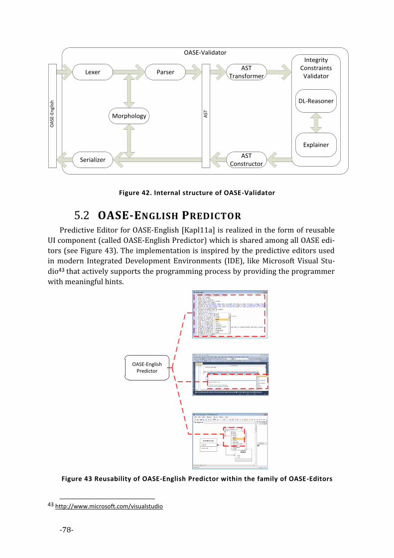
-78-
OASE-ValidatorIntegrity
Constraints Validator
Lexer Parser
Morphology
AST Constructor
Serializer
OA
SE-E
ngl
ish
AST
AST Transformer
DL-Reasoner
Explainer
Figure 42. Internal structure of OASE-Validator
OASE-ENGLISH PREDICTOR 5.2Predictive Editor for OASE-English [Kapl11a] is realized in the form of reusable
UI component (called OASE-English Predictor) which is shared among all OASE edi-
tors (see Figure 43). The implementation is inspired by the predictive editors used
in modern Integrated Development Environments (IDE), like Microsoft Visual Stu-
dio43 that actively supports the programming process by providing the programmer
with meaningful hints.
OASE-English Predictor
Figure 43 Reusability of OASE-English Predictor within the family of OASE-Editors
43 http://www.microsoft.com/visualstudio

-79-
OASE-English Predictor allows one to create a variety of predictive editors that
support the OASE-English. It is realized as a library, which manages a number of to-
kens that are the possible continuations of a given OASE-English sentence and pre-
presents them to the user. It is developed by basing on general principles of LALR(1)
grammar, which allows to determine the possible tokens that can be placeholders of
the new language production. OASE-Editor Predictor is a generic component. Based
on this component there is provided the OASE-Editor standalone application
(see Figure 44). The standalone editor is a valuable tool for all involved stakeholders
as it provides the means for a direct modification of OASE ontologies by using pre-
dictive editor, however to provide designer and programmer with more intuitive
(and adapted to their needs) tools, we have invented another two OASE-Editors:
OASE-Annotator and OASE-Diagrammer (described in the following subchapters).
Figure 44. Standalone application of predictive editor for OASE-English based on
OASE-English Predictor component
OASE-TRANSFORMATION PROCESSOR 5.3The OASE-Transformation processor allows programmers and designers to deal
with OASE without the need for any modification of their daily work habits. They
still operate on objects in the form of its representation in either source code or UML
diagrams as OASE-Transformation processor maps those two artifacts onto the
OASE-English scripts. OASE-Transformation processor is based on StringTemplate
[Parr06] Engine that produces scripts from Class-Descriptors w.r.t. given

-80-
OASE-Transformation (see Figure 45) and is actively used internally by the entire
OASE toolkit.
OASE-Template processorO
ASE
-Tem
pla
te
OA
SE-E
ngl
ish
Stri
ngT
emp
late
StringTemplate Engine
Class-Descriptor
Figure 45. Architecture of OASE-Transformation processor
OASE-ANNOTATOR 5.4OASE-Annotations and OASE-Assertions allow for the protection of the pro-
grammer from breaking the design-time or runtime assumptions and can be
checked by the reasoning services (OWL-Processor) in terms of consistency and
preservation of logical constraints. The OASE-Annotator supports editing of the
OASE-Annotations. It is a MS Visual Studio IDE plugin (see Figure 46).
Figure 46. OASE-Annotator MS. Visual Studio plugin
When there is a need to edit the OASE-Annotation, the programmer places the
caret on the annotation and then by pressing the combination of keys she invokes
the OASE-Annotator. OASE-Annotator reuses the OASE-English Predictor

-81-
(see Figure 43) making it possible to take advantages of supporting hints during an
edition of OASE-Annotation.
OASE-DIAGRAMMER 5.5OASE-Diagrammer adds the ability to use the iconic language (UML), together
with the OASE framework. OASE-Diagrammer is dual to OASE-Annotator. It allows
to draw the UML representations of software entities and supports
OASE-Annotations. OASE-Annotations can be placed here using UML Notes, which if
attached correctly to the corresponding software entities, are equivalent to
OASE-Annotations, entered by the programmer, that use OASE-Annotator described
earlier. OASE-Diagrammer reuse the OASE-English Predictor (see Figure 43) there-
fore, during the edition of Notes, designer is supported with meaningful hints.
Figure 47. OASE-Diagrammer

-82-
6. OASE-TOOLS IN CUSTOM
APPLICATIONS Besides the support for software development, we have discovered that it is pos-
sible to use OASE-Tools, described in the previous chapter, in terms of components
of practical software solutions. We have found two areas of interests that can be ap-
proached with the OASE-Tools. We call them: Inferred-UI and Self-Implemented
Requirement. First aims to use the reasoner to generate MVC automatically. Second
aims to use OASE-English predictive UI-Component together with the reasoning ser-
vices, in order to provide the ability for the end-user to modify (by himself) the
requirement she have earlier put on the software. They are presented in the follow-
ing subchapters. The feasibility of the practical usage of both of them is proven by
the implementation of Clinical Decision Support System described in details in Ap-
pendix 6.
INFERRED-UI 6.1The Model-View-Controller (MVC) [Busc96] [Busc07b] architectural pattern is
one of the most frequently used solutions in (among the others) internet services. It
divides an application, concerning the three roles:
A Model - that contains the core functionality and provides an access to the database.
Views that display an information to a user. Controllers that control a user input.
Views and Controllers together form a User Interface (UI). A change-propagation
mechanism ensures consistency between the UI and the Model (see Figure 48). The
“naked objects” [Paws04] architectural pattern allows for automatic implementation
of MVC by applying three principles:
1. Business logic is encapsulated by domain objects.
2. The user interface is a direct representation of the domain objects, with all us-
er actions consisting, explicitly, of creating or retrieving domain objects and/or
invoking methods on those objects.
3. The user interface is automatically created from the definition of the domain
objects.
Inferred-UI discussed here, is an application of “naked objects” in the domain of
ontology editors. It actively uses reasoning services. In other words: the Inferred-UI
is a program that automatically generates the MVC-application, which fulfills a speci-
fication formed by a given ontology. The UI of the generated application allows a
user to browse and modify the A-Box of its parental ontology. During the interactive
activities that result in the A-Box modification, the generator adapts the current

-83-
state of the ontology to the MVC and updates its model. The final application arises
as a product of the generator, which continuously reconstructs the application with
a respect to the modified ontology.
Controller
View
View
Model
View Controller
There can be many
Controllers.
Controllers can be
implemented with a
Strategy Pattern
There can be many Views.
Views are implemented with
a Compisite Pattern
The notification mechanism
can be implemented as a
Observer Pattern
The Model is an abstraction of
Database equipped with
mechanism of notifications.
Database
Figure 48. MVC architectural pattern
There are two main components of the Inferred-UI (see Figure 49): a generator
and an application. The generator has a direct access to the knowledge base via the
session object. The session therefore, maintains the ontology of interest. The rea-
soner manages the inferred knowledge and provides automated reasoning tasks.
The heart of the system - the MVC Generator - uses the reasoner to build and/or up-
date MVC Applications according to the knowledge inferred by the reasoner. The
way in which the MVC Factory determines the whole UI, depends on the implemen-
tation and the UI framework, but a general algorithm can be described as well (see
also Figure 50):
1) The algorithm assumes that the UI framework supports the MVC by provid-
ing a set of UI controls that can be bound to its models. In other words: each
UI control is also an implementation of MVC. Supposing that the UI frame-
work contains: panel control (control that can aggregate other UI controls),
Combo Box control (control that allows selection), Text Box, Button, List etc.
in order to build View/Controller MVC factory, the algorithm would go recur-
sively from the top of the inferred ontology and place a Panel control for each
subsumpion of concepts.
2) Each concept can then be examined whether its instances exist and those in-
stances, if found, can be checked for the existence of relationships with other
instances.
3) If such a relationship is discovered, then the algorithm can generate a Combo
Box that allows to select any instance of the most specific concept (that the
corresponding instance is an instance of).

-84-
4) The controller part of such an interface inserts or modifies the A-Box of the
particular instance; both the concept-assertion and the role-assertion. The
View and Controller in this scenario remain unchanged because DL is mono-
tonic and new assertions do not have an impact on the overall ontology but
add the new knowledge to the OMS.
5) The T-Box can be modified by other application (i.e. the application for ex-
perts) and such modification will invalidate the View and Controller and
therefore will trigger the full UI generation process. Information derived
from the reasoner, can be submitted back from the Inferred-UI to the expert,
for a review or analysis to let him fully understand the semantic implications
of asserted knowledge.
Self-Implemented
Requirement
Infered-UI
Knowledge
Base
Generated
Model
Generated application
implements MVC.
Controller
View
ViewGenerated
View
Generated
Controller
Application
MVC
Factory
Session manages
connectivity with Reasoner
User that interacts
with the system.
The MVC Factory
continously adopt
Application to the newest
state of infered ontology.
Requirement
provider
Predictive
Editor
ReasonerSession
Reasoner
manages inferred
ontology.
Generator
Generated application
modifies knowledge
base via Session
Changes in
Knowledge Base
execute the
Algorithm
Algorithm use
Automated
Reasoning Tasks
Reasoner reads
ontology
Figure 49. Architecture of Inferred-UI Pattern Application
Inferred-UI application uses DL reasoning services intensively and can activate
other custom application functionalities. The reasoner is in this case a standard
component of the application that uses Inferred-UI.

-85-
<new>
Y
A
C
BD
R
E
X
AB
C
E
D
Z
Y
W
XR
S
T
R
everything
nothing
concept
instance
concept
subsuption
relation
beetween
instances
concept
instantianization
A B C
ED
XY
X R
Y+
Figure 50. Ontology and generated View-Controller.
SELF-IMPLEMENTED REQUIREMENT 6.2The ability to change and trace the requirements of the software system, typical-
ly results in the involvement of a designer, programmer and requirement-engineer.
The possibility to build the system in the way that gives the end-user possibility of
changing and validating the requirements “in-vivo” (of the running system) will re-
duce the overall cost of the software system. Self-Implemented Requirement is a
software solution that follows this observation.
When combined with Inferred-UI, it is possible to build sophisticated application
that exhibits to the end user a part of system requirements. Inferred-UI allows for a
modification of the World-Description (A-Box) of the system directly. The ability of

-86-
changing the Terminology part (T-Box) of a knowledge base (see Figure 51) given to
the end-user, can be implemented by using Self-Implemented requirement.
Self-Implemented Requirement
End-user
Knowledge
Base
Application
Figure 51. Self-Implemented Requirement
6.2.1 RELATED ONTOLOGY EDITORS
Protégé 44 allows editing ontology and inspecting the inferred knowledge
[Muse10]. Both Protégé and Inferred-UI allow editing an A-Box via an automatically
generated UI. However, the main difference between the Inferred-UI and Protégé
lies in the means of user’s interaction with the system. While Protégé generates a UI
for an A-Box, basing on the asserted ontology, the Inferred UI Pattern does it by us-
ing the reasoner. User interactions force the reasoner to classify new facts and
inferred (and only inferred) knowledge which is used to build a UI or display a mes-
sage to a user.
44 http://protege.stanford.edu/
-87-
7. SUMMARY
RESULTS OF THE THESIS 7.1By this thesis, we tried to prove that the Knowledge Representation and Rea-
soning (KRR) is applicable in the area of software development. We focused on the
modern offspring of KRR, namely Description Logic (DL), and we have shown that its
expressiveness is sufficient to build the bridge between the world of formal specifi-
cation and the particular sub-world of software development which we recognized
as a world of static software structures. To complete the bridge we invented
OASE-English – a Controlled Natural Language (CNL) that verbalizes the DL. Moreo-
ver, we found out that the software development process can be represented in
terms of a formal semiotic system that fulfills the laws of semiotics and allows inter-
preting the semantics of signs in a formal way. OASE (Ontology-Aided Software
Engineering) is the name for the proposed formal semiotic system that we have in-
troduced.
A) We have created the Proposal for Natural Kernel Language in terms of Kernel
Language requested by SEMAT [Jaco12], but that has a representation in natural
language. Our Natural Kernel Language supports five principal applications:
1) Describing universals: practices and patterns that are the building blocks
and the composition mechanisms for building methods out of these ele-
ments. OASE allows for description of practices and patterns (we have
evaluated its usability within the survey (see Appendix 4)) by allowing for
the description of both of them in the OASE-English. We have shown that an
object-oriented program forms a world description (A-Box) that is built on
top of a specific terminology (T-Box). The terminology is a formal representa-
tion of object-oriented design ontology (that consists of general rules that
rule the world of object-oriented programming e.g., polymorphism and en-
capsulation). The requirements (e.g., use of design patterns, architectural
limitations, use of generic structures, etc.) can then be considered as Integrity
Constraints in terms of OASE-English pseudo-modal expression, and there-
fore we can say that within the OASE method the architecture and design
patterns are becoming clear in terms of both terminology and semantics. The
other field of the usage of OASE-English is a human-machine interface be-
tween the software system and developers. The system can specify the errors
that occur in the middle of programmers’ work by using OASE-English to in-
teract with the engineers who can fix the problems found by the system itself
(with the full support of natural language). This task is supported by
OASE-Annotations (see chapter 4.14) and OASE-Assertions (see chapter 4.15)
which have a form of formal comments and contracts (respectively) written
in OASE-English within the source code itself.

-88-
2) Simulating software systems. OASE allows for the simulation of software
systems in terms of their static structure; therefore, we can say that
OASE-English is a Kernel Language for the static structure of the software
(see Chapter 4).
3) Closing the communication gap between stakeholders involved in soft-
ware development process. By carrying out an experiment on a group of
programmers (see Appendix 5), we have proved that this statement is suita-
ble for OASE. They felt like OASE-Validator was leading them by the hand, or
they were simply solving the puzzle-like problem. Moreover, we applied
OASE-Tools in the pilot implementation of a clinical decision support system
(CDSS). The properties that are useful for stakeholders involved in a software
development process (e.g.: a human-machine interface in controlled natural
language, automatic explanations, or decidability of a knowledge base) are al-
so valuable in the medical treatment.
4) Method elements are useful outside the area of their origin. We have
shown that OASE is applicable in other areas – solely outside the software
development process, which we have proven with a feasibility study, we per-
formed on the application of the Clinical Practice Guideline (see Appendix 6)
for lung cancer staging. OASE-Tools can be used separately, within a wide
range of applications, as ordinal yet powerful software components.
5) Allowing for addition or modification of practices, patterns and possibly
composition techniques. This is true for OASE. OASE-English allows for
building extensible domain descriptions – domain-specific ontologies
(see Chapter 4).
B) OASE-English is understandable for people and can be automatically pro-
cessed by machines. It can also be used in many areas of software development,
where natural language is currently used, because of the pragmatic problems. We
have proven this within the implementation of a CDSS, especially by providing the
Self-Implemented Requirement (see Chapter 6.2) implementation as part of the
CDSS.
C) The language is formal. It can be processed by the Description Logic
reasoners and therefore allows its users to take a benefit from the implicit
knowledge. The reasoner aids the stakeholders in their daily work. We implemented
OASE-Tools (see Chapter 0): the computer (by using DL reasoning services) auto-
matically maintains the overall knowledge base and communicates to all the
stakeholders if any inconsistencies are found. This is done via OASE-English that is
embedded either into a programming language (by using annotations) or into a UML
(in the form of UML notes).

-89-
CONTRIBUTION TO THE FIELD 7.2The main contribution of this thesis may be summarized as follows:
1) Review of current state of the art in the field of formal semiotic systems with
special focus on computational semantics, and ontology engineering. We take a
closer look at the knowledge representation and reasoning with a special fo-
cus on description logic (DL), its properties and algorithms that are used to
deal therewith. We also discuss an emerging area that bridges the computa-
tional semantics with software development, namely a semiotics of software
artifacts.
2) Chronological review of methods and tools used in the software development
process. Starting from a classification of programming languages and ap-
proaches that aim to formalize them, we discuss approaches that allow to
deal with complex software systems. We discuss computability and complexi-
ty of software structures. Moreover, we discuss the differences between
engineered and agile software methodologies. Finally, we discuss the lan-
guage of software patterns as an example of a software-oriented semiotic
system.
3) Definition of the ontology aided software development process that is an exten-
sion of software engineering. We call it Ontology-Aided Software Engineering
(OASE) as it gives the possibility of dealing with artifacts that appear within
the software development process in means of knowledge engineering and
tools. OASE pretends to be a formal semiotic system focused on the field of
object-oriented software development.
4) Definition of OASE-English. OASE-English is a verbalization of DL intended to
deal with software design. We provide the mapping between OASE-English
and Description Logic.
5) Definition of OASE-Transformations which bridge the world of software design
with the OASE. We provide OASE-Transformations that convert the object-
oriented source code into OASE-English script. Moreover, we present exam-
ples showing that OASE-Transformation can be used as a language for formal
specification of design patterns.
6) Development of general-purpose tools and components that support
OASE-English-oriented activities.
a. OASE-Validator – a general purpose tool that provides communication
with reasoning services in OASE-English. It takes speciation and re-
turns to the user explanations of validation results.
b. OASE-English Predictor – a general purpose predictive editor for
OASE-English.
c. OASE-Transformation Processor – a general purpose tool (based on
StringTemplate engine) that transforms any enumerable input and
produces an OASE-English script. It allows programmers and design-
ers to deal with OASE without the need for any modification of their

-90-
daily work habits. They still operate on representations of objects via
manipulation of either a source code or UML diagrams. OASE-
Transformation processor maps those two artifacts onto
OASE-English scripts.
7) Development of a Clinical Decision Support System – a custom application of
OASE-Tools. We present two ideas: Inferred UI – a way to automatically gen-
erate a UI from ontology and a Self-Implemented requirement – a way to
reduce the cost of change in terms of business requirements. We built a CDSS
that implements these solutions. Therefore, we have proven that OASE-Tools
are not only directed to support and extend the software engineering process
but that they have a large spectrum of practical applications.
8) Definition of OASE-Annotations – enrichment of programming that makes use
of formal annotations verbalized in OASE-English. OASE-Annotations are
checked by the OASE-Validator – the tool that performs reasoning tasks.
9) Definition of OASE-Assertions – enrichment of programming that makes use of
formal assertions verbalized in OASE-English. Verification of OASE-Assertions
is performed in runtime by the OASE-Validator.
10) Development of OASE-oriented tools.
a. OASE-Annotator – OASE-oriented, MS Visual Studio IDE plugin that al-
lows programmers for manipulating OASE-Assertions and OASE-
Annotations directly from IDE.
b. OASE-Diagrammer – OASE-oriented tool that provides the ability to
use the iconic language (UML), together with the OASE framework. It
equips the designer with a UML tool that supports OASE-Annotations.
OASE-Annotations are placed here in the form of UML Notes.
11) Evaluation of OASE. We carried out a survey and a validation experiment. The
survey was prepared to acquire the necessary information about the OASE
method and validate some crucial assumptions taken for OASE. The usability
of OASE was validated within the experiment.
12) Creating the Web-page [www.oase-tools.net] for OASE. It is an entry point for
the community interested in OASE.
FUTURE WORK 7.3One can consider modern software-intensive systems as made of three kinds
of participants: software, hardware and people. While communication between
software and hardware is realized by a computer code, a programming language
bridges software components with people. It is worth to make a detailed research on
aspects of a dialog between a human and a machine when OASE-English is used. It is
especially important to provide a new version of the language.
From the pragmatic perspective, the OASE-Tools demand some further de-
velopment in terms of the full integration with the daily work of programmers and
designers. Moreover, we expect to find more potential applications of OASE-Tools,

-91-
that can be used as standard software components. Special care needs to be taken of
pseudo-modal expressions. We discovered that their meaning is ambiguous for pro-
grammers (see Appendix 4).
The computability limitations that are caused by the core properties of de-
scription logic constitute another direction of the future work that needs to be done.
We expect that the usage of reasoners with polynomial complexity (like that for
++ DL) and set heuristic-based cartographic algorithms (see Chapter 2.7.3) can
provide an efficient implementation of OASE-Validator for source codes of very large
software systems. Nevertheless, some further studies in this area are need to be
done.

-92-
Appendix 1. MAPPING
BETWEEN OASE-ENGLISH
AND DL
OASE-English grammar that allows describing the DL statements in
terms of natural language is presented below in EBNF form:
<paragraph> ::= {<sentence> ‘.’}
<sentence> ::= <subject>[<modalWord>] {‘equivalent-of’} <objectRoleExpression>
| ‘if’ ‘X’ <roleChain> ‘Y’ ‘then’ ‘X’ <role> ‘Y’
| ‘if’ ‘X’ <roleChain> ‘Y’ ‘then’ ‘Y’ <role> ‘X’
| <subject> ‘and’ <subject> ’means-the-same’
| ‘X’ <role> ‘Y’ ‘and’ ‘X’ <role> ‘Y’ ’means-the-same’
| ‘X’ <role> ‘Y’ ‘and’ ‘Y’ <role> ‘X’ ’means-the-same’
<subject> ::= (’every’|’no’) <single> | ’everything’ [<that>] | <instance>| ’nothing’
<modalWord> ::= [‘must’|’should’]
<objectRoleExpression> ::= [{‘not’}] ((‘is’|’be’|’are’) <object>| <role> <objectRestriction>)
<roleChain> ::= <role> [{‘something’ ‘that’ <role>}]
<role> ::= <id> | (‘is’|’be’|’are’) <id> ‘by’
<instance> ::= <bigid>
<object> ::= [‘a’|’an’] <single> | ’something’ [<that>] | <instance> | ’nothing’
<objectRestriction> ::= <object>
| (’nothing-but’|<comparer><count>) (<single>|<instance>|’something’ <that>
| ‘none’
| ’itself’
<single> ::= <id> [<that>] | ’thing’ | ’things’
<that> ::= ’that’ <objectRoleExpressionIntersectionUnion>
| ’(‘ ‘that’ <objectRoleExpressionIntersectionUnion> ‘)’
| ’(‘ ‘that-is-one-of:’ <instance> {‘,’ <instance>} ‘)’
<objectRoleExpressionIntersection> ::= <objectRoleExpression> [{‘and’ <objectRoleExpression>}]
<objectRoleExpressionIntersectionUnion>::=<objectRoleExpressionIntersection> [{‘or’ <objectRoleExpressionIntersec-
tion>}]
<comparer> ::= [‘at-most’|’at-least’|’less-than’|’more-than’|’different-than’]
<count> ::= (‘no’| ‘single’ |’two’ |’three’ |...|'ten') | <num>
<bigname> ::= <upperl><lowerl>*(‘-‘((<upperl><lowerl>*)|(<digt>+)))*
<entityid> ::= ‘[‘ <anyid> ‘]’

-93-
<name> ::= <lowerl>+(‘-‘((<lowerl>+)|(<digit>+)))*
<anyid> ::= (<upperl>|<lowerl>)(<upperl>|<lowerl>|’-‘)*
<terms> ::= ‘[‘ ‘in-terms-of’ <anyid> ‘]’
<bigid> ::= ((‘The-thing-called’ <anyid>)|<bigname>)<terms>?|<entityid>
<id> :: = <name><terms>?
<num> ::= <digit>+
<upperl> ::= [A-Z]
<lowerl> ::= [a-z]
<digit> ::= [0-9]

-94-
Appendix 2. OASE-TRANSFORMATIONS
FOR OASE-MAPPING The main StringTemplate which allows for a conversion between the Class-
Descriptor and OASE-English is presented below:
group Mapping;
global() ::= <<
If X is-subtype-of something that is-subtype-of Y then X is-subtype-of Y.
X is-subtype-of Y and Y is-supertype-of X means-the-same.
If X is-instance-of Y then Y is-type-of X.
If X is-instance-of something that is-subtype-of Y then Y is-type-of X.
X is-type-of Y and Y has-type-that-is X means-the-same.
X is-instance-of Y and Y has-instance-that-is X means-the-same.
If X is-subtype-of something that has-member-that-is Y then X has-member-that-is Y.
X is-member-of Y and Y has-member-that-is X means-the-same.
If X has-member-that-is Y then X is-part-of Y.
If X has-member-that-is something that is-part-of Y then X is-part-of Y.
If X calls something that calls Y then X calls Y.
If X creates something that is constructed by Y then X calls Y.
If X is implemented by something that calls something that implements Y then X uses-directly Y.
If X is-type-of something that has-member-that-is something that has-type-that-is Y then X uses-
directly Y.
If X is-type-of something that is constructed by something that creates something that has-type-
that-is Y then X uses-directly Y.
If X is implemented by something that gets something that fills Y then X reads Y.
If X is implemented by something that gets something that has-type-that-is Y then X reads Y.
If X is implemented by something that calls something that gets something that fills Y then X
reads Y.
If X is implemented by something that sets something that fills Y then X writes Y.
If X is implemented by something that calls something that sets something that fills Y then X
writes Y.
If X reads Y then X uses-directly Y.

-95-
If X writes Y then X uses-directly Y.
If X uses-directly Y then X uses Y.
If X uses something that uses Y then X uses Y.
Every class and every attribute and every signature and every constructor and every method and
every function and every object are different.
Everything that is-removed-from The-Design-Of-The-Program is nothing.
>>
mapType(class) ::= <<
[<class.className>] is a class.
<class.baseFullNames:{baseFullName |
[<baseFullName>] is a class.
[<class.className>] is-subtype-of [<baseFullName>] .
}>
<class.fields:{field |
[<class.className>.<field.name>] is an attribute.
[<class.className>.<field.name>] is-member-of [<class.className>] .
[<class.className>.<field.name>] is-placeholder-for [<field.typeDesc.className>] .
[.<field.name>] is a signature.
Everything (that is identified by [.<field.name>] and is-member-of [<class.className>])
is-equivalent-of [<class.className>.<field.name>] .
Everything (that fills [<class.className>.<field.name>]) has-type-that-is
[<field.typeDesc.className>] .
Everything (that is-instance-of [<class.className>]) has-member-that-is an object (that
fills [<class.className>.<field.name>]).
}>
<first(class.constructors):{constructor |
[<class.className>.~ctor] is a constructor.
Everything (that constructs object (that is-instance-of [<class.className>])) is-equivalent-
of [<class.className>.~ctor] .
}>
<class.constructors:{constructor |
[<class.className>.~ctor.<constructor.id>.~impl] is a function.
[<class.className>.~ctor.<constructor.id>.~impl] implements [<class.className>.~ctor]
.
Everything (that is-instance-of [<class.className>]) has-member-that-is
[<class.className>.~ctor.<constructor.id>.~impl] .
<constructor.parameters :{param |
[<class.className>.~ctor.<constructor.id>.~impl] takes object (that has-type-
that-is [<param.typeDesc.className>]).
[<class.className>.~ctor.<constructor.id>.~impl] gets an object (that has-type-
that-is [<param.typeDesc.className>]).
}>
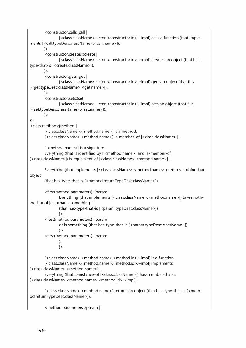
-96-
<constructor.calls:{call |
[<class.className>.~ctor.<constructor.id>.~impl] calls a function (that imple-
ments [<call.typeDesc.className>.<call.name>]).
}>
<constructor.creates:{create |
[<class.className>.~ctor.<constructor.id>.~impl] creates an object (that has-
type-that-is [<create.className>]).
}>
<constructor.gets:{get |
[<class.className>.~ctor.<constructor.id>.~impl] gets an object (that fills
[<get.typeDesc.className>.<get.name>]).
}>
<constructor.sets:{set |
[<class.className>.~ctor.<constructor.id>.~impl] sets an object (that fills
[<set.typeDesc.className>.<set.name>]).
}>
}>
<class.methods:{method |
[<class.className>.<method.name>] is a method.
[<class.className>.<method.name>] is-member-of [<class.className>] .
[.<method.name>] is a signature.
Everything (that is identified by [.<method.name>] and is-member-of
[<class.className>]) is-equivalent-of [<class.className>.<method.name>] .
Everything (that implements [<class.className>.<method.name>]) returns nothing-but
object
(that has-type-that-is [<method.returnTypeDesc.className>]).
<first(method.parameters) :{param |
Everything (that implements [<class.className>.<method.name>]) takes noth-
ing-but object (that is something
(that has-type-that-is [<param.typeDesc.className>])
}>
<rest(method.parameters) :{param |
or is something (that has-type-that-is [<param.typeDesc.className>])
}>
<first(method.parameters) :{param |
).
}>
[<class.className>.<method.name>.<method.id>.~impl] is a function.
[<class.className>.<method.name>.<method.id>.~impl] implements
[<class.className>.<method.name>] .
Everything (that is-instance-of [<class.className>]) has-member-that-is
[<class.className>.<method.name>.<method.id>.~impl] .
[<class.className>.<method.name>] returns an object (that has-type-that-is [<meth-
od.returnTypeDesc.className>]).
<method.parameters :{param |

-97-
[<class.className>.<method.name>.<method.id>.~impl] takes object (that has-
type-that-is [<param.typeDesc.className>]).
[<class.className>.<method.name>.<method.id>.~impl] gets an object (that
has-type-that-is [<param.typeDesc.className>]).
}>
<method.calls:{call |
[<class.className>.<method.name>.<method.id>.~impl] calls a function (that
implements [<call.typeDesc.className>.<call.name>]).
}>
<method.creates:{create |
[<class.className>.<method.name>.<method.id>.~impl] creates an object (that
has-type-that-is [<create.className>]).
}>
<method.gets:{get |
[<class.className>.<method.name>.<method.id>.~impl] gets an object (that fills
[<get.typeDesc.className>.<get.name>]).
}>
<method.sets:{set |
[<class.className>.<method.name>.<method.id>.~impl] sets an object (that fills
[<set.typeDesc.className>.<set.name>]).
}>
}>
<if(class.isAbstract)>
[<class.className>] has-instance-that-is none.
<endif>
<if(class.isFinal)>
[<class.className>] is-supertype-of none.
<endif>
>>
To understand in what way the StringTemplate processes the enumerable input
(here it is a class-descriptor), the reader is recommended to do a further reading
about it on the StringTemplate webpage45.
45 http://www.stringtemplate.org/

-98-
Appendix 3. OASE-TRANSFORMATION
FOR ADAPTER DESIGN PATTERN
In Figure 52 adapter design pattern is presented. It is realized by the net of class-
descriptors for: client, target, adapter and adaptee. Those class-descriptors are con-
nected with the generalization and calls (besides its name, each class, has a number
of methods that calls or can be called by other methods). All class-descriptors have
to be labeled with a unique patternID, as design patterns can interfere with each other
(the same class can potentially have multiple labels with different patternIDs).
<adapter>
<target> <adaptee><client>
In case of
class adapter
<<call>>
<<call>>
In case of
object adapter
+name+pattern-name+is-by-composition
requests
+name
+name+pattern-name
specific-requests
+name
+name+pattern-name
target-requests
+name
+name+pattern-name
operations
+name
Figure 52. Adapter design pattern as a wood of symbols

-99-
The class descriptors allow to represent adapter design pattern as a set of four
OASE-Transformations (one for each: adapter, target, client and adaptee). Each
script directly correspond to the given class descriptor (see Figure 53). Those
OASE-Transformations if combined with class-descriptors produce the ontology of
adapter design pattern.
group GOF_Adapter;
adapter(patternID,className,requests) ::= <<
[<className>] must be a class.
[<className>] must be-subtype-of a target-of-<patternID>.
One-and-only adapter-of-<patternID> is [<className>].
<requests:{methodName |
[<className>.<methodName>.~impl] must be a function.
[<className>.<methodName>.~impl] is an adapter-request-of-<patternID>.
}>
Every adapter-request-of-<patternID> should call a function (that implements an
adaptee-specific-request-of-<patternID>).
>>
target(patternID,className,targetRequests) ::= <<
[<className>] must be a class.
[<className>] must have-instance-that-is none.
One-and-only target-of-<patternID> is [<className>].
<targetRequests:{methodName |
[<className>.<methodName>] must be a method.
[<className>.<methodName>] is an target-request-of-<patternID>.
}>
>>
adaptee(patternID,className,specificRequests) ::= <<

-100-
[<className>] must be a class.
One-and-only adaptee-of-<patternID> is [<className>].
<specificRequests:{methodName |
[<className>.<methodName>] must be a method.
[<className>.<methodName>] is an adaptee-specific-request-of-<patternID>.
}>
>>
adapterClient(patternID,className,operations) ::= <<
[<className>] must be a class.
[<className>] is an adapter-client-of-<patternID>.
<operations:{methodName |
[<className>.<methodName>.~impl] must be a function.
[<className>.<methodName>.~impl] is an client-operation-of-<patternID>.
}>
Every client-operation-of-<patternID> should call a function (that implements a target-
request-of-<patternID>).
>>
Figure 53. OASE-Transformations for Adapter Design Pattern
There are four OASE-Transformations. Each corresponds to one class descriptor
and finally to one of the components of adapter design pattern. They are processed
by the OASE kernel in the matter that takes advantage of reflexion and semantic an-
notations (see Figure 54)
using System;
using System.Collections.Generic;
using System.Linq;
using System.Text;
using System.Diagnostics;
using Antlr3.ST;
using System.IO;
namespace OASE.GOF
{
[Ignore]
static class AdapterLoader
{
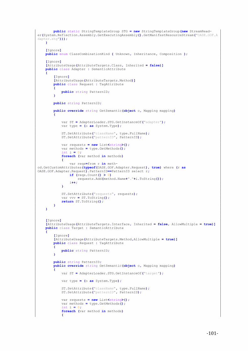
-101-
public static StringTemplateGroup STG = new StringTemplateGroup(new StreamRead-
er(System.Reflection.Assembly.GetExecutingAssembly().GetManifestResourceStream("OASE.GOF.A
dapter.stg")));
}
[Ignore]
public enum ClassCombinationKind { Unknown, Inheritance, Composition };
[Ignore]
[AttributeUsage(AttributeTargets.Class, Inherited = false)]
public class Adapter : SemanticAttribute
{
[Ignore]
[AttributeUsage(AttributeTargets.Method)]
public class Request : TagAttribute
{
public string PatternID;
}
public string PatternID;
public override string GetSemantic(object o, Mapping mapping)
{
var ST = AdapterLoader.STG.GetInstanceOf("adapter");
var type = (o as System.Type);
ST.SetAttribute("className", type.FullName);
ST.SetAttribute("patternID", PatternID);
var requests = new List<string>();
var methods = type.GetMethods();
int i = 0;
foreach (var method in methods)
{
var reqs=from r in meth-
od.GetCustomAttributes(typeof(OASE.GOF.Adapter.Request), true) where (r as
OASE.GOF.Adapter.Request).PatternID==PatternID select r;
if (reqs.Count() > 0)
requests.Add(method.Name+"."+i.ToString());
i++;
}
ST.SetAttribute("requests", requests);
var vvv = ST.ToString();
return ST.ToString();
}
}
[Ignore]
[AttributeUsage(AttributeTargets.Interface, Inherited = false, AllowMultiple = true)]
public class Target : SemanticAttribute
{
[Ignore]
[AttributeUsage(AttributeTargets.Method,AllowMultiple = true)]
public class Request : TagAttribute
{
public string PatternID;
}
public string PatternID;
public override string GetSemantic(object o, Mapping mapping)
{
var ST = AdapterLoader.STG.GetInstanceOf("target");
var type = (o as System.Type);
ST.SetAttribute("className", type.FullName);
ST.SetAttribute("patternID", PatternID);
var requests = new List<string>();
var methods = type.GetMethods();
int i = 0;
foreach (var method in methods)
{

-102-
var reqs = from r in meth-
od.GetCustomAttributes(typeof(OASE.GOF.Target.Request), true) where (r as
OASE.GOF.Target.Request).PatternID == PatternID select r;
if (reqs.Count() > 0)
requests.Add(method.Name);
i++;
}
ST.SetAttribute("targetRequests", requests);
return ST.ToString();
}
}
[Ignore]
[AttributeUsage(AttributeTargets.Class, Inherited = false, AllowMultiple = true)]
public class Adaptee : SemanticAttribute
{
[Ignore]
[AttributeUsage(AttributeTargets.Method, AllowMultiple = true)]
public class SpecificRequest : TagAttribute
{
public string PatternID;
}
public string PatternID;
public override string GetSemantic(object o, Mapping mapping)
{
var ST = AdapterLoader.STG.GetInstanceOf("adaptee");
var type = (o as System.Type);
ST.SetAttribute("className", type.FullName);
ST.SetAttribute("patternID", PatternID);
var requests = new List<string>();
var methods = type.GetMethods();
int i = 0;
foreach (var method in methods)
{
var reqs = from r in meth-
od.GetCustomAttributes(typeof(OASE.GOF.Adaptee.SpecificRequest), true) where (r as
OASE.GOF.Adaptee.SpecificRequest).PatternID == PatternID select r;
if (reqs.Count() > 0)
requests.Add(method.Name);
i++;
}
ST.SetAttribute("specificRequests", requests);
return ST.ToString();
}
}
[Ignore]
[AttributeUsage(AttributeTargets.Class, Inherited = false, AllowMultiple = true)]
public class AdapterClient : SemanticAttribute
{
[Ignore]
[AttributeUsage(AttributeTargets.Method,AllowMultiple = true)]
public class Operation : TagAttribute
{
public string PatternID;
}
public string PatternID;
public override string GetSemantic(object o, Mapping mapping)
{
var ST = AdapterLoader.STG.GetInstanceOf("adapterClient");
var type = (o as System.Type);
ST.SetAttribute("className", type.FullName);
ST.SetAttribute("patternID", PatternID);
var requests = new List<string>();
var methods = type.GetMethods();

-103-
int i = 0;
foreach (var method in methods)
{
var reqs = from r in meth-
od.GetCustomAttributes(typeof(OASE.GOF.AdapterClient.Operation), true) where (r as
OASE.GOF.AdapterClient.Operation).PatternID == PatternID select r;
if (reqs.Count() > 0)
requests.Add(method.Name + "." + i.ToString());
i++;
}
ST.SetAttribute("operations", requests);
return ST.ToString();
}
}
}
Figure 54. The source code for adapter
Usability issues of this approach were evaluated within the survey
(see Appendix 4).

-104-
Appendix 4. THE SURVEY The survey was prepared to acquire the necessary information about the OASE
method and to validate some crucial assumptions taken in OASE. It is divided into
Info&Test and four main parts (1,2,3,4) in two versions (A,B). Participants (subjects
of the survey) were given a combination of Info&Test and (1A or 1B), (2A or 2B),
(3A or 3B) and (4A or 4B). Versions (A or B) were randomly selected.
Info&Test was prepared in order to collect the basic properties of the subject.
This part included a brief description of OASE and a quick test of knowledge about
C# language to provide simple measurement of programming skills owned by the
subject.
Part 1 was prepared to examine the differentiation between “what is” and “what
has to be done” in terms of software development process. We have prepared two
versions. First version (1A) was to check what is a default meaning of modalities in
OASE-English in the context of UML diagram, the purpose of the second one (1B)
was to check the meaning of modalities in the context of C# source program.
The aim of the part 2 was to check the usefulness of OASE-Annotations in terms
of layered architecture (see chapter 4.17.1). To examine the usefulness we have cre-
ated two versions: 2A – without the output of OASE-Validator and 2B – with the
output. Both versions were equipped with the same OASE-Annotations in the at-
tached source code.
The aim of part 3 was to check the usefulness of OASE-Annotations as a design
pattern language. We selected adapter design pattern (see chapter 4.18.1). To exam-
ine the usefulness we created two versions: 3A – without the output of OASE-
Validator and 3B – with the output. Both versions were equipped with the same
OASE-Annotations in the attached source code.
The aim of part 4 was to check the usefulness of OASE-Annotations in terms of
design constraints put on Pipes&Fiters (see chapter 4.17.2). To examine the useful-
ness we have created two versions: 4A – without the output of OASE-Validator and
4B – with the output. Both versions were equipped with the same OASE-Annotations
in the attached source code. Reader can find the full text of the survey at the end of
this appendix (see pages 108-117).
EXECUTION OF THE SURVEY Below we present the collected output of the survey that was taken on the
group of students and professionals. They are ordered by the level of their skills –
first are presented answers of the less skilled ones.

-105-
Case 1 – The Junior C++ Programmer
The programmer responded for the call and described himself as a student that has
a basic knowledge about C++ without any knowledge about C#. The core program-
ming test proven that he was a novice in object-oriented programming as he has not
distinguished the subtyping from aggregation. His skills were too low for the rest of
the survey; however he was able to solve the task (see Appendix 4).
Case 2 - The Junior C# programmer
The programmer responded for the call and described himself as a student that has
good knowledge about C# programming language. Tests performed by him in Part 1
confirmed his skills. He was requested to solve the survey in the following case
(1B,2A,3B,4A). He answered only query no. 1B. His skills were too to fill in the rest of
the survey; however he was able to solve the task (see Appendix 4).
1B) Respondent selected all of the answers as “must”.
Case 3 - The Junior C# programmer with basic UML skills
The programmer responded for the call and described himself as a student with
basic knowledge about C# programming language. Tests performed by him in Part 1
confirmed his skills. He was requested to solve the survey in the following case
(1B,2B,3A,4A).
1B) Respondent selected almost all responses as “is” but just one as “must”. The one
selected was: [Purchase] must have-member-that-is an attribute (that is-
placeholder-for [Clothing]).”
2B) “Error is caused by the fact that GfxDriver class creates an object that is assigned
to other than the "Drivers" or "Cross-Cutting" layer.” This is a correct answer
3A) Respondent answered that: “The problem lies in the implementation of Drive
method of the Adapter (Class CDrivableCessna172), where the recursive call is at-
tempted to itself, which leads to stack overflow.” This is a correct answer.
4A) Respondent answered that: “In the first line of execute() method there is forced
connection between Pipe-B and Pipe-A and Pipe-D.I assume that this is correct due
to the fact that it is consistent with the axiom. Execute() method also attempts to
create a connection between Pipe-B and Pipe-D. This is a situation similar to the
previous one, but with the exception that the validator should exhibit an error here
because the "sink" is checked against SinkOfText class condition (assert) connection,
and the only possible, defined by a combination of the Pipe-B is a Pipe-A.” This an-
swer is very complex and shows that the participant had a problem with
understanding the particular situation.

-106-
Case 4 - The Senior C++ programmer
The programmer responded for the call and described himself as a professional C++
programmer that has basic knowledge about C# programming language. Tests per-
formed by him in Part 1 confirmed his skills. He was requested to solve the survey in
the following case (1A,2A,3B,4B).
1A) Respondent selected as a “must” all responses to questions about modalities in
the second round of software development regarding UML diagram. He thought that
the diagram that appears in the iterative way expresses an obligation for the pro-
grammer.
2A) Respondent answered that: “GfxDriver (Drivers-Level) should not contain/call
TextBoxController (Application level)”, therefore he made correct answer without
the support of OASE-Annotator explanations.
3B) Respondent answered that:”Drive method from Adapter class (CDrivableCesn-
na172) should call Fly() method from Adaptee class (CCesna172). Recurrent call for
Drive() method”. It is a correct answer.
4B) Respondent answered that: “Pipe-D is not connectable to Pipe-B”. It is a correct
answer.
Case 5 -The Senior C++ and C# programmer with UML skills
The programmer responded for the call and described himself as a professional in
C++ that has good knowledge about C# programming language. Tests performed by
him in Part 1 confirmed his skills. He was requested to solve the survey in the fol-
lowing case (1A,2A,3B,4B).
1A) Respondent selected all almost responses as “must” but one as “is”. The one se-
lected was: “[IPrice] is-superclass-of [Price4BuyTwoGetOneFree].” He argued that
when speaking about class hierarchies, you refer to things that are true by defini-
tions (even if this is a second cycle and the diagram specifies changes that need to be
made. In other words, even if he had selected “must” for all other responses the “is”
represents the semantics of class subtyping better.
2A) Respondent answered that: “GfxDriver class calls directly TextBoxController
object, which leads to flow control in both directions between layers (upper and
lower) instead of event-driven approach. And secondly, in this case, Driver-Layer
object (GfxDriver) communicates directly with Application-Layer object, bypassing
the Middleware-Layer”. It is a correct answer.
3B) Respondent answered that: “CDrivableCesna172 object is not going to flyany-
where, because its method Drive() calls itself (infinite recursion) instead of calling
CCesna172::fly() method.” It is a correct answer. Unfortunately, he had noticed it at
the very beginning, while reading the code, therefore he made correct answer with-
out the support of OASE-Annotator explanations.

-107-
4B) Subject answered that: “SinkOfText:sink()” asserts that its argument must be
connectable to Pipe-B. In the second line of Execute() method SourceOfText:source()
returns stream attributed as Pipe-D and there is no axiom stating that Pipe-D is con-
nectable to Pipe-B”. It is a correct answer.
INTERPRETATION OF RESULTS OF THE SURVEY In Part 1 we have found out that the differentiation between “what is” and “what
has to be done” in terms of software development process exists. The differentiation
exists in two areas: the stakeholders role within the software development process
(if he was a designer or the programmer), and on the phase of the development pro-
cess (if it was the initial or continuous phase of the development process). We
expected to find out which modal word is the best to be used in OASE-Annotations in
both UML-notes and source code comments. Participants that were in the designer
shoes were convinced that the diagrams are specifying what has to be done in the
future (the “must” answers), however participants that were in the programmer
shoes, were describing the situation either as it already “is” or it “must” be done. The
differentiations between those two points of view made us think that the modality
expressed in OASE-Annotations is ambiguous for the programmers, and can lead to
misuse of “must” and “is” keyword. This shows that there is a need to introduce the
programmers with the semantics of pseudo-modal expressions before they start
their work with OASE.
Parts 2 and 3 were solved correctly regardless whether they were equipped with
hints from OASE-Validator or not, but the Part 4 has proved that with the aid of
OASE-Validator explanations it is easier to find out what really is the source of the
problem . One of the programmers was unable to understand what is happening in
the Pipes&Filers design, while the others, who were able to take a use of the
OASE-Validator explanations, were able to understand it clearly.

-108-
FULL TEXT OF THE SURVEY
I) The modalities Version A
Imagine that you are involved with the group of designers in the development
process of some program. The first iteration of software development process re-
sulted in the following design diagram that was implemented as a prototype of
working system:
After the first iteration the group of designers decided that there is a need for
refactoring of the produced code. They proposed that the design of the program is
now:
Keeping in mind that you are now in the second iteration of the software devel-
opement process, what statements suit best the new design model in terms of work
that is going to be done by the programmers?
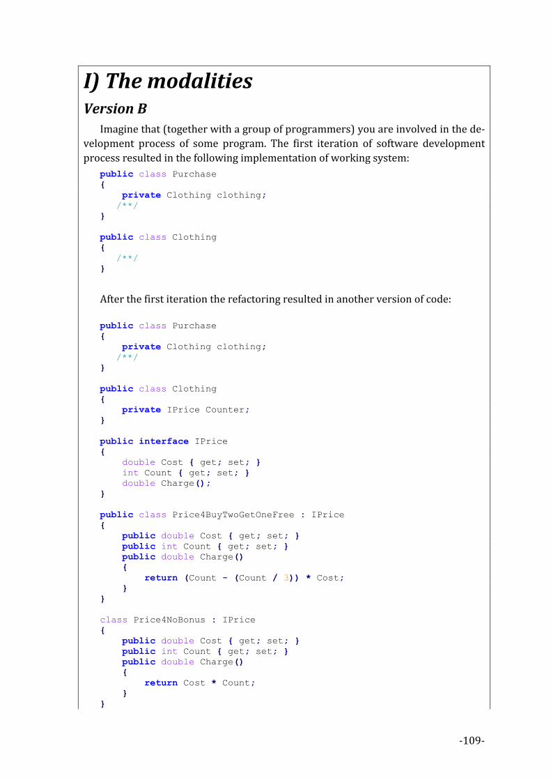
-109-
I) The modalities Version B
Imagine that (together with a group of programmers) you are involved in the de-
velopment process of some program. The first iteration of software development
process resulted in the following implementation of working system:
public class Purchase
{
private Clothing clothing;
/**/
}
public class Clothing
{
/**/
}
After the first iteration the refactoring resulted in another version of code:
public class Purchase
{
private Clothing clothing;
/**/
}
public class Clothing
{
private IPrice Counter;
}
public interface IPrice
{
double Cost { get; set; }
int Count { get; set; }
double Charge();
}
public class Price4BuyTwoGetOneFree : IPrice
{
public double Cost { get; set; }
public int Count { get; set; }
public double Charge()
{
return (Count - (Count / 3)) * Cost;
}
}
class Price4NoBonus : IPrice
{
public double Cost { get; set; }
public int Count { get; set; }
public double Charge()
{
return Cost * Count;
}
}
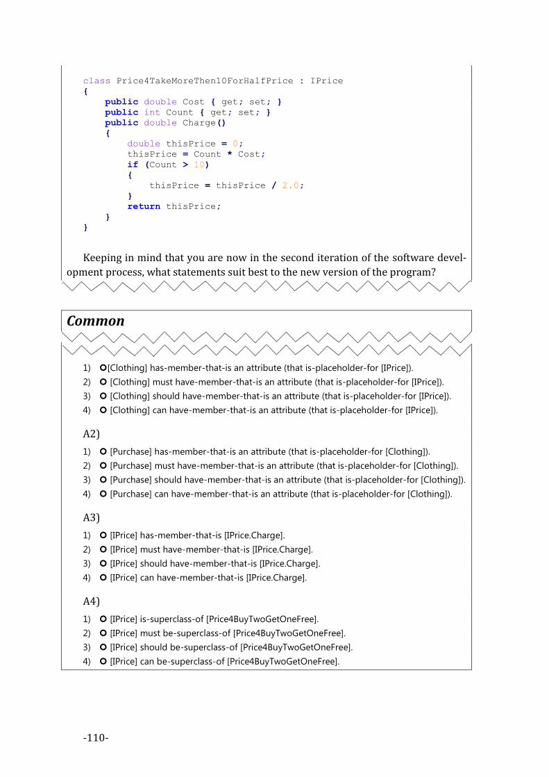
-110-
class Price4TakeMoreThen10ForHalfPrice : IPrice
{
public double Cost { get; set; }
public int Count { get; set; }
public double Charge()
{
double thisPrice = 0;
thisPrice = Count * Cost;
if (Count > 10)
{
thisPrice = thisPrice / 2.0;
}
return thisPrice;
}
}
Keeping in mind that you are now in the second iteration of the software devel-
opment process, what statements suit best to the new version of the program?
Common
A1)
1) [Clothing] has-member-that-is an attribute (that is-placeholder-for [IPrice]).
2) [Clothing] must have-member-that-is an attribute (that is-placeholder-for [IPrice]).
3) [Clothing] should have-member-that-is an attribute (that is-placeholder-for [IPrice]).
4) [Clothing] can have-member-that-is an attribute (that is-placeholder-for [IPrice]).
A2)
1) [Purchase] has-member-that-is an attribute (that is-placeholder-for [Clothing]).
2) [Purchase] must have-member-that-is an attribute (that is-placeholder-for [Clothing]).
3) [Purchase] should have-member-that-is an attribute (that is-placeholder-for [Clothing]).
4) [Purchase] can have-member-that-is an attribute (that is-placeholder-for [Clothing]).
A3)
1) [IPrice] has-member-that-is [IPrice.Charge].
2) [IPrice] must have-member-that-is [IPrice.Charge].
3) [IPrice] should have-member-that-is [IPrice.Charge].
4) [IPrice] can have-member-that-is [IPrice.Charge].
A4)
1) [IPrice] is-superclass-of [Price4BuyTwoGetOneFree].
2) [IPrice] must be-superclass-of [Price4BuyTwoGetOneFree].
3) [IPrice] should be-superclass-of [Price4BuyTwoGetOneFree].
4) [IPrice] can be-superclass-of [Price4BuyTwoGetOneFree].

-111-
II) Layered Architecture Common
The layer separation paradigm manages usage of relationships between software
entities. It uses the architectural layer concept as a mark for each software entity
and requires the ordered usage of labeled entities. The most common layered archi-
tecture is 3+1 architecture (3-vertical layers + 1 cross cutting layer).
Upper-Layer (presentation)
Middle-Layer (bussiness)
Lower-Layer (data-access) Cro
ss-C
utt
ing-
Laye
r (s
yste
m)
Layered Architecture
To take advantage of Layered Architecture, the designer (or system architect)
needs to give a mark to every software entity with exactly one Id of Layer.
You are given the following source code marked with OASE annotations: [module: OASE.Architecture.LayerOrdering(
UpperLayerID = "Application-Layer",
MiddleLayerID = "Middleware-Layer",
LowerLayerID = "Drivers-Layer",
CrossCuttingLayerID = "System-Layer"
)]
[OASE.Architecture.Layer(LayerID = "Application-Layer")]
public class TextBoxController
{
EditorModel model = new EditorModel();
Utilities utils = new Utilities();
TextBoxView view = new TextBoxView();
public void a(){
model.m();
utils.s();
view.x();
}
}
[OASE.Architecture.Layer(LayerID = "Applicationlayer")]
public class TextBoxView
{
EditorModel model = new EditorModel();
TextBoxController ctrl = new TextBoxController();
public void x()
{
model.m();
ctrl.a();
/*...*/
}
}
[OASE.Architecture.Layer(LayerID = "Middleware-Layer")]
public class EditorModel
{
GfxDriver gfx = new GfxDriver();
Utilities utils = new Utilities();
public void m()
{
gfx.d();
utils.s();
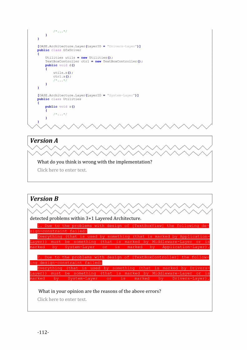
-112-
/*...*/
}
}
[OASE.Architecture.Layer(LayerID = "Drivers-Layer")]
public class GfxDriver
{
Utilities utils = new Utilities();
TextBoxController ctrl = new TextBoxController();
public void d()
{
utils.s();
ctrl.a();
/*...*/
}
}
[OASE.Architecture.Layer(LayerID = "System-Layer")]
public class Utilities
{
public void s()
{
/*...*/
}
}
Version A
What do you think is wrong with the implementation?
Click here to enter text.
Version B
OASE-Reasoner produced the following description of errors that describe the
detected problems within 3+1 Layered Architecture.
1. Due to the problems with design of [TextBoxView] the following de-
sign-constraint failed:
Everything (that is used by something (that is marked by Application-
Layer)) must be something (that is marked by Middleware-Layer or is
marked by System-Layer or is marked by Application-Layer).
2. Due to the problems with design of [TextBoxController] the follow-
ing design-constraint failed:
Everything (that is used by something (that is marked by Drivers-
Layer)) must be something (that is marked by Middleware-Layer or is
marked by System-Layer or is marked by Drivers-Layer).
What in your opinion are the reasons of the above errors?
Click here to enter text.

-113-
III) Adapter Common
One of the most common design patterns is Adapter. Adapter design pattern trans-
lates one interface for a class into a compatible interface. Adapter allows classes that
normally could not cope together (because of incompatible interfaces), to work to-
gether by providing special interface (Target) to the client. Adapter translates calls
to the new interface into calls to the original interface. Depending on the designer
decision on Adoptee class it can be implemented via aggregation or inheritance: we
call it a class-adapter (when the adapter class inherits from the adaptee class) or
object-adapters (when the adapter class contains the adaptee class)
+Request()
Target
+SpecificRequest()
Adaptee
+Request()
Adapter
Client
In case of
class adapter
<<call>>
<<call>>
In case of
object adapter
Adapter design pattern involves four classes and therefore all of them have to be
labeled with a unique patternID. Design patterns can interfere with each other so the
same class can potentially have many labels with different patternIDs.
In this query we are dealing with the following vehicles:
Cesna 172 Subaru Impreza
You are given the following source code marked with OASE annotations: using System;
[OASE.GOF.Target(PatternID = "A1")]
public interface IDrivable
{
[OASE.GOF.Target.Request(PatternID = "A1")]
void Drive();
}
public class CSubaruImpreza : IDrivable
{

-114-
public void Drive()
{
Console.WriteLine("Vroom Vroom, we're off in our Subaru Imreza...");
}
}
[OASE.GOF.Adaptee(PatternID = "A1")]
public class CCessna172
{
[OASE.GOF.Adaptee.SpecificRequest(PatternID = "A1")]
public void Fly()
{
Console.WriteLine("Static runup OK, we're off in our Cesna 172...");
}
}
[OASE.GOF.Adapter(PatternID = "A1")]
public class CDrivableCessna172 : CCessna172, IDrivable
{
[OASE.GOF.Adapter.Request(PatternID = "A1")]
public void Drive()
{
Drive();
}
}
[OASE.GOF.AdapterClient(PatternID = "A1")]
public class CDriver
{
[OASE.GOF.AdapterClient.Operation(PatternID = "A1")]
public void Drive(IDrivable thing)
{
thing.Drive();
}
}
class Program
{
static void Main(string[] args)
{
var car_driver = new CDriver();
car_driver.Drive(new CDrivableCessna172());
car_driver.Drive(new CSubaruImpreza());
}
}
Version A
What do you think is wrong with the implementation?
Click here to enter text.
Version B
And the following warning is produced by the OASE processor that describes the
detected problem within Adapter-Pattern implementation.

-115-
1. Due to the problems with design of [CDrivableCessna172.Drive] the
following design-constraint failed:
Everything (that is an adapter-request and is labeled by A1) should
call a function (that implements an adaptee-specific-request (that is
labeled by A1)).
What are the reasons of the above warning?
Click here to enter text.

-116-
IV) Pipes & Filters Common
The Pipes & Filters is a well-known Design Pattern, that is used to divide the task
of a system into several sequential processing steps. Each processing step is imple-
mented by a filter component that consumes and delivers data incrementally. The
filters are connected sequentially by pipes. Filters are usually implemented as sepa-
rate objects that use one common interface of a generic pipe and therefore filters
can be freely configured, however it is highly desirable to prevent such a free-style
by incorporating some design constraints. The solution requires some kind of speci-
fication language to be incorporated, which would allow the designer to specify
exactly which pairs of filters are compatible with each other. OASE-English as a Se-
mantic Annotation language allows the programmer to build a Pipe and Filters
design pattern validator, with formal semantic background. The validator is execut-
ed in runtime when the new connection between pipes is detected.
You are given the following source code marked with OASE annotations: using System;
using System.Collections.Generic;
using System.Linq;
using System.Text;
using OASE.Architecture;
[module: OASE.Axiom("Pipe-A is-connectable-to Pipe-B.")]
public class IdentityFilter
{
[OASE.Architecture.PipeConnector("Pipe-A")]
public IEnumerable<string> filter(IEnumerable<string> arg)
{
foreach (var a in arg)
{
yield return a + "f";
}
}
}
public class Multiplexer
{
[OASE.Architecture.PipeConnector("Pipe-B")]
public IEnumerable<string> filter(IEnumerable<string> arg1, IEnumerable<string>
arg2)
{
OASE.Debugging.Assert(arg1.GetPipeID() + " must be-connectable-to Pipe-A.");
OASE.Debugging.Assert(arg2.GetPipeID() + " must be-connectable-to Pipe-A.");
foreach (var a1 in arg1)
{
yield return a1 + "f";
}
}
}
public class SourceOfText
{
[OASE.Architecture.PipeConnector("Pipe-D")]
public IEnumerable<string> source()
{
for (int i = 0; i < 10; i++)
{
yield return "aaaa";
}
}
}

-117-
public static class PFApplication
{
static IdentityFilter identityFilter = new IdentityFilter();
static SourceOfText sourceOfText = new SourceOfText();
static SinkOfText sinkOfText = new SinkOfText();
public static void Execute()
{
sinkOfText.sink(identityFilter.filter(sourceOfText.source()));
sinkOfText.sink(sourceOfText.source());
}
}
Version A
public class SinkOfText
{
public void sink(IEnumerable<string> arg)
{
OASE.Debugging.Assert(arg.GetPipeID() + " must be-connectable-to Pipe-B."); foreach (var a in arg)
{
Console.WriteLine(a);
}
}
}
What is wrong here?
Click here to enter text.
Version B
public class SinkOfText
{
public void sink(IEnumerable<string> arg)
{
OASE.Debugging.Assert(arg.GetPipeID() + " must be-connectable-to Pipe-
B."); foreach (var a in arg)
{
Console.WriteLine(a);
}
}
}
OASE-Assert (marked on red) was broken and raised an runtime exception.
Why? What is wrong here?
Click here to enter text.

-118-
Appendix 5. 9VALIDATION
EXPERIMENT
REFACTORING TASK WITH OASE-ANNOTATIONS The aim of this case study was to check the usability of OASE as an effective tool
that allows for effective interactions between designer and programmer (in terms of
the required refactoring that needs to be made on existing source code). The task
was inspired by the example taken from Martin Fowler book [Fowl99], transformed
from Java into C# with some modifications made by applying OASE-Annotations.
Figure 55. Validation experiment source code loaded into Visual Studio
The program to be refactored implements the functionality of the internet shop.
Source code of the shop consists of few files and classes, like: 1) The class Clothing
models clothing, 2) The class Purchase models a single purchase of clothing, 3) The
class Customer models customer-services and other constructs.
The subject of the test is asked to refactor the “Customer.Statement” method
which in the original form uses the "switch" expression over "PriceCode". The sub-

-119-
ject should eliminate the “PriceCode” in the way that “Customer.Statement” method
uses the hierarchy of Prices instead. Each class derived from Price class should final-
ly realize specific case from the refactored "switch" expression.
The original program included OASE-Annotations that formed Integrity Con-
straints that had to be preserved. In addition, it included the Unitary Tests to
provide the way of checking the functionality during the refactoring job (see the
source code below).
While the programmer works with a debugger, OASE-Annotations are continu-
ously checked by the OASE-Validator each time she runs the program. This is a kind
of dialogue between programmer and program via OASE-Validator. OASE-Validator
explains what (and why) is (still) wrong in the program (w.r.t. Integrity Constraints
specified within OASE-Annotations). Without the support of OASE-Validator, OASE-
Annotations would be only a way for an unambiguous code-documentation.
The respondent was provided with a source code that she was requested to load
into the Visual Studio programming environment (see Figure 55).
Reader can find the full text of the task as well as the source code of the task at
the end of this appendix (see pages 123-132).
EXECUTION OF THE EXPERIMENT The target population of the programmers was selected basing on the prepared
survey (see Appendix 4). The following presents the brief description of each pro-
grammer-case.
Case 1 – The Junior C++ Programmer
The programmer responded for the call and described himself as a student that has
a basic knowledge about C++ without any knowledge about C# (he admitted that he
did not know anything about the memory management in terms of differences be-
tween C++ and C# in the field). The core programming test proved that he was a
novice in the object-oriented programming. He did not distinguished the subtyping
from aggregation. However, he was able to solve the task in unlimited time (it took
around 8h) without any additional help. He executed the validator more than 10
times. The solution was fully-acceptable. In addition, he (by himself) learned about
object-oriented methodology and made the following conclusion:
1) The removal of the BonusCodes class, together with the OASE-Annotation was
for him ridiculous because he felt that he cannot do such operation, as he was re-
quested to do only the refactoring. He assumed that the OASE-Annotation is a
part of final design and any modification in the field is prohibited.
2) As interface and class are different keywords in C#, it was hard to understand for
him that within the OASE both of them are represented in the same manner,
however he was able to finish the task.

-120-
3) When asked, if the OASE-Annotations and if they were helpful to finish the task,
he responded that the task was to remove the errors produced by OASE-
Validator. It makes us wondering if he was thinking about the task in terms of
solving a puzzle-like problem.
Case 2 - The Junior C# programmer
The programmer responded for the call and described himself as a student that has
a good knowledge about C# programming language. He was able to resolve the task
in 1 hour without any additional help. He executed the OASE-Validator 7 times. The
solution was fully-acceptable. In addition, he made the following conclusion:
1) He found out that the usage of namespaces generates a problem as long as the
specification is in a form of: “It must be-supertype-of [Price4NoBonus].” He
needed some time to realize that the implementation of Price4NoBonus class
must be placed in the default namespace. This is considered as a bug in the
OASE-Toolkit and is resolved in the new version.
2) He said that he has solved it only by reading the OASE-Annotation and without
the need for any other support - in this case he was also (like the Case 1 pro-
grammer) thinking about the task in terms of a puzzle-like problem.
Case 3 - The Junior C# programmer with basic UML skills
The programmer responded for the call and described himself as a student with a
basic knowledge about C# programming language. He was able to resolve the task in
2 hours. The solution was fully-acceptable. He executed OASE-Validator 5 times. In
addition, he made the following conclusion:
1) From the programmer's standpoint, OASE is certainly a great help. If the annota-
tions are written in 100% correctly, the programmer will neither have to search
over the code in order to find out what to do next, nor debug the entire program
step by step. He is told what structures require additional source code editing.
2) From the designer’s/architect’s point of view OASE-Annotations will allow to
communicate the required work clearly. The programmer also has (due to the
OASE-Validator support) a guarantee that the programmer’s job will be well
done, as the OASE-Validator ensures it.
3) The potential disadvantage of OASE is the responsibility of the software designer
to formulate the OASE-Annotation correctly, if not, then the result of the OASE
aided process will be ineffective as well.
Case 4 - The Senior C++ programmer
The programmer responded for the call and described himself as a professional C++
programmer that has a basic knowledge about C# programming language. He was
able to resolve the task in less than 1 hour without any additional help. The solution

-121-
was fully-acceptable. He executed OASE-Validator 4 times. In addition, he made the
following conclusion:
1) Once he understood how the OASE-Validator works, he rapidly resolved the task
by the continuous checking of what to do after each build. He said that: “It felt
like the OASE-Validator leaded me by the hand. I did not even needed to plunge
into what and how this program was supposed to do. Nevertheless I made it.”
2) He was glad to see the idea of OASE. As he has knowledge about software design,
he said that OASE is a revolutionary method, that allows to force the design to
the programmer.
Case 5 - The Senior C++ and C# programmer with UML skills
The programmer responded for the call and described himself as a professional C++
that has good knowledge about C# programming language. He was able to resolve
the task in 30 minutes. He executed OASE-Validator 2 times. He found out that the
survey (see Appendix 4) contained the design diagram of the task, however he was
not looking at it. The solution was fully acceptable. In addition he made the follow-
ing conclusion:
1) Once he understood how OASE-Validator works he rapidly resolved the task.
Only one iteration of OASE-Validator was needed to support him. The one itera-
tion was about the annotation [BonusCode] must be-removed-from The-Design-
Of-The-Program“ – so simply he forgot to remove the class within the refactoring
task. It made us think that the selected task was too easy for the senior pro-
grammers with UML skills.
2) He said that OASE-Annotations were understandable enough to resolve the task
even without the need for additional support of OASE-Validator.
3) He said that OASE looks very promising and that he would like to use it if had
been in commercial phase.
INTERPRETATION OF RESULTS OF THE EXPERIMENT Experiment was performed on the group of programmers that were novices in
the OASE. There was no future communication regarding the task. All participants
were able to solve the given task. This proves that OASE-Annotations composed with
OASE-Validator (in terms of the required refactoring that needs to be made on exist-
ing source code) were at least as valuable as personal interactions between the task
inventor and the programmer would be.
Analysis of the experiment results (see Figure 56) uncovers the interesting po-
tential in the correlation between the programmer skills and the usefulness of OASE
in this particular scenarios (here – we deal with a refactoring task). The higher skills
the programmer has, the shorter time and lower amount of needed OASE-Validator
runs are required. Moreover, if our conclusion is correct, we can provide another
useful application of OASE-Validator that is the programming-skills validation in
terms of knowledge about the high-level design structure implementation. Once we

-122-
have executed the experiment on the candidate that tries to get a job, the recruiter
can verify her skills, taking into consideration that there exists a correlation be-
tween the time of the experiment execution, number of OASE-Validator runs and his
programming skills.
OASE limits the need for direct-communication. Validation experiment allows us
to argue that OASE can be helpful in cost prone development environments due to
the necessity of personal communication (e.g. distributed development environ-
ments, large teams, etc.).
Figure 56. Analysis of the experiment results.
0
1
2
3
4
5
6
7
8
9
10
1 2 3 4 5
Task completion time(hours)
Number of OASE-Validator runs
Order of the skills
1-worst, 5 best

-123-
FULL TEXT OF THE TASK AND ITS SOURCE CODE
Task Please try to run the program by clicking Run Button on the toolbar (see below) (or simply hit [F5]
key).
To preserve the functionality the unitary tests (UT) are checked first. If some UT is broken you will be
informed in the following manner:
If such a situation occurs then it mean that the functionality is not preserved.
After UT, the program will load its design into OASE-Validator.
After loading the design is checked agains the broken design constrains.
And finally all design errors that still exists in the source code are presented to the programmer:
Take a look at the errors; do you understand what they mean?

-124-
Next, after pressing any key the program starts to execute its "Main" function:
This demo program realizes shopping system. Right now it is fully functional and consist of few files
and classes like: 1) The class Clothing models clothing, 2) The class Purchase models a single pur-
chase of clothing, 3) The class Customer models a customer-services and other constructs. Please
take a while to understand how it works.
Please take a look at the OASE OASE-Annotations e.g.:
Do you understand what OASE-Annotations are all about? They are to protect the design and are
checked by OASE-Validator. When you modify the source code you can run it and the OASE-Validator
check the Semantic Annotations against the design.
The Task:

-125-
You are requested to refactor the Customer.Statement method. Right now it is computing the state-
ment using "switch" expresion over "PriceCode". You should provide the way to eliminate the need
for PriceCode (PriceCode should be removed from the final version). The Customer.Statement meth-
od should instead use the hierarchy of Prices placed in Price.cs file. Each price in the file should
realize specific case from the refactored "switch" expression. You should start from designing the
overall Price hierarchy in Price.cs file. Next you should move the functionality from Custom-
er.Statement "switch" expression into the newly created hierarchy. Please remember that the
Customer.Statement should use directly Purchase class, which should use Clothing.Price member to
obtain the correct Price object.
At the end there should be no error in the design (you should eliminate all 10 design errors that ap-
pear when you run the program) while UT should be preserved.
Good luck!

-126-
Source code
File: Customer.cs
using System;
using System.Collections.Generic;
/// <summary>
/// Customer represents a customer of the store.
/// </summary>
public class Customer
{
private string name;
private List<Purchase> purchases = new List<Purchase>();
/* Constructor */
public Customer(string name)
{
this.name = name;
}
/* Properties */
public string Name
{
get { return name; }
}
/* Methods */
public void Buy(Purchase arg)
{
purchases.Add(arg);
}
[OASE._("It must use a method (that is-member-of [Purchase] and uses
[IPrice.Charge]).")]
public string Statement()
{
double totalPrice = 0;
string result = "Purchase record for " + name + "\n";
foreach (var purchase in purchases)
{
double thisPrice = 0;
// Determine amounts for each line
switch (purchase.Clothing.PriceCode)
{
case BonusCodes.NoBonus:
thisPrice += purchase.Quantity * purchase.Clothing.BasePrice;
break;
case BonusCodes.BuyTwoGetOneFree:
thisPrice += (purchase.Quantity - (purchase.Quantity / 3)) * pur-
chase.Clothing.BasePrice;
break;
case BonusCodes.TakeMoreThen10ForHalfPrice:
thisPrice = purchase.Quantity * purchase.Clothing.BasePrice;
if (purchase.Quantity > 10)
{
thisPrice = thisPrice / 2.0;
}
break;
}
// Show figures for this purchase
result += "\t" + purchase.Clothing.Name + "\t" + thisPrice.ToString() + "\n";

-127-
totalPrice += thisPrice;
}
// Add footer lines
result += "Amount owed is " + totalPrice.ToString() + "\n";
return result;
}
}
File: Clothing.cs using System;
/// <summary>
/// Price codes (bonuses)
/// </summary>
[OASE._("It must be-removed-from The-Design-Of-The-Program.")]
public enum BonusCodes
{
NoBonus, //normal price
BuyTwoGetOneFree, //buy two and get one free
TakeMoreThen10ForHalfPrice // buy big boxex (more than 10 for 1/2 price)
}
/// <summary>
/// Clothing is just a simple data class.
/// </summary>
[OASE._("It must have-member-that-is an attribute (that is-placeholder-for [IPrice]).")]
public class Clothing
{
/* Fields */
// Data members
private string name;
private BonusCodes priceCode;
private double basePrice;
/* Constructor */
[OASE._("It can-not use [BonusCodes].")]
[OASE._("It must use [IPrice].")]
public Clothing(string name, BonusCodes priceCode, double basePrice)
{
this.name = name;
this.priceCode = priceCode;
this.basePrice = basePrice;
}
/* Properties */
public BonusCodes PriceCode
{
get { return priceCode; }
set { priceCode = value; }
}
public string Name
{
get { return name; }
}
public double BasePrice
{
get { return basePrice; }
}
}

-128-
File: Purchase.CS using System;
/// <summary>
/// Purchase represents a customer buying clothing.
/// </summary>
[OASE._("It must have-member-that-is a method that uses [IPrice.Charge].")]
public class Purchase
{
/* Fields */
// Data members
private Clothing clothing;
private int quantity;
/* Constructor */
public Purchase(Clothing clothing, int quantity)
{
this.clothing = clothing;
this.quantity = quantity;
}
/* Properties */
public int Quantity
{
get { return quantity; }
}
public Clothing Clothing
{
get { return clothing; }
}
}
File: Price.CS using System;
using System.Collections.Generic;
using System.Linq;
using System.Text;
[OASE._("It must have-member-that-is [IPrice.Charge]. ")]
[OASE._("It must be-superclass-of [Price4NoBonus]. ")]
[OASE._("It must be-superclass-of [Price4BuyTwoGetOneFree]. ")]
[OASE._("It must be-superclass-of [Price4TakeMoreThen10ForHalfPrice]. ")]
public interface IPrice
{
}
File: UnitTest.CS using System;
using System.Diagnostics;
[OASE.Ignore]
public class UnitTests : IDisposable
{
public void Dispose()
{
}
/* Fields */
// Clothings
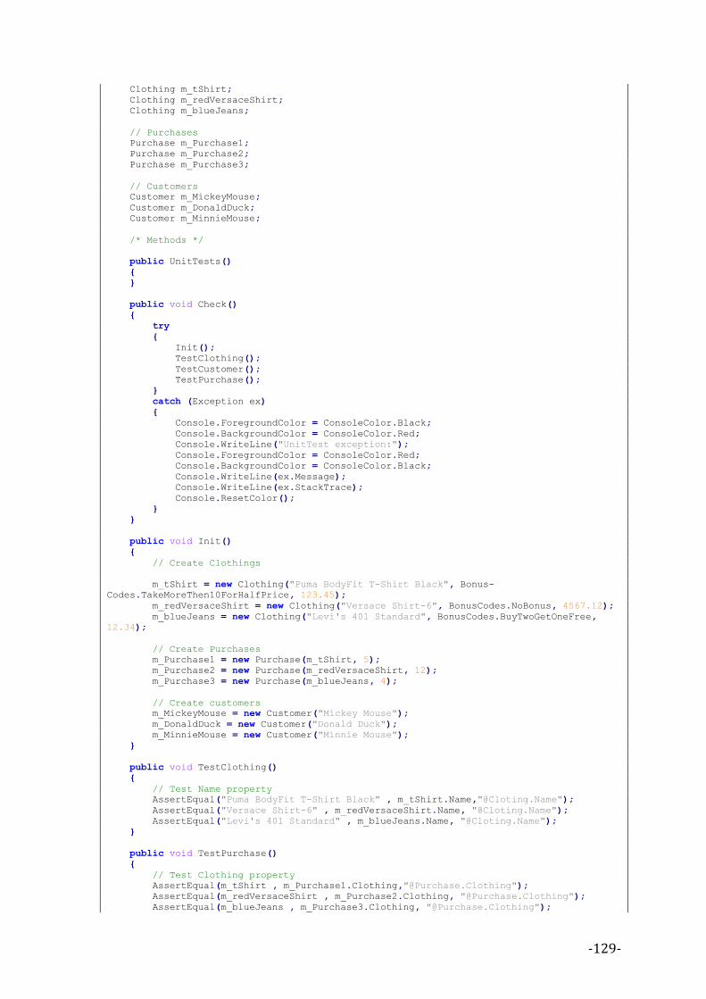
-129-
Clothing m_tShirt;
Clothing m_redVersaceShirt;
Clothing m_blueJeans;
// Purchases
Purchase m_Purchase1;
Purchase m_Purchase2;
Purchase m_Purchase3;
// Customers
Customer m_MickeyMouse;
Customer m_DonaldDuck;
Customer m_MinnieMouse;
/* Methods */
public UnitTests()
{
}
public void Check()
{
try
{
Init();
TestClothing();
TestCustomer();
TestPurchase();
}
catch (Exception ex)
{
Console.ForegroundColor = ConsoleColor.Black;
Console.BackgroundColor = ConsoleColor.Red;
Console.WriteLine("UnitTest exception:");
Console.ForegroundColor = ConsoleColor.Red;
Console.BackgroundColor = ConsoleColor.Black;
Console.WriteLine(ex.Message);
Console.WriteLine(ex.StackTrace);
Console.ResetColor();
}
}
public void Init()
{
// Create Clothings
m_tShirt = new Clothing("Puma BodyFit T-Shirt Black", Bonus-
Codes.TakeMoreThen10ForHalfPrice, 123.45);
m_redVersaceShirt = new Clothing("Versace Shirt-6", BonusCodes.NoBonus, 4567.12);
m_blueJeans = new Clothing("Levi's 401 Standard", BonusCodes.BuyTwoGetOneFree,
12.34);
// Create Purchases
m_Purchase1 = new Purchase(m_tShirt, 5);
m_Purchase2 = new Purchase(m_redVersaceShirt, 12);
m_Purchase3 = new Purchase(m_blueJeans, 4);
// Create customers
m_MickeyMouse = new Customer("Mickey Mouse");
m_DonaldDuck = new Customer("Donald Duck");
m_MinnieMouse = new Customer("Minnie Mouse");
}
public void TestClothing()
{
// Test Name property
AssertEqual("Puma BodyFit T-Shirt Black" , m_tShirt.Name,"@Cloting.Name");
AssertEqual("Versace Shirt-6" , m_redVersaceShirt.Name, "@Cloting.Name");
AssertEqual("Levi's 401 Standard" , m_blueJeans.Name, "@Cloting.Name");
}
public void TestPurchase()
{
// Test Clothing property
AssertEqual(m_tShirt , m_Purchase1.Clothing,"@Purchase.Clothing");
AssertEqual(m_redVersaceShirt , m_Purchase2.Clothing, "@Purchase.Clothing");
AssertEqual(m_blueJeans , m_Purchase3.Clothing, "@Purchase.Clothing");

-130-
// Test Quantity property
AssertEqual(5 , m_Purchase1.Quantity, "@Purchase.Quantity");
AssertEqual(12 , m_Purchase2.Quantity, "@Purchase.Quantity");
AssertEqual(4 , m_Purchase3.Quantity, "@Purchase.Quantity");
}
public void TestCustomer()
{
// Test Name property
AssertEqual("Mickey Mouse" , m_MickeyMouse.Name, "@Customer.Name");
AssertEqual("Donald Duck" , m_DonaldDuck.Name, "@Customer.Name");
AssertEqual("Minnie Mouse" , m_MinnieMouse.Name, "@Customer.Name");
// Test Buy() method - set up for test
m_MickeyMouse.Buy(m_Purchase1);
m_MickeyMouse.Buy(m_Purchase2);
m_MickeyMouse.Buy(m_Purchase3);
// Test the Statement() method
string theResult = m_MickeyMouse.Statement();
// Parse the result
char[] delimiters = "\n\t".ToCharArray();
string[] results = theResult.Split(delimiters);
AssertEqual("Puma BodyFit T-Shirt Black", results[2], "@Customer.Statement when
counting Name");
AssertEqual(617.25 , Convert.ToDouble(results[3]), "@Customer.Statement when
counting price");
AssertEqual("Versace Shirt-6", results[5], "@Customer.Statement when counting
Name");
AssertEqual(54805.44, Convert.ToDouble(results[6]), "@Customer.Statement when
counting price");
AssertEqual("Levi's 401 Standard", results[8], "@Customer.Statement when counting
Name");
AssertEqual(37.02 , Convert.ToDouble(results[9]), "@Customer.Statement when count-
ing price");
AssertEqual(results[10], "Amount owed is " + (55459.71D).ToString(),
"@Customer.Statement when counting amount owed");
}
[OASE.Ignore]
class AssertionExeption : Exception
{
public AssertionExeption(string msg, string a, string b)
: base("Assertion Failed (" + a + "!=" + b + ") at " + msg) { }
}
void AssertEqual<X>(X a, X b,string msg)
{
if (!(a.Equals(b)))
{
throw new AssertionExeption(msg,a.ToString(),b.ToString());
}
}
}
File: MainClass.CS using System;
/// <summary>
/// Summary description for MainClass.
/// </summary>
class MainClass
{
/// <summary>
/// The main entry point for the application.
/// </summary>
[STAThread]
static void Main(string[] args)
{
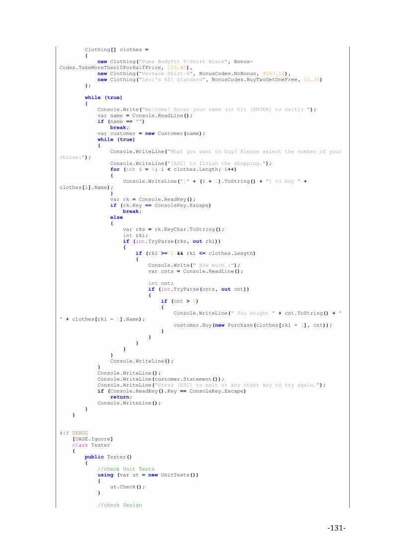
-131-
Clothing[] clothes =
{
new Clothing("Puma BodyFit T-Shirt Black", Bonus-
Codes.TakeMoreThen10ForHalfPrice, 123.45),
new Clothing("Versace Shirt-6", BonusCodes.NoBonus, 4567.12),
new Clothing("Levi's 401 Standard", BonusCodes.BuyTwoGetOneFree, 12.34)
};
while (true)
{
Console.Write("Welcome! Enter your name (or hit [ENTER] to exit): ");
var name = Console.ReadLine();
if (name == "")
break;
var customer = new Customer(name);
while (true)
{
Console.WriteLine("What you want to buy? Please select the number of your
choise:");
Console.WriteLine("[ESC] to finish the shopping.");
for (int i = 0; i < clothes.Length; i++)
{
Console.WriteLine("[" + (i + 1).ToString() + "] to buy " +
clothes[i].Name);
}
var rk = Console.ReadKey();
if (rk.Key == ConsoleKey.Escape)
break;
else
{
var rks = rk.KeyChar.ToString();
int rki;
if (int.TryParse(rks, out rki))
{
if (rki >= 1 && rki <= clothes.Length)
{
Console.Write(" How much :");
var cnts = Console.ReadLine();
int cnt;
if (int.TryParse(cnts, out cnt))
{
if (cnt > 0)
{
Console.WriteLine(" You bought " + cnt.ToString() + "
" + clothes[rki - 1].Name);
customer.Buy(new Purchase(clothes[rki - 1], cnt));
}
}
}
}
}
Console.WriteLine();
}
Console.WriteLine();
Console.WriteLine(customer.Statement());
Console.WriteLine("Press [ESC] to exit or any other key to try again.");
if (Console.ReadKey().Key == ConsoleKey.Escape)
return;
Console.WriteLine();
}
}
#if DEBUG
[OASE.Ignore]
class Tester
{
public Tester()
{
//check Unit Tests
using (var ut = new UnitTests())
{
ut.Check();
}
//check Design

-132-
using (var oase = new OASE.ConsoleChecker(new OASE.OASEMapping()))
{
var assembly = System.Reflection.Assembly.GetExecutingAssembly();
oase.LoadAssembly(assembly);
oase.Check();
}
}
}
static Tester ____ = new Tester();
#endif
}

-133-
Appendix 6. CDSS The Inferred-UI approach and Self-Implemented Requirement were implement-
ed in the form of Clinical Decision Support System (CDSS) [Kapl10a]. The CDSS
focuses on oncology and implements the Clinical Practice Guideline. Moreover, it
supports the diagnosis of a lung cancer staging. Clinical practice guidelines are sys-
tematically developing statements designed to assist medical practitioners and
patients with decisions about appropriate health-care for the specific clinical cir-
cumstances [Stah04]. The automation of a decision support occurs when the
computer can make a use of patients’ clinical data, follow its own algorithm, and
present the information relevant to the current clinical situation [Cast08].
Figure 57. Example domain specific expert knowledge in OASE-English
The prototype has been implemented on top of the OASE-Toolkit software stack
and proved that the approach is feasible. First, the medical-knowledge taken directly
from the clinical-guideline was transcribed into OASE-English using OASE-English
predictive editor (see Figure 57). In standard approaches to CDSS which is based on
decision trees - generating and modifying the knowledge base requires the IT pro-
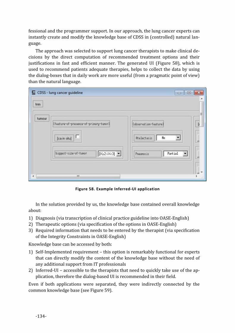
-134-
fessional and the programmer support. In our approach, the lung cancer experts can
instantly create and modify the knowledge base of CDSS in (controlled) natural lan-
guage.
The approach was selected to support lung cancer therapists to make clinical de-
cisions by the direct computation of recommended treatment options and their
justifications in fast and efficient manner. The generated UI (Figure 58), which is
used to recommend patients adequate therapies, helps to collect the data by using
the dialog-boxes that in daily work are more useful (from a pragmatic point of view)
than the natural language.
Figure 58. Example Inferred-UI application
In the solution provided by us, the knowledge base contained overall knowledge
about:
1) Diagnosis (via transcription of clinical practice guideline into OASE-English)
2) Therapeutic options (via specification of the options in OASE-English)
3) Required information that needs to be entered by the therapist (via specification
of the Integrity Constraints in OASE-English)
Knowledge base can be accessed by both:
1) Self-Implemented requirement – this option is remarkably functional for experts
that can directly modify the content of the knowledge base without the need of
any additional support from IT professionals
2) Inferred-UI – accessible to the therapists that need to quickly take use of the ap-
plication, therefore the dialog-based UI is recommended in their field.
Even if both applications were separated, they were indirectly connected by the
common knowledge base (see Figure 59).

-135-
Self-Implemented
Requirement
Infered-UI
Knowledge
Base
Lung cancer
therapist
Lung cancer
expert/researcher.
Reasoner
Predictive
Editor
Figure 59. Architecture of CDSS
The CDSS presented here can be freely downloaded from the project website
(see Appendix 7).


-137-
Appendix 7. THE WEB PAGE The address of the website that supports the community interested in
is: www.oase-tools.net. It is a good starting point for one that would like to make a
future growth in OASE driven formal methods within the area of software develop-
ment. The website will contains all the source codes and results described in
appendixes of this thesis. It will be possible to take an advantage of using
OASE-Tools by downloading them directly from the website; moreover it will be a
source of knowledge about the OASE. The crucial knowledge about the purpose and
usage of OASE is presented here, giving the opportunity to extend it for interested
user. The website is made on WikiMedia solution. It allows one to add new articles,
comments and/or upload the software solutions that take advantage from
OASE-Tools.

-138-
8. BIBLIOGRAPHY [Abel96] H. Abelson, G. Sussman, and J. Sussman. Structure and Interpretation of
Computer Programs. Mit Electrical Engineering and Computer Science Series, Mit Press, 1996.
[Abra04] A. Abran, J. W. Moore, P. Bourque, R. Dupuis, and L. L. Tripp. Guide to the Software Engineering Body of Knowledge (SWEBOK). IEEE, 2004. ISO Technical Report ISO/IEC TR 19759.
[Aho88] A. Aho, R. Sethi, and J. Ullman. Compilers: principles, techniques, and tools. Addison-Wesley series in computer science, Addison-Wesley Pub. Co., 1988.
[Alex77] C. Alexander, S. Ishikawa, and M. Silverstein. A Pattern Language: Towns, Buildings, Construction (Center for Environmental Structure Series). Oxford University Press, later printing Ed., Aug. 1977.
[Ande90] P. Andersen. A theory of computer semiotics: semiotic approaches to construction and assessment of computer systems. Cambridge series on human-computer interaction, Cambridge University Press, 1990.
[Baad03] F. Baader, D. Calvanese, D. McGuinness, D. Nardi, and P. Patel-Schneider. The Description Logic Handbook: Theory, Implementation and Applications. Cambridge University Press, January 2003.
[Baad06] F. Baader, C. Lutz, and B. Suntisrivaraporn. “Efficient Reasoning in EL +”. In: Proceedings of the 2006 International Workshop on Description Logics (DL2006), 2006.
[Back54] J. W. Backus. “The IBM 701 Speedcoding System”. J. ACM, Vol. 1, No. 1, pp. 4–6, Jan. 1954.
[Barw77] J. Barwise. Handbook of Mathematical Logic. North-Holland Pub. Co, Amsterdam, 1977.
[Bass03] L. Bass, P. Clements, and R. Kazman. Software Architecture in Practice. Addison-Wesley, Boston, MA, 2. Ed., 2003.
[Bech03] S. Bechhofer, R. Volz, and P. W. Lord. “Cooking the Semantic Web with the OWL API”. In: The Semantic Web – ISWC 2003: Second International Semantic Web Conference, Sanibel Island, FL, USA, pp. 659–675, 2003.
[Beck01] K. Beck, M. Beedle, A. van Bennekum, A. Cockburn, W. Cunningham, M. Fowler, J. Grenning, J. Highsmith, A. Hunt, R. Jeffries, J. Kern, B. Marick, R. C. Martin, S. Mellor, K. Schwaber, J. Sutherland, and D. Thomas. “Manifesto for Agile Software Development”. 2001. [http://agilemanifesto.org/].
[Beck02] K. Beck. Test Driven Development: By Example. Addison-Wesley Longman Publishing Co., Inc., Boston, MA, USA, 2002.
[Bell08] M. Bell. Service-Oriented Modeling: Service Analysis, Design, and Architecture. Wiley Publishing, 2008.
[Bera03] D. Berardi, D. Calvanese, and G. De Giacomo. “Reasoning on UML Class Diagrams is EXPTIME-hard”. In: Proc. of the 16th Int. Workshop on Description Logic (DL 2003), pp. 28–37, 2003.

-139-
[Bern01] T. Berners-Lee, J. Hendler, and O. Lassila. “The Semantic Web”. Scientific American, Vol. 284, No. 5, pp. 34–43, 2001.
[Bern97] A. Bernth. “EasyEnglish: a tool for improving document quality”. In: Proceedings of the fifth conference on Applied natural language processing, pp. 159–165, Association for Computational Linguistics, Stroudsburg, PA, USA, 1997.
[Booc87] G. Booch. Software Engineering with Ada. Benjamin/Cummings Pub. Co, Menlo Park, 1987.
[Brad79] R. Bradley and N. Swartz. Possible worlds: an introduction to logic and its philosophy. B. Blackwell, 1979.
[Busc07a] F. Buschmann, K. Henney, and D. C. Schmidt. Pattern-Oriented Software Architecture: A Pattern Language for Distributed Computing. Vol. 4 of Wiley Series in Software Design Patterns, John Wiley & Sons, 2007.
[Busc07b] F. Buschmann, K. Henney, and D. C. Schmidt. Pattern-Oriented Software Architecture: On Patterns and Pattern Languages. Vol. 5 of Wiley Series in Software Design Patterns, John Wiley & Sons, 2007.
[Busc96] F. Buschmann, R. Meunier, H. Rohnert, P. Sommerlad, and M. Stal. Pattern-Oriented Software Architecture: A System of Patterns. Vol. 1 of Wiley Series in Software Design Patterns, John Wiley & Sons, 1996.
[Cast08] M. A. Casteleiro and J. J. Des Diz. “Clinical practice guidelines: A case study of combining OWL-S, OWL, and SWRL”. Know.-Based Syst., Vol. 21, No. 3, pp. 247–255, 2008.
[Chan07] D. Chandler. Semiotics: The Basics. Taylor & Francis, second Ed., 2007.
[Chur40] A. Church. “A Formulation of the Simple Theory of Types”. Jurnal of Symbolic Logic, Vol. 5, No. 2, pp. 56–68, June 1940.
[Cirs03] H. Cirstea, L. Liquori, and B. Wack. “Rewriting Calculus with Fixpoints: Untyped and First-order Systems”. Springer, 2003.
[Cloc03] W. F. Clocksin and C. S. Mellish. Programming in Prolog. Springer-Verlag, Berlin; New York, 2003.
[Codd70] E. F. Codd. “A relational model of data for large shared data banks”. Commun. ACM, Vol. 13, No. 6, pp. 377–387, June 1970.
[Creg07] A. Cregan, R. Schwitter, and T. Meyer. “Sydney OWL Syntax - towards a Controlled Natural Language Syntax for OWL 1.1”. In: Proceedings of the OWLED 2007 Workshop on OWL: Experiences and Directions, 2007.
[Dahl66] O. Dahl and K. Nygaard. SIMULA: A language for programming and description of discrete event systems. Introduction and user’s manual : by Ole-Johan Dahl and Kristen Nygaard. Norwegian Computing Center, 1966.
[Date97] C. Date. A guide to the SQL standard : a user’s guide to the standard database language SQL. Addison-Wesley, Reading, Mass, 1997.
[Dijk72] E. W. Dijkstra. “The humble programmer”. Commun. ACM, Vol. 15, pp. 859–866, October 1972.
[Eijk89] P. V. Eijk and M. Diaz, Eds. Formal Description Technique Lotos: Results of the Esprit Sedos Project. Elsevier Science Inc., New York, NY, USA, 1989.

-140-
[Elli96] W. J. Ellis, Richard, P. T. Poon, D. Rayford, T. F. Saunders, B. Sherlund, and R. L. Wade. “Toward a Recommended Practice for Architectural Description”. 1996.
[Erl05] T. Erl. Service-Oriented Architecture: Concepts, Technology, and Design. Prentice Hall PTR, Upper Saddle River, NJ, USA, 2005.
[Fowl01] M. Fowler and K. Beck. Refactoring: improving the design of existing code. Addison-Wesley object technology series, Addison-Wesley, 2001.
[Fowl99] M. Fowler. Refactoring: Improving the Design of Existing Code. Addison-Wesley, Boston, MA, USA, 1999.
[Fuch90] N. E. Fuchs, U. Schwertel, and R. Schwitter. “Attempto Controlled English - Not Just Another Logic Specification Language”. In: LOPSTR ’98: Proceedings of the 8th International Workshop on Logic Programming Synthesis and Transformation, pp. 1–20, Springer-Verlag, London, UK, 1990.
[Gall78] H. Gallaire and J. Minker. Logic and Data Bases. Plenum Press, New York, 1978.
[Gamm95] E. Gamma, R. Helm, R. Johnson, and J. Vlissides. Design patterns: elements of reusable object-oriented software. Addison-Wesley Longman Publishing Co., Inc., Boston, MA, USA, 1995.
[Gasp08] E. Gasparis, J. Nicholson, and A. H. Eden. “LePUS3: An Object-Oriented Design Description Language”. In: Diagrams ’08: Proceedings of the 5th international conference on Diagrammatic Representation and Inference, pp. 364–367, Springer-Verlag, Berlin, Heidelberg, 2008.
[Genn03] J. H. Gennari, M. A. Musen, R. W. Fergerson, W. E. Grosso, M. Crubézy, H. Eriksson, N. F. Noy, and S. W. Tu. “The evolution of Protégé an environment for knowledge-based systems development”. Int. J. Hum.-Comput. Stud., Vol. 58, No. 1, pp. 89–123, Jan. 2003.
[Gocz06] K. Goczyła, T. Grabowska, W. Waloszek, and M. Zawadzki. “The Knowledge Cartography – A new approach to reasoning over Description Logics ontologies”. 2006.
[Gocz11] K. Goczyła. Ontologie w systemach informatycznych. Akademicka Oficyna Wydawnicza EXIT, 2011.
[Gosl05] J. Gosling, B. Joy, G. Steele, and G. Bracha. The Java Language Specification, Third Edition. Addison-Wesley Longman, Amsterdam, 3 Ed., June 2005.
[Grah94] I. Graham. Graham/SOMA (Semantic Object Modeling Approach) method, pp. 73–83. Wiley-QED Publishing, Somerset, NJ, USA, 1994.
[Hank04] C. Hankin. An introduction to lambda calculi for computer scientists. Texts in computing, Kings College, 2004.
[Herb10] S. Herbert. C# 4.0: The Complete Reference. TATA MCGRAW-HILL, 2010.
[Hhnl02] R. Hähnle, K. Johannisson, and A. Ranta. “An authoring tool for informal and formal requirements specifications”. In: Fundamental Approaches to Software Engineering (FASE), Part of Joint European Conferences on Theory and Practice of Software, ETAPS, Grenoble, volume 2306 of LNCS, pp. 233–248, Springer, 2002.
[Holm94] J. R. Holmevik. “Compiling Simula: A historical study of technological genesis”. IEEE Annals in the History of Computing, Vol. 16, No. 4, p. 25–37, 12 1994.
-141-
[Hopc79] J. Hopcroft. Introduction to Automata Theory, Languages, and Computation. Addison-Wesley, Boston, 1979.
[Horr06a] M. Horridge, N. Drummond, J. Goodwin, A. L. Rector, R. Stevens, and H. Wang. “The Manchester OWL Syntax”. In: OWLED, 2006.
[Horr06b] I. Horrocks, O. Kutz, and U. Sattler. “The Even More Irresistible SROIQ.”. In: P. Doherty, J. Mylopoulos, and C. A. Welty, Eds., KR, pp. 57–67, AAAI Press, 2006.
[Jack02] D. Jackson. “Alloy: a lightweight object modelling notation”. ACM Trans. Softw. Eng. Methodol., Vol. 11, No. 2, pp. 256–290, Apr. 2002.
[Jaco12] I. Jacobson, S. Huang, M. Kajko-Mattsson, P. McMahon, and E. Seymour. “Semat - Three Year Vision”. Programming and Computer Software, Vol. 38, No. 1, pp. 1–12, 2012.
[Jens85] K. Jensen, N. Wirth, and A. Mickel. PASCAL user manual and report. Springer Study Edition, Springer-Verlag, 1985.
[Kalj07] K. Kaljurand. Attempto Controlled English as a Semantic Web Language. PhD thesis, Faculty of Mathematics and Computer Science, University of Tartu, 2007.
[Kaly07] A. Kalyanpur, B. Parsia, M. Horridge, and E. Sirin. “Finding all justifications of OWL DL entailments”. In: Proceedings of the 6th international The semantic web and 2nd Asian conference on Asian semantic web conference, pp. 267–280, Springer-Verlag, Berlin, Heidelberg, 2007.
[Kamp98] C. Kamprath, E. Adolphson, T. Mitamura, and E. Nyberg. “Controlled Language for Multilingual Document Production: Experience with Caterpillar Technical English”. 1998.
[Kapl08] P. Kaplanski. “Description logic as a common software engineering artifacts language”. In: Proc. 1st Int. Conf. Information Technology IT 2008, pp. 1–4, 2008.
[Kapl09] P. Kaplanski. “Syntactic Modular Decomposition of Large Ontologies with Relational Database”. In: ICCCI (SCI Volume), pp. 65–72, 2009.
[Kapl10a] P. Kaplanski. “Description logic based generator of data-centric applications”. In: Proceedings of the 2010 2ND International Conference On Information Technology, ICIT 2010, pp. 53–56, 2010.
[Kapl10b] P. Kaplanski. “Modeling Object Oriented Systems via Controlled English Verbalization of Description Logic”. CEUR Workshop Proceedings ISSN 1613-0073 Vol-622 urn:nbn:de:0074-622-4, Pre-Proceedings of the Second Workshop on Controlled Natural Languages, Marettimo Island, Sicily, Italy, September 13-15, 2010,, 2010.
[Kapl11a] P. Kaplanski. “Controlled English Interface for Knowledge Bases”. Studia Informatica, Formerly: Zeszyty Naukowe Politechniki Śląskiej, seria INFORMATYKA, Volume 32, Number 2A (96), PL ISSN 0208-7286, QUARTERLY (s. 485-494), 2011.
[Kapl11b] P. Kaplanski. “Programowanie Obiektowe z Użyciem Adnotacji Semantycznych”. Zeszyty naukowe Wydziału Elektroniki Telekomunikacji i Informatyki Politechniki Gdańskiej Tom 1, ISBN: 978-83-60-779-11-8 (s. 363-368), 2011.
[Keme64] J. Kemeny and T. Kurtz. Basic: a manual for BASIC, the elementary algebraic language designed for use with the Dartmouth Time Sharing System. Dartmouth Publications, 1964.
-142-
[Kern88] B. W. Kernighan. The C Programming Language. Prentice Hall Professional Technical Reference, 2nd Ed., 1988.
[Kife05] M. Kifer. “Rules and Ontologies in F-Logic”. In: Reasoning Web, First International Summer School, Msida, Malta, pp. 22–34, 2005.
[Kife89] M. Kifer and G. Lausen. “F-logic: a higher-order language for reasoning about objects, inheritance, and scheme”. In: SIGMOD ’89: Proceedings of the 1989 ACM SIGMOD international conference on Management of data, pp. 134–146, ACM, New York, NY, USA, 1989.
[Kirc04] M. Kirchner and P. Jain. Pattern-Oriented Software Architecture: Patterns for Resource Management. Vol. 3 of Wiley Series in Software Design Patterns, John Wiley & Sons, 2004.
[Koid05] S. Koide, J. Aasman, and S. Haflich. “OWL vs. Object Oriented Programming”. In: Workshop on Semantic Web Enabled Software Engineering (SWESE), November 2005. Galway, Ireland.
[Krip80] S. Kripke. Naming and necessity. Harvard University Press, 1980.
[Kruc03] P. Kruchten. The Rational Unified Process: An Introduction. Addison-Wesley Longman Publishing Co., Inc., Boston, MA, USA, 3 Ed., 2003.
[Kruc95] P. Kruchten. “Architectural Blueprints — The “4+1” View Model of Software Architecture”. IEEE Software, Vol. 12, No. 6, pp. 42–50, Nov. 1995.
[Kuhn09] T. Kuhn. “How to Evaluate Controlled Natural Languages”. In: N. E. Fuchs, Ed., Pre-Proceedings of the Workshop on Controlled Natural Language (CNL 2009), CEUR-WS, April 2009.
[Kuhn10] T. Kuhn. “Codeco: A Grammar Notation for Controlled Natural Language in Predictive Editors”. In: M. Rosner and N. E. Fuchs, Eds., Pre-Proceedings of the Second Workshop on Controlled Natural Languages (CNL 2010), CEUR-WS, 2010.
[Larm03] C. Larman. Agile and Iterative Development: A Manager’s Guide. Pearson Education, 2003.
[Li05] M. Li and M. Baker. The grid core technologies. John Wiley & Sons, 2005.
[Liu00] K. Liu. Semiotics in Information Systems Engineering. CUP, Cambridge, UK, 2000.
[Liu96] C. Liu. Smalltalk, objects, and design. ToExcel, San Jose, 1996.
[McCa65] J. McCarthy. LISP 1.5 programmer’s manual. M.I.T. Press, 1965.
[Mell02] S. J. Mellor and M. Balcer. Executable UML: A Foundation for Model-Driven Architectures. Addison-Wesley Longman Publishing Co., Inc., Boston, MA, USA, 2002.
[Mell09] P. Mell and T. Grance. “The NIST Definition of Cloud Computing”. Tech. Rep., July 2009.
[Mens06] T. Mens and P. V. Gorp. “A Taxonomy of Model Transformation”. Electronic Notes in Theoretical Computer Science, Vol. 152, pp. 125 – 142, 2006. Proceedings of the International Workshop on Graph and Model Transformation (GraMoT 2005).
[Meye92] B. Meyer. Eiffel: the language. Prentice Hall object-oriented series, Prentice Hall, 1992.

-143-
[Mins75] M. Minsky. “A Framework for Representing Knowledge”. In: P. Winston, Ed., The Psychology of Computer Vision, pp. 211–277, McGraw-Hill, New York, 1975.
[Mitc02] R. Mitchell and J. McKim. Design by contract, by example. Addison Wesley, 2002.
[Mlle09] A. Müller. “VDM - The Vienna Development Method”. Bachelor thesis in "Formal Methods in Software Engineering", Research Institute for Symbolic Computation (RISC), Johannes Kepler University Linz, Austria, April 2009.
[Morr38] C. W. Morris. Foundations of the Theory of Signs. University of Chicago Press, Chicago, IL, 1st Ed., 1938.
[Muse10] M. Musen, N. Noy, C. Nyulas, M. O’Connor, T. Redmond, S. Tu, T. Tudorache, J. Vendetti, and S. S. of Medicine. “Protégé”. 2010. [http://protege.stanford.edu].
[Nata02] C. Natali and R. D. A. Falbo. “Knowledge Management in Software Engineering Environments”. In: Proc. of the 16 th Brazilian Symposium on Software Engineering, pp. 238–253, 2002.
[Newc04] E. Newcomer and G. Lomow. Understanding SOA with Web Services (Independent Technology Guides). Addison-Wesley Professional, 2004.
[Orwe90] G. Orwell. 1984. Signet Book, May 1990.
[Parr06] T. J. Parr. “A Functional Language For Generating Structured Text”. 2006.
[Paws04] R. Pawson. Naked objects. PhD thesis, Department of Computer Science, Trinity College, Dublin, 2004.
[Peir31] C. S. Peirce. Collected Papers of Charles Sanders Peirce. Thoemmes Continuum, 1931.
[Penr05] R. Penrose. The road to reality : a complete guide to the laws of the universe. A.A. Knopf, New York, 2005.
[Pnue77] A. Pnueli. “The temporal logic of programs”. Foundations of Computer Science, Annual IEEE Symposium on, Vol. 0, pp. 46–57, 1977.
[Rant04] A. Ranta. “Grammatical Framework: A Type-Theoretical Grammar Formalism”. Journal of Functional Programming, Vol. 14, No. 02, pp. 145–189, March 2004.
[Rose69] D. J. Rosenkrantz and R. E. Stearns. “Properties of deterministic top down grammars”. In: STOC ’69: Proceedings of the first annual ACM symposium on Theory of computing, pp. 165–180, ACM, New York, NY, USA, 1969.
[Roze97] G. Rozenberg. Handbook of graph grammars and computing by graph transformation: volume I. foundations. World Scientific Publishing Co., Inc., River Edge, NJ, USA, 1997.
[Rudo08] S. Rudolph, M. Krötzsch, and P. Hitzler. “Cheap Boolean Role Constructors for Description Logics”. In: JELIA ’08: Proceedings of the 11th European conference on Logics in Artificial Intelligence, pp. 362–374, Springer-Verlag, Berlin, Heidelberg, 2008.
[Rumb05] J. Rumbaugh, I. Jacobson, and G. Booch. The Unified Modeling Language Reference Manual. Addison-Wesley, Boston, MA, 2. Ed., 2005.
[Scha07] S. R. Schach. Object-Oriented and Classical Software Engineering. McGraw-Hill, Inc., New York, NY, USA, 7 Ed., 2007.

-144-
[Schm00] D. Schmidt, M. Stal, H. Rohnert, and F. Buschman. Pattern-Oriented Software Architecture: Patterns for Concurrent and Networked Objects. Vol. 2 of Wiley Series in Software Design Patterns, John Wiley & Sons, 2000.
[Sene08] O. Seneviratne and T. Berners-Lee. “The Point of View Axis: Varying the Levels of Explanation Within a Generic RDF Data Browsing Environment”. 2008.
[Shea08] R. Shearer, B. Motik, and I. Horrocks. “HermiT: A Highly-Efficient OWL Reasoner”. In: A. Ruttenberg, U. Sattler, and C. Dolbear, Eds., Proc. of the 5th Int. Workshop on OWL: Experiences and Directions (OWLED 2008 EU), Karlsruhe, Germany, October 26–27 2008.
[Sowa00] J. F. Sowa. “Ontology, Metadata, and Semiotics”. In: Proceedings of the Linguistic on Conceptual Structures: Logical Linguistic, and Computational Issues, pp. 55–81, Springer-Verlag, London, UK, 2000.
[Spin07] D. Spinellis. “Another Level of Indirection”. In: A. Oram and G. Wilson, Eds., Beautiful Code: Leading Programmers Explain How They Think, Chap. 17, pp. 279–291, O’Reilly and Associates, Sebastopol, CA, 2007.
[Stah04] D. C. Stahl, L. Rouse, D. Ko, and J. C. Niland. “GDSI: A Web-Based Decision Support System to Facilitate the Efficient and Effective Use of Clinical Practice Guidelines”. Hawaii International Conference on System Sciences, Vol. 6, p. 60150, 2004.
[Stam73] R. Stamper. Information in Business and Administrative Systems. John Wiley and Sons, 1973.
[Stan95] Standish. “The Standish Group - Chaos Report”. 1995. [http://www.cs.nmt.edu/ cs328/reading/Standish.pdf].
[Stee90] G. L. Steele. Common LISP: The Language. Digital Press, Bedford, MA, 2. Ed., 1990.
[Stro00] B. Stroustrup. The C++ Programming Language. Addison-Wesley Longman Publishing Co., Inc., Boston, MA, USA, 3rd Ed., 2000.
[Taib07] T. Taibi. Design patterns formalization techniques. IGI Pub., 2007.
[Vasw08] V. Vaswani. PHP: a beginner’s guide. Beginner’s Guide, McGraw Hill, 2008.
[Vazi00] M. Vaziri and D. Jackson. “Some Shortcomings of OCL, the Object Constraint Language of UML”. In: Proceedings of the Technology of Object-Oriented Languages and Systems (TOOLS 34), p. 555+, IEEE Computer Society, Washington, DC, USA, 2000.
[Warm99] J. Warmer and A. Kleppe. The Object Constraint Language: Precise Modeling with UML. Addison-Wesley, Reading, MA, 1999.
[Wieg03] K. E. Wiegers. Software Requirements, Second Edition (Pro-Best Practices). Microsoft Press, 2 sub Ed., 2003.
[Wojc90] R. H. Wojcik, J. E. Hoard, and K. Holzhauser. “The Boeing Simplified English Checker”. In: Proceedings of the International Conference Human Machine Interaction and Artificial Intelligence in Aeronautics and Space, pp. 43–57, Toulouse: Centre d’Etudes et de Recherches de Toulouse, 1990.

-1-
Inżynieria Oprogramowania
Wspomagana Ontologicznie
Paweł Kapłański
Gdańsk 2012
Streszczenie
WPROWADZENIE Niniejsza praca doktorska łączy dziedziny takie jak: sztuczna inteligencja (AI),
systemy formalnej reprezentacji wiedzy i wnioskowania (ang. Knowledge Represen-
tation and Reasoning - KRR), komputerowe wspomaganie wytwarzania
oprogramowania (ang. Computer-Aided Software Engineering - CASE), oraz inżynierii
oprogramowania opartej o modelowanie (ang. Model-Driven Engineering - MDE).
W szczególności, rozważamy tutaj logikę opisową (będącą podstawą matema-
tyczną standardu W3C o nazwie OWL2). Formalizm ten pozwala na zapis statycznej
struktury programu komputerowego, którą to jest rozstrzygalna (wnioskowanie o
cechach tej struktury jest rozstrzygalne). Pokazujemy, że struktury statyczne są po-
wszechne w inżynierii oprogramowania (np. diagramy klas UML, struktura wzorców
projektowych, niektóre wymagania) oraz wskazujemy jak można poszerzyć obszar
zastosowań logiki opisowej do zapisu kontraktów, których spójność jest badana w
czasie wykonania programu.
Praca ta pokazuje również, w jaki sposób można połączyć świat specyfikacji for-
malnych ze światem języków programowania poprzez zastosowanie
kontrolowanego języka naturalnego (ang. Controlled Natural Language - CNL) będą-
cego werbalizacją logiki opisowej.
Celem niniejszej pracy doktorskiej jest wykazanie, że:
1) Można zdefiniować język, który pozwoli na zapis formalny (możliwy do prze-
twarzania automatycznego) struktur występujące w obiektowych metodach
wytwarzania oprogramowania, który ma właściwości języka naturalnego. Możli-
wość tą upatrujemy w zastosowania kontrolowanego języka naturalnego, jako
werbalizacji logiki opisowej.
-2-
2) Język ten może być stosowany w obszarach związanych z wytwarzaniem
oprogramowania obecnie ściśle zarezerwowanych dla języka naturalnego.
3) Język ten jest użyteczny w procesie wspomagania produkcji oprogramowania.
STRUKTURA PRACY Praca rozpoczyna się wprowadzeniem (rozdział 1). W rozdziale numer 2 zajmu-
jemy się zagadnieniem inżynierii wiedzy z szczególnym naciskiem na ontologie, ich
semiotykę oraz semantykę. Prezentujemy tu obecny stan wiedzy dotyczącej semio-
tyki formalnej z szczególnym naciskiem na logikę opisową - formalizm pozwalający
na zapis użytecznych, rozstrzygalnych ontologii. Prezentujemy algorytmy pozwala-
jące na wnioskowanie w logice opisowej. Dyskutujemy tu również semiotykę
artefaktów pojawiających się w procesie wytwarzania oprogramowania.
W rozdziale numer 3 czytelnik znajdzie przegląd metod wytwarzania oprogra-
mowania. Rozpoczynamy od przedstawienia historii oraz użyteczności
poszczególnych rodzin języków programowania. Rozpatrujemy istniejące metody
formalnego przedstawienia programów komputerowych. Wskazujemy różnice po-
między metodami zwinnymi a metodami inżynieryjnymi. W końcu, dyskutujemy
koncepcję języka wzorców, która zainspirowana została pracami architekta Chri-
stophera Alexandra [Alex77].
W rozdziale 4 opisujemy, wynalezioną przez nas metodę o nazwie: “Inżynieria
Oprogramowania Wspomagana Ontologicznie” (ang. Ontology-Aided Software Engi-
neering - OASE). W metodzie tej, program komputerowy, jego projekt oraz
wymagania przed nim stawiane, traktujemy jako ontologie. Dzięki takiemu przed-
stawieniu artefaktów algorytmy wnioskujące w logice (ang. reasoners) mogą
aktywnie wspierać inżyniera zajmującego się rozwojem oprogramowania. Uogólnia-
jąc, prezentujemy podejście do procesu wytwarzania oprogramowania w
kategoriach semiotyki formalnej. W tym rozdziale rozważamy również zagadnienia
związane z rozstrzygalnością oraz złożonością struktur występujących w progra-
mach komputerowych. Przedstawiamy również przykładowe problemy, które
zmotywowały nas do rozpoczęcia badań nad metodą OASE. Wprowadzamy tutaj
język OASE-English – kontrolowany język angielski, który pozostając werbalizacją
logiki opisowej, został zaprojektowany specjalnie dla metody OASE, oraz przedsta-
wiamy zarówno jego gramatykę jak i semantykę. Ponadto prezentujemy
transformacje łączące świat wytwarzania oprogramowania z metodą OASE. Nazwa-
liśmy je OASE-Transformations. Prezentujemy koncept adnotacji oraz asercji
semantycznych (odpowiednio: OASE-Annotations, OASE-Assertions). Adnotacje se-
mantyczne wzbogacają język programowania, natomiast asercje semantyczne
pomagają w znajdywaniu błędów w programach oraz mogą być traktowane, jak kon-
trakty (w rozumieniu programowania opartego o kontrakty). Na końcu tego

-3-
rozdziału, przedstawiamy OASE jako metodę pozwalającą na zapisanie, w sposób
formalny, wzorców projektowych i przez co umożliwiającą zautomatyzowane wnio-
skowanie na temat poprawności ich użycia.
W rozdziale numer 5 prezentujemy narzędzia wspierające pracę z metodą OASE.
Opisujemy ich strukturę wewnętrzną, sposób działania oraz przedstawiamy ich
praktyczne zastosowania.
W rozdziale 6 przedstawiamy rozwiązania bazujące na ww. narzędziach takie
jak: „Wywnioskowany interfejs użytkownika” (ang. Inferred UI) – sposób automa-
tycznego generowania interfejsu użytkownika z ontologii, oraz „Wymaganie samo-
implementujące się” (ang. Self-Implemented Requirement) – sposób na ograniczenie
kosztów związanych ze zmieniającymi się wymaganiami użytkownika. Rozwiązania
te dowodzą użyteczności ww. narzędzi również poza polem ich bezpośredniego za-
stosowania.
Podsumowanie oraz rezultaty pracy przedstawiono w rozdziale 7.
W pracy znajduje się siedem załączników. W załączniku pierwszym opisano w
sposób szczegółowy mapowanie pomiędzy językiem kontrolowanym OASE-English
a konstruktami logiki opisowej. Drugi załącznik prezentuje transformację OASE-
Transformation, używaną do konwertowania kodu źródłowego programów napisa-
nych w obiektowym języku programowania, do postaci skryptu w języku
OASE-English. Załącznik numer 3 prezentuje transformację OASE-Transformation
wzorca projektowego Adapter do skryptu w języku OASE-English. Załącznik numer
4 opisuje rezultaty ankiety, którą przeprowadzono na grupie projektantów i pro-
gramistów mającej wskazać obecne ograniczenia i drogi dalszego rozwoju metody
OASE. Załącznik numer 5 prezentuje wyniki eksperymentu walidacyjnego przepro-
wadzonego na tej samej grupie projektantów i programistów. Eksperyment ten miał
za zadanie wykazanie użyteczność metody OASE. W załączniku numer 6 prezentu-
jemy opis systemu wspierającego podejmowanie decyzji klinicznych (CDSS), który
został zaimplementowany przez w ramach badań nad użytecznością narzędzi
wspierających metodę OASE. Załącznik nr 7 prezentuje stronę internetową OASE
(www.oase-tools.net), która w zamierzeniu ma stać się punktem wyjścia dla użyt-
kowników zainteresowanych metodą OASE.
REZULTATY PRACY Stworzona przez nas metoda pozwala na:
1) Opisywanie praktyk i wzorców (uniwersaliów) wchodzących w skład procesu
wytwarzania oprogramowania oraz na komponowanie ich w nowe praktyki i
wzorce. OASE pozwala na opisywanie uniwersaliów występujących w procesie
wytwarzania oprogramowania (użyteczność metody OASE oceniono w bada-

-4-
niu ankietowym oraz w eksperymencie walidacyjnym). OASE pozwala na za-
pis uniwersaliów w kontrolowanym języku angielskim OASE-English.
Pokazaliśmy, że program zapisany w obiektowym języku programowania
tworzy Opis Świata w rozumieniu systemów zarządzania wiedzą. Ww. Opis
Świata (ang. World Description) jest zbudowany na bazie określonej Termino-
logii będącej reprezentacją praw rządzących światem obiektowych języków
programowania (takich jak np. polimorfizm, dziedziczenie, itp.) Wymagania
stawiane przed programem (np. wymóg korzystania z pewnych wzorców pro-
jektowych, ograniczenia architektoniczne wprowadzone przez projektanta
itp.) są reprezentowane tutaj, jako Ograniczniki Wiedzy (ang. Integrity Con-
strains), które mają reprezentację w bazie wiedzy w postaci wyrażeń pseudo-
modalnych. W kontekście OASE, architektura systemu, system oraz wzorce
projektowe stają się równoprawne zarówno ze względu na semantykę jak i
używaną przez użytkowników tej metody terminologię. Pozwala to na jednoli-
te korzystanie z nich przez wszystkie osoby zaangażowane w rozwój
oprogramowania. OASE pozwala również na automatyczne śledzenie postę-
pów prac prowadzonych przez programistów, dzięki narzędziu
walidacyjnemu, wcześniej zapisanych w postaci adnotacji i asercji, wymogów
dotyczących tworzonego oprogramowania. Walidator udostępnia programi-
ście wyjaśnienia w języku angielskim (ściśle w OASE-English), które prowadzą
go niejako za rękę i dają jasne wskazówki, co do zakresu dalszych, wymaga-
nych prac.
2) Symulacja oprogramowania. OASE pozwala na symulację struktury statycznej
oprogramowania obiektowego poprzez umożliwienie wnioskowania w mode-
lu formalnym tej struktury.
3) Zamknięcie luki komunikacyjnej pomiędzy podmiotami zaangażowanymi w
proces tworzenia oprogramowania. To, że OASE zamyka lukę komunikacyjną
udowadnia w pewien sposób przeprowadzony przez nas eksperyment wyko-
nany na grupie programistów. W przeprowadzanych z nimi wywiadach
opisują oni swoje osobiste doświadczenia z metodą OASE jako: „prowadzenie
za rękę”, czy „rozwiązywanie problemu typu puzzle”. Co więcej, komponenty
wspierające OASE (o nazwie OASE-Tools) udowodniły swoją przydatność w
realizacji systemu wspomagania decyzji klinicznej (ang. Clinical Decision
Support System – CDSS) – a co za tym idzie wykazaliśmy, że narzędzia
OASE-Tools można wykorzystywać tak jak zwykłe (choć potężne) komponen-
ty programów komputerowych.
4) Elementy metody są użyteczne w innych dziedzinach niż wytwarzanie oprogra-
mowania. Stworzyliśmy rozwiązanie bazujące na komponentach OASE-Tools
realizujące System Wspomagania Decyzji Klinicznych (CDSS), z szczególnym
uwzględnieniem wiedzy dotyczącej raka płuca. Dzięki stworzeniu ww. Syste-
mu wykazaliśmy, że komponenty wchodzące w skład metody OASE mają

-5-
zastosowanie również poza samą metodą. W przypadku CDSS pozwalają one
na reużycie kanału komunikacyjnego wspieranego przez język OASE-English
(stworzonego dla ludzi zajmujących się rozwijaniem oprogramowania) rów-
nież przez terapeutów – lekarzy.
5) Możliwość rozszerzania oraz modyfikacji metody. Język OASE-English pozwala
na pokrycie ekspresywności baz wiedzy w logice opisowej typu .
Dzięki temu, możliwe jest rozszerzanie proponowanych przez nas praktyk i
wzorców.
Stworzony przez nas język OASE-English jest zrozumiały dla ludzi, a jednocze-
śnie może być przetwarzany automatycznie. Język ten może być stosowany w
dziedzinach związanych z rozwojem oprogramowania, zarezerwowanych obecnie
dla języka naturalnego. Udowodniliśmy to poprzez realizację systemu CDSS, który
implementował wynalezione przez nas rozwiązania o nazwie „Wywnioskowany in-
terfejs użytkownika” oraz „Wymaganie samo-implementujące się”.
Stworzony język jest formalny a co za tym idzie może być przetwarzany przez al-
gorytmy dowodzenia w logice opisowej. Dzięki temu, narzędzia wspierające OASE
pozwalają na stworzenie procesu wytwarzania oprogramowania, w którym to kom-
puter (przy użyciu algorytmów wnioskowania) utrzymuje automatycznie spójność
bazy wiedzy, a wszelkie niespójności komunikowane są zainteresowanymi stronom
w podzbiorze języka naturalnego. Komunikacja odbywa się w języku OASE-English,
który jest wbudowany w język programowania (poprzez adnotacje) lub w języ-
ku UML (poprzez notatki języka UML).
OPIS METODY OASE Wynaleziona przez nas metoda rozwoju oprogramowania nazwana jest OASE
(ang. Ontology-Aided Software Engineering), w nawiązaniu do metody CASE (ang.
Computer-Aided Software Engeenring). OASE implementuje semiotyczny system
formalny, lecz koncentruje się bezpośrednio na wytwarzaniu oprogramowania. Ar-
tefakty, będące produktami procesu wytwarzania oprogramowania, są wejściem dla
głównego procesu wspieranego przez OASE (patrz Rysunek 1). Proces ten składa się
z następujących etapów:
1) Artefakty oprogramowania (wymienione poniżej) stworzone przy wsparciu na-
rzędzi OASE-Tool są przekształcane do skryptów w języku OASE-English za
pomocą transformacji OASE-Transformation.
a. Kod źródłowy – tworzony przez programistów
b. Adnotacje i asercje semantyczne OASE-Annotations i OASE-Assertions –
tworzone przez projektantów i programistów.
c. Diagramy UML - wykonane przez projektantów (wyposażone w notatki
zapisane w języku OASE-English)

-6-
d. Inne specyfikacje w języku OASE-English – takie jak wymagania dotyczące
tworzonego programu, wiedza domenowa itp.
2) W drugim kroku, zbiorczy skrypt zapisany w języku OASE-English jest przetwa-
rzany przez narzędzie o nazwie OASE-Validator. OASE-Validator interpretuje
wyrażenia pseudo-modalne i uruchamia algorytmy wnioskowania w logice opi-
sowej. Warto zauważyć, że właściwości logiki opisowej (jej rozstrzygalność)
gwarantują, że proces wnioskowania się skończy.
3) OASE-Validator zwraca objaśnienia w formie ciągu wyrażeń w języku
OASE-English. Objaśnienia są cenne dla użytkowników metody, gdyż opisują po-
wody sytuacji konfliktowych.
OASE-Validator
Source Code
Code Annotations
General mapping OASE-Transformation
Problem Specific OASE-Transformation
UML Diagrams
UML mapping OASE-Transformation
Specifications in OASE-English
OASE-English Script
Reasoner Explanations
Explanations in OASE-English
Rysunek 1. OASE
OASE tworzy kanał komunikacyjny pomiędzy uczestnikami procesu wytwarza-
nia oprogramowania. Jako, że kanał komunikacyjny musi spełniać wymogi
semiotyki, OASE został wyposażony we wszystkie warstwy semiotyczne: składnio-
wą (ikony i symbole), semantyczną (logika opisowa) i pragmatyczną (narzędzia),
aby jednak można było uznać OASE za użyteczną metodę rozwoju oprogramowania,
musi ona dawać „coś więcej” niż obecne w literaturze i niejednokrotnie sprawdzone
metody. Aby temu sprostać, kładziemy duży nacisk na ewaluację metody OASE w
warunkach jak najbardziej zbliżonych do tych, z którymi będzie ona konfrontowana
w rzeczywistości. Również z tego powodu postanowiliśmy wspierać w OASE, obec-
nie popularne, modelowanie graficzne w języku UML. Wynika to również z
poczynionej przez nas obserwacji, że struktury oprogramowania mogą być widziane
z wielu perspektyw. Wybrane perspektywy są z kolei preferowane przez osoby na
skojarzonych z nimi stanowiskach. I tak, diagramy UML preferowane są przez pro-
jektantów i architektów oprogramowania i każda próba ograniczenia ich
dostępności skazana jest na niepowodzenie. Narzędzia wspierające OASE umożli-

-7-
wiają konwertowanie diagramów UML do skryptów zapisanych w języku OASE-
English, dzięki czemu narzędzia wspierające OASE eliminują to ograniczenie.
OASE-English jest werbalizacja logiki opisowej. Logika opisowa jest rozstrzygal-
nym podzbiorem logiki pierwszego rzędu (FOL) i z tego względu logika opisowa, jest
idealnym kandydatem dla struktur statycznych występujących powszechnie w
obiektowych metodach wytwarzania oprogramowania.
a) Logika opisowa koncentruje się na umożliwieniu zapisywania ontologii, a wiele
struktur występujących w procesie wytwarzania oprogramowania jest ontolo-
giami. Ta właściwość logiki opisowej pozwala na korzystanie z jednego i tego
samego sposobu reprezentacji wiedzy zarówno do zapisu wymagań, projektu jak
i do zapisu wysokopoziomowej architektury systemów informatycznych.
b) Logika opisowa jest rozstrzygalna z definicji, ponadto ma ona dialekty o wielo-
mianowej złożoności obliczeniowej (np. ++).
c) Dla logiki opisowej opracowano wydajne algorytmy wnioskowania, które umoż-
liwiają stworzenie narzędzi zapewniających logiczną spójność artefaktów
powstałych na różnych etapach rozwoju oprogramowania. Algorytmy te również
zapewniają spójności pomiędzy artefaktami tworzonymi przez rzadko komuni-
kujące się grupy osób (uczestniczących w danym projekcie informatycznym).
Struktury oprogramowania, w połączeniu z wiedzą formalną (w postaci ontologii
zapisanych w logice opisowej), wspierane przez odpowiednie narzędzia, po podda-
niu procesowi wnioskowania w logice, prowadzą do zdobycia dodatkowej wiedzy na
temat programu komputerowego. Wiedza ta może być następnie użyta do weryfika-
cji ograniczeń projektowych lub może prowadzić do powstania potrzeby
modyfikacji oprogramowania. Odpowiednio zarządzając ww. wiedzą można wytwo-
rzyć cykliczny proces wytwarzania oprogramowania, który jednocześnie zapewni
głębokie zrozumienia problemów występujących w ww. procesie. Logika opisowa w
tym procesie: jest zarówno formalizmem semantycznym pozwalającym na jego
przetwarzanie przez maszynę w ograniczanym czasie i przestrzeni, zapewnia dobre
rozumienie wiedzy przez szerokie grono ekspertów, oraz pozwala na formalne mo-
delowanie oprogramowania.
Warstwa pragmatyczna metody OASE jest pokryta poprzez narzędzia np.: edytor
predyktywny umożliwiający szybkie wprowadzenie poprawnych pod względem
gramatycznym zdań w języku OASE-English. Narzędzia te pozwalają w łatwy sposób
zintegrować OASE z istniejącym w organizacji środowiskiem programistycznym.
Warto mieć na uwadze, że potrzeba używania edytora predyktywnego ważna jest
jedynie w kontekście edycji wiedzy, natomiast sam proces czytania wyrażeń języka
OASE-English nie przysparza trudności nawet początkującym użytkownikom tego
języka, jako że jest to podzbiór języka angielskiego. Z drugiej strony osoby, które
posługujące się w codziennej pracy językiem UML mogą w łatwy sposób przestawić

-8-
się na metodę OASE dzięki narzędzia wspierającego język UML o nazwie
OASE-Diagrammer.
Metoda OASE nie jest zorientowana na konkretną metody tworzenia oprogra-
mowania (pod warunkiem używania metod obiektowych), dzięki czemu można jej
używać powszechnie.
WKŁAD W ROZWÓJ DZIEDZINY
Nasz wkład w rozwój dziedziny można podsumować następująco:
1) Wykonaliśmy przegląd aktualnego stanu wiedzy w zakresie formalnych syste-
mów semiotycznych, kładąc szczególny nacisk na semantykę formalną i
inżynierię ontologii. W szczególności rozważamy systemy reprezentacji wie-
dzy, ze szczególnym naciskiem na systemy oparte o logikę opisową (DL).
Rozważamy również właściwości algorytmów wnioskowania w logice opiso-
wej. Przyglądamy się również nowemu obszarowi badawczemu – semiotyce
artefaktów powstających w procesie wytwarzania oprogramowania.
2) Wykonaliśmy przegląd metod i narzędzi wykorzystywanych w procesie tworze-
nia oprogramowania. Począwszy od klasyfikacji języków programowania i
wspierających je formalizmów, poprzez podejścia do wytwarzania złożonych
systemów oprogramowania, kończymy na problematyce obliczalności i zło-
żoność struktur oprogramowania. Wskazaliśmy różnice pomiędzy zwinnymi
metodami a inżynieryjnymi metodami wytwarzania oprogramowania. Ponad-
to dyskutujemy koncepcję języka wzorców projektowych, jako przykładu
systemu semiotycznego.
3) Zdefiniowaliśmy metodę wytwarzania oprogramowania wspieraną ontologiami
(OASE). Metoda ta pozwala na traktowanie artefaktów powstających w proce-
sie wytwarzania oprogramowania, jako ontologii, a co za tym idzie daje
możliwość stosowania narzędzi wspierających formalne systemy zarządzania
wiedzą w procesie wytwarzania oprogramowania. OASE jest formalnym sys-
temem semiotycznym stworzonym specjalnie dla wspierania procesu
wytwarzania oprogramowania.
4) Zdefiniowaliśmy kontrolowany język OASE-English. OASE-English jest werbali-
zacją logiki opisowej. Przedstawiamy również, w szczegółach, mapowanie
pomiędzy logiką opisową a OASE-English.
5) Zdefiniowaliśmy transformacje OASE-Transformation, pozwalające na bezpo-
średnią translację konstruktów pojawiających się w świecie oprogramowania
zorientowanego obiektowo na język OASE-English. Pokazujemy jak OASE-
Transformation można zastosować do formalnej specyfikacji wzorców pro-
jektowych.

-9-
6) Stworzyliśmy narzędzia i komponenty ogólnego przeznaczenia wspierające ję-
zyk OASE-English.
a. OASE-Validator – komponent ogólnego przeznaczenia, narzędzie zapew-
niające komunikację z systemem dowodzenia poprzez interfejs w języku
OASE-English. Przeprowadza wnioskowanie, sprawdza spójność wiedzy i
zwraca wyniki walidacji w języku OASE-English.
b. OASE-English-Predictor – komponent ogólnego przeznaczenia, edytor
predyktywny języka OASE-English.
c. OASE-Transformation Procesor – komponent ogólnego przeznaczenia
działający na bazie silnika StringTemplate [Parr06]. Komponent prze-
kształca wejście (w postaci drzewa symboli) do postaci skryptu
zapisanego w OASE-English. W kontekście OASE narzędzie to pozwala na
używanie OASE z poziomu zarówno języka programowania, jak i z pozio-
mu graficznego narzędzia wspierającego język UML, bez konieczności
jakiejkolwiek modyfikacji swoich codziennych nawyków pracy. Manipula-
cja kodu źródłowego czy diagramu UML jest transformowana, dzięki temu
narzędziu, na manipulację skryptami OASE-English.
7) Opracowanie systemu wspomagania decyzji klinicznych (CDSS), jako przykładu
zastosowania narzędzi OASE-Tools w praktycznym rozwiązaniu niezwiązanym
bezpośrednio z procesem rozwoju oprogramowania. Prezentujemy dwie idee:
„Wywnioskowany interfejs użytkownika”, oraz „Wymaganie samo-
implementujące się”. CDDS implementuje obie idee i dowodzi, że komponenty
składowe OASE-Tools mają szeroki wachlarz zastosowań praktycznych, rów-
nież poza dziedziną z której się wywodzi.
8) Zdefiniowaliśmy adnotacje semantyczne OASE-Annotations, które wzbogacają
samo programowanie poprzez umożliwienie korzystania z formalnych specy-
fikacji werbalizowanych w języku OASE-English. Adnotacje OASE-Annotations
są walidowane za pomocą komponentu OASE-Validator.
9) Zdefiniowaliśmy asercje semantyczne OASE-Assertions, pozwalające na zapis
kontraktów w postaci wyrażeń w języku OASE-English. Asercje sprawdzane
są przez komponent OASE-Validator.
10) Stworzyliśmy specjalistyczne narzędzia i komponenty zaprojektowane dla me-
tody OASE.
a. OASE-Annotator – Wtyczka do środowiska MS Visual Studio, pozwalająca
programistom na manipulowania asercjami i adnotacjami semantycznymi
bezpośrednio z środowiska programistycznego. Narzędzie jest skierowa-
ne dla programistów.
b. OASE-Diagrammer - Narzędzie pozwalające na korzystanie z adnotacji
semantycznych jak z notatek w języku UML. Narzędzie to jest skierowane
do projektantów przywykłych do obcowania z narzędziami modelowania
graficznego w języku UML.

-10-
11) Przeprowadziliśmy weryfikację i ocenę użyteczności metody OASE za pomocą
badania ankietowego oraz eksperymentu walidacyjnego. Badanie ankietowe
miało na celu zebranie wiedzy dotyczącej poprawności założeń metody OASE.
Z kolei eksperyment walidacyjny potwierdził użyteczność metody OASE.
12) Stworzyliśmy stronę internetową [www.oase-tools.net]. Jest ona punktem wej-
ścia dla społeczności programistów i projektantów oraz wszystkich
zainteresowanych metodą OASE.
OCENA UŻYTECZNOŚCI METODY
Semiotyczne warstwy OASE były oceniane w ramach eksperymentu walidacyj-
nego oraz w ramach odpowiednio spreparowanej ankiety. Ewaluacja wykazuje, że
język OASE-English jest zrozumiały dla jego użytkowników, jednak okazuje się, że
pewne aspekty użycia wyrażeń pseudo-modalnych mogą prowadzić do niejedno-
znaczności wśród programistów. Ustaliliśmy, że OASE poprawia komunikację
pomiędzy projektantem i programistą dzięki zmniejszeniu ilości niezbędnych ko-
munikacji pomiędzy nimi. Narzędzie OASE-Validator jest tutaj swoistym
mediatorem, zapewniającym programistę o słuszności obranej przez niego drogi.
Własność ta jest bardzo ważna w środowiskach rozproszonych (powszechnych
obecnie ze względu na coraz większe znaczenie outsourcingu prac programistycz-
nych), gdzie częsta komunikacja pomiędzy projektantem a programistą jest w
znaczonym stopniu utrudniona.
DALSZE PRACE BADAWCZE
Systemy komputerowe możemy obecnie uważane są za systemy złożone z trzech
typów agentów: oprogramowania, sprzętu i ludzi. Komunikacja między oprogramo-
waniem a sprzętem realizowane jest za pomocą kodu maszynowego, języki
programowania z kolei umożliwiają komunikację człowieka z oprogramowaniem.
Możliwość bezpośredniej komunikacji człowieka z maszyną (bez udziału języka
programowania), staje się obecnie coraz bardziej pożądana. Naszym zdaniem warto
prowadzić badania w tym kierunku. OASE-English jest podzbiorem języka angiel-
skim. Proponujemy rozszerzenie spektrum języków o inne języki naturalne.
Chcemy również prowadzić dalsze prace nad praktycznym aspektem metody
OASE, ze szczególnym uwzględnianiem pełnej integracji zespołów zajmujących się
wytwarzaniem oprogramowania. W szczególności chcemy zbadać aspekt postrzega-
nia modalności artefaktów powstających w procesie wytwarzania oprogramowania,
jako, że odkryliśmy, iż ich znaczenie jest niejednoznaczne dla programistów. Spo-
dziewamy się również znaleźć więcej potencjalnych zastosowań komponentów
OASE-Tools w praktycznych aplikacjach w oderwaniu od samego procesu wytwa-
rzania oprogramowania.

-11-
Ograniczenia metody OASE związane ze złożonością algorytmów wnioskowania
w logice opisowej wskazują kolejny kierunek dalszych prac. Spodziewamy się, że
wykorzystanie algorytmów dowodzenia mających złożoność wielomianową
(np. ++) lub wykorzystanie algorytmu kartograficznego [Gocz06] może zapewnić
realizację narzędzi typu OASE-Validator, będących w stanie przetwarzać efektywnie
kod źródłowy bardzo dużych systemów informatycznych.

![Ontology-Aided Software Engineering · ware Engineering Language (as it states in [Jaco12]) should also be able to express . Ontology-Aided Software Engineering (OASE)) and ).](https://cdn.vdocuments.us/doc/165x107/5e29c62493971819c75f5f53/ontology-aided-software-engineering-ware-engineering-language-as-it-states-in-jaco12.jpg)


