
NASA / CR-2000-210314
On the Coupling of CDISC Design MethodWith FPX Rotor Code
Hong Hu
Hampton University, Hampton, Virginia
December 2000
https://ntrs.nasa.gov/search.jsp?R=20010014169 2018-06-02T01:25:50+00:00Z

The NASA STI Program Office... in Profile
Since its founding, NASA has been dedicated tothe advancement of aeronautics and spacescience. The NASA Scientific and Technical
Information (STI) Program Office plays a key
part in helping NASA maintain this importantrole.
The NASA STI Program Office is operated byLangley Research Center, the lead center forNASA's scientific and technical information. The
NASA STI Program Office provides access to the
NASA STI Database, the largest collection of
aeronautical and space science STI in the world.The Program Office is also NASA's institutional
mechanism for disseminating the results of its
research and development activities. Theseresults are published by NASA in the NASA STI
Report Series, which includes the followingreport types:
• TECHNICAL PUBLICATION. Reports ofcompleted research or a major significant
phase of research that present the results ofNASA programs and include extensive
data or theoretical analysis. Includes
compilations of significant scientific andtechnical data and information deemed to
be of continuing reference value. NASAcounterpart of peer-reviewed formal
professional papers, but having less
stringent limitations on manuscript lengthand extent of graphic presentations.
• TECHNICAL MEMORANDUM. Scientific
and technical findings that are preliminaryor of specialized interest, e.g., quick release
reports, working papers, andbibliographies that contain minimalannotation. Does not contain extensive
analysis.
CONTRACTOR REPORT. Scientific and
technical findings by NASA-sponsored
contractors and grantees.
CONFERENCE PUBLICATION. Collected
papers from scientific and technical
conferences, symposia, seminars, or other
meetings sponsored or co-sponsored byNASA.
SPECIAL PUBLICATION. Scientific,technical, or historical information from
NASA programs, projects, and missions,
often concerned with subjects havingsubstantial public interest.
TECHNICAL TRANSLATION. English-
language translations of foreign scientificand technical material pertinent to NASA'smission.
Specialized services that complement the STI
Program Office's diverse offerings indude
creating custom thesauri, building customizeddatabases, organizing and publishing research
results ... even providing videos.
For more information about the NASA STI
Program Office, see the following:
• Access the NASA STI Program Home Page
at http://www.sti.nasa.gov
• E-mail your question via the Intemet to
• Fax your question to the NASA STI HelpDesk at (301) 621-0134
• Phone the NASA STI Help Desk at(301) 621-0390
Write to:
NASA STI Help Desk
NASA Center for AeroSpace Information7121 Standard Drive
Hanover, MID 21076-1320
a
z
m
z

NASA / CR-2000-210314
On the Coupling of CDISC Design MethodWith FPX Rotor Code
Hong Hu
Hampton University, Hampton, Virginia
National Aeronautics and
Space Administration
Langley Research Center
Hampton, Virginia 23681-2199
Prepared for Langley Research Centerunder Contract NAS1-19935
December 2000

Available from: ........
NASA Center for AeroSpace Information (CASI)7121 Standard Drive
Hanover, MD 21076-1320
(301) 621-0390
National Technical Information Service (NTIS)
5285 Port Royal R0ad-_ _i_i
Springfield, VA 22!6!-2!,7! : =(703) 605:6000 _ -: =-
__=
=
I[

PREFACE
The work presented in this report is performed under contract NAS 1-19935, Task
No. 15 from National Aeronautics and Space Administration, Langley Research Center.
Dr. Henry E. Jones is the Technical Monitor. The author would like to express his
appreciation to Dr. Henry E. Jones for providing many helpful suggestions during the
entire investigation, and to Dr. Richard L. Campbell for providing the newest version of
the CDISC code and useful discussion about the code.

PREFACE
Summary
1. Introduction
2. The CDISC Method
3. The FPX Rotor Code
4. Implementation
5. Results
5.1 Basic DISC Results
5.2 CDISC Results
6. Conclusions
References
CONTENTS
ii
i
1
2
2
4
5
6
6
7
8
33

On the Coupling of CDISC Design Method with FPX Rotor Code
by
Hong Hu
Hampton University
Hampton, Virginia 23668
Summary
A rotor'section aerodynamic design package is developed by coupling Constrained
Direct Iterative Surface Curvature (CDISC) design method with FPX rotor code. The
coupling between the CDISC design and the FPX flow analysis is fully automated. The
CDISC design method employs a predictor-corrector procedure iteratively to determine
a surface geometry which produces a target pressure distribution, where target pressure
distribution is either pre-defined or automatically generated through flow and geometry
constraints. The FPX code is an eXtended Full-Potential rotor Computational Fluid
Dynamics (CFD) code, which solves three-dimensional unsteady full-potentiM equation
in a strong conservative form using an implicit approximate-factorization finite-difference
scheme with entropy and viscosity corrections. Application of the CDISC design method
coupled with the FPX rotor code is made for rotor blades in hovering motions. Several
design examples are presented to demonstrate the capability and efficiency of the new
package in rotor section design.

1. Introduction
The recent advances in Computational Fluid Dynamics (CFD) have provided accurate
and detailed flow solutions in an efficient way. These advances have generated interest in
integrating CFD code into design methods. Automated aerodynamic design methods are
beginning to become part of this process. These methods can be divided into two general
categories: inverse methods that use an inverse solver, and predictor-corrector methods
that use a direct flow analysis in an iterative manner. The predictor-corrector methods can
be coupled with any flow solver and hence take advantage of the advances in Computational
Fluid Dynamics.
The Constrained Direct Iterative Surface Curvature (CDISC) design method of Camp-
bell and Smith 1 and Campbell 2 is a pressure based predictor-corrector design method. The
CDISC method determines a surface geometry which produces a target pressure distribu-
tion, where target pressure distribution is either pre-defined or automatically generated
through flow and geometry constraints. The method has been coupled with several ad-
vanced CFD flow solvers 1-5 for fixed-wing section design, including design in the presence
of nacelles. Results from these codes indicate that the CDISC method is robust and
accurate.
This report presents the coupling of the CDISC method with a rotor Computational
Fluid Dynamics code - the. FPX code. As the best of author's knowledge, this is the
first time on using the CDISC method in helicopter rotor section design. In the next few
sections, a brief description of the CDISC method and the FPX rotor CFD code is given,
which is followed by the implementation of their coupling. Finally, several design examples
are presented to demonstrate the capability azld efficiency of the new design package in
rotor section design.
2. The CDISC Method
The Constrained DISC method (CDISC method) is an extension of the basic DISC
method. The DISC method employs a pressure based predictor-corrector design procedure,
where the calculated surface pressure distribution is compared with a target distribution
and the correction to surface geometry is then made to achieve the target pressure dis-
tribution. In more detail, the DISC method starts with an initial surface geometry and
flow condition at design point, a flow analysis code is used to generate surface pressure
distribution. The calculated pressure distributions are then compared with the target dis-
tribution and the difference gives the correction to the surface geometry through a design
module. A new geometry is obtained and the flow analysis code is used again to generate
a new surface pressure distribution until the target pressure distribution is achieved.
The DISC design module relates the difference between the calculated and the target

surface pressure coefficients (ACp) to the change in surface curvature (AC) at a given
chordwise location. Different modules are used in different regions during the design pro-
cess. For subsonic and low supercritical flows where a small change in surface geometry
can only result in a small change in surface pressure, the relationship is derived 1 from the
momentum equation as
/',C = A(1 + C2)BZXC, (1)
where A is 1 for the upper surface and -1 for the lower surface; B is input constant
ranging from 0.0 to 0.5, with the higher values giving faster convergence but decreasing
the numerical stability; and C is streamline curvature at aerodynamic surface. For the
moderate to high supercritical flows where a small change in surface geometry can cause a
large change in surface pressure coefficients, the relationship is obtained 1 from supersonic
thin airfoil equation as
AC - d(ACp) Av/ML - 1dx 2 [1 + (dy/dx)2] 1"5
(2)
where y defines airfoil surface.
The advantage of the DISC method over the inverse method is that the method can
be treated as a "black box". The "black box" can be incorporated into any CFD code,
and thus take the advantage of the advances of CFD.
The Constrained DISC method specifies desirable characteristics of the target pressure
distribution. The target pressure is automatically generated and updated at each step
based on the specified characteristics - the constraints. The typical flow constraints are lift,
drag, pitching moment and pressure gradient. The typical geometry constraints are airfoil
maximum/minimum thickness and leading edge radius, and so on. Including geometry
constraints in the design process will yield an airfoil/wing/rotor blade that not only satisfies
target pressure distributions but also be practical to build. In the CDISC design method,
constraints are easily included in the design process to satisfy various design requirements.
For example, upper and lower surfaces can be designed individually and therefore designing
only one surface is possible, which is very useful in design of very thin airfoil sections.
Partial surface design is an option. Surface smoothing eliminates sharp changes in surface
curvature. The limitation of surface curvature is useful in highly cambered airfoil section
design.
The three-dimensional (3D) wing/rotor blade design is considered as a set of airfoil
section design problems at specified span-locations. For 3D span-load distribution design,
the DISC method can also be used by modifying twist distributions. For simultaneous
airfoil section and span-load distribution design, the surface curvature and twist modifi-
cation methods can be used together. The CDISC design method has been shown to be
comprehensive and easy to use, it is therefore highly desirable to use the method in various
configuration designproblems. In the presentwork, the CDISC is usedfor helicopter rotorsection designwhen coupled with a rotor CFD code.
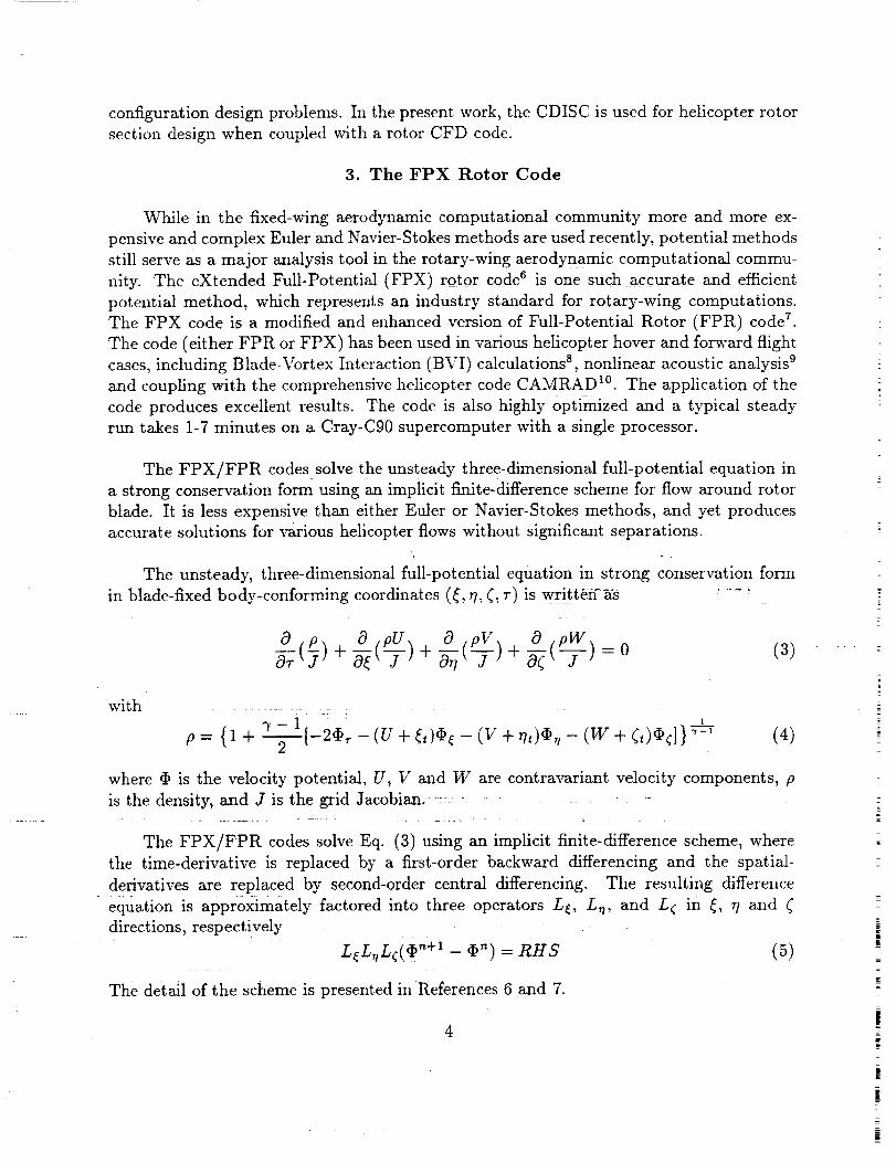
3. The FPX Rotor Code
While in the fixed-wing aerodynamic computational community more and more ex-
pensive and complex Euler and Navier-Stokes methods are used recently, potential methods
still serve=aS a major anaiysis tool :in the r0tary-wing aerodynamic computational commu-
nity. The eXtended Full-Potential (FPX) rotor code s i_s one such accurate and efficient
potential method, which represents an industry standard for rotary-wing computations.
The FPX code is a modified and enhanced version of Full-Potential Rotor (FPR) code 7.
The code (either FPR or FPX) has been used in various helicopter hover and forward flight
cases, including Blade-Vortex Interaction (BVI) calculations 8, nonlinear acoustic analysis 9
and coupling with the comprehensive helicopter code CAMRAD 1°. The application of the
code produces excellent results. The code is also highly Optimized and a typical steady
run takes 1-7 minutes on a Cray-C90 supercomputer with a single processor.
The FPX/FPR codes solve the unsteady three-dimensional full-potential equation in
a strong conservation form using an implicit finite-difference scheme for flow around rotor
blade. It is less expensive than either Euler or Navier-Stokes methods, and yet produces
accurate solutions for various helicopter flows without significant separations.
The unsteady, three-dimensional full-potential equation in strong conservation form
in blade-fixed body-conforming coordinates (_, 77,_, r) is writteff as ....
0 p 0 ___ 0 pV_ 0 p____0--;(7)+ ) + N(-7- , + N( ) = 0 (3)
with
p= {1 + _--_[-2_-(U + (t)_5¢- (V + rh)O , -
i
(W + (t)q_¢]} _-' (4)
where _ is the velocity potential, U, V and W are contravariant velocity components, p
is the density, and J is the grid Jacobian.
The FPX/FPR codes solve Eq. (3) using an implicit finite-difference scheme, where
the time-derivative is replaced by a first-order backward differencing and the spatial-
derivatives are replaced by second-order central differencing. The resulting difference
equation is approximately factored into three operators L_, L_, and L_ in _, 7? and (
directions, respectively
: L_L,tL_(_ n+i - _') = RHS (5)
The detail of the scheme is presented in References 6 and 7.
4
i
z
i#

The FPX is the substantially modified version of the FPR code. Both entropy and
viscosity corrections are included in the FPX code. The entropy correction potential formu-
lation accounts for the shock produced entropy to enhance physical modeling capabilities
for strong shock cases. Either a two-dimensional or a three-dimensional boundary layer
model is coupled with the FPX code to account for viscosity effects. In addition, an axial
flow capability is added into the FPX code to treat tilt-rotors in forward flight. In addi-
tion to the O-H grid topology, an H-H grid topology is added as well. More recently, the
Vorticity Embedding (VE) is incorporated into the FPX code to enhance the prediction
capability of parallel blade-vortex interactions 11.
A grid generation package GRGN3 is used to generate O-H mesh around rotor blade.
The blade surface is defined by an input file. The far-field boundary of the mesh is set at a
fixed number of chords from blade surface. The mesh points are generated between blade
surface and far-filed boundary. This grid generator is combined into the flow solver FPX
recently 12.
4. Implementation
The coupling of the CDISC design method with the rotor FPX code is the main scope
of the present work. Two methods chin be used for coupling the CDISC module with
the FPX flow analysis code: direct coupling where the CDISC module is treated as a
subroutine called by the flow solver; and indirect coupling where a job control language is
used. The indirect coupling offers advantages in code maintenance and portability, and the
design module does not add to the central memory requirement. In the present work, an
indirect coupling is used where a UNIX script file is used to control entire design procedure
automatically. User interference during the design processes is not needed.
Information is passed between the CDISC module and the FPX flow solver using blade
section geometry file and surface pressure coefficient file. The FPX flow solver with a built-
in grid generator 12 is used in this coupling, so that the grid can be re-generated within the
flow solver each time when a new blade section geometry file is obtained from the CDISC
module. Some modifications on input and output statements to the CDISC code and the
FPX code are made as required by the coupling, and thus any type of auxiliary pre- or
post-processor codes is not needed. The UNIX script file starts the FPX flow solver to
produce an output file containing blade section surface pressure coefficients. This file along
with the initial blade section geometry file is then fed into the CDISC design module. The
CDISC design module then produces a new geometry file. This new geometry file is used
as input for the FPX flow solver. The built-in grid generator generates a new grid and then
the flow solver produces a new surface pressure coefficient file. This procedure continues
for desired number of cycles as specified in the UNIX script file. Typical cases take 15-30

cycles to get a convergent design.
5. Results
As a test of capability of the new pac'l_ge using the CDISC and the FPX codes in
rotor section design, several sample design cases are made for a rotor blade. The planform
of the blade is shown in Figure 1 along with seven design stations as indicated. The
blade has a zero-twist. The first three cases are basic DISC design where target pressure
distributions are pre-deflned without any constraints. The next two cases are CDISC
design where target pressure distributions are automatically generated. The following
sub-sections present these results.
5.1 Basic DISC Results
In all three basic DISC design cases, initial blade sections are NACA0012 airfoil sec-
tions and target pressure distributions are obtained from a known "target" geometry. The
new design package is then used to "reproduce" the original "target" configuration. The
tip Mach number is set at 0.6288 for the first and second cases, 0.95 for the third case.
In the first case, the "target" geometry is NACA0008 airfoil section. Thirty design
cycles are executed to get a convergent (almost convergent at tip-station) design. This case
requires around 26 minutes on the Cray-C90 computer with a single processor. The results
of this case are presented in Figures 2a-2e. Figures 2a and 2b are design history in terms
of blade section geometry and surface pressure distributions, respectively. Figure 2c gives
design history of spanwise lifting coefficients, moment coefficients and drag coefficients.
A good approximation to the target pressure distributions is achieved after only a few
(ten) design cycles (target pressure is given next). Figures 2d gives a comparison of design
geometry and target geometry along with the initial geometry, while Figure 2e gives a
comparison for surface pressure distributions for four design stations as indicated (although
a total of seven stations are designed). The correlation between the final design and target
pressure distributions at each station is very good. The new airfoil sections generated
compare well with the original "target" geometry.
The second case is very similar to the first case. In this case however, the "target"
geometry is an "after-design" NACA0008 airfoil, where a CDISC procedure is first applied
to NACA0008 to produce a modified airfoil for reducing drag. The target pressure dis-
tribution is the final design pressure during this design process. The results of this =ease
are presented in Figures 3a-3e. Figures 3a-3c are design history. Figures 3d and 3e are
comparison of design and target. A good agreement between design and target is obtained
again.
In the third case, the "target" geometry and target pressure are provided from a
6
|
i

CDISC design case applied to MDHC HH02 and NACA64A006 airfoil sections. It is ex-
pected that a large number of design cycles is needed for this case to get a convergent
design due to a substantial difference between the initial geometry and the "target" ge-
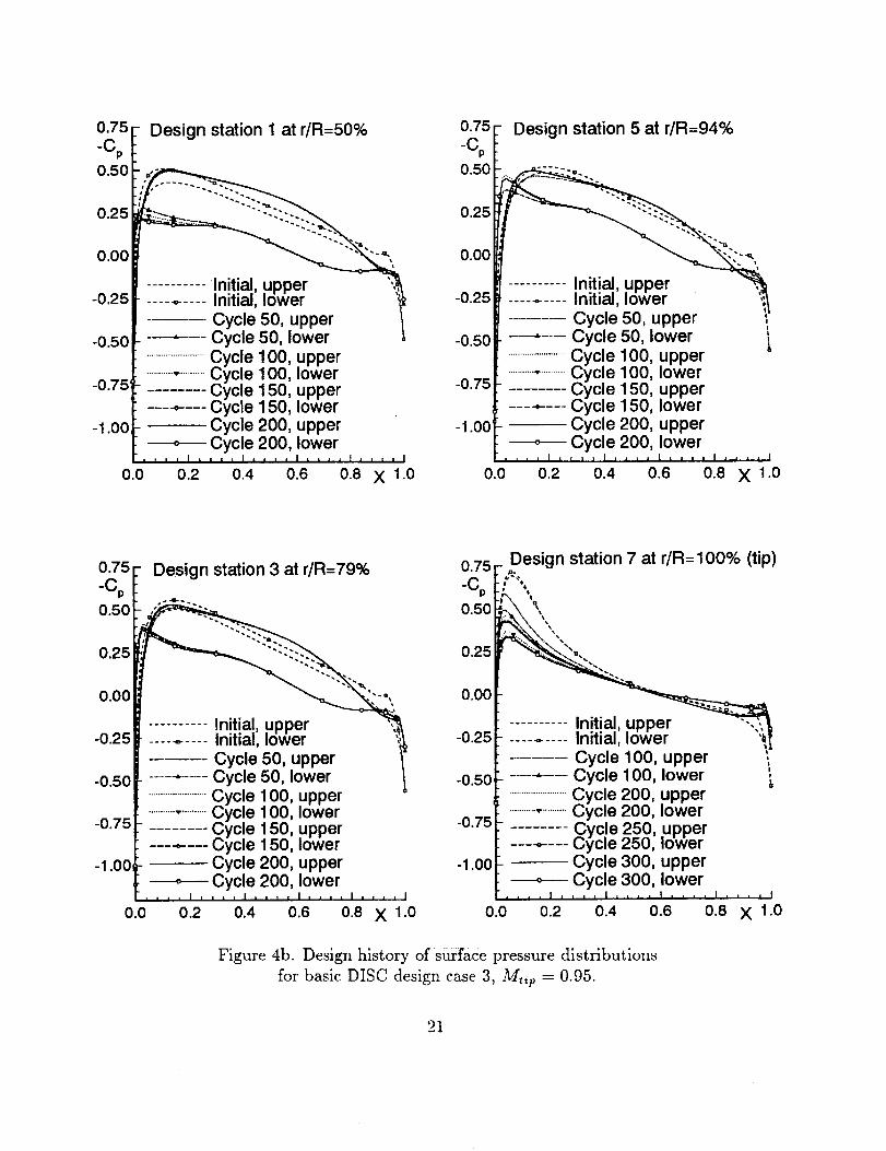
ometry, particularly at tip station. As a consequence, 300 design cycles are executed for
this case to examine the nature of convergence. The results of this case are presented in
Figures 4a-4g. Figures 4a and 4b are design history in terms of airfoil section geometry
and surface pressure distributions, respectively. Figure 4c gives design history of spanwise
lifting coefficients, moment coefficients and drag coefficients. It is seen that the solution
is convergent between design cycles 150 and 200 for Stations 1, 3 and 5, and almost con-
vergent at design cycle 300 at Station 7 (the tip station). Figures 4d gives a comparison
of final design geometry and target geometry along with the initial geometry, while Figure
4e gives a comparison for surface pressure distributions for the four design stations. The
correlation between the final design and target pressure distributions at Stations 5 and 7
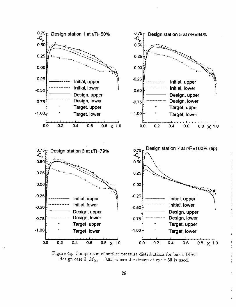
is very good. However, some discrepancies exist for Stations 1 and 3. Same is true for the
comparison of geometry. Figures 4f and 4g then made another comparison of target with
design where design geometry and pressure are obtained at design cycle 50 for Stations 1,
3 and 5. It is now noted that the agreement between design and target is better than that
of Figures 4d and 4e for Stations 1 and 3, particularly for Station 1.
5.2 CDISC Results
With the Constrained DISC approach, the emphasis is shifted to meeting the con-
straints where target pressure is generated automatically within the design module. In the
next sample cases, two constraints are imposed: one to fix the original spanload distri-
bution, and other one to reduce drag using the Modified Uniform Distribution (MUD) of
chordwise loading constraint option. A MUD value of 0.2 is used according to Campbell 5
to obtain a best result in reducing drag. The tip Math number is set at 0.95. In both
cases, 15 design cycles are executed.
Figures 5a-5c are the results of the first CDISC sample design case, where initial blade
sections are NACA0012 sections. Figures 5a and 5b give the history of design for blade
section geometry and surface pressure distributions, respectively. Figure 5c presents a
spanwise lifting coefficient, moment coefficient, drag coefficient and maximum local Mach
number distributions. It is seen that the design reduces the negative lifting force, pitching
moment a_nd drag force. By examining the drag coefficients, it is found that the drag is
reduced by 12.5_ at Station 3 and 7.5% at Station 5 through the CDISC design. The
maximum local Mach numbers are unchanged during the design process.
Figures 6a-6c are the results of the second CDISC sample design case, where initial
blade sections are MDHC HH02 airfoil for Stations 1 through 5, and NACA64A006 airfoil
for Stations 6 and 7. Figures 6a and 6b give the history of design for blade section geom-
etry and surface pressure distributions, respectively. Figure 6c presents a spanwise lifting

coefficient, moment coefficient, drag coefficient and shock Mach number distributions. By
examining the drag coefficients, it is found that the drag is reduced by 12.7% at Station 1,
9.6% at Station 3, 25.6% at Station 5 and 12.5% at Station 7 through the redistribution
of the loading and smoothing. Shock is also eliminated through the design as indicated,
in the figure, by zero-shock Math number along the span.
6. Conclusions
A rotor section aerodynamic design package is developed by coupling the CDISC
design method with the FPX rotor CFD code. The coupling between the CDISC design
and the FPX flow analysis is fully automated using a UNIX script file to control job flow.
Five sample design cases are presented for both basic DISC and Constrained DISC design
for a zero-twist blade in hovering motion. The results indicate that the CDISC method is
a robust and efficient design method when used in rotor section design coupled with theFPX code.
These sample cases demonstrate that the target pressure can be achieved even when
the initial geometry is not "close" to the "target" geometry. A constrained DISC design
case demonstrates a shock-free design using MUD method, where drag is significantly
reduced. Actual computational effort depends on the complexity of the target pressure
distributions and the difference between the initial and "target" geometry. A typical
design case with 30 design cycles for designing 7 stations requires around 26 minutes CPU
time on the Cray-C90 computer with a single processor. Presently, all sample design cases
are made to a zero-twist blade without in-flow angles for either symmetric or cambered
airfoil section design. The further work is needed in extending the current design package
into high-lifting flows with large twist and in-flow angles.
8

Station1
r/R=50%
Station 2 Station 3
Station 4
Station 5 Station 7
1 r_-mo0°_(tip)
II
Station 6
Figure 1. The rotor blade planform.

0.08
Y0.06
0.04
0,02
0.00
-0.02
-0.04
-0.06
Design station 1 at r/R = 50%
Initial ...Cycle 5
..........................Cycle 10Cycle 15Cycle 20Cycle 25Cycle 30
js"
•'J
rs "°
0.08
Y0.06
0.04
Design station 5 at r/R = 94%
Initial
0.02 .......... (_yc!e 5.........................._ycle 10
Cycle 150.o0 Cycle 20
Cycle 25-0.02 Cycle 30
-0.04 ,,,'"
-0.06 ""............
-0.080.0 0.2 0.4 0.6 0.8 X 1.0 0.2 0.4 0.6 0.8 X 1.0
0.08
Y0.06
0.04
0.02
0.00
-0.02
-0.080.0
Design station 3 at dR = 79%
........... Initial
Cycle 5..........................Cycle 10
Cycle 15C yc!e 20_ycue 25Cycle 30
0.08 -Design station 7 at r/R = 100% (tip)
Y
0.06 ,-'" ............. ,
0.04
.......... Initial
0.02 Cycle 5
..........................Cycle 10
o.oo Cycle 15Cycle 20
-o.o2 Cycle 25Cycle
-0.04 .- "o• °
-0.06 ""...........
0.2 0.4 0.6-0.08
0.8 X 1.0 0.0 0.2 0.4 0.6 0.8 X 1.0
Figure 2a. Design history of blade section geometry
for basic DISC design case 1, Mtir = 0.6288.
10

0.75
-Cp
0.50
0.25
0.00
-0.25
-0.50
-0.75
-1.00
0.0
Design station 1 at r/R=50%
"_-...--.'.-...
............. Initial, lowerCycle 10, upper },
.......... Cycle 1O, lower
................................Cycle 20, upper
..............."..............Cycle 20, lowerCycle 30, upper
o Cycle 30, lower.... I .... I .... I .... I . , . . I
0.2 0.4 0.6 0.8 X 1.0
0.75
-Cp
0.50
0.25
0.00
-0.25
-0.50
-0.75
-1.00
0.0
Design station 5 at r/R=94%
,;=._ ='::=:.
............. Initial_
............ Initial, lower }i
Cycle 10, upper
.............. Cycle 10, lower
................................Cycle 20, upper
...............o..............Cycle 20, lower
Cycle 30, upper
.... Cycle 30, lower,
0.2 0.4 0.6 0.8 X 1.0
0.75
-Cp
0.50
0.25
0.00
-0.25
-0.50
-0.75
-1.00
0.0
Design station 3 at r/R=79%
............. Initial, lower t__
Cycle 10, upper
......... Cycle
................................Cycle
...............* ..............Cycle
Cycle
cycle0.2 0.4
10, lower
20, upper
20, lower
30, upper
?o,,Iower .... ,0.6 0.8 X 1.0
0.25
0.00
-0.25
-0.50
Design station 7 at r/R=100% (tip)
........ Initial, lowerCycle 10, upper !
............ Cycle 10, lower
-o.75 ................................Cycle 20, upper
I ...............* ..............Cycle 20, lower-1 .OOl- Cycle 30, upper
,,,, • .... C,yc!e 30, lower= . i = = , . = = I
0.0 0.2 0.4 0.6 0.8 X 1.0
Figure 2b. Design history of surface pressure distributions
for basic DISC design case 1, Mtip = 0.6288.
11

0.02
CL
0.00
-0.0,_
-0.04
-0.06
Y;
............. Initial
Cycle 10
...............................Cycle 20Cycle 30
_,, , , I L, , , I , _ , , I .... I, ,_,_j,,l_ I
50 60 70 80 90 100
r/R (in %)
0.01
Co
0.00
-0.01
-0.02
-0.03 -
-0.04
............. Initial
............. Cycle' 10
................................Cycle 20
Cycle 30.... I .... I , i ..-i . , r t i .... I .... I
50 60 70 80 90 100
r/R (in %)
0.02
CM
0.01
0.00
-0.01
"%. _L
:" ........... Initial
............... Cycle 10
................................Cycle 20
Cycle 30, , , I ,-,-_;-.TT, , , I i I i i I T I _ , I ,_. i I
=50 60 70 8o 90r/R (in %)
Figure 2c. Design history of spanwise lifting (CL), moment (CM) and drag (CD)
coefficients for basic DISC design Case 1, Mtip = 0.6288.
12

0.08 - Design station 1 at dR = 50%
Y
0.06 ,,, .......... ,,
0.04 ,,_,,
........... Initial
0.00,, _ Design ,_o Target _j_. ,,"
-0.02 _ _,,'"
0.0 0.2 0.4 0.6 0.8 X 1.0
0.08
Y0.06
0.04
0.02
0.00
-0.02
-0.04
-0.06
Design station 5 at r/R = 94%
r" -.
r7 ""'"""'_s
Design 2
0.?? F Design station 3 at fiR= 79%
Y_
0.06_- , ,........... ""-,,
0.04 I[ _'"',"
o........... Initial
0.00_- _ Designo Target ,.._.'• "
0.0 0.2 0.4 0.6 0.8 X 1.0
0.08 _Design station 7 at r/R = 100% (tip)
Y0.06
0.04 _,,
0.02 oo_,,,
........... Initial %
0.00 _ Design _'o Target _ ._,,"
008 / .... J .... i .... i .... i .... i0.0 0.2 0.4 0.6 0.8 X 1.0
Figure 2d. Comparison of blade section geometry
for basic DISC design case 1, Mtip = 0.6288.
13

0.75_ V Design station 1 at r/R=50%
"_P i0.50 _--.'.'--.
1"/4k ....... A+ "" _ _'_0.25....,...,.,&...._....
i',_.. 2._..;+_
oo:i;;-0.2E
-0.50
Design, upper
-o.75 ................................Design, lower
° Target, upper
-1 .oo • Target, lower
, _ I .... I . , , , l , , , , I . j.+. _ ]
0.0 0.2 0.4 0.6 0.8 X 1.0
0.75
-Cp
0.50
0.25
0.00
-0.25
-0.50
-0.75
_1.00
0.0
Design station 5 at r/R=94%
.... +l_'_+u -
Initial, upper
............. Initial, lower I
Design, upper
..............................Design, lower
° Target, upper
• Target, lower
, , , I , , _ , I , • _ I I z z , , I , , , , I
0.2 0.4 0.6 0.8 X 1.0
0:_75F Design station 3 at r/R=79%
-(';P i0.50 ,,_1- L'.::-,,_;/ "-._-..I_:l_ ........"-"-
0.25 _:...
-0 25 _]• - .......... Initial, upper
-0.50 ............. Initial, lower I
Design, upper
-0.75 ................................Design, lower
° Target, upper
-1 .oo • Target, lower
. . , , .I . , . .I ,_ , , I . , . , I !.! I i |
010 0.2 0.4 0.6 0.8 X 1.0
0.75
"Cp
0.5(
0.2.=
0.0(
-0.2E
-0.50
-0.75
-1.00
0.0
_ Design station 7 at r/R=100% (tip)
............. Initial, lower _-
Design, upper
................................Design, lower
° Target, upper
" Target, lower
.... I .... I , L , , I .... I _ , = , I
0.2+ 0.4 0.6+ o.s=X +.o
Figure 2e. Comparison of surface pressure distributions
for basic DISC design case 1, Mtil)= 0.6288.
14

0.08
Y0.06
0.04
0.02
0"00 f
iiill-0.06
-0.080.0
Design station 1 at r/R ---50%
Cycle 20_ C_/cle 25 _,_'"
i %., se
i I I I ] .... I .... I , , , , I , , , , ]
0.2 0.4 0.6 0.8 X 1.0
0.08
Y0.06
0.04
0.02
0.00
-0.02
-0.04
-0.080.0
Design station 5 at r/R = 94%
InitialC_ycle 5
.........................._.,ycle ] uCycle 15Cycle 20Cycle 25Cycle 30
0.2 0.4 0.6 0.8 X 1.0
0.08
Y0.06
0.04
0.02
0.00
-0.02
-0.04
-0.06
Design station 3 at r/R = 79%
Initial
Cycle 5..........................Cycle 10
Cycle 15Cycle 20Cycle 25Cycle 30
0.08
Y0.06
0.04
0.02
0.00
-0.02
n station 7 at r/R = 100% (tip)
........... Initial
Cycle 5..........................Cycle 10
......... Cycle 15Cycle 20Cycle 25Cycle
o"
s
-0.080.0 0.8 X 1.0
Figure 3a. Design history of blade section geometry
for basic DISC design case 2, Mtip = 0.6288.
15

0.75 I-Cp0.50
0.25
0.00
-0.25
-0.50
-0.75
-1.00,
0.0
Design station 1 at r/R=50%
............ In'dial, lower
L Cycle 10, upper!
...... Cycle 10, lower
................................Cycle 20, upper
...............* .............Cycle 20, lowerCycle 30, upper
Cycle 30: lower| , , , J • = = i | i i t I , | .... I
0.2 0.4 0.6 0.8 X 1.0
0.75 -
-Cp
0.50
0.25
0.00
-0.25
-0.50
-0.75
d
-1.00
0.0
Design station 5 at r/R=94%
o -o-;;'°-:::::..::.
............. Initial, lower 1
................ Cycle 10, upper
.................. Cycle 10, lower
................................Cycle 20, upper
...............° ..............Cycle 20, lower
Cycle 30, upper
--==o Cycle 30, loweri i i i ] ¢,4 , ' , , , . , , , , I , , , = I
0.2 0.4 0.6 0.8 X 1.0
0 75 Design station 3 at r/R=79%
I0.50 _,-'2.'.".... _.
0.25 . -.::::::. "-..
0.00
0 25 ............. Initial, upper "_
- ' ............. Initial, lower
-0.50 Cycle 10, upper i............... Cycle 10, lower
-o.75 ................................Cycle 20, upper
...............° ..............Cycle 20, lower
-1 .o0 Cycle 30, upperCycle 30, lower
= JL, , I , , = = I .... I , , , , I .... 1
0.0 0.2 0.4 0.6 0.8 X 1.0
0.25
0.00
-O.25
-0.50
-0.75
-1.00
0.0
Design station 7 at r/R=100% (tip)
............. Initial, lower _,
Cycle 10, upper !
............ Cyc!el O, lower
................................Cycle 20, upper
...............o..............Cycle 20, lower
Cycle 30, upperCycle 30, lower
,_, = , , _ , _/'= =L J I , , , , I , , , , i
0.2 0.4 0.6 0.8 X 1,0
Figure 3b. Design history of surface pressure distributions
for basic DISC design case 2, Mtip = 0.6288.
16

0.02
CL
0.00
-0.02
-0.04
-0.06
-0.08
-0.10
mrs
i
,i
i I
...°-
............. Initial
Cycle 10
................................Cycle 20Cycle 30
, , , I = , , , | _ = _ i I .... I , , , , I , , , , I
50 60 70 80 90 1O0r/R (in %)
0.01
CD
0.00
-0.01
-0.02
-0.03
-0.04
11
,,
............. Initial
.............. Cycle 10
................................Cycle 20
Cycle 30,,,I,,.,I .... ImLlll .... I .... ]
50 60 70 80 90 100
r/R (in %)
0.01
0.00
-0.01
--. ......... . ................ ...
1
i
..... _ ..................... "-_
............. Initial
Cycle 10
................................Cycle 20Cycle 30
.,,,I,,,,I=L,,I,=,, I,,,,I,,,_1
so 6o 7o 8o 90 1oodR (in %)
Figure 3c. Design history of spanwise lifting (CL), moment (CM) and drag (CD)
coefficients for basic DISC design case 2, Mt,p = 0.6288.
17

0.08
Y0.06
0.04
0.02
0.00
-0.02
-0.04
-0.06
-0.080.0
Design station 1 at r/R = 50%
, , , , I .... I .... I .... ! .... I
0.2 0.4 0.6 0.8 X i.0
0.08
Y0.06
0.04
0.02
0.00
-0.02
-0.04
-0.06
Design station 5 at r/R = 94%
Design
0.08
Y0.06
Design station 3 at r/R = 79%
I"
0.04 ' ""
0.020.00,
-0.02
-0.04 1 ""'" "'"'""'"
-0.06_- """............ ""
[008 r .... , .... , .... , .... , .... ,
0.0 0.2 0.4 0.6 0.8 X 1.0
0.08 _Design station 7 at r/R = 100% (tip)
Y0.06
0.04
0.02
0.00
-0.06
........... Initial
Design
o Target
-0.080.0 012 0.4 0.6
Figur e 3d. Comparison of blade section geometry
for basic DISC design case 2, Mtip - 0.6288.
0.8 Xl.0
18

0.75
-Cp
0.50
0.25
0.00
-0.25
-0.50
-0.75
-1.00
0.0
- Design station 1 at r/R=50%
"L--2.-c->.../
........... Initial, Upp er _'_
....... Initial, lower L
Design, upper
...............................Design, lower
o Target, upper
• Target, lower
[ I _ , I .... I, i,, I _,, , I .... •
0.2 0.4 0.6 0.8 X 1.0
0.75[- Design station 5 at r/R=94%
0.00 i: " """: .... -=,_.
-0.25 Initial, upper '_
............. Initial, lower /-0.50
-0.75 I
-1.00 f
0.0
Design, upper
................................Design, lower
o Target, upper
• Target, lower
.... I,, , , I .... I A , = , I , , ,
0.2 0.4 0.6 0.8 X 1.0
0.75
-C 0
0.50
0.25
0.00
-0.25
-0.50
-0.75
-1.00
Design station 3 at r/R=79%
" _.-:.-..-.::-..:...,"S" ---:--..
,=_ "-:-::-.
...... Initial, lower
Design, upper
................................Design, lower
o Target, upper
" Target, lower
, • i , | i i ,
0.o 0.2
, | , , , , i .... ! .... I
0.4 0.6 0.8 X 1.0
0 75- Design station 7 at r/R=100% (tip)
o.5o ,,,,"\
0.25 __.
0.00
-0.25 ........... Initial, upper I............. Initial, lower
-0.50Design, upper[
-o.75 _- ...............................Design, lower
i ° Target, upper-1 .oo " Target, lower
i , , , I , , , , I _ _ , , I , , , , I , , , • 1
0.0 0.2 0.4 0.6 0.8 X 1.0
Figure 3e. Comparison of surface pressure distributions
for basic DISC design ease 2, Mtip = 0.6288.
19

0.08
Y0.06
0.04
0.02
0"00 I
-0.02 f
-0.04
-0.06
-0.080.0
Design station 1 at r/R = 50%
......... Cycle 150 _,.
Cycle 20_
_ "J'e t
.... I .... I , , _ , I .... I .... I
0.2 0.4 0.6 0.8 X 1.0
0.08 Design station 5 at r/R = 94%
o.Y
0.04 ........... .
0.02 ............................Cycle 100 _...
......... Cycle 150 "_
0.00 _ Cycle 200
-0.02 _\, _'_ .."'"
004 F_'""'"'""
f """ ........... "'"
E_0.08 / .... I .... I , , , , I .... t .... ]
0.0 0.2 0.4 0.6 0.8 X 1.0
0.08 -
Y0.06
0.04
0.02
0.00
-0.02
Design station 3 at r/R = 79%
I_' _ Cycle 200 ,.
-0.041 ""'" "'"'"'"
-0.06_- """ ............ "'"
[008 r .... , .... i .... I .... _ .... J
0.0 0.2 0.4 0.6 0.8 X 1.0
0.08 Design station 7 at r/R = 100% (tip)
Y
0.06 .... .......... -..
F ,," _f...._...--..;._.-:.--_-..>.. -,,,
0.04 IT ,' .._...-.S_...... "_"-......'>. "-., ....' ,. _ _ ...... _-..'.>. -.-..
o.o2_- __;.'..
ooor-:-" c vC',e oo_, ..... ,-- C_,cle 150 _?
-0.02 !_ ...... Cycle__.'"
-0.04 - ',, "_ii-..-_..-..=-..--..-.2.-222_ ,•'"
-0.06 Cycle 250
_----- Cycle 300-0.08 .... ' .... ' .... i,, .. i .... ,
0.0 0.2 0.4 0.6 0.8 X 1.0
Figure 4a. Design history of blade section geometry
for basic DISC design case 3, M, ip = 0.95.
2O
0.75
°Cp
0.50
0.25
0.00
-0.25
-0.50
-0.75
-1.00
0.0
Design station 1 at r/R=50%
_-- I.ni.t!a!,upper "_----_-----Initial,/6wer _
u2ye; 1..... C' ,cle 50, lower........................ 01
......................C _
........ C____._---C I
C'_.__..o-...--C ,
i,,,1111
0.2
tcle 100, upperrcle 100, lower'cle 150, upper'cle 150, lower,cle 200, upper,cle 200, lower, I j = , , I .... ! .... I
0.4 0.6 0.8 X 1.0
0.75
-Cp
0.50
0.25
0.00
-0.25
-0.50
-0.75
-1.00
0.0
Design station 5 at r/R=94%
........................ O1
........... ,r .......... C'
C-------e------- C
Initial, lower'i/_' uppe_
.............. C _,cle 50, upperrcle 50, lower i,cle 100, upper,cle 100, lower,cle 150, upperfcle 150, lowerfcle 200, upper
----o--- Cycle 200, lower., , _ I , , 1 • I,. , , I = 1,. I, . , . I
0.2 0.4 0.6 0.8 X 1.0
0.75
-Cp
0.50
0.25
0.00
-0.25
-0.50
-0.75
-1.001
).0
Design station 3 at r/R=79%0.75
-Cp
0.50
_°pper
wer50, upper50, lower100, upper100, lower150, upper150, lower200, upper
0.250.00
.......... Initial,
......... Initial, -o.25Cycle
........... Cycle -0.50
........................Cycle
......................Cycle -o.75Cycle
....... CycleCycle -1.oo
___o--- Cycle 200, lower.... l = ., , l ,., , I,.,. I.,, i I
0.2 0.4 0.6 0.8 X 1.0
_Design station 7 at r/R=100% (tip)
_\. ,,,_y'%.\ ,,
----_----Initial, lower '_ICycle 100, upper
....... Cycle 100, lower i........................Cycle 200, upper......................Cycle 200, lower........ Cycle 250, .upper----,---- _ycle 250, lower
Cycle 300, upper._= Cycle 300, lower
,,,,=L .... I. ''' l' ''_l_'''l
0.0 0.2 0.4 0.6 0.8 X 1.0
Figure 4b. Design history of s_face pressure distributions
for basic DISC design case 3, Mt,p = 0.95.
21

0.30
CL0.20
0.10
0.00
-0.10
-0.305O
............. Initial
Cycle 50
................................Cycle 100
........... Cycle 150C, 200
60 70 80 90 1O0
r/R (in %)
0.0;
0.01
O.OC
-0.01
-0.02
-0.03
-0.04
-0.05
-0.06
-0.07
-0.08
Co
............. Initial
Cycle 50
.............................Cycle 100
Cycle 150
Cycle 200
50 60 70 80 90 1O0
r/R (in %)
0.0;
0.00
-0.02
-0.04
-0,06
-0.08
-0.10
yemm_m-'--- - L •
+ -............ Initial
Cycle 50
. ...............................Cycle 100
Cycle 150
Cycle 200
L
-- -- Z
50. 60 70 80 90 ._100 . _- :
r/R %)Figure 4c. Design l_istory of spanwise lifting (CL), moment (CM) and drag (Co)
coei:Ficients for basic DISC design case 3, Mtis- 0.95.
22

0.08
Y0.06
Design station 1 at r/R = 50%
0.04
0.02
........... Initial
0.00 Design
o Target-0.02
O jD
0 0 0 0 0 .1 •
04 ' ""0 '
-0.06 ""............
-0.080.0 0.2 0.4 0.6 0.8 X 1.0
0.08
Y0.06
0,04
0.02
i Design station 5 at r/R = 94%
0.00,
-0.02
-0.04
-0.06
-0.080.0
Design
_x o II
.... I .... = .... = .... L .... i
0.2 0.4 0.6 0.8 X 1.0
0.08
Y0.06
Design station 3 at r/R = 79%
oo,0.02 "'",
°'0°:' L o Target Z -..,,-"
,- _ Design
-0.02 _°,,O;o_ o o .,1-'""0 0 0 0 0 s"
-0 04 [ ' .• o J
-0.06[,., _o, .... i .... , .... i .... i .... I
0.0 0.2 0.4 0.6 0.8 X 1.0
0.08
Y0.06
_Design station 7 at r/R = 100% (tip)
• " -.
S I ".
0.04 ,'
0.02 _.
oooky
-0.04 I'""'" "'" ""'"J'""
-0.06_- """ ............ ""
[_0.08 / .... i .... i .... i .... J .... I
0.0 0.2 0.4 0.6 0.8 X 1.0
Figure 4d. Comparison of blade section geometry for basic DISC
design case 3, Mtip = 0.95, where final design is used.
23

0.75
-Cp
0.50
0.25
0.00
-0.25
-0.50
-0.75
4
-1.00 iI
0.0
Design station 1 at r/R=50%
o
"".,.,,
....;=............._..._ _,,
Initial, upper 1
............. Initial, lower
Design, upper
................................Design, lower
o Target, upper
• Target, lower
.... 1 .... I , , , , | L , _ , I .... I
0.2 0.4 0.6 0.8 X 1.0
0.75
-Cp
0.50
0.25
0.00
-0.25
-0.50
0.75
-1.00'
Design station 5 at r/R=94%
z ........... _"_ ",,
o %
%t
............. Initial, lower I!
Design, upper
................................Design, lower
o Target, upper
• Target, lower
0.0 0.2 0.4 0.6 0.8 x l.0
0.75 Design station 3 at r/R=79%-Cp
Os -I_ .
....."!
0.25 ' , •0.00
-0.25
-0.50
I _ Design, upper
-0.75[- ........ Design, lower
_ o Target, upper
-1.00[ • Target, i.ower .r .... 1 _ _ l , z • • I .... I .... I
0.0 0.2 0.4 0.6 0'8 X 1.0
0 75 Design station 7 at r/R=100% (tip)_c
o2o
0.00 . __:.. .....
0.25 .......... Initial, upper............. Initial, lower
0.50Design, upper
T-
o.75_- ................................Design, lower
i o Target, upper1.00 " Target, lower
.... I , . , = I _ , . . I .... t .... J
0.0 0.2 0.4 0.6 0.8 X 1.0
Figure 4e. Comparison of surface pressure distributions for basic DISC
design case 3, Mtip = 0.95, where final design is used.
24

0.08 Design station 1 at r/R = 50%
0.06 _9_
0.04 y
0.02 -_..
...........Initial %.0.00_- _ Design
o Target .._ ../
-°°°f "_0.081 . • , , I , _ . . i .... _ .... :,, ,, I
0.0 0.2 0.4 0.6 0.8 X 1.0
0.08
Y0.06
Design station 5 at r/R = 94%
0.04 _.
0.02 ........... Initial %
-0.02 _,, o o . ,..-".,
-0.04 1 "' "'"""
-0.06[008 ..... _ .... ,,,,, I , , ,,.I .... ,
0.0 0.2 0.4 0.6 0.8 X 1.0
0.08
Y0.06
Design station 3 at r/R = 79%
0.02
......... Initi I
o.oo :L _ Design
-o.o2 • o Target o_.o .__......-'"-_'-
_u s aj J_J
-0 04 v- ' -"
"0"06 f008" .... ' .... ' .... ' .... I .... I
0.0 0.2 0.4 0.6 0.8 X 1.0
0.08
Y0.06
0.04
0.02
0.00
0.02
Design station 7at r/R = 100% (tip)
0.041 '
0.0
•sp r'l
, . , I .... I .... I , , . a I a _ = = I
0.2 0.4 0.6 0.8 X 1.0
Figure 4f. Comparison of blade section geometry for basic DISC
design case 3, Mtip = 0.95, where the design at cycle 50 is used.
25
0.75
-Cp
0.50
0.25
0.00
-0.25
-0.50
-0.75
-1.00
0.0
Design station 1 at r/R=50%
o
F o
............. Initial, lower
Design, upper
................................Design, lower
o Target, upper
• Target, lower
L .... _J_ _ L_J , , I .... I
0.2 0.4 0.6 0.8 X 1.0
0.75
-Cp
0.50
0.25
0.00
-0.25
-0.50
-0.75
-1.00
0.0
Design station 5 at r/R=94%
,,. ":---- "_-..-....
............. Initial, lower /t
Design, upper
................................Design, lower
° Target, upper
• Target, lower
, , , I , , ] _ I.._.. _ , , I t I i I | J = _ = I
0.2 0.4 0.6 0.8 X 1.0
0.75
-Cp
0.50
0.25
0.00
-0.25
-0.50
-0.75
-1.00
Design station 3 at r/R=79%
Initial, upper
............. Initial, lower 1',1
Design, upper
................................Design, lower
° Target, upper
• Target, lower
.... I , _,L , I .... 1 .... I .... I
0.0 0.2 0.4 0.6 0.8 X 1.0
-0.25
-0.50
-0.75
-1.00
0 75 Design station 7 at r/R=100% (tip)
o.5o , \0.25 \.
0.00 _ ............
_L
Initial, upper
............. Initial, lowerI
Design, upper
.............................Design, lower
o Target, upper
• Target, lower
.... I .... I .... I ,, ,, t , _ ,, I
0.0 0.2 0.4 0.6 0.8 X 1.0
Figure 4g. Comparison of surface pressure distributions for basic DISC
design case 3, M, ip = 0.95, where the design at cycle 50 is used.
26

0.08
Y0.0(
Design station 1 at dR = 50%0.08
Y0.06
Design station 5 at fir = 94%
0.02
0.00
-0.02
-0.04
-0.0(
-0.010.0
.......... Initial
......... Cycle 5
..........................Cycle 10
Cycle 15
0.04
o.0c
-0.02
-o.o4
-o.o6
-0,08o.o
........... Initial
Cycle 5
..........................Cycle 10
Cycle 15
o.o8
Y0.06
0.04
0.02
0.00
-0.02
-0.04
-0.06!
-0.080.0
Design station 3 at r/R = 79%0.08
Yo.o6
Design station 7 at r/R = 100% (tip)
0.04
.......... Initial 0.02 .......... InitialCycle 5
....... Cycle 5..........................Cycle 10 0.00
..........................Cycle 10Cycle 15
-0.o2 Cycle 15
0.4 0.6 0.8 X 1.0 -0.0[ 0.0 0.2 0.4
Figure 5a. Design history of blade section geometry
for CDISC design case 1, Mtip = 0.95.
0.6 0.8 X 1.0
27

0.75
-Cp
0.50
0.25
0.00
-0.25
-0.50
-0.75
-1.00
0.75 -
-Cp
0.50Design station 1 at r/R=50%
0.25
o.00
............. Initial, lower _ -0.25
- Cycle 5, upper
........ Cycle 5, lower _ -o.5o
................................Cycle 10, upper
..............................Cycle 10, lower -o.75
Cycle 15, upper -1 .ooo Cycle 15, lower
.... I , , , j I .... I .... I , , , i I
0.0 0.2 0.4 0.6 0.8 X 1.0 0.0
Design station 5 at r/R=94%
............. Initial, lower
----_i .... CYcle 5, upper /......... Cycle 5, lower },
................................Cycle 10, upper
...............° ..............Cycle 10, lower
Cycle 15, upper
o Cycle 15, lowerI ' ' ' I , , • , ! .... I , , , , | , , , . I
0.2 0.4 0.6 0.8 X 1.0
0.75
-Cp
0.50
0.25
0.00
-0.25
-0.50
-0.75
-1.00
0.0
0.75
Design station 3 at r/R=79% -Cp
" :_:',.- ""'"'-_._ 0.50
0.25
0.00
............. Initial, lower _ -0.25
....... Cycle 5, upper /............ Cycle 5, lower ], -0.50
................................Cycle 10, upper-0.75
...............- ..............Cycle 10, lower
Cycle 15, upper -1.00o Cycle 15, lower
.... I , i i _ I i i i i I i , , , I .... I
0.2 0.4 0.6 0.8 X 1.0 0.0
(tip)
............. Initial, upper
...... Initial, lower "_
---_---- Cycle 5, upper /......... Cycle 5, lower _,
................................Cycle 10, upper
..............................Cycle 10, lower
Cycle 15, Upper
__-o---- Cycle !5, lower.... I .... I .... ] .... I: .... I
0.2 0.4 0.6 0.8 X 1.0
Figure 55: Design history of surface pressure distributions
for CDISC design case 1, Mtip = 0.95.
28
:

0.02
CL
0.00
-0.02
-0.04
-0.06
-0,08
-0.10
........................................................................................ "'"""-"
__J" ;
r
t
............. Initial
......... Cycle 5
...............................Cycle 10Cycle 15
,,, I, , j ,I., ,, I. ,,, I , . . .I., , . I
50 60 70 80 90 100r/R (in %)
C D
0.00
-0.01
-0.02
-0.03
-0.04
-0.05
-0.06
............. Initial
Cycle 5
................................Cycle 10
Cycle 15
.... I , , z , I _ . . . I , , , , I , , , . 1
60 70 80 90 1O0r/R (in %)
0.02
CM
0.01
0.00
-0.01
-0.02
i
............. Initial
Cycle 5
................................Cycle 10
Cycle 15,.. I .... I .... I_ _,, I .... ,I .... I
50 60 70 eo 90 lOOr/R (in %)
1.50
1.00
0.50
0.00
-0.50
_A A A & &&
• Initial
z_ Cycle 5
o Cycle 10
o Cycle 15
50 60 70 80 90 1oor/R (in %)
Figure 5c. Design history of spanwise lifting (CL), moment (CM) , drag (CD)
coefficients and local maximum Mach No. for CDISC design case 1, Mtip = 0.95.
29

0.08 -
Y0.06
Design station 1 at r/R = 50%
0.04 _"
0.02
..........................Cycle 10 "",_,,_X_
o.00 _ Cycle15 __
-o.o4 I
-o.06[
008- .... ' .... i .... r .... ,.,, LI0.o 0.2 0.4 0.6 0.8 X 1.o
0.08
Y0.06
0.04
0.02
0.00
-0.02
-0.04
-0.06
-0.080.0
Design station 5 at r/R -- 94%
.......... Initial
........... Cycle 5
..........................Cycle 10
Cycle 15
0.2 0.4 0.6 0.8 X 1.0
0.08 Design station 3 at r/R = 79%
Y .-:c'_':c_._.
u.uQ __
oo,F.......0 02 ............. Cycle 5
-0.04 F --
-0.06_
0 08 _ '.
0.0L_ J = , , = t • • • _ I t I I ' ] I J J _ |
0.2 0.4 0.6 0.8 X 1.0
::o :IOe'0n0,04P
0.02
0.00
-0.0;
-0.0_
-0.06
-0,080.0
station 7 at r/R = 100% (tip)
_ 1 I I ] .... I I 1 I I ( _ [ , , I , i i _
0.2 0.4 0.6 0.8 X 1.0
Figure 6a. Design history _0f })lade section geometry
for CDISC design case 2, Mtip = 0.95.
30

0.75
-Cp f
0.50
0.25
0.00
-0.25
-0.50
-0.75
-1.00
0.0
Design station 1 at r/R=50%
; ".........._...:.:_... ..............
Cycle 5, upper
.......... Cycle 5, lower
................................Cycle 10, upper
..............................Cycle 10, lowerCycle 15, upper
___o___cycle1,s:lower= " [ _ | * " " I I I = * = ' I I I
0.2 0.4 0.6 0.8 X 1.0
0.75
-Cp
0.50
0.25
0.00
-0.25
-0.50
-0.75
-1.00
0.0
- Design station 5 at r/R=94%
. ...... o°'-.
........... Initial, lower ',-'
................ Cycle 5, upper
......... Cycle 5, lower
................................Cycle 10, upper
...............•...............Cycle 10, lower
Cycle 15, upper
o .Cycle 15, !ower, , , , I , , , , , , , , I I I = , , I
0.2 0.4 0.6 0.8 X 1.0
0.75
-Cp
0.50
0.25
0.00
-0.25
-0.50
-0.75
-1.00
0.(
Design station 3 at r/R=79%
!
.......... Init'_, lower ,,,_; 1
Cycle 5, upper
........... Cycle 5, lower
................................Cycle 10, upper
...............° ..............Cycle 10, lower
Cycle 15, upper
o Cyc, le ! 5, Iowe r, = i x * | I I = = J i = I I I
0.2 0.4 0.6 0.8 X 1.0
0.75 Design station 7 at r/R=100% (tip)oC ol
-0.75
-1.00
0.25_0.00
............. Initial, upper-0.25
............. Initial, lower
-0.50 ............. Cycle 5, upper............. Cycle 5, lower
................................Cycle 10, upper
...............•..............Cycle 10, lower
Cycle 15, upper
° Cycle 15, lower.... t .... I , , , , I , , , , I , , , , I
0.0 0.2 0.4 0.6 0.8 X 1.0
Figure 6b. Design history of surface pressure distributions
for CDISC design case 2, Mtip = 0.95.
31

0.30 -
CL
0.20
0.10
0.00
-0.1 0
-0.20
-0.30
............. Initial
Cycle 5
................................Cycle 10Cycle 15
,r,___.A, ' I .... | .... | .... I .... ] .... I
50 60 70 80 90 100
r/R (in %)
0.02
CD
0.01
0.00
-0,01
-0.02
-0.03
-0.04
/.----
istai
............. Initial
Cycle 5
................................Cycle 10Cycle 15
.... I,,, , I=== = I, ,,,[_,,, I ,,,, I
50 60 70 80 90 100
r/R (in %)
=
0.06
CM0.04
0.02
0.00
-0.02
-0.04
-0.06
-0.08
-0.10
J!
,t
.y
.222- ....
............. Initial
Cycle 5
................................Cycle 10Cycle 15
,,,I,_,,1_,,,I .... I .... I .... I
5o so ....s0 90 loodR (in %)
1.50
1.00
0.50
0.00
0.50
:E
OoJ_U)
• . A A A
A A _ o o
• Initial,
,_ Cycle 5
•o Cycle 10
o Cycle !5..... I .... I .... I , , ,G=_ _ _ I .... I
50 60 ;70 80 90 _ 100
r/R (in %)
Figure 6c. Design history of spanwise rifting (CL), moment (CM), drag (CD)
coefficients and shock Math No. for CDISC design case 2, Mtip = 0.95.
32

References
1. Campbell, R. L. and Smith, L. A., "A Hybrid Algorithm For Transonic Airfoil andWing Design", AIAA Paper 87-2552, 1987.
2. Campbell, R. L., "An Approach to Constrained Aerodynamic Design With Applica-tion to Airfoils", NASA TP 3260, 1992.
3. Smith, L. A. and Campbell, R. L., "Applications of a Direct/Iterative Design Methodto Complex Transonic Configurations", NASA TP 3234, 1992.
4. Mineck, R. E. and Campbell, R. L., "Demonstration of Multipoint Design Procedures
for Transonic Airfoils, AIAA Paper 93-3114, 1993.
5. Campbell, R. L., "Efficient Constrained Design Using Navier-Stokes Codes", AIAA
Paper 95-1808, 1995.
6. Bridgeman, J. O., Prichard, D. and Caradonna, F. X., "The Development of A CFDPotential Method for The Analysis of Tilt-Rotors", the Proceedings of the AHS Tech-
nical Specialists Meeting on Rotorcraft Acoustics and Fluid Dynamics, Philadelphia,PA, October 15-17, 1991.
7. Strawn, R. and Caradonna, F. X., "Conservative Full-Potential Model for UnsteadyTransonic Rotor Flows", AIAA Journal, Vol. 25, No. 2, 1987, pp. 193-198.
8. Caradonna, F. X., Strawn, R. C. and Bridgeman, J. O., "An Experimental and Com-
putational Study of Rotor-Vortex Interactions", the Proceedings of the FourteenthEuropean Rotorcraft Forum, Milano, Italy, September 20-23, 1988.
9. Purcell, T., "A Prediction of High-Speed Rotor Noise", AIAA Paper -89-1130, pre-sented at the AIAA 12th Aeroacoustics Conference, San Antonio, Texas, April 10-12,
1989.
10. Strawn, R. C. and Bridgeman, J. O., "An Improved Three-Dimensional Aerodynam-ics Model for Helicopter Airloads Prediction", the AIAA 29th Aerospace Sciences
Meeting, Reno, Nevada, January 7-10, 1991.
11. Bridgeman, J. O., Ramachandran, K., Caradonna, F. X. and Prichard, D., "A Compu-tational Analysis of Parallel Blade-Vortex Interactions Using Vorticity Embedding",the Proceedings of the 50th AHS Annum Forum, Washington, DC, May 11-13, 1994,pp. 1197-1210.
12. Hu, H., "Development of an Automatic Differentiation Version of the FPX RotorCode", Technical Report, NAS-l-19935-Tll, Hampton University, Hampton, Virginia,1996.
33
REPORT DOCUMENTATION PAGE Fo.__op_vedOMB No. 0704-0188
--Public reporting burden for this Collection of information Is estimated to average 1 hour per response, including the time tOl reviewing instructions, searching existing data'sources, gathe_ng and maintaining the data needed, and completing and reviewing the collection of information. Send comments regarding this burden estimate or any o_eraspect of this collection of information, including suggestions |or reducing this burden, to Washington Headquarters Services, Directorate for Information Operations andReports, 12i5 Jefferson Davis Highway, Suite 1204, Arlington, VA 222_-4302, and to the Office o_ Management and Budget, PapenNork Reduction Project (0704-0188),Washin_tonLDC20503.1. AGENCY USE ONLY (Leave blank) 2. REPORT DATE .... 3. REPORT TYPE AND DATES COVERED
December 2000 Contractor Report4. TITLE AND SUBTITI'E
On the Coupling of CDISC Design Method With FPX Rotor Code
6. AUTHOR(S)
Hong Hu
-7. PERFORMING ORGANIZATION NAME(S) AND ADDRESS(ES i
Hampton UniversityHampton, Virginia
9. SPONSORING/MONITORING AGENCY NAME(S) AND ADDRESS(ES)
National Aeronautics and Space Administration
Langley Research CenterHampton, VA 23681-2199
i1_ SUPPLEMt=_£rARYNOTES
Langley Technical Monitor: Henry E. Jones
5. FUNDING NUMBERS
NAS1-19935
WU 505-598-705
8. PERFORMING ORGANIZATIONREPORT NUMBER
10. SPONSORINGJMONITORINGAGENCY REPORT NUMBER
NASA/CR-2000-210314
[
12a. DISTRIBUTION/AVAILABILITY STATEMENT 12b. DISTRIBUTION CODE
Unclassified-Unlimited
Subject Category 70 Distribution: NonstandardAvailability: NASA CASI (301) 621-0390
!l
13. ABSTRACT (Maximum 200 words)
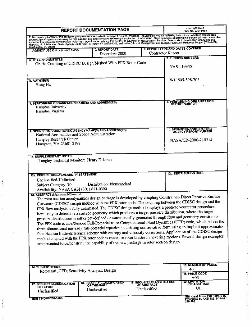
The rotor section aerodynamics design package is developed by coupling Constrained Direct Iterative Surface
Curvature (CDISC) design method with the FPX rotor code. The coupling between the CDISC design and the
FPX flow analysis is fully automated. The CDISC design method employs a predictor-corrector procedure
iteratively to determine a surface geometry which produces a target pressure distribution, where the targetpressure distributions is either pre-defined or automatically generated through flow and geometry constraints.
The FPX code is an eXtended Full-Potential rotor Computational Fluid Dynamics (CFD) code, which solves the
three-dimensional unsteady full-potential equation in a strong conservative form using an implicit approximate-
factorization finite-difference scheme with entropy and viscosity corrections. Application of the CDISC design
method coupled with the FPX rotor code is made for rotor blades in hovering motions. Several design examples
are presented to demonstrate the capability of the new package in rotor section design.
14. SUBJECT TERMS
Rotorcraft; CFD; Sensitivity Analysis; Design
17. SECURITY CLASSIRCATIONOF REPORT
Unclassified
NSN 7540-01-280-5500' '
18. uP.cuHrrY CLASUlH_ATIONOF THIS PAGE
Unclassified
19.51_CUHI I Y GLA_SSIP 1(3ATIONOF ABSTRACT
Unclassified
15. NUMBER OF PAGES
4016. PRICE CODE
A0320. LIMIIAIIQN
OF ABSTRACT
UL
Standard I;orm 298 (Rev. 2-89)Prescribed by ANSI Std. Z-39-18298-10'2


