NPS-61-85-006
NAVAL POSTGRADUATE SCHOOL
Monterey, California
OBSERVATION OF MICROWAVE CERENKOVRADIATION AS A DIFFRACTION PATTERN
By
X. K. Maruyama, J. R. Neighbours,
F. R. Buskirk, D. D. Snyder, M. Vujaklija,R. G. Bruce
and
1 August 1985
Technical Report
PedDocsD 208.14/2NPS-61-85-006
Approved for public release; distribution unlimited
Prepared for:
Naval Sea Systems CommandWashington, D.C. 20376
NAVAL POSTGRADUATE SCHOOLMonterey, California
Rear Admiral R. H. Shumaker D. A. SchradySuperintendent Provost
The work reported herein was supported by the Naval SeaSystems Command and by the Naval Surface Weapons Center.
Reproduction of all or part of this report is authorized.
This report was prepared by:
Unflassif iedSECURITY CLASSIFICATION OF THIS PAGE (Whmn Data Entered)
REPORT DOCUMENTATION PAGE READ INSTRUCTIONSBEFORE COMPLETING FORM
I. REPORT NUMBER
NPS-61-85-006
2. GOVT ACCESSION NO 3. RECIPIENT'S CATALOG NUMBER
«. TITLE (and Subtitle)
Observation of Microwave Cerenkov Radiation asDiffraction Pattern
5. TYPE OF REPORT a PERIOD COVERED
Technical Report
>. PERFORMING ORG. REPORT NUMBER
7. AUTHORfs;
X. K. Maruyama, J. R. Neighbours,F. R. Buskirk, D. D. Snyder, M. Vujaklija, andR. G. Bruce
• CONTRACT OR GRANT NUMBERC*)
9. PERFORMING ORGANIZATION NAME AND ADDRESS
Naval Postgraduate SchoolMonterey, CA 9394 3
tO. PROGRAM ELEMENT. PROJECT, TASKAREA 4 WORK UNIT NUMBERS
PE 62101NN0002485WR14821
11. CONTROLLING OFFICE NAME AND ADDRESS
Naval Sea Systems CommandWashington, D.C. 20362
12. REPORT DATE
August 198513. NUMBER OF PAGES
1514. MONITORING AGENCY NAME a AODRESSC// dlltatent from Controlling Office) 15. SECURITY CLASS, (ot thla taport)
15a. DECLASSIFICATION. DOWNGRADINGSCHEDULE
16. DISTRIBUTION STATEMENT (ol thla Report)
Approved for public release; distribution unlimited
17. DISTRIBUTION STATEMENT (ol tha abatract antatad In Block 30. U dltlarant Irooi Raport)
18. SUPPLEMENTARY NOTES
19. KEY WORDS (Continue on reverae alda II nacaaaary and Identity by block nutnbar)
Microwave Cerenkov Radiation, Emission Length, Bunched ElectronsRelativistic Electron Beams
20. ABSTRACT (Continue on tavataa alda II nacaaaary and Identify by block number)
Measurement of microwave Cerenkov radiation in air exhibits the diffractionpattern predicted in earlier work. The radiation appears only at harmonics ofthe frequency of periodic electron bunches, angular distribution power measure-ments are presented for frequencies of 2.86, 5.71, 8.57 and 11 & 12 GHzcorresponding to the fundamental and the first three harmonics of an S bandRF linac.
.
DD,^M
73 1473 EDITION OF I NOV 65 IS OBSOLETE
S'N 0102- LF-OU-6601Unclassified
SECURITY CLASSIFICATION OF THIS PAGE (When Data Bntared)
SECURITY CLASSIFICATION OF THIS PAGE (Whan Dmtm Bnfrad)
S'N 0102- LF- 014- 6601
SECURITY CLASSIFICATION OF THIS PAGEfWhMl Data Enlarad)

OBSERVATION OF MICROWAVE CERENKOV
RADIATION AS A DIFFRACTION PATTERN
X. K. Maruyama*, J. R. Neighbours, F. R. Buskirk, D.D. Snyder,M. Vujaklija, and R. G. Bruce
Physics DepartmentNaval Postgraduate School
Monterey, California 93943
ABSTRACT
Measurement of microwave Cerenkov radiation in air exhibits
the diffraction pattern predicted in earlier work. The radiation
appears only at harmonics of the frequency of periodic electron
bunches. Angular distribution power measurements are presented
for frequencies of 2.86, 5.71, 8.57 and 11.42 GHz corresponding
to the fundamental and the first three harmonics of an S band RF
linac.
INTRODUCTION
When the interaction region of a charged particle going
faster than the speed of light in a dielectric medium has a
finite length"! »2, 3, the Cerenkov radiation is spread over a range
of emission angles. This condition is readily realized by
passing a relativistic electron beam through a gas such as air.
In a previous work^ , Cerenkov radiation from periodic electron
bunches was considered and the radiation pattern was calculated.
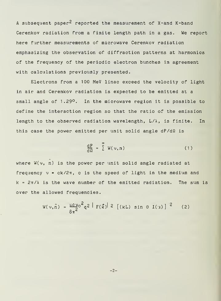
A subsequent paper 2 reported the measurement of X-and K-band
Cerenkov radiation from a finite length path in a gas. We report
here further measurements of microwave Cerenkov radiation
emphasizing the observation of diffraction patterns at harmonics
of the frequency of the periodic electron bunches in agreement
with calculations previously presented.
Electrons from a 100 MeV linac exceed the velocity of light
in air and Cerenkov radiation is expected to be emitted at a
small angle of 1.29°. In the microwave region it is possible to
define the interaction region so that the ratio of the emission
length to the observed radiation wavelength, L/X, is finite. In
this case the power emitted per unit solid angle dP/dft is
g-fw(v.n) CD
where W(v, n) is the power per unit solid angle radiated at
frequency v = ck/2ir, c is the speed of light in the medium and
k = 2ir/A is the wave number of the emitted radiation. The sum is
over the allowed frequencies.
W(v,n) = ^° q2 I F(k)l 2 [(kL) sin I(u) ]
2(2)
8ir
-2-

The parameters describing the radiation are
u = -p (cos0c -cos0)
Ku) - ^_u
* - t"x S . ny» , nz » ] (3)
p'(if) - / / / dx dy dz exp[-ii<.r • ]p' <r'
)
— 00 — 00 — 00
-q F(S)
where nx , ny , n z are components of the unit vector n in the
emission direction, v is the frequency of the emitted radiation,
and L is the length of the interaction region. The observation
angle 9 is defined by cos9 = n*z, z defining the direction of the
electron beam. The total charge of one bunch is q, corresponding
to a charge distribution p (r) with Fourier transform p (r) and
F(k) is defined as a dimensionless form factor. The bunch
frequency v is equal to the electron velocity divided by the
electron bunch spacing, i.e., the fundamental operating frequency
of the linac. Radiation is emitted only at frequencies v which
are integer multiples of v . A fuller discussion of equations 1
through 3 is presented in Ref. 1 and 2.
-3-
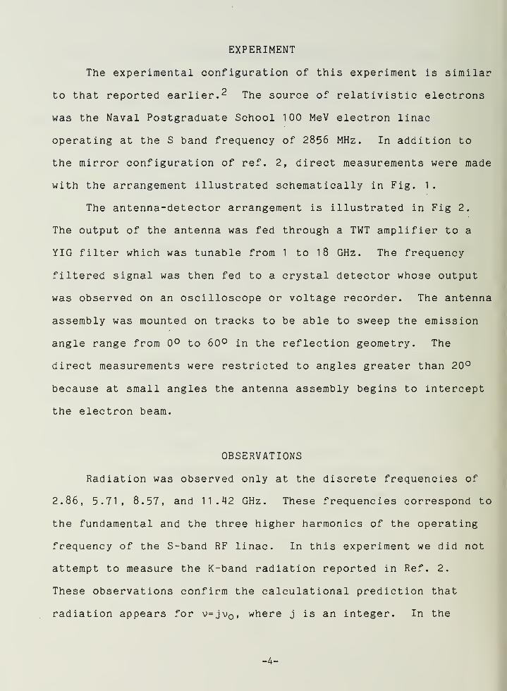
EXPERIMENT
The experimental configuration of this experiment is similar
to that reported earlier. 2 The source of relativistic electrons
was the Naval Postgraduate School 100 MeV electron linac
operating at the S band frequency of 2856 MHz. In addition to
the mirror configuration of ref. 2, direct measurements were made
with the arrangement illustrated schematically in Fig. 1
.
The antenna-detector arrangement is illustrated in Fig 2.
The output of the antenna was fed through a TWT amplifier to a
YIG filter which was tunable from 1 to 1 8 GHz. The frequency
filtered signal was then fed to a crystal detector whose output
was observed on an oscilloscope or voltage recorder. The antenna
assembly was mounted on tracks to be able to sweep the emission
angle range from 0° to 60° in the reflection geometry. The
direct measurements were restricted to angles greater than 20°
because at small angles the antenna assembly begins to intercept
the electron beam.
OBSERVATIONS
Radiation was observed only at the discrete frequencies of
2.86, 5.71, 8.57, and 11.42 GHz. These frequencies correspond to
the fundamental and the three higher harmonics of the operating
frequency of the S-band RF linac. In this experiment we did not
attempt to measure the K-band radiation reported in Ref. 2.
These observations confirm the calculat ional prediction that
radiation appears for v=jv , where j is an integer. In the
-4-

previous work the frequency resolution was broad, but in this
measurement, we are able to identify separately the mode numbers
j = 1 , 2, 3 and 4.
Another improvement of the present measurement over the
previous measurement is in decreasing the emission length L to 1
4
cm, so that all measurements were done in the far field. 5 The
experimental room was too small to increase the distance from the
source to the antenna. The decrease in L had the consequence of
making more pronounced the diffraction effect and shifted the
observed peak radiation angle from the classical Cerenkov angle
of 1.29° to angles from 20° to 45°.
A preliminary series of measurements are presented in Fig. 3
for the frequencies corresponding to j - 1, 2, 3 and 4. In the
earlier analysis of these measurements the angular distribution
was shifted arbitrarily (approx. 12°) so that the calculated
pattern enveloped the observed radiation pattern. This empirical
shift in angle was necessitated by the lack of definition of the
electron beam direction and mirror orientation due to the short
lever arms available in a small experimental space. Furthermore,
the data exhibited fine structure, inconsistent with predictions,
since the charge distribution within a single bunch is unlikely
to have structure large enough for the form factor of equation
(2) to influence the radiation pattern. Instead the observed
fine structure is thought to be due to interference of the
primary radiation with reflections from physical structures in
-5-

the experimental area. These include reflections from metal
cable trays, a large magnetic spectrometer and its mount, and
plumbing fixtures in the experimental room.
A direct measurement was made after some improvement in
shielding and the results are presented in Fig. 4. At all
frequencies, the radiation pattern was observed to lie within
the envelope defined by the calculated prediction without angular
shift. In particular, for j=3 and 4, the observed peak value and
the null between the first and second peak are consistent with
theory. The inconclusive results for j=1 and 2 are thought to
arise from the use of a pyramidal antenna whose angular
resolution was broad and susceptible to observing radiation
reflected from structures which were not in the emission region.
In addition, the emission length is only a few wavelengths long
and edge effects with their subsequent interference are more
pronounced. The fine structure is still evident for j=3 and 4.
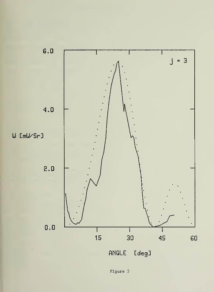
In order to show that the fine structure was due to
interference from reflected signals, the area near the emission
region was carefully shielded with airmat, an RF absorbing
material. In addition, a copper screen wall was erected between
the experimental area and the klystron gallery of the RF linac.
Our efforts were concentrated on measuring Cerenkov radiation at
the frequency v = 3v . A mirror configuration was used in order
to be able to measure the full angular range of the first lobe.
The result is presented in Fig. 5.
-6-
In these measurements, no rigorous attempt was made to
measure the absolute power and the observations have been
normalized to the calculated values. An incompletely calibrated
measurement of the observed peak power per unit solid angle for
j = 3 and 4 gave results consistent to 20$ with the predicted
power levels. In figures 3» ^» and 5 each bunch of electrons
is assumed to contain 1.5 x 10~ 12 Coulomb. This value
corresponds to an average linac current of 0.25 yA with a pulse
repetition rate of 60 Hz and macro pulse length of 1 usee.
CONCLUSIONS
Refinements of the experimental configuration beyond that of
reference (2) have led to agreement with the theoretical
calculations. Although some fine structure remains in Fig. 5 we
ascribe this to interference of reflected waves rather than a
fundamental mechanism. The measurements demonstrate that the
diffraction nature of Cerenkov radiation when the path of the
beam in a medium is of finite length and that periodic bunches
will produce Cerenkov radiation only at harmonics of the bunch
frequency.
Improvements in the measurement environment and apparatus
are being contemplated to test other features of the predictions
of the previous works as manifested in equation 1 through 3, in
particular, the quadratic dependence of the radiated power to the
-7-

total bunch charge q and more refined measurements of mode
numbers other than j = 3. Form factor effects will be realizable
only at much higher frequencies or for physically larger bunches.
A short discussion of form factor effects and their consequences
for induction linacs appears in another work."
ACKNOWLEDGEMENTS
This work was partially supported by the Naval Surface
Weapons Center and the Naval Sea Systems Command. The assistance
of D. Womble in computer programming for data presentation is
gratefully acknowledged.
^Permanent Address, Center for Radiation Research, National
Bureau of Standards, Gai thersburg, MD 20899
-8-

REFERENCES
1. F. R. Buskirk and J. R. Neighbours, Phys. Rev. A28_, 1531
(1983)
2. John R. Neighbours, Fred R. Buskirk, and A. Saglam, Phys.
Rev. A29, 3246 (1984).
3. A. P. Kobzev and I. M. Frank have noted that in the optical
case the width of the Cerenkov cone depends on the radiator
thickness. See A. P. Kobzev, Yad. Fiz 27, 1256 (1978)
[Sov. J. Nucl. Phys. 664(1978)]; A. P. Kobzev and I. M.
Frank, ibid. 3J_, 1253 (1980) [31, 647 (1980)]; 34, 125 (1981)
[34, 71 (1981)].
4. J. V. Jelley, Cerenkov Radiation and Its Applications
(Pergamon, London, 1958) p. 62-68.
5. M. I. Skolnik, Introduction to Radar Systems , McGraw Hill
Book Company, NY 1980
6. X. K. Maruyama, J. R. Neighbours and F. R. Buskirk, IEEE
Transactions in Nuclear Science 1985 (to be published)
-9-

FIGURE CAPTIONS
Fig. 1 - Schematic experimental arrangement for direct
measurements. Electrons pass from the accelerator into
air and generate Cerenkov radiation which is measured by
an antenna-detector assembly which can be translated on
a track (not shown). The emission length, L, is defined
between the exit window of the linac and an RF shield.
Fig. 2 - Block diagram of the microwave antenna-detector
apparatus. Horn antennas were used to observe
frequencies above 8 GHZ and a pyramidal antenna was used
to observe below 8 GHZ . Crystal detectors and TWT
amplifiers were matched to the frequency sensitivity of
the antennas. The YIG filter was tunable from 1 to 1
8
MHz. A frequency resolution of ±20MHz was used in these
measurements
.
Fig. 3 - The observed angular distribution of microwave Cerenkov
radiation with a mirror geometry (preliminary results)
.
The solid curve is the measurements and the dotted curve
is calculated. The fine structure is believed to be the
result of interference from reflected radiation from
physical structure in the experimental area. The
observed angle has been increased approximately 12° (see
text). The emission length L is 1 4 cm. The data have
been normalized to the calculated power per unit solid
angle assuming q = 1.5 x 10 1 ^ Coulomb.
-10-

Fig. 4 - Direct measurement of microwave Cerenkov radiation. The
solid curve is the measurement and the dotted curve is
calculated. At angles less than 20°, the antenna
assembly begins to intercept the electron beam and
therefore radiation at small angles was not measurable.
The emission length L = 14 cm. The data have been
normalized to the calculated power per unit solid
angle assuming q = 1.5 x 10~ 12 Coulomb.
Fig. 5 - Microwave Cerenkov radiation at v = 3v after
shielding to eliminate interference effects. The solid
curve represents the measured data and the dotted curve
is calculated. The emission length L = 14 cm. The data
have been normalized to the calculated power per unit
solid angle assuming q = 1.5 x 10~12 Coulomb.
-11-


Antenna - Detector
/"Linac Beam Pipe
Cerenkov
Red i at i on
L
iec:rcn
Beam
Figure 1

Antenna TUTAmpl if ier
->YIG
Filter-*
CrystalDetector
Obseruer
Figure 2

4.0
2.0
0.0
4.0
2.0
U CmU/Sr]
0.0
4.0
2.0
0.0
S.O
4.0
a.o
0.0
1S 30 4S
ANGLE CdagJ
SO
Figure 3

4.0 i r
J - 1
z.o
0.0
J - 2
U lirWSrl
4.0
8.0
0.0
4.0
2.0
0.0
e.o
4.0 r-
a.o -
0.0
J - 3
i i r
J= 4
Figure 4
6.0
4.0 -
U CmU/Sr]
E.O -
0.0
15 30 45 60
ANGLE [cleg]
Figure 5


DISTRIBUTION LIST
Dr. Xavier K. Maruyama 1
Bldg. 245, Room R-108National Bureau of standardsGaithersburg, MD 20899
Mission Research Corporation 1
Attn: Dr. N. J. CarronP. 0. Box 719Santa Barbara, CA 93102
Office of Naval Research 1
CDR R. Swafford800 N. Quincy StreetArlington, VA 22217
Office of Naval Research 1
CDR James Offutt1030 East Green StreetPasadena, CA 91106
Library 2
Code 0142Naval Postgraduate SchoolMonterey, CA 93943
Office of Research Administration 2
Code 01 2ANaval Postgraduate SchoolMonterey, CA 93943
F. R. Buskirk & J. R. Neighbours 20Naval Postgraduate SchoolPhysics Department, Code 61
Monterey, CA 93943
Dr. Joseph Mack 1
M4, M.S. 940Los Alamos National LaboratoryLos Alamos, NM 87545
MAJ E. W. Pogue 1
M4, M.S. 940Los Alamos National LaboratoryLos Alamos, NM 87545
Dr. Richard Briggs 2
L-321Lawrence Livermore National LaboratoryBox 808Livermore, CA 94550

Dr. Kenneth W. StruveLawrence Livermore National LaboratoryP. 0. Box 808Livermore, CA 94550
Dr. C. M. HuddlestonR-401Naval Surface Weapons CenterWhite OakSilver Spring, MD 20910
COMMODORE R. L. ToppingPMS 405Strategic Systems Project OfficeNaval Sea Systems CommandWashington, D.C. 20376
Dr. David MerrittPMS 405Strategic Systems Project OfficeNaval Sea Systems CommandWashington, D.C. 20376
CDR William BassettPMS 405Strategic Systems Project OfficeNaval Sea Systems CommandWashington, D.C. 20376
LCDR E. TurnerPMS 405Strategic Systems Project OfficeNaval Sea Systems CommandWashington, D.C. 20376
Director, Defense Advanced ResearchProject AgencyATTN: LC0L Richard A. Gullickson1400 Wilson Blvd.Arlington, CA 22209
Defense Technical Information CenterCameron StationAlexandria, VA 22314
Defense Advanced Research Project AgencyATTN: MAJ George P. Lasche1 400 Wilson Blvd.Arlington, VA 22209
Sandia National LaboratoryAttn: Dr. Michael Mazarakis (1272)P. 0. Box 5800Albuquerque, NM 87185

The Charles Stark Draper LaboratoryAttn: Dr. Edwin Olsson555 Technology SquareCambridge, MA 02139
Naval Surface Weapons CenterAttn: Dr. Ralph Fiorite (R41)
Dr. Donald Rule (R41
)
Dr. Eugene E. Nolting (H23)Dr. Han S. Uhm (R41
)
White Oak Laboratory


DUDLEY KNOX LIBRARY


