Numerical study on heat transfer and fluid flow characteristic of tube bank with
integral wake splitters (Effect of wake splitter length)
Abobaker Mohammed Alakashi
A thesis submitted in fulfillment of the requirement for the award of the
Degree of Master of Engineering
Faculty of Mechanical and Manufacturing Engineering
University Tun Hussein Onn Malaysia
April 2011

VI
ABSTRACT
The purpose of this research is to study pressure drop and heat transfer characteristics in
a tube bank heat exchanger with triangular arrangements by using Computational Fluid
Dynamics (CFD). Given the importance of wide practical applications in our lives for
heat exchanger. We can improve the thermal and hydraulic performance for heat
exchangers by several ways same like adding integral wake splitters (fins) on tubes to
reduce pressure drop and increase heat transfer across tube bank. When the flow of fluid
through the tube banks in the heat exchanger, there is a rise in pressure drop and
decrease in heat transfer, to reduce pressure drop and increase heat transfer through the
tube banks must consider how to improve and develop the arrangement of tubes
(diameter, length, St and Sl) for tube bank in heat exchanger, To improving the thermal
and hydraulic performance of these heat exchangers have been reached several ways to
improve performance like adding a new set of integral wake splitter (0.5D, 1D with
different direction) on tube bank. For this study we used the 395 x 395 x 1230 mm test
section size. The geometric layout of the tube bank is staggered with seven rows of five
tubes in each row. The tube diameter, transverse pitch and horizontal pitch are 48.5 mm,
79 mm and 65.8 mm respectively. The analysis was at different values of Reynolds
number between (5000 < Re > 27800). The temperature of air was (290 K), and heat
flux for each tube was (5250 W/m2).

VII
ABSTRACT
Tujuan kajian ini bertujuan untuk mengkaji kejatuhan nilai tekanan dan cirri-ciri
pemindahan haba di dalam tiub penukar haba dengan susunan segitiga dengan
menggunakan Penkomputeran Dinamik Bendalir (CFD). Memandangkan pentingnya
aplikasi praktikal yang luas dalam hidup kita untuk penukar panas, kita dapat
meningkatkan prestasi terma dan hidrolik untuk penukar panas dengan beberapa cara
yang sama seperti menambah pemisah (sirip) pada tabung untuk mengurangkan
penurunan tekanan dan meningkatkan pemindahan haba merentasi tabung tiub . Bila
aliran cecair melalui tabung tiub dalam penukar haba, ada peningkatan dalam penurunan
tekanan dan dalam penukar haba, untuk mengurangkan penurunan tekanan dan
peningkatan pemindahan haba melalui tabung tiub harus mempertimbangkan bagaimana
untuk meningkatkan dan membina susunan tabung (diameter, panjang, St dan Sl) untuk
tabung tiub di dalam penukar haba, Untuk meningkatkan prestasi terma dan hidrolik
penukar haba ini telah dicapai beberapa cara untuk meningkatkan prestasi seperti
menambah satu set baru pemisah integral, (0.5D 1D dengan berbeza arah) pada tabung
tiub. Untuk kajian ini, kami telah menggunakan saiz 395 x 395 x 1230 mm untuk
bahagian ujian. Susunan geometri tabung tiub bersilih ganti dengan tujuh deretan lima
tabung dalam setiap baris. Diameter tabung, pitch melintang dan pitch mendatar masing-
masingn adalah 48,5 mm, 79 mm dan 65,8 mm. Analisis ini dibuat pada nilai nombor
Reynolds yang berbeza antara (5000 <Re> 27800). Suhu udara (290 K), dan panas fluks
untuk setiap balang (5250 W/m2).
VIII
CONTENTS
CHAPTER TITLE PAGE
TITLE I
DECLARATION III
DEDICATION IV
ACKNOWLEDGEMENT V
ABSTRACT VI
CONTENTS VIII
LIST OF TABLE XI
LIST OF FIGURES XII
LIST OF SYMBOLS AND ABBREVIATIONS XIX
CHAPTER 1
Introduction 1
1.1 Introduction 1
1.2
The methods used to improve performance of heat
exchanger
8
1.3 Project background 8
1.4 Problem Statement 9
1.5 Research Objectives 9
1.6 Scope of Research Study 10

IX
1.7 Significance of the study 10
1.8 Expected results. 11
1.9 Research Organization 11
1.10 Conclusion. 15
CHAPTER 2
LITERATURE REVIEW
16
2.1 Introduction 16
2.2 Tube and Tube Banks 17
2.3 Tubes with wake splitters 23
CHAPTER 3
RESEARCH METHODOLOGY 25
3.1 Flow chart 25
3.2 Methodology 26
3.2.1 Computational Fluid Dynamics Description 26
3.2.2 Governing Equations and boundary condition 28
3.2.3 Geometry of tube bank 30
3.2.4 Flow chart methodology procedure 32
3.2.4.1 Create geometry in Gambit 35
3.2.4.2 Mesh geometry in Gambit 37
3.2.4.3 Specify Boundary Types in GAMBIT 40
3.2.4.4 Set Up Problem in FLUENT 40
3.2.4.5 Data analysis 41
CHAPTER 4
RESULTS AND DISCUSSION

X
4.1 Introduction 42
4.2 Results and discussion 42
4.2.1 Result of tube bank without wake splitter 43
4.2.2 Result of tube bank with 0.5 D wake splitter in upstream
direction
49
4.2.3 Result of tube bank with 0.5 D wake splitter in
downstream direction
54
4.2.4 Result of tube bank with 1D wake splitter in upstream
direction
59
4.2.5 Result of tube bank with 1D wake splitter in downstream
direction
64
4.2.6
Result of tube bank with 0.5D wake splitter from two
directions
70
CHAPTER 5
CONCLUSION AND RECOMMENDATION 80
5.1 Introduction 80
5.2 Conclusion 81
5.3 Recommendation 82
Reference
83
Appendix
90

XII
LIST OF FIGURES
1.1 Tube bank 2
1.2.a Flow past a cylinder 3
1.2.b Flow past a cylinder 3
1.3.a Velocity ( ) at any point on the cylinder surface 4
1.3.b Velocity ( ) at any point on the cylinder surface 4
1.3.c Stagnation Points for Flow about a Circular Cylinder 5
1.4 Cp distribution for flow past a circular cylinder 6
3.1 Methodology flow chart 25
3.2.1 Mechanism of CFD 27
3.2.3.a Test section design layout (all dimensions are in millimeters (mm)). 31
3.2.3.b Base cylinder with longitudinal slot for splitter plate assembly 31
3.2.4 Methodology procedures in a flow chart 32
3.2.4.1.a Tube bank without wake splitter 35
3.2.4.1.b Tube bank with wake splitter (L=D) in downstream direction 35
3.2.4.1.C Tube bank with wake splitter (L=D) in upstream direction 35
XIII
3.2.4.1.d Tube bank with wake splitter (L=0.5D) in downstream direction tubes 36
3.2.4.1.e Tube bank with wake splitter (L=0.5D) in upstream direction 36
3.2.4.1.f
3.2.4.2.a
Tube bank with wake splitter (L=0.5D) in both direction
Boundary layer of mesh for edge
36
37
3.2.4.2.b Creation of edge mesh 38
3.2.4.2.C Create of Face Mesh 38
3.2.4.2.d Create of Face Mesh 39
3.2.4.2.e Detail of Face Mesh 39
4.1 Distribution of the flow through tubes bank in tube bank without
wake splitter
43
4.2.a Relation between Reynolds number and pressure drop in tube bank
without wake splitter
45
4.2.b CFD and Experimental results, Relation between Reynolds number
and pressure drop in tube bank without wake splitter
45
4.3 Distribution of the velocity on the cylinder at separation point in tube
bank without wake splitter
46
4.4 Creating the vortexes behind the tube in tube bank without wake
splitter
46
4.5 Relation between the pressure drop and power of pump in tube bank
without wake splitter
47

XIV
4.6 Relation between Re Reynolds number and ∆T difference
temperatures between upstream and downstream in tube bank without
wake splitter
47
4.7 Relation between Reynolds number and average heat transfer
coefficient (W/m2 K) in tube bank without wake splitter)
48
4.8 Relation between ∆p pressure drop and ∆T difference temperatures
between upstream and downstream in tube bank without wake splitter
48
4.9 Distribution of the flow through tubes bank.
0.5 D wake splitter in upstream
49
4.10.a Relations between Reynolds number and pressure drop in tube bank
with 0.5D wake splitter in upstream direction
51
4.10.b CFD and Experimental results, Relations between Reynolds number
and pressure drop in tube bank with 0.5D wake splitter in upstream
direction
51
4.11 Relation between the pressure drop and power of pump in tube bank
with 0.5D wake splitter in upstream direction
52
4.12 Relation between Re and ∆T difference temperatures between
upstream and downstream in tube bank with 0.5D wake splitter in
upstream direction
52
4.13 Changing the temperature of fluid on tube banks 53
4.14 Relation between Reynolds number and average heat transfer
coefficient heat transfer coefficient (W/m2 K) in tube bank with 0.5D
wake splitter in upstream direction
53

XV
4.15 Relation between ∆p and ∆T difference temperatures between
upstream and downstream in tube bank with 0.5D wake splitter in
upstream direction
54
4.16 Distribution of the flow through tube banks 0.5 D wake splitter in
downstream direction
54
4.17.a Relations between Reynolds number and pressure drop in tube bank
with 0.5D wake splitter in downstream direction
56
4.17.b CFD and Experimental results, Relations between Reynolds number
and pressure drop in tube bank with 0.5D wake splitter in
downstream direction
56
4.18 Separation the area of vortices 57
4.19 Relation between the pressure drop and power of pump in tube bank
with 0.5D wake splitter in downstream direction
57
4.20 Relation between Re and ∆T difference temperatures between
upstream and downstream in tube bank with 0.5D wake splitter in
downstream direction
58
4.21 Relation between Reynolds number and average heat transfer
coefficient (W/m2 K) in tube bank with 0.5D wake splitter in
downstream direction
58
4.22 Relation between ∆p and ∆T difference temperatures between
upstream and downstream in tube bank with 0.5D wake splitter in
downstream direction
59
4.23 Distribution of the flow through tubes bank 59
XVI
1 D wake splitter in upstream direction
4.24.a Relations between Reynolds number and pressure drop in tube bank
with 1D wake splitter in upstream direction
61
4.24.b CFD and Experimental results, Relations between Reynolds number
and pressure drop in tube bank with 1D wake splitter in upstream
direction
62
4.25 Relation between the pressure drop and power of pump in tube bank
with 1D wake splitter in upstream direction
62
4.26 Relation between Re and ∆T difference temperatures between
upstream and downstream in tube bank with 1D wake splitter in
upstream direction
63
4.27 Relation between Reynolds number and average heat transfer
coefficient (W/m2 K) in tube bank with 1D wake splitter in upstream
direction
63
4.28 Relation between ∆p and ∆T difference temperatures between
upstream and downstream in tube bank with 1D wake splitter in
upstream direction
64
4.29 Distribution of the flow through Tube banks with 1D splitter in
downstream direction
64
4.30.a Relations between Reynolds number and pressure drop in tube bank
with 1D wake splitter in downstream direction
66
4.30.b CFD and Experimental results, Relations between Reynolds number
and pressure drop in tube bank with 1D wake splitter in downstream
67

XVII
direction
4.31 Relation between the pressure drop and power of pump in tube bank
with 1D wake splitter in downstream direction
67
4.32 Relation between Re and ∆T difference temperatures between
upstream and downstream in tube bank with 1D wake splitter in
downstream direction
68
4.33 Changing the temperature of fluid on tube banks in tube bank with
1D wake splitter in downstream direction
68
4.34 Relation between Reynolds number and average heat transfer
coefficient (W/m2 K) in tube bank with 1D wake splitter in downstream
direction
69
4.35 Relation between ∆p and ∆T difference temperatures between
upstream and downstream in tube bank with 1D wake splitter in
downstream direction
69
4.36 Distribution of the flow through tubes bank with 0.5D wake splitter
from two directions
70
4.37.a Relations between Reynolds number and pressure drop in tube bank
with 0.5D wake splitter in two side directions
71
4.37.b CFD and Experimental results, Relations between Reynolds number
and pressure drop in tube bank with 0.5D wake splitter in two side
directions
72
4.38 Relation between the pressure drop and power of pump in tube bank
with 0.5D wake splitter in two side directions
72

XVIII
4.39 Relation between Re and ∆T difference temperatures between
upstream and downstream in tube bank with 0.5D wake splitter in
two side directions
73
4.40 Changing the temperature of fluid on tube banks in tube bank with
0.5D wake splitter in two side directions
73
4.41 Relation between Reynolds number and average heat transfer
coefficient (W/m2 K) in tube bank with 0.5D wake splitter in two side
directions
74
4.42 Relation between ∆p and ∆T difference temperatures between
upstream and downstream in tube bank with 0.5D wake splitter in
two side directions
74
4.43 Relations between Reynolds number and pressure drop in tube bank
with all results
76
4.44 Experimental results Relations between Reynolds number and
pressure drop in tube bank with all results
77
4.45 Relation between Re and ∆T difference temperatures between
upstream and downstream in tube bank with all results
78
4.46 Relation between Re and h, average heat transfer coefficient between
upstream and downstream in tube bank with all results
79

XI
LIST OF TABLES
3.1 Specify Boundary Types 40
4.1 Results of tube bank without wake splitter 43
4.2 Results of tube bank with 0.5D wake splitter in upstream direction 49
4.3 Results of tube bank with 0.5D wake splitter in downstream direction 55
4.4 Results of tube bank with 1D wake splitter in upstream direction 60
4.5 Results of tube bank with 1D wake splitter in downstream direction 65
4.6 Results of tube bank with 0.5D wake splitter from two directions 70
4.7 Results of between Reynolds number and pressure drop in tube bank with
all cases
75
4.8 Results of Re and ∆T difference temperatures between upstream and
downstream in tube bank with all cases
78
4.9 Results of Re and h, heat transfer coefficient between upstream and
downstream in tube bank with all cases
79

XIX
LIST OF SYMBOLS AND ABBREVIATION
P∞ Pressure upstream
Po Pressure at the stagnation point
U Flow velocity
Velocity at any point on the cylinder surface
Q Heat transfer flux
Average heat transfer coefficient
Re Reynolds number.
Uapp Approach velocity of the fluid.
Ttube Temperature of the tube
Twall Temperature of the wall
2D Two dimensions
3D Three dimensions
St Transverse pitch
Sl Horizontal pitch
D Diameter of tube
L Length of tube
F Outside forces effect on the body
Air dynamic viscosity

XX
ρ Density of the fluid
Vupstream Upstream velocity
Vdownstream Downstream velocity
∆P Pressure drop
EGM Entropy generation minimization
β Coefficient of thermal expansion
∆T Average difference temperature
P pump Power of pump
Numerical study on heat transfer and fluid flow characteristic of tube bank with
integral wake splitters
1.1- Introduction.
A heat exchanger is a device designed for efficient heat transfer from one medium to
other. Where, a flow can be separate into a heat exchanger by a solid wall, as can be
mixed or unmixed.
The selecting a heat exchanger to a particular use is depending on some
characteristics “temperature, fluid phases (liquid or gas), the amount of energy required
to transfer, and a pressure drop ...etc”. As, a pressure drop linked directly with the
pumping capacity and indirectly associated with the rate of heat transfer. Whereas, a
pressure drop controls the flow speed, hence on the rate flow cluster. Therefore, these
factors will affect on the performance of heat exchanger. (J. R. Culham and M. M.
Yovanovich, 2007).
The following Figure 1 shows the details of the heat exchanger of the type tube
banks. When, the Fluid (I) move across the tubes while fluid (II) at a different
temperature passes through the tubes as the figure: -

2
Figure 1.1 tube bank (Tao Xing 2000)
The fluid flow is ideally normal to the tubes. The most usual tube arrays are staggered
and inline, although other arrangements are possible. The flow converges in the inter-
tube spaces inside a bank and forms a highly turbulent flow over the inner tubes. The
recirculation region in the rear of an inner tube is smaller than in a single tube. The
situation is governed by the relative pitches and the bank geometry. The more compact a
bank is, the larger is the difference from the single-tube situation. (M. A. Mehrabian Iran
2008)
Generally speaking, flow around a body placed in a uniform flow develops a thin
layer along the body surface with largely changing a velocity and a pressure, i.e. the
boundary layer, due to the viscosity of the fluid. Furthermore, the flow separates behind
the body, discharging a wake with eddies. Figure 2-a and 2-b shows the flows around a
cylinder. The flow from an upstream point (a) is stopped at point (b) on the body surface
with its velocity decreasing to zero; (b) is called a stagnation point. The flow divides
into the upper and lower flows at point (b). For a cylinder, the flow separates at point(c)
producing a wake with eddies.

3
Let the pressure upstream at (a), which is not affected by the body, be (P∞). The flow
velocity is (U) and the pressure at the stagnation point is (Po) Hence.
…………………………………………………………………… ….. (1. 1)
Figure 1.2-a Flow past a cylinder. (Johan H.lienhard . 2004)
Figure 1.2.b Flow past a cylinder . (Johan H.lienhard . 2004)
U

4
Let us theoretically study (neglecting the viscosity of fluid) a cylinder placed in a flow.
The flow around a cylinder placed at right angles to the flow (U) of an ideal fluid is as
shown in Fig 3-a and 3-b the velocity ( ) at any point on the cylinder surface is as
follows:
= 2Usin …………………..………………………………………………………… (1. 2)
Figure 1.3.a velocity ( ) at any point on the cylinder surface (Johan H.lienhard . 2004)
Figure 1.3.b velocity ( ) at any point on the cylinder surface (Johan H.lienhard. 2004)
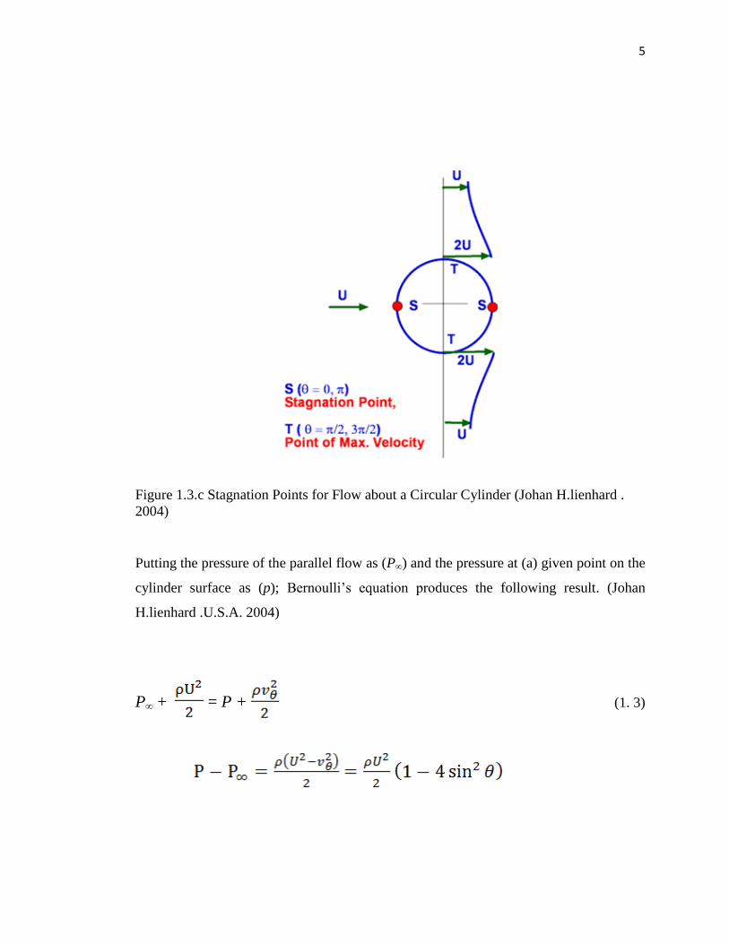
5
Figure 1.3.c Stagnation Points for Flow about a Circular Cylinder (Johan H.lienhard .
2004)
Putting the pressure of the parallel flow as (P∞) and the pressure at (a) given point on the
cylinder surface as (p); Bernoulli‟s equation produces the following result. (Johan
H.lienhard .U.S.A. 2004)
P∞ + = P + ……. ………………………………………………. (1. 3)

6
………………………… …………………………………… .. (1. 4)
Figure 1.4 Cp distributions for flow past a circular cylinder (Johan H.lienhard . 2004)
Convection heat transfer is described by Newton's law of cooling, which states
that the rate of heat loss of a body is proportional to the difference in temperatures
between the body and its surroundings. The law is given as the equation (Y.Nakayama.
Japan.2000).
(1.5)
…………………………….
Flow inside inline banks approaches that in straight channels, and the mean
velocity distribution in the minimum inter-tube space of a transverse row is highly

7
influenced by the relative pitches. The leading tubes induce vertical flow and a variable
velocity distribution around the inner tubes. The fluid flow inside a staggered bank may
by compared to periodically narrowing and widening channels such as those formed
between corrugated plates in plate heat exchangers. At low Reynolds number, the inside
flow is predominantly laminar with large vortices in the recirculation regions. Their
effect on the front parts of inner tubes is eliminated by viscous forces and negative
pressure gradients. Laminar boundary layers are still formed on the inner tubes which
separate and form recirculation regions in the rear. This pattern may be called a
predominantly laminar flow and is observed at Reynolds number <1000. Significant
changes are introduced at higher values of Reynolds number. The Inter-tube flow
becomes vertical and highly turbulent. On inner tubes, in spite of high turbulence,
laminar boundary layers are still observed (A.Zukauskas and J.Ziugzda, 1985). A
negative pressure gradient on the front part of an inner tube causes an acceleration of the
flow. The boundary layer is thin and changes but little with the distance from the
stagnation point. Both the intensity of turbulence and its generation in the inter-tube
spaces are governed by the bank geometry and Reynolds number. With shorter
transverse pitches, the velocity fluctuations become more intensive. The turbulence level
of the main flow can influence fluid dynamics only over the first and second rows (E. S.
Gaddis, and V. Gnielinsky, 1985).
But there is a way; it can change the properties of the wake downstream.
Through the development of plate separation in the middle of a circular tube usually,
does not prevent the formation of eddies, but can reduce them. Plate separation greatly
reduces the pressure loss and reduced heat transfer from the surface of the tube.
However, the existence of separate panel increases the total heat transfer to a large
extent through a supplement to the extended surface heat transfer. Thus, the team's
results in the promotion of the General Division of the heat transfer. (S.Tiwari,D.
Chakraborty.G.BiswasP.K.PanigrahiInstitute. Indian. 2004).

8
1.2- The methods used to improve performance of heat exchangers
Given the importance of heat exchangers and the frequent use started to go towards
improving the thermal and hydraulic performance of these heat exchangers have been
reached several ways to improve performance (Kakac Setal. 1981).
1. Add surface roughness.
2. Extended surfaces or fins.
3. Methods to move fluid.
4. Rotation of flow fluid.
5. Methods of surface tension.
6. An addition improved materials to thermal properties of liquids.
7. An addition improved materials to thermal properties of gases.
8. The surface vibration.
9. The use of electrostatic fields.
10. Injection fluids with good thermal properties.
11. The withdrawal or removal of membrane fumes.
1.3- Project background
When flow of fluid through the tube banks into the heat exchanger. There is, a rise in
pressure drop and increase in heat transfer through the tube banks, because there

9
Vortices behind the tubes. Where, the properties of the fluid in that region are changing
rapidly. Meanwhile, Vortices are causing pressure drop and Increase of heat transfer.
Therefore, must considering by studying the pipes, through adding a new set of wake
splitters to tubes .They will be a different forms, lengths and directions,. To improve
heat exchanger (reduce pressure drop and Increase the area of heat transfer).
1.4- Problem Statement.
A Heat exchanger design is a complex problem which involves both quantitative
calculations and qualitative judgments. The amounts of pressure drop and heat transfer
are highly dependent on the geometry of the tube bank. The flow of fluid will create
Vortices behind the tubes, they will be a reason on change the properties of the fluid at
those regions a rapidly. Meanwhile, they are causing to increase (pressure drop and heat
transfer) (Osama Abd Elhamid 2008).
1.5- Research objectives.
The purpose of this project is using Computational Fluid Dynamics (CFD) to study on
heat transfer and fluid flow characteristic of tube bank with several types and different
location of wake splitters. Where, heat transfer and pressure drop represent coefficients
those imposed on the flow by each successive row of tubes.

10
1.6- Research of scopes.
1. Design of model using the (Gambit).
2. Analysis the model using the (Fluent).
3. Study will be conducting at Reynolds number Re = based on tube bank
diameter.
5000< Re <280000
4. Studying a Pressure drop and a heat transfer between an entrance and an outlet of
tube bank.
1.7- Significance of the study.
There are many studies on the effects of fin is only done on a single tube. There has been
no farther study was conducted by CFD on the effect of weak splitters to heat transfer
and fluid flow characteristic to a tube bank. This project aims to improve the heat
exchanger performance. Through decreasing the pressure drop and Increase the heat
exchange.

11
1.8- Expected results.
The results will be expected for this project. When adding different types of several
wake splitter on the tube bank. It is expected decrease on pressure drop and an increase
to heat transfer, Compared to tube bank without several wake splitter.
1.9- Research Organization.
1.9.1- Thesis Planning
This study divided into five chapters as follows:
1- Chapter one will Show the introduction, this chapter covers some aspects of the
general information about the Project, background of the problems, statement of the
problems, thesis objectives, and scope of thesis are also presented in this chapter.
2- Chapter two will be discussing the literature review.
3- Chapter three will be talking about the research methodology.
4- Chapter four will draft the results.
5- Chapter five will Shows the summary of entire work, conclusions and
recommendations for future research.
1.9.2- Thesis Outline
Below is the proposal the steps of this study. „Title, research problem, research
objectives, research scope, research methodology‟ Expected result and thesis planning
are correlates to each other.

12
1 2
3
The purpose of this project is using Computational Fluid Dynamics
(CFD) to study on heat transfer and fluid flow characteristic of tube
bank with integral wake splitters. Where, heat transfer and pressure
drop represent coefficients those imposed on the flow by each
successive row of tubes.
Heat exchanger design is a complex problem which involves both
quantitative calculations and qualitative judgments. The amount of
pressure drop and heat transfer is highly dependent on the geometry
of the tube bank. Where, vortices behind the tubes are causing to
change the properties of the fluid on those regions a rapidly.
Meanwhile they are causing (pressure drop and heat transfer).
Research Objectives
Numerical study on heat transfer and fluid flow
characteristic of tube bank with integral wake splitters
When, flow of fluid through the tube banks into the heat exchanger.
There, a rise in pressure drop and increase in heat transfer through the
tube banks, because there Vortices behind the tubes. Where, the
properties of the fluid in that region are changing rapidly. During that
moment, they are causing pressure drop and increase of heat transfer.
Problem Statement
Research Title
Project background

13
There are many studies on the effects of fin is only done on a single
tube. There has been no farther study was conducted on the effect
of weak splitters to heat transfer and fluid flow characteristic to
tube bank. This project aims to improve the heat exchanger
performance. Through decreasing the pressure drop and Increase
the heat exchange.
Significance of the study
Scopes of study are:
1. Design of model using the (Gambit).
2. Analysis the model using the (Fluent).
3. Study will be conducting when the Reynolds number based on
tube bank diameter.
10000< Re <50000
4. Studying a Pressure drop and a heat transfer between an
entrance and an outlet of tube bank.
1 2
Scope of Research Study
1

14
1
Chapter 1 – Introduction, background of the Thesis, thesis objectives,
Scope of study, and expected result
Chapter 2 - This chapter will discuss the literature review
Chapter 3 – Will explain the methodology
Chapter 4 –This chapter will explain the results.
Chapter 5 – Shows the summary of entire work, conclusions and
recommendations for future research.
Thesis Planning

15
1.10- Conclusion
Chapter one covers some characteristic when the fluid flows around cylinder. Methods
used to improve performance of heat exchangers, thesis problems, Project background,
thesis objectives, Problem Statement, Scope of Research Study, Significance of the
study, Research organization.
CHAPTER 2
LITERATURE REVIEW
2.1 Introduction
Heat exchangers with a tube array are commonly used in air-conditioning industry and
in air-cooled condensers of power plants. One of the challenging tasks for researchers is
to optimize the arrangement of tube bundles. The flow fluid inside heat exchangers is
associated with maximum heat transfer and minimum pressures drop/pumping power.
The information accumulated from earlier work serves as a basis to bring into
perspective the later work on tubes and tube bundles. In a bank of tubes, each tube has a
neighbor in the longitudinal or lateral direction. The influence of the neighbors is
considerable for Close-pitched tubes, in the direction of flow. Also, a number of reports
have been published in recent years describing attempts to modify the boundary layer on
the circular cylinder in transverse air flow, and these studies are explaining that:
(McClintock, 1951) was the first one who employed the concept of irreversibility
for estimating and minimizing the usable energy wasted in heat exchangers design.
Bejan (1977, 1982) presented an optimum design method for balanced and imbalanced

17
counterflow heat exchangers. He proposed the use of a “number of entropy production
units” Ns as a basic parameter in describing heat exchanger performance. This method
was applied to a shell and tube regenerative heat exchanger to obtain the minimum heat
transfer area when the amount of units was fixed. Later on, Aceves-Saborio et al. (1989)
extended that approach to include a term to account for the energy of the heat exchanger
material. Grazzini and Gori (1988) Sekulic (1990), Zhang et al. (1997), Ordonez and
Bejan (2000) and Bejan (2001, 2002) demonstrated that the optimal geometry of a
counterflow heat exchanger can be determined based on a thermodynamic optimization
subject to volume constraint. Yilmaz et al. [2001] first recalled and discussed the need
for the systematic design of heat exchangers using a second-law-based procedure and
then presented second-law-based performance evaluation criteria for heat exchangers.
Entropy generation rate is generally used in a dimensionless form. Unuvarn and Kargici
[2004] and Peters and Timmerhaus (1991) presented an approach for the optimum
design of heat exchangers.
They used the method of steepest descent for the minimization of annual total
cost. They observed that this approach is more efficient and effective to solve the design
problem of heat exchangers. Optimization of plate-fin and tube-fin crossflow heat
exchangers was presented by Shah et al. (1978) and Van den Bulck (1991). They
employed optimal distribution of the UA value across the volume of crossflow heat
exchangers and optimized different design variables like fin thickness, fin height, and fin
pitch. Cylinder geometry was optimized in a paper by Poulikakos and Bejan (1982) and
Khan et al. (2003). After the general formula was derived using the entropy generation
minimization (EGM) method analytical methods and graphical results were developed
that resulted in the optimum selection of the dimensions of several different fin
configurations. Bejan et al. (1996) showed that EGM may be used by itself in the
preliminary stages of design, to identify trends and the existence of optimization
opportunities. In two different studies, Stanescu et al. (1996), and Matos et al. (2001)
demonstrated that the geometric arrangement of tubes/cylinders in crossflow forced
convection can be optimized for maximum heat transfer subject to overall volume
constraint. They used FEM to show the optimal spacings between rows of tubes. Vargas

18
et al. (2001) documented the process of determining the internal geometric configuration
of a tube bank by optimizing the global performance of the installation that uses the
cross flow heat exchanger.
2.2 Tube and Tube Banks
In a bank of tubes, each tube has a neighbour in the longitudinal or lateral
direction. The influence of the neighbours is considerable for close-pitched tubes. In the
direction of flow, a tube is immersed in the wake of another tube, Examined the two
dimensional, non-homogeneous flow over a circular cylinder immersed in the wake of
another identical cylinder. He found that the aerodynamic parameters are determined by
the oncoming wake flow which is characterized by variations of velocity, static pressure
and turbulence quantities in both the lateral and longitudinal directions. The mean lift on
the rear cylinder, when the two cylinders are not aligned with the free stream flow
direction, is directed towards the centerline of the oncoming wake, which is opposite to
the direction predicted by in viscid flow theory. The main factors contributing to the
generation of this lift force are identified as (i) the static pressure gradient in the
approaching flow and (ii) the gradient of turbulence intensities between the two sides of
the rear cylinder which affects the boundary layer development on both sides, resulting
in asymmetrical separation points and pressure distribution.
Study Endres, L. et al, This study was entitle (some characteristics of the
fluctuating wall pressure field in tube bank), This study was focused on analysis of
pressure and velocity fluctuations of the cross flow in tube banks, with triangular and
square arrangements, and four different aspect ratios.

19
Study J. R. Culham and M. M. Yovanovich 2007, this study was entitle (Optimal
Design of Tube Banks in Crossflow Using Entropy Generation Minimization Method).
This study was designed to reduce losses geothermal heat transfer and pressure drop for
fluid flow in the banks of tubes, through the evaluation of the combined effect of heat
transfer and pressure drop at a time through interaction with the banks of tubes, the
results of this study that there is a range of different variables affect the heat transfer and
low pressure in the banks of tubes at one time and also there are other variables such as
engineering standards and conditions of fluid flow in pipes.
Hilton and Generous, (1933) suggested the general correlations of the friction
factor in a turbulent flow. This correlation is slightly conservative for staggered banks
but gives low pressure losses for in-line banks. Gunter and Shaw (1945) also suggested
the correlation equation of the friction factor using an equivalent. Volumetric hydraulic
diameter in a turbulent flow. This correlation gives a rather good representation of data
from both in-line and staggered banks for a turbulent flow. Grimison (1937) attempted
graphical correlation of the extensive data for heat transfer and pressure drop of Huge
(1937) and Pierson (1937). His correlation is the best method for representing available
data for various configurations in the Reynolds number range of 2.000 to 40.000. As an
alternative. Jakob (1938) proposed an expression for representing the friction factor in
terms of tube spacing. An excellent critical comparison of pressure data and the
proposed correlation was given by Boucher and Lapple (1948).
Pierson (1937) this study was about a large number of tube arrangements in the
bank at Reynolds numbers between 2,000 and 40,000. Huge (1937) tested different tube
diameters at Reynolds numbers ranging from 2,000 to 70,000. He confirmed the validity
of the principle of similarity applied to the tube banks in spite of some departure from
the true geometric similarity in the ratio of length to diameter or to the intertube space.
Brevoort and Tifford (1942) detailed the flow conditions in a bank of staggered circular

20
tubes, especially to clarify the physical picture of the phenomena occurring in tube
banks with Reynolds numbers over 2 x 10⁴.
Kays and London tried to extend the available data to lower Reynolds numbers.
From 1,000 to 10,000, for a flow of gases normal to banks of circular tubes of small
diameter in various staggered arrangements (1952) and in-line arrangements (1954) Mc
Adams (1942) discussed the effect of the Prandtl number and large differences in
temperature dependent properties in a wide range Reynolds numbers from laminar to
turbulent flow. Laminar flow and pressure drop across tube banks has been investigated
by Bergelin et al. (1949, 1950, and 1952). They tested different variables. Such as tube
arrangement and tube diameter, for Reynolds numbers less than 1.000 and suggested
correlation equations for the flow and pressure drop. The nondimensional viscosity term
was added into the general pressure drop correlation equations to predict the large
differences in temperature dependent properties.
Jones, Monroe (1958) and Gram: Mackey and Monroe (1958) in two companion
papers. Reported and correlated overall pressure drop and heat transfer coefficients in a
cross-air flow with different temperature ranges. Fairchild and Welch reported new heat
transfer and pressure drop data after correcting some deficiencies in the above two
papers. They examined a cross-air flow over ten row deep tube bundles within a range of
Reynolds numbers between 1.000 and 20.000.Also. In another paper by Welch and
Fairchild (1964) obtained heat transfer coefficients on the individual rows of the tube
banks under various pitch ratio arrangements across ten rows in in-line tube banks.
The most recent series of investigations has been carried out by Zukauskas and
his coworkers to study rates of pressure drop in the cross flow over bundles of smooth
tubes. One of these investigations By Samoshka et al. (1968).Was of a closely-spaced
staggered tube bundle of large diameter smooth tubes in water streams within a turbulent

21
region. They found that the efficiencies of the bundles from an energetic point of view
increases as the tube spacing of the bundles decreases. Zukauskas (1972) reported the
pressure and hydrodynamic resistance of single tubes and banks of tubes of various
arrangements in flows of gases and v-viscous liquids at higher Reynolds numbers and
various Prandtl numbers from 0.7 to 500. Pressure drops for each row in the tube bundle
were compared. And the influence of the properties of fluids, Different ranges of Prandtl
numbers from 3 to 7 were considered by Zukauskas and Ulinskas (1978) for in-line and
staggered tube bundles in a cross flow of water at Reynolds numbers ranging from 5 x
104 to 2 x 10⁶. They considered the patterns of the pressure drop in a critical flow past
the bundles and determined the optimal configurations and geometries of the tube
bundles, in a cross flow of oil at Reynolds numbers from 1 to 2 X 10⁴.
Two papers of the Engineering Science Data Item covered a wide range of
regular arrays of in-line and staggered tubes for the heat transfer coefficient and pressure
drop (1973) over tube banks, in these data, based on existing experimental data, the
various variables, such as the number of tube rows, Different pitch ratios, Inlet
turbulence, And tube inclination to the cross flow. Were considered in order to correlate
various variables of the cross flow.
A. Page and J.H.Warsap, British Aero. Res. 1930, “Effect of Roughness and
Stream Turbulence on the Drag of Circular Cylinders”, This study was showed that free
stream turbulence surface roughness and surface roughness elements all had a systematic
effect on the relationship of drag coefficient to Reynolds number, investigations of the
boundary layer on a cylinder where the influence of Reynolds number and turbulence
was demonstrated, particularly near the separation point. A most extensive and precise
measurement of the local variation of the heat transfer coefficient around a cylinder was
made by Schmidt and Werner

22
Study. Jayavel and Shaligram Tiwari 2008, This study was entitle (Numerical
study of heat transfer and pressure drop for flow past inline and staggered tube bundles),
this study was developed an indigenous three-dimensional computational code and apply
it to compare flow and heat transfer characteristics for inline and staggered arrangement
of circular tubes in a tube bundle. A finite volume-based numerical investigation is
carried out to study the flow and heat transfer for flow past inline and staggered
arrangement of tube bundles confined in a rectangular channel. The investigations are
performed after thorough grid independence study and the computed results are
validated against those available in literature. The present investigation identify the
range of Reynolds number in which staggered arrangement of tubes in a tube bundle
provide more heat transfer causing less pressure drop compared with inline arrangement
of tubes. However, at lower Reynolds numbers inline arrangement of tubes are found to
be preferable due to heat transfer and smaller pressure drop.
Recently Zukauskas (1980) reviewed the various schemes and types of air-
cooled heat exchangers. He examined pressure drop of different configurations of
smooth and rough, or finned, tube banks in a cross flow of air at Reynolds numbers
ranging from 1 to 107, which gives an opportunity to characterize in detail the process of
pressure drop in sub critical, critical and supercritical flow ranges.
Mueller (1983) has reviewed some alternate correlation between Delaware's data
by Bergelin et at. Anddata by Zukauskas et al, at low Reynolds numbers. It was pointed
out that the Delaware and Russian data have good agreement (within 10%) for the in-
line arrangement of 1.5 pitch ratio. but the two curves have slightly different slopes for
the staggered arrangement.

23
2.3 Tubes with wake splitters
The conventional augmentation techniques aim to increase heat transfer without
a proportionate increase in pressure drop. Another approach to augmentation of heat
exchanger performance is to reduce the pressure drop without a proportionate reduction
or even no reduction in heat transfer. This approach is of particular value for gases such
as air, since the cost. This was attributed to the fact that the splitter plate altered the
downstream flow to a separated and reattached boundary layer enclosing a region of
reverse flow between it and the surfaces of the plate and the cylinder.
Tiwari, D. Chakraborty, G. Biswas P.K. Panigrahi 2004 (Numerical prediction
of flow and heat transfer in a channel in the presence of a built-in circular tube with and
without an integral wake splitter) This study was focused on the coefficient of pressure,
coefficient of drag, vortex structure, limiting streamlines and heat transfer with the
chord length of the splitter plate. This study has shown that the characteristics of the
wake downstream of a circular tube can be altered by placing a splitter plate on the wake
centerline downstream of the circular tube. Flow visualization indicated that a splitter
plate produced a stabilizing effect via reduction of transverse flapping of the shear
layers. The splitter plate streamlines the flow. The vortices are pushed downstream,
followed by narrowing of the wake. Usually, the plate does not inhibit the formation of
vortices, but the vertical motion does not extend far downstream. The heat transfer is
decreased from the tube surface. However, the presence of the splitter plate increases the
total heat transfer substantially by complementing for extended surface heat transfer.
Hence, the splitter plate results in an overall enhancement of heat transfer. The splitter
plate being a slender body reduces the pressure loss penalty significantly.
Study W.A. Khan and others 2006, This study was entitle (Convection heat
transfer from tube banks in crossflow: Analytical approach), in this study Heat transfer
from tube banks in crossflow was investigated analytically and simplified models of heat
transfer for both arrangements (in-line and staggered). The results obtained from this

24
study are as follows: Both models can be applied over a wide range of parameters and
are suitable for use in the design of tube banks. The average heat transfer coefficients for
tube banks in crossflow depend on the longitudinal and transverse pitches, Reynolds and
Prandtl numbers. Compact banks (in-line or staggered) indicate higher heat transfer
rates than widely spaced ones. The staggered arrangement gives higher heat transfer
rates than the in-line arrangement.
Study Bengt Sunden, Lund University, Lund, Sweden, 2010 Was entitle
(Simulation of compact heat exchanger performance) The purpose of this study was
presenting some methods to analyses and determine the performance of compact heat
exchangers; show the applicability of various computational approaches and their
limitations, provide examples to demonstrate the methods, and present results to
highlight the opportunities and limitations of the considered methods. A description of
computational procedures for compact heat exchangers was provided. Rating and sizing
methods as well as CFD procedures for analysis of heat transfer and fluid flow for
surfaces in heat exchanger applications were presented.
Examples to demonstrate the methods were provided.
Problems and difficulties were outlined.
It is found that computational heat transfer methods of various kinds, complexities etc.
are useful tools if carefully handled. However, there are several constraints, difficulties
and limitations to be aware of Simulation of compact heat exchanger performance.

83
REFERENCES:
Aceves-Saborio, S., Ranasinghe, J., and Reistad, G. M. (An Extension to the Irreversibility
Minimization Analysis Applied to Heat Exchangers) Journal of Heat Transfer, Vol.
111, No. 1, 1989, pp. 29–36.
A.Page and J.H.Warsap, Aero. Res. Council, “Effect of Roughness and Stream Turbulence on
the Drag of Circular Cylinders”. UK, 1930.
A.Zukauskas and J. Ziugzda, (Heat Transfer of a Cylinder in Cross Flow). Washington D. C:
Hemisphere, 1985.
Bejan, A., “Fundamentals of Energy Analysis, Entropy Generation Minimization, and the
Generation of Flow Architecture,” International Journal of Energy Research, Vol. 26,
No. 7, 2002, pp. 545–565.
Bejan, A., Entropy Generation through Heat and Fluid Flow, John Wiley & Sons, New
York, 1982.
Bejan, A., (The Concept of Irreversibility in Heat Exchanger Design: Counterflow Heat
Exchangers for Gas-to- Gas Applications) Journal of Heat Transfer, Vol. 99, Aug.
1977, pp. 375–380.
Bergelin, O. P., Hull, G. A., and Sullivan, F. W., Heat Transfer and Fluid Friction during
Viscous Flow .4.cross Banks of Tubes III, Trans. ASME, Vol. 72, pp, 881-888, 1950.
Bergelin, O. P., Brown, G. A., and Doberstien, S. C., Heat Transfer and Fluid

84
Friction during Flow across Banks of Tubes IV, Trans. ASME, Vol. 74, pp. 953-960,
1952.
Bengt Sunden, Lund University, Lund, (Simulation of compact heat exchanger performance).
Sweden, 2010.
Boucher, D. F., and Lapple, C. E., Pressure Drop across Tube Banks: Critical Comparison of
Available Data and of Proposed J'lethods of Correlation; Chemical Engineering
Progress, Vol 44, No.2 pp. 117-134, Feb., 1948.
Chilton, T. H. And Genereaux, R. P., Pressure Drop across Tube Banks. Trans. Aiche, Vol.
29, pp. 161-173, 1933.
E. S. Gaddis, and V. Gnielinsky, (Pressure Drop in Cross Flow across Tube Bundles),
International Journal of Chemical Engineering, 1985).
Fluent Inc. October 12, 2006.
Grimison, E. D., Correlation and Utilization of New Data on Flow Resistance and Heat
Transfer for Cross Flow of Gases Ot'er Tube Banks. Trans. ASME. Vol. 59, pp... 583-
594, Oct., 1937.
Grazzini, G., and Gori, F. (Entropy Parameters for Heat Exchanger Design) International
Journal of Heat and Mass Transfer, Vol. 31, No. 12, 1988, pp. 2547–2554.
Gunter, A. Y., and Shaw, W. A., .4 General Correlation of Friction Factors for various
Types of Surfaces in Crossflow, Trans. ASME, Vol. 67. 1945.
Huge, E. C., Experimental Investigation of Effects of Equipment Size on Connection
Heat Transfer and Flow Resistance in Cross Flow of Gases over Tube Banks, Trans.
ASME, Vol. 59, pp. 573-.581, 1937.

85
.
J.R.Culham and M.M.Yovanovich University of Waterloo, Waterloo N2L 3G1, (Optimal
Design of Tube Banks in Crossflow Using Entropy Generation Minimization Method).
Canada 2007.
Johan H.lienhard (A heat transfer text book Third Edition) Cambridge Massachusetts .U.S.A.
2004.
Jones, C.E.Monroe, E.S., Convection heat transfer and pressure drop of air flowing across in
–line tube banks. Part I, trans. ASME vol.80.pp.18-24, 1958.
Kakac Setal.(Heat exchangers thermal and hydraulic fundamentals and design )Hemisphere
Publishing Corp., New York, 1981.
Kays, W.M., and London, A. 1., Basic Heat Transfer and Flow Friction Design Data for Gas
Flow Normal to Banks of Staggered Tubes - Use of Transient Technique, Tech. Rpt.
15, Stanford Univ., Aug., 1952.
Khan, W. A., Culham, J. R., and Yovanovich, M. M., “The Role of Fin Geometry in Heat
Sink Performance,” presented at International Electronic Packaging Technical
Conference and Exhibition, American Society of Mechanical Engineers, New York,
2003; also Journal of Electronic Packaging (to be published).
M.A.Mehrabian University of Kerman (Heat transfer and pressure drop characteristics of
cross flow of air over a circular tube in isolation and/or in a tube bank). Iran 2008.
Matos, R. S., Vargas, J. V. C., Laursen, T. A., and Saboya, F. E. M., “Optimization Study
and Heat Transfer Comparison of Staggered Circular and Elliptic Tubes in Forced
Convection,” International Journal of Heat and Mass Transfer, Vol. 44, 2001, pp.
3953–3961
McClintock, F. A., (The Design of Heat Exchangers for Minimum Irreversibility) ASME Paper 51-
A-108, 1951.

86
McAdams, W. H., Heat Transmission, McGraw-Hill' Company. Inc., New York, N. Y., 1942.
Moneno, A. A. Y., Heat Transfer and Pressure Drop in Tube Bank Inclined with Respect to
the Flow, Ph.D. Thesis, University of Minnesota, 1985.
Mueller A. C., Experimental Data and Correlations for Tube Banks. Low Reynolds number
heat exchanger design, hemisphere pub., 1983.
Ordonez, J. C., and Bejan, A., “Entropy Generation Minimization in Parallel-Plates
Counterflow Heat Exchangers,” International Journal of Energy Research, Vol. 24,
No. 10, 2000, pp. 843–864.
Osama Abd Elhamid (An Experimental and Numerical Investigation of Tube Bank Heat
Exchanger Thermo fluids). Abu Dhabi, United Arab Emirates 2008.
Omohundro. G. A., Bergelin, O. P., and Colburn, A. P., Heat Transfer and Fluid Friction
during Viscous Flow Across Banks of Tubes, Trans. ASME, Vol. 71, pp. 27-34, 1949.
Peters, M., and Timmerhaus, K., Plant Design and Economics for Chemical Engineers, 4th
ed., McGraw–Hill, Singapore, 1991.
Pierson, O. L., Experimental Investigation of the Influence of Tube Arrangement on
Convection Heat Transfer and Flow Resistance in cross Flow of Gases over Tube
Banks, Trans. ASME, Vol. .59, pp. 563-572, 1937.
Samoshka, P. S., Makaryavichyus, V. I, Shlanchyauskas, A.A., Zhyughda, II,
Zukauskas, A. A., Heat Transfer and Pressure Drop for Closely Spaced Tube Banks
in Water Flow, International Chemical Engineering, Vol. 18.No.3, pp.388-392, 1968.
Sekulic, D. P.(The Second Law Quality of Energy Transformation in a Heat Exchanger)
Journal of Heat Transfer, Vol. 112, May 1990, pp. 295–300.
87
S Jayavel and Shaligram Tiwari, Institute of Technology Madras, Chennai, India. This study
was entitle (Numerical study of heat transfer and pressure drop for flow past inline and
staggered tube bundles), Indian.2008.
Shah, R. K., Afimiwala, K. A., and Mayne, R. W., “Heat Exchanger Optimization,”
Proceedings of the Sixth International Heat Transfer Conference, Vol. 4, Hemisphere
Publishing Corporation, Washington, DC, 1978, pp. 185–191.
S. Tiwari, D. Chakraborty, G. Biswas P.K. PanigrahiInstitute of Technology Kanpur
(Numerical prediction of flow and heat transfer in a channel in the presence of a
built-in circular tube with and without an integral wake splitter). Indian. 2004
Stanescu, G., Fowler, A. J., and Bejan, A., “The Optimal Spacing of Cylinders in Free- Stream
Crossflow Forced Convection,” International Journal of Heat and Mass Transfer, Vol. 39, No.
2, 1996, pp. 311–317.
S. Tiwari, D. Chakraborty, G. Biswas P.K. Panigrahi Indian Institute of Technology Kanpur
(Numerical prediction of flow and heat transfer in a channel in the presence of a
built-in circular tube with and without an integral wake splitter). Indian .2004.
Tao Xing and Fred Stern IIHR-Hydro science (Mechanics of Fluids) & Engineering the
University of Iowa. 2000
Unuvarn, A., and Kargici, S., “An Approach for the Optimum Design of Heat Exchangers,”
International Journal of Energy Research, Vol. 28, No. 15, pp. 1379–1392.2004
Vargas, Jose, V. C., Bejan, A., and Siems, D. L., “Integrative Thermodynamic Optimization
of the Crossflow Heat Exchanger for an Aircraft Environmental Control System,”
Journal of Heat Transfer, Vol. 123, Aug. 2001, pp. 760–769.
Van Den Bulck, E., “Optimal Design of Crossflow Heat Exchangers,” Journal of Heat
Transfer, Vol. 113, No. 2, 1991, pp. 341–347.

88
W.A. Khan and others, University of Waterloo, Waterloo, Ont. (Convection heat transfer
from tube banks in crossflow Analytical approach). Canada .2006.
Welch, C. P., and Fairchild, H. N., Individual Row Heat Transfer in A Crossflow: In- line
Tube Banks, Trans. ASME, Vol. • pp. 143-148. 1964.
Yilmaz, M., Sara, O. N., and Karsli, S., “Performance Evaluation Criteria for Heat
Exchangers Based on Second Law Analysis,” Energy, Vol. 1, No. 4, pp. 278–
294.2001.
Y.Nakayama. Former Professor, (Introduction to Fluid Mechanics).Tokai University, Japan
and UK Editor R. F. BOUCHER Principal and Vice Chancellor, UMIST, 2000.
Zhihua Li, Jane Davidson and Susan Mantell( Numerical simulation of fluid field and heat
transfer of streamlined cylinder in crossflow).U.S.A. 2005
Zhang, L. W., Balachandar, S., Tafti, D. K., and Najjar, F. M.(Heat Transfer Enhancement
Mechanisms in In-line and Staggered Parallel- Plate Fin Heat Exchangers)
International Journal of Heat and Mass Transfer, Vol. 40, No. 10, 1997, pp. 2307–
2325.
Zukauskas, A. A .Heat Transfer from Tubes in Crossflow. Advanced heat transfer, Vol. 8,
PP.93-160, Academic press, New York, 1972.
Zukauskas, A. A.,Ulinskas, R. V., Heat Transfer Efficiency of Tube Bundles in Crossflow at
Critical Reynolds Numbers, Heat Transfer-Soviet Research, Vol. 10, No.5, pp. 9-15,
1978.

89
Zukauskas, A. A., Air Cooled Heat Exchangers, Heat Exchanger. : McGraw Hill Company,
New York, 1980.


