
Paper: ASAT-16-031-TH
16th
International Conference on
AEROSPACE SCIENCES & AVIATION TECHNOLOGY,
ASAT - 16 – May 26 - 28, 2015, E-Mail: [email protected]
Military Technical College, Kobry Elkobbah, Cairo, Egypt
Tel : +(202) 24025292 – 24036138, Fax: +(202) 22621908
* Teaching Assistant, Department of Mechanical Power Engineering, Faculty of Engineering at El-Mattaria, Helwan University, Masaken El-Helmia P.O., Cairo 11718, Egypt.
** Assistant Professor, Department of Mechanical Power Engineering, Faculty of Engineering at El-Mattaria, Helwan University, Masaken El-Helmia P.O., Cairo 11718, Egypt.
*** Associate Professor, Department of Mechanical Power Engineering, Faculty of Engineering at
ElMattaria, Helwan University, Masaken El-Helmia P.O., Cairo 11718, Egypt.
Numerical Study of Characteristics of Heat Transfer and Pressure
Drop in Microchannels Using Nanofluid I. Elbadawy
**, A. Anas
*, M. Abd El-Rahman
***
Department of Mechanical Power Engineering, Faculty of Engineering at El-Mattaria,
Helwan University, Masaken El-Helmia P.O., Cairo 11718, Egypt
ABSTRACT The fluid flow and heat transfer characteristics in a three dimensional (3D) rectangular
shaped microchannel heat sink (MCHS) with Al2O3-water nanofluids is numerically
investigated. The thermal and flow fields are analyzed using different Reynolds numbers and
nanoparticles with different concentrations. The 3D, steady, laminar flow and heat transfer
governing equations are solved by finite volume method using ANSYS 14.0. The evaluating
parameter such as temperature, heat transfer coefficient and pressure drop are obtained
from the simulation. Results show enhanced performance with the usage of nanofluids, and
slightly penalty in pressure drop. The increase in Reynolds number leads to increase in heat
transfer rate as well as pressure drop and power.
KEYWORDS Heat transfer, Microchannels, Heat sink, Numerical study, Nanofluid.
Paper: ASAT-16-031-TH
NOMENCLATURE
A Area (m2) μ Dynamic viscosity (kg/m s)
cp Specific heat capacity (J/kg k) Κ Thermal conductivity (W/m K)
Dh hydraulic diameter of the fluid flow
channel (m)
Φ Particle volume fraction
Subscript
Average heat transfer coefficient
increasing (W/m.K )
av Average
F fluid
H Height or thickness (m) Nf nanofluid
hav
L
Average heat transfer coefficient
(W/m.K )
Channel length (m)
p
b
j
solid particles
bulk
Directions (x,y,z)
Heat flux (W/m2) I Directions (x,y,z)
Re Reynolds number Ch Channel
uin Fluid inlet velocity (m/s) In Inlet
u, v, w
x, y, z
T
Velocity in x, y, and z direction
Cartesian coordinates
Temperature (K)
Out Outlet
Th Thermocouple location
t Top thickness
W Width (m) U Unit cell
Greek Symbols 0 At inlet x=0
Ρ density (kg/m3)
INTRODUCTION
Due to the higher generation of heat in the electronic chips, there have been widely using
liquid cooling systems for their own safety considerations. But, the developing technology
requires more effective coolant for these systems. The invention of nanofluid has promised to
enhance the effectiveness of the new liquid coolant [1]. The suspension of nano-scaled
particles (up to 100 nm) to the base fluid is generally defined as a nanofluid. The mixture of
solid particles to the liquid generally increases the thermal conductivity of the liquid because
of its higher thermal conductivity itself. Miniaturization of the heat sink is another technique
to increase the cooling efficiency of the cooling system. Since last two decades, there have
been committed a lot of numerical, analytical and a few experimental investigation of
nanofluids performances applying to the miniaturized heat sink for cooling of electronics [2-
7].
Keblinski et al. [8] investigated the thermal transportation of nanofluids. They reported that a
layer of liquid cluster around the nanoparticle had significant effects to increase the thermal
conductivity of the nanofluids. It is also reported that the Brownian motion did not play a vital
role to improve the thermal transportation of the nanofluids. While, Tokit et al. [9] mentioned
that the Brownian motion has an important role to enhance the thermal conductivity by
helping the cluster formation of the nanoparticle at a lower motion itself. Putra et al. [10]
studied Al2O3-water and TiO2-water nanofluids for cooling of electronic chips. The necessity
to develop a new cooling technique for microchip cooling instead of conventional technique
was discussed in the study. A significant improvement in heat rejection from the electronic
chip using nanofluid was obtained. Das et al. [11] inspected the effects of temperature on the
heat transfer performances of nanofluids. At 4 vol.% concentration of CuO–H2O, increasing
the temperature from 21 to 51 C. Also, it is observed that the thermal conductivity went up
from 14% to 36%, respectively. Nguyen et al. [12] experimentally studied the enhancement of
heat transfer coefficient of Al2O3– H2O nanofluid compared to the pure water. About 40%

Paper: ASAT-16-031-TH
increase in the heat transfer coefficient using 6.8 vol.% of nanoparticle was obtained. The
lower particle size of nanoparticles leaded to better thermal performances compared to the
large particle size. The heat transfer enhancement using Al2O3–H2O nanofluid in a
commercial water block was studied by Selvakumar and Suresh [13]. They reported about
20% improvement in the conductance using 20 – 30 nm alumina nanofluid compared to the
deionized water. A little increment on pumping power with the nanofluids was also
mentioned. Whelan et al. [14] designed and investigated a tube array remote heat exchanger
for CPU cooling. It is successfully obtained a suitable base temperature and a lower thermal
resistance.
Recently, the MCHS has become a very good topic to attract the researcher’s attention. The
application of nanofluids to microchannel heat sink has offered significant cooling
performances for cooling of electronics. Ho and Chen [15] performed an experiment on
MCHS using Al2O3–H2O nanofluid. A very high improvement in heat transfer coefficients
using nanofluid compared to the pure water was obtained. Tullius and Bayazitoglu [16] also
studied the influence of Al2O3–H2O nanofluid on enhancing the heat transfer performance of
the circular fin structured MCHS. The nanofluid showed a great enhancement in thermal
transportation. In the same time, a little surface imperfection problem occurred because of the
nanoparticle sedimentation, which was responsible for reducing the heat transfer
performances. The heat transfer characteristics using TiO2–H2O nanofluid in a rectangular
minichannel were also experimentally investigated by Naphon and Nakharintr [17]. A
significant enhancement in thermal performance without increasing the pumping power was
achieved. Keshavarz et al. [18] numerically investigated the nanofluids cooling effects and the
pressure drop across the MCHS. After getting satisfactory results compared to the other
available analysis, a contextual connection for Nusselt number and friction factor was
suggested.
It should be noted from the above literature review, however, that limited studies are available
on nanofluid flow and heat transfer characteristics of rectangular shaped MCHS performance
and this has motivated the present study. Thus, the present study deals with 3D numerical
simulations of laminar flow and heat transfer characteristics of rectangular shaped MCHS
using Al2O3-water nanofluid with volume fraction ranged from 1% to 5%, Reynolds number
ranged from 200 to 1500, and the heat flux, q=100 W/cm2. Results of interests such as
temperature distribution, heat transfer coefficient and pressure drop are the key parameters to
illustrate the effects of nanofluid volume fraction and Reynolds number on MCHS
performance.
MATERIALS AND METHODS
Description of the Design Cooling Model
The three-dimensional fluid flow and heat transfer in a rectangular copper MCHS were
analyzed using water and Al2O3-water nanofluid as the cooling fluid. Figure 1 shows a
schematic structure and main dimensions of a rectangular MCHS. The dimensions are listed
in Table 1.

Paper: ASAT-16-031-TH
Table 1. Dimensions of MCHS unit cell.
Parameters Values [mm]
Channel width [Wch] 0.2
Channel height [Hch ] 0.7
Channel length [L] 44.764
Unit cell width [Wu] 0.467
Half-width of wall separating channels [Ws] 0.118
Unit cell height [H] 19.05
Cover plate thickness [Ht] 12.7
Thickness from unit cell bottom wall to channel bottom
wall [HB]
4.637
Thermocouple plane height [Hth] 3.175
Governing Equation
Following Elbadawy et al. [19], the assumptions used in this study is indicated in Table 2.
According to these assumptions the conservation mass, momentum and energy equations,
respectively are as follows
(1)
(2)
(3)
Table 2. Assumptions
Parameters Assumptions
Flow characteristics Three dimensions, steady, incompressible , laminar and
single phase
Body force Neglected
Fluid properties Constant and viscous dissipation is neglected
No slip boundary condition at solid wall [20, 21]
Inlet velocity Uniform [20, 21]
Microchannels Identical in heat transfer and flow characteristics
(one channel can be investigated) [22]
The boundary conditions for the computational study, indicated in Fig. 1, were provided via
experimental data of Qu and Mudawar [23]. At the channel inlet (x=0) the velocity is
determine for each Re. The flow inters the channel at 288 k the governing systems of
equations described above were solved using the commercial CFD package, ANSYS
[FLUENT] 14.0.
Thermophysical Properties of Nanofluids
The thermophysical properties of the nanofluids were assumed constant due to small
variations with the temperature range tested. These properties mainly depend upon the
properties of the base fluid and the solid particles, volume fraction of the solid particles in the
suspension and particles shape. The properties of nanofluids can be calculated using the
following relations [24].
Thermal conductivity

Paper: ASAT-16-031-TH
(4)
where n is solid particle shape factor (n = 3 for spherical particles).
Dynamic viscosity:
(5)
Fig. 1: Schematic of the microchannel heat sink [19].
Density:
(6)
Heat capacity:
(7)
where is particle volume fraction, the subscript “nf” refers to nanofluid, “bf” refers to base
fluid, and “p” refers to particle. According to the nanoparticle volume fraction used in the
current study, the thermophysical properties as listed in Table 3.

Paper: ASAT-16-031-TH
Table 3. Thermophysical properties of Al2O3 nanoparticles, water, and Al2O3-water nanofluid
at 288 K. [25]
Properties Nanoparticle
(Alumina)
Base fluid
(Water)
Nanofluid (alumina–water)
φ=0.01 φ=0.03 φ=0.05
ρ ( kg/m3) 3970 1000 1029.7 1089.1 1148.5
cp (J/kg K) 765 4183 4148.82 4080.46 4012.1
κ (W/m k) 36 0.6 0.6172936 0.652897227 0.689923793
µ (kg/m s) 0.001003 0.001028075 0.001078225 0.001128375
RESULTS AND DISCUSSION
The governing equations associated with the boundary conditions were solved numerically
using the finite volume method. A second order upwind scheme was used to discretize the
convection terms in pressure, momentum and energy equations. Before carrying out the whole
simulation work with FLUENT, a grid independent study was investigated. According to the
suitable mesh size obtained [19], the accuracy of results was verified by comparison the
current computational results with the available data published by Qu and Mudawar [23]. The
experimental model presented in [23] was a rectangular MCHS with hydraulic diameter 348.9
μm, channel height 713 μm, channel width 231 μm and length 44.764 mm. Qu and Mudawar
measured the temperature in four points along the channel bottom wall at height of 3175 μm,
Re=890, inlet temperature of 288 k and constant heat flux of 100 W/cm2.
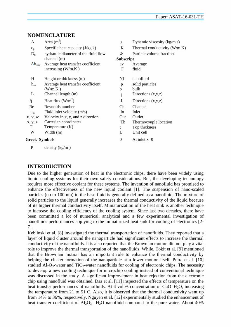
The mesh investigation is one the important steps in the simulation. It concerned with the type
and the sizes of the mesh intervals. The best size was selected according to comparison done
between the three sizes results.Accordingly, three different levels of cell volume are used (20,
40 and 60 μm3). It is found that the maximum percentage change in result is 1.5%. Therefore,
the largest size is chosen to save the computing time as shown in figure 2.
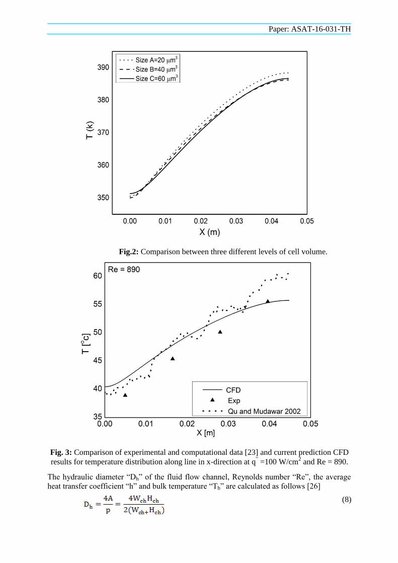
Figure 3 shows the comparison between results of present numerical model and the
experimental data [23] for local temperature distribution along the thermocouple plane (xy-
plane). It can be seen that, the agreement between numerical and experimental results is
acceptable. Therefore, the present numerical model is reliable and can be used to study the
effect of using nanofluid as a coolant on the performance of a MCHS.
The generated heat in electronic components whenever electric current flows through them
causes their temperatures to rise. In order to minimize the temperature rise of the components,
the dissipation of heat with a high rate is necessary for their proper functioning. According to
literature review, nanofluids have a significant effect on cooling process. As a result, this
study was carried out using Al2O3-water nanofluid with volume fraction ranged from 1%, 3%
and 5% at Reynolds number ranged from 200 to 1500 and constant heat flux of 100 W/cm2.
The series CFD results present the influence of these parameters on temperature and heat
transfer coefficient distribution along line in x-direction at Hth =3175 µm.
Paper: ASAT-16-031-TH
Fig.2: Comparison between three different levels of cell volume.
Fig. 3: Comparison of experimental and computational data [23] and current prediction CFD
results for temperature distribution along line in x-direction at q” =100 W/cm
2 and Re = 890.
The hydraulic diameter “Dh” of the fluid flow channel, Reynolds number “Re”, the average
heat transfer coefficient “h” and bulk temperature “Tb” are calculated as follows [26]
(8)
Paper: ASAT-16-031-TH
(9)
(10)
(11)
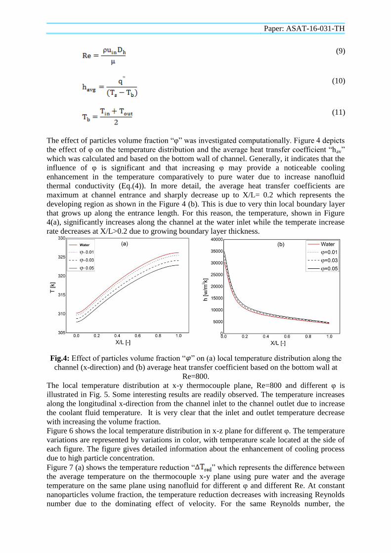
The effect of particles volume fraction “φ” was investigated computationally. Figure 4 depicts
the effect of φ on the temperature distribution and the average heat transfer coefficient “hav”
which was calculated and based on the bottom wall of channel. Generally, it indicates that the
influence of φ is significant and that increasing φ may provide a noticeable cooling
enhancement in the temperature comparatively to pure water due to increase nanofluid
thermal conductivity (Eq.(4)). In more detail, the average heat transfer coefficients are
maximum at channel entrance and sharply decrease up to X/L= 0.2 which represents the
developing region as shown in the Figure 4 (b). This is due to very thin local boundary layer
that grows up along the entrance length. For this reason, the temperature, shown in Figure
4(a), significantly increases along the channel at the water inlet while the temperate increase
rate decreases at X/L>0.2 due to growing boundary layer thickness.
Fig.4: Effect of particles volume fraction “ ” on (a) local temperature distribution along the
channel (x-direction) and (b) average heat transfer coefficient based on the bottom wall at
Re=800.
The local temperature distribution at x-y thermocouple plane, Re=800 and different φ is
illustrated in Fig. 5. Some interesting results are readily observed. The temperature increases
along the longitudinal x-direction from the channel inlet to the channel outlet due to increase
the coolant fluid temperature. It is very clear that the inlet and outlet temperature decrease
with increasing the volume fraction.
Figure 6 shows the local temperature distribution in x-z plane for different φ. The temperature
variations are represented by variations in color, with temperature scale located at the side of
each figure. The figure gives detailed information about the enhancement of cooling process
due to high particle concentration.
Figure 7 (a) shows the temperature reduction “ ” which represents the difference between
the average temperature on the thermocouple x-y plane using pure water and the average
temperature on the same plane using nanofluid for different φ and different Re. At constant
nanoparticles volume fraction, the temperature reduction decreases with increasing Reynolds
number due to the dominating effect of velocity. For the same Reynolds number, the

Paper: ASAT-16-031-TH
temperature reduction increases with increasing the volume fraction. As a result, the heat sink
temperature decreases with increasing the volume fraction of nanoparticles.
Figure 7(b) represents the increasing in the average heat transfer coefficient “ ” which
represents the difference between the average heat transfer coefficient on the channel bottom
using pure water and the average heat transfer coefficient on the same plane using nanofluid
for different φ and different Re . At constant volume fraction, increased Reynolds number
leads to significant increasing in . Also, at constant Reynolds number, increased volume
fraction enhances significantly the heat transfer coefficient comparing with that of pure water.
For example, at Re=800 the heat transfer coefficient enhancement for φ= 1%, 3% and 5%
increases by approximately 270, 812 and 1360 (W/m.K), respectively.
Figure 8 shows the values of the pressure drop versus Reynolds number for various volume
fractions of nanoparticles. It is observed that by increasing both Re and , the pressure drop
increases. Nanofluid indicated higher pressure drop compared with the base fluid, especially
at high Reynolds number. Obviously, friction factor increases with increasing in concentration
of nanoparticles due to the rise of working fluid viscosity (Eq. (5)).
CONCLUSION
A computational model was utilized to simulate a three dimensional fluid flow and heat
transfer in a 3D MCHS filled with AL2O3-water nanofluid. Based on the present
computational study, the following results are obtained:
For all values of nanoparticles volume fractions, the temperature of the coolant fluid
and MCHS increase along the channel length;
Addition of nanoparticles slightly increases the heat transfer coefficient and
significantly decreases the MCHS temperature compared with that of the pure water.
Therefore, nanofluids could be a promising replacement for pure water in MCHS;
The pressure drop increases by increasing Reynolds number and nanoparticles volume
fraction as well as the required power;
Using nanofluids compared to the base fluid “water” leads to increase in the pressure
drop.

Paper: ASAT-16-031-TH
Fig.5: Local temperature distribution along x-y thermocouple plane at different and
Re= 800.
Fig.6: Local temperature distribution contours in x-z plane at different and Re= 800.

Paper: ASAT-16-031-TH
Fig.7: (a) Temperature reduction and (b) average heat transfer coefficient increasing at
different and Re.
Fig.8: Pressure drop at different and Re.
REFERENCES
[1] S.U.S. Choi and J.A. Eastman, “Enhancing thermal conductivity of fluids with
nanoparticles”, in: Conference: 1995 International Mechanical Engineering Congress
and Exhibition, San Francisco, CA, United states, 12–17 November, ASME, San
Francisco, 1995, pp. 99–105.
[2] L. Godson, B. Raja, D. Mohan Lal and S. Wongwises, “Enhancement of heat transfer
using nanofluids”, an overview, Renew. Sustain. Energy Rev. 14, 2010, 629– 641.
Paper: ASAT-16-031-TH
[3] B.H. Salman, H.A. Mohammed and A.S. Kherbeet, “Heat transfer enhancement of
nanofluids flow in microtube with constant heat flux”, Int. Commun. Heat Mass
Transfer 39, 2012, 1195–1204.
[4] S. Lee and S.U.S. Choi, “Application of metallic nanoparticle suspensions in advanced
cooling systems, Recent Advances in Solid/Structures and Applications of Metallic
Materials”, PVP vol. 342/MD-vol 72, ASME, New York, 1996, pp. 227–234.
[5] A. Asthana, I. Zinovik, C. Weinmueller and D. Poulikakos, “Significant Nusselt
number increase in microchannels with a segmented flow of two immiscible liquids:
an experimental study”, Int. J. Heat Mass Transfer 54 ,2013, 1456– 1464.
[6] E.M. Tokit, H.A. Mohammed and M.Z. Yusoff, “Thermal performance of optimized
interrupted microchannel heat sink (IMCHS) using nanofluids”, Int. Commun. Heat
Mass Transfer39, 2013, 1595–1604.
[7] M.R. Sohel, R. Saidur, M.F.M. Sabri, M. Kamalisarvestani, M.M. Elias and A. Ijam,
“Investigating the heat transfer performance and thermophysical properties of
nanofluids in a circular micro-channel”, Int. Commun. Heat Mass Transfer 42, 2013,
75–81.
[8] P. Keblinski, J.A. Eastman and D.G. Cahill, “Nanofluids for thermal transport”, Mater.
Today 8, 2013, 36–44.
[9] E. Mat Tokit, M.Z. Yusoff and H.A. Mohammed, “Generality of Brownian motion
velocity of two phase approach in interrupted microchannel heat sink”, Int. Commun.
Heat Mass Transfer 49, 2013, 128–135.
[10] N. Putra, Yanuar and F.N. Iskandar, “Application of nanofluids to a heat pipe
liquidblock and the thermoelectric cooling of electronic e uipment”, Exp. Therm.
Fluid Sci. 35, 2011, 1274–1281.
[11] S.K. Das, N. Putra, P. Thiesen and W. Roetzel, “Temperature dependence of thermal
conductivity enhancement for nanofluids”, J. Heat Transfer 125, 2003, 567– 574.
[12] C.T. Nguyen, G. Roy, C. Gauthier and N. Galanis, “Heat transfer enhancement using
Al2O3–water nanofluid for an electronic li uid cooling system”, Appl. Therm. Eng.
27, 2007, 1501–1506.
[13] N.A. Roberts and D.G. Walker, “Convective performance of nanofluids in commercial
electronics cooling systems”, Appl. Therm. Eng. 30, 2010, 2499– 2504.
[14] B.P. Whelan, R. Kempers and A.J. Robinson, “A li uid-based system for CPU cooling
implementing a jet array impingement waterblock and a tube array remote heat
exchanger”, Appl. Therm. Eng. 39,2012, 86–94.
[15] C.J. Ho and W.C. Chen, “An experimental study on thermal performance of Al2O3/
water nanofluid in a minichannel heat sink”, Appl. Therm. Eng. 50, 2013, 516– 522.
[16] J.F. Tullius and Y. Bayazitoglu, “Effect of Al2O3/H2O nanofluid on MWNT circular
fin structures in a minichannel”, Int. J. Heat Mass Transfer 60, 2013, 523–530.

Paper: ASAT-16-031-TH
[17] P. Naphon and L. Nakharintr, “Heat transfer of nanofluids in the mini-rectangular fin
heat sinks”, Int. Commun. Heat Mass Transfer 40, 2013, 25–31.
[18] M. Keshavarz Moraveji, R. Mohammadi Ardehali and A. Ijam, “CFD investigation of
nanofluid effects (cooling performance and pressure drop) in mini-channel heat sink”,
Int. Commun. Heat Mass Transfer 40, 2013, 58–66.
[19] I. Elbadawy, S. Anbr and M. Fatouh,” Heat transfer Characteristics of Water Flowing
Through Single and Double Stack Rectangular Microchanels”, 16th
Int. AMME
Conference, Egypt, 2014
[20] S.V. Patankar, “Numerical Heat Transfer and Fluid Flow”, Hemisphere, NY, 1980.
[21] W.Q. Tao,”Numerical Heat Transfer”, second ed., Xi’an Jiaotong University Press,
Xi’an, China, 2001.
[22] X. L. Xie, Z. J. Liu, Y. L. He and W. Q. Tao, “Numerical study of laminar heat
transfer and pressure drop characteristics in a water-cooled minichannel heat sink”,
Applied thermal engineering, vol. 29, 2009, pp. 64-74.
[23] W. Qu and I. Mudawar, “Experimental and numerical study of pressure drop and heat
transfer in a single-phase micro-channel heat sink”, International Journal of Heat and
Mass Transfer 45, 2002, pp. 2549-2565
[24] Jaeseon Lee and Issam Mudawar, “Assessment of the effectiveness of nanofluids for
single-phase and two-phase heat transfer in micro-channels”, International Journal of
Heat and Mass Transfer 50, 2007, 452–463
[25] M. Amoura, M. Alloti, A. Mouassi and N. Zeraibi, “ Study of Heat Transfer of
Nanofluids in a Circular Tube”, International Journal of Mathematical,
Computational, Physical and Quantum Engineering Vol:7 No:9, 2013
[26] O. Levenspiel, “Engineering Flow and Heat Exchange” , 2nd
Edition, Plenum Press,
1998


