
Non-contact 3D Digitizer
Instruction Manual

The following symbols are used in this manual to prevent accidents which may occur as a result of incorrect use of the instrument.
Denotes a sentence regarding a safety warning or note.Read the sentence carefully to ensure safe and correct use.
Denotes a prohibited operation.The operation must never been performed.
Denotes an instruction.The instruction must be strictly adhered to.
Denotes an instruction.Disconnect the AC adapter from the AC outlet.
Denotes a prohibited operation.Never disassemble the instrument.
Safety Symbols
Notes on This Manual● CopyingorreproductionofalloranypartofthecontentsofthismanualwithoutKONICAMINOLTASENCING's
permission is strictly prohibited.● Thecontentsofthismanualaresubjecttochangewithoutpriornotice.● Everyefforthasbeenmadeinthepreparationofthismanualtoensuretheaccuracyofitscontents.However,
shouldyouhaveanyquestionsorfindanyerrors,pleasecontactthenearestKONICAMINOLTASENCING-authorized service facility.
● KONICAMINOLTASENCINGwillnotacceptanyresponsibilityforconsequencesarisingfromtheuseoftheinstrument.

�
Whenusingthishandware,thefollowingpointsmustbestrictlyobservedtoensurecorrectandsafeuse.Afteryouhavereadthismanual,keepitinasafeplacewhereitcanbereferredtoanytimeaquestionarises.
WARNING (Failuretoadheretothefollowingpointsmayresultindeathorseriousinjury.)
DonotusetheRANGE7inplaceswhereflammableorcombustiblegases(gasolineetc.)are present. Doing so may cause fire.
DonotinsertordisconnecttheACpowercord'splug with wet hands. Doing so may cause electricshock.
AlwaysusetheACadaptersuppliedasastandardaccessorywiththeRANGE7,andconnectittoanACoutletofratedvoltageandfrequency. Failure to do so may in damage the RANGE7,causingafireorelectricshock.
DonotdisassembleormodifytheRANGE7orACadapter.Doingsomaycauseafireorelectricshock.
TakespecialcarenottoallowliquidormetalobjectstoentertheRANGE7.Doingsomaycauseafireorelectricshock.ShouldliquidormetalobjectsentertheRANGE7,turnthepowerOFFimmediately,disconnecttheACadapterfromtheACoutlet,andcontactthenearestKONICAMINOLTASENSING-authorizedservice facility.
Donotbend,twistorpulltheACpowercordexcessively.Also,donotplaceheavyobjectontheACpowercord,ordamageormodifytheRANGE7.DoingsomaycausedamagetotheACpowercord,resultinginfireorelectricshock.
TheRANGE7shouldnotbeoperatedifdirtordust has entered through the vent holes. Doing somayresultinafire.Forperiodicinspection,contactthenearestKONICAMINOLTASENSING-authorizedservicefacility.
WhendisconnectingtheACadapter'splug,always hold the plug and pull it to remove it. NeverpulltheACpowercorditself.DoingsomaydamagetheACpowercord,causingafireorelectricshock.
IftheRANGE7willnotbeusedforalongtime,disconnecttheACadapterfromtheACoutlet.AccumulateddirtorwaterontheprongsoftheACadapter'splugmaycauseafire. If there is any dirt or water on the prongs of theACadapter'splug,removeit.
Neverstareintothelaseremittingwindow.
Donotplacealens,mirrororopticalelement in the passage of the laser beam. Doing so may converge the laserbeam,resultingindamagetoyoureyes,burnsorfire.Topreventtheaboveaccidents,makesurethatawallorsimilarwhichcanblockthelaser beam is located behind the object.
TheRANGE7shouldnotbeoperatedifitisdamaged,orsmokeoroddsmellsaredetected.Doingsomayresultinafire.Insuchsituations,turnthepowerOFFimmediately,disconnecttheACadapterfromtheACoutlet,andcontactthenearestKONICAMINOLTASENSING-authorized service facility.
Safety Precautions
CAUTIONBesuretoconnecttheACpowercordplugtoanACoutletthathasagroundingterminal.
Do not place the instrument on an unstable or sloping surface. Doing so may result in its droppingoroverturning,causinginjury.Takecare not to drop the instrument when carrying it.MakesurethattheACoutletislocatednearthe
RANGE7andthattheACadapter'splugcanbeeasily connected and disconnected.
(Failuretoadheretofollowingpointsmayresultininjuryordamagetothisinstrumentorotherproperty.)

�
Foreward
Notes On Use• WeshallguaranteetheRANGE7operationat10°Cto40°Cambienttemperatureand65%orlessrelative
humidity.EnsurethattheRANGE7operatingenvironmentiswithinthisrange.• TheRANGE7hasbeencalibratedat20°C.Itisrecommendedthatthisinstrumentshouldbeusedataroomtemperatureof20°C.• TheRANGE7hasbeendesignedforindooruse.Donotusethisinstrumentoutdoors.• DonotusetheRANGE7inaplaceexposedtodirectsunlightinsummer,ornearaheater. TheRANGE7temperaturebecomesmuchhigherthantheambienttemperature,causingafaultofthe
instrument.UsetheRANGE7inawell-ventilatedplace.Donotblocktheventilationport.• DonotusetheRANGE7inadustyplace,orinaplacewithhighhumidity.Otherwise,theremaybeafaultwiththeinstrument.• DonotstrikeorapplystrongvibrationtotheRANGE7.Otherwise,theinstrumentmayhaveafault.• DonotusetheRANGE7nearahigh-risebuildingoraroadwithheavytraffic.IftheRANGE7andthetargets
beingmeasuredshake,theRANGE7maynotobtainaccuratemeasurementresults.• DonotoverturntheRANGE7.Otherwise,theinstrumentmayhaveafault.• DonotdisconnectanycablewhiletheRANGE7isON(whilePowerbuttonislityellow-green.)Otherwise,there
may be a fault with the instrument.• TheRANGE7isaclass2laserinstrumentasspecifiedinIECPublication60825-1.Handlethisinstrument
properly by observing the instructions given in this manual.• UsetheRANGE7atanaltitudeof2000mmax.• WhenyouusetheRANGE7forthefirsttime,oraftertransportation,makesurethatthelensissecurely
fastened.Ifthelensbecomesloose,tightenitsecurelybyfollowingthelensexchangingprocedure.
Care On Storage• TheRANGE7shouldbestoredinareaswithtemperaturesofbetween-10ºCand+50ºC.Donotstoreitinareas
subjecttohightemperatureorhighhumidityorwheresuddenchangesintemperatureorcondensationarelikelytooccur.WerecommendstoringtheRANGE7aroundroomtemperature(20ºC)withadesiccant(silicageletc.).
• DonotleavetheRANGE7insideaclosedcarorinthetrunkofacar.Underdirectsunlight,theincreaseintemperature can be extreme and may result in malfunctions.
• Whenshippingtheproduct,usetheoriginalpackingmaterialsinwhichtheproductwasshipped.Thematerialswillprovideprotectionagainstvibrationsandimpact,andalsoprovidesomeprotectionagainstsuddenchangesintemperature.
• TheRANGE7shouldnotbestoredinareaswherethereisanexcessiveamountofdust,cigarettesmokeorchemicalgas.Failuretoadheretothismayresultinperformancedegradationorbreak-down.
• Whenlensesarenotinuse,attachthelensandmountcapsandstorethelensesintheexclusivecase.• WhenstoringtheRANGE7withlensattached,putthelenscaponthelens.
Notes On Cleaning• IftheRANGE7needscleaning,wipewithasoftdrycloth.Neverusesolventssuchasthinnerorbenzene.• Ifthelensorlaseremittingwindowisdirty,blowoffsandordustusingablower.Ifthelensisstilldirty,wipethe
lens gently with a piece of cleaning paper dampened with a cleaning agent.• Incasesofmalfunction,donotdisassembletheRANGE7orattempttorepairityourself.Contactthenearest
KONICAMINOLTASENSING-authorizedservicefacility.
Disposal Method• MakesurethattheRANGE7,accessoriesandbatteryareeitherdisposedoforrecycledcorrectlyinaccordance
with local laws and regulations.
About the packing materials contained in your product package• Pleaseensurethatyoucarefullykeepthepackingmaterials(corrugatedcardboard,cushionmaterials,and
plasticbags)containedinyourproductpackage.• TheRANGE7isaprecisionmeasuringinstrument.IfyoutransporttheRANGE7toourfactoryforthepurposeof
maintenance(repair,etc.),youshouldusethepackingmaterialscontainedintheproductpackageinordertominimizeimpactandshockduringtransportation.Ifanyofthepackingmaterialsarelostordamaged,pleasecontactaKONICAMINOLTASENSING-authorizedservicefacility.

�
<FRONT>
<REAR>
RANGE7
Laser Label Indication
Warning and instruction labels about the laser
Other warning label

4
About this Manual (Contents)
Contents and Descriptions
This instruction manual provides the following contents about preparations for use of the RANGE7.
• Precautions for Use
• Part Names and Functions
• System Confi guration and Accessories
• Setup Procedure for Measurement with the RANGE7
• RANGE7 Measuring Steps (Images)
• Measuring Principle of the RANGE7
• RANGE7 Specifi cations and Accessories
SafetySymbolsNotesonThisManual
SafetyPrecautions ………………………………………………………………………………………………………… �
Foreward …………………………………………………………………………………………………………………… �Aboutthepackingmaterialscontainedinyourproductpackage ……………………………………………………………… �NotesOnUse ……………………………………………………………………………………………………………………… �CareOnStorage …………………………………………………………………………………………………………………… �NotesOnCleaning ………………………………………………………………………………………………………………… �Disposal Method …………………………………………………………………………………………………………………… �
LaserLabelIndication ……………………………………………………………………………………………………… �Warning and instruction labels about the laser ………………………………………………………………………………… �Otherwarninglabel ………………………………………………………………………………………………………………… �
AboutthisManual(Contents) ……………………………………………………………………………………………… 4ContentsandDescriptions ………………………………………………………………………………………………………… 4
AbouttheRANGE7 ………………………………………………………………………………………………………… 5nSystemDiagram ………………………………………………………………………………………………………………… 5nNamesofPartsandFunctions ………………………………………………………………………………………………… 6n Dimensions ……………………………………………………………………………………………………………………… 7
InstallationandSetup ……………………………………………………………………………………………………… 8n Installation ………………………………………………………………………………………………………………………… 81)Directinstallationontable …………………………………………………………………………………………………… 82)Installationusingtripodset(underoptionalaccessories) ………………………………………………………………… 83)Installationusingthemeasuringstandset(underoptionalaccessories) ……………………………………………… 9
nSetup ……………………………………………………………………………………………………………………………… �01)InstallingtheRANGE7 ……………………………………………………………………………………………………… ��2)SettingtheRANGE7’spositionrelativetothemeasuringtarget,andexchangingthelens ………………………… ��3)ConnectingtheACadaptor ………………………………………………………………………………………………… ��4)ConnectingtheRANGE7toaPC …………………………………………………………………………………………… ��5)Turningpoweron/off ………………………………………………………………………………………………………… �4
nAboutFieldCalibration ………………………………………………………………………………………………………… �5
MeasuringSteps(Images) …………………………………………………………………………………………………�6nInstallationandMeasurement(Image) ……………………………………………………………………………………… �6nShootingandFocusing(Image) ………………………………………………………………………………………………… �7nScanning(Image) ……………………………………………………………………………………………………………… �7
Troubleshooting ……………………………………………………………………………………………………………�8
OtherInformation ……………………………………………………………………………………………………………�9nMeasuringPrinciples …………………………………………………………………………………………………………… �9nSpecifications …………………………………………………………………………………………………………………… �0
5
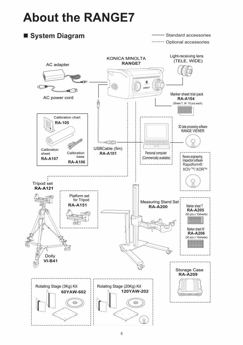
About the RANGE7n System Diagram
Light-receiving lens(TELE, WIDE)KONICA MINOLTA
RANGE7AC adapter
AC power cord
USBCable (5m)RA-A101
Marker sheet trial pack
(Sheet T, W: 10 pcs each)
RANGE VIEWER
Rapidform®XOV TM/ XORTM
Personal computer(Commercially available)
Standard accessoriesOptional accessories
3D data processing software
Rotating Stage (3Kg) Kit Rotating Stage (20Kg) Kit60YAW-602 120YAW-202
Tripod setRA-A121
Platform setfor Tripod
RA-A151
DollyVI-B41
Measuring Stand SetRA-A200 Marker sheet T
(50 pcs x 10sheets)
(50 pcs x 10sheets)
Storage CaseRA-A209
Marker sheet W
Revers engineering/inspection software
RA-A104
RA-A205
RA-A206
Calibrationsheet
Calibration chart
RA-105
RA-A107Calibration
base
RA-A106

6
n Names of Parts and Functions
1)Carryinghandle UsedtoliftorcarrytheRANGE7.(BesuretoholdtheRANGE7bodywithbothhands.)2)Light-receivinglens Exchangethelight-receivinglensforanoptimumlens(TeleorWidelens),dependingon
the measuring target size and measuring distance.3)Laser-emittingwindow Alaserbeamisemittedtoameasuringtargetfromthiswindow.(Donotstaredirectlyinto
thelaserbeam.)4)Lensshutter Whenthepowerisswitchedoff,thisshutterclosestoprotectthelaseremittingwindow.5)Rubbersole Fourrubbersolesareattachedat thebottomof theRANGE7.To install theRANGE7
directlyonafirmtable,usetheseparts.Also,usethecalibrationchartsetduringfieldcalibration(understandardaccessories);orwhenmountingtheRANGE7tothetripodset,ormeasuringstandset (underoptionalaccessories),use theseparts toset theRANGE7inplace.
6)Platformmountingscrewhole ScrewholesforfasteningtheRANGE7tothemeasuringstandplatformortripodplatform(underoptionalaccessories).
7)Powerswitch TurnsON/OFFtheRANGE7powersupply.8)ACadaptorterminal ConnecttheRANGE7ACadaptorplugtothisterminal.9)USBport WhenconnectingtheRANGE7toaPC,connect theUSBcable(standardaccessory)
Type B plug.
3)Laser-emittingWindow
4)Lasershutter
5)Rubbersole
7)Powerswitch
8)ACadapterterminal
6)Platformmountingscrewhole
WARNING
Alaserbeamisemittedfrom this port. Do not stare directly into the laser beam.
1)Carryinghandle
2)Light-ReceivingLens
9)USBport(TipeB)LaserLabelIndication(page5)

7
n Dimensions
199.
648
.3
ø74.7
ø66
ø 35ø61.5
9.1
141
387.920
.8
57.7
57.7
197.7
ø15
9
189.
6
292.4
55°
248
111

8
Installation and Setup n Installation This section describes the RANGE7 installation procedures and precautions for installation.
<Installation procedure>To install the RANGE7, you can use the following three methods:
1) Direct installation on a table or like surface (including a measuring table prepared by user)
2) Installation using tripod set (under optional accessories)
3) Installation using measuring stand set (under optional accessories)
1) Direct installation on table The RANGE7 can be directly installed on a table or like surface by using the rubber soles at the bottom of the unit.
NOTE • Install the RANGE7 on a firm, level table. • To install the RANGE7 on a table prepared by user, use a firm, level table wide enough to put to completely secure the four
rubber soles.
• When the RANGE7 is directly installed on a table, the RANGE7 may not obtain the correct measurement results depending on
the position relative to the measuring target.
In this case, use of the tripod set or measuring stand set (under optional accessories) is recommended.
2) Installation using tripod set (under optional accessories)Mount the RANGE7 to the tripod platform (under optional accessories).
NOTE • Before mounting the RANGE7, make sure that the tripod platform is properly mounted to the tripod.
* For the tripod platform to tripod mounting procedure, refer to the instruction manual with regards to the tripod platform.
• When using the tripod set, tighten the lock lever for each part so that the tripod will not accidentally shake.
• Install the tripod set on a firm floor. To move the tripod set, slide it slowly with the dolly (under optional accessories).
[Mounting procedure]1) Hold the tripod platform swing plate mounted to the tripod, set horizontally.
2) Hold the handles with both hands, and put the RANGE7 on the swing plate.
* Among the four rubber soles at the bottom of the RANGE7, the two soles
on the rear side must fit securely into the swing plate positioning holes.
3) Insert the four screws on the back of the swing plate into the platform
mounting screw holes at the bottom of the RANGE7, and turn the screws
clockwise to tighten them securely.
NOTE
• When removing the RANGE7, perform the above procedure in the reverse
order.
• Normally, the screws at the bottom of the swing plate will not come off.
However, if the screws are forcibly turned from the RANGE7 removing
position, the screws may come off.

9
3) Installation using the measuring stand set (under optional accessories)Mount the RANGE7 to the measuring stand platform (under optional accessories).
NOTE • Before mounting the RANGE7, make sure that the measuring stand platform is properly mounted to the measuring stand. * For the procedure on how to mount the measuring stand platform to the measuring stand, refer to the instruction manual for
the measuring stand set.
• When using the measuring stand, tighten the lock lever for each part so that the measuring stand will not accidentally shake.
• Install the measuring stand on a firm floor. Do not step on the leg, or hang on the arm.
[Mounting procedure]1) Hold the measuring stand platform swing plate horizontally mounted to
the measuring stand arm.
2) Hold the handles with both hands, and put the RANGE7 on the swing
plate.
* Among the four rubber soles at the bottom of the RANGE7, the two
soles on the rear side must securely fit into the swing plate positioning
holes.
3) Insert four screws on the back of the swing plate into the platform mounting
screw holes at the bottom of the RANGE7, and turn the screws clockwise to
tighten them securely.
NOTE
• When removing the RANGE7, perform the above procedure in the
reverse order.
• Normally, the screws at the bottom of the swing plate will not come off.
However, if the screws are forcibly turned from the RANGE7 removing
position, the screws may come of

10
To execute measurement using the RANGE7, mount an optimum lens depending on the measuring target size and the measuring distance,
and install the RANGE7 at an optimum position relative to the measuring target. The following is an example of the ordinary RANGE7
setup using the tripod setting (under optional accessories).
n Setup
Object
RANGE7
(100V AC main outlet with a grounding terminal)
AC adapter
AC power cord
Tripod SetPlatform for Tripod
USB cable
Personal Computer
RANGE VIEWER
Cable clamp

��
<Setup procedure>
This section describes the procedure for installing the RANGE7 properly, and completing the preparations for measurement.
Make preparations according to the following procedures:
1) Installing the RANGE7.
2) Set the RANGE7 at a position relative to the proper target, and mount the lens suitable in question as the target of measure.
3) Connect the AC adaptor to the RANGE7.
4) Connect the RANGE7 to a PC.
5) Turn ON the RANGE7 power switch to start warming up the RANGE7.
1) Installing the RANGE7The RANGE7 can be directly installed on a table by using the rubber soles at the bottom. Also, it can be installed with the tripod set or
measuring stand (under optional accessories).
When the tripod set or measuring stand are used, the RANGE7 orientation can be freely changed (up/down and right/left). This feature is
useful for measurement.
Memo For installation procedure details, please refer to the description on “Installation”.
2) Setting the RANGE7’s position relative to the measuring target, and exchanging the lens
Scan Position Adjustment
ThelocationandpostureoftheworkandRANGE7canbeadjustedsothatthetwoareappropriatelypositionedfor
scanning.Theseadjustmentsaremadebyactivatingthemonitoringfeatureandwatchingtheworkinthemonitorwindow.
Clickthe[Monitor]buttontochecktheworkonthemonitorwindow.Distancetoworkandworksize (Unit:mm)Lens TELElens WIDElens
Distance 450 800 450 800X×Y 79×99 141×176 150×188 267×334
Z 54 97 109 194Distancetoworkandworksize inMultiFocusmode (Unit:mm)Lens TELElens WIDElens
Distance 462 781 475 766X×Y 81×102 138×172 159×199 256×320
Z 54 97 109 194
Distancetowork450mmto800mm
Receiver lens(Interchangeable)TELE/WIDE
RANGE7
Work
Y
X Z
• The origin is set at the sensor position which is
approximately 120 mm behind the center of the lens
surface. Therefore, the Z dimension has an offset of
around 120 mm applied.
RANGE VIEWER monitor window
��
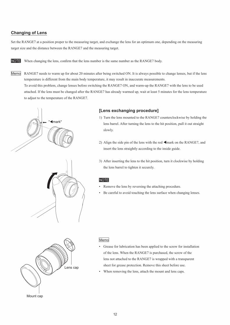
[Lens exchanging procedure]1) Turn the lens mounted to the RANGE7 counterclockwise by holding the
lens barrel. After turning the lens to the hit position, pull it out straight
slowly.
2) Align the side pin of the lens with the red mark on the RANGE7, and
insert the lens straightly according to the inside guide.
3) After inserting the lens to the hit position, turn it clockwise by holding
the lens barrel to tighten it securely.
NOTE
• Remove the lens by reversing the attaching procedure.
• Be careful to avoid touching the lens surface when changing lenses.
Memo
• Grease for lubrication has been applied to the screw for installation
of the lens. When the RANGE7 is purchased, the screw of the
lens not attached to the RANGE7 is wrapped with a transparent
sheet for grease protection. Remove this sheet before use.
• When removing the lens, attach the mount and lens caps.
Changing of Lens
Set the RANGE7 at a position proper to the measuring target, and exchange the lens for an optimum one, depending on the measuring
target size and the distance between the RANGE7 and the measuring target.
NOTE When changing the lens, confirm that the lens number is the same number as the RANGE7 body.
Memo RANGE7 needs to warm up for about 20 minutes after being switched ON. It is always possible to change lenses, but if the lens temperature is different from the main body temperature, it may result in inaccurate measurements.
To avoid this problem, change lenses before switching the RANGE7 ON, and warm-up the RANGE7 with the lens to be used
attached. If the lens must be changed after the RANGE7 has already warmed up, wait at least 5 minutes for the lens temperature
to adjust to the temperature of the RANGE7.
"mark"
Mount cap
Lenscap

��
3) Connecting the AC adaptor 1) Connect the AC cable to the AC adaptor for the RANGE7.
2) Insert the AC adaptor plug of the dedicated AC adaptor (AC-A324)
to the AC adaptor connection terminal on the right of the
RANGE7 rear panel.
3) Insert the AC cable plug connected to the AC adaptor to a 100 V
AC main outlet.
NOTE Insert the plug securely to the innermost position.
4) Connecting the RANGE7 to a PC1) Insert the Type B plug of the dedicated USB cable to the USB
port on the right of the RANGE7 rear panel.
Memo The USB connection port of the RANGE7 is equipped with the plug hold mechanism. First, when the plug is inserted, it
will hit something. Then, you must further insert the plug
securely to the innermost position.
2) Insert the end of the USB cable (Type A plug) into the USB port
of the PC.
NOTE • Insert the plug securely to the innermost position. • During measurement with the RANGE7, or during data
processing after measurement, do not disconnect the USB
cable.

14
5) Turning power on/off1) Push the white power button in the upper right part of the rear
panel of the RANGE7.
A short beep sounds, the power is switched on, and the power
button is lit yellow-green.
2) Warming-up of the RANGE7 starts when the laser shutter is
opened.
Memo
• RANGE7 needs to warm up for about 20 minutes after being
switched ON.
• While the RANGE7 is warming up, a message that the RANGE7
is now warming up will appear on the screen of RANGE
VIEWER software. This message will disappear when warming-
up of the RANGE7 is completed.
3) Push the yellow-green-lit power button again. Two short beeps
will sound, the power is switched off, and then the light of the
power button will disappear.
NOTE
• Do not turn the RANGE7 off during measurement or data
processing after a measurement.
• When turning the power OFF, do not unplug the AC power cord
from the AC outlet until the power light disappears.
Power button

15
n About Field Calibration
Calibration sheet
The figure below shows an example of setting up the RANGE7 for calibration using the Calibration Set.
Calibration should be performed in the following cases:
• Before using for the first time after purchase.
• If the RANGE7 has not been used for a few days.
• If the ambient temperature during storage or use is drastically different from the ambient temperature at the time calibration was last
performed.
• If the RANGE7 may have been subject to vibrations during shipping or movement.
• To achieve higher measurement accuracy.
NOTE
• The Calibration Chart has been calibrated using the RANGE7 unit with which it was shipped. When performing calibration, be sure to
use the Calibration Chart with the same number as the RANGE7 body.
• Before performing calibration, confirm that the lens number is the same number as the RANGE7 body.
Enough space is needed to spread out the sheet. 1280×430 mm
Set the calibration chart in the position marked on the sheet for the lens being used.
Do not touch the front side of the chart with bare hands. If dirty, wipe the chart clean with a dry soft piece of cloth.
Scanning is done seven times for calibration. Position and angle the calibration chart as indicated in the Calibration Wizard.
Calibration is easy to understand and perform with the Calibration Wizard. For details, see “5-1. Calibration” on p. 68 of the Reference Manual.
RANGE7Calibration chart
Calibration base

16
n Installation and Measurement (Image)
Measuring Steps (Images)
ExampleofinstallationonMeasuringStandSetRA-A200(optionalaccessory)
ExampleofinstallationonTripodSetRA-A121(optionalaccessory)

17
n Shooting and Focusing (Image)
n Scanning (Image)

18
TroubleshootingIfyouhavesomeproblemswhenusingtheRANGE7,pleaserefertothefollowingtabletocheckonthesituation.TheRANGE7operation iscontrolledby the3Dprocessingsoftware“RANGEVIEWER”.TheRANGEVIEWERmonitorstheRANGE7condition,anddisplaystheappropriatemessages.Pleasealsorefertothe“ErrorMessage”sectionintheRANGEVIEWERReferenceManual.
Symptoms Itemtocheck/Possiblecauses CorrectiveactionsPowerisnotturnedON. • IstheACadapterconnected?
• IstheACcordoftheACadapterproperly
connectedtothemainoutlet?
• IsthegreenindicatorontheACadapter
ON?
• ChecktheACadaptorandACcord
connections.Ifnotconnected,doso
properly.The indicator does not light
yellow when the power switch is
pressed.
• ConnecttheRANGE7ACadaptertoa
100to240Vac(50to60Hz)mainoutlet
before use.The yellow indicator went off
withoutturningOFFthepower.
• DidyoudisconnecttheUSBcableduring
measurement?
• ConnecttheUSBcableproperly,and
turnONtheRANGE7poweragain.
• TheRANGE7isconnectedtoaPCusing
theUSBcable,andmeasurementsare
controlled by the �D processing software
“RANGEVIEWER”.WhentheUSBcable
isdisconnectedduringmeasurement,
theRANGE7powerturnsoff.• IstheACadapterconnected?
• IstheACcordoftheACadapterproperly
connectedtothedesignatedmainoutlet?
• ChecktheACadaptorandACcord
connections.Ifnotconnected,doso
properly.
• ConnecttheRANGE7ACadapterto
100to240Vac(50to60Hz)mainoutlet
before use.Does not scan • IstheRANGE7properlyconnectedtoa
PCusingtheUSBcable?
• Isthelensproperlyattached?
• IstheRANGE7powerturnedON?
• CheckthattheRANGE7isproperly
connectedtoaPCusingtheUSBcable.
AlsocheckthattheUSBcableBplugis
securelyconnectedtotheRANGE7USB
connection port.
• Properlyattachthelensaccordingto
objectsize,ordistancetosaidobject.
• Confirmthatthepowerbuttonislit
yellow-greenwhenthepowerbuttonin
the upper right part of the rear panel of
theRANGE7ispressed.TheRANGE7exteriorbecomes
hot
• IstheRANGE7ventblocked? • Donotblockthevent.
* Doing so may cause affect air circulation
and cause the internal temperature of
theRANGE7torise.

�9
Other Informationn Measuring Principles
<Basic Principle>TheRANGE7usesthelight-stripemethodtoemitahorizontalstripelightthroughacylindricallenstotheobject.ThereflectedlightfromtheobjectisreceivedbytheCMOSsensor,andthenconvertedbytriangulationintodistanceinformation.ThisprocessisrepeatedbyscanningthestripelightverticallyontheobjectsurfaceusingaGalvanomirror,toobtaina3Dimagedataoftheobject.
<High-Speed Image Processing Circuit>ThestripelightisscannedontheCMOSimageplaneatonehorizontallineperframe,andtheCMOSisdrivensothattheblockreadoutstartpositionisshiftedonelineperframe.Approximately1400framesareacquired.• Framerate:600frames/sec.• Blockreadout:350linesTheoutputsignalfromtheCMOSsensoristhenconvertedintoadigitalsignal,whichisthensubjectedtodigitalsignalprocessing.TheprocesseddataisfinallytransferredtothecomputerviatheUSBinterface.
CMOSSensor
GalvanoScanner
LazerDiodo
CPU
Driver
CPUDataBus
A/DFPGA
FrameMemory
USBDriver USB
<Time center of gravity and Space center of gravity>Withthisinstrument,3DimagesareobtainedbycalculatingthetimecenterofgravityofeachpixeloftheCMOSsensor.Withthismethod,comparedtothespacecenterofgravity,useofthetimecenterofgravityreducestheinfluenceofsensitivityvariationsoftheCMOSsensorpixelsandvariationsinobjectbrightness.
Frame interlineTransfer CCD
GalvanoScanner
CPU
A/D
Clock Generator
FIFO
Host I/F
DSP
FrameMemory
LaserDiode
DriverCPU Data Bus
Galvano mirror
Emitting lens
Laser beam
Light-receiving lens(Exchangeable)
Object
CMOS sensor

20
n SpecificationsMODELNAME KONICAMINOLTARANGE7ScanningMethod Triangulation,lasercuttingsystemLight-Source Semiconductorlaserλ=660nmLaserClassification Class2(IEC60825-1edition2)
SensorName CMOSPhotodiodePixcel 1.31MegaPixel
MeasuringDistance(mm) 450to800(DistancefromLight-ReceivingLens*1)LightReceivingLens TELE/WIDE
Measuring Range (mm)
MultiFocus modeDisabled
Lens TELE TELE WIDE WIDEDistance 450 800 450 800X-Ysize 79×99 141×176 150×188 267×334Z 54 97 109 194Meas.pitchofX-Y 0.08 0.14 0.16 0.28
MultiFocus modeEnabled
Lens TELE TELE WIDE WIDEDistance 462 781 475 766X-Ysize 81×102 138×172 159×199 256×320Z 54 97 109 194Meas.pitchofX-Y 0.08 0.13 0.08 0.25
Accuracy(Interglobulerdistance)*2 ±40μmPrecision(Z,σ)*3 4μmAutoFocus availableAutoExporsure availableScanningTime about2-8sec.perscanPreviewFunction available(about0.4sec.per1scan)EnvironmentBrightness 500lxorlessFileFormat*4 IN/OUT:.rgv,.rvm(Originalformat),OUTonly:.stlOutputInterface USB2.0HighSpeed
PowerSupplyACadapter
100-240Vac(50-60Hz),1.4A
Dimensions(mm)295(W)x190(H)x200(D)
*withoutHandleandLensWeight(Kg) about6.7OperatingCondition 10to40ºC(relativehumidity65%orless,withnocondensation)StorageCondition -10to50ºC(relativehumidity85%orless[at35ºC],withnocondensation)Remarks(Controledvia) Controledvia"RANGEVIEWER"
*1 Due to the difference of origins on the measurement reference surface and measuring data, the Z axis coordinate has an offset as about 120 mm for the measuring
distance.
*2 When the interglobuler distance for the ball bars (2 globes) specified in VDI/VDE2634-2 is measured under the following conditions defined by KONICA
MINOLTA SENSING:
Our conditions: Temperature 20±1ºC / Using the TELE lens / Distance 450 mm / Warming up 20 min. / Using the KONICA MINOLTA SENSING processing
software / With Calibration / Measuring object: Standard KONICA MINOLTA SENSING (2 globes) instrument / Measuring object arrangement:
KONICA MINOLTA SENSING (10 positions within measurement space) standard position/ Evaluation uncertainty of the standard instrument is
not included.
*3 Measuring conditions: Temperature 20±1ºC / Using the TELE lens / Distance 450 mm / Warming up 20 min. / Using the KONICA MINOLTA SENSING processing
software / Measuring object: KONICA MINOLTA SENSING reference plain chart / 1σ
*4 Using the KONICA MINOLTA SENSING “RANGE VIEWER” processing software
• The RANGE7 incorporates the eT-Kernel/Compact from sSOL Co., Ltd.


9222-A0V8-11 AIDAEE©2008 KONICA MINOLTA SENSING, INC.


