
Machine Automation Controller NJ-series
Troubleshooting Manual
W503-E1-09
NJ501-15@@ NJ501-14@@ NJ501-13@@ NJ301-12@@ NJ301-11@@

All rights reserved. No part of this publication may be reproduced, stored in a retrieval system, or transmitted, in any form, or by any means, mechanical, electronic, photocopying, recording, or otherwise, without the prior written permission of OMRON.
No patent liability is assumed with respect to the use of the information contained herein. Moreover, because OMRON is constantly striving to improve its high-quality products, the information contained in this manual is subject to change without notice. Every precaution has been taken in the preparation of this manual. Nevertheless, OMRON assumes no responsibility for errors or omissions. Neither is any liability assumed for damages resulting from the use of the information contained in this publication.
© OMRON, 2011
• Sysmac and SYSMAC are trademarks or registered trademarks of OMRON Corporation in Japan and other countries for OMRON factory automation products.
• Windows, Windows XP, Windows Vista, Windows 7, and Windows 8 are registered trademarks of Microsoft Corporation in the USA and other countries.
• EtherCAT® is registered trademark and patented technology, licensed by Beckhoff Automation GmbH, Germany.
• ODVA, CIP, CompoNet, DeviceNet, and EtherNet/IP are trademarks of ODVA.
• The SD and SDHC logos are trademarks of SD-3C, LLC.
Other company names and product names in this document are the trademarks or registered trademarks of their respective companies.
Trademarks
Introduction
Introduction
Thank you for purchasing an NJ-series CPU Unit.This manual contains information that is necessary to use the NJ-series CPU Unit. Please read thismanual and make sure you understand the functionality and performance of the NJ-series CPU Unitbefore you attempt to use it in a control system.Keep this manual in a safe place where it will be available for reference during operation.
This manual is intended for the following personnel, who must also have knowledge of electrical sys-tems (an electrical engineer or the equivalent).
• Personnel in charge of introducing FA systems.
• Personnel in charge of designing FA systems.
• Personnel in charge of installing and maintaining FA systems.
• Personnel in charge of managing FA systems and facilities.
For programming, this manual is intended for personnel who understand the programming languagespecifications in international standard IEC 61131-3 or Japanese standard JIS B 3503.
This manual covers the following products.
• NJ-series CPU Units
• NJ501-15
• NJ501-14
• NJ501-13
• NJ301-12
• NJ301-11
Part of the specifications and restrictions for the CPU Units are given in other manuals. Refer to Rele-vant Manuals on page 2 and Related Manuals on page 19.
Intended Audience
Applicable Products
1NJ-series Troubleshooting Manual (W503)
Relevant Manuals
Relevant Manuals
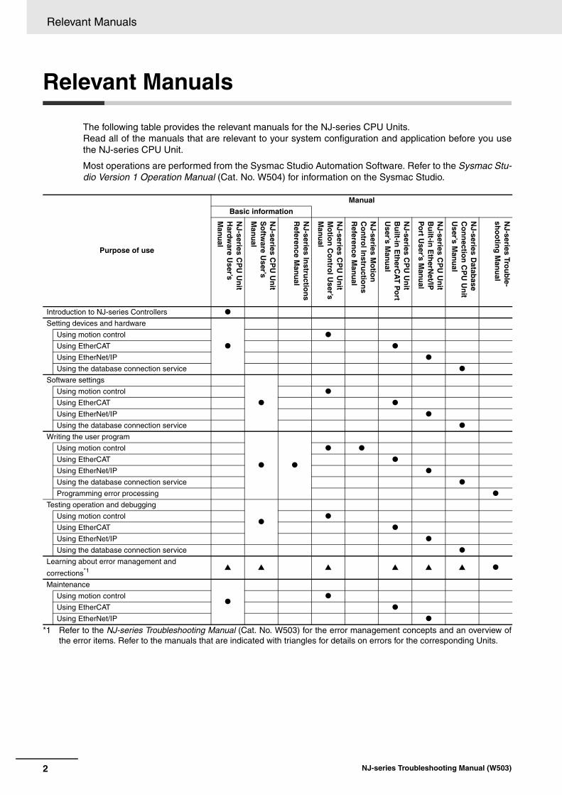
The following table provides the relevant manuals for the NJ-series CPU Units.Read all of the manuals that are relevant to your system configuration and application before you usethe NJ-series CPU Unit.
Most operations are performed from the Sysmac Studio Automation Software. Refer to the Sysmac Stu-dio Version 1 Operation Manual (Cat. No. W504) for information on the Sysmac Studio.
*1 Refer to the NJ-series Troubleshooting Manual (Cat. No. W503) for the error management concepts and an overview ofthe error items. Refer to the manuals that are indicated with triangles for details on errors for the corresponding Units.
Purpose of use
Manual
Basic information
NJ-series C
PU
Un
it H
ardware U
ser’s M
anu
al
NJ-series C
PU
Un
it S
oftw
are User’s
Man
ual
NJ-series In
structio
ns
Referen
ce Man
ual
NJ-series C
PU
Un
it M
otio
n C
on
trol U
ser’s M
anu
al
NJ-series M
otio
n
Co
ntro
l Instru
ction
s R
eference M
anu
al
NJ-series C
PU
Un
it B
uilt-in
Eth
erCA
T P
ort
User’s M
anu
al
NJ-series C
PU
Un
it B
uilt-in
Eth
erNet/IP
P
ort U
ser’s Man
ual
NJ-series D
atabase
Co
nn
ection
CP
U U
nit
User’s M
anu
al
NJ-series Tro
ub
le-sh
oo
ting
Man
ual
Introduction to NJ-series Controllers
Setting devices and hardware
Using motion control
Using EtherCAT
Using EtherNet/IP
Using the database connection service
Software settings
Using motion control
Using EtherCAT
Using EtherNet/IP
Using the database connection service
Writing the user program
Using motion control
Using EtherCAT
Using EtherNet/IP
Using the database connection service
Programming error processing
Testing operation and debugging
Using motion control
Using EtherCAT
Using EtherNet/IP
Using the database connection service
Learning about error management and
corrections*1
Maintenance
Using motion control
Using EtherCAT
Using EtherNet/IP
2 NJ-series Troubleshooting Manual (W503)
Manual Structure
Manual Structure
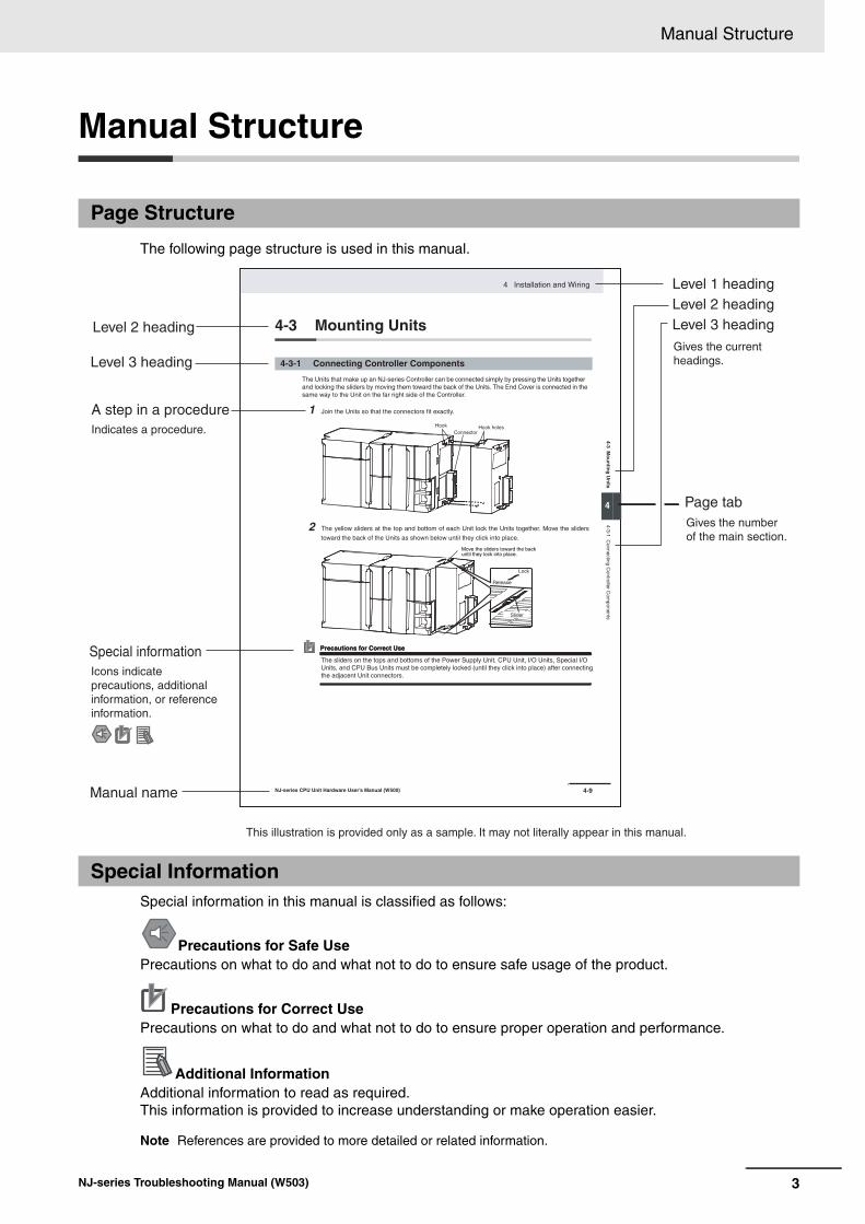
The following page structure is used in this manual.
Special information in this manual is classified as follows:
Note References are provided to more detailed or related information.
Page Structure
Special Information
Precautions for Safe UsePrecautions on what to do and what not to do to ensure safe usage of the product.
Precautions for Correct UsePrecautions on what to do and what not to do to ensure proper operation and performance.
Additional InformationAdditional information to read as required.This information is provided to increase understanding or make operation easier.
4-9
4 Installation and Wiring
NJ-series CPU Unit Hardware User’s Manual (W500)
sti
nU
gni
tn
uo
M 3-
4
4
stne
nop
moC
rell
ortn
oC
gnit
cenn
oC
1-3-
4
4-3 Mounting Units
The Units that make up an NJ-series Controller can be connected simply by pressing the Units togetherand locking the sliders by moving them toward the back of the Units. The End Cover is connected in thesame way to the Unit on the far right side of the Controller.
1 Join the Units so that the connectors fit exactly.
2 The yellow sliders at the top and bottom of each Unit lock the Units together. Move the sliders
toward the back of the Units as shown below until they click into place.
Precautions for Correct UsePrecautions for Correct Use
4-3-1 Connecting Controller Components
ConnectorHook Hook holes
Slider
Lock
Release
Move the sliders toward the back until they lock into place.
Level 1 headingLevel 2 headingLevel 3 headingLevel 2 heading
A step in a procedure
Manual name
Special information
Level 3 heading
Page tab
Gives the current headings.
Indicates a procedure.
Icons indicate precautions, additional information, or reference information.
Gives the number of the main section.
This illustration is provided only as a sample. It may not literally appear in this manual.
The sliders on the tops and bottoms of the Power Supply Unit, CPU Unit, I/O Units, Special I/O Units, and CPU Bus Units must be completely locked (until they click into place) after connecting the adjacent Unit connectors.
3NJ-series Troubleshooting Manual (W503)

Manual Structure
In this manual, “download” refers to transferring data from the Sysmac Studio to the physical Controllerand “upload” refers to transferring data from the physical Controller to the Sysmac Studio.
For the Sysmac Studio, synchronization is used to both upload and download data. Here, “synchronize”means to automatically compare the data for the Sysmac Studio on the computer with the data in thephysical Controller and transfer the data in the direction that is specified by the user.
Precaution on Terminology
4 NJ-series Troubleshooting Manual (W503)

Sections in this Manual
I
Sections in this Manual
1
2
3
1
2
3
Overview of Errors
Error Troubleshooting Methods
Error Tables
I Index
5NJ-series Troubleshooting Manual (W503)

Sections in this Manual
6 NJ-series Troubleshooting Manual (W503)

CONTENTS
CONTENTS
Introduction............................................................................................................... 1
Relevant Manuals...................................................................................................... 2
Manual Structure ...................................................................................................... 3
Sections in this Manual............................................................................................ 5
Terms and Conditions Agreement .......................................................................... 9
Safety Precautions ................................................................................................. 11
Precautions for Safe Use ....................................................................................... 12
Precautions for Correct Use .................................................................................. 13
Regulations and Standards ................................................................................... 14
Unit Versions........................................................................................................... 16
Related Manuals ..................................................................................................... 19
Revision History ..................................................................................................... 22
Section 1 Overview of Errors
1-1 Overview of NJ-series Errors ................................................................................................. 1-21-1-1 Types of Errors............................................................................................................................ 1-21-1-2 CPU Unit Status.......................................................................................................................... 1-3
1-2 Fatal Errors............................................................................................................................... 1-41-2-1 Types of Fatal Errors................................................................................................................... 1-41-2-2 Checking for Fatal Errors ............................................................................................................ 1-4
1-3 Non-fatal Errors ....................................................................................................................... 1-51-3-1 Types of Non-fatal Errors ............................................................................................................ 1-51-3-2 Checking for Non-fatal Errors ................................................................................................... 1-121-3-3 Resetting Non-fatal Errors ........................................................................................................ 1-14
Section 2 Error Troubleshooting Methods
2-1 Troubleshooting Flowcharts................................................................................................... 2-22-1-1 Checking to See If the CPU Unit Is Operating............................................................................ 2-22-1-2 Troubleshooting Flowchart for Non-fatal Errors .......................................................................... 2-3
2-2 Troubleshooting Fatal Errors.................................................................................................. 2-4
2-3 Troubleshooting Non-fatal Errors .......................................................................................... 2-52-3-1 Identifying and Resetting Errors with the Sysmac Studio ........................................................... 2-52-3-2 Identifying and Resetting Errors with an NS-series PT .............................................................. 2-92-3-3 Identifying and Resetting Errors from the User Program.......................................................... 2-112-3-4 Checking for Errors with System-defined Variables.................................................................. 2-13
2-4 Troubleshooting When You Cannot Go Online from the Sysmac Studio......................... 2-142-4-1 Causes and Correction When You Cannot Go Online from the Sysmac Studio....................... 2-142-4-2 Troubleshooting for Each Cause............................................................................................... 2-15
7NJ-series Troubleshooting Manual (W503)
CONTENTS
Section 3 Error Tables
3-1 Errors by Source...................................................................................................................... 3-23-1-1 Interpreting Error Descriptions .................................................................................................... 3-23-1-2 Errors in the PLC Function Module............................................................................................. 3-23-1-3 Errors in the Motion Control Function Module........................................................................... 3-503-1-4 Errors in the EtherNet/IP Function Module ............................................................................... 3-803-1-5 Errors in the EtherCAT Master Function Module....................................................................... 3-843-1-6 Errors in the DB Connection Service Function ......................................................................... 3-883-1-7 Errors in Slave Terminals .......................................................................................................... 3-933-1-8 Errors in EtherCAT Slaves....................................................................................................... 3-1143-1-9 Errors in CJ-series Units ......................................................................................................... 3-135
3-2 Events in Order of Event Codes......................................................................................... 3-1553-2-1 Interpreting Error Descriptions ................................................................................................ 3-1553-2-2 Error Table............................................................................................................................... 3-156
3-3 Instruction Error Table ........................................................................................................ 3-189
Index
8 NJ-series Troubleshooting Manual (W503)

Terms and Conditions Agreement
Terms and Conditions Agreement
Exclusive Warranty
Omron’s exclusive warranty is that the Products will be free from defects in materials and workman-ship for a period of twelve months from the date of sale by Omron (or such other period expressed in writing by Omron). Omron disclaims all other warranties, express or implied.
Limitations
OMRON MAKES NO WARRANTY OR REPRESENTATION, EXPRESS OR IMPLIED, ABOUT NON-INFRINGEMENT, MERCHANTABILITY OR FITNESS FOR A PARTICULAR PURPOSE OF THE PRODUCTS. BUYER ACKNOWLEDGES THAT IT ALONE HAS DETERMINED THAT THE PRODUCTS WILL SUITABLY MEET THE REQUIREMENTS OF THEIR INTENDED USE.
Omron further disclaims all warranties and responsibility of any type for claims or expenses based on infringement by the Products or otherwise of any intellectual property right.
Buyer Remedy
Omron’s sole obligation hereunder shall be, at Omron’s election, to (i) replace (in the form originally shipped with Buyer responsible for labor charges for removal or replacement thereof) the non-com-plying Product, (ii) repair the non-complying Product, or (iii) repay or credit Buyer an amount equal to the purchase price of the non-complying Product; provided that in no event shall Omron be responsible for warranty, repair, indemnity or any other claims or expenses regarding the Products unless Omron’s analysis confirms that the Products were properly handled, stored, installed and maintained and not subject to contamination, abuse, misuse or inappropriate modification. Return of any Products by Buyer must be approved in writing by Omron before shipment. Omron Companies shall not be liable for the suitability or unsuitability or the results from the use of Products in combi-nation with any electrical or electronic components, circuits, system assemblies or any other materi-als or substances or environments. Any advice, recommendations or information given orally or in writing, are not to be construed as an amendment or addition to the above warranty.
See http://www.omron.com/global/ or contact your Omron representative for published information.
OMRON COMPANIES SHALL NOT BE LIABLE FOR SPECIAL, INDIRECT, INCIDENTAL, OR CON-SEQUENTIAL DAMAGES, LOSS OF PROFITS OR PRODUCTION OR COMMERCIAL LOSS IN ANY WAY CONNECTED WITH THE PRODUCTS, WHETHER SUCH CLAIM IS BASED IN CONTRACT, WARRANTY, NEGLIGENCE OR STRICT LIABILITY.
Further, in no event shall liability of Omron Companies exceed the individual price of the Product on which liability is asserted.
Warranty, Limitations of Liability
Warranties
Limitation on Liability; Etc
9NJ-series Troubleshooting Manual (W503)

Terms and Conditions Agreement
Omron Companies shall not be responsible for conformity with any standards, codes or regulations which apply to the combination of the Product in the Buyer’s application or use of the Product. At Buyer’s request, Omron will provide applicable third party certification documents identifying ratings and limitations of use which apply to the Product. This information by itself is not sufficient for a com-plete determination of the suitability of the Product in combination with the end product, machine, sys-tem, or other application or use. Buyer shall be solely responsible for determining appropriateness of the particular Product with respect to Buyer’s application, product or system. Buyer shall take applica-tion responsibility in all cases.
NEVER USE THE PRODUCT FOR AN APPLICATION INVOLVING SERIOUS RISK TO LIFE OR PROPERTY WITHOUT ENSURING THAT THE SYSTEM AS A WHOLE HAS BEEN DESIGNED TO ADDRESS THE RISKS, AND THAT THE OMRON PRODUCT(S) IS PROPERLY RATED AND INSTALLED FOR THE INTENDED USE WITHIN THE OVERALL EQUIPMENT OR SYSTEM.
Omron Companies shall not be responsible for the user’s programming of a programmable Product, or any consequence thereof.
Data presented in Omron Company websites, catalogs and other materials is provided as a guide for the user in determining suitability and does not constitute a warranty. It may represent the result of Omron’s test conditions, and the user must correlate it to actual application requirements. Actual perfor-mance is subject to the Omron’s Warranty and Limitations of Liability.
Product specifications and accessories may be changed at any time based on improvements and other reasons. It is our practice to change part numbers when published ratings or features are changed, or when significant construction changes are made. However, some specifications of the Product may be changed without any notice. When in doubt, special part numbers may be assigned to fix or establish key specifications for your application. Please consult with your Omron’s representative at any time to confirm actual specifications of purchased Product.
Information presented by Omron Companies has been checked and is believed to be accurate; how-ever, no responsibility is assumed for clerical, typographical or proofreading errors or omissions.
Application Considerations
Suitability of Use
Programmable Products
Disclaimers
Performance Data
Change in Specifications
Errors and Omissions
10 NJ-series Troubleshooting Manual (W503)

Safety Precautions
Safety Precautions
Refer to the following manuals for safety precautions.
• NJ-series CPU Unit Hardware User’s Manual (Cat No. W500)
• NJ-series CPU Unit Software User’s Manual (Cat No. W501)
11NJ-series Troubleshooting Manual (W503)

Precautions for Safe Use
Precautions for Safe Use
Refer to the following manuals for precautions for the safe use of the NJ-series Controller.Installation precautions are also provided for the NJ-series CPU Unit and the NJ-series Controller sys-tem.
• NJ-series CPU Unit Hardware User’s Manual (W500)
• NJ-series CPU Unit Software User’s Manual (W501)
12 NJ-series Troubleshooting Manual (W503)

Precautions for Correct Use
Precautions for Correct Use
Refer to the following manuals for precautions for the correct use of the NJ-series Controller.Installation precautions are also provided for the NJ-series CPU Unit and the NJ-series Controller sys-tem.
• NJ-series CPU Unit Hardware User’s Manual (W500)
• NJ-series CPU Unit Software User’s Manual (W501)
13NJ-series Troubleshooting Manual (W503)
Regulations and Standards
Regulations and Standards
• EMC Directives
• Low Voltage Directive
EMC DirectiveOMRON devices that comply with EC Directives also conform to the related EMC standards so thatthey can be more easily built into other devices or the overall machine. The actual products havebeen checked for conformity to EMC standards.*Whether the products conform to the standards in the system used by the customer, however, mustbe checked by the customer. EMC-related performance of the OMRON devices that comply with ECDirectives will vary depending on the configuration, wiring, and other conditions of the equipment orcontrol panel on which the OMRON devices are installed. The customer must, therefore, perform thefinal check to confirm that devices and the overall machine conform to EMC standards.
* Applicable EMC (Electromagnetic Compatibility) standards are as follows: EMS (Electromagnetic Susceptibility): EN 61131-2 and EN 61000-6-2EMI (Electromagnetic Interference): EN 61131-2 and EN 61000-6-4 (Radiated emission: 10-m regulations)
Low Voltage DirectiveAlways ensure that devices operating at voltages of 50 to 1,000 VAC and 75 to 1,500 VDC meet therequired safety standards. The applicable directive is EN 61131-2.
Conformance to EC DirectivesThe NJ-series Controllers comply with EC Directives. To ensure that the machine or device in whichthe NJ-series Controller is used complies with EC Directives, the Controller must be installed as fol-lows:
• The NJ-series Controller must be installed within a control panel.
• You must use reinforced insulation or double insulation for the DC power supplies connected toDC Power Supply Units and I/O Units.
• NJ-series Controllers that comply with EC Directives also conform to the Common Emission Stan-dard (EN 61000-6-4). Radiated emission characteristics (10-m regulations) may vary dependingon the configuration of the control panel used, other devices connected to the control panel, wir-ing, and other conditions.You must therefore confirm that the overall machine or equipment complies with EC Directives.
Conformance to EC Directives
Applicable Directives
Concepts
14 NJ-series Troubleshooting Manual (W503)

Regulations and Standards
Observe the following precaution if you use NX-series Units in Korea.
Class A Device (Broadcasting Communications Device for Office Use)
This device obtained EMC registration for office use (Class A), and it is intended to be used in placesother than homes.
Sellers and/or users need to take note of this.
The NJ-series Controllers comply with the following shipbuilding standards. Applicability to the ship-building standards is based on certain usage conditions. It may not be possible to use the product insome locations. Contact your OMRON representative before attempting to use a Controller on aship.
• The NJ-series Controller must be installed within a control panel.
• Gaps in the door to the control panel must be completely filled or covered with gaskets or othermaterial.
• The following noise filter must be connected to the power supply line.
Noise Filter
This product incorporates certain third party software. The license and copyright information associ-ated with this software is available at http://www.fa.omron.co.jp/nj_info_e/.
Conformance to KC Standards
Conformance to Shipbuilding Standards
Usage Conditions for NK and LR Shipbuilding Standards
Manufacturer ModelCosel Co., Ltd. TAH-06-683
Software Licenses and Copyrights
15NJ-series Troubleshooting Manual (W503)

Unit Versions
Unit Versions
A “unit version” has been introduced to manage CPU Units in the NJ Series according to differences infunctionality accompanying Unit upgrades.
The unit version is given on the ID information label of the products for which unit versions are man-aged, as shown below.
Example for NJ-series NJ501- CPU Unit:
The following information is provided on the ID information label.
You can use the Unit Production Information on the Sysmac Studio to check the unit version of the CPUUnit, CJ-series Special I/O Units, CJ-series CPU Bus Units, and EtherCAT slaves. The unit versions ofCJ-series Basic I/O Units cannot be checked from the Sysmac Studio.
CPU Unit and CJ-series Units
1 Double-click CPU/Expansion Racks under Configurations and Setup in the Multiview
Explorer. Or, right-click CPU/Expansion Racks under Configurations and Setup and selectEdit from the menu.
The Unit Editor is displayed for the Controller Configurations and Setup layer.
Unit Versions
Notation of Unit Versions on Products
Item Description
Unit model Gives the model of the Unit.
Unit version Gives the unit version of the Unit.
Lot number and serial number
Gives the lot number and serial number of the Unit.
DDMYY: Lot number, : For use by OMRON, xxxx: Serial number
“M” gives the month (1 to 9: January to September, X: October, Y: November, Z: December)
MAC address Gives the MAC address of the built-in port on the Unit.
Confirming Unit Versions with Sysmac Studio
ID information label
Unit model Unit version
Lot number and serial number MAC address
NJ501 - 1500 Ver.1.��
PORT1 MAC ADDRESS: ������������
PORT2 MAC ADDRESS: ������������
Lot No. DDMYY� xxxx
16 NJ-series Troubleshooting Manual (W503)

Unit Versions
2 Right-click any open space in the Unit Editor and select Production Information.
The Production Information Dialog Box is displayed.
In this example, “Ver.1.00” is displayed next to the unit model.
The following items are displayed.
EtherCAT Slaves
1 Double-click EtherCAT under Configurations and Setup in the Multiview Explorer. Or, right-
click EtherCAT under Configurations and Setup and select Edit from the menu.
The EtherCAT Configuration Tab Page is displayed for the Controller Configurations and Setuplayer.
2 Right-click the master in the EtherCAT Configurations Editing Pane and select Display Produc-tion Information.
The Production Information Dialog Box is displayed.
The following items are displayed.Node addressType information*Serial number
* If the model number cannot be determined (such as when there is no ESI file), the vendor ID, productcode, and revision number are displayed.
Simple Display Detailed Display
CPU Unit CJ-series Units
Unit model
Unit version
Lot number
Unit model
Unit version
Lot number
Rack number, slot number, and unit number
17NJ-series Troubleshooting Manual (W503)

Unit Versions
You can access the _UnitVersion (Unit Version) system-defined variable from the user program to checkthe unit version of the CPU Unit._UnitVersion is an USINT array variable with two elements. _UnitVersion[0] and _UnitVersion[1] corre-spond to the integer part and the fractional part of the unit version, respectively.
Version Information
A CPU Unit with unit version 1.08 or later and the Sysmac Studio version 1.09 or higher arerequired to confirm the unit version using the system-defined variable.
Additional Information
Refer to the manual for the specific Unit for the unit versions of the CPU Units, CommunicationsCoupler Units, NX Units, and Safety Control Units to which the database connection service andother functions were added.
The events that can occur depend on the unit versions of the NJ-series CPU Unit and the EtherCATslaves. You must use the corresponding version of Sysmac Studio to display events that were added forversion upgrades when troubleshooting from the Sysmac Studio or from the Troubleshooter on an NS-series PT. Refer to the product manuals for information on the unit versions of the CPU Unit and Ether-CAT slaves, and for the relationship with the version of the Sysmac Studio.
In this manual, unit versions are specified as shown in the following table.
Confirming Unit Versions with System-defined Variable
Unit Versions and Sysmac Studio Versions
Unit Version Notation
Product nameplate Notation in this manual Remarks
“Ver.1.0” or later to the right of the lot number
Unit version 1.0 or later Unless unit versions are specified, the information in this manual applies to all unit versions.
18 NJ-series Troubleshooting Manual (W503)
Related Manuals
Related Manuals
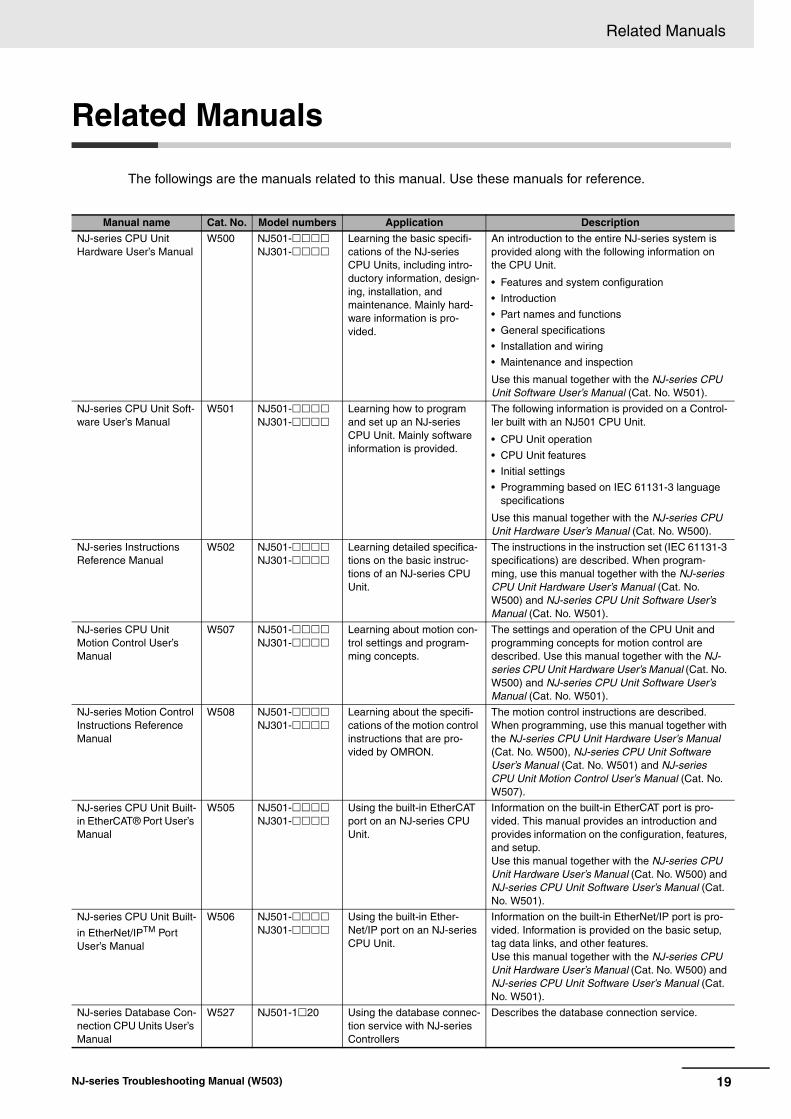
The followings are the manuals related to this manual. Use these manuals for reference.
Manual name Cat. No. Model numbers Application Description
NJ-series CPU Unit Hardware User’s Manual
W500 NJ501-NJ301-
Learning the basic specifi-cations of the NJ-series CPU Units, including intro-ductory information, design-ing, installation, and maintenance. Mainly hard-ware information is pro-vided.
An introduction to the entire NJ-series system is provided along with the following information on the CPU Unit.
• Features and system configuration
• Introduction
• Part names and functions
• General specifications
• Installation and wiring
• Maintenance and inspection
Use this manual together with the NJ-series CPU Unit Software User’s Manual (Cat. No. W501).
NJ-series CPU Unit Soft-ware User’s Manual
W501 NJ501-NJ301-
Learning how to program and set up an NJ-series CPU Unit. Mainly software information is provided.
The following information is provided on a Control-ler built with an NJ501 CPU Unit.
• CPU Unit operation
• CPU Unit features
• Initial settings
• Programming based on IEC 61131-3 language specifications
Use this manual together with the NJ-series CPU Unit Hardware User’s Manual (Cat. No. W500).
NJ-series Instructions Reference Manual
W502 NJ501-NJ301-
Learning detailed specifica-tions on the basic instruc-tions of an NJ-series CPU Unit.
The instructions in the instruction set (IEC 61131-3 specifications) are described. When program-ming, use this manual together with the NJ-series CPU Unit Hardware User’s Manual (Cat. No. W500) and NJ-series CPU Unit Software User’s Manual (Cat. No. W501).
NJ-series CPU Unit Motion Control User’s Manual
W507 NJ501-NJ301-
Learning about motion con-trol settings and program-ming concepts.
The settings and operation of the CPU Unit and programming concepts for motion control are described. Use this manual together with the NJ-series CPU Unit Hardware User’s Manual (Cat. No. W500) and NJ-series CPU Unit Software User’s Manual (Cat. No. W501).
NJ-series Motion Control Instructions Reference Manual
W508 NJ501-NJ301-
Learning about the specifi-cations of the motion control instructions that are pro-vided by OMRON.
The motion control instructions are described. When programming, use this manual together with the NJ-series CPU Unit Hardware User’s Manual (Cat. No. W500), NJ-series CPU Unit Software User’s Manual (Cat. No. W501) and NJ-series CPU Unit Motion Control User’s Manual (Cat. No. W507).
NJ-series CPU Unit Built-in EtherCAT® Port User’s Manual
W505 NJ501-NJ301-
Using the built-in EtherCAT port on an NJ-series CPU Unit.
Information on the built-in EtherCAT port is pro-vided. This manual provides an introduction and provides information on the configuration, features, and setup.Use this manual together with the NJ-series CPU Unit Hardware User’s Manual (Cat. No. W500) and NJ-series CPU Unit Software User’s Manual (Cat. No. W501).
NJ-series CPU Unit Built-
in EtherNet/IPTM Port User’s Manual
W506 NJ501-NJ301-
Using the built-in Ether-Net/IP port on an NJ-series CPU Unit.
Information on the built-in EtherNet/IP port is pro-vided. Information is provided on the basic setup, tag data links, and other features.Use this manual together with the NJ-series CPU Unit Hardware User’s Manual (Cat. No. W500) and NJ-series CPU Unit Software User’s Manual (Cat. No. W501).
NJ-series Database Con-nection CPU Units User’s Manual
W527 NJ501-120 Using the database connec-tion service with NJ-series Controllers
Describes the database connection service.
19NJ-series Troubleshooting Manual (W503)

Related Manuals
NJ-series Troubleshoot-ing Manual
W503 NJ501-NJ301-
Learning about the errors that may be detected in an NJ-series Controller.
Concepts on managing errors that may be detected in an NJ-series Controller and informa-tion on individual errors are described.Use this manual together with the NJ-series CPU Unit Hardware User’s Manual (Cat. No. W500) and NJ-series CPU Unit Software User’s Manual (Cat. No. W501).
Sysmac Studio Version 1 Operation Manual
W504 SYSMAC-SE2
Learning about the operat-ing procedures and func-tions of the Sysmac Studio.
Describes the operating procedures of the Sysmac Studio.
NX-series Communica-tions Coupler Unit User’s Manual
W519 NX-ECC Leaning how to use an NX-series Communications Coupler Unit and Slave Ter-minals
Introduces the system, configuration methods, Unit hardware, setting methods, and functions of Slave Terminals that consist of a Communications Cou-pler Unit and NX Units.
NX-series NX Units User’s Manuals
W521 NX-IDNX-IANX-OCNX-OD
Learning how to use NX Units
Describes the hardware, setup methods, and func-tions of the NX Units.Manuals are available for the following Units.Digital I/O Units, Analog I/O Units, System Units, and Position Interface Units.W522 NX-AD
NX-DANX-TS
W523 NX-PD1NX-PF0NX-PC0NX-TBX
W524 NX-EC0NX-ECSNX-PG0
NX-series Data Reference Manual
W525 NX- Referring to the list of data required for NX-series unit system configuration.
Provides the list of data required for system config-uration including the power consumption and weight of each NX-series unit.
NX-series Safety Control Unit User’s Manual
Z930 NX-SLNX-SINX-SO
Learning how to use NX-series Safety Control Units
Describes the hardware, setup methods, and func-tions of the NX-series Safety Control Units.
NX-series Safety Control Unit Instructions Refer-ence Manual
Z931 NX-SL Learning about the specifi-cations of instructions for the Safety CPU Unit.
Describes the instructions for the Safety CPU Unit.When programming, use this manual together with the NX-series Safety Control Unit User’s Manual (Cat. No. Z930).
GX-series EtherCAT Slave Units User's Man-ual
W488 GX-IDGX-ODGX-OCGX-MDGX-ADGX-DAGX-ECXWT-IDXWT-OD
Learning how to use the EtherCAT remote I/O terminals.
Describes the hardware, setup methods and func-tions of the EtherCAT remote I/O terminals.
MX2/RX Series Inverter EtherCAT Communica-tion Unit User’s Manual
I574 3G3AX-MX2-ECT3G3AX-RX-ECT
Leaning how to connect a 3G3AX-MX2-ECT or 3G3AX-RX-ECT EtherCAT Communications Unit for MX2/RX-series Inverters.
Describes the following information for the 3G3AX-MX2-ECT and 3G3AX-RX-ECT EtherCAT Com-munications Unit for MX2/RX-series Inverters: installation, parameter settings required for opera-tion, troubleshooting, and inspection methods.
G5-series AC Servomot-ers/Servo Drives User's Manuals
I576 R88M-KR88D-KN-ECT
Leaning how to use the AC Servomotors/Servo Drives with built-in EtherCAT Com-munications.
Describes the hardware, setup methods and func-tions of the AC Servomotors/Servo Drives with built-in EtherCAT Communications.The linear motor type model and the model dedi-cated for position controls are available in G5-series.
I577 R88L-EC-R88D-KN-ECT-L
EtherCAT Digital-type Sensor Communication Unit Operation Manual
E413 E3X-ECT Leaning how to connect E3X-series EtherCAT Slave Units.
Provides the specifications of and describes appli-cation methods for E3X-series EtherCAT Slave Units.
E3NW-ECT EtherCAT Digital Sensor Communi-cations Unit Operation Manual
E429 E3NW-ECT Leaning how to connect E3NW EtherCAT Slave Units.
Provides the specifications of and describes appli-cation methods for E3NW EtherCAT Slave Units.
Manual name Cat. No. Model numbers Application Description
20 NJ-series Troubleshooting Manual (W503)

Related Manuals
FQ-M-series Specialized Vision Sensor for Posi-tioning User’s Manual
Z314 FQ-MS12 Leaning how to connect FQ-M-series Specialized Vision Sensor for Positioning.
Describes the following information for the FQ-M-series Specialized Vision Sensor for Positioning: installation, wiring methods, parameter settings required for operation, troubleshooting, and inspection methods.
FH/FZ5 Vision System FH/FZ5 Series User’s Manual for Communica-tions Settings
Z342 FH-3FH-1
Leaning how to connect FH/FZ5-series Vision Sys-tems
The functions, settings, and communications meth-ods to communicate with FH/FZ5-series Vision Systems from a PLC or other external device are described.
ZW-CE1T Confocal Fiber Type Displacement Sensor User's Manual
Z332 ZW-CE1T Learning how to connect ZW-CE1T EtherCAT Slave Units.
Provides the specifications of and describes appli-cation methods for ZW-CE1T EtherCAT Slave Units.
CJ-series Special Unit Manuals for NJ-series CPU Unit
W490 CJ1W-ADCJ1W-DACJ1W-MAD42
Learning how to use CJ-series Units with an NJ-series CPU Unit.
The methods and precautions for using CJ-series Units with an NJ501 CPU Unit are described, including access methods and programming inter-faces. Manuals are available for the following Units.Analog I/O Units, Insulated-type Analog I/O Units, Temperature Control Units, ID Sensor Units, High-speed Counter Units, Serial Communications Units, DeviceNet Units, EtherNet/IP Units, and CompoNet Master Units.
Use these manuals together with the NJ-series CPU Unit Hardware User’s Manual (Cat. No. W500) and NJ-series CPU Unit Software User’s Manual (Cat. No. W501).
W491 CJ1W-TC
W492 CJ1W-CT021
W498 CJ1W-PDC15CJ1W-PH41UCJ1W-AD04U
W493 CJ1W-CRM21
W494 CJ1W-SCU
W495 CJ1W-EIP21
W497 CJ1W-DRM21
Z317 CJ1W-V680
NS-series Programmable Terminals Programming Manual
V073 NS15-NS12-NS10-NS8-NS5-
Learning how to use the NS-series Programmable Terminals.
Describes the setup methods, functions, etc. of the NS-series Programmable Terminals.
Manual name Cat. No. Model numbers Application Description
21NJ-series Troubleshooting Manual (W503)

Revision History
Revision History
A manual revision code appears as a suffix to the catalog number on the front and back covers of themanual.
Revision code Date Revised content01 July 2011 Original production
02 March 2012 Added information related to the upgrade to unit version 1.01, made additions and changes to events related to the addition of devices that can be connected, and corrected mistakes.
03 May 2012 Added information related to the upgrade to unit version 1.02, made additions and changes to events related to the addition of devices that can be connected, and corrected mistakes.
04 August 2012 Made additions to events and changes to the contents related to the upgrade to unit version 1.03, and corrected mistakes.
05 February 2013 Made additions to events and changes to the contents related to the upgrade to unit version 1.04, and corrected mistakes.
06 April 2013 Made additions to events and changes to the contents related to the upgrade to unit version 1.05, and corrected mistakes.
07 June 2013 Made additions to events and changes to the contents related to the upgrade to unit version 1.06, and corrected mistakes.
08 September 2013 Made additions to events and changes to the contents related to the upgrade to unit version 1.07, and corrected mistakes.
09 December 2013 Made additions to events and changes to the contents related to the upgrade to unit version 1.08, and corrected mistakes.
W503-E1-09Revision code
Cat. No.
22 NJ-series Troubleshooting Manual (W503)

1
This section provides information that is required to troubleshoot errors. It introducesthe types of errors that can occur on an NJ-series Controller, the operation that occursin response to errors, and the methods you can use to check for errors. Refer to Sec-tion 2 Error Troubleshooting Methods for information on troubleshooting errors.
1-1 Overview of NJ-series Errors . . . . . . . . . . . . . . . . . . . . . . . . . . . . . . . . . . . . 1-21-1-1 Types of Errors . . . . . . . . . . . . . . . . . . . . . . . . . . . . . . . . . . . . . . . . . . . . . . . . . 1-2
1-1-2 CPU Unit Status . . . . . . . . . . . . . . . . . . . . . . . . . . . . . . . . . . . . . . . . . . . . . . . . 1-3
1-2 Fatal Errors . . . . . . . . . . . . . . . . . . . . . . . . . . . . . . . . . . . . . . . . . . . . . . . . . . . 1-41-2-1 Types of Fatal Errors . . . . . . . . . . . . . . . . . . . . . . . . . . . . . . . . . . . . . . . . . . . . 1-4
1-2-2 Checking for Fatal Errors . . . . . . . . . . . . . . . . . . . . . . . . . . . . . . . . . . . . . . . . . 1-4
1-3 Non-fatal Errors . . . . . . . . . . . . . . . . . . . . . . . . . . . . . . . . . . . . . . . . . . . . . . . 1-51-3-1 Types of Non-fatal Errors . . . . . . . . . . . . . . . . . . . . . . . . . . . . . . . . . . . . . . . . . 1-51-3-2 Checking for Non-fatal Errors . . . . . . . . . . . . . . . . . . . . . . . . . . . . . . . . . . . . 1-12
1-3-3 Resetting Non-fatal Errors . . . . . . . . . . . . . . . . . . . . . . . . . . . . . . . . . . . . . . . 1-14
Overview of Errors
1-1NJ-series Troubleshooting Manual (W503)
1 Overview of Errors
1-1 Overview of NJ-series Errors
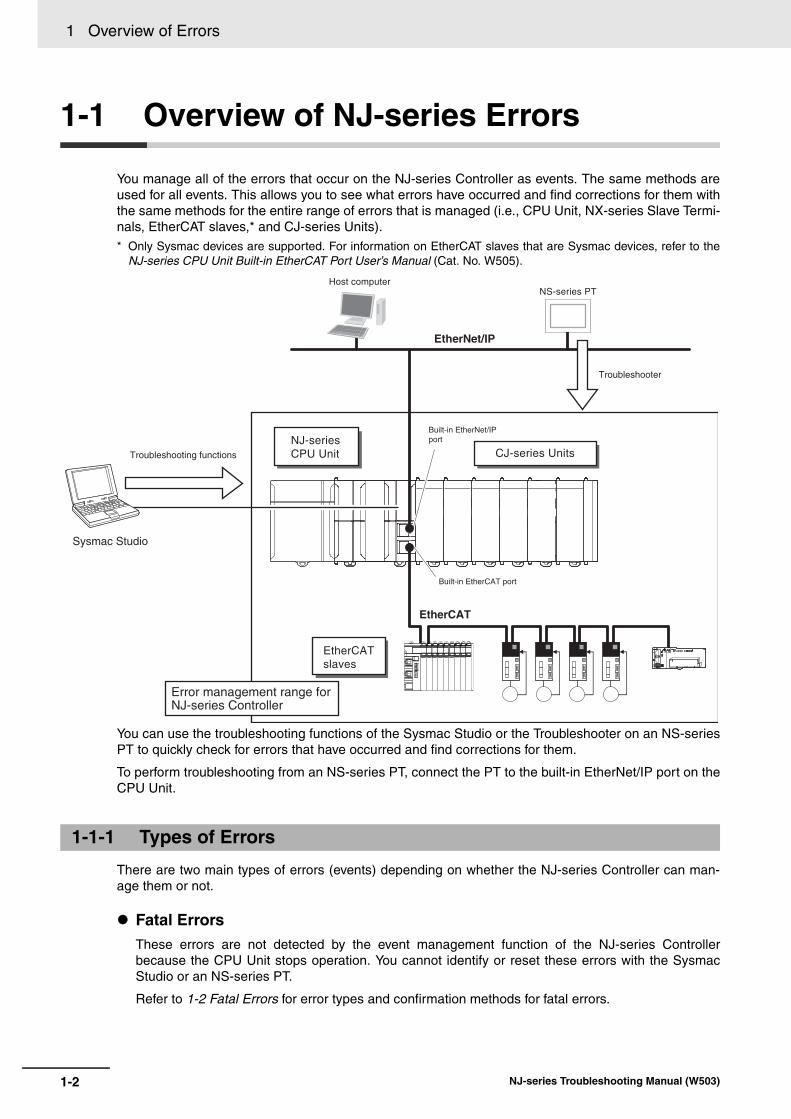
You manage all of the errors that occur on the NJ-series Controller as events. The same methods areused for all events. This allows you to see what errors have occurred and find corrections for them withthe same methods for the entire range of errors that is managed (i.e., CPU Unit, NX-series Slave Termi-nals, EtherCAT slaves,* and CJ-series Units).* Only Sysmac devices are supported. For information on EtherCAT slaves that are Sysmac devices, refer to the
NJ-series CPU Unit Built-in EtherCAT Port User’s Manual (Cat. No. W505).
You can use the troubleshooting functions of the Sysmac Studio or the Troubleshooter on an NS-seriesPT to quickly check for errors that have occurred and find corrections for them.
To perform troubleshooting from an NS-series PT, connect the PT to the built-in EtherNet/IP port on theCPU Unit.
There are two main types of errors (events) depending on whether the NJ-series Controller can man-age them or not.
Fatal ErrorsThese errors are not detected by the event management function of the NJ-series Controllerbecause the CPU Unit stops operation. You cannot identify or reset these errors with the SysmacStudio or an NS-series PT.
Refer to 1-2 Fatal Errors for error types and confirmation methods for fatal errors.
1-1-1 Types of Errors
NS-series PTHost computer
Built-in EtherCAT port
Built-in EtherNet/IP port
Troubleshooting functions
Troubleshooter
EtherNet/IP
EtherCAT
Sysmac Studio
CJ-series UnitsNJ-series CPU Unit
Error management range for NJ-series Controller
EtherCAT slaves
1-2 NJ-series Troubleshooting Manual (W503)

1 Overview of Errors1-1 O
verview o
f NJ-series E
rrors
1
1-1-2 CP
U U
nit Status
Non-fatal ErrorsThese errors are detected and managed with the event management function of the NJ-series Con-troller. You can confirm these errors with the Sysmac Studio or an NS-series PT.
Refer to 1-3 Non-fatal Errors for error types and confirmation methods for non-fatal errors.
You can check the operating status of the CPU Unit with the PWR, RUN, and ERROR indicators on thefront panels of the Power Supply Unit and CPU Unit.
The following table shows the status of the front-panel indicators, the status of user program execution,and the ability to make a software connection to the Sysmac Studio or an NS-series PT during startup,during normal operation, and when there are errors in the Controller.
*1 Refer to 1-2 Fatal Errors for information on individual errors.
*2 Refer to 1-3 Non-fatal Errors for information on individual errors.
*3 The function module where the error occurred stops.
1-1-2 CPU Unit Status
CPU Unit operating status
Power Supply
UnitCPU Unit User pro-
gram execu-tion status
Software connec-tion to Sysmac Stu-dio or NS-series PTPWR
(green)RUN
(green)ERROR
(red)
During startupLit Flashing
(1-s inter-vals).
Not lit Stops. Not possible.
During normal operation
RUN mode Lit Lit Not lit Continues. Possible.PROGRAM mode Lit Not lit Not lit Stops.
Fatal errors
Power Supply Error*1 Not lit Not lit Not lit Stops. Not possible.
CPU Unit Reset*1 Lit Not lit Not lit Stops.
Incorrect Power Sup-ply Unit Connected*1
Lit Flashing (3-s inter-
vals).
Lit Stops.
CPU Unit Watchdog Timer Error*1
Lit Not lit Lit Stops.
Non-fatal errors
Major fault*2 Lit Not lit Lit Stops. Possible. (Communi-cations can be con-nected from an NS-series PT if Ether-Net/IP is operating
normally.)
Partial fault*2Lit Lit Flashing
(1-s inter-vals).
Continues.*3
Minor fault*2Lit Lit Flashing
(1-s inter-vals).
Continues.
Observation*2 Lit Lit Not lit Continues.
PWR indicatorRUN indicator
ERROR indicator
Power Supply Unit CPU Unit
1-3NJ-series Troubleshooting Manual (W503)

1 Overview of Errors
1-2 Fatal Errors
This section describes the errors that cause the operation of the NJ-series CPU Unit to stop. Software connections to the Sysmac Studio or an NS-series PT cannot be made if there is a fatal errorin the Controller.
Power Supply ErrorPower is not supplied, the voltage is outside of the allowed range, or the Power Supply Unit is faulty.
CPU Unit ResetThe CPU Unit stopped operation because of a hardware error. Other than hardware failures, thiserror also occurs at the following times.
• The power supply to an Expansion Rack is OFF.
• The I/O Connecting Cable is incorrectly installed.
• The IN and OUT connectors are reversed.
• The connectors are not mated properly.
• There is more than one I/O Control Unit on the CPU Rack or there is an I/O Control Unit on anExpansion Rack.
Incorrect Power Supply Unit ConnectedThere is a CJ-series Power Supply Unit connected to the CPU Rack. The operation of the Controlleris stopped.
CPU Unit Watchdog Timer ErrorThis error occurs in the CPU Unit. This error occurs when the watchdog timer times out because ahardware failure or when temporary data corruption causes the CPU Unit to hang.
You can identify fatal errors based on the status of the PWR indicator on the Power Supply Unit and theRUN and ERROR indicators on the CPU Unit, as well as by the ability to go online with the CPU Unitfrom the Sysmac Studio. Refer to Section 2 Error Troubleshooting Methods for information on identify-ing errors and corrections.
* Power Supply Errors and Incorrect Power Supply Unit Connected errors can be differentiated with the indicators.There is no need to see if you can go online with the CPU Unit from the Sysmac Studio.
1-2-1 Types of Fatal Errors
1-2-2 Checking for Fatal Errors
Indicators Going online from the Sysmac Studio
CPU Unit operating statusPWR (green) RUN (green) ERROR (red)
Not lit Not lit Not lit Not possible.* Power Supply ErrorLit Not lit Not lit CPU Unit Reset
Lit Flashing (3-s intervals).
Lit Incorrect Power Supply Unit Connected
Lit Not lit Lit CPU Unit Watchdog Timer Error
1-4 NJ-series Troubleshooting Manual (W503)

1 Overview of Errors1-3 N
on
-fatal Erro
rs
1
1-3-1 Types of Non-fatal E
rrors
1-3 Non-fatal Errors
Non-fatal errors that occur are managed as events in the NJ-series Controller. You can check the eventto find out what type of error occurred.
You use the same methods to manage all of the events that occur on the NJ-series Controller. Theevents that occur are saved in battery-backup memory in the CPU Unit and NX-series Slave Terminals.You can use the Sysmac Studio or an NS-series PT to confirm current Controller events and the log ofevents that occurred before. This log is called an event log.
To use an NS-series PT to check events, connect the PT to the built-in EtherNet/IP port on the CPUUnit.
Note Refer to the manual for the Communications Coupler Unit for details on the event log in a Slave Terminal.
The following events can occur.
Controller EventsThe Controller automatically detects these events. Controller events include events for the functionmodules in the CPU Unit, NX-series Slave Terminal, EtherCAT slaves, and CJ-series Units.
The error logs from within the EtherCAT slaves and the CJ-series Special Units are not included.Refer to the manuals for the slaves or Special Units for the procedures to read their error logs. Youcan check the error logs from CJ-series Special Units on the Controller Event Log Tab Page of theSysmac Studio.
User-defined EventsThese are events that occur in applications that the user developed.
Refer to the NJ-series CPU Unit Software User’s Manual (Cat. No. W501) for information on user-defined events.
Non-fatal errors are managed as Controller events. This section describes mainly the Controller events.
1-3-1 Types of Non-fatal Errors
Overview of Controller Events (Errors and Information)
NJ-series CPU Unit
Event logs
Event source
Sysmac Studio
NS-series PT
CJ-series Units
Backup battery
Create User-defined Error instruction:
SetAlarm
Create User-defined Information
instruction: SetInfo
User program
Or
PLC Function Module
Motion Control Function Module
EtherCAT Master Function Module
EtherNet/IP Function Module Errors in
Special Units
Check current Controller
events and the event log
of past events.
Check current Controller
events and the event log
of past events.
EtherCAT slave
EtherCAT Slave Terminal
1-5NJ-series Troubleshooting Manual (W503)

1 Overview of Errors
Sources of Controller EventsThe Event source information indicates the location where an event occurred. The event sourceidentifies the particular function module in the CPU Unit in which the event occurred. For some func-tion modules, there is more detailed information about the event source. This information is calledthe Source details. The following information is provided as the event source details.
The event source is displayed on the Sysmac Studio or NS-series PT.
Levels of Controller Events (Errors and Information)The following table classifies the levels of Controller events according to the effect that the errorshave on control.
Errors with a higher level have a greater impact on the functions that the NJ-series Controller pro-vides, and are more difficult to recover from. When an event occurs, the Sysmac Studio or PT willdisplay the level.
Event Levels• Major Fault Level
These errors prevent control operations for the entire Controller. When the CPU Unit detects amajor fault, it immediately stops the execution of the user program and turns OFF the loads of allslave, including remote I/O. With EtherCAT slaves and some CJ-series Special Units, you can setthe slave settings or Unit settings to select whether outputs will go OFF or retain their previousstatus. You cannot reset major fault level errors from the user program, the Sysmac Studio or anNS-series PT. To recover from a major fault level error, remove the cause of the error, and eithercycle the power supply to the Controller, or reset the Controller from the Sysmac Studio.
• Partial Fault LevelThese errors prevent control operations in a certain function module in the Controller. The NJ-series CPU Unit continues to execute the user program even after a partial fault level error occurs.You can include error processing in the user program in order to stop equipment safely. After youremove the cause of the error, execute one of the following to return to normal status.
• Reset the error from the user program, the Sysmac Studio, or an NS-series PT.
• Cycle the power supply.
• Reset the Controller from the Sysmac Studio.
• Minor Fault LevelThese errors prevent part of the control operations in a certain function module in the Controller.The troubleshooting for minor fault level errors is the same as the processing for partial fault levelerrors.
Details on Controller Events (Errors and Information)
Event source Source detailsPLC Function Module Instructions, I/O bus master, or CJ-series UnitMotion Control Function Module Common, axis, or axes group
EtherCAT Master Function Module Communications port, EtherCAT master, EtherCAT Coupler Unit, NX Unit, or EtherCAT slave
EtherNet/IP Function Module Communications port, CIP, FTP, NTP, or SNMP
No. Level Classification Level name1 High Controller errors Major fault level
2 Partial fault level3 Minor fault level
4 Observation
5 Low Controller informa-tion
Information
1-6 NJ-series Troubleshooting Manual (W503)

1 Overview of Errors1-3 N
on
-fatal Erro
rs
1
1-3-1 Types of Non-fatal E
rrors
• ObservationsThese errors do not affect the control operations of the Controller. The observation notifies you ofpotential problems before they develop into a minor fault level error or worse.
• InformationEvents that are classified as information provide information that do not indicate errors.
You can change the event level for some events. Refer to the NJ-series CPU Unit Software User’s Man-ual (Cat. No. W501) for details on changing event levels. Refer to 3-1 Errors by Source in this manual tosee the events for which you can change the event level.
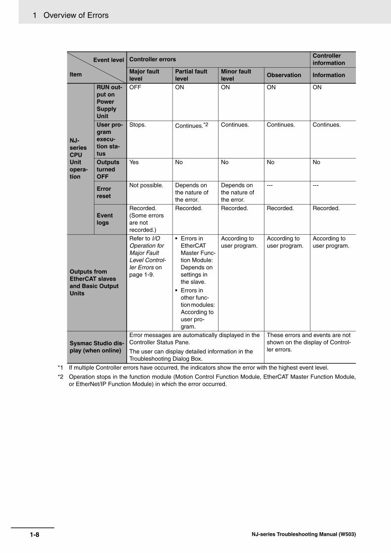
Operation for Each LevelThe way that the Controller operates when an event occurs depends on the level of the Controllerevent.
Event level
Item
Controller errorsController information
Major fault level
Partial fault level
Minor fault level
Observation Information
Definition
These errors are serious errors that pre-vent control operations for the entire Con-troller.
These errors prevent all of the control in a function mod-ule other than PLC Function Module.
These errors prevent part of the control operations in a certain func-tion module.
These errors do not affect system control operations.
These are not errors, but appear in the event log to notify the user of specific information.
Event examples (Only a few exam-ples are provided here. Refer to Sec-tion 3 Error Tables for a list of all of the errors.
• I/O Bus Check Error (PLC Func-tion Module)
• Motion Con-trol Period Exceeded (Motion Con-trol Function Module)
• Communica-tions Control-ler Failure (EtherCAT Master Func-tion Module)
• Positive Limit Input Detected (Motion Con-trol Function Module)
• Analog Input Disconnec-tion Detected (CJ-series Unit)
• Low Battery Voltage (PLC Function Module)
• Packet Dis-carded Due to Full Reception Buffer (Eth-erNet/IP Function Module)
• Power Turned ON
• Power Inter-rupted
• Memory All Cleared
Front-panel indica-tors*1
PWR (green)
Lit Lit Lit Lit Lit
RUN (green)
Not lit Lit Lit Lit Lit
ERROR (red)
Lit Flashes at 1-s intervals.
Flashes at 1-s intervals.
Not lit Not lit
1-7NJ-series Troubleshooting Manual (W503)
1 Overview of Errors
*1 If multiple Controller errors have occurred, the indicators show the error with the highest event level.
*2 Operation stops in the function module (Motion Control Function Module, EtherCAT Master Function Module,or EtherNet/IP Function Module) in which the error occurred.
NJ-series CPU Unit opera-tion
RUN out-put on Power Supply Unit
OFF ON ON ON ON
User pro-gram execu-tion sta-tus
Stops. Continues.*2 Continues. Continues. Continues.
Outputs turned OFF
Yes No No No No
Error reset
Not possible. Depends on the nature of the error.
Depends on the nature of the error.
--- ---
Event logs
Recorded. (Some errors are not recorded.)
Recorded. Recorded. Recorded. Recorded.
Outputs from EtherCAT slaves and Basic Output Units
Refer to I/O Operation for Major Fault Level Control-ler Errors on page 1-9.
• Errors in EtherCAT Master Func-tion Module: Depends on settings in the slave.
• Errors in other func-tion modules: According to user pro-gram.
According to user program.
According to user program.
According to user program.
Sysmac Studio dis-play (when online)
Error messages are automatically displayed in the Controller Status Pane.
The user can display detailed information in the Troubleshooting Dialog Box.
These errors and events are not shown on the display of Control-ler errors.
Event level
Item
Controller errorsController information
Major fault level
Partial fault level
Minor fault level
Observation Information
1-8 NJ-series Troubleshooting Manual (W503)
1 Overview of Errors1-3 N
on
-fatal Erro
rs
1
1-3-1 Types of Non-fatal E
rrors
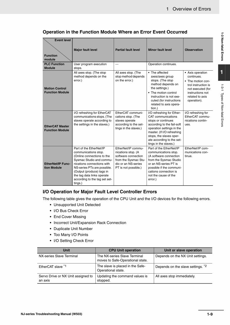
Operation in the Function Module Where an Error Event Occurred
I/O Operation for Major Fault Level Controller ErrorsThe following table gives the operation of the CPU Unit and the I/O devices for the following errors.
• Unsupported Unit Detected
• I/O Bus Check Error
• End Cover Missing
• Incorrect Unit/Expansion Rack Connection
• Duplicate Unit Number
• Too Many I/O Points
• I/O Setting Check Error
Event level
Function module
Major fault level Partial fault level Minor fault level Observation
PLC Function Module
User program execution stops.
--- Operation continues.
Motion Control Function Module
All axes stop. (The stop method depends on the error.)
All axes stop. (The stop method depends on the error.)
• The affected axes/axes group stops. (The stop method depends on the settings.)
• The motion control instruction is not exe-cuted (for instructions related to axis opera-tion.)
• Axis operation continues.
• The motion con-trol instruction is not executed (for instructions not related to axis operation).
EtherCAT Master Function Module
I/O refreshing for EtherCAT communications stops. (The slaves operate according to the settings in the slaves.)
EtherCAT communi-cations stop. (The slaves operate according to the set-tings in the slaves.)
I/O refreshing for Ether-CAT communications stops or continues according to the fail-soft operation settings in the master. (If I/O refreshing stops, the slaves oper-ate according to the set-tings in the slaves.)
I/O refreshing for EtherCAT commu-nications contin-ues.
EtherNet/IP Func-tion Module
Part of the EtherNet/IP communications stop. (Online connections to the Sysmac Studio and commu-nications connections with NS-series PTs are possible. (Output (produce) tags in the tag data links operate according to the tag set set-tings.)
EtherNet/IP commu-nications stop. (A software connection from the Sysmac Stu-dio or an NS-series PT is not possible.)
Part of the EtherNet/IP communications stop. (A software connection from the Sysmac Studio or an NS-series PT is possible if the communi-cations connection is not the cause of the error.)
EtherNet/IP com-munications con-tinue.
Unit CPU Unit operation Unit or slave operation
NX-series Slave Terminal The NX-series Slave Terminal moves to Safe-Operational state.
Depends on the NX Unit settings.
EtherCAT slave *1 The slave is placed in the Safe-Operational state.
Depends on the slave settings. *2
Servo Drive or NX Unit assigned to an axis
Updating the command values is stopped.
All axes stop immediately.
1-9NJ-series Troubleshooting Manual (W503)

1 Overview of Errors
*1 Excluding Servo Drives assigned to an axis.
*2 Settings and setting methods depend on the slave. Refer to the manual for the slave. For a Servo Drive, opera-tion depends on the setting of object 605E hex (Fault Reaction Option Code).
*3 You can set whether to clear output or maintain the data from before the error occurred. Refer to the NJ-seriesCPU Unit Built-in EtherNet/IP Port User’s Manual (Cat. No. W506) for details.
The following table gives the operation of the CPU Unit and the I/O devices for the errors that are notlisted above.
*1 Excluding Servo Drives assigned to an axis.
*2 Settings and setting methods depend on the slave. Refer to the manual for the slave. For a Servo Drive, opera-tion depends on the setting of object 605E hex (Fault Reaction Option Code).
*3 You can set whether to clear output or maintain the data from before the error occurred. Refer to the NJ-seriesCPU Unit Built-in EtherNet/IP Port User’s Manual (Cat. No. W506) for details.
Event CodeEvents that occur in a Controller have an event code. When an event occurs, the Sysmac Studio orPT will display the event code. You can use the instructions that get error status to read the errorcodes of current errors from the user program.
The event codes are 8-digit hexadecimal values. The first digit of a Controller event represents itscategory. These categories are listed in the table below.
CJ-series Basic I/O Unit Refreshing is stopped. • All outputs are turned OFF.
• All inputs are turned OFF.
CJ-series Special Unit Refreshing is stopped. Depends on the Unit operating specifications (the ERH indicator lights).
Devices connected with EtherNet/IP • For the originators of tag data links, the variables and I/O mem-ory addresses for input (con-sume) tags are not refreshed.
• For the targets of tag data links, operation depends on the set-tings of the tags sets for the out-put (produce) tags. *3
Depends on the specifications of the connected devices.
Unit CPU Unit operation Unit or slave operation
NX-series Slave Terminal The NX-series Slave Terminal moves to Safe-Operational state.
Depends on the NX Unit settings.
EtherCAT slave *1 The slave is placed in the Safe-Operational state.
Depends on the slave settings. *2
Servo Drive or NX Unit assigned to an axis
Updating the command values is stopped.
All axes stop immediately.
CJ-series Basic I/O Unit • The values of all outputs are cleared to zero.
• Input refreshing continues.
• All outputs are turned OFF.• External inputs are refreshed.
CJ-series Special Unit Refreshing continues. Depends on the Unit operating specifications.
Devices connected with EtherNet/IP • For the originators of tag data links, the variables and I/O mem-ory addresses for input (con-sume) tags are not refreshed.
• For the targets of tag data links, operation depends on the set-tings of the tags sets for the out-put (produce) tags. *3
Depends on the specifications of the connected devices.
Unit CPU Unit operation Unit or slave operation
1-10 NJ-series Troubleshooting Manual (W503)

1 Overview of Errors1-3 N
on
-fatal Erro
rs
1
1-3-1 Types of Non-fatal E
rrors
Relationship between Event Codes and Error CodesIn addition to the event codes that indicate errors, the function modules and Units have their ownerror codes. If there are corresponding event and error codes, you can tell what the other code is ifyou know either one of them. This allows you to know when the same error is being given when youcheck errors with more than one method.
The following table shows the relationship between the error codes and event codes.
* The following are system-defined variables for motion control:
First digit of the code (hex)
Classification Meaning
0 Hardware errors An error caused by a hardware problem such as an inter-nal part malfunction, contact failure, temperature error, undervoltage, overvoltage, or overcurrent.
1 Data errors An error caused by incorrectly saved data or data cor-ruption in the Controller.
2 Hardware setting errors An error caused by incorrect handling of hardware set-tings (e.g., hardware switches) or restrictions (e.g., Unit assignment locations).
3 Configuration errors An error caused by incorrect parameter values, parame-ters and hardware configurations that do not match, or configurations set by the user.
4 Software errors An error caused by Controller software.
5 User software errors An error that is caused by the user program. (For exam-ple, an input value to an instruction that is out of range.)
6 Observation errors An error that was detected in monitoring operation that occurs due to user settings in the Controller. (For exam-ple, if the task period is exceeded or if a position outside of the motion range is detected.)
7 Control errors An error caused by a control process. (For example, if the operating status does not meet the required condi-tions or if the timing is incorrect.)
8 Communications errors An error caused by communications with an external device or host system.
9 Information Events that are classified as information and provide information that do not indicate errors.
Error code (4-digit hexadecimal)Corresponding event code
(8-digit hexadecimal)Example: Event code for an error code of A123 hexClassification Used in Upper 4 digits Lower 4 digits
Error codes in the Motion Control Function Module
• ErrorID output variable for motion control instruc-tions
• System-defined variables for motion control*
Error code 0000 hex A1230000 hex
Error codes for basic instructions
ErrorID output vari-able for basic instructions
5401 hex Error code 5401A123 hex
Error codes in CJ-series Special Units
Error logs from CJ-series Special Units
0000 hex Error code 0000A123 hex
Variable Name_MC_COM.PFaultLvl.Code MC Common Partial Fault Code
_MC_COM.MFaultLvl.Code MC Common Minor Fault Code
_MC_COM.Obsr.Code MC Common Observation Code_MC_AX[0..63].MFaultLvl.Code Axis Minor Fault Code
1-11NJ-series Troubleshooting Manual (W503)

1 Overview of Errors
For descriptions of the error codes for the Motion Control Function Module or basic instructions,refer to the descriptions of the corresponding event codes. Refer to the NJ-series CPU UnitMotion Control User’s Manual (Cat. No. W507) and NJ-series Motion Control Instructions Refer-ence Manual (Cat. No. W508) for error information on the Motion Control Function Module, and tothe NJ-series Instructions Reference Manual (Cat. No. W502) for error information on basicinstructions. For error information on a CJ-series Special Unit, refer to the manual for the relevantUnit. For the corresponding event codes, refer to the descriptions of the error codes.
Exporting the Error LogYou can use the Sysmac Studio or an NS-series PT to export the displayed event log to a CSV file.Refer to the NJ-series CPU Unit Software User’s Manual (Cat. No. W501) for information on export-ing event logs
Use the following methods to check for non-fatal errors.
*1 Detailed information, such as error causes and corrections, is not displayed.
*2 To perform troubleshooting from an NS-series PT, connect the PT to the built-in EtherNet/IP port on the CPUUnit.
This section describes the above checking methods.
Checking the Level of a Controller ErrorYou can use the PWR indicator on the Power Supply Unit and the RUN and ERROR indicators onthe CPU Unit to determine the level of an error. The following table shows the relationship betweenthe Controller’s indicators and the event level.
_MC_AX[0..63].Obsr.Code Axis Observation Code
_MC_GRP[0..31].MFaultLvl.Code Axes Group Minor Fault Code_MC_GRP[0..31].Obsr.Code Axes Group Observation Code
1-3-2 Checking for Non-fatal Errors
Checking Methods
Checking method What you can checkChecking the indicators You can use the indicators to confirm the Controller error level, the error
status of the EtherCAT Master Function Module, and the error status of the EtherNet/IP Function Module.
Checking with the Troubleshooting Function of Sysmac Studio
You can check for current Controller errors, a log of past Controller errors, error sources, error causes, and corrections. You can also check error logs from CJ-series Special Units.*1
Checking with the Troubleshooter of an NS-series PT*2
You can check for current Controller errors, a log of past Controller errors, error sources, error causes, and corrections.
Instructions that read function mod-ule error status
You can check the highest-level status and highest-level event code in the current Controller errors.
Checking with system-defined vari-ables
You can check the current Controller error status for each function mod-ule.
Checking the Indicators
IndicatorsEvent level
PWR (green) RUN (green) ERROR (red)Lit Not lit Lit Major fault level
Lit Lit Flashing (1-s intervals).
Partial fault level
Minor fault level
Variable Name
1-12 NJ-series Troubleshooting Manual (W503)

1 Overview of Errors1-3 N
on
-fatal Erro
rs
1
1-3-2 Checking for N
on-fatal Errors
Checking Errors in the EtherCAT Master Function Module and EtherNet/IP Function ModuleFor the EtherCAT Master Function Module and EtherNet/IP Function Module, use the EtherCAT andEtherNet/IP NET ERR indicators to determine whether an error that affects process data communi-cations has occurred and whether a minor fault level error or higher-level error has occurred. Theindicators let you check the status given in the following table.
When an error occurs, you can connect the Sysmac Studio online to the Controller to check currentController errors and the log of past Controller errors.
Current ErrorsOpen the Sysmac Studio’s Controller Error Tab Page to check the current error’s level, source,source details, event name, event code, details, attached information 1 to 4, actions, and correc-tions. Errors are not displayed for observations.
Log of Past ErrorsOpen the Sysmac Studio’s Controller Event Log Tab Page to check the times, levels, sources,source details, event names, event codes, details, attached information 1 to 4, actions, and correc-tions for previous errors.
Error logs from CJ-series Special Units are displayed on the Controller Event Log Tab Page.Detailed information is not displayed. To check detailed information, use the event codes that aredisplayed and refer to the error codes that are given in the manual for the relevant Unit. The relation-ship between error codes and event codes is described in Details on Controller Events (Errors andInformation) under 1-3-1 Types of Non-fatal Errors.
Refer to the NJ-Series Sysmac Studio Version 1 Operation Manual (Cat. No. W504) for details ontroubleshooting with the Sysmac Studio.
When an error occurs, if you can connect communications between an NS-series PT and the Control-ler, you can check current Controller errors and the log of past Controller errors.
To perform troubleshooting from an NS-series PT, connect the PT to the built-in EtherNet/IP port on theCPU Unit.
Lit Lit Not lit Observation
Indicators Indicated statusEtherCAT
NET ERR
EtherCAT Master Function Module Status
• Lit: Errors for which normal status cannot be recovered through user actions (i.e., errors for which you must replace the CPU Unit or contact your OMRON representative).
• Flashing: Errors for which normal status can be recovered through user actions.
• Not lit: An error that affects process data communications has not occurred.
EtherNet/IP
NET ERR
EtherNet/IP Function Module Status
• Lit: Errors for which normal status cannot be recovered through user actions (i.e., errors for which you must replace the CPU Unit or contact your OMRON representative).
• Flashing: Errors for which normal status can be recovered through user actions.
• No lit: There are no minor fault level or higher-level errors.
Checking with the Troubleshooting Function of Sysmac Studio
Checking with the Troubleshooter of an NS-series PT
IndicatorsEvent level
PWR (green) RUN (green) ERROR (red)
1-13NJ-series Troubleshooting Manual (W503)

1 Overview of Errors
Current ErrorsOpen the Controller Error Tab Page on the NS-series PT’s Troubleshooter to check the currenterror’s event name, event code, level, source, source details, time, details, and attached information1 to 4. However, for some NX Units, you cannot check the event names, event codes, details, andattached information for current errors. Also, observations are not displayed as errors.
Log of Past ErrorsOpen the Controller Event Log Tab Page on the NS-series PT’s Troubleshooter to check the time,level, source, event name, event code, details, and attached information 1 to 4 for previous errors.However, you cannot check the log of previous errors for the Communications Coupler Units, NXUnits, EtherCAT slaves, and CJ-series Units.
Refer to the NS-series Programmable Terminals Programming Manual (Cat. No. V073) for details onthe NS-series PT’s Troubleshooter.
You can determine the error status with the instructions that get error status provided for each functionmodule from the user program. These instructions get the status and the event code of the error withthe highest level.
For details on the instructions that get error status, refer to the NJ-series Instructions Reference Manual(Cat. No. W502).
You can check the Error Status variable in the system-defined variables to determine the status oferrors in a Controller. You can read the Error Status variable from an external device by using communi-cations. Refer to the NJ-series CPU Unit Software User’s Manual (Cat. No. W501) for information onsystem-defined variables.
Unless you reset an error, the CPU Unit will retain the error status until you turn OFF the power supplyto the Controller or reset the Controller.
To reset a Controller error, it is necessary to eliminate the cause of the error. The same error will occuragain if you reset the error, but do not eliminate the cause of the error.
Precautions for Safe Use
Always confirm safety at the connected equipment before you reset Controller errors with anevent level of partial fault or higher for the EtherCAT Master Function Module. When the error isreset, all slaves that were in any state other than Operational state (in which outputs are dis-abled) due to the Controller error with an event level of partial fault or higher will go to Opera-tional state and the outputs will be enabled. Before you reset all errors, confirm that no Controllererrors with an event level of partial fault have occurred for the EtherCAT Master Function Module.
Instructions That Read Function Module Error Status
Applicable function module Instruction name InstructionPLC Function Module Get PLC Controller Error Status GetPLCError
Get I/O Bus Error Status GetCJBError
Motion Control Function Module Get Motion Control Error Status GetMCError
EtherCAT Master Function Mod-ule
Get EtherCAT Error Status GetECError
EtherNet/IP Function Module Get EtherNet/IP Error Status GetEIPError
Checking with System-defined Variables
1-3-3 Resetting Non-fatal Errors
1-14 NJ-series Troubleshooting Manual (W503)

1 Overview of Errors1-3 N
on
-fatal Erro
rs
1
1-3-3 Resetting N
on-fatal Errors
Always confirm safety at the connected equipment before you reset Controller errors for a CJ-series Special Unit. When the Controller error is reset, the Unit where the Controller error with anevent level of observation or higher will be restarted. Before you reset all errors, confirm that noController errors with an event level of observation or higher have occurred for the CJ-seriesSpecial Unit. Observation level events do not appear on the Controller Error Tab Page, so it ispossible that you may restart the CJ-series Special Unit without intending to do so. You cancheck the status of the _CJB_UnitErrSta[0,0] to _CJB_UnitErrSta[3,9] Error Status variables ona Watch Tab Page to see if an observation level Controller error has occurred.
Precautions for Correct UsePrecautions for Correct Use
Resetting an error is not the same as eliminating the cause of the error. Always eliminate thecause of an error before you perform the procedure to reset the error.
Error Resetting Methods
Method OperationErrors that are reset
Description
Commands from Sysmac Studio
Resetting Controller errors
Resetting all errors in the entire Control-ler
Reset the Controller errors from the Sys-mac Studio’s Troubleshooting Dialog Box.
Resetting all Slave Terminal errors
Refer to the manual for the Communica-tions Coupler Unit for details on resetting errors in a Slave Terminal.Resetting errors for
individually speci-fied NX Units
Downloading Resetting all errors for a specific func-tion module
After the causes of the Controller errors are removed, all Controller errors in the relevant function module are reset as a result. Errors are not reset when you download the Con-troller Configurations and Setup.
Clear All Memory Resetting all errors for all function mod-ules
After the causes of the Controller errors are removed, all Controller errors in all function modules are reset as a result. Errors for Slave Terminals are not reset.*1
Controller reset After the causes of the Controller errors are removed, all Controller errors in all function modules are reset as a result. Errors for Slave Terminals are not reset.*1
Clear All Memory operation for Slave Terminal
Resetting all Slave Terminal errors
If the causes for the Controller errors are removed, all Controller errors in the Slave Terminals are reset.
Restarting the Slave Terminal
Commands from an NS-series PT*2
Resetting Controller errors
Resetting all errors in the entire Control-ler
Reset Controller errors from the Trouble-shooter of an NS-series PT that is compati-ble with NJ-series Controllers.
You can reset errors from a PT that is not directly compatible with the NJ-series Con-troller or another company’s HMI if you use the PT/HMI in combination with the reset error instruction for the function module in the user program.
1-15NJ-series Troubleshooting Manual (W503)

1 Overview of Errors
*1 Some errors are reset when the EtherCAT communications link is established rather than when the reset oper-ation is performed.
*2 To reset errors from an NS-series PT, connect the PT to the built-in EtherNet/IP port on the CPU Unit.
Commands from the user program
Resetting Controller errors
Resetting errors for individual function modules
Execute the reset error instruction for the function module in the user program.
• For the Motion Control Function Module, you can reset all errors, errors for a par-ticular axis, or errors for a particular axes group.
• For the I/O bus, you can reset all errors or just the errors for a particular Unit.
Commands from a host computer
Resetting Controller errors with CIP mes-sages
Resetting all errors for all function mod-ules
Use a CIP message from a host computer to reset errors.
Cycling the Control-ler’s power supply
--- Resets all errors. After the causes of the Controller errors are removed, all Controller errors in all function modules are reset as a result.
Cycling the power supply to the Slave Terminal
--- Resetting all Slave Terminal errors
If the causes for the Controller errors are removed, all Controller errors in the Slave Terminals are reset.
Method OperationErrors that are reset
Description
1-16 NJ-series Troubleshooting Manual (W503)

2
This section describes troubleshooting methods for specific errors.
2-1 Troubleshooting Flowcharts . . . . . . . . . . . . . . . . . . . . . . . . . . . . . . . . . . . . . 2-22-1-1 Checking to See If the CPU Unit Is Operating . . . . . . . . . . . . . . . . . . . . . . . . . 2-2
2-1-2 Troubleshooting Flowchart for Non-fatal Errors . . . . . . . . . . . . . . . . . . . . . . . . 2-3
2-2 Troubleshooting Fatal Errors . . . . . . . . . . . . . . . . . . . . . . . . . . . . . . . . . . . . 2-4
2-3 Troubleshooting Non-fatal Errors . . . . . . . . . . . . . . . . . . . . . . . . . . . . . . . . . 2-52-3-1 Identifying and Resetting Errors with the Sysmac Studio . . . . . . . . . . . . . . . . 2-5
2-3-2 Identifying and Resetting Errors with an NS-series PT . . . . . . . . . . . . . . . . . . 2-9
2-3-3 Identifying and Resetting Errors from the User Program . . . . . . . . . . . . . . . . 2-112-3-4 Checking for Errors with System-defined Variables . . . . . . . . . . . . . . . . . . . . 2-13
2-4 Troubleshooting When You Cannot Go Online from the Sysmac Studio 2-142-4-1 Causes and Correction When You Cannot Go Online from the
Sysmac Studio . . . . . . . . . . . . . . . . . . . . . . . . . . . . . . . . . . . . . . . . . . . . . . . . 2-14
2-4-2 Troubleshooting for Each Cause . . . . . . . . . . . . . . . . . . . . . . . . . . . . . . . . . . 2-15
Error Troubleshooting Methods
2-1NJ-series Troubleshooting Manual (W503)

2 Error Troubleshooting Methods
2-1 Troubleshooting Flowcharts
This section provides basic error identification and troubleshooting flowcharts. Use them when an erroroccurs in the NJ-series Controller.
When an error occurs in the NJ-series Controller, use the following flowchart to determine whether theerror is a fatal error or a non-fatal error.
Whenever possible, set the Sysmac Studio’s software connection method in the flowchart to a directUSB connection. If you use Ethernet, there are many reasons that prevent a software connection fromthe Sysmac Studio, so time is required to determine if a fatal or non-fatal error has occurred. If you can-not go online from the Sysmac Studio, perform 2-4 Troubleshooting When You Cannot Go Online fromthe Sysmac Studio before you assume that the error is a fatal error.
2-1-1 Checking to See If the CPU Unit Is Operating
Flashing.
Not possible.
Not possible.
Error occurs.
RUN indicator (green)?
Not lit.
Lit.
Lit.
Not lit.
Not lit.
Power Supply Error
CPU Unit Reset
CPU Unit Watchdog Timer Error
Incorrect Power Supply Unit Connected
A
Possible.
Possible.
PWR indicator (green)?
ERROR indicator (red)?
Going online from the Sysmac Studio?
Going online from the Sysmac Studio?
A fatal error occurred. Refer to 2-2 Troubleshooting Fatal Errors.
A non-fatal error occurred. Refer to 2-1-2 Troubleshooting Flowchart for Non-fatal Errors.
2-2
NJ-series Troubleshooting Manual (W503)
2 Error Troubleshooting Methods2-1 Tro
ub
lesho
otin
g F
lowch
arts
2
2-1-2 Troubleshooting Flow
chart for Non-fatal E
rrors
For a non-fatal error, use the Sysmac Studio or an NS-series PT to troubleshoot the error with the fol-lowing flowchart. You can use the indicators to check the following:
• Level
• Whether the error is in the EtherNet/IP Function Module or the EtherCAT Master Function Module
• If the sources of the error is the EtherNet/IP Function Module or the EtherCAT Master Function Mod-ule, whether you can restore normal status yourself
2-1-2 Troubleshooting Flowchart for Non-fatal Errors
A
Lit.
Not lit.
Flashing.
Lit.Lit.
Flashing.Flashing.
Check all of the following branches that correspond to the status of the EtherNet/IP NET ERR and EtherCAT NET ERR indicators.
EtherNet/IP NET ERR indicator is lit or flashing.
EtherCAT NET ERR indicator is lit or flashing.
Major fault level
Observa-tion
Error in the EtherNet/IP Function Module for which you cannot restore normal status by yourself.
Error in the EtherNet/IP Function Module for which you can restore normal status by yourself.
Error in the EtherCAT Master Function Module for which you cannot restore normal status by yourself.
Error in the EtherCAT Master Function Module for which you can restore normal status by yourself.
Error in PLC Function Module or MC Function Module
To immediately check the specific error
Non-fatal error
To check error status with the indicators
Both indicators are not lit.
Partial fault level or minor fault level
ERROR indicator (red)?
EtherCAT NET ERR indicator (red)?
EtherNet/IP NET ERR indicator (red)?
Troubleshoot the error with the Sysmac Studio or NS-series PT. Refer to 2-3 Troubleshooting Non-fatal Errors.
NJ-series Troubleshoot
2-3ing Manual (W503)
2 Error Troubleshooting Methods
2-2 Troubleshooting Fatal Errors
The section describes the procedure to troubleshoot fatal errors.
Power Supply Error
CPU Unit Reset
Incorrect Power Supply Unit Connected
CPU Unit Watchdog Timer Error
Cause CorrectionPower is not being input. Turn ON the power.The voltage is outside of the allowable range for the power supply.
Check the Controller’s power supply system, and correct it so that the voltage is within the allowable range.
Power supply system error caused by mounted Unit
Remove the Units from the CPU Rack one by one. If the error is elim-inated, replace that Unit.
Power Supply Unit failure If the error persists even after you make the above corrections, replace the Power Supply Unit.
Cause CorrectionA conductive object has gotten inside. If there is conductive material nearby, blow out the CPU Unit with air.
The power supply to an Expansion Rack is OFF.
Supply the correct voltage to the Power Supply Unit on the Expansion Rack.
The I/O Connecting Cable is incorrectly installed.
Correct the connection of the I/O Connecting Cable.
Noise If the error did not result from the above causes, cycle the power to the Controller and see if that resets the error. If the error occurs fre-quently, check the FG and power supply lines to see if noise is enter-ing on them. Implement noise countermeasures as required.
CPU Unit failure If the error persists even after you make the above corrections, replace the CPU Unit.
Cause CorrectionA CJ-series Power Supply Unit is con-nected to the CPU Rack.
Connect an NJ-series Power Supply Unit to the CPU Rack.
Cause CorrectionA conductive object has gotten inside. If there is conductive material nearby, blow out the CPU Unit with air.
Noise If the error did not result from the above causes, cycle the power to the Controller and see if that resets the error. If the error occurs fre-quently, check the FG and power supply lines to see if noise is enter-ing on them. Implement noise countermeasures as required.
CPU Unit failure If the error persists even after you make the above corrections, replace the CPU Unit.
2-4 NJ-series Troubleshooting Manual (W503)

2 Error Troubleshooting Methods2-3 Tro
ub
lesho
otin
g N
on
-fatal Erro
rs
2
2-3-1 Identifying and Resetting E
rrors with the S
ysmac S
tudio
2-3 Troubleshooting Non-fatal Errors
Troubleshooting functions are provided by the Sysmac Studio. You can use the troubleshooting func-tions to identify errors that occur in a Controller, and reset the errors.
If an error occurs while the Sysmac Studio is online with the CPU Unit, the Sysmac Studio notifies theuser of the error in the Controller Status Pane. From there, you can open the Troubleshooting and EventLogs Window to read detailed error information and troubleshooting methods.
Click the Troubleshooting Button in the toolbar, or select Troubleshooting from the Tools Menu.
The Sysmac Studio automatically collects the Controller’s error information, and opens the Trouble-shooting Window.
2-3-1 Identifying and Resetting Errors with the Sysmac Studio
Displaying Errors on the Sysmac Studio
2-5NJ-series Troubleshooting Manual (W503)
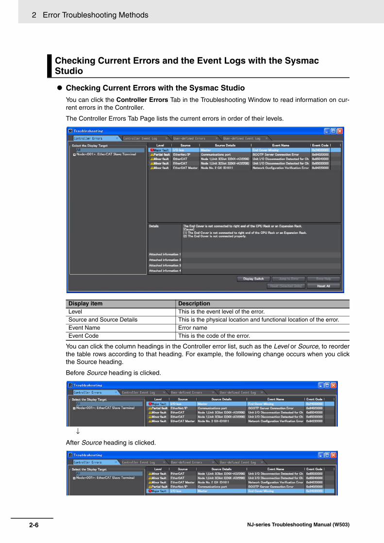
2 Error Troubleshooting Methods
Checking Current Errors with the Sysmac StudioYou can click the Controller Errors Tab in the Troubleshooting Window to read information on cur-rent errors in the Controller.
The Controller Errors Tab Page lists the current errors in order of their levels.
You can click the column headings in the Controller error list, such as the Level or Source, to reorderthe table rows according to that heading. For example, the following change occurs when you clickthe Source heading.
Before Source heading is clicked.
↓
After Source heading is clicked.
Checking Current Errors and the Event Logs with the Sysmac Studio
Display item DescriptionLevel This is the event level of the error.Source and Source Details This is the physical location and functional location of the error.Event Name Error nameEvent Code This is the code of the error.
2-6 NJ-series Troubleshooting Manual (W503)

2 Error Troubleshooting Methods2-3 Tro
ub
lesho
otin
g N
on
-fatal Erro
rs
2
2-3-1 Identifying and Resetting E
rrors with the S
ysmac S
tudio
Displaying Event Logs with the Sysmac StudioWith Sysmac Studio, you can check a log of the Controller events that previously occurred on theController Event Log Tab Page.
You can select the event logs and levels to display in the Display Settings Area. Information on theevents that you specify are displayed in the detailed information area.
Error logs from CJ-series Special Units are displayed on the Controller Event Log Tab Page.Detailed information is not displayed. To check detailed information, use the event codes that aredisplayed and refer to the error codes that are given in the manual for the relevant Unit. The relation-ship between error codes and event codes is described in Details on Controller Events (Errors andInformation) under 1-3-1 Types of Non-fatal Errors.
You can use the Sysmac Studio to reset errors that occur in a Controller. With a CPU Unit with unit ver-sion 1.05 or later and Sysmac Studio version 1.06 or higher you can also reset errors for individualUnits.
Before you attempt to reset a Controller error, isolate and remove the cause of the error.
The Troubleshooting Dialog Box displays the cause, source, and corrections for the error. You canselect any of the items from the error list to display the following information about that error. Click theDisplay Switch Button to switch between displaying details and attached information and displayingactions and corrections.
After confirming the cause of the displayed error and the conditions in which it occurred, perform thedisplayed error corrections to eliminate the cause of the error.
Resetting Errors with the Sysmac Studio
Display item DescriptionDetails Detailed information on the error is displayed, such as the probable causes.Attached information 1 through 4
Detailed information about the source of the error is displayed.
Action and Correction Methods to correct the probable causes of the error are displayed.
2-7NJ-series Troubleshooting Manual (W503)

2 Error Troubleshooting Methods
To eliminate the cause of the error, first select the item to perform from the Action and Correction list.When you select the appropriate step in the Action and Correction list, either the Jump to Error orError Help Button is enabled, depending on the contents. In some cases, neither button will operate.Click the enabled button, and proceed with the displayed troubleshooting steps.
After you complete all of the troubleshooting steps for the current errors, click the Reset (SelectedUnits) or Reset All Button to reset all of the current errors. If the cause of the error is not removed, or ifthe power supply is not cycled or the Controller is not reset as required after resetting the error, theerror will occur again.
It is necessary to synchronize the data between the Sysmac Studio and the connected CPU Unit beforeyou use the Jump to Error Button.
For details on synchronization, refer to the Sysmac Studio Version 1 Operation Manual (Cat. No. W504)
If you have enabled the verification of operation authority, it is necessary to confirm your authoritybefore you can reset Controller errors. The Operator, Maintainer, Designer, and Administrator have the authority to reset errors. For an Opera-tor, however, verification is required each time.Refer to the NJ-series CPU Unit Software User’s Manual (Cat. No. W501) for information on operationauthority.
The Controller errors in all function modules are reset when you reset the Controller from the SysmacStudio. If the cause of the error is not removed, the error will occur again.
Button DescriptionJump to Error This button is enabled when the error correction involves a change in the Sysmac Studio
settings. When you click the button, the Sysmac Studio will automatically switch to the Editing Pane.
Error Help The correction methods or the attached information is displayed if it is not possible to jump to the settings display.
Reset (Selected Units)
This button resets the current errors in the selected Unit.
Reset All This button resets all of the current errors, and reads errors again.
2-8 NJ-series Troubleshooting Manual (W503)

2 Error Troubleshooting Methods2-3 Tro
ub
lesho
otin
g N
on
-fatal Erro
rs
2
2-3-2 Identifying and Resetting E
rrors with an N
S-series P
T
You can connect one of the following OMRON NS-series PTs to an NJ-series CPU Unit through an Eth-erNet/IP network, and use it to read and reset errors that occurred in the Controller. (The Trouble-shooter of the PT is used.)
To perform troubleshooting from an NS-series PT, connect the PT to the built-in EtherNet/IP port on theCPU Unit.
• NS8, NS10, NS12, and NS15NS-T01-V2 (The V2 versions have an Ethernet port.)
• NS5NS5-Q11-V2 (These models have expanded memory and an Ethernet port.)
• NSJ8, NSJ10, and NSJ12All models
• NSJ5NSJ5-Q11- (These models have expanded memory and an Ethernet port.)
The above models of NS-series PTs with system version 8.5 or higher are compatible with the NJ-series Controllers.
You can check for errors in the Controller using the Troubleshooter of an NS-series PT that is compati-ble with NJ-series Controllers. You can also use the Troubleshooter to read detailed error informationand corrections for current errors. However, for some NX Units, you cannot check the event name,event code, details, and attached information for current errors.
Refer to the NS-series Programmable Terminals Programming Manual (Cat. No. V073) for details onthe NS-series PT’s Troubleshooter.
The following example demonstrates the procedure used to check for errors with an NS8, NS10, NS12,or NS15 PT.
You can check the event source in the Function Module View of the Troubleshooter. If you click theSelect Button for a function module in the Event source Table, you can display the Source details forevents for that function module. You can select the list in the Source details Table to display the ListView.
The List View displays a list of the errors produced by the event source that you selected in the FunctionModule View.
2-3-2 Identifying and Resetting Errors with an NS-series PT
Checking for Current Errors with an NS-series PT
2-9NJ-series Troubleshooting Manual (W503)
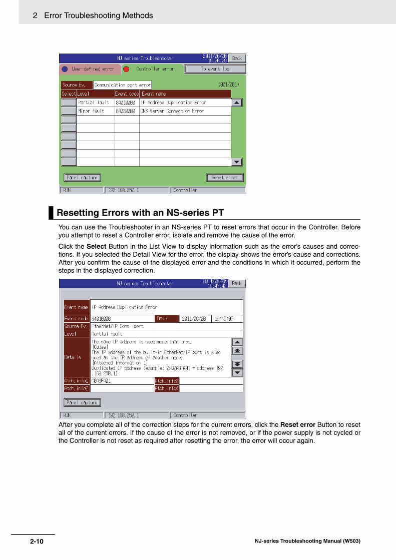
2 Error Troubleshooting Methods
You can use the Troubleshooter in an NS-series PT to reset errors that occur in the Controller. Beforeyou attempt to reset a Controller error, isolate and remove the cause of the error.
Click the Select Button in the List View to display information such as the error’s causes and correc-tions. If you selected the Detail View for the error, the display shows the error’s cause and corrections.After you confirm the cause of the displayed error and the conditions in which it occurred, perform thesteps in the displayed correction.
After you complete all of the correction steps for the current errors, click the Reset error Button to resetall of the current errors. If the cause of the error is not removed, or if the power supply is not cycled orthe Controller is not reset as required after resetting the error, the error will occur again.
Resetting Errors with an NS-series PT
2-10 NJ-series Troubleshooting Manual (W503)
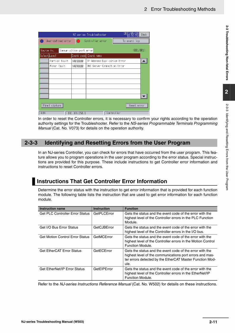
2 Error Troubleshooting Methods2-3 Tro
ub
lesho
otin
g N
on
-fatal Erro
rs
2
2-3-3 Identifying and Resetting E
rrors from the U
ser Program
In order to reset the Controller errors, it is necessary to confirm your rights according to the operationauthority settings for the Troubleshooter. Refer to the NS-series Programmable Terminals ProgrammingManual (Cat. No. V073) for details on the operation authority.
In an NJ-series Controller, you can check for errors that have occurred from the user program. This fea-ture allows you to program operations in the user program according to the error status. Special instruc-tions are provided for this purpose. These include instructions to get Controller error information andinstructions to reset Controller errors.
Determine the error status with the instruction to get error information that is provided for each functionmodule. The following table lists the instruction that are used to get error information for each functionmodule.
Refer to the NJ-series Instructions Reference Manual (Cat. No. W502) for details on these instructions.
2-3-3 Identifying and Resetting Errors from the User Program
Instructions That Get Controller Error Information
Instruction name Instruction Function
Get PLC Controller Error Status GetPLCError Gets the status and the event code of the error with the highest level of the Controller errors in the PLC Function Module.
Get I/O Bus Error Status GetCJBError Gets the status and the event code of the error with the highest level of the Controller errors in the I/O bus.
Get Motion Control Error Status GetMCError Gets the status and the event code of the error with the highest level of the Controller errors in the Motion Control Function Module.
Get EtherCAT Error Status GetECError Gets the status and the event code of the error with the highest level of the communications port errors and mas-ter errors detected by the EtherCAT Master Function Mod-ule.
Get EtherNet/IP Error Status GetEIPError Gets the status and the event code of the error with the highest level of the Controller errors in the EtherNet/IP Function Module.
2-11NJ-series Troubleshooting Manual (W503)

2 Error Troubleshooting Methods
Example of Error Detection for the EtherCAT Master Function Module
You can use the instructions that are provided to reset errors in the user program to reset errors thatoccur in the Controller. Before you attempt to reset a Controller error, isolate and remove the cause ofthe error. Reset the errors with the instruction provided to reset errors for each function module.
Refer to the NJ-series Instructions Reference Manual (Cat. No. W502) for details on these instructions.
Name Data type Initial value Comment
Trigger BOOL FALSE Get Condition
EC_Error BOOL FALSE EtherCAT Master Error Flag
Resetting Controller Errors with Instructions
Instruction name Instruction FunctionReset PLC Controller Error ResetPLCError Resets current Controller errors from the PLC Function
Module.Reset I/O Bus Controller Error ResetCJBError Resets current Controller errors from the I/O bus.
Reset Motion Control Error ResetMCError Resets current Controller errors from the Motion Control Function Module.
Reset EtherCAT Error ResetECError Resets current Controller errors from the EtherCAT Mas-ter Function Module.
GetECError
EN
Level
Code
EC_ErrorTrigger
2-12 NJ-series Troubleshooting Manual (W503)

2 Error Troubleshooting Methods2-3 Tro
ub
lesho
otin
g N
on
-fatal Erro
rs
2
2-3-4 Checking for E
rrors with S
ystem-defined V
ariables
The system-defined variables include an Error Status variable, which shows the error status. The fol-lowing diagram shows the structure of this variable. The system determines the error status of eachlevel by logically ORing the error status information of the next lower level. You can read the Error Sta-tus variable from an external device through communications. Refer to the NJ-series CPU Unit Soft-ware User’s Manual (Cat. No. W501) for information on system-defined variables.
2-3-4 Checking for Errors with System-defined Variables
_ErrSta
_PLC_ErrSta
_CJB_ErrSta
_CJB_UnitErrSta
Level 1 Level 2 Level 3 Level 4
Error status variable for PLC Function Module
Error Status variable (for the entire Controller)
Error status variable for I/O bus
Error status variable for master
Error status variable for Units
Error status variable for Motion Control Function Module
Common error status variable
Axis error status variable
Axes group error status variable
_MC_ErrSta
_MC_ComErrSta
_MC_AX_ErrSta
_MC_GRP_ErrSta
_CJB_MstrErrSta
_EIP_ErrSta
_EIP_PortErr
_EIP_CipErr
_EIP_TcpAppErr
Error status variable for EtherNet/IP Function Module
Error status variable for communications ports
Error status variable for CIP communications
Error status variable of the TCP application function
_EC_ErrSta
_EC_PortErr
_EC_MstrErr
_EC_SlavErr
_EC_SlavErrTbl
Error status variable for EtherCAT Master Function Module
Error status variable for communications ports
Error status variable for master
Summary error status variable for all slaves
Error status variable for slaves
2-13NJ-series Troubleshooting Manual (W503)
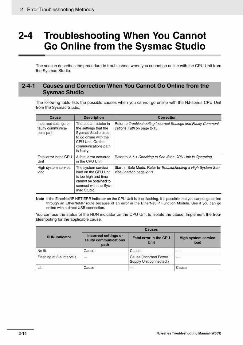
2 Error Troubleshooting Methods
2-4 Troubleshooting When You Cannot Go Online from the Sysmac Studio
The section describes the procedure to troubleshoot when you cannot go online with the CPU Unit fromthe Sysmac Studio.
The following table lists the possible causes when you cannot go online with the NJ-series CPU Unitfrom the Sysmac Studio.
Note If the EtherNet/IP NET ERR indicator on the CPU Unit is lit or flashing, it is possible that you cannot go onlinethrough an EtherNet/IP route because of an error in the EtherNet/IP Function Module. See if you can goonline with a direct USB connection.
You can use the status of the RUN indicator on the CPU Unit to isolate the cause. Implement the trou-bleshooting for the applicable cause.
2-4-1 Causes and Correction When You Cannot Go Online from the Sysmac Studio
Cause Description Correction
Incorrect settings or faulty communica-tions path
There is a mistake in the settings that the Sysmac Studio uses to go online with the CPU Unit. Or, the communications path is faulty.
Refer to Troubleshooting Incorrect Settings and Faulty Communi-cations Path on page 2-15.
Fatal error in the CPU Unit
A fatal error occurred in the CPU Unit.
Refer to 2-1-1 Checking to See If the CPU Unit Is Operating.
High system service load
The system service load on the CPU Unit is too high and time cannot be obtained to connect with the Sys-mac Studio.
Start in Safe Mode. Refer to Troubleshooting a High System Ser-vice Load on page 2-19.
RUN indicator
Causes
Incorrect settings or faulty communications
path
Fatal error in the CPU Unit
High system service load
No lit. Cause Cause ---
Flashing at 3-s intervals. --- Cause (Incorrect Power Supply Unit connected.)
---
Lit. Cause --- Cause
2-14 NJ-series Troubleshooting Manual (W503)
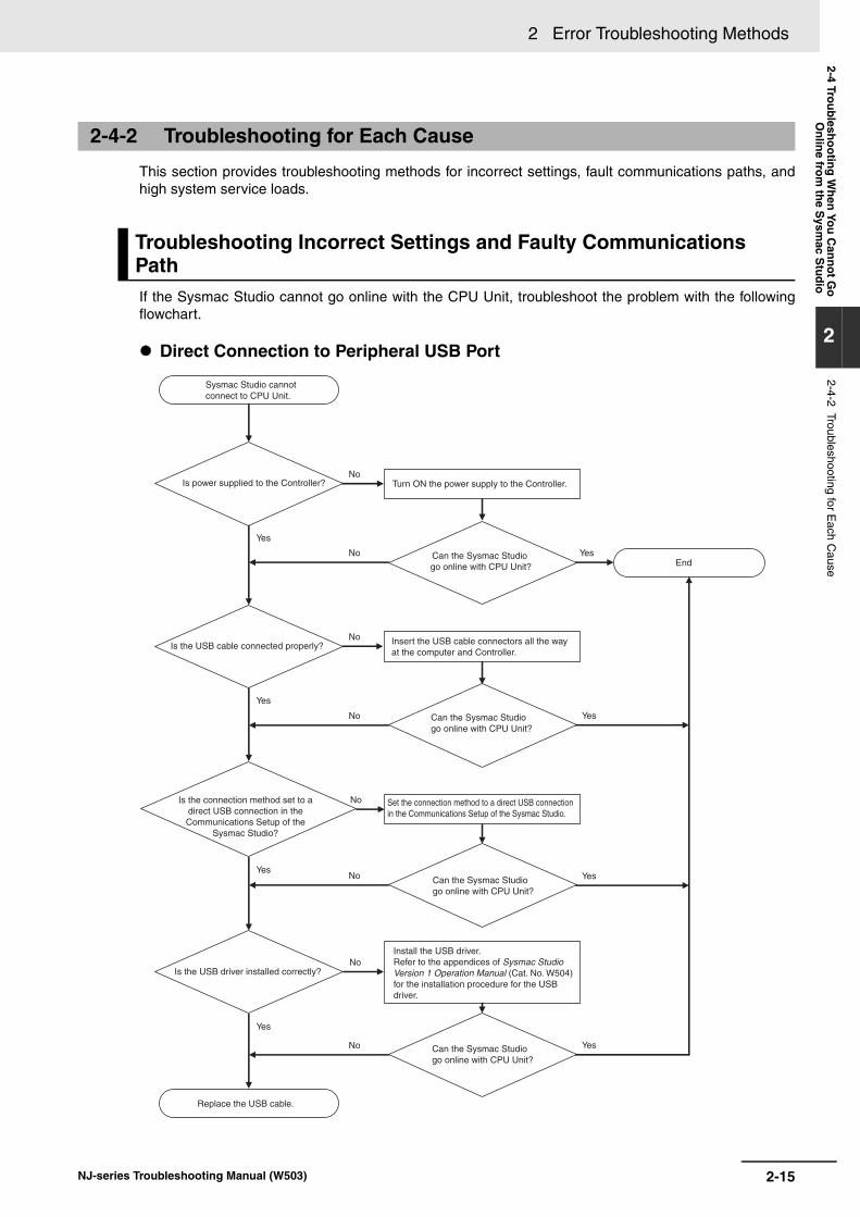
2 Error Troubleshooting Methods2-4 Tro
ub
lesho
otin
g W
hen
You
Can
no
t Go
On
line fro
m th
e Sysm
ac Stu
dio
2
2-4-2 Troubleshooting for Each C
ause
This section provides troubleshooting methods for incorrect settings, fault communications paths, andhigh system service loads.
If the Sysmac Studio cannot go online with the CPU Unit, troubleshoot the problem with the followingflowchart.
Direct Connection to Peripheral USB Port
2-4-2 Troubleshooting for Each Cause
Troubleshooting Incorrect Settings and Faulty Communications Path
Yes
Is the USB driver installed correctly?
Replace the USB cable.
End
No
No
No
No
No
No
No
No
Insert the USB cable connectors all the way at the computer and Controller.
Turn ON the power supply to the Controller.
Is the USB cable connected properly?
Is power supplied to the Controller?
Yes
Can the Sysmac Studio go online with CPU Unit?
Can the Sysmac Studio go online with CPU Unit?
Can the Sysmac Studio go online with CPU Unit?
Sysmac Studio cannot connect to CPU Unit.
Yes
Yes
Yes
Yes
Yes
Yes
Can the Sysmac Studio go online with CPU Unit?
Is the connection method set to a direct USB connection in the Communications Setup of the
Sysmac Studio?
Set the connection method to a direct USB connection in the Communications Setup of the Sysmac Studio.
Install the USB driver.Refer to the appendices of Sysmac Studio Version 1 Operation Manual (Cat. No. W504) for the installation procedure for the USB driver.
2-15NJ-series Troubleshooting Manual (W503)

2 Error Troubleshooting Methods
Remote Connection to Peripheral USB Port
End
No
No
No
No
No
No
No
No
No
No
Insert the cable connectors all the way at the computer and Controller.
Turn ON the power supply to the Controller.Is power supplied to the Controller?
Can the Sysmac Studio go online with CPU Unit?
Can the Sysmac Studio go online with CPU Unit?
Sysmac Studio cannot connect to CPU Unit.
Yes
Yes
Yes
Yes
Yes
Yes
Yes
Yes
Yes
Yes
Is the connection method set to a remote USB connection
in the Communications Setup of the Sysmac Studio?
Set the connection method to a remote USB connection in the Communications Setup of the Sysmac Studio. Set the destination IP address for a remote USB connection or Ethernet-hub connection in the Communica-tions Setup of the Sysmac Studio.
Can the Sysmac Studio go online with CPU Unit?
Can the Sysmac Studio go online with CPU Unit?
Can the Sysmac Studio go online with CPU Unit?
Is the destination IP address for a remote USB
connection or Ethernet-hub connection in the Communications Setup of the
Sysmac Studio set correctly and is the IP address set correctly in the
destination Controller?
Correct the destination IP address for a remote USB connection or Ethernet-hub connection in the Communications Setup of the Sysmac Studio. Correct the IP address setting in the destination Controller.
Is the USB driver installed correctly?
Install the USB driver. Refer to the appendices of Sysmac Studio Version 1 Operation Manual (Cat. No. W504) for the installation procedure for the USB driver.
Replace the USB cable, or the Ethernet cables and Ethernet switches between the computer and the Controller.
Are the USB cable and Ethernet cables connected properly?
2-16 NJ-series Troubleshooting Manual (W503)
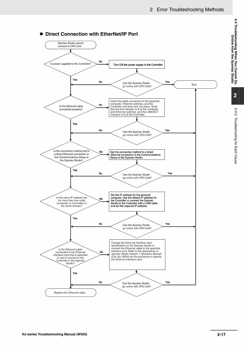
2 Error Troubleshooting Methods2-4 Tro
ub
lesho
otin
g W
hen
You
Can
no
t Go
On
line fro
m th
e Sysm
ac Stu
dio
2
2-4-2 Troubleshooting for Each C
ause
Direct Connection with EtherNet/IP Port
End
No
No
No
No
No
No
No
No
Turn ON the power supply to the Controller.
Is the Ethernet cable connected properly?
Is power supplied to the Controller?
YesCan the Sysmac Studio connect to CPU Unit?
Sysmac Studio cannot connect to CPU Unit.
Yes
Yes
Yes
Yes
Yes
Yes
YesNo
Yes
Yes
No
Can the Sysmac Studio connect to CPU Unit?
Can the Sysmac Studio connect to CPU Unit?
Can the Sysmac Studio connect to CPU Unit?
Can the Sysmac Studio connect to CPU Unit?
Is the connection method set to a direct Ethernet connection in the Communications Setup of
the Sysmac Studio?
Set the connection method to a direct Ethernet connection in the Communications Setup of the Sysmac Studio.
Is the same IP address set for more than one node
(computer or Controller) in the same domain?
Set the IP address for the personal computer. Use the default IP address for the Controller or connect the Sysmac Studio to the Controller with a USB cable and set the required IP address.
Is the Ethernet cable connected to the Ethernet
interface card that is specified to use to connect to the Controller in the Sysmac
Studio?
Change the Ethernet interface card specification on the Sysmac Studio or connect the Ethernet cable to the specified interface card. Refer to the appendices of Sysmac Studio Version 1 Operation Manual (Cat. No. W504) for the procedure to specify the Ethernet interface card.
Replace the Ethernet cable.
Insert the cable connectors at the personal computer, Ethernet switches, and the Controller until they lock into place. Verify that the link indicator is lit at the computer and Ethernet switches, and the LINK/ACT indicator is lit at the Controller.
End
No
No
No
No
No
No
No
No
Turn ON the power supply to the Controller.
Is the Ethernet cable connected properly?
Is power supplied to the Controller?
YesCan the Sysmac Studio go online with CPU Unit?
Sysmac Studio cannot connect to CPU Unit.
Yes
Yes
Yes
Yes
Yes
Yes
YesNo
Yes
Yes
No
Can the Sysmac Studio go online with CPU Unit?
Can the Sysmac Studio go online with CPU Unit?
Can the Sysmac Studio go online with CPU Unit?
Can the Sysmac Studio go online with CPU Unit?
Is the connection method set to a direct Ethernet connection in the Communications Setup of
the Sysmac Studio?
Set the connection method to a direct Ethernet connection in the Communications Setup of the Sysmac Studio.
Is the same IP address set for more than one node
(computer or Controller) in the same domain?
Set the IP address for the personal computer. Use the default IP address for the Controller or connect the Sysmac Studio to the Controller with a USB cable and set the required IP address.
Is the Ethernet cable connected to the Ethernet
interface card that is specified to use to connect to the Controller in the Sysmac
Studio?
Replace the Ethernet cable.
2-17NJ-series Troubleshooting Manual (W503)

2 Error Troubleshooting Methods
Ethernet Hub Connection
End
No
YesNo
No
No
No
No
No
Turn ON the power supply to the Controller.Is power supplied to the Controller?
Yes
Sysmac Studio cannot connect to CPU Unit.
Yes
NoYes
Yes
Yes
Yes
Yes
A
Can the Sysmac Studio go online with CPU Unit?
Can the Sysmac Studio go online with CPU Unit?
Can the Sysmac Studio go online with CPU Unit?
Can the Sysmac Studio go online with CPU Unit?
Is the Ethernet cable connected properly?
Insert the cable connectors at the personal computer,Ethernet switches, and the Controller until they lock into place. Verify that the link indicator is lit at the computer and Ethernet switches, and the LINK/ACT indicator is lit at the Controller.
Is the connection method set to an Ethernet hub
connection in the Communications Setup of
the Sysmac Studio?
Set the connection method to an Ethernet hub connection in the Communications Setup of the Sysmac Studio. Set the destination IP address for a remote USB connection or Ethernet-hub connection in the Communications Setup.
Is the destination IP address for a remote USB connection or Ethernet-hub
connection set correctly in the Communications Setup of the
Sysmac Studio?
Correct the destination IP address for a remote USB connection or Ethernet-hub connection in the Communications Setup of the Sysmac Studio.
2-18 NJ-series Troubleshooting Manual (W503)

2 Error Troubleshooting Methods2-4 Tro
ub
lesho
otin
g W
hen
You
Can
no
t Go
On
line fro
m th
e Sysm
ac Stu
dio
2
2-4-2 Troubleshooting for Each C
ause
If a high system service load is the problem, you will be able to go online with the CPU Unit from theSysmac Studio if you start in Safe Mode. Use the following procedure.
1 Set on the DIP switch on the CPU Unit as shown below and then cycle the power supply to theController.
The CPU Unit will start in Safe Mode.
2 Go online with the CPU Unit from the Sysmac Studio and perform the required operation.
Ensure that there is sufficient system service time to enable the Sysmac Studio to go online withthe CPU Unit. To do so, either increase the period of the primary periodic task or decrease thesizes of the programs in the primary periodic task. Refer to NJ-series CPU Unit Software User’sManual (Cat. No. W501) for information on setting the primary periodic task.
3 Turn OFF all DIP switch pins and then cycle the power supply to the Controller to restore normalCPU Unit operation.
Troubleshooting a High System Service Load
End
Yes
Yes
A
No Yes
No
No
No
Yes
Is the same IP address set for more than one node (computer
or Controller) in the same domain?
Set the IP address for the personal computer. Use the default IP address for the Controller or connect the Sysmac Studio to the Controller with a USB cable and set the required IP address.
Can the Sysmac Studio go online with CPU Unit?
Can the Sysmac Studio go online with CPU Unit?
Is the Ethernet cable connected to the Ethernet interface card
that is specified to use to connect to the Controller in the
Sysmac Studio?
Change the Ethernet interface card specification on the Sysmac Studio or connect the Ethernet cable to the specified interface card. Refer to the appendices of Sysmac Studio Version 1 Operation Manual (Cat. No. W504) for the procedure to specify the Ethernet interface card.
Replace the Ethernet cable or Ethernet switch.
ONON
1234
Turn OFF.
Turn ON.
2-19NJ-series Troubleshooting Manual (W503)
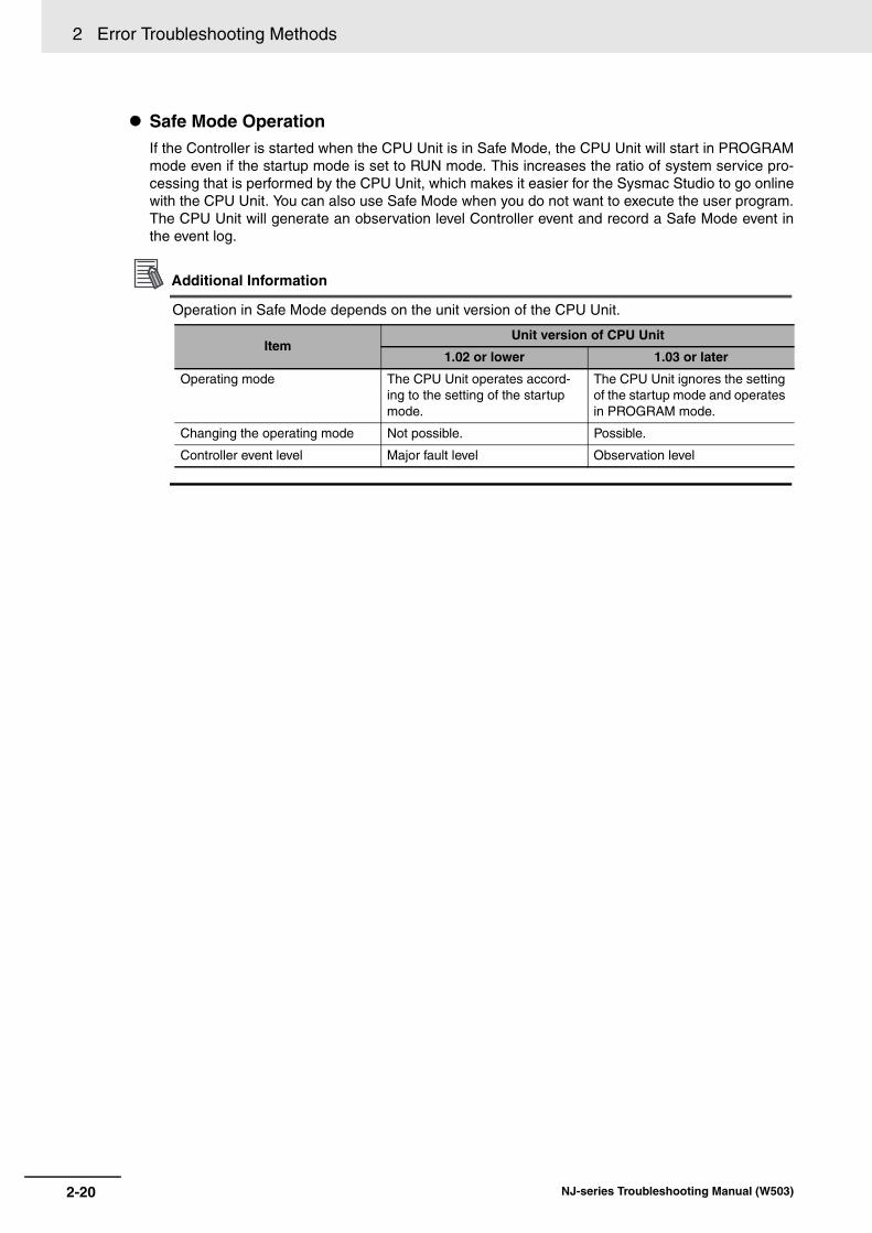
2 Error Troubleshooting Methods
Safe Mode OperationIf the Controller is started when the CPU Unit is in Safe Mode, the CPU Unit will start in PROGRAMmode even if the startup mode is set to RUN mode. This increases the ratio of system service pro-cessing that is performed by the CPU Unit, which makes it easier for the Sysmac Studio to go onlinewith the CPU Unit. You can also use Safe Mode when you do not want to execute the user program.The CPU Unit will generate an observation level Controller event and record a Safe Mode event inthe event log.
Additional Information
Operation in Safe Mode depends on the unit version of the CPU Unit.
ItemUnit version of CPU Unit
1.02 or lower 1.03 or later
Operating mode The CPU Unit operates accord-ing to the setting of the startup mode.
The CPU Unit ignores the setting of the startup mode and operates in PROGRAM mode.
Changing the operating mode Not possible. Possible.
Controller event level Major fault level Observation level
2-20 NJ-series Troubleshooting Manual (W503)

3
This section lists all of the errors (events) that can occur on NJ-series Controllers.
3-1 Errors by Source . . . . . . . . . . . . . . . . . . . . . . . . . . . . . . . . . . . . . . . . . . . . . . 3-23-1-1 Interpreting Error Descriptions . . . . . . . . . . . . . . . . . . . . . . . . . . . . . . . . . . . . . 3-2
3-1-2 Errors in the PLC Function Module . . . . . . . . . . . . . . . . . . . . . . . . . . . . . . . . . 3-2
3-1-3 Errors in the Motion Control Function Module . . . . . . . . . . . . . . . . . . . . . . . . 3-503-1-4 Errors in the EtherNet/IP Function Module . . . . . . . . . . . . . . . . . . . . . . . . . . 3-80
3-1-5 Errors in the EtherCAT Master Function Module . . . . . . . . . . . . . . . . . . . . . . 3-84
3-1-6 Errors in the DB Connection Service Function . . . . . . . . . . . . . . . . . . . . . . . 3-883-1-7 Errors in Slave Terminals . . . . . . . . . . . . . . . . . . . . . . . . . . . . . . . . . . . . . . . . 3-93
3-1-8 Errors in EtherCAT Slaves . . . . . . . . . . . . . . . . . . . . . . . . . . . . . . . . . . . . . . 3-114
3-1-9 Errors in CJ-series Units . . . . . . . . . . . . . . . . . . . . . . . . . . . . . . . . . . . . . . . 3-135
3-2 Events in Order of Event Codes . . . . . . . . . . . . . . . . . . . . . . . . . . . . . . . . 3-1553-2-1 Interpreting Error Descriptions . . . . . . . . . . . . . . . . . . . . . . . . . . . . . . . . . . . 3-1553-2-2 Error Table . . . . . . . . . . . . . . . . . . . . . . . . . . . . . . . . . . . . . . . . . . . . . . . . . . 3-156
3-3 Instruction Error Table . . . . . . . . . . . . . . . . . . . . . . . . . . . . . . . . . . . . . . . . 3-189
Error Tables
3-1NJ-series Troubleshooting Manual (W503)

3 Error Tables
3-1 Errors by Source
This section provides tables of errors (events) by source. Within each source, errors are given by func-tional classifications. Events that are not errors are also given in the tables.
The contents of the error tables are described below.
Note This symbol appears only for events for which the user can change the event level.
The section provides tables of the events that can occur in the PLC Function Module. They are dividedinto the following functional classifications.
• Self-diagnosis
• Unit configuration
• Tasks
• Controller operation
• FINS communications
• Instructions
Additional Information
• Instruction events are supported by CPU Units with unit version 1.02 or later.
• To create instruction events, you must select Use for Event Log Settings − Instruction ErrorOutput on the Controller Setup. With the default setting, instructions events are not output.Sysmac Studio version 1.03 or higher is required to use the Event Log Settings.
3-1-1 Interpreting Error Descriptions
Item Description
Event code The event code of the error in the NJ-series Controller is given. The codes are given in eight hexadecimal digits.
Event name The name of the error is given
Meaning A short description of the error is given.
Assumed cause The assumed cause of the error is given
Level The level of influence on control is given. The abbreviations have the following meanings.
Maj: Major fault level
Prt: Partial fault level
Min: Minor fault level
Obs: Observation
Info: Information
The symbols have the following meanings.
S: Event levels that are defined by the system.
U: Event levels that can be changed by the user. (See note.)
Reference The name and catalog number of the manual that provides details on the event are given.
3-1-2 Errors in the PLC Function Module
3-2 NJ-series Troubleshooting Manual (W503)

3 Error Tables3-1 E
rrors by S
ou
rce
3
3-1-2 Errors in the P
LC F
unction Module
Errors for Self Diagnosis
Event code Event name Meaning Assumed causeLevel
ReferenceMaj Prt Min Obs Info
00090000 hex DIP Switch Setting Error
An error was detected in the DIP switch setting.
• There is an error in the DIP switch setting.
S NJ-series CPU Unit Hardware User’s Manual (Cat. No. W500)
000D0000 hex Internal NJ-series Bus Check Error
A fatal error was detected on the internal bus.
• Conductive material has gotten inside.
• Noise
• The CPU Unit has failed.
S Same as above.
000E0000 hex Non-volatile Memory Life Exceeded
The specified num-ber of deletions for non-volatile mem-ory was exceeded. Or, the number of bad blocks in mem-ory exceeded the specified value.
• Non-volatile memory life expired.
S Same as above.
10010000 hex Non-volatile Memory Restored or Formatted
An error was detected in the non-volatile memory check and file sys-tem recovery or for-matting was executed. Previous files may have been deleted.
• The Controller power supply was turned OFF while the BUSY indicator was lit.
• The power supply to the Con-troller was interrupted momen-tarily while the BUSY indicator was lit.
S Same as above.
10020000 hex Non-volatile Memory Data Corrupted
A file that must be in non-volatile memory is missing or corrupted.
• The Controller power supply was turned OFF while the BUSY indicator was lit.
• The power supply to the Con-troller was interrupted momen-tarily while the BUSY indicator was lit.
• The CPU Unit has failed.
S Same as above.
10080000 hex Main Memory Check Error
An error was detected in the memory check of the main memory in the CPU Unit.
• Conductive material has gotten inside.
• Noise
• There is a software error.
• The CPU Unit has failed.
S Same as above.
100C0000 hex (Ver. 1.03)
Event Level Setting Error
The settings in the event level setting file are not correct.
• The event level settings are not correct because the power sup-ply to the Controller was inter-rupted or communications with the Sysmac Studio were dis-connected during a download of the event level settings.
• The event level settings are not correct because the power sup-ply to the Controller was inter-rupted during a Clear All Memory operation.
• Non-volatile memory failed.
S Same as above.
00070000 hex Real-Time Clock Stopped
The oscillation of the real-time clock stopped. The real-time clock is set to an illegal time.
• The battery voltage is low.
• The battery connector has come loose.
• The Battery is missing.
S U Same as above.
3-3NJ-series Troubleshooting Manual (W503)

3 Error Tables
00080000 hex Real-Time Clock Failed
The real-time clock in the CPU Unit failed.
• The CPU Unit clock has failed. S NJ-series CPU Unit Hardware User’s Manual (Cat. No. W500)
000B0000 hex Low Battery Voltage
The voltage of the Battery has dropped.
• The battery voltage is low.
• The battery connector has come loose.
• The Battery is missing.
S U Same as above.
000C0000 hex CPU Unit Overheat
The temperature inside the CPU Unit exceeded the spec-ified value.
• The ambient operating temper-ature is too high.
S Same as above.
10090000 hex Battery-backup Mem-ory Check Error
An error was detected in the memory check of the battery-backup memory in the CPU Unit.
• The battery voltage is low.
• The battery connector has come loose.
• The Battery is missing.
S U Same as above.
000F0000 hex SD Memory Card Invalid Type
The current SD Memory Card is not supported.
• An SD Memory Card that is not supported was inserted into the CPU Unit.
S Same as above.
00100000 hex SD Memory Card Life Exceeded
The specified num-ber of deletions for the SD Memory Card was exceeded. Or, the number of bad blocks exceeded the specified value.
• The service life of the SD Mem-ory Card was exceeded.
U S Same as above.
10030000 hex SD Memory Card Invalid Format
The file format of the SD Memory Card is not FAT16 or FAT32.
• The file format of the SD Mem-ory Card inserted in the CPU Unit is not FAT16 or FAT32.
S Same as above.
10040000 hex SD Memory Card Restored or Formatted
An error was detected during the file system check and the file system was restored. Files may have been deleted.
• The Controller power supply was turned OFF while the SD BUSY indicator was lit.
• The power supply to the Con-troller was interrupted momen-tarily while the SD BUSY indicator was lit.
• The SD Memory Card was removed while the SD PWR indicator was lit.
• The SD Memory Card is dam-aged.
U S Same as above.
10060000 hex SD Memory Card Data Corrupted
A file that must be in the SD Memory Card is missing or corrupted.
• The Controller power supply was turned OFF while the SD BUSY indicator was lit.
• The power supply to the Con-troller was interrupted momen-tarily while the SD BUSY indicator was lit.
• The SD Memory Card was removed while the SD PWR indicator was lit.
• The SD Memory Card is dam-aged.
U S Same as above.
Event code Event name Meaning Assumed causeLevel
ReferenceMaj Prt Min Obs Info
3-4 NJ-series Troubleshooting Manual (W503)

3 Error Tables3-1 E
rrors by S
ou
rce
3
3-1-2 Errors in the P
LC F
unction Module
10070000 hex SD Memory Card Access Power OFF Error
The power supply to the Controller was interrupted during access to the SD Memory Card.
• The Controller power supply was turned OFF while the SD BUSY indicator was lit.
• The power supply to the Con-troller was interrupted momen-tarily while the SD BUSY indicator was lit.
S NJ-series CPU Unit Hardware User’s Manual (Cat. No. W500)
10310000 hex (Ver. 1.02)
Incorrect SD Memory Card Removal
SD Memory Card removal process-ing failed.
• The SD Memory Card was removed while the SD PWR indicator was lit.
S Same as above.
Errors Related to Unit Configuration
Event code Event name Meaning Assumed causeLevel
ReferenceMaj Prt Min Obs Info
04010000 hex I/O Bus Check Error
An error occurred in a bus line transmis-sion between the CPU Unit and the Units in the rack slots. Or, detection of all Special I/O Units and CPU Bus Units was not com-pleted when the power supply to the Controller was turned ON.
• The I/O Connecting Cable is disconnected or wires inside it are broken.
• Conductive material has gotten inside.
• The connector contact is faulty due to foreign material in the connector.
• Noise
• A Unit has failed.
S NJ-series CPU Unit Hardware User’s Manual (Cat. No. W500)
24010000 hex Unsupported Unit Detected
An unsupported CJ-series Unit or Power Supply Unit is mounted.
• An unsupported CJ-series Unit or Power Supply Unit was detected.
S Same as above.
24020000 hex Too Many I/O Points
The total number of I/O points in the connected CJ-series Units exceeds the maxi-mum specified value of the CPU Unit.
• The total number of I/O points in the connected CJ-series Basic I/O Units exceeds 2,560.
S Same as above.
24030000 hex End Cover Missing
The End Cover is not connected to right end of the CPU Rack or an Expansion Rack.
• The End Cover is not con-nected to right end of the CPU Rack or an Expansion Rack.
• The End Cover is not con-nected properly.
S Same as above.
24040000 hex Incorrect Unit/Expan-sion Rack Connection
The number of Units or Expansion Racks exceeds the maximum value specified for the CPU Unit. Or, an Interrupt Input Unit was mounted to a unsupported slot or to an Expansion Rack.
• More than 10 Units are con-nected to one Rack.
• More than three Expansion Racks are connected.
• More than two Interrupt Input Units are mounted.
• An Interrupt Input Unit was mounted to a unsupported slot or to an Expansion Rack.
S Same as above.
Event code Event name Meaning Assumed causeLevel
ReferenceMaj Prt Min Obs Info
3-5NJ-series Troubleshooting Manual (W503)

3 Error Tables
24050000 hex Duplicate Unit Number
The same unit num-ber is set for more than one Special I/O Unit or more than one CPU Bus Unit.
• The same unit number is set for more than one Special I/O Unit or more than one CPU Bus Unit.
• The same unit number is assigned to a Special I/O Unit that uses more than one unit number and another Special I/O Unit.
S NJ-series CPU Unit Hardware User’s Manual (Cat. No. W500)
34010000 hex I/O Setting Check Error
There is an incon-sistency between a Unit model in the Unit Configuration in the CPU Unit and the Unit model that is mounted in the Controller.
• A Unit model or Special Unit unit number in the Unit Configu-ration in the CPU Unit is differ-ent from the Unit model or the Special Unit unit number of the Unit that is mounted in the Con-troller.
S Same as above.
64010000 hex Impossible to Access Spe-cial Unit
An error occurred in data exchange between the CPU Unit and a Special Unit.
• The setting of the rotary switches or a DIP switch pin on a Special Unit is not correct.
• An error occurred in the Special Unit.
• The Unit connection is faulty.
• Noise
• A Unit has failed.
S Same as above.
102D0000 hex (Ver. 1.03)
CJ-series Unit Backup Failed
The backup opera-tion for a CJ-series Unit ended in an error.
• An error occurred in the Unit Configuration.
• An error occurred for a Special Unit.
• A restart is in progress for the Special Unit.
• A Unit model or Special Unit unit number in the Unit Configu-ration in the CPU Unit is differ-ent from the Unit model or the Special Unit unit number of the Unit that is mounted in the Con-troller.
• The CPU Unit or CJ-series Unit has failed.
S Same as above.
102E0000 hex (Ver. 1.03)
CJ-series Unit Restore Operation Failed
The restore opera-tion for a CJ-series Unit ended in an error.
• An error occurred in the Unit Configuration.
• An error occurred for a Special Unit.
• The Unit Configuration in the backup file does not agree with the physical Unit configuration.
• A restart is in progress for the Special Unit.
• The restore conditions that are required by the Special Unit are not met.
• The backup files are corrupted.
• The CPU Unit or CJ-series Unit has failed.
S Same as above.
30200000 hex (Ver. 1.02)
Unsupported Unit Setting
A setting in the Special Unit is not supported.
• A setting in the Special Unit is not supported by the CPU Unit.
S Same as above.
Event code Event name Meaning Assumed causeLevel
ReferenceMaj Prt Min Obs Info
3-6 NJ-series Troubleshooting Manual (W503)

3 Error Tables3-1 E
rrors by S
ou
rce
3
3-1-2 Errors in the P
LC F
unction Module
80010000 hex Illegal Packet Discarded
An illegal packet was received during message communi-cations. The illegal packet was dis-carded.
• Noise S NJ-series CPU Unit Hardware User’s Manual (Cat. No. W500)
Errors Related to Tasks
Event code Event name Meaning Assumed causeLevel
ReferenceMaj Prt Min Obs Info
60020000 hex Task Execu-tion Timeout
Task execution exceeded the time-out detection time.
• The timeout detection time set-ting is too short.
• The task period setting is too short.
• A user program is too large.
• The number of times that pro-cessing is repeated is larger than expected.
• Task Priority Error
• Frequent Event Task Execution
S NJ-series CPU Unit Soft-ware User’s Manual (Cat. No. W501)
60030000 hex I/O Refresh-ing Timeout Error
Consecutive I/O refresh failures occurred during the primary periodic task or periodic task period.
• The task period setting is too short.
• Task Priority Error for Periodic Tasks and Event Tasks
• There are too many Units and slaves that perform I/O refresh in the task period.
• Frequent Event Task Execution
S Same as above.
60040000 hex Insufficient System Ser-vice Time Error
The specified sys-tem service execu-tion time could not be obtained.
• There was not sufficient time to execute the tasks and tag data link service.
• The system service execution interval is too short or the sys-tem service execution time ratio is too long in the System Ser-vice Monitoring Settings.
S Same as above.
60010000 hex Task Period Exceeded
Task execution was not completed dur-ing the set task period for the pri-mary periodic task or a periodic task.
• The task period setting is too short.
• A user program is too large.
• The number of times that pro-cessing is repeated is larger than expected.
• Task Priority Error for Periodic Tasks and Event Tasks
• Frequent Event Task Execution
S Same as above.
60050000 hex Task Period Exceeded
Task execution was not completed dur-ing the set task period for the pri-mary periodic task or fixed periodic task.
• The task period setting is too short.
• A user program is too large.
• The number of times that pro-cessing is repeated is larger than expected.
• Task Priority Error for Periodic Tasks and Event Tasks
• Frequent Event Task Execution
S Same as above.
Event code Event name Meaning Assumed causeLevel
ReferenceMaj Prt Min Obs Info
3-7NJ-series Troubleshooting Manual (W503)

3 Error Tables
Errors Related to Controller Operation
Event code Event name Meaning Assumed causeLevel
ReferenceMaj Prt Min Obs Info
10200000 hex User Pro-gram/Con-troller Configura-tions and Setup Trans-fer Error
The user program or Controller Con-figurations and Setup were not transferred cor-rectly.
• The user program or Controller Configurations and Setup are not correct because the power supply to the Controller was interrupted during a download of the user program or the Con-troller Configurations and Setup.
• The user program or Controller Configurations and Setup are not correct because the power supply to the Controller was interrupted during online edit-ing.
• The user program or Controller Configurations and Setup are not correct because the power supply to the Controller was interrupted during a Clear All Memory operation.
• The user program or Controller Configurations and Setup are not correct because the power supply to the Controller was interrupted during a restore operation.
• Non-volatile memory failed.
S NJ-series CPU Unit Hardware User’s Manual (Cat. No. W500)
NJ-series CPU Unit Soft-ware User’s Manual (Cat. No. W501)
10210000 hex Illegal User Program Execution ID
The user program execution IDs set in the user program and in the CPU Unit do not match.
• The user program execution IDs set in the user program and in the CPU Unit do not match.
• A user program execution ID is set in the CPU Unit but not in the user program.
S Same as above.
10240000 hex Illegal User Program
The user program is not correct.
• There are more than 8 nesting levels for functions or function blocks.
S Same as above.
10250000 hex Illegal User Pro-gram/Con-troller Configura-tions and Setup
The upper limit of the usable memory was exceeded or the user program or Controller Configu-rations and Setup is corrupted.
• The upper limit of the data size was exceeded.
• The main memory capacity was exceeded.
• Non-volatile memory is deterio-rating or has failed.
S Same as above.
3-8 NJ-series Troubleshooting Manual (W503)

3 Error Tables3-1 E
rrors by S
ou
rce
3
3-1-2 Errors in the P
LC F
unction Module
10270000 hex (Ver. 1.03)
Error in Start-ing Auto-matic Transfer
An error was detected in pre-exe-cution checks for automatic transfer.
• An SD Memory Card is not inserted.
• The SD Memory Card type is not correct.
• The format of the SD Memory Card is not correct.
• There is no autoload folder on the SD Memory Card.
• There are no backup files in the autoload folder on the SD Mem-ory Card.
• Either the backup files in the autoload folder on the SD Mem-ory Card are corrupted or required data is not in the backup files on the SD Memory Card.
• The unit version of the CPU Unit to which to transfer the files is older than the unit version of the backup files on the SD Memory Card.
• The model of the CPU Unit to which to transfer the files is not the same as the model of the CPU Unit of the backup files on the SD Memory Card.
• Recovery was executed for the SD Memory Card.
• The CPU Unit is write-pro-tected.
• The settings in the automatic transfer command file (Auto-loadCommand.ini) are not cor-rect.
• Reading the data for automatic transfer failed because the SD Memory Card is faulty or not formatted correctly.
• The SD Memory Card is dam-aged.
S NJ-series CPU Unit Hardware User’s Manual (Cat. No. W500)
NJ-series CPU Unit Soft-ware User’s Manual (Cat. No. W501)
10280000 hex (Ver. 1.03)
Error in Exe-cuting Auto-matic Transfer
The automatic transfer ended in an error.
• It was not possible to read the data for automatic transfer.
• The SD Memory Card was removed during an automatic transfer.
• There are no backup files in the autoload folder on the SD Mem-ory Card.
• The backup files in the autoload folder on the SD Memory Card are corrupted.
• The SD Memory Card is dam-aged.
S Same as above.
40160000 hex Safe Mode The Controller started in Safe Mode.
• The power supply was turned ON to the Controller when Safe Mode was set on the DIP switch on the CPU Unit.
S Same as above.
10230000 hex Event Log Restoration Error
Restoring the event log failed.
• A low battery voltage prevented retention of memory during a power interruption.
S Same as above.
Event code Event name Meaning Assumed causeLevel
ReferenceMaj Prt Min Obs Info
3-9NJ-series Troubleshooting Manual (W503)

3 Error Tables
10260000 hex Trace Setting Transfer Fail-ure
The power supply was interrupted while transferring the trace settings.
• The power supply was inter-rupted while transferring the trace settings.
S NJ-series CPU Unit Hardware User’s Manual (Cat. No. W500)
NJ-series CPU Unit Soft-ware User’s Manual (Cat. No. W501)
10290000 hex (Ver. 1.03)
Backup Failed to Start
An error was detected in pre-exe-cution checks for a backup operation.
• An SD Memory Card is not inserted.
• The SD Memory Card type is not correct.
• The format of the SD Memory Card is not correct.
• The SD Memory Card is write protected.
• The Prohibiting backing up data to the SD Memory Card param-eter is set to prohibit backing up data to an SD Memory Card.
• Another backup operation is in progress.
• Synchronization, online edit-ing, or the Clear All Memory operation is in progress.
• The backup was canceled by the user.
• The online connection with the Sysmac Studio was discon-nected.
• The SD Memory Card is dam-aged.
S Same as above.
102A0000 hex (Ver. 1.03)
Backup Failed
The backup opera-tion ended in an error.
• The capacity of the SD Memory Card is insufficient.
• It was not possible to save the data that was specified for backup.
• The SD Memory Card was removed during a backup oper-ation.
• Failed to back up Unit or slave.
• The backup was canceled by the user.
• Execution of the Save Cam Table instruction or changing the CPU Unit name is in prog-ress.
• The online connection with the Sysmac Studio was discon-nected.
• It was not possible to save the data that was specified for backup to the computer.
• The SD Memory Card is dam-aged.
S Same as above.
Event code Event name Meaning Assumed causeLevel
ReferenceMaj Prt Min Obs Info
3-10 NJ-series Troubleshooting Manual (W503)

3 Error Tables3-1 E
rrors by S
ou
rce
3
3-1-2 Errors in the P
LC F
unction Module
102B0000 hex (Ver. 1.03)
Restore Operation Failed to Start
An error was detected in pre-exe-cution checks for a restore operation.
• An SD Memory Card is not inserted.
• The SD Memory Card type is not correct.
• The format of the SD Memory Card is not correct.
• There are no backup files on the SD Memory Card.
• Either the backup files on the SD Memory Card are corrupted or required data is not in the backup files on the SD Memory Card.
• The unit version of the CPU Unit to which to restore the files is older than the unit version of the backup files on the SD Memory Card.
• The model of the CPU Unit to which to restore the files is not the same as the model of the CPU Unit of the backup files on the SD Memory Card.
• Recovery was executed for the SD Memory Card.
• The CPU Unit is write-pro-tected.
• The settings in the restore com-mand file (RestoreCom-mand.ini) are not correct.
• A backup operation is in prog-ress.
• Synchronization, online edit-ing, or the Clear All Memory operation is in progress.
• The online connection with the Sysmac Studio was discon-nected.
• Reading the data for restoration failed because the SD Memory Card is faulty or not formatted correctly.
• The SD Memory Card is dam-aged.
S NJ-series CPU Unit Hardware User’s Manual (Cat. No. W500)
NJ-series CPU Unit Soft-ware User’s Manual (Cat. No. W501)
102C0000 hex (Ver. 1.03)
Restore Operation Failed
The restore opera-tion ended in an error.
• It was not possible to read the data to restore.
• The SD Memory Card was removed during a restore oper-ation.
• Failed to restore Unit or slave.
• The SD Memory Card is dam-aged.
S Same as above.
40170000 hex (Ver. 1.03)
Safe Mode The Controller started in Safe Mode.
• The power supply was turned ON to the Controller when Safe Mode was set on the DIP switch on the CPU Unit.
S Same as above.
80230000 hex (Ver. 1.05)
NX Message Communica-tions Error
An error has occurred in mes-sage communica-tions.
• The communications cable is broken.
• The communications cable con-nector is disconnected.
• The NX message communica-tions load is high.
S Same as above.
Event code Event name Meaning Assumed causeLevel
ReferenceMaj Prt Min Obs Info
3-11NJ-series Troubleshooting Manual (W503)

3 Error Tables
90010000 hex Clock Changed
The clock time was changed.
• The clock time was changed. S NJ-series CPU Unit Hardware User’s Manual (Cat. No. W500)
NJ-series CPU Unit Soft-ware User’s Manual (Cat. No. W501)
90020000 hex Time Zone Changed
The time zone was changed.
• The time zone was changed. S Same as above.
90080000 hex Variable Changed to TRUE with Forced Refreshing
Changing a variable to TRUE with forced refreshing was specified.
• Changing a variable to TRUE with forced refreshing was specified by the user.
S Same as above.
90090000 hex Variable Changed to FALSE with Forced Refreshing
Changing a variable to FALSE with forced refreshing was specified.
• Changing a variable to FALSE with forced refreshing was specified by the user.
S Same as above.
900A0000 hex All Forced Refreshing Cleared
Clearing all forced refreshing values was specified.
• Clearing all forced refreshing values was specified by the user.
S Same as above.
900B0000 hex Memory All Cleared
All of memory was cleared.
• A user with Administrator rights cleared all of the memory.
S Same as above.
900C0000 hex Event Log Cleared
The event log was cleared.
• The event log was cleared by the user.
S Same as above.
900F0000 hex (Ver. 1.03)
Automatic Transfer Completed
The automatic transfer was com-pleted.
• The automatic transfer was completed.
S Same as above.
90110000 hex Power Turned ON
The power supply was turned ON.
• The power supply was turned ON.
S Same as above.
90120000 hex Power Inter-rupted
The power supply was interrupted.
• The power supply was inter-rupted.
S Same as above.
90130000 hex Operation Started
Operation was started.
• A command to start operation was received.
S Same as above.
90140000 hex Operation Stopped
Operation was stopped.
• A command to stop operation was received.
S Same as above.
90150000 hex Reset Exe-cuted
A reset was exe-cuted.
• A reset command was received.
S Same as above.
90160000 hex User Pro-gram Execu-tion ID Write
The user program execution ID was set or changed in the CPU Unit.
• A user with Administrator rights changed the user program exe-cution ID that is set in the CPU Unit.
S Same as above.
90180000 hex All Controller Errors Cleared
All current errors were cleared.
• The user cleared all current errors.
S Same as above.
90190000 hex Forced Refreshing Cleared
Clearing a forced refreshing value was specified.
• Clearing a forced refreshing value was specified by the user.
S Same as above.
901A0000 hex (Ver. 1.03)
Backup Started
A backup operation was started.
• A backup operation was started.
S Same as above.
Event code Event name Meaning Assumed causeLevel
ReferenceMaj Prt Min Obs Info
3-12 NJ-series Troubleshooting Manual (W503)
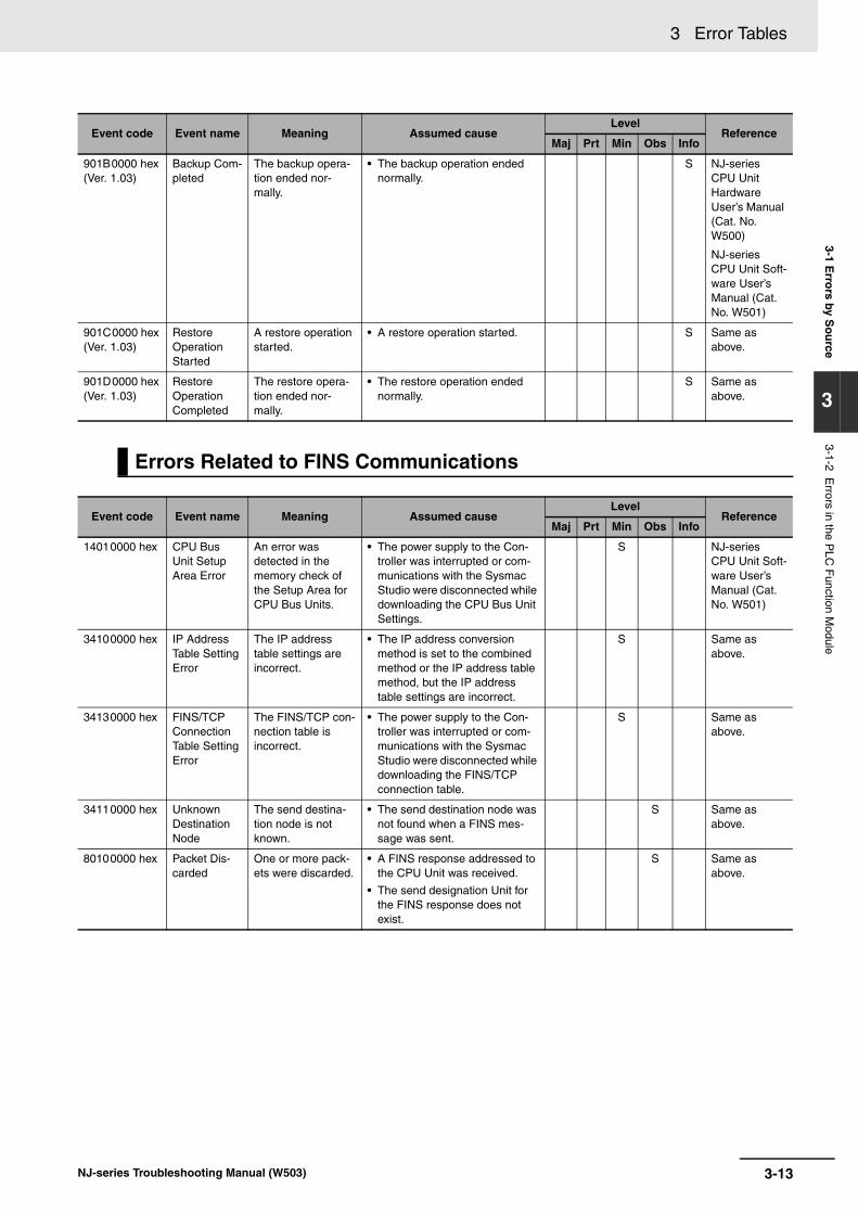
3 Error Tables3-1 E
rrors by S
ou
rce
3
3-1-2 Errors in the P
LC F
unction Module
901B0000 hex (Ver. 1.03)
Backup Com-pleted
The backup opera-tion ended nor-mally.
• The backup operation ended normally.
S NJ-series CPU Unit Hardware User’s Manual (Cat. No. W500)
NJ-series CPU Unit Soft-ware User’s Manual (Cat. No. W501)
901C0000 hex (Ver. 1.03)
Restore Operation Started
A restore operation started.
• A restore operation started. S Same as above.
901D0000 hex (Ver. 1.03)
Restore Operation Completed
The restore opera-tion ended nor-mally.
• The restore operation ended normally.
S Same as above.
Errors Related to FINS Communications
Event code Event name Meaning Assumed causeLevel
ReferenceMaj Prt Min Obs Info
14010000 hex CPU Bus Unit Setup Area Error
An error was detected in the memory check of the Setup Area for CPU Bus Units.
• The power supply to the Con-troller was interrupted or com-munications with the Sysmac Studio were disconnected while downloading the CPU Bus Unit Settings.
S NJ-series CPU Unit Soft-ware User’s Manual (Cat. No. W501)
34100000 hex IP Address Table Setting Error
The IP address table settings are incorrect.
• The IP address conversion method is set to the combined method or the IP address table method, but the IP address table settings are incorrect.
S Same as above.
34130000 hex FINS/TCP Connection Table Setting Error
The FINS/TCP con-nection table is incorrect.
• The power supply to the Con-troller was interrupted or com-munications with the Sysmac Studio were disconnected while downloading the FINS/TCP connection table.
S Same as above.
34110000 hex Unknown Destination Node
The send destina-tion node is not known.
• The send destination node was not found when a FINS mes-sage was sent.
S Same as above.
80100000 hex Packet Dis-carded
One or more pack-ets were discarded.
• A FINS response addressed to the CPU Unit was received.
• The send designation Unit for the FINS response does not exist.
S Same as above.
Event code Event name Meaning Assumed causeLevel
ReferenceMaj Prt Min Obs Info
3-13NJ-series Troubleshooting Manual (W503)

3 Error Tables
80110000 hex Packet Dis-carded
One or more pack-ets were discarded.
• An attempt was made to send a FINS response with over 2002 bytes.
• An attempt was made to route a FINS response with over 2002 bytes.
• Packet was received with a No Such Unit routing error.
• Packet was received with a Routing Error routing error.
• Packet was received with a No Routing Table routing error.
• Packet was received with an Event Area Size Over Limit routing error.
• There is insufficient space in the internal buffer.
• FINS message routing failed because the communications load is too high.
S NJ-series CPU Unit Soft-ware User’s Manual (Cat. No. W501)
Event code Event name Meaning Assumed causeLevel
ReferenceMaj Prt Min Obs Info
3-14 NJ-series Troubleshooting Manual (W503)
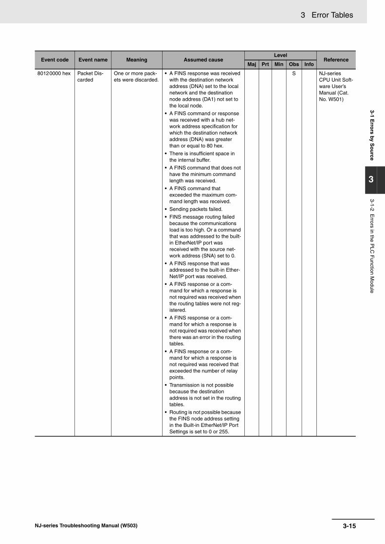
3 Error Tables3-1 E
rrors by S
ou
rce
3
3-1-2 Errors in the P
LC F
unction Module
80120000 hex Packet Dis-carded
One or more pack-ets were discarded.
• A FINS response was received with the destination network address (DNA) set to the local network and the destination node address (DA1) not set to the local node.
• A FINS command or response was received with a hub net-work address specification for which the destination network address (DNA) was greater than or equal to 80 hex.
• There is insufficient space in the internal buffer.
• A FINS command that does not have the minimum command length was received.
• A FINS command that exceeded the maximum com-mand length was received.
• Sending packets failed.
• FINS message routing failed because the communications load is too high. Or a command that was addressed to the built-in EtherNet/IP port was received with the source net-work address (SNA) set to 0.
• A FINS response that was addressed to the built-in Ether-Net/IP port was received.
• A FINS response or a com-mand for which a response is not required was received when the routing tables were not reg-istered.
• A FINS response or a com-mand for which a response is not required was received when there was an error in the routing tables.
• A FINS response or a com-mand for which a response is not required was received that exceeded the number of relay points.
• Transmission is not possible because the destination address is not set in the routing tables.
• Routing is not possible because the FINS node address setting in the Built-in EtherNet/IP Port Settings is set to 0 or 255.
S NJ-series CPU Unit Soft-ware User’s Manual (Cat. No. W501)
Event code Event name Meaning Assumed causeLevel
ReferenceMaj Prt Min Obs Info
3-15NJ-series Troubleshooting Manual (W503)

3 Error Tables
A version in parentheses in the Event code column is the unit version of the CPU Unit when the eventcode was added.
Instructions
Event code Event name Meaning Assumed causeLevel Refer-
enceMaj Prt Min Obs Info
54010400 hex Input Value Out of Range
An input parameter for an instruction exceeded the valid range for an input vari-able. Or, division by an inte-ger of 0 occurred in division or remainder calculations.
• An input parameter for an instruction exceeded the valid range for an input vari-able. Or, division by an integer of 0 occurred in division or remain-der calculations.
S NJ-series Instruc-tions Ref-erence Manual (Cat. No. W502)
54010401 hex Input Mismatch The relationship for the instruction input parame-ters did not meet required conditions. Or, a numeric value during or after instruction execution did not meet conditions.
• The relationship for an input parameter did not meet required con-ditions.
• A value when process-ing an instruction or in the result does not meet the conditions.
S Same as above.
54010402 hex Floating-point Error
Non-numeric data was input for a floating-point number input parameter to an instruction.
• Non-numeric data was input for a floating-point number input parameter to an instruction.
S Same as above.
54010403 hex BCD Error A value that was not BCD was input for a BCD input parameter to an instruction.
• A hexadecimal digit of A, B, C, D, E, or F was input for a BCD input parameter to an instruction.
S Same as above.
54010404 hex Signed BCD Error An illegal value was input for the most significant digit for a signed BCD input parameter to an instruction.
• An illegal value was input for the most sig-nificant digit for a signed BCD input parameter to an instruction.
• The most-signifi-cant digit was 2 to F when _BCD0 was specified as the BCD format.
• The most-signifi-cant digit was A, B, C, D, or E when _BCD2 was speci-fied as the BCD for-mat.
• The most-signifi-cant digit was B, C, D, or E when _BCD3 was specified as the BCD format.
S Same as above.
54010405 hex Illegal Bit Position Specified
The bit position specified for an instruction was ille-gal.
• The bit position speci-fied for an instruction exceeds the data range.
S Same as above.
3-16 NJ-series Troubleshooting Manual (W503)

3 Error Tables3-1 E
rrors by S
ou
rce
3
3-1-2 Errors in the P
LC F
unction Module
54010406 hex Illegal Data Posi-tion Specified
A memory address or data size that was specified for the instruction is not suit-able.
• A memory address that was specified for an instruction was out-side the valid range. The data size that was specified for an instruction exceeded the valid range. For example, the data type of a variable and the data size may not agree.
S NJ-series Instruc-tions Ref-erence Manual (Cat. No. W502)
54010407 hex Data Range Exceeded
The results of instruction processing exceeded the data area range of the out-put parameter.
• The results of instruc-tion processing, such as the number of array elements, exceeded the data area range of the output parameter.
S Same as above.
54010409 hex No Errors to Clear An instruction to clear a Controller error was exe-cuted when there was no error in the Controller.
• An instruction to clear a Controller error was executed when there was no error in the Controller.
S Same as above.
5401040B hex No User Errors to Clear
An instruction to clear user-defined errors was exe-cuted when there was no user-defined error.
• An instruction to clear user-defined errors was executed when there was no user-defined error.
S Same as above.
5401040C hex Limit Exceeded for User-defined Errors
An attempt was made to use the Create User-defined Error instruction to create more than the maxi-mum number of user-defined errors.
• An attempt was made to use the Create User-defined Error instruction to create more than the maxi-mum number of user-defined errors.
S Same as above.
5401040D hex Illegal Unit Speci-fied
The Unit specified for an instruction does not exist.
• A Unit that does not exist in the Unit config-uration information was specified.
• A Unit that is in the Unit configuration information was speci-fied, but the Units does not actually exist in the Controller.
S Same as above.
5401040F hex Unit Restart Failed Restarting a Special I/O Unit or CPU Bus Unit failed.
• The Special I/O Unit or CPU Bus Unit is pro-cessing data.
S Same as above.
54010410 hex Text String Format Error
The text string input to an instruction is not correct.
• The text string that is input to the instruction for conversion to a number does not rep-resent a number or it does not represent a positive number.
• The input text string does not end in NULL.
S Same as above.
54010411 hex Illegal Program Specified
The program specified for an instruction does not exist.
• The program speci-fied by the function does not exist (e.g., it was deleted).
S Same as above.
Event code Event name Meaning Assumed causeLevel Refer-
enceMaj Prt Min Obs Info
3-17NJ-series Troubleshooting Manual (W503)

3 Error Tables
54010413 hex Undefined CJ-series Memory Address
The required specification is missing for a variable for which CJ-series Unit mem-ory must be specified.
• The required AT speci-fication is missing for a variable for which CJ-series Unit memory must be specified.
S NJ-series Instruc-tions Ref-erence Manual (Cat. No. W502)
54010414 hex Stack Underflow There is no data in a stack. • An attempt was made to read data from a stack that contains no data.
S Same as above.
54010416 hex Illegal Number of Array Elements or Dimensions
The valid range was exceeded for the number of array elements or dimen-sions in an array I/O param-eter for an instruction.
• The valid range was exceeded for the num-ber of array elements or dimensions in an array I/O parameter for an instruction.
S Same as above.
54010417 hex Specified Task Does Not Exist
The task specified for the instruction does not exist.
• The specified task does not exist.
S Same as above.
54010418 hex Unallowed Task Specification
An unallowed task was specified for an instruction.
• The local task, the pri-mary periodic task, or a periodic task was specified.
S Same as above.
54010419 hex Incorrect Data Type
A data type that cannot be used for an instruction is specified for an input or in-out variable.
• A data type that can-not be used for an instruction is specified for an input or in-out variable.
S Same as above.
5401041A hex Multi-execution of Instructions
Multi-execution was speci-fied for an instruction that does not support it.
• Execution of an instruction that does not support multi-exe-cution of instructions was specified more than once.
S Same as above.
5401041B hex (Ver. 1.02)
Data Capacity Exceeded
Processing was not possi-ble because the data that was passed to the instruc-tion was too large.
• Data that exceeded the size that can be processed was passed to an instruc-tion.
S Same as above.
5401041C hex (Ver. 1.04)
Different Data Sizes
The size of the data speci-fied for instruction input or in-out data is different from the size of the target parameter.
• Data of a size that is different from the size of the target parame-ter was specified for the input or in-out data of an instruction.
S Same as above.
5401041D hex (Ver. 1.05)
Exceeded Simulta-neous Instruction Executed Resources
The maximum resources that you can use for the rel-evant instruction group at the same time was exceeded.
• More than the maxi-mum number of rele-vant instructions were executed at the same time. The maximum number of instruc-tions for the relevant instruction group is as follows:
• DB connection instructions: 32
S Same as above.
54010800 hex FINS Error An error occurred when a FINS command was sent or received.
• An error occurred when a FINS com-mand was sent or received.
S Same as above.
54010801 hex FINS Port Already in Use
The FINS port is being used.
• The FINS port is being used.
S Same as above.
Event code Event name Meaning Assumed causeLevel Refer-
enceMaj Prt Min Obs Info
3-18 NJ-series Troubleshooting Manual (W503)

3 Error Tables3-1 E
rrors by S
ou
rce
3
3-1-2 Errors in the P
LC F
unction Module
54010C00 hex Illegal Serial Com-munications Mode
The Serial Communica-tions Unit is not in the serial communications mode required to execute an instruction.
• The serial communi-cations port for the Serial Communica-tions Unit is not set to the mode expected by the instruction.
S NJ-series Instruc-tions Ref-erence Manual (Cat. No. W502)
54010C02 hex Port Setup Already Busy
A Change Port Setup instruction was executed during execution of another Change Port Setup instruc-tion.
• A Change Port Setup instruction was exe-cuted during execution of another Change Port Setup instruction.
S Same as above.
54011400 hex SD Memory Card Access Failure
SD Memory Card access failed when an instruction was executed.
• An SD Memory Card is either not inserted or is not inserted prop-erly.
• The SD Memory Card is broken.
• The SD Memory Card slot is broken.
S Same as above.
54011401 hex SD Memory Card Write-protected
An attempt was made to write to a write-protected SD Memory Card when an instruction was executed.
• An attempt was made to write to a write-pro-tected SD Memory Card.
S Same as above.
54011402 hex SD Memory Card Insufficient Capac-ity
The capacity of the SD Memory Card was insuffi-cient when writing to the SD Memory Card for an instruction.
• The SD Memory Card has run out of free space.
S Same as above.
54011403 hex File Does Not Exist The file specified for an instruction does not exist.
• The specified file does not exist.
S Same as above.
54011404 hex Too Many Files/ Directories
The maximum number of files/directories was exceeded when creating a file/directory for an instruc-tion.
• The number of files or directories exceeded the maximum number.
S Same as above.
54011405 hex File Already in Use A file specified for an instruction cannot be accessed because it is already being used.
• An instruction attempted to read or write a file already being accessed by another instruction.
S Same as above.
54011406 hex Open Mode Mis-match
A file operation for an instruction was inconsistent with the open mode of the file.
• The file open mode specified by the Open File instruction does not match the file operation attempted by a subsequent SD Memory Card instruc-tion.
S Same as above.
54011407 hex Offset Out of Range
Access to the address is not possible for the offset specified for an instruction.
• An attempt was made to access beyond the size of the file.
S Same as above.
54011408 hex Directory Not Empty
A directory was not empty when the Delete Directory instruction was executed or when an attempt was made to change the directory name.
• A directory was not empty when the Delete Directory instruction was exe-cuted.
• A directory contained another directory when an attempt was made to change the directory name.
S Same as above.
Event code Event name Meaning Assumed causeLevel Refer-
enceMaj Prt Min Obs Info
3-19NJ-series Troubleshooting Manual (W503)
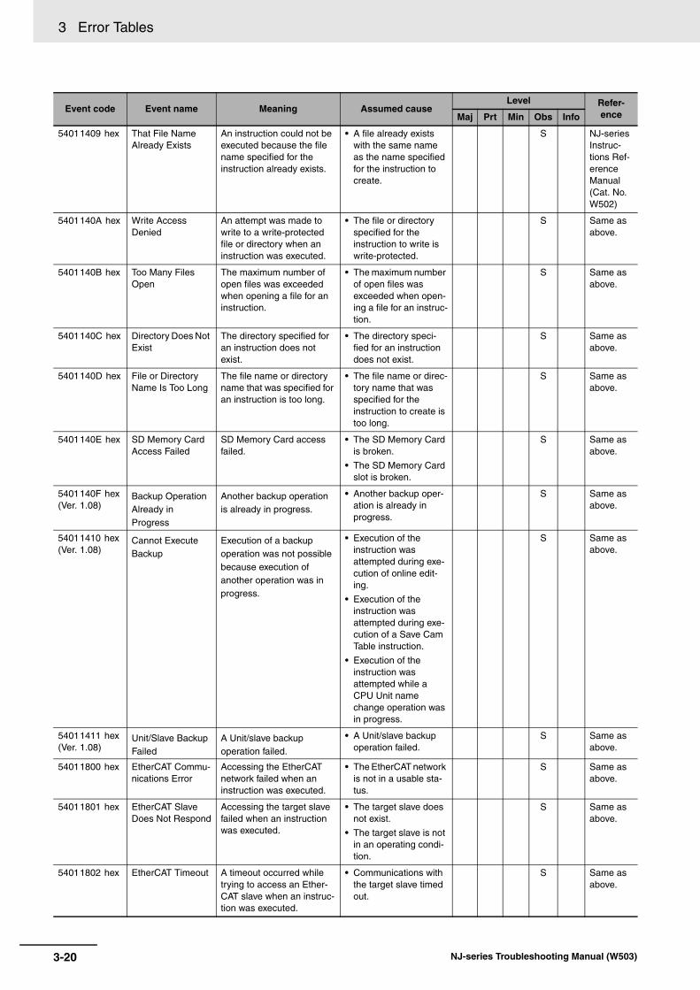
3 Error Tables
54011409 hex That File Name Already Exists
An instruction could not be executed because the file name specified for the instruction already exists.
• A file already exists with the same name as the name specified for the instruction to create.
S NJ-series Instruc-tions Ref-erence Manual (Cat. No. W502)
5401140A hex Write Access Denied
An attempt was made to write to a write-protected file or directory when an instruction was executed.
• The file or directory specified for the instruction to write is write-protected.
S Same as above.
5401140B hex Too Many Files Open
The maximum number of open files was exceeded when opening a file for an instruction.
• The maximum number of open files was exceeded when open-ing a file for an instruc-tion.
S Same as above.
5401140C hex Directory Does Not Exist
The directory specified for an instruction does not exist.
• The directory speci-fied for an instruction does not exist.
S Same as above.
5401140D hex File or Directory Name Is Too Long
The file name or directory name that was specified for an instruction is too long.
• The file name or direc-tory name that was specified for the instruction to create is too long.
S Same as above.
5401140E hex SD Memory Card Access Failed
SD Memory Card access failed.
• The SD Memory Card is broken.
• The SD Memory Card slot is broken.
S Same as above.
5401140F hex (Ver. 1.08)
Backup Operation Already in Progress
Another backup operation is already in progress.
• Another backup oper-ation is already in progress.
S Same as above.
54011410 hex (Ver. 1.08)
Cannot Execute Backup
Execution of a backup operation was not possible because execution of another operation was in progress.
• Execution of the instruction was attempted during exe-cution of online edit-ing.
• Execution of the instruction was attempted during exe-cution of a Save Cam Table instruction.
• Execution of the instruction was attempted while a CPU Unit name change operation was in progress.
S Same as above.
54011411 hex (Ver. 1.08)
Unit/Slave Backup Failed
A Unit/slave backup operation failed.
• A Unit/slave backup operation failed.
S Same as above.
54011800 hex EtherCAT Commu-nications Error
Accessing the EtherCAT network failed when an instruction was executed.
• The EtherCAT network is not in a usable sta-tus.
S Same as above.
54011801 hex EtherCAT Slave Does Not Respond
Accessing the target slave failed when an instruction was executed.
• The target slave does not exist.
• The target slave is not in an operating condi-tion.
S Same as above.
54011802 hex EtherCAT Timeout A timeout occurred while trying to access an Ether-CAT slave when an instruc-tion was executed.
• Communications with the target slave timed out.
S Same as above.
Event code Event name Meaning Assumed causeLevel Refer-
enceMaj Prt Min Obs Info
3-20 NJ-series Troubleshooting Manual (W503)
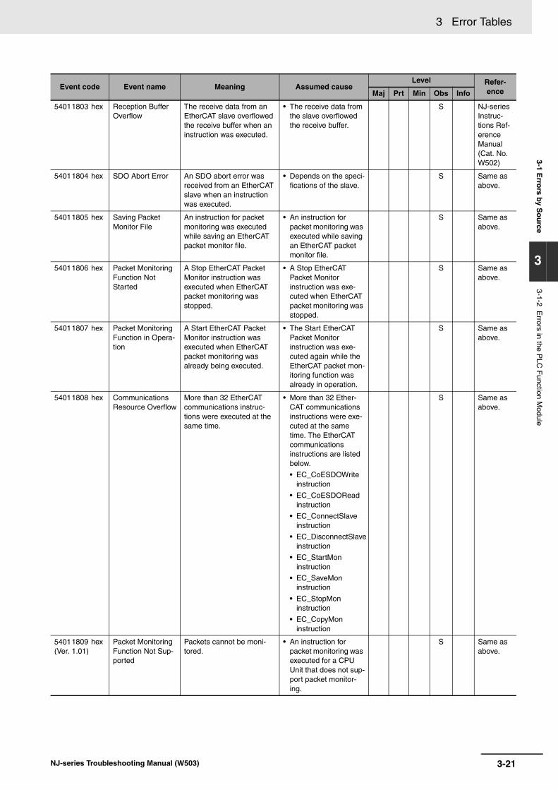
3 Error Tables3-1 E
rrors by S
ou
rce
3
3-1-2 Errors in the P
LC F
unction Module
54011803 hex Reception Buffer Overflow
The receive data from an EtherCAT slave overflowed the receive buffer when an instruction was executed.
• The receive data from the slave overflowed the receive buffer.
S NJ-series Instruc-tions Ref-erence Manual (Cat. No. W502)
54011804 hex SDO Abort Error An SDO abort error was received from an EtherCAT slave when an instruction was executed.
• Depends on the speci-fications of the slave.
S Same as above.
54011805 hex Saving Packet Monitor File
An instruction for packet monitoring was executed while saving an EtherCAT packet monitor file.
• An instruction for packet monitoring was executed while saving an EtherCAT packet monitor file.
S Same as above.
54011806 hex Packet Monitoring Function Not Started
A Stop EtherCAT Packet Monitor instruction was executed when EtherCAT packet monitoring was stopped.
• A Stop EtherCAT Packet Monitor instruction was exe-cuted when EtherCAT packet monitoring was stopped.
S Same as above.
54011807 hex Packet Monitoring Function in Opera-tion
A Start EtherCAT Packet Monitor instruction was executed when EtherCAT packet monitoring was already being executed.
• The Start EtherCAT Packet Monitor instruction was exe-cuted again while the EtherCAT packet mon-itoring function was already in operation.
S Same as above.
54011808 hex Communications Resource Overflow
More than 32 EtherCAT communications instruc-tions were executed at the same time.
• More than 32 Ether-CAT communications instructions were exe-cuted at the same time. The EtherCAT communications instructions are listed below.
• EC_CoESDOWrite instruction
• EC_CoESDORead instruction
• EC_ConnectSlave instruction
• EC_DisconnectSlave instruction
• EC_StartMon instruction
• EC_SaveMon instruction
• EC_StopMon instruction
• EC_CopyMon instruction
S Same as above.
54011809 hex (Ver. 1.01)
Packet Monitoring Function Not Sup-ported
Packets cannot be moni-tored.
• An instruction for packet monitoring was executed for a CPU Unit that does not sup-port packet monitor-ing.
S Same as above.
Event code Event name Meaning Assumed causeLevel Refer-
enceMaj Prt Min Obs Info
3-21NJ-series Troubleshooting Manual (W503)

3 Error Tables
54011C00 hex Explicit Message Error
An error response code was returned for an explicit message that was sent with a CIP communications instruction.
• Depends on the nature of the error.
S NJ-series Instruc-tions Ref-erence Manual (Cat. No. W502)
54011C01 hex Incorrect Route Path
The format of the route path that is specified for a CIP communications instruction is not correct.
• The format of the route path that is specified for a CIP communications instruction is not cor-rect.
S Same as above.
54011C02 hex CIP Handle Out of Range
The handle that is specified for the CIP communications instruction is not correct.
• The handle that is specified for the CIP communications instruction is not cor-rect.
S Same as above.
54011C03 hex CIP Communica-tions Resource Overflow
The maximum resources that you can use for CIP communications instruc-tions at the same time was exceeded.
• More than 32 CIP communications instructions were exe-cuted at the same time.
• An attempt was made to use more than 32 handles at the same time.
S Same as above.
54011C04 hex CIP Timeout A CIP timeout occurred during execution of a CIP communications instruc-tion.
• A device does not exist for the specified IP address.
• The CIP connection for the specified han-dle timed out and was closed.
• Power to the remote device is OFF.
• Communications are stopped at the remote device.
• The Ethernet cable connector for Ether-Net/IP is discon-nected.
• The Ethernet cable for EtherNet/IP is discon-nected.
• Noise
S Same as above.
54011C05 hex (Ver. 1.06)
Class-3 Connec-tion Not Estab-lished
Establishing a class-3 con-nection failed for a CIP communications instruc-tion.
• The CIPOpen instruc-tion was executed for a device that does not support class 3 (Large_Forward_Open).
• The CIPOpenWithDa-taSize instruction was executed with a speci-fied data size of 510 bytes or larger for a device that does not support class 3 (Large_Forward_Open).
S Same as above.
Event code Event name Meaning Assumed causeLevel Refer-
enceMaj Prt Min Obs Info
3-22 NJ-series Troubleshooting Manual (W503)

3 Error Tables3-1 E
rrors by S
ou
rce
3
3-1-2 Errors in the P
LC F
unction Module
54011C06 hex (Ver. 1.06)
CIP Communica-tions Data Size Exceeded
An attempt was made to send a class-3 explicit mes-sage with a data size that is larger than the sendable size with a CIP communica-tions instruction.
• The data size that was specified for the input variable to the CIPRead, CIPWrite, or CIPSend instruction exceeded the data size that was specified with the CIPOpen-WithData-Size instruc-tion.
S NJ-series Instruc-tions Ref-erence Manual (Cat. No. W502)
54012000 hex Local IP Address Setting Error
An instruction was exe-cuted when there was a setting error in the local IP address.
• An instruction was executed when there was a setting error in the local IP address.
S Same as above.
54012001 hex TCP/UDP Port Already in Use
The UDP or TCP port was already in use when the instruction was executed.
• The UDP or TCP port is already in use.
S Same as above.
54012002 hex Address Resolu-tion Failed
Address resolution failed for a remote node with the domain name that was specified in the instruction.
• The domain name specified for the instruction is not cor-rect.
• The hosts and DNS settings in the Control-ler are incorrect.
• The DNS server set-tings are incorrect.
S Same as above.
Event code Event name Meaning Assumed causeLevel Refer-
enceMaj Prt Min Obs Info
3-23NJ-series Troubleshooting Manual (W503)

3 Error Tables
54012003 hex Status Error The status was not suit-able for execution of the instruction.
• SktUDPRcv Instruc-tion
• The socket is receiv-ing data.
• The socket is not open.
• SktUDPSend Instruc-tion
• The socket is send-ing data.
• The socket is not open.
• SktTCPAccept Instruc-tionThe specified TCP port is in one of the following states.
• The port is being opened.
• The port is being closed.
• A connection is already established for this instruction for the same IP address and TCP port.
• SktTCPConnect Instruction
• The TCP port that is specified with the SrcTcpPort input variable is already open.
• The remote node that is specified with DstAdr input vari-able does not exist.
• The remote node that is specified with DstAdr and DstTcp-Port input variables is not waiting for a connection.
• SktTCPRcv Instruc-tion
• The specified socket is receiving data.
• The specified socket is not connected.
• SktTCPSend Instruc-tion
• The specified socket is sending data.
• The specified socket is not connected.
S NJ-series Instruc-tions Ref-erence Manual (Cat. No. W502)
54012004 hex Local IP Address Not Set
The local IP address was not set when a socket ser-vice instruction was exe-cuted.
• There is a BOOTP server setting error.
• The BOOTP server does not exist.
• The local IP address is not set because oper-ation just started.
S Same as above.
Event code Event name Meaning Assumed causeLevel Refer-
enceMaj Prt Min Obs Info
3-24 NJ-series Troubleshooting Manual (W503)
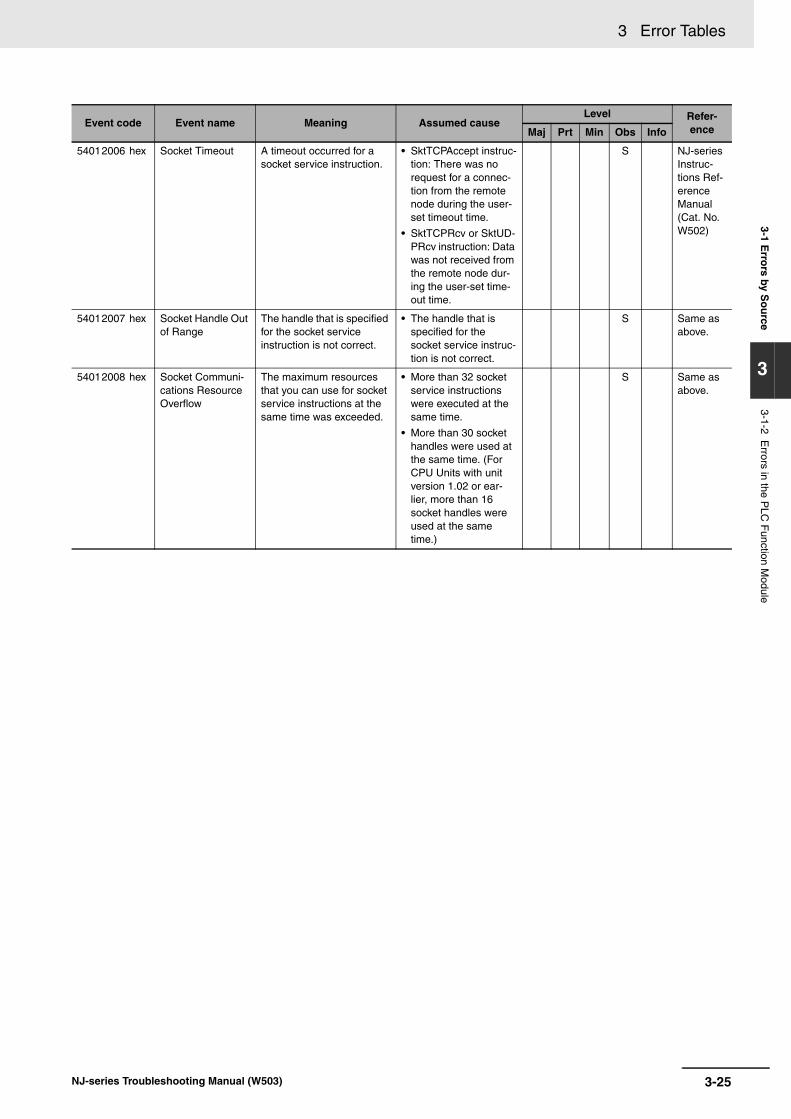
3 Error Tables3-1 E
rrors by S
ou
rce
3
3-1-2 Errors in the P
LC F
unction Module
54012006 hex Socket Timeout A timeout occurred for a socket service instruction.
• SktTCPAccept instruc-tion: There was no request for a connec-tion from the remote node during the user-set timeout time.
• SktTCPRcv or SktUD-PRcv instruction: Data was not received from the remote node dur-ing the user-set time-out time.
S NJ-series Instruc-tions Ref-erence Manual (Cat. No. W502)
54012007 hex Socket Handle Out of Range
The handle that is specified for the socket service instruction is not correct.
• The handle that is specified for the socket service instruc-tion is not correct.
S Same as above.
54012008 hex Socket Communi-cations Resource Overflow
The maximum resources that you can use for socket service instructions at the same time was exceeded.
• More than 32 socket service instructions were executed at the same time.
• More than 30 socket handles were used at the same time. (For CPU Units with unit version 1.02 or ear-lier, more than 16 socket handles were used at the same time.)
S Same as above.
Event code Event name Meaning Assumed causeLevel Refer-
enceMaj Prt Min Obs Info
3-25NJ-series Troubleshooting Manual (W503)
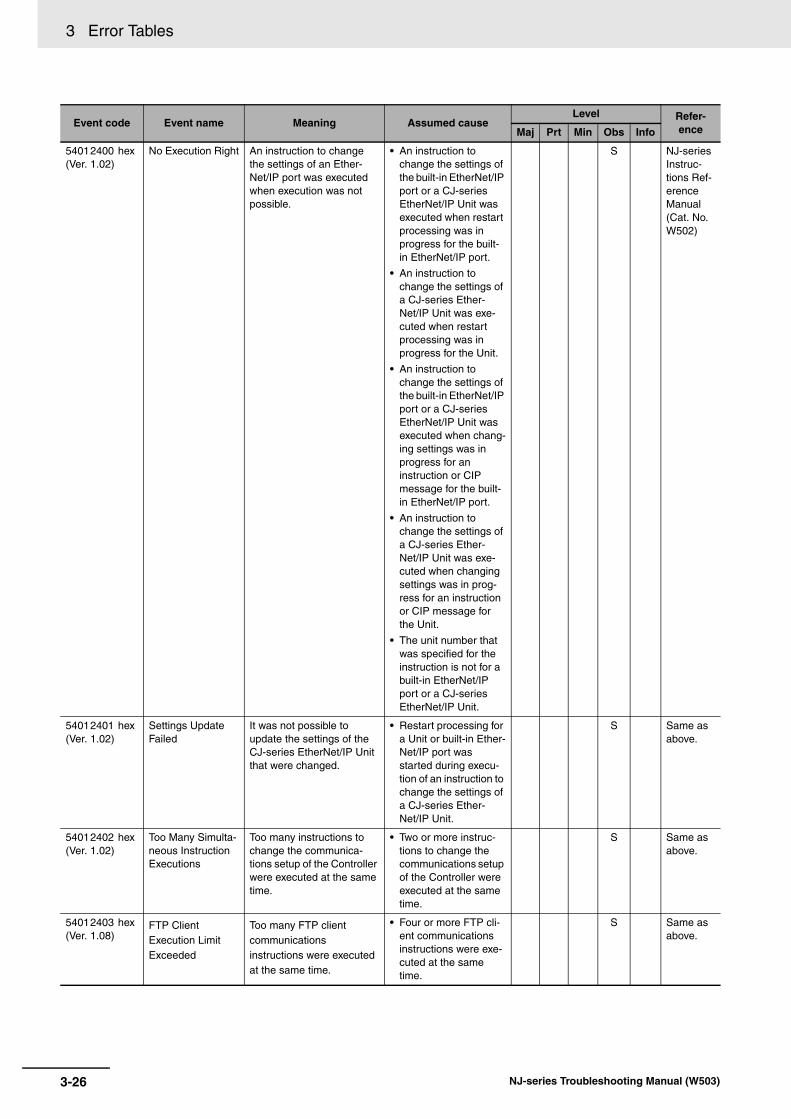
3 Error Tables
54012400 hex (Ver. 1.02)
No Execution Right An instruction to change the settings of an Ether-Net/IP port was executed when execution was not possible.
• An instruction to change the settings of the built-in EtherNet/IP port or a CJ-series EtherNet/IP Unit was executed when restart processing was in progress for the built-in EtherNet/IP port.
• An instruction to change the settings of a CJ-series Ether-Net/IP Unit was exe-cuted when restart processing was in progress for the Unit.
• An instruction to change the settings of the built-in EtherNet/IP port or a CJ-series EtherNet/IP Unit was executed when chang-ing settings was in progress for an instruction or CIP message for the built-in EtherNet/IP port.
• An instruction to change the settings of a CJ-series Ether-Net/IP Unit was exe-cuted when changing settings was in prog-ress for an instruction or CIP message for the Unit.
• The unit number that was specified for the instruction is not for a built-in EtherNet/IP port or a CJ-series EtherNet/IP Unit.
S NJ-series Instruc-tions Ref-erence Manual (Cat. No. W502)
54012401 hex (Ver. 1.02)
Settings Update Failed
It was not possible to update the settings of the CJ-series EtherNet/IP Unit that were changed.
• Restart processing for a Unit or built-in Ether-Net/IP port was started during execu-tion of an instruction to change the settings of a CJ-series Ether-Net/IP Unit.
S Same as above.
54012402 hex (Ver. 1.02)
Too Many Simulta-neous Instruction Executions
Too many instructions to change the communica-tions setup of the Controller were executed at the same time.
• Two or more instruc-tions to change the communications setup of the Controller were executed at the same time.
S Same as above.
54012403 hex (Ver. 1.08)
FTP Client Execution Limit Exceeded
Too many FTP client communications instructions were executed at the same time.
• Four or more FTP cli-ent communications instructions were exe-cuted at the same time.
S Same as above.
Event code Event name Meaning Assumed causeLevel Refer-
enceMaj Prt Min Obs Info
3-26 NJ-series Troubleshooting Manual (W503)

3 Error Tables3-1 E
rrors by S
ou
rce
3
3-1-2 Errors in the P
LC F
unction Module
54012404 hex (Ver. 1.08)
File Number Limit Exceeded
The number of files specified with a wildcard for an FTP client communications instruction exceeded 1,000.
• The number of files specified with a file name that contained a wildcard for an FTP client communica-tions instruction exceeded 1,000.
S NJ-series Instruc-tions Ref-erence Manual (Cat. No. W502)
54012405 hex (Ver. 1.08)
Directory Does Not Exist (FTP)
The directory specified for an FTP client communica-tions instruction does not exist in the Controller or an incorrect path was speci-fied.
• The directory speci-fied for an FTP client communications instruction does not exist in the Controller or an incorrect path was specified.
S Same as above.
54012406 hex (Ver. 1.08)
FTP Server Connection Error
The destination FTP server that was specified for an FTP client communications instruction does not exist on the network or the specified FTP server is not operating.
• The destination FTP server that was speci-fied for an FTP client communications instruction does not exist on the network.
• The destination FTP server that was speci-fied for an FTP client communications instruction is not oper-ating.
S Same as above.
54012407 hex (Ver. 1.08)
Destination FTP Server Execution Failure
The destination FTP server for an FTP client communications instruction returned an error.
• The destination FTP server for the FTP cli-ent communications instruction failed to execute the requested processing.
S Same as above.
54012408 hex (Ver. 1.08)
SD Memory Card Access Failed for FTP
SD Memory Card access from the FTP client failed.
• An SD Memory Card is not inserted.
• The SD Memory Card was removed during execution of the FTP client communica-tions instruction.
• The capacity of the SD Memory Card is insuf-ficient.
• The SD Memory Card is write protected.
S Same as above.
54012409 hex (Ver. 1.08)
Specified File Does Not Exist
A file specified for an FTP client communications instruction does not exist.
• A file specified for an FTP client communi-cations instruction does not exist.
S Same as above.
5401240A hex (Ver. 1.08)
Specified File Is Write Protected
The data was not transferred because the FTP client communications instruction was set to not overwrite files with the same name.
• The data was not transferred because the FTP client commu-nications instruction was set to not over-write files with the same name and a file with the specified file name already existed at the destination.
S Same as above.
Event code Event name Meaning Assumed causeLevel Refer-
enceMaj Prt Min Obs Info
3-27NJ-series Troubleshooting Manual (W503)

3 Error Tables
5401240B hex (Ver. 1.08)
Failed To Delete Specified File
A file was not deleted after it was transferred with an FTP client communications instruction.
• The FTP client com-munications instruc-tion was set to delete files after they are transferred, but it was not possible to delete the specified file because it had a read-only attribute.
• It was not possible to delete the file speci-fied for the FTP client communications instruction because it was in use by another application.
S NJ-series Instruc-tions Ref-erence Manual (Cat. No. W502)
5401240C hex (Ver. 1.08)
Specified File Access Failed
An FTP transfer for an FTP client communications instruction failed because file access failed.
• The file specified for the FTP client commu-nications instruction was in use by another application.
• The file or directory specified for the FTP client communica-tions instruction to write is write pro-tected.
S Same as above.
54012C00 hex (Ver. 1.05)
NX Message Error An error response code was returned for an NX message.
• Depends on the nature of the error.
S Same as above.
54012C01 hex (Ver. 1.05)
NX Message Resource Overflow
The maximum resources that you can use for NX message instructions at the same time was exceeded.
• More than 32 NX mes-sage instructions were executed at the same time.
S Same as above.
54012C02 hex (Ver. 1.05)
NX Message Timeout
A timeout occurred during execution of an NX mes-sage.
• The specified NX Unit does not exist.
• The NX message was closed because it timed out.
• Power to the remote Unit is OFF.
• Communications are stopped at the remote Unit.
• The communications cable connector is dis-connected.
• The communications cable is broken.
• Noise
S Same as above.
54012C03 hex (Ver. 1.05)
Incorrect NX Mes-sage Length
The length of the NX mes-sage is not correct.
• The size that is speci-fied for WriteDat or Path is too long.
S Same as above.
54012C05 hex (Ver. 1.05)
NX Message EtherCAT Network Error
An error occurred in Ether-CAT communications on the NX message path.
• An error occurred in EtherCAT communica-tions on the NX mes-sage path.
S Same as above.
54012C06 hex (Ver. 1.05)
External Restart Already Executed for Specified NX Units
A restart was already in execution from the Sysmac Studio when the instruction was executed.
• A restart was already in execution from the Sysmac Studio when the instruction was executed.
S Same as above.
Event code Event name Meaning Assumed causeLevel Refer-
enceMaj Prt Min Obs Info
3-28 NJ-series Troubleshooting Manual (W503)

3 Error Tables3-1 E
rrors by S
ou
rce
3
3-1-2 Errors in the P
LC F
unction Module
54012C07 hex (Ver. 1.05)
Unapplicable Unit Specified for Instruction
A slave that cannot be specified for the instruction was connected at the slave node address of the speci-fied Unit.
• A slave that cannot be specified for the instruction was con-nected to the slave node address of the specified Unit.
S NJ-series Instruc-tions Ref-erence Manual (Cat. No. W502)
54013461 hex Process Data Object Setting Missing
The PDO mapping is not correct.
• The PDOs that are required for the motion control instruction are not mapped.
• The relevant instruc-tion was executed for a device that does not have an object that supports the instruc-tion.
• A motion control instruction that speci-fies phase Z (_mcEncoderMark) as the trigger conditions was executed for an axis that is mapped to an OMRON GX-EC02 EtherCAT Encoder slave.
S Same as above.
54015420 hex Electronic Gear Ratio Numerator Setting Out of Range
The parameter specified for the RatioNumerator input variable to a motion control instruction is out of range.
• Instruction input parameter exceeded the valid range of the input variable.
S Same as above.
54015421 hex Electronic Gear Ratio Denomina-tor Setting Out of Range
The parameter specified for the RatioDenominator input variable to a motion control instruction is out of range.
• Instruction input parameter exceeded the valid range of the input variable.
S Same as above.
54015422 hex Target Velocity Setting Out of Range
The parameter specified for the Velocity input variable to a motion control instruc-tion is out of range.
• Instruction input parameter exceeded the valid range of the input variable.
S Same as above.
54015423 hex Acceleration Set-ting Out of Range
The parameter specified for the Acceleration input vari-able to a motion control instruction is out of range.
• Instruction input parameter exceeded the valid range of the input variable.
S Same as above.
54015424 hex Deceleration Set-ting Out of Range
The parameter specified for the Deceleration input vari-able to a motion control instruction is out of range.
• Instruction input parameter exceeded the valid range of the input variable.
S Same as above.
54015425 hex Jerk Setting Out of Range
The parameter specified for the Jerk input variable to a motion control instruction is out of range.
• Instruction input parameter exceeded the valid range of the input variable.
S Same as above.
54015427 hex Torque Ramp Set-ting Out of Range
The parameter specified for the TorqueRamp input vari-able to a motion control instruction is out of range.
• Instruction input parameter exceeded the valid range of the input variable.
S Same as above.
54015428 hex Master Coefficient Scaling Out of Range
The parameter specified for the MasterScaling input variable to a motion control instruction is out of range.
• Instruction input parameter exceeded the valid range of the input variable.
S Same as above.
Event code Event name Meaning Assumed causeLevel Refer-
enceMaj Prt Min Obs Info
3-29NJ-series Troubleshooting Manual (W503)

3 Error Tables
54015429 hex Slave Coefficient Scaling Out of Range
The parameter specified for the SlaveScaling input vari-able to a motion control instruction is out of range.
• Instruction input parameter exceeded the valid range of the input variable.
S NJ-series Instruc-tions Ref-erence Manual (Cat. No. W502)
5401542A hex Feeding Velocity Setting Out of Range
The parameter specified for the FeedVelocity input vari-able to a motion control instruction is out of range.
• The Feed Velocity (input variable Feed-Velocity) is still at the default (0).
S Same as above.
5401542B hex Buffer Mode Selec-tion Out of Range
The parameter specified for the BufferMode input vari-able to a motion control instruction is out of range.
• Instruction input parameter exceeded the valid range of the input variable.
S Same as above.
5401542C hex Coordinate System Selection Out of Range
The parameter specified for the CoordSystem input variable to a motion control instruction is out of range.
• Instruction input parameter exceeded the valid range of the input variable.
S Same as above.
5401542D hex Circular Interpola-tion Mode Selec-tion Out of Range
The parameter specified for the CircMode input variable to a motion control instruc-tion is out of range.
• Instruction input parameter exceeded the valid range of the input variable.
S Same as above.
5401542E hex Direction Selec-tion Out of Range
The parameter specified for the Direction input variable to a motion control instruc-tion is out of range.
• Instruction input parameter exceeded the valid range of the input variable.
S Same as above.
5401542F hex Path Selection Out of Range
The parameter specified for the PathChoice input vari-able to a motion control instruction is out of range.
• Instruction input parameter exceeded the valid range of the input variable.
S Same as above.
54015430 hex Position Type Selection Out of Range
The parameter specified for the ReferenceType input variable to a motion control instruction is out of range.
• Instruction input parameter exceeded the valid range of the input variable.
S Same as above.
54015431 hex Travel Mode Selec-tion Out of Range
The parameter specified for the MoveMode input vari-able to a motion control instruction is out of range.
• Instruction input parameter exceeded the valid range of the input variable.
S Same as above.
54015432 hex Transition Mode Selection Out of Range
The parameter specified for the TransitionMode input variable to a motion control instruction is out of range.
• Instruction input parameter exceeded the valid range of the input variable.
• _mcAborting or _mcBuffered was specified for Buffer-Mode and _mcTMCornerSuperimposed was speci-fied for Transition-Mode.
S Same as above.
54015433 hex Continue Method Selection Out of Range
The value of the reserved input variable Continuous to a motion control instruc-tion changed.
• The value of the reserved input vari-able Continuous changed.
S Same as above.
54015434 hex Combine Mode Selection Out of Range
The parameter specified for the CombineMode input variable to a motion control instruction is out of range.
• Instruction input parameter exceeded the valid range of the input variable.
S Same as above.
54015435 hex Synchronization Start Condition Selection Out of Range
The parameter specified for the LinkOption input vari-able to a motion control instruction is out of range.
• Instruction input parameter exceeded the valid range of the input variable.
S Same as above.
Event code Event name Meaning Assumed causeLevel Refer-
enceMaj Prt Min Obs Info
3-30 NJ-series Troubleshooting Manual (W503)

3 Error Tables3-1 E
rrors by S
ou
rce
3
3-1-2 Errors in the P
LC F
unction Module
54015436 hex Master and Slave Defined as Same Axis
The same axis is specified for the Master and Slave input variables to a motion control instruction.
• The parameter is the same for the Master and Slave input vari-ables to the instruc-tion.
S NJ-series Instruc-tions Ref-erence Manual (Cat. No. W502)
54015437 hex Master and Auxil-iary Defined as Same Axis
The same axis is specified for the Master and Auxiliary input variables to a motion control instruction.
• The parameter is the same for the Master and Auxiliary input variables to the instruction.
S Same as above.
54015438 hex Master/Slave Axis Numbers Not in Ascending Order
The axis numbers specified for the Master and Slave input variables to a motion control instruction are not in ascending order.
• The parameters for the Master and Slave input variables to the instruction were not in ascending order when _mcLatestCommand was specified for the ReferenceType input variable to the instruc-tion.
S Same as above.
54015439 hex Incorrect Cam Table Specification
The parameter specified for the CamTable input vari-able to a motion control instruction is out of range.
• Something other than a cam data variable was specified for the CamTable input vari-able to the instruction.
S Same as above.
5401543A hex Synchronization Stopped
A synchronized control motion control instruction was executed, but condi-tions required for execution were not met.
• The MC_CamOut (End Cam Operation) instruction was exe-cuted even though the MC_CamIn (Start Cam Operation) instruction is not being executed.
• The MC_GearOut (End Gear Operation) instruction was exe-cuted even though the MC_GearIn (Start Gear Operation) or the MC_GearInPos (Posi-tioning Gear Opera-tion) instruction is not being executed.
• The MC_Phasing (Shift Master Axis Phase) instruction was executed even though the MC_CamIn (Start Cam Operation), MC_GearIn (Start Gear Operation), MC_GearInPos (Start Gear Operation), or MC_MoveLink (Syn-chronous Positioning) instruction is not being executed.
S Same as above.
5401543B hex Motion Control Instruction Re-exe-cution Disabled
An attempt was made to re-execute a motion control instruction that cannot be re-executed.
• A motion control instruction that cannot be re-executed was re-executed.
S Same as above.
Event code Event name Meaning Assumed causeLevel Refer-
enceMaj Prt Min Obs Info
3-31NJ-series Troubleshooting Manual (W503)

3 Error Tables
5401543C hex Motion Control Instruction Multi-execution Disabled
Multiple functions that can-not be executed simultane-ously were executed for the same target (MC common, axis, or axes group).
• Multiple functions that cannot be executed simultaneously were executed for the same target (MC common or axis).
S NJ-series Instruc-tions Ref-erence Manual (Cat. No. W502)
5401543D hex Instruction Not Allowed for Encoder Axis Type
An operation instruction was executed for an encoder axis.
• An operation instruc-tion was executed for an encoder axis.
S Same as above.
5401543E hex Instruction Cannot Be Executed dur-ing Multi-axes Coordinated Con-trol
An operation instruction was executed for an axis or an axes group that was in a coordinated multi-axes motion.
• An operation instruc-tion was executed for an axis or an axes group that was in a coordinated multi-axes motion.
S Same as above.
5401543F hex Multi-axes Coordi-nated Control Instruction Exe-cuted for Disabled Axes Group
A multi-axes coordinated control instruction was exe-cuted for an axes group that was in the Axes Group Disabled state.
• A multi-axes coordi-nated control instruc-tion was executed for an axes group that was in the Axes Group Disabled state.
S Same as above.
54015440 hex Axes Group Can-not Be Enabled
Execution of the MC_GroupEnable (Enable Axes Group) instruction failed.
• When the MC_GroupEnable (Enable Axes Group) instruction was exe-cuted, there was a composition axis that was not stopped.
• When the MC_GroupEnable (Enable Axes Group) instruction was exe-cuted, there was a composition axis for which the MC_TouchProbe (Enable External Latch) instruction was being executed.
S Same as above.
54015441 hex Impossible Axis Operation Speci-fied when the Servo is OFF
An operation instruction was executed for an axis for which the Servo is OFF.
• An operation instruc-tion was executed for an axis for which the Servo is OFF.
• Home was preset with the MC_Home or MC_HomeWithParameter instruction for an axis for which Ether-CAT process data communications are not established.
S Same as above.
54015442 hex Composition Axis Stopped Error
A motion instruction was executed for an axes group while the MC_Stop instruc-tion was being executed for a composition axis.
• A motion instruction was executed for an axes group while the MC_Stop instruction was being executed for a composition axis.
S Same as above.
Event code Event name Meaning Assumed causeLevel Refer-
enceMaj Prt Min Obs Info
3-32 NJ-series Troubleshooting Manual (W503)

3 Error Tables3-1 E
rrors by S
ou
rce
3
3-1-2 Errors in the P
LC F
unction Module
54015443 hex Motion Control Instruction Multi-execution Buffer Limit Exceeded
The number of motion con-trol instructions that is buff-ered for Buffered or Blending Buffer Modes exceeded the buffer limit.
• An axis instruction was executed when there was already a current instruction and a buffered instruction for the same axis.
• An axes group instruc-tion was executed when there was already eight current instructions and buff-ered instructions for the same axis.
S NJ-series Instruc-tions Ref-erence Manual (Cat. No. W502)
54015444 hex Insufficient Travel Distance
The specified motion can-not be executed for the deceleration rate or accel-eration rate that was speci-fied for multi-execution or re-execution of a position-ing instruction.
• Stopping at the target position was not pos-sible for the specified acceleration/decelera-tion rate for multi-exe-cution or re-execution of a positioning instruction when the Acceleration/Deceler-ation Over parameter was set to generate a minor fault and stop.
S Same as above.
54015445 hex Insufficient Travel Distance to Achieve Blending Transit Velocity
There is not sufficient travel distance to accelerate or decelerate to the transit velocity.
• There was not suffi-cient travel distance to accelerate the current command to the tran-sit velocity when the Acceleration/Deceler-ation Over parameter was set to generate a minor fault and stop.
S Same as above.
54015446 hex Move Link Con-stant Velocity Insufficient Travel Distance
The constant-velocity travel distance of the master axis is less than zero.
• The constant velocity travel distance of the master axis is below 0 for the MC_MoveLink (Synchronous Posi-tioning) instruction.
S Same as above.
54015447 hex Positioning Gear Operation Insuffi-cient Target Veloc-ity
For the MC_GearInPos (Positioning Gear Opera-tion) instruction, the target velocity of the slave axis is too small to achieve the required velocity.
• For the MC_GearInPos (Posi-tioning Gear Opera-tion) instruction, the value of the Velocity (Target Velocity) input variable is smaller than the master axis velocity multiplied by the gear ratio when the instruction was executed.
S Same as above.
Event code Event name Meaning Assumed causeLevel Refer-
enceMaj Prt Min Obs Info
3-33NJ-series Troubleshooting Manual (W503)

3 Error Tables
54015448 hex Same Start Point and End Point for Circular Interpola-tion
The start point and end point were the same when the radius method was specified for the MC_MoveCircular2D (Cir-cular 2D Interpolation) instruction. Or, the start point, end point, and border point were the same when the border point method was specified.
• The start point and end point were the same when the radius method was specified for the MC_MoveCircular2D (Circular 2D Interpola-tion) instruction.
• The start point, end point, and border point were the same when the border point method was specified for the MC_MoveCircular2D (Circular 2D Interpola-tion) instruction.
S NJ-series Instruc-tions Ref-erence Manual (Cat. No. W502)
54015449 hex Circular Interpola-tion Center Specifi-cation Position Out of Range
The position specified for the center point exceeded the allowed range when the center method was speci-fied for the MC_MoveCircular2D (Cir-cular 2D Interpolation) instruction.
• The difference between the distance from the start point to the center point and the distance between the end point to the center point exceeded the permitted value specified for the cor-rection allowance ratio in the axes group set-tings when the center designation method was specified for the MC_MoveCircular2D (Circular 2D Interpola-tion) instruction.
S Same as above.
5401544A hex Instruction Execu-tion Error Caused by Count Mode Setting
An instruction that cannot be used when the Count Mode is set to Rotary Mode was executed for an axis that was set to Rotary Mode.
• An instruction that cannot be used when the Count Mode is set to Rotary Mode was executed for an axis that was set to Rotary Mode.
S Same as above.
5401544C hex Parameter Selec-tion Out of Range
The parameter specified for the ParameterNumber input variable to a motion control instruction is out of range.
• Instruction input parameter exceeded the valid range of the input variable.
S Same as above.
5401544D hex Stop Method Selection Out of Range
The parameter specified for the StopMode input vari-able to a motion control instruction is out of range.
• Instruction input parameter exceeded the valid range of the input variable.
S Same as above.
5401544E hex Latch ID Selection Out of Range for Trigger Input Con-dition
The parameter specified for the TriggerInput::LatchID input variable to a motion control instruction is out of range.
• Instruction input parameter exceeded the valid range of the input variable.
S Same as above.
5401544F hex Setting Out of Range for Writing MC Setting
The parameter specified for the SettingValue input vari-able to a motion control instruction is out of range.
• Instruction input parameter exceeded the valid range of the input variable.
• The parameter specifi-cation and the data type of the setting value do not agree.
S Same as above.
Event code Event name Meaning Assumed causeLevel Refer-
enceMaj Prt Min Obs Info
3-34 NJ-series Troubleshooting Manual (W503)
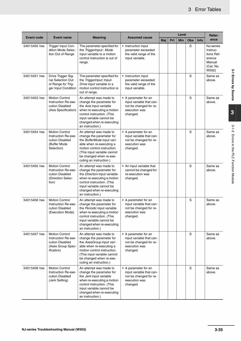
3 Error Tables3-1 E
rrors by S
ou
rce
3
3-1-2 Errors in the P
LC F
unction Module
54015450 hex Trigger Input Con-dition Mode Selec-tion Out of Range
The parameter specified for the TriggerInput:: Mode input variable to a motion control instruction is out of range.
• Instruction input parameter exceeded the valid range of the input variable.
S NJ-series Instruc-tions Ref-erence Manual (Cat. No. W502)
54015451 hex Drive Trigger Sig-nal Selection Out of Range for Trig-ger Input Condition
The parameter specified for the TriggerInput::Input-Drive input variable to a motion control instruction is out of range.
• Instruction input parameter exceeded the valid range of the input variable.
S Same as above.
54015453 hex Motion Control Instruction Re-exe-cution Disabled (Axis Specification)
An attempt was made to change the parameter for the Axis input variable when re-executing a motion control instruction. (This input variable cannot be changed when re-executing an instruction.)
• A parameter for an input variable that can-not be changed for re-execution was changed.
S Same as above.
54015454 hex Motion Control Instruction Re-exe-cution Disabled (Buffer Mode Selection)
An attempt was made to change the parameter for the BufferMode input vari-able when re-executing a motion control instruction. (This input variable cannot be changed when re-exe-cuting an instruction.)
• A parameter for an input variable that can-not be changed for re-execution was changed.
S Same as above.
54015455 hex Motion Control Instruction Re-exe-cution Disabled (Direction Selec-tion)
An attempt was made to change the parameter for the Direction input variable when re-executing a motion control instruction. (This input variable cannot be changed when re-executing an instruction.)
• An input variable that cannot be changed for re-execution was changed.
S Same as above.
54015456 hex Motion Control Instruction Re-exe-cution Disabled (Execution Mode)
An attempt was made to change the parameter for the Periodic input variable when re-executing a motion control instruction. (This input variable cannot be changed when re-executing an instruction.)
• A parameter for an input variable that can-not be changed for re-execution was changed.
S Same as above.
54015457 hex Motion Control Instruction Re-exe-cution Disabled (Axes Group Spec-ification)
An attempt was made to change the parameter for the AxesGroup input vari-able when re-executing a motion control instruction. (This input variable cannot be changed when re-exe-cuting an instruction.)
• A parameter for an input variable that can-not be changed for re-execution was changed.
S Same as above.
54015458 hex Motion Control Instruction Re-exe-cution Disabled (Jerk Setting)
An attempt was made to change the parameter for the Jerk input variable when re-executing a motion control instruction. (This input variable cannot be changed when re-executing an instruction.)
• A parameter for an input variable that can-not be changed for re-execution was changed.
S Same as above.
Event code Event name Meaning Assumed causeLevel Refer-
enceMaj Prt Min Obs Info
3-35NJ-series Troubleshooting Manual (W503)

3 Error Tables
54015459 hex Motion Control Instruction Re-exe-cution Disabled (Master Axis)
An attempt was made to change the parameter for the Master input variable when re-executing a motion control instruction. (This input variable cannot be changed when re-executing an instruction.)
• A parameter for an input variable that can-not be changed for re-execution was changed.
S NJ-series Instruc-tions Ref-erence Manual (Cat. No. W502)
5401545A hex Motion Control Instruction Re-exe-cution Disabled (MasterOffset)
An attempt was made to change the parameter for the MasterOffset input vari-able when re-executing a motion control instruction. (This input variable cannot be changed when re-exe-cuting an instruction.)
• A parameter for an input variable that can-not be changed for re-execution was changed.
S Same as above.
5401545B hex Motion Control Instruction Re-exe-cution Disabled (MasterScaling)
An attempt was made to change the parameter for the MasterScaling input variable when re-executing a motion control instruction. (This input variable cannot be changed when re-exe-cuting an instruction.)
• A parameter for an input variable that can-not be changed for re-execution was changed.
S Same as above.
5401545C hex Motion Control Instruction Re-exe-cution Disabled (MasterStartDis-tance)
An attempt was made to change the parameter for the MasterStartDistance input variable when re-exe-cuting a motion control instruction. (This input vari-able cannot be changed when re-executing an instruction.)
• A parameter for an input variable that can-not be changed for re-execution was changed.
S Same as above.
5401545D hex Motion Control Instruction Re-exe-cution Disabled (Continuous)
An attempt was made to change the parameter for the Continuous input vari-able when re-executing a motion control instruction. (This input variable cannot be changed when re-exe-cuting an instruction.)
• A parameter for an input variable that can-not be changed for re-execution was changed.
S Same as above.
5401545E hex Motion Control Instruction Re-exe-cution Disabled (MoveMode)
An attempt was made to change the parameter for the MoveMode input vari-able when re-executing a motion control instruction. (This input variable cannot be changed when re-exe-cuting an instruction.)
• A parameter for an input variable that can-not be changed for re-execution was changed.
S Same as above.
5401545F hex Illegal Auxiliary Axis Specification
The axis specified for the Auxiliary input variable to a motion control instruction does not exist.
• An axis does not exist for the variable speci-fied for the Auxiliary input variable to the instruction.
S Same as above.
54015460 hex Illegal Axis Specifi-cation
The axis specified for the Axis input variable to a motion control instruction does not exist.
• An axis does not exist for the variable speci-fied for the Axis input variable to the instruc-tion.
S Same as above.
Event code Event name Meaning Assumed causeLevel Refer-
enceMaj Prt Min Obs Info
3-36 NJ-series Troubleshooting Manual (W503)

3 Error Tables3-1 E
rrors by S
ou
rce
3
3-1-2 Errors in the P
LC F
unction Module
54015461 hex Illegal Axes Group Specification
The axes group specified for the AxesGroup input variable to a motion control instruction does not exist or is not a used group.
• An axes group does not exist for the vari-able specified for the AxesGroup input vari-able to the instruction.
• The axes group speci-fied for the AxesGroup input variable to the instruction is not spec-ified as a used group.
S NJ-series Instruc-tions Ref-erence Manual (Cat. No. W502)
54015462 hex Illegal Master Axis Specification
The axis specified for the Master input variable to a motion control instruction does not exist or is not a sync master axis.
• An axis does not exist for the variable speci-fied for the Master input variable to the instruction.
• The axis that was specified for the Mas-ter input variable to the MC_Phasing (Shift Master Axis Phase) instruction is not the master axis for sync-ing.
S Same as above.
54015463 hex Motion Control Instruction Re-exe-cution Disabled (SlaveOffset)
An attempt was made to change the SlaveOffset input variable when re-exe-cuting a motion control instruction. (This input vari-able cannot be changed when re-executing an instruction.)
• A parameter for an input variable that can-not be changed for re-execution was changed.
S Same as above.
54015464 hex Motion Control Instruction Re-exe-cution Disabled (SlaveScaling)
An attempt was made to change the SlaveScaling input variable when re-exe-cuting a motion control instruction. (This input vari-able cannot be changed when re-executing an instruction.)
• A parameter for an input variable that can-not be changed for re-execution was changed.
S Same as above.
54015465 hex Motion Control Instruction Re-exe-cution Disabled (StartPosition)
An attempt was made to change the StartPosition input variable when re-exe-cuting a motion control instruction. (This input vari-able cannot be changed when re-executing an instruction.)
• A parameter for an input variable that can-not be changed for re-execution was changed.
S Same as above.
54015466 hex Instruction Execu-tion Error with Undefined Home
High-speed homing or an interpolation instruction was executed when home was undefined.
• High-speed homing was executed when home was undefined.
• An interpolation instruction was exe-cuted for an axes group that includes an axis with no defined home.
S Same as above.
54015467 hex Motion Control Instruction Re-exe-cution Disabled (Position Type)
An attempt was made to change the ReferenceType input variable when re-exe-cuting a motion control instruction. (This input vari-able cannot be changed when re-executing an instruction.)
• A parameter for an input variable that can-not be changed for re-execution was changed.
S Same as above.
Event code Event name Meaning Assumed causeLevel Refer-
enceMaj Prt Min Obs Info
3-37NJ-series Troubleshooting Manual (W503)

3 Error Tables
54015468 hex Unused Axis Spec-ification for Master Axis
The master axis specified for a motion control instruc-tion is an unused axis.
• The master axis speci-fied for a motion con-trol instruction is an unused axis.
S NJ-series Instruc-tions Ref-erence Manual (Cat. No. W502)
54015469 hex First Position Set-ting Out of Range
The parameter specified for the FirstPosition input vari-able to a motion control instruction is out of range.
• Instruction input parameter exceeded the valid range of the input variable.
S Same as above.
5401546A hex Last Position Set-ting Out of Range
The parameter specified for the LastPosition input vari-able to a motion control instruction is out of range.
• Instruction input parameter exceeded the valid range of the input variable.
S Same as above.
5401546B hex Illegal First/Last Position Size Rela-tionship (Linear Mode)
The parameter specified for the LastPosition input vari-able to a motion control instruction is smaller than the parameter specified for the FirstPosition input vari-able.
• The value of the Last-Position input parame-ter is less than the value of the FirstPosi-tion input variable for the instruction when the Count Mode is set to Linear Mode.
S Same as above.
5401546C hex Master Sync Start Position Setting Out of Range
The parameter specified for the MasterSyncPosition input variable to a motion control instruction is out of range.
• Instruction input parameter exceeded the valid range of the input variable.
S Same as above.
5401546D hex Slave Sync Start Position Setting Out of Range
The parameter specified for the SlaveSyncPosition input variable to a motion control instruction is out of range.
• Instruction input parameter exceeded the valid range of the input variable.
S Same as above.
5401546E hex Duplicate Latch ID for Trigger Input Condition
The same latch ID was specified for more than one motion control instruction.
• The same latch ID is used simultaneously for more than one of the following instruc-tions: MC_TouchProbe (Enable External Latch) instruction, MC_MoveLink (Syn-chronous Positioning) instruction, and MC_MoveFeed (Inter-rupt Feeding) instruc-tion.
• The MC_AbortTrigger (Disable External Latch) instruction was executed to cancel a latch that was used by an instruction other than the MC_TouchProbe (Enable External Latch) instruction.
S Same as above.
5401546F hex Jerk Override Fac-tor Out of Range
The parameter specified for the JerkFactor input vari-able to a motion control instruction is out of range.
• Instruction input parameter exceeded the valid range of the input variable.
S Same as above.
Event code Event name Meaning Assumed causeLevel Refer-
enceMaj Prt Min Obs Info
3-38 NJ-series Troubleshooting Manual (W503)

3 Error Tables3-1 E
rrors by S
ou
rce
3
3-1-2 Errors in the P
LC F
unction Module
54015470 hex Accelera-tion/Deceleration Override Factor Out of Range
The parameter specified for the AccFactor input vari-able to a motion control instruction is out of range.
• Instruction input parameter exceeded the valid range of the input variable.
S NJ-series Instruc-tions Ref-erence Manual (Cat. No. W502)
54015471 hex First Position Method Specifica-tion Out of Range
The parameter specified for the StartMode input vari-able to a motion control instruction is out of range.
• Instruction input parameter exceeded the valid range of the input variable.
S Same as above.
54015472 hex Motion Control Instruction Re-exe-cution Disabled (First Position Method)
An attempt was made to change the StartMode input variable when re-exe-cuting a motion control instruction. (This input vari-able cannot be changed when re-executing an instruction.)
• A parameter for an input variable that can-not be changed for re-execution was changed.
S Same as above.
54015474 hex Unused Axis Spec-ification for Auxil-iary Axis
The axis specified for the Auxiliary input variable to a motion control instruction is an unused axis.
• The axis specified for the Auxiliary input variable to the instruc-tion is an unused axis.
S Same as above.
54015475 hex Position Gear Value Error
Synchronized motion is not possible for the velocity, acceleration rate, and deceleration rate that were input to a motion control instruction.
• The specified synchro-nized motion cannot be performed at the velocity, acceleration rate, or deceleration rate that is input to the instruction.
S Same as above.
54015476 hex Position Gear Mas-ter Axis Zero Velocity
The velocity of the master axis was zero when a motion control instruction was started.
• The velocity of the master axis was 0 when the instruction was started.
S Same as above.
54015478 hex Target Position Setting Out of Range
The parameter specified for the Position input variable to a motion control instruc-tion is out of range.
• Instruction input parameter exceeded the valid range of the input variable.
• The target position of a Rotary Mode axis is not within the ring set-ting range.
S Same as above.
54015479 hex Travel Distance Out of Range
The parameter that was specified for the Distance input variable to a motion control instruction is out of range or the target position with the value of Distance added is out of range.
• The absolute value of the instruction input parameter exceeded the range of 40-bit data when it is con-verted to pulses.
• For a Linear Mode axis, the target posi-tion with the travel dis-tance added exceeded signed 40-bit data when the absolute value is con-verted to pulses.
S Same as above.
5401547A hex Cam Table Start Point Setting Out of Range
The parameter specified for the StartPosition input vari-able to a motion control instruction is out of range.
• Instruction input parameter exceeded the valid range of the input variable.
S Same as above.
Event code Event name Meaning Assumed causeLevel Refer-
enceMaj Prt Min Obs Info
3-39NJ-series Troubleshooting Manual (W503)

3 Error Tables
5401547B hex Cam Master Axis Following First Position Setting Out of Range
The parameter specified for the MasterStartDistance input variable to a motion control instruction is out of range.
• Instruction input parameter exceeded the valid range of the input variable.
S NJ-series Instruc-tions Ref-erence Manual (Cat. No. W502)
5401547C hex Circular Interpola-tion Radius Set-ting Error
It was not possible to cre-ate a circular path for the specified radius when the radius method was speci-fied for the MC_MoveCircular2D (Cir-cular 2D Interpolation) instruction.
• For the MC_MoveCircular2D (Circular 2D Interpola-tion) instruction, it was not possible to create a circular path for the specified radius when the radius method was specified for circular interpolation.
S Same as above.
5401547D hex Circular Interpola-tion Radius Over-flow
For the MC_MoveCircular2D (Cir-cular 2D Interpolation) instruction, the radius of the circle exceeded the maxi-mum value for the border point or center specification method.
• For the MC_MoveCircular2D (Circular 2D Interpola-tion) instruction, the radius of the circle exceeded 40-bit data when converted to pulses for the border point or center specifi-cation method.
S Same as above.
5401547E hex Circular Interpola-tion Setting Out of Range
The parameter specified for the CircAxes input variable to a motion control instruc-tion is out of range.
• Instruction input parameter exceeded the valid range of the input variable.
• The axes that were specified in CircAxes are not included in the composition axes in the Axes Group Set-tings.
• The same axis was specified for both axes of CircAxes.
S Same as above.
5401547F hex Auxiliary/Slave Axis Numbers Not in Ascending Order
The values of the parame-ters for the Auxiliary and Slave input variables to a motion control instruction are not in ascending order.
• The parameters for the Auxiliary and Slave input variables to the instruction are not in ascending order.
S Same as above.
54015480 hex Cam Table Prop-erty Ascending Data Error at Update
A phase that was not in ascending order was found during calculating the num-ber of valid data. Or, after calculations, the number of valid data is 0.
• A phase that was not in ascending order was found when cal-culating the number of valid data.
• After calculations, the number of valid data is 0.
S Same as above.
54015481 hex MC_Write Target Out of Range
The parameter specified for the Target input variable to a motion control instruction is out of range.
• Instruction input parameter exceeded the valid range of the input variable.
S Same as above.
54015482 hex Master Travel Dis-tance Specifica-tion Out of Range
The parameter specified for the MasterDistance input variable to a motion control instruction is out of range.
• Instruction input parameter exceeded the valid range of the input variable.
S Same as above.
Event code Event name Meaning Assumed causeLevel Refer-
enceMaj Prt Min Obs Info
3-40 NJ-series Troubleshooting Manual (W503)
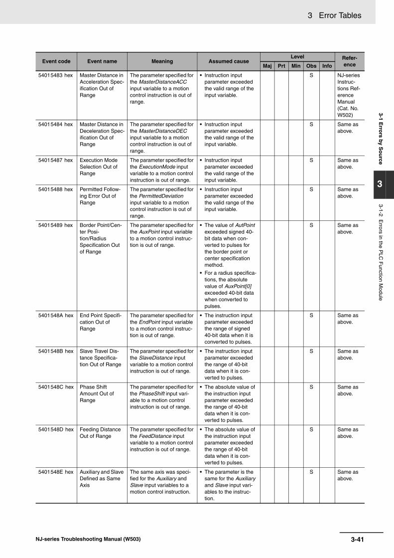
3 Error Tables3-1 E
rrors by S
ou
rce
3
3-1-2 Errors in the P
LC F
unction Module
54015483 hex Master Distance in Acceleration Spec-ification Out of Range
The parameter specified for the MasterDistanceACC input variable to a motion control instruction is out of range.
• Instruction input parameter exceeded the valid range of the input variable.
S NJ-series Instruc-tions Ref-erence Manual (Cat. No. W502)
54015484 hex Master Distance in Deceleration Spec-ification Out of Range
The parameter specified for the MasterDistanceDEC input variable to a motion control instruction is out of range.
• Instruction input parameter exceeded the valid range of the input variable.
S Same as above.
54015487 hex Execution Mode Selection Out of Range
The parameter specified for the ExecutionMode input variable to a motion control instruction is out of range.
• Instruction input parameter exceeded the valid range of the input variable.
S Same as above.
54015488 hex Permitted Follow-ing Error Out of Range
The parameter specified for the PermittedDeviation input variable to a motion control instruction is out of range.
• Instruction input parameter exceeded the valid range of the input variable.
S Same as above.
54015489 hex Border Point/Cen-ter Posi-tion/Radius Specification Out of Range
The parameter specified for the AuxPoint input variable to a motion control instruc-tion is out of range.
• The value of AutPoint exceeded signed 40-bit data when con-verted to pulses for the border point or center specification method.
• For a radius specifica-tions, the absolute value of AuxPoint[0] exceeded 40-bit data when converted to pulses.
S Same as above.
5401548A hex End Point Specifi-cation Out of Range
The parameter specified for the EndPoint input variable to a motion control instruc-tion is out of range.
• The instruction input parameter exceeded the range of signed 40-bit data when it is converted to pulses.
S Same as above.
5401548B hex Slave Travel Dis-tance Specifica-tion Out of Range
The parameter specified for the SlaveDistance input variable to a motion control instruction is out of range.
• The instruction input parameter exceeded the range of 40-bit data when it is con-verted to pulses.
S Same as above.
5401548C hex Phase Shift Amount Out of Range
The parameter specified for the PhaseShift input vari-able to a motion control instruction is out of range.
• The absolute value of the instruction input parameter exceeded the range of 40-bit data when it is con-verted to pulses.
S Same as above.
5401548D hex Feeding Distance Out of Range
The parameter specified for the FeedDistance input variable to a motion control instruction is out of range.
• The absolute value of the instruction input parameter exceeded the range of 40-bit data when it is con-verted to pulses.
S Same as above.
5401548E hex Auxiliary and Slave Defined as Same Axis
The same axis was speci-fied for the Auxiliary and Slave input variables to a motion control instruction.
• The parameter is the same for the Auxiliary and Slave input vari-ables to the instruc-tion.
S Same as above.
Event code Event name Meaning Assumed causeLevel Refer-
enceMaj Prt Min Obs Info
3-41NJ-series Troubleshooting Manual (W503)

3 Error Tables
5401548F hex Relative Position Selection Out of Range
The parameter specified for the Relative input variable to a motion control instruc-tion is out of range.
• Instruction input parameter exceeded the valid range of the input variable.
S NJ-series Instruc-tions Ref-erence Manual (Cat. No. W502)
54015490 hex Cam Transition Specification Out of Range
The parameter specified for the CamTransition input variable to a motion control instruction is out of range.
• Instruction input parameter exceeded the valid range of the input variable.
S Same as above.
54015491 hex Synchronized Con-trol End Mode Selection Out of Range
The parameter specified for the OutMode input variable to a motion control instruc-tion is out of range.
• Instruction input parameter exceeded the valid range of the input variable.
S Same as above.
54015492 hex Enable External Latch Instruction Execution Dis-abled
_mcImmediateStop was specified for the StopMode input variable when the MC_TouchProbe (Enable External Latch) instruction was executed in Drive Mode, but the Control Mode was not CSP Mode.
• _mcImmediateStop was specified for the StopMode input vari-able when the MC_TouchProbe (Enable External Latch) instruction was executed in Drive Mode, but the Control Mode was not CSP Mode or the Servo was OFF.
S Same as above.
54015493 hex Master Axis Offset Out of Range
The parameter specified for the MasterOffset input vari-able to a motion control instruction is out of range.
• The instruction input parameter exceeded the range of signed 40-bit data when it is converted to pulses.
S Same as above.
54015494 hex Slave Axis Offset Out of Range
The parameter specified for the SlaveOffset input vari-able to a motion control instruction is out of range.
• The instruction input parameter exceeded the range of signed 40-bit data when it is converted to pulses.
S Same as above.
54015495 hex Command Current Position Count Selection Out of Range
The parameter specified for the CmdPosMode input variable to a motion control instruction is out of range.
• Instruction input parameter exceeded the valid range of the input variable.
S Same as above.
54015496 hex Master Axis Gear Ratio Numerator Out of Range
The parameter specified for the RatioNumeratorMaster input variable to a motion control instruction is out of range.
• Instruction input parameter exceeded the valid range of the input variable.
S Same as above.
54015497 hex Master Axis Gear Ratio Denomina-tor Out of Range
The parameter specified for the RatioDenominatorMas-ter input variable to a motion control instruction is out of range.
• Instruction input parameter exceeded the valid range of the input variable.
S Same as above.
54015498 hex Auxiliary Axis Gear Ratio Numerator Out of Range
The parameter specified for the RatioNumeratorAuxil-iary input variable to a motion control instruction is out of range.
• Instruction input parameter exceeded the valid range of the input variable.
S Same as above.
54015499 hex Auxiliary Axis Gear Ratio Denomina-tor Out of Range
The parameter specified for the RatioDenominatorAuxil-iary input variable to a motion control instruction is out of range.
• Instruction input parameter exceeded the valid range of the input variable.
S Same as above.
Event code Event name Meaning Assumed causeLevel Refer-
enceMaj Prt Min Obs Info
3-42 NJ-series Troubleshooting Manual (W503)

3 Error Tables3-1 E
rrors by S
ou
rce
3
3-1-2 Errors in the P
LC F
unction Module
5401549A hex Master Axis Posi-tion Type Selec-tion Out of Range
The parameter specified for the ReferenceTypeMaster input variable to a motion control instruction is out of range.
• Instruction input parameter exceeded the valid range of the input variable.
S NJ-series Instruc-tions Ref-erence Manual (Cat. No. W502)
5401549B hex Auxiliary Axis Posi-tion Type Selec-tion Out of Range
The parameter specified for the ReferenceTypeAuxil-iary input variable to a motion control instruction is out of range.
• Instruction input parameter exceeded the valid range of the input variable.
S Same as above.
5401549C hex Target Position Ring Counter Out of Range
Operation is not possible because the target position is out of range for the ring counter of the executed instruction.
• High-speed homing was executed when 0 was not included in the ring counter.
S Same as above.
5401549D hex (Ver. 1.01)
Axes Group Com-position Axis Set-ting Out of Range
The parameter specified for the Axes input variable to a motion control instruction is out of range.
• Instruction input parameter exceeded the valid range of the input variable.
S Same as above.
5401549E hex (Ver. 1.04)
Axis Use Setting Out of Range
The parameter specified for the AxisUse input variable to a motion control instruc-tion is out of range.
• Instruction input parameter exceeded the valid range of the input variable.
S Same as above.
54015700 hex (Ver. 1.03)
Homing Parame-ter Setting Out of Range
The parameter specified for the HomingParameter input variable to a motion control instruction is out of range.
• Instruction input parameter exceeded the valid range of the input variable.
S Same as above.
54015702 hex (Ver. 1.04)
Axis Use Change Error
The MC_ChangeAxisUse (Change Axis Use) instruc-tion was executed when the axis was not stopped or when the command veloc-ity of the axis was satu-rated.
• The MC_ChangeAxisUse (Change Axis Use) instruction was exe-cuted when the axis was not stopped or when the command velocity of the axis was saturated.
S Same as above.
54015703 hex (Ver. 1.06)
Cannot Change Axis Use
The MC_ChangeAxisUse (Change Axis Use) instruc-tion was executed in a way that would cause the maxi-mum number of used real axes to be exceeded.
• The MC_ChangeAxisUse (Change Axis Use) instruction was exe-cuted in a way that would cause the maxi-mum number of used real axes to be exceeded.
S Same as above.
Event code Event name Meaning Assumed causeLevel Refer-
enceMaj Prt Min Obs Info
3-43NJ-series Troubleshooting Manual (W503)
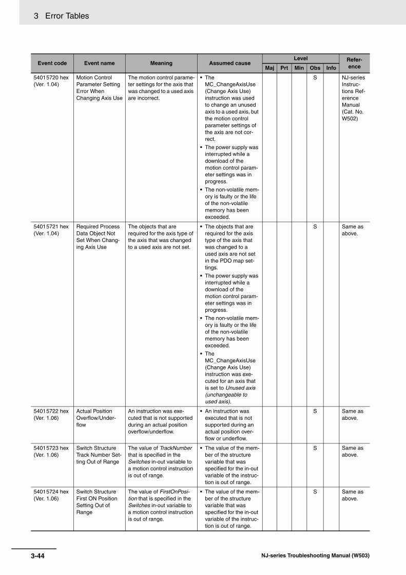
3 Error Tables
54015720 hex (Ver. 1.04)
Motion Control Parameter Setting Error When Changing Axis Use
The motion control parame-ter settings for the axis that was changed to a used axis are incorrect.
• The MC_ChangeAxisUse (Change Axis Use) instruction was used to change an unused axis to a used axis, but the motion control parameter settings of the axis are not cor-rect.
• The power supply was interrupted while a download of the motion control param-eter settings was in progress.
• The non-volatile mem-ory is faulty or the life of the non-volatile memory has been exceeded.
S NJ-series Instruc-tions Ref-erence Manual (Cat. No. W502)
54015721 hex (Ver. 1.04)
Required Process Data Object Not Set When Chang-ing Axis Use
The objects that are required for the axis type of the axis that was changed to a used axis are not set.
• The objects that are required for the axis type of the axis that was changed to a used axis are not set in the PDO map set-tings.
• The power supply was interrupted while a download of the motion control param-eter settings was in progress.
• The non-volatile mem-ory is faulty or the life of the non-volatile memory has been exceeded.
• The MC_ChangeAxisUse (Change Axis Use) instruction was exe-cuted for an axis that is set to Unused axis (unchangeable to used axis).
S Same as above.
54015722 hex (Ver. 1.06)
Actual Position Overflow/Under-flow
An instruction was exe-cuted that is not supported during an actual position overflow/underflow.
• An instruction was executed that is not supported during an actual position over-flow or underflow.
S Same as above.
54015723 hex (Ver. 1.06)
Switch Structure Track Number Set-ting Out of Range
The value of TrackNumber that is specified in the Switches in-out variable to a motion control instruction is out of range.
• The value of the mem-ber of the structure variable that was specified for the in-out variable of the instruc-tion is out of range.
S Same as above.
54015724 hex (Ver. 1.06)
Switch Structure First ON Position Setting Out of Range
The value of FirstOnPosi-tion that is specified in the Switches in-out variable to a motion control instruction is out of range.
• The value of the mem-ber of the structure variable that was specified for the in-out variable of the instruc-tion is out of range.
S Same as above.
Event code Event name Meaning Assumed causeLevel Refer-
enceMaj Prt Min Obs Info
3-44 NJ-series Troubleshooting Manual (W503)

3 Error Tables3-1 E
rrors by S
ou
rce
3
3-1-2 Errors in the P
LC F
unction Module
54015725 hex (Ver. 1.06)
Switch Structure Last ON Position Setting Out of Range
The value of LastOnPosi-tion that is specified in the Switches in-out variable to a motion control instruction is out of range.
• The value of the mem-ber of the structure variable that was specified for the in-out variable of the instruc-tion is out of range.
S NJ-series Instruc-tions Ref-erence Manual (Cat. No. W502)
54015726 hex (Ver. 1.06)
Switch Structure Axis Direction Out of Range
The value of AxisDirection that is specified in the Switches in-out variable to a motion control instruction is out of range.
• The value of the mem-ber of the structure variable that was specified for the in-out variable of the instruc-tion is out of range.
S Same as above.
54015727 hex (Ver. 1.06)
Switch Structure Cam Switch Mode Out of Range
The value of CamSwitch-Mode that is specified in the Switches in-out variable to a motion control instruc-tion is out of range.
• The value of the mem-ber of the structure variable that was specified for the in-out variable of the instruc-tion is out of range.
S Same as above.
54015728 hex (Ver. 1.06)
Switch Structure Duration Setting Out of Range
The value of Duration that is specified in the Switches in-out variable to a motion control instruction is out of range.
• The value of the mem-ber of the structure variable that was specified for the in-out variable of the instruc-tion is out of range.
S Same as above.
54015729 hex (Ver. 1.06)
Track Option Struc-ture ON Compen-sation Setting Out of Range
The value of OnCompensa-tion that is specified in the TrackOptions in-out vari-able to a motion control instruction is out of range.
• The value of the mem-ber of the structure variable that was specified for the in-out variable of the instruc-tion is out of range.
S Same as above.
5401572A hex (Ver. 1.06)
Track Option Struc-ture OFF Compen-sation Setting Out of Range
The value of OffCompensa-tion that is specified in the TrackOptions in-out vari-able to a motion control instruction is out of range.
• The value of the mem-ber of the structure variable that was specified for the in-out variable of the instruc-tion is out of range.
S Same as above.
5401572B hex (Ver. 1.06)
Number of Array Elements in Switch Structure Variable Out of Range
The number of elements in an array in the structure variable that is specified in the Switches in-out variable to a motion control instruc-tion is out of range.
• The number of ele-ments in an array of the structure variable that was specified for the in-out variable of the instruction is out of range.
S Same as above.
5401572C hex (Ver. 1.06)
Number of Array Elements in Output Signal Structure Variable Out of Range
The number of elements in an array in the structure variable that is specified in the Outputs in-out variable to a motion control instruc-tion is out of range.
• The number of ele-ments in an array of the structure variable that was specified for the in-out variable of the instruction is out of range.
S Same as above.
5401572D hex (Ver. 1.06)
Number of Array Elements in Track Option Structure Variable Out of Range
The number of elements in an array in the structure variable that is specified in the TrackOptions in-out variable to a motion control instruction is out of range.
• The number of ele-ments in an array of the structure variable that was specified for the in-out variable of the instruction is out of range.
S Same as above.
Event code Event name Meaning Assumed causeLevel Refer-
enceMaj Prt Min Obs Info
3-45NJ-series Troubleshooting Manual (W503)

3 Error Tables
5401572E hex (Ver. 1.06)
Numbers of Ele-ments in Output Signals and Track Option Arrays Not Matched
The arrays in the structure variables that are specified for the Outputs and Track-Options in-out variables to a motion control instruction do not have the same num-ber of elements.
• The arrays in the out-put signal structure variable and track option structure vari-able that are specified for the in-out variables to the instruction do not have the same number of elements.
S NJ-series Instruc-tions Ref-erence Manual (Cat. No. W502)
5401572F hex (Ver. 1.06)
Motion Control Instruction Multi-execution Dis-abled (Master Axis)
A Master in-out variable that cannot be changed during multi-execution of instructions was changed.
• A Master in-out vari-able that cannot be changed during multi-execution of instruc-tions was changed.
S Same as above.
54015730 hex (Ver. 1.06)
Motion Control Instruction Multi-execution Dis-abled (Position Type Selection)
A ReferenceType in-out variable that cannot be changed during multi-exe-cution of instructions was changed.
• A ReferenceType in-out variable that can-not be changed during multi-execution of instructions was changed.
S Same as above.
54015731 hex (Ver. 1.06)
Same Track Num-ber Setting in Switch Structure Out of Range
The same track number was specified more than the allowable number of times for the TrackNumber in the Switches in-out vari-able to a motion control instruction.
• The same track num-ber was specified more than the allow-able number of times for the TrackNumber in the Switches in-out variable to a motion control instruction.
S Same as above.
5401573A hex (Ver. 1.08)
Cannot Write Axis Parameters
The instruction was exe-cuted for an axis that is not an unused axis.
• The instruction was executed for a used axis or an undefined axis.
S Same as above.
5401573B hex (Ver. 1.08)
Axis Parameter Setting Out of Range
The parameter specified for the AxisParameter input variable to a motion control instruction is outside of the valid range.
• The parameter speci-fied for the AxisParam-eter input variable to the instruction is out of range for the input variable.
S Same as above.
5401573C hex (Ver. 1.08)
Cam Property Set-ting Out of Range
The parameter specified for the CamProperty input vari-able to a motion control instruction is outside of the valid range.
• The parameter speci-fied for the CamProp-erty input variable to the instruction is out of range for the input variable.
S Same as above.
5401573D hex (Ver. 1.08)
Cam Node Setting Out of Range
The parameter specified for the CamNodes input vari-able to a motion control instruction is outside of the valid range.
• The parameter speci-fied for the CamNodes input variable to the instruction is out of range for the input variable.
S Same as above.
5401573E hex (Ver. 1.08)
Incorrect Cam Node Type Specifi-cation
The parameter specified for the CamNodes input vari-able to a motion control instruction is not an _sMC_CAM_NODE array variable.
• The parameter speci-fied for the CamNodes input variable to the instruction is not an _sMC_CAM_NODE array variable.
S Same as above.
5401573F hex (Ver. 1.08)
Insufficient Nodes in Cam Table
The array variable of the parameter specified for the CamNodes input variable to a motion control instruction has a Phase value of 0 for element number 0.
• The array variable of the parameter speci-fied for the CamNodes input variable to the instruction has a Phase (master axis phase) value of 0 for element number 0.
S Same as above.
Event code Event name Meaning Assumed causeLevel Refer-
enceMaj Prt Min Obs Info
3-46 NJ-series Troubleshooting Manual (W503)

3 Error Tables3-1 E
rrors by S
ou
rce
3
3-1-2 Errors in the P
LC F
unction Module
54015740 hex (Ver. 1.08)
Cam Node Master Axis Phase Not in Ascending Order
The values of Phase in the array variable of the param-eter specified for the Cam-Nodes input variable to a motion control instruction are not in ascending order according to the element numbers.
• The values of Phase (master axis phase) in the array variable of the parameter speci-fied for the CamNodes input variable to the instruction are not in ascending order according to the ele-ment numbers. Or, truncating the digits that are not effective more than seven digits caused the phases to not be in ascending order.
S NJ-series Instruc-tions Ref-erence Manual (Cat. No. W502)
54015741 hex (Ver. 1.08)
Too Many Data Points in Cam Table
The number of generated cam data points exceeded the number of elements in the array in the cam data variable that is specified for the CamTable input variable to a motion control instruction.
The number of cam data points in the generated cam table exceeded the number of elements in the array in the cam data variable that is specified for the CamTable input variable to the instruction.
S Same as above.
54015742 hex (Ver. 1.08)
Cam Table Displacement Overflow
Distance in the generated cam table exceeded the range of REAL data.
• Distance in the gener-ated cam table exceeded the range of REAL data.
S Same as above.
54015743 hex (Ver. 1.08)
Aborted Cam Table Used
A cam data variable that was aborted during generation was specified for the CamTable input variable to an instruction.
• A cam data variable that was aborted dur-ing generation due to an error in the MC_GenerateCamTable (Generate Cam Table) instruction was specified for the Cam-Table input variable to the instruction.
S Same as above.
54016440 hex Target Position Positive Software Limit Exceeded
The specified position exceeds the positive soft-ware limit.
• The parameter speci-fied for the Position input variable to the instruction is beyond the positive software limit.
• The first position is beyond the positive software limit and an instruction that speci-fies motion in the opposite direction of the software limit was executed.
• The parameter that was specified for the AuxPoint input vari-able to a border point MC_MoveCircular2D (Circular 2D Interpola-tion) instruction is beyond the positive software limit.
S Same as above.
Event code Event name Meaning Assumed causeLevel Refer-
enceMaj Prt Min Obs Info
3-47NJ-series Troubleshooting Manual (W503)

3 Error Tables
54016441 hex Target Position Negative Software Limit Exceeded
The specified position exceeds the negative soft-ware limit.
• The parameter speci-fied for the Position input variable to the instruction is beyond the negative software limit.
• The first position is beyond the negative software limit and an instruction that speci-fies motion in the opposite direction of the software limit was executed.
• The parameter that was specified for the AuxPoint input vari-able to a border point MC_MoveCircular2D (Circular 2D Interpola-tion) instruction is beyond the negative software limit.
S NJ-series Instruc-tions Ref-erence Manual (Cat. No. W502)
54016442 hex Command Posi-tion Over-flow/Underflow
Positioning, an instruction in the underflow/overflow direction, or an instruction for which the direction is not specified was executed when there was an under-flow/overflow in the com-mand position.
• One of the following was executed when there was a command position over-flow/underflow.
• A positioning instruction
• A continuous con-trol instruction in the underflow/overflow direction
• An instruction for which the direction is not specified (syncing or torque control)
S Same as above.
Event code Event name Meaning Assumed causeLevel Refer-
enceMaj Prt Min Obs Info
3-48 NJ-series Troubleshooting Manual (W503)

3 Error Tables3-1 E
rrors by S
ou
rce
3
3-1-2 Errors in the P
LC F
unction Module
54016443 hex Positive Limit Input An instruction was exe-cuted for a motion in the positive direction when the positive limit input was ON.
• An instruction for a motion in the positive direction was exe-cuted when the posi-tive limit input was ON, or an instruction for a motion with no direction specification was executed when the positive limit input was ON. An axes group motion control instruction was exe-cuted when the posi-tive limit input was ON.
S NJ-series Instruc-tions Ref-erence Manual (Cat. No. W502)
54016444 hex Negative Limit Input
An instruction for a motion in the negative direction was executed when the negative limit input was ON.
• An instruction for a motion in the negative direction was exe-cuted when the nega-tive limit input was ON, or an instruction for a motion with no direction specification was executed when the negative limit input was ON. An axes group motion control instruction was exe-cuted when the nega-tive limit input was ON.
S Same as above.
54017422 hex Servo Main Cir-cuits OFF
An attempt was made to turn ON the Servo when the main circuit power sup-ply to the Servo Drive was OFF.
• An attempt was made to turn ON the Servo when the main circuit power supply to the Servo Drive was OFF.
S Same as above.
Event code Event name Meaning Assumed causeLevel Refer-
enceMaj Prt Min Obs Info
3-49NJ-series Troubleshooting Manual (W503)

3 Error Tables
The section provides tables of the errors (events) that can occur in the Motion Control Function Module.They are divided into the following functional classifications.
• General motion control
• Motion control instructions
Motion control instruction errors occur when a motion control instruction is executed. Notification ofthese errors is provided as events, but also the upper four digits of the event code is output to theErrorID output variable of the motion control instruction and to the *.Lvl.Code system-defined variablefor motion control.
3-1-3 Errors in the Motion Control Function Module
General Motion Control
Event code Event name Meaning Assumed causeLevel
ReferenceMaj Prt Min Obs Info
14600000 hex Absolute Encoder Home Offset Read Error
The absolute encoder current position that is retained during power interruptions was lost.
• The life of the Battery in the CPU Unit has expired.
• Backup memory failure
S NJ-series CPU Unit Motion Con-trol User’s Manual (Cat. No. W507)
14610000 hex Motion Con-trol Parame-ter Setting Error
The MC parameters that were saved in non-volatile mem-ory are missing.
• The power supply to the Con-troller was interrupted or com-munications with the Sysmac Studio were disconnected while downloading the motion control parameter settings or clearing memory.
• Non-volatile memory failure
S Same as above.
14620000 hex Cam Data Read Error
The cam data that was saved in non-volatile memory is missing.
• Power was interrupted during save processing for cam data
• Non-volatile memory failure
S Same as above.
34600000 hex Required Process Data Object Not Set
The object that is required for the axis type is not allocated to PDO.
• The required PDOs are not mapped when the axis type is set to a servo axis or encoder axis.
• Non-volatile memory failure
S Same as above.
34630000 hex Axis Slave Disabled
The slave to which the axis is assigned is disabled.
• The slave to which the axis is assigned is disabled.
S Same as above.
34640000 hex Network Configura-tion Informa-tion Missing for Axis Slave
The network config-uration information is not registered for the slave to which the axis is assigned.
• The EtherCAT network configu-ration information is not regis-tered for the slave to which the axis is assigned.
S Same as above.
44200000 hex Motion Con-trol Initializa-tion Error
A fatal error occurred in the sys-tem and prevented initialization of the Motion Control Function Module.
• Hardware has failed. S Same as above.
74200000 hex Motion Con-trol Period Exceeded
Processing for the primary periodic task was not fin-ished within two control periods.
• The processing load in the pri-mary periodic task is too heavy.
S Same as above.
14630000 hex Cam Table Save Error
Saving a cam table to a file failed.
• Saving a cam table to a file failed.
S Same as above.
3-50 NJ-series Troubleshooting Manual (W503)
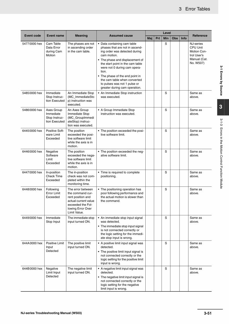
3 Error Tables3-1 E
rrors by S
ou
rce
3
3-1-3 Errors in the M
otion Control F
unction Module
54770000 hex Cam Table Data Error during Cam Motion
The phases are not in ascending order in the cam table.
• Data containing cam table phases that are not in ascend-ing order was detected during cam motion.
• The phase and displacement of the start point in the cam table were not 0 during cam opera-tion.
• The phase of the end point in the cam table when converted to pulses was not 1 pulse or greater during cam operation.
S NJ-series CPU Unit Motion Con-trol User’s Manual (Cat. No. W507)
54850000 hex Immediate Stop Instruc-tion Executed
An Immediate Stop (MC_ImmediateStop) instruction was executed.
• An Immediate Stop instruction was executed.
S Same as above.
54860000 hex Axes Group Immediate Stop Instruc-tion Executed
An Axes Group Immediate Stop (MC_GroupImmediateStop) instruc-tion was executed.
• A Group Immediate Stop instruction was executed.
S Same as above.
64450000 hex Positive Soft-ware Limit Exceeded
The position exceeded the posi-tive software limit while the axis is in motion.
• The position exceeded the posi-tive software limit.
S Same as above.
64460000 hex Negative Software Limit Exceeded
The position exceeded the nega-tive software limit while the axis is in motion.
• The position exceeded the neg-ative software limit.
S Same as above.
64470000 hex In-position Check Time Exceeded
The in-position check was not com-pleted within the monitoring time.
• Time is required to complete positioning.
S Same as above.
64480000 hex Following Error Limit Exceeded
The error between the command cur-rent position and actual current value exceeded the Fol-lowing Error Over Limit Value.
• The positioning operation has poor following performance and the actual motion is slower than the command.
S Same as above.
64490000 hex Immediate Stop Input
The immediate stop input turned ON.
• An immediate stop input signal was detected.
• The immediate stop input signal is not connected correctly or the logic setting for the immedi-ate stop input is wrong.
S Same as above.
644A0000 hex Positive Limit Input Detected
The positive limit input turned ON.
• A positive limit input signal was detected.
• The positive limit input signal is not connected correctly or the logic setting for the positive limit input is wrong.
S Same as above.
644B0000 hex Negative Limit Input Detected
The negative limit input turned ON.
• A negative limit input signal was detected.
• The negative limit input signal is not connected correctly or the logic setting for the negative limit input is wrong.
S Same as above.
Event code Event name Meaning Assumed causeLevel
ReferenceMaj Prt Min Obs Info
3-51NJ-series Troubleshooting Manual (W503)

3 Error Tables
64560000 hex Illegal Follow-ing Error
The difference between the com-mand position and the actual current position exceeds the range of 30-bit data when con-verted to pulses.
• The command current position was restricted so that the axis velocity of the slave axis would not exceed the axis maximum velocity for the specified travel distance.
• Performance of slave axis posi-tioning operation is poor and the actual motion is slower than the command.
S NJ-series CPU Unit Motion Con-trol User’s Manual (Cat. No. W507)
64570000 hex Servo OFF Error
The Servo was turned OFF for an axis due to an axes group error.
• The Servo was turned OFF for an axis due to an axes group error.
S Same as above.
64580000 hex Absolute Encoder Cur-rent Position Calculation Failed
It was not possible to correctly restore the current position from the absolute encoder information that was saved when power was interrupted.
• The ring counter setting in the Controller or the ring counter setting in the Servo Drive set-tings was changed.
• The position to restore when converted to pulses exceeded the range of signed 40-bit data.
S Same as above.
64590000 hex Home Unde-fined during Coordinated Motion
Home of the logical axis became unde-fined during axes group motion or while decelerating to a stop.
• The command position or actual position overflowed or underflowed for a logical axis in an axes group motion or a logi-cal axis that was decelerating to a stop and the home definition was lost.
• A slave communications error occurred for a logical axis and home became undefined during axes group motion or while decelerating to a stop.
• A slave for a logical axis left the network or was disabled and home became undefined during axes group motion or while decelerating to a stop.
S Same as above.
74210000 hex Servo Main Circuit Power OFF
The main circuit power of the Servo Drive turned OFF while the Servo was ON.
• The main circuit power of the Servo Drive was interrupted while the Servo was ON.
S Same as above.
74230000 hex Interrupt Feeding Interrupt Sig-nal Missing
An interrupt input was not received during execution of an MC_MoveFeed (Interrupt Feeding) instruction.
• The latch enabled range speci-fication is invalid.
• There is a problem with the wir-ing of the interrupt signal.
• The sensor that outputs the interrupt signal has failed.
S Same as above.
74240000 hex Homing Opposite Direction Limit Input Detected
The limit signal in the direction oppo-site to the homing direction was detected during a homing operation.
• The Operation Selection at Negative Limit Input or Opera-tion Selection at Positive Limit Input parameter is set to No reverse turn.
• The location of the homing input signal sensors, homing settings, and homing start posi-tion cause a limit input to be reached.
• The input signal sensor wiring is incorrect or the sensor is faulty.
S Same as above.
Event code Event name Meaning Assumed causeLevel
ReferenceMaj Prt Min Obs Info
3-52 NJ-series Troubleshooting Manual (W503)

3 Error Tables3-1 E
rrors by S
ou
rce
3
3-1-3 Errors in the M
otion Control F
unction Module
74250000 hex Homing Direction Limit Input Detected
The limit signal in the homing direc-tion was detected during a homing operation.
• The Operation Selection at Negative Limit Input or Opera-tion Selection at Positive Limit Input parameter is set to No reverse turn.
• The location of the homing input signal sensors, homing settings, and homing start posi-tion cause a limit input to be reached.
• The input signal sensor wiring is incorrect or the sensor is faulty.
S NJ-series CPU Unit Motion Con-trol User’s Manual (Cat. No. W507)
74260000 hex Homing Limit Inputs Detected in Both Direc-tions
The limit signals in both directions were detected dur-ing a homing opera-tion.
• The wiring of the limit signal is incorrect.
• The limit sensor is installed in the wrong location.
• The contact logic of the limit signal is not correct.
• The limit sensor failed.
S Same as above.
74270000 hex Home Prox-imity/Homing Opposite Direction Limit Input Detected
The home proxim-ity input and the limit signal in the direction opposite to the homing direc-tion were detected during a homing operation.
• The wiring of the home proxim-ity signal or limit signal is incor-rect.
• The home proximity sensor or limit sensor is installed in the wrong location.
• The contact logic of the home proximity signal or limit signal is not correct.
• The home proximity sensor or limit sensor failed.
S Same as above.
74280000 hex Home Prox-imity/Homing Direction Limit Input Detected
The home proxim-ity input and the limit signal in the homing direction were detected at the same time dur-ing a homing opera-tion.
• The wiring of the home proxim-ity signal or limit signal is incor-rect.
• The home proximity sensor or limit sensor is installed in the wrong location.
• The contact logic of the home proximity signal or limit signal is not correct.
• The home proximity sensor or limit sensor failed.
S Same as above.
74290000 hex Home Input/Hom-ing Opposite Direction Limit Input Detected
The home input and the limit signal in the direction oppo-site to the homing direction were detected at the same time during a homing operation.
• The wiring of the home input signal or limit signal is incorrect.
• The home input sensor or limit sensor is installed in the wrong location.
• The contact logic of the home input signal or limit signal is not correct.
• The home input signal output device or limit sensor failed.
S Same as above.
742A0000 hex Home Input/Hom-ing Direction Limit Input Detected
The home input and the limit signal in the homing direc-tion were detected at the same time during a homing operation.
• The wiring of the home input signal or limit signal is incorrect.
• The home input sensor or limit sensor is installed in the wrong location.
• The contact logic of the home input signal or limit signal is not correct.
• The home input signal output device or limit sensor failed.
S Same as above.
Event code Event name Meaning Assumed causeLevel
ReferenceMaj Prt Min Obs Info
3-53NJ-series Troubleshooting Manual (W503)

3 Error Tables
742B0000 hex Invalid Home Input Mask Distance
The setting of the home input mask distance is not suit-able for the MC_Home or MC_HomeWithParameter instruction.
• The set value of the home input mask distance when the oper-ating mode of the MC_Home instruction is set to Proximity Reverse Turn/Home Input Mask Distance is insufficient to decel-erate from the homing velocity to the homing approach veloc-ity.
S NJ-series CPU Unit Motion Con-trol User’s Manual (Cat. No. W507)
742C0000 hex No Home Input
There was no home signal input during the homing opera-tion. Or, a limit sig-nal was detected before there was a home input.
• There was no home signal input during the homing operation.
• A limit signal was detected before there was a home input.
S Same as above.
742D0000 hex No Home Proximity Input
There was no home proximity signal input during the homing operation.
• There was no home proximity signal input during the homing operation when a home proxim-ity input signal was specified.
S Same as above.
742F0000 hex Slave Error Detected
An error was detected for the EtherCAT slave or NX Unit that is allo-cated to an axis.
• An error was detected for the EtherCAT slave or NX Unit that is allocated to an axis.
S Same as above.
74300000 hex Axes Group Composition Axis Error
An error occurred for an axis in an axes group.
• An error occurred for an axis in an axes group that was in motion.
S Same as above.
74330000 hex MC Com-mon Error Occurrence
An MC common error occurred.
• Partial fault level MC common error occurred.
S Same as above.
74340000 hex Latch Posi-tion Overflow
An overflow occurred for the latched position for the MC_TouchProbe (Enable External Latch) instruction.
• An overflow occurred for the latched position for the MC_TouchProbe (Enable Exter-nal Latch) instruction.
S Same as above.
74350000 hex Latch Posi-tion Under-flow
An underflow occurred for the latched position for the MC_TouchProbe (Enable External Latch) instruction.
• An underflow occurred for the latched position for the MC_TouchProbe (Enable Exter-nal Latch) instruction.
S Same as above.
74360000 hex Master Sync Direction Error
The master axis continued to move in the direction opposite to the sync direction.
• The master axis continued to move in the direction opposite to the sync direction of the mas-ter and slave axes, resulting in an overflow.
S Same as above.
74370000 hex Slave Dis-connection during Servo ON
An EtherCAT slave or NX Unit that is allocated to an axis was disconnected, replaced, or dis-abled while the Servo was ON.
• An EtherCAT slave or NX Unit that is allocated to an axis was disconnected, replaced, or dis-abled while the Servo was ON.
S Same as above.
Event code Event name Meaning Assumed causeLevel
ReferenceMaj Prt Min Obs Info
3-54 NJ-series Troubleshooting Manual (W503)

3 Error Tables3-1 E
rrors by S
ou
rce
3
3-1-3 Errors in the M
otion Control F
unction Module
74380000 hex Feed Dis-tance Over-flow
The target position after the interrupt input was received for the MC_MoveFeed (Interrupt Feeding) instruction over-flowed or under-flowed.
• The target position after the interrupt input was received for the MC_MoveFeed (Interrupt Feeding) instruction exceeded the range of signed 40-bit data when converted to pulses.
S NJ-series CPU Unit Motion Con-trol User’s Manual (Cat. No. W507)
74390000 hex Error in Changing Servo Drive Control Mode
Changing the Con-trol Mode was not completed within the specified time.
• When the MC_SyncMoveVelocity instruc-tion was stopped, the actual current velocity was not reduced to 10% or less of the maximum velocity within 10 seconds for three consecutive periods after a command veloc-ity of 0 was output.
• For an OMRON G5-series Servo Drive, the actual current velocity was not reduced to 10% or less of the maximum velocity within 10 seconds for three consecutive periods when the MC_TorqueControl instruc-tion was stopped.
• Changing the Control Mode of the Servo Drive between CSP, CSV, and CST was not com-pleted within one second after the command was executed.
S Same as above.
743A0000 hex Master Axis Position Read Error
The synchronized instruction was not executed because an error occurred in the position of the master axis of the synchronized instruction.
• EtherCAT process data com-munications are not established for the master axis of the syn-chronized instruction or the I/O data of the NX Unit cannot be used for control.
• The slave of the master axis for the synchronized instruction was disconnected or disabled.
• An Absolute Encoder Current Position Calculation Failed error (6458000 hex) was detected for the master axis of a synchro-nized instruction.
• The master axis for the syn-chronized instruction is an unused axis.
S Same as above.
743B0000 hex Auxiliary Axis Position Read Error
The synchronized instruction was not executed because an error occurred in the position of the auxiliary axis of the synchronized instruction.
• EtherCAT process data com-munications are not established for the auxiliary axis of the syn-chronized instruction or the I/O data of the NX Unit cannot be used for control.
• The slave of the auxiliary axis for the synchronized instruction was disconnected or disabled.
• An Absolute Encoder Current Position Calculation Failed error (6458000 hex) was detected for the auxiliary axis of a synchro-nized instruction.
• The auxiliary axis for the syn-chronized instruction is an unused axis.
S Same as above.
Event code Event name Meaning Assumed causeLevel
ReferenceMaj Prt Min Obs Info
3-55NJ-series Troubleshooting Manual (W503)

3 Error Tables
84400000 hex EtherCAT Slave Com-munications Error
A communications error occurred for the EtherCAT slave or NX Unit that is allocated to an axis.
• A communications error occurred for the EtherCAT slave or NX Unit that is allocated to an axis.
S NJ-series CPU Unit Motion Con-trol User’s Manual (Cat. No. W507)
571D0000 hex (Ver. 1.02)
Too Many Reset Motion Control Error Instructions
There are more than 100 instances of the ResetMCEr-ror (Reset Motion Control Error) instruction.
• There are more than 100 instances of the ResetMCError (Reset Motion Control Error) instruction declared in the user program. Instances inside func-tion blocks are included.
S Same as above.
644C0000 hex Following Error Warn-ing
The following error exceeded the Fol-lowing Error Warn-ing Value.
• Performance of positioning operation is poor and the actual motion is slower than the com-mand.
S Same as above.
644D0000 hex Velocity Warning
The command velocity exceeded the velocity warn-ing value.
• The command velocity exceeded the velocity warning value.
U S Same as above.
644E0000 hex Acceleration Warning
The command acceleration exceeded the acceleration warn-ing value.
• The command acceleration rate exceeded the acceleration warning value.
U S Same as above.
644F0000 hex Deceleration Warning
The command deceleration exceeded the deceleration warn-ing value.
• The command deceleration rate exceeded the deceleration warning value.
U S Same as above.
64500000 hex Positive Torque Warn-ing
The torque com-mand value exceeded the posi-tive torque warning value.
• The torque command value exceeded the positive torque warning value.
U S Same as above.
64510000 hex Negative Torque Warn-ing
The torque com-mand value exceeded the nega-tive torque warning value.
• The torque command value exceeded the negative torque warning value.
U S Same as above.
64520000 hex Command Position Overflow
The number of pulses for the com-mand position over-flowed.
• In Linear Mode, the command position when converted to pulses exceeded the upper limit of signed 40-bit data.
U S Same as above.
64530000 hex Command Position Underflow
The number of pulses for the com-mand position exceeded the valid range. (It under-flowed.)
• In Linear Mode, the command position when converted to pulses exceeded the lower limit of signed 40-bit data.
U S Same as above.
64540000 hex Actual Posi-tion Overflow
The number of pulses for the actual position overflowed.
• The actual position when con-verted to pulses exceeded the upper limit of signed 40-bit data.
U S Same as above.
64550000 hex Actual Posi-tion Under-flow
The number of pulses for the actual position under-flowed.
• The actual position when con-verted to pulses exceeded the lower limit of signed 40-bit data.
U S Same as above.
74320000 hex Slave Obser-vation Detected
A warning was detected for an EtherCAT slave or NX Unit.
• A warning was detected for the EtherCAT slave or NX Unit that is allocated to an axis.
U S Same as above.
Event code Event name Meaning Assumed causeLevel
ReferenceMaj Prt Min Obs Info
3-56 NJ-series Troubleshooting Manual (W503)

3 Error Tables3-1 E
rrors by S
ou
rce
3
3-1-3 Errors in the M
otion Control F
unction Module
743C0000 hex Cannot Exe-cute Save Cam Table Instruction
You cannot save a cam table to a file when non-volatile memory is being accessed by another operation.
• An attempt was made to exe-cute the MC_SaveCamTable instruction when another opera-tion was accessing the non-vol-atile memory (e.g., transfer or data trace operation from the Sysmac Studio).
S NJ-series CPU Unit Motion Con-trol User’s Manual (Cat. No. W507)
94200000 hex Notice of Insufficient Travel Dis-tance to Achieve Blending Transit Veloc-ity
There is not suffi-cient travel distance to accelerate or decelerate to the transit velocity dur-ing blending opera-tion.
• When the Acceleration/Decel-eration Over parameter was set to Use rapid acceleration/decel-eration (Blending is changed to Buffered), the results of profile creation caused the accelera-tion/deceleration rate to be exceeded when blending was specified, so buffered was used.
• Blending was specified, but the target position was already reached, so it was changed to Buffered because the profile could not be created.
• Blending was specified for an interpolation instruction, but based on the results of profile creation, this was changed to Buffered because the execution time of the instruction before the transition was less than four control periods.
U S Same as above.
94210000 hex Error Clear from MC Test Run Tab Page
An error was cleared from the MC Test Run Pane of the Sysmac Stu-dio.
• An error was cleared from the MC Test Run Pane of the Sys-mac Studio.
S Same as above.
94220000 hex Slave Error Code Report
The error code was reported by the slave when a Slave Error Detected error occurred.
• The error code was reported by the slave when a Slave Error Detected error (742F0000 hex) occurred.
S Same as above.
Event code Event name Meaning Assumed causeLevel
ReferenceMaj Prt Min Obs Info
3-57NJ-series Troubleshooting Manual (W503)

3 Error Tables
Motion Control Instructions
Event code Event name Meaning Assumed causeLevel
ReferenceMaj Prt Min Obs Info
34610000 hex Process Data Object Set-ting Missing
The PDO mapping is not correct.
• The PDOs that are required for the motion control instruction are not mapped.
• The relevant instruction was executed for a device that does not have an object that sup-ports the instruction.
• A motion control instruction that specifies phase Z (_mcEncoderMark) as the trig-ger conditions was executed for an axis that is mapped to an OMRON GX-EC02 Ether-CAT Encoder slave.
S NJ-series Motion Con-trol Instruc-tions Reference Manual (Cat. No. W508)
54200000 hex Electronic Gear Ratio Numerator Setting Out of Range
The parameter specified for the RatioNumerator input variable to a motion control instruction is out of range.
• Instruction input parameter exceeded the valid range of the input variable.
S Same as above.
54210000 hex Electronic Gear Ratio Denominator Setting Out of Range
The parameter specified for the RatioDenominator input variable to a motion control instruction is out of range.
• Instruction input parameter exceeded the valid range of the input variable.
S Same as above.
54220000 hex Target Veloc-ity Setting Out of Range
The parameter specified for the Velocity input vari-able to a motion control instruction is out of range.
• Instruction input parameter exceeded the valid range of the input variable.
S Same as above.
54230000 hex Acceleration Setting Out of Range
The parameter specified for the Acceleration input variable to a motion control instruction is out of range.
• Instruction input parameter exceeded the valid range of the input variable.
S Same as above.
54240000 hex Deceleration Setting Out of Range
The parameter specified for the Deceleration input variable to a motion control instruction is out of range.
• Instruction input parameter exceeded the valid range of the input variable.
S Same as above.
54250000 hex Jerk Setting Out of Range
The parameter specified for the Jerk input variable to a motion control instruction is out of range.
• Instruction input parameter exceeded the valid range of the input variable.
S Same as above.
54270000 hex Torque Ramp Setting Out of Range
The parameter specified for the TorqueRamp input variable to a motion control instruction is out of range.
• Instruction input parameter exceeded the valid range of the input variable.
S Same as above.
3-58 NJ-series Troubleshooting Manual (W503)

3 Error Tables3-1 E
rrors by S
ou
rce
3
3-1-3 Errors in the M
otion Control F
unction Module
54280000 hex Master Coef-ficient Scal-ing Out of Range
The parameter specified for the MasterScaling input variable to a motion control instruction is out of range.
• Instruction input parameter exceeded the valid range of the input variable.
S NJ-series Motion Con-trol Instruc-tions Reference Manual (Cat. No. W508)
54290000 hex Slave Coeffi-cient Scaling Out of Range
The parameter specified for the SlaveScaling input variable to a motion control instruction is out of range.
• Instruction input parameter exceeded the valid range of the input variable.
S Same as above.
542A0000 hex Feeding Velocity Set-ting Out of Range
The parameter specified for the FeedVelocity input variable to a motion control instruction is out of range.
• The Feed Velocity (input vari-able FeedVelocity) is still at the default (0).
S Same as above.
542B0000 hex Buffer Mode Selection Out of Range
The parameter specified for the BufferMode input variable to a motion control instruction is out of range.
• Instruction input parameter exceeded the valid range of the input variable.
S Same as above.
542C0000 hex Coordinate System Selection Out of Range
The parameter specified for the CoordSystem input variable to a motion control instruction is out of range.
• Instruction input parameter exceeded the valid range of the input variable.
S Same as above.
542D0000 hex Circular Inter-polation Mode Selec-tion Out of Range
The parameter specified for the Cir-cMode input vari-able to a motion control instruction is out of range.
• Instruction input parameter exceeded the valid range of the input variable.
S Same as above.
542E0000 hex Direction Selection Out of Range
The parameter specified for the Direction input vari-able to a motion control instruction is out of range.
• Instruction input parameter exceeded the valid range of the input variable.
S Same as above.
542F0000 hex Path Selec-tion Out of Range
The parameter specified for the PathChoice input variable to a motion control instruction is out of range.
• Instruction input parameter exceeded the valid range of the input variable.
S Same as above.
54300000 hex Position Type Selection Out of Range
The parameter specified for the ReferenceType input variable to a motion control instruction is out of range.
• Instruction input parameter exceeded the valid range of the input variable.
S Same as above.
54310000 hex Travel Mode Selection Out of Range
The parameter specified for the MoveMode input variable to a motion control instruction is out of range.
• Instruction input parameter exceeded the valid range of the input variable.
S Same as above.
Event code Event name Meaning Assumed causeLevel
ReferenceMaj Prt Min Obs Info
3-59NJ-series Troubleshooting Manual (W503)
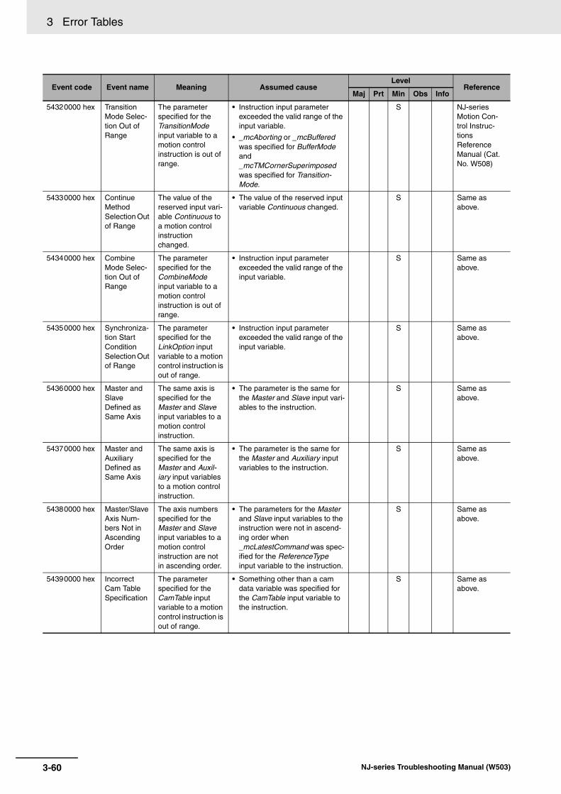
3 Error Tables
54320000 hex Transition Mode Selec-tion Out of Range
The parameter specified for the TransitionMode input variable to a motion control instruction is out of range.
• Instruction input parameter exceeded the valid range of the input variable.
• _mcAborting or _mcBuffered was specified for BufferMode and _mcTMCornerSuperimposed was specified for Transition-Mode.
S NJ-series Motion Con-trol Instruc-tions Reference Manual (Cat. No. W508)
54330000 hex Continue Method Selection Out of Range
The value of the reserved input vari-able Continuous to a motion control instruction changed.
• The value of the reserved input variable Continuous changed.
S Same as above.
54340000 hex Combine Mode Selec-tion Out of Range
The parameter specified for the CombineMode input variable to a motion control instruction is out of range.
• Instruction input parameter exceeded the valid range of the input variable.
S Same as above.
54350000 hex Synchroniza-tion Start Condition Selection Out of Range
The parameter specified for the LinkOption input variable to a motion control instruction is out of range.
• Instruction input parameter exceeded the valid range of the input variable.
S Same as above.
54360000 hex Master and Slave Defined as Same Axis
The same axis is specified for the Master and Slave input variables to a motion control instruction.
• The parameter is the same for the Master and Slave input vari-ables to the instruction.
S Same as above.
54370000 hex Master and Auxiliary Defined as Same Axis
The same axis is specified for the Master and Auxil-iary input variables to a motion control instruction.
• The parameter is the same for the Master and Auxiliary input variables to the instruction.
S Same as above.
54380000 hex Master/Slave Axis Num-bers Not in Ascending Order
The axis numbers specified for the Master and Slave input variables to a motion control instruction are not in ascending order.
• The parameters for the Master and Slave input variables to the instruction were not in ascend-ing order when _mcLatestCommand was spec-ified for the ReferenceType input variable to the instruction.
S Same as above.
54390000 hex Incorrect Cam Table Specification
The parameter specified for the CamTable input variable to a motion control instruction is out of range.
• Something other than a cam data variable was specified for the CamTable input variable to the instruction.
S Same as above.
Event code Event name Meaning Assumed causeLevel
ReferenceMaj Prt Min Obs Info
3-60 NJ-series Troubleshooting Manual (W503)

3 Error Tables3-1 E
rrors by S
ou
rce
3
3-1-3 Errors in the M
otion Control F
unction Module
543A0000 hex Synchroniza-tion Stopped
A synchronized control motion con-trol instruction was executed, but con-ditions required for execution were not met.
• The MC_CamOut (End Cam Operation) instruction was exe-cuted even though the MC_CamIn (Start Cam Opera-tion) instruction is not being executed.
• The MC_GearOut (End Gear Operation) instruction was exe-cuted even though the MC_GearIn (Start Gear Opera-tion) or the MC_GearInPos (Positioning Gear Operation) instruction is not being exe-cuted.
• The MC_Phasing (Shift Master Axis Phase) instruction was executed even though the MC_CamIn (Start Cam Opera-tion), MC_GearIn (Start Gear Operation), MC_GearInPos (Start Gear Operation), or MC_MoveLink (Synchronous Positioning) instruction is not being executed.
S NJ-series Motion Con-trol Instruc-tions Reference Manual (Cat. No. W508)
543B0000 hex Motion Con-trol Instruc-tion Re-execution Disabled
An attempt was made to re-execute a motion control instruction that can-not be re-executed.
• A motion control instruction that cannot be re-executed was re-executed.
S Same as above.
543C0000 hex Motion Con-trol Instruc-tion Multi-execution Disabled
Multiple functions that cannot be exe-cuted simultane-ously were executed for the same target (MC common, axis, or axes group).
• Multiple functions that cannot be executed simultaneously were executed for the same tar-get (MC common or axis).
S Same as above.
543D0000 hex Instruction Not Allowed for Encoder Axis Type
An operation instruction was exe-cuted for an encoder axis.
• An operation instruction was executed for an encoder axis.
S Same as above.
543E0000 hex Instruction Cannot Be Executed during Multi-axes Coordi-nated Control
An operation instruction was exe-cuted for an axis or an axes group that was in a coordi-nated multi-axes motion.
• An operation instruction was executed for an axis or an axes group that was in a coordinated multi-axes motion.
S Same as above.
543F0000 hex Multi-axes Coordinated Control Instruction Executed for Disabled Axes Group
A multi-axes coordi-nated control instruction was exe-cuted for an axes group that was in the Axes Group Disabled state.
• A multi-axes coordinated con-trol instruction was executed for an axes group that was in the Axes Group Disabled state.
S Same as above.
Event code Event name Meaning Assumed causeLevel
ReferenceMaj Prt Min Obs Info
3-61NJ-series Troubleshooting Manual (W503)

3 Error Tables
54400000 hex Axes Group Cannot Be Enabled
Execution of the MC_GroupEnable (Enable Axes Group) instruction failed.
• When the MC_GroupEnable (Enable Axes Group) instruc-tion was executed, there was a composition axis that was not stopped.
• When the MC_GroupEnable (Enable Axes Group) instruc-tion was executed, there was a composition axis for which the MC_TouchProbe (Enable Exter-nal Latch) instruction was being executed.
S NJ-series Motion Con-trol Instruc-tions Reference Manual (Cat. No. W508)
54410000 hex Impossible Axis Opera-tion Speci-fied when the Servo is OFF
An operation instruction was exe-cuted for an axis for which the Servo is OFF.
• An operation instruction was executed for an axis for which the Servo is OFF.
• Home was preset with the MC_Home or MC_HomeWithParameter instruction for an axis for which EtherCAT process data com-munications are not estab-lished.
S Same as above.
54420000 hex Composition Axis Stopped Error
A motion instruction was executed for an axes group while the MC_Stop instruction was being executed for a composition axis.
• A motion instruction was exe-cuted for an axes group while the MC_Stop instruction was being executed for a composi-tion axis.
S Same as above.
54430000 hex Motion Con-trol Instruc-tion Multi-execution Buffer Limit Exceeded
The number of motion control instructions that is buffered for Buff-ered or Blending Buffer Modes exceeded the buf-fer limit.
• An axis instruction was exe-cuted when there was already a current instruction and a buff-ered instruction for the same axis.
• An axes group instruction was executed when there was already eight current instruc-tions and buffered instructions for the same axis.
S Same as above.
54440000 hex Insufficient Travel Dis-tance
The specified motion cannot be executed for the deceleration rate or acceleration rate that was specified for multi-execution or re-execution of a positioning instruc-tion.
• Stopping at the target position was not possible for the speci-fied acceleration/deceleration rate for multi-execution or re-execution of a positioning instruction when the Accelera-tion/Deceleration Over parame-ter was set to generate a minor fault and stop.
S Same as above.
54450000 hex Insufficient Travel Dis-tance to Achieve Blending Transit Veloc-ity
There is not suffi-cient travel distance to accelerate or decelerate to the transit velocity.
• There was not sufficient travel distance to accelerate the cur-rent command to the transit velocity when the Accelera-tion/Deceleration Over parame-ter was set to generate a minor fault and stop.
S Same as above.
54460000 hex Move Link Constant Velocity Insufficient Travel Dis-tance
The constant-veloc-ity travel distance of the master axis is less than zero.
• The constant velocity travel dis-tance of the master axis is below 0 for the MC_MoveLink (Synchronous Positioning) instruction.
S Same as above.
Event code Event name Meaning Assumed causeLevel
ReferenceMaj Prt Min Obs Info
3-62 NJ-series Troubleshooting Manual (W503)

3 Error Tables3-1 E
rrors by S
ou
rce
3
3-1-3 Errors in the M
otion Control F
unction Module
54470000 hex Positioning Gear Opera-tion Insuffi-cient Target Velocity
For the MC_GearInPos (Positioning Gear Operation) instruc-tion, the target velocity of the slave axis is too small to achieve the required velocity.
• For the MC_GearInPos (Posi-tioning Gear Operation) instruc-tion, the value of the Velocity (Target Velocity) input variable is smaller than the master axis velocity multiplied by the gear ratio when the instruction was executed.
S NJ-series Motion Con-trol Instruc-tions Reference Manual (Cat. No. W508)
54480000 hex Same Start Point and End Point for Circular Inter-polation
The start point and end point were the same when the radius method was specified for the MC_MoveCircular2D (Circular 2D Interpolation) instruction. Or, the start point, end point, and border point were the same when the bor-der point method was specified.
• The start point and end point were the same when the radius method was specified for the MC_MoveCircular2D (Circular 2D Interpolation) instruction.
• The start point, end point, and border point were the same when the border point method was specified for the MC_MoveCircular2D (Circular 2D Interpolation) instruction.
S Same as above.
54490000 hex Circular Inter-polation Cen-ter Specification Position Out of Range
The position speci-fied for the center point exceeded the allowed range when the center method was specified for the MC_MoveCircular2D (Circular 2D Interpolation) instruction.
• The difference between the dis-tance from the start point to the center point and the distance between the end point to the center point exceeded the per-mitted value specified for the correction allowance ratio in the axes group settings when the center designation method was specified for the MC_MoveCircular2D (Circular 2D Interpolation) instruction.
S Same as above.
544A0000 hex Instruction Execution Error Caused by Count Mode Setting
An instruction that cannot be used when the Count Mode is set to Rotary Mode was executed for an axis that was set to Rotary Mode.
• An instruction that cannot be used when the Count Mode is set to Rotary Mode was exe-cuted for an axis that was set to Rotary Mode.
S Same as above.
544C0000 hex Parameter Selection Out of Range
The parameter specified for the ParameterNumber input variable to a motion control instruction is out of range.
• Instruction input parameter exceeded the valid range of the input variable.
S Same as above.
544D0000 hex Stop Method Selection Out of Range
The parameter specified for the StopMode input variable to a motion control instruction is out of range.
• Instruction input parameter exceeded the valid range of the input variable.
S Same as above.
544E0000 hex Latch ID Selection Out of Range for Trigger Input Condition
The parameter specified for the TriggerInput::Lat-chID input variable to a motion control instruction is out of range.
• Instruction input parameter exceeded the valid range of the input variable.
S Same as above.
Event code Event name Meaning Assumed causeLevel
ReferenceMaj Prt Min Obs Info
3-63NJ-series Troubleshooting Manual (W503)

3 Error Tables
544F0000 hex Setting Out of Range for Writing MC Setting
The parameter specified for the SettingValue input variable to a motion control instruction is out of range.
• Instruction input parameter exceeded the valid range of the input variable.
• The parameter specification and the data type of the setting value do not agree.
S NJ-series Motion Con-trol Instruc-tions Reference Manual (Cat. No. W508)
54500000 hex Trigger Input Condition Mode Selec-tion Out of Range
The parameter specified for the TriggerInput:: Mode input variable to a motion control instruction is out of range.
• Instruction input parameter exceeded the valid range of the input variable.
S Same as above.
54510000 hex Drive Trigger Signal Selec-tion Out of Range for Trigger Input Condition
The parameter specified for the TriggerInput::Input-Drive input variable to a motion control instruction is out of range.
• Instruction input parameter exceeded the valid range of the input variable.
S Same as above.
54530000 hex Motion Con-trol Instruc-tion Re-execution Disabled (Axis Specifi-cation)
An attempt was made to change the parameter for the Axis input variable when re-executing a motion control instruction. (This input variable can-not be changed when re-executing an instruction.)
• A parameter for an input vari-able that cannot be changed for re-execution was changed.
S Same as above.
54540000 hex Motion Con-trol Instruc-tion Re-execution Disabled (Buffer Mode Selection)
An attempt was made to change the parameter for the BufferMode input variable when re-executing a motion control instruction. (This input variable cannot be changed when re-executing an instruction.)
• A parameter for an input vari-able that cannot be changed for re-execution was changed.
S Same as above.
54550000 hex Motion Con-trol Instruc-tion Re-execution Disabled (Direction Selection)
An attempt was made to change the parameter for the Direction input vari-able when re-exe-cuting a motion control instruction. (This input variable cannot be changed when re-executing an instruction.)
• An input variable that cannot be changed for re-execution was changed.
S Same as above.
54560000 hex Motion Con-trol Instruc-tion Re-execution Disabled (Execution Mode)
An attempt was made to change the parameter for the Periodic input vari-able when re-exe-cuting a motion control instruction. (This input variable cannot be changed when re-executing an instruction.)
• A parameter for an input vari-able that cannot be changed for re-execution was changed.
S Same as above.
Event code Event name Meaning Assumed causeLevel
ReferenceMaj Prt Min Obs Info
3-64 NJ-series Troubleshooting Manual (W503)

3 Error Tables3-1 E
rrors by S
ou
rce
3
3-1-3 Errors in the M
otion Control F
unction Module
54570000 hex Motion Con-trol Instruc-tion Re-execution Disabled (Axes Group Specification)
An attempt was made to change the parameter for the AxesGroup input variable when re-executing a motion control instruction. (This input variable cannot be changed when re-executing an instruction.)
• A parameter for an input vari-able that cannot be changed for re-execution was changed.
S NJ-series Motion Con-trol Instruc-tions Reference Manual (Cat. No. W508)
54580000 hex Motion Con-trol Instruc-tion Re-execution Disabled (Jerk Setting)
An attempt was made to change the parameter for the Jerk input variable when re-executing a motion control instruction. (This input variable can-not be changed when re-executing an instruction.)
• A parameter for an input vari-able that cannot be changed for re-execution was changed.
S Same as above.
54590000 hex Motion Con-trol Instruc-tion Re-execution Disabled (Master Axis)
An attempt was made to change the parameter for the Master input vari-able when re-exe-cuting a motion control instruction. (This input variable cannot be changed when re-executing an instruction.)
• A parameter for an input vari-able that cannot be changed for re-execution was changed.
S Same as above.
545A0000 hex Motion Con-trol Instruc-tion Re-execution Disabled (MasterOff-set)
An attempt was made to change the parameter for the MasterOffset input variable when re-executing a motion control instruction. (This input variable cannot be changed when re-executing an instruction.)
• A parameter for an input vari-able that cannot be changed for re-execution was changed.
S Same as above.
545B0000 hex Motion Con-trol Instruc-tion Re-execution Disabled (MasterScal-ing)
An attempt was made to change the parameter for the MasterScaling input variable when re-executing a motion control instruction. (This input variable cannot be changed when re-executing an instruction.)
• A parameter for an input vari-able that cannot be changed for re-execution was changed.
S Same as above.
Event code Event name Meaning Assumed causeLevel
ReferenceMaj Prt Min Obs Info
3-65NJ-series Troubleshooting Manual (W503)

3 Error Tables
545C0000 hex Motion Con-trol Instruc-tion Re-execution Disabled (MasterStart-Distance)
An attempt was made to change the parameter for the MasterStartDis-tance input variable when re-executing a motion control instruction. (This input variable can-not be changed when re-executing an instruction.)
• A parameter for an input vari-able that cannot be changed for re-execution was changed.
S NJ-series Motion Con-trol Instruc-tions Reference Manual (Cat. No. W508)
545D0000 hex Motion Con-trol Instruc-tion Re-execution Disabled (Continuous)
An attempt was made to change the parameter for the Continuous input variable when re-executing a motion control instruction. (This input variable cannot be changed when re-executing an instruction.)
• A parameter for an input vari-able that cannot be changed for re-execution was changed.
S Same as above.
545E0000 hex Motion Con-trol Instruc-tion Re-execution Disabled (MoveMode)
An attempt was made to change the parameter for the MoveMode input variable when re-executing a motion control instruction. (This input variable cannot be changed when re-executing an instruction.)
• A parameter for an input vari-able that cannot be changed for re-execution was changed.
S Same as above.
545F0000 hex Illegal Auxil-iary Axis Specification
The axis specified for the Auxiliary input variable to a motion control instruction does not exist.
• An axis does not exist for the variable specified for the Auxil-iary input variable to the instruction.
S Same as above.
54600000 hex Illegal Axis Specification
The axis specified for the Axis input variable to a motion control instruction does not exist.
• An axis does not exist for the variable specified for the Axis input variable to the instruction.
S Same as above.
54610000 hex Illegal Axes Group Speci-fication
The axes group specified for the AxesGroup input variable to a motion control instruction does not exist or is not a used group.
• An axes group does not exist for the variable specified for the AxesGroup input variable to the instruction.
• The axes group specified for the AxesGroup input variable to the instruction is not specified as a used group.
S Same as above.
54620000 hex Illegal Mas-ter Axis Specification
The axis specified for the Master input variable to a motion control instruction does not exist or is not a sync master axis.
• An axis does not exist for the variable specified for the Master input variable to the instruction.
• The axis that was specified for the Master input variable to the MC_Phasing (Shift Master Axis Phase) instruction is not the master axis for syncing.
S Same as above.
Event code Event name Meaning Assumed causeLevel
ReferenceMaj Prt Min Obs Info
3-66 NJ-series Troubleshooting Manual (W503)

3 Error Tables3-1 E
rrors by S
ou
rce
3
3-1-3 Errors in the M
otion Control F
unction Module
54630000 hex Motion Con-trol Instruc-tion Re-execution Disabled (SlaveOffset)
An attempt was made to change the SlaveOffset input variable when re-executing a motion control instruction. (This input variable cannot be changed when re-executing an instruction.)
• A parameter for an input vari-able that cannot be changed for re-execution was changed.
S NJ-series Motion Con-trol Instruc-tions Reference Manual (Cat. No. W508)
54640000 hex Motion Con-trol Instruc-tion Re-execution Disabled (SlaveScal-ing)
An attempt was made to change the SlaveScaling input variable when re-executing a motion control instruction. (This input variable cannot be changed when re-executing an instruction.)
• A parameter for an input vari-able that cannot be changed for re-execution was changed.
S Same as above.
54650000 hex Motion Con-trol Instruc-tion Re-execution Disabled (StartPosi-tion)
An attempt was made to change the StartPosition input variable when re-executing a motion control instruction. (This input variable cannot be changed when re-executing an instruction.)
• A parameter for an input vari-able that cannot be changed for re-execution was changed.
S Same as above.
54660000 hex Instruction Execution Error with Undefined Home
High-speed hom-ing or an interpola-tion instruction was executed when home was unde-fined.
• High-speed homing was exe-cuted when home was unde-fined.
• An interpolation instruction was executed for an axes group that includes an axis with no defined home.
S Same as above.
54670000 hex Motion Con-trol Instruc-tion Re-execution Disabled (Position Type)
An attempt was made to change the ReferenceType input variable when re-executing a motion control instruction. (This input variable can-not be changed when re-executing an instruction.)
• A parameter for an input vari-able that cannot be changed for re-execution was changed.
S Same as above.
54680000 hex Unused Axis Specification for Master Axis
The master axis specified for a motion control instruction is an unused axis.
• The master axis specified for a motion control instruction is an unused axis.
S Same as above.
54690000 hex First Position Setting Out of Range
The parameter specified for the FirstPosition input variable to a motion control instruction is out of range.
• Instruction input parameter exceeded the valid range of the input variable.
S Same as above.
546A0000 hex Last Position Setting Out of Range
The parameter specified for the LastPosition input variable to a motion control instruction is out of range.
• Instruction input parameter exceeded the valid range of the input variable.
S Same as above.
Event code Event name Meaning Assumed causeLevel
ReferenceMaj Prt Min Obs Info
3-67NJ-series Troubleshooting Manual (W503)

3 Error Tables
546B0000 hex Illegal First/Last Position Size Relationship (Linear Mode)
The parameter specified for the LastPosition input variable to a motion control instruction is smaller than the parameter speci-fied for the FirstPo-sition input variable.
• The value of the LastPosition input parameter is less than the value of the FirstPosition input variable for the instruction when the Count Mode is set to Linear Mode.
S NJ-series Motion Con-trol Instruc-tions Reference Manual (Cat. No. W508)
546C0000 hex Master Sync Start Posi-tion Setting Out of Range
The parameter specified for the MasterSyncPosi-tion input variable to a motion control instruction is out of range.
• Instruction input parameter exceeded the valid range of the input variable.
S Same as above.
546D0000 hex Slave Sync Start Posi-tion Setting Out of Range
The parameter specified for the SlaveSyncPosition input variable to a motion control instruction is out of range.
• Instruction input parameter exceeded the valid range of the input variable.
S Same as above.
546E0000 hex Duplicate Latch ID for Trigger Input Condition
The same latch ID was specified for more than one motion control instruction.
• The same latch ID is used simultaneously for more than one of the following instruc-tions: MC_TouchProbe (Enable External Latch) instruction, MC_MoveLink (Synchronous Positioning) instruction, and MC_MoveFeed (Interrupt Feed-ing) instruction.
• The MC_AbortTrigger (Disable External Latch) instruction was executed to cancel a latch that was used by an instruction other than the MC_TouchProbe (Enable External Latch) instruc-tion.
S Same as above.
546F0000 hex Jerk Over-ride Factor Out of Range
The parameter specified for the JerkFactor input variable to a motion control instruction is out of range.
• Instruction input parameter exceeded the valid range of the input variable.
S Same as above.
54700000 hex Accelera-tion/Deceler-ation Override Fac-tor Out of Range
The parameter specified for the AccFactor input variable to a motion control instruction is out of range.
• Instruction input parameter exceeded the valid range of the input variable.
S Same as above.
54710000 hex First Position Method Specification Out of Range
The parameter specified for the StartMode input variable to a motion control instruction is out of range.
• Instruction input parameter exceeded the valid range of the input variable.
S Same as above.
Event code Event name Meaning Assumed causeLevel
ReferenceMaj Prt Min Obs Info
3-68 NJ-series Troubleshooting Manual (W503)
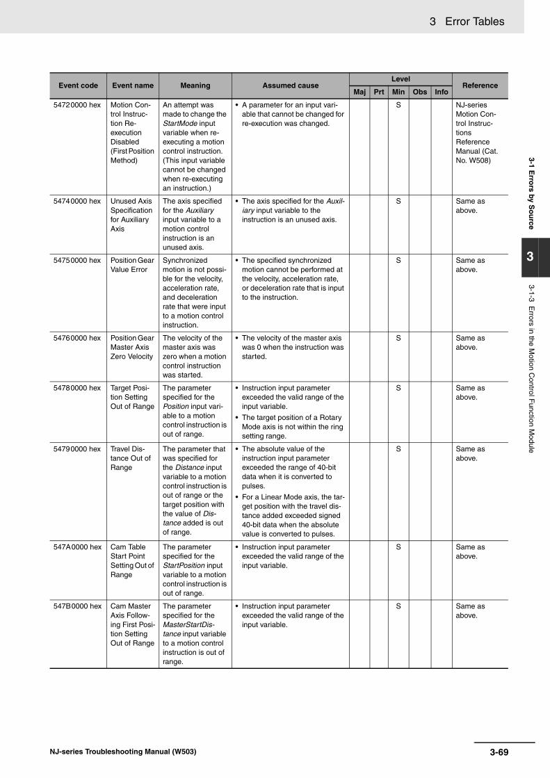
3 Error Tables3-1 E
rrors by S
ou
rce
3
3-1-3 Errors in the M
otion Control F
unction Module
54720000 hex Motion Con-trol Instruc-tion Re-execution Disabled (First Position Method)
An attempt was made to change the StartMode input variable when re-executing a motion control instruction. (This input variable cannot be changed when re-executing an instruction.)
• A parameter for an input vari-able that cannot be changed for re-execution was changed.
S NJ-series Motion Con-trol Instruc-tions Reference Manual (Cat. No. W508)
54740000 hex Unused Axis Specification for Auxiliary Axis
The axis specified for the Auxiliary input variable to a motion control instruction is an unused axis.
• The axis specified for the Auxil-iary input variable to the instruction is an unused axis.
S Same as above.
54750000 hex Position Gear Value Error
Synchronized motion is not possi-ble for the velocity, acceleration rate, and deceleration rate that were input to a motion control instruction.
• The specified synchronized motion cannot be performed at the velocity, acceleration rate, or deceleration rate that is input to the instruction.
S Same as above.
54760000 hex Position Gear Master Axis Zero Velocity
The velocity of the master axis was zero when a motion control instruction was started.
• The velocity of the master axis was 0 when the instruction was started.
S Same as above.
54780000 hex Target Posi-tion Setting Out of Range
The parameter specified for the Position input vari-able to a motion control instruction is out of range.
• Instruction input parameter exceeded the valid range of the input variable.
• The target position of a Rotary Mode axis is not within the ring setting range.
S Same as above.
54790000 hex Travel Dis-tance Out of Range
The parameter that was specified for the Distance input variable to a motion control instruction is out of range or the target position with the value of Dis-tance added is out of range.
• The absolute value of the instruction input parameter exceeded the range of 40-bit data when it is converted to pulses.
• For a Linear Mode axis, the tar-get position with the travel dis-tance added exceeded signed 40-bit data when the absolute value is converted to pulses.
S Same as above.
547A0000 hex Cam Table Start Point Setting Out of Range
The parameter specified for the StartPosition input variable to a motion control instruction is out of range.
• Instruction input parameter exceeded the valid range of the input variable.
S Same as above.
547B0000 hex Cam Master Axis Follow-ing First Posi-tion Setting Out of Range
The parameter specified for the MasterStartDis-tance input variable to a motion control instruction is out of range.
• Instruction input parameter exceeded the valid range of the input variable.
S Same as above.
Event code Event name Meaning Assumed causeLevel
ReferenceMaj Prt Min Obs Info
3-69NJ-series Troubleshooting Manual (W503)
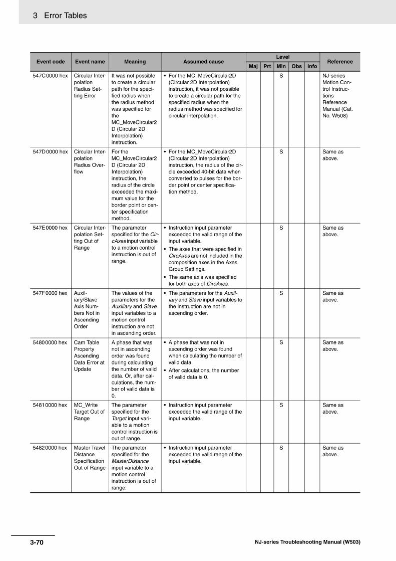
3 Error Tables
547C0000 hex Circular Inter-polation Radius Set-ting Error
It was not possible to create a circular path for the speci-fied radius when the radius method was specified for the MC_MoveCircular2D (Circular 2D Interpolation) instruction.
• For the MC_MoveCircular2D (Circular 2D Interpolation) instruction, it was not possible to create a circular path for the specified radius when the radius method was specified for circular interpolation.
S NJ-series Motion Con-trol Instruc-tions Reference Manual (Cat. No. W508)
547D0000 hex Circular Inter-polation Radius Over-flow
For the MC_MoveCircular2D (Circular 2D Interpolation) instruction, the radius of the circle exceeded the maxi-mum value for the border point or cen-ter specification method.
• For the MC_MoveCircular2D (Circular 2D Interpolation) instruction, the radius of the cir-cle exceeded 40-bit data when converted to pulses for the bor-der point or center specifica-tion method.
S Same as above.
547E0000 hex Circular Inter-polation Set-ting Out of Range
The parameter specified for the Cir-cAxes input variable to a motion control instruction is out of range.
• Instruction input parameter exceeded the valid range of the input variable.
• The axes that were specified in CircAxes are not included in the composition axes in the Axes Group Settings.
• The same axis was specified for both axes of CircAxes.
S Same as above.
547F0000 hex Auxil-iary/Slave Axis Num-bers Not in Ascending Order
The values of the parameters for the Auxiliary and Slave input variables to a motion control instruction are not in ascending order.
• The parameters for the Auxil-iary and Slave input variables to the instruction are not in ascending order.
S Same as above.
54800000 hex Cam Table Property Ascending Data Error at Update
A phase that was not in ascending order was found during calculating the number of valid data. Or, after cal-culations, the num-ber of valid data is 0.
• A phase that was not in ascending order was found when calculating the number of valid data.
• After calculations, the number of valid data is 0.
S Same as above.
54810000 hex MC_Write Target Out of Range
The parameter specified for the Target input vari-able to a motion control instruction is out of range.
• Instruction input parameter exceeded the valid range of the input variable.
S Same as above.
54820000 hex Master Travel Distance Specification Out of Range
The parameter specified for the MasterDistance input variable to a motion control instruction is out of range.
• Instruction input parameter exceeded the valid range of the input variable.
S Same as above.
Event code Event name Meaning Assumed causeLevel
ReferenceMaj Prt Min Obs Info
3-70 NJ-series Troubleshooting Manual (W503)
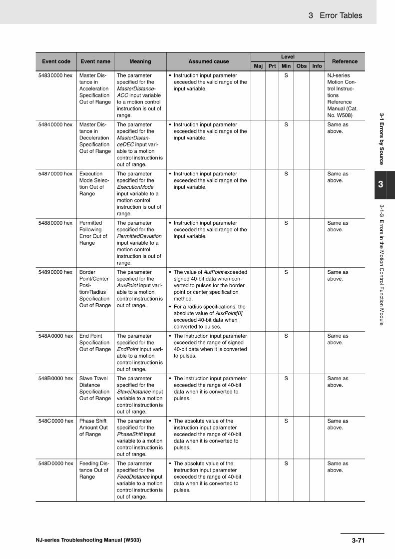
3 Error Tables3-1 E
rrors by S
ou
rce
3
3-1-3 Errors in the M
otion Control F
unction Module
54830000 hex Master Dis-tance in Acceleration Specification Out of Range
The parameter specified for the MasterDistance-ACC input variable to a motion control instruction is out of range.
• Instruction input parameter exceeded the valid range of the input variable.
S NJ-series Motion Con-trol Instruc-tions Reference Manual (Cat. No. W508)
54840000 hex Master Dis-tance in Deceleration Specification Out of Range
The parameter specified for the MasterDistan-ceDEC input vari-able to a motion control instruction is out of range.
• Instruction input parameter exceeded the valid range of the input variable.
S Same as above.
54870000 hex Execution Mode Selec-tion Out of Range
The parameter specified for the ExecutionMode input variable to a motion control instruction is out of range.
• Instruction input parameter exceeded the valid range of the input variable.
S Same as above.
54880000 hex Permitted Following Error Out of Range
The parameter specified for the PermittedDeviation input variable to a motion control instruction is out of range.
• Instruction input parameter exceeded the valid range of the input variable.
S Same as above.
54890000 hex Border Point/Center Posi-tion/Radius Specification Out of Range
The parameter specified for the AuxPoint input vari-able to a motion control instruction is out of range.
• The value of AutPoint exceeded signed 40-bit data when con-verted to pulses for the border point or center specification method.
• For a radius specifications, the absolute value of AuxPoint[0] exceeded 40-bit data when converted to pulses.
S Same as above.
548A0000 hex End Point Specification Out of Range
The parameter specified for the EndPoint input vari-able to a motion control instruction is out of range.
• The instruction input parameter exceeded the range of signed 40-bit data when it is converted to pulses.
S Same as above.
548B0000 hex Slave Travel Distance Specification Out of Range
The parameter specified for the SlaveDistance input variable to a motion control instruction is out of range.
• The instruction input parameter exceeded the range of 40-bit data when it is converted to pulses.
S Same as above.
548C0000 hex Phase Shift Amount Out of Range
The parameter specified for the PhaseShift input variable to a motion control instruction is out of range.
• The absolute value of the instruction input parameter exceeded the range of 40-bit data when it is converted to pulses.
S Same as above.
548D0000 hex Feeding Dis-tance Out of Range
The parameter specified for the FeedDistance input variable to a motion control instruction is out of range.
• The absolute value of the instruction input parameter exceeded the range of 40-bit data when it is converted to pulses.
S Same as above.
Event code Event name Meaning Assumed causeLevel
ReferenceMaj Prt Min Obs Info
3-71NJ-series Troubleshooting Manual (W503)

3 Error Tables
548E0000 hex Auxiliary and Slave Defined as Same Axis
The same axis was specified for the Auxiliary and Slave input variables to a motion control instruction.
• The parameter is the same for the Auxiliary and Slave input variables to the instruction.
S NJ-series Motion Con-trol Instruc-tions Reference Manual (Cat. No. W508)
548F0000 hex Relative Position Selection Out of Range
The parameter specified for the Relative input vari-able to a motion control instruction is out of range.
• Instruction input parameter exceeded the valid range of the input variable.
S Same as above.
54900000 hex Cam Transi-tion Specifi-cation Out of Range
The parameter specified for the CamTransition input variable to a motion control instruction is out of range.
• Instruction input parameter exceeded the valid range of the input variable.
S Same as above.
54910000 hex Synchro-nized Con-trol End Mode Selec-tion Out of Range
The parameter specified for the OutMode input vari-able to a motion control instruction is out of range.
• Instruction input parameter exceeded the valid range of the input variable.
S Same as above.
54920000 hex Enable Exter-nal Latch Instruction Execution Disabled
_mcImmediateStop was specified for the StopMode input variable when the MC_TouchProbe (Enable External Latch) instruction was executed in Drive Mode, but the Control Mode was not CSP Mode.
• _mcImmediateStop was speci-fied for the StopMode input variable when the MC_TouchProbe (Enable Exter-nal Latch) instruction was exe-cuted in Drive Mode, but the Control Mode was not CSP Mode or the Servo was OFF.
S Same as above.
54930000 hex Master Axis Offset Out of Range
The parameter specified for the MasterOffset input variable to a motion control instruction is out of range.
• The instruction input parameter exceeded the range of signed 40-bit data when it is converted to pulses.
S Same as above.
54940000 hex Slave Axis Offset Out of Range
The parameter specified for the SlaveOffset input variable to a motion control instruction is out of range.
• The instruction input parameter exceeded the range of signed 40-bit data when it is converted to pulses.
S Same as above.
54950000 hex Command Current Posi-tion Count Selection Out of Range
The parameter specified for the CmdPosMode input variable to a motion control instruction is out of range.
• Instruction input parameter exceeded the valid range of the input variable.
S Same as above.
54960000 hex Master Axis Gear Ratio Numerator Out of Range
The parameter specified for the RatioNumerator-Master input vari-able to a motion control instruction is out of range.
• Instruction input parameter exceeded the valid range of the input variable.
S Same as above.
Event code Event name Meaning Assumed causeLevel
ReferenceMaj Prt Min Obs Info
3-72 NJ-series Troubleshooting Manual (W503)
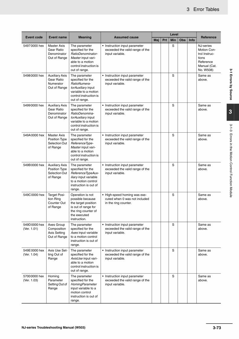
3 Error Tables3-1 E
rrors by S
ou
rce
3
3-1-3 Errors in the M
otion Control F
unction Module
54970000 hex Master Axis Gear Ratio Denominator Out of Range
The parameter specified for the RatioDenominator-Master input vari-able to a motion control instruction is out of range.
• Instruction input parameter exceeded the valid range of the input variable.
S NJ-series Motion Con-trol Instruc-tions Reference Manual (Cat. No. W508)
54980000 hex Auxiliary Axis Gear Ratio Numerator Out of Range
The parameter specified for the RatioNumera-torAuxiliary input variable to a motion control instruction is out of range.
• Instruction input parameter exceeded the valid range of the input variable.
S Same as above.
54990000 hex Auxiliary Axis Gear Ratio Denominator Out of Range
The parameter specified for the RatioDenomina-torAuxiliary input variable to a motion control instruction is out of range.
• Instruction input parameter exceeded the valid range of the input variable.
S Same as above.
549A0000 hex Master Axis Position Type Selection Out of Range
The parameter specified for the ReferenceType-Master input vari-able to a motion control instruction is out of range.
• Instruction input parameter exceeded the valid range of the input variable.
S Same as above.
549B0000 hex Auxiliary Axis Position Type Selection Out of Range
The parameter specified for the ReferenceTypeAux-iliary input variable to a motion control instruction is out of range.
• Instruction input parameter exceeded the valid range of the input variable.
S Same as above.
549C0000 hex Target Posi-tion Ring Counter Out of Range
Operation is not possible because the target position is out of range for the ring counter of the executed instruction.
• High-speed homing was exe-cuted when 0 was not included in the ring counter.
S Same as above.
549D0000 hex (Ver. 1.01)
Axes Group Composition Axis Setting Out of Range
The parameter specified for the Axes input variable to a motion control instruction is out of range.
• Instruction input parameter exceeded the valid range of the input variable.
S Same as above.
549E0000 hex (Ver. 1.04)
Axis Use Set-ting Out of Range
The parameter specified for the AxisUse input vari-able to a motion control instruction is out of range.
• Instruction input parameter exceeded the valid range of the input variable.
S Same as above.
57000000 hex (Ver. 1.03)
Homing Parameter Setting Out of Range
The parameter specified for the HomingParameter input variable to a motion control instruction is out of range.
• Instruction input parameter exceeded the valid range of the input variable.
S Same as above.
Event code Event name Meaning Assumed causeLevel
ReferenceMaj Prt Min Obs Info
3-73NJ-series Troubleshooting Manual (W503)

3 Error Tables
57020000 hex (Ver. 1.04)
Axis Use Change Error
The MC_ChangeAxisUse (Change Axis Use) instruction was executed when the axis was not stopped or when the command velocity of the axis was saturated.
• The MC_ChangeAxisUse (Change Axis Use) instruction was executed when the axis was not stopped or when the command velocity of the axis was saturated.
S NJ-series Motion Con-trol Instruc-tions Reference Manual (Cat. No. W508)
57030000 hex (Ver. 1.06)
Cannot Change Axis Use
The MC_ChangeAxisUse (Change Axis Use) instruction was executed in a way that would cause the maxi-mum number of used real axes to be exceeded.
• The MC_ChangeAxisUse (Change Axis Use) instruction was executed in a way that would cause the maximum number of used real axes to be exceeded.
S Same as above.
57200000 hex (Ver. 1.04)
Motion Con-trol Parame-ter Setting Error When Changing Axis Use
The motion control parameter settings for the axis that was changed to a used axis are incorrect.
• The MC_ChangeAxisUse (Change Axis Use) instruction was used to change an unused axis to a used axis, but the motion control parameter set-tings of the axis are not correct.
• The power supply was inter-rupted while a download of the motion control parameter set-tings was in progress.
• The non-volatile memory is faulty or the life of the non-vola-tile memory has been exceeded.
S Same as above.
57210000 hex (Ver. 1.04)
Required Process Data Object Not Set When Changing Axis Use
The objects that are required for the axis type of the axis that was changed to a used axis are not set.
• The objects that are required for the axis type of the axis that was changed to a used axis are not set in the PDO map set-tings.
• The power supply was inter-rupted while a download of the motion control parameter set-tings was in progress.
• The non-volatile memory is faulty or the life of the non-vola-tile memory has been exceeded.
• The MC_ChangeAxisUse (Change Axis Use) instruction was executed for an axis that is set to Unused axis (unchange-able to used axis).
S Same as above.
572F0000 hex (Ver. 1.06)
Motion Con-trol Instruc-tion Multi-execution Disabled (Master Axis)
A Master in-out variable that can-not be changed during multi-execu-tion of instructions was changed.
• A Master in-out variable that cannot be changed during multi-execution of instructions was changed.
S Same as above.
Event code Event name Meaning Assumed causeLevel
ReferenceMaj Prt Min Obs Info
3-74 NJ-series Troubleshooting Manual (W503)

3 Error Tables3-1 E
rrors by S
ou
rce
3
3-1-3 Errors in the M
otion Control F
unction Module
57300000 hex (Ver. 1.06)
Motion Con-trol Instruc-tion Multi-execution Disabled (Position Type Selec-tion)
A ReferenceType in-out variable that cannot be changed during multi-execu-tion of instructions was changed.
• A ReferenceType in-out vari-able that cannot be changed during multi-execution of instructions was changed.
S NJ-series Motion Con-trol Instruc-tions Reference Manual (Cat. No. W508)
573A0000 hex (Ver. 1.08)
Cannot Write Axis Parameters
The instruction was executed for an axis that is not an unused axis.
• The instruction was executed for a used axis or an undefined axis.
S Same as above.
573B0000 hex (Ver. 1.08)
Axis Parameter Setting Out of Range
The parameter specified for the AxisParameter input variable to a motion control instruction is outside of the valid range.
• The parameter specified for the AxisParameter input variable to the instruction is out of range for the input variable.
S Same as above.
573C0000 hex (Ver. 1.08)
Cam Property Setting Out of Range
The parameter specified for the CamProperty input variable to a motion control instruction is outside of the valid range.
• The parameter specified for the CamProperty input variable to the instruction is out of range for the input variable.
S Same as above.
573D0000 hex (Ver. 1.08)
Cam Node Setting Out of Range
The parameter specified for the CamNodes input variable to a motion control instruction is outside of the valid range.
• The parameter specified for the CamNodes input variable to the instruction is out of range for the input variable.
S Same as above.
573E0000 hex (Ver. 1.08)
Incorrect Cam Node Type Specification
The parameter specified for the CamNodes input variable to a motion control instruction is not an _sMC_CAM_NODE array variable.
• The parameter specified for the CamNodes input variable to the instruction is not an _sMC_CAM_NODE array vari-able.
S Same as above.
573F0000 hex (Ver. 1.08)
Insufficient Nodes in Cam Table
The array variable of the parameter specified for the CamNodes input variable to a motion control instruction has a Phase value of 0 for element number 0.
• The array variable of the parameter specified for the CamNodes input variable to the instruction has a Phase (master axis phase) value of 0 for ele-ment number 0.
S Same as above.
Event code Event name Meaning Assumed causeLevel
ReferenceMaj Prt Min Obs Info
3-75NJ-series Troubleshooting Manual (W503)

3 Error Tables
57400000 hex (Ver. 1.08)
Cam Node Master Axis Phase Not in Ascending Order
The values of Phase in the array variable of the parameter specified for the CamNodes input variable to a motion control instruction are not in ascending order according to the element numbers.
• The values of Phase (master axis phase) in the array variable of the parameter specified for the CamNodes input variable to the instruction are not in ascending order according to the element numbers. Or, trun-cating the digits that are not effective more than seven digits caused the phases to not be in ascending order.
S NJ-series Motion Con-trol Instruc-tions Reference Manual (Cat. No. W508)
57410000 hex (Ver. 1.08)
Too Many Data Points in Cam Table
The number of generated cam data points exceeded the number of elements in the array in the cam data variable that is specified for the CamTable input variable to a motion control instruction.
• The number of cam data points in the generated cam table exceeded the number of ele-ments in the array in the cam data variable that is specified for the CamTable input variable to the instruction.
S Same as above.
57420000 hex (Ver. 1.08)
Cam Table Displacement Overflow
Distance in the generated cam table exceeded the range of REAL data.
• Distance in the generated cam table exceeded the range of REAL data.
S Same as above.
57430000 hex (Ver. 1.08)
Aborted Cam Table Used
A cam data variable that was aborted during generation was specified for the CamTable input variable to an instruction.
• A cam data variable that was aborted during generation due to an error in the MC_GenerateCamTable (Gen-erate Cam Table) instruction was specified for the CamTable input variable to the instruction.
S Same as above.
64400000 hex Target Posi-tion Positive Software Limit Exceeded
The specified posi-tion exceeds the positive software limit.
• The parameter specified for the Position input variable to the instruction is beyond the posi-tive software limit.
• The first position is beyond the positive software limit and an instruction that specifies motion in the opposite direction of the software limit was executed.
• The parameter that was speci-fied for the AuxPoint input vari-able to a border point MC_MoveCircular2D (Circular 2D Interpolation) instruction is beyond the positive software limit.
S Same as above.
Event code Event name Meaning Assumed causeLevel
ReferenceMaj Prt Min Obs Info
3-76 NJ-series Troubleshooting Manual (W503)
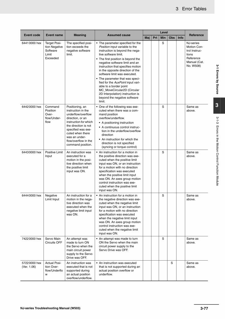
3 Error Tables3-1 E
rrors by S
ou
rce
3
3-1-3 Errors in the M
otion Control F
unction Module
64410000 hex Target Posi-tion Negative Software Limit Exceeded
The specified posi-tion exceeds the negative software limit.
• The parameter specified for the Position input variable to the instruction is beyond the nega-tive software limit.
• The first position is beyond the negative software limit and an instruction that specifies motion in the opposite direction of the software limit was executed.
• The parameter that was speci-fied for the AuxPoint input vari-able to a border point MC_MoveCircular2D (Circular 2D Interpolation) instruction is beyond the negative software limit.
S NJ-series Motion Con-trol Instruc-tions Reference Manual (Cat. No. W508)
64420000 hex Command Position Over-flow/Under-flow
Positioning, an instruction in the underflow/overflow direction, or an instruction for which the direction is not specified was exe-cuted when there was an under-flow/overflow in the command position.
• One of the following was exe-cuted when there was a com-mand position overflow/underflow.
• A positioning instruction
• A continuous control instruc-tion in the underflow/overflow direction
• An instruction for which the direction is not specified (syncing or torque control)
S Same as above.
64430000 hex Positive Limit Input
An instruction was executed for a motion in the posi-tive direction when the positive limit input was ON.
• An instruction for a motion in the positive direction was exe-cuted when the positive limit input was ON, or an instruction for a motion with no direction specification was executed when the positive limit input was ON. An axes group motion control instruction was exe-cuted when the positive limit input was ON.
S Same as above.
64440000 hex Negative Limit Input
An instruction for a motion in the nega-tive direction was executed when the negative limit input was ON.
• An instruction for a motion in the negative direction was exe-cuted when the negative limit input was ON, or an instruction for a motion with no direction specification was executed when the negative limit input was ON. An axes group motion control instruction was exe-cuted when the negative limit input was ON.
S Same as above.
74220000 hex Servo Main Circuits OFF
An attempt was made to turn ON the Servo when the main circuit power supply to the Servo Drive was OFF.
• An attempt was made to turn ON the Servo when the main circuit power supply to the Servo Drive was OFF.
S Same as above.
57220000 hex (Ver. 1.06)
Actual Posi-tion Over-flow/Underflow
An instruction was executed that is not supported during an actual position overflow/underflow.
• An instruction was executed that is not supported during an actual position overflow or underflow.
S Same as above.
Event code Event name Meaning Assumed causeLevel
ReferenceMaj Prt Min Obs Info
3-77NJ-series Troubleshooting Manual (W503)
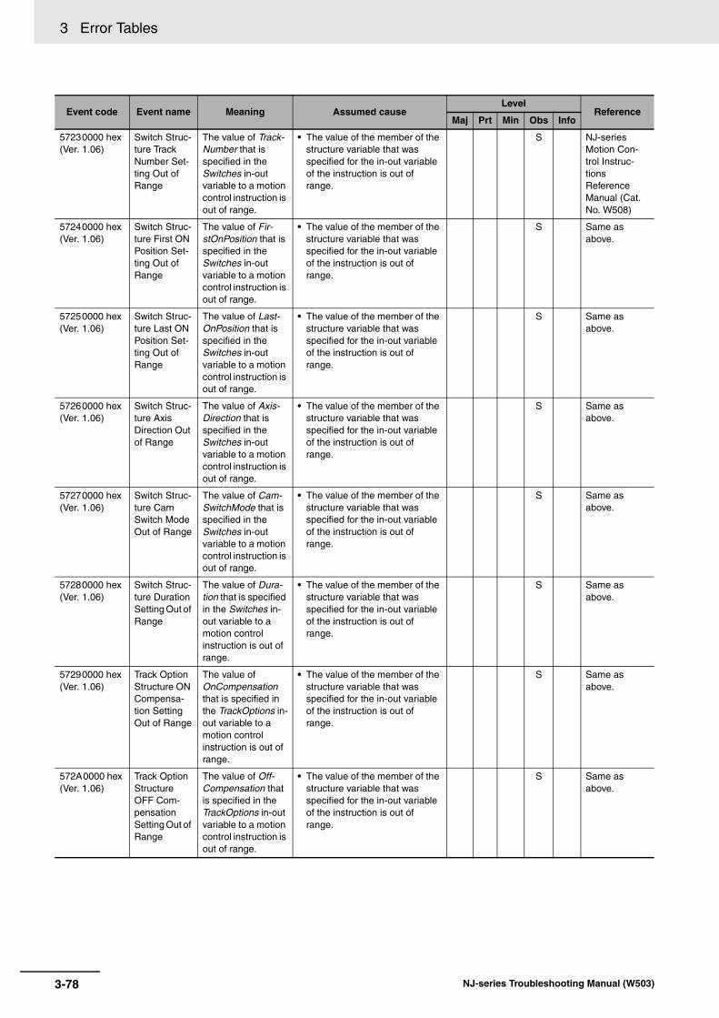
3 Error Tables
57230000 hex (Ver. 1.06)
Switch Struc-ture Track Number Set-ting Out of Range
The value of Track-Number that is specified in the Switches in-out variable to a motion control instruction is out of range.
• The value of the member of the structure variable that was specified for the in-out variable of the instruction is out of range.
S NJ-series Motion Con-trol Instruc-tions Reference Manual (Cat. No. W508)
57240000 hex (Ver. 1.06)
Switch Struc-ture First ON Position Set-ting Out of Range
The value of Fir-stOnPosition that is specified in the Switches in-out variable to a motion control instruction is out of range.
• The value of the member of the structure variable that was specified for the in-out variable of the instruction is out of range.
S Same as above.
57250000 hex (Ver. 1.06)
Switch Struc-ture Last ON Position Set-ting Out of Range
The value of Last-OnPosition that is specified in the Switches in-out variable to a motion control instruction is out of range.
• The value of the member of the structure variable that was specified for the in-out variable of the instruction is out of range.
S Same as above.
57260000 hex (Ver. 1.06)
Switch Struc-ture Axis Direction Out of Range
The value of Axis-Direction that is specified in the Switches in-out variable to a motion control instruction is out of range.
• The value of the member of the structure variable that was specified for the in-out variable of the instruction is out of range.
S Same as above.
57270000 hex (Ver. 1.06)
Switch Struc-ture Cam Switch Mode Out of Range
The value of Cam-SwitchMode that is specified in the Switches in-out variable to a motion control instruction is out of range.
• The value of the member of the structure variable that was specified for the in-out variable of the instruction is out of range.
S Same as above.
57280000 hex (Ver. 1.06)
Switch Struc-ture Duration Setting Out of Range
The value of Dura-tion that is specified in the Switches in-out variable to a motion control instruction is out of range.
• The value of the member of the structure variable that was specified for the in-out variable of the instruction is out of range.
S Same as above.
57290000 hex (Ver. 1.06)
Track Option Structure ON Compensa-tion Setting Out of Range
The value of OnCompensation that is specified in the TrackOptions in-out variable to a motion control instruction is out of range.
• The value of the member of the structure variable that was specified for the in-out variable of the instruction is out of range.
S Same as above.
572A0000 hex (Ver. 1.06)
Track Option Structure OFF Com-pensation Setting Out of Range
The value of Off-Compensation that is specified in the TrackOptions in-out variable to a motion control instruction is out of range.
• The value of the member of the structure variable that was specified for the in-out variable of the instruction is out of range.
S Same as above.
Event code Event name Meaning Assumed causeLevel
ReferenceMaj Prt Min Obs Info
3-78 NJ-series Troubleshooting Manual (W503)

3 Error Tables3-1 E
rrors by S
ou
rce
3
3-1-3 Errors in the M
otion Control F
unction Module
572B0000 hex (Ver. 1.06)
Number of Array Ele-ments in Switch Struc-ture Variable Out of Range
The number of ele-ments in an array in the structure vari-able that is speci-fied in the Switches in-out variable to a motion control instruction is out of range.
• The number of elements in an array of the structure variable that was specified for the in-out variable of the instruction is out of range.
S NJ-series Motion Con-trol Instruc-tions Reference Manual (Cat. No. W508)
572C0000 hex (Ver. 1.06)
Number of Array Ele-ments in Out-put Signal Structure Variable Out of Range
The number of ele-ments in an array in the structure vari-able that is speci-fied in the Outputs in-out variable to a motion control instruction is out of range.
• The number of elements in an array of the structure variable that was specified for the in-out variable of the instruction is out of range.
S Same as above.
572D0000 hex (Ver. 1.06)
Number of Array Ele-ments in Track Option Structure Variable Out of Range
The number of ele-ments in an array in the structure vari-able that is speci-fied in the TrackOptions in-out variable to a motion control instruction is out of range.
• The number of elements in an array of the structure variable that was specified for the in-out variable of the instruction is out of range.
S Same as above.
572E0000 hex (Ver. 1.06)
Numbers of Elements in Output Sig-nals and Track Option Arrays Not Matched
The arrays in the structure variables that are specified for the Outputs and TrackOptions in-out variables to a motion control instruction do not have the same number of ele-ments.
• The arrays in the output signal structure variable and track option structure variable that are specified for the in-out vari-ables to the instruction do not have the same number of ele-ments.
S Same as above.
57310000 hex (Ver. 1.06)
Same Track Number Set-ting in Switch Structure Out of Range
The same track number was speci-fied more than the allowable number of times for the Track-Number in the Switches in-out variable to a motion control instruction.
• The same track number was specified more than the allow-able number of times for the TrackNumber in the Switches in-out variable to a motion con-trol instruction.
S Same as above.
Event code Event name Meaning Assumed causeLevel
ReferenceMaj Prt Min Obs Info
3-79NJ-series Troubleshooting Manual (W503)
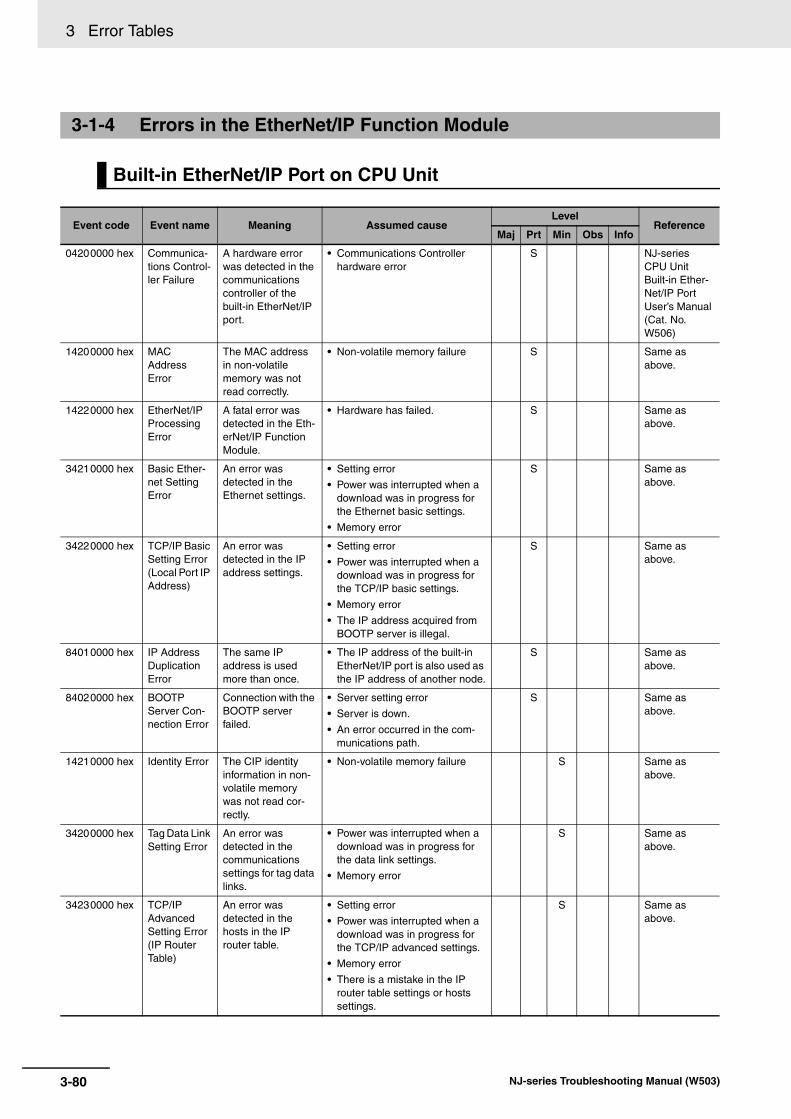
3 Error Tables
3-1-4 Errors in the EtherNet/IP Function Module
Built-in EtherNet/IP Port on CPU Unit
Event code Event name Meaning Assumed causeLevel
ReferenceMaj Prt Min Obs Info
04200000 hex Communica-tions Control-ler Failure
A hardware error was detected in the communications controller of the built-in EtherNet/IP port.
• Communications Controller hardware error
S NJ-series CPU Unit Built-in Ether-Net/IP Port User’s Manual (Cat. No. W506)
14200000 hex MAC Address Error
The MAC address in non-volatile memory was not read correctly.
• Non-volatile memory failure S Same as above.
14220000 hex EtherNet/IP Processing Error
A fatal error was detected in the Eth-erNet/IP Function Module.
• Hardware has failed. S Same as above.
34210000 hex Basic Ether-net Setting Error
An error was detected in the Ethernet settings.
• Setting error
• Power was interrupted when a download was in progress for the Ethernet basic settings.
• Memory error
S Same as above.
34220000 hex TCP/IP Basic Setting Error (Local Port IP Address)
An error was detected in the IP address settings.
• Setting error
• Power was interrupted when a download was in progress for the TCP/IP basic settings.
• Memory error
• The IP address acquired from BOOTP server is illegal.
S Same as above.
84010000 hex IP Address Duplication Error
The same IP address is used more than once.
• The IP address of the built-in EtherNet/IP port is also used as the IP address of another node.
S Same as above.
84020000 hex BOOTP Server Con-nection Error
Connection with the BOOTP server failed.
• Server setting error
• Server is down.
• An error occurred in the com-munications path.
S Same as above.
14210000 hex Identity Error The CIP identity information in non-volatile memory was not read cor-rectly.
• Non-volatile memory failure S Same as above.
34200000 hex Tag Data Link Setting Error
An error was detected in the communications settings for tag data links.
• Power was interrupted when a download was in progress for the data link settings.
• Memory error
S Same as above.
34230000 hex TCP/IP Advanced Setting Error (IP Router Table)
An error was detected in the hosts in the IP router table.
• Setting error
• Power was interrupted when a download was in progress for the TCP/IP advanced settings.
• Memory error
• There is a mistake in the IP router table settings or hosts settings.
S Same as above.
3-80 NJ-series Troubleshooting Manual (W503)

3 Error Tables3-1 E
rrors by S
ou
rce
3
3-1-4 Errors in the E
therNet/IP
Function M
odule
34240000 hex FTP Server Setting Error
An error was detected in the FTP server settings.
• Setting error
• Power was interrupted when a download was in progress for the FTP server settings.
• Memory error
S NJ-series CPU Unit Built-in Ether-Net/IP Port User’s Manual (Cat. No. W506)
34250000 hex NTP Client Setting Error
An error was detected in the NTP client settings.
• Setting error
• Power was interrupted when a download was in progress for the NTP client settings.
• Memory error
S Same as above.
34260000 hex SNMP Set-ting Error
An error was detected in the SNMP agent/trap settings.
• Setting error
• Power was interrupted when a download was in progress for the SNMP agent/trap settings.
• Memory error
S Same as above.
34270000 hex Tag Name Resolution Error
Resolution of a tag used in a tag data link failed.
• The size of the network-pub-lished variable is different from the tag settings.
• The I/O direction set for a tag data link and the I/O direction of the Controller variable do not match.
• There are no network-published variables for the Controller tag settings.
• A variable in the Controller that is set for a tag data link has the Network Publish attribute set to Input but also has the Constant attribute.
S Same as above.
50010000 hex (Ver. 1.02)
Controller Insufficient Memory Warning
The amount of data for the EtherCAT slave configuration, network-published information, or other data exceeds the value that is specified for the CPU Unit. You may not be able to per-form online editing or other operations.
• The amount of data for the EtherCAT slave configuration, network-published information, or other data exceeds the value that is specified for the CPU Unit.
S Same as above.
84030000 hex DNS Server Connection Error
Connection with the DNS server failed.
• Parameter error
• Server is down.
• An error occurred in the com-munications path.
S Same as above.
84040000 hex NTP Server Connection Error
Connection with the NTP server failed.
• Parameter error
• Server is down.
• An error occurred in the com-munications path.
S Same as above.
84070000 hex Tag Data Link Connection Failed
Establishing a tag data link connection failed.
• The tag data link connection information is not the same for the originator and target.
• Insufficient connections
S Same as above.
Event code Event name Meaning Assumed causeLevel
ReferenceMaj Prt Min Obs Info
3-81NJ-series Troubleshooting Manual (W503)

3 Error Tables
84080000 hex Tag Data Link Timeout
A timeout occurred in a tag data link.
• The power supply to the target node is OFF.
• Communications with the target node stop.
• The Ethernet cable for Ether-Net/IP is disconnected.
• The Ethernet cable for Ether-Net/IP is broken.
• Noise
S NJ-series CPU Unit Built-in Ether-Net/IP Port User’s Manual (Cat. No. W506)
84090000 hex (Ver. 1.04)
Tag Data Link Connection Timeout
A timeout occurred while trying to establish a tag data link connection.
• The power supply to the target node is OFF.
• Communications at the target node are stopped.
• The Ethernet cable connector for EtherNet/IP is disconnected.
• The Ethernet cable for Ether-Net/IP is broken.
• An error occurred in the com-munications path.
S U Same as above.
54E00000 hex Access Detected Outside Range of Variable
Accessing a value that is out of range was detected for a tag variable that is used in a tag data link.
• An out-of-range value was writ-ten by an EtherNet/IP tag data link for a variable with a speci-fied range.A value that does not specify an enumerator was written by an EtherNet/IP tag data link for an enumeration variable.
S Same as above.
84050000 hex Packet Dis-carded Due to Full Reception Buffer
A packet was dis-carded.
• A network convergence occurred.
S Same as above.
84060000 hex Link OFF Detected
An Ethernet Link OFF was detected.
• An Ethernet cable is broken, disconnected, or loose.
• The Ethernet switch’s power supply is turned OFF.
• Baud rate mismatch.
• Noise
• One of the following operations was performed.
• The Identify object was reset.
• Settings were downloaded from the Network Configura-tor and EtherNet/IP was restarted.
• Settings for EtherNet/IP were downloaded from the Sysmac Studio or the Memory All Clear operation was per-formed.
U S Same as above.
94010000 hex Tag Data Link Download Started
Changing the tag data link settings started.
• Changing the tag data link set-tings started.
S Same as above.
94020000 hex Tag Data Link Download Finished
Changing the tag data link settings finished.
• Changing the tag data link set-tings finished.
S Same as above.
Event code Event name Meaning Assumed causeLevel
ReferenceMaj Prt Min Obs Info
3-82 NJ-series Troubleshooting Manual (W503)

3 Error Tables3-1 E
rrors by S
ou
rce
3
3-1-4 Errors in the E
therNet/IP
Function M
odule
94030000 hex Tag Data Link Stopped
Tag data links were stopped by Network Configurator or manipulation of a system-defined variable. Or, the data link table was downloaded from the Network Config-urator again.
• Tag data links were stopped by Network Configurator or manip-ulation of a system-defined variable.
S NJ-series CPU Unit Built-in Ether-Net/IP Port User’s Manual (Cat. No. W506)
94040000 hex Tag Data Link Started
Tag data links were started by Network Configurator or manipulation of a system-defined variable. Or, the data link table was downloaded from the Network Config-urator again.
• Tag data links were started by Network Configurator or manip-ulation of a system-defined variable.
S Same as above.
94050000 hex Link Detected
Establishment of an Ethernet link was detected.
• Establishment of an Ethernet link was detected.
S Same as above.
94060000 hex Restarting Ethernet Port
The built-in Ether-Net/IP port was restarted.
• The built-in EtherNet/IP port was restarted.
S Same as above.
94070000 hex Tag Data Link All Run
Tag data link con-nections to all nodes have been established.
• Tag data link connections to all target nodes have been estab-lished.
S Same as above.
94080000 hex IP Address Fixed
The correct IP address has been determined and Ethernet communi-cations can start.
• The correct IP address has been determined and Ethernet communications can start.
S Same as above.
94090000 hex BOOTP Cli-ent Started
The BOOTP client started requesting an IP address.
• The BOOTP client started requesting an IP address.
S Same as above.
940A0000 hex FTP Server Started
The FTP agent started normally.
• The FTP agent started nor-mally.
S Same as above.
940B0000 hex NTP Client Started
The NTP client started normally and a request for the NTP server to obtain the time started.
• The NTP client started normally and a request for the NTP server to obtain the time started.
S Same as above.
940C0000 hex SNMP Started
The SNMP agent started normally.
• The SNMP agent started nor-mally.
S Same as above.
Event code Event name Meaning Assumed causeLevel
ReferenceMaj Prt Min Obs Info
3-83NJ-series Troubleshooting Manual (W503)

3 Error Tables
3-1-5 Errors in the EtherCAT Master Function Module
Built-in EtherCAT Master in CPU Unit
Event code Event name Meaning Assumed causeLevel
ReferenceMaj Prt Min Obs Info
04400000 hex Communica-tions Control-ler Failure
An error was detected in the hardware test at startup.
• The CPU Unit has failed. S NJ-series CPU Unit Built-in Ether-CAT Port User’s Manual (Cat. No. W505)
14400000 hex MAC Address Error
The MAC address is incorrect.
• The CPU Unit has failed. S Same as above.
44010000 hex EtherCAT Fault
A fatal error was detected in the EtherCAT Master Function Module.
• Software is corrupted. S Same as above.
84200000 hex Link OFF Error
A Link OFF state occurred.
• The Ethernet cable is broken between the master and slaves.
• The Ethernet cable connector is disconnected.
• The Ethernet cable is not con-nected.
S Same as above.
24200000 hex Slave Node Address Duplicated
The same slave address is used for two nodes.
• The same node address is set for more than one slave.
S Same as above.
34400000 hex Network Configura-tion Informa-tion Error
There is an error in the network config-uration information.
• The power supply to the Con-troller was interrupted or com-munications with the Sysmac Studio were disconnected while downloading the network con-figuration information.
S Same as above.
50010000 hex (Ver. 1.02)
Controller Insufficient Memory Warning
The amount of data for the EtherCAT slave configuration, network-published information, or other data exceeds the value that is specified for the CPU Unit. You may not be able to per-form online editing or other operations.
• The amount of data for the EtherCAT slave configuration, network-published information, or other data exceeds the value that is specified for the CPU Unit.
S Same as above.
84210000 hex Network Configura-tion Error
The EtherCAT net-work configuration is incorrect.
• Slave output ports are con-nected to each other.
• The master and slave are con-nected with the slave output port.
• The number of connected slaves exceeded the maximum number of slaves, 192 nodes, for the EtherCAT master.
S Same as above.
3-84 NJ-series Troubleshooting Manual (W503)

3 Error Tables3-1 E
rrors by S
ou
rce
3
3-1-5 Errors in the E
therCAT
Master F
unction Module
84220000 hex Network Configura-tion Verifica-tion Error
A slave that is in the network configura-tion information is not connected. Or, a slave that is not in the network config-uration information is connected.
• A slave that is in the network configuration information is not connected.
• There is a node address mis-match.
• A different slave from the one that is specified in the network configuration information is connected.
• A slave that is not in the net-work configuration information is connected.
• The hardware switches for the slave node address were changed to a value other than 0 after the Write Slave Node Address operation was per-formed from the Sysmac Stu-dio.
• The Ethernet physical layer is broken between two slaves.
S NJ-series CPU Unit Built-in Ether-CAT Port User’s Manual (Cat. No. W505)
84230000 hex Slave Initial-ization Error
Slave initialization failed.
• An error occurred in EtherCAT master processing.
• An initialization error occurred in the EtherCAT slave.
• An initialization error occurred in the EtherCAT Coupler Unit.
• A major fault level Controller error occurred.
• The Ethernet cable is broken or the specified cable is not being used.
• A connector on the Ethernet cable is disconnected, the con-tact is faulty, or parts are faulty.
• A general-purpose Ethernet hub is connected.
• The master failed.
• The slave failed.
• Noise.
S Same as above.
84280000 hex Slave Appli-cation Error
An error occurred in the slave applica-tion.
• An error was detected in the slave’s application layer status register.
S Same as above.
84290000 hex Process Data Transmis-sion Error
Sending process data failed.
• It was not possible to send the EtherCAT frame during the EtherCAT communications period.
• The frame transmission jitter exceeded the limit.
S Same as above.
Event code Event name Meaning Assumed causeLevel
ReferenceMaj Prt Min Obs Info
3-85NJ-series Troubleshooting Manual (W503)

3 Error Tables
842B0000 hex Process Data Reception Timeout
Process data reception timed out.
• The Ethernet cable is broken or the specified cable is not being used.
• A connector on the Ethernet cable is disconnected, the con-tact is faulty, or parts are faulty.
• A general-purpose Ethernet hub is connected.
• The master failed.
• The slave failed.
• The Ethernet cable is too long.
• The CPU Unit task period is too short.
• Noise
S NJ-series CPU Unit Built-in Ether-CAT Port User’s Manual (Cat. No. W505)
842C0000 hex Process Data Communica-tions Error
An error occurred in process data com-munications.
• A slave left the network even though the disconnection oper-ation was not performed.
• The Ethernet cable is broken or the specified cable is not being used.
• A connector on the Ethernet cable is disconnected, the con-tact is faulty, or parts are faulty.
• The slave failed.
S Same as above.
102F0000 hex(Ver. 1.03)
EtherCAT Slave Backup Failed
The backup opera-tion for an Ether-CAT slave ended in an error.
• There is no connection between the EtherCAT master and the slave (Link OFF).
• An error caused an incorrect EtherCAT master status.
• The EtherCAT network configu-ration information does not agree with the physical net-work configuration.
• The request to the EtherCAT slave failed.
• The EtherCAT master was tem-porarily unable to perform the processing because it was exe-cuting other processing.
• Initialization of the EtherCAT slave failed.
• It was not possible to read the backup parameters from the EtherCAT slave.
• Communications with an OMRON Communications Cou-pler Unit or NX Unit failed.
S Same as above.
Event code Event name Meaning Assumed causeLevel
ReferenceMaj Prt Min Obs Info
3-86 NJ-series Troubleshooting Manual (W503)

3 Error Tables3-1 E
rrors by S
ou
rce
3
3-1-5 Errors in the E
therCAT
Master F
unction Module
10300000 hex(Ver. 1.03)
EtherCAT Slave Restore Operation Failed
The restore opera-tion for an Ether-CAT slave ended in an error.
• There is no connection between the EtherCAT master and the slave (Link OFF).
• An error caused an incorrect EtherCAT master status.
• The EtherCAT network configu-ration information does not agree with the physical net-work configuration.
• The request to the EtherCAT slave failed.
• The EtherCAT master was tem-porarily unable to perform the processing because it was exe-cuting other processing.
• Initialization of the EtherCAT slave failed.
• It was not possible to write the backup parameters to the MX2/RX Series Inverter.
• It was not possible to write the backup parameters to the EtherCAT slave.
• Incorrect backup data was detected.
• The EtherCAT network configu-ration in the backup data does not agree with the physical net-work configuration.
• An error occurred at an OMRON Communications Cou-pler Unit.The following causes are possi-ble.
• Reading a backup file failed at the Communications Cou-pler Unit (when attached information 4 is 1).
• Communications with the Communications Coupler Unit or NX Unit failed (when attached information 4 is 2).
• The Unit Configuration of the NX Units in the Communica-tions Coupler Unit when data was backed up did not agree with the actual configuration of NX Units (when attached information 4 is 3).
S NJ-series CPU Unit Built-in Ether-CAT Port User’s Manual (Cat. No. W505)
64200000 hex Emergency Message Detected
An emergency message was detected.
• An emergency message was received from a slave.
S Same as above.
842D0000 hex EtherCAT Message Error
An error occurred in a message commu-nications with the slave.
• Refer to the attached informa-tion to check the error.
S Same as above.
94400000 hex Slave Dis-connected
A slave was discon-nected for a discon-nection command.
• An operation to disconnect the slave was executed from the Sysmac Studio.
• The EC_DisconnectSlave instruction was executed.
S Same as above.
Event code Event name Meaning Assumed causeLevel
ReferenceMaj Prt Min Obs Info
3-87NJ-series Troubleshooting Manual (W503)

3 Error Tables
The section provides tables of the errors (events) that can occur in the DB connection service or DBconnection instructions.
You can use the DB connection service and DB connection instructions with an NJ501-120 CPU Unit.
The errors are divided into the following functional groups.
• DB connection service
• DB connection instructions
94410000 hex Slave Con-nected
A slave was recon-nected for a recon-nection command.
• An operation to reconnect the slave was executed from the Sysmac Studio.
• The EC_ConnectSlave instruc-tion was executed.
S NJ-series CPU Unit Built-in Ether-CAT Port User’s Manual (Cat. No. W505)
94430000 hex Errors Reset A command was received to reset errors.
• An error reset operation was performed from the Sysmac Studio.
• The ResetECError instruction was executed.
S Same as above.
94440000 hex (Ver. 1.04)
Slave Dis-abled
The EtherCAT Slave was disabled.
• The EC_ChangeEnableSetting instruction was executed.
S Same as above.
94450000 hex (Ver. 1.04)
Slave Enabled
The EtherCAT Slave was enabled.
• The EC_ChangeEnableSetting instruction was executed.
S Same as above.
3-1-6 Errors in the DB Connection Service Function
Errors Related to DB Connection Service
Event code Event name Meaning Assumed causeLevel
ReferenceMaj Prt Min Obs Info
14D00000 hex (Ver. 1.05)
Spool Mem-ory Cor-rupted
The Spool memory is corrupted.
• The user application made an invalid writing to the Spool memory.
S NJ-series Database Connection CPU Units User’s Manual (Cat. No. W527)
14D20000 hex (Ver. 1.05)
Execution Log Save Failed
Failed to save the Execution Log to the SD Memory Card.
• An SD Memory Card is not inserted.
• The SD Memory Card is not the correct type of card.
• The format of the SD Memory Card is not correct.
• The SD Memory Card is write-protected.
• The capacity of the SD Memory Card is insufficient.
• The SD Memory Card is dam-aged.
S U Same as above.
Event code Event name Meaning Assumed causeLevel
ReferenceMaj Prt Min Obs Info
3-88 NJ-series Troubleshooting Manual (W503)

3 Error Tables3-1 E
rrors by S
ou
rce
3
3-1-6 Errors in the D
B C
onnection Service F
unction
14D30000 hex (Ver. 1.05)
SQL Execu-tion Failure Log Save Failed
Failed to save the SQL Execution Fail-ure Log to the SD Memory Card.
• An SD Memory Card is not inserted.
• The SD Memory Card is not the correct type of card.
• The format of the SD Memory Card is not correct.
• The SD Memory Card is write-protected.
• The capacity of the SD Memory Card is insufficient.
• The SD Memory Card is dam-aged.
S U NJ-series Database Connection CPU Units User’s Manual (Cat. No. W527)
35300000 hex (Ver. 1.05)
DB Connec-tion Setting Error
The DB Connec-tion settings are not correct.
• The power supply to the Con-troller was interrupted during a download of the DB Connection settings.
• The DB Connection settings are not correct because the power supply to the Controller was interrupted during a Clear All Memory operation.
• The DB Connection settings are not correct because the power supply to the Controller was interrupted during a Restore operation.
• Non-volatile memory failed.
S Same as above.
85100000 hex (Ver. 1.05)
DB Connec-tion Discon-nected Error
The DB Connec-tion was discon-nected due to an error.
• The power supply to the server is OFF.
• The DB is stopped in the server.
• The Ethernet cable connector is disconnected.
• The Ethernet cable is broken.
• Noise
S Same as above.
95300000 hex (Ver. 1.05)
DB Connec-tion Service Started
The DB Connec-tion Service was started.
• The DB Connection Service was successfully started.
S Same as above.
95310000 hex (Ver. 1.05)
DB Connec-tion Service Stopped
The DB Connec-tion Service was stopped.
• The DB Connection Service was stopped.
S Same as above.
95320000 hex (Ver. 1.05)
DB Connec-tion Service Shutdown
The DB Connec-tion Service was shut down.
• The DB Connection Service was shut down for turning OFF the power supply safely.
S Same as above.
Event code Event name Meaning Assumed causeLevel
ReferenceMaj Prt Min Obs Info
3-89NJ-series Troubleshooting Manual (W503)

3 Error Tables
Errors are given as event codes that use the error code as the lower four digits. For descriptions of anerror code, refer to the description of the corresponding event code. For example, if the error code forthe instruction is 16#3000, refer to the description for event code 54013000 hex.
Errors Related to DB Connection Instructions
Event code Event name Meaning Assumed causeLevel
ReferenceMaj Prt Min Obs Info
54013000 hex (Ver. 1.05)
DB Connec-tion Service Not Started
The DB Connec-tion Service has not been started.
• A command to start the DB Connection Service was not given before the execution of relevant instruction.
• A command to stop the DB Connection Service was given before the execution of relevant instruction.
S NJ-series Database Connection CPU Units User’s Manual (Cat. No. W527)
54013001 hex (Ver. 1.05)
DB Connec-tion Service Run Mode Change Failed
Failed to change the Run mode of the DB Connection Service.
• Run mode change to Test Mode was executed by the relevant instruction while running in Operation Mode.
• Run mode change to Operation Mode was executed by the rele-vant instruction while running in Test Mode.
• Start of the DB Connection Ser-vice was commanded while the DB Connection Service was being stopped.
• Shutdown of the DB Connec-tion Service was commanded while the DB Connection Ser-vice was being stopped.
S Same as above.
54013002 hex (Ver. 1.05)
DB Connec-tion Service Shutdown or Shutting Down
The DB Connec-tion Service is already shut down or being shut down.
• The relevant instruction was executed after the DB Connec-tion Service was shut down.
• The relevant instruction was executed while the shutdown processing of the DB Connec-tion Service was in progress.
S Same as above.
54013003 hex (Ver. 1.05)
Invalid DB Connection Name
The specified DB Connection Name is not set in any DB Connection set-tings.
• The DB Connection Name specified in the DBConnection-Name input variable of the rele-vant instruction is wrong.
• The DB Connection Name set in the DB Connection settings is wrong.
S Same as above.
54013004 hex (Ver. 1.05)
DB Connec-tion Rejected
The DB rejected the connection.
• The user name or password set in the DB Connection settings is wrong.
S Same as above.
54013005 hex (Ver. 1.05)
DB Connec-tion Failed
Failed to connect to the DB.
• A server does not exist for the specified IP address or the specified host name.
• The power supply to the server is OFF.
• The DB is stopped in the server.
• The Ethernet cable connector is disconnected.
• The Ethernet cable is broken.
S Same as above.
54013006 hex (Ver. 1.05)
DB Connec-tion Already Established
A same-name DB Connection is already estab-lished.
• The relevant instruction was executed when a same-name DB Connection was already established.
S Same as above.
3-90 NJ-series Troubleshooting Manual (W503)

3 Error Tables3-1 E
rrors by S
ou
rce
3
3-1-6 Errors in the D
B C
onnection Service F
unction
54013007 hex (Ver. 1.05)
Too Many DB Connections
The number of DB Connections that can be established at the same time is exceeded.
• The relevant instruction was executed when the maximum number of DB Connections that can be established at the same time were already established.
S NJ-series Database Connection CPU Units User’s Manual (Cat. No. W527)
54013008 hex (Ver. 1.05)
Invalid DB Connection
The specified DB Connection is not correct, or the DB Connection is already closed.
• The DB Connection specified in the DBConnection input vari-able of the relevant instruction is wrong.
• The DB Connection specified in the DBConnection input vari-able of the relevant instruction is closed.
S Same as above.
54013009 hex (Ver. 1.05)
Invalid DB Map Variable
The specified DB Map Variable is not correct.
• A structure variable that con-tains a derivative data type of member was specified as a DB Map Variable.
• A non-structure variable was specified as a DB Map Variable.
• A structure array variable was specified as a DB Map Variable for INSERT or UPDATE.
S Same as above.
5401300A hex (Ver. 1.05)
Unregistered DB Map Vari-able
The specified DB Map Variable has not been regis-tered.
• The DB Map Variable has not been created by a DB_CreateMapping instruction.
• A variable that is not registered as a DB Map Variable was specified in MapVar.
• The DB Connection specified in the relevant instruction is differ-ent from the one specified at the execution of DB_CreateMapping instruction.
S Same as above.
Event code Event name Meaning Assumed causeLevel
ReferenceMaj Prt Min Obs Info
3-91NJ-series Troubleshooting Manual (W503)
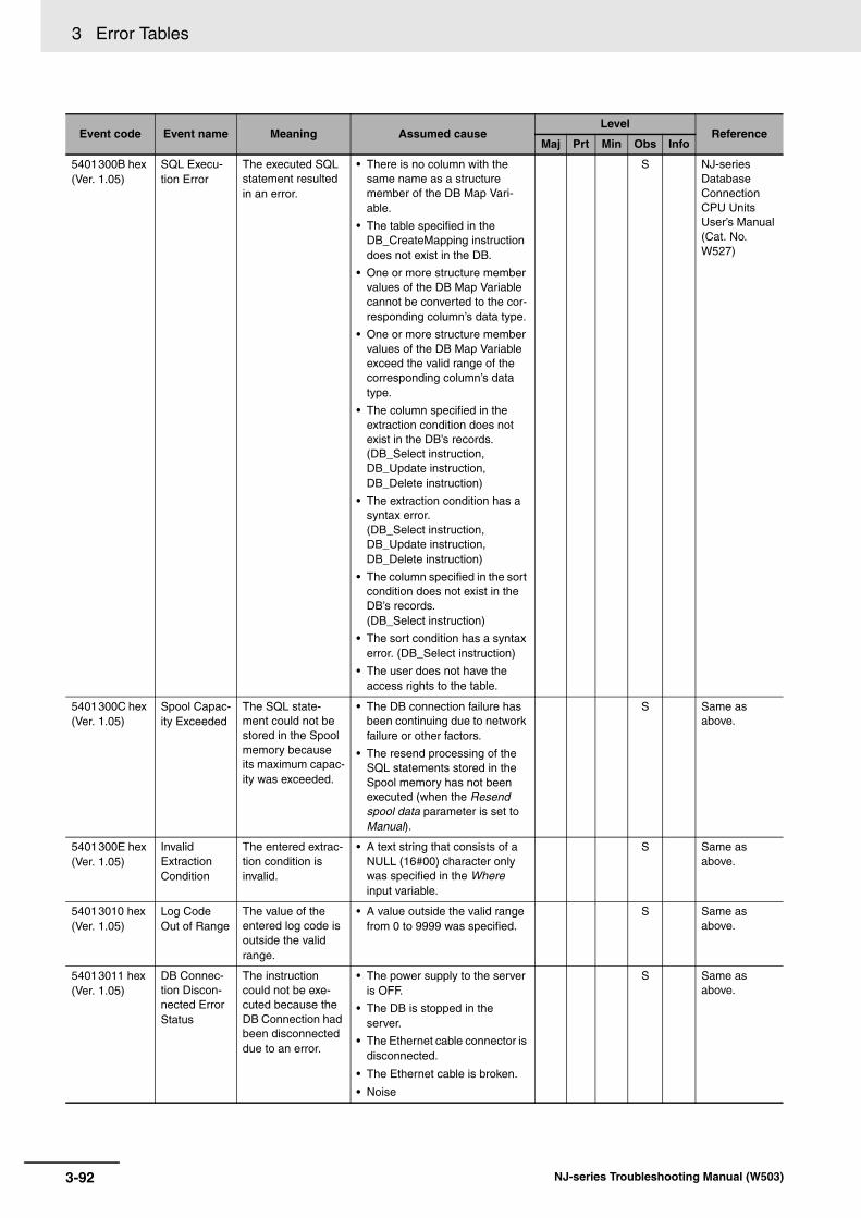
3 Error Tables
5401300B hex (Ver. 1.05)
SQL Execu-tion Error
The executed SQL statement resulted in an error.
• There is no column with the same name as a structure member of the DB Map Vari-able.
• The table specified in the DB_CreateMapping instruction does not exist in the DB.
• One or more structure member values of the DB Map Variable cannot be converted to the cor-responding column’s data type.
• One or more structure member values of the DB Map Variable exceed the valid range of the corresponding column’s data type.
• The column specified in the extraction condition does not exist in the DB’s records. (DB_Select instruction, DB_Update instruction, DB_Delete instruction)
• The extraction condition has a syntax error. (DB_Select instruction, DB_Update instruction, DB_Delete instruction)
• The column specified in the sort condition does not exist in the DB’s records. (DB_Select instruction)
• The sort condition has a syntax error. (DB_Select instruction)
• The user does not have the access rights to the table.
S NJ-series Database Connection CPU Units User’s Manual (Cat. No. W527)
5401300C hex (Ver. 1.05)
Spool Capac-ity Exceeded
The SQL state-ment could not be stored in the Spool memory because its maximum capac-ity was exceeded.
• The DB connection failure has been continuing due to network failure or other factors.
• The resend processing of the SQL statements stored in the Spool memory has not been executed (when the Resend spool data parameter is set to Manual).
S Same as above.
5401300E hex (Ver. 1.05)
Invalid Extraction Condition
The entered extrac-tion condition is invalid.
• A text string that consists of a NULL (16#00) character only was specified in the Where input variable.
S Same as above.
54013010 hex (Ver. 1.05)
Log Code Out of Range
The value of the entered log code is outside the valid range.
• A value outside the valid range from 0 to 9999 was specified.
S Same as above.
54013011 hex (Ver. 1.05)
DB Connec-tion Discon-nected Error Status
The instruction could not be exe-cuted because the DB Connection had been disconnected due to an error.
• The power supply to the server is OFF.
• The DB is stopped in the server.
• The Ethernet cable connector is disconnected.
• The Ethernet cable is broken.
• Noise
S Same as above.
Event code Event name Meaning Assumed causeLevel
ReferenceMaj Prt Min Obs Info
3-92 NJ-series Troubleshooting Manual (W503)

3 Error Tables3-1 E
rrors by S
ou
rce
3
3-1-7 Errors in S
lave Terminals
The section provides tables of the errors (events) that can occur in the following Units in OMRON SlaveTerminals.
• NX-series EtherCAT Coupler Units
• NX-series Digital I/O Units
• NX-series Analog I/O Units
• NX-series System Units
• NX-series Position Interface Units
• NX-series Safety Control Units
54013012 hex (Ver. 1.05)
DB Connec-tion Instruc-tion Execution Timeout
The instruction was not completed within the time specified for time-out.
• The power supply to the server is OFF.
• The Ethernet cable connector is disconnected.
• The Ethernet cable is broken.
• The server’s processing time is long.
S NJ-series Database Connection CPU Units User’s Manual (Cat. No. W527)
54013013 hex (Ver. 1.05)
DB Connec-tion Service Error Stop
The instruction could not be exe-cuted because the DB Connection Service was stopped due to an error.
• The DB Connection settings are corrupted.
S Same as above.
54013014 hex (Ver. 1.05)
Data Already Spooled
One or more SQL statements are already stored in the Spool memory.
• A DB_Insert or DB_Update instruction was executed when one or more SQL statements were already stored in the Spool memory.
• A DB_Select or DB_Delete instruction was executed when one or more SQL statements were already stored in the Spool memory.
S Same as above.
54013015 hex (Ver. 1.05)
DB Connec-tion Service Initializing
The instruction could not be exe-cuted because the initialization pro-cessing of the DB Connection Ser-vice is in progress.
• The relevant instruction was executed during the initializa-tion processing of the DB Con-nection Service.
S Same as above.
54013016 hex (Ver. 1.05)
DB in Pro-cess
The instruction could not be exe-cuted because the DB is under pro-cessing in the server.
• Though a DB Connection Instruction Execution Timeout occurred for the previous instruction, the relevant instruc-tion was executed before com-pletion of the DB’s processing in the server.
S Same as above.
54013017 hex (Ver. 1.05)
Operation Log Disabled
The log could not be recorded because the speci-fied Operation Log is disabled.
• Though Execution Log was specified in the LogType input variable, the Execution Log is disabled.
• Though Debug Log was speci-fied in the LogType input vari-able, recording to the Debug Log is stopped.
S Same as above.
3-1-7 Errors in Slave Terminals
Event code Event name Meaning Assumed causeLevel
ReferenceMaj Prt Min Obs Info
3-93NJ-series Troubleshooting Manual (W503)

3 Error Tables
The section provides a table of the errors (events) that can occur in the following Unit.
NX-ECC201
NX-series EtherCAT Coupler Units
Event code Event name Meaning Assumed causeLevel
ReferenceMaj Prt Min Obs Info
00210000 hex Bus Control-ler Error
An internal bus error occurred.
• A Unit failed or an I/O communi-cations error occurred between the EtherCAT Coupler Unit and the NX Unit.
S NX-series EtherCAT Coupler Unit User’s Manual (W519)
00220000 hex Non-volatile Memory Hardware Error
An error occurred in non-volatile mem-ory.
• Non-volatile memory failure S Same as above.
05010000 hex ESC Error An error occurred in the EtherCAT slave communications controller.
• An error occurred in the Ether-CAT slave communications controller.
S Same as above.
05020000 hex ESC Initial-ization Error
Initialization of the EtherCAT slave communications controller failed.
• An initialization error occurred in the EtherCAT slave commu-nications controller.
S Same as above.
05030000 hex Slave Unit Verification Error
An error occurred in Slave Unit verifica-tion.
• An error occurred in Slave Unit information.
S Same as above.
10420000 hex Non-volatile Memory Con-trol Parame-ter Error
An error occurred in the control parame-ters.
• The power supply to an NX Unit was turned OFF or Sysmac Studio communications were disconnected while writing the control parameters.
S Same as above.
10430000 hex Memory Cor-ruption Detected
Memory corruption was detected.
• Memory corruption was detected.
S Same as above.
24A00000 hex Unit Configu-ration Error, Too Many Units
The number of con-nected NX Units exceeds the maxi-mum value for the EtherCAT Coupler Unit.
• More than the maximum num-ber of NX Units is connected to the EtherCAT Coupler Unit.
S Same as above.
24A10000 hex Unit Configu-ration Error, Unsupported Configuration
An unsupported NX Unit is mounted. Or, the total byte size of all I/O data for the connected NX Units exceeds the prede-termined maximum value for the Ether-CAT Coupler Unit.
• An unsupported NX Unit was detected.
• The total byte size of all I/O data for the connected NX Units exceeds 1,024 bytes for input data or 1,024 bytes for output data.
S Same as above.
35000000 hex Unit Configu-ration Infor-mation Error
An error occurred in the Unit configura-tion information in the EtherCAT Cou-pler Unit.
• The power supply to the Ether-CAT Coupler Unit was turned OFF or Sysmac Studio commu-nications were disconnected while downloading the Unit con-figuration information.
S Same as above.
3-94 NJ-series Troubleshooting Manual (W503)

3 Error Tables3-1 E
rrors by S
ou
rce
3
3-1-7 Errors in S
lave Terminals
35010000 hex Unit Configu-ration Verifi-cation Error
There is an incon-sistency between the Unit configura-tion information in the EtherCAT Cou-pler Unit and the Units that are actu-ally connected. Or, the Unit configura-tion was changed during operation while the Unit con-figuration informa-tion was not set in the EtherCAT Cou-pler Unit.
• An NX Unit that is registered in the Unit configuration informa-tion is not connected.
• A connected NX Unit does not agree with the NX Unit that is registered in the Unit configura-tion information.
• An NX Unit that is not regis-tered in the Unit configuration information is connected.
• A Unit that is disabled in the Unit configuration information is mounted.
• An NX Unit became discon-nected during operation.
• An NX Unit was connected dur-ing operation.
• The serial number of a Unit that is registered in the Unit configu-ration information does not agree with the serial number of the Unit that is connected. (The Serial Number Check Method is set to Setting = Actual device.)
• The version of a Unit that is reg-istered in the Unit configuration information is newer than the version of the Unit that is con-nected.
• The power supply to an Addi-tional NX Unit Power Supply Unit is not turned ON.
S NX-series EtherCAT Coupler Unit User’s Manual (W519)
35020000 hex NX Unit Minor Fault
A minor fault was detected in an NX Unit.
• A minor fault level error occurred in a Unit where an error was detected.This event is recorded in the event log in the Communica-tions Coupler Unit.
S Same as above.
35040000 hex Mailbox Set-ting Error
An incorrect mail-box setting was detected for the Sync Manager. (AL-Status Code: 0016 hex)
• An incorrect mailbox setting was detected for the Sync Man-ager.
S Same as above.
35050000 hex RxPDO Set-ting Error
An error was detected in the RxPDO settings. (AL-Status Code: 001D hex)
• An error was detected in the RxPDO settings.
S Same as above.
35060000 hex TxPDO Set-ting Error
An error was detected in the TxPDO settings. (AL-Status Code: 001E hex)
• An error was detected in the TxPDO settings.
S Same as above.
35070000 hex PDO WDT Setting Error
An incorrect PDO WDT setting was detected. (AL-Sta-tus Code: 001F hex)
• An incorrect PDO WDT setting was detected.
S Same as above.
35080000 hex SM Event Mode Set-ting Error
An SM Event Mode that is not sup-ported was set. (AL-Status Code: 0028 hex)
• An SM Event Mode that is not supported was set.
S Same as above.
Event code Event name Meaning Assumed causeLevel
ReferenceMaj Prt Min Obs Info
3-95NJ-series Troubleshooting Manual (W503)

3 Error Tables
35090000 hex TxPDO Map-ping Error
An incorrect TxPDO was set. (AL-Sta-tus Code: 0024 hex)
• An incorrect TxPDO was set, e.g., the index, subindex, or size was outside of the allow-able range.
S NX-series EtherCAT Coupler Unit User’s Manual (W519)
350A0000 hex RxPDO Map-ping Error
An incorrect RxPDO was set. (AL-Status Code: 0025 hex)
• An incorrect RxPDO was set, e.g., the index, subindex, or size was outside of the allow-able range.
S Same as above.
350B0000 hex Illegal State Transition Request Received
An incorrect state transition request was received. (AL-Status Code: 0011 hex)
• An incorrect state transition request was received.
S Same as above.
350C0000 hex Error State Transition Received
An unclear state transition request was received. (AL-Status Code: 0012 hex)
• An unclear state transition request was received.
S Same as above.
350D0000 hex Synchroniza-tion Cycle Setting Error
When DC Mode was confirmed, the cycle time was set to a value that made operation impossible. (AL-Status Code: 0035 hex)
• When DC Mode was confirmed, the cycle time was set to a value that made operation impossible.
S Same as above.
84C00000 hex NX Unit Communica-tions Timeout
An error occurred in I/O data communi-cations with the NX Units.
• An NX Unit is not mounted properly.
• An NX Unit has failed.
S Same as above.
84C10000 hex NX Unit Ini-tialization Error
Initializing an NX Unit failed.
• An error occurred in processing the EtherCAT Coupler Unit.
• An initialization error occurred in an NX Unit.
• The Enabled Channel Settings for all channels of the Analog Input Unit are set to Disable.The Enabled Channel Settings for all channels of the Analog Output Unit are set to Disable.
S Same as above.
85000000 hex Process Data WDT Error
Process data com-munications were stopped for more than the specified period of time.
• The EtherCAT communications cable is disconnected or bro-ken.
• There is an error in the host controller.
S Same as above.
85010000 hex Synchroniza-tion Interrup-tion Error
A synchronization interruption error occurred.
• The EtherCAT communications cable is disconnected or bro-ken.
• There is a synchronization set-ting error in the EtherCAT Cou-pler Unit.
• There is a hardware error in the EtherCAT Coupler Unit.
S Same as above.
85020000 hex Synchroniza-tion Error
A synchronization error occurred.
• The EtherCAT communications cable is disconnected or bro-ken.
• There is a synchronization set-ting error in the EtherCAT mas-ter or EtherCAT Coupler Unit.
• There is a hardware error in the EtherCAT Coupler Unit.
S Same as above.
Event code Event name Meaning Assumed causeLevel
ReferenceMaj Prt Min Obs Info
3-96 NJ-series Troubleshooting Manual (W503)

3 Error Tables3-1 E
rrors by S
ou
rce
3
3-1-7 Errors in S
lave Terminals
The section provides a table of the errors (events) that can occur in the following Units.
NX-ID
NX-OC
NX-OD
85030000 hex Communica-tions Syn-chronization Error
The number of consecutive errors in receiving the synchronization data exceeded the value that is specified in the Communications Error Settings.
• Power to the host controller was interrupted during process data communications.
• The EtherCAT communications cable is disconnected or bro-ken.
S NX-series EtherCAT Coupler Unit User’s Manual (W519)
84C50000 hex NX Unit Startup Error
Starting an NX Unit failed.
• A startup error occurred in an NX Unit.
S Same as above.
35030000 hex NX Unit Observation
An observation was detected in an NX Unit.
• An observation level error occurred in a Unit where an error was detected.This event is recorded in the event log in the Communica-tions Coupler Unit.
S Same as above.
350E0000 hex NX Bus Cycle Delay Detected
Exceeding the NX bus cycle was detected.
• The NX bus cycle was exceeded.
S Same as above.
80220000 hex NX Message Communica-tions Error
An error was detected in mes-sage communica-tions and the message frame was discarded.
• The message communications load is high.
• The communications cable is disconnected or broken.This cause does not apply if attached information 2 is 0 (NX bus).
• Message communications were cut off as the result of executing a synchronization or restora-tion operation on the Sysmac Studio or as the result of dis-connecting an EtherCAT slave.
S Same as above.
90400000 hex Event Log Cleared
The event log was cleared.
• The event log was cleared by the user.
S Same as above.
90420000 hex Restart Exe-cuted
A restart was exe-cuted.
• A restart command was received.
S Same as above.
90430000 hex Memory All Cleared
The Unit settings were cleared.
• The non-volatile memory in the EtherCAT Coupler Unit was cleared.
S Same as above.
94600000 hex I/O Check Execution Started
I/O checking was started.
• I/O checking was started. S Same as above.
NX-series Digital I/O Units
Event code Event name Meaning Assumed causeLevel
ReferenceMaj Prt Min Obs Info
00200000 hex Non-volatile Memory Hardware Error
An error occurred in non-volatile mem-ory.
• Non-volatile memory failure S NX-series Dig-ital I/O Units User’s Manual (W521)
Event code Event name Meaning Assumed causeLevel
ReferenceMaj Prt Min Obs Info
3-97NJ-series Troubleshooting Manual (W503)

3 Error Tables
10410000 hex Control Parameter Error in Mas-ter
An error occurred in the control parame-ters that are saved in the master.
• There is an error in the area of the non-volatile memory in the Communications Coupler Unit in which the control parameters for the NX Unit are saved.
• The power supply to the NX Unit was turned OFF or Sys-mac Studio communications were disconnected while writing the control parameters.
S NX-series Dig-ital I/O Units User’s Manual (W521)
80200000 hex NX Unit I/O Communica-tions Error
An I/O communica-tions error occurred between the Com-munications Cou-pler Unit and the NX Unit.
• The NX Unit is not mounted properly.
• The power cable for the Unit power supply is disconnected. Or, the wiring from the Unit power supply to the NX Units is incorrect.
• The power cable for the Unit power supply is broken.
• The voltage of the Unit power supply is outside the specified range. Or, the capacity of the Unit power supply is insuffi-cient.
• There is a hardware error in the NX Unit.
S Same as above.
80210000 hex NX Unit Out-put Synchro-nization Error
An output synchro-nization error occurred in the NX Unit.
• The NX Unit is not mounted properly.
• The Slave Terminal Configura-tion Information when the EtherCAT Coupler Unit syn-chronization settings were downloaded did not agree with the actual configuration of the Slave Terminal.
• There is an NX Unit that cannot be synchronized to the speci-fied output synchronization tim-ing.(This will not cause an error when the synchronization set-ting is made from the Sysmac Studio.)
S Same as above.
80240000 hex NX Unit Clock Not Synchro-nized Error
An error occurred in the clock informa-tion between the EtherCAT Coupler Unit and the NX Unit.
• There is a hardware error in the NX Unit.
• There is a hardware error in the EtherCAT Coupler Unit.
S Same as above.
70010000 hex (Ver. 1.06)
Previous Time Speci-fied
A previous time was specified for output refreshing with a specified time stamp.
• A mistake in the user program caused the specification of a previous time.
• A Communications Synchroni-zation Error caused a delay in the I/O data reaching the NX Unit.
S Same as above.
90400000 hex Event Log Cleared
The event log was cleared.
• The event log was cleared by the user.
S Same as above.
Event code Event name Meaning Assumed causeLevel
ReferenceMaj Prt Min Obs Info
3-98 NJ-series Troubleshooting Manual (W503)

3 Error Tables3-1 E
rrors by S
ou
rce
3
3-1-7 Errors in S
lave Terminals
The section provides a table of the errors (events) that can occur in the following Units.
NX-AD
NX-DA
NX-TS
Analog Input Units and Analog Output Units
NX-series Analog I/O Units
Event code Event name Meaning Assumed causeLevel
ReferenceMaj Prt Min Obs Info
00200000 hex Non-volatile Memory Hardware Error
An error occurred in non-volatile mem-ory.
• Non-volatile memory failure S NX-series Analog I/O Units User’s Manual (W522)
10400000 hex Analog Unit Calibration Parameter Error
An error occurred for the calibration data in the Analog Unit.
• The power supply to the Analog Unit was turned OFF or Sys-mac Studio communications were disconnected while writing the calibration values to the Analog Unit.
S Same as above.
10410000 hex Control Parameter Error in Mas-ter
An error occurred in the control parame-ters that are saved in the master.
• There is an error in the area of the non-volatile memory in the Communications Coupler Unit in which the control parameters for the NX Unit are saved.
• The power supply to the NX Unit was turned OFF or Sys-mac Studio communications were disconnected while writing the control parameters.
S Same as above.
14C00000 hex Unit Calibra-tion Value Parity Error
An error occurred in the user calibration data in the NX Unit.
• An error was detected in the calibration data.
S Same as above.
65030000 hex Unit I/O Dis-connection Detected for Channel 1
A disconnected input was detected for channel 1.
• Input wiring is broken.
• Input wiring is disconnected.
S U Same as above.
65040000 hex Unit I/O Dis-connection Detected for Channel 2
A disconnected input was detected for channel 2.
• Input wiring is broken.
• Input wiring is disconnected.
S U Same as above.
65050000 hex Unit I/O Dis-connection Detected for Channel 3
A disconnected input was detected for channel 3.
• Input wiring is broken.
• Input wiring is disconnected.
S U Same as above.
65060000 hex Unit I/O Dis-connection Detected for Channel 4
A disconnected input was detected for channel 4.
• Input wiring is broken.
• Input wiring is disconnected.
S U Same as above.
65070000 hex Unit I/O Dis-connection Detected for Channel 5
A disconnected input was detected for channel 5.
• Input wiring is broken.
• Input wiring is disconnected.
S U Same as above.
65080000 hex Unit I/O Dis-connection Detected for Channel 6
A disconnected input was detected for channel 6.
• Input wiring is broken.
• Input wiring is disconnected.
S U Same as above.
3-99NJ-series Troubleshooting Manual (W503)

3 Error Tables
65090000 hex Unit I/O Dis-connection Detected for Channel 7
A disconnected input was detected for channel 7.
• Input wiring is broken.
• Input wiring is disconnected.
S U NX-series Analog I/O Units User’s Manual (W522)
650A0000 hex Unit I/O Dis-connection Detected for Channel 8
A disconnected input was detected for channel 8.
• Input wiring is broken.
• Input wiring is disconnected.
S U Same as above.
80200000 hex NX Unit I/O Communica-tions Error
An I/O communica-tions error occurred between the Com-munications Cou-pler Unit and the NX Unit.
• The NX Unit is not mounted properly.
• The power cable for the Unit power supply is disconnected. Or, the wiring from the Unit power supply to the NX Units is incorrect.
• The power cable for the Unit power supply is broken.
• The voltage of the Unit power supply is outside the specified range. Or, the capacity of the Unit power supply is insuffi-cient.
• There is a hardware error in the NX Unit.
S Same as above.
80210000 hex NX Unit Out-put Synchro-nization Error
An output synchro-nization error occurred in the NX Unit.
• The NX Unit is not mounted properly.
• The Slave Terminal Configura-tion Information when the EtherCAT Coupler Unit syn-chronization settings were downloaded did not agree with the actual configuration of the Slave Terminal.
• There is an NX Unit that cannot be synchronized to the specified output synchronization timing. (This will not cause an error when the synchronization setting is made from the Sysmac Studio.)
S Same as above.
80240000 hex NX Unit Clock Not Synchro-nized Error
An error occurred in the clock informa-tion between the EtherCAT Coupler Unit and the NX Unit.
• There is a hardware error in the NX Unit.
• There is a hardware error in the EtherCAT Coupler Unit.
S Same as above.
64F00000 hex Unit Over Range for Channel 1
The analog input data for input chan-nel 1 exceeded the upper limit of the input range. Or, the analog output data for output channel 1 exceeded the upper limit of the output range.
• The analog input data exceeded the upper limit of the input range. Or, the analog out-put data exceeded the upper limit of the output range.
U S Same as above.
Event code Event name Meaning Assumed causeLevel
ReferenceMaj Prt Min Obs Info
3-100 NJ-series Troubleshooting Manual (W503)

3 Error Tables3-1 E
rrors by S
ou
rce
3
3-1-7 Errors in S
lave Terminals
64F10000 hex Unit Over Range for Channel 2
The analog input data for input chan-nel 2 exceeded the upper limit of the input range. Or, the analog output data for output channel 2 exceeded the upper limit of the output range.
• The analog input data exceeded the upper limit of the input range. Or, the analog out-put data exceeded the upper limit of the output range.
U S NX-series Analog I/O Units User’s Manual (W522)
64F20000 hex Unit Over Range for Channel 3
The analog input data for input chan-nel 3 exceeded the upper limit of the input range. Or, the analog output data for output channel 3 exceeded the upper limit of the output range.
• The analog input data exceeded the upper limit of the input range. Or, the analog out-put data exceeded the upper limit of the output range.
U S Same as above.
64F30000 hex Unit Over Range for Channel 4
The analog input data for input chan-nel 4 exceeded the upper limit of the input range. Or, the analog output data for output channel 4 exceeded the upper limit of the output range.
• The analog input data exceeded the upper limit of the input range. Or, the analog out-put data exceeded the upper limit of the output range.
U S Same as above.
64F40000 hex Unit Over Range for Channel 5
The analog input data for input chan-nel 5 exceeded the upper limit of the input range. Or, the analog output data for output channel 5 exceeded the upper limit of the output range.
• The analog input data exceeded the upper limit of the input range. Or, the analog out-put data exceeded the upper limit of the output range.
U S Same as above.
64F50000 hex Unit Over Range for Channel 6
The analog input data for input chan-nel 6 exceeded the upper limit of the input range. Or, the analog output data for output channel 6 exceeded the upper limit of the output range.
• The analog input data exceeded the upper limit of the input range. Or, the analog out-put data exceeded the upper limit of the output range.
U S Same as above.
64F60000 hex Unit Over Range for Channel 7
The analog input data for input chan-nel 7 exceeded the upper limit of the input range. Or, the analog output data for output channel 7 exceeded the upper limit of the output range.
• The analog input data exceeded the upper limit of the input range. Or, the analog out-put data exceeded the upper limit of the output range.
U S Same as above.
Event code Event name Meaning Assumed causeLevel
ReferenceMaj Prt Min Obs Info
3-101NJ-series Troubleshooting Manual (W503)

3 Error Tables
64F70000 hex Unit Over Range for Channel 8
The analog input data for input chan-nel 8 exceeded the upper limit of the input range. Or, the analog output data for output channel 8 exceeded the upper limit of the output range.
• The analog input data exceeded the upper limit of the input range. Or, the analog out-put data exceeded the upper limit of the output range.
U S NX-series Analog I/O Units User’s Manual (W522)
64F80000 hex Unit Under Range for Channel 1
The analog input data for input chan-nel 1 went below the lower limit of the input range. Or, the analog output data for output channel 1 went below the lower limit of the output range.
• The analog input data went below the lower limit of the input range. Or, the analog output data went below the lower limit of the output range.
U S Same as above.
64F90000 hex Unit Under Range for Channel 2
The analog input data for input chan-nel 2 went below the lower limit of the input range. Or, the analog output data for output channel 2 went below the lower limit of the output range.
• The analog input data went below the lower limit of the input range. Or, the analog output data went below the lower limit of the output range.
U S Same as above.
64FA0000 hex Unit Under Range for Channel 3
The analog input data for input chan-nel 3 went below the lower limit of the input range. Or, the analog output data for output channel 3 went below the lower limit of the output range.
• The analog input data went below the lower limit of the input range. Or, the analog output data went below the lower limit of the output range.
U S Same as above.
64FB0000 hex Unit Under Range for Channel 4
The analog input data for input chan-nel 4 went below the lower limit of the input range. Or, the analog output data for output channel 4 went below the lower limit of the output range.
• The analog input data went below the lower limit of the input range. Or, the analog output data went below the lower limit of the output range.
U S Same as above.
64FC0000 hex Unit Under Range for Channel 5
The analog input data for input chan-nel 5 went below the lower limit of the input range. Or, the analog output data for output channel 5 went below the lower limit of the output range.
• The analog input data went below the lower limit of the input range. Or, the analog output data went below the lower limit of the output range.
U S Same as above.
Event code Event name Meaning Assumed causeLevel
ReferenceMaj Prt Min Obs Info
3-102 NJ-series Troubleshooting Manual (W503)

3 Error Tables3-1 E
rrors by S
ou
rce
3
3-1-7 Errors in S
lave Terminals
Temperature Input Units
64FD0000 hex Unit Under Range for Channel 6
The analog input data for input chan-nel 6 went below the lower limit of the input range. Or, the analog output data for output channel 6 went below the lower limit of the output range.
• The analog input data went below the lower limit of the input range. Or, the analog output data went below the lower limit of the output range.
U S NX-series Analog I/O Units User’s Manual (W522)
64FE0000 hex Unit Under Range for Channel 7
The analog input data for input chan-nel 7 went below the lower limit of the input range. Or, the analog output data for output channel 7 went below the lower limit of the output range.
• The analog input data went below the lower limit of the input range. Or, the analog output data went below the lower limit of the output range.
U S Same as above.
64FF0000 hex Unit Under Range for Channel 8
The analog input data for input chan-nel 8 went below the lower limit of the input range. Or, the analog output data for output channel 8 went below the lower limit of the output range.
• The analog input data went below the lower limit of the input range. Or, the analog output data went below the lower limit of the output range.
U S Same as above.
90400000 hex Event Log Cleared
The event log was cleared.
• The event log was cleared by the user.
S Same as above.
Event code Event name Meaning Assumed causeLevel
ReferenceMaj Prt Min Obs Info
00200000 hex Non-volatile Memory Hardware Error
An error occurred in non-volatile mem-ory.
• Non-volatile memory failure. S NX-series Analog I/O Units User’s Manual (W522)
05100000 hex A/D Con-verter Error
An error occurred in the A/D converter
• Noise
• A/D converter failure
S Same as above.
05110000 hex Cold Junction Sensor Error
The temperature cannot be con-verted because the cold junction sensor is disconnected.
• There is a faulty connection to the cold junction sensor.
• The cold junction sensor failed.
S U Same as above.
10410000 hex Control Parameter Error in Mas-ter
An error occurred in the control parame-ters that are saved in the master.
• There is an error in the area of the non-volatile memory in the Communications Coupler Unit in which the control parameters for the NX Unit are saved.
• The power supply to the NX Unit was turned OFF or Sys-mac Studio communications were disconnected while writing the control parameters.
S Same as above.
Event code Event name Meaning Assumed causeLevel
ReferenceMaj Prt Min Obs Info
3-103NJ-series Troubleshooting Manual (W503)

3 Error Tables
65100000 hex Sensor Dis-connected Error
A disconnected temperature sen-sor was detected.
• The temperature sensor is damaged or the wires are bro-ken.
• An unused channel is not dis-abled.
S U NX-series Analog I/O Units User’s Manual (W522)
80200000 hex NX Unit I/O Communica-tions Error
An I/O communica-tions error occurred between the Com-munications Cou-pler Unit and the NX Unit.
• The NX Unit is not mounted properly.
• The power cable for the Unit power supply is disconnected. Or, the wiring from the Unit power supply to the NX Units is incorrect.
• The power cable for the Unit power supply is broken.
• The voltage of the Unit power supply is outside the specified range. Or, the capacity of the Unit power supply is insuffi-cient.
• There is a hardware error in the NX Unit.
S Same as above.
80240000 hex NX Unit
Clock Not
Synchronized
Error
An error occurred in
the clock informa-tion
between the
EtherCAT Coupler
Unit and the NX
Unit.
• There is a hardware error in the NX Unit.
• There is a hardware error in the EtherCAT Coupler Unit.
S Same as above.
65110000 hex Process Value Over Range
The process tem-perature exceeded the upper limit of temperature con-version range.
• The sensor is disconnected.
• The sensor or the compensat-ing cables are not wired cor-rectly.
• The sensor and the input type setting do not agree.
• The range of the input type is too narrow for the temperatures that need to be measured.
• An unused channel is not dis-abled.
U S Same as above.
65120000 hex Process Value Under Range
The process tem-perature went below the lower limit of temperature conversion range.
• The sensor or the compensat-ing cables are not wired cor-rectly.
• The sensor and the input type setting do not agree.
• The range of the input type is too narrow for the temperatures that need to be measured.
U S Same as above.
80220000 hex NX Message Communica-tions Error
An error was detected in mes-sage communica-tions and the message frame was discarded.
• The message communications load is high.
• The communications cable is disconnected or broken.This cause does not apply if attached information 2 is 0 (NX bus).
• Message communications were cut off as the result of executing a synchronization or restora-tion operation on the Sysmac Studio or as the result of dis-connecting an EtherCAT slave.
S Same as above.
Event code Event name Meaning Assumed causeLevel
ReferenceMaj Prt Min Obs Info
3-104 NJ-series Troubleshooting Manual (W503)
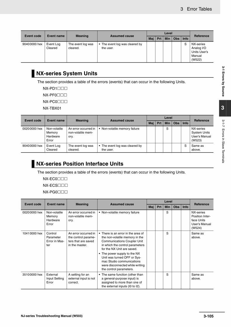
3 Error Tables3-1 E
rrors by S
ou
rce
3
3-1-7 Errors in S
lave Terminals
The section provides a table of the errors (events) that can occur in the following Units.
NX-PD1
NX-PF0
NX-PC0
NX-TBX01
The section provides a table of the errors (events) that can occur in the following Units.
NX-EC0
NX-ECS
NX-PG0
90400000 hex Event Log Cleared
The event log was cleared.
• The event log was cleared by the user.
S NX-series Analog I/O Units User’s Manual (W522)
NX-series System Units
Event code Event name Meaning Assumed causeLevel
ReferenceMaj Prt Min Obs Info
00200000 hex Non-volatile Memory Hardware Error
An error occurred in non-volatile mem-ory.
• Non-volatile memory failure S NX-series System Units User’s Manual (W523)
90400000 hex Event Log Cleared
The event log was cleared.
• The event log was cleared by the user.
S Same as above.
NX-series Position Interface Units
Event code Event name Meaning Assumed causeLevel
ReferenceMaj Prt Min Obs Info
00200000 hex Non-volatile Memory Hardware Error
An error occurred in non-volatile mem-ory.
• Non-volatile memory failure S NX-series Position Inter-face Units User’s Manual (W524)
10410000 hex Control Parameter Error in Mas-ter
An error occurred in the control parame-ters that are saved in the master.
• There is an error in the area of the non-volatile memory in the Communications Coupler Unit in which the control parameters for the NX Unit are saved.
• The power supply to the NX Unit was turned OFF or Sys-mac Studio communications were disconnected while writing the control parameters.
S Same as above.
35100000 hex External Input Setting Error
A setting for an external input is not correct.
• The same function (other than a general-purpose input) is assigned to more than one of the external inputs (I0 to I2).
S Same as above.
Event code Event name Meaning Assumed causeLevel
ReferenceMaj Prt Min Obs Info
3-105NJ-series Troubleshooting Manual (W503)

3 Error Tables
35110000 hex SSI Data Set-ting Error
There is an error in the SSI data set-tings.
• The sum of the values set for the Valid Data Length and the Leading Bits parameters exceeds 32.
• The sum of the values set for the Multi-turn Data Length, Sin-gle-turn Data Length, and the Status Data Length parame-ters exceeds 32.
• The sum of the value set for the start bit position and the data length of the SSI data exceeds the value set for the Valid Data Length parameter.
• The value set for the Encoder Resolution parameter exceeds the range expressed by the data length set for the Single-turn Data Length parameter.
S NX-series Position Inter-face Units User’s Manual (W524)
743D0000 hex Incorrect Synchroniza-tion Com-mand
Updating the target position data in the synchronization refresh failed con-secutively for more than the specified number of times.
• The task period of the primary periodic task in the NJ-series CPU Unit or the synchroniza-tion settings in the EtherCAT Coupler Unit is not correct.
• The motion control period in the Motion Control Function Mod-ule executed the task period of the primary periodic task.
• Noise
S U Same as above.
743E0000 hex Illegal Follow-ing Error
The difference between the com-mand position and actual position exceeds the range expressed by 29 bits.
• A command that exceeded the maximum velocity (500 kpps) was output continuously, so the following error for the actual output, which is restricted by the maximum velocity, has increased.
• A command velocity that does not correspond to the command position was specified when a velocity-continuous pulse out-put was used, so the number of pulses that were actually output for the updated command posi-tion has increased.
S Same as above.
743F0000 hex Illegal State Transition
The EtherCAT mas-ter or EtherCAT Coupler Unit exe-cuted a command to change the com-munications status when the Pulse Output Unit is in the Operation Enabled status.
• A communications command to change the current communica-tions status was received from the communications master while the Unit is in the Opera-tion Enabled status.
S Same as above.
Event code Event name Meaning Assumed causeLevel
ReferenceMaj Prt Min Obs Info
3-106 NJ-series Troubleshooting Manual (W503)
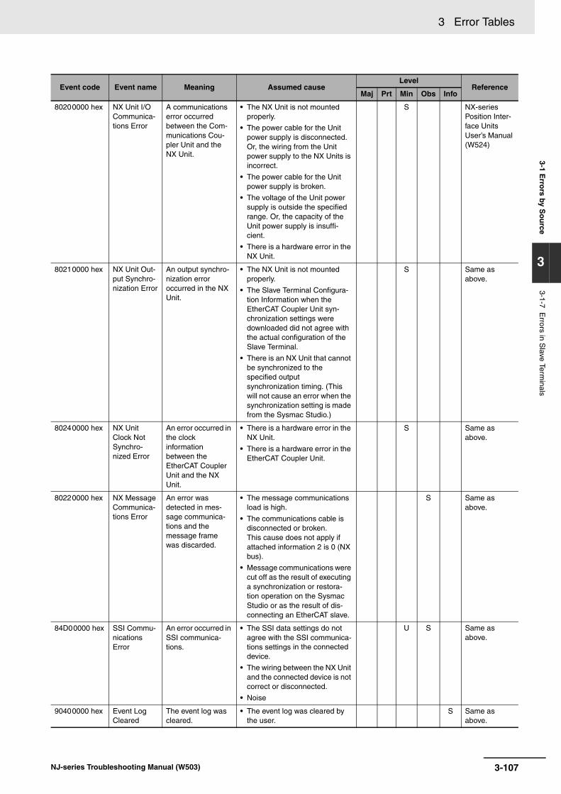
3 Error Tables3-1 E
rrors by S
ou
rce
3
3-1-7 Errors in S
lave Terminals
80200000 hex NX Unit I/O Communica-tions Error
A communications error occurred between the Com-munications Cou-pler Unit and the NX Unit.
• The NX Unit is not mounted properly.
• The power cable for the Unit power supply is disconnected. Or, the wiring from the Unit power supply to the NX Units is incorrect.
• The power cable for the Unit power supply is broken.
• The voltage of the Unit power supply is outside the specified range. Or, the capacity of the Unit power supply is insuffi-cient.
• There is a hardware error in the NX Unit.
S NX-series Position Inter-face Units User’s Manual (W524)
80210000 hex NX Unit Out-put Synchro-nization Error
An output synchro-nization error occurred in the NX Unit.
• The NX Unit is not mounted properly.
• The Slave Terminal Configura-tion Information when the EtherCAT Coupler Unit syn-chronization settings were downloaded did not agree with the actual configuration of the Slave Terminal.
• There is an NX Unit that cannot be synchronized to the specified output synchronization timing. (This will not cause an error when the synchronization setting is made from the Sysmac Studio.)
S Same as above.
80240000 hex NX Unit Clock Not Synchro-nized Error
An error occurred in the clock information between the EtherCAT Coupler Unit and the NX Unit.
• There is a hardware error in the NX Unit.
• There is a hardware error in the EtherCAT Coupler Unit.
S Same as above.
80220000 hex NX Message Communica-tions Error
An error was detected in mes-sage communica-tions and the message frame was discarded.
• The message communications load is high.
• The communications cable is disconnected or broken.This cause does not apply if attached information 2 is 0 (NX bus).
• Message communications were cut off as the result of executing a synchronization or restora-tion operation on the Sysmac Studio or as the result of dis-connecting an EtherCAT slave.
S Same as above.
84D00000 hex SSI Commu-nications Error
An error occurred in SSI communica-tions.
• The SSI data settings do not agree with the SSI communica-tions settings in the connected device.
• The wiring between the NX Unit and the connected device is not correct or disconnected.
• Noise
U S Same as above.
90400000 hex Event Log Cleared
The event log was cleared.
• The event log was cleared by the user.
S Same as above.
Event code Event name Meaning Assumed causeLevel
ReferenceMaj Prt Min Obs Info
3-107NJ-series Troubleshooting Manual (W503)

3 Error Tables
The following table lists the events that can occur for NX-series Safety Control Units with the followingmodel numbers.
NX-SL
NX-SI
NX-SO
Safety CPU Units
NX-series Safety Control Units
Event code Event name Meaning Assumed causeLevel
ReferenceMaj Prt Min Obs Info
05200000 hex System Error A hardware error was detected dur-ing self-diagnosis of the hardware.
• Hardware has failed.
• A memory error occurred due to a transient cause, such as a software error or excessive noise.
S NX-series Safety Control Unit User’s Manual (Z930)
10500000 hex NX Bus Com-munications Settings Read Error
There is an error in the NX bus commu-nications settings that are saved in non-volatile mem-ory.
• A hardware failure occurred in the non-volatile memory.
• Power was turned OFF while saving data to the non-volatile memory.
S Same as above.
10510000 hex Safety Appli-cation Data Read Error
There is an error in the safety applica-tion data that is saved in non-vola-tile memory.
• A hardware failure occurred in the non-volatile memory.
• Power was turned OFF while saving data to the non-volatile memory.
S Same as above.
10520000 hex NX Bus Com-munications Settings and Safety Appli-cation Data Mismatch
There is an error in the safety applica-tion data that is saved in non-vola-tile memory.
• The NX bus communications settings that were transferred to the Safety CPU Unit do not match the safety application data.
S Same as above.
10530000 hex Non-volatile Memory Access Error
Reading/writing non-volatile mem-ory failed.
Non-volatile memory failed. S Same as above.
35200000 hex Safety Pro-cess Data Communica-tions Not Established Error
Safety process data communications was not estab-lished with one or more safety slaves.
• The communications settings for safety process data are not correct, the safety slave is not in the correct status, etc.
• The safety slave for safety pro-cess data communications is not connected.
• The safety slave for safety pro-cess data communications is disabled.
S Same as above.
55000000 hex Division by Zero
Division by zero was detected.
The divisor is zero. S Same as above.
55010000 hex Cast Error A casting error was detected.
A value was input that exceeded the range of the receiving vari-able.
S Same as above.
55020000 hex MUX Error An MUX instruction error was detected.
The value of the selection input (K) to the MUX instruction is not correct.
S Same as above.
74A00000 hex SF_Antivalent Error
An error was detected in execu-tion of a safety function block.
Refer to information on the diag-nostic code that is given for attached information 1 in the NX-series Safety Control Unit Instruc-tions Reference Manual (Cat. No. Z931)
S Same as above.
3-108 NJ-series Troubleshooting Manual (W503)

3 Error Tables3-1 E
rrors by S
ou
rce
3
3-1-7 Errors in S
lave Terminals
74A10000 hex SF_EDM Error
An error was detected in execu-tion of a safety function block.
Refer to information on the diag-nostic code that is given for attached information 1 in the NX-series Safety Control Unit Instruc-tions Reference Manual (Cat. No. Z931)
S NX-series Safety Control Unit User’s Manual (Z930)
74A20000 hex SF_EmergencyStop Error
An error was detected in execu-tion of a safety function block.
Refer to information on the diag-nostic code that is given for attached information 1 in the NX-series Safety Control Unit Instruc-tions Reference Manual (Cat. No. Z931)
S Same as above.
74A30000 hex SF_EnableSwitch Error
An error was detected in execu-tion of a safety function block.
Refer to information on the diag-nostic code that is given for attached information 1 in the NX-series Safety Control Unit Instruc-tions Reference Manual (Cat. No. Z931)
S Same as above.
74A40000 hex SF_Equivalent Error
An error was detected in execu-tion of a safety function block.
Refer to information on the diag-nostic code that is given for attached information 1 in the NX-series Safety Control Unit Instruc-tions Reference Manual (Cat. No. Z931)
S Same as above.
74A50000 hex SF_ESPE Error
An error was detected in execu-tion of a safety function block.
Refer to information on the diag-nostic code that is given for attached information 1 in the NX-series Safety Control Unit Instruc-tions Reference Manual (Cat. No. Z931)
S Same as above.
74A60000 hex SF_GuardLocking Error
An error was detected in execu-tion of a safety function block..
Refer to information on the diag-nostic code that is given for attached information 1 in the NX-series Safety Control Unit Instruc-tions Reference Manual (Cat. No. Z931)
S Same as above.
74A70000 hex SF_GuardMonitoring Error
An error was detected in execu-tion of a safety function block.
Refer to information on the diag-nostic code that is given for attached information 1 in the NX-series Safety Control Unit Instruc-tions Reference Manual (Cat. No. Z931)
S Same as above.
74A80000 hex SF_ModeSelector Error
An error was detected in execu-tion of a safety function block.
Refer to information on the diag-nostic code that is given for attached information 1 in the NX-series Safety Control Unit Instruc-tions Reference Manual (Cat. No. Z931)
S Same as above.
74A90000 hex SF_MutingPar Error
An error was detected in execu-tion of a safety function block.
Refer to information on the diag-nostic code that is given for attached information 1 in the NX-series Safety Control Unit Instruc-tions Reference Manual (Cat. No. Z931)
S Same as above.
74AA0000 hex SF_MutingPar_2Sensor Error
An error was detected in execu-tion of a safety function block.
Refer to information on the diag-nostic code that is given for attached information 1 in the NX-series Safety Control Unit Instruc-tions Reference Manual (Cat. No. Z931)
S Same as above.
Event code Event name Meaning Assumed causeLevel
ReferenceMaj Prt Min Obs Info
3-109NJ-series Troubleshooting Manual (W503)

3 Error Tables
74AB0000 hex SF_MutingSeq Error
An error was detected in execu-tion of a safety function block.
Refer to information on the diag-nostic code that is given for attached information 1 in the NX-series Safety Control Unit Instruc-tions Reference Manual (Cat. No. Z931)
S NX-series Safety Control Unit User’s Manual (Z930)
74AC0000 hex SF_OutControl Error
An error was detected in execu-tion of a safety function block.
Refer to information on the diag-nostic code that is given for attached information 1 in the NX-series Safety Control Unit Instruc-tions Reference Manual (Cat. No. Z931)
S Same as above.
74AD0000 hex SF_SafetyRequest Error
An error was detected in execu-tion of a safety function block.
Refer to information on the diag-nostic code that is given for attached information 1 in the NX-series Safety Control Unit Instruc-tions Reference Manual (Cat. No. Z931)
S Same as above.
74AE0000 hex SF_TestableSafetySen-sor Error
An error was detected in execu-tion of a safety function block.
Refer to information on the diag-nostic code that is given for attached information 1 in the NX-series Safety Control Unit Instruc-tions Reference Manual (Cat. No. Z931)
S Same as above.
74AF0000 hex SF_TwoHandControlTyp-eII Error
An error was detected in execu-tion of a safety function block.
Refer to information on the diag-nostic code that is given for attached information 1 in the NX-series Safety Control Unit Instruc-tions Reference Manual (Cat. No. Z931)
S Same as above.
74B00000 hex SF_TwoHandControlTyp-eIII Error
An error was detected in execu-tion of a safety function block.
Refer to information on the diag-nostic code that is given for attached information 1 in the NX-series Safety Control Unit Instruc-tions Reference Manual (Cat. No. Z931)
S Same as above.
80200000 hex NX Unit I/O Communica-tions Error
An I/O communica-tions error occurred between the Com-munications Cou-pler Unit and the NX Unit.
• The NX Unit is not mounted properly.
• There is a hardware error in the NX Unit.
S Same as above.
80300000 hex Safety Pro-cess Data Communica-tions Timeout
A communications timeout occurred in safety process data communications with the Safety CPU Unit.
• A setting is not correct. The set-ting of the safety task period of the Safety CPU Unit is too short. Or, the PDO communica-tions safety task period of the EtherCAT master is too short.
• There is excessive noise.
• The Safety CPU Unit entered a status where it could not con-tinue safety process data com-munications.
• An error or status change occurred in the EtherCAT Cou-pler Unit to which the Unit is connected, preventing correct process data communications.
S Same as above.
84F00000 hex NX Bus I/O Communica-tions Stopped
An error occurred in I/O communications between the Com-munications Cou-pler Unit and an NX Unit.
There is a hardware error in the Communications Coupler Unit or an NX Unit.
S Same as above.
Event code Event name Meaning Assumed causeLevel
ReferenceMaj Prt Min Obs Info
3-110 NJ-series Troubleshooting Manual (W503)

3 Error Tables3-1 E
rrors by S
ou
rce
3
3-1-7 Errors in S
lave Terminals
Safety I/O Units
80220000 hex NX Message Communica-tions Error
An error was detected in mes-sage communica-tions for an NX Unit and the message frame was dis-carded.
The message communications load is high.
S NX-series Safety Control Unit User’s Manual (Z930)
90400000 hex Event Log Cleared
The event log was cleared.
The event log was cleared by the user.
S Same as above.
90430000 hex Memory All Cleared
The Unit settings were cleared.
The Clear All Memory operation was performed.
S Same as above.
951E0000 hex Sysmac Stu-dio Commu-nications Connection Timeout
A communications timeout occurred between the Sys-mac Studio and the Safety CPU Unit.
• The communications cable was disconnected.
S Same as above.
951F0000 hex Clear All Memory Rejected
Clearing all of memory failed.
• The Clear All Memory operation was performed for the entire Slave Terminal.
S Same as above.
Event code Event name Meaning Assumed causeLevel
ReferenceMaj Prt Min Obs Info
05200000 hex System Error A hardware error was detected dur-ing self-diagnosis of the hardware.
• Hardware has failed.
• A memory error occurred due to a transient cause, such as a software error or excessive noise.
S NX-series Safety Control Unit User’s Manual (Z930)
05210000 hex Internal Cir-cuit Error at Safety Input
A fault was detected in the internal circuit for the safety input ter-minal.
• The internal circuit for the safety input terminal is faulty.
• A memory error or signal error occurred due to a transient cause, such as a software error or excessive noise.
S Same as above.
05220000 hex Internal Cir-cuit Error at Test Output
A fault was detected in the internal circuit for the test output ter-minal.
• The internal circuit for the test output terminal is faulty.
• A memory error or signal error occurred due to a transient cause, such as a software error or excessive noise.
S Same as above.
05230000 hex Internal Cir-cuit Error at Safety Output
A fault was detected in the internal circuit for the safety output terminal.
• The internal circuit for the safety output terminal is faulty.
• A memory error or signal error occurred due to a transient cause, such as a software error or excessive noise.
S Same as above.
35210000 hex Safety Pro-cess Data Communica-tions Not Established - Incorrect Unit Parameter Error
Safety process data communications was not estab-lished with the Safety CPU Unit.
• The model or safety I/O termi-nal settings are not correct.
S Same as above.
Event code Event name Meaning Assumed causeLevel
ReferenceMaj Prt Min Obs Info
3-111NJ-series Troubleshooting Manual (W503)
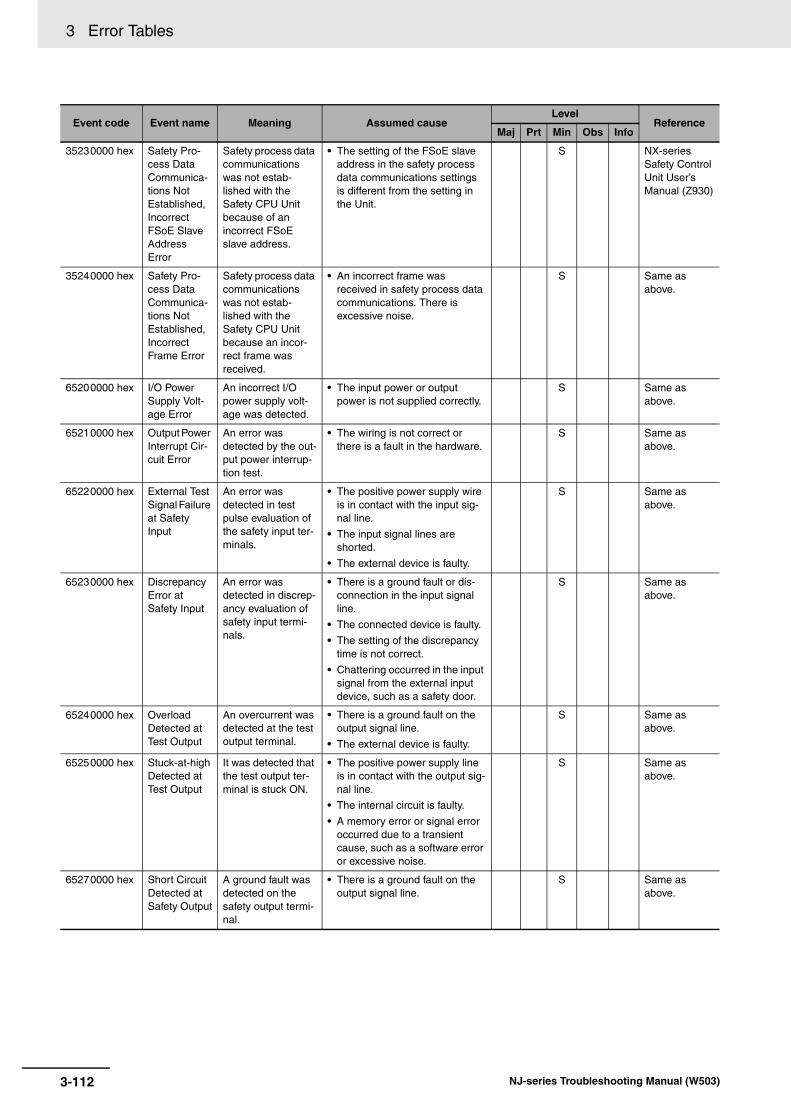
3 Error Tables
35230000 hex Safety Pro-cess Data Communica-tions Not Established, Incorrect FSoE Slave Address Error
Safety process data communications was not estab-lished with the Safety CPU Unit because of an incorrect FSoE slave address.
• The setting of the FSoE slave address in the safety process data communications settings is different from the setting in the Unit.
S NX-series Safety Control Unit User’s Manual (Z930)
35240000 hex Safety Pro-cess Data Communica-tions Not Established, Incorrect Frame Error
Safety process data communications was not estab-lished with the Safety CPU Unit because an incor-rect frame was received.
• An incorrect frame was received in safety process data communications. There is excessive noise.
S Same as above.
65200000 hex I/O Power Supply Volt-age Error
An incorrect I/O power supply volt-age was detected.
• The input power or output power is not supplied correctly.
S Same as above.
65210000 hex Output Power Interrupt Cir-cuit Error
An error was detected by the out-put power interrup-tion test.
• The wiring is not correct or there is a fault in the hardware.
S Same as above.
65220000 hex External Test Signal Failure at Safety Input
An error was detected in test pulse evaluation of the safety input ter-minals.
• The positive power supply wire is in contact with the input sig-nal line.
• The input signal lines are shorted.
• The external device is faulty.
S Same as above.
65230000 hex Discrepancy Error at Safety Input
An error was detected in discrep-ancy evaluation of safety input termi-nals.
• There is a ground fault or dis-connection in the input signal line.
• The connected device is faulty.
• The setting of the discrepancy time is not correct.
• Chattering occurred in the input signal from the external input device, such as a safety door.
S Same as above.
65240000 hex Overload Detected at Test Output
An overcurrent was detected at the test output terminal.
• There is a ground fault on the output signal line.
• The external device is faulty.
S Same as above.
65250000 hex Stuck-at-high Detected at Test Output
It was detected that the test output ter-minal is stuck ON.
• The positive power supply line is in contact with the output sig-nal line.
• The internal circuit is faulty.
• A memory error or signal error occurred due to a transient cause, such as a software error or excessive noise.
S Same as above.
65270000 hex Short Circuit Detected at Safety Output
A ground fault was detected on the safety output termi-nal.
• There is a ground fault on the output signal line.
S Same as above.
Event code Event name Meaning Assumed causeLevel
ReferenceMaj Prt Min Obs Info
3-112 NJ-series Troubleshooting Manual (W503)

3 Error Tables3-1 E
rrors by S
ou
rce
3
3-1-7 Errors in S
lave Terminals
65280000 hex Stuck-at-high Detected at Safety Output
It was detected that the safety output terminal is stuck ON.
• The positive power supply line is in contact with the output sig-nal line.
• The output power supply is out-side the specifications.
• The internal circuit is faulty.
• A memory error or signal error occurred due to a transient cause, such as a software error or excessive noise.
S NX-series Safety Control Unit User’s Manual (Z930)
80200000 hex NX Unit I/O Communica-tions Error
An I/O communica-tions error occurred between the Com-munications Cou-pler Unit and the NX Unit.
• The NX Unit is not mounted properly.
• There is a hardware error in the NX Unit.
S Same as above.
80300000 hex Safety Pro-cess Data Communica-tions Timeout
A communications timeout occurred in safety process data communications with a safety slave.
• A setting is not correct. The set-ting of the safety task period of the Safety CPU Unit is too short. Or, the setting of the PDO communications safety task period of the EtherCAT master is too short.
• There is excessive noise.
• The safety slave entered a sta-tus where it could not continue safety process data communi-cations.
• An error or status change occurred in the EtherCAT Cou-pler Unit to which the Unit is connected, preventing correct process data communications.
S Same as above.
84F10000 hex NX Bus I/O Communica-tions Stopped
An error occurred in I/O communications between the Com-munications Cou-pler Unit and an NX Unit.
There is a hardware error in the Communications Coupler Unit or an NX Unit.
S Same as above.
80220000 hex NX Message Communica-tions Error
An error was detected in mes-sage communica-tions for an NX Unit and the message frame was dis-carded.
• The message communications load is high.
• The communications cable is disconnected or broken.
S Same as above.
90400000 hex Event Log Cleared
The event log was cleared.
The event log was cleared by the user.
S Same as above.
90430000 hex Memory All Cleared
The Unit settings were cleared.
The Clear All Memory operation was performed.
S Same as above.
Event code Event name Meaning Assumed causeLevel
ReferenceMaj Prt Min Obs Info
3-113NJ-series Troubleshooting Manual (W503)

3 Error Tables
This section provides tables of the events for which OMRON EtherCAT slaves provide notification to theNJ-series CPU Unit.
• Block I/O (GX-series EtherCAT Slave Units)
• Servo G5 (G5-series AC Servo Drives with Built-in EtherCAT Communications) and G5 Linear (G5-series Linear Motors/Drives with Built-in EtherCAT Communications Linear Motor Type)
• MX2/RX-series Inverters with EtherCAT Communications Units
• FH-series Vision Systems
• EtherCAT FQ-M-series Specialized Vision Sensors for Positioning
• E3X-series Fiber Sensors with EtherCAT Communications Unit for Digital Sensors
• E3NW-ECT EtherCAT Digital Sensor Communications Unit
• ZW-CE1T Confocal Fiber Type Displacement Sensor
Event codes are given for both G5-series Cylinder-type (rotary) Servomotors and Linear Motor Type.The following abbreviations are used for the manual names.
3-1-8 Errors in EtherCAT Slaves
Block I/O (GX-series EtherCAT Slave Units)
Event code Event name Meaning Assumed causeLevel
ReferenceMaj Prt Min Obs Info
14A00000 hex Non-volatile Memory Checksum Error
An error occurred in the control parame-ters.
• Noise S GX-series EtherCAT Slave Units User's Manual (Cat. No. W488)
24610000 hex Switch Set-ting Error
The setting switch is set out of range.
• The analog range that is set on the switch is outside the setting range.
S Same as above.
64CC0000 hex I/O Discon-nection Detected
An I/O signal line is disconnected.
• I/O signal wiring is discon-nected or has a faulty connec-tion.
• An I/O signal line is discon-nected.
S Same as above.
04A10000 hex Non-volatile Memory Hardware Error
An error occurred in non-volatile mem-ory.
• Non-volatile memory failure S Same as above.
Servo G5 (G5-series AC Servo Drives with Built-in EtherCAT Communications) and G5 Linear (G5-series Linear Motors/Drives with Built-in EtherCAT Communications Linear Motor Type)
Manual name abbreviation Manual name
Cylinder-type Motor Manual G5-series AC Servomotors/Servo Drives with Built-in EtherCAT Com-munications User’s Manual
Linear Motor Manual G5-series Linear Motors/Drives with Built-in EtherCAT Communica-tions Linear Motor Type User’s Manual
3-114 NJ-series Troubleshooting Manual (W503)

3 Error Tables3-1 E
rrors by S
ou
rce
3
3-1-8 Errors in E
therCAT
Slaves
Event code Event name Meaning Assumed causeLevel
ReferenceMaj Prt Min Obs Info
04A80000 hex Control Power Sup-ply Under-voltage
The voltage between the posi-tive and negative terminals in the control power sup-ply converter dropped below the specified value.
• Power supply undervoltage. Or, the power supply voltage dropped because there was inrush current when the main power supply was turned ON.
• A momentary power interrup-tion occurred.
• The Servo Drive failed.
S Cylinder-type Motor Manual (Cat. No. I576) and Linear Motor Manual (Cat. No. I577)
04A90000 hex Overvoltage The power supply voltage exceeded the allowable input voltage range.
• The voltage between the posi-tive and negative terminals in the control power supply con-verter exceeded the specified value.
• The voltage was suddenly increased by the phase advance capacitor or the unin-terruptible power supply (UPS).
• The Regeneration Resistor wir-ing is broken.
• The External Regeneration Resistor is not suitable.
• The Servo Drive failed.
S Same as above.
04AA0000 hex Main Circuit Power Sup-ply Under-voltage (Undervolt-age between positive and negative ter-minals)
If the Undervoltage Error Selection (3508 hex) is set to 1, a momentary power interruption occurred between L1 and L3 for longer than the value specified for the Momentary Hold Time. The voltage between the posi-tive and negative terminals in the main power supply converter dropped below the specified value while the Servo was ON.
• Insufficient power supply capacity
• The electromagnetic contactor in the main circuit power supply was tripped.
• A momentary power interrup-tion occurred.
• A Servo Drive with 3-phase input specifications was oper-ated with a single-phase power supply.
• The Servo Drive failed.
S Same as above.
04AB0000 hex Main Circuit Power Sup-ply Under-voltage (AC Cutoff Detected)
If the Undervoltage Error Selection (3508 hex) is set to 1, a momentary power interruption occurred between L1 and L3 for longer than the value specified for the Momentary Hold Time. The voltage between the posi-tive and negative terminals in the main power supply converter dropped below the specified value while the Servo was ON.
• Insufficient power supply capacity
• The electromagnetic contactor in the main circuit power supply was tripped.
• A momentary power interrup-tion occurred.
• A Servo Drive with 3-phase input specifications was oper-ated with a single-phase power supply.
• The Servo Drive failed.
S Same as above.
3-115NJ-series Troubleshooting Manual (W503)

3 Error Tables
04AC0000 hex Overcurrent The current flowing through the con-verter exceeded the specified value.
• A short-circuit, line-to-ground fault, contact failure, or insula-tion failure occurred on the U, V, or W motor line.
• The Servo Drive failed.
• The relay for the dynamic brake has been welded due to fre-quent Servo ON/OFF opera-tions.
• Motor windings are burned out.
• The Servomotor is not suitable for the Servo Drive.
• The command input timing is the same as or earlier than the Servo ON timing.
S Cylinder-type Motor Manual (Cat. No. I576) and Linear Motor Manual (Cat. No. I577)
04AD0000 hex IPM Error The current flowing through the con-verter exceeded the specified value.
• A short-circuit, line-to-ground fault, contact failure, or insula-tion failure occurred on the U, V, or W motor line.
• The Servo Drive failed.
• The relay for the dynamic brake has been welded due to fre-quent Servo ON/OFF opera-tions.
• Motor windings are burned out.
• The Servomotor is not suitable for the Servo Drive.
• The pulse input timing is the same as or earlier than the Servo ON timing.
S Same as above.
04AE0000 hex Regenera-tion Tr Error
The Servo Drive regeneration drive Tr is faulty.
• The Servo Drive regeneration drive Tr is faulty.
S Same as above.
04AF0000 hex Encoder Phase-Z Error
A missing serial incremental encoder phase-Z pulse was detected.
• The encoder is faulty. S Cylinder-type Motor Manual (Cat. No. I576)
04B00000 hex Encoder CTS Signal Error
A missing serial incremental encoder CTS signal logic error was detected.
• The encoder is faulty. S Same as above.
04B10000 hex Node Address Set-ting Error
The node address that was read from the rotary switches was not between 00 and 99.
• The Servo Drive failed. S Cylinder-type Motor Manual (Cat. No. I576) and Linear Motor Manual (Cat. No. I577)
04B20000 hex Other Errors The Servo Drive malfunctioned, or an error occurred in the Servo Drive.
• The control circuit malfunc-tioned temporarily due to excess noise.
• The Servo Drive’s self-diagno-sis function detected an error in the Servo Drive.
S Linear Motor Manual (Cat. No. I577)
08080000 hex Encoder Communica-tions Discon-nection Error
A disconnection was detected because communi-cations between the encoder and the Servo Drive were stopped more fre-quently than the specified value.
• The encoder is not wired cor-rectly.
S Cylinder-type Motor Manual (Cat. No. I576)
Event code Event name Meaning Assumed causeLevel
ReferenceMaj Prt Min Obs Info
3-116 NJ-series Troubleshooting Manual (W503)

3 Error Tables3-1 E
rrors by S
ou
rce
3
3-1-8 Errors in E
therCAT
Slaves
08090000 hex Encoder Communica-tions Error
There is a commu-nications error for the encoder.
• The power supply voltage of the encoder is low.
• Noise
S Cylinder-type Motor Manual (Cat. No. I576)
080A0000 hex Encoder Communica-tions Data Error
There is an error in the communica-tions data of the encoder.
• The power supply voltage of the encoder is low.
• Noise
S Same as above.
080B0000 hex Safety Input Error
At least one of the input photocou-plers for safety inputs 1 and 2 turned OFF.
• The cable is disconnected or broken.
S Cylinder-type Motor Manual (Cat. No. I576) and Linear Motor Manual (Cat. No. I577)
080C0000 hex External Encoder Connection Error
A disconnection was detected because communi-cations between the external encoder and the Servo Drive were stopped more frequently than the specified value.
• The wiring is incorrect. S Same as above.
080D0000 hex External Encoder Communica-tions Data Error
There was a com-munications error in data from the exter-nal encoder.
• There is insufficient external encoder power supply voltage.
• Noise
S Same as above.
080E0000 hex External Encoder Sta-tus Error 0
Bit 00 of the exter-nal encoder error code (ALMC) was set to 1.
• Bit 00 of the external scale error code (ALMC) was set to 1.
S Same as above.
080F0000 hex External Encoder Sta-tus Error 1
Bit 01 of the exter-nal encoder error code (ALMC) was set to 1.
• Bit 01 of the external encoder error code (ALMC) was set to 1.
S Same as above.
08100000 hex External Encoder Sta-tus Error 2
Bit 02 of the exter-nal encoder error code (ALMC) was set to 1.
• Bit 02 of the external encoder error code (ALMC) was set to 1.
S Same as above.
08110000 hex External Encoder Sta-tus Error 3
Bit 03 of the exter-nal encoder error code (ALMC) was set to 1.
• Bit 03 of the external encoder error code (ALMC) was set to 1.
S Same as above.
08120000 hex External Encoder Sta-tus Error 4
Bit 04 of the exter-nal encoder error code (ALMC) was set to 1.
• Bit 04 of the external encoder error code (ALMC) was set to 1.
S Same as above.
08130000 hex External Encoder Sta-tus Error 5
Bit 05 of the exter-nal encoder error code (ALMC) was set to 1.
• Bit 05 of the external encoder error code (ALMC) was set to 1.
S Same as above.
08140000 hex Phase-A Connection Error
An error such as broken wiring was detected in the external encoder phase-A connec-tion.
• An error such as broken wiring was detected in the external encoder phase-A connection.
S Same as above.
08150000 hex Phase-B Connection Error
An error such as broken wiring was detected in the external encoder phase-B connec-tion.
• An error such as broken wiring was detected in the external encoder phase-B connection.
S Same as above.
Event code Event name Meaning Assumed causeLevel
ReferenceMaj Prt Min Obs Info
3-117NJ-series Troubleshooting Manual (W503)
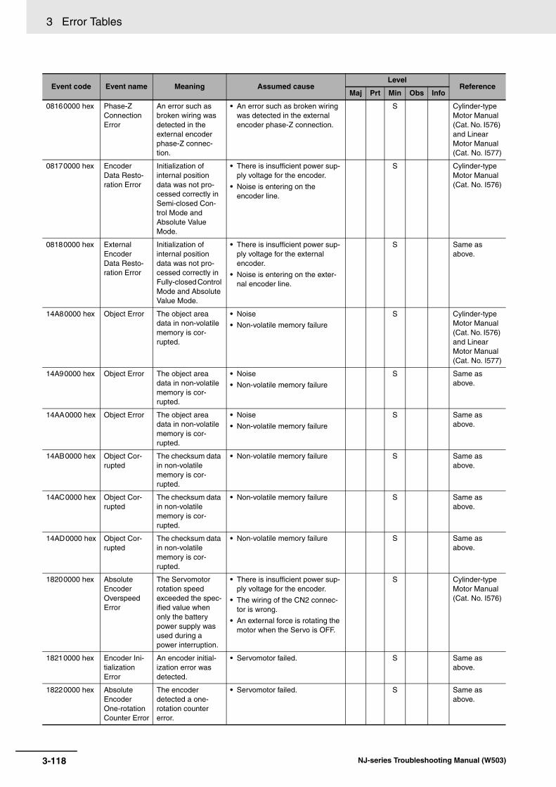
3 Error Tables
08160000 hex Phase-Z Connection Error
An error such as broken wiring was detected in the external encoder phase-Z connec-tion.
• An error such as broken wiring was detected in the external encoder phase-Z connection.
S Cylinder-type Motor Manual (Cat. No. I576) and Linear Motor Manual (Cat. No. I577)
08170000 hex Encoder Data Resto-ration Error
Initialization of internal position data was not pro-cessed correctly in Semi-closed Con-trol Mode and Absolute Value Mode.
• There is insufficient power sup-ply voltage for the encoder.
• Noise is entering on the encoder line.
S Cylinder-type Motor Manual (Cat. No. I576)
08180000 hex External Encoder Data Resto-ration Error
Initialization of internal position data was not pro-cessed correctly in Fully-closed Control Mode and Absolute Value Mode.
• There is insufficient power sup-ply voltage for the external encoder.
• Noise is entering on the exter-nal encoder line.
S Same as above.
14A80000 hex Object Error The object area data in non-volatile memory is cor-rupted.
• Noise
• Non-volatile memory failure
S Cylinder-type Motor Manual (Cat. No. I576) and Linear Motor Manual (Cat. No. I577)
14A90000 hex Object Error The object area data in non-volatile memory is cor-rupted.
• Noise
• Non-volatile memory failure
S Same as above.
14AA0000 hex Object Error The object area data in non-volatile memory is cor-rupted.
• Noise
• Non-volatile memory failure
S Same as above.
14AB0000 hex Object Cor-rupted
The checksum data in non-volatile memory is cor-rupted.
• Non-volatile memory failure S Same as above.
14AC0000 hex Object Cor-rupted
The checksum data in non-volatile memory is cor-rupted.
• Non-volatile memory failure S Same as above.
14AD0000 hex Object Cor-rupted
The checksum data in non-volatile memory is cor-rupted.
• Non-volatile memory failure S Same as above.
18200000 hex Absolute Encoder Overspeed Error
The Servomotor rotation speed exceeded the spec-ified value when only the battery power supply was used during a power interruption.
• There is insufficient power sup-ply voltage for the encoder.
• The wiring of the CN2 connec-tor is wrong.
• An external force is rotating the motor when the Servo is OFF.
S Cylinder-type Motor Manual (Cat. No. I576)
18210000 hex Encoder Ini-tialization Error
An encoder initial-ization error was detected.
• Servomotor failed. S Same as above.
18220000 hex Absolute Encoder One-rotation Counter Error
The encoder detected a one-rotation counter error.
• Servomotor failed. S Same as above.
Event code Event name Meaning Assumed causeLevel
ReferenceMaj Prt Min Obs Info
3-118 NJ-series Troubleshooting Manual (W503)

3 Error Tables3-1 E
rrors by S
ou
rce
3
3-1-8 Errors in E
therCAT
Slaves
18230000 hex Absolute Encoder Multi-rotation Counter Error
The encoder detected a multi-rotation counter error.
• Servomotor failed. S Cylinder-type Motor Manual (Cat. No. I576)
24680000 hex Motor Non-conformity
The Servo Drive and Servomotor combination is not correct.
• The Servo Drive and Servomo-tor combination is not correct.
S Same as above.
24690000 hex Motor Non-conformity
The Servo Drive and Servomotor combination is not correct.
• The Servo Drive and Servomo-tor combination is not correct.
S Same as above.
246A0000 hex Motor Non-conformity
The Servo Drive and Servomotor combination is not correct.
• The Servo Drive and Servomo-tor combination is not correct.
S Same as above.
246B0000 hex Motor Non-conformity
The Servo Drive and Servomotor combination is not correct.
• The Servo Drive and Servomo-tor combination is not correct.
S Same as above.
246C0000 hex Motor Non-conformity
The Servo Drive and Servomotor combination is not correct.
• The Servo Drive and Servomo-tor combination is not correct.
S Same as above.
28010000 hex Motor Set-ting Error
Settings associ-ated with the motor and external encoder are miss-ing.
• Settings associated with the motor and external encoder are missing.
S Linear Motor Manual (Cat. No. I577)
28020000 hex Motor Combi-nation Error 1
The value set for the motor current exceeds the maxi-mum motor capac-ity allowed for the Servo Drive.
• The Motor Rated Rms Cur-rent/Motor Peak Absolute Cur-rent exceeds the maximum motor capacity allowed for the Servo Drive.
S Same as above.
28030000 hex Motor Combi-nation Error 2
The value set for the motor exceeds the drive range of the motor.
• The Motor Rated Rms Current is too low compared with the maximum motor capacity of the Servo Drive.
• The percentage of the Motor Coil Unit Mass to the Motor Rated Force is too high.
• The automatically adjusted Cur-rent Loop Proportional Gain/Current Loop Integral Gain is too high.
• The percentage of the Motor Peak Absolute Current to the Motor Rated Rms Current is greater than 500%.
S Same as above.
34E10000 hex Servo Drive Overheat
The temperature of the Servo Drive radiator or power elements exceeded the specified value.
• The ambient temperature of the Servo Drive exceeded the specified value.
• Overload
S Cylinder-type Motor Manual (Cat. No. I576) and Linear Motor Manual (Cat. No. I577)
Event code Event name Meaning Assumed causeLevel
ReferenceMaj Prt Min Obs Info
3-119NJ-series Troubleshooting Manual (W503)

3 Error Tables
34E20000 hex Overload When the feedback value for torque/force com-mand exceeds the overload level spec-ified in the Overload Detection Level Setting (3512 hex), overload protection is performed according to the overload character-istics.
• Operation was continued for a long time while overloaded.
• There is incorrect wiring of the motor line or a broken cable.
S Cylinder-type Motor Manual (Cat. No. I576) and Linear Motor Manual (Cat. No. I577)
34E30000 hex Regenera-tion Overload
The regenerative energy exceeds the processing capac-ity of the Regenera-tion Resistor.
• The load inertia/load mass is too large. Or, the Servomotor rotation speed/motor speed is too high to absorb the regener-ative energy within the speci-fied deceleration time.
• This Regeneration Resistor cannot be used for continuous regenerative braking. (The operating limit of the external resistor is limited to a 10% duty.)
S Same as above.
34E40000 hex Error Counter Overflow
Position error pulses exceeded the setting of the Following error win-dow (6065 hex).
• Motor operation does not fol-low the command.
• The value of the Following error window (6065 hex) is small.
• The encoder/external encoder wiring is incorrect.
S Same as above.
34E50000 hex Excessive Velocity Error
The difference between the inter-nal position com-mand velocity and the actual velocity (i.e., the velocity error) exceeded the Excessive Velocity Error Setting (3602 hex).
• Motor operation does not fol-low the command.
• The setting of the Excessive Velocity Error Setting (3602 hex) is too small.
S Same as above.
34E60000 hex Overspeed The Servomotor rotation speed/motor speed exceeded the value set on the Over-speed Detection Level Setting (3513 hex).
• The velocity command value is too large.
• There is overshooting.
• The wiring is incorrect.
S Same as above.
383F0000 hex Excessive Hybrid Fol-lowing Error
During fully-closed control, the differ-ence between the load position from the external encoder and the Servomotor posi-tion from the encoder was larger than the number of pulses set as the Hybrid Following Error Counter Over-flow Level (3328 hex).
• Connections are not correct.
• The settings are not correct.
S Cylinder-type Motor Manual (Cat. No. I576)
Event code Event name Meaning Assumed causeLevel
ReferenceMaj Prt Min Obs Info
3-120 NJ-series Troubleshooting Manual (W503)

3 Error Tables3-1 E
rrors by S
ou
rce
3
3-1-8 Errors in E
therCAT
Slaves
38400000 hex Overspeed 2 The Servomotor rotation speed/motor speed exceeded the value set on Overspeed Detection Level Setting at Immedi-ate Stop (3615 hex).
• The velocity command value is too large.
• There is overshooting.
• The wiring is incorrect.
S Cylinder-type Motor Manual (Cat. No. I576) and Linear Motor Manual (Cat. No. I577)
38410000 hex Command Error
The position com-mand variation after the electronic gear exceeded the spec-ified value.
• The change in position com-mand is too large.
• The backlash compensation amount is too large.
S Same as above.
38420000 hex Command Generation Error
During position command process-ing, an error such as a calculation range error occurred.
• During position command pro-cessing, an error such as a cal-culation range error occurred.
S Same as above.
38430000 hex Error Counter Overflow 1
The absolute encoder posi-tion/absolute scale position in pulses divided by the elec-tronic gear ratio exceeded ±231 (2,147,483,648).
• The absolute encoder posi-tion/absolute scale position in pulses divided by the electronic gear ratio exceeded ±231 (2,147,483,648).
S Same as above.
38440000 hex Error Counter Overflow 2
The position follow-ing error in pulses exceeded ±229 (536,870,912). Or, the position follow-ing error in com-mand units exceeded ±230 (1,073,741,824).
• There is insufficient torque/force.
• There is insufficient gain.
• The encoder/external encoder wiring is incorrect.
S Same as above.
38450000 hex Interface Input Dupli-cate Alloca-tion Error 1
There is a dupli-cate setting in the input signal (IN1, IN2, IN3, and IN4) function allocations.
• There is a duplicate setting in the input signal (IN1, IN2, IN3, and IN4) function allocations.
S Same as above.
38460000 hex Interface Input Dupli-cate Alloca-tion Error 2
There is a dupli-cate setting in the input signal (IN5, IN6, IN7, and IN8) function allocations.
• There is a duplicate setting in the input signal (IN5, IN6, IN7, and IN8) function allocations.
S Same as above.
38470000 hex Interface Input Func-tion Number Error 1
There is an unde-fined number speci-fication in the input signal (IN1, IN2, IN3, and IN4) func-tion allocations. Or, a logic setting error was detected.
• There is an undefined number specification in the input signal (IN1, IN2, IN3, and IN4) func-tion allocations.
• Different logic is set for the same function in the function assignments of the input sig-nals (IN1, IN2, IN3, and IN4).
S Same as above.
38480000 hex Interface Input Func-tion Number Error 2
There is an unde-fined number speci-fication in the input signal (IN5, IN6, IN7, and IN8) func-tion allocations. Or, a logic setting error was detected.
• There is an undefined number specification in the input signal (IN5, IN6, IN7, and IN8) func-tion allocations.
• Different logic is set for the same function in the function assignments of the input sig-nals (IN5, IN6, IN7, and IN8).
S Same as above.
Event code Event name Meaning Assumed causeLevel
ReferenceMaj Prt Min Obs Info
3-121NJ-series Troubleshooting Manual (W503)

3 Error Tables
38490000 hex Interface Out-put Function Number Error 1
There is an unde-fined number speci-fication in the output signal (OUTM1) function allocation.
• There is an undefined number specification in the output sig-nal (OUTM1) function alloca-tion.
S Cylinder-type Motor Manual (Cat. No. I576) and Linear Motor Manual (Cat. No. I577)
384A0000 hex Interface Out-put Function Number Error 2
There is an unde-fined number speci-fication in the output signal (OUTM2) function allocation.
• There is an undefined number specification in the output sig-nal (OUTM2) function alloca-tion.
S Same as above.
384B0000 hex External Latch Input Allocation Error
There is an error in the latch input func-tion allocation.
• The latch input was allocated to an input signal other than IN5, IN6, or IN7.
• A latch input is assigned to an NC signal.
• The same latch input is not assigned to the same pin in all Control Modes.
S Same as above.
384C0000 hex Overrun Limit Error
The Servomotor exceeded the allow-able operating range set in the Overrun Limit Set-ting (3514 hex) with respect to the posi-tion command input range.
• The gain or inertial ratio/mass ratio is not suitable.
• The set value of the Overrun Limit Setting (3514 hex) is too small.
S Same as above.
384D0000 hex Absolute Encoder Sys-tem Down Error
The voltage of the built-in capacitor dropped below the specified value because the power supply to the encoder or the bat-tery power supply was down.
• The voltage of the built-in capacitor dropped below the specified value because the power supply to the encoder or the battery power supply was down.
S Cylinder-type Motor Manual (Cat. No. I576)
384E0000 hex Absolute Encoder Counter Overflow Error
The multi-rotation counter of the encoder exceeded the specified value.
• The set value for switching operation with the absolute encoder is too large.
• The traveling distance from home of the machine exceeded 32,767 revolutions.
S Same as above.
384F0000 hex Object Set-ting Error 1
The electronic gear ratio exceeded the allowable range.
• The electronic gear ratio exceeded the allowable range.
S Cylinder-type Motor Manual (Cat. No. I576) and Linear Motor Manual (Cat. No. I577)
38500000 hex Object Set-ting Error 2
External encoder ratio exceeded the allowable range.
• External encoder ratio exceeded the allowable range.
S Same as above.
38510000 hex External Encoder Connection Error
The set value of the External Feedback Pulse Type Selec-tion (3323 hex) dif-fers from the external encoder type that is con-nected for serial communications.
• The set value of the External Feedback Pulse Type Selec-tion (3323 hex) differs from the external encoder type that is connected for serial communi-cations.
S Same as above.
Event code Event name Meaning Assumed causeLevel
ReferenceMaj Prt Min Obs Info
3-122 NJ-series Troubleshooting Manual (W503)

3 Error Tables3-1 E
rrors by S
ou
rce
3
3-1-8 Errors in E
therCAT
Slaves
38520000 hex Function Set-ting Error
The function that was set does not support the com-munications period.
• The electronic gear object ratio was not 1:1 when the communi-cations period was set to 500 μs.
• Modes of operation (6060 hex) was set to pp or hm when the communications period was set to 500 μs.
• More than 12 bytes were mapped for RxPDO in Fully-closed Control Mode (This applies only to Cylinder-type Servomotors.).
• Modes of operation (6060 hex) was set to pp or hm in Fully-closed Control Mode when the communications period was set to 1 ms and the electronic gear parameter ratio was not set to 1:1 (This applies only to Cylin-der-type Servomotors.).
• No bytes (i.e., no objects) were mapped for RxPDO.
• More than 10 objects were mapped for RxPDO.
• More than 11 objects were mapped for TxPDO.
• CSP Switching Reference Posi-tion (4020 hex) was mapped for TxPDO when the communica-tions period was set to 500 μs or when the electronic gear object ratio was not set to 1:1.
S Cylinder-type Motor Manual (Cat. No. I576) and Linear Motor Manual (Cat. No. I577)
38530000 hex Magnetic Pole Position Estimation Error 1
Magnetic pole posi-tion estimation was not completed suc-cessfully.
• Settings associated with the external encoder are incorrect.
• The command time or force command value for magnetic pole position estimation is too low.
• There is a large unbalanced load or friction.
S Linear Motor Manual (Cat. No. I577)
38540000 hex Magnetic Pole Position Estimation Error 2
Magnetic pole posi-tion estimation was not completed suc-cessfully because the motor did not stop within the Magnetic Pole Posi-tion Estimation Time Limit for Stop.
• The value set for the Magnetic Pole Position Estimation Time Limit for Stop (3927 hex) is small compared with the actual stop time of the motor.
• The motor is moving when no force is applied.
S Same as above.
38550000 hex Magnetic Pole Position Estimation Error 3
Magnetic pole posi-tion restoration was not completed suc-cessfully.
• The Magnetic Pole Detection Method (3920 hex) object was set to 3 (Magnetic pole position restoration method), although magnetic pole position estima-tion had never been executed.
• The Magnetic Pole Detection Method (3920 hex) was set to 3 (Magnetic pole position restora-tion method) when a non-abso-lute type external encoder was used.
S Same as above.
Event code Event name Meaning Assumed causeLevel
ReferenceMaj Prt Min Obs Info
3-123NJ-series Troubleshooting Manual (W503)

3 Error Tables
38560000 hex Motor Auto-setting Error
The current exceeded the limit when it was applied to the Motor when the Servo was locked or when FFT measurement prep-arations were per-formed.
• The Current Loop Proportional Gain or the Current Loop Inte-gral Gain was too large before auto-setting was performed.
S Linear Motor Manual (Cat. No. I577)
64E00000 hex Drive Prohibi-tion Input Error 1
When the Drive Prohibition Input Selection (3504 hex) was set to 0, both the For-ward/Positive Drive Prohibition Input (POT) and Reverse/Negative Drive Prohibition Input (NOT) turned ON. Or, when the Drive Prohibition Input Selection (3504 hex) was set to 2, either the For-ward/Positive Drive Prohibition Input (POT) or Reverse/Negative Drive Prohibition Input (NOT) turned ON.
• A problem occurred with the switches, wires, and power sup-plies that are connected to the Forward/Positive Drive Prohibi-tion Input (POT) and Reverse/Negative Drive Prohi-bition Input (NOT).
S Cylinder-type Motor Manual (Cat. No. I576) and Linear Motor Manual (Cat. No. I577)
64E10000 hex Drive Prohibi-tion Input Error 2
An operation com-mand (such as a trial run of FFT) was received from the CX-Drive when the Drive Prohibi-tion Input Selection (3504 hex) was set to 0, EtherCAT communications was interrupted, and either POT or NOT was ON. Or, POT or NOT turned ON while operation was being per-formed for a CX-Drive operation command.
• A problem occurred with the switches, wires, and power sup-plies that are connected to the Forward/Positive Drive Prohibi-tion Input (POT) and Reverse/Negative Drive Prohi-bition Input (NOT).
S Same as above.
64E20000 hex Immediate Stop Input Error
An Immediate Stop (STOP) signal was input.
• An Immediate Stop (STOP) sig-nal was input.
• Incorrect wiring of the immedi-ate stop input (STOP).
S Same as above.
Event code Event name Meaning Assumed causeLevel
ReferenceMaj Prt Min Obs Info
3-124 NJ-series Troubleshooting Manual (W503)

3 Error Tables3-1 E
rrors by S
ou
rce
3
3-1-8 Errors in E
therCAT
Slaves
74810000 hex Command Error
A mistake was made in using a command.
• When bit 09 (Remote) of the Statusword (6041 hex) was set to 1 (remote), and the Servo Drive was in operation enabled state (Servo ON), a command was received that changes the communications state from Operational to another state (Init, Pre-operational, or Safe-operational state).
• When bit 09 (Remote) of the Statusword (6041 hex) was set to 0 (local), a command was received during FFT or test run status that changes the ESM state from Operational, Safe-operational, or Pre-operational state to Init state.
• An unsupported number was set for 6060 hex (Operation Mode).
• During Fully-closed Control Mode, csv or cst was set for 6060 hex (Operation Mode) (This applies to Cylinder-type Servomotors.).
• The setting of 6060 hex (Opera-tion Mode) was changed at an interval of less than 2 ms.
• Homing was started when 6098 hex (Homing Method) was set to a value other than 8, 12, 19, 20, 33, 34,or 35.
• Data setting warnings (B0 hex) occurred continuously for the number of data setting warn-ings that is set in 3781 hex (Data Setting Warning Detec-tion Count).
S Cylinder-type Motor Manual (Cat. No. I576) and Linear Motor Manual (Cat. No. I577)
78010000 hex Operation Command Competition
An attempt was made to establish EtherCAT commu-nications or to turn ON the Servo from the Controller (enable operation) while executing an FFT that operates with the Servo Drive alone or a trial run.
• EtherCAT communications (change from Init to Pre-opera-tional state) was established or an attempt to turn ON the Servo from the Controller (enable operation) was made while executing an FFT that operates with the Servo Drive trial run.
S Same as above.
78020000 hex Absolute Encoder Sta-tus Error
The rotation of the encoder was higher than the specified value when the power supply was turned ON.
• The rotation of the encoder was higher than the specified value when the power supply was turned ON.
S Cylinder-type Motor Manual (Cat. No. I576)
84B10000 hex EtherCAT State Change Error
A communications state change com-mand was received for which the cur-rent communica-tions state could not be changed.
• A communications state change command was received for which the current communi-cations state could not be changed.
S Cylinder-type Motor Manual (Cat. No. I576) and Linear Motor Manual (Cat. No. I577)
Event code Event name Meaning Assumed causeLevel
ReferenceMaj Prt Min Obs Info
3-125NJ-series Troubleshooting Manual (W503)

3 Error Tables
84B20000 hex EtherCAT Illegal State Change Error
An undefined com-munications state change command was received.
• An undefined communications state change command was received.
S Cylinder-type Motor Manual (Cat. No. I576) and Linear Motor Manual (Cat. No. I577)
84B30000 hex Communica-tions Syn-chronization Error
The number of con-secutive errors in receiving data dur-ing the communica-tion sync time exceeded the value specified for the Communications Error Setting (2200 hex).
• Power to the host controller was interrupted during PDO com-munications.
• An EtherCAT communications cable is disconnected, broken, or incorrectly connected.
• Noise
S Same as above.
84B40000 hex Synchroniza-tion Error
A synchronization error occurred.
• Noise
• Control PCB error
S Same as above.
84B50000 hex Sync Man-ager WDT Error
PDO communica-tions were stopped for more than the specified period of time.
• The EtherCAT communications cable is disconnected or bro-ken.
• There is an error in the host controller.
S Same as above.
84B60000 hex ESC Initial-ization Error
An error occurred in ESC initialization.
• Control PCB error S Same as above.
84B70000 hex Slave Unit Verification Error
An error occurred in Slave Unit verifica-tion.
• Control PCB error S Same as above.
84B80000 hex Communica-tions Setting Error
There is an error in the communica-tions settings.
• An out-of-range value was set from the host controller.
• A command that changes the communications state to an unsupported state was received.
S Same as above.
84B90000 hex Synchroniza-tion Interrup-tion Error
A synchronization interruption error occurred.
• Control PCB error S Same as above.
98010000 hex Absolute Value Cleared
The multi-rotation counter for the absolute encoder was cleared during USB communica-tions by the CX-Drive.
• The multi-rotation counter for the absolute encoder was cleared during USB communi-cations by the CX-Drive.
S Cylinder-type Motor Manual (Cat. No. I576)
98020000 hex Position Data Initialized
A Config operation was performed or the multi-rotation counter was cleared for the absolute encoder during EtherCAT communications.
• A Config operation was per-formed during EtherCAT com-munications.
• The multi-rotation counter was cleared for the absolute encoder. (This applies only to Cylinder-type Servomotors.)
S Cylinder-type Motor Manual (Cat. No. I576) and Linear Motor Manual (Cat. No. I577)
08010000 hex Battery Warning
The battery voltage is 3.2 V or less.
• The battery voltage is 3.2 V or lower.
S Cylinder-type Motor Manual (Cat. No. I576)
08020000 hex Fan Warning The fan stop state continued for 1 sec-ond.
• There is foreign matter in the fan.
• The Servo Drive failed.
S Cylinder-type Motor Manual (Cat. No. I576) and Linear Motor Manual (Cat. No. I577)
Event code Event name Meaning Assumed causeLevel
ReferenceMaj Prt Min Obs Info
3-126 NJ-series Troubleshooting Manual (W503)
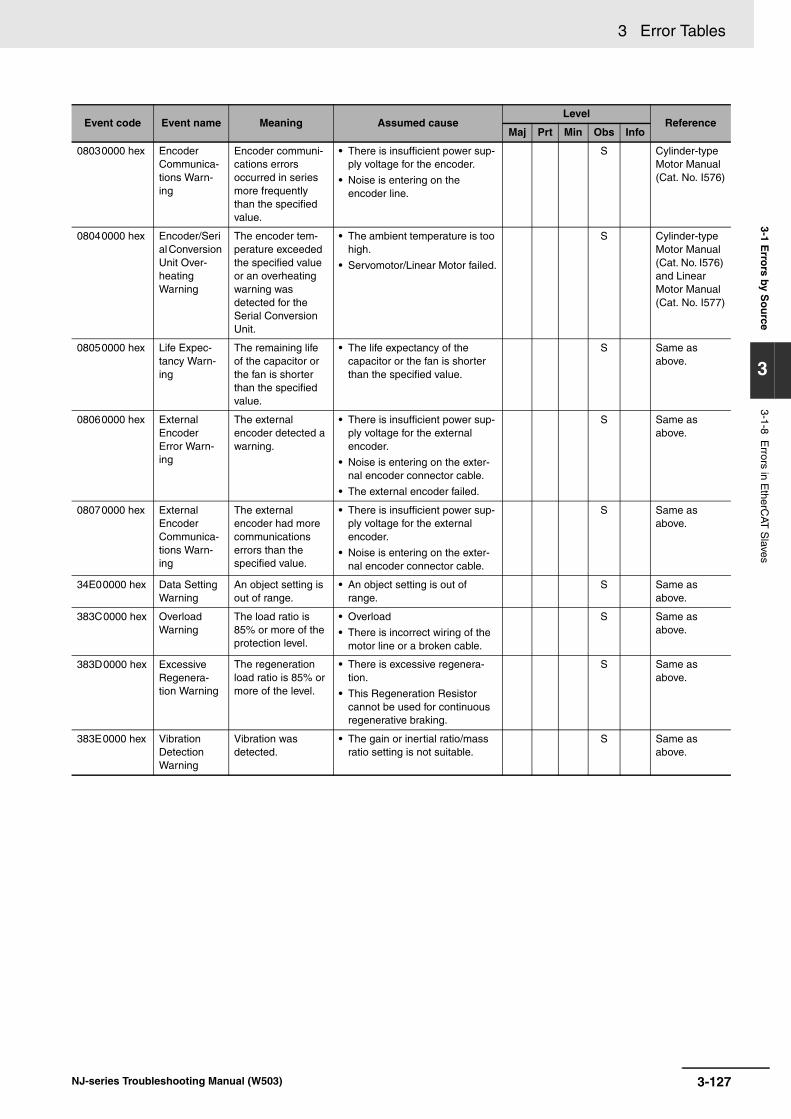
3 Error Tables3-1 E
rrors by S
ou
rce
3
3-1-8 Errors in E
therCAT
Slaves
08030000 hex Encoder Communica-tions Warn-ing
Encoder communi-cations errors occurred in series more frequently than the specified value.
• There is insufficient power sup-ply voltage for the encoder.
• Noise is entering on the encoder line.
S Cylinder-type Motor Manual (Cat. No. I576)
08040000 hex Encoder/Serial Conversion Unit Over-heating Warning
The encoder tem-perature exceeded the specified value or an overheating warning was detected for the Serial Conversion Unit.
• The ambient temperature is too high.
• Servomotor/Linear Motor failed.
S Cylinder-type Motor Manual (Cat. No. I576) and Linear Motor Manual (Cat. No. I577)
08050000 hex Life Expec-tancy Warn-ing
The remaining life of the capacitor or the fan is shorter than the specified value.
• The life expectancy of the capacitor or the fan is shorter than the specified value.
S Same as above.
08060000 hex External Encoder Error Warn-ing
The external encoder detected a warning.
• There is insufficient power sup-ply voltage for the external encoder.
• Noise is entering on the exter-nal encoder connector cable.
• The external encoder failed.
S Same as above.
08070000 hex External Encoder Communica-tions Warn-ing
The external encoder had more communications errors than the specified value.
• There is insufficient power sup-ply voltage for the external encoder.
• Noise is entering on the exter-nal encoder connector cable.
S Same as above.
34E00000 hex Data Setting Warning
An object setting is out of range.
• An object setting is out of range.
S Same as above.
383C0000 hex Overload Warning
The load ratio is 85% or more of the protection level.
• Overload
• There is incorrect wiring of the motor line or a broken cable.
S Same as above.
383D0000 hex Excessive Regenera-tion Warning
The regeneration load ratio is 85% or more of the level.
• There is excessive regenera-tion.
• This Regeneration Resistor cannot be used for continuous regenerative braking.
S Same as above.
383E0000 hex Vibration Detection Warning
Vibration was detected.
• The gain or inertial ratio/mass ratio setting is not suitable.
S Same as above.
Event code Event name Meaning Assumed causeLevel
ReferenceMaj Prt Min Obs Info
3-127NJ-series Troubleshooting Manual (W503)

3 Error Tables
74800000 hex Command Warning
A command could not be executed.
• The absolute multi-rotation counter was cleared when the Servo was not OFF when using an absolute encoder for semi-closed control (This applies only to Cylinder-type Servomo-tors.).
• A forced brake operation request was sent while the Servo was ON.
• A Switch ON command was sent when the main power was OFF. (When 3508 hex = 0)
• An Enable Operation com-mand was sent to request turn-ing ON the Servo when the Servomotor was operating at 30 r/min or 30 mm/s, or higher.
• A latch operation was started under the following conditions.
• An absolute external encoder was used and phase Z was selected as the trigger for fully-closed control (This applies only to Cylinder-type Servomotors.).
• The absolute multi-rotation data was being cleared or the Config operation was being performed.
• The Statusword (6041 hex) bit 09 (remote) was 0 (local).
• An operation command is given in the prohibited direction after the motor made an immediate stop due to a drive prohibition input.
S Cylinder-type Motor Manual (Cat. No. I576) and Linear Motor Manual (Cat. No. I577)
84B00000 hex EtherCAT Communica-tions Warn-ing
An EtherCAT com-munications error occurred one or more times.
• The EtherCAT communications cable is disconnected or bro-ken.
• Noise
S Same as above.
MX2/RX-series Inverters with EtherCAT Communications Units
Event code Event name Meaning Assumed causeLevel
ReferenceMaj Prt Min Obs Info
04A10000 hex Non-volatile Memory Hardware Error
An error occurred in non-volatile mem-ory.
• Non-volatile memory failure S MX2/RX Series Inverter EtherCAT Communica-tion Unit User’s Manual (Cat. No. I574)
Event code Event name Meaning Assumed causeLevel
ReferenceMaj Prt Min Obs Info
3-128 NJ-series Troubleshooting Manual (W503)

3 Error Tables3-1 E
rrors by S
ou
rce
3
3-1-8 Errors in E
therCAT
Slaves
04BA0000 hex Connection Error between Inverter and Communica-tions Unit
An error occurred in the connection between the Inverter and the EtherCAT Commu-nications Unit for the Inverter.
• Contact failure between the Inverter and the EtherCAT Communications Unit for the Inverter.
• Inverter trip was reset.
• The Inverter was initialized or the mode was changed.
• The EtherCAT Communications Unit for the Inverter failed.
S MX2/RX Series Inverter EtherCAT Communica-tion Unit User’s Manual (Cat. No. I574)
04BB0000 hex Inverter Warning
An Inverter warn-ing was detected.
• An Inverter warning was detected.
S Same as above.
04BC0000 hex Inverter Trip An Inverter trip was detected.
• An Inverter trip was detected. S Same as above.
34F00000 hex PDO Setting Error
There is an illegal setting value in the PDO mapping.
• The PDO mapping or Sync-Manager settings are incorrect.
S Same as above.
FH-series Vision Systems
Event code Event name Meaning Assumed causeLevel
ReferenceMaj Prt Min Obs Info
08210000 hex Fan/Power Supply Error
An error occurred in the fan or power supply.
• A foreign object is interfering with fan operation.
• A suitable power supply voltage is not being used, resulting in an overvoltage or undervoltage.
S FH/FZ5 Vision System FH/FZ5 Series User’s Manual for Communi-cations Set-tings (Z342)
08220000 hex Camera Overcurrent Detected
An overcurrent flowed to the Cam-era.
• There is a short circuit inside the Camera cable or in a circuit inside the Controller.
S Same as above.
08230000 hex Parallel I/O Overcurrent Detected
An overcurrent occurred in the par-allel I/O interface.
• A parallel I/O interface line is short-circuited.
S Same as above.
182D0000 hex Setting Data Load Error
Loading the scene group data failed.
• The data is corrupted because the power supply was turned OFF while saving the previous scene data.
• As the result of changing the operation mode, the required amount of memory increased, resulting in insufficient memory.
Same as above.
38590000 hex Camera Con-nection Error
The Camera con-nection is wrong.
• A Camera is not connected to the Controller.
• The Camera cable is broken.
• The Camera Selection settings are not correct in the Camera Image Input and Camera Switching processing items.
• A Camera is not connected to the Camera port on the Control-ler according to the Camera Selection settings in the Cam-era Image Input and Camera Switching processing items.
S Same as above.
385A0000 hex Change in Connected Camera
The Camera that is connected is differ-ent from when data was last saved.
• The Camera connection infor-mation in the scene data does not agree with the connection information for the Camera con-nected to the Controller.
S Same as above.
Event code Event name Meaning Assumed causeLevel
ReferenceMaj Prt Min Obs Info
3-129NJ-series Troubleshooting Manual (W503)

3 Error Tables
48020000 hex System Error An error occurred in the system.
• A serious error occurred in the system in the Controller.
S FH/FZ5 Vision System FH/FZ5 Series User’s Manual for Communi-cations Set-tings (Z342)
58210000 hex Output Con-trol Timeout for Parallel I/O, PLC Link, or Eth-erNet/IP
A timeout occurred in data output hand-shaking control for measurement results.
• The data output handshaking controls in the program (i.e., the ON/OFF timing of the DSA sig-nal) are not correct.
• The output control timeout time is too short in comparison with the program processing time.
• The parallel I/O DSA or GATE signal is not wired correctly.
S Same as above.
58220000 hex Output Con-trol Timeout for EtherCAT
A timeout occurred in data output hand-shaking control for measurement results.
• The data output handshaking controls in the program (i.e., the ON/OFF timing of the Result Set Request signal) are not cor-rect.
• The output control timeout time is too short in comparison with the program processing time.
S Same as above.
78190000 hex Image Log-ging Disk Write Error
Writing data to the image logging disk failed.
• A logging disk is not inserted.
• The available space on the log-ging disk is not sufficient.
• There is no logging folder.
• Security restrictions are set on the logging disk.
S Same as above.
781A0000 hex Setting Data Transfer Error
An error occurred while transferring the scene data.
• Scene data was edited when there was little available space on the RAM disk and the opera-tion mode was Single- line High-speed Mode.
• The data transfer button was clicked when there was little available space on the RAM disk and the operation mode was Non-stop Adjustment Mode.
S Same as above.
781B0000 hex Output Buf-fer Error (EtherCAT)
The data output buffer for measure-ment data is full.
• Data measurements are being performed on a period that is shorter than the time that is required for data output hand-shake controls in the program.
S Same as above.
88080000 hex PLC Link Communica-tions Error
A PLC Link cannot be established.
• There is a mistake in the PLC or Vision Sensor communica-tions settings.
• The Ethernet or RS-232C cable is damaged.
S Same as above.
Event code Event name Meaning Assumed causeLevel
ReferenceMaj Prt Min Obs Info
3-130 NJ-series Troubleshooting Manual (W503)

3 Error Tables3-1 E
rrors by S
ou
rce
3
3-1-8 Errors in E
therCAT
Slaves
EtherCAT FQ-M-series Specialized Vision Sensors for Positioning
Event code Event name Meaning Assumed causeLevel
ReferenceMaj Prt Min Obs Info
78080000 hex TRIG Input Error
A TRIG signal was input when the BUSY signal for Sensor measure-ment was ON.
• A TRIG signal was input when the BUSY signal for Sensor measurement was ON.
• Chattering occurred for a con-tact input.
S FQ-M-series Specialized Vision Sensor for Positioning User’s Manual (Cat. No. Z314)
780A0000 hex Scene Data Error
The scene data to switch to is cor-rupted.
• The power supply was inter-rupted when the scene data to switch to was saved.
S Same as above.
780B0000 hex Model Error A model was re-registered with an image with low con-trast.
• A model was re-registered with an image with low contrast.
S Same as above.
780C0000 hex Logging Error Some data was not saved when logging data to files on an SD card.
• Too much data to log in files occurred in a short period of time, and writing to the SD card could not keep up.
S Same as above.
780D0000 hex Output Time-out
A timeout occurred in data output hand-shaking control for measurement results.
• The data output handshaking controls in the program (i.e., the ON/OFF timing of the DSA sig-nal) are not correct.
• The output control timeout time is too short in comparison with the program processing time.
S Same as above.
780E0000 hex Output Size Error
The data output size setting and the PDO mapping set-ting do not agree.
• The EtherCAT data output size setting in the Sensor and the PDO mapping setting in the EtherCAT master do not agree.
S Same as above.
E3X-series Fiber Sensors with EtherCAT Communications Unit for Digital Sensors
Event code Event name Meaning Assumed causeLevel
ReferenceMaj Prt Min Obs Info
04C40000 hex Sensor Com-munications Error
An error occurred in a Sensor connec-tion.
• The Sensor is disconnected. S EtherCAT Digi-tal-type Sen-sor Communica-tions Unit Operation Manual (Cat. No. E413)
04C50000 hex Sensor Com-munications Has Not Been Estab-lished
Communications has not been estab-lished with the Sen-sor.
• A Sensor is not connected. S Same as above.
14A00000 hex Non-volatile Memory Checksum Error
An error occurred in the control parame-ters.
• Noise S Same as above.
3-131NJ-series Troubleshooting Manual (W503)

3 Error Tables
24780000 hex Number of Sensors Ver-ify Error
The number of Sen-sors that is con-nected does not agree with the set-tings.
• The set value does not match the number of Sensors that are actually connected.
S EtherCAT Digi-tal-type Sen-sor Communica-tions Unit Operation Manual (Cat. No. E413)
24790000 hex Number of Sensors Over Limit
Too many Sensors are connected.
• More than the maximum num-ber of Sensors are connected.
S Same as above.
34F80000 hex Dummy Sen-sors Setting Error
Too many Dummy Units are set.
• There are too many Dummy Units set, so some Sensors are not assigned logical unit num-bers.
S Same as above.
04A10000 hex Non-volatile Memory Hardware Error
An error occurred in non-volatile mem-ory.
• Non-volatile memory failure S Same as above.
E3NW-ECT EtherCAT Digital Sensor Communications Unit
Event code Event name Meaning Assumed causeLevel
ReferenceMaj Prt Min Obs Info
04C4 0000 hex Sensor Com-munications Error
An error occurred in a Sensor connec-tion.
• The Sensor is disconnected. S EtherCAT Digi-tal Sensor Communica-tions Unit Operation Manual (Cat. No. E429)
04C5 0000 hex Sensor Com-munications Has Not Been Estab-lished
Communications has not been estab-lished with the Sen-sor.
• A sensor is not connected. S Same as above.
14A0 0000 hex Non-volatile Memory Checksum Error
An error occurred in the control parame-ters.
• Noise S Same as above.
247A 0000 hex Number of Distributed Sensor Unit Verify Error
The number of Dis-tributed Sensor Unit that is checked at power up is decreased.
• The Distributed Sensor Unit is disconnected
S Same as above.
247B 0000 hex Number of Sensors Over Limit
Too many Sensors are connected.
• More than the maximum num-ber of Sensors are connected.
S Same as above.
247C 0000 hex Number of Sensors Ver-ify Error
The number of Sen-sors that is con-nected does not agree with the set-tings.
• The set value does not match the number of Sensors that are actually connected
S Same as above.
Event code Event name Meaning Assumed causeLevel
ReferenceMaj Prt Min Obs Info
3-132 NJ-series Troubleshooting Manual (W503)

3 Error Tables3-1 E
rrors by S
ou
rce
3
3-1-8 Errors in E
therCAT
Slaves
247D 0000 hex Number of Sensors Over at Distrib-uted Sensor Unit
Too many Sensors are connected at Distributed Sensor Unit.
• More than the maximum num-ber of Sensors are connected at Distributed Sensor Unit.
S EtherCAT Digi-tal Sensor Communica-tions Unit Operation Manual (Cat. No. E429)
34F8 0000 hex Dummy Sen-sors Setting Error
Too many Dummy Units are set.
• There are too many Dummy Units set, so some Sensors are not assigned logical unit num-bers.
S Same as above.
04A1 0000 hex Non-volatile Memory Hardware Error
An error occurred in non-volatile mem-ory.
• Non-volatile memory failure S Same as above.
ZW-CE1T Confocal Fiber Type Displacement Sensor
Event code Event name Meaning Assumed causeLevel
ReferenceMaj Prt Min Obs Info
04D00000 hex Hardware error
Some abnormality occurred on the dis-placement sensor hardware.
• Hardware damage S ZW-CE1T Confocal Fiber Type Displace-ment Sensor User’s Manual (Cat. No. Z332)
14B00000 hex Linearity cor-rection data error
The linearity correc-tion data of the dis-placement sensor is damaged.
• Calibration ROM damage S Same as above.
14B10000 hex Linearity cor-rection data read error
Reading of the dis-placement sensor linearity correction data was not exe-cuted correctly.
• Calibration ROM not inserted
• Calibration ROM damage
S Same as above.
14B20000 hex System set-ting error
The system set-tings saved to the displacement sen-sor are corrupt.
• The displacement sensor power was turned OFF during saving/loading of system set-tings.
S Same as above.
14B30000 hex Bank data error
The bank data saved to the dis-placement sensor is corrupt.
• The displacement sensor power was turned OFF during saving/loading of bank data.
S Same as above.
24810000 hex Ethernet communica-tion parame-ter error
An invalid IP address is set for the displacement sensor.
• Invalid IP address setting S Same as above.
74900000 hex Multiple con-trol signal input error
Multiple control sig-nals turned ON in the same cycle.
• Multiple control signals turned ON in the same cycle.
S Same as above.
74910000 hex EXE input error
EXE input process-ing was not exe-cuted correctly.
• EXE input turned ON in the FUN mode.
• EXE input turned ON with READY output OFF.
S Same as above.
74920000 hex SYNC input error
SYNC input pro-cessing was not executed correctly.
• SYNC input turned ON in the FUN mode.
S Same as above.
Event code Event name Meaning Assumed causeLevel
ReferenceMaj Prt Min Obs Info
3-133NJ-series Troubleshooting Manual (W503)

3 Error Tables
74930000 hex TIMING input error
TIMING input pro-cessing was not executed correctly.
• TIMINGx input turned ON in the FUN mode.
• TIMINGx input turned ON or OFF while RESETx input was ON.
• TIMINGx input turned ON in a non-measurement state.
• TIMINGx input turned ON before the "delay time + sam-pling time" elapsed.
S ZW-CE1T Confocal Fiber Type Displace-ment Sensor User’s Manual (Cat. No. Z332)
74940000 hex RESET input error
RESET input pro-cessing was not executed correctly.
• RESETx input turned ON in the FUN mode.
S Same as above.
74950000 hex ZERO input error
ZERO input pro-cessing was not executed correctly.
• ZEROx input turned ON in the FUN mode.
• ZEROx input turned ON in a non-measurement state.
• ZEROx input turned ON for a task whose status is OFF.
S Same as above.
74960000 hex ZEROCLR input error
ZEROCLR input processing was not executed correctly.
• ZEROCLRx input turned ON in the FUN mode.
S Same as above.
Event code Event name Meaning Assumed causeLevel
ReferenceMaj Prt Min Obs Info
3-134 NJ-series Troubleshooting Manual (W503)

3 Error Tables3-1 E
rrors by S
ou
rce
3
3-1-9 Errors in C
J-series Units
The section provides tables of the events that can occur in the CJ-series Units.
• Analog I/O Units
• Process I/O Units
• Temperature Control Units
• ID Sensor Units
• High-speed Counter Units
• Serial Communications Units
• DeviceNet Units
• EtherNet/IP Units
• CompoNet Master Units
The section provides tables of the events that can occur in the following Units.
CJ1W-AD041-V1/AD081-V1
CJ1W-AD042
CJ1W-DA021/DA041
CJ1W-DA08V/DA08C
CJ1W-DA042V
CJ1W-MAD42
3-1-9 Errors in CJ-series Units
CJ-series Analog I/O Units
Event code Event name Meaning Assumed causeLevel
ReferenceMaj Prt Min Obs Info
04600000 hex A/D Conver-sion Error
An error occurred in A/D conversion.
• There is a source of noise nearby.
• A/D converter failed.
S U CJ-series Analog I/O Units Opera-tion Manual for NJ-series CPU Unit (Cat. No. W490)
04620000 hex Non-volatile Memory Error
An error occurred in non-volatile mem-ory.
• There is a source of noise nearby.
• Non-volatile memory failed.
S Same as above.
34800000 hex Mean Value Processing Setting Error
There is a mistake in the setting of the number of sam-plings for mean value processing.
• There is a mistake in the setting of the number of samplings for mean value processing.
S Same as above.
34830000 hex Scaling Data Setting Error
There is a mistake in the scaling data settings.
• The upper or lower limit data for scaling is outside the setting range. Or, the maximum value and minimum value are not 0 and they are the same.
S Same as above.
34840000 hex Input Signal Range Set-ting Error or Error in Num-ber of Inputs Setting
There is a mistake in the input signal range setting or in the number of inputs setting.
• The settings of the input signal range or the setting of the num-ber of analog inputs that are used is incorrect.
S Same as above.
3-135NJ-series Troubleshooting Manual (W503)
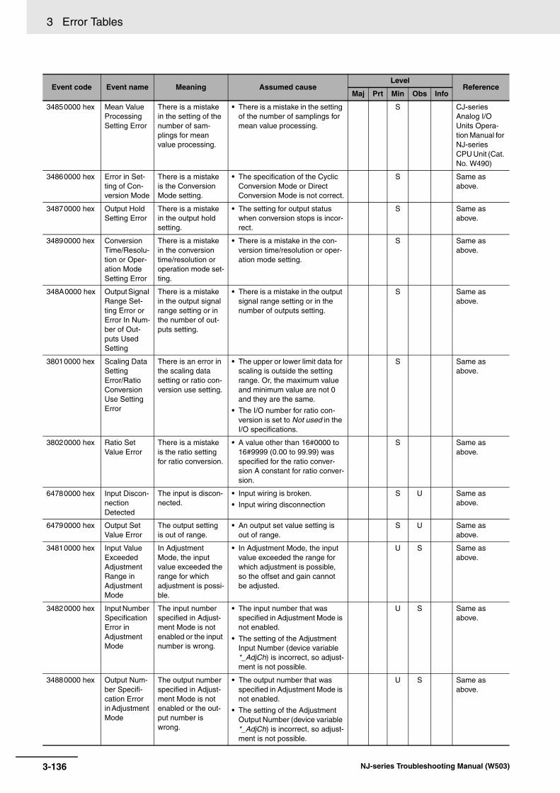
3 Error Tables
34850000 hex Mean Value Processing Setting Error
There is a mistake in the setting of the number of sam-plings for mean value processing.
• There is a mistake in the setting of the number of samplings for mean value processing.
S CJ-series Analog I/O Units Opera-tion Manual for NJ-series CPU Unit (Cat. No. W490)
34860000 hex Error in Set-ting of Con-version Mode
There is a mistake is the Conversion Mode setting.
• The specification of the Cyclic Conversion Mode or Direct Conversion Mode is not correct.
S Same as above.
34870000 hex Output Hold Setting Error
There is a mistake in the output hold setting.
• The setting for output status when conversion stops is incor-rect.
S Same as above.
34890000 hex Conversion Time/Resolu-tion or Oper-ation Mode Setting Error
There is a mistake in the conversion time/resolution or operation mode set-ting.
• There is a mistake in the con-version time/resolution or oper-ation mode setting.
S Same as above.
348A0000 hex Output Signal Range Set-ting Error or Error In Num-ber of Out-puts Used Setting
There is a mistake in the output signal range setting or in the number of out-puts setting.
• There is a mistake in the output signal range setting or in the number of outputs setting.
S Same as above.
38010000 hex Scaling Data Setting Error/Ratio Conversion Use Setting Error
There is an error in the scaling data setting or ratio con-version use setting.
• The upper or lower limit data for scaling is outside the setting range. Or, the maximum value and minimum value are not 0 and they are the same.
• The I/O number for ratio con-version is set to Not used in the I/O specifications.
S Same as above.
38020000 hex Ratio Set Value Error
There is a mistake is the ratio setting for ratio conversion.
• A value other than 16#0000 to 16#9999 (0.00 to 99.99) was specified for the ratio conver-sion A constant for ratio conver-sion.
S Same as above.
64780000 hex Input Discon-nection Detected
The input is discon-nected.
• Input wiring is broken.
• Input wiring disconnection
S U Same as above.
64790000 hex Output Set Value Error
The output setting is out of range.
• An output set value setting is out of range.
S U Same as above.
34810000 hex Input Value Exceeded Adjustment Range in Adjustment Mode
In Adjustment Mode, the input value exceeded the range for which adjustment is possi-ble.
• In Adjustment Mode, the input value exceeded the range for which adjustment is possible, so the offset and gain cannot be adjusted.
U S Same as above.
34820000 hex Input Number Specification Error in Adjustment Mode
The input number specified in Adjust-ment Mode is not enabled or the input number is wrong.
• The input number that was specified in Adjustment Mode is not enabled.
• The setting of the Adjustment Input Number (device variable *_AdjCh) is incorrect, so adjust-ment is not possible.
U S Same as above.
34880000 hex Output Num-ber Specifi-cation Error in Adjustment Mode
The output number specified in Adjust-ment Mode is not enabled or the out-put number is wrong.
• The output number that was specified in Adjustment Mode is not enabled.
• The setting of the Adjustment Output Number (device variable *_AdjCh) is incorrect, so adjust-ment is not possible.
U S Same as above.
Event code Event name Meaning Assumed causeLevel
ReferenceMaj Prt Min Obs Info
3-136 NJ-series Troubleshooting Manual (W503)

3 Error Tables3-1 E
rrors by S
ou
rce
3
3-1-9 Errors in C
J-series Units
The section provides tables of the events that can occur in the following Units.
CJ1W-PDC15
CJ1W-AD04U
CJ1W-PH41U
348C0000 hex I/O Number Specification Error in Adjustment Mode
The I/O numbers specified in Adjust-ment Mode are not enabled or the I/O numbers are wrong.
• The I/O numbers that were specified in Adjustment Mode are not enabled.
• The setting of the Adjustment I/O Number (device variable *_AdjCh) is incorrect, so adjust-ment is not possible.
U S CJ-series Analog I/O Units Opera-tion Manual for NJ-series CPU Unit (Cat. No. W490)
CJ-series Process I/O Units
Event code Event name Meaning Assumed causeLevel
ReferenceMaj Prt Min Obs Info
04600000 hex A/D Conver-sion Error
An error occurred in A/D conversion.
• There is a source of noise nearby.
• A/D converter failed.
S U CJ-series Analog I/O Units Opera-tion Manual for NJ-series CPU Unit (Cat. No. W498)
04610000 hex Cold Junction Sensor Error
An error occurred in the cold junction sensor.
• Faulty connection to the cold junction sensor for the CJ1W-PH41U.
• The cold junction sensor failed.
S U Same as above.
04620000 hex Non-volatile Memory Error
An error occurred in non-volatile mem-ory.
• There is a source of noise nearby.
• Non-volatile memory failed.
S Same as above.
348D0000 hex Data Range Error
A set value is out of range.
• A set value is out of range. S Same as above.
647A0000 hex Input Error An input error occurred.
• The analog input signal is out of range.
• Input wiring is broken.
• Input wiring disconnection or loose terminal
S U Same as above.
647D0000 hex Zero/Span Adjustment Period End
The zero/span adjustment period expired.
• The zero/span adjustment period expired.
U S Same as above.
647E0000 hex Zero/Span Adjustment Period Notice
The zero/span adjustment period is close to expiring.
• The notification period for the expiration of zero/span adjust-ment occurred.
U S Same as above.
Event code Event name Meaning Assumed causeLevel
ReferenceMaj Prt Min Obs Info
3-137NJ-series Troubleshooting Manual (W503)

3 Error Tables
The section provides tables of the events that can occur in the following Units.
CJ1W-TC003
CJ1W-TC004
CJ1W-TC103
CJ1W-TC104
The section provides tables of the events that can occur in the following Units.
CJ1W-V680C11
CJ1W-V680C12
CJ-series Temperature Control Units
Event code Event name Meaning Assumed causeLevel
ReferenceMaj Prt Min Obs Info
04680000 hex Cold Junction Sensor Error
An error occurred in the cold junction sensor.
• Faulty connection to the cold junction sensor.
• The cold junction sensor failed.
U S CJ-series Temperature Control Units Operation Manual for NJ-series CPU Unit (Cat. No. W491)
34940000 hex Setting Error There is an illegal setting.
• The set value is incorrect. U S Same as above.
64840000 hex Sensor Error An error occurred in the sensor input.
• Error in input from the Sensor. U S Same as above.
64850000 hex CT Overflow An overflow occurred in the CT input.
• The heater current exceeded 55.0 A.
U S Same as above.
64860000 hex Heater Burn-out Alarm
A heater burnout occurred.
• The power supply to the heater is not ON.
• The heater is burned out or deteriorated.
U S Same as above.
CJ-series ID Sensor Units
Event code Event name Meaning Assumed causeLevel
ReferenceMaj Prt Min Obs Info
046C0000 hex Unit Status, Antenna Power Sup-ply Error
An error occurred in the power supply to the Antenna.
• An error occurred in the power supply (24 V) to the Antenna.
S CJ-series ID Sensor Units Operation Manual for NJ-series CPU Unit (Cat. No. Z317)
046D0000 hex Unit Status, Memory Error
An error occurred when reading non-volatile memory.
• There is a source of noise nearby.
• Non-volatile memory failure
S Same as above.
046E0000 hex Results Infor-mation, Antenna Error
An error occurred in the Antenna.
• The Antenna is not connected.
• Antenna failure
• The ID Sensor Unit failed.
S Same as above.
046F0000 hex Unit Status, Unit Busy
An error occurred in an ID Sensor Unit.
• There is a source of noise nearby.
• The ID Sensor Unit failed.
S Same as above.
3-138 NJ-series Troubleshooting Manual (W503)

3 Error Tables3-1 E
rrors by S
ou
rce
3
3-1-9 Errors in C
J-series Units
24400000 hex Unit Status, Antenna Error
An error occurred in the Antenna.
• The setting of the Connected Antenna Setting (device vari-able *_Ch#_AntConn) does not agree with the Antenna that is connected.
• The V680-H01 or V680-H01-V2 was connected to the CJ1W-V680C12.
S CJ-series ID Sensor Units Operation Manual for NJ-series CPU Unit (Cat. No. Z317)
34980000 hex Results Infor-mation, Data Storage Area Specification Error
The data storage area specification is not correct.
• The user program specifies addresses in the DM, CIO, AR, EM, or other areas that exceed the ranges defined for the data storage area specifications.
S Same as above.
54A00000 hex Results Infor-mation, ID Tag Address Error
The address of the ID Tag is wrong.
• The address of an ID Tag spec-ified in a command is incorrect.
S Same as above.
54A10000 hex Results Infor-mation, Write Protection Error
An attempt was made to write to a write-protected area of the ID Tag.
• The specified address or num-ber of bytes is incorrect.
• Write-protection is enabled for the area you attempted to write to in the ID Tag.
S Same as above.
54A20000 hex Results Infor-mation, Com-mand Error
The command to the ID Sensor Unit is not correct.
• The contents of the following external device variables is not data that can be specified (where # is the channel num-ber).*_Ch#_CmdSet*_Ch#_ProcAdr*_Ch#_ProcByte*_Ch#_CmdOption“#” in the variable name is the Antenna (Head) number.
S Same as above.
648C0000 hex Unit Status, Command Error End
A processing error occurred.
• A processing error occurred. S Same as above.
648D0000 hex Results Infor-mation, Veri-fication Error
The correct data could not be writ-ten to the ID Tag.
• The travel speed of the ID Tag is outside the specified range.
• The distance between the Antenna and ID Tag is outside the specified range.
• Noise
S Same as above.
648E0000 hex Results Infor-mation, ID Tag Commu-nications Error
An error occurred in communications with an ID Tag, pre-venting a normal end.
• The travel speed of the ID Tag is outside the specified range.
• The distance between the Antenna and ID Tag is outside the specified range.
• Noise
S Same as above.
648F0000 hex Results Infor-mation, ID Tag Missing Error
There is no ID Tag in the communica-tions area.
• The communications specifica-tion is set to trigger, and the ID Tag is not in the communica-tions area when the trigger occurs.
• The communications specifica-tion is set to single auto or repeat auto, and the wait time reached the Auto Wait Time.
• An Amplifier is connected, but an Antenna is not connected.
S Same as above.
64900000 hex Results Infor-mation, ID System Error 1
ID system error 1 occurred.
• System error 1 occurred. S Same as above.
Event code Event name Meaning Assumed causeLevel
ReferenceMaj Prt Min Obs Info
3-139NJ-series Troubleshooting Manual (W503)

3 Error Tables
The section provides tables of the events that can occur in the following Units.
CJ1W-CT021
64910000 hex Results Infor-mation, ID System Error 2
ID system error 2 occurred.
• System error 2 occurred. S CJ-series ID Sensor Units Operation Manual for NJ-series CPU Unit (Cat. No. Z317)
64920000 hex Results Infor-mation, ID System Error 3
ID system error 3 occurred.
• System error 3 occurred. S Same as above.
64930000 hex Results Infor-mation, ID Tag Status
One of the following occurred.
• The number of writes was exceeded for a Number of Writes Control com-mand.
• An overflow or underflow occurred for a Calculation Write command.
• The data did not verify for a Data Check command.
• An error occurred in the data for a Read with Error Correction com-mand.
• An error occurred when writing for a Copy command.
• The number of writes was exceeded for a Number of Writes Control command.
• An overflow or underflow occurred for a Calculation Write command.
• The data did not verify for a Data Check command.
• An error occurred in the data for a Read with Error Correction command.
• An error occurred when writing for a Copy command.
S Same as above.
64940000 hex Results Infor-mation, Error Correction
A Write with Error Correction com-mand performed a 1-bit error correc-tion.
• There is ambient noise where the ID Tag is used.
• ID Tag error.
S Same as above.
CJ-series High-speed Counter Units
Event code Event name Meaning Assumed causeLevel
ReferenceMaj Prt Min Obs Info
68010000 hex Unit Error An error occurred in the High-speed Counter Unit.
• There is an error in the Special Unit Setup.
• An overflow or underflow error occurred.
• An illegal preset value was used.
• A CPU Unit monitor error or bus error occurred.
S CJ-series High-speed Counter Units Operation Manual for NJ-series CPU Unit (Cat. No. W492)
Event code Event name Meaning Assumed causeLevel
ReferenceMaj Prt Min Obs Info
3-140 NJ-series Troubleshooting Manual (W503)
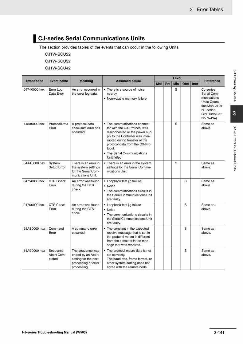
3 Error Tables3-1 E
rrors by S
ou
rce
3
3-1-9 Errors in C
J-series Units
The section provides tables of the events that can occur in the following Units.
CJ1W-SCU22
CJ1W-SCU32
CJ1W-SCU42
CJ-series Serial Communications Units
Event code Event name Meaning Assumed causeLevel
ReferenceMaj Prt Min Obs Info
04740000 hex Error Log Data Error
An error occurred in the error log data.
• There is a source of noise nearby.
• Non-volatile memory failure
S CJ-series Serial Com-munications Units Opera-tion Manual for NJ-series CPU Unit (Cat. No. W494)
14800000 hex Protocol Data Error
A protocol data checksum error has occurred.
• The communications connec-tor with the CX-Protocol was disconnected or the power sup-ply to the Controller was inter-rupted during transfer of the protocol data from the CX-Pro-tocol.
• The Serial Communications Unit failed.
S Same as above.
34A40000 hex System Setup Error
There is an error in the system settings for the Serial Com-munications Unit.
• There is an error in the system settings for the Serial Commu-nications Unit.
S Same as above.
04750000 hex DTR Check Error
An error was found during the DTR check.
• Loopback test jig failure.
• Noise
• The communications circuits in the Serial Communications Unit are faulty.
S Same as above.
04760000 hex CTS Check Error
An error was found during the CTS check.
• Loopback test jig failure.
• Noise
• The communications circuits in the Serial Communications Unit are faulty.
S Same as above.
54A80000 hex Command Error
A command error occurred.
• The constant in the expected receive message that is set in the protocol macro is different from the constant in the mes-sage that was received.
S Same as above.
54A90000 hex Sequence Abort Com-pleted
The sequence was ended by an Abort setting for the next processing or error processing.
• The protocol macro data is not set correctly. The baud rate, frame format, or other system setting does not agree with the remote node.
S Same as above.
3-141NJ-series Troubleshooting Manual (W503)

3 Error Tables
54AA0000 hex Protocol Macro Error
An error occurred in the protocol macro.
• Sequence No. Error: An unreg-istered number was specified for SeqNo (communications sequence number) of the ExecPMCR instruction (no indi-cators light).
• Data read/write area exceeded error: The specified area range was exceeded when data was written to or read from the CPU Unit. (The ERC indicator and ERR/ALM indicator will flash.)
• Protocol data syntax error: There was a code that cannot be executed during protocol execution. (The ERC indicator and ERR/ALM indicator will flash.)
• The total of the areas speci-fied for link words O1, O2, I1, and I2 exceeded 500 words.
• The same link word is used by both ports 1 and 2.
• Writing was specified with a constant.
• Interrupt notification was specified for a Serial Commu-nications Unit.
• Thirty one or more items were set for the write attribute data for one message.
• A length of 0 bytes was speci-fied for a message that was sent or received.
• The length of a message to be sent or received exceeds the maximum send/receive bytes.
• A message is not registered for matrix reception.
• The transmission control is set to both RTS/CTS flow control and Xon/Xoff flow control.
S CJ-series Serial Com-munications Units Opera-tion Manual for NJ-series CPU Unit (Cat. No. W494)
64A00000 hex Tfs (Send Finished Monitoring Time) Exceeded
The time required to complete a send operation exceeded the Send Finished Monitoring Time.
• Noise
• The monitor time is shorter than the actual completion time.
S Same as above.
64A10000 hex Tfr (Receive Finished Monitoring Time) Exceeded
The time required to complete a reception operation exceeded the Receive Finished Monitoring Time.
• Noise
• The monitoring time is shorter than the actual completion time.
S Same as above.
64A20000 hex Tr (Receive Wait Monitor-ing Time) Exceeded
The receive waiting time exceeded the Receive Wait Moni-toring Time.
• Noise
• The monitoring time is shorter than the actual completion time.
S Same as above.
Event code Event name Meaning Assumed causeLevel
ReferenceMaj Prt Min Obs Info
3-142 NJ-series Troubleshooting Manual (W503)

3 Error Tables3-1 E
rrors by S
ou
rce
3
3-1-9 Errors in C
J-series Units
64A30000 hex FCS Check Error
One of the following errors occurred in the converted pro-tocol at the serial gateway.
• When converting to CompoWay/F command: BCC error
• When converting to Modbus-RTU command: CRC error
• When converting to Modbus-ASCII command: CRC error
• When converting to Host Link FINS command: FCS error
Protocol Macros
• The check code attached to the received mes-sage does not match the check code that was calculated from the received mes-sage.
• Noise
• There was a mistake in the CRC code that was attached to the command frame.
S CJ-series Serial Com-munications Units Opera-tion Manual for NJ-series CPU Unit (Cat. No. W494)
64A40000 hex Timeout Error
A timeout error occurred.
• The steps in the communica-tions sequence of a protocol macro are not progressing.
• There is no remote device to receive the command.
• The command frame is incor-rect.
• The remote device is not using the same serial communica-tions settings.
• Wiring is not correct or termi-nating resistance is not set cor-rectly.
• The remote device could not interpret the protocol com-mand.
• The response from the remote device was sent too soon.
• The response timeout monitor-ing time of the serial gateway is too short.
• The loopback test jig failed.
• The communications circuits in the Serial Communications Unit are faulty.
• A serial gateway interrupted processing between protocol macro steps.
• Noise occurred.
• The Serial Communications Mode setting is incorrect.
S Same as above.
Event code Event name Meaning Assumed causeLevel
ReferenceMaj Prt Min Obs Info
3-143NJ-series Troubleshooting Manual (W503)
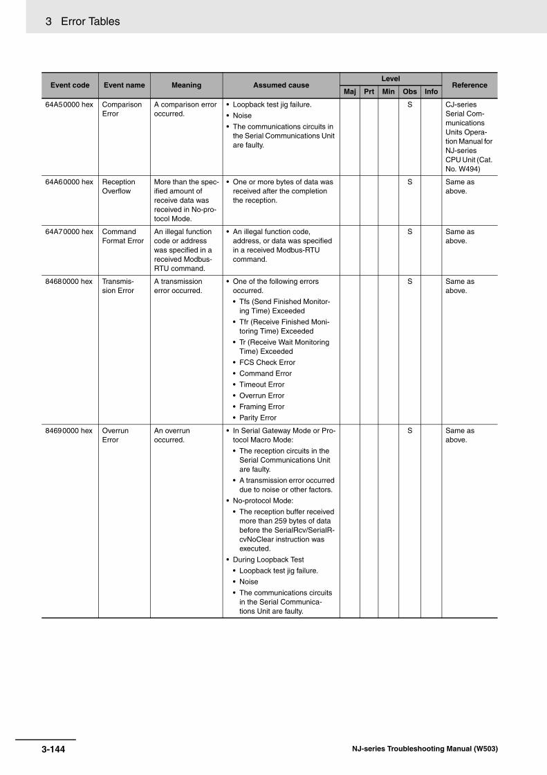
3 Error Tables
64A50000 hex Comparison Error
A comparison error occurred.
• Loopback test jig failure.
• Noise
• The communications circuits in the Serial Communications Unit are faulty.
S CJ-series Serial Com-munications Units Opera-tion Manual for NJ-series CPU Unit (Cat. No. W494)
64A60000 hex Reception Overflow
More than the spec-ified amount of receive data was received in No-pro-tocol Mode.
• One or more bytes of data was received after the completion the reception.
S Same as above.
64A70000 hex Command Format Error
An illegal function code or address was specified in a received Modbus-RTU command.
• An illegal function code, address, or data was specified in a received Modbus-RTU command.
S Same as above.
84680000 hex Transmis-sion Error
A transmission error occurred.
• One of the following errors occurred.
• Tfs (Send Finished Monitor-ing Time) Exceeded
• Tfr (Receive Finished Moni-toring Time) Exceeded
• Tr (Receive Wait Monitoring Time) Exceeded
• FCS Check Error
• Command Error
• Timeout Error
• Overrun Error
• Framing Error
• Parity Error
S Same as above.
84690000 hex Overrun Error
An overrun occurred.
• In Serial Gateway Mode or Pro-tocol Macro Mode:
• The reception circuits in the Serial Communications Unit are faulty.
• A transmission error occurred due to noise or other factors.
• No-protocol Mode:
• The reception buffer received more than 259 bytes of data before the SerialRcv/SerialR-cvNoClear instruction was executed.
• During Loopback Test
• Loopback test jig failure.
• Noise
• The communications circuits in the Serial Communica-tions Unit are faulty.
S Same as above.
Event code Event name Meaning Assumed causeLevel
ReferenceMaj Prt Min Obs Info
3-144 NJ-series Troubleshooting Manual (W503)

3 Error Tables3-1 E
rrors by S
ou
rce
3
3-1-9 Errors in C
J-series Units
846A0000 hex Framing Error
A frame error occurred.
• In Serial Gateway Mode or Pro-tocol Macro Mode:
• The reception circuits in the Serial Communications Unit are faulty.
• A transmission error occurred due to noise or other factors.
• During Loopback Test
• Loopback test jig failure.
• Noise
• The communications circuits in the Serial Communica-tions Unit are faulty.
S CJ-series Serial Com-munications Units Opera-tion Manual for NJ-series CPU Unit (Cat. No. W494)
846B0000 hex Parity Error A parity error occurred.
• In Serial Gateway Mode or Pro-tocol Macro Mode:
• The reception circuits in the Serial Communications Unit are faulty.
• A transmission error occurred due to noise or other factors.
• During Loopback Test
• Loopback test jig failure.
• Noise
• The communications circuits in the Serial Communica-tions Unit are faulty.
S Same as above.
846C0000 hex Overrun Error, Fram-ing Error, or Parity Error (Transmis-sion Error)
An overrun error, framing error, or parity error occurred.
• The communications conditions and baud rate settings do not match the host.
• Noise or other external interfer-ence.
• The baud rate is outside the allowable range or there are bit errors due to different stop bit settings or other parameters.
• The communications cable wir-ing is faulty.
• Terminating resistance is not set correctly for the RS-422A/485 ports.
• Wiring is faulty or terminating resistance is not set correctly on an NT-AL001 or other Adapter.
S Same as above.
846D0000 hex Transmis-sion Error (CRC Error)
A CRC error occurred.
• Noise
• CRC calculation method does not match the device.
S Same as above.
Event code Event name Meaning Assumed causeLevel
ReferenceMaj Prt Min Obs Info
3-145NJ-series Troubleshooting Manual (W503)

3 Error Tables
The section provides tables of the events that can occur in the following Units.
CJ1W-DRM21
CJ-series DeviceNet Units
Event code Event name Meaning Assumed causeLevel
ReferenceMaj Prt Min Obs Info
04880000 hex Unit Memory Error
An error occurred when writing to internal memory where the error his-tory is saved.
• There is a source of noise nearby.
• Non-volatile memory failure
S U CJ-series DeviceNet Units Opera-tion Manual for NJ-series CPU Unit (Cat. No. W497)
04890000 hex Network Power Error
Network power is not being supplied.
• Communications power is not being supplied normally from the network.
S Same as above.
148D0000 hex Invalid Scan List Data
There is an error in the contents of the slave scan list or master scan list stored in non-vola-tile memory.
• The power was interrupted dur-ing writing the scan list to the non-volatile memory.
S Same as above.
148E0000 hex Invalid Setup Data
There is illegal data in the settings for the slave function.
• The power was interrupted while the system was writing the parameters.
• Non-volatile memory life
S Same as above.
24480000 hex Node Address Duplicated Error
An error was dis-covered during the node address dupli-cation check when starting the DeviceNet Unit.
• The node address of the DeviceNet Unit is also set for another node.
S Same as above.
34BC0000 hex Routing Table Error
There is illegal data in the routing tables set in the CPU Unit.
• The local DeviceNet Unit is not in the routing tables.
• The routing table format is incorrect.
• Reading the routing tables timed out.
S U Same as above.
3-146 NJ-series Troubleshooting Manual (W503)
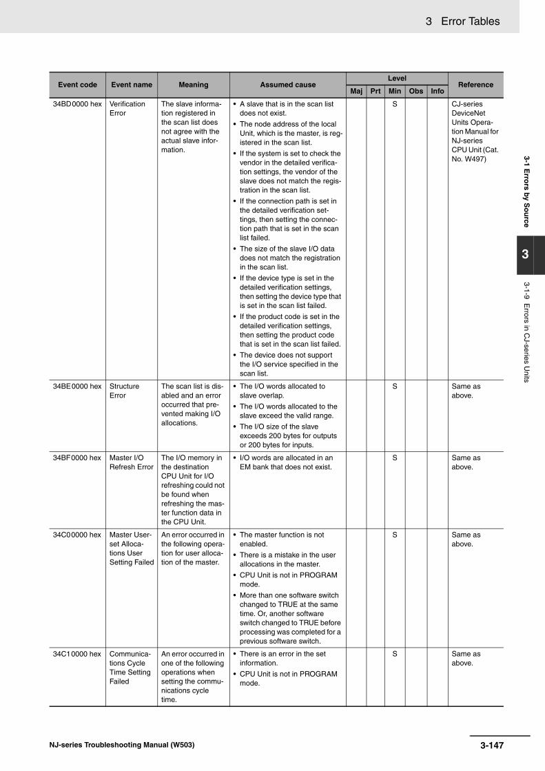
3 Error Tables3-1 E
rrors by S
ou
rce
3
3-1-9 Errors in C
J-series Units
34BD0000 hex Verification Error
The slave informa-tion registered in the scan list does not agree with the actual slave infor-mation.
• A slave that is in the scan list does not exist.
• The node address of the local Unit, which is the master, is reg-istered in the scan list.
• If the system is set to check the vendor in the detailed verifica-tion settings, the vendor of the slave does not match the regis-tration in the scan list.
• If the connection path is set in the detailed verification set-tings, then setting the connec-tion path that is set in the scan list failed.
• The size of the slave I/O data does not match the registration in the scan list.
• If the device type is set in the detailed verification settings, then setting the device type that is set in the scan list failed.
• If the product code is set in the detailed verification settings, then setting the product code that is set in the scan list failed.
• The device does not support the I/O service specified in the scan list.
S CJ-series DeviceNet Units Opera-tion Manual for NJ-series CPU Unit (Cat. No. W497)
34BE0000 hex Structure Error
The scan list is dis-abled and an error occurred that pre-vented making I/O allocations.
• The I/O words allocated to slave overlap.
• The I/O words allocated to the slave exceed the valid range.
• The I/O size of the slave exceeds 200 bytes for outputs or 200 bytes for inputs.
S Same as above.
34BF0000 hex Master I/O Refresh Error
The I/O memory in the destination CPU Unit for I/O refreshing could not be found when refreshing the mas-ter function data in the CPU Unit.
• I/O words are allocated in an EM bank that does not exist.
S Same as above.
34C00000 hex Master User-set Alloca-tions User Setting Failed
An error occurred in the following opera-tion for user alloca-tion of the master.
• The master function is not enabled.
• There is a mistake in the user allocations in the master.
• CPU Unit is not in PROGRAM mode.
• More than one software switch changed to TRUE at the same time. Or, another software switch changed to TRUE before processing was completed for a previous software switch.
S Same as above.
34C10000 hex Communica-tions Cycle Time Setting Failed
An error occurred in one of the following operations when setting the commu-nications cycle time.
• There is an error in the set information.
• CPU Unit is not in PROGRAM mode.
S Same as above.
Event code Event name Meaning Assumed causeLevel
ReferenceMaj Prt Min Obs Info
3-147NJ-series Troubleshooting Manual (W503)

3 Error Tables
34C20000 hex Slave I/O Refresh Error
The I/O memory in the destination CPU Unit for I/O refreshing could not be found when refreshing the slave function data in the CPU Unit.
• I/O words are allocated in an EM bank that does not exist.
S CJ-series DeviceNet Units Opera-tion Manual for NJ-series CPU Unit (Cat. No. W497)
34C30000 hex Slave User Allocation Area Setting Failed
An error occurred in the following opera-tion for user alloca-tion of the slave.
• The slave function is not dis-abled.
• There is a mistake in the user allocations to a slave.
• CPU Unit is not in PROGRAM mode.
• More than one software switch changed to TRUE at the same time. Or, another software switch changed to TRUE before processing was completed for a previous software switch.
S Same as above.
64AC0000 hex Send Time-out Error
A send timeout occurred.
• There is no slave or other device on the network.
• The same baud rate is not set for all nodes.
• Communications cable lengths (trunk line and branch lines) are unsuitable.
• A communications cable is dis-connected or loose.
• The terminating resistance is somewhere other than the ends of the trunk line.
• Noise
• There is an error in the CAN controller.
S Same as above.
74600000 hex Master Func-tion Enable/Dis-able Failed
An operating error occurred when enabling or dis-abling the master function.
• An attempt was made to enable the master function when it was already enabled.
• An attempt was made to dis-able the master function when it was already disabled.
• CPU Unit is not in PROGRAM mode.
• More than one software switch changed to TRUE at the same time. Or, another software switch changed to TRUE before processing was completed for a previous software switch.
S Same as above.
74610000 hex Master Fixed Allocation Area Setting Failed
An error occurred in one of the following operations for fixed allocation of the master.
• The master function is not enabled.
• The scan list is not disabled.
• CPU Unit is not in PROGRAM mode.
• More than one software switch changed to TRUE at the same time. Or, another software switch changed to TRUE before processing was completed for a previous software switch.
S Same as above.
Event code Event name Meaning Assumed causeLevel
ReferenceMaj Prt Min Obs Info
3-148 NJ-series Troubleshooting Manual (W503)
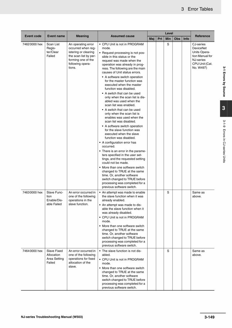
3 Error Tables3-1 E
rrors by S
ou
rce
3
3-1-9 Errors in C
J-series Units
74620000 hex Scan List Regis-ter/Clear Failed
An operating error occurred when reg-istering or clearing the scan list by per-forming one of the following opera-tions.
• CPU Unit is not in PROGRAM mode.
• Request processing is not pos-sible in this status or the request was made when the operation was already in prog-ress. The following are the main causes of Unit status errors.
• A software switch operation for the master function was executed when the master function was disabled.
• A switch that can be used only when the scan list is dis-abled was used when the scan list was enabled.
• A switch that can be used only when the scan list is enables was used when the scan list was disabled.
• A software switch operation for the slave function was executed when the slave function was disabled.
• A configuration error has occurred.
• There is an error in the parame-ters specified in the user set-tings, and the requested setting could not be made.
• More than one software switch changed to TRUE at the same time. Or, another software switch changed to TRUE before processing was completed for a previous software switch.
S CJ-series DeviceNet Units Opera-tion Manual for NJ-series CPU Unit (Cat. No. W497)
74630000 hex Slave Func-tion Enable/Dis-able Failed
An error occurred in one of the following operations in the slave function.
• An attempt was made to enable the slave function when it was already enabled.
• An attempt was made to dis-able the slave function when it was already disabled.
• CPU Unit is not in PROGRAM mode.
• More than one software switch changed to TRUE at the same time. Or, another software switch changed to TRUE before processing was completed for a previous software switch.
S Same as above.
74640000 hex Slave Fixed Allocation Area Setting Failed
An error occurred in one of the following operations for fixed allocation of the slave.
• The slave function is not dis-abled.
• CPU Unit is not in PROGRAM mode.
• More than one software switch changed to TRUE at the same time. Or, another software switch changed to TRUE before processing was completed for a previous software switch.
S Same as above.
Event code Event name Meaning Assumed causeLevel
ReferenceMaj Prt Min Obs Info
3-149NJ-series Troubleshooting Manual (W503)

3 Error Tables
84740000 hex Bus Off Detected
A Bus Off error occurred (i.e., com-munications stopped because there were too many communica-tions errors).
• The master and slave have dif-ferent baud rates.
• Communications cable lengths (trunk line and branch lines) are unsuitable.
• A communications cable is dis-connected or loose.
• The terminating resistance is somewhere other than the ends of the trunk line.
• Noise
S CJ-series DeviceNet Units Opera-tion Manual for NJ-series CPU Unit (Cat. No. W497)
84750000 hex Remote I/O Communica-tions Error
A timeout occurred in remote I/O com-munications.
• The master and slaves have dif-ferent baud rates.
• Communications cable lengths (trunk line and branch lines) are unsuitable.
• A communications cable is dis-connected or loose.
• The terminating resistance is somewhere other than the ends of the trunk line.
• Noise
S U Same as above.
84760000 hex Remote I/O Communica-tions Error (during Slave Operation)
An error occurred in remote I/O commu-nications.
• The master is not in operation.
• The master and slaves have dif-ferent baud rates.
• Communications cable lengths (trunk line and branch lines) are unsuitable.
• A communications cable is dis-connected or loose.
• The terminating resistance is somewhere other than the ends of the trunk line.
• Noise
S Same as above.
84770000 hex Slave COS Send Failed
An attempt was made to send COS data to the master using the Slave COS Send Switch (software switch 2, device variable *_Sw2SlavCOSSendCmd), but the send failed.
• A COS connection to the mas-ter is not open.
• A Bus Off state occurred.
• A network power error occurred.
• A send timeout occurred.
S Same as above.
048A0000 hex File Read/Write Error
An error occurred when user setup data was read from an SD Memory Card in the CPU Unit or when data was written as a file to an SD Memory Card.
• The available capacity on the SD Memory Card was insuffi-cient to write a file.
• Write-protection is set on the SD Memory Card when you write to a file.
• Noise
• The SD Memory Card is dam-aged.
• The CPU Unit has failed.
U S Same as above.
148C0000 hex Invalid Mes-sage Timer List Error
The data in the message monitor-ing timer list is not correct.
• The power supply was inter-rupted while writing the mes-sage-monitoring timer list to the non-volatile memory.
U S Same as above.
Event code Event name Meaning Assumed causeLevel
ReferenceMaj Prt Min Obs Info
3-150 NJ-series Troubleshooting Manual (W503)

3 Error Tables3-1 E
rrors by S
ou
rce
3
3-1-9 Errors in C
J-series Units
The following table lists the events that can occur for an EtherNet/IP Unit with the following model num-ber.
CJ1W-EIP21
CJ-series EtherNet/IP Unit
Event code Event name Meaning Assumed causeLevel
ReferenceMaj Prt Min Obs Info
047A0000 hex Unit Memory Error (Device Error)
An error occurred when writing to the error history or device parameters in non-volatile memory in the Eth-erNet/IP Unit.
• There is a source of noise nearby.
• Non-volatile memory failure
S CJ-series Eth-erNet/IP Units Operation Manual for NJ-series CPU Unit (Cat. No. W495)
047B0000 hex Non-volatile Memory Error
An error occurred in non-volatile mem-ory.
• There is a source of noise nearby.
• Non-volatile memory failure
S Same as above.
047C0000 hex Communica-tions Control-ler Error
An error occurred in the communica-tions controller.
• Noise
• Communications Controller hardware error
S Same as above.
14840000 hex Invalid Com-munications Parameter
An error was found in the validation check of the param-eters for tag data links that are saved in non-volatile memory.
• The power was interrupted dur-ing a download.
• A communications error occurred during a download.
• Non-volatile memory failure
S Same as above.
14850000 hex Tag Data-base Error
A tag database error occurred in the CPU Unit when using variables for tag data links, sta-tus layout, etc.
• The power was interrupted dur-ing a download.
• A communications error occurred during a download.
S Same as above.
34A80000 hex Verification Error
The information registered for a tar-get node in the tag data link parame-ters is different from the actual node information.
• The specified target does not exist.
• Variable names do not match.
• The connection size is incor-rect.
• Insufficient connection resources
S Same as above.
34A90000 hex Tag Data Link Error
There were two or more errors in a connection as an originator. The fol-lowing are excluded.
• Connections as a target
• Connection time-outs due to a Link OFF Error with the Ethernet switch
• The power supply to the target node is OFF.
• Communications with the target node stop.
• The Ethernet cable for Ether-Net/IP is disconnected.
• The Ethernet cable for Ether-Net/IP is disconnected.
• Noise
S Same as above.
34AA0000 hex Tag Refresh Error
An unsupported data area or address range is specified for the tag data links.
• An unsupported data area or address range was specified for the tag data links.
S Same as above.
3-151NJ-series Troubleshooting Manual (W503)

3 Error Tables
34AB0000 hex Basic Ether-net Setting Error
There is an illegal TCP/IP setting.
• The power was interrupted dur-ing a download.
• A communications error occurred during a download.
S CJ-series Eth-erNet/IP Units Operation Manual for NJ-series CPU Unit (Cat. No. W495)
34AC0000 hex IP Address Table Error
The IP address table information is incorrect.
• The power was interrupted dur-ing a download.
• A communications error occurred during a download.
S Same as above.
34AD0000 hex IP Router Table Error
The IP router table information is incor-rect.
• The power was interrupted dur-ing a download.
• A communications error occurred during a download.
S Same as above.
34AE0000 hex Routing Table Error
The routing table information is incor-rect.
• The power was interrupted dur-ing a download.
• A communications error occurred during a download.
S Same as above.
34AF0000 hex Ethernet Advanced Setting Error
There is an illegal FINS setting.
• The power was interrupted dur-ing a download.
• A communications error occurred during a download.
S Same as above.
34B00000 hex Address Mis-match
The host ID of the local IP address is inconsistent with the FINS node address. Or, the last segment of the local IP address is inconsistent with the setting on the node address switches.
• The IP address conversion method is set to automatic gen-eration, but the host ID of the local IP address is inconsistent with the FINS node address or the last segment of the local IP address is inconsistent with the setting on the node address switch.
S Same as above.
381C0000 hex Status Area Layout Set-ting Error
An error occurred in the layout setting of the EtherNet/IP Unit.
• There is an error in the layout settings of the EtherNet/IP Unit.
S Same as above.
54AE0000 hex Multiple Switches ON Error
More than one soft-ware switch changed to TRUE at the same time.
• More than one software switch changed to TRUE at the same time. Or, another software switch changed to TRUE before processing was completed for a previous software switch.
S U Same as above.
84E00000 hex IP Address Duplication Error
The same IP address is used more than once.
• The IP address of the Ether-Net/IP port is also used as the IP address of another node.
S Same as above.
Event code Event name Meaning Assumed causeLevel
ReferenceMaj Prt Min Obs Info
3-152 NJ-series Troubleshooting Manual (W503)

3 Error Tables3-1 E
rrors by S
ou
rce
3
3-1-9 Errors in C
J-series Units
The section provides a table of the events that can occur in the following Unit.CJ1W-CRM21
84E10000 hex BOOTP Server Error
Connection with the BOOTP server failed.
• Server setting error (The acquired IP address is illegal.)
• Server is down.
• An error occurred in the com-munications path.
S CJ-series Eth-erNet/IP Units Operation Manual for NJ-series CPU Unit (Cat. No. W495)
54AF0000 hex Access Detected Outside Range of Variable
Accessing a value that is out of range was detected for a tag variable that is used in a tag data link.
• An out-of-range value was writ-ten by an EtherNet/IP tag data link for a variable with a speci-fied range. A value that does not specify an enumerator was written by an EtherNet/IP tag data link for an enumeration variable.
S Same as above.
84E20000 hex Link OFF Error
The Ethernet link status turned OFF.
• The Ethernet cable is discon-nected.
• An Ethernet cable is discon-nected or loose.
• The switching hub power sup-ply is turned OFF.
• Baud rate mismatch.
• Noise
U S Same as above.
CJ-series CompoNet Master Unit
Event code Event name Meaning Assumed causeLevel
ReferenceMaj Prt Min Obs Info
349C0000 hex Registration Table Verifi-cation Error
An inconsistency was found when verifying the slave registration table.
• There is at least one entry in the slave registration table where the node address and Slave Unit model are inconsis-tent.
S CJ-series CompoNet Master Units Operation Manual for NJ-series CPU Unit (Cat. No. W493)
349D0000 hex Slave Unit Duplicated Address Error
The same address is used by more than one Slave Unit or the same word has been allocated to more than one Slave Unit.
• The same node address is set for more than one Slave Unit.
• There are no duplicated node addresses set for the Slave Units, but allocated words over-lap.
• A Slave Unit was disconnected from the network, and then another Slave Unit with the same node address but a differ-ent I/O capacity joined the net-work.
S Same as above.
349E0000 hex Repeater Unit Node Duplicated Address Error
The node address of the Repeater Unit is also set for another node.
• The node address of the Repeater Unit is also used for anther node.
S Same as above.
Event code Event name Meaning Assumed causeLevel
ReferenceMaj Prt Min Obs Info
3-153NJ-series Troubleshooting Manual (W503)

3 Error Tables
84600000 hex Communica-tions Error
A Slave Unit was disconnected from the network.
• Cable lengths (trunk line and branch lines) are unsuitable.
• A cable is disconnected or loose.
• A terminating resistance is not connected. Or, the terminating resistance is somewhere other than the end of the trunk line.
• Noise
• The Slave Unit does not respond to communications from the Master Unit because the Slave Unit is faulty, the line is disconnected, or the commu-nications power supply is inter-rupted.
S U CJ-series CompoNet Master Units Operation Manual for NJ-series CPU Unit (Cat. No. W493)
84610000 hex Repeater Unit Commu-nications Error
An error occurred in Repeater Unit com-munications.
• Cable lengths (trunk line and branch lines) are unsuitable.
• A cable is disconnected or loose.
• A terminating resistance is not connected. Or, the terminating resistance is somewhere other than the end of the trunk line.
• Noise
• The Repeater Unit does not respond to communications from the Master Unit because the Repeater Unit is faulty, the line is disconnected, or the communications power is inter-rupted.
S U Same as above.
64980000 hex Representa-tive Warning
A warning has occurred in at least one Slave Unit.
• A warning has occurred in at least one Slave Unit.
S Same as above.
64990000 hex Representa-tive Alarm
An alarm has occurred in at least one Slave Unit.
• An alarm has occurred in at least one Slave Unit.
S Same as above.
Event code Event name Meaning Assumed causeLevel
ReferenceMaj Prt Min Obs Info
3-154 NJ-series Troubleshooting Manual (W503)

3 Error Tables3-2 E
vents in
Ord
er of E
vent C
od
es
3
3-2-1 Interpreting Error D
escriptions
3-2 Events in Order of Event Codes
This section provides a table of all events in order of the event codes. Events that are not errors are alsogiven in the tables.
The contents of the error table is described below.
Refer to information for the specified functional classification of the error in the error descriptions in themanual given in the Reference column in the tables for detailed information on an error.
The manual names are given below for the catalog numbers.
3-2-1 Interpreting Error Descriptions
Item Description
Event code The event code of the error in the NJ-series Controller is given. The codes are given in eight hexadecimal digits.
Event name The name of the event is given
Functional classification A functional classification of the source is given.
Reference The catalog number of the manual that provides details on the event are given.
Cat. No. Manual name
W500 NJ-series CPU Unit Hardware User’s Manual
W501 NJ-series CPU Unit Software User’s Manual
W502 NJ-series Instructions Reference Manual
W521 NX-series Digital I/O Units User’s Manual
W522 NX-series Analog I/O Units User’s Manual
W523 NX-series System Units User’s Manual
W527 NJ-series Database Connection CPU Units User’s Manual (NJ501-120)
W490 CJ-series Analog I/O Units Operation Manual for NJ-series CPU Unit
W491 CJ-series Temperature Control Units Operation Manual for NJ-series CPU Unit
W492 CJ-series High-speed Counter Units Operation Manual for NJ-series CPU Unit
W498 CJ-series Analog I/O Units Operation Manual for NJ-series CPU Unit
W488 GX-series EtherCAT Slave Units User's Manual
W493 CJ-series CompoNet Master Units Operation Manual for NJ-series CPU Unit
W494 CJ-series Serial Communications Units Operation Manual for NJ-series CPU Unit
W495 CJ-series EtherNet/IP Units Operation Manual for NJ-series CPU Unit
W497 CJ-series DeviceNet Units Operation Manual for NJ-series CPU Unit
W505 NJ-series CPU Unit Built-in EtherCAT Port User’s Manual
W506 NJ-series CPU Unit Built-in EtherNet/IP Port User’s Manual
W519 NX-series EtherCAT Coupler Unit User’s Manual
I574 MX2/RX Series Inverter EtherCAT Communication Unit User’s Manual
W507 NJ-series CPU Unit Motion Control User’s Manual
W508 NJ-series Motion Control Instructions Reference Manual
I576 AC Servomotors/Servo Drives G5 Series with Built-in EtherCAT Communications User's Manual
I577 G5-series Linear Motors/Drives with Built-in EtherCAT Communications Linear Motor Type User’s Manual
W524 NX-series Position Interface Units User’s Manual
3-155NJ-series Troubleshooting Manual (W503)

3 Error Tables
Events that are marked with an asterisk in the Event code column were added for version upgrades.Refer to 3-1 Errors by Source for the versions for which events can occur. Event codes for instructionsare supported by CPU Units with unit version 1.02 or later.
E413 EtherCAT Digital-type Sensor Communications Unit Operation Manual
E429 EtherCAT Digital Sensor Communications Unit Operation Manual
Z317 CJ-series ID Sensor Units Operation Manual for NJ-series CPU Unit
Z314 FQ-M-series Specialized Vision Sensor for Positioning User’s Manual
Z342 FH/FZ5 Vision System FH/FZ5 Series User’s Manual for Communications Settings
Z332 ZW-CE1T Confocal Fiber Type Displacement Sensor User’s Manual
Z930 NX-series Safety Control Unit User’s Manual
3-2-2 Error Table
Event code Event name Functional classification Reference
00070000 hex Real-Time Clock Stopped Errors for Self Diagnosis W500
00080000 hex Real-Time Clock Failed Errors for Self Diagnosis W500
00090000 hex DIP Switch Setting Error Errors for Self Diagnosis W500
000B0000 hex Low Battery Voltage Errors for Self Diagnosis W500
000C0000 hex CPU Unit Overheat Errors for Self Diagnosis W500
000D0000 hex Internal NJ-series Bus Check Error Errors for Self Diagnosis W500
000E0000 hex Non-volatile Memory Life Exceeded Errors for Self Diagnosis W500
000F0000 hex SD Memory Card Invalid Type Errors for Self Diagnosis W500
00100000 hex SD Memory Card Life Exceeded Errors for Self Diagnosis W500
00200000 hex* Non-volatile Memory Hardware Error NX-series Digital I/O Units, NX-series Analog I/O Units, NX-series System Units, and NX-series Position Inter-face Units
W521, W522, W523, and W524
00210000 hex* Bus Controller Error NX-series EtherCAT Coupler Unit W519
00220000 hex* Non-volatile Memory Hardware Error NX-series EtherCAT Coupler Unit W519
04010000 hex I/O Bus Check Error Errors Related to Unit Configuration W500
04200000 hex Communications Controller Failure Built-in EtherNet/IP Port on CPU Unit W506
04400000 hex Communications Controller Failure Built-in EtherCAT Master in CPU Unit W500
04600000 hex A/D Conversion Error CJ-series Analog I/O Units and CJ-series Process I/O Units
W490, W498
04610000 hex Cold Junction Sensor Error CJ-series Process I/O Units W498
04620000 hex Non-volatile Memory Error CJ-series Analog I/O Units and CJ-series Process I/O Units
W490, W498
04680000 hex Cold Junction Sensor Error CJ-series Temperature Control Units W491
046C0000 hex Unit Status, Antenna Power Supply Error
CJ-series ID Sensor Units Z317
046D0000 hex Unit Status, Memory Error CJ-series ID Sensor Units Z317
046E0000 hex Results Information, Antenna Error CJ-series ID Sensor Units Z317
046F0000 hex Unit Status, Unit Busy CJ-series ID Sensor Units Z317
04740000 hex Error Log Data Error CJ-series Serial Communications Units
W494
04750000 hex DTR Check Error CJ-series Serial Communications Units
W494
Cat. No. Manual name
3-156 NJ-series Troubleshooting Manual (W503)
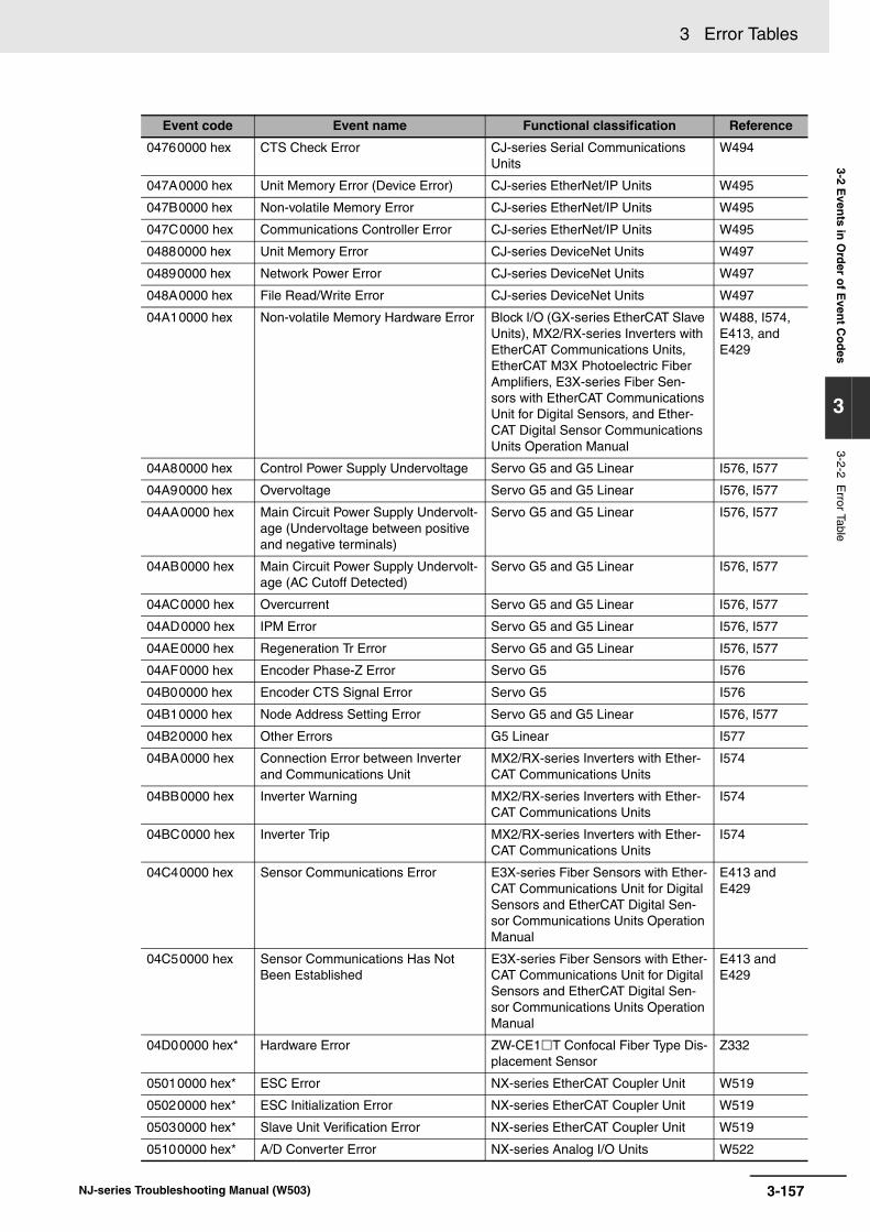
3 Error Tables3-2 E
vents in
Ord
er of E
vent C
od
es
3
3-2-2 Error Table
04760000 hex CTS Check Error CJ-series Serial Communications Units
W494
047A0000 hex Unit Memory Error (Device Error) CJ-series EtherNet/IP Units W495
047B0000 hex Non-volatile Memory Error CJ-series EtherNet/IP Units W495
047C0000 hex Communications Controller Error CJ-series EtherNet/IP Units W495
04880000 hex Unit Memory Error CJ-series DeviceNet Units W497
04890000 hex Network Power Error CJ-series DeviceNet Units W497
048A0000 hex File Read/Write Error CJ-series DeviceNet Units W497
04A10000 hex Non-volatile Memory Hardware Error Block I/O (GX-series EtherCAT Slave Units), MX2/RX-series Inverters with EtherCAT Communications Units, EtherCAT M3X Photoelectric Fiber Amplifiers, E3X-series Fiber Sen-sors with EtherCAT Communications Unit for Digital Sensors, and Ether-CAT Digital Sensor Communications Units Operation Manual
W488, I574, E413, and E429
04A80000 hex Control Power Supply Undervoltage Servo G5 and G5 Linear I576, I577
04A90000 hex Overvoltage Servo G5 and G5 Linear I576, I577
04AA0000 hex Main Circuit Power Supply Undervolt-age (Undervoltage between positive and negative terminals)
Servo G5 and G5 Linear I576, I577
04AB0000 hex Main Circuit Power Supply Undervolt-age (AC Cutoff Detected)
Servo G5 and G5 Linear I576, I577
04AC0000 hex Overcurrent Servo G5 and G5 Linear I576, I577
04AD0000 hex IPM Error Servo G5 and G5 Linear I576, I577
04AE0000 hex Regeneration Tr Error Servo G5 and G5 Linear I576, I577
04AF0000 hex Encoder Phase-Z Error Servo G5 I576
04B00000 hex Encoder CTS Signal Error Servo G5 I576
04B10000 hex Node Address Setting Error Servo G5 and G5 Linear I576, I577
04B20000 hex Other Errors G5 Linear I577
04BA0000 hex Connection Error between Inverter and Communications Unit
MX2/RX-series Inverters with Ether-CAT Communications Units
I574
04BB0000 hex Inverter Warning MX2/RX-series Inverters with Ether-CAT Communications Units
I574
04BC0000 hex Inverter Trip MX2/RX-series Inverters with Ether-CAT Communications Units
I574
04C40000 hex Sensor Communications Error E3X-series Fiber Sensors with Ether-CAT Communications Unit for Digital Sensors and EtherCAT Digital Sen-sor Communications Units Operation Manual
E413 and E429
04C50000 hex Sensor Communications Has Not Been Established
E3X-series Fiber Sensors with Ether-CAT Communications Unit for Digital Sensors and EtherCAT Digital Sen-sor Communications Units Operation Manual
E413 and E429
04D00000 hex* Hardware Error ZW-CE1T Confocal Fiber Type Dis-placement Sensor
Z332
05010000 hex* ESC Error NX-series EtherCAT Coupler Unit W519
05020000 hex* ESC Initialization Error NX-series EtherCAT Coupler Unit W519
05030000 hex* Slave Unit Verification Error NX-series EtherCAT Coupler Unit W519
05100000 hex* A/D Converter Error NX-series Analog I/O Units W522
Event code Event name Functional classification Reference
3-157NJ-series Troubleshooting Manual (W503)

3 Error Tables
05110000 hex* Cold Junction Sensor Error NX-series Analog I/O Units W522
05200000 hex* System Error NX-series Safety Control Unit Z930
05210000 hex* Internal Circuit Error at Safety Input NX-series Safety Control Unit Z930
05220000 hex* Internal Circuit Error at Test Output NX-series Safety Control Unit Z930
05230000 hex* Internal Circuit Error at Safety Output NX-series Safety Control Unit Z930
08010000 hex Battery Warning Servo G5 I576
08020000 hex Fan Warning Servo G5 and G5 Linear I576, I577
08030000 hex Encoder Communications Warning Servo G5 I576
08040000 hex Encoder/Serial Conversion Unit Over-heating Warning
Servo G5 and G5 Linear I576, I577
08050000 hex Life Expectancy Warning Servo G5 and G5 Linear I576, I577
08060000 hex External Encoder Error Warning Servo G5 and G5 Linear I576, I577
08070000 hex External Encoder Communications Warning
Servo G5 and G5 Linear I576, I577
08080000 hex Encoder Communications Disconnec-tion Error
Servo G5 I576
08090000 hex Encoder Communications Error Servo G5 I576
080A0000 hex Encoder Communications Data Error Servo G5 I576
080B0000 hex Safety Input Error Servo G5 and G5 Linear I576, I577
080C0000 hex External Encoder Connection Error Servo G5 and G5 Linear I576, I577
080D0000 hex External Encoder Communications Data Error
Servo G5 and G5 Linear I576, I577
080E0000 hex External Encoder Status Error 0 Servo G5 and G5 Linear I576, I577
080F0000 hex External Encoder Status Error 1 Servo G5 and G5 Linear I576, I577
08100000 hex External Encoder Status Error 2 Servo G5 and G5 Linear I576, I577
08110000 hex External Encoder Status Error 3 Servo G5 and G5 Linear I576, I577
08120000 hex External Encoder Status Error 4 Servo G5 and G5 Linear I576, I577
08130000 hex External Encoder Status Error 5 Servo G5 and G5 Linear I576, I577
08140000 hex Phase-A Connection Error Servo G5 and G5 Linear I576, I577
08150000 hex Phase-B Connection Error Servo G5 and G5 Linear I576, I577
08160000 hex Phase-Z Connection Error Servo G5 and G5 Linear I576, I577
08170000 hex Encoder Data Restoration Error Servo G5 I576
08180000 hex External Encoder Data Restoration Error
Servo G5 I576
08210000 hex* Fan/Power Supply Error FH/FZ5 Series Vision System Z342
08220000 hex* Camera Overcurrent Detected FH/FZ5 Series Vision System Z342
08230000 hex* Parallel I/O Overcurrent Detected FH/FZ5 Series Vision System Z342
10010000 hex Non-volatile Memory Restored or For-matted
Errors for Self Diagnosis W500
10020000 hex Non-volatile Memory Data Corrupted Errors for Self Diagnosis W500
10030000 hex SD Memory Card Invalid Format Errors for Self Diagnosis W500
10040000 hex SD Memory Card Restored or For-matted
Errors for Self Diagnosis W500
10060000 hex SD Memory Card Data Corrupted Errors for Self Diagnosis W500
10070000 hex SD Memory Card Access Power OFF Error
Errors for Self Diagnosis W500
10080000 hex Main Memory Check Error Errors for Self Diagnosis W500
10090000 hex Battery-backup Memory Check Error Errors for Self Diagnosis W500
Event code Event name Functional classification Reference
3-158 NJ-series Troubleshooting Manual (W503)

3 Error Tables3-2 E
vents in
Ord
er of E
vent C
od
es
3
3-2-2 Error Table
100C0000 hex* Event Level Setting Error Errors for Self Diagnosis W500
10200000 hex User Program/Controller Configura-tions and Setup Transfer Error
Errors Related to Controller Opera-tion
W500, W501
10210000 hex Illegal User Program Execution ID Errors Related to Controller Opera-tion
W500, W501
10230000 hex Event Log Restoration Error Errors Related to Controller Opera-tion
W500, W501
10240000 hex Illegal User Program Errors Related to Controller Opera-tion
W500, W501
10250000 hex Illegal User Program/Controller Con-figurations and Setup
Errors Related to Controller Opera-tion
W500, W501
10260000 hex Trace Setting Transfer Failure Errors Related to Controller Opera-tion
W500, W501
10270000 hex* Error in Starting Automatic Transfer Errors Related to Controller Opera-tion
W500, W501
10280000 hex* Error in Executing Automatic Transfer Errors Related to Controller Opera-tion
W500, W501
10290000 hex* Backup Failed to Start Errors Related to Controller Opera-tion
W500, W501
102A0000 hex* Backup Failed Errors Related to Controller Opera-tion
W500, W501
102B0000 hex* Restore Operation Failed to Start Errors Related to Controller Opera-tion
W500, W501
102C0000 hex* Restore Operation Failed Errors Related to Controller Opera-tion
W500, W501
102D0000 hex* CJ-series Unit Backup Failed Errors Related to Unit Configuration W500
102E0000 hex* CJ-series Unit Restore Operation Failed
Errors Related to Unit Configuration W500
102F0000 hex* EtherCAT Slave Backup Failed Built-in EtherCAT Master in CPU Unit W505
10300000 hex* EtherCAT Slave Restore Operation Failed
Built-in EtherCAT Master in CPU Unit W505
10310000 hex* Incorrect SD Memory Card Removal Errors for Self Diagnosis W500
10400000 hex* Analog Unit Calibration Parameter Error
NX-series Analog I/O Units W522
10410000 hex* Control Parameter Error in Master NX-series Digital I/O Units, NX-series Analog I/O Units, and NX-series Position Interface Units
W521, W522, and W524
10420000 hex* Non-volatile Memory Control Parame-ter Error
NX-series EtherCAT Coupler Unit W519
10430000 hex* Memory Corruption Detected NX-series EtherCAT Coupler Unit W519
10500000 hex* NX Bus Communications Settings Read Error
NX-series Safety Control Unit Z930
10510000 hex* Safety Application Data Read Error NX-series Safety Control Unit Z930
10520000 hex* NX Bus Communications Settings and Safety Application Data Mis-match
NX-series Safety Control Unit Z930
10530000 hex* Non-volatile Memory Access Error NX-series Safety Control Unit Z930
14010000 hex CPU Bus Unit Setup Area Error Errors Related to FINS Communica-tions
W501
14200000 hex MAC Address Error Built-in EtherNet/IP Port on CPU Unit W506
14210000 hex Identity Error Built-in EtherNet/IP Port on CPU Unit W506
14220000 hex EtherNet/IP Processing Error Built-in EtherNet/IP Port on CPU Unit W506
Event code Event name Functional classification Reference
3-159NJ-series Troubleshooting Manual (W503)
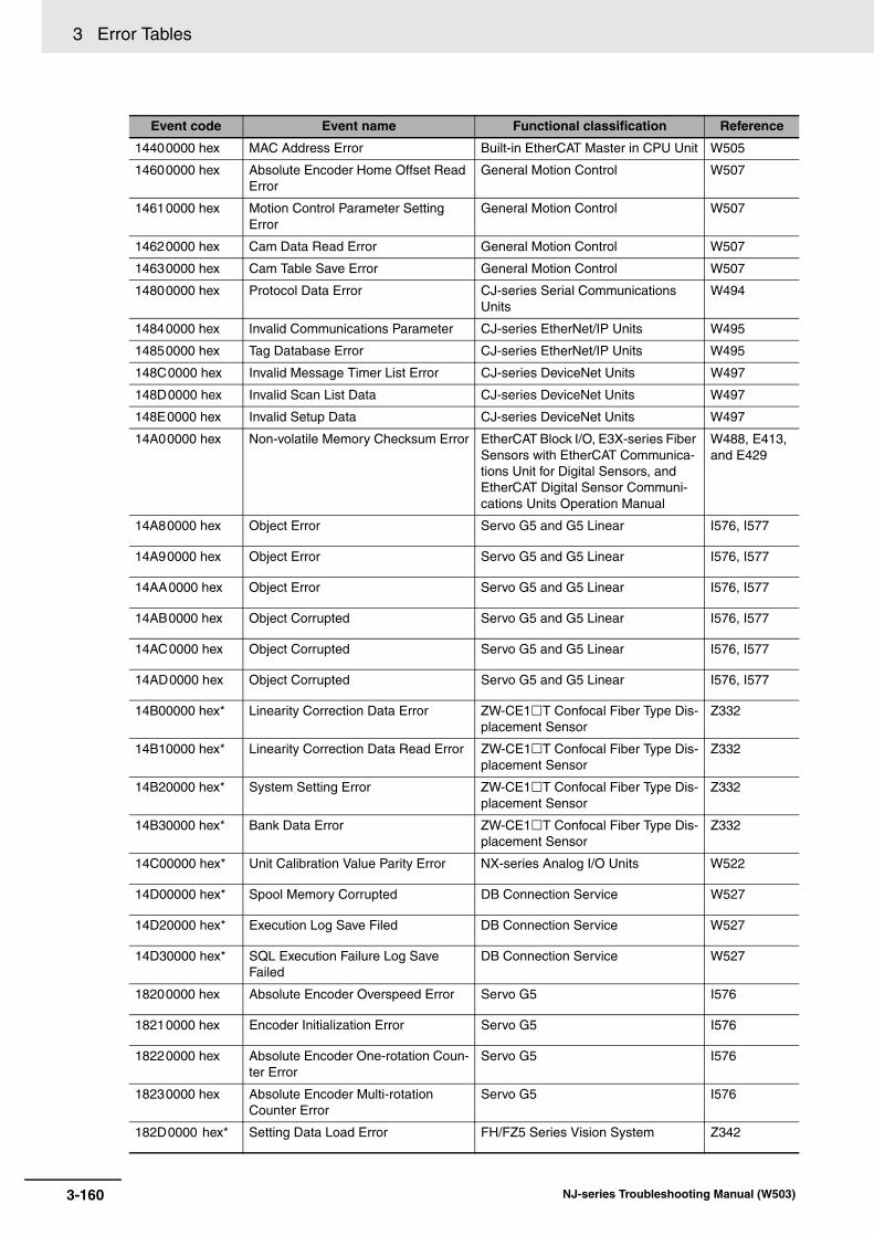
3 Error Tables
14400000 hex MAC Address Error Built-in EtherCAT Master in CPU Unit W505
14600000 hex Absolute Encoder Home Offset Read Error
General Motion Control W507
14610000 hex Motion Control Parameter Setting Error
General Motion Control W507
14620000 hex Cam Data Read Error General Motion Control W507
14630000 hex Cam Table Save Error General Motion Control W507
14800000 hex Protocol Data Error CJ-series Serial Communications Units
W494
14840000 hex Invalid Communications Parameter CJ-series EtherNet/IP Units W495
14850000 hex Tag Database Error CJ-series EtherNet/IP Units W495
148C0000 hex Invalid Message Timer List Error CJ-series DeviceNet Units W497
148D0000 hex Invalid Scan List Data CJ-series DeviceNet Units W497
148E0000 hex Invalid Setup Data CJ-series DeviceNet Units W497
14A00000 hex Non-volatile Memory Checksum Error EtherCAT Block I/O, E3X-series Fiber Sensors with EtherCAT Communica-tions Unit for Digital Sensors, and EtherCAT Digital Sensor Communi-cations Units Operation Manual
W488, E413, and E429
14A80000 hex Object Error Servo G5 and G5 Linear I576, I577
14A90000 hex Object Error Servo G5 and G5 Linear I576, I577
14AA0000 hex Object Error Servo G5 and G5 Linear I576, I577
14AB0000 hex Object Corrupted Servo G5 and G5 Linear I576, I577
14AC0000 hex Object Corrupted Servo G5 and G5 Linear I576, I577
14AD0000 hex Object Corrupted Servo G5 and G5 Linear I576, I577
14B00000 hex* Linearity Correction Data Error ZW-CE1T Confocal Fiber Type Dis-placement Sensor
Z332
14B10000 hex* Linearity Correction Data Read Error ZW-CE1T Confocal Fiber Type Dis-placement Sensor
Z332
14B20000 hex* System Setting Error ZW-CE1T Confocal Fiber Type Dis-placement Sensor
Z332
14B30000 hex* Bank Data Error ZW-CE1T Confocal Fiber Type Dis-placement Sensor
Z332
14C00000 hex* Unit Calibration Value Parity Error NX-series Analog I/O Units W522
14D00000 hex* Spool Memory Corrupted DB Connection Service W527
14D20000 hex* Execution Log Save Filed DB Connection Service W527
14D30000 hex* SQL Execution Failure Log Save Failed
DB Connection Service W527
18200000 hex Absolute Encoder Overspeed Error Servo G5 I576
18210000 hex Encoder Initialization Error Servo G5 I576
18220000 hex Absolute Encoder One-rotation Coun-ter Error
Servo G5 I576
18230000 hex Absolute Encoder Multi-rotation Counter Error
Servo G5 I576
182D0000 hex* Setting Data Load Error FH/FZ5 Series Vision System Z342
Event code Event name Functional classification Reference
3-160 NJ-series Troubleshooting Manual (W503)

3 Error Tables3-2 E
vents in
Ord
er of E
vent C
od
es
3
3-2-2 Error Table
24010000 hex Unsupported Unit Detected Errors Related to Unit Configuration W500
24020000 hex Too Many I/O Points Errors Related to Unit Configuration W500
24030000 hex End Cover Missing Errors Related to Unit Configuration W500
24040000 hex Incorrect Unit/Expansion Rack Con-nection
Errors Related to Unit Configuration W500
24050000 hex Duplicate Unit Number Errors Related to Unit Configuration W500
24200000 hex Slave Node Address Duplicated Built-in EtherCAT Master in CPU Unit W505
24400000 hex Unit Status, Antenna Error CJ-series ID Sensor Units Z317
24480000 hex Node Address Duplicated Error CJ-series DeviceNet Units W497
24610000 hex Switch Setting Error Block I/O (GX-series EtherCAT Slave Units)
W488
24680000 hex Motor Non-conformity Servo G5 I576
24690000 hex Motor Non-conformity Servo G5 I576
246A0000 hex Motor Non-conformity Servo G5 I576
246B0000 hex Motor Non-conformity Servo G5 I576
246C0000 hex Motor Non-conformity Servo G5 I576
24780000 hex Number of Sensors Verify Error E3X-series Fiber Sensors with Ether-CAT Communications Unit for Digital Sensors
E413
24790000 hex Number of Sensors Over Limit E3X-series Fiber Sensors with Ether-CAT Communications Unit for Digital Sensors
E413
247A0000 hex* Number of Distributed Sensor Unit Verify Error
EtherCAT Digital Sensor Communi-cations Units Operation Manual
E429
247B0000 hex* Number of Sensors Over Limit EtherCAT Digital Sensor Communi-cations Units Operation Manual
E429
247C0000 hex* Number of Sensors Verify Error EtherCAT Digital Sensor Communi-cations Units Operation Manual
E429
247D0000 hex* Number of Sensors Over at Distrib-uted Sensor Unit
EtherCAT Digital Sensor Communi-cations Units Operation Manual
E429
24810000 hex* Ethernet Communications Parameter Error
ZW-CE1T Confocal Fiber Type Dis-placement Sensor
Z332
24A00000 hex* Unit Configuration Error, Too Many Units
NX-series EtherCAT Coupler Unit W519
24A10000 hex* Unit Configuration Error, Unsup-ported Configuration
NX-series EtherCAT Coupler Unit W519
28010000 hex Motor Setting Error G5 Linear I577
28020000 hex Motor Combination Error 1 G5 Linear I577
28030000 hex Motor Combination Error 2 G5 Linear I577
30200000 hex* Unsupported Unit Setting Errors Related to Unit Configuration W500
34010000 hex I/O Setting Check Error Errors Related to Unit Configuration W500
34100000 hex IP Address Table Setting Error Errors Related to FINS Communica-tions
W501
34110000 hex Unknown Destination Node Errors Related to FINS Communica-tions
W501
34130000 hex FINS/TCP Connection Table Setting Error
Errors Related to FINS Communica-tions
W501
34200000 hex Tag Data Link Setting Error Built-in EtherNet/IP Port on CPU Unit W506
Event code Event name Functional classification Reference
3-161NJ-series Troubleshooting Manual (W503)

3 Error Tables
34210000 hex Basic Ethernet Setting Error Built-in EtherNet/IP Port on CPU Unit W506
34220000 hex TCP/IP Basic Setting Error (Local Port IP Address)
Built-in EtherNet/IP Port on CPU Unit W506
34230000 hex TCP/IP Advanced Setting Error (IP Router Table)
Built-in EtherNet/IP Port on CPU Unit W506
34240000 hex FTP Server Setting Error Built-in EtherNet/IP Port on CPU Unit W506
34250000 hex NTP Client Setting Error Built-in EtherNet/IP Port on CPU Unit W506
34260000 hex SNMP Setting Error Built-in EtherNet/IP Port on CPU Unit W506
34270000 hex Tag Name Resolution Error Built-in EtherNet/IP Port on CPU Unit W506
34400000 hex Network Configuration Information Error
Built-in EtherCAT Master in CPU Unit W505
34600000 hex Required Process Data Object Not Set
General Motion Control W507
34610000 hex Process Data Object Setting Missing Motion Control Instructions W508
34630000 hex Axis Slave Disabled General Motion Control W507
34640000 hex Network Configuration Information Missing for Axis Slave
General Motion Control W507
34800000 hex Mean Value Processing Setting Error CJ-series Analog I/O Units W490
34810000 hex Input Value Exceeded Adjustment Range in Adjustment Mode
CJ-series Analog I/O Units W490
34820000 hex Input Number Specification Error in Adjustment Mode
CJ-series Analog I/O Units W490
34830000 hex Scaling Data Setting Error CJ-series Analog I/O Units W490
34840000 hex Input Signal Range Setting Error or Error in Number of Inputs Setting
CJ-series Analog I/O Units W490
34850000 hex Mean Value Processing Setting Error CJ-series Analog I/O Units W490
34860000 hex Error in Setting of Conversion Mode CJ-series Analog I/O Units W490
34870000 hex Output Hold Setting Error CJ-series Analog I/O Units W490
34880000 hex Output Number Specification Error in Adjustment Mode
CJ-series Analog I/O Units W490
34890000 hex Conversion Time/Resolution Setting Error or Operation Mode Setting Error
CJ-series Analog I/O Units W490
348A0000 hex Output Signal Range Setting Error or Error In Number of Outputs Used Set-ting
CJ-series Analog I/O Units W490
348C0000 hex I/O Number Specification Error in Adjustment Mode
CJ-series Analog I/O Units W490
348D0000 hex Data Range Error CJ-series Process I/O Units W498
34940000 hex Setting Error CJ-series Temperature Control Units W491
34980000 hex Results Information, Data Storage Area Specification Error
CJ-series ID Sensor Units Z317
349C0000 hex Registration Table Verification Error CJ-series CompoNet Master Unit W493
349D0000 hex Slave Unit Duplicated Address Error CJ-series CompoNet Master Unit W493
349E0000 hex Repeater Unit Node Duplicated Address Error
CJ-series CompoNet Master Unit W493
34A40000 hex System Setup Error CJ-series Serial Communications Units
W494
34A80000 hex Verification Error CJ-series EtherNet/IP Units W495
34A90000 hex Tag Data Link Error CJ-series EtherNet/IP Units W495
34AA0000 hex Tag Refresh Error CJ-series EtherNet/IP Units W495
Event code Event name Functional classification Reference
3-162 NJ-series Troubleshooting Manual (W503)

3 Error Tables3-2 E
vents in
Ord
er of E
vent C
od
es
3
3-2-2 Error Table
34AB0000 hex Basic Ethernet Setting Error CJ-series EtherNet/IP Units W495
34AC0000 hex IP Address Table Error CJ-series EtherNet/IP Units W495
34AD0000 hex IP Router Table Error CJ-series EtherNet/IP Units W495
34AE0000 hex Routing Table Error CJ-series EtherNet/IP Units W495
34AF0000 hex Ethernet Advanced Setting Error CJ-series EtherNet/IP Units W495
34B00000 hex Address Mismatch CJ-series EtherNet/IP Units W495
34BC0000 hex Routing Table Error CJ-series DeviceNet Units W497
34BD0000 hex Verification Error CJ-series DeviceNet Units W497
34BE0000 hex Structure Error CJ-series DeviceNet Units W497
34BF0000 hex Master I/O Refresh Error CJ-series DeviceNet Units W497
34C00000 hex Master User-set Allocations User Set-ting Failed
CJ-series DeviceNet Units W497
34C10000 hex Communications Cycle Time Setting Failed
CJ-series DeviceNet Units W497
34C20000 hex Slave I/O Refresh Error CJ-series DeviceNet Units W497
34C30000 hex Slave User Allocation Area Setting Failed
CJ-series DeviceNet Units W497
34E00000 hex Data Setting Warning Servo G5 and G5 Linear I576, I577
34E10000 hex Servo Drive Overheat Servo G5 and G5 Linear I576, I577
34E20000 hex Overload Servo G5 and G5 Linear I576, I577
34E30000 hex Regeneration Overload Servo G5 and G5 Linear I576, I577
34E40000 hex Error Counter Overflow Servo G5 and G5 Linear I576, I577
34E50000 hex Excessive Velocity Error Servo G5 and G5 Linear I576, I577
34E60000 hex Overspeed Servo G5 and G5 Linear I576, I577
34F00000 hex PDO Setting Error MX2/RX-series Inverters with Ether-CAT Communications Units
I574
34F80000 hex Dummy Sensors Setting Error E3X-series Fiber Sensors with Ether-CAT Communications Unit for Digital Sensors and EtherCAT Digital Sen-sor Communications Units Operation Manual
E413 and E429
35000000 hex* Unit Configuration Information Error NX-series EtherCAT Coupler Unit W519
35010000hex* Unit Configuration Verification Error NX-series EtherCAT Coupler Unit W519
35020000hex* NX Unit Minor Fault NX-series EtherCAT Coupler Unit W519
35030000hex* NX Unit Observation NX-series EtherCAT Coupler Unit W519
35040000hex* Mailbox Setting Error NX-series EtherCAT Coupler Unit W519
35050000hex* RxPDO Setting Error NX-series EtherCAT Coupler Unit W519
35060000hex* TxPDO Setting Error NX-series EtherCAT Coupler Unit W519
35070000 hex* PDO WDT Setting Error NX-series EtherCAT Coupler Unit W519
35080000 hex* SM Event Mode Setting Error NX-series EtherCAT Coupler Unit W519
35090000 hex* TxPDO Mapping Error NX-series EtherCAT Coupler Unit W519
Event code Event name Functional classification Reference
3-163NJ-series Troubleshooting Manual (W503)
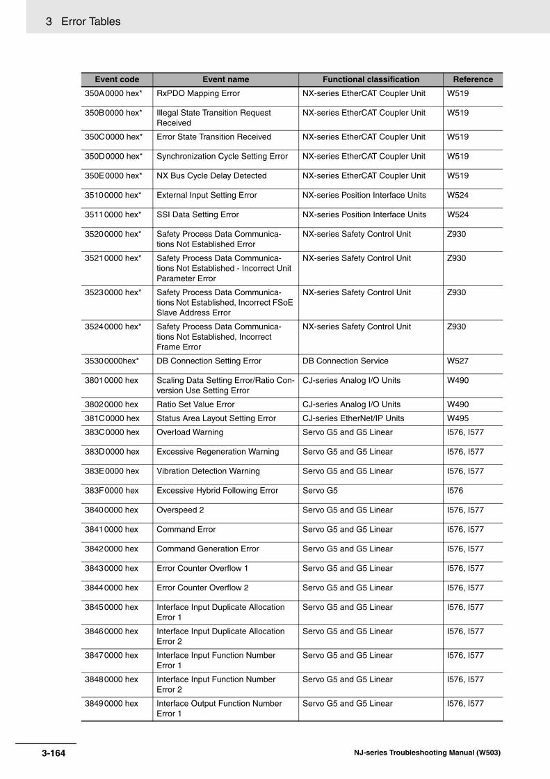
3 Error Tables
350A0000 hex* RxPDO Mapping Error NX-series EtherCAT Coupler Unit W519
350B0000 hex* Illegal State Transition Request Received
NX-series EtherCAT Coupler Unit W519
350C0000 hex* Error State Transition Received NX-series EtherCAT Coupler Unit W519
350D0000 hex* Synchronization Cycle Setting Error NX-series EtherCAT Coupler Unit W519
350E0000 hex* NX Bus Cycle Delay Detected NX-series EtherCAT Coupler Unit W519
35100000 hex* External Input Setting Error NX-series Position Interface Units W524
35110000 hex* SSI Data Setting Error NX-series Position Interface Units W524
35200000 hex* Safety Process Data Communica-tions Not Established Error
NX-series Safety Control Unit Z930
35210000 hex* Safety Process Data Communica-tions Not Established - Incorrect Unit Parameter Error
NX-series Safety Control Unit Z930
35230000 hex* Safety Process Data Communica-tions Not Established, Incorrect FSoE Slave Address Error
NX-series Safety Control Unit Z930
35240000 hex* Safety Process Data Communica-tions Not Established, Incorrect Frame Error
NX-series Safety Control Unit Z930
35300000hex* DB Connection Setting Error DB Connection Service W527
38010000 hex Scaling Data Setting Error/Ratio Con-version Use Setting Error
CJ-series Analog I/O Units W490
38020000 hex Ratio Set Value Error CJ-series Analog I/O Units W490
381C0000 hex Status Area Layout Setting Error CJ-series EtherNet/IP Units W495
383C0000 hex Overload Warning Servo G5 and G5 Linear I576, I577
383D0000 hex Excessive Regeneration Warning Servo G5 and G5 Linear I576, I577
383E0000 hex Vibration Detection Warning Servo G5 and G5 Linear I576, I577
383F0000 hex Excessive Hybrid Following Error Servo G5 I576
38400000 hex Overspeed 2 Servo G5 and G5 Linear I576, I577
38410000 hex Command Error Servo G5 and G5 Linear I576, I577
38420000 hex Command Generation Error Servo G5 and G5 Linear I576, I577
38430000 hex Error Counter Overflow 1 Servo G5 and G5 Linear I576, I577
38440000 hex Error Counter Overflow 2 Servo G5 and G5 Linear I576, I577
38450000 hex Interface Input Duplicate Allocation Error 1
Servo G5 and G5 Linear I576, I577
38460000 hex Interface Input Duplicate Allocation Error 2
Servo G5 and G5 Linear I576, I577
38470000 hex Interface Input Function Number Error 1
Servo G5 and G5 Linear I576, I577
38480000 hex Interface Input Function Number Error 2
Servo G5 and G5 Linear I576, I577
38490000 hex Interface Output Function Number Error 1
Servo G5 and G5 Linear I576, I577
Event code Event name Functional classification Reference
3-164 NJ-series Troubleshooting Manual (W503)

3 Error Tables3-2 E
vents in
Ord
er of E
vent C
od
es
3
3-2-2 Error Table
384A0000 hex Interface Output Function Number Error 2
Servo G5 and G5 Linear I576, I577
384B0000 hex External Latch Input Allocation Error Servo G5 and G5 Linear I576, I577
384C0000 hex Overrun Limit Error Servo G5 and G5 Linear I576, I577
384D0000 hex Absolute Encoder System Down Error
Servo G5 I576
384E0000 hex Absolute Encoder Counter Overflow Error
Servo G5 I576
384F0000 hex Object Setting Error 1 Servo G5 and G5 Linear I576, I577
38500000 hex Object Setting Error 2 Servo G5 and G5 Linear I576, I577
38510000 hex External Encoder Connection Error Servo G5 and G5 Linear I576, I577
38520000 hex Function Setting Error Servo G5 and G5 Linear I576, I577
38530000 hex Magnetic Pole Position Estimation Error 1
Servo G5 I576
38540000 hex Magnetic Pole Position Estimation Error 2
Servo G5 I576
38550000 hex Magnetic Pole Position Estimation Error 3
Servo G5 I576
38560000 hex Motor Auto-setting Error Servo G5 I576
38590000 hex* Camera Connection Error FH/FZ5 Series Vision System Z342
385A0000 hex* Change in Connected Camera FH/FZ5 Series Vision System Z342
40160000 hex Safe Mode Errors Related to Controller Opera-tion
W500, W501
40170000 hex* Safe Mode Errors Related to Controller Opera-tion
W500, W501
44010000Hex EtherCAT Fault Built-in EtherCAT Master in CPU Unit W505
44200000 hex Motion Control Initialization Error General Motion Control W507
48020000 hex* System Error FH/FZ5 Series Vision System Z342
50010000 hex* Controller Insufficient Memory Warn-ing
Built-in EtherCAT Master in CPU Unit and Built-in EtherNet/IP Port on CPU Unit
W500, W501
54010400 hex Input Value Out of Range Instructions W502
54010401 hex Input Mismatch Instructions W502
54010402 hex Floating-point Decimal Error Instructions W502
54010403 hex BCD Error Instructions W502
54010404 hex Signed BCD Error Instructions W502
54010405 hex Illegal Bit Position Specified Instructions W502
54010406 hex Illegal Data Position Specified Instructions W502
54010407 hex Data Range Exceeded Instructions W502
54010409 hex No Errors to Clear Instructions W502
5401040B hex No User Errors to Clear Instructions W502
5401040C hex Limit Exceeded for User-defined Error Instructions W502
5401040D hex Illegal Unit Specified Instructions W502
5401040F hex Unit Restart Failed Instructions W502
54010410 hex Text String Format Error Instructions W502
54010411 hex Illegal Program Specified Instructions W502
Event code Event name Functional classification Reference
3-165NJ-series Troubleshooting Manual (W503)

3 Error Tables
54010413 hex Undefined CJ-series Memory Address
Instructions W502
54010414 hex Stack Underflow Instructions W502
54010416 hex Illegal Number of Array Elements or Dimensions
Instructions W502
54010417 hex Specified Task Does Not Exist Instructions W502
54010418 hex Unallowed Task Specification Instructions W502
54010419 hex Incorrect Data Type Instructions W502
5401041A hex Multi-execution of Instructions Instructions W502
5401041B hex* Data Capacity Exceeded Instructions W502
5401041C hex* Different Data Sizes Instructions W502
5401041D hex* Exceeded Simultaneous Instruction Executed Resources
Instructions W502
54010800 hex FINS Error Instructions W502
54010801 hex FINS Port Already in Use Instructions W502
54010C00 hex Illegal Serial Communications Mode Instructions W502
54010C02 hex Port Setup Already Busy Instructions W502
54011400 hex SD Memory Card Access Failure Instructions W502
54011401 hex SD Memory Card Write-protected Instructions W502
54011402 hex SD Memory Card Insufficient Capac-ity
Instructions W502
54011403 hex File Does Not Exist Instructions W502
54011404 hex Too Many Files/ Directories Instructions W502
54011405 hex File Already in Use Instructions W502
54011406 hex Open Mode Mismatch Instructions W502
54011407 hex Offset Out of Range Instructions W502
54011408 hex Directory Not Empty Instructions W502
54011409 hex That File Name Already Exists Instructions W502
5401140A hex Write Access Denied Instructions W502
5401140B hex Too Many Files Open Instructions W502
5401140C hex Directory Does Not Exist Instructions W502
5401140D hex File or Directory Name Is Too Long Instructions W502
5401140E hex SD Memory Card Access Failed Instructions W502
5401140F hex* Backup Operation Already in Prog-ress
Instructions W502
54011410 hex* Cannot Execute Backup Instructions W502
54011411 hex* Unit/Slave Backup Failed Instructions W502
54011800 hex EtherCAT Communications Error Instructions W502
54011801 hex EtherCAT Slave Does Not Respond Instructions W502
54011802 hex EtherCAT Timeout Instructions W502
54011803 hex Reception Buffer Overflow Instructions W502
54011804 hex SDO Abort Error Instructions W502
54011805 hex Saving Packet Monitor File Instructions W502
54011806 hex Packet Monitoring Function Not Started
Instructions W502
54011807 hex Packet Monitoring Function in Opera-tion
Instructions W502
54011808 hex Communications Resource Overflow Instructions W502
Event code Event name Functional classification Reference
3-166 NJ-series Troubleshooting Manual (W503)

3 Error Tables3-2 E
vents in
Ord
er of E
vent C
od
es
3
3-2-2 Error Table
54011809 hex* Packet Monitoring Function Not Sup-ported
Instructions W502
54011C00 hex Explicit Message Error Instructions W502
54011C01 hex Incorrect Route Path Instructions W502
54011C02 hex CIP Handle Out of Range Instructions W502
54011C03 hex CIP Communications Resource Over-flow
Instructions W502
54011C04 hex CIP Timeout Instructions W502
54011C05 hex* Class-3 Connection Not Established Instructions W502
54011C06 hex* CIP Communications Data Size Exceeded
Instructions W502
54012000 hex Local IP Address Setting Error Instructions W502
54012001 hex TCP/UDP Port Already in Use Instructions W502
54012002 hex Address Resolution Failed Instructions W502
54012003 hex Status Error Instructions W502
54012004 hex Local IP Address Not Set Instructions W502
54012006 hex Socket Timeout Instructions W502
54012007 hex Socket Handle Out of Range Instructions W502
54012008 hex Socket Communications Resource Overflow
Instructions W502
54012400 hex* No Execution Right Instructions W502
54012401 hex* Settings Update Failed Instructions W502
54012402 hex* Too Many Simultaneous Instruction Executions
Instructions W502
54012403 hex* FTP Client Execution Limit Exceeded Instructions W502
54012404 hex* File Number Limit Exceeded Instructions W502
54012405 hex* Directory Does Not Exist (FTP) Instructions W502
54012406 hex* FTP Server Connection Error Instructions W502
54012407 hex* Destination FTP Server Execution Failure
Instructions W502
54012408 hex* SD Memory Card Access Failed for FTP
Instructions W502
54012409 hex* Specified File Does Not Exist Instructions W502
5401240A hex* Specified File is Write Protected Instructions W502
5401240B hex* Failed To Delete Specified File Instructions W502
5401240C hex* Specified File Access Failed Instructions W502
54012C00 hex* NX Message Error Instructions W502
54012C01 hex* NX Message Resource Overflow Instructions W502
54012C02 hex* NX Message Timeout Instructions W502
54012C03 hex* Incorrect NX Message Length Instructions W502
54012C05 hex* NX Message EtherCAT Network Error Instructions W502
54012C06 hex* External Restart Already Executed for Specified NX Units
Instructions W502
54012C07 hex* Unapplicable Unit Specified for Instruction
Instructions W502
54013000 hex* DB Connection Service Not Started DB Connection Instructions W527
54013001 hex* DB Connection Service Run Mode Change Failed
DB Connection Instructions W527
Event code Event name Functional classification Reference
3-167NJ-series Troubleshooting Manual (W503)
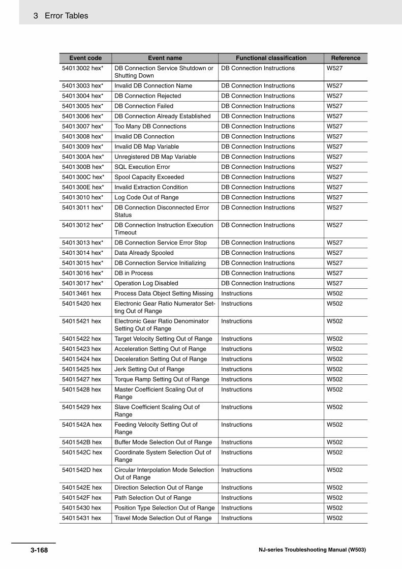
3 Error Tables
54013002 hex* DB Connection Service Shutdown or Shutting Down
DB Connection Instructions W527
54013003 hex* Invalid DB Connection Name DB Connection Instructions W527
54013004 hex* DB Connection Rejected DB Connection Instructions W527
54013005 hex* DB Connection Failed DB Connection Instructions W527
54013006 hex* DB Connection Already Established DB Connection Instructions W527
54013007 hex* Too Many DB Connections DB Connection Instructions W527
54013008 hex* Invalid DB Connection DB Connection Instructions W527
54013009 hex* Invalid DB Map Variable DB Connection Instructions W527
5401300A hex* Unregistered DB Map Variable DB Connection Instructions W527
5401300B hex* SQL Execution Error DB Connection Instructions W527
5401300C hex* Spool Capacity Exceeded DB Connection Instructions W527
5401300E hex* Invalid Extraction Condition DB Connection Instructions W527
54013010 hex* Log Code Out of Range DB Connection Instructions W527
54013011 hex* DB Connection Disconnected Error Status
DB Connection Instructions W527
54013012 hex* DB Connection Instruction Execution Timeout
DB Connection Instructions W527
54013013 hex* DB Connection Service Error Stop DB Connection Instructions W527
54013014 hex* Data Already Spooled DB Connection Instructions W527
54013015 hex* DB Connection Service Initializing DB Connection Instructions W527
54013016 hex* DB in Process DB Connection Instructions W527
54013017 hex* Operation Log Disabled DB Connection Instructions W527
54013461 hex Process Data Object Setting Missing Instructions W502
54015420 hex Electronic Gear Ratio Numerator Set-ting Out of Range
Instructions W502
54015421 hex Electronic Gear Ratio Denominator Setting Out of Range
Instructions W502
54015422 hex Target Velocity Setting Out of Range Instructions W502
54015423 hex Acceleration Setting Out of Range Instructions W502
54015424 hex Deceleration Setting Out of Range Instructions W502
54015425 hex Jerk Setting Out of Range Instructions W502
54015427 hex Torque Ramp Setting Out of Range Instructions W502
54015428 hex Master Coefficient Scaling Out of Range
Instructions W502
54015429 hex Slave Coefficient Scaling Out of Range
Instructions W502
5401542A hex Feeding Velocity Setting Out of Range
Instructions W502
5401542B hex Buffer Mode Selection Out of Range Instructions W502
5401542C hex Coordinate System Selection Out of Range
Instructions W502
5401542D hex Circular Interpolation Mode Selection Out of Range
Instructions W502
5401542E hex Direction Selection Out of Range Instructions W502
5401542F hex Path Selection Out of Range Instructions W502
54015430 hex Position Type Selection Out of Range Instructions W502
54015431 hex Travel Mode Selection Out of Range Instructions W502
Event code Event name Functional classification Reference
3-168 NJ-series Troubleshooting Manual (W503)

3 Error Tables3-2 E
vents in
Ord
er of E
vent C
od
es
3
3-2-2 Error Table
54015432 hex Transition Mode Selection Out of Range
Instructions W502
54015433 hex Continue Method Selection Out of Range
Instructions W502
54015434 hex Combine Mode Selection Out of Range
Instructions W502
54015435 hex Synchronization Start Condition Selection Out of Range
Instructions W502
54015436 hex Master and Slave Defined as Same Axis
Instructions W502
54015437 hex Master and Auxiliary Defined as Same Axis
Instructions W502
54015438 hex Master/Slave Axis Numbers Not in Ascending Order
Instructions W502
54015439 hex Incorrect Cam Table Specification Instructions W502
5401543A hex Synchronization Stopped Instructions W502
5401543B hex Motion Control Instruction Re-execu-tion Disabled
Instructions W502
5401543C hex Motion Control Instruction Multi-exe-cution Disabled
Instructions W502
5401543D hex Instruction Not Allowed for Encoder Axis Type
Instructions W502
5401543E hex Instruction Cannot Be Executed dur-ing Multi-axes Coordinated Control
Instructions W502
5401543F hex Multi-axes Coordinated Control Instruction Executed for Disabled Axes Group
Instructions W502
54015440 hex Axes Group Cannot Be Enabled Instructions W502
54015441 hex Impossible Axis Operation Specified when the Servo is OFF
Instructions W502
54015442 hex Composition Axis Stopped Error Instructions W502
54015443 hex Motion Control Instruction Multi-exe-cution Buffer Limit Exceeded
Instructions W502
54015444 hex Insufficient Travel Distance Instructions W502
54015445 hex Insufficient Travel Distance to Achieve Blending Transit Velocity
Instructions W502
54015446 hex Move Link Constant Velocity Insuffi-cient Travel Distance
Instructions W502
54015447 hex Positioning Gear Operation Insuffi-cient Target Velocity
Instructions W502
54015448 hex Same Start Point and End Point for Circular Interpolation
Instructions W502
54015449 hex Circular Interpolation Center Specifi-cation Position Out of Range
Instructions W502
5401544A hex Instruction Execution Error Caused by Count Mode Setting
Instructions W502
5401544C hex Parameter Selection Out of Range Instructions W502
5401544D hex Stop Method Selection Out of Range Instructions W502
5401544E hex Latch ID Selection Out of Range for Trigger Input Condition
Instructions W502
5401544F hex Setting Out of Range for Writing MC Setting
Instructions W502
Event code Event name Functional classification Reference
3-169NJ-series Troubleshooting Manual (W503)
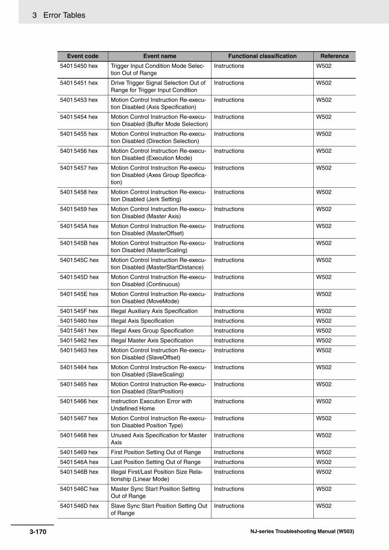
3 Error Tables
54015450 hex Trigger Input Condition Mode Selec-tion Out of Range
Instructions W502
54015451 hex Drive Trigger Signal Selection Out of Range for Trigger Input Condition
Instructions W502
54015453 hex Motion Control Instruction Re-execu-tion Disabled (Axis Specification)
Instructions W502
54015454 hex Motion Control Instruction Re-execu-tion Disabled (Buffer Mode Selection)
Instructions W502
54015455 hex Motion Control Instruction Re-execu-tion Disabled (Direction Selection)
Instructions W502
54015456 hex Motion Control Instruction Re-execu-tion Disabled (Execution Mode)
Instructions W502
54015457 hex Motion Control Instruction Re-execu-tion Disabled (Axes Group Specifica-tion)
Instructions W502
54015458 hex Motion Control Instruction Re-execu-tion Disabled (Jerk Setting)
Instructions W502
54015459 hex Motion Control Instruction Re-execu-tion Disabled (Master Axis)
Instructions W502
5401545A hex Motion Control Instruction Re-execu-tion Disabled (MasterOffset)
Instructions W502
5401545B hex Motion Control Instruction Re-execu-tion Disabled (MasterScaling)
Instructions W502
5401545C hex Motion Control Instruction Re-execu-tion Disabled (MasterStartDistance)
Instructions W502
5401545D hex Motion Control Instruction Re-execu-tion Disabled (Continuous)
Instructions W502
5401545E hex Motion Control Instruction Re-execu-tion Disabled (MoveMode)
Instructions W502
5401545F hex Illegal Auxiliary Axis Specification Instructions W502
54015460 hex Illegal Axis Specification Instructions W502
54015461 hex Illegal Axes Group Specification Instructions W502
54015462 hex Illegal Master Axis Specification Instructions W502
54015463 hex Motion Control Instruction Re-execu-tion Disabled (SlaveOffset)
Instructions W502
54015464 hex Motion Control Instruction Re-execu-tion Disabled (SlaveScaling)
Instructions W502
54015465 hex Motion Control Instruction Re-execu-tion Disabled (StartPosition)
Instructions W502
54015466 hex Instruction Execution Error with Undefined Home
Instructions W502
54015467 hex Motion Control Instruction Re-execu-tion Disabled Position Type)
Instructions W502
54015468 hex Unused Axis Specification for Master Axis
Instructions W502
54015469 hex First Position Setting Out of Range Instructions W502
5401546A hex Last Position Setting Out of Range Instructions W502
5401546B hex Illegal First/Last Position Size Rela-tionship (Linear Mode)
Instructions W502
5401546C hex Master Sync Start Position Setting Out of Range
Instructions W502
5401546D hex Slave Sync Start Position Setting Out of Range
Instructions W502
Event code Event name Functional classification Reference
3-170 NJ-series Troubleshooting Manual (W503)

3 Error Tables3-2 E
vents in
Ord
er of E
vent C
od
es
3
3-2-2 Error Table
5401546E hex Duplicate Latch ID for Trigger Input Condition
Instructions W502
5401546F hex Jerk Override Factor Out of Range Instructions W502
54015470 hex Acceleration/Deceleration Override Factor Out of Range
Instructions W502
54015471 hex First Position Method Specification Out of Range
Instructions W502
54015472 hex Motion Control Instruction Re-execu-tion Disabled (First Position Method)
Instructions W502
54015474 hex Unused Axis Specification for Auxil-iary Axis
Instructions W502
54015475 hex Position Gear Value Error Instructions W502
54015476 hex Position Gear Master Axis Zero Velocity
Instructions W502
54015478 hex Target Position Setting Out of Range Instructions W502
54015479 hex Travel Distance Out of Range Instructions W502
5401547A hex Cam Table Start Point Setting Out of Range
Instructions W502
5401547B hex Cam Master Axis Following First Posi-tion Setting Out of Range
Instructions W502
5401547C hex Circular Interpolation Radius Setting Error
Instructions W502
5401547D hex Circular Interpolation Radius Over-flow
Instructions W502
5401547E hex Circular Interpolation Setting Out of Range
Instructions W502
5401547F hex Auxiliary/Slave Axis Numbers Not in Ascending Order
Instructions W502
54015480 hex Cam Table Property Ascending Data Error at Update
Instructions W502
54015481 hex MC_Write Target Out of Range Instructions W502
54015482 hex Master Travel Distance Specification Out of Range
Instructions W502
54015483 hex Master Distance in Acceleration Specification Out of Range
Instructions W502
54015484 hex Master Distance in Deceleration Specification Out of Range
Instructions W502
54015487 hex Execution Mode Selection Out of Range
Instructions W502
54015488 hex Permitted Following Error Out of Range
Instructions W502
54015489 hex Border Point/Center Position/Radius Specification Out of Range
Instructions W502
5401548A hex End Point Specification Out of Range Instructions W502
5401548B hex Slave Travel Distance Specification Out of Range
Instructions W502
5401548C hex Phase Shift Amount Out of Range Instructions W502
5401548D hex Feeding Distance Out of Range Instructions W502
5401548E hex Auxiliary and Slave Defined as Same Axis
Instructions W502
5401548F hex Relative Position Selection Out of Range
Instructions W502
Event code Event name Functional classification Reference
3-171NJ-series Troubleshooting Manual (W503)
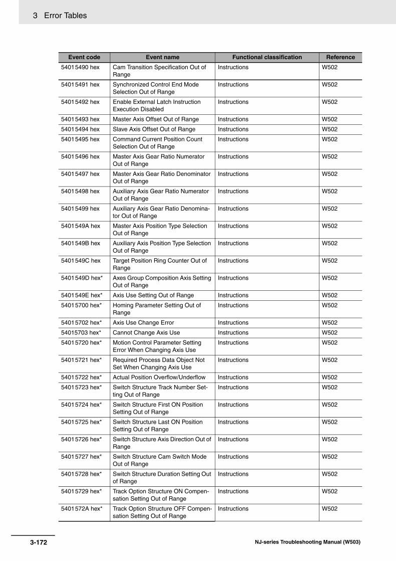
3 Error Tables
54015490 hex Cam Transition Specification Out of Range
Instructions W502
54015491 hex Synchronized Control End Mode Selection Out of Range
Instructions W502
54015492 hex Enable External Latch Instruction Execution Disabled
Instructions W502
54015493 hex Master Axis Offset Out of Range Instructions W502
54015494 hex Slave Axis Offset Out of Range Instructions W502
54015495 hex Command Current Position Count Selection Out of Range
Instructions W502
54015496 hex Master Axis Gear Ratio Numerator Out of Range
Instructions W502
54015497 hex Master Axis Gear Ratio Denominator Out of Range
Instructions W502
54015498 hex Auxiliary Axis Gear Ratio Numerator Out of Range
Instructions W502
54015499 hex Auxiliary Axis Gear Ratio Denomina-tor Out of Range
Instructions W502
5401549A hex Master Axis Position Type Selection Out of Range
Instructions W502
5401549B hex Auxiliary Axis Position Type Selection Out of Range
Instructions W502
5401549C hex Target Position Ring Counter Out of Range
Instructions W502
5401549D hex* Axes Group Composition Axis Setting Out of Range
Instructions W502
5401549E hex* Axis Use Setting Out of Range Instructions W502
54015700 hex* Homing Parameter Setting Out of Range
Instructions W502
54015702 hex* Axis Use Change Error Instructions W502
54015703 hex* Cannot Change Axis Use Instructions W502
54015720 hex* Motion Control Parameter Setting Error When Changing Axis Use
Instructions W502
54015721 hex* Required Process Data Object Not Set When Changing Axis Use
Instructions W502
54015722 hex* Actual Position Overflow/Underflow Instructions W502
54015723 hex* Switch Structure Track Number Set-ting Out of Range
Instructions W502
54015724 hex* Switch Structure First ON Position Setting Out of Range
Instructions W502
54015725 hex* Switch Structure Last ON Position Setting Out of Range
Instructions W502
54015726 hex* Switch Structure Axis Direction Out of Range
Instructions W502
54015727 hex* Switch Structure Cam Switch Mode Out of Range
Instructions W502
54015728 hex* Switch Structure Duration Setting Out of Range
Instructions W502
54015729 hex* Track Option Structure ON Compen-sation Setting Out of Range
Instructions W502
5401572A hex* Track Option Structure OFF Compen-sation Setting Out of Range
Instructions W502
Event code Event name Functional classification Reference
3-172 NJ-series Troubleshooting Manual (W503)
3 Error Tables3-2 E
vents in
Ord
er of E
vent C
od
es
3
3-2-2 Error Table
5401572B hex* Number of Array Elements in Switch Structure Variable Out of Range
Instructions W502
5401572C hex* Number of Array Elements in Output Signal Structure Variable Out of Range
Instructions W502
5401572D hex* Number of Array Elements in Track Option Structure Variable Out of Range
Instructions W502
5401572E hex* Numbers of Elements in Output Sig-nals and Track Option Arrays Not Matched
Instructions W502
5401572F hex* Motion Control Instruction Multi-exe-cution Disabled (Master Axis)
Instructions W502
54015730 hex* Motion Control Instruction Multi-exe-cution Disabled (Position Type Selec-tion)
Instructions W502
54015731 hex* Same Track Number Setting in Switch Structure Out of Range
Instructions W502
5401573A hex* Cannot Write Axis Parameters Instructions W502
5401573B hex* Axis Parameter Setting Out of Range Instructions W502
5401573C hex* Cam Property Setting Out of Range Instructions W502
5401573D hex* Cam Node Setting Out of Range Instructions W502
5401573E hex* Incorrect Cam Node Type Specifica-tion
Instructions W502
5401573F hex* Insufficient Nodes in Cam Table Instructions W502
54015740 hex* Cam Node Master Axis Phase Not in Ascending Order
Instructions W502
54015741 hex* Too Many Data Points in Cam Table Instructions W502
54015742 hex* Cam Table Displacement Overflow Instructions W502
54015743 hex* Aborted Cam Table Used Instructions W502
54016440 hex Target Position Positive Software Limit Exceeded
Instructions W502
54016441 hex Target Position Negative Software Limit Exceeded
Instructions W502
54016442 hex Command Position Overflow/Under-flow
Instructions W502
54016443 hex Positive Limit Input Instructions W502
54016444 hex Negative Limit Input Instructions W502
54017422 hex Servo Main Circuits OFF Instructions W502
54200000 hex Electronic Gear Ratio Numerator Set-ting Out of Range
Motion Control Instructions W508
54210000 hex Electronic Gear Ratio Denominator Setting Out of Range
Motion Control Instructions W508
54220000 hex Target Velocity Setting Out of Range Motion Control Instructions W508
54230000 hex Acceleration Setting Out of Range Motion Control Instructions W508
54240000 hex Deceleration Setting Out of Range Motion Control Instructions W508
54250000 hex Jerk Setting Out of Range Motion Control Instructions W508
54270000 hex Torque Ramp Setting Out of Range Motion Control Instructions W508
54280000 hex Master Coefficient Scaling Out of Range
Motion Control Instructions W508
Event code Event name Functional classification Reference
3-173NJ-series Troubleshooting Manual (W503)
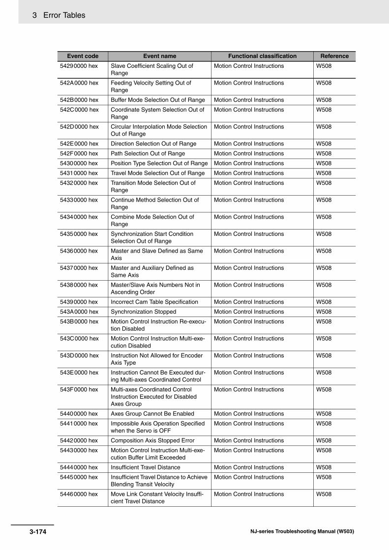
3 Error Tables
54290000 hex Slave Coefficient Scaling Out of Range
Motion Control Instructions W508
542A0000 hex Feeding Velocity Setting Out of Range
Motion Control Instructions W508
542B0000 hex Buffer Mode Selection Out of Range Motion Control Instructions W508
542C0000 hex Coordinate System Selection Out of Range
Motion Control Instructions W508
542D0000 hex Circular Interpolation Mode Selection Out of Range
Motion Control Instructions W508
542E0000 hex Direction Selection Out of Range Motion Control Instructions W508
542F0000 hex Path Selection Out of Range Motion Control Instructions W508
54300000 hex Position Type Selection Out of Range Motion Control Instructions W508
54310000 hex Travel Mode Selection Out of Range Motion Control Instructions W508
54320000 hex Transition Mode Selection Out of Range
Motion Control Instructions W508
54330000 hex Continue Method Selection Out of Range
Motion Control Instructions W508
54340000 hex Combine Mode Selection Out of Range
Motion Control Instructions W508
54350000 hex Synchronization Start Condition Selection Out of Range
Motion Control Instructions W508
54360000 hex Master and Slave Defined as Same Axis
Motion Control Instructions W508
54370000 hex Master and Auxiliary Defined as Same Axis
Motion Control Instructions W508
54380000 hex Master/Slave Axis Numbers Not in Ascending Order
Motion Control Instructions W508
54390000 hex Incorrect Cam Table Specification Motion Control Instructions W508
543A0000 hex Synchronization Stopped Motion Control Instructions W508
543B0000 hex Motion Control Instruction Re-execu-tion Disabled
Motion Control Instructions W508
543C0000 hex Motion Control Instruction Multi-exe-cution Disabled
Motion Control Instructions W508
543D0000 hex Instruction Not Allowed for Encoder Axis Type
Motion Control Instructions W508
543E0000 hex Instruction Cannot Be Executed dur-ing Multi-axes Coordinated Control
Motion Control Instructions W508
543F0000 hex Multi-axes Coordinated Control Instruction Executed for Disabled Axes Group
Motion Control Instructions W508
54400000 hex Axes Group Cannot Be Enabled Motion Control Instructions W508
54410000 hex Impossible Axis Operation Specified when the Servo is OFF
Motion Control Instructions W508
54420000 hex Composition Axis Stopped Error Motion Control Instructions W508
54430000 hex Motion Control Instruction Multi-exe-cution Buffer Limit Exceeded
Motion Control Instructions W508
54440000 hex Insufficient Travel Distance Motion Control Instructions W508
54450000 hex Insufficient Travel Distance to Achieve Blending Transit Velocity
Motion Control Instructions W508
54460000 hex Move Link Constant Velocity Insuffi-cient Travel Distance
Motion Control Instructions W508
Event code Event name Functional classification Reference
3-174 NJ-series Troubleshooting Manual (W503)
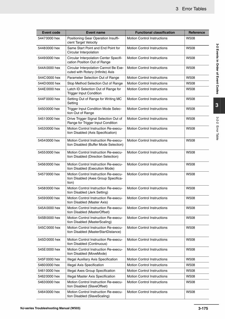
3 Error Tables3-2 E
vents in
Ord
er of E
vent C
od
es
3
3-2-2 Error Table
54470000 hex Positioning Gear Operation Insuffi-cient Target Velocity
Motion Control Instructions W508
54480000 hex Same Start Point and End Point for Circular Interpolation
Motion Control Instructions W508
54490000 hex Circular Interpolation Center Specifi-cation Position Out of Range
Motion Control Instructions W508
544A0000 hex Circular Interpolation Cannot Be Exe-cuted with Rotary (Infinite) Axis
Motion Control Instructions W508
544C0000 hex Parameter Selection Out of Range Motion Control Instructions W508
544D0000 hex Stop Method Selection Out of Range Motion Control Instructions W508
544E0000 hex Latch ID Selection Out of Range for Trigger Input Condition
Motion Control Instructions W508
544F0000 hex Setting Out of Range for Writing MC Setting
Motion Control Instructions W508
54500000 hex Trigger Input Condition Mode Selec-tion Out of Range
Motion Control Instructions W508
54510000 hex Drive Trigger Signal Selection Out of Range for Trigger Input Condition
Motion Control Instructions W508
54530000 hex Motion Control Instruction Re-execu-tion Disabled (Axis Specification)
Motion Control Instructions W508
54540000 hex Motion Control Instruction Re-execu-tion Disabled (Buffer Mode Selection)
Motion Control Instructions W508
54550000 hex Motion Control Instruction Re-execu-tion Disabled (Direction Selection)
Motion Control Instructions W508
54560000 hex Motion Control Instruction Re-execu-tion Disabled (Execution Mode)
Motion Control Instructions W508
54570000 hex Motion Control Instruction Re-execu-tion Disabled (Axes Group Specifica-tion)
Motion Control Instructions W508
54580000 hex Motion Control Instruction Re-execu-tion Disabled (Jerk Setting)
Motion Control Instructions W508
54590000 hex Motion Control Instruction Re-execu-tion Disabled (Master Axis)
Motion Control Instructions W508
545A0000 hex Motion Control Instruction Re-execu-tion Disabled (MasterOffset)
Motion Control Instructions W508
545B0000 hex Motion Control Instruction Re-execu-tion Disabled (MasterScaling)
Motion Control Instructions W508
545C0000 hex Motion Control Instruction Re-execu-tion Disabled (MasterStartDistance)
Motion Control Instructions W508
545D0000 hex Motion Control Instruction Re-execu-tion Disabled (Continuous)
Motion Control Instructions W508
545E0000 hex Motion Control Instruction Re-execu-tion Disabled (MoveMode)
Motion Control Instructions W508
545F0000 hex Illegal Auxiliary Axis Specification Motion Control Instructions W508
54600000 hex Illegal Axis Specification Motion Control Instructions W508
54610000 hex Illegal Axes Group Specification Motion Control Instructions W508
54620000 hex Illegal Master Axis Specification Motion Control Instructions W508
54630000 hex Motion Control Instruction Re-execu-tion Disabled (SlaveOffset)
Motion Control Instructions W508
54640000 hex Motion Control Instruction Re-execu-tion Disabled (SlaveScaling)
Motion Control Instructions W508
Event code Event name Functional classification Reference
3-175NJ-series Troubleshooting Manual (W503)

3 Error Tables
54650000 hex Motion Control Instruction Re-execu-tion Disabled (StartPosition)
Motion Control Instructions W508
54660000 hex Instruction Execution Error with Undefined Home
Motion Control Instructions W508
54670000 hex Motion Control Instruction Re-execu-tion Disabled (Position Type)
Motion Control Instructions W508
54680000 hex Unused Axis Specification for Master Axis
Motion Control Instructions W508
54690000 hex First Position Setting Out of Range Motion Control Instructions W508
546A0000 hex Last Position Setting Out of Range Motion Control Instructions W508
546B0000 hex Illegal First/Last Position Size Rela-tionship (Linear Mode)
Motion Control Instructions W508
546C0000 hex Master Sync Start Position Setting Out of Range
Motion Control Instructions W508
546D0000 hex Slave Sync Start Position Setting Out of Range
Motion Control Instructions W508
546E0000 hex Duplicate Latch ID for Trigger Input Condition
Motion Control Instructions W508
546F0000 hex Jerk Override Factor Out of Range Motion Control Instructions W508
54700000 hex Acceleration/Deceleration Override Factor Out of Range
Motion Control Instructions W508
54710000 hex First Position Method Specification Out of Range
Motion Control Instructions W508
54720000 hex Motion Control Instruction Re-execu-tion Disabled (First Position Method)
Motion Control Instructions W508
54740000 hex Unused Axis Specification for Auxil-iary Axis
Motion Control Instructions W508
54750000 hex Position Gear Value Error Motion Control Instructions W508
54760000 hex Position Gear Master Axis Zero Velocity
Motion Control Instructions W508
54770000 hex Cam Table Data Error during Cam Motion
General Motion Control W507
54780000 hex Target Position Setting Out of Range Motion Control Instructions W508
54790000 hex Travel Distance Out of Range Motion Control Instructions W508
547A0000 hex Cam Table Start Point Setting Out of Range
Motion Control Instructions W508
547B0000 hex Cam Master Axis Following First Posi-tion Setting Out of Range
Motion Control Instructions W508
547C0000 hex Circular Interpolation Radius Setting Error
Motion Control Instructions W508
547D0000 hex Circular Interpolation Radius Over-flow
Motion Control Instructions W508
547E0000 hex Circular Interpolation Setting Out of Range
Motion Control Instructions W508
547F0000 hex Auxiliary/Slave Axis Numbers Not in Ascending Order
Motion Control Instructions W508
54800000 hex Cam Table Property Ascending Data Error at Update
Motion Control Instructions W508
54810000 hex MC_Write Target Out of Range Motion Control Instructions W508
54820000 hex Master Travel Distance Specification Out of Range
Motion Control Instructions W508
Event code Event name Functional classification Reference
3-176 NJ-series Troubleshooting Manual (W503)
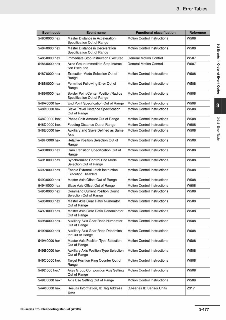
3 Error Tables3-2 E
vents in
Ord
er of E
vent C
od
es
3
3-2-2 Error Table
54830000 hex Master Distance in Acceleration Specification Out of Range
Motion Control Instructions W508
54840000 hex Master Distance in Deceleration Specification Out of Range
Motion Control Instructions W508
54850000 hex Immediate Stop Instruction Executed General Motion Control W507
54860000 hex Axes Group Immediate Stop Instruc-tion Executed
General Motion Control W507
54870000 hex Execution Mode Selection Out of Range
Motion Control Instructions W508
54880000 hex Permitted Following Error Out of Range
Motion Control Instructions W508
54890000 hex Border Point/Center Position/Radius Specification Out of Range
Motion Control Instructions W508
548A0000 hex End Point Specification Out of Range Motion Control Instructions W508
548B0000 hex Slave Travel Distance Specification Out of Range
Motion Control Instructions W508
548C0000 hex Phase Shift Amount Out of Range Motion Control Instructions W508
548D0000 hex Feeding Distance Out of Range Motion Control Instructions W508
548E0000 hex Auxiliary and Slave Defined as Same Axis
Motion Control Instructions W508
548F0000 hex Relative Position Selection Out of Range
Motion Control Instructions W508
54900000 hex Cam Transition Specification Out of Range
Motion Control Instructions W508
54910000 hex Synchronized Control End Mode Selection Out of Range
Motion Control Instructions W508
54920000 hex Enable External Latch Instruction Execution Disabled
Motion Control Instructions W508
54930000 hex Master Axis Offset Out of Range Motion Control Instructions W508
54940000 hex Slave Axis Offset Out of Range Motion Control Instructions W508
54950000 hex Command Current Position Count Selection Out of Range
Motion Control Instructions W508
54960000 hex Master Axis Gear Ratio Numerator Out of Range
Motion Control Instructions W508
54970000 hex Master Axis Gear Ratio Denominator Out of Range
Motion Control Instructions W508
54980000 hex Auxiliary Axis Gear Ratio Numerator Out of Range
Motion Control Instructions W508
54990000 hex Auxiliary Axis Gear Ratio Denomina-tor Out of Range
Motion Control Instructions W508
549A0000 hex Master Axis Position Type Selection Out of Range
Motion Control Instructions W508
549B0000 hex Auxiliary Axis Position Type Selection Out of Range
Motion Control Instructions W508
549C0000 hex Target Position Ring Counter Out of Range
Motion Control Instructions W508
549D000 hex* Axes Group Composition Axis Setting Out of Range
Motion Control Instructions W508
549E0000 hex* Axis Use Setting Out of Range Motion Control Instructions W508
54A00000 hex Results Information, ID Tag Address Error
CJ-series ID Sensor Units Z317
Event code Event name Functional classification Reference
3-177NJ-series Troubleshooting Manual (W503)

3 Error Tables
54A10000 hex Results Information, Write Protection Error
CJ-series ID Sensor Units Z317
54A20000 hex Results Information, Command Error CJ-series ID Sensor Units Z317
54A80000 hex Command Error CJ-series Serial Communications Units
W494
54A90000 hex Sequence Abort Completed CJ-series Serial Communications Units
W494
54AA0000 hex Protocol Macro Error CJ-series Serial Communications Units
W494
54AE0000 hex Multiple Switches ON Error CJ-series EtherNet/IP Units W495
54AF0000 hex Access Detected Outside Range of Variable
CJ-series EtherNet/IP Units W495
54E00000 hex Access Detected Outside Range of Variable
Built-in EtherNet/IP Port on CPU Unit W506
55000000 hex* Division by Zero NX-series Safety Control Unit Z930
55010000 hex* Cast Error NX-series Safety Control Unit Z930
55020000 hex* MUX Error NX-series Safety Control Unit Z930
57000000 hex* Homing Parameter Setting Out of Range
Motion Control Instructions W508
57020000 hex* Axis Use Change Error Motion Control Instructions W508
57030000 hex* Cannot Change Axis Use Motion Control Instructions W508
571D0000 hex* Too Many Reset Motion Control Error Instructions
General Motion Control W507
57200000 hex* Motion Control Parameter Setting Error When Changing Axis Use
Motion Control Instructions W508
57210000 hex* Required Process Data Object Not Set When Changing Axis Use
Motion Control Instructions W508
57220000 hex* Actual Position Overflow/Underflow Motion Control Instructions W508
57230000 hex* Switch Structure Track Number Set-ting Out of Range
Motion Control Instructions W508
57240000 hex* Switch Structure First ON Position Setting Out of Range
Motion Control Instructions W508
57250000 hex* Switch Structure Last ON Position Setting Out of Range
Motion Control Instructions W508
57260000 hex* Switch Structure Axis Direction Out of Range
Motion Control Instructions W508
57270000 hex* Switch Structure Cam Switch Mode Out of Range
Motion Control Instructions W508
57280000 hex* Switch Structure Duration Setting Out of Range
Motion Control Instructions W508
57290000 hex* Track Option Structure ON Compen-sation Setting Out of Range
Motion Control Instructions W508
572A0000 hex* Track Option Structure OFF Compen-sation Setting Out of Range
Motion Control Instructions W508
572B0000 hex* Number of Array Elements in Switch Structure Variable Out of Range
Motion Control Instructions W508
572C0000 hex* Number of Array Elements in Output Signal Structure Variable Out of Range
Motion Control Instructions W508
572D0000 hex* Number of Array Elements in Track Option Structure Variable Out of Range
Motion Control Instructions W508
Event code Event name Functional classification Reference
3-178 NJ-series Troubleshooting Manual (W503)

3 Error Tables3-2 E
vents in
Ord
er of E
vent C
od
es
3
3-2-2 Error Table
572E0000 hex* Numbers of Elements in Output Sig-nals and Track Option Arrays Not Matched
Motion Control Instructions W508
572F0000 hex* Motion Control Instruction Multi-exe-cution Disabled (Master Axis)
Motion Control Instructions W508
57300000 hex* Motion Control Instruction Multi-exe-cution Disabled (Position Type Selec-tion)
Motion Control Instructions W508
57310000 hex* Same Track Number Setting in Switch Structure Out of Range
Motion Control Instructions W508
573A0000 hex* Cannot Write Axis Parameters Motion Control Instructions W508
573B0000 hex* Axis Parameter Setting Out of Range Motion Control Instructions W508
573C0000 hex* Cam Property Setting Out of Range Motion Control Instructions W508
573D0000 hex* Cam Node Setting Out of Range Motion Control Instructions W508
573E0000 hex* Incorrect Cam Node Type Specifica-tion
Motion Control Instructions W508
573F0000 hex* Insufficient Nodes in Cam Table Motion Control Instructions W508
57400000 hex* Cam Node Master Axis Phase Not in Ascending Order
Motion Control Instructions W508
57410000 hex* Too Many Data Points in Cam Table Motion Control Instructions W508
57420000 hex* Cam Table Displacement Overflow Motion Control Instructions W508
57430000 hex* Aborted Cam Table Used Motion Control Instructions W508
58210000 hex* Output Control Timeout for Parallel I/O, PLC Link, or EtherNet/IP
FH/FZ5 Series Vision System Z342
58220000 hex* Output Control Timeout for EtherCAT FH/FZ5 Series Vision System Z342
60010000 hex Task Period Exceeded Errors Related to Tasks W501
60020000 hex Task Execution Timeout Errors Related to Tasks W501
60030000 hex I/O Refreshing Timeout Error Errors Related to Tasks W501
60040000 hex Insufficient System Service Time Error
Errors Related to Tasks W501
60050000 hex Task Period Exceeded Errors Related to Tasks W501
64010000 hex Impossible to Access Special Unit Errors Related to Unit Configuration W500
64200000 hex Emergency Message Detected Built-in EtherCAT Master in CPU Unit W505
64400000 hex Target Position Positive Software Limit Exceeded
Motion Control Instructions W508
64410000 hex Target Position Negative Software Limit Exceeded
Motion Control Instructions W508
64420000 hex Command Position Overflow/Under-flow
Motion Control Instructions W508
64430000 hex Positive Limit Input Motion Control Instructions W508
64440000 hex Negative Limit Input Motion Control Instructions W508
64450000 hex Positive Software Limit Exceeded General Motion Control W507
64460000 hex Negative Software Limit Exceeded General Motion Control W507
64470000 hex In-position Check Time Exceeded General Motion Control W507
64480000 hex Following Error Limit Exceeded General Motion Control W507
64490000 hex Immediate Stop Input General Motion Control W507
644A0000 hex Positive Limit Input Detected General Motion Control W507
644B0000 hex Negative Limit Input Detected General Motion Control W507
644C0000 hex Following Error Warning General Motion Control W507
644D0000 hex Velocity Warning General Motion Control W507
Event code Event name Functional classification Reference
3-179NJ-series Troubleshooting Manual (W503)

3 Error Tables
644E0000 hex Acceleration Warning General Motion Control W507
644F0000 hex Deceleration Warning General Motion Control W507
64500000 hex Positive Torque Warning General Motion Control W507
64510000 hex Negative Torque Warning General Motion Control W507
64520000 hex Command Position Overflow General Motion Control W507
64530000 hex Command Position Underflow General Motion Control W507
64540000 hex Actual Position Overflow General Motion Control W507
64550000 hex Actual Position Underflow General Motion Control W507
64560000 hex Illegal Following Error General Motion Control W507
64570000 hex Servo OFF Error General Motion Control W507
64580000 hex Absolute Encoder Current Position Calculation Failed
General Motion Control W507
64590000 hex Home Undefined during Coordinated Motion
General Motion Control W507
64780000 hex Input Disconnection Detected CJ-series Analog I/O Units W490
64790000 hex Output Set Value Error CJ-series Analog I/O Units W490
647A0000 hex Input Error CJ-series Process I/O Units W498
647D0000 hex Zero/Span Adjustment Period End CJ-series Process I/O Units W498
647E0000 hex Zero/Span Adjustment Period Notice CJ-series Process I/O Units W498
64840000 hex Sensor Error CJ-series Temperature Control Units W491
64850000 hex CT Overflow CJ-series Temperature Control Units W491
64860000 hex Heater Burnout Alarm CJ-series Temperature Control Units W491
648C0000 hex Unit Status, Command Error End CJ-series ID Sensor Units Z317
648D0000 hex Results Information, Verification Error CJ-series ID Sensor Units Z317
648E0000 hex Results Information, ID Tag Commu-nications Error
CJ-series ID Sensor Units Z317
648F0000 hex Results Information, ID Tag Missing Error
CJ-series ID Sensor Units Z317
64900000 hex Results Information, ID System Error 1
CJ-series ID Sensor Units Z317
64910000 hex Results Information, ID System Error 2
CJ-series ID Sensor Units Z317
64920000 hex Results Information, ID System Error 3
CJ-series ID Sensor Units Z317
64930000 hex Results Information, ID Tag Status CJ-series ID Sensor Units Z317
64940000 hex Results Information, Error Correction CJ-series ID Sensor Units Z317
64980000 hex Representative Warning CJ-series CompoNet Master Unit W493
64990000 hex Representative Alarm CJ-series CompoNet Master Unit W493
64A00000 hex Tfs (Send Finished Monitoring Time) Exceeded
CJ-series Serial Communications Units
W494
64A10000 hex Tfr (Receive Finished Monitoring Time) Exceeded
CJ-series Serial Communications Units
W494
64A20000 hex Tr (Receive Wait Monitoring Time) Exceeded
CJ-series Serial Communications Units
W494
64A30000 hex FCS Check Error CJ-series Serial Communications Units
W494
64A40000 hex Timeout Error CJ-series Serial Communications Units
W494
64A50000 hex Comparison Error CJ-series Serial Communications Units
W494
Event code Event name Functional classification Reference
3-180 NJ-series Troubleshooting Manual (W503)

3 Error Tables3-2 E
vents in
Ord
er of E
vent C
od
es
3
3-2-2 Error Table
64A60000 hex Reception Overflow CJ-series Serial Communications Units
W494
64A70000 hex Command Format Error CJ-series Serial Communications Units
W494
64AC0000 hex Send Timeout Error CJ-series DeviceNet Units W497
64CC0000 hex I/O Disconnection Detected Block I/O (GX-series EtherCAT Slave Units)
W488
64E00000 hex Drive Prohibition Input Error 1 Servo G5 and G5 Linear I576, I577
64E10000 hex Drive Prohibition Input Error 2 Servo G5 and G5 Linear I576, I577
64E20000 hex Immediate Stop Input Error Servo G5 and G5 Linear I576, I577
64F00000 hex* Unit Over Range for Channel 1 NX-series Analog I/O Units W522
64F10000 hex* Unit Over Range for Channel 2 NX-series Analog I/O Units W522
64F20000 hex* Unit Over Range for Channel 3 NX-series Analog I/O Units W522
64F30000 hex* Unit Over Range for Channel 4 NX-series Analog I/O Units W522
64F40000 hex* Unit Over Range for Channel 5 NX-series Analog I/O Units W522
64F50000 hex* Unit Over Range for Channel 6 NX-series Analog I/O Units W522
64F60000 hex* Unit Over Range for Channel 7 NX-series Analog I/O Units W522
64F70000 hex* Unit Over Range for Channel 8 NX-series Analog I/O Units W522
64F80000 hex* Unit Under Range for Channel 1 NX-series Analog I/O Units W522
64F90000 hex* Unit Under Range for Channel 2 NX-series Analog I/O Units W522
64FA0000 hex* Unit Under Range for Channel 3 NX-series Analog I/O Units W522
64FB0000 hex* Unit Under Range for Channel 4 NX-series Analog I/O Units W522
64FC0000 hex* Unit Under Range for Channel 5 NX-series Analog I/O Units W522
64FD0000 hex* Unit Under Range for Channel 6 NX-series Analog I/O Units W522
64FE0000 hex* Unit Under Range for Channel 7 NX-series Analog I/O Units W522
64FF0000 hex* Unit Under Range for Channel 8 NX-series Analog I/O Units W522
65030000 hex* Unit I/O Disconnection Detected for Channel 1
NX-series Analog I/O Units W522
65040000 hex* Unit I/O Disconnection Detected for Channel 2
NX-series Analog I/O Units W522
65050000 hex* Unit I/O Disconnection Detected for Channel 3
NX-series Analog I/O Units W522
65060000 hex* Unit I/O Disconnection Detected for Channel 4
NX-series Analog I/O Units W522
65070000 hex* Unit I/O Disconnection Detected for Channel 5
NX-series Analog I/O Units W522
65080000 hex* Unit I/O Disconnection Detected for Channel 6
NX-series Analog I/O Units W522
65090000 hex* Unit I/O Disconnection Detected for Channel 7
NX-series Analog I/O Units W522
Event code Event name Functional classification Reference
3-181NJ-series Troubleshooting Manual (W503)

3 Error Tables
650A0000 hex* Unit I/O Disconnection Detected for Channel 8
NX-series Analog I/O Units W522
65100000 hex Sensor Disconnected Error NX-series Analog I/O Units W522
65110000 hex Process Value Over Range NX-series Analog I/O Units W522
65120000 hex Process Value Under Range NX-series Analog I/O Units W522
65200000 hex* I/O Power Supply Voltage Error NX-series Safety Control Unit Z930
65210000 hex* Output Power Interrupt Circuit Error NX-series Safety Control Unit Z930
65220000 hex* External Test Signal Failure at Safety Input
NX-series Safety Control Unit Z930
65230000 hex* Discrepancy Error at Safety Input NX-series Safety Control Unit Z930
65240000 hex* Overload Detected at Test Output NX-series Safety Control Unit Z930
65250000 hex* Stuck-at-high Detected at Test Output NX-series Safety Control Unit Z930
65270000 hex* Short Circuit Detected at Safety Out-put
NX-series Safety Control Unit Z930
65280000 hex* Stuck-at-high Detected at Safety Out-put
NX-series Safety Control Unit Z930
68010000 hex Unit Error CJ-series High-speed Counter Units W492
70010000 hex* Previous Time Specified NX-series Digital I/O Units W521
74200000 hex Motion Control Period Exceeded General Motion Control W507
74210000 hex Servo Main Circuit Power OFF General Motion Control W507
74220000 hex Servo Main Circuits OFF Motion Control Instructions W508
74230000 hex Interrupt Feeding Interrupt Signal Missing
General Motion Control W507
74240000 hex Homing Opposite Direction Limit Input Detected
General Motion Control W507
74250000 hex Homing Direction Limit Input Detected
General Motion Control W507
74260000 hex Homing Limit Inputs Detected in Both Directions
General Motion Control W507
74270000 hex Home Proximity/Homing Opposite Direction Limit Input Detected
General Motion Control W507
74280000 hex Home Proximity/Homing Direction Limit Input Detected
General Motion Control W507
74290000 hex Home Input/Homing Opposite Direc-tion Limit Input Detected
General Motion Control W507
742A0000 hex Home Input/Homing Direction Limit Input Detected
General Motion Control W507
742B0000 hex Invalid Home Input Mask Distance General Motion Control W507
742C0000 hex No Home Input General Motion Control W507
742D0000 hex No Home Proximity Input General Motion Control W507
742F0000 hex Slave Error Detected General Motion Control W507
74300000 hex Axes Group Composition Axis Error General Motion Control W507
74320000 hex Slave Observation Detected General Motion Control W507
74330000 hex MC Common Error Occurrence General Motion Control W507
74340000 hex Latch Position Overflow General Motion Control W507
74350000 hex Latch Position Underflow General Motion Control W507
Event code Event name Functional classification Reference
3-182 NJ-series Troubleshooting Manual (W503)

3 Error Tables3-2 E
vents in
Ord
er of E
vent C
od
es
3
3-2-2 Error Table
74360000 hex Master Sync Direction Error General Motion Control W507
74370000 hex Slave Disconnection during Servo ON General Motion Control W507
74380000 hex Feed Distance Overflow General Motion Control W507
74390000 hex Error in Changing Servo Drive Con-trol Mode
General Motion Control W507
743A0000 hex Master Axis Position Read Error General Motion Control W507
743B0000 hex Auxiliary Axis Position Read Error General Motion Control W507
743C0000 hex Cannot Execute Save Cam Table Instruction
General Motion Control W507
743D0000 hex* Incorrect Synchronization Command NX-series Position Interface Units W524
743E0000 hex* Illegal Following Error NX-series Position Interface Units W524
743F0000 hex* Illegal State Transition NX-series Position Interface Units W524
74600000 hex Master Function Enable/Disable Failed
CJ-series DeviceNet Units W497
74610000 hex Master Fixed Allocation Area Setting Failed
CJ-series DeviceNet Units W497
74620000 hex Scan List Register/Clear Failed CJ-series DeviceNet Units W497
74630000 hex Slave Function Enable/Disable Failed CJ-series DeviceNet Units W497
74640000 hex Slave Fixed Allocation Area Setting Failed
CJ-series DeviceNet Units W497
74800000 hex Command Warning Servo G5 and G5 Linear I576, I577
74810000 hex Command Error Servo G5 and G5 Linear I576, I577
74900000 hex* Multiple Control Signal Input Error ZW-CE1T Confocal Fiber Type Dis-placement Sensor
Z332
74910000 hex* EXE Input Error ZW-CE1T Confocal Fiber Type Dis-placement Sensor
Z332
74920000 hex* SYNC Input Error ZW-CE1T Confocal Fiber Type Dis-placement Sensor
Z332
74930000 hex* TIMING Input Error ZW-CE1T Confocal Fiber Type Dis-placement Sensor
Z332
74940000 hex* RESET Input Error ZW-CE1T Confocal Fiber Type Dis-placement Sensor
Z332
74950000 hex* ZERO Input Error ZW-CE1T Confocal Fiber Type Dis-placement Sensor
Z332
74960000 hex* ZEROCLR Input Error ZW-CE1T Confocal Fiber Type Dis-placement Sensor
Z332
74A00000 hex* SF_Antivalent Error NX-series Safety Control Unit Z930
74A10000 hex* SF_EDM Error NX-series Safety Control Unit Z930
74A20000 hex* SF_EmergencyStop Error NX-series Safety Control Unit Z930
74A30000 hex* SF_EnableSwitch Error NX-series Safety Control Unit Z930
74A40000 hex* SF_Equivalent Error NX-series Safety Control Unit Z930
74A50000 hex* SF_ESPE Error NX-series Safety Control Unit Z930
74A60000 hex* SF_GuardLocking Error NX-series Safety Control Unit Z930
74A70000 hex* SF_GuardMonitoring Error NX-series Safety Control Unit Z930
Event code Event name Functional classification Reference
3-183NJ-series Troubleshooting Manual (W503)

3 Error Tables
74A80000 hex* SF_ModeSelector Error NX-series Safety Control Unit Z930
74A90000 hex* SF_MutingPar Error NX-series Safety Control Unit Z930
74AA0000 hex* SF_MutingPar_2Sensor Error NX-series Safety Control Unit Z930
74AB0000 hex* SF_MutingSeq Error NX-series Safety Control Unit Z930
74AC0000 hex* SF_OutControl Error NX-series Safety Control Unit Z930
74AD0000 hex* SF_SafetyRequest Error NX-series Safety Control Unit Z930
74AE0000 hex* SF_TestableSafetySensor Error NX-series Safety Control Unit Z930
74AF0000 hex* SF_TwoHandControlTypeII Error NX-series Safety Control Unit Z930
74B00000 hex* SF_TwoHandControlTypeIII Error NX-series Safety Control Unit Z930
78010000 hex Operation Command Competition Servo G5 and G5 Linear I576, I577
78020000 hex Absolute Encoder Status Error Servo G5 I576
78080000 hex TRIG Input Error EtherCAT FQ-M-series Specialized Vision Sensors for Positioning
Z314
780A0000 hex Scene Data Error EtherCAT FQ-M-series Specialized Vision Sensors for Positioning
Z314
780B0000 hex Model Error EtherCAT FQ-M-series Specialized Vision Sensors for Positioning
Z314
780C0000 hex Logging Error EtherCAT FQ-M-series Specialized Vision Sensors for Positioning
Z314
780D0000 hex Output Timeout EtherCAT FQ-M-series Specialized Vision Sensors for Positioning
Z314
780E0000 hex Output Size Error EtherCAT FQ-M-series Specialized Vision Sensors for Positioning
Z314
78190000 hex* Image Logging Disk Write Error FH/FZ5 Series Vision System Z342
781A0000 hex* Setting Data Transfer Error FH/FZ5 Series Vision System Z342
781B0000 hex* Output Buffer Error (EtherCAT) FH/FZ5 Series Vision System Z342
80010000 hex Illegal Packet Discarded Errors Related to Unit Configuration W500
80100000 hex Packet Discarded Errors Related to FINS Communica-tions
W501
80110000 hex Packet Discarded Errors Related to FINS Communica-tions
W501
80120000 hex Packet Discarded Errors Related to FINS Communica-tions
W501
80200000 hex* NX Unit I/O Communications Error NX-series Digital I/O Units, NX-series Analog I/O Units, NX-series Position Interface Units, and NX-series Safety Control Unit
W521, W522, W524, and Z930
80210000 hex* NX Unit Output Synchronization Error NX-series Digital I/O Units, NX-series Analog I/O Units, and NX-series Position Interface Units
W521, W522, and W524
80220000 hex* NX Message Communications Error NX-series EtherCAT Coupler Unit, NX-series Analog I/O Units, NX-series Position Interface Units, and NX-series Safety Control Unit
W519, W522, W524, and Z930
Event code Event name Functional classification Reference
3-184 NJ-series Troubleshooting Manual (W503)

3 Error Tables3-2 E
vents in
Ord
er of E
vent C
od
es
3
3-2-2 Error Table
80230000 hex* NX Message Communications Error Errors Related to Controller Opera-tion
W500, W501
80240000 hex* NX Unit Clock Not Synchronized Error
NX-series Digital I/O Units, NX-series Analog I/O Units, and NX-series Position Interface Units
W521, W522, and W524
80300000 hex* Safety Process Data Communica-tions Timeout
NX-series Safety Control Unit Z930
84010000 hex IP Address Duplication Error Built-in EtherNet/IP Port on CPU Unit W506
84020000 hex BOOTP Server Connection Error Built-in EtherNet/IP Port on CPU Unit W506
84030000 hex DNS Server Connection Error Built-in EtherNet/IP Port on CPU Unit W506
84040000 hex NTP Server Connection Error Built-in EtherNet/IP Port on CPU Unit W506
84050000 hex Packet Discarded Due to Full Recep-tion Buffer
Built-in EtherNet/IP Port on CPU Unit W506
84060000 hex Link OFF Detected Built-in EtherNet/IP Port on CPU Unit W506
84070000 hex Tag Data Link Connection Failed Built-in EtherNet/IP Port on CPU Unit W506
84080000 hex Tag Data Link Timeout Built-in EtherNet/IP Port on CPU Unit W506
84090000 hex* Tag Data Link Connection Timeout Built-in EtherNet/IP Port on CPU Unit W506
84200000 hex Link OFF Error Built-in EtherCAT Master in CPU Unit W505
84210000 hex Network Configuration Error Built-in EtherCAT Master in CPU Unit W505
84220000 hex Network Configuration Verification Error
Built-in EtherCAT Master in CPU Unit W505
84230000 hex Slave Initialization Error Built-in EtherCAT Master in CPU Unit W505
84280000 hex Slave Application Error Built-in EtherCAT Master in CPU Unit W505
84290000 hex Process Data Transmission Error Built-in EtherCAT Master in CPU Unit W505
842B0000 hex Process Data Reception Timeout Built-in EtherCAT Master in CPU Unit W505
842C0000 hex Process Data Communications Error Built-in EtherCAT Master in CPU Unit W505
842D0000 hex EtherCAT Message Error Built-in EtherCAT Master in CPU Unit W505
84400000 hex EtherCAT Slave Communications Error
General Motion Control W507
84600000 hex Communications Error CJ-series CompoNet Master Unit W493
84610000 hex Repeater Unit Communications Error CJ-series CompoNet Master Unit W493
84680000 hex Transmission Error CJ-series Serial Communications Units
W494
84690000 hex Overrun Error CJ-series Serial Communications Units
W494
846A0000 hex Framing Error CJ-series Serial Communications Units
W494
846B0000 hex Parity Error CJ-series Serial Communications Units
W494
846C0000 hex Overrun Error, Framing Error, or Par-ity Error (Transmission Error)
CJ-series Serial Communications Units
W494
846D0000 hex Transmission Error (CRC Error) CJ-series Serial Communications Units
W494
84740000 hex Bus Off Detected CJ-series DeviceNet Units W497
84750000 hex Remote I/O Communications Error CJ-series DeviceNet Units W497
84760000 hex Remote I/O Communications Error (during Slave Operation)
CJ-series DeviceNet Units W497
84770000 hex Slave COS Send Failed CJ-series DeviceNet Units W497
84B00000 hex EtherCAT Communications Warning Servo G5 and G5 Linear I576, I577
Event code Event name Functional classification Reference
3-185NJ-series Troubleshooting Manual (W503)

3 Error Tables
84B10000 hex EtherCAT State Change Error Servo G5 and G5 Linear I576, I577
84B20000 hex EtherCAT Illegal State Change Error Servo G5 and G5 Linear I576, I577
84B30000 hex Communications Synchronization Error
Servo G5 and G5 Linear I576, I577
84B40000 hex Synchronization Error Servo G5 and G5 Linear I576, I577
84B50000 hex Sync Manager WDT Error Servo G5 and G5 Linear I576, I577
84B60000 hex ESC Initialization Error Servo G5 and G5 Linear I576, I577
84B70000 hex Slave Unit Verification Error Servo G5 and G5 Linear I576, I577
84B80000 hex Communications Setting Error Servo G5 and G5 Linear I576, I577
84B90000 hex Synchronization Interruption Error Servo G5 and G5 Linear I576, I577
84C00000 hex* NX Unit Communications Timeout NX-series EtherCAT Coupler Unit W519
84C10000 hex* NX Unit Initialization Error NX-series EtherCAT Coupler Unit W519
84C50000 hex* NX Unit Startup Error NX-series EtherCAT Coupler Unit W519
84D00000 hex* SSI Communications Error NX-series Position Interface Units W524
84E00000 hex IP Address Duplication Error CJ-series EtherNet/IP Units W495
84E10000 hex BOOTP Server Error CJ-series EtherNet/IP Units W495
84E20000 hex Link OFF Error CJ-series EtherNet/IP Units W495
84F00000 hex* NX Bus I/O Communications Stopped NX-series Safety Control Unit Z930
84F10000 hex* NX Bus I/O Communications Stopped NX-series Safety Control Unit Z930
85000000 hex* Process Data WDT Error NX-series EtherCAT Coupler Unit W519
85010000 hex* Synchronization Interruption Error NX-series EtherCAT Coupler Unit W519
85020000 hex* Synchronization Error NX-series EtherCAT Coupler Unit W519
85030000 hex* Communications Synchronization Error
NX-series EtherCAT Coupler Unit W519
85100000 hex* DB Connection Disconnected Error DB Connection Service W527
88080000 hex* PLC Link Communications Error FH/FZ5 Series Vision System Z342
90010000 hex Clock Changed Errors Related to Controller Opera-tion
W500, W501
90020000 hex Time Zone Changed Errors Related to Controller Opera-tion
W500, W501
90080000 hex Variable Changed to TRUE with Forced Refreshing
Errors Related to Controller Opera-tion
W500, W501
90090000 hex Variable Changed to FALSE with Forced Refreshing
Errors Related to Controller Opera-tion
W500, W501
900A0000 hex All Forced Refreshing Cleared Errors Related to Controller Opera-tion
W500, W501
900B0000 hex Memory All Cleared Errors Related to Controller Opera-tion
W500, W501
900C0000 hex Event Log Cleared Errors Related to Controller Opera-tion
W500, W501
Event code Event name Functional classification Reference
3-186 NJ-series Troubleshooting Manual (W503)

3 Error Tables3-2 E
vents in
Ord
er of E
vent C
od
es
3
3-2-2 Error Table
900F0000 hex* Automatic Transfer Completed Errors Related to Controller Opera-tion
W500, W501
90110000 hex Power Turned ON Errors Related to Controller Opera-tion
W500, W501
90120000 hex Power Interrupted Errors Related to Controller Opera-tion
W500, W501
90130000 hex Operation Started Errors Related to Controller Opera-tion
W500, W501
90140000 hex Operation Stopped Errors Related to Controller Opera-tion
W500, W501
90150000 hex Reset Executed Errors Related to Controller Opera-tion
W500, W501
90160000 hex User Program Execution ID Write Errors Related to Controller Opera-tion
W500, W501
90180000 hex All Controller Errors Cleared Errors Related to Controller Opera-tion
W500, W501
90190000 hex Forced Refreshing Cleared Errors Related to Controller Opera-tion
W500, W501
901A0000 hex* Backup Started Errors Related to Controller Opera-tion
W500, W501
901B0000 hex* Backup Completed Errors Related to Controller Opera-tion
W500, W501
901C0000 hex* Restore Operation Started Errors Related to Controller Opera-tion
W500, W501
901D0000 hex* Restore Operation Completed Errors Related to Controller Opera-tion
W500, W501
90400000 hex* Event Log Cleared NX-series EtherCAT Coupler Unit, NX-series Digital I/O Units, NX-series Analog I/O Units, NX-series System Units, NX-series Position Interface Units, and NX-series Safety Control Unit
W519, W521, W522, W523, W524, and Z930
90420000 hex* Restart Executed NX-series EtherCAT Coupler Unit W519
90430000 hex* Memory All Cleared NX-series EtherCAT Coupler Unit and NX-series Safety Control Unit
W519, Z930
94010000 hex Tag Data Link Download Started Built-in EtherNet/IP Port on CPU Unit W506
94020000 hex Tag Data Link Download Finished Built-in EtherNet/IP Port on CPU Unit W506
94030000 hex Tag Data Link Stopped Built-in EtherNet/IP Port on CPU Unit W506
94040000 hex Tag Data Link Started Built-in EtherNet/IP Port on CPU Unit W506
94050000 hex Link Detected Built-in EtherNet/IP Port on CPU Unit W506
94060000 hex Restarting Ethernet Port Built-in EtherNet/IP Port on CPU Unit W506
94070000 hex Tag Data Link All Run Built-in EtherNet/IP Port on CPU Unit W506
94080000 hex IP Address Fixed Built-in EtherNet/IP Port on CPU Unit W506
94090000 hex BOOTP Client Started Built-in EtherNet/IP Port on CPU Unit W506
940A0000 hex FTP Server Started Built-in EtherNet/IP Port on CPU Unit W506
940B0000 hex NTP Client Started Built-in EtherNet/IP Port on CPU Unit W506
940C0000 hex SNMP Started Built-in EtherNet/IP Port on CPU Unit W506
94200000 hex Notice of Insufficient Travel Distance to Achieve Blending Transit Velocity
General Motion Control W507
94210000 hex Error Clear from MC Test Run Tab Page
General Motion Control W507
94220000 hex Slave Error Code Report General Motion Control W507
Event code Event name Functional classification Reference
3-187NJ-series Troubleshooting Manual (W503)

3 Error Tables
94400000 hex Slave Disconnected Built-in EtherCAT Master in CPU Unit W505
94410000 hex Slave Connected Built-in EtherCAT Master in CPU Unit W505
94430000 hex Errors Reset Built-in EtherCAT Master in CPU Unit W505
94440000 hex* Slave Disabled Built-in EtherCAT Master in CPU Unit W505
94450000 hex* Slave Enabled Built-in EtherCAT Master in CPU Unit W505
94600000 hex* I/O Check Execution Started NX-series EtherCAT Coupler Unit W519
951E0000 hex* Sysmac Studio Communications Connection Timeout
NX-series Safety Control Unit Z930
951F0000 hex* Clear All Memory Rejected NX-series Safety Control Unit Z930
95300000 hex* DB Connection Service Started DB Connection Service W527
95310000 hex* DB Connection Service Stopped DB Connection Service W527
95320000 hex* DB Connection Service Shutdown DB Connection Service W527
98010000 hex Absolute Value Cleared Servo G5 I576
98020000 hex Position Data Initialized Servo G5 and G5 Linear I576, I577
Event code Event name Functional classification Reference
3-188 NJ-series Troubleshooting Manual (W503)
3 Error Tables3-3 In
structio
n E
rror Tab
le
3
3-3 Instruction Error Table
For descriptions of the error codes for the motion control instructions and other instructions, refer to thedescriptions of the corresponding event codes. Events that occur for motion control instructions aregiven in 3-1-3 Errors in the Motion Control Function Module. Events that occur for other instructions aregiven in 3-1-2 Errors in the PLC Function Module. Refer to 1-3-1 Types of Non-fatal Errors for the rela-tionship between event codes and error codes.
3-189NJ-series Troubleshooting Manual (W503)

3 Error Tables
3-190 NJ-series Troubleshooting Manual (W503)
I
Index
Index-1NJ-series Troubleshooting Manual (W503)

Index
Index
A
assumed causes .............. 3-3, 3-5, 3-50, 3-80, 3-84, 3-88, 3-90, 3-94, 3-97, 3-99, 3-103, 3-105, 3-108, 3-111, 3-114,3-115, 3-128, 3-129, 3-131, 3-135, 3-137, 3-138, 3-140,3-141, 3-146
B
Block I/O .................................................................... 3-114built-in EtherCAT master ............................................. 3-84built-in EtherNet/IP port ............................................... 3-80
C
CJ1W-AD041-V1/AD081-V1 ..................................... 3-135CJ1W-AD042 ............................................................. 3-135CJ1W-AD04U ............................................................ 3-137CJ1W-CT021 ............................................................. 3-140CJ1W-DA021/DA041 ................................................. 3-135CJ1W-DA042V .......................................................... 3-135CJ1W-DA08V/DA08C ................................................ 3-135CJ1W-DRM21 ........................................................... 3-146CJ1W-MAD42 ............................................................ 3-135CJ1W-PDC15 ............................................................ 3-137CJ1W-PH41U ............................................................ 3-137CJ1W-SCU2 .............................................................. 3-141CJ1W-SCU32 ............................................................ 3-141CJ1W-SCU42 ............................................................ 3-141CJ1W-TC003 ............................................................. 3-138CJ1W-TC004 ............................................................. 3-138CJ1W-TC103 ............................................................. 3-138CJ1W-TC104 ............................................................. 3-138CJ1W-V680C11 ......................................................... 3-138CJ1W-V680C12 ......................................................... 3-138CJ-series Analog I/O Units ........................................ 3-135CJ-series DeviceNet Units ........................................ 3-146CJ-series High-speed Counter Units ......................... 3-140CJ-series ID Sensor Units ......................................... 3-138CJ-series Process I/O Units ...................................... 3-137CJ-series Serial Communications Units .................... 3-141CJ-series Temperature Control Units ........................ 3-138CJ-series Units .......................................................... 3-135Controller errors ............................................................ 1-6Controller events ........................................................... 1-5
sources .................................................................... 1-6Controller information .................................................... 1-6Controller operation ....................................................... 3-8CPU Unit operating status ............................................. 1-3CPU Unit Reset ......................................................1-4, 2-4CPU Unit Watchdog Timer Error ............................1-4, 2-4
D
DB connection instructions .......................................... 3-90DB connections service ............................................... 3-88
E
Error Status variable ...........................................1-14, 2-13errors
checking with system-defined variables ................. 2-13identifying and resetting ...........................2-5, 2-9, 2-11resetting ................................................................. 2-12
EtherCAT Master Function Module ............................. 3-84EtherCAT slaves ........................................................ 3-114EtherNet/IP Function Module ...................................... 3-80event codes .............1-10, 3-3, 3-5, 3-50, 3-80, 3-84, 3-88,
3-90, 3-94, 3-97, 3-99, 3-103, 3-105, 3-108, 3-111, 3-114,3-115, 3-128, 3-129, 3-131, 3-135, 3-137, 3-138, 3-140,3-141, 3-146, 3-156
event codes in sequential order ........................... 3-155event log ........................................................................ 1-5event names ............3-3, 3-5, 3-50, 3-80, 3-84, 3-88, 3-90,
3-94, 3-97, 3-99, 3-103, 3-105, 3-108, 3-111, 3-114, 3-115, 3-128, 3-129, 3-131, 3-135, 3-137, 3-138, 3-140,3-141, 3-146, 3-156
events ............................................................1-2, 1-5, 3-50levels ........................................................................ 1-6
F
fatal errors ..............................................................1-2, 1-4checking for fatal errors ........................................... 1-4troubleshooting ........................................................ 2-4
FINS communications ................................................. 3-13
G
GX-series EtherCAT Slave Units ............................... 3-114
I
Incorrect Power Supply Unit Connected .................1-4, 2-4indicators ..............................................................1-3, 1-12information level ............................................................ 1-7instructions
GetCJBError .................................................1-14, 2-11GetECError ...................................................1-14, 2-11GetEIPError ..................................................1-14, 2-11GetMCError ..................................................1-14, 2-11GetPLCError .................................................1-14, 2-11getting error information ......................................... 2-11reading function module error status ..................... 1-14ResetCJBError ....................................................... 2-12ResetECError ........................................................ 2-12
Index-2
NJ-series Troubleshooting Manual (W503)
I
Index
ResetMCError ....................................................... 2-12ResetPLCError ...................................................... 2-12
M
major fault level ............................................................. 1-6minor fault level ............................................................. 1-6motion control
general .................................................................. 3-50instructions ............................................................ 3-58
Motion Control Function Module ................................. 3-50MX2/RX-series Inverters ........................................... 3-128
N
non-fatal errors .............................................. 1-3, 1-5, 1-12resetting ................................................................ 1-14troubleshooting ........................................................ 2-5
NX-AD ............................................................ 3-99NX-DA ............................................................ 3-99NX-EC0 ........................................................... 3-105NX-ECC201 ................................................................ 3-94NX-ECS ........................................................... 3-105NX-ID ............................................................. 3-97NX-OC............................................................. 3-97NX-OD ............................................................ 3-97NX-PC0 ........................................................... 3-105NX-PD1 ........................................................... 3-105NX-PF0 ............................................................ 3-105NX-PG0 ........................................................... 3-105NX-series Analog I/O Units ......................................... 3-99NX-series Digital I/O Units .......................................... 3-97NX-series EtherCAT Coupler Units ............................. 3-94NX-series Position Interface Units ............................ 3-105NX-series System Units ............................................ 3-105NX-TBX01 ................................................................. 3-105NX-TS ............................................................ 3-99
O
observation level ........................................................... 1-7online
troubleshooting problems going online .................. 2-14
P
partial fault level ............................................................ 1-6Power Supply Error ................................................ 1-4, 2-4
R
resetting errors ............................................................ 2-12resetting non-fatal errors ............................................. 1-14
S
Safe Mode ................................................................... 2-19self diagnosis ................................................................ 3-3source details ................................................................ 1-6
NJ-series Troubleshooting Manual (W503)
startingSafe Mode ............................................................. 2-19
system-defined variables ............................................ 1-14checking for errors ................................................. 2-13
T
tasks .............................................................................. 3-7Troubleshooter ..................................................... 1-13, 2-9troubleshooting .................................................... 1-13, 2-5
fatal errors ............................................................... 2-4non-fatal errors ........................................................ 2-5
U
Unit configuration .......................................................... 3-5user-defined events ....................................................... 1-5
Index-3

Index
Index-4
NJ-series Troubleshooting Manual (W503)
Terms and Conditions of Sale1. Offer; Acceptance. These terms and conditions (these "Terms") are deemed
part of all quotes, agreements, purchase orders, acknowledgments, price lists,catalogs, manuals, brochures and other documents, whether electronic or inwriting, relating to the sale of products or services (collectively, the "Products")by Omron Electronics LLC and its subsidiary companies (“Omron”). Omronobjects to any terms or conditions proposed in Buyer’s purchase order or otherdocuments which are inconsistent with, or in addition to, these Terms.
2. Prices; Payment Terms. All prices stated are current, subject to change with-out notice by Omron. Omron reserves the right to increase or decrease priceson any unshipped portions of outstanding orders. Payments for Products aredue net 30 days unless otherwise stated in the invoice.
3. Discounts. Cash discounts, if any, will apply only on the net amount of invoicessent to Buyer after deducting transportation charges, taxes and duties, and willbe allowed only if (i) the invoice is paid according to Omron’s payment termsand (ii) Buyer has no past due amounts.
4. Interest. Omron, at its option, may charge Buyer 1-1/2% interest per month orthe maximum legal rate, whichever is less, on any balance not paid within thestated terms.
5. Orders. Omron will accept no order less than $200 net billing. 6. Governmental Approvals. Buyer shall be responsible for, and shall bear all
costs involved in, obtaining any government approvals required for the impor-tation or sale of the Products.
7. Taxes. All taxes, duties and other governmental charges (other than generalreal property and income taxes), including any interest or penalties thereon,imposed directly or indirectly on Omron or required to be collected directly orindirectly by Omron for the manufacture, production, sale, delivery, importa-tion, consumption or use of the Products sold hereunder (including customsduties and sales, excise, use, turnover and license taxes) shall be charged toand remitted by Buyer to Omron.
8. Financial. If the financial position of Buyer at any time becomes unsatisfactoryto Omron, Omron reserves the right to stop shipments or require satisfactorysecurity or payment in advance. If Buyer fails to make payment or otherwisecomply with these Terms or any related agreement, Omron may (without liabil-ity and in addition to other remedies) cancel any unshipped portion of Prod-ucts sold hereunder and stop any Products in transit until Buyer pays allamounts, including amounts payable hereunder, whether or not then due,which are owing to it by Buyer. Buyer shall in any event remain liable for allunpaid accounts.
9. Cancellation; Etc. Orders are not subject to rescheduling or cancellationunless Buyer indemnifies Omron against all related costs or expenses.
10. Force Majeure. Omron shall not be liable for any delay or failure in deliveryresulting from causes beyond its control, including earthquakes, fires, floods,strikes or other labor disputes, shortage of labor or materials, accidents tomachinery, acts of sabotage, riots, delay in or lack of transportation or therequirements of any government authority.
11. Shipping; Delivery. Unless otherwise expressly agreed in writing by Omron:a. Shipments shall be by a carrier selected by Omron; Omron will not drop ship
except in “break down” situations.b. Such carrier shall act as the agent of Buyer and delivery to such carrier shall
constitute delivery to Buyer;c. All sales and shipments of Products shall be FOB shipping point (unless oth-
erwise stated in writing by Omron), at which point title and risk of loss shallpass from Omron to Buyer; provided that Omron shall retain a security inter-est in the Products until the full purchase price is paid;
d. Delivery and shipping dates are estimates only; ande. Omron will package Products as it deems proper for protection against nor-
mal handling and extra charges apply to special conditions.12. Claims. Any claim by Buyer against Omron for shortage or damage to the
Products occurring before delivery to the carrier must be presented in writingto Omron within 30 days of receipt of shipment and include the original trans-portation bill signed by the carrier noting that the carrier received the Productsfrom Omron in the condition claimed.
13. Warranties. (a) Exclusive Warranty. Omron’s exclusive warranty is that theProducts will be free from defects in materials and workmanship for a period oftwelve months from the date of sale by Omron (or such other period expressedin writing by Omron). Omron disclaims all other warranties, express or implied.(b) Limitations. OMRON MAKES NO WARRANTY OR REPRESENTATION,EXPRESS OR IMPLIED, ABOUT NON-INFRINGEMENT, MERCHANTABIL-
ITY OR FITNESS FOR A PARTICULAR PURPOSE OF THE PRODUCTS.BUYER ACKNOWLEDGES THAT IT ALONE HAS DETERMINED THAT THEPRODUCTS WILL SUITABLY MEET THE REQUIREMENTS OF THEIRINTENDED USE. Omron further disclaims all warranties and responsibility ofany type for claims or expenses based on infringement by the Products or oth-erwise of any intellectual property right. (c) Buyer Remedy. Omron’s sole obli-gation hereunder shall be, at Omron’s election, to (i) replace (in the formoriginally shipped with Buyer responsible for labor charges for removal orreplacement thereof) the non-complying Product, (ii) repair the non-complyingProduct, or (iii) repay or credit Buyer an amount equal to the purchase price ofthe non-complying Product; provided that in no event shall Omron be responsi-ble for warranty, repair, indemnity or any other claims or expenses regardingthe Products unless Omron’s analysis confirms that the Products were prop-erly handled, stored, installed and maintained and not subject to contamina-tion, abuse, misuse or inappropriate modification. Return of any Products byBuyer must be approved in writing by Omron before shipment. Omron Compa-nies shall not be liable for the suitability or unsuitability or the results from theuse of Products in combination with any electrical or electronic components,circuits, system assemblies or any other materials or substances or environ-ments. Any advice, recommendations or information given orally or in writing,are not to be construed as an amendment or addition to the above warranty.See http://www.omron247.com or contact your Omron representative for pub-lished information.
14. Limitation on Liability; Etc. OMRON COMPANIES SHALL NOT BE LIABLEFOR SPECIAL, INDIRECT, INCIDENTAL, OR CONSEQUENTIAL DAMAGES,LOSS OF PROFITS OR PRODUCTION OR COMMERCIAL LOSS IN ANYWAY CONNECTED WITH THE PRODUCTS, WHETHER SUCH CLAIM ISBASED IN CONTRACT, WARRANTY, NEGLIGENCE OR STRICT LIABILITY.Further, in no event shall liability of Omron Companies exceed the individualprice of the Product on which liability is asserted.
15. Indemnities. Buyer shall indemnify and hold harmless Omron Companies andtheir employees from and against all liabilities, losses, claims, costs andexpenses (including attorney's fees and expenses) related to any claim, inves-tigation, litigation or proceeding (whether or not Omron is a party) which arisesor is alleged to arise from Buyer's acts or omissions under these Terms or inany way with respect to the Products. Without limiting the foregoing, Buyer (atits own expense) shall indemnify and hold harmless Omron and defend or set-tle any action brought against such Companies to the extent based on a claimthat any Product made to Buyer specifications infringed intellectual propertyrights of another party.
16. Property; Confidentiality. Any intellectual property in the Products is the exclu-sive property of Omron Companies and Buyer shall not attempt to duplicate itin any way without the written permission of Omron. Notwithstanding anycharges to Buyer for engineering or tooling, all engineering and tooling shallremain the exclusive property of Omron. All information and materials suppliedby Omron to Buyer relating to the Products are confidential and proprietary,and Buyer shall limit distribution thereof to its trusted employees and strictlyprevent disclosure to any third party.
17. Export Controls. Buyer shall comply with all applicable laws, regulations andlicenses regarding (i) export of products or information; (iii) sale of products to“forbidden” or other proscribed persons; and (ii) disclosure to non-citizens ofregulated technology or information.
18. Miscellaneous. (a) Waiver. No failure or delay by Omron in exercising any rightand no course of dealing between Buyer and Omron shall operate as a waiverof rights by Omron. (b) Assignment. Buyer may not assign its rights hereunderwithout Omron's written consent. (c) Law. These Terms are governed by thelaw of the jurisdiction of the home office of the Omron company from whichBuyer is purchasing the Products (without regard to conflict of law princi-ples). (d) Amendment. These Terms constitute the entire agreement betweenBuyer and Omron relating to the Products, and no provision may be changedor waived unless in writing signed by the parties. (e) Severability. If any provi-sion hereof is rendered ineffective or invalid, such provision shall not invalidateany other provision. (f) Setoff. Buyer shall have no right to set off any amountsagainst the amount owing in respect of this invoice. (g) Definitions. As usedherein, “including” means “including without limitation”; and “Omron Compa-nies” (or similar words) mean Omron Corporation and any direct or indirectsubsidiary or affiliate thereof.
Certain Precautions on Specifications and Use1. Suitability of Use. Omron Companies shall not be responsible for conformity
with any standards, codes or regulations which apply to the combination of theProduct in the Buyer’s application or use of the Product. At Buyer’s request,Omron will provide applicable third party certification documents identifyingratings and limitations of use which apply to the Product. This information byitself is not sufficient for a complete determination of the suitability of the Prod-uct in combination with the end product, machine, system, or other applicationor use. Buyer shall be solely responsible for determining appropriateness ofthe particular Product with respect to Buyer’s application, product or system.Buyer shall take application responsibility in all cases but the following is anon-exhaustive list of applications for which particular attention must be given:(i) Outdoor use, uses involving potential chemical contamination or electricalinterference, or conditions or uses not described in this document.(ii) Use in consumer products or any use in significant quantities. (iii) Energy control systems, combustion systems, railroad systems, aviationsystems, medical equipment, amusement machines, vehicles, safety equip-ment, and installations subject to separate industry or government regulations. (iv) Systems, machines and equipment that could present a risk to life or prop-erty. Please know and observe all prohibitions of use applicable to this Prod-uct. NEVER USE THE PRODUCT FOR AN APPLICATION INVOLVING SERIOUSRISK TO LIFE OR PROPERTY OR IN LARGE QUANTITIES WITHOUTENSURING THAT THE SYSTEM AS A WHOLE HAS BEEN DESIGNED TO
ADDRESS THE RISKS, AND THAT THE OMRON’S PRODUCT IS PROP-ERLY RATED AND INSTALLED FOR THE INTENDED USE WITHIN THEOVERALL EQUIPMENT OR SYSTEM.
2. Programmable Products. Omron Companies shall not be responsible for theuser’s programming of a programmable Product, or any consequence thereof.
3. Performance Data. Data presented in Omron Company websites, catalogsand other materials is provided as a guide for the user in determining suitabil-ity and does not constitute a warranty. It may represent the result of Omron’stest conditions, and the user must correlate it to actual application require-ments. Actual performance is subject to the Omron’s Warranty and Limitationsof Liability.
4. Change in Specifications. Product specifications and accessories may bechanged at any time based on improvements and other reasons. It is our prac-tice to change part numbers when published ratings or features are changed,or when significant construction changes are made. However, some specifica-tions of the Product may be changed without any notice. When in doubt, spe-cial part numbers may be assigned to fix or establish key specifications foryour application. Please consult with your Omron’s representative at any timeto confirm actual specifications of purchased Product.
5. Errors and Omissions. Information presented by Omron Companies has beenchecked and is believed to be accurate; however, no responsibility is assumedfor clerical, typographical or proofreading errors or omissions.

OMRON CANADA, INC. • HEAD OFFICEToronto, ON, Canada • 416.286.6465 • 866.986.6766 • www.omron247.com
OMRON ELECTRONICS DE MEXICO • HEAD OFFICEMéxico DF • 52.55.59.01.43.00 • 01-800-226-6766 • [email protected]
OMRON ELECTRONICS DE MEXICO • SALES OFFICEApodaca, N.L. • 52.81.11.56.99.20 • 01-800-226-6766 • [email protected]
OMRON ELETRÔNICA DO BRASIL LTDA • HEAD OFFICESão Paulo, SP, Brasil • 55.11.2101.6300 • www.omron.com.br
OMRON ARGENTINA • SALES OFFICECono Sur • 54.11.4783.5300
OMRON CHILE • SALES OFFICESantiago • 56.9.9917.3920
OTHER OMRON LATIN AMERICA SALES54.11.4783.5300
Authorized Distributor:
Note: Specifications are subject to change. © 2014 Omron Electronics LLC Printed in U.S.A.
Printed on recycled paper.
Automation Control Systems• Machine Automation Controllers (MAC) • Programmable Controllers (PLC) • Operator interfaces (HMI) • Distributed I/O • Software
Drives & Motion Controls • Servo & AC Drives • Motion Controllers & Encoders
Temperature & Process Controllers • Single and Multi-loop Controllers
Sensors & Vision• Proximity Sensors • Photoelectric Sensors • Fiber-Optic Sensors• Amplified Photomicrosensors • Measurement Sensors• Ultrasonic Sensors • Vision Sensors
Industrial Components • RFID/Code Readers • Relays • Pushbuttons & Indicators • Limit and Basic Switches • Timers • Counters • Metering Devices • Power Supplies
Safety • Laser Scanners • Safety Mats • Edges and Bumpers • Programmable Safety Controllers • Light Curtains • Safety Relays • Safety Interlock Switches
OMRON AUTOMATION AND SAFETY • THE AMERICAS HEADQUARTERS • Chicago, IL USA • 847.843.7900 • 800.556.6766 • www.omron247.com
OMRON EUROPE B.V. • Wegalaan 67-69, NL-2132 JD, Hoofddorp, The Netherlands. • +31 (0) 23 568 13 00 • www.industrial.omron.eu


