Level detector with NAMUR input for connectingany NAMUR sensor
Application
• Point level detection in liquid tanks and bulk solids silos, also in hazardous areas• For sensors in Zone 0 or Zone 20• Liquid detection in pipes for dry-run protection of pumps• Overfill prevention in tanks with flammable or non-flammable water-polluting
liquids• Two-point control and point level detection in one switching unit• Application in safety systems with functional safety requirements up to SIL 2 in
accordance in IEC 61508 when using the Liquiphant M/S with electronic insertFEL56 and FEL58 or Soliphant M with electronic insert FEM58
Your benefits
• Intrinsically safe signal circuits [Ex ia] for use of sensors in hazardous areas• Compact housing for simple side-by-side installation on standard DIN rails in
cabinet• Easy connection with plug-in terminal blocks• NAMUR interface according to IEC/EN 60947-5-6 for connecting NAMUR sensors
or electronic inserts
Products Solutions Services
Technical InformationNivotester FTL325NVibronic
TI00353F/00/EN/13.1571297043

Nivotester FTL325N
2 Endress+Hauser
Table of contents
Document information . . . . . . . . . . . . . . . . . . . . . . . 3Document conventions . . . . . . . . . . . . . . . . . . . . . . . . . . 3
Function and system design . . . . . . . . . . . . . . . . . . . 3Measuring principle . . . . . . . . . . . . . . . . . . . . . . . . . . . . 3NAMUR interface . . . . . . . . . . . . . . . . . . . . . . . . . . . . . 3Measuring system . . . . . . . . . . . . . . . . . . . . . . . . . . . . . 5
Input . . . . . . . . . . . . . . . . . . . . . . . . . . . . . . . . . . . . . 9Measured variable . . . . . . . . . . . . . . . . . . . . . . . . . . . . . 9Measuring range . . . . . . . . . . . . . . . . . . . . . . . . . . . . . . 9Input signal . . . . . . . . . . . . . . . . . . . . . . . . . . . . . . . . . 9
Output . . . . . . . . . . . . . . . . . . . . . . . . . . . . . . . . . . . 9Output signal . . . . . . . . . . . . . . . . . . . . . . . . . . . . . . . . 9Overvoltage category according to EN 61010 . . . . . . . . . . . 9Protection class . . . . . . . . . . . . . . . . . . . . . . . . . . . . . . 9Signal on alarm . . . . . . . . . . . . . . . . . . . . . . . . . . . . . . . 9Galvanic isolation . . . . . . . . . . . . . . . . . . . . . . . . . . . . . 9
Power supply . . . . . . . . . . . . . . . . . . . . . . . . . . . . . 10Electrical connection . . . . . . . . . . . . . . . . . . . . . . . . . . 10Supply voltage . . . . . . . . . . . . . . . . . . . . . . . . . . . . . . 10Power consumption . . . . . . . . . . . . . . . . . . . . . . . . . . . 10
Performance characteristics . . . . . . . . . . . . . . . . . . 10Switch-on behavior . . . . . . . . . . . . . . . . . . . . . . . . . . . 10
Installation . . . . . . . . . . . . . . . . . . . . . . . . . . . . . . . 11Mounting location . . . . . . . . . . . . . . . . . . . . . . . . . . . . 11Orientation . . . . . . . . . . . . . . . . . . . . . . . . . . . . . . . . 11
Environment . . . . . . . . . . . . . . . . . . . . . . . . . . . . . . 12Ambient temperature range . . . . . . . . . . . . . . . . . . . . . 12Climate and mechanical application class . . . . . . . . . . . . 12Degree of protection . . . . . . . . . . . . . . . . . . . . . . . . . . 12Electromagnetic compatibility (EMC) . . . . . . . . . . . . . . . 12
Mechanical construction . . . . . . . . . . . . . . . . . . . . 13Design, dimensions . . . . . . . . . . . . . . . . . . . . . . . . . . . 13Weight . . . . . . . . . . . . . . . . . . . . . . . . . . . . . . . . . . . 13Materials . . . . . . . . . . . . . . . . . . . . . . . . . . . . . . . . . . 13Terminals . . . . . . . . . . . . . . . . . . . . . . . . . . . . . . . . . 13
Operability . . . . . . . . . . . . . . . . . . . . . . . . . . . . . . . 15Operating concept . . . . . . . . . . . . . . . . . . . . . . . . . . . . 15Display elements . . . . . . . . . . . . . . . . . . . . . . . . . . . . . 15Operating elements . . . . . . . . . . . . . . . . . . . . . . . . . . . 15
Certificates and approvals . . . . . . . . . . . . . . . . . . . 16CE mark . . . . . . . . . . . . . . . . . . . . . . . . . . . . . . . . . . . 16RCM-Tick mark . . . . . . . . . . . . . . . . . . . . . . . . . . . . . . 16Ex approval . . . . . . . . . . . . . . . . . . . . . . . . . . . . . . . . 16Type of protection . . . . . . . . . . . . . . . . . . . . . . . . . . . . 16Overfill prevention . . . . . . . . . . . . . . . . . . . . . . . . . . . . 16
Other standards and guidelines . . . . . . . . . . . . . . . . . . . 16Functional safety . . . . . . . . . . . . . . . . . . . . . . . . . . . . . 16
Ordering information . . . . . . . . . . . . . . . . . . . . . . . 16
Accessories . . . . . . . . . . . . . . . . . . . . . . . . . . . . . . . 17Protective housing . . . . . . . . . . . . . . . . . . . . . . . . . . . . 17
Supplementary documentation . . . . . . . . . . . . . . . 17Operating Instructions . . . . . . . . . . . . . . . . . . . . . . . . . 17Technical Information . . . . . . . . . . . . . . . . . . . . . . . . . 17Functional safety (SIL) . . . . . . . . . . . . . . . . . . . . . . . . . 17WHG . . . . . . . . . . . . . . . . . . . . . . . . . . . . . . . . . . . . . 17Certificate . . . . . . . . . . . . . . . . . . . . . . . . . . . . . . . . . 18

Nivotester FTL325N
Endress+Hauser 3
Document information
Document conventions Symbols for certain types of information
Symbol Meaning
TipIndicates additional information.
Reference to pageRefers to the corresponding page number.
Symbols for graphics
Symbol Meaning
1, 2, 3 ... Item numbers
A, B, C, ... Views
Function and system design
Measuring principle Signal transmission
The intrinsically safe signal inputs of the Nivotester are galvanically isolated from the mains and theoutput.
The Nivotester supplies a DC current to the sensors or to sensors specified to IEC/EN 60947-5-6 viaa two-wire loop. Examples of the sensors include Liquiphant M/S with electronic insert FEL56 orFEL58 and Soliphant M with electronic insert FEM58. At the same time, a control current istransferred along this power supply line. The control current range: < 1.2 mA and > 2.1 mAdepending on the switching status.
Signal evaluation
The Nivotester measures the control current which is transferred along the sensor power supply lineand evaluates it. The relay for the level alarm switches when the sensor is covered or not covered. Ayellow LED on the front panel of the Nivotester signals the relay switching state. A red LED signalsfaults, e.g. a short circuit or cable open circuit.
Fail-safe mode
By selecting the correct fail-safe mode, you ensure that the relays always operate with quiescentcurrent safety.
The error current signal of the connected sensor (< 1.2 mA and > 2.1 mA) can be set for eachchannel with the DIL switches on the Nivotester. This means that the Nivotester can be used for anyapplication at the required level of operational safety. Combined with a sensor, quiescent currentsafety is defined as follows:
• MAX = maximum safety: the relay drops out when the switch point is exceeded (sensor iscovered), a fault occurs or the power supply fails.
• MIN = minimum safety: the relay drops out when the switch point is undershot (sensor is notcovered), a fault occurs or the power supply fails.
NAMUR interface The Nivotester FTL325N has a NAMUR interface in accordance with IEC/EN 60947-5-6. The controlcurrent is evaluated, displayed and output by the Nivotester FTL325N according to the NAMURstandard.
The following Endress+Hauser sensors can be connected in accordance with IEC/EN 60947-5-6:
• Liquiphant M, Liquiphant S with FEL56, FEL58• Soliphant M with FEM58• Liquicap M with FEI58• Solicap M, Solicap S with FEI58
Nivotester FTL325N
4 Endress+Hauser
In addition, it is also possible to connect all sensors specified to IEC/EN 60947-5-6 and contactswitches with an appropriate external resistance circuit for cable open circuit and short-circuitmonitoring. When contact switches without a resistance circuit are used, alarm detection for short-circuiting and signal cable disconnection must be switched off at the appropriate channel.
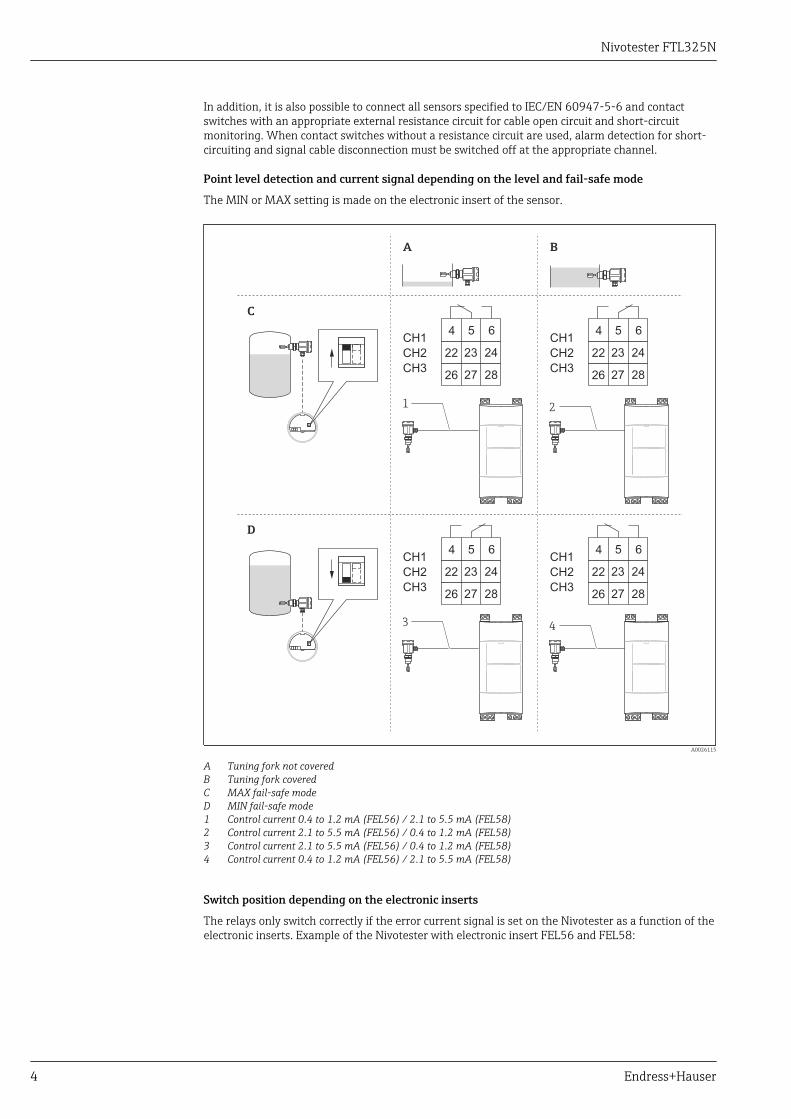
Point level detection and current signal depending on the level and fail-safe mode
The MIN or MAX setting is made on the electronic insert of the sensor.
5
5
5
5
23
23
23
23
27
27
27
27
6
6
6
6
24
24
24
24
28
28
28
28
4
4
4
4
22
22
22
22
26
26
26
26
CH1
CH1
CH1
CH1
CH2
CH2
CH2
CH2
CH3
CH3
CH3
CH3
A B
C
D
1 2
3 4
A0026115
A Tuning fork not coveredB Tuning fork coveredC MAX fail-safe modeD MIN fail-safe mode1 Control current 0.4 to 1.2 mA (FEL56) / 2.1 to 5.5 mA (FEL58)2 Control current 2.1 to 5.5 mA (FEL56) / 0.4 to 1.2 mA (FEL58)3 Control current 2.1 to 5.5 mA (FEL56) / 0.4 to 1.2 mA (FEL58)4 Control current 0.4 to 1.2 mA (FEL56) / 2.1 to 5.5 mA (FEL58)
Switch position depending on the electronic inserts
The relays only switch correctly if the error current signal is set on the Nivotester as a function of theelectronic inserts. Example of the Nivotester with electronic insert FEL56 and FEL58:

Nivotester FTL325N
Endress+Hauser 5
CH1
CH2
[Ex ia]
1 2
ON
1 2
3
4
ON
1 2
3
4
ON
CH2
CH2
CH2
CH2
CH3
CH3
CH3
CH3
1 2
ON
CH1CH1
CH1CH1 1
2O
N
A A
B B
A0026178
A Electronic insert FEL56: error current signal > 2.1 mAB Electronic insert FEL58, FEM58, FEI58: error current signal < 1.2 mA
For applications requiring functional safety in accordance with IEC 61508 (SIL), see the→ 17 "Supplementary documentation" section of the Functional Safety Manual. If severaltanks are in use, a separate Nivotester must be used for each level.
Function monitoring
To increase operational safety, the Nivotester is equipped with a function monitoring system. Asthere is a proof test button for every channel, function monitoring can be performed separately. Thepower supply to the sensor is interrupted during this process.
The red LED on the front panel indicates that a fault has occurred that causes the relays for the levelalarm and fault signaling system to drop out.
A fault is reported if the control current leaves the valid range, for example in the event of:
• A short-circuit, or if the signal line to the sensor is disconnected• Sensor corrosion• Defective electronics in the sensor• A defective Nivotester input circuit.
Two-point control (Δs)
Two-point control in a tank is possible with the 3-channel Nivotester (e.g. for pump control). Theinstallation location of the sensors defines the switching hysteresis.
Measuring system The measuring system can consist of the following components:
• 1 to 3 sensors, e.g. Liquiphant M/S• 1-channel or 3-channel Nivotester• Control or signal devicesAlternatively, sensors specified to IEC/EN 60947-5-6 or contact switches with an appropriateresistance circuit can be used. See also the "NAMUR interface" chapter → 3.

Nivotester FTL325N
6 Endress+Hauser
Contact switch with resistance circuit
0.47…2.7 kW
R1
R2
6.8…16 kW
A0026113
1-channel Nivotester
• 1 sensor• 1-channel Nivotester• Control or signal devices
A0026077
3-channel Nivotester
1. The 3 individual channels are used for point level measurement
• 3 sensors• 3-channel Nivotester• Control or signal devices
CH1
CH2
CH3
A0026079
Nivotester FTL325N
Endress+Hauser 7
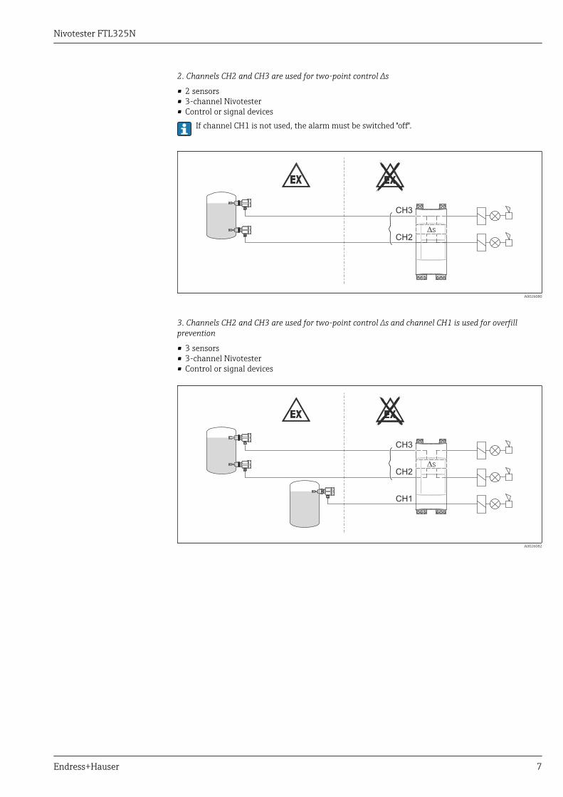
2. Channels CH2 and CH3 are used for two-point control Δs
• 2 sensors• 3-channel Nivotester• Control or signal devices
If channel CH1 is not used, the alarm must be switched "off".
CH2
CH3
Ds
A0026080
3. Channels CH2 and CH3 are used for two-point control ∆s and channel CH1 is used for overfillprevention
• 3 sensors• 3-channel Nivotester• Control or signal devices
CH1
CH2
CH3
Ds
A0026082
Nivotester FTL325N
8 Endress+Hauser
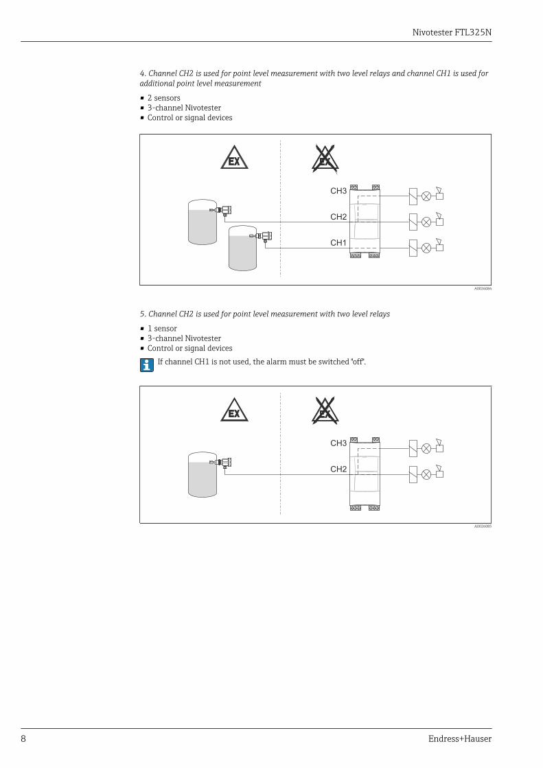
4. Channel CH2 is used for point level measurement with two level relays and channel CH1 is used foradditional point level measurement
• 2 sensors• 3-channel Nivotester• Control or signal devices
CH1
CH2
CH3
A0026084
5. Channel CH2 is used for point level measurement with two level relays
• 1 sensor• 3-channel Nivotester• Control or signal devices
If channel CH1 is not used, the alarm must be switched "off".
CH2
CH3
A0026085

Nivotester FTL325N
Endress+Hauser 9
Input
Measured variable The point level signal is triggered at MIN level or MAX level, depending on the setting.
Measuring range The measuring range depends on the installation location of the sensors.
Input signal • Galvanically isolated from power supply and output• Type of protection: intrinsic safety [Ex ia] IIC / [Ex ia] IIIC• Suitable sensors for connection:
– Liquiphant M FTL50/51/50H/51H, FTL51C with electronic insert FEL56 or FEL58– Liquiphant S FTL70/71 with electronic insert FEL56 or FEL58– Soliphant M FTM50/51/52 with FEM58– Solicap M FTI55, FTI56, Solicap S FTI77, Liquicap M FTI51, FTI52 with FEI58– Sensors certified to IEC/EN 60947-5-6– Contact switch with appropriate resistance circuit
• Sensors powered by Nivotester• Connection cable: twin-core, shield not required• Cable length/cable resistance: 1 000 m (3 281 ft)/max. 25 Ω per wire• Signal transmission: current signal over power supply line• Control current: < 1.2 mA / > 2.1 mA; cable open circuit monitoring < 200 µA, short-circuit
monitoring > 6.1 mA (can be switched off for unused channels)See the relevant certificates for more information on using the sensors in hazardous areas→ 17, "Supplementary documentation" section.
Output
Output signal • Relay output per channel: a potential-free changeover contact for the level alarm• Quiescent current fail-safe mode: MIN/MAX safety can be selected with DIL switch• 1 fault-signaling relay for channels 1, 2 and 3 (1 potential-free changeover contact, but it is only
possible to connect to two contacts)• Switching delay: approx. 0.5 s• Operating life: at least 105 switching operations with maximum contact load• Function indicator: LEDs for operation, level alarm and fault• Relay contact switching capacity:
Alternating voltage (AC)U ~ maximum 250 VI ~ maximum 2 AP ~ maximum 500 VA with cos φ ≥ 0.7Direct current (DC)U = maximum 40 VI = maximum 2 AP = maximum 80 W
Overvoltage categoryaccording to EN 61010
II
Protection class II (double or reinforced insulation)
Signal on alarm Level relay per channel dropped out; fault signaled by red LEDs, fault-signaling relay dropped out
Galvanic isolation All input and output channels and relay contacts are galvanically isolated from each other. Ifsimultaneously functional low voltage is connected to the power supply circuit or to the relaycontacts, safe galvanic isolation is guaranteed up to a voltage of 150 VAC.

Nivotester FTL325N
10 Endress+Hauser
Power supply
Electrical connection Sensor operation in the hazardous area
Observe all national explosion protection regulations concerning the type and installation ofintrinsically safe signal cabling.
Refer to the safety instructions for the maximum admissible values for capacitance and inductance→ 17, "Supplementary documentation" section.
Connecting the sensors
The removable terminal blocks are color-coded into intrinsically safe and non-intrinsically safeterminals. This difference helps to ensure safe wiring.
Blue terminal blocks at top for hazardous area
Twin-core connection cable between the Nivotester and sensor, e.g. commercially availableinstrument cable or cores in a multi-core cable for measurement purposes.Use a shielded cable in the event of strong electromagnetic interference, e.g. from machines or radioequipment. Only connect the shield to the grounding terminal in the sensor. Do not connect it to theNivotester.
Connecting the signal and control units
Gray terminal blocks at bottom for the non-hazardous area
The relay function depends on the level and fail-safe mode. If a device is connected at highinductance (e.g. contactor, solenoid valve etc.), a spark arrester must be installed to protect the relaycontact.
Connecting the supply voltage
Green terminal block at bottom
A fuse is integrated into the power supply circuit. An additional fine-wire fuse is not necessary. TheNivotester has reverse polarity protection.
Supply voltage Alternating current version (AC)
Voltage range: 85 to 253 V AC, 50/60 Hz
Direct current range (DC)
• Voltage range: 20 to 30 V AC / 20 to 60 V DC• D/C power supply:
– 1-channel: maximum 60 mA– 3-channel: maximum 113 mA
• Permitted residual ripple within tolerance: Uss = maximum 2 V
Power consumption AC• 1-channel: maximum 1.75 W• 3-channel: maximum 2.75 WDC• 1-channel: 1.2 W (for Umin 20 V)• 3-channel: 2.25 W (for Umin 20 V)
Performance characteristics
Switch-on behavior Correct switch state after switching on the power supply: 10 to 20 s, depending on the connectedsensor.
Nivotester FTL325N
Endress+Hauser 11
Installation
Mounting location • The Nivotester must be housed in a cabinet outside the hazardous area.• The devices must be mounted in such a way that they are protected from impact and weather
conditions. Where possible, mount the device in a location where it is not exposed to directsunlight, particularly in warm climates.
• A protective housing (IP65) for up to four 1-channel or two 3-channel Nivotesters is available foroutdoor installation, see → 17 "Accessories" section.
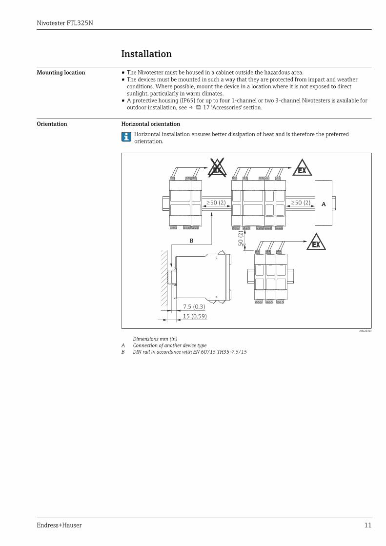
Orientation Horizontal orientation
Horizontal installation ensures better dissipation of heat and is therefore the preferredorientation.
A50 (2)£
7.5 (0.3)
15 (0.59)
50
(2
)£
50 (2)£
B
A0026303
Dimensions mm (in)A Connection of another device typeB DIN rail in accordance with EN 60715 TH35-7.5/15
Nivotester FTL325N
12 Endress+Hauser
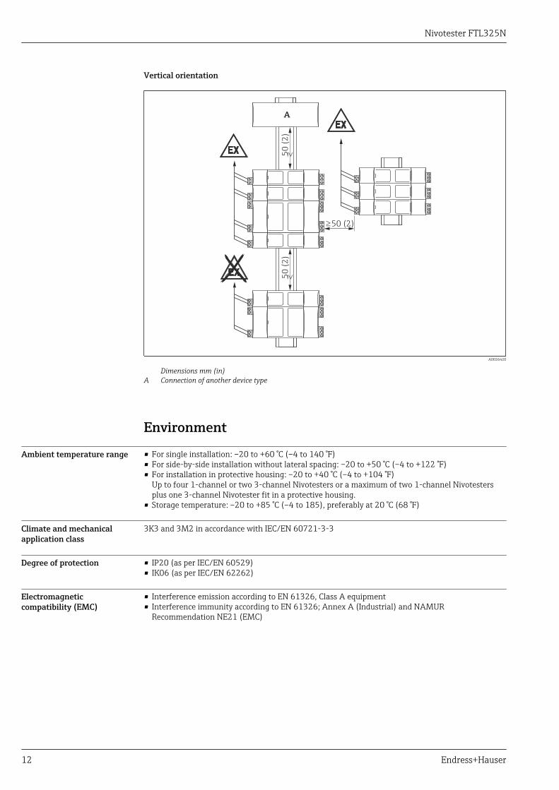
Vertical orientation
A
50
(2
)£
50 (2)£
50
(2
)
£
A0026420
Dimensions mm (in)A Connection of another device type
Environment
Ambient temperature range • For single installation: –20 to +60 °C (–4 to 140 °F)• For side-by-side installation without lateral spacing: –20 to +50 °C (–4 to +122 °F)• For installation in protective housing: –20 to +40 °C (–4 to +104 °F)
Up to four 1-channel or two 3-channel Nivotesters or a maximum of two 1-channel Nivotestersplus one 3-channel Nivotester fit in a protective housing.
• Storage temperature: –20 to +85 °C (–4 to 185), preferably at 20 °C (68 °F)
Climate and mechanicalapplication class
3K3 and 3M2 in accordance with IEC/EN 60721-3-3
Degree of protection • IP20 (as per IEC/EN 60529)• IK06 (as per IEC/EN 62262)
Electromagneticcompatibility (EMC)
• Interference emission according to EN 61326, Class A equipment• Interference immunity according to EN 61326; Annex A (Industrial) and NAMUR
Recommendation NE21 (EMC)

Nivotester FTL325N
Endress+Hauser 13
Mechanical construction
Design, dimensions Dimensions
45 (1.77) 112 (4.41)22.5 (0.89)
95
(3
.74
)
10
8 (
4.2
5)
1 2
A0026095
Dimensions mm (in)1 1-channel Nivotester2 3-channel Nivotester
Weight • 1-channel: approx. 148 g (5.22 oz)• 3-channel: approx. 250 g (8.81 oz)
Materials • Housing: polycarbonate• Front cover: PP polypropylene• Fixing slide to secure to DIN rail: polyamide PA6
Terminals 1-channel• 2 screw terminals: sensor power supply• 3 screw terminals: level relay• 2 screw terminals: fault-signaling relay• 2 screw terminals: power supply3-channel• 3x2 screw terminals: sensor power supply, channel 1 to 3• 3x3 screw terminals: level relay, channel 1 to 3• 2 screw terminals: fault-signaling relay• 2 screw terminals: power supply
Connection cross-section
Maximum 1 x 2.5 mm2 (14 AWG) or 2 x 1.5 mm2 (16 AWG)
Nivotester FTL325N
14 Endress+Hauser
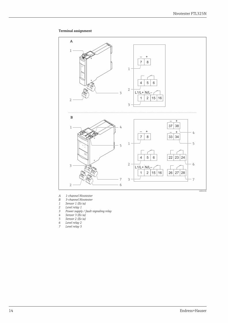
Terminal assignment
1
2
3
A
CH1
CH1
[Ex ia]
8
8
34
38
2
2
16
16
5
5
23
27
6
6
24
28
7
7
33
37
1
1
15
15
4
4
22
26
L1/L+
L1/L+
N/L–
N/L–
– +
– +
1
5
4
4
7
6
51
1
3
2
62
2
73
3
CH1
CH2
CH2
CH3
CH3
[Ex ia]
B
– +
– +
A0026100
A 1-channel NivotesterB 3-channel Nivotester1 Sensor 1 (Ex ia)2 Level relay 13 Power supply / fault-signaling relay4 Sensor 3 (Ex ia)5 Sensor 2 (Ex ia)6 Level relay 27 Level relay 3

Nivotester FTL325N
Endress+Hauser 15
Operability
Operating concept Onsite configuration with DIL switches behind fold-down front panel
Display elements Light emitting diodes (LEDs)• Green light emitting diode: operational• One red LED per channel: fault signal• One yellow LED per channel: level relay picked up
Operating elements 1-channel Nivotester
CH1
[Ex ia]
1 2
ON
1 2
ON
CH1CH1
2
1
A0026315
1 DIL switch: error current signal 2.1 mA / 1.2 mA (1), fault on/off position (2)2 Light emitting diodes (LEDs)
3-channel Nivotester
1
2
3
4
ON
1 2
ON
CH1
CH2
[Ex ia] 1 2
3
4
ON
CH2CH2
CH3CH3
3
1 2
3
4
ON
1
4
3
2
1
2
3
4
1 2
ON
CH1CH1
2
1
5
A0026107
1 DIL switch for channel 1: error current signal 2.1 mA / 1.2 mA (1), fault on/off position (2)2 Light emitting diodes (LEDs)3 DIL switch for channel 2 and 3: fault on/off position (1/3), error current signal 2.1 mA / 1.2 mA (2/4)4 Switch for functions: ∆s, e.g. pump control (1), two level relays (2), individual channels (3)5 Light emitting diodes (LEDs)

Nivotester FTL325N
16 Endress+Hauser
Certificates and approvals
CE mark The measuring device is in conformity with the statutory requirements of the applicable ECDirectives. These are listed in the corresponding EC Declaration of Conformity along with thestandards applied.
Endress+Hauser confirms successful testing of the device by affixing to it the CE mark.
RCM-Tick mark The measuring device complies with the EMC requirements of the "Australian Communications andMedia Authority (ACMA)".
Ex approval The Endress+Hauser sales center can provide information on the hazardous area versions currentlyavailable. All data relevant to explosion protection are provided in separate documents which can besupplied on request, "Supplementary documentation" section.
Type of protection II(1)G [Ex ia Ga] IIC
II(1)D [Ex ia Da] IIIC
Overfill prevention • WHG• Leak approval
Other standards andguidelines
The applicable European guidelines and standards can be found in the relevant EU Declarations ofConformity.
• IEC/EN 60947-5-6: Low-voltage switchgear and control gear - DC interface for proximity sensorsand switching amplifiers (NAMUR)
• IEC/EN 60721-3-3: Classification of environmental conditions• IEC/EN 60529: Degrees of protection provided by enclosures (IP code)• IEC/EN 61010: Safety requirements for electrical equipment for measurement, control and
laboratory use• IEC/EN 61326: Interference emission (class A equipment), interference immunity (Appendix A -
Industrial)• IEC 61508: Functional safety of safety-related electric/electronic/programmable electronic
systems (E/E/PES)
Functional safety SIL 1, SIL 2 for protection functions as
• Overfill prevention in conjunction with Liquiphant + electronic insert FEL56/58 or Soliphant +FEM58
• Minimum detection in conjunction with Liquiphant + electronic insert FEL56/58Refer to the Functional Safety Manual → 17, "Supplementary documentation" section!
Ordering informationDetailed ordering information is available from the following sources:• In the Product Configurator on the Endress+Hauser website: www.endress.com → Select your
country → Products → Select measuring technology, software or components → Select the product(picklists: measurement method, product family etc.) → Device support (right-hand column):Configure the selected product → The Product Configurator for the selected product opens.
• From your Endress+Hauser Sales Center: www.addresses.endress.comProduct Configurator - the tool for individual product configuration• Up-to-the-minute configuration data• Depending on the device: Direct input of measuring point-specific information such as
measuring range or operating language• Automatic verification of exclusion criteria• Automatic creation of the order code and its breakdown in PDF or Excel output format• Ability to order directly in the Endress+Hauser Online Shop

Nivotester FTL325N
Endress+Hauser 17
Accessories
Protective housing The protective housing with IP66 ingress protection is equipped with an integrated DIN rail and isclosed by a transparent cover which can also be lead-sealed.
• Dimensions in mm (in) B/H/D: 180/182/165 (7.1/7.2/6.5)• Part number: 52010132
Supplementary documentationThe following document types are also available in the Download Area of the Endress+Hauserwebsite: www.endress.com → download
Operating Instructions Document code Content
• KA00170F/00/A6• KA00171F/00/A6
• Nivotester FTL325N with NAMUR input, 1-channel• Nivotester FTL325N with NAMUR input, 3-channel
Technical Information Document code Content
TI00328F/00/EN Liquiphant M FTL50(H), FTL51(H), sensor for point level detection in liquids
TI00347F/00/EN Liquiphant M FTL51C, sensor for point level detection in liquids with highly corrosion-resistant coating
TI00354F/00/EN Liquiphant S FTL70/71, sensor for point level detection in liquids for mediumtemperatures up to 280 °C (536 °F)
TI00392F/00/EN Soliphant M FTM50/51/52, universal point level switch for fine-grained bulk solids,also for dust incendive hazard areas
TI00417F/00/EN Liquicap M FTI51, FTI52, point level switch for liquids
TI00433F/00/EN Solicap S FTI77, robust point level switch for bulk solids also in combination with veryhigh temperatures
TI00418F/00/EN Solicap M FTI55, FTI56, point level switch for bulk solids
TI00367F/00/EN Protective housing → system components for DIN rail housing
Functional safety (SIL) Document code Content
SD00168F/00/EN Nivotester FTL325N (HW-V01.00)+Liquiphant M/S+FEL56; MAX detection
SD00188F/00/EN Nivotester FTL325N, (HW-V01.00)+Liquiphant M/S+FEL56; MIN detection
SD01521F/00/EN Nivotester FTL325N (HW-V02.00)+Liquiphant M/S+FEL56; MIN and MAX detection
SD00161F/00/EN Nivotester FTL325N (HW-V01.00)+Liquiphant M/S+FEL58; MAX detection
SD00170F/00/EN Nivotester FTL325N (HW-V01.00)+Liquiphant M/S+FEL58; MIN detection
SD01522F/00/EN Nivotester FTL325N (HW-V02.00)+Liquiphant M/S+FEL58; MIN and MAX detection
SD00206F/00/EN Nivotester FTL325N (HW-V01.00+HW-V02.00)+Soliphant M+FEM58; MAXdetection
WHG Document code Content
ZE00233F/00/EN Liquiphant M FTL50(H), FTL51(H) FTL51C / Liquiphant S FTL70/71;General approval by the building authorities Z-65.11-230 (DIBt), overfill prevention
ZE00271F/00/EN Liquiphant M FTL50(H), FTL51(H) FTL51C / Liquiphant S FTL70/71;Z-65.40-446 leak approval
Nivotester FTL325N
18 Endress+Hauser
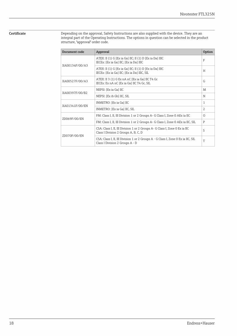
Certificate Depending on the approval, Safety Instructions are also supplied with the device. They are anintegral part of the Operating Instructions. The options in question can be selected in the productstructure, "approval" order code.
Document code Approval Option
XA00134F/00/A3
ATEX: II (1) G [Ex ia Ga] IIC; II (1) D [Ex ia Da] IIICIECEx: [Ex ia Ga] IIC; [Ex ia Da] IIIC F
ATEX: II (1) G [Ex ia Ga] IIC; II (1) D [Ex ia Da] IIICIECEx: [Ex ia Ga] IIC; [Ex ia Da] IIIC, SIL H
XA00527F/00/A3 ATEX: II 3 (1) G Ex nA nC [Ex ia Ga] IIC T4 GcIECEx: Ex nA nC [Ex ia Ga] IIC T4 Gc, SIL G
XA00397F/00/B2NEPSI: [Ex ia Ga] IIC M
NEPSI: [Ex ib Gb] IIC, SIL N
XA01341F/00/ENINMETRO: [Ex ia Ga] IIC 1
INMETRO: [Ex ia Ga] IIC, SIL 2
ZD069F/00/ENFM: Class I, II, III Division 1 or 2 Groups A- G Class I, Zone 0 AEx ia IIC O
FM: Class I, II, III Division 1 or 2 Groups A- G Class I, Zone 0 AEx ia IIC, SIL P
ZD070F/00/EN
CSA: Class I, II, III Division 1 or 2 Groups A- G Class I, Zone 0 Ex ia IICClass I Division 2 Groups A, B, C, D S
CSA: Class I, II, III Division 1 or 2 Groups A - G Class I, Zone 0 Ex ia IIC, SILClass I Division 2 Groups A - D T


www.addresses.endress.com
*71297043*71297043


