Gas Well Deliquification WorkshopSheraton Hotel, Denver, Colorado
February 22 - 24, 2010
New Perspectives on Gas WellLiquid Loading & UnloadingStefan Belfroid, TNO Science and Industry, Delft
Kees Veeken, Shell E&P Europe, Assen
Outline of Presentation
• Compare droplet size postulated by Turner againstdroplet size observed in nature and flow loop testing
• Recognise role of film reversal observed in flow loopexperiments and transient multiphase flow modelling
• Explore consequences for gas well deliquification
– Reduce droplet size
– Generate swirl
– Create foam
– Modify tubing wall
• Summary
Feb. 22 - 24, 2010 2010 Gas Well Deliquification WorkshopDenver, Colorado
2
Droplet Size in Turner – Big Rain
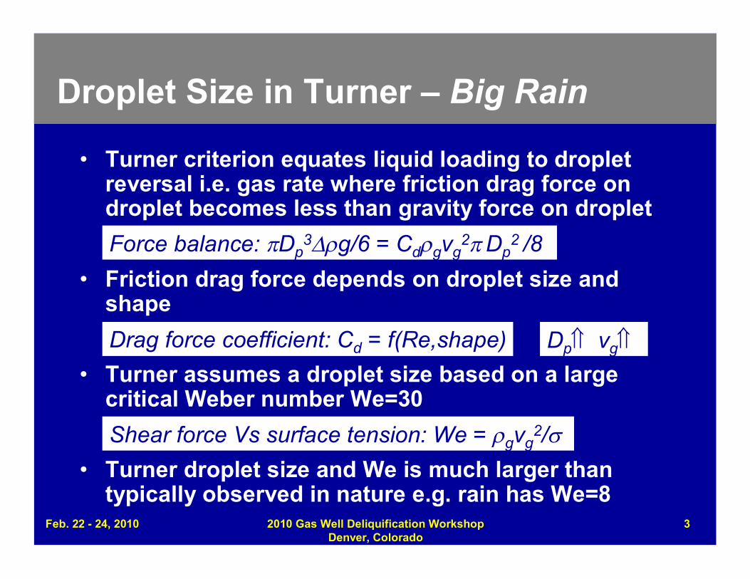
• Turner criterion equates liquid loading to dropletreversal i.e. gas rate where friction drag force ondroplet becomes less than gravity force on droplet
• Friction drag force depends on droplet size andshape
• Turner assumes a droplet size based on a largecritical Weber number We=30
• Turner droplet size and We is much larger thantypically observed in nature e.g. rain has We=8
Shear force Vs surface tension: We = gvg2/
Drag force coefficient: Cd = f(Re,shape)
Force balance: Dp3g/6 = Cdgvg
2Dp2 /8
Dp vg
Feb. 22 - 24, 2010 2010 Gas Well Deliquification WorkshopDenver, Colorado
3
Feb. 22 - 24, 2010 2010 Gas Well Deliquification WorkshopDenver, Colorado
4
Droplet Size in Flow Loop Tests
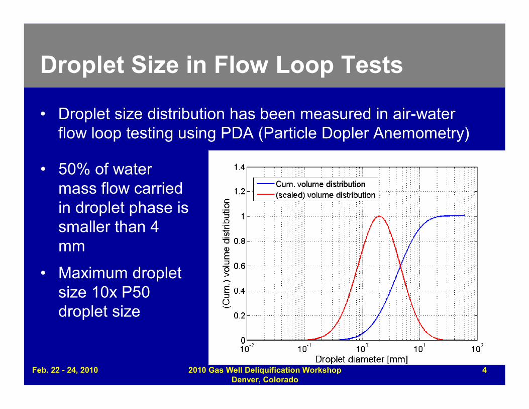
• Droplet size distribution has been measured in air-waterflow loop testing using PDA (Particle Dopler Anemometry)
• 50% of watermass flow carriedin droplet phase issmaller than 4mm
• Maximum dropletsize 10x P50droplet size
Feb. 22 - 24, 2010 2010 Gas Well Deliquification WorkshopDenver, Colorado
5
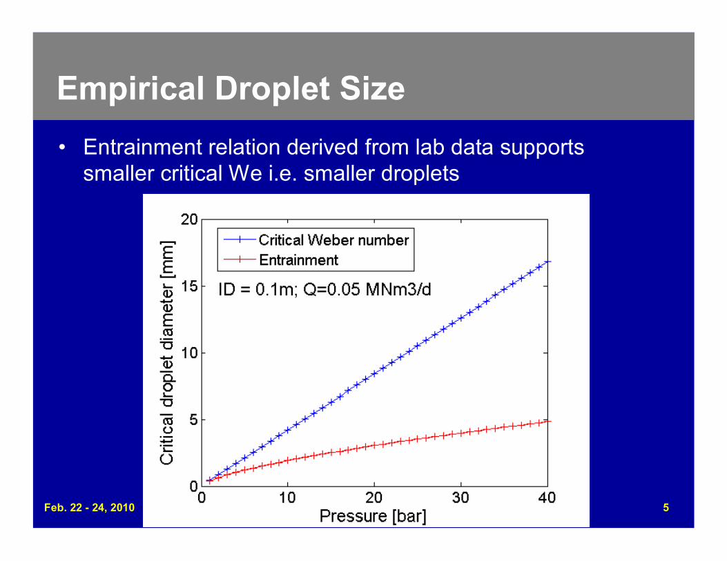
Empirical Droplet Size
• Entrainment relation derived from lab data supportssmaller critical We i.e. smaller droplets
Feb. 22 - 24, 2010 2010 Gas Well Deliquification WorkshopDenver, Colorado
6
Droplet Reversal?
0 0.001 0.002 0.003 0.004 0.005 0.006 0.007 0.008 0.009 0.010
0.5
1
1.5
2
2.5
3
3.5
4
4.5
5
FDrag = FGravity (Downhole )
FDrag = FGravity (We llhead)
Turne rs c riterium (Downhole)Turne rs c riterium (Wellhea d)
Drop Diameter (m)
Gas
Vel
ocity
(m/s
)
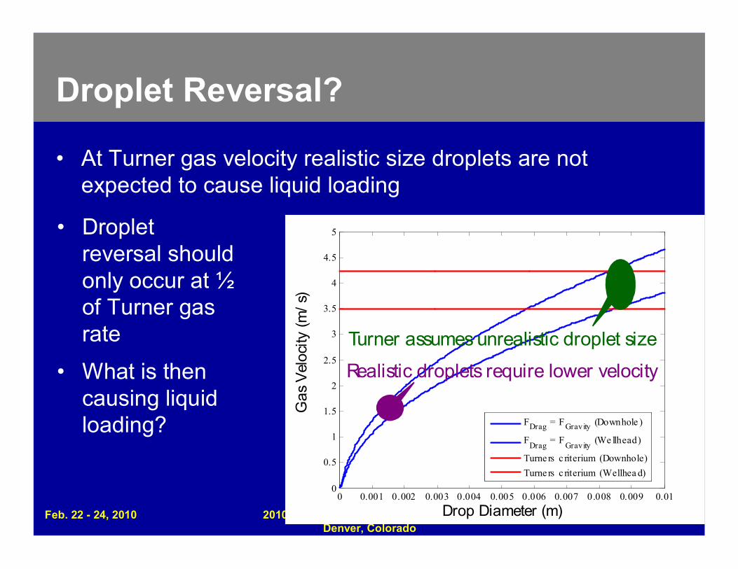
Turner assumes unrealistic droplet size
Realistic droplets require lower velocity
• At Turner gas velocity realistic size droplets are notexpected to cause liquid loading
• Dropletreversal shouldonly occur at ½of Turner gasrate
• What is thencausing liquidloading?
Feb. 22 - 24, 2010 2010 Gas Well Deliquification WorkshopDenver, Colorado
7
Droplet Reversal?
0 0.001 0.002 0.003 0.004 0.005 0.006 0.007 0.008 0.009 0.010
0.5
1
1.5
2
2.5
3
3.5
4
4.5
5
FDrag = FGravity (Downhole )
FDrag = FGravity (We llhead)
Turne rs c riterium (Downhole)Turne rs c riterium (Wellhea d)
Drop Diameter (m)
Gas
Vel
ocity
(m/s
)
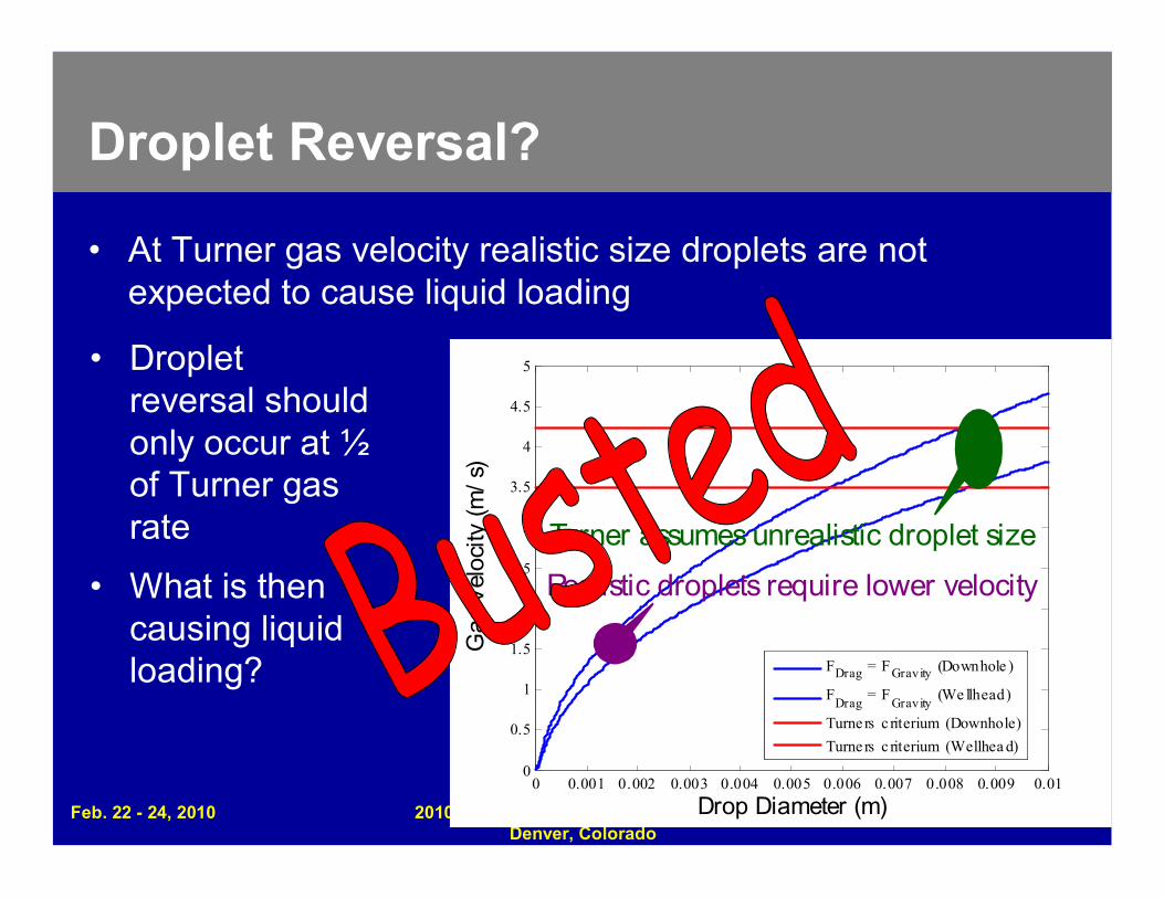
Turner assumes unrealistic droplet size
Realistic droplets require lower velocity
• At Turner gas velocity realistic size droplets are notexpected to cause liquid loading
• Dropletreversal shouldonly occur at ½of Turner gasrate
• What is thencausing liquidloading?
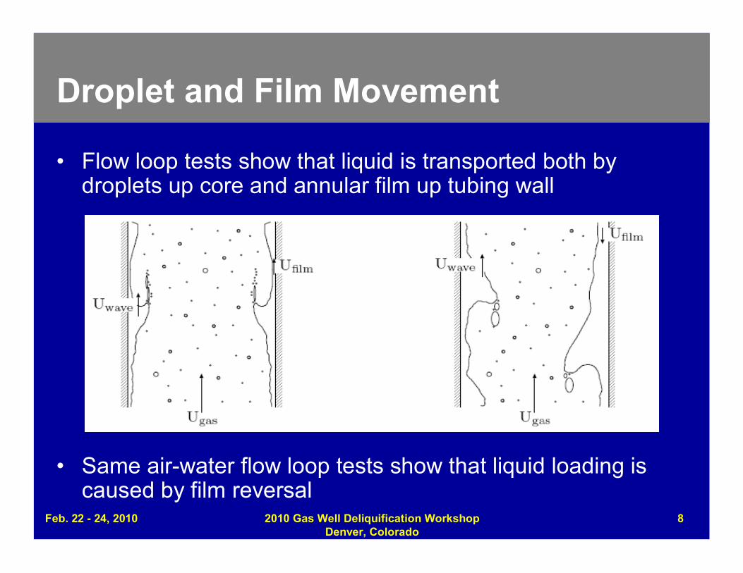
Droplet and Film Movement
• Flow loop tests show that liquid is transported both bydroplets up core and annular film up tubing wall
• Same air-water flow loop tests show that liquid loading iscaused by film reversal
Feb. 22 - 24, 2010 2010 Gas Well Deliquification WorkshopDenver, Colorado
8
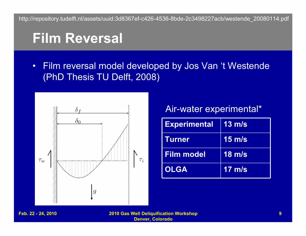
Film Reversal
• Film reversal model developed by Jos Van ‘t Westende(PhD Thesis TU Delft, 2008)
Experimental 13 m/s
Turner 15 m/s
Film model 18 m/s
OLGA 17 m/s
Air-water experimental*
http://repository.tudelft.nl/assets/uuid:3d8367ef-c426-4536-8bde-2c3498227acb/westende_20080114.pdf
Feb. 22 - 24, 2010 2010 Gas Well Deliquification WorkshopDenver, Colorado
9

Feb. 22 - 24, 2010 2010 Gas Well Deliquification WorkshopDenver, Colorado
10
Use of Turner Criterion
• Turner criterion remains extremely useful engineering tool:film and droplet reversal depend on the same well andfluid parameters in a similar manner
QTurner ~ FTHP0.5.ID2
Turner Ratio, TR = Qmin / QTurner• SPE 123657introducesModified Turnercriterion, basedon field data andin line withmultiphase flowmodelling results
Feb. 22 - 24, 2010 2010 Gas Well Deliquification WorkshopDenver, Colorado
11
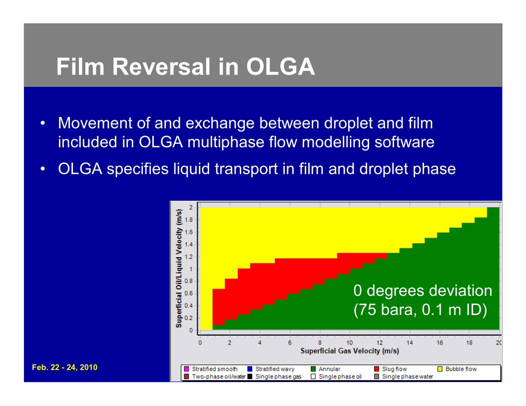
Film Reversal in OLGA
• Movement of and exchange between droplet and filmincluded in OLGA multiphase flow modelling software
• OLGA specifies liquid transport in film and droplet phase
0 degrees deviation(75 bara, 0.1 m ID)
Feb. 22 - 24, 2010 2010 Gas Well Deliquification WorkshopDenver, Colorado
12Paper #1 12
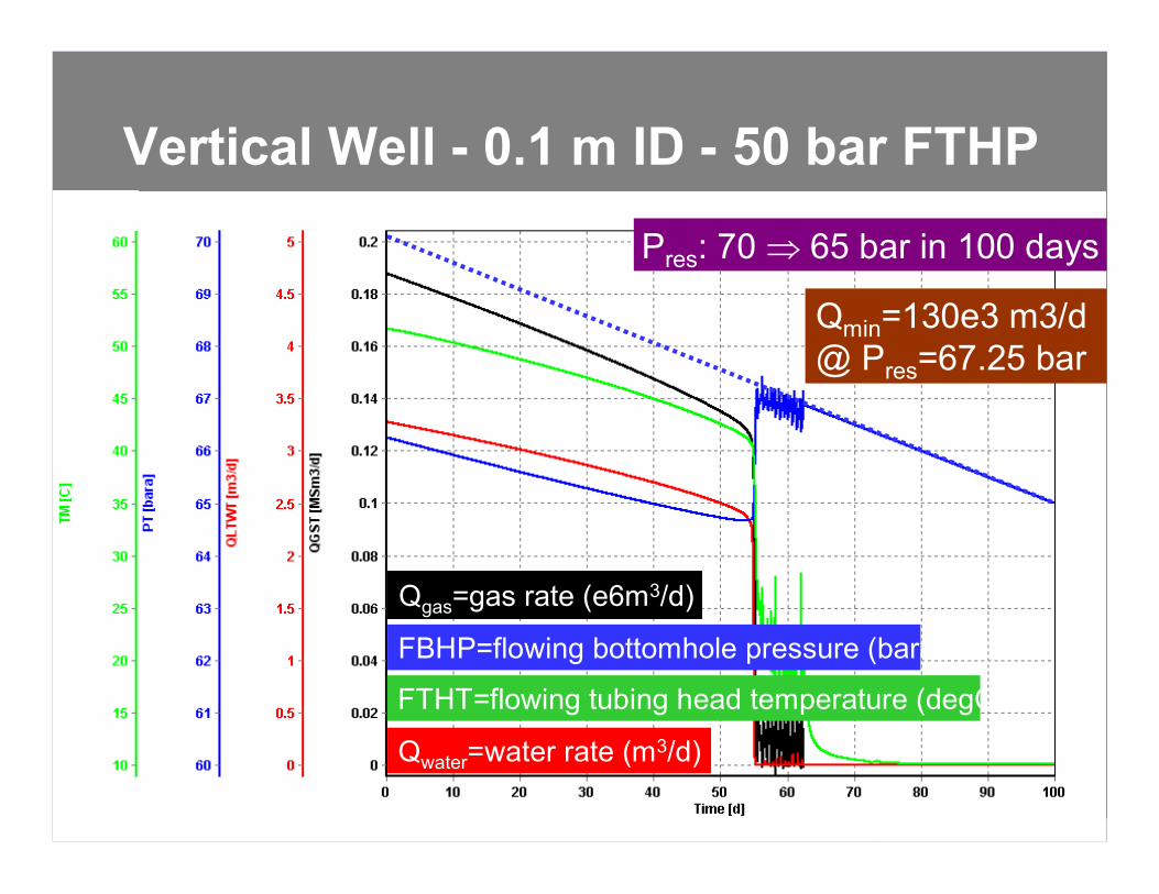
Qmin=130e3 m3/d@ Pres=67.25 bar
Qgas=gas rate (e6m3/d)
FTHT=flowing tubing head temperature (degC)
Qwater=water rate (m3/d)
FBHP=flowing bottomhole pressure (bara)
Pres: 70 65 bar in 100 days
Vertical Well - 0.1 m ID - 50 bar FTHP
Feb. 22 - 24, 2010 2010 Gas Well Deliquification WorkshopDenver, Colorado
13Paper #1 13
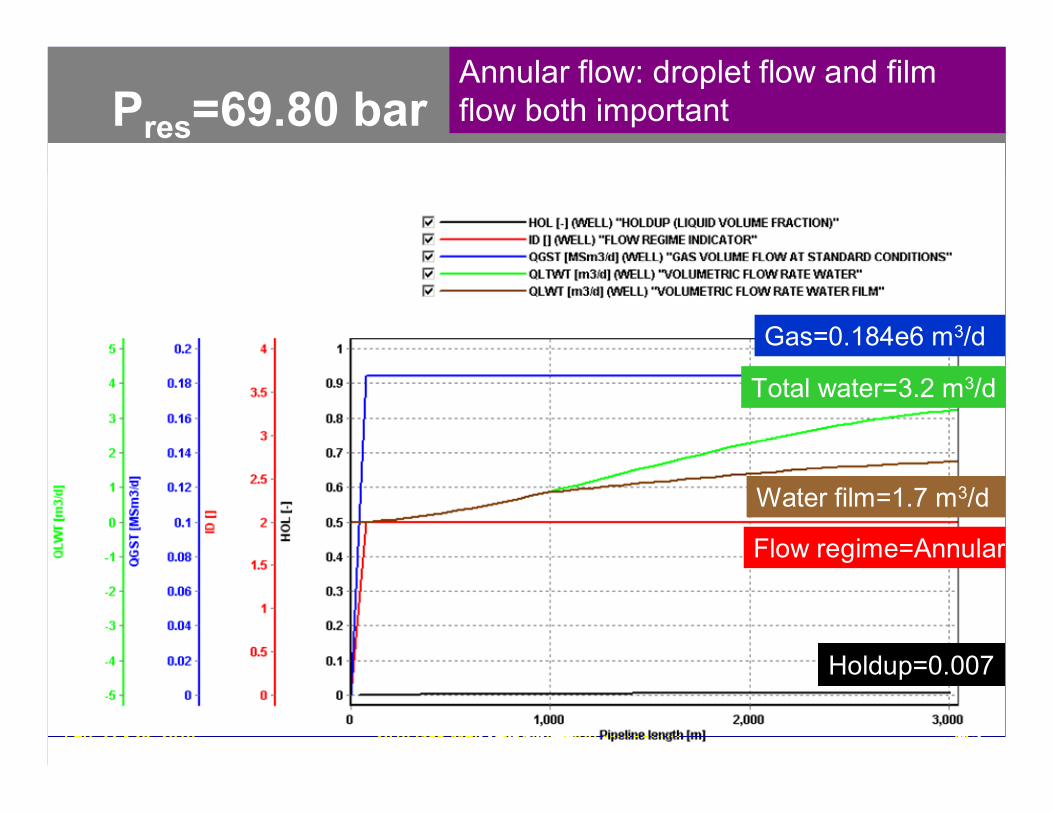
Annular flow: droplet flow and filmflow both important
Holdup=0.007
Water film=1.7 m3/d
Total water=3.2 m3/d
Gas=0.184e6 m3/d
Flow regime=Annular
Pres=69.80 bar
Feb. 22 - 24, 2010 2010 Gas Well Deliquification WorkshopDenver, Colorado
14Paper #1 14
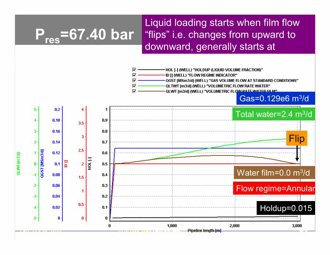
Liquid loading starts when film flow“flips” i.e. changes from upward todownward, generally starts atwellhead
Flip
Holdup=0.015
Water film=0.0 m3/d
Total water=2.4 m3/d
Gas=0.129e6 m3/d
Flow regime=Annular
Pres=67.40 bar
Feb. 22 - 24, 2010 2010 Gas Well Deliquification WorkshopDenver, Colorado
15Paper #1 15
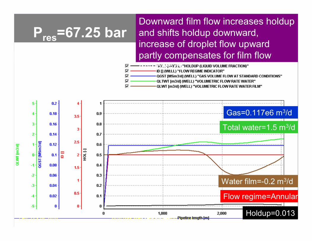
Downward film flow increases holdupand shifts holdup downward,increase of droplet flow upwardpartly compensates for film flowdownward
Holdup=0.013
Water film=-0.2 m3/d
Total water=1.5 m3/d
Gas=0.117e6 m3/d
Flow regime=Annular
Pres=67.25 bar
Feb. 22 - 24, 2010 2010 Gas Well Deliquification WorkshopDenver, Colorado
16Paper #1 16
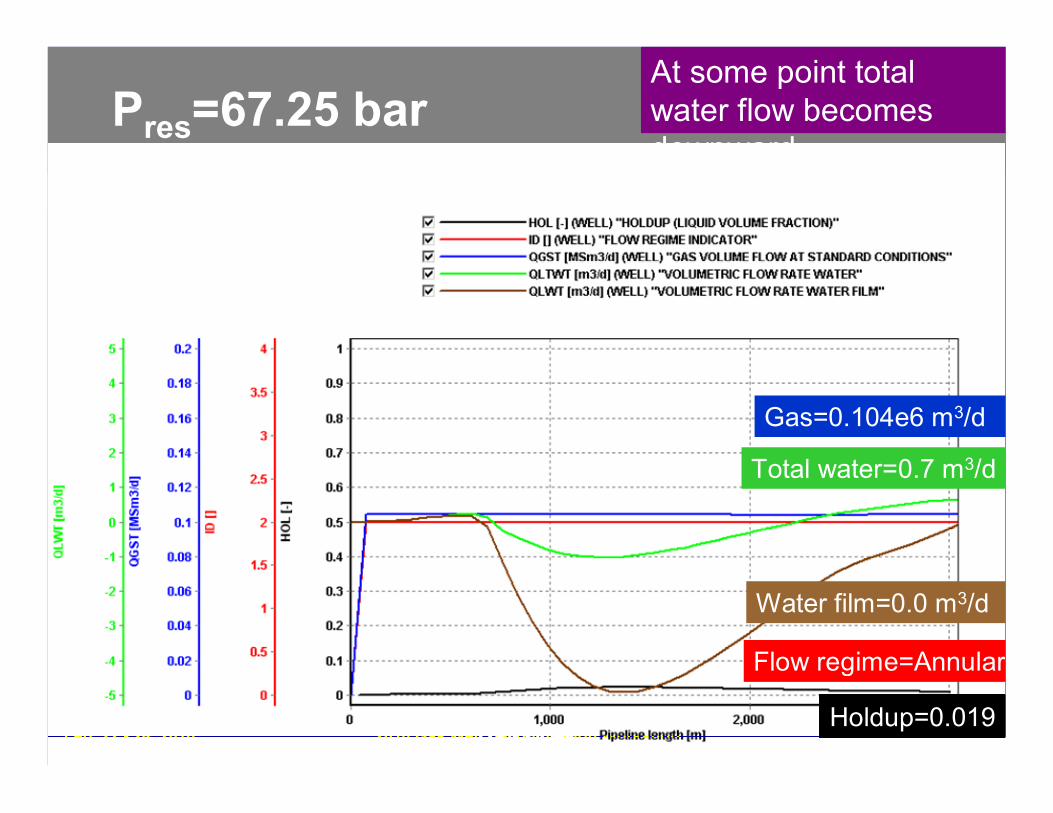
At some point totalwater flow becomesdownward
Holdup=0.019
Water film=0.0 m3/d
Total water=0.7 m3/d
Gas=0.104e6 m3/d
Flow regime=Annular
Pres=67.25 bar
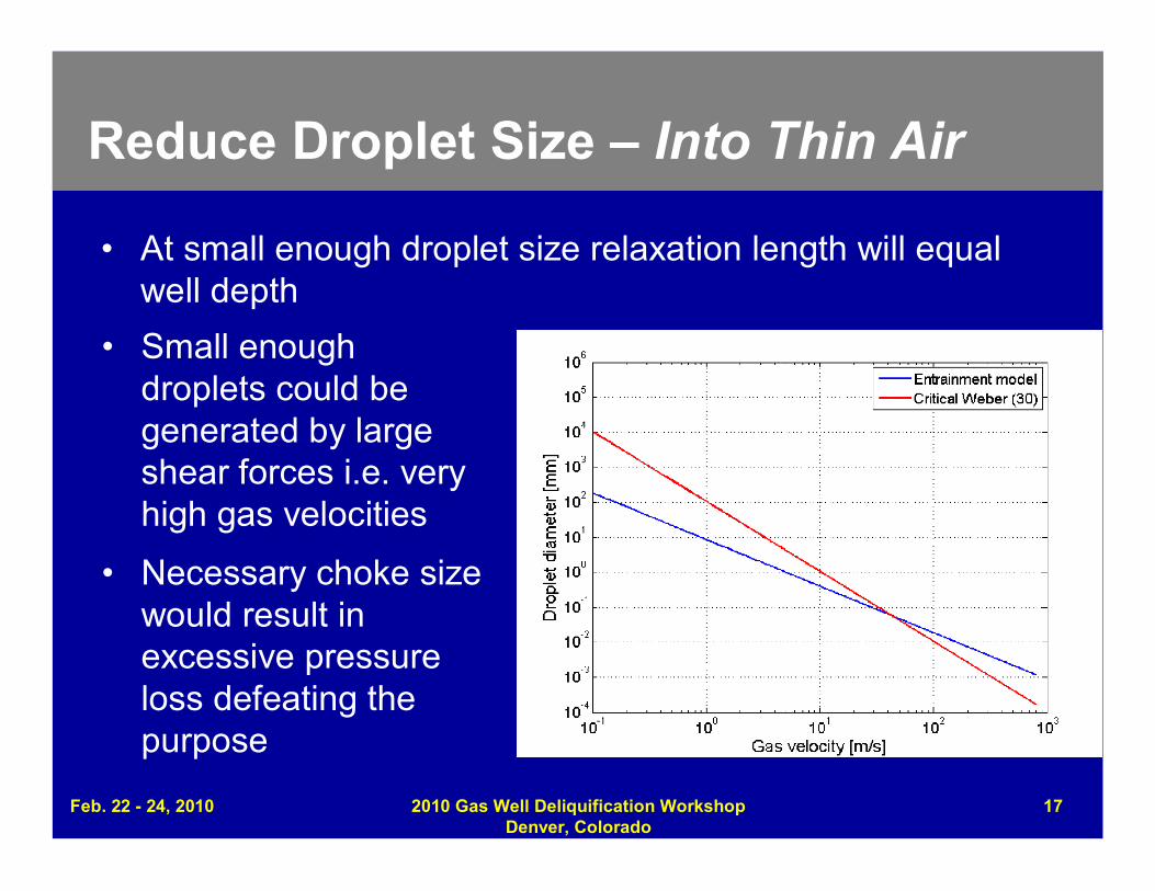
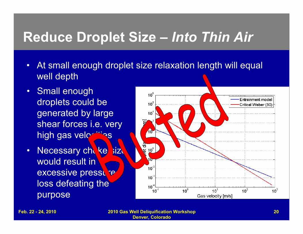
Reduce Droplet Size – Into Thin Air
• At small enough droplet size relaxation length will equalwell depth
• Small enoughdroplets could begenerated by largeshear forces i.e. veryhigh gas velocities
• Necessary choke sizewould result inexcessive pressureloss defeating thepurpose
Feb. 22 - 24, 2010 2010 Gas Well Deliquification WorkshopDenver, Colorado
17
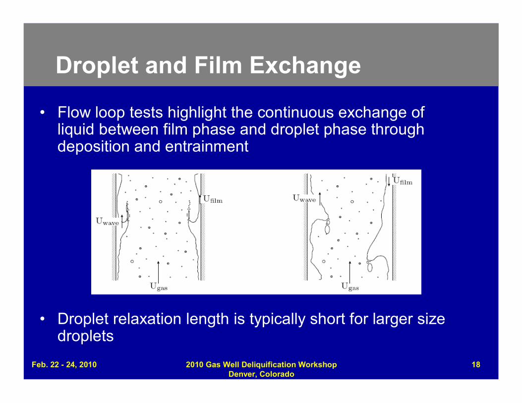
Droplet and Film Exchange
• Flow loop tests highlight the continuous exchange ofliquid between film phase and droplet phase throughdeposition and entrainment
• Droplet relaxation length is typically short for larger sizedroplets
Feb. 22 - 24, 2010 2010 Gas Well Deliquification WorkshopDenver, Colorado
18
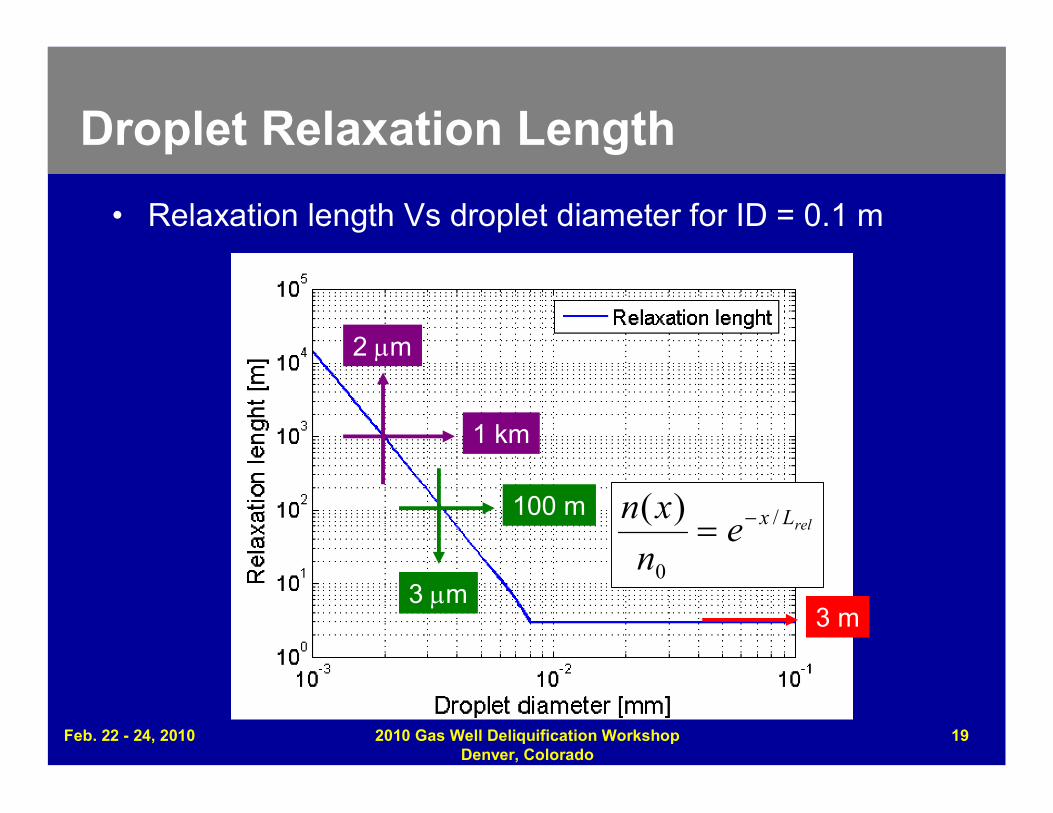
Droplet Relaxation Length
• Relaxation length Vs droplet diameter for ID = 0.1 m
relLxen
xn /
0
)(
1 km
2 m
100 m
3 m3 m
Feb. 22 - 24, 2010 2010 Gas Well Deliquification WorkshopDenver, Colorado
19
Reduce Droplet Size – Into Thin Air
• At small enough droplet size relaxation length will equalwell depth
• Small enoughdroplets could begenerated by largeshear forces i.e. veryhigh gas velocities
• Necessary choke sizewould result inexcessive pressureloss defeating thepurpose
Feb. 22 - 24, 2010 2010 Gas Well Deliquification WorkshopDenver, Colorado
20
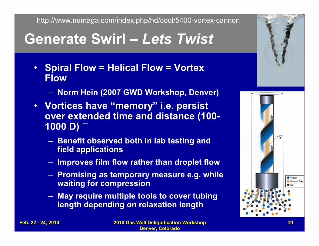
Generate Swirl – Lets Twist
–
• Spiral Flow = Helical Flow = VortexFlow– Norm Hein (2007 GWD Workshop, Denver)
• Vortices have “memory” i.e. persistover extended time and distance (100-1000 D)– Benefit observed both in lab testing and
field applications
– Improves film flow rather than droplet flow
– Promising as temporary measure e.g. whilewaiting for compression
– May require multiple tools to cover tubinglength depending on relaxation length
http://www.numaga.com/index.php/hd/cool/5400-vortex-cannon
Feb. 22 - 24, 2010 2010 Gas Well Deliquification WorkshopDenver, Colorado
21
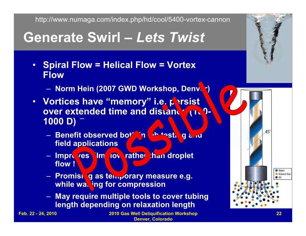
Generate Swirl – Lets Twist
–
• Spiral Flow = Helical Flow = VortexFlow– Norm Hein (2007 GWD Workshop, Denver)
• Vortices have “memory” i.e. persistover extended time and distance (100-1000 D)– Benefit observed both in lab testing and
field applications
– Improves film flow rather than dropletflow ! ?
– Promising as temporary measure e.g.while waiting for compression
– May require multiple tools to cover tubinglength depending on relaxation length
http://www.numaga.com/index.php/hd/cool/5400-vortex-cannon
Feb. 22 - 24, 2010 2010 Gas Well Deliquification WorkshopDenver, Colorado
22
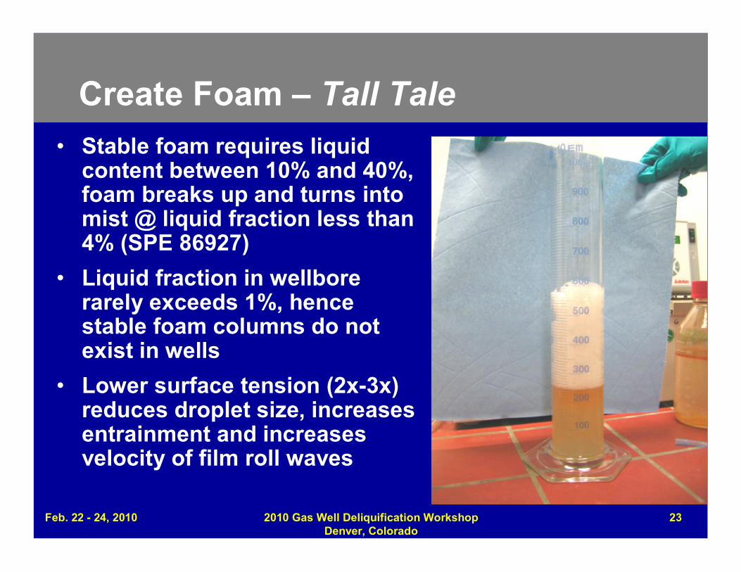
Create Foam – Tall Tale• Stable foam requires liquid
content between 10% and 40%,foam breaks up and turns intomist @ liquid fraction less than4% (SPE 86927)
• Liquid fraction in wellborerarely exceeds 1%, hencestable foam columns do notexist in wells
• Lower surface tension (2x-3x)reduces droplet size, increasesentrainment and increasesvelocity of film roll waves
Feb. 22 - 24, 2010 2010 Gas Well Deliquification WorkshopDenver, Colorado
23
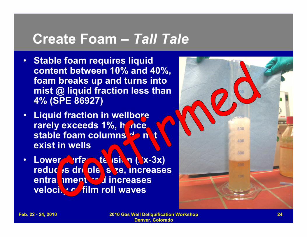
Create Foam – Tall Tale• Stable foam requires liquid
content between 10% and 40%,foam breaks up and turns intomist @ liquid fraction less than4% (SPE 86927)
• Liquid fraction in wellborerarely exceeds 1%, hencestable foam columns do notexist in wells
• Lower surface tension (2x-3x)reduces droplet size, increasesentrainment and increasesvelocity of film roll waves
Feb. 22 - 24, 2010 2010 Gas Well Deliquification WorkshopDenver, Colorado
24
Feb. 22 - 24, 2010 2010 Gas Well Deliquification WorkshopDenver, Colorado
25
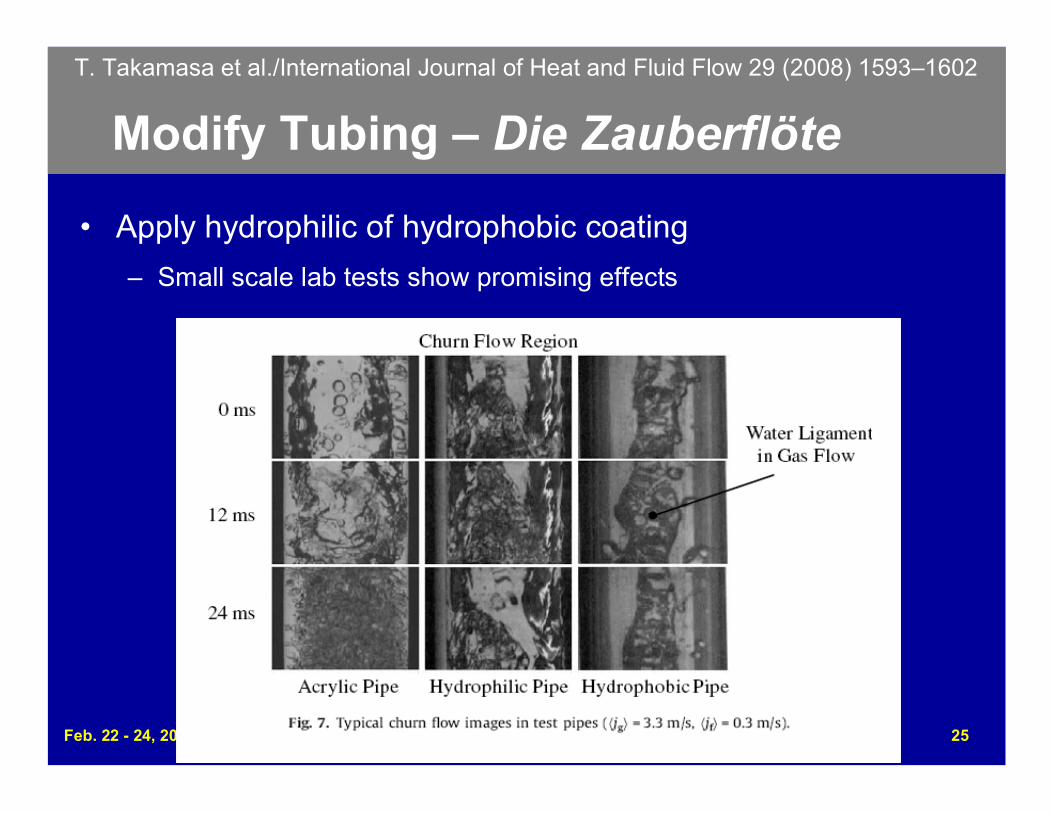
Modify Tubing – Die Zauberflöte
• Apply hydrophilic of hydrophobic coating
– Small scale lab tests show promising effects
T. Takamasa et al./International Journal of Heat and Fluid Flow 29 (2008) 1593–1602
Feb. 22 - 24, 2010 2010 Gas Well Deliquification WorkshopDenver, Colorado
26
Modify Tubing – Die Zauberflöte
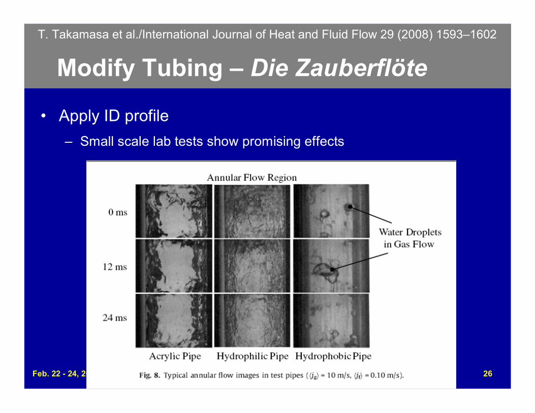
• Apply ID profile
– Small scale lab tests show promising effects
T. Takamasa et al./International Journal of Heat and Fluid Flow 29 (2008) 1593–1602
Feb. 22 - 24, 2010 2010 Gas Well Deliquification WorkshopDenver, Colorado
27
Modify Tubing – Die Zauberflöte
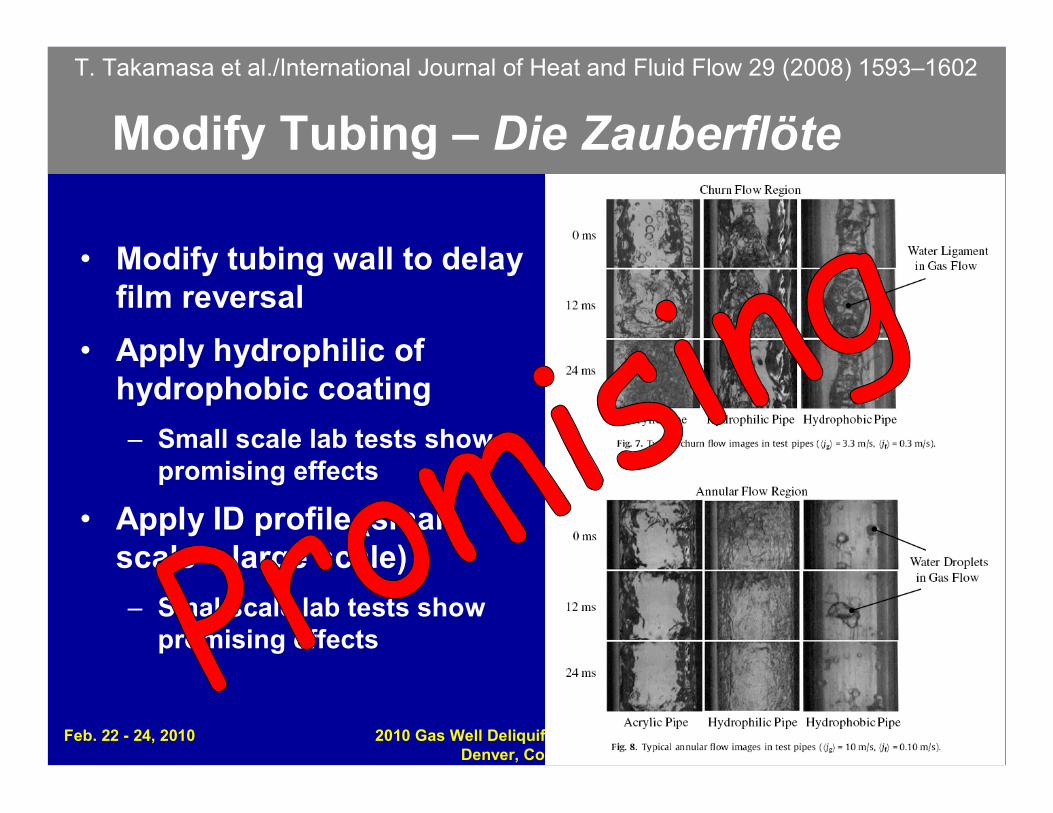
• Modify tubing wall to delayfilm reversal
• Apply hydrophilic ofhydrophobic coating
– Small scale lab tests showpromising effects
• Apply ID profile (smallscale – large scale)
– Smal scale lab tests showpromising effects
T. Takamasa et al./International Journal of Heat and Fluid Flow 29 (2008) 1593–1602
Summary
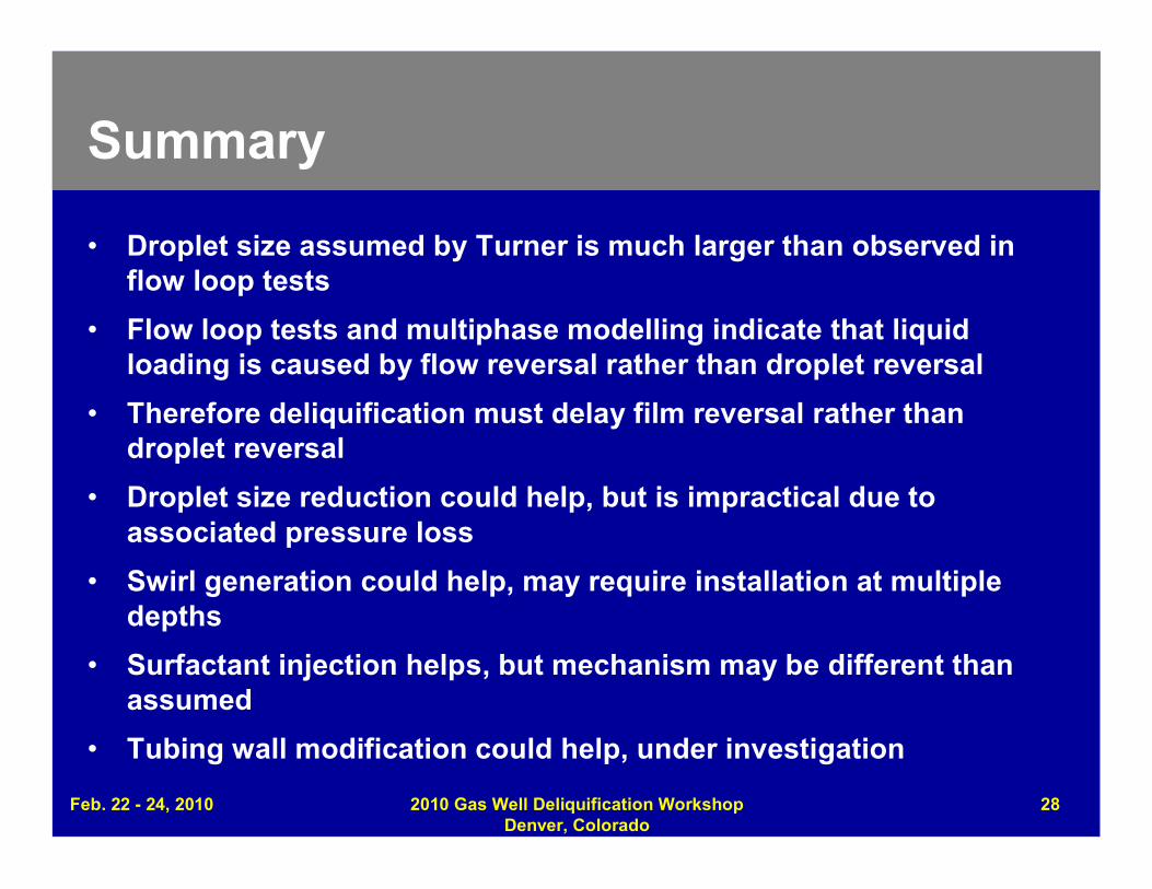
• Droplet size assumed by Turner is much larger than observed inflow loop tests
• Flow loop tests and multiphase modelling indicate that liquidloading is caused by flow reversal rather than droplet reversal
• Therefore deliquification must delay film reversal rather thandroplet reversal
• Droplet size reduction could help, but is impractical due toassociated pressure loss
• Swirl generation could help, may require installation at multipledepths
• Surfactant injection helps, but mechanism may be different thanassumed
• Tubing wall modification could help, under investigation
Feb. 22 - 24, 2010 2010 Gas Well Deliquification WorkshopDenver, Colorado
28
Feb. 22 - 24, 2010 2010 Gas Well Deliquification WorkshopDenver, Colorado
29
Copyright
Rights to this presentation are owned by the company(ies) and/orauthor(s) listed on the title page. By submitting this presentation tothe Gas Well Deliquification Workshop, they grant to the Workshop,the Artificial Lift Research and Development Council (ALRDC), andthe Southwestern Petroleum Short Course (SWPSC), rights to:
– Display the presentation at the Workshop.
– Place it on the www.alrdc.com web site, with access to the site to beas directed by the Workshop Steering Committee.
– Place it on a CD for distribution and/or sale as directed by theWorkshop Steering Committee.
Other use of this presentation is prohibited without the expressedwritten permission of the author(s). The owner company(ies) and/orauthor(s) may publish this material in other journals or magazines ifthey refer to the Gas Well Deliquification Workshop where it wasfirst presented.
DisclaimerThe following disclaimer shall be included as the last page of a Technical Presentation orContinuing Education Course. A similar disclaimer is included on the front page of the Gas WellDeliquification Web Site.
The Artificial Lift Research and Development Council and its officers and trustees, and the GasWell Deliquification Workshop Steering Committee members, and their supporting organizationsand companies (here-in-after referred to as the Sponsoring Organizations), and the author(s) ofthis Technical Presentation or Continuing Education Training Course and their company(ies),provide this presentation and/or training material at the Gas Well Deliquification Workshop "as is"without any warranty of any kind, express or implied, as to the accuracy of the information or theproducts or services referred to by any presenter (in so far as such warranties may be excludedunder any relevant law) and these members and their companies will not be liable for unlawfulactions and any losses or damage that may result from use of any presentation as a consequenceof any inaccuracies in, or any omission from, the information which therein may be contained.
The views, opinions, and conclusions expressed in these presentations and/or training materialsare those of the author and not necessarily those of the Sponsoring Organizations. The author issolely responsible for the content of the materials.
The Sponsoring Organizations cannot and do not warrant the accuracy of these documentsbeyond the source documents, although we do make every attempt to work from authoritativesources. The Sponsoring Organizations provide these presentations and/or training materials asa service. The Sponsoring Organizations make no representations or warranties, express orimplied, with respect to the presentations and/or training materials, or any part thereof, includingany warrantees of title, non-infringement of copyright or patent rights of others, merchantability, orfitness or suitability for any purpose.
Feb. 22 - 24, 2010 2010 Gas Well Deliquification WorkshopDenver, Colorado
30


