
NETWORK EMULATOR VIRTUAL APPLIANCE
INSTALLATION AND CONFIGURATION GUIDE
Global Support Email: [email protected]
Regional Telephone Hotline Support:
Americas: 1-888-448-4366 EMEA: +44 (0)1799 252 200

NE-ONE Network Emulator Virtual Appliance
Copyright © 2011-2020 iTrinegy Limited Page 2
NOTICE
iTrinegy provides this publication "as is" without warranty of any kind, either expressed or
implied, including, but not limited to, the implied warranties of merchantability or fitness for
any particular purpose. iTrinegy will not be liable (i) to you for any incidental, consequential,
or indirect damages (including damages for loss of business profits, business interruption,
loss of business information, and the like) arising out of the use of or inability to use this
product even if iTrinegy or any authorised iTrinegy representative has been advised of the
possibility of such damages, or (ii) for any claim by any other party. Further, iTrinegy
reserves the right to make changes or improvements to the product described in this guide
and to this publication without obligation of iTrinegy to notify any person of such revision or
changes.
TRADEMARKS
iTrinegy and iTrinegy NE-ONE are trademarks of iTrinegy Limited. All other trademarks or
registered trademarks are the property of the respective manufacturers of the products
associated with them.
COPYRIGHT
Copyright © 2011-2020 iTrinegy Limited.
All rights reserved.
No part of this publication may be reproduced, translated or distributed without the prior
written permission.
Edition: V5.0 June 2020

NE-ONE Network Emulator Virtual Appliance
Copyright © 2011-2020 iTrinegy Limited Page 3
Contents Introduction ............................................................................................................................................ 5
Installation .............................................................................................................................................. 5
Configuration and Setup ......................................................................................................................... 7
Configure the network management port .......................................................................................... 8
Obtain a licence key ............................................................................................................................ 8
Install the licence key ........................................................................................................................ 10
Configuring VMware Resources ........................................................................................................ 10
Configure the Network Test Environment ............................................................................................ 11
Virtual Distributed Switch Configuration .......................................................................................... 11
Routed Configuration ........................................................................................................................ 18
Network Emulator Configuration .................................................................................................. 19
Client and Server Configuration .................................................................................................... 21
Running the Tests .......................................................................................................................... 22
Non-routed Configuration ................................................................................................................ 24
Network Emulator Configuration .................................................................................................. 24
Client and Server Configuration .................................................................................................... 27
Running the Tests .......................................................................................................................... 29
Appendix A: Tuning VMware for NE-ONE ............................................................................................. 31
Introduction ...................................................................................................................................... 31
Memory ............................................................................................................................................. 31
Reserving memory in the Hypervisor............................................................................................ 31
CPUs .................................................................................................................................................. 33
Reserving CPUs in the Hypervisor ................................................................................................. 33
Latency Sensitivity ............................................................................................................................. 34
Advanced Options ............................................................................................................................. 35
Locking in CPU’s and More ........................................................................................................... 35
Appendix B: VMware vSwitch Security and iTrinegy Network Emulators ............................................ 36
Introduction and Essentials............................................................................................................... 36
vSwitch Basics ................................................................................................................................... 36
Hardware Switches ....................................................................................................................... 36
vSwitches ...................................................................................................................................... 36
Distributed vSwitches ....................................................................................................................... 37
Adding our Network Emulators to an existing vSwitch environment .............................................. 37

NE-ONE Network Emulator Virtual Appliance
Copyright © 2011-2020 iTrinegy Limited Page 4
Appendix C: High CPU Utilisation .......................................................................................................... 38
Appendix D: Connecting VM’s Directly To Physical Networks Without Using Virtual Switches ........... 39

NE-ONE Network Emulator Virtual Appliance
Copyright © 2011-2020 iTrinegy Limited Page 5
Introduction This guide provides information of how to install and configure the Network Emulator Virtual
Appliance. Some example scenarios are included although please note that detailed product
information can be found in the product guides and videos.
Installation The following instructions detail how to import the Network Emulator Virtual Appliance (VA) using
VMware’s Web-Gui client. The instructions in this document apply to deploying the iTrinegy
Network Emulator OVA on platform ESXi v6.5 onwards. iTrinegy have tested the Virtual Appliance
on VMware’s ESXi server products, workstation support will be added in a later release.
1. Download the Network Emulator Virtual Appliance from here or copy the link
(http://support.itrinegy.com/VirtualAppliances/NE-ONE%20Emulator.ova) in preparation for
step 3.
2. Using a Web Browser, enter the IP of your ESXi vCenter Server where you would like to
deploy the Network Emulator.
3. Select the host that you want to deploy the NE-ONE onto, right click on it in the menu tree
and select Deploy OVF Template from the menu that appears.
4. From the screen that appears, select either URL or Local File depending on your preference
(if your host is internet connected it is recommended you select URL).
a. If choosing URL enter the link from the top of this guide:
http://support.itrinegy.com/VirtualAppliances/NE-ONE%20Emulator.ova in the
provided field.
b. If choosing Local File then browse to find the file on your PC and upload to your
host.

NE-ONE Network Emulator Virtual Appliance
Copyright © 2011-2020 iTrinegy Limited Page 6
5. Enter a name for your new virtual machine (in this case it’s NE-ONE Network Emulator) and
select an appropriate location, if not already selected.
6. Select the server you want the NE-ONE to be hosted on (if not already selected) and click
Next.
7. Review your VM details and make sure everything is set to the desired settings.

NE-ONE Network Emulator Virtual Appliance
Copyright © 2011-2020 iTrinegy Limited Page 7
8. Enter the desired storage settings for your appliance, the iTrinegy reccomendation is that
you thick provision with eager zeroing for optimal performance when performing PCAP and
logging operations.
9. Select the desired port groups to be connected to the respective ports on the emulator, for
reference:
a. Prod_ManagementNet – Management Network port
b. Prod_TestNet1 – Emulation port
c. Prod_TestNet2 – Emulation port
10. Review all details for the last time and then click Finish to deploy the OVA.
Configuration and Setup The Network Emulator Virtual Appliance is preconfigured with 2 CPUs, 8GB RAM, 12GB SCSI hard
disk and 3 virtual network interface cards. This configuration is usually sufficient for most
emulations and should only be changed under guidance from your support representative.
There are three stages to complete before you can use the Network Emulator:

NE-ONE Network Emulator Virtual Appliance
Copyright © 2011-2020 iTrinegy Limited Page 8
1. Configure the network management port
2. Obtain and install a licence key
3. Configure the network test environment
Configure the network management port The network management or netmgt port is connected to your LAN so that you can access the
Network Emulator using a web browser.
1. Launch the Network Emulator console and login as user: itrinegy password: itrinegy
2. Select ‘Set Network Management Address’ and then select either Static or DHCP configuration.
3. Once set, confirm that you can access the Network Emulator from your workstation. Do not exit the Console as we will need it in the next step.
Obtain a licence key 1. On the menu, identify the host ID for the appliance at the top of the screen.

NE-ONE Network Emulator Virtual Appliance
Copyright © 2011-2020 iTrinegy Limited Page 9
2. Make a note of the Host Id, in this case the Host Id is 000C29-9A587F.
3. Send an email to [email protected] that includes your name, contact telephone number
and Host Id.
4. You cannot continue to the next stage until iTrinegy Support have sent you an email confirming
that the license key is ready for download.
5. Using a web browser, connect to https://support.iTrinegy.com
6. Enter your Username and Password. If you haven’t received your login credentials please
contact [email protected].
7. Hover-over the Menu item so that the drop-down menu appears. Check that the Key Code is
identical to your Host Id. Select the Create Key option. In the following example the key code
obtained was: 000C29-9A587F.

NE-ONE Network Emulator Virtual Appliance
Copyright © 2011-2020 iTrinegy Limited Page 10
8. The Support Portal will create the licence key file and your web browser will automatically
download a file named license.txt.
Install the licence key 1. Using a web browser login using https to the Network Emulator specifying the IP Address or
hostname that you have configured.
2. Login using the below credentials:
Username: admin Password: admin
You’ll be logged in and if this is your initial setup the GUI will popup saying “License check error – Not Licensed” Click OK to dismiss the popup.
3. From the menu click on the Settings/Licensing.
4. Browse for your License File and select the licence file that was downloaded from the
support site. Finally, click the Upload button.
NOTE: If this is your initial setup you won’t be able to use any other options at this time, only
License File browse and Upload.
5. The Network Emulator automatically reboots. Please give it a short time to be ready for use.
Configuring VMware Resources The NE-ONE OVA (or OVF) provided is set up to not require too much in the way of CPU or Memory
resources from the VMware hypervisor. However, in certain high performance (high packet rate,
high bit rate, high burst rate) applications, or where there is too much competition for resources
between the VMware guests, then you may need to provide more resources to the NE-ONE VM than
configured by default.
How to do this is explained in Appendix A: Tuning VMware for NE-ONE on page 31.

NE-ONE Network Emulator Virtual Appliance
Copyright © 2011-2020 iTrinegy Limited Page 11
Configure the Network Test Environment Before you start using the Network Emulator it is necessary to configure the network in VMware.
Below details the procedure of creating a vDS in VMware.
Virtual Distributed Switch Configuration VMware supports the use of both Virtual Switches (vS) and Virtual Distributed Switches (vDS) . In this
guide we will detail the setup procedure of a vDS, for instructions concerning the setup of a vS
please contact iTrinegy Support.
1. Navigate to the Networking tree view - by clicking on the network icon located just above
the left-hand pane:
2. The tree view now shows the data centers and network port groups:

NE-ONE Network Emulator Virtual Appliance
Copyright © 2011-2020 iTrinegy Limited Page 12
3. In the left-hand column, right click on the data-centre which you wish to configure the
distributed switch for. You get these choices:
4. Choose “Distributed Switch → New Distributed Switch…”:

NE-ONE Network Emulator Virtual Appliance
Copyright © 2011-2020 iTrinegy Limited Page 13
5. A dialogue box will open, similar to the following:
6. Go through the steps, with appropriate values for your environment:
1. Name and location: Name the switch appropriate for your needs and select (if you
have more than one) the Location (aka Datacenter)
2. Select version: When selecting versions of vSwitch you will need to choose the
highest version compatible with all the vSphere host versions that you need to the
vSwitch to operate with
3. Configure settings: In Number of Uplinks ensure you specify enough uplinks, equal
to the number of vSphere hosts (not to be confused with guest VMs) you are
connecting together. Leave the Network I/O Control Enabled and choose to Create a
default port group with an appropriate Port group name for your purposes.

NE-ONE Network Emulator Virtual Appliance
Copyright © 2011-2020 iTrinegy Limited Page 14
7. Click Next and you’ll see a summary of your choices:
8. Review everything before clicking Finish

NE-ONE Network Emulator Virtual Appliance
Copyright © 2011-2020 iTrinegy Limited Page 15
You can find your new distributed switch towards the bottom of the left-hand tree view, below all
the standard (i.e. non distributed) Port Groups:
Adding vSphere Hosts to your distributed vSwitch
In order to begin to connect VMs (Guests) to your distributed vSwitch (dvSwitch), you must first
specify which vSphere hosts are going to be connected to the switch
1. Right click on the on the dvSwitch you just created and choose ‘Add and Manage Hosts…’

NE-ONE Network Emulator Virtual Appliance
Copyright © 2011-2020 iTrinegy Limited Page 16
2. You’ll get this dialog:
1. Select Task: Select the Add hosts option and click Next
2. Select Hosts: Add hosts to your dvSwitch by clicking the ‘New hosts…’ button and
selecting all the vSphere hosts you want to add for this dvSwitch, then click Next
3. Manage physical adapters: You need to select at least 1 physical NIC for each
vSphere host to use, in order that “parts” of the dvSwitch located on each host can
transmit packets between each other, and therefore combine to make one switch.
The process is:
1. Select a free NIC (preferably - you can also select a used NIC, but be aware
that this NIC will now be shared between multiple tasks and so could easily
overload. Discuss this thoroughly with the network team before choose to
share any NICs) and click the now ungreyed Assign uplink button
2. Do the same for each vSphere host that will use this dvSwitch
3. You can now click on the Next button through the rest of the pages (unless
you want to specify any of the other settings)
3. If you want to migrate any of the VMs (guests) over to the new dvSwitch, you can do so on
the Migrate VM networking’ page. (Note: you can also connect VMs to the Distributed
Switch upon their creation).
4. Finally, review all of your settings and click Finish.
You will now have a Distributed Switch you can use with vCenter and connect VMs to.

NE-ONE Network Emulator Virtual Appliance
Copyright © 2011-2020 iTrinegy Limited Page 17
Additional Port Groups
When you created the new dvSwitch it automatically created a distributed Port Group on that
switch. If you need more distributed Port groups right click on the dvSwitch and choose Distributed
Port Group → New Distributed Port Group
Repeat the above processes to set up a second distributed switch (if required) and further port
groups.
Security
This step is vital in the dvSwitch(es) and Port Groups to work with our Emulators
1. Navigate to the first distributed switch and locate the distributed port group.
2. Right click on the port group and select ‘Edit Settings’. You get to this screen:
NE-ONE Network Emulator Virtual Appliance
Copyright © 2011-2020 iTrinegy Limited Page 18
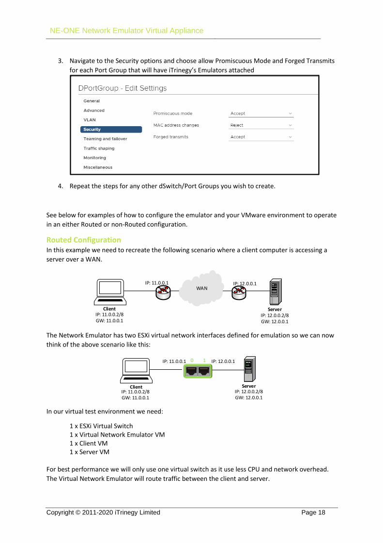
3. Navigate to the Security options and choose allow Promiscuous Mode and Forged Transmits
for each Port Group that will have iTrinegy’s Emulators attached
4. Repeat the steps for any other dSwitch/Port Groups you wish to create.
See below for examples of how to configure the emulator and your VMware environment to operate
in an either Routed or non-Routed configuration.
Routed Configuration In this example we need to recreate the following scenario where a client computer is accessing a
server over a WAN.
WAN
ServerClientIP: 11.0.0.2/8GW: 11.0.0.1
IP: 11.0.0.1
IP: 12.0.0.2/8GW: 12.0.0.1
IP: 12.0.0.1
The Network Emulator has two ESXi virtual network interfaces defined for emulation so we can now
think of the above scenario like this:
IP: 11.0.0.2/8GW: 11.0.0.1
IP: 11.0.0.1 IP: 12.0.0.1
ServerIP: 12.0.0.2/8GW: 12.0.0.1
Client
In our virtual test environment we need:
1 x ESXi Virtual Switch 1 x Virtual Network Emulator VM 1 x Client VM 1 x Server VM For best performance we will only use one virtual switch as it use less CPU and network overhead.
The Virtual Network Emulator will route traffic between the client and server.

NE-ONE Network Emulator Virtual Appliance
Copyright © 2011-2020 iTrinegy Limited Page 19
Network Emulator Configuration
VMware vCenter
To finalize the setup of the emulator in vCenter connect the TestNet1 and TestNet2 ports to the
same test switch (see below):
Port Addressing
To assign IP address to the NE-ONEs ports you can enable the Port Addressing settings under Port
Settings on the emulator menu:
To enable Port Addressing, click on the Port Addressing under the Ports 0 and 1 link – this brings up
the Port Addressing dialog. Enter the IP addresses and Netmask and then click on the Enable Port
Addressing tickbox to activate Port Addressing, and then click the Update button.

NE-ONE Network Emulator Virtual Appliance
Copyright © 2011-2020 iTrinegy Limited Page 20
The Network Emulator now has the IP addresses assigned to its physical ports and will respond to
pings.
Emulation
1. Login to the Network Emulator GUI – https://<netmgt address>. The default username is admin,
password admin.
2. Click on HOME in the left-hand column, either double click on LAN_No_Impairment or click on
the emulation to highlight it and click on the Load an emulation icon at the end of the line. Click
on OK to load it on Ports 0 and 1. We will start with no impairment to test client to server
connectivity and then increase the latency. Now click on the Configured green link.

NE-ONE Network Emulator Virtual Appliance
Copyright © 2011-2020 iTrinegy Limited Page 21
We can see that we have configured a perfect 1 gigabit link, i.e. there is zero latency and loss. Click
on OK to dismiss the Link Properties dialog.
IP: 11.0.0.2/8GW: 11.0.0.1
IP: 11.0.0.1 IP: 12.0.0.1
ServerIP: 12.0.0.2/8GW: 12.0.0.1
Client
To start the emulation click on Emulation->Ports 0 and 1->Setup & Control link in the left hand menu
column, and then click on the Start button. We will ping the Network Emulator from the client and
server in the next section.
Client and Server Configuration On our esxtest server we have two Windows 8.1 test machines, i.e. one client and one server. These
are configured to route their traffic through the Network Emulator:

NE-ONE Network Emulator Virtual Appliance
Copyright © 2011-2020 iTrinegy Limited Page 22
Client Configuration Server Configuration
The output below shows that we can ping the server from the client with < 1ms latency.
Running the Tests Now that the virtual network, Network Emulator and test machines are configured we can impede
the network traffic. First let’s change the bandwidth and latency to something that’s more
representative of a WAN.
1. Login to the Network Emulator, click on Emulation->Ports 0 and 1->Setup & Control link, and
click on the scenario link between the end points. Change the Bandwidth to 1Mbps
(1000000 bps) and set the Min and Max Latency to 5.

NE-ONE Network Emulator Virtual Appliance
Copyright © 2011-2020 iTrinegy Limited Page 23
Click on the Ok & Update button to make the changes take effect. Note that latency is
applied in both directions so we will expect to see an overall roundtrip time of 10ms.
We can now see that the ping, from the client to the server, has changed from 1ms to 10ms
proving that the Network Emulator is now impeding the traffic.

NE-ONE Network Emulator Virtual Appliance
Copyright © 2011-2020 iTrinegy Limited Page 24
Non-routed Configuration In this example we need to recreate the following scenario where a client computer is accessing a
server over a LAN.
ServerClientIP: 192.168.0.100/24 IP: 192.168.0.5/24
LAN
The Network Emulator has two ESXi virtual network interfaces defined for emulation so we can now
think of the above scenario like this:
IP: 192.168.0.100/24Server
IP: 192.168.0.5/24Client
In our virtual test environment we need:
2 x ESXi Virtual Switch/Virtual Distributed Switch 1 x Virtual Network Emulator VM 1 x Client VM 1 x Server VM Although using two ESXi virtual switches does not provide the best performance compared to using
only one virtual switch, as shown in the routed configuration, it is necessary otherwise traffic would
not pass through the Network Emulator.
Network Emulator Configuration
VMware vCenter
To finalize the setup of the emulator in vCenter connect the TestNet1 and TestNet2 ports to two
separate test switches (see below):

NE-ONE Network Emulator Virtual Appliance
Copyright © 2011-2020 iTrinegy Limited Page 25
Emulator
1. Login to the Network Emulator GUI – https://<netmgt address>. The default username is admin,
password admin.
2. Go to the Port Settings page and make sure Port Addressing is disabled (i.e. If Port Addressing is
enabled, untick Enable Port Addressing and click Update).
3. Click on the HOME link in the left-hand column, choose LAN_No_Impairment and click on OK.
We will start with no impairment to test client to server connectivity and then increase the
latency. Now click on the Configured green link.

NE-ONE Network Emulator Virtual Appliance
Copyright © 2011-2020 iTrinegy Limited Page 26
4. We can see that we have configured a perfect 1 gigabit link, i.e. there is zero latency and loss.
Click on OK as no further changes are needed.
To start the emulation, click on Emulation->Ports 0 and 1->Setup & Control link in the left-hand side
menu, and click the Start button. We will ping the Network Emulator from the client and server in
the next section.

NE-ONE Network Emulator Virtual Appliance
Copyright © 2011-2020 iTrinegy Limited Page 27
Client and Server Configuration On our esxtest server we have two Windows 8.1 test machines, i.e. one client and one server.
Client Configuration Server Configuration
The below output shows that we can ping the server from the client with < 1ms latency.
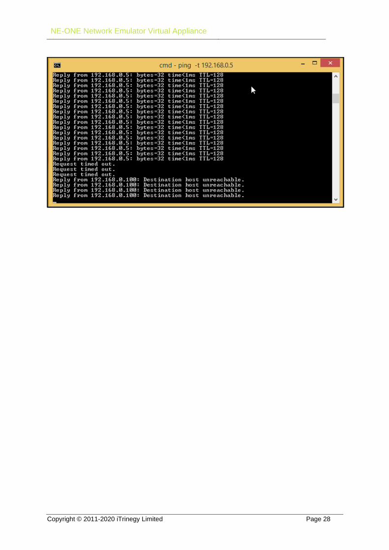
To prove that the client to server traffic is going through the Network Emulator stop the running
emulation by clicking on the Emulation->Ports 0 and 1->Setup & Control link in the left-hand column
menu and click the Stop button. We can see that the ping requests from the client to server have
started to fail.
NE-ONE Network Emulator Virtual Appliance
Copyright © 2011-2020 iTrinegy Limited Page 28

NE-ONE Network Emulator Virtual Appliance
Copyright © 2011-2020 iTrinegy Limited Page 29
Running the Tests Now that the virtual network, Network Emulator and test machines are configured we can impede
the network traffic. First let’s change the bandwidth and latency to something that’s more
representative of a WAN.
1. Login to the Network Emulator, click on Emulation->Ports 0 and 1->Setup & Control and click
on the scenario link. Change the Bandwidth to 1Mbps (1000000 bps) and set the Min and
Max Latency to 8. Note that latency is applied in both directions so we will expect to see an
overall roundtrip time of 16ms.
Click on the OK & Update button. We can now see that the ping, from the client to the
server, is 16ms proving that the Network Emulator is impeding the traffic.

NE-ONE Network Emulator Virtual Appliance
Copyright © 2011-2020 iTrinegy Limited Page 30

NE-ONE Network Emulator Virtual Appliance
Copyright © 2011-2020 iTrinegy Limited Page 31
Appendix A: Tuning VMware for NE-ONE
Introduction When iTrinegy provides the OVAs/OVFs for NE-ONE our primary concern is that if you start them up,
their VMware “footprint” (i.e. CPU and Memory requirements) should not be too large. This is so
that they will not have a large impact on the other VMs (Guests) in your VMware environment.
The truth is that both are real time products and going by the VMware tuning guide for real time
products we should lock in both the CPU and memory resources, as far as possible. If you need
more information iTrinegy has a separate technical paper on tuning for VMware; here we
concentrate on the steps to take, not the reasons.
Memory
Reserving memory in the Hypervisor Power off the NE-ONE Network Emulator. Then either right click over the Network Emulator VM in
the left-hand column, or click on the Actions link at the top of the page, and select Edit Settings:
NE-ONE Network Emulator Virtual Appliance
Copyright © 2011-2020 iTrinegy Limited Page 32
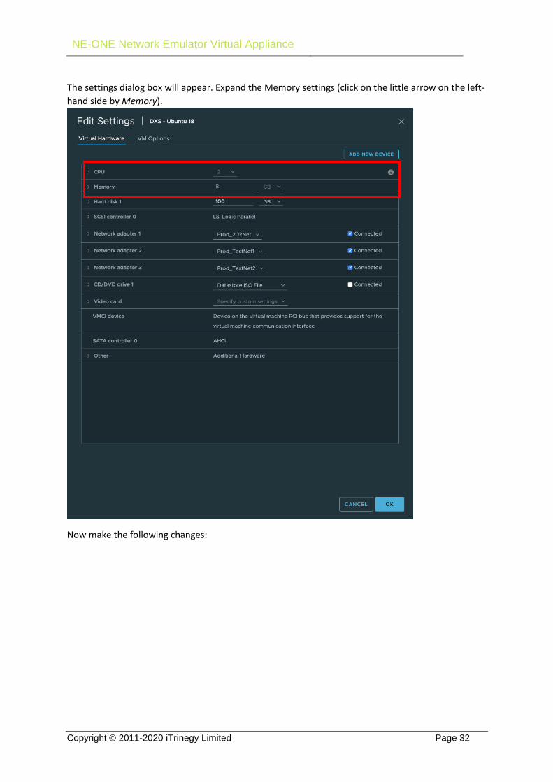
The settings dialog box will appear. Expand the Memory settings (click on the little arrow on the left-
hand side by Memory).
Now make the following changes:

NE-ONE Network Emulator Virtual Appliance
Copyright © 2011-2020 iTrinegy Limited Page 33
• Set Memory Shares to High (or better still Custom and then choose the maximum value from
the dropdown box containing the shares value). This is so that the NE-ONE gets priority
access to memory resources
• Change reservation to None, which means reserve as much as possible (will vary depending
on the number of other VM’s present and running on that host and the physical
environment i.e. The size of the physical memory available). The user can set the reservation
to a specific value but it will need to be tuned and can be set to a maximum value set for the
VM, but the user should be aware it may affect the performance of the Network Emulator
VM as well as other VM’s running on the host, that will also be demanding a share of the
resources.
• Make sure Limit is set to Unlimited
Before you say OK to this read on as the CPU resources are changed from the same dialog…
CPUs
Reserving CPUs in the Hypervisor Now collapse the Memory section and expand the CPU section as we wish to raise the priority of the
NE-ONE’s VM in CPU and reserve as much CPU as we can:

NE-ONE Network Emulator Virtual Appliance
Copyright © 2011-2020 iTrinegy Limited Page 34
Here we:
• Set the CPU shares to High (but Custom, followed by choosing the maximum value for
custom is even better) and
• Set the Reservation to the None. This means automatically reserve as much as possible
depending on availability. You can opt to specify an actual value, the higher the better, but
please bear in mind this may affect the running of the other VM’s on that host. Obviously if
the Network Emulator is the only VM you can specify the maximum possible value. For
example, if you have a single dual-core processor operating at 3.33GHz and you have 2
virtual CPU’s, and you specify in this dialog that you want 2 CPU’s with 2 Cores Per Socket,
giving you 1 socket, the maximum value you can reserve is 6666MHz. A smaller value may be
more appropriate depending on what else is running on that Host. We supply the OVA set
with a basic set of parameters that should allow it to run in any environment, and it’s then
down to the user to look at his environment and tune these parameters depending on the
physical resources available, number of VM’s running (as these demand a share of the
resources at the same time) etc.
• Make sure Limit is set to Unlimited
Now we can click on OK. After tuning, when the VM is restarted it may take slightly longer to initially
boot as the VMware environment will adjust itself to the new parameters for that VM. Thereafter
the VM environment should remember the settings and subsequent boots should be more normal.
Latency Sensitivity The VMware system treats NE-ONE as a normal host, but in fact it ideally needs to be treated as a
latency sensitive host. Once again click on Edit Settings and select the VM Options tab at the top:

NE-ONE Network Emulator Virtual Appliance
Copyright © 2011-2020 iTrinegy Limited Page 35
Expand the Advanced section and locate the Latency Sensitivity setting in this section.
• Here we set the latency sensitivity to High.
Advanced Options
Locking in CPU’s and More It is possible to also lock in certain fixed hardware CPUs into the VM, but this is advanced and usually
not required, please contact Support if you wish to do this, or would like any further guidance on
tuning NE-ONE’s VMs or reducing their Memory/CPU footprints, where feasible.

NE-ONE Network Emulator Virtual Appliance
Copyright © 2011-2020 iTrinegy Limited Page 36
Appendix B: VMware vSwitch Security and iTrinegy Network Emulators
Introduction and Essentials When attaching the NE-ONE or the INE Network Emulators into a VMware vSwitched environment it often proves difficult to get the Network Emulators to be able to either receive or transmit traffic from the vSwitch they are connected to. This invariably is due to security settings on the vSwitch.
The bottom line for our Network Emulators to be able to work is that security must be set like this:
• The Network Emulator must be connected to a port group on the vSwitch on which: o Promiscuous Mode is set to Accept o Forged Transmits is set to Accept
Note the implications: • The entire vSwitch does not have to be set to accept promiscuous traffic and forged
transmits, only the port group to which our Network Emulator is attached.
We could stop there but the next sections explain a bit more about what’s going on and why we need those settings.
vSwitch Basics
Hardware Switches First a little on hardware switches to use as a comparison. Hardware switches “learn” what devices (computers, ip-phones etc etc) are connected to their ports by inspecting the packets that arrive at each port.
For packets arriving at switch port N, say, the switch records the Source MAC (Ethernet) Address and puts it in the table against that port. Exact switch design may vary from product to product but in general this table is called the CAM table, there is one such table per switch, and the table contains a lookup of MAC Address to Port. So, when the switch needs to transmit a packet out it can look up the port and sent the packet directly to that port, not any other port (or all ports as old style “hubs” used to do).
Hardware switches basically fully support bridging by simply cabling them together, so when we use our Network Emulators to bridge them, this is seen as the same thing.
vSwitches vSwitches don’t work like their Hardware counterparts. They are essentially “hardwired”.

NE-ONE Network Emulator Virtual Appliance
Copyright © 2011-2020 iTrinegy Limited Page 37
vSwitches “know” what is connected to their virtual ports, because you actually connect those (virtual) devices manually. (They don’t know what is connected to their hardware ports though, as they’re outside VMware - so these ports work more like hardware switches).
Our Network Emulators create bridges which may connect several systems on one vSwitch to another vSwitch via our Network Emulator. vSwitches do not support bridging (or virtual cabling) between them, so some settings are required to allow our Network Emulators to do that.
Promiscuous Mode is required to allow the vSwitch to send packets to our Network Emulator that do not have the Network Emulators MAC address as their destination i.e. are destined for a server or system somewhere else.
Forged Transmits is required to allow our Network Emulator to send packets out into a vSwitch that do not come from its own MAC address (they came from another system), as VMware regards these as forged. In reality they are not forged at all, they came from a VMware or physical host but VMware does not know that.
Distributed vSwitches A distributed vSwitch (vDS) is an extension of a vSwitch that VMware have developed to work across
multiple virtual hosts enabling access to a single vSwitch from multiple hosts. Beyond this there is
little difference between non-distributed and distributed vSwitches, with almost no noticeable
difference at all.
Adding our Network Emulators to an existing vSwitch
environment There are two ways to go here:
• Change the existing vSwitch to set its defaults and/or port groups to Promiscuous Mode: Accept & Forged Transmits: Accept
• Add a new port group to the existing vSwitch, attach our Network Emulator to this new port group and set the new port group’s security settings to be Promiscuous Mode: Accept & Forged Transmits: Accept
The problem with the first solution is that it may feel like we’re opening up too much security amongst the systems connected to the same vSwitch. In the second example this security is only relaxed for the Network Emulator, and therefore any systems on switches “bridged”
Of course, the Network Emulator may have more than two emulation ports and this security must be repeated for each emulation port.

NE-ONE Network Emulator Virtual Appliance
Copyright © 2011-2020 iTrinegy Limited Page 38
Appendix C: High CPU Utilisation
For performance reasons the iTrinegy Network Emulators allocate one processor to the operating system and the remaining processors for Network Emulation purposes. The processor allocated to normal operating system functions will run at approximately 1% CPU utilization. CPU’s allocated for handling network emulations constantly poll, to ensure that packets are processed efficiently, which is why they run at approximately 100% usage. Therefore, if the hypervisor statistics and logs for the Network Emulator VM are showing CPU utilization as very high during an emulation then this behaviour should be considered normal. In a 2 CPU configuration the statistics will show the CPU’s running an average of approximately 50% utilization, and a 4 CPU configuration will show the CPU’s running an average of approximately 75% utilisation (i.e. 1 CPU for use by the Operating System, and the other 3 for use by the Network Emulator engine). This means that the more CPU’s added to the configuration will actually result in a higher average CPU utilization. The default Virtual Appliance configuration of 4 CPU’s is suitable for most customer environments
although should you consider adding additional CPUs then further help and guidance is available
from the iTrinegy Support Team.

NE-ONE Network Emulator Virtual Appliance
Copyright © 2011-2020 iTrinegy Limited Page 39
Appendix D: Connecting VM’s Directly To Physical Networks Without Using Virtual Switches
You can set passthrough using the web client by using the Manage feature under the host - you have to toggle passthrough on the Network adapters and reboot the host.
To use the adapters in the guest you need to add PCI devices and not Network devices:

NE-ONE Network Emulator Virtual Appliance
Copyright © 2011-2020 iTrinegy Limited Page 40
If you already have Network Adapters in place you will need to keep the first one for Network Management – we still want to manage our Network Emulator via the virtual environment, but the Emulation Ports that are connected via the Network Adapters need to be replaced with direct physical network connections. If you Edit the VM Settings, delete the Network Adapters for the emulations ports and then add New PCI devices, selecting the desired Network Connection settings that map to NIC ports.


