
NAVAL POSTGRADUATE
SCHOOL
MONTEREY, CALIFORNIA
THESIS
Approved for public release. Distribution is unlimited.
FEASIBILITY STUDY ON MISSILE LAUNCH DETECTION AND TRAJECTORY TRACKING
by
Chee Mun Kelvin Wong
September 2016
Thesis Advisor: Oleg A. Yakimenko Second Reader: Fotis A. Papoulias

THIS PAGE INTENTIONALLY LEFT BLANK
i
REPORT DOCUMENTATION PAGE Form Approved OMB No. 0704–0188
Public reporting burden for this collection of information is estimated to average 1 hour per response, including the time for reviewing instruction, searching existing data sources, gathering and maintaining the data needed, and completing and reviewing the collection of information. Send comments regarding this burden estimate or any other aspect of this collection of information, including suggestions for reducing this burden, to Washington headquarters Services, Directorate for Information Operations and Reports, 1215 Jefferson Davis Highway, Suite 1204, Arlington, VA 22202-4302, and to the Office of Management and Budget, Paperwork Reduction Project (0704-0188) Washington, DC 20503.
1. AGENCY USE ONLY (Leave blank)
2. REPORT DATE September 2016
3. REPORT TYPE AND DATES COVERED Master’s thesis
4. TITLE AND SUBTITLE FEASIBILITY STUDY ON MISSILE LAUNCH DETECTION AND TRAJECTORY TRACKING
5. FUNDING NUMBERS
6. AUTHOR(S) Chee Mun Kelvin Wong
7. PERFORMING ORGANIZATION NAME(S) AND ADDRESS(ES)Naval Postgraduate School Monterey, CA 93943-5000
8. PERFORMING ORGANIZATION REPORT NUMBER
9. SPONSORING /MONITORING AGENCY NAME(S) AND ADDRESS(ES)
N/A
10. SPONSORING / MONITORING AGENCY REPORT NUMBER
11. SUPPLEMENTARY NOTES The views expressed in this thesis are those of the author and do not reflect the official policy or position of the Department of Defense or the U.S. Government. IRB number ____N/A____. 12a. DISTRIBUTION / AVAILABILITY STATEMENT Approved for public release. Distribution is unlimited.
12b. DISTRIBUTION CODE A
13. ABSTRACT (maximum 200 words)
With the increased use of Unmanned Aerial Vehicles (UAVs) in military operations, their role in a missile defense operation is not well defined. The simulation program discussed in this thesis studies the feasibility of utilizing UAVs to patrol a potential Intercontinental Ballistic Missile (ICBM) launch area using a single or multiple Counter Unmanned Aerial Vehicles (CUAVs), detecting the launch event and tracking an ICBM using the CUAVs’ onboard optical sensors. The ultimate goal is to assess the parameters of ICBM ascent and provide target information to bring the attacking UAVs onto the anti-missile launch course to reliably intercept the threat.
This thesis explores the challenges in creating a simulation program to process video footage from an unstable platform and the limitations of using background subtraction method to detect the missile motion. Although the simulation program test results showed that it is unable to consistently detect a missile launch and track its trajectory for all the test videos; the developed algorithms allowed a surveillance UAV to detect a missile launch for most of the videos and also track its trajectory with an accuracy that is sufficient for targeting purposes.
This thesis is limited to using the simulation program to detect a launch event offline and is based on the amateur rocket launch data gathered during the launch trials at Mojave Desert in May of 2016. 14. SUBJECT TERMS missile launch detection, missile trajectory tracking, computer vision, ORB (Oriented FAST and Rotated BRIEF)
15. NUMBER OF PAGES
71 16. PRICE CODE
17. SECURITY CLASSIFICATION OF REPORT
Unclassified
18. SECURITY CLASSIFICATION OF THIS PAGE
Unclassified
19. SECURITY CLASSIFICATION OF ABSTRACT
Unclassified
20. LIMITATION OF ABSTRACT
UU
NSN 7540–01-280-5500 Standard Form 298 (Rev. 2–89) Prescribed by ANSI Std. 239–18

ii
THIS PAGE INTENTIONALLY LEFT BLANK

iii
Approved for public release. Distribution is unlimited.
FEASIBILITY STUDY ON MISSILE LAUNCH DETECTION AND TRAJECTORY TRACKING
Chee Mun Kelvin Wong Civilian, Defence Science Technology Agency
B.Eng., Nanyang Technological University, 2005
Submitted in partial fulfillment of the requirements for the degree of
MASTER OF SCIENCE IN MECHANICAL ENGINEERING
from the
NAVAL POSTGRADUATE SCHOOL September 2016
Approved by: Professor Oleg A. Yakimenko Thesis Advisor
Professor Fotis A. Papoulias Second Reader
Garth V. Hobson Chair, Department of Mechanical and Aerospace Engineering

iv
THIS PAGE INTENTIONALLY LEFT BLANK

v
ABSTRACT
With the increased use of Unmanned Aerial Vehicles (UAVs) in military
operations, their role in a missile defense operation is not well defined. The
simulation program discussed in this thesis studies the feasibility of utilizing
UAVs to patrol a potential Intercontinental Ballistic Missile (ICBM) launch area
using a single or multiple Counter Unmanned Aerial Vehicles (CUAVs), detecting
the launch event and tracking an ICBM using the CUAVs’ onboard optical
sensors. The ultimate goal is to assess the parameters of ICBM ascent and
provide target information to bring the attacking UAVs onto the anti-missile
launch course to reliably intercept the threat.
This thesis explores the challenges in creating a simulation program to
process video footage from an unstable platform and the limitations of using
background subtraction method to detect the missile motion. Although the
simulation program test results showed that it is unable to consistently detect a
missile launch and track its trajectory for all the test videos; the developed
algorithms allowed a surveillance UAV to detect a missile launch for most of the
videos and also track its trajectory with an accuracy that is sufficient for targeting
purposes.
This thesis is limited to using the simulation program to detect a launch
event offline and is based on the amateur rocket launch data gathered during the
launch trials at Mojave Desert in May of 2016.

vi
THIS PAGE INTENTIONALLY LEFT BLANK

vii
TABLE OF CONTENTS
I. INTRODUCTION ........................................................................................ 1 A. BACKGROUND .............................................................................. 1 B. PREVIOUS WORK ON MOTION TRACKING AND
DETECTION .................................................................................... 3 C. THESIS ORGANIZATION ............................................................... 4
II. ALGORITHMS FOR MISSILE LAUNCH DETECTION AND TRAJECTORY TRACKING ....................................................................... 5 A. VIDEO STABILIZATION ................................................................. 5 B. EXPERIMENTAL SETUP ............................................................... 7 C. SIMULATION PROGRAM ALGORITHM ........................................ 8
1. Missile Launch Detection Phase ....................................... 9 2. Missile Trajectory-Tracking Phase .................................. 10
III. ALGORITHMS VERIFICATION ............................................................... 17 A. EFFECTS OF CAMERA ORIENTATION ...................................... 17 B. ALGORITHM INITIATION TUNING .............................................. 18
1. Number of Frames to Skip after the “Training” Frame ................................................................................. 19
2. Number of Frames Delayed after Missile Launch Flag Triggered ................................................................... 21
IV. POSITION ESTIMATION ......................................................................... 25 A. MISSILE SPEED ........................................................................... 25 B. MISSILE ORIENTATION .............................................................. 28 C. SUMMARY .................................................................................... 29
V. CONCLUSION AND FUTURE RESEARCH ............................................ 31 A. CONCLUSION .............................................................................. 31 B. FURTHER STUDIES ..................................................................... 31
1. Determine Missile Location in 3D Space ........................ 32 2. Object Motion Tracking .................................................... 32 3. Video Stabilization ............................................................ 32
APPENDIX A. SIMULATION PROGRAM PYTHON CODE ............................... 35
APPENDIX B. TEST RESULTS OF MISSILE LAUNCH VIDEOS .................... 41
viii
A. OPTIMIZATION TEST RESULT FOR THE NUMBER OF FRAMES TO SKIP AFTER THE “TRAINING” FRAME ............... 41
B. OPTIMIZATION TEST RESULT FOR THE NUMBER OF FRAMES TO DELAY AFTER MISSILE LAUNCH ........................ 46
LIST OF REFERENCES ..................................................................................... 51
INITIAL DISTRIBUTION LIST ............................................................................ 53
ix
LIST OF FIGURES
Figure 1. Images of Missile Launch from Two Different Angles ...................... 6
Figure 2. Images of Missile Launch after Background Subtraction ................. 6
Figure 3. Background Subtraction Images after Video Stabilization ............... 7
Figure 4. Experimental Setup of the Missile Launch ....................................... 8
Figure 5. Overview of the Simulation Program Algorithm ............................... 9
Figure 6. Missile Launches and the Corresponding Background Subtraction Frames ......................................................................... 9
Figure 7. Missile Launch Detected by the Simulation Program .................... 10
Figure 8. Missile Position Cannot Be Identified after the Background Subtraction Method ....................................................................... 11
Figure 9. Unique Features detected by the ORB Method on the “Training” Frame (left) and the “Query” Frame (right) .................... 12
Figure 10. Matching of the Features in the “Training” and “Query” Frames by the ORB Method ....................................................................... 12
Figure 11. Features Search Area Superimposed on the “Training” and “Query” Frames ............................................................................. 13
Figure 12. The Missile Trajectory-Tracking Algorithm Detecting the Smoke Plume instead of the Missile .............................................. 14
Figure 13. Testing of the Simulation Program for Missile Launch in Horizontal Direction ....................................................................... 18
Figure 14. Testing of the Simulation Program for Missile Launch in Vertical Direction ........................................................................... 18
Figure 15. Outcome of the First Optimization Test ......................................... 20
Figure 16. Visualization of the Second Optimization Test Results .................. 22
Figure 17. Observing a Missile Launch from UAV .......................................... 25
Figure 18. Detecting a Missile Launch using the Pinhole Camera Model ....... 26

x
Figure 19. Rocket Speed Calculation ............................................................. 27
Figure 20. Rocket Speed Time History ........................................................... 27
Figure 21. Time History of Missile Deflection Angle ....................................... 29

xi
LIST OF TABLES
Table 1. Test Results of the First Optimization Test .................................... 20
Table 2. Test Results of the First Optimization Test without Minimal Smoke Plume Missile Launch Videos ............................................ 21
Table 3. Test Results of the Second Optimization Test ............................... 21
Table 4. Test Results of the Second Optimization Test without Minimal Smoke Plume Missile Launch Videos. ........................................... 22

xii
THIS PAGE INTENTIONALLY LEFT BLANK

xiii
LIST OF ACRONYMS AND ABBREVIATIONS
CUAV Counter Unmanned Aerial Vehicle
ICBM Intercontinental Ballistic Missile
IDF Israel Defense Forces
ORB Oriented FAST and Rotated BRIEF
RGB Red-Blue-Green
SIFT Scale-Invariant Feature Transform
SURF Speeded-Up Robust Feature
UAV Unmanned Aerial Vehicle

xiv
THIS PAGE INTENTIONALLY LEFT BLANK

xv
ACKNOWLEDGMENTS
The author would like to acknowledge his wife, Wan Tyng, and his two
boys, Ethan and Eason, for their patience and understanding about the time I
spent working on this thesis instead of with them at home and in school.
The author would also like to thank his thesis advisor, Prof. Oleg
Yakimenko, for his guidance and advice on this thesis. His helpfulness and
understanding provided the author with many opportunities to learn a new
subject in a short period of time and made this thesis a success.
Finally, the author would like to thank Prof. Mathias Kolsch for teaching
the author about key topics needed to complete the thesis.

xvi
THIS PAGE INTENTIONALLY LEFT BLANK

1
I. INTRODUCTION
A. BACKGROUND
Missiles and rockets have been deployed in many military operations
throughout the years. They have been used as offensive and defensive weapons
against munitions, aircraft, buildings, vehicles, and many other high-value targets
in the theatre. In July 2014, Hamas attacked Israel by firing a series of rockets on
neighboring cities [1], [2]. In response, the Israel Defense Force (IDF) deployed
the Iron Dome air defense system to counter the rockets that were approaching
these populated areas [3].
Missile detection and tracking, using either active or passive sensors
mounted on a UAV, is essential in effecting any missile defense. Active sensors
such as radar utilize a transmitter to bounce a radio frequency off the target and
a receiver to capture the signal reflected from the target. These active sensors,
though, are detectable by the anti-radar sensors deployed by the adversary. In
response, the adversary can identify the tracking system’s location and launch
countermeasures against it.
An UAV utilizing passive sensors, such as a thermal-imaging camera or a
color-imaging camera, have the advantage of detecting and tracking the target
without alerting an adversary. The passive sensor does not transmit any energy
toward the target; instead, it utilizes video imagery from its sensor and identifies
the target from the video footage. Therefore, the susceptibility of the UAV against
countermeasures during operations is reduced significantly.
In order to track and detect the missile passively using the UAV’s passive
sensor; the target needs to have a distinctive signature in the video footage. The
UAV can detect an adversary’s missile by processing the thermal imagery from
the thermal-imaging sensor, which captures the temperature gradient of the
surroundings within its field of view. As the missile’s propulsion motor emits
gases at high temperature to generate the thrust required for its flight, the heat
2
signature of the propulsion motor will be detected by the thermal-imaging sensor.
However, in order to achieve a high temperature gradient between the missile’s
propulsion motor and the surroundings, the thermal-imaging sensor needs to be
cooled down before the start of every operation. This increases the setup time for
the passive sensor on the UAV, and the coolant mechanism increases the UAV’s
overall weight.
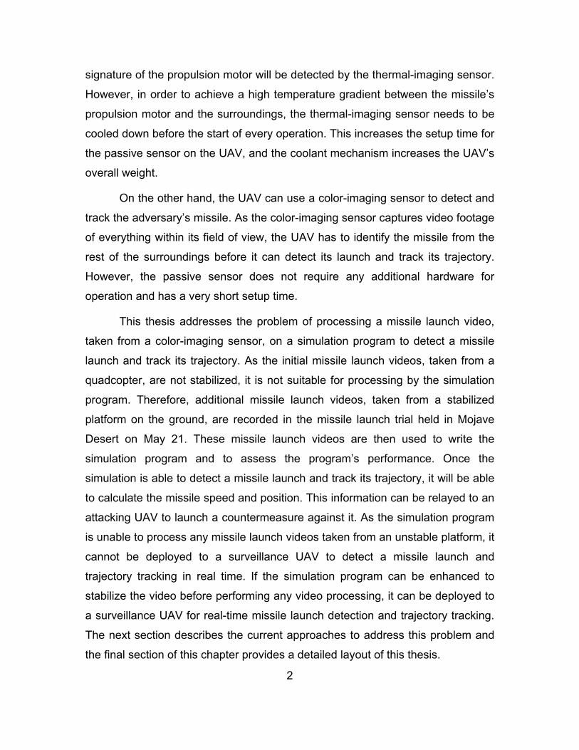
On the other hand, the UAV can use a color-imaging sensor to detect and
track the adversary’s missile. As the color-imaging sensor captures video footage
of everything within its field of view, the UAV has to identify the missile from the
rest of the surroundings before it can detect its launch and track its trajectory.
However, the passive sensor does not require any additional hardware for
operation and has a very short setup time.
This thesis addresses the problem of processing a missile launch video,
taken from a color-imaging sensor, on a simulation program to detect a missile
launch and track its trajectory. As the initial missile launch videos, taken from a
quadcopter, are not stabilized, it is not suitable for processing by the simulation
program. Therefore, additional missile launch videos, taken from a stabilized
platform on the ground, are recorded in the missile launch trial held in Mojave
Desert on May 21. These missile launch videos are then used to write the
simulation program and to assess the program’s performance. Once the
simulation is able to detect a missile launch and track its trajectory, it will be able
to calculate the missile speed and position. This information can be relayed to an
attacking UAV to launch a countermeasure against it. As the simulation program
is unable to process any missile launch videos taken from an unstable platform, it
cannot be deployed to a surveillance UAV to detect a missile launch and
trajectory tracking in real time. If the simulation program can be enhanced to
stabilize the video before performing any video processing, it can be deployed to
a surveillance UAV for real-time missile launch detection and trajectory tracking.
The next section describes the current approaches to address this problem and
the final section of this chapter provides a detailed layout of this thesis.

3
B. PREVIOUS WORK ON MOTION TRACKING AND DETECTION
There are several computer vision methods used to detect and track an
object from video footage. Methods such as background subtraction, Scale-
Invariant Feature Transform (SIFT) and Speeded-Up Robust Feature (SURF)
detection, and Kalman filtering are frequently used for object tracking. These
methods have been applied frequently on video records of sportsman in their
sports event for the coaches to find ways to improve the performance of their
sportsman.
In motion detection and tracking, it is always desired to have the motion of
the object in interest, left in the frame after applying the background subtraction
method on successive frames. However, due to the camera motion during
filming, the surroundings will also move according to the camera motion. This will
cause the surroundings to appear as noise in the frame after applying the
background subtraction method. Therefore, the video image has to be stabilized
before applying background subtraction, to reduce the noise created by the
surroundings movement, so that the object motion can be detected easily by the
simulation program. Lucas and Kanade presented a method to identify features
in two images that could be used as an anchor to stabilize the video footage [4].
Szeliski presented a method [5] that can automatically register video frames into
2D and partial 3D scene models. This method allows common features in
successive images to be identified and stitched together to form a video mosaic.
With the video image stabilized, the targeted object in the video frame
could be identified using descriptors of the unique features of the object. This
could be done using the SIFT method [6] and the SURF method [7]. Rublee et al.
presented an alternative method to SIFT and SURF, which improves on their
performance and efficiency of feature detection [8].
Once the object had been identified in the video image, the motion of the
object could be estimated through the comparison of the object’s location in
successive video frames. Patel used successive frame differencing and pixel

4
variance to track, detect, and validate a moving object in a video sequence [9].
Fleet and Weiss described a variety of mathematical models that could be used
to determine the object’s motion [10].
C. THESIS ORGANIZATION
This thesis consists of four chapters. Chapter I provides a brief
introduction to the purpose of missile detection and tracking and an overview of
previous work on the topic of motion tracking and detection. It also formulates a
problem this thesis tries to address.
Chapter II gives an overview of the method used in a simulation program
to detect missile launch and track its trajectory. A detailed breakdown of the
methods used and the lessons learnt are discussed in this chapter.
Chapter III discusses the test results of the simulation program on several
missile launch videos. The performance of the simulation program is presented in
this chapter.
Chapter IV discusses the methods to perform pose estimation of the
missile and compares the estimates from the simulation program with an actual
firing.
Chapter V discusses the feasibility of using the simulation program to
detect a missile launch and tracks its trajectory. This chapter also recommends
future work that could expand on this study.
The Python code for the simulation program and the summarized results
of all the tested missile launch videos are given in Appendix A and Appendix B,
respectively.
5
II. ALGORITHMS FOR MISSILE LAUNCH DETECTION AND TRAJECTORY TRACKING
This chapter addresses the video stabilization issues encountered in
processing the unstable video footage taken from a quadcopter in previous
rocket launch and describes the new experimental setup that is used to capture
the rocket launch videos. From the rocket launch videos, the algorithms of the
simulation program are written based on the characteristics of the missile
launches during the trial. Subsequently, the chapter will describe the essence of
the simulation program written in Python using open-sourced libraries from
Opencv that are commonly used for video processing.
The simulation program is split into two main sections, namely a missile
launch detection phase and a missile trajectory tracking phase. The simulation
program first breaks down the videos into individual frames and converts them to
grayscale. The frames have fewer variables to process in grayscale than in Red-
Green-Blue (RGB) color format. Once the frames have been processed for each
phase, the results are back projected to the frames in RGB format and saved as
color video footage. The following sections address the problem of video
stabilization and describe the simulation program algorithm.
A. VIDEO STABILIZATION
Two rocket launch videos (each taken from a different perspective by a
quadcopter) were initially used to write the simulation program. Sample frames
are shown in Figure 1. Due to the stability of the quadcopter during flight, the
video footage of the rocket launches was not very stable. This posed a great
challenge in detecting the rocket launch and tracking its trajectory using the video
processing tools available.

6
Figure 1. Images of Missile Launch from Two Different Angles
In the most common video processing for motion, the background
subtraction method is used to sieve out any objects that are moving in the video.
It subtracts the intensity of two video frames and creates a new frame, in
grayscale, to show the objects that were moving between the frames. As shown
in Figure 2, the background subtraction method detects the rocket launch and
also the surrounding features due to the motion of the quadcopter during the
recording. The video processing tools in Opencv cannot stabilize the video
footage enough for the simulation program to perform its task.
Figure 2. Images of Missile Launch after Background Subtraction
Therefore, we stabilize the videos using external video processing
software, and the results are shown in Figure 3.

7
Figure 3. Background Subtraction Images after Video Stabilization
The results of the background subtraction images after video stabilization
are good for launch detection and trajectory tracking. However, as the motion of
the video footage is too pronounced, the stabilization results are not consistent in
all the video frames. Some of the frames still have the surrounding features
captured by the background subtraction method. This causes the simulation
program to falsely detect a missile launch and also mistake a patch of grass as a
missile in flight. Therefore, the two missile launch videos taken from a
quadcopter are not suitable for use by the simulation program.
To simplify the problem of detecting a missile launch and tracking its
trajectory, another series of missile launch videos is taken from a camera
mounted onto a tripod on the ground so that there are no issues of video
stabilization.
B. EXPERIMENTAL SETUP
The missile launch trials are held in the Mojave Desert on May 21, 2016. A
total of six missile launch videos is recorded using a Canon 650D during the trial.
The camera is capable of recording videos in 1080p (1920 x 1080 pixels) with a
frame rate of 25 frames per second. The range of the camera to the missile
launch site is not measured during the trial as the main objective is to record
missile launch videos to be used as test videos for creating the simulation
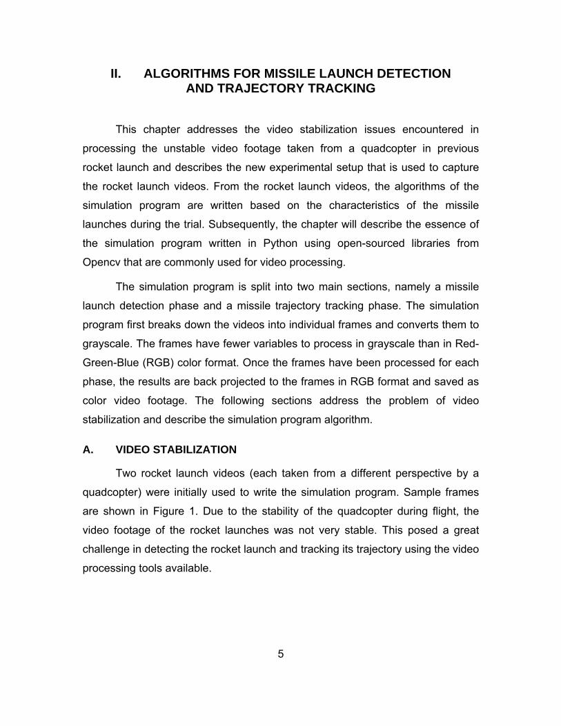
program. The experimental setup is shown in Figure 4.
8
Figure 4. Experimental Setup of the Missile Launch
C. SIMULATION PROGRAM ALGORITHM
As mentioned earlier, the simulation program has two main phases,
namely the missile launch detection phase and the missile trajectory tracking
phase. When a missile launch has been detected in the first phase, the program
transitions to the missile trajectory tracking phase and attempts to track the
missile’s trajectory. In this phase, the program first locates the missile in each
frame and tracks its position as the missile moves across the camera’s field of
view. The simulation program marks the missile location with a red circle on each
of the video frames to indicate a successful track and outputs it to the missile
video. An overview of the simulation program algorithm is shown in Figure 5.

9
Figure 5. Overview of the Simulation Program Algorithm
1. Missile Launch Detection Phase
When the missile is launched from the launch pad, smoke plumes are
generated by the rocket motor to provide the thrust needed to propel the
missile. Therefore, the smoke plume is a good indication that a missile has
been launched. Through the detection of smoke plumes of a certain size in
each frame, the simulation program can identify a missile launch. As different
missiles produce different sized smoke plumes during launch (Figure 6), the size
of the smoke plume that can be used for missile launch declaration, have to
be optimized.
Figure 6. Missile Launches and the Corresponding Background Subtraction Frames
10
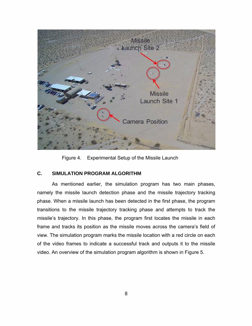
The simulation program determines the size of the smoke plume by
calculating the area of the white “blob” in the frame. When the program detects a
smoke plume with the required size, a missile launch flag is triggered and the
program declares a missile launch.
Figure 7. Missile Launch Detected by the Simulation Program
For missiles with minimal smoke plumes, the simulation program can still
detect the smoke plumes by setting the threshold to a very low value. However,
this may cause the simulation program to falsely declare multiple missile
launches for missiles with huge smoke plumes. This is because some missiles
eject a lot of smoke before liftoff from the launchpad. This will create a problem
for the missile trajectory-tracking phase of the program, as it will not be able to
differentiate the missile from the smoke plume or the launch rail. Due to the huge
differences in the smoke plume size for different missiles, the threshold level is
set at an optimal level where most of the missile launch videos will have a
positive missile launch declared. On the other hand, the simulation program
will not be able to detect a missile launch for those missiles with minimal
smoke plumes.
2. Missile Trajectory-Tracking Phase
The missile trajectory-tracking phase starts only when a missile launch
flag is triggered by the missile launch detection phase. To track the missile’s
trajectory, the simulation program has to detect the position of the missile in each
frame. In this case, the background subtraction method is again used to sieve out

11
the missile moving between each frame. However, the missile location in each
frame is not prominent due to the smoke plume at the trailing end of the missile.
As the smoke plume is ejecting out of the rocket motor, the background
subtraction method detects it as a moving object (Figure 7), causing it to mask
the actual missile location. Since the missile location cannot be easily identified
from the background subtraction frame, the missile location can still be found by
identifying the missile nose tip using the ORB (Oriented FAST and Rotated
BRIEF) method.
Figure 8. Missile Position Cannot Be Identified after the Background Subtraction Method
a. Oriented FAST and Rotated BRIEF Method for Determining Missile Location
As the missile is always located at the tip of the white blob in each frame,
the simulation program can determine the missile’s location by detecting the
leading edge of the white blob using the ORB (Oriented FAST and Rotated
BRIEF) method.
The ORB method can detect the leading edge of the white blob, which will
in turn determine the missile’s nose tip. First, using the method, the algorithm
looks for unique features in the “training” and “query” frames1 and determines the
1 The “training” frame is usually the immediate frame, or several frames, before the “query”
frame. “Training” frames are used as a template for comparison with the “query” frame.

12
descriptors for each feature in both frames (Figure 9). Thereafter, it compares the
feature descriptors of both frames and matches them (Figure 10).
Figure 9. Unique Features detected by the ORB Method on the “Training” Frame (left) and the “Query” Frame (right)
Figure 10. Matching of the Features in the “Training” and “Query” Frames by the ORB Method
Although the ORB method can determine the missile’s position, it cannot
reliably track the missile’s trajectory throughout its flight. This shortcoming arises
because the ORB method cannot consistently match the missile nose tip in each
frame. As previously described, the ORB method assigns descriptors to
determine the missile nose tip, but it may also assign similar descriptors to the
smoke plumes that are moving underneath the missile and match them with the
missile nose tip. To circumvent this problem, the ORB method must ignore the
features detected on the smoke plume and only allow features that are found to
be in the same direction of the missile flight. The latter can be used as a match
with the missile nose tip in the “training” frame.
The missile flight direction is found by using the coordinates of the first
matching missile nose tip in the “training” and “query” frames. With the missile

13
flight direction found, a search area can be defined in the “query” frame using the
position of the missile nose tip, which is found in the “training” frame as the
starting point of the search area, as shown in Figure 11.
Figure 11. Features Search Area Superimposed on the “Training” and “Query” Frames
If the coordinates of the features found are not in the search area, the
simulation program will not include them in the list of features to be used for
matching with the “training” frame. In this way, the ORB method would not match
the missile nose tip with the smoke plume underneath.
b. Factors Affecting Correct Matching by ORB Method
The method described in the previous section hinges on the first
successful match of the missile nose tip in the “training” and “query” frames.
Therefore, the first match is very critical in determining the success of the
program’s ability to track the missile. To have a good first match, as explained in
more detail in the following subsection, the timing to start the missile trajectory-
tracking phase is very important. If a missile launch is declared and the missile
has not left the launching rail, the missile trajectory-tracking algorithm will not be
able to locate the missile, and as result, the program will create an erroneous
match. An erroneous match can also occur if the features found on the smoke
plume are similar to those found for the missile nose tip of the “training” frame,
14
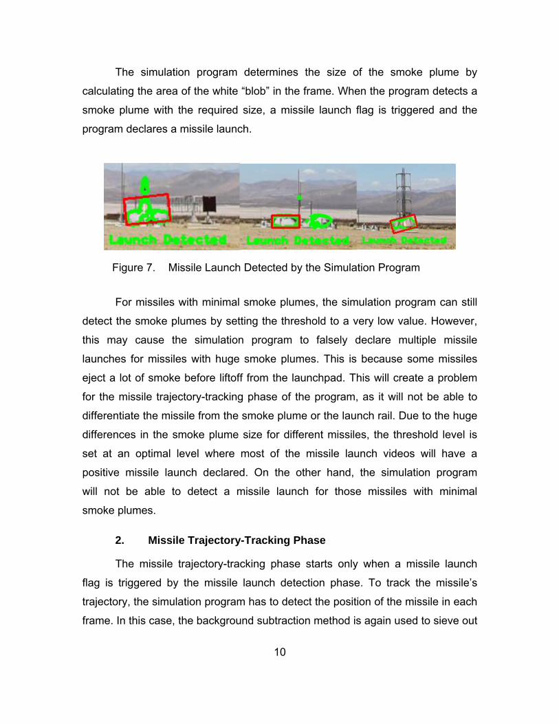
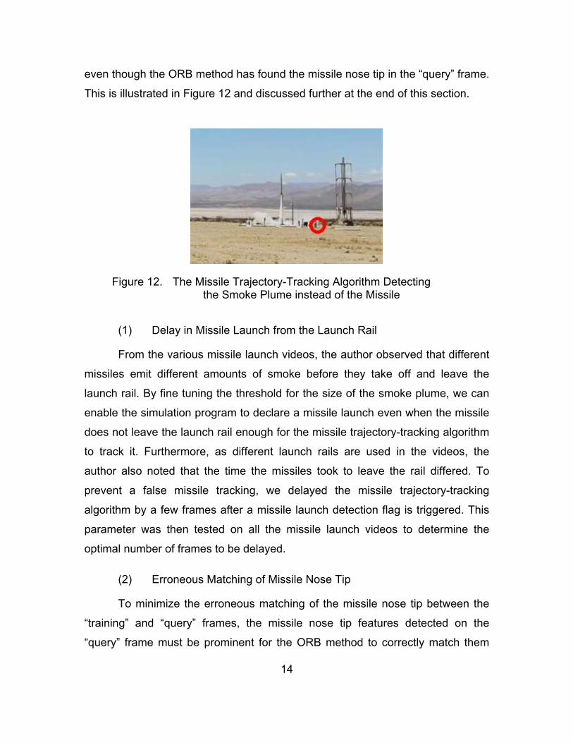
even though the ORB method has found the missile nose tip in the “query” frame.
This is illustrated in Figure 12 and discussed further at the end of this section.
Figure 12. The Missile Trajectory-Tracking Algorithm Detecting the Smoke Plume instead of the Missile
(1) Delay in Missile Launch from the Launch Rail
From the various missile launch videos, the author observed that different
missiles emit different amounts of smoke before they take off and leave the
launch rail. By fine tuning the threshold for the size of the smoke plume, we can
enable the simulation program to declare a missile launch even when the missile
does not leave the launch rail enough for the missile trajectory-tracking algorithm
to track it. Furthermore, as different launch rails are used in the videos, the
author also noted that the time the missiles took to leave the rail differed. To
prevent a false missile tracking, we delayed the missile trajectory-tracking
algorithm by a few frames after a missile launch detection flag is triggered. This
parameter was then tested on all the missile launch videos to determine the
optimal number of frames to be delayed.
(2) Erroneous Matching of Missile Nose Tip
To minimize the erroneous matching of the missile nose tip between the
“training” and “query” frames, the missile nose tip features detected on the
“query” frame must be prominent for the ORB method to correctly match them

15
with the corresponding features on the “training” frame. In most of the test cases,
when the missile launch detection algorithm declared a missile launch, the ORB
method could not correctly match the missile nose tip when the “query” frame
was immediately after the “training” frame. This can be due to the insufficient
displacement of the missile position between the two frames. To solve this
problem, the “query” frame has to be several frames after the “training” frame to
allow a good displacement of the missile location between the frames. This
parameter was tested on all the missile launch videos to determine the optimal
number of frames to be skipped.
Once the simulation program could detect the missile launch and track its
trajectory properly, the program was tested with more missile launch videos to
determine its performance. These test results are presented in the next chapter.

16
THIS PAGE INTENTIONALLY LEFT BLANK

17
III. ALGORITHMS VERIFICATION
Six missile launch videos were available with which to test and verify the
performance of the simulation program. As each missile launches differently in
the videos, the simulation program was trained with one video and then tested
with the other videos to tune the performance of the simulation program. In this
way, the performance of the simulation program was optimized for all the missile
launch videos.
A. EFFECTS OF CAMERA ORIENTATION
From the logic of the missile trajectory-tracking algorithm, the simulation
program is capable of tracking the missile trajectory in all directions. As the
missiles were launched from the ground up in all the videos, these videos did not
provide any opportunity to test the algorithm against different perspectives on the
missile launch direction. Therefore, the missile launch videos are rotated using
external video editing software (iMovie) and then tested on the simulation
program. A total of three additional missile launch videos were created in this
process to simulate the missile launch from top to bottom, left to right, and right
to left directions in the video frames.
From Figures 13 and 14, it can be seen that the simulation program is
capable of tracking the missile trajectory in the horizontal and vertical directions.
Therefore, this test proved that the simulation program is able to track a missile
launch in any direction.
18
Figure 13. Testing of the Simulation Program for Missile Launch in Horizontal Direction
Figure 14. Testing of the Simulation Program for Missile Launch in Vertical Direction
B. ALGORITHM INITIATION TUNING
As mentioned in the previous chapter, there are two parameters in the
simulation program that need to be optimized to improve the performance of the
simulation program. They are: 1) the number of frames to be delayed after the
missile launch flag has been triggered, and 2) the number of frames to skip after
the “training” frame to select the “query” frame. In this optimization test, a total of
nine missile launch videos are used, including the additional three missile launch
videos mentioned in the previous section.

19
The optimization tests are done by running all the videos through the
simulation program and evaluating the performance of the program on individual
frames in each video. The evaluation criteria for each frame are categorized as
follows:
True Positive: The simulation program correctly identifies the missile location in the frame.
False Alarm (False Positive): The simulation program wrongly identifies another object as the missile location in the frame.
False Negative: The simulation program does not identify the missile location in the frame when the missile is in flight.
Once all the frames have been evaluated, the total number of frames for
each category is tallied to calculate the average percentage of true positives and
false alarms. This determines the performance of the simulation program for
each combination of the two parameters.
As there are two parameters to be optimized, one of the parameters has
to be fixed while the other parameter is iterated. For the first optimization test, the
number of frames to be delayed after missile launch flag triggered is set at four
frames, while the number of frames to be skipped after the “Training” frame is
iterated from one to ten frames. In the second optimization test, the optimal
number of frames to be skipped, found in the first test, is used while iterating the
number of frames to be delayed after missile launch, from one to ten frames.
1. Number of Frames to Skip after the “Training” Frame
The results of the first optimization test are summarized in Table 1 and
plotted in Figure 14.

20
Table 1. Test Results of the First Optimization Test
Number of frames to skip (9 videos)
1 2 3 4 5 6 7 8 9 10
Average % of true positive tracking
40.96 49.40 47.30 47.08 42.33 40.61 35.36 35.92 39.06 40.88
Average % of false alarm
59.04 50.60 52.70 52.92 57.67 59.39 64.64 64.08 60.94 59.12
The number by each marker represents the number of frames that were skipped.
Figure 15. Outcome of the First Optimization Test
From Figure 15, it follows that the optimal number of frames to be skipped
is two frames. This is because the simulation program has the highest true
positive percentage2 at 49.4 percent and the lowest false alarm rate at 50.6
percent.
2 The percentage calculation is based on the total number of frames for all nine tested
videos.
10
9
87
6
5
4 3
Skip 2 frames50.60%, 49.40%
1
30.00%
35.00%
40.00%
45.00%
50.00%
55.00%
50.00% 52.00% 54.00% 56.00% 58.00% 60.00% 62.00% 64.00% 66.00% 68.00% 70.00%Percentage of Positive M
issile Tracking
Percentage of False Alarm

21
If the two missile launch videos with minimal smoke plume are excluded
from the test, the test results have an improvement of about 10 percent in both
the true positive percentage and false alarm rate. The newly tabulated test
results are summarized in Table 2.
Table 2. Test Results of the First Optimization Test without Minimal Smoke Plume Missile Launch Videos
Number of frames to skip (7 videos)
1 2 3 4 5 6 7 8 9 10
Average % of true positive tracking
50.10 59.14 58.36 58.09 49.90 49.87 40.69 46.18 48.63 52.56
Average % of false alarm
49.90 40.86 41.64 41.91 50.10 50.13 59.31 53.82 51.37 47.44
From Table 2, the optimal number of frames to skip is still at two frames
even though the missile launch videos with minimal smoke plume are excluded
from the tabulation. This shows that the missile launch videos with minimal
smoke plumes do not have any impact on the optimization test.
2. Number of Frames Delayed after Missile Launch Flag Triggered
From the first test results, the optimized number of frames to be skipped
from the ‘training’ frame is used in the second test to find the optimized number
of frames to be delayed. The results are summarized in Table 3 and plotted in
Figure 15.
Table 3. Test Results of the Second Optimization Test
Number of frames delayed (9 videos)
1 2 3 4 5 6 7 8 9 10
Average % of true positive tracking
30.90 35.41 40.96 47.08 47.51 48.22 42.33 39.93 35.36 36.07
Average % of false alarm
69.10 64.59 59.04 52.92 52.49 51.78 57.67 60.07 64.64 63.93

22
The number by each marker represents the number of frames that were delayed.
Figure 16. Visualization of the Second Optimization Test Results
The second optimization test results show that when the simulation
program starts tracking the missile at the sixth frame after the missile launch flag
was triggered, it would have the highest true positive percentage at 48.22
percent and the lowest false alarm rate at 51.78 percent.
When the two missile launch videos with minimal smoke plume are
excluded from the test, the test results have an improvement of about 3 percent
to 10 percent in both the true positive percentage and false alarm rate. The newly
tabulated test results are shown in Table 4.
Table 4. Test Results of the Second Optimization Test without Minimal Smoke Plume Missile Launch Videos.
Number of frames delayed (7 Videos)
1 2 3 4 5 6 7 8 9 10
Average % of true positive tracking
33.87 40.44 50.10 58.09 58.64 57.52 49.90 48.98 40.69 46.18
Average % of false alarm
66.13 59.56 49.90 41.91 41.36 42.48 50.10 51.02 59.31 53.82
10
9
8
7
Delay Track by 6 Frameafter Missile Detection
51.78%, 48.22%
5 4
3
2
1
30.00%
35.00%
40.00%
45.00%
50.00%
55.00%
50.00% 52.00% 54.00% 56.00% 58.00% 60.00% 62.00% 64.00% 66.00% 68.00% 70.00%
Percentage of Positive M
issile
Tracking
Percentage of False Alarm

23
The optimal number of frames to be delayed after the missile launch flag
triggered has changed from the sixth frame to the fifth frame. By comparing the
results of the optimal frames in Tables 3 and 4, we find a 10 percent
improvement in both the true positive tracking percentage and false alarm rate.
This shows that the missile videos with minimal smoke plumes have a significant
influence on this parameter. The performance of the simulation program is
improved from a percentage of 48.22 percent in true positive tracking and 51.78
percent false alarm rate, to 58.64 percent in true positive tracking and 41.36
percent in false alarm rate.

24
THIS PAGE INTENTIONALLY LEFT BLANK

25
IV. POSITION ESTIMATION
A. MISSILE SPEED
As mentioned previously, military operations are making increased use of
UAVs, and the purpose of this thesis is to explore the feasibility of their use to
patrol a potential ICBM launch area. The onboard camera of such a UAV has the
capability to record the tilt and pan of a gimbal, which, along with inertial
measurement unit/ global positioning system (IMU/GPS) information, allows
calculating a missile’s geographic position. Figure 17 represents a general
geometry of tracking a missile launch by a UAV.
Figure 17. Observing a Missile Launch from UAV
In the experiment that took place in Mojave Desert, there was no tilt/pan
information (the stationary ground camera was used) and the camera’s position
data was not available either. Hence, only a limited analysis on the missile could
be carried over. Figure 18 represents the geometry in this case.

26
Figure 18. Detecting a Missile Launch using the Pinhole Camera Model
Using the pinhole camera model, the size of a rocket in the image frame,
lp via its physical size, L , can be expressed as
lp f
RL
1
kL (1)
In Equation (1), R is the (unknown) range to the missile launch site and f
is the (unknown) focal point of the camera. With the values L and lp known
before the launch, the coefficient k can be estimated as
k
L
lp [m/pixel] (2)
Therefore, the rocket speed, v, can be estimated using the camera frame
rate, , and the number of pixels the rocket has moved between the two
consecutive frames, dp , as
v kdp [m/s] (3)
Figure 18 shows how the estimated rocket speed calculated from the
simulation program is displayed in the video.

27
Figure 19. Rocket Speed Calculation
Figure 19 provides a comparison of the rocket speed calculated by the
simulation program and the actual speed recorded using the accelerometer and
barometric altimeter carried onboard the rocket. The errors in the speed values
are due to the simulation program limited accuracy in detecting the rocket
position. The simulation program cannot accurately detect the same spot on the
moving rocket in each frame.
Figure 20. Rocket Speed Time History

28
The aforementioned method of calculating the rocket speed could be
enhanced by accounting for the elevation angle α (see Figure 17). In this case,
Equation (3) becomes
v kdpcos
[m/s] (4)
where tan1 H
R
. While the rocket altitude, H , could be estimated as
H vdt0
t
(5)
(and verified using onboard sensor data), the range from the camera focal point
to the missile launch site was not measured. In addition, Equation (4) does not
account for the rocket orientation, which might be slightly different from a straight
vertical.
Another set of field experiments to gather more data and conduct an
advanced analysis was scheduled in mid-August, but it was postponed. Hence,
the results based on those additional trials did not make it into this thesis.
B. MISSILE ORIENTATION
Using two consecutive frames of a stationary camera, a launch plane
orientation (with respect to the camera coordinate frame) can also be determined
as
tan1 y2 y1
x2 x1
(6)
where refers to the coordinates of the missile nose tip in the first frame
and refers to the coordinates of the missile nose tip in the second frame.
The deflection angle (from the vertical), computed using Equation (6), by
the simulation program is shown in Figure 20.
x1, y1 x2 , y2

29
Figure 21. Time History of Missile Deflection Angle
The error bars shown in Figure 20 are estimated based on the rocket
speed and the fact that x- and y-coordinates of the rocket nose tip are only
accurate to about 1 pixel. These outliers are probably related to the fact that the
camera was mounted on a tripod relatively close to the launch position, causing it
to vibrate during the launch.
If a missile launch is observed by two UAVs, using the plane angle
would result in an estimate of the missile altitude, which would in turn result in a
further correction of Equation (4).
C. SUMMARY
Based on the results of the calculated missile speed by the simulation
program, the program showed that it is capable of estimating the missile speed
using the missile position captured in each frame. The simulation program is also
able to calculate the missile deflection angle from the vertical. However, it will
only be useful when the missile deflection angle is calculated by two UAVs
separated by at least 90 degrees in azimuth from the missile launch site. In this
way, the missile altitude can be triangulated using the plane angles from each
UAV.

30
THIS PAGE INTENTIONALLY LEFT BLANK

31
V. CONCLUSION AND FUTURE RESEARCH
A. CONCLUSION
The simulation program was able to detect a missile launch and track its
trajectory in the video’s field of view. Although it could only achieve a true
positive tracking percentage of 58.46 percent, the update rate of the missile
position by the simulation program was sufficient for a weapon system to
intercept it reliably. This means that for a missile launch video with 25 frames per
second, the simulation program was able to provide about 14 updates on the
missile position per second.
On the other hand, the simulation program is unable to process any
missile launch videos that are not stabilized and is also unable to detect a missile
launch of a missile with a minimal smoke plume. In its current state, the
simulation program cannot process the surveillance videos from the CUAV to
achieve its objective of providing targeting information for an attacking UAV to
reliably intercept it. However, if the surveillance video can be stabilized before
processed by the simulation program, it can be installed on a surveillance UAV to
detect a missile launch threat and provide targeting information to an attacking
UAV to reliably intercept the missile.
B. FURTHER STUDIES
The simulation program can be enhanced to improve the missile trajectory
tracking methods and determine the 3D location of the missile. This information
will enhance the accuracy of the targeting information that will be fed to the
attacking UAV for intercepting the missile. Further work can also be done to
stabilize the video in real time before processing the missile launch video using
the simulation program. This will allow real-time surveillance by the UAV at the
missile launch site.
32
1. Determine Missile Location in 3D Space
The calculation of the missile speed and orientation by the current
simulation program is only accurate if the missile down range of the video
camera remains constant, which will not be possible in real life. To determine the
actual 3D location of the missile, future research should use multiple cameras
with known distances and bearing from each other, to enable the calculation of
the missile location using the triangulation method [11]. By using the missile
trajectory-tracking algorithm in this simulation program, the researcher can write
a program to process the missile launch videos from multiple cameras and
determine a missile’s location in 3D space.
2. Object Motion Tracking
The background subtraction method used in this simulation program is
unable to identify the missile position in each frame due to the smoke plume
created by the missile rocket motor. In addition, the missile launch algorithm of
the simulation program is also unable to detect the launch of a missile with a
minimal smoke plume.
Instead of using the background subtraction method to track object
motion, researchers can consider the optical flow technique. Optical flow [12]
performs estimation of the motion in each individual pixel of the frame by
calculating the motion of each pixel. Once the motion of each pixel has been
calculated, the mean shift method can be used to cluster the pixels with similar
motion descriptions together to identify the missile’s location in each frame.
3. Video Stabilization
To perform detection of a missile launch and trajectory tracking from a
single or multiple CUAVs, the researcher must ensure the video footage from the
CUAV is stabilized before any video processing can be done. Matsushita et al.
recommended a methodology to stabilize a video with minimal impact to the size
of the video frames [13]. This methodology can be applied to stabilize the missile

33
launch video and subsequently feed it into the simulation program for missile
launch detection and trajectory tracking. In this way, the videos taken from the
CUAV(s) can be used to perform a surveillance mission and track a launched
missile so that an attacking UAV can intercept it.

34
THIS PAGE INTENTIONALLY LEFT BLANK

35
APPENDIX A. SIMULATION PROGRAM PYTHON CODE
The Python code provided here detects the missile launch from a video
and tracks the missile’s trajectory within the video’s field of view. When a missile
launch is detected by the simulation program, a “Missile Launch Detected”
indicator appears in the top left corner of the video. The speed and orientation of
the missile launch are indicated in the same corner. A green indicator flashes on
the video to indicate a missile launch detected from the missile smoke plume. If
the simulation program also detects the missile’s location, a red circle shows up
in the video to indicate that location. Finally, the simulation program overlays all
indicators mentioned previously on the existing missile launch video and outputs
it as a video file saved on the hard disk.
import sys sys.path.append('/Applications/OpenCV3/build/lib/python3') import cv2 import numpy as np import matplotlib.pyplot as plt import math cv2.ocl.setUseOpenCL(False) # Loading a missile launch video cap = cv2.VideoCapture('ML-Side1.mov') framecount = 1 #Initialise the background subtraction technique bgs = cv2.createBackgroundSubtractorMOG2() #Retrieve the video properties fps = cap.get(cv2.CAP_PROP_FPS) width = cap.get(cv2.CAP_PROP_FRAME_WIDTH) height = cap.get(cv2.CAP_PROP_FRAME_HEIGHT) count = cap.get(cv2.CAP_PROP_FRAME_COUNT) outsize = (int(width), int(height)) TFrame = cap.get(7) #Initialise the parameters to output a video

36
fourcc = cv2.VideoWriter_fourcc(*'XVID') out = cv2.VideoWriter('ML1 Final.avi', fourcc, fps, outsize, isColor=True) a = 0 b = 0 Ang1 = 0 flag=1 delay=0 detection =0 firstorb = 0 FSkip = 1000000 MLcount = 100000 deFlag = 0 LText = 1 Repeat = 0 MxVel = [] #Initialise count for performance verification Positive = 0 FPositive = 0 DCount = 0 while True and framecount <= TFrame: ret, frame = cap.read() Detect = frame.copy() print('\n\nFrame count = ',framecount) if frame is None : print('\nFrame is empty!!!!') break #Perform Gaussian Blur to the frame before background subtraction gframe = cv2.GaussianBlur(frame, (15, 15), 0) fgmask = bgs.apply(gframe) ret,thresh = cv2.threshold(fgmask,125,255,cv2.THRESH_BINARY) if framecount ==2: M1 = thresh.copy() M2 = thresh.copy() if framecount >2: im2, contours, hierarchy = cv2.findContours(thresh,cv2.RETR_LIST,cv2.CHAIN_APPROX_SIMPLE) moments = [cv2.moments(x) for x in contours]
37
#Calculation of the missile smoke plume size for missile launch detection for c in contours: area = cv2.contourArea(c) #print('Area is ', area, '\n') if(area>500) and deFlag == 0: detection=1 print('Launch Detected!!!!') MLcount = framecount + 6 cv2.drawContours(Detect, c, -1, (0,255,0), 3) deFlag = 1 #Creation of the Missile Launch indicator text if detection == 1: font = cv2.FONT_HERSHEY_SIMPLEX LText +=1 if LText %2 == 0: cv2.putText(Detect,'Missile Launch Detected',(100,100), font, 1,(50,50,255),3,cv2.LINE_AA) print('Checking flag = ', framecount >= MLcount) #Feature Matching Algorithm if framecount >= MLcount: orb = cv2.ORB_create(nfeatures=200) kps1 = orb.detect(M1, None) kps1, descriptors1 = orb.compute(M1, kps1) if len(kps1)!= 0 and framecount <= FSkip: if firstorb == 0: #Number of frame to skip after the "Training" frame FSkip = framecount + 2 firstorb = 1 else: DCount += 1 kps2 = orb.detect(M2, None) kps2, descriptors2 = orb.compute(M2, kps2) bf = cv2.BFMatcher(cv2.NORM_HAMMING, crossCheck=True) if len(kps2) != 0: matches = bf.match(descriptors1, descriptors2) matchesy = sorted(matches, key = lambda y:y.distance) print("Found {} matching feature pairs.".format(len(matches))) Best = matchesy[:5]

38
if len(matches) != 0: # Initialize lists of matching fetures SelectTrans = 0 EuclideanDist = [] Px1 = [] Py1 = [] Px2 = [] Py2 = [] AngList = [] i = 0 # For each match... for mat in Best: # Get the matching keypoints for each frame img1_idx = mat.queryIdx img2_idx = mat.trainIdx # x - columns # y - rows # Get the coordinates (x1,y1) = kps1[img1_idx].pt (x2,y2) = kps2[img2_idx].pt Px1.append(x1) Py1.append(y1) Px2.append(x2) Py2.append(y2) DistTrans = math.sqrt(math.pow((x1-x2),2)+math.pow((y1-y2),2)) EuclideanDist.append(DistTrans) #Initial Parameters for the first iteration SEu = np.argmax(EuclideanDist, axis=0) if a == 0 and b == 0: a = Px1[SEu] b = Py1[SEu] #Calculation of the missile orientation Ang = -math.atan2((Py2[SEu]-b),(Px2[SEu]-a)) if Ang1 == 0: Ang1 = Ang

39
#Checking whether the features found are within the search area. if Ang <= (Ang1 + math.radians(35)) and Ang >= (Ang1 - math.radians(35)): #y2 - b < 0: Olda = a Oldb = b a = Px2[SEu] b = Py2[SEu] Ang1 = Ang DistTrans = 0 if b != b1: a = np.int0(a) b = np.int0(b) #Draw a circle on the detected missile location cv2.circle(Detect,(a,b), 10,(0,0,255),3) print('Circle Drawn\n') #Calculate the distance that the missile has travelled between 2 frames if Repeat == 0: MxDist = math.sqrt(math.pow((a-Olda),2)+math.pow((b-Oldb),2)) else: MxDist = math.sqrt(math.pow((Py2[SEu]-Py1[SEu]),2)+math.pow((Px2[SEu]-Px1[SEu]),2)) Repeat = 0 #Calculate the speed of the missile MxSpeed = np.around(((MxDist/22.601)*1.52)*fps, decimals=2) print('\nMissile Speed = ', MxSpeed) #Display of the missile speed and orientation in the output video cv2.putText(Detect,'Missile Speed = %.2f m/s' % MxSpeed,(100,150), font, 1,(50,255,50),2,cv2.LINE_AA) cv2.putText(Detect,'Deflection Angle = %.2f degrees' % np.around(90 - math.degrees(Ang), decimals=2),(100,200), font, 1,(50,255,50),2,cv2.LINE_AA) cv2.putText(Detect,'from the Vertical',(100,250), font, 1,(50,255,50),2,cv2.LINE_AA) MxVel.append(format(MxSpeed, '.2f')) Positive += 1 print('Deflection Angle = ', 90 - math.degrees(Ang)) else:

40
cv2.putText(Detect,'Missile Speed = %.2f m/s' % MxSpeed,(100,150), font, 1,(50,255,50),2,cv2.LINE_AA) cv2.putText(Detect,'Deflection Angle = %.2f degrees' % np.around(90 - math.degrees(Ang1), decimals=2),(100,200), font, 1,(50,255,50),2,cv2.LINE_AA) cv2.putText(Detect,'from the Vertical',(100,250), font, 1,(50,255,50),2,cv2.LINE_AA) Repeat = 1 FPositive += 1 print('\nMissile Speed = ', MxSpeed) print('Deflection Angle = ', 90 - math.degrees(Ang1)) else: print('No matches in kps2') M1 = M2.copy() b1 = b #Output the processed video out.write(Detect) #Display the processed video cv2.imshow('Missile Launch Post processing', Detect) cv2.waitKey(100) if cv2.waitKey(1) & 0xFF == ord ('q'): break framecount += 1 print('\nThe number of postive detection is ', Positive) print('The number of false postive detection is ', FPositive) print('The expected total number of detection is ', DCount) print('The number of frames true negative in the video is ', (framecount - DCount)) print('\nThe camera fps is ', fps) cap.release() cv2.destroyAllWindows()

41
APPENDIX B. TEST RESULTS OF MISSILE LAUNCH VIDEOS
A. OPTIMIZATION TEST RESULT FOR THE NUMBER OF FRAMES TO SKIP AFTER THE “TRAINING” FRAME
Skip Frame = 10 ML1 ML3 ML4 ML6 ML5 ML2-Slow ML1 L-R ML1 R-L ML6 U-D
Positive 7 17 21 9 0 0 8 7 8
False Positive 7 11 10 9 7 66 7 8 9
False Negative 0 0 0 1 1 3 0 0 2
False Alarm 7 11 10 10 8 69 7 8 11
Total 14 28 31 19 8 69 15 15 19
% Positive 50.00% 60.71% 67.74% 47.37% 0.00% 0.00% 53.33% 46.67% 42.11%
% False Alarm 50.00% 39.29% 32.26% 52.63% 100.00% 100.00% 46.67% 53.33% 57.89%
Average % Positive 40.88% Average % Positive w/o ML5 & ML2-Slow 52.56%
Average % False Alarm 59.12% Average % False Alarm w/o ML5 & ML2-Slow 47.44%
Skip Frame = 9 ML1 ML3 ML4 ML6 ML5 ML2-Slow ML1 L-R ML1 R-L ML6 U-D
Positive 8 18 22 10 1 0 9 8 0
False Positive 7 11 10 9 8 68 7 8 19
False Negative 0 0 0 1 0 2 0 0 1
False Alarm 7 11 10 10 8 70 7 8 20
Total 15 29 32 20 9 70 16 16 20
% Positive 53.33% 62.07% 68.75% 50.00% 11.11% 0.00% 56.25% 50.00% 0.00%
% False Alarm 46.67% 37.93% 31.25% 50.00% 88.89% 100.00% 43.75% 50.00% 100.00%
Average % Positive 39.06% Average % Positive w/o ML5 & ML2-Slow 48.63%
Average % False Alarm 60.94% Average % False Alarm w/o ML5 & ML2-Slow 51.37%
Skip Frame = 8 ML1 ML3 ML4 ML6 ML5 ML2-Slow ML1 L-R ML1 R-L ML6 U-D

42
Positive 9 18 0 11 0 0 10 9 9
False Positive 7 11 30 9 9 68 7 8 10
False Negative 0 1 3 1 1 3 0 0 2
False Alarm 7 12 33 10 10 71 7 8 12
Total 16 30 33 21 10 71 17 17 21
% Positive 56.25% 60.00% 0.00% 52.38% 0.00% 0.00% 58.82% 52.94% 42.86%
% False Alarm 43.75% 40.00% 100.00% 47.62% 100.00% 100.00% 41.18% 47.06% 57.14%
Average % Positive 35.92% Average % Positive w/o ML5 & ML2-Slow 46.18%
Average % False Alarm 64.08% Average % False Alarm w/o ML5 & ML2-Slow 53.82%
Skip Frame = 7 ML1 ML3 ML4 ML6 ML5 ML2-Slow ML1 L-R ML1 R-L ML6 U-D
Positive 10 19 22 12 2 11 0 0 10
False Positive 7 12 11 9 9 59 17 17 10
False Negative 0 0 1 1 0 2 1 1 2
False Alarm 7 12 12 10 9 61 18 18 12
Total 17 31 34 22 11 72 18 18 22
% Positive 58.82% 61.29% 64.71% 54.55% 18.18% 15.28% 0.00% 0.00% 45.45%
% False Alarm 41.18% 38.71% 35.29% 45.45% 81.82% 84.72% 100.00% 100.00% 54.55%
Average % Positive 35.36% Average % Positive w/o ML5 & ML2-Slow 40.69%
Average % False Alarm 64.64% Average % False Alarm w/o ML5 & ML2-Slow 59.31%

43
Skip Frame = 6 ML1 ML3 ML4 ML6 ML5 ML2-Slow ML1 L-R ML1 R-L ML6 U-D
Positive 10 19 23 12 0 12 11 2 11
False Positive 7 12 12 9 10 59 8 17 10
False Negative 1 1 0 2 2 2 0 0 2
False Alarm 8 13 12 11 12 61 8 17 12
Total 18 32 35 23 12 73 19 19 23
% Positive 55.56% 59.38% 65.71% 52.17% 0.00% 16.44% 57.89% 10.53% 47.83%
% False Alarm 44.44% 40.63% 34.29% 47.83% 100.00% 83.56% 42.11% 89.47% 52.17%
Average % Positive 40.61% Average % Positive w/o ML5 & ML2-Slow 49.87%
Average % False Alarm 59.39% Average % False Alarm w/o ML5 & ML2-Slow 50.13%
Skip Frame = 5 ML1 ML3 ML4 ML6 ML5 ML2-Slow ML1 L-R ML1 R-L ML6 U-D
Positive 11 20 24 13 2 12 12 10 0
False Positive 8 13 12 9 10 60 8 10 23
False Negative 0 0 0 2 1 2 0 0 1
False Alarm 8 13 12 11 11 62 8 10 24
Total 19 33 36 24 13 74 20 20 24
% Positive 57.89% 60.61% 66.67% 54.17% 15.38% 16.22% 60.00% 50.00% 0.00%
% False Alarm 42.11% 39.39% 33.33% 45.83% 84.62% 83.78% 40.00% 50.00% 100.00%
Average % Positive 42.33% Average % Positive w/o ML5 & ML2-Slow 49.90%
Average % False Alarm 57.67% Average % False Alarm w/o ML5 & ML2-Slow 50.10%

44
Skip Frame = 4 ML1 ML3 ML4 ML6 ML5 ML2-Slow ML1 L-R ML1 R-L ML6 U-D
Positive 12 22 26 14 0 13 14 12 12
False Positive 9 13 12 9 13 61 8 10 11
False Negative 0 0 0 3 2 2 0 0 3
False Alarm 9 13 12 12 15 63 8 10 14
Total 21 35 38 26 15 76 22 22 26
% Positive 57.14% 62.86% 68.42% 53.85% 0.00% 17.11% 63.64% 54.55% 46.15%
% False Alarm 42.86% 37.14% 31.58% 46.15% 100.00% 82.89% 36.36% 45.45% 53.85%
Average % Positive 47.08% Average % Positive w/o ML5 & ML2-Slow 58.09%
Average % False Alarm 52.92% Average % False Alarm w/o ML5 & ML2-Slow 41.91%
Skip Frame = 3 ML1 ML3 ML4 ML6 ML5 ML2-Slow ML1 L-R ML1 R-L ML6 U-D
Positive 13 22 26 15 0 13 14 12 11
False Positive 9 13 12 9 13 61 8 10 11
False Negative 0 0 0 2 2 2 0 0 4
False Alarm 9 13 12 11 15 63 8 10 15
Total 22 35 38 26 15 76 22 22 26
% Positive 59.09% 62.86% 68.42% 57.69% 0.00% 17.11% 63.64% 54.55% 42.31%
% False Alarm 40.91% 37.14% 31.58% 42.31% 100.00% 82.89% 36.36% 45.45% 57.69%
Average % Positive 47.30% Average % Positive w/o ML5 & ML2-Slow 58.36%
Average % False Alarm 52.70% Average % False Alarm w/o ML5 & ML2-Slow 41.64%

45
Skip Frame = 2 ML1 ML3 ML4 ML6 ML5 ML2-Slow ML1 L-R ML1 R-L ML6 U-D
Positive 13 23 27 15 2 14 15 13 12
False Positive 9 13 12 9 11 61 8 10 11
False Negative 0 0 0 3 3 2 0 0 4
False Alarm 9 13 12 12 14 63 8 10 15
Total 22 36 39 27 16 77 23 23 27
% Positive 59.09% 63.89% 69.23% 55.56% 12.50% 18.18% 65.22% 56.52% 44.44%
% False Alarm 40.91% 36.11% 30.77% 44.44% 87.50% 81.82% 34.78% 43.48% 55.56%
Average % Positive 49.40% Average % Positive w/o ML5 & ML2-Slow 59.14%
Average % False Alarm 50.60% Average % False Alarm w/o ML5 & ML2-Slow 40.86%
Skip Frame = 1 ML1 ML3 ML4 ML6 ML5 ML2-Slow ML1 L-R ML1 R-L ML6 U-D
Positive 14 24 0 15 0 14 16 14 13
False Positive 9 13 37 9 16 62 8 10 11
False Negative 0 0 3 4 1 2 0 0 4
False Alarm 9 13 40 13 17 64 8 10 15
Total 23 37 40 28 17 78 24 24 28
% Positive 60.87% 64.86% 0.00% 53.57% 0.00% 17.95% 66.67% 58.33% 46.43%
% False Alarm 39.13% 35.14% 100.00% 46.43% 100.00% 82.05% 33.33% 41.67% 53.57%
Average % Positive 40.96% Average % Positive w/o ML5 & ML2-Slow 50.10%
Average % False Alarm 59.04% Average % False Alarm w/o ML5 & ML2-Slow 49.90%

46
B. OPTIMIZATION TEST RESULT FOR THE NUMBER OF FRAMES TO DELAY AFTER MISSILE LAUNCH
Start Track = 10 ML1 ML3 ML4 ML6 ML5 ML2-Slow ML1 L-R ML1 R-L ML6 U-D
Positive 9 18 0 11 0 1 10 9 9
False Positive 7 11 30 9 9 68 7 8 10
False Negative 0 1 3 1 1 2 0 0 2
False Alarm 7 12 33 10 10 70 7 8 12
Total 16 30 33 21 10 71 17 17 21
% Positive 56.25% 60.00% 0.00% 52.38% 0.00% 1.41% 58.82% 52.94% 42.86%
% False Alarm 43.75% 40.00% 100.00% 47.62% 100.00% 98.59% 41.18% 47.06% 57.14%
% False Positive 43.75% 36.67% 90.91% 42.86% 90.00% 95.77% 41.18% 47.06% 47.62%
Average % Positive 36.07% Average % Positive w/o ML5 & ML2-Slow 46.18%
Average % False Alarm 63.93% Average % False Alarm w/o ML5 & ML2-Slow 53.82%
Start Track = 9 ML1 ML3 ML4 ML6 ML5 ML2-Slow ML1 L-R ML1 R-L ML6 U-D
Positive 10 19 22 12 2 11 0 0 10
False Positive 7 12 11 9 9 59 17 17 10
False Negative 0 0 1 1 0 2 1 1 2
False Alarm 7 12 12 10 9 61 18 18 12
Total 17 31 34 22 11 72 18 18 22
% Positive 58.82% 61.29% 64.71% 54.55% 18.18% 15.28% 0.00% 0.00% 45.45%
% False Alarm 41.18% 38.71% 35.29% 45.45% 81.82% 84.72% 100.00% 100.00% 54.55%
% False Positive 41.18% 38.71% 32.35% 40.91% 81.82% 81.94% 94.44% 94.44% 45.45%
Average % Positive 35.36% Average % Positive w/o ML5 & ML2-Slow 40.69%
Average % False Alarm 64.64% Average % False Alarm w/o ML5 & ML2-Slow 59.31%

47
Start Track = 8 ML1 ML3 ML4 ML6 ML5 ML2-Slow ML1 L-R ML1 R-L ML6 U-D
Positive 10 19 23 13 0 12 11 0 11
False Positive 7 12 12 9 10 59 8 17 10
False Negative 1 1 0 1 2 2 0 2 2
False Alarm 8 13 12 10 12 61 8 19 12
Total 18 32 35 23 12 73 19 19 23
% Positive 55.56% 59.38% 65.71% 56.52% 0.00% 16.44% 57.89% 0.00% 47.83%
% False Alarm 44.44% 40.63% 34.29% 43.48% 100.00% 83.56% 42.11% 100.00% 52.17%
% False Positive 38.89% 37.50% 34.29% 39.13% 83.33% 80.82% 42.11% 89.47% 43.48%
Average % Positive 39.93% Average % Positive w/o ML5 & ML2-Slow 48.98%
Average % False Alarm 60.07% Average % False Alarm w/o ML5 & ML2-Slow 51.02%
Start Track = 7 ML1 ML3 ML4 ML6 ML5 ML2-Slow ML1 L-R ML1 R-L ML6 U-D
Positive 11 20 24 13 2 12 12 10 0
False Positive 8 13 12 9 10 60 8 10 23
False Negative 0 0 0 2 1 2 0 0 1
False Alarm 8 13 12 11 11 62 8 10 24
Total 19 33 36 24 13 74 20 20 24
% Positive 57.89% 60.61% 66.67% 54.17% 15.38% 16.22% 60.00% 50.00% 0.00%
% False Alarm 42.11% 39.39% 33.33% 45.83% 84.62% 83.78% 40.00% 50.00% 100.00%
% False Positive 42.11% 39.39% 33.33% 37.50% 76.92% 81.08% 40.00% 50.00% 95.83%
Average % Positive 42.33% Average % Positive w/o ML5 & ML2-Slow 49.90%
Average % False Alarm 57.67% Average % False Alarm w/o ML5 & ML2-Slow 50.10%

48
Start Track = 6 ML1 ML3 ML4 ML6 ML5 ML2-Slow ML1 L-R ML1 R-L ML6 U-D
True Positive 11 21 25 14 2 13 13 11 12
False Positive 8 13 12 9 10 60 8 10 11
False Negative 1 0 0 2 2 3 0 0 2
True Negative 20 64 16 20 22 26 19 0 20
False Alarm 9 13 12 11 12 63 8 10 13
Total 20 34 37 25 14 76 21 21 25
% Positive 55.00% 61.76% 67.57% 56.00% 14.29% 17.11% 61.90% 52.38% 48.00%
% False Alarm 45.00% 38.24% 32.43% 44.00% 85.71% 82.89% 38.10% 47.62% 52.00%
% False Positive 40.00% 38.24% 32.43% 36.00% 71.43% 78.95% 38.10% 47.62% 44.00%
Average % Positive 48.22% Average % Positive w/o ML5 & ML2-Slow 57.52%
Average % False Alarm 51.78% Average % False Alarm w/o ML5 & ML2-Slow 42.48%
Start Track = 5 ML1 ML3 ML4 ML6 ML5 ML2-Slow ML1 L-R ML1 R-L ML6 U-D
Positive 12 22 26 15 0 13 14 12 12
False Positive 9 13 12 9 13 61 8 10 11
False Negative 0 0 0 2 2 2 0 0 3
False Alarm 9 13 12 11 15 63 8 10 14
Total 21 35 38 26 15 76 22 22 26
% Positive 57.14% 62.86% 68.42% 57.69% 0.00% 17.11% 63.64% 54.55% 46.15%
% False Alarm 42.86% 37.14% 31.58% 42.31% 100.00% 82.89% 36.36% 45.45% 53.85%
% False Positive 42.86% 37.14% 31.58% 34.62% 86.67% 80.26% 36.36% 45.45% 42.31%
Average % Positive 47.51% Average % Positive w/o ML5 & ML2-Slow 58.64%
Average % False Alarm 52.49% Average % False Alarm w/o ML5 & ML2-Slow 41.36%

49
Start Track = 4 ML1 ML3 ML4 ML6 ML5 ML2-Slow ML1 L-R ML1 R-L ML6 U-D
Positive 12 22 26 14 0 13 14 12 12
False Positive 9 13 12 9 13 61 8 10 11
False Negative 0 0 0 3 2 2 0 0 3
False Alarm 9 13 12 12 15 63 8 10 14
Total 21 35 38 26 15 76 22 22 26
% Positive 57.14% 62.86% 68.42% 53.85% 0.00% 17.11% 63.64% 54.55% 46.15%
% False Alarm 42.86% 37.14% 31.58% 46.15% 100.00% 82.89% 36.36% 45.45% 53.85%
% False Positive 42.86% 37.14% 31.58% 34.62% 86.67% 80.26% 36.36% 45.45% 42.31%
Average % Positive 47.08% Average % Positive w/o ML5 & ML2-Slow 58.09%
Average % False Alarm 52.92% Average % False Alarm w/o ML5 & ML2-Slow 41.91%
Start Track = 3 ML1 ML3 ML4 ML6 ML5 ML2-Slow ML1 L-R ML1 R-L ML6 U-D
Positive 14 24 0 15 0 14 16 14 13
False Positive 9 13 37 9 16 62 8 10 11
False Negative 0 0 3 4 1 2 0 0 4
False Alarm 9 13 40 13 17 64 8 10 15
Total 23 37 40 28 17 78 24 24 28
% Positive 60.87% 64.86% 0.00% 53.57% 0.00% 17.95% 66.67% 58.33% 46.43%
% False Alarm 39.13% 35.14% 100.00% 46.43% 100.00% 82.05% 33.33% 41.67% 53.57%
% False Positive 39.13% 35.14% 92.50% 32.14% 94.12% 79.49% 33.33% 41.67% 39.29%
Average % Positive 40.96% Average % Positive w/o ML5 & ML2-Slow 50.10%
Average % False Alarm 59.04% Average % False Alarm w/o ML5 & ML2-Slow 49.90%

50
Skip Track = 2 ML1 ML3 ML4 ML6 ML5 ML2-Slow ML1 L-R ML1 R-L ML6 U-D
Positive 15 0 0 15 3 15 17 14 13
False Positive 9 37 38 10 12 62 8 11 11
False Negative 0 1 3 4 3 2 0 0 5
False Alarm 9 38 41 14 15 64 8 11 16
Total 24 38 41 29 18 79 25 25 29
% Positive 62.50% 0.00% 0.00% 51.72% 16.67% 18.99% 68.00% 56.00% 44.83%
% False Alarm 37.50% 100.00% 100.00% 48.28% 83.33% 81.01% 32.00% 44.00% 55.17%
% False Positive 37.50% 97.37% 92.68% 34.48% 66.67% 78.48% 32.00% 44.00% 37.93%
Average % Positive 35.41% Average % Positive w/o ML5 & ML2-Slow 40.44%
Average % False Alarm 64.59% Average % False Alarm w/o ML5 & ML2-Slow 59.56%
Skip Track = 1 ML1 ML3 ML4 ML6 ML5 ML2-Slow ML1 L-R ML1 R-L ML6 U-D
Positive 16 0 0 16 4 16 18 1 14
False Positive 9 38 41 10 12 62 8 25 12
False Negative 0 1 1 4 3 2 0 0 4
False Alarm 9 39 42 14 15 64 8 25 16
Total 25 39 42 30 19 80 26 26 30
% Positive 64.00% 0.00% 0.00% 53.33% 21.05% 20.00% 69.23% 3.85% 46.67%
% False Alarm 36.00% 100.00% 100.00% 46.67% 78.95% 80.00% 30.77% 96.15% 53.33%
% False Positive 36.00% 97.44% 97.62% 33.33% 63.16% 77.50% 30.77% 96.15% 40.00%
Average % Positive 30.90% Average % Positive w/o ML5 & ML2-Slow 33.87%
Average % False Alarm 69.10% Average % False Alarm w/o ML5 & ML2-Slow 66.13%
51
LIST OF REFERENCES
[1] Israel's Wars and Operations, “Operation Protective Edge: Background and Overview,” American-Israeli Cooperative Enterprise, July 8, 2014, http://www.jewishvirtuallibrary.org/jsource/talking/89_protective.html (accessed on 06/07/2016).
[2] Islamic Resistance Movement, “Hamas,” https://en.wikipedia.org/wiki/Hamas (accessed on 06/07/2016).
[3] Israeli Air Defense System, “Iron Dome,” https://en.wikipedia.org/wiki/Iron_Dome (accessed on 06/07/2016).
[4] Lucas, B. D., and Kanade, T., “An Iterative Image Registration Technique with an Application in Stereo Vision,” Proc 7th Intl Joint Conf on Artificial Intelligence, IJCAI, Vancouver, British Columbia, 1981, pp.674–679.
[5] Szeliski, R., “Video Mosaics for Virtual Environments,” IEEE Computer Graphics and Applications, IEEE Vol. 16, No. 2, Mar. 1996, pp. 22–30. doi: 10.1109/38.486677
[6] Lowe, D. G., “Object Recognition from Local Scale-Invariant Features” Computer Vision, 1999. The Proceedings of the Seventh IEEE International Conference on, IEEE Vol 2: 1999, pp. 1150–1157 vol.2. doi: 10.1109/ICCV.1999.790410
[7] Bay, H., Ess, A., Tuytelaars, T., and Gool, L. V., “Speeded-Up Robust Features (SURF),” Computer Vision and Image Understanding, Vol 110, Issue 3, Jun. 2008, pp. 346–359. doi:10.1016/j.cviu.2007.09.014
[8] Rublee, E., Rabaud, V., Konolige, K. and Bradski, G., “ORB: an efficient alternative to SIFT or SURF,” 2011 International Conference on Computer Vision, Nov 2011, pp. 2564 - 2571. doi: 10.1109/ICCV.2011.6126544
[9] Patel, N., “Motion Detection based on Multi Frame Video under Surveillance System,” International Journal of Emerging Technology and Advanced Engineering website: http://www.ijetae.com, ISSN 2250–2459, Vol. 2, No. 1, Jan. 2012.
[10] Fleet, D. J. and Weiss, Y., “Optical Flow Estimation,” Retrieved from http://www.cs.toronto.edu/~fleet/research/Papers/flowChapter05.pdf (accessed on 08/07/2016).
52
[11] Lee, Y. J., “Real-Time Object Motion and 3D Localization from Geometry,” Ph.D. dissertation, The Ohio State University, Columbus, OH, 2014, ISBN 9781321579109.
[12] Szeliski R., Computer Vision Algorithms and Applications. Springer London Dordrecht Heidelberg New York, 2011.
[13] Matsushita, Y., Ofek, E., Ge, W., Tang, X. and Shum, H. Y., “Full-Frame Video Stabilization with Motion Inpainting,” IEEE Transactions on Pattern Analysis and Machine Intelligence, IEEE Vol 28, No. 7, Jul. 2006, pp. 1150–1163

53
INITIAL DISTRIBUTION LIST
1. Defense Technical Information Center Ft. Belvoir, Virginia 2. Dudley Knox Library Naval Postgraduate School Monterey, California


