
NANJING UNIVERSITY 18 MARCH 2007
3 D Display: Current and future
technologies in EuropePart 2: 3D Display Research at
DMU
Phil SurmanWing Kai Lee
Imaging and Displays Research GroupDe Montfort University
Leicester UK

NANJING UNIVERSITY 18 MARCH 2007
Presentation
1) Principle of operation of DMU display
2) ATTEST multi-user 3D prototype
3) MUTED 3D display project
4) Future work

NANJING UNIVERSITY 18 MARCH 2007
PRINCIPLE OF OPERATION of DMU
Display

NANJING UNIVERSITY 18 MARCH 2007
DMU Display
Side mirror
Exit pupils
Viewers
Screen
Steering opticsHead tracker

NANJING UNIVERSITY 18 MARCH 2007
Exit Pupils
VIEWER
EXIT PUPIL PAIR
L
RSCREEN
A
B
CMULTIPLE EXIT PUPILS
PLAN VIEWS

NANJING UNIVERSITY 18 MARCH 2007
Exit Pupil Formation
Illumination source
Lens
Exit pupil
Screen
LENS

NANJING UNIVERSITY 18 MARCH 2007
Multiple Exit Pupil Formation with a Lens
Illumination source A
Exit pupils
Illumination source C
Illumination source B
Viewer A
Viewer C
Viewer B
Lens and vertical diffuser
VIEWING FIELD

NANJING UNIVERSITY 18 MARCH 2007
Exit Pupil Formation with Array
Illumination sources
Exitpupil

NANJING UNIVERSITY 18 MARCH 2007
Exit Pupil Steering
Exit pupil
Illu
min
atio
nso
urc
es
Steering array lenses

NANJING UNIVERSITY 18 MARCH 2007
Exit Pupil Steering
Illu
min
atio
nso
urc
es
Steering array lenses
Exit pupil

NANJING UNIVERSITY 18 MARCH 2007
Exit Pupil Steering
Illu
min
atio
nso
urc
es
Steering array lenses
Exit pupil

NANJING UNIVERSITY 18 MARCH 2007
Coaxial Optical Element
• Illumination and refracting surfaces both cylindrical with common vertical axis
• Aperture centred at axis
• No off-axis aberrations
• Light contained in element by total internal reflection
Aperture
Illumınatıon surface
Refractıng surface
To screenLıght contaıned wıthın element by total ınternal reflectıon

NANJING UNIVERSITY 18 MARCH 2007
Collimated Beam Formation
Virtual image of aperture
Virtual image of aperture
To exit pupil
To exit pupil
Axial Rays
TOP VIEWS
Off-axis Rays
COAXIAL OPTICS BEAM FORMATION

NANJING UNIVERSITY 18 MARCH 2007
Spatial Multiplexing
MUXscreen
From rightsource
To exit pupils
R
L
To right exit pupil
To left exit pupil
LCD
From leftsource

NANJING UNIVERSITY 18 MARCH 2007
Spatial MUX with Parallax Barrier
R
R
L
L
Illuminationsources
Parallaxbarrier
SIDE VIEW
LCD

NANJING UNIVERSITY 18 MARCH 2007
Spatial MUX with Lenticular Screen
R
L
Lenticularscreen
R
L
Illuminationsources
SIDE VIEW

NANJING UNIVERSITY 18 MARCH 2007
First Prototype
RL
Screenassembly
Lightsources Lower
mirror
Uppermirror
LR
Exitpupils
This prototype has fixed pupils – its purpose is to demonstrate spatial multiplexing

NANJING UNIVERSITY 18 MARCH 2007
First Prototype
UPPER MIRROR
LOWER MIRROR
SCREEN
LAMPS

NANJING UNIVERSITY 18 MARCH 2007
Early Work: Schematic Diagram from PhD
FIG.1.1 SCHEMATIC DIAGRAM OF PROTOTYPE 3D DISPLAY
LCD(Ch.6)
Vertical diffuser(Ch.7)
IR camera(Ch.12)
Illuminationsource
(Chs.9&10)Head
trackingprocessor
(Ch.12) Fresnel lens
(Ch.3)
Retro-reflector(Ch.12)
Viewingfield
(Ch.8)
Foldingmirrors(Ch.4)
Viewer(Ch.8)
LR
Multiplexingscreen(Ch.5)
Exitpupils(Ch.3)

NANJING UNIVERSITY 18 MARCH 2007
Early Work: Head Tracker
FIG.12.1 HEAD TRACKING SET-UP
IR diodes andcamera lens
LED array showinghead position
Retro-reflector
Head

NANJING UNIVERSITY 18 MARCH 2007
Early Work: Head Tracker
Retroreflector
Region imagedby IR array
Head
(a) View from Camera Lens
(b) Red LED Array
FIG.12.2 HEAD ‘SHADOW’

NANJING UNIVERSITY 18 MARCH 2007
Early Work: Moving Illumination Source
Track
Pinion
Wheel
Wheel
Steppermotor
Lefthalogenaperture
Righthalogenaperture
Rack
FIG.10.2 HALOGEN LAMP ILLUMINATION ASSEMBLY
Magnet
Reedswitch

NANJING UNIVERSITY 18 MARCH 2007
ATTEST PROTOTYPE
CONSTRUCTION AND RESULTS

NANJING UNIVERSITY 18 MARCH 2007
ATTEST: Array Element and Illumination/Driver Board
• Aperture printed on strip of film (RH figure)
• 2 aperture components cemented together with aperture in between
Toviewer
Aperture
Driver board
LED array
Soft Aperture

NANJING UNIVERSITY 18 MARCH 2007
ATTEST: Array Element and Illumination/Driver Board
• This shows first version with 90 x 3mm white LEDs.• Exit pupils move in large increments (~30mm)

ATTEST:LCD Diffraction
90 x 3mm WHITE LEDs
LED DRIVERS
LIGHT
ATTEST: Illumination/driver Board Version 1
NANJING UNIVERSITY 18 MARCH 2007

NANJING UNIVERSITY 18 MARCH 2007
ATTEST: Illumination/driver Board Version 2
• 256 x 1 mm surface-mount white LEDs• Comprises 16 x 16-element modules

NANJING UNIVERSITY 18 MARCH 2007
WHITE LED& LENS ARRAY
DRIVER CHIP
HEAT SINK
HEAT SINK DRIVER
CHIP
LIGHT
LIGHT
MICROLENS ARRAY
• 16 x 1 mm surface-mount white LEDs• Integral driver and heat sink
ATTEST: LED Module

NANJING UNIVERSITY 18 MARCH 2007
ATTEST: Illumination Sources
• This shows collimated beams formed in different directions• Beam width can be increased by lighting more LEDs

NANJING UNIVERSITY 18 MARCH 2007
ATTEST: Multiple Exit Beams
• Multiple beams formed by lighting several
sets of adjacent LEDs

NANJING UNIVERSITY 18 MARCH 2007
ATTEST: DemonstratorArray
• Constructed for demonstration of multiple exit pupil formation but without use of LCD

NANJING UNIVERSITY 18 MARCH 2007
ATTEST: Demonstrator Exit Pupils
• Beams formed on targets.• Polhemus electromagnetic tracker pickups
located at targets

NANJING UNIVERSITY 18 MARCH 2007
ATTEST: Array ConfigurationLowerlayer
Illumination surfaces
Refracting surfaces
Upperlayer
Upperlayer
PLAN VIEW
Aperture Aperture
• One ten-element array is used for each of the left and right sets of exit pupils
• comprises two sets of five staggered elements

NANJING UNIVERSITY 18 MARCH 2007
ATTEST: Appearance of Front of Array
WS
WI
Continuous illumination over this width
• Aperture images are effective LCD backlight
• Vertical diffuser required to enable aperture images to illuminate full LCD height

NANJING UNIVERSITY 18 MARCH 2007
ATTEST: Soft Apertures
B B&CA&B
SOFT APERTURES(VIEWED FROM FRONT)
BA
C
• Soft apertures allow for constructional errors and aperture image width variation
• Fading width determined from trials on perception of brightness variation

NANJING UNIVERSITY 18 MARCH 2007
ATTEST: Aperture Intensity Variation
(a) Appearance of aperture images
(b) Intensity variationDistance across array
Relativeintensity

NANJING UNIVERSITY 18 MARCH 2007
ATTEST: Folding Mirrors
Mirror
Mirror
Steeringoptics
Virtualimage
Virtualimage
Steeringoptics
(a) Without Folding (b) With Folding
PLAN VIEWS
• Virtual arrays formed either side of actual array• Reduces housing size

NANJING UNIVERSITY 18 MARCH 2007
ATTEST: Folding
Foldingmirrors
Multiplexingscreen, LCD
and vertical diffuser
Steeringoptics
Foldingmirror
Light path
• 5 Mirror folding enables same housing size as current rear projected displays (side mirrors not shown)

NANJING UNIVERSITY 18 MARCH 2007
ATTEST: Prototype
Side mirror
Optical array
Screen
Side mirror

NANJING UNIVERSITY 18 MARCH 2007
ATTEST: Plan view of Prototype
Optical array
Side mirror
Screen
Side mirror
TOP VIEW

NANJING UNIVERSITY 18 MARCH 2007
ATTEST: Prototype Side Elevation
Side mirror
Screen
Optical array
SIDE VIEW

NANJING UNIVERSITY 18 MARCH 2007
ATTEST: Prototype
STEERING ARRAY
FOLDING MIRROR SCREEN
ASSY.
• Incorporates same large optical elements as used in demonstrator
• Large cylindrical convex in front of LCD to increase brightness

NANJING UNIVERSITY 18 MARCH 2007
ATTEST: Display Sub-pixels
100 milliradians
• 15µM structure within RGB sub-pixels
RGB Sub-pixels
Diffraction
• Very high first-order component

NANJING UNIVERSITY 18 MARCH 2007
ATTEST: LCD Diffraction
0 50 100 150 200 250 0
10
20
30
40
50
60
70
80
90
100
Rel
ativ
e In
tens
ity %
Distance / mm DISTANCE (mm)
RE
LA
TIV
E I
NT
EN
SIT
Y (
%)
• Vertical diffraction << horizontal diffraction
• large first order gives ~ 15% crosstalk

• NANJING UNIVERSITY 18 MARCH 2007
ATTEST: Exit Pupil Profile
0 50 100 150 200 250 300 350 0
10
20
30
40
50
60
70
80
90
100
110
Distance / mm
Rel
ativ
e In
tens
ity %
Scattering Diffraction
L R
DISTANCE (mm)
RE
LA
TIV
E I
NT
EN
SIT
Y (
%) • Maxima produced by
use of discrete components
• Left eye located at position L
• Right eye located at position R
• Profile is convolution of aperture function with diffraction function (PSF)

NANJING UNIVERSITY 18 MARCH 2007
ATTEST: White LED Colour Variation
00
X0.5
0.5 Typical whiteLED variation
Y
• Blue region shows total variation from manufacturer
• This region divided into four
• Even with LEDs from one batch, variation still large

NANJING UNIVERSITY 18 MARCH 2007
ATTEST: Further Work Identified• Use LCD with suitable sub-pixel structure to
minimise diffraction
• Select appropriate material and manufacturing process to minimise scattering
• Use single illumination source to illuminate colour and brightness variation
• Use low etendue illumination source to reduce light loss
• Reduce housing size - consumer preference is for ‘hang-on-wall’
• Develop multi-user non-intrusive head tracker

NANJING UNIVERSITY 18 MARCH 2007
MUTEDMulti-user
Three-dimensional Television
Display

NANJING UNIVERSITY 18 MARCH 2007
MUTED: Brief Summary
• EU-funded
• Kicked-off July 2006
• 30 months duration
• 30 person years of effort
• 7 partners including SLE and Fraunhofer HHI

NANJING UNIVERSITY 18 MARCH 2007
MUTED: Technical Summary • RBG laser illumination source
• Provides wide colour gamut
• Holographic projector-controlled exit pupils
• Developing multi-user non-intrusive head tracker
• Human factors issues examined
• Investigation into low-diffraction LCD
• Investigation into temporal MUX
• Exploitation of display in medical applications

NANJING UNIVERSITY 18 MARCH 2007
MUTED: Semi-coaxial Array
Bottom layer Top layer
Apertures
Refractingsurfaces
Light toLCD
Illumination Plane
TOP VIEW
• Array elements have flat back surface – hence semi-coaxial
• Enables other means of illumination, for example projection

NANJING UNIVERSITY 18 MARCH 2007
MUTED: Optical Array
10CM
Illu
min
ati
on
in
th
is
pla
ne
Light fromprojector
Light toscreen
assy.
SECTION OF ARRAY

NANJING UNIVERSITY 18 MARCH 2007
MUTED: Illumination Plane
LATERALPOSITION
DISTANCE
EXIT PUPIL POSITION
VIEWER A
VIEWER B
• Each exit pupil position can be mapped to a diagonal series of small sources
• Slope of diagonal determines exit pupil distance and lateral position the x-co-ordinate

NANJING UNIVERSITY 18 MARCH 2007
MUTED: Optical Array
X
YX
Y
ILLUMINATION PLANE
• Conventional projection blocks ~ of 95% of light
• Use of CGH projector utilises complete wavefront on LCOS SLM
• Binary phase hologram gives around 40% efficiency
• Investigating use of conjugate image to double efficiency
HOLOGRAPHIC PROJECTION

NANJING UNIVERSITY 18 MARCH 2007
MUTED: Schematic Diagram
RGB LASER
LCOS
LCDOPTICALARRAY
MOBILEVIEWERS
HEAD TRACKER
SIMPLIFIED SCHEMATIC DIAGRAM OF DISPLAY

NANJING UNIVERSITY 18 MARCH 2007
MUTED: Current Status
•Investigation into aperture-less optical elements for simplified construction
•Refining LCOS algorithms
•Measurement of suitable LCD panels wrt to speed and diffraction
•Deciding multi-user tracker route
•Low power monochromatic version under construction

NANJING UNIVERSITY 18 MARCH 2007
MUTED: Enabling Technologies
Table 2 Time Scales for Development of Principal Enabling
Technologies.
available unavailable
Generic display type
Enabling technology 20
06
200
7
2008
200
9
2010
201
1
201
2
2013
201
4
2015
201
6
LCD OLED
View-directing screen 2D/3D switching
Fixed – non HT
Robust single-user HT Horizontal pixel LCD
Single user HT
Multi-user HT
Steering backlight unit Suitable LC panel (horiz. pixels)
RGB laser Light valve
Bin
ocu
lar
Multi-user HT
Suitable SLM
High-resolution LCDs (<20m)
High-resolution OLED (<20m) Multi-view video projector Direction selective screen
Multi-view
Multiple view rendering
Very high res. OLED (~1m) Very fast LV (>104 FPS)
Large (>1m x .6m) FE barrier
Holoform
Large (>1m x .6m) HOE
Multi-layer LC screen (>50 layers) Very fast LV (>104 FPS)
Volumetric
Voxel opacity
MUTEDM
UTED
co
mp
lete
d

NANJING UNIVERSITY 18 MARCH 2007
MUTED: Display Performance
Display typeNo. of
viewersViewer
movementMotionparallax
Acc./con.rivalry
Imagetransparency
Binocular
Fixed – non HT
Single Very limited
No Yes No
Single user HT*
Single Adequate Possible Yes No
Multi-user HT* Multiple Large Possible Yes No
Multi-view Multiple Reasonable Yes Yes No
Holoform Multiple Large Yes No No
Volumetric Multiple Large Yes No Yes
Holographic Multiple Large Yes No No
MUTED

NANJING UNIVERSITY 18 MARCH 2007
FUTUREWORK

NANJING UNIVERSITY 18 MARCH 2007
Future Work
•European Union Framework 7 round of funding started in December 2006
•First Call closes 8th May 2007
•Multi-user 3D displays included in call
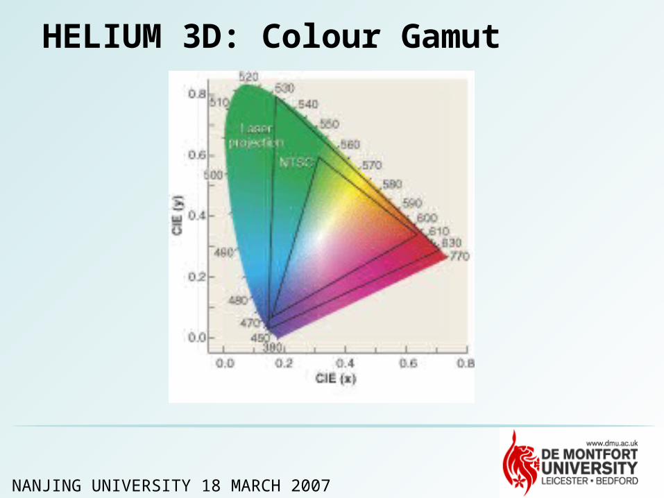
•Also high colour gamut
•Interactivity supported

NANJING UNIVERSITY 18 MARCH 2007
Extract from EU Workplan
Advanced visualisation systems and novel display technologies.
Visualisation systems extending colour gamut and dynamic range beyond current state-of-the-art, taking into account human vision and perceptual models. They should support multi-viewer, unaided and unrestricted 3D viewing, as well as natural interaction modalities. This includes signal acquisition, processing and representation technologies for 3D-systems.

NANJING UNIVERSITY 18 MARCH 2007
High Efficiency Laser-based Multi-user Multi-modal 3D Display (HELIUM3D)
• Direct-view laser-based 3D display to be developed
• Does not require LCD
• Image information supplied by light valve
• Illumination source is RGB lasers.
• High colour gamut
• Direct-view
• Does not have light attenuation of LCD - energy efficient
• Frees reliance on LCD fabrication plants

NANJING UNIVERSITY 18 MARCH 2007
HELIUM 3D: Schematic Diagram
Mobileviewers
MEMSscanner
Head tracker
RGBLaser
Light valve
SLM
Screen
NANJING UNIVERSITY 18 MARCH 2007
HELIUM 3D: Colour Gamut

NANJING UNIVERSITY 18 MARCH 2007
HELIUM 3D: Display Functionality • Display is functionally scalable
• Fast light valve speed could enable a different image to be seen by each eye in viewing field
• Enables motion parallax
• Each viewer could choose their desired viewpoint if scene captured by a camera array
• Each viewer could see completely different images to other viewers
• Display will work in near field and far field modes

NANJING UNIVERSITY 18 MARCH 2007
HELIUM 3D: Near Field Operation
• Screen around 1 – 1.5 metre from viewer
• Immerse hands into image – therefore image ~ 0.5 m from user
• 1 or 2 users, single or collaborative working
• Large disparities – up to I/O distance
• Large convergence/accommodation rivalry (human factors work necessary)

NANJING UNIVERSITY 18 MARCH 2007
HELIUM 3D: Near Field Tracking
• Requires low tracker latency – high latency will affect task performance and could cause nausea
• Requires high tracker accuracy (more than for just locating exit pupils)
• Head tracking in x, y and z directions
• Images rendered in accordance with head co-ordinates

NANJING UNIVERSITY 18 MARCH 2007
HELIUM 3D: Near Field Example
‘Virtual Clay concept’ - ‘clay’ shaped with naked hands
• A virtual chunk of clay floats in front of screen
• Touching and shaping the ‘clay’ with the naked hands enables user to directly manipulate object
• Approach completely differs from existing techniques - perceptual space matches interaction space
• This technique potentially useful in medical task applications

NANJING UNIVERSITY 18 MARCH 2007
HELIUM 3D: Far Field OperationViewing distance around 2 – 4 metres
• Gaming
• Television
• Videoconferencing ………


