
Forum for Electromagnetic Research Methods and Application Technologies (FERMAT)
Multistatic Nearfield Imaging Radar for Portal Security Systems Using a High Gain Toroidal
Reflector Antenna Carey M. Rappaport and Borja Gonzalez-Valdes
ALERT Center of Excellence, Northeastern University, Boston (MA), USA
EuCAP Lisbon, Portugal, April 15, 2015.
Abstract—A Toroidal reflector, consisting of a tilted ellipse rotated about the vertical axis, provides for multiple, overlapping high-resolution nearfield beams that form multi-view, true multistatic mm-wave imaging for security applications. Modeled results indicate the PSF on a torso target is wide and short, allowing for quickly computed 2D images which can be stacked to reconstruct detailed 3D surfaces.
Keywords— Imaging Systems, Multistatic radar system, Security scanning.
References:
1. D. Sheen, D. McMakin, and T. Hall, “Three-Dimensional MillimeterWave Imaging for Concealed Weapon Detection,” IEEE T. Microwave Theory and Techniques, vol. 49, no. 9, pp. 1581-1592, Sept. 2001.
2. Cooper, K.B.; Dengler, R.J.; Llombart, N.; Thomas, B.; Chattopadhyay, G.; Siegel, P.H., "THz Imaging Radar for Standoff Personnel Screening," IEEE T. Terahertz Science and Technology, , vol.1, no.1, pp.169-182, Sept. 2011.
3. Rappaport, C.M.; Gonzalez-Valdes, B., "The blade beam reflector antenna for stacked nearfield millimeter-wave imaging," IEEE Antennas and Propagation Society Int’l Symp. , vol., no., pp.1-2, 8-14 July 2012.
4. Alvarez, Y.; Gonzalez-Valdes, B.; Ángel Martinez, J.; Las-Heras, F.; Rappaport, C.M., "3D Whole Body Imaging for Detecting ExplosiveRelated Threats," IEEE T. Antennas and Propagation, vol.60, no.9, pp. 4453, 4458, Sept. 2012.
5. Martinez-Lorenzo, J.A; Gonzalez-Valdes, B.; Rappaport, C.; Gutierrez Meana, J.; Garcia Pino, A, "Reconstructing Distortions on Reflector Antennas With the Iterative-Field-Matrix Method Using Near-Field Observation Data," IEEE T. Antennas and Propagation, vol.59, no.6, pp. 2434-2437, June 2011.
*This use of this work is restricted solely for academic purposes. The author of this work owns the copyright and no reproduction in any form is permitted without written permission by the author.*

Carey Rappaport and Borja González-Valdés ALERT Center of Excellence
Northeastern University, Boston, MA
Carey Rappaport and Borja González-Valdés ALERT Center of Excellence
Northeastern University, Boston, MA
Multistatic Nearfield Imaging Radar for Portal Security Systems Using a High
Gain Toroidal Reflector Antenna
Multistatic Nearfield Imaging Radar for Portal Security Systems Using a High
Gain Toroidal Reflector Antenna
EuCAP Lisbon, Portugal, April 15, 2015
OutlineOutline
State of the art
Multistatic radar
Blade beam reflector
Elliptical Toroidal Reflector
Simulation Results
Experimental Results
State of the art
Multistatic radar
Blade beam reflector
Elliptical Toroidal Reflector
Simulation Results
Experimental Results

3
Mm-Wave Imager: Current State-of-the-Practice – L3 ProVisionMm-Wave Imager: Current State-of-the-Practice – L3 ProVision
Detects many types of materials based on shape (metallic and non-metallic): liquids, gels, plastics, metals, ceramics
Limitations “Dead Spots” No chemical info Limited views Poor penetration through leather
and metallic clothing No penetration through skin or
into body cavities
Detects many types of materials based on shape (metallic and non-metallic): liquids, gels, plastics, metals, ceramics
Limitations “Dead Spots” No chemical info Limited views Poor penetration through leather
and metallic clothing No penetration through skin or
into body cavities

4
State of the art
Current mm-wave scanners arebased on monostatic radar:
•Presents specular reflection only –no depth encoding
•Uses Fourier inversion – fast, butnot best for close imaging.
•Shows shapes of metallic objects,but does not fully consider reverseimaging of weak dielectrics (i.e.explosives).Dihedral
Artifacts
Non-spectral Dropouts
Sheen, D., McMakin, D., Hall, T., “Three-Dimensional Millimeter Wave Imaging for Concealed Weapon Detection,” IEEE T-MTT, 9/01
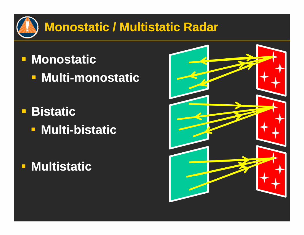
Monostatic / Multistatic RadarMonostatic / Multistatic Radar
Monostatic Monostatic Multi-monostatic Multi-monostatic
Bistatic Bistatic Multi-bistatic Multi-bistatic
Multistatic Multistatic
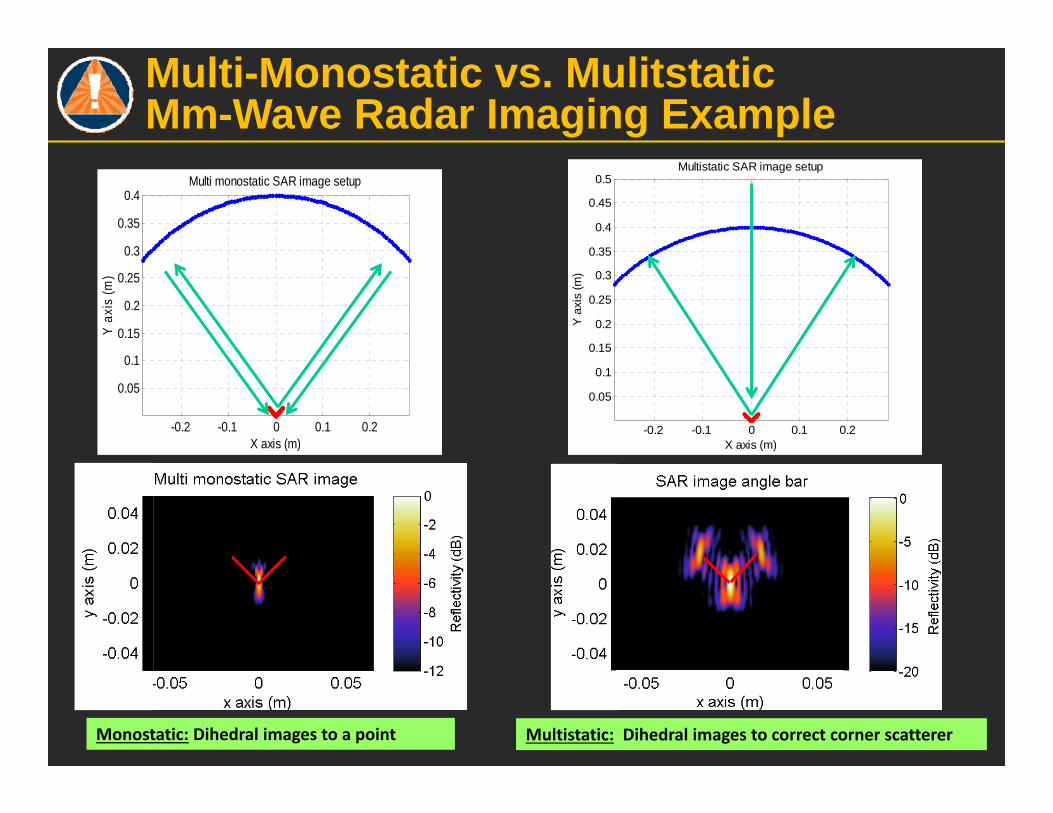
Multi-Monostatic vs. Mulitstatic Mm-Wave Radar Imaging Example
-0.2 -0.1 0 0.1 0.2
0.05
0.1
0.15
0.2
0.25
0.3
0.35
0.4
X axis (m)
Y a
xis
(m)
Multi monostatic SAR image setup
-0.2 -0.1 0 0.1 0.2
0.05
0.1
0.15
0.2
0.25
0.3
0.35
0.4
0.45
0.5
X axis (m)
Y a
xis
(m)
Multistatic SAR image setup
Monostatic: Dihedral images to a point Multistatic: Dihedral images to correct corner scatterer
7
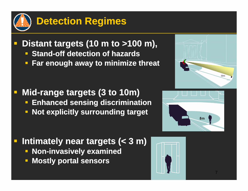
Detection RegimesDetection Regimes
Distant targets (10 m to >100 m), Stand-off detection of hazards Far enough away to minimize threat
Mid-range targets (3 to 10m) Enhanced sensing discrimination Not explicitly surrounding target
Intimately near targets (< 3 m) Non-invasively examined Mostly portal sensors
Distant targets (10 m to >100 m), Stand-off detection of hazards Far enough away to minimize threat
Mid-range targets (3 to 10m) Enhanced sensing discrimination Not explicitly surrounding target
Intimately near targets (< 3 m) Non-invasively examined Mostly portal sensors

Custom designed elliptical torus reflector allows multiple overlapping beams for focused wide-angle illumination to speed data acquisition and image inclined body surfaces.
Multiple transmitters provide horizontal resolution and imaging of full 120 deg. of body.
Multistatic Tx and Rx array sensing avoids dihedral artifacts from body crevices and reduces non-specular drop-outs.
Overview & Technical Approach

(1) 2D imaging (one slice)
(2) Stacked 2D images (slices)
(3) 3D surface generation
(4) ATR algorithm and results display
Vertical (z-axis) motion
Operational Concept: Stack 2D Slices to Generate 3D Surface – Minimize Hardware, Simplify Calculation

10
System setup: vertically Moving Focusing Reflector Antenna Trans./Arc Array Rec.
One transmitter• Moves up/down• Focuses on thin slice• Allows multiple 2D processing• Minimal motion artifacts
Arc Receiver• Quarter circle• Sparse element positions• Moves up/down with transmitter• Multistatic: no dihedral artifactsz
x y
Human bodySlice illuminated
by the beam
Blade-Beamreflector antenna
(transmitter)
Incident beam
Arcs of receivers
Dielectric object
90º
R =1 m
R =0.75 m
Incident field
Scattered field
Upper arc
Lower arc
Scattered field
11
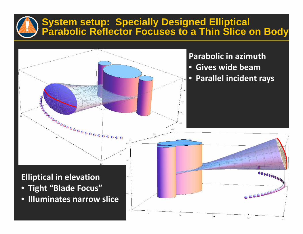
System setup: Specially Designed Elliptical Parabolic Reflector Focuses to a Thin Slice on Body
Parabolic in azimuth• Gives wide beam• Parallel incident rays
Patent Pending on Novel Reflector Design
Elliptical in elevation• Tight “Blade Focus”• Illuminates narrow slice
100 80 60 40 20
80
60
40
20
20
40
60
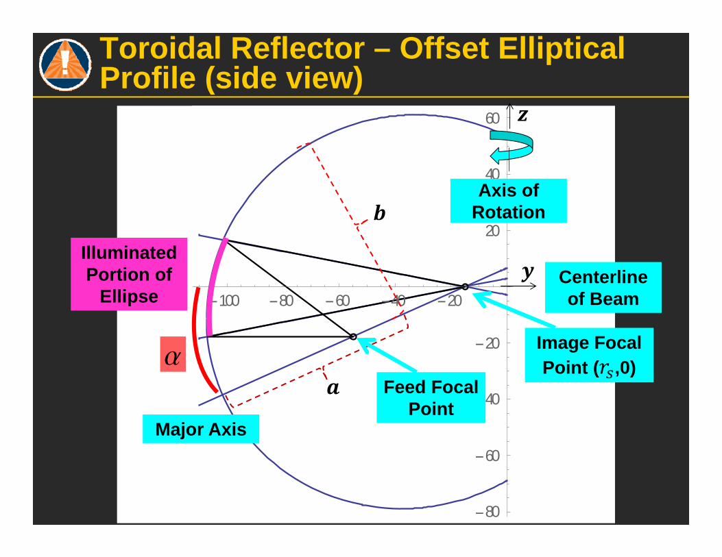
a
Centerline of Beam
Illuminated Portion of
Ellipse
Feed Focal Point
Image Focal Point ( ,0)
Major Axis
Axis of Rotation
Toroidal Reflector – Offset Elliptical Profile (side view)
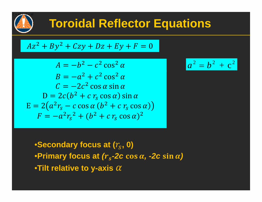
Toroidal Reflector Equations1 ˆ ˆ ˆr xx yy zz
2 2 2+ ca b
•Secondary focus at ( , 0)•Primary focus at ( -2c , -2c )•Tilt relative to y-axis
0
coscos
2 cos sinD 2 cos sin
E 2 cos coscos

Reflector View from Above for Two Feed Positions 0 and 45 deg.Reflector View from Above for Two Feed Positions 0 and 45 deg.
Tx position
Target (0.2x0.4 half elliptical cylinder)
Tx position
Target
45o
Circular Focal Arc
Second Focal Line
Second Focal Line
z
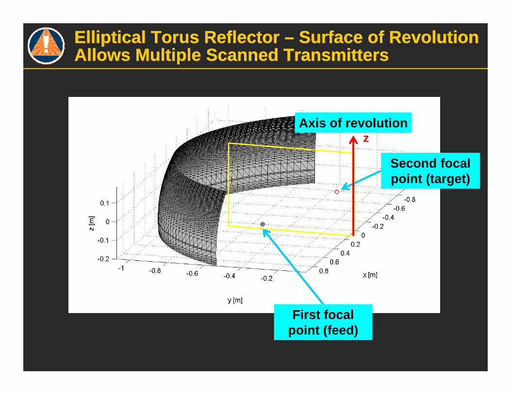
Elliptical Torus Reflector – Surface of Revolution Allows Multiple Scanned TransmittersElliptical Torus Reflector – Surface of Revolution Allows Multiple Scanned Transmitters
First focal point (feed)
Second focal point (target)
Axis of revolution

Fabricated Torus ReflectorFabricated Torus Reflector
Axis of revolution
First focal point (feed)
Second focal point (target)
Receiver

Aluminum Reflector Machined with CNC Milling Machine – 0.0001m Surface ToleranceAluminum Reflector Machined with CNC Milling Machine – 0.0001m Surface Tolerance
Back view, showing rough cuts for weight reduction
4 Identical panels 8 kg per panel Elliptical vertical profile X circular arc horizontal profile

Torus Reflector Configured with Both Transmit and Receive Elements on Focal Arc, Facing TorusTorus Reflector Configured with Both Transmit and Receive Elements on Focal Arc, Facing Torus
Transmitter (feed)
Receiver
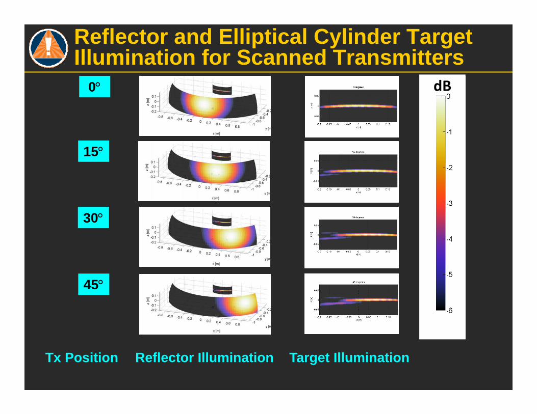
dB0
15
30
45
Reflector and Elliptical Cylinder Target Illumination for Scanned Transmitters
Tx Position Reflector Illumination Target Illumination
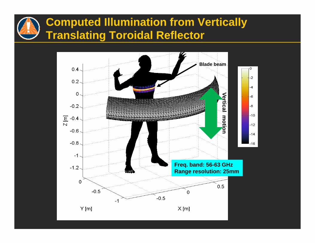
Blade beam
Vertical motion
Freq. band: 56-63 GHzRange resolution: 25mm
Computed Illumination from Vertically Translating Toroidal Reflector

Multistatic Imaging with Torus Reflector –20 deg. Inclined Metal Box, Half Receiver ArcMultistatic Imaging with Torus Reflector –20 deg. Inclined Metal Box, Half Receiver Arc
Ground Truth in Green
Image from Modeled DataImage from Measured Data

Torus Reflector – Metal Torso Simulant Measured over Left & Right Half ArcsTorus Reflector – Metal Torso Simulant Measured over Left & Right Half Arcs
Image from Measured Data Image from Modeled Data
Ground Truth in Green
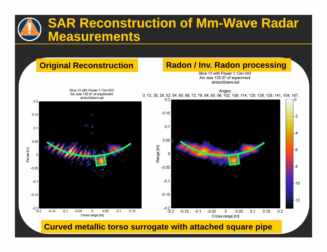
SAR Reconstruction of Mm-Wave Radar MeasurementsSAR Reconstruction of Mm-Wave Radar Measurements
Radon / Inv. Radon processing
Curved metallic torso surrogate with attached square pipe
Original Reconstruction
ConclusionsConclusions
Extension of Blade Beam Reflector into Elliptical Torus for multiple overlapping high quality beams
Illumination and receiver focusing on narrow slice for fast computation
Fabrication, testing, optimization of wideband 60GHz multistatic radar
Novel reflector antenna, stacked 2D reconstruction, and fast inversion for real time processing
Minimal artifacts from dihedrals, full depth information and advanced visualization
This work supported by U.S. Dept. of Homeland Security, Award # 2008-ST-061-ED0001.The views and conclusions contained herein are those of the authors and should not be interpreted as necessarilyrepresenting the official policies, either expressed or implied of the Dept. of Homeland Security.


