
1/14MultiDim Control System
Product Features and Benefi tsMultiDim consists of an integrated range of DALI-compatible devices that can be combined fl exibly to provide exactly the desired control functions. The system’s addressable digital architecture means that only a single two-core cable is needed to interconnect all units. The possibil-ity to eliminate conventional vertical wall wiring both reduces instal-lation time and cost, and greatly increases the ease with which later changes can be implemented.
The MultiDim controllers can be used in combination with DALI-com-patible fl uorescent lamp ballasts and lamp interface units (both mains voltage incandescent lamps and low voltage halogen lamps). Where necessary control functions can be extended by adding the required MultiDim units such as dimmers, control panels, IR remote control units and multi sensors for light levels and room occupancy.
Thanks to the system’s digital addressable control and communication concept, each unit in the DALI network has its own unique address that allows it to be switched and controlled independently. The sys-tem’s single control pair can be used to control different groups of lamps. Up to 63 devices (DALI luminaires and controllers) connected to the same physical control wire can be addressed and controlled independently.
Summary of the main DALI features
• Individual control of lamps.
• A single control cable can be used to control several different groups of lamps.
• No mains switching required.
• All system units are interconnected using a simple two-core cable.
• In MultiDim up to 63 devices can be connected with a maximum cable length of 300 metres.
• The operation of the system can be reconfi gured quickly without modifi cation of the hardware.
• If the lighting system needs to be enlarged, new components can be added anywhere on the DALI cable.
ApplicationsMultiDim is scene-setting lighting control range that covers a wide range of applications. Light scenes can simply be activated at the touch of a button. With an easy-to-use remote control different preset scenes can be programmed and selected, changing the mood of the space in seconds.
Philips DALI MultiDim offers today’s most versatile and easy-to-install solution to bring the benefi ts of digital lighting control to many dif-ferent application areas. Whether in shops, offi ces, conference rooms, hotels, restaurants, cafes, lecture theatres, show rooms or other ap-plications. MultiDim offers unbeatable freedom and ease of lighting system design.
With its capacity to control up to 16 different lighting groups, MultiDim is suited for applications using different types of luminaires including incandescent, halogen and fl uorescent (HF-DALI) lamps. In addition MultiDim can also be used to switch on projectors, lower projection screens or close window blinds at just the touch of a but-ton.
Digital Addressable Lighting Interface
MultiDim Modular Control Panels
DCMD302 - Multisensor DCMD303 - IR Remote Control
DCMD450 - 800 W Dimmer

2/14MultiDim Control SystemAbout MultiDim Systems
DALI Compatibility and ComplianceThe MultiDim controllers can be used with any DALI compatible ballast or Lamp Interface Unit.
In addition, all MultiDim Lamp Interface Units (such as the 800 Watt Dimmer) can be used in conjunction with other manufacturer’s DALI compatible control systems.
However, it may not be possible (and is not recommended) to use MultiDim controllers on the same system as other types of DALI con-troller.
Cable Choice The electrical specifi cation for DALI systems provides a great deal of fl exibility in both the choice of cable used and how it is installed. The basic requirements are:
• The cable should be mains rated
• 2 wire, 0.5 - 1.5mm2
• The maximum voltage drop on the DALI cable must not exceed 2Volts (for standard cables, this means that the total length of con-necting cable can be up to 300 metres)
This means that standard mains cable can be used successfully - par-ticularly useful where a system is being retrofi tted to an existing instal-lation.
Cable TopologyAs you can see from the layout diagram on the following page, there are few restrictions on the cable topology.
No special terminations are required, and there are no complex rules about how the nodes should be connected together.
Ring confi gurations should be avoided, but otherwise the only require-ments are that the cable be continuous throughout, and that each node be connected to the cable at some point.
Nodes can be daisy chained together in series and spurs be added at any point. The cable topology can be optimised to either simplify test-ing or to minimise cable use.
DALI ConnectionsAll MultiDim units are fi tted with removable connectors with paired terminals for the DALI connection. These provide a simple means of linking through, and the only requirement is to maintain the power sup-ply polarity throughout the system.
Power Supply RequirementsMultiDim Controllers without a direct mains connection must be pro-vided with power via the DALI control cable. This has the advantage that no additional power cabling is required, but it does mean that you have to ensure that an adequate power supply is available on the system.
This supply must be designed for DALI use and be capable of provid-ing suffi cient power to supply the controllers connected to the system. In addition, to maintain signalling integrity, it must not be capable of providing more than 250mA to the system.
See page 12 for details of the dedicated MultiDim Power Supply Units.
Confi gurationAll MultiDim units are fully confi gurable. They are supplied pre-confi gured with factory default settings that ensure that a system will be functional as soon as the power is applied.
This has the advantage that a newly installed system will provide basic operation from the moment the power is fi rst applied. For simple systems, this may be all that is required. But for systems that are more complex (and to gain access to advanced MultiDim functions) the sys-tem must be reconfi gured using one of three different methods:
• Confi guration Using Button Controllers. Eight and fi ve button MultiDim panel controllers provide some limited confi guration fea-tures from the control buttons. These include the ability to store four pre-set light levels and the ability to customise those levels.
• Confi guration Using the IR Remote Control Unit. The MultiDim IR remote control unit can be used to confi gure a number of advanced system functions. For more details see page 9 of this datasheet.
• Confi guration Using MultiDim User software. The MultiDim User application (DCMD502) is a Windows based software confi guration tool, designed to make setting up a complex system as simple as possible. See: www.dimming.philips.com for more details.
DA+
DA+ DA+
SC
SC SC
DA-
DA- DA-
DA+
DA+ DA+
SC DA-
DA- DA-
MultiDim Terminal Connections Using Standard Cable.
MultiDim Terminal Connections Using Screened Cable

3/14MultiDim Control SystemAbout MultiDim Systems
1 The MultiDim system can be used with any DALI compliant elec-
tronic ballast for fl uorescent lamps.
2 Power for the controllers can be supplied by the DCMD401 (il-
lustrated) or the DCMD400 DIN rail mounted power supply
or any main connected MultiDim unit such as the DCMD450
Dimmer.
3 Low cost cable can be used to interconnect all of the system
components. The recommended total length of the cable is
300m.
4 The MultiDim MultiSensor provides IR, light-level and occupancy
sensor, which can be used independently or in combined to
provide energy saving functions such as automatic operation and
constant light level.
5 The MultiDim DCMD450 800 Watt dimmer is a fully compliant
DALI LIU for use with incandescent lamps and low voltage elec-
tronic transformers.
6 MultiDim control panels are modular in construction. Sliders, ro-
tary controls and fi ve different button panels are available.
7 The double gang panels can contain up to three controller mod-
ules. The modules are completely interchangeable within the
panel, and custom panels can be created as desired.
8 The MultiDim IR remote control unit provides both means of
controlling individual units and a simple confi guration tool. All of
the modular controllers and the MultiSensor are fi tted with IR
sensor and can be used with the remote control.
Typical Layout of a MultiDim System

4/14MultiDim Control SystemControl Modules
IntroductionA range of DALI compatible manual control panels that can be confi gured to suit almost any control requirement. The range includes pushbutton, rotary, and slider control modules, all of which can be inserted into either single or triple gang fascia panels. The modular construction provides fl exibility and allows many different panel con-fi gurations to be constructed.
All of the control modules are fi tted with indicator LEDs and an IR receiver that allows the module operate with the MultiDim IR remote control unit.
Confi gurationEach control is supplied pre-confi gured with immediately usable default settings, but can be easily re-confi gured to suit a particular application using either the MultiDim IR Remote, or MultiDim User software. Eight and fi ve button controllers also provide limited confi guration features via the control buttons.
DCMD170 - IR Receiver DCMD126 - 8Button
DCMD121 - 2Button On/Off DCMD100 - Rotary
DCMD125 - 7Button DCMD124 - 5Button
DCMD110 - Single Slider DCMD111 - Twin Slider
DCMD122 - 2Button Raise/Lower DCMD150 - Blank Panel

5/14MultiDim Control SystemMultiDim Control Panels
Mechanical DataThe modular controllers are available in satin white plastic fi nish. The various control panel combinations can be constructed from the fol-lowing separately packaged components:
• The Control Modules (see opposite for variations).
• Single gang chassis plate and fascia panel, designed for use with a standard, single gang backbox. This provides a mounting for a single module.
• Triple gang chassis plate and fascia panel, designed for use with a standard, double gang backbox. This provides a mounting for up to three modules.
DALI Cable ConnectionStandard MultiDim removable connectors with paired terminals. A con-nection between the SC terminal and a local earth is required for EMC protection
Module Power Supply RequirementsSupplied via DALI network cables. 13 to 19 V, 10 mA
Conformity & StandardsEMC Emission EN 55 015 Immunity EN 61 547Safety Safety EN 60 669-1, IEC 60 669-2-1 Isolation 4kV IP rating 30
Environmental RequirementsAmbient temperature 0°C to 35°CStorage temperature -10°C to +70°CRelative humidity 90% maximum, non-condensing
141.80
73.80
73.80
73.80
DCMD200D - Double Frame
DCMD200S - Single Frame
35.40 31.80
48.40
DA+ SC DA-
DA-DA+ DA+DA-
Module Dimensions The chassis plates and fascia panels are designed to fi t both DIN and UK standard backboxes with a minimum depth of 35mm.

6/14MultiDim Control SystemDCMD302 MultiDim MultiSensor
IntroductionA ceiling mounted module, containing the sensors required for an automated DALI lighting control system. The MultiSensor contains an Infra-Red receiver for use with the MultiDim IR Remote, a constant light sensor (which measures refl ected light from below the device), and a PIR occupancy sensor with a range of up to 4.5 metres.
PIR OperationThe PIR sensor can be used on its own to provide automatic control of lighting depending on the room’s occupancy. The operation and tim-ing of the PIR is fully confi gurable and includes the ability to set the unit to provide “off only” operation and an adjustable “PIR transition time” that can improve the life-span of fl uorescent tubes used in cor-ridor applications.
Local SwitchThe MultiSensor is provided with terminal connectors for a local wall switch. This provides a manual dimming function if required.
Confi gurationThe MultiSensor is supplied pre-confi gured with immediately usable default settings. However, it can be easily re-confi gured using either the IR Remote, or MultiDim User software.
In addition, the MultiSensor is fi tted with fi ve rear mounted DIL switch-es that will allow some of the main functions to be pre-confi gured. The DIL switch settings are applied when power is fi rst applied but can be overridden using the MultiDim IR Remote, or MultiDim DCMD502 User software.
IR Sensor
ConstantLight Sensor
PIR
60°- 85°
4.5m
0.5m
3.0m
3.0m
120°
3m
14.0m
1.6m
0.8m
100°
7.1m
5.2m
3.0m
IR Sensor Range and Angle of View
Constant Light Sensor Range and Angle of View (without Restrictor)
PIR Sensor Range and Angle of view
Constant Light OperationThe PIR and constant light sensors operate together to provide auto-matic constant light control of the surrounding lamps.
For effective constant light operation, careful positioning of the MultiSensor is essential. In particular, it is important to ensure that the sensor is not exposed to direct light, and that it is positioned in such a way that most of the light that it receives is under its control. Mount the MultiSensor away from direct light entering through windows. See the installation instructions for more details.
The constant light feature is disabled by default and must be enabled using the MultiDim IR Remote Control or MultiDim User software.

7/14MultiDim Control SystemDCMD302 MultiDim MultiSensor
Fixing DataThe MultiSensor’s housing is designed for push fi t mounting into a ceiling, or inside a luminaire casing. Its spring-loaded mount-ing system will allow it to be fi tted into a wide range of fi xing materials, including sheet metal and fi brous ceiling tiles. For thin materials, a slightly smaller mount-ing hole is required.
40°
2.1m
3.0m
/ 52.0mm
0.5mm- 2.0mm
/ 55.0mm>2.0mm
/ 65.00
26.40
51.40
Fitting the Constant Light Sensor Viewing Angle Restrictor
DCMD302 - for ceiling mounting With the cable shroud removed
53
2
On
14
OFF
PIR Control
IR Receiver
PIR Test
Factory DefaultSettings
Local Switch
Constant Light
Off
Switch Function
On
Off
Off
Manual Confi guration Using the MultiSensor’s DIL switch
SC DA-DA+
Touch DimmerCable
fadeN.o
Switch (Mains rated)
0.22 - 2.5 mm(Mains rated)
²MomentaryI
Operation
HoldMomentary
5
32
14
OFF
5
DA+SC
DA-
0
DALI Cable ConnectionStandard MultiDim removable connectors with paired terminals.Module Power SupplySupplied via DALI network cables 13 to 19 V, 15 mA
Constant Light SensorViewing Angle 100° (40° with viewing angle restrictor)Range 5 to 5000 lux.SW1 Switch Functions On Set level to nominal value Off Defaults to maximum
IR ReceiverOperation Omni-directionalFrequency 36kHzSW2 Switch Functions On Receives all remote control commands Off Ignores remote control commands (except confi guration commands)
PIR SensorOperation Omni-directional pyro-electric SW3 Switch Functions On Last level recall Off PIR response ignored SW4 (PIR Test) Switch Functions On Timeout reduced to 10 seconds - use for testing Off Normal PIR function (default 20 minute time-out)
Local switchOperation Single mechanical switch connected as shown provides “touch dimmer” style operationSW5 Switch Functions On Local Switch enabled Off Local Switch disabled
Conformity and Standards (EMC) Emission EN 55 015 Immunity EN 61 547 Safety IEC 60 950 Isolation 4kV IP rating 30
Operating Conditions Ambient temp 0°C to +50°C Storage temp -10°C to +70°C Relative Humidity 90% maximum, non-condensing
Connecting a Local Switch

8/14
IntroductionThe MultiDim Infra-red remote control is designed to work in conjunc-tion with all Philips MultiDim products fi tted with an IR receiver, includ-ing the Philips MultiDim control panels and MultiSensor.
The IR Remote is a dual function device. Its main purpose is to pro-vide a simple and intuitive remote control for MultiDim control systems.
When used as such, it provides a number of basic functions, including On/Off, Raise/Lower, and selecting from four predefi ned Scenes.
However, the IR Remote can also be used as a basic confi guration tool for simple systems where the use of MultiDim User software and its associated Programming Point is inconvenient.
In this case, the control buttons are used in combination to provide ba-sic confi guration functions. This includes, creating and adding to groups of lamps, setting pre-set scenes and disabling or enabling IR receivers. The IR Remote will allow the settings to be locked to prevent the user from accidentally making changes to the confi guration.
Basic Control Functions On/Off Recall Scene 1-4 Raise/Lower lamp levels Store Scene
Confi guration Functions Set default Preset Levels (1=100%, 2=75%, 3=50%, 4=25%) Creating Group Add to Group Creating Scene Restrict the IR Control signal to Specifi c Groups Disable/Enable IR sensors on specifi c controllers Confi guration Lock (prevents users inadvertently changing the settings)
Technical Data Power 2 x IEC, LR03/AAA, 1.5 V Battery Weight 50 g Operating Frequency 36 kHz Size 120mm x 57mm x 24mm
1
34
2
0/10/1
+
C
D
B
A
E
F
G 9
D 4
0E 2
5
87 6B
A
F
C
3
1
A LED Indicator (Flashes when a button is operated)B Scene Recall/Confi gurationC On/Off/ShiftD Modifi er KeysE TransmitterF Battery CoverG Rotary Switch (Normal position 0)
MultiDim Control SystemDCMD303 MultiDim IR Remote Control

9/14MultiDim Control SystemDCMD400, DCMD401 MultiDim Power Supplies
IntroductionPower for MultiDim devices can be supplied from a number of differ-ent sources. Some mains connected MultiDim units (such as the 800 Watt Dimmer) are provided with an internal DALI power supply. If the system contains one of these, it will provide an ideal source of power.
Alternatively, a dedicated MultiDim power supply unit (DCMD400 or DCMD401) can be used. Both of these units have similar output capa-bilities and can supply the maximum of 250 mA permitted for a DALI system. However, the DCMD400 is designed for DIN rail mounting in a control cabinet and the DCMD401 for mounting in a ceiling void.
L
N230V
AC
DA+DA+ DA- DA-
DA+ SC DA-
DALI
45m
m
58mm
90m
m
70mm
POWER SUPPLY
DCMD400
DA+
ENL
Sc DA-
Power
DALI
AC
DCMD400
DCMD400 Module Dimensions
DCMD400 Module Wiring
L
L
DA N
N
DALI HF BALLAST
DCMD401
DALIL
N
230V
DA+ DA-
DA+ SC DA-
DALI
63m
m
100mm 51mm
DCMD401
DCMD401 Module Dimensions DCMD401 Module Wiring
Note. If a power supply unit is connected to the system no additional power supplies may be applied
Technical Data
Mains Supply DCMD400 230VAC (nom), 197-264VAC(abs);
50Hz (nom), 48-62Hz (abs) DCMD401 230VAC -10%/ +6%, 50-60Hz
DALI Supply Power Output 250 mA (nom)
Operating ConditionsAmbient Temperature DCMD400 0° to 50°C DCMD401 0° to 40°CRelative Humidity 90% max, non-condensingIP rating 30
Mechanical Data DCMD400 DIN Rail case 70mm (4M)
DALI Cable DCMD400 Standard MultiDim removable
connectors with paired terminals DCMD401 1m, 2x0.75mm² stranded
Mains Cable DCMD400 <4mm² solid core <2.5mm² stranded DCMD401 1.5m, 2x0.75mm² stranded
Installation Notes1. The external supply must be protected. It is recommended that a 2A
MCB is used.
2. All cabling must be 230V mains rated.
3. The DCMD400 is for installation in a restricted access location only.
!

10/14MultiDim Control SystemDCMD444 MultiDim Push-button Interface
Introduction The MultiDim Push-button Interface is a small, pre-wired, encapsulated printed circuit board containing all of the electronic components of a fully DALI compatible controller. It provides a simple method of adding custom designed switches to a MultiDim lighting control system.
The Push-button Interface can be used with switches, sensors, time clocks, or other on/off control devices and is small enough to fi t into a standard size back boxes. Despite its small size, it provides almost all of the capabilities of a standard MultiDim modular controller .
Key Features • Pre-confi gured with three scene recall and one touch dimmer inputs
• Fits into all standard size back boxes and architrave style back boxes
• Touch dimming with a momentary push switch
• Can be used with momentary or latching switches
• Fully programmable using MultiDim User software
Technical Data
Voltage-free Switched Inputs Connections 1-4 Inputs (active low) COM Input GroundVoltage Pins 1-4 5 V nominal with switch open, must be less
than 0.3V switch closedOverload Protection ±7 VShort-circuit Current 0.5 mA maximumDebounce Period 50 mS
Connections DALI Ribbon cable terminated with 1.2 mm2
Ferrules Switch Ribbon cable terminated with 1.2 mm2
Ferrules
Power DALI Supply Output None (Use external DALI power supply)DALI Consumption 10 mA
Operating Conditions Ambient Temperature 0° to 40º CRelative Humidity 90% max, non-condensingStorage Temp -10º to +70º C
Mechanical Data Housing Encapsulated printed circuit
boardWeight 10 g
Conformity & Standards EMC Emission EN 55 015Immunity EN 61 547SafetySafety EN 60 950IP Rating 20Isolation 1.5 kV
Default Functions IP1 (Red) Store/Recall Scene 1 IP2 (Orange) Store/Recall Scene 2 IP3 (Yellow) Store/Recall Scene 3 IP4 (Green) Touch Switch Control
Note. The default functions can be re-confi gured using MultiDim User Software.
Installation Notes 1. All switches and cables must be mains rated.
2. To avoid interference problems the pre-wired leads should not be increased in length.
200mm
50mm
30mm
20m
m10
mm
IP1
IP2
IP4
IP3
COM
YELLOW
BROWN
RED
ORANGE
GREEN
BLUE
VIOLET
444
DA+
DA-
Fitted to a 4 gang mains switch in a single gang back box.

11/14MultiDim Control SystemDCMD450 MultiDim 800W Transistor Dimmer
IntroductionThe MultiDim 800 Watt Transistor Dimmer is a fully DALI compatible Lamp Interface Unit, designed to allow incandescent lamps to be incor-porated into a DALI controlled lighting system.
The dimmer is a DIN-rail mounted unit that can control a maximum load of up to 800W. It can be connected to mains voltage lamps directly, or to low voltage lamps via an electronic transformer designed for both capacitive and resistive loads.
The dimmer is provided with local switch terminals, an indicator LED, a physical selection switch and a built-in DALI power supply.
The local switch terminals will allow a momentary push button switch to provide local “touch dimmer” style control. The indicator LED provides status and fault indications, and the physical selection switch is used to identify the device during system confi guration.
The DALI power supply is switch activated, and will provide up to the maximum of 250mA, 18V to the DALI system.
Note that, if the power supply is enabled, no additional power supplies may be applied.
LOCAL CONTROL
DALI
AC
DALI + 250 mA
PhysicalSelectionSwitch
DALI
Status LED
ONON
Physicalselection
DA+
ENL
LOCAL CONTROL
Sc DA- DALI POWER
ONOFF
StatusLED
800W DIMMER
DCMD450
45m
m
88mm 58mm
90m
m
Physicalselection
DA+
ENL
LOCAL CONTROL
Sc DA- DALI POWER
ONOFF
StatusLED
800W DIMMER
DCMD450
DALI
LOCAL CONTROL
AC
L
N230V
DA+
DA+DA+
SC DA-
DA- DA-
< 50m
Additional DALI Functions• Min/Max levels, Scenes, Groups• Lamp status report• Dimmer status report
Connection DALI Standard MultiDim removable connectors with paired terminals Mains <4mm² solid core <2.5mm² stranded
Power Mains Supply 220 to 240VAC, 50Hz DALI supply output 250 mA
Operating Conditions Ambient Temperature 0°C to 35°C Relative Humidity 90% max, non-condensing.
Mechanical data DIN-rail case 88mm wide (5M)
Conformity & Standards (EMC) Emission EN 55 015 Immunity EN 61 547
Safety Safety EN 60 950 IP rating 30 Isolation 4kV, Mains to dimmer unit (Basic, Dimmer internal isolation to DALI terminals)
Installation Notes1. The dimmer is for use with incandescent lamps and low voltage elec-
tronic transformers. It is not suitable for use with fl uorescent ballasts or conventional transformers.
2. The external supply must be protected. It is recommended that a 6 A MCB is used.
3. All cabling must be 230V mains rated.
4. For installation in a restricted access location only.
!
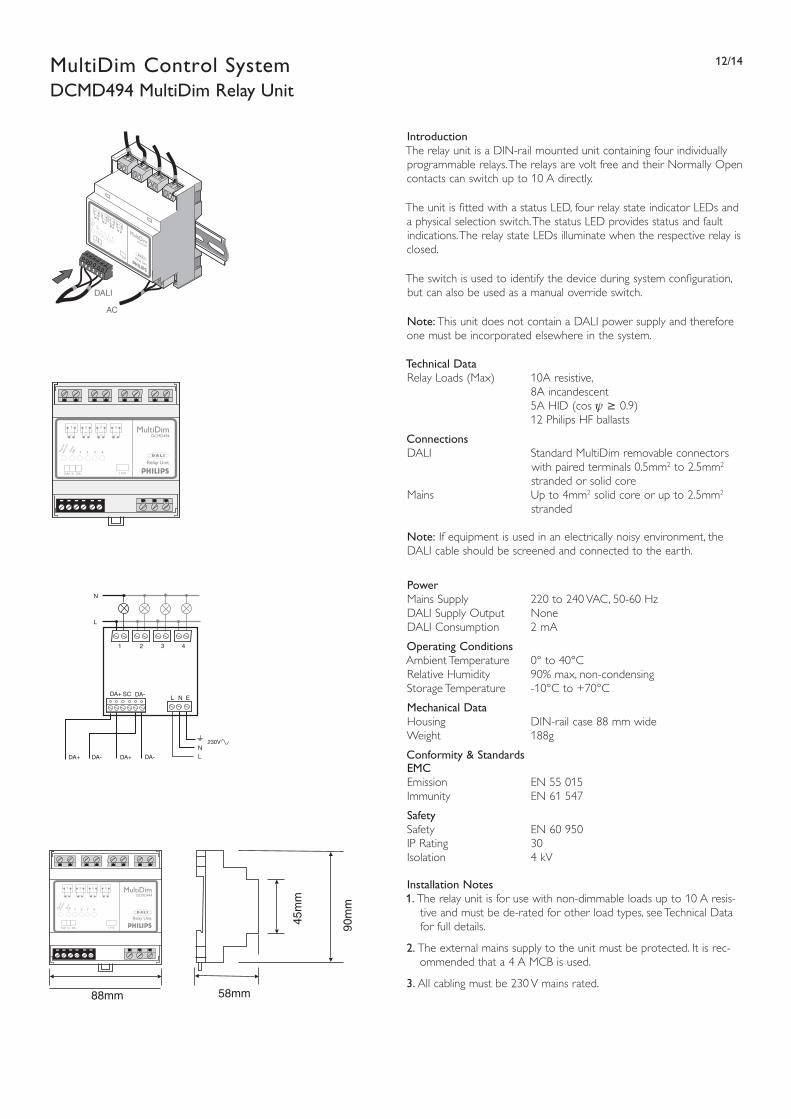
12/14MultiDim Control SystemDCMD494 MultiDim Relay Unit
Introduction The relay unit is a DIN-rail mounted unit containing four individually programmable relays. The relays are volt free and their Normally Open contacts can switch up to 10 A directly.
The unit is fi tted with a status LED, four relay state indicator LEDs and a physical selection switch. The status LED provides status and fault indications. The relay state LEDs illuminate when the respective relay is closed.
The switch is used to identify the device during system confi guration, but can also be used as a manual override switch.
Note: This unit does not contain a DALI power supply and therefore one must be incorporated elsewhere in the system.
Technical Data Relay Loads (Max) 10A resistive, 8A incandescent 5A HID (cos ψ ≥ 0.9) 12 Philips HF ballasts
Connections DALI Standard MultiDim removable connectors
with paired terminals 0.5mm2 to 2.5mm2 stranded or solid core
Mains Up to 4mm2 solid core or up to 2.5mm2 stranded
Note: If equipment is used in an electrically noisy environment, the DALI cable should be screened and connected to the earth.
Power Mains Supply 220 to 240 VAC, 50-60 HzDALI Supply Output NoneDALI Consumption 2 mA
Operating Conditions Ambient Temperature 0° to 40°CRelative Humidity 90% max, non-condensingStorage Temperature -10°C to +70°C
Mechanical Data Housing DIN-rail case 88 mm wide Weight 188g
Conformity & Standards EMC Emission EN 55 015 Immunity EN 61 547
Safety Safety EN 60 950 IP Rating 30 Isolation 4 kV
Installation Notes 1. The relay unit is for use with non-dimmable loads up to 10 A resis-
tive and must be de-rated for other load types, see Technical Data for full details.
2. The external mains supply to the unit must be protected. It is rec-ommended that a 4 A MCB is used.
3. All cabling must be 230 V mains rated.
Relay Unit
DCMD494
1Phys
ical
Sele
ctio
nSt
atus
LED
2 3 4
L N EDA+ Sc DA-
1 2 3 4
DA+DA-DA+ DA-
DA+ SC DA-
L
1 2 3 4
N
L
L N E
N230V
DALI
AC
DA+ ScDA-
45m
m
58mm
90m
m
88mm
Relay Unit
DCMD494
1Phys
ica l
Sel e
ctio
nSt
a tus
LED 2 3 4
L N EDA+ Sc DA-
1 2 3 4

13/14MultiDim Control SystemDCMD502 MultiDim Programming Kit
IntroductionThe MultiDim Programming Kit contains a licensed copy of the MultiDim User software, a Programming Point module, and an adapter cable which will allow the system to be connected directly to a PC.
The MultiDim User software is a Windows based software confi gura-tion tool, designed to make setting up a MultiDim system as simple and intuitive as possible. It has an Explorer style interface that allows the most common operations to be carried out through drag and drop operations. Beneath this is a system of menus and dialogue boxes that provide access to every aspect of a MultiDim system.
To use the software as a confi guration tool, the computer must be connected to the system via the special adapter cable that is provided with the kit. This cable must be inserted into a system programming point module that must be installed as part of the MultiDim system.
Demonstration VersionA free demonstration version of the software is available for download from: http://www.dimming.philips.com. This version is fully working, with the exception that it cannot be used in the online mode required for system confi guration.
Recommended SystemAn IBM PC compatible computer running:• Microsoft® Windows XP to 95 (with Internet Explorer V3.02)
• Intel Pentium ™ based computer
• 32MB RAM Minimum
• Mouse or other pointing device
• CD-ROM drive
Programming Kit Contents• MultiDim User Software
• Programming Point Panel
• Adapter Cable

14/14MultiDim Control System
Ordering and Packing DataType Description Ordering Number EAN1* Weight Weight Dimensions EAN3* Net gr. Gross gr. l x w x h mmDCMD100 Multidim rotary module 9137 005 30803 87 11500 747921 44 76 35x48x44DCMD110 Multidim single slider module 9137 005 30903 87 11500 747938 47 79 35x48x48DCMD111 Multidim twin slider module 9137 005 31003 87 11500 747945 47 79 35x48x48DCMD121 Multidim 2 button on/off module 9137 005 31103 87 11500 747952 42 79 35x48x39DCMD122 Multidim 2 button raise/lower module 9137 005 31203 87 11500 747969 42 74 35x48x39DCMD124 Multidim 5 button module 9137 005 31303 87 11500 747976 43 77 35x48x39DCMD125 Multidim 7 button module 9137 005 31403 87 11500 747983 43 77 35x48x39DCMD126 Multidim 8 button module 9137 005 31503 87 11500 747990 44 75 35x48x39DCMD150 Multidim single blank module 9137 005 31603 87 11500 748003 16 49 35x48x38DCMD170 Multidim IR receiver module 9137 005 31703 87 11500 748010 36 72 35x48x38DCMD180 Multidim programming point module 9137 005 31803 87 11500 748027 32 66 35x48x38DCMD200D Multidim double frame -white 9137 005 31903 87 11500 748034 107 165 160x88x14DCMD200S Multidim single frame - white 9137 005 32003 87 11500 748041 59 96 88x88x14DCMD302 Multidim ceiling multisensor 9137 005 30103 87 11500 747877 56 108 DIA 65x66DCMD303 Multidim 7 button IR transmitter 9137 005 30203 87 11500 747884 75 90 120x55x25DCMD400 Multidim DIN rail power supply 9137 005 30403 87 11500 747891 116 168 90x70x58DCMD401 Multidim ceiling mounted power supply 9137 005 30303 87 11500 748744 592 636 120x51x63DCMD444 Multidim push button interface 9137 001 82003 87 11500 928887 10 15 205x20x10DCMD450 Multidim 800W DALI dimmer 9137 005 30603 87 11500 747914 239 258 90x88x58DCMD494 Multidim relay unit 9137 001 84703 87 11500 928894 300 344 90x88x58DCMD502 Multidim programming kit 9137 005 30703 87 11500 749802 960 960 267x212x79
* For all MultiDim products the EAN1 code and EAN3 code are the same.
12NC 3222 636 42081 June 2004Data subject to change
www.dimming.philips.com


