Download - MPLS in communication networks

MPLS in communication networks.
«Computer networks and telecommunications» (Additional
chapters).

Icons and Symbols
Router Workgroup Switch
Edge Label SwitchRouter
Line: Serial
Line: Ethernet
Network Cloud,

Foundations of Traditional IP Routing
– Routing protocols are used to distribute Layer 3 routing information.
– Forwarding decision is made based on:• Packet header• Local routing table
– Routing lookups are independently performed at every hop.

Traditional IP Routing
– Every router may need full Internet routing information.
– Destination-based routing lookup is needed on every hop.
Benefits of MPLS
– MPLS supports multiple applications including:
• Unicast and multicast IP routing• VPN• TE• QoS• AToM
– MPLS decreases forwarding overhead on core routers.
– MPLS can support forwarding of non-IP protocols.

MPLS Architecture: Control Plane

MPLS Architecture: Data Plane

MPLS Devices: LSRs
– The LSR forwards labeled packets in the MPLS domain.
– The edge LSR forwards labeled packets in the MPLS domain, and it forwards IP packets into and out of the MPLS domain.
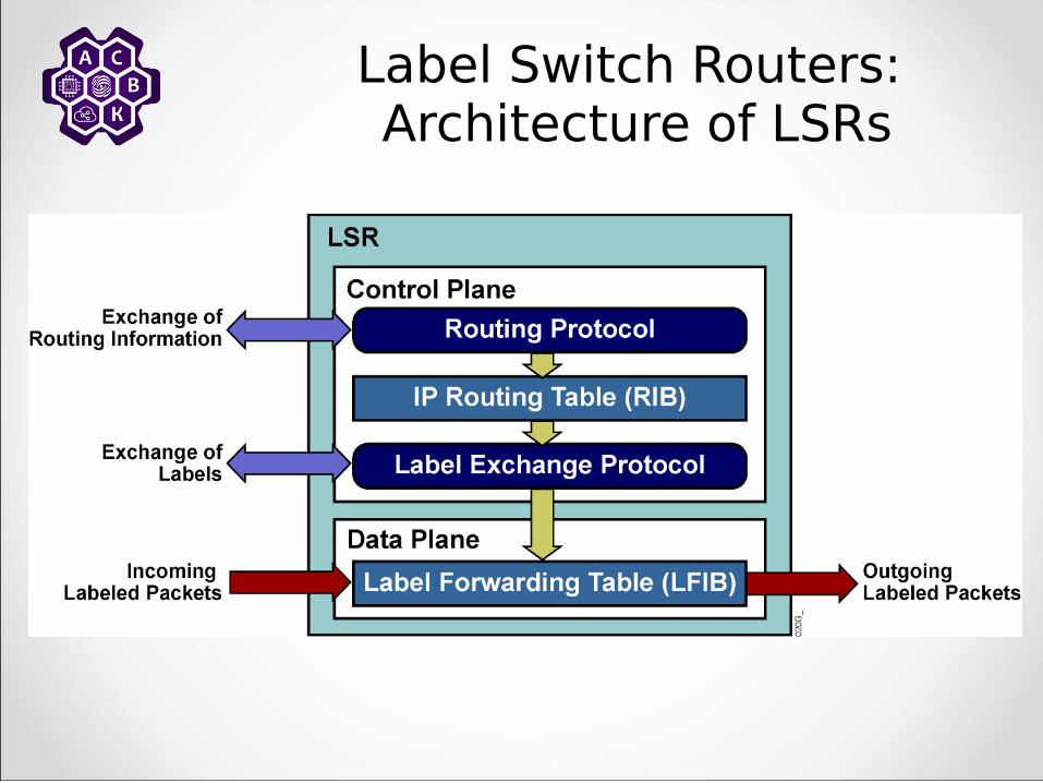
Label Switch Routers: Architecture of LSRs

LSRs: Architecture of Edge LSRs

Basic MPLS Example
MPLS core routers swap labels and forward packets based on simple label lookups.
MPLS edge routers also perform a routing table lookup, and add or remove labels.

MPLS Concepts
Introducing MPLS Labels and Label Stacks
MPLS Labels
– Are 4 byte identifiers used for forwarding decisions
– Define the destination and services for a packet
– Identify a forwarding equivalence class (FEC)– Have local significance
• Each LSR independently maps a label to an FEC in a label binding.
• Label bindings are exchanged between LSRs.

FEC and MPLS Forwarding
– An FEC is a group of packets forwarded: • In the same manner • Over the same path• With the same forwarding treatment
– MPLS packet forwarding consists of:• Assigning a packet to a specific FEC• Determining the next hop of each FEC
– MPLS forwarding is connection-oriented.

MPLS Label Format
• MPLS uses a 32-bit label field that contains the information that follows:– 20-bit label (a number)– 3-bit experimental (Traffic Class - TC) field
(typically used to carry IP precedence value)– 1-bit bottom-of-stack indicator (indicates whether
this is the last label before the IP header)– 8-bit TTL (equal to the TTL in the IP header)

MPLS Labels
– MPLS technology is intended to be used anywhere regardless of Layer 1 media and Layer 2 encapsulation.
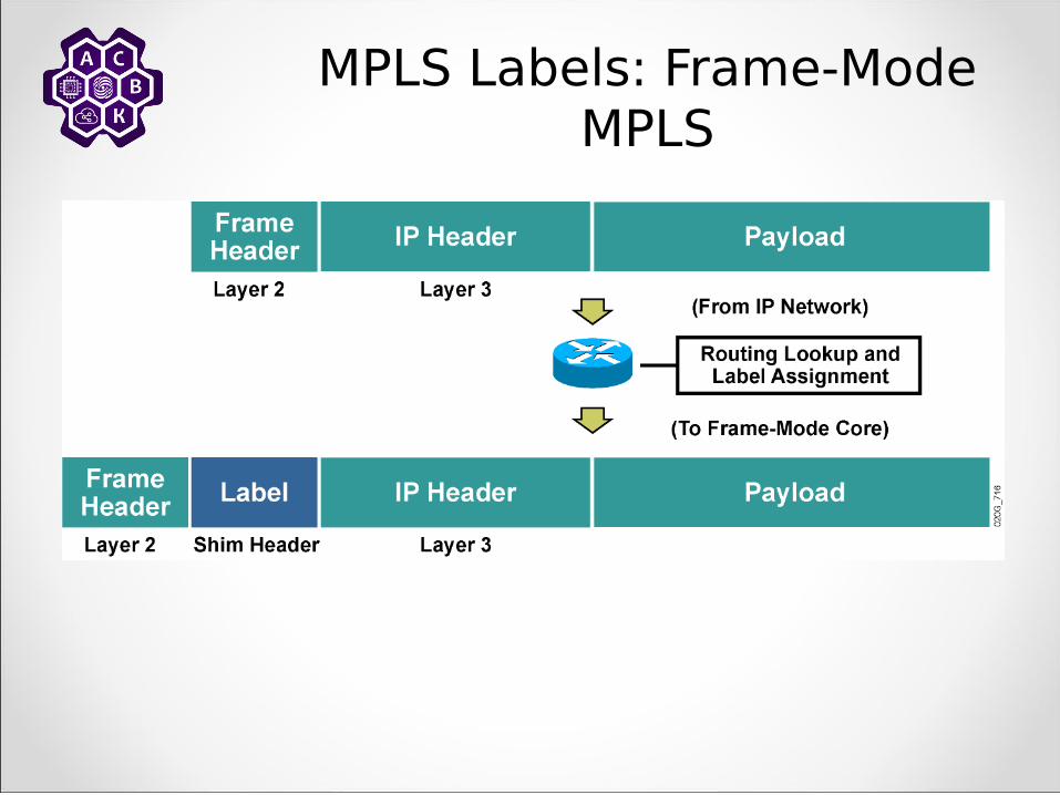
– Frame-mode MPLS is MPLS over a frame-based Layer 2 encapsulation
• The label is inserted between the Layer 2 and Layer 3 headers.
– Cell-mode MPLS is MPLS over ATM.• The fields in the ATM header are used as
the label.
MPLS Labels: Frame-Mode MPLS

MPLS Label Stack
– Usually only one label is assigned to a packet, but multiple labels in a label stack are supported.
– These scenarios may produce more than one label:
• MPLS VPNs (two labels): The top label points to the egress router, and the second label identifies the VPN.
• MPLS TE (two or more labels): The top label points to the endpoint of the traffic engineering tunnel and the second label points to the destination.
• MPLS VPNs combined with MPLS TE (three or more labels).

Example: MPLS Label Stack
– The outer label is used for switching the packet in the MPLS network (points to the TE destination).
– Inner labels are used to separate packets at egress points (points to egress router and identifies VPN).

Example: MPLS Label Stack Format
– The PID in a Layer 2 header specifies that the payload starts with a label (labels) followed by an IP header.
– The bottom-of-stack bit indicates whether the label is the last label in the stack.
– The receiving router uses the top label only.

MPLS Label Operations
– An LSR can perform these functions:• Insert (impose or push) a label or a stack of
labels on ingress edge LSR• Swap a label with a next-hop label or a stack
of labels in the core• Remove (pop) a label on egress edge LSR

MPLS Label Operations: Frame Mode
• On ingress, a label is assigned and imposed.
• LSRs in the core swap labels based on the contents of the label forwarding table.
• On egress, the label is removed and a routing lookup is used to forward the packet.

MPLS Concepts
Identifying MPLS Applications

MPLS Applications– MPLS is already used in many different
applications:• Unicast IP routing• Multicast IP routing• MPLS TE• QoS• MPLS VPNs (course focus)• AToM

MPLS Unicast IP Routing
–Basic MPLS service supports unicast IP routing. –MPLS unicast IP routing provides enhancement over traditional IP routing.• The ability to use labels for packet forwarding:
• Label-based forwarding provides greater efficiency.
• The FEC corresponds to a destination address stored in the IP routing table.
• Labels support connection-oriented services.• The capability to carry a stack of labels assigned to a
packet:• Label stacks allow implementation of enhanced
applications.

MPLS Multicast IP Routing
– MPLS can also support multicast IP routing:
• A dedicated protocol is not needed to support multicast traffic across an MPLS domain.
• The FEC is equal to a destination multicast address stored in the multicast routing table.
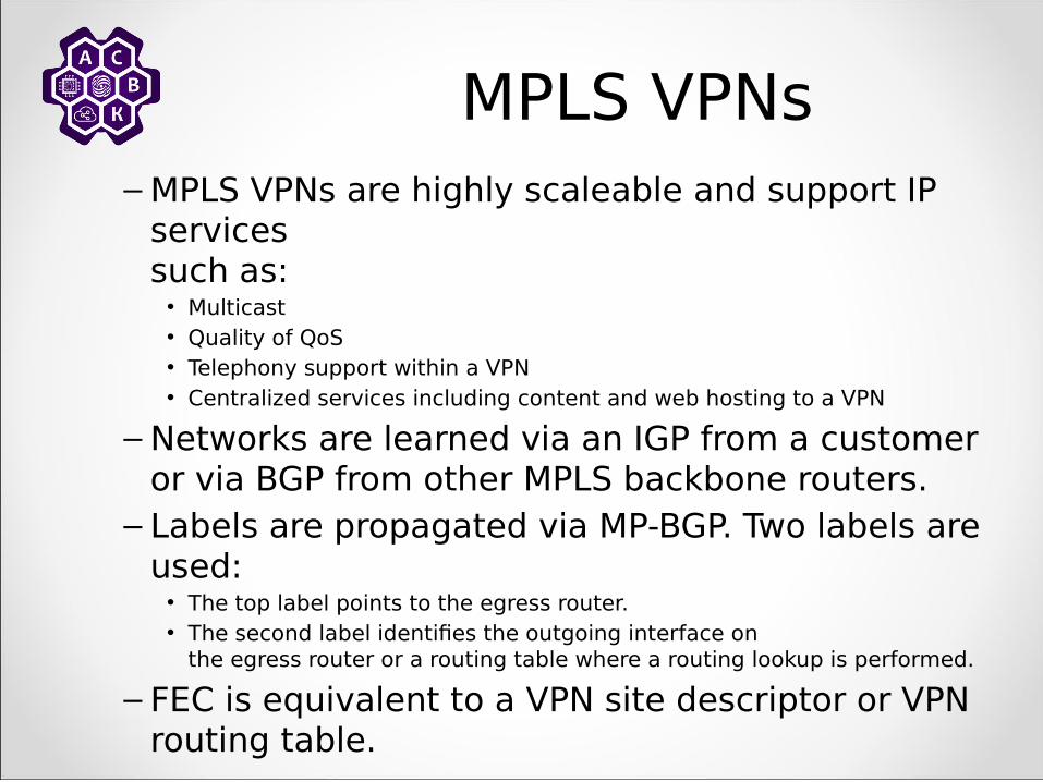
MPLS VPNs– MPLS VPNs are highly scaleable and support IP
services such as:
• Multicast • Quality of QoS • Telephony support within a VPN • Centralized services including content and web hosting to a VPN
– Networks are learned via an IGP from a customer or via BGP from other MPLS backbone routers.
– Labels are propagated via MP-BGP. Two labels are used:
• The top label points to the egress router.• The second label identifies the outgoing interface on
the egress router or a routing table where a routing lookup is performed.
– FEC is equivalent to a VPN site descriptor or VPN routing table.

MPLS TE
– MPLS TE supports constraints-based routing– MPLS TE enables the network administrator to
• Control traffic flow in the network • Reduce congestion in the network • Make best use of network resources
– MPLS TE requires OSPF or IS IS with extensions to hold the entire network topology in their databases.
– OSPF and IS-IS should also have some additional information about network resources and constraints.
– RSVP is used to establish TE tunnels and to propagate labels.

MPLS QoS– MPLS QoS provides differentiated types of
service across an MPLS network.
– MPLS QoS offers:• Packet classification• Congestion avoidance• Congestion management.
– MPLS QoS is an extension to unicast IP routing that provides differentiated services.
– Extensions to LDP are used to propagate different labels for different classes.
– The FEC is a combination of a destination network and a class of service.

Label Assignment and Distribution
Discovering LDP Neighbors

LDP Neighbor Session Establishment
– LDP establishes a session in two steps:• Hello messages are periodically sent on all
MPLS-enabled interfaces.• MPLS-enabled routers respond to received hello
messages by attempting to establish a session with the source of the hello messages.
– LDP link hello message is a UDP packet sent to the “all routers on this subnet” multicast address (224.0.0.2).
– TCP is used to establish the session.– Both TCP and UDP use well-known LDP port
number 646.

LDP Link Hello Message
– Hello messages are sent to all routers reachable through an interface.
– LDP uses well-known port number 646 with UDP for hello messages.
– A 6-byte LDP identifier (TLV) identifies the router (first 4 bytes) and label space (last 2 bytes).
– The source address used for an LDP session can be set by adding the transport address TLV to the hello message.
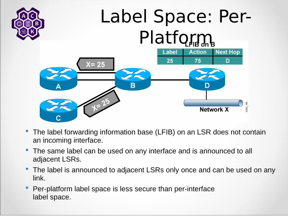
Label Space: Per-Platform
The label forwarding information base (LFIB) on an LSR does not contain an incoming interface.
The same label can be used on any interface and is announced to all adjacent LSRs.
The label is announced to adjacent LSRs only once and can be used on any link.
Per-platform label space is less secure than per-interface label space.

Negotiating Label Space
– LSRs establish one LDP session per label space.
• Per-platform label space requires only one LDP session, even if there are multiple parallel links between a pair of LSRs.
– Per-platform label space is announced by setting the label space ID to 0, for example:
• LDP ID = 1.0.0.1:0

LDP Neighbor Discovery
• An LDP session is established from the router with the higher IP address.

LDP Session Negotiation
– Peers first exchange initialization messages.
– The session is ready to exchange label mappings after receiving the first keepalive.

Label Assignment and Distribution
Introducing Typical Label Distribution in Frame-Mode
MPLS

MPLS Unicast IP Routing Architecture
– MPLS introduces a label field that is used for forwarding decisions.
– Although labels are locally significant, they have to be advertised to directly reachable peers.
• One option would be to include this parameter in existing IP routing protocols.
• The other option is to create a new protocol to exchange labels.
– The second option has been used because there are too many existing IP routing protocols that would have to be modified to carry labels.

MPLS Unicast IP Routing Architecture (Cont.)

MPLS Unicast IP Routing Architecture (Cont.)

MPLS Unicast IP Routing Architecture (Cont.)

Label-Switched Path
– An LSP is a sequence of LSRs that forwards labeled packets of a certain forwarding equivalence class.
• MPLS unicast IP forwarding builds LSPs based on the output of IP routing protocols.
• LDP advertises labels only for individual segments in the LSP.
– LSPs are unidirectional.• Return traffic uses a different LSP (usually the reverse
path because most routing protocols provide symmetrical routing).
– An LSP can take a different path from the one chosen by an IP routing protocol (MPLS TE).

LSP Building
The IP routing protocol determines the path.

LSP Building (Cont.)
LDP propagates labels to convert the path to an LSP.
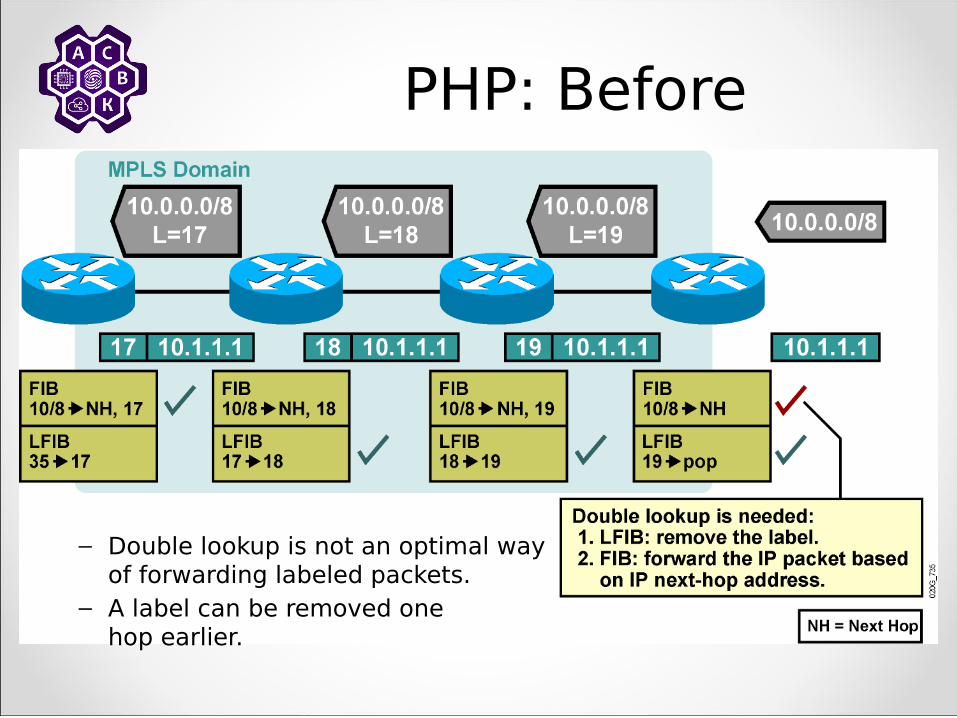
PHP: Before
– Double lookup is not an optimal way of forwarding labeled packets.
– A label can be removed one hop earlier.
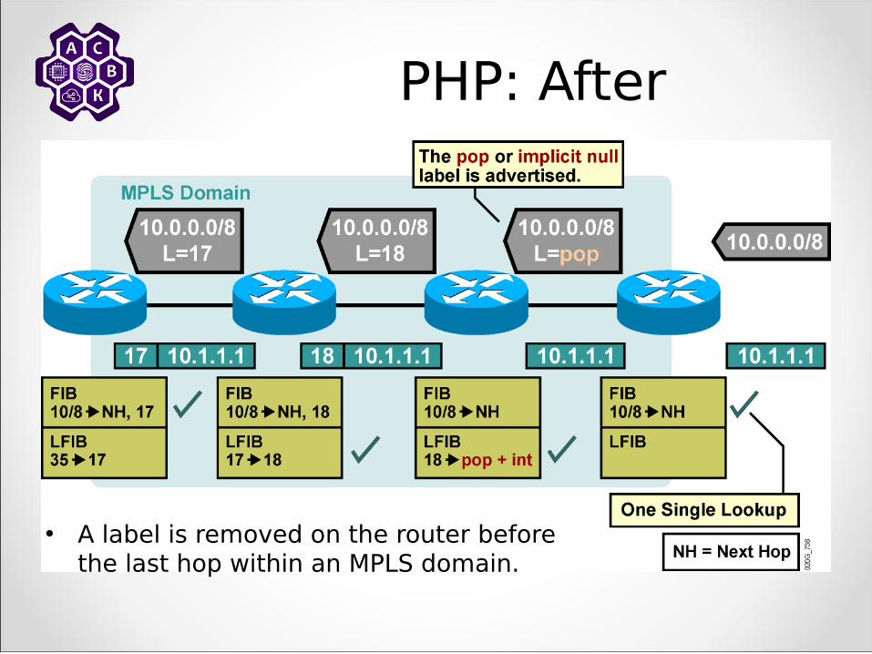
PHP: After
• A label is removed on the router before the last hop within an MPLS domain.

PHP
– Penultimate hop popping optimizes MPLS performance(one less LFIB lookup).
– PHP does not work on ATM. (virtual path identifier/virtual channel identifier cannot be removed.)
– The pop or implicit null label uses a reserved value when being advertised to a neighbor.

Label Allocation in a Frame-Mode MPLS Network
• Label allocation and distribution in a frame-mode MPLS network follows these steps:– IP routing protocols build the IP routing table.– Each LSR assigns a label to every destination
in the IP routing table independently.– LSRs announce their assigned labels to all
other LSRs.– Every LSR builds its LIB, LFIB, and FIB data
structures based on received labels.
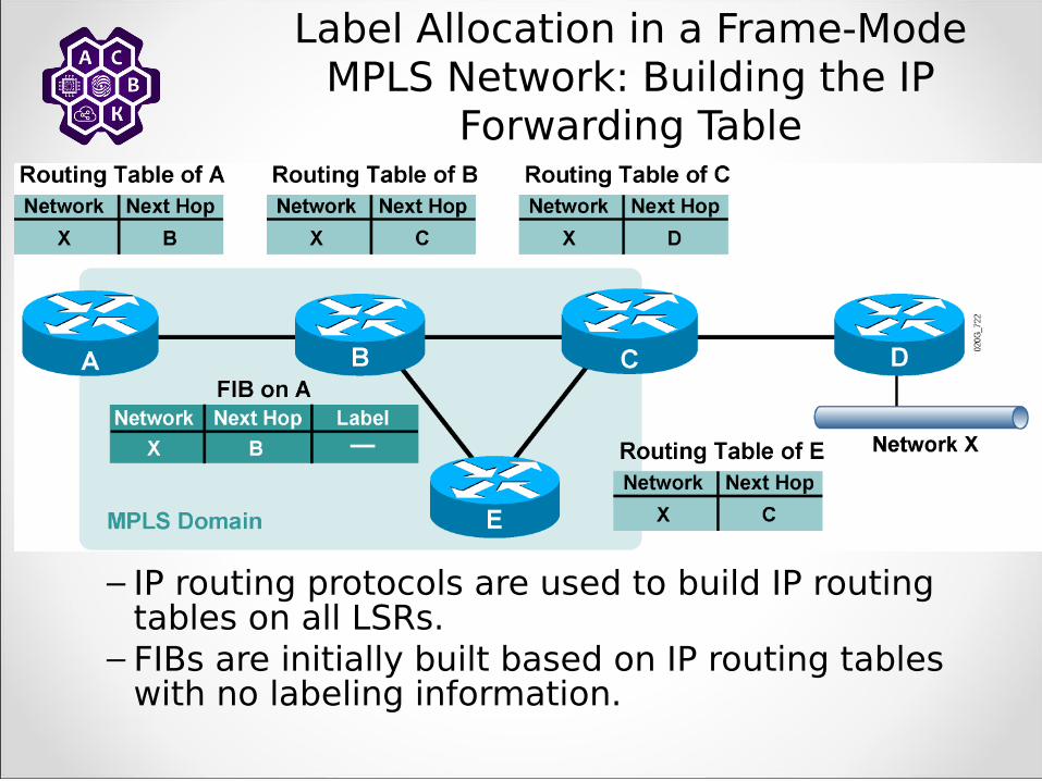
– IP routing protocols are used to build IP routing tables on all LSRs.
– FIBs are initially built based on IP routing tables with no labeling information.
Label Allocation in a Frame-Mode MPLS Network: Building the IP
Forwarding Table
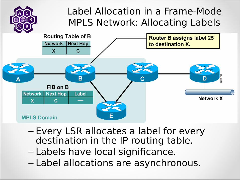
– Every LSR allocates a label for every destination in the IP routing table.
– Labels have local significance.– Label allocations are asynchronous.
Label Allocation in a Frame-Mode MPLS Network: Allocating Labels

• LIB and LFIB structures have to be initialized on the LSR allocating the label.
Label Allocation in a Frame-Mode MPLS Network: LIB and LFIB Setup

– Router A allocates a label for X independently of router B.
Label Allocation in a Frame-Mode MPLS Network: Labels and Table
Setup
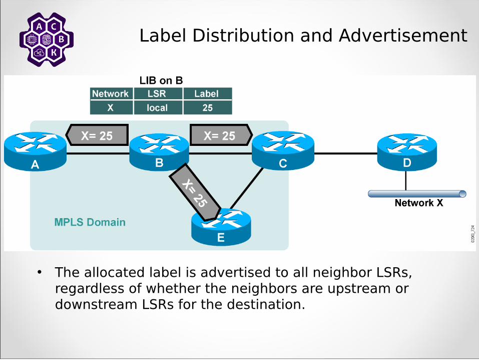
Label Distribution and Advertisement
• The allocated label is advertised to all neighbor LSRs, regardless of whether the neighbors are upstream or downstream LSRs for the destination.

Label Distribution and Advertisement:
Receiving Label Advertisement
– Every LSR stores the received label in its LIB.
– Edge LSRs that receive the label from their next hop also store the label information in the FIB.

Label Distribution and Advertisement:
Interim Packet Propagation
• Forwarded IP packets are labeled only on the path segments where the labels have already been assigned.
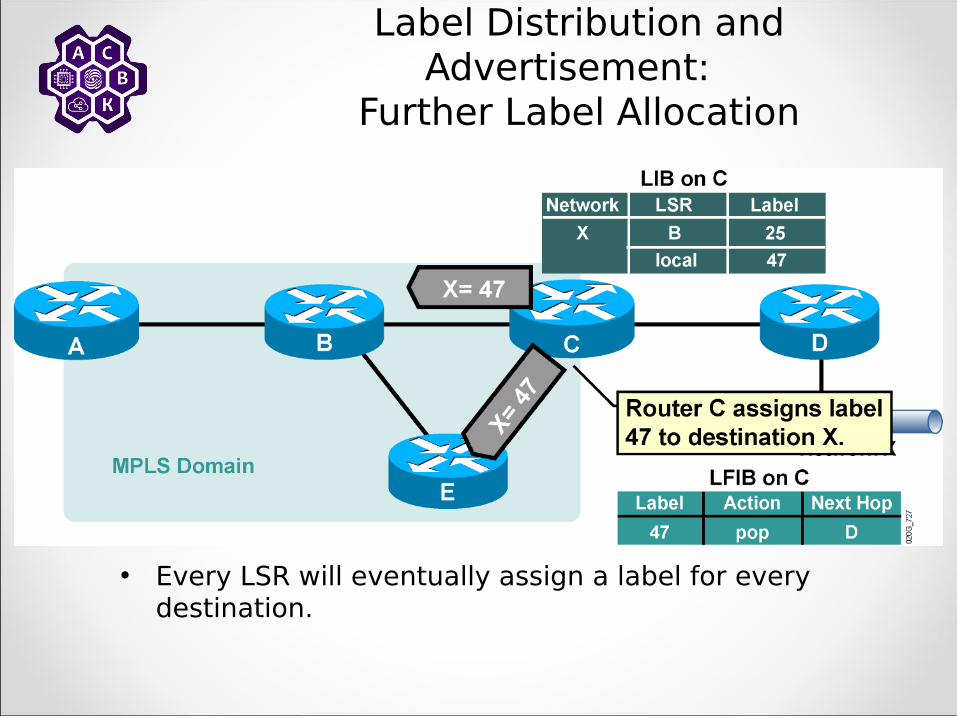
Label Distribution and Advertisement:
Further Label Allocation
• Every LSR will eventually assign a label for every destination.

Label Distribution and Advertisement:
Receiving Label Advertisement
– Every LSR stores received information in its LIB.– LSRs that receive their label from their next-hop LSR will also
populate the IP forwarding table.
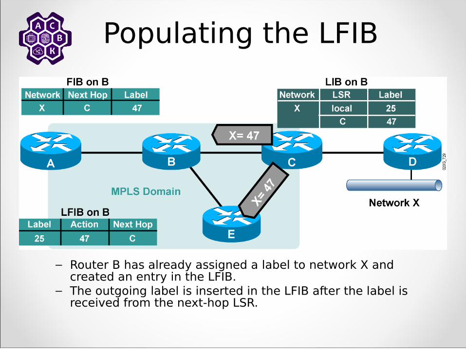
Populating the LFIB
– Router B has already assigned a label to network X and created an entry in the LFIB.
– The outgoing label is inserted in the LFIB after the label is received from the next-hop LSR.
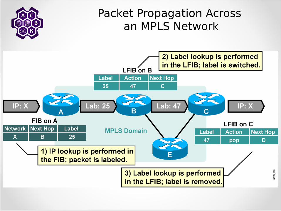
Packet Propagation Across an MPLS Network

Loop Detection
– LDP relies on loop detection mechanisms built into IGPs that are used to determine the path.
– If, however, a loop is generated (that is, misconfiguration with static routes), the TTL field in the label header is used to prevent indefinite looping of packets.
– TTL functionality in the label header is equivalent to TTL in the IP headers.
– TTL is usually copied from the IP headers to the label headers (TTL propagation).

Normal TTL Operation
• On ingress: TTL is copied from IP header to label header.
• On egress: TTL is copied from label header to IP header.

Labeled packets are dropped when the TTL is decreased to 0.
TTL and Loop Detection

Disabling TTL Propagation
– TTL propagation can be disabled.– The IP TTL value is not copied into the TTL
field of the label, and the label TTL is not copied back into the IP TTL.
– Instead, the value 255 is assigned to the label header TTL field on the ingress LSR.
– Disabling TTL propagation hides core routers in the MPLS domain.
– Traceroute across an MPLS domain does not show any core routers.

Traceroute with Disabled TTL Propagation
• The first traceroute packet (ICMP or UDP) that reaches the network is dropped on router A.
• An ICMP TTL exceeded message is sent to the source from router A.

Traceroute with Disabled TTL Propagation (Cont.)
• The second traceroute packet that reaches the network is dropped on router D.
• An ICMP TTL exceeded message is sent to the source from router D.

Label Assignment and Distribution
Introducing Convergence in Frame-Mode MPLS

Steady-State Operation Description
• Occurs after the LSRs have exchanged the labels, and the LIB, LFIB, and FIB data structures are completely populated

Link Failure Actions
– Routing protocol neighbors and LDP neighbors are lost after a link failure.
– Entries are removed from various data structures.

Routing Protocol Convergence
• Routing protocols rebuild the IP routing table and the IP forwarding table.

MPLS Convergence
• The LFIB and labeling information in the FIB are rebuilt immediately after the routing protocol convergence, based on labels stored in the LIB.

Link Recovery Actions
• Routing protocol neighbors are discovered after link recovery.

Link Recovery Actions: IP Routing Convergence
– IP routing protocols rebuild the IP routing table.– The FIB and the LFIB are also rebuilt, but the label
information might be lacking.

Link Recovery Actions:MPLS Convergence
– Routing protocol convergence optimizes the forwarding path after a link recovery.
– The LIB might not contain the label from the new next hop by the time the IGP convergence is complete.
– End-to-end MPLS connectivity might be intermittently broken after link recovery.
– Use MPLS TE for make-before-break recovery.

Operating and Configuring Huawei VRP Devices
Operating Huawei VRP Software

• Configurations can come from many sources.
• Configurations will act in device memory.
External Configuration Sources

Device connection
ConsoleMini USB
AR2200
S5700
Console

– A CLI is used to enter commands.– Operations vary on different
internetworking devices.– Users type or paste entries in the
console command modes. – Command modes have distinctive
prompts.– Enter key instructs device to parse
and execute the command.– Two primary modes are user mode
and system mode.
Huawei VRP User Interface Functions

CLI Command Line Views
Interface View
User View
System View
Protocol View
<Huawei>system-view
Enter system view, return user view with Ctrl+Z.
[Huawei]interface GigabitEthernet 0/0/0
[Huawei-GigabitEthernet0/0/0]
<Huawei>system-view
Enter system view, return user view with Ctrl+Z.
[Huawei]interface GigabitEthernet 0/0/0
[Huawei-GigabitEthernet0/0/0]
View the running status
and statistics of the device.
Set the system parameters
of the device.
Configure interface
parameters.
Configure most routing
protocol parameters.

CLI Help Features
Command Line Help
Partial Help
<Huawei> d?
<Huawei> display h?
Complete Help
<Huawei> ?
<Huawei> display ?
[Huawei]d?
ddns dhcp
dhcpv6 diagnose
display dns
domain dot1x
[Huawei]d?
ddns dhcp
dhcpv6 diagnose
display dns
domain dot1x

CLI Basic Device Setup
Command Function
sysname Configures the Device Name..
<Huawei>system-view
Enter system view, return user view with Ctrl+Z.
[Huawei]sysname RTA
[RTA]
<Huawei>system-view
Enter system view, return user view with Ctrl+Z.
[Huawei]sysname RTA
[RTA]
The system name should be assigned to uniquely identify each device within an enterprise network.
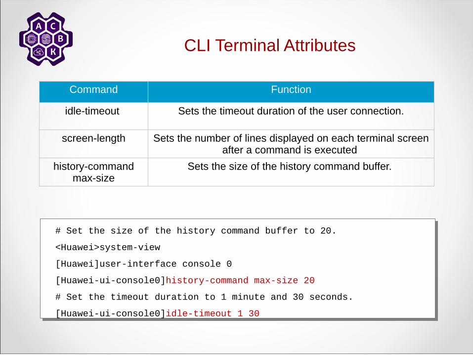
CLI Terminal Attributes
Command Function
idle-timeout Sets the timeout duration of the user connection.
screen-length Sets the number of lines displayed on each terminal screen after a command is executed
history-command max-size
Sets the size of the history command buffer.
# Set the size of the history command buffer to 20.
<Huawei>system-view
[Huawei]user-interface console 0
[Huawei-ui-console0]history-command max-size 20
# Set the timeout duration to 1 minute and 30 seconds.
[Huawei-ui-console0]idle-timeout 1 30
# Set the size of the history command buffer to 20.
<Huawei>system-view
[Huawei]user-interface console 0
[Huawei-ui-console0]history-command max-size 20
# Set the timeout duration to 1 minute and 30 seconds.
[Huawei-ui-console0]idle-timeout 1 30

CLI Interface Configuration
RTA RTB
G0/0/0 G0/0/0
10.0.12.1/241.1.1.1/32
# Configure an IP address of 10.0.12.1/24 on interface G0/0/0
and an IP address of 1.1.1.1/32 on loopback interface 0.
<Huawei>system-view
[Huawei]interface GigabitEthernet 0/0/0
[Huawei-GigabitEthernet0/0/0]ip address 10.0.12.1 255.255.255.0
[Huawei-GigabitEthernet0/0/0]interface loopback 0
[Huawei-LoopBack0]ip address 1.1.1.1 32

Configuration File Management System
RAM
Current-
Configuration File
Flash
Saved-
Configuration FileSave
Load

Saving the Configuration File
Command Function
Save Save the current configuration
<Huawei>saveThe current configuration will be written to the device.Are you sure to continue?[Y/N]yIt will take several minutes to save configuration file, please
wait............... Configuration file had been saved successfully Note: The configuration file will take effect after being activated
<Huawei>saveThe current configuration will be written to the device.Are you sure to continue?[Y/N]yIt will take several minutes to save configuration file, please
wait............... Configuration file had been saved successfully Note: The configuration file will take effect after being activated

– Unique addressing allows communication between end stations.
– Path choice is based on destination address.
Configuring IP Addresses

Configuring Loopback interface
[R1]interface loopback 0[R1-LoopBack0]ip address 2.2.2.2 24

Checking the routing table and the possibility of a connection
[R2]ping 10.0.1.2 PING 10.0.1.2: 56 data bytes, press CTRL_C to break Reply from 10.0.1.2: bytes=56 Sequence=1 ttl=253 time=36 ms Reply from 10.0.1.2: bytes=56 Sequence=2 ttl=253 time=31 ms Reply from 10.0.1.2: bytes=56 Sequence=3 ttl=253 time=31 ms Reply from 10.0.1.2: bytes=56 Sequence=4 ttl=253 time=31 ms Reply from 10.0.1.2: bytes=56 Sequence=5 ttl=253 time=31 ms
--- 10.0.1.2 ping statistics --- 5 packet(s) transmitted 5 packet(s) received 0.00% packet loss round-trip min/avg/max = 31/32/36 ms

Checking the status of routing tables
[R2]display ip routing-tableRoute Flags: R - relay, D - download to fib----------------------------------------------------------------------------Routing Tables: Public Destinations : 19 Routes : 19
Destination/Mask Proto Pre Cost Flags NextHop Interface
2.2.2.2/32 OSPF 10 1562 D 10.0.12.1 Serial1/0/0 3.3.3.0/24 Direct 0 0 D 3.3.3.3 LoopBack0 3.3.3.3/32 Direct 0 0 D 127.0.0.1 InLoopBack0 3.3.3.255/32 Direct 0 0 D 127.0.0.1 InLoopBack0 4.4.4.4/32 OSPF 10 1562 D 10.0.23.3 Serial2/0/0 10.0.1.0/24 OSPF 10 1563 D 10.0.12.1 Serial1/0/0 10.0.2.0/24 OSPF 10 1563 D 10.0.23.3 Serial2/0/0 10.0.12.0/24 Direct 0 0 D 10.0.12.2 Serial1/0/0 10.0.12.1/32 Direct 0 0 D 10.0.12.1 Serial1/0/0 10.0.12.2/32 Direct 0 0 D 127.0.0.1 InLoopBack0 10.0.12.255/32 Direct 0 0 D 127.0.0.1 InLoopBack0 10.0.23.0/24 Direct 0 0 D 10.0.23.2 Serial2/0/0 10.0.23.2/32 Direct 0 0 D 127.0.0.1 InLoopBack0 10.0.23.3/32 Direct 0 0 D 10.0.23.3 Serial2/0/0 10.0.23.255/32 Direct 0 0 D 127.0.0.1 InLoopBack0 127.0.0.0/8 Direct 0 0 D 127.0.0.1 InLoopBack0 127.0.0.1/32 Direct 0 0 D 127.0.0.1 InLoopBack0127.255.255.255/32 Direct 0 0 D 127.0.0.1 InLoopBack0255.255.255.255/32 Direct 0 0 D 127.0.0.1 InLoopBack0

Checking the status of LDP sessions between devices
[R2]display mpls ldp session LDP Session(s) in Public Network Codes: LAM(Label Advertisement Mode), SsnAge Unit(DDDD:HH:MM) A '*' before a session means the session is being deleted. ---------------------------------------------------------------------------- PeerID Status LAM SsnRole SsnAge KASent/Rcv ---------------------------------------------------------------------------- 2.2.2.2:0 Operational DU Active 0000:00:11 46/46 4.4.4.4:0 Operational DU Passive 0000:00:10 43/43 ---------------------------------------------------------------------------- TOTAL: 2 session(s) Found.

Checking LDP LSP routes
[R2]display mpls ldp lsp LDP LSP Information ---------------------------------------------------------------------------- DestAddress/Mask In/OutLabel UpstreamPeer NextHop OutInterface ---------------------------------------------------------------------------- 2.2.2.2/32 NULL/3 - 10.0.12.1 S1/0/0 2.2.2.2/32 1024/3 2.2.2.2 10.0.12.1 S1/0/0 2.2.2.2/32 1024/3 4.4.4.4 10.0.12.1 S1/0/0*2.2.2.2/32 Liberal/1024 DS/4.4.4.4 3.3.3.3/32 3/NULL 2.2.2.2 127.0.0.1 InLoop0 3.3.3.3/32 3/NULL 4.4.4.4 127.0.0.1 InLoop0*3.3.3.3/32 Liberal/1024 DS/2.2.2.2 *3.3.3.3/32 Liberal/1025 DS/4.4.4.4 4.4.4.4/32 NULL/3 - 10.0.23.3 S2/0/0 4.4.4.4/32 1025/3 2.2.2.2 10.0.23.3 S2/0/0 4.4.4.4/32 1025/3 4.4.4.4 10.0.23.3 S2/0/0*4.4.4.4/32 Liberal/1025 DS/2.2.2.2 ---------------------------------------------------------------------------- TOTAL: 8 Normal LSP(s) Found. TOTAL: 4 Liberal LSP(s) Found. TOTAL: 0 Frr LSP(s) Found. A '*' before an LSP means the LSP is not established A '*' before a Label means the USCB or DSCB is stale A '*' before a UpstreamPeer means the session is in GR state A '*' before a DS means the session is in GR state A '*' before a NextHop means the LSP is FRR LSP

Switching policy for LSR
Switch the policy to All for all LSR so that all static routes and routes from dynamic routing protocols (such as IGP) can be used to build LDP LSPs routes.
[R2]mpls[R2-mpls]lsp-trigger all

Configuring the input policy for LDP
If the labels received on the router are not controlled, then it will set a large number of LSP routes, which will require a large amount of memory.When configuring the input policy for LDP, the router must be configured to receive labels only from the specified router and sets the LSPs route to it, while saving resources.
[R1]ip ip-prefix prefix1 permit 10.0.12.0 24[R1]mpls ldp[R1-mpls-ldp]inbound peer 3.3.3.3 fec ip-prefix prefix1[R1-mpls-ldp]quit[R1]display mpls lsp---------------------------------------------------------------------------- LSP Information: LDP LSP----------------------------------------------------------------------------FEC In/Out Label In/Out IF Vrf Name 2.2.2.2/32 3/NULL -/- 10.0.12.0/24 3/NULL -/- 10.0.1.0/24 3/NULL -/- 2.2.2.0/24 3/NULL -/-

MPLS Implementation on Huawei VRP Platforms

Configuring IGP on the Backbone Network
VPN 1 (branch 1)172.16.1.1/32
172.16.2.1/32VPN 2 (branch 2)
AS200
CE1
CE2
PPE1 PE2CE3
(HQ)VPN310.1.23.0/24
10.1.13.0/24
AS100
AS 500AS300
10.1.34.0/24 10.1.45.0/24 10.1.56.0/24G0/0/0
G0/0/1G0/0/1
OSPF Area 0
G0/0/0G0/0/1G0/0/0
172.16.3.1/32
G1/0/0G0/0/0
G0/0/0
G0/0/0
router id 3.3.3.3 ospf 1 area 0.0.0.0 network 3.3.3.3 0.0.0.0 network 10.1.34.0 0.0.0.255
router id 4.4.4.4ospf 1 area 0.0.0.0 network 4.4.4.4 0.0.0.0 network 10.1.34.0 0.0.0.255 network 10.1.45.0 0.0.0.255
router id 5.5.5.5 ospf 1 area 0.0.0.0 network 5.5.5.5 0.0.0.0 network 10.1.45.5 0.0.0.255

Configuring MPLS
VPN 1 (branch 1)
AS200
CE1
CE2
CE3
(HQ)VPN310.1.23.0/24
10.1.13.0/24AS100
AS 500
10.1.34.0/24 10.1.45.0/24 10.1.56.0/24G0/0/0
G0/0/1G0/0/1
OSPF Area 0
G0/0/0G0/0/1G0/0/0
172.16.3.1/32
G1/0/0G0/0/0
G0/0/0
G0/0/0
VPN 2 (branch 2)
mpls lsr-id 3.3.3.3mplsmpls ldp#interface GigabitEthernet1/0/0 mpls mpls ldp
mpls lsr-id 4.4.4.4mplsmpls ldp#interface GigabitEthernet0/0/0 mpls mpls ldp#interface GigabitEthernet0/0/1 mpls mpls ldp
mpls lsr-id 5.5.5.5mplsmpls ldp#interface GigabitEthernet0/0/0 mpls mpls ldp

– The LDP session does not start.– Labels are not allocated.– Labels are not distributed.– Packets are not labeled, although the labels
have been distributed.– MPLS intermittently breaks after an interface
failure.– Large packets are not propagated across the
network.
Symptoms of Common Frame-Mode MPLS Issues
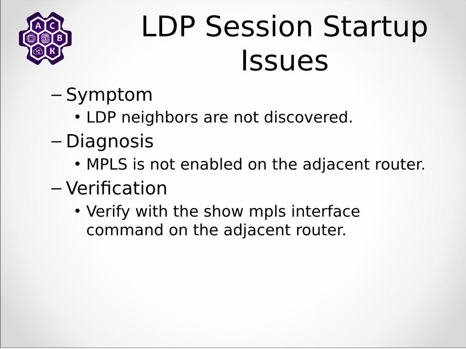
LDP Session Startup Issues
– Symptom• LDP neighbors are not discovered.
– Diagnosis• MPLS is not enabled on the adjacent router.
– Verification• Verify with the show mpls interface
command on the adjacent router.
LDP Session Startup Issues (Cont.)
– Symptom• LDP neighbors are not discovered.
– Diagnosis• Packet filter drops LDP neighbor discovery
packets.
– Verification• Verify access list presence with the show ip
interface command.• Verify access list contents with the show
access-list command.

LDP Session Startup Issues (Cont.)
– Symptom• LDP neighbors are discovered; the LDP session is
not established.
– Diagnosis• The connectivity between loopback interfaces is
broken; the LDP session is usually established between loopback interfaces of adjacent LSRs.
– Verification• Verify connectivity with the extended ping
command.

Intermittent MPLS Failures After Interface Failure
– Symptom• The overall MPLS connectivity in a router
intermittently breaks after an interface failure.
– Diagnosis• The IP address of a physical interface is used
for the LDP identifier. Configure a loopback interface on the router.
– Verification• Verify the local LDP identifier.

Packet Propagation Issues
– Symptom• Large packets are not propagated across the network.
– Use of the extended ping command with varying packet sizes fails for packet sizes close to 1500 packets.
• In some cases, MPLS might work, but MPLS VPN will fail.– Diagnosis
• There are label MTU issues or switches that do not support jumbo frames in the forwarding path.
– Verification• Issue the traceroute command through the forwarding
path; identify all LAN segments in the path.• Verify the label MTU setting on routers attached to LAN
segments.• Check for low-end switches in the transit path.


![[] Troubleshooting MPLS VPN Networks org](https://cdn.vdocuments.us/doc/165x107/577d20a41a28ab4e1e9361dd/-troubleshooting-mpls-vpn-networks-org.jpg)

