
Monoblock burners for heating, commercial and light industry applicationsTechnical information
VECTRON G1 to G6 (14,5 kW to 1907 kW)VECTRON GL2 to GL06 (35 kW to 2050 kW)VECTRON L1 to L6 (18 kW to 2080 kW)
www.elco-burners.com
2
VECTRON range:ELCO sets the standard for perfection with its gas, light oil and dual fuel program
Reliable heating solutions for every requirementWherever small or medium-scale heating solution is needed, ELCO is the best partner you can rely on. A comprehensive offer of tailor-made solutions is proposed by ELCO and offered by its worldwide network of distributors. A partner in professional heating offering a wide range of burner operations to fit individual and commercial needs with optimum combustion technology respectful of sustainable environment.
VECTRON: an optimal combination of experience and innovation With its gas and light oil burners series VECTRON, ELCO offers a product range capitalising more than 80 years of experience in the development of bur-ners in all sizes. All burners series VECTRON are characterized by economical consumption, ease of installation, adjustment and maintenance embedded in an excellent product engineering. The new generation models are equipped with an integrated display featuring an interactive, intuitive communication system. Burner and packaging are 100% recyclable.
VECTRON GRanging from the output of 14,5 to 1907 kW VECTRON models offer a wide choice of opera-tion, one and two stages, progressive pneumatic, modulating with electronic compound and a com-plete program of gas burners with speed control.
VECTRON GLELCO offers its dual fuel range working in gas and in light oil from 35 to 2050 kW, with models available in one stage, two stages and progressive pneumatic operation.
VECTRON L The light oil program ranging from the output of 18 to 2080 kW includes powerful variants for all applications and low-emission models with Blue and Yellow flame technology.
Competent advice Your contacts at ELCO and its partners are reco-gnized experts with years of experience. Our worldwide support starts from concept creation to planning, design and project management up to commissioning and on-going operation of the plant throughout its life cycle.
Outstanding serviceAs an ELCO customer, you can rely on your instal-lation to perform reliably. Our guarantee is backed up by a service that sets standards in our field.
Main features 4 - 5
ELCO operations and Systems 6 - 9
Designation 10
Range overview 11
Gas range technical data 12 - 21
Dual fuel range technical data 22 - 25
Light oil range technical data 26 - 29
Gas trains matching 30 - 32
Contents

3

4
CommunicationChoose an intuitive and interactive system
The new MDE2 System and the Elcogram, equipped on VECTRON range constantly give real-time information to professional operators.
■ During the commissioning. The setting of all necessary parameters for the burner operation is carried out by a user-friendly method thanks to the 5 buttons and the big size display.
■ During the burner operation.The instantaneous data of each ignition follow one another in real time, allowing a quick check of the burner running (voltage value, flame signal, time for ignition…).
■ At each operation cycle.The system records every event that happened during the last heating season and displays the stored data in the form of statistics.
Elcogram, a universal language
As ELCO products are distributed worldwide, the company has developed a universal language composed of pictograms and numerical data. The pictograms use the majority of the symbols used on the wiring diagrams which are recognised and understood by all Nations. This ensures that information is easier to read than ever before.
22,0°
22,0°
22,0°
48,0°
22,0°
22,0°
22,0°
45,2°
00:01:43s6µA
2 stages and progressive burners1 stage burners

5
MaintenanceChoose a rapid and easy maintenance solution
In order to grant cost benefits and high performance on all ELCO burners, we implemented features that simplify commissioning and allow quick and efficient burner maintenance.
For an easier maintenance, the combustion parts can be quickly removed, easily cleaned and, even when they are disassembled, they easily get back to their position after all the servicing work. The RTC System developed by ELCO guarantees a simple commissioning and exceptional operation from firstto last day of the heating season.
■ Quick: reduces downtime and cost of maintenance ■ Efficient: grants optimal performance like after first commissioning
EnvironmentPrefer a clean and silent technologyCommitted in a continuous developing path, ELCO always develops new technologies to respect the environment.
ELCO burners are also available in Low NOx versions: ■ VECTRON G: class 3 (NOx < 80 mg NOx/kWh) ■ VECTRON L: class 2 (NOx < 185 mg NOx/kWh) ■ VECTRON L Blue and Eco: class 3 (NOx < 120 mg NOx/kWh)
Devoted to eco-friendly solution.
The recently revised ELCO burners: ■ grant reduced electrical consumption ■ are completely recyclable, packaging included
For a greater user’s comfort, ELCO has taken particular care to the acoustic of the VECTRON range:
■ sound trap integrated in the air intake ■ air intake box made of composite materials equipped with a
honeycomb structure working like a soundtrap (VECTRON 1)■ air circuit seal pressurised ■ propylene cover to reduce acoustic emissions

6
Through an optimized combustion head design, patented as IME (Multi-stage Injection), this burner technology ensures a stable combustion quality and simultaneously ensures excellent energy efficiency.
Developed and produced by ELCO, the AGP (proportional air-gas) system provides:•perfect stability of the air-gas mixture;•a constantly high CO2 content over the whole burner output range;•precise control of air excess, which is important for high-efficiency
operation, in particular for condensing generators.
ELCO operations and Systems
The heat is even cleaner and more efficient
An outstanding technology for our gas burners
Duo
Duo Plus

7
Everything is perfectly under control with high reliability and optimum combustion values.The new display ensures easy commissioning and provides real time information on burner operation with precise fault diagnosis based on a detailed error log. The integrated gas leakage control provides additional security. Ready to plug connection for REMOTE SOLUTION monitoring.
To improve the performance of heating or industrial systems, ELCO applies Variatron (fan speed control) as an option or as a version.In combination with AGP, we can ensure optimum combustion by constantly controlling minimum air excess in all operating conditions.
Variatron
Modulo
ELCO operations and Systems
Cutting-edge technology for our modulating gas burners
Digital burner manager for our electronic gas burners

8
Silent and stylish: a dynamic and functional design
Cubic design, powerful, low noise and reliable.Installation, commissioning and maintenance are user friendly and quick.These are the main features of the new VECTRON models.
Permanent communication of information easy to use
With its new MDE2 System and the integrated display, VECTRON burners provide constant information updates for professionals and users. Instantaneous data (starting cycle, voltage measurement values and flame signal, etc.) and stored data (operating statistics) are now displayed.
Optimal acoustic comfort
Low Noise System
MDE2 System
ELCO operations and Systems

9
Low NOx Blue flame technology
The VECTRON Blue light oil burners have reached an excellent combustion technique for an improved quality of life. The combustion fuel is already in the form of gas-air mixture and ready for the combustion, thanks to the light oil atomizer. The result is a clean combustion with very low NOx emissions. These burners are electronically controlled and with the uncountable adjustable flue gas recirculation they can satisfy any installation requirements, from new boilers to older ones. These burners are 1.BImSchV conform.
Low NOx Yellow flame technology
The precision of the combustion head of the VECTRON Eco light oil burner series is particularly efficient and grants low NOx emissions. The characteristic crown of baffle plates optimizes the combustion by mixing fuel and air. The result of this innovative combustion head is a low air excess, a clean flame and high-efficiency energy saving. The internal flue gas recirculation considerably reduces NOx emissions. These burners are 1.BImSchV conform.
Blue flame
Yellow flame
Model ECOVE1.34VE1.50VE1.75
0 4020 6010 5030 70 80 kW
Model BLUEVB1.20VB1.24VB1.28VB1.30VB1.35
0 252010 355 3015 4540 50 kW
ELCO operations and Systems
10
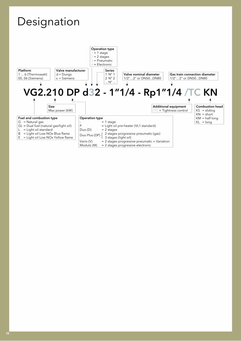
Platform1 ... 6 (Thermowatt) 05, 06 (Siemens)
SizeMax power (kW)
Operation type1 = 1 stage2 = 2 stages3 = Pneumatic4 = Electronic
Gas train connection diameter1/2”…2” or DN50...DN80
Fuel and combustion typeG = Natural gas GL = Dual fuel (natural gas/light oil)L = Light oil standardB = Light oil Low NOx Blue flameE = Light oil Low NOx Yellow flame
Operation type- = 1 stageP = Light oil pre-heater (VL1 standard)Duo (D) = 2 stages
Duo Plus (DP) { 2 stages progressive pneumatic (gas) 3 stages (light oil)Vario (V) = 2 stages progressive pneumatic + VariatronModulo (M) = 2 stages progressive electronic
Combustion headKS = slidingKN = shortKM = half longKL = long
Valve nominal diameter1/2”…2” or DN50...DN80
Valve manufacturerd = Dungss = Siemens
Series1 N° 12 N° 2... N° ...
Additional equipment/TC = Tightness control
VG2.210 DP d32 - 1”1/4 - Rp1”1/4 /TC KN
Designation
11
Burnermodel
Outputrange(kW)
Operation
1 stage 2 stages 2 stages progressive pneumatic (AGP)
2 stages progressive pneumatic (AGP) +
Variatron
2 stages progressive electronic
VG1 14,5 ... 85 •
VG01 45 ... 85 •
VG2 40 ... 210 • •(1) •(1) • •
VG3 70 ... 360 •(1) •(1) • •
VG4 100 ... 610 •(1) •(1) • •
VG5 170 ... 1160 •(1) (2) •
VG6 300 ... 1907 • (2) •
Burnermodel
Outputrange(kW)
Operation
1 stage 2 stages2 stages progressive pneumatic in gas / 2 stages in light oil
2 stages progressive pneumatic in gas / 3 stages in light oil
VGL2 35 ... 190 •
VGL3 95 ... 360 •
VGL4 168 ... 610 •
VGL05 200 ... 1000 •
VGL06 300 ... 2050 •
Burnermodel
Outputrange(kW)
Operation
1 stage 2 stages 3 stages
VL1 18 ... 95 •
VL2 60 ... 210 • •
VL3 130 ... 360 •
VL4 180 ... 610 • •
VL5 260 ... 1186 • •
VL6 320 ... 2080 •
Overview of dual fuel burners
Overview of light oil burners
Overview of gas burners
(1): version with tightness control on request
(2): available as an option
Range overview

12
VECTRONGas burners: VG1 to VG4 DWorking fields and overall dimensions
VG1, VG2
00
0,5
1
1,5
2
50 100 150 200 kW
mbar
VG1.40VG1.55
VG1.85
VG2.140VG2.200
VG01 D, VG2 D
00
0,5
1
1,5
2
2,5
3
50 100 150 200 250 kW
mbar
VG2.120 D
VG01.85 D
VG2.210 DVG2.160 D
VG3 D
00
1
2
3
4
5
100 200 300 400 kW
mbar
VG3.360 D
VG3.290 D
VG4 D
00
1
2
3
4
6
5
100 200 300 400 500 600 kW
mbar
VG4.460 D

13
A
165
16
5
10
0JB
E2
37
229
G H
M
L
ØK
VG2VG2 D
VG1 VG01 D
Model Gas train A B EG H
J Ø KL
Mmin max min max min max
VG1.40/55 h3/8”-Rp1/2” 263 120 484 297 337 70 110 Rp1/2” 80 21 61 48
VG1.85 d3/4”-Rp3/4” 282 140 477 300 355 70 138 Rp3/4” 90 15 83 52
VG01.85 D d3/4”-Rp3/4” 290 210 535 300 355 70 138 Rp3/4” 90 15 83 52
Model Gas train A B C D E F Ø G H I N P Rp R S T U W
VG2 d3/4”-Rp3/4” 331 326 KN398...518
KL398...638 256 69 15
min 100 KN30...150
KL30...270
185x
185113 min 115 3/4” 46 150 120 133 330
VG2 Dd3/4”-Rp3/4”
331 326 KN398...518
KL398...638 256 69 15
min 115 KN30...150
KL30...270
185x
185113 min
115 3/4” 46 210 120133
330
d1”1/4-Rp1”1/4 55 1”1/4 55 260 145 360
Model Gas train A B C D E F Ø G H I N Rp R S T W
VG3 D
d3/4”-Rp3/4”
406 379 576 297 82 120 130KN180
KL320
195 x
205170
3/4” 46 210 120 479
d1”1/4-Rp1”1/4 1”1/4 55 260 145 526
d1”1/2-Rp2” 2” 80 330 100 603
VG4 D
d3/4”-Rp3/4”
465 475 640 377 97 149 150KN220
KL360
245 x
245195
3/4” 46 210 120 489
d1”1/4-Rp1”1/4 1”1/4 55 260 145 536
d1”1/2-Rp2” 2” 80 330 100 613
VG3 DVG4 D
14
VECTRONGas burners: VG2 DP to VG4 VWorking fields and overall dimensions
VG2 DP, VG2 V
00
0,5
1
1,5
2
2,5
3
50 100 150 200 250 kW
mbar
VG2.120 DP
VG2.210 DP/VVG2.160 DP
VG3 DP, VG3 V
00
1
2
3
4
5
100 200 300 400 kW
mbar
VG3.360 DP/V
VG3.290 DP/V
VG4 DP, VG4 V
00
1
2
3
4
5
6
7
100 200 300 400 500 600 700 kW
mbar
VG4.610 DP/V
VG4.460 DP/V

15
VG2 DPVG2 V
Model Gas train A B C D E F Ø G H I N P Rp R S T U W
VG2 DP/Vd3/4” - Rp3/4”
331 326KN
398…518KL
398…638256 69
15 min
115KN
30...150KL
30...270185
x185
113 min
115 3/4” 70 160 120133
345
d1”1/4 - Rp1”1/4 55 1”1/4 80 175 145 380
Model Gas train A B C D E F Ø G H I N Rp R S T W RpF Z
VG3 DP/V
d3/4”-Rp3/4”
406 379 576 297 82 120 130KN180
KL320
195 x
205170
3/4” 70 160 120 479 1” 160
d1”1/4-Rp1”1/4 1”1/4 80 175 145 526 - -
d1”1/2-Rp2” 2” 100 185 100 603 - -
Model Gas train A B C D E F Ø G H I N Rp R S T W RpF Z
VG4 DP/V
d3/4”-Rp1”
465 475 640 377 97 149 150KN220
KL360
245 x
245195
1” 70 160 120 489 1” 160
d1”1/4-Rp1”1/4 1”1/4 80 175 145 536 - -
d1”1/2-Rp2” 2” 100 185 100 613 - -
VG3 DPVG3 V
VG4 DPVG4 V

16
VECTRONGas burners: VG5 DP to VG6 DPWorking fields and overall dimensions
VG5 DP
00
2
4
6
8
10
12
400 600200 800 1000 1200 kW
mbar
VG5.1200 DPVG5.950 DP
VG6 DP
00
2
4
6
8
10
12
400 800 1200 1600 2000 kW
mbar
VG6.2100 DPVG6.1600 DP

17
VG5 DP
VG6 DP
Model A B C D E F Ø G H I K N
VG6 DP 592 553 1050 456 97 421 227 KN360
KM460
KL560 326 x 335 144 247
Model A B C D E F Ø G H I N
VG5 DP 581 549 752 450 99 164 170 KN215
KM325
KL435 230 x 238 244
Model J R S V X Zd1”1/4-Rp1”1/4 /TC 450 100 141 95 58 186
d1”1/2-Rp2” /TC 540 123 190 95 55 -
Model J R S V X Zd3/4”-Rp1” 420 100 122 55 50 160
d1”1/4-Rp2” 450 100 141 58 58 186
d1”1/2-Rp2” 540 123 190 55 55 -
Model J R S V X Zs2”-Rp2” /TC 612 103 330 110 150 186
s65-DN65 /TC 600 135 360 110 150 320
s80-DN80 /TC 600 120 350 110 150 290
Model J R S V X Zs2”-Rp2” 612 103 330 110 150 186
s65-DN65 600 135 360 110 150 320
with gas train ”d”: with gas train ”s”:
with gas train ”d”: with gas train ”s”:
18
VECTRONGas burners: VG2 M to VG4 MWorking fields and overall dimensions
VG4 M
00
1
2
3
4
5
6
7
100 200 300 400 500 600 700 kW
mbar
VG4.610 M
VG4.460 M
VG2 M
VG3 M
00
1
2
3
4
100 200 300 400 kW
mbar
VG3.290 M
VG3.360 M
00
0,5
1
1,5
2
2,5
3
50 100 150 200 250 kW
mbar
VG2.120 MVG2.210 MVG2.160 M

19
VG2 M
VG4 M
VG3 M
Model Gas train A B C D E F Ø G H I N P Rp R S T U W
VG2 M d3/4”-Rp1”1/4 /TC 331 326KN
398…518KL
398…638256 69 15 min 115
KN30…150
KL30…270
185x
18530...150 193 3/4” 60 173 146 133 455
Model Gas train A B C D E F Ø G H I N Rp R S T W
VG4 Md3/4”-Rp1”1/4 /TC
465 475 640 377 97 149 150KN220
KL360
245 x
245195
1”1/4 60 173 146 587
d1”1/2-Rp1”1/2 /TC 1”1/2 80 185 160 649
Model Gas train A B C D E F Ø G H I N Rp R S T W
VG3 Md3/4”-Rp1”1/4 /TC
406 379 576 297 82 120 130KN180
KL320
195 x
205170
1”1/4 60 173 146 577
d1”1/2-Rp1”1/2 /TC 1”1/2 80 185 160 638

20
VECTRONGas burners: VG5 M to VG6 MWorking fields and overall dimensions
VG5 M
VG6 M
00
2
4
6
8
10
12
400 600200 800 1000 1200 kW
mbar
VG5.1200 MVG5.950 M
00
2
4
6
8
10
12
400 800 1200 1600 2000 kW
mbar
VG6.2100 MVG6.1600 M

21
VG5 M
VG6 M
Model A B C D E F Ø G H I K N
VG6 M 592 553 1050 456 97 421 227 KN360
KM460
KL560 326 x 335 144 247
Model A B C D E F Ø G H I K N
VG5 M 581 549 752 450 99 164 170 KN215
KM325
KL435 230 x 238 89 244
Model J R S V X Zd3/4”-Rp1”1/4 /TC 498 60 173 88 58 -
d1”1/2-Rp2” /TC 662 80 185 102 57 -
d2”-Rp2” /TC 740 96 330 125 81 -
d65-DN65 /TC 820 183 245 110 98 320
Model J R S V X Zd1”1/2-Rp2” /TC 662 80 185 102 57 -
d2”-Rp2” /TC 740 96 330 125 81 -
d65-DN65 /TC 820 183 245 110 98 320
with gas train ”d”:
with gas train ”d”: with gas train ”s”:
Model J R S V X Zs65-DN65 /TC 530 118 300 106 126 320

22
VECTRONDual fuel burners: VGL2 to VGL4 DPWorking fields and overall dimensions
VGL4 DP
00
1
2
3
4
5
6
7
100 200 300 400 500 600 700 kW
mbar
VGL4.610 DPVGL4.460 DP
VGL2
VGL3 D
00
1
2
3
4
100 200 300 400 kW
mbar
VGL3.290 D VGL3.360 D
00
0,5
1
1,5
2
2,5
3
50 100 150 200 250 kW
mbar
VGL2.120
VGL2.210

23
VGL2
Model A B C D E F Ø G H I N P Rp R S T U W
VGL2 331 325 KL398…638 256 69 15 min 115 KL
30...270 185 x 185 113min 115 3/4” 46 140 120 133 330
Model Gas train A B C D E F Ø G H I N Rp R S T W
VGL3 D
d3/4”-Rp3/4”
406 379 576 297 82 120 130KN180
KL320
195 x
205170
3/4“ 46 210 120 479
d1”1/4-Rp1”1/4 1“1/4 55 260 145 526
d1”1/2-Rp2” 2” 80 330 100 603
Model Gas train A B C D E F Ø G H I N Rp R S T W RpF Z
VGL4 DP
d3/4”-Rp1”
465 475 640 377 97 149 150KN220
KL360
245 x
245195
1” 70 160 120 489 1” 160
d1”1/4-Rp1”1/4 1”1/4 80 175 145 536 - -
d1”1/2-Rp2” 2” 100 185 100 613 - -
VGL3 D
VGL4 DP

24
VECTRONDual fuel burners: VGL05 DP to VGL06 DPWorking fields and overall dimensions
VGL05 DP
VGL06 DP
00
2
4
6
8
10
12
400 600200 800 1000 1200 kW
mbar
VGL05.1000 DPVGL05.700 DP
00
2
4
6
8
10
12
300 600 900 1200 1500 1800 2100 kW
mbar
VGL06.2100 DPVGL06.1600 DP

25
with gas train "d":
with gas train "s":
VGL05 DP
D F HMBVEF407 120 516 Rp3/4"
MBVEF412 177 540 Rp1"1/4
MBVEF420 - 635 -
D E F G HVGD20 186 292 734 344 2"
VGD40 290 292 740 365 DN65
VGD40 320 312 746 375 DN80
D E F G HVGD20 186 292 734 344 Rp2"
VGD40 290 292 740 365 DN65
D E HMBVEF412 160 590 Rp2"
MBVEF420 - 690 Rp2"
VGL06 DP
with gas train "d":
with gas train "s":

26
VECTRONLight oil burners: VL1 to VL3 DWorking fields and overall dimensions
VL1
VL2
VL2 D
VL3 D
00
0,4
0,2
0,8
0,6
1
4020 8060 100 kW
mbar
VL1.40 PVL1.55/P VL1.95VL1.42
00
0,5
1
1,5
2
10050 200150 250 kW
mbar
VL2.200VL2.140
00
1
2
2,5
1,5
0,5
3
10050 150 200 250 kW
mbar
VL2.160 DVL2.120 D VL2.210 D
00
1
2
3
4
100 200 300 400 kW
mbar
VL3.290 D
VL3.360 D

27
229
237
57
A B
D
ØC
ModelA B
Ø CD
min max min max min maxVL 1.40 P
270 310 70 120 80 21 71VL 1.42
VL 1.55 / 1.55 P
VL 1.95 297 357 70 138 90 15 83
VL1
VL2 VL2 D
VL3 D
Model A B C D E F Ø G H I J
VL2.120/160/200/210 331 326KN
398…518KL
398…638256 69 15 min 115
KN30…150
KL30…270
185 x 185 1200
VL2.140 331 326KN
398…518KL
398…638256 69 15 min 100
KN30…150
KL30…270
185 x 185 1200
Model A B C D E F Ø G H I J
VL3 D 406 379 576 297 82 120 130KN180
KL320
195 x 205 1000

28
VECTRONLight oil burners: VL4 D to VL6 DPWorking fields and overall dimensions
VL4 D, VL4 DP
VL6 DP
VL5 D, VL5 DP
00
2
4
6
8
10
12
400 800 1200 1600 kW
mbar
VL5.950 D/DP VL5.1200 D/DP
00
1
2
3
4
5
6
7
100 200 300 400 500 600 700 kW
mbar
VL4.610 D/DP
VL4.460 D/DP
00
2
4
6
8
10
12
400 800 1200 1600 2000 2400 kW
mbar
VL6.2100 DPVL6.1600 DP

29
VL5 DVL5 DP
VL6 DP
Model A B C D E F Ø G H I J
VL5 D/DP 581 549 752 450 99 164 170 KN215
KM325
KL435 230 x 238 950
Model A B C D E E1 F Ø G H I J
VL6 DP 592 553 1050 456 97 239 421 227 KN270
KM370
KL470 326 x 335 850
VL4 D VL4 DP
Model A B C D E F Ø G H I J
VL4 D/DP 465 475 640 377 97 149 150KN220
KL360
245 x 245 1000

30
d...°
Ø a
Ø b
c
Ø a Ø b c d
VG1.40/55, VL1.40/55 85...104 150...170 M8 45°
VG1.85, VG01.85, VL1.95 95...104 150...170 M8 45°
V2 120...135 150...184 M8 45°
V3 155...190 175...220 M10 45°
V4 180...240 200...270 M10 45°
V5 195 220...260 M10 45°
VGL05 172...195 220...260 M10 45°
V6, VGL06 250 300...400 M12 45°
Connecting flangeDimensions
Gas trainsMatching
Model Burner range output [kW]
Natural gas pressure range for max power [mbar] Gas train Valve Filter
VG1.40 14,5 - 40 20 … 50 h3/8”-Rp1/2” VR4625 Integrated
VG1.55 35 - 55 20 … 50 h3/8”-Rp1/2” VR4625 Integrated
VG1.85 45 - 85 20 … 300 d3/4”-Rp3/4” MB-DLE 407 Integrated
VG2.140 80 - 140 20 … 300 d3/4”-Rp3/4” MB-DLE 407 Integrated
VG2.200 130 - 20020 … 300 d3/4”-Rp3/4” MB-DLE 407 Integrated
20 … 300 d1”1/4-Rp1”1/4 MB-ZRDLE 412 Integrated
VG01.85 D 42 (52,5) - 90 20 … 300 d3/4”-Rp3/4” MB-DLE 407 Integrated
VG2.120 D (40) 80 - 120 20 … 300 d3/4”-Rp3/4” MB-ZRDLE 407 Integrated
VG2.160 D (60) 110 - 160 20 … 300 d3/4”-Rp3/4” MB-ZRDLE 407 Integrated
VG2.210 D
(80) 150 - 210 20 … 100 d1”1/4-Rp1”1/4 MB-ZRDLE 412 Integrated
(80) 150 - 210 100 … 300 d3/4”-Rp3/4” MB-ZRDLE 407 Integrated
(80) 140 - 180 20 … 100 d3/4”-Rp3/4” MB-ZRDLE 407 Integrated
VG3.290 D (95) 190 - 29020 … 60 d1”1/4-Rp1”1/4 MB-ZRDLE 412 Integrated
60 … 300 d3/4”-Rp3/4” MB-ZRDLE 407 Integrated
VG3.360 D (120) 240 - 360
20 ... 30 d1”1/2-Rp2” MB-ZRDLE 420 Integrated
20 … 60 d1”1/4-Rp1”1/4 MB-ZRDLE 412 Integrated
60 … 300 d3/4”-Rp3/4” MB-ZRDLE 407 Integrated
VG4.460 D (150) 300 - 460
20 … 50 d1”1/2-Rp2” MB-ZRDLE 420 Integrated
20 … 100 d1”1/4-Rp1”1/4 MB-ZRDLE 412 Integrated
100 … 300 d3/4”-Rp3/4” MB-ZRDLE 407 Integrated
VG2.120 DP (40) 80 - 12020 … 300 d333-3/4”-Rp3/4” MB-VEF 407 Integrated
20 … 100 d332-3/4”-Rp3/4” MB-VEF 407 Integrated
VG2.160 DP (60) 110 - 16020 … 300 d347-3/4”-Rp3/4” MB-VEF 407 Integrated
20 … 100 d345-3/4”-Rp3/4” MB-VEF 407 Integrated
VG2.210 DP/V
(80) 150 - 210 20 … 40 d1”1/4-Rp1”1/4 MB-VEF 412 Integrated
(80) 150 - 210 40 … 100 d346-3/4”-Rp3/4” MB-VEF 407 Integrated
(80) 150 - 180 100 … 300 d345-3/4”-Rp3/4” MB-VEF 407 Integrated
VG3.290 DP/V (70) 190 - 29020 … 60 d1”1/4-Rp1”1/4 MB-VEF 412 Integrated
60 … 300 d3/4”-Rp1” MB-VEF 407 External 1”
VG3.360 DP/V (80) 240 - 360
20 … 60 d1”1/2-Rp2” MB-VEF 420 Pocket Filter
20 … 30 d1”1/4-Rp1”1/4 MB-VEF 412 Integrated
60 ... 300 d3/4”-Rp1” MB-VEF 407 External 1”

31
Gas trainsMatching
Model Burner range output [kW]
Natural gas pressure range for max power [mbar] Gas train Valve Filter
VG4.460 DP/V (100) 300 - 460
20 … 100 d1”1/2-Rp2” MB-VEF 420 Pocket Filter
100 … 300 d1”1/4-Rp1”1/4 MB-VEF 412 Integrated
100 … 300 d3/4”-Rp1” MB-VEF 407 External 1”
VG4.610 DP/V (130) 390 - 610
20 … 40 d1”1/2-Rp2” MB-VEF 420 Pocket Filter
40 … 60 d1”1/4-Rp1”1/4 MB-VEF 412 Integrated
60 … 300 d3/4”-Rp1” MB-VEF 407 External 1”
VG5.950 DP (170) 510 - 950
20 … 40 s2”-Rp2” VGD 20-5011 External 2”
40 … 50 d1”1/2-Rp2” MB-VEF 420 Pocket Filter
50 … 100 d1”1/4-Rp2” MB-VEF 412 External 2”
100 … 300 d3/4”-Rp1” MB-VEF 407 External 1”
VG5.1200 DP (250) 750 - 1160
20 … 35 s65-DN65 VGD 40-065 External DN65
35 … 40 s2”-Rp2” VGD 20-5011 External 2”
40 … 50 d1”1/2-Rp2” MB-VEF 420 Pocket Filter
50 … 300 d1”1/4-Rp2” MB-VEF 412 External 2”
VG6.1600 DP (300) 890 - 1600
30 … 40 s80-DN80/TC VGD 40-080 External DN80
40 … 50 s65-DN65/TC VGD 40-065 External DN65
50 … 70 s2”-Rp2”/TC VGD 20-5011 External 2”
70 … 100 d1”1/2-Rp2”/TC MB-VEF 420 Pocket Filter
100 … 300 d1”1/4-Rp2”/TC MB-VEF 412 External 2”
VG6.2100 DP (400) 1180 - 1907
40 … 50 s80-DN80/TC VGD 40-080 External DN80
50 … 60 s65-DN65/TC VGD 40-065 External DN65
60 … 70 s2”-Rp2”/TC VGD 20-5011 External 2”
70 … 100 d1”1/2-Rp2”/TC MB-VEF 420 Pocket Filter
100 … 300 d1”1/4-Rp2”/TC MB-VEF 412 External 2”
VG2.120 M (30) 80 - 120 20 … 300 d3/4”-Rp3/4” /TC MBC300 Integrated
VG2.160 M (40) 110 - 160 20 … 300 d3/4”-Rp3/4” /TC MBC300 Integrated
VG2.210 M (80) 136 - 210 20 … 300 d3/4”-Rp3/4” /TC MBC300 Integrated
VG3.290 M (50) 190 - 290 20 … 300 d3/4”-Rp1”1/4 /TC MBC300 Integrated
VG3.360 M (60) 240 - 36020 … 40 d1”1/2-Rp1”1/2 /TC MBC700 Integrated
40 … 300 d3/4”-Rp1”1/4 /TC MBC300 Integrated
VG4.460 M (86) 300 - 46020 … 50 d1”1/2-Rp1”1/2 /TC MBC700 Integrated
50 … 300 d3/4”-Rp1”1/4 /TC MBC300 Integrated
VG4.610 M (90) 390 - 61020 … 60 d1”1/2-Rp1”1/2 /TC MBC700 Integrated
60 … 300 d3/4”-Rp1”1/4 /TC MBC300 Integrated
VG5.950 M (160) 510 - 900
20 … 30 d65-DN65 /TC MBC1900 External DN65
30 … 40 d2”-Rp2” /TC MBC1200 Integrated
40 … 300 d1”1/2-Rp2” /TC MBC700 Integrated
300 d3/4”-Rp1”1/4 /TC MBC300 Integrated
VG5.1200 M (160) 750 - 1200
20 … 25 d65-DN65 /TC MBC1900 External DN65
25 … 30 d2”-Rp2” /TC MBC1200 Integrated
30 … 300 d1”1/2-Rp2” /TC MBC700 Integrated
300 d3/4”-Rp1”1/4 /TC MBC300 Integrated
VG6.1600 M (300) 890 - 1600
20 … 25 s65-DN65 /TC VGD 40-065 External DN65
20 … 25 d65-DN65 /TC MBC1900 External DN65
25 … 30 d2”-Rp2” /TC MBC1200 Integrated
30 … 300 d1”1/2-Rp2” /TC MBC700 Integrated
VG6.2100 M (400) 1180 - 1907
20 … 25 s65-DN65 /TC VGD 40-065 External DN65
20 … 60 d65-DN65 /TC MBC1900 External DN65
60 … 80 d2”-Rp2” /TC MBC1200 Integrated
80 … 300 d1”1/2-Rp2” /TC MBC700 Integrated

32
Model Burner range output [kW]
Natural gas pressure range for max power [mbar] Gas train Valve Filter
VGL2.120 35 - 120 20 … 300 d3/4“-Rp3/4“ MB-DLE 407 Integrated
VGL2.210 100 - 190 20 … 300 d3/4“-Rp3/4“ MB-DLE 407 Integrated
VGL3.290 D (95) 190 - 29020 … 60 d1“1/4-Rp1“1/4 MB-ZRDLE 412 Integrated
60 … 300 d3/4“-Rp3/4“ MB-ZRDLE 407 Integrated
VGL3.360 D (120) 240 - 360
20 ... 30 d1“1/2-Rp2“ MB-ZRDLE 420 Integrated
20 … 60 d1“1/4-Rp1“1/4 MB-ZRDLE 412 Integrated
60 … 300 d3/4“-Rp3/4“ MB-ZRDLE 407 Integrated
VGL4.460 DP (168) 300 - 460
20 … 100 d1“1/2-Rp2“ MB-VEF 420 Pocket Filter
100 … 300 d1“1/4-Rp1“1/4 MB-VEF 412 Integrated
100 … 300 d3/4“-Rp1“ MB-VEF 407 External 1“
VGL4.610 DP (190) 360 - 610
20 … 40 d1“1/2-Rp2“ MB-VEF 420 Pocket Filter
40 … 60 d1“1/4-Rp1“1/4 MB-VEF 412 Integrated
60 … 300 d3/4“-Rp1“ MB-VEF 407 External 1“
VGL05.700 DP (200) 350 - 700
20 … 40 s2“-Rp2“ VGD 20-5011 External 2“
40 … 50 d1“1/2-Rp2“ MB-VEF 420 Pocket Filter
50 … 100 d1“1/4-Rp2“ MB-VEF 412 External 1“1/2
100 … 300 d3/4“-Rp1“ MB-VEF 407 External 1“
VGL05.1000 DP (240) 530 - 1000
20 … 35 s65-DN65 VGD 40-065 External DN65
35 … 40 s2“-Rp2“ VGD 20-5011 External 2“
40 … 50 d1“1/2-Rp2“ MB-VEF 420 Pocket Filter
50 … 100 d1“1/4-Rp2“ MB-VEF 412 External 1“1/2
100 … 300 d3/4“-Rp1“ MB-VEF 407 External 1“
VGL06.1600 DP (300) 800 - 1600
30 … 40 s80-DN80 VGD 40-080 External DN80
40 … 50 s65-DN65 VGD 40-065 External DN65
50 … 70 s2“-Rp2“ VGD 20-5011 External 2“
70 … 100 d1“1/2-Rp2“ MB-VEF 420 Pocket Filter
100 … 300 d1“1/4-Rp2“ MB-VEF 412 External 2“
VGL06.2100 DP (480) 1100 - 2050
40 … 50 s80-DN80 VGD 40-080 External DN80
50 … 60 s65-DN65 VGD 40-065 External DN65
60 … 70 s2“-Rp2“ VGD 20-5011 External 2“
70 … 100 d1“1/2-Rp2“ MB-VEF 420 Pocket Filter
100 … 300 d1“1/4-Rp2“ MB-VEF 412 External 2“
Gas trainsMatching

Notes
www.elco-burners.com
C O N T A C T S
Netherlands
Meerpaalweg, 11332 BB AlmereP.O. box 300481303 AA Almere
Tel. +31 088 69 573 11 Fax +31 088 69 573 90
Germany
Dreieichstrasse, 10 64546 Moerfelden Walldorf
Tel. +49 06 105 968 192 Fax +49 06 105 968 199
Italy
Viale Roma, 4128100 Novara
Tel. +39 0732 633 590Fax +39 0732 633 599
China
17A2, V-Capital Bldg No. 333 Xian Xia Road 200336 Shanghai
Tel. +86 21 6039 8691 Fax +86 21 6039 8620
England
Suite 3, The Crown HouseBlackpole East,Blackpole Road,Worcester WR3 8SG
Tel. +44 01905 788010Fax +44 01905 788011
Subsidiaries:
Subsidiariesand worldwide network
Contact usto know our worldwide partners details
Russia
Eniseyskaya str. 1, bld 1, Office Center ”LIRA“ #415129344 Moscow
Tel. +7 495 213 0300 #5700Fax +7 495 213 0302
ELC
O d
eclin
es a
ll re
spo
nsib
ility
for
any
pri
ntin
g m
ista
kes
or
any
cont
ent t
rans
crip
tion
in th
e p
rese
nt d
ocu
men
t and
rese
rves
the
rig
ht to
m
od
ify, w
itho
ut p
rio
r no
tice,
any
pro
duc
t dat
as o
r ch
arac
teri
stic
s - V
ersi
on
1.8
- 10/
11/2
014
France
14, rue du Saule TrapuParc d’activité du Moulin91882 Massy
Tel. +33 01 60 13 64 64Fax +33 01 60 13 64 65
![[XLS] · Web viewHeating boilers - Test code for heating boilers for atomizing oil burners Heating boilers - Part 2: Heating boilers with forced draught burners - Special requirements](https://cdn.vdocuments.us/doc/165x107/5aa92e707f8b9a72188c8d49/xls-viewheating-boilers-test-code-for-heating-boilers-for-atomizing-oil-burners.jpg)


