
1
Monitor Unit Calculations forMonitor Unit Calculations forPhotons and Electrons:Photons and Electrons:
Report of TGReport of TG--7171
John P. Gibbons1 and Donald M. Roback2
1Mary Bird Perkins Cancer CenterBaton Rouge, Louisiana
2Maplewood Cancer CenterMinneapolis, Minnesota
OutlineOutline
I.I. TG71 Formation and ChargeTG71 Formation and ChargeII.II. Photon CalculationsPhoton CalculationsIII.III. Electron CalculationsElectron CalculationsIV.IV. ConclusionsConclusions
AAPM Task Group 71AAPM Task Group 71
There is a need for AAPM to endorse a There is a need for AAPM to endorse a national protocol for MU calculationsnational protocol for MU calculationsRecognizing this need, TGRecognizing this need, TG--71 was 71 was establishedestablishedTGTG--71 Membership:71 Membership:–– John Gibbons (chair), Eric Klein, Kwok Lam, John Gibbons (chair), Eric Klein, Kwok Lam,
Don Don RobackRoback,, JatinderJatinder PaltaPalta,, SaifulSaiful HuqHuq, John , John AntolakAntolak, David , David FollowillFollowill, Mark Reid (AAMD , Mark Reid (AAMD liasonliason), ), FaizFaiz Khan (consultant)Khan (consultant)
TGTG--7171Task Group ChargeTask Group Charge
• Emphasize the importance of a unified methodology
• Recommend of consistent terminology for MU calcs
• Recommend measurement and/or calculation methods
• Recommend QA tests
• Provide example calculations for common clinical setups
2
TG71 Report StatusTG71 Report Status
Formulated in 2001Formulated in 2001–– First meeting 2001 AAPM MeetingFirst meeting 2001 AAPM Meeting–– TwoTwo--year sunset date; Extended last yearyear sunset date; Extended last year
Draft report submitted to RTC 2004Draft report submitted to RTC 2004Final report due end of 2004Final report due end of 2004
TG71 Report OutlineTG71 Report Outline1.1. IntroductionIntroduction2.2. NomenclatureNomenclature3.3. Calculation FormalismCalculation Formalism
1.1. MU EquationsMU Equations2.2. Input Parameters (Depth, Field Size)Input Parameters (Depth, Field Size)
4.4. MeasurementsMeasurements5.5. Interface to TPSInterface to TPS6.6. Quality AssuranceQuality Assurance7.7. ExamplesExamples
Monitor Unit CalculationsMonitor Unit CalculationsOverviewOverview
• Accuracy within ±5%• Absolute versus Relative Dosimetry • Consistency with Treatment Plan• QA program
Reference and Normalization Reference and Normalization DepthsDepths
Reference depth (dReference depth (drefref ): Defined within ): Defined within calibration protocols as the depth for calibration protocols as the depth for measurement of absolute beam output.measurement of absolute beam output.–– TG51: dTG51: drefref = 10cm= 10cm
Normalization depth (dNormalization depth (d00): The depth at ): The depth at which all relative dosimetry functions (e.g., which all relative dosimetry functions (e.g., Scp, TPR) are set to unity.Scp, TPR) are set to unity.–– Most clinics dMost clinics d00=d=dmm

3
Normalization vs. Reference ConditionsNormalization vs. Reference Conditions
d0dref
dmax
OutlineOutline
I.I. IntroductionIntroductionII.II. Photon CalculationsPhoton Calculations
III.III. Electron CalculationsElectron CalculationsIV.IV. Future EffortsFuture Efforts
Nomenclature PrincipalsNomenclature Principals(3 Laws of Nomenclature)(3 Laws of Nomenclature)
Law 1: Use commonly understood Law 1: Use commonly understood symbolssymbolsLaw 2: Maintain consistency with other Law 2: Maintain consistency with other TG reports, unless it conflicts with Law 1TG reports, unless it conflicts with Law 1Law 3: Avoid multipleLaw 3: Avoid multiple--letter subscripts letter subscripts and/or variables, unless it conflicts with and/or variables, unless it conflicts with Laws 1 or 2Laws 1 or 2
NomenclatureNomenclaturePhoton CalculationsPhoton Calculations
ConstantsConstants
DD00’’ Dose rate at normalization pointDose rate at normalization pointdd00 Reference depthReference depthrr00 Normalization field sizeNormalization field sizeSADSAD Source to Isocenter (Axis) DistanceSource to Isocenter (Axis) DistanceSSDSSD00 Source to Surface Distance under Source to Surface Distance under
normalization conditionsnormalization conditions

4
NomenclatureNomenclaturePhoton CalculationsPhoton Calculations
Independent VariablesIndependent Variables
dd Depth to point of calculationDepth to point of calculationddeffeff Effective or radiological depthEffective or radiological depthddmm Depth of maximum doseDepth of maximum doserr Field size at the surfaceField size at the surfacerrdd Field size at the depth of the calc pt.Field size at the depth of the calc pt.rrcc Field size defined by the collimator Field size defined by the collimator
jawsjaws
NomenclatureNomenclaturePhoton CalculationsPhoton Calculations
Independent VariablesIndependent Variables
SPDSPD Source to (calculation) Point DistanceSource to (calculation) Point DistanceSSDSSD Source to Surface DistanceSource to Surface Distancexx Off Axis DistanceOff Axis Distance
NomenclatureNomenclaturePhoton CalculationsPhoton Calculations
Dependent VariablesDependent Variables
DD Dose to the calculation pointDose to the calculation pointOAROAR OffOff--Axis RatioAxis RatioPDDPDD Percentage Depth DosePercentage Depth DosePDDPDDNN Normalized Percentage Depth DoseNormalized Percentage Depth DoseSSc,pc,p Output FactorOutput FactorSScc In Air Output RatioIn Air Output RatioSSpp Phantom Scatter FactorPhantom Scatter Factor
NomenclatureNomenclaturePhoton CalculationsPhoton Calculations
Dependent VariablesDependent Variables
TPRTPR Tissue Phantom RatioTissue Phantom RatioTFTF Tray FactorTray FactorWFWF Wedge FactorWedge Factor

5
Depth of NormalizationDepth of Normalization
All quantities should be determined at this All quantities should be determined at this depthdepthRecommended beyond the range of electron Recommended beyond the range of electron contaminationcontaminationExtrapolated dExtrapolated dmm for largest SSD, smallest rfor largest SSD, smallest rESTRO Report recommends depth of 10cm.ESTRO Report recommends depth of 10cm.
Reference DepthReference Depth
• TG71 Recommends d0=10cm
• Why d0=10cm?1. Consistency with TG-512. PDD(dmax) is inaccurate.3. Electron Contamination at dm creates problems
• TG71 Formalism Valid for d0= maximum dm
Photon Calculation FormalismPhoton Calculation Formalism
SPD
d
rc
SPD0
x
rdrdrd do rd
0
d
SPDSPD
r
a) c) d)b)
� � � �
�
�
SPD
d
rc
SPD0
x
rdrdrd do rd
0
d
SPDSPD
r
a) c) d)b)
�� �� �� ��
��
��
Isocentric Calculation Technique
Photon Calculation FormalismPhoton Calculation Formalism
SPD SPD0
rc ro
0
d
SPDSPD
r
rdrd
d) e) f) g)
� ��
�
do
SPD SPD0
rcrc roro
0
d
SPDSPD
r
rdrd
d) e) f) g)
�� ����
��
do
Isocentric Calculation Technique

6
Isocentric CalculationsIsocentric CalculationsCalculation to the IsocenterCalculation to the Isocenter
2
' 0 0
0( ) ( ) ( , ) ( , )
c c p d d d
DMUSSD dD S r S r TPR d r WF d r TF
SAD
=+ ⋅ ⋅ ⋅ ⋅ ⋅ ⋅
Isocentric CalculationsIsocentric CalculationsCalculations to Arbitrary PointsCalculations to Arbitrary Points
2
' 0 0
0( ) ( ) ( , ) ( , ) ( , )
c c p d d d
DMUSSD dD S r S r TPR d r WF d r TF OAR d x
SPD
=+ ⋅ ⋅ ⋅ ⋅ ⋅ ⋅ ⋅
NonNon--Isocentric (SSD) Isocentric (SSD) CalculationsCalculations
2
' 0 0
0 0
0
100%
( ) ( ) ( , , ) ( , ) ( , )c c p d N
DMUSSD dD S r S r PDD d r SSD WF d r TF OAR d xSSD d
⋅= +
⋅ ⋅ ⋅ ⋅ ⋅ ⋅ ⋅ +
Determination of Field SizeDetermination of Field SizeMethod of Equivalent SquareMethod of Equivalent Square
Rectangular fields may be calculated using Rectangular fields may be calculated using the dosimetric quantities for an equivalent the dosimetric quantities for an equivalent square:square:–– Equivalent Square Approximation: 4*A/PEquivalent Square Approximation: 4*A/P–– Equivalent Square Tables (Equivalent Square Tables (e.ge.g, Day and , Day and AirdAird,,
‘‘83)83)Highly irregular fields may be calculated using Highly irregular fields may be calculated using a Clarkson integrationa Clarkson integrationThese relationships should be verified for SThese relationships should be verified for Scc

7
Determination of Field Size for SDetermination of Field Size for Scc
Open or Blocked (Cerrobend) FieldsOpen or Blocked (Cerrobend) Fields–– Protocol uses Equivalent Square of Collimator Protocol uses Equivalent Square of Collimator
Field SizeField Size–– More accurate methods (e.g., PEV model) More accurate methods (e.g., PEV model)
may be required if:may be required if:Rectangular Fields of large aspect ratioRectangular Fields of large aspect ratioHighly Irregular FieldsHighly Irregular Fields
Determination of Field Size for SDetermination of Field Size for SccSources of Head ScatterSources of Head Scatter
• Backscatter to monitor chamber
• Head Scatter• Adjustable Collimators• Flattening Filter
Determination of Field Size for SDetermination of Field Size for SccPoints Eye View ModelPoints Eye View Model
Determination of Field Size for SDetermination of Field Size for SccCollimator Exchange EffectCollimator Exchange Effect
Defined: Defined: SScc(a,b(a,b)) ≠≠ SScc(b,a(b,a))
Demonstrated for Open and Wedged Demonstrated for Open and Wedged FieldsFields
Magnitude is typically < 2%Magnitude is typically < 2%

8
Determination of Field Size for SDetermination of Field Size for SccCollimator Exchange EffectCollimator Exchange Effect
Determination of Field Size for SDetermination of Field Size for SccPoints Eye View ModelPoints Eye View Model
Determination of Field Size for SDetermination of Field Size for Scc
MLC FieldsMLC Fields–– Under PEV model, only apertures close to FF Under PEV model, only apertures close to FF
will effect Scwill effect Sc–– Thus Field Size depends on MLC modelThus Field Size depends on MLC model
Upper Collimator ReplacementUpper Collimator ReplacementLower Collimator ReplacementLower Collimator ReplacementTertiary MLC Tertiary MLC
MLC TypesMLC Types
Upper Jaw Replaced(Elekta)
Lower Jaw Replaced(Seimens)
Tertiary Collimation(Varian)

9
Determination of Field Size for SDetermination of Field Size for SccCollimator Scatter with Collimator Scatter with MLCsMLCs
Upper Jaw Replacement:Upper Jaw Replacement:–– PaltaPalta found Sc best described by MLC fieldfound Sc best described by MLC field
Lower Jaw Replacement:Lower Jaw Replacement:–– DasDas found Sc best described by MLC fieldfound Sc best described by MLC field
Tertiary Collimator:Tertiary Collimator:–– Klein found Sc best described by collimator Klein found Sc best described by collimator
jawsjaws
Determination of Field SizeDetermination of Field Size
Other parameters are affected by the Other parameters are affected by the amount of scatter within the phantom amount of scatter within the phantom material.material.Define the Define the ““Effective Field SizeEffective Field Size”” as the as the equivalent square of the field size incident equivalent square of the field size incident on the phantom. This field size is reduced on the phantom. This field size is reduced byby–– Custom Blocking/Custom Blocking/MLCsMLCs–– Missing Tissue (Missing Tissue (““Fall OffFall Off””))
Determination of Field SizeDetermination of Field Size
SSpp–– Use effective field size at depth (isocentric) or Use effective field size at depth (isocentric) or
at the normalization depth (SSD)at the normalization depth (SSD)TPR, WFTPR, WF–– Use effective field size at depthUse effective field size at depth
PDDPDDNN–– Use effective field size on the surfaceUse effective field size on the surface
Determination of DepthDetermination of DepthUse of Heterogeneity CorrectionsUse of Heterogeneity Corrections
Not universally usedNot universally usedImportance of physician awarenessImportance of physician awarenessTwo possible methods for manual Two possible methods for manual calculationscalculations–– Ratio of TAR (RTAR) methodRatio of TAR (RTAR) method–– Power law TAR (Power law TAR (““BathoBatho MethodMethod””))

10
Measuring Dosimetric ParametersMeasuring Dosimetric ParametersPhoton Output FactorsPhoton Output Factors
c
pcp S
SS ,=
• Sc,p measured in phantom at reference depth• Important to separate collimator and phantom scatter • Sp usually determined indirectly:
Measuring Dosimetric ParametersMeasuring Dosimetric ParametersPhoton Output FactorsPhoton Output Factors
• Sc measured in air at reference depth. • Traditionally, measured with buildup cap• Larger do will require mini-phantoms
• Should avoid scatter from surrounding structures (support stands, floor, wall)
Measuring Dosimetric ParametersMeasuring Dosimetric Parameters6MV Output Comparisons6MV Output Comparisons
0.800.820.840.860.880.900.920.940.960.981.001.021.041.061.081.101.121.141.161.181.201.221.24
0 5 10 15 20 25 30 35 40 45Field Size [cm]
Scp
6 MV, d=106 MV, d=1.5
Measuring Dosimetric ParametersMeasuring Dosimetric Parameters6MV Output Comparisons6MV Output Comparisons
0.800.820.840.860.880.900.920.940.960.981.001.021.041.061.081.101.121.141.161.181.201.221.24
0 5 10 15 20 25 30 35 40 45Field Size [cm]
Sp 6 MV, d=106 MV, d=1.5

11
Measuring Dosimetric ParametersMeasuring Dosimetric Parameters6MV Output Comparisons6MV Output Comparisons
0.800.820.840.860.880.900.920.940.960.981.001.021.041.061.081.101.121.141.161.181.201.221.24
0 5 10 15 20 25 30 35 40 45Field Size [cm]
Sc 6 MV, d=106 MV, d=1.5
Measuring Dosimetric ParametersMeasuring Dosimetric Parameters24 MV Photon Beams24 MV Photon Beams
Frye et al., Med Phys 22 (1995)
Measuring Dosimetric ParametersMeasuring Dosimetric ParametersWhich SWhich Scc to use?to use?
rd
�
rdrd
�
rd
Measuring Dosimetric ParametersMeasuring Dosimetric ParametersWhich SWhich Scc??
The Ratio of Dose Rates from these two The Ratio of Dose Rates from these two scenarios is:scenarios is:
D(d,rD(d,rcc,r,rdd) / D(d,r) / D(d,rcc’’,r,rdd) = S) = Scc(r(rcc) / S) / Scc(r(rcc’’))
ButBut……this is irrespective of normalization depththis is irrespective of normalization depth
Explanation is found in Collimator Field Size Explanation is found in Collimator Field Size dependence of other parameters (Sdependence of other parameters (Spp, TMR) for , TMR) for dd00=d=dmm..
12
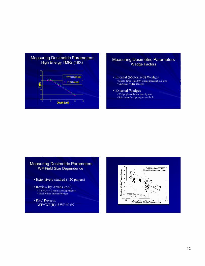
Measuring Dosimetric ParametersMeasuring Dosimetric ParametersHigh Energy High Energy TMRsTMRs (18X)(18X)
0.6
0.7
0.8
0.9
1
1.1
1.2
0 5 10 15 20 25Depth [cm]
TMR
TPR(d,20x20,6x6)
TPR(d,6x6,6x6)
Measuring Dosimetric ParametersMeasuring Dosimetric ParametersWedge FactorsWedge Factors
• Internal (Motorized) Wedges• Single, large (e.g., 60o) wedge placed above jaws• Universal wedge concept
• External Wedges• Wedge placed below jaws by user• Selection of wedge angles available
Measuring Dosimetric ParametersMeasuring Dosimetric ParametersWF Field Size DependenceWF Field Size Dependence
• Extensively studied (>20 papers)
• Review by Arrans et al.,• ↓ SWD => ↓ Field Size Dependence• Not hold for Internal Wedges
• RPC Review: WF=WF(R) if WF<0.65
13
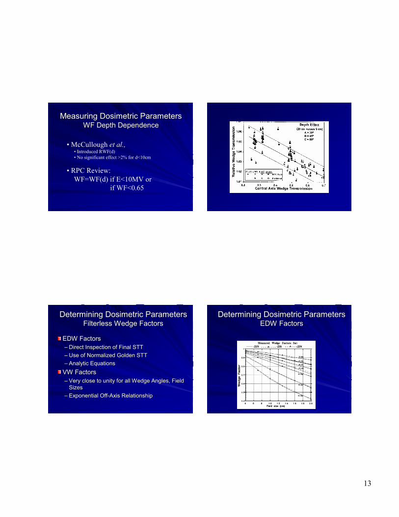
Measuring Dosimetric ParametersMeasuring Dosimetric ParametersWF Depth DependenceWF Depth Dependence
• McCullough et al.,• Introduced RWF(d)• No significant effect >2% for d<10cm
• RPC Review: WF=WF(d) if E<10MV or
if WF<0.65
Determining Dosimetric ParametersDetermining Dosimetric ParametersFilterlessFilterless Wedge FactorsWedge Factors
EDW FactorsEDW Factors–– Direct Inspection of Final STTDirect Inspection of Final STT–– Use of Normalized Golden STTUse of Normalized Golden STT–– Analytic EquationsAnalytic Equations
VW FactorsVW Factors–– Very close to unity for all Wedge Angles, Field Very close to unity for all Wedge Angles, Field
SizesSizes–– Exponential OffExponential Off--Axis RelationshipAxis Relationship
Determining Dosimetric ParametersDetermining Dosimetric ParametersEDW FactorsEDW Factors

14
Measuring Dosimetric ParametersMeasuring Dosimetric ParametersAsymmetric Fields Asymmetric Fields FilterlessFilterless WedgesWedges
0
0.2
0.4
0.6
0.8
1
1.2
1.4
-20 -15 -10 -5 0 5 10
OFF AXISDISTANCE
VWF
Measuring Dosimetric ParametersMeasuring Dosimetric ParametersOff Axis RatiosOff Axis Ratios
Calculations to offCalculations to off--axis points may be axis points may be performed in two methods:performed in two methods:
1.1. Use of offUse of off--axis dosimetry functionsaxis dosimetry functions2.2. Use of CA dosimetry functions with a offUse of CA dosimetry functions with a off--
axis ratio: OAR(x,d,r)axis ratio: OAR(x,d,r)
Measuring Dosimetric ParametersMeasuring Dosimetric ParametersOffOff--Axis RatiosAxis Ratios
OffOff--Axis Ratios have been determined in Axis Ratios have been determined in several waysseveral ways
1.1. Large field profile dataLarge field profile data2.2. Primary OffPrimary Off--Axis Ratios (POAR(x,d))Axis Ratios (POAR(x,d))3.3. Analytic EquationsAnalytic Equations
Measuring Dosimetric ParametersMeasuring Dosimetric ParametersOffOff--Axis RatiosAxis Ratios
OAR Comparisons (Gibbons & Khan, OAR Comparisons (Gibbons & Khan, ’’95):95):[6, 24MV photons at 5,10,15cm [6, 24MV photons at 5,10,15cm OADsOADs/depths/depths]]
Average (Max) ErrorAverage (Max) ErrorLarge Field Profiles:Large Field Profiles: 2.5% (6.7%)2.5% (6.7%)
POARsPOARs:: 0.8% (1.8%)0.8% (1.8%)Analytic Equation:Analytic Equation: 0.5% (1.7%)0.5% (1.7%)
15
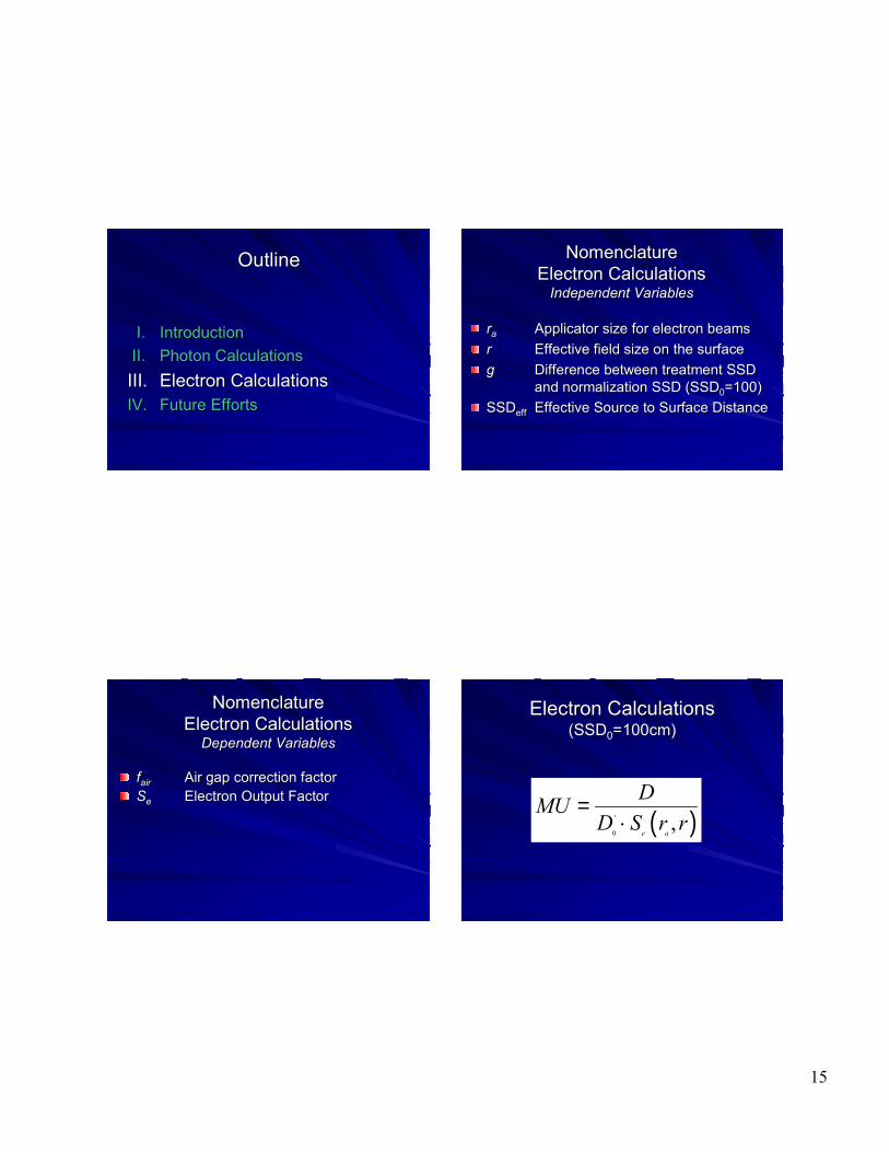
OutlineOutline
I.I. IntroductionIntroductionII.II. Photon CalculationsPhoton CalculationsIII.III. Electron CalculationsElectron CalculationsIV.IV. Future EffortsFuture Efforts
NomenclatureNomenclatureElectron CalculationsElectron Calculations
Independent VariablesIndependent Variables
rraa Applicator size for electron beamsApplicator size for electron beamsrr Effective field size on the surfaceEffective field size on the surfacegg Difference between treatment SSD Difference between treatment SSD
and normalization SSD (SSDand normalization SSD (SSD00=100) =100) SSDSSDeffeff Effective Source to Surface DistanceEffective Source to Surface Distance
NomenclatureNomenclatureElectron CalculationsElectron Calculations
Dependent VariablesDependent Variables
ffairair Air gap correction factorAir gap correction factorSSee Electron Output FactorElectron Output Factor
Electron CalculationsElectron Calculations(SSD(SSD00=100cm)=100cm)
( )'
0,
e a
DMUD S r r
=⋅

16
Electron CalculationsElectron Calculations(SSD>SSD(SSD>SSD00))
( )2'
0 0 0( , ) ( ) ( )
e a eff eff
DMUD S r r SSD d SSD d g
=⋅ ⋅ + + +
Method 1: SSDeff Technique
Electron CalculationsElectron Calculations(SSD>SSD(SSD>SSD00))
Method 2: Air Gap Technique
( )2'
0 0 0( , ) ( ) ( ) ( , )
e a air
DMUD S r r SSD d SSD d g f r SSD
=⋅ ⋅ + + + ⋅
Electron Output FactorsElectron Output Factors
For square fields, SFor square fields, See measured at measured at commissioningcommissioningFor rectangular fields, use Square Root For rectangular fields, use Square Root Method:Method:
SSee(r(raa,LxW) = [S,LxW) = [See(r(raa,LxL) ,LxL) ·· SSee(r(raa,WxW)],WxW)]1/21/2
Many irregular fields can be approximated Many irregular fields can be approximated by rectangular fields.by rectangular fields.
Electron Cone InsertsElectron Cone Inserts
From Hogstrom et al., “MU Calculations for Electron Beams”, 2000

17
Electron Irregular FieldsElectron Irregular Fields
Special considerations required if FS very Special considerations required if FS very small (r < E/2.5) small (r < E/2.5) For these conditions, SFor these conditions, See may be may be determined bydetermined by–– Special DosimetrySpecial Dosimetry–– Method of Lateral Buildup Ratio (LBR)Method of Lateral Buildup Ratio (LBR)
Electron Irregular FieldsElectron Irregular Fields
Electron Irregular FieldsElectron Irregular Fields
WherePDD is the percentage depth dose for a broad fieldfa is the ratio of applicator to reference fluencefi is the ratio of insert to reference fluenceLBR is the average lateral buildup ratio
LBR is the ratio of the central axis depth dose in a given circularfield to the central axis depth dose in a broad field for the sameincident fluence - measured data
'
0 100%e a i
PDDS D f f LBR= ⋅ ⋅ ⋅ ⋅
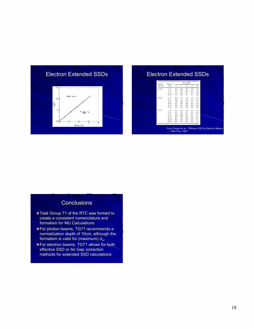
ElectronElectronExtended SSD CalculationsExtended SSD Calculations
Many treatment geometries require Many treatment geometries require extended extended SSDsSSDs
The The Air Gap FactorAir Gap Factor may be determined may be determined –– Using inverse square correction with virtual Using inverse square correction with virtual
SSDSSDrequires air gap scatter correction termrequires air gap scatter correction term
–– Using inverse square correction with effective Using inverse square correction with effective SSD SSD
18
Electron Extended Electron Extended SSDsSSDs Electron Extended Electron Extended SSDsSSDs
From Roback et al., “Effective SSD for Electron Beams …”, Med Phys 1995
ConclusionsConclusions
Task Group 71 of the RTC was formed to Task Group 71 of the RTC was formed to create a consistent nomenclature and create a consistent nomenclature and formalism for MU Calculationsformalism for MU CalculationsFor photon beams, TG71 recommends a For photon beams, TG71 recommends a normalization depth of 10cm, although the normalization depth of 10cm, although the formalism is valid for (maximum) dformalism is valid for (maximum) dmm..For electron beams, TG71 allows for both For electron beams, TG71 allows for both effective SSD or Air Gap correction effective SSD or Air Gap correction methods for extended SSD calculationsmethods for extended SSD calculations


